vistawall - alexcoalexco.com.lb/wp-content/uploads/.../10/sec-01-general-information.pdf ·...
TRANSCRIPT
INTERNATIONAL
VISTAWALL
Vistawall International is committed to being the
service and quality leader in the specification,
design, engineering and distribution of innovative
window and door systems, low-rise framing, and
high performance custom engineered curtain
walls, skylights and translucent panels systems
P. O. Box 18040, Dubai, United Arab Emirates Phone: + (971) 4 886 0691 ● Fax: + (971) 4 886 0720 ● Email [email protected]


INTERNATIONAL
P. O. Box 18040, Dubai, United Arab Emirates
Phone: + (971) 4 886 0691 ● Fax: + (971) 4 886 0720 ● Email [email protected]
Vistawall International is part of the large Vistawall Architectural Products Group who has built their reputation on providing competitively priced, top quality innovative glazing and framing systems around the world. Vistawall International, from its base in Dubai, continues this tradition by supplying a complete line of systems to the region. Whilst many of these products have their roots in the Vistawall Architectural Products Group, they have been adapted to suit the local market requirements. Top quality system components are supplied with all our aluminium profiles to ensure that all parts are of a standard that will provide long term service with little or no maintenance other than regular cleaning. As Vistawall International is locally based we are able to provide a quick response to queries and requests from building owners, consultants, architects, contractors and installation partners using our in house team of representatives, estimators, designers, draftsmen and structural engineers. Our design team prides itself on its ability to custom design and engineer its products to unique and specific project requirements. We are close at hand to provide information, samples and assistance as required to ensure the smooth progress and satisfactory completion of each project. We can provide conceptual designs, preliminary structural calculations and quotations as well as specifications, samples and any other information that may be required. When a project becomes an order we can prepare the shop drawings and structural calculations or provide our customer with manuals or working designs for him to use in the production of the shop drawings. If required we can also produce materials take offs, fabrication drawings and fabrication manuals. Installation manuals are normally supplied for each project and factory or site visits and assistance will be made as necessary. Following is a summary of our services:
• Conceptual designs • Estimating • Samples and brochures • Working designs • Shop drawings and structural calculations • Materials Take off • Fabrication drawings • Fabrication and installation manuals • Supply of framing system – finished aluminium profiles, fasteners and accessories • Factory and site visits and assistance
Vistawall International is committed to providing a high level of service to building owners, consultants, architects, main contractors and installation partners to ensure that their requirements for the building envelope are met or exceeded.
VISTAWALL


KPa KPH M/S MPH PSF0.1 46.36 12.89 28.80 2.12 INTERNATIONAL0.2 65.57 18.23 40.73 4.25
0.3 80.30 22.32 49.88 6.370.4 92.73 25.78 57.60 8.490.5 103.67 28.82 64.39 10.62 WEIGHT AND MEASURE0.6 113.57 31.57 70.54 12.74 EQUIVALENTS AND CONVERSIONS:0.7 122.67 34.10 76.19 14.860.8 131.14 36.46 81.45 16.98 MILE = 1.609 KM0.9 139.09 38.67 86.39 19.111.0 146.62 40.76 91.07 21.20 METER = 3.28 FT1.1 153.77 42.75 95.51 23.351.2 160.61 44.65 99.76 25.48 KM = 1000 M1.3 167.17 46.47 103.83 27.601.4 173.48 48.23 107.75 29.72 INCH = 25.40 MM1.5 179.57 49.92 111.53 31.851.6 185.46 51.56 115.19 33.97 KIP = 1000 LBS1.7 191.16 53.14 118.74 36.091.8 196.71 54.68 122.18 38.21 KG = 9.81 NEWTON1.9 202.10 56.18 125.53 40.342.0 207.35 57.64 128.79 42.46 = 2.2046 LBS 2.1 212.47 59.07 131.97 44.582.2 217.47 60.46 135.07 46.71 KN = 1000 NEWTON2.3 222.35 61.81 138.11 48.832.4 227.14 63.14 141.08 50.95 Pa = N/M22.5 231.82 64.45 143.99 53.082.6 236.41 65.72 146.84 55.20 1 KPa ( kN/ M 2 ) = 1000 Pa ( Newton / M2 ) 2.7 240.91 66.97 149.64 57.322.8 245.34 68.20 152.38 59.442.9 249.68 69.41 155.08 61.573.0 253.95 70.60 157.73 63.693.1 258.14 71.76 160.34 65.813.2 262.27 72.91 162.90 67.943.3 266.34 74.04 165.43 70.063.4 270.35 75.16 167.92 72.183.5 274.29 76.25 170.37 74.313.6 278.18 77.34 172.79 76.433.7 282.02 78.40 175.17 78.553.8 285.81 79.45 177.52 80.673.9 289.54 80.49 179.84 82.804.0 293.23 81.52 182.13 84.924.1 296.87 82.53 184.39 87.044.2 300.47 83.53 186.63 89.174.3 304.03 84.52 188.84 91.294.4 307.54 85.50 191.02 93.414.5 311.02 86.46 193.18 95.544.6 314.46 87.42 195.31 97.664.7 317.86 88.36 197.43 99.784.8 321.22 89.30 199.52 101.904.9 324.55 90.22 201.58 104.035.0 327.84 91.14 203.63 106.155.1 331.11 92.05 205.66 108.275.2 334.34 92.95 207.66 110.405.3 337.54 93.83 209.65 112.525.4 340.70 94.72 211.62 114.645.5 343.84 95.59 213.57 116.775.6 346.96 96.45 215.50 118.895.7 350.04 97.31 217.42 121.015.8 353.10 98.16 219.32 123.135.9 356.13 99.00 221.20 125.266.0 359.13 99.84 223.06 127.38
WIND VELOCITY vs STATIC PRESSURECONVERSION CHART
VISTAWALL


INTERNATIONAL
VISTAWALL
The following General Specification is
provided to assist the Consultant /
Architect in writing the specification for
curtain wall, windows and other
architectural glazed systems. Vistawall
personnel can provide further assistance
to make this general specification suit the
particular type of construction.
P. O. Box 18040, Dubai, United Arab Emirates Phone: + (971) 4 886 0691 ● Fax: + (971) 4 886 0720 ● Email [email protected]


1
GENERAL SPECIFICATION FOR VISTAWALL GLAZED ALUMINIUM FRAMING SYSTEMS **************************************************************************************** Design and Supply by :- Vistawall International P.O. Box 18040, Dubai, United Arab Emirates. Phone +971 4 886 0691 Fax +971 4 886 0720 **************************************************************************************** PART 1 - GENERAL **************************************************************************************** A. CODES AND STANDARDS General
1. AAMA Aluminium curtain wall design manual. 2. AAMA Metal curtain wall, window, storefront and entrance – Guide
specification manual. 3. AAMA Curtain wall manual #10 – Care and handling of architectural
aluminium From Shop to Site. Windloads
1. BS 6399.2 Code of practice for windloads 2. BS CP3 Ch5 Part 2:1972 Windloads
Aluminium
1. ASTM B209 Aluminum and aluminum-alloy sheet and plate. 2. ASTM B221 Aluminum-alloy extruded bars, rods, wire, shapes, and
tubes. 3. ASTM B308 Aluminum-alloy 6061-T6 standard structural shapes,
rolled or extruded. 4. BS1470 Specification for wrought aluminium and aluminium alloys-
plate, sheet and strip. 5. BS EN755-9 Aluminum-alloy extrusion. 6. BS8118 Specification for the structural use of aluminium
Glass and Glazing
1. ANSI Z97.1 Specifications and methods of test for safety glazing material used in buildings.
2. ASTM C1036 Specification for flat glass 3. ASTM C1048 Specification for heat treated flat glass
2
3. ASTM C1048 Specification for heat treated flat glass 4. ASTM C1172 Specification for laminated architectural glass 5. ASTM E773 Test method for seal durability of sealed insulating glass
units. 6. ASTM E774 Sealed insulating glass units. 7. ASTM E1300 Standard practice for determining load resistance of
glass in buildings 8. FGMA - Flat glass marketing association: Glazing manual 9. BS 952 Glass and glazing 10. BS 6206 Specification for impact performance requirements for flat
safety glass and safety plastics for use in buildings 11. BS 6262 Code of practice for glazing of buildings
Sealants
1. ASTM C794 Test methods for adhesion – in peel of elastomeric joint sealants
2. ASTM C920 Elastomeric joint sealants. 3. BS 5889 Specification for one part gun grade Silicone based sealants
Gaskets
1. ASTM C509 Cellular elastomeric preformed gaskets 2. ASTM C864 Dense preformed gaskets 3. ASTM C1115 Silicone Gaskets 4. BS 4255 Rubber for use in preformed gaskets for weather exclusion
from buildings Protective Coatings
1. AAMA 2605 Voluntary specification for high performance organic coatings on architectural extrusions and aluminum.
2. AAMA607.1 Specifications and inspection methods for clear anodic finishes for architectural aluminum.
3. AAMA608.1 Specification and Inspection methods for electrolytically Deposited Color Anodic finishes for architectural aluminum.
4. BS3987 Specification for anodic oxidation coatings on wrought aluminium for external architectural applications.
5. BS4842 Specification for liquid organic coatings application on aluminium alloy extrusions, sheet, and preformed sections for external architectural purposes.
6. BS6161 Method of test for anodic oxidation coatings on aluminium alloys.
7. BS6496 Specification for powder organic coatings on aluminium extrusion, sheet and preformed sections for external architectural purposes.
8. BS6497 Specification for powder organic coatings on hot dip galvanized sections and sheet for external architectural purposes.

3
Fire Protection
1. BS476 Fire tests on building materials and structures. Performance Testing
1. ASTM E283 Rate of air leakage through exterior windows, curtain walls, and doors.
2. ASTM E330 Structural performance of exterior windows, curtain walls, and doors by uniform static air pressure difference.
3. ASTM E331 Test method for water penetration of exterior windows, curtain Walls, and doors by uniform static air pressure difference.
4. AAMA 501 Method of testing for exterior walls 5. AAMA 501.1 Standard test method for exterior windows, and curtain
walls for water penetration using dynamic pressure. 6. AAMA 501.2 Field check of metal curtain walls for water leakage. 7. BS5368 Methods of testing windows. 8. BS6375 Performance of windows.
Steel
1. ASTM A36 Structural steel. 2. ASTM A123 Zinc (hot-dip galvanized) coatings on iron and steel
products. 3. ASTM A525 General requirements for steel sheet, zinc-coated
(galvanized) by the hot-dip process. 4. ASTM A526 Sheet steel, zinc coated (galvanized) by the hot-dip
process, commercial quality. 5. BS729 Specification for hot dip galvanised coatings on iron and steel
Fasteners
1. BS4190 Specification for ISO metric black hexagon bolts, nuts and screws.
Miscellaneous
1. BS6651 Code of practice for protection of structures against lightning. **************************************************************************************** B GENERAL
1. Metal framed systems with interior and exterior exposed metal framing. 2. Operable vent with sight line concealed from the exterior. 3. System supplier shall provide curtainwall systems, including necessary
modifications to meet specified requirements and maintaining visual design concepts.
4. Fabricate glazing systems for exterior glazing at vision areas and exterior glazing at spandrel areas.
4
5. Perimeter conditions shall allow for installation tolerances, expansion and contraction of adjacent materials, and sealant manufacturer's recommended joint design.
6. Do not assume glass, sealants, and interior finishes contribute to framing member strength, stiffness, or lateral stability.
7. Allow for expansion and contraction due to structural movement without detriment to appearance or performance.
8. Water entering joints and condensation occurring within system shall drain to exterior face of wall, by drain holes and gutters of adequate size to evacuate water without infiltration to interior or the top of lower lites of glass.
9. Provide concealed fastening. 10. Metal faces are required to be visually flat under all lighting conditions,
subject to acceptance of Architect. 11. Provide uniform color and profile appearance at components exposed
to view. 12. EPDM Glazing gaskets are to be provided to the interior and exterior of
the glass. The gasket should create a water and air seal. 13. Provide pre-drilled pressure plates to ensure correct quantity and
spacing of fasteners. 14. Stresses placed on structural silicone sealants shall be kept within
sealant manufacturer's recommended maximum. 15. Vibration harmonics, wind whistles, noises caused by thermal
movement, thermal movement transmitted to other building elements, loosening, weakening, or fracturing of attachments or components of system are all not permitted.
****************************************************************************************
C. PERFORMANCE REQUIREMENTS: 1. The curtain wall system is designed to meet the following performance
standards for the fixed areas:- a. Air Infiltration - Infiltration shall not exceed 1.08m3/h/m2 of fixed
area at a static test pressure of 75Pa in accordance with ASTM E283.
b. Water penetration - There shall be no visible water on any inside surface at a test pressure of 720Pa when tested in accordance with ASTM E331.
**************************************************************************************** D. STRUCTURAL REQUIREMENTS:
1. Wind loading: Design to a basic windspeed of 45m/s (factors and coefficients according to BS CP3 or BS6399 to be applied)
2. Maximum deflection under uniform loading at design wind pressure, shall not exceed L/175 of span or 20mm when tested in accordance with ASTM E330.

5
3. Parallel to wall deflection shall not exceed 3mm. **************************************************************************************** E. CAST IN INSERTS:
1. Furnish inserts and anchoring devices that need to be preset and built into structure to appropriate trade.
2. Supply on timely basis to avoid delay in work. 3. Instruct other trades of proper location and position. 4. Furnish setting drawings, diagrams, templates and installation
instructions. **************************************************************************************** F. SUBMITTALS
1. Submit manufacturer's descriptive literature for each manufactured products.
2. Submit information for factory finishes, accessories and other required components.
3. Submit Mock-up Drawings. 4. Submit project drawings indicating: elevations, detailed design,
dimensions, member profiles, joint locations, arrangement of units, member connections, thickness of various components, drainage details and flow diagrams, anchorage system, interfacing with building construction, provisions for system expansion and contraction, thermal breaks. Also indicate glazing details, methods, locations of various types and thickness of glass, emergency breakout locations (if required), internal sealant requirements. Clearly indicate locations of any exposed fasteners and joints for Architect's acceptance. Clearly show where and how manufacturer's system deviates from contract drawings and specifications.
**************************************************************************************** G. SAMPLES:
1. Submit manufactures samples indicating quality of finish in required colors.
2. Where normal texture or color variations are expected, include additional samples illustrating range of variation.
3. Submit samples of glazing gaskets, 300mm lengths. 4. Submit samples of sealants for color selection. 5. Submit manufacturer's certification stating that installed system is in
compliance with specified requirements. 6. Submit manufacturer's printed installation instructions. (Include
detailed instructions describing each step of reglazing procedures.) 7. Warranty: Submit specified warranties.
****************************************************************************************
6
H. DELIVERY, STORAGE, AND HANDLING
1. Protect finished surfaces to prevent damage. 2. Do not use adhesive papers or sprayed coatings which become firmly
bonded when exposed to sun. 3. Do not leave coating residue on surfaces. 4. Deliver glass units with manufacturer's labels intact on interior side of
glass. Ensure labels indicate glass thickness, unit location, glass strength and orientation of units in vertical position.
5. Protect glass edges and corners to prevent chipping, cracking, and other similar damages.
**************************************************************************************** I. PROJECT CONDITIONS
1. Ensure ambient and surface temperatures and joint conditions are suitable for installation of materials.
**************************************************************************************** J. WARRANTY
1. Provide written warranty in form acceptable to Owner jointly signed by manufacturer, installer and Contractor warranting work to be watertight, free from deflective materials, defective workmanship, glass breakage due to defective design, and agreeing to replace components which fail within 5 years from date of Substantial Completion. Warranty shall cover following:
a. Complete watertight and airtight system installation within specified tolerances.
b. Glass and glazing gaskets will not break or "pop" from frames due to design wind, expansion or contraction movement or structural loading.
c. Glazing sealants and gaskets will remain free from abnormal deterioration or dislocation due to sunlight, weather or oxidation.
****************************************************************************************
K. LIFE EXPEXCTANCY 1. Façade to perform satisfactorily for 25years with minimum
maintenance (apart from regular cleaning).
**************************************************************************************** PART 2 - PRODUCTS ****************************************************************************************
7
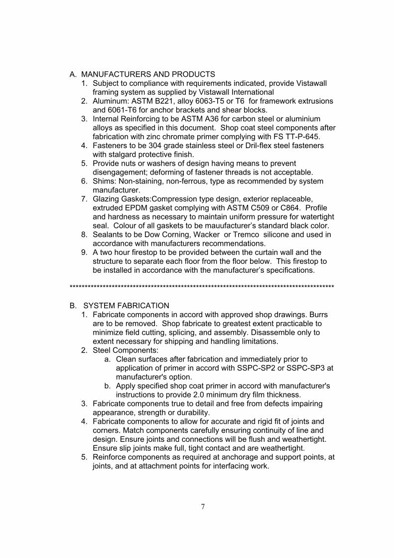
A. MANUFACTURERS AND PRODUCTS 1. Subject to compliance with requirements indicated, provide Vistawall
framing system as supplied by Vistawall International 2. Aluminum: ASTM B221, alloy 6063-T5 or T6 for framework extrusions
and 6061-T6 for anchor brackets and shear blocks. 3. Internal Reinforcing to be ASTM A36 for carbon steel or aluminium
alloys as specified in this document. Shop coat steel components after fabrication with zinc chromate primer complying with FS TT-P-645.
4. Fasteners to be 304 grade stainless steel or Dril-flex steel fasteners with stalgard protective finish.
5. Provide nuts or washers of design having means to prevent disengagement; deforming of fastener threads is not acceptable.
6. Shims: Non-staining, non-ferrous, type as recommended by system manufacturer.
7. Glazing Gaskets:Compression type design, exterior replaceable, extruded EPDM gasket complying with ASTM C509 or C864. Profile and hardness as necessary to maintain uniform pressure for watertight seal. Colour of all gaskets to be mauufacturer’s standard black color.
8. Sealants to be Dow Corning, Wacker or Tremco silicone and used in accordance with manufacturers recommendations.
9. A two hour firestop to be provided between the curtain wall and the structure to separate each floor from the floor below. This firestop to be installed in accordance with the manufacturer’s specifications.
**************************************************************************************** B. SYSTEM FABRICATION
1. Fabricate components in accord with approved shop drawings. Burrs are to be removed. Shop fabricate to greatest extent practicable to minimize field cutting, splicing, and assembly. Disassemble only to extent necessary for shipping and handling limitations.
2. Steel Components: a. Clean surfaces after fabrication and immediately prior to
application of primer in accord with SSPC-SP2 or SSPC-SP3 at manufacturer's option.
b. Apply specified shop coat primer in accord with manufacturer's instructions to provide 2.0 minimum dry film thickness.
3. Fabricate components true to detail and free from defects impairing appearance, strength or durability.
4. Fabricate components to allow for accurate and rigid fit of joints and corners. Match components carefully ensuring continuity of line and design. Ensure joints and connections will be flush and weathertight. Ensure slip joints make full, tight contact and are weathertight.
5. Reinforce components as required at anchorage and support points, at joints, and at attachment points for interfacing work.
8
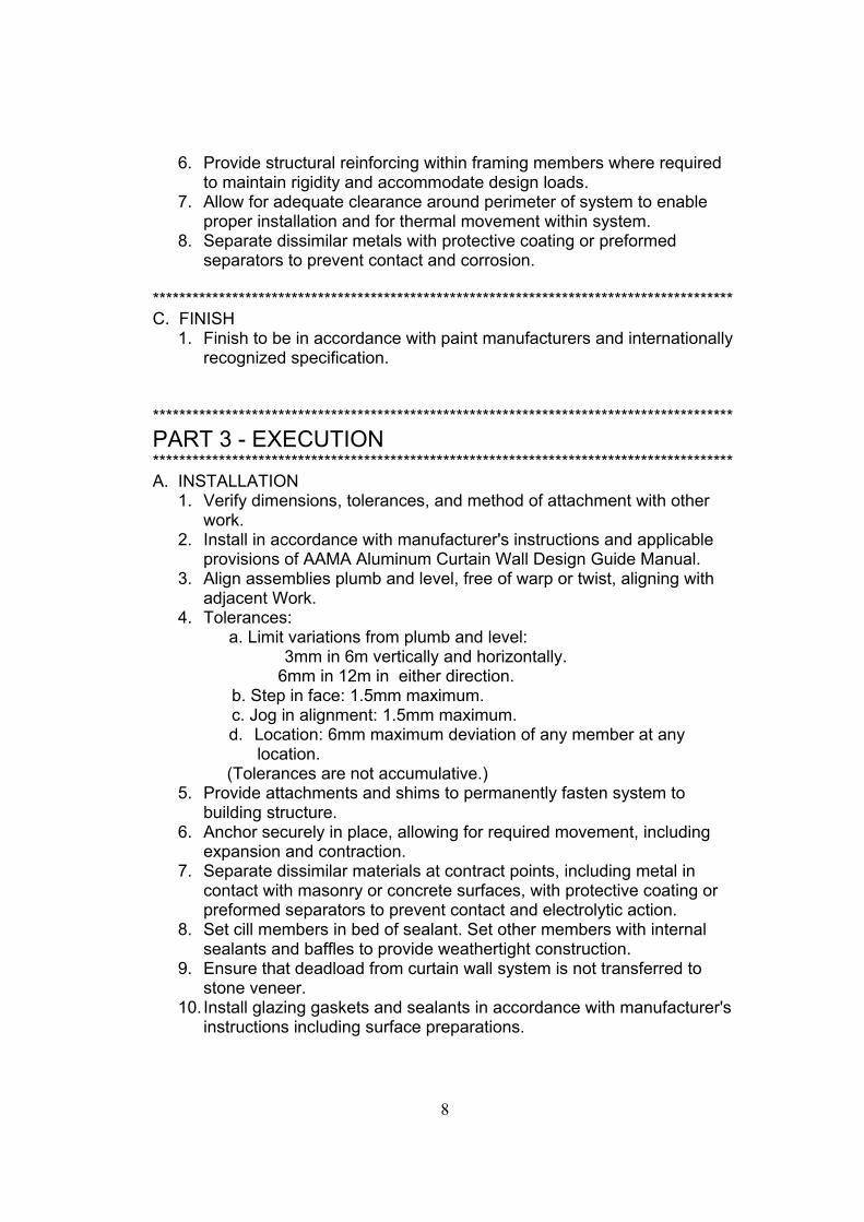
6. Provide structural reinforcing within framing members where required to maintain rigidity and accommodate design loads.
7. Allow for adequate clearance around perimeter of system to enable proper installation and for thermal movement within system.
8. Separate dissimilar metals with protective coating or preformed separators to prevent contact and corrosion.
**************************************************************************************** C. FINISH
1. Finish to be in accordance with paint manufacturers and internationally recognized specification.
**************************************************************************************** PART 3 - EXECUTION **************************************************************************************** A. INSTALLATION
1. Verify dimensions, tolerances, and method of attachment with other work.
2. Install in accordance with manufacturer's instructions and applicable provisions of AAMA Aluminum Curtain Wall Design Guide Manual.
3. Align assemblies plumb and level, free of warp or twist, aligning with adjacent Work.
4. Tolerances: a. Limit variations from plumb and level:
3mm in 6m vertically and horizontally. 6mm in 12m in either direction.
b. Step in face: 1.5mm maximum. c. Jog in alignment: 1.5mm maximum.
d. Location: 6mm maximum deviation of any member at any location.
(Tolerances are not accumulative.) 5. Provide attachments and shims to permanently fasten system to
building structure. 6. Anchor securely in place, allowing for required movement, including
expansion and contraction. 7. Separate dissimilar materials at contract points, including metal in
contact with masonry or concrete surfaces, with protective coating or preformed separators to prevent contact and electrolytic action.
8. Set cill members in bed of sealant. Set other members with internal sealants and baffles to provide weathertight construction.
9. Ensure that deadload from curtain wall system is not transferred to stone veneer.
10. Install glazing gaskets and sealants in accordance with manufacturer's instructions including surface preparations.
9
11. Install fire safing and curtain wall insulation in accordance with manufacturers instructions.
12. Carry out field hose test for water penetration. 13. Clean surfaces in compliance with manufacturer's recommendations:
remove excess mastic, mastic smears, and other foreign materials. 14. Clean metal surfaces exercising care to avoid damage.
**************************************************************************************** END OF SECTION