visual representation in industrial design …
TRANSCRIPT

VISUAL REPRESENTATION IN INDUSTRIAL DESIGN REGISTRATION:
A PROPOSED GUIDELINE FOR TURKEY BASED ON LEGAL TEXTS AND
GUIDELINES FROM EIGHT DIFFERENT JURISDICTIONS, AND INTERVIEWS
WITH TURKISH PATENT INSTITUTE EXAMINERS
IRMAK YALÇINER
SEPTEMBER 2012

VISUAL REPRESENTATION IN INDUSTRIAL DESIGN REGISTRATION: A PROPOSED GUIDELINE FOR TURKEY BASED ON LEGAL TEXTS AND
GUIDELINES FROM EIGHT DIFFERENT JURISDICTIONS, AND INTERVIEWS WITH TURKISH PATENT INSTITUTE EXAMINERS
A THESIS SUBMITTED TO THE GRADUATE SCHOOL OF NATURAL AND APPLIED SCIENCES
OF MIDDLE EAST TECHNICAL UNIVERSITY
BY
IRMAK YALÇINER
IN PARTIAL FULFILMENT OF THE REQUIREMENTS FOR
THE DEGREE OF MASTER OF SCIENCE IN
INDUSTRIAL DESIGN
SEPTEMBER 2012

VISUAL REPRESENTATION IN INDUSTRIAL DESIGN REGISTRATION: A PROPOSED GUIDELINE FOR TURKEY BASED ON LEGAL TEXTS AND
GUIDELINES FROM EIGHT DIFFERENT JURISDICTIONS, AND INTERVIEWS WITH TURKISH PATENT INSTITUTE EXAMINERS
Submitted by IRMAK YALÇINER in partial fulfilment of the requirements for the degree of Master of Science in Industrial Design Department, Middle East Technical University by,
Prof Dr. Canan Özgen ______________
Dean, Graduate School of Natural Applied Sciences
Assoc. Prof. Dr. Gülay Hasdoğan ______________
Head of Department, Industrial Design
Assist. Prof. Dr. Fatma Korkut ______________
Supervisor, Industrial Design Dept., METU
Examining Committee Members:
Assist. Prof. Dr. Çağla Doğan ______________
Industrial Design Dept., METU
Assist. Prof. Dr. Fatma Korkut ______________
Industrial Design Dept., METU
Inst. Refik Toksöz ______________
Industrial Design Dept., METU
Assist. Prof. Dr. Aydın Öztoprak ______________
Industrial Design Dept. TOBB University
Inst. Dr. Gülçin Cankız Elibol ______________
Interior Architecture and Environmental Design Dept. Hacettepe University
Date: September 13, 2012

iii
I hereby declare that all information in this document has been obtained and presented in accordance with academic rules and ethical conduct. I also declare that, as required by these rules and conduct, I have fully cited and referenced all material and results that are not original to this work.
Name, Last Name: Irmak YALÇINER Signature :
iv
ABSTRACT
VISUAL REPRESENTATION IN INDUSTRIAL DESIGN REGISTRATION:
A PROPOSED GUIDELINE FOR TURKEY BASED ON LEGAL TEXTS AND
GUIDELINES FROM EIGHT DIFFERENT JURISDICTIONS, AND INTERVIEWS
WITH TURKISH PATENT INSTITUTE EXAMINERS
Yalçıner, Irmak
M.Sc., Department of Industrial Design
Supervisor: Assist. Prof. Dr. Fatma Korkut
September 2012, 178 pages
Visual representation is the most important element of a design registration in
terms of scope of protection. This study examines national, regional and
international design registration systems in terms of legal texts and guidelines
related to visual representation, investigates problematic issues concerning the
features and qualities of visual representation in industrial design registration
applications in Turkey through the interviews conducted with the Turkish Patent
Institute examiners, and proposes a guideline for Turkey which would assist
applicants and attorneys in preparing visual representations.
Keywords: Design protection, design registration, industrial design registration in
Turkey, visual representation of designs, guideline for visual representation,
examination of visual representation, preparation of visual representation.

v
ÖZ
ENDÜSTRİYEL TASARIM TESCİLİNDE GÖRSEL ANLATIM:
SEKİZ FARKLI HUKUK SİSTEMİNDEKİ DÜZENLEMELER VE KILAVUZLAR
İLE TÜRK PATENT ENSTİTÜSÜ UZMANLARIYLA YAPILAN GÖRÜŞMELER
TEMELİNDE TÜRKİYE’YE YÖNELİK BİR KILAVUZ ÖNERİSİ
Yalçıner, Irmak
Yüksek Lisans, Endüstri Ürünleri Tasarımı Bölümü
Tez Yöneticisi: Yrd. Doç. Dr. Fatma Korkut
Eylül 2012, 178 sayfa
Görsel anlatım, bir tasarım tescilinde koruma kapsamını belirleyen en önemli
unsurdur. Bu çalışma, ulusal, bölgesel ve uluslararası tasarım tescil sistemlerinde
görsel anlatıma ilişkin hukuki düzenlemeleri ve kılavuzları incelemekte, Türk
Patent Enstitüsü uzmanlarıyla yapılan görüşmelere dayanarak Türkiye’de
endüstriyel tasarım tescili başvurularında kullanılan görsel anlatımların
özelliklerine ve niteliklerine ilişkin sorunları araştırmakta ve görsel anlatımların
hazırlanmasında başvuru sahiplerine ve vekillere yardımcı olacak bir kılavuz
önermektedir.
Anahtar Kelimeler: Tasarım koruması, tasarım tescili, Türkiye’de endüstriyel
tasarım tescili, tasarımların görsel anlatımı, görsel anlatım kılavuzu, görsel
anlatımın incelenmesi, görsel anlatımın hazırlanması.

vi
To my beloved parents

vii
ACKNOWLEDGEMENTS
I would like to express my deepest gratitude to my supervisor Assist. Prof. Dr.
Fatma Korkut for her guidance, advice, criticism, encouragement and insight
throughout my research.
I would also like to thank my father Uğur G. Yalçıner for his endless support,
guidance, encouragement and suggestions, and my mother Mine Yalçıner for her
support and encouragement during my research. It is hard to express the extent of
my gratitude to them.
I would like to thank my colleagues at our office for their support and for standing
in for me while I have been on leave during this study. I am extremely lucky to be
working with them.

viii
TABLE OF CONTENTS
ABSTRACT ....................................................................................................................... iv
ÖZ ....................................................................................................................................... v
ACKNOWLEDGMENTS .............................................................................................. vii
TABLE OF CONTENTS ................................................................................................ viii
LIST OF TABLES ............................................................................................................ ix
LIST OF FIGURES ......................................................................................................... xii
LIST OF ABBREVIATIONS .......................................................................................... xi
CHAPTERS
1. INTRODUCTION ......................................................................................................... 1
1.1 Background and motivation ............................................................................. 2
1.2 Aim and scope of the thesis .............................................................................. 2
1.3 Structure of the thesis ......................................................................................... 2
2. LITERATURE REVIEW PART 1: INDUSTRIAL DESIGN REGISTRATION AND
VISUAL REPRESENTATION ......................................................................................... 4
2.1 Strategies and limitations of the literature review ......................................... 4
2.2 Introduction to the intellectual property rights and industrial design
registration system in Turkey ................................................................................. 6
2.3 Definition of “industrial design” in the reviewed legal texts and guidelines
..................................................................................................................................... 9
2.4 Definition of “visual representation” in the reviewed legal texts and
guidelines ................................................................................................................. 12
2.5 Importance of visual representation in industrial design registration ..... 14
2.6 Problems related to visual representation in industrial design registration
applications .............................................................................................................. 17
3. LITERATURE REVIEW PART II: FEATURES AND QUALITIES OF VISUAL
REPRESENTATIONSAS DESCRIBED IN LEGAL TEXT AND GUIDELINES .... 19
3.1 Types of representation.. ................................................................................. 23
3.1.1 Graphic representation ......................................................................... 24

ix
3.1.2 Photograph ............................................................................................. 34
3.1.3 Specimen ................................................................................................. 35
3.2 Content of visual representation .................................................................... 35
3.2.1 Article ...................................................................................................... 35
3.2.2 Background ............................................................................................. 36
3.2.3 Colour ...................................................................................................... 36
3.3 Views of design ................................................................................................. 38
3.3.1 Dimensions of views ............................................................................. 39
3.3.2 Types of views ........................................................................................ 40
3.3.2.1 Conventional views .................................................................. 40
3.3.2.2 Non-conventional views .......................................................... 41
3.3.2.3 Repeating surface patterns ...................................................... 51
3.3.2.4 Articles with indefinite length and width ............................. 52
3.3.2.5 Typographic typeface designs ................................................ 58
3.3.2.6 Designs comprising multiple components and complex
products ................................................................................................. 59
3.3.3 Ordering and numbering the views .................................................... 63
3.4 Partial disclaimer .............................................................................................. 65
3.4.1 Visual representation of partial disclaimer ........................................ 66
3.4.2 Verbal description of partial disclaimer ............................................. 71
3.5 Format and quality of visual representation ................................................ 72
3.5.1 Physical quality ...................................................................................... 72
3.5.2 Data format for e-filing ......................................................................... 76
3.6 Unacceptable visual representations ............................................................. 77
4. FIELD STUDY ............................................................................................................. 81
4.1 Background of the field study ........................................................................ 81
4.2 Interview schedule and data collection ........................................................ .82
4.3 Data analysis ..................................................................................................... 84
4.4 Findings of the field study .............................................................................. 90
4.4.1 Importance of the visual representation and formal examination . 90
4.4.2 Types of representation ......................................................................... 92
4.4.2.1 Graphic representation ............................................................ 92
4.4.2.2 Photograph ................................................................................ 93
4.4.2.3 Specimen .................................................................................... 93
4.4.3 Content of the visual representation ................................................... 93
4.4.3.1 Article ......................................................................................... 93

x
4.4.3.2 Background ............................................................................... 95
4.4.3.3 Colour ......................................................................................... 95
4.4.4 Views of design ...................................................................................... 96
4.4.4.1 Dimensions of views ................................................................ 98
4.4.4.2 Types of views .......................................................................... 99
4.4.4.2.1 Conventional views .................................................. 99
4.4.4.2.2 Non-conventional views ........................................ 100
4.4.4.2.3 Repeating surface patterns .................................... 105
4.4.4.2.4 Articles with indefinite length and width ........... 105
4.4.4.2.5 Typographic typeface designs .............................. 105
4.4.4.2.6 Designs comprising multiple components and
complex products .................................................................. 106
4.4.4.3 Ordering and numbering the views .................................... 109
4.4.5 Partial disclaimer ................................................................................. 110
4.4.5.1 Visual representation of partial disclaimer ......................... 110
4.4.5.2 Verbal description of partial disclaimer .............................. 110
4.4.6 Format and quality of visual representation ................................... 111
4.4.6.1 Physical quality ....................................................................... 111
4.4.6.2 Data format for e-filing .......................................................... 111
4.4.7 Unacceptable visual representations ................................................ 112
4.5 Further comments and suggestions by the TPI experts ............................ 113
5. CONCLUSION ......................................................................................................... 116
5.1 Proposed guideline for visual representations .......................................... 117
5.1.1 Types of representation ....................................................................... 119
5.1.1.1 Graphic representation .......................................................... 119
5.1.1.2 Photograph .............................................................................. 121
5.1.1.3 Specimen .................................................................................. 122
5.1.2 Content of visual representation ....................................................... 122
5.1.2.1 Article ....................................................................................... 122
5.1.2.2 Background ............................................................................. 123
5.1.2.3 Colour ....................................................................................... 124
5.1.3 Views of design .................................................................................... 124
5.1.3.1 Dimensions of views .............................................................. 126
5.1.3.2 Types of views ........................................................................ 126
5.1.3.2.1 Conventional views ................................................ 126
5.1.3.2.2 Non-conventional views ........................................ 127

xi
5.1.3.2.3 Repeating surface patterns .................................... 130
5.1.3.2.4 Articles with indefinite length and width ........... 131
5.1.3.2.5 Typographic typeface designs .............................. 132
5.1.3.2.6 Designs comprising multiple components and
complex products .................................................................. 132
5.1.3.3 Ordering and numbering the views .................................... 133
5.1.4 Partial disclaimer ................................................................................. 135
5.1.4.1 Visual representation of partial disclaimer ......................... 135
5.1.4.2 Verbal description of partial disclaimer .............................. 137
5.1.5 Format and quality of visual representation ................................... 137
5.1.5.1 Physical quality ....................................................................... 137
5.1.5.2 Data format for e-filing .......................................................... 139
5.1.6 Unacceptable visual representations ................................................ 139
5.1.7 Examples of acceptable visual representations ............................... 140
5.1.8 Further comments and suggestions .................................................. 140
5.2 Further studies ................................................................................................ 141
GLOSSARY .................................................................................................................... 142
REFERANCES ............................................................................................................... 143
APPENDICES ............................................................................................................... 147
A CONTRACTING PARTIES OF THE OF THE HAGUE AGREEMENT
GENEVA ACT (1999) ...................................................................................... 147
B LETTER TO THE HEAD OF THE DESIGN DEPARTMENT OF THE
TURKISH PATENT INSTITUTE REQUESTING AN INTERVIEW (IN
TURKISH) ......................................................................................................... 148
C LETTER TO THE HEAD OF THE DESIGN DEPARTMENT OF THE
TURKISH PATENT INSTITUTE REQUESTING AN INTERVIEW (IN
ENGLISH) ......................................................................................................... 150
D ELECTRONIC MAIL TO THE TURKISH PATENT INSTITUTE
EXAMINERS (IN TURKISH) ......................................................................... 152
E ELECTRONIC MAIL TO THE TURKISH PATENT INSTITUTE
EXAMINERS (IN ENGLISH) ......................................................................... 155
F INTERVIEW SCHEDULE FOR TURKISH PATENT INSTITUTE
EXAMINERS (IN TURKISH) ......................................................................... 158
G INTERVIEW SCHEDULE FOR TURKISH PATENT INSTITUTE
EXAMINERS (IN ENGLISH) ......................................................................... 168

xii
LIST OF TABLES
TABLES
Table 1 Legal texts and guidelines covered in the literature review ........................ 5
Table 2 Legal texts on industrial design protection in force in Turkey .................... 8
Table 3 Definition of design in the reviewed legal texts and guidelines ................. 9
Table 4 Forms of visual representation in the reviewed legal texts and guidelines .
........................................................................................................................................... 13
Table 5 Interview schedule parts and number of main questions .......................... 83
Table 6 Information on interviewees ........................................................................... 84
Table 7 Final coding scheme for topics and sub-topics ............................................ 87

xiii
LIST OF FIGURES
FIGURES
Figure 1 Stages of a design registration in Turkey and the procedures where the
visual representation plays an important role. .......................................................... 15
Figure 2 Categorization board for the “Physical quality” topic .............................. 20
Figure 3 The list of topics and sub-topics of the features and qualities of visual
representation ................................................................................................................. 22
Figure 4 Shading sample given by CIPO (CIPO 2010b, 6) ....................................... 26
Figure 5 Straight-line surface shading samples (USPTO 2012, 12) ......................... 27
Figure 6 Samples of surface shading by stippling (USPTO 2012, 13) ..................... 28
Figure 7 Combinations of straight line shading and stippling (USPTO 2012, 13) 28
Figure 8 Surface shading samples on different views of a Recycle Bin design (CIPO
2010b, 5) ........................................................................................................................... 29
Figure 9 Representation of a butter dish design showing transparent parts (CIPO
2010b, 6). Transparency represented by the thin shading lines .............................. 30
Figure 10 Sample shows denoting of translucency in drawings (CIPO 2010b, 9) 31
Figure 11 Samples showing transparent materials (USPTO 2012, 14) .................... 31
Figure 12 Symbols denoting materials, various properties and colours in design
patent drawings, as given by USPTO (USPTO 2012, 18) .......................................... 32
Figure 13 Representation of different materials on drawings (USPTO 2012, 17) . 33
Figure 14 Cross-sectional view samples as given by CIPO (CIPO 2010b, 20) ....... 42
Figure 15 Cross-sectional view sample as given by USPTO (USPTO 2012, 16) .... 43
Figure 16 Open and closed positional view sample (CIPO 2010b, 10) ................... 44
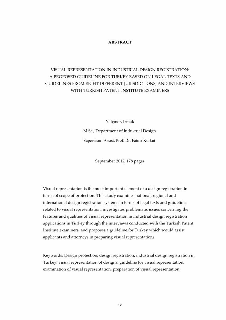
Figure 17 Alternative positional view sample (USPTO 2012, 16) ........................... 45
Figure 18 Extended and retracted positional view sample (CIPO 2010b, 13) ....... 46

xiv
Figure 19 Positional view sample of a flexible article (CIPO 2010b, 11) ................ 47
Figure 20 Enlarged fragmentary view sample (CIPO 2010b, 19) ............................ 48
Figure 21 Extended view sample (CIPO 2010b, 12) .................................................. 50
Figure 22 Exploded view sample (USPTO 2012, 12) ................................................. 51
Figure 23 Sample showing an article with indefinite length of a constant cross-
section (CIPO 2010b, 14). Indefinite length is indicated by sinusoidal lines ......... 53
Figure 24 Sample showing an article with indefinite length of a constant cross-
section (CIPO 2010b, 15). Indefinite length is indicated by sharp jagged lines ..... 53
Figure 25 Sample showing an article with indefinite length of a constant cross-
section (CIPO 2010b, 15). Indefinite length is indicated by parallel lines broken by a
zig-zag line ...................................................................................................................... 54
Figure 26 Two different ways of showing indefinite length of a surface pattern
design (CIPO 2010b, 16). Indefinite length is indicated by sharp jagged line ....... 54
Figure 27 Two different ways of showing indefinite length and width of a
repeating surface pattern design (CIPO 2010b, 18). Indefinite length and width is
indicated by stippled line .............................................................................................. 55
Figure 28 Sample showing an article with indefinite length of a repeating three-
dimensional feature of the design (CIPO 2010b, 16). Indefinite length and width is
indicated by sinusoidal lines ........................................................................................ 56
Figure 29 Sample showing variable length of a relevant portion of the design
(CIPO 2010b, 17). Variable length is indicated by sharp jagged line ...................... 57
Figure 30 Article with an indeterminate length as given by USPTO (USPTO 2012,
16) ...................................................................................................................................... 58
Figure 31 Visual representation of a registered community design typeface at
OHIM, with the number RCD 000041496-0001 in Locarno class 18-03 .................. 59
Figure 32 Representation sample of a flatware design (CIPO 2010b, 23) .............. 61
Figure 33 Visual representation sample of a design with multiple embodiments of
a single concept (USPTO 2012, 16) .............................................................................. 62
Figure 34 Representation of a design with a partial disclaimer (TPI 2012, 12).
Disclaimed features of the design are shown in dashed lines ................................ .67
Figure 35 Partial disclaimer shown in solid and stippled lines (CIPO 2010b, 3) .. 68

xv
Figure 36 Partial disclaimer samples, where non-design portions of the design are
shown in broken lines (USPTO 2012, 16) .................................................................... 69
Figure 37 Partial disclaimer sample, showing the opaque non-design portions of
the design (CIPO 2010b, 4) ........................................................................................... 69
Figure 38 Partial disclaimer sample showing the use of bold and wavy lines to
indicate the design portions of a shoe design (CIPO 2010b, 23) .............................. 70
Figure 39 Partial disclaimer sample showing the use of bold and wavy lines
together with stippled lines to indicate the non-design portions of a clothes washer
design (CIPO 2010b, 23) ................................................................................................ 71
Figure 40 Visual representation pages from a multiple design application in A4
format (TPI 2012, 19) ...................................................................................................... 73
Figure 41 Sample of an illustration page given by IPO (IPO 2012b, 8) .................. 74
Figure 42 Acceptable and unacceptable ways of representing a complete finished
article (CIPO 2010b, 2) ................................................................................................... 78
Figure 43 Acceptable and unacceptable ways of representing a complete finished
article. The acceptable version identifies the finished article to which the electronic
icon is applied (CIPO 2010b, 22) .................................................................................. 79
Figure 44 Acceptable and unacceptable representation examples showing the
article in isolation (CIPO 2010b, 7) ............................................................................... 80
Figure 45 Colour coding for topics and sub-topics ................................................... 86
Figure 46 Sample pages from transcribed interviews ............................................... 89
Figure 47 The size of the article in relation to the size of the frame ........................ 99
Figure 48 Visual representation of a sliding system profile design for furniture 101
Figure 49 Exploded view samples of USPTO (USPTO 2012, 12), which are shown to
the TPI examiners. The fully assembled view on the left hand side is considered
acceptable and exploded view on the right hand side by the TPI examiners. .... 104
Figure 50 Visual representations of a registered complex product design in Turkey
with the number TR 2011/07942 ................................................................................ 107
Figure 51 Visual representation of a turnable mob design in Turkey with the
number TR 2012/00059 ............................................................................................... 114

xvi
Figure 52 Visual representation of a vacuum cleaner design in Turkey with the
number TR 2012/03440 ............................................................................................... 115
Figure 53 Visual representation of a container design in Turkey with the number
TR 2012/03459 .............................................................................................................. 109
Figure 54 The topics and sub-topics concerning the features and qualities of visual
representation based on both the literature review and the field survey findings118

xvii
LIST OF ABBREVIATIONS
Administrative
Instructions Administrative Instructions for the Application of the Hague Agreement
CDIR
COMMISSION REGULATION (EC) No 2245/2002 of 21 October 2002 implementing Council Regulation (EC) No 6/2002 on Community designs (OJ EC No L 341 of 17.12.2002, p. 28) amended by Commission Regulation (EC) No 876/2007 on 24 July 2007 amending Regulation (EC) No 2245/2002 implementing Council Regulation (EC) No 6/2002 on Community designs following the accession of the European Community to the Geneva Act of the Hague Agreement concerning the international registration of industrial designs
(OJ EC No L 193 of 25.7.2007, p. 13)
CDR
COUNCIL REGULATION (EC) No 6/2002 of 12 December 2001 on Community designs (OJ EC No L 3 of 5.1.2002, p. 1) amended by Council Regulation No 1891/2006 of 18 December 2006 amending Regulations (EC) No 6/2002 and (EC) No 40/94 to give effect to the accession of the European Community to the Geneva Act of the Hague Agreement concerning the international registration of industrial designs
(OJ EC No L 386 of 29.12.2006, p. 14)
CIPO Canadian Intellectual Property Office
Common
Regulations Common Regulations under the 1999 Act and the 1960 Act of the Hague Agreement
Directive Directive 98/71/EC of the European Parliament and of the Council of 13 October 1998 on the legal protection of designs
Council
Regulation
COUNCIL REGULATION (EC) No 6/2002 of 12 December 2001 on Community designs (OJ EC No L 3 of 5.1.2002, p. 1) amended by Council Regulation No 1891/2006 of 18 December 2006 amending Regulations (EC) No 6/2002 and (EC) No 40/94 to give effect to the accession of the European Community to the Geneva Act of the Hague Agreement concerning the international registration of industrial designs (OJ EC No L 386 of 29.12.2006, p. 14)
Decree-Law Turkish Decree-Law no. 554 Pertaining to the Protection of the

xviii
No. 554 Industrial Designs of June 27, 1995 amended by the Law No. 4128
of November 7, 1995
Implementing
Regulation of
Decree-Law
Implementing Regulation under Turkish Decree-Law no. 554
Pertaining to the Protection of the Industrial Designs of June 27,
1995
IP Australia Australian Intellectual Property Office
IPO Intellectual Property Office of United Kingdom
TPE Türk Patent Enstitüsü (See TPI)
TPI Turkish Patent Institute
KIPO Korean Intellectual Property Office
OHIM Office of Harmonization for the Internal Market
PEM Patent and Trademark Attorneys’ Association of Turkey
RCD Registered Community Design
USPTO United States Patent and Trademark Office
WIPO World Intellectual Property Organization

1
CHAPTER 1
INTRODUCTION
1.1 Background and motivation
Design registration is a system put in place for the protection of designs within the
industrial property branch of the intellectual property system. In respect of the
principle of territoriality, in Turkey designs are protected by the Decree-Law and
the Implementing Regulation under the Decree-Law that aims to protect designs by
giving exclusive rights to the right holders to facilitate the formation and
development of industry in a fair but competitive environment.
After being awarded a Bachelor of Arts degree in graphic design, I started working
in an intellectual property agency in 2006. Serving clients in the protection of their
industrial property rights and working as a court expert for the specialized
intellectual property courts has allowed me to observe a number of problems
related to the visual representation of designs, such as representing a three-
dimensional design with a single view, or using low resolution images which fall
short of representing the details of the design for which protection is sought. Since
registered industrial designs are protected on the basis of their visual representation
and description, and the visual representation is the “key element of the design
right to be established” (TPI 2011 Article 2.9), the problems in the representations
that attracted my attention, not only as an attorney and court expert but also as a
graphic designer, represent a crucial flaw in the industrial design registration
system.
Hasdoğan mentions that inadequate visual representations are one of the major
problems observed in design registrations in Turkey, and are a key aspect in the
falling through of court actions related to design protection (Hasdoğan 2005, 344;
348). Elibol suggests that the visual representation requirements of designs should
be standardised (Elibol 2011, 139). It is the applicant’s responsibility to provide
adequate representation, including a sufficient number of views so as to represent
all of the features of the design to be protected (TPI 2011 Article 2.9). However there
are no specialized checklists or guidelines published by the Turkish Patent Institute

2
for applicants, or their representatives or attorneys, which cover all the requisite
elements of the visual representations and offer advice during the application
preparation stage. Consequently, a study to come up with such a document is
imperative in the industrial design registration field in Turkey.
1.2 Aim and scope of the thesis
The aim of this study is to examine national, regional and international design
registration systems in terms of legal texts –which include legislations, by-laws and
agreements- and guidelines related to visual representation, to investigate
problematic issues concerning the features and qualities of visual representation in
industrial design registration applications in Turkey, and to develop a guideline
which would assist applicants and attorneys in preparing visual representations.
The key questions of this research are as follows:
• What is visual representation as it is defined in national, regional and
international design registration systems?
• What are the features and qualities of visual representation as described in legal
texts and guidelines in national, regional and international design registration
systems?
• How does the Turkish Patent Institute examine the visual representations? Are
there any internal examination guidelines, checklists or procedures used for the
examination of visual representations?
• What are the critical and problematic issues observed by the Turkish Patent
Institute concerning the features and qualities of visual representations in
industrial design registration applications in Turkey?
• What are the elements of a guideline, which would assist applicants and
attorneys in preparing visual representations for industrial design registration
applications in Turkey?
1.3 Structure of the thesis
In the first chapter, the research topic, background, motivation and aim of the study,
and the key research questions are explained.
Chapter 2 contains the first part of the literature review, which introduces the study
area in general from a legal perspective by explaining and comparing the definitions
of “industrial design” and “visual representation” within the surveyed jurisdictions.

3
The importance and the problems of the visual representation in design registration
systems are also explained in this chapter.
Chapter 3 is the second part of the literature review, which explores the features and
qualities of visual representations as described in the legal texts and guidelines in
national, regional and international design registration systems. The findings are
discussed and presented in a categorized form addressing topics and issues relevant
for a guideline for visual representation.
After the categorization of the literature survey findings and forming the main
topics and sub topics of the guideline to be developed, a field study was conducted
of the practitioners responsible for the examination of visual representations in the
field of industrial design registration in Turkey –the design examiners of the TPI.
Chapter 4 presents the field study and discusses the findings concerning the main
problems in visual representations from the perspective of the design examiners at
TPI. This chapter helps to understand the problematic areas and issues in visual
representations in industrial design registration applications in Turkey together
with the suggestions of the examiners, and the eligibility of significant and unusual
literature survey findings for adaptation and adoption into the Turkish design
protection system.
Drawing upon the findings of both the literature review and the field study,
Chapter 5, the concluding chapter, proposes a guideline, which assists design
attorneys and applicants in preparing visual representations for industrial design
registration applications in Turkey.

4
CHAPTER 2
LITERATURE REVIEW PART I:
INDUSTRIAL DESIGN REGISTRATION AND VISUAL REPRESENTATION
2.1 Strategies and limitations of the literature review
The purpose of the literature review in this study is to explore visual representation
in industrial design registration from a legal perspective, and to investigate legal
texts and guidelines within the scope of visual representation in Turkey, as well as
in other national, regional and international design registration systems.
The general keywords used during the literature survey, mainly of legal literature,
are as follows:
• Design law. Design and industrial design registration, design legislation,
design regulation, design act, design directive, design implementation
• Design Registration Guideline. Design registration principles, design
registration manual, design application guideline, design examination
guideline, design checklist, guide for filing design, guide to industrial design
registration, design registration basic facts.
• Visual representation. Representation, reproduction, illustration, drawing,
photography, visual features, visual description, visualizing a registered
design, specimen, view.
Chapter 2, the first part of the literature review comprises an introduction to the
industrial property in general and presents a brief history of the developments in
industrial design registration in Turkey. Thereafter, definitions of “industrial
design” and “visual representation” are discussed and comparisons are made of in
respect to the legal texts and the guidelines published by the authorized bodies. A
discussion on the importance of visual representation in industrial design
registration follows, taking into account legal texts and guidelines in Turkey and in
other national, regional and international design registration systems covered in this
study. The chapter concludes with a review of the problems related to visual
representation in industrial design registration applications.

5
The literature review covers the sources available in Turkish or in English, which
constitutes a limitation for the study. The legal texts and guidelines reviewed in this
study include the ones concerning the national design protection systems in Turkey,
Australia, Canada, South Korea, the United Kingdom and the United States of
America; the regional design protection system for the European Community
designs administered by OHIM; and the international design protection system -the
Hague System- administered by WIPO.
Table 1 Legal texts and guidelines covered in the literature review
Jurisdiction Authority Legal texts and guidelines
Turkey TPI • Decree-Law No. 554
• Implementing Regulation
• Examination Guideline
Contracting
Parties to the
Hague System
WIPO • Common Regulations Under the 1999 Act, the
1960 Act and the 1934 Act of the Hague
Agreement
• Administrative Instructions
• Guide to the International Registration of
Industrial Designs
European
Community
OHIM • Directive
• Council Regulation (CDR)
• Commission Regulation (CDIR)
• Examination Guidelines for Community
Designs
Australia IP Australia • Australian Design Act
• A Guide to Applying for Your Design
Canada CIPO • Industrial Design Act
• Industrial Design Regulations
• A Guide to Industrial Designs
• Industrial Design Office Practices

6
Table 1 (Continued)
United
Kingdom
IPO • Registered Designs Act
• Registered Designs Rules
• Applying for a Design: Illustrations of your
design
United States
of America
USPTO • Design Patent Law
• Design Patent Rules
• A Guide to Filing A Design Patent Application
• Manual of Patent Examining Procedure
(MPEP)
South Korea KIPO • Industrial Design Protection Act
• Enforcement Decree of the Design Protection
Act
• Overview of the Design System in Korea
• Application procedures for designs
2.2 Introduction to the intellectual property rights and industrial design
registration system in Turkey
Intellectual property is the umbrella term covering all of the rights concerning
inventions, artistic works, trade secrets, etc. WIPO divides intellectual property into
two main branches: Copyright and industrial property (WIPO 2011). Yalçıner (2011)
classifies intellectual property into three main groups: Author’s rights (referred to as
“copyright” in some jurisdictions), industrial property rights and other rights. He
specifies industrial property rights as:
1. Patents and utility models for the protection of inventions,
2. Trademarks for the protection of brands,
3. Industrial designs for the protection of designs,
4. Geographical indications, also known as appellations of origin, for the
protection of geographical signs,
5. Topographies of integrated circuits for the protection of integrated circuits,
([Yalçıner] 2011, 11)
Yalciner also specifies other rights related to intellectual property:

7
1. Plant breeders' rights for the protection of new plant varieties,
2. Trade names
3. Unregistered rights under general provisions, such as unfair competition in
commercial law in Turkey
4. Undisclosed information, such as know-how and trade secrets
5. Domain names, etc. ([Yalçıner] 2011, 11).
“Intellectual production is as old as the human history” says Karahan, Suluk, Saraç
and Nal, adding that the legal protection of intellectual products is a very new
concept in human history (Karahan et al. 2011, 23). Yalçıner (2000) claims that the
first recorded evidence of intellectual property in history dates to 1443 in Venice,
with the first patent law officially announced in 1474 in Venice (Yalçıner 2000, 5).
The United States of America and France followed Venice in the protection of
inventions. On March 23, 1879 the Ottoman Empire’s patent law İhtira Beratı Kanunu
(in Turkish) entered into force, resulting in the first regulation of intellectual
property in Turkey (what was then the Ottoman Empire), and the sixth patent law
in world history (Karahan et al. 2011, 24). Despite the fact that Turkey was one of
the first implementers of patents, up until 1995 there was no specialized design
protection law.
Yalçıner (2000), providing a history of design registration in the world, claims that
the protection of designs began with a specialized legislation in Lyon, France in 1711
for the textile designs (Yalçıner 2000, 7). He adds “in 1787 legislation for designer’s
rights for fabric ornamentations entered into force in Florence. The same year, in the
United Kingdom, a law came into force for the new products of ornamentations
made of wool” (Yalçıner 2000, 7). The United States of America provided a
specialized implementation within patent law for designs in 1842, which was
followed by Germany (1876) and Japan (1888) (Yalçıner 2000, 8). In Turkey, designs
were not protected under a specialized law until June 27, 1995, when Decree Law
No. 554 and the implementing regulation entered into force following the
establishment of the Turkish Patent Institute in 1994. Karahan, Suluk, Saraç and Nal
states that “1995 is the milestone of the intellectual property rights” in Turkey
(Karahan et al. 2011, 24).
In Turkey, the Turkish Patent Institute is authorized to implement the regulations
related to industrial property rights, including patents, utility models, trademarks,
industrial designs, geographical indications and topographies of integrated circuits.
Representing Turkey at international organizations, the TPI is authorized to look

8
after Turkey’s interests in international agreements on industrial property rights,
and to implement such agreements in Turkey according to Law No. 5000 (TPI 2003
Article 3). The legal texts on industrial design protection in force in Turkey are given
in Table 2.
Table 2 Legal texts on industrial design protection in force in Turkey
Legal text Date of Entry into
Force in Turkey
Decree Law No: 554 for the Protection of Industrial
Designs (national) June 27, 1995
Implementing regulation of Decree Law No: 554 for the
Protection of Industrial Designs (national) November 5, 1995
Locarno Agreement Establishing an
International Classification for Industrial Designs, 1968 November 30, 1998
1999 Geneva Act of the Hague Agreement Concerning the
International Registration of Industrial Designs�January 1, 2005
In Turkey, a design can be protected in three different ways within the scope of
intellectual property rights: A design can obtain protection by industrial design
registration; a design obtains protection automatically when it is made available to
the public within the scope of the author’s rights, also known as copyrights; and a
design that is already commercialized may obtain protection under the general
provisions of unfair competition in Commercial Law.
Before June 27, 1995 designs were protected under the general provisions of unfair
competition within Commercial Law in Turkey, as well as under author’s rights.
After the establishment of Turkish Patent Institute in 1994, the Decree Law No. 554
entered into force in 1995, by which registered designs are able to be protected
under a specialized industrial property law. Today, the national industrial design
registration system in Turkey is based on three grounds: Decree Law No. 554; the
implementing regulation of the Decree Law No. 554; and the examination guideline
published by TPI.

9
2.3 Definition of “industrial design” in the reviewed legal texts and guidelines
WIPO defines industrial design as “the ornamental or aesthetic aspect of a useful
article” (WIPO 2011, 9). “Useful article” is defined in Canadian Industrial Design
Act Section 2 as “an article that has a utilitarian function and includes a model of
any such article”, while the utilitarian function of an article means “a function other
than merely serving as a substrate or carrier for artistic or literary matter” (CIPO
2003). CIPO defines design as “the visual features of shape, configuration, pattern or
ornament (or any combination of these) applied to a manufactured article” (CIPO
2012a under “Glossary”).
The term “article” refers to an object that is the outcome of a design activity, such as
a three-dimensional product or two-dimensional ornamentation (CIPO 2012a under
“Glossary”). KIPO explains the term “article as being a generally tangible, movable
and independent thing” (KIPO 2011 under “What is a design?”). CIPO defines the
article in Section 2 as “anything that is made by hand, tool or machine”.
Table 3 Definition of design in the reviewed legal texts and guidelines
Authority Legal Text or
Guideline Definition of Industrial Design
TPI Decree Law
Article 3/1 (a)
“Concerning the whole or a part of a product, or its
ornamentation, “design” means the entirety resulting
from the various features or characteristics perceived
by the human senses such as line, shape, form, colour,
texture, material or elasticity"”(TPI 2005 Article
3/1(a))
WIPO
Understanding
the Industrial
Property
“… is the ornamental or aesthetic aspect of a useful
article” (WIPO 2011, 9)

10
Table 3 (Continued)
WIPO
Handbook On
Industrial
Property
Information
and
Documentation
“Industrial designs include two-dimensional and
three-dimensional features of shape and surface of
objects, and thus cover both concepts of ‘designs’ and
‘models’ where a distinction is made between the
former and the latter” (WIPO 2004, 3.80.1)
OHIM Council
Regulation
“The appearance of the whole or a part of a product
resulting from the features of, in particular, the lines,
contours, colours, shape, texture and/or materials of
the product itself and/or its ornamentation” (OHIM
2006 CDR Article 3/1(a))
IP
Australia
Design Act
Section 5
“In relation to a product, [design] means the overall
appearance of the product resulting from one or more
visual features of the product.” (IP Australia 2010
Section 5)
Design Act
Section 8
“In this Act, a reference to a design is a reference to a
design in relation to a product.” (IP Australia 2010
Section 5)
IPO
Registered
Designs Act
Section 1/2
“The appearance of the whole or a part of a product
resulting from the features of, in particular, the lines,
contours, colours, shape, texture or materials of the
product or its ornamentation.” (IPO 2006a Section
1/2)
CIPO
Industrial
Design Act
Article 2
“ ’Design’ or ‘industrial design’ means features of
shape, configuration, pattern or ornament and any
combination of those features that, in a finished
article, appeal to and are judged solely by the eye.”
(CIPO 2011a Article 2)
USPTO
Manual of
Patent
Examining
Procedure
(MPEP)
“The design for an article consists of the visual
characteristics embodied in or applied to an article”
(USPTO 2012 MPEP Article 1502).

11
Table 3 (Continued)
USPTO
A Guide to
Filing a Design
Patent
Application
A design consists of the visual ornamental
characteristics embodied in, or applied to, an article of
manufacture. Since a design is manifested in
appearance, the subject matter of a design patent
application may relate to the configuration or shape of
an article, to the surface ornamentation applied to an
article, or to the combination of configuration and
surface ornamentation. A design for surface
ornamentation is inseparable from the article to which
it is applied and cannot exist alone. It must be a
definite pattern of surface ornamentation, applied to
an article of manufacture. (USPTO 2011 under the
“Definition of a Design”)
KIPO Design Act
Article 2/1
“Shape, pattern or colour or a combination of these in
an article which produces an aesthetic impression in
the sense of ‘sigh’” (KIPO 2011 under “What is a
Design?”)
TPI, IP Australia, IPO and OHIM explain “design” within the concept of product
rather than article. The Turkish legislation1 provides a definition of product:
“… any industrial or handicraft item, parts of a complex system, sets,
compositions of items, packaging, get-ups, graphic symbols and typographic
typefaces, excluding computer programmes and semi-conductor products” (TPI
1995).
OHIM describes product, and further, complex product, within Council Regulation
Article 3 (OHIM 2006 CDR Article 3(1)(b); Article 3(1)(b) (c)). Product “means any
industrial or handicraft item, including inter alia parts intended to be assembled
into a complex product, packaging, get-up, graphic symbols and typographic
typefaces, but excluding computer programs”. It is described as a product
composed of multiple components, which can be replaced by disassembly and re-
assembly of the product within the Counsel Regulation (OHIM 2007 CDIR Article
3(c)). The UK industrial design registration system defines product in the same way
1 Decree Law No. 554 Article 3/1(a) and (b)

12
as OHIM in the Registered Designs Act Article 1/3, as “any industrial or handicraft
item other than a computer program; and, in particular, includes packaging, get-up,
graphic symbols, typographic type-faces and parts intended to be assembled into a
complex product”. The UK Registered Designs Act defines a complex product as “a
product which is composed of at least two replaceable component parts permitting
disassembly and reassembly of the product” in Article 1/3, as same definition as in
the Australian Design Act Section 5 (IP Australia 2003).
According to WIPO's definitions and explanations the aim of registered design
protection is to protect the visual features of a design in all of the member states.
The Handbook on Industrial Property Information and Documentation indicates
that the term “industrial design” does not refer to patents or supplementary
protection certificates (SPC) specified in the WIPO Standard ST.9 (WIPO 2004 under
“Definitions”). In the United States of America, registered designs are protected
within the Patent Rules and Laws and called “design patents”; however it is
explained that design patent’s scope of protection only covers the appearance of the
article, disregarding its structural or utilitarian features (USPTO 2011 under the
“Definition of a Design”). The functionality, construction methodology or other
such qualifications cannot be protected with design registration or design patents,
and therefore it is the design’s visual qualities and features that are reflected within
the visual representations that are protected by design registration.2
2.4 Definition of “visual representation” in the reviewed legal texts and
guidelines
The visual representation of a registered design means “to specify the features of the
design for which protection is sought” according to OHIM, which states further that
it is of utmost importance that the representation be clear and complete, and that
nothing regarding the design is left conjecture (OHIM 2012 Ch. 4.4). Current
regulations in Turkey3 describes visual representation as the visual appearance of
the product in which the design is incorporated, or to which it is applied, prepared
in a drawing, picture, graphic, photograph or some other medium, specifying that it
must clearly show all special characteristics of the design and must be suitable for
reproduction through publication (TPI 2009 Article 26/1(b)). IPO, in the Registered
Design Rules, defines “suitable for reproduction” as suitable for publication (IPO
2 The definitions of design covered in this section give reference to visual features and qualities; the legislations of Canada and South Korea refer to the sense of sight directly. The Turkish legislation, on the other hand, implies a wider scope covering the qualities and features “perceived by the human senses”. 3 Decree Law No. 554 and Implementing Regulation

13
2006b Rule 9/5). WIPO describes visual representation in its Common Regulations
as “reproductions,” and explains “they shall be in the form of photographs or other
graphic representations of the industrial design itself, or of the product or products
which constitute the industrial design” (WIPO 2012, Rule 9).
The Australian Design Act defines the form of visual representation in the definition
section as drawings, tracings or specimens (IP Australia 2003, Ch.1, Part 2, Sec. 5).
As a non-legislative text, IPO’s “Illustrations of your design” offers a guideline for
applicants, and states that the representation should be an “accurate and complete
picture of the design,” and divides the suggested form of visual representations into
drawn views and photographic views (IPO 2012a under “Illustrations of your
design”). Another non-legislative text from CIPO is the guideline suggesting visual
representations in the form of drawings and photographs (CIPO 2012a under
“Preparing an Industrial Design Application”). As mentioned previously, in the
United States of America, designs are protected within patent law as design patents,
and accordingly, USPTO 37 C.F.R. § 1.152 refers to patent drawings, and mentions
types of drawings and photographs. The Korean design registration system also
cites forms of visual representation, defining drawings and photographs in the
Design Act. The forms of visual representation specified in the reviewed legal texts
and guidelines are given in Table 4.
Table 4 Forms of visual representation in the reviewed legal texts and guidelines
Authority Legal Text or
Guideline Forms of Visual Representation
TPI Decree Law
Article 26/1(b)
Drawing, picture, graphic, photograph or similar
representation of the design suitable for reproduction
WIPO
Common
Regulations
Rule 9
Photographs or other graphic representations

14
Table 4 (Continued)
OHIM
Council
Regulation
Article 36/1(c)
CDIR Article
4(1)
Representation of the design suitable for reproduction
Graphic or photographic reproduction of the design
IP
Australia
Design Act
2003 Ch.1, Part
2, Sec. 5
Drawing, tracing or specimen
IPO
The Registered
Design Rules
2006 Rule 9/5
“Illustrations
of your
designs” (non-
legislative)
“Suitable representation,” meaning a representation
of the design that is suitable for publication
Accurate and complete picture of the design
Drawn views or photographic views
CIPO
Industrial
Design Act
Article 4
Drawing or photograph of the design
USPTO
37 C.F.R. §
1.152 refers to
37 C.F.R. § 1.84
Drawing and photograph
KIPO
Industrial
Design
Protection Act
Article 5/1
Drawing (3D-modelling drawing also mentioned) and
photograph
2.5 Importance of visual representation in industrial design registration
Design registration in Turkey consists of three main stages: Application, registration
and post-registration (Figure 1). The visual representation of a design has an
important role in terms of the scope of protection in all these stages. During the

15
application stage at which the formal examination takes place, inadequate visual
representations may result in formal deficiencies. After the formal examination the
registration stage starts. During the registration stage, the design registration
application is published in the Official Industrial Design Bulletin, and third parties
may file an opposition against the registration within six months. The visual
representation of the design plays a critical role in the case of an opposition that
involves the comparison of the design with earlier designs. During the post-
registration stage, invalidity or infringement actions also involve the comparison of
the visual representation of a registered design with earlier designs.
Figure 1 Stages of a design registration in Turkey and the procedures where the
visual representation plays an important role.
WIPO states that if the applicant wishes to obtain maximum protection for their
design, they should ensure that the design is fully represented, as only the aspects
that are visibly represented shall be protected (WIPO 2012c BII.22.05.10).
Visualizing the design for registration is important in the industrial design
protection system in Turkey. Implementing regulation in Turkey deems that a
registered design shall be protected by the visual representations and descriptions
filed at the application stage (TPI 2005 Article 9/1(a)). According to OHIM the
description of the design cannot contain any reference to features that cannot be
seen in the visual representation (OHIM 2012 Ch. 9.2), meaning that the features
that cannot be seen in the visual representation will fall outside the scope of the
protection.
If the visual representation does not fulfil the requirements specified in the legal
texts, it may affect the application date or may be ground for the refusal of an

16
application. OHIM rules that an application date cannot be granted if the
representation of the design:
• is not in jpeg data format in electronic filing applications,
• is submitted without a neutral background, or has been retouched using ink
or correction fluid, or
• if the visual quality is not sufficient for displaying all of the details of the
design for which protection is sought (OHIM 2007 CDIR Article 4(1)(d);
Article 4(1)(e); Article 10(1)(c) and OHIM 2012 Ch. 4.4).
In the Turkish legislation visual representation(s) are a mandatory requirement for
the application date to be granted. Decree Law Article 26/1(b) contains the
following provision: “An application for registration of a design must be filed with a
drawing, painting, graphic, photographic or similar representation of the design
suitable for reproduction and reflecting all of its specific features”. KIPO also
indicates the representation of the design must be submitted at the same time of
filing the design application (KIPO 2011 under “Application Procedure for
Designs”).
Contracting Parties of the Hague Agreement (1999 and 1960 Acts) have the right to
refuse an international design registration application on the grounds that the
reproductions of the design are not sufficient to disclose the industrial design fully
(WIPO 2012b Rule 4). Additionally, corrections that change the representations are
not permitted according to Community Design Regulations (OHIM 2007 CDIR
Article 12(3) and OHIM 2012 Ch. 13.2). A description is also filed together with the
visual representation, however, as stated by KIPO, “the description of a design is
not as important as the specification of a patent or utility model application, so long
as drawings of the design are correctly and properly prepared” (KIPO 2011 under
the “Application Procedure for Design”). Therefore, it is very important to prepare
and submit the correct representations of the design to be protected while filing the
application.
It is very important to show all the new features of the design on the representation
to ensure that they are enforceable in any legal dispute (IPO under Design practice
notice (DPN) 6/06, 6/03). IPO emphasizes that the purpose of the representations
and specimens is to present an accurate and complete picture of the design to be
registered, and also to identify those features of the design which are novel and for
which protection is sought (IPO under Design practice notice (DPN) 1/04).

17
The visual representation of the design plays a vital role, claims Elibol, for the
assessment of protection conditions, novelty and distinctive character in design
registration in Turkey; the examination to assess the novelty and distinctive
character of the design is based on the features which can be clearly shown in the
visual representation of the design (Elibol 2011, 44). It is the applicant’s or the
representative’s obligation to submit or provide adequate and sufficient
representations, which reflect and display all of the visual properties for which
protection shall be sought at the application stage (TPI 2011 Article 2.9). During the
registration stage, designs are published in order to permit third-party oppositions.
Comparisons are based on the application’s visual representations versus the earlier
design. If the earlier design is also registered, then both visual representations shall
be evaluated. Should an infringement action be filed against a product on the
market, then the visual representation of the plaintiff’s registered design shall be
compared with the product of the defendant. Thereof, visual representations are a
very important element affecting the scope of the protection in every stage, from the
filing of a registered design to post-registration. It is also underlined by TPI that
visual representations are the key element of the design right to be established, in
that they constitute the expression for which protection is sought (TPI 2011 Ch. 2.9).
TPI has a formal procedure for the examination of visual representations at the
application stage. Designs with inadequate visual representations should not be
accepted at this formal examination stage, according to the implementing regulation
Article 8/1(a) which rules that inadequate visual representations are a major
deficiency that may affect the allocation of the application date. Furthermore,
Turkish regulations do not allow for any amendments to visual representations after
registration, as is the case with OHIM's implementation.4 Representations can only
be amended if the examiner requests the remedying of a formal deficiency in the
visual representation, which shall affect the allocation of the application date5.
2.6 Problems related to visual representation in industrial design registration
applications
Hasdoğan claims that in the Turkish industrial design registration system there are
four main problems related to the visual representations of registered designs:
Firstly, photographic views do not reflect the exact size of the design; secondly,
4 Explained within OHIM 2007 CDIR Article 12(3) 5 Provisioned in Decree Law Article 26 and 33, Implementing Regulation Article 14, OHIM CDIR Article 10(1)(c) and OHIM 2010 Examination Guidelines Community Design Article. 5.3

18
submitting one photographic view and one technical representation (graphic
representation) of the design prohibits an understanding of the three dimensional
features of the design; thirdly, designs photographed in an embroiling composition,
such as displaying all the elements of a set of furniture in one representation; and
finally, partial disclaimer cases where the part(s) of the product for which protection
are sought are not indicated or shown clearly (Hasdoğan 2005, 348).
Elibol also cites insufficient visual representations as one of the problems when
making an assessment of the novelty and distinctive character of the design to be
protected, stating “Good quality visual representation would facilitate the
assessment” (Elibol 2011 144; 167).
Common problems at the application stage related to the visual representations in
the UK are described in Design Practice Notice 1/04 as follows:
• More than one design is shown in the visual representations.
• Representations include dimensions and other technical drawing features,
which obscure the design.
• The examiner is unable to identify the design from the representations given
(IPO 2004 DPN 1/04).

19
CHAPTER 3
LITERATURE REVIEW PART II: FEATURES AND QUALITIES OF VISUAL REPRESENTATION AS
DESCRIBED IN LEGAL TEXTS AND GUIDELINES
All of the legal text and guidelines of national, regional and international design
registration systems cited in Table 1 are analysed by first selecting the parts related
to the visual representations of design registrations for classifying the main features
and qualities of the visual representations. Afterwards, each sentence within the
surveyed parts that describes a feature of a visual representation is highlighted to
allow an easy comparison of the common issues in different jurisdictions. The
analysis continued by printing and cutting out the highlighted statements, and
grouping them under potential topics in respect to the features and qualities
covered. This categorization and grouping is done by preparing a board for each
topic and mapping the highlighted parts according to each topic and sub-topic on a
separate board. An example of one of the boards prepared for the “Physical quality”
topic is given below.

20
Figu
re 2
Cat
egor
izat
ion
boar
d fo
r th
e “P
hysi
cal q
ual
ity”
top
ic

21
As given in Figure 2, the findings, which explain the physical quality of the visual
representations, are extracted from the document and pasted on the board, which
the example is the board prepared for the “Physical quality” sub-topic under
“Format and Quality of Visual Representation” topic. Colour codes were given for
common features or qualities, i.e. green is used for the explanations on size and
quality of the paper and blue is used for the clarifications on size of the
representation.
Subsequently, after analysing the legal text and guidelines of the eight jurisdictions,
including that of Turkey, six main topics were identified: types of representation,
content of visual representation, views of the design, partial disclaimer, format and
quality of visual representation and unacceptable visual representation. All the
topics of features and qualities of visual representation are given in Figure 3 and
each topic is explained in below.

Figu
re 3
The
list
of t
opic
s an
d s
ub-
top
ics
of th
e fe
atu
res
and
qu
alit
ies
of v
isu
al r
epre
sent
atio
n
����������� ��
��������� �����
�� �����
��������� �����
������� ���
���������
������������� ��
��������� �����
��������
� ���������
�������
��� �����������
!����������
������
" ��������� ��
" #��$��������� ��
" ���� �������� ���
� �������
" ��������� ����
����%�������������
��� �����
" !�������
�����������
���������
����������� ���
������&����������
'�������� ���
���(������
� ��� ��
����� �����
���� ��
��������� �����
���( ��
������������
)��� �� ���
*� �����
������ ��*� �����
! � ���� �����
�$%������
+� ����� (���
��� ��
��������� ������
22

23
3.1 Types of Representation
Visual representations are categorized into three main groups: Graphic
representations, photographs and specimen.
1. Graphic representation which includes drawings, ink drawings, and or similar
ways of representation (TPI 2011 Article 2.2.2; WIPO 2012c Section 401(a);
WIPO 2012b Article 9(1)a; OHIM 2007 CDIR Article 4(1;) OHIM 2012 Article
11.4; IPO Design Practice Notice (DPN) 1/04; USPTO 2010 37 CFR § 1.84), and
2. Photography in colour or black and white (TPI 2011 Article 2.2.2, WIPO 2012c
Section 4(a); WIPO 2012b Article 9(1) a; OHIM 2007 CDIR Article 4(1)), OHIM
2012 Article11.4; IPO Design Practice Notice (DPN) 1/04). Only USPTO
expresses the requirement of black and white photography (USPTO 2010 37
CFR § 1.152).
3. Specimen may be filed instead of visual representation during the filing the
application for two-dimensional designs if a deferment of publication is
requested (TPI 2011 Article 2.2.3). The study does not covers requirements or
features and qualities of specimen of design applications.
TPI indicates that a visual representation can be prepared as a drawing, picture,
graphic, photograph or similar media (TPI 2011 Article 2.2.2). TPI Examination
Guidelines adds that there is no limitation on the form of representation (TPI 2011
Article 2.9.2), so long as they are suitable for reproduction in terms of publishing
(TPI 2011 Article 2.2.2; OHIM 2012 Article 4.4).
WIPO and OHIM emphasize that both types of representations can be used for a
single or multiple design application (OHIM 2012 Article 11.4 and WIPO 2012c
Section 11.4); while USPTO, on the other hand, underlines that it is not permissible
to use a combination of both ink drawings and photographs in one design
application, giving the reason that a combination may result in inconsistencies
between the two (USPTO 37 CFR § 1.152). USPTO permits colour drawings, if
necessary, of sufficient quality for all detail in the drawings to be reproducible in
black and white print (USPTO 2010 37 CFR § 1.84).
Visual representations can be submitted in black and white or in colour (TPI 2011
Article 2.9.2, WIPO 2012d Section 4(a), OHIM 2007 CDIR Article 4(1) and OHIM
2012 Article 11.4) except for USPTO (please see also section 3.1.2 Photography). Both
types of graphic or photographic representations, either in black and white or in
colour, must show clearly all characteristics of the design (TPI 2011 Article 2.2.2).

24
3.1.1 Graphic representation
How graphic representations should be prepared is defined by TPI, WIPO, IPO and
USPTO. TPI states that graphic representations must be drawn using drafting tools
or electronic means, and must be explicit and clear (TPI 2011 Article 2.9.2). Similarly,
WIPO indicates that the graphic representation must be in a professional standard,
produced by using drawing instruments or executed by electronic means (WIPO
2012c Section 404 (b) and WIPO 2012d BII. 22.05.08). IPO emphasizes the drawn
views as ink drawings or, better still, good quality scans or copies of them (IPO
2012a under “Illustrating your design”). USPTO calls for normally black and white
drawings, drawn with India ink or equivalent that secures solid black lines, and
indicates that all drawings must have satisfactory reproduction characteristics, and
states that it is not necessary to submit colour drawings (USPTO 2010 37 CFR §
1.84).
Types of line drawings. USPTO explains that there are two means of representing a
design in drawing format: Ink drawings and coloured drawings (USPTO 2010 37
CFR § 1.84). On rare occasions, coloured drawings may be necessary such as in
cases when they are the only practical medium to disclose the design (USPTO 2010
37 CFR § 1.84)
IPO also dictates the ink drawing format in Design Practice Notices of DPN 1/04, in
which it is recommended to use plain black and white line drawings, so long as the
design protection does not cover a particular colour (IPO 2012a under “Disclaiming
other visual features”).
Quality of lines. USPTO points out that every lines within the representations must
be durable, clean and black (except in colour drawings), sufficiently dense and dark,
and uniformly thick and well-defined (USPTO 2010 37 CFR § 1.84). The weight of
lines, including shading and lines representing cut surfaces of sectional views, must
be heavy enough for reproduction (USPTO 2010 37 CFR § 1.84). Different
thicknesses of lines and strokes in the same drawing may be used in the same
drawing to denote different meanings (USPTO 2010 37 CFR § 1.84). That said, the
thickness and density (as plain, dashed, stippled or dotted) of the lines in one
representation may change, however, all different types of lines must be produced
in sufficient quality to be reproducible in black and white on the printed patent
document (USPTO 210 37 CFR § 1.84).
Broken lines or stippled lines. TPI, OHIM, CIPO and USPTO clarify the use and
features of broken lines. OHIM and TPI indicates two use that dotted lines are used

25
either to show features that are not a part of the protection being sought (see section
3.4.1 Visual Means of Partial Disclaimer), or for indicating parts which are not
visible in that particular view (TPI 2011 Article 2.9.2; OHIM 2012 Article 11.4).
OHIM adds that dotted lines should be used to identify elements that are not part of
that view (OHIM 2012 Article. 11.4). It is the applicant’s responsibility to use such
lines in a way to identify which features are requested for protection, as the
examiner shall only conduct an examination to assess the suitability of the
representation for publication (OHIM 2012 Article 11.4).
CIPO also explains that well-defined solid lines must illustrate the design portions,
and that the non-design portions of the article may be shown in stippled lines (CIPO
2010a Article 6.5.3). According to USPTO, broken lines may be used to show the
environmental structure or boundaries that form the non-design parts of the article
for which protection is claimed (USPTO 2012 under “Drawing Examples”). Where
the drawings are supplied in lieu of photographs as representations, the
environmental structure must not be disclosed (USPTO 2010 37 CFR § 1.152);
however there are exceptions when there is a need to show the environmental
structure and the design together in one representation, in addition to other views
that fully disclose the design itself (USPTO under “Broken Lines”). Similar to CIPO,
USPTO also indicates that broken lines may be used to show structures that are not
part of the design, but are necessary to show the visible environment in which
design is used (USPTO 2010 37 CFR § 1.152; USPTO 2012 under “Broken Lines”).
Where broken lines are used to show such an environmental structure, they must
not intrude upon, or cross the claimed design, and should not prohibit a clear
understanding of the design (USPTO under “Broken Lines”). Broken lines should
be lighter than the lines indicating the parts of the design to be protected (USPTO
2011 under “Broken Lines”).
USPTO states that broken lines may not be used to show hidden planes and surfaces
that cannot be seen through an opaque material of the article (USPTO2010 37 CFR §
1.152).
USPTO also indicates that it is not permitted to submit alternate position or a
moved position of a design component illustrated by full and broken lines in the
same view, which can be shown by a broken line superimposed upon a suitable
view without crowding the representation (USPTO 2010 37 CFR § 1.152).
Shading. TPI, WIPO, CIPO and USPTO legislation covers shading techniques. TPI
emphasizes that embossed parts of the design can be shown by shading or in the
form of parallel lines (TPI 2011 Article 2.9.2). WIPO states that the design

26
representation may comprise shading in order to provide relief (WIPO 2012c Section
4(a); WIPO 2012d BII.05.08). CIPO declares that visual representations may contain
shading if the intention is to illustrate the shape of the design (CIPO 2010a Article
6.5.2). On the other hand, CIPO states that it is acceptable to use contrasting tones of
shading, as shown in Figure 4.
“Title: Jacket
Description. The design consists of the features of shape, configuration, pattern
and ornament of the JACKET as shown in the drawings.”
Figure 4 Shading sample given by CIPO (CIPO 2010b, 6)
USPTO states that shading is used to indicate the surface or shape of spherical,
cylindrical and conical elements of an object (USPTO 2010 37 CFR § 1.84). Shading is
also necessary to distinguish the open and closed solid areas of the article (USPTO
2012 under “Surface Shading”). USPTO explains appropriate and adequate surface
shading as that which shows the character and contour of all surfaces of any three-
dimensional aspects of the design being represented (USPTO 2010 37 CFR § 1.152;
USPTO 2012 under “Surface Shading”). It is also emphasized by USPTO that surface
delineation should preferably be shown using proper shading (USPTO 2010 37 CFR
§ 1.84).
USPTO refers to two types of shading for design patent representations; straight-
line surface shading and stippling and adds that individually or in combination,

27
these can effectively represent the character and contour of most surfaces (USPTO
2012 under “Drawing Examples”). It is permitted to use a combination of both
styles in the same article in order to show the surface contrast, but it is not
permissible to use a combination on the same surface (USPTO 2012 “Drawing
Examples”).
Wrist Watch
Sink
Lawn Sprinkler Vacuum Cleaner
Figure 5 Straight-line surface shading samples (USPTO 2012, 12)

28
Shower Caddy
Puppet
Figure 6 Samples of surface shading by stippling (USPTO 2012, 13)
Wheel
Chair
Figure 7 Combinations of straight line shading and stippling (USPTO 2012, 13)

29
CIPO offers few notes about the general characteristics of the representation and
which shading techniques are to be applied. Shading should not distort or hide the
design and should be shown consistently (CIPO 2010a Article 6.5.2). On the other
hand, shading should not be made on the non-design portions, which are to be
illustrated using stippled lines (CIPO 2010a Article6.5.2). An example from the
Office Practices Booklet of CIPO is given in Figure 8.
Fig. 1
Fig. 2
“Title: Recycling Bin
Description: The design consists of the features of shape and configuration of
the Recycling Bin as shown in the drawings.
Figure 1 is a perspective view of the Recycling Bin.
Figure 2 is a perspective view with the lid in an open position.”
Figure 8 Surface shading samples on different views of a Recycle Bin design (CIPO
2010b, 5)
Solid black surface shading is not permitted, according to the USPTO design patent
law, excluding the use of representing the colour black as well as the colour contrast
(USPTO 2010 37 CFR § 1.152; USPTO 2012 under “Surface Shading”).
USPTO states flat parts must be lightly shaded, and adds that flat part shading is
preferred for the parts showing perspective, but not for cross sections (USPTO 2010
37 CFR § 1.84). Thin, in contrast to the rest of the drawing, and spaced lines are

30
recommended for shading (USPTO 2010 37 CFR § 1.84.). USPTO adds, “As a
substitute of shading, heavy lines on the shade side of the objects can be used”
except where they superimpose on each other (USPTO 2010 37 CFR § 1.84). It is
recommended by USPTO that during shading; the angle of light should be 45
degrees, coming from upper left corner (USPTO 2010 37 CFR § 1.84).
Transparency and translucency. CIPO says transparency may be illustrated by using
thin lines of shading (CIPO 2010a Article 6.5.2). CIPO’s example is given in Figure 9.
“Title: Butter Dish
Description. The design consists of the features of shape, configuration and
ornament of the Butter Dish as shown in the drawings.“
Figure 9 Representation of a butter dish design showing transparent parts (CIPO
2010b, 8). Transparency is represented by thin shading lines.
It is important to make visible portions of the design through its transparent parts,
however transparency should not be shown using stippled lines on any non-
designed portion of the article (CIPO 2010a Article 6.5.2). Similar to CIPO, USPTO
emphasizes that transparent surfaces should be shown using light and full lines
rather than broken lines (USPTO 2012 under “Drawing Examples”).
Translucency is another subject covered by CIPO, which can be shown with thin
shade lines and overall shading throughout the translucent areas (CIPO 2010b, 9).
An example of such representation is given in Figure 10.

31
“Title: Sunglasses
Description. The design consists of features of shape, configuration, pattern and
ornament of the Sunglasses, as is shown in the drawings. “
Figure 10 Sample shows denoting of translucency in drawings (CIPO 2010b, 9)
USPTO also states that elements behind the transparent surfaces of the design
should be shown using light but full lines, and not broken lines (USPTO 2012 under
“Drawing Examples”).
Aquarium
Perfume Bottle
Figure 11 Samples showing transparent materials (USPTO 2012, 14)

32
Hatching. WIPO emphasizes that design representations may also draw upon
hatching in order to provide relief (WIPO 2012c Section 4(a); WIPO 2012d BII.05.08).
USPTO refers to hatching methods within the sectional view part of the legislation
in 37 CFR § 1.84, which is explained in section 3.3.2.2 Non-conventional views.
Denoting materials, properties and colours. USPTO supplies a key of graphic
symbols to be used in order to show the conventional elements of the design in a
drawing format (USPTO 2012 under “Symbols for Draftsmen").
Figure 12 Symbols denoting materials, various properties and colours in design
patent drawings, as given by USPTO (USPTO 2012, 18)
USPTO states that other standard or commonly used symbols other than those
given above may be accepted by the office, so long as they provide a clear

33
understanding, adequate specification as filed and do not result in confusion with
other symbols used in the drawings (USPTO 2012 under “Symbols of Draftsmen”).
Multi-Pocketed Storage Bag
Sandal
Computer Printer Stand
Figure 13 Representation of different materials on drawings (USPTO 2012, 17)

34
3.1.2 Photograph
WIPO indicates that the photographs submitted as visual representations must be to
a professional standard (WIPO 2012c Section 404 (a); WIPO 2912 BII.05.07). The
USPTO design patent system cites limitations on photographic representations, as it
is not usually permitted to submit photographs for design patent applications
(USPTO 2010 37 CFR § 1.84); if black and white photography is the only practicable
medium for illustrating the claimed design, then it is permissible (USPTO 2010 37
CFR § 1.84). The examiner shall request a drawn illustration rather than a
photograph if he or she considers the subject matter suitable for depiction by
drawing (USPTO 2010 37 CFR § 1.84). Coloured photography will also be accepted
by USPTO if it is the only practical medium for disclosing the design to be protected
(USPTO 2010 37 CFR § 1.84).
IPO emphasizes that black and white photography will serve as well as coloured,
unless the design protection does not cover a particular colour (Design Practice
Notice (DPN) 1/04) (Please see section 3.2.3 Colour for details of colour as a part of
the sought protection).
Photograph quality is mentioned by USPTO, stating that it must be of sufficient
quality for all of the details in the photographs to be reproducible in the printed
patent (USPTO 2010 37 CFR § 1.84) (See section 3.5 Format and quality for the
physical quality and data format of the representations).
WIPO and IPO express clearly that the article should be photographed on a neutral,
plain and clear background (WIPO 2912 BII.05.07; IPO 2012a under “Illustrations of
your designs”). WIPO indicates that photographic representations may not be
retouched with ink or correction fluid (WIPO 2012d BII.05.07).
IPO indicates that photographic representations should include no items other than
the design itself (IPO 2012a under “Illustrations of your designs”); while USPTO
also emphasizes that photographic images of designs should contain only the
claimed design itself, and should not contain the environmental structure of the
claimed design (USPTO 2011 under “The View"). The content of the photographic
representations instead of drawings must not disclose the environmental structure
(USPTO 2012 under “Drawings”) (Please see section 2.7.2 Content of Visual
Representation for the article and background details).
IPO expresses two other issues regarding photographic representations, which are:
• Avoiding confusing highlights, reflections and heavy shadows, and

35
• Preventing misleading distortion as a result of the camera being too close to
the article (IPO Design Practice Notice (DPN) 1/04).
IPO indicates that tonal contrast is best shown using photographic representation
(IPO Design Practice Notice (DPN) 1/04).
3.1.3 Specimen
Submitting a specimen of the design to the patent and trademark office is a way of
allocating the application date should it not be possible to submit a visual
representation of a two-dimensional design if deferment of publication is requested
(TPI 2009 Article 9(f); 2011 Article 2.2, Article 2.2.3, Article 2.9); however specimens
of designs do not fall within the scope of this study and so shall be disregarded.
3.2 Content of visual representation
Content of visual representation is explained within three main groups: Article,
background and colour. IPO reveals that a common problem related to the content
of representations at the application stage6 is the inability of the examiner to identify
the design from the representations (IPO Design Practice Notice (DPN) 1/04). TPI
says that the representation of the design must be explicit, clear, definite and
complete, and must show clearly all of the special characteristics of the design and
be suitable for publishing (TPI 2011 Article 2.2.2, 2.9.2). The representation of the
design must not raise any doubts or misunderstandings about the design or product
in which industrial design is incorporated, or how it is applied (TPI 2011 Article
2.2.2). This clarity of the representation of the design is also important for the
granting or allocating of the application date (TPI 2011 Article 2.2.2). Similar to
Turkey, USPTO indicates that representations must be clear and complete, with
nothing regarding the design sought to be patented left to conjecture (USPTO 2012
under “Drawings”).
3.2.1 Article
As mentioned previously, designs must be shown in complete isolation; however
CIPO states that one of the views may show the environment and the design
together in order to show the article in context, but it should comply with the
following:
• the application must contain other views that show the article in isolation,
6 Application stage can also be named as filing stage.

36
• environment should be shown in stippled lines, indicating that they do not
fall under the scope of protection,
• inclusion of the environment should help provide a better understanding of
the features of the design and the finished article to which the design is
applied,
• the drawings, the description and the title of the design must be in
combination and indicate clearly the design features, and differentiate
clearly between what is the finished article to which the design is applied
and what is the environment for which protection is not sought (CIPO 2010a
Article 6.5.1).
USPTO also states that photographs included with design patent applications must
not include environmental structures and must be limited to the design for which
protection is sought (USPTO 2010 37 CFR § 1.152).
In addition to the above mentioned environment inclusion in the representations,
for three-dimensional designs, lines of the features which cannot be seen on that
particular view of the article should not be displayed on the drawing representation
(TPI 2011 Article 2.9.2).
3.2.2 Background
TPI, WIPO and OHIM mention that the design or the product into which the design
is to be incorporated or applied should be visualized on a simple, plain and neutral
background (TPI 2011 Article 2.9.2; WIPO 2012d BII.05.07; OHIM 2012 Article 4.4,
Article 11.4) WIPO highlights that this neutral and plain background principle
should also be implemented for representations executed by electronic means
(WIPO 2012d BII.05.08). OHIM states that not having a neutral background is a
formal deficiency, which may result in a refusal to grant an application date7 (OHIM
2007 CDIR Article 10(1)(c)). TPI adds that the background must be in contrasting
colours to the design (TPI 2011 Article 2.9.2).
3.2.3 Colour
Concerning colour, IPO identifies two types of representations: Monochrome (black
and white), and colour (IPO 2003 Design Practice Notices (DPN) 6/03).
7 Application date can also be named as filing date

37
Monochrome or black and white representations. Colour is mentioned specifically
in the amended 1949 Registered Design Act8 in the United Kingdom, in which it is
stated that it is important to decide whether or not colour is an element of the rights
being claimed (IPO under “Design Practice Notice DPN 6/06). If the representation
is monochrome, then it will be assumed that colour is not an element of that design,
and if the representation is in colour, but the applicant is not seeking protection for
colour, then indication under Registered Design Rules 6A may be applied (IPO
under “Design Practice Notice DPN 6/06). Design registration requests for a single
colour without being applied to a product is unlikely to be considered as “design”
according to design law9 in UK law, however registering more than one colour
might be possible (IPO under “Design Practice Notice DPN 6/06). IPO declares that
if a single colour is being applied to a known product, the applicant will be requested
to list the pantone number applicable to that colour (IPO under “Design Practice
Notice DPN 6/06). In contrast, this may not be applied to typefaces and graphic
symbols. IPO states “A single colour will not assist an ordinary typeface or typical
graphic symbol to proceed to registration if it does not pass the examination of
novelty and individual character” (IPO under “Design practice notice (DPN) 6/03).
TPI indicates that the same design represented in a different colour shall be
accepted as an additional view, not as an additional design (TPI Article 2.9.3).
If the design application filed in monochrome, then the examiner accepts that colour
is not a part of the application (IPO 2003 Design Practice Notices (DPN) 6/03, DPN
06/06). IPO also indicates that statements about the design that are intended to
cover different colour variations shall not add anything to the scope of protection
(IPO 2003 Design Practice Notices (DPN) 6/03, 2006 DPN 6/06). If the applicant
wishes to protect the shape of the design without limiting the protection to a
particular colour, black and white drawings can be submitted (IPO 2012a under
“Partial Disclaimer”).
Colour representations. OHIM emphasizes clearly that the Office accepts colour
representations, adding that in the event of the representation being filed in colour,
then the registration and the publication will also be in colour (OHIM 2012 Article
11.4). Only USPTO has limitations on the submission of coloured representations.
According to design patent law, the reasons for submitting coloured drawings or
photographs must be explained (USPTO 2012 under “Colour Drawings and Colour
Photographs”).
8 1949 Registered Designs Act as amended Section 1(1) 9 1949 Registered Designs Act as amended Section 1(2)

38
If the application is filed in colour but it is not the intention of the applicant to
include colour as a design feature to be protected, an indication may be used under
Rule17A, stating that colour does not form any part of the design (IPO 2003 Design
Practice Notices (DPN) 6/03, 2006 DPN 6/06). For this reason, it is important at the
time of making an application to decide whether or not colour is an element of the
rights being claimed (IPO 2006 Design Practice Notices (DPN) 6/06). Disclaimers
regarding the colours of the design must also be added for design patents in the
United States of America. USPTO says that if colour photographs are submitted as
representations and the colour is not a part of the design, a disclaimer should be
added, i.e. “the colour shown on the claimed design forms no part thereof”. In the
absence of such disclaimer, colours shall be accepted as an integral part of the
disclosed and claimed design (USPTO 2012 under “Black and white photographs”).
Such disclaimers can only be used for coloured photographs as informal drawings;
while other kinds of disclaimer in formal drawings must be limited to the design
claimed (USPTO 2012 under “Black and white photographs”) (Please see also
section 3.4 Partial Disclaimer).
3.3 Views of design
Assessments of novelty and individual character are conducted through an analysis
of the features shown in the representations of the design. TPI states that the
features of the design, which are not clearly recognizable from the views, shall not
be taken into consideration while assessing novelty and individual character (TPI
2011 Article 4.2.4).
TPI defines additional representations or additional views as views taken from
different angles of the same design (TPI 2011 Article 2.9.3). TPI indicates that the
additional views of the design must be as clear as the others, and adds that the
views must reflect all aspects of the design in order to allow a clearer understanding
of the design (TPI 2011 Article 2.9.3) IPO suggests that if the design is three-
dimensional, then visual representations must consist of a series of views from
different angles in order to show the overall appearance of the product to which the
design is applied (IPO 2012a under “Illustrations of your designs”), and adds there
should be sufficient different views to avoid any doubt of exactly what it is the
applicant wants to register (IPO 2012a under “The Views”).
WIPO indicates that if the applicant wishes to obtain a maximum protection
through the registration, then the design should be fully represented, and adds that
it is important to represent the design from several different angles to ensure the

39
design is fully represented, as only the visible aspects in the representation shall be
protected by the registration (WIPO 2012d BII.22.05.10).
TPI and OHIM mention the importance of the unity of additional views. TPI
explains that the examiner may be ensure that that the views belong to the same
design at first sight, and adds that the additional views should not disturb the unity
of the design (TPI 2011 Article 2.9.3). OHIM states that all views of a design must be
of the same design for which protection is being requested; and representations and
additional views of the design must be limited to the features of that design for
which protection is sought (OHIM 2012 Article 11.4). OHIM also rules that the
examiner shall ensure that all the views belong to same design as prima facie
(OHIM 2012 Article 11.4).
OHIM warns applicants that once the application has been filed to the Office, the
submission of additional views will be prohibited (OHIM 2012 Article 11.4).
TPI, WIPO and OHIM indicate that views of the design must be submitted
separately. TPI expresses that more than one view of the design taken from different
angles within one representation shall not be accepted, even if the views are clear
and explicit (TPI 2011 Article 2.9.2). WIPO states that views of the design from
different angles must be submitted in different photographs or in other graphic
representations (WIPO 2012b Article 9(1)(a)), while OHIM states that any graphic or
photographic representation must contain only one view (OHIM 2007Article 4(2)).
About the descriptions of the additional views, as explained by TPI, it may be
sufficient to describe from which angle the article is disclosed (TPI 2011 Article 2.7).
All the views must be designated properly, such as perspective view, front view,
side view, etc., (IPO 2004) and all should be grouped together, avoiding wasted
space (USPTO 2010 37 CFR § 1.84).
3.3.1 Dimensions of views
In the implementing regulations in Turkey, the dimensions of representations are
indicated as minimum 8 cm x 8 cm and maximum 16 cm x 16 cm (TPI Article
9/1(a)). WIPO indicates that the representation of an international design cannot
exceed 16 x 16 cm, and minimum 3 cm for one of those dimensions (WIPO 2012
Administrative Instructions Section 402 (a) and WIPO 2012D BII.22.05.13). It can be
understood that a representation of an international design application must have
minimum dimensions of 3 cm x 3 cm and maximum of 16 x 16 cm.

40
OHIM states that representations of the design should be no larger than 26.2 cm x 17
cm, and that a margin of at least 2.5 cm should be left on the left hand side of the
representation sheet (OHIM 2007 Article 4(1)(c)). WIPO expresses that the
representations of designs must fall within a right-angled quadrilateral, which
means both squares and rectangles (WIPO 2012 Section 401(e) and WIPO 2012D
BII.22.05.03). An adds that they should not contain any other representation or part
of another representation or numbering and WIPO 2012D BII.22.05.03) with a
margin of 5 mm around the representation (WIPO 2012 Section 401(e); WIPO 2012D
BII.22.05.02; BII.22.05.03).
3.3.2 Types of views
Only CIPO differentiates between types of views, listing conventional views and non-
conventional views (CIPO 2010b, 9). Other legal texts and guidelines made no such
differentiation; however they did mention various types of views for special kinds
of designs, such as repetitive surface patterns, typographic typeface designs or
designs having multiple components, which are explained separately from the
conventional and non-conventional views.
3.3.2.1 Conventional Views
Conventional views comprise perspective, front, back, top, bottom, right and left
side (CIPO 2010b, 9). KIPO also cites that the representations may contain a
perspective view, a front view, a rear view, a right side view, a left side view, a top
view and a bottom view (KIPO 2012a under “Application Procedure for Designs”).
IPO, CIPO and USPTO recommend perspective view, with CIPO stating that this
type of view discloses all three dimensions (CIPO 2010a Article 6.5.1). IPO indicates
that a perspective view is the best option for showing the product from different
angles, and can reveal important details of the design that cannot be displayed in a
single view (IPO 2012a under “Views of the design”). USPTO suggests a perspective
view for three-dimensional designs as well, and adds that if all the surfaces are
clearly understood and fully disclosed in a perspective view, then those surfaces
shown would not normally be required to be illustrated in other views (USPTO 2011
under “The Views”).
Concerning conventional views, KIPO expresses that if the article is flat in shape,
then only the top and rear views need to be indicated (KIPO 2012a under
“Application Procedure for Designs”). If the bottom side is flat or unornamented,
this may be cited in the description according to US Design Patent Law (USPTO
2011 under “The View”). If two sides of the article are identical, a statement

41
indicating as such is sufficient in UK design law (IPO 2012a under “Labelling the
views”). USPTO also indicates that if both sides of the design are identical or a
mirror image, then one view should be provided with a statement in the description
that the other side is identical or a mirror image (USPTO 2011 under “The View”).
3.3.2.2 Non-conventional views
Non-conventional views show features that cannot be seen in conventional views,
such as views showing open and closed positions, cross-sectional views,
fragmentary views and those showing indefinite length and repetitive patterns
(CIPO 2010b, 9).
Sectional, cross-sectional or cut-through view. CIPO, IPO, USPTO and KIPO
explain why sectional, cross-sectional or cut-through views can be used for
visualizing the design to be protected. According to IPO, cross-sectional or cut-
through views are essential to show the features of the design properly, and must
not show internal features that are not normally seen in the finished product (IPO
2012a under “Illustrations of our designs”). IPO expresses that “sectional views
should be used if it is absolutely necessary to demonstrate an aspect of an external
shape which would not otherwise be clear in two-dimensional drawings or
photographs” (IPO under Design Practice Notices (DPN) 1/04). CIPO also indicates
that cross-sectional views can be used in order to better show the exterior features of
the design (CIPO 2010a Article 6.5.2); the features shown in the cross-sectional view
should be visible when the article is in use (CIPO 2010b, 20). USPTO indicates that
cross-sectional views may be used to clarify the disclosure of the design and
minimize the number of views (USPTO 2012 under “Drawing Examples”). USPTO
expresses that sectional views which are clearly brings out the elements of the
design are permissible as representations, however the sectional views must not
show functional features or any interior structure that does not form part of the
claimed design (USPTO 20102 under “The views”) (See also section 3.6 Unaccepted
visual representations). KIPO exemplifies a sectional view within “other views” that
can be used if deemed necessary or useful in describing the design (KIPO 2011
under “Application Procedure for Designs”).
Means of illustrating sectional views are explained by IPO, USPTO and CIPO. IPO
mentions two issues that must clearly be shown within the representations of the
design if a sectional view is submitted as an additional view. Firstly, where the
section is taken on the article must be shown; and secondly, the direction from
which it is being viewed must be clear: “The line should be indicted on one of the
other views to show the line of the cut, and this line should be suitably labelled.”

42
IPO states that this cut should be marked as “X-X,” or any pair of letters or
numerals, on an additional view accompanying the sectional view. The direction
from which the article is being viewed can be best shown by arrows at the end of the
cut line (IPO under Design Practice Notices (DPN) 1/04). USPTO indicates, “the
plane upon which the sectional view is taken should be indicated on the view from
which the section is cut by a broken line” (USPTO 2011 37 CFR § 1.84). CIPO
underlines that the cross-section must be marked on one of the conventional views
using arrows and letters (CIPO 2010a Article 6.5.2). From this it can be understood
that the section must be indicated by a line or a broken line on one of the
conventional views. The legislation in Turkey does not specify a labelling and
marking technique for sectional views.
CIPO states “the cut surface of the article may be shown either as solid black or as
alternating black and white diagonal lines” (CIPO 2010a Article 6.5.2). See the given
example from the CIPO Office Practices Annex B for cross-sectional views in the
Figure 14.
Fig. 4
Fig. 5
Fig. 5
“Title: Mug
Description: The design consists of the visual features of the entire mug as shown
in the drawings.
Figure 4 is a front view.
Figure 5 is a cross sectional view taken along line 5-5 of figure 4.”
Figure 14 Cross-sectional view samples as given by CIPO (CIPO 2010b, 20)

43
USPTO suggests hatching methods to indicate section portions of an article (USPTO
2011 37 CFR § 1.84) USPTO emphasizes that “the cross-section must be set out and
drawn to show all the materials as they are shown in the view from which the cross-
section was taken” (USPTO 2011 37 CFR § 1.84). USPTO indicates that the parts
within the cross-sectional view must show proper materials through hatching (see
Figure 12) (USPTO 2011 37 CFR § 1.84). The hatching for the section portions of an
object should be made with regularly spaced oblique parallel lines with a
substantial angle to the surrounding axes or principle lines, preferably at 45 degrees
and spaced sufficiently apart to enable the lines of the design to be distinguished
without difficulty (USPTO 2011 37 CFR § 1.84). Since specific hatching methods are
suggested to differentiate materials in the cross-sectional view, the same materials
should be hatched in the same manner, and should accurately and graphically
indicate the nature of that material(s) (USPTO 2011 37 CFR § 1.84). Different
elements must be hatched at different angles, as different types of hatching should
have different conventional meanings in the cross-section (USPTO 2011 37 CFR §
1.84).
Christmas Tree Stand
Figure 15 Cross-sectional view sample as given by USPTO (USPTO 2012, 16)
In cases where large areas are to be hatched, USPTO suggests that hatching may be
confined to an edging drawn around the entire inside of the outline of the area to be
hatched (USPTO 2011 37 CFR § 1.84).
Showing the design in use. In some cases the features of the design for which
protection is sought may require it to be shown in practical use. TPI points out that
images reflecting the utilizing features of the design are accepted as extra views for
designs that become clear and meaningful in practical use (TPI 2011 Article 2.9.3).

44
According to CIPO, representations of open and closed positions or extended and
retracted positions of the design may help reveal the design features of the article
when in use in those positions (CIPO 2010a Article 6.5.2; 2010b 13). CIPO
recommends that the figure reference should indicate the different positions (CIPO
2010b, 10).
Fig. 1
Fig. 2
“Title: Pill Container
Description: The design consists of the features of shape, pattern, ornament and
configuration of the pill container as shown in the drawings.
Figure 1 is a perspective view of the pill container with the lid in an open position.
Figure 2 is a side view with the lid in the closed position."
Figure 16 Open and closed positional view sample (CIPO 2010b, 10)
IPO states “an article with moveable parts needs to be shown in a sequence of views
from the same angle in order to reveal the appearance of the product in different
phases of its operation or cycle” (IPO under “Design Practice Notices (DPN) 1/04).
IPO also indicates how such kinds of views can be described within the description
with additional wording. For example “perspective view” may become “perspective
view in first alternative position” and “perspective view in a second alternative
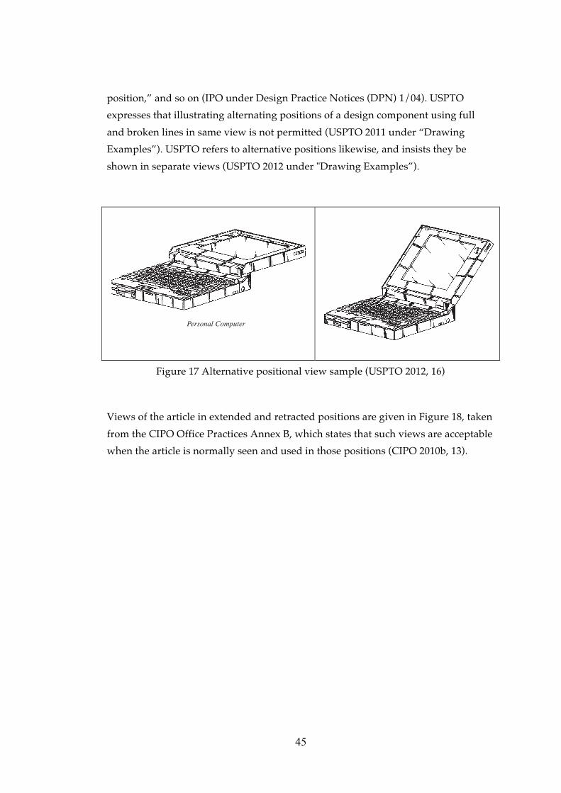
45
position,” and so on (IPO under Design Practice Notices (DPN) 1/04). USPTO
expresses that illustrating alternating positions of a design component using full
and broken lines in same view is not permitted (USPTO 2011 under “Drawing
Examples”). USPTO refers to alternative positions likewise, and insists they be
shown in separate views (USPTO 2012 under "Drawing Examples”).
Personal Computer
Figure 17 Alternative positional view sample (USPTO 2012, 16)
Views of the article in extended and retracted positions are given in Figure 18, taken
from the CIPO Office Practices Annex B, which states that such views are acceptable
when the article is normally seen and used in those positions (CIPO 2010b, 13).

46
Fig. 1
Fig. 2
“Title: Patio Umbrella
Description: The design consists of the features of shape and configuration of the
entire Patio Umbrella as shown in the drawings.
Figure 1 is a side view of the patio umbrella in a retracted position.
Figure 2 is a side view of the patio umbrella in an extended position.”
Figure 18 Extended and retracted positional view sample (CIPO 2010b, 13)
CIPO also mentions flexible flat articles such as clothing and cushions, the
appearance of which may differ when laid flat or in use, and these should also be
shown clearly and accurately (CIPO 2010a Article 6.5.1). CIPO gives an example for
flexible articles within its Office Practices, which is given in Figure 19.

47
Fig. 1
Fig. 2
“Title: Bandanna
Description: The design consists of the features of shape and ornamentation of the
bandanna as shown in the drawings.
Figure 1 is a front view of the bandana design.
Figure 2 is a front view of the bandana design in use.”
Figure 19 Positional view sample of a flexible article (CIPO 2012b, 11)
Detailed, fragmentary or partial view. A detailed view of the design, used to
display parts of a design in detail, allowing an understanding of the details for
which protection is sought, is considered an additional representation under Decree
Law (TPI 2011 Article 2.9.3). TPI explains that the purpose of a detailed view is to
focus and enlarge in order to display a part of a concerned design in detail (TPI 2011
Article 2.9.3). The submission of detailed views of portions of the design on an
enlarged scale is also permitted by OHIM (OHIM 2012 Article 11.4).
Fragmentary views may be considered as detailed views, according to CIPO, which
defines a fragmentary view as a portion of the design shown in a larger scale in
order to better display small details of the design (CIPO 2010b, 19). The means of
illustrating fragmentary view is explained by CIPO accordingly:
• marking with a circle on a conventional view the portion shown in the
fragmentary view and numbering it with the same figure number as the
figure showing the fragment view, or
• using an arrow near to a conventional view pointing to the area shown in the
fragmentary view (CIPO 2010a Article 6.5.2).

48
An example of this from the CIPO Practice notes is given in Figure 20. Turkish
design system does not allow indications or text on representations as arrows or
letters (TPI 2011 2.9.2).
“Title: Putter
Description: The design consists of the features of shape and configuration of the
entire putter as shown in the drawings.
Figure 1 is a side view of the putter.�
Figure 2 is an enlarged fragmentary view of the putter head of figure 1.”
Figure 20 Enlarged fragmentary view sample (CIPO 2010b, 19)
USPTO explains the enlarged view, being the portion of the article used for the
purpose of magnification within a partial view, in Article 37 CFR, and indicates that
the smaller scale of the whole design view and the enlarged view must be labelled
as separate views (USPTO 2010 37 CFR § 1.84). Therefore, it is recommended to
show the whole design in one view and any details in a separate enlarged view.
Smaller-scale views should be included in order to show the whole formed by the
partial views, and should indicate the positions of the parts that are shown (USPTO
2010 37 CFR § 1.84).

49
Both the enlarged view and the partial view can be considered as detailed views, in
that both views represent a portion of the design in detail. USPTO adds that partial
views can be drawn on separate sheets, or a very long view may be divided into
several parts, however they must be capable of being linked, and the relationship
between the parts must be clear and unambiguous (USPTO 37 CFR § 1.84).
If individual protection is to be sought for a detailed image, it must be submitted as
an additional design, not as an additional view. The examiner shall ask the
applicant or his representative to provide a statement indicating whether further
registrations related to the case are being requested or not, and will accept the
detailed view as an additional view or design according to this statement (TPI 2011
Article 2.9.3).
Incomplete images of puzzles. Only TPI mentions incomplete images of puzzles;
representations along with the completed images are accepted as extra views of the
design (TPI 2011 Article 2.9.3).
Plan and elevation views. OHIM, CIPO and USPTO accept elevation views. CIPO
and USPTO indicate that two-dimensional, plan and elevation views are acceptable
(CIPO 2010a Article 6.5.2 and USPTO 37 CFR § 1.84), while OHIM and USPTO
express that views of the design may be plans or elevations (OHIM 2012 Article
11.4).
Extended and exploded view. CIPO mentions extended views for multi-component
articles that must be fully assembled (CIPO 2010b, 12). An extended view may be
included in order to indicate that the article is seen and used in that state (CIPO
2010b, 12). The example given by CIPO in the Office Practice Notes is shown in
Figure 21.

50
“Title: Feeder For Animals
Description: The design consists of the features of shape and configuration of the
feeder for animals as shown in the drawings.
Figure 1 is a perspective view of the Feeder for Animals.
Figure 2 is an extended view of the feeder of Figure 1.”
Figure 21 Extended view sample (CIPO 2010b, 12)
USPTO indicates that exploded views are permitted according to US Design Patent
Law, but only if they are supplementary to a fully assembled view, and may employ
a bracket to show the association of elements (USPTO 2011 under “Drawing
Examples”).

51
Set of Game Components- Fully Assembled View
lyto
Set of Game Components-Exploded View
Figure 22 Exploded view sample (USPTO 2012, 12)
Modified forms of construction. Only USPTO expresses modified forms of
construction, which must be illustrated in a separate view (USPTO 2010 37 CFR §
1.84).
3.3.2.3 Repeating surface patterns
TPI explains that patterns and ornamentation are used for the purpose of
decoration, and can be applied to the surface of various types of products without
affecting their three-dimensional forms or lines (TPI 2011 Article 2.5)
OHIM, IPO and UK state common criteria for representations of pattern designs.
OHIM emphasises that a representation must include the complete pattern and a
sufficient portion of the repeating surface (OHIM 2007 CDIR Article 4(3); 2012
Article 11.5). Likewise, IPO also indicates that the representation of the design must
show the complete patent, adding that it should be surrounded with enough of the
repeated portion in order to show how pattern repeats, thus illustrating the entire
pattern (IPO 2006b Rule 4/7; 2012 under “Illustrations of your Designs”).
TPI states that a pattern applied to a product may be accepted as an additional
visual representation, and should be numbered as an additional view (TPI 2011

52
Article 2.6; 2.9.3). In addition, since patterns and ornamentations are considered
within one class, even if the class of the product in which the design incorporated is
different, the protection of the pattern or ornamentation covers all classes (TPI 2011
Article 2.6). IPO indicates that where the surface pattern is embodied within an
article, the article must be shown in broken lines (USPTO 2012 under “Broken
Lines”). The description of the additional representation, which includes the design
applied to the product, must have the indication of “the pattern as being applied to
the product” (TPI 2011 Article 2.9.3). CIPO indicates that if the design has repeating
pattern on its surface, or repeating three-dimensional features, the depiction must
indicate that such features repeat consistently and at regular intervals along the
length of the portion (CIPO 2010a Article 6.5.2).
3.3.2.4 Articles with indefinite length and width
CIPO addresses the subject of articles with indefinite length and width in detail, and
indicates two types: Articles, which have indefinite length and/or width, and
articles, which have variable length on a portion of the article.
Articles with indefinite length and/or width. CIPO states that the broken lines are
necessary to illustrate articles with indefinite length and/or width, being used to
show the break in the article and the non-design portions of the submitted design
(CIPO 2010a Article 6.5.2). CIPO also indicates that break lines may be shown with
double sinusoidal lines, a sharp jagged line or a pair of angled straight parallel lines
broken occasionally by a zig-zag line (CIPO 2010a Article 6.5.2). CIPO adds that the
description should indicate that an indefinite length and/or width are depicted in
the representation (CIPO 2010a Article 6.5.2). There is no reference in the legislation
in Turkey to the specific use of lines for indicating indefinite length and/or width.
CIPO mentions four types of article to indicate indefinite length and/or width as
follows:
• Articles with indefinite length with a constant cross-section, such as
extrusions for mouldings, where you cut the article, the cross-section is
identical and no surface pattern or three-dimensional features (CIPO 2010a
Article 6.5.2).

53
“Title: Decorative Moulding
Description: The design consists of the features of shape and configuration of the
entire Decorative Molding of indefinite length as shown in the drawings.”
Figure 23 Sample showing an article with indefinite length of a constant cross-
section (CIPO 2010b, 14). Indefinite length is indicated by sinusoidal lines.
Fig. 1
Fig. 2
“Title: Extrusion
Description: The design consists of the features of shape and configuration of the
entire Extrusion of indefinite length as shown in the drawings.
Figure 1 is a perspective view.
Figure 2 is a front view.”
Figure 24 Sample showing an article with indefinite length of a constant cross-
section (CIPO 2010b, 15). Indefinite length is indicated by sharp jagged lines.

54
“Title: Window Extrusion
Description: The design comprises the features of shape and the configuration of the
entire Window Extrusion of indefinite length, as shown in the drawings.”
Figure 25 Sample showing an article with indefinite length of a constant cross-
section (CIPO 2010b, 15). Indefinite length is indicated by parallel lines broken by a
zig-zag line.
• Articles of indefinite length with a repeating surface pattern, such as ribbon,
where the repeating pattern is located on the surface of the article, (CIPO
2010a Article 6.5.2).
Indefinite length indicated by a sharp
jagged line shown in the middle of the
article on the representation.
Indefinite length indicated by a sharp
jagged line shown at the end of the
article on the representation.
“Title: Ribbon
Description: The design consists of the features of shape, ornament and pattern of
the entire ribbon of indefinite length as shown in the drawings. The pattern shown
on the surface repeats throughout the length of the article”
Figure 26 Two different ways of showing indefinite length of a surface
pattern design (CIPO 2010b, 16). Indefinite length is indicated by sharp
jagged line.

55
• Articles of indefinite length and width with a repeating surface pattern, such
as fabric with a repeating pattern, where both the indefinite length and
width may be shown with stippled line around the pattern to be repeated
(CIPO 2010a Article 6.5.2).
“Title: Paper Towel
Description: The design comprises the
features of a Paper Towel of indefinite
length and width, as shown in solid lines
in the drawings. The pattern shown on
the surface repeats throughout the
length and width of the article.”
“Title: Fabric
“Description: The design comprises the
features of a Fabric of indefinite length
and width, as shown in solid lines in the
drawings. The pattern shown on the
surface repeats throughout the length
and width of the article.”
Figure 27 Two different ways of showing indefinite length and width of a repeating
surface pattern design (CIPO 2010b, 18). Indefinite length and width is indicated by
stippled line
• Articles of indefinite length with repeating three-dimensional features, such
as a drainage track with repeating apertures, where the cross-section is not
constant, yet the three dimensional features are repeated at regular intervals
along the article’s length (CIPO 2010a Article 6.5.2).

56
“Title: Drainage track
Description: The design comprises the features of shape, ornamentation pattern and
configuration of a Drainage Track of indefinite length, as shown in the drawings.
The apertures are repeated at regular intervals along the length of the article.”
Figure 28 Sample showing an article with indefinite length of a repeating three-
dimensional feature of the design (CIPO 2010b, 16). Indefinite length and width is
indicated by sinusoidal lines.
Articles containing parts of variable length. CIPO explains this as a distinct portion
of the article being of variable length, but adds that a portion that comes in more
than one definite length differs from an article of indefinite length, such as an
extrusion that is cut to measure. Break lines should be used to show the relevant
portion, and the description must indicate that variable length is being shown in the
representation (CIPO 2010a Article 26.5.2).
CIPO describes three types of design in which variable length may feature in a
portion of the article:
• The relevant portion has a constant cross-section, such as a broom with a
handle of variable length, which has no repeating surface pattern or
repeating three dimensional features, and the cross-section is constant,

57
“Title: Rake
Description: The design consists of the features of shape, ornament, pattern and
configuration of the entire rake having a handle of variable length as shown in the
drawings.”
Figure 29 Sample showing variable length of a relevant portion of the design (CIPO
2010b, 17). Variable length is indicated by sharp jagged line.
• The relevant portion has a repeating surface pattern, such as a geometric
pattern on a broom handle that is consistent across the surface of the
relevant portion and a constant cross-section,
• The relevant portion has repeating three-dimensional features, such as a
paint roller with protruding shapes repeats at regular intervals due to rolling
surface which the cross-section of the relevant portion is not constant but the
three dimensional features repeat at regular intervals throughout its length
(CIPO 2010a Article 6.5.2)
USPTO indicates the use of brackets on the representation to indicate that the
precise length of the article is not claimed (USPTO 2012 under “Drawing Examples”
of “Indeterminate Length”).
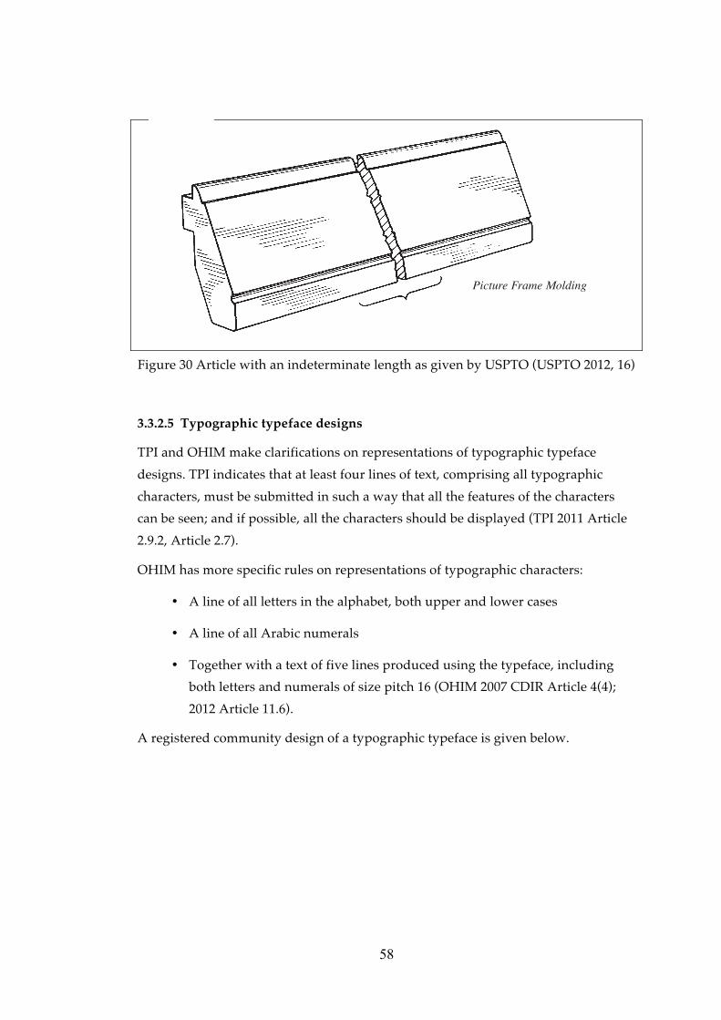
58
med.
Picture Frame Molding
Figure 30 Article with an indeterminate length as given by USPTO (USPTO 2012, 16)
3.3.2.5 Typographic typeface designs
TPI and OHIM make clarifications on representations of typographic typeface
designs. TPI indicates that at least four lines of text, comprising all typographic
characters, must be submitted in such a way that all the features of the characters
can be seen; and if possible, all the characters should be displayed (TPI 2011 Article
2.9.2, Article 2.7).
OHIM has more specific rules on representations of typographic characters:
• A line of all letters in the alphabet, both upper and lower cases
• A line of all Arabic numerals
• Together with a text of five lines produced using the typeface, including
both letters and numerals of size pitch 16 (OHIM 2007 CDIR Article 4(4);
2012 Article 11.6).
A registered community design of a typographic typeface is given below.

59
Figure 31 Visual representation of a registered community design typeface at
OHIM, with the number RCD 000041496-0001 in Locarno class 18-03
IPO includes an additional statement on typographic typeface design, stating colour
as a feature for protection: “A single colour will not assist an ordinary typographic
typeface or the graphic symbol to proceed to registration if it does not pass the
novelty and individual characters tests set out in Section 1B(1)(2) and (3).” (IPO 2003
Design Practice Notices (DPN) 6/03).
3.3.2.6 Designs comprising multiple components and complex products
Regarding designs comprising multiple components, such as pots, pens or cups, TPI
clarifies that the components forming the design must have same visual properties
of the design that can be seen during normal use, or the indication of the product in
which the main design is classified should be same (TPI 2011 Article 2.9.3).
Otherwise, according to TPI such visual representations may be perceived as
different designs, i.e. the representation of a pen with its cover or without its cover
may be accepted as additional visual representations; however, an individual

60
representation of the cover itself is considered as a different design10, not as an
additional representation (TPI 2011 Article 2.9.3).
According to TPI trade dress, indoor or outdoor designs, layout and get-up designs
require multiple views, and one of the views should be the top view in order to
display the layout clearly (TPI 2011 Article 2.9.3). TPI also adds that description of a
get-up should not indicate the individual features of all the components forming the
design. However, the description must mention the matter for which the protection
is sought and reflect the ambiance resulting from the overall appearance of the
components (TPI 2011 Article 2.7).
OHIM mentions two types of design: Designs comprising a set of articles, and
designs comprising multiple components (OHIM 2012 Article 5.1). OHIM indicates
it must be clearly understandable from the representation exactly which elements
protection is sought for in designs made up of a combination of the features of the
articles and adds “such combinations may arise e.g. where the articles of the set are
so closely related that they can be considered as forming a single product,” for
example forks, spoons and knives (OHIM 2012 Article 5.1). It is important to include
at least one view that shows the product as a whole in representations of designs
comprising multiple components, such as with all the components assembled,
otherwise the design representations are perceived as multiple design applications,
not as a single design application with multiple components (OHIM 2012 Article
5.1). A single application comprising multiple designs may result in a formal
deficiency (OHIM 2012 5.1 and 11.4).
CIPO indicates that all of the pieces of the set of articles must be shown within the
drawings and photographs (CIPO 2010a Article 6.5.1).
10 According to Turkish legislation Decree Law Article 28 it may be possible to file several designs in one application, so long as they all belong to the same sub-class, the same set or are parts of the same item.

61
“Title: Set of flatware
Description: Design comprises features of ornamentation applied to the outer
portion of the handles of the set of flatware, as shown in the drawings.
Fig. 1 is a front view of the spoon, fork and knife of the set of flatware”
Figure 32 Representation sample of a set of flatware design (CIPO 2010b, 23).
USPTO states that designs with multiple embodiments of a single concept can be
filed in a single design patent application, so long as they are similar in appearance
and shape, as given in the example below (USPTO 2012 under “Multiple
Embodiments”).

62
“ Combined Writing Instrument and Pocket Holder”
Figure 33 Visual representation sample of a design with multiple embodiments of a
single concept (USPTO 2012, 16)
Representation of a complex product. In cases where the applicant would like to
register a component part of a complex product11 it is important to submit views of
the product incorporated into a complex product in such a way that those parts
which are novel and have individual character remain visible in the normal use12 of
that complex product (IPO 2003 Design Practice Notices (DPN) 1/03). All of the
internally visible features, such as steering wheel, seats and dashboard, shall be
visible in normal use, as well as the externally visible features of the complex
product, such as the overall contours, ornamentation of grille badges, door handle,
wheel trims etc. (IPO 2003 Design Practice Notices (DPN) 1/03).
Only USPTO emphasizes that when the protection claim is for the entire article, but
when all sides of the entire article are not visible in normal use, it is not necessary to
disclose all of them (USPTO 2012 under “The Views”).
11 Definitions of product and complex product is given in section 2.3 12 Normal use is defined as use by the end user by the IPO Registered Designs Act 1949 (c.88) as amended Section 1B(9). The Design Practice Notes exemplified the end user of a motor car as being the owner or the driver rather than the service mechanic (IPO 2003 Design Practice Notices (DPN) 1/03).

63
3.3.3 Ordering and numbering the views
Total number of views. TPI, WIPO and KIPO declare that there is no limitation on
the number of submitted views (TPI 2011 Article 2.9.3; WIPO 2012d BII.05.10; KIPO
2011 under “Overview of the design system in Korea”).
WIPO states that no contracting party may require more than one view of a design
where the design or the product is two dimensional, and more than six views where
the design or the product is three-dimensional (WIPO 2012b Rule 9/3(b)). CIPO
indicates “at least one drawing or photograph is required that is of sufficient clarity
to see the article and the design” (CIPO 2010a Article 2.4) KIPO says it is up to the
applicant how many views they submit with a design application, although it is
suggested to submit a perspective and a set of six views (KIPO 2011 under the
“Overview of the Design System in Korea”). OHIM, on the other hand, sets a limit
of seven views for each design, and adds that submissions of extra views that exceed
this limit will be disregarded by the Office (OHIM 2003 Article 4; 2007 CDIR Article
4(2); 2012 Article 11.4).
TPI applies no limitation to the number of representations, however the examiner
shall be ensure that the submitted representations display clearly all the distinctive
visual features of the design for which protection is sought (TPI 2011 Article 2.9.3).
OHIM emphasizes that there must be a sufficient number of views submitted to
specify all the features of the design for which protection is sought, as the examiner
will not check whether the design has features other than those shown in the
submitted views (OHIM 2012 Article 11.4). IPO states that if the design is three-
dimensional, then the representations should include a series of views from
different angles to show the overall appearance of the design (IPO 2012a under
“Illustrations of your designs”). CIPO and IPO also mentions that there must be
sufficient number of views, which shows the article clearly and accurately, so as to
leave no doubt when understanding the design features for which protection is
sought (CIPO 2010a Article 6.5.1; IPO 2004 Design Practice Notices (DPN) 1/04).
CIPO indicates that the number of views must be sufficient to show clearly and
accurately the features of the design (CIPO 2010a Article 6.5.1).
USPTO indicates that the number of views must be sufficient to facilitate complete
disclosure of the appearance of the claimed design (USPTO 2010 37 CFR § 1.152;
2012 under “The Views”). USPTO’s “A Guide to Filling a Design Patent
Application” explains that “The drawings or photographs should contain a
sufficient number of views to completely disclose the appearance of the claimed
design, i.e., front, rear, right and left sides, top and bottom. While not compulsory, it

64
is suggested that perspective views be submitted to clearly show the appearance
and shape of three-dimensional designs. If a perspective view is submitted, the
surfaces shown would normally not be required to be illustrated in other views if
these surfaces are clearly understood and fully disclosed in the
perspective.”(USPTO 2011 under “The View”).
Arrangement of the views. WIPO, CIPO and USPTO clarify how the views should
be arranged in the design application. WIPO states that representations must be
arranged in the order that the applicant wishes them to be published (WIPO 2012c
Section 401(d)); while CIPO states that grouping views according to each variant13 is
preferred (CIPO 2010a Article 6.5.1).
USPTO requests the physical arrangement of the views on sheets be made as
follows:
• One view must not be placed upon another, or within the outline of another,
• All views on the same sheet should stand in the same direction, preferably in
an upright position (USPTO 2010 37 CFR § 1.84) (See section 3.5.1 Physical
quality for details of the quality of the representations).
USPTO indicates that it is preferable for the order of the views to be as they appear
on the drawing sheet(s) (USPTO 2010 37 CFR § 1.84).
Numbering and labelling the views. WIPO emphasizes that for non-electronic filing
(i.e. paper submission applications), each design must be identified by an individual
number, appearing in the margin of each representation, and states that the
electronic filing interface adds numbering automatically (WIPO 2012d BII.05.11); it
is also important that representations contain no numbering (WIPO 2012d BII.05.03).
The numbering of the additional views is similarly specified by OHIM and WIPO.
All additional views for each design are numbered with two digits separated by a
dot. The first indicates the design, and the second indicates the number of the view
(e.g. the 7th view of a design numbered 3 shall be numbered 3.7) (OHIM 2007 CDIR
Article 4(2) and OHIM 2012 Article 11.4). WIPO states that the design represented
from different angles must be numbered with two digit numbers, i.e. 1.1, 1.2, 1.3 …
etc., for the first design; and 2.1, 2.2, 2.3… etc., for the second design (WIPO 2010
BII.22.05.11).
13 “Variant: An application must relate to one design or to designs that constitute variants. To be accepted as variants, the designs must be very similar and possess the described features without substantial variation.” (CIPO 2011a Article 6.4.5 (e))

65
USPTO says that views must be numbered in consecutive order with simple and
clear Arabic numerals, starting from one, and without brackets, circles or inverted
commas (USPTO 2010 37 CFR § 1.84). Regarding photographic representations,
CIPO suggests that the numbers of views should be in sequence, and should be
written, stamped or typed on the rear of the photograph using permanent ink (CIPO
2010a Article 6.5.1).
IPO indicates that views should be labelled and exemplifies the labelling of views as
“front view”, “view on one side” and “perspective view from front, above and one
side” (IPO 2012a under “Labelling the views”).
3.4 Partial Disclaimer
A design registration is not always requested for the whole article or product, as in
some cases the applicant is seeking to limit or extent the scope of protection of a
design. For this reason, protection can be also requested for only a part of a design
(TPI 2011 Article 2.9.2).
IPO states that a design registration may be accompanied by a disclaimer that:
• limits or extent the scope of protection being applied for in relation to the
design, or
• indicates that the application for registration relates to a design that forms
only a part of the appearance of a product (IPO 2006b Rule 6).
If the applicant wishes to protect the design of only a part of a product, or to
disclaim visual features such as colours or materials, a partial disclaimer must be
used (IPO 2012 “Partial disclaimers”). A partial disclaimer can also be used in cases
where the applicant wishes to protect a specific feature of the design, such as the
three-dimensional shape but not the surface decoration (IPO 2012a under “Partial
Disclaimer”).
WIPO expresses that the disclaimer must be indicated within the description
and/or within the representation by means of dotted or broken lines (WIPO 2012c
Section 403; 2012d BII.05.09). Partial disclaimers shall be evaluated by the examiner
from two parts of the application: visual materials, showing the disclaimer on the
representation; and written statements, indicated in the description. There are three
features of the application cited by TPI that must comply with each other:14
14 It is the examiner’s responsibility to ensure the conformity of these three features of the design with each other in relation to the element for which protection is being sought (TPI 20122 Article 2.9.2).

66
Indication of the product, representation, and written description (TPI 2011 Article
2.9.2). Those three features must be in combination in the applications where the
partial disclaimer is requested as well.
3.4.1 Visual representation of a partial disclaimer
TPI states that the parts for which protection is requested shall be clearly marked on
photographic representations (TPI 2009 Article 9/1(a); 2011 Article 2.9.2).
The design and the part or parts for which protection is sought must be clearly
identified (IPO 2012a under “Partial Disclaimer”). OHIM and IPO suggest three
ways of identifying and showing clearly the part or parts of the design for which
protection is sought, to be applied to all views of the design:
• Colouring the part or parts in question,
• Drawing the part or parts in question in solid lines and the part for which
protection is not sought in dotted lines,
• Carefully outlining the part or parts in coloured ink, referred to as
boundaries (OHIM 2012 Article 11.4; IPO 2012a under “Partial Disclaimers”).
In addition to the above, OHIM advises that colouring may also be used on black
and white drawings in order to highlight the features of the design for which
protection is sought (OHIM 2012 Article 11.4).
IPO defines three ways to indicate the features for which protection is not sought:
• Dotted lines,
• Blue wash, or
• Circled in red ink (IPO 2004 DPN 1/04).
OHIM indicates that it is the applicant’s responsibility to use such lines in a way
that identifies clearly for which features protection is sought, as the examiner shall
only assess the suitability of the representation for publication (OHIM 2012 Ch.
11.4).
Stippled, dotted, dashed or broken lines in a partial disclaimer. TPI and WIPO
advises the use of dotted, dashed or broken lines to show the parts of the design for
which protection is not sought, especially on graphic representations (TPI 2009
Article 9/1(a); 2011 Article 2.9.2; WIPO 2012d 05.09). IPO makes a similar request,
advising the use of broken or dotted lines to show the parts for which protection is
not sought, but adding that as yet there is no formal requirement to do this (IPO

67
2003 DPN 2/03; 2004 DPN 1/04). USPTO indicates that only broken lines will be
used to indicate the features that are not part of the design (USPTO 2012 under
“Broken Lines”).
(�)������ *� )������ *��)������
Front view Left side View Right Side View
Figure 34 Representation of a design with a partial disclaimer (TPI 2012, 12).
Disclaimed features of the design are shown in dashed lines.
Similar to TPI and WIPO, CIPO explains that the article can be illustrated by either
showing the whole article in solid lines and specifying the design and non-design
features or parts claimed or disclaimed within the description, or by showing the
design in solid lines and the portions of the article that are not part of the design in
stippled lines, formed by evenly spaced short dashes, evenly spaced short dots, or
evenly spaced and alternating short dashes and dots (CIPO 2010a Article 6.5.2).

68
1. Solid Lines 2. Solid and Stippled Lines
“Title: Training cup”
“Description: The design consists of the
features of shape and configuration of
the lid of the training cup as shown in
the drawings.”
“Description: The design consists of the
features of shape and configuration of the
portion of the training cup as shown in
solid lines in the drawings. The stippled
line portions do not form part of the
design.”
Figure 35 Partial disclaimer shown in solid and stippled lines (CIPO 2010b, 3)
USPTO indicates that a broken line is to be used in illustrations only to show the
non-design features of the design, and adds that it may also be used to indicate
structures that are not part of the design, but show the environment in which the
design is used (USPTO 2012 “Broken Lines”; “Drawing Examples”).

69
Tire
Paper Cutter
Figure 36 Partial disclaimer samples, where non-design portions of the
design are shown in broken lines (USPTO 2012, 16)
CIPO indicates that the non-design features of the article must be shown as opaque,
and non-transparent, unless they are actually transparent (CIPO 2010b, 4)
Not Acceptable Acceptable
“Title: Spray bottle
Description: The design consists of the features of the shape and ornamentation of a
Spray Bottle, as shown in solid lines in the drawings. The portions shown in
stippled lines do not form part of the design.”
Figure 37 Partial disclaimer sample, showing the opaque non-design portions of the
design (CIPO 2010b, 4)
TireTire

70
CIPO indicates that there are additional means of showing the design and the non-
design portions of the article in the visual representation in combination with the
use of solid and stippled lines: the use of bold and wavy lines (CIPO 2010a Article
6.5.3): “As a matter of office practice, the Office will accept the use of bold wavy
lines in exceptional cases to define a boundary between the design and non-design
portions of the article where the use of solid and stippled lines alone does not
clearly show the design as applied to the article” (CIPO 2010a Article 6.5.3). CIPO
explains the requirements with which the applicant must comply for using bold and
wavy lines:
“1. It must be clear what the bold wavy lines are illustrating, such that the
description and drawings clearly indicate what are the design features and what
are the portions of the article where the design resides.
2. Such lines in the drawings must clearly be bold and wavy, i.e. so that they are
not confused with ordinary solid lines, stippled lines or with break lines.
3. The description must include a statement clearly indicating that the bold wavy
lines are not part of the design (CIPO 2010a Article 6.5.3).
Figure 1
“Title: Shoe
Description: The design consists of the visual features of the shoe, shown in solid
lines in the drawing. The bold, wavy line does not constitute a feature of the design.
It is included for illustrative purposes only in order to define the boundary of the
design.
Fig. 1 is a side view is of the shoe.”
Figure 38 Partial disclaimer sample showing the use of bold and wavy lines to
indicate the design portions of a shoe design (CIPO 2010b, 23)

71
Figure 1
“Title: Clothes washer
Ddescription: The design consists of the features of shape, configuration, and
ornamentation of the portion of the clothes washer shown in solid lines in the
drawing. The portions shown in stippled lines do not form part of the design. The
bold, wavy line does not constitute a feature of the design. It is included for
illustrative purposes only in order to define the boundary of the design.
Figure 1 is a front view of the clothes washer.”
Figure 39 Partial disclaimer sample showing the use of bold and wavy lines together
with stippled lines to indicate the non-design portions of a clothes washer design
(CIPO 2010b, 23)
3.4.2 Verbal description of partial disclaimer
WIPO states that the description may also serve for disclaiming protection in respect
of some features of the design (WIPO 2012d BII.04.39). TPI indicates that if
protection is sought for only a part of a product, then the expression of “a part of a
product” must be indicated in the description and shown on the representation (TPI
2011 Article 2.9.2).
IPO emphasizes that if the application contains a partial disclaimer, then it should
be indicated in the relevant section of the application form and at the bottom of the
illustration pages (IPO 2012a under “Partial Disclaimer”). IPO suggests that if
protection is sought for only a part of a product, such as the handle of a cup, or
limited to such a part, the partial disclaimer is to be worded as “The design is that
applied to the handle of the cup, as shown in the representations,” or “The

72
protection to be conferred by the registration is limited to the handle of the cup as
shown in the representations.” (IPO 2003 DPN 2/03). IPO also suggests wording in
the case of protection being sought for the whole product only, as “the design is
limited to the shape and configuration of the whole product. Protection is not
sought for the separate parts of the design.” (IPO 2004 DPN 1/04).
IPO gives additional examples for the wording to be used in the case of partial
disclaimers:
“Protection is sought for the shape and configuration of the design only.”
“No claim is made for the colour or colours shown.”
“Protection is sought for the two-dimensional surface decoration only” (IPO 2012a
under “Partial Disclaimer”).
IPO also gives a sample description: “The features of the design for which
protection is sought are the part or parts of the design shaded in blue in the
illustrations” (IPO 2012a under “Partial Disclaimer”).
IPO provides an example of wording to highlight additional items that do not form
part of the design: “Protection is sought for the garment only. The mannequin does
not form part of the design and is shown only for illustrative purposes only” (IPO
2012a under “Partial Disclaimer”).
3.5 Format and Quality of Visual Representation
3.5.1 Physical quality
WIPO states that representations must be of the highest possible quality, in that the
scope of protection depends upon the content and the quality of the reproductions
(WIPO 2012d BII.05.15). The visual quality of representations shall distinguish all
details of the design clearly and permit publication (WIPO 2012b Rule 9(2)(a)).
OHIM also states that the quality of the representation must distinguish clearly all
the details of the design for which protection is claimed (OHIM 2012 Article 4.4)
when the reproduction is reduced or enlarged to a size of not more than 8 cm x 16
cm per view (OHIM 2007 Article 4(1)(e); 2012 Article 4.4; 11,4). OHIM indicates that
it is the responsibility of the applicant, not the examiner, to ensure that the quality of
the representation is suitable for publication (OHIM 2012 Article 4.4; 11.4).
TPI states that representations must be suitable for duplication by scanning and
reproduction through publication (TPI 2011 Article 2.9.2). IPO explains that
“suitable representation” means representation of the design suitable for
publication (IPO 2006b Rule (5)). For graphic representations, IPO states that the

73
quality of the ink-drawings should be of good enough quality for scans or
photocopies (IPO 2012a under “Illustrations of your designs”). CIPO states that all
drawings must be sufficiently large in order to show all features of the design “clear
and apparent” (CIPO 2012a under “Drawings and Photographs”), and must also be
legible and reproducible in black and white by the Office (CIPO 2010a Article 6.5.1).
For photographic representations, IPO indicates that photographs must be capable
of being reproduced using the IT scanning equipment of the Office (IPO 2004).
USPTO expresses that photographic representations must be of sufficient quality for
all the details of the article in the photograph to be reproducible in print (USPTO
2010 37 CFR § 1.84).
TPI and OHIM state that it is more appropriate to submit visual representations on
the application form prepared by the Office (TPI 2011 Article 2.9.2; OHIM 2007
Article 4(1)(a)).
TPE-T-101/1 �
�������� � ��� �� ������������������������
�������� � ��� �� �������������������������
����������� � � ����������� � �������������
������� �� ������ � ������������������� ������������������ ������������������������������������������������������������������
���
�������� � ��� �� ������������������������
�
�������� � ��� �� �������������������������
��-.�/��.�
����������������
��� ��
���������
���� ��/�����
���������� �� ������� ���
�
���������� � ������� �
�
�
TPE-T-101/3 �
��
���������������� ��������� ����������� ������������� ��������
��
���������������� ������������������ ���������������������������������������������������������������������
���������� �� ������� ���
�
����������� �� ������� ���
�
������������������������ �
������
���������������� �
������������
�
��������������������������������� ���������������������!"�!��� ���#��� �"�������
Figure 40 Visual representation pages from a multiple design application in A4
format (TPI 2012, 19)
Other than the visual representation, TPI states that the page must contain the
name, surname, title and signature of the applicant or his representative (TPI 2011
Article 2.9.2). The visual representation itself should not contain any other
representation or part of another representation or numbering (TPI 2011 2.9.2WIPO
2012c Section 401(e); 2012d BII.05.03). Similar to TPI, OHIM also indicates that there

74
should be no explanatory text, wording or symbols, or anything other than the
consecutive number of the design, an indication of the view such as “top,” and the
name or address of the applicant, which may be displayed on the representation
page (OHIM 2007 Article 4(1)(c)).
Both drawings and photographs must be submitted in the form of right-angled
quadrilaterals, which means squares and rectangles, with all their edges cut at right
angles (WIPO 2012c 401(e); 404(b); 2012d BII.22.05.03; 05.07; BII.05.08). The
reproduction area must not contain any other or part of another reproduction, even
in the case of a multiple design application (TPI 2011 2.9.2; WIPO 2012c Section
401(e); 2012d BII.05.03). The details of the dimensions of the views are given in
section 3.3.1.
Numbering the views. Numbering techniques of the views given by the Offices are
discussed in section 3.3.3. Ordering and numbering the views. The numbering of the
representation pages, the placing of the representation numbers and the numbering
of the representations of each design in multiple design applications will be
discussed within this section.
IPO states that each page must be numbered in consecutive order, indicating the
total number of pages, such as “1 of 3”, “2 of 3” and “3 of 3” (IPO 2008 Rule 9(5)).
Page numbers must be placed in the top right hand corner (IPO 2012a under “The
Views of the Design”). Illustration page example of IPO is given in Figure 41.
Figure 2
2/2OPAL CRAFTS LIMITED
Plan
Underneath plan
Elevation of other side
2Number sheets
3Drawings or photosare OK
4Clear and accuratedrawings, no jaggedlines. Solid lines arebest as images areelectronicallycaptured
5Show only productyou want registered
6You can show morethan one view persheet, but say whatthe view is
How to present your design illustration(s)
1Applicant'sfull Name
Figure 1
1/2OPAL CRAFTS LIMITED
Front perspective
view from one side
Rear elevation
Figure 41 Sample of an illustration page given by IPO (IPO 2012b, 8)

75
USPTO states that the figure number should be entered on the face of the
representation (USPTO 2012 under” Drawings or Black and White Photographs”).
The representation number should be placed in the margin of each representation,
with the first digit indicating the number of the design and the second digit,
separated by a dot, indicating the number of the view when the design is
represented from different angles, such as 2.1, 2.2 and 2.3 (WIPO 2012c Section 405
(a); 2012d BII.05.11; OHIM 2007 Article 4(2)). All representation must be submitted
in ascending numerical order (WIPO 2012c Section 405 (b); 2012d BII.05.11).
IPO emphasizes a different method to be used if the application is a multiple design
application. The design should be marked, “This is the first of the three designs”
(IPO 2012a under “The Views of the Design”).
Size and quality of paper. TPI states that visual representations must be submitted
on 21.0 cm x 29.7 cm DIN size A4 format paper (TPI 2011 Article 2.9.2; WIPO 2012c
Section 401(c); OHIM 2007 Article 4(1)(c); 2012 Article 11.4 IPO 2012a under ”The
Photographic Views”; “Views of the Design”; 2004). Only USPTO refers to both DIN
size A4 and 21.6 cm x 27.9 cm (8��x 11 inches) paper format (USPTO 2010 37 CFR §
1.84). All drawing sheets must be the same size (USPTO 2010 37 CFR 37 § 1.84)
Paper quality is defined by TPI, WIPO and OHIM as plain, white, good quality and
opaque (TPI 2011 Article 2.9.2; WIPO 2012c Section 401(c); 2012d BII.22.05.02;
BII.05.08; OHIM 2007 Rule 4(1)(b); 2012 Article 11.4)
USPTO states that the paper must be flexible, strong, white, smooth, non-shiny and
durable (USPTO 2010 37 CFR 37 § 1.84), and requests that photographs be
submitted on double weight photographic paper (USPTO 2012 under “Drawings or
Black and White Photographs”). IPO and USPTO state that only one side of the
paper must be used (IPO 2004; 2012 under “The Views of the Design”; USPTO 2010
37 CFR 37 § 1.84)
TPI, WIPO and OHIM indicate that the representation and the page should not be
folded or stapled (TPI 2009Article 9/1(a); 2011 Article 2.9.2; WIPO 2012c Section
401(e); 2012d BII.05.03; OHIM 2007 Rule 4(1)(b); 2012 Article 11.4); while TPI adds
that the representation must also not be erased or scratched, and WIPO adds that it
should not be marked (TPI 2011 Article 2.9.2; WIPO 2012c Section 401(e); 2012d
BII.05.03).
It is also important, particularly for photographic representations, that they shall not
be retouched with ink or correction fluid (WIPO 2012c Section 401(a); 2012d

76
BII.02.07; OHIM 2007 CDIR Article 4(1)(e)). If the representation has been retouched,
then it will be accepted as a formal deficiency, which will affect the allocation of the
application date by the Office (OHIM 2007 Article 4(1)(e); 2012 Article 4(4)). USPTO
states that the sheets bearing representations must be free from cracks, creases,
folds, erasures, alterations, overwritings and interlineations (USPTO 2010 37 CFR
37 § 1.84).
TPI, WIPO and OHIM state that the representation must be either printed or pasted
on the representation page (TPI 2011 Article 2.9.2; WIPO 2012c Section 401(c); 2012d
BII.05.02; OHIM 2007 Rule 4(1)(b); 2012 Article 11.4).
Size of the representation. The permissible dimensions of views are discussed in
section 3.3.1. Dimensions of visual representations, however the size limits of the
representations will be discussed within this section. The dimensions of each
representation are given by TPI as at least 8 cm x 8 cm, and at most, 16 cm x 16 cm
(TPI 2009 Article 9/2(a); 2011 Article 2.9.2). Similar to Turkish implementations,
WIPO sets the maximum dimensions of representations at 16 cm x 16 cm, and adds
that one of these dimensions must be at least 3 cm (WIPO 2012c Section 402(b);
2012d BII.05.13). OHIM says that the space used for representations cannot be larger
than 26.2 cm x 17 cm (OHIM 2012 Article 11.4). USPTO sets the size limits of the
representation at 17 cm x 26.2 cm on DIN size A4 page, and 17.6 cm x 24.4 cm (6
15/16 x 9 5/8 inches) on 21.6 cm x 27.9 cm (8 � x 11 inch) page (USPTO 2010 37 CFR
37 § 1.84). USPTO stated that representations must be submitted on one side of the
representation page and must not contain a frame (USPTO 2010 37 CFR 37 § 1.84).
Margins. WIPO emphasizes there should be at least a 5 mm margin around the
representation (WIPO 2012c Section 01(d); 2012d BII.05.02).
OHIM sets the left and right side margins of the representation page as at least 2.5
cm (OHIM 2007 Rule 4(1)(c)); while USPTO sets the minimum margins of the
representation page at 2.5 cm for the top, 2.5 cm for the left, 1.5 cm for the right and
1 cm for the bottom (USPTO 2010 37 CFR 37 § 1.84).
3.5.2 Data format for e-filing
WIPO states that international design applications must be filed on the official form
or through WIPO’s electronic filing (e-filing) interface, including the
representation(s) of the design to be protected and the designation of the contracting
parties where the protection is sought (WIPO 2012d 02.10).

77
WIPO clarifies that the file format for representations submitted using the WIPO e-
filing should be as follows:
Data format: jpeg or tiff
File size: Not exceeding 2 megabytes
Colour mode: RGB mode, not CMYK (WIPO 2012d BII.22.05.05)
The combination of pixel number and resolution must be sufficient to ensure that,
when the representation is printed, the dimensions of the graphic or photographic
representation do not exceed 16 cm x 16 cm, and one dimension must be at least 3
cm (WIPO 2012d BII.05.14).
For electronic filing cases, the OHIM Regulations and Guidelines refer to the
President of the Office Decision No. EK-03-8 dated June 25, 2003, which states that
the data format of the representations in e-filing applications must be in jpeg format
(OHIM 2003 Article 3(1)). OHIM states that different designs in multiple design
applications or different views must be identified in the manner noted on the
electronic filing application form (OHIM 2003 Article 3(1)).
3.6 Unacceptable visual representations
The following representations are deemed unacceptable:
• Representations that include objects other than the design itself (TPI 2011
Article 2.9.2).
• Representations that include multiple views or contain other representations
or parts of other representations ((TPI 2011 2.9.2; WIPO 2012c Section 401(e);
2012d BII.05.03).
• Representations, which include accessories that do not fall under the scope
of the design protection (TPI 2011 Article 2.9.2).
• Representations that include measurement indications and technical
drawings, particularly with axis or dimensions (TPI 2011 Article 2.9.2; IPO
2004 IPO in DPN 1/04 and explained in WIPO 2012c Section 402(c)(i)).
• Displaying the products in sections or plans, especially together with axis
and dimensions (TPI 2011 Article 2.9.2).
• Representations that include explanatory text or legends or numbering or
wording and symbols or indications other than the consecutive numbering
of the design on the representation (TPI 2011 Article 2.9.2; WIPO 2012c
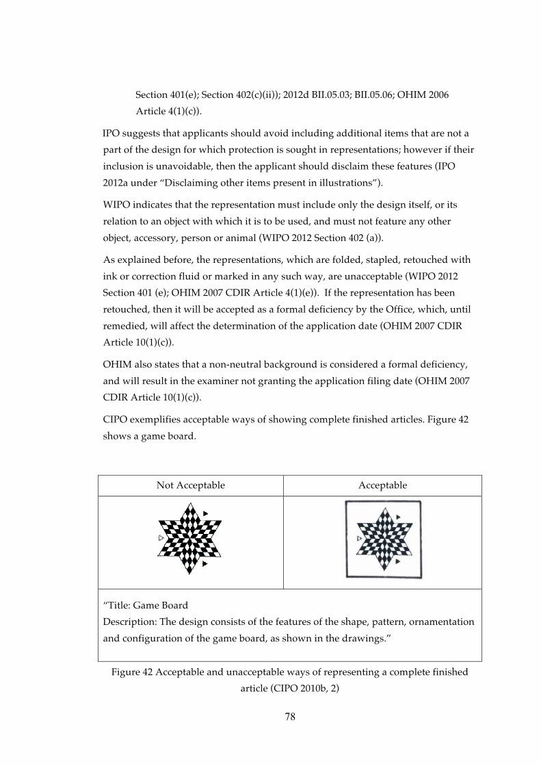
78
Section 401(e); Section 402(c)(ii)); 2012d BII.05.03; BII.05.06; OHIM 2006
Article 4(1)(c)).
IPO suggests that applicants should avoid including additional items that are not a
part of the design for which protection is sought in representations; however if their
inclusion is unavoidable, then the applicant should disclaim these features (IPO
2012a under “Disclaiming other items present in illustrations”).
WIPO indicates that the representation must include only the design itself, or its
relation to an object with which it is to be used, and must not feature any other
object, accessory, person or animal (WIPO 2012 Section 402 (a)).
As explained before, the representations, which are folded, stapled, retouched with
ink or correction fluid or marked in any such way, are unacceptable (WIPO 2012
Section 401 (e); OHIM 2007 CDIR Article 4(1)(e)). If the representation has been
retouched, then it will be accepted as a formal deficiency by the Office, which, until
remedied, will affect the determination of the application date (OHIM 2007 CDIR
Article 10(1)(c)).
OHIM also states that a non-neutral background is considered a formal deficiency,
and will result in the examiner not granting the application filing date (OHIM 2007
CDIR Article 10(1)(c)).
CIPO exemplifies acceptable ways of showing complete finished articles. Figure 42
shows a game board.
Not Acceptable Acceptable
“Title: Game Board
Description: The design consists of the features of the shape, pattern, ornamentation
and configuration of the game board, as shown in the drawings.”
Figure 42 Acceptable and unacceptable ways of representing a complete finished
article (CIPO 2010b, 2)

79
Another example by CIPO for showing an electronic icon is shown in Figure 43.
Not Acceptable Acceptable
“Title: Electronic Icon” “Title: Computer Monitor”
“Description: The design consists of
the ornamentation of the electronic
icon as shown in the drawings.”
“Description: The design consists of the
ornamentation of the computer monitor as
shown in solid lines in the drawings. The
stippled line portions do not form part of
the design.”
Figure 43 Acceptable and unacceptable ways of representing a complete finished
article. The acceptable version identifies the finished article to which the electronic
icon is applied (CIPO 2010b, 22)
CIPO indicates that explanatory text and other indications are not acceptable (as
shown in Figure 44) and adds that the article must be shown in complete isolation
(CIPO 2010b, 7).

80
Not Acceptable Acceptable
“Title: In-line skate
Description: The design consists of the features of shape, configuration and
ornament of the in-line skate as shown in the drawings.”
Figure 44 Acceptable and unacceptable representation examples showing the article
in isolation (CIPO 2010b, 7)

81
CHAPTER 4
FIELD STUDY
4.1 Background of the field study
After identifying and categorizing the main features and qualities of visual
representations required by different jurisdictions in the literature survey, the field
study focuses on the implementation in Turkey.
The main actors of the industrial design registration system in Turkey are:
• Applicants,
• Attorneys (both patent and trademark attorneys and attorneys at law),
• TPI examiners,
• Judges and court experts.
The aim of the field study is to investigate critical and problematic issues related to
the features and qualities of visual representation in industrial design registration
applications in Turkey. In line with the aim of the study, the target population was
defined as the Turkish Patent Institute examiners who are responsible from the
formal examination of industrial design registration applications. For the field
study, the most appropriate method for data gathering was considered to be in-
depth interviews with the examiners at the Industrial Designs Department of TPI.
The head of the Industrial Designs Department of TPI was approached to introduce
the researcher, the research topic, the content of the study and the content of the
interview. The letter to the head of Industrial Designs Department of TPI is
presented in Turkish in Appendix B and in English in Appendix C.
During the meeting with the head of the Industrial Designs Department, it was
learned that three examiners are responsible for examining design applications at
TPI. Each examiner was contacted by telephone and given brief information about
the research topic and study, and an appointment date and time for an interview

82
was requested. After confirmation of the date and time, brief information was sent
to each interviewee regarding the content of the interview via e-mail, along with a
copy of a shortened interview schedule, and each examiner was asked, if possible, to
prepare acceptable and unacceptable examples from actual design registration
applications with their visual representations, before our meeting. The e-mail
sample is presented in Turkish in Appendix D and in English in Appendix E.
4.2 Interview schedule and data collection
The interview schedule was developed by taking into account the final topics and
sub-topics concerning the features and qualities of visual representation identified
in the literature survey.
At the beginning of the interview, the interviewees were thanked for their assistance
and given brief information about the study, and they were asked for their
permission to video record the interview. The first part of the interview comprised
general questions on the formal examination, and more specifically on the formal
examination of visual representations. The second part focused on problems
encountered by the interviewees in their assessments of visual representations. The
third part included questions on types of visual representation, while the fourth
part comprised questions on the article, background and colour. The fifth part was
the most comprehensive section, focusing on types of views, such as conventional
views, non-conventional views; views of designs of indeterminate length and/or
width, typographic character designs, etc. including ordering and numbering the
views. The sixth part was related to both visual and verbal partial disclaimers. The
seventh part included questions on format and quality for both electronic filing and
paper applications. Questions on unacceptable visual representations were rendered
in the eighth part of the interview, while the interviewees were asked to provide
examples of acceptable visual representations in the ninth part. In the tenth part the
interviewees were asked for any additional comments or remarks. The interview
ended with questions on the professional details of the interviewees, such as years
of expertise and previous duties at TPI. The main topics of the interview schedule
are given in Table 5;the interview schedule is given in Turkish in Appendix E and in
English in Appendix F.

83
Table 5 Interview schedule parts, and number of main questions
Part no. Title
Number
of main
questions
I Formal examination of visual representations 2
II Problems encountered in visual representations 1
III Types of visual representations 3
IV Article, background and colour in visual representations 3
V Views 8
VI Partial disclaimer 2
VII Format and quality of visual representations 3
VIII Unaccepted visual representations 1
IX Examples of acceptable visual representations 4
X Final Questions 3
Total number of questions 30
All three examiners in the Industrial Designs Department of TPI, who are
responsible from conducting formal examinations, agreed to take part in the study.
Two of the interviewees were female, one interviewee was male; the average age of
the interviewees were 46; the average experience at TPI was 16, and the average
experience in formal examination the Industrial Designs Department of TPI was 11.
Both video and audio recordings were made of the interviews as a precaution
against loss of data through technical error. The video recordings alone were
suitable for the final analysis. Information on the interviewees and the interview
durations are given in Table 6.

84
Table 6 Information on interviewees
Age Years at
TPI
Current
department
Years at the
current
department
Duration
Interviewee 1 44 18 Industrial
Designs
15 1 hr 22 min
Interviewee 2 46 18 Industrial
Designs
3 35 min
Interviewee 3 48 15 Industrial
Designs
15 58 min
During the interviews, all three interviewees received the same information from
the researcher (Appendix C and D) and had the same questions addressed to them
in the same order (Appendix E and F). Only slight changes were made during the
interview in the wording of the questions.
4.3 Data analysis
The video recordings were transcribed verbatim (i.e. word for word) during two
viewings of the recordings. The examples of visual representations given by the
examiners were inserted into the transcribed data.
The interviewees provided two types of examples of visual representations during
the interviews: Problematic examples that contained formal deficiencies, and
acceptable examples. The acceptable examples, which have already been published
in the TPI Official Industrial Designs Bulletin, are available for publication. Those
published examples are cited within the findings of the field survey by their
application numbers, and the visual representations are presented herein. The
visual representation examples containing formal deficiencies have not yet been
remedied, and to date have not been published in the TPI Official Industrial Designs
Bulletin, and therefore, cannot be used in this study.
All the interviews were transcribed by the researcher for an in-depth analysis. The
analysis of the data was carried out through a rereading of the transcripts and a re-
listening to the recordings at the same time. The parts deemed significant for the
study were highlighted on the transcribed document. In the second part of the data

85
analysis, those highlighted parts of the transcribed document were organized
according to the topics and sub-topics defined in the literature survey.
As seen in Figure 45 each sub-topic was given a colour code, and each highlighted
phrase was underlined following that code, together with the name of the category
noted in the right margin of the transcribed document.

86
Figure 45 Colour coding for topics and sub-topics

87
The schematic table of the guide page given in Figure 45 including the colour codes
which was identified through literature survey is also represented in the Table 7.
Table 7 Final coding scheme for topics and sub-topics
Category
No.
Topic or Sub-topic Question
No.
Colour Code
1 Importance of the visual representation
and formal examination
1.1 Importance 3 Green
1.2 Formal Examination 1, 2 Green
3 Types of visual representation
3.1 Graphic representation 5 Pink
3.2 Photograph 4 Light blue
3.3 Specimen 6 Black
4 Content of visual representation
4.1 Article 8 Brown
4.2 Background 7 Blue
4.3 Colour 9 Dark green
5 Views of design Light green
5.1 Dimensions of views 10 Dark pink
5.2 Types of views
5.2.1 Conventional views 11 Dark blue
5.2.2 Non-conventional views 12 Violet
5.2.3 Repeating surface patterns 13 Violet
5.2.4 Articles with indefinite length and width 14 Violet
5.2.5 Typographic typeface designs 15 Violet

88
Table 7 (Continued)
5.2.6 Multiple Components or Multiple
Embodiments and Complex Products
16 Violet
5.3 Ordering and numbering the views 17 Yellow
6. Partial disclaimer
6.1 Visual means of partial disclaimer 18 Red
6.2 Verbal means of partial disclaimer 19 Red
7. Format and quality of visual
representation
20
7.1 Physical quality 21 Orange
7.2 Data format for e-filing 22 Orange
8 Unacceptable visual representations 23 Dark blue
Accepted visual representation 24 Dark blue
9 Further comments and suggestions by
the TPI experts
25, 26, 27 Blue pen
Last questions 28, 29, 30 Blue pen
The left margin of the transcribed interview document contained line numbers for
ease of reference. Three digits, 1, 2 and 3, in the left margin identify which of the
interviewees’ data was being analysed and interpreted into the field survey findings
for that specific topic. A sample page from a transcribed document is given in
Figure 46.

Inte
rvie
wee
1
Inte
rvie
wee
2
Inte
rvie
wee
3
Figu
re 4
6 Sa
mp
le p
ages
from
tran
scri
bed
inte
rvie
ws
89

90
4.4 Findings of the field study
4.4.1 Importance of visual representation and formal examination
Interviewee 1 explained the importance of visual representation in design
registration as the backbone of a design registration. Interviewee 1 also expressed
that she had become aware of the importance of the visual representation during
her work as an expert witness in intellectual property courts. She added that merely
understandable visual representations are not enough, as they need to be very
understandable.
Interviewees 1 and 2 both expressed at the end of their interviews that the most
important part of a design registration was the visual representation. Interviewee 2
added that a failure to remedy formal deficiencies in visual representations would
invalidate the application. Interviewee 1 emphasized the importance of the visual
representation with a comparison of other industrial property rights: the scope of
protection is limited to the list of goods and services in trademarks, claims in
patents and utility models, and visual representation in designs.
All of the interviewees expressed that the visual representation is important after
registration of the design. Interviewee 1 indicated that the clarity of the visual
representation was important if the applicant ever needed to claim protection after
registration. Moreover, she added, clarity is also important for comparison in an
opposition phase at the Re-Examination and Re-Evaluation Board [Yeniden İnceleme
ve Değerlendirme Kurulu] of TPI. If the visual representation is not clear, or there are
no additional representation showing the design from different angles, it might
confuse the Board members during the evaluation of novelty and distinctive
character of that design in an opposition phase. Interviewee 2 also underlined that
views of design from different angles help the comparison at the opposition phase.
Interviewee 3 also mentioned that visual representations should allow for
comparison with earlier dated designs, such as in opposition cases. Interviewee 3
indicated that visual representations are checked for their suitability for
comparison.
Interviewee 1 expressed that visual representations should be prepared to show the
features that are to be protected, and should be based on the aim of the protection.
She explained that it should be easily understood what features of the design are
claimed for protection from the visual representation. Another approach
Interviewee 1 recommended was for the visual representation to be prepared based
on the features that the applicant would like to prevent third parties from

91
producing. Interviewee 1 specifically expressed that descriptions are important and
useful.
Interviewee 3 said that the most common problem encountered in design
registrations was the visual representation. He added that protection is claimed for
only the appearance of the design, meaning that the scope of protection is limited to
that shown in the visual representation, and therefore visual representations need to
be very good.
Interviewees 1 and 2 declared that the most common problem encountered in visual
representations was related to clarity. Interviewee 1 added that a further problem
that was encountered often in visual representations was the reluctance of
applicants to submit additional views due to monetary reasons. Interviewee 2 cited
the intelligibility of the visual representation as another problem.
Formal examination. Interviewees 1 and 2 both expressed that they began the
formal examination procedure from the visual representation of the design
registration application. Interviewee 1 explained that after receiving an application
file for formal examination, she first checks the visual representation before
checking the applicant or other information, as the visual representation is very
important. She stated that the visual representation must be clear if third parties are
to understand what is protected and are able to determine the scope of the
protection of the registered design. Interviewee 2 said that she ensures that the
design represented in the visual representation is in the scope of “design” defined in
Decree Law Article 3 (b).
Formal examination checklist. All of the interviewees mentioned an internal
checklist, which is applied during the formal examination of every industrial design
application. Interviewee 1 presented the checklist, which is printed inside the front
cover of the physical application file, and Interviewee 3 presented the same list on
the computer data system of TPI. Interviewee 1 said that the formal examination
checklist had been prepared in respect to the trademarks’ formal examination list.
Interviewees 1 and 2 said that there are three important questions to be answered
when allocating a application date to an application in respect to the Decree-Law
and the Regulation:
• Is the application form signed?
• Has visual representation been submitted?
• Has the application fee been paid?
If the answer to any of the above is no, then the application date cannot be allocated.

92
Within the formal examination checklist, there are three questions relating to the
visual representation of the design:
• Has a visual representation been submitted? (*essential15)
• Is the visual representation complete and suitable for publication?
• Are any additional views necessary?
Formal deficiencies related to visual representation. Interviewee 1 said that 50% of
design applications have formal deficiencies, with monetary deficiencies taking first
place, followed by deficiencies related to visual representation.
Interviewee 1 claimed that formal deficiencies in the visual representations were
mostly encountered in the three-dimensional designs, and that deficiencies in
representations of two-dimensional designs, such as ornamentations or patterns, are
rare. Interviewee 2 agreed that most formal deficiencies of applications were
encountered in the submitted visual representations, but in contrast to Interviewee
1, she claimed that two-dimensional design applications were hard to examine
because they were mainly filed as multiple design applications, including more than
50 or 100 designs in one application. Such a large amount of designs in a multiple
design application creates problems when attempting to check the compatibility of
all the visual representations on the data system (on the monitor) or submitted
application form.
Interviewees 1 and 3 indicated that the visual representations of the international
design applications conducted through the Hague Agreement were usually very
clear.
4.4.2 Types of visual representation
4.4.2.1 Graphic representation
Interviewee 1 suggested using graphic representations rather than photographs,
claiming that graphic representations were easier to perceive, stating that there were
never any major problems with visual representations in graphic format. She went
on to state that 99% of the visual representations contained within international
design applications filed through the Hague Agreement were in graphic format.
Interviewee 3 indicated that visual representations submitted in a black and white
line drawing format rarely contained major problems; however interviewees 2 and 3
both indicated that some line drawings were submitted containing explanatory texts
or measurements, which was unacceptable. In such cases, the examiners ask for the
15 Essential for the allocation of a application date

93
texts to be removed from the visual representation, which should contain only a
visualisation of the design to be protected.
4.4.2.2 Photograph
Interviewee 1 indicated two common problems with photographic representations:
blurred photos; and photos not coming up to professional standards having been
taken using a mobile phone, or a regular camera rather than a professional camera.
She also mentioned that flashlight reflections from the article were also a problem
affecting the legibility of the article in photographic representations, especially
articles made of aluminium or shiny plastic materials. She suggested using graphic
representations rather than photography for articles that are not suitable for
photographic representation.
Interviewees 1 and 3 indicated that photographic representations usually had
problems with their background, indicating that black articles should not be
photographed on a black background. In other words, the article and the
background need to be in contrasting colours. Interviewee 3 stated that
photographic representations were sometimes submitted other than a plain
background. A further analysis and findings related to the background
configuration is given in section 4.4.3.2 Background.
4.4.2.3 Specimen
Interviewee 3 mentioned that applications containing specimens were rare; and
Interviewees 1 and 2 expressed that they had never received such a design
application, and therefore had never had to make a formal examination of a
specimen.
4.4.3 Content of visual representation
In respect to the content of the visual representation, Interviewee 1 expressed that
the visual representation should not contain measurements or explanatory notes,
such as indications in letters, “A” or “B”.
4.4.3.1 Article
Interviewee 2 expressed that the visual representation should contain only the
article, which the design is applied and its visual features to be protected, adding
that the visual representation should not include any non-design elements.
Interviewee 1 gave the example of a tribune design application, in which the design
was shown together with non-design elements such as buildings, trees and a trowel.
Interviewee 2 indicated that the visual representation should contain the design as a

94
whole; without cropping the article from the outside of the frame of the visual
representation. Interviewee 3 emphasized that the title of the design and the article
displayed in the visual representation should be consistent.
Interviewee 1 indicated that some applicants believe that the design registration
protects the way a design is made, giving the example of a design application made
for a stand that included three visual representations of the design: the first showing
one part of the stand, the second showing another part, and the third showing how
the user should assemble the two parts, with a representation of a person holding a
screwdriver. Such representations cannot be accepted as visual representations of a
design registration.
Interviewee 3 expressed that if representations contain additional articles that may
come under the description of “design” described within the Decree Law, then the
examiners may ask for the removal of those parts from the representation. He gave
the example a bedstead design that contains also such non-design elements such as
a mattress, bedspread, pillow, etc. The examiners may request the non-design
elements to be removed from the main visual representation.
Interviewees 1 and 2 mentioned that visual representation of the articles coloured
black are particularly challenging. Interviewee 2 explained that applicants should
avoid submitting representations of white or black articles, due to very light and
dark colours may obscure the understanding of the features of the design to be
protected. Interviewee 2 suggested displaying articles in “middle colours,” such as
blue or green, are more suitable for displaying the visual features of a design.
Interviewee 2 emphasized that problems were often encountered with articles made
of glass, and that no matter how hard they tried, there was always a loss of
displaying of the features on the visual representations. As mentioned previously,
Interviewee 1 indicated that reflections from the flashlight of the camera should be
taken into consideration when taking photos, especially of articles made of
aluminium or other shiny plastics or glass. Articles made of such materials may not
be suitable for photographic representation, and should be represented in graphic
format.
Interviewee 3 stated that different sizes of the same article could be protected within
one design application, and so there is no need to file multiple applications for the
same design in different sizes. Interviewee 2 indicated if the proportions of the
article changes as a result of such size changes, then another application should be
filed for each different size. She gave the example of a mug design, in which the size

95
of the body of the mug changes, but the handle remains the same size. In this case,
there are two different designs due to the changed proportions, thereof, a further
application should be filed.
4.4.3.2 Background
Interviewee 3 explained that the background and the article should be in contrasting
colours when taking photographs. Interviewees 1 and 2 stated that in cases where
the article and the background are in same colour; such as black article on a black
background or white article on a white background, the design features to be
protected often cannot be understood, and lead the application receiving a formal
deficiency. Interviewee 2 mentioned the examiners preferred to see a colour
difference between the article and the background. Interviewee 2 added that a light
coloured background should not be used for articles made of transparent materials.
Interviewees 1 and 3 indicated that the background must be clear and smooth, while
Interviewee 3 said there should be no non-design objects in the background of the
visual representation. Interviewee 1 added that when explaining clarity regarding
the background, she usually told applicants “the photograph must be clear, like a
head shot or a passport photo”.
4.4.3.3 Colour
All of the interviewees indicated that even if the design is filed in one colour, the
scope of protection covers the same design in different colours as well. Interviewee
1 indicated that colour was distinctive in ornamentation or pattern designs, such as
the harmonization between colours, which gives the distinctive character to the
design. Such designs should be filed in colour, she said. She clarified, however, that
this does not mean that the scope of protection of black and white visual
representations is limited to articles in black and white. A visual representation of
an ornamentation or a pattern design may be submitted in black and white,
however the applicant may use his or her design in different colours. In other
words, scope of protection of the design registration includes the design in different
colours. She gave an example for clarification of colour protection: a pattern design,
which is made up of a composition of three different colours, should be submitted
in colour. However, in such case as a hosepipe design, if the applicant submits the
same design in blue as a first design, in yellow as a second design and in green as a
third design, this will be perceived as a repeated registration of the design [mükerrer
tescil]; in other words same protection will be sought for more than one design
application. Interviewee 1 said that in this case, they would usually warn the

96
applicant or their representative that the second and the third design is same as the
first, and as such would be repeated registrations.
Likewise, Interviewee 2 also indicated that there is no specific colour protection in
design registration, unless there is a colour combination on the design, in which case
it may be subject to design protection. If the visual features of the design do not
change due to the change in colour, then the design can be applied for in one colour,
but protected in different colours.
Similar to the other interviewees, Interviewee 3 mentioned that the same article in
different colours does not extend the scope of protection. The design in different
colours falls within the same scope of protection. Colours may be distinctive for
graphic designs or logo designs, however this does not provide additional
protection separately for the same design in each different colours. Interviewee 3
added that if there are more visual representations of the design in different colours,
those representations should be additional views, not additional designs.
4.4.4 Views of design
Interviewee 1 explained additional views as “views of the design from different
angles,” and added such views of the design are necessary in design registrations.
Interviewee 1 also indicated if the design is not shown from different angles or if
unclear representations are submitted, it may cause problems during the
examination. Interviewee 3 noted that the formal examination includes a check of
whether the design is shown in its entirety or not in the views.
About the post-registration phase, Interviewee 2 indicated that filing a design
application with only one view may result in problems. Views from different angles
of the design help giving better decisions by the Re-examination and Re-evaluation
Board at the opposition phase at TPI. Design registrations with a visual
representation containing a single view from one angle prevent comparisons with
other designs after registration.
Interviewee 1 suggested filing additional views for three-dimensional designs,
recommending that two or three views should be submitted, of which one of them
should be a perspective view. Interviewee 3 recommended a minimum of three
views of the design from different angles. Interviewee 1 stated that visual
representation should not include more than one view within the same frame.
Interviewee 1 stated that a view shall be accepted as an additional design (not as an
additional view) if the visual features of that article change, even if the title or the
design itself stays the same. She gave the example of a “bicycle design for multiple

97
drivers”. The first view of that design is the final version of the article, in which all
the external aspects of the design, such as seats, shade, tyres are visible. However,
the second view shows only the structure of the same bicycle. In this example, even
though the title of the design and the article are same, the second view displays a
different appearance, which means the second view is another design to be
protected. In this case, the second view should be filed as an additional design, not
as an additional view.
Interviewees 1 and 3 suggested that the views should not interfere with, or distract
from the entirety of the design. Interviewee 3 added that views showing the
individual parts of the design shall not be accepted as additional views, because
additional views should rather display the design from different angles. Interviewee
1 gave the example of a design for a wheelbarrow, in which two disassembled
handles were shown in an additional view. The view of the handles distorts the
entirety of the wheelbarrow design, and would be considered as another design,
namely “handles for wheelbarrow”, which belongs to another Locarno class and
another scope of protection should be sought. Interviewee 1 showed another
example, a couch design, in which one of the views of the design was submitted
showing the couch with cushions in place, and the second one without cushions.
She suggested that the applicant should file two separate design applications for
each view rather than filing as additional views (i.e. a couch with cushions as the
first design, and a couch without cushions as the second in a multiple design
application). Interviewee 1 suggested filing the visual representation of a nest of
tables as follows: The view showing all the tables individually as the first view, and
the view showing all the tables telescoped as the additional view. Interviewee 1
indicated that individual views of the parts of an ordinary design cannot be
accepted as additional views, that is, the foot of a table design cannot be accepted as
an additional view of a table design, as the foot is another design itself and belongs
to a different Locarno class.
Interviewee 1 stated that in the past they had not accepted multiple design
applications containing designs from different Locarno sub-classes16, however she
informed that the implementation had changed. For only articles with their
ornamentations, multiple design applications are accepted, even when the Locarno
classes are different. She gave the example of a furniture design and its
ornamentation, stating that the furniture design should be in class 06-06 and the
16 Second two digit is the sub-class in Locarno classification; i.e. Locarno class 06-07, “07” refers the sub class of the 6th Locarno class.

98
ornament in 32-00. She cited such two designs with different Locarno classes are
accepted in one multiple design application due the term of “except ornaments”
within Regulation Article 9/1 (g).
Interviewee 1 gave the example of a yarn design, which may have different details
such as beads or pompoms, and for which the visual representation is submitted as
a skein. In such cases, Interviewee 1 said they would ask for a new visual
representation displaying the design as a line, not as a skein, in order to allow an
understanding of all the details of the design.
4.4.4.1 Dimensions of views
All the interviewees emphasized that having to represent an article in a very small
area within the defined frame (i.e. minimum 8 cm x 8 cm and maximum 16 cm x 16
cm) led to problems. Interviewee 2 expressed that applicants and attorneys did not
pay enough attention to the dimensions of views, which must conform to the cited
measurements.
Interviewee 1 indicated that the size of the frame should be chosen in such a way
that all of the details of the design should be clear and visible. She explained the
importance of the dimensions of views through the example of a design registration
application for a toothbrush. If the visual representation is large in size, the visual
features of the design, such as the structure of the brush, the curve of the handle and
the body of the design can be understood clearly. She showed an example of a
visual representation of a bike for multiple users, which was submitted in an 8 cm x
8 cm frame. She indicated that such a large article should have been submitted in a
16 cm x 16 cm frame, since the design and its features cannot be clearly understood
in such an inadequately small frame, and as such it would be considered as a formal
deficiency. She gave another example in which three different building designs
were placed in a single frame, emphasizing that the visual features of the designs
cannot be seen since the frame is too small.
All of the interviewees said that when they received visual representations that do
not fill the frame, but are placed in the middle of the frame, small in size, they
would request a larger image of the article that fills the frame. Interviewee 2 showed
an example of such a problem. The representation of the article was submitted in an
8 cm x 8 cm frame, however the actual size of the article was only 1 cm x 1 cm
within that frame. She described such visual representations as being “like a dot
within the 8 cm x 8 cm frame,” by which neither the visual features nor the design
can be understood. The examiners expect the article to fill the whole frame. She also

99
indicated that they would request articles larger scale, which fills the frame having 8
cm x 8 cm minimum, 16 cm x 16 cm maximum dimensions. The schematic
description of the example given by Interviewee 2 is given in Figure 47.
Acceptable Not acceptable
Figure 47 The size of the article in relation to the size of the frame
Interviewee 3 expressed that a small frame size is particularly problematic in carpet
and other pattern designs, for which 8 cm x 8 cm may not be sufficient in order to
disclose features of the design. In addition, if the pattern is in light colours, it is
more difficult to understand the design. He indicated that the frame size is
important, and if necessary, the visual representation should be submitted in a 16
cm x 16 cm format. If the applicant submits visual representations that are too small,
the examiner may ask for a larger representation.
4.4.4.2 Types of views
4.4.4.2.1 Conventional views
Interviewee 1 explained the importance of submitting all conventional views,
provided the example of a wheelbarrow design. The design was shown in five
different views: right side, bottom, back, front and top. She indicated that if the
applicant had not filed the bottom view and a third party produced a wheelbarrow
with a similar bottom view, then the applicant cannot claim infringement
concerning the bottom of the registered design. In other words, the scope of
protection is limited to the views given in the visual representation.

100
During the interview, the researcher used the term “technical views” for front, back,
top, bottom, left, and right side views. Interviewee 1 warned that the use of the term
“technical view” should not be confused with “technical drawings,” which may
contain measurements, and which are not acceptable in visual representations. She
suggested the phrase “views from different angles” instead of “technical views”.
Interviewee 3 suggested that for effective protection, all views should be submitted,
adding that they usually asked for a perspective view in order to be able to see at
least a side and front view of the article. Interviewee 1 also suggested that at least
one perspective view should be submitted for three-dimensional articles.
4.4.4.2.2 Non-conventional views
Sectional, cross-sectional or cut-through view. Interviewee 1, referring to
Implementing Regulation Article 9, stated that cross-sectional views are not
accepted individually as a visual representation in a design registration application,
as most cross-sectional views do not reflect the external appearance of the design,
and only visual properties, in other words, the appearance of the object during
normal use can be protected. On the other hand, Interviewee 2 indicated that cross-
sectional views are still problematic, and are not acceptable according to the
Implementing Regulation.
All of the interviewees indicated that cross-sectional views are acceptable as
additional views to the perspective view of a design. Interviewee 3 noted that TPI
accepts cross-sectional views for profile designs only as an additional view.
Interviewee 1 gave the example of the sliding system profile design (Registration
No. TR 2012 02861) as an acceptable visual representation which includes a cross-
sectional view (Figure 48).

101
Registration No. TR 2012 02861 Registration No. TR 2012 02861
Design No. 1.1 Design No. 1.2
Title of the design: Sliding system profile
(for furniture)
Title of the design: Sliding system profile
(for furniture)
Figure 48 Visual representation of a sliding system profile design for furniture
Interviewee 3 stated that according to the latest court decisions, cross-sectional
views are not accepted in court procedures if the product is a complex product. He
cited that a court has decided that invisible parts of complex products, such as
profiles of window or balcony systems, cannot be protected. However, he added
that TPI accepts such cross-sectional views as additional views to a three-
dimensional view of the design. He gave the example of a tyre design, and indicated
that the tyre treads can be understood from their cross-sectional views, which are
mainly filed by foreign applicants.
Interviewee 3 stated that cross-sectional views, except for profile designs, are not
acceptable. He indicated that the design registration system protects only the
appearance of the design, and gave the example of foodstuff designs, which may be
filed by cross sectional view in order to show the inner structure of the food as an
additional view. Cross-sectional views of such foodstuff designs are not acceptable.
Views showing the design in use. Interviewees 1 and 3 indicated that views showing
the design in use are acceptable. When the researcher gave the example of a design
for a sofa, which can be converted to a bed, Interviewees 1 and 3 indicated that the
view of the sofa as converted to bed is an additional view, showing the design in
use. Interviewee 3 underlined that there is only one article, a sofa, which can be
converted to a bed, and so the sofa configuration and the bed configuration views of
the same article should not be filed as additional designs. However, Interviewee 1

102
added, if there is a sofa with cushions submitted as the first view, and without
cushions submitted as the second view, the second view cannot be accepted as an
additional view showing the design in use. Contrary to the comments of
Interviewees 1 and 3, Interviewee 2 stated that the sofa design which can be
converted to a bed has two positions: The sofa position and the bed position, which
means two different appearances. She stated that each position of the design
includes different designs: a sofa design and a bed design. For this reason, she said,
two different design applications should be filed for each position of the article.
Moreover, if the Locarno sub-classes of these designs are different from each other,
then they cannot be filed as a multiple design registration application; they should
be filed as two separate design registration applications.
Interviewee 2 said that the view that shows the design in use should be given as an
additional view; the first view should show the design solely, and the additional
view should show the design in use. Interviewee 2 explained that the additional
view, submitted to show the design in use, should include a physical connection.
She gave the example of a container design. If the container has a lid, which is
connected to the body, then a view with the lid in an open position can be accepted
as an additional view of the container design. On the other hand, if the lid and the
body are not connected, then the lid in an open position will be perceived as an
extended or exploded view, and could not be accepted as an additional view.
Interviewee 2 stated that the views given by CIPO in Figure 16 and in Figure 18 are
acceptable.
Detailed, fragmentary or partial view. Interviewee 1 indicated that a detailed view
of a design would not provide individual protection for the fragmented parts. She
gave the example of a chair design to describe the scope of protection in
fragmentary views. She indicated that if the applicant files the handle of the chair as
an additional view to the chair design, the handle shall not be protected
individually. If a third party produces a chair design with the same handle but a
different body part, the applicant would not be able to claim infringement to the
handle of his or her design, as only the overall impression of the registered design
falls under the scope of protection. If the applicant desires to protect the handle
itself, separately from the chair, then another design application should be filed,
rather than submitting the handle as a detailed view of the chair design.
Interviewee 1 added that detailed views are problematic, in that they may distract
from the entirety of the design. Interviewee 3 said that if the part within the detailed
view can be subject to another design, examiners should not accept it as an

103
additional view. If the part within the detailed view cannot be a design itself and the
title does not change, then that detailed view will be accepted as an additional view.
He also gave the example of a chair design in which the first view is given as a side
view of that chair design, and the second as a zoomed view of the arm of the chair.
In this case, the second visual representation comprises another design, that of a
“chair arm”.
Interviewee 1 gave the example of a wheelbarrow design, for which the design is
submitted in six different views: bottom, back, front, top, assembled handle parts in
details and the sixth view, submitted as an additional view, of two disassembled
handles shown at different angles. Interviewee 1 indicated that the sixth view could
not be accepted as an additional view of a “wheelbarrow” design, as it is actually
another design, which should be entitled “handle for wheelbarrow”. If the applicant
wishes to protect the handle itself, then another design application should be filed.
Interviewee 2 gave the example of a water slide design as an acceptable example of
a detailed view. The first view of the water slide design is a perspective view of the
design, the second is again a perspective view, but from a different angle, and the
third view is a detailed view of the top part of the slide. She indicated that it is
clearly apparent that the part shown in the third view belongs to the same design,
and said that this third view would be accepted as an additional view as part of the
same water slide design.
Interviewee 3 mentioned that a fragmentary view could be used for decorative or
architectural designs. The first view could display the article as a whole, namely as
the general view, while fragmentary views of the design may be submitted as
additional views.
Incomplete images of puzzles. Interviewee 3 expressed that incomplete images of
puzzles are accepted as additional views; while Interviewee 2 indicated that such
articles should not be presented as an extended or exploded view. Interviewee 2
added that incomplete images of puzzles should not distort the entirety of the
design. Interviewee 1 explained that views should be submitted as a representation
of the regular puzzle, with only a small part not completed. Interviewee 1 noted that
views of incomplete images of puzzles are not accepted by OHIM.
Plan and elevation views. Interviewee 2 stated that plan views can be problematic,
in that they mainly include explanatory text or measurements. Interviewees 1 and 3
added that plan views would be accepted as long as they do not include
measurements.
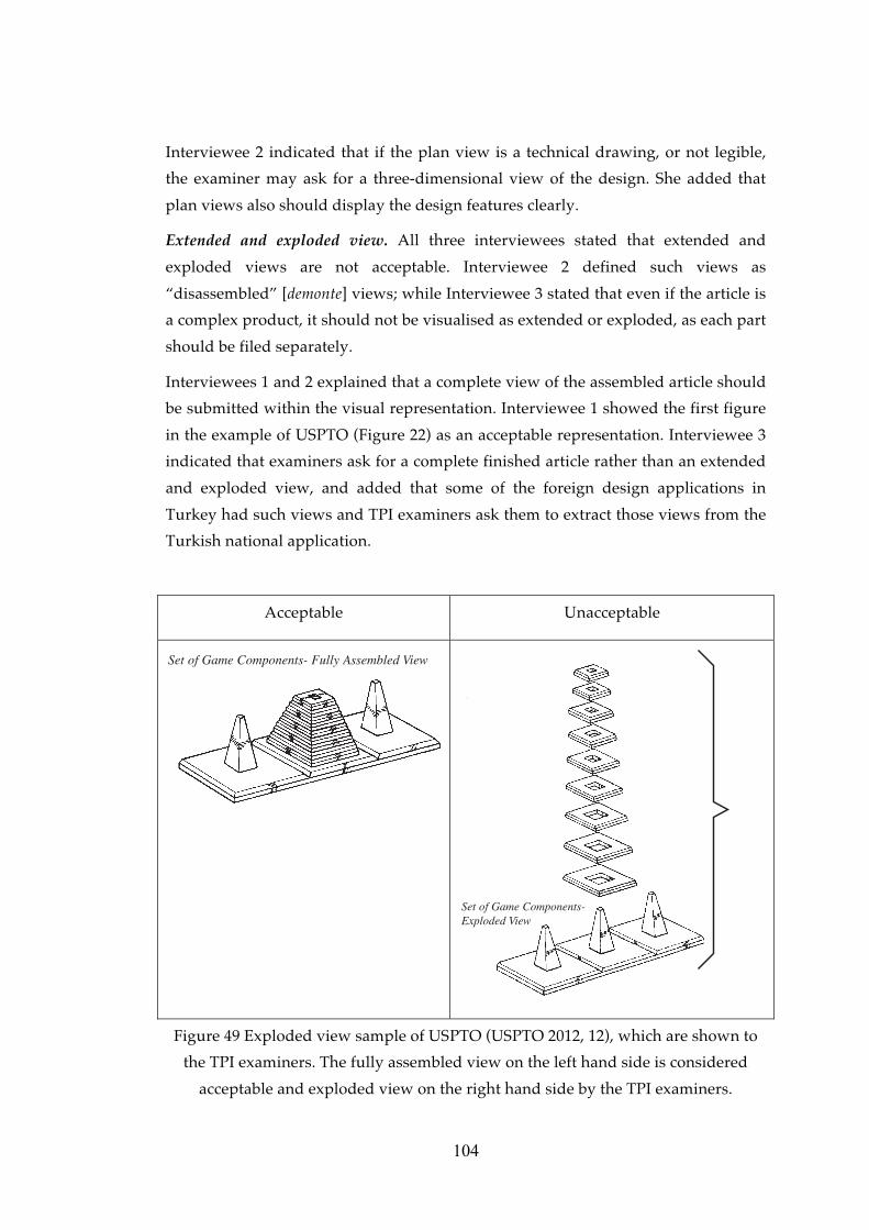
104
Interviewee 2 indicated that if the plan view is a technical drawing, or not legible,
the examiner may ask for a three-dimensional view of the design. She added that
plan views also should display the design features clearly.
Extended and exploded view. All three interviewees stated that extended and
exploded views are not acceptable. Interviewee 2 defined such views as
“disassembled” [demonte] views; while Interviewee 3 stated that even if the article is
a complex product, it should not be visualised as extended or exploded, as each part
should be filed separately.
Interviewees 1 and 2 explained that a complete view of the assembled article should
be submitted within the visual representation. Interviewee 1 showed the first figure
in the example of USPTO (Figure 22) as an acceptable representation. Interviewee 3
indicated that examiners ask for a complete finished article rather than an extended
and exploded view, and added that some of the foreign design applications in
Turkey had such views and TPI examiners ask them to extract those views from the
Turkish national application.
Acceptable Unacceptable
Set of Game Components- Fully Assembled View
llyto
Set of Game Components-Exploded View
Figure 49 Exploded view sample of USPTO (USPTO 2012, 12), which are shown to
the TPI examiners. The fully assembled view on the left hand side is considered
acceptable and exploded view on the right hand side by the TPI examiners.

105
4.4.4.2.3 Repeating surface patterns
Interviewees 1 and 2 indicated that it does not matter if the applicant displays only
one portion a surface pattern or more than one portion repeated in the visual
representation in terms of the scope of protection.
Interviewee 3 gave the example of a carpet design, and indicated that applicants
usually file a picture of the whole carpet as a visual representation. He indicated
that if the views of the complete carpet design are submitted in 8 cm x 8 cm format,
the visibility of the details of the design will be obscured. For this reason, only the
portion which will be repeated through that design is convenient for representation,
and in large dimensions, which will also help to perceive the details of the design.
4.4.4.2.4 Articles with indefinite length and width
Interviewee 1 indicated that if the proportions of the design change due to a change
in size, an additional view of the same design will not suffice, and an additional
design application should be made. Interviewee 1 gave the example of a waiting
seat design for articles of indefinite length, stating that only one portion of the
article need to be submitted in the visual representation if the design repeats
consecutively. For another example, that of a profile design, she indicated that the
appearance would not change when the size changes. On the other hand, in a
vacuum cleaner design proportions may change as the size increases. In such cases,
she stated, another application should be filed for the changed version of the design.
Interviewee 3 also gave the example of profiles, and indicated that applicants
usually sought to protect the chambers within their profile designs. He stated that
even though visual representations are in three-dimensional format, protection is
sought for those chambers, meaning that cross-sectional views are very important in
profile designs. He added that in some cases the outer appearance of the profiles
may become more of an issue, for example in the case of a profile design having an
elliptical outside surface, in which case three-dimensional views are important.
Interviewee 2 cited a design of a fence as an example of an article of indefinite
length or width, and stated that only a portion of the repeated part is required in the
visual representation in terms of scope of protection.
4.4.4.2.5 Typographic typeface designs
Interviewee 3 indicated that all characters must be shown in one view. Interviewee 1
stated she had only examined one typographic typeface design application, but
stated that she had asked for separate views of 8 cm x 8 cm for each character of the

106
typeface. On that occasion the applicant failed to remedy the formal deficiency, and
the application was deemed invalid. Interviewee 2 expressed she had not had the
opportunity to examine a typographic typeface design.
Registered Community Design No. 000041496-0001 of a typographic typeface,
which includes all letters of the alphabet, in both upper and lower cases, Arabic
numerals and punctuation marks displayed in one view as seen in Figure 31, was
shown to the interviewees. Interviewee 1 said that they may implement OHIM’s
practice in Turkey. Interviewee 2, on the other hand, stated that as it had been
encountered previously, she would define such a representation as a page layout
design rather than a typographic typeface design.
4.4.4.2.6 Designs comprising multiple components and complex products
Complex product. Interviewee 3 explained that each individual component of a
design can be protected individually if the design is of a complex product, and
added that if only the whole complex product is submitted within one application
without submitting each component as a separate design application, then the
complex product as a whole, not the components individually, shall be protected.
All of the interviewees indicated that if individual protection is sought for the
components of a complex product, visual representation of the whole complex
product should be filed as the first design, and each component for which
protection is sought should be filed as an additional design in one multiple design
application.
As an example of a complex product, Interviewee 1 gave the example of a vacuum
cleaner, which is accepted as one article in terms of design registration. She added
that a tea pot [çaydanlık] design also falls within the scope of the definition a
complex product design, being perceived as a combination of multiple objects.
Interviewee 1 gave the registration number of a multiple design application, TR
2011/07942, in order to show an acceptable example of a complex product’s visual
representation.

107
TR
2011/07942 Views of the designs
Design No: 1
Title: Vacuum
Cleaner
Design No: 2
Title: Part of a
vacuum
cleaner
Design No: 3
Title: Part of a
vacuum
cleaner
Design No: 4
Title: Part of a
vacuum
cleaner
Design No: 5
Title: Part of a
vacuum
cleaner
Design No: 6
Title: Part of a
vacuum
cleaner
Figure 50 Visual representations of a registered complex product design in Turkey
with the number TR 2011/07942

108
Figure 48 (Continued)
Design No: 7
Title: Part of a
vacuum
cleaner
Design No: 8
Title: Part of a
vacuum
cleaner
Design No: 9
Title: Part of a
vacuum
cleaner
Design No: 10
Title: Part of a
vacuum
cleaner
Design No: 11
Title: Part of a
vacuum
cleaner
Design No: 12
Title: Part of a
vacuum
cleaner
Design No: 13
Title: Part of a
vacuum
cleaner

109
Figure 48 (Continued)
Design No: 14
Title: Part of a
vacuum
cleaner
4.4.4.3 Ordering and numbering the views
Total number of views. Interviewee 3 put forward an application by a foreign
applicant as an acceptable example, which included six or seven different views.
However, he did mention that submitting three different views of the design might
have been sufficient.
Arrangement of views. Interviewee 1 indicated that applicants rarely pay enough
attention to the order of views, and complained that they often arrange the views
randomly in design applications.
All of the interviewees indicated that the perspective view should be submitted as
the first view. Interviewees 1 and 2 stated that the first view should be a perspective
view, which allows a clear understanding of the design and shows the general
features of the design to be protected. Interviewee 2 expressed that “submitting the
side view as 1.1” does not help with the legibility of the design. Side views and the
like should be submitted as additional views.
Interviewee 2 mentioned common deficiencies in the arrangement of views, and
gave the example of an application filed as one design registration application with
eleven views. However, during the examination of the visual representation, the
examiner found out that there were two different designs: First design having five,
and the second design having six different views. Such mistakes of arrangement of
the views not only cause remedy of the arrangement of visual representation, but
also they require remedies on descriptions of the designs.
Numbering and labelling the views. Interviewees 1 and 3 explained the two-digit
numbering system for design applications, with the first digit indicating the number
of the design, and the second indicating the number of the view of that design, i.e.
“1.1,” refers to the first view of the first design, and “1.3,” the third view of the first
design. Interviewee 3 indicated that the views labelled as 1.1, 1.2 and 1.3 as if they
are different views of the design may turn out to be the representations of three

110
different designs which should be labelled as 1.1, 2.1 and 3.1.
4.4.5 Partial disclaimer
4.4.5.1 Visual representation of partial disclaimer
All of the interviewees indicated that partial disclaimers should be indicated very
clearly on the visual representation, and suggested two alternative ways of doing
this by visual means:
• Showing the portion for which protection is claimed by adding a circle,
ellipse or square around it. Interviewee 3 suggested outlining the part for
which protection is sought with a red circle.
• Showing the non-design portions of the design in stippled or dotted lines.
Interviewee 3 underlined that dotted lines are only used for features of the
design for which no protection is claimed, with the features for which
protection is claimed shown in solid bold lines.
Interviewee 1 added that whichever method is selected, the partial disclaimer
should be clearly visible on the representation, even after scanning.
Interviewee 1 indicated that if there is a partial disclaimer for a design not shown in
the visual representation, it would be a ground for a formal deficiency. She gave the
example of a bottle lid. If the visual representation of the lid design is submitted
together with the bottle, without clearly indicating that it is the lid for which
protection is sought, the examiner shall ask for a partial disclaimer on the visual
representation. She added that a much more appropriate way for representing a lid
design would be to show the design individually from different angles, and
submitting a view of the lid on the bottle with a partial disclaimer as an additional
view.
Interviewee 1 indicated that sometimes a portion of the article is claimed to be
protected but it cannot be visualized separately. Interviewee 2 gave the example of a
spoon design, where the design to be protected is the ornamentation on the handle
part of the spoon. In this case the examiners would ask for a visual indication of the
parts of the article for which protection is claimed on the visual representation.
4.4.5.2 Verbal description of partial disclaimer
Interviewee 1 indicated that any partial disclaimer should be in combination with
the visual representation, the title of the design, and the description of the article.
Again using the lid design example, she suggested the title “the lid of a bottle”.
Interviewees 2 and 3 added that the description should not describe the entire

111
article but only the portion and its features for which protection is sought.
4.4.6 Format and quality of visual representation
Interviewee 3 indicated that the resolution of the image submitted as representation
is the most common problem related to the format and quality of visual
representations.
4.4.6.1 Physical quality
All of the interviewees claimed that the scanning procedure at TPI is a problem in
terms of the loss of resolution of the image when dealing with paper submission
applications. Interviewee 2 explained that all visual representations submitted with
paper applications are scanned at TPI and uploaded onto the system. Interviewees 1
and 2 indicated that if the submitted visual representation is only medium
resolution, the resolution after scanning gets even worse. Both interviewees
indicated an approximately 10% loss of image clarity due to scanning; and during
publication there will be a further loss of resolution. Interviewee 1 added that
scanning also causes a loss of colour in the visual representation. In particular, if the
article being represented is black, details of the design will disappear after scanning.
Interviewee 2 stated that it is better to submit visual representations in digital
format as well when filing a paper submission application. She said that some of the
examiners’ computers do not have DVD readers, and therefore soft copies of visual
representations should be submitted in CD rather than DVD format.
Interviewee 1 indicated that they had once received an application on which the
visual representations were pasted with glue. After a while, they observed that after
the glue had dried, the visual representations had become totally invisible.
Size and quality of paper. Interviewees 2 and 3 indicated that applicants should not
submit visual representations on the application form, but rather printed on a
separate sheet of A4 paper, otherwise a formal deficiency may be given by the
examiners.
Only Interviewee 1 indicated that some applications were not submitted on A4
white paper. She mentioned that the problem is rare, but stated that one time they
had received an application form with visual representations printed on low-quality
newsprint paper. On another occasion, she encountered an application in which the
visual representations were submitted on scrap paper.
4.4.6.2 Data format for e-filing
All of the interviewees stated that applicants who file their applications

112
electronically commonly make errors in the ordering and numbering of visual
representations. For example, while assessing a design application of one design
with eleven views, during formal examination it emerged that there were actually
two different designs with five and six views each.
Interviewee 1 indicated that they did not encounter problems of resolution in the
visual representations of electronically filed applications; however, Interviewee 3
stated that in electronically submitted visual representations, problems of size and
clarity may be encountered.
Interviewee 2 stated that uploading the visual representation of an electronically
filed application on to the data system is easier than scanning and uploading the
representation of an application submitted on paper.
4.4.7 Unacceptable visual representations
Interviewee 2 indicated that only visual representations that are contrary to the
principles of public order and general morality are provisionally refused.
Interviewees 2 and 3 expressed that an application will be refused if it does not
confirm with the definitions of “design” and “product” given in the Decree Law
Article 3(a) and (b) during the formal examination. Interviewee 2 added that if the
visual representation displays an article, which is accepted as “design” but has
formal deficiencies, then the examiner would request the formal deficiencies to be
remedied for granting the application date. Interviewee 2 said that if the formal
deficiency is not remedied within the time period stated in the Implementing
Regulation, then the application shall be deemed invalid.
Interviewee 1 stated that production, construction or composition methods cannot
be protected by industrial design registration, as industrial design registration
protects only the appearance of the design. Therefore, she added, visual
representations showing production, construction or composition methods would
not be accepted. She gave the example of a visual representation of a sack full of
different herbs, which was submitted as the visual representation of a design
application seeking protection for a particular mix of herbs. The examiner had to
inform the applicant that this did not fall under the scope of design registration.
Another example she gave was of a visual representation of the construction of an
article, a view of a nail being hammered, which is also an unacceptable
representation.
Interviewee 2 provided a list of unacceptable visual representations:

113
• Unclear views,
• Visual representations containing numbers, explanatory text or descriptions
of the design,
• Designs which cannot be perceived clearly due to problems in the use of
colour in figure-background relationship.
Interviewee 3 provided the following list of unacceptable features in visual
representations:
• Lack of clarity which is the most important one,
• Visual features of the design that are not clearly shown,
• Background and article are in the same colour,
• More than one view in one visual representation.
As mentioned before, all of the interviewees stated that extended and exploded
views are unacceptable.
4.5 Further comments and suggestions by the TPI experts
Interviewee 1 recommended that visual representations should be bright, in large
dimensions, sufficiently clear, and should include the views of the design from
different angles. She added that the description of the design is also important.
Interviewee 1 gave an example of a bowl design, for which, the applicant claimed,
the distinctive part of the design was the four “ticks” on the bottom of the bowl. The
applicant defined the way his/her design differs from other bowl designs on the
market by indicating that in the description.
Interviewee 3 said that applicants should give more weight and importance to the
visual representations.
Interviewee 1 suggested that applicants and attorneys attach more importance to
their duty. Interviewee 1 expressed that the power of attorney or application fee
might be missing, however, the visual representation should not be, as it constitutes
the most important part of a design registration application. Interviewee 2
suggested to both attorneys and applicants that:
• They should carefully read the information published by TPI on how design
registration applications are made, and
• They should call the examiners directly if they want more specific
information about their application.
Interviewees 1 and 2 advised attorneys working in the design registration field to
explain the importance of submitting additional views and the clarity of the visual

114
representations to their clients, which will help in achieving acceptable visual
representations. Interviewee 3 indicated that the international applications through
the Hague System and applications with priority of foreign registrations or
applications usually submitted adequate visual representations. He suggested
attorneys to use drawing software for preparing visual representations of design.
Interviewee 2 stated that the reason for deficiencies is generally related to the
knowledge level of the applicant when no attorney has been assigned.
Interviewee 3 gave three design registration applications as “acceptable visual
representation examples” during the interview. The visual representations of those
applications are given in Figure 51, 52 and 53 together with their application
numbers.
TR 2012/00059
Views of the design
Design No. 1 Title: Turnable mob
Design No. 2 Title: Turnable mob
Design No. 3 Title: Turnable mob
Design No. 4 Title: Turnable mob
Figure 51 Visual representation of a turnable mob design in Turkey with the
number TR 2012/00059

115
TR 2012/03440
Views of the design
Design No. 1 Title: Vacuum cleaner
Figure 52 Visual representation of a vacuum cleaner design in Turkey with the
number TR 2012/03440
TR 2012/03459 Views of the design Design No. 1 Title: Container
Design No. 2 Title: Container
Design No. 3 Title: Container
Figure 53 Visual representation of a container design in Turkey with the number TR
2012/03459

116
CHAPTER 5
CONCLUSION
The aim of this study has been to clarify the main features and qualities of visual
representations required by design registration systems in various jurisdictions
including Turkey with the intention of developing a guideline which would assist
the applicants and attorneys in preparing visual representations. The study has been
conducted in two parts: A literature survey in which national, regional and
international design registration systems have been studied, in particular their
regulations and guidelines, to obtain an understanding of their main features and
requirements for visual representations; and a field study has been conducted
which involved in-depth interviews with TPI examiners in order to investigate the
main problems and critical issues concerning visual representations in design
registration applications in Turkey.
In the literature survey, the legal texts of eight different jurisdictions, including
Turkey, Community designs by OHIM and international design registrations
through WIPO, were analysed. This part of the study concluded with the
categorization of the findings into a list of features and qualities of visual
representations that not only helped in the development of the interview schedule
used in the field survey, but also formed the basis of the proposed guideline.
After the investigation of the main problems encountered, and after hearing
suggestions related to the features and qualities of visual representations cited by
TPI examiners, the findings of the field study were analysed and presented
according to the features and qualities compiled during the literature survey.
The significant aspects of this study were as follows:
• The legal texts and official guidelines of the Hague System, the Community
Design system and the national design registration systems of Turkey,
Australia, Canada, the United Kingdom, the United States and South Korea

117
have been analysed in terms of the features and qualities of visual
representations.
• These features and qualities related to visual representations have been
studied together with the problems encountered by TPI examiners.
• The study also highlighted the suggestions of TPI examiners to applicants
and attorneys concerning visual representations in design registration
applications.
The limitations of the study were as follows:
• The legal texts and official guidelines in eight jurisdictions only were
reviewed due to time and language restrictions.
• The examples of unacceptable visual representations revealed in the field
study were not presented within this thesis as those design applications are
still pending and have not been published, yet. In order not to prejudice the
novelty and distinctive character of those designs, only verbal or schematic
descriptions of their visual representations were presented.
5.1 Proposed guideline for visual representation
A general overview of the topics and sub-topics of the proposed guideline is given
in Figure 54, and the proposed content of the topics and sub-topics is covered in the
following sections.

Figu
re 5
4 T
he to
pic
s an
d s
ub-
top
ics
conc
erni
ng th
e fe
atu
res
and
qu
alit
ies
of v
isu
al r
epre
sent
atio
n
base
d o
n bo
th th
e lit
erat
ure
rev
iew
and
the
fiel
d s
urv
ey fi
ndin
gs
�����������
�� �����
������� ���
���������
�������������
��������
� ���������
�������
��� �����������
!����������
������
" ��������� ��
" #��$
��������� ��
" ���� �����
��� ���
� �������
" ��������� ����
����%������
������� ���
�����
" !�������
�����������
���������
�����������
���������&�
���������
'�������� ���
���(������
� ��� ��
����� �����
���� ��
��������� �����
���( ��
������������
)��� �� ���
*� �����
������ ��
*� �����
! � ���� ��
����$%������
+� ����� (���
����
������ (���
�& ������
)�������
��������� ���
������������
118
119
5.1.1 Types of visual representation
Visual representation of designs can be submitted in three forms: Graphic
representation, which includes drawings and ink drawings in particular,
photograph and specimen. Visual representations can be submitted in black and
white or in colour, so long as they are suitable for reproduction by publishing.
5.1.1.1 Graphic representations
Graphic representations of a design can be prepared by using drafting instruments,
or executed by electronic means to a professional standard. Either way, the graphic
representations should:
• Be explicit and clear,
• Be of good quality, either the original drawing, or better still, good quality
scans or copies,
• Have satisfactory reproduction characteristics, such as visible solid black
lines,
• Have all edges cut at right angles,
• Be prepared in such a way that the article is shown on a neutral, plain
background.
It is recommended to use drawing software in the preparation of visual
representations.
Graphic representations that include explanatory text or measurement indications
are unacceptable.
Types of line drawings. There are two types of drawings: Ink drawings, which refer
to line drawings or black and white drawings; and coloured drawings. It is up to the
applicant to select the most practical type for depicting the design clearly. It is
suggested that plain black and white drawings be used if the scope of protection
does not cover a particular colour.
Quality of lines. The lines of the drawings should be durable, clean, solid,
sufficiently dense and dark, uniformly thick and well-defined.
The lines should be solid and the weight of the lines, including lines representing
shading or cut surfaces of cross-sectional views, must be heavy enough for
reproduction through publishing or scanning.
Lines or strokes in different thicknesses may be used to denote different elements,
i.e. bold lines for the outline of the design to be protected. In such cases it is

120
important that all lines stay visible after reproduction through publishing or
scanning.
Broken lines, dotted lines or stippled lines. Dotted lines can be used either to show
the features or parts for which protection is not being sought (partial disclaimer), or
to indicate parts that are not visible in that particular view. It is suggested for three-
dimensional designs, not to show the lines of the features, which cannot be seen on
that particular view of the article on the drawing. Dotted lines should not be used
to indicate elements that are not part of the design to be protected, while solid lines
should be used to show the features for which protection is being sought. It is
suggested not to use the broken lines for showing hidden planes and surfaces that
cannot be seen through an opaque material of the article due to possibility of
preventing an explicit understanding of the design.
Broken lines can also be used to show environmental structures17 that are not part
of the design. If broken lines are used in this way, they should not intrude upon or
cross the claimed design, prohibiting a clear understanding of the design.
Another use of broken lines is the boundaries that form the non-design parts of the
article for which protection is claimed.
Showing alternate positions of the design using full and broken lines on the same
view is prohibited.
Broken lines should be lighter than solid lines which indicate the design features to
be protected, however all lines should be heavy enough to be visible after
reproduction through publishing or scanning.
Shading. Embossed parts of the design can be shown through shading or in the
form of parallel lines. Shading can also be used for providing relief. Shading can be
used to illustrate the shape of the design, in particular, any spherical, cylindrical or
conical elements of an article. Additionally, shading is used to distinguish the open
and closed solid areas of the article. Another use of shading may indicate a contrast
of tones in the design, which is shown in Figure 3. On the other hand, the character
and contour of all surfaces of any three-dimensional aspects of the design can be
represented by shading.
There are two styles of shading accepted by USPTO: Straight-line surface shading
and stippling; the sample representations are given in Figure 5, 6 and 7. A
17 The environmental structure should not be disclosed unless it is necessary to show the environmental structure and the design together in a representation for a better understanding.

121
combination of both styles on the same article can be used to show surface contrast
in Turkey, however such a combination on the same surface should not be used
because it may distort the understanding of the design.
Shading should not distort or hide the design to be protected and should be
consistent in all views. If non-design portions are illustrated using stippled lines,
then shading should not be used on those sections.
Solid black surface shading should not be used, as it may hide features of the
design. Black shading should only be used in cases where protection of the colour
black is part of a design for which protection is sought.
Flat parts need to be lightly shaded. If possible, shading should be indicated by
spaced and lighter lines, lighter than those used in the rest of the drawing, so as not
to distort the understanding of the contour of the design to be protected. The angle
of the shading lines could be 45 degrees, coming from the upper left corner.
Transparency and translucency. Transparency may be illustrated by using thin lines
of shading, as shown in Figure 9. It should not be shown using stippled lines,
especially in cases where non-design portions of the design are also illustrated using
stippled lines. Transparent surfaces should be shown using light and full lines
rather than stippled or broken lines.
Translucency can also be indicated by using thin shading lines and an overall
shading of the translucent area; the sample representation is given in Figure 10.
Additionally, elements behind transparent parts of the design should be illustrated
using light but full lines rather than broken lines as shown in Figure 11.
Hatching. Hatching can be used to provide relief. Another use of hatching is in cross
sectional views, which is explained within section 5.1.3.2.2 Non-conventional views.
5.1.1.2 Photograph
Photographs must be to a professional standard and of high quality, preferably
taken by a professional camera. They should be explicit and clear, not blurred.
Black and white photography serves as well as coloured photography, unless the
particular colour of the design is not intended to be protected as a design feature.
Black and white photography, in other words, images in grey scale, should not
result in a loss of clarity of the details of the design.
Photography should be of sufficient quality to ensure that all the details of the
design are visible during or after reproduction by printing or scanning,.

122
The article should be presented in front of a natural, plain and clear background,
which should be in a contrasting colour to the article so as to allow a clear
understanding of the design. For example, black articles should not be
photographed in front of a black background. For further explanations on article
and background configurations, please see section 5.1.2.
Photographic representations must not be retouched using ink or correction fluid.
Photographs should include no items other than the design itself, including the
environmental structure if it is not necessary for a clear understanding.
Using a spotlight may impede visibility and affect the legibility of the design and its
features. Confusing highlights, reflections and heavy shadows should be avoided.
If the article is made of transparent or shiny materials, then a graphic representation
rather than photography may permit a clearer definition of its features.
During photographing, if the camera is too close to the article it may cause
distortion and prevent a clear understanding of the design.
5.1.1.3 Specimen18
A specimen rather than printed visual representations may be submitted if it is not
possible to submit a visual representation of a two-dimensional design and a
deferment of publication is requested.
5.1.2 Content of the visual representation
The content of the representation of the design must be explicit, clear, definite and
complete. All of the special characteristics, in other words, the features of the design
to be protected, should be shown clearly. The representation should be suitable for
reproduction by publication or scanning.
The submitted representations of the design should raise no doubts or
misunderstandings about the design or the features sought for protection. Nothing
regarding the design to be protected should be left to conjecture.
The representation should contain no other representation, part of any other
representation, numbering, measurement indications or explanatory text.
5.1.2.1 Article
The article should be shown in complete isolation, containing no non-design
elements. For example, visual representations of a tribune design should not include
18 Requirements concerning specimens fall outside the scope of this thesis, and so are not included within the proposed guideline.

123
anything that is not part of the design, such as buildings, trees, towel left beside the
tribune, etc.
In some cases a view that shows the environment and the design together may be
acceptable, so long as the environment helps provide a better understanding of the
design. The environment may be illustrated in stippled lines in order to indicate that
it is a non-design part and is not being claimed for protection. The drawings, the
description and the title of the design must be in combination and indicate clearly
the design features. It is important to indicate clearly the differentiation between the
finished article to which the design is applied and the environment on the visual
representation. In cases where the application is filed with a view showing the
environment and the design together, it is recommended that the application
contain also views of the article in complete isolation.
The article should be shown completely, as a whole, on the visual representation
frame without cropping.
Care should be taken when photographing articles that are either very light or dark
colour to ensure the details of the design to be protected are clearly visible. Light or
dark coloured articles may impede visibility and prevent the clear understanding of
the details of the design.
Articles made of transparent or shiny materials, such as glass, may also be
unsuitable for representation with photography. As mentioned in section 5.1.1.2, it
is more convenient to submit a graphic representation of such designs, which are
made of such kinds of transparent of shiny material for disclosing all the details.
If the proportions of the article do not change with changes in the size of the design,
then there is no need to file an additional design application for a different size of
the same article. However, if the design proportions do change, then an additional
design application should be filed for each design, for example, two mugs of similar
design with identical handles but with different sized main container sections. In
this case an additional design application should be filed for the second design, in
that the proportions have changed, affecting the appearance.
5.1.2.2 Background
The background should be simple, plain, smooth and neutral. There should be no
non-design elements on the background of the visual representation.
Additionally, the background should be in a contrasting colour to the article. For
example, using a black background for a black article may limit the understanding

124
of the features of the design and may result in the application receiving a formal
deficiency. Using a light-coloured background for articles made of transparent
materials may also reduce the legibility of the details of the design to be protected.
5.1.2.3 Colour
There are two types of representations in terms of colours: monochrome (black and
white) and colour.
Monochrome representations can be used where no protection is claimed for the
colour of the design. If the applicant wishes to protect only the shape of the design
without defining a particular colour, then black and white drawings are
recommended. When a visual representation is submitted in colour, the scope of
protection covers the design also in different colours. The design in different colours
can be accepted as additional views, but not as additional designs.
Colour may be accepted as distinctive in ornamental or pattern designs, graphic
designs or logos, as the harmony between colours may give individual character to
the design to be protected. In such cases, if the colour is a part of the design,
representations should be filed in colour.
5.1.3 Views of design
Additional views, in other words additional visual representations, are images of
the same design from different perspectives.
At the application stage, the formal examination includes an assessment of whether
the design is shown entirely and clearly in the visual representations and additional
views. Representing the design from different angles is very important after the
registration stage, when the assessment of the novelty and individual character or
an infringement analysis is conducted, based on the visual representations of the
design. For this reason, the submitted views of the design must be as clear as others
and must reflect all aspects of the design and allow a clear and explicit
understanding of the design and its features. Submitting different views of the same
design is also important for illustrating all of the characteristic features of the
design.
If the applicant wants to obtain a maximum protection through the registration,
then the design should be fully represented. The applicant should ensure that the
design is fully represented because only aspects of the design that are visible in the
visual representations shall be protected. Accordingly, the visual representation
should consist a series of views form different angles in order to show the overall

125
appearance of the design, especially where the design is three-dimensional. . Hence,
there should be a sufficient number of different views to avoid any doubt of exactly
what the applicant is requesting to be registered. It is recommended that three-
dimensional articles should be represented in at least three views, one of which
should a perspective view showing the three sides of the article.
Once the application has been filed at the Office, the submission of additional views
is prohibited. For this reason, views should be prepared and selected carefully
before submitting an application.
All views should be filed separately. In other words, the visual representations
should not include more than one view within one representation, and each view
should be submitted on a separate visual representation frame. Views of the design
from different angles within one representation will not be accepted, even if the
views are explicit and clear.
Additional views of the design should not disturb the integrity or unity of the
design, and all views must belong to the same design for which protection is being
sought. Individual or dissembled views of the parts of the design will not be
accepted as additional views. For example, in the case of a wheelbarrow design
application, views of two disassembled handles of the wheelbarrow submitted as an
additional view cannot be accepted as an additional view of a wheelbarrow design.
The representation does not contain the wheelbarrow, only the handles, and if
protection is sought specifically for the handles, it must be filed as an additional
design under the title “handles of a wheelbarrow”. If the appearance of the design
differs from the other views and the title changes, then that view should be filed as
an additional design rather than as an additional view.
All the views must be designated properly, such as perspective view, front view,
side view, etc. and describe from which angle the article is disclosed can be added to
the description of that particular view.
Additional views, the description and the title of the design should be in unity. The
description of the additional view should describe the visual properties of that view,
and all views should be designated properly.
A view may be accepted as additional design if the visual features change, even if
the title and the design itself stay the same. For example, a bicycle design for
multiple riders. The first view of that design is the completed version of the design
in which all of the component parts are assembled, including seats, shades, tyres,
etc., while the second view shows only the main structure of the same article

126
without the external parts. Even though the title and the article are the same in both
views, the second view cannot be accepted as an additional view of the first design
because the appearance of the article is different. In such cases, where the overall
appearance differs, the views should be filed as additional designs, not additional
views.
5.1.3.1 Dimensions of views
Visual representations should be submitted minimum 8 cm by 8cm and maximum
16 cm by 16 cm. Representations cannot exceed 16 cm by 16 cm. All representations
must be presented as a whole, and must be submitted in the form of right-angled
quadrilaterals (squares and rectangles), with their edges cut at right angles.
The representation of the article should be positioned in the representation frame in
large scale. In other words, the image of the article should fill the frame of the
above-mentioned dimensions. Schematic description of the size of the article in
relation to the size of the visual representation frame is given in Figure 47.
The selected size of frame should suitable for showing all details of the design
clearly. If the size of the representation is large, then the visual features and the
details of the design can be understood clearly. In particular, articles with intricate
details, such as toothbrush designs or carpet patterns, or articles that are large, such
as cars, bikes, buildings, etc., should be filed in the maximum dimensions.
5.1.3.2 Types of view
There are two main types of views: conventional and non-conventional. In addition
to these, there are other types of views suitable for other situations, such as
repeating surface patterns, articles of indefinite length and width, typographic
typeface designs, etc., which are also explained within this section.
5.1.3.2.1 Conventional views
Conventional views are perspective, front, back, top, bottom, right and left side
views.
A perspective view is the best option for showing the product from all three
dimensions, and can reveal important details of the design on a single view. It is
recommended that one of the views should be a perspective view for three-
dimensional designs because of three different sides of the same article can be
displayed in one view. It also helps better understanding of the design if all the
surfaces are clearly understood and fully disclosed in a perspective view.

127
Unless all the surfaces are fully represented and the details of the design reflected
clearly in the perspective view, additional views will be necessary to ensure a clear
understanding of the overall appearance of the design.
The scope of protection is limited to the views given as visual representations of the
design. If one of the views is missing, such as a bottom view of a three-dimensional
design, then the applicant cannot claim an infringement concerning the bottom of
his/her registered design against a similar bottom design of a third party’s product.
If the two sides of the design to be protected are exactly same, a statement
indicating as such can be filed within the description.
5.1.3.2.2 Non-conventional views
Non-conventional views are views that display features of the article that cannot be
seen from conventional views, and include cross-sectional views, views showing the
design in use, detailed views, incomplete images of puzzles, plan and elevation
views, and extended and exploded views.
Sectional, cross-sectional or cut-through views. Since the design registration
protects only the external appearance of articles in their normal use, cross-sectional
views can be used to show any exterior features of the design. Cross-sectional views
should be used if it is necessary to display a particular aspect of an external shape of
the design, which may not otherwise be clear in a two-dimensional drawing. It
should not show internal features of the design that cannot be seen during the
normal use of the article. It is important for cross-sectional views to display features
of the article that are visible when the article in use. In such cases, using cross-
sectional views also helps provide a better understanding of the design and
minimizes the number of views required.
Cross-sectional views must not show functional features or any interior structure
that does not form a part of that claimed design. For example, a cross-sectional view
of a foodstuff design, which shows the inner layout of the food used in it, cannot be
accepted, as the registration system protects only the appearance of the design, not
the inner layout.
All materials of the article in a cross sectional view can be shown on a drawing by
using hatching method. Hatching can be used to denote different materials used in
the design in a cross-sectional view, which are to be regularly spaced, parallel and
oblique, and the space between strokes should be chosen to suit the total area to be
hatched. Hatching lines should be sufficiently spaced to enable the lines of the
design to be easily distinguishable. Different types of hatching should have different

128
meanings to denote the different materials seen in a cross-sectional view. Different
elements must be hatched at different angles.
Cross-sectional views cannot be accepted individually, and should be filed as an
additional view to a view that displays the external appearances of the design. As
seen in Figure 48, the first visual representation of the design can be a perspective
view, while the cross-sectional view can be submitted as a second (additional) view
of the design.
Showing the design in use. Views reflecting the utilizing features of the design are
accepted as additional views by TPI. Such views can be used for designs that
become clearer and more meaningful when shown in practical use. For example,
showing open or closed positions or extended or retracted positions of articles may
help to reveal the design features and clear understanding.
For views showing the article in open and closed positions to be accepted, the article
should have a physical connection while in both positions as shown in Figure 16.
For example, for a design of a container, if the body and lid are connected when the
container is open, then a representation of the open position of the article can be
accepted as a view showing the design in an alternative position. However, if there
is no physical connection between the lid and the body, then the lid in an open
position will constitute two designs, a body of a container and a lid of a container,
which should have different design titles and different Locarno sub-classes. Such
views are unacceptable, and can be perceived as extended or exploded views, which
are also not accepted by the TPI.
If a movable part of the article needs to be shown when in normal use, it should be
shown in a sequence of views, illustrated at the same angle, so as to reveal the
appearance of the product in different phases of its operation, cycle or use. Such
views should be indicated within the description of the view. For example, a
perspective view showing the design in use in a different position can be worded as
“perspective view in first alternative position".
Positional views of the design should not be illustrated using full or broken lines on
the same view. An example of an alternative positional view is given in 17.
Extended or retracted positional views of the design are acceptable if the article is
normally seen and used in those positions. An example is given in Figure 18.
The appearance of flexible flat articles may differ when laid flat or when in use, such
as such as clothing or cushion designs. Such articles may be demonstrated in both
positions: Laid and in use. An example is given Figure 19.

129
Detailed, fragmentary, enlarged of partial view. A detailed or partial view is used
to display part or parts of the design in detail to allow the understanding of the
details for which protection is sought. A detailed view should focus and enlarge
part of the article of which the design is applied in order to show the part in detail.
Fragmentary views are acceptable so long as they show a portion of the design in a
larger scale to better display of the details of the design.
An enlarged view or partial view can also be used considered as detailed view in
terms of using such views for the purpose of to magnification a portion of the
design.
A view of the whole design should be submitted together with any detailed,
fragmented, enlarged or partial view. Such view should be submitted on separate
visual representation frames and should be numbered separately. For example, a
perspective view of the design as a whole as representation may be numbered 1.1,
and the detailed view of the design may be numbered 1.2. The relationship between
the whole design and the detailed view should be clear and unambiguous.
If individual protection is sought for a part of a design shown on a detailed image,
then it must be submitted as an additional design, not as an additional view. For
example, if the applicant files an enlarged view of the handle of a chair as an
additional view to a chair design, the handle will not be protected individually. If a
third party produces a chair with a same handle but different body part, then the
owner cannot claim an infringement for the handle of that design as only the overall
impression of a registered design falls under the scope of protection. Therefore, if
the applicant desires to protect the part of the design shown in the detailed view
individually, being the handle of the chair in this example, another design
application needs to be filed, rather than submitting that view as an additional
detailed view to the design views as a whole.
Detailed views should not distract from the integrity and unity of the design to be
registered, as they may be problematic if the part within the detailed view can be
subject to another design registration. Examiners may not accept the detailed view
of a design if the part within that representation cannot be described as an
individual “design” and the title of that view changes. In the case of the chair and
handle example, the handle can be subject to another design application, and the
representation showing the handle of the chair can be entitled “handle of a chair”.
Detailed views should not display dissembled parts of the design.

130
It should be clearly understood that a detailed view filed as an additional view is
part of the same design.
Incomplete images of puzzles. Such views should be submitted displaying the
regular puzzle with only a small part not completed, and must be filed as an
additional view along to a completed view of the design.
Views of the incomplete puzzle should not distort the integrity of the design, and
the article should not be shown in an extended or exploded view.
Plan and elevation views. Two-dimensional plan views should be free from
measurements or explanatory text. They should be legible and clearly display the
design features. If such a view is not legible or clear, then the examiner may ask for
a three-dimensional view of the design.
Extended or exploded views. Extended or exploded views of multi-component
articles, known as “dissembled views,” are not acceptable as shown in the extracted
views marked as “FIG: 2” at Figure 21 and exploded view marked as “Set of Game
Components- Exploded view” in Figure 22. The article should be shown fully
assembled in the visual representation. Even if the article is a complex product, it
should not be illustrated in an extended or exploded view; rather, each part should
be displayed and filed separately.
5.1.3.2.3 Repeating surface patterns
Patterns and ornamental designs are used for purposes of decoration, and can be
applied to the surface of various types of products without affecting their three-
dimensional forms or lines. Visual representations should show the complete
pattern and a sufficient portion of the repeating surface. The complete pattern
should be surrounded by enough of the repeated pattern to show how the pattern
repeats.
It is important to show the details of ornamentation or pattern designs, and
therefore filing an ornament or pattern design as a whole in an 8 cm by 8 cm frame
may not be sufficient for displaying the small details. For this reason, the repeated
portion and a sufficient portion of the repeating surrounding surface on a large scale
may provide a better understating and a good perception of the details of the
pattern.
A pattern design applied to a product may be accepted as an additional view of the
same pattern design, and should be filed as an additional view. If the surface

131
pattern is applied to an article, the article may be shown in broken lines to indicate
protection is sought for only the pattern design.
If the design is shown on a product, the description should state clearly “the pattern
as applied to a product”. The description may also indicate that the features repeat
consistently and at regular intervals along the length or width of the item.
Since pattern and ornamentation designs are considered in one Locarno class, even
if the class of the product onto which the design is incorporated is different, the
scope of protection of the pattern or ornamentation design covers all classes.
5.1.3.2.4 Articles with indefinite length and width
Different types of articles with indefinite length and width are explained below.
• Articles with indefinite length with a constant cross-section, such as
extrusions for mouldings, are can be defined as the articles that, when you
cut, the cross-section is identical and do not comprise surface pattern or
three-dimensional features.
• Articles with indefinite length with a repeating surface pattern, such as an
ornamented ribbon design, in which the repeating pattern is located on the
surface of the article, which does not affect the article’s width.
• Articles of indefinite length and width with a repeating surface pattern, such
as fabric with a repeating pattern. Both the indefinite length and width may
be shown with a stippled line around the pattern to be repeated which the
article’s section is constant and the sectional view is not affected.
• Articles of indefinite length with repeating three-dimensional features, such
as a drainage track with repeating apertures, where the cross-section is not
constant, yet the three-dimensional features are repeated at regular intervals
along the article’s length.
It is important to note that if the proportions of the article change with changes in
length and/or width, then the appearance of the product changes. Accordingly,
additional design applications should be filed for each different design.
Illustrating a portion of the repeated part of the article can be sufficient if the pattern
repeats consecutively and the appearance does not change with repetition, i.e. a
profile design for a sliding door or a fence design. The length of the article is
variable but repeats consecutively, but the appearance does not change.
Descriptions of such designs may indicate the features that are repeated consistently
and at what intervals along the length or width of the portion.

132
5.1.3.2.5 Typographic typeface designs
Visual representations of typographic typeface designs should show at least four
lines of text comprising all typographic characters in such a way that all the features
of each character can be clearly be seen. All characters should be shown, meaning all
letters of the alphabet in both upper and lower cases, a line of Arabic numerals and
five lines of text produced using the typeface, including both letters and numerals at
the minimum size of 16 Point as given in Figure 31.
On the other hand, single colour shall not assist ordinary typographic typeface or
graphic symbol design as a feature to be protected, if the design does not pass the
novelty and individual character criteria.
5.1.3.2.6 Designs comprising multiple components and complex products
Each component of a multiple component design can be filed as additional designs
within one design application if:
• the components forming the design have the same the visual properties that
can be seen during normal use, and
• the indication of the product in which the main design is classified should be
the same.
This is to prevent the component designs from being perceived as different designs,
in other words, multiple design applications rather than a design with multiple
components. For example, the representation of a pen with its cover or without its
cover may be accepted as additional visual representations; however, an individual
representation of the cover itself is considered as a different design, not as an
additional representation.
Get-up designs. Get-up designs are designs in which more than one product or set
of items that constitute a composition by them and can be perceived as one design,
such as trade dress, in-store layouts, indoor or outdoor designs, layouts. Such
designs need to be filed with multiple views, one of which should be a top view, in
order to display the layout of the design clearly. The description of the views should
not indicate all of the individual features of the products comprising the design, but
should reflect the ambiance of the overall appearance of the components and state
precisely for what protection is being claimed.
Designs comprising a set of articles. Such designs made up of a combination of
features should show clearly which elements are being claimed for protection such
as he articles of the set are so closely related that they can be considered as forming

133
a single product, i.e. spoons and knives as shown in Figure 32. At least one of the
views should show the set of articles together.
All of the pieces of the set of articles must be shown within the visual
representations of the design.
Representation of a complex product. Views of components incorporated into a
complex product should disclose the novel and individual character that remains
visible in the normal use19of that complex product. The representation of a complex
product should cover all internal and external features that are visible in normal use
by the end user, not the maintenance provider or service engineer of the article.
Individual parts of a complex product can be protected individually. If individual
protection is sought for each part of a complex product, visual representations of the
whole complex product should be filed as a first design, and afterwards, each
individual part of that complex product should filed as additional designs in one
multiple design application. If the complex product is displayed as a whole in the
representations without submitting views of the individual components as
additional designs, then the complex product can only be protected as a whole, and
not the individual components.
An example of a complex product design registration is given in Figure 50. The
complex product is illustrated in its entirety as design no. 1, with each individual
part of the complex product given as an additional design separately with different
views in one multiple design application.
5.1.3.3 Ordering and numbering the views
Total number of views. There is no limit on the number of representations and
views that can be submitted, so long as they clearly display the design and show all
of its novel and individual features clearly and accurately. There should be a
sufficient number of views of the design to specify all the features and to be
understood without leaving any doubt for which design features protection is being
sought. In other words, the views should facilitate complete disclosure of the
appearance of the claimed design.
As a guide, the minimum number of views may be suggested as: one view for a
two-dimensional design; and seven conventional views, one being a perspective, for
19 Normal use is defined as use by the end user by the IPO Registered Designs Act 1949 (c.88) as amended in Section 1B(9). The Design Practice Notes define the end user of a motor car as being the owner or the driver rather than the service engineer (IPO 2003 Design Practice Notices (DPN) 1/03).

134
a three-dimensional design in order to display every side in one representation and
show the overall appearance of the product with nothing regarding the design for
which protection is sought left to conjecture. It is suggested to submit one of the
views of a three*dimensional design as a perspective view in order to show the
appearance of the design clearly.
It should be noted that Registered Community Design (RCD) regulations limit the
number of views in an application to seven,20 and so if a national design application
is the priority application for an RCD, then only the first seven views will be
considered as the views of the design.
Arrangement of the views. Representations should be arranged in the order in
which the applicant wishes them to be published. It is preferred to have the
perspective of the design as the first representation of the design so as to allow a
clear understanding of the design, after which the views should be grouped
according to each variant rather than arranged randomly. In multiple design
applications, the representations of each design should be arranged together and
not mixed with the representations of other designs. In one example case, an
application was filed as one design with 11 views, however after the formal
examination of the visual representations, the examiner realised that there were
actually two different designs, with the first design illustrated in five views, and the
second in six views. Such mistakes in the arrangement of views results not only in
the need to remedy the formal deficiency of the arrangement of the visual
representation, but the descriptions of the designs as well.
All views should be placed on an upright position and must not be overlap upon or
within the outline of another view.
Numbering and labelling the views. Each design and each view must be
consecutively numbered with simple and clear Arabic numerals. All additional
views for each design shall be numbered with two digits separated by a dot. The
first digit indicates the design number, and the second indicates the view number
i.e. 3.7 denotes the 7th view of a design numbered 3. The design represented from
different angles must be denoted with two-digit numbers, i.e. 1.1, 1.2, 1.3, etc. for the
first design; and 2.1, 2.2, 2.3, etc. for the second design. For example, a multiple
design application with three designs, each presented in one view, should be
numbered 1.1, 2.1 and 3.1.
20 OHIM2003 Article 4; 2007 CDIR Article 4(2); 2012 Article 11.4

135
It is important that the reproductions themselves contain no numbering on them.
There is a space for numbering on the application form of TPI for paper submission
applications.
5.1.4 Partial Disclaimer
Protection may not be always requested for the whole of an article. In cases where
the applicant seeks to limit or extend the scope of protection, and protection can be
requested for only a part of the design.
A disclaimer can be used to:
• Limit or extend the scope of protection being sought in relation to the design,
or
• Indicate that an application details only a part of the appearance of a
product.
A partial disclaimer can be used to protect a specific feature of the design, such as
the three-dimensional shape but not the surface decoration; or to disclaim some of
the visual features of the design, such as colours or materials; or to show the design
attached to another article for which protection is not sought, but merely to depict
the design in a clear manner. An example of this would be automotive parts, which
in normal use would be attached to a vehicle.
The partial disclaimer must be indicated within the description and/or within the
representation of the design. Additionally, the indication of the product, the visual
representation and the written description must be in combination.
5.1.4.1 Visual representation of partial disclaimer
The parts for which protection is sought should be indicated clearly on the visual
representation. For example, if the partial disclaimer is to be used to limit the
application to a particular element of the article, such as its shape or decoration, it
must be clearly marked as such on the visual representation.
If there is a partial disclaimer for the design to be protected and it is not shown on
the visual representations, then a formal deficiency may arise. For example, if
protection is requested for the “lid of a bottle” and the representations are
submitted presenting the bottle as a whole, without disclaiming the bottle part or
showing the lid specifically, the application will not be accepted.
If an design requested protection that cannot be visualized separately from the
article which the design is applied, then the design portion for which protection is
sought should be indicated on the visual representation. For example, in the case of

136
a spoon for which protection is sought for only the ornamentation on the handle,
there should be a visual disclaiming of the spoon, and a clear indication of the
ornamentation for which protection is sought.
There are three ways of showing a partial disclaimer on visual representations:
• Using stippled, dotted, dashed or broken lines
• Colouring or blue wash,
• Outlining, or
No matter which method is used to show the partial disclaimer on the
representation, it should be indicated clearly with a high quality image. All
markings should be clearly understandable after reproduction and be suitable for
reproduction through publishing or scanning.
Stippled, dotted, dashed or broken lines in a partial disclaimer: Using stippled,
dotted, dashed or broken lines to show parts for which protection is not requested
or parts that are not a part of the claimed design. This method can be used for
especially graphic representations in a drawing format. The article can be illustrated
showing the design for which protection is claimed in solid lines and the portions of
the features that are not part of the design in stippled lines, formed by evenly
spaced short dashes or dots, or evenly spaced and alternating short dashes and dots
as shown in Figure 34 and 35.
Non-design features of the article should be shown as opaque or non-transparent,
unless those parts are actually transparent as shown in Figure 36.
It is important that broken lines be used only to illustrate the non-design features of
the article, but they may also be used to indicate environmental structures that are
not part of the design to show the environment in which the design is to be used,
facilitating a clear understanding of the design. Further use of broken lines is
explained within the section 5.1.1.1 Graphic representation in detail.
When showing partial disclaimers on drawn graphic representations, the
boundaries between the design and the non-design portions of the article, in cases
where the use of solid and stippled lines alone does not clearly show the design
applied to the article, can be illustrated using bold and wavy lines. It is important to
illustrate clearly the bold and wavy lines and to indicate the design features to be
protected and the sections of the article relating to the design and they should no
confused with ordinary solid, stippled or broken lines. It is recommended that an
explanation be provided in the description of what is illustrated or represented by
the bold and wavy lines on the drawings. Such use of bold and wavy lines is

137
suggested by CIPO, however, TPI examiners confirmed that this method can also be
applied to Turkish national applications which the examples are given in Figure 37
and 38.
Colouring in partial disclaimers. A partial disclaimer can also be made using visual
means through the use of colour, either by colouring the parts for which protection
is not sought in one single colour, known as blue wash,21 or by colouring only the
parts for highlighting the features for which protection is sought on a black and
white drawing.
Outlining in partial disclaimers. A further indication of a partial disclaimer can be
achieved on a representation through the outlining of the part or parts containing
the design features that are to be protected with a boundary22, preferably in coloured
ink.
Alternatively, a circle, ellipse or square can be drawn around the part or parts for
which protection is sought to indicate a partial disclaimer, so long as the legibility of
the design features is not distorted.
5.1.4.2 Verbal description of partial disclaimer
The description may also serve for disclaiming the protection of some features of the
design. The partial disclaimer should correspond to the visual representation, the
title of the design and the description. If protection is sought for only part of an
article, then the expression “a part a product” should be indicated in the description
and the title of the design accompanying the representation itself. The description
should highlight the design features for which protection is sought.
5.1.5 Format and quality of the visual representation
5.1.5.1 Physical quality
It is important to submit visual representations in a highest quality, which
distinguish is all details of the design clearly, is one of the formal requirements for
the allocation of the application date.
No matter it is a graphic or photographic representation, the physical quality of the
representation should be capable of being reproduced using IT scanning equipment
and reproducible in print. In other words, the quality of the representation should
remain high and details of the design should be legible even after scanning or
publishing.
21 IPO 2004 DPN 1/04 22 OHIM 2012 Article 11.4; IPO 2012a under “Partial Disclaimers”

138
Drawings should be of sufficient size to show all the features and details of the
design in a clear way and the quality of the line in drawings should be of good
enough quality for scanning, copying or publishing.
The resolution of the representation should be such that all the features of the
design are apparent when the reproduction is reduced or enlarged to a size of 8 cm
by 16 cm.
It is recommended that visual representations be submitted in jpeg format, recorded
on a CD with high resolution so as to avoid problems during the scanning process at
TPI for non-digital paper applications. Further explanations on non-digital paper
submission applications are rendered in the next section 5.1.5.2 Data format for e-
filing applications.
Submission on the application form. Visual representations should be submitted on
the application form published by TPI. The Turkish national design application
form example is given in Figure 40 to show the physical content of representations
on the page of the application form.
The representation page should contain the name, surname, title and signature of
the applicant or his representative. Each representation frame should contain only
one view, and should contain no other representations or parts of representations.
There should be no explanatory text, wording or symbols, or indications of direction
of view, such as “top,” on the representation page.
Each design and their views should be grouped together and should appear on the
application in that order, labelled with consecutive design and view numbers. The
consecutive numbers of the design and views should be written in the designated
areas on the application form.
Representations of the design should be placed in upright position in the frame.
Numbering of representation pages. Each page must be numbered in consecutive
order. Page numbers must be written in the designated areas on the application
form.
Size and quality of paper. The representation page should be submitted on 21.0 cm
to 29.7 cm DIN size A4 paper. All sheets should be the same size. The paper should
be good quality, plain, white and opaque, and it is recommended that it be flexible,
strong, smooth, non-shiny and durable.
Only one side of the paper should be used. Neither the representation nor the page
should be folded. The paper should be free from cracks, creases, folds, erasure

139
marks, alterations, overwriting and interlineations. Only one copy of the each
representation page should be submitted.
Representations should be printed or pasted on the representation page, and must
not be stapled, folded, scratched or retouched with ink or correction fluid.
5.1.5.2 Data format for e-filing applications
WIPO, in the Guide to International Registration of Industrial Design23,
recommends representations be submitted in jpeg or tiff format in RGB colour
mode, and in files not exceeding 2 megabytes. The resolution should be 300 dpi. The
representation of design and any additional views should be arranged respectively.
The views should be ordered and numbered carefully.
5.1.6 Unacceptable visual representations
Applications that contain visual representations that are contrary to the principles of
public order and general morality are provisionally refused. Additionally, if the
content is found to fall outside of the coverage of the “design” and “product”
description within the Decree Law24, the application shall be refused. As an
example, if the construction of an article is visualized on the representation, the
application shall be refused on the grounds that the design registration system does
not protect methods of production, construction or composition. Another example is
a representation showing a sack of mixed herbs for which protection is claimed for
the mix. Such requests do not fall under the scope of design protection.
Unaccepted visual representations, for which a formal deficiency shall be raised, are
listed below.
• Representations that include objects, accessories, people or animals that do not
fall under the scope of the design protection. The representation should
include only the design or its relation to an object with which it is to be used.
• Applicants should avoid including additional items that are not a part of the
design for which protection is sought. If their inclusion is unavoidable, then
the applicant should disclaim the non-design features.
• Representations that include measurement indications and technical
drawings, particularly with axes or dimensions.
23 The image format for representations are indicated as for international design applications by WIPO (WIPO 2012d BII.22.05.05)

140
• Representations that include explanatory text, legends, numbering or
wording and symbols, or other such indications.
• Displaying the product in sections or plans, together with axis and
dimensions.
• Representations that include multiple views or contain other representations
or parts of other representations.
• Representations that are folded, stapled or marked in any way.
• Representations that have been retouched with ink or correction fluid.
• Representations on a non-neutral background.
In addition to the above list, the following may also prevent acceptance:
• Representations in which the design features cannot be understood clearly
due to the use of the same colour for the article and the background, such as
using a white background for a white article.
• Lack of clarity, preventing the visual features of the design from being
displayed clearly.
5.1.7 Examples of acceptable visual representations
Examples of acceptable visual representations are given in Figure 51, 52 and 53.
5.1.8 Further comments and suggestions
Representations should be bright, in large dimensions, sufficiently clear and
comprise additional views from different angles of the design in order to be
understood clearly.
The applicant needs to be sure that the novel and distinctive character of the design
to be registered is shown clearly on the visual representations.
The article in the representation, the description and the title of the design should be
in unity.
It is recommended that applicants or their attorneys read the information published
by TPI. They can contact TPI examiners directly to ask for specific information
regarding an application and its visual representation.

141
5.2 Further studies
In the course of this study, while investigating the field of visual representation in
design registration, the researcher noted down a number of other areas for further
study :
• A checklist can be developed basing on the proposed guideline for the use of
the applicants and/or attorneys for checking the applications before filing
the applications.
• Each topic in the proposed guideline can be enhanced further in terms of
visual representation samples in collaboration with TPI examiners.
• The proposed guideline can be extended to other jurisdictions.
• A comprehensive guideline can be developed for applicants and attorneys
detailing the preparation of visual representations, including how to
visualize the design to be registered.
• A checklist can be developed covering all formal examination procedures
and the requirements, for use by applicants and attorneys before filing an
application.
• A guideline can be build for the requirements concerning specimens.

142
GLOSSARY
Applicant. Right holder who could be a natural person or a legal entity.
Attorney. A natural person or a legal entity who is entitled to represent a right
holder at the Patent and Trademark Offices. Patent and/or trademark attorneys are
entitled for the design registration procedures in Turkey.
Guidelines. Guides for preparing or examining an industrial design registration or
a design patent published by Patent and Trademark Offices or other by an
Authority entitled to regulate and implement industrial property rights.
Legal Texts. National, regional or international laws, decree-laws, regulations, and
the related provisions of the treaties, agreements or conventions including
administrative instructions by regional or international bodies.
Patent and Trademark Office. The Authority entitled to regulate and implement
industrial property rights.
Representative. See Attorney.
Reproduction. The act of making copies in terms of printing, publishing or
scanning. WIPO and KIPO, on the other hand, use the term “reproduction” as refer
to visual representation of a design.
Visual representation. Pictures or images of the design, either in graphic or
photographic format, which is available for reproduction in terms of printing,
publishing or scanning.
143
REFERANCES
1. Australian Government IP Australia (IP Australia). Designs Act 2003. 2010.
Last visited on September 1, 2012
http://www.wipo.int/wipolex/en/text.jsp?file_id=182580
2. ___. Guide to Designs. 2011. Last visited on October 5, 2012
http://www.ipaustralia.gov.au/uploaded-files/2973/Design-Guide
3. ___. Design Application Process. 2012, Last visited on October 5, 2012
http://www.ipaustralia.gov.au/designs/process_index.shtml
4. CIPO (Canada Intellectual Property Office). 2010a. Industrial Design Office
Practices. 2010a. Last visited on October 5, 2012
http://www.ic.gc.ca/eic/site/cipointernet-internetopic.nsf/eng/wr00256.html
5. ___. 2010b. Industrial Design Office Practices Annex B Sample Drawings. 2010.
Last visited on October 5, 2012.http://www.ic.gc.ca/eic/site/cipointernet-
internetopic.nsf/eng/wr01218.html.
6. ___. Industrial Design Act. 2011a. Current to 2011. Last visited on October 5,
2012 http://laws-lois.justice.gc.ca/eng/acts/I-9/
7. ___. 2011b. Industrial Design Regulation. Last amended on 2008, Current to
2011. Last visited on October 5, 2012 http://laws-lois.justice.gc.ca/PDF/SOR-99-460
8. Elibol, Gülçin Cankız “Assesment of Novelty and Distinctive Character in
Industrial Design Protection in Turkey.” PhD Diss. Middle East Technical
University. 2011.
9. Hasdoğan, Gülay, “Türkiye’de Endüstriyel Tasarımların Korunmasında
Uygulamaya Yönelik Sorunlar: Ayırt Edici Nitelik Değerlendirmesi için Kavramsal Bir
Model Önerisi.” Legal Fikri ve Sınai Haklar Dergisi no. 2 (2005): 341-353.
10. IPO (Intellectual Property Office). Designs Practice Notice (DPN) 1/04. 2004,
http://www.ipo.gov.uk/pro-types/pro-design/d-law/d-dpn/d-dpn-104.htm
11. ___. 2006a. Registered Designs Act 1949 (c.88) Consolidated Version. 2006,
http://www.ipo.gov.uk/regdesignactchanges.pdf
12. ___. 2006b. The Registered Designs Rules. 2006,
http://www.legislation.gov.uk/uksi/2006/1975/pdfs/uksi_20061975_en.pdf
144
13. ___. Designs Practice Notice (DPN) 6/06. 2006, http://www.ipo.gov.uk/pro-
types/pro-design/d-law/d-dpn/d-dpn-606.htm
14. ___. 2012a. Applying for a Design. 2012a,
http://www.ipo.gov.uk/types/design/d-applying.htm
15. ___. 2012b. Example Illustrations. 2012b, http://www.ipo.gov.uk/d-
illustrationexample.pdf
16. Karahan, Sami, Suluk, Cahit, Saraç, Tahir, Nal, Temel. Fikri Mülkiyet
Hukukunun Esasları. 3rd ed. Ankara: Seçkin Yayıncılık. 2011
17. KIPO (Korean Intellectual Property Office). Industrial Design Protection Act.
2009. Last visited on October 5, 2012
http://www.kipo.go.kr/upload/en/download/DesignAct
18. ___. Overview of the Design System in Korea. Last updated on April 3, 2012.
Last visited on October 5, 2012 http://www.kipo.go.kr/kpo/.
19. ___. Application Procedure for Designs. Last updated on April 3, 2012. Last
visited on October 5, 2012 http://www.kipo.go.kr/kpo/eng/.
20. OHIM (Office of Harmonization Internal Market). Decision of the President of
the Office No. EX-03-8. 25 June 2003. Last visited on October 5i 2012
http://oami.europa.eu/en/office/aspects/pdf/Ex03-8.pdf
21. ___. Council Regulation (EC) No 6/2002 as amended by Council Regulation No
1891/2006. 2006. Last visited on October 5, 2012
http://oami.europa.eu/ows/rw/resource/documents/RCD/regulations/62002_e
n_cv.pdf
22. ___. Commision Regulation (EC) No 2245/2002 as amended Commission
Regulation (EC) No 876/2007. 2007,
http://oami.europa.eu/ows/rw/resource/documents/RCD/regulations/22452002
_cv_en.pdf
23. TPI (Turkish Patent Institute), 554 Sayılı Endüstriyel Tasarımların Korunması
Hakkında Kanun Hükmünde Kararname. Ankara 1995. Last visited on October 5, 2012
http://www.tpe.gov.tr/dosyalar/mevzuat/TasarimKhk.pdf
24. ___, 5000 Sayılı Türk Patent Enstitüsü Kuruluş Kanunu. 2003. Last visited on
October 5, 2012 http://www.turkpatent.gov.tr/dosyalar/mevzuat/TPEKanun.pdf
25. ___. Endüstriyel Tasarımların Korunması Hakkında Kanun Hükmünde
Kararnamenin Uygulama Şeklini Gösterir Yönetmelik. 2005.
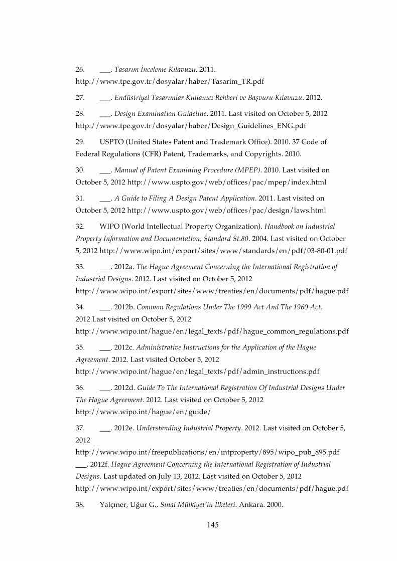
145
26. ___. Tasarım İnceleme Kılavuzu. 2011.
http://www.tpe.gov.tr/dosyalar/haber/Tasarim_TR.pdf
27. ___. Endüstriyel Tasarımlar Kullanıcı Rehberi ve Başvuru Kılavuzu. 2012.
28. ___. Design Examination Guideline. 2011. Last visited on October 5, 2012
http://www.tpe.gov.tr/dosyalar/haber/Design_Guidelines_ENG.pdf
29. USPTO (United States Patent and Trademark Office). 2010. 37 Code of
Federal Regulations (CFR) Patent, Trademarks, and Copyrights. 2010.
30. ___. Manual of Patent Examining Procedure (MPEP). 2010. Last visited on
October 5, 2012 http://www.uspto.gov/web/offices/pac/mpep/index.html
31. ___. A Guide to Filing A Design Patent Application. 2011. Last visited on
October 5, 2012 http://www.uspto.gov/web/offices/pac/design/laws.html
32. WIPO (World Intellectual Property Organization). Handbook on Industrial
Property Information and Documentation, Standard St.80. 2004. Last visited on October
5, 2012 http://www.wipo.int/export/sites/www/standards/en/pdf/03-80-01.pdf
33. ___. 2012a. The Hague Agreement Concerning the International Registration of
Industrial Designs. 2012. Last visited on October 5, 2012
http://www.wipo.int/export/sites/www/treaties/en/documents/pdf/hague.pdf
34. ___. 2012b. Common Regulations Under The 1999 Act And The 1960 Act.
2012.Last visited on October 5, 2012
http://www.wipo.int/hague/en/legal_texts/pdf/hague_common_regulations.pdf
35. ___. 2012c. Administrative Instructions for the Application of the Hague
Agreement. 2012. Last visited October 5, 2012
http://www.wipo.int/hague/en/legal_texts/pdf/admin_instructions.pdf
36. ___. 2012d. Guide To The International Registration Of Industrial Designs Under
The Hague Agreement. 2012. Last visited on October 5, 2012
http://www.wipo.int/hague/en/guide/
37. ___. 2012e. Understanding Industrial Property. 2012. Last visited on October 5,
2012
http://www.wipo.int/freepublications/en/intproperty/895/wipo_pub_895.pdf
___. 2012f. Hague Agreement Concerning the International Registration of Industrial
Designs. Last updated on July 13, 2012. Last visited on October 5, 2012
http://www.wipo.int/export/sites/www/treaties/en/documents/pdf/hague.pdf
38. Yalçıner, Uğur G., Sınai Mülkiyet’in İlkeleri. Ankara. 2000.

146
39. [Yalçıner, Uğur G.] Patent ve Marka Vekilleri Derneği (PEM) 2011 Yılı Patent ve
Marka Vekilliği Sınavı Hazırlık Kitabı. Ankara 2011.

147
APPENDIX A
CONTRACTING PARTIES OF THE HAGUE AGREEMENT GENEVA ACT (1999)
In refer to Hague Agreement Concerning the International Registration of Industrial
Designs Geneva Act (1999) publication of WIPO which was updated on July 13, 212
(WIPO 2012f, 19)
Name of Country Name of Country African Intellectual Property Organization (OAPI)
Lithuania
Albania Luxembourg Armenia Mali Azerbaijan Monaco Belgium Mongolia Belize Montenegro Benin Morocco Bosnia and Herzegovina Namibia Botswana Netherlands Bulgaria Niger Co ̂te d'Ivoire Norway Croatia Oman Democratic People's Republic of Korea Poland Denmark Republic of Moldova Egypt Romania Estonia Rwanda European Union Sao Tome and Principe Finland Senegal France Serbia Gabon Singapore Georgia Slovenia Germany Spain Ghana Suriname Greece Switzerland Holy See Syrian Arab Republic Hungary Tajikistan Iceland the former Yugoslav Republic of
Macedonia Italy Tunisia Kyrgyzstan Turkey Latvia Ukraine Liechtenstein

148
APPENDIX B
LETTER TO THE HEAD OF DESIGN DEPARTMENT OF TURKISH PATENT INSTITUTE FOR REQUESTING INTERVIEW IN TURKISH
Türk Patent Enstitüsü Endüstriyel Tasarımlar Dairesi Başkanlığına,
Hipodrom Caddesi No:115 (06330) Yenimahalle / ANKARA
TPE Santral : (0 312) 303 10 00
Enformasyon Faks: (0 312) 303 11 73
Tarih
Sayın Naim Uğur,
Orta Doğu Teknik Üniversitesi (ODTÜ) Endüstri Ürünleri Tasarımı Bölümünde
yüksek lisans öğrencisiyim. Yrd. Doç. Dr. Fatma Korkut danışmanlığında
yürüttüğüm yüksek lisans tezimin amacı, Türkiye’de endüstriyel tasarım tescilinde
kullanılan görsel anlatımlarda yaşanan problemleri saptamak ve buna yönelik bir
kılavuz önerisi geliştirmektir. Bu kapsamda Türkiye’nin ve diğer ulusal, bölgesel ve
uluslararası sistemlerin mevzuat ve kılavuzlarını inceledikten sonra Türkiye’deki
uygulamada görsel anlatımlara ilişkin karşılaştığınız problemler ve çözüm
önerileriniz için Türk Patent Enstitüsü (TPE) uzmanları ile görüşmeler yapmak
istiyorum. Geliştireceğim bu kılavuz ile başvuru sahiplerinin ve vekillerin, görsel
anlatımlara ilişkin bu problemleri başvurudan önce giderebilmelerini sağlamayı
amaçlıyorum.
Enstitünüz bünyesinde Endüstriyel Tasarımlar Dairesinde görev yapan tasarım
uzmanlarıyla yapılacak görüşmelerde daha sonra analiz edilebilmek amacıyla ses ve
görüntü kaydı yapılacaktır. Bu kayıtlar sadece benim ve gerekirse danışmanım
tarafından izlenecek ve görüşmeler sırasında elde edilen bilgiler sadece bilimsel
amaçlarla kullanılacaktır. Kişilere ilişkin kimlik bilgileri saklı tutulacaktır.

149
Görsel anlatımlarla ilgili yaşanan çeşitli sorunlara örnekler üzerinden bakmamız
araştırmam açısından faydalı olacaktır. Bu nedenle bu tür örneklerin görüşme
öncesinde hazırlanması araştırmam açısından önem taşımaktadır.
Dilediğiniz takdirde araştırma sonuçlarını size iletmekten mutluluk duyacağım.
Konu ile ilgili geri dönüşünüzü bekler, yardımlarınız ve desteğiniz için şimdiden
teşekkür ederim.
Saygılarımla,
Irmak Yalçıner ODTÜ Endüstri Ürünleri Tasarımı Bölümü Yüksek Lisans Programı öğrencisi ODTÜ Mimarlık Fakültesi Endüstri Ürünleri Tasarımı Bölümü İnönü Bulvarı 06531 Ankara E-posta: Mobil tel: Tez danışmanı: Yrd. Doç. Dr. Fatma Korkut ODTÜ Mimarlık Fakültesi Endüstri Ürünleri Tasarımı Bölümü İnönü Bulvarı 06531 Ankara E-posta: Tel: Mobil tel:

150
APPENDIX C
LETTER TO THE HEAD OF DESIGN DEPARTMENT OF TURKISH PATENT INSTITUTE FOR REQUESTING INTERVIEW IN ENGLISH
To the Turkish Patent Institute Department of Industrial Design,
Hipodrom Caddesi No: 115 (06330) Yenimahalle / ANKARA
TPI Operator: (0 312) 303 10 00
Information Fax: (0 312) 303 11 73
Date
Dear Naim Uğur,
I am a graduate student at Middle Eastern Technical University (METU)
Department of Industrial Design. The aim of my graduate dissertation, under the
counselling of Assistant Professor Dr. Fatma Korkut, is to identify the issues
encountered in the visual representations of industrial design registration in Turkey
and develop a guideline proposal towards this. In this context, after reviewing
Turkey’s and other national, regional and international systems’ regulations and
guidelines, I wish to conduct interviews with examiners from the Turkish Patent
Institute (TPI) regarding the issues they have encountered of visual representation
practices in Turkey and their suggestions for solutions. The purpose of this
guideline that I am developing is to allow applicants and their attorneys to solve
their issues on visual representation prior to the application.
The interviews to be conducted with the design examiners working at the Industrial
Designs Department within the Institute shall be recorded in audio and video in
order to be analysed afterwards. These recordings shall only be view by myself and
if necessary by my supervisor and all information obtained from these interviews
shall only be used for scientific purposes. The identity of these interviewees shall
not be disclosed.

151
It will be beneficial for my research for us me to review various problems in visual
representations by means of examples. Therefore it is essential for my research that
these kinds of examples are prepared prior to our interview.
If you wish I would be delighted to share the outcome of my research with yourself.
I am looking forward to your reply in this matter and thank you in advance for all
your assistance and support.
Best Regards,
Irmak Yalçıner METU Department of Industrial Design Graduate Program Student METU Faculty of Architecture Department of Industrial Design İnönü Bulvarı 06531 Ankara E-mail: Mobile: Thesis Supervisor: Asst. Prof. Dr. Fatma Korkut ODTÜ Faculty of Architecture Department of Industrial Design İnönü Bulvarı 06531 Ankara E-mail: Phone: Mobile:

152
APPENDIX D
ELECTRONIC MAIL TO THE TURKISH PATENT INSTITUTE EXAMINERS IN TURKISH
Sayın (Görüşme yapılacak kişinin adı),
Türkiye’de endüstriyel tasarım tescilinde kullanılan görsel anlatımlarda yaşanan
sorunları saptamayı ve buna yönelik bir kılavuz önerisi geliştirmeyi amaçladığım
araştırma kapsamında görüşmeyi kabul ettiğiniz için teşekkür ederim.
(Tarih) tarihli telefon görüşmemizde belirttiğim üzere görsel anlatımlarla ilgili
sorunlara örnekler üzerinden bakmamız araştırmam açısından faydalı olacaktır.
Aşağıda sunulan konulardaki örneklerin görüşme öncesinde hazırlanması
araştırmam açısından önem taşımaktadır. Bu konudaki yardımlarınız için şimdiden
teşekkür ederim.
I. Görsel anlatımın şekli incelemesi
Görsel anlatımların incelenmesinde nasıl bir prosedür izliyorsunuz, hangi konulara
dikkat ediyorsunuz, örnek bir dosya üzerinden anlatabilir misiniz?
II. Görsel anlatımlara ilişkin karşılaşılan sorunlar
Görsel anlatımlarda en sık karşılaştığınız sorunlar nelerdir, örnekler üzerinden
anlatabilir misiniz?
III. Görsel anlatım çeşitleri
Fotoğraf, grafik ve numune formatında verilen görsel anlatımlardaki sorunlara
örnekler verebilir misiniz? Bu formatlar açısından dikkat edilmesi gereken konular
nelerdir, olumlu ve olumsuz örnekler üzerinden anlatabilir misiniz?
III. Görsel anlatımda tasarım, zemin, fon ve renk
Görsel anlatımda tasarım, zemin, fon ve renge ilişkin sorunlara örnekler verebilir
misiniz? Bu konuda dikkat edilmesi gereken konular nelerdir, olumlu ve olumsuz
örnekler üzerinden anlatabilir misiniz?

153
IV. Görünümler
Görsel anlatımda görünümün boyutlarına, geleneksel (perspektif ve teknik
görünüşler) ve geleneksel olmayan (kesit, detay, açık kapalı halleri, vb.)
görünümlere ilişkin dikkat edilmesi gereken konular nelerdir, olumlu ve olumsuz
örnekler üzerinden anlatabilir misiniz?
Tekrar eden yüzey deseni tasarımlarının, değişebilir veya kesin olmayan boyutlara
sahip tasarımların, tipografik karakter tasarımlarının, bileşik ürün tasarımlarının
görünümlerine ilişkin dikkat edilmesi gereken konular nelerdir, olumlu ve olumsuz
örnekler üzerinden anlatabilir misiniz?
V. Kısmı tescil talebi
Kısmı tescil talepli görsel anlatımlarda dikkat edilmesi gereken konular nelerdir,
olumlu ve olumsuz örnekler üzerinden anlatabilir misiniz?
VI. Görsel anlatımın formatı ve niteliği
Dijital olmayan, kağıt üzerinde yapılan başvurularda dikkat edilmesi gereken
konular nelerdir, olumlu ve olumsuz örnekler üzerinden anlatabilir misiniz??
Elektronik olarak yapılan başvurularda dikkat edilmesi gereken konular nelerdir,
olumlu ve olumsuz örnekler üzerinden anlatabilir misiniz?
VII. Kabul edilmeyen görsel anlatımlar
TPE tarafından şekli inceleme aşamasında kesinlikle kabul edilmeyen görsel
anlatımlara ilişkin örnekler nelerdir?
VIII. Örnek görsel anlatımlar
TPE tarafından şekli inceleme aşamasında kabul edilen, şekli açıdan uygun bulunan
iyi (olumlu) görsel anlatım örnekleri nelerdir?
Eposta mesajımı aldığınıza dair teyidinizi rica ederim.
Saygılarımla
Irmak Yalçıner
ODTÜ Endüstri Ürünleri Tasarımı Bölümü
Yüksek Lisans Programı öğrencisi
ODTÜ Mimarlık Fakültesi Endüstri Ürünleri Tasarımı Bölümü İnönü Bulvarı 06531
Ankara

154
E-posta:
Mobil tel:
Tez danışmanı:
Yrd. Doç. Dr. Fatma Korkut
ODTÜ Mimarlık Fakültesi
Endüstri Ürünleri Tasarımı Bölümü İnönü Bulvarı 06531 Ankara
E-posta:
Tel: Mobil tel:

155
APPENDIX E
ELECTRONIC MAIL TO THE TURKISH PATENT INSTITUTE EXAMINERS IN ENGLISH
Dear (Interviewee’s Name)
Thank you for granting the interview in scope of my research wherein I aim to
determine the issues in the visual representations used in the registration of
industrial designs in Turkey and develop a related guideline.
As I have stated at out telephone conversation on (date) it will be beneficial for my
research for us to review various issues in visual representations by means of
examples. It is essential for my research that examples for the below mentioned
subjects are prepared prior to our interview. Thank you in advance for your
assistance in this matter.
III. Formal examination of the visual representations
During the examination of visual representations, what procedures do you implement, what are the issues that you pay attention, could you explain via an exemplary file?
IV. Encountered problems on visual representations
What are the most common problems encountered regarding visual representations, can you explain through examples?
IV. Types of visual representations
Can you give examples to visual representations submitted in photographic,
graphic and specimen formats? What are the points to be taken into consideration in
regard to these formats, could you explain with positive and negative examples?
V. Article, background and colour in visual representation
Can you give examples on the problems regarding the article, background and
colour in visual representation? What are the points to be taken into consideration
on this matter, could you explain with positive and negative examples?

156
VI. Views
What are the points to be taken into consideration regarding conventional views
(perspective and technical views) and unconventional views (cross sectional, detail,
open/closed configuration, etc.) in visual representation, could you explain with
positive and negative examples?
What are the points to be taken into consideration regarding the views of repetitive
surface pattern designs, designs with indefinite length and width, typographic
character designs and complex product designs, could you explain with positive
and negative examples?
V. Partial Disclaimer
What are the points to be taken into consideration regarding visual representations
with partial disclaimer, could you explain with positive and negative examples?
VIV. Format and quality of visual representation
What are the points to be taken into consideration regarding non digital, paper
submission applications, could you explain with positive and negative examples?
What are the points to be taken into consideration regarding electronic filing
applications, could you explain with positive and negative examples?
VV. Unaccepted visual representations
What are the examples of visual representations that have definitely not been
accepted by the TPI during the formal examination phase?
VVI. Good examples of visual representations What are the examples of good (positive) visual representations that have been
deemed formally appropriate and have been accepted by the TPI during the formal
examination phase?
I kindly request confirmation of safe receipt of this e-mail.
Best Regards,
Irmak Yalçıner
METU Department of Industrial Design
Graduate Program Student
METU Faculty of Architecture Department of Industrial Design
İnönü Bulvarı 06531 Ankara
E-mail:

157
Mobile:
Thesis Supervisor:
Asst. Prof. Dr. Fatma Korkut
ODTÜ Faculty of Architecture
Department of Industrial Design
İnönü Bulvarı 06531 Ankara
E-mail:
Phone:
Mobile:

158
APPENDIX F
INTERVIEW SCHEDULE FOR THE TURKISH PATENT INSTITUTE EXAMINERS IN TURKISH
Giriş
Araştırmama önemli bir katkı sağlayacak olan bu görüşmeyi yapmayı kabul
ettiğiniz için teşekkür ederim. Adım Irmak Yalçıner. Orta Doğu Teknik Üniversitesi
Endüstri Ürünleri Tasarımı Bölümünde yüksek lisans öğrencisiyim. Yrd. Doç. Dr.
Fatma Korkut’un danışmanlığında yürüttüğüm bu araştırmanın amacı, Türkiye’de
endüstriyel tasarım tescilinde kullanılan görsel anlatımlarda yaşanan sorunları
saptamak ve buna yönelik bir kılavuz önerisi geliştirmektir. Yapacağımız
görüşmede size araştırma konusuyla ile ilgili sorular soracağım. Görüşme sırasında
elde edilen bilgiler sadece bilimsel amaçlarla kullanılacak ve kimliğiniz saklı
tutulacaktır. Görüşmemizi daha sonra analiz edebilmek için ses ve görüntü kaydı
yapacağım. Bu kayıtlar sadece ben ve gerekirse danışmanım tarafından izlenecektir.
Görüşmemize başlamadan önce sormak istediğiniz herhangi bir şey var mı?
I. Görsel anlatımın şekli incelemesi
1. Bir endüstriyel tasarım tescili başvurusunda görsel anlatımın şekli incelemesini
nasıl yapıyorsunuz, bir örnek dosya üzerinden ayrıntılı olarak anlatır mısınız?
> Endüstriyel tasarım tescil başvurularının şekli inceleme sürecinde kullandığınız
genel bir kontrol listesi, yönerge, kılavuz veya benzeri bir doküman var mı?
> Bu kontrol listesinde görsel anlatımların incelenmesine ilişkin bölümler nelerdir?
> Görsel anlatımların şekli incelenmesine ilişkin kullandığınız özel bir kontrol
listesi, yönerge, kılavuz veya benzeri bir doküman var mı?
2. Görsel anlatımların şekli incelemesinde hangi konulara dikkat ediyorsunuz? Bu
unsurları örnekler üzerinden anlatır mısınız?
II. Görsel anlatımlara ilişkin karşılaşılan sorunlar

159
3. Tasarım tescil başvurularındaki görsel anlatımlarda en sık karşılaştığınız sorunlar
nelerdir?
> Görsel anlatımlardaki bu şekli eksikliklere ilişkin örneklere bakabilir miyiz?
> En çok hangi tasarım konularında veya hangi Lokarno sınıfında yer alan
tasarımlarda görsel anlatıma ilişkin şekli eksikliklere rastlıyorsunuz?
> Konu ile ilgili istatistiksel veriler var mı?
V. Görsel anlatım çeşitleri
4. Fotoğraf formatında verilen görsel anlatımlarda gözlemlediğiniz sorunlar ve şekli
eksiklikler nelerdir?
5. Grafik formatta verilen görsel anlatımlarda gözlemlediğiniz sorunlar ve şekli
eksiklikler nelerdir?
> Örneğin, saydamlığın veya malzeme farklılığının çizimle anlatılması.
6. Numune formatında verilen görsel anlatımlarda gözlemlediğiniz sorunlar ve şekli
eksiklikler nelerdir?
> Örneğin, numunenin boyutları.
VI. Görsel anlatımda tasarım, zemin, fon ve renk
7. Görsel anlatımlarda kullanılan zemine veya fona ilişkin dikkat edilmesi gereken
konular nelerdir? Bu konuda gözlemlediğiniz sorunlar ve şekli eksiklikler nelerdir?
Örnekler verebilir misiniz?
[Örneğin, koruma kapsamında yer almayan unsurların yer alması, şeffaf bir
tasarımın uygun olmayan bir zeminde görüntülenmesi, tasarımın rengiyle zeminin
veya fonun birbirine karışması, vb.]
8. Görsel anlatımlarda tasarıma ilişkin unsurlarda veya niteliklerde dikkat edilmesi
gereken konular nelerdir? Bu konuda gözlemlediğiniz sorunlar ve şekli eksiklikler
nelerdir? Örnekler verebilir misiniz?
[Örneğin, tasarımın net bir şekilde gösterilmemiş olması, görsel anlatımda
tasarımın tamamının yer almaması, tasarımın koruma kapsamında yer almayan
unsurlarının görsel anlatımda mevcut olması, vb.]
9. Görsel anlatımlarda renk kullanımına ilişkin dikkat edilmesi gereken konular
nelerdir? Bu konuda gözlemlediğiniz sorunlar ve şekli eksiklikler nelerdir? Örnekler
verebilir misiniz?
VII. Görünümler

160
10. Görünümlerin boyutlarına ilişkin sorunlar ve şekli eksiklikler nelerdir?
11. Sayacağım geleneksel görünümlere ilişkin dikkat edilmesi gereken konuları belirtir
misiniz? Örnekler verebilir misiniz?
> Perspektif görünüş
> Teknik görünüşler (ön, arka, üst, alt, sağ ve sol)
12. Sayacağım geleneksel olmayan görünümlere ilişkin dikkat edilmesi gereken
konuları belirtir misiniz? Örnekler verebilir misiniz?
> Kesit görünümler
Cross sectional view and description
sample (CIPO 2010b, 20)
Christmas Tree Stand Cross Sectional View Sample (USPTO 2012, 16)
> Detay görünümler Enlarged fragmentary view and
description sample (CIPO 2010b, 19)
> Plan ve cephe (elevation)
> Birden fazla parçadan oluşan bir tasarımın parçalarını ayrılmış şekilde
gösteren görünümler (extended) ve patlamış görünümler
Extended view and description sample (CIPO 2010b,
12)

161
Set of Game Components- Fully Assembled View
llyto
Set of Game Components-Exploded View
Exploded view sample (USPTO 2012, 12)
> Tasarımın kullanım halindeki görünümü Fig. 1 Fig. 2 View Samples of a
recycle bin design (CIPO 2010b, 5)
Open and closed positional view sample and their
descriptions (CIPO 2010b, 10)
> Yap bozların tamamlanmamış görünümleri
> Bir tasarımın farklı kurgulardaki görünümleri (yatak olabilen koltuk)
Personal Computer Alternate positional view sample (USPTO 2012, 16)
Extended and retracted positional view and description
sample (CIPO 2010b, 13)
Positional view and description sample of a
flexible article (CIPO 2012b, 11)
13. Tekrar eden yüzey desenlerine ilişkin dikkat edilmesi gereken konuları belirtir
misiniz? Örnekler verebilir misiniz?

162
Two different ways of showing
indefinite length on the representation of a surface pattern design (CIPO 2010b, 16)
Indefinite length indicated by jagged line.
Two different samples of showing indefinite
length and width on the representation of a repeating surface pattern design (CIPO
2010b, 18) Indefinite length and width indicated by stippled line.
14. Değişebilir veya kesin olmayan boyutlara sahip tasarımların görünümlerine ilişkin
dikkat edilmesi gereken konuları belirtir misiniz? Örnekler verebilir misiniz?
Sample showing indefinite length on the representation of a
repeating three dimensional feature of the design (CIPO 2010b, 16) Indefinite length
and width indicated by sinusoidal lines.
Sample showing indefinite length of a relevant portion of the design
on the representation (CIPO 2010b, 17) Indefinite length indicated by a break of the
lines.
Sample showing indefinite length of a constant cross section of the
design on the representation (CIPO 2010b, 14) Indefinite length indicated by
sinusoidal lines.

163
Sample showing indefinite length of a constant cross section of
the design on the representation (CIPO 2010b, 14) Indefinite length indicated by
sharp jagged sinusoidal lines.
Sample showing indefinite length of a constant cross section of
the design on the representation (CIPO 2010b, 15) Indefinite length indicated by
parallel lines broken by a zig zag.
med.
Picture Frame Molding
Indeterminate length sample (USPTO 2012, 16)
15.Tipografik karakter tasarımlarının görünümlerine ilişkin dikkat edilmesi gereken
konuları belirtir misiniz? Örnekler verebilir misiniz?
Visual representation of a registered community design of a
typeface at OHIM with the number RCD 000041496-0001 in Locarno class 18-03
16. Bileşik ürün tasarımlarının görünümlerine ilişkin dikkat edilmesi gereken konuları
belirtir misiniz? Örnekler verebilir misiniz?
The representation and description sample of clothes washer design
(CIPO 2010b, 23)

164
Extended view sample (USPTO 2012, 16)
> Bu konuda belirtmek istediğiniz başka hususlar var mı?
17. Görünümlerin sıralanmasına ve numaralandırılmasına ilişkin dikkat edilmesi
gereken konuları belirtir misiniz? Örnekler verebilir misiniz?
VIII. Kısmı tescil talebi
18. Kısmı tescil talepli başvuruların görsel anlatımında dikkat edilmesi gereken
konuları belirtir misiniz? Örnekler verebilir misiniz?
(�)������ *� )������ *��)������ A representation sample of a partial disclaimer (
TPI 2012, 12). Diclaimed features of the design shown by dashed lines.
Partial disclosure sample shown by solid and stippled lines
(CIPO 2010b, 3)
Partial disclaimer sample of showing the opaque non
design portions of the design (CIPO 2010b, 4)

165
Figure 1 Partial disclaimer sample showing the use of bold and wavy
lines for indicating the design portions in a shoe design (CIPO 2010b, 23)
Figure 1
Partial disclaimer sample showing the use of bold and
wavy lines together with the stippled lines for indicating the non design portions in
a clothes washer design (CIPO 2010b, 23)
Tire
Paper Cutter Partial disclaimer sample where non design portions
of the design shown by broken lines (USPTO 2012, 16)
19. Kısmı tescil talepli başvuruların tarifnamelerinde dikkat edilmesi gereken
konuları belirtir misiniz? Örnekler verebilir misiniz?
VI. Görsel anlatımın formatı ve niteliği
20. Görsel anlatımın formatına ve niteliğine ilişkin genellikle ne tür hatalarla
karşılaşıyorsunuz? Örnekler var ise benimle paylaşabilir misiniz?
21. Dijital olmayan, kağıt üzerinde yapılan başvurularda dikkat edilmesi gereken
konular nelerdir (Örneğin, zımba kullanılmaması, elle düzeltme yapılmamış olması,
ek olarak görsel anlatımın dijital formatta verilmesi, vb.)?
22. Elektronik olarak yapılan başvurularda dikkat edilmesi gereken konular nelerdir
(Örneğin, görsel anlatımın baskıya uygun çözünürlükte olmaması, çözünürlüğün
çok düşük olması, vb.)?

166
IX. Kabul edilmeyen görsel anlatımlar
23. TPE tarafından şekli inceleme aşamasında kesinlikle kabul edilmeyen görsel
anlatımlar veya görsel anlatımlara ilişkin nitelik veya unsurlar nelerdir? Örneklerle
anlatabilir misiniz?
X. Örnek görsel anlatımlar
24. TPE tarafından şekli inceleme aşamasında kabul edilen, şekli açıdan uygun
bulunan örnek gösterebileceğiniz görsel anlatımları paylaşır mısınız?
25. Görsel anlatımlardaki yetersizliklerin ve eksikliklerin sizce en önemli nedenleri
nelerdir?
26. Görsel anlatımlara ilişkin sorunların yaşanmaması için vekillere yönelik
önerileriniz nelerdir?
27. Görsel anlatımlara ilişkin sorunların yaşanmaması için başvuru sahiplerine
yönelik önerileriniz nelerdir?
X. Son Sorular
28. Eklemek veya söylemek istediğiniz başka bir şey var mı?
29. Üzerinde yeterince konuşmadığımız veya eksik kaldığını düşündüğünüz bir şey
var mı?
30. Araştırma tamamlandıktan sonra sonuçların bir özetini size iletmemi ister
misiniz?
Elektronik posta: ________________@________________________________________
veya
Adres: ___________________________________________________________________
___________________________________________________________________
___________________________________________________________________
Araştırmaya katkıda bulunduğunuz ve zaman ayırdığınız için çok teşekkür ederim.
Eğer daha sonra görüşmeye ilişkin herhangi bir şey sormak ya da söylemek

167
isterseniz, bana bu karttaki telefonlardan veya elektronik posta adresinden
ulaşabilirsiniz. Yardımlarınız için teşekkür ederim.
Görüşme yapılan kişiye ilişkin bilgiler
Ad Soyad:
Cinsiyet:
Doğum yılı:
Şimdiki görevi ve unvanı:
TPE’de aldığı diğer görevler ve süreleri:
Endüstriyel tasarım başvurularına ilişkin şekli inceleme görevinde geçirdiği süre ve
yıllar:
Eğitim
Lisans (üniversite, program):
Yüksek lisans (üniversite, program):
Doktora (üniversite, program):

168
APPENDIX G
INTERVIEW SCHEDULE FOR THE TURKISH PATENT INSTITUTE EXAMINERS IN ENGLISH
Introduction
Thank you for participating in this interview which shall contribute significantly to
my research. My name is Irmak Yalçıner. I am a graduate student at Middle East
Technical University Depart of Industrial Design. The purpose of this study, under
the counselling of Asst. Prof. Dr. Fatma Korkut, is to identify the issues encountered
in the visual representations of industrial design registration in Turkey and develop
a guideline proposal towards this. During our interview I will ask you questions in
respect to the topic of the study. Information obtained through the interview shall
only be used for scientific purposes and your identity shall be not be disclosed. I
shall record audio and video at our interview in order to be analysed later. These
recordings shall only be viewed by myself and by my supervisor if necessary. Is
there anything you wish to ask before we begin our interview?
I. Formal examination of the visual representations
1. How do you conduct the formal examination of visual representations of an
industrial design registration, could you explain in detail by showing an exemplary
file?
> Is there a general checklist, instructions, manual of similar document that you use
during the formal examination of industrial design registration applications?
> What are the sections in this checklist related to the examination of visual
representations?
> Is there a specific checklist, instructions, manual or similar document that you are
using for the formal examination of visual representations?

169
2. What are the topics that you pay attention to during the formal examination of
visual representations? Can you explain these elements by showing examples?
II. Encountered problems on visual representations
2. What are the most common problems encountered regarding visual
representations of design registration applications?
> Can we examine examples of these formal deficiencies in visual
representations?
> In which design fields or designs in Locarno classes do you encounter formal
deficiencies regarding visual representations?
> Are there any statistical data on the subject?
V. Types of visual representations
3. What are the problems and formal deficiencies you have observed of visual
representations in the photograph format?
4. What are the problems and formal deficiencies you have observed of visual
representations in the graphics format?
> For example conveying of opacity or differences in materials with drawing.
5. What are the problems and formal deficiencies you have observed of visual
representations in the specimen format?
> For example the dimensions of the specimen.
VII. Article, background and colour in visual representations
6. What are the points to be taken into consideration in regard to backgrounds or
backdrops used in visual representations? What are the problems and formal
deficiencies in this aspect? Can you give examples?

170
[For example elements that are not within the scope of protection, a transparent
design represented on an unsuitable background, the colour of the design blending
with the background or backdrop, etc.}
7. What are the points to be taken into consideration in regard to features and
qualities of the design in visual representations? What are the problems and formal
deficiencies in this aspect? Can you give examples?
[For example, the design not being shown clearly, the design not being shown fullly
in the visual representation, elements that are not within the scope of protection
being shown in the visual representation, etc.]
8. What are the points to be taken into consideration in regard to the use of colour in
visual representations? What are the problems and formal deficiencies in this
aspect? Can you give examples?
VIII. Views
9. What are the problems and formal deficiencies regarding dimensions of views?
10. Can you specify the points to be taken into consideration regarding the
conventional views I shall state? Can you give examples?
> Perspective view
> Technical views (front, back, top, bottom, right and left)
11. Can you specify the points to be taken into consideration regarding the
unconventional views I shall state? Can you give examples?
> Cross sectional views
Cross sectional view and
description sample (CIPO 2010b, 20)
Christmas Tree Stand Cross Sectional View Sample (USPTO 2012, 16)

171
> Detail views Enlarged fragmentary view and description
sample (CIPO 2010b, 19)
> Plan and elevation
> Extended and exploded views showing separated elements of a design made
of multiple parts
Extended view and description sample (CIPO 2010b,
12)
Set of Game Components- Fully Assembled View
llyto
Set of Game Components-Exploded View
Exploded view sample (USPTO 2012, 12)
> View of the design in use Fig. 1 Fig. 2 View Samples of a recycle bin
design (CIPO 2010b, 5)
Open and closed positional view sample and their
descriptions (CIPO 2010b, 10)
> Incompleted images of puzzles
> Views of a design in different configurations (a sofa that can be converted into
a bed)
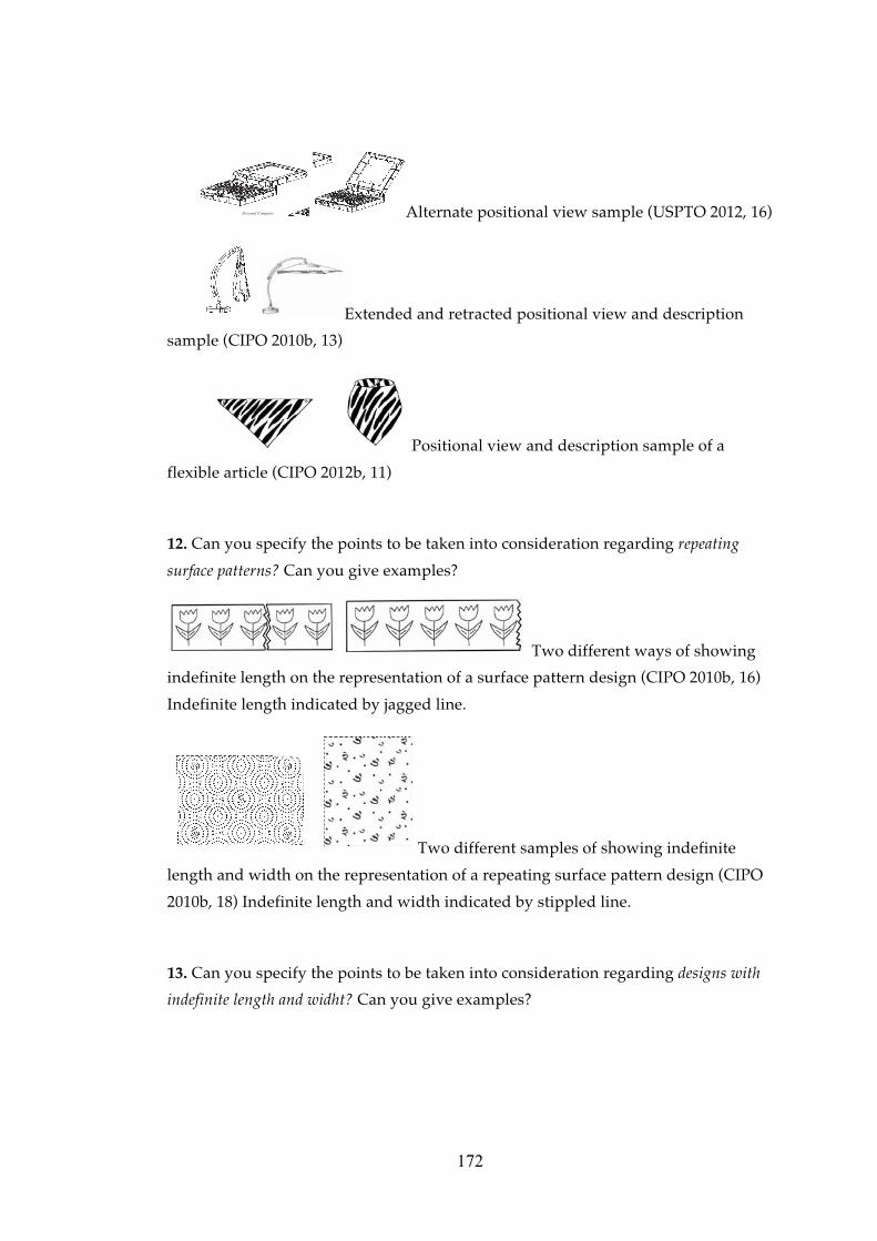
172
Personal Computer Alternate positional view sample (USPTO 2012, 16)
Extended and retracted positional view and description
sample (CIPO 2010b, 13)
Positional view and description sample of a
flexible article (CIPO 2012b, 11)
12. Can you specify the points to be taken into consideration regarding repeating
surface patterns? Can you give examples?
Two different ways of showing
indefinite length on the representation of a surface pattern design (CIPO 2010b, 16)
Indefinite length indicated by jagged line.
Two different samples of showing indefinite
length and width on the representation of a repeating surface pattern design (CIPO
2010b, 18) Indefinite length and width indicated by stippled line.
13. Can you specify the points to be taken into consideration regarding designs with
indefinite length and widht? Can you give examples?

173
Sample showing indefinite length on the representation of a
repeating three dimensional feature of the design (CIPO 2010b, 16) Indefinite length
and width indicated by sinusoidal lines.
Sample showing indefinite length of a relevant portion of the design
on the representation (CIPO 2010b, 17) Indefinite length indicated by a break of the
lines.
Sample showing indefinite length of a constant cross section of the
design on the representation (CIPO 2010b, 14) Indefinite length indicated by
sinusoidal lines.
Sample showing indefinite length of a constant cross section of
the design on the representation (CIPO 2010b, 14) Indefinite length indicated by
sharp jagged sinusoidal lines.
Sample showing indefinite length of a constant cross section of
the design on the representation (CIPO 2010b, 15) Indefinite length indicated by
parallel lines broken by a zig zag.
med.
Picture Frame Molding
Indeterminate length sample (USPTO 2012, 16)
14.Can you specify the points to be taken into consideration regarding typographic
typeface designs? Can you give examples?
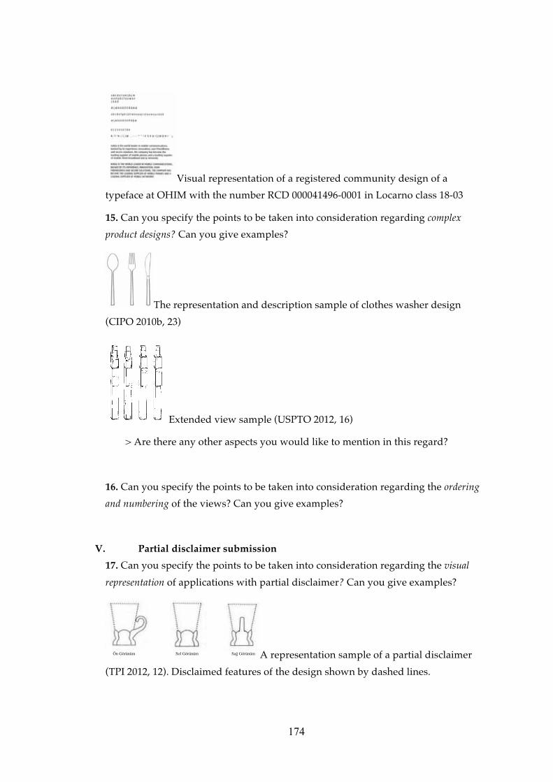
174
Visual representation of a registered community design of a
typeface at OHIM with the number RCD 000041496-0001 in Locarno class 18-03
15. Can you specify the points to be taken into consideration regarding complex
product designs? Can you give examples?
The representation and description sample of clothes washer design
(CIPO 2010b, 23)
Extended view sample (USPTO 2012, 16)
> Are there any other aspects you would like to mention in this regard?
16. Can you specify the points to be taken into consideration regarding the ordering
and numbering of the views? Can you give examples?
V. Partial disclaimer submission
17. Can you specify the points to be taken into consideration regarding the visual
representation of applications with partial disclaimer? Can you give examples?
(�)������ *� )������ *��)������ A representation sample of a partial disclaimer
(TPI 2012, 12). Disclaimed features of the design shown by dashed lines.

175
Partial disclaimer sample shown by solid and stippled lines
(CIPO 2010b, 3)
Partial disclaimer sample of showing the opaque non
design portions of the design (CIPO 2010b, 4)
Figure 1 Partial disclaimer sample showing the use of bold and wavy
lines for indicating the design portions in a shoe design (CIPO 2010b, 23)
Figure 1
Partial disclaimer sample showing the use of bold and
wavy lines together with the stippled lines for indicating the non design portions in
a clothes washer design (CIPO 2010b, 23)
Tire
Paper Cutter Partial disclaimer sample where non design portions
of the design shown by broken lines (USPTO 2012, 16)

176
18. Can you specify the points to be taken into consideration regarding specifications
for applications with partial disclaimer? Can you give examples?
VVII. Format and quality of visual representations
19. What kind of mistakes do you generally come across regarding format and
quality of visual representations? Are there any examples you would like to share
with me?
20. Can you specify the points to be taken into consideration regarding non-digital
applications submitted on paper (for example, not using staples, no handwritten
corrections, the digital format of the visual representation being additionally
submitted)?
21. Can you specify the points to be taken into consideration regarding applications
submitted electronically (for example the visual representation not being in a
resolution which is suitable for printing, the resolution being too low, etc)?
VVIII. Unaccepted visual representations
22. What are the visual representations or features or qualities of visual
representations that are absolutely unaccepted by the TPI at the formal examination
phase? Can you explain with examples?
VIX. Examples of good representation
23. Can you share with me the visual representations that are acceptable by the TPI
at the formal examination phase and are exemplary to being formally suitable.
24. What do you think are the most important reasons of inadequacies and
deficiencies of visual representations?
25. What are your suggestions to attorneys against problems regarding visual
representations?
26. What are your suggestions to applicants against problems regarding visual
representations?

177
VX. Final Questions
27. Is there anything else you would like to add or state?
28. Is there anything that you think we have not talked about adequately or have
missed?
29. Would you like me to convey to you a summary of the finding once my research
is complete?
E-mail: ________________@________________________________________
or
Address:
___________________________________________________________________
___________________________________________________________________
___________________________________________________________________
Thank you for participating in the research and taking the time. If you have any
questions regarding this interview or would like to add something you can reach
me on the telephone number on the card or via my e-mail address. Thank you for
your assistance.
Information regarding the person interviewed
Name Surname:
Gender:
Year of Birth:
Current position and title:
Other positions held at the TPI and their durations:
Years and duration at the position of formal examining of the visual representations
regarding industrial design applications:

178
Education:
Undergraduate (university, program):
Graduate (university, program):
Ph.D. (university, program):