visually believable explosions in real time - york …amana/research/ca2001.pdf · visually...
TRANSCRIPT
Visually Believable Explosions in Real Time
Claude MartinsElectronic Arts Canada4330 Sanderson WayBurnaby, BC, Canada
John BuchananElectronic Arts Canada4330 Sanderson WayBurnaby, BC, Canada
John AmanatidesDept. of Computer Science
York University4700 Keele Street
Toronto, ON, [email protected]
AbstractThe paper presents a real-time physically based simulationof object damage and motion due to a blast wave impact.An improved connected voxel model is used to represent theobjects. The paper also explores auxiliary visual effectscaused by the blast wave that increase visual believabilitywithout being rigorously physically based or computation-ally expensive.
1. Introduction
Explosions, and their resultant blast waves, continue tobe a popular phenomenon depicted in film, television, com-puter games, and other visual media. There are certain ad-vantages to simulating the appearance and behavior of blastwaves using computer graphics, such as safety, reproduci-bility, customizability, and interactivity.
Blast waves, however, follow complex fluid dynamicsrules, and modeling them very accurately is computationallyexpensive. This is especially true for a game or a real-timeapplication, where immediate visual feedback is paramount.Users expect instant gratification with unpredictable andchaotic blast effects. Meticulous physical accuracy is lessdesirable here than a fast simulation speed.
This paper takes the blast wave simulator and connectedvoxel model presented by Mazarak et al [MMA99] andextends its scope to real-time graphics. The pertinent en-hancements and simplifications necessary for the improve-ment of computing time are discussed. The functionality ofthe model is also enhanced by the introduction of arbitraryvoxel shapes. Furthermore, certain commonly expectedvisual cues are added to the simulation to improve the vis-ual believability of the explosion at low computational cost.
2. Previous work
Previous efforts on explosion modeling in the field ofcomputer graphics have traditionally focused more on thegraphical representation of an explosion, rather than its ef-fects on objects in the environment. Usually, the attributesand motion of an explosion are controlled explicitly by theuser, or else the explosion follows a set of informal behav-ioral rules [Reeves83]. Other techniques concentrate on cer-tain after-effects of an explosion, such as fire [COMM94]and smoke.
Interest has recently been rekindled in blast waves andtheir effects. In his Master’s thesis, Bashforth employs vol-ume cell subdivision to model shock front propagation[Bashforth98]. Neff and Fiume model the fracturing of aplanar surface into polygonal fragments by a spherical blastwave [NF99]. Mazarak et al use connected voxels to modelobjects breaking into solid debris when hit by a sphericalblast wave [MMA99]. Yngve et al model blast wave propa-gation using a combination of spatial voxelization and finiteelements [YOH00]. Except for [MMA99], these approacheseschew simulation speed in favor of rigorous physical accu-racy, which makes them inappropriate for use in real-timegraphics.
Although papers discussing explosions and blast wavesare somewhat rare in the field of computer graphics, it isimportant to note that this is not the case for the disciplinesof physics and chemistry. There have been numerous workspublished in those areas that delve with great detail into thecreation and detonation of explosive materials, the propa-gation of the generated shock fronts, and their effect onvarious materials.
Several computer methods for the modeling of blastwaves have also been proposed and implemented [Baker73].These models, however, are concerned primarily with pre-dicting and duplicating the behavior of explosions and ex-plosion effects down to the smallest detail. They require
substantial computational power and time to handle thegoverning fluid dynamics equations.
In real-time computer graphics, replicating blast wavebehavior in every detail is simply not feasible. Instead, wecull some of the overall relevant physical properties, andmake certain simplifications and optimizations. In this way,it is possible to obtain a balance between accurate modelingand realistic visuals without sacrificing a great deal of com-puting time.
3. Blast wave theory
An explosion in air causes a blast wave to propagateoutwards from the source at supersonic speed. Since theresurgence of recent interest in blast wave modeling incomputer graphics, the fundamentals of blast wave theoryhave been adequately covered in several papers ([MMA99],[NF99], and [YOH00]).
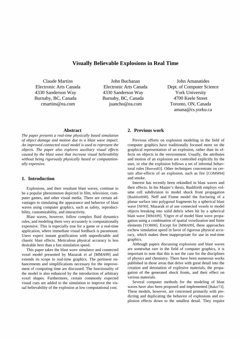
Our blast wave model is a combination of simplifiedphysical equations and experimental data. The air sur-rounding the explosion is assumed to be still and homoge-nous, and the explosion source is spherically symmetric.This results in an ideal blast wave that is itself perfectlysymmetrical. The pressure profile generated by an idealblast wave at a point at some fixed distance R removed fromthe center of the explosion is as shown in the followingFigure 1 [Baker73].
Figure 1. Pressure-time curve of an ideal blastwave
Before the shock front reaches the given point, the ambi-ent pressure is p0. At arrival time ta, the pressure rises dis-
continuously to the peak value of p0 + +sP . The quantity
+sP is called the peak overpressure. The pressure then de-
cays to ambient in total time ta + +T , drops to a partial vac-
uum of value p0 - −
sP , and eventually returns to the ambi-
ent pressure p0, in total time ta + +T + −T [Baker73].
Our simulation models blast wave profiles using themodified Friedlander equation:
p(t) = p0 + +sP (1 – t / +T )
+− Tbte / (3-1)
Time is measured from time of arrival ta. The blast wave
parameters +sP , ta,
+T , and b allow freedom to customize
the pressure profile curve for any explosion, at various dis-tances from the source.
The modified Friedlander equation improves over sim-pler formulae, which either have linear decay or fail to re-turn to ambient pressure [Baker73]. More complex equa-tions given by Brode [Brode95] and Dewey [Dewey64]generate blast wave profiles that are closer to experimentalor theoretical models. For a real-time simulation, however,the increased accuracy does not justify the concomitanthigher computational costs.
Our blast wave model employs Equation (3-1) to com-pute physically accurate pressure changes at any distance Rfrom the source of the explosion. The blast wave parametersrequired by Equation (3-1) are obtained from experimentaldata for a reference explosion of one kilogram of TNT (tri-nitrotoluene) in a standard atmosphere [KG85]. The ex-
perimental data contains values for peak overpressure +sP ,
expected arrival time ta, positive phase duration +T , andthe pressure decay coefficient b, measured at certain dis-tances R1, R2, …, Rn, from the source. The correspondingparameters for any arbitrary distance R are obtained by lin-ear interpolation.
Time and distance related parameters for explosions withdifferent yields than one kilogram of TNT are derived fromthe reference explosion data by using an appropriate scalingfactor as determined by the scaling laws [KG85]. Thisscaling factor is normally equal to the inverse of the cuberoot of the energy of the derived explosion:
3/1W
RZ = (3-2)
where Z is the scaled distance, R is the actual distance fromthe center of the explosion in meters, and W is the mass ofthe explosive converted into an equivalent weight of TNTin kilograms.
Since blast waves move at supersonic velocities, theypropagate in a non-linear fashion. Environmental interac-tions frequently cause pressure increases, irregular reflec-tions, vortices, and other complex phenomena [Baker73].These computationally intensive effects are difficult tosimulate in real time, so we use a simple model that propa-gates blast waves outwards as if they were in the open airand not being affected by surrounding objects. As a result,
p0 + +sP
p0 - −sP
p0
ta ++T + −Tta +
+T
PR
ES
SU
RE
ta
TIME
Positive phase
Negative phasep(t)
00
object damage occurs that is not identical to a real-life ex-plosion. Fracturing in our simulation is more accurate whenthere are no, or few, obstructions between the explosionsource and a given object.
4. Modeling and animation
Rigid bodies in the environment are affected by blastwaves in two major ways. Firstly, the blast wave createstensile stress within the object that can cause it to fractureand break apart. Secondly, the blast wave pressure exertsforces on the object that can cause it to move and rotate.Therefore, a particular object model must be chosen thattakes both of these effects into account.
4.1 Connected voxels
The objects in the simulation are modeled with con-nected voxels [MMA99]. An object is decomposed into vol-ume elements, or voxels, that make up its volume. Adjacentvoxels are connected to each other with inflexible links thatkeep the voxels firmly attached together.
The connected voxel approach offers several advantagesover other models. Firstly, it is volumetric- rather than sur-face-based, so fracturing of an object’s interior is possible.Secondly, the model is scaleable. If a more accurate simu-lation is desired, the voxel size can be reduced, allowing afiner representation. Likewise, if simulation speed is moreimportant than precision, a larger voxel size can be used.Thirdly, the links connecting the voxels are infinitely stiff,unlike the spring-mass particle model [TPBF87]. This makesthe object a true rigid body, and the simulation remains ro-bust. Finally, surface association for the objects is not re-quired when using connected voxels because each voxelalready has a given shape assigned to it. This is an impor-tant benefit in a real-time explosion simulation, becauseaccurately computing new surfaces for the dynamically cre-ated debris is non-trivial.
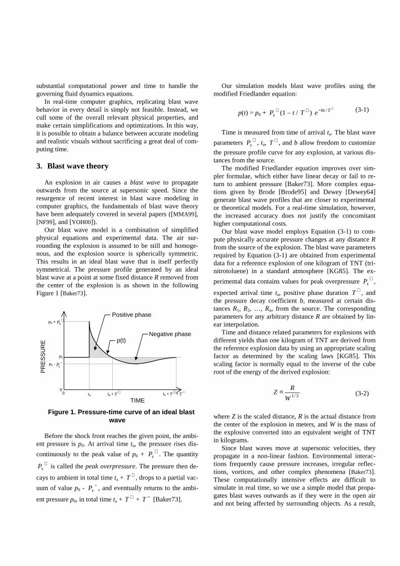
In the original implementation by Mazarak et al[MMA99], every voxel was identical and homogenous. Abasic voxel cube shape resulted in objects that were blockyand unrealistic. Our simulation improves upon this noticea-bly, through the introduction of arbitrarily shaped voxels.The basic voxel cube shape can be scaled by any desiredamount along any axis. As well, the voxel’s vertices can bedisplaced by any amount in any arbitrary direction.
Each voxel can also have unique properties appropriatefor the material it represents. This makes object modelingmuch more flexible, and permits the user to create voxelshapes that better suit his or her needs for a particular appli-cation.
Determination of visible surfaces is trivial in the con-nected voxel model. Any voxel face that does not have a
link attached to it is visible and must be rendered. Render-ing is thus linear on the number of boundary voxels.
Regardless of the voxel shape, the simulation assumesthat any given voxel has a constant density, which simplifiesthe force and torque computations used in object animation.
4.2 Fracture simulation
When a blast wave hits an object, pressure differentialscause the object to weaken and fracture. We simulate thisby weakening and breaking links and voxels in the objectmodel. As the object breaks apart, new fragments may becreated. Independent objects in the scene are represented bythe connected components of the entire scene’s connectivitygraph, where the nodes are individual voxels and the arcsare the links between voxels [MMA99].
Every link has an associated yield limit, which is themaximum pressure that the link can withstand beforebreaking. A link is broken whenever the absolute value ofthe pressure at that link’s midpoint exceeds its yield limit.Any links that encounter a blast wave have their yield limitsweakened, making them vulnerable to subsequent explo-sions.
Additionally, links that are parallel to the direction of thewave are further weakened by an orientation factor, com-
puted as a dot product of the wave’s radius vector Rr
and
the link vector lr
. The inclusion of this orientation factorallows the simulation to better mimic a real explosion,where tensile forces created by the blast wave inside anobject are much stronger in the direction parallel to the di-rection of the wave than normal to it.
An enhancement can be made to the fracture model byadding a yield limit for the voxels themselves. Pressurefrom a blast wave is measured at the center of each voxel. Ifthe absolute value of the pressure at a voxel’s center ex-ceeds its yield limit, that voxel is removed and replacedwith a small particle system. Linear momentum of the origi-nal voxel is passed on to the individual particles in the re-placement particle system. This simulates the destruction ofobject fragments into particulate dust if they undergo suffi-cient stress due to the blast wave. As with damaged links,voxels that survive a first blast wave have their yield limitsweakened.
Figure 2. Flexible object modeling using arbi-trary voxels.
A significant benefit of replacing voxels with particlesystems is that particles are easier to handle computation-ally, and are also generally quicker to render. Furthermore,allowing voxels to be destroyed helps circumvent certainproblems such as prolonged interpenetration during colli-sion.
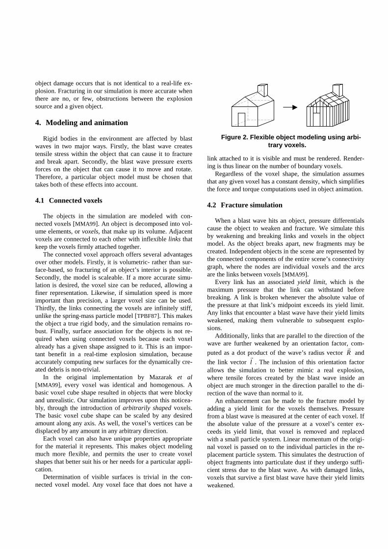
Since the shock front pressure forces are very strong,objects in the environment tend to start tumbling every-where once the blast wave hits them. This is unrealistic forbuildings that are supposed to have foundations. For suchfixed structures, the simulation tags voxels that are in con-tact with the ground as foundation voxels. An object havingthese foundation voxels in it is defined as “fixed”, i.e., blastwaves will affect voxel and link strength but will not impartany momentum to the structure. This allows debris to fly offthe object and have momentum, but the original structureremains stationary and does not tumble around.
Figure 3. Foundation voxels (shown shaded)stabilize the rigid body.
Of course, blast waves can sometimes be strong enoughto rip a building right off its foundations. So, a foundationyield limit is introduced for each foundation voxel. As withvoxel yield limits, the blast wave pressure measured at thecenter of each voxel is used to diminish its foundation yieldlimit. Once a voxel’s foundation yield limit drops to zero orbelow—assuming it hasn’t been destroyed completely—itsfoundation voxel status is removed. If all of the foundationvoxels in a structure revert to ordinary voxels in this way,that object is no longer “fixed”. In effect, it has been blownoff its foundations. Blast waves hitting the structure nowimpart momentum to it, as well as voxel and link damage.
We assign variable yield limits by perturbing some ran-dom value, generated within a certain range, around somemean value [TF88]:
yield_limit = mean_yield ± rand(var_yield) (4-1)
This allows the object to have a non-homogenous struc-ture, with weaker and stronger sections. The continual dete-rioration of the object’s links and voxels also simulates par-tial, persistent damage.
It is possible that a simple variance in object structuremight be insufficient. For example, a game designer maywant a specific building wall to be easily destroyed. He orshe can then alter link and voxel properties explicitly to
customize objects for a particular game and override thebasic variance values assigned in object configuration.
4.3 Animation
The blast wave not only causes object fracture and frag-mentation; it also affects their translation and rotationthrough the application of forces and torques. Computingthe force at the voxel center [MMA99] is insufficient sinceone-voxel bodies would not experience torque. Further-more, forces exerted on arbitrary voxel shapes would beinaccurate. Therefore, the forces exerted by the blast waveare evaluated at the vertices of each voxel.
The force at a given vertex is computed as a product ofthe blast wave pressure and the area of that voxel projectedonto the surface of the shock front. Assuming a sphericalblast wave, the force vector is congruent to the blast waveradius vector:
R
RAtpF
r
r
r
⋅⋅= )( (4-2)
where p(t) is a function that returns the pressure value at agiven voxel vertex at time t, A is the surface area of thevoxel projected onto the spherical shock front, and R is aradius vector from the source of the explosion to the voxelvertex.
The projected surface area of a cubic voxel onto aspherical blast wave varies mainly on its size and very littledepending on its orientation. Computing the actual pro-jected surface area for each voxel is too time-consuming ina real-time simulation, so A is assumed to be constant, de-pending on the size of the voxel. Non-cubic voxels are as-signed the projected surface area of a cubic voxel with aside equal to the original voxel’s largest dimension. Thisapproximation is imprecise, with the accuracy decreasing asthe difference increases between the non-cubic voxel andthe original cubic voxel.
The torque on the body is computed as the cross productof the relative position of a specific voxel vertex within thebody, and the force experienced by that vertex:
FrTr
r
r
×= (4-3)
where rr
is the relative position of the voxel vertex to thecenter of mass of the body. The force and torque computa-tion for a single voxel vertex is shown in Figure 4.
Noting that the body’s boundary voxels approximate itssurface implies that the force and torque vectors only needto be computed for the boundary voxels. These force andtorque vectors are then summed up to obtain the resultantforce and torque vectors for the entire body.
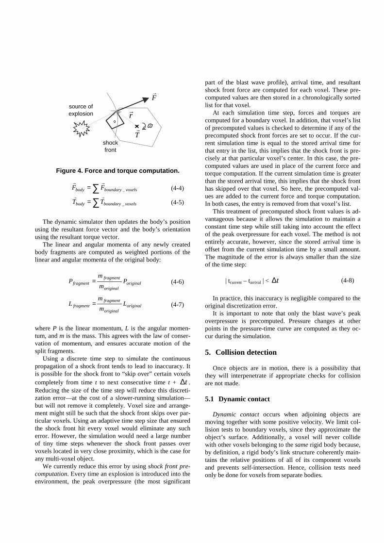
∑= voxelsboundarybody FF _
rr
(4-4)
∑= voxelsboundarybody TT _
rr
(4-5)
The dynamic simulator then updates the body’s positionusing the resultant force vector and the body’s orientationusing the resultant torque vector.
The linear and angular momenta of any newly createdbody fragments are computed as weighted portions of thelinear and angular momenta of the original body:
originaloriginal
fragmentfragment P
m
mP = (4-6)
originaloriginal
fragmentfragment L
m
mL = (4-7)
where P is the linear momentum, L is the angular momen-tum, and m is the mass. This agrees with the law of conser-vation of momentum, and ensures accurate motion of thesplit fragments.
Using a discrete time step to simulate the continuouspropagation of a shock front tends to lead to inaccuracy. Itis possible for the shock front to “skip over” certain voxelscompletely from time t to next consecutive time t + t∆ .Reducing the size of the time step will reduce this discreti-zation error—at the cost of a slower-running simulation—but will not remove it completely. Voxel size and arrange-ment might still be such that the shock front skips over par-ticular voxels. Using an adaptive time step size that ensuredthe shock front hit every voxel would eliminate any sucherror. However, the simulation would need a large numberof tiny time steps whenever the shock front passes overvoxels located in very close proximity, which is the case forany multi-voxel object.
We currently reduce this error by using shock front pre-computation. Every time an explosion is introduced into theenvironment, the peak overpressure (the most significant
part of the blast wave profile), arrival time, and resultantshock front force are computed for each voxel. These pre-computed values are then stored in a chronologically sortedlist for that voxel.
At each simulation time step, forces and torques arecomputed for a boundary voxel. In addition, that voxel’s listof precomputed values is checked to determine if any of theprecomputed shock front forces are set to occur. If the cur-rent simulation time is equal to the stored arrival time forthat entry in the list, this implies that the shock front is pre-cisely at that particular voxel’s center. In this case, the pre-computed values are used in place of the current force andtorque computation. If the current simulation time is greaterthan the stored arrival time, this implies that the shock fronthas skipped over that voxel. So here, the precomputed val-ues are added to the current force and torque computation.In both cases, the entry is removed from that voxel’s list.
This treatment of precomputed shock front values is ad-vantageous because it allows the simulation to maintain aconstant time step while still taking into account the effectof the peak overpressure for each voxel. The method is notentirely accurate, however, since the stored arrival time isoffset from the current simulation time by a small amount.The magnitude of the error is always smaller than the sizeof the time step:
| tcurrent – tarrival | < t∆ (4-8)
In practice, this inaccuracy is negligible compared to theoriginal discretization error.
It is important to note that only the blast wave’s peakoverpressure is precomputed. Pressure changes at otherpoints in the pressure-time curve are computed as they oc-cur during the simulation.
5. Collision detection
Once objects are in motion, there is a possibility thatthey will interpenetrate if appropriate checks for collisionare not made.
5.1 Dynamic contact
Dynamic contact occurs when adjoining objects aremoving together with some positive velocity. We limit col-lision tests to boundary voxels, since they approximate theobject’s surface. Additionally, a voxel will never collidewith other voxels belonging to the same rigid body because,by definition, a rigid body’s link structure coherently main-tains the relative positions of all of its component voxelsand prevents self-intersection. Hence, collision tests needonly be done for voxels from separate bodies.
Figure 4. Force and torque computation.
source ofexplosion
shockfront
Fr
Tr
ωrrr
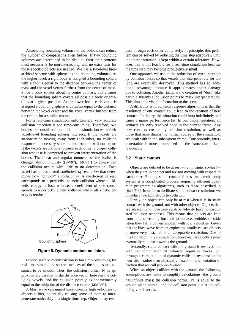
Associating bounding volumes to the objects can reducethe number of comparisons even further. If two boundingvolumes are determined to be disjoint, then their contentsmust necessarily be non-intersecting, and no extra tests forthose specific objects are needed. We use a two-level hier-archical scheme with spheres as the bounding volumes. Atthe higher level, a rigid body is assigned a bounding spherewith a radius equal to the distance between the center ofmass and the voxel vertex furthest from the center of mass.Since a body rotates about its center of mass, this ensuresthat the bounding sphere covers all possible body orienta-tions at a given position. At the lower level, each voxel isassigned a bounding sphere with radius equal to the distancebetween the voxel center and the voxel vertex furthest fromthe center, for a similar reason.
For a real-time simulation, unfortunately, very accuratecollision detection is too time-consuming. Therefore, twobodies are considered to collide in the simulation when theirvoxel-level bounding spheres intersect. If the voxels arestationary or moving away from each other, no collisionresponse is necessary since interpenetration will not occur.If the voxels are moving towards each other, a proper colli-sion response is computed to prevent interpenetration of thebodies. The linear and angular momenta of the bodies ischanged discontinuously ([BW97], [MC95]) to ensure thatthe collision occurs with little to no deformation. Eachvoxel has an associated coefficient of restitution that deter-mines how “bouncy” a collision is. A coefficient of zerocorresponds to a perfectly inelastic collision where all ki-netic energy is lost, whereas a coefficient of one corre-sponds to a perfectly elastic collision where all kinetic en-ergy is retained.
Figure 5. Dynamic contact collision.
Precise surface reconstruction is too time-consuming forreal-time simulation, so the surfaces of the bodies are as-
sumed to be smooth. Thus, the collision normal Nr
is ap-proximately parallel to the distance vector between the col-liding voxels, and the collision point p is approximatelyequal to the midpoint of the distance vector [MMA99].
A blast wave can impart exceptionally high velocities toobjects it hits, potentially causing some of them to inter-penetrate noticeably in a single time step. Objects may even
pass through each other completely. In principle, this prob-lem can be solved by reducing the time step adaptively untilthe interpenetration is kept within a certain tolerance. How-ever, this is not feasible for a real-time simulation becausethe time step may become prohibitively small.
One approach we use is the reduction of voxel strengthby collision forces so that voxels that interpenetrate for toolong are eventually destroyed. This method has an addi-tional advantage because it approximates object damagedue to collision. Another tactic is the creation of “dust”-likeparticle systems at collision points to mask interpenetration.This also adds visual information to the scene.
A difficulty with collision response algorithms is that theresolution of one contact could lead to the creation of newcontacts. In theory, this situation could loop indefinitely andcause a major performance hit. In our implementation, allcontacts are only resolved once in the current frame. Anynew contacts created by collision resolution, as well asthose that arise during the normal course of the simulation,are dealt with in the subsequent frame. Consequently, inter-penetration is more pronounced but the frame rate is keptreasonable.
5.2 Static contact
Objects are defined to be at rest—i.e., in static contact—when they are in contact and are not moving with respect toeach other. Finding static contact forces for a multi-bodysystem is a complicated process, requiring efficient quad-ratic programming algorithms, such as those described in[Baraff94]. In order to facilitate static contact resolution, weintroduce two limitations to collision.
Firstly, an object can only be at rest when it is in staticcontact with the ground, not with other objects. Objects thatare adjacent and have zero relative velocity have no associ-ated collision responses. This means that objects are keptfrom interpenetrating but tend to bounce, wobble, or slidewhen they fall atop one another with low velocities. Giventhat the blast wave from an explosion usually causes objectsto move very fast, this is an acceptable restriction. Due tothis limitation in our simulation, however, large debris pileseventually collapse towards the ground.
Secondly, static contact with the ground is resolved notwith the computation of balanced repulsive forces, butthrough a combination of dynamic collision response and aheuristic—rather than physically based—implementation offriction that we call pseudo-friction.
When an object collides with the ground, the followingassumptions are made to simplify calculations: the ground
has infinite mass; the collision normal Nr
is equal to theground plane normal; and the collision point p is at the col-liding voxel vertex.
p
Bounding sphere
Nr
If the object is moving into the ground, the simulatorcomputes the proper dynamic collision response to preventinterpenetration. As mentioned above, collision forces di-minish voxel strength—destroying the voxel and replacingit with a particle system if its strength drops to zero or be-low—and “dust”-like particle systems are spawned at colli-sion points.
Simulating rigid body dynamics using the dynamic col-lision methods detailed above leads to the following diffi-culty. Objects tend to keep moving, spinning, and slidingaround on the ground. It takes a long time for them to cometo rest, if ever. In order to compel the objects to eventuallycome to rest, the simulation uses a sort of pseudo-friction.
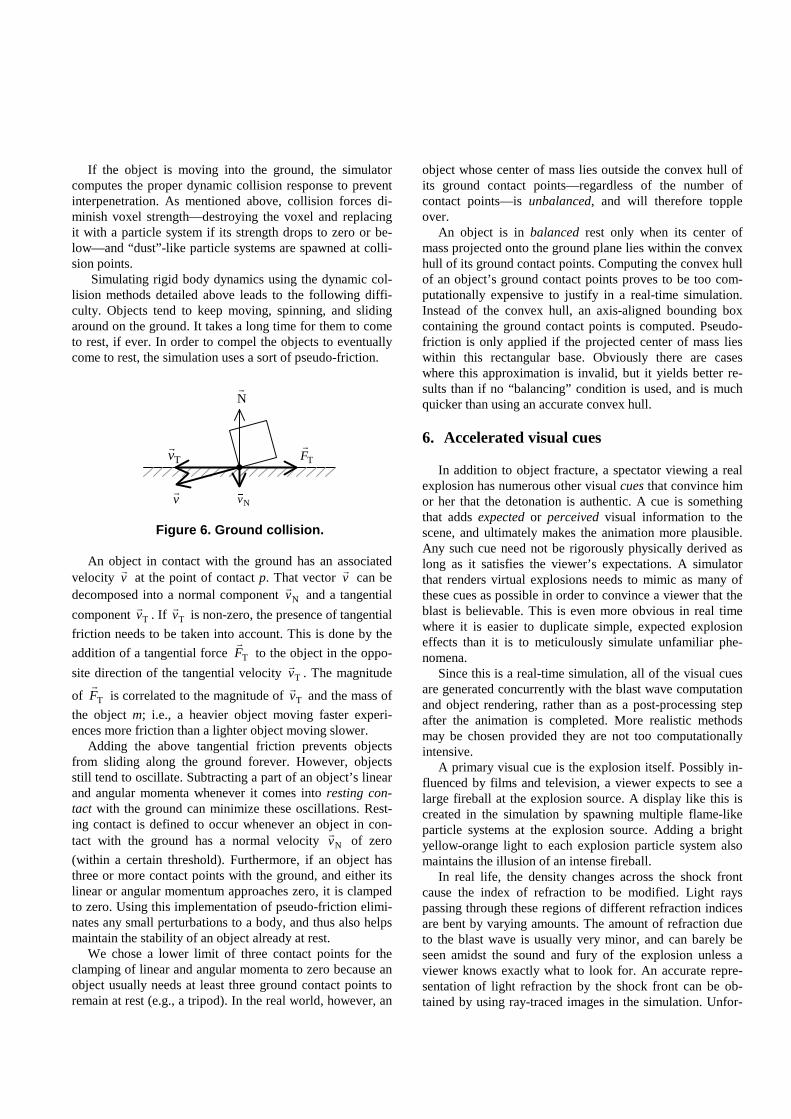
Figure 6. Ground collision.
An object in contact with the ground has an associatedvelocity v
r
at the point of contact p. That vector vr
can bedecomposed into a normal component Nv
r
and a tangential
component Tvr
. If Tvr
is non-zero, the presence of tangential
friction needs to be taken into account. This is done by the
addition of a tangential force TFr
to the object in the oppo-
site direction of the tangential velocity Tvr
. The magnitude
of TFr
is correlated to the magnitude of Tvr
and the mass of
the object m; i.e., a heavier object moving faster experi-ences more friction than a lighter object moving slower.
Adding the above tangential friction prevents objectsfrom sliding along the ground forever. However, objectsstill tend to oscillate. Subtracting a part of an object’s linearand angular momenta whenever it comes into resting con-tact with the ground can minimize these oscillations. Rest-ing contact is defined to occur whenever an object in con-tact with the ground has a normal velocity Nv
r
of zero
(within a certain threshold). Furthermore, if an object hasthree or more contact points with the ground, and either itslinear or angular momentum approaches zero, it is clampedto zero. Using this implementation of pseudo-friction elimi-nates any small perturbations to a body, and thus also helpsmaintain the stability of an object already at rest.
We chose a lower limit of three contact points for theclamping of linear and angular momenta to zero because anobject usually needs at least three ground contact points toremain at rest (e.g., a tripod). In the real world, however, an
object whose center of mass lies outside the convex hull ofits ground contact points—regardless of the number ofcontact points—is unbalanced, and will therefore toppleover.
An object is in balanced rest only when its center ofmass projected onto the ground plane lies within the convexhull of its ground contact points. Computing the convex hullof an object’s ground contact points proves to be too com-putationally expensive to justify in a real-time simulation.Instead of the convex hull, an axis-aligned bounding boxcontaining the ground contact points is computed. Pseudo-friction is only applied if the projected center of mass lieswithin this rectangular base. Obviously there are caseswhere this approximation is invalid, but it yields better re-sults than if no “balancing” condition is used, and is muchquicker than using an accurate convex hull.
6. Accelerated visual cues
In addition to object fracture, a spectator viewing a realexplosion has numerous other visual cues that convince himor her that the detonation is authentic. A cue is somethingthat adds expected or perceived visual information to thescene, and ultimately makes the animation more plausible.Any such cue need not be rigorously physically derived aslong as it satisfies the viewer’s expectations. A simulatorthat renders virtual explosions needs to mimic as many ofthese cues as possible in order to convince a viewer that theblast is believable. This is even more obvious in real timewhere it is easier to duplicate simple, expected explosioneffects than it is to meticulously simulate unfamiliar phe-nomena.
Since this is a real-time simulation, all of the visual cuesare generated concurrently with the blast wave computationand object rendering, rather than as a post-processing stepafter the animation is completed. More realistic methodsmay be chosen provided they are not too computationallyintensive.
A primary visual cue is the explosion itself. Possibly in-fluenced by films and television, a viewer expects to see alarge fireball at the explosion source. A display like this iscreated in the simulation by spawning multiple flame-likeparticle systems at the explosion source. Adding a brightyellow-orange light to each explosion particle system alsomaintains the illusion of an intense fireball.
In real life, the density changes across the shock frontcause the index of refraction to be modified. Light rayspassing through these regions of different refraction indicesare bent by varying amounts. The amount of refraction dueto the blast wave is usually very minor, and can barely beseen amidst the sound and fury of the explosion unless aviewer knows exactly what to look for. An accurate repre-sentation of light refraction by the shock front can be ob-tained by using ray-traced images in the simulation. Unfor-
Nr
vr
Tvr
Nv�
TFr
tunately, ray tracing is too time-consuming to use in a real-time simulation.
Nevertheless, viewers still expect to see some visual in-dication of the shock front itself. Since the simulation as-sumes the blast wave is spherical, a viewer’s expectationscan be fulfilled in this case by rendering a semi-transparentsphere centered at the explosion source, and having a radiusequal to the radius of the blast wave. Transparency isgradually increased as the radius increases.
Since the blast wave itself is almost invisible, its propa-gation is notable mainly by the effect it has on the environ-ment. As the blast wave moves along the ground, it kicks upclouds of dust. We achieve this by adding dust-like particlesystems at the intersection of the expanding blast wavesphere and the ground plane. The blast wave also knocksdust off of the objects in its path. To imitate this effect, wegenerate particle systems at the intersection of the blastwave and the voxels.
A visual indicator not limited to explosions is the dustthrown off when objects hit the ground or each other withsufficient force. Again, the simulation reproduces this byspawning dust-like particle systems at voxel collisionpoints. The dust thrown up at collision points also helps tomask any interpenetration that occurs.
Explosions produce high temperature conditions thatlead to nearby flammable objects getting set on fire. For theaverage viewer, there is an inextricable link—again, possi-bly reinforced by films and television—between explosionsand fire. Currently, the simulation models the pressurechanges across a shock front using physically derived meth-ods. It is possible to emulate combustibility by using a sim-pler, heuristic approach.
As with the yield limit, each voxel has a combustibilitylimit that is assigned in a similar fashion. During an explo-sion, the blast wave pressure measured at each voxel’s cen-ter is scaled by a user-definable parameter. This scaledpressure is then used to diminish the combustibility limit forthat voxel. Once a voxel’s combustibility drops below zero,it is “set on fire”, i.e., it spawns fire- and smoke-like particlesystems. Voxels that are on fire have their yield limitsweakened continually as long as they are aflame. Links thatare attached to burning voxels also have their yield limitsweakened. This simulates the destructive nature of fire.
In the real world, fire propagates based on the presenceof nearby flammable objects that are affected by elevatedtemperatures. Rather than use a proximity approach—whichis much more computationally expensive—the simulationtakes advantage of the existence of links and propagatesheat along them instead. Non-burning voxels attached toburning voxels have their combustibility limits weakened inturn. Based on the observation that fire tends to spread up-wards in a structure, an orientation factor is computed forthe position of the neighboring non-burning voxel. Voxelslocated directly above the burning voxel are accorded a
larger orientation factor than voxels located to the side orbelow. This orientation factor is then used to scale deterio-ration of neighboring voxels so that fire propagation anddamage tends to progress upwards.
When objects break apart, the sides that were hidden inthe original object usually have a different appearance thanthe exposed faces. Any voxel face not originally visible thatsubsequently appears due to object breakage is assigned ageneric “voxel damage” texture. This effect can be im-proved by having specific “damage” textures for individualvoxels. It can be generalized further by having appropriate“damage” textures painted on as a voxel diminishes instrength, or is affected by fire.
Lastly, it is self-evident that footage of real explosions isshot with real cameras. What is less obvious, though, is thatthey are as affected by the blast wave as other objects. Un-less the camera is locked down completely (and sometimeseven then), it will shake as the blast wave passes it. Addinga similar “wobble” to the simulated camera when it en-counters the blast wave helps to bring the virtual scene evencloser to its real-world counterpart.
7. Results
The simulation generates animations that are visuallysimilar to real-world explosions, through the use of physi-cally based methods and the presence of particular visualcues. Important aspects of the blast wave, such as the peakoverpressure and the negative phase, are present in thesimulation.
Without collision detection, the simulation speed is de-pendent on the computation of connected bodies in thescene. This has an upper bound of O(n), where n is the totalnumber of voxels in the scene. Pair-wise testing for colli-sion detection increases the simulation time to O(m2), wherem is the total number of boundary voxels in the scene. Theaddition of object-level bounding spheres reduces the initialnumber of tests to O(k2), where k is the total number of ob-jects in the scene.
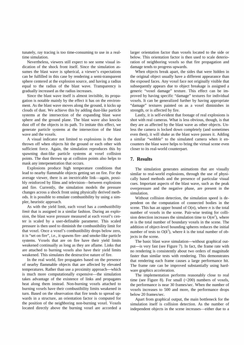
The basic blast wave simulation—without graphical out-put—is very fast (see Figure 7). In fact, the frame rate withno rendering is consistently about two orders of magnitudefaster than similar tests with rendering. This demonstratesthat rendering each frame causes a large performance hit.The frame rate can be improved substantially using hard-ware graphics acceleration.
The implementation performs reasonably close to realtime (see Figure 8). For small (<200) numbers of voxels,the performance is near 30 frames/sec. When the number ofvoxels increases to 500 and more, the performance dropsbelow 20 frames/sec.
Apart from graphical output, the main bottleneck for thesimulation itself is collision detection. As the number ofindependent objects in the scene increases—either due to a
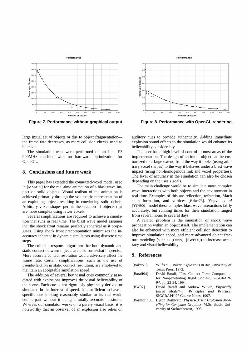
large initial set of objects or due to object fragmentation—the frame rate decreases, as more collision checks need tobe made.
The simulation tests were performed on an Intel P3900MHz machine with no hardware optimization forOpenGL.
8. Conclusions and future work
This paper has extended the connected-voxel model usedin [MMA99] for the real-time animation of a blast wave im-pact on solid objects. Visual realism of the animation isachieved primarily through the volumetric representation ofan exploding object, resulting in convincing solid debris.Arbitrary voxel shapes permit the creation of objects thatare more complex using fewer voxels.
Several simplifications are required to achieve a simula-tion that runs in real time. The blast wave model assumesthat the shock front remains perfectly spherical as it propa-gates. Using shock front precomputation minimizes the in-accuracy inherent in dynamic simulators using discrete timesteps.
The collision response algorithms for both dynamic andstatic contact between objects are also somewhat imprecise.More accurate contact resolution would adversely affect theframe rate. Certain simplifications, such as the use ofpseudo-friction in static contact resolution, are employed tomaintain an acceptable simulation speed.
The addition of several key visual cues commonly asso-ciated with explosions improves the visual believability ofthe scene. Each cue is not rigorously physically derived orsimulated in the interest of speed. It is sufficient to have aspecific cue looking reasonably similar to its real-worldcounterpart without it being a totally accurate facsimile.Whereas our simulator works on a purely visual basis, it isnoteworthy that an observer of an explosion also relies on
auditory cues to provide authenticity. Adding immediateexplosion sound effects to the simulation would enhance itsbelievability considerably.
The user has a high level of control in most areas of theimplementation. The design of an initial object can be cus-tomized to a large extent, from the way it looks (using arbi-trary voxel shapes) to the way it behaves under a blast waveimpact (using non-homogenous link and voxel properties).The level of accuracy in the simulation can also be chosendepending on the user’s goals.
The main challenge would be to simulate more complexwave interactions with both objects and the environment inreal time. Examples of this are reflection, refraction, Machstem formation, and vortices [Baker73]. Yngve et al[YOH00] model these complex blast wave interactions fairlyaccurately, but running times for their simulation rangedfrom several hours to several days.
A related problem is the simulation of shock wavepropagation within an object itself. The implementation canalso be enhanced with more efficient collision detection toimprove simulation speed, and more advanced object frac-ture modeling (such as [OH99], [SWB00]) to increase accu-racy and visual believability.
9. References
[Baker73] Wilfred E. Baker, Explosions in Air, University ofTexas Press, 1973.
[Baraff94] David Baraff, “Fast Contact Force Computationfor Nonpenetrating Rigid Bodies”, SIGGRAPH94, pp. 23-34, 1994.
[BW97] David Baraff and Andrew Witkin, PhysicallyBased Modeling: Principles and Practice,SIGGRAPH 97 Course Notes, 1997.
[Bashforth98] Byron Bashforth, Physics-Based Explosion Mod-elling for Computer Graphics, M.Sc. thesis, Uni-versity of Saskatchewan, 1998.
Performance
0.0
500.0
1000.0
1500.0
2000.0
2500.0
3000.0
3500.0
4000.0
0 500 1000 1500 2000 2500 3000 3500 4000 4500 5000
Number of Voxels
Fra
mes
per
Sec
on
d
Figure 7. Performance without graphical output.
Performance
0.0
10.0
20.0
30.0
40.0
50.0
60.0
70.0
0 500 1000 1500 2000 2500 3000 3500 4000 4500 5000
Number of Voxels
Fra
mes
per
Sec
on
d
Figure 8. Performance with OpenGL rendering.
[Brode95] H.L. Brode, “Numerical Solutions of SphericalBlast Waves”, Jour. Appl. Phys., 26, 1995.
[COMM94] N. Chiba, S. Ohkawa, K. Muraoka, and M. Miura,“Two-dimensional Visual Simulation of Flames,Smoke and the Spread of Fire”, The Journal ofVisualization and Computer Animation, Vol. 5,No. 1, 1994.
[Dewey64] John M. Dewey, “The Air Velocity in BlastWaves from TNT Explosions”, Proc. Roy. Soc.,A, 1964.
[KG85] G. F. Kinney and F. J. Graham, Explosive Shocksin Air, 2nd Ed., Springer-Verlag, 1985.
[MMA99] Oleg Mazarak, Claude Martins, and JohnAmanatides, “Animating Exploding Objects”,Graphics Interface 99, pp. 211-218, 1999.
[MC95] B. Mirtich, J. Canny, “Impulse-based Simulationof Rigid Bodies”, 1995 Symposium on Interactive3D Graphics, pp. 181-188, 1995.
[NF99] Michael Neff and Eugene Fiume, “A VisualModel for Blast Waves and Fracture”, GraphicsInterface 99, pp. 193-202, 1999.
[OH99] James F. O’Brien and Jessicca K. Hodgins,“Graphical Modeling and Animation of BrittleFracture”, SIGGRAPH 99, pp. 137-146, 1999.
[Reeves83] William T. Reeves, “Particle Systems—A Tech-nique for Modeling a Class of Fuzzy Objects”,ACM Transactions on Graphics, Vol. 2, No. 2,1983.
[SWB00] Jeffrey Smith, Andrew Witkin, and David Baraff,“Fast and Controllable Simulation of the Shat-tering of Brittle Objects”, Graphics Interface 00,pp. 27-34, 2000.
[TF88] D. Terzopoulos and K. Fleischer, “ModelingInelastic Deformation: Viscoelasticity, Plasticity,Fracture”, SIGGRAPH 88, pp. 269-278, 1988.
[TPBF87] D. Terzopoulos, John Platt, Alan Barr, and K.Fleischer, “Elastically Deformable Models”,SIGGRAPH 87, pp. 205-214, 1987.
[YOH00] Gary D. Yngve, James F. O’Brien, and Jessica K.Hodgins, “Animating Explosions”, SIGGRAPH00, pp. 29-36, 2000.
(a) (b) (c)
(d) (e) (f)
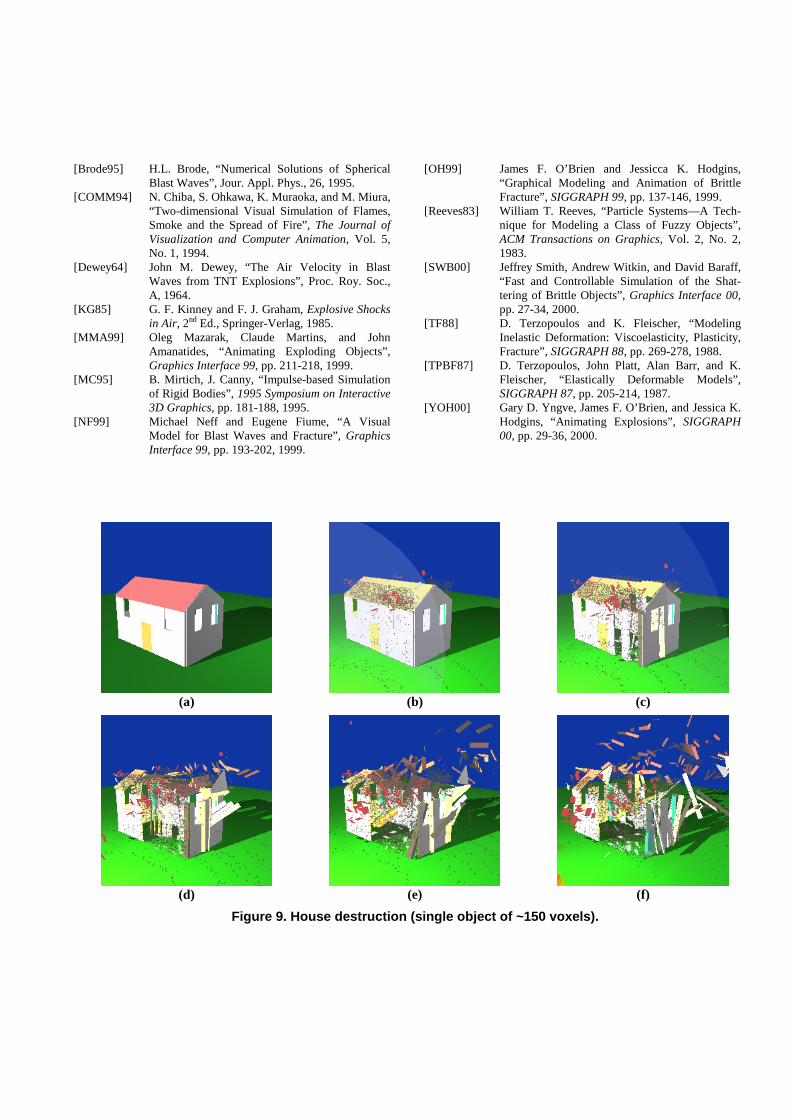
Figure 9. House destruction (single object of ~150 voxels).
(a) (b) (c)
(d) (e) (f)
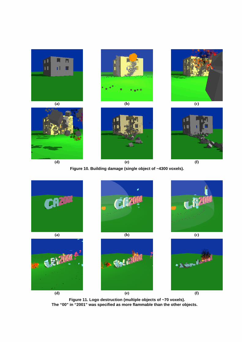
Figure 10. Building damage (single object of ~4300 voxels).
(a) (b) (c)
(d) (e) (f)
Figure 11. Logo destruction (multiple objects of ~70 voxels).The “00” in “2001” was specified as more flammable than the other objects.