vitodens 222-f b2tb residential boiler · technology strategy with one common platform. ... panel...
TRANSCRIPT
Application GuideVitodens 222-F B2TBResidential Boiler


Application Guide
The application examples contained in this document serve as a guideline only. These are not engineered drawings and are not intended to replace project de-signs provided by a professional engineer. It is the responsibility of the installing contractor to ensure all aspects of the system comply with the local authorities having jurisdiction.
© 2015 by Viessmann. All rights reserved.
No part of this book may be used or reproduced in any manner whatsoever without prior written permission.
For information, contact:
Viessmann Manufacturing Company Inc. 750 McMurray Road Waterloo ON, N2V 2G5, Canada
Phone: 519-885-6300 Toll Free: 800-387-7373
www.viessmann.ca

IV
1
Each day Viessmann heating systems face a wide variety of requirements and challenges here in North America, and around the world. Whether in historically protected homes, modern commercial buildings, or in large facil-ities, Viessmann products meet every demand and offer solutions for all your needs: wood, oil, or gas fired boilers for both residential and commercial use, from 12KBTU to 17.9MBH (4 to 5263kW), domestic hot water storage tanks, solar collectors, Biogas technol-ogies, and much more.
Viessmann also sets the standard for operational reliability, operating comfort, environmental friendliness and a long service life. All Viessmann products have one thing in common: they are based on a modular
technology strategy with one common platform. This way, different product versions can be created to fulfill each customer’s specific requirements. In short, Viessmann takes care of all your needs, from start to finish.
Part of that is a comprehensive support program: A knowledgeable Viessmann sales representative network, technical training academy, and technical support personnel as-sist you right from the planning stage through to the installation and start-up phase of a project.
With Viessmann you are witnessing intelligent, high-tech boiler technology at work. We have selected some of the most interesting Viessmann appli-cations from across North America for your reference.
Pre-Face / Overview
2
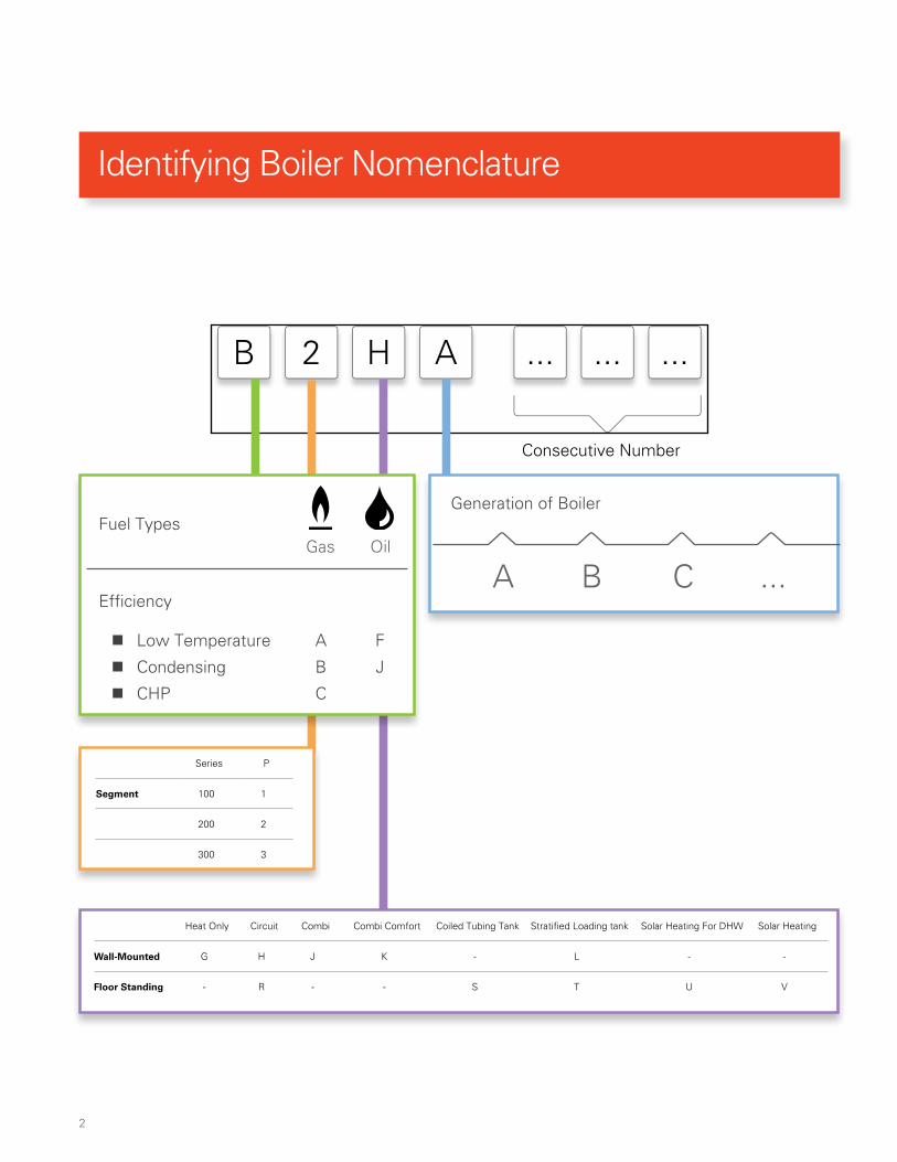
AH2 ... ... ...B
Fuel Types
Efficiency
� Low Temperature A F
� Condensing B J
� CHP C
Gas Oil
Generation of Boiler
Consecutive Number
A B C ...
Heat Only Circuit Combi Combi Comfort Coiled Tubing Tank Stratified Loading tank Solar Heating For DHW Solar Heating
Wall-Mounted G H J K - L - -
Floor Standing - R - - S T U V
Series P
Segment 100 1
200 2
300 3
Identifying Boiler Nomenclature

3
X2VD TI 2HC ZP 01I2
Number of boilers in system Number of heating circuits
1, 2, 3 ...
Number of supply water temperatures in the system.
Number of zones in the system
Drawing version
How system is zoned
ZP Pumps
ZV Zone valves
TV Thermostatic Radiator Valves
C Combination
Boiler Segment
VD Vitodens
CU
CM Vitocrossal
CT
VR Vitorond
Segment / Series
1 100 Series
2 200 Series
3 300 Series
Domestic Capability
X No DHW
I With indirect DHW
C On demand DHW
T Stratified loading tank
1 1
Identifying Application Codes
4
Medium120 -160 °F
Low80 -120 °F
High160 -190 °F
Medium140 -160 °F
High160 -190 °F
1 1
2
2
1 1
Medium180 -120 °F
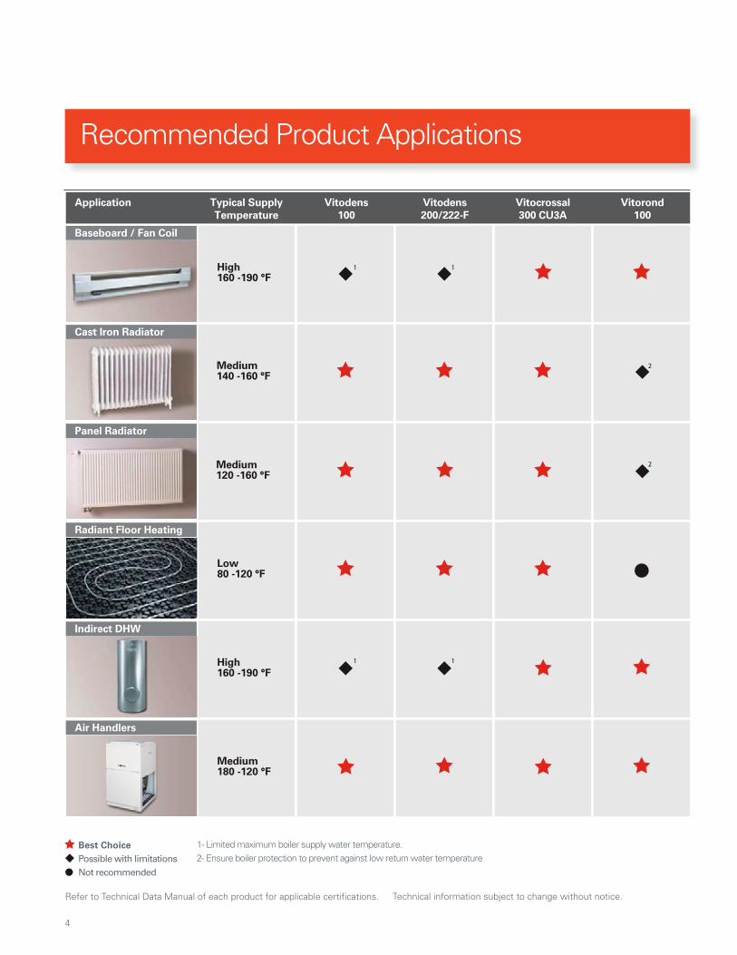
Refer to Technical Data Manual of each product for applicablT e certifications. Technical information subject to change without notTT ice.
Best Choice Possible with limitationsNot recommended
1- Limited maximum boiler supply water temperature.2- Ensure boiler protection to prevent against low return water temperature
Baseboard / Fan Coil
Cast Iron Radiator
Panel Radiator
Radiant Floor Heating
Indirect DHW
Air Handlers
Vitodens100
Vitodens200/222-F
Vitorond100
Vitocrossal300 CU3A
Typical SupplyTemperature
Application
Recommended Product Applications

5
Vitodens 222-F with Connection Set Ball Valve Circulator with isolation flanges Aquastat Secondary Low Water Cut-off
Low Loss Header Thermostatic Mixing valve Radiant infloor manifold Motorized Mixing Valve Outdoor Temperature Sensor
Panel Radiator Flow check valve Hot water baseboard Radiator Thermostat Temperature Sensor
Boiler water feed with double back check valve
Air eliminator Expansion Tank Viessmann Vitotrol Multi-Zone Control
Purge assembly: (sediment faucet and ball valve)
Zone Valve Hydronic Air Handler 24V Zone Valve Circulator
Towel Radiator Viessmann 3-Way Mixing Valve with actuator motor
Plate and frame Heat Exchanger 120 Volt Power
Hydronic Components Electrical Components
Component Index

6

7
Vitodens 222-F (B2TB)
Application # Application Code Page
Application 1 - VD2T 1HC1T1ZP.01 22
Application 2 - VD2T 1HC1T4ZV.01 26
Application 3 - VD2T 1HC1T4ZP.01 30
Application 4 - VD2T 2HC2T2ZP.01 34
Application 5 - VD2T 2HC2T2ZP.02 38
Application 6 - VD2T 3HC3T3ZP.01 42
8
Product may not be exactly as shown
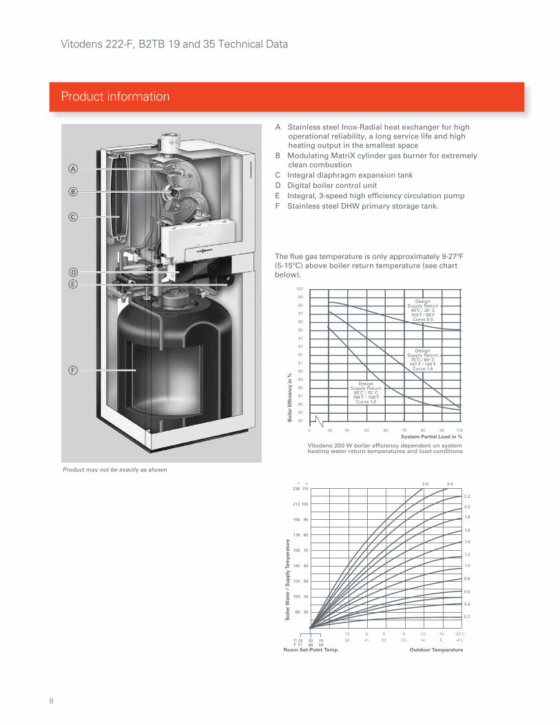
The flue gas temperature is only approximately 9-27ºF (5-15ºC) above boiler return temperature (see chart below).
A Stainless steel Inox-Radial heat exchanger for high operational reliability, a long service life and high heating output in the smallest spaceB Modulating MatriX cylinder gas burner for extremely clean combustionC Integral diaphragm expansion tankD Digital boiler control unitE Integral, 3-speed high efficiency circulation pumpF Stainless steel DHW primary storage tank.
Product information
Vitodens 222-F, B2TB 19 and 35 Technical Data

9
Boiler Model No. 222-F B2TB 19 35
Natural Gas / Liquid Propane GasCSA input
CSA output/DOE *1heating capacity
Net AHRI rating *2
MBHkW
MBHkW
MBHkW
12-683.5-2011-64
3.2-19
5516
19-1255.5-37
18-1175.1-34
10230
Heat exchanger surface area ft. 2
m212.96
1.212.96
1.2
Min. gas supply pressureNatural gasLiquid propane gas
“w.c.“w.c.
410
410
Max. gas supply pressure *3Natural gasLiquid propane gas
“w.c.“w.c.
1414
1414
A.F.U.E. 5959%
Weight(including installation fittings)
lbs(kg)
278(126)
278(126)
Boiler water content USG(L)
1.02(3.88)
1.02(3.88)
Boiler max. flow rate *4 GPM(L/h)
6.2(1400)
6.2(1400)
Expansion tank *5(for heating system side)Precharge pressureCapacity
psigUSG
(L)
123.2
(12)
123.2
(12)
Max. operating pressureat 210ºF (99ºC)
psigbar
453
453
Boiler water temperature- Adjustable high limit (AHL) range space heating (steady state) - Fixed high limit (FHL)
ºF(ºC)
ºF (ºC)
68 to 165(20 to 74)
210 (99)
68 to 165(20 to 74)
210 (99)
Boiler connectionsBoiler heating supply and return Pressure relief valve Drain valve
Boiler supply/return for indirect-fired DHW storage tank (field supplied)Gas valve connection
NPTM”NPTF”(male
thread)
NPT”
NPTF”
¾”¾”¾”
¾”
¾”
¾”¾”¾”
¾”
¾”
*1 Output based on 140ºF (60ºC), 120ºF (49ºC) system supply/return temperature.
*2 Net AHRI rating based on piping and pick-up allowance of 1.15.
*3 If the gas supply pressure exceeds the maximum gas supply pressure value, a separate gas pressure regulator must be installed upstream of the heating system.
*4 See “Waterside Flow” starting on page 8 in this manual.*5 Determine the required size of the expansion tank to be installed in the heating system. If the integral expansion tank is insufficient, install a suitably sized expansion tank on site.
Technical Data
Vitodens 222-F, B2TB 19 and 35 Technical Data

10
Technical Data
Vitodens 222-F, B2TB 19 and 35 Technical Data

11
Note: The dimensional drawing shows example fittings for upward connection and connection to the left/right, for installation on finished walls. Order the connection sets separately as accessories. For the dimensions of the individual connection sets, see the design information.
Model B2TB 19 and 35 Model B2TB 19 and 35
a *1 in. (mm) 46.1 (1172) k * 1 in. (mm) 65.6 (1665)
b *1 in. (mm) 48.3 (1227) l *1 in. (mm) 68.0 (1726)
c * 1 in. (mm) 28 (710) approx. m in. (mm) 16.1 (410)
d *1 in. (mm) 52.6 (1337) n in. (mm) 8.8 (224)
f * 1 in. (mm) 57.0 (1447) o in. (mm) 15.3 (389)
g in. (mm) 2.0 (50) p in. (mm) 14.2 (361)
h *1 in. (mm) 59.1 (1502) q in. (mm) 12.6 (320)
i *1 in. (mm) 64.2 (1630) r in. (mm) 13.0 (330)
j *1 in. (mm) 65.6 (1666) s in. (mm) 8.7 (220)
Legend A Condensate Drain (side)
*1
Note: All height dimensions of the boiler have a tolerance of +.6 in. (+15 mm) due to the factory installed adjustable feet
*1 Add 1f in. (40 mm) when using the optional accessory seismic bracket kit. Note: All height dimensions of the boiler have a tolerance of +.5 in. (+13 mm) due to the seismic bracket adjustable feet.
Boiler Dimensions
Vitodens 222-F, B2TB 19 and 35 Technical Data

12
Note: eht dessap sah reliob BT2B ,F-222 snedotiV ehT zero inches vent clearance to combustibles testing requirements dictated by the boiler Harmonized Standard ANSI Z21.13. CSA 4.9 (latest edition) and therefore is listed for zero clearance to combustibles when vented with a single-wall UL/ULC certified special venting system. The zero inches vent clearance to combustibles for the Vitodens boiler supercedes the clearance to combustibles listing that appears on the special venting system label.
The back or side clearance shall be increased if piping installation is required.
Recommended minimum service clearances
See the Vitodens 222-F B2TB Venting System Installation Instructions for details.
Boiler model B2TB 19 35Top 0 0Sides (left and right) 0 0Vent pipe 0 0Front (alcove or closet) 0 0Rear 0 0Floor combustible combustible
Minimum clearances to combustibles
Boiler Dimensions
Vitodens 222-F, B2TB 19 and 35 Technical Data
13
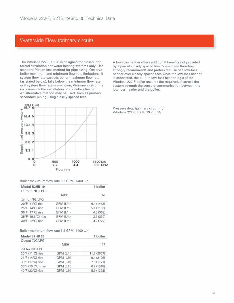
The Vitodens 222-F, B2TB is designed for closed loop, forced circulation hot water heating systems only. Use standard friction loss method for pipe sizing. Observe boiler maximum and minimum flow rate limitations. If system flow rate exceeds boiler maximum flow rate (as stated below), falls below the minimum flow rate or if system flow rate is unknown, Viessmann strongly recommends the installation of a low-loss header. An alternative method may be used, such as primary secondary piping using closely spaced tees.
A low-loss header offers additional benefits not provided by a pair of closely spaced tees. Viessmann therefore strongly recommends and prefers the use of a low-loss header over closely spaced tees. Once the low-loss header is connected, the built-in low-loss header logic of the Vitodens 222-F boiler ensures the required t across the system through the sensory communication between the low-loss header and the boiler.
Pressure drop (primary circuit) for Vitodens 222-F, B2TB 19 and 35
Boiler maximum flow rate 6.2 GPM (1400 L/h)
Boiler maximum flow rate 6.2 GPM (1400 L/h)
Model B2HB 19 1 boilerOutput (NG/LPG) MBH 64t for NG/LPG20ºF (11ºC) rise GPM (L/h) 6.4 (1453) 25ºF (14ºC) rise GPM (L/h) 5.1 (1163)30ºF (17ºC) rise GPM (L/h) 4.3 (969)35ºF (19.5ºC) rise GPM (L/h) 3.7 (830)40ºF (22ºC) rise GPM (L/h) 3.2 (727)
Model B2HB 35 1 boilerOutput (NG/LPG) MBH 117t for NG/LPG20ºF (11ºC) rise GPM (L/h) 11.7 (2657) 25ºF (14ºC) rise GPM (L/h) 9.4 (2126) 30ºF (17ºC) rise GPM (L/h) 7.8 (1771) 35ºF (19.5ºC) rise GPM (L/h) 6.7 (1518)40ºF (22ºC) rise GPM (L/h) 5.9 (1328)
Flow rate
Su
pp
ly h
ead
pre
ssu
re (
wat
er)
Waterside Flow (primary circuit)
Vitodens 222-F, B2TB 19 and 35 Technical Data
14
Pump InformationIMPORTANT
Pump selection must be based on accurate system flow and pressure drop calculations (includes DHW sizing).
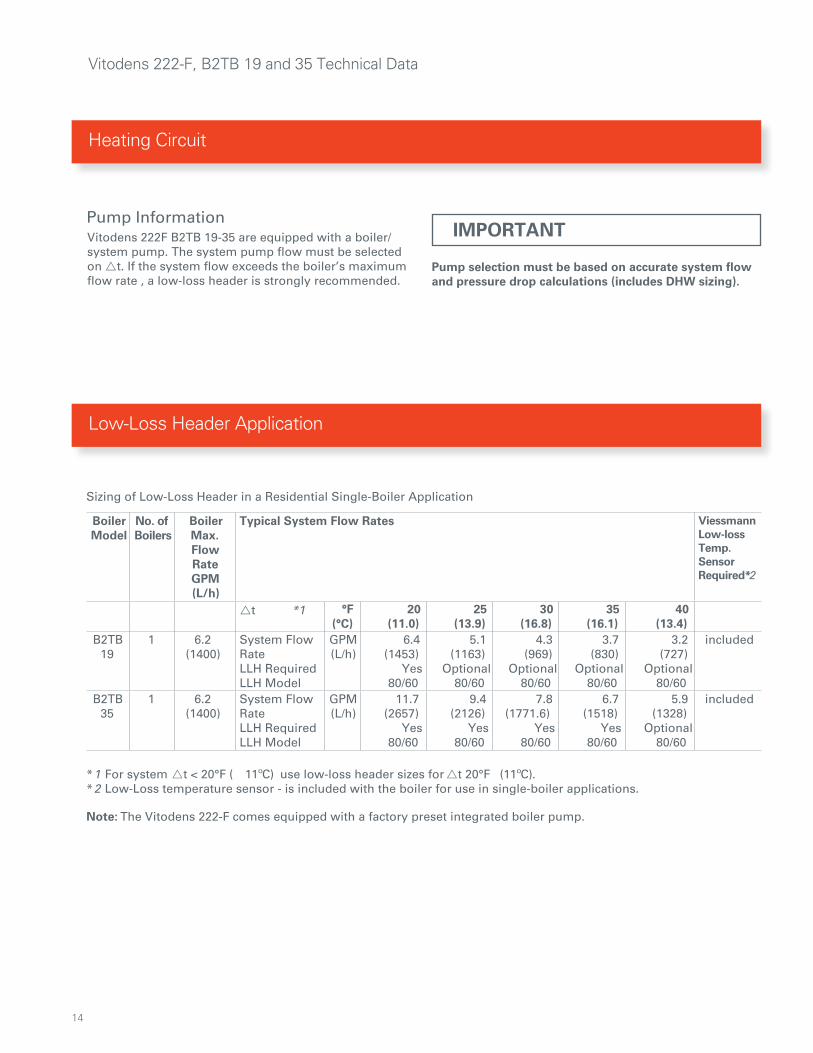
Sizing of Low-Loss Header in a Residential Single-Boiler Application
*1 For system t < 20°F ( 11ºC) use low-loss header sizes for t 20°F (11ºC).*2 Low-Loss temperature sensor - is included with the boiler for use in single-boiler applications.
BoilerModel
No. ofBoilers
Boiler Max. Flow RateGPM (L/h)
Typical System Flow Rates Viessmann Low-lossTemp.Sensor Required*2
t *1 °F(°C)
20(11.0)
25(13.9)
30(16.8)
35(16.1)
40(13.4)
B2TB 19
1 6.2(1400)
System Flow RateLLH RequiredLLH Model
GPM(L/h)
6.4(1453)
Yes80/60
5.1(1163)
Optional80/60
4.3(969)
Optional80/60
3.7(830)
Optional80/60
3.2(727)
Optional80/60
included
B2TB 35
1 6.2(1400)
System Flow RateLLH RequiredLLH Model
GPM(L/h)
11.7(2657)
Yes80/60
9.4(2126)
Yes80/60
7.8(1771.6)
Yes80/60
6.7(1518)
Yes80/60
5.9(1328)
Optional80/60
included
Note: The Vitodens 222-F comes equipped with a factory preset integrated boiler pump.
Vitodens 222F B2TB 19-35 are equipped with a boiler/system pump. The system pump flow must be selected on t. If the system flow exceeds the boiler’s maximum flow rate , a low-loss header is strongly recommended.
Low-Loss Header Application
Heating Circuit
Vitodens 222-F, B2TB 19 and 35 Technical Data
15
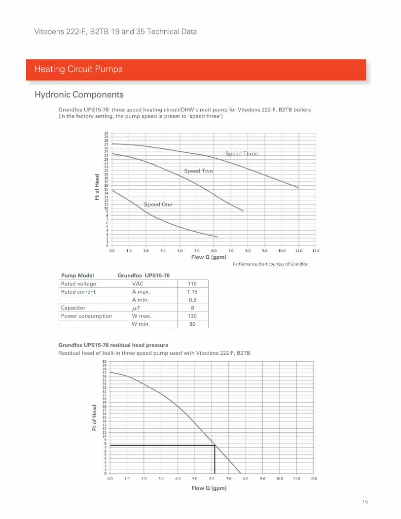
Pump Model Grundfos UPS15-78
Rated voltage VAC 115Rated current A max. 1.15
A min. 0.8Capacitor F 8
Power consumption W max. 130W min. 80
Grundfos UPS15-78 three speed heating circuit/DHW circuit pump for Vitodens 222-F, B2TB boilers (in the factory setting, the pump speed is preset to ‘speed three’)
Speed One
Speed Three
Speed Two
Flow Q (gpm)
Ft o
f H
ead
Performance chart courtesy of Grundfos
Grundfos UPS15-78 residual head pressureResidual head of built-in three speed pump used with Vitodens 222-F, B2TB
Flow Q (gpm)
Ft o
f H
ead
Hydronic Components
Heating Circuit Pumps
Vitodens 222-F, B2TB 19 and 35 Technical Data

16
Boiler locationAs a direct vent appliance, the Vitodens 222-F can be installed for room air independent operation (sealed combustion) regardless of size and ventilation method of the room in which it is located.The Vitodens 222-F can be installed, for example, in the main living area of a house, in non-ventilated utility rooms, cupboards, closets and alcoves with no clearance required from combustible materials, as well as in attics with a direct outlet for the flue gas/fresh air system. Follow all local and national codes.
Flue gas systemViessmann PPS (Polypropylene) concentric flue gas/fresh air systems for room air independent operation (sealed combustion) and side wall venting are tested to ANSI Z21.13 - CSA 4.9 - 2000 standards and are certified together with the Vitodens 222-F boiler as a constructional unit.The Vitodens 222-F boiler may also be vented vertically, using an AL29-4C® special stainless steel, single-wall, room air dependent venting system (UL listed for category IV).For a more detailed description of the direct vent and single-wall vent system, please refer to the Vitodens 222-F Venting System Installation Instructions.
Flue gas temperature protectionFlue pipes used for the Vitodens 222-F are suitable for max. flue gas temperatures of up to 230°F (110°C).No flue gas temperature protection is required as the maximum permissible flue gas temperature is not exceeded in any operating condition or in the event of malfunctioning.
Low water cut-offA low water cut-off may be required by local codes. If the boiler is installed above the radiation level, a low water cut-off device of approved type must be installed in all instances. An approved type low water cut-off device must be provided by the heating contractor. Do not install an isolation valve between the boiler and the low water cut-off.
Water connectionsVitodens 222-F boilers can be used in any fully pumped hot water heating system.Minimum system pressure is 14 psig.Chemical corrosion protection productsCorrosion does not typically occur in sealed heating systems which have been correctly installed and are correctly operated.Many manufacturers of plastic pipes recommend the use of chemical additives. In this case, only those commercially available corrosion protection products approved for boilers with domestic hot water heating via single-wall heat exchangers (instantaneous plate heat exchangers or DHW tanks) must be used.
Water qualityTreatment for boiler feed water should be considered in areas of known problems, such as where a high mineral content and hardness exist. In areas where freezing might occur, an antifreeze may be added to the system water to protect the system. Please adhere to the specifications given by the antifreeze manufacturer. Do not use automotive silicate based antifreeze. Please observe that an antifreeze/water mixture may require a backflow preventer within the automatic water feed and influence components such as diaphragm expansion tanks, radiation, etc. Maximum antifreeze content is 50% for the Vitodens 222-F boiler. Do not use antifreeze other than specifically made for hot water heating systems. System also may contain components which might be negatively affected by antifreeze. Check total system frequently when filled with antifreeze. Advise system operator/ultimate owner that system is filled with a glycol mix. The heating contractor must provide a MSDS (Material Safety Data Sheet) for the antifreeze used to the system operator/ultimate owner.
Total permissible hardness of the fill and top-up water
Total heating output Specific heating volume
MBH <5 USG per 3412 BTU 5 USG per 3412 BTU to<13 USG per 3412 BTU
13 USG per 3412 BTU
170 300 pp 17.5 gpg 200 ppm 11.7 gpg 2 ppm 0.11 gpg
>170 to 682 200 pp 11.7 gpg 150 ppm 8.8 gpg 2 ppm 0.11 gpg
>682 to 170 150 pp 8.8 gp 2 ppm 0.11 gpg 2 ppm 0.11 gpg
gpg 11.0 mpp 2gpg11.0mpp 2gpg 11.0mpp 20502>
ppm - parts per milliongpg - grains per gallon
System Design Considerations
Vitodens 222-F, B2TB 19 and 35 Technical Data

17
Oxygen diffusion barrier underfloor tubingThe boiler warranty does not cover leaks resulting from corrosion caused by the use of underfloor plastic tubing without an oxygen diffusion barrier. Such systems must have the non-oxygen diffusion barrier tubing separated from the boiler with a heat exchanger. Viessmann recommends the use of underfloor plastic tubing with an oxygen diffusion barrier.
WarrantyOur warranty does not cover damages resulting from the following:- installation or service by unqualified and unlicensed personnel.- attempting to perform any repair work on the boiler other than that mentioned in the boiler literature.- tampering with or attempting, without Viessmann permission, to readjust the factory settings of the; -combination gas valve -combustion air opening of the burner blower - leaks resulting from corrosion caused by the use of underfloor plastic tubing without an oxygen diffusion barrier. For detailed warranty information, please read warranty sheet supplied with product.
System layout The max. boiler water temperature for space heating
and DHW production is 165°F (74°C) for models B2TB 19 and 35. To minimize distribution losses, Viessmann recommends that the heating and domestic hot water systems be based on a maximum boiler supply temperature of 158°F (70°C).
Due to the low return temperatures required for gas condensing, no mixing valves should be used in the heating circuit whenever possible. If mixing valves are required, e.g. for multi-circuit systems or underfloor heating systems, only 3-way mixing valves must be used. Do not use 4-way mixing valves with condensing boilers.
Underfloor heating systemsFor underfloor heating systems Viessmann recommends the use of plastic tubing with an oxygen diffusion barrier in order to prevent the diffusion of oxygen through tubing. If plastic tubing without an oxygen diffusion barrier is used in underfloor heating systems, Viessmann recommends that such systems be separated from the boiler with a heat exchanger.Underfloor heating systems and heating circuits containing a very large volume of water must be connected to the boiler via a 3-way mixing valve; please refer to the applicable installation example in this manual.
System Design System Design Considerations (continued)
Vitodens 222-F, B2TB 19 and 35

18
Power
Pump
MixingModule
SupplySensor
Comm. BusOn Boiler
145145 2
17
5220
not used 40A
40
Notes/Comments
1. When multiple 145 communication accessories are being installed, 145 cables will need to be run from device to device. (Daisy Chain)
2. Ensure to set the S1 switch to assign the mixing valve heating circuit.
Product information
Wiring a Mixing Valve Controller

19
Product information
Storage Tank Loading System (STLS)
��
�
�
��
One key aspect of the Vitodens 222-F is its unique approach to meeting varying loads of DHW demands. The Advanced Storage Tank Loading System (STLS) technology ensures a reliable and efficient DHW supply by combining storage and tankless technology. The STLS utilizes a plate heat exchanger and innovative piping strategy to combine the benefits of both a storage type water heater and on-de-mand DHW. This allows the 222-F to meet a varying range of loads from small to large without affecting the operation of the boiler. Here’s how it works:
Micro DHW LoadsA demand for DHW is where the 222-F starts to outshine all other products on the market. Imagine you turn the hot water tap on to rinse a glass, or better yet trickle a little bit of hot water while you shave. A typical on demand type water heater would short cycle or may not even turn on for such a small amount of DHW. The 26 gallon storage tank on the 222-F addresses this by simply storing a small amount of hot water(1) for these types of situations. Therefore the small volume of hot water(2) is taken from the onboard storage tank preventing the boiler from short cycling and eliminating common is-sues with on demand units. This will also allow the boiler to continue to provide heat to the heating system uninterrupted(3).
Heating ModeIn heating mode the boiler functions in the exact same way as a typical low mass hi efficiency condensing gas boiler. The internal circulator(1) draws in cool return water from the system(2), pushes it through the boiler where it is heated up and sent back out into the system(3).
20
Product information
Storage Tank Loading System (STLS))
�
�
� �
�
�
�
�
�
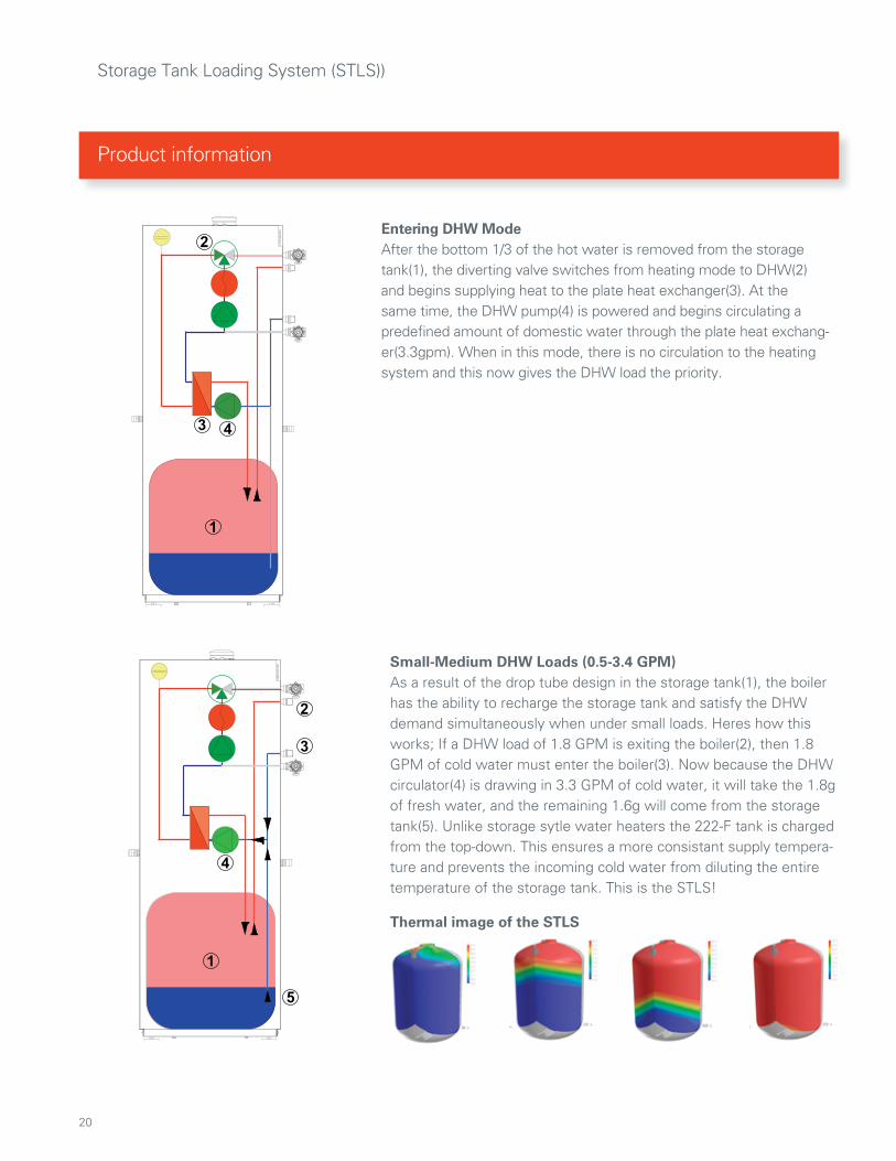
Entering DHW ModeAfter the bottom 1/3 of the hot water is removed from the storage tank(1), the diverting valve switches from heating mode to DHW(2) and begins supplying heat to the plate heat exchanger(3). At the same time, the DHW pump(4) is powered and begins circulating a predefined amount of domestic water through the plate heat exchang-er(3.3gpm). When in this mode, there is no circulation to the heating system and this now gives the DHW load the priority.
Small-Medium DHW Loads (0.5-3.4 GPM)As a result of the drop tube design in the storage tank(1), the boiler has the ability to recharge the storage tank and satisfy the DHW demand simultaneously when under small loads. Heres how this works; If a DHW load of 1.8 GPM is exiting the boiler(2), then 1.8 GPM of cold water must enter the boiler(3). Now because the DHW circulator(4) is drawing in 3.3 GPM of cold water, it will take the 1.8g of fresh water, and the remaining 1.6g will come from the storage tank(5). Unlike storage sytle water heaters the 222-F tank is charged from the top-down. This ensures a more consistant supply tempera-ture and prevents the incoming cold water from diluting the entire temperature of the storage tank. This is the STLS!
Thermal image of the STLS
21
Product information
Storage Tank Loading System (STLS)
�
�
�
�
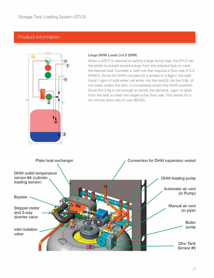
Large DHW Loads (>3.5 GPM)
When a 222-F is required to satisfy a large dump load, the STLS has the ability to extract stored energy from the onboard tank to meet the desired load. Consider a bath tub that requires a flow rate of 4.4 GPM(1). Since the DHW circulator(2) is preset to 3.4gpm, the addi-tional 1 gpm of cold water will enter into the tank(3). As the 3.4g of hot water enters the tank, it immediately enters the DHW outlet(4). Since this 3.4g is not enough to satisfy the demand, 1gpm is taken from the tank to meet this target outlet flow rate. This allows for a ten minute draw rate of over 60USG.

22
Vito
dens
222
-FA
pp
licat
ion
1
Low
Los
s H
eade
rC
lose
ly S
pace
d Te
e’s
P3
P3
Ap
plic
atio
n C
od
e
VD
2T 1
HC
1T1Z
P .0
1
Not
es /
Com
men
ts
1.
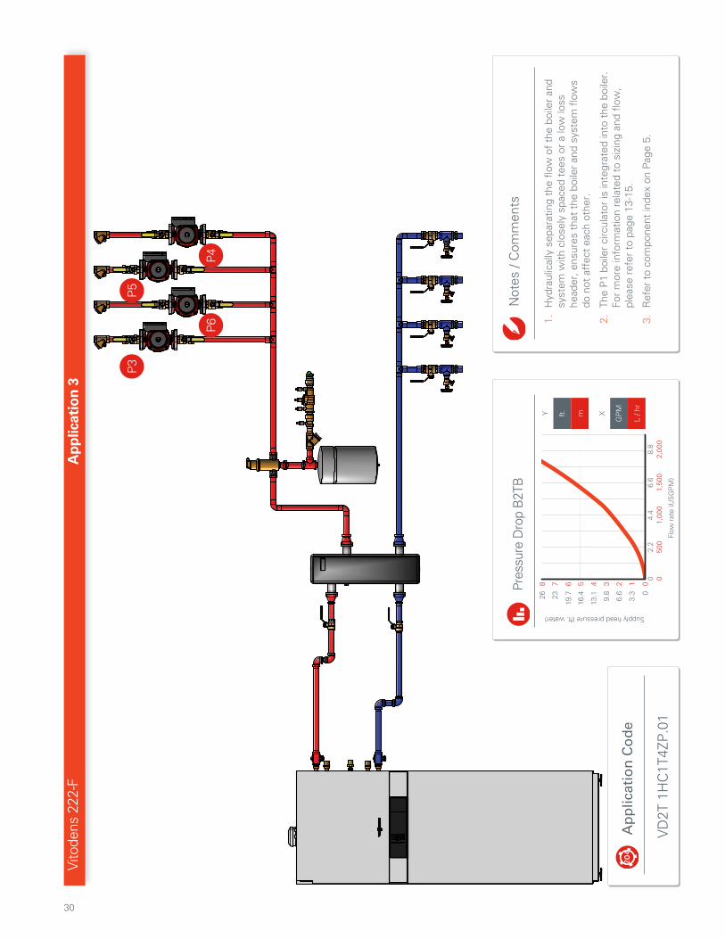
Hyd
raul
ical
ly s
epar
atin
g th
e flo
w o
f th
e bo
iler
and
syst
em w
ith c
lose
ly s
pace
d te
es o
r a
low
loss
he
ader
, ens
ures
tha
t th
e bo
iler
and
syst
em f
low
s do
not
aff
ect
each
oth
er.
2.
The
P1
boile
r ci
rcul
ator
is in
tegr
ated
into
the
boi
ler.
Fo
r m
ore
info
rmat
ion
rela
ted
to s
izin
g an
d flo
w,
plea
se r
efer
to
page
13-
15.
3.
Ref
er t
o co
mpo
nent
inde
x on
Pag
e 5.
Pres
sure
Dro
p B
2TB

23
Vito
dens
222
-FA
pp
licat
ion
1
HC1
Th
erm
osta
t
Pum
p(P
3)
Pow
er
Out
door
Sens
or
Low
Los
s H
eade
r Se
nsor
Op
tiona
l Vi
totr
ol
OR
X11
Not
es /
Com
men
ts
1.
For
a si
mpl
ified
inst
alla
tion
and
mor
e in
telli
gent
op
erat
ion,
the
Vito
trol
200
-A a
nd V
itotr
ol 3
00-A
can
be
use
d in
pla
ce o
f a
trad
ition
al t
herm
osta
t.
2.
••••••
indi
cate
s op
tiona
l con
nect
ion.
App
licat
ion
Cod
e
VD
2T 1
HC
1T1Z
P.0
1
24
Vitodens 222-F, B2TB
Application 1 - Operational Setup Instructions
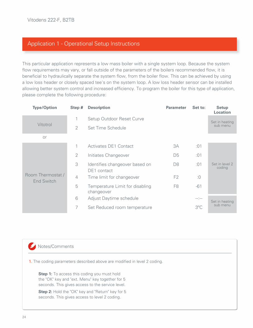
1. The coding parameters described above are modified in level 2 coding.
Notes/Comments
1.
Step 1: To access this coding you must hold the "OK" key and "ext. Menu" key together for 5 seconds. This gives access to the service level.
Step 2: Hold the "OK" key and "Return" key for 5 seconds. This gives access to level 2 coding.
This particular application represents a low mass boiler with a single system loop. Because the system flow requirements may vary, or fall outside of the parameters of the boilers recommended flow, it is beneficial to hydraulically separate the system flow, from the boiler flow. This can be achieved by using a low loss header or closely spaced tee's on the system loop. A low loss header sensor can be installed allowing better system control and increased efficiency. To program the boiler for this type of application, please complete the following procedure:
Type/Option Step # Description Parameter Set to: SetupLocation
Vitotrol1 Setup Outdoor Reset Curve
Set in heatingsub menu2 Set Time Schedule
or
Room Thermostat / End Switch
1 Activates DE1 Contact 3A :01
2 Initiates Changeover D5 :01
3 Identifies changeover based on DE1 contact
D8 :01 Set in level 2coding
4 Time limit for changeover F2 :0
5 Temperature Limit for disabling changeover
F8 -61
6 Adjust Daytime schedule --:--Set in heating
sub menu7 Set Reduced room temperature 3ºC

25
Application 1 - Operational Setup ... continued
Notes/Comments

26
Vito
dens
222
-FA
pp
licat
ion
2
Ap
plic
atio
n C
od
e
VD
2T 1
HC
1T4Z
V.0
1
P3
Z1Z2
Z3Z4
Not
es /
Com
men
ts
1.
Hyd
raul
ical
ly s
epar
atin
g th
e flo
w o
f th
e bo
iler
and
syst
em w
ith c
lose
ly s
pace
d te
es o
r a
low
loss
he
ader
, ens
ures
tha
t th
e bo
iler
and
syst
em f
low
s do
not
aff
ect
each
oth
er.
2.
The
P1
boile
r ci
rcul
ator
is in
tegr
ated
into
the
boi
ler.
Fo
r m
ore
info
rmat
ion
rela
ted
to s
izin
g an
d flo
w,
plea
se r
efer
to
page
13-
15.
3.
Ref
er t
o co
mpo
nent
inde
x on
Pag
e 5.
Pres
sure
Dro
p B
2TB

27
Vito
dens
222
-FA
pp
licat
ion
2
Not
es /
Com
men
ts
1.
Ens
ure
the
field
sup
plie
d tr
ansf
orm
er is
siz
ed a
ppro
pria
tely
to
acc
omm
odat
e th
e lo
ad o
f th
e zo
ne v
alve
s.2.
Th
e tr
ansf
orm
er/z
one
valv
es w
ill o
nly
have
pow
er w
hen
the
boile
r is
pow
ered
. The
refo
re if
the
pow
er s
uppl
y to
the
boi
ler
is t
urne
d of
f fo
r se
rvic
e, a
ll zo
ne v
alve
s/th
erm
osta
ts w
ill b
e in
activ
e.
3.
This
app
licat
ion
can
also
be
achi
eved
thr
ough
the
use
of
a zo
ne v
alve
mul
ti-zo
ne c
ontr
ol a
s sh
own
in a
pplic
atio
n #3
.
App
licat
ion
Cod
e
VD
2T 1
HC
1T4Z
V.0
1

28
Vitodens 222-F, B2TB
Application 2 - Operational Setup Instructions
1. The coding parameters described above are modified in level 2 coding. Step1: To access this coding you must hold the "OK" key and "Ext. Menu" key together for 5 seconds. This gives access to the service level.
Step 2: Hold the "OK" key and "Return" key for 5 seconds. This gives access to level 2 coding.
Notes/Comments
In this system you have a Vitodens 222-F, and a four zone single temperature system. Upon a call for heat, a zone valve opens turning on the P1(internal) & P3 circulators. In the event there is a call for DHW, the flow provided by the P1 Circulator will be diverted through the internal plate heat exchanger. This will provide a do-mestic priority function for the purpose of quickly satisfying a DHW demand. It is recommended to use a vari-able speed system circulator that will adjust flow based on opening/closing zone valves. If a single speed pump is being used, ensure a pressure differential bypass is incorporated into the system to avoid “over pumping” a circuit when a single zone is calling for heat. To setup the boiler for this application you will need to compete the following:
Type/Option Step# Description Parameter Set to: SetupLocation
1 Assign P3 as a heat circuit pump 53: :02
Set in Level 2 Coding
2 Configure boiler to operate upon a call for heat
Activates DE1 Contact 3A :01
Initiates Changeover D5 :01
Identifies changeover based on DE1 contact D8 :01
Time limit for changeover F2 :0
Temperature Limit for disabling changeover F8 -61
Adjust Daytime schedule -- Set in heating
sub menuSet Reduced room temperature 3ºC
3 Setup HC1 Outdoor Reset Curve
4 Set DHW Temperature
Optional Adjustments
Set a Heating Schedule. Set in heating
sub menuSet an individual DHW Schedule
Configure P1 to shut down once low loss header has reached its setpoint temperature 51: :01Set in Level 2 Coding

29
Application 2 - Operational Setup ... continued
Notes/Comments
30
Vito
dens
222
-FA
pp
licat
ion
3
Ap
plic
atio
n C
od
e
VD
2T 1
HC
1T4Z
P.0
1
P3
P4
P6
P5
Not
es /
Com
men
ts
1.
Hyd
raul
ical
ly s
epar
atin
g th
e flo
w o
f th
e bo
iler
and
syst
em w
ith c
lose
ly s
pace
d te
es o
r a
low
loss
he
ader
, ens
ures
tha
t th
e bo
iler
and
syst
em f
low
s do
not
aff
ect
each
oth
er.
2.
The
P1
boile
r ci
rcul
ator
is in
tegr
ated
into
the
boi
ler.
Fo
r m
ore
info
rmat
ion
rela
ted
to s
izin
g an
d flo
w,
plea
se r
efer
to
page
13-
15.
3.
Ref
er t
o co
mpo
nent
inde
x on
Pag
e 5.
Pres
sure
Dro
p B
2TB

31
120V
Po
wer
Zone
1
Zone
2
Pow
er
Zone
3
Zone
4
P6 P5 P4 P3
FOU
R ZO
NE
EXPA
ND
ABLE
SWIT
CH
ING
REL
AY
SR
50
4-E
XP
-4
SLAV
EM
ASTE
R
PRIO
RITY
OFF
RESE
TNO
RMAL
PRIM
ARY
PUM
PO
FF
POST
PU
RGE
OFF
PRIO
R.
PRO
TECT
OFF
PUM
P EX
ERCI
SEO
FF
30 S
EC
/ 2
WK
4 M
IN
/ 24
HR
LOW
LIM
IT (
ZC)
OFF
ZON
E3ZO
NE2
ZON
E1ZO
NE4
THER
MO
STA
TS (2
4 VA
C)
R W
CR
W C
R W
CR
W C
X X
MAI
N
END
SW
ITCH
1 2
NET
120
VOLT
CIR
CULA
TORS
ZON
E4ZO
NE3
ZON
E2ZO
NE1
PRIM
ARY
ZCZR
HH
NH
NH
NH
NH
NH
NH
INP
UT
120
VAC
120
VAC
LED
IND
ICA
TORS
POW
ER
ZON
E 1
ZON
E 2
ZON
E 3
ZON
E 4
FUSE
6 A
MP
FUSE
6 A
MP
FUSE
6 A
MP
FUSE
6 A
MP
FUSE
6 A
MP
FUSE
6 A
MP
ACCE
SSO
RYPO
RT
Multizon
eCo
ntrol
Out
door
Sens
or
Low
Los
s H
eade
r Se
nsor
X11
Vito
dens
222
-FA
pp
licat
ion
3
Not
es /
Com
men
ts
1.
Con
nect
ion
betw
een
the
mul
tizon
e co
ntro
l and
th
e D
E c
onta
ct o
n th
e bo
iler
is o
ptio
nal.
See
ap
prop
riate
cod
ing
on t
he f
ollo
win
g pa
ge.
2.
••••••
indi
cate
s op
tiona
l con
nect
ion.
App
licat
ion
Cod
e
VD
2T 1
HC
1T4Z
P.0
1

32
Vitodens 222-F, B2TB
Application 3 Operational Setup Instructions
1. Using Optional DE Connection- Using this connection puts boiler in standby mode when there is no call for heat from the system.
2. Not using Optional DE Connection - The P1 circulator will start/stop based on the low loss header temperature or warm weather shutdown.
3. The coding parameters described above are modified in level 2 coding. Step1 :To access this coding you must hold the "OK" key and "ext. Menu" key together for 5 seconds. This gives access to the service level.
Step 2: Hold the "OK" key and "Return" key for 5 seconds. This gives access to level 2 coding
Notes/Comments
If zoning with pumps is your thing, then consider this application for your next install. In this system you have a Vitodens 222-F, and a four zone single temperature system. Upon a call for heat from the thermostat, the associated zone pump is energized by the multi zone control. Once the boiler detects a drop in temperature at the low loss header, it is taken out of standby mode until the call for heat is satisfied. This is a very simple control solution for single temperature applications. To setup this boiler for this application you will need to complete the following:
Type/Option Step# Description Parameter Set to: SetupLocation
Without the DE Contact
1 Setup HC1 Outdoor Reset CurveSet in heating
sub menu2 Set DHW Temperature
3 Configure P1 to shut down once low loss header has reached its setpoint temperature 51: :01 Set in Level 2 Coding
OR
Using the optional DE Connection in
the boiler:
1 Setup HC1 Outdoor Reset Curve Set in heatingsub menu
2 Set DHW Temperature
3 Configure P1 to operate upon a call for heat
Set in Level 2Coding
Activates DE1 Contact 3A :01
Initiates Changeover D5 :01
Identifies changeover based on DE1 contact D8 :01
Time limit for changeover F2 :0
Temperature Limit for disabling changeover F8 -61
Adjust Daytime schedule --:-- Set in heatingsub menu
Set Reduced room temperature 3ºC
Optional Adjustments
Set a Heating Schedule (not required if DE contact is being used as a changeover) Set in heatingsub menu
Set an Individual DHW Schedule

33
Application 3 - Operational Setup ... continued
Notes/Comments
34
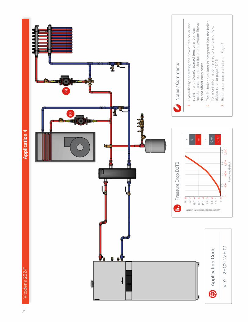
Vito
dens
222
-FA
pp
licat
ion
4
P4
P3
Ap
plic
atio
n C
od
e
VD
2T 2
HC
2T2Z
P.0
1
Not
es /
Com
men
ts
1.
Hyd
raul
ical
ly s
epar
atin
g th
e flo
w o
f th
e bo
iler
and
syst
em w
ith c
lose
ly s
pace
d te
es o
r a
low
loss
he
ader
, ens
ures
tha
t th
e bo
iler
and
syst
em f
low
s do
not
aff
ect
each
oth
er.
2.
The
P1
boile
r ci
rcul
ator
is in
tegr
ated
into
the
boi
ler.
Fo
r m
ore
info
rmat
ion
rela
ted
to s
izin
g an
d flo
w,
plea
se r
efer
to
page
13-
15.
3.
Ref
er t
o co
mpo
nent
inde
x on
Pag
e 5.
Pres
sure
Dro
p B
2TB
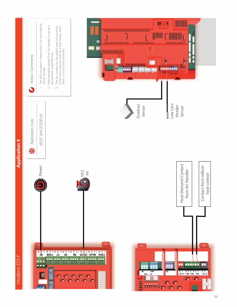
35
Pow
er
HC1 P4
Out
door
Sens
or
Low
Los
s H
eade
r Se
nsor
X11
Hea
t Dem
and
Con
tact
fro
m A
ir H
and
ler
Cont
act f
rom
in�o
or
heat
con
trol
Vito
dens
222
-FA
pp
licat
ion
4
Not
es /
Com
men
ts
1.
The
(P3)
circ
ulat
or in
Hea
t ci
rcui
t 2
is c
ontr
olle
d by
th
e ai
r ha
ndle
r.
2.
Hea
t de
man
d co
ntac
t fr
om a
ir ha
ndle
r m
ust
be a
dr
y co
ntac
t / p
oten
tial f
ree.
3.
The
dry
cont
act
for
the
radi
ant
heat
circ
uit
coul
d co
me
from
a d
evic
e su
ch a
s a
ther
mos
tat,
zon
e va
lve,
or
mul
ti zo
ne c
ontr
olle
r.
App
licat
ion
Cod
e
VD
2T 2
HC
2T2Z
P.0
1

36
Vitodens 222-F, B2TB
Application 4 Operational Setup Instructions
1. The coding parameters described above are modified in level 2 coding. Step1 To access this coding you must hold the "OK" key and "ext. Menu" key together for 5 seconds. This gives access to the service level. Step 2: Hold the "OK" key and "Return" key for 5 seconds. This gives access to level 2 coding.
2. External Changeover- A function in which a contact from an external device forces the boiler into a standby/setback mode.
3. External Demand- A function in which a contact from an external device forces the boiler to target a specific water temperature. This overrides any/all outdoor reset curves until the external contact re-opens.
Notes/Comments
In this application there are 2 heat circuits which operate at different temperatures. This particular drawing portrays HC1 is a low temperature circuit, and HC2 is a Mid/High temperature circuit. Although there are many different configurations, the setup below will operate HC1 as an on/off function (External Change-over) using an outdoor reset curve, and HC2 as a constant set point temperature (External Demand). It is important to provide a method of protecting the HC1 from high water temperatures when HC2 is operat-ing, so don't forget to include the thermostatic mixing valve. To setup the boiler for this application you will need to complete the following:
Type/Option Step # Description Parameter Set to: SetupLocation
1 Set DHW Temperature Set in heatingsub menu
HC1Programming
2 Designate 28/20 Contact as HC1 Pump(P4) 53 :02
Set in Level 2Coding
3 Configure boiler to operate upon a call for heat from HC1
Activates DE1 Contact 3A :01
Initiates Changeover D5 :01
Identifies changeover based on DE1 contact D8 :01
Time limit for changeover F2 :0
Set Pump Post Purge Time F5 # of Minutes
Temperature Limit for disabling changeover F8 -61
Turns off boiler circulator upon completion of call for heat A3 :-9
A4 :01Note: This disables the Frost Protection function.
4 Setup HC1 Outdoor Reset CurveSet in heating
sub menu5 Adjust Daytime schedule --:--6 Set Reduced room temperature 3ºC
External Demand
Programming
7 Configure boiler to operate as an External Demand from HC2
Set in Level 2 Coding
(Ext. Demand)
Set desired setpoint temperature 9B Set Temp.
Identify DE2 as external demand contact 3B :02
Internal Circulator stays in control mode during "External Demand"
3F :02
Optional Adjustments
Set a Heating Schedule Set in heatingsub menuSet an individual DHW Schedule
Configure P1 to shut down once low loss header has reached its setpoint temperature 51: :01 Set in Level 2Coding

37
Application 4 - Operational Setup ... continued
Notes/Comments

38
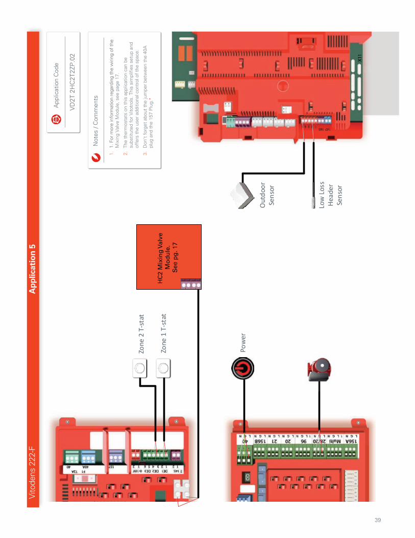
Vito
dens
222
-FA
pp
licat
ion
5
Ap
plic
atio
n C
od
e
VD
2T 2
HC
2T2Z
P.0
2
P4
P3
Not
es /
Com
men
ts
1.
Hyd
raul
ical
ly s
epar
atin
g th
e flo
w o
f th
e bo
iler
and
syst
em w
ith c
lose
ly s
pace
d te
es o
r a
low
loss
he
ader
, ens
ures
tha
t th
e bo
iler
and
syst
em f
low
s do
not
aff
ect
each
oth
er.
2.
The
P1
boile
r ci
rcul
ator
is in
tegr
ated
into
the
boi
ler.
Fo
r m
ore
info
rmat
ion
rela
ted
to s
izin
g an
d flo
w,
plea
se r
efer
to
page
13-
15.
3.
Ref
er t
o co
mpo
nent
inde
x on
Pag
e 5.
Pres
sure
Dro
p B
2TB
39
Pow
er
Zone
2 T
-sta
t
Zone
1 T
-sta
t
Out
door
Sens
or
Low
Los
s H
eade
r Se
nsor
X11
HC
2 M
ixin
g V
alve
M
od
ule
.S
ee p
g. 1
7
Vito
dens
222
-FA
pp
licat
ion
5
Not
es /
Com
men
ts
1.
1. F
or m
ore
info
rmat
ion
rega
rdin
g th
e w
iring
of
the
Mix
ing
Val
ve M
odul
e, s
ee p
age
17.
2.
The
ther
mos
tats
on
this
app
licat
ion
can
be
subs
titut
ed f
or V
itotr
ols.
Thi
s si
mpl
ifies
set
up a
nd
offe
rs t
he u
ser
addi
tiona
l con
trol
of
the
spac
e.
3.
Don
't f
orge
t ab
out
the
jum
per
betw
een
the
40A
pl
ug a
nd t
he 1
57 P
lug.
*
App
licat
ion
Cod
e
VD
2T 2
HC
2T2Z
P.0
2
40
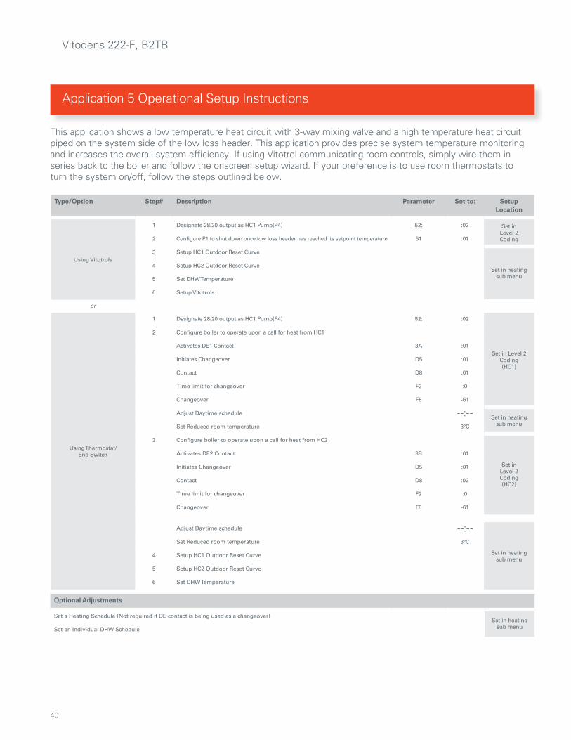
Vitodens 222-F, B2TB
Application 5 Operational Setup Instructions
This application shows a low temperature heat circuit with 3-way mixing valve and a high temperature heat circuit piped on the system side of the low loss header. This application provides precise system temperature monitoring and increases the overall system efficiency. If using Vitotrol communicating room controls, simply wire them in series back to the boiler and follow the onscreen setup wizard. If your preference is to use room thermostats to turn the system on/off, follow the steps outlined below.
Type/Option Step# Description Parameter Set to: SetupLocation
Using Vitotrols
1 Designate 28/20 output as HC1 Pump(P4) 52: :02 Set in Level 2Coding2 Configure P1 to shut down once low loss header has reached its setpoint temperature 51 :01
3 Setup HC1 Outdoor Reset Curve
Set in heatingsub menu
4 Setup HC2 Outdoor Reset Curve
5 Set DHW Temperature
6 Setup Vitotrols
or
Using Thermostat/End Switch
1 Designate 28/20 output as HC1 Pump(P4) 52: :02
Set in Level 2Coding(HC1)
2 Configure boiler to operate upon a call for heat from HC1
Activates DE1 Contact 3A :01
Initiates Changeover D5 :01
Contact D8 :01
Time limit for changeover F2 :0
Changeover F8 -61
Adjust Daytime schedule --:-- Set in heatingsub menuSet Reduced room temperature 3°C
3 Configure boiler to operate upon a call for heat from HC2
Set in Level 2Coding(HC2)
Activates DE2 Contact 3B :01
Initiates Changeover D5 :01
Contact D8 :02
Time limit for changeover F2 :0
Changeover F8 -61
Adjust Daytime schedule --:--
Set in heatingsub menu
Set Reduced room temperature 3°C
4 Setup HC1 Outdoor Reset Curve
5 Setup HC2 Outdoor Reset Curve
6 Set DHW Temperature
Optional Adjustments
Set a Heating Schedule (Not required if DE contact is being used as a changeover)Set in heating
sub menuSet an Individual DHW Schedule

41
Application 5 - Operational Setup ... continued
Notes/Comments

42
Vito
dens
222
-FA
pp
licat
ion
6
Ap
plic
atio
n C
od
e
VD
2T 3
HC
3T3Z
P.0
1
No
tes/
Co
mm
ents
1.
Ref
er t
o co
mpo
nent
inde
x on
pag
e 5
2.
Ext
erna
l flo
w c
heck
val
ves
are
not
nece
ssar
y if
built
in
to t
he c
ircul
ator
s.
3.
The
P1
boile
r ci
rcul
ator
is in
tegr
ated
into
the
boi
ler.
Fo
r m
ore
info
rmat
ion
rela
ted
to s
izin
g an
d flo
w, p
leas
e re
fer
to p
age
13-1
5.
P5
P4
M2
P3
M1
HC
3H
C2
HC
1
Pres
sure
Dro
p B
2TB
43
���
HC
2 M
ixin
g V
alve
M
od
ule
.S
ee p
g. 2
5
HC
3 M
ixin
g V
alve
M
od
ule
.S
ee p
g. 2
5
Pow
er
Out
door
Sens
or
Low
Los
sH
eade
rSe
nsor
Opti
onal
HC3
Vitotrol
Opti
onal
HC2
Vitotrol
HC3
T-s
tat
HC2
T-s
tat
HC1
T-s
tat
HC1 P3
Vito
dens
222
-FA
pp
licat
ion
6
Not
es /
Com
men
ts
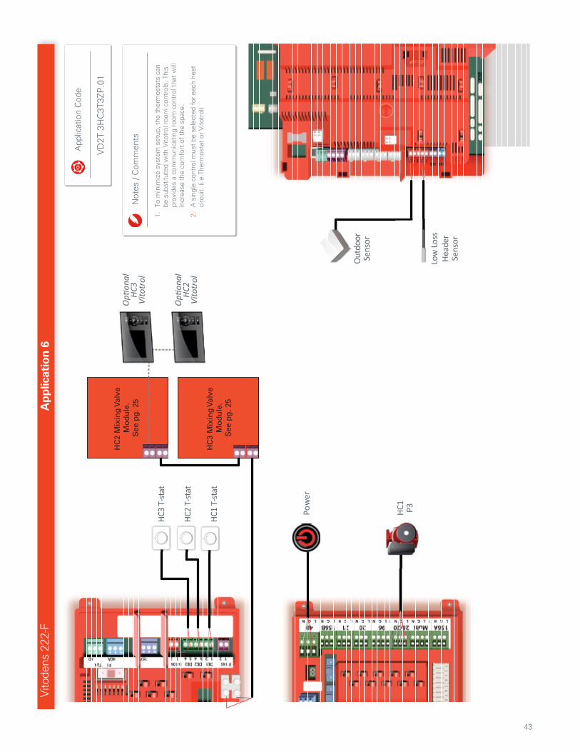
1.
To m
inim
ize
syst
em s
etup
, the
the
rmos
tats
can
be
sub
stitu
ted
with
Vito
trol
roo
m c
ontr
ols.
Thi
s pr
ovid
es a
com
mun
icat
ing
room
con
trol
tha
t w
ill
incr
ease
the
com
fort
of
the
spac
e.
2.
A s
ingl
e co
ntro
l mus
t be
sel
ecte
d fo
r ea
ch h
eat
circ
uit.
(i.e
.The
rmos
tat
or V
itotr
ol)
App
licat
ion
Cod
e
VD
2T 3
HC
3T3Z
P.0
1
44
Vitodens 222-F, B2TB
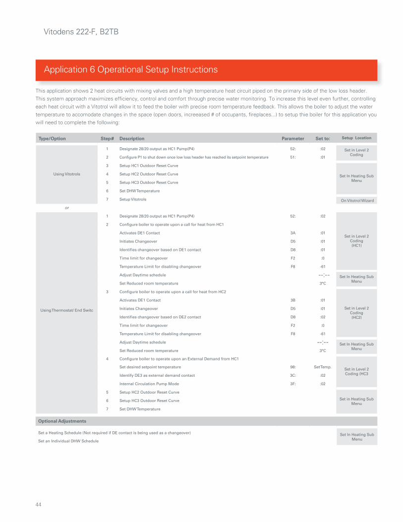
This application shows 2 heat circuits with mixing valves and a high temperature heat circuit piped on the primary side of the low loss header. This system approach maximizes efficiency, control and comfort through precise water monitoring. To increase this level even further, controlling each heat circuit with a Vitotrol will allow it to feed the boiler with precise room temperature feedback. This allows the boiler to adjust the water temperature to accomodate changes in the space (open doors, increeased # of occupants, fireplaces...) to setup thie boiler for this application you will need to complete the following:
Type/Option Step# Description Parameter Set to: Setup Location
Using Vitotrols
1 Designate 28/20 output as HC1 Pump(P4) 52: :02 Set in Level 2 Coding
2 Configure P1 to shut down once low loss header has reached its setpoint temperature 51: :01
3 Setup HC1 Outdoor Reset Curve
Set In Heating Sub Menu
4 Setup HC2 Outdoor Reset Curve
5 Setup HC3 Outdoor Reset Curve
6 Set DHW Temperature
7 Setup Vitotrols On Vitotrol Wizard
or
Using Thermostat/ End Switc
1 Designate 28/20 output as HC1 Pump(P4) 52: :02
Set in Level 2 Coding(HC1)
2 Configure boiler to operate upon a call for heat from HC1
Activates DE1 Contact 3A :01
Initiates Changeover D5 :01
Identifies changeover based on DE1 contact D8 :01
Time limit for changeover F2 :0
Temperature Limit for disabling changeover F8 -61
Adjust Daytime schedule --:-- Set In Heating Sub MenuSet Reduced room temperature 3°C
3 Configure boiler to operate upon a call for heat from HC2
Set in Level 2 Coding(HC2)
Activates DE1 Contact 3B :01
Initiates Changeover D5 :01
Identifies changeover based on DE2 contact D8 :02
Time limit for changeover F2 :0
Temperature Limit for disabling changeover F8 -61
Adjust Daytime schedule --:-- Set In Heating Sub MenuSet Reduced room temperature 3°C
4 Configure boiler to operate upon an External Demand from HC1
Set in Level 2 Coding (HC3
Set desired setpoint temperature 98: Set Temp.
Identify DE3 as external demand contact 3C: :02
Internal Circulation Pump Mode 3F: :02
5 Setup HC2 Outdoor Reset Curve
Set in Heating Sub Menu
6 Setup HC3 Outdoor Reset Curve
7 Set DHW Temperature
Optional Adjustments
Set a Heating Schedule (Not required if DE contact is being used as a changeover) Set In Heating Sub MenuSet an Individual DHW Schedule
Application 6 Operational Setup Instructions

45
Application 6 - Operational Setup ... continued
Notes/Comments

46
This is ViessmannThe Viessmann Group is one of the world’s leading manufacturers of heating and renewable energy systems. Family-owned since 1917, Prof. Dr. Martin Viessmann leads the company in its third generation. The group today employs over 11,400 employees worldwide and has a turnover of approx. 2.1 billion Euro. 27 manufacturing facilities in 11 countries, sales & distribution facilities in Germany and 74 other countries, and 120 sales offices worldwide provide customer proximity and a strong global presence. For three generations, Viessmann has been providing comfortable, efficient and environmentally-responsible heating solutions, tailored to the needs of the market. With ongoing research and development and a focus on product innovation, Viessmann has pioneered technologies that have continuously set standards and made the company into a technological innovator and pace-setter of the entire industry.
With the current comprehensive product range, Viessmann is offering a multi-level program of high-tech, state-of-the-art heating products. Wall-mounted gas-fired condensing boilers, floor-standing oil – or gas-fired hot water heating boilers, solar thermal systems, control technology
and DHW storage tanks – all designed to achieve superior performance, reliability and energy savings.
Accountability for the environment and society, fairness when dealing with business partners as well as the pursuit of perfection and maximum efficiency in all business transactions are key values for Viessmann – as a company, and as individuals. This, together with the products and services we offer, allows us to offer our customers the benefit and added value of a strong brand.
Viessmann Manufacturing Company Inc. 750 McMurray Rd. Waterloo, ON N2V 2G5, Canada 1-800-387-7373 [email protected]
www.viessmann.ca
Viessmann Manufacturing Company Inc. 6350 204th St. Langley, BC V2Y 2V1, Canada 1-877-853-3288 [email protected]
www.viessmann.ca
Viessmann Manufacturing Company Inc. USA 45 Access Rd. Warwick, RI 02886, USA 1-800-288-0667
www.viessmann.com
Global Presence, Local Expertise.

47
Global Presence, Local Expertise.

Viessmann Manufacturing Company Inc. Waterloo, ON Canada 1-800-387-7373 www.viessmann.ca
Technical information subject to change without notice. Printed in Canada