vitrification of of the hllw simulated surrogate solutions
TRANSCRIPT

WM2009 Conference, March 1-5, 2009, Phoenix, AZ
Vitrification of HLLW Surrogate Solutions Containing Sulfate in a Direct-Induction Cold Crucible Melter – 9136
Eric Tronche, Jacques Lacombe, Alain Ledoux, Roger Boen, Christian Ladirat CEA Marcoule, DEN/DTCD/SCDV
BP 17171, 30207 Bagnols-sur-Cèze cedex, France
ABSTRACT
Efforts were made in the People’s Republic of China to solidify legacy high level liquid waste (HLLW) by the Liquid-Fed Ceramic Melter process (LFCM) in the 1990s. This process was to be a continuous process with high throughput as in the French Marcoule Vitrification Plant (AVM) or the LFCM. In this context, the CEA (Commissariat à l’Energie Atomique is a French government-funded technological research organization) suggests the Cold Crucible Induction Melter (CCIM) technology that has been developed by the CEA since the 1980s to improve the performance of the vitrification process. In this context a series of vitrification tests has been carried out in a CCIM. CEA and AREVA have designed an integrated platform based on the CCIM technology on a sufficient scale to be used for demonstration programs of the one-step process. In 2003 a test was carried out at Marcoule in southern France on simulated HLLW with high sulfur content. In order to ensure the tests performed at Marcoule were consistent with the Chinese wasteforms, the glass frit was supplied by a Chinese Industry. The CCIM facility is described in detail, including process instrumentation. The test run is also described, including how the solution was directly fed on the surface of the molten glass. A maximum capacity was determined according to the applied process parameters including the high operating temperature. The electrical power supply characteristics are detailed and a glass mass balance is also presented covering more than seven hundred kilograms of glass produced in a sixty-hour test run.
INTRODUCTION
The vitrification of HLLW in a LFCM in the People’s Republic of China is discussed in the 1993 reference article [1]. This process was to be a continuous process with high throughput as in the French AVM or the LFCM. The operating LFCM temperature is 1150°C which is close to the maximum temperature of 1180°C. The HLLW are legacy wastes which contains large amounts of sodium, sulfur, iron and uranium. The waste oxide loading of borosilicate glass is limited to 16 wt% to prevent yellow phase separation (consisting mainly of sodium sulfate). This yellow phase can be a problem because its density is low and it can float on the molten glass. Its electrical conductivity differs from that of the molten glass and can cause problems during the melter heating phase. Finally it can contribute to corrosion of the melter walls. In this context, the CEA suggested the use of the Cold Crucible Induction Melter (CCIM) technology which can avoid the “yellow phase” issue and meet the technical requirements noted above. The high specific power directly transferred by induction to the melt allows higher operating temperatures, thereby eliminating the yellow phase issue without any impact on the process equipment. Since all the process equipment is water cooled and protected by a solidified glass layer, the technology overcomes difficulties such as corrosion usually associated with high temperatures, and the melter has a virtually unlimited lifetime. The main process components are simple, compact, modular and easy to maintain remotely. Since there is no upper bound on the operating temperature, the CCIM can produce glass formulations with higher proportions of glass formers.

WM2009 Conference, March 1-5, 2009, Phoenix, AZ
A vitrification test has been carried out in a CCIM. CEA and AREVA have designed an integrated platform based on the CCIM technology on a sufficient scale to be used for demonstration programs using one-step process [2]. In July 2003 a test took place at Marcoule in France on simulated HLLW with a high sulfur content. In order to ensure the tests performed at Marcoule were perfectly consistent with the Chinese wasteforms, the glass frit was supplied by a Chinese Industry. This paper describes the test and indicates the preliminary conclusions that can be drawn from this test. Note that the context, process and apparatus of this test are specifics for these legacy wastes and different from those of a Nuclear Reactor Power Fuels reprocessing plant.
DESCRIPTION OF THE TEST FACILITY
The demonstrations were performed by CEA/DEN/DTCD/SCDV using the existing Large Scale Integrated CCIM Pilot Facility at Marcoule, which was adapted to the specific requirements of the project. The demonstration facility is self-contained and comprises all the systems and components necessary to perform a large-scale continuous one-week demonstration run: a melter feed system, a 650 mm diameter CCIM, a glass pouring station, a canister filling station, a complete off-gas treatment system, and related auxiliary equipment, including the control system. The facility is installed on four levels covering 160 m2 at ground level.
Fig. 1. Overall view of the test facility.
1: 650 mm diameter CCIM behind its protection barriers 2: canister filling station equipped with a balance to measure the poured glass mass 3: glass frit tanks above the solid gravity-feed system

WM2009 Conference, March 1-5, 2009, Phoenix, AZ
4: high-frequency generator 5: water cooled supply system 6: (a) the liquid dust scrubber system; (b) the unused solid dust scrubber system 7: condenser 8: washing column 9: extractor 10: mobile tank for liquid in front of the static tank 11: to the auxiliary control system room 12: wooden crate containing the glass frit
Vitrification system
The development version melter used in 2003 for the demonstration was a 650 mm diameter cold-crucible induction melter not representative of the robust design that has been qualified for radioactive operation in the La Hague vitrification plant today.
Fig. 2. View of the CCIM.
The melter was powered by a ~300 kHz, 600 kW high-frequency generator delivering power to a copper inductor (0) wrapped around the melter sectored vertical wall. The power supply line to the inductor included a high-frequency high-voltage line (1) and an impedance matching device (2) to adapt the generator to the load in the crucible. The tuning of this impedance adaptor is based on modeling and calculations performed prior to the demonstration, which took into account the physical properties of the glass versus temperature (thermal conductivity, electrical conductivity, and viscosity). The facility included a cooling loop with separate branches for the melter, the dome (3), and for ancillary equipment, as well as an emergency cooling system for the melter. Each branch was individually equipped with temperature and flow rate measuring devices (4) to gather data inputs necessary for the thermal balance. The melter was equipped with a water-cooled retractable mechanical stirrer and its drive mechanism (5), a cooled bubbling tube to assist melt homogenization, and a pouring device consisting of two cooled slide valves and their actuators (6). The melter was also equipped with two thermocouples for measuring the

WM2009 Conference, March 1-5, 2009, Phoenix, AZ
melt temperature from the bottom. A viewing system including a video camera (7) and a viewport was mounted on the dome of the CCIM and allowed remote monitoring of the cold cap.
Melter feed system
The existing liquid feed system of the demonstration platform was used for this demonstration. This melter feed system included a preparation and feed tank located inside the building equipped with a mechanical stirrer designed with three levels of blades: a smaller blade below two levels of full-size blades. The useful volume of the feed tank was 8 m3. The tank was also equipped with dip tube bubbler-based level and density measurements, and a thermocouple for temperature measurement. The built-in stirring capability of the feeding tank was supplemented by a high flow rate (> 5 m3/h) recirculation loop extracting the liquid from the bottom of the tank and reinjecting it at the top. Sampling was also possible in this loop, directly below the bottom of the tank. The solution was pumped from the recirculation loop and metered before it was added to the CCIM. Glass frit stored in a tank was transferred by a worm screw and metered by the screw rotation speed. The glass frit dropped into an airlock to ensure frit supply as well as depressurized gas confinement in the CCIM.
Glass pouring enclosure and canister filling station
During glass pouring, the receiving canister was located inside an insulated enclosure equipped with weighing scales. The canisters were made of ordinary carbon steel and could receive approximately 400 kg of glass. Glass sampling could be performed below the outlet of the CCIM pouring system by grabbing small quantities of glass in steel or cast iron pans.
Off-gas treatment system (OGTS)
The melter off-gas outlet is directly connected to the liquid dust scrubber. The dust scrubber is a heated vessel topped with a column in which the off-gas is contacted with a counter-current flow of liquid circulated from the vessel in order to trap the entrained particles. The dust scrubber is heated to prevent internal condensation. In normal operation the dust scrubber is continuously fed with a small flow of fresh water, and the excess liquid, loaded with the collected material, is recycled to the CCIM with the main feed. This represents around 10% of the feed. The off-gas then flows through a condenser where the moisture is condensed. The condensates are collected in a specific cooled tank. Downstream of the condenser, the off-gas flows through a washing column where it is contacted with a caustic solution to remove the acidic gases (NOx and others). A centrifuge extractor removes the off-gas and provides for a slightly negative pressure throughout the system to the melter. The three components can be sampled to confirm the estimated distribution of entrained and volatilized species. Each is equipped with level and temperature measuring instruments. Pressure is measured before and after each equipment item.
Control and monitoring
The Large Scale Integrated CCIM Pilot Facility is fully instrumented and operated remotely using a Programmable Logic Controller and a Digital Control System with a multi-screen display. All the process parameters can be monitored, time-stamped, and recorded to provide historical trend information. The control system includes warning thresholds on each critical measurement and automatic shut-down sequence to assure safe operation of the system.
WM2009 Conference, March 1-5, 2009, Phoenix, AZ
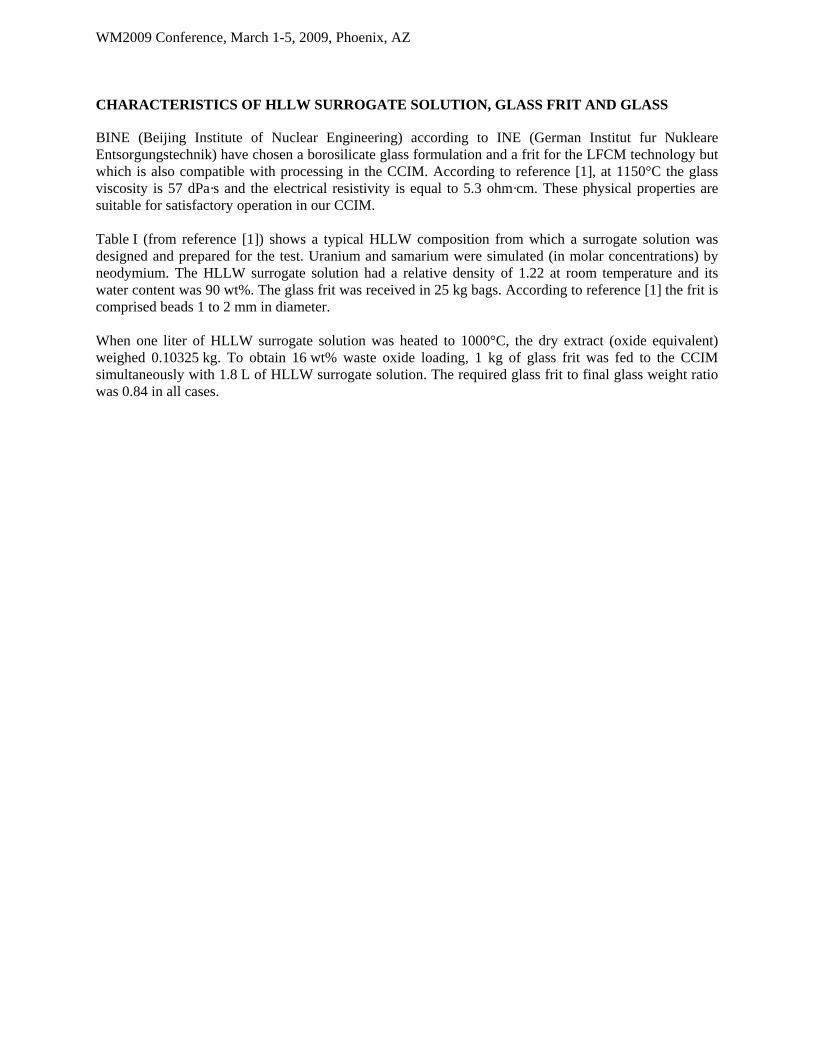
CHARACTERISTICS OF HLLW SURROGATE SOLUTION, GLASS FRIT AND GLASS
BINE (Beijing Institute of Nuclear Engineering) according to INE (German Institut fur Nukleare Entsorgungstechnik) have chosen a borosilicate glass formulation and a frit for the LFCM technology but which is also compatible with processing in the CCIM. According to reference [1], at 1150°C the glass viscosity is 57 dPa·s and the electrical resistivity is equal to 5.3 ohm·cm. These physical properties are suitable for satisfactory operation in our CCIM. Table I (from reference [1]) shows a typical HLLW composition from which a surrogate solution was designed and prepared for the test. Uranium and samarium were simulated (in molar concentrations) by neodymium. The HLLW surrogate solution had a relative density of 1.22 at room temperature and its water content was 90 wt%. The glass frit was received in 25 kg bags. According to reference [1] the frit is comprised beads 1 to 2 mm in diameter. When one liter of HLLW surrogate solution was heated to 1000°C, the dry extract (oxide equivalent) weighed 0.10325 kg. To obtain 16 wt% waste oxide loading, 1 kg of glass frit was fed to the CCIM simultaneously with 1.8 L of HLLW surrogate solution. The required glass frit to final glass weight ratio was 0.84 in all cases.

WM2009 Conference, March 1-5, 2009, Phoenix, AZ
Table I: Characteristics of the HLLW surrogate solution, glass frit and glass
HLLW element/
ion as [1]
HLLW concentratio
n as [1] (g/l)
Surrogate solution
Simulated concentration
(g/l)
Oxide as [1]
Glass Frit composition
as [1] (%)
Glass Composition
as [1] (%)
Glass Composition
target (%)
SO4 5.09 SO4 3.40 SiO2 59.8 50.23 50.23 PO4 0.61 PO4 0.61 B2O3 22.0 18.48 18.48 Al 4.9 Al 4.90 Na2O 5.0 11.19 11.21 Fe 14.47 Fe 14.47 Al2O3 3.5 4.38 4.43 K 0.5 K 0.50 CaO 5.4 4.54 4.54 Na 33.22 Na 32.41 Li2O 2.3 1.93 1.93 U* 16.14 Nd 10.48 TiO2 1.0 0.89 0.89 Cr 1.3 Cr 1.30 MgO 1.0 0.84 0.84 Ni 2.97 Ni 2.97 Fe2O3 3.23 3.32 Ti 0.19 Ti 0.19 Cr2O3 0.296 0.31 Ce 0.28 Ce 0.28 CeO2 0.054 0.05 La 0.18 La 0.18 La2O3 0.033 0.03 Nd 0.59 Nd P2O3 0.030 0.07 Pr 0.17 Pr 0.17 NiO 0.59 0.61
Sm* 0.11 Nd Nd2O3 1.91 1.96 Ba 0.12 Ba 0.12 BaO 0.02 0.02 Sr 0.2 Sr 0.20 SrO 0.037 0.038
Mo 0.68 Mo 0.68 MoO3 0.159 0.164 Zr 0.73 Zr 0.73 ZrO2 0.154 0.158
Ru** 0.14 - - RuO2 0.029 0 Cs 0.72 Cs 0.72 Cs2O 0.119 0.123
Rh** 0.01 - - PdO 0.003 0 Tc* 0.1 Mn 0.06 MnO2 0.014 0.015 Y** 0.08 - - Y2O3 0.016 0 Pd** 0.01 - - SO3 0.66 0.45 HNO3 93.24 93.24 K2O# 0
Pr2O3# 0.097 Total 99.83 99.97%
*: surrogate element was used **: element not present in feed #: species not taken into account in reference [1]
The 0.45% content of SO3 equivalent in the glass was relatively high. Incorporating this quantity in the glass formulation depends on the waste oxide loading, temperature (°C), throughput (kg/h) and stirring. The waste oxide loading of borosilicate glass is limited to 16wt% to prevent yellow phase separation consisting mainly of sodium sulfate (Na2SO4). In a previous test run some yellow phase was obtained at temperatures near 1150°C. Samples of this solidified phase at room temperature were examined by SEM/EDS. It reveals sodium sulfate cristals. The yellow color is probably due to chromium oxide (Cr2O3) but it can also contain molybdenum, which has the same peak as sulfur. This yellow phase is a liquid at 1150°C; its density is low and it can float on the molten glass. Its electrical conductivity differs from that of the molten glass and can allow an electric

WM2009 Conference, March 1-5, 2009, Phoenix, AZ
current loop to form all around the CCIM sectors and destroy them during the melter heating phase. As this yellow phase can contribute to the corrosion of the melter walls, its liquid form is prohibited in an operating CCIM. One of the major advantages identified for the CCIM is its ability to operate at high temperature, which allows the transformation of the liquid yellow phase to the gaseous form when the temperature reaches about 1250°C.
DEMONSTRATION RUN
Two brief tests were carried out before this demonstration run to obtain preliminary data on the feed and glass behavior in the CCIM. The demonstration run was performed in a single step cold by feeding the liquid directly to the cold crucible without any prior solution treatment.
CCIM startup
Glass being an electrical insulator at room temperature, it must be preheated enough for electromagnetic coupling and to sustain induction heating. The startup procedure used a magnetic susceptor positioned in the crushed glass load in the CCIM. The electrical characteristics of the generator are shown in figure 3. The generator power was progressively increased, reaching 260 kW after 2 hours. At 100 kW the load impedance in the CCIM dropped about 200 mohm, indicating that the heating processing is engaged and a few minutes later the temperature increased. After 3 hours, the temperature reached 1250°C and the glass stirring system was started. When the bath temperature stabilized the liquid feed was initiated: this constituted the zero point on the X-axis in figure 3.
Strat-up characteristics
0
50
100
150
200
250
300
350
400
450
500
-5 -4 -3 -2Time (hours before liquid feeding)
Vol
tage
(V
) -
Ele
ctri
c P
ower
(kW
)
0
150
300
450
600
750
900
1050
1200
1350
1500
Inte
nsit
y (A
), te
mpe
ratu
re (
°C)
voltage (V)electric power (kW)intensity (A)Impedance (mohm)CCIM temperature (°C)
Figure 3: Startup characteristics

WM2009 Conference, March 1-5, 2009, Phoenix, AZ
HLLW surrogate solution treatment in the CCIM
Flow characteristics for the HLLW surrogate solution, recycling solution and glass frit are shown in figure 4. Note that the solution from the dust scrubber was continuously recycled to the CCIM during this demonstration run.
0
200
400
600
800
1000
1200
0 5 10 15 20 25 30 35 40 45 50 55 60 65 70
Tops (h)
Vol
um
e (L
), w
eig
ht (
kg),
L/k
g*1
00
Cumulative Liquid Feed volume recording
Cumulative Glass frit Feed Weight recording
L/kg ratio*100
1114 l
615 kg
Figure 4: CCIM feed characteristics
The test was performed with a feed ramp of 8 L/h to determine the maximum capacity on the basis of a cold cap coverage surface of 95%, corresponding approximately to the bubblers surface impact. The feed rate was then increased in steps to 10 L/h, 15 L/h and finally 20 L/h. After a few hours at this rate the glass surface was well covered as shown the second image in figure 5, indicating that the maximum capacity had been reached; the 20 L/h feed rate was therefore maintained throughout the demonstration run.

WM2009 Conference, March 1-5, 2009, Phoenix, AZ
Figure 5: Molten glass surface with a feed rate of 8 L/h (left) and 20 L/h (right)
These images show the impact on the bath surface of different liquid feed rates. Air bubble formed on the surface from one sparging tube can be seen on the right; the stirrer shaft plug rotating in the glass is visible on the left. The HLLW surrogate solution was supplied to the CCIM at a rate of 8 L/h for more than one hour. The glass bath surface was partially occupied by the glass formers. The capacity can be increase as shown the left-hand image in figure 5. The feeding system operated correctly. The operators continually tuned the liquid or glass frit metering to obtain the required ratio just before each pour. For the glass frit the mass balance was relatively stable and reliable. The liquid feed volume was followed by observing either the decreasing level of the liquid feed tank or the metered liquid feed volume of the metering pump. With the progressive feed rate increase to 20 L/h during this run at 1250°C, the glass production rate was 12.9 kg per hour.
CCIM process operating characteristics
The glass bath temperature was monitored by the generator power. The target temperature was 1250°C. One thermocouple was used for regulation and its signal was monitored by a backup thermocouple. The glass was synthesized in the CCIM in 100 kg batches on a glass heel. The glass was poured in quantities of about 100 kg. The liquid and frit feeds are not interrupted during the pours. This operating mode is allowed because formers (frit or solution ashes)were not found in the solidified glass. This operating mode increased the overall CCIM production rate.

WM2009 Conference, March 1-5, 2009, Phoenix, AZ
Assessment on Glass
0
100
200
300
400
500
600
700
800
0 10 20 30 40 50 60 7Tops (h)
Wei
ght
(kg)
0
Calculated Glass Weight elaborated
Recorded Weight of glass poured
Glass Weight variation in the furnace
1 2 3 45 6
7
x Number of pouring glass operation
Figure 6: CCIM glass weight management
The glass weight produced can be calculated from the recorded feed characteristics shown in figure 3. The melts were poured when a 100 kg load has been produced, so the glass mass in the CCIM varied between the same high and low levels. Seven melts were performed, for a total of 730 kg of glass.
Electrical characteristics all over the run
0
100
200
300
400
500
600
700
800
0 5 10 15 20 25 30 35 40 45 50 55 60 65 70
Time (hours)
Vol
tage
(V
) -
Ele
ctri
c P
ower
(kW
)
0
200
400
600
800
1000
1200
1400
1600
Impe
danc
e, I
nten
sity
(A
), te
mpe
ratu
re (
°C)
voltage (V)electric power (kW)intensity (A)Impedance (mohm)CCIM temperature (°C)
Figure 7: CCIM electrical parameters
WM2009 Conference, March 1-5, 2009, Phoenix, AZ
The current intensity increased with the mass in the CCIM heated by Joule effect for the same stable temperature. During each pour the level of glass decreased in the CCIM, resulting in the same current drop. The generator voltage remained relatively stable at about 220 V throughout the demonstration run. The generator intensity reached 1200 to 1400 A during each melt. The generator power reached 230 to 260 kW depending on the melt. A fraction of this power was dissipated as heat in the generator, the impedance matching device, the high voltage line and the coils. Additional electrical losses occurred in all the structures of the CCIM but mainly in the metal walls. The remaining power was transferred to the glass melt. The two thermocouples positioned at different points of the CCIM bottom indicated the same temperature, about 1250°C. The CCIM atmosphere was satisfactorily maintained at 300 Pa below atmospheric pressure throughout the demonstration run. No overpressure occurred during the run.
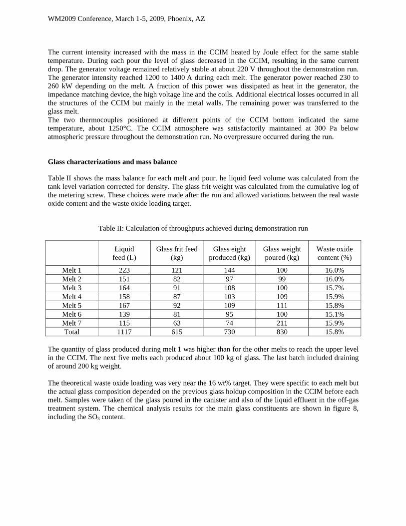
Glass characterizations and mass balance
Table II shows the mass balance for each melt and pour. he liquid feed volume was calculated from the tank level variation corrected for density. The glass frit weight was calculated from the cumulative log of the metering screw. These choices were made after the run and allowed variations between the real waste oxide content and the waste oxide loading target.
Table II: Calculation of throughputs achieved during demonstration run
Liquid
feed (L) Glass frit feed
(kg) Glass eight
produced (kg) Glass weight poured (kg)
Waste oxide content (%)
Melt 1 223 121 144 100 16.0% Melt 2 151 82 97 99 16.0% Melt 3 164 91 108 100 15.7% Melt 4 158 87 103 109 15.9% Melt 5 167 92 109 111 15.8% Melt 6 139 81 95 100 15.1% Melt 7 115 63 74 211 15.9% Total 1117 615 730 830 15.8%
The quantity of glass produced during melt 1 was higher than for the other melts to reach the upper level in the CCIM. The next five melts each produced about 100 kg of glass. The last batch included draining of around 200 kg weight. The theoretical waste oxide loading was very near the 16 wt% target. They were specific to each melt but the actual glass composition depended on the previous glass holdup composition in the CCIM before each melt. Samples were taken of the glass poured in the canister and also of the liquid effluent in the off-gas treatment system. The chemical analysis results for the main glass constituents are shown in figure 8, including the SO3 content.

WM2009 Conference, March 1-5, 2009, Phoenix, AZ
Elaborated Glass Main Compositions
0%
10%
20%
30%
40%
50%
60%
1 2 3 4 5 6 7
Pours
wt (
%)
0,00%
0,10%
0,20%
0,30%
0,40%
0,50%
0,60%
SO3 Wt %
SiO2
B2O3
Na2O
Al2O3
SO3
Figure 8: Glass composition analysis for the main elements
The concentrations of the main borosilicate glass constituents (SiO2, B2O3, Na2O, Al2O3) represented more than 80 wt% of the total mass of the glass. The resulting glass compositions were stable for all seven melts and confirmed that the glass target composition (Table I) was obtained. The SO3 content in the glass continuously increased during the demonstration run. This increasing shows that the conditions of saturation are not reached after more than 65 hours test run. Beside kinetic considerations the bath temperature goes against SO3 incorporation. However, no liquid yellow phase was observed at any time during the test. The final SO3 content was 0.37 wt% in the glass for a target value of 0.45 wt%. All the solidified glass samples obtained were smooth, bright with neither crystalline inclusions nor solidified yellow phase. They were black, with a thin yellow-green layer in some cases. All these technological glasses can be considered excellent based on macroscopic observations.
DEMONSTRATION PERFORMANCE ASSESSMENT
In 2003 the CCIM at Marcoule evaporated 22.5 liters of liquid per hour at 1250°C, consisting of 2.5 L/h of recycled liquid and 20 L/h of HLLW surrogate solution. The power required to produce the glass from the glass frit and the liquid dry extract was low, only a few kW. Most of the power supplied to the melt and not transferred to the structure was used to evaporate the liquid at the melt surface (about 18 kW in this demonstration run). The melter capacity is proportional to the melt surface area. With the CCIM surface area (0.332 m2), the HLLW surrogate feed rate was about 60 (L/h)/m2 at 1250°C, and the glass production per unit area was 38.8 kg/h/m2 at 1250°C. These values depended mainly on the melting temperature, the HLLW liquid composition and the glass composition. These values can be compared with those of the LFCM using the same HLLW liquid and glass composition. Table III compares some test data from the CCIM and from the LFCM [1].

WM2009 Conference, March 1-5, 2009, Phoenix, AZ
Table III Physical and process data for LFCM and CCIM
LFCM data from [1] CCIM test results
Design liquid feed rate 65 L/h 20 L/h Glass production rate 38.4 kg/h 12.9 kg/h
Glass melting surface area 1.4 m2 0.332 m2 Weight 28 metric tons <500 kg
Operating temperature 1150°C 1250°C
Calculated HLLW feed rate 47 (L/h)/m2 60 (L/h)/m2 and
67.5 (L/h)/m2 with recycled flow
Calculated glass production per unit area 27.4 (kg/h)/m2 38.8 (kg/h)/m2 The CCIM liquid feed rate was at least 25% higher than for the LFCM. To evaluate the demonstration run, comparisons have been made with data found all around the world.
Effect of dry CCIM feed
Some studies were conducted in Russia [3] on a CCIM before 2000. The process used a two-stage evaporator and CCIM technology. This system confirmed its advantages in comparison with current industrial technologies. No liquid feed appears to have been supplied to the CCIM, which was used only to produce glass with a dry process. The melt surface area was 6.7 dm2 and the glass production rate was up to 18 kg/h. This means that without liquid the glass production capacity per unit area could reach 300 kg/h/m2. The throughput is high, but this means that a prior evaporation step is necessary, requiring additional remote handling and management.
Effect of dry CCIM feed without mechanical stirring
Some studies have been conducted in India [5] [6] on a CCIM. The glass production rate was determined with natural convection in the CCIM, without mechanical stirring. Supplying 110 kW to the glass bath resulted in a glass melting rate of 40 kg/h. The CCIM diameter was 0.5 m so the available melting surface area was 0.196 m2. This means that with dry feeding the glass production capacity per unit area was about 200 kg/h/m2. This value is of the same order of magnitude as the data from [3]. Natural convection appears to be less effective than mechanical stirring. In our 2003 demonstration run the CCIM included a mechanical stirrer and an air bubbling device. These technologies increased the glass production rates.
Effect of a different CCIM design
The CCIM Pilot Facility at Marcoule also includes another type of cold crucible melter (known as “Creuset Froid Avancé” noted CFA) that is heated from the bottom by a pancake coil. The diameter of the melt surface is 1.1 m. In article [4] the indicated liquid feed capacity is 50 L/h. The liquid feed flux achieved is around 53 (L/h)/m2. The CCIM performance during the 2003 demonstration run was comparable to the results reported for the CFA in [4], also obtained in 2003.

WM2009 Conference, March 1-5, 2009, Phoenix, AZ
Effect of a different HLLW liquid feed composition
The CCIM Pilot Facility at Marcoule was used to vitrify a Savannah River Surrogate Sludge in 2007 [7]. The slurry water content was 60 wt%. The 0.65 m diameter CCIM was similar to those used for the Chinese HLLW surrogate. At 1250°C the slurry feed rate was 150 (L/h)/m2. The glass production capacity per unit area was 65 kg/h/m2 at 1250°C, and even 75 kg/h/m2 at 1300°C. Similar slurry has been also treated in Russia [8] by feeding it directly to a CCIM. A slurry containing about 60% water was supplied directly to a 0.216 m diameter CCIM. The glass production per unit area was 47 kg/h/m2, but could be doubled if the moisture content were decreased to about 30%. The calculated glass production rates per unit area were higher with this slurry than for the Chinese HLLW surrogate solution for two reasons: the water content was lower for the slurry, and the glass frit powder provided higher reactivity to synthesize the glass. These assessments can provide guidelines for improving the performance of HLLW surrogate solutions containing sulfate.
CONCLUSIONS
For these Chinese legacy wastes containing sulfate, the one-step demonstration run carried out in 2003 on HLLW surrogate solution was successfully completed. With a HLLW surrogate solution feed rate of 20 L/h to the CCIM, the liquid feed flow was about 60 (L/h)/m2 at 1250°C. The glass was produced at a rate of 12.9 kg/h, corresponding to a throughput per unit area of 38.8 kg/h/m2. During this run, 1114 liters of HLLW surrogate solution was treated and 730 kg of glass were fabricated in 62 hours. The overall production rate was 11.8 kg/h for the entire test, including the phases necessary to determine the maximum capacity. This result was made possible by maintaining liquid feed while each of the seven 100 kg melts was poured, and includes the 210 kg of glass removed from the melter on completion of the test. In 2003 this appeared to be the best throughput obtained by direct liquid feed in a CCIM. Our CCIM has been modified since that date, and a higher throughput could be obtained from the same process. With prior concentration of the liquid feed stream supplied to the CCIM, the glass throughput could be even higher. This process can’t be applied for HLLW coming from the treatment of Nuclear Reactor Power Fuels
REFERENCES
[1] Sung Dong hui, Wang Xian do, Pu Yong ning, Wan Xiao Ii, S. Weisenburger. “Vitrification of HLLW in the People’s Republic of CHINA”. Nuclear waste management and environmental remediation: 4th biennial Alexandre, D. Ed. Vol 1993 PT Vol.1 pp 129-134. (1993) [2] R. Do Quang, A. Jensen, A. Prod’homme, R. Fatoux, J. Lacombe. “Integrated Pilot Plant for a Large Cold Crucible Induction Melter”. Proceedings of the Waste Management 2002 Symposium WM’02 Conference, February 24-28, 2002, AZ, Tucson, USA (2002) [3] A.V. Demine, N.V. Krylova, P.P. Polyektov, I.N. Shestoperov, TV. Smelova, V.F. Gorn, G.M. Medvedev. “High Level Liquid Waste Solidification Using a Cold Crucible Induction Melter” Proceedings of the Atalante 2000 conference, October 24-26, 2000, Avignon, France (2000) [4] C. Ladirat, J. Lacombe, R. Do Quang, A. Prod’homme. “Advanced Cold Crucible Melter Pilot Plant characteristics and First Results on HLLW Surrogates”. Proceedings of the Waste Management 2004 Symposium WM’04 Conference, February 29 March 4, 2004, AZ, Tucson, USA (2004)

WM2009 Conference, March 1-5, 2009, Phoenix, AZ
[5] G. Sugilal. “Experimental Study of Natural Convection in a Glass Pool Inside a Cold Crucible Induction Melter”. International Journal of Thermal Sciences 47 918-925, (2008) [6] G. Sugilal. “Experimental Analysis of the Performance of Cold Crucible Induction Glass Melter”. Applied Thermal Engineering 28 1952-1961, (2008) [7] C. Girold, M. Delaunay, J.L. Dussossoy, J. Lacombe, S. Marra, D. Peeler, C. Herman, M. Smith, R. Edwards, A. Barnes, M. Stone, D. Iverson, R. Do Quang, E. Tchemitcheff, C. Veyer. “Cold Crucible Induction Melter (CCIM) Demonstration Using a Representative Savannah River Site Sludge Simulant on the Large-Size Pilot Platform at the CEA Marcoule”. Proceedings of the Waste Management 2008 Symposium WM’08 Conference, February 24-28, AZ, Phoenix, USA (2008) [8] A.P. Kobelev, S.V. Stefanovskii, V.N. Zakharenko, M.A. Polkanov, O.A. Knyazev, T.N. Lashchenova, A.G. Ptashkin, E. Holtzscheiter, J. Marra. “Vitrification of a Surrogate for High Level Wastes from the Savannah River Plant (USA) on a Cold Crucible Bench Facility” Atomic Energy, Vol 102, N°4, (2007)