vive wireless hub spec (369902) - lutron electronics · ®specifica al page ob name: ob number:...
TRANSCRIPT
® SPECIF ICAT ION SUBMITTAL Page
Job Name:
Job Number:
Model Numbers:
Vive HJS-0, HJS-1, HJS-2 Wireless Hub
369902i 1 07.11.18
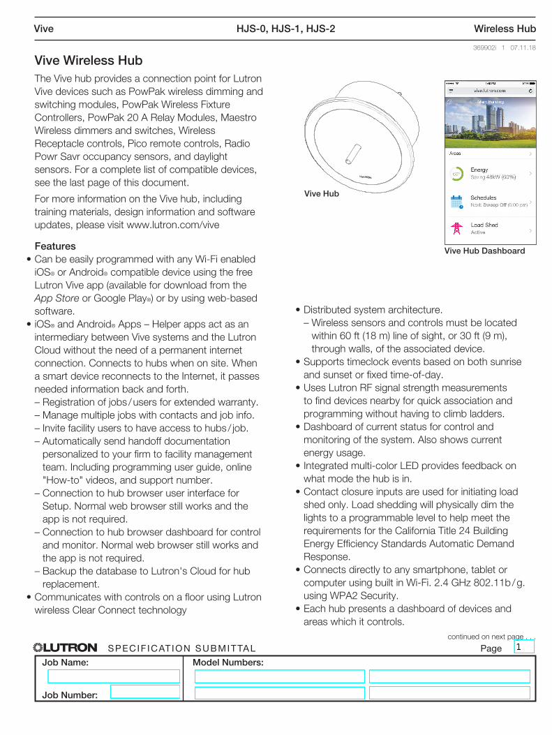
Vive Hub
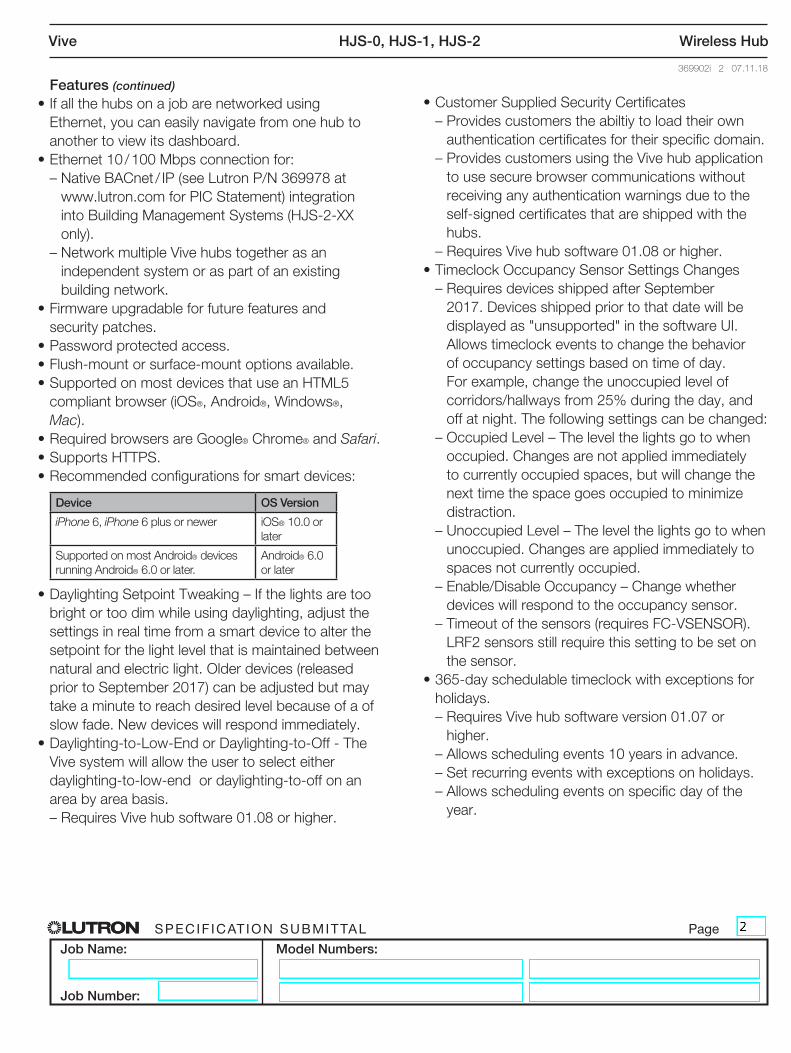
Vive Hub Dashboard
Vive Wireless Hub The Vive hub provides a connection point for Lutron Vive devices such as PowPak wireless dimming and switching modules, PowPak Wireless Fixture Controllers, PowPak 20 A Relay Modules, Maestro Wireless dimmers and switches, Wireless Receptacle controls, Pico remote controls, Radio Powr Savr occupancy sensors, and daylight sensors. For a complete list of compatible devices, see the last page of this document.
For more information on the Vive hub, including training materials, design information and software updates, please visit www.lutron.com/vive
Features• Can be easily programmed with any Wi-Fi enabled
iOS® or Android® compatible device using the free Lutron Vive app (available for download from the App Store or Google Play®) or by using web-based software.
• iOS® and Android® Apps – Helper apps act as an intermediary between Vive systems and the Lutron Cloud without the need of a permanent internet connection. Connects to hubs when on site. When a smart device reconnects to the Internet, it passes needed information back and forth.
– Registration of jobs / users for extended warranty. – Manage multiple jobs with contacts and job info. – Invite facility users to have access to hubs / job. – Automatically send handoff documentation
personalized to your firm to facility management team. Including programming user guide, online "How-to" videos, and support number.
– Connection to hub browser user interface for Setup. Normal web browser still works and the app is not required.
– Connection to hub browser dashboard for control and monitor. Normal web browser still works and the app is not required.
– Backup the database to Lutron's Cloud for hub replacement.
• Communicates with controls on a floor using Lutron wireless Clear Connect technology
• Distributed system architecture. – Wireless sensors and controls must be located
within 60 ft (18 m) line of sight, or 30 ft (9 m), through walls, of the associated device.
• Supports timeclock events based on both sunrise and sunset or fixed time-of-day.
• Uses Lutron RF signal strength measurements to find devices nearby for quick association and programming without having to climb ladders.
• Dashboard of current status for control and monitoring of the system. Also shows current energy usage.
• Integrated multi-color LED provides feedback on what mode the hub is in.
• Contact closure inputs are used for initiating load shed only. Load shedding will physically dim the lights to a programmable level to help meet the requirements for the California Title 24 Building Energy Efficiency Standards Automatic Demand Response.
• Connects directly to any smartphone, tablet or computer using built in Wi-Fi. 2.4 GHz 802.11b / g. using WPA2 Security.
• Each hub presents a dashboard of devices and areas which it controls.
continued on next page . . .
® SPECIF ICAT ION SUBMITTAL Page
Job Name:
Job Number:
Model Numbers:
Vive HJS-0, HJS-1, HJS-2 Wireless Hub
369902i 2 07.11.18
Features (continued)• If all the hubs on a job are networked using
Ethernet, you can easily navigate from one hub to another to view its dashboard.
• Ethernet 10 / 100 Mbps connection for: – Native BACnet / IP (see Lutron P/N 369978 at
www.lutron.com for PIC Statement) integration into Building Management Systems (HJS-2-XX only).
– Network multiple Vive hubs together as an independent system or as part of an existing building network.
• Firmware upgradable for future features and security patches.
• Password protected access.• Flush-mount or surface-mount options available. • Supported on most devices that use an HTML5
compliant browser (iOS®, Android®, Windows®, Mac).
• Required browsers are Google® Chrome® and Safari. • Supports HTTPS.• Recommended configurations for smart devices:
Device OS Version
iPhone 6, iPhone 6 plus or newer iOS® 10.0 or later
Supported on most Android® devices running Android® 6.0 or later.
Android® 6.0 or later
• Daylighting Setpoint Tweaking – If the lights are too bright or too dim while using daylighting, adjust the settings in real time from a smart device to alter the setpoint for the light level that is maintained between natural and electric light. Older devices (released prior to September 2017) can be adjusted but may take a minute to reach desired level because of a of slow fade. New devices will respond immediately.
• Daylighting-to-Low-End or Daylighting-to-Off - The Vive system will allow the user to select either daylighting-to-low-end or daylighting-to-off on an area by area basis.
– Requires Vive hub software 01.08 or higher.
• Customer Supplied Security Certificates – Provides customers the abiltiy to load their own
authentication certificates for their specific domain. – Provides customers using the Vive hub application
to use secure browser communications without receiving any authentication warnings due to the self-signed certificates that are shipped with the hubs.
– Requires Vive hub software 01.08 or higher.• Timeclock Occupancy Sensor Settings Changes – Requires devices shipped after September
2017. Devices shipped prior to that date will be displayed as "unsupported" in the software UI. Allows timeclock events to change the behavior of occupancy settings based on time of day. For example, change the unoccupied level of corridors/hallways from 25% during the day, and off at night. The following settings can be changed:
– Occupied Level – The level the lights go to when occupied. Changes are not applied immediately to currently occupied spaces, but will change the next time the space goes occupied to minimize distraction.
– Unoccupied Level – The level the lights go to when unoccupied. Changes are applied immediately to spaces not currently occupied.
– Enable/Disable Occupancy – Change whether devices will respond to the occupancy sensor.
– Timeout of the sensors (requires FC-VSENSOR). LRF2 sensors still require this setting to be set on the sensor.
• 365-day schedulable timeclock with exceptions for holidays.
– Requires Vive hub software version 01.07 or higher.
– Allows scheduling events 10 years in advance. – Set recurring events with exceptions on holidays. – Allows scheduling events on specific day of the
year.
® SPECIF ICAT ION SUBMITTAL Page
Job Name:
Job Number:
Model Numbers:
Vive HJS-0, HJS-1, HJS-2 Wireless Hub
369902i 3 07.11.18
Additional Software Features
• Measured energy data for PowPak Wireless Fixture Control accurate to ±2% or 0.5 W, whichever is higher.
• Calculated energy data for PowPak modules and Maestro dimmers or switches at 10% accuracy.
• Create and edit areas.• Tune area light levels by trimming the high-end and
low-end output to save energy.• Adjust occupancy settings. Create occupancy
groups.• Load shed is configurable.• Can extend the RF range of up to 15 Pico wireless
remotes per Vive hub. These remotes can be set up to control any device within the 71 ft (22 m) range of that Vive hub.
® SPECIF ICAT ION SUBMITTAL Page
Job Name:
Job Number:
Model Numbers:
Vive HJS-0, HJS-1, HJS-2 Wireless Hub
369902i 4 07.11.18
Specifications
Regulatory Approvals
• cULus Listed• FCC approved. Complies with the limits for a Class B
device, pursuant to Part 15 of the FCC rules.• IC• COFETEL• NOM
Power / Performance
• Input to power supply: 120 – 277 V~ 50 / 60 Hz 0.6 A
• Input to Vive hub: 24 V- 350 mA
System Limits
• HJS-1, HJS-2 support up to 700 Lutron Wireless devices. HJS-0 supports 75 Lutron Wireless devices. Devices must be located within 71 ft (22 m) of the Vive hub.
• Any given load device can be controlled by 10 occupancy sensors, 10 Pico remote controls and 1 daylight sensor (Pico remote controls and sensors must be located within 30 ft [9 m] of the load device they are controlling).
Mounting
• Vive hub units should be mounted in the middle of non-metal ceiling tile or drywall, visible from inside the space.
• Installation near metal, other than a junction box, may reduce RF range. Hub should be at least 12 in (305 mm) away from metal objects.
• Use surface-mount version for mounting to a hard or cement ceiling.
• Power supply mounts to a standard 4 in x 4 in (101 mm x 101 mm) square junction box.
• Power supply must be mounted within 100 ft (31 m) of the Vive hub. Wiring should be 24 AWG to 12 AWG (0.2 mm2 to 2.5 mm2).
Environment
• For indoor use only.• 32 to 104 °F (0 to 40 °C).• Relative humidity less than 90% non-condensing.
Contact Closure Input Terminals
• Contact closure inputs are used for initiating load shed only. Load shedding will physically dim the lights to a programmable level to help meet the requirements for The California Title 24 Building Energy Efficiency Standards Automatic Demand Response.
• Only the first contact closure is used.• Accepts only maintained inputs.• Off-state leakage current must be less than 100 μA.• Open circuit voltage: 24 V- maximum.• Input wiring: 24 AWG to 12 AWG (0.2 mm2 to 2.5 mm2). • Contact Closure Inputs on multiple hubs can be
wired in parallel. DO NOT wire inputs in parallel with other equipment as it can cause the inputs on either of the devices to falsely trigger.
• Up to 4 hubs in parallel.• To ensure proper operation of Contact Closure
Inputs, a PS-J-20W-UNV power supply may not be used to provide power to more than one hub.
• Inputs must be dry contact closure, solid state, open collector, or active-low (NPN) / active high (PNP) output.
– Open collector NPN or active-low on-state voltage must be less than 2 V- and sink 3.0 mA.
– Open collector PNP or active-high on-state voltage must be greater than 12 V- and source 3.0 mA.
Programming
• The Vive Hub is meant to be permanently installed. It is NOT intended to be used as a programming tool that can be removed from the site after commissioning. Various Vive system features are dependent on the hub for proper functionality. In addition, users and other maintainers will be forced to recommission the entire system in order to make simple changes or additions if the hub is not installed on-site as part of the commissioned system.
Warranty
• 1 year limited warranty. The customer can register the product to increase the warranty period from 1 year to 5 years. Please visit www.lutron.com/TechnicalDocument Library/369-119_Wallbox_Warranty.pdf for warranty details.
® SPECIF ICAT ION SUBMITTAL Page
Job Name:
Job Number:
Model Numbers:
Vive HJS-0, HJS-1, HJS-2 Wireless Hub
369902i 5 07.11.18
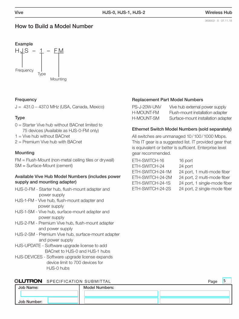
How to Build a Model Number
Example
H J S – 1 – F M
Frequency
J = 431.0 – 437.0 MHz (USA, Canada, Mexico)
Type
0 = Starter Vive hub without BACnet limited to 75 devices (Available as HJS-0-FM only)
1 = Vive hub without BACnet 2 = Premium Vive hub with BACnet
Mounting
FM = Flush-Mount (non-metal ceiling tiles or drywall) SM = Surface-Mount (cement)
Available Vive Hub Model Numbers (includes power supply and mounting adapter)
HJS-0-FM - Starter hub, flush-mount adapter and power supply
HJS-1-FM - Vive hub, flush-mount adapter and power supply
HJS-1-SM - Vive hub, surface-mount adapter and power supply
HJS-2-FM - Premium Vive hub, flush-mount adapter and power supply
HJS-2-SM - Premium Vive hub, surface-mount adapter and power supply
HJS-UPDATE - Software upgrade license to add BACnet to HJS-0 and HJS-1 hubs
HJS-DEVICES - Software upgrade license expands device limit to 700 devices for HJS-0 hubs
Frequency
MountingType
Replacement Part Model Numbers
PS-J-20W-UNV Vive hub external power supply H-MOUNT-FM Flush-mount installation adapter H-MOUNT-SM Surface-mount installation adapter
Ethernet Switch Model Numbers (sold separately)
All switches are unmanaged 10 / 100 / 1000 Mbps. This IT gear is a suggested list. IT provided gear that is equivalent or better is sufficient. Enterprise level gear recommended.
ETH-SWITCH-16 16 port ETH-SWITCH-24 24 port ETH-SWITCH-24-1M 24 port, 1 multi-mode fiber ETH-SWITCH-24-2M 24 port, 2 multi-mode fiber ETH-SWITCH-24-1S 24 port, 1 single-mode fiber ETH-SWITCH-24-2S 24 port, 2 single-mode fiber
® SPECIF ICAT ION SUBMITTAL Page
Job Name:
Job Number:
Model Numbers:
Vive HJS-0, HJS-1, HJS-2 Wireless Hub
369902i 6 07.11.18
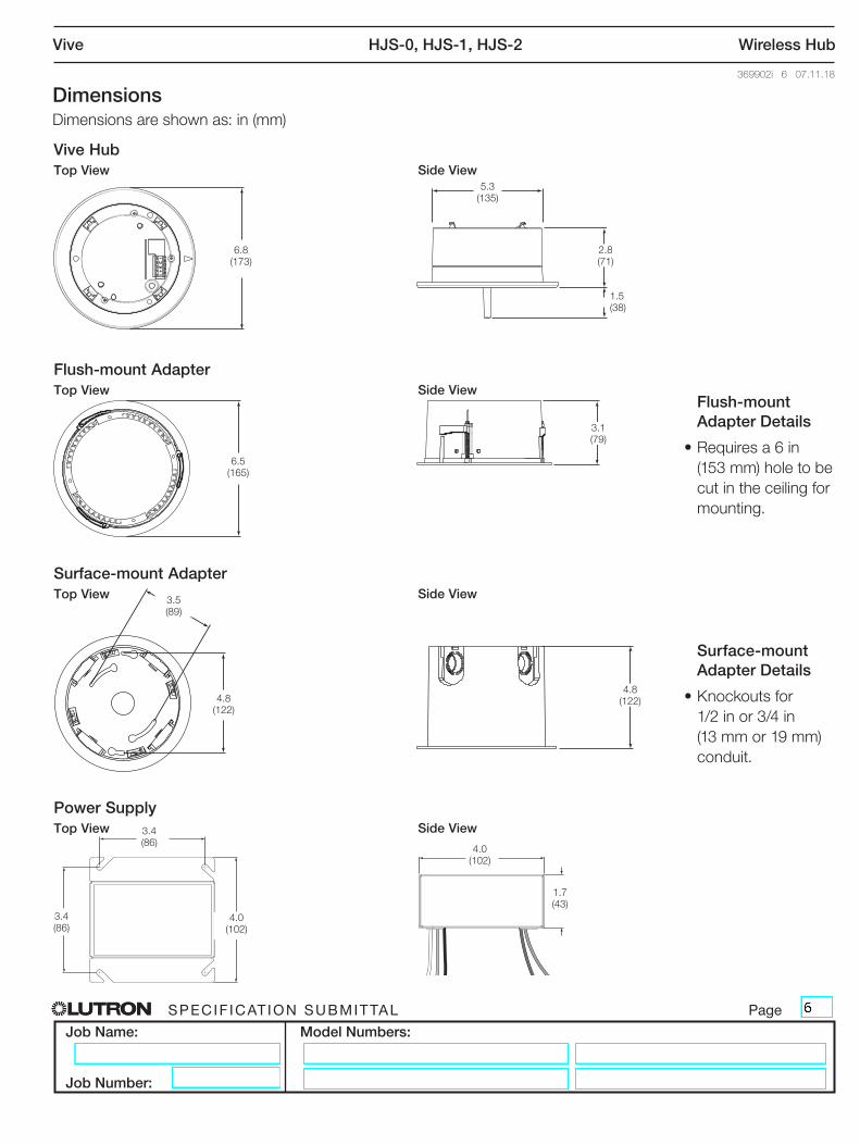
Dimensions Dimensions are shown as: in (mm)
Surface-mount Adapter Details
• Knockouts for 1/2 in or 3/4 in (13 mm or 19 mm) conduit.
Vive HubTop View Side View
6.8(173)
5.3(135)
2.8(71)
1.5(38)
Flush-mount AdapterTop View Side View
6.5(165)
3.1(79)
Surface-mount AdapterTop View Side View
4.8(122)
4.8(122)
3.5(89)
Power SupplyTop View Side View
4.0(102)
3.4(86)
3.4(86)
4.0(102)
1.7(43)
Flush-mount Adapter Details
• Requires a 6 in (153 mm) hole to be cut in the ceiling for mounting.
® SPECIF ICAT ION SUBMITTAL Page
Job Name:
Job Number:
Model Numbers:
Vive HJS-0, HJS-1, HJS-2 Wireless Hub
369902i 7 07.11.18
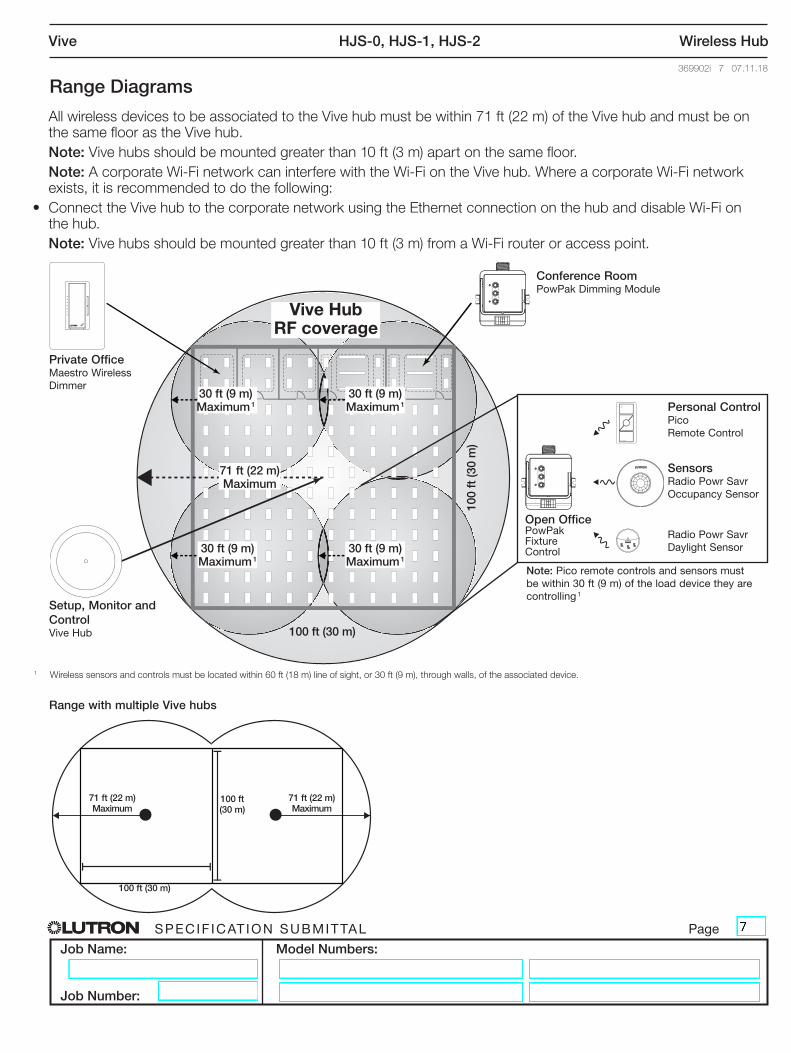
Range Diagrams
100 ft (30 m)
100
ft (3
0 m
)
Private OfficeMaestro Wireless Dimmer
Conference RoomPowPak Dimming Module
Open OfficePowPak Fixture Control
Personal ControlPico Remote Control
SensorsRadio Powr Savr Occupancy Sensor
Radio Powr Savr Daylight Sensor
Setup, Monitor and ControlVive Hub
71 ft (22 m) Maximum
71 ft (22 m) Maximum
100 ft (30 m)
100 ft (30 m)
Note: Pico remote controls and sensors must be within 30 ft (9 m) of the load device they are controlling 1
Range with multiple Vive hubs
All wireless devices to be associated to the Vive hub must be within 71 ft (22 m) of the Vive hub and must be on the same floor as the Vive hub.
Note: Vive hubs should be mounted greater than 10 ft (3 m) apart on the same floor. Note: A corporate Wi-Fi network can interfere with the Wi-Fi on the Vive hub. Where a corporate Wi-Fi network
exists, it is recommended to do the following: • Connect the Vive hub to the corporate network using the Ethernet connection on the hub and disable Wi-Fi on
the hub. Note: Vive hubs should be mounted greater than 10 ft (3 m) from a Wi-Fi router or access point.
30 ft (9 m) Maximum 1
30 ft (9 m) Maximum 1
30 ft (9 m) Maximum 1
30 ft (9 m) Maximum 1
71 ft (22 m) Maximum
Vive Hub RF coverage
1 Wireless sensors and controls must be located within 60 ft (18 m) line of sight, or 30 ft (9 m), through walls, of the associated device.
® SPECIF ICAT ION SUBMITTAL Page
Job Name:
Job Number:
Model Numbers:
Vive HJS-0, HJS-1, HJS-2 Wireless Hub
369902i 8 07.11.18
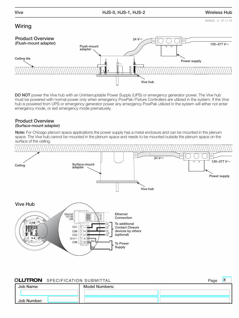
Wiring
24 V-
120 –277 V~
Product Overview (Flush-mount adapter)
Ceiling tilePower supply
Vive hub
Flush-mount adapter
Vive Hub
To Power Supply
To additional Contact Closure devices by others (optional)
CCI1
COM
24 V-
COM
CCI2
Red
Blue
Ethernet10/100
LAN
Ethernet Connection
24 V-120 –277 V~
Ceiling
Power supply
Vive hub
Surface-mount adapter
Product Overview (Surface-mount adapter)
Note: For Chicago plenum space applications the power supply has a metal enclosure and can be mounted in the plenum space. The Vive hub cannot be mounted in the plenum space and needs to be mounted outside the plenum space on the surface of the ceiling.
DO NOT power the Vive hub with an Uninterruptable Power Supply (UPS) or emergency generator power. The Vive hub must be powered with normal power only when emergency PowPak / Fixture Controllers are utilized in the system. If the Vive hub is powered from UPS or emergency generator power any emergency PowPak utilized in the system will either not enter emergency mode, or exit emergency mode prematurely.
® SPECIF ICAT ION SUBMITTAL Page
Job Name:
Job Number:
Model Numbers:
Vive HJS-0, HJS-1, HJS-2 Wireless Hub
369902i 9 07.11.18
Vive Security Statement
Lutron takes the security of the Vive Lighting Control System very seriously.
The Vive Lighting Control System has been designed and engineered with attention to security since its inception. Lutron has engaged security experts and independent testing firms throughout the entire development of the Vive Lighting Control System. Lutron is committed to security and continuous improvement throughout the Vive product lifecycle.
The Vive Lighting Control System uses a multi-tiered approach to security and National Institute of Standards and Technology (NIST) recommended techniques for security.
They include:
1. An architecture that isolates the wired Ethernet network from the wireless network, which strictly limits the possibility of the Vive Wi-Fi being used to access the corporate network and gain confidential information
2. A distributed security architecture with each hub having its own unique keys that would limit any potential breach to only a small area of the system
3. Multiple levels of password protection (Wi-Fi network and the hubs themselves), with built-in rules that force the user to enter a strong password
4. NIST-recommended best practices including salting and SCrypt for securely storing usernames and passwords
5. AES 128-bit encryption for network communications
6. HTTPS (TLS 1.2) protocol for securing connections to the hub over the wired network
7. WPA2 technology for securing connections to the hub over the Wi-Fi network
8. Azure provided encryption-at-rest technologies
The Vive hub can be deployed in one of two ways:
• Dedicated Lutron Network
• Connected to the corporate IT network via Ethernet. The Vive hub must be connected via Ethernet to access certain features such as BACnet® for BMS integration. Lutron advises following best practices in this instance, including separating the business information network and the building infrastructure network. Use of a VLAN or physically separated networks is recommended for secure deployment.
Dedicated Lutron Network Deployment
The Vive hub is not connected to the building network. Wi-Fi is used to connect to a smart device such as a phone, tablet, or PC for commissioning and configuration only. The Vive hub serves web pages for setup and maintenance via a password-protected connection. The Wi-Fi SSID can be set to not broadcast. The Vive hub Wi-Fi may be disabled if desired.
Corporate IT Network Deployment
The Vive hub may be deployed with a fixed IP address or served over DHCP. Once the IT network is operational, the Vive hub will serve password protected web pages for access and maintenance. The Vive hub Wi-Fi may be disabled if desired.
The Vive hub acts as a Wi-Fi access point purely for the configuration and commissioning of the Vive system. It is not a substitute for your building’s normal Wi-Fi access point. The Vive hub does not act as a bridge between wireless and wired networks.
It is strongly recommended that local IT security professionals be involved with the network configuration and set-up to ensure the installation meets their security needs.
® SPECIF ICAT ION SUBMITTAL Page
Job Name:
Job Number:
Model Numbers:
Vive HJS-0, HJS-1, HJS-2 Wireless Hub
369902i 10 07.11.18
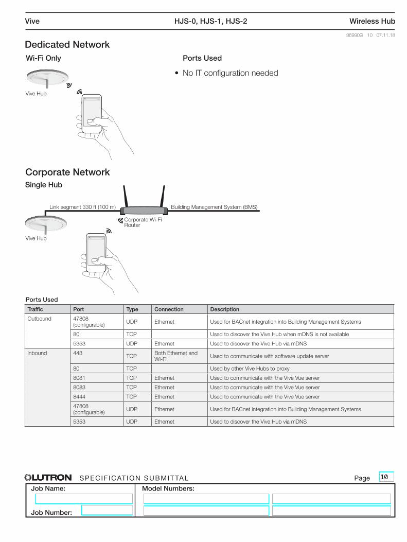
Dedicated NetworkWi-Fi Only
XVive
Ports Used
• No IT configuration needed
Corporate NetworkSingle Hub
XVive
Ports Used
Link segment 330 ft (100 m) Building Management System (BMS)
Vive Hub
Vive Hub
Corporate Wi-Fi Router
Traffic Port Type Connection Description
Outbound 47808 (configurable) UDP Ethernet Used for BACnet integration into Building Management Systems
80 TCP Used to discover the Vive Hub when mDNS is not available
5353 UDP Ethernet Used to discover the Vive Hub via mDNS
Inbound 443 TCP Both Ethernet and Wi-Fi Used to communicate with software update server
80 TCP Used by other Vive Hubs to proxy
8081 TCP Ethernet Used to communicate with the Vive Vue server
8083 TCP Ethernet Used to communicate with the Vive Vue server
8444 TCP Ethernet Used to communicate with the Vive Vue server
47808 (configurable) UDP Ethernet Used for BACnet integration into Building Management Systems
5353 UDP Ethernet Used to discover the Vive Hub via mDNS
® SPECIF ICAT ION SUBMITTAL Page
Job Name:
Job Number:
Model Numbers:
Vive HJS-0, HJS-1, HJS-2 Wireless Hub
369902i 11 07.11.18
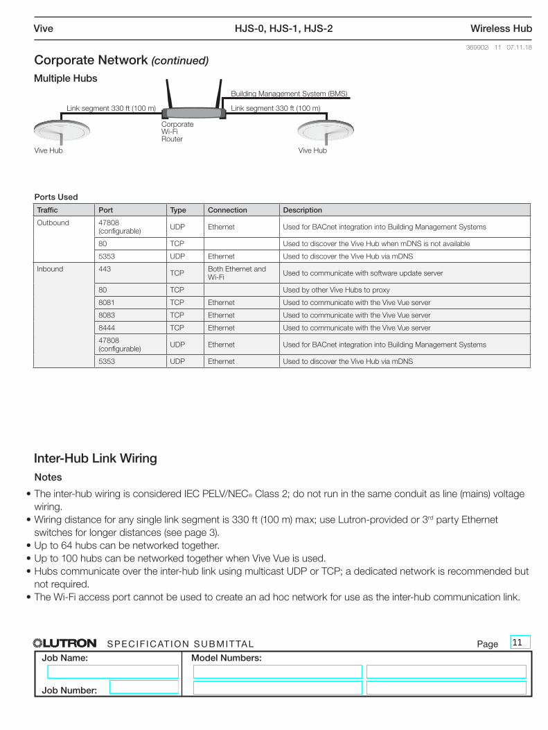
Corporate Network (continued)Multiple Hubs
Link segment 330 ft (100 m)
Building Management System (BMS)
Vive Hub
Corporate Wi-Fi Router
Vive Hub
Notes
• The inter-hub wiring is considered IEC PELV/NEC® Class 2; do not run in the same conduit as line (mains) voltage wiring.
• Wiring distance for any single link segment is 330 ft (100 m) max; use Lutron-provided or 3rd party Ethernet switches for longer distances (see page 3).
• Up to 64 hubs can be networked together.• Up to 100 hubs can be networked together when Vive Vue is used.• Hubs communicate over the inter-hub link using multicast UDP or TCP; a dedicated network is recommended but
not required.• The Wi-Fi access port cannot be used to create an ad hoc network for use as the inter-hub communication link.
Inter-Hub Link Wiring
Link segment 330 ft (100 m)
Ports Used
Traffic Port Type Connection Description
Outbound 47808 (configurable) UDP Ethernet Used for BACnet integration into Building Management Systems
80 TCP Used to discover the Vive Hub when mDNS is not available
5353 UDP Ethernet Used to discover the Vive Hub via mDNS
Inbound 443 TCP Both Ethernet and Wi-Fi Used to communicate with software update server
80 TCP Used by other Vive Hubs to proxy
8081 TCP Ethernet Used to communicate with the Vive Vue server
8083 TCP Ethernet Used to communicate with the Vive Vue server
8444 TCP Ethernet Used to communicate with the Vive Vue server
47808 (configurable) UDP Ethernet Used for BACnet integration into Building Management Systems
5353 UDP Ethernet Used to discover the Vive Hub via mDNS
® SPECIF ICAT ION SUBMITTAL Page
Job Name:
Job Number:
Model Numbers:
Vive HJS-0, HJS-1, HJS-2 Wireless Hub
369902i 12 07.11.18
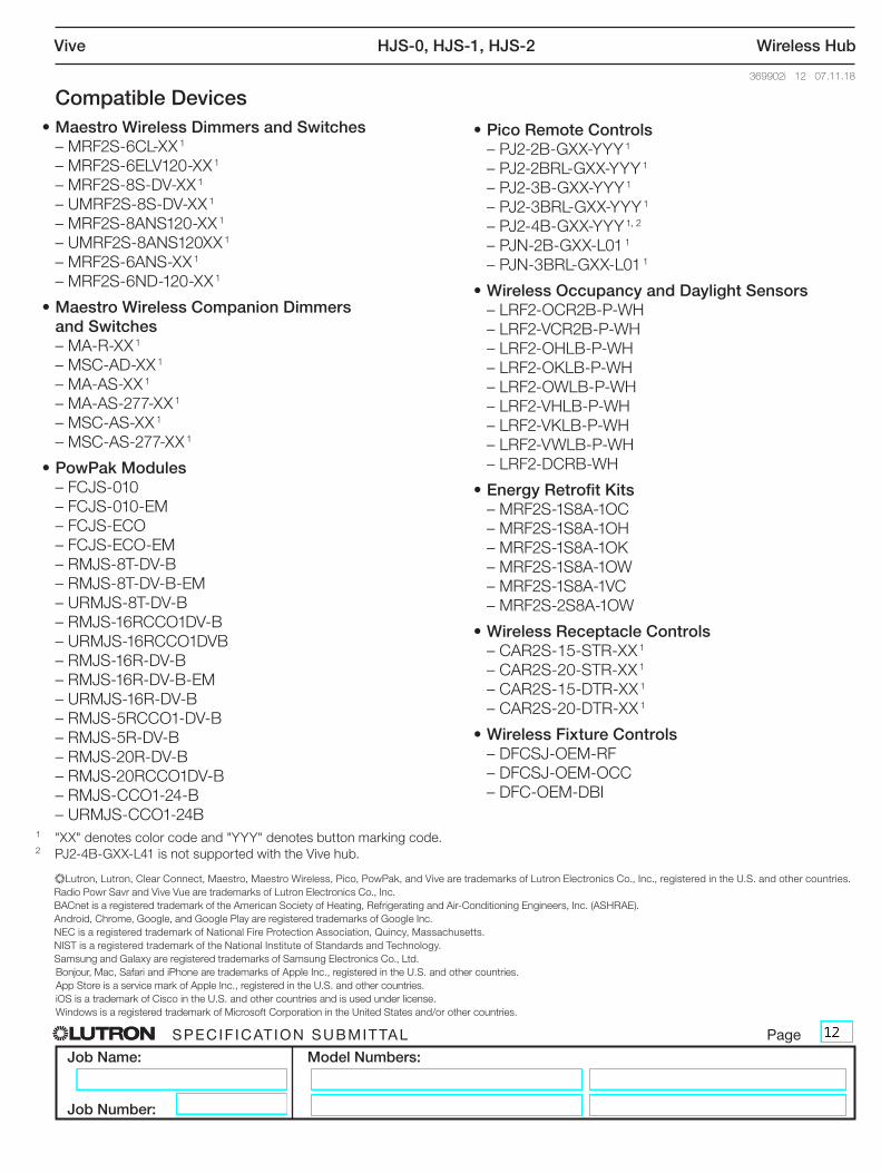
Compatible Devices• Maestro Wireless Dimmers and Switches – MRF2S-6CL-XX 1
– MRF2S-6ELV120-XX 1
– MRF2S-8S-DV-XX 1
– UMRF2S-8S-DV-XX 1
– MRF2S-8ANS120-XX 1
– UMRF2S-8ANS120XX 1
– MRF2S-6ANS-XX 1
– MRF2S-6ND-120-XX 1
• Maestro Wireless Companion Dimmers and Switches
– MA-R-XX 1
– MSC-AD-XX 1
– MA-AS-XX 1
– MA-AS-277-XX 1
– MSC-AS-XX 1
– MSC-AS-277-XX 1
• PowPak Modules – FCJS-010 – FCJS-010-EM – FCJS-ECO – FCJS-ECO-EM – RMJS-8T-DV-B – RMJS-8T-DV-B-EM – URMJS-8T-DV-B – RMJS-16RCCO1DV-B – URMJS-16RCCO1DVB – RMJS-16R-DV-B – RMJS-16R-DV-B-EM – URMJS-16R-DV-B – RMJS-5RCCO1-DV-B – RMJS-5R-DV-B – RMJS-20R-DV-B – RMJS-20RCCO1DV-B – RMJS-CCO1-24-B – URMJS-CCO1-24B
• Pico Remote Controls – PJ2-2B-GXX-YYY 1
– PJ2-2BRL-GXX-YYY 1
– PJ2-3B-GXX-YYY 1
– PJ2-3BRL-GXX-YYY 1
– PJ2-4B-GXX-YYY 1, 2
– PJN-2B-GXX-L01 1
– PJN-3BRL-GXX-L01 1
• Wireless Occupancy and Daylight Sensors – LRF2-OCR2B-P-WH – LRF2-VCR2B-P-WH – LRF2-OHLB-P-WH – LRF2-OKLB-P-WH – LRF2-OWLB-P-WH – LRF2-VHLB-P-WH – LRF2-VKLB-P-WH – LRF2-VWLB-P-WH – LRF2-DCRB-WH
• Energy Retrofit Kits – MRF2S-1S8A-1OC – MRF2S-1S8A-1OH – MRF2S-1S8A-1OK – MRF2S-1S8A-1OW – MRF2S-1S8A-1VC – MRF2S-2S8A-1OW
• Wireless Receptacle Controls – CAR2S-15-STR-XX 1
– CAR2S-20-STR-XX 1
– CAR2S-15-DTR-XX 1
– CAR2S-20-DTR-XX 1
• Wireless Fixture Controls – DFCSJ-OEM-RF – DFCSJ-OEM-OCC – DFC-OEM-DBI
1 "XX" denotes color code and "YYY" denotes button marking code.2 PJ2-4B-GXX-L41 is not supported with the Vive hub.
)Lutron, Lutron, Clear Connect, Maestro, Maestro Wireless, Pico, PowPak, and Vive are trademarks of Lutron Electronics Co., Inc., registered in the U.S. and other countries. Radio Powr Savr and Vive Vue are trademarks of Lutron Electronics Co., Inc. BACnet is a registered trademark of the American Society of Heating, Refrigerating and Air-Conditioning Engineers, Inc. (ASHRAE). Android, Chrome, Google, and Google Play are registered trademarks of Google Inc. NEC is a registered trademark of National Fire Protection Association, Quincy, Massachusetts. NIST is a registered trademark of the National Institute of Standards and Technology. Samsung and Galaxy are registered trademarks of Samsung Electronics Co., Ltd. Bonjour, Mac, Safari and iPhone are trademarks of Apple Inc., registered in the U.S. and other countries. App Store is a service mark of Apple Inc., registered in the U.S. and other countries. iOS is a trademark of Cisco in the U.S. and other countries and is used under license. Windows is a registered trademark of Microsoft Corporation in the United States and/or other countries.