vlan trunking protocol
TRANSCRIPT

VLAN Trunking Protocol
VLAN Trunking Protocol (VTP) is a Cisco proprietary protocol that propagates the definition of Virtual
Local Area Networks (VLAN) on the whole local area network.[1] To do this, VTP carries VLAN
information to all the switches in a VTP domain. VTP advertisements can be sent over ISL, 802.1Q, IEEE
802.10 and LANE trunks. VTP is available on most of the Cisco Catalyst Family products. Using VTP, each
Catalyst Family Switch advertises the following on its trunk ports:
1. Management domain
2. Configuration revision number
3. Known VLANs and their specific parameter
One concept in VTP is that larger scale networks may need to be limited in terms of which switches will
act as the VLAN servers. VTP offers various options for recovery after a crash or for efficiently serving up
redundant network traffic.
In the image above, each switch has two VLANs. On the first switch, VLAN A and VLAN B are sent
through a single port (trunked) to the router and through another port to the second switch. VLAN C
and VLAN D are trunked from the second switch to the first switch and through the first switch to the
router. This trunk can carry traffic from all four VLANs. The trunk link from the first switch to the router
can also carry all four VLANs. In fact, this one connection to the router allows the router to appear on all
four VLANs, as if it had four different physical ports connected to the switch.
The VLANs can communicate with each other via the trunking connection between the two switches
using the router. For example, data from a computer on VLAN A that needs to get to a computer on
VLAN B (or VLAN C or VLAN D) must travel from the switch to the router and back again to the switch.
Because of the transparent bridging algorithm and trunking, both PCs and the router think that they are
on the same physical segment!
Figure 1 VLAN Trunking Protocol

VLAN Trunking Protocol
Implementation Details
On Cisco Devices, VTP (VLAN Trunking Protocol) maintains VLAN configuration consistency across the
entire network. VTP uses Layer 2 trunk frames to manage the addition, deletion, and renaming of VLANs
on a network-wide basis from a centralized switch in the VTP server mode. VTP is responsible for
synchronizing VLAN information within a VTP domain and reduces the need to configure the same VLAN
information on each switch.
VTP minimizes the possible configuration inconsistencies that arise when changes are made. These
inconsistencies can result in security violations, because VLANs can cross connect when duplicate names
are used. They also could become internally disconnected when they are mapped from one LAN type to
another, for example, Ethernet to ATM LANE ELANs or FDDI 802.10 VLANs. VTP provides a mapping
scheme that enables seamless trunking within a network employing mixed-media technologies.
Currently there are three version of VLAN Trunking Protocol (VTP). The functions of VTP Version 1 and
VTP Version 2 are almost similar. The support for Token Ring VLANs is there with VTP V2.
According to Cisco VTP V3 documentation, VLAN Trunking Protocol (VTP) Version 3 introduces the
concept of transferring an opaque database in situations where VTP version 1 and VTP version 2
interacted with the VLAN process directly. VTP version 3 includes support for the MST mapping table.
Figure 2 Example without and with VTP

VLAN Trunking Protocol
These are the enhancements made on VLAN Trunk Protocol (VTP) V3:
1. Protection from unintended database overrides during insertion of new switches.
2. Support for VLAN numbers up to 4096.
3. Support for interaction with VTP Version 1 and VTP Version 2.
4. Support for a structured and secure VLAN environment (Private VLAN, or PVLAN).
5. Option of clear text or hidden password protection.
6. Configuration option on a per port base instead of only a global scheme.
7. Optimized resource handling and more efficient transfer of information.
Benefits
VTP provides the following benefits:
1. VLAN configuration consistency across the network
2. Mapping scheme that allows a VLAN to be trunked over mixed media
3. Accurate tracking and monitoring of VLANs
4. Dynamic reporting of added VLANs across the network
5. Plug-and-play configuration when adding new VLANs
Downside
As beneficial as VTP can be, it does have disadvantages that are normally related to the spanning tree
protocol (STP) as a bridging loop propagating throughout the network can occur. Cisco switches run an
instance of STP for each VLAN, and since VTP propagates VLANs across the campus LAN, VTP effectively
creates more opportunities for a bridging loop to occur.
Before creating VLANs on the switch that will propagate via VTP, a VTP domain must first be set up. A
VTP domain for a network is a set of all contiguously trunked switches with the same VTP domain name.
All switches in the same management domain share their VLAN information with each other, and a
switch can participate in only one VTP management domain. Switches in different domains do not share
VTP information.
Another, even greater concern with VTP is the issue known colloquially as the "VTP Bomb". When a new
switch is added to the network, by default it is configured with no VTP domain name or password, but in
VTP server mode. Since a new switch has a VTP version of 0, it will accept any larger version number as
newer and add that VLAN information to its configuration as long as the other switches have the same
VTP domain and password. However, if you were to accidentally connect a switch to the network with
the correct VTP domain name and password but a higher VTP version number than what the network
currently has, then the entire network would adopt the VLAN configuration of the new switch - likely
bringing down your entire network, or at least that VTP domain.

VLAN Trunking Protocol
Dynamic Trunking Protocol
The Dynamic Trunking Protocol (DTP) is a proprietary networking protocol developed by Cisco Systems
for the purpose of negotiating trunking on a link between two VLAN-aware switches, and for negotiating
the type of trunking encapsulation to be used. It works on the Layer 2 of the OSI model. VLAN trunks
formed using DTP may utilize either IEEE 802.1Q or Cisco ISL trunking protocols.
DTP should not be confused with VTP, as they serve different purposes. VTP communicates VLAN
existence information between switches. DTP aids with trunk port establishment. Neither protocol
transmits the data frames that trunks carry.
Switch port modes
The following switch port mode settings exist:
1. Access- Puts the LAN port into permanent nontrunking mode and negotiates to convert the link
into a nontrunk link. The LAN port becomes a nontrunk port even if the neighboring LAN port
does not agree to the change.
2. Trunk- Puts the LAN port into permanent trunking mode and negotiates to convert the link into a
trunk link. The LAN port becomes a trunk port even if the neighboring port does not agree to the
change.
3. Dynamic Auto- Makes the LAN port willing to convert the link to a trunk link. The LAN port
becomes a trunk port if the neighboring LAN port is set to trunk or desirable mode.
4. Dynamic Desirable- Makes the LAN port actively attempt to convert the link to a trunk link. The
LAN port becomes a trunk port if the neighboring LAN port is set to trunk, desirable, or auto
mode. This is the default mode for all LAN ports.
5. Nonegotiate- Puts the LAN port into permanent trunking mode but prevents the port from
generating DTP frames. You must configure the neighboring port manually as a trunk port to
establish a trunk link.
VTP Advertisement Messages
Three types of VLAN Trunking Protocol (VTP) advertisement messages are:
1. Client Advertisement Request: A client advertisement request message is a VTP message which
a client generates for VLAN information to a server. Servers respond with both summary and
subset advertisements.

VLAN Trunking Protocol
2. Summary Advertisement: Summary advertisements are sent out every 300 seconds (5 minutes)
by default or when a configuration change occurs, which is the summarized VLAN information.
3. Subset Advertisement: Subset advertisements are sent when a configuration change takes place
on the server switch. Subset advertisements are VLAN specific and contain details about each
VLAN.
VTP Protocol
Cisco Inter-Switch Link (ISL)
Cisco Inter-Switch Link (ISL) is a Cisco Systems proprietary protocol that maintains VLAN information in
Ethernet frames as traffic flows between switches and routers, or switches and switches.
ISL is Cisco's VLAN Encapsulation protocol and is supported only on some Cisco equipment over Fast and
Gigabit Ethernet links. It is offered as an option to the IEEE 802.1Q standard, a widely used VLAN tagging
protocol, although the use of ISL for new sites is deprecated by Cisco. In the case of ISL the tag is
external to the Ethernet frame, which effectively is the same as encapsulating the Ethernet frame,
whereas with IEEE 802.1Q the tag is internal. This is a key advantage for IEEE 802.1Q as it means tagged
frames can be sent over standard Ethernet links.
The size of an Ethernet encapsulated ISL frame can be expected to start from 94 bytes and increase up
to 1548 bytes because of the overhead (additional fields) the protocol creates via encapsulation. ISL
adds a 26-byte header (containing a 15-bit VLAN identifier) and a 4-byte CRC trailer to the frame. ISL
functions at the Data-Link layer of the OSI model. ISL is used to maintain redundant links.
Another related Cisco protocol, Dynamic Inter-Switch Link Protocol (DISL) simplifies the creation of an
ISL trunk from two interconnected Fast Ethernet devices. Fast EtherChannel technology enables
aggregation of two full-duplex Fast Ethernet links for high-capacity backbone connections. DISL
minimizes VLAN trunk configuration procedures because only one end of a link needs to be configured
as a trunk.
IEEE 802.1Q
IEEE 802.1Q is the networking standard that supports virtual LANs (VLANs) on an Ethernet network. The
standard defines a system of tagging for Ethernet frames and the accompanying procedures to be used
by bridges and switches in handling such frames. The standard also contains provisions for a quality of
service prioritization scheme commonly known as IEEE 802.1p and defines the Generic Attribute
Registration Protocol.
Portions of the network which are VLAN-aware (i.e., IEEE 802.1Q conformant) can include VLAN tags.
When a frame enters the VLAN-aware portion of the network, a tag is added to represent the VLAN
membership of the frame's port or the port/protocol combination, depending on whether port-based or

VLAN Trunking Protocol
port-and-protocol-based VLAN classification is being used. Each frame must be distinguishable as being
within exactly one VLAN. A frame in the VLAN-aware portion of the network that does not contain a
VLAN tag is assumed to be flowing on the native (or default) VLAN.
The standard was developed by IEEE 802.1, a working group of the IEEE 802 standards committee, and
continues to be actively revised with notable revisions including IEEE 802.1ak, IEEE 802.1Qat and IEEE
802.1Qay.
Frame Format
802.1Q does not encapsulate the original frame. Instead, for Ethernet frames, it adds a 32-bit field
between the source MAC address and the EtherType/length fields of the original frame, leaving the
minimum frame size unchanged at 64 bytes (octets) and extending the maximum frame size from 1,518
bytes to 1,522 bytes (for the payload a 42-octet minimum applies when 802.1Q is present; when absent,
a 46-octet minimum applies. IEEE 802.3-2005 Clause 3.5). Two bytes are used for the tag protocol
identifier (TPID), the other two bytes for tag control information (TCI). The TCI field is further divided
into PCP, DEI, and VID.
16 bits 3 bits 1 bit 12 bits
TPID
TCI
PCP DEI VID
Tag protocol identifier (TPID): a 16-bit field set to a value of 0x8100 in order to identify the frame as an
IEEE 802.1Q-tagged frame. This field is located at the same position as the EtherType/length field in
untagged frames, and is thus used to distinguish the frame from untagged frames.
Figure 3 Insertion of 802.1Q tag in an Ethernet frame

VLAN Trunking Protocol
Tag control information (TCI)
1. Priority code point (PCP): a 3-bit field which refers to the IEEE 802.1p class of service and maps
to the frame priority level. Values in order of priority are: 1 (background), 0 (best effort), 2
(excellent effort), 3 (critical application), ..., 7 (network control). These values can be used to
prioritize different classes of traffic (voice, video, data, etc.).
2. Drop eligible indicator (DEI): a 1-bit field. (formerly CFI[note 1][2]) May be used separately or in
conjunction with PCP to indicate frames eligible to be dropped in the presence of congestion.
3. VLAN identifier (VID): a 12-bit field specifying the VLAN to which the frame belongs. The
hexadecimal values of 0x000 and 0xFFF are reserved. All other values may be used as VLAN
identifiers, allowing up to 4,094 VLANs. The reserved value 0x000 indicates that the frame does
not belong to any VLAN; in this case, the 802.1Q tag specifies only a priority and is referred to as
a priority tag. On bridges, VLAN 1 (the default VLAN ID) is often reserved for a management
VLAN; this is vendor-specific.
For frames using IEEE 802.2/SNAP encapsulation with an OUI field of 00-00-00 (so that the protocol ID
field in the SNAP header is an EtherType), as would be the case on LANs other than Ethernet, the
EtherType value in the SNAP header is set to 0x8100 and the aforementioned extra 4 bytes are
appended after the SNAP header.
Because inserting the VLAN tag changes the frame, 802.1Q encapsulation forces a recalculation of the
original frame check sequence field in the Ethernet trailer.
The IEEE 802.3ac standard increased the maximum Ethernet frame size from 1518 bytes to 1522 bytes
to accommodate the four-byte VLAN tag. Some network devices that do not support the larger frame
size will process the frame successfully but may report them as a "baby giant" anomalies.
Double Tagging
With the IEEE standard 802.1ad, double-tagging can be useful for Internet service providers, allowing
them to use VLANs internally while mixing traffic from clients that are already VLAN-tagged. The outer
(next to source MAC and representing ISP VLAN) S-TAG (service tag) comes first, followed by the inner C-
TAG (customer tag). In such cases, 802.1ad specifies a TPID of 0x88a8 for service-provider outer S-TAG.
Figure 4 Insertion of 802.1ad double tag in an Ethernet frame

VLAN Trunking Protocol
Multiple VLAN Registration Protocol
IEEE 802.1Q defines the Multiple VLAN Registration Protocol (MVRP), an application of the Multiple
Registration Protocol, allowing bridges to negotiate the set of VLANs to be used over a specific link.
MVRP replaced the slower GARP VLAN Registration Protocol (GVRP) in 2007 with the IEEE 802.1ak-2007
amendment.
IEEE 802.10
IEEE 802.10 is a former standard for security functions that could be used in both local area networks
and metropolitan area networks based on IEEE 802 protocols.
802.10 specifies security association management and key management, as well as access control, data
confidentiality and data integrity.
The IEEE 802.10 standards were withdrawn in January 2004 and this working group of the IEEE 802 is
not currently active. Security for wireless networks was standardized in 802.11i.
The Cisco Inter-Switch Link (ISL) protocol for supporting VLANs on Ethernet and similar LAN technologies
was based on IEEE 802.10; in this application 802.10 has largely been replaced by IEEE 802.1Q.
The standard being developed has 8 parts:
a. Model, including security management
b. Secure Data Exchange (SDE) protocol
c. Key Management
d. - has now been incorporated in 'a' -
e. SDE Over Ethernet 2.0
f. SDE Sublayer Management
g. SDE Security Labels
h. SDE PICS Conformance.
Parts b, e, f, g, and h are incorporated in IEEE Standard 802.10-1998.
VLAN Trunking Protocol (VTP) Modes
A network switch, which is participating in VLAN Trunking Protocol (VTP), can have three different
modes.
Server Mode
Server Mode is the default VTP mode for all Catalyst switches. At least one server is required in a VTP
domain to propagate VLAN information within the VTP domain. We can create, add, or delete VLANs of

VLAN Trunking Protocol
a VTP domain in a Switch which is in VTP Server mode and change VLAN information in a VTP Server.
The changes made in a switch in server mode are advertised to the entire VTP domain.
Client Mode
Client Mode switches listen to VTP advertisements from other switches and modify their VLAN
configurations accordingly. A network switch in VTP client mode requires a server switch to inform it
about the VLAN changes. We CANNOT create, add, or delete VLANs in a VTP client.
Transparent Mode
Transparent Mode switches do not participate in the VTP domain, but VTP transparent mode switches
can receive and forward VTP advertisements through the configured trunk links.
VTP Pruning
Pruning is a feature in Cisco switches, which stops VLAN update information traffic from being sent
down trunk links if the updates are not needed. If the VLAN traffic is needed later, VLAN Trunking
Protocol (VTP) will dynamically add the VLAN back to the trunk link.
In normal operation a switch needs to flood broadcast frames, multicast frames, or unicast frames
where the destination MAC address is unknown to all its ports. If the neighbouring switch doesn’t have
any active ports in the source VLAN, this broadcast is unnecessary and excessive unwanted traffic may
create problems on the network.
Figure 5 VTP Modes

VLAN Trunking Protocol
VLAN Trunking Protocol (VTP) pruning helps in increasing the available bandwidth by reducing
unnecessary flooded traffic. Broadcast frames, multicast frames, or unicast frames where the
destination MAC address is unknown are forwarded over a trunk link only if the switch on the receiving
end of the trunk link has ports in the source VLAN.
Configuration
3512xl#configure terminal
Enter configuration commands, one per line. End with CNTL/Z.
3512xl(config)#int vlan 1
3512xl(config-if)#ip address 10.10.10.2 255.255.255.0
3512xl(config-if)#exit
3512xl(config)#ip default-gateway 10.10.10.1
3512xl(config)#end
3512xl#vlan database
3512xl(vlan)#vtp transparent
Figure 6 VTP Topology
VLAN Trunking Protocol
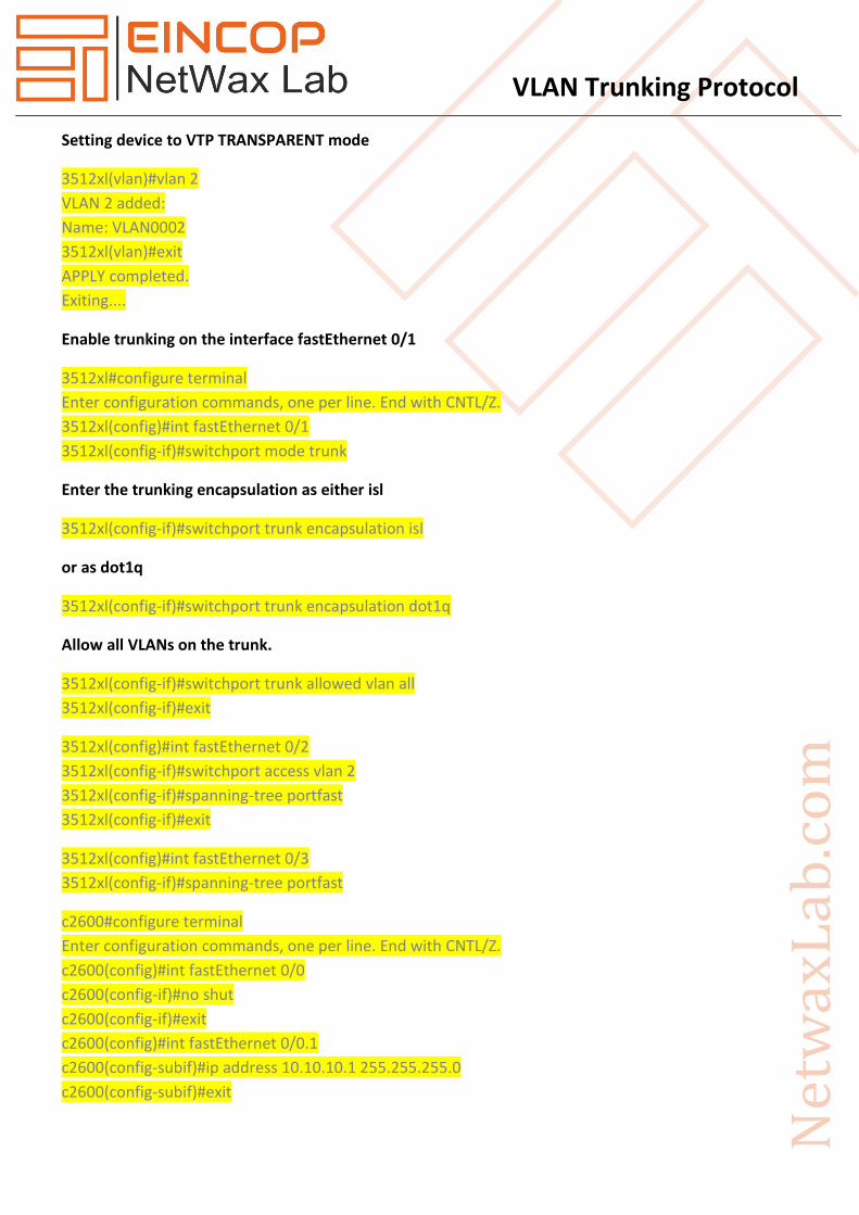
Setting device to VTP TRANSPARENT mode
3512xl(vlan)#vlan 2
VLAN 2 added:
Name: VLAN0002
3512xl(vlan)#exit
APPLY completed.
Exiting....
Enable trunking on the interface fastEthernet 0/1
3512xl#configure terminal
Enter configuration commands, one per line. End with CNTL/Z.
3512xl(config)#int fastEthernet 0/1
3512xl(config-if)#switchport mode trunk
Enter the trunking encapsulation as either isl
3512xl(config-if)#switchport trunk encapsulation isl
or as dot1q
3512xl(config-if)#switchport trunk encapsulation dot1q
Allow all VLANs on the trunk.
3512xl(config-if)#switchport trunk allowed vlan all
3512xl(config-if)#exit
3512xl(config)#int fastEthernet 0/2
3512xl(config-if)#switchport access vlan 2
3512xl(config-if)#spanning-tree portfast
3512xl(config-if)#exit
3512xl(config)#int fastEthernet 0/3
3512xl(config-if)#spanning-tree portfast
c2600#configure terminal
Enter configuration commands, one per line. End with CNTL/Z.
c2600(config)#int fastEthernet 0/0
c2600(config-if)#no shut
c2600(config-if)#exit
c2600(config)#int fastEthernet 0/0.1
c2600(config-subif)#ip address 10.10.10.1 255.255.255.0
c2600(config-subif)#exit

VLAN Trunking Protocol
Enter the trunking encapsulation as either isl
c2600(config-subif)#encapsulation isl 1
or as dot1q
c2600(config-subif)#encapsulation dot1Q 1 ?
native Make this is native vlan
<cr>
c2600(config-subif)#encapsulation dot1Q 1 native
c2600(config-subif)#exit
c2600(config)#int fastEthernet 0/0.2
c2600(config-subif)#ip address 10.10.11.1 255.255.255.0
c2600(config-subif)#encapsulation isl 2
or as dot1q
c2600(config-subif)#encapsulation dot1Q 2
c2600(config-subif)#exit
Debug and show Commands
On the Catalyst 2900XL/3500XL/2940/2950/2970 switch, use the following commands:
1. show int {FastEthernet | GigabitEthernet} <module/port> switchport
2. show vlan
3. show vtp status
On the Cisco 2600 router, use the following commands:
1. show vlan
2. show interface