vlsi implementation of energy detection algorithm...
TRANSCRIPT

VLSI Implementation of Energy Detection Algorithm
for WLAN and WiMAX Applications
A THESIS SUBMITTED IN PARTIAL FULFILMENT
OF THE REQUIRMENTS FOR THE DEGREE OF
MASTER OF TECHNOLOGY
in
Electronics and Communication Engineering
VLSI and Embedded System Design
by
JHARANA DALAI
Roll No: 211EC2076
DEPARTMENT OF ELECTRONICS AND COMMUNICATION
ENGINEERING
NATIONAL INSTITUTE OF TECHNOLOGY
ROURKELA, ODISHA
INDIA
2013

VLSI Implementation of Energy Detection Algorithm
for WLAN and WiMAX Applications
A THESIS SUBMITTED IN PARTIAL FULFILMENT
OF THE REQUIRMENTS FOR THE DEGREE OF
MASTER OF TECHNOLOGY
in
Electronics and Communication Engineering
VLSI AND EMBEDDED SYSTEM DESIGN by
JHARANA DALAI
Roll No: 211EC2076
Under the guidance of
Prof. SARAT KUMAR PATRA
DEPARTMENT OF ELECTRONICS AND COMMUNICATION
ENGINEERING
NATIONAL INSTITUTE OF TECHNOLOGY
ROURKELA, ODISHA
INDIA
2013

Dedicated to My Loving parents
and my brothers

NATIONAL INSTITUTE OF TECHNOLOGY Dept. of Electronics and Communication Engineering
Rourkela-769008, Odisha, India
CERTIFICATE
This is to certify that the work entitled in this thesis, “VLSI Implementation of Energy
Detection Algorithm for WLAN and WiMAX applications” submitted by JHARANA
DALAI in partial fulfilment of the requirements for the award of Master of Technology
Degree in Electronics & Communication Engineering with specialization in VLSI and
Embedded System Design during 2011-2013 at the National Institute of Technology,
Rourkela. This is an authentic work carried out by her under my supervision and guidance.
To the best of my knowledge, neither this thesis nor any part of it has been submitted for
any degree or diploma elsewhere.
Place: Rourkela Prof. Sarat Kumar Patra
Date: (Supervisor)

NATIONAL INSTITUTE OF TECHNOLOGY Dept. of Electronics and Communication Engineering
Rourkela-769008, Odisha, India
Declaration
I certify that
a) The work contained in the thesis is original and has been done by myself under the
supervision of my supervisor.
b) The work has not been submitted to any other Institute for any degree or diploma.
c) I have followed the guidelines provided by the Institute in writing the thesis.
d) Whenever I have used materials (data, theoretical analysis, and text) from other sources,
I have given due credit to them by citing them in the text of the thesis and giving their
details in the references.
Jharana Dalai
29 May 2013

ACKNOWLEDGEMENT
I am deeply indebted to Prof. S.K. Patra of E&CE Department, supervisor of my
project providing me the required guidance to complete the project successfully in time
with his valuable support. He was always ready to share his knowledge at every stage of
my project.
I sincerely thank to Prof. S. Meher, Prof K. K. Mahapatra, Prof. D.P. Acharya,
Prof A. K. Swain, Prof P. Tiwari, and Prof. N.M. Islam for teaching and helping me
during two year of M.Tech course. I would like humble thank to all the faculty members of
Electronics and Communication Engineering Department for their help and guidance.
I would like to thank all my friends of VLSI specialization for immense support and
my classmates for all discussions about study and project which make the project come to
successful. I have enjoyed two year of M. Tech life at NIT, Rourkela with the companion
of all my friends and PhD scholars. I would to like express my hearty gratitude and special
thanks to all my seniors and friends of mobile communication lab for their help during the
research period for motivating and supporting in my project.
Lastly, I would like to thank my parents and well-wishers and expressing utmost
gratitude before the God Almighty.
Jharana Dalai

Page i
ABSTRACT
The electromagnetic spectrum is a natural resource. The current spectrum licensing
scheme is unable to accommodate rapidly growing demand in wireless communication due
the static spectrum allocation policies. This allocation leads to increase in spectrum scarcity
problem. Cognitive radio (CR) technology is an advanced wireless radio design which aims
to increase spectrum utilization by identifying unused and under-utilized spectrum in
dynamically changing environments. Spectrum sensing is a one of the key method of
cognitive radio which detects the presence of primary user in licensed frequency band
using dynamic spectrum allocation policies to utilize unused spectrum.
Energy detection is a simple spectrum sensing technique, which does not require
prior information of signal which is present in the frequency band. But in low signal to
noise ratio (SNR) conditions, its performance is weak, which can be improved by signal
processing algorithm. As energy detection is simple and easily implemented in hardware,
so it is preferred in emerging standard like IEEE 802.22, Wireless Region Area Network
(WRAN), IEEE 802.11a, Wireless Local Area Network (WLAN) and 802.16, World Wide
Interoperability Microwave Access (WiMAX).
In this thesis energy detection technique is applied for WLAN and WiMAX under
BPSK modulation method and Monte-Carlo simulations are performed to test the
performance of received signals in WLAN and WiMAX. Following to this work VLSI
implementation of spectrum sensing using energy detection have been implemented for
pseudo random sequence generated signal and BPSK modulates signal. OFDM is used as
modulation standard and it is implemented in VLSI for WLAN and WiMAX.

Page ii
List of Figures
Figure 2-1 Cognitive radio cycle ............................................................................................ 5
Figure 3-1 CR Functional Blocks ........................................................................................... 9
Figure 3-2 Problem formulation using Hypothesis .............................................................. 10
Figure 3-3 Classification of Spectrum sensing Technique .................................................. 12
Figure 3-4 Block Diagram of Energy Detector .................................................................... 13
Figure 3-5 Block Diagram of Matched-filter Detection ....................................................... 16
Figure 3-6 Block diagram of Cyclostationary Feature Detection ........................................ 17
Figure 3-7 Cooperative sensing techniques: - 1. Centralised Coordinated, 2. Decentralised
Coordinated and 3. Decentralised Uncoordinated ................................................................ 18
Figure 3-8 ROC for BPSK, Pfa=0.1, Pfa=0.01, Pfa=0.5 ........................................................ 21
Figure 3-9 ROC for BPSK at different SNR ....................................................................... 21
Figure 3-10 OFDM signal with different cyclic extension. ................................................ 26
Figure 3-11 Power Spectrum of OFDM signal ................................................................... 26
Figure 3-12 Block Diagram of OFDM transceiver ............................................................. 27
Figure 3-13 ROC for WLAN Pfa=0.1, Pfa=0.01, Pfa=0.5 ...................................................... 33
Figure 3-14 ROC for WLAN at different SNR ................................................................... 34
Figure 3-15 ROC for WLAN Pfa=0.1, Pfa=0.01, Pfa=0.5 ..................................................... 34
Figure 3-16 ROC for WLAN at different SNR ................................................................... 35
Figure 3-17 ROC for WIMAX Pfa=0.1, Pfa=0.01, Pfa=0.5 ................................................... 36
Figure 3-18 ROC for WIMAX at different SNR ................................................................ 36
Figure 3-19 ROC for WIMAX Pfa=0.1, Pfa=0.01, Pfa=0.5 .................................................. 37
Figure 3-20 ROC for WIMAX at different SNR ................................................................ 37
Figure 4-1 Architecture of Energy Detector........................................................................ 40
Figure 4-2 XOR operation of Pseudo Random Sequence Generator ................................... 41
Figure 4-3 A 4-bit Pseudo Random Sequence Generator ................................................... 42
Figure 4-4 Block Diagram of BPSK Modulator with Energy Detector Module. ................ 43
Figure 4-5 Block Diagram for Pseudo-random data generator for BPSK Modulator......... 44
Figure 4-6 Block diagram of Serial to parallel converter ..................................................... 46
Figure 4-7 Block diagram of Parallel to serial converter ..................................................... 46
Figure 4-8 Radix-2 butterfly diagram .................................................................................. 46
Figure 4-9 Block diagram of radix-4 IFFT ......................................................................... 47
Page iii
Figure 4-10 Generated Binary Sequence for PRSG ............................................................. 48
Figure 4-11 Detected Energy value for N=8 ........................................................................ 48
Figure 4-12 Detected Energy value for N=16 ...................................................................... 48
Figure 4-13 RTL for Pseudo Random Sequence Generator ................................................ 48
Figure 4-14 Binary output for BPSK ................................................................................... 49
Figure 4-15 Detected energy value for BPSK N=8 .............................................................. 50
Figure 4-16 Detected energy value for BPSK N=16 ............................................................ 50
Figure 4-17 RTL for BPSK modulator ................................................................................ 50
Figure 4-18 Simulation result for Serial in parallel out shift register .................................. 52
Figure 4-19 Simulation result for parallel in serial out shift register ................................... 52
Figure 4-20 Simulation result for radix-4 IFFT .................................................................. 53
Figure 4-21 RTL for radix-4 IFFT ....................................................................................... 53
Figure 4-22 Simulation result for radix-4 IFFT ................................................................... 55
Figure 4-23 RTL for radix-4 IFFT ....................................................................................... 55
Figure 4-24 Result from chipscope for PRSG ..................................................................... 57

Page iv
List of Tables
Table 3-1 Parameters for IEEE 802.11 a/g standard ..................................................................... 31
Table 3-2 Parameters for IEEE 802.16 standard ........................................................................... 32
Table 4-1 A 4-bit PRSG ................................................................................................................ 43
Table 4-2 Design summary for PRSG ........................................................................................... 49
Table 4-3 Design summary for BPSK modulator ......................................................................... 51
Table 4-4 Design summary for IFFT ............................................................................................ 53
Table 4-5 Design summary for radix-4 IFFT for N=8 .................................................................. 55

Page v
List of Abbreviation
AWGN : Additive White Gaussian Noise
BPSK : Binary Phase Shift Keying
CR : Cognitive Radio
DAB : Digital Audio Broadcast
DFT : Discrete Fourier Transform
DSP : Digital Signal Processing
DVB : Digital Video Broadcasting
FCC : Federal Communication Commission
FPGA : Field Programmable Gate Array
OFDM : Orthogonal Frequency Division Multiplexing
PDA : Personal Digital Assistants
RF : Radio Frequency
RKRL : Radio Knowledge Representation Language
ROC : Receiver Operating Characteristics
SDR : Software Defined Radio
SNR : Signal to Noise Ratio
TRAI : Telecom Regulation Authority of India
UHF : Ultra High Frequency
WLAN : Wireless Local Area Network
WIMAX : World Wide Interoperability Microwave Access
WRAN : Wireless Regional Area Network

Page vi
Contents
ACKNOWLEDGEMENTS .................................................................................................... i
ABSTRACT ............................................................................................................................ i
List of Figures ........................................................................................................................ ii
List of Tables ......................................................................................................................... iv
List of Abbreviation ............................................................................................................... v
................................................................................................................................ 1 Chapter 1
Introduction ............................................................................................................................ 1
1.1 Introduction to Cognitive radio ............................................................................... 2
1.2 Motivation and Objective ........................................................................................ 2
1.3 Thesis layout ............................................................................................................ 3
................................................................................................................................ 1 Chapter 2
2.1 History of Cognitive Radio ...................................................................................... 2
2.2 Cognitive Radio Definitions .................................................................................... 3
2.3 Cognitive radio Cycle .............................................................................................. 4
2.3.1 Rising cognitive radio cycle ............................................................................. 4
2.4 Application, advantages and disadvantages of CR .................................................. 5
2.4.1 Application: ...................................................................................................... 5
2.4.2 Advantages ....................................................................................................... 6
2.4.3 Disadvantages ................................................................................................... 6
................................................................................................................................ 7 Chapter 3
Spectrum Sensing Using Energy Detection Technique ......................................................... 7
3.1 Introduction ............................................................................................................. 8
3.2 Spectrum Sensing from the Cognitive Radio Network Perspective ........................ 8
3.2.1 No Prior Knowledge on the Signal Structure ................................................... 8
3.2.2 Sensing Time .................................................................................................... 8

Page vii
3.2.3 Fading Channels ............................................................................................... 9
3.3 Cognitive radio functional blocks ............................................................................ 9
3.4 Spectrum Sensing .................................................................................................. 10
3.4.1 Problem Formulation ...................................................................................... 10
3.4.2 Spectrum sensing classification ..................................................................... 12
3.5 Energy Detection for Single-carrier Modulation and Multicarrier Modulation .... 19
3.5.1 Energy Detection for Single carrier Modulation ............................................ 19
3.5.2 Energy Detection for Multicarrier Modulation .............................................. 21
3.5.2.1 Wireless Local Area Network (WLAN): ....................................................... 30
3.6 Simulation Results ................................................................................................. 32
3.6.1 Simulation Results for WLAN for AWGN: ................................................... 33
3.6.2 Simulation Results for WLAN for Rayleigh: ................................................. 34
3.6.3 Simulation Results for WiMAX for AWGN: ................................................ 35
3.6.4 Simulation Results for WiMAX for Rayleigh: .............................................. 37
.............................................................................................................................. 39 Chapter 4
VLSI implementation of Energy Detector Technique ......................................................... 39
4.1 Introduction ........................................................................................................... 40
4.2 Architecture of Energy Detection Technique: ....................................................... 40
4.3 VHDL implementation of BPSK for Energy Detection ........................................ 43
4.4 VHDL implementation of OFDM for Energy Detection ...................................... 45
4.4.1 Serial to parallel converter (SIPO): ................................................................ 45
4.4.2 Parallel to serial converter (PISO) ................................................................. 46
4.4.3 Inverse Fast Fourier Transform (IFFT) .......................................................... 46
4.5 Results and Discussion .......................................................................................... 47
4.5.1 Simulation Result for Pseudo Random Sequence Generator ......................... 47
4.5.2 Simulation Result for Binary Phase Shift Keying .......................................... 49

Page viii
4.5.3 Simulation result for different blocks of OFDM ............................................ 52
4.6 Hardware implementation of Energy detection for PRSG .................................... 56
.............................................................................................................................. 58 Chapter 5
Conclusion and future work ................................................................................................. 58
5.1 Conclusion ............................................................................................................. 59
5.1.1 Introduction .................................................................................................... 59
5.1.2 Contribution ................................................................................................... 59
5.1.3 Limitation ....................................................................................................... 59
5.1.4 Future Work ................................................................................................... 60
Publication ............................................................................................................................ 61
Bibliography ......................................................................................................................... 62

VLSI Implementation of Energy Detection Algorithm for WLAN and WiMAX Applications Introduction to Cognitive Radio
Jharana Dalai Page 1
Chapter 1
Introduction

VLSI Implementation of Energy Detection Algorithm for WLAN and WiMAX Applications Introduction to Cognitive Radio
Jharana Dalai Page 2
1.1 Introduction to Cognitive radio
Wireless communication usage is increasing day by day due to rapid increasing of
communication devices. Due to limited spectrum allocation policy, scarcity of spectral
resources is increasing while most of the allocated spectrum is underutilized. Most of the
useful spectrum is allocated to licensed users (e.g. mobile carriers, TV broadcasting
companies) that do not utilizes allocation spectrum band in all the geographical locations all
the time. The licensed users are those users who paid licensing fee to the government
agencies like Telecom Regulatory Authority of India (TRAI) and Federal Communications
Commission (FCC) in the United States. If this unused spectrum is opened for unlicensed
user (e.g. private users, short range networks) then it becomes promising solution to spectrum
scarcity problem. Some of the examples are Wi-Fi and Bluetooth operating in unlicensed
bands. These two standards share some part of undesirable spectrum with many other
technologies [1, 2].
Cognitive radio (CR) has become a promising technology that enables a radio device to
monitor, sense, detect electromagnetic radio environment and intelligently adapt its
communications channel access in which it exists. CR devices monitor a radio spectrum and
modify their operational parameters such as frequency, different modulation schemes, and
transmitting power, in order utilize available natural resources. A CR can increase spectrum
efficiency leading to higher bandwidth and reduce the burdens of centralized spectrum
management by a particular spectrum distribution authority.
The cognitive radio is an emerging technology in wireless communication. It is still too
early to tell what a cognitive radio seems to be for different wireless applications due to
complexity in implementation of cognitive radio in practical.
1.2 Motivation and Objective
CR is an advanced technique which reduces the problem of spectrum scarcity in
electromagnetic spectrum. Spectrum sensing is one of the method which checks the emptiness
of primary user allocated to particular frequency spectrum. There are several methods for
spectrum sensing for non-cooperative and cooperative CR users. Some of the techniques for
spectrum sensing for non-cooperative CR users are energy detection, matched filter,
cyclostationary feature detection. Matched filter and cyclostationary methods are complex
techniques compared to energy detection technique. The energy detection technique dose not
requires any information about signal structure present in the licensing band to detect the

VLSI Implementation of Energy Detection Algorithm for WLAN and WiMAX Applications Introduction to Cognitive Radio
Jharana Dalai Page 3
occupancy of user in that band. Energy detection works in high signal-to-ratio values
compared to other methods.
The main aim of this work is to explain different types of spectrum sensing methods,
problem related to spectrum sensing methods. We discussed energy detection spectrum
sensing algorithm and studied performance of energy detection for BPSK signal and in
wireless technologies like WLAN and WIMAX [3, 4]. The hardware implementation for
energy detection using VHDL also explained which is applicable for real time applications.
1.3 Thesis layout
The thesis is organized in five chapters. The current chapter discusses introduction to
this thesis in detail. The motivation and objective behind choosing this work are framed out
and it ends with its layout.
Chapter 2- Introduction to Cognitive Radio
The history of cognitive radio, CR definition according to different organization, types
of CR, classification of CR and its application, advantage, disadvantages are discussed in this
chapter.
Chapter 3- Spectrum Sensing
This chapter deals with Spectrum sensing classification. The performance studies using
energy detection technique for single carrier and multicarrier applications are discussed in
this chapter. The simulation results for BPSK, WLAN and WIMAX through AWGN and
Rayleigh channel are discussed.
Chapter 4 – Hardware Implementation for Energy Detection Technique
The purpose of this chapter is to provide architecture for energy detection which is
implemented in hardware platform. The architecture is implemented using VHDL coding
where input is taken as either random binary sequence or BPSK modulated signal.
Chapter 5- Conclusion and future work
This chapter discussed summary of work and scope for future work. Some limitations to
this thesis also are listed out and finally provide a concluding remark to this work

VLSI Implementation of Energy Detection Algorithm for WLAN and WiMAX Applications Introduction to Cognitive Radio
Jharana Dalai Page 1
Chapter 2
Introduction to Cognitive Radio

VLSI Implementation of Energy Detection Algorithm for WLAN and WiMAX Applications Introduction to Cognitive Radio
Jharana Dalai Page 2
2.1 History of Cognitive Radio
The cognitive radio is an emerging technology in wireless communication. It is still too
early to tell what a cognitive radio seems to be for different wireless applications due to
complexity in implementation of cognitive radio in practical. Therefore, the following history
shows the generics of cognitive radio technology [1, 2, 5] .
In 1998: The concept of cognitive radio was first proposed by Joseph Mitola III in a
seminar at KTH (the Royal Institute of Technology in Stockholm).
In 1999: A comprehensive description of the term cognitive radio was first discussed
in a paper written by J. Mitola III and Gerald Q. Maguire.
In 2000: J. Mitola III wrote his PhD dissertation on cognitive radio as a natural
extension of the SDR concept. Mitola described the term cognitive radio as: the point
in which wireless personal digital assistants (PDAs) and the related networks are
sufficiently computationally intelligent about radio resources and related computer-
to-computer communications to detect user communications needs as a function of
use context, and provides resources to radio and wireless services.
In 2002, the FCC published a report which was aimed at the changes in technology
and the profound impact that those changes would have on spectrum policy.
The National Science Foundation (NSF) of United State starts research in the field of
spectrum measurements and dynamic spectrum access in 2003.
The FCC of United States issues a Notice of Proposed Rulemaking on Facilitating
Opportunities for Flexible, Efficient, and Reliable Spectrum by employing Cognitive
Radio Technologies in 2004.
DARPA XG and NSF of United States projects are done projects a series of spectrum
occupancy measurements. These projects have less than 10 per cent occupancy in
time and in space less than 3 GHz, in 2005.
In 2005, IEEE lunched project of 1900 series standard for next generation and
spectrum management.
In 2006, FCC of United States establishes Rule and Order on to use CR devices in
unused portions of the TV Whitespaces by secondary basic in 2006.
FCC United States initiates testing of prototype TV Whitespace devices in 2007.
An Ofcom Consultation United Kingdom creates new opportunities for CR to use
interleaved spectrum without causing interference in 2007.

VLSI Implementation of Energy Detection Algorithm for WLAN and WiMAX Applications Introduction to Cognitive Radio
Jharana Dalai Page 3
DARPA XG of United States demonstrates spectrum in opportunistic manner in
2008.
FCC United States released final rule to use licensed user white space by unlicensed
user in 2010.
The IEEE published 802.22 WRAN (Wireless Regional Area Network) as official
standard for CR in 2011.
2.2 Cognitive Radio Definitions
CR is an emerging radio technology. The concept and definitions of cognitive radio are
given by many peoples. Some of these definitions are as:
Encyclopedia of Computer science [2]: It has three points to define cognition
1. Mental states and processes intervene between input stimuli and output responses.
2. The mental states and processes are described by algorithms
3. The mental states and processes lend themselves to scientific investigations.
Mitola [2, 6] : The CR definition is given by Mitola as ”Wireless personal digital assistants
and the related networks that are sufficiently computationally intelligent about radio
resources, and related computer-to-computer communications, to detect user needs as a
function of use context and to provide radio resources and wireless services most appropriate
to those needs”. The term “cognitive radio” is coined in 1999.The definition of cognitive
radio as “A radio employs model to achieve a specified level of competence in radio-related
domains.”
IEEE 1900.1: IEEE standard definition for CR as
(a) A wireless radio in which communication systems are aware of their environment and
internal state and can make decisions about their radio operating behaviour based on that
information and predefined objectives;
(b) Cognitive radio [as defined in item a] that uses software-defined radio, adaptive radio, and
other technologies to adjust automatically its behaviour or operations to achieve desired
objectives.
Haykin [2] : In the recent cited paper of Haykin CR definition is given “Cognitive radio is an
intelligent wireless communication system that is aware of its environment (i.e., outside
world), and uses the methodology of understanding by building to learn from the
environment and adapt its internal states to statistical variations in the incoming RF stimuli by
making corresponding changes in certain operating parameters (e.g., transmit-power, carrier
frequency, and modulation strategy) in the real time with two primary objectives in mind:

VLSI Implementation of Energy Detection Algorithm for WLAN and WiMAX Applications Introduction to Cognitive Radio
Jharana Dalai Page 4
1. Highly reliable communication whenever and wherever needed
2. Efficient utilization of the radio spectrum”.
IEEE USA: IEEE USA defines CR as: “A radio frequency transmitter/receiver that is
designed to intelligently detect whether a particular segment of the radio spectrum is currently
in use, and to jump into (and out of, as necessary) the temporarily-unused spectrum with high
mobility and without interfering with the transmissions of other authorized users.”
2.3 Cognitive radio Cycle
2.3.1 Rising cognitive radio cycle
Cognitive radios (CR), first proposed by Mitola have been chosen as an enabling
platform in realizing such dynamic spectrum sharing due to their built-in cognition
capabilities. A cognitive radio system is a 'smart' network that can observe the environment,
learn from it, and adjust to changing environment conditions. The SAN (software-adaptable
network) is analogous to the software-defined radio (SDR) which is the physical control of
the system that provides the action space for the cognitive process. According to SAN
cognitive radio is designed using OODA (Observe-Orient-Decide-Act) loop. The OODA loop
is first used for military officers, later on it was adopted for general decision making process.
The loop consists of four main components with other two components:
1. Observe: This process senses the network environment and creates an internal model
of it. Information can be observed through sensor in SAN or extracted from previous
decisions taken from sensed results. Possible information which are directly observed
include the presence of spectrum signal from primary and secondary users,
received signal-to-interference and noise ratio(SINR), packet delays, selection of
node parameters(location, channel selection ,transmission power.
2. Orient: In this process priority are set according to observed information. The
cognitive radio elements must interface to sources of networks for effectiveness of
cognitive radio to orient it. This step provides guidelines to different cognitive radio
elements that how to behave in the network.
3. Plan: This schedule are planed according to the systems constraints. This step planned
the procedure through which cognitive radio elements work. This process is not good
choice.

VLSI Implementation of Energy Detection Algorithm for WLAN and WiMAX Applications Introduction to Cognitive Radio
Jharana Dalai Page 5
4. Decide: The cognitive process has observed the network environment and is oriented
to the end-to-end objectives, it must make a decision. The decision making is a two-
step process
(i) A centralized decision-making unit that gathers network state data and
distributes state information to the nodes of the network, or
(ii) A distributed process across the network nodes, with each node making
decisions under some degree of autonomy.
5. Act: Finally an appropriate action is taken during the act step in which message is
send, reconfigure the system and then modify power level.
6. Learn: learning abilities enable communication equipment to evaluate the quality of
their past actions. The decision making engine learns from its past successes and
failures to tune its parameters and its decision rules to its specific environment.
One of the CR cycle is shown in Figure 2-1 [6].
Figure 2-1 Cognitive radio cycle
2.4 Application, advantages and disadvantages of CR
2.4.1 Application:
Improving reliability in wireless communication system
Less expensive radio

VLSI Implementation of Energy Detection Algorithm for WLAN and WiMAX Applications Introduction to Cognitive Radio
Jharana Dalai Page 6
Advanced network topologies
Enhancing SDR techniques
Automatic radio resources management
2.4.2 Advantages
Mitigate and solving spectrum access issues
Spectrum utilization improves
Improves wireless network performance through increased user throughput and
system reliability
More adaptability and less co-ordination
2.4.3 Disadvantages
Software reliability
Loss of control
Regulatory concerns
Fear of undesirable adaptations
Significant research is to be done to commercially use cognitive radio.

VLSI Implementation of Energy Detection Algorithm for WLAN and WiMAX Applications Spectrum sensing using Energy Detection Technique
Jharana Dalai Page 7
Chapter 3Spectrum Sensing Using Energy
Detection Technique

VLSI Implementation of Energy Detection Algorithm for WLAN and WiMAX Applications Spectrum sensing using Energy Detection Technique
Jharana Dalai Page 8
3.1 Introduction
Cognitive radio is a novel approach to utilization of unused natural resources. CR
improves spectrum efficiency by allowing secondary user to use free unutilized spectrum of
primary user for temporary period. CR is an intelligent radio technology which changes its
transmitter and reception parameters according to changes parameters like time, frequency,
modulation types, transmission power etc. according to radio environment. A CR is a radio
technology which is used to detect whether a particular band of frequency is presently in use
and to jump to unutilized band without interfering with the other authorized users. In CR
terminology, primary users are those users who have licensed agreement with the
Government agencies. And secondary users are those user who have not licensed agreement
with government agencies but they try to detect free spectrum by licensed user and if
spectrum is unused then they can be utilized that spectrum for that period without interfering
with the primary user. Once primary user switches to licensed spectrum then secondary user
have to vacant that spectrum to avoid interference Primary user have higher priority with
legacy rules whereas secondary users have less priority with these rules.
3.2 Spectrum Sensing from the Cognitive Radio Network Perspective
Signal detection is considered while spectrum sensing for cognitive radio. Spectrum
sensing in cognitive radio perspective have some problems due to spectrum policies. There
are some policies which have to follow by the CR users to operate in the licensed network.
Some of these restrictions are provided below [5]:
3.2.1 No Prior Knowledge on the Signal Structure
There are portions of the spectrum where multiple technologies (using different
protocols) share the spectrum. Cognitive radios networks must be able to deal with the
existing multiple technologies, as well as new those technologies which are going to be
appear in wireless network in future. These networks should be able to work properly in the
medium irrespective of the technologies in use. Cognitive user must able to use spectrum
without prior information about the signal structure.
3.2.2 Sensing Time
The work of CR user is to detect the presence of primary user if that band is unused
then that is used by secondary user. The secondary users must be designed to free the
spectrum as soon as it senses that a primary user appear in the legacy network. These
secondary networks sense available spectrum as fast as possible, in the minimum possible

VLSI Implementation of Energy Detection Algorithm for WLAN and WiMAX Applications Spectrum sensing using Energy Detection Technique
Jharana Dalai Page 9
number of received sample without interfering with the primary users. Cooperative spectrum
sensing technique decreases the sensing time for the same level of accuracy.
3.2.3 Fading Channels
Spectrum sensing is particularly sensitive to fading environments. Spectrum-sensing
devices must be able to detect in heavily faded channels. Several works have focused on
sensing for the fading environment in the noncooperative environment, but it is cooperative
sensing performs in a better way in fading channels.
3.3 Cognitive radio functional blocks
CR can be explained in different ways. They are includes four main functional blocks shown
in Figure 3-1 [7, 8]:
Figure 3-1CR Functional Blocks
Spectrum sensing: aims to determine which spectrum are available and to detect the
presence of the licensed users (also known as a primary user) when a user operates in a
licensed band. CR continuously monitors the radio spectrum and detect unallocated band
which further used by secondary user.
Spectrum management: is to predict how long the spectrum holes are likely to remain
available for use to the unlicensed users (also called cognitive radio users or secondary
users). To get best available band to unlicensed user, CR checks data rate, modes of
transmission before use any free band by primary user.
Spectrum sharing: is to distribute the spectrum holes fairly among the secondary users,
bearing in mind usage costs. CR provides different scheduling algorithms among unlicensed
user for spectrum hole distribution.
Spectrum mobility: is to maintain seamless communication requirements during the
transition to better spectrum utilization. If any spectrum is used by unlicensed user and then
Cognitive
Radio
SPECTRUM SENSING
SPECTRUM
MANAGEMENT
SPECTRUM SHARING
SPECTRUM MOBILITY
VLSI Implementation of Energy Detection Algorithm for WLAN and WiMAX Applications Spectrum sensing using Energy Detection Technique
Jharana Dalai Page 10
CR user finds primary user then that frequency band is handed over to licensed user to avoid
interference.
3.4 Spectrum Sensing
The cognitive radio network analyzes all degree of freedom (time, frequency and space
to predict spectrum usage. There are several techniques available for spectrum sensing.
Spectrum sensing is a method which determines whether a given frequency band is being
used.
3.4.1 Problem Formulation
Spectrum sensing is a signal detection method for identifying the presence of a signal in
a noisy environment. Signal detection can be reduced and given by the hypothesis test in
(3.1) [5].
( ) { ( )
( ) ( ) (3.1)
Where y(k) is the sample to be analysed at each instant k
n(k) is the noise (not necessarily white Gaussian noise) of variance σ2
s(k) is the signal present in the network which is to be detected
H0 and H1 are the noise-only and signal-plus-noise hypotheses, respectively.
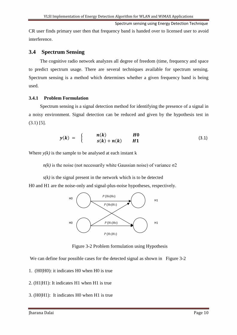
Figure 3-2 Problem formulation using Hypothesis
We can define four possible cases for the detected signal as shown in Figure 3-2
1. (H0|H0): it indicates H0 when H0 is true
2. (H1|H1): It indicates H1 when H1 is true
3. (H0|H1): It indicates H0 when H1 is true
H0 H1
H0 H1
P (H0|H1)
P (H1|H0)
P (H0|H0)
P (H1|H1)

VLSI Implementation of Energy Detection Algorithm for WLAN and WiMAX Applications Spectrum sensing using Energy Detection Technique
Jharana Dalai Page 11
4. (H1|H0): it indicates H1 when H0 is true
Case 1 is for noise which is not detected. Case 2 is known as a correct detection,
whereas cases 3 and 4 are known as a missed detection and a false alarm, respectively.
Missed detections are the biggest issue for spectrum sensing, as it means possibly interfering
with the primary system. Nevertheless, it is desirable to keep the false alarm rate as low as
possible for spectrum sensing, so that the system can exploit all possible transmission
opportunities.
The spectrum sensor select hypothesis H1, it shows presence of primary user and if
select hypothesis H0 otherwise. Unfortunately, spectrum sensing algorithms may fall into
mistakes in practice, which can be classified into miss detections and false alarms. Miss
detection occurs when a primary signal is present in the sensed band and the spectrum
sensing algorithm selects hypothesis H0.Ihis results harmful interference to primary users in
CR network. On the other hand, a false alarm occurs when the sensed spectrum band is free
and the spectrum sensing algorithm selects hypothesis H1. The false alarm results in missed
transmission of signal and therefore in a lower spectrum utilization. A detection occur when
a primary signal is present in the frequency band and it spectrum sensing algorithm select
hypothesis H1 which results correct detection of signal. Based on these definitions the
performance of any spectrum sensing algorithm can be summarized by means of two
probabilities: the probability of miss detection Pmd = P (H0/H1), probability of detection Pd =
P (H1/H1) = 1−Pmd.
The performance of the spectrum-sensing technique is usually determined by the
probability of false alarm Pfa = P (H1|H0), because this is the most influential metric. The
performance is evaluated by receiver operation characteristic (ROC) curves, which plotted
between the probability of detection Pd = P (H1|H1) and the probability of false alarm Pfa.
H0 andH1 are represented to differentiate signal from noise is required. The noise
characteristics are very important for the spectrum-sensing procedure. Most works on
spectrum sensing consider noise to be additive white Gaussian noise (AWGN), because many
independent sources of noise are added (central limit theory).
Poor Performance is poor for all of the techniques available because of negatively
affected by channels are presented in (3.2) as

VLSI Implementation of Energy Detection Algorithm for WLAN and WiMAX Applications Spectrum sensing using Energy Detection Technique
Jharana Dalai Page 12
( ) { ( ) ( ) ( ) ( )
(3.2)
Where gain for fading channel at each instant is h(k).
A key problem in cognitive radio is that the secondary users need to detect the presence
of primary users in a licensed spectrum and quit the frequency band as quickly as possible if
the corresponding primary radio emerges in order to avoid interference to primary users. The
technique is called spectrum sensing, which is a fundamental problem in cognitive radio.
3.4.2 Spectrum sensing classification
Spectrum sensing techniques can be classified into three categories: transmitter
detection, cooperative detection and interference based detection. These techniques are
subdivided into different categories which are presented in Figure 3-3.
3.4.2.1 Noncooperative Sensing Techniques
There are situations in which only one sensing terminal is available or in which no
cooperation is allowed due to the lack of communication between sensing terminals. So it is
known as noncooperative sensing.
There are several classical techniques for this purpose, including energy detector (ED) [9]
matched filter (MF) [8], and cyclostationary feature detection (CFD) [10, 11].
Figure 3-3 Classification of Spectrum sensing Technique
3.4.2.1.1 Energy Detection
It is a no cooperative detection technique .It simple detection technique because it
does not require prior information about structure of signal. Energy detection detects the
SPECTRUM SENSING
COOPERATIVE
SYSTEM
NON-COOPERATIVE
SYSTEM
INTERFERENCE
BASEDSENSING
Centralised Uncoordinated
Decentralised Uncoordinated
Decentralised Coordinated
Energy Detection
Matched Filter Detection
Cyclostationary Detection
DETECTION
Receiver-Centric Interference Management
Transmitter-Centric
Interference Management

VLSI Implementation of Energy Detection Algorithm for WLAN and WiMAX Applications Spectrum sensing using Energy Detection Technique
Jharana Dalai Page 13
spectrum by measuring the energy of the received signal in a certain frequency band, also
called radiometry. It is the most common detection method for spectrum sensing in cognitive
radio networks.
ED is a simple detection technique. The ED is said to be a blind signal detector
because it ignores the structure of the signal. ED is based on the principle that, at the
reception, the energy of the signal to be detected is calculated. It estimates the presence of a
signal by comparing the energy received with a known threshold λ derived from the statistics
of the noise.
The Figure 3-4 shows the general block diagram of energy detection for anolog input signal
[9].
Figure 3-4 Block Diagram of Energy Detector
Let y(k) be a samples of received signal k =1, 2, . . . ,N at the signal detector. Then, the
decision statistics can be stated as
( ) {
(3.3)
Where E = E[| y(k) |2] is the estimated energy of the received signal
λ is chosen to be the noise variance σ2 [12]
In practical, one does not dispose of the actual received energy power E. The ED
technique approximation , where
∑ ( )
(3.4)
As the number of samples N becomes large, by the law of the large numbers,
converges to E. Nevertheless, in spite of its simplicity, the ED is not a perfect solution. The
approximation of signal energy E gets better as N increases. Thus, the performance of the ED
is directly linked to the number of samples.
Pre-filter Analog to
Digital
Converter
Squaring
device
Average
of N
samples
Test
statistics
Input
signal

VLSI Implementation of Energy Detection Algorithm for WLAN and WiMAX Applications Spectrum sensing using Energy Detection Technique
Jharana Dalai Page 14
a) Advantages: Implementation simplicity and computational complexities low: an energy
detector can be implemented similar to a spectrum analyser by averaging frequency bins of a
FFT. Since it is easy to implement, the recent work on detection of the primary user has
generally adopted the energy detector. In addition, energy detection is the optimum detection
if the primary user signal is not known.
b) Disadvantages: The performance of the energy detector is highly susceptible to noise
level uncertainty. The noise uncertainty causes problems especially in the case of a simple
energy detector because it is difficult to set the threshold properly without the knowledge of
the accurate noise level. Secondly, an energy detector can’t differentiate between modulated
signals, noise, and interference. The performance of an energy detector in shadowing and
fading environments degrades clearly. Moreover, it is hard to select the right threshold for
energy detection.
Energy Detector in AWGN Channels:
This case has been studied in the work of Urkowitz in 1967 [13]. It is known that the
energy detection is the optimal signal detector in AWGN considering no prior information on
the signal structure. The performance of ED can be understand by two probabilities: the
probability of detection Pd = Prob{ and false alarm Pfa = Prob{
behave with the measured received signal energy.
Zero mean Gaussian noise is used to model the AWGN noise signal. The primary signal
energy varies with respect to the noise. In the ED method, test statistics E follows a
noncentral chi-square distribution with variance 2=1 and central chi-square distribution with
2N degree of freedom.
{
( )
(3.5)
Where is signal to noise ratio. is the signal variance and
is the noise variance
The performance of ED method is measured by analysing ROC in term of probability
of detection (Pd) vs. probability of false alarm(Pfa) for given threshold and probability of
detection vs. SNR for given probability of false alarm. The signal is detected when the
primary user is present and false alarm is occurring when the user is absent. The probability
of detection and probability of false alarm are evaluated by:
( ) ( ) (3.6)

VLSI Implementation of Energy Detection Algorithm for WLAN and WiMAX Applications Spectrum sensing using Energy Detection Technique
Jharana Dalai Page 15
( ) (
)
( ) (3.7)
Energy Detector in Fading Channels
The performance of the ED in fading channels studied in 2002, Kostylev. The
analytical expressions for the ED over the Rayleigh fading channel is derived by Kostyley.,
the problem was revisited by Digham et al. in 20003, who provided an alternative analytical
method for Rayleigh,Rice and Nakagami fading channels. In this chapter, however, we
discussed only the Rayleigh channel which performs for ED technique.
Kostylev characterized the statistics of the energy of the signal for both the H0 and H1
cases, assuming h(k) is for Rayleigh distributed as:
{ ( )
( ) ( )
(3.8)
Where ( ) is the exponential distribution with parameter ( ) with
Probability density function( ) , where is the SNR.
It is clear that, under the hypothesis H0, the statistics are the same as for the AWGN channel
case, so the probability of false alarm is the same as in (3.7).
( ) (
)
( ) (3.9)
The probability of detection for H1 given by [22]
∑
(
) (
)
( )
∑
( ) (3.10)
3.4.2.1.2 Matched filter Detection
The best sensing technique in AWGN environment without ant prior information about
the signal is ED technique. If we considered the signal structure, then we can get best
performance by using matched filter method.
Matched filter is a linear filter which used to maximize signal to noise ratio in presence
of additive noise. It provides coherent detection. A coherent detector uses the knowledge of
the phase of the carrier wave to demodulate the signal.
Figure 3-5 shows the block diagram for primary user detection using matched filter in
which a signal received from primary user is passed through channel. The channel output is
applied to matched filter. Matched filter correlates the original signal with time shifted

VLSI Implementation of Energy Detection Algorithm for WLAN and WiMAX Applications Spectrum sensing using Energy Detection Technique
Jharana Dalai Page 16
version of signal and compare between final outputs of matched filter and matched filtered
signal predetermined threshold which determine the presence of primary user.
Figure 3-5 Block Diagram of Matched-filter Detection
In wireless communication technologies transmission of pilot carrier is necessary for
channel estimation. Secondary systems can exploit pilot signals to detect the presence of
transmissions of primary systems in their vicinity. MF detection achieves optimal signal
detection if pilot signal is known. It maximizes, the SNR. The threshold value for MF is not
like threshold value taken in ED. In ED threshold value is depend on noise variance. MF is
performs well in low SNR condition, since MF maximizes power.
Advantages:
1. It requires short time to achieve a particular probability of false alarm.
2. The required number of samples grows as O (1/SNR) for a target probability of false alarm
at low SNR.
3. Matched-filtering requires cognitive radio to demodulate received signal. Hence it requires
information about primary signal’s features like operating frequency, modulation type and
order, bandwidth and frame format.
Disadvantages:
1. Complexity of sensing device due to requirement of receiving unit for all types of signal.
2. Various algorithms are used to detect primary user. Hence it gives rise to more power
consumption.
3. Pilot carrier transmission is required for channel estimation. But CR might not recognize
which network is in operation in that radio environment in that time. So CR sensor is unable
to know which to which pilot sequence it is looking for. So if it detects incorrect pilot then it
detects as that spectrum band is free which treated as false detection.
4. MF requires pilot in every medium for signal transmission. But pilot carriers are
transmitted in downlink direction and in uplink direction pilot carriers are uncovered.
5. MF is coherent reception method. But in practical to get coherent reception is very
difficult.
Channel Mixed signal
output
Matched
Filter
Threshold
value
Input signal Detected
signal

VLSI Implementation of Energy Detection Algorithm for WLAN and WiMAX Applications Spectrum sensing using Energy Detection Technique
Jharana Dalai Page 17
3.4.2.1.3 Cyclostationary Feature Detection
MF detection performances better in low SNR condition. But MF requires prior
information about signal structure for licensed user detection. If knowledge about the signal
structure is not good then MF dose not perform well. So with limited information about
signal structure primary user detection can be possible by using cyclostationary feature
detection.
To detect primary user in spectrum band, it requires periodicity of received signal. The
periodicity are generally relies on sinusoidal carriers, pulse trains, spreading codes, pilot
sequences, cyclic prefixes and other repetitive carriers. These periodicity characteristics
signals are having spectral correlation and periodic statistics properties. But these properties
are not found in noise signal. Since noise is a random signal. Cyclostationary feature
detection performs better in low SNR condition than ED method because it is robust to noise.
But it requires prior knowledge about signal and it able to differentiate primary user signal
with CR transmission signal.
CR detects random signals having stochastic noise. The periodic statistics features are
extracted using spectral correlation. Figure 3-6 represents block diagram of cyclostationary
Figure 3-6 Block diagram of Cyclostationary Feature Detection
Feature detection. Spectral correlation function is two dimensional function whose cyclic
frequency α and it represents power spectral density when α=0.
Thus the cyclostationaty signal detection technique is a good detection technique
because it performs well with less information about signal structure.
Advantages:
1. Accuracy of cyclostationary is more than ED and MF.
2. It provider better performance than Ed method.
Disadvantages:
1. It is a complex technique.
2. It requires larger computational time.
Band Pass
Filter
FFT Correlation Average
over T
Feature
Detection

VLSI Implementation of Energy Detection Algorithm for WLAN and WiMAX Applications Spectrum sensing using Energy Detection Technique
Jharana Dalai Page 18
3.4.2.2 Cooperative Sensing Techniques
Noncooperative based sensing method performs well for AWGN channels. But these
techniques do not provide satisfactory results for fading channels due to hidden node
problems. So cooperative technique provides improvement result upon noncoperative based
techniques. Various topologies are provided which explain this technique is in Figure 3-7 [7,
8]. The topologies are:
Figure 3-7 Cooperative sensing techniques: - 1. Centralised Coordinated, 2. Decentralised
Coordinated and 3. Decentralised Uncoordinated
1. Centralised Coordinated Topology: Any CR users (secondary user) in a wireless
network detect presence of primary user and it informs this information to centralised
control CR. The centralised CR then circulate this message to all other CR users the
network.
2. Decentralised Coordinated Topology: In this network CR does not play as
centralised controller. The CR user gathers information and provides this information
to other CR users. In this topology all CR user play same role no controller used. This
technique uses different algorithms to convey information to other CR users.
3. Decentralised Uncoordinated Topology: CR user does not require any cooperation
with other CR users. It has independently detected presence of primary user and
leaves the spectrum if primary user present.
Cooperative sensing method is better in conditions like multipath fading, shadowing effect,
low power requirement and high sensitivity cases. But it must be periodically senses the
network for better performances.

VLSI Implementation of Energy Detection Algorithm for WLAN and WiMAX Applications Spectrum sensing using Energy Detection Technique
Jharana Dalai Page 19
3.4.2.3 Interference Based Sensing
CR networks will have some set of policies which followed by some by regulatory
agencies. FCC and TRAI are regulatory bodies for radio which determine the spectrum usage
and its policies. The idea behind these policies is central in which primary systems that have
the right to the spectrum and secondary systems that are allowed to use the spectrum so long
as they do not disturb the communications of the primary systems. So the main idea behind
this policy is that secondary user should not interference primary user in any case and follows
the legacy rule for white space utilization. The problem is one of interference management.
This problem has two different points of view: receiver centric or transmitter centric.
3.4.2.4 Receiver-Centric Interference Management
This approach determines the restriction on the power of the transmitters around it
which has interference limitation at the receiver. This interference called the interference
temperature. It is chosen to be the worst case that can be accepted without disturbing the
receiver operation beyond its operating point. This approach requires information of the
interference limits of all receivers in a primary system. It includes individual locations,
fading, modulations, coding schemes, and services.
3.4.2.5 Transmitter-Centric Interference Management
In the transmitter-centric approach, the focus is shifted to the source of interference.
The transmitter does not know the interference temperature, but by means of sensing, it tries
to detect free bandwidth. The sensing procedure allows the transmitter to classify the channel
status to decide whether it can transmit and with how much power. In practice, the transmitter
does not know the location of the receivers or their channel conditions; it is not able to know
how much interference these receivers can tolerate. Thus, spectrum sensing solves the
problem for worst-case scenario, assuming strong interference channels, so that the secondary
system transmits only when it senses an empty medium.
3.5 Energy Detection for Single-carrier Modulation and Multicarrier
Modulation
3.5.1 Energy Detection for Single carrier Modulation
Single-carrier modulation techniques use only one signal is transmitted at all times.
But, in the multi-carrier modulation techniques, several signals are transmitted
simultaneously. In general single-carrier modulation techniques modify only one of

VLSI Implementation of Energy Detection Algorithm for WLAN and WiMAX Applications Spectrum sensing using Energy Detection Technique
Jharana Dalai Page 20
parameters like amplitude, frequency and phase of the sinusoidal signal and according to the
binary information to be transmitted. These techniques are known as amplitude shift
keying (ASK) for amplitude modification, frequency shift keying (FSK) for frequency
modification and phase shift keying (PSK) for phase modification of sine wave respectively.
For digital signals, the information is collections of bits called symbols that are modulated
onto the carrier. The basic time unit is a symbol, which is composed of a segment of the
sinusoidal waveform. There is different combination of symbol formation. If there are only
two possible different symbols in a digital modulation, then it is called a binary modulation is
a modulation technique.
3.5.1.1 Binary Phase Shift Keying
It is a simplest form of phase shift keying. It is a type of modulation using 2 distinct
phases to signal which are separated by 180 degree and so it is termed as 2-psk. The
constellation points positioned at any point either in the real axis or in the imaginary axis in
the figure but separated by 180.The example of constellation diagram for BPSK where points
are positioned in real axis, at 0 degree and 180 degree. This modulation is the most robust of
all the PSKs since it takes the highest level of noise or distortion to make the demodulator
reach an incorrect decision. BPSK is only able to modulate at 1 bit/symbol and so it is
unsuitable for high data-rate applications.
3.5.1.2 Simulation Result for Binary Phase Shift Keying
Result for BPSK using AWGN channel
With the binary hypothesis simulation was made. Input is taken as random bit
sequences and the received signal at receiver is original signal with passes through AWGN
[14].
The performance of signal can be studied by using ROC curve. The Roc curve is plotted
between probability of detection (pd) and signal-to -noise ratio (SNR) in Figure 3-8. The
detection performance can be performed finding the probability of detection by varying SNR
from -25 dB to 10 dB using Monte Carlo simulation. The graph is plotted for SNR values on
X-axis and probability of detection on Y-axis. Here we have taken different values of
probability of false alarm i.e., 0.1, 0.05 and .01 and number of samples N. It is observed that
performance is better at higher SNR values for a particular probability of false alarm with
higher number of samples. And at high value of probability of false alarm signal detects
faster compare to lower value of probability of false alarm for same number of samples.

VLSI Implementation of Energy Detection Algorithm for WLAN and WiMAX Applications Spectrum sensing using Energy Detection Technique
Jharana Dalai Page 21
Figure 3-8 ROC for BPSK, Pfa=0.1, Pfa=0.01, Pfa=0.5
Again ROC curve is plotted between probability of false alarm on X-axis and
probability of detection on Y-axis as shown in Figure 3-9. Here we have varied probability of
false alarm from 0 to 1 with different number of samples and different SNR values. It is
observed that detection performance increases with higher value of SNR with a fixed value of
N.
Figure 3-9 ROC for BPSK at different SNR
3.5.2 Energy Detection for Multicarrier Modulation
The success of 4G wireless system will depends on the choice of technology, concepts
spectrum allocation method, utilization of spectrum and innovation in architecture. Therefore,
advanced technologies and high performance physical layers are required to provide high
speed data rate with flexible bandwidth allocation. The past several decades an increasing
number of data communication systems have started employing another form of transmission
-25 -20 -15 -10 -5 0 5 100
0.1
0.2
0.3
0.4
0.5
0.6
0.7
0.8
0.9
1
SNR in dB
pro
babili
ty o
f dete
ction
ROC of ED under AWGN for BPSK
Pfa=.1 N=520
Pfa=.05 N=520
Pfa=.01 N=520
Pfa=.1 N=5200
Pfa=.05 N=5200
Pfa=.01 N=5200
Pfa=.1 N=52000
Pfa=.05 N=52000
Pfa=.01 N=52000
0 0.1 0.2 0.3 0.4 0.5 0.6 0.7 0.8 0.9 10
0.1
0.2
0.3
0.4
0.5
0.6
0.7
0.8
0.9
1
probability of false alaram
pro
bability o
f dete
ction
ROC of ED under AWGN for BPSK
SNR=20 dB, N=520
SNR=-15 dB, N=520
SNR=20 dB, N=5200
SNR=-15 dB, N=5200
SNR=20 dB, N=52000
SNR=-15 dB, N=52000

VLSI Implementation of Energy Detection Algorithm for WLAN and WiMAX Applications Spectrum sensing using Energy Detection Technique
Jharana Dalai Page 22
framework based on sending parallel streams of information in the frequency domain on
different centre frequencies. Employed in a wide range of applications, including digital
subscriber line (DSL) modems, IEEE 802.11a wireless local area networks (WLANs), digital
audio broadcasting (DAB), and digital video broadcasting (DVB), IEEE 802.16 (WIMAX),
multicarrier modulation has exhibited its potential to transmit large amounts of data across a
channel while possessing reasonable error robustness [15].
Signals to be transmitted in any medium usually suffer from fading effects such as flat
fading and frequency fading. Researchers proposed many solutions to these fading problems.
Wireless medium signals are generally suffers due to frequency selective fading. Single-
carrier systems, uses complex equalization schemes to combat frequency-selective fading.
The ideal equalizer has a frequency response that is the exact inverse of that of the channel
which requires infinite number of equalizer taps. When a deep fade occur, it results in failure
of communication link in single-carrier systems.
Multicarrier modulation is proposed to combat frequency-selective fading channels. In
this system, system is divided into number of sub-channels which use carriers that fall within
faded frequency band. Corrupted sub-channels can be recovered easily using different
encoding schemes in multicarrier systems.
The primary advantage of multicarrier modulation is its subcarrier operating parameters
on an individual or block-by-block basis. This additional flexibility over high data rate single-
carrier transmission techniques makes it an excellent candidate for dynamic spectrum access
.Another advantage of multi-carrier transmission is its robustness in frequency selective
fading channels is the reduced signal processing complexity by equalization in the frequency
domain.
History
The multi-carrier transmission has become more interesting technique for its high data
rates for broadband applications. OFDM is a multicarrier transmission which is FDM (e.g.
frequency division multiplexing) started in 1950s, which has high spectral and low cost
implementation of FDM became possible in the 1970s and 1980s with advances in Digital
Fourier Transform (DFT). OFDM is modern wireless communication network started in
1990: A few historical aspects relater to OFDM are given below [16]:
1958: Kinplex, a military multicarrier high-frequency communication system.

VLSI Implementation of Energy Detection Algorithm for WLAN and WiMAX Applications Spectrum sensing using Energy Detection Technique
Jharana Dalai Page 23
1960: Chang published for multi-channel transmission on the synthesis of band-limited
signals in mid of 1960s.
1966: R.W.chang at Bell labs describes the concept of using parallel data transmission and
FDM.
1970: First patent issued on OFDM [b1]
1971: Weinstein and Ebert presented the Fourier transform for baseband processing.
1881: Hirosaki proposed DFT implementation of FDM.
1990: The breakthrough for OFDM came out which was modulation chosen for ADSL in
USA.
1995: ETSI DAB standard first comes out based on OFDM wireless standard for digital audio
broadcasting.
1997: DVB-Terrestrial digital video broadcasting standard.
1999: IEEE 802.11a standard for wireless LAN
2004: IEEE 802.16a/d standard for fixed broadband wireless MAN.
2005: OFDM-based mobile cellular networks being developed under 802.16e and IEEE
802.20.
Orthogonal Frequency Division Multiplexing (OFDM):
OFDM is a form of multi carrier modulation that transmits broadband data over parallel
narrowband streams. A communication system with multi-carrier modulation transmits Nc
complex-valued source symbols Sk, k=0.1…Nc-1, in parallel on to Nc sub-carriers. The
source symbols are complex symbols which are transmitted over OFDM modulation. The
OFDM signal can be represented by [17]
( ) ∑ ∑
( ) (3.11)
where fk=f0+KΔf and
( ) {
(3.12)
Ts and Δf are called the symbol duration and sub channel spacing respectively. The OFDM
signal can be demodulated at receiver by using orthogonally condition. The orthogonality
condition states as (the symbol duration must be long enough signal) Ts Δf=1.
The orthogonality condition states as:
∫
( )
( )
=
∫ ( )

VLSI Implementation of Energy Detection Algorithm for WLAN and WiMAX Applications Spectrum sensing using Energy Detection Technique
Jharana Dalai Page 24
=
∫ ( )
= (3.13)
Where is known as delta function and its definition is given as
{
(3.11) shows that ( )
is set of orthogonal functions.
The OFDM signal can be demodulated using orthogonal property expressed by
∫ ( )
=
∫ (∑
( ))
( )
= ∑
= Sk (3.14)
FFT Implementation
This section describes the relation between OFDM signal and discrete Fourier
transform (DFT).This DFT can be implemented by low complexity fast Fourier transform
(FFT).
From (3.12), an OFDM signal can be expressed as:
( ) ∑
The sampling interval of x(t) is
,then
( ) ∑
(3.15)
Taking f0 =0 and fkTs = k, equation () becomes
∑
(3.16)
where IDFT denotes Inverse discrete Fourier Transform. Therefore, the OFDM transmitter
can be implemented using IDFT and receiver can be implemented using DFT.
Instead of DFT and IDFT we can use FFT and IFFT respectively. FFT algorithm
provides efficient algorithm to implement DFT and IDFT. Number of complex
multiplication reduces from N2
to
for an N-point DFT or IDFT. The FFT

VLSI Implementation of Energy Detection Algorithm for WLAN and WiMAX Applications Spectrum sensing using Energy Detection Technique
Jharana Dalai Page 25
algorithm provides OFDM implementation is less complex than DFT algorithm OFDM
implementation.
Cyclic Prefix, Power Spectrum and Efficiency
A cyclic prefix is used to deal with multipath delays in OFDM system. There are three
different ways to represent cyclic prefix shown in Figure 3-10(a). Let us consider length of
cyclic prefix which is inserted between OFDM sub-channel blocks is Tg. The OFDM signal x
(t) can be extended to ( ) shown in Figure 3-10 (b).
( ) { ( )
( ) (3.17)
Now the duration of OFDM symbol extended from Ts to Ts+Tg. The cyclic prefix
extension for OFDM signal is shown in Figure 3-10(b). The other types of cyclic extension
are shown in Figure 3-10 (c) and Figure 3-10 (d).
Figure (a) OFDM Signal
Figure (b) OFDM Signal with cyclic prefix
Figure (c) OFDM Signal with cyclic prefix
0 Ts t
0 Ts t Ts+Tg
Tg 0 t Ts

VLSI Implementation of Energy Detection Algorithm for WLAN and WiMAX Applications Spectrum sensing using Energy Detection Technique
Jharana Dalai Page 26
Figure (d) OFDM Signal with cyclic prefix
Figure 3-10 OFDM signal with different cyclic extension.
X(t) expressed in (3.11) is a summation of truncated complex exponential functions with
different frequencies. The power density spectrum of x(t) is a function of
as Figure
3-11.
Figure 3-11 Power Spectrum of OFDM signal
The OFDM signal consists of Nc sub channels. Therefore bandwidth of OFDM signal is
given about ( ) .The rate of transmission of each sub-channel is
symbols/sec and
total transmission rate of OFDM signal is
symbol/sec. Hence, bandwidth efficiency of
OFDM signal is
( )
=
( )
( )
=
(3.18)
It is in symbols/sec. In real time scenario of OFDM system Nc is much larger than 1 and
cyclic prefix much smaller than OFDM symbol duration.
Ts 0 t Tg/2 -Tg/2
VLSI Implementation of Energy Detection Algorithm for WLAN and WiMAX Applications Spectrum sensing using Energy Detection Technique
Jharana Dalai Page 27
OFDM realization
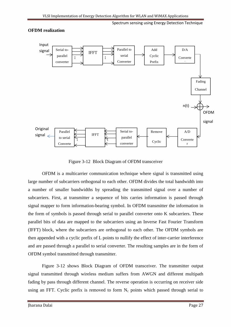
Figure 3-12 Block Diagram of OFDM transceiver
OFDM is a multicarrier communication technique where signal is transmitted using
large number of subcarriers orthogonal to each other. OFDM divides the total bandwidth into
a number of smaller bandwidths by spreading the transmitted signal over a number of
subcarriers. First, at transmitter a sequence of bits carries information is passed through
signal mapper to form information-bearing symbol. In OFDM transmitter the information in
the form of symbols is passed through serial to parallel converter onto K subcarriers. These
parallel bits of data are mapped to the subcarriers using an Inverse Fast Fourier Transform
(IFFT) block, where the subcarriers are orthogonal to each other. The OFDM symbols are
then appended with a cyclic prefix of L points to nullify the effect of inter-carrier interference
and are passed through a parallel to serial converter. The resulting samples are in the form of
OFDM symbol transmitted through transmitter.
Figure 3-12 shows Block Diagram of OFDM transceiver. The transmitter output
signal transmitted through wireless medium suffers from AWGN and different multipath
fading by pass through different channel. The reverse operation is occurring on receiver side
using an FFT. Cyclic prefix is removed to form Nc points which passed through serial to
OFDM
signal
Input
signal
Fading
Channel
Serial to-
parallel
converter
IFFT Parallel to
serial
Converter
Add
Cyclic
Prefix
D/A
Converte
r
Parallel
to serial
Converte
IFFT Serial to-
parallel
converter
Remove
Cyclic
Prefix
A/D
Converte
r
n(t)
)
Original
signal

VLSI Implementation of Energy Detection Algorithm for WLAN and WiMAX Applications Spectrum sensing using Energy Detection Technique
Jharana Dalai Page 28
parallel converter .The output of serial-to-parallel converter fed to FFT and output of FFT
processed through parallel-to-serial converter. Different decoding schemes and different
algorithms are used to recover information bits [16, 18].
A block of data consists of information bits that can be represented as the OFDM
symbol Sn, n=0, 1… Nc-1 is represented in vector form
( ) (3.19)
The IFFT operator is applied to s which converts frequency domain signal into time
domain signal [16] and the corresponding time domain signal is given by
( ) [ ( ) ( ) ( ) ( )( )] (3.20)
Where, Nc is the block length of IFFT.
The output of the IFFT block is an OFDM symbol. Acyclic prefix is inserted before
the OFDM symbol. Ncp numbers of cyclic prefix bits are added and the transmitted signal
becomes:
( ) ( ) ( ) ( ) ( ) ( )( ) (3.21)
Where the extra cyclic block is represented as
( ) ( ) ( ) ( ) (3.22)
The OFDM signal is transmitted through the fading channels.
The NcXNc matrix for channel is
[
]
And AWGN signal can be represented in form of matrix as:
At the receiver side original symbol is received after Inverse process of OFDM. The received
symbol is represented as
r = Hs + n
which is in matrix form as
VLSI Implementation of Energy Detection Algorithm for WLAN and WiMAX Applications Spectrum sensing using Energy Detection Technique
Jharana Dalai Page 29
Advantages:
1. High spectral efficient due to use of OFDM subcarriers and allowing overlap among
subcarriers spectrums.
2. OFDM is more resistant to frequency-selective fading than single carrier systems by
dividing spectrum into number of sub-channel spectrums.
It reduces ICI (Inter-carrier-Interference) and ISI (Inter-symbol-Interference) by adding
cyclic prefixes.
3. Symbol lost due to Frequency-selective fading can be reduced using some adequate
coding technique and interleaving.
4. Channel equalizer is simpler than single-carrier modulation which uses adaptive
equalizer.
5. It is less sensitive to timing offset because of cyclic prefix.
6. Implementation is simple by using FFT and IFFT algorithm.
Disadvantages:
1. It is more susceptive to frequency offset. It is because of tightly spaced subcarriers,
FFT and modulation schemes used.
2. The OFDM signal has noise like amplitude in a dynamic range. So it requires high-
peak-to-average power ratio in A/Ds and D/As and in linear power amplifier.
3. More susceptive to Doppler spread than single-carrier modulation.
4. Synchronization of frequency and time is required.
5. The performance of transmitter and receiver is imperfect due to phase noise.
Applications:
There are lot of applications which use OFDM technology over the last few years. Some of
the application areas are as below:
There are many standard for wireless communication. Some of the standards are
WiMAX (IEEE 802.16), WiFi (IEEE 802.11), LTE (3GPP release 8), DAVB
Proprietary solutions as: Flash OFDM (Flarion)
Wired broadband access: xDSL
Data transmission through power line: (PLC = Power Line Communications)

VLSI Implementation of Energy Detection Algorithm for WLAN and WiMAX Applications Spectrum sensing using Energy Detection Technique
Jharana Dalai Page 30
Wireless Technologies:
Wireless technologies can be classified in different ways depending on their range.
Wireless technology is designed in such a sense which serves for a specific usage segment.
The requirements for using these segments based on a variety parameters like Bandwidth
needs, distance and Power. There are many wireless technologies like Wireless Wide Area
Network (WWAN), Wireless Personal Area Network (WPAN), Wireless Local Area
Network (WLAN), worldwide interoperability for microwave access (WIMAX). In this thesis
only two technologies WLAN and WiMAX are explained.
3.5.2.1 Wireless Local Area Network (WLAN):
WLAN is one of the popular wireless technologies. It is alternative to cable LAN. It
provides user to move from one place to another without thinking about wires. It has grown
in popularity along with the rise of laptop, computers and low cost netbooks. WLAN meant
for short range applications and deliver faster speeds compare WIMAX. WLAN provide high
speed since its hardware is not meant to transmit or receive signals from far away.
Wireless LAN technology is standardized within the IEEE 802.11 working Group. The
IEEE standard for wireless LAN provide flexibility and mobility .This technology has
improved access to fixed LAN and higher performance in ad hoc networks. The IEEE 802.11
working Group had different standards. The 802.11a and 802.11g are two standards which
utilize OFDM modulation technology. The 802.11a standard has higher bandwidth compare
to 802.11g and 802.11b (Wi-Fi).The 802.11a has bandwidth 5GHz (54 Mbps) while 802.11b
(Wi-Fi) has bandwidth 2.4 GHz (11Mbps) with 802.11g standard.
IEEE 802.11a:
This standard operates in 5GHz with rates up to 54 Mbps. It uses OFDM technique
with 52 sub-carriers. The most popular advantage of this technology is less interference to
other network. The application areas are limited to homes and office buildings. The Wireless
LAN has the following features:
1. It has less interference to noise.
2. It is easily dealt with hidden node problems.

VLSI Implementation of Energy Detection Algorithm for WLAN and WiMAX Applications Spectrum sensing using Energy Detection Technique
Jharana Dalai Page 31
3. It has provision for time bound services.
4. It requires overlapping of multiple networks.
The 802.11a/g working Group utilizes OFDM modulation technology to provide data rates
from 6 to 54Mbps. The parameters of wireless LAN on OFDM is summarized in Table 3-1.
Table 3-1 Parameters for IEEE 802.11 a/g standard
Data rate 6,9,12,18,24,36,48,54 Mbps
Modulation BPSK,QPSK,16-QAM,64-QAM
Coding rate 1/2,2/3,3/4
Number of sub-carriers 52
Number of pilots 4
OFDM symbol duration 4us
Guard interval 8us
Useful Symbol time 40us
Bandwidth 5GHz
The major limitation of wireless LAN includes less area of coverage with high carrier
frequency. It is less secure than 802.11e standard and it cannot penetrate as far as 802.11b
standard. The application include transmission of audio, mobile access, video, audio and
video conferencing etc.
3.5.2.2 Worldwide interoperability for microwave access (WIMAX)
It is not very popular technology which gaining attention due to its services in
industries. WIMAX provides services in between high speed low range WLAN and low
speed low range 3G and 2G technologies. The speed that can be achieved with WIMAX is
not constant through it is depend on the distance between base station and subscriber. It
provides better bandwidth distribution compare to WLAN.
IEEE 802.16:
WIMAX is standardized within the IEEE 802.16 working Group. It is a wireless
service designed to cover wide geographical areas with a large number of user at low cost.
IEEE 802.16 support point-to-multipoint architecture in the 10-66 GHz range with data rates

VLSI Implementation of Energy Detection Algorithm for WLAN and WiMAX Applications Spectrum sensing using Energy Detection Technique
Jharana Dalai Page 32
upto 120Mbps. WIMAX provides portable high-speed packet services. It has the following
features:
1. It provides uses OFDM and OFDMA modulation technique.
2. It provides full mobility of data and transmission of data at higher speed.
3. It has variable channel configuration for multiuser diversity.
4. It utilizes multiple-input multiple-output (MIMO) communication.
Table 3-2 Parameters for IEEE 802.16 standard
Parameter Fixed Mobile
Data rate 70 Mbps 70 Mbps
Modulation BPSK, QPSK, 16-QAM, 64-QAM
Coding rate 1/32,1/16,1/8,1/4
Number of sub-carriers 256 128 512 1024 2048
Number of pilots 8 12 60 120 240
OFDM symbol duration 72us 102.9us
Guard interval(1/8) 8us 11.4us
Useful Symbol time 64us 91.4 us
Bandwidth 3.5 GHz 5GHz
The application areas of 802.16 include mesh networks, broad band mobile network
and wireless DSL to residential. WIMAX allows DSL operates to extend service rapidly and
effectively into areas of poor wire quality and lower population density. WiMAX uses
OFDM and OFDMA modulation technique. The WIMAX has two categories: Fixed WIMAX
and Mobile WIMAX. The WIMAX parameters utilizing OFDM technique is presented in
Table 3-2.
3.6 Simulation Results
In this chapter we described WLAN and WIMAX standard in IEEE working Group
and its usage in different application areas. The performances are evaluated from simulation
results done for WLAN and WIMAX.

VLSI Implementation of Energy Detection Algorithm for WLAN and WiMAX Applications Spectrum sensing using Energy Detection Technique
Jharana Dalai Page 33
3.6.1 Simulation Results for WLAN for AWGN:
In this section the performance of WLAN is studied by using ROC plots. The
detection performance can be performed by finding the probability of detection varying SNR
from -25 dB to 10 dB using Monte Carlo simulation for AWGN noise taking SNR values on
X-axis and probability of detection on Y-axis shown in the Figure 3-13. Here we have taken
different values of probability of false alarm i.e., 0.1, 0.05 and .01 and different number of
sample points i.e. 520, 5200, 52000.The simulation result shows performance is better at
higher SNR values for a particular probability of false alarm and if we consider only number
of samples then also detection is faster at higher number of sample value.
Figure 3-13 ROC for WLAN Pfa=0.1, Pfa=0.01, Pfa=0.5
Figure 3-14 shows the plot between probability of detection and probability of false
alarm for WLAN with AWGN. This result indicates at higher value of SNR, detection is
faster than lower SNR values and performance is better for more number of samples than less
number of sample points.
-25 -20 -15 -10 -5 0 5 100
0.1
0.2
0.3
0.4
0.5
0.6
0.7
0.8
0.9
1
SNR in dB
pro
bability o
f dete
ction
ROC of ED under AWGN for WLAN
Pfa=.01 N=520
Pfa=.05 N=520
Pfa=.1 N=520
Pfa=.01 N=5200
Pfa=.05 N=5200
Pfa=.1 N=5200
Pfa=.01 N=52000
Pfa=.05 N=52000
Pfa=.1 N=52000

VLSI Implementation of Energy Detection Algorithm for WLAN and WiMAX Applications Spectrum sensing using Energy Detection Technique
Jharana Dalai Page 34
Figure 3-14 ROC for WLAN at different SNR
3.6.2 Simulation Results for WLAN for Rayleigh:
Figure 3-15 ROC for WLAN Pfa=0.1, Pfa=0.01, Pfa=0.5
The Monte-Carlo simulation is performed for WiMAX for Rayleigh channel. The
Rayleigh channel has more noise effect compare to AWGN channel. Figure 3-15 indicate
ROC curve for WLAN with Rayleigh channel which shows detection is higher with increase
the value of probability of false alarm and if the number of sample points are more.
0 0.1 0.2 0.3 0.4 0.5 0.6 0.7 0.8 0.9 10
0.1
0.2
0.3
0.4
0.5
0.6
0.7
0.8
0.9
1
prob of false alarm
pro
bability o
f dete
ction
ROC of ED under AWGN for WLAN
SNR=-15dB N=520
SNR=-20dB N=520
SNR=-15dB N=5200
SNR=-20dB N=5200
SNR=-15dB N=52000
SNR=-20dB N=52000
-25 -20 -15 -10 -5 0 5 100
0.1
0.2
0.3
0.4
0.5
0.6
0.7
0.8
0.9
1
SNR in dB
pro
b o
f dete
ction
ED under Rayleigh channel for WLAN
Pfa=.01 N=520
Pfa=.05 N=520
Pfa=.1 N=520
Pfa=.01 N=5200
Pfa=.05 N=5200
Pfa=.1 N=5200
Pfa=.01 N=52000
Pfa=.05 N=52000
Pfa=.1 N=52000

VLSI Implementation of Energy Detection Algorithm for WLAN and WiMAX Applications Spectrum sensing using Energy Detection Technique
Jharana Dalai Page 35
Figure 3-16 ROC for WLAN at different SNR
Figure 3-16 shows ROC for WLAN at different values of SNR at different number of
sample values. The ROC shows for different SNR values, probability of detection is different
and detection quality is good at higher value of SNR. From number of samples it shows that
detection is good at high value of SNR and high value of number of samples.
3.6.3 Simulation Results for WiMAX for AWGN:
The performance of WIMAX is evaluated using parameter given in Table 3.2. The
detection of primary user is low at low value if SNR and it better at high value of SNR. The
performance is studied taking probability of detection in y-axis and SNR in x-axis in Figure
3-17. The simulation is performed for different probability of detection values i.e. 0.1.0.05
0 0.1 0.2 0.3 0.4 0.5 0.6 0.7 0.8 0.9 10
0.1
0.2
0.3
0.4
0.5
0.6
0.7
0.8
0.9
1
probability of false alarm
pro
bability o
f dete
ction
ROC of ED under rayleigh channel for WLAN
SNR=-15dB N=520
SNR=-20dB N=520
SNR=-15dB N=5200
SNR=-20dB N=5200
SNR=-15dB N=52000
SNR=-20dB N=52000
0 0.1 0.2 0.3 0.4 0.5 0.6 0.7 0.8 0.9 10
0.1
0.2
0.3
0.4
0.5
0.6
0.7
0.8
0.9
1
probability of false alarm
pro
bability o
f dete
ction
ROC of ED under rayleigh channel for WLAN
SNR=-15dB N=520
SNR=-20dB N=520
SNR=-15dB N=5200
SNR=-20dB N=5200
SNR=-15dB N=52000
SNR=-20dB N=52000

VLSI Implementation of Energy Detection Algorithm for WLAN and WiMAX Applications Spectrum sensing using Energy Detection Technique
Jharana Dalai Page 36
and 0.01 and for number of samples i.e. 2560, 25600, 256000. The performance is good for
high value of SNR compare low SNR values at a particular value of probability of false alarm
and it also shows good result for more number of samples.
Figure 3-17 ROC for WIMAX Pfa=0.1, Pfa=0.01, Pfa=0.5
Figure 3-18 ROC for WIMAX at different SNR
Figure 3-18 is the ROC for different SNR values. From ROC probability of detection
are different for different value of SNR and different for number of samples. The detection
quality is good at higher value of SNR and also it better for more number of samples.
-25 -20 -15 -10 -5 0 5 100
0.1
0.2
0.3
0.4
0.5
0.6
0.7
0.8
0.9
1
SNR in dB
pro
bability o
f dete
ction
ROC of ED under AWGN for WiMAX
Pfa=.01 N=2560
Pfa=.05 N=2560
Pfa=.1 N=2560
Pfa=.01 N=25600
Pfa=.05 N=25600
Pfa=.1 N=25600
Pfa=.01 N=256000
Pfa=.05 N=256000
Pfa=.1 N=256000
0 0.1 0.2 0.3 0.4 0.5 0.6 0.7 0.8 0.9 10
0.1
0.2
0.3
0.4
0.5
0.6
0.7
0.8
0.9
1
prob of false alarm
prob of detectio
n
ROC of ED under AWGN
SNR=-20dB N=256000
SNR=-15dB N=256000
SNR=-20dB N=25600
SNR=-15dB N=25600
SNR=-20dB N=2560
SNR=-15dB N=2560

VLSI Implementation of Energy Detection Algorithm for WLAN and WiMAX Applications Spectrum sensing using Energy Detection Technique
Jharana Dalai Page 37
3.6.4 Simulation Results for WiMAX for Rayleigh:
Figure 3-19 ROC for WIMAX Pfa=0.1, Pfa=0.01, Pfa=0.5
This section discusses the performance of WIMAX at rayleigh fading channel. The
performance is degraded for fading channel. The signal performance is passed through fading
channel and it degraded than AWGN channel. The Monte-Carlo simulation for WIMAX
with rayleigh channel is performed at different values of probability of false alarm for
different number of samples in Figure 3-19. The performance is good at higher value of SNR
and higher number of samples.
Figure 3-20 ROC for WIMAX at different SNR
-25 -20 -15 -10 -5 0 5 100
0.1
0.2
0.3
0.4
0.5
0.6
0.7
0.8
0.9
1
SNR in dB
pro
babili
ty o
f dete
ction
ED under Rayleigh channel for WiMAX
Pfa=.01 N=2560
Pfa=.05 N=2560
Pfa=.1 N=2560
Pfa=.01 N=25600
Pfa=.05 N=25600
Pfa=.1 N=5200
Pfa=.01 N=256000
Pfa=.05 N=256000
Pfa=.1 N=256000
0 0.1 0.2 0.3 0.4 0.5 0.6 0.7 0.8 0.9 10
0.1
0.2
0.3
0.4
0.5
0.6
0.7
0.8
0.9
1
probability of false alarm
probability of detectio
n
ROC of ED under rayleigh channel for WiMAX
SNR=-15dB N=2560
SNR=-20dB N=2560
SNR=-15dB N=25600
SNR=-20dB N=25600
SNR=-15dB N=256000
SNR=-20dB N=256000
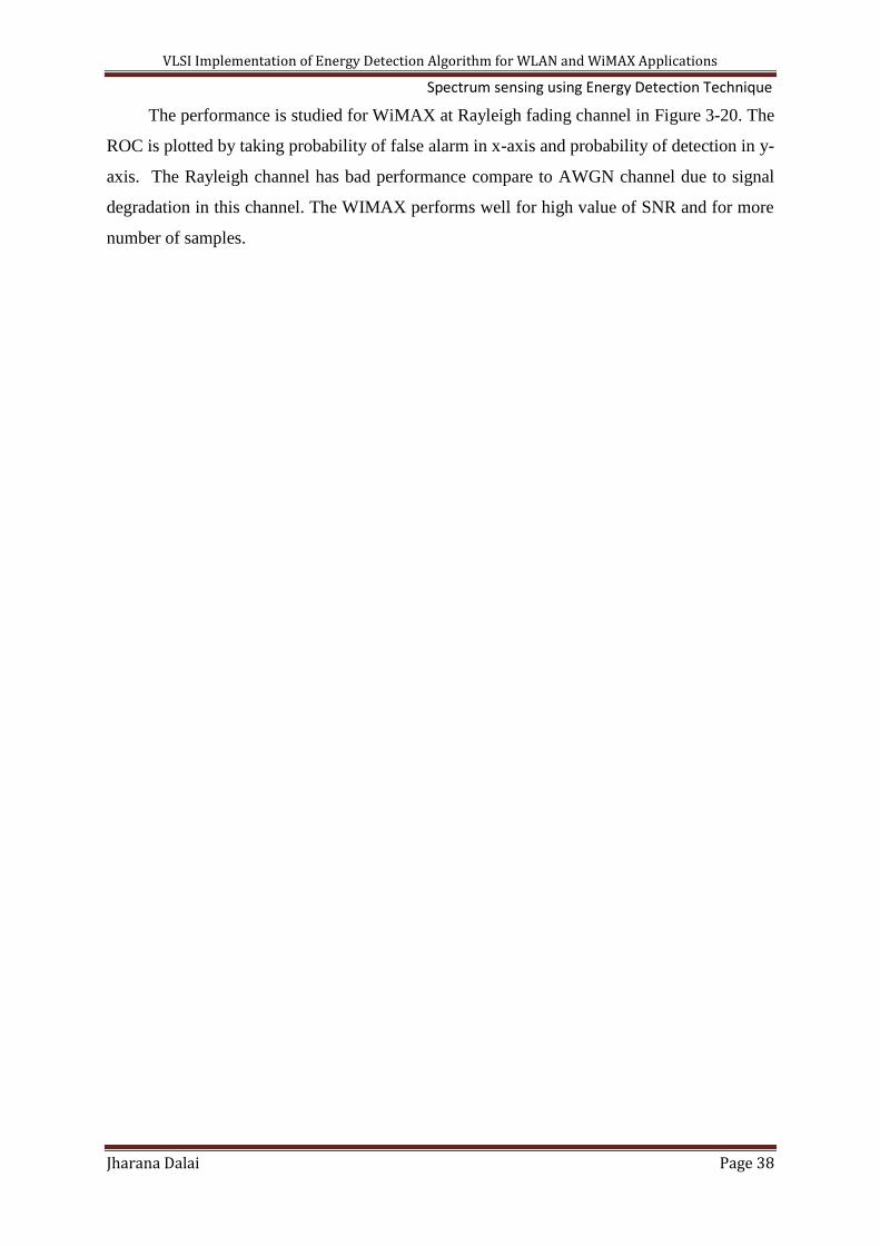
VLSI Implementation of Energy Detection Algorithm for WLAN and WiMAX Applications Spectrum sensing using Energy Detection Technique
Jharana Dalai Page 38
The performance is studied for WiMAX at Rayleigh fading channel in Figure 3-20. The
ROC is plotted by taking probability of false alarm in x-axis and probability of detection in y-
axis. The Rayleigh channel has bad performance compare to AWGN channel due to signal
degradation in this channel. The WIMAX performs well for high value of SNR and for more
number of samples.

VLSI Implementation of Energy Detection Algorithm for WLAN and WiMAX Applications VLSI Implementation of Energy Detection Technique
Jharana Dalai Page 39
Chapter 4VLSI Implementation of Energy
Detector Technique

VLSI Implementation of Energy Detection Algorithm for WLAN and WiMAX Applications VLSI Implementation of Energy Detection Technique
Jharana Dalai Page 40
4.1 Introduction
The previous chapters are discussed CR, spectrum sensing and one of the techniques of
spectrum sensing i.e. Energy Detection to detect presence of primary user in frequency
spectrum. The chapter 3 provides the idea about detection of licensed user in single-carrier
modulation (BPSK modulation) and multi-carrier modulation (WLAN and WiMAX) wireless
technology. This chapter discusses hardware implementation of Energy Detector module
using FPGA. This chapter designed Energy detector module for random generated signal and
single-carrier modulated (BPSK) signal.
4.2 Architecture of Energy Detection Technique:
Figure 4-1 Architecture of Energy Detector
Architecture is proposed for ED technique in Figure 4-1. This ED model consists of
multiplier, adder circuit, register, counter and multiplexer. The ED model is tested by
providing different types of signal to input of ED [19].
The inputs samples are passed through the multiplier in order to get the square of the
samples. The resulted squared samples are added and accumulated using an adder–register
d1
M
U
X
s d0
D
D
Q Register 1
Counter Bitwise AND
Register 2
Input
signal
Q

VLSI Implementation of Energy Detection Algorithm for WLAN and WiMAX Applications VLSI Implementation of Energy Detection Technique
Jharana Dalai Page 41
arrangement, as shown in Figure 4-1. Here different number of samples is taken to get
detected energy value However, the value N can be chosen to be higher for better accuracy.
The counters count from 0 to total number of samples continuously. For Example if total
numbers of samples are taken 16 then, then counter counts and When 16 samples are reached,
the content of the counter becomes 15; then, the output of bitwise AND becomes “1,” and
Register1 is cleared or reset. The select Signal for multiplexer Mux now becomes “1,” and
the energy value for 16 samples is fed to Register2, which forms the output. During the
course of counting from 0 to 15, i.e., during the accumulation of 16 samples, the output of
bitwise AND gate is “0;” hence, the Mux will select the output of Register2 itself, and hence,
the output remains constant. As a result of this, irrespective of the time of duration of the
input signal, the energy for 16 samples will be obtained at the output; hence, the proposed
energy detector can be used for real time applications.
Initially pseudo–random code is used as input signal. The pseudo random generation block
diagram is given in Figure 4-2.
Pseudo Random Generator
The sequence generated by PRSG. It is a shift register whose input is taken as random
value. The only single bit is function of XOR logic. Here first input bit provided by taking
linear XOR function of first and last bit. The other bits are depended on previous bit. The
operation is deterministic to generate random bits. The sequence of bits are produced by shift
registers and its current state completely determined by its previous state. The register has
finite number of states and random sequence is repeated after some cycles. The PRSG can be
well explained in Figure 4-2. It produces a sequence of bits which is random and generates a
long cycle sequence. [20]
Figure 4-2 XOR operation of Pseudo Random Sequence Generator
1 1 1 1
+

VLSI Implementation of Energy Detection Algorithm for WLAN and WiMAX Applications VLSI Implementation of Energy Detection Technique
Jharana Dalai Page 42
Analysis of Pseudo-Random–Sequence-Generator
An n bit Pseudo-Random–Sequence-Generator consists of an n-bit length shift register
with feedback to its input. The feedback is formed by using XORing the outputs of selected
stages of shift register and then inputting this to least significant bit (0 stages). In this paper
first and last bit inputs are EXORed and then it applied to output of least significant bit. The
next bit outputs are depending on previous bit. Each stage has common clock. An n bit
Pseudo-Random–Sequence-Generator block diagram is shown in Figure 4-3.
PRSG will produce a random sequence of length 2n -1stages (where n is number of
stages). So for 4-bit PRSG total number of stages is 8. The sequences are repeated as long as
clock is clocked. Example of 4-bit PRSG generated sequence is given in Table 4-1. In this
PRSG initial input is taken as FH (in binary “1111” or hexadecimal F). The output of XOR
will be 0(XOR of two input 1 (1 XOR 1) =0) and clock is triggered to all stages. So XOR
output is loaded to first stage.
Figure 4-3 A 4-bit Pseudo Random Sequence Generator
The one stage does not pass through PRSG generator is 00H. If the feedback contains
00H then the value to the feedback is 0(0 XOR0= 0) and all stages the output of PRSG is 0. It
will never leave 00H stage. It is important since in FPGA platforms, the internal d-type flip-
flops clear to 0 on power-up or when the global reset net is activated. This problem can be
avoided by using XNOR feedback instead of the XOR feedback (since 0 XNOR 0 = 1). This
problem can be avoided in Some FPGAs (e.g. Xilinx) by allowing the individual flip-flops to
be either set or reset on power-up or initialisation and providing a non-zero initial value.
+
D Q D D D Q Q Q
> > > >
clk

VLSI Implementation of Energy Detection Algorithm for WLAN and WiMAX Applications VLSI Implementation of Energy Detection Technique
Jharana Dalai Page 43
Table 4-1 A 4-bit PRSG
PRSG Stages HEX value(3:0)
3 2 1 0
1 1 1 1 F
1 1 1 0 E
1 1 0 1 D
1 0 1 0 A
0 1 0 1 5
1 0 1 1 B
0 1 1 0 6
1 1 0 0 C
1 0 0 1 9
0 0 1 0 2
0 1 0 0 4
1 0 0 0 8
0 0 0 1 1
0 0 1 1 3
0 1 1 1 7
4.3 VHDL implementation of BPSK for Energy Detection
Figure 4-4 Block Diagram of BPSK Modulator with Energy Detector Module.
In this chapter we are described designed of BPSK modulator and energy detected
value from this BPSK modulator. The BPSK modulator is constituted by a random
generated pseudo sequence and BPSK modulator itself. The BPSK modulator block
clk
rst
Serial_dat
a
Data
Generator
BPSK
Modulator
Energy
Detector
clk
rst
data
BPSK_modulateddata
BPSK_Energyoutput
Energy_data

VLSI Implementation of Energy Detection Algorithm for WLAN and WiMAX Applications VLSI Implementation of Energy Detection Technique
Jharana Dalai Page 44
diagram shown in Figure 4-4.The pseudo random data generator has two inputs (clk and rst)
and one output(serial_data), BPSK modulator has three inputs (clk,reset,data), one
output(BPSK_modulateddata) and energy detector has 3 inputs (clk, rst ,Energy_data )and
has one output(BPSK_Energyoutput).
Data Generation Using Pseudo Random Sequence Generator
The random sequence generator has generated by using Pseudo-random-Sequence-
Generator (PRSG). The PRSG is constituted from four registers and total number of sequence
generated is=24-1. The detail about random sequence generator is explained in previous
chapters. The generator of random sequence is little bit different than the previous sections.
In this part random sequence is generated by XORing output of LSB and output of MSB. The
block diagram is shown in Figure 4-5
Figure 4-5 Block Diagram for Pseudo-random data generator for BPSK Modulator
The PRSG responds to positive edge triggered of clock signal and negative edge
triggered reset signal which forces the register to logic 1 level. The rising edge of clock
makes the data of DFF transferred to its output Q.
BPSK Modulator:
In this BPSK Modulator, the on-board clock frequency is 50 MHz. Therefore the
modulator clock which controls the sine wave table has to oscillate at a frequency 32 times
slower than that of the basis on-board clock. The data generated and provided to sine wave
for modulation must be maintained unalterable during at least a complete cycle of the sine
wave. It is constituted by M samples; hence the data clock has to oscillate at frequency M
times slower than that of the table addressing generated for sine wave. BPSK modulator is
designed using this clock frequency.
clk
+
> > >
D Q D D D Q Q Q
>
rst

VLSI Implementation of Energy Detection Algorithm for WLAN and WiMAX Applications VLSI Implementation of Energy Detection Technique
Jharana Dalai Page 45
A package constant is defined which is used during the design of BPSK modulator. In
this package constant N is the length of data generator and constant M for the position s of a
table which contain the values of sine waves. The number of bits of each word of table is
(nbits) and number of bits used as decimals is ndec. All these bits are required to define a
constant which used for modulation process of BPSK.
A table is required to generate samples for sine wave. Thus, we created a package,
where all the necessary functions are provided to define sine wave samples. The package
name is “realbit”. It has two functions “trun” to generate samples of sine wave. The function
“trun” is converted a real number to a binary number of nbits bits by two’s complement
method (signed bit). Finally, we have defined a function called sin_table, which contains the
sample values of the sine wave in an array of integers in M consecutive positions.
The generated clock signal (clk) is the on-board 50 MHz clock oscillator. A sine_table
that contains the samples of the sine wave are stored in an array of integers of M length.
Given that the samples are sequentially positioned in the table, at positive edge of clock
signal a new sample will be taken from the table along the time. Hence, after M jumps, the
representation of the sine wave will be completed.
We have created the value from table in the form that if the data digit supplied by the
data generator (serial_data) is “0” or this same value but negated if the data digit is “1”. This
is generation of process of a BPSK modulation. After that, BPSK modulated data passed
through Energy Detector Module and Energy output is found out.
4.4 VHDL implementation of OFDM for Energy Detection
The OFDM modulation is a multicarrier modulation. The single carrier modulation
using VHDL is designed in previous section. The basic blocks to design OFDM is signal
mapper to implement BPSK modulator, serial to parallel converter, IFFT block, parallel to
serial converter and then energy detector. This chapter frame out the entire module to
implement OFDM [21].
4.4.1 Serial to parallel converter (SIPO):
In SIPO data are entered serially and comes out parallel manner. The operation is
performed by shifting data from left to right hand direction one bit at each clock transition
signal. The data entered to the shift register serially one after another from left hand side and
after four clock transition the 4 bit register has four bit parallel output. The data are comes out

VLSI Implementation of Energy Detection Algorithm for WLAN and WiMAX Applications VLSI Implementation of Energy Detection Technique
Jharana Dalai Page 46
in single clock signal. This register has four serial input and four parallel output. The circuit
diagram of Serial to parallel converter circuit is shown in Figure 4-6.
Figure 4-6 Block diagram of Serial to parallel converter
4.4.2 Parallel to serial converter (PISO)
In PISO data entered parallel manner but comes our serially one after another. The
register has parallel input and these parallel input data loaded into the register by activating
load signal. The data come out serially with the application of the clock transition. Thus 4-
data is completely shifter after 4-clock transitions.
Figure 4-7 Block diagram of Parallel to serial converter
4.4.3 Inverse Fast Fourier Transform (IFFT)
The IFFT is required to do the signal to orthogonal. The IFFT with butterfly diagram is in
principle parallel, which make is suitable for FPGA implementation. The principle structure
is based on butterfly diagram. The 4-point algorithm is implemented using radix-4 butterfly
diagram. Radix-2 butterfly is represented in Figure 4-8 which is used to implement radix-4
butterfly structure.
Figure 4-8 Radix-2 butterfly diagram
1 2 3 4
1 2 3 4
a
b
C= a+ b W
d= a- b W
-1 W

VLSI Implementation of Energy Detection Algorithm for WLAN and WiMAX Applications VLSI Implementation of Energy Detection Technique
Jharana Dalai Page 47
There are two inputs a and b and two outputs c and d. The twiddle factor is W. The outputs
are given as:
C=a + b W and d=a - b W
Figure 4-9 Block diagram of radix-4 IFFT
This 2-point butterfly unit is used to implement 4-point IFFT. Here 4-point radix-4 butterfly
is generated to get the IFFT of different samples. . A single input is divided into two parts-
real and imaginary part and generated output is also consists of two parts real and imaginary
part. Total four inputs are taken and total outputs are generated to implement radix-4 IFFT.
The inputs are in0, in1, in2, in3 and outputs are out0, out1, out2 and out3. The generated
outputs for given inputs are shown below
yr0=(r0 + r1 + r2 + r3) yi0=(i0 + i1 + i2 + i3)
yr1=(r0 - i1 - r2 + i3) yi1=(i0 + r1 -i2 - r3)
yr2=(r0 - r1 + r2 - r3) yi2=(i0 - i1 + i2 - i3)
yr3=( r0 + i1 - r2 - i3) yi3=(i0 - r1 - i2 + r3)
4.5 Results and Discussion
4.5.1 Simulation Result for Pseudo Random Sequence Generator
The behaviour of the PRSG is checked by using ISE Simulator. We use Xilinx 13.3 to write
VHDL code for detected energy value for PRSG. The input to PRSG is clk, rst and output is
energy output.
Radix-4 IFFT
in0=r0+j(i0)
in1=r1+j(i1)
in1=r2+j(i2)
in3=r3+j(i3)
Out0=yr0+j(yi0) yr0
Out1=yr1+j(yi1)
Out2=yr2+j(yi2)
Out3=yr3+j(yi3)

VLSI Implementation of Energy Detection Algorithm for WLAN and WiMAX Applications VLSI Implementation of Energy Detection Technique
Jharana Dalai Page 48
Figure 4-10 Generated Binary Sequence for PRSG
Figure 4-11 Detected Energy value for N=8
Figure 4-12 Detected Energy value for N=16
In this work all the inputs are taken inform of digital and outputs are also taken as digital.
The PRSG is used to generate random 4 bit binary sequence. Figure 4-10 shows that binary
sequence is generated for positive edged triggered clk when reset is not set. The detected
energy value is found using energy detector architecture, where input sequence is generated
from PRSG. Figure 4-11, Figure 4-12 shows detected energy value for number of samples
N=8 and N=16 respectively. Figure 4-13 Shows RTL and Table 4-2 presents total device
utilization for PRSG.
Figure 4-13 RTL for Pseudo Random Sequence Generator

VLSI Implementation of Energy Detection Algorithm for WLAN and WiMAX Applications VLSI Implementation of Energy Detection Technique
Jharana Dalai Page 49
Table 4-2 Design summary for PRSG
Device Utilization Summary (estimated values) %
Logic Utilization Used Available Utilization
Number of bonded IOBs 32 66 48%
Number of GCLKs 1 24 4%
Design Statistics for PRSG
Cell usage Gate count
IOS 38
BELS 2
GND 1
LUTS 1
Flip flops/Latches 4
FDP 4
Clock buffers 1
BUFGP 1
IO Buffers 37
IBUF 1
OBUF 36
Speed: 449.438MHz
Total power: 0.034W.
4.5.2 Simulation Result for Binary Phase Shift Keying
Figure 4-14 Binary output for BPSK
A random binary data is fed to BPSK modulator. The BPSK modulated data with length 12
is generated at output. The generated binary sequence is shown in Figure 4-14.

VLSI Implementation of Energy Detection Algorithm for WLAN and WiMAX Applications VLSI Implementation of Energy Detection Technique
Jharana Dalai Page 50
Simulation Result for detected energy value for Binary Phase Shift Keying
Figure 4-15 Detected energy value for BPSK N=8
Figure 4-16 Detected energy value for BPSK N=16
The PRSG provides random binary sequence. This binary sequence is fed to BPSK
modulator. The modulated output from BPSK modulator is having length 12 in bit. Figure
4-15 and Figure 4-16 shown the BPSK modulated data output ,its squared value for each
samples and total detected energy value for N=8 and N=16 respectively. Figure 4-17 Shows
RTL of BPSK and Table 4-3 presents design summary of BPSK modulator.
Figure 4-17 RTL for BPSK modulator

VLSI Implementation of Energy Detection Algorithm for WLAN and WiMAX Applications VLSI Implementation of Energy Detection Technique
Jharana Dalai Page 51
Table 4-3 Design summary for BPSK modulator
Device Utilization Summary (estimated values) %
Logic Utilization Used Available Utilization
Number of Slices 29 960 3%
Number of Slice Flip Flops 7 1920 0%
Number of 4 input LUTs 54 1920 2%
Number of bonded IOBs 17 66 25%
Number of GCLKs 1 24 4%
Design Statistics for BPSK modulator
cell Gate count
IOS 18
BELS 91
GND 1
INV 10
LUT2 1
LUT2_L 1
LUT3 14
MUXCY 11
MUXF5 12
VCC 1
XORCY 12
Flipflops/latches 7
FDP 7
Clock Buffers 1
BUFG1 1
IO Buffers 17
IBUF 3
OBUF 14
Speed: 302.057MHz
Power: 0.034 W

VLSI Implementation of Energy Detection Algorithm for WLAN and WiMAX Applications VLSI Implementation of Energy Detection Technique
Jharana Dalai Page 52
4.5.3 Simulation result for different blocks of OFDM
The OFDM consists of different blocks. These blocks are SIPO, PISO, and IFFT
blocks. Figure 4-18 gives information that parallel output generated with positive clock and
negative reset signal for serial input data. Figure 4-19 represents serial data output generated
with positive clock and negative reset signal for parallel input data. The load and shift are act
as control signal. When load is 1, all the parallel data are loaded and when load is 0, data are
comes out serially.
Simulation result for SIPO
Figure 4-18 Simulation result for Serial in parallel out shift register
Simulation result for PISO
Figure 4-19 Simulation result for parallel in serial out shift register
Simulation result for IFFT
In this section radix-4 is realized. OFDM requires IFFT for orthogonality. A single
input is divided into two parts- real and imaginary part and generated output is also consists
of two parts real and imaginary part. Total four inputs are taken and total outputs are
generated to implement radix-4 IFFT shown in
Figure 4-20 Figure 4-21 Shows RTL of BPSK and Figure 4-21 RTL for radix IFFT and
Table 4-4 presents design summary of BPSK modulator.

VLSI Implementation of Energy Detection Algorithm for WLAN and WiMAX Applications VLSI Implementation of Energy Detection Technique
Jharana Dalai Page 53
Figure 4-20 Simulation result for radix-4 IFFT
Figure 4-21 RTL for radix-4 IFFT
Table 4-4 Design summary for IFFT
Device Utilization Summary (estimated values) %
Logic Utilization Used Available Utilization
Number of Slices 4 960 0%
Number of Slice Flip Flops 8 1920 0%
Number of 4 input LUTs 8 1920 0%
Number of bonded IOBs 11 66 16%
Number of GCLK 1 24 4%

VLSI Implementation of Energy Detection Algorithm for WLAN and WiMAX Applications VLSI Implementation of Energy Detection Technique
Jharana Dalai Page 54
Design Statistics for 4 point radix-4 IFFT
cell Gate count
IOS 11
BELS 8
LUT2 1
LUT3 7
FD 8
Flip flops/latches 8
Clock Buffers 1
IO Buffers 10
BUFGP 1
IBUF 9
0BUF 1
Speed- 485.909MHz
Power: 0.034W
Simulation result for IFFT for N=8
In this section radix-4 is realized. The radix-4 algorithm is used to found out IFFT of N
=8 number of samples. Finally IFFT of eight samples are taken at output side and energy
value is detected. Total eight inputs are taken and total eight outputs are generated using
radix-4 IFFT shown in Figure 4-22. Figure 4-23 Shows RTL of BPSK and Table 4-5 presents
design summary of BPSK modulator.

VLSI Implementation of Energy Detection Algorithm for WLAN and WiMAX Applications VLSI Implementation of Energy Detection Technique
Jharana Dalai Page 55
Figure 4-22 Simulation result for radix-4 IFFT
Figure 4-23 RTL for radix-4 IFFT
Table 4-5 Design summary for radix-4 IFFT for N=8
Device Utilization Summary (estimated values) %
Logic Utilization Used Available Utilization
Number of Slice LUTs 395 28800 1%
Number of bonded IOBs 272 480 56%

VLSI Implementation of Energy Detection Algorithm for WLAN and WiMAX Applications VLSI Implementation of Energy Detection Technique
Jharana Dalai Page 56
Design statistics for radix-4 IFFT for N=8
Cell Gate
IOs 291
LUT2 387
LUT3 4
LUT6 4
MUXCY 334
VCC 1
XORCY 392
IO Buffers 272
IBUF 112
BEL 183
OBUF 160
GND 1
4.6 Hardware implementation of Energy detection for PRSG
The energy detector module is implemented using PRSG with Xilinx 10.1. The
generated output is binary sequence .This energy detection for PRSG is dumped in Sparten-
3E. The resultant energy detected signal is viewed through chipscope pro shown in Figure
4-24. The result shows energy detected Figure 4-24 value for many samples.
The behaviour of the PRSG is checked by using ISE Simulator. We use Xilinx 13.3 to write
VHDL code for detected energy value for PRSG. The input to PRSG is clk, rst and output is
energy detected values.

VLSI Implementation of Energy Detection Algorithm for WLAN and WiMAX Applications VLSI Implementation of Energy Detection Technique
Jharana Dalai Page 57
Figure 4-24 Result from chipscope for PRSG

VLSI Implementation of Energy Detection Algorithm for WLAN and WiMAX Applications Conclusion and future works
Jharana Dalai Page 58
Chapter 5
Conclusion and future work

VLSI Implementation of Energy Detection Algorithm for WLAN and WiMAX Applications Conclusion and future works
Jharana Dalai Page 59
5.1 Conclusion
5.1.1 Introduction
This thesis provides some idea about cognitive radio technology, its different
classifications and different spectrum sensing techniques. The work of this thesis contributes
toward energy detection technique in different wireless communication areas and finally
energy detection technique implemented using VHDL code.
5.1.2 Contribution
The performances of spectrum sensing using energy detection technique are studied for
single-carrier modulation and multicarrier modulation. The single carrier modulation and
multicarrier modulation technique performances are verified using Monte-Carlo simulation.
The performance analysis can be done by plotting ROC cure between probabilities of false
alarm vs. probabilities of detection and signal to noise ration vs. probability of detection. This
thesis presents performance of single carrier modulation for BPSK and multicarrier
modulation for OFDM. In this thesis OFDM modulation is figured out in the field of WLAN
and WiMAX standards. WLAN uses IEEE 802.11a standard and WiMAX uses IEEE 802.16
standard. The works are figured out using parameters based on IEEE standards for WLAN
and WiMAX. The BPSK modulation and OFDM modulation performances are studied.
The VHDL implementation of energy detector module is provided in this thesis. The
performance is figured out for energy detector module using input as pseudorandom sequence
generation for different number of samples. The Energy detection is carried out for BPSK for
different number of samples. The energy detector for OFDM is studied only for 8-point IFFT.
5.1.3 Limitation
All the works in this thesis are based on MATLAB and VHDL simulation. The
simulation results are taken for different number of samples to study energy detection
performances. The Monte-Carlo simulation done only for WLAN and WiMAX using OFDM.
In this work simulation works are taken for digital input signal and output are also taken out
inform of digital. In this thesis IFFT is implemented using radix-4 algorithm. The higher
sample IFFT implementations are required to transmit higher samples of data in VHDL. This
implementation can be done through floating point IFFT implementation using VHDL.

VLSI Implementation of Energy Detection Algorithm for WLAN and WiMAX Applications Conclusion and future works
Jharana Dalai Page 60
5.1.4 Future Work
This thesis work is for one year Master degree course. The energy detection for OFDM
in WLAN and WiMAX will be carried out in VHDL and it will be implemented in hardware
using FPGA. The energy detection for cooperative methods and its hardware implementation
will be carried out in future.

VLSI Implementation of Energy Detection Algorithm for WLAN and WiMAX Applications Publication
Jharana Dalai Page 61
Publication
J. Dalai, S. K. Patra, “Spectrum sensing for WLAN and WIMAX using Energy Detection
Technique”, International Conference on Emerging Trends in Communication, Computing
and Nanotechnology, Tamil Nadu, India,25-26 March,2013. (Accepted and Presented)

VLSI Implementation of Energy Detection Algorithm for WLAN and WiMAX Applications References
Jharana Dalai Page 62
Bibliography
[1] Fette, Bruce A, Cognitive radio technology, Burlington: Academic Press, 2009.
[2] S.Haykin, “Cognitive radio: brain-empowered wireless communications,” Selected Areas
in Communications, IEEE Journal on, vol. 23, no. 2, pp. 201-220, 2005.
[3] Al-Habashna, A. and Dobre, O.A. and Venkatesan, R. and Popescu, D.C., “Second-
Order Cyclostationarity of Mobile WiMAX and LTE OFDM Signals and Application to
Spectrum Awareness in Cognitive Radio Systems,” Selected Topics in Signal
Processing, IEEE Journal of, vol. 6, pp. 26-42, 2012.
[4] Yao Hua and Qian Zhang and Zhisheng Niu, “A cooperative MAC protocol with virtual-
antenna array support in a multi-AP WLAN system,” Wireless Communications, IEEE
Transactions on, vol. 8, pp. 4806-4814, 2009.
[5] B. Sayrac, Cognitive Radio and its Application for Next Generation Cellular and
Wireless Networks, Springer Netherlands, 2012.
[6] Mitola, J. and Maguire, G.Q., Jr., “Cognitive radio: making software radios more
personal,” Personal Communications, IEEE, vol. 6, pp. 13-18, 1999.
[7] M.Subhedar and G. Birajda, “Spectrum Sensing Technique in Cognitive Radio
Networks: A Survey,” International Journal of Next-Generation Networks(IJNGN), vol.
3, no. 2, pp. 37-51,, June 2011.
[8] T.Yucek. andH.Arslan, “A Survey of Spectrum Sensing Algorithms for Cognitive Radio
applications,” IEEE Communications Surveys and Tutorials, vol. 1, no. 1, pp. 116-130,
2009.
[9] M. Lopez-Benitez, F. Casadevall and C. Martell, “ Performance of Spectrum Sensing for
Cognitive Radio based on Field Measurements of Various Radio technologies,” Proc.
16thEuropean Wireless Conference(EW 2010), Special Session on Cognitive Radi,pp.1-
9,April, pp. 1-9, 2009.

VLSI Implementation of Energy Detection Algorithm for WLAN and WiMAX Applications References
Jharana Dalai Page 63
[10] W.A. Gardner, C.M. Spoone, “Signal interception: performance advantages of cyclic-
feature detectors,” IEEE Trans. Commun 1992, 40, (1), pp. 149–159, vol. 40, no. 1, pp.
149-159, 1992.
[11] Y. Zeng, C.Y. Liang, “Spectrum-sensing algorithms for cognitive radio based on
statistical covariances,” IEEE Trans. Veh. Technol., vol. 58, no. 4, p. 1804–1815, 2009.
[12] J.J. Lehtomaki , M. Juntti, H. Saarnisaari, S.Koivu, “Threshold setting strategies for a
quantized total power radiometer,” IEEE Signal Process.Lett, vol. 12, no. 11, p. 796–
799, 2005.
[13] Yan Zhang,Jun Zheng,Hsiao-Hwa Chen, COGNITIVE RADIO NETWORKS
Architecture, Protocols , and Standards, United States of America : AUERBACH
PUBLICATIONS, 2010.
[14] A.Taherpour, S. Gazor, M. Nasiri-Kenari , “Wideband spectrum sensing in unknown
white Gaussian noise,” Communications, IET , vol. 2, no. 6, pp. 763-771, 2008.
[15] J.G.Proakis, Digital communications, McGraw-Hill, 5th edn., 2008.
[16] Hui Lui and Guoqing Li, OFDM based broadband Wireless Networks,Design and
Optimisation, Hoboken, New Jersey: A John Wiley& Sons, Inc., Publication, 2005.
[17] Y. G. a. S. G. L. Li, Orthogonal frequency division multiplexing for wireless
communications, springer, 2006.
[18] Hou-Shin Chen and Wen Gao and Daut, D.G., “Spectrum sensing for OFDM systems
employing pilot tones,” Wireless Communications, IEEE Transactions on, vol. 8, pp.
5862-5870, 2009.
[19] R. Mahesh and A. P. Vinod, “A Low-Complexity Flexible Spectrum-Sensing Scheme for
Mobile Cognitive Radio Terminals,” IEEE TRANSACTIONS ON CIRCUITS AND
SYSTEMS—II, vol. 58, no. 6, pp. 371-375, 2011.
[20] Zainalabedin Navabi, VHDL Modular Design and Synthesis of Cores and Systems,
United States of America: McGraw-Hill companies, 2007.

VLSI Implementation of Energy Detection Algorithm for WLAN and WiMAX Applications References
Jharana Dalai Page 64
[21] S. Kishk, and A. Mansou, and M. Eldin, “Implementation of an OFDM system using
FPGA,” in Radio Science Conference, 2009. NRSC 2009. National, 2009.