vlti - ut vibration monitoring system - eso.org · eso vlti - ut vibration monitoring system doc....
TRANSCRIPT

ESO
VLTI - UT Vibration Monitoring System
Doc. Issue Date Page
VLT-SPE-ESO-15400-4013 1 09/11/2006 2 of 27
CHANGE RECORD
ISSUE DATE SECTION/PAGE AFFECTED
REASON/INITIATION DOCUMENTS/REMARKS
1.0 / prep 1 18/07/2006 All First Preparation 1.0 / prep 2 06/09/2006 All After lab tests in Garching
1 09/11/2006 All After sky tests Paranal

ESO
VLTI - UT Vibration Monitoring System
Doc. Issue Date Page
VLT-SPE-ESO-15400-4013 1 09/11/2006 3 of 27
TABLE OF CONTENTS 1 INTRODUCTION 5 2 OVERVIEW 7 3 EXTERNAL CONNECTIONS 9 4 ELECTRONICS CABINET 10 5 BOARD CONFIGURATION 15 6 NEXUS AMPLIFIER CONFIGURATION 17 7 MECHANICAL INTERFACE 19 8 LOCATION OF HARDWARE AS OF OCTOBER 2006 20 9 SOFTWARE 22 10 MAINTENENACE 25

ESO
VLTI - UT Vibration Monitoring System
Doc. Issue Date Page
VLT-SPE-ESO-15400-4013 1 09/11/2006 4 of 27
ESO
VLTI - UT Vibration Monitoring System
Doc. Issue Date Page
VLT-SPE-ESO-15400-4013 1 09/11/2006 5 of 27
1 INTRODUCTION
1.1 Purpose The purpose of this document is to specify the system of sensors in the Unit Telescope main structure to measure vibrations. The signals from these sensors are used by the VLTI fringe tracking loop to improve the performance. The project is code named Manhattan21.
1.2 Scope
This document is applicable to the design, installation, commissioning and maintenance of the UT Vibration Monitoring System.
The current version reflects the “as-built” status after first sky tests using UT3 and UT4 in October 2006. The document shall be updated after full deployment on all UTs.
The documentation is kept under configuration control in the cmm module named VLT-SPE-ESO-15400-4013.
1.3 Applicable Documents
Ref Document Number Issue Date Title
1.4 Reference Documents
Ref Document Number Issue Date Title
1 VMIC E VMIVME-3123 Product Manual
2 Brüel & Kjaer Product Data Nexus 2690-2693
1 For an explanation of this name, please contact the author.
ESO
VLTI - UT Vibration Monitoring System
Doc. Issue Date Page
VLT-SPE-ESO-15400-4013 1 09/11/2006 6 of 27
1.5 Abbreviations and Acronyms This document employs several abbreviations and acronyms to refer concisely to an item, after it has been introduced. The following list is aimed to help the reader in recalling the extended meaning of each short expression: AD Applicable Documents ADC Analogue to Digital Converter AT Auxiliary Telescope cmm Configuration Management Module CPU Central Processing Unit DL Delay Line DLCS Delay Line Control Software FSU Fringe Sensor Unit I/O Input/Output LCU Local Control Unit OPD Optical Path Difference OPL Optical Path Length PPC Power PC PSD Power Spectral Density RD Reference Document RMN Reflective Memory Network S/N Serial number SCP Service Connection Point TBC To Be Confirmed TBD To Be Defined TIM Time Interface Module TRS Time Reference System UT Unit Telescope VLT Very Large Telescope VLTI VLT Interferometer VME Versa Module Europe

ESO
VLTI - UT Vibration Monitoring System
Doc. Issue Date Page
VLT-SPE-ESO-15400-4013 1 09/11/2006 7 of 27
2 OVERVIEW The purpose of Manhattan2 is to provide sensors (accelerometers) to measure vibrations, which introduce OPD perturbations, in the UT telescopes structure. The sensor signals are acquired, processed and published on the reflective memory network and made available to the fringe tracking loop algorithms. Using the delay lines as actuators the system can attenuate the OPD residuals seen by the interferometric instruments. Manhattan2 consists of a new local control unit (LCU), named ltXvib, in each of the UT’s. This new LCU is located inside the mirror cell in order to interface to accelerometers mounted on the optical surfaces on the moving part of the telescope. The LCU is expandable to interface up to 12 accelerometers. The final number and exact locations of accelerometers are expected to be determined during the cause of tests in 2006 and 2007. This is supported by the finite element model of the telescope as well as local measurements. Interface to the outside world is implemented using the SCP in the mirror cell. The signal path is illustrated in Figure 2.1.
lt1vib lt2vib lt3vib lt4vib ldlfadu ldlopdc ldl1 ldl2 ldl3 ldl4
Reflective Memory Network (RMN)
accelero UT1
accelero UT2
accelero UT3
accelero UT4
Fringe sensor
Delay Line 1
Delay Line 2
Delay Line 3
Delay Line 4
Figure 2.1. Signal path for using accelerometers in the fringe tracking loop
2.1 Principle of Operation In the baseline scenario the system is used for feed forward control. The accelerometers on each optical surface are scaled to m/s2, averaged, band pass filtered, double integrated and scaled again depending on the geometrical relation between optical surface and OPL. Finally all optical surfaces OPL are added together to generate one telescope OPL signal written on the RMN at the location corresponding to the associated delay line. The delay line reads the OPL correction signal from the associated telescope and adds this to its setpoint. All nodes on the RMN are synchronized by the VLT time reference system and the sampling rate is 2 kHz. Taking into account the system delays, in particular the delay line actuation, it is possible to achieve a good coherence in the frequency range of interest (~10-30 Hz) and therefore a decent attenuation with these parameters.
ESO
VLTI - UT Vibration Monitoring System
Doc. Issue Date Page
VLT-SPE-ESO-15400-4013 1 09/11/2006 8 of 27
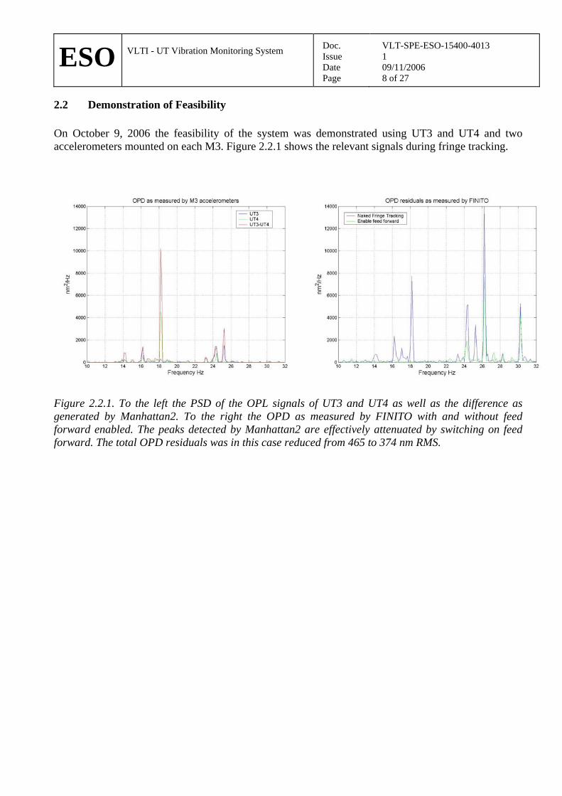
2.2 Demonstration of Feasibility On October 9, 2006 the feasibility of the system was demonstrated using UT3 and UT4 and two accelerometers mounted on each M3. Figure 2.2.1 shows the relevant signals during fringe tracking.
Figure 2.2.1. To the left the PSD of the OPL signals of UT3 and UT4 as well as the difference as generated by Manhattan2. To the right the OPD as measured by FINITO with and without feed forward enabled. The peaks detected by Manhattan2 are effectively attenuated by switching on feed forward. The total OPD residuals was in this case reduced from 465 to 374 nm RMS.

ESO
VLTI - UT Vibration Monitoring System
Doc. Issue Date Page
VLT-SPE-ESO-15400-4013 1 09/11/2006 9 of 27
3 EXTERNAL CONNECTIONS The electronics cabinet with LCU mounted in M1 cell connects to the M1 cell SCP. The external connections are power, liquid coolant and fiber optics. The fiber optic connections are illustrated in Figure 3.1. Each LCU uses 5 fibers; 2 for RMN, 2 for network and 1 for TIM. The network is connected to the Ethernet fiber optic hub in the UT NAP. The TIM connects to the time distribution system in the UT NAP. The RMN is patched through to the VLTI computer room. Here it terminates in the RMN patch panel located to the right in the front row of cabinets in the VLTI computer room. The patch panel allows connecting and disconnecting (bypass) the node from the RMN ring network. The required changes to Paranal fiber optic network have been documented in PPRS-020299 and PPRS-020300.
SCP-B M1 cell
LC
U
UT NAP
Ethernet HUB
TIM distribution
RMN Network TIM
Cable wrap
SCP-B M1 cell
LC
U
UT NAP
Ethernet HUB
TIM distribution
RMN Network TIM
Cable wrap
VLTI NAP
RMN Patch Panel
UT X
UT Y
Figure 3.1. Fiberoptic interconnections (only 2 UTs are shown for simplicity)

ESO
VLTI - UT Vibration Monitoring System
Doc. Issue Date Page
VLT-SPE-ESO-15400-4013 1 09/11/2006 10 of 27
4 ELECTRONICS CABINET The LCU requires four VME boards; PPC CPU, RMN, TIM and ADC, plus the standard transition module for serial port and network. The first two VME boards require access to P2 backplane (ADC board is configured to use short I/O, e.g not use P2). A 19” 6HE standard VME crate is shared between a 5 slot VME and accelerometer amplifiers, type Nexus 2692. A maximum of three amplifiers can be mounted in the allocated volume and each amplifier has four channels, e.g. the total system can support a maximum of 12 accelerometers. Initially only two amplifiers will be installed (max 8 accelerometers). The input from accelerometer uses connectors 10-32 UNF (compatible with Microdot) and adapters to TNC connectors and the output to ADC uses BNC. The internal wiring from amplifiers to ADC is provided inside the cabinet. The fans are of good quality in order not to induce vibrations.
Figure 4.1. Front view of cabinet
C
PU (M
VM
E260
4)
Pow
er su
pply
A
DC
(VM
IVM
E-31
23)
T
IM (E
SO T
IM)
s
pare
R
MN
(VM
IVM
E-55
76-0
10)
Nexus 2692
Nexus 2692
spare
Inle
t \ o
utle
t
620 mm
350
mm
Tr
ansi
tion
mod
. (M
VM
E712
M)
FO
tran
scei
ver

ESO
VLTI - UT Vibration Monitoring System
Doc. Issue Date Page
VLT-SPE-ESO-15400-4013 1 09/11/2006 11 of 27
Figure 4.2. Picture of cabinet.
Figure 4.3. Detail of cooling liquid interface

ESO
VLTI - UT Vibration Monitoring System
Doc. Issue Date Page
VLT-SPE-ESO-15400-4013 1 09/11/2006 12 of 27
Inle
t / O
utle
t
Con
trolle
r Fans
Heat Exchanger
VME
Sign
al
conn
ecto
rs
Pow
er
620 mm
560
mm
Sign
al
conn
ecto
rs
Figure 4.4. Top view of cabinet The complete cabinet is closed. It is a reuse of cooled cabinet developed by the Infrared group for CRIRES and future IR instruments. All I/O connections to VME boards are done from the front. Therefore the distance between cabinet front panel and VME must be sufficiently large (> 5 cm). All external connections are made at the side; power, 2 fiber network, 2 fiber RMN, 1 fiber TIM, 12 accelerometers and liquid coolant inlet and outlet. The liquid cooling supply from M1 cell SCPs have the following characteristics
• Maximum Delta Pressure: 1.1 Bar (without flow) • Maximum Flow: 11 l/m, with a delta pressure of 0.3 Bar
Cabinets have been tested in the lab using a small portable cooling system (~3 l/m, ~0.3 Bar). Infrared camera was used to verify surface temperature compliance.

ESO
VLTI - UT Vibration Monitoring System
Doc. Issue Date Page
VLT-SPE-ESO-15400-4013 1 09/11/2006 13 of 27
Figure 4.5. LCU interconnections
CPU MVME712
RMN
TIM
ADC P3 & P4
P1 P2
FO transc
Ethernet
Reflective Memory Network
Time Bus
Spare
4
4
Accelero- meters (max 12)
Power 220V AC Power distribution Fan
VME PS
4
Heat Exchanger Liquid Inlet Outlet
Nexus 2692
Nexus 2692
Item Number Description Comment 1 1 VME crate 5 slot horizontal 2 1 Backplane P1 5-slot P1 backplane 3 1 Backplane P2 3-slot P2 backplane 4 1 Power Supply Kniel 5 1 FO Transceiver AUI - FO 6 1 Transition module MVME712M Motorola Transition Module 7 1 CPU MVME2604 8 1 RMN VMIVME-5576 reflective memory 9 1 TIM ESO Time Interface Module 10 1 ADC VMIVME-3123 analogue to digital converter 11 2 Cooling fans 12 1 Heat Exchanger 13 1 Power distribution 14 Max 3 Nexus 2692 Amplifiers to I/F accelerometers 15 Max 3 Power adapters Adapters for Nexus 2692
Table 4.1. Specification and list of components
ESO
VLTI - UT Vibration Monitoring System
Doc. Issue Date Page
VLT-SPE-ESO-15400-4013 1 09/11/2006 14 of 27
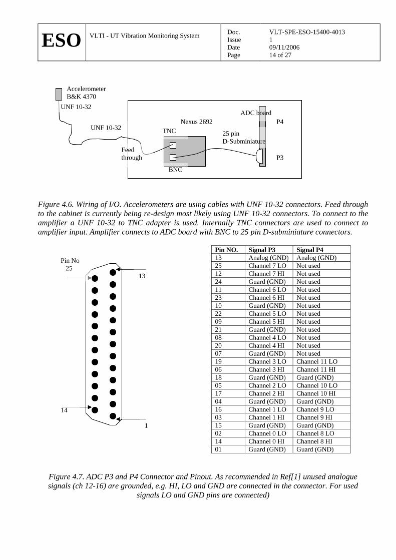
Figure 4.6. Wiring of I/O. Accelerometers are using cables with UNF 10-32 connectors. Feed through to the cabinet is currently being re-design most likely using UNF 10-32 connectors. To connect to the amplifier a UNF 10-32 to TNC adapter is used. Internally TNC connectors are used to connect to amplifier input. Amplifier connects to ADC board with BNC to 25 pin D-subminiature connectors.
Pin NO. Signal P3 Signal P4 13 Analog (GND) Analog (GND) 25 Channel 7 LO Not used 12 Channel 7 HI Not used 24 Guard (GND) Not used 11 Channel 6 LO Not used 23 Channel 6 HI Not used 10 Guard (GND) Not used 22 Channel 5 LO Not used 09 Channel 5 HI Not used 21 Guard (GND) Not used 08 Channel 4 LO Not used 20 Channel 4 HI Not used 07 Guard (GND) Not used 19 Channel 3 LO Channel 11 LO 06 Channel 3 HI Channel 11 HI 18 Guard (GND) Guard (GND) 05 Channel 2 LO Channel 10 LO 17 Channel 2 HI Channel 10 HI 04 Guard (GND) Guard (GND) 16 Channel 1 LO Channel 9 LO 03 Channel 1 HI Channel 9 HI 15 Guard (GND) Guard (GND) 02 Channel 0 LO Channel 8 LO 14 Channel 0 HI Channel 8 HI 01 Guard (GND) Guard (GND)
Figure 4.7. ADC P3 and P4 Connector and Pinout. As recommended in Ref[1] unused analogue signals (ch 12-16) are grounded, e.g. HI, LO and GND are connected in the connector. For used
signals LO and GND pins are connected)
Pin No 25
1
14
13
Accelerometer B&K 4370
UNF 10-32
UNF 10-32 TNC
BNC
25 pin D-Subminiature
ADC board
P3
P4 Nexus 2692
Feed through
ESO
VLTI - UT Vibration Monitoring System
Doc. Issue Date Page
VLT-SPE-ESO-15400-4013 1 09/11/2006 15 of 27
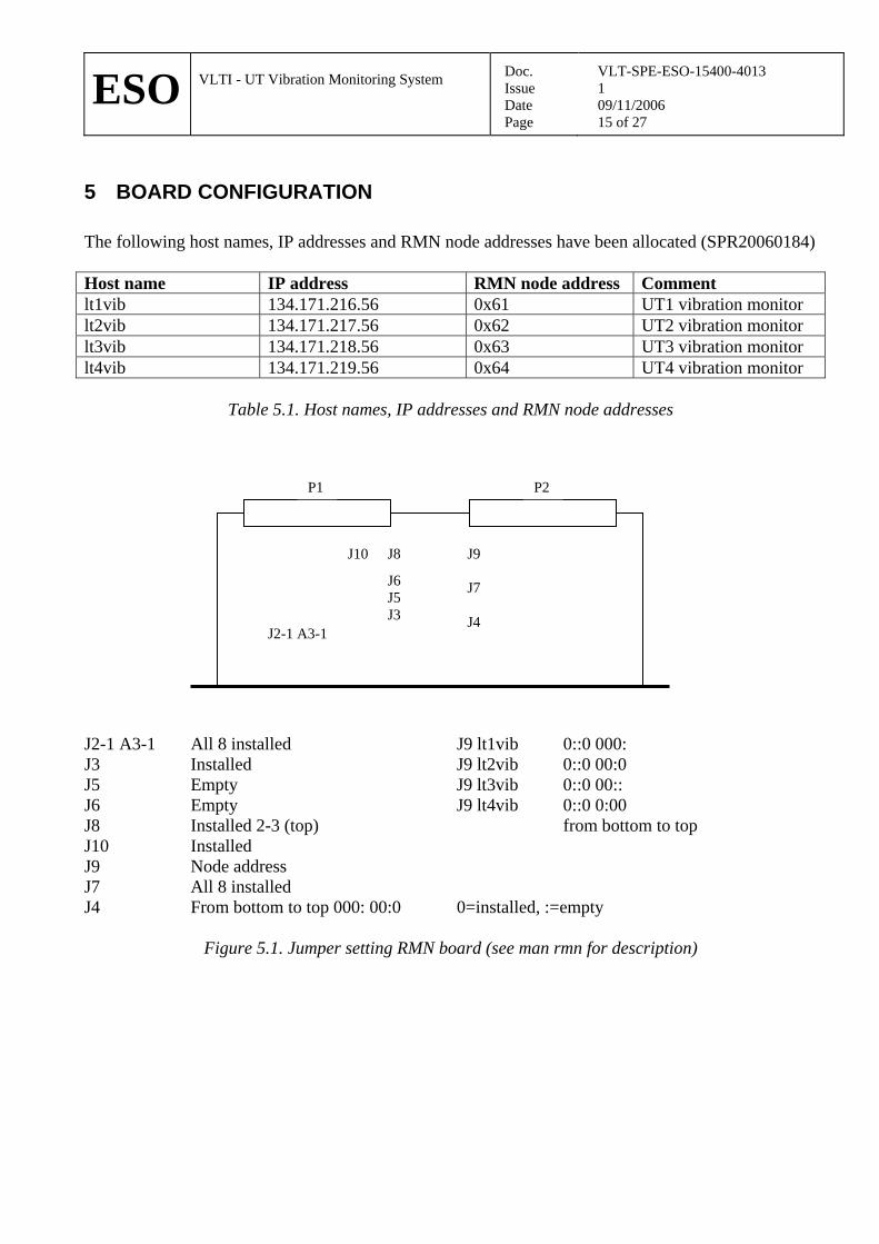
5 BOARD CONFIGURATION The following host names, IP addresses and RMN node addresses have been allocated (SPR20060184) Host name IP address RMN node address Comment lt1vib 134.171.216.56 0x61 UT1 vibration monitor lt2vib 134.171.217.56 0x62 UT2 vibration monitor lt3vib 134.171.218.56 0x63 UT3 vibration monitor lt4vib 134.171.219.56 0x64 UT4 vibration monitor
Table 5.1. Host names, IP addresses and RMN node addresses
P1 P2
J2-1 A3-1
J10 J8
J6 J5 J3
J9 J7 J4
J2-1 A3-1 All 8 installed J9 lt1vib 0::0 000: J3 Installed J9 lt2vib 0::0 00:0 J5 Empty J9 lt3vib 0::0 00:: J6 Empty J9 lt4vib 0::0 0:00 J8 Installed 2-3 (top) from bottom to top J10 Installed J9 Node address J7 All 8 installed J4 From bottom to top 000: 00:0 0=installed, :=empty
Figure 5.1. Jumper setting RMN board (see man rmn for description)
ESO
VLTI - UT Vibration Monitoring System
Doc. Issue Date Page
VLT-SPE-ESO-15400-4013 1 09/11/2006 16 of 27
P1 P2
E41E40
E1E2
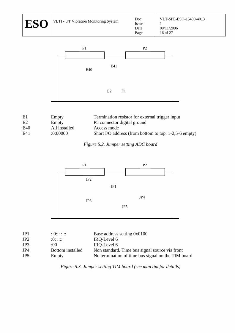
E1 Empty Termination resistor for external trigger input E2 Empty P5 connector digital ground E40 All installed Access mode E41 :0:00000 Short I/O address (from bottom to top, 1-2,5-6 empty)
Figure 5.2. Jumper setting ADC board
P1 P2
JP1
JP2
JP4JP3
JP5
JP1 : 0::: :::: Base address setting 0x0100 JP2 :0: :::: IRQ-Level 6 JP3 :00 IRQ-Level 6 JP4 Bottom installed Non standard. Time bus signal source via front JP5 Empty No termination of time bus signal on the TIM board
Figure 5.3. Jumper setting TIM board (see man tim for details)

ESO
VLTI - UT Vibration Monitoring System
Doc. Issue Date Page
VLT-SPE-ESO-15400-4013 1 09/11/2006 17 of 27
6 NEXUS AMPLIFIER CONFIGURATION The Nexus conditioning amplifier is programmable (Ref 2) from the front panel (there is also a RS-232 interface which could be used from the LCU, but this has not been implemented at this time). Each individual accelerometer is delivered with a calibration sheet. The sensitivity value (pC/ms-2) has to be entered in the amplifier for the corresponding channel. Further, a gain value (V to m/s2) has to be entered. Finally the cut-off frequencies for built-in filters must be specified. The accelerometer assignment and amplifier settings, as of October 2006, are summarized in tables below. Accelerometers with SN 10662-10664 do not belong to Manhattan2, but were borrowed.
6.1 UT 4 Serial Number Sensitivity /pC/ms-2 30063 9.97 assigned to UT4 Channel 1 10664 9.92 assigned to UT4 Channel 2
Table 6.1.1. Accelerometers installed on M3 UT4
Serial Number Location in rack Accelerometric Channels 2500458 Top 1-4 2551135 Middle 5-8
Table 6.1.2. Amplifier assignment on UT4
Acceler. Channel
High pass / Hz
Low pass / kHz
Gain / V/ms-2
Sensitivity / pC/ms-2
Input / Output floating Correction
1 0.1 1 100 9.97 Yes / Yes 2 0.1 1 100 9.92 Yes / Yes 3 Not used 4 Not used 5 Not used 6 Not used 7 Not used 8 Not used
Table 6.1.3. Nexus conditioning amplifier setup on UT4
6.2 UT 3
Serial Number Sensitivity /pC/ms-2 10663 9.89 assigned to UT3 Channel 1 10662 9.89 assigned to UT3 Channel 2
Table 6.2.1. Accelerometers installed on M3 UT3
Serial Number Location in rack Accelerometric Channels 2551134 Top 1-4 2551136 Middle 5-8
Table 6.2.2. Amplifier assignment on UT3

ESO
VLTI - UT Vibration Monitoring System
Doc. Issue Date Page
VLT-SPE-ESO-15400-4013 1 09/11/2006 18 of 27
Acceler. Channel
High pass / Hz
Low pass / kHz
Gain / V/ms-2
Sensitivity / pC/ms-2
Input / Output floating Correction
1 0.1 1 100 9.89 Yes / Yes 2 0.1 1 100 9.89 Yes / Yes 3 Not used 4 Not used 5 Not used 6 Not used 7 Not used 8 Not used
Table 6.2.3. Nexus conditioning amplifier setup on UT3
ESO
VLTI - UT Vibration Monitoring System
Doc. Issue Date Page
VLT-SPE-ESO-15400-4013 1 09/11/2006 19 of 27
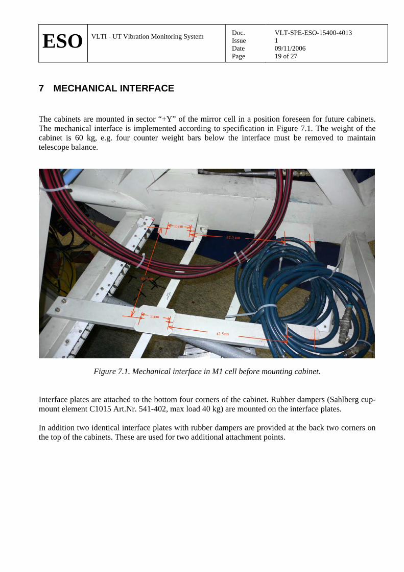
7 MECHANICAL INTERFACE The cabinets are mounted in sector “+Y” of the mirror cell in a position foreseen for future cabinets. The mechanical interface is implemented according to specification in Figure 7.1. The weight of the cabinet is 60 kg, e.g. four counter weight bars below the interface must be removed to maintain telescope balance.
Figure 7.1. Mechanical interface in M1 cell before mounting cabinet. Interface plates are attached to the bottom four corners of the cabinet. Rubber dampers (Sahlberg cup-mount element C1015 Art.Nr. 541-402, max load 40 kg) are mounted on the interface plates. In addition two identical interface plates with rubber dampers are provided at the back two corners on the top of the cabinets. These are used for two additional attachment points.

ESO
VLTI - UT Vibration Monitoring System
Doc. Issue Date Page
VLT-SPE-ESO-15400-4013 1 09/11/2006 20 of 27
8 LOCATION OF HARDWARE AS OF OCTOBER 2006
8.1 UT 4 Cooling Box with 2 amplifiers (thus 8 accelerometer capacity) mounted in the M1 cell, Power, cooling liquid, RMN, TIM and network connected.
Figure 8.1.1. Integration of the cooling box in the UT4 M1 cell
- Accelerometers mounted on back of M3 cell, electrically not insulated - The 30 m cable (labelled AO0122 D300 14/06) is connected to Ch1 accelerometer - The (extended) 10 m cable (labelled AO0122 D100 20/06 on cooling box side) is connected
to Ch2 accelerometer

ESO
VLTI - UT Vibration Monitoring System
Doc. Issue Date Page
VLT-SPE-ESO-15400-4013 1 09/11/2006 21 of 27
Figure 8.1.2. Location of the accelerometers on UT4 M3 cell
8.2 UT 3
Cooling Box with 2 amplifiers (thus 8 accelerometer capacity) mounted in the M1 cell, Power, cooling liquid, RMN, TIM and network connected. - Accelerometers mounted on back of M3 cell, electrically not insulated, Ch1 and Ch2
positions are interchanged with respect to UT4! - Both cables are 30 m long, the one connected to Ch1 accelerometer is labeled red on cooling
box side
Figure 8.2.1. Location of the accelerometers on UT3 M3 cell

ESO
VLTI - UT Vibration Monitoring System
Doc. Issue Date Page
VLT-SPE-ESO-15400-4013 1 09/11/2006 22 of 27
9 SOFTWARE The software application makes use of tac with its associated flexibility. The application (tac configuration file, custom blocks etc) is being developed in the cmm module vib. A support module, vibBUILD, is also provided to generate required software and the LCU environment. Each telescope is expected to deliver two doubles on RMN at 2 kHz. These are total displacement (OPL) and total acceleration. Location of these new data on the reflective memory is defined in rmac v 1.32 and tac blocks to write and read these data in taclib v 1.78. The basic signal processing to obtain OPL is:
• Acquire accelerometer signals • If using multiple accelerometers average them (position dependent) • Cancel any pre-amplifier high pass. • Add a 3 pole high pass butterworth at 0.1 Hz or as required (2 poles to cancel integrator + AC
couple) • Double integrator to convert to displacement (OPL). • Cancel anti-aliasing filter. • Cancel pre-amplifier low pass. • Add desired low pass to limit feed forward bandwidth. • Add lead network for time-delay compensation. • Write result on RMN
The tac configuration file implemented in vib v 1.5 is illustrated in Figure 9.1
ADC V-m/s2 TF1 TF2 TF3 M3
RMN
probe
M3
Figure 9.1. Illustration of algorithm. V-ms2 must match amplifier setting. M3 is scaling from displacement to OPL, e.g. sqrt(2) in case of M3. TF1, 2 and 3 are cascading filters (see below). The probe block allows real-time visualization with rtdscope or standard tac sampling into a file. Data columns can be deducted from Figure 9.1.
ESO
VLTI - UT Vibration Monitoring System
Doc. Issue Date Page
VLT-SPE-ESO-15400-4013 1 09/11/2006 23 of 27
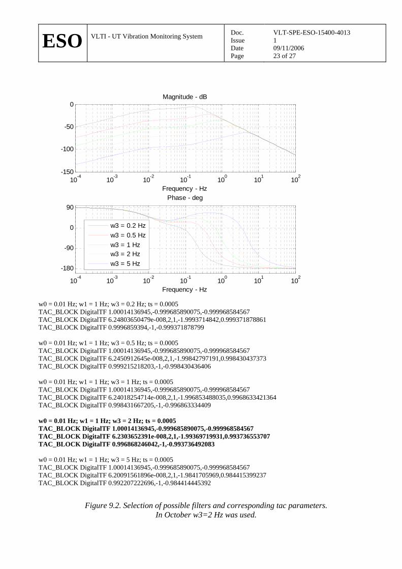
10-4 10-3 10-2 10-1 100 101 102-150
-100
-50
0Magnitude - dB
Frequency - Hz
10-4 10-3 10-2 10-1 100 101 102
-180
-90
0
90Phase - deg
Frequency - Hz
w3 = 0.2 Hzw3 = 0.5 Hzw3 = 1 Hzw3 = 2 Hzw3 = 5 Hz
w0 = 0.01 Hz; w1 = 1 Hz; w3 = 0.2 Hz; ts = 0.0005 TAC_BLOCK DigitalTF 1.00014136945,-0.999685890075,-0.999968584567 TAC_BLOCK DigitalTF 6.24803650479e-008,2,1,-1.9993714842,0.999371878861 TAC_BLOCK DigitalTF 0.9996859394,-1,-0.999371878799 w0 = 0.01 Hz; w1 = 1 Hz; w3 = 0.5 Hz; ts = 0.0005 TAC_BLOCK DigitalTF 1.00014136945,-0.999685890075,-0.999968584567 TAC_BLOCK DigitalTF 6.2450912645e-008,2,1,-1.99842797191,0.998430437373 TAC_BLOCK DigitalTF 0.999215218203,-1,-0.998430436406 w0 = 0.01 Hz; w1 = 1 Hz; w3 = 1 Hz; ts = 0.0005 TAC_BLOCK DigitalTF 1.00014136945,-0.999685890075,-0.999968584567 TAC_BLOCK DigitalTF 6.24018254714e-008,2,1,-1.996853488035,0.9968633421364 TAC_BLOCK DigitalTF 0.998431667205,-1,-0.996863334409 w0 = 0.01 Hz; w1 = 1 Hz; w3 = 2 Hz; ts = 0.0005 TAC_BLOCK DigitalTF 1.00014136945,-0.999685890075,-0.999968584567 TAC_BLOCK DigitalTF 6.2303652391e-008,2,1,-1.99369719931,0.993736553707 TAC_BLOCK DigitalTF 0.996868246042,-1,-0.993736492083 w0 = 0.01 Hz; w1 = 1 Hz; w3 = 5 Hz; ts = 0.0005 TAC_BLOCK DigitalTF 1.00014136945,-0.999685890075,-0.999968584567 TAC_BLOCK DigitalTF 6.20091561896e-008,2,1,-1.9841705969,0.984415399237 TAC_BLOCK DigitalTF 0.992207222696,-1,-0.984414445392
Figure 9.2. Selection of possible filters and corresponding tac parameters. In October w3=2 Hz was used.

ESO
VLTI - UT Vibration Monitoring System
Doc. Issue Date Page
VLT-SPE-ESO-15400-4013 1 09/11/2006 24 of 27
LCU boot parameters as stored in non volatile memory are shown below boot device : dc0 processor number : 0 host name : wt3tcs file name : /vlt/JAN2006/vw5.4/target/config/mv2604/vxWorks inet on ethernet (e) : 134.171.218.56:ffffff00 inet on backplane (b): host inet (h) : 134.171.218.1 gateway inet (g) : user (u) : vx ftp password (pw) (blank = use rsh): flags (f) : 0x8 target name (tn) : lt3vib startup script (s) : /vltdata/ENVIRONMENTS/lt3vib/bootScript other (o) : boot device : dc0 processor number : 0 host name : wt4tcs file name : /vlt/JAN2006/vw5.4/target/config/mv2604/vxWorks inet on ethernet (e) : 134.171.219.56:ffffff00 inet on backplane (b): host inet (h) : 134.171.219.1 gateway inet (g) : user (u) : vx ftp password (pw) (blank = use rsh): flags (f) : 0x8 target name (tn) : lt4vib startup script (s) : /vltdata/ENVIRONMENTS/lt4vib/bootScript other (o) :

ESO
VLTI - UT Vibration Monitoring System
Doc. Issue Date Page
VLT-SPE-ESO-15400-4013 1 09/11/2006 25 of 27
10 MAINTENENACE
10.1 Assembling the Cooling Box Procedure to mount/dismount Manhattan2 cooling box: Situation before starting the mounting procedure: -cooling box top cover is removed (this can be done in-situ)
-LCU crate (ltXvib) is completely disconnected and removed from the cooling box
Amplifiers
Crate
Figure 10.1. Cooling box in semi-assembled state
Figure 10.2. Cooling Box in assembled state

ESO
VLTI - UT Vibration Monitoring System
Doc. Issue Date Page
VLT-SPE-ESO-15400-4013 1 09/11/2006 26 of 27
1. Mount amplifiers into crate -mount top amplifier first, then middle, then bottom (amplifiers are fastened from below) 2. Connect amplifier BNC outputs to ADC board -Top amplifier output channels 1-4 connected to ADC input channels 1-4 -Middle amplifier output channels 1-4 connected to ADC input channels 5-8
(this is the configuration for only two amplifiers; nominal configuration due to cable lengths would be: bottom amp. -> ADC channels1-4, middle amp. ->ADC 5-8, top amp.->ADC 9-12)
3. Mount power supplies for amplifiers -remove cover plate -glue the power supplies to the back plate of the crate using double sided tape -put cover plate back -connect power supply lemo connectors to amplifier 4. Mount LCU crate into the cooling box -make sure the crate main power supply is switched ON -slide crate into cooling box -connect crate power supply (cable from cooling box) -connect the amplifier power supplies (cable from cooling box) -connect TNC cables according to channel configuration above 5. Make first functional test -power up cooling box, crate should power up automatically -power up amplifiers
-connect accelerometer to all cooling box inputs and check that the correct amplifier channels are connected
6. Fasten crate inside cooling box -fasten the 8 M8 front screws -fasten the 2 'pushers' at the back upper corners of the crate 7. Mount fibre feed through (when dismounting, the fibre patchpanel has to be removed before taking
the crate out of the cooling box) -mount fibre feedthrough to the cooling box -connect fibres to the assigned positions 8. Mount cooling box cover -mount and fasten cover plate -mount interface plates -mount vibration insulators 9. Close the remaining amplifier slot to insure efficient air flow 10. Close the front door and fasten with screws (don't loose them!)
ESO
VLTI - UT Vibration Monitoring System
Doc. Issue Date Page
VLT-SPE-ESO-15400-4013 1 09/11/2006 27 of 27
___oOo___