vmdc architecture with citrix netscaler vpx and sdx€¦ · ethernet (10 ge) and 1 gbps ethernet (1...
TRANSCRIPT
VMD
VMDC Architecture with Citrix NetScaler VPX and SDX
Note This document is a complimentary technical configuration note, and is not to be construed as a Cisco Validated Design (CVD), or addendum to such.
Citrix offers a suite of appliances designed for performing server load balancing and offloading for certain applications. These appliances are currently offered in a physical or virtual form factor. With the advent of multi-tenant architectures that require increasing virtualization of network services, the virtual form factors of these appliances are a viable option in fulfilling this role.
This paper describes design recommendations and guidance for the insertion of NetScaler VPX and SDX in Virtual Multiservice Data Center (VMDC) 2.2 and VMDC 3.0 architectural models. These recommendations were gathered during an evaluation of the VPX in a VMware environment, and on a Citrix SDX multi-tenant appliance. Most of the testing was conducted using the publicly available NetScaler OS 10.0 code version, while some was conducted on an early beta of the NetScaler OS 10.1 code. This code became publicly available on May 31st 2013.
The audience for this document is Cisco field service teams and partners using NetScaler VPX and SDX in cloud designs and Data Center solutions for Cisco customers. The purpose of the doucment is to serve as a guide for replacing the ACE module or appliance in VMDC architectures. The following list provides guidance for configuring specific commonly-applied ACE server load balancing features on the NetScaler appliance:
• For high availability (active/active or active/standby), see High Availability
• For virtual MAC (VMAC), see VMAC
• For server load balancing, see Server Load Balancing
• For server health monitoring, see Server Health Check
• For SSL offload, see SSL Offload
• For access control lists (ACLs), see Layer 4-7 Access Control Lists
Note Product screen shots and similar materials in this document are used for illustration purposes only and may show trademarks of VMWare, Inc., or Citrix Systems, Inc. All other marks and names mentioned herein may be trademarks of respective companies. Use of the word “partner” or “partnership” does not imply a legal relationship between Cisco and another company.
1C Architecture with Citrix NetScaler VPX and SDX
VMDC Architecture with Citrix NetScaler VPX and SDXNetScaler VPX and SDX Overview
NetScaler VPX and SDX OverviewThe Citrix NetScaler products offer server load balancing and content switching, along with application acceleration, Layer 4-Layer 7 (L4-L7) traffic management, data compression, SSL acceleration, network optimization, and application security.
The NetScaler VPX has the same features as the NetScaler MPX physical appliance, but is a virtual form factor of the NetScaler product. It is installed as a VM on a hypervisor. At the time of the authoring of this paper, the VPX can be installed on XenServer, VMware, and Hyper-V. The NetScaler VPX can handle up to 3 Gbps of HTTP traffic when deployed on VMware or Hyper-V. Results are based on the type of license installed on the VPX instance. For more information on testing specifications for the various VPX incarnations, refer to:
http://www.citrix.com/products/netscaler-application-delivery-controller/features/platforms/vpx.html
Validation utilized VMware-based VPX systems, therefore installation, configuration requirements and examples will pertain to this brand of hypervisor unless specified.
Installation requirements for the VPX VM on VMware include:
• 1 vCPUs
• 2 GB RAM
• 20 GB HD
• At least one vNIC (a separate interface is not required for High Availability)
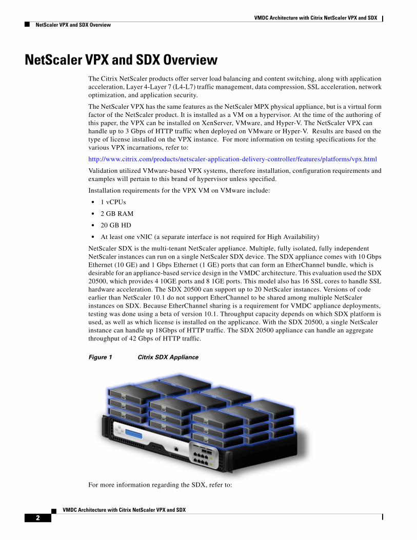
NetScaler SDX is the multi-tenant NetScaler appliance. Multiple, fully isolated, fully independent NetScaler instances can run on a single NetScaler SDX device. The SDX appliance comes with 10 Gbps Ethernet (10 GE) and 1 Gbps Ethernet (1 GE) ports that can form an EtherChannel bundle, which is desirable for an appliance-based service design in the VMDC architecture. This evaluation used the SDX 20500, which provides 4 10GE ports and 8 1GE ports. This model also has 16 SSL cores to handle SSL hardware acceleration. The SDX 20500 can support up to 20 NetScaler instances. Versions of code earlier than NetScaler 10.1 do not support EtherChannel to be shared among multiple NetScaler instances on SDX. Because EtherChannel sharing is a requirement for VMDC appliance deployments, testing was done using a beta of version 10.1. Throughput capacity depends on which SDX platform is used, as well as which license is installed on the applicance. With the SDX 20500, a single NetScaler instance can handle up 18Gbps of HTTP traffic. The SDX 20500 appliance can handle an aggregate throughput of 42 Gbps of HTTP traffic.
Figure 1 Citrix SDX Appliance
For more information regarding the SDX, refer to:
2VMDC Architecture with Citrix NetScaler VPX and SDX
VMDC Architecture with Citrix NetScaler VPX and SDXVMDC 2.2 Overview
http://www.citrix.com/products/netscaler-application-delivery-controller/features/platforms/sdx.html
Both the VPX and SDX can be configured using CLI or a browser-based interface. CLI configurations are used as examples in this technical paper.
NetScaler OS uses four types of IP addresses for its various operations:
• NSIP—This IP address refers to the management address. Although it is not required to have a separate subnet for management, this is the design that was used during this evaluation.
• SNIP—This IP address is a subnet IP that represents an interface the NetScaler device uses to pass traffic between the server farm and clients. By default, this is the address used as the source ip address for packets coming from outside clients.
• VIP—This is the virtual IP address. It is shared address outside clients will use to connect to the server farm.
• MIP—This is the mapped IP address. It is used for server-side connections when no SNIP is configured or the USNIP option is disabled (this is enabled by default).
For more information about NetScaler IP address, refer to:
http://support.citrix.com/proddocs/topic/ns-system-10-map/ns-nw-ipaddrssng-confrng-ns-ownd-ip-addrss-con.html
VMDC 2.2 OverviewVirtualized Multiservice Data Center (VMDC) is the Cisco reference architecture for IaaS cloud deployments, and VMDC 2.2 is the large scale version of this architecture. This IaaS cloud architecture is designed around a set of modular DC components consisting of building blocks of resources called pods. These pods consist of the Cisco Unified Computing System (UCS), SAN and NAS storage arrays, access (switching) layers, aggregation (switching and routing) layers connecting into the Data Center Services Node (DSN)-based services layer, and multiple 10 GE fabrics using highly scalable, Cisco network switches and routers.
The VMDC system is built around the UCS, Nexus 1000V, Nexus 5000 and Nexus 7000 switches, Multilayer Director Switch (MDS), Aggregation Services Router (ASR) 9000, ASR 1000, Adaptive Security Appliance (ASA) 5585-X or ASA Services Module (ASASM), Catalyst 6500 DSN, ACE, Nexus 1000V VSG, VMware vSphere, EMC VMAX, and NetApp FAS storage arrays. Cloud service orchestration is currently provided by the BMC Cloud Lifecycle Management (CLM) suite.
Note NetScaler products were not evaluated in the VMDC 2.3 architecture due to time constraints and lab availability. However, results and observations are expected to be similar to those for VMDC 2.2.
VMDC 2.2 ArchitectureVMDC 2.2 uses a hierarchical network design for high availability and scalability. The hierarchical (layered) DC design uses redundant switches at each network layer in the network topology for device-level failover that creates a highly available transport between end nodes using the network. Additional services such as SLB, firewall, and intrusion prevention are provided via modules populating a slot of one of the switching nodes in the network or via standalone service appliances.
Each service approach also supports redundant hardware deployment to preserve high availability standards set by the network topology. This layered approach is the basic foundation of the VMDC design to provide scalability, performance, flexibility, resiliency, and service assurance.
3VMDC Architecture with Citrix NetScaler VPX and SDX
VMDC Architecture with Citrix NetScaler VPX and SDXVMDC 2.2 Overview
VLANs and Virtual Routing and Forwarding (VRF) instances provide tenant isolation in the DC architecture, and routing protocols in the VRF instances interconnect the various networking and service devices. The VMDC 2.2 architecture is based on a VRF-Lite design end-to-end through the data center routing platforms, with routing between the VRF instances provided by BGP peering.
Note For detailed information about the VMDC 2.2 system architecture, refer to the following documents:
• VMDC 2.2 Design Guide
• VMDC 2.2 Implementation Guide
Information about previous VMDC system releases can be found at:
• VMDC System Releases
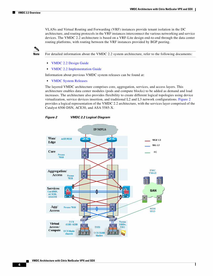
The layered VMDC architecture comprises core, aggregation, services, and access layers. This architecture enables data center modules (pods and compute blocks) to be added as demand and load increases. The architecture also provides flexibility to create different logical topologies using device virtualization, service devices insertion, and traditional L2 and L3 network configurations. Figure 2 provides a logical representation of the VMDC 2.2 architecture, with the services layer comprised of the Catalyst 6500 DSN, ACE30, and ASA 5585-X.
Figure 2 VMDC 2.2 Logical Diagram
4VMDC Architecture with Citrix NetScaler VPX and SDX
VMDC Architecture with Citrix NetScaler VPX and SDXVMDC 3.0 Overview
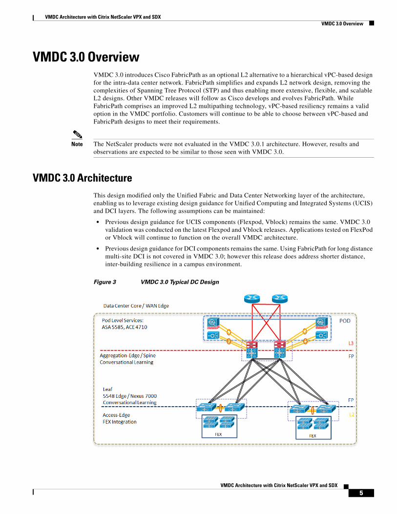
VMDC 3.0 OverviewVMDC 3.0 introduces Cisco FabricPath as an optional L2 alternative to a hierarchical vPC-based design for the intra-data center network. FabricPath simplifies and expands L2 network design, removing the complexities of Spanning Tree Protocol (STP) and thus enabling more extensive, flexible, and scalable L2 designs. Other VMDC releases will follow as Cisco develops and evolves FabricPath. While FabricPath comprises an improved L2 multipathing technology, vPC-based resiliency remains a valid option in the VMDC portfolio. Customers will continue to be able to choose between vPC-based and FabricPath designs to meet their requirements.
Note The NetScaler products were not evaluated in the VMDC 3.0.1 architecture. However, results and observations are expected to be similar to those seen with VMDC 3.0.
VMDC 3.0 ArchitectureThis design modified only the Unified Fabric and Data Center Networking layer of the architecture, enabling us to leverage existing design guidance for Unified Computing and Integrated Systems (UCIS) and DCI layers. The following assumptions can be maintained:
• Previous design guidance for UCIS components (Flexpod, Vblock) remains the same. VMDC 3.0 validation was conducted on the latest Flexpod and Vblock releases. Applications tested on FlexPod or Vblock will continue to function on the overall VMDC architecture.
• Previous design guidance for DCI components remains the same. Using FabricPath for long distance multi-site DCI is not covered in VMDC 3.0; however this release does address shorter distance, inter-building resilience in a campus environment.
Figure 3 VMDC 3.0 Typical DC Design
5VMDC Architecture with Citrix NetScaler VPX and SDX
VMDC Architecture with Citrix NetScaler VPX and SDXNetScaler VPX in VMDC Design
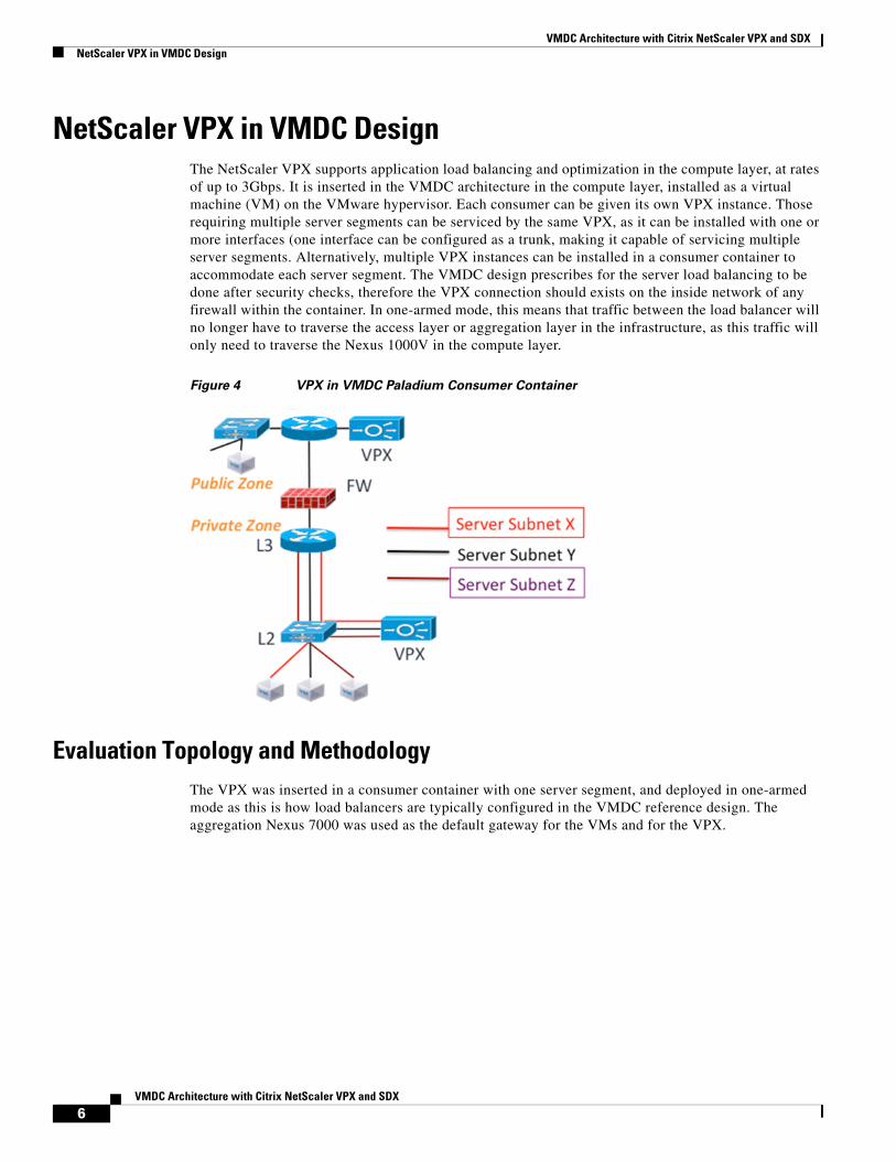
NetScaler VPX in VMDC DesignThe NetScaler VPX supports application load balancing and optimization in the compute layer, at rates of up to 3Gbps. It is inserted in the VMDC architecture in the compute layer, installed as a virtual machine (VM) on the VMware hypervisor. Each consumer can be given its own VPX instance. Those requiring multiple server segments can be serviced by the same VPX, as it can be installed with one or more interfaces (one interface can be configured as a trunk, making it capable of servicing multiple server segments. Alternatively, multiple VPX instances can be installed in a consumer container to accommodate each server segment. The VMDC design prescribes for the server load balancing to be done after security checks, therefore the VPX connection should exists on the inside network of any firewall within the container. In one-armed mode, this means that traffic between the load balancer will no longer have to traverse the access layer or aggregation layer in the infrastructure, as this traffic will only need to traverse the Nexus 1000V in the compute layer.
Figure 4 VPX in VMDC Paladium Consumer Container
Evaluation Topology and MethodologyThe VPX was inserted in a consumer container with one server segment, and deployed in one-armed mode as this is how load balancers are typically configured in the VMDC reference design. The aggregation Nexus 7000 was used as the default gateway for the VMs and for the VPX.
6VMDC Architecture with Citrix NetScaler VPX and SDX
VMDC Architecture with Citrix NetScaler VPX and SDXNetScaler VPX in VMDC Design
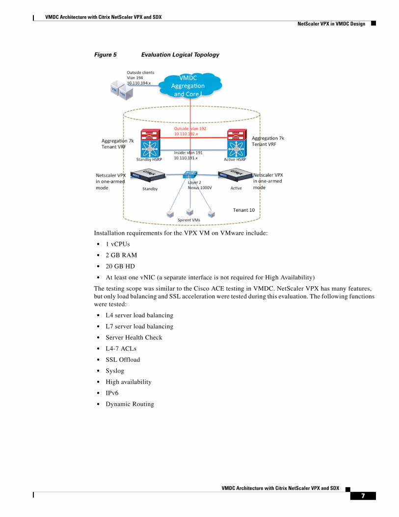
Figure 5 Evaluation Logical Topology
Installation requirements for the VPX VM on VMware include:
• 1 vCPUs
• 2 GB RAM
• 20 GB HD
• At least one vNIC (a separate interface is not required for High Availability)
The testing scope was similar to the Cisco ACE testing in VMDC. NetScaler VPX has many features, but only load balancing and SSL acceleration were tested during this evaluation. The following functions were tested:
• L4 server load balancing
• L7 server load balancing
• Server Health Check
• L4-7 ACLs
• SSL Offload
• Syslog
• High availability
• IPv6
• Dynamic Routing
7VMDC Architecture with Citrix NetScaler VPX and SDX
VMDC Architecture with Citrix NetScaler VPX and SDXNetScaler VPX in VMDC Design
VPX Evaluation Observations and Deployment ConsiderationsThe following section provide VPX evaluation observations and deployment considerations:
• VPX Installation on VMware Hypervisor, page -8
• Server Load Balancing, page -8
• Server Health Check, page -9
• SSL Offload, page -9
• Layer 4-7 Access Control Lists, page -9
• High Availability, page -9
• Dynamic Routing, page -10
• IPv6, page -10
VPX Installation on VMware Hypervisor
As stated previously, the VPX is installed as a VM on the VMware hypervisor. The .ovf file and other VMware-related files can be obtained from the Citrix website with a valid myCitrix account. A license is not needed to install the VM, but one is required for operation. Once the files are obtained, installation is done using the .ovf file. As many as 10 interfaces can be allocated to the VPX VM. More than one CPU may be allocated to the VM.
Console access through VMware has to be used to configure out-of-band management access using the CLI. The default username and password are nsroot. To configure management access, the following configuration is needed:
set ns config -IPAddress 172.26.162.225 -netmask 255.255.0.0
This IP address maps to the first port on the VPX VM. It must be connected to the management vlan for OOB management to be possible. Once the NSIP is configured, all management access methods are available by default (ssh, telnet, http, ftp). To configure the other interface IP addresses, ssh access can be used to get to the CLI. IP addresses for data must be entered in the order they were created on the VM. The command to add a SNIP is as follows:
add ns ip 10.110.191.250 255.255.255.0 -vServer DISABLED -dynamicRouting ENABLED
Server Load Balancing
The VPX was tested as both an L4 (TCP) and L7 (HTTP) load balancer. It can be configured to use many different load balancing algorithms, such as least connections and round robin. The following configuration, which was used in the evaluation, uses a round robin algorithm:
add lb vserver vip-1-http-80 HTTP 10.110.191.200 80 -persistenceType NONE -lbMethod ROUNDROBIN -cltTimeout 180 -icmpVsrResponse ACTIVE
In this example, the VIP is using port 80 for the IP 10.110.191.200.
To bind servers to this virtual IP address (VIP), server objects must be created and then bound to a service that is eventually bound to the VIP:
add server server-1 10.110.191.100add service service-1-http-80 server-1 HTTP 80 -gslb NONE -maxClient 0 -maxReq 0 -cip DISABLED -usip NO -useproxyport YES -sp ON -cltTimeout 180 -svrTimeout 360 -CustomServerID "\"None\"" -CKA YES -TCPB YES -CMP NObind lb vserver vip-1-http-80 service-1-http-80
8VMDC Architecture with Citrix NetScaler VPX and SDX
VMDC Architecture with Citrix NetScaler VPX and SDXNetScaler VPX in VMDC Design
Server Health Check
The VPX can be configured to determine whether a server is down using many different monitors, including ICMP and TCP/UDP. The following configuration snippet from the evaluation uses the default ICMP monitor:
bind service service-1-http-80 -monitorName ping
The VPX could detect server failure as it was configured.
SSL Offload
The VPX was configured to perform SSL transactions for a group of HTTP servers. In this deployment, clients made an SSL connection to the VIP. The VPX then created an HTTP connection to the real server. A generic certificate was generated on the VPX for testing purposes. The certificate for the server was installed on the VPX so that it could act as a proxy for the real server. It is also possible to configure the VPX to make a secure connection to the real server using SSL, but that configuration was not used.
set ssl vserver vip-1-ssl-443 -eRSA ENABLEDbind lb vserver vip-1-ssl-443 service-1-http-80bind ssl service nshttps-::1l-443 -certkeyName ns-server-certificate
For more information on generating SSL certificates on the VPX, refer to:
http://support.citrix.com/proddocs/topic/netscaler-traffic-management-10-map/ns-ssl-generate-server-test-cert-tsk.html
For more information SSL offload configuration, refer:
http://support.citrix.com/proddocs/topic/netscaler-traffic-management-10-map/ns-ssl-config-ssloffloading-con.html
Layer 4-7 Access Control Lists
The VPX can protect the VIP from unauthorized connections using an ACL. These lists can be applied to any VPX segment, and can even be used to protect the VPX VM management interface. These ACLs can be standard (IP) or extended (L4-L7). In this configuration snippet, the VIP is being protected from a certain client:
add ns acl block_outside_client DENY -srcIP = 10.110.192.100 -destIP = 10.110.191.1-10.110.191.254 -destPort = 80 -protocol TCP -interface 1/1 -priority 10 -state ENABLED -kernelstate APPLIED
High Availability
The VPX supports active/standby failover and clustering. In High Availability (HA) mode, heartbeat packets are sent on all active interfaces; therefore, there is no need to dedicate an interface for this purpose. Failover in HA mode during normal operations takes at least 3 seconds. This is because failover depends on the dead-interval that is configured. By default, this is 3 seconds, which is also the shortest time that can be configured for this parameter. The dead-interval indicates how long the secondary VPX will wait for heartbeat packets before it considers the primary VPX down. During failover, connections must be reestablished on the new primary instance of the VPX.
To create an HA pair, the following needs to be configured on the primary VPX first:
add HA node 1 172.26.162.227
The IP address refers to the management IP address or NSIP of the VPX that is to the be the secondary in the pair. The number 1 represents the node ID which is local to the VPX and must be unique for each node added. For this evaluation, the default value for the dead interval was used.
For more information about configuring HA, refer to:
http://support.citrix.com/proddocs/topic/ns-system-10-map/ns-nw-ha-intro-wrppr-con.html
9VMDC Architecture with Citrix NetScaler VPX and SDX
VMDC Architecture with Citrix NetScaler VPX and SDXNetScaler VPX in VMDC Design
Clustering is a NetScaler feature that supports making multiple VPX instances appear as one device. This feature was not tested in this evaluation. For more information on clustering, refer to:
http://support.citrix.com/article/CTX132840
Dynamic Routing
The VPX supports the following routing protocols: RIP, OSPF, ISIS, and BGP. Dynamic routing must be enabled on the IP interface used to connect to the routing protocol. VMDC uses OSPF as its internal routing protocol, so VPX was configured to participate in the OSPF process already present in the VMDC deployment used for the evaluation:
router ospf 1 redistribute static area 0 range 5.13.2.0/24 network 5.13.2.0/24 area 0
This config must be entered in the Virtual Teletype Shell interface (VTYSH). This shell can be accessed by connecting to the VPX’s CLI and entering “vtysh”.
In some cases, BGP may be used as the main routing protocol for a VMDC implementation. The configuration for BGP on the VPX must be entered in VTYSH also. An example follows:
router bgp 13 bgp router-id 5.13.2.78 network 5.13.2.0/24 neighbor 5.13.2.251 remote-as 13
For more information on configuring dynamic routing protocols on the VPX, refer to:
http://support.citrix.com/proddocs/topic/ns-system-10-map/ns-nw-iprouting-config-dyna-rout-con.html
IPv6
The VPX can perform load balancing and SSL offloading in IPv6 mode, and can simultaneously service an IPv4 and IPv6 traffic flows. This evaluation tested basic load balancing and SSL offloading using IPv6. The following configuration snippet shows a basic load balancing and SSL offloading configuration using IPv6:
add server server-1-ipv6 2001:db8:c18:1::4add server server-2-ipv6 2001:db8:c18:1::5
add service service-1-ipv6-http-80 server-1-ipv6 HTTP 80 -gslb NONE -maxClient 0 -maxReq 0 -cip DISABLED -usip NO -useproxyport YES -sp OFF -cltTimeout 180 -svrTimeout 360 -CustomServerID "\"None\"" -CKA YES -TCPB YES -CMP YESadd service service-2-ipv6-http-80 server-2-ipv6 HTTP 80 -gslb NONE -maxClient 0 -maxReq 0 -cip DISABLED -usip NO -useproxyport YES -sp OFF -cltTimeout 180 -svrTimeout 360 -CustomServerID "\"None\"" -CKA YES -TCPB YES -CMP YES
add lb vserver vip-1-ipv6-http-80 HTTP 2001:db8:c18:1::10 80 -persistenceType NONE -cltTimeout 180add lb vserver vip-1-ipv6-ssl-443 SSL 2001:db8:c18:1::10 443 -persistenceType NONE -cltTimeout 180
bind lb vserver vip-1-ipv6-http-80 service-1-ipv6-http-80bind lb vserver vip-1-ipv6-http-80 service-2-ipv6-http-80bind lb vserver vip-1-ipv6-ssl-443 service-1-ipv6-http-80bind lb vserver vip-1-ipv6-ssl-443 service-2-ipv6-http-80
10VMDC Architecture with Citrix NetScaler VPX and SDX
VMDC Architecture with Citrix NetScaler VPX and SDXSDX Evaluation in VMDC 3.0
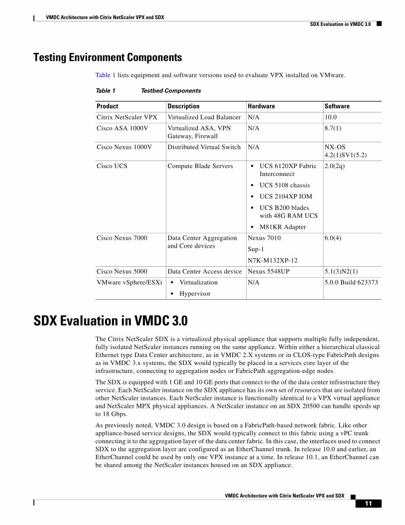
Testing Environment ComponentsTable 1 lists equipment and software versions used to evaluate VPX installed on VMware.
SDX Evaluation in VMDC 3.0The Citrix NetScaler SDX is a virtualized physical appliance that supports multiple fully independent, fully isolated NetScaler instances running on the same appliance. Within either a hierarchical classical Ethernet type Data Center architecture, as in VMDC 2.X systems or in CLOS-type FabricPath designs as in VMDC 3.x systems, the SDX would typically be placed in a services core layer of the infrastructure, connecting to aggregation nodes or FabricPath aggregation-edge nodes.
The SDX is equipped with 1 GE and 10 GE ports that connect to the of the data center infrastructure they service. Each NetScaler instance on the SDX appliance has its own set of resources that are isolated from other NetScaler instances. Each NetScaler instance is functionally identical to a VPX virtual appliance and NetScaler MPX physical appliances. A NetScaler instance on an SDX 20500 can handle speeds up to 18 Gbps.
As previously noted, VMDC 3.0 design is based on a FabricPath-based network fabric. Like other appliance-based service designs, the SDX would typically connect to this fabric using a vPC trunk connecting it to the aggregation layer of the data center fabric. In this case, the interfaces used to connect SDX to the aggregation layer are configured as an EtherChannel trunk. In release 10.0 and earlier, an EtherChannel could be used by only one VPX instance at a time. In release 10.1, an EtherChannel can be shared among the NetScaler instances housed on an SDX appliance.
Table 1 Testbed Components
Product Description Hardware Software
Citrix NetScaler VPX Virtualized Load Balancer N/A 10.0
Cisco ASA 1000V Virtualized ASA, VPN Gateway, Firewall
N/A 8.7(1)
Cisco Nexus 1000V Distributed Virtual Switch N/A NX-OS4.2(1)SV1(5.2)
Cisco UCS Compute Blade Servers • UCS 6120XP Fabric Interconnect
• UCS 5108 chassis
• UCS 2104XP IOM
• UCS B200 blades with 48G RAM UCS
• M81KR Adapter
2.0(2q)
Cisco Nexus 7000 Data Center Aggregation and Core devices
Nexus 7010
Sup-1
N7K-M132XP-12
6.0(4)
Cisco Nexus 5000 Data Center Access device Nexus 5548UP 5.1(3)N2(1)
VMware vSphere/ESXi • Virtualization
• Hypervisor
N/A 5.0.0 Build 623373
11VMDC Architecture with Citrix NetScaler VPX and SDX

VMDC Architecture with Citrix NetScaler VPX and SDXSDX Evaluation in VMDC 3.0
Figure 6 SDX Network Topology in VMDC 3.0
The installation process involves bringing up the SDX appliance fully, then bringing up the NetScaler instances. Licensing is different from the VPX on VMware in that a license is needed for the SDX appliance, not the VPX instances. For more information on SDX installation, refer to:
http://support.citrix.com/proddocs/topic/netscaler-getting-started-map-10/ns-instpk-install-ns-wrapper.html
Evaluation Topology and MethodologyThis component of the evaluation how SDX can be used in VMDC 3.0, including failure convergence scenarios. The following features were tested:
• High Availability
• VMAC
• Layer 4 SLB and ACL
• Syslog
• DSCP Marking Preservation
• Convergence Results
Convergence testing were also done. In cases in which traffic generation was needed, IXIA was used.
High Availability
High Availability (HA) for ACE involves an active/active partnership between two appliances. Each context is active on one appliance and standby on the other.
With the NetScaler SDX, the HA relationship exists only between two different NetScaler instances. To decrease the chances of losing both NetScaler instances, we recommend placing the HA pair on different SDX chassis.
12VMDC Architecture with Citrix NetScaler VPX and SDX
VMDC Architecture with Citrix NetScaler VPX and SDXSDX Evaluation in VMDC 3.0
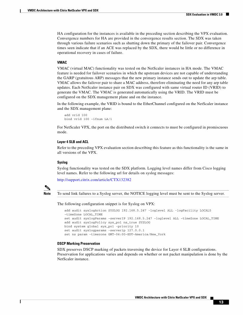
HA configuration for the instances is available in the preceding section describing the VPX evaluation. Convergence numbers for HA are provided in the convergence results section. The SDX was taken through various failure scenarios such as shutting down the primary of the failover pair. Convergence times seen indicate that if an ACE was replaced by the SDX, there would be little or no difference in operational recovery in cases of failure.
VMAC
VMAC (virtual MAC) functionality was tested on the NetScaler instances in HA mode. The VMAC feature is needed for failover scenarios in which the upstream devices are not capable of understanding the GARP (gratuitous ARP) messages that the new primary instance sends out to update the arp table. VMAC allows the failover pair to share a MAC address, therefore eliminating the need for any arp table updates. Each NetScaler instance pair on SDX was configured with same virtual router ID (VRID) to generate the VMAC. The VMAC is generated automatically using the VRID. The VRID must be configured on the SDX management plane and on the instance.
In the following example, the VRID is bound to the EtherChannel configured on the NetScaler instance and the SDX management plane:
add vrid 100bind vrid 100 -ifnum LA/1
For NetScaler VPX, the port on the distributed switch it connects to must be configured in promiscuous mode.
Layer 4 SLB and ACL
Refer to the preceding VPX evaluation section describing this feature as this functionality is the same in all versions of the VPX.
Syslog
Syslog functionality was tested on the SDX platform. Logging level names differ from Cisco logging level names. Refer to the following url for details on syslog messages:
http://support.citrix.com/article/CTX132382
Note To send link failures to a Syslog server, the NOTICE logging level must be sent to the Syslog server.
The following configuration snippet is for Syslog on VPX:
add audit syslogAction SYSLOG 192.168.5.247 -loglevel ALL -logFacility LOCAL5 -timeZone LOCAL_TIMEset audit syslogParams -serverIP 192.168.5.247 -loglevel ALL -timeZone LOCAL_TIMEadd audit syslogPolicy sys_pol ns_true SYSLOGbind system global sys_pol -priority 10set audit syslogparams -serverip 127.0.0.1set ns param -timezone GMT-04:00-EDT-America/New_York
DSCP Marking Preservation
SDX preserves DSCP marking of packets traversing the device for Layer 4 SLB configurations. Preservation for applications varies and depends on whether or not packet manipulation is done by the NetScaler instance.
13VMDC Architecture with Citrix NetScaler VPX and SDX
VMDC Architecture with Citrix NetScaler VPX and SDXSDX Evaluation in VMDC 3.0
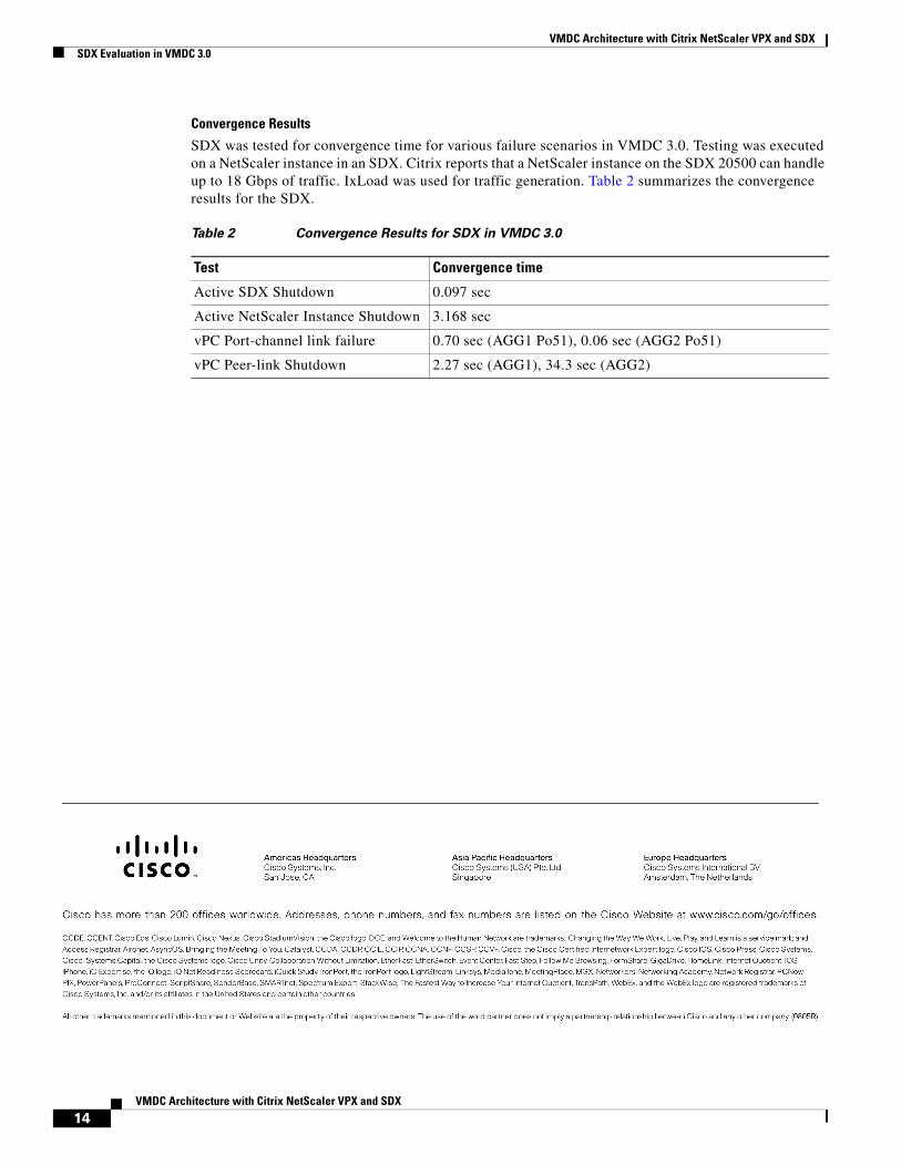
Convergence Results
SDX was tested for convergence time for various failure scenarios in VMDC 3.0. Testing was executed on a NetScaler instance in an SDX. Citrix reports that a NetScaler instance on the SDX 20500 can handle up to 18 Gbps of traffic. IxLoad was used for traffic generation. Table 2 summarizes the convergence results for the SDX.
Table 2 Convergence Results for SDX in VMDC 3.0
Test Convergence time
Active SDX Shutdown 0.097 sec
Active NetScaler Instance Shutdown 3.168 sec
vPC Port-channel link failure 0.70 sec (AGG1 Po51), 0.06 sec (AGG2 Po51)
vPC Peer-link Shutdown 2.27 sec (AGG1), 34.3 sec (AGG2)
14VMDC Architecture with Citrix NetScaler VPX and SDX