vmm-4sny compact video and audio monitoring unit for sony
TRANSCRIPT

VMM-4SNY Compact Video and AudioMonitoring Module for Sony® Monitors
Installation and Operation Manual
Rev. —Part Number 062004

VMM-4SNYCompact Video and Audio Monitoring Module for Sony Monitors
Installation and Operation Manual
Rev. — February 2010

Copyright InformationCopyright © 2010 Harris Corporation, 1025 West NASA Boulevard, Melbourne,Florida 32919-0001 U.S.A. All rights reserved. This publication supersedes allprevious releases. Printed in Canada.
This product and related documentation are protected by copyright and aredistributed under licenses restricting their use, copying, distribution, anddecompilation. No part of this product or related documentation may bereproduced in any form by any means without prior written authorization of HarrisCorporation and its licensors, if any.
This publication could include technical inaccuracies or typographical errors.Changes are periodically added to the information herein; these changes will beincorporated into new editions of the publication. Harris Corporation may makeimprovements and/or changes in the product(s) and/or the program(s) described inthis publication at any time.
Warranty InformationThe limited warranty policy provides a complete description of your warrantycoverage, limitations, and exclusions, as well as procedures for obtaining warrantyservice. To view the complete warranty, visit our Harris Broadcast support webportal.

iii
Copyright © 2010, Harris Corporation
Contents
About This ManualIntended Audience .............................................................................................ixFinding Specific Information in This Guide ..........................................................ixManual Information ............................................................................................x
Revision History ............................................................................................xWriting Conventions ...................................................................................xiObtaining Documents .................................................................................xi
Unpacking/Shipping Information ........................................................................xiUnpacking a Product ...................................................................................xiProduct Servicing ........................................................................................ xiiReturning a Product ................................................................................... xii
Operator’s Safety Summary ............................................................................... xiiEnsuring Safety .......................................................................................... xiiExplanation of Symbols ............................................................................. xiiiCertification Labels and Symbol Locations ................................................. xiv
Directives and Compliances .............................................................................. xivRestriction on Hazardous Substances (RoHS) Directive ............................... xivWaste from Electrical and Electronic Equipment(WEEE) Directive ......................................................................................... xv
IntroductionMain Features .................................................................................................... 2Standard Features ............................................................................................... 2Ordering Information .......................................................................................... 3Video Formats Supported ................................................................................... 4Web RCU Control Panel and Back Panel.............................................................. 6Service and Support ........................................................................................... 7
InstallationInspecting the Shipment .................................................................................... 9Setting Sony Option Board Emulation Mode ...................................................... 9Installing a VMM-4SNY Module into a Sony Monitor ........................................ 12Connecting a VMM-4SNY ................................................................................ 12

Contentsiv
Copyright © 2010, Harris Corporation
Using the IP Configuration Utility ..................................................................... 13Installing the Utility .................................................................................... 13Using the Utility ......................................................................................... 21
VMM-4SNY Flash Update ................................................................................. 22Update Procedure ..................................................................................... 22Update Verification Procedure ................................................................... 23Web RCU Troubleshooting ........................................................................ 23
Installing Software Option VMM-H23GBF (3G-SDI) .......................................... 24
General InformationTerms ............................................................................................................... 27Types of Controllers .......................................................................................... 27Sony Monitor- Based Controls........................................................................... 28
Web-Based Panel Controls ........................................................................ 29Sleep Mode ............................................................................................... 32Selecting an Input ..................................................................................... 32
Display Selections.............................................................................................. 33Full Screen and Quad Displays ................................................................... 33Overlay Display .......................................................................................... 34Main Title Bar ............................................................................................ 36Icons ......................................................................................................... 36Status Bar .................................................................................................. 36
Selecting an Internal or External Reference........................................................ 36Selecting a Function.......................................................................................... 36Accessing and Navigating the Setup Menu........................................................ 37Capturing a Display........................................................................................... 37
Storing a Captured Display ........................................................................ 37Recalling a Captured Display ..................................................................... 37Clearing a Captured Display ...................................................................... 38
OperationWaveform Display ............................................................................................ 39
Waveform Panel Selections ........................................................................ 43Waveform Setup Menu ............................................................................. 46
Vector Display .................................................................................................. 46Vector Display Selections ........................................................................... 52
Gamut Display ................................................................................................. 54Composite Gamut ..................................................................................... 56RGB Gamut Display ................................................................................... 58Placing the Gamut Display in Line Select Mode .......................................... 59Gamut Setup Menu ................................................................................... 60
Picture Display ................................................................................................. 60Placing the Picture in Line Select Mode ...................................................... 61Picture Setup Menu ................................................................................... 62
PIP Display ....................................................................................................... 62

VMM-4SNYInstallation and Operation Manual
v
Copyright © 2010, Harris Corporation
Moving a PIP ............................................................................................. 63Scaling a PIP .............................................................................................. 63Removing a PIP .......................................................................................... 63
Audio Display ................................................................................................... 63Audio Scales .............................................................................................. 64Vertical Audio Displays .............................................................................. 65Expanding the Audio Display ..................................................................... 74
Alarm Display ................................................................................................... 74Alarm Log Display ..................................................................................... 75Alarm Status Display .................................................................................. 76
Timing Display ................................................................................................. 78SDI Input and External Reference Formats Supported ................................. 80Things to Remember When Using the Timing Display ................................ 81Timing Setup Menu ................................................................................... 81
Preset Display Selections .................................................................................. 82Selecting Presets ........................................................................................ 82Storing Presets .......................................................................................... 82Recalling Presets ........................................................................................ 82
Global Setup Menu FunctionsSetup Menus and Alarm Tables ........................................................................ 84Video Setup Menu Selections ........................................................................... 94Audio Mapping Setup Menu Selections ............................................................ 95Time Code Source Setup Menu Selections ........................................................ 96Waveform Setup Menu Selections .................................................................... 96Vector Setup Menu Selections .......................................................................... 97Gamut Setup Menu Selections ......................................................................... 98Picture Setup Menu Selections ......................................................................... 99Audio Setup Menu Selections ........................................................................ 100Timing Setup Menu Selections ....................................................................... 102MLT Setup Menu Selections ........................................................................... 102Alarms Setup Menu Selections ....................................................................... 103Clear Setup Menu Selections .......................................................................... 103Unit Configuration Display Setup Selections ................................................... 104About Display Screen ..................................................................................... 106
Alarm DescriptionsSetting VMM-4SNY Alarms ............................................................................ 107Alarm Setup Menus ....................................................................................... 107Video Alarms Setup Descriptions .................................................................... 113Audio Alarms Setup Descriptions ................................................................... 114Time Code Alarms Setup Descriptions ............................................................ 115GPI Alarms ..................................................................................................... 116Alarm Log ...................................................................................................... 116Alarm Status .................................................................................................. 116

Contentsvi
Copyright © 2010, Harris Corporation
External ControlBrowser Interface .......................................................................................... 117
Accessing the Web-Based Control Panel .................................................. 118Accessing the Index of Captures .............................................................. 118Managing User Accounts ........................................................................ 118
TroubleshootingInitial Checks ................................................................................................. 121Restarting a Unit ............................................................................................ 121Problems, Causes, and Solutions .................................................................... 122
SpecificationsInputs ............................................................................................................ 125Outputs ......................................................................................................... 127Audio Monitoring .......................................................................................... 127Control .......................................................................................................... 127Display ........................................................................................................... 127Time Code ..................................................................................................... 128Gamut Display ............................................................................................... 128Magnification ................................................................................................ 129Communication Interfaces ............................................................................. 129Power Consumption ...................................................................................... 130Mechanical Specifications .............................................................................. 130Environmental Specifications .......................................................................... 130Accessories and Options ................................................................................ 131
Appendix: PinoutsEthernet Connectors ...................................................................................... 133LTC/GPIO Connectors .................................................................................... 134
Appendix: Open Source Software CopyrightInformationFreeType License ............................................................................................ 135LibJPEG License .............................................................................................. 135CMU/UCD Copyright Notice .......................................................................... 135Networks Associates Technology, Inc. Copyright Notice (BSD) ........................ 136Cambridge Broadband Ltd. Copyright Notice (BSD) ........................................ 136Sun Microsystems, Inc. Copyright Notice (BSD) ............................................... 137Sparta, Inc. Copyright Notice (BSD) ................................................................ 138Cisco/BUPTNIC Copyright Notice (BSD) ........................................................... 138Fabasoft R&D Software GmbH & Co. KG Copyright Notice (BSD) ................... 139The GNU v2 License ....................................................................................... 140

VMM-4SNYInstallation and Operation Manual
vii
Copyright © 2010, Harris Corporation
GNU General Public License ..................................................................... 140Preamble ................................................................................................. 140GNU General Public License ..................................................................... 141No Warranty ........................................................................................... 144
GNU Lesser Public License .............................................................................. 145GNU Lesser General Public License .......................................................... 145Preamble ................................................................................................. 145GNU Lesser General Public License .......................................................... 147No Warranty ........................................................................................... 152
Appendix: GlossaryTerms ............................................................................................................ 153
IndexKeywords ....................................................................................................... 167

Contentsviii
Copyright © 2010, Harris Corporation
ix
Copyright © 2010, Harris Corporation
About This Manual
This manual details the features, installation procedures, operational procedures,and specifications of the VMM-4SNY compact video and audio monitoring modulefor Sony monitors.
About This Manual provides an overview of this installation and operationmanual, describes manual conventions, and tells you where to look for specificinformation. This section also gives you important information on unpacking andshipping your product.
IntendedAudience
This manual is written for engineers, technicians, and operators responsible for theinstallation, setup, and/or operation of the VMM-4SNY compact video and audiomonitoring module.
FindingSpecific
Informationin This Guide
Table P-1 shows the location of specific information in this guide.
Table P-1 Finding Specific Information in this Guide
If you are looking for Go to
Alarms Page 107 through Page 116
Back panel illustrations Page 6, Page 12
Connections Page 12
Controller types Page 27
Controls Page 28
Display types Page 39 through Page 82
External control Page 117
Features Page 2
Flash updates Page 22

About This Manualx
Copyright © 2010, Harris Corporation
ManualInformation
This section provides information about the revision history of the manual, writingconventions used for ease of understanding as well as for navigation throughoutthe document, and information about obtaining other product manuals.
Revision History
Web RCU illustrations Page 6, Page 30
Installing a module Page 12
Operation Page 39
Pinouts Page 133 through Page 134
Service and support Page 7
Setting Board Emulation mode Page 9
Setup menu Page 37
Setup menu functions Page 83 through Page 106
Specifications Page 125 through Page 132
Troubleshooting Page 121
Using the IP configuration utility Page 12
Video formats supported Page 4
VMM-H23GBF (3G-SDI upgrade) Page 3, Page 24
Table P-1 Finding Specific Information in this Guide (Continued)
If you are looking for Go to
Table P-2 Manual Revision History
Edition Date Revision History
— February 2010 Initial release
VMM-4SNYInstallation and Operation Manual
xi
Copyright © 2010, Harris Corporation
WritingConventions
To enhance your understanding, the authors of this manual have adhered to thefollowing text conventions:
ObtainingDocuments
Technical documents can be viewed or downloaded from our website.Alternatively, contact your Customer Service representative to request a document.
Unpacking/Shipping
Information
This product was carefully inspected, tested, and calibrated before shipment toensure years of stable and trouble free service.
Unpacking aProduct
1 Check equipment for any visible damage that may have occurred duringtransit.
2 Confirm that you have received all items listed on the packing list.
3 Contact your dealer if any item on the packing list is missing.
4 Contact the carrier if any item is damaged.
5 Remove all packaging material from the product and its associatedcomponents before you install the unit.
Table P-3 Manual Style and Writing Conventions
Term orConvention Description
Bold Indicates dialog boxes, property sheets, fields,buttons, check boxes, list boxes, combo boxes,menus, submenus, windows, lists, and selectionnames
Italics Indicates email addresses, the names of books orpublications, and the first instances of new termsand specialized words that need emphasis
CAPS Indicates a specific key on the keyboard, such asENTER, TAB, CTRL, ALT, or DELETE
Code Indicates variables or command-line entries, such asa DOS entry or something you type into a field
> Indicates the direction of navigation through ahierarchy of menus and windows
hyperlink Indicates a jump to another location within theelectronic document or elsewhere
Internet address Indicates a jump to a website or URL
NOTE: Indicates important information that helps to avoidand troubleshoot problems

About This Manualxii
Copyright © 2010, Harris Corporation
Product Servicing VMM-4SNY modules are not designed for field servicing. All hardware upgrades,modifications, or repairs require you to return the modules to the Customer Servicecenter. For more information see Service and Support on page 7.
Returning aProduct
In the unlikely event that your product fails to operate properly, please contactCustomer Service to obtain a Return Authorization (RA) number, and then sendthe unit back for servicing.
Keep at least one set of original packaging, in the event that you need to return aproduct for servicing. If the original packaging is not available, you can purchasereplacement packaging at a modest cost or supply your own packaging as long asit meets the following criteria:
Withstands the weight of the product
Holds the product rigid within the packaging
Leaves at least two inches of space between the product and the container
Protects the corners of the product
Ship products back to us for servicing prepaid and, if possible, in the originalpackaging material. If the product is still within the warranty period, we will returnthe product prepaid after servicing. For more information see Service andSupport on page 7.
Operator’sSafety
Summary
WARNING: These instructions are for use by qualified personnelonly. To reduce the risk of electric shock, do not perform thisinstallation or any servicing unless you are qualified to do so. Referall servicing to qualified service personnel.
Ensuring Safety The unit should not be exposed to dripping or splashing, and no objects filledwith liquids, such as vases, shall be placed on the unit.
When the unit is to be permanently cabled, connect the protective groundconductor before making any other connections.
Operate built in units only when they are properly fitted into the system.
For permanently cabled units without built in fuses, automatic switches, orsimilar protective facilities, the AC supply line must be fitted with fuses ratedto the units.
Before switching on the unit, ensure that the operating voltage set at the unitmatches the line voltage, if appropriate. If a different operating voltage is to beset, use a fuse with the appropriate rating. Refer to the InstallationInstructions.
Units of Protection Class I with an AC supply cable and plug that can bedisconnected must be operated only from a power socket with protectiveground contact:

VMM-4SNYInstallation and Operation Manual
xiii
Copyright © 2010, Harris Corporation
Do not use an extension cable-it can render the protective groundconnection ineffective.
Do not intentionally interrupt the protective ground conductor.
Do not break the protective ground conductor inside or outside the unit orloosen the protective ground connection; such actions can cause the unitto become electrically hazardous.
Before opening the unit, isolate it from the AC supply. Then ensure that
Adjustments, part replacements, maintenance, and repairs are carried outby qualified personnel only.
Safety regulations and rules are observed to prevent accidents.
Only original parts are used to replace parts relevant to safety (forexample, the power on/off switches, power transformers, and fuses).
Replaceable fuses can be hazardous when live. Before replacing a fuse,disconnect the AC power source.
Use caution when cleaning the equipment; isopropyl alcohol or similarsolvents can damage or remove the labels.
Observe any additional safety instructions specified in this manual.
Explanation ofSymbols
These symbols may appear on Harris equipment:
Figure P-1 Safety Symbols Appearing on Harris Equipment
About This Manualxiv
Copyright © 2010, Harris Corporation
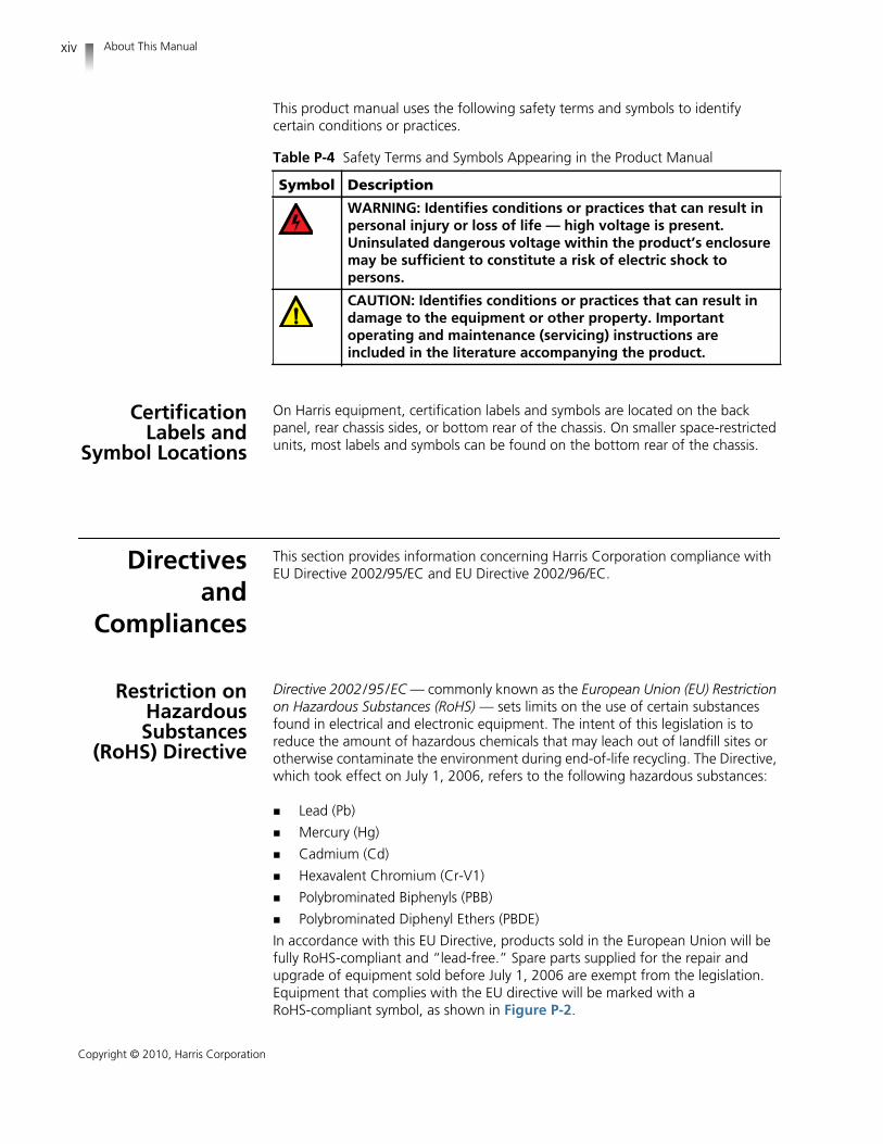
This product manual uses the following safety terms and symbols to identifycertain conditions or practices.
CertificationLabels and
Symbol Locations
On Harris equipment, certification labels and symbols are located on the backpanel, rear chassis sides, or bottom rear of the chassis. On smaller space-restrictedunits, most labels and symbols can be found on the bottom rear of the chassis.
Directivesand
Compliances
This section provides information concerning Harris Corporation compliance withEU Directive 2002/95/EC and EU Directive 2002/96/EC.
Restriction onHazardousSubstances
(RoHS) Directive
Directive 2002/95/EC — commonly known as the European Union (EU) Restrictionon Hazardous Substances (RoHS) — sets limits on the use of certain substancesfound in electrical and electronic equipment. The intent of this legislation is toreduce the amount of hazardous chemicals that may leach out of landfill sites orotherwise contaminate the environment during end-of-life recycling. The Directive,which took effect on July 1, 2006, refers to the following hazardous substances:
Lead (Pb)
Mercury (Hg)
Cadmium (Cd)
Hexavalent Chromium (Cr-V1)
Polybrominated Biphenyls (PBB)
Polybrominated Diphenyl Ethers (PBDE)
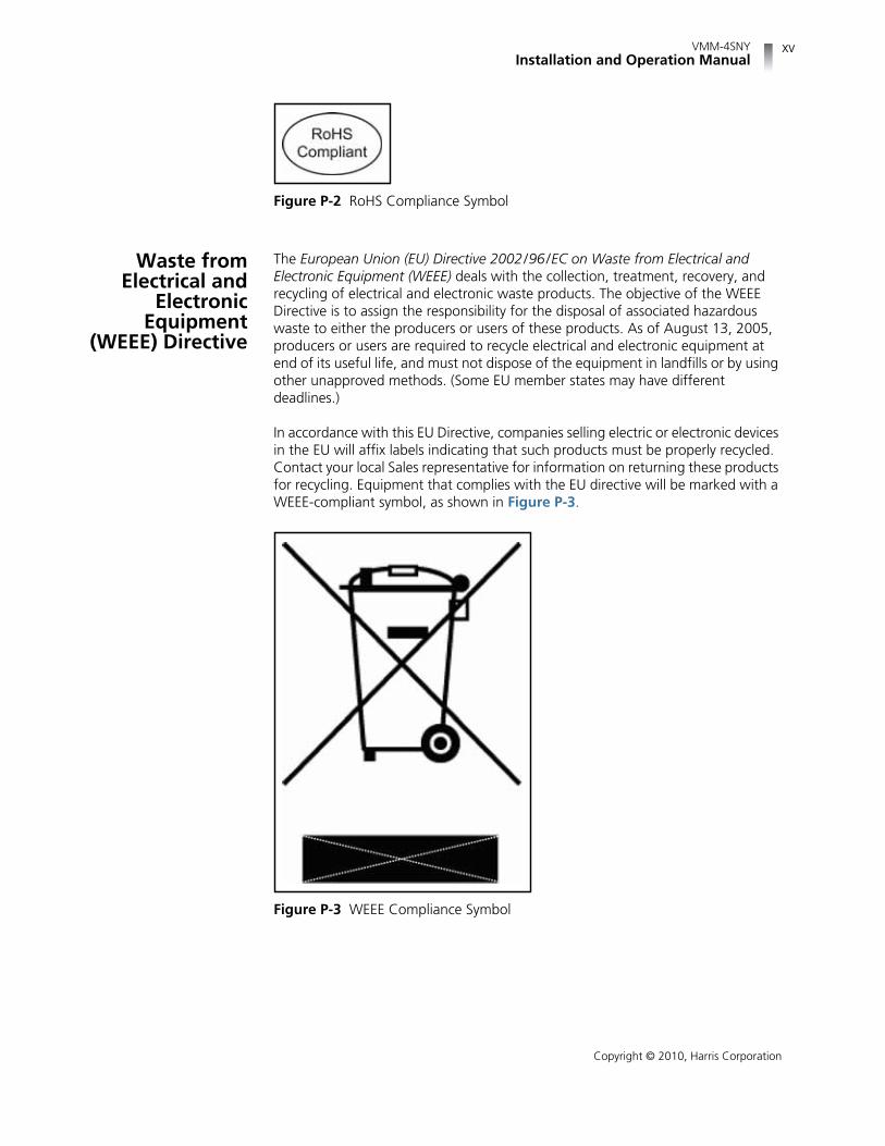
In accordance with this EU Directive, products sold in the European Union will befully RoHS-compliant and “lead-free.” Spare parts supplied for the repair andupgrade of equipment sold before July 1, 2006 are exempt from the legislation.Equipment that complies with the EU directive will be marked with aRoHS-compliant symbol, as shown in Figure P-2.
Table P-4 Safety Terms and Symbols Appearing in the Product Manual
Symbol Description
WARNING: Identifies conditions or practices that can result inpersonal injury or loss of life — high voltage is present.Uninsulated dangerous voltage within the product’s enclosuremay be sufficient to constitute a risk of electric shock topersons.
CAUTION: Identifies conditions or practices that can result indamage to the equipment or other property. Importantoperating and maintenance (servicing) instructions areincluded in the literature accompanying the product.
VMM-4SNYInstallation and Operation Manual
xv
Copyright © 2010, Harris Corporation
Figure P-2 RoHS Compliance Symbol
Waste fromElectrical and
ElectronicEquipment
(WEEE) Directive
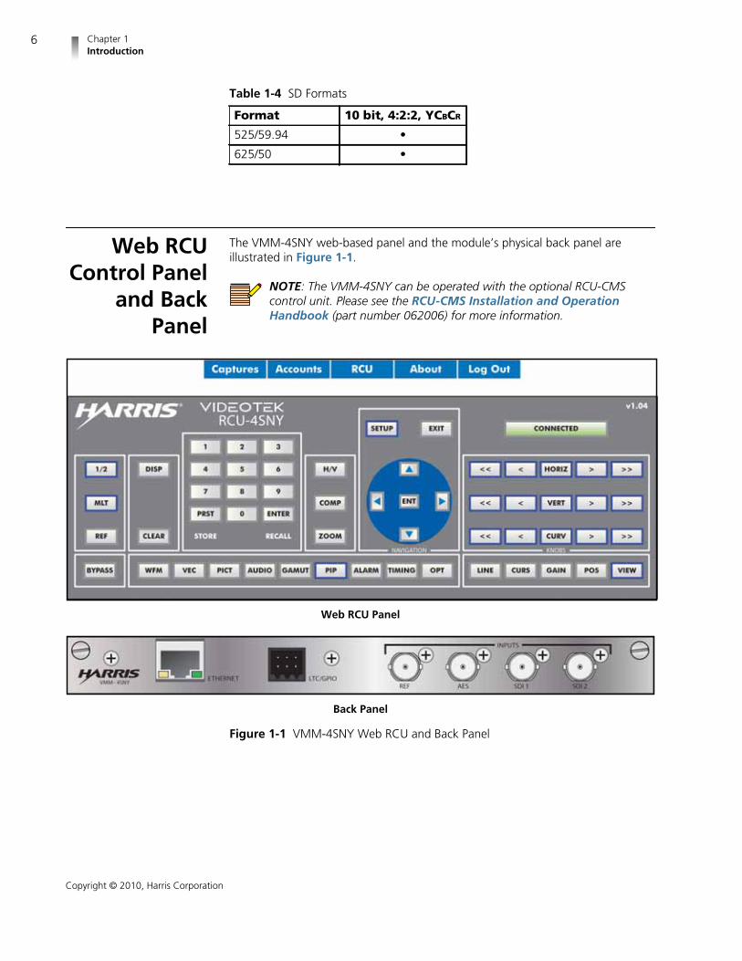
The European Union (EU) Directive 2002/96/EC on Waste from Electrical andElectronic Equipment (WEEE) deals with the collection, treatment, recovery, andrecycling of electrical and electronic waste products. The objective of the WEEEDirective is to assign the responsibility for the disposal of associated hazardouswaste to either the producers or users of these products. As of August 13, 2005,producers or users are required to recycle electrical and electronic equipment atend of its useful life, and must not dispose of the equipment in landfills or by usingother unapproved methods. (Some EU member states may have differentdeadlines.)
In accordance with this EU Directive, companies selling electric or electronic devicesin the EU will affix labels indicating that such products must be properly recycled.Contact your local Sales representative for information on returning these productsfor recycling. Equipment that complies with the EU directive will be marked with aWEEE-compliant symbol, as shown in Figure P-3.
Figure P-3 WEEE Compliance Symbol

About This Manualxvi
Copyright © 2010, Harris Corporation

1
Copyright © 2010, Harris Corporation
1 Introduction
The Harris VMM-4SNY compact video and audio monitoring module is the mostadvanced, versatile, and intuitive monitoring instrument available today. TheVMM-4SNY is available for HD-SDI/SD-SDI (which can be upgraded to 3G-SDIcapability). With 100% digital signal processing technology, the VMM-4SNYprovides an accurate and stable user customizable display of waveform, vector,gamut, audio, picture, relative timing, and alarm status functions in full-screen andmultiple view displays. Quick setup and parameter changes are possible with directaccess to display functions and screen location, 99 presets, context-sensitiveshortcut menus, and an intuitive navigation system.
The VMM-4SNY is a new concept in monitoring for video and audio sources. Thismodule fits into various Sony® monitors, and provides a direct connection formonitoring video and audio sources. The unit provides waveform, vector, gamut,timing, picture, alarms, or audio in a quad display; or individually, as a full screendisplay. The full screen picture is available in Bypass mode. The module alsoprovides a scalable waveform, vector, and picture display.
The VMM-4SNY module fits into the following Sony LCD monitors:
LMD-2450W
LMD-2050W
LMD-1750W
LMD-4250W
LMD-2451W
BVM-L170
PVM-L2300
BVM-L230
The audio output is connected to the monitor’s internal speakers (when available)with no external connections. Functional control is through a standard Ethernetconnection via a web browser or via an optional remote control unit (RCU-CMS).

Chapter 1Introduction
2
Copyright © 2010, Harris Corporation
MainFeatures
Test and measurement incorporated into a module for an existing professionalmonitor, including internal audio (internal speakers in the monitor are requiredand available only in certain Sony models) and video connections to themonitor
Cost effective alternative to the test and measurement equipment in separaterack mount units
HD/SD SDI capabilities with upgrade to 3G-SDI
Web interface for control or remote control unit RCU-CMS is available
Meter all 16 channels of embedded audio
Two terminating SDI inputs
One AES audio input
Multi-display (MLT) Overlay mode with independent size and position ofwaveform, vector and picture
Selectable quad or full-screen display of picture, waveform, vector, gamut,timing, picture, alarms and audio
Powered by the monitor; no external power supply
99 presets
The VMM-4SNY seamlessly integrates into any broadcast, post-production, cameramaintenance, satellite or cable facility; and is the ultimate choice for qualitycontrol, troubleshooting, or compliance checking applications.
StandardFeatures
Fits into the following Sony LCD monitors:
LMD-2450W
LMD-2050W
LMD-1750W
LMD-4250W
LMD-2451W
BVM-L170
PVM-L2300
BVM-L230
Two terminating 3G-SDI/HD-SDI/SD-SDI video inputs with auto detection(version dependent)
One AES input
Terminating external reference to support blackburst and tri-level sync
5x oversampling for enhanced audio True Peak detection
All AES and embedded audio inputs are sample rate converted to 48 kHz
Twelve-button numeric keypad on Web RCU and on optional remote controlunit (RCU-CMS)

VMM-4SNYInstallation and Operation Manual
3
Copyright © 2010, Harris Corporation
Audio monitoring through monitor’s speakers (when available)
Customizable function display screen location, multiple displays via overlayand quad display
Alarms with Peak Level Report
1280×720 high resolution output through monitor’s internal port
Patented Video Relative Timing display
Patented Gamut display
99 user presets
Illuminated controls and indicators on Web interface or optional remotecontrol unit (RCU-CMS)
Ethernet
Applicable standards: SMPTE 125M-1995, SMPTE 259M-1997, SMPTE274M-2005, SMPTE 276M, SMPTE 292M-1998, SMPTE 296M-2001, SMPTE352M-2002, SMPTE 424M-2006, SMPTE 425M-2006, SMPTE RP 178-2004,SMPTE RP 198-1998, SMPTE RP 219-2002
OrderingInformation
VMM-4SNY: The VMM-4SNY video and audio monitoring module for Sonymonitors supports HD-SDI and SD-SDI input formats, up to 16 channels ofembedded audio, and 1 AES audio input. The VMM-4SNY supports externalreference of black burst or tri-level sync. The 720p 60 Hz internal output issupported by several Sony LCD monitors including the LMD2450W,LMD-2050W, LMD 4250W, LMD 2451W, BVM L170, PVM L2300 andBVM-L230.
VMM-4SNY-3GB: The VMM-4SNY-3GB video and audio monitoring modulefor Sony monitor supports 3G-SDI, HD-SDI, and SD-SDI input formats; up to16 channels of embedded audio; and 1 AES audio input. The VMM-4SNY-3GBsupports external reference of black burst or tri-level sync. The 720p 60 Hzinternal output is supported by several Sony LCD monitors, including theLMD2450W, LMD-2050W, LMD 4250W, LMD 2451W, BVM L170, PVM L2300and BVM-L230.
VMM-H23GBF: The VMM-H23GBF is a field upgrade for 3G-SDI option. (Thisis a software upgrade that enables the 3G-SDI input formats.)
RCU-CMS: The RCU-CMS is the remote control unit option. It provides theremote control panel for desk top applications, including Ethernet connectionsoftware for setup of the RCU and IP addresses of connected units. TheRCU-CMS provides connections for up to 32 independent units.
PTC-4: The PTC-4 is a portable case with tilt stand for RCU-CMS desk topapplication.
DRT-4: The DRT-4 is a double rack mount tray for RCU-CMS and CMN-41 (useBLK-4 to fill unused space if needed).

Chapter 1Introduction
4
Copyright © 2010, Harris Corporation
VideoFormats
Supported
Table 1-1 through Table 1-4 provide information about the VMM-4SNYsupported video formats.
Video will not display correctly in Bypass mode if its format is notsupported by your Sony monitor. Consult your monitor's user guide forsupported video formats.
Table 1-1 Options and Supported Video Formats• = Supported Standards and Formats
Video Formats VMM-4SNY VMM-4SNY-3GB
DVB-ASI and SMPTE-310
Analog Composite
SD-SDI • •
HD-SDI • •
3G-SDI •
Table 1-2 3G-SDI Formats
Format10 bit4:2:2YCBCR
10 bit4:4:4YCBCR
10 bit4:4:4:4YCBCR +A
10 bit4:4:4RGB
10 bit4:4:4:4RGB+A
12 bit4:2:2YCBCR
12 bit4:4:4YCBCR
12 bit4:4:4RGB
1080i
1080i/60 • • • • • • •
1080i/59.94 • • • • • • •
1080i/50 • • • • • • •
1080p
1080p/60 •
1080p/59.94 •
1080p/50 •
1080p/30 • • • • • • •
1080p/29.97 • • • • • • •
1080p/25 • • • • • • •
1080p/24 • • • • • • •
1080p/23.98 • • • • • • •
1080psF/30 • • • • • • •
1080psF/29.97 • • • • • • •
1080psF/25 • • • • • • •
1080psF/24 • • • • • • •
1080psF/23.98 • • • • • • •
720p
720p/60 • • • •
720p/59.94 • • • •
720p/50 • • • •

VMM-4SNYInstallation and Operation Manual
5
Copyright © 2010, Harris Corporation
NOTE: Both Level A and Level B 3G-SDI formats are supported. When a3G-SDI Level A signal is detected, the standard is shown with the letter “A”appended to the format (1080p/59.94 A). When a 3G-SDI Level B signal isdetected, the standard is shown with the letter “B” appended to theformat (1080p/59.94 B).
720p/30 • • • •
720p/29.97 • • • •
720p/24 • • • •
720p/23.98 • • • •
Table 1-2 3G-SDI Formats (Continued)
Format10 bit4:2:2YCBCR
10 bit4:4:4YCBCR
10 bit4:4:4:4YCBCR +A
10 bit4:4:4RGB
10 bit4:4:4:4RGB+A
12 bit4:2:2YCBCR
12 bit4:4:4YCBCR
12 bit4:4:4RGB
Table 1-3 HD Formats
Format 10 bit, 4:2:2, YCBCR
1080i
1080I/60 •
1080I/59.94 •
1080I/50 •
1080p
1080P/30 •
1080P/29.97 •
1080P/25 •
1080P/24 •
1080P/23.98 •
720p
720p/60 •
720p/59.94 •
720p/50 •
720p/30 •
720p/29.97 •
720p/24 •
720p/23.98 •
Segmented Frame
1080P/30sF •
1080P/29.97sF •
1080P/25sF •
1080P/24sF •
1080P/23.98sF •
Chapter 1Introduction
6
Copyright © 2010, Harris Corporation
Web RCUControl Panel
and BackPanel
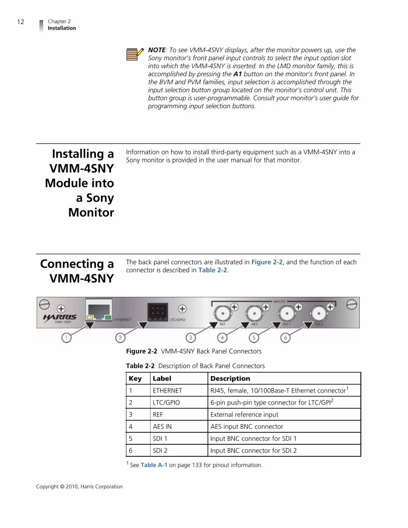
The VMM-4SNY web-based panel and the module’s physical back panel areillustrated in Figure 1-1.
NOTE: The VMM-4SNY can be operated with the optional RCU-CMScontrol unit. Please see the RCU-CMS Installation and OperationHandbook (part number 062006) for more information.
Web RCU Panel
Back Panel
Figure 1-1 VMM-4SNY Web RCU and Back Panel
Table 1-4 SD Formats
Format 10 bit, 4:2:2, YCBCR
525/59.94 •
625/50 •

VMM-4SNYInstallation and Operation Manual
7
Copyright © 2010, Harris Corporation
Service andSupport
For service and support, telephone the Harris Customer Service Department at1-888-534-8246. If the problem cannot be resolved over the telephone and theinstrument must be shipped to Harris for service or repair:
Obtain a Return Authorization (RA) number from the Harris Customer ServiceDepartment.
Attach a tag to the unit with the following information:
Your company name, address, and telephone number
The name of the contact person at your company
The RA number
The unit serial number
An explanation of the problem
To prevent shipping damage, pack the unit the same way Harris had packed it.If possible, use the original packing materials in the original shipping container.
Ship the unit to the following location:
Harris CorporationVideotek Test and Measurement243 Shoemaker RoadPottstown, PA 19464-6433
Attn: RA xxxx (where xxxx is the RA number)
Email: [email protected]

Chapter 1Introduction
8
Copyright © 2010, Harris Corporation

9
Copyright © 2010, Harris Corporation
2 Installation
This section provides information about inspecting, installing, and configuring theVMM-4SNY.
Inspectingthe Shipment
Before installing the VMM-4SNY, inspect the box and the contents. Report anydamage to the shipper, and then telephone the Harris Corporation CustomerService Department (see Service and Support on page 7).
NOTE: Refer to the enclosed packing sheet for the latest list of items thatare supplied with the unit.
The box contains the following:
One VMM-4SNY main unit
One VMM-4SNY Installation and Operation Manual on CD
One push-pin type connector (for LTC/GPI)
Save the box and packing material for any future shipping requirements.
Setting SonyOption Board
EmulationMode
For proper operation in your particular monitor, the Sony option board emulationmode must be set by setting position 4 of DIP switch 2. This is accomplished with athin tool such as a miniature screwdriver though an access hole in metal lid of theunit (see Figure 2-1).

Chapter 2Installation
10
Copyright © 2010, Harris Corporation
NOTE: The unit is shipped from the factory in emulation mode 1 withswitch position 4 set to OFF.
NOTE: Make sure that only switch position 4 is changed during emulationmode selection. The rest of the positions should remain in the default (OFF)state.
Table 2-1 VMM-4SNY Emulation Modes
Monitor EmulationMode Monitor Emulation
Mode
LMD-1750W 1 BVM-L170 2
LMD-2050W 1 BVM-L230 2
LMD-2450W 1 PVM-L2300 2
LMD-4250W 1
LMD-2451W 2

VMM-4SNYInstallation and Operation Manual
11
Copyright © 2010, Harris Corporation
Figure 2-1 Setting Sony Emulation Mode via DIP Switches
The VMM-4SNY module supports two emulation modes named “1” and “2.” SeeTable 2-1 for the correct emulation mode for your monitor. The emulation mode“1” (default) is selected by switching switch to OFF (slider to the left); theemulation mode “2” is selected by switching switch to ON (slider to the right).
Chapter 2Installation
12
Copyright © 2010, Harris Corporation
NOTE: To see VMM-4SNY displays, after the monitor powers up, use theSony monitor’s front panel input controls to select the input option slotinto which the VMM-4SNY is inserted. In the LMD monitor family, this isaccomplished by pressing the A1 button on the monitor’s front panel. Inthe BVM and PVM families, input selection is accomplished through theinput selection button group located on the monitor’s control unit. Thisbutton group is user-programmable. Consult your monitor’s user guide forprogramming input selection buttons.
Installing aVMM-4SNY
Module intoa Sony
Monitor
Information on how to install third-party equipment such as a VMM-4SNY into aSony monitor is provided in the user manual for that monitor.
Connecting aVMM-4SNY
The back panel connectors are illustrated in Figure 2-2, and the function of eachconnector is described in Table 2-2.
Figure 2-2 VMM-4SNY Back Panel Connectors
Table 2-2 Description of Back Panel Connectors
Key Label Description
1 ETHERNET RJ45, female, 10/100Base-T Ethernet connector1
1 See Table A-1 on page 133 for pinout information.
2 LTC/GPIO 6-pin push-pin type connector for LTC/GPI2
3 REF External reference input
4 AES IN AES input BNC connector
5 SDI 1 Input BNC connector for SDI 1
6 SDI 2 Input BNC connector for SDI 2
VMM-4SNYInstallation and Operation Manual
13
Copyright © 2010, Harris Corporation
NOTE: All VMM-4SNY units shipped from the factory are configured with same IPaddress. Connecting multiple units to the same network without changing the IPaddress may result in a network conflict. See Connecting a VMM-4SNY onpage 12 for information on how to configure network parameters of VMM-4SNY.
Using the IPConfigura-tion Utility
The Harris Device IP Configuration Utility is used to set the IP network settings ofyour Harris device(s). This utility is used to set the network settings for theVMM-4SNY and the RCU-CMS. This utility is also used to manage the IP list in theRCU-CMS that directs the RCU connection to the VMM-4SNY and othercompatible Harris products.
Installing theUtility
1 To install the utility, place the CD that came with your device into a drive of thePC.
2 Using Microsoft® Windows® Explorer1, open the DEVIPCONFIG folder, andthen double-click setup.exe.
If your PC does not have the required version of Microsoft .NET Framework,the Preparing to Install dialog box opens, as shown in Figure 2-3. (Note thatwhen .NET has been installed, the installer will automatically go to the nextdialog box.)
2 See Table A-2 on page 134 for pinout information
1 Windows, Windows Explorer, and Internet Explorer are trademarks or registered trade-marks of Microsoft Corporation or its subsidiaries in the United States and other countries.
Chapter 2Installation
14
Copyright © 2010, Harris Corporation
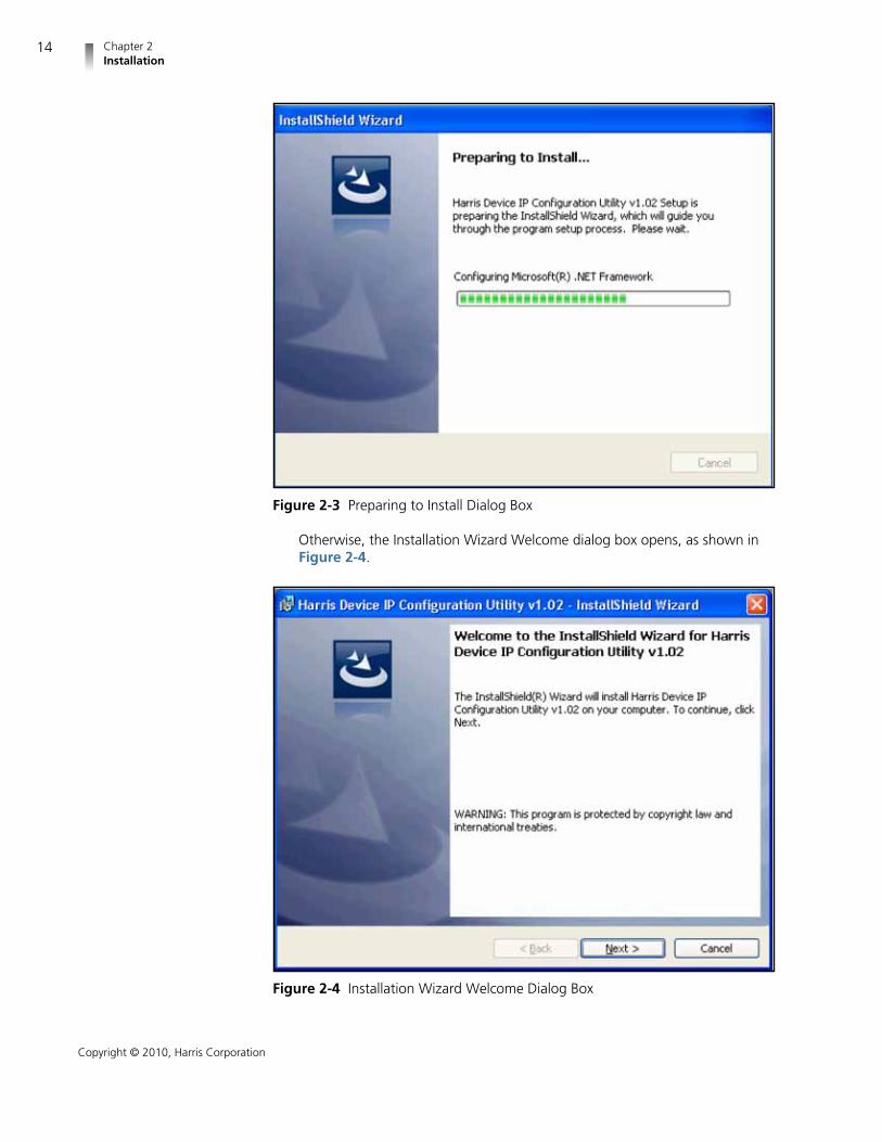
Figure 2-3 Preparing to Install Dialog Box
Otherwise, the Installation Wizard Welcome dialog box opens, as shown inFigure 2-4.
Figure 2-4 Installation Wizard Welcome Dialog Box

VMM-4SNYInstallation and Operation Manual
15
Copyright © 2010, Harris Corporation
3 Click Next.
The Destination Folder dialog box (Figure 2-5) opens.
Figure 2-5 Destination Folder Dialog Box
4 Click Next.
The Ready to Install dialog box (Figure 2-6) opens.

Chapter 2Installation
16
Copyright © 2010, Harris Corporation
Figure 2-6 Ready to Install Dialog Box
5 Click Install.
As part of the installation, WinPcap will be installed on your PC. This allowsthe utility to communicate with your device. The WinPcap installer isself-contained and has its own sequence of installer windows. If WinPcap isalready installed, you will be asked whether you want to install over theexisting installation (see Figure 2-7).
Figure 2-7 Setup Configuration Information Message
Answer Yes unless you are sure the version indicated is installed.
If you answer with Yes or WinPcap is not present on your PC, the WinPcapInstaller Splash Screen dialog box (Figure 2-8) opens.

VMM-4SNYInstallation and Operation Manual
17
Copyright © 2010, Harris Corporation
Figure 2-8 Installer Splash Screen
6 Click Next.
The Setup Welcome dialog box (Figure 2-9) opens.
Figure 2-9 Setup Welcome Dialog Box
Chapter 2Installation
18
Copyright © 2010, Harris Corporation
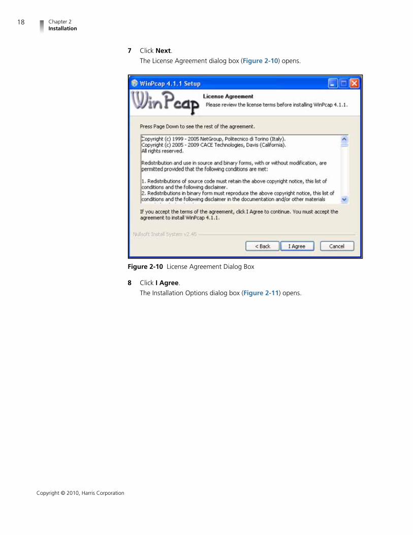
7 Click Next.
The License Agreement dialog box (Figure 2-10) opens.
Figure 2-10 License Agreement Dialog Box
8 Click I Agree.
The Installation Options dialog box (Figure 2-11) opens.

VMM-4SNYInstallation and Operation Manual
19
Copyright © 2010, Harris Corporation
Figure 2-11 Installation Options Dialog Box
Leave the Automatically start the WinPcap driver at boot time optionchecked. This allows the utility to access the driver from any Windows user,even if the user does not have administrative privilege. If you uncheck thisoption, the driver will not be loaded until the utility is run and may not besuccessful if the user does not have administrative privileges.
9 Click Install.
The WinPcap Setup Completion dialog box (Figure 2-12) opens.

Chapter 2Installation
20
Copyright © 2010, Harris Corporation
Figure 2-12 WinPcap Setup Completion Dialog Box
10 Click Finish.
The Installation Completed dialog box (Figure 2-13) opens.
Figure 2-13 Installation Completed Dialog Box

VMM-4SNYInstallation and Operation Manual
21
Copyright © 2010, Harris Corporation
11 Click Finish.
The installation is now complete.
Using the Utility Once installed, the IP configuration utility is ready to use.
1 Locate the Harris Corporation group in the Windows program list.
2 Navigate to the Harris Device IP Configuration Utility group, and thenselect the Launch DevIPConfig.exe shortcut.
The IP configuration utility main dialog box opens:
Figure 2-14 IP Configuration Utility Main Dialog Box
Leave the NIC Adaptor field set to Auto select unless you know whichadaptor in your PC is connected to the Harris device.
3 To establish a connection, the MAC address of your Harris device must beentered in the MAC Address field. Your device’s MAC address is located inthe following places:
In the main title bar
When delivered from the factory and installed inside the monitor, theVMM-4SNY displays the MAC address in the main title bar. Once IPconfiguration has been performed, this behavior can be changed throughthe device’s Unit Configuration Display Setup menu (see page 104 formore information) so it may not be located there when reconfiguring theIP address after the initial installation. However, the MAC address is always

Chapter 2Installation
22
Copyright © 2010, Harris Corporation
displayed in the main title bar for a few seconds after powering up thedevice, regardless of the menu setting.
In the About Display Screen (see page 106 for more information)
This will only be useful if the IP address is already known, since you mustconnect to the device using the Web RCU or RCU-CMS to use the menuto view the About Display Screen.
On a label applied to the top of the device
The first three segments of the MAC address already appear in the MACaddress field. Only the last three segments need to be entered.
4 Click Get (located in the From Device group of the main dialog box).
The utility collects all of the IP configuration information and displays it in theFrom Device group.
5 Click Copy to copy the fields from the From Device group to the To Devicegroup.
NOTE: You can skip steps 4 and 5 if you are going to enter newinformation into the To Device fields. These steps are intended to makechanging existing information easier since data entry can start with theexisting information.
You are now ready to configure the device’s IP information. This informationshould be obtained from your IT group or personnel responsible for your network.It consists of an IP address, a subnet mask, and possibly a gateway. Ensure that theIP address you have obtained is unique and is a static IP address. Enter the IPinformation into the appropriate fields of the To Device group. If a gateway is notneeded, leave the Gateway field blank. When you have entered the IPinformation into the To Device fields, click Set in the To Device group.
Your device’s IP configuration is now set. For more information on how to use theutility, see the on-line help found in the Help > Help menu of the main dialog boxor pressing the keyboard’s F1 key.
VMM-4SNYFlash Update
NOTE: You need a PC with a VFLASH rev 2.3.0.1 installed (see VMM-4SNYdocumentation/supporting software CD) to flash update a VMM-4SNYunit:.
UpdateProcedure
1 Download the current VMM-4SNY firmware contained in thevmm-4sny_rXXXX.flu file (XXXX represents the current “.flu” file version) fromthe Harris BCD Support website: http://support.broadcast.harris.com/
2 Run VFLASH on a PC.

VMM-4SNYInstallation and Operation Manual
23
Copyright © 2010, Harris Corporation
Figure 2-15 VFLASH Setup Dialog Box
3 At the setup dialog box, select the Ethernet update option, and then enterthe IP address of the unit to be updated.
4 Click the Browse button, and then navigate to and select the FLU file thatcontains the update.
5 Click the Update button and wait for update to complete.
NOTE: If power is lost during the update, the update will not be successfuland the FLASH procedure should be repeated.
UpdateVerification
Procedure
Check the firmware version using the following steps:
1 Connect to the unit using either the Web RCU or the RCU-CMS control unit.
2 Push the SETUP button.
3 Select ABOUT.
The firmware version should read “XXXX” of the FLU file used in step 1 of theUpdate procedure.
Web RCUTroubleshooting
Depending on how your PC environment is configured, it is possible that yourbrowser will not run the latest version of the Web RCU after a firmware upgrade.This is due to the previous version having been cached by your browser. The RCURev. field in the ABOUT menu selection contains the current revision of the WebRCU when the VMM-4SNY is not connected to RCU-CMS. You can verify theversion of the Web RCU running in your browser by looking in the upper rightcorner of the front panel graphic on the RCU web page.
The following list shows some things to try when the version displayed on the RCUweb page is not the version indicated in the ABOUT menu selection. After trying abulleted item, check the web RCU version to see if it has updated. If not, try thenext listed item.

Chapter 2Installation
24
Copyright © 2010, Harris Corporation
1 Click the browser refresh button or select VIEW REFRESH.
2 Select TOOLS INTERNET OPTIONS from the browser’s main tool bar, andthen click Delete Files in the Temporary Internet Files group.
3 At the Microsoft Windows task bar
Click Start, and then select Control Panel.
Double click the Java icon, and then click Settings in the TemporaryInternet Files group.
Click Delete Files, and then check the Applications and Applets box.
Click OK to accept the change.
InstallingSoftware
OptionVMM-H23GBF
(3G-SDI)
When purchasing VMM-H23GBF have the serial number of your VMM-4SNYready. The serial number is available from the on-screen menu About selection, orfrom the About web page as described below.
1 Set up an Ethernet connection to the VMM-4SNY and configure it with an IPaddress.
For information on how to configure the IP address, refer to page 22 in thismanual, and the appropriate sections in the DevIPConfig user manuals.
2 On a PC connected to the same network as the VMM-4SNY, run MicrosoftInternet Explorer 6.0+.
3 Log in to the VMM-4SNY. (For information on how to log in, see page 117.)
The Index of/Captures page opens, as shown in Figure 2-16.
Figure 2-16 Index of/Captures Page
4 Click on About.
The System Information page opens, as shown in Figure 2-17.

VMM-4SNYInstallation and Operation Manual
25
Copyright © 2010, Harris Corporation
Figure 2-17 System Information Page
NOTE: System status information may be different on your unit.
5 Under the section Unlock Options is a text box, as shown in Figure 2-17.Enter the 12-digit key that you obtained from Harris sales/service, and thenclick on the Upgrade button.
A new page opens on your Internet browser.
If the upgrade is successful, the new page appears as shown inFigure 2-18.
Figure 2-18 Successful Upgrade Page

Chapter 2Installation
26
Copyright © 2010, Harris Corporation
6 Cycle power on the VMM-4SNY to activate the new features.
If the upgrade key was incorrectly entered or not valid for the productserial number, the new page appears as shown in Figure 2-19.
Figure 2-19 Unsuccessful Upgrade Page
Click the Back arrow on your Internet browser to restart the upgrade process,and then follow Step 5 on page 25 and Step 6 on page 26.

27
Copyright © 2010, Harris Corporation
3 General Information
The VMM-4SNY, in conjunction with Web control, is shown in Figure 3-2 anddescribed in Table 3-1. The VMM-4SNY can display one input at a time. In fullscreen mode, each screen provides a user-selectable customized display ofwaveform, vector, gamut, audio, picture, relative timing, or alarm functions. Inoverlay mode, the waveform display, gamut display, and picture are shown. Inquad display mode, four different displays are shown.
NOTE: Pressing and holding certain buttons will activate menus foradditional functionality. See Table 3-1 for more information.
Terms The following terms are used in this section:
Bypass: VMM-4SNY mode in which video at the SDI input is forwardeddirectly to the monitor
Display: Video displayed on the monitor when VMM-4SNY is selected forinput
Full: Full-screen display of the selected input
MLT: Quad or overlay multi-mode operational state
Overlay mode: A combination of the waveform, vector, and (if desired)picture-in-picture (PIP) displays
Quad: Four different displays for selected input shown simultaneously
Types ofControllers
The VMM-4SNY is controlled in these ways:
Monitor-Based Controls: Buttons on the Sony monitor front panel used forselecting input and bypass modes.
Web Interface Control: A PC, using a web browser, connects to theVMM-4SNYY using the Ethernet IP address.
Optional RCU-CMS: The RCU-CMS connects to the VMM-4SNY using theEthernet IP address.

Chapter 3General Information
28
Copyright © 2010, Harris Corporation
Menu Settings: Shortcut menus within a function that are used to control theparameters for the individual function.
Global Setup Menu Settings: Setup menu parameters that affect the entireunit (not function-specific). The Setup menu is accessed by pressing the SETUPbutton.
SonyMonitor-
BasedControls
Monitors have two buttons designated for controlling the option board. Thedefault functionality is for one of the buttons to select one of the option boardinputs for view and for the second button to select the second option board input.
The VMM-4SNY unit takes up two adjacent option board slots and thus has twobutton pairs available for monitor-based controls.
The functionality of buttons is defined as follows:
Pressing the button in the button pair that selects the slot into which the leftside of the VMM-4SNY is plugged in selects the Bypass mode
Pressing one of the buttons in the button pair that select option slot intowhich the right side of the VMM-4SNY is plugged in selects the normalmonitoring mode.
Figure 3-1 VMM-4SNY Option Slots

VMM-4SNYInstallation and Operation Manual
29
Copyright © 2010, Harris Corporation
Within the option slot selection button pair, one button selects SDI input 1 and theother button selects SDI input 2.
The LUMA family of monitors has only two option board slots, labeled A and B.Slot A accepts the right side of the VMM-4SNY. Slot B accepts the left side of theVMM-4SNY. Thus, in the LUMA monitor family, button A1 selects SDI input 1 formonitoring, button A2 selects SDI input 2 for monitoring, button B1 selects SDIinput 1 for Bypass, and button B2 selects SDI input 2 for Bypass.
NOTE: The highlighted state of these buttons may not be the trueindication of the Bypass state or the Input Selection state, because changesto the Bypass state and Input Selection made through either web-basedcontrols or RCU-CMS do not update the state of monitor-based controls.
In the BVM and PVM families, monitor-based control is accomplished through theinput selection button group located on the monitor’s control unit. This buttongroup is user-programmable. Consult your monitor’s user guide for programminginput selection buttons to select an option board and an input on that optionboard.
Web-Based PanelControls
The web-based panel controls are illustrated in Figure 3-2. See Chapter 7,External Control on page 117 for information on how to access the web-basedcontrols.
NOTE: The VMM-4SNY can be operated with the optional RCU-CMScontrol unit. Please see the RCU-CMS Installation and OperationHandbook (part number 062006) for more information.
Web-based controls are accessible from a computer that has Java™Standard Edition Version 6, Update 17 or later installed. (Java1 can bedownloaded at www.java.com.)
1 Java is a trademark of Sun Microsystems, Inc. or its subsidiaries in the United States andother countries.

Chapter 3General Information
30
Copyright © 2010, Harris Corporation
Figure 3-2 VMM-4SNY Web-Based Panel Controls
Most buttons and text are in a low-tally (grey outline) state; under certainconditions, however, some buttons and text reach a high-tally (blue outline) state,as described in Table 3-1. If a function is not operational, the associated buttonappears greyed.
NOTE: Multiple buttons may be high tally at the same time. The lastcontrol selected is the active control.
To invoke a button sequence that requires simultaneous button presses,press and hold the PC keyboard’s CTRL key and click the desired Web RCUbuttons.
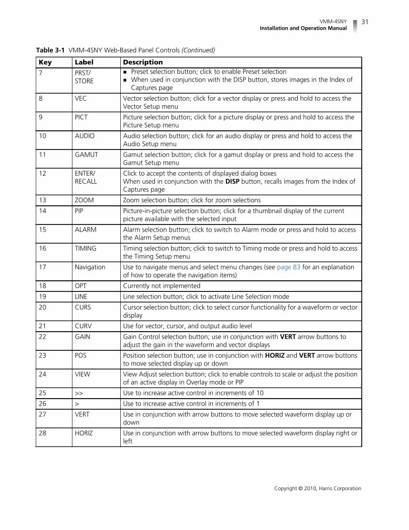
Table 3-1 VMM-4SNY Web-Based Panel Controls
Key Label Description
1 1/2 SDI input button, click to toggle between SDI input 1 and 2
2 MLT Multi-display button; click to toggle between a full-display and a multi-displayscreen or press and hold to access the MLT Setup menu
3 REF External Reference selection button; click to toggle between internal and externalreference
4 BYPASS Bypass button; click to toggle between displaying SDI input video (Bypass mode)and the normal VMM-4SNY displays (waveform, vector, multi, and so forth)
NOTE: Video will not display correctly in Bypass if its format is notsupported by your Sony monitor. Consult your monitor's user guide forsupported video formats
5 CLEAR Clear Display selection button; click to clear a display or press and hold to accessthe Clear Setup menu
6 WFM Waveform selection button; click for a waveform display or press and hold toaccess the Waveform Setup menu
VMM-4SNYInstallation and Operation Manual
31
Copyright © 2010, Harris Corporation
7 PRST/STORE
Preset selection button; click to enable Preset selection When used in conjunction with the DISP button, stores images in the Index of
Captures page
8 VEC Vector selection button; click for a vector display or press and hold to access theVector Setup menu
9 PICT Picture selection button; click for a picture display or press and hold to access thePicture Setup menu
10 AUDIO Audio selection button; click for an audio display or press and hold to access theAudio Setup menu
11 GAMUT Gamut selection button; click for a gamut display or press and hold to access theGamut Setup menu
12 ENTER/RECALL
Click to accept the contents of displayed dialog boxesWhen used in conjunction with the DISP button, recalls images from the Index ofCaptures page
13 ZOOM Zoom selection button; click for zoom selections
14 PIP Picture-in-picture selection button; click for a thumbnail display of the currentpicture available with the selected input
15 ALARM Alarm selection button; click to switch to Alarm mode or press and hold to accessthe Alarm Setup menus
16 TIMING Timing selection button; click to switch to Timing mode or press and hold to accessthe Timing Setup menu
17 Navigation Use to navigate menus and select menu changes (see page 83 for an explanationof how to operate the navigation items)
18 OPT Currently not implemented
19 LINE Line selection button; click to activate Line Selection mode
20 CURS Cursor selection button; click to select cursor functionality for a waveform or vectordisplay
21 CURV Use for vector, cursor, and output audio level
22 GAIN Gain Control selection button; use in conjunction with VERT arrow buttons toadjust the gain in the waveform and vector displays
23 POS Position selection button; use in conjunction with HORIZ and VERT arrow buttonsto move selected display up or down
24 VIEW View Adjust selection button; click to enable controls to scale or adjust the positionof an active display in Overlay mode or PIP
25 >> Use to increase active control in increments of 10
26 > Use to increase active control in increments of 1
27 VERT Use in conjunction with arrow buttons to move selected waveform display up ordown
28 HORIZ Use in conjunction with arrow buttons to move selected waveform display right orleft
Table 3-1 VMM-4SNY Web-Based Panel Controls (Continued)
Key Label Description

Chapter 3General Information
32
Copyright © 2010, Harris Corporation
Sleep Mode To setup up Sleep mode, choose the UNIT CONFIGURATION DISPLAY SETUP SLEEP MODE selection option. This menu allows the selection of how much timehas to pass without any button presses in order for the unit to enter Sleep mode.
When entering Sleep mode, the instrument sets the display to all black, and thenturns off highlighting on the buttons of the web RCU and illumination on thebuttons of the RCU-CMS.The unit exits Sleep mode when any button is pressed onthe monitor input buttons, the Web RCU, or the RCU-CMS. When exiting Sleepmode, the display resumes and the illumination/highlighting will return to the WebRCU or RCU-CMS buttons.
NOTE: The display is not affected by Sleep mode if the Bypass mode isactive.
To take the unit out of Sleep mode the Web RCU (or RCU-CMS) must becommunicating with the unit when the button is pressed.
Selecting anInput
Click the 1/2 input button to select input 1 or 2. (Input 1 is thedefault selection.) When an input is selected, pressing the inputbutton again will change to the new input from the previous input.High tally indicates input 1 is selected.
29 CONNECTIONSTATUS
Indicates whether the web-based control panel is actively connected to theVMM-4SNY unitIf the Web RCU is disconnected, reconnect by refreshing the page using your Webbrowser’s Refresh function; alternatively, leave the Web RCU page and select theRCU menu bar link again
30 < Use to decrease active control in increments of 1
31 << Use to decrease active control in increments of 10
32 EXIT Exit selection button; click to leave certain menu function selections
33 SETUP Setup button; click to access Setup mode
34 H/V Horizontal/vertical sweep selection button; click to toggle between waveformhorizontal and vertical sweep
35 COMP Component selection button; click to cycle through individual waveformcomponents
36 Numeric entrybuttons
Press to select, store, or delete a selection in the Preset memory bank Press to enter numeric values for certain parameters (the button bank will be
high tally to indicate that the numeric keypad is available for direct parameterentry)
37 DISP Display button; click to freeze a display Once a display is frozen, click to toggle between live and frozen mode
Table 3-1 VMM-4SNY Web-Based Panel Controls (Continued)
Key Label Description

VMM-4SNYInstallation and Operation Manual
33
Copyright © 2010, Harris Corporation
DisplaySelections
The VMM-4SNY unit screen display shows data in a full-screen, overlay, or quaddisplay. The screen display also contains the Main Title Bar, the display, and thestatus bar.
Click the MLT button to toggle between full screen and overlay orquad display. MLT is high tally when selected.
Full Screen andQuad Displays
There are various screens for the VMM-4SNY: full-screen display, quad (4 displaypanes), and overlay (2 or 3 display panes). The display pane always contains theMain Title Bar, the display, and the status bar. A diagram of the full-screen displayis shown in Figure 3-3. The Full Screen display mode shows a full-screenrepresentation of a waveform, picture, alarm, vector, gamut, audio, or timingdisplay for a single input at a time.
A diagram of the quad display is shown in Figure 3-4.
Figure 3-3 Full-Screen Display with PIP Enabled

Chapter 3General Information
34
Copyright © 2010, Harris Corporation
Figure 3-4 Quad Display
Overlay Display Overlay mode is a combination of the waveform, vector, and (if desired)picture-in-picture (PIP) displays. Descriptions of these display types start onpage 39.
A sample overlay display is shown in Figure 3-5 and described in Table 3-2.

VMM-4SNYInstallation and Operation Manual
35
Copyright © 2010, Harris Corporation
Figure 3-5 Overlay Display
Each component in the Overlay display can be adjusted individually. Use theappropriate function button (WFM, VEC, or PIP) to select the display to beadjusted. Refer to the appropriate function description sections for moreinformation.
To move a selected display component, make sure the VIEW button isin high tally. Use the VERT and HORIZ arrow buttons to move theselected display to the desired location on the screen. Use the CURVarrow buttons to scale the size of the selected display.
Table 3-2 Description of Overlay Display
Key Description
1 Main title bar
2 Display icon area
3 Vector display
4 Overlay status bar
5 PIP display
6 Waveform display
7 Specific elements of function display
Chapter 3General Information
36
Copyright © 2010, Harris Corporation
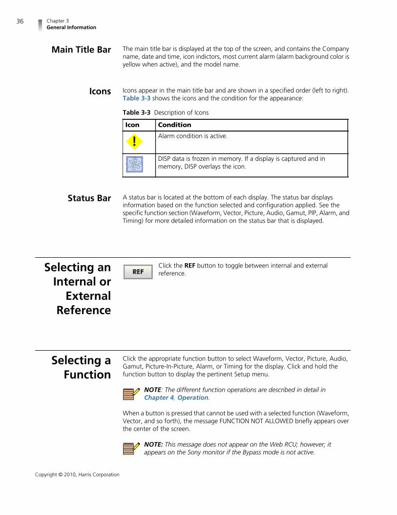
Main Title Bar The main title bar is displayed at the top of the screen, and contains the Companyname, date and time, icon indictors, most current alarm (alarm background color isyellow when active), and the model name.
Icons Icons appear in the main title bar and are shown in a specified order (left to right).Table 3-3 shows the icons and the condition for the appearance:
Status Bar A status bar is located at the bottom of each display. The status bar displaysinformation based on the function selected and configuration applied. See thespecific function section (Waveform, Vector, Picture, Audio, Gamut, PIP, Alarm, andTiming) for more detailed information on the status bar that is displayed.
Selecting anInternal or
ExternalReference
Click the REF button to toggle between internal and externalreference.
Selecting aFunction
Click the appropriate function button to select Waveform, Vector, Picture, Audio,Gamut, Picture-In-Picture, Alarm, or Timing for the display. Click and hold thefunction button to display the pertinent Setup menu.
NOTE: The different function operations are described in detail inChapter 4, Operation.
When a button is pressed that cannot be used with a selected function (Waveform,Vector, and so forth), the message FUNCTION NOT ALLOWED briefly appears overthe center of the screen.
NOTE: This message does not appear on the Web RCU; however; itappears on the Sony monitor if the Bypass mode is not active.
Table 3-3 Description of Icons
Icon Condition
Alarm condition is active.
DISP data is frozen in memory. If a display is captured and inmemory, DISP overlays the icon.
VMM-4SNYInstallation and Operation Manual
37
Copyright © 2010, Harris Corporation
Accessingand
Navigatingthe Setup
Menu
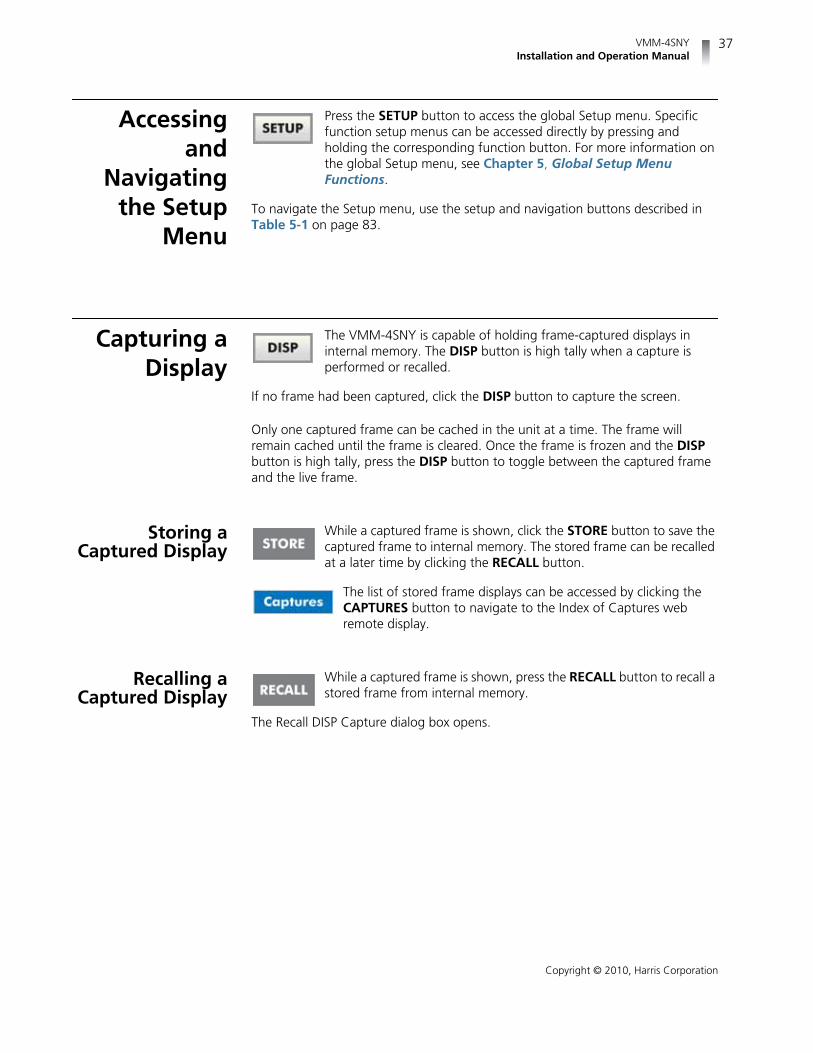
Press the SETUP button to access the global Setup menu. Specificfunction setup menus can be accessed directly by pressing andholding the corresponding function button. For more information onthe global Setup menu, see Chapter 5, Global Setup MenuFunctions.
To navigate the Setup menu, use the setup and navigation buttons described inTable 5-1 on page 83.
Capturing aDisplay
The VMM-4SNY is capable of holding frame-captured displays ininternal memory. The DISP button is high tally when a capture isperformed or recalled.
If no frame had been captured, click the DISP button to capture the screen.
Only one captured frame can be cached in the unit at a time. The frame willremain cached until the frame is cleared. Once the frame is frozen and the DISPbutton is high tally, press the DISP button to toggle between the captured frameand the live frame.
Storing aCaptured Display
While a captured frame is shown, click the STORE button to save thecaptured frame to internal memory. The stored frame can be recalledat a later time by clicking the RECALL button.
The list of stored frame displays can be accessed by clicking theCAPTURES button to navigate to the Index of Captures webremote display.
Recalling aCaptured Display
While a captured frame is shown, press the RECALL button to recall astored frame from internal memory.
The Recall DISP Capture dialog box opens.

Chapter 3General Information
38
Copyright © 2010, Harris Corporation
Figure 3-6 Recall DISP Capture Dialog Box
Follow the on screen instructions to perform the desired tasks.
Clearing aCaptured Display
While a captured frame is shown, press the CLEAR button to clearthe frozen frame. Once the frozen frame is cleared, a new framecapture can be performed.
39
Copyright © 2010, Harris Corporation
4 Operation
In the VMM-4SNY, certain buttons function differently, depending on theparameters selected. Once the function is determined, more detailed settings canbe configured. This section focuses on the operation of the VMM-4SNY accordingto the selected display. See Figure 3-2 on page 30 for information about thelocation of the buttons described in this section. See Chapter 3, GeneralInformation for general information on how the VMM-4SNY operates.
Waveform DisplayClick the WFM function button to access the Waveform display. Thewaveform graticule scales, units of measure, and critical amplitudelimits change according to the video format displayed.
Click and hold the WFM function button to access the Waveform Setup menuselection options. (Click the SETUP or the EXIT button to clear the WaveformSetup menu.)
Table 4-1 shows the units of measure that appear for a video format. Table 4-2lists the critical amplitude limits, which are indicated on the screen by specialdashed lines for the video formats that can be displayed.
Table 4-1 Video Formats and Units of Measure
Video Format Unit of Measure
High Definition and StandardDefinition 525 and 625
Volts or Percent (Selectable)
High Definition 59.94 or 60, orStandard Definition 525 displayed ascomposite (NTSC)
IRE
High Definition 50 or StandardDefinition 625 displayed as composite(PAL)
Units or Volts (Selectable)

Chapter 4Operation
40
Copyright © 2010, Harris Corporation
A waveform display is shown in Figure 4-1 and described in Table 4-3. The figureshows the location for the various waveform display fields.
Figure 4-1 Waveform Display Diagram
Table 4-2 Video Formats and Critical Amplitude Limits
Video Format Critical Amplitude Limits
High Definition and StandardDefinition
0.6125 V = upper 75% chroma limit0.525 V = 75% luminance limit0.350 V = 50% point; black for colordifference channels0.0875 V = lower 75% chroma limit
Standard Definition 525 as Composite(NTSC)
7.5 IRE – black level
Table 4-3 Description of Waveform Display Diagram
FieldIdentifier
Fieldinformation Nomenclature
1 Input Displays selected input (1 or 2)
2 Standard Displays the Line Rate/Frame Rate; this isselected in the Video Setup menu

VMM-4SNYInstallation and Operation Manual
41
Copyright © 2010, Harris Corporation
Graticules are configured by selecting the Video Input Format along with theappropriate Waveform Setup scale adjustment (Units, %, or Volts). The scales canalso change when the ZOOM button is pressed.
Figure 4-2 to Figure 4-4 illustrate some waveform graticules with the criticalamplitude limits for the video formats that can be displayed by the VMM-4SNY.The critical amplitude limits are indicated on the screen by special dashed lines.
3 Format Displayed as YCBCR, RGB, or Composite(CMPST); this can be selected in the Display/Format selection options of the WaveformSetup menu
4 Filter For component displayed as Flat, Low Pass,or BowtieFor composite displayed as Flat, Low Pass,Chroma, or Flat and Low PassThis can be selected in the Composite orComponent Filter selection options of theWaveform Setup menu
5 Line selectinformation
Shown as Line number with the ODD orEVEN field (odd or even field will only showfor interlaced Video Formats); blank whendisabled
6 Reference Displays the reference as INT, EXT (toggledby clicking the REF button)
7 Scale Indicates the major graticule indications fortime
8 Time cursor readout Displays the time cursor as TIME and theselected numerical value followed by theunit of measure (µs)
9 Amplitude cursorreadout
Displays the amplitude cursor as AMP andthe selected numerical value, followed bythe unit or measure (mV, units, or IRE)
10 Gain Displays the selected gain; Gain ranges arex0.5 to x15.0
11 Zoom Displays Zoom when enabled; blank whendisabled
12 WFM graticule Shows the WFM RGB, YCBCR, or Compositegraticule; the graticule is dependent uponthe Video format, Zoom, and scaleselections
Table 4-3 Description of Waveform Display Diagram (Continued)
FieldIdentifier
Fieldinformation Nomenclature

Chapter 4Operation
42
Copyright © 2010, Harris Corporation
Figure 4-2 RGB and YCBCR Graticule
Figure 4-3 RGB and YCBCR Zoom 0 mV Graticule
Figure 4-4 RGB and YCBCR Zoom 700 mV Graticule

VMM-4SNYInstallation and Operation Manual
43
Copyright © 2010, Harris Corporation
Waveform PanelSelections
The following buttons directly affect the waveform display.
Moving theWaveform
Click the POS button to activate the position control. Move thewaveform display relative to the graticule by selecting the appropriatehorizontal, vertical, and arrow buttons for horizontal or verticalmovement.
Click the VERT button to center the waveform, and its corresponding<<, >>, <, or > buttons for vertical direction.
Click the HORIZ button to center the waveform, and itscorresponding <<, >>, <, or > buttons for horizontal direction.
SelectingHorizontal or
Vertical Sweep
Click the H/V button to toggle between horizontal and vertical sweepmodes.
Figure 4-5 Sample Waveform in Vertical Sweep Mode
Setting Verticaland Horizontal
AmplificationRange
Gain is used to set the range of the vertical and horizontal amplification in thevideo signal. The standard gain in the video signal is x1.
Click the GAIN button to activate the gain controls. The vertical gainsetting appears in the upper left portion of the waveform display, asshown in Figure 4-6. The horizontal gain setting appears in theupper-right portion of the waveform display.
Click the VERT arrow buttons to select one of the preset gainselections (x0.5, x1.0, x2.5, x5.0). Use the VERT arrow buttons toincrease or decrease the gain in 0.01 steps.
Click the HORIZ arrow buttons to cycle through the horizontal gainsequence of x1.0, x5.0, x10.0, and back to x1.0. When vertical sweepis selected, the gain sequence changes to x1.0, x5.0, and x25.0.

Chapter 4Operation
44
Copyright © 2010, Harris Corporation
Figure 4-6 Establishing Gain
SelectingComponents
Click the COMP button to step through single or multiplecomponents in a signal.
When multiple components are selected, use the H/V button to toggle between1H and 1V. With only one component selected, click the H/V button to togglebetween 1H and 1V, or 2H and 2V.
Selecting DisplayOptions
Click the ZOOM button to cycle through these display options:
ZOOM positioned on the 0 IRE, 0 mV, or 0% graticule line
ZOOM positioned on the 100 IRE or 700 mV, or 100% graticule line
Normal view
At each zoom position, the graticule scale and waveform displays expand toprovide more resolution around the zoom point.
Placing theWaveform
Display in LineSelect Mode
Click the LINE button to enable the monitoring of a single line of avideo signal. To view a line in Line Select mode:
1 Click the LINE button to place the selected waveform display in Line Selectmode. At the bottom-center of the display, the Line number and the Odd orEven field appear, as shown in Figure 4-7.
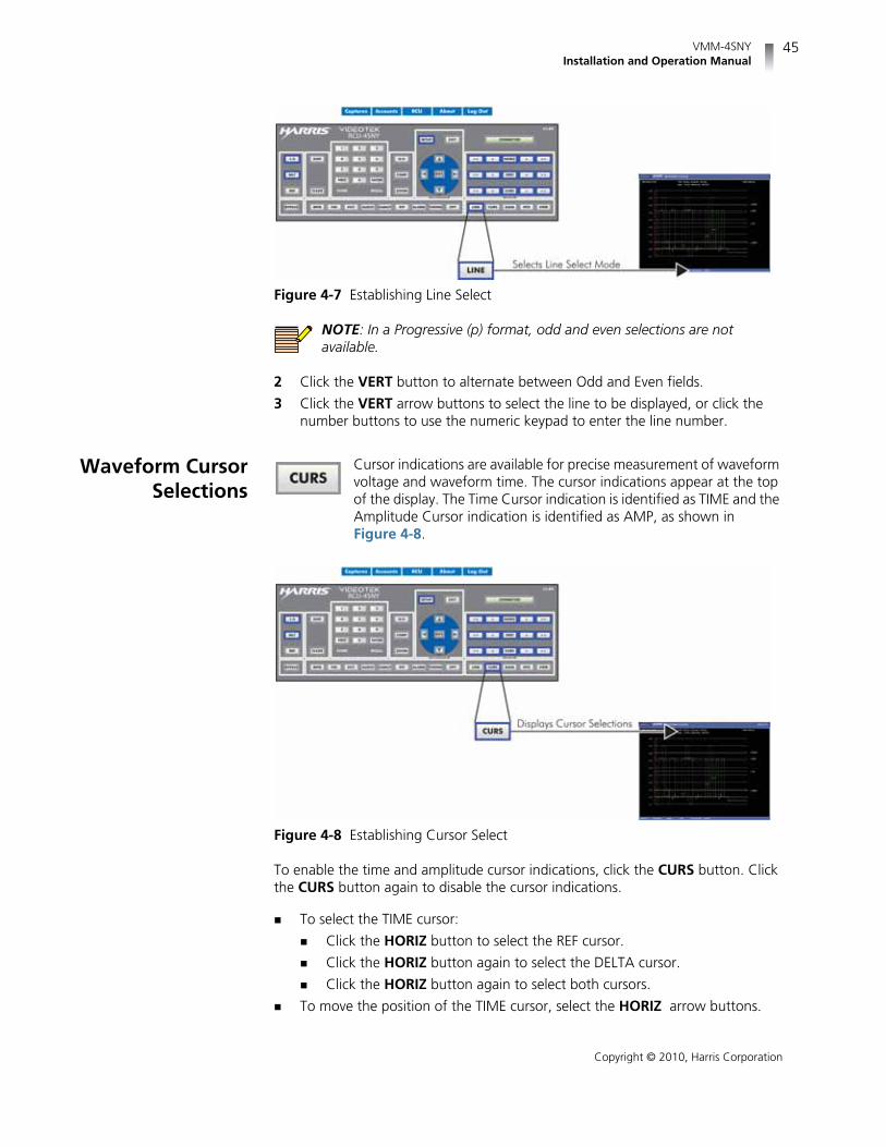
VMM-4SNYInstallation and Operation Manual
45
Copyright © 2010, Harris Corporation
Figure 4-7 Establishing Line Select
NOTE: In a Progressive (p) format, odd and even selections are notavailable.
2 Click the VERT button to alternate between Odd and Even fields.
3 Click the VERT arrow buttons to select the line to be displayed, or click thenumber buttons to use the numeric keypad to enter the line number.
Waveform CursorSelections
Cursor indications are available for precise measurement of waveformvoltage and waveform time. The cursor indications appear at the topof the display. The Time Cursor indication is identified as TIME and theAmplitude Cursor indication is identified as AMP, as shown inFigure 4-8.
Figure 4-8 Establishing Cursor Select
To enable the time and amplitude cursor indications, click the CURS button. Clickthe CURS button again to disable the cursor indications.
To select the TIME cursor:
Click the HORIZ button to select the REF cursor.
Click the HORIZ button again to select the DELTA cursor.
Click the HORIZ button again to select both cursors.
To move the position of the TIME cursor, select the HORIZ arrow buttons.

Chapter 4Operation
46
Copyright © 2010, Harris Corporation
To select the AMP cursor:
Click the VERT button to select the REF cursor.
Click the VERT button again to select the DELTA cursor.
Click the VERT button again to select both cursors.
To move the position of the AMP cursor, select the VERT arrow buttons.
In all cases, the TIME and AMP numeric readout at the top of the display indicatesthe difference between the REF and DELTA cursors. The active cursor (REF, DELTA,or both) is shown with small arrows at both ends of the cursor.
To exit the cursor function while leaving the cursors active, click the WFM buttonor select another mode in the display (that is, LINE, GAIN, or POS).
Waveform SetupMenu
Click and hold the WFM button to access the Waveform Setup menu. For moreinformation on the Waveform Setup menu, see page 86. For descriptions ofWaveform Setup menu selection options, see page 96.
Vector Display Click the VEC function button to access the vector display. A vectordisplay is shown in Figure 4-9 and described in Table 4-4. Thisillustrates the general location for the various vector fields.
Click and hold the VEC function button to access the Vector Setup menu selectionoptions. (Click the SETUP or the EXIT button to clear the Vector Setup menu.)
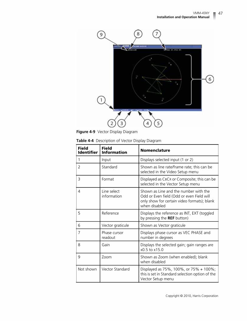
VMM-4SNYInstallation and Operation Manual
47
Copyright © 2010, Harris Corporation
Figure 4-9 Vector Display Diagram
Table 4-4 Description of Vector Display Diagram
FieldIdentifier
FieldInformation Nomenclature
1 Input Displays selected input (1 or 2)
2 Standard Shown as line rate/frame rate; this can beselected in the Video Setup menu
3 Format Displayed as CBCR or Composite; this can beselected in the Vector Setup menu
4 Line selectinformation
Shown as Line and the number with theOdd or Even field (Odd or even Field willonly show for certain video formats); blankwhen disabled
5 Reference Displays the reference as INT, EXT (toggledby pressing the REF button)
6 Vector graticule Shown as Vector graticule
7 Phase cursorreadout
Displays phase cursor as VEC PHASE andnumber in degrees
8 Gain Displays the selected gain; gain ranges arex0.5 to x15.0
9 Zoom Shown as Zoom (when enabled); blankwhen disabled
Not shown Vector Standard Displayed as 75%, 100%, or 75% + 100%;this is set in Standard selection option of theVector Setup menu

Chapter 4Operation
48
Copyright © 2010, Harris Corporation
Graticules are configured by selecting the Video Input Format along with theappropriate Vector Setup standard.
Some graticule scales are illustrated in Figure 4-10 to Figure 4-17.
Figure 4-10 Vector NTSC Graticule
Figure 4-11 Vector NTSC Zoom Upper Left

VMM-4SNYInstallation and Operation Manual
49
Copyright © 2010, Harris Corporation
Figure 4-12 Vector NTSC Zoom Upper Right
Figure 4-13 Vector NTSC Zoom Lower Right

Chapter 4Operation
50
Copyright © 2010, Harris Corporation
Figure 4-14 Vector NTSC Zoom Lower Left
Figure 4-15 Vector PAL Zoom Center

VMM-4SNYInstallation and Operation Manual
51
Copyright © 2010, Harris Corporation
Figure 4-16 Vector SD with I/Q
Figure 4-17 Vector HD 75% + 100% Graticule

Chapter 4Operation
52
Copyright © 2010, Harris Corporation
Vector DisplaySelections
The following buttons directly affect the vector display.
Setting theVector Gain
Gain is used to set the range of the amplification in the video signal. The standardgain in the vector is x1.0. The gain setting appears in the upper left portion of thevector display, as shown in Figure 4-18.
Click the GAIN button, and then use the vertical arrow buttons toadjust the variable gain. Use the VERT button to step through presetgain selections (x.05, x1.0, x2.5, x5.0).
Figure 4-18 Establishing the Vector Gain
Setting DisplayOptions
Vector Zoom is helpful when an increased resolution of phase orsaturation is required. Click the ZOOM button to cycle through thesedisplay views:
Expand the center
Expand the upper left quadrant
Expand the upper right quadrant
Expand the lower right quadrant
Expand the lower left quadrant
Normal view
Placing theVector Display inLine Select Mode
Clicking the LINE button enables monitoring of a single line of avideo signal. This enables Line Select to monitor individual areas ofthe entire image. To view a line in Line Select mode:
1 Click the LINE button to place the selected vector display in Line Select mode.At the bottom-center of the display, the Line number and the Odd or Evenfield appear, as shown in Figure 4-19.

VMM-4SNYInstallation and Operation Manual
53
Copyright © 2010, Harris Corporation
Figure 4-19 Establishing Line Select
NOTE: In a Progressive (p) format, odd and even selection is not available.
2 Click the VERT button to alternate between Odd and Even fields.
3 Click theVERT arrow buttons to select the line to be displayed, or click thenumeric keypad to enter the line number.
Vector CursorSelections
Cursors are available for precise measurement of vector phase (indegrees). Click the CURS button on the web-enabled panel to enablethe cursors for the selected display. The Phase Cursor indications areshown in Figure 4-20.
Figure 4-20 Establishing Cursor Select
To enable the Phase cursors, click and release the CURS button. Click the CURSbutton again to disable the cursor information.
When the cursor is selected, the Phase indication appears at the top of the display.Next to the Phase indication is a numeric readout that indicates the differencebetween the REF and DELTA cursors. The active cursor (REF, DELTA, or both) isshown with small arrows at the outer end of the line.

Chapter 4Operation
54
Copyright © 2010, Harris Corporation
To select a cursor line for control:
1 Click the CURV button to select the REF or DELTA line to control. The REF lineis the solid line, and the DELTA line is the dotted line.
2 Click the CURV arrow buttons to move the REF or DELTA line to the desiredlocation.
3 Click the CURV button for the next cursor.
4 Click the CURV button a third time to control both the REF and DELTA lines.
5 Repeat as necessary.
Once the cursors are no longer necessary, click the CURS button to disable thePhase cursor selection.
To exit the cursor function while leaving the cursor active, click the VEC functionbutton or select another mode (that is, LINE, GAIN, or POS)
Vector SetupMenu
Click and hold the VEC function button to access the Vector Setupmenu. For more information on the Vector Setup menu, see page 87.For descriptions of Vector Setup menu selection options, see page 97.
Gamut DisplayA constant setback in video production is the difference between the allowableranges of dissimilar component and composite color spaces. Combinations ofvalues that are within the range of a color-difference component video systemproduce signal amplitudes outside the ranges when the signal is transcoded tocomposite or RGB color space.
Click the GAMUT function button to access the Gamut display. TheGamut displays show RGB limits or composite video limits.
Click and hold the GAMUT function button to access the Gamut Setup menuselection options. (Click the SETUP or the EXIT button to clear the Gamut Setupmenu.)
Both Gamut displays illustrate what colors are causing illegal excursions andwhether these digressions are above or below the allowable limits. The inputs areshown as an encoded display with gamut alarms. The displays show RGB andcomposite video limits.
Vector excursion marks are shown in the gamut display. The excursion marks helpto visualize the minimum/maximum value of a 100% color bar signal. The positionof the excursion marks depend on the selected Video Format selection from theVideo Setup menu.
A gamut display diagram is shown in Figure 4-21 and described in Table 4-5. Thediagram illustrates the general location for the various gamut fields.

VMM-4SNYInstallation and Operation Manual
55
Copyright © 2010, Harris Corporation
Figure 4-21 Gamut Display Diagram
Table 4-5 Gamut Display Diagram Description
FieldIdentifier
FieldInformation Nomenclature
1 Input Displays selected input (1 or 2)
2 Standard Displays the line rate/frame rate [1080i/59.94]; this is selected in the Video Setupmenu
3 Format Displayed as Cps and RGB; this can beselected in the Gamut Setup menu
4 Line selectinformation
Shown as Line and the number with theOdd or Even field (when applicable); blankwhen disabled
5 Reference Displays the reference as INT, EXT (toggledby clicking the REF button)
6 Lower luma alarmlimit (Compositeonly)
Displayed as Lower = xxx yy; xxx is the Lumalower threshold setting and yy is determinedby the format (IRE for NTSC and Units or mVfor PAL)
7 Upper luma alarmlimit (Compositeonly)
Displayed as Upper = xxx yy; xxx is the Lumaupper threshold setting and yy isdetermined by the format (IRE for NTSC andUnits or mV for PAL)
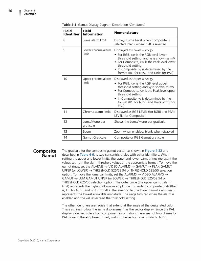
Chapter 4Operation
56
Copyright © 2010, Harris Corporation
CompositeGamut
The graticule for the composite gamut vector, as shown in Figure 4-22 anddescribed in Table 4-6, is two concentric circles with other identifiers. Whensetting the upper and lower limits, the upper and lower gamut rings represent thevalues set from the alarm threshold values of the appropriate format. To move thegamut rings, set the ALARMS VIDEO ALARMS GAMUT PEAK GAMUTUPPER (or LOWER) THRESHOLD 525/59.94 or THRESHOLD 625/50 selectionoption. To move the luma bar limits, set the ALARMS VIDEO ALARMS GAMUT LUM GAMUT UPPER (or LOWER) THRESHOLD 525/59.94 orTHRESHOLD 625/50 selection option. The outer circle (the upper gamut alarmlimit) represents the highest allowable amplitude in standard composite units (thatis, IRE for NTSC and units for PAL). The inner circle (the lower gamut alarm limit)represents the lowest allowable amplitude. The rings turn red when the alarm isenabled and the values exceed the threshold setting.
The other identifiers are radials that extend at the angle of the designated color.These six lines follow the same displacement as the vector display. Since the PALdisplay is derived solely from component information, there are not two phases forPAL signals. The +V phase is used, making the vectors look similar to NTSC.
8 Luma alarm limit Displays Luma Level when Composite isselected; blank when RGB is selected
9 Lower chroma alarmlimit
Displayed as Lower = xxx yy• For RGB, xxx is the RGB level lower
threshold setting, and yy is shown as mV• For Composite, xxx is the Peak level lower
threshold setting• In Composite, yy is determined by the
format (IRE for NTSC and Units for PAL)
10 Upper chroma alarmlimit
Displayed as Upper = xxx yy• For RGB, xxx is the RGB level upper
threshold setting and yy is shown as mV• For Composite, xxx is the Peak level upper
threshold setting• In Composite, yy is determined by the
format (IRE for NTSC and Units or mV forPAL)
11 Chroma alarm limits Displayed as RGB LEVEL (for RGB) and PEAKLEVEL (for Composite)
12 Luma/Mono bargraticule
Shows the Luma/Mono bar graticule
13 Zoom Zoom when enabled; blank when disabled
14 Gamut Graticule Composite or RGB Gamut graticule
Table 4-5 Gamut Display Diagram Description (Continued)
FieldIdentifier
FieldInformation Nomenclature

VMM-4SNYInstallation and Operation Manual
57
Copyright © 2010, Harris Corporation
NOTE: An alarm persistence of two seconds is associated with any alarmindication. After an alarm has cleared, two seconds will pass before thegamut alarm indicator returns to normal.
Figure 4-22 Composite Gamut Vector Display Graticule Markings
Table 4-6 Composite Gamut Indicators Description
Key Indicator Description
1 Lower gamut ring The lower gamut ring indicates the Gamutalarm Peak Lower limit. When the Gamutalarm is enabled and the Peak Lower limit isexceeded, the lower gamut ring turns red.
2 Upper gamut ring The upper gamut ring indicates the Gamutalarm Peak Upper limit. When the Gamutalarm Peak Upper limit is exceeded, theupper gamut ring turns red.
3 Luma lower limitline
The Luma Lower Limit Line indicates theGamut alarm Luma Lower limit. When theGamut alarm is enabled, and the Lumalower limit is exceeded, the Luma LowerLimit line and LUMA turn red.
4 Luma upper limitline
The Luma Upper Limit Line indicates theGamut alarm Luma Upper limit. When theGamut alarm is enabled, and the LumaUpper limit is exceeded, the luma upperlimit line and LUMA turn red.

Chapter 4Operation
58
Copyright © 2010, Harris Corporation
RGB GamutDisplay
When setting the upper and lower limits, the upper and lower gamut ringsrepresent the alarm threshold values. To move the gamut rings, set the ALARMS VIDEO ALARMS GAMUT RGB GAMUT UPPER (or LOWER) THRESHOLDselection option. The RGB Gamut Display, shown in Figure 4-23 and described inTable 4-7, is similar to the Composite Gamut Display. The RGB Gamut vectordisplays video amplitudes (which are in mV) in a polar format to represent colorinformation. The rings turn red when the alarm is enabled and the values exceedthe threshold setting.
Each R, G, and B pixel is plotted using amplitude and phase. The amplitude isderived from the R, G, B component. The phase is derived from the CB CR
information of the digital signal. The pixels can be plotted as a single color or aseach component color. Unlike the composite Gamut vector, which plots two pointsper pixel, the RGB Gamut vector plots three points. Also, signals with no colorcontent are displayed on a separate bar graph labeled Mono.
The RGB graticule is nearly identical to the composite graticule. The onlydifferences are
Amplitudes are displayed in mV rather than IRE or UNITS.
The radials representing color vectors are 60° apart since they are displayed ina component color space.
Mono bar graph is for monochrome.
NOTE: There is an alarm persistence of two seconds associated with anyalarm indication. After an alarm has cleared, two seconds will pass beforethe gamut indicator returns to normal.
5 Vector excursionmark
The excursion marks help to visualize theminimum/maximum value of 100% colorbars.
Table 4-6 Composite Gamut Indicators Description (Continued)
Key Indicator Description

VMM-4SNYInstallation and Operation Manual
59
Copyright © 2010, Harris Corporation
Figure 4-23 Component (RGB) Gamut Vector Display Graticule Markings
Placing theGamut Display inLine Select Mode
Click the LINE button to enable monitoring of a single line of a videosignal. This enables Line Select to monitor individual lines of the entireimage. To view a line in Line Select mode:
1 Click the LINE button to place the selected Gamut display in Line Select mode.At the bottom of the display, the Line number and Odd or Even field appear, asshown in Figure 4-24.
Table 4-7 RGB Gamut Indicator Descriptions
Key Indicator Description
1 Lower gamut ring The lower gamut ring indicates the RGBGamut alarm Lower limit. When the RGBGamut alarm is enabled and the Lower limitis exceeded, the lower gamut ring turns red.
2 Upper gamut ring The upper gamut ring indicates the RGBGamut alarm Upper limit. When the RGBGamut alarm is enabled, and the Upper limitis exceeded, the upper gamut ring turns red.
3 Vector excursionmark
The excursion marks help to visualize theminimum/maximum values of 100% colorbars.
4 Mono Mono indicates the monochrome of theRGB signal. There is no alarm associatedwith Mono.

Chapter 4Operation
60
Copyright © 2010, Harris Corporation
Figure 4-24 Establishing Line Select
NOTE: In a Progressive (p) format, Odd and Even selections are notavailable.
2 Click the VERT button to alternate between the Odd and Even fields forinterlaced formats.
3 Click the VERT arrow buttons to select the line to be displayed.
Setting DisplayOptions
Click the ZOOM button to cycle through the displays of theComposite or RGB gamut graticule:
Expand the center
Expand the upper left quadrant
Expand the upper right quadrant
Expand the lower right quadrant
Expand the lower left quadrant
Normal view
Gamut SetupMenu
Click and hold the GAMUT function button to access the Gamut Setup menu. Formore information on the global Gamut Setup menu, see page 88. For descriptionsof Gamut Setup menu selection options, see page 98.
Picture Display The Picture Display is used to show the picture of the selected input.Click the PICT function button to display the picture. A Picture displaydiagram is shown in Figure 4-25 and described in Table 4-8. Onlyone picture can be displayed.
Click and hold the PICT button to access the Picture Setup menu. (Click the SETUPor the EXIT button to clear the Picture Setup menu.)
NOTE: Pictures can be used as thumbnails. For more information, seepage 97.

VMM-4SNYInstallation and Operation Manual
61
Copyright © 2010, Harris Corporation
Figure 4-25 Picture Display Diagram
The picture display changes according to the aspect ratio and anamorphicselections in the global Setup menu.
Placing thePicture in Line
Select Mode
To enable Line Select mode:
1 Click the LINE button to place the selected Picture display in Line Select mode.A cursor appears on the selected line, as shown in Figure 4-26.
Table 4-8 Picture Display Diagram Description
FieldIdentifier
FieldInformation Nomenclature
1 Input Displays selected input (1 or 2)
2 Standard Displays the line rate/frame rate; select theStandard in the Video Setup menu
3 Line selectinformation
Shown as Line and the number with theOdd or Even field (when applicable); blankwhen disabled
4 Picture Displays picture of the selected video input
5 Timecode Displays the timecode information whentimecode is enabled

Chapter 4Operation
62
Copyright © 2010, Harris Corporation
Figure 4-26 Establishing Line Select
NOTE: In a Progressive (p) format, Odd and Even selections are notavailable.
2 Click the VERT button to alternate between the Odd and Even fields forinterlaced formats.
3 Click the VERT arrow buttons to select the line to be displayed.
Picture SetupMenu
Click and hold the PICT function button to access the Picture Setup menu. Formore information on the global Picture Setup menu, see page 88. For descriptionsof Picture Setup menu selection options, see page 99.
PIP Display The Picture-In-Picture (PIP) function shows a “thumbnail” of the selected input’spicture display (with the selected function display information appearing in thebackground) and time full screen displays, as well as the Overlay display mode. ThePIP function is available with the waveform, vector, gamut, audio, alarm, timefunctions, and overlay mode.
While in the active display, click the PIP function button to enable thepicture-in-picture display.
Figure 4-27 shows the PIP function enabled in Overlay Display mode, along withthe waveform and vector displays.

VMM-4SNYInstallation and Operation Manual
63
Copyright © 2010, Harris Corporation
Figure 4-27 Sample PIP Display
Moving a PIP To move a PIP, make sure the PIP function button and the VIEW button are in hightally. Use the VERT and HORIZ arrow buttons to reposition the PIP on the display.
Scaling a PIP To scale a PIP display’s size, make sure the PIP function button and the VIEWbutton are in high tally. Use the CURV arrow buttons to resize the PIP on thedisplay.
Removing a PIP To remove a PIP from the display, make sure the PIP function button is in high tally,and then click the PIP function button. The display disappears from the screen.
Audio Display Click the AUDIO function button to display the audio display. TheVMM-4SNY accepts one AES/EBU and up to four groups ofembedded audio inputs. Any two input channels can be selected tobe monitored on the Sony monitor’s internal speakers (if available).Click and hold the AUDIO function button to access Audio Setupmenu selection options.
Configure the audio display type and parameters using the AUDIO CHANNELselection options. Audio can be displayed as one of the following:
One two-channel bar graph with one Lissajous and one Phase bar

Chapter 4Operation
64
Copyright © 2010, Harris Corporation
Two two-channel bar graphs (for a total of four channels) with two Lissajousand two Phase bars
Three two-channel bar graphs (for a total of six channels) with three Phasebars or CineSound 5.1 with two Phase bars
Four two-channel bar graphs (for a total of eight channels) with four Phasebars or CineSound 5.1+AUX, 6.1, or 7.1 with up to three phase bars
Eight two-channel bar graphs (for a total of sixteen channels) with eight Phasebars
Lissajous can be selected as Soundstage or X-Y displays.
Input assignments, scaling, input levels, and response can also be modified usingthe Audio Setup menu.
Audio Scales The Vertical audio graticule scales change according to the selections made in theAUDIO METER SETUP SCALE selection options. The Scale selection optionsare as follows:
Type I
Type IIA
Type IIB
Type I + 8
Nordic
DIN 45406
dBFS
Zero Ref dBFS
Custom dBFS
Custom dB

VMM-4SNYInstallation and Operation Manual
65
Copyright © 2010, Harris Corporation
Vertical AudioDisplays
Vertical Audio display diagrams are shown in Figure 4-28 to Figure 4-31, anddescribed in Table 4-9 to Table 4-12. The Vertical audio graticule scales changeaccording to the scale selections made in the Setup menu.
Figure 4-28 Two Bar Graph Display with Lissajous Diagram
Table 4-9 Two Bar Graph Display with Lissajous Diagram Description
FieldIdentifier
FieldInformation Nomenclature
1 Input Displays selected input (1 or 2)
2 Status Displays audio type as Mute, AES, orEmbedded; blank when disabled
3 Channel number Shown as Ø (Mute) , A1-A2 (AES), orE1-E16 (Embedded)
4 Device Displays labels for lissajous, bar graphs, andheadphone outputs
5 Lissajous display Lissajous of bar graph 1 with labels for R, L,and the number of the meter beingmonitored (for example, M-1)
6 Zoom Zoom when enabled; blank when disabled
7 Scale selection Displays the selected meter scale: Type I,Type IIa, Type IIb, Type I + 8, Nordic, DIN45406, dBFS, Zero REF dBFS, Custom dB,and Custom dBFS

Chapter 4Operation
66
Copyright © 2010, Harris Corporation
8 Level markers Shows peak levels for the signal; this can beadjusted in the AUDIO METER SETUPselection options
9 Meter response Displays the selected meter response: VU,Peak, True Peak, VU + Peak, VU + TruePeak, Custom
10 Audio graticule(with meter labels)
Shown as stereo pairs (L1, R1), SMPTE320M, or custom label
11 Phase bar Phase meter of bar graph 1
Table 4-9 Two Bar Graph Display with Lissajous Diagram Description (Continued)
FieldIdentifier
FieldInformation Nomenclature

VMM-4SNYInstallation and Operation Manual
67
Copyright © 2010, Harris Corporation
Figure 4-29 Four Bar Graph with Lissajous Display Diagram
Table 4-10 Four Bar Graph with Lissajous Display Diagram Description
FieldIdentifier
FieldInformation Nomenclature
1 Input Displays selected input (1 or 2)
2 Status Displays audio type as Mute, AES, orEmbedded; blank when disabled
3 Channel number Shown as Ø (Mute) , A1-A2 (AES), orE1-E16 (Embedded)
4 Device Displays labels for lissajous, bar graphs, andheadphone outputs
5 Lissajous display (2) Lissajous of bar graph 2 with labels for R, L,and the number of the meter beingmonitored (for example, M-2)
6 Lissajous display (1) Lissajous of bar graph 1 with labels for R, L,and the number of the meter beingmonitored (for example, M-1)
7 Zoom Zoom (when enabled); blank when disabled
8 Scale selection Displays the selected meter scale: Type I,Type IIa, Type IIb, Type I + 8, Nordic, DIN45406, dBFS, Zero REF dBFS, Custom dB,and Custom dBFS
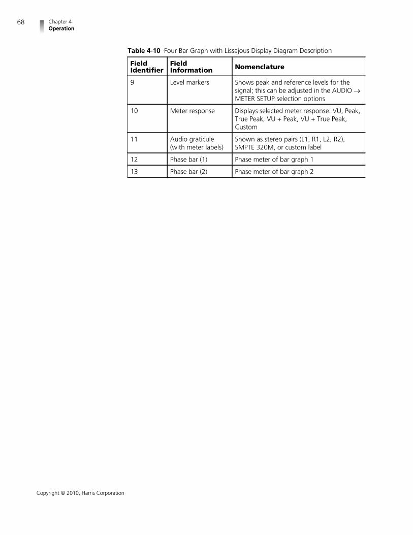
Chapter 4Operation
68
Copyright © 2010, Harris Corporation
9 Level markers Shows peak and reference levels for thesignal; this can be adjusted in the AUDIO METER SETUP selection options
10 Meter response Displays selected meter response: VU, Peak,True Peak, VU + Peak, VU + True Peak,Custom
11 Audio graticule(with meter labels)
Shown as stereo pairs (L1, R1, L2, R2),SMPTE 320M, or custom label
12 Phase bar (1) Phase meter of bar graph 1
13 Phase bar (2) Phase meter of bar graph 2
Table 4-10 Four Bar Graph with Lissajous Display Diagram Description
FieldIdentifier
FieldInformation Nomenclature

VMM-4SNYInstallation and Operation Manual
69
Copyright © 2010, Harris Corporation
Figure 4-30 Six Bar Graph Display Diagram
Table 4-11 Six Bar Graph Display Diagram Description
FieldIdentifier
FieldInformation Nomenclature
1 Input Displays selected input (1 or 2)
2 Status Displays audio type as Mute, AES, orEmbedded; blank when disabled
3 Phase bar (2) Phase Meter of bar graph 2
4 Channel number Shown as Ø (Mute) , A1-A2 (AES), orE1-E16 (Embedded)
5 Device Displays labels for lissajous, bar graphs, andheadphone outputs
6 Phase bar (3) Phase meter of bar graph 3
7 Level markers Shows peak and reference levels for thesignal; this can be adjusted in the AUDIO METER SETUP selection options
8 Zoom Zoom (when enabled); blank when disabled
9 Scale selection Displays the selected meter scale: Type I,Type IIa, Type IIb, Type I + 8, Nordic, DIN45406, dBFS, Zero REF dBFS, Custom dB,and Custom dBFS

Chapter 4Operation
70
Copyright © 2010, Harris Corporation
10 Meter response Displays the selected meter response: VU,Peak, True Peak, VU + Peak, VU + TruePeak, Custom
11 Audio graticule(with meter labels)
Shown as stereo pairs (L1, R1, L2, R2, L3,R3), SMPTE 320M, or custom label
12 Phase bar (1) Phase meter of bar graph 1
Table 4-11 Six Bar Graph Display Diagram Description (Continued)
FieldIdentifier
FieldInformation Nomenclature

VMM-4SNYInstallation and Operation Manual
71
Copyright © 2010, Harris Corporation
Figure 4-31 Eight Bar Graph Display Diagram
Table 4-12 Eight Bar Graph Display Diagram Description
FieldIdentifier
FieldInformation Nomenclature
1 Input Displays selected input (1 or 2)
2 Status Displays audio type as Mute, AES, orEmbedded; blank when disabled
3 Channel number Shown as Ø (Mute) , A1-A2 (AES), orE1-E16 (Embedded)
4 Device Displays labels for lissajous, bar graphs, andheadphone outputs
5 Phase bar (3) Phase Meter of bar graph 3
6 Phase bar (4) Phase Meter of bar graph 4
7 Level meters Shows peak and reference levels for thesignal; this can be adjusted in the AUDIO METER SETUP selection options
8 Zoom Zoom when enabled; blank when disabled
9 Scale selection Displays the selected meter scale: Type I,Type IIa, Type IIb, Type I + 8, Nordic, DIN45406, dBFS, Zero REF dBFS, Custom dB,and Custom dBFS
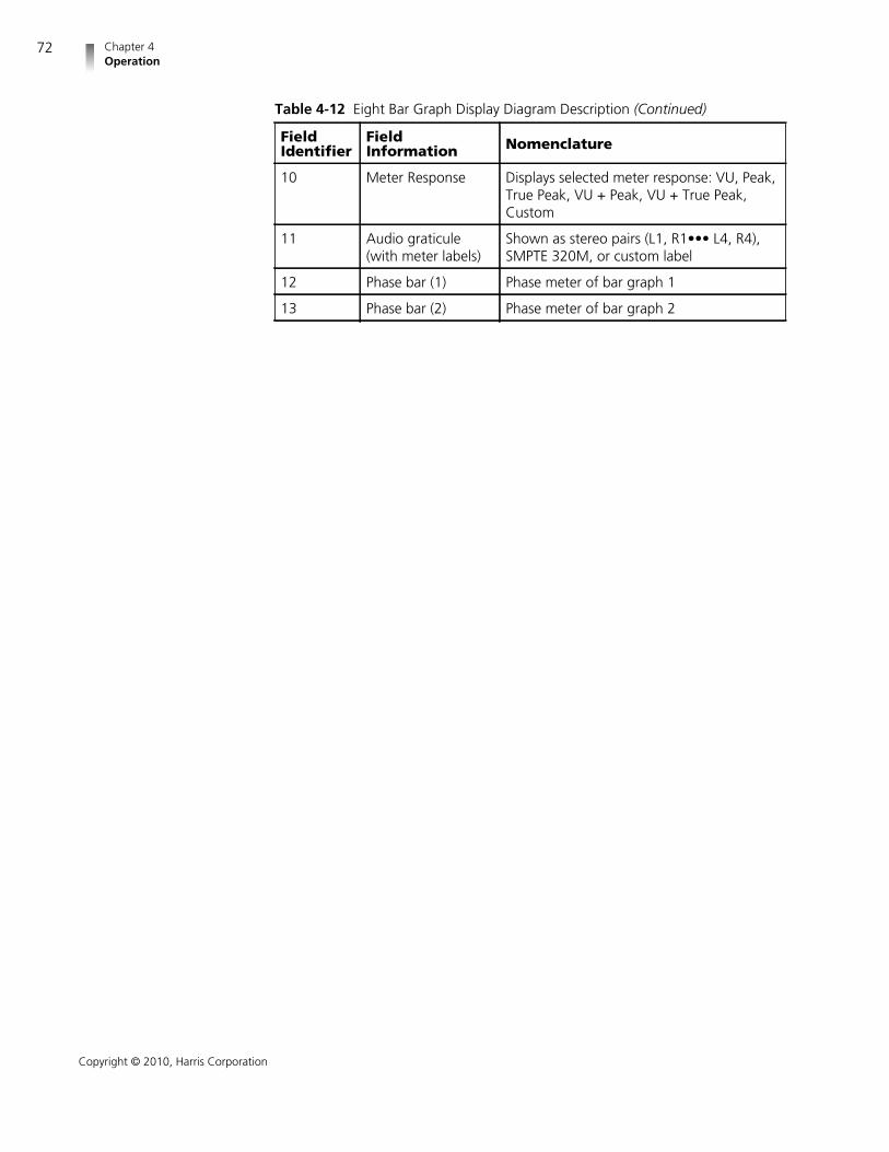
Chapter 4Operation
72
Copyright © 2010, Harris Corporation
10 Meter Response Displays selected meter response: VU, Peak,True Peak, VU + Peak, VU + True Peak,Custom
11 Audio graticule(with meter labels)
Shown as stereo pairs (L1, R1••• L4, R4),SMPTE 320M, or custom label
12 Phase bar (1) Phase meter of bar graph 1
13 Phase bar (2) Phase meter of bar graph 2
Table 4-12 Eight Bar Graph Display Diagram Description (Continued)
FieldIdentifier
FieldInformation Nomenclature

VMM-4SNYInstallation and Operation Manual
73
Copyright © 2010, Harris Corporation
Figure 4-32 Sixteen Bar Graph Display Diagram
Table 4-13 Sixteen Bar Graph Display Diagram Description
FieldIdentifier
FieldInformation Nomenclature
1 Input Displays selected input (1 or 2)
2 Status Displays audio type as Mute, AES, orEmbedded; blank when disabled
3 Channel number Shown as Ø (Mute) , A1-A2 (AES), orE1-E16 (Embedded)
4 Device Displays labels for lissajous, bar graphs, andheadphone outputs
5 Phase bar (3) Phase meter of bar graph 3
6 Phase bar (4) Phase meter of bar graph 4
7 Phase bar (5) Phase meter of bar graph 5
8 Phase bar (6) Phase meter of bar graph 6
9 Phase bar (7) Phase meter of bar graph 7
10 Phase bar (8) Phase meter of bar graph 8
11 Level markers Shows peak and reference levels for thesignal; this can be adjusted in the AUDIO METER SETUP selection options
12 Zoom Zoom when enabled; blank when disabled

Chapter 4Operation
74
Copyright © 2010, Harris Corporation
Expanding theAudio Display
Click the ZOOM button to access the audio zoom feature.
The range of the zoom is dependent on the selections made in the ZOOM CENTERand ZOOM RANGE menu. Click and hold the ZOOM button to access this menu.
Zoom Center: Adjustable from +20 dB to –60 dB in 1 dB steps. The default isthe Reference Level setting. The zoom center adjustment is restricted by AudioScale, Reference Level, and Zoom Range selections.
Zoom Range: Adjustable from 4 dB to 20 dB in 2 dB steps. The default is 10dB. The Zoom Range adjustment is restricted by Audio Scale, Reference Level,and Zoom Center selections.
NOTE: Zoom must be enabled to view the new adjustments.
Audio Mapping The Audio Mapping matrix is used to assign any audio input to a meter and/oraudio monitoring output. See page 95 for more information.
Audio Setup Click the AUDIO button to access the global Audio Setup menu. For moreinformation on the global Audio Setup menu, see page 89. For descriptions ofAudio Setup menu selection options, see page 100.
Alarm Display Click ALARM function button for the alarm display. Click and holdthe ALARM function button to access the Alarm Setup menu. Thedefault alarm display is the Alarm Log. For information on individualalarms, see Setting VMM-4SNY Alarms on page 107.
13 Scale selection Displays the selected meter scale: Type I,Type IIa, Type IIb, Type I + 8, Nordic, DIN45406, dBFS, Zero REF dBFS, Custom dB,and Custom dBFS
14 Meter response Displays selected meter response: VU, Peak,True Peak, VU + Peak, VU + True Peak,Custom
15 Audio graticule(with meter labels)
Shown as stereo pairs (L1, R1•••L8, R8),SMPTE 320M, or custom label
16 Phase bar (1) Phase meter of bar graph 1
17 Phase bar (2) Phase meter of bar graph 2
Table 4-13 Sixteen Bar Graph Display Diagram Description (Continued)
FieldIdentifier
FieldInformation Nomenclature

VMM-4SNYInstallation and Operation Manual
75
Copyright © 2010, Harris Corporation
Alarm LogDisplay
The Alarm Log display lists all the alarms, the date, time, time code, duration, andpeak value. The alarm list begins with the most recent alarm and can hold amaximum of 100 alarms.
NOTE: The Alarm Log display is the default alarm display. The Alarm Statusdisplay is accessed via the Alarm Setup menu.
An Alarm Log display diagram is shown in Figure 4-33 and described inTable 4-14. The diagram illustrates the general location for the various alarmfields.
Figure 4-33 Alarm Log Display Diagram
Table 4-14 Alarm Log Display Diagram Description
FieldIdentifier
FieldInformation Nomenclature
1 Input Displays selected input (1 or 2)
2 Column Labels Displays the labels # (for the number in thealarm list), ALARM NAME, DATE, TIME,TIMECODE, LENGTH (Duration), and PEAKVALUE*
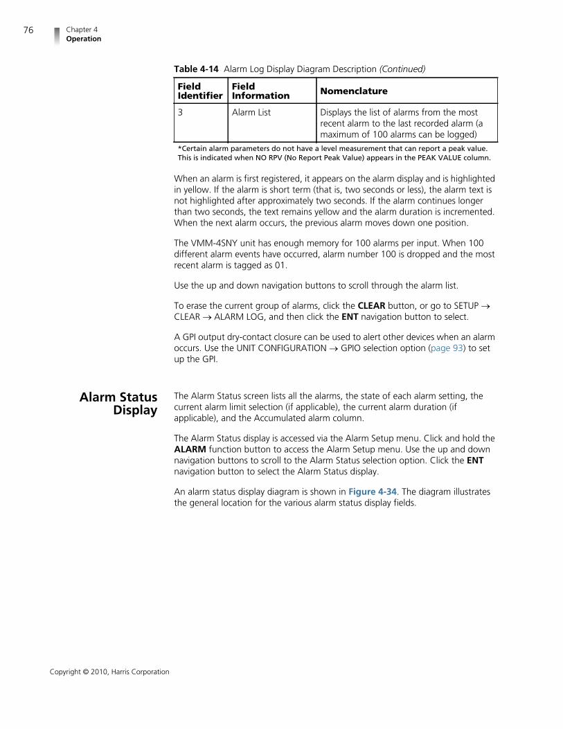
Chapter 4Operation
76
Copyright © 2010, Harris Corporation
When an alarm is first registered, it appears on the alarm display and is highlightedin yellow. If the alarm is short term (that is, two seconds or less), the alarm text isnot highlighted after approximately two seconds. If the alarm continues longerthan two seconds, the text remains yellow and the alarm duration is incremented.When the next alarm occurs, the previous alarm moves down one position.
The VMM-4SNY unit has enough memory for 100 alarms per input. When 100different alarm events have occurred, alarm number 100 is dropped and the mostrecent alarm is tagged as 01.
Use the up and down navigation buttons to scroll through the alarm list.
To erase the current group of alarms, click the CLEAR button, or go to SETUP CLEAR ALARM LOG, and then click the ENT navigation button to select.
A GPI output dry-contact closure can be used to alert other devices when an alarmoccurs. Use the UNIT CONFIGURATION GPIO selection option (page 93) to setup the GPI.
Alarm StatusDisplay
The Alarm Status screen lists all the alarms, the state of each alarm setting, thecurrent alarm limit selection (if applicable), the current alarm duration (ifapplicable), and the Accumulated alarm column.
The Alarm Status display is accessed via the Alarm Setup menu. Click and hold theALARM function button to access the Alarm Setup menu. Use the up and downnavigation buttons to scroll to the Alarm Status selection option. Click the ENTnavigation button to select the Alarm Status display.
An alarm status display diagram is shown in Figure 4-34. The diagram illustratesthe general location for the various alarm status display fields.
3 Alarm List Displays the list of alarms from the mostrecent alarm to the last recorded alarm (amaximum of 100 alarms can be logged)
*Certain alarm parameters do not have a level measurement that can report a peak value.This is indicated when NO RPV (No Report Peak Value) appears in the PEAK VALUE column.
Table 4-14 Alarm Log Display Diagram Description (Continued)
FieldIdentifier
FieldInformation Nomenclature

VMM-4SNYInstallation and Operation Manual
77
Copyright © 2010, Harris Corporation
Figure 4-34 Alarm Status Display Diagram
The alarm status screen contains detailed information concerning alarm statusindicators. This information is separated into columns sorted by alarm name,whether or not the alarm is enabled, lower and upper limits, thresholds, duration,and total number of alarms. The alarm name text can appear in a colored state.The colored states are:
White: indicates alarm is not enabled.
Green: indicates alarm is enabled and not exceeding alarm limits.
Red: indicates the alarm is enabled and exceeding an alarm limits.
There is a two-second persistence for any alarm name color change.
Use the up and down navigation buttons to scroll through the Alarm Status list.
Video Alarms Click and hold the ALARM button to access the Alarms Setup menu. If necessary,use the Up and Down navigation arrows to select the Video Alarms selectionoption. Click the ENT navigation button to show the available selection options.
For more information on the global Video Alarms Setup menu, see page 108. Fordescriptions of Video Alarms selection options, see page 113.
Audio Alarms Click and hold the ALARM button to access the Alarms Setup menu. If necessary,use the Up and Down navigation arrows to select the Audio Alarms selectionoption. Click the ENT navigation button to show the available selection options.
For more information on the global Audio Alarms Setup menu, see page 110. Fordescriptions of Audio Alarms selection options, see page 114.
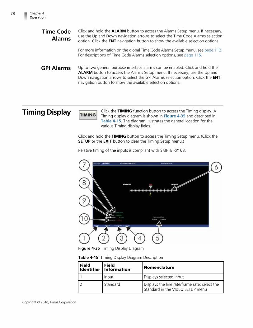
Chapter 4Operation
78
Copyright © 2010, Harris Corporation
Time CodeAlarms
Click and hold the ALARM button to access the Alarms Setup menu. If necessary,use the Up and Down navigation arrows to select the Time Code Alarms selectionoption. Click the ENT navigation button to show the available selection options.
For more information on the global Time Code Alarms Setup menu, see page 112.For descriptions of Time Code Alarms selection options, see page 115.
GPI Alarms Up to two general purpose interface alarms can be enabled. Click and hold theALARM button to access the Alarms Setup menu. If necessary, use the Up andDown navigation arrows to select the GPI Alarms selection option. Click the ENTnavigation button to show the available selection options.
Timing Display Click the TIMING function button to access the Timing display. ATiming display diagram is shown in Figure 4-35 and described inTable 4-15. The diagram illustrates the general location for thevarious Timing display fields.
Click and hold the TIMING button to access the Timing Setup menu. (Click theSETUP or the EXIT button to clear the Timing Setup menu.)
Relative timing of the inputs is compliant with SMPTE RP168.
Figure 4-35 Timing Display Diagram
Table 4-15 Timing Display Diagram Description
FieldIdentifier
FieldInformation Nomenclature
1 Input Displays selected input
2 Standard Displays the line rate/frame rate; select theStandard in the VIDEO SETUP menu

VMM-4SNYInstallation and Operation Manual
79
Copyright © 2010, Harris Corporation
When a signal is processed, there is the potential for it to be delayed with respectto a reference signal. The timing display is used to indicate when a video input isdeviating in time from the reference. See page 102 for more information onreference selection.
3 V Vertical offset graticule scale; representationof each division of vertical offset graticule(usually in lines)
4 H Horizontal offset graticule scale;representation of each division of horizontaloffset graticule (usually in micro-seconds)
5 REF OFFSET Displays that the zero point of the timingmeasurements are offset from the REFselection by xx lines yy.yyy µs
6 Timing graticule Shows the timing graticules, cursors, andlabels
7 Selected reference Displays the selected reference as REF: Xwhere X is ExtREF or LTC; the REF is selectedin the Timing Setup menu; also indicatesreference format
8 Test Indicates input being measured against theselected reference in Field Identifier 1; alsodisplays the input’s line rate/frame rate(shown in Figure 4-35 as 525/59.94);selected in the Video Setup menu
9 VERT (Vertical) The offset line in full-video lines betweenthe reference and the displayed videoDisplays the Vertical Error Measurement asVERT: xxx Line(s), where xxx is the measureddifference between the reference and thetest input alignment of the vertical timing(sync/TRS) in lines
10 HORZ (Horizontal) The offset time in microseconds betweenthe reference and the displayed video.Displays the Horizontal Error Measurementas HORZ: yy.yyy µs, where yy.yyy is themeasured difference between the referenceand the test input alignment of thehorizontal timing (sync/TRS)Horizontal can be yellow at 0 µs. It displaysthe minimum scale resolution at 1 and theminimum timing resolution at 0.037 s forHD (High Definition) and 0.74 s for SD(Standard Definition).
Table 4-15 Timing Display Diagram Description (Continued)
FieldIdentifier
FieldInformation Nomenclature

Chapter 4Operation
80
Copyright © 2010, Harris Corporation
The reference input indicator (REF), located in the center of the timing display,indicates the reference timing point for the type of signal being monitored. REF isgreen when the line and µs (microseconds) cursors are all aligned. As the signalfalls out of timing alignment, the line and the µs cursors change color when itmoves from REF. When this occurs, the REF turns red. Each hash mark represents avertical line (top scale) and 1µs (bottom scale). Once the line or µs cursors are atthe edge of the display, arrows will appear to the right or left of the timing line.
NOTE: The Timing Display alignment accuracy is ±300 ns.
SDI Input andExternal
ReferenceFormats
Supported
Table 4-16 on page 80 provides information for SDI input and supported externalreference formats.
Table 4-16 SDI Input and External Reference Formats Supported• = Supported
External Reference Format
SDI Input Format
NTS
C
PA
L
1080i6
0(p
30sf
)
1080i5
9.9
4
1080i5
0(p
25sf
)
1080p
30
1080p
29.9
7
1080p
25
1080p
24
1080p
23.9
8
1080p
24sf
1080p
23.9
8sf
720p
60
720p
59.9
4
720p
50
720p
30
720p
29.9
7
720p
24
720p
23.9
8
525/59.94 • • •
625/50 • • •
1080i60(p30sf) • •
1080i59.94(p29.97sf) • • •
1080i50(p25sf) • • •
1080p60
1080p59.94 • • •
1080p50 • • •
1080p30 • • •
1080p29.97 • • • •
1080p25 • • •
1080p24 • • •
1080p23.98 • • •
1080p24sf • •

VMM-4SNYInstallation and Operation Manual
81
Copyright © 2010, Harris Corporation
Things toRemember WhenUsing the Timing
Display
The Timing Display measures the elapsed time between the vertical syncs oftwo inputs. The elapsed time is expressed in units of microseconds and lines ofthe selected input video, not of the reference.
When referencing a standard definition video input to an external tri-levelreference input, the line number indication in the timing display representsstandard definition video lines. If the relative timing is adjusted in highdefinition video lines, it may take an adjustment of two or more lines beforethe line number changes in the timing display. This is due to the high definitionvideo lines, which are shorter than the standard definition video linesrepresented by the timing display.
When referencing a high definition video input to an external composite (BB)reference input, the line number indication in the timing display representshigh definition video lines. If the relative timing is adjusted in standarddefinition video lines, a single video line adjustment will cause a change of twoor more lines in the timing display. This is due to the standard definition videolines, which are longer than the high definition video lines represented by thetiming display.
The information of the Timing Display should not be used when captured SDIfreeze data is displayed.
Timing SetupMenu
Click and hold the TIMING function button to access the Timing Setup menu. Formore information on the global Timing Setup menu, see page 92. For descriptionsof Timing selection options, see page 102.
1080p23.98sf • •
720p60 • • • •
720p59.94 • • • • •
720p50 • • • •
720p30 • • • •
720p29.97 • • • • •
720p24 • • •
720p23.98 • • •
Table 4-16 SDI Input and External Reference Formats Supported (Continued)• = Supported

Chapter 4Operation
82
Copyright © 2010, Harris Corporation
Preset Display SelectionsPresets are used to store menu configurations anddisplay settings. A total of 99 presets can be stored inthe VMM-4SNY.
Selecting Presets Click the PRST function button to access the bank of presets. Adialog box appears on the display screen, which shows the Presetnumber. Click selection button 1 to 99 to select a preset. Click PRSTto store or overwrite an existing Preset, or click ENTER to recall.
Storing Presets Click the PRST button to bring up the Presets dialog box. selection button 1 to 99(or scroll through the available list) to store the Preset. Click the PRST button tostore a new or overwrite an existing Preset.
Recalling Presets NOTE: Information must be stored in a preset location before beingrecalled.
Click the PRST function button to bring up the Presets dialog box. Click selectionbutton 1 to 99 to recall the Preset. Click the ENTER button to recall the Preset.
If a preset does not exist for the selected number, nothing happens.

83
Copyright © 2010, Harris Corporation
5 Global Setup MenuFunctions
Click the SETUP button to access the global setup menu. Use the navigationbuttons to navigate the global Setup menu selections. The setup and navigationbuttons are described in Table 5-1.
Table 5-1 Setup and Navigation Button Functions
Button Function
Click to enter or exit the Setup menu.
Click to exit the Setup menu.
Click to select a menu item, or open a menu or submenu.
Click to move up in a menu or submenu tree.
Click to move right to the next submenu.
Click to move out of a submenu.
Click to move down in a menu or submenu.
Click to set numeric values for certain parameters.Click to set parameter to default value.

Chapter 5Global Setup Menu Functions
84
Copyright © 2010, Harris Corporation
Setup Menusand Alarm
Tables
The following tables make up the global Setup menu. An asterisk (*) is shown nextto the default menu selections. The Setup menu items are listed in Table 5-2 withtheir corresponding Table and Description pages.
Click to use the numeric keypad for direct parameter entry. TheENTER button is high tally to indicate that the numeric keypadis available for direct parameter entry.
Table 5-1 Setup and Navigation Button Functions (Continued)
Button Function
Table 5-2 Setup Menu Tables
Selection Table Page Description Page
Video 84 94
Audio mapping 86 95
Time code source 86 96
Waveform 86 96
Vector 87 97
Gamut 88 98
Picture 88 99
Audio 89 100
Timing 92 102
MLT 92 102
Alarms Alarm setup tables and correspondingdescriptions appear in Chapter 6, AlarmDescriptions
Clear 92 103
Unit Configuration 92 104
About 92 106
Table 5-3 Video Setup MenuNOTE: Descriptions for these selections start on page 94.
Selection Selection Selection
Auto Detect *
1080i Enable
1080i frame rate 60
59.94 *

VMM-4SNYInstallation and Operation Manual
85
Copyright © 2010, Harris Corporation
50
1080p Enable
1080p frame rate 60
59.94 *
50
30
29.97
25
24
23.98
1080psF Enable
1080psF frame rate 30sF
29.97sF *
25sF
24sF
23.98sF
720p Enable
720p frame rate 60
59.94 *
50
30
29.97
24
23.98
625/50
525/59.94
Structure Auto Detect *
10 bit YCbCr 4:2:2
10 bit YCbCr 4:4:4
10 bit RGB 4:4:4
Table 5-3 Video Setup Menu (Continued)NOTE: Descriptions for these selections start on page 94.
Selection Selection Selection

Chapter 5Global Setup Menu Functions
86
Copyright © 2010, Harris Corporation
12 bit YCbCr 4:4:4
12 bit RGB 4:4:4
12 bit YCbCr 4:2:2
Table 5-4 Audio Mapping MenuNOTE: Descriptions for these selections start on page 95.
Selection
Matrix Screen
Table 5-5 Time Code Source Setup MenuNOTE: Descriptions for these selections start on page 96.
Selection Selection
LTC *
ANC LTC
ANC DIVTC 0
ANC DVITC 1
DVITC
DVITC Line 525 Line 10 to 30(line 14 *)
DVITC Line 625 Line 6 to 30 (line 14 *)
Table 5-6 Waveform Setup MenuNOTE: Descriptions for these selections start on page 96.
Selection Selection Selection
Display/Format YCbCr *NOTE: TheYCbCr + Alphaand RGB +Alpha selec-tions are avail-able with the3G-SDI optiononly
RGB
Composite
YCbCr + Alpha
RGB + Alpha
YRGB
Component Filter Flat *
Low pass
Bowtie
Table 5-3 Video Setup Menu (Continued)NOTE: Descriptions for these selections start on page 94.
Selection Selection Selection

VMM-4SNYInstallation and Operation Manual
87
Copyright © 2010, Harris Corporation
Composite Filter Flat *
Low pass
Chroma
Flat + Low Pass
Component Overlay
Blanking Blank All *
Show SAV/EAV
Show All
Error Highlighting
Graticule Digital WaveformGraticule
Volts *
Percent
NTSC Pedestal *
PAL Waveform Scale Volts *
Units
Intensity 0% to 100% (72% *)
Contrast 0% to 100% (31% *)
Persistence 0% to Infinite (0% *)
Attack 1% to Maximum (6% *)
Table 5-7 Vector Setup MenuNOTE: Descriptions for these selections start on page 97.
Selection Selection
Standard 75%
100% *
75% + 100%
I/Q Lines
Scale to Composite
Intensity 0% to 100% (86% *)
Contrast 0% to 100% (55% *)
Persistence 0% to Infinite (0% *)
Attack 1% to Maximum(10% *)
Table 5-6 Waveform Setup Menu (Continued)NOTE: Descriptions for these selections start on page 96.
Selection Selection Selection

Chapter 5Global Setup Menu Functions
88
Copyright © 2010, Harris Corporation
Table 5-8 Gamut Setup MenuNOTE: Descriptions for these selections start on page 98.
Selection Selection
Single color
RGB *
Composite
Data Error Persistence Enable
0% to Infinite (0% *)
Intensity 0% to 100% (86% *)
Contrast 0% to 100% (55% *)
Persistence 0% to Infinite (0%)*
Table 5-9 Picture Setup MenuNOTE: Descriptions for these selections start on page 99.
Selection Selection Selection
Markers Center
Safe Title Off
Corners
Box
Safe Action Off
Corners
Box
Clean Aperture Off
Corners
Box
Custom Off
Corners
Box
Custom Position 1% to 49% (20% *)
Custom Length 3% to 47 (5% *)
Anamorphic
Time Code Enable
Show LTC
Position Top *
Center
Bottom

VMM-4SNYInstallation and Operation Manual
89
Copyright © 2010, Harris Corporation
Brightness 0% to 100% (59% *)
Contrast 0% to 200% (105% *)
Color Green *
Blue *
Red *
VBI Mask
Native
Delay Enable
H Position 1 pixel to xxx pixels(format-dependent)
V Position 1 line to xxx lines(format-dependent)
Gamut ErrorHighlighting
Table 5-9 Picture Setup Menu (Continued)NOTE: Descriptions for these selections start on page 99.
Selection Selection Selection
Table 5-10 Audio Setup MenuNOTE: Descriptions for these selections start on page 100.
Selection Selection Selection Selection
2 Channels
4 Channels
6 Channels
6 Channel Display Vertical *
CineSound
8 Channels
8 Channel Display* Vertical *
CineSound 5.1 + AUX
CineSound 6.1
CineSound 7.1
16 Channels
Meter Setup Reference Level –22 dBFS to –8 dBFS (–20dBFS *)
Peak Program Level Type I +1 dB to +11 dB (+8 dB *)
Type IIa +1 dB to +11 dB (+8 dB *)
Type IIb +1 dB to +11 dB (+8 dB *)
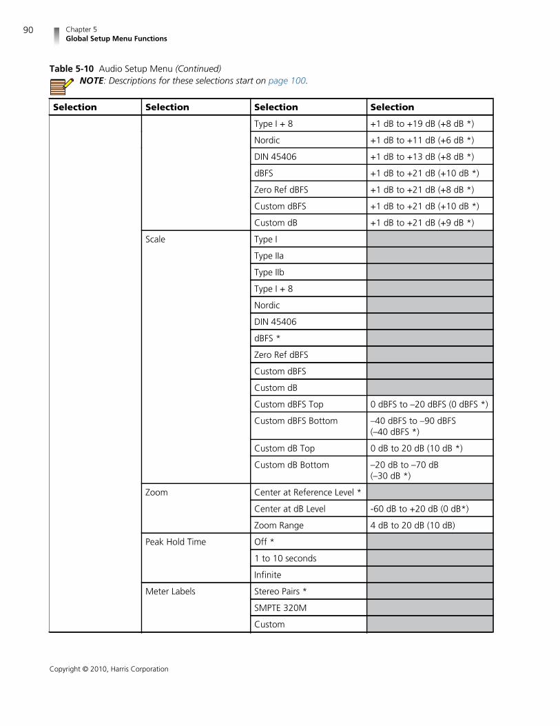
Chapter 5Global Setup Menu Functions
90
Copyright © 2010, Harris Corporation
Type I + 8 +1 dB to +19 dB (+8 dB *)
Nordic +1 dB to +11 dB (+6 dB *)
DIN 45406 +1 dB to +13 dB (+8 dB *)
dBFS +1 dB to +21 dB (+10 dB *)
Zero Ref dBFS +1 dB to +21 dB (+8 dB *)
Custom dBFS +1 dB to +21 dB (+10 dB *)
Custom dB +1 dB to +21 dB (+9 dB *)
Scale Type I
Type IIa
Type IIb
Type I + 8
Nordic
DIN 45406
dBFS *
Zero Ref dBFS
Custom dBFS
Custom dB
Custom dBFS Top 0 dBFS to –20 dBFS (0 dBFS *)
Custom dBFS Bottom –40 dBFS to –90 dBFS(–40 dBFS *)
Custom dB Top 0 dB to 20 dB (10 dB *)
Custom dB Bottom –20 dB to –70 dB(–30 dB *)
Zoom Center at Reference Level *
Center at dB Level -60 dB to +20 dB (0 dB*)
Zoom Range 4 dB to 20 dB (10 dB)
Peak Hold Time Off *
1 to 10 seconds
Infinite
Meter Labels Stereo Pairs *
SMPTE 320M
Custom
Table 5-10 Audio Setup Menu (Continued)NOTE: Descriptions for these selections start on page 100.
Selection Selection Selection Selection

VMM-4SNYInstallation and Operation Manual
91
Copyright © 2010, Harris Corporation
Custom Labels 1-8 Channel (1-8) Use arrowkeys to edit and changecharacters
Custom Labels 9-16 Channel (9-16) Use arrowkeys to edit and changecharacters
LFE Offset –10 dB
None *
CineSound Direction Outward *
Inward
Audio Markers Enable
Position –50 to +12 dB (0 dB *)
Meter Response VU *
Peak
True Peak
VU + Peak
VU + True Peak
Custom
Custom Attack 0 to 20 ms (0 ms *)
Custom Decay 0.3 to 5.0 seconds (1.5seconds *)
Lissajous Setup Persistence 0% to Infinite (0% *)
Attack 1% to Maximum (50% *)
Automatic Gain Control
Plot Soundstage *
X-Y
Configure PhaseBar(s)
Polarity Normal *
Reverse
Damping Slow
1 to 10 (5 *)
Fast
AES Validity Bit
Status Readout *
Table 5-10 Audio Setup Menu (Continued)NOTE: Descriptions for these selections start on page 100.
Selection Selection Selection Selection

Chapter 5Global Setup Menu Functions
92
Copyright © 2010, Harris Corporation
NOTE: Alarm setup tables and corresponding descriptions appear inChapter 6, Alarm Descriptions
Table 5-11 Timing Setup MenuNOTE: Descriptions for these selections start on page 102.
Selection Selection
Reference External Ref *
LTC
Factory *
Offset
Set Zero Ref
Table 5-12 MLT Setup MenuNOTE: Descriptions for these selections start on page 102.
Selection Selection Selection
Quadrant Display *
Overlay Display
Overlay Settings Intensity 0% to 100% (72% *)
Contrast 0% to 100% (31% *)
Persistence 0% to Infinite (0% *)
Attack 1% to Maximum (6% *)
Table 5-13 Clear Setup MenuNOTE: Descriptions for these selections start on page 103.
Selection
DISP Captures
Audio Peak Hold
Alarm Log
Alarm Error Count
Timing Zero Reference
Persistence
Table 5-14 Unit Configuration Setup MenuNOTE: Descriptions for these selections start on page 104.
Selection Selection Selection Selection
Display Setup Input Color White
Yellow
Light Magenta
Light Red

VMM-4SNYInstallation and Operation Manual
93
Copyright © 2010, Harris Corporation
Light Cyan
Light Green *
Light Blue
Dark Gray
Gray
Brown
Magenta
Red
Cyan
Green
Blue
PIP Offset Left
Off *
Right
Sleep Mode Off to 60 Minutes
Monochrome Display
Graticule Intensity 1 to 100% (40% *)
Cursor Intensity 1 to 100% (70%)*
Front Panel High Tally 35 to 100% (80% *)
Low Tally 0 to 10% (5% *)
GPIO Input Function Input 1 User GPI Alarm 1
SDI Input 1
SDI Input 2
No Action*
Input 2 User GPI Alarm 2
SDI Input 1
SDI Input 2
No Action*
Identifier Display MAC Address
Display IP Address
Display Unit Name
Unit Name Unit Name SetupScreen
System Time Time Setup Screen
Show Clock *
Table 5-14 Unit Configuration Setup Menu (Continued)NOTE: Descriptions for these selections start on page 104.
Selection Selection Selection Selection
Chapter 5Global Setup Menu Functions
94
Copyright © 2010, Harris Corporation
Video SetupMenu
Selections
The Video Setup selections are used to automatically or manually select the videoformat reference standard for the SDI input. The format selection determines theunit of measure and the critical amplitude limits for the input. The Video Setupselections are described below.
Auto Detect: This selection is used to automatically detect the format of theinput signal. This is the default setting.
1080i: This selection is used to force the unit into 1080 interlaced video mode.
1080i Frame Rate: This selection is used to set up the 1080i frame rate.Selections are 60, 59.94, and 50. The default setting is 59.94.
1080p: This selection is used to force the unit into 1080 progressive videomode.
1080p Frame Rate: This selection is used to set up the 1080p frame rate.Selections are 60, 59.94, 50, 30, 29.97, 25, 24, and 23.98. The default settingis 59.94.
1080psF: This selection is used to force the unit into 1080 progressivesegmented frame video mode.
1080psF Frame Rate: This selection is used to set up the 1080psF frame rate.Selections are 30sF, 29.97sF, 25sF, 24sF, and 23.98sF. The default setting is29.97sF.
720p: This selection is used to force the unit into 720 progressive video mode.
720p Frame Rate: This selection is used to set up the 720p frame rate.Selections are 60, 59.94, 50, 30, 29.97, 24, and 23.98. The default setting is59.94.
625/50: This selection is used force the unit into video frames with 625-line/50Hz video mode.
525/59.94: This selection is used force the unit into frames with 525-line/(60*1000/1001) Hz video mode.
Structure: This selection is used to configure the signal handling path to a10-bit or 12-bit RGB or YCbCr sampling structure. 12-bit modes are notavailable with formats 1080p/60, 1080p/59.94, and 1080p/50. 4:4:4 and4:2:2 are the format rates selected with the 10-bit and 12-bit samplingstructures. 4:2:2 is only available with 12-bit YCbCr. The selections are asfollows.
Auto Detect: The sampling structure is determined from the VideoPayload Identifier. If there is no detected VPI, a 10-bit YCBCR samplingstructure will be assumed. This is the default setting.
10 bit YCbCr 4:2:2: The signal handling path will be configured for a10-bit YCbCr mode of operation.
Table 5-15 About Setup Menu
Selection
Matrix Screen

VMM-4SNYInstallation and Operation Manual
95
Copyright © 2010, Harris Corporation
10-bit YCbCr 4:4:4: The signal handling path will be configured for a10-bit YCbCr mode of operation. This selection is only available for3G-SDI HD.
10-bit RGB 4:4:4: The signal handling path will be configured for a 10-bitRGB mode of operation. This selection is only available for 3G-SDI HD.
12-bit YCbCr 4:4:4: The signal handling path will be configured for a12-bit YCbCr mode of operation. This selection is only available for 3Gb/sHD.
12-bit RGB 4:4:4: The signal handling path will be configured for a 12-bitRGB mode of operation. This selection is only available for 3G-SDI HD.
12-bit YCbCr 4:2:2: The signal handling path will be configured for a12-bit YCbCr mode of operation. This selection is only available for3G-SDI HD.
AudioMapping
Setup MenuSelections
The Audio Mapping matrix is used to assign the input to the meter display andmonitor output to the Sony monitor’s internal speakers (when available). Whenthe Audio Mapping setup option is selected, a matrix screen for Mute, Embedded,and AES appears (see Figure 5-3). Use the Right/Left arrow buttons to scrollthrough the column selections. Use the Up/Down arrow buttons to scroll throughindividual cell selections. Click the ENT button to assign an input to a meter.Different audio types (AES or Embedded) can be assigned to a meter or speakeroutput.
Figure 5-1 Audio Mapping Matrix Display

Chapter 5Global Setup Menu Functions
96
Copyright © 2010, Harris Corporation
Time CodeSource Setup
MenuSelections
The Time Code Source Menu is used to determine the Time Code Source for eachformat. The VMM-4SNY can read LTC (Longitudinal Time Code) and DVITC (DigitalVertical Interval Time Code) based on the format selected. The Time Code Sourcemenu has these selections:
LTC (default)
ANC LTC
ANC DVITC 0
ANC DVITC 1
DVITC: DVITC is monitored on selected lines. After DVITC is selected, adjustthe line selection in the DVITC LINE 525 or DVITC LINE 625 menus to theselected line. The range for DVITC LINE 525 is adjustable from Line 10 to 30,and DVITC LINE 625 is adjustable from line 6 to 30.
For more information on displaying time code see page 99.
WaveformSetup Menu
Selections
The Waveform Setup items are described below.
Display Format: This selection allows a choice of display formats: YCbCr(default), RGB, Composite, YCbCr + Alpha, RGB + Alpha, and YRGB.Table 5-16 lists the relationships between the input and display formats.
Component Filter: Component filters are used when the waveform displayformat is set to YCbCr or RGB. Filter selections are Flat, Low Pass, and Bowtie.
Flat: No filtering (default)
Low Pass: Selects the Low Pass filter
Bowtie: Checks the timing relationships between the digital components(a bowtie test signal is required)
Composite Filter: Composite filters are used when the waveform displayformat is set to Composite. Filter selections are Flat, Low Pass, Chroma, andFlat and Low Pass.
Flat: No filtering (default)
Low Pass: Selects the Low Pass filter
Chroma: Selects the Chroma filter
Flat and Low Pass: Selects Flat and Low Pass filtering
Table 5-16 Input and Display Format Relationship
InputFormat YCbCr RGB Composite
YCbCr +Alpha(10 bitonly)
RGB +Alpha(10 bitonly)
YRGB
3G-SDI Yes Yes Yes Yes Yes Yes
HD Yes Yes Yes No No Yes
SD Yes Yes Yes No No Yes
VMM-4SNYInstallation and Operation Manual
97
Copyright © 2010, Harris Corporation
Component Overlay: When Component Overlay is selected for a singleinput, the components of the input signal are displayed over each other (thatis, R over G over B in an RGB signal).
Blanking: The blanking selections are Blank All, EAV/SAV, and Show All.
Blank All displays only the active video of the input signal (default).
Show EAV/SAV displays the active video and the EAV/SAV headers of theinput signal.
Show All displays the ancillary data, EAV/SAV, and active video.
NOTE: To view ancillary data in picture while picture delay is active,Blanking must be set to Show All.
Error Highlighting: Error highlighting changes the color of the portion of thewaveform that exceeds the alarm settings. The default selection is OFF. Thehighlighting is dependent upon the format and gamut settings selected. Thefollowing are rules to consider:
Composite format with Flat filter follows the alarm settings for GamutPeak upper and lower; it follows the threshold settings for the alarm, evenwhen it is not enabled
Composite format with Low Pass filter follows the Luma Upper and Lowerthresholds.
Component format with RGB filter will follow the RGB gamut.
No highlighting in YCbCr.
Graticule: This selection is used to select the unit of measurement in percentor volts for the Digital Waveform Graticule, and in volts or units for the PALWaveform Scale.
NTSC Pedestal: This selection adds setup to the Composite display (default).
Intensity: This selection is used to raise or lower the brightness of thedisplayed waveform. The range of intensity is 0% to 100%. The defaultwaveform intensity is 72%.
Contrast: This selection is used to adjust the overall difference between thelightest and darkest colors of the waveform. The range of contrast is 0% to100%. The default waveform contrast is 31%.
Persistence: This selection is used to determine how long a data point (pixel)in the waveform remains on the display. The range of persistence is 0% toInfinite. The default waveform persistence is 0%.
Attack: Attack is the initial intensity that the data point (pixel) appears in thedisplay. The range of attack is 1% to Maximum. The default waveform attackis 6%.
Vector SetupMenu
Selections
The Vector Setup menu is used to select the Standard, IQ Lines, Scale toComposite, Intensity, Contrast, Persistence, and Attack. The Vector Setupselections are described below.

Chapter 5Global Setup Menu Functions
98
Copyright © 2010, Harris Corporation
Standard: Standard is used to set the marks on the vector display. The markson the vector help to visualize the minimum/maximum value of a video signal.The position of the excursion marks are 75% or 100% (default) for SD andHD. The HD standard also can be selected as 75% and 100% simultaneously.
I/Q Lines: This selection is used to turn OFF and ON the I and Q marker lineson the Vector Display. The default condition is OFF.
Scale to Composite: The Scaled to Composite menu can be used to scale theSD or HD vector to reflect a composite format. The default condition is OFF.
Intensity: This selection is used to raise or lower the brightness of thedisplayed vector. The range of intensity is 0% to 100%. The default selectionis 86%.
Contrast: This selection is used to adjust the overall difference between thelightest and darkest colors of the vector. The range of contrast is 0% to 100%.The default selection is 55%.
Persistence: This selection is used to determine how long a data point (pixel)in the vector remains on the display. The range of persistence is 0% to Infinite.The default selection is 0%.
Attack: This selection is used to determine the initial intensity that the datapoint (pixel) appears in the display. The range of Attack is 1% to Maximum.The default selection is 10%.
Gamut SetupMenu
Selections
The Gamut Setup menu is used to change a gamut’s color plots, Data ErrorPersistence, Intensity, Contrast, and Persistence. The Gamut Setup selections aredescribed below.
Single Color, RGB, Composite (Color Plot): These selections are used to setthe color for plotting RGB and Composite pixels. The pixels for RGB can beone single color or RGB (red, green, or blue). Composite is always a singlecolor. Multiple colors help to indicate which color of the RGB signal movesbeyond the inner and outer parameters of the gamut graticule. The defaultselection is RGB.
Data Error Persistence: This selection is used to determine how long a pointof data beyond the inner and outer parameters of the gamut graticule. Therange of persistence is 0% to Infinite. The default selection is 0%.
Intensity: This selection is used to raise or lower the brightness of thedisplayed gamut. The range of intensity is 0% to 100%. The default selectionis 86%.
Contrast: This selection is used to adjust the overall difference between thelightest and darkest colors of the gamut. The range of contrast is 0% to100%. The default selection is 55%.
Persistence: This selection is used to determine how long a data point (pixel)in the Gamut remains on the display. The range of Persistence is 0% toInfinite. The default selection is 0%.

VMM-4SNYInstallation and Operation Manual
99
Copyright © 2010, Harris Corporation
Picture SetupMenu
Selections
The Picture Setup selections are described below.
Markers: There are several markers available to be indicated in a picture.
Center location is equal to 50% of the picture height and 50% of thepicture width.
Safe Title is equal to 80% of the picture height and 80% of the picturewidth.
Safe Action is equal to 90% of the picture height and 90% of the picturewidth.
Clean Aperture shows the limits for the active pixel area. Brackets appearon the picture or a box surrounds the picture to show these limits. Thecenter marker identifies the location of the center of the picture.
Custom (Corners) and Custom (Box) allows the setup of customizedmarkers for a picture display.
Custom Position is used in conjunction with the Custom Corners andCustom Box selections. It allows the adjustment of the custom corner orbox size.
Custom Length is used in conjunction with the Custom Cornersselection. It allows the adjustment of the corner lengths.
Anamorphic: This selection is used to correct the anamorphic display. Settingthe menu selection to ON changes the actual source aspect ratio to an aspectratio that fills the screen (for example, SD squeezed horizontally 16×9 to 4×3DVD source). This selection is only available with an SD-SDI input.
Time Code: This selection is used to display the time code; that is, the timethat is associated with each video frame. Time Code is keyed over the pictureon the right side. Adjacent to the Time Code, the LTC/DVITC is keyed over thepicture on the right side when Show LTC is selected. (Show LTC has no effectunless ENABLE is selected.) The Position selection is used for the verticalplacement of the time code at the top, center, and bottom (beyond safe actionareas).
Brightness: This selection is used to make the picture brightness lighter ordarker. The brightness range is from 0% (for the darkest picture) to 100% (forthe brightest picture). The default picture brightness is 59%.
Contrast: This selection is used to increase the overall difference between thelightest and darkest colors. The contrast range is from 0% (for no differencebetween the lightest and darkest colors) to 200% (for the most amount ofdifference between the lightest and darkest colors). The default picturecontrast is 105%.
Color: This selection is used to change the picture color gun selection. Whenall three colors are de-selected the picture display changes to monochrome.
Green: Green is a setup feature that is used to show the green colorcomponent of the input video. Use the Green feature to set the Saturationand Hue by matching the intensity of all green bars when a SMPTE splitfield color bar signal is applied.
Blue: Blue is a setup feature that is used to show the blue colorcomponent of the input video. Use the Blue feature to set the Saturationand Hue by matching the intensity of all blue bars when a SMPTE splitfield color bar signal is applied.

Chapter 5Global Setup Menu Functions
100
Copyright © 2010, Harris Corporation
Red: Red is a setup feature that is used to show the red color componentof the input video. Use the Red feature to set the Saturation and Hue bymatching the intensity of all red bars when a SMPTE split field color barsignal is applied.
VBI Mask: The VBI (Vertical Blanking Interval) Mask selection is used to masknon-active lines. With VBI Mask set to ON, only active lines will be shown onthe picture portion of the display.
Native: When this selection is enabled, it displays the SD picture as aone-for-one pixel mapping. When Native mode is not checked, the SD picturefills the screen.
NOTE: The Native mode menu item only appears when an SD format isdetected or selected.
Delay: This selection is used to view the horizontal and vertical blanking areasof the video signal. Delay enables and disables the Delay mode. Delay Positiondisplays the amount of vertical and horizontal delay. Using the Delay Position,click the up/down and right/left arrow buttons to position the picture. TheDelay feature is not affected by the Native mode selection. The Line Selectmarker is not available in this mode.
NOTE: To view ancillary data in picture while picture delay is active,Blanking must be set to Show All. See page 97 for more informationabout the Blanking selection.
Gamut Error Highlighting: When Gamut Error Highlighting is selected in thePicture setup menu, a grid pattern appears over the picture displayhighlighting gamut errors. Gamut highlighting is determined by the gamutthreshold settings in the ALARMS VIDEO ALARMS GAMUT selection.
Audio SetupMenu
Selections
The Audio Setup selections are described below.
2 Channels: This selection allows the display of one 2-channel bar graph withone lissajous and one phase bar.
4 Channels: This selection allows the display of two 2-channel bar graphs (fora total of four channels) with two lissajous and two phase bars.
6 Channels: This selection allows the display of three 2-channel bar graphs(for a total of six channels) with three phase bars, or CineSound 5.1 with twophase bars
8 Channels: This selection allows the display of four 2-channel bar graphs (fora total of eight channels) with four phase bars; CineSound 5.1 + Aux withthree phase bars; CineSound 6.1 with two phase bars, or CineSound 7.1 withthree phase bars
16 Channels: This selection allows the display of eight 2-channel bar graphs(for a total of 16 channels) with eight phase bars.
Meter Setup: This selection is used to select the response, ballistics, and othermeter features.

VMM-4SNYInstallation and Operation Manual
101
Copyright © 2010, Harris Corporation
Ref Level: This selection is used to set the reference level on the metersfor a digital signal. The range is from –8 dBFS to –22 dBFS. The defaultselection is –20 dBFS. Content below this setting is green. Content abovethis setting is yellow.
Peak Program Level: This selection is used to adjust the position of thepeak marker on an Audio meter display. Value is the number of dB abovethe reference level. Content above this value is red.
This adjustment is scale-dependent. The user must select the proper scale.
Scale: This selection is used to determine the type of scale that appears onthe Audio meter display. Custom dBFS and Custom dB can customize thetop and bottom of the dBFS or dB scales.
Zoom: This selection is used to set the Zoom modes. Selections are Centerat Reference Level, Center at dB level, and Zoom Range. The Center at dBlevel has a range from –60 dB to +20 dB; the default selection is 0 dB. TheZoom range is from 4 dB to 20 dB; the default selection is 10 dB.
Peak Hold Time: This selection is a user-selectable duration value of Off,1 to 10 seconds, or Infinite. The duration only applies to the hold time ofthe PEAK value, not the attack or decay time. The default selection is Off.
Meter Labels: This selection menu is used to select the audio mappingscheme for the selected input. Only the Vertical Bar Meter labels can becustomized. When the CineSound display is selected, the audio inputsfollow a SMPTE 320M mapping scheme. For vertical meters only, theSMPTE 320M meter label-mapping scheme can be changed to a stereopair-mapping scheme or Custom Labels. (SMPTE 320M label mappingscheme is not available for 16 channels.) default selection is Stereo.
LFE Offset: This selection adjusts the LFE by –10 dB when enabled. LFEOffset only occurs when CineSound is displayed or SMPTE 320M label isselected for the vertical bars.
CineSound Direction: This selection is used to reverse the default metermovement for the CineSound display. The default selection for theCineSound direction is from the center outward. Select INWARD to reversethe meter movement.
Audio Markers: This selection is used to place adjustable markers in theaudio meters. Adjustable markers can be placed in audio meters to showspecific critical levels.
Meter Response: This selection is used to display the selected meterresponse. Selections are VU, Peak, True Peak, VU + Peak, VU + True Peak,Loudness, Custom, Custom Attack, and Custom Decay. The default selection isVU.
Lissajous Setup: This selection is used to set up the display amplitude andphase relationships between two input signals. Selections are Persistence,Attack, AGC, and Plot.
Persistence: This selection is used to determine how long a data point(pixel) remains on the display. The range of Persistence is 0% to Infinite.The default selection is 0%.
Attack: This selection is the initial intensity that the data point (pixel)appears in the display. The range of Attack is 1% to Maximum. Thedefault selection is 50%.
Automatic Gain Control: This selection is used to keep the display visiblefrom very small levels to very high levels.

Chapter 5Global Setup Menu Functions
102
Copyright © 2010, Harris Corporation
Plot: This selection is used to select one of two types of Lissajous displays.The soundstage selection displays a Lissajous that is rotated so that thein-phase signals appear on the vertical axis and out of phase signalsappear on the horizontal axis. X-Y displays a Lissajous with the leftchannel mapped to the vertical axis, and the right channel mapped to thehorizontal axis.
Configure Phase Bar(s): Phase bars are used to monitor the instantaneousphase relationship between two channels of audio. On a vertical audio displaythe “+” marking indicates a phase difference of 0°, and the “–” markingindicates a phase difference of 180°. A properly phased stereo pair produces aphase pointer that moves within the green zone, whereas a reversed channelproduces a pointer that moves within the red zone.
Polarity: This selection is used to set the phase bar polarity to Normal orReverse. The default selection is Normal.
Damping: The effect of higher damping in a phase meter is to show anaveraged rather than a peak value of phase. This selection is used to setthe phase bar damping to Fast, 1 to 10, or Slow. The default selection is 5.
AES Validity Bit: The AES Validity Bit is used to detect pulse code modulation(PCM) audio or non PCM audio. Non-PCM audio can include Dolby or otherdigital data. When the AES Validity Bit option is enabled, the output tomonitor’s speakers will be muted unless AES validity bit of the AES stream iszero. The audio meters are unaffected by state of the AES validity bit.
Timing SetupMenu
Selections
The Timing Setup menu is used to set the offset of the reference to the signal. TheTiming Setup selections are described below; the default selection is Factory.
Reference: This selection is used to set the reference source.
External REF: This selection uses the blackburst or tri-level signalconnected to the External Reference input.
Factory: This selection is used to set the factory reference to 0. WhenFACTORY is selected, the OFFSET field does not appear on the screen.
Offset: This selection Enables and displays the Offset field. The referenceoffset is not applied until Set Zero Ref is selected.
Set Zero Ref: This selection is used to apply the current offset setting as thezero reference point.
MLT SetupMenu
Selections
The MLT Setup menu is used to set up the Quadrant and Overlay display modes.Selections are described below; the default selection is Quadrant Display.
Quadrant Display: This selection is used to select the quad (four-screen)display mode as shown in Figure 3-4 on page 34.
Overlay Display: This selection is used to select the overlay display mode asshown in Figure 3-5 on page 35.

VMM-4SNYInstallation and Operation Manual
103
Copyright © 2010, Harris Corporation
Overlay Settings: This selection is used to select the settings for the overlaydisplay.
Intensity: This selection is used to raise or lower the brightness of thedisplayed waveform and vector. The range of intensity is 0% to 100%.The default selection is 72%.
Contrast: This selection is used to adjust the overall difference betweenthe lightest and darkest colors of the displayed waveform and vector. Therange of contrast is 0% to 100%. The default selection is 31%.
Persistence: This selection is used to determine how long a data point(pixel) in the displayed waveform and vector remains on the display. Therange of persistence is 0% to Infinite. The default selection is 0%.
Attack: This selection is the initial intensity that the data point (pixel)appears in the display. The range of attack is 1% to Maximum. The defaultselection is 6%.
Alarms SetupMenu
Selections
For information on alarm setup and descriptions, see Chapter 6, AlarmDescriptions.
Clear SetupMenu
Selections
The Clear Setup menu is associated with all unit operations that allow aninstantaneous clear of the active function. The Clear Setup selections are describedbelow.
DISP Captures: This selection is used to clear a display capture from theVMM-4SNY unit’s memory.
Audio Peak Hold: This selection is used to clear the peak audio hold.
Alarm Log: This selection is used to clear the alarm log.
Alarm Error Count: This selection is used to clear an alarm status.
Timing Zero Reference: This selection used to reset all the alarm counts tozero.
Persistence: This selection is used to clear the waveform or vector infinitepersistence.

Chapter 5Global Setup Menu Functions
104
Copyright © 2010, Harris Corporation
Unit Configu-ration Dis-play SetupSelections
The Unit Configuration Display Setup selections are described below.
Display Setup: The Display Setup selections are used to configure the displaycolors, aspect ratio, PIP offset, sleep mode, screen saver, and monochromedisplay.
Input Color: This selection is used to select the color for the waveformand vector displays. Color selections are white, yellow, light magenta, lightred, light cyan, light green, light blue, dark gray, gray, brown, magenta,red, cyan, green, and blue.
The default selection is light green. Use the navigation arrow buttons toscroll through the available color selections.
PIP Offset: This selection is used in full screen mode to offset the displayleft or right to allow the maximum size of the picture in PIP mode. Offsetselections are Left, Off, and Right. The default selection is Off.
Sleep Mode: This selection is used to turn off all LEDs and the displayafter there is no activity for the specified duration. In Sleep mode theVMM-4SNY is still active (alarms still triggered and/or logged). The time ittakes for Sleep mode to activate can range from 1 to 60 minutes.
Monochrome Display: This selection is used to provide ablack-and-white display output.
Graticule Intensity: This selection is used to raise or lower the brightness ofthe displayed graticule. The range of graticule intensity is 1% to 100%. Thedefault selection is 40%.
Cursor Intensity: This selection is used to raise or lower the brightness of thedisplayed cursor. The range cursor intensity is 1% to 100%. The defaultselection is 70%.
Front Panel: This selection is used to raise or lower the brightness levels of theRCU-CMS front panel function buttons.
High Tally: This selection is used to set the brightness of the High Tallystate. The brightness of the high tally state is determined by the contrastand brightness of the low tally state. The range of button contrast is 35%to 100%. The default selection is 80%.
Low Tally: This selection allows for setting the brightness of the buttonsin a low tally state. The range of brightness is 0% to 10%. The defaultselection is 5%.
GPIO: The GPIO selections are described below
Input Function: This selection is used to select a GPI to adjust. There areselectable functions to allow external control of the unit or to show anonscreen alarm.
Input 1/Input 2: This selection is used to set either GPI input 1 or GPIinput 2.
SDI Input 1: This selection is used to select SDI input 1 formonitoring or bypass when the GPI activates
SDI Input 2: This selection is used to select SDI input 2 formonitoring or bypass when the GPI activates.
User GPI Alarm 1/User GPI Alarm 2: This selection is used toselect either GPI alarm 1 or GPI alarm 2 as the on screen alarm.
No Action: This selection is used to disable the GPI.
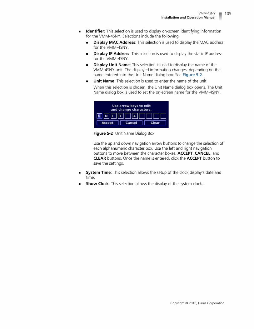
VMM-4SNYInstallation and Operation Manual
105
Copyright © 2010, Harris Corporation
Identifier: This selection is used to display on-screen identifying informationfor the VMM-4SNY. Selections include the following:
Display MAC Address: This selection is used to display the MAC addressfor the VMM-4SNY.
Display IP Address: This selection is used to display the static IP addressfor the VMM-4SNY.
Display Unit Name: This selection is used to display the name of theVMM-4SNY unit. The displayed information changes, depending on thename entered into the Unit Name dialog box. See Figure 5-2.
Unit Name: This selection is used to enter the name of the unit.
When this selection is chosen, the Unit Name dialog box opens. The UnitName dialog box is used to set the on-screen name for the VMM-4SNY.
Figure 5-2 Unit Name Dialog Box
Use the up and down navigation arrow buttons to change the selection ofeach alphanumeric character box. Use the left and right navigationbuttons to move between the character boxes, ACCEPT, CANCEL, andCLEAR buttons. Once the name is entered, click the ACCEPT button tosave the settings.
System Time: This selection allows the setup of the clock display’s date andtime.
Show Clock: This selection allows the display of the system clock.

Chapter 5Global Setup Menu Functions
106
Copyright © 2010, Harris Corporation
AboutDisplayScreen
This selection allows the display of the About screen (see Figure 5-3). The Aboutscreen contains the model, serial number, optoion, device, and version. Click theEXIT button to exit from the screen.
Figure 5-3 About Display Screen

107
Copyright © 2010, Harris Corporation
6 Alarm Descriptions
SettingVMM-4SNY
Alarms
The VMM-4SNY alarms monitor video and audio signals, time code errors, and GPIerrors.
Limits are selected in the Setup menu by choosing a value using the navigationarrow buttons.
Sensitivity and Duration are two general terms used in the Alarm menus.
Sensitivity is set by Consecutive Errored Samples (CES). When settingamplitude limits, a noise spike can exceed the limit while the video amplitudecan be within the limit. With the CES set to a low number, a spike is detectedand an alarm is displayed. Set the CES to a higher number to ignore the fastspike. Each CES occurs at 37ns intervals for SD and 13.5ns for HD. Use this asa guideline to select the appropriate CES value.
Not all alarms have CES associated with them; in such cases, use the durationto increase or decrease the general sensitivity.
Duration is used to determine how long an error must persist before it isreported. Set the duration to 0 to cause an error to be displayed as soon as theCES value is met.
Alarm SetupMenus
The Alarm Setup menu items, along with their corresponding Table andDescription page locations are listed in Table 6-1. An asterisk (*) is shown next tothe default menu selections.
NOTE: See page 83 for information on how to navigate through the Setupmenus.
Table 6-1 Alarms Setup Menu
Selection Table Page Description Page
Video alarms 108 113
Audio alarms 110 114
Time code alarms 112 115
GPI Alarms 112 116

Chapter 6Alarm Descriptions
108
Copyright © 2010, Harris Corporation
Table 6-2 Video Alarms Setup MenuNOTE: Descriptions for these selections start on page 113.
Selection Selection Selection Selection
Format Change
Payload ID Mismatch
Loss of Carrier Enable
Duration 0 to 60 seconds (2 seconds *)
Loss of Reference Enable
Duration 0 to 60 seconds (2 seconds *)
Loss of Active Video Enable
Threshold 0 to 350 mV (300 mV *)
Sensitivity 2 * to 20 CES
Duration 0 to 60 seconds (2 seconds *)
Loss of Payload ID Enable
Duration 0 to 60 seconds (2 seconds *)
Gamut RGB Gamut Upper Enable
Threshold 650 to 750 mV (710 mV *)
Sensitivity 1 to 20 CES (15 CES *)
Duration 0 to 60 seconds (2 seconds *)
RGB Gamut Lower Enable
Threshold –50 to 50 mV (–10 mV *)
Sensitivity 1 to 20 CES (15 CES *)
Duration 0 to 60 seconds (2 seconds *)
Luminance Gamut Upper Enable
Threshold 525/59.94 90 to 108 IRE (105 IRE *)
Threshold 625/50 92 to 109 units setting (107units *)
Sensitivity 1 to 20 CES (15 CES *)
Duration 0 to 60 seconds (2 seconds *)
Luminance Gamut Lower Enable
Threshold 525/59.94 1.5 * to 20 IRE
Threshold 625/50 –7 to 20 units setting(–4 units *)
Sensitivity 1 to 20 CES (15 CES *)
Duration 0 to 60 seconds (2 seconds *)
Peak Gamut Upper Enable
Threshold 525/59.94 50 to 140 IRE (120 IRE *)
Threshold 625/50 51 to 143 Units + mV setting(123 Units *)
Sensitivity 1 to 20 CES (15 CES *)
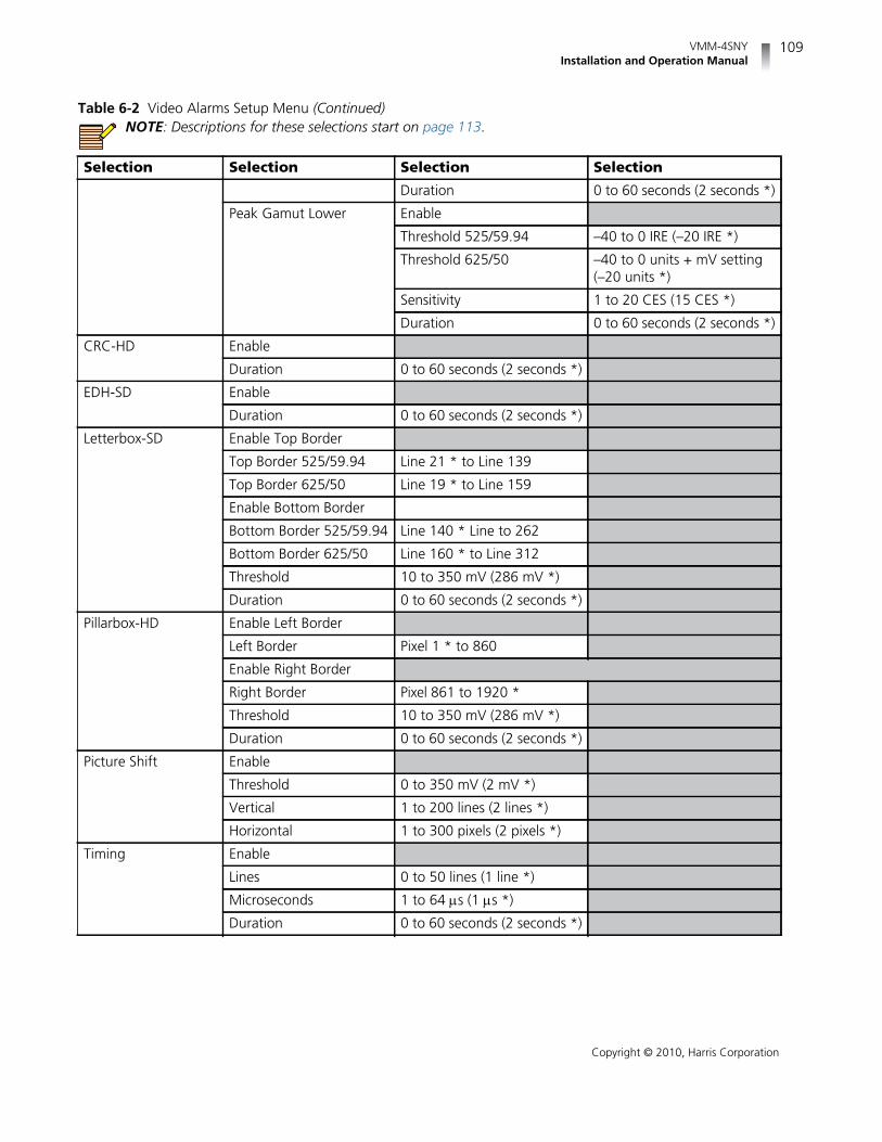
VMM-4SNYInstallation and Operation Manual
109
Copyright © 2010, Harris Corporation
Duration 0 to 60 seconds (2 seconds *)
Peak Gamut Lower Enable
Threshold 525/59.94 –40 to 0 IRE (–20 IRE *)
Threshold 625/50 –40 to 0 units + mV setting(–20 units *)
Sensitivity 1 to 20 CES (15 CES *)
Duration 0 to 60 seconds (2 seconds *)
CRC-HD Enable
Duration 0 to 60 seconds (2 seconds *)
EDH-SD Enable
Duration 0 to 60 seconds (2 seconds *)
Letterbox-SD Enable Top Border
Top Border 525/59.94 Line 21 * to Line 139
Top Border 625/50 Line 19 * to Line 159
Enable Bottom Border
Bottom Border 525/59.94 Line 140 * Line to 262
Bottom Border 625/50 Line 160 * to Line 312
Threshold 10 to 350 mV (286 mV *)
Duration 0 to 60 seconds (2 seconds *)
Pillarbox-HD Enable Left Border
Left Border Pixel 1 * to 860
Enable Right Border
Right Border Pixel 861 to 1920 *
Threshold 10 to 350 mV (286 mV *)
Duration 0 to 60 seconds (2 seconds *)
Picture Shift Enable
Threshold 0 to 350 mV (2 mV *)
Vertical 1 to 200 lines (2 lines *)
Horizontal 1 to 300 pixels (2 pixels *)
Timing Enable
Lines 0 to 50 lines (1 line *)
Microseconds 1 to 64 s (1 s *)
Duration 0 to 60 seconds (2 seconds *)
Table 6-2 Video Alarms Setup Menu (Continued)NOTE: Descriptions for these selections start on page 113.
Selection Selection Selection Selection

Chapter 6Alarm Descriptions
110
Copyright © 2010, Harris Corporation
Table 6-3 Audio Alarms Setup MenuNOTE: Descriptions for these selections start on page 114.
Selection Selection Selection
Peak Audio Enable Channel 1••Enable Channel 16
Level –30 to 0 dBFS (–10 dBFS *)
Duration 0 to 60 seconds (2 seconds *)
Phase Enable Pair 1••Enable Pair 8
Value 0 degrees to 178 degrees *
Duration 0 to 60 seconds (2 seconds *)
Loss of Sound Enable Channel 1••Enable Channel 16
Level –60 * to 0 dBFS
Duration 0 to 60 seconds (2 seconds *)
Loss of AES Data Enable
Duration 0 to 60 seconds (2 seconds *)
Loss of Embedded Data Enable Group 1 Pair 1
Enable Group 1 Pair 2
Enable Group 2 Pair 1
Enable Group 2 Pair 2
Enable Group 3 Pair 1
Enable Group 3 Pair 2
Enable Group 4 Pair 1
Enable Group 4 Pair 2
Duration 0 to 60 seconds (2 seconds *)
Continuous Tone Enable Channel 1••Enable Channel 16
Threshold 1 * to 20 dB
Duration 0 to 60 seconds (2 seconds *)
Audio Clip Enable Channel 1••Enable Channel 16

VMM-4SNYInstallation and Operation Manual
111
Copyright © 2010, Harris Corporation
Sensitivity 1 to 100 CES (50 CES *)
Duration 0 to 60 seconds (2 seconds *)
Audio Mute Enable Channel 1••Enable Channel 16
Sensitivity 1 to 100 CES (50 CES *)
Duration 0 to 60 seconds (2 seconds *)
AES/EBU V-Bit Enable
Duration 0 to 60 seconds (2 seconds *)
Embedded V-Bit Data Enable Group 1 Pair 1
Enable Group 1 Pair 2
Enable Group 2 Pair 1
Enable Group 2 Pair 2
Enable Group 3 Pair 1
Enable Group 3 Pair 2
Enable Group 4 Pair 1
Enable Group 4 Pair 2
Duration 0 to 60 seconds (2 seconds *)
Low Audio Enable Channel 1••Enable Channel 16
Level –60 * to 0 dBFS
Duration 0 to 60 seconds (2 seconds *)
BCH Enable
Duration 0 to 60 seconds (2 seconds *)
Table 6-3 Audio Alarms Setup MenuNOTE: Descriptions for these selections start on page 114.
Selection Selection Selection

Chapter 6Alarm Descriptions
112
Copyright © 2010, Harris Corporation
Table 6-4 Time Code Alarms Setup MenuNOTE: Descriptions for these selections start on page 115.
Selection Selection Selection
LTC Loss of Time Code Enable
Duration 0 to 600 seconds (240 seconds *)
LTC Time Code Level Enable
Range 0.2 to 1.8 volts (0.5 volts *)
Duration 0 to 600 seconds (240 seconds *)
LTC Time Code Framing Enable
Range 1.5 to 10.5 * lines
Duration 0 to 600 seconds (240 seconds *)
LTC Time CodeContinuity
LTC/DVITC Compare Enable
Threshold 1 * to 30 frames
Duration 0 to 600 seconds (240 seconds *)
DVITC Loss of Time Code Enable
Duration 0 to 600 seconds (240 seconds *)
DVITC Line Enable
Line Number – 525/59.94 Line 10 to Line 30 (Line 14 *)
Line 625 – 625/50 Line 6 to Line 30 lines (Line 14 *)
Duration 0 to 600 seconds (240 seconds *)
DVITC Continuity
DVITC CRC Enable
Duration 0 to 600 seconds (240 seconds *)
Table 6-5 GPI Alarms Setup MenuNOTE: Descriptions for these selections start on page 116.
Selection
GPI 1 Alarm Enable
GPI 1 Disable*
GPI 2 Alarm Enable
GPI 2 Disable *

VMM-4SNYInstallation and Operation Manual
113
Copyright © 2010, Harris Corporation
Video AlarmsSetup
Descriptions
The Video Alarms Setup menu contents are listed below.
Format Change: The Format Change alarm is used to indicate that theincoming video format has changed.
Payload ID Mismatch: The Payload ID Mismatch alarm is used to indicatethat the payload indicated in a SMPTE 352M ancillary data packet does notmatch the detected input format such as HD/SD and frame rate.
Loss of Carrier: The Loss of Carrier alarm occurs when there is no TimingReference Signal (TRS) detected.
Loss of Reference: The Loss of Reference alarm occurs when no sync signal isdetected in the external reference for a period in excess of the durationsetting. (For more information necessary to select the appropriate externalreference, see page 102.)
Loss of Active Video: The Loss of Active Video occurs when active video fallsbelow the adjustable threshold for a period in excess of the duration setting.
Loss of Payload ID: The Loss of Payload ID alarm is used to indicate when theSMPTE 352M Video Payload ID ancillary data packet is not detected in thereceived data stream for a period in excess of the duration setting.
Gamut: Gamut alarms are used to indicate when components of an RGB,Composite (luma), or peak (chroma) signal fall outside upper or lower presetlimits.
RGB Gamut Upper/Lower: The RGB Upper and Lower alarm occurswhen any component of the transcoded RGB signal falls outside the upperor lower limits for a period in excess of the duration setting. The Sensitivitycan be increased to provide immunity to fast transcoding spikes.
Luminance Gamut Upper/Lower: The Luminance Upper and Loweralarms scan the composite encoded signal derived from the selecteddigital input. The alarms occur when the luminance video falls outside theadjustable limits for a period in excess of the duration setting. TheSensitivity can be increased to provide immunity to fast noise spikes.
Peak Gamut Upper/Lower: The Peak Upper and Lower alarms scan thecomposite encoded signal derived from the selected digital input. Thealarm occurs when the peak video falls outside the adjustable limits for aperiod in excess of the duration setting. The Sensitivity can be increased toprovide immunity to fast noise spikes.
CRC-HD: The CRC-HD alarm occurs when the internally calculated CRC valueis different from the received CRC value.
EDH-SD: Per SMPTE RP 165-1994; the EDH-SD alarm occurs when one ormore errors are detected for a period in excess of the duration setting.
Letterbox-SD: The Letterbox is the top and bottom border surrounding theactive video. The top border is defined as having video below the threshold onthe set line and having video above on the following line. The bottom borderis defined as having video above the threshold on the previous line and videobelow the threshold on the set line. The Letterbox SD alarm is activated wheneither the top line or the bottom line deviates from the user settings (StandardDefinition only).

Chapter 6Alarm Descriptions
114
Copyright © 2010, Harris Corporation
Pillarbox-HD: The Pillarbox is the border to the right and left of the activevideo. The “End of Left Border” and “Start of Right Border” defines the setpoints when the video is below the threshold. If the video is outside of thethreshold and CES values for the specified duration, the Pillarbox HD alarmoccurs (High Definition only).
Picture Shift: The Picture Shift alarm activates when the luma portion of thevideo does not exceed the amplitude threshold along any of the four bordersof active video. The “Left/Right” and “Top/Bottom” border settings define thetolerance of the Picture Shift alarm. If one or more pixels are above thethreshold for each of the four tolerance borders, no alarm will be declared. Forinterlaced video formats Picture Shift checks the first field only. For example, ifa signal is 525/59.94 SDI video format, where “Left/Right” is set to 20 pixels,“Top/Bottom” is set to 4 lines, the threshold is set to 2 mV, and the“Duration” is set to 2 seconds, the alarm will be activated if pixels 1 through20 or 701 through 720, or lines 1 through 4, or 240 through 244 of activevideo do not exceed the 2 mV threshold and exceeds the duration of 2seconds.
Timing: The Timing Alarm occurs when the Time and Line range(s) areexceeded for a period in excess of the duration setting.
Audio AlarmsSetup
Descriptions
The Audio Alarms Setup menu contents are listed below.
Peak Audio: The Peak Audio alarm occurs when the peak audio level exceedsthe adjustable limit for a period in excess of the duration setting. The limit canbe set from -30 dBFS to 0 dBFS, in 1 dB increments.
Phase: The Phase alarm occurs when the phase difference between any audiopair (L and R) exceeds an adjustable range for a period in excess of theduration setting. The range is 0 to 178 degrees, in 1 degree increments. Therange is a global setting. If eight channels (four pairs) are displayed, the settingis valid for all pairs.
Loss of Sound: The Loss of Sound alarm occurs when the peak amplitudefalls below an adjustable limit for a period in excess of the duration setting.This alarm is valid for the displayed input (AES/EBU or embedded). The audiorange is -60 dBFS to 0 dBFS, in 1 dB increments. The range point is global andis independent of the scale type or input format.
Loss of AES Data: The Loss of AES Data alarm monitors the AES/EBU datastream. The alarm occurs when a loss of data is detected for a period in excessof the duration setting.
Loss of Embedded Data: The Loss of Embedded Data alarm monitors theEmbedded Audio data stream. The alarm occurs when a valid embeddedaudio data is not detected for a period in excess of the duration setting.
Continuous Tone: The Continuous Tone alarm occurs when a continuoussound level is present for a period in excess of the duration setting.
Audio Clip: The Audio Clip alarm occurs when the digital audio is at amaximum level for a period in excess of the duration setting. For theVMM-4SNY, the accuracy of the audio clip alarm is 0.1 dB.

VMM-4SNYInstallation and Operation Manual
115
Copyright © 2010, Harris Corporation
Audio Mute: The Audio Mute alarm occurs when the audio sample is “0” fora period in excess of the duration settings.
AES/EBU V-Bit: The V-Bit alarm occurs when the V-Bit is detected as “1” inthe audio AES source for the specified duration.
Embedded V-Bit Data: The Embedded V-Bit alarm occurs when the V-Bit isdetected as “1” in the embedded audio source for the specified duration.
Low Audio: The Low Audio alarm occurs when the peak audio sample doesnot exceed the adjustable digital level for a period of time in excess of theduration setting. The peak audio sample is an absolute measurement of theaudio sample and represents the true audio peak. It is not averaged over time,and can be enabled per channel.
BCH: The BCH alarm occurs when errors are detected in an HD embeddedaudio packet
Time CodeAlarms SetupDescriptions
The Time Code Alarms Setup menu contents are listed below.
LTC Loss of Time Code: The Loss of Time Code alarm occurs when thepeak-to-peak level of the LTC input signal falls below an adjustable limit for aperiod in excess of the duration setting.
LTC Time Code Level: The Time Code Level alarm occurs when thepeak-to-peak level of the LTC input signal falls outside the user defined rangecentered around 2 Vp-p. For example, if the Range setting is set to 0.2, anyvalue below 1.8 or exceeding 2.2 Vp-p for a period in excess of the durationsetting will activate the alarm.
LTC Time Code Framing: The Time Code Framing alarm occurs when thealignment of the start of LTC (ANSI/SMPTE 12M-1999) exceeds the range limitfor a period in excess of the duration setting.
LTC Time Code Continuity: The Time Code Continuity alarm occurs when abreak or interruption in the time code count occurs.
LTC/DVITC Compare: The LTC/DVITC alarm occurs when LTC and DVITC arecompared and differ beyond the threshold (1 to 30 frames) selection for aperiod in excess of the duration setting.
DVITC Loss of Time Code: The DVITC Loss of Time Code alarm occurs whenno DVITC time code in the video signal is detected for a period in excess of theduration setting.
DVITC Line: The DVITC Line alarm is used to select the line number on whichthe DVITC time code is detected for the “DVITC Continuity” and “DVITCCRC” fields. When time code is not detected on the selected line number, thealarm activates.
DVITC Continuity: The DVITC Continuity alarm occurs when a break orinterruption in the digital vertical interval time code frames occur for a periodin excess of the duration setting.
DVITC CRC: The DVITC CRC alarm occurs when the cyclic redundancy check(CRC) within the digital vertical interval time code field does not correlate withthe calculated CRC for a period in excess of the duration setting.

Chapter 6Alarm Descriptions
116
Copyright © 2010, Harris Corporation
GPI Alarms The input GPIs have selectable functions. There are selectable functions to allowexternal control of the unit or to show an on screen alarm. The GPI alarm allows analarm log entry to be entered by external control. To activate this function the GPIinput function must be set to ALARM and the alarm enabled. A contact closure toground on a GPI input will trigger an on screen GPI alarm indication, if the GPIalarm for that input is enabled.
Alarm Log The Alarm Log selection enables the Alarm Log display. The Alarm Log display listsall the alarms, the date, time, time code, duration, and peak value. The alarm listbegins with the most recent alarm and can hold a maximum of 100 alarms.
An Alarm Log display diagram is shown in Figure 4-33 on page 75 and describedin Table 4-14 on page 75. The diagram illustrates the general location for thevarious alarm fields.
When an alarm is first registered, it appears on the Alarm Log display and ishighlighted in yellow. If the alarm is short term (that is, two seconds or less), thealarm text is not highlighted after approximately two seconds. If the alarmcontinues longer than two seconds, the text remains yellow and the alarmduration is incremented. When the next alarm occurs, the previous alarm movesdown one position.
Alarm Status The alarm status screen contains detailed information concerning alarm statusindicators. This information is separated into columns sorted by alarm name,whether or not the alarm is enabled, lower and upper limits, thresholds, andduration, and total number of alarms. The alarm name text can appear in a coloredstate. The colored states are:
White: indicates alarm is not enabled.
Green: indicates alarm is enabled and not exceeding alarm limits.
Red: indicates the alarm is enabled and exceeding an alarm limits.
There is a two-second persistence for any Alarm Name color change.
Use the up and down navigation buttons to scroll through the alarm status list.
An alarm status display diagram is shown in Figure 4-34 on page 77. The diagramillustrates the general location for the various alarm status display fields.

117
Copyright © 2010, Harris Corporation
7 External Control
BrowserInterface
NOTE: Microsoft® Internet Explorer version 6 or later is the recommendedbrowser.
The website for each unit is accessed by pointing the web browser at theVMM-4SNY IP address. Before the default web screen appears, a user ID andpassword must be entered.
User ID: admin
Password: Harris
NOTE: The user ID admin is the default user ID and Harris is the defaultpassword. These are set at the factory but can be changed by the user viathe Accounts web page. Keep in mind, though that once the user ID andpassword have been changed, the only way to reset the unit to the defaultuser ID and its default password is to send the unit back to the factory forrepairs.
Once the user ID and password have been entered, the web page appears,showing a list of captures that have been stored in the VMM-4SNY’s internalmemory. Use the web page to view the files or save them to disk. A sample webpage is shown in Figure 7-1.

Chapter 7External Control
118
Copyright © 2010, Harris Corporation
Figure 7-1 Sample Web Remote Display
Accessing theWeb-Based
Control Panel
Access the web browser as described on page 117. Once theIndex of Captures/Web Remote Display page opens, click the RCUbutton to access the web-based control panel.
NOTE: The VMM-4SNY unit allows access to one controller at a time. If theunit receives a request for another Web RCU (or RCU-CMS) session whilepreviously established control session (Web RCU or RCU-CMS) exists, therequest will be granted after the previously established session isterminated.
A Web RCU session that was terminated due to conflict with anothercontrol session can be re-established by repeating the logon procedure.
Accessing theIndex of Captures
Click the CAPTURES button on the web-based control panel toaccess the Index of Captures page.
Managing UserAccounts
The VMM-4SNY allows user accounts to be added or edited at theUser, System, or Administrator levels. Both User and System levelaccounts are allowed general control of the unit. Only operators atthe Administrator level can manage accounts.

VMM-4SNYInstallation and Operation Manual
119
Copyright © 2010, Harris Corporation
Adding Accounts Add a new user account as follows:
1 Click the Accounts button on the web-based control panel.
The Accounts Display page opens.
Figure 7-2 Accounts Display Page
2 In the Add new account(s) box, enter the following information:
A unique identifier for the new account in the User ID text box.
A password for the new account (confirm the password by entering itagain in the Confirm Password text box).
An access level of User, System, or Administrator from the Access Leveldrop-down list box.
3 Click Save to accept the new account, or click Reset to clear the previouslyentered information and start again.
Editing Accounts Password and access level information for existing accounts can be edited asfollows:
1 Click the Accounts button on the web-based control panel.
The Accounts Display page opens.
2 In the Edit/Delete existing account(s) box, locate the unique identifier inthe User ID text box for the account to be edited.
3 Change one or more of the following fields as appropriate:
Change a password for the existing account by entering a new passwordin the New Password text box.
Confirm the password by entering it again in the Confirm Password textbox.

Chapter 7External Control
120
Copyright © 2010, Harris Corporation
Change the user access level by making a different selection at the AccessLevel drop-down list box.
4 Click Save to accept the account changes, or click Reset to restore theoriginal information and start again.
DeletingAccounts
User accounts can be deleted as follows:
1 Click the Accounts button on the web-based control panel.
The Accounts Display page opens.
2 In the Edit/Delete existing account(s) box, locate the unique identifier inthe User ID text box for the account to be deleted.
3 Click the Delete check box to the right of the account to be deleted.
4 Click Save.
The account is deleted.

121
Copyright © 2010, Harris Corporation
8 Troubleshooting
WARNING: These instructions are for use by qualified personnelonly. To reduce the risk of electric shock, do not perform thisinstallation or any servicing unless you are qualified to do so. Referall servicing to qualified service personnel.
NOTE: When power is applied to the unit, the display shows the startupscreen for about 45 seconds.
Initial ChecksIf the VMM-4SNY is not functioning properly, first verify the following:
The VMM-4SNY is inserted all the way into the slot and the thumbscrews aretightened.
The monitor is powered and monitor’s front panel input control selects inputoption slot into which VMM-4SNY is inserted (see your monitor user guide).
All cables are correctly connected (see Chapter 2, Installation).
Initial difficulties with operation or display can be due to improper setup. Reviewthe Setup menus (see Chapter 5, Global Setup Menu Functions) to ensure thatthe proper adjustments have been made for the signal requirements.
Restarting a UnitIf a problem persists after the cables are correctly connected and the unit is set up,restart the unit by doing the following:
1 Connect to the unit using a Web browser, and then navigate to the Web RCUpage.
2 Hold the CTRL key of the computer keyboard, and then press the SETUP,HORIZ, and VERT buttons on Web RCU in sequence until the SYSTEM RESETmessage appears on the display.

Chapter 8Troubleshooting
122
Copyright © 2010, Harris Corporation
3 Press and hold the ENT button to reset the unit’s configuration. All front paneland Setup menu selections are reset to the factory default settings.
4 Press and hold the PRST button to restart the unit. The unit reboots and allfront panel and Setup menu selections are reset to the factory default settings.
Problems, Causes, and Solutions
Table 8-1 VMM-4SNY: Problems, Causes, and Solutions
Problem/Symptom Possible Cause Solution or Explanation
No video is displayed when inputselection buttons are pressed onmonitor’s front panel.
The VMM-4SNY module is not fullyinserted in the slot.
Re-insert the VMM-4SNY module.
Waveform not locked whenExternal Reference (Ref:EXT) isselected
The video signal is too low inamplitude or the sync edge is toonoisy.
Verify that the External Referencesignal is of sufficient amplitude.
EXT REF is selected but there is noreference input, or the ExternalReference is non-synchronous.
Select Internal Reference (INT REF)and/or verify that the ExternalReference signal is synchronous.
No sound coming out of monitor’sspeakers
Monitor’s volume level is set toolow, monitor speakers are mutedwith the Audio Mapping menufunction, or the monitor does notsupport audio.
If monitors supports audio, adjustvolume using volume controls and/or disable muting using the AudioMapping menu function.
Audio Mapping is incorrect. Select Audio Mapping from theSetup menu, and then configurethe monitor’s left and rightchannels for valid audio input.
Audio level reading too low The input reference level is notcorrectly set.
Use the Setup menu to check theinput reference level setting.
No communications on Ethernetport
The IP address is incorrect. Either provide correct IP address toInternet browser or set correct IPparameters of VMM-4SNY using IPConfiguration Utility.
Incorrect Ethernet cable For a direct connection, use acrossover cable. For a networkconnection, use a standard Ethernetcable.
An Ethernet cable is connected but Icannot control the VMM-4SNY withWeb RCU nor with RCU-CMS.
The Ethernet cable is plugged intomonitor's Ethernet port rather thanVMM-4SNY Ethernet port.
Connect the Ethernet cable to theVMM-4SNY Ethernet port.

VMM-4SNYInstallation and Operation Handbook
123
Copyright © 2010, Harris Corporation
If the problem still exists after troubleshooting the VMM-4SNY, see Service andSupport on page 7 for further instructions.
The VMM-4SNY module is insertedall the way into the option slot ofmy LUMA family monitor and isgetting power, but the monitor isnot showing VMM-4SNY displays.
The Sony option board emulationmode is not set correctly on theVMM-4SNY.
See Chapter 2, Installation, forinformation about setting the Sonyemulation mode compatible withyour monitor type.
The VMM-4SNY module is insertedall the way into the option slot ofmy BVM (or PVM) family monitorand is getting power, but themonitor reports “No Sync” and/orthe picture rolls.
The Sony option board emulationmode is not set correctly onVMM-4SNY.
See Chapter 2, Installation, forinformation about setting the Sonyemulation mode compatible withyour monitor type.
The VMM-4SNY module is insertedall the way and is getting power,but the monitor is not showingVMM-4SNY displays.
The monitor’s inputs selectioncontrol is not set to display videofrom the VMM-4SNY.
If your monitor is from LUMAfamily, press the A1 button on thefront of the monitor; otherwiseconsult the monitor’s user guide onhow to change the input selection.
I have a good video signalconnected to the VMM-4SNY inputbut the monitor reports “No Sync,”there are artifacts in the picture,and/or the picture rolls when theVMM-4SNY is in bypass mode.
The monitor does not support theincoming video format.
Consult the monitor’s user guide forsupported video formats.
My BMV-L230 (or BVM-L138 orPVM-L2300) reports a “No Sync”and/or picture rolls when theVMM-4SNY is in bypass mode andthe input video format is 3G.
The monitor’s input configuration isnot set to support 3G video.
Set input configuration format to3G/HD/SD-SDI Auto. See the moni-tor’s user guide for instructions.
I have several VMM-4SNY units onmy network but can not connect tosome of them with either Web RCUor RCU-CMS.
Multiple VMM-4SNY units areconfigured with the same IPaddress.
Use the Device IP ConfigurationUtility to configure eachVMM-4SNY with a unique IPaddress. (If your network is beingadministered, ask your networkadministrator for additional IPaddresses.) See Connecting aVMM-4SNY on page 12 for moreinformation.
Table 8-1 VMM-4SNY: Problems, Causes, and Solutions (Continued)
Problem/Symptom Possible Cause Solution or Explanation

Chapter 8Troubleshooting
124
Copyright © 2010, Harris Corporation
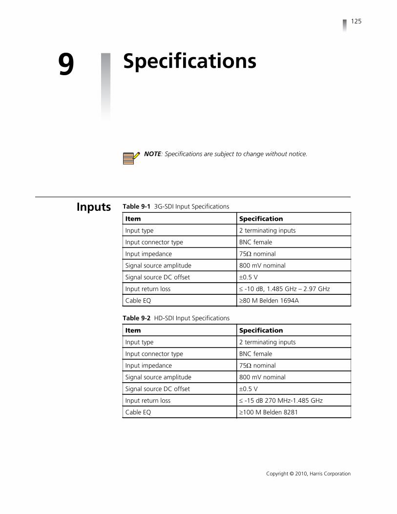
125
Copyright © 2010, Harris Corporation
9 Specifications
NOTE: Specifications are subject to change without notice.
Inputs Table 9-1 3G-SDI Input Specifications
Item Specification
Input type 2 terminating inputs
Input connector type BNC female
Input impedance 75 nominal
Signal source amplitude 800 mV nominal
Signal source DC offset 0.5 V
Input return loss -10 dB, 1.485 GHz – 2.97 GHz
Cable EQ 80 M Belden 1694A
Table 9-2 HD-SDI Input Specifications
Item Specification
Input type 2 terminating inputs
Input connector type BNC female
Input impedance 75 nominal
Signal source amplitude 800 mV nominal
Signal source DC offset 0.5 V
Input return loss -15 dB 270 MHz-1.485 GHz
Cable EQ 100 M Belden 8281

Chapter 9Specifications
126
Copyright © 2010, Harris Corporation
Table 9-3 SD-SDI Input Specifications
Item Specification
Input type 2 terminating inputs
Input connector type BNC female
Input impedance 75 nominal
Signal source amplitude 800 mV nominal
Signal source DC offset 0.5 V
Input return loss -25 dB 5 MHz-270 MHz
Cable EQ 300 M Belden 8281
Table 9-4 External Reference Input Specifications
Item Specification
Input connector type BNC female
Input type 1 terminating input
Input impedance 75 nominal
Blackburst input amplitude (Externalreference)
NTSCPAL
Sync and burst 286 mV nominalSync and burst 300 mV nominal
Blackburst input amplitude tolerance 6 dB
Tri-level sync amplitude 600 mV p-p
Tri-level sync amplitude tolerance 3 dB
Return loss -40 dB 100 kHz to 5 MHz
Table 9-5 Digital Audio Input Specifications
Item Specification
Audio formats AES/EBU, embedded audio
AES input connector type 1 BNC female
AES input impedance 75 nominal
AES input return loss 25dB, 0.1MHz to 6MHz (Unbalanced)
AES input level 0.2 to 2.0 V
AES input sample rate
NOTE: Audio inputs are samplerate converted to 48 kHz.
32 kHz 44.1 kHz 48 kHz 88.2 kHz 96 kHz
Meter accuracy over frequency ±0.1 dB from 20 Hz to 20 kHz with 0to -40 dBFS sine wave input, except forwithin 7 Hz of some submultiples ofthe 240 kHz oversampling frequency.

VMM-4SNYInstallation and Operation Handbook
127
Copyright © 2010, Harris Corporation
Outputs
AudioMonitoring
Control
Display
Table 9-6 Monitoring Display Output Specifications
Item Specification
Output connector Sony proprietary
Output resolution 1280×720
Display accuracy ± 1% waveform ± 1° vector ± 300 ns timing digital
Table 9-7 Audio Monitoring Specification (Monitors Speaker)
Item Specification
Monitor speakers See your monitor’s user manual
Table 9-8 Control Specifications
Item Specification
GPI Two total, with each user configurableas either input selection or a GPI alarm
Connector 6-pin push pin type
Input impedance 10 k returned to +3.0 VDC
Table 9-9 Display Specifications
Item Specification
General A full-screen display for viewing aninput as picture, waveform, vector,audio, alarm status, or timing
Waveform Composite; YCBCR or RGB, parade/overlay of like formats
Sweep time base 1H or 2H with x1, x5, and x10horizontal magnification
1V or 2V with x1, x5, and x25horizontal magnification
Waveform accuracy ±1%

Chapter 9Specifications
128
Copyright © 2010, Harris Corporation
Time Code
GamutDisplay
Vector CB vs. CR for HD or SD
Vector accuracy 1°
Gamut Encoded or RGB gamut displays withupper and lower limit selection
Audio 2, 4, 6, 8, or 16 channels displayedsimultaneously
Table 9-10 Waveform Display Characteristics – External Reference and LTC
Item Specification
Waveform Amplitude Accuracy ±5%
Waveform Frequency Response 25 Hz to 4.5MHz within ±5% ofamplitude at 50 kHz
Table 9-9 Display Specifications (Continued)
Item Specification
Table 9-11 Time Code Specifications
Item Specification
Input LTC via back panel connector Ancillary Time Code (HD only) DVITC extracted from SD inputs
Display Displayed directly
Table 9-12 Gamut Display
Item Specification
Monitored parameters Composite gamut (positive andnegative chroma packet excursionsabout luma levels)
RGB gamut
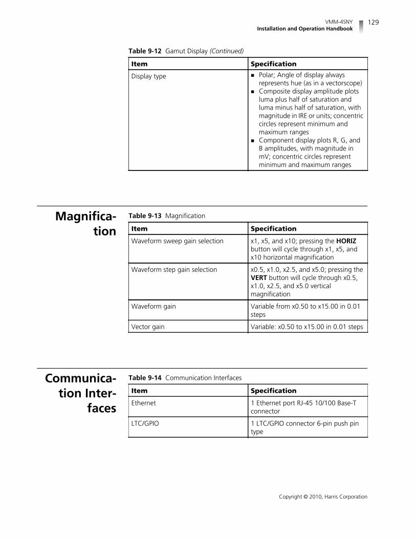
VMM-4SNYInstallation and Operation Handbook
129
Copyright © 2010, Harris Corporation
Magnifica-tion
Communica-tion Inter-
faces
Display type Polar; Angle of display alwaysrepresents hue (as in a vectorscope)
Composite display amplitude plotsluma plus half of saturation andluma minus half of saturation, withmagnitude in IRE or units; concentriccircles represent minimum andmaximum ranges
Component display plots R, G, andB amplitudes, with magnitude inmV; concentric circles representminimum and maximum ranges
Table 9-12 Gamut Display (Continued)
Item Specification
Table 9-13 Magnification
Item Specification
Waveform sweep gain selection x1, x5, and x10; pressing the HORIZbutton will cycle through x1, x5, andx10 horizontal magnification
Waveform step gain selection x0.5, x1.0, x2.5, and x5.0; pressing theVERT button will cycle through x0.5,x1.0, x2.5, and x5.0 verticalmagnification
Waveform gain Variable from x0.50 to x15.00 in 0.01steps
Vector gain Variable: x0.50 to x15.00 in 0.01 steps
Table 9-14 Communication Interfaces
Item Specification
Ethernet 1 Ethernet port RJ-45 10/100 Base-Tconnector
LTC/GPIO 1 LTC/GPIO connector 6-pin push pintype

Chapter 9Specifications
130
Copyright © 2010, Harris Corporation
PowerConsumption
MechanicalSpecifications
Environmen-tal Specifica-
tions
Table 9-15 Ethernet
Item Specification
Standard 10/100 Base-T conforms to IEEE802.3
Connector RJ-45
Performance metric Transfer a captured frame to a PC in 30 seconds, dedicated LAN
Table 9-16 Power Requirements
Item Specification
Power consumption 12 W nominal out of monitor’s powersupply
Table 9-17 Mechanical
Item Specification
Dimensions Height: 0.77 in. (1.96 cm) Width: 7.90 in. (20.01 cm) Depth: 6.30 in. (16.08 cm)
Weight 1.30 lb (0.59 kg)
Table 9-18 Environmental
Item Specification
Operating temperature 0° to +35°C
Storage temperature -20 to +60C
Humidity (non-condensing) Operating: 30% to 80% Non-operating: 5% to 90%
Transportation 24 in. (9.5 cm) impact-drop survivablein original factory packaging

VMM-4SNYInstallation and Operation Handbook
131
Copyright © 2010, Harris Corporation
Accessoriesand Options
Table 9-19 Standard Accessories
Item Specification
Standard accessories VMM-4SNY Installation andOperation Handbook on CD
6-pin push pin type connector forLTC/GPI
Table 9-20 Options
Item Specification
TVM-WRTY2 Full extended warranty plan: Addsthree years to the standard two-yearwarranty
VMM-4SNY Video and audio monitoring modulefor Sony monitorsSupports HD-SDI and SD-SDI inputformats, and up to 16 channels ofembedded audio, and supports 1 AESAudio inputSupports external reference of blackburst or tri-level sync720p 60Hz internal output is supportedby several Sony LCD monitors,including LMD2450W, LMD-2050W,LMD 4250W, LMD 2451W, BVM L170,PVM L2300 or BVM-L230
VMM-4SNY-3GB Video and audio monitoring modulefor Sony monitorsSupports 3G-SDI, HD-SDI and SD-SDIinput formats and up to 16 channels ofembedded audio, and supports 1 AESAudio inputSupports external reference of blackburst or tri-level sync720p 60Hz internal output is supportedby several Sony LCD monitors includingLMD2450W, LMD-2050W, LMD4250W, LMD 2451W, BVM L170, PVML2300 or BVM-L230
VMM-H23G-F Field upgrade for 3G-SDI option;software upgrade that enables the3G-SDI input formats

Chapter 9Specifications
132
Copyright © 2010, Harris Corporation
RCU-CMS Remote control unit option; providesthe remote control panel for desktopapplicationsIncludes Ethernet connection softwarefor setup of the RCU and IP addressesof connected unitsConnections for up to 32 independentunits
Table 9-20 Options (Continued)
Item Specification

133
Copyright © 2010, Harris Corporation
A Pinouts
EthernetConnectors
Figure A-1 Ethernet RJ-45 Connector
Table A-1 Ethernet RJ-45 Connector Pinouts
Pinout Signal Pinout Signal
1 TX+ 5 N.C.
2 TX- 6 RX-
3 RX+ 7 N.C.
4 N.C. 8 N.C.

Appendix APinouts
134
Copyright © 2010, Harris Corporation
LTC/GPIOConnectors
Figure A-2 LTC/GPIO Connector
Table A-2 LTC/GPIO Connector Pinouts
Pinout Signal Pinout Signal
1 LTC+ 4 GND
2 LTC- 5 GPI1
3 GND 6 GPI2

135
Copyright © 2010, Harris Corporation
B Open Source SoftwareCopyright Information
Copyright information for certain Open Source software products is providedbelow. Source code for all Open Source software used in the development of thisproduct is available upon request (contact the Harris Customer ServiceDepartment). See Service and Support on page 7 for contact information.
FreeType LicensePortions of this software are copyright © 2008 The FreeType Project(www.freetype.org). All rights reserved.
LibJPEG LicenseThis software is based in part on the work of the Independent JPEG Group.
CMU/UCD Copyright NoticeCopyright © 1989, 1991, 1992 by Carnegie Mellon University.
Derivative Work - 1996, 1998-2000.
Copyright © 1996, 1998-2000, The Regents of the University of California. Allrights reserved.
Permission to use, copy, modify and distribute this software and its documentationfor any purpose and without fee is hereby granted, provided that the abovecopyright notice appears in all copies and that both that copyright notice and thispermission notice appear in supporting documentation, and that the name of CMUand The Regents of the University of California not be used in advertising or publicitypertaining to distribution of the software without specific written permission.
Appendix BOpen Source Software Copyright Information
136
Copyright © 2010, Harris Corporation
CMU AND THE REGENTS OF THE UNIVERSITY OF CALIFORNIA DISCLAIM ALLWARRANTIES WITH REGARD TO THIS SOFTWARE, INCLUDING ALL IMPLIEDWARRANTIES OF MERCHANTABILITY AND FITNESS. IN NO EVENT SHALL CMU ORTHE REGENTS OF THE UNIVERSITY OF CALIFORNIA BE LIABLE FOR ANY SPECIAL,INDIRECT OR CONSEQUENTIAL DAMAGES OR ANY DAMAGES WHATSOEVERRESULTING FROM THE LOSS OF USE, DATA OR PROFITS, WHETHER IN AN ACTIONOF CONTRACT, NEGLIGENCE OR OTHER TORTIOUS ACTION, ARISING OUT OF ORIN CONNECTION WITH THE USE OR PERFORMANCE OF THIS SOFTWARE.
Networks Associates Technology, Inc. Copyright Notice(BSD)
Copyright © 2001-2003, Networks Associates Technology, Inc. All rights reserved.
Redistribution and use in source and binary forms, with or without modification,are permitted provided that the following conditions are met:
Redistributions of source code must retain the above copyright notice, this listof conditions and the following disclaimer.
Redistributions in binary form must reproduce the above copyright notice, thislist of conditions and the following disclaimer in the documentation and/orother materials provided with the distribution.
Neither the name of the Networks Associates Technology, Inc. nor the namesof its contributors may be used to endorse or promote products derived fromthis software without specific prior written permission.
THIS SOFTWARE IS PROVIDED BY THE COPYRIGHT HOLDERS AND CONTRIBUTORS“AS IS” AND ANY EXPRESS OR IMPLIED WARRANTIES, INCLUDING, BUT NOTLIMITED TO, THE IMPLIED WARRANTIES OF MERCHANTABILITY AND FITNESS FOR APARTICULAR PURPOSE ARE DISCLAIMED. IN NO EVENT SHALL THE COPYRIGHTHOLDERS OR CONTRIBUTORS BE LIABLE FOR ANY DIRECT, INDIRECT, INCIDENTAL,SPECIAL, EXEMPLARY, OR CONSEQUENTIAL DAMAGES (INCLUDING, BUT NOTLIMITED TO, PROCUREMENT OF SUBSTITUTE GOODS OR SERVICES; LOSS OF USE,DATA, OR PROFITS;OR BUSINESS INTERRUPTION) HOWEVER CAUSED AND ON ANYTHEORY OF LIABILITY,WHETHER IN CONTRACT, STRICT LIABILITY, OR TORT(INCLUDING NEGLIGENCE OR OTHERWISE) ARISING IN ANY WAY OUT OF THE USEOF THIS SOFTWARE, EVEN IF ADVISED OF THE POSSIBILITY OF SUCH DAMAGE.
Cambridge Broadband Ltd. Copyright Notice (BSD)Portions of this code are copyright © 2001-2003, Cambridge Broadband Ltd. Allrights reserved.
Redistribution and use in source and binary forms, with or without modification,are permitted provided that the following conditions are met:
VMM-4SNYInstallation and Operation Handbook
137
Copyright © 2010, Harris Corporation
Redistributions of source code must retain the above copyright notice, this listof conditions and the following disclaimer.
Redistributions in binary form must reproduce the above copyright notice, thislist of conditions and the following disclaimer in the documentation and/orother materials provided with the distribution.
The name of Cambridge Broadband Ltd. may not be used to endorse orpromote products derived from this software without specific prior writtenpermission.
THIS SOFTWARE IS PROVIDED BY THE COPYRIGHT HOLDER “AS IS” AND ANYEXPRESS OR IMPLIED WARRANTIES, INCLUDING, BUT NOT LIMITED TO, THEIMPLIED WARRANTIES OF MERCHANTABILITY AND FITNESS FOR A PARTICULARPURPOSE ARE DISCLAIMED. IN NO EVENT SHALL THE COPYRIGHT HOLDER BELIABLE FOR ANY DIRECT, INDIRECT, INCIDENTAL, SPECIAL, EXEMPLARY, ORCONSEQUENTIAL DAMAGES (INCLUDING, BUT NOT LIMITED TO, PROCUREMENTOF SUBSTITUTE GOODS OR SERVICES; LOSS OF USE, DATA, OR PROFITS; ORBUSINESS INTERRUPTION) HOWEVER CAUSED AND ON ANY THEORY OFLIABILITY, WHETHER IN CONTRACT, STRICT LIABILITY, OR TORT (INCLUDINGNEGLIGENCE OR OTHERWISE) ARISING IN ANY WAY OUT OF THE USE OF THISSOFTWARE, EVEN IF ADVISED OF THE POSSIBILITY OF SUCH DAMAGE.
Sun Microsystems, Inc. Copyright Notice (BSD)Copyright © 2003 Sun Microsystems, Inc., 4150 Network Circle, Santa Clara,California 95054, U.S.A. All rights reserved.
Use is subject to license terms below.
This distribution may include materials developed by third parties.
Sun, Sun Microsystems, the Sun logo and Solaris are trademarks or registeredtrademarks of Sun Microsystems, Inc. in the U.S. and other countries.
Redistribution and use in source and binary forms, with or without modification,are permitted provided that the following conditions are met:
Redistributions of source code must retain the above copyright notice, this listof conditions and the following disclaimer.
Redistributions in binary form must reproduce the above copyright notice, thislist of conditions and the following disclaimer in the documentation and/orother materials provided with the distribution.
Neither the name of the Sun Microsystems, Inc. nor the names of itscontributors may be used to endorse or promote products derived from thissoftware without specific prior written permission.
THIS SOFTWARE IS PROVIDED BY THE COPYRIGHT HOLDERS AND CONTRIBUTORS“AS IS” AND ANY EXPRESS OR IMPLIED WARRANTIES, INCLUDING, BUT NOTLIMITED TO, THE IMPLIED WARRANTIES OF MERCHANTABILITY AND FITNESS FOR APARTICULAR PURPOSE ARE DISCLAIMED. IN NO EVENT SHALL THE COPYRIGHT

Appendix BOpen Source Software Copyright Information
138
Copyright © 2010, Harris Corporation
HOLDERS OR CONTRIBUTORS BE LIABLE FOR ANY DIRECT, INDIRECT, INCIDENTAL,SPECIAL, EXEMPLARY, OR CONSEQUENTIAL DAMAGES (INCLUDING, BUT NOTLIMITED TO, PROCUREMENT OF SUBSTITUTE GOODS OR SERVICES; LOSS OF USE,DATA, OR PROFITS; OR BUSINESS INTERRUPTION) HOWEVER CAUSED AND ON ANYTHEORY OF LIABILITY, WHETHER IN CONTRACT, STRICT LIABILITY, OR TORT(INCLUDING NEGLIGENCE OR OTHERWISE) ARISING IN ANY WAY OUT OF THE USEOF THIS SOFTWARE, EVEN IF ADVISED OF THE POSSIBILITY OF SUCH DAMAGE.
Sparta, Inc. Copyright Notice (BSD)Copyright © 2003-2008, Sparta, Inc. All rights reserved.
Redistribution and use in source and binary forms, with or without modification,are permitted provided that the following conditions are met:
Redistributions of source code must retain the above copyright notice, this listof conditions and the following disclaimer.
Redistributions in binary form must reproduce the above copyright notice, thislist of conditions and the following disclaimer in the documentation and/orother materials provided with the distribution.
Neither the name of Sparta, Inc. nor the names of its contributors may be usedto endorse or promote products derived from this software without specificprior written permission.
THIS SOFTWARE IS PROVIDED BY THE COPYRIGHT HOLDERS AND CONTRIBUTORS“AS IS” AND ANY EXPRESS OR IMPLIED WARRANTIES, INCLUDING, BUT NOTLIMITED TO, THE IMPLIED WARRANTIES OF MERCHANTABILITY AND FITNESS FOR APARTICULAR PURPOSE ARE DISCLAIMED. IN NO EVENT SHALL THE COPYRIGHTHOLDERS OR CONTRIBUTORS BE LIABLE FOR ANY DIRECT, INDIRECT, INCIDENTAL,SPECIAL, EXEMPLARY, OR CONSEQUENTIAL DAMAGES (INCLUDING, BUT NOTLIMITED TO, PROCUREMENT OF SUBSTITUTE GOODS OR SERVICES; LOSS OF USE,DATA, OR PROFITS; OR BUSINESS INTERRUPTION) HOWEVER CAUSED AND ON ANYTHEORY OF LIABILITY, WHETHER IN CONTRACT, STRICT LIABILITY, OR TORT(INCLUDING NEGLIGENCE OR OTHERWISE) ARISING IN ANY WAY OUT OF THE USEOF THIS SOFTWARE, EVEN IF ADVISED OF THE POSSIBILITY OF SUCH DAMAGE.
Cisco/BUPTNIC Copyright Notice (BSD)Copyright © 2004, Cisco, Inc and Information Network Center of Beijing Universityof Posts and Telecommunications. All rights reserved.
Redistribution and use in source and binary forms, with or without modification,are permitted provided that the following conditions are met:
Redistributions of source code must retain the above copyright notice, this listof conditions and the following disclaimer.

VMM-4SNYInstallation and Operation Handbook
139
Copyright © 2010, Harris Corporation
Redistributions in binary form must reproduce the above copyright notice, thislist of conditions and the following disclaimer in the documentation and/orother materials provided with the distribution.
Neither the name of Cisco, Inc, Beijing University of Posts andTelecommunications, nor the names of their contributors may be used toendorse or promote products derived from this software without specific priorwritten permission.
THIS SOFTWARE IS PROVIDED BY THE COPYRIGHT HOLDERS AND CONTRIBUTORS“AS IS” AND ANY EXPRESS OR IMPLIED WARRANTIES, INCLUDING, BUT NOTLIMITED TO, THE IMPLIED WARRANTIES OF MERCHANTABILITY AND FITNESS FOR APARTICULAR PURPOSE ARE DISCLAIMED. IN NO EVENT SHALL THE COPYRIGHTHOLDERS OR CONTRIBUTORS BE LIABLE FOR ANY DIRECT, INDIRECT, INCIDENTAL,SPECIAL, EXEMPLARY, OR CONSEQUENTIAL DAMAGES (INCLUDING, BUT NOTLIMITED TO, PROCUREMENT OF SUBSTITUTE GOODS OR SERVICES; LOSS OF USE,DATA, OR PROFITS; OR BUSINESS INTERRUPTION) HOWEVER CAUSED AND ON ANYTHEORY OF LIABILITY, WHETHER IN CONTRACT, STRICT LIABILITY, OR TORT(INCLUDING NEGLIGENCE OR OTHERWISE) ARISING IN ANY WAY OUT OF THE USEOF THIS SOFTWARE, EVEN IF ADVISED OF THE POSSIBILITY OF SUCH DAMAGE.
Fabasoft R&D Software GmbH & Co. KG Copyright Notice(BSD)
Copyright © Fabasoft R&D Software GmbH & Co. KG, 2003 [email protected]: Bernhard Penz
Redistribution and use in source and binary forms, with or without modification,are permitted provided that the following conditions are met:
Redistributions of source code must retain the above copyright notice, this listof conditions and the following disclaimer.
Redistributions in binary form must reproduce the above copyright notice, thislist of conditions and the following disclaimer in the documentation and/orother materials provided with the distribution.
The name of Fabasoft R&D Software GmbH & Co KG or any of its subsidiaries,brand or product names may not be used to endorse or promote productsderived from this software without specific prior written permission.
THIS SOFTWARE IS PROVIDED BY THE COPYRIGHT HOLDER ``AS IS'' AND ANYEXPRESS OR IMPLIED WARRANTIES, INCLUDING, BUT NOT LIMITED TO, THEIMPLIED WARRANTIES OF MERCHANTABILITY AND FITNESS FOR A PARTICULARPURPOSE ARE DISCLAIMED. IN NO EVENT SHALL THE COPYRIGHT HOLDER BELIABLE FOR ANY DIRECT, INDIRECT, INCIDENTAL, SPECIAL, EXEMPLARY, ORCONSEQUENTIAL DAMAGES (INCLUDING, BUT NOT LIMITED TO, PROCUREMENTOF SUBSTITUTE GOODS OR SERVICES; LOSS OF USE, DATA, OR PROFITS; ORBUSINESS INTERRUPTION) HOWEVER CAUSED AND ON ANY THEORY OF

Appendix BOpen Source Software Copyright Information
140
Copyright © 2010, Harris Corporation
LIABILITY, WHETHER IN CONTRACT, STRICT LIABILITY, OR TORT (INCLUDINGNEGLIGENCE OR OTHERWISE) ARISING IN ANY WAY OUT OF THE USE OF THISSOFTWARE, EVEN IF ADVISED OF THE POSSIBILITY OF SUCH DAMAGE.
The GNU v2 License
GNU GeneralPublic License
Version 2, June 1991Copyright © 1989, 1991 Free Software Foundation, Inc., 51 Franklin Street, FifthFloor, Boston, MA 02110-1301 USA. Everyone is permitted to copy and distributeverbatim copies of this license document, but changing it is not allowed.
Preamble The licenses for most software are designed to take away your freedom to shareand change it. By contrast, the GNU General Public License is intended toguarantee your freedom to share and change free software--to make sure thesoftware is free for all its users. This General Public License applies to most of theFree Software Foundation's software and to any other program whose authorscommit to using it. (Some other Free Software Foundation software is covered bythe GNU Lesser General Public License instead.) You can apply it to your programs,too.
When we speak of free software, we are referring to freedom, not price. OurGeneral Public Licenses are designed to make sure that you have the freedom todistribute copies of free software (and charge for this service if you wish), that youreceive source code or can get it if you want it, that you can change the softwareor use pieces of it in new free programs; and that you know you can do thesethings.
To protect your rights, we need to make restrictions that forbid anyone to denyyou these rights or to ask you to surrender the rights. These restrictions translate tocertain responsibilities for you if you distribute copies of the software, or if youmodify it.
For example, if you distribute copies of such a program, whether gratis or for a fee,you must give the recipients all the rights that you have. You must make sure thatthey, too, receive or can get the source code. And you must show them theseterms so they know their rights.
We protect your rights with two steps: (1) copyright the software, and (2) offer youthis license which gives you legal permission to copy, distribute and/or modify thesoftware.
Also, for each author's protection and ours, we want to make certain thateveryone understands that there is no warranty for this free software. If thesoftware is modified by someone else and passed on, we want its recipients toknow that what they have is not the original, so that any problems introduced byothers will not reflect on the original authors’ reputations.

VMM-4SNYInstallation and Operation Handbook
141
Copyright © 2010, Harris Corporation
Finally, any free program is threatened constantly by software patents. We wish toavoid the danger that redistributors of a free program will individually obtainpatent licenses, in effect making the program proprietary. To prevent this, we havemade it clear that any patent must be licensed for everyone's free use or notlicensed at all.
The precise terms and conditions for copying, distribution and modificationfollow.
GNU GeneralPublic License
Terms and Conditions for Copying, Distribution andModification0. This License applies to any program or other work which contains a noticeplaced by the copyright holder saying it may be distributed under the terms of thisGeneral Public License. The “Program,” below, refers to any such program orwork, and a “work based on the Program” means either the Program or anyderivative work under copyright law: that is to say, a work containing the Programor a portion of it, either verbatim or with modifications and/or translated intoanother language. (Hereinafter, translation is included without limitation in theterm “modification.”) Each licensee is addressed as “you.”
Activities other than copying, distribution and modification are not covered by thisLicense; they are outside its scope. The act of running the Program is not restricted,and the output from the Program is covered only if its contents constitute a workbased on the Program (independent of having been made by running theProgram). Whether that is true depends on what the Program does.
1. You may copy and distribute verbatim copies of the Program's source code asyou receive it, in any medium, provided that you conspicuously and appropriatelypublish on each copy an appropriate copyright notice and disclaimer of warranty;keep intact all the notices that refer to this License and to the absence of anywarranty; and give any other recipients of the Program a copy of this License alongwith the Program.
You may charge a fee for the physical act of transferring a copy, and you may atyour option offer warranty protection in exchange for a fee.
2. You may modify your copy or copies of the Program or any portion of it, thusforming a work based on the Program, and copy and distribute such modificationsor work under the terms of Section 1 above, provided that you also meet all ofthese conditions:
a) You must cause the modified files to carry prominent notices stating thatyou changed the files and the date of any change.
b) You must cause any work that you distribute or publish, that in whole or inpart contains or is derived from the Program or any part thereof, to be licensedas a whole at no charge to all third parties under the terms of this License.
c) If the modified program normally reads commands interactively when run,you must cause it, when started running for such interactive use in the mostordinary way, to print or display an announcement including an appropriatecopyright notice and a notice that there is no warranty (or else, saying that youprovide a warranty) and that users may redistribute the program under these

Appendix BOpen Source Software Copyright Information
142
Copyright © 2010, Harris Corporation
conditions, and telling the user how to view a copy of this License. (Exception:if the Program itself is interactive but does not normally print such anannouncement, your work based on the Program is not required to print anannouncement.)
These requirements apply to the modified work as a whole. If identifiable sectionsof that work are not derived from the Program, and can be reasonably consideredindependent and separate works in themselves, then this License, and its terms, donot apply to those sections when you distribute them as separate works. But whenyou distribute the same sections as part of a whole which is a work based on theProgram, the distribution of the whole must be on the terms of this License, whosepermissions for other licensees extend to the entire whole, and thus to each andevery part regardless of who wrote it.
Thus, it is not the intent of this section to claim rights or contest your rights towork written entirely by you; rather, the intent is to exercise the right to control thedistribution of derivative or collective works based on the Program.
In addition, mere aggregation of another work not based on the Program with theProgram (or with a work based on the Program) on a volume of a storage ordistribution medium does not bring the other work under the scope of thisLicense.
3. You may copy and distribute the Program (or a work based on it, under Section2) in object code or executable form under the terms of Sections 1 and 2 aboveprovided that you also do one of the following:
a) Accompany it with the complete corresponding machine-readable sourcecode, which must be distributed under the terms of Sections 1 and 2 above ona medium customarily used for software interchange; or,
b) Accompany it with a written offer, valid for at least three years, to give anythird party, for a charge no more than your cost of physically performingsource distribution, a complete machine-readable copy of the correspondingsource code, to be distributed under the terms of Sections 1 and 2 above on amedium customarily used for software interchange; or,
c) Accompany it with the information you received as to the offer to distributecorresponding source code. (This alternative is allowed only fornoncommercial distribution and only if you received the program in objectcode or executable form with such an offer, in accord with Subsection babove.)
The source code for a work means the preferred form of the work for makingmodifications to it. For an executable work, complete source code means all thesource code for all modules it contains, plus any associated interface definitionfiles, plus the scripts used to control compilation and installation of the executable.However, as a special exception, the source code distributed need not includeanything that is normally distributed (in either source or binary form) with themajor components (compiler, kernel, and so on) of the operating system on whichthe executable runs, unless that component itself accompanies the executable.
If distribution of executable or object code is made by offering access to copy froma designated place, then offering equivalent access to copy the source code fromthe same place counts as distribution of the source code, even though third partiesare not compelled to copy the source along with the object code.

VMM-4SNYInstallation and Operation Handbook
143
Copyright © 2010, Harris Corporation
4. You may not copy, modify, sublicense, or distribute the Program except asexpressly provided under this License. Any attempt otherwise to copy, modify,sublicense or distribute the Program is void, and will automatically terminate yourrights under this License. However, parties who have received copies, or rights,from you under this License will not have their licenses terminated so long as suchparties remain in full compliance.
5. You are not required to accept this License, since you have not signed it.However, nothing else grants you permission to modify or distribute the Programor its derivative works. These actions are prohibited by law if you do not accept thisLicense. Therefore, by modifying or distributing the Program (or any work based onthe Program), you indicate your acceptance of this License to do so, and all itsterms and conditions for copying, distributing or modifying the Program or worksbased on it.
6. Each time you redistribute the Program (or any work based on the Program), therecipient automatically receives a license from the original licensor to copy, distributeor modify the Program subject to these terms and conditions. You may not imposeany further restrictions on the recipients’ exercise of the rights granted herein. Youare not responsible for enforcing compliance by third parties to this License.
7. If, as a consequence of a court judgment or allegation of patent infringement orfor any other reason (not limited to patent issues), conditions are imposed on you(whether by court order, agreement or otherwise) that contradict the conditions ofthis License, they do not excuse you from the conditions of this License. If youcannot distribute so as to satisfy simultaneously your obligations under this Licenseand any other pertinent obligations, then as a consequence you may not distributethe Program at all. For example, if a patent license would not permit royalty-freeredistribution of the Program by all those who receive copies directly or indirectlythrough you, then the only way you could satisfy both it and this License would beto refrain entirely from distribution of the Program.
If any portion of this section is held invalid or unenforceable under any particularcircumstance, the balance of the section is intended to apply and the section as awhole is intended to apply in other circumstances.
It is not the purpose of this section to induce you to infringe any patents or otherproperty right claims or to contest validity of any such claims; this section has thesole purpose of protecting the integrity of the free software distribution system,which is implemented by public license practices. Many people have madegenerous contributions to the wide range of software distributed through thatsystem in reliance on consistent application of that system; it is up to the author/donor to decide if he or she is willing to distribute software through any othersystem and a licensee cannot impose that choice.
This section is intended to make thoroughly clear what is believed to be aconsequence of the rest of this License.
8. If the distribution and/or use of the Program is restricted in certain countrieseither by patents or by copyrighted interfaces, the original copyright holder whoplaces the Program under this License may add an explicit geographicaldistribution limitation excluding those countries, so that distribution is permittedonly in or among countries not thus excluded. In such case, this Licenseincorporates the limitation as if written in the body of this License.

Appendix BOpen Source Software Copyright Information
144
Copyright © 2010, Harris Corporation
9. The Free Software Foundation may publish revised and/or new versions of theGeneral Public License from time to time. Such new versions will be similar in spiritto the present version, but may differ in detail to address new problems orconcerns.
Each version is given a distinguishing version number. If the Program specifies aversion number of this License which applies to it and “any later version,” youhave the option of following the terms and conditions either of that version or ofany later version published by the Free Software Foundation. If the Program doesnot specify a version number of this License, you may choose any version everpublished by the Free Software Foundation.
10. If you wish to incorporate parts of the Program into other free programs whosedistribution conditions are different, write to the author to ask for permission. Forsoftware which is copyrighted by the Free Software Foundation, write to the FreeSoftware Foundation; we sometimes make exceptions for this. Our decision will beguided by the two goals of preserving the free status of all derivatives of our freesoftware and of promoting the sharing and reuse of software generally.
No Warranty 11. BECAUSE THE PROGRAM IS LICENSED FREE OF CHARGE, THERE IS NOWARRANTY FOR THE PROGRAM, TO THE EXTENT PERMITTED BY APPLICABLELAW. EXCEPT WHEN OTHERWISE STATED IN WRITING THE COPYRIGHT HOLDERSAND/OR OTHER PARTIES PROVIDE THE PROGRAM “AS IS” WITHOUT WARRANTYOF ANY KIND, EITHER EXPRESSED OR IMPLIED, INCLUDING, BUT NOT LIMITED TO,THE IMPLIED WARRANTIES OF MERCHANTABILITY AND FITNESS FOR APARTICULAR PURPOSE. THE ENTIRE RISK AS TO THE QUALITY ANDPERFORMANCE OF THE PROGRAM IS WITH YOU. SHOULD THE PROGRAM PROVEDEFECTIVE, YOU ASSUME THE COST OF ALL NECESSARY SERVICING, REPAIR ORCORRECTION.
12. IN NO EVENT UNLESS REQUIRED BY APPLICABLE LAW OR AGREED TO INWRITING WILL ANY COPYRIGHT HOLDER, OR ANY OTHER PARTY WHO MAYMODIFY AND/OR REDISTRIBUTE THE PROGRAM AS PERMITTED ABOVE, BE LIABLETO YOU FOR DAMAGES, INCLUDING ANY GENERAL, SPECIAL, INCIDENTAL ORCONSEQUENTIAL DAMAGES ARISING OUT OF THE USE OR INABILITY TO USE THEPROGRAM (INCLUDING BUT NOT LIMITED TO LOSS OF DATA OR DATA BEINGRENDERED INACCURATE OR LOSSES SUSTAINED BY YOU OR THIRD PARTIES OR AFAILURE OF THE PROGRAM TO OPERATE WITH ANY OTHER PROGRAMS), EVEN IFSUCH HOLDER OR OTHER PARTY HAS BEEN ADVISED OF THE POSSIBILITY OFSUCH DAMAGES.
END OF TERMS AND CONDITIONS

VMM-4SNYInstallation and Operation Handbook
145
Copyright © 2010, Harris Corporation
GNU Lesser Public License
GNU LesserGeneral Public
License
Version 2.1, February 1999Copyright © 1991, 1999 Free Software Foundation, Inc., 51 Franklin Street, FifthFloor, Boston, MA 02110-1301 USA. Everyone is permitted to copy and distributeverbatim copies of this license document, but changing it is not allowed.
[This is the first released version of the Lesser GPL. It also counts as the successorof the GNU Library Public License, version 2, hence the version number 2.1.]
Preamble The licenses for most software are designed to take away your freedom to shareand change it. By contrast, the GNU General Public Licenses are intended toguarantee your freedom to share and change free software--to make sure thesoftware is free for all its users.
This license, the Lesser General Public License, applies to some specially designatedsoftware packages--typically libraries--of the Free Software Foundation and otherauthors who decide to use it. You can use it too, but we suggest you first thinkcarefully about whether this license or the ordinary General Public License is thebetter strategy to use in any particular case, based on the explanations below.
When we speak of free software, we are referring to freedom of use, not price.Our General Public Licenses are designed to make sure that you have the freedomto distribute copies of free software (and charge for this service if you wish); thatyou receive source code or can get it if you want it; that you can change thesoftware and use pieces of it in new free programs; and that you are informed thatyou can do these things.
To protect your rights, we need to make restrictions that forbid distributors to denyyou these rights or to ask you to surrender these rights. These restrictions translateto certain responsibilities for you if you distribute copies of the library or if youmodify it.
For example, if you distribute copies of the library, whether gratis or for a fee, youmust give the recipients all the rights that we gave you. You must make sure thatthey, too, receive or can get the source code. If you link other code with the library,you must provide complete object files to the recipients, so that they can relinkthem with the library after making changes to the library and recompiling it. Andyou must show them these terms so they know their rights.
We protect your rights with a two-step method: (1) we copyright the library, and(2) we offer you this license, which gives you legal permission to copy, distributeand/or modify the library.
To protect each distributor, we want to make it very clear that there is no warrantyfor the free library. Also, if the library is modified by someone else and passed on,the recipients should know that what they have is not the original version, so thatthe original author’s reputation will not be affected by problems that might beintroduced by others.

Appendix BOpen Source Software Copyright Information
146
Copyright © 2010, Harris Corporation
Finally, software patents pose a constant threat to the existence of any freeprogram. We wish to make sure that a company cannot effectively restrict theusers of a free program by obtaining a restrictive license from a patent holder.Therefore, we insist that any patent license obtained for a version of the librarymust be consistent with the full freedom of use specified in this license.
Most GNU software, including some libraries, is covered by the ordinary GNUGeneral Public License. This license, the GNU Lesser General Public License, appliesto certain designated libraries, and is quite different from the ordinary GeneralPublic License. We use this license for certain libraries in order to permit linkingthose libraries into non-free programs.
When a program is linked with a library, whether statically or using a shared library,the combination of the two is legally speaking a combined work, a derivative ofthe original library. The ordinary General Public License therefore permits suchlinking only if the entire combination fits its criteria of freedom. The Lesser GeneralPublic License permits more lax criteria for linking other code with the library.
We call this license the “Lesser” General Public License because it does Less toprotect the user’s freedom than the ordinary General Public License. It also providesother free software developers Less of an advantage over competing non-freeprograms. These disadvantages are the reason we use the ordinary General PublicLicense for many libraries. However, the Lesser license provides advantages incertain special circumstances.
For example, on rare occasions, there may be a special need to encourage thewidest possible use of a certain library, so that it becomes a de-facto standard. Toachieve this, non-free programs must be allowed to use the library. A morefrequent case is that a free library does the same job as widely used non-freelibraries. In this case, there is little to gain by limiting the free library to freesoftware only, so we use the Lesser General Public License.
In other cases, permission to use a particular library in non-free programs enables agreater number of people to use a large body of free software. For example,permission to use the GNU C Library in non-free programs enables many morepeople to use the whole GNU operating system, as well as its variant, the GNU/Linux operating system.
Although the Lesser General Public License is Less protective of the users’ freedom,it does ensure that the user of a program that is linked with the Library has thefreedom and the wherewithal to run that program using a modified version of theLibrary.
The precise terms and conditions for copying, distribution and modification follow.Pay close attention to the difference between a “work based on the library” and a“work that uses the library.” The former contains code derived from the library,whereas the latter must be combined with the library in order to run.

VMM-4SNYInstallation and Operation Handbook
147
Copyright © 2010, Harris Corporation
GNU LesserGeneral Public
License
Terms and Conditions for Copying, Distribution andModification0. This License Agreement applies to any software library or other program whichcontains a notice placed by the copyright holder or other authorized party saying itmay be distributed under the terms of this Lesser General Public License (alsocalled “this License”). Each licensee is addressed as “you.”
A “library” means a collection of software functions and/or data prepared so as tobe conveniently linked with application programs (which use some of thosefunctions and data) to form executables.
The “Library,” below, refers to any such software library or work which has beendistributed under these terms. A “work based on the Library” means either theLibrary or any derivative work under copyright law: that is to say, a workcontaining the Library or a portion of it, either verbatim or with modifications and/or translated straightforwardly into another language. (Hereinafter, translation isincluded without limitation in the term “modification.”)
“Source code” for a work means the preferred form of the work for makingmodifications to it. For a library, complete source code means all the source codefor all modules it contains, plus any associated interface definition files, plus thescripts used to control compilation and installation of the library.
Activities other than copying, distribution and modification are not covered by thisLicense; they are outside its scope. The act of running a program using the Libraryis not restricted, and output from such a program is covered only if its contentsconstitute a work based on the Library (independent of the use of the Library in atool for writing it). Whether that is true depends on what the Library does andwhat the program that uses the Library does.
1. You may copy and distribute verbatim copies of the Library’s complete sourcecode as you receive it, in any medium, provided that you conspicuously andappropriately publish on each copy an appropriate copyright notice and disclaimerof warranty; keep intact all the notices that refer to this License and to the absenceof any warranty; and distribute a copy of this License along with the Library.
You may charge a fee for the physical act of transferring a copy, and you may atyour option offer warranty protection in exchange for a fee.
2. You may modify your copy or copies of the Library or any portion of it, thusforming a work based on the Library, and copy and distribute such modifications orwork under the terms of Section 1 above, provided that you also meet all of theseconditions:
a) The modified work must itself be a software library.
b) You must cause the files modified to carry prominent notices stating thatyou changed the files and the date of any change.
c) You must cause the whole of the work to be licensed at no charge to allthird parties under the terms of this License.
d) If a facility in the modified Library refers to a function or a table of data tobe supplied by an application program that uses the facility, other than as anargument passed when the facility is invoked, then you must make a good

Appendix BOpen Source Software Copyright Information
148
Copyright © 2010, Harris Corporation
faith effort to ensure that, in the event an application does not supply suchfunction or table, the facility still operates, and performs whatever part of itspurpose remains meaningful.
(For example, a function in a library to compute square roots has a purposethat is entirely well-defined independent of the application. Therefore,Subsection 2d requires that any application-supplied function or table used bythis function must be optional: if the application does not supply it, the squareroot function must still compute square roots.)
These requirements apply to the modified work as a whole. If identifiable sectionsof that work are not derived from the Library, and can be reasonably consideredindependent and separate works in themselves, then this License, and its terms, donot apply to those sections when you distribute them as separate works. But whenyou distribute the same sections as part of a whole which is a work based on theLibrary, the distribution of the whole must be on the terms of this License, whosepermissions for other licensees extend to the entire whole, and thus to each andevery part regardless of who wrote it.
Thus, it is not the intent of this section to claim rights or contest your rights towork written entirely by you; rather, the intent is to exercise the right to control thedistribution of derivative or collective works based on the Library.
In addition, mere aggregation of another work not based on the Library with theLibrary (or with a work based on the Library) on a volume of a storage ordistribution medium does not bring the other work under the scope of thisLicense.
3. You may opt to apply the terms of the ordinary GNU General Public Licenseinstead of this License to a given copy of the Library. To do this, you must alter allthe notices that refer to this License, so that they refer to the ordinary GNUGeneral Public License, version 2, instead of to this License. (If a newer version thanversion 2 of the ordinary GNU General Public License has appeared, then you canspecify that version instead if you wish.) Do not make any other change in thesenotices.
Once this change is made in a given copy, it is irreversible for that copy, so theordinary GNU General Public License applies to all subsequent copies andderivative works made from that copy.
This option is useful when you wish to copy part of the code of the Library into aprogram that is not a library.
4. You may copy and distribute the Library (or a portion or derivative of it, underSection 2) in object code or executable form under the terms of Sections 1 and 2above provided that you accompany it with the complete correspondingmachine-readable source code, which must be distributed under the terms ofSections 1 and 2 above on a medium customarily used for software interchange.
If distribution of object code is made by offering access to copy from a designatedplace, then offering equivalent access to copy the source code from the same placesatisfies the requirement to distribute the source code, even though third partiesare not compelled to copy the source along with the object code.

VMM-4SNYInstallation and Operation Handbook
149
Copyright © 2010, Harris Corporation
5. A program that contains no derivative of any portion of the Library, but isdesigned to work with the Library by being compiled or linked with it, is called a“work that uses the Library.” Such a work, in isolation, is not a derivative work ofthe Library, and therefore falls outside the scope of this License.
However, linking a “work that uses the Library” with the Library creates anexecutable that is a derivative of the Library (because it contains portions of theLibrary), rather than a “work that uses the library.” The executable is thereforecovered by this License. Section 6 states terms for distribution of such executables.
When a “work that uses the Library” uses material from a header file that is part ofthe Library, the object code for the work may be a derivative work of the Libraryeven though the source code is not. Whether this is true is especially significant ifthe work can be linked without the Library, or if the work is itself a library. Thethreshold for this to be true is not precisely defined by law.
If such an object file uses only numerical parameters, data structure layouts andaccessors, and small macros and small inline functions (ten lines or less in length),then the use of the object file is unrestricted, regardless of whether it is legally aderivative work. (Executables containing this object code plus portions of theLibrary will still fall under Section 6.)
Otherwise, if the work is a derivative of the Library, you may distribute the objectcode for the work under the terms of Section 6. Any executables containing thatwork also fall under Section 6, whether or not they are linked directly with theLibrary itself.
6. As an exception to the Sections above, you may also combine or link a “workthat uses the Library” with the Library to produce a work containing portions ofthe Library, and distribute that work under terms of your choice, provided that theterms permit modification of the work for the customer’s own use and reverseengineering for debugging such modifications.
You must give prominent notice with each copy of the work that the Library isused in it and that the Library and its use are covered by this License. You mustsupply a copy of this License. If the work during execution displays copyrightnotices, you must include the copyright notice for the Library among them, as wellas a reference directing the user to the copy of this License. Also, you must do oneof these things:
a) Accompany the work with the complete corresponding machine-readablesource code for the Library including whatever changes were used in the work(which must be distributed under Sections 1 and 2 above); and, if the work isan executable linked with the Library, with the complete machine-readable“work that uses the Library,” as object code and/or source code, so that theuser can modify the Library and then relink to produce a modified executablecontaining the modified Library. (It is understood that the user who changesthe contents of definitions files in the Library will not necessarily be able torecompile the application to use the modified definitions.)
b) Use a suitable shared library mechanism for linking with the Library. Asuitable mechanism is one that (1) uses at run time a copy of the libraryalready present on the user’s computer system, rather than copying libraryfunctions into the executable, and (2) will operate properly with a modified

Appendix BOpen Source Software Copyright Information
150
Copyright © 2010, Harris Corporation
version of the library, if the user installs one, as long as the modified version isinterface-compatible with the version that the work was made with.
c) Accompany the work with a written offer, valid for at least three years, togive the same user the materials specified in Subsection 6a, above, for acharge no more than the cost of performing this distribution.
d) If distribution of the work is made by offering access to copy from adesignated place, offer equivalent access to copy the above specified materialsfrom the same place.
e) Verify that the user has already received a copy of these materials or thatyou have already sent this user a copy.
For an executable, the required form of the “work that uses the Library” mustinclude any data and utility programs needed for reproducing the executable fromit. However, as a special exception, the materials to be distributed need not includeanything that is normally distributed (in either source or binary form) with themajor components (compiler, kernel, and so on) of the operating system on whichthe executable runs, unless that component itself accompanies the executable.
It may happen that this requirement contradicts the license restrictions of otherproprietary libraries that do not normally accompany the operating system. Such acontradiction means you cannot use both them and the Library together in anexecutable that you distribute.
7. You may place library facilities that are a work based on the Library side-by-sidein a single library together with other library facilities not covered by this License,and distribute such a combined library, provided that the separate distribution ofthe work based on the Library and of the other library facilities is otherwisepermitted, and provided that you do these two things:
a) Accompany the combined library with a copy of the same work based onthe Library, uncombined with any other library facilities. This must bedistributed under the terms of the Sections above.
b) Give prominent notice with the combined library of the fact that part of it isa work based on the Library, and explaining where to find the accompanyinguncombined form of the same work.
8. You may not copy, modify, sublicense, link with, or distribute the Library exceptas expressly provided under this License. Any attempt otherwise to copy, modify,sublicense, link with, or distribute the Library is void, and will automaticallyterminate your rights under this License. However, parties who have receivedcopies, or rights, from you under this License will not have their licensesterminated so long as such parties remain in full compliance.
9. You are not required to accept this License, since you have not signed it. However,nothing else grants you permission to modify or distribute the Library or its derivativeworks. These actions are prohibited by law if you do not accept this License.Therefore, by modifying or distributing the Library (or any work based on theLibrary), you indicate your acceptance of this License to do so, and all its terms andconditions for copying, distributing or modifying the Library or works based on it.
VMM-4SNYInstallation and Operation Handbook
151
Copyright © 2010, Harris Corporation
10. Each time you redistribute the Library (or any work based on the Library), therecipient automatically receives a license from the original licensor to copy,distribute, link with or modify the Library subject to these terms and conditions.You may not impose any further restrictions on the recipients’ exercise of the rightsgranted herein. You are not responsible for enforcing compliance by third partieswith this License.
11. If, as a consequence of a court judgment or allegation of patent infringementor for any other reason (not limited to patent issues), conditions are imposed onyou (whether by court order, agreement or otherwise) that contradict theconditions of this License, they do not excuse you from the conditions of thisLicense. If you cannot distribute so as to satisfy simultaneously your obligationsunder this License and any other pertinent obligations, then as a consequence youmay not distribute the Library at all. For example, if a patent license would notpermit royalty-free redistribution of the Library by all those who receive copiesdirectly or indirectly through you, then the only way you could satisfy both it andthis License would be to refrain entirely from distribution of the Library.
If any portion of this section is held invalid or unenforceable under any particularcircumstance, the balance of the section is intended to apply, and the section as awhole is intended to apply in other circumstances.
It is not the purpose of this section to induce you to infringe any patents or otherproperty right claims or to contest validity of any such claims; this section has thesole purpose of protecting the integrity of the free software distribution systemwhich is implemented by public license practices. Many people have madegenerous contributions to the wide range of software distributed through thatsystem in reliance on consistent application of that system; it is up to the author/donor to decide if he or she is willing to distribute software through any othersystem and a licensee cannot impose that choice.
This section is intended to make thoroughly clear what is believed to be aconsequence of the rest of this License.
12. If the distribution and/or use of the Library is restricted in certain countrieseither by patents or by copyrighted interfaces, the original copyright holder whoplaces the Library under this License may add an explicit geographical distributionlimitation excluding those countries, so that distribution is permitted only in oramong countries not thus excluded. In such case, this License incorporates thelimitation as if written in the body of this License.
13. The Free Software Foundation may publish revised and/or new versions of theLesser General Public License from time to time. Such new versions will be similarin spirit to the present version, but may differ in detail to address new problems orconcerns.
Each version is given a distinguishing version number. If the Library specifies aversion number of this License which applies to it and “any later version,” youhave the option of following the terms and conditions either of that version or ofany later version published by the Free Software Foundation. If the Library does notspecify a license version number, you may choose any version ever published by theFree Software Foundation.

Appendix BOpen Source Software Copyright Information
152
Copyright © 2010, Harris Corporation
14. If you wish to incorporate parts of the Library into other free programs whosedistribution conditions are incompatible with these, write to the author to ask forpermission. For software which is copyrighted by the Free Software Foundation,write to the Free Software Foundation; we sometimes make exceptions for this.Our decision will be guided by the two goals of preserving the free status of allderivatives of our free software and of promoting the sharing and reuse ofsoftware generally.
No Warranty 15. BECAUSE THE LIBRARY IS LICENSED FREE OF CHARGE, THERE IS NOWARRANTY FOR THE LIBRARY, TO THE EXTENT PERMITTED BY APPLICABLE LAW.EXCEPT WHEN OTHERWISE STATED IN WRITING THE COPYRIGHT HOLDERS AND/OR OTHER PARTIES PROVIDE THE LIBRARY “AS IS” WITHOUT WARRANTY OF ANYKIND, EITHER EXPRESSED OR IMPLIED, INCLUDING, BUT NOT LIMITED TO, THEIMPLIED WARRANTIES OF MERCHANTABILITY AND FITNESS FOR A PARTICULARPURPOSE. THE ENTIRE RISK AS TO THE QUALITY AND PERFORMANCE OF THELIBRARY IS WITH YOU. SHOULD THE LIBRARY PROVE DEFECTIVE, YOU ASSUMETHE COST OF ALL NECESSARY SERVICING, REPAIR OR CORRECTION.
16. IN NO EVENT UNLESS REQUIRED BY APPLICABLE LAW OR AGREED TO INWRITING WILL ANY COPYRIGHT HOLDER, OR ANY OTHER PARTY WHO MAYMODIFY AND/OR REDISTRIBUTE THE LIBRARY AS PERMITTED ABOVE, BE LIABLETO YOU FOR DAMAGES, INCLUDING ANY GENERAL, SPECIAL, INCIDENTAL ORCONSEQUENTIAL DAMAGES ARISING OUT OF THE USE OR INABILITY TO USE THELIBRARY (INCLUDING BUT NOT LIMITED TO LOSS OF DATA OR DATA BEINGRENDERED INACCURATE OR LOSSES SUSTAINED BY YOU OR THIRD PARTIES OR AFAILURE OF THE LIBRARY TO OPERATE WITH ANY OTHER SOFTWARE), EVEN IFSUCH HOLDER OR OTHER PARTY HAS BEEN ADVISED OF THE POSSIBILITY OFSUCH DAMAGES.

153
Copyright © 2010, Harris Corporation
C Glossary
Terms
16 VSB Vestigial sideband modulation with 16 discrete amplitude levels.
601 An international standard (ITU-R BT.601) for component digital television. It definesthe sampling systems, matrix values, and filter characteristics for digital television.
8 VSB Vestigial sideband modulation with 8 discrete amplitude levels.
Advanced Television Systems Committee (ATSC)
The parent organization that developed, tested and described the form andfunction of the US digital television formats.
AES/EBU A digital audio standard established jointly by the Audio Engineering Society (AES)and the European Broadcasting Union (EBU).
AFD Active format description
ANC Ancillary data
Artifacts Unwanted visible effects in the picture created by disturbances in the transmissionor image processing, such as edge crawl or “hanging dots” in analog pictures or“pixelation” in digital pictures.
Aspect Ratio The ratio of horizontal to vertical dimensions. A square has an aspect of 1:1 sincethe horizontal and vertical measurements are always equal. Current televisionscreen aspect ratios are 4:3 and 16:9.

Appendix CGlossary
154
Copyright © 2010, Harris Corporation
AsynchronousSerial Interface
(ASI)
A transmission method adopted by the DVB, and called DVB-ASI. The transmissionmethod allows for the transport of varying data payloads in a constant datastream. The DVB-ASI transport stream rate is 270 Mb/s.
Audio Breakaway Routing video and accompanying audio in separate signal paths.
Audio-Follow Routing video and accompanying audio together in the same signal path.
Auto Trans Automatic transition. The execution of a single wipe or fade from current pictureto another picture by way of an automatic device.
Bandwidth The range of frequencies used to transmit information such as picture and sound.
Baseband Video An unmodulated video signal.
Black Also color black, blackburst. A composite color video signal that has the compositesync, reference burst, and a black video signal.
BlankingProcessor
A circuit which removes sync, burst and blanking from the program video and thenreplaces it with sync, burst and blanking from the reference input. The processensures constant sync and burst levels on program video.
Border An electronically-generated picture member that is used in wipes to separate thetwo video sources used in the wipe. It is of even thickness and has color producedby the matte generator.
Broadcast Legal Encoding video signal parameters to conform to prescribed limits for broadcast.Encoding rules vary by NTSC, PAL, country and broadcast facility.
BTSC Broadcast Television Standards Committee. A US standard for stereo audioencoding in NTSC broadcast television.
CC Closed captioned
CAV Component Analog Video
CES Consecutive Errored Samples
CH Chroma; see also Chrominance

VMM-4SNYInstallation and Operation Handbook
155
Copyright © 2010, Harris Corporation
Chrominance The color portion of a video signal that represents the saturation and hue. Black,gray and white have no chrominance; color signals have both chrominance andluminance.
Chrominance/Luminance Delay
(C/L Delay)
A measurement that indicates the amount to which chrominance and luminanceare aligned with respect to each other. A low C/L delay figure can minimize theeffects of ghosts or color offset on the received picture.
Clipping The electronic process of shearing off the peaks of either the white or blackexcursions of a video signal for limiting purposes. Clipping is often performed priorto modulation to limit the signal.
CMRR Common Mode Rejection Ratio
Color Burst The portion of a color video signal which contains a short sample of the colorsubcarrier. It is used as a color synchronization signal to establish a reference forthe color information following it and is used by a color monitor to decode thecolor portion of a video signal. The color burst acts as both amplitude and phasereference for color hue and intensity. The color oscillator of a color televisionreceiver is phase locked to the color burst.
Composite Sync A signal consisting of horizontal sync pulses, vertical sync pulses and equalizingpulses only.
Composite Video A single video signal that includes all color video and timing information. Acomposite signal includes luminance, chrominance, blanking pulses, sync pulsesand color burst information.
CRC Cyclical Redundancy Check
Crosspoint An electronic switch, usually controlled by a button on the panel. Control logic willallow for only one crosspoint, for each bus, to be switched “ON” one at a time.
D/A Conversion of digital to analog signals.
DA Distribution Amplifier
Data Element An item of data as represented before encoding and after decoding.
DBN Data block number (see SMPTE S291M)
Decibel (dB) A logarithmic measure of the ratio between two powers, voltages, currents, soundintensities, etc. Signal-to-noise ratios are expressed in decibels.

Appendix CGlossary
156
Copyright © 2010, Harris Corporation
Decoded Stream The decoded reconstruction of a compressed bit stream.
Default A factory preset value or condition.
Demodulator A receiver, such as for television broadcast, cable, and closed circuit applications. ATV demodulator receives and processes off-air or cable RF signals and providesbaseband video and audio outputs.
DHCP Dynamic Host Configuration Protocol
DID Data ID (see SMPTE S291M)
Differential Gain A measurement that specifies how much the chrominance gain is affected by theluminance level. Expressed as a percentage showing the largest amplitude changebetween any two levels, it indicates how much color saturation variance occurswhen the luminance level changes.
Differential Phase A peak-to-peak measurement that specifies the extent to which the chrominancephase is affected by the luminance level. Expressed in degrees of subcarrier phase,it indicates how much hue shift occurs with luminance level changes.
Digital Video Broadcasting (DVB)
A specific project office of the European Broadcast Union. This group has produceda set of digital broadcasting standards.
Display The output that appears on the TVM-4MA LCD display
DSK Down Stream Key, a keyer which is electronically located after (or down streamfrom) all other functions of a switcher. The key resulting will appear to be on top ofall other pictures from the switcher.
DVITC Digital Vertical Interval Time Code. Timecode information stored on specific lines inthe vertical blanking interval of a television signal.
EAV End of Active Video in component digital systems.
EBU European Broadcasting Union
EDH Error Detection and Handling. A recommended practice defined in SMPTE RP 165.A system to generate and then detect video data errors in serial digital videosystems.
VMM-4SNYInstallation and Operation Handbook
157
Copyright © 2010, Harris Corporation
Editor A device or system which controls video tape recorders, video switchers, and otherrelated devices in order to electronically splice segments of recorded video into afinished production.
Effects Keyer A keyer which is electronically located in the mix/wipe generator portion of aswitcher. The resulting key would appear under the down stream key.
EIA Rack Space orUnit
A specific size as designated by the Electronics Industry Association. The rack unitis 19 inches wide, and is 1.75 inches tall. A device which requires 3 EIA rack units is19 in. wide and 5.25 in. (3×1.75 = 5.25) high.
ElementaryStream (ES)
A generic term for one of the coded video, audio or other variable length bitstreams which are packetized to form MPEG-2 transport streams. Consists ofcompressed data from a single source (audio, video, data, etc.). One elementarystream is carried in a sequence of PES packets with one and only one stream ID.
Embedded Audio Digital audio information multiplexed onto a serial digital data stream. Up tosixteen channels can be multiplexed on a single stream of 601 video, minimizingcabling and routing requirement.
Encoded ClipSoftness
In the encoded legalization process, “softness,” as applied to encoded clips, refersto the processing of the video at the point of the clip. The clips are applied inYCbCr color space. The clip point is either an immediate limit (no softness) or willhave a range of values leading to the clip point, all reduced to smooth the clippoint to a less immediate limit (softness).
EncodedLegalization
Limiting of the luminance and color difference signals such that, once encodedinto a composite video signal, the resultant encoded video does not violate themaximum or minimum signal levels as defined by the specific encoding rules. NTSCand PAL video plus various users of these types of video have many varied rules formaximum and minimum encoding limits. Encoded legalization usually calculatesfirst the encoded luminance value and then the corresponding chroma value tomake legalization judgments.
Encoded Video A combined single video signal that is constructed from either separate RGB orluminance and two color difference video signals. NTSC, PAL, and SECAM are allexamples of encoded video.
ENG Electronic News Gathering
EnvelopeDetection
An RF signal detection technique that does not respond to phase variations in thecarrier signal, enabling measurement of a transmitter’s incidental phase. Whenused together with synchronous detection, envelope detection helps isolate eithervideo and/or RF as the causes of phase distortion.
External KeyInput
This is an alternate source for key cut. This is usually a separate external input to aswitcher

Appendix CGlossary
158
Copyright © 2010, Harris Corporation
Fade-thru-Black A production technique which is a two step process. The first step will fade theprogram video to black. The second step will fade from black to the video selectedon the preview bus. This is usually used in major scene transitions.
Fade-to-Black A production technique which simply fades the program video to black andprogram audio to silent. This is used to end programs and to escape fromembarrassing pictures or sounds.
Field A picture or picture portion which is produced within one cycle of verticalsynchronization. In interlaced systems, a full picture or frame requires twoconsecutive fields.
FM Trap A circuit designed to minimize potential interference from strong FM signals inreceiving equipment, such as a TV demodulator. For example, an FM trap canattenuate signals between 88-108 MHz to reduce interference on NTSC televisionchannel 6.
Frame A single full resolution picture as viewed in either a video or film system. In thecase of interlaced video, two consecutive fields provide all of the information ofone frame. In non-interlaced systems, one cycle of vertical synchronizationproduces a frame. A 60 Hz interlaced system, produces 30 frames of video in onesecond. A 60 Hz progressive (or non-interlaced) system produces 60 frames ofvideo in one second. Common frame rates are 24 (film) 25, 29.97, 30, 50, 59.94and 60.
Frame Store An electronic method of capturing and storing a single frame of video.
FrameSynchronizer
An electronic device that synchronizes two or more video signals. Using one inputas a reference, it locks a second signal to the reference.
Gamma This term applies to the linearity of the change from black to white. Gammacontrols adjust the gray or 50% point of the video either up or down, with theeffect of changing the gray level of the video.
Gamut The whole or total of whatever is being addressed. In color space, gamut refers toall colors which are included in a particularly defined color group, such as 601gamut.
Genlock(Generator Lock)
A method of synchronization involving the generation of a video signal that is timeand phase locked with another signal.
GPI General Purpose Interface
Graticule A graticule is a network of fine lines, dots, cross hairs, or wires in the focal plane ofthe eyepiece of an optical instrument.

VMM-4SNYInstallation and Operation Handbook
159
Copyright © 2010, Harris Corporation
HANC Ancillary data in the horizontal blanking interval (after EAV but before SAV)
Headend In a cable TV system, the facilities where program sources (satellite, terrestrial, VTR,local) are received and remodulated for distribution through a cable plant.
High Definition Television (HDTV)
High definition television has a resolution of approximately twice that ofconventional television in both the horizontal (H) and vertical (V) dimensions and apicture aspect ratio (H to V) of 16:9.
High Level A range of allowed picture parameters defined by the MPEG-2 video codingspecification which corresponds to high definition television.
HRC Harmonically-Related Carrier
Hue Color tint
I.R.E. Refers to the Institute of Radio Engineers, and is used as a unit of measurement. InNTSC television, 1 volt of signal equals 140 IRE units.
ICPM Incidental Carrier Phase Modulation. A measurement of picture carrier phasedistortion (affected by the video signal level) that occurs in the transmitter.
IP Internet Protocol
IRC Incrementally-Related Carrier
ISP Internet Service Provider
Jitter A deformation of a signal affected by poor synchronization.
Key An effect in television where a selected portion of background video is removedand replaced with another video.
Key Cut In a key effect, this is the video which designates the portion of background videowhich is removed.
Key Fill In a key effect, this is the video which is used to replace the portion of backgroundvideo which was removed. This may be the same video as the Key Cut video.
Key Invert In a key effect, this is an electronic action which reverses the polarity of the key cutsignal. It makes black appear as white, and white appear as black.

Appendix CGlossary
160
Copyright © 2010, Harris Corporation
Key Mask In a key effect, it uses a wipe pattern from the wipe pattern generator to restrictthe key cut from removing video in a portion of the screen. This requires the use ofthe wipe pattern generator and the Mask/Preset Size controls.
Key Source Same as key cut. See also Key Cut
LCD Liquid Crystal Display
LED Light-Emitting Diode
Legalization The modification of serial digital video to conform to analog color space rules, asrequired by users.
LFE Low Frequency Effects
Lissajous A display of the amplitude and phase relationships between two input signals.
LS Left Surround
Luminance The degree of brightness (black and white portion of the video signal) at any givenpoint in the video image. A video signal is comprised of luminance, chrominanceand sync. If luminance is high, the picture is bright and if low the picture is dark.Changing the chrominance does not affect the brightness of the picture.
M/E Mix/Effects System
Main Level A range of allowed picture parameters defined by the MPEG-2 video codingspecification with maximum resolution equivalent to standard definition television.
Main Profile A subset of the syntax of the MPEG-2 video coding specification that is supportedover a large range of applications. Applications include, MP@HL (Main profile athigh level) and MP@ML (Main profile at main level).
Mask/Preset Size Uses the wipe pattern generator in the keyer portion of the effects generator. Thisis used to adjust the size of a preset pattern or for adjusting the size of a mask toblock a portion of the key cut (source) from use in the keyer.
Matte Generator An internal generator which can make any color, is used for border color and maybe used for key fill. It is identical to the Color Background Generator, but simplyused in other areas of the switcher.
Mbps Megabits Per Second
VMM-4SNYInstallation and Operation Handbook
161
Copyright © 2010, Harris Corporation
MP@HL Main profile at high level
MP@ML Main profile at main level
MPEG Refers to standards developed by the ISO/IEC JTC1/SC29 WG11, Moving PictureExperts Group.
MPEG-2 Refers to ISO/IEC standards 13818-1 (Systems), 13818-2 (Video), 13818-3 (Audio),and 13818-4 (Compliance).
MRU Most Recently Used
Multi-LevelEffects
Applies to any effects generator which can do more than one effect at a time.Typically, a multi level switcher can produce a Key and a Background transition inthe same effects generator at one time.
mV Millivolts
NTSC National Television Systems Committee, the color television system used in theUnited States, Canada, Mexico and Japan.
NVRAM Nonvolatile RAM
OSD On-screen display
Packet A packet consists of a header followed by a number of contiguous bytes from anelementary data stream. It is a layer in the system coding syntax.
Packet Identifier(PID)
A unique integer value used to associate elementary streams of a program in asingle or multi-program transport stream.
PacketizedElementary
Stream (PES)
The data structure used to carry elementary stream data. The packets consist of aheader followed by payload data, and a stream is a series of packets which forman elementary stream and have a single stream identification.
PAL Phase Alternation Line; the standard color television system in many European andother countries.
Pane One quadrant in a four-quadrant screen

Appendix CGlossary
162
Copyright © 2010, Harris Corporation
Passive Looping Video and audio signals routed through components, even if power is removed.Signals are not amplified or processed, maintaining transparency.
Pedestal Level An offset used in a video system to separate the active video from the blankinglevel by maintaining the black level above the blanking level by a small amount.
Pixel A Picture cell or Picture element representing one sample of picture information,such as an individual sample of R, G, B, luminance or chrominance.
Preset Refers to establishing any condition prior to use on the Program output. This termis used in reference to wipe patterns and is often interchanged with Preview.
Preview The video output channel used to view the intended Program results prior to theexecution of the next transition.
PRO Audio A transmitted audio channel for talent cueing via Interrupt Foldback (IFB) to ENGvans and remote applications. Some demodulators support PRO audio monitoring.
Program A transport stream combination of a video stream and one or more audio and datastreams associated with that video stream. In analog terms, “Program” refers tothe Base Band video and audio produced by the final output of a switcher.
Program and System Information Protocol (PSIP)
Information sent out as part of an ATSC transport stream which lists all of thevideo, audio, data and program information contained in the stream. This is the"TV guide" for a given stream.
ProgramAssociation Table
(PAT)
A list of all programs that are in the ATSC data stream.
Program ClockReference (PCR)
This is a time reference signal that is placed in MPEG streams for the purpose oftime coordinating various data streams.
Program MapTable (PMT)
A listing of all elementary streams that comprise a complete (television) program.
ProgressiveScanning
Also non-interlaced. A system of video scanning where lines of a picture aretransmitted consecutively, such as with VGA monitor displays.
Push-push ToggleSwitch
An electro-mechanical device which, when pushed, alternates the condition of theswitch. Push once, it's off, push again, it's on.

VMM-4SNYInstallation and Operation Handbook
163
Copyright © 2010, Harris Corporation
QAM Quadrature Amplitude Modulation, the technique used by cable TV systems(64-QAM and 256-QAM) to remodulate signals for distribution in a cable plant.
QPSK Quadrature Phase Shift Keying, typically used by satellite downlinks.
QuadratureOutput
An output in a television demodulator used for measuring Incidental Carrier PhaseModulation (ICPM) in a transmitter.
Reclocking The process of regenerating digital data with a clock recovered from the inputdata.
Reference streamset
A collection of DID/SDIDs that occurred within a predefined period of time.
Resolution A measure of the finest detail that can be seen, or resolved, in a reproducedimage.
RGB Legalization Limiting of luminance and color difference video signals such that, oncetranscoded into RGB component video signals, the resultant video does not violatethe maximum or minimum signal levels as defined by component video level rules.Typically, the maximum value for R, G, or B is 700 mV, and the absolute minimumvalue for any of these signals is 0 mV.
RS Right Surround
RS-422 Recommended Standard number 422, an E.I.A. standard which describes a type ofdata interchange. Television products use this standard as its communicationformat between the electronics frame and editors, control panel and computers.An RS-422 line may be extended up to 1,000 feet (304m).
Sampling Process by which an analog signal is sampled to convert the analog signal todigital.
SAP Secondary Audio Program, used in television broadcast for second languagebroadcasting, simulcasting, and separate audio programming.
Saturation Color intensity
SAV Start of Active Video
SAW Filter Surface Acoustic Wave filter
SDID Secondary data ID (see SMPTE S291M)

Appendix CGlossary
164
Copyright © 2010, Harris Corporation
Segment ErrorRate (SER)
A calculated average of uncorrected transport stream packets vs. total packets asaccumulated over a designated period of time.
Signal to NoiseRatio-Analog
(SNR)
A measurement of the noise level in a signal expressed in dB (decibels) as a ratio ofbetween the audio or video signal’s maximum peak-to-peak signal voltage and themeasured voltage of noise present when the signal is removed. Higher SNR figuresindicate that any noise introduced by system components will not be perceived inthe picture and sound output signals.
Signal to NoiseRatio-8VSB (SNR)
As applies to 8VSB transmissions, this is a calculated average power of the idealsignal divided by the actual demodulated signal power.
SMPTE Society of Motion Picture and Television Engineers
StandardDefinition
Television (SDTV)
This term is used to signify a digital television system in which the quality isapproximately equivalent to that of NTSC. This equivalent quality may be achievedfrom pictures originated at the 4:2:2 level of ITU-R BT.601 and subjected toprocessing as part of the bit rate compression. The results should be such thatwhen judged across a representative sample of program material, subjectiveequivalence with NTSC is achieved. The displayed picture may be either thetraditional 4:3 or the wide-screen 16:9 aspect ratio.
STL Studio Transmitter Link
S-Video Also Y/C. Transmits luminance and color portions separately via multiple wires,thus avoiding the color encoding process and resulting loss of picture quality.
SynchronousDetection
A common detection technique used in television demodulators that removesquadrature distortion, enabling comparison of transmitter output with video inputsignal.
Tally A system used to light lamps and indicate usage. Most production switchers havean internal tally system to indicate selected functions, and which selected functionsare currently involved with Program.
TCP Transmission Control Protocol
TCXO Temperature Compensated Crystal Oscillator
Telecine A device used to convert film to video; movie film is digitally sampled andconverted to video frame by frame in real-time.
THD Total Harmonic Distortion

VMM-4SNYInstallation and Operation Handbook
165
Copyright © 2010, Harris Corporation
TransportStream-ATSC (TS)
Consists of the following: (1) Packets: 188 bytes - fixed length with descriptivedata, (2) Carries several programs, (3) has a PID which identifies the type of TSpacket (video, audio, other), and (4) carries descriptive information about theprogram.
UHF Ultra High Frequency
Unity Gain An electronic term indicating that a signal will be neither amplified nor attenuated.One volt of signal level in results in one volt of signal level out.
UUT Unit Under Test
VANC Ancillary data in the vertical blanking interval (between fields and after SAV butbefore EAV)
VBI Vertical blanking interval
Vector A measure that has two individual properties: magnitude and direction.
Vector Clip A special encoded clip version that limits only the Cb and Cr input video signalsand does not affect (nor is it affected by) the luminance component. Thiscolor-only clip limits the maximum vector excursions as viewed in an encoded stateand is intended for users who wish to prevent encoded vectors from everexceeding the perimeter circle of an encoded vector display.
VHF Very High Frequency
VITC Vertical Interval Time Code, a method for recording on to video tape the timecodeaddress for each video frame inserted in the vertical interval.
Waveform A visual representation of a signal in the shape of a wave that plots amplitudeversus time.
White Balance An electronic process used to calibrate the picture for accurate color display indifferent lighting conditions.
White Level The brightest part of a video signal, corresponding to approximately 1.0 Volt.
Wipe A special effect in which two pictures from different video sources are displayed onone screen. Production switchers and special effects generators provide numerouswipe patterns varying from simple horizontal and vertical wipes to multi-shaped,multi-colored arrangements.
WSS Widescreen signaling

Appendix CGlossary
166
Copyright © 2010, Harris Corporation
XDS Extended data services
XGA High resolution 1024×768 non-interlaced (progressive) display monitor
Y/C Describes the separation of video signal luminance and chrominance components.See also S-video.
YCbCr CAV format composed of luminance (Y) and two color difference signals (Cb andCr); the digital counterpart of YPbPr
YPbPr CAV format composed of luminance (Y) and two color difference signals (Pb andPr); the analog counterpart of YCbCr
YRGB CAV format composed of luminance (Y) and red, green, and blue color channels
Zero Carrier Pulse(chopper)
In a TV demodulator, removes the carrier in the vertical interval for a short period,enabling depth of field measurement.

167
Copyright © 2010, Harris Corporation
Index
Keywords
AAbout display screen 106Accessories
optional 131standard 131
Alarmsaudio 77display 74duration 107GPI 78log 75, 116sensitivity 107setting 107setup menu 103, 107status 76, 116time code 78video 77
Amplitude limits 40Audience ixAudio
alarms 77, 114display 63, 65mapping 74, 95monitoring specifications 127scales 64setup 74setup menu 89, 100, 114zoom 74
BBack panel 6, 12
CCapture
clearing displays 38
displays 37recalling displays 37storing displays 37
CES. See Consecutive Errored SamplesClear setup menu 92, 103Clearing displays 38Communication interfaces 129Composite gamut 56Configuration 13–22Connectors, back panel 12Consecutive Errored Samples 107Controls
front panel 29specifications 127types 27
Critical amplitude limits 40Cursor
vector 53waveform 45
Customer Service 7
DDIP switches 11Directives
RoHS xivWEEE xv
Displaysalarms 74audio 63, 65capturing 37clearing 38gamut 54options
gamut 60vector 52
picture 60PIP 62presets 82

Index168
Copyright © 2010, Harris Corporation
recalling 37selections
full screen 33overlay 34, 102quad 33, 102
specifications 127external reference 128LTC 128waveform 128
storing 37timing 78vector 46waveform 39
DRT-4 3See also ordering information
EEmulation, Sony 9Environmental specifications 130Ethernet
connector pinouts 133, 134specifications 130
External referencedisplay specifications 128formats supported 80selecting 36specifications 126
FFeatures
main 2options 3standard 2
Finding information ixFlash update procedure 22–24Formats
external reference 80SDI input 80selecting 96video 4
critical amplitude limits 40unit of measure 39
Front panel 6, 29Full screen display 33Function selection 36
GGain
vector 52waveform 43
Gamutcomposite 56display 54
component 59specifications 128
display options 60line select 59RGB 58setup menu 60, 88, 98
GPIalarms 78, 112, 116setup menu 112setup menu alarms 116
GPIO connector pinouts 134
HHarris Device IP configuration utility13–22
I-J-KIcons 36Input selection 32Input specifications 125, 126Inspecting shipment 9Installation 9–12
checking contents 9connecting unit 12VMM-H23GBF 24–26
Internal reference 36IP configuration utility 13–22
LLine select
gamut 59picture 61vector 52waveform 44
LTCconnector pinouts 134display specifications 128
MMagnification specifications 129Main features 2

VMM-4SNYInstallation and Operation Manual
169
Copyright © 2010, Harris Corporation
Mechanical specifications 130Moving
PIPs 63waveform 43
NNavigating the setup menu 37
OOption board emulation mode 9Optional accessories 131Ordering information 3Output specifications 127Overlay display
description 34setup 102setup menu 92, 102
PPanels
back connectors 6, 12back panel 6front panel 6Web RCU 6, 30–32
Picturedisplay 60line select 61setup menu 62, 88, 99
PinoutsEthernet connector 133, 134GPIO connector 134LTC connector 134
PIPdisplay 62moving 63removing 63scaling 63
Power requirements 130Presets 82
recalling 82selecting 82storing 82
Product service xiiPTC-4 3
See also ordering information
QQuad display
definition 27description 33selections 33setup 102
RRA See Return AuthorizationRCU-CMS 3, 13, 27, 32, 118, 122,132
See also ordering informationRecalling
displays 37presets 82
Reference 79external 36internal 36selection 36
Removing PIPs 63Restriction on Hazardous Substances(RoHS) directive xivReturn Authorization 7Returning products xii
SSafety
compliances xiidirectives xiv–xvstandards xiisymbols xiii–xiv
Scaling PIPs 63SDI input formats supported 80Selecting
components 44display options
gamut 60vector 52waveform 44
functions 36inputs 32presets 82references 36sweep modes 43
Service 7Servicing products xiiSetting alarms 107Setup menu
accessing 37
Index170
Copyright © 2010, Harris Corporation
alarms 103audio 89, 100audio mapping 86, 95clear 92, 103gamut 60, 88, 98navigating 37overlay display 92, 102picture 62, 88, 99time code source 86, 96timing 81, 92, 102unit configuration display 92vector 54, 87, 97video 84, 94waveform 46, 86, 96
Shipments, returning to Harris Corpo-ration 7Shipping information xiSleep mode 32Slot options 28Sony option board emulation mode 9Specifications
3G-SDI 125audio monitoring 127communication interfaces 129control 127displays 127environmental 130Ethernet 130external reference 126gamut display 128HD-SDI 125input
3G-SDI 125digital audio 126HD-SDI 125SD-SDI 126
magnification 129mechanical 130output 127power requirements 130SD-SDI 126time code 128
Standard accessories 131Standard features 2Status bar 36Storing
displays 37presets 82
Sweep modes 43
TTerms 27Time code
alarms 78, 112, 115setup menu 112, 115source setup menu 86, 96specifications 128
Timingdisplay 78setup menu 81, 92, 102
Title bar 36Troubleshooting 121–123
restarting unit 121
UUnit configuration display
setup menu 92Unit of measure, video format 39Unpacking modules xiUpdate VFlash 22–24
VVector
cursor 53display 46display options 52gain 52line select 52setup menu 54, 87, 97
Videoalarms 77, 108, 113setup menu 84, 94, 108, 113
Video formats supported 4VMM-4SNY-3GB. See ordering infor-mationVMM-H23GBF installation 24–26VMM-H23GBF. See ordering informa-tion
WWaste from Electrical and ElectronicEquipment (WEEE) directive xvWaveform
cursor 45display 39display specifications 128gain 43

VMM-4SNYInstallation and Operation Manual
171
Copyright © 2010, Harris Corporation
graticules 41line select mode 44moving 43selecting
components 44display options 44
setup menu 46, 86, 96sweep modes 43
Web remote display 118Web-based panel 6, 30–32
X-ZZoom, audio 74

Index172
Copyright © 2010, Harris Corporation