voice communication over mobile ad-hoc …nuahmed/reimagined/ug-thesis.pdf · voice communication...
TRANSCRIPT

VOICE COMMUNICATION OVER MOBILE AD-HOC NETWORKS
A thesis submitted in partial fulfillment of the requirements for the degree of
Bachelor of Science in Engineering Department of Computer Science and Engineering
Bangladesh University of Engineering and Technology
by Nafees Uddin Ahmed Student No: 02 05 007
Supervised by Dr. Md. Humayun Kabir
Associate Professor
Department of Computer Science and Engineering Bangladesh University of Engineering and Technology
December 2007
Certificate
This is to certify that this thesis is the outcome of thorough study and research
done by Nafees Uddin Ahmed under the supervision of Dr. Md. Humayun
Kabir, Associate Professor of Computer Science and Engineering at
Bangladesh University of Engineering and Technology. This report is
composed by the undersigned and it is not a reproduction of any report
submitted elsewhere. This thesis is hereby declared to be self-contained and
without any resemblance with any other report of this sort.
Supervisor Submitted by
Dr. Md. Humayun Kabir
Associate Professor,
Department of CSE,
BUET.
Nafees Uddin Ahmed
Std. No. 0205007
Department of CSE,
BUET
iii
Acknowledgement
Here the author expresses his heartiest and most sincere gratitude to the
patrons of his thesis work, without whom it was impossible to pull this
enormous task from its natal stage to a palatable one.
First and foremost the author bows to the support and guide provided by Dr.
Md. Humayun Kabir, Associate Professor, Department of Computer
Science and Engineering, BUET. This thesis was completed under his
supervision. He provided me with every bit of support he could manage.
When I felt like exploring new field or topics I was allowed to work on my
own, and whenever I lost my way he guided me back to track with patience
and interest.
The author also thanks to Dr. A.K.M. Ashikur Rahman, Assistant
Professor, Department of Computer Science and Engineering, BUET and
Ahmed Khurshid, Lecturer, Department of Computer Science and
Engineering, BUET for their unconditional help with implementation issues
with their thorough knowledge over the subject
The author also wishes to thank all of his classmates for their suggestions and
technical help and even providing with new ideas when something was stuck
in the deadlock.
iv
Abstract The purpose of this thesis is to study different issues concerning voice
communication over mobile ad-hoc networks and try to find some solves for
them. Starting with basic understanding of ad-hoc networks, its applicability
and somewhat details of existing works of ad-hoc routing, this thesis digs into
different troubles we face in ad-hoc voice communication. After that the
research work focuses onto betterment of SIP Architecture support in ad-hoc
realm. A new protocol is proposed in this purpose to improve performance
over existing works and details is given on how the protocol works and how it
would behave in different situations. A section is also provided on how to set
up the simulation environment to analyze performance of such protocol. But
in order to maintain brevity and conciseness, their discussion has been
limited.
v
Table of Contents
CERTIFICATE ......................................................................................................................... II
ACKNOWLEDGEMENT ......................................................................................................... III
ABSTRACT ........................................................................................................................... IV
TABLE OF CONTENTS ............................................................................................................ V
LIST OF FIGURES ................................................................................................................. VII
C H A P T E R 1 INTRODUCTION .......................................................................................... 1
1.1 MOTIVATION ....................................................................................................................... 2 1.2 PROBLEM SPECIFICATION ........................................................................................................ 4 1.3 RELATED WORKS .................................................................................................................. 5 1.4 PROJECT ORGANIZATION ........................................................................................................ 7
C H A P T E R 2 GENERAL CONCEPTS .................................................................................. 8
2.1 WIRELESS AD‐HOC NETWORKS ................................................................................................. 9 2.1.1 General ..................................................................................................................... 9 2.1.2 Usage ..................................................................................................................... 11 2.1.3 Characteristics ........................................................................................................ 12
2.2 ROUTING ........................................................................................................................... 13 2.2.1 Conventional protocols .......................................................................................... 13 2.2.2 Link State ................................................................................................................ 14 2.2.3 Distance Vector ...................................................................................................... 14 2.2.4 Source Routing ....................................................................................................... 15 2.2.5 Flooding ................................................................................................................. 15 2.2.6 Classification .......................................................................................................... 16
2.3 AD‐HOC ROUTING PROTOCOLS ............................................................................................... 17 2.3.1 Desirable properties ............................................................................................... 17 2.3.2 MANET ................................................................................................................... 19 2.3.3 Destination Sequenced Distance Vector ‐ DSDV .................................................... 20 2.3.4 Ad‐hoc On Demand Distance vector ‐ AODV .......................................................... 21 2.3.5 Dynamic Source Routing ‐ DSR ............................................................................... 24 2.3.6 Zone Routing Protocol ‐ ZRP ................................................................................... 26 2.3.7 Temporally‐Ordered Routing Algorithm ‐ TORA .................................................... 28 2.3.7 Optimized Link State Routing Protocol ‐ OLSR ....................................................... 30
2.4 SIP: SESSION INITIATION PROTOCOL ....................................................................................... 35 2.4.1 Overview ................................................................................................................ 35 2.4.2 Components of SIP ................................................................................................. 36 2.4.3 How SIP Works ....................................................................................................... 38
2.5 SIMULATION ENVIRONMENT ................................................................................................. 42
C H A P T E R 3 PSEUDO CELLULAR ARCHITECTURE ........................................................... 47
3.1 OVERVIEW ......................................................................................................................... 48 3.2 DEFINITION OF PROTOCOL SPECIFIC PARAMETERS ...................................................................... 48
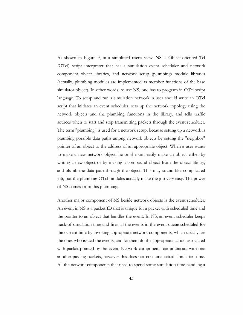
3.2.1 Cell .......................................................................................................................... 48 3.2.2 Distance ................................................................................................................. 49 3.2.3 Cell Diameter .......................................................................................................... 50

vi
3.2.4 Registrar Server Advertisement Interval ................................................................ 50 3.2.5 Registration Timeout Interval ................................................................................ 51 3.2.6 Collision .................................................................................................................. 51 3.2.7 Collision Set ............................................................................................................ 51 3.2.8 Intra‐Cell Messages ................................................................................................ 52 3.2.9 Inter‐Cell Messages ................................................................................................ 52
3.3 PROTOCOL DETAILS ............................................................................................................. 53 3.3.1 Scenarios ................................................................................................................ 53 3.3.2 Registrar Server Rearrangement ............................................................................ 54
3.4 STATE DIAGRAM ................................................................................................................. 58
C H A P T E R 4 PERFORMANCE EVALUATION .................................................................. 59
4.1 PERFORMANCE METRIC ....................................................................................................... 60 4.2 QUALITATIVE EVALUATION .................................................................................................... 60 4.3 QUANTITATIVE EVALUATION ................................................................................................. 61
4.3.1 Installation ............................................................................................................. 61 4.3.2 Simulation Architecture.......................................................................................... 61 4.3.4 Plugging into NS2 ................................................................................................... 75
C H A P T E R 5 CONCLUSION ........................................................................................... 79
BIBLIOGRAPHY ................................................................................................................... 80
vii
List of Figures FIGURE 1 EXAMPLE OF A THREE NODE MOBILE AD‐HOC NETWORK ............................................................. 9
FIGURE 2 BLOCK DIAGRAM OF MOBILE NODE ACTING BOTH AS HOSTS AND AS ROUTER ................................. 11
FIGURE 3 DIRECTED ACYCLIC GRAPH ROOTED AT DESTINATION. ............................................................... 29
FIGURE 4 MRP FORWARDING: NODE M IS THE MRP SET OF SOURCE NODE .............................................. 32
FIGURE 5 COMPARISON BETWEEN FLOODING AND MRP ....................................................................... 34
FIGURE 6 SIP ARCHITECTURE ........................................................................................................... 37
FIGURE 7 SIP COMMUNICATION WITHIN SAME DOMAIN ....................................................................... 40
FIGURE 8 SIP COMMUNICATION IN DIFFERENT DOMAIN ........................................................................ 41
FIGURE 9 SIMPLIFIED USER'S VIEW OF NS .......................................................................................... 42
FIGURE 10 C++ AND OTCL: THE DUALITY ......................................................................................... 45
FIGURE 11 ARCHITECTURAL VIEW OF NS ........................................................................................... 45
FIGURE 12 EXAMPLE OF CELL ........................................................................................................... 49
FIGURE 13 EXAMPLE OF DISTANCE .................................................................................................... 50
FIGURE 14 ILLUSTRATION OF CELL DIAMETER ....................................................................................... 50
FIGURE 15 COLLISION SET OF SIZE 3 .................................................................................................. 52
FIGURE 16 CREATION OF COLLISION: REGISTRAR SERVER C ENTERS THE NETWORK DUE TO MOBILITY. ............ 56
FIGURE 17 REARRANGEMENT WHEN A>B>C IN TERMS OF STRENGTH ...................................................... 56
FIGURE 18 REARRANGEMENT WHEN A>C>B ...................................................................................... 57
FIGURE 19 STATES OF NODES IN THIS PROTOCOL ................................................................................. 58
FIGURE 20 SIMULATION ARCHITECTURE OF THE PROTOCOL .................................................................... 62

1
Chap t e r 1
Introduction
2
1.1 Motivation
Whenever there is an opportunity of achieving some services or goods for free,
it’s a common human response is to get hold of it even if there is a compromise
to be made about quality, performance or security. In modern world the burden
of distant communication is mostly handled by cellular networks, which is
popular, reliable, easily available, widely accepted but comes at a price. Now if
someone provides the mass people with something that can enable them to skip
the existing cellular communication structure and have voice conversation for
hours without having to worry about credits running out, surely, it would be very
interesting. In a perfect world it might have been possible to provide all possible
communications for free. But in reality we can provide such facility in some small
scale. When a caller tries to call someone from cellular phone, who is
geographically very close to him, we might think it as a waste of cellular network
because we are trying to make a communication through complicated cellular
architecture that might have been really easily made directly between two devices.
Since every cellular phone is some kind of sophisticated radio device and can
connect to a base station that is far off, it already has the capability of connecting
to another device that is nearby. So if we can somehow provide a way of
connecting those two devices without the help of any central architecture, we can
allow free, independent communication between caller and callee.
The idea of communicating without the help of any central architecture is known
as ad-hoc communication. Ad-hoc network is a general concept and can be
created on any kind of radio capable network mechanism. Most suitable of them
is wireless LAN or (1)WiFi. With more and more devices being made WiFi
enabled (including cell phones), having ad-hoc networks available is becoming
easier day by day. Besides the obvious and elusive feature of free calling, having
facility of voice communication over such a network can provide us a lot of
3
advantages in some situations with deferent perspectives. The base concept of
such communication is to avoid any infrastructure based communication. So
whenever we face a situation where the reliability of such structures comes into
question, we have our system come to rescue.
• Every infrastructure based voice communication system (GSM, CDMA
etc) is driven by centralized structures like Base Station/MTSO etc.,
which are limited in capacity and can only provide for some statistically
average load. When a huge gathering happens, like in a football match or
concert or some procession they miserably fail to support voice
communication. In such an extreme cases, ad-hoc network can provide
useful alternate way of communication between people.
• In case of natural calamity like earthquake, flood, cyclone infrastructure
based communication is bound to suffer disturbance or lack of
operability. Rescue or relief teams generally have to be well equipped with
expensive equipments to enable communication between individuals.
Introduction of ad-hoc network based voice communication can serve
well in this purpose. Also people suffering such disaster can have a way to
communicate with each other and the rescue team. Since this network
doesn’t require any predefined setup or any non-regular device,
connectivity is instant and useful.
• When communication between groups is required to be secured (like
covert teams) avoidance of public network is necessary. Ad-hoc network
in some secured channel with proper encryption can go a long way here
in providing some solution.
So voice communication over such alternate network can be really handy.
4
1.2 Problem Specification
To transmit real time data like voice over any network, there are always some
common requirements to meet to bring out acceptable performance. To support
voice transmission a network should provide,
• Minimal delay in connection setup
• Minimal delay in packet transmission
• Minimal jitter
• Minimal hand-off time
• Adequate bandwidth allocation to transmit voice packets etc.
When we think about voice transmission, we need to think about these properties
of a network. There had been some real progress in voice transmission over IP
networks. But in case of ad-hoc networks it’s still in the early stages of research
cycle.
Like any other infrastructureless network, ad-hoc network suffers from lot of
complexities due to its dynamic nature and it fails to provide the reliability of a
structured network. There are lots of things to be done in this field. The primary
goal of this research work is to go in deep of this field and to make ad-hoc voice
communication as close as possible to voice communication systems available to
general users in terms of both performance and usability.
Existing ad-hoc structure provides us with dynamic mechanism of routing and IP
assignment of nodes, and gives the upper layer a way of sending datagram
packets from one node to another node. But the service is best of effort without
5
any promise of QoS. Aside from assurance of voice transmission quality, we have
few more issues to consider when we try to match our system existing well-
developed cellular network. One issue is subscriber identification. When we try to
mail someone, we use a mail address. When we try to call someone we use a
phone number that is unique to that person. In case of ad-hoc network, when we
start up some device enabled with ad-hoc networking capability, what we are
presented with is a list of IP addresses or MAC addresses. This might be
meaningful to lot of researchers but when general communication is concerned,
this is just meaningless. Since nodes are assigned with dynamic IP addresses we
can never tell which one is who, just by looking at such list. To support usability
of such network, we must provide with something like email address or phone
number that can identify a user among all these devices.
Now there are many existing mechanism of translating some human identifiable
name into IP address or other number (one being DNS). In recent times SIP
(session initiation protocol) has gained a lot of credibility in the realm of VoIP for
its simplicity and acceptability. SIP also provides a useful mechanism similar to
DNS in translating SIP URI into IP address. But the architecture of SIP is built
assuming that it would be implemented on an infrastructure-based network. But
in case of ad-hoc network this is quite impossible to have some special node that
can act like some server and be dedicated. So to allow users to call others using
some name or number we need to adopt SIP into dynamic non-centralized
structure of ad-hoc network. This thesis work is wholly devoted to this problem.
1.3 Related Works
There had been some effort made to adopt SIP architecture onto ad-hoc
networks (2) (3) (4) (5) . But most of them lacked the required performance
criteria. Few of those tried to create an overlay network on top of ad-hoc
network to give a common naming mechanism. But maintaining such a network
6
can be costly in terms of overhead generated. Such methods require a lot of
broadcasts at the application level. Since the underlying routing mechanism itself
does a lot of flooding there is already some control overhead. When addition
overhead is generated on its top, quality of communication degrades a lot due to
lack of available bandwidth. One way to subside this problem is to merge SIP
architecture with routing broadcast. Merging network layer to optimize
performance might seem irrational at first but the performance advantage can be
well worth.
Li Li and Louise Lamont published a paper (4) with a view to utilize optimized
flooding mechanisms provided by underlying routing algorithm and support SIP
registration service to SIP nodes available in the network. Here the base concept
is that every SIP node is also a registrar server itself. Each of them saves a table
with URI to IP address mapping. Each SIP node periodically broadcasts register
message in the network. Any other node receiving that message updates its table.
Whenever it needs to communicate with someone else on the network, it just
looks up the table and connects using the IP address. Problem with this
mechanism is there is still broadcast from each node. The paper states that if
there is some registrar server available on the network, SIP nodes just stops
broadcasting on their part and registers themselves on that registrar server. But
they don’t make any kind of reference about how the server was created or what
happens when they goes down. If we can manage such registrar server obviously
control overhead of maintaining SIP architecture decreases, but again we face
some other problems. Every time a node tries to connect to other node on the
network it has to make a query to the registrar server and waits for response. So
data packet concentration around that server increases by a huge amount and
creates congestion. Having a single registrar server also creates the problem of
single point of failure. When this node goes down the whole network will go
down. So existing works provide us with two solutions to adopt SIP, one is
7
totally decentralized with lot of broadcast and the other one with totally
centralized mechanism with possible congestion and downtime. In our work, we
can try to make something better by utilizing both the concept and creating
something that lies in between.
1.4 Project Organization
This thesis dissertation describes the design and performance measure of the
protocol to incorporate SIP architecture onto ad-hoc networks.
Chapter 2 provides background reading required to understand the protocol
developed.
Chapter 3 specifies in details how the protocol works.
Chapter 4 gives an overview on performance testing of the protocol in simulated
environment. It also provides details on how to setup such simulation.
Chapter 5 will suggest improvements and extensions for future development and
the thesis will conclude with a brief summary.

8
Chap t e r 2
General Concepts
9
2.1 Wireless ad-hoc networks
2.1.1 General
A wireless ad-hoc network (6) is a collection of mobile/semi-mobile nodes with
no pre-established infrastructure, forming a temporary network. Each of the
nodes has a wireless interface and communicates with each other over either
radio or infrared. Laptop computers and personal digital assistants that
communicate directly with each other are some examples of nodes in an ad-hoc
network. Nodes in the ad-hoc network are often mobile, but can also consist of
stationary nodes, such as access points to the Internet. Semi mobile nodes can be
used to deploy relay points in areas where relay points might be needed
temporarily.
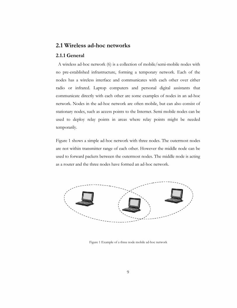
Figure 1 shows a simple ad-hoc network with three nodes. The outermost nodes
are not within transmitter range of each other. However the middle node can be
used to forward packets between the outermost nodes. The middle node is acting
as a router and the three nodes have formed an ad-hoc network.
Figure 1 Example of a three node mobile ad-hoc network
10
An ad-hoc network uses no centralized administration. This is to be sure that the
network won’t collapse just because one of the mobile nodes moves out of
transmitter range of the others. Nodes should be able to enter/leave the network
as they wish. Because of the limited transmitter range of the nodes, multiple hops
may be needed to reach other nodes. Every node wishing to participate in an ad-
hoc network must be willing to forward packets for other nodes. Thus every
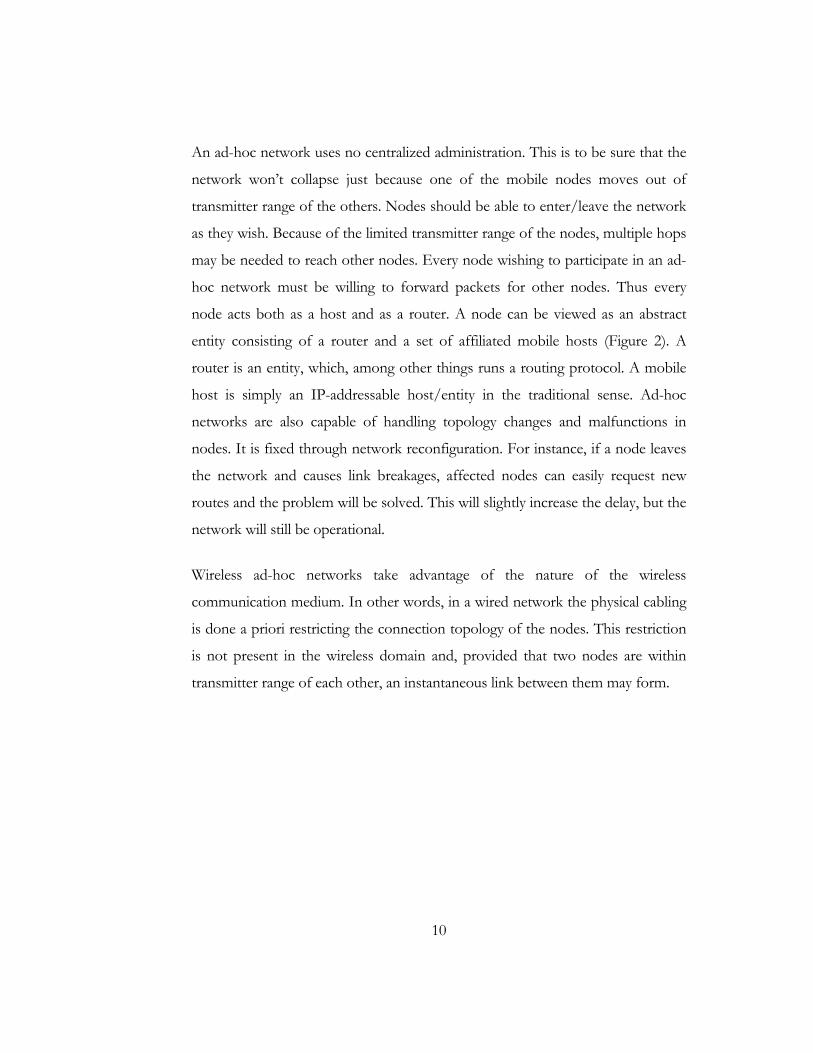
node acts both as a host and as a router. A node can be viewed as an abstract
entity consisting of a router and a set of affiliated mobile hosts (Figure 2). A
router is an entity, which, among other things runs a routing protocol. A mobile
host is simply an IP-addressable host/entity in the traditional sense. Ad-hoc
networks are also capable of handling topology changes and malfunctions in
nodes. It is fixed through network reconfiguration. For instance, if a node leaves
the network and causes link breakages, affected nodes can easily request new
routes and the problem will be solved. This will slightly increase the delay, but the
network will still be operational.
Wireless ad-hoc networks take advantage of the nature of the wireless
communication medium. In other words, in a wired network the physical cabling
is done a priori restricting the connection topology of the nodes. This restriction
is not present in the wireless domain and, provided that two nodes are within
transmitter range of each other, an instantaneous link between them may form.

11
Figure 2 Block diagram of mobile node acting both as hosts and as router
2.1.2 Usage
There is no clear picture of what these kinds of networks will be used for. The
suggestions vary from document sharing at conferences to infrastructure
enhancements and military applications. In areas where no infrastructure such as
the Internet is available an ad-hoc network could be used by a group of wireless
mobile hosts. This can be the case in areas where a network infrastructure may be
undesirable due to reasons such as cost or convenience. Examples of such
situations include disaster recovery personnel or military troops in cases where
the normal infrastructure is either unavailable or destroyed.
Other examples include business associates wishing to share files in an airport
terminal, or a class of students needing to interact during a lecture. If each mobile
host wishing to communicate is equipped with a wireless local area network
interface, the group of mobile hosts may form an ad-hoc network. Access to the
12
Internet and access to resources in networks such as printers are features that
probably also will be supported.
With more and more portable devices with WiFi radio pre-built coming into
market soon it might be get some real acceptance in the filed of insecure but free
voice communication over short rage in case of campus talk or disaster scenarios
where no infrastructure might be up and running.
2.1.3 Characteristics
Ad-hoc networks are often characterized by a dynamic topology due to the fact
that nodes change their physical location by moving around. This favors routing
protocols that dynamically discover routes over conventional routing algorithms
like distant vector and link state (7). Another characteristic is that a host/node
have very limited CPU capacity, storage capacity, battery power and bandwidth,
also referred to as a “thin client”. This means that the power usage must be
limited thus leading to a limited transmitter range. The access media, the radio
environment, also has special characteristics that must be considered when
designing protocols for ad-hoc networks. One example of this may be
unidirectional links. These links arise when for example two nodes have different
strength on their transmitters, allowing only one of the host to hear the other, but
can also arise from disturbances from the surroundings. Multihop in a radio
environment may result in an overall transmit capacity gain and power gain, due
to the squared relation between coverage and required output power. By using
multihop, nodes can transmit the packets with a much lower output power.

13
2.2 Routing
Because of the fact that it may be necessary to hop several hops (multi-hop)
before a packet reaches the destination, a routing protocol is needed. The routing
protocol has two main functions, selection of routes for various source-
destination pairs and the delivery of messages to their correct destination. The
second function is conceptually straightforward using a variety of protocols and
data structures (routing tables).
2.2.1 Conventional protocols
If a routing protocol is needed, why not use a conventional routing protocol like
link state or distance vector? They are well tested and most computer
communications people are familiar with them. The main problem with link-state
and distance vector is that they are designed for a static topology, which means
that they would have problems to converge to a steady state in an ad-hoc
network with a very frequently changing topology.
Link state and distance vector would probably work very well in an ad-hoc
network with low mobility, i.e. a network where the topology is not changing very
often. The problem that still remains is that link-state and distance-vector are
highly dependent on periodic control messages. As the number of network nodes
can be large, the potential number of destinations is also large. This requires large
and frequent exchange of data among the network nodes. This is in contradiction
with the fact that all updates in a wireless interconnected ad hoc network are
transmitted over the air and thus are costly in resources such as bandwidth,
battery power and CPU. Because both link-state and distance vector tries to
maintain routes to all reachable destinations, it is necessary to maintain these
routes and this also wastes resources for the same reason as above.
14
Another characteristic for conventional protocols are that they assume bi-
directional links, e.g. that the transmission between two hosts works equally well
in both directions. In the wireless radio environment this is not always the case.
Because many of the proposed ad-hoc routing protocols have a traditional
routing protocol as underlying algorithm, it is necessary to understand the basic
operation for conventional protocols like distance vector, link state and source
routing.
2.2.2 Link State
In link-state routing (7), each node maintains a view of the complete topology
with a cost for each link. To keep these costs consistent; each node periodically
broadcasts the link costs of its outgoing links to all other nodes using flooding.
As each node receives this information, it updates its view of the network and
applies a shortest path algorithm to choose the next-hop for each destination.
Some link costs in a node view can be incorrect because of long propagation
delays, partitioned networks, etc. Such inconsistent network topology views can
lead to formation of routing-loops. These loops are however short-lived, because
they disappear in the time it takes a message to traverse the diameter of the
network.
2.2.3 Distance Vector
In distance vector (7) each node only monitors the cost of its outgoing links, but
instead of broadcasting this information to all nodes, it periodically broadcasts to
each of its neighbors an estimate of the shortest distance to every other node in
15
the network. The receiving nodes then use this information to recalculate the
routing tables, by using a shortest path algorithm. Compared to link-state,
distance vector is more computation efficient, easier to implement and requires
much less storage space. However, it is well known that distance vector can cause
the formation of both short-lived and long-lived routing loops. The primary
cause for this is that the nodes choose their next-hops in a completely distributed
manner based on information that can be stale.
2.2.4 Source Routing
Source routing (7)means that each packet must carry the complete path that the
packet should take through the network. The routing decision is therefore made
at the source. The advantage with this approach is that it is very easy to avoid
routing loops. The disadvantage is that each packet requires a slight overhead.
2.2.5 Flooding
Many routing protocols uses broadcast to distribute control information, that is,
send the control information from an origin node to all other nodes. A widely
used form of broadcasting is flooding (7) and operates as follows. The origin
node sends its information to its neighbors (in the wireless case, this means all
nodes that are within transmitter range). The neighbors relay it to their neighbors
and so on, until the packet has reached all nodes in the network. A node will only
relay a packet once and to ensure this some sort of sequence number can be used.
This sequence number is increased for each new packet a node sends.

16
2.2.6 Classification
Routing protocols can be classified (8) into different categories depending on
their properties.
• Centralized vs. Distributed
• Static vs. Adaptive
• Reactive vs. Proactive
One way to categorize the routing protocols is to divide them into centralized
and distributed algorithms. In centralized algorithms, all route choices are made
at a central node, while in distributed algorithms, the computation of routes is
shared among the network nodes.
Another classification of routing protocols relates to whether they change routes
in response to the traffic input patterns. In static algorithms, the route used by
source-destination pairs is fixed regardless of traffic conditions. It can only
change in response to a node or link failure. This type of algorithm cannot
achieve high throughput under a broad variety of traffic input patterns. Most
major packet networks uses some form of adaptive routing where the routes used
to route between source-destination pairs may change in response to congestion
A third classification that is more related to ad-hoc networks is to classify the
routing algorithms as either proactive or reactive. Proactive protocols attempt to
continuously evaluate the routes within the network, so that when a packet needs
to be forwarded, the route is already known and can be immediately used. The
family of Distance-Vector protocols is an example of a proactive scheme.
Reactive protocols, on the other hand, invoke a route determination procedure
on demand only. Thus, when a route is needed, some sort of global search
17
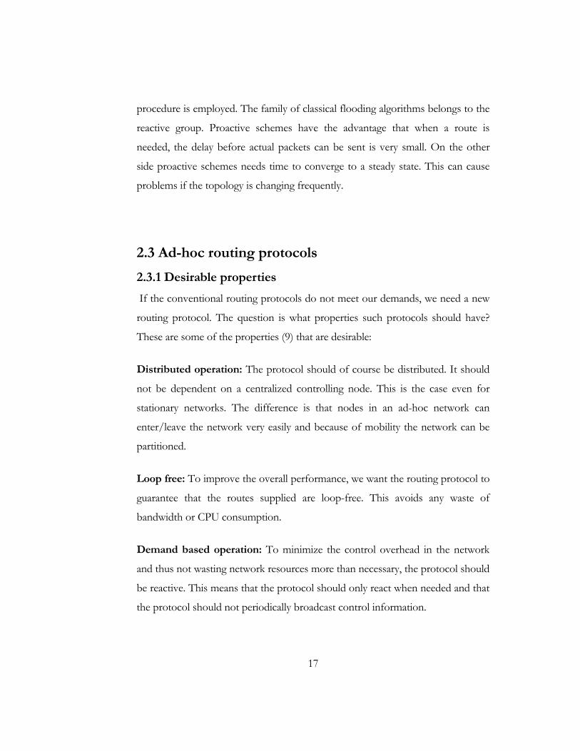
procedure is employed. The family of classical flooding algorithms belongs to the
reactive group. Proactive schemes have the advantage that when a route is
needed, the delay before actual packets can be sent is very small. On the other
side proactive schemes needs time to converge to a steady state. This can cause
problems if the topology is changing frequently.
2.3 Ad-hoc routing protocols
2.3.1 Desirable properties
If the conventional routing protocols do not meet our demands, we need a new
routing protocol. The question is what properties such protocols should have?
These are some of the properties (9) that are desirable:
Distributed operation: The protocol should of course be distributed. It should
not be dependent on a centralized controlling node. This is the case even for
stationary networks. The difference is that nodes in an ad-hoc network can
enter/leave the network very easily and because of mobility the network can be
partitioned.
Loop free: To improve the overall performance, we want the routing protocol to
guarantee that the routes supplied are loop-free. This avoids any waste of
bandwidth or CPU consumption.
Demand based operation: To minimize the control overhead in the network
and thus not wasting network resources more than necessary, the protocol should
be reactive. This means that the protocol should only react when needed and that
the protocol should not periodically broadcast control information.
18
Unidirectional link support: The radio environment can cause the formation of
unidirectional links. Utilization of these links and not only the bi-directional links
improves the routing protocol performance.
Security: The radio environment is especially vulnerable to impersonation
attacks, so to ensure the wanted behavior from the routing protocol, we need
some sort of preventive security measures. Authentication and encryption is
probably the way to go and the problem here lies within distributing keys among
the nodes in the ad-hoc network. There are also discussions about using IP-sec
(10)that uses tunneling to transport all packets.
Power conservation: The nodes in an ad-hoc network can be laptops and thin
clients, such as PDAs that are very limited in battery power and therefore uses
some sort of stand-by mode to save power. It is therefore important that the
routing protocol has support for these sleep-modes.
Multiple routes: To reduce the number of reactions to topological changes and
congestion multiple routes could be used. If one route has become invalid, it is
possible that another stored route could still be valid and thus saving the routing
protocol from initiating another route discovery procedure.
Quality of service support: Some sort of Quality of Service support is probably
necessary to incorporate into the routing protocol. This has a lot to do with what
these networks will be used for. It could for instance be real-time traffic support.
None of the proposed protocols from MANET have all these properties, but it is
necessary to remember that the protocols are still under development and are
probably extended with more functionality. The primary function is still to find a
route to the destination, not to find the best/optimal/shortest-path route.
19
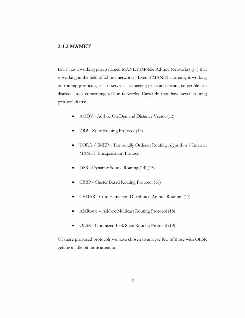
2.3.2 MANET
IETF has a working group named MANET (Mobile Ad-hoc Networks) (11) that
is working in the field of ad-hoc networks.. Even if MANET currently is working
on routing protocols, it also serves as a meeting place and forum, so people can
discuss issues concerning ad-hoc networks. Currently they have seven routing
protocol drafts:
• AODV - Ad-hoc On Demand Distance Vector (12)
• ZRP - Zone Routing Protocol (13)
• TORA / IMEP - Temporally Ordered Routing Algorithm / Internet
MANET Encapsulation Protocol
• DSR - Dynamic Source Routing (14) (15)
• CBRP - Cluster Based Routing Protocol (16)
• CEDAR - Core Extraction Distributed Ad hoc Routing (17)
• AMRoute – Ad-hoc Multicast Routing Protocol (18)
• OLSR - Optimized Link State Routing Protocol (19)
Of these proposed protocols we have chosen to analyze few of those with OLSR
getting a little bit more attention.

20
2.3.3 Destination Sequenced Distance Vector - DSDV
Description
DSDV (20) is a hop-by-hop distance vector routing protocol that in each node
has a routing table that for all reachable destinations stores the next-hop and
number of hops for that destination. Like distance-vector, DSDV requires that
each node periodically broadcast routing updates. The advantage with DSDV
over traditional distance vector protocols is that DSDV guarantees loop-freedom.
To guarantee loop-freedom DSDV uses a sequence numbers to tag each route.
The sequence number shows the freshness of a route and routes with higher
sequence numbers are favorable. A route R is considered more favorable than R'
if R has a greater sequence number or, if the routes have the same sequence
number but R has lower hop-count. The sequence number is increased when a
node A detects that a route to a destination D has broken. So the next time node
A advertises its routes, it will advertise the route to D with an infinite hop-count
and a sequence number that is larger than before. DSDV basically is distance
vector with small adjustments to make it better suited for ad-hoc networks.
These adjustments consist of triggered updates that will take care of topology
changes in the time between broadcasts. To reduce the amount of information in
these packets there are two types of update messages defined: full and
incremental dump. The full dump carries all available routing information and the
incremental dump that only carries the information that has changed since the
last dump.
21
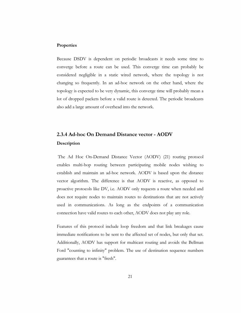
Properties
Because DSDV is dependent on periodic broadcasts it needs some time to
converge before a route can be used. This converge time can probably be
considered negligible in a static wired network, where the topology is not
changing so frequently. In an ad-hoc network on the other hand, where the
topology is expected to be very dynamic, this converge time will probably mean a
lot of dropped packets before a valid route is detected. The periodic broadcasts
also add a large amount of overhead into the network.
2.3.4 Ad-hoc On Demand Distance vector - AODV
Description
The Ad Hoc On-Demand Distance Vector (AODV) (21) routing protocol
enables multi-hop routing between participating mobile nodes wishing to
establish and maintain an ad-hoc network. AODV is based upon the distance
vector algorithm. The difference is that AODV is reactive, as opposed to
proactive protocols like DV, i.e. AODV only requests a route when needed and
does not require nodes to maintain routes to destinations that are not actively
used in communications. As long as the endpoints of a communication
connection have valid routes to each other, AODV does not play any role.
Features of this protocol include loop freedom and that link breakages cause
immediate notifications to be sent to the affected set of nodes, but only that set.
Additionally, AODV has support for multicast routing and avoids the Bellman
Ford "counting to infinity" problem. The use of destination sequence numbers
guarantees that a route is "fresh".

22
The algorithm uses different messages to discover and maintain links. Whenever
a node wants to try and find a route to another node, it broadcasts a Route
Request (RREQ) to all its neighbors. The RREQ propagates through the network
until it reaches the destination or a node with a fresh enough route to the
destination. Then the route is made available by unicasting a RREP back to the
source.
The algorithm uses hello messages (a special RREP) that are broadcasted
periodically to the immediate neighbors. These hello messages are local
advertisements for the continued presence of the node and neighbors using
routes through the broadcasting node will continue to mark the routes as valid.
If hello messages stop coming from a particular node, the neighbor can assume
that the node has moved away and mark that link to the node as broken and
notify the affected set of nodes by sending a link failure notification (a special
RREP) to that set of nodes.
Properties
The advantage with AODV compared to classical routing protocols like distance
vector and link-state is that AODV has greatly reduced the number of routing
messages in the network. AODV achieves this by using a reactive approach. This
is probably necessary in an ad-hoc network to get reasonably performance when
the topology is changing often.
AODV is also routing in the more traditional sense compared to for instance
source routing based proposals like DSR. The advantage with a more traditional
routing protocol in an ad-hoc network is that connections from the ad-hoc
network to a wired network like the Internet is most likely easier.

23
The sequence numbers that AODV uses represents the freshness of a route and
is increased when something happens in the surrounding area. The sequence
prevents loops from being formed, but can however also be the cause for new
problems. What happens for instance when the sequence numbers no longer are
synchronized in the network? This can happen when the network becomes
partitioned, or the sequence numbers wrap around.
AODV only support one route for each destination. It should however be fairly
easy to modify AODV, so that it supports several routes per destination. Instead
of requesting a new route when an old route becomes invalid, the next stored
route to that destination could be tried. The probability for that route to still be
valid should be rather high.
Although the Triggered Route Replies are reduced in number by only sending the
Triggered Route Replies to affected senders, they need to traverse the whole way
from the failure to the senders. This distance can be quite high in numbers of
hops. AODV sends one Triggered RREP for every active neighbor in the active
neighbor list for all entries that have been affected of a link failure. This can mean
that each active neighbor can receive several triggered RREPs informing about
the same link failure, but for different destinations, if a large fraction of the
network traffic is routed through the same node and this node goes down. An
aggregated solution would be more appropriate here.
AODV uses hello messages at the IP-level. This means that AODV does not
need support from the link layer to work properly. It is however questionable if
this kind of protocol can operate with good performance without support from
the link layer. The hello messages adds a significant overhead to the protocol.
AODV does not support unidirectional links. When a node receives a RREQ, it
will setup a reverse route to the source by using the node that forwarded the
24
RREQ as nexthop. This means that the route reply, in most cases is unicasted
back the same way as the route request used. Unidirectional link support would
make it possible to utilize all links and not only the bi-directional links. It is
however questionable if unidirectional links are desirable in a real environment.
The acknowledgements in the MAC protocol IEEE 802.11 would for instance
not work with unidirectional links.
2.3.5 Dynamic Source Routing - DSR
Description
Dynamic Source Routing (DSR) (22) (14) (15) also belongs to the class of
reactive protocols and allows nodes to dynamically discover a route across
multiple network hops to any destination. Source routing means that each packet
in its header carries the complete ordered list of nodes through which the packet
must pass. DSR uses no periodic routing messages (e.g. no router
advertisements), thereby reducing network bandwidth overhead, conserving
battery power and avoiding large routing updates throughout the ad-hoc network.
Instead DSR relies on support from the MAC layer (the MAC layer should
inform the routing protocol about link failures).
Properties
DSR uses the key advantage of source routing. Intermediate nodes do not need
to maintain up-to-date routing information in order to route the packets they
forward. There is also no need for periodic routing advertisement messages,
which will lead to reduce network bandwidth overhead, particularly during
periods when little or no significant host movement is taking place. Battery power
25
is also conserved on the mobile hosts, both by not sending the advertisements
and by not needing to receive them, a host could go down to sleep instead.
This protocol has the advantage of learning routes by scanning for information in
packets that are received. A route from A to C through B means that A learns the
route to C, but also that it will learn the route to B. The source route will also
mean that B learns the route to A and C and that C learns the route to A and B.
This form of active learning is very good and reduces overhead in the network.
However, each packet carries a slight overhead containing the source route of the
packet. This overhead grows when the packet has to go through more hops to
reach the destination. So the packets sent will be slightly bigger, because of the
overhead.
Running the interfaces in promiscuous mode is a serious security issue. Since the
address filtering of the interface is turned off and all packets are scanned for
information. A potential intruder could listen to all packets and scan them for
useful information such as passwords and credit card numbers. Applications have
to provide the security by encrypting their data packets before transmission. The
routing protocols are prime targets for impersonation attacks and must therefore
also be encrypted.
DSR also has support for unidirectional links by the use of piggybacking the
source route a new request. This can increase the performance in scenarios where
we have a lot of unidirectional links. We must however have a MAC protocol
that also supports this.

26
2.3.6 Zone Routing Protocol - ZRP
Description
Zone Routing Protocol (ZRP) (13) is a hybrid of a reactive and a proactive
protocol. It divides the network into several routing zones and specifies two
totally detached protocols that operate inside and between therouting zones.
The Intrazone Routing Protocol (IARP) operates inside the routing zone and
learns the minimum distance and routes to all the nodes within the zone. The
protocol is not defined and can include any number of proactive protocols, such
as Distance Vector or link-state routing. Different zones may operate with
different intrazone protocols as long as the protocols are restricted to those
zones. A change in topology means that update information only propagates
within the affected routing zones as opposed to affecting the entire network.
The second protocol, the Interzone Routing Protocol (IERP) is reactive and is
used for finding routes between different routing zones. This is useful if the
destination node does not lie within the routing zone.
The protocol then broadcasts (i.e. bordercasts) a Route REQuest (RREQ) to all
border nodes within the routing zone, which in turn forwards the request if the
destination node is not found within their routing zone. This procedure is
repeated until the requested node is found and a route reply is sent back to the
source indicating the route. IERP uses a Bordercast Resolution Protocol (BRP)
(13) that is included in ZRP. BRP provides bordercasting services, which do not
exist in IP. Bordercasting is the process of sending IP datagrams from one node
to all its peripheral nodes. BRP keeps track of the peripheral nodes and resolves a
border cast address to the individual IP-addresses of the peripheral nodes. The
27
message that was bordercasted is then encapsulated into a BRP packet and sent
to each peripheral node.
Properties
ZRP is a very interesting protocol and can be adjusted of its operation to the
current network operational conditions (e.g. change the routing zone diameter).
However this is not done dynamically, but instead it is suggested that this zone
radius should be set by the administration of the network or with a default value
by the manufacturer. The performance of this protocol depends quite a lot on
this decision.
Since this is a hybrid between proactive and reactive schemes, this protocol use
advantages from both. Routes can be found very fast within the routing zone,
while routes outside the zone can be found by efficiently querying selected nodes
in the network. One problem is however that the proactive intrazone routing
protocol is not specified. The use of different intrazone routing protocols would
mean that the nodes would have to support several different routing protocols.
This is not a good idea when dealing with thin clients. It is better to use the same
intrazone routing protocol in the entire network.
ZRP also limits propagation of information about topological changes to the
neighborhood of the change only (as opposed to a fully proactive scheme, which
would basically flood the entire network when a change in topology occurred).
However, a change in topology can affect several routing zones.
28
2.3.7 Temporally-Ordered Routing Algorithm - TORA
Description
Temporally Ordered Routing Algorithm (TORA) (23) (24) is a distributed routing
protocol. The basic underlying algorithm is one in a family referred to as link
reversal algorithms. TORA is designed to minimize reaction to topological
changes. A key concept in its design is that control messages are typically
localized to a very small set of nodes. It guarantees that all routes are loop-free
(temporary loops may form), and typically provides multiple routes for any
source/destination pair. It provides only the routing mechanism and depends on
Internet MANET Encapsulation Protocol for other underlying functions.
TORA can be separated into three basic functions: creating routes, maintaining
routes, and erasing routes. The creation of routes basically assigns directions to
links in an undirected network or portion of the network, building a directed
acyclic graph (DAG) rooted at the destination (See Figure 3).

29
Figure 3 Directed acyclic graph rooted at destination.
TORA associates a height with each node in the network. All messages in the
network flow downstream, from a node with higher height to a node with lower
height. Routes are discovered using Query (QRY) and Update (UPD) packets.
When a node with no downstream links needs a route to a destination, it will
broadcast a QRY packet. This QRY packet will propagate through the network
until it reaches a node that has a route or the destination itself. Such a node will
then broadcast a UPD packet that contains the node height. Every node receiving
this UPD packet will set its own height to a larger height than specified in the
UPD message. The node will then broadcast its own UPD packet. This will result
in a number of directed links from the originator of the QRY packet to the
destination. This process can result in multiple routes.
Maintaining routes refers to reacting to topological changes in the network in a
manner such that routes to the destination are re-established within a finite time,
30
meaning that its directed portions return to a destination-oriented graph within a
finite time. Upon detection of a network partition, all links in the portion of the
network that has become partitioned from the destination are marked as
undirected to erase invalid routes. The erasing of routes is done using clear (CLR)
messages.
Properties
The protocols underlying link reversal algorithm will react to link changes
through a simple localized single pass of the distributed algorithm. This prevents
CLR packets to propagate too far in the network. A comparison made by the
CMU Monarch project has however shown that the overhead in TORA is quite
large because of the use of IMEP.
The graph is rooted at the destination, which has the lowest height. However, the
source originating the QRY does not necessarily have the highest height. This can
lead to the situation, where multiple routes are possible from the source to the
destination, but only one route will be discovered. The reason for this is that the
height is initially based on the distance in number of hops from the destination.
2.3.7 Optimized Link State Routing Protocol - OLSR
Description
The Optimized Link State Routing Protocol (OLSR) is developed for mobile ad
hoc networks. It operates as a table driven, proactive protocol, i.e., exchanges
31
topology information with other nodes of the network regularly. Each node
selects a set of its neighbor nodes as "multipoint relays" (MPR). In OLSR, only
nodes, selected as such MPRs, are responsible for forwarding control traffic,
intended for diffusion into the entire network. MPRs provide an efficient
mechanism for flooding control traffic by reducing the number of transmissions
required.
Nodes, selected as MPRs, also have a special responsibility when declaring link
state information in the network. Indeed, the only requirement for OLSR to
provide shortest path routes to all destinations is that MPR nodes declare link-
state information for their MPR selectors. Additional available link-state
information may be utilized, e.g., for redundancy.
Nodes which have been selected as multipoint relays by some neighbor node(s)
announce this information periodically in their control messages. Thereby a node
announces to the network, that it has reachability to the nodes which have
selected it as an MPR. In route calculation, the MPRs are used to form the route
from a given node to any destination in the network. Furthermore, the protocol
uses the MPRs to facilitate efficient flooding of control messages in the
network.
A node selects MPRs from among its one hop neighbors with "symmetric", i.e.,
bi-directional, linkages. Therefore, selecting the route through MPRs
automatically avoids the problems associated with data packet transfer over uni-
directional links (such as the problem of not getting link-layer acknowledgments
for data packets at each hop, for link-layers employing this technique for unicast
traffic). OLSR is developed to work independently from other protocols.
Likewise, OLSR makes no assumptions about the underlying link-layer.
32
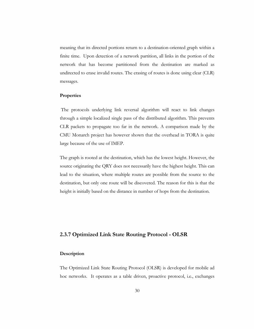
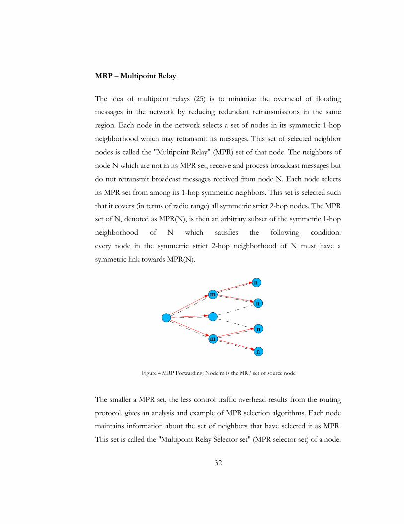
MRP – Multipoint Relay
The idea of multipoint relays (25) is to minimize the overhead of flooding
messages in the network by reducing redundant retransmissions in the same
region. Each node in the network selects a set of nodes in its symmetric 1-hop
neighborhood which may retransmit its messages. This set of selected neighbor
nodes is called the "Multipoint Relay" (MPR) set of that node. The neighbors of
node N which are not in its MPR set, receive and process broadcast messages but
do not retransmit broadcast messages received from node N. Each node selects
its MPR set from among its 1-hop symmetric neighbors. This set is selected such
that it covers (in terms of radio range) all symmetric strict 2-hop nodes. The MPR
set of N, denoted as MPR(N), is then an arbitrary subset of the symmetric 1-hop
neighborhood of N which satisfies the following condition:
every node in the symmetric strict 2-hop neighborhood of N must have a
symmetric link towards MPR(N).
Figure 4 MRP Forwarding: Node m is the MRP set of source node
The smaller a MPR set, the less control traffic overhead results from the routing
protocol. gives an analysis and example of MPR selection algorithms. Each node
maintains information about the set of neighbors that have selected it as MPR.
This set is called the "Multipoint Relay Selector set" (MPR selector set) of a node.

33
A node obtains this information from periodic HELLO messages received from
the neighbors. A broadcast message, intended to be diffused in the whole
network, coming from any of the MPR selectors of node N is assumed to be
retransmitted by node N, if N has not received it yet. This set can change over
time (i.e., when a node selects another MPR-set) and is indicated by the selector
nodes in their HELLO messages.
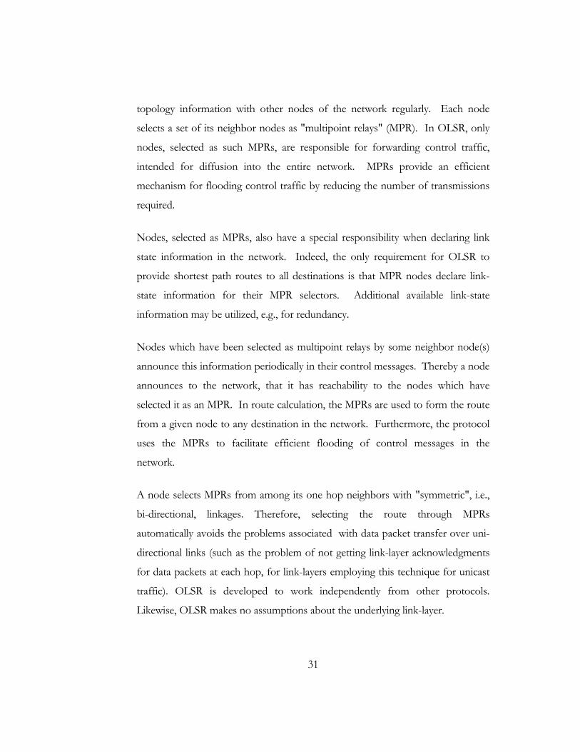
MRP forwarding gives certain edge over ordinary flooding. That’s where OLSR
gains over some other flooding based protocols. Figure 5 shows an example
comparison between ordinary flooding and MRP flooding.
Figure 5.a Network topology
Figure 5.b Ordinary Flooding
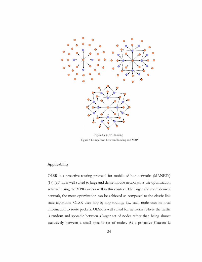
34
Figure 5.c MRP Flooding
Figure 5 Comparison between flooding and MRP
Applicability
OLSR is a proactive routing protocol for mobile ad-hoc networks (MANETs)
(19) (26). It is well suited to large and dense mobile networks, as the optimization
achieved using the MPRs works well in this context. The larger and more dense a
network, the more optimization can be achieved as compared to the classic link
state algorithm. OLSR uses hop-by-hop routing, i.e., each node uses its local
information to route packets. OLSR is well suited for networks, where the traffic
is random and sporadic between a larger set of nodes rather than being almost
exclusively between a small specific set of nodes. As a proactive Clausen &
35
Jacquet Experimental [Page 7] RFC 3626 Optimized Link State Routing October
2003 protocol, OLSR is also suitable for scenarios where the communicating
pairs change over time: no additional control traffic is generated in this situation
since routes are maintained for all known destinations at all times.
2.4 SIP: Session Initiation Protocol
2.4.1 Overview
Session Initiation Protocol (SIP) (27) is the Internet Engineering Task Force's
(IETF's) standard for multimedia conferencing over IP. SIP is an ASCII-based,
application-layer control protocol (defined in RFC 2543) that can be used to
establish, maintain, and terminate calls between two or more end points.
Like other VoIP protocols, SIP is designed to address the functions of signaling
and session management within a packet telephony network. Signaling allows call
information to be carried across network boundaries. Session management provides
the ability to control the attributes of an end-to-end call.
SIP provides the capabilities to:
• Determine the location of the target end point—SIP supports address
resolution, name mapping, and call redirection.
• Determine the media capabilities of the target end point—Via Session
Description Protocol (SDP), SIP determines the "lowest level" of
common services between the end points. Conferences are established
using only the media capabilities that can be supported by all end points.
• Determine the availability of the target end point—If a call cannot be
completed because the target end point is unavailable, SIP determines
whether the called party is already on the phone or did not answer in the
36
allotted number of rings. It then returns a message indicating why the
target end point was unavailable.
• Establish a session between the originating and target end point—If the
call can be completed, SIP establishes a session between the end points.
SIP also supports mid-call changes, such as the addition of another end
point to the conference or the changing of a media characteristic or
codec.
• Handle the transfer and termination of calls—SIP supports the transfer
of calls from one end point to another. During a call transfer, SIP simply
establishes a session between the transferee and a new end point
(specified by the transferring party) and terminates the session between
the transferee and the transferring party. At the end of a call, SIP
terminates the sessions between all parties.
Conferences can consist of two or more users and can be established using
multicast or multiple unicast sessions.
2.4.2 Components of SIP
SIP is a peer-to-peer protocol. The peers in a session are called User Agents
(UAs). A user agent can function in one of the following roles:
• User agent client (UAC)—A client application that initiates the SIP request.
• User agent server (UAS)—A server application that contacts the user when a SIP request is received and that returns a response on behalf of the user.
Typically, a SIP end point is capable of functioning as both a UAC and a UAS,
but functions only as one or the other per transaction. Whether the endpoint
functions as a UAC or a UAS depends on the UA that initiated the request.
37
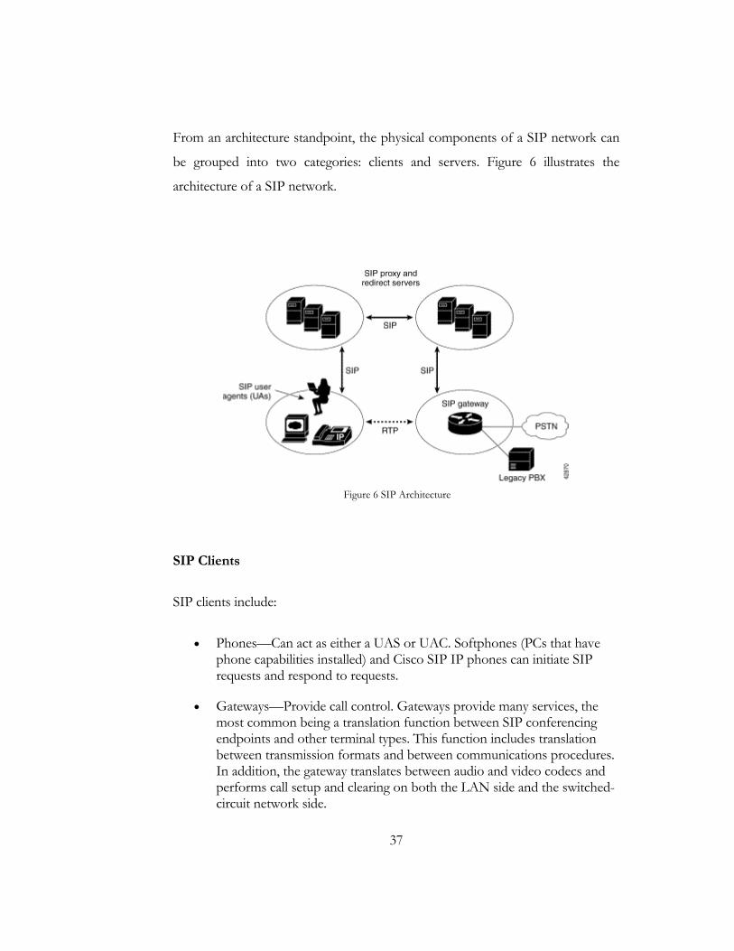
From an architecture standpoint, the physical components of a SIP network can
be grouped into two categories: clients and servers. Figure 6 illustrates the
architecture of a SIP network.
Figure 6 SIP Architecture
SIP Clients
SIP clients include:
• Phones—Can act as either a UAS or UAC. Softphones (PCs that have phone capabilities installed) and Cisco SIP IP phones can initiate SIP requests and respond to requests.
• Gateways—Provide call control. Gateways provide many services, the most common being a translation function between SIP conferencing endpoints and other terminal types. This function includes translation between transmission formats and between communications procedures. In addition, the gateway translates between audio and video codecs and performs call setup and clearing on both the LAN side and the switched-circuit network side.
38
SIP Servers
SIP servers include:
• Proxy server—The proxy server is an intermediate device that receives SIP requests from a client and then forwards the requests on the client's behalf. Basically, proxy servers receive SIP messages and forward them to the next SIP server in the network. Proxy servers can provide functions such as authentication, authorization, network access control, routing, reliable request retransmission, and security.
• Redirect server—Provides the client with information about the next hop or hops that a message should take and then the client contacts the next hop server or UAS directly.
• Registrar server—Processes requests from UACs for registration of their current location. Registrar servers are often co-located with a redirect or proxy server.
2.4.3 How SIP Works
SIP is a simple, ASCII-based protocol that uses requests and responses to
establish communication among the various components in the network and to
ultimately establish a conference between two or more end points. (28)
Users in a SIP network are identified by unique SIP addresses. A SIP address is
similar to an e-mail address and is in the format of sip:[email protected]. The
user ID can be either a user name or an E.164 address.
Users register with a registrar server using their assigned SIP addresses. The
registrar server provides this information to the location server upon request.
When a user initiates a call, a SIP request is sent to a SIP server (either a proxy or
a redirect server). The request includes the address of the caller (in the From
header field) and the address of the intended callee (in the To header field). The
39
following sections provide simple examples of successful, point-to-point calls
established using a proxy and a redirect server.
Over time, a SIP end user might move between end systems. The location of the
end user can be dynamically registered with the SIP server. The location server
can use one or more protocols (including finger, rwhois, and LDAP) to locate the
end user. Because the end user can be logged in at more than one station and
because the location server can sometimes have inaccurate information, it might
return more than one address for the end user. If the request is coming through a
SIP proxy server, the proxy server will try each of the returned addresses until it
locates the end user. If the request is coming through a SIP redirect server, the
redirect server forwards all the addresses to the caller in the Contact header field
of the invitation response.
Establishing A SIP Session Within the Same Domain
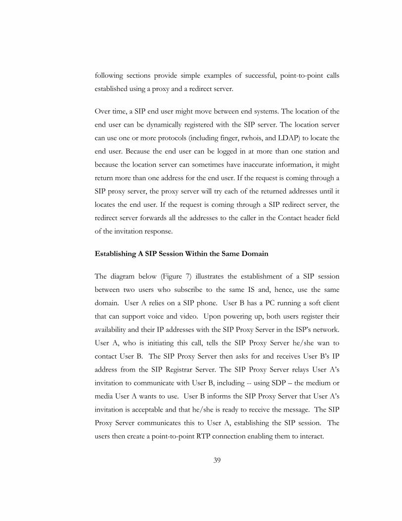
The diagram below (Figure 7) illustrates the establishment of a SIP session
between two users who subscribe to the same IS and, hence, use the same
domain. User A relies on a SIP phone. User B has a PC running a soft client
that can support voice and video. Upon powering up, both users register their
availability and their IP addresses with the SIP Proxy Server in the ISP’s network.
User A, who is initiating this call, tells the SIP Proxy Server he/she wan to
contact User B. The SIP Proxy Server then asks for and receives User B’s IP
address from the SIP Registrar Server. The SIP Proxy Server relays User A’s
invitation to communicate with User B, including -- using SDP – the medium or
media User A wants to use. User B informs the SIP Proxy Server that User A’s
invitation is acceptable and that he/she is ready to receive the message. The SIP
Proxy Server communicates this to User A, establishing the SIP session. The
users then create a point-to-point RTP connection enabling them to interact.
40
Figure 7 SIP Communication within same domain
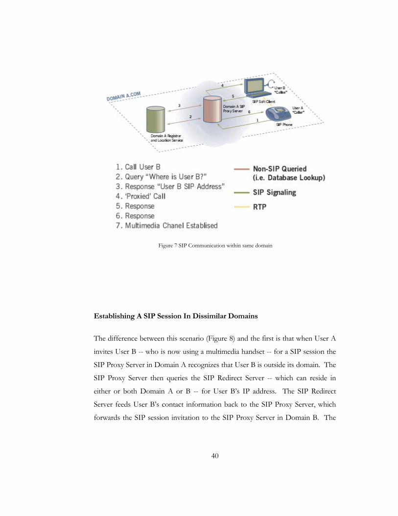
Establishing A SIP Session In Dissimilar Domains
The difference between this scenario (Figure 8) and the first is that when User A
invites User B -- who is now using a multimedia handset -- for a SIP session the
SIP Proxy Server in Domain A recognizes that User B is outside its domain. The
SIP Proxy Server then queries the SIP Redirect Server -- which can reside in
either or both Domain A or B -- for User B’s IP address. The SIP Redirect
Server feeds User B’s contact information back to the SIP Proxy Server, which
forwards the SIP session invitation to the SIP Proxy Server in Domain B. The
41
Domain B SIP Proxy Server delivers User A’s invitation to User B, who forwards
his/her acceptance along the same path the invitation traveled.
Figure 8 SIP Communication in different domain
2.5 S
For si
extens
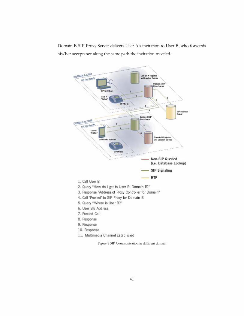
NS i
simula
and U
router
routin
and so
now a
display
well-kn
and OMIT)
Simulatio
imulation pu
sion of OOL
is an event
ates variety o
UPD, traffic
r queue man
ng algorithms
ome of the M
a part of the
y, analysis an
nown genera
OTcl (Tcl s
is available.
on Enviro
urpose we ha
SR.
driven netw
of IP network
source behav
nagement m
such as Dijk
MAC layer p
VINT prnd converter
ators to NS f
script languag
Figure
42
onment
ave used NS
work simulat
ks. It implem
vior such as
echanism su
kstra, and m
protocols for
roject that
rs that conv
formats. Curr
ge with Obj
e 9 Simplified Use
S2 (Network
tor develope
ments networ
s FTP, Telne
uch as Drop
ore. NS also
LAN simula
develops too
ert network
rently, NS (v
ect-oriented
er's View of NS
Simulator)
ed at UC B
rk protocols
et, Web, CBR
p Tail, RED
implements
ations. The N
ols for simul
topologies g
version 2) wri
extensions d
(29) with an
Berkeley that
such as TCP
R and VBR,
D and CBQ,
multicasting
NS project is
lation results
generated by
itten in C++
developed at
n
t
P
,
,
g
s
s
y
+
t
43
As shown in Figure 9, in a simplified user's view, NS is Object-oriented Tcl
(OTcl) script interpreter that has a simulation event scheduler and network
component object libraries, and network setup (plumbing) module libraries
(actually, plumbing modules are implemented as member functions of the base
simulator object). In other words, to use NS, one has to program in OTcl script
language. To setup and run a simulation network, a user should write an OTcl
script that initiates an event scheduler, sets up the network topology using the
network objects and the plumbing functions in the library, and tells traffic
sources when to start and stop transmitting packets through the event scheduler.
The term "plumbing" is used for a network setup, because setting up a network is
plumbing possible data paths among network objects by setting the "neighbor"
pointer of an object to the address of an appropriate object. When a user wants
to make a new network object, he or she can easily make an object either by
writing a new object or by making a compound object from the object library,
and plumb the data path through the object. This may sound like complicated
job, but the plumbing OTcl modules actually make the job very easy. The power
of NS comes from this plumbing.
Another major component of NS beside network objects is the event scheduler.
An event in NS is a packet ID that is unique for a packet with scheduled time and
the pointer to an object that handles the event. In NS, an event scheduler keeps
track of simulation time and fires all the events in the event queue scheduled for
the current time by invoking appropriate network components, which usually are
the ones who issued the events, and let them do the appropriate action associated
with packet pointed by the event. Network components communicate with one
another passing packets, however this does not consume actual simulation time.
All the network components that need to spend some simulation time handling a

44
packet (i.e. need a delay) use the event scheduler by issuing an event for the
packet and waiting for the event to be fired to itself before doing further action
handling the packet. For example, a network switch component that simulates a
switch with 20 microseconds of switching delay issues an event for a packet to be
switched to the scheduler as an event 20 microsecond later. The scheduler after
20 microsecond dequeues the event and fires it to the switch component, which
then passes the packet to an appropriate output link component. Another use of
an event scheduler is timer. For example, TCP needs a timer to keep track of a
packet transmission time out for retransmission (transmission of a packet with
the same TCP packet number but different NS packet ID). Timers use event
schedulers in a similar manner that delay does. The only difference is that timer
measures a time value associated with a packet and does an appropriate action
related to that packet after a certain time goes by, and does not simulate a delay.
NS is written not only in OTcl but in C++ also. For efficiency reason, NS
separates the data path implementation from control path implementations. In
order to reduce packet and event processing time (not simulation time), the event
scheduler and the basic network component objects in the data path are written
and compiled using C++. These compiled objects are made available to the OTcl
interpreter through an OTcl linkage that creates a matching OTcl object for each
of the C++ objects and makes the control functions and the configurable
variables specified by the C++ object act as member functions and member
variables of the corresponding OTcl object. In this way, the controls of the C++
objects are given to OTcl. It is also possible to add member functions and
variables to a C++ linked OTcl object. The objects in C++ that do not need to
be controlled in a simulation or internally used by another object do not need to
be linked to OTcl. Likewise, an object (not in the data path) can be entirely
implemented in OTcl. Figure 10 shows an object hierarchy example in C++ and
OTcl. One thing to note in the figure is that for C++ objects that have an OTcl

linkage
similar
Figure
an NS
and ru
The ev
C++
e forming a
r to that of C
e 11shows th
S developer) c
unning simul
vent schedul
and available
a hierarchy, t
C++.
Figure
Figur
he general arc
can be thoug
lations in Tc
lers and mos
e to OTcl th
45
there is a m
10 C++ and OT
re 11 Architectur
chitecture of
ght of standin
cl using the s
t of the netw
rough an OT
matching OT
TCL: The Duality
ral View of NS
NS. In this
ng at the left
simulator obj
work compon
Tcl linkage th
Tcl object hi
y
figure a gene
bottom corn
jects in the O
nents are imp
hat is implem
ierarchy very
eral user (not
ner, designing
OTcl library.
plemented in
mented using
y
t
g
.
n
g

46
tclcl. The whole thing together makes NS, which is an OO extended Tcl
interpreter with network simulator libraries.

47
Chap t e r 3
Pseudo Cellular Architecture
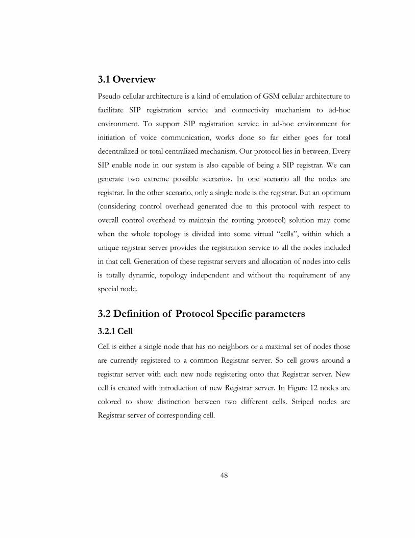
48
3.1 Overview
Pseudo cellular architecture is a kind of emulation of GSM cellular architecture to
facilitate SIP registration service and connectivity mechanism to ad-hoc
environment. To support SIP registration service in ad-hoc environment for
initiation of voice communication, works done so far either goes for total
decentralized or total centralized mechanism. Our protocol lies in between. Every
SIP enable node in our system is also capable of being a SIP registrar. We can
generate two extreme possible scenarios. In one scenario all the nodes are
registrar. In the other scenario, only a single node is the registrar. But an optimum
(considering control overhead generated due to this protocol with respect to
overall control overhead to maintain the routing protocol) solution may come
when the whole topology is divided into some virtual “cells”, within which a
unique registrar server provides the registration service to all the nodes included
in that cell. Generation of these registrar servers and allocation of nodes into cells
is totally dynamic, topology independent and without the requirement of any
special node.
3.2 Definition of Protocol Specific parameters
3.2.1 Cell
Cell is either a single node that has no neighbors or a maximal set of nodes those
are currently registered to a common Registrar server. So cell grows around a
registrar server with each new node registering onto that Registrar server. New
cell is created with introduction of new Registrar server. In Figure 12 nodes are
colored to show distinction between two different cells. Striped nodes are
Registrar server of corresponding cell.

49
Figure 12 Example of Cell
3.2.2 Distance
Distance between two nodes under this protocol is the number of hops traversed
from source node to destination node along the path that the routing algorithm
provides. Two important aspects about this distance measure are:
• Distance according to this definition might not the shortest distance
between the two nodes in the graph of the network. i
• Distances might not be equal in both directions.ii
Figure 13 shows distance between two neighboring registrar servers. Here the distance is 4.
i Shortest Path Length obviously is the lower limit of Distance.
ii Due to the directional nature of the wireless links, all routes are unidirectional and hence might differ when we switch source and destination. Different routes can easily have different distance value.
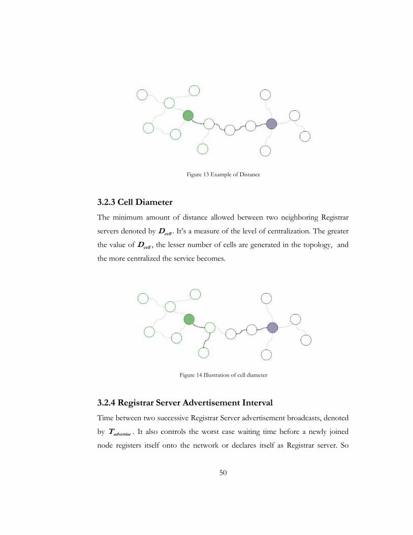
50
Figure 13 Example of Distance
3.2.3 Cell Diameter
The minimum amount of distance allowed between two neighboring Registrar
servers denoted by Dcell . It’s a measure of the level of centralization. The greater
the value of Dcell , the lesser number of cells are generated in the topology, and
the more centralized the service becomes.
Figure 14 Illustration of cell diameter
3.2.4 Registrar Server Advertisement Interval
Time between two successive Registrar Server advertisement broadcasts, denoted
by Tadvertise . It also controls the worst case waiting time before a newly joined
node registers itself onto the network or declares itself as Registrar server. So

51
increasing Tadvertise decreases overall control overhead but causes poor system
response time. On the contrary, decreasing Tadvertise, gives better network
response with additional broadcast overhead.
3.2.5 Registration Timeout Interval
Each registration entry in the registrar server remains valid for a predefined time.
This is registration timeout interval, denoted as Tregistration. So even if a node
registers itself to a server it must re-register itself after passing Tregistration time. If
we increase the value of this parameter, number of REGISTER messages
generated is decreased but network response becomes worsei.
3.2.6 Collision
Two registrar server is said to be in collision if they reside within a distance less
than Dcell .
3.2.7 Collision Set
A Collision Set is a maximalii set of nodes where each node is a Registrar server
and is in Collision with at least one other member of the same set.
i When a registrar server goes down or loses its registration data somehow, all the nodes within that cell is
barred calling others until registrar server is fed with valid data. So if we feed the server with REIGSTER with longer intervals, system down time also becomes larger.
ii By maximal we mean there is no other set of nodes that is both a collision set and a pure superset of this set.
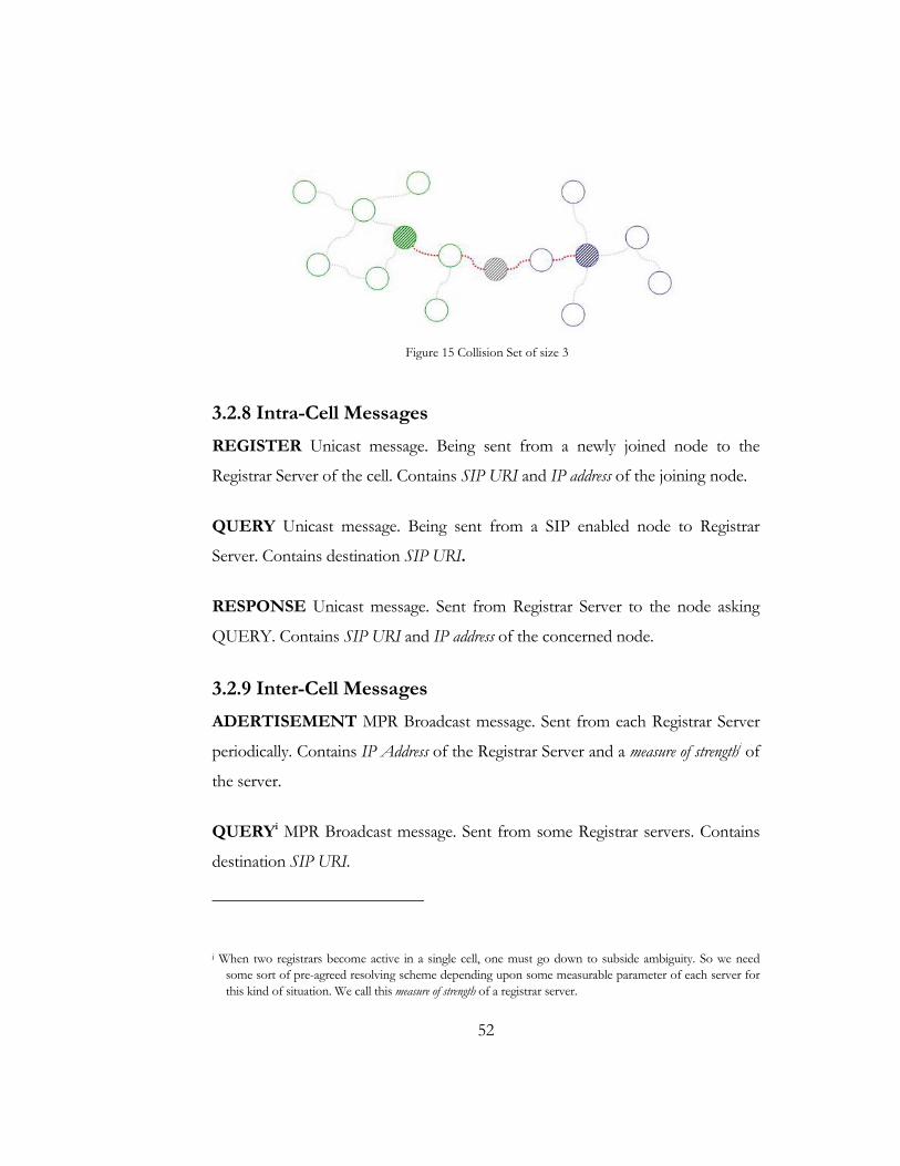
52
Figure 15 Collision Set of size 3
3.2.8 Intra-Cell Messages
REGISTER Unicast message. Being sent from a newly joined node to the
Registrar Server of the cell. Contains SIP URI and IP address of the joining node.
QUERY Unicast message. Being sent from a SIP enabled node to Registrar
Server. Contains destination SIP URI.
RESPONSE Unicast message. Sent from Registrar Server to the node asking
QUERY. Contains SIP URI and IP address of the concerned node.
3.2.9 Inter-Cell Messages
ADERTISEMENT MPR Broadcast message. Sent from each Registrar Server
periodically. Contains IP Address of the Registrar Server and a measure of strengthi of
the server.
QUERYi MPR Broadcast message. Sent from some Registrar servers. Contains
destination SIP URI.
i When two registrars become active in a single cell, one must go down to subside ambiguity. So we need
some sort of pre-agreed resolving scheme depending upon some measurable parameter of each server for this kind of situation. We call this measure of strength of a registrar server.
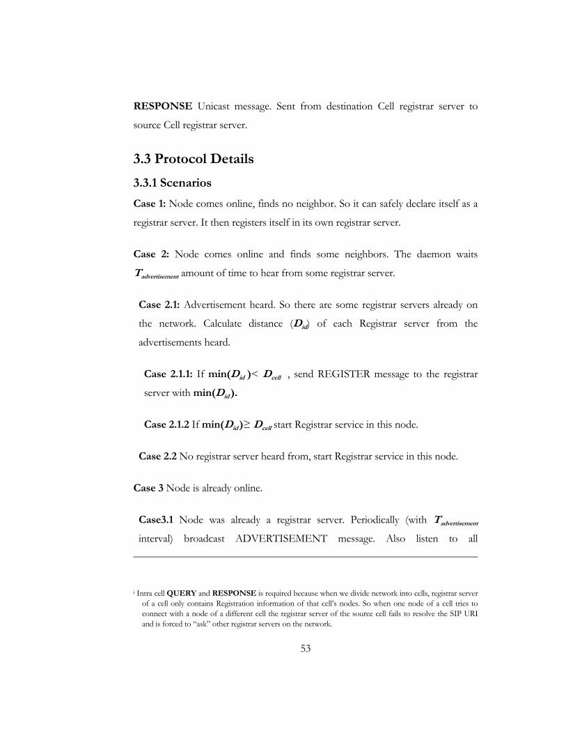
53
RESPONSE Unicast message. Sent from destination Cell registrar server to
source Cell registrar server.
3.3 Protocol Details
3.3.1 Scenarios
Case 1: Node comes online, finds no neighbor. So it can safely declare itself as a
registrar server. It then registers itself in its own registrar server.
Case 2: Node comes online and finds some neighbors. The daemon waits
Tadvertisement amount of time to hear from some registrar server.
Case 2.1: Advertisement heard. So there are some registrar servers already on
the network. Calculate distance (Did) of each Registrar server from the
advertisements heard.
Case 2.1.1: If min(Did )< Dcell , send REGISTER message to the registrar
server with min(Did ).
Case 2.1.2 If min(Did )≥ Dcell start Registrar service in this node.
Case 2.2 No registrar server heard from, start Registrar service in this node.
Case 3 Node is already online.
Case3.1 Node was already a registrar server. Periodically (with Tadvertisement
interval) broadcast ADVERTISEMENT message. Also listen to all i Intra cell QUERY and RESPONSE is required because when we divide network into cells, registrar server
of a cell only contains Registration information of that cell’s nodes. So when one node of a cell tries to connect with a node of a different cell the registrar server of the source cell fails to resolve the SIP URI and is forced to “ask” other registrar servers on the network.
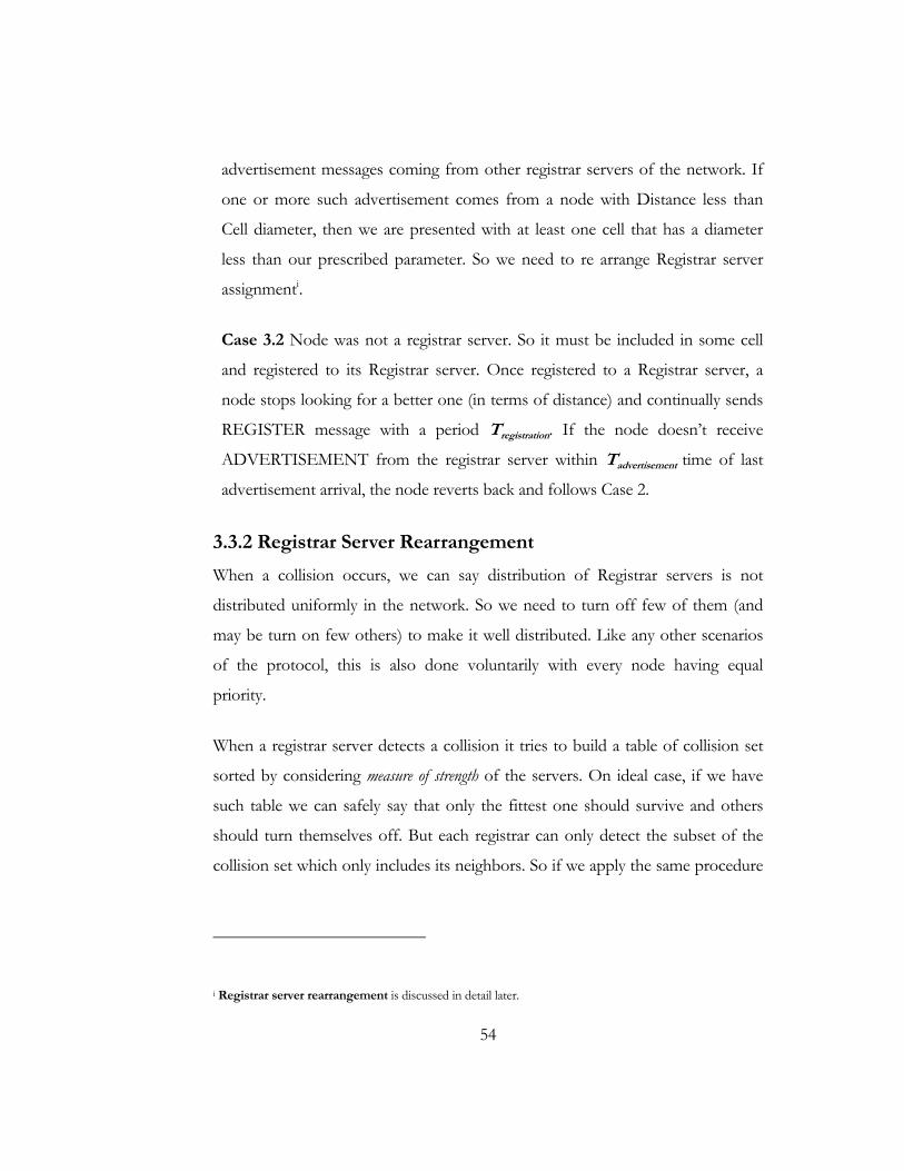
54
advertisement messages coming from other registrar servers of the network. If
one or more such advertisement comes from a node with Distance less than
Cell diameter, then we are presented with at least one cell that has a diameter
less than our prescribed parameter. So we need to re arrange Registrar server
assignmenti.
Case 3.2 Node was not a registrar server. So it must be included in some cell
and registered to its Registrar server. Once registered to a Registrar server, a
node stops looking for a better one (in terms of distance) and continually sends
REGISTER message with a period Tregistration. If the node doesn’t receive
ADVERTISEMENT from the registrar server within Tadvertisement time of last
advertisement arrival, the node reverts back and follows Case 2.
3.3.2 Registrar Server Rearrangement
When a collision occurs, we can say distribution of Registrar servers is not
distributed uniformly in the network. So we need to turn off few of them (and
may be turn on few others) to make it well distributed. Like any other scenarios
of the protocol, this is also done voluntarily with every node having equal
priority.
When a registrar server detects a collision it tries to build a table of collision set
sorted by considering measure of strength of the servers. On ideal case, if we have
such table we can safely say that only the fittest one should survive and others
should turn themselves off. But each registrar can only detect the subset of the
collision set which only includes its neighbors. So if we apply the same procedure
i Registrar server rearrangement is discussed in detail later.

55
onto the subset of collision table on each colliding servers. It takes several
iterations for the topology to settle down.
Figure 16 shows a common case of collision generation. Figure 17 and Figure 18
shows two cases of registrar server reassignment.
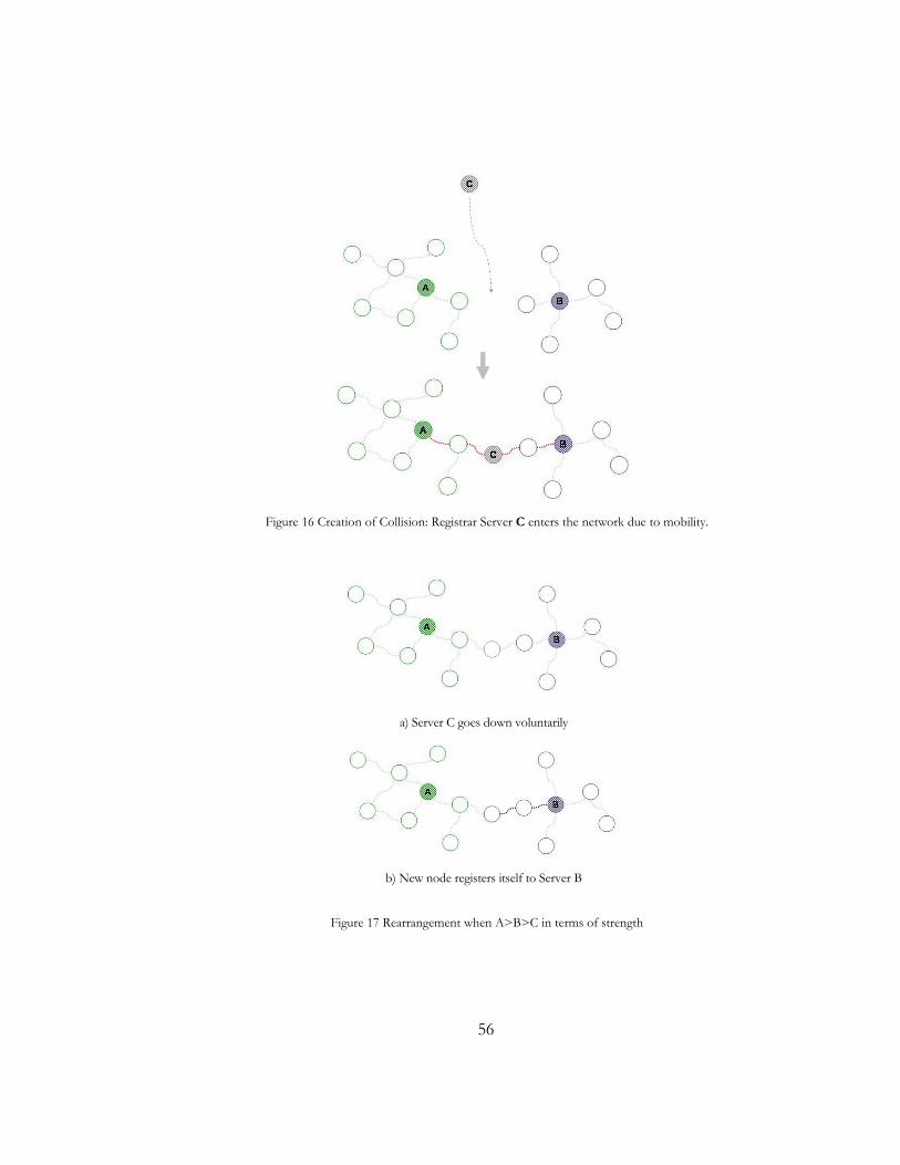
56
Figure 16 Creation of Collision: Registrar Server C enters the network due to mobility.
a) Server C goes down voluntarily
b) New node registers itself to Server B
Figure 17 Rearrangement when A>B>C in terms of strength

57
a) C goes down because A>C and B goes down because C>B
b) All the nodes outside Dcell decides to become server of the new Cell. Which creates new collision set
c) E is the strongest one of the new set so all others goes down.
d) Free nodes now register onto the new cell.
Figure 18 Rearrangement when A>C>B

58
3.4 State Diagram
According to this protocol each SIP enabled ad-hoc node can reside in four
possible states. Transition between states are voluntary, deterministic and
triggered upon receive of messages or timeouts.
Figure 19 States of Nodes in this protocol
This chapter provided details on the protocol developed. On the next one we
focus our attention on evaluating the performance of the protocol.

59
Chap t e r 4
Performance Evaluation
60
4.1 Performance Metric
Here we are trying to transmit voice data over some network. Quality of voice
depends upon a lot of factors, and performance evaluation can be
multidimensional. In our case we are trying to build some protocol that creates a
SIP based architecture onto ad-hoc network, which eventually will support voice
transmission. The design of SIP architecture doesn’t have any direct influence
over voice quality but since such protocol has to be maintained through some
packet transfer between nodes, the more overhead it causes, the lesser the
bandwidth remains for the user to use it for any actual purpose. So, our
measurement of performance would be how much control overhead is required
to actually maintain the protocol up and running.
Overhead ratio = T
P
OO
Where,
OP = Control overhead due to this protocol
OT = Control overhead generated due to the routing protocol
4.2 Qualitative Evaluation
Here we try to answer the question, why this protocol should perform better than
the existing ones available? This protocol generates registrar server dynamically
and divides the whole topology into cells. As such number of broadcasting nodes
decreases and as a whole total overhead decreases. So in terms of control
overhead this should perform better than total decentralized broadcast
mechanism. On the other hand if we let a single registrar server handle the whole
thing congestion will arise. So we need some load balance between multiple
registrar servers. Dividing the topology into multiple cells helps this cause but
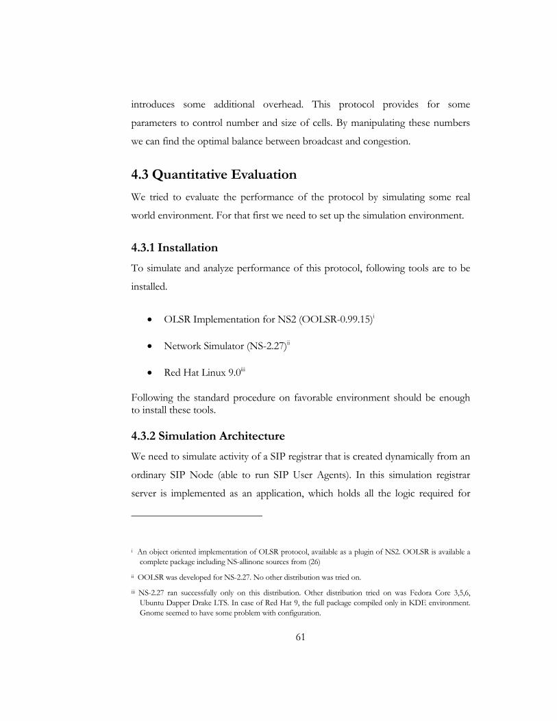
61
introduces some additional overhead. This protocol provides for some
parameters to control number and size of cells. By manipulating these numbers
we can find the optimal balance between broadcast and congestion.
4.3 Quantitative Evaluation
We tried to evaluate the performance of the protocol by simulating some real
world environment. For that first we need to set up the simulation environment.
4.3.1 Installation
To simulate and analyze performance of this protocol, following tools are to be
installed.
• OLSR Implementation for NS2 (OOLSR-0.99.15)i
• Network Simulator (NS-2.27)ii
• Red Hat Linux 9.0iii
Following the standard procedure on favorable environment should be enough to install these tools.
4.3.2 Simulation Architecture
We need to simulate activity of a SIP registrar that is created dynamically from an
ordinary SIP Node (able to run SIP User Agents). In this simulation registrar
server is implemented as an application, which holds all the logic required for
i An object oriented implementation of OLSR protocol, available as a plugin of NS2. OOLSR is available a
complete package including NS-allinone sources from (26)
ii OOLSR was developed for NS-2.27. No other distribution was tried on.
iii NS-2.27 ran successfully only on this distribution. Other distribution tried on was Fedora Core 3,5,6, Ubuntu Dapper Drake LTS. In case of Red Hat 9, the full package compiled only in KDE environment. Gnome seemed to have some problem with configuration.
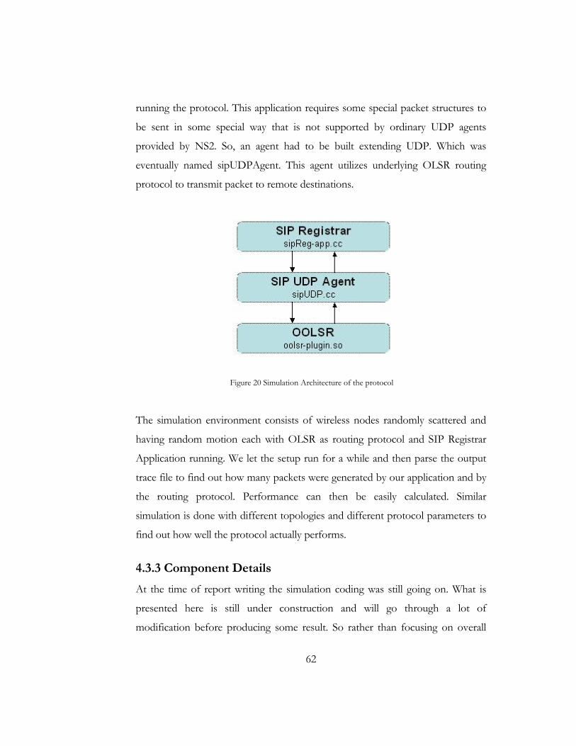
62
running the protocol. This application requires some special packet structures to
be sent in some special way that is not supported by ordinary UDP agents
provided by NS2. So, an agent had to be built extending UDP. Which was
eventually named sipUDPAgent. This agent utilizes underlying OLSR routing
protocol to transmit packet to remote destinations.
Figure 20 Simulation Architecture of the protocol
The simulation environment consists of wireless nodes randomly scattered and
having random motion each with OLSR as routing protocol and SIP Registrar
Application running. We let the setup run for a while and then parse the output
trace file to find out how many packets were generated by our application and by
the routing protocol. Performance can then be easily calculated. Similar
simulation is done with different topologies and different protocol parameters to
find out how well the protocol actually performs.
4.3.3 Component Details
At the time of report writing the simulation coding was still going on. What is
presented here is still under construction and will go through a lot of
modification before producing some result. So rather than focusing on overall

63
functionality this section gives some insight on problems encountered during
implementation and solves of the simulation system.
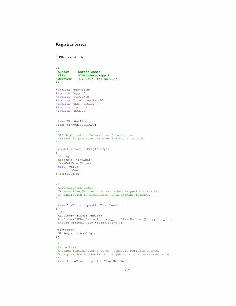
64
Registrar Server
SIPRegistrarApp.h
/* Author: Nafees Ahmed File: SIPRegistrarApp.h Written: 31/07/07 (for ns-2.27) */ #include "packet.h" #include "app.h" #include "sipUDP.h" #include "timer-handler.h" #include "hash_table.h" #include <vector> #include "node.h" class TimeOutTimer; class SIPRegistrarApp; /* SIP Registration Information Datastructure timeout is provided for each individual record. */ typedef struct SIPregInfoType { string uri; nsaddr_t nodeAddr; TimeOutTimer* timer; bool valid; int hopCount; } SIPRegInfo; /* Advertisement timer. Extends TimerHandler that can schedule periodic events. On expiration it broadcasts ADVERTISEMENT message. */ class AdvTimer : public TimerHandler { public: AdvTimer():TimerHandler(){} AdvTimer(SIPRegistrarApp* app_) : TimerHandler(), app(app_) {} inline virtual void expire(Event*); protected: SIPRegistrarApp* app; }; /* Probe timer. Extends TimerHandler that can schedule periodic events. On expiration it checks for neighbor on interfaces available. */ class ProbeTimer : public TimerHandler
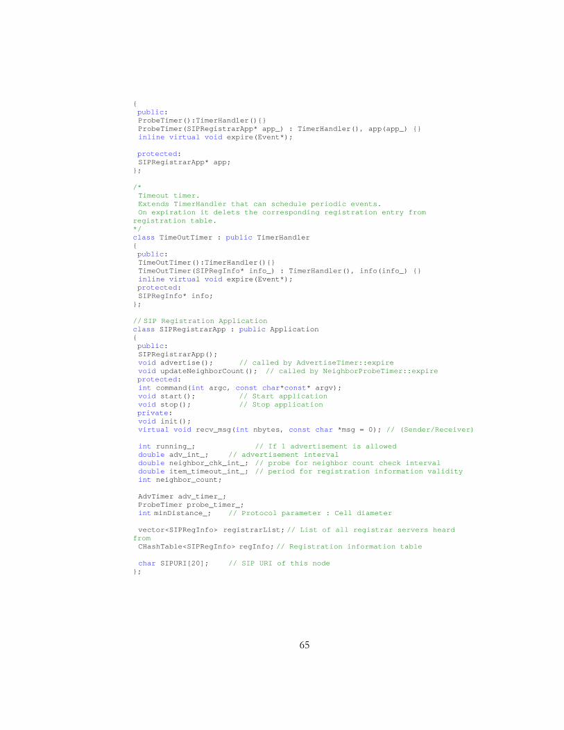
65
{ public: ProbeTimer():TimerHandler(){} ProbeTimer(SIPRegistrarApp* app_) : TimerHandler(), app(app_) {} inline virtual void expire(Event*); protected: SIPRegistrarApp* app; }; /* Timeout timer. Extends TimerHandler that can schedule periodic events. On expiration it delets the corresponding registration entry from registration table. */ class TimeOutTimer : public TimerHandler { public: TimeOutTimer():TimerHandler(){} TimeOutTimer(SIPRegInfo* info_) : TimerHandler(), info(info_) {} inline virtual void expire(Event*); protected: SIPRegInfo* info; }; // SIP Registration Application class SIPRegistrarApp : public Application { public: SIPRegistrarApp(); void advertise(); // called by AdvertiseTimer::expire void updateNeighborCount(); // called by NeighborProbeTimer::expire protected: int command(int argc, const char*const* argv); void start(); // Start application void stop(); // Stop application private: void init(); virtual void recv_msg(int nbytes, const char *msg = 0); // (Sender/Receiver) int running_; // If 1 advertisement is allowed double adv_int_; // advertisement interval double neighbor_chk_int_; // probe for neighbor count check interval double item_timeout_int_; // period for registration information validity int neighbor_count; AdvTimer adv_timer_; ProbeTimer probe_timer_; int minDistance_; // Protocol parameter : Cell diameter vector<SIPRegInfo> registrarList; // List of all registrar servers heard from CHashTable<SIPRegInfo> regInfo; // Registration information table char SIPURI[20]; // SIP URI of this node };
66
sipRegistrarApp.cc /* Author: Nafees Ahmed File: SIPRegistrarApp.cc Written: 31/07/07 (for ns-2.27) */ #include "sipReg-app.h" // When advertisement expires call advertisement sending function void AdvTimer::expire(Event*) { app->advertise(); } // When probe timer expires probe for neighbor information void ProbeTimer::expire(Event*) { app->updateNeighborCount(); } // When information times out, make it invalid void TimeOutTimer::expire(Event*) { info->valid = false; } // SIPRegistrarApp OTcl linkage class static class SIPRegistrarAppClass : public TclClass { public: SIPRegistrarAppClass() : TclClass("Application/VoWiFi/SIPRegistrar") {} TclObject* create(int, const char*const*) { return (new SIPRegistrarApp); } } class_app_sip; //small utility to color a NAM node. Used to identify registrar servers on NAM output.Still on test. void changeNodeColor(double atTime,const char * newColor,int id_) { Tcl& tcl = Tcl::instance(); int INTERVAL_COLOR_TIME = 5; int INTERVAL_COLOR = 1; if(atTime > 0.0 ) atTime += 0.0000000001; atTime +=0.1; // int i; // for(i=0;i<INTERVAL_COLOR_TIME;i++) // { // tcl.evalf("[Simulator instance] at %.9f {[Simulator instance] puts-nam-traceall {n -t %.9f -s %d -S COLOR -c %s -o %s}}",atTime,atTime,id_,"white","white"); // atTime += INTERVAL_COLOR; tcl.evalf("[Simulator instance] at %.9f {[Simulator instance] puts-nam-traceall {n -t %.9f -s %d -S COLOR -c %s -o %s}}",atTime,atTime,id_,newColor,newColor);

67
// atTime=atTime+INTERVAL_COLOR*INTERVAL_COLOR_TIME; // } } /* Constructor Initializes instances of timers And binds OTcl variables to C++ variables. */ SIPRegistrarApp::SIPRegistrarApp() : running_(0),adv_timer_(this),probe_timer_(this) { bind("neighbor_chk_int", &neighbor_chk_int_); bind("adv_int", &adv_int_); bind("item_timeout_int",&item_timeout_int_); bind("minDistance",&minDistance_); strcpy(SIPURI,"MOBILE"); bind("SIPURI",$SIPURI); bind("running", &running_); } // OTcl command interpreter int SIPRegistrarApp::command(int argc, const char*const* argv) { Tcl& tcl = Tcl::instance(); if (argc == 3) { if (strcmp(argv[1], "attach-agent") == 0) { agent_ = (Agent*) TclObject::lookup(argv[2]); if (agent_ == 0) { tcl.resultf("no such agent %s", argv[2]); return(TCL_ERROR); } // Make sure the underlying agent support MM if(agent_->supportSIP()) { agent_->enableSIP(); } else { tcl.resultf("agent \"%s\" does not support SIP Application", argv[2]); return(TCL_ERROR); } agent_->attachApp(this); return(TCL_OK); } } return (Application::command(argc, argv)); } /* initialize the application For now the URI is set to Node identifier of the node. */ void SIPRegistrarApp::init() { char buf[30]; sprintf(buf,"%d",agent_->addr());
68
strcat(SIPURI,buf); } //starts the application void SIPRegistrarApp::start() { init(); running_ = 0; probe_timer_.resched(adv_int_); //start probe timer adv_timer_.resched(adv_int_); //start advertisement timer Tcl& tcl = Tcl::instance(); tcl.evalf("puts \"\ndevice %s online\"", SIPURI); } //stop the application void SIPRegistrarApp::stop() { running_ = 0; } /* Funtion for counting neighbor. Also holds part of the protocol logic. The neighbor count portion still doesn't work fully. */ void SIPRegistrarApp::updateNeighborCount() { //do something to update neighbor count int neighborCount=0; Node* thisNode = Node::get_node_by_address(agent_->addr()); neighbor_list_node* neighbor = thisNode->neighbor_list_; while(neighbor) { neighbor = neighbor->next; neighborCount++; } //check for proxy list and decide whether advertise for proxy service Tcl& tcl = Tcl::instance(); tcl.evalf("puts \"\n\nnode %d \"",agent_->addr(),neighborCount); int minHopCount=99999; for(int i=0;i<registrarList.size();i++) { //reschedule the timer SIPRegInfo* info; info = ®istrarList[i]; tcl.evalf("puts \"\nentry %s :\"",info->uri.data()); if(info!=0) { if(info->valid == true) { if(info->hopCount <= minHopCount ) { minHopCount = info->hopCount; } } } }
69
if(minHopCount > minDistance_) //yes there is need for a new proxy server { running_ = true; changeNodeColor(Scheduler::instance().clock(),"red",agent_->addr()); } else //no need { running_ = false; changeNodeColor(Scheduler::instance().clock(),"black",agent_->addr()); } probe_timer_.resched(neighbor_chk_int_); } /* Receive message from underlying agent Place for writing the whole protocol logic. Partially completed. */ void SIPRegistrarApp::recv_msg(int nbytes, const char *msg) { int a; if(msg) { hdr_mm* mh_buf = (hdr_mm*) msg; if(agent_->addr()==0) a=0; switch (mh_buf->msgType) { case 1: //advertisement broadcast received { bool found = false; if(strcmp("data-packet",mh_buf->SIPuri)==0) found = true; if(!found) { for(int i=0;i<registrarList.size();i++) { if(strcmp(registrarList[i].uri.data(),mh_buf->SIPuri)==0) //already there is some entry { //reschedule the timer SIPRegInfo* info; info = ®istrarList[i]; if(info!=0) { info->valid = true; info->timer->resched(item_timeout_int_); info->hopCount = mh_buf->hopCount; } found = true; } } } if(!found) //if new entry is to be made { SIPRegInfo* proxyInfo; proxyInfo = new SIPRegInfo(); proxyInfo->uri = mh_buf->SIPuri; proxyInfo->nodeAddr = mh_buf->nodeAddr; proxyInfo->valid = true;
70
proxyInfo->hopCount = mh_buf->hopCount; TimeOutTimer* t = new TimeOutTimer(proxyInfo); t->resched(item_timeout_int_); proxyInfo->timer = t; registrarList.push_back(*proxyInfo); } //resolveProxyAssignment(); } break; case 2: //register break; case 3: break; } } } //ADVERTISEMENT broadcast function void SIPRegistrarApp::advertise(void) { double local_time = Scheduler::instance().clock(); Tcl& tcl = Tcl::instance(); int a; if(agent_->addr()==49) a=0; if(running_) { hdr_mm adv_buf; adv_buf.msgType =1; adv_buf.nodeAddr = agent_->addr(); strcpy(adv_buf.SIPuri,SIPURI); adv_buf.nbytes = 40; // send advertise message //agent_->sendmsg(adv_buf.nbytes, (char*) &adv_buf); ((UdpMmAgent*)agent_)->sendToAll(adv_buf.nbytes,(char*) &adv_buf); //tcl.evalf("\nputs \"Message from %d, sent to %d\"",frmAddress,toAddress); //changeNodeColor(Scheduler::instance().clock(),"red",agent_->addr()); } else { //changeNodeColor(Scheduler::instance().clock(),"black",agent_->addr()); } //schedule next ACK time adv_timer_.resched(adv_int_); }

71
UDP Agent
sipUDP.h
/* Author: Nafees Ahmed File: sipUDP.h Written: 31/07/07 (for ns-2.27) */ #include "udp.h" #include "ip.h" #include <string> #include "config.h" #define MAXTTL 65 // Header Structure struct hdr_mm { int msgType; nsaddr_t nodeAddr; //source node address char SIPuri[30]; //SIP uri int hopCount; //# of hops traveled // Packet header access functions static int offset_; inline static int& offset() {return offset_;} inline static hdr_mm* access(const Packet* p){ return (hdr_mm*) p->access(offset_); } }; // sipUDPAgent Class definition class sipUDPAgent : public UdpAgent { public: UdpMmAgent(); UdpMmAgent(packet_t); virtual int supportSIP() { return 1; } virtual void enableSIP() { support_mm_ = 1; } virtual void sendmsg(int nbytes, const char *flags = 0); void sendTo(int nbytes,const char *msg,nsaddr_t node); void sendToAll(int nbytes,const char *msg); void recv(Packet*, Handler*); void setPort(nsaddr_t); protected: int support_mm_; // set to 1 if above is sipAPP }; #endif
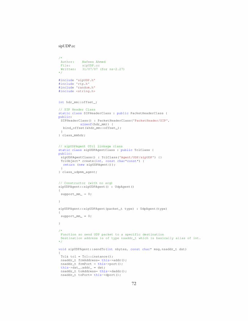
72
sipUDP.cc
/* Author: Nafees Ahmed File: sipUDP.cc Written: 31/07/07 (for ns-2.27) */ #include "sipUDP.h" #include "rtp.h" #include "random.h" #include <string.h> int hdr_mm::offset_; // SIP Header Class static class SIPHeaderClass : public PacketHeaderClass { public: SIPHeaderClass() : PacketHeaderClass("PacketHeader/SIP", sizeof(hdr_mm)) { bind_offset(&hdr_mm::offset_); } } class_mmhdr; // sipUDPAgent OTcl linkage class static class sipUDPAgentClass : public TclClass { public: sipUDPAgentClass() : TclClass("Agent/UDP/sipUDP") {} TclObject* create(int, const char*const*) { return (new sipUDPAgent()); } } class_udpmm_agent; // Constructor (with no arg) sipUDPAgent::sipUDPAgent() : UdpAgent() { support_mm_ = 0; } sipUDPAgent::sipUDPAgent(packet_t type) : UdpAgent(type) { support_mm_ = 0; } /* Function so send UDP packet to a specific destination Destination address is of type nsaddr_t which is basically alias of int. */ void sipUDPAgent::sendTo(int nbytes, const char* msg,nsaddr_t dst) { Tcl& tcl = Tcl::instance(); nsaddr_t frmAddress= this->addr(); nsaddr_t frmPort = this->port(); this->dst_.addr_ = dst; nsaddr_t toAddress= this->daddr(); nsaddr_t toPort= this->dport();
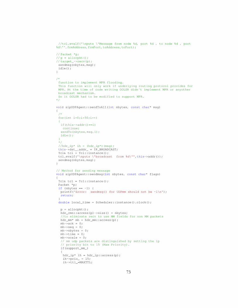
73
//tcl.evalf("\nputs \"Message from node %d, port %d , to node %d , port %d\"",frmAddress,frmPort,toAddress,toPort); // Packet *p; // p = allocpkt(); // target_->recv(p); sendmsg(nbytes,msg); idle(); } /* function to implement MPR flooding. This function will only work if underlying routing protocol provides for MPR. At the time of code writing OOLSR didn't implement MPR or anyother broadcast mechanism.
So it OOLSR had to be modified to support MPR. */ void sipUDPAgent::sendToAll(int nbytes, const char* msg) { /* for(int i=0;i<50;i++) { if(this->addr()==i) continue; sendTo(nbytes,msg,i); idle(); } */ //hdr_ip* ih = (hdr_ip*)(msg); this->dst_.addr_ = IP_BROADCAST; Tcl& tcl = Tcl::instance(); tcl.evalf("\nputs \"broadcast from %d\"",this->addr()); sendmsg(nbytes,msg); } // Method for sending message void sipUDPAgent::sendmsg(int nbytes, const char* flags) { Tcl& tcl = Tcl::instance(); Packet *p; if (nbytes == -1) { printf("Error: sendmsg() for UDPmm should not be -1\n"); return; } double local_time = Scheduler::instance().clock(); p = allocpkt(); hdr_cmn::access(p)->size() = nbytes; //to eliminate recv to use MM fields for non MM packets hdr_mm* mh = hdr_mm::access(p); mh->ack = 0; mh->seq = 0; mh->nbytes = 0; mh->time = 0; mh->scale = 0; // mm udp packets are distinguished by setting the ip // priority bit to 15 (Max Priority). if(support_mm_) { hdr_ip* ih = hdr_ip::access(p); ih->prio_ = 15; ih->ttl_=MAXTTL;

74
if(flags) memcpy(mh, flags, sizeof(hdr_mm)); } target_->recv(p); idle(); } // Receive funtion void sipUDPAgent::recv(Packet* p, Handler*) { hdr_ip* ih = hdr_ip::access(p); int bytes_to_deliver = hdr_cmn::access(p)->size(); if(app_) { // if SIP Application exists hdr_mm* mh = hdr_mm::access(p); // update hop count mh->hopCount = MAXTTL - ih->ttl_; hdr_mm mh_buf; memcpy(&mh_buf, mh, sizeof(hdr_mm)); app_->recv_msg(mh_buf.nbytes, (char*) &mh_buf); Tcl& tcl = Tcl::instance(); nsaddr_t frmAddress= this->addr(); nsaddr_t frmPort = this->port(); //tcl.evalf("\nputs \"Message from node %d, port %d , hop %d\"",frmAddress,frmPort,MAXTTL - ih->ttl_); } Packet::free(p); }
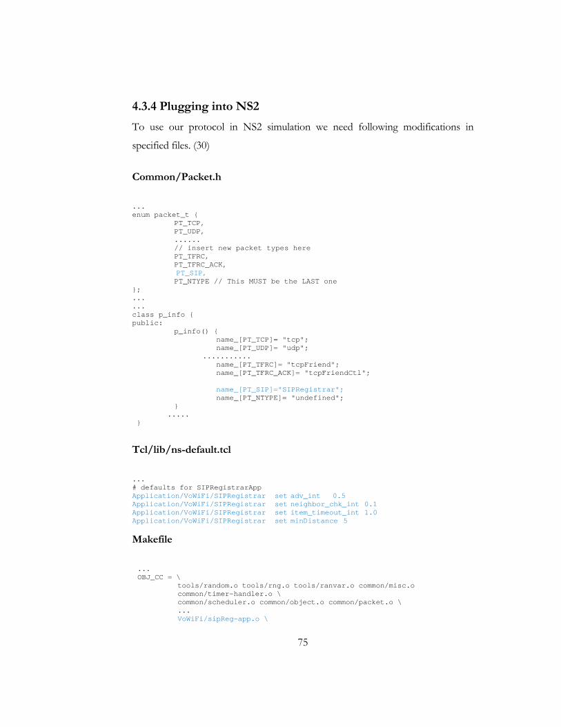
75
4.3.4 Plugging into NS2
To use our protocol in NS2 simulation we need following modifications in
specified files. (30)
Common/Packet.h
... enum packet_t { PT_TCP, PT_UDP, ...... // insert new packet types here PT_TFRC, PT_TFRC_ACK, PT_SIP, PT_NTYPE // This MUST be the LAST one }; ... ... class p_info { public: p_info() { name_[PT_TCP]= "tcp"; name_[PT_UDP]= "udp"; ........... name_[PT_TFRC]= "tcpFriend"; name_[PT_TFRC_ACK]= "tcpFriendCtl"; name_[PT_SIP]="SIPRegistrar"; name_[PT_NTYPE]= "undefined"; } ..... }
Tcl/lib/ns-default.tcl
... # defaults for SIPRegistrarApp Application/VoWiFi/SIPRegistrar set adv_int 0.5 Application/VoWiFi/SIPRegistrar set neighbor_chk_int 0.1 Application/VoWiFi/SIPRegistrar set item_timeout_int 1.0 Application/VoWiFi/SIPRegistrar set minDistance 5
Makefile
... OBJ_CC = \
tools/random.o tools/rng.o tools/ranvar.o common/misc.o common/timer-handler.o \ common/scheduler.o common/object.o common/packet.o \ ... VoWiFi/sipReg-app.o \
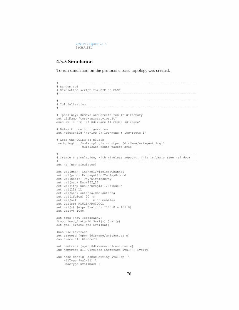
76
VoWiFi/sipUDP.o \ $(OBJ_STL)
4.3.5 Simulation
To run simulation on the protocol a basic topology was created.
#--------------------------------------------------------------------------- # Random.tcl # Simulation script for SIP on OLSR #--------------------------------------------------------------------------- #--------------------------------------------------------------------------- # Initialization #--------------------------------------------------------------------------- # (possibly) Remove and create result directory set dirName "test-unicast-result" exec sh -c "rm -rf $dirName && mkdir $dirName" # Default node configuration set nodeConfig "no-log 0; log-none ; log-route 1" # Load the OOLSR as plugin load-plugin ./oolsr-plugin --output $dirName/ns2agent.log \ multicast route packet-drop #--------------------------------------------------------------------------- # Create a simulation, with wireless support. This is basic (see ns2 doc) #--------------------------------------------------------------------------- set ns [new Simulator] set val(chan) Channel/WirelessChannel set val(prop) Propagation/TwoRayGround set val(netif) Phy/WirelessPhy set val(mac) Mac/802_11 set val(ifq) Queue/DropTail/PriQueue set val(ll) LL set val(ant) Antenna/OmniAntenna set val(ifqlen) 50 ;# set val(nn) 50 ;# nb mobiles set val(rp) PLUGINPROTOCOL set val(x) [expr $val(nn) *100.0 + 100.0] set val(y) 1000 set topo [new Topography] $topo load_flatgrid $val(x) $val(y) set god [create-god $val(nn)] #$ns use-newtrace set tracefd [open $dirName/unicast.tr w] $ns trace-all $tracefd set namtrace [open $dirName/unicast.nam w] $ns namtrace-all-wireless $namtrace $val(x) $val(y) $ns node-config -adhocRouting $val(rp) \ -llType $val(ll) \ -macType $val(mac) \
77
-ifqType $val(ifq) \ -ifqLen $val(ifqlen) \ -antType $val(ant) \ -propType $val(prop) \ -phyType $val(netif) \ -channel [new $val(chan)] \ -topoInstance $topo \ -agentTrace ON \ -routerTrace ON \ -macTrace OFF \ -movementTrace OFF #--------------------------------------------------------------------------- # Create nodes with OOLSR agent #--------------------------------------------------------------------------- for {set i 0} {$i < $val(nn)} {incr i} { set node($i) [$ns node] set agent($i) [new Agent/UDP/sipUDP] set app($i) [new Application/VoWiFi/SIPRegistrar] $ns attach-agent $node($i) $agent($i) $app($i) attach-agent $agent($i) $node($i) random-motion 1 $node($i) set X_ [expr $i * 100.0] $node($i) set Y_ [expr 500.0 + ((($i * 93) % 21) - 10 ) * 10.0] $node($i) set Z_ 0.0 $ns initial_node_pos $node($i) 20 # [$node($i) set ragent_] set-config \ # "$nodeConfig ; log-file-name $dirName/oolsr-node-$i.log" } for {set i 0} {$i < $val(nn)} {incr i} { $ns connect $agent($i) $agent([expr $val(nn) - $i -1]) $ns at ($i) "$app($i) start" } #--------------------------------------------------------------------------- # Sending traffic #--------------------------------------------------------------------------- #attach and start some CBR application to simulate phone calls. #should be filled up at the time of simulation. #modify this section to evaluate performance of the protocol in different #situations. #--------------------------------------------------------------------------- # Finishing procedure #--------------------------------------------------------------------------- proc finishSimulation { } { global ns node val dirName # Log the final state of all the nodes for {set i 0} {$i < $val(nn)} {incr i} { [$node($i) set ragent_] state "$dirName/oolsr-node-$i.final-state" } # Exit puts "Finished simulation." $ns halt
78
} #--------------------------------------------------------------------------- # Run the simulation #--------------------------------------------------------------------------- proc runSimulation {duration} { global ns finishSimulation $ns at $duration "finishSimulation" $ns run } # decide how long the simulation will run runSimulation 500.0
This script is to be simulated by NS and then output trace files (.tr) and animator
files (.nam) can be analyzed to verify the performance of the protocol. Since the
protocol was not completed at the time of report writing, simulation result is
unavailable.
79
Chap t e r 5
Conclusion Ad-Hoc network is an emerging field in networking arena. Transmission of voice
over such network makes it more applicable in real world. This research work
was devoted solely towards betterment of such feature. A protocol is also
developed in this regard. But simulation test of the protocol is yet to be done.
This protocol adapts to the dyanamiticity of ad-hoc realm to support service
discovery of SIP Registrar in a distributed manner. It is dynamic in a sense that
given value of cell diameter this protocol distributes the registrar servers evenly in
the whole topology, but static in terms of protocol parameters. Different network
scenarios are suitable for different protocol parameters. A possible improvement
of this protocol can be dynamic cell diameter to better adaption to changing
environment. Improving this protocol is not just the end of it. There are many
more issues still untouched in voice communication on ad-hoc networks and
improving those can have great effect on improving voice transmission quality on
such network.

80
Bibliography 1. WiFi. WikiPedia. [Online] http://en.wikipedia.org/wiki/WiFi. 2. A SIP-based Multicast Framework in MANET. Yu, Ying and Agarwal, Anjali.
s.l. : IEEE, 2005. WiMobapos. pp. 229 - 236. 3. A telephony application for MANETs, Voice over a MANET-extended JXTA Overlay
Network. Bernardo, Luis, et al. 2006. WINSYS. 4. Support of Multimedia SIP Application in Mobile Ad Hoc Networks: Service Discovery
and Networking Architecture. Li, Li and Lamon, Louise. 2005. GLOBECOM. 5. A framework to use SIP in Ad-Hoc Networks. Khlifi, Hechmi, Agarwal, Anjali
and Gregoire, Jean-Charles. s.l. : IEEE, 2003. CCECE. pp. 985 - 988. 6. Mobile ad-hoc network. WikiPedia. [Online]
http://en.wikipedia.org/wiki/Mobile_ad-hoc_network. 7. Tanenbaum, Andrew S. Computer Networks, 4e. s.l. : Prentice Hall, 2007. 8. Bertsekas, Dimitri and Gallager, Robert. Data Networks. 2e. s.l. : Prentice
Hall. 9. Scott, Corsosn and Joseph, Macker. Mobile Ad Hoc Networking
(MANET): Routing Protocol Performance Issues and Evaluation Considerations. Internet-Draft. [Online] draft-ietf-manet-issues-01.txt.
10. Kent, Stephen and Atkinson, Randall. Security Architecture for the Internet Protocol. Internet Draft. [Online] July 1998. draft-ietf-opsec-arch-sec-07.txt.
11. Mobile Ad-hoc Networks (MANET). [Online] http://www.ietf.org/html.charters/manet-charter.html.
12. Perkins, Charles E. Mobility support, Mobile IP and Wireles Channel Support for ns-2. Internet draft. [Online] draft-ietfmanet-aodv-01.txt.
13. Haas, Zygmunt J. and Pearlman, Marc R. The Zone Routing Protocol(ZRP) for Ad Hoc Networks. Internet Draft. [Online] draft-ietf-manet-zone-zrp-01.txt.
14. Dynamic source routing in ad hoc wireless networks. Johnson, David B. and A.Maltz, David. s.l. : Kluwer Academic Publisher. Mobile Computing. pp. 153-181.
15. Protocols for adaptive wireless and mobile computing. Johnson, David B. and Maltz, David A. 1996. IEEE Personal Communications.
16. Jiang, Mingliang, Li, Jinyang and Tay, Yong Chiang. Cluster Based Routing Protocol (CBRP) Functional specification. Internet draft. [Online] draft-ietf-manet-cbrp-spec-00.txt.
17. Sivakumar, Raghupathy, Sinha, Prasun and Bharghavan, Vaduvur. Core Extraction Distributed Ad hoc Routing (CEDAR) Specification. Internet draft. [Online] draft-ietf-manet-cedar-spec-00.txt.
81
18. Bommaiah, McAuley and Talpade. Ad-Hoc Multicast Routing Protocol. Internet Draft. [Online] drafttalpade-manet-amroute-00.txt.
19. Jacquet, Philippe, Muhethaler, Paul and Qayyum, Amir. Optimized Link State Routing Protocol. Internet Draft. [Online] draft-ietf-manetosr-00.txt.
20. Highly dynamic Destination-Sequenced Distance-Vector routing (DSDV) for mobile computers. Perkins, Charles E. and Bhagwat, Pravin. 1994. SIGCOM. pp. 234-244.
21. Perkins, Charles E. Ad Hoc On Demand Distance Vector (AODV) Routing. Internet draft. [Online] aodv-01.txt.
22. A performance Comparison f Multi-Hop Wireless Ad-Hoc Network Routing Protocols. Broch, Josh, et al. Texas, Dallas : s.n., 1998. Mobicom.
23. Park, Vincent D. and Corson, M. Scott. Temporally-Ordered Routing Algorithm (TORA) Version 1:Functional specification. Internet Draft. [Online] draft-ietf-manet-tora-spec-01.txt.
24. A performance comparison of the Temporally-Ordered Routing Algorithm and Ideal Link-state routing. Park, Vincent D. and Corson, M. Scott. 1998. IEEE Symposium on Computers and Communication.
25. Multipoint Relaying: An Efficient Technique for Flooding in Mobile Wireless Networks. Laouiti, A., Qayyum, A. and Viennot, L. 2002. 35th Annual Hawaii International Conference on System Sciences (HICSS).
26. OLSR : Optimized Link State Routing Protocol. [Online] http://hipercom.inria.fr/olsr/.
27. al, J. Rosenberg et. SIP: Session Initiation Protocol. Internet Draft. [Online] RFC 3261.
28. SIP Whitepaper. SIP Center. [Online] http://www.sipcenter.com/sip.nsf/html/WEBB5YNVK8/$FILE/Ubiquity_SIP_Overview.pdf.
29. The Network Simulator - ns-2. [Online] http://www.isi.edu/nsnam/ns/. 30. Chung, Jae and Claypool, Mark. NS By Example. Worcester Polytchnic
Institute : Computer Science. [Online] http://nile.wpi.edu/NS/. 31. Rosenberg, J. and Schulzrinne, H. Session Initiation Protocol (SIP):
Locating SIP Servers. Internet Draft. [Online] IETF RFC 3263. 32. Koodli, Rajeev and Perkins, Charles. Service Discovery in On-Demand
Ad Hoc Networks. Internet Draft. [Online] draft-koodli-manet-service-discovery-00.txt.
33. al, J. Jeong et. DNS Service for Mobile Ad Hoc Networks. Internet draft. [Online] draft-jeong-manet-dns-service-00.txt.

4