vol 2a package 616-01
DESCRIPTION
CONSTRUCTION OF SUBSTATION ALONGWITH TRANSMISSION LINE & ASSOCIATEDSYSTEMSTECHNICAL SPECIFICATIONTRANSCRIPT

ORISSA POWER TRANSMISSION CORPORATION LIMITED
CONSTRUCTION OF SUBSTATION ALONG WITH TRANSMISSION LINE & ASSOCIATED
SYSTEMS
TECHNICAL SPECIFICATION
VOLUME-IIA
BID DOCUMENT NO: NESCL/OPTCL/CS-OS-616-01
(PACKAGE-1)
NTPC ELECTRIC SUPPLY COMPANY LIMITED

IMPORTANT INSTRUCTION TO BIDDERS
• This volume (Volume-IIA) of technical
specification comprises of two parts- Scope of Works & Guaranteed Technical Particulars (GTP) & shall be read in conjunction with technical specification Volume-II as they are integral parts of Technical Specification.
• Bidders shall fill up complete Guaranteed
Technical Particulars (GTP) & shall submit along with Technical Bid(Part-1).

SCOPE OF WORKS
FOR
(PACKAGE-1) ON TURNKEY BASIS
SUBSTATION & TRANSMISSIONN
LINE PACKAGE
PACKAGE REF. NO:- NESCL/OPTCL/CS-OS-616-01

IMPORTANT NOTE
THE BIDDERS ARE ADVISED TO VISIT THE SITE BEFORE QUOTING THE BID. THEY SHOULD ASCERTAIN ALL THE REQUIRED DATA FOR TURNKEY COMPLETION OF THE SUBSTATION AND ASSOCIATED TRANSMISSION LINES SUCH AS;
1. SOIL BEARING CAPABILITY.
2. REQUIRED BENCHING AND FILLING FOR SITE LEVELLING.
3. TYPE OF STRUCTURES FOR BOTH LINE & SUBSTATION.
4. TOTAL QUANTITY OF ATERIALS/STRUCTURES/EQUIPMENTS.
5. TYPE OF FOUNDATIONS FOR ERECTION OF LINE TOWERS & SUB STATION EQUIPMENTS/STRUCTURES.
6. ASCERTAINING THE LENGTH OF THE REQUIRED BOUNDARY WALL, FENCING AND ROADS.
7. ANY OTHER DATA REQUIRED FOR DESIGNING OF THE LINE & SUBSTATION.
NESCL/OPTCL/CS-OS-616-01 SCOPE DETAILS PACKAGE-1 Page-1 of 23
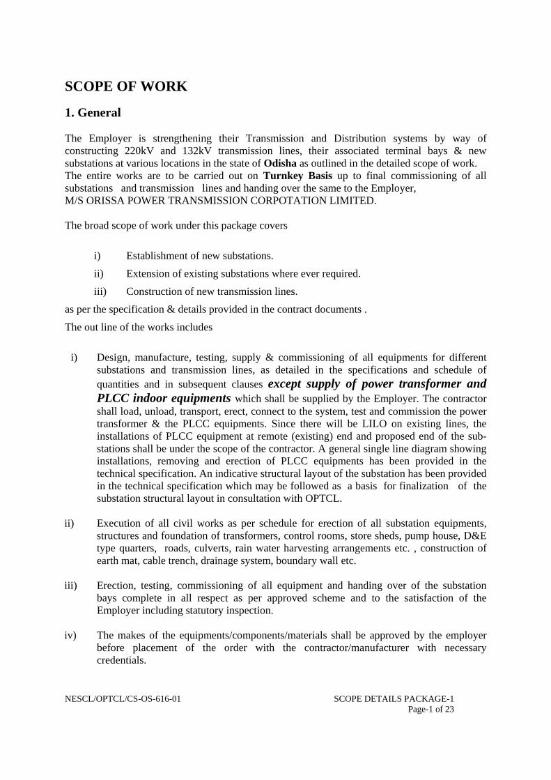
SCOPE OF WORK
1. General The Employer is strengthening their Transmission and Distribution systems by way of constructing 220kV and 132kV transmission lines, their associated terminal bays & new substations at various locations in the state of Odisha as outlined in the detailed scope of work. The entire works are to be carried out on Turnkey Basis up to final commissioning of all substations and transmission lines and handing over the same to the Employer, M/S ORISSA POWER TRANSMISSION CORPOTATION LIMITED.
The broad scope of work under this package covers
i) Establishment of new substations.
ii) Extension of existing substations where ever required.
iii) Construction of new transmission lines.
as per the specification & details provided in the contract documents .
The out line of the works includes
i) Design, manufacture, testing, supply & commissioning of all equipments for different
substations and transmission lines, as detailed in the specifications and schedule of quantities and in subsequent clauses except supply of power transformer and PLCC indoor equipments which shall be supplied by the Employer. The contractor shall load, unload, transport, erect, connect to the system, test and commission the power transformer & the PLCC equipments. Since there will be LILO on existing lines, the installations of PLCC equipment at remote (existing) end and proposed end of the sub-stations shall be under the scope of the contractor. A general single line diagram showing installations, removing and erection of PLCC equipments has been provided in the technical specification. An indicative structural layout of the substation has been provided in the technical specification which may be followed as a basis for finalization of the substation structural layout in consultation with OPTCL.
ii) Execution of all civil works as per schedule for erection of all substation equipments,
structures and foundation of transformers, control rooms, store sheds, pump house, D&E type quarters, roads, culverts, rain water harvesting arrangements etc. , construction of earth mat, cable trench, drainage system, boundary wall etc.
iii) Erection, testing, commissioning of all equipment and handing over of the substation
bays complete in all respect as per approved scheme and to the satisfaction of the Employer including statutory inspection.
iv) The makes of the equipments/components/materials shall be approved by the employer
before placement of the order with the contractor/manufacturer with necessary credentials.

NESCL/OPTCL/CS-OS-616-01 SCOPE DETAILS PACKAGE-1 Page-2 of 23
v) The contractor (s) has the responsibility to arrange construction power supply for construction of the project. The expenditure for such arrangement till completion of the project shall be to the contractors account.
vi) The contractor(s) has the responsibility to arrange clean water for construction and curing
to the civil works.
vii) The work as mentioned in the price schedule shall generally be considered for the evaluation of the bid.
viii) The contractor shall have to engage his own security at his own cost for security of all the
materials including owners supply materials (handed over to him for the site) that are required for successful completion of the project till final handing over of the entire work to OPTCL.
ix) Contractor has to obtain Project License in respect of the projects from the competent
authority at his own cost, prior to commencement of works.
x) The scope of work includes the provision of one official copy of each Standard listed in the appropriate schedule.
2. Detailed Scope of work The contractor shall be fully responsible for providing all equipment, material, systems and services which are required to complete the construction and successful commissioning of the works in all respects excepting those specifically excluded under the clause “1.2 - Specific exclusions” in the chapter “General Clauses”. The Contractor shall also refer to the Technical Specification (Vol.-II), for proper understanding of the works involved in respect of each substation. The scope of work on Turnkey basis includes design, engineering, manufacture, type testing, (factory testing) supply on FOR destination site basis, transportation, handling, storage at site, erection, site testing, commissioning complete in all respects and maintenance of plant and equipment until handing over of works in accordance with Conditions of Contract and the stipulations under various chapters of this specification at the prices stated in the Price Schedule for the following
(a) At SAMUKA BEACH , (District-PURI)
i. 132/33 KV sub station comprising of (1X20 MVA + 1X40 MVA transformers) as per single line diagram attached for the purpose.
ii. Associated 132 KV LILO transmission line of 11.01 kM on double circuit towers.

NESCL/OPTCL/CS-OS-616-01 SCOPE DETAILS PACKAGE-1 Page-3 of 23
(b) At CHANDPUR (District-KHURDA)
i. 132/33 KV sub station comprising of (2X12.5 MVA) sub-station as per single line diagram attached for the purpose.
ii. Associated 132 KV LILO transmission line of 3.21 kM on double circuit towers.
(c) At PURUSHOTAMPUR(District-GANJAM)
i. 132/33 KV sub station comprising of 132/33 KV (2X12.5 MVA)
ii. Associated 132 kV LILO transmission line of 2.5kM on double circuit towers.
A power map of Odisha is enclosed at the end of this chapter to help bidders locate the proposed work site. 2.1. Substations 2.1.1. Electrical The scope includes but is not limited to i) Supply erection, testing & commissioning of the following equipments:
1. Circuit breakers
2. Isolators
3. Current transformers
4. Voltage transformers (capacitive and electromagnetic)
5. CT, CVT, IVT console boxes with aluminium alloy having minimum three mm thickness.
6. All other out door kiosks/boxes, BMKs shall be MS sheet of minimum 2mm thickness with aluminium alloy canopy of 3mm thickness.
7. Surge arresters
8. Post insulators
9. Protection, control, and metering systems
10. PLCC systems
11. Insulator strings and other hardware
12. Busbar, circuit conductor and all conductor accessories
13. Power and control cables, cabling accessories, cable trays etc.
14. ACDC systems including all distribution boards, battery and charger systems, auxiliary transformers.
15. Air conditioning plant and systems for control room
16. Fire fighting systems and equipment

NESCL/OPTCL/CS-OS-616-01 SCOPE DETAILS PACKAGE-1 Page-4 of 23
17. Steel structures for switchyard gantries and portals (lattice type); and equipment (pipe or lattice type) including those for lightning protection
18. Earthing system and conductors
19. Testing and maintenance equipment
20. Lighting of substation area and substation buildings. Illumination and emergency lighting system at different locations.
21. Control and relay panels as proposed.
22. Installation of 220 V battery sets and 48 Volts Battery sets as proposed with suitable Battery chargers for the above batteries.
23. Event logger panel
24. AC and DC distribution boards as per requirement and as proposed.
25. Bus bar protection scheme (for 220kV SS only).
26. Disturbance recorder with Time synchronization.
27. Sub station level PC/Lap top provision for Relay configuration with their software.
28. The scope covers supply, delivery, installation and commissioning of exhaust fans to provide ventilation of Control Room building. Exhaust fans as specified below are to be provided in the following locations of Control Room building above lintel level :
i. Battery Room 8 No.
ii. Toilet 1 No.
The exhaust fans will be having 600 mm. Diameter for battery room and 450 mm diameter for the toilet, propeller type conforming to IS: 2312 and designed for continuous use. The exact locations of fixing the exhaust fans will be finalized while approving drawing for control room building. The supply voltage of exhaust fans shall be 230 V A.C. depending on rating of the fan. Exhaust fans will be having 4 poles to obtain a speed of 1440 r.p.m,
29. Any other items required for completion of the project are also in the scope of this contract in order to complete the sub-station in all respect.
ii) Erection, testing & commissioning of the following equipments: 1. Power transformers /auto transformers
2. Indoor PLCC equipments at both the ends
iii) Only supply of the following equipments: 1. Mandatory spares for substation equipment being supplied under this contract as perBid
proposal Sheet( BPS) schedule-3.
2. Maintenance & testing equipment etc as per the list provided in relevant chapter of technical specifications.
NESCL/OPTCL/CS-OS-616-01 SCOPE DETAILS PACKAGE-1 Page-5 of 23
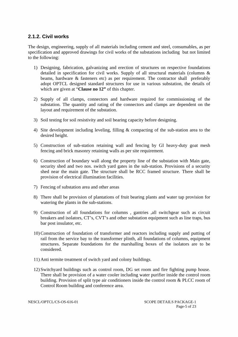
2.1.2. Civil works
The design, engineering, supply of all materials including cement and steel, consumables, as per specification and approved drawings for civil works of the substations including but not limited to the following:
1) Designing, fabrication, galvanizing and erection of structures on respective foundations detailed in specification for civil works. Supply of all structural materials (columns & beams, hardware & fasteners etc) as per requirement. The contractor shall preferably adopt OPTCL designed standard structures for use in various substation, the details of which are given at “Clause no 12” of this chapter.
2) Supply of all clamps, connectors and hardware required for commissioning of the substation. The quantity and rating of the connectors and clamps are dependent on the layout and requirement of the substation.
3) Soil testing for soil resistivity and soil bearing capacity before designing.
4) Site development including leveling, filling & compacting of the sub-station area to the desired height.
5) Construction of sub-station retaining wall and fencing by GI heavy-duty goat mesh fencing and brick masonry retaining walls as per site requirement.
6) Construction of boundary wall along the property line of the substation with Main gate, security shed and two nos. switch yard gates in the sub-station. Provisions of a security shed near the main gate. The structure shall be RCC framed structure. There shall be provision of electrical illumination facilities.
7) Fencing of substation area and other areas
8) There shall be provision of plantations of fruit bearing plants and water tap provision for watering the plants in the sub-stations.
9) Construction of all foundations for columns , gantries ,all switchgear such as circuit breakers and isolators, CT’s, CVT’s and other substation equipment such as line traps, bus bar post insulator, etc.
10) Construction of foundation of transformer and reactors including supply and putting of rail from the service bay to the transformer plinth, all foundations of columns, equipment structures. Separate foundations for the marshalling boxes of the isolators are to be considered.
11) Anti termite treatment of switch yard and colony buildings.
12) Switchyard buildings such as control room, DG set room and fire fighting pump house. There shall be provision of a water cooler including water purifier inside the control room building. Provision of split type air conditioners inside the control room & PLCC room of Control Room building and conference area.

NESCL/OPTCL/CS-OS-616-01 SCOPE DETAILS PACKAGE-1 Page-6 of 23
13) There shall be provision of store shed, one Ramp with winch for lifting the materials and lowering the materials up to 5 MT and out side platform to store the materials like transformer bushing, CT, CVT and other equipments.
14) Construction of D-type, E-type quarters.
15) Supply and spreading of uniform 20mm nominal size HG metal of 100mm thick inside both the switch yard area of the Sub- Stations. The spreading will be done above a finished level of switch yard land by plain cement concrete of thickness 75 mm (ratio 1:4:8). Anti weed treatment of the switch yard area to be made as per prevailing practice before spreading of PCC.
16) Construction of drainage system of the sub-stations and the newly constructed quarters & flood water discharge systems. Miscellaneous works like manholes soak pits, RCC, trench, fencing, etc. within the switchyard.
17) Construction of rain water harvesting arrangements in the substation.
18) Construction of cable trenches with trays & covers & sump pit with pump, as per requirement.
19) Construction of approach road to the new sub-stations as per requirement. Construction of periphery roads inside the fencing. The roads inside the switchyard & at the periphery shall be of 3.75 mtrs wide & the road inside switch yard shall be of concrete road as per technical specification. The other roads main and approach road shall be 7 mtrs wide and shall be bitumen grading.
20) Supply and putting of sub-station illumination system. All the light fittings shall be metal halide type & these fittings shall be mounted on switch yard portal structures such as columns & beams. No separate lighting mast is required. Entire substation lighting system in the switch yard & colony shall be designed using under ground cables only. No over head conductors are permitted for this purpose. For street lighting one outdoor lighting kiosk with two incomers of 200A rating switch fuse units (SFU) & with six feeders of 32A rating fitted with MCB shall be considered. Similar type of out door kiosk shall be considered for colony power supply with 200A SFU & ten out going feeder of 32A rating fitted with MCB shall be considered
21) Designing and providing the earth mat and earthing of the sub-station lighting protection, equipment earthing etc. Earth mat shall be designed using 75X10mm GI flat. For lightening protection individual spike not less than 2.5mtrs shall be provided on each column of the switchyard. Water tap provision shall be provided for pouring water into the earth pits constructed inside & around the periphery fence the switchyard. The earthing shall be extended beyond 2 mtrs from the fencing and the fencing earthing are also to be taken care.
22) Boring of two nos. new bore wells at a suitable location including construction of RCC pump house with 5 HP submersible pumps and its control inside the new proposed sub-station area. Making water supply arrangement for the colony and the Substation area

NESCL/OPTCL/CS-OS-616-01 SCOPE DETAILS PACKAGE-1 Page-7 of 23
including supply & erection of PVC pipe & its fittings, from pump house to Over head tank & from over head tank to all the distributaries system as per approval of the layouts.
23) Township colony, residential quarters for staff and employees of the Employer including electrification, water supply & other amenities for quarters.
24) Civic amenities for the township including drainage and sewerage systems.
25) All other materials, which the contractor feels to be required for completion of the sub-station.
2.2. Transmission lines.
i) Survey & ROW issues
1. Detailed line Survey works as per specification.
2. The contractor shall have to solve the entire right of way problem at his own cost. Contractor shall also resolve the issues related to the tree cutting in the transmission line and sub-station at his own cost. However the details of ROW issues has been indicated in Special Condition of Contract (SCC) –Vol.-1A.
ii) Design & Manufacturing (as applicable), supply, storage, erection, testing & commissioning of following materials
1. Galvanized Structural materials of towers as per requirement. OPTCL adopted standard towers shall preferably be used for the transmission line, the details of which is given at “Clause no.-13” in this chapter. However no standard design is available with OPTCL for multi circuit towers for 132kV line. The bidders shall use their own type tested design for multi circuit towers for 132kV line.
2. Foundation for various types of towers including revetment and piling (including under Rim piling & river bed piling as per requirement) works if required.
3. Insulators, hard wares.
4. ACSR conductors, GI earth wire etc and its stringing.
5. Commissioning of transmission lines.
6. Any other items required are also in the scope of this contract in order to complete the proposed transmission lines in all respect.
3. Electrical System Data of 400/220/132/33
1. Nominal System Voltage (KV) 400/220/132/33
2. Highest System Voltage (kV) 420/245/145/36
3. System Neutral Earthing. Effectively earthed

NESCL/OPTCL/CS-OS-616-01 SCOPE DETAILS PACKAGE-1 Page-8 of 23
4. Basic Insulation Level (KVP)
i) Bus 1550/1050/650/170
ii) Equipment other than Transformer 1550/1050/650/170
iii) Transformer 1300/1050/650/170
5. Power Frequency withstand voltage (KV rms) 520/460/275/80
6. System fault level KA 40/40/31.5/25
7. Creepage distance for insulators (mm) 10500/6125/3625/900
8. Min. recommended clearance in air(mm)as per CBIP
i) Phase-to-phase 4200/2100/1300/320
ii) Phase-to-earth 4000/2100/1300/320
iii) Sectional clearance 6500/5000/4000/3000
9. Min. ground clearance (as per IE Rules) 8500/5500/5000/4000
10. Bus configuration for 400/220/132/33 kV
Selection of ACSR conductor shall be Chosen from Moose, Zebra and panther as per requirement and decision of employer.
11. Phase-to-phase distance:
i) Along the bay (mm) 7000/4500//3000/1500
ii) Strung bus (mm) 7000/4500/3000/1500
12. Reference design temperature 50 Deg. Centigrade. Detailed technical particulars of different equipments have been specified in the
respective specifications in the subsequent section. If any technical particulars are missed from this volume the same may please be referred from relevant IS: specification for bidding purpose.
4. Design work
The Bidder shall furnish detailed design of the substations & transmission lines. The design work shall include but not limited to technical calculations, preparation of drawings and bill of materials and specifying equipments not specified in the specification but necessary for the completion of the substations & transmission lines on the turnkey basis. The technical calculation design drawings, etc. shall be submitted to

NESCL/OPTCL/CS-OS-616-01 SCOPE DETAILS PACKAGE-1 Page-9 of 23
the Employer for approval. However the layout drawing furnished by OPTCL shall be taken as a guide line.
5. Standards
All materials and equipments shall generally comply in all respects with the latest edition of the relevant Indian Standards. International Electro-Technical Commission (IEC) or any other internationally accepted Standard equivalent or better than relevant Indian Standard. Equipment complying with all other authoritative standards such as British, ASA, VDE, etc. will also be considered if performance equivalent or superior to Indian Standard is ensured.
In the event of supply of equipment confirming to any International or internationally recognized Standard other than the Standard listed in the Specification. The salient features of comparison shall be brought out and furnished along with the bid.
In case of adopting any standard other than that IS or IEC, a complete set of adopted standard shall be supplied by the bidder. However it is desirable and preferred that the equipment offered shall comply with one consistent set of standard unless other than exceptional cases.
The equipment shall also comply with the latest revision of Indian Electricity Act and Indian Electricity Rules and any other Electrical Statutory Provision, Rules and Regulations.
6. Reference Drawings
Drawings showing indicating scope of work are enclosed. Drawings are complementary to specifications and shall be referred to for better understanding as well as for estimation of quantities and bill of materials for arising at lump sum bid price on turnkey basis.
The bidder shall submit with the tender, plan of the substation showing broadly the scope of work incorporated as per technical specification. All the drawings shall be submitted in quadruplicate, enumerated in conformity with relevant clause stipulated in the Technical Section.
These drawings shall show proposed layout plan with section. Drawings sufficient overall dimension, clearance etc. required for assembling and dismantling and space requirements of all the apparatus to be supplied to enable the Employer to examine the design and layout at the installation.
7. Packing and Marking
The bidder shall include and provide for securely protecting and packing the plant so as to avoid damage in transit under proper condition and shall be responsible for all loss or damage caused by any defect in packing.

NESCL/OPTCL/CS-OS-616-01 SCOPE DETAILS PACKAGE-1 Page-10 of 23
Large and heavy items such as 400 KV, 220 kV, 132 kV and 33 KV equipments and structural steel shall be packed and shipped as per standard international practice.
Container/Cartoons, boxes, trunks and other packages shall be strong and sturdy in construction to withstand Ocean shipping. Several times loading and unloading, transport on rough roads, and storage in tropical area and hauling and handling during erection etc. Boxes and packages shall also be protected by suitable lagging or galvanized steel strips.
A layer of waterproof material shall be provided inside the cartoon/boxes/packages to protect the equipment from water seepage and to avoid rust.
The following information shall be marked on the container/boxes/packages etc.
a. Contractor’s/manufacturer’s name, project title and contract reference.
b. Plant/accessory identification No. and title.
c. Net/gross weight.
d. Employer’s name with other dispatch particulars such as destination.
The employer shall take no responsibility for any damage done to the plant on route to the site of work or place of delivery whichever is applicable.
8. Tests
i. Unless otherwise specified in respective section, all equipment shall be subjected routine and type test as covered and specified in any standard in presence of the authorized representative of the employer.
ii. Bidder shall submit type test report from a recognized laboratory along with the bid.
iii. At least 15 days advance notice shall be given by the contractor to the employer for witness the tests.
9. Compliance to IE rule 1956
i) The construction agency shall posses a safety manual duly approved by competent authority in the Govt. of his State Governing the safety in work by the personnel and staff.
ii) The agency shall posses valid contractor’s license issued by the Electrical Licensing Board of Odisha (ELBO) failing which he will not be allowed to start the work.
iii) All supervisory of works shall posses appropriate valid supervisory certificate of competency issued ELBO, Odisha.
NESCL/OPTCL/CS-OS-616-01 SCOPE DETAILS PACKAGE-1 Page-11 of 23
iv) At least 50% of electrical workmen employed in the project shall posses valid workmen permit by ELBO.
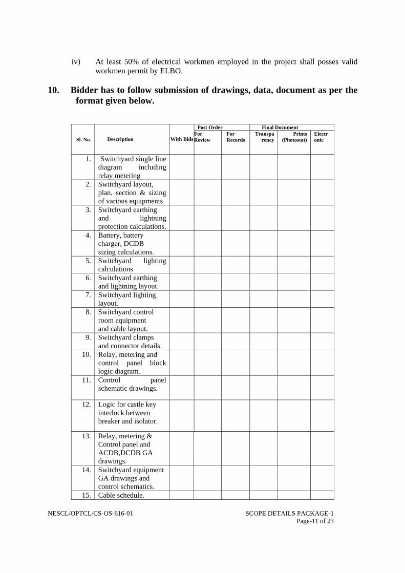
10. Bidder has to follow submission of drawings, data, document as per the
format given below.
Post Order Final Document
Sl. No. Description With Bids
For Review
For Records
Transparency
Prints (Photostat)
Electronic
1. Switchyard single line diagram including relay metering
2. Switchyard layout, plan, section & sizing of various equipments
3. Switchyard earthing and lightning protection calculations.
4. Battery, battery charger, DCDB sizing calculations.
5. Switchyard lighting calculations
6. Switchyard earthing and lightning layout.
7. Switchyard lighting layout.
8. Switchyard control room equipment and cable layout.
9. Switchyard clamps and connector details.
10. Relay, metering and control panel block logic diagram.
11. Control panel schematic drawings.
12. Logic for castle key interlock between breaker and isolator.
13. Relay, metering & Control panel and ACDB,DCDB GA drawings.
14. Switchyard equipment GA drawings and control schematics.
15. Cable schedule.

NESCL/OPTCL/CS-OS-616-01 SCOPE DETAILS PACKAGE-1 Page-12 of 23
Post Order Final Document
Sl. No. Description With BidsFor Review
For Records
Transparency
Prints (Photostat)
Electronic
16. Interconnection diagrams.
17. Relay setting calculations and Coordination drawings.
18. SLDs of ACDB and DCDB.
19. Soak pit and waste oil pit layout and sizing calculation.
20. Structural design calculations super structures.
21. Civil drawings for foundation and cable trenches.
22. Structural fabrication drawings of equipments gantries etc.
23. Filled in equipment data sheets as per enclosed format.
24. Complete literature, leaflets for all equipments.
25. Operational/ maintenance manual.
26. Deviation schedule w.r.t. a) Specification b) Document/ attachments.
27. List of spare parts for each major equipment.
28. List of special tools and tackles.
29. List of sub-vendors. 30. QA plan of vendor 31. Installation operating
and maintenance instruction.
32. Inspection Plan and Testing Procedure.
33. Test Records.

NESCL/OPTCL/CS-OS-616-01 SCOPE DETAILS PACKAGE-1 Page-13 of 23
Post Order Final Document
Sl. No. Description With BidsFor Review
For Records
Transparency
Prints (Photostat)
Electronic
34. List of commissioning/ maintenance spares.
35. Data Book/Manual a)Installation Manual b) Operating/Mainte- nance. c)Catalogues/ Brochures.
11. Minimum clearance for substation design shall be as per details given in
the table below.
Highest system voltage (kV)
Insulation level (kVP)
Switching Impulse Voltage (KVP)
Sectional Clearance (mm)
Minimum clearance Ground Clearance (mm)
Between phase & ground
Between phases
36KV 170 - 3000 320 320 3700 145KV 550
650 - 4000 1300 1300 4600
245KV 950 1050
- 4500 5000
2100 2100 5500
420KV 1425 1050 6500 3500 4200 8000 12. OPTCL adopted standard switchyard structure:
The bidders may adopt their own type tested design for switchyard structures with approval from OPTCL. However the standard switchyard structures adopted in OPTCL switchyards system in different voltage levels are given below.
A 220 KV SIDE:
1. COLUMN: P1S TYPE,- HEIGHT-21.5 MTRS,WEIGHT-4.464MT 2. BEAM:Q1 TYPE,-LENGTH-18 MTRS, WEIGHT-1.473MT
B 132 KV SIDE:
1. COLUMN: T1S TYPE,- HEIGHT-15 MTRS,-WEIGHT-1.193 MT
2. COLUMN: T4S TYPE,-HEIGHT-11 MTRS,-WEIGHT-0.924 MT
3. BEAM:G1 TYPE,-LENGTH-10.4 MTRS,-WEIGHT-0.613 MT
4. BEAM:G2 TYPE,-LENGTH-14.9875 MTRS,-WEIGHT-0.906 MT
5. BEAM:G1X TYPE,-LENGTH-10.4 MTRS,-WEIGHT-1.370 MT

NESCL/OPTCL/CS-OS-616-01 SCOPE DETAILS PACKAGE-1 Page-14 of 23
6. BEAM:G1,2 TYPE,-LENGTH-10.4 MTRS,-WEIGHT-1.25 MT
C 33 KV SIDE:
1. COLUMN: T8S TYPE,- HEIGHT-10.5 MTRS,WEIGHT- 0.777 MT
2. COLUMN: T9S TYPE,-HEIGHT-7.5 MTRS,WEIGHT - 0.592 MT
3. BEAM:G4 TYPE,-LENGTH-5.5 MTRS,WEIGHT-0.306 MT
4. BEAM:G4X TYPE,-LENGTH-5.5 MTRS,WEIGHT-0.306 MT 5. BEAM:G6 TYPE,-LENGTH- MTRS,WEIGHT-7.25 MT
D THE BAY WIDTH OF DIFFERENT VOLTAGE LEVEL ARE AS BELOW
1. 220 KV SYSTEM SHALL BE 18 MTRS 2. 132 KV SYSTEM SHALL BE 10.4/13.1MTRS. 3. 33 KV SYSTEM SHALL BE 5.5 MTRS
13. OPTCL adopted standard Tower structure for transmission line:
The bidders may adopt their own type tested design for transmission line structures/towers with approval from OPTCL. However the standard tower structures adopted in OPTCL for different voltage levels are given below.
A. 132 KV Transmission line.
(i) “PA” type: Unit weight: 3.430 MT.
(ii) + 3 mtrs: Unit weight: 0.537 MT.
(iii) + 6 mtrs: Unit weight: 1.349MT.
(iv) “PB” type: Unit weight: 4.973 MT.
(v) + 3 mtrs: Unit weight: 1.018 MT.
(vi) + 6 mtrs: Unit weight: 2.104 MT.
(vii) “PC” type: Unit weight: 6.214 MT.
(viii) + 3 mtrs: Unit weight: 1.119 MT.
(ix) + 6 mtrs: Unit weight: 2.342 MT.
(x) Templates for PA- Unit weight: 0.665 MT
(xi) Templates for PB- Unit weight: 0.602 MT
(xii) Templates for PC- Unit weight: 1.904 MT
B. 220 KV Transmission line.
(i) “OA” type: Unit weight: 4.351 MT.
(ii) + 3 mtrs: Unit weight: 0.727 MT.
(iii) + 6 mtrs: Unit weight: 1.448 MT.
(iv) “OB” type: Unit weight: 7.574 MT.

NESCL/OPTCL/CS-OS-616-01 SCOPE DETAILS PACKAGE-1 Page-15 of 23
(v) + 3 mtrs: Unit weight: 1.305 MT.
(vi) + 6 mtrs: Unit weight: 2.242 MT.
(vii) “OC” type: Unit weight: 9.839 MT.
(viii) + 3 mtrs: Unit weight: 1.436 MT.
(ix) + 6 mtrs: Unit weight: 2.599 MT.
(x) +15 mtrs: Unit weight: 6.670 MT
(xi) “UR” : Unit weight: 13.585 MT.
(xii) “UR” + 3 mtrs type: Unit weight: 17.316 MT.
(xiii) “UR” + 6 mtrs type: Unit weight: 4.249 MT.
(xiv) Templates for OA- Unit weight: 0.597 MT
(xv) Templates for OB- Unit weight: 0.815 MT
(xvi) Templates for OC- Unit weight: 1.172 MT
(xvii) Templates for UR- Unit weight: 1.509 MT
C. No. of Bolts & Nuts used in each of the Tower
Type of Tower
Normal +3 mtrs +6 mtrs
PA 1002 142 276 PB 1097 273 542 PC 1654 313 592 OA 1147 180 228 OB 1299 236 372 OC 1877 254 402 UR 2283 357 588
14. Approved Make Of Switchgear And Equipments.
The following make of the equipments/materials shall be supplied with prior
approval from OPTCL.
1. Breakers-Alstom /Siemens /ABB/ Crompton /BHEL.
2. CT,PT&CVT- Areva /Siemens/ABB/ Compton/ BHEL.
3. SA- Areva /CGL/Oblum.
4. CR Panels-Siemens/ Areva/ABB.
5. Battery and charger- Exide for Battery, Caldyne for Charger

NESCL/OPTCL/CS-OS-616-01 SCOPE DETAILS PACKAGE-1 Page-16 of 23
6. Isolator- ABB/Siemens/Switch gear and structural /GR Power/Areva .
7. Station transformer-Alstom / Crompton
8. Hardware fittings-Rashtriya Udhyog / Eritech /IAC.
9. Conductors- APAR/Gupta Cables/ Hightech Powercon / Eritech / Cabcon / Sterlite
10. Fire fighting: Mini Max, Cease Fire.
11. Lighting fixtures: Philips, Bajaj, CGL.
12. Wave trap: BPL, ABB, AREVA.
13. Tower Structure: Either from the OPTCL Rate contract holders or from Reputed make
to be approved by OPTCL
14. PVC insulated Control and XLPE insulated Power cable- Nicco, Gloster, CCI, KEI,
Crystal, Poly Cab
15. Insulators: BHEL, WS, MGK Birla, Modern Insulator
16. Earth Wire: Bharat Wire ropes, Usha Martin, UIC Wires.
17. Cement: OPC Grade 43: ACC, Ultra Tech, Lafarge.
18. Steel: SAIL, TISCO (TATA), RINL
19. GI Pipe: TATA, JINDAL
20. Air Conditioners: Hitachi, Carrier, Blue Star.
21. PVC wires (FRLS type): L&T, Finolex
22. All Switches-Anchor/ABB/ Cona
23. All MCB-L&T(Hager)/MDS/ indo Asian
24. ACB and MCCB-L&T, Siemens/Merlin Gerin
25. All PVC Wires-FRLS type –Anchor/L&T/ Finolex /KDK/ Indo Asian
26. All Clamps and Connectors- Heavy duty type of reputed make to be approved by OPTCL.
27. All Civil Engineering Materials- reputed make to be approved by OPTCL.
28. Foundation Bolts- Reputed make
29. GI Bolts and Nuts-Nexo or reputed make to be approved by OPTCL

NESCL/OPTCL/CS-OS-616-01 SCOPE DETAILS PACKAGE-1 Page-17 of 23
Any other items required for completion of the project shall be considered as included &
the make of such items shall be subject to approval by OPTCL.
15. Portable Fire Extinguisher Portable fire extinguishers of the following types shall be supplied to each sub-station.
Quantity Required Sl No
Description of Items
Unit capacity At each 132/33 kV S/S
At each 220/132/33 kV S/S
At each 220/33 kV S/S
1 Soda Acid Type Nos 9 ltrs 2 4 4 2 Foam Type Nos 9 ltrs 2 4 4 3 Dry chemical
Powder Type(Trolley mounted)
Nos 22.5 Kgs
2 4 2
4 Dry Powder Type Nos 5 Kgs 2 4 2 5 Carbon dioxide
(CO2
Nos 9Kgs 5 10 5
6 Carbon Dioxide (CO2)
Nos 4.5Kgs 5 10 5
7 Carbon dioxide (CO2) Trolley mounted
Nos 22.5 Kgs
2 4 2
8 Fire bucket with (a set comprises of six nos Bucket in each stand & one stand )
Set 3 5 3
• The quantities are indicative. Bidders are advised to design as per the requirement.
16. Maintenance & Testing Equipment Maintenance & testing equipments shall be supplied & installed for each
substation as per the list given below. Quantity Required Srl. No Description of Items Unit
At each 132/33 KV S/S
At each 220/132/33 KV S/S
At each 220/33 KV S/S
1 100 kv transformer oil breakdown voltage test set
Nos 1 1 1
2 Insulation resistance tester (megger)
Nos 1 1 1
3 Oil sampling bottle Nos 4 4 4 4 SF6 gas leak detector Nos 1 1 1 5 LCD, digital multimeter Nos 2 2 2 6 Analogue Multimeter(features
same as digital multimeter) Nos 1 2 1
7 LCD, clamp on meter Nos 2 2 2

NESCL/OPTCL/CS-OS-616-01 SCOPE DETAILS PACKAGE-1 Page-18 of 23
Quantity Required Srl. No Description of Items Unit At each 132/33 KV S/S
At each 220/132/33 KV S/S
At each 220/33 KV S/S
8 Digital earth tester
Nos 1 1 1
9 Discharge rod as per standard for carrying out the switch yard maintenance work
Nos 6 6 6
10 Rubber gloves of operation of isolators and earth switch
Pairs 2 2 2
11 Relay tools kit Sets 1 1 1 12 Portable emergency light Nos 4 4 4 13 Latest version desktop PC of
reputed make with all its accessories including CPU, Monitor, UPS and having all latest loaded software and also its back up in shape of CD and separate pen drive . Suitable for loading of software as recommended by the relay manufacturer. It includes supply of one no portable laser printer of reputed make. Make of PC and printer: HP/DELL
Set 1 1 1
** The multimeters (both digital and analogue), clamp on meters, earth tester shall preferably of “Motwane” make. Prior approvals of OPTCL for all the testing equipments are to be taken.
17. Other Tools and Plants (T&P’s) Requirement: Following T&P’s of reputed make shall be supplied & installed at each substation.
Quantity Required Sl No
Description of Items unit
At each 132/33 KV S/S
At each 220/132/33 KV S/S
At each 220/33 KV S/S
1 Set of “D” spanner(6mm – 42mm)
Set 1 1 1
2 Set of “Ring” spanner(6mm – 42mm)
Set 1 1 1
3 Socket wrench with sockets, handles, and other attachment(6mm-42mm)
Set 1 1 1
4 Insulated cutting plier Nos 2 2 2 5 Insulated nose plier Nos 2 2 2

NESCL/OPTCL/CS-OS-616-01 SCOPE DETAILS PACKAGE-1 Page-19 of 23
Quantity Required Sl No
Description of Items unit
At each 132/33 KV S/S
At each 220/132/33 KV S/S
At each 220/33 KV S/S
6 Monkey plier Nos 1 1 1 7 Circlip plier Nos 1 1 1 8 Pipe wrench
a)12 inch – 1 no b)18 inch – 1 no
Set
1 1 1
9 Sly wrench a)12inch – 2 nos b)18inch – 1 no
Set
1 1 1
Insulated handle screw drivers of different sizes as per required a)12inch plain head – 2 nos b)8inch plain head – 2 nos c) 12inch star head – 1 no d) small size6inch plain and star head – 2 each e)Complete set of different head in one box/set -1set
Set 1 1 1
11 “L”-N keys set of different sizes in one box/set
Set 1 1 1
12 M.S Files(12inch and 6inch sizes) Round files and flat files-one each of different sizes)
set 1 1 1
13 Hammar with handle a)1 lb – 2 nos b)1/2 lb-2 nos c)2 lb-1 no
Set 1 1 1
14 Crow bar a)5 ft – 2nos b)3ft-2 nos
set 1 1 1
15 Steel scale(12inch) Nos 2 2 2 16 Steel tape
a)5 mtrs-2 nos b)30mtrs-1 no
Set 1 1 1
17 Oil cane Nos 2 2 2 18 Spirit level (8inch) No 2 2 2 19 Plumb head with string and
attachment No 1 1 1
20 Maintenance safety belt with all attachment and helmets(complete one set)
Set 3 4 3
21 Hand drill machine with different bits and key.(Wolf make)
No 1 1 1
22 Vacuum cleaner having hot blower provision with all attachments (Eureka Forbes make)
No 1 1 1

NESCL/OPTCL/CS-OS-616-01 SCOPE DETAILS PACKAGE-1 Page-20 of 23
Quantity Required Sl No
Description of Items unit
At each 132/33 KV S/S
At each 220/132/33 KV S/S
At each 220/33 KV S/S
23 230-250VAC,80W,450mm sweep,1400 rpm stand(rugged) FAN Make: Almonard,CGL
No 2 4 2
** All the T&P’s shall be of Taparia make. The hand drill and vacuum cleaner shall be wolf and Eureka Forbes make.
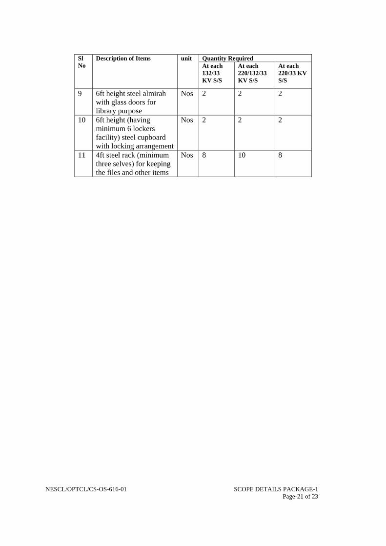
18. Office Furniture:
Office furniture shall be supplied & installed at each substation as per the list given below. All the furniture shall be of Godrej make. Before supply of the furniture to the sub-station, approval from OPTCL is required. Details of the scope of supply are as indicated below.
Quantity Required Sl
No Description of Items unit
At each 132/33 KV S/S
At each 220/132/33 KV S/S
At each 220/33 KV S/S
1 5ftX3ft executive table with drawer both sides
Nos 5 6 5
2 3ftX2&1/2ft Table with one side drawer
Nos 7 8 7
3 Computer table suitable keeping monitor, CPU,UPS and printer with two nos revolving arm chair suitable for computer use.
Set 1 1 1
4 Executive revolving ,adjustable(height) chairs with arm
Nos 5 6 5
5 Cane gutting “S” type steel chairs with arm
Nos 18 24 18
6 6ftX3ft conference table Nos 1 1 1 7 Cushion arm steel chairs
for conference table purpose
Nos 6 8 6
8 6ft height steel almirah (only with selves) for keeping records and other valuable items
Nos 4 6 4
NESCL/OPTCL/CS-OS-616-01 SCOPE DETAILS PACKAGE-1 Page-21 of 23
Quantity Required Sl No
Description of Items unit At each 132/33 KV S/S
At each 220/132/33 KV S/S
At each 220/33 KV S/S
9 6ft height steel almirah with glass doors for library purpose
Nos 2 2 2
10 6ft height (having minimum 6 lockers facility) steel cupboard with locking arrangement
Nos 2 2 2
11 4ft steel rack (minimum three selves) for keeping the files and other items
Nos 8 10 8

132 KV SIDER O A D R O A D
10.4 13.1 10.4 13.1 10.4T1S G1 T1S G1 T1S T1S G1 T1S G1 T1S
G2 10.4 G1 G1 G2 RR 14.9875 14.9875
T4S T4S OO T4S T4S
AA
G2 T4S G2 DD 14.9875 14.9875
G1 G1 G1 G1 G1
T1S T1STIS TIS T1S T1S T1S
8.4 8.4
3.5 3.5 G1,2 G1,2
T1S TIS T1S T1S4.5 10.4 10.4 4.5
R O A D R O A D
R 4.5 R33 KV SIDE T9S
O T9S T9S T9S O
A G4X G4X G4X G4X 5.5 A
D T9S T9S T9S T9S D
7.05 T8S G4 G4 G4 G4 T8S T8S G4 G4 G4
G6 T8S T8S T8S G6 T8S T8S G67.25
T9S T9S T9S
5.5 5.5
R O A D R O A D
* ALL THE DIMENSIONS ARE IN MTRS
INDICATIVE STRACTURAL NETWORK OF 132/33 KV SUB STATION
Transformer
Transformer
Page 1 of 1

Feeder-1 Feeder 2
132kV MAIN BUS132 KV BAYSFEEDER 02 NOS.TRANSF 02 NOS.BUS COU 01 NO.
132kV RESERVE BUS
40MVA, 132/33kV
20MVA, 132/33kV
PVC CABLE
33kV MAIN BUS33KV BAYFEEDER 05 NOS. PVC CABLETRANSF 02 NOS.BUS COU 01 NO. AB SW HG FUSE STN TFR
33/0.4KV250KVA
33kV RESERVE BUS
F1 F2 F3 F4 F5
SLD FOR 132/33kV SUB-STATION AT PURI FOR SAMUKA BEACH
Page 1 of 3
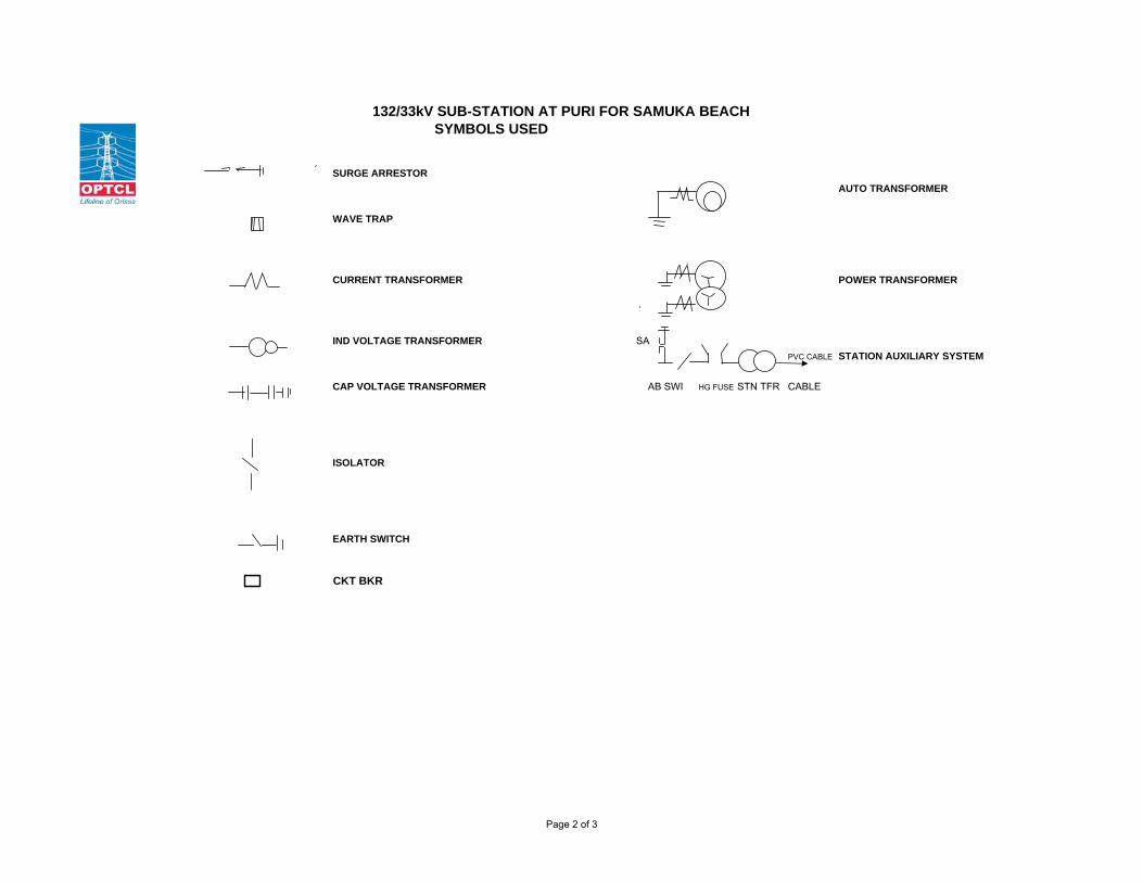
SYMBOLS USED
SURGE ARRESTORAUTO TRANSFORMER
WAVE TRAP
CURRENT TRANSFORMER POWER TRANSFORMER
IND VOLTAGE TRANSFORMER SAPVC CABLE STATION AUXILIARY SYSTEM
CAP VOLTAGE TRANSFORMER AB SWI HG FUSE STN TFR CABLE
ISOLATOR
EARTH SWITCH
CKT BKR
132/33kV SUB-STATION AT PURI FOR SAMUKA BEACH
Page 2 of 3

SCOPE OF WORK OTHER IMPORTANT INFORMATIONS► 132kV Feeder bay -2Nos. ► 132kV BUS CONDUCTOR- MAIN-- TWIN ACSR MOOSE► 132kV Transfoprmer Bay-2 Nos. ► 132kV BUS CONDUCTOR- RESERVE-- SINNGLE ACSR MOOSE► 132kV Bus Couplar Bay-1 No. ► 33kV BUS CONDUCTOR- MAIN-- TWIN ACSR MOOSE► 132/33kV, 40MVA-1 No & 20 MVA-1 No. ► 33kV BUS CONDUCTOR- RESERVE-- SINNGLE ACSR MOOSE► 33kV Feeder bay -5Nos. ► BUS CONFIGURATION: MAIN & TRANSFER BUS SYSTEM.► 33kV Transfoprmer Bay- 2 Nos.► 33kV Bus Couplar Bay-1 No.
REQUIREMENT OF EQUIPMENT/MATERIALS
132kV EQUIPMENTS / MATERIALS 33kV EQUIPMENTS / MATERIALSSl No. Items Qty Sl No. Items Qty
1 SF6 Circuit Breake 5 1 Vaccum C Breaker 82 Current Transform 15 2 Current Transform 243 CVT 6 3 IVT 34 IVT 3 4 Surge Arrester 215 Surge Arrester 12 5 BPI 166 Wave Trap 4 6 SI w/o ES 97 BPI 16 7 DI w/o ES 28 SI w/o ES 8 8 DI with ES 59 DI w/o ES 2 9 SI with BM 2
10 DI with ES 2 10 NCT 4 For Tfr11 D Ten Insulator str 18 11 D Ten Insulator str 1812 S.Ten Insulator str 42 12 S.Ten Insulator str 3913 Sus Insulator string 21 13 Sus Insulator string 3614 BMK 3 14 BMK 315 Lighting Board 1 15 Lighting Board 116 Receptical Board 1 16 Receptical Board 117 Receptical Tfr oil fi 1 17 T9S 1118 T1S 16 18 T8S 919 T4S 5 19 G4 720 G1 7 20 G4X 421 G2 4 21 G6 322 G1,2 2 22 250 KVA STN TFR 2 For Stn Tfr23 G1X 4 23 HG FUSE SET 2 For Stn Tfr
24 AB Switch 2 set For Stn Tfr25 Surge Arrester 6 For Stn Tfr
132/33kV SUB-STATION AT PURI FOR SAMUKA BEACH
Page 3 of 3

CHANDPUR
132 KV 132 KVFDR FDR
BUS PT
132 KV BAYSFEEDER 02 NOS. 132kV MAIN BUSTRANSF 02 NOS. BUS COU 01 NO.
132kV RESERVE BUS
12.5MVA, 132/33kV
TRANSFORMER 12.5MVA, 132/33kV TRANSFORMER
33kV MAIN BUS33KV BAY PVC CABLEFEEDER 04 NOS.TRANSF 02 NOS.BUS COU 01 NO. AB SW HG FUSE STN TFR PVC CABLE
33/0.4KV250KVA
33kV RESERVE BUSF1 F2 F3 F4
SLD FOR 132/33 KV DUB-STATION, CHANDPUR
Page 1

PURUSOTTAMPUR
132 KV 132 KVFDR FDR
BUS PT
132 KV BAYSFEEDER 02 NOS. 132kV MAIN BUSTRANSF 02 NOS. BUS COU 01 NO.
132kV RESERVE BUS
12.5MVA, 132/33kV
TRANSFORMER 12.5MVA, 132/33kV TRANSFORMER
33kV MAIN BUS33KV BAY PVC CABLEFEEDER 05 NOS.TRANSF 02 NOS.BUS COU 01 NO. AB SW HG FUSE STN TFR PVC CABLE
33/0.4KV250KVA
33kV RESERVE BUS F1 F2 F3 TFR1 B/C F4 TFR2 F5
SLD FOR 132/33 KV DUB-STATION, PURUSOTTAMPUR
Page 1

SamukaR WT R WT R WT
Y Y YB WT WT B WT B WT
CVT CVT CVT CVT CVT CVT
M
PuriKhurdaChandaka
FCBC(75A)
48V/300AHBATT
LMDULMU LMU LMDU LMU LMU LMDULMDU
ULDC PROJECT'S
WIDEBAND NETWORK
STALLION MODULE
(CFE-1)
SPLITTER
(SP100)
STALLION MODULE
(CFE-2)
M R U AX C
SCHEMATIC LAYOUT FOR SPEECH,PROTECTION & DATA CONNCWETIVITY RELATED TO LILO OF 132KV KHURDA-PURI SAMUKA BEACH
LMU LMDULMU LMDU
PUNCOM(Existing)Sp+Data
ETL-42ETL-42
PLCC N# Ch1 S Data K 5 # Ch2 Sp+Prot.
RTU
PLCC # Ch1 Sp+Prot. # Ch2 Speech
PLCC # Ch1 Sp+Prot. # Ch2 Speech
PLCC # Ch1 Data # Ch2 Sp+Prot.
PLCC # Ch1 Data (Samuka)
N PLCCS DataK5 (Samuka)
R A MUXC 1511 BA
ETL-42ETL-42ETL-41 ETL-41PLCC # Ch1 Data Existing
PLCC
Existing
PUNCOM ETL-21
PLCC
Existing
ETL-21
BBSR SUB-LDC

R WT R WT
YB WT WT
CVT CVT
Sub-LDC,BBSR
CHANDAKA CHANDPUR KHURDA
SCHEMATIC LAYOUT FOR SPEECH,PROTECTION & DATA CONNECTIVITY RELATED TO LILO OF 132 KV KHURDA-BALUGAON AT CHANDPUR
RTU
FCBC(75A)
48V/300AHBATT
LMULMDU LMDU LMU
R A MUXC 1511 BA
STALLION MODULE
CFE-1
SPLITTER
(SP
STALLION MODULE
CFE-2
ULDC PROJECT'S
WIDEBAND NETWORK
M R U AX C1511BA
LMULMDLMU LMDU
PLCC
Data
YB
RY
B
132kV220kV
PLCC N# Ch1 S Sp+Data K 5 # Ch2 Prot.
ETL‐42
PLCC# Ch1 Sp+Data # Ch2 Prot.
ETL‐42ETL‐41
N PLCCSK Data5
ETL-41
CVTCVT
WT
WT
LMU
BALUGAON
PLCC # Ch1 Sp+Prot. # Ch2Khurda-Balugaon Speech
PLCCExsting
Khurda-Balugaon Speech
*ETI‐22 *ETI‐22PLCCexisting Khurda-Balugaon Speech
PLCCSLDC-BAM Speech
* Marked ETI21/ETI22 PLCC sets working at Balugaon for Khurda directionwill be shifted to Chandpur & used for SLDC‐Balugaon speech & Khurda‐Balugaon Exp communication.
LMDU
WT
WT
CVT CVTCVT
PLCC # Ch1 Prot.
# Ch2Khurda-Balugaon Speech
PLCC SLDC-BAM Speech
ETL‐42 ETL‐41 ETL‐42ETL‐41ETL‐42
GENERAL MANAGERTELECOMMUNICATION
PLCCSLDC-BalugaonSpeech
PLCCSLDC-BalugaonSpeech
* ETI-21 * ETI-21
LMDU LMDU
EPBAX

R WT R WT
YB WT WT
CVT CVT
Sub-LDC,Jayanagar
Narendrapur PurusottampurChhatrapur
SCHEMATIC LAYOUT FOR SPEECH,PROTECTION & DATA CONNECTIVITY RELATED TO LILO OF 132 KV CHHATRAPUR-ASKA AT PURUSOTTAMPUR
RTU
FCBC(75A)
48V/300AHBATT
LMULMDU LMDU LMU
R A MUXC 1511 BA
STALLION MODULE
CFE-1
SPLITTER
(SP
STALLION MODULE
CFE-2
ULDC PROJECT'S
WIDEBAND NETWORK
M R U AX C1511BA
LMULMDLMU LMDU
PLCC
Data
YB
RY
B
132kV220kV
PLCC N# Ch1 S Data K 5 # Ch2 Prot.
ETL‐42
PLCC# Ch1 Data # Ch2 Prot.
ETL‐42ETL‐41
N PLCCSK Data5
ETL-41
CVTCVT
WT
WT
LMU LMDU
Aska
PLCC # Ch1 Speech Prot # Ch2
PLCCExsting
Speech
*ETI‐21 *ETI‐21PLCCexisting Speech
PLCC Speech
* Marked ETI PLCC set workingat Aska for Chhatrapur directionwill be shifted to Chhatrapur & used for Purusottampur‐ChhatarpurSpeech.
LMU LMDU
WT
WT
CVT CVTCVT
PLCC # Ch1 Data # Ch2 Speech.
PLCC Speech
ETL‐41 ETL‐42ETL‐41ETL‐42
GENERAL MANAGERTELECOMMUNICATION
EPBAX


GUARANTEED TECHNICAL PARTCULARS
(TO BE FILLED AND SUBMITTED BY BIDDERS WITH
THE TECHNICAL BID)

NESCL/OPTCL/CS-OS-616 GTP- Page 1 of 196
GUARANTEED TECHNICAL PARTICULARS
IVT AND CVT

NESCL/OPTCL/CS-OS-616 GTP- Page 2 of 196
GUARANTEED TECHNICAL PARTICULARS. Sl. No.
Description. 220KV IVT
132KV IVT
33KV IVT 400 KV/220KV CVT
132KV CVT
3P/0.2 Accuracy Class
3P/0.2 Accuracy Class
0.2 Accuracy Class
3P/3P/0.2 Accuracy Class.
3P/3P/0.2 Accuracy Class.
1 Bidder’s name and address. 2 Name and address of the Manufacturer. 3 Manufacturer’s type and designation. 4 Standards applicable. 5 Type of IVT/CVT 6 Rated primary voltage (kv). 7 Rated secondary voltage (volts). 7.1 Winding-I. 7.2 Winding-II. 7.3 Winding-III. 8 Rated frequency [HZ]. 9 Rated burden:-
Protection Winding Protection Winding Metering Winding
10 Number of secondary windings. 11 Accuracy class. [I] [protection] Winding [II] [metering] Winding 12 Rated voltage factor for continuous
operation at rated frequency.
13 Rated voltage factor for 30 seconds at rated frequency.
14 One minute dry and wet power frequency withstand voltage for primary side [kv] rms.
15 One minute power frequency withstand voltage for secondary winding [kv] rms.
16 1.2/50 micro- second impulse withstand test voltage for primary side
17 Temperature rise over an ambient temperature of 50°C
[a] With 1.2 times rated primary voltage at rated frequency and at rated burdens. [I] Winding [°C] [II] Oil [°C] [III] Other parts [°C]
[b] With 1.5 times rated primary voltage for 30 seconds at rated frequency and at rated burdens.

NESCL/OPTCL/CS-OS-616 GTP- Page 3 of 196
Sl. No.
Description. 220KV IVT
132KV IVT
33KV IVT 400 KV/220KV CVT
132KV CVT
3P/0.2 Accuracy Class
3P/0.2 Accuracy Class
0.2 Accuracy Class
3P/3P/0.2 Accuracy Class.
3P/3P/0.2 Accuracy Class.
[I] Winding [°C] [II] Oil [°C] [III] Other parts [°C]
18 Class of insulation.
19 Total creepage distance in (mm) 20 Maximum radio interference voltage at
1.1 times maximum line to ground voltage (micro volts)
21 Corona inception and extinction voltage (kv) rms
22 Partial discharge level (piccocoulombs) 23 Primary.[For 220KV, 132KV & 33KV
IVT] (a) No. of primary turns (b) Material of primary (c) Size of the primary conductor
bare/insulated. (d) Cross sectional area of primary
conductor (sq.mm) (e) Current density adopted for primary
winding(A/sq.mm) (f) Type of primary winding. (g) Name of the insulating materials
used for primary conductor. (h) Weight of primary winding.
24 Secondary. [For 220KV, 132KV & 33KV IVT] (a)No. of secondary turns (b) Material of secondary © Size of the secondary conductor bare /insulated. (d)Cross sectional area of secondary conductor (mm2) (e)Current density adopted for secondary winding(A/mm2) (f)Type of secondary winding (g)Name of the insulating materials used for secondary conductor. (h)Weight of secondary winding.
25. Core. [For 220KV, 132KV & 33KV IVT] (a)Shape of the core

NESCL/OPTCL/CS-OS-616 GTP- Page 4 of 196
Sl. No.
Description. 220KV IVT
132KV IVT
33KV IVT 400 KV/220KV CVT
132KV CVT
3P/0.2 Accuracy Class
3P/0.2 Accuracy Class
0.2 Accuracy Class
3P/3P/0.2 Accuracy Class.
3P/3P/0.2 Accuracy Class.
(b)Material and grade of the core laminations (c)Thickness of the core lamination (mm) (d)Maximum flux density adopted (Tesla) (e)Net iron area of the core (f)Watt loss/kg. for the core materials at the operating flux density(W/kg) (g) Total weight of the core(kg) (h)Whether B-H curve for core material enclosed? (i)Whether specific loss vrs. Flux density curve enclosed ?
26 INSULATION. .[For 220KV, 132KV & 33KV IVT] (a) Insulation between core and secondaries. (b) Insulation between secondaries. © Insulation between secondary and primary. (d) Insulation between primary .and core.
27 DIMENSIONS OF CORE AND WINDINGS. .[For 220KV, 132KV & 33KV IVT] (a)Diameter of the core (mm) (b)Inner diameter of the secondary windings(mm) (c) Outer diameter of the secondary windings (mm) (d) Inner diameter of the primary winding(mm) (e) Outer diameter of the primary winding(mm) (f) Minimum clearance from primary winding to tank(mm) (g) Minimum clearance from secondary winding to tank(mm)
28. Percentage voltage ratio (error)/phase displacement (min.)at 100% rated burden at 0.8PF lagging for measuring winding. (a) 80% of rated voltage at frequency:- (b) 120% of rated voltage at
frequency:-
, .

NESCL/OPTCL/CS-OS-616 GTP- Page 5 of 196
Sl. No.
Description. 220KV IVT
132KV IVT
33KV IVT 400 KV/220KV CVT
132KV CVT
3P/0.2 Accuracy Class
3P/0.2 Accuracy Class
0.2 Accuracy Class
3P/3P/0.2 Accuracy Class.
3P/3P/0.2 Accuracy Class.
(c) Accuracy of standard PT to be used. during determination of errors (0.05 or better.
29. Percentage Voltage ratio /phase displacement (min.)at 25% rated burden at 0.8PF lagging for measuring winding. (a) 80% of rated voltage at rated
frequency:- (b) 120% of rated voltage at rated
frequency:-
.
30. Percentage voltage (ratio)error /phase displacement (min.) at 100% rated burden at 0.8PF lagging for protection winding (a)5% of rated voltage. (b)1.2 times rated voltage ( c)1.5 times rated voltage (d) 2% of rated voltage..
31. Percentage voltage (ratio) error /phase displacement (min) at 25% of rated burden at 0.8PF lagging for protection winding (a)5% of rated voltage (b)1.2 times rated voltage. ©1.5 times rated voltage. (d) 2% of rated voltage.
32. Whether IVT/CVT is suitable for horizontal transportation.
33. Quantity of oil per IVT/ CVT (Ltrs/kg) 34. Standard to which oil conforms. 35. Characteristic of oil(Prior to filling) 35.1.
Breakdown voltage (kv-rms)
35.2.
Dielectric dissipation constant tan delta)
35.3
Water content(PPM)
35.4
Gas content(PPM)
35.5
Interfacial tension at 27 degree C(N/m)
35.6
Specific resistance.
35. At 90 deg.C(ohm-cm)

NESCL/OPTCL/CS-OS-616 GTP- Page 6 of 196
Sl. No.
Description. 220KV IVT
132KV IVT
33KV IVT 400 KV/220KV CVT
132KV CVT
3P/0.2 Accuracy Class
3P/0.2 Accuracy Class
0.2 Accuracy Class
3P/3P/0.2 Accuracy Class.
3P/3P/0.2 Accuracy Class.
6.1 35.6.2
At 27 deg.C(ohm-cm)
36. Whether IVTS are hermetically sealed ? If so how ?
37. Total Weight (kg) 38. Transport weight (kg) 39. Dimensional details. 40 Whether IVT characteristic curves
enclosed?
41. TANK AND SECONDARY TERMINAL BOX.
41.1
Material of the IVT/ CVT tank
41.2
Material of the secondary terminal box.
41.3
Thickness of the IVT/ CVT tank material.
41.4
Thickness of the secondary terminal box material.
41.5
Zinc coating of IVT/ CVT tank(g/sq.m)
41.6
Zinc coating of the secondary terminal box (g/sq.m)
41.7
Weather proof rating of secondary terminal box.
41.8
Weight of tank fitting and other accessories.
TERMINAL CONNECTORS 01. Manufacturer’s name 02. Applicable standards., 03. Type. 04. Material of connector.
(a)Clamp body. (b)Bolts and Nuts. (c ) Spring Washers
05. Rated current. 06. (a) Rated terminal load(kg)
(b) Factor of safety.
07. Minimum thickness of any part(mm) 08. Weight of connector complete with
hardware.

NESCL/OPTCL/CS-OS-616 GTP- Page 7 of 196
Sl. No.
Description. 220KV IVT
132KV IVT
33KV IVT 400 KV/220KV CVT
132KV CVT
3P/0.2 Accuracy Class
3P/0.2 Accuracy Class
0.2 Accuracy Class
3P/3P/0.2 Accuracy Class.
3P/3P/0.2 Accuracy Class.
09. Type test reports as per IS enclosed. 10. OGA drawing enclosed. BUSHING/SUPPORT INSULATOR 01 Manufacturer’s name 02. Type. 03. Applicable standards. 04
Dimensions: (i)Height(mm) (ii)Diameter(top)(mm) (iii)Diameter( bottom)(mm)
05 Total creepage distance (mm). 06. Rated voltage(KV)(rms) 07.
Power frequency withstand voltage for (1 minute dry and wet(KV/rms)
08.
1.2/50 micro-second Impulse withstand voltage (KVP)
09. Corona Extinction voltage(kv) 10. Weight(kg) 11. Maximum allowable span (mm) 12. Cantilever strength(kg) 13. OGA drawing enclosed.

NESCL/OPTCL/CS-OS-616 GTP- Page 8 of 196
ADDITIONAL TECHNICAL REQUIREMENT FOR 400 KV,220KV & 132KV CVT
1. Rated capacitance of the CVT
2. High frequency capacitance for entire carrier frequency range. 3. Equivalent series resistance over the entire frequency. 4. Stray capacitance and stray conductance of the LV terminal over entire carrier frequency range. 5. Capacitance (PF) /Tan delta between:-
a) HV-HF point b) HF point-Ground point of
International Transformer. c) HV-Ground point of Intermediate
Transformer winding. 6. Capacitive reactance of the two parts of the divider i.e. High voltage capacitor, and Intermediate voltage capacitor, connected in parallel. 7. Total Inductive reactance, offered by CVT. 8. Voltage ratio of the capacitor divider. 9. Open circuit Intermediate voltage. 10. Rated open circuit Intermediate voltage. 11. Reference range of temperatures within which the CVT complies with the relevant accuracy requirements. 12. Protective device, in-corporate in the CVT for limiting over voltages and/or to prevent sustained Ferro resonance. 13. Rated voltage of Surge Arrester, connected at the secondary of CVT. 14. Natural frequency of coupling (KHZ). 15. Self tuning frequency of CVT (KHZ). 16. Bandwidth (KHZ).

NESCL/OPTCL/CS-OS-616 GTP- Page 9 of 196
17. Temperature rise over ambient. 18. One minute power frequency test voltage of secondary winding (KV). 19. One minute power frequency test voltage of H.F. terminal (KV). 20. One minute power frequency test voltage of capacitor (dry & wet) (KV). 21. 1.2/50/micro second Impulse withstand test voltage of capacitor (KVP). 22. 250/2500 micro second switching surge withstand voltage of capacitor (dry & wet). 23. Literature Whether the followings are enclosed? 23.1 Type Test reports as per IEC 186. 23.2 OGA drawing of CVT and terminal connector. 23.3 Characteristic curves. 23.4 Drawing showing clearance from earthed object.
23.5 Details of Surge Arrester, connected at secondary winding of CVT. 24. ELECTROMAGNENIC UNIT:- 24.1 CORE:-
a) Core diameter (mm) b) Window Weight (mm) c) Leg centre (mm) d) Net cross sectional area of iron
In the core (mm² ) e) Core lamination thickness (mm) f) Type & grade of core. g) Design flux density at rated voltage.
And rated frequency (Tesla) h) Design flux density at highest system voltage
& lowest system frequency (Tesla). i) Minimum knee point voltage (volts).

NESCL/OPTCL/CS-OS-616 GTP- Page 10 of 196
24.2 PRIMARY WINDING:-
a) No. of turns. b) Bare size of conductor c) Insulated size of conductor. d) Area of cross section. e) Current density (A/ mm²). f) Conductor material. g) Class of insulation. h) Power frequency withstand level.
(KV-rms). i) Impulse withstand level (KVP).
24.3 Secondary Winding Protection Protection Metering Winding Winding Winding.
a) No.of turns b) Bare conductor size (mm) c) Insulated conductor size (mm) d) Cross-sectional area (sq.mm) e) Current density (A/ mm²) f) Conductor material. g) Class of Insulation.’ h) Power frequency withstand
Level (KV-rms).
Signature of the Tenderer with seal and date.

NESCL/OPTCL/CS-OS-616 GTP- Page 11 of 196
ANNEXURE –B. CALIBRATION STATUS OF TESTING EQUIPMENTS AND INSTRUMENTS/METERS.
Name of the test.
Meters and equipments required for the correspondi-ng test with range, accuracy, make and Sl. No.
Date of Calibra- tion.
Due date of Cali- bration.
Name of the Cali- brating Agency.
Whether Calibrat- ing Agency is Govt. Approv- ed.
Whether documents relating to Govt. Approval of the cali-brating Agency furnished ?
Whether the meters/ equipment fulfill the accuracy class as per calibration report
Whether the calibra ting agency has put any limitation towards the use of the particular meter/equipment. If yes, state the limitations.
Whether green sticker or blue sticker or yellow sticker has been affixed on the body of the particular equipment/meter. State the colour of the affixed sticker.
Inspite of imposed limitations,, whether the particular meter/equipment can still be used ? Justify its use for corresponding test(s).
Rema- rks
1 2 3 4 5 6 7 8 9 10 11 12
Signature of the tenderer with seal and date.

NESCL/OPTCL/CS-OS-616 E27-GTP- Page 12 of 169
ANNEXURE-C
CHECK LIST TOWARDS TYPE TEST REPORTS.
Nam
e of
the
Type
Tes
t.
Dat
e of
Tes
t.
Nam
e of
the
Labo
rato
ry w
here
the
Test
has
be
en c
ondu
cted
.
Whe
ther
the
Labo
rato
ry is
Gov
ernm
ent
App
rove
d.
Whe
ther
the
Test
repo
rts a
re v
alid
as p
er
Cla
use
No.
8.1
of T
.S.
Whe
ther
the
copy
of T
est R
epor
t in
com
plet
e sh
ape
alon
gwith
dra
win
gs e
tc. f
urni
shed
or
not ?
Whe
ther
the
Test
ed I.
V.T
. ful
fills
the
tech
nica
l re
quire
-men
ts a
s per
TS.
If th
e ty
pe te
sted
I.V
.T
does
not
fulfi
ll th
e te
chni
cal r
equi
rem
ents
as p
er
this
spec
ifica
tion,
whe
ther
the
bidd
er a
gree
s to
cond
uct t
he p
artic
ular
test
(s) a
gain
at t
heir
own
cost
with
out a
ny fi
nanc
ial l
iabi
lity
to O
PTC
L in
th
e pr
esen
ce o
f OPT
CL’
s rep
rese
ntat
ive
with
in
the
spec
ified
del
iver
y pe
riod.
Re
mar
k
1 2 3 4 5 6 7 8
Signature of the Tenderer with seal and date.

NESCL/OPTCL/CS-OS-616 E27-GTP- Page 13 of 196 13
GUARANTEED TECHNICAL PARTICULARS
BATTERY AND BATTERY CHARGER

NESCL/OPTCL/CS-OS-616 E27-GTP- Page 14 of 196 14
ANNEXURE – I
SCHEDULE OF GUARANTEED TECHNICAL PARTICULARS FOR 220V LEAD ACID PLANTE STORAGE BATTERY.
[To be filled in by the bidder]
350AH/550AH Values/Others
1. Manufacturer’s Name and address alongwith Fax No. & Tele phone No.
2. Conforming to standards 3. Type and designation as per ISS 4. Manufacturer’s type and designation 5. AH capacity and voltage of the battery
at 27 deg.C.
[a] At 10 hour rate of discharge. [b] At 5 hours rate of discharge. [c] At 1 hour rate of discharge [d] At 1 minute rate of discharge. [e] At ½ hour rate of discharge. 6. Open circuit voltage of each battery
cell.
[a] Fully charged [b] Floating condition. [c] When completely discharged at. [i]. 10hr. rate. [ii]. 5 hour rate [iii] 1 hour rate [iv] ½ hr. rate [v]. 1 minute rate [vi] 1-second rate. 7. Recommended float charging voltage
[volts] across the battery terminals.
8. Recommended boost charging voltage [volts].
9. Time required for boost charging from discharged conditions [in hours]
10. Trickle charging Current range/cell
11. AH capacity at 10 hour rate at 10 hour rate at room temperatures of :
[a] 15 deg C. [b] 27 deg C. [c] 50 deg C. 12. CELL DETAILS

NESCL/OPTCL/CS-OS-616 E27-GTP- Page 15 of 196 15
[i]. No. of cells per battery [ii]. Total nos. of plates per cell. [iii] No. of positive plates per cell.
(iv) Type of positive plate (v) No. of negative plates per cell (vi) Type of negative plate (vii) Surface area of plates in sq. mm. (viii) CONSTRUCTIONAL DETAILS AND DIMENSIONS OF (a) Positive plate (b) Negative plate (c) Material of the container (d) Thickness of the container (e) Overall dimensions of each cell
(LxBxH)
ix. Weight per Cell (Kg) (a) Active elements-positive (b) Active elements-Negative (c) Container (d) Net dry weight (e) Weight with electrolyte x. Distance between centre of cells
where erected.
xi. Nominal cell voltage. xii. Internal resistance of each cell at (a) Fully charged condition (b) Fully discharged condition (c) Floating condition 13. Type, Thickness and materials of
the separators
14. Containers (a) Type (b) Material (c) Outside dimensions (LxBxH) 15. Cover and its type and material 16. Clearance in mm between (a) Top of plates and top of container (b) Bottom of plates and bottom of
container
(c) Edges of plates and inner surface of container.

NESCL/OPTCL/CS-OS-616 E27-GTP- Page 16 of 196 16
17. Sediment space (depth) in mm 18. ELECTROLYTE (a) Amount of electrolyte and specific
gravity at 27 deg. C for first filling.
(b) First filling per set with 10% of extra furnished.
(c) Electrolyte conforms to standard (d) Rated specific gravity of electrolyte
when fully charged at room’s temperature of
(i) 15 deg. C (ii) 27 deg. C (iii) 50 deg C. (e) Specific gravity of electrolyte at
the end of discharge at 10 hour discharge rate.
(f) Maximum electrolyte temp. that the cells can withstand without injurious effect.
(i) Continuously (ii) For short period 19. INTER CELL CONNECTOR (a) Whether Inter-cell connector to be
furnished ? (Yes / No)
(b) Type of inter-cell connector (bolted or others)
(c) Materials of inter cell connector 20. (a)
Inter row, inter-tier connectors and end take-off furnished ? (Yes / No)
(b) Description, size, current rating, type and material.
21. RACKS (a) No. of racks per battery (b) No. of cells per rack (c) Type of racks (rows and tiers) (d) Material of the rack (e) Racks provided with (i) Numbering tags for cell (ii) Teak wood clamps for cables (f) Whether anti-acid coating provided
?
(g) Description of rack insulators

NESCL/OPTCL/CS-OS-616 E27-GTP- Page 17 of 196 17
(h) Outline dimensions of racks (i) Net weight of racks (j) Shipping weight 22. Recommended rate for charging
the battery in 8 hours. Start Finish
(a) Current (b) Voltage 23. Recommended float charge rate 24. Resistance of the battery including
inter-connector between the cells in ohms.
25. (a)
Maximum short circuit current per battery
(b) Allowable duration of short circuit 26. Short circuit current for a dead
short across the battery terminals when
(a) Float at 2.1 volts per cell. (b) Boost charge to 2.75 volts per cell. 27.(a) Time to full charge at finishing rate
only
(b) Time to full charge at higher starting rate
(c) Time for full charge to charge by two step charging at starting up and finishing rates
28. Guaranteed AH efficiency at 10 hour rate of discharge in percent.
29. Guaranteed WH efficiency at 10 hour rate of discharge in percent.
30. Instructions for filling and initial charging of the battery with finishing and two step charging rates.
31. Recommended interval at which battery should be discharged at 10 hour rate and quick charged.
32. Recommended floating voltage per cell and the minimum variation.
33. Recommended maximum period of storage before the first charge.
34. Average life in years

NESCL/OPTCL/CS-OS-616 E27-GTP- Page 18 of 196 18
35. Guaranteed life of battery in years. 36. Estimated life of battery in years. 37. Total shipping weight of battery
units
38. Dimensioned lay-out drawings of the rack and battery to be attached with the tender. (Whether furnished ? Yes / No)
39. The following characteristic curves, to be furnished alongwith the tender (whether furnished)
(a) Battery discharge curves at various rates between one minute and 10 hour rate. (Yes / No.)
(b) Curves showing the relation between the specific gravity and amount of charge in the battery for both charging and discharging conditions. (Yes / No)
(c) Curves showing the relation between cell voltage and charging current when charged at
(i) Finishing rate (Yes/ No) (ii) High starting rate (Yes/ No) (iii) Two step charging by starting and
finishing rate (Yes / No)
(d) Curve of internal resistance at the end of various discharge rates (Whether furnished (Yes / No)

NESCL/OPTCL/CS-OS-616 E27-GTP- Page 19 of 196 19
ANNEXURE – II
GUARANTEED TECHNICAL PARTICULARS FOR BATTERY CHARGER (220 V D.C. SYSTEM) SUITABLE
FOR SPECIFIED LEAD ACID PLANTE STORAGE BATTERY
(To be filled in by the Bidder)
Values/ Others 1. Manufacturer’s Name
2. Rated output of the charger
2.1 Voltage (volts)
2.2 Current (amps)
2.3 Power factor
3. Short time rating
4. Type of cooling
5. Hottest stack temperature (0C)
6. Charger dimensions
6.1 Height (mm)
6.2 Depth (mm)
6.3 Width (mm)
6.4 Sheet thickness (mm)
7. Charger weight
8. Charger rated output current
8.1 Float charging mode
8.2 Boost charging mode
9. Load limiter current setting range (Trickle mode)
10. RECTIFIER TRANSFORMER Float Boost

NESCL/OPTCL/CS-OS-616 E27-GTP- Page 20 of 196 20
Charger Charger 10.1 Make
10.2 Type
10.3 Rated KVA
10.4 Over current impedance (ohms)
10.5 Input line winding connection
in vector representation
10.6 Rated primary voltage (volts)
10.7 Rated secondary voltage (volts)
10.8 Rated frequency (Hertz.)
10.9 Rated output (amps)
10.10 Turn ratio
10.11 Insulation level
10.12 Impulse withstand test voltage (KVP)
10.13 One minute power frequency over voltage.
(a) Primary winding (KV-rms).
(b) Secondary winding (KV-rms)
10.14 Material of primary winding conductor
10.15 Material of secondary winding conductor
10.16 Size, Cross-sectional area and current density of primary winding conductor.
10.17 Size, cross-sectional area and current density of secondary winding conductor
10.18 No. of turns of primary / phase
10.19 No. of turns of secondary / phase
10.20 Name of the insulating materials used and class
10.21 Core
10.21.1 Name of the core material
10.21.2 Grade of the core
10.21.3 Thickness of core material (mm)
10.22 Maximum temperature rise over an ambient temperature of 500C

NESCL/OPTCL/CS-OS-616 E27-GTP- Page 21 of 196 21
(a) Primary Winding (0C) (b) Secondary Winding (0C) (c) Core (0C)
10.23 standards applicable
11.0 RECTIFIER ASSEMBLY :
11.1 Make
11.2 Type of semi conductor material
11.3 Rated direct current per cell (A)
11.4 Rated direct voltage (V)
11.5 Rated input voltage (V)
11.6 Type of connections of rectifier elements.
11.7 Forward power loss and reverse power loss (watts).
11.8 Forward voltage drop and reverse voltage drop (volts)
11.9 Conversion efficiency (%)
11.10 Rated DC output voltage (V)
11.11 Rated AC input voltage (V)
11.12 Rated output current (A)
11.13 Ripple factor
11.14 Voltage factor
11.15 Current factor
11.16 Maximum temperature rise over an ambient temperature of 500C (0C)
11.17 Maximum permissible ambient temperature for guaranteed rating (0C)
11.18 Maximum and minimum permissible humidity rating (%)
11.19 Life expectancy (years)
11.20 Standard(s) applicable
11.21 Characteristic curve of DC output plotted against output current (Whether
submitted ?) Yes / No.
12.0 AUTOMATIC VOLTAGE REGULATOR
12.1 manufacturer’s name

NESCL/OPTCL/CS-OS-616 E27-GTP- Page 22 of 196 22
12.2 Manufacturer’s type
12.3 Percentage stabilisation of the rectifier with the help of AVR when
(a) Input voltage changes with ± of its nominal value.
(b) DC output of the rectifier varies from no-load to full load.
12.4 Rated output voltage
12.5 Allowable AC frequency fluctuations
12.6 Voltage setting range
12.7 Response time of automatic voltage regulator
13.0 Manual voltage regular (float mode)
13.1 Type
13.2 Voltage setting range
14.0 Boost charging current setting range
15.0 Boost charging limit setting range
16.0 DIODES
16.1 Manufacturer’s name
16.2 Type of circuit
16.3 Method of construction
16.4 Continuous current rating (Amps.)
16.5 Short time current rating (Amps)
16.6 Type of cooling
16.7 Forward power loss and reverse power less (W)
16.8 Life expectancy
16.9 Forward voltage drop on rated current
16.10 Resistance offered for reverse current flow
16.11 Maximum temperature rise over an ambient temperature of 500 C.
17.0 CONTACTORS / MOULDED CASE CIRCUIT BREAKERS
17.1 Type
17.2 Make
17.3 Rated voltage (V)

NESCL/OPTCL/CS-OS-616 E27-GTP- Page 23 of 196 23
17.4 Rated continuous currents (A)
17.5 Contact material
17.6 Operating coil
17.6.1 Voltage (V)
17.6.2 Voltage range and power for closing and holding
17.6.3 Voltage range and power for drop off.
17.7 Thermal trip rating
17.8 Thermal trip time
17.9 Details of CT if any
17.10 Auxiliary contacts
17.10.1 Number
17.10.2 Current rating
17.11 Characteristics of back-up HRC fuse
18.0 RELAYS : 18.1 Make and type of protective and alarm relays
(a) Thermal overload relay
(b) Input under voltage relay
(c) Single phasing alarm relay
(d) Phase reversal relay
(e) D.C. output over-voltage relay
(f) D.C. output under voltage relay
(g) Charger failure relay
(h) Battery earth fault relay
(i) A.C. input failure relay (for connecting the D.C. load)
(j) Fuse failure relay
(k) Alarm accept relay
18.2 Rated voltage of each of the above (a) AC/DC (b) Permissible variation (c) Frequency

NESCL/OPTCL/CS-OS-616 E27-GTP- Page 24 of 196 24
18.3 VA burden of each of the above
18.4 Operating time of each of the above
18.5 Time vs current curves of each of the above.
(to be enclosed alongwith the offer)
18.6 Reset time
18.7 Accuracy
18.8 Setting range
18.9 Reset factor
18.10 Number of contacts
(a) Normally open
(b) Normally closed
18.11 Rating of contacts
(a) Rated Voltage (V)
(b) Rated making and breaking
(c) Continuous rating
18.12 No. of operations
18.13 Operation indicator
19.0 INDICATING LAMPS
19.1 Manufacturer’s name
19.2 Type and designation
19.3 Permissible voltage variation
19.4 Rated power consumption (watts). 19.5 Series resistance, if any 20.0 SWITCHES: 20.1 Manufacturer’s name
20.2 Ratings
(a) Continuous current
(b) Short circuit – making capacity
(c) Breaking capacity

NESCL/OPTCL/CS-OS-616 E27-GTP- Page 25 of 196 25
(d) Voltage
20.3 Operating mechanism details
20.4 Type of visual indication
(a) OFF and ON position
(b) Fuse blow out
21.0 FUSES
(a) Make
(b) Type
(c) Rating (Amps)
(d) Interrupting rating (KA)
22.0 INSTRUMENTS
22.1 Manufacturer’s Name
(a) Ammeter
(b) Voltmeter
22.2 Type
(a) Ammeter (b) Voltmeter
22.3 Standard
(a) Ammeter (b) Voltmeter
22.4 Scale range 22.4.1 Ammeter
(a) Float charger (b) Boost charger (c) Battery float (d) Battery boost
22.4.2 Volt meter
(a) Input supply (b) Charger output (c) Load

NESCL/OPTCL/CS-OS-616 E27-GTP- Page 26 of 196 26
22.5 Size of dial (a) Volt meter (b) Ammeter
22.6 Accuracy class
(a) Volt meter (b) Ammeter
22.7 Temperature at which calibrated
22.8 Limit of errors
22.9 Out line dimensions
22.10 Type of mounting
22.11 Selector switch for volt meter (AC & DC)
(a) Make
(b) Rating
23.0 CAPACITOR 23.1 Manufacturer’s name
23.2 Type
23.3 Capacitance (Farad)
23.4 Maximum temperature rise over an ambient temperature of 500C.
24. Reference float voltage at ambient temperature of 270C
25. Whether protection is given for float voltage to Avoid low battery voltage due
to sensor or circuit Malfunction. (Yes/ No)

NESCL/OPTCL/CS-OS-616 E27-GTP- Page 27 of 196
ANNEXURE – IV-A (For Testing of Battery)
(To be filled in by the bidder)
CALIBRATION STATUS OF TESTING EQUIPMENTS AND INSTRUMENTS/ METERS Name of the Test
Meters & Equipments required for the corresponding test with range, accuracy, make & Sl. No.
Date of Calibr-ation
Due date of Calibration
Name of the Calibratig Agency
Whether Calibrating Agency is Govt. approved
Whether documents relating to Govt. approval of the calibrating Agency furnished
Whether the meters/ equipments fulfil the accuracy class as per calibration report.
Whether the calibrating agency has put any limitation towards the use of the particular meter/ equipment. If yes, state the limitations
Whether the calibrating agency has put any limitation towards the use of the particular meter/equip-ment/ meter. State the colour of the affixed sticker
Inspite of imposed limitations. Whether the particular meter / equipment can still be used ? Justify its use for corresponding test(s)
Remarks
1 2 3 4 5 6 7 8 9 10 11 12
Signature of the tenderer with seal & date

NESCL/OPTCL/CS-OS-616 E27-GTP- Page 28 of 196
ANNEXURE – IV-B
(For Testing of Battery Charger) (To be filled in by the bidder)
CALIBRATION STATUS OF TESTING EQUIPMENTS AND INSTRUMENTS/ METERS
Name of the Test
Meters & Equipments required for the corresponding test with range, accuracy, make & Sl. No.
Date of Calibr-ation
Due date of Calibration
Name of the Calibratig Agency
Whether Calibrating Agency is Govt. approved
Whether documents relating to Govt. approval of the calibrating Agency furnished
Whether the meters/ equipments fulfil the accuracy class as per calibration report.
Whether the calibrating agency has put any limitation towards the use of the particular meter/ equipment. If yes state the limitations
Whether the calibrating agency has put any limitation towards the use of the particular meter/equip-ment/ meter. State the colour of the affixed sticker
Inspite of imposed limitations. Whether the particular meter / equipment can still be used ? Justify its use for corresponding test(s)
Remarks
1 2 3 4 5 6 7 8 9 10 11 12
Signature of the tenderer with seal & date

NESCL/OPTCL/CS-OS-616 E27-GTP- Page 29 of 196
ANNEXURE V – A (To be filled in by the bidder)
CHECK LIST TOWARDS TYPE TEST REPORTS FOR BATTERY
Name of the Type Test
Date of Test
Name of the Laboratory where the Test has been conducted
Whether the Laboratory is Government approved
Whether the Test report is valid as per Spn.
Whether the Test report in complete shape alongwith drawings etc. furnished or not ?
Whether the type tested Plante lead acid battery fulfills the technical requirements as per TS
If the type tested battery does not fulfill the technical requirements as per this specification, whether the bidder agrees to conduct he particular type test again at their own cost without any financial liability to OPTCL in the presence of OPTCL’s representative within the specified delivery period
Remarks
1 2 3 4 5 6 7 8 9 Signature of the tenderer with seal & date

NESCL/OPTCL/CS-OS-616 E27-GTP- Page 30 of 196
ANNEXURE V – B
(To be filled in by the bidder) CHECK LIST TOWARDS TYPE TEST REPORTS FOR BATTERY CHARGER
Name of the Type Test
Date of Test
Name of the Laboratory where the Test has been conducted
Whether the Laboratory is Government approved
Whether the Test report is valid as per Spn.
Whether the Test report in complete shape alongwith drawings etc. furnished or not ?
Whether the type tested battery charger fulfills the technical requirements as per TS
If the type tested battery charger does not fulfill the technical requirements as per this specification, whether the bidder agrees to conduct he particular type test again at their own cost without any financial liability to OPTCL in the presence of OPTCL’s representative within the specified delivery period
Remarks
1 2 3 4 5 6 7 8 9 Signature of the tenderer with seal & date.

NESCL/OPTCL/CS-OS-616 E27-GTP- Page 31 of 196
GUARANTEED TECHNICAL PARTICULARS
FOR
SF6 AND VACUUM CIRCUIT BREAKERS

NESCL/OPTCL/CS-OS-616 E27-GTP- Page 32 of 196
GUARANTEED TECHNICAL PARTICULARS FOR CIRCUIT BREAKERS
( To be filled in & furnished by the Bidder , separately for 245kv &145 KV SF6 Circuit Breakers)
1. (a) Maker’s name and country of manufacture
(b) Manufacturer’s type Designation
1. Applicable technical standards
2. (a) Rated voltage(kV)
(b) Rated frequency(Hz)
4. Number of Poles
5. Class
6. Rated normal current
(a) Under site conditions(Amps)
(b) Rated (Amps)
7. (a) Rated short circuit breaking current
(i) Rms value of AC component of rated
short circuit current (KA)
(ii) Percentage DC component (iii) Assymetrical Breaking Current at Highest System Voltage (iv) Certificate or report no
(iii) Oscillogram no. (b) Rated short circuit making current (KA peak)
(i) At Higher rated Voltage (ii) At Lower rated Voltage (c) (i) Maximum Breaking capacity Under Phase Opposition(KAP)
(iii) Max Pole discrepancy(ms) (iv) Max arc duration & Corresponding current under lockout
pressure

NESCL/OPTCL/CS-OS-616 E27-GTP- Page 33 of 196
8. First pole to clear factor
9. Rated transient recovery voltage for terminal faults
(kV peak)
10. Rated characteristics for short line faults.
11. Rated operating sequence
12. Rated duration of short circuit(Sec.)
13. Rated out of phase making & breaking current (kA)
14. (a) Opening time (ms)
(i) Maximum Opening time under any condition (ii) With limiting Voltage & Pressure.
(b) Arcing time (ms)
(i) At 100% rated breaking current (ms)
(ii) At 50% rated breaking current (ms)
(iii) At 25% rated breaking current (ms)
(iv) At 10% rated breaking current (ms)
(v) Maximum arcing time at lowest
fault current (ms).
(c) Break Time (ms)
(i) At 100% rated breaking current (ms)
(ii) At 50% rated breaking current (ms)
(iii) At 25% rated breaking current (ms)
(iv) At 10% rated breaking current (ms)
(v) Maximum break time at lowest
fault current (ms).
(v) Maximum Total Break Time under any duty condition For any current up to rated breaking current with limiting condition of Voltage & Pressure(ms)

NESCL/OPTCL/CS-OS-616 E27-GTP- Page 34 of 196
(d) Closing time (ms)
(e) Minimum dead time for 3 phase reclosing
(f) Maximum Close Open Time under any condition
With limiting Voltage & Pressure.
(g) Minimum Time Interval between each make/ Break Operation.
15. Rated line charging breaking current (kA)
16. Rated small inductive breaking current (kA)
17. (i)Max. rise of temperature over ambient for
current rating under sl. 6.
(ii)Max. rise of temperature for
Main contacts over design ambient temperature of 50deg C.
18. Interrupting capacity based on duty cycle as per sl. 11.
(a) AC ;component (kA)
(b) Percentage DC component.
19. Latching current (kA)
20. No. of breaks in series per pole.
21. Length of contact travel (mm)
22. Total length of break per pole (mm)
23. Rate of contact travel:
(a) At tripping (metres/sec.)
(b) At closing (metres/sec.)
24. Type of devices, if any, used to obtain
uniform voltage distribution between breaks.

NESCL/OPTCL/CS-OS-616 E27-GTP- Page 35 of 196
25. Recovery voltage distribution between
breaks in percent of rated voltage.
(a) Single line to ground fault
(b) Interruption on short lines.
(c ) Switching off an unloaded, transformer
26. (i) Type of main contact.
(ii) Number of auxiliary contacts per pole for normal operation(NO & NC) (iii)Number of auxiliary contacts per pole provided for Owner’s use(NO &
NC) (iv) Current rating of Auxiliary contacts
27. Type of arcing-contacts and/or arc
control device
28. Material of contacts:
i. Main ii. Arcing
iii. Whether contacts are silver plated
iv. Thickness of silver coating mm
v. Contact pressure, kg/sq. mm.
29. Insulation level of the breaker:
(a) 1 minute power frequency withstand voltage kV rms(Dry & Wet)
(i) Between live terminals & Ground (ii) Between terminals with Breaker contacts open
(b) Switching surge withstand test Voltage kV (peak)
- To earth
- Across open contacts
(c ) Lightning impulse withstand test voltage, kV(peak)

NESCL/OPTCL/CS-OS-616 E27-GTP- Page 36 of 196
- To earth
- Across open contacts
(d) Max. dynamic power frequency over voltage
withstand kV (peak)
30. i) RIV level (Max)
ii) Corona inception voltage (kV rms) iii) Corona extinction voltage (kV rms)
31. Minimum clearances
(a) Between phases (live parts)(mm)
(b) Between live parts and earth (mm)
( c) Total Creepage Distance (i) To ground
(ii) Between Terminals
32. Whether the circuit breaker is fixed trip or trip free
33. Method of closing
(a) Normal (b) Emergency
34. Type of closing mechanism
35. (a) Normal voltage of closing
(b) Pick up range (volts DC)
36. (a) Power at normal voltage of closing mechanism (watts)
(b) Power at 85% of normal voltage of closing mechanism(watts)
(c) No of closing coils in operation
37. Type of tripping mechanism
Number of Tripping Coil
38. (A) Normal voltage of tripping coils(volts)

NESCL/OPTCL/CS-OS-616 E27-GTP- Page 37 of 196
(a) Power at normal voltage for Tripping coils (watts)
(b) Power at 70% normal voltage for Tripping coils (watts).
(c) No. of tripping coils in operation (d) Pick up range (V DC)
(B) Number of close open operation
(i) possible after failure of AC supply to motor (ii) Time required for motor to charge the closing spring(Sec)
(iii) Wheather indication of spring charged condition will be provided in control cabinet.
39. Arc duration at 100% (ms)
40. Interruption capacity:
a) Opening Arcing time no. of loops and time including resistor current duration (cycle)
Resistor current duration (cycle)
Total length of the arc (mm)
Max. length of the arc (mm)
Total interrupting time measured from instant of trip coil energisation to arc extinction of resistor current (cycles)
b) Closing time measured from instant of application of power to

NESCL/OPTCL/CS-OS-616 E27-GTP- Page 38 of 196
closing device upto arcing contacts touchings (cycles)
41. Critical current (current giving the longest arc
when a break takes place) (kA)
a) Recovery voltage when circuit breaker tested at 100% rated breaking capacity (kV inst.)
b) Rate of rise of restriking voltage at breaking
i) for 30% breaking capacity (kV/microsecs.)
ii) for 100% breaking capacity (kV/microsecs.)
c) Maximum over-voltage factor of the circuit breaker when switching off.
i) Unloaded transformers
ii) Loaded transformer
iii)Open circuited lines
42. When switching of synchronous systems: (a) Max. current (kA) (b) Max. contacts of 1 pole (kV)
43. No. of openings the circuit breaker is capable of performing without inspection, replacement of contacts or other main parts.
(a) at 50% rated current (b) at 100% rated current
(c ) at current corresponding to 50% rated breaking capacity.
(d ) at current corresponding to 100% rated breaking capacity.

NESCL/OPTCL/CS-OS-616 E27-GTP- Page 39 of 196
44. (A)a) W eight of complete circuit breaker (Kg).
b) Impact loading for foundation design, to include deed load plus impact value on opening at maximum interrupting ratings, in terms of equivalent static load (Kg.)
c ) Overall dimensions:
Height (mm)
Width (mm)
Length (mm)
(B)- Type & Material of Gasket used to ensure gas tight joints for
(i)Metal to Metal Joint
(ii) Metal to Porcelain Joints
(C ) Type & Make of
a) Density Monitor
b)Pressure Gauge
(D) Density Monitor Setting
a) Lock Out b) Alarm
45. Porcelain:
a) Make b) Type c) Descriptive pamphlet no. d) Weight (kg.) e) Transport dimensions (mm) f) Height above floor, required to remove
porcelain (mm). g) Insulation class h) One minute power frequency withstand,
kV (rms) (dry & wet) i) Flash over voltage (kV) j) Lightning impulse withstand voltage kV
(peak) (dry & wet) k) Switching surge withstand voltage kV
(peak) (wet) l) Corona discharge voltage (kV rms)

NESCL/OPTCL/CS-OS-616 E27-GTP- Page 40 of 196
m) Creepage distance, total protected (mm) n) Permissible safe cantilever loading on
installed porcelain (Kg.m)
46. (i)Rated pressure of SF6 gas in the circuit breaker (Kg/sq.cm )
(ii) Rated Pressure of SF6 in operating Chamber(kg/cm2) at 20deg C
(iii) Limits of Pressure of extinguishing medium
47. Rated pressure of SF6 gas in the gas cylinders (Kg/sq.cm )
48. (i)Quantity of SF6 gas required per single pole unit (Kg.) at rated Pressure & at 20 deg C
(ii) Guaranteed Maximum Leakage rate per Year.
49. Quantity of SF6 gas per cylinder (Kg.)
Standard to which SF6 Gas Complies.
50. (i) Weight of empty cylinder (Kg.) (ii) Wheather Breakers are dispatched filled with SF6 Gas or filled at site.
51. Quantity of absorbent required per pole (Kg.) 52. Recommended interval for renewal of absorbent in case of outdoor circuit breakers operating in tropical conditions.
53. Chemical composition of absorbent 54. Quantity of absorbent covered in the scope of supply (including spare quantities)
55. Limits of gas pressure for pressure operation of circuit breaker – (Kg/sq.cm )
56. Pressure and temperature at which the temperature compensated gas pressure switch will a. give alarm (Kg/sq.cm., deg. C) b. cut off (Kg/sq.cm. deg. C)
57. Name of SF6 supplier and country of origin. 58. Quantity of SF6 gas supplied for
a. Actual use in breakers (Kg.)

NESCL/OPTCL/CS-OS-616 E27-GTP- Page 41 of 196
b. As spare (Kg.) 59. Chemical composition of gas:
a. Qty. of air by weight (ppm) b. Qty. of H20 by weight (ppm) c. Qty. of CF4 by weight (ppm) d. Qty. of free acid by weight (ppm) e. Density f. Oil Content g. Resistivity
60. Motor For Circuit Breaker a) Manufacture’s name & address b) Eqipment driven by motor or not. c) Motor Type d) Country of Origin e) Type of Duty f) Type of Enclosure & Method of Cooling g) Applicable Standard to which motor confirms h) Type of mounting i) Direction of rotations as viewed from non driving end. j) Standard Continuous rating at 50deg C k) Rated Voltage l) Rated Speed at rated Voltage & Frequency(rpm). m) Full Load current at rated voltage & frequency. n) Power Factor at rated load. o) Rating of the Motor. p) Time for fully charging the closing spring
61. Control Cabinet (a) Material of enclosure (b) Thickness of sheet steel (c) Painting for control cubicle (d) Paint shade (e) Degree of protection (f) Dimension (g) Material of gasket
Name of the firm…………………. Signature of Bidder………………..
Designation & Seal ……………….. Date ……………………………….

NESCL/OPTCL/CS-OS-616 E27-GTP- Page 42 of 196
SCHEDULE OF GUARANTEED TECHNICAL PARTICULARS FOR 36 KV
CIRCUIT BREAKERS
1. Name of Manufacturer.
2. Manufacturer’s type designation.
3. Rated Voltage. - KV
4. Maximum (continuous) service rated Voltage - KV
5. Normal current rating.
a) Under normal conditions.
b) Under site conditions.
6. Short time current rating for seconds (rms)
7. Maximum temperature rise over ambient. -°C
8. Breaking capacity.
a) Symmetrical. KVA
b) Assymmetrical. MVA
9. Making capacity. KA
10. Total break time in ms.
a) at 10% rated interrupting capacity - MS
b) at rated interrupting capacity - MS
11.Arcing time. - M.S.
12. Make time. - M.S.
13. Minimum reclosing time at full rated - M.S. Interrupting MVA from
the instant ofTrip coil energisation.
14. Minimum dead time for 3 phase reclosing.- M.S.
15. Whether restricting free. - Yes/No

NESCL/OPTCL/CS-OS-616 E27-GTP- Page 43 of 196
16. One minute dry power frequency
Withstanding test voltage (KV rms)
Between line terminal and ground objects. - KV rms.
Between terminal with breaker contacts open. -KV rms.
17. 1.2/50micros full wave impulse withstand test voltage for the two cases above.
i) Between line terminal & grounded objects. -KV(Peak)
ii) Between terminal with breaker Contacts open. -
18. Busing or Insulators :
i) Type of bushing. -
ii) Dry 1 minute power frequency - KV rms
withstand test voltage.
iii) Dry flashover value. - KV rms.
iv) Wet flashover value. - KV rms.
V) 1.2/50 impulse withstand - KV(Peak)
vi) Creepage distance. - mm
vii) Puncture value of bushing. - KV
viii) Weight of bushing. - Kg.
19. Minimum clearance in air.
i) Between phases. - mm
ii) Live parts to earth. - mm
iii) Live parts to ground level - mm

NESCL/OPTCL/CS-OS-616 E27-GTP- Page 44 of 196
iv) Between live parts & grounded object. - mm
20. Number of poles of circuit breaker.
21. Number of breaks per phase.
22. Total length of break per phase.
23. Type of main contacts.
24. Type of Aux. Contacts.
25. Materials of auxiliary contacts.
26. Contacts silver plated or not.
27. Thickness of silver plating.
28. Contact pressure.
29. Voltage distribution between breaker.
30. Type of device if any, used to limit
the rate of rise or restricting voltage.
31. Voltage grading device if any used.
32. Number of auxiliary contacts provided.
i) Those closed when breaker is closed.
ii) These open when breaker is closed.
iii) Those adjustable with respect to the position of main contacts.
33. Type of operating mechanism.
i) Operning
ii) Closing.
34. Control circuit voltage.
35. Power required for trip coil - Watts
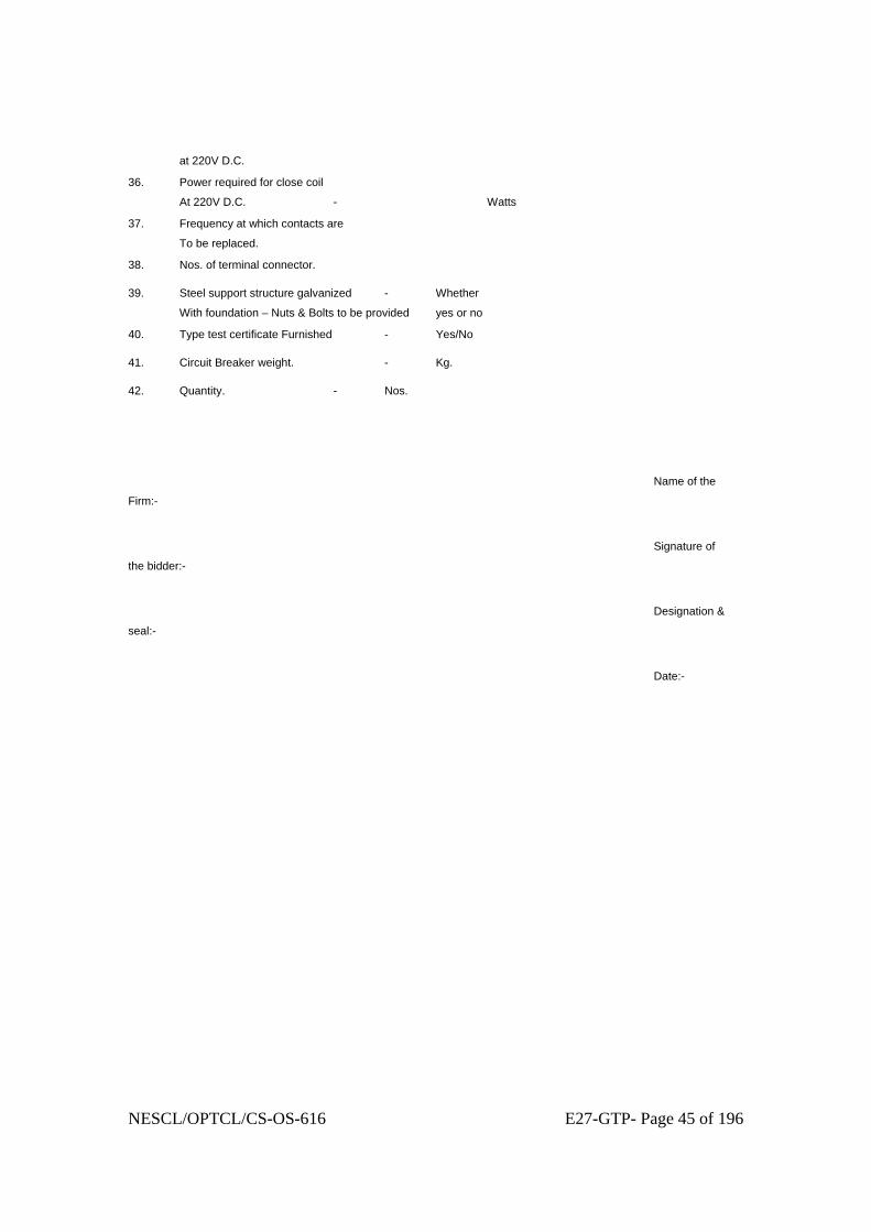
NESCL/OPTCL/CS-OS-616 E27-GTP- Page 45 of 196
at 220V D.C.
36. Power required for close coil
At 220V D.C. - Watts
37. Frequency at which contacts are
To be replaced.
38. Nos. of terminal connector.
39. Steel support structure galvanized - Whether
With foundation – Nuts & Bolts to be provided yes or no
40. Type test certificate Furnished - Yes/No
41. Circuit Breaker weight. - Kg.
42. Quantity. - Nos.
Name of the
Firm:-
Signature of
the bidder:-
Designation &
seal:-
Date:-

NESCL/OPTCL/CS-OS-616 E27-GTP- Page 46 of 196
GUARANTEED TECHNICAL PARTICULARS
FOR
CURRENT TRANSFORMER

NESCL/OPTCL/CS-OS-616 E27-GTP- Page 47 of 196
GUARANTEED TECHNICAL PARTICULARS FOR CURRENT
TRANSFORMER TO BE FILLED BY THE BIDDER.
Sl. No.
Description 33KV
132KV
220KV
a)400-200A-100/ 1-1-1A
b) 800-400- 200A-/ 1-1-1A
a) 800-400- 200A/
1-1-1-1A
b)600-300- 150A/ 1-1-1-1A
c) 400-200- 100A/
1-1-1-1A
d)400-200A/ 1-1-1-1A
1200-600-300A/ 1-1-1-1-1A
1. Bidder’s name and address
2. Name and address of the Manufacturer
3. Manufacture’s type designation
4. Standards applicable
5. Rated frequency (HZ)
6. Rated Voltage (KV)
7.0 Rated current (A)
7.1 Rated continuous current (A)
7.2 Rated extended primary current (A)
8. Short time thermal current withstand for stipulated time duration (KA)
9. Dynamic current withstand (KAP)
10.
1.2/50 μs impulse withstand voltage (KVP)

NESCL/OPTCL/CS-OS-616 E27-GTP- Page 48 of 196
Sl. No.
Description 33KV
132KV
220KV
a)400-200A-100/ 1-1-1A
b) 800-400- 200A-/ 1-1-1A
a) 800-400- 200A/
1-1-1-1A
b)600-300- 150A/ 1-1-1-1A
c) 400-200- 100A/
1-1-1-1A
d)400-200A/ 1-1-1-1A
1200-600-300A/ 1-1-1-1-1A
11. One minute dry
and wet power frequency withstand voltage (KV-rms)
12. No. of cores per CT
13. Transformation Ratio
14. No. of secondary turns
15. Rated output at all ratios for metering core (VA)
16. Accuracy class
17. Minimum Knee point voltage at different taps for all ‘PS’ class cores (V)
18. Secondary winding resistance at different taps for all cores (Ω) (750C)
19.0
Maximum exciting current at all ratios (for all PS class cores)
19.1 100% KPV

NESCL/OPTCL/CS-OS-616 E27-GTP- Page 49 of 196
Sl. No.
Description 33KV
132KV
220KV
a)400-200A-100/ 1-1-1A
b) 800-400- 200A-/ 1-1-1A
a) 800-400- 200A/
1-1-1-1A
b)600-300- 150A/ 1-1-1-1A
c) 400-200- 100A/
1-1-1-1A
d)400-200A/ 1-1-1-1A
1200-600-300A/ 1-1-1-1-1A
(Knee point voltage) (mA)
19.2 25% KPV (Knee point voltage) (mA)
19.3 20% KPV (Knee point voltage) (mA)
19.4 10% KPV (Knee point voltage) (mA)
20. Instrument security factor at different ratios.
21. Radio interference voltage at 1.1 Vr / 31/2 at 1.0 MHZ (Micro volts)
22. Whether auxiliary CT provided for metering winding
23. Corona extinction voltage (KV rms)
24. Partal discharge level (PC)
25. Total creepage distance (mm)
26. Primary 26.1 No. of primary
turns
26.2 Material and cross-section of primary (mm2)

NESCL/OPTCL/CS-OS-616 E27-GTP- Page 50 of 196
Sl. No.
Description 33KV
132KV
220KV
a)400-200A-100/ 1-1-1A
b) 800-400- 200A-/ 1-1-1A
a) 800-400- 200A/
1-1-1-1A
b)600-300- 150A/ 1-1-1-1A
c) 400-200- 100A/
1-1-1-1A
d)400-200A/ 1-1-1-1A
1200-600-300A/ 1-1-1-1-1A
26.3 Type of primary 27. Whether CT is
suitable for transportation horizontally.
28. Percentage current (ratio) error and phase displacement in minutes at rated burden and at
28.1 5% rated current
28.2 10% rated current
28.3.
20% rated current
28.4.
120% rated current
29. Percentage current (ratio) error and phase displacement in minutes at 25% rated burden and
29.1 At 5% rated current
29.2 At 10% rated current
29.3.
At 20% rated current
29.4.
At 120% rated current
30. Quantity of oil per CT (Litres)
31. Standard to which oil

NESCL/OPTCL/CS-OS-616 E27-GTP- Page 51 of 196
Sl. No.
Description 33KV
132KV
220KV
a)400-200A-100/ 1-1-1A
b) 800-400- 200A-/ 1-1-1A
a) 800-400- 200A/
1-1-1-1A
b)600-300- 150A/ 1-1-1-1A
c) 400-200- 100A/
1-1-1-1A
d)400-200A/ 1-1-1-1A
1200-600-300A/ 1-1-1-1-1A
conforms generally.
32. Characteristics of oil (prior to filling)
32.1 Breakdown voltage (KVrms)
32.2 Dielectric dissipation constant (tan delta)
32.3 Water content (ppm)
32.4 Gas content 32.5 Interfacial
tension at 270C (N/m)
32.6 Specific resistance
32.6.1
At 900C (Ωcm)
32.6.2
At 270 C (Ωcm)
33. Whether current transformers are hermetically sealed. If so, how ?
34. Total weight (Kg)
35. Transport weight (Kg)
36.1 Temperature rise over an ambient temperature of 500C for continuous

NESCL/OPTCL/CS-OS-616 E27-GTP- Page 52 of 196
Sl. No.
Description 33KV
132KV
220KV
a)400-200A-100/ 1-1-1A
b) 800-400- 200A-/ 1-1-1A
a) 800-400- 200A/
1-1-1-1A
b)600-300- 150A/ 1-1-1-1A
c) 400-200- 100A/
1-1-1-1A
d)400-200A/ 1-1-1-1A
1200-600-300A/ 1-1-1-1-1A
operation at rated continuous thermal current.
36.1 Winding 36.2 Oil 36.3 External surface
of the core, metallic parts in contact with or adjacent to insulation.
37. Whether CT characteristic curves enclosed.
37.1 Ratio and phase angle curve
37.2 Magnetisation curves
37.3 Ratio correction factor curves.
38. DATA ON PRIMARY WINDING
38.1 Rated primary current (A)
38.2 No. of conductors in one turn
38.3 No. of turns of primary
38.4 Material of the primary conductors
38.5 Size of the primary conductor

NESCL/OPTCL/CS-OS-616 E27-GTP- Page 53 of 196
Sl. No.
Description 33KV
132KV
220KV
a)400-200A-100/ 1-1-1A
b) 800-400- 200A-/ 1-1-1A
a) 800-400- 200A/
1-1-1-1A
b)600-300- 150A/ 1-1-1-1A
c) 400-200- 100A/
1-1-1-1A
d)400-200A/ 1-1-1-1A
1200-600-300A/ 1-1-1-1-1A
(Bare/ Insulated (mm x mm)
38.6 Cross-sectional area of each conductor (mm2)
38.7 Total cross-sectional area of primary winding (mm2) conductors
38.8 Current density(A/mm2)
(i) At highest ratio
(ii) At intermediate ratio
(iii) At lowest ratio
38.9 Short circuit current densiry (A/mm2)
(i) At highest ratio
(ii) At intermediate ratio
(iii) At lowest ratio
38.10
Ampere-turn of Primary (AT)
(i) At highest ratio
(ii)At intermediate ratio
(iii) At lowest

NESCL/OPTCL/CS-OS-616 E27-GTP- Page 54 of 196
Sl. No.
Description 33KV
132KV
220KV
a)400-200A-100/ 1-1-1A
b) 800-400- 200A-/ 1-1-1A
a) 800-400- 200A/
1-1-1-1A
b)600-300- 150A/ 1-1-1-1A
c) 400-200- 100A/
1-1-1-1A
d)400-200A/ 1-1-1-1A
1200-600-300A/ 1-1-1-1-1A
ratio 38.11
Length of primary conductor (m)
38.12
Weight of primary winding (kg.)
39. CORE 39.1 Material and
grade of the core
39.2 Thickness of core (mm)
39.3 Net Iron cross-sectional area of core (mm2)
39.3.1
Core-1
39.3.2
Core – 2
39.3.3
Core – 3
39.3.4
Core – 4
39.3.5
Core – 5
39.4 Mean magnetic path length (cm)
39.4.1
Core – 1
39.4.2
Core – 2
39.4.3
Core – 3
39.4.4
Core – 4
39.4.5
Core – 5

NESCL/OPTCL/CS-OS-616 E27-GTP- Page 55 of 196
Sl. No.
Description 33KV
132KV
220KV
a)400-200A-100/ 1-1-1A
b) 800-400- 200A-/ 1-1-1A
a) 800-400- 200A/
1-1-1-1A
b)600-300- 150A/ 1-1-1-1A
c) 400-200- 100A/
1-1-1-1A
d)400-200A/ 1-1-1-1A
1200-600-300A/ 1-1-1-1-1A
39.5 Whether B-H curve for the core material, used, furnished ? (B-wb/m2, H-AT/cm)
39.6 Whether specific loss vs. flux density graph for the core material used furnished ?
39.7 Axial length of core (mm)
39.7.1
Core – 1
39.7.2
Core – 2
39.7.3
Core – 3
39.7.4
Core – 4
39.7.5
Core – 5
39.8 Inside diameter / outside diameter of the cores (mm)
39.8.1
Core – 1
39.8.2
Core – 2
39.8.3
Core – 3
39.8.4
Core – 4
39.8 Core – 5
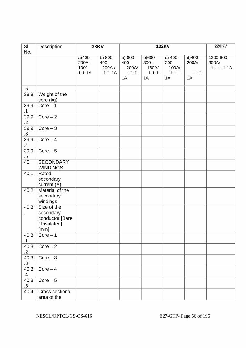
NESCL/OPTCL/CS-OS-616 E27-GTP- Page 56 of 196
Sl. No.
Description 33KV
132KV
220KV
a)400-200A-100/ 1-1-1A
b) 800-400- 200A-/ 1-1-1A
a) 800-400- 200A/
1-1-1-1A
b)600-300- 150A/ 1-1-1-1A
c) 400-200- 100A/
1-1-1-1A
d)400-200A/ 1-1-1-1A
1200-600-300A/ 1-1-1-1-1A
.5 39.9 Weight of the
core (kg)
39.9.1
Core – 1
39.9.2
Core – 2
39.9.3
Core – 3
39.9.4
Core – 4
39.9.5
Core – 5
40. SECONDARY WINDINGS
40.1 Rated secondary current (A)
40.2 Material of the secondary windings
40.3.
Size of the secondary conductor [Bare / Insulated] [mm]
40.3.1
Core – 1
40.3.2
Core – 2
40.3.3
Core – 3
40.3.4
Core – 4
40.3.5
Core – 5
40.4 Cross sectional area of the

NESCL/OPTCL/CS-OS-616 E27-GTP- Page 57 of 196
Sl. No.
Description 33KV
132KV
220KV
a)400-200A-100/ 1-1-1A
b) 800-400- 200A-/ 1-1-1A
a) 800-400- 200A/
1-1-1-1A
b)600-300- 150A/ 1-1-1-1A
c) 400-200- 100A/
1-1-1-1A
d)400-200A/ 1-1-1-1A
1200-600-300A/ 1-1-1-1-1A
secondary conductor (mm2)
40.4.1
Core – 1
40.4.2
Core – 2
40.4.3
Core –3
40.4.4
Core – 4
40.4.5
Core – 5
40.5 Current density of secondary windings (A/mm2)
40.5.1
Core – 1
40.5.2
Core – 2
40.5.3
Core – 3
40.5.4
Core – 4
40.5.5
Core – 5
40.6 No. of secondary turns
40.6.1
Core – 1
40.6.2
Core – 2
40.6.3
Core – 3
40.6.4
Core – 4
40.6 Core – 5

NESCL/OPTCL/CS-OS-616 E27-GTP- Page 58 of 196
Sl. No.
Description 33KV
132KV
220KV
a)400-200A-100/ 1-1-1A
b) 800-400- 200A-/ 1-1-1A
a) 800-400- 200A/
1-1-1-1A
b)600-300- 150A/ 1-1-1-1A
c) 400-200- 100A/
1-1-1-1A
d)400-200A/ 1-1-1-1A
1200-600-300A/ 1-1-1-1-1A
.5 40.7 No. of layers 40.7.1
Core – 1
40.7.2
Core – 2
40.7.3
Core – 3
40.7.4
Core – 4
40.7.5
Core – 5
40.8 No. of turns / layer
40.8.1
Core – 1
40.8.2
Core – 2
40.8.3
Core – 3
40.8.4
Core – 4
40.8.5
Core – 5
40.9 Average length / turn of secondary windings (mm)
40.9.1
Core – 1
40.9.2
Core – 2
40.9.3
Core – 3
40.9.4
Core – 4
40.9.5
Core – 5

NESCL/OPTCL/CS-OS-616 E27-GTP- Page 59 of 196
Sl. No.
Description 33KV
132KV
220KV
a)400-200A-100/ 1-1-1A
b) 800-400- 200A-/ 1-1-1A
a) 800-400- 200A/
1-1-1-1A
b)600-300- 150A/ 1-1-1-1A
c) 400-200- 100A/
1-1-1-1A
d)400-200A/ 1-1-1-1A
1200-600-300A/ 1-1-1-1-1A
40.10
Resistance of the conductor used for secondary winding per meter length at 750C (Ω/M)
40.11
Weight of secondary windings (kg)
40.11.1
Core – 1
40.11.2
Core – 2
40.11.3
Core – 3
40.11.4
Core – 4
40.11.5
Core – 5
41 INSULATION 41.1 Name and class
of insulating material between core and secondary winding.
41.2 Name/s of Insulating materials between secondary winding and primary windings.
41.3 Insulating materials used to achieve

NESCL/OPTCL/CS-OS-616 E27-GTP- Page 60 of 196
Sl. No.
Description 33KV
132KV
220KV
a)400-200A-100/ 1-1-1A
b) 800-400- 200A-/ 1-1-1A
a) 800-400- 200A/
1-1-1-1A
b)600-300- 150A/ 1-1-1-1A
c) 400-200- 100A/
1-1-1-1A
d)400-200A/ 1-1-1-1A
1200-600-300A/ 1-1-1-1-1A
grading of capacitance.
42. DIAMETER OF WINDINGS
42.1 Inside / outside diameter of secondary windings (mm)
42.1.1
Inside / outside diameter of secondary windings (mm)
42.1.1
Core – 1
42.1.2
Core – 2
42.1.3
Core – 3
42.1.4
Core – 4
42.1.5
Core – 5
42.2 Inside / outsde diameters of primary winding (mm)
42.3 Minimum clearance from tank (mm)
42.4 Minimum clearance from secondary to tank (mm)
43. TANK AND SECONDARY TERMINAL BOX
43.1 Material of the

NESCL/OPTCL/CS-OS-616 E27-GTP- Page 61 of 196
Sl. No.
Description 33KV
132KV
220KV
a)400-200A-100/ 1-1-1A
b) 800-400- 200A-/ 1-1-1A
a) 800-400- 200A/
1-1-1-1A
b)600-300- 150A/ 1-1-1-1A
c) 400-200- 100A/
1-1-1-1A
d)400-200A/ 1-1-1-1A
1200-600-300A/ 1-1-1-1-1A
CT tank 43.2 Material of the
CT secondary terminal box
43.3 Thickness of CT tank material (mm)
43.4 Thickness of CT secondary terminal box material (mm)
43.5 Zinc coating of the CT tank (gm/m2) as per relevant upto date ISS
43.6 Zinc coating of the CT secondary terminal box (gm/m2) as per the relevant upto date ISS.
43.7 Ingress protection rating of the secondary terminal box.
43.8 Weight of the tank, fittings and other accessories (kg)
44. TERMINAL CONNECTOR
44.1 Manufacturer’s name
44.2 Applicable standard

NESCL/OPTCL/CS-OS-616 E27-GTP- Page 62 of 196
Sl. No.
Description 33KV
132KV
220KV
a)400-200A-100/ 1-1-1A
b) 800-400- 200A-/ 1-1-1A
a) 800-400- 200A/
1-1-1-1A
b)600-300- 150A/ 1-1-1-1A
c) 400-200- 100A/
1-1-1-1A
d)400-200A/ 1-1-1-1A
1200-600-300A/ 1-1-1-1-1A
44.3 Type 44.4 Material of
connector
44.4.1
Clamp body
44.4.2
Bolts and Nuts
44.4.3
Spring washers
44.5 Rated current (Amp)
44.6 Rated terminal load (Kg)
44.7 Factor of safety
44.8 Minimum thickness of any part (mm)
44.9 Weight of clamp complete with hardwares (kg)
44.10
Type test reports as per IS enclosed
44.11
OGA drawing enclosed
45. INSULATOR 45.1 Manufacturer’s
name
45.2 Type 45.3 Applicable
standards
45.4 Height (mm) 45.5 Diameter (top)
(mm)
45.7 Total creepage distance (mm)
45.8 Rated voltage

NESCL/OPTCL/CS-OS-616 E27-GTP- Page 63 of 196
Sl. No.
Description 33KV
132KV
220KV
a)400-200A-100/ 1-1-1A
b) 800-400- 200A-/ 1-1-1A
a) 800-400- 200A/
1-1-1-1A
b)600-300- 150A/ 1-1-1-1A
c) 400-200- 100A/
1-1-1-1A
d)400-200A/ 1-1-1-1A
1200-600-300A/ 1-1-1-1-1A
. (KV)
45.9 Power frequency withstand voltage for 1 min. dry and wet. (KV – rms)
45.10
1.2/50 micro-sec impulse withstand voltage (KVP)
45.1
1
Corona
extinction
vollage (KV)
45.1
2
Weight (Kg)
45.1
3
Maximum
allowable span
(mm)
45.1
4
Cantilever
strength (Kg)
45.1
5
The drawing
enclosed.
46. Dielectric dissipation factor at 245/1.732KV (for 220KV C.T)

NESCL/OPTCL/CS-OS-616 E27-GTP- Page 64 of 196
Sl. No.
Description 33KV
132KV
220KV
a)400-200A-100/ 1-1-1A
b) 800-400- 200A-/ 1-1-1A
a) 800-400- 200A/
1-1-1-1A
b)600-300- 150A/ 1-1-1-1A
c) 400-200- 100A/
1-1-1-1A
d)400-200A/ 1-1-1-1A
1200-600-300A/ 1-1-1-1-1A
and 145/1.732 KV (for 132 kv C.T.) at ambient temperature.
47. Accuracy class of standard C.T. to be used towards determination of ratio errors and phase angle errors for metering cores.

NESCL/OPTCL/CS-OS-616 E27-GTP- Page 65 of 196
GUARANTEED TECHNICAL PARTICULARS
FOR CONTROL CABLE & POWER CABLE

NESCL/OPTCL/CS-OS-616 E27-GTP- Page 66 of 196
PART 4: SCHEDULES 25. TECHNICAL DATA SCHEDULES 3. 650/1100V Cable Schedule The Contractor must complete a schedule for each size of cable supplied ITEM NO.
DESCRIPTION
UNITS
BIDDERS OFFER
1 Standards to which the cable conforms IS-1554/IEC 502
2 Catalogue Number -
3
Conductor Material
-
4
Conductor Strands
Number
5
Conductor Shape
-
6
Conductor cross sectional area
mm2
7
Outer Diameter of Conductor
mm
8
Number of Cores
—
9
Reduced neutral conductor cross sectional area
mm2
10
Insulation Material
-
11
Minimum thickness of insulation
mm
12
Nominal thickness of insulation
mm
13
Outer Diameter over insulation
mm
14
Nominal thickness of inner sheathing
mm
15
Sheath Material
-
16
Type of armouring
—
17
Number and diameter/size of armour wires/strips No/mm

NESCL/OPTCL/CS-OS-616 E27-GTP- Page 67 of 196
18
Minimum outersheath thickness mm
19
Nominal outersheath thickness mm
20
Overall diameter of cable mm
21
Minimum Bending Radius mm
650/1100V Cable Schedule (Continued) ITEM NO.
DESCRIPTION
UNITS
BIDDERS OFFER
22
Cable identification per Clause 9
-
23
Rated Voltage per IEC 502/IS - 1554
kV
24
Conductor DC resistance per km at 20°C
ohm/km
25
Conductor AC resistance per km at 20°C and 50Hz
ohm/km
26
Maximum continuous rating of cable in the conditions outlined in Clause 4: System Conditions
A
27
Minimum insulation resistance per km at 90°C
Mohm/km
28
Maximum permissible continuous conductor temperature
°C
29
Maximum permissible continuous outersheath temperature
°C
30
DC test voltage for 15 mins. after installation
kV
31
Delivery length per drum
m
32
Weight of conductor per km
kg/km
33
Weight of cable per km
kg/km
34
Gross weight of full cable drum
kg
35
Outer diameter of the cable drum
mm

NESCL/OPTCL/CS-OS-616 E27-GTP- Page 68 of 196
36
Width of cable drum
mm
37
Maximum permissible cable pulling tension
kg
38
Maximum permissible cable side wall pressure
kg
39
Manufacturers Name
-
40
Country of Origin
-
NESCL/OPTCL/CS-OS-616 E27-GTP- Page 69 of 196
GUARANTEED TECHNICAL PARTICULARS
FOR
CONDUCTOR, EARTH WIRE, INSULATORS

NESCL/OPTCL/CS-OS-616 E27-GTP- Page 70 of 196
A P P E N D I X - IV
Guaranteed Technical Particulars of Conductor ACSR CONDUCTOR: MOOSE ZEBRA PANTHOR
Sl. Description To be specified No. by Tenderers 1. Code Word
2. Maker’s name address and
Country.
a) Aluminum rods
b) Steel Wire/rods
c) Complete conductor
3. Stranding and wire diameter
a) Aluminum.
b) Steel.
4. Standard nominal copper
area in sq. mm
5. Calculated equivalent
aluminum area in sq. mm
6. Actual aluminum area

NESCL/OPTCL/CS-OS-616 E27-GTP- Page 71 of 196
in sq. mm.
7. Standard area of cross
section in sq. mm.
a) Aluminum strand
b) Steel strand
c) Conductor
8. Diameter of complete conductor in mm.
9. Minimum ultimate tensile stress of strand, in Kg/sq. mm.
Before stranding and after stranding for
a) Aluminum strand.
b) Steel strand
10. Guaranteed ultimate tensile strength of conductor in Kg.
11. Minimum breaking load in Kg. Before stranding and after stranding for a) Aluminum strand.
b) Steel strand.
12. Purity of aluminum rods.
13. Zinc coating of steel strand. a) Uniformity of coating
number and/duration of dips.
b) Minimum weight of coating gm/sq. mm.
14. Weight in Kg. per K.M.
a) Aluminum.

NESCL/OPTCL/CS-OS-616 E27-GTP- Page 72 of 196
b) Steel.
c) Conductor.
15. Resistance in ohms per Km. at 20° c.
16. Continuous maximum current
rating of conductor in still
air at 45° C ambient temperature,
considering temp. rise of 50°C.
17. Modulus of elasticity of :
Conductor.
18. Co-efficient of linear expansion
per degree centigrade of.
a) Aluminum strand.
b) Steel Strand.
c) Conductor.
19. Percentage of carbon in
steel wire.
20. Standard length of each
peace in Km.
21. Initial and final sags and
tension and stringing charts,
whether furnished.
22. Tolerance, if any on standard length.
23. Number of standard length
in one reel.
24. Dimensions of the reel in cms.
25. Weight of the Conductor

NESCL/OPTCL/CS-OS-616 E27-GTP- Page 73 of 196
in one reel in Kg.
26. Weight of the reel in Kg.
27. Gross weight of the reel
including weight of the conductor.
28. Wheather the conductor will be manufactured
as per the relevant Indian Standard Specification
& as per Section-IV ‘Technical specification’ of this specification.
29. Wheather the conductor will be Tested
as per the relevant Indian Standard Specification
& as per Section-IV ‘Technical specification’ of this specification.
( Cause-12 of Section –IV of Technical Specification)
29. Other particulars, if any.
Signature of the Tenderer
Address
Fax No. Ph. No.
Seal

NESCL/OPTCL/CS-OS-616 E27-GTP- Page 74 of 196
GUARANTEED TECHNICAL PARTICULARS OF THE
GALVANIZED STEEL G.I. EARTH WIRE TO BE FURNISHED
BY THE BIDDER(For 7/3.15 and 7/3.66mm) 1. Maker’s name, address and
country :
2. Percentage of carbon content of the steel wire.
:
3. Particular of steel strands a) Number of strands. b) Diameter c) Standard sectional area d) Minimum ultimate tensile
strength. e) Minimum breaking land f) Final stress in steel wires
:
Mm Sq.mm N/mm2 N/mm2 KN/mm2
4. (a) Uniformity of coating of number and duration of dips.
: Minutes Number of dips.
1. 2.
b) Minimum weight of coating
: GM/m2
5. Standard overall diameter of ground wire.
: Sq.mm
6. Area of cross section of ground wire.
: Mm
7. Guaranteed ultimate tensile strength of ground wire.
: N/mm2
8. Maximum working tension : N/mm2 9. Resistance in ohms per KM at
200C. :
10. Standard length of ground wire.
: Km.
11. Modulus of elasticity of ground wire.
: Kg / cm2 Final Initial
12. Co-efficient of linear expansion.
:
13. Zinc coating :- a) Number of one minute dip : b) Number of half minute dip. c) Quality of zinc : 14. Weight of coating on wire : 15. Process of galvanising :

NESCL/OPTCL/CS-OS-616 E27-GTP- Page 75 of 196
GUARANTEED TECHNICAL PARTICULARS FOR INSULATORS (SEPARATE SHEETS MAY BE FILLED IN FOR EACH VOLTAGE
RATING) Sl. No.
Description. Single Suspension
Double suspension
Single Tension
Double Tension.
1. 2. 3. 4. 5. 6. 1. Makers name
and address and country.
2. Size and designation of Ball and socket and standard to which if will conform mm.
3. No. of insulator discs per string.
4. Outside dia of the disc. Mm
5. Spacing – mm
6. Creepage distance of the single disc –mm
7. Electro-mechanical strength of single disc. Kg.
8. Withstand voltage of single disc.
8.1 Power frequency:
a) Dry-kV (rms) b) Wet-kV (rms

NESCL/OPTCL/CS-OS-616 E27-GTP- Page 76 of 196
Sl. No.
Description. Single Suspension
Double suspension
Single Tension
Double Tension.
8.2 Impulse voltage 1.2/50 micro second.
a) Positive-kV (peak) b) Negative-kV (peak)
9. Withstand voltage for the complete string.
9.1 Power frequency: a) Dry-kV (rms) b) Wet kV (rms)
With and without corona ang.
9.2 Lighting impulse voltage 1.2/50 micro second.
a) Positive kV(peak) b) Negative Kv(Peak)
-do-
9.3 Switching surge voltage 250/2500 micro second (for 400KV only)
a) Dry-kV
-do-
NESCL/OPTCL/CS-OS-616 E27-GTP- Page 77 of 196
Sl. No.
Description. Single Suspension
Double suspension
Single Tension
Double Tension.
(rms) b) Wet kV (rms)
10. Flashover voltage for the disc.
10.1 Power frequency: a) Dry-kV (rms) b) Wet kV (rms)
10.2 Lighting impulse voltage 1.2/50 micro second.
a) Positive kV(peak)
b) Negative Kv(Peak)
11. Flashover voltage for the complete string.
11.1 Power frequency:
a) Dry-kV (rms) b) Wet kV
With and without corona ring.

NESCL/OPTCL/CS-OS-616 E27-GTP- Page 78 of 196
Sl. No.
Description. Single Suspension
Double suspension
Single Tension
Double Tension.
(rms) 11.2 Lighting impulse
voltage 1.2/50 micro second. a) Positive kV(peak) b) Negative Kv(Peak)

NESCL/OPTCL/CS-OS-616 E27-GTP- Page 79 of 196
GUARANTEED TECHNICAL PARTICULARS
FOR
ISOLATORS

NESCL/OPTCL/CS-OS-616 E27-GTP- Page 80 of 196
GUARANTEED TECHNICAL PARTICULARS FOR DISCONNECTOR
(ISOLATORS)
(To be filled in separately for Disconnectors of different voltage classes and types) 400/220/132/33 KV
1. Type / installation
2. Manufacturer’s Name and
Country of manufacure
3. standard/s according to which
the isolator are manufactured
4. Maximum design voltage at which
the isolator can operate (kv)
5. frequency (Hz)
6. Rated Voltage (kv)
7. Max. current that can be safely interrupted by the isolator
Inductive (A & % PF)
Capacitive (A & % PF)
8. Continuous current rating (Amps)
9. Rated short time current
(i) For 3 second (KA rms)
(ii) Rated peak short time current (kVp)
10. Current density at the minimum cross-section of
a) Moving blade (Amps/Sq.mm)
b) Terminal pad
c) Contacts
d) Terminal Connector

NESCL/OPTCL/CS-OS-616 E27-GTP- Page 81 of 196
11. Max. temp rise of current carrying parts when carrying rated current continuously. (deg. C)
12. factor for specified site conditions.
13. Derating Insulation levels.
i) Impulse withstand voltage (kV peak)
a) Phase to Earth
b) Across isolating Distance
ii) Switching surge withstand voltage (kV peak)
(a) Phase to Earth
(b) Across isolating Distance
iii) Power frequency withstand voltage (kV rms)
(a) Phase to Earth
(b) Across isolating distance
iv) Radio interference voltage at 1.1 times maximum line to ground voltage (micro volts)
v) Corona inception voltage (kV rms)
vi) Corona extinction voltage (KV rms)
14. Minimum clearance in air:
i) Between poles (mm)
ii) Between live parts and earth (mm)
iii) Between live part when switch is open
(a) On the same pole (mm)
(b) Between adjacent poles (mm)
15. Rated mechanical terminal load
a) Load along the terminal connector side (kg)
ii) Load across the terminal connector side(kg)
16. Torque required to operate the switch in Kg. m.
14. Contact zone
(i) Horizontal deflection (mm)
(ii) Vertical deflection (mm)
NESCL/OPTCL/CS-OS-616 E27-GTP- Page 82 of 196
(iii) Total amplitude of longitudinal movement w.r.t. conductor supporting
fixing contact (mm)
15. Design and Construction
i) No. of Insulators per pole
ii) Contacts
a) Material and grade
b) Cross-sectional area in sq.mm
i) Moving Blades
a) Material and grade
b) Cross sectional area
ii) Contact Support
a) Material and size of channel / block
b) Material and size of plate
iii) Rain hood – Material grade and size
iv) Turn and twist mechanism
a) Material and size of clamps
b) Material and size of springs
c) Whether springs are encased
v) Nuts and Bolts.
a) Size, material and grade in live parts.
b) Size material and grade in other parts
viii) Insulator base plate
Material and size of plate below insulators
ix) Bearings.
a) Material and size of housing
b) No. of bearings, location and size
x) Tandem pipe
a) Size class and no. of pipes
b) Size of shackle, screw
c) No. of bearings / bush and its material and size
xi) Type of inter lock

NESCL/OPTCL/CS-OS-616 E27-GTP- Page 83 of 196
xii) Down pipe size and class
xiii) Type of universal / swivel joint
a) Between bearing and down pipe
b) Between down pipe and operating mechanism
xiv) Operating mechanism
a) Control cabinet
Material and thickness
Degree of protection
Type size and no. of cable glands
Whether removable gland plate provided.
b) Make type, rating and qty. of motors per isolator
Gears
Limit switches
Contactors
Over load relay
Single phase preventor
Auxiliary switch
Terminal blocks
Insuiator wires
HRC fuses
Pole discrepancy relay
Timer
Space Heater
Interlocks
xv) Insulators
a) Type
b) No. of units per insulator stack.
c) Rating of insulator (kV)
d) Height of each insulator stack (mm)
e) Bolt circle diameter (mm)
f) Tensile strength (kg)
g) Compressive strengh

NESCL/OPTCL/CS-OS-616 E27-GTP- Page 84 of 196
h) Torsional strength (kg. m)
i) Cantilver strength upright (kg)
j) Power frequency dry flash over voltage (kV) rms
k) Power frequency wet flash over voltage (kV) rms
l) Power frequency puncture voltage (kV) rms
m) Impulse flash over voltage (positive wave) (kV) peak
n) Impulse withstand voltage (kV) peak
o) Power frequency withstand voltage (kV) rms
p) Visual discharge voltage level (kV) rms
q) Creepage distance
Total (mm)
Protected (mm)
r) Dry arcing distance (mm)
xvi) Base
a) Size of steel sections used
b) Overall size
c) Total weight
xvii) Terminal connectors
a) Clamp Body
Alloy Composition
Plating if any
Area at min. cross section
b)Bolts and nuts size
Alloy composition
Tensile strength
c)Type of washers used
d)Materials of braids
e)Temperature rise when carrying rated current at 50 deg. C ambient (deg.C)
f)Weight of each type of clamp (kg)

NESCL/OPTCL/CS-OS-616 E27-GTP- Page 85 of 196
List of bought out items.
Sl. No.
Particulars of components Qty. Rating
Make Type
19.0 List of test certificates (Type and routine)
20.0 List of drawings furnished.
Name of the firm …………………….
Signature of Bidder ………………….
Designation and seal ………………..
Date …………………………………….

NESCL/OPTCL/CS-OS-616 E27-GTP- Page 86 of 196
GUARANTEED TECHNICAL PARTICULARS
FOR
SURGE ARRESTORS

NESCL/OPTCL/CS-OS-616 E27-GTP- Page 87 of 196
ANNEXURE-A. GUARANTEED TECHNICAL PARTICULARS.
390 KV 216 KV 120 KV 30KV 1 Bidder’s Name and Address. 2 Manufacturer’s Name. 3 Manufacturer’s type designation. 4 Applicable standards. 5 Arrester class and type. 6 Rated Arrester Voltage (KV rms). 7 Maximum continuous operating
voltages (MCOV) at design ambient temperature (KV-rms).
8 Nominal discharge current (8/20 micro second wave) (KA).
9 Minimum discharge capability referred to rated voltage at minimum of discharge characteristics (KJ/KV).
10 Line discharge class as per IEC. 11 Maximum switching surge residual
voltage at 1 KA (KVP) for 390KV,216KV, 120KV and for 30KV at 500A.
12 Maximum switching surge residual voltage at 1 KA for 216 KV.
13 Maximum residual voltage for 8/20 micro-second current wave.
(a) At 50 % nominal discharge current. (b) At 100 % nominal discharge
current.
(c) At 200 % nominal discharge current.
14 Maximum residual voltage with 1 micro-second current wave at 10 KAP

NESCL/OPTCL/CS-OS-616 E27-GTP- Page 88 of 196
(KVP). 15 One minute power frequency (dry) &
(wet) withstand voltage of arrester (KV-rms).
16 Impulse withstand test voltage of arrester housing with 1.2/50 micro-second wave (KVP).
17 High current short duration (4/10 micro-second impulse wave) (KAP).
18 Low current long duration (KAP). 19 Reference voltage and corresponding
reference current of arrester (KV)(mA).
20 Maximum internal leakage current by its rms or peak value and both resistive and capacitive component separately at
(a) COV (resistive/capacitive) (mA). (b) 1.1 COV (resistive/capacitive)
(mA).
(c) COV at 150°C (resistive/capacitive) (mA).
(d) Reference voltage (resistive/capacitive)(mA).
21 Pressure relief class. 22 Are the protection levels affected by
pollution of external insulation.
23 Energy absorption capability per operation of the arrester, during a switching surge discharge (KJ).
24 Maximum amount of energy that may be despatched into the arrester during discharge assuming that discharge takes place within 1 minute period and state the switching surge current (KJ/KA).
25 Internal pressure required to operate pressure relief device as a percentage of burst pressure of porcelain (KJ) & %.
26 Dynamic over-voltage withstand capability (KV-rms).
(a) For 0.1 Second. (b) For 1 Second. (c) For 10 Seconds. (d) For 100 Seconds. 27 Minimum prospective symmetrical
fault current (KA).
28 Rejection rate of ZnO blocks during
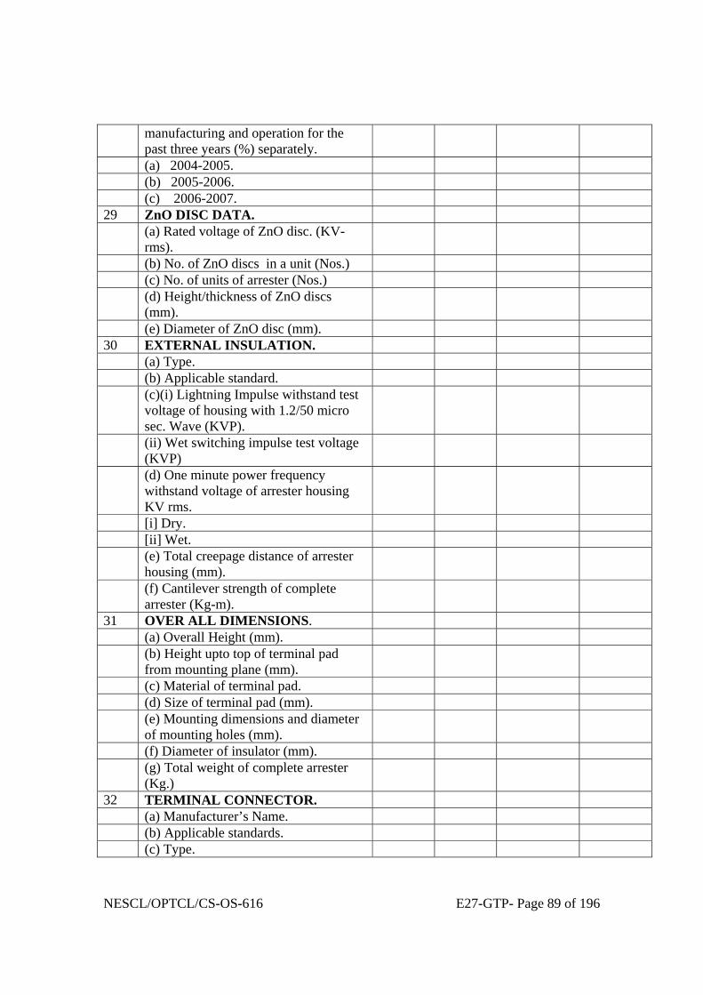
NESCL/OPTCL/CS-OS-616 E27-GTP- Page 89 of 196
manufacturing and operation for the past three years (%) separately.
(a) 2004-2005. (b) 2005-2006. (c) 2006-2007. 29 ZnO DISC DATA. (a) Rated voltage of ZnO disc. (KV-
rms).
(b) No. of ZnO discs in a unit (Nos.) (c) No. of units of arrester (Nos.) (d) Height/thickness of ZnO discs
(mm).
(e) Diameter of ZnO disc (mm). 30 EXTERNAL INSULATION. (a) Type. (b) Applicable standard. (c)(i) Lightning Impulse withstand test
voltage of housing with 1.2/50 micro sec. Wave (KVP).
(ii) Wet switching impulse test voltage (KVP)
(d) One minute power frequency withstand voltage of arrester housing KV rms.
[i] Dry. [ii] Wet. (e) Total creepage distance of arrester
housing (mm).
(f) Cantilever strength of complete arrester (Kg-m).
31 OVER ALL DIMENSIONS. (a) Overall Height (mm). (b) Height upto top of terminal pad
from mounting plane (mm).
(c) Material of terminal pad. (d) Size of terminal pad (mm). (e) Mounting dimensions and diameter
of mounting holes (mm).
(f) Diameter of insulator (mm). (g) Total weight of complete arrester
(Kg.)
32 TERMINAL CONNECTOR. (a) Manufacturer’s Name. (b) Applicable standards. (c) Type.

NESCL/OPTCL/CS-OS-616 E27-GTP- Page 90 of 196
(d) Material of connector. [i] Clamp body. [ii] Bolts and Nuts. [iii] Spring washers. (e) Rated current (Amps.) (f) Rated terminal load (kg.) (g) Factor of safety. (h) Minimum thickness of any part
(mm).
(i) Weight of clamp complete with hard ware (kg.)
(j) Type test report as per IS enclosed. (k) OGA Drawing enclosed. 33 INSULATORS. (a) Manufacturers Name. (b) Type. (c) Applicable standards. (d) Height (mm). (e) Diameter (top)(mm). (f) Diameter (bottom) (mm). (g) Total creepage distance (mm). (h) Rated voltage (KV – rms). (i) Power frequency withstand voltage
for 1 min. dry and wet (KV – rms).
(j) 1.2/50 micro - second impulse withstand voltage (KVP)
(k) Corona Extinction voltage (KV-rms)
(l) Weight (kg.) (m) Maximum allowable span (mm). (n) Cantilever strength (Kg – m).

NESCL/OPTCL/CS-OS-616 E27-GTP- Page 91 of 196
GUARANTEED TECHNICAL PARTICULARS
FOR
33/0.433 KV,250 KVA STATION TRANSFORMER

NESCL/OPTCL/CS-OS-616 E27-GTP- Page 92 of 196
GUARANTEED TECHNICAL PARTICULARS FOR 33/0.433 KV ,STATION TRANSFORMER:-
1. Name of the manufacturer.
2. Service.
3. KVA Rating:-
a) H.V. Winding. KVA
b) L.V. Winding. KVA
4. Highest system voltage/Nominal voltage.
a) H.V. Winding. KV
b) L.V.Winding KV
5. Rated frequency. Hz
6. Number of phases.
7. Connections:-
a) H.V. Winding.
b) L.V. Winding.
8. Connection symbol (See IS: 2026 (Part-IV-1977).
9. Tappings:-
a) Range
b) Number of steps for high

NESCL/OPTCL/CS-OS-616 E27-GTP- Page 93 of 196
voltages variation.
10. Reference ambient temperature:-
a) Maximum ambient air/temperature. ºC.
b) Maximum daily average ambient air ºC.
temperature.
c) Maximum yearly average ambient ºC.
air temperature.
d) Minimum ambient air temperature. ºC.
e) Maximum cooling water temperature. ºC.
11. Type of cooling (See IS-2026 (Part-II)/1977.)
12. Temperature rise (See 2026 (Part-II)/1977)
a) Temperature of oil ºC.
b) Winding. ºC.
13. i) Total loss at rated nominal voltage KW
at normal tap & rated frequency.
ii) Stray loss at 75ºC.
iii) % Regulation.
14. (A) Component losses.
a) No-load loss at rated nominal voltage KW
and normal frequency.
b) Load loss at rated current and rated frequency at normal tapping at 75ºC. & at extreme taps.
(B) Resistance at normal tap & at 75ºC.
i) H.V.
ii) L.V.
15. Impedance voltage & percentage Impedance

NESCL/OPTCL/CS-OS-616 E27-GTP- Page 94 of 196
at full rated current at 75ºC. for the
a) Normal tap.
b) Lowest tap position
c) Highest tap position.
16. Reactance at rated current and Percentage.
rated frequency.
17. No load current at rated nominal voltage and rated frequency and at 50%, 75%, 100%, 110% & 121%
voltage & at rated frequency.
18. Insulation level (See IS-2026 (Part-III/1977).
a) Separate source power frequency voltage withstand i) H.V. Winding KV rms.
ii) L.V. Winding. KV rms.
b) Induced over voltage withstand. i) H.V. Winding. KV rms.
ii) L.V. Winding. KV rms.
c) Full wave lighting impulse withstand voltage with time vrs. peak voltage characteristic curves.
i) H.V. Winding. KV Peak.
ii) L.V. Winding. KV Peak.
d) P.I. value.
19. Efficiencies at 75ºC at unity power factor. a) At full load. Percent b) At ¾ full load -do- c) At ½ full load -do- d) At 120% of full load.
20. Regulation at full load at 75ºC
a) At unity power factor. -do- b) At 0.8 power factor loading & lagging. -do-
21. Equipment for ONAN cooling.

NESCL/OPTCL/CS-OS-616 E27-GTP- Page 95 of 196
a) State. i) No.of Radiators on main tank.
ii) Make & type iii) Total radiating surface
iv) Thickness of radiator fins v) Clear distance between fins vi) Width of radiator fins
22. Number of coolers or cooler banks per transformer
23. Rating of each cooler or cooler bank.
24. Terminal arrangement.
a) High voltage. b) Low voltage. c) Neutral.
25. Approximate masses:-
a) Core Kg. b) Winding. Kg. c) Tank, fittings & accessories. (Name of Kg.
accessories to be mentioned).
d) Oil. Kg. e) Core coil assembly Kg.
f) radiators Kg.
g) Total mass Kg.
26. a)Approximate quantity of oil required Ltrs.
for first filling.
b)Name of the manufacturer of oil used
27. Approximate tank dimensions for
over all dimensions.
a) Length mm b) Breadth. mm c) Height. mm d) Thickness of main tank cover plate, mm
side & bottom plate.
e) Tank inside & outside dimension. mm

NESCL/OPTCL/CS-OS-616 E27-GTP- Page 96 of 196
Length/breadth/height. No. of tubes in each
rediator. Tube length in copper, thickness
& dia. Each side tubes (Nos.).
28. Despatch details.
a) Approximate mass of heaviest package. Kg.
b) Approximate dimensions of largest package.
i) Length. mm ii) Breadth. mm
iii) Height. mm
29. Un-tanking height. mm
30. Additional technical particulars.
i) (a) i. Maximum flux density at highest system Tesla or Wo/m².
voltage & 48.5 c/s frequency.
ii) Maximum flux density at rated system
voltage & rated frequency.
(b) Maximum current density in windings. Amps/Sq.Cm
(c) Size of conductor used. HV/LV
High voltage.
Low voltage.
ii) Efficiency at 75ºC and 0.8 P.F. lagging
At full load. Percent.
At ¾ full load -do-
At ½ full load -do-
Over loading capacity & efficiency.
iii) Load at which maximum efficiency occurs. -do-
iv) Maximum efficiency. Percent.
v) Impulse level with 1/50 Micro.S. Wave. High voltage KV
Low voltage KV
vi) No-load loss at 110% rated nominal

NESCL/OPTCL/CS-OS-616 E27-GTP- Page 97 of 196
voltage and rated frequency. KV
vii) No load current at 110% & 121% of nominal
voltage & rated frequency. Percentage.
viii) Type of winding.
High voltage.
Low voltage.
No. of turns of H.V.
No. of turns of L.V.
ix) Insulation materials.
Turn insulation high voltage.
Turn insulation low voltage.
Insulation core to low voltage.
Insulation high voltage to low voltage.
x) Clearance:-
Minimum clearance between phases.
a) In oil. mm b) Out of oil. mm
Maximum clearance high voltage to
tank in oil. mm
Minimum clearance high voltage to
earth in oil. mm
xi) Minimum clearance height for lifting
core & windings from rank. mm.
31. CORE :-
(i) Core materials used. (grade & thickness). (ii) Loss in watts/Kg. of core materials corres- (Watts/Kg. curve to be
ponding to desired flux densities. furnished along with
the bid.).
(iii) EMF per turn

NESCL/OPTCL/CS-OS-616 E27-GTP- Page 98 of 196
(iv) Core circumcircle dia (d).
(v) No. of core bolt holes per phase.
(vi) Dia of each core bolt holes in mm.
(vii) Net iron section (cm²). Limb/Yoke.
(viii) Weight (Kg.)
(ix) Total GI (Kg.)
(x) Total (KW).
No. of steps. 1 2 3 4
Stack in mm.
Width of core in mm.
Stacking factor of core.
------------------------------------------------------------------------------------------------------------------------ 32.(a) WINDING :-
Current per phase (Amp.) LV HV HV regulating.
conductor bare (mm) No. of
conductor insulation (mm).
Conductor section (mm²)
Current density (A/mm²)
Turns per phase (T).
Coils per limb.
Arranged.
Turns per coil.
Turns per layer.
Layers per coil.
Winding depth.
Coil dia inside.
Coil dia outside.
NESCL/OPTCL/CS-OS-616 E27-GTP- Page 99 of 196
Length of mean turns.
Resistance at 75ºC,
Total 1² R including stray at 75ºC,
Weight of copper with/without
insulations.
(b) Radiators provided (Nos.).
No. of fins provided.
Radiator size in mm (Length x wide x fin Nos.)
Loss to be dissipated by Radiators in KW.
Dissipation per fin at 50ºC.
Thermal head in mm.
Radiator area.
33. Oil data:-
1. Quantity for first filling. Ltr.
2. Grade of oil used.
3. Maker’s name.
4. BOV at the time of filling.
5. Type of oil.
34. Make of breather and type with capacity
of silica gal filled in grams.
35. Inter layer insulation provided in design for:-
1. Top and bottom layer. mm
2. In between all layers. mm
3. Details of insulation. mm
4. Whether wedges are provided at
50% turns of the coil.
36. Insulation materials.
a) For conductors. H.V.
b) For core. L.V.

NESCL/OPTCL/CS-OS-616 E27-GTP- Page 100 of 196
37. Particulars of bushings:-
1. Maker’s name.
2. Type IS-3347/IS-1180.
3. Rating as per I.S.
4. Dry flash over voltage
KV
5. We flash over voltage
KV.
38. I.R. value at 30ºC.
HV/E
LV/E
HV/LV
39. Polarisation Index :-
Measurement of Insulation resistance at
10 minutes/1 minute.
HV/E.
LV/E.
HV/LV.

NESCL/OPTCL/CS-OS-616 E27-GTP- Page 101 of 196
GUARANTEED TECHNICAL PARTICULARS
FOR
Surge Arrestor

NESCL/OPTCL/CS-OS-616 E27-GTP- Page 102 of 196
ANNEXURE-A. GUARANTEED TECHNICAL PARTICULARS.
390 KV 216 KV 120 KV 30KV 1 Bidder’s Name and Address. 2 Manufacturer’s Name. 3 Manufacturer’s type designation. 4 Applicable standards. 5 Arrester class and type. 6 Rated Arrester Voltage (KV rms). 7 Maximum continuous operating
voltages (MCOV) at design ambient temperature (KV-rms).
8 Nominal discharge current (8/20 micro second wave) (KA).
9 Minimum discharge capability referred to rated voltage at minimum of discharge characteristics (KJ/KV).
10 Line discharge class as per IEC. 11 Maximum switching surge residual
voltage at 1 KA (KVP) for 390KV,216KV, 120KV and for 30KV at 500A.
12 Maximum switching surge residual voltage at 1 KA for 216 KV.
13 Maximum residual voltage for 8/20 micro-second current wave.
(a) At 50 % nominal discharge current. (b) At 100 % nominal discharge
current.
(c) At 200 % nominal discharge current.
14 Maximum residual voltage with 1 micro-second current wave at 10 KAP (KVP).

NESCL/OPTCL/CS-OS-616 E27-GTP- Page 103 of 196
15 One minute power frequency (dry) & (wet) withstand voltage of arrester (KV-rms).
16 Impulse withstand test voltage of arrester housing with 1.2/50 micro-second wave (KVP).
17 High current short duration (4/10 micro-second impulse wave) (KAP).
18 Low current long duration (KAP). 19 Reference voltage and corresponding
reference current of arrester (KV)(mA).
20 Maximum internal leakage current by its rms or peak value and both resistive and capacitive component separately at
(a) COV (resistive/capacitive) (mA). (b) 1.1 COV (resistive/capacitive)
(mA).
(c) COV at 150°C (resistive/capacitive) (mA).
(d) Reference voltage (resistive/capacitive)(mA).
21 Pressure relief class. 22 Are the protection levels affected by
pollution of external insulation.
23 Energy absorption capability per operation of the arrester, during a switching surge discharge (KJ).
24 Maximum amount of energy that may be despatched into the arrester during discharge assuming that discharge takes place within 1 minute period and state the switching surge current (KJ/KA).
25 Internal pressure required to operate pressure relief device as a percentage of burst pressure of porcelain (KJ) & %.
26 Dynamic over-voltage withstand capability (KV-rms).
(a) For 0.1 Second. (b) For 1 Second. (c) For 10 Seconds. (d) For 100 Seconds. 27 Minimum prospective symmetrical
fault current (KA).
28 Rejection rate of ZnO blocks during manufacturing and operation for the

NESCL/OPTCL/CS-OS-616 E27-GTP- Page 104 of 196
past three years (%) separately. (a) 2004-2005. (b) 2005-2006. (c) 2006-2007. 29 ZnO DISC DATA. (a) Rated voltage of ZnO disc. (KV-
rms).
(b) No. of ZnO discs in a unit (Nos.) (c) No. of units of arrester (Nos.) (d) Height/thickness of ZnO discs
(mm).
(e) Diameter of ZnO disc (mm). 30 EXTERNAL INSULATION. (a) Type. (b) Applicable standard. (c)(i) Lightning Impulse withstand test
voltage of housing with 1.2/50 micro sec. Wave (KVP).
(ii) Wet switching impulse test voltage (KVP)
(d) One minute power frequency withstand voltage of arrester housing KV rms.
[i] Dry. [ii] Wet. (e) Total creepage distance of arrester
housing (mm).
(f) Cantilever strength of complete arrester (Kg-m).
31 OVER ALL DIMENSIONS. (a) Overall Height (mm). (b) Height upto top of terminal pad
from mounting plane (mm).
(c) Material of terminal pad. (d) Size of terminal pad (mm). (e) Mounting dimensions and diameter
of mounting holes (mm).
(f) Diameter of insulator (mm). (g) Total weight of complete arrester
(Kg.)
32 TERMINAL CONNECTOR. (a) Manufacturer’s Name. (b) Applicable standards. (c) Type. (d) Material of connector.

NESCL/OPTCL/CS-OS-616 E27-GTP- Page 105 of 196
[i] Clamp body. [ii] Bolts and Nuts. [iii] Spring washers. (e) Rated current (Amps.) (f) Rated terminal load (kg.) (g) Factor of safety. (h) Minimum thickness of any part
(mm).
(i) Weight of clamp complete with hard ware (kg.)
(j) Type test report as per IS enclosed. (k) OGA Drawing enclosed. 33 INSULATORS. (a) Manufacturers Name. (b) Type. (c) Applicable standards. (d) Height (mm). (e) Diameter (top)(mm). (f) Diameter (bottom) (mm). (g) Total creepage distance (mm). (h) Rated voltage (KV – rms). (i) Power frequency withstand voltage
for 1 min. dry and wet (KV – rms).
(j) 1.2/50 micro - second impulse withstand voltage (KVP)
(k) Corona Extinction voltage (KV-rms)
(l) Weight (kg.) (m) Maximum allowable span (mm). (n) Cantilever strength (Kg – m).

NESCL/OPTCL/CS-OS-616 E27-GTP- Page 106 of 196
GTP FOR CONTROL & RELAY PANEL
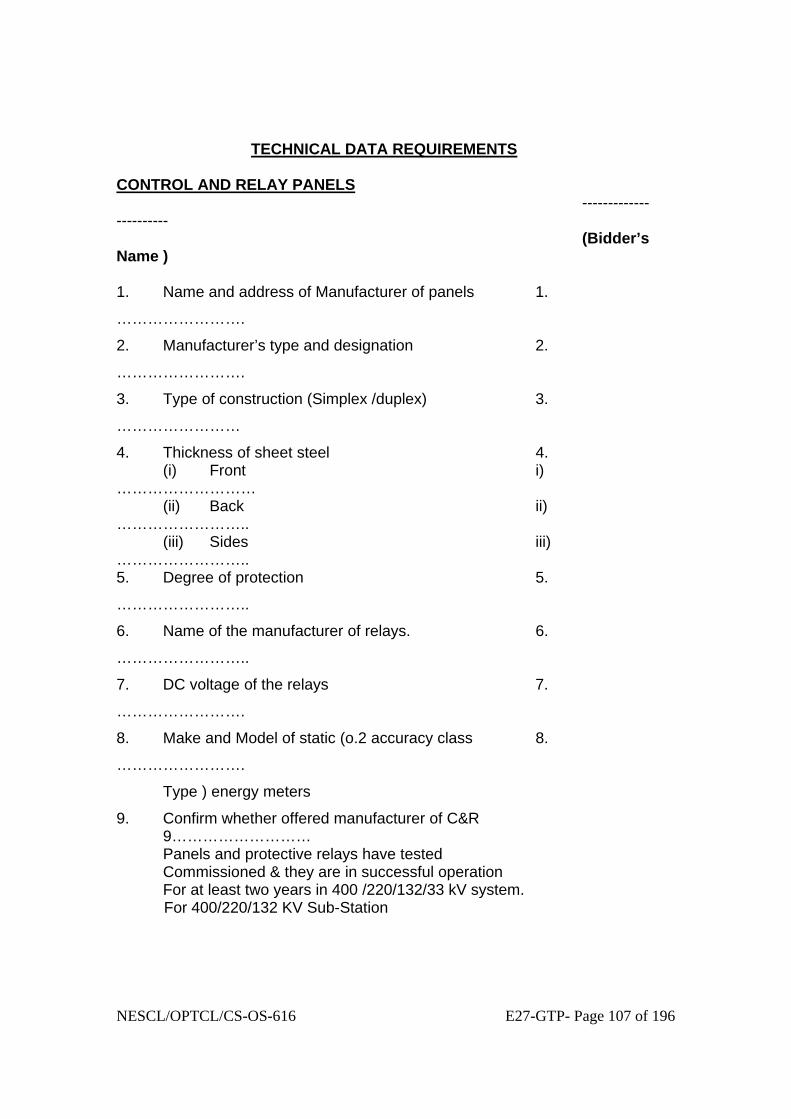
NESCL/OPTCL/CS-OS-616 E27-GTP- Page 107 of 196
TECHNICAL DATA REQUIREMENTS CONTROL AND RELAY PANELS ----------------------- (Bidder’s Name ) 1. Name and address of Manufacturer of panels 1.
…………………….
2. Manufacturer’s type and designation 2.
…………………….
3. Type of construction (Simplex /duplex) 3.
……………………
4. Thickness of sheet steel 4. (i) Front i) ……………………… (ii) Back ii) …………………….. (iii) Sides iii) …………………….. 5. Degree of protection 5.
……………………..
6. Name of the manufacturer of relays. 6.
……………………..
7. DC voltage of the relays 7.
…………………….
8. Make and Model of static (o.2 accuracy class 8.
…………………….
Type ) energy meters
9. Confirm whether offered manufacturer of C&R 9……………………… Panels and protective relays have tested Commissioned & they are in successful operation For at least two years in 400 /220/132/33 kV system. For 400/220/132 KV Sub-Station

NESCL/OPTCL/CS-OS-616 E27-GTP- Page 108 of 196
1). (A) TYRANSMISSION LINE PROTECTION Numerical Distance protection Scheme 1. Name and address of Manufacturer of Relay/panels 1.
…………………….
2. Manufacturer’s type and designation 2.
…………………….
3. Switched or Non-switched type (is 3. ……………………. It with separate measurements for Single/three phase faults) 4. Setting range of off set feature
4………………………
5. Whether the relay is having self 5. …………………….. Monitoring feature.
6. Whether relays is compatible for 6. ………………………
PLCC equipment and can be used for Permissive Under reach/over reach /Blocking scheme etc.
7. Suitable for single and three phase Trip? 7.
……………………..
8. Type of shaped characteristic 8.
……………………..
9. Whether it is communicable to other relays
9...............................
of different manufacturer. Also mention the
communicating protocol.
10. Features like broken conductor,SOTF,Distance
10............................
to fault locater & other features as per Tech Spec
are available or not.

NESCL/OPTCL/CS-OS-616 E27-GTP- Page 109 of 196
11. No of tripping contacts with making 11. …………………… Capacity of 30 amp for 0.2 seconds.
12. In case 16 contacts as per above 12. ………………….. Clause are not available with the distance relay Offered, type tripping relays being offered.
13. Maximum operating time for at 50% of the 13. ………………….. Reach setting of 2 ohms and 10/20 ohms (with CVT) including all trip relays, if any (Bidder is required to enclose isochronic Curve with CVT on line)
a) at SIR=4 a) ……………………. b) at SIR=15, (3 phase faults) b) ………………….. c) at SIR=15 (other faults) c) …………………….
14. IDMT earthy fault relay meeting Normal 14................. Inverse Characteristics as per IEC 60253 Is being offered as built in feature for 400/220/132 KV lines.
15. If no, type of IDMT relay being offered 15.......................
16. Built in feature offered with the relay (YES/NO) 16........ a) Disturbance recorder a) …………………… b) Fault locater b) …………………… c) Over voltage (one stage only) c) …………………… d) Auto recluse along with Dead line d) …………………. e) Charging and check synchronizing. e) …………………. 17. Indicate the no. of Binary Input & Out put contacts 17........................

NESCL/OPTCL/CS-OS-616 E27-GTP- Page 110 of 196
(B) STATIC DISTANCE PROTECTION SCHEME 1. Name and address of Manufacturer 1.
…………………….
2. Manufacturer’s type and designation 2.
…………………….
3. Switched or Non-switched type (is 3. ……………………. it with separate measurements for Single/three phase faults) 4. Setting range of off set feature.
4………………………
5. Whether the relay is compatible for PLCC 5. ……………………. Equipment and can be used for permissive Under reach/over reach/Blocking scheme etc. 6. Suitable for single and three phase Trip 6. ……………………… 7. Type of shaped characteristic 7. …………………. 8. No of tripping contacts with making 8. …………………… Capacity of 30 amp for 0.2 seconds.
9. In case 16 contacts as per above 9. ………………….. Clause are not Available with the distance relay Offered, type of tripping relays being offered.
10. Maximum operating time for at 50% of the 10. ………………….. Reach setting of 2 ohms and 10/20 ohms (with CVT) including all trip relays, if any (Bidder is required to enclose isochronic Curve with CVT on line)
a) at SIR=4 a) ……………………. b) at SIR=15, (3 phase faults) b) ………………….. c) at SIR=15 (other faults) c)
………………….
11. Built in feature offered with the relay (YES/NO)

NESCL/OPTCL/CS-OS-616 E27-GTP- Page 111 of 196
a) Disturbance recorder a) …………………… b) Fault locator b) …………………… c) Over voltage (one stage only) c) …………………… d) Auto recluse along with Dead line d) …………………. Charging and check synchronizing. (C) BACKUP DIRECTIONAL OVER CURRENT AND EARTH FAULT PROTECTION SCHEME( Numerical) 1. Name and address of Manufacturer 1.
…………………….
2. Manufacturer’s type and designation 2.
…………………….
3. Three over current and one E/F elements 3.
…………………..
Are whether independent or composite unit
4. Type of relay (Numerical) 4.
………………….
5. Directional sensitivity. 5.
…………………..
6. Whether characteristics conform to IEC 255-3 6.
…………………..
7. Over current unit setting range inverse time
7……………………
8. Earth fault unit setting range inverse time 8.
………………..
9. VT Fuse failure relay/ feature included 9. …………………. For alarm. 10. Whether it is communicable to other relays
10...............................
of different manufacturer. Also mention the
communicating protocol.
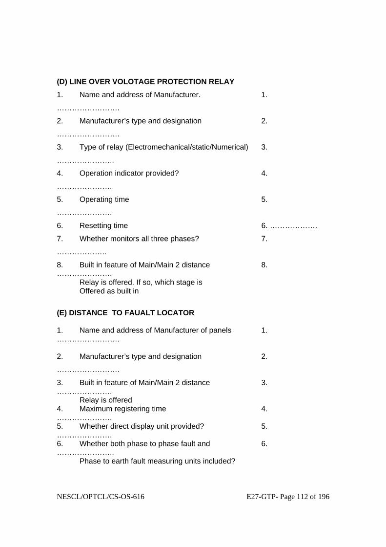
NESCL/OPTCL/CS-OS-616 E27-GTP- Page 112 of 196
(D) LINE OVER VOLOTAGE PROTECTION RELAY
1. Name and address of Manufacturer. 1.
…………………….
2. Manufacturer’s type and designation 2.
…………………….
3. Type of relay (Electromechanical/static/Numerical) 3.
…………………..
4. Operation indicator provided? 4.
………………….
5. Operating time 5.
………………….
6. Resetting time 6. ……………….
7. Whether monitors all three phases? 7.
………………..
8. Built in feature of Main/Main 2 distance 8. …………………. Relay is offered. If so, which stage is Offered as built in
(E) DISTANCE TO FAUALT LOCATOR 1. Name and address of Manufacturer of panels 1. ……………………. 2. Manufacturer’s type and designation 2.
…………………….
3. Built in feature of Main/Main 2 distance 3. …………………. Relay is offered 4. Maximum registering time 4. …………………. 5. Whether direct display unit provided? 5. …………………. 6. Whether both phase to phase fault and 6. ………………….. Phase to earth fault measuring units included?

NESCL/OPTCL/CS-OS-616 E27-GTP- Page 113 of 196
7. Whether-On-Line type 7. …………..... 8. Accuracy for the typical conditions defined 8. ……………….. Under technical specification. (F) DISTURBANCE RECORDER a. Acquisition unit. 1. Name and address of Manufacturer . 1.
…………………….
2. Manufacturer’s type and designation 2.
…………………….
3. No. of analogue channels 3.
…………………..
4. No. of digital recording channels. 4.
……………………
5. Built in feature of Main 1/ Main 2 distances. 5.
…………………..
Relay is offered.
6. Pre-fault memory (milli seconds) 6. ……………….
7. Post fault memory (seconds) 7. …………….
8. Total storage memory is seconds. 8.
…………….
9. Sampling Frequency. 9. …………….
10. Resolution of the event channels (ms) 10. …………….
11. Time display present? 11.
………………
12. Data out put in COMTRADE is available. 12.
………………
b. Evaluation Unit. 1. Name and address of Manufacturer 1. …………….
2. Manufacturer’s type and designation 2………………

NESCL/OPTCL/CS-OS-616 E27-GTP- Page 114 of 196
3. No. of acquisition unit that can be connected` 3. To one evaluation unit. 4. Technical parameters of evaluation unit 4.
A. Processor and speed. A.
B. RAM and hard disk capacity. B.
C. Additional facilities. C.
D. Details of printer. D.
5. Details of power supply arrangement for 5. Acquisition unit (including printer). (G) AUTO RECLOSE RELAY 1. Name and address of Manufacturer. 1…………… 2. Manufacturer’s type and designation. 2. ………. 3. Electromechanical/ static /numerical. 3……………
4. Auto re closure relay along with Dead line charging 4. And check synchronizing relay (For 132 KV Lines) offered as a part of distance relay. 5. Built in feature of Main 1/ Main 2 distances. 5.
…………………..
Relay is offered.
6. Suitable for single and three phase? 5. …………..
7. Single phase dead time setting Range. 6. ……………
8. Three phase dead time setting range. 7. …………. 9. Reclaim time setting range. 8……………
2.)

NESCL/OPTCL/CS-OS-616 E27-GTP- Page 115 of 196
TRANSFORMER PROTECTION a) Differential relay. 1. Name and address of Manufacturer 1. …………….
2. Manufacturer’s type and designation 2………………
3. Second harmonic restraint provided. 3. ………….
4. Whether three instantaneous units provided 4. ………….
5. Operating current setting range. 5…………..
6. Bias setting range,. 6. ………..
7. Operating time at 5X setting current. 7. ………..
8. Resetting time. 8. ……….
9. How ratio / phase angle corrections are being 9. …………… done (inter posting transformer/ internal feature
in the relay) 10. Whether numerical or not 10................. 11. Fifth Harmonic restraint feature. 11................ 12. Communication protocol 12.............. b) Restricted Earth Fault Protection 1. Name and address of Manufacturer 1. …………….
2. Manufacturer’s type and designation 2……………… 3. Operating time at 2 x setting. 3. …………….. 4. Whether numerical 4................. 5. Whether suitable for all type of transformer 5............. windings or not. c) Over Fluxing relays. 1. Name and address of Manufacturer 1. …………….
2. Manufacturer’s type and designation 2………………
3. Whether inverse time operating characteristics 5. ………….
4. Maximum operating time. 6. …………….
5. Accuracy of operating time. 7.
………….
6. Resetting time. 8. ………….
d) Directional O/C and E/F relays.

NESCL/OPTCL/CS-OS-616 E27-GTP- Page 116 of 196
1. Name and address of Manufacturer 1. …………….
2. Manufacturer’s type and designation 2………………
3. Whether Characteristic will confirm to IEC 255-3 3…………….
4. Directional sensitivity. 4………………
5. Over current unit setting range 5. …………..
a) Inverse time a) ……
b) High set b) ………….
6. Earth fault unit setting range. 7. ……………
a) Inverse time a) ……………
b) High set b) …………..
7. Whether numerical 7................
8. Features of disturbance recording 8..............
3)
GENERAL PROTECTION / MONITORING EQUIPMENT a) Trip Circuit Supervision relay. 1. Name and address of Manufacturer 1. …………….
2. Manufacturer’s type and designation 2………………
3. Whether pre-closing and post closing 3. …………… Supervision provided? 4. Time delay. 4. …………… b) High Speed Trip Relays. 1. Name and address of Manufacturer 1. …………….
2. Manufacturer’s type and designation 2………………
3. Contact rating. 3. …………… a) Making and carry continuously a) …………. b) Make and carry for 0.5 sec. b)…………. c) Break. c) ………….. i) Resistive load. I) …………… ii) Inductive load. Ii) …………… (With L/R= 40 milli sec.). 4. Operating time at rated voltage (maximum) 4. ……………
5. Resetting time .. 5. ………….

NESCL/OPTCL/CS-OS-616 E27-GTP- Page 117 of 196
6. Whether supervisory relays included. 6. ……………
c) Local breaker back-up protection. 1. Name and address of Manufacturer 1. …………….
2. Manufacturer’s type and designation 2………………
3. Operating time 3. …………….
4. Resetting time. 4. ……………
5. Setting ranges 5. ……………
a) Current a) …………..
b) Time. b) …………..
4) BUS BAR PROTECTION 1. Name and address of Manufacturer 1. …………….
2. Manufacturer’s type and designation 2………………
3. Type of relay (Numerical) 3. …………… 4. Principle of operation (Biased.High/Low impedance) 4. ………….
5. Operating time 5. …………….
6. Resetting time. 6. ………….. 7. Resetting ranges. 7. ………….. (i) Current. (i) ……….. (ii) Time. (ii) …………… 8. Whether will it cause tripping for the differential 8. …………….. Current below the load current of heavily Loaded feeder (Bidder shall submit application Check of the same). 9. Whether LBB protection features available. 9...................... 10. Features of disturbance recording 10..................
11. Communication protocol 11.............. 5) Meters and Instruments Indicating meters. 1. Name and address of Manufacturer 1. …………….

NESCL/OPTCL/CS-OS-616 E27-GTP- Page 118 of 196
2. Manufacturer’s type and designation 2………………
3. Operating principle or type of movement. 3. ………….. 4. Range: 4. …………….
(i) Voltage. (i) ……………
(ii) Current (ii) ………….
(iii) Frequency (iii) ……………
iv) Megawatt (iv) …………….
v) Megavar (v) ……………..
5. Accuracy class. 5. ……………….
6. Total deflection angle 6. ………………
7. Overall dimensions in mm. 7. ………………
8. Burden 8. …………….
(i) Current coil (i) ……………
(ii) Voltage coil. (ii) …………..
9. Digital type 9...............
a) Recording Meter for voltage 1. Name and address of Manufacturer 1. …………….
2. Manufacturer’s type and designation 2………………
3. Accuracy class. 3. ……………
4. Full span response time 4. …………..
5. Is it strip type recorder/ digital type 5. ……………
6. If it is digital type 6……………
i) No of channels beings used. I) ………………..
ii) Whether time tagged information is available ii) ……………..
iii) Whether EMNC./EMI compatibility is tested iii) …………….
b) Recording Meter for Current 1. Name and address of Manufacturer 1. …………….
2. Manufacturer’s type and designation 2………………
3. Accuracy class. 3. ……………
4. Full span response time 4. …………..
5. Is it strip type recorder/ digital type 5. ……………

NESCL/OPTCL/CS-OS-616 E27-GTP- Page 119 of 196
6. If it is digital type 6……………
i) No of channels beings used. I) ………………..
ii) Whether time tagged information is available ii) ……………..
iii) Whether EMNC./EMI compatibility is tested iii) …………….
c) Recording Meter for MW 1. Name and address of Manufacturer 1. …………….
2. Manufacturer’s type and designation 2………………
3. Accuracy class. 3. ……………
4. Full span response time 4. …………..
5. Is it strip type recorder/ digital type 5. ……………
6. If it is digital type 6……………
i) No of channels beings used. I) ………………..
ii) Whether time tagged information is available ii) ……………..
iii)Whether EMC./EMI compatibility is tested i ii) ……………. d) Recording Meter for MVAR 1. Name and address of Manufacturer 1. …………….
2. Manufacturer’s type and designation 2………………
3. Accuracy class. 3. ……………
4. Full span response time 4. …………..
5. Is it strip type recorder/ digital type 5. ……………
6. If it is digital type 6……………
i) No of channels beings used. I) ………………..
ii) Whether time tagged information is available ii) ……………..
iii)Whether EMC./EMI compatibility is tested iii) ……………. e) Recording Meter for frequency. 1. Name and address of Manufacturer 1. …………….
2. Manufacturer’s type and designation 2………………
3. Accuracy class 3. …………..
4. Full span response time. 4. …………..
5. Is it strip type recorder/ digital type 5. …………..
6. If it is digital type 6……………

NESCL/OPTCL/CS-OS-616 E27-GTP- Page 120 of 196
i) No of channels beings used. I) ………………..
ii) Whether time tagged information is available ii) ……………..
iii) Whether EMC./EMI compatibility is tested iii) …………….
6) OTHERS: a) Terminal Block 1. Name and address of Manufacturer 1. …………….
2. Manufacturer’s type and designation 2………………
3. Rated current. 3. ……………
4. Rated voltage. 4. ……………
5. Minimum no. of conductors of area 5. 2.5mm² suitable for connection. (i) All circuits except CT./P.TCircuits.
(i)……………
(ii) C.T. Circuits. (ii) ………….
b) Switches. i) Control Switches. 1. Name and address of Manufacturer 1. …………….
2. Manufacturer’s type and designation 2………………
3. No.of contacts. 3. ……………
4. Type of handle. 4. ……………..
5. Rating of handle. 5. …………….
6. Rating of contacts. 6. ……….. …….
a) Make and carry continuously. a) …………..
b) Make & carry for 0.5 sec. b) …………….
c) Break resistive load, in Amps (d.c) c) ………..
d) Break inductive load with L/R=40 m.sec d) ………….. inn Amps. (d.c) 7. Life of switch in terms of million mechanical 7. operations
ii) Synchronizing switch 1. Name and address of Manufacturer 1. …………….

NESCL/OPTCL/CS-OS-616 E27-GTP- Page 121 of 196
2. Manufacturer’s type and designation 2………………
3. Contact ratings. 3. …………..
4. No.of positions. 4. ……………
5. Removable handle type? 5. ……………
6. No.of contacts 6. ……………
iii) Indicating Lamps. 1. Name and address of Manufacturer 1. …………….
2. Manufacturer’s type and designation 2………………
3. Ratings
(i) Current (i) …….
(ii) Voltage (ii) …………
(iii) Wattage (iii) …………
4. Whether series resistors are provided? 4. ……………
5. If series resistors provided, give 5. ……………
(i) Ohmic value (i) ……..
(ii) Wattage (ii) …………..
6. Life of Lamps in burning hours. 6. ……………
7. Permissible voltage variation 7. …………..
8. Whether LED type 8...............
iv) Push Buttons. 1. Name of Manufacturer. 1.
…………………….
2. Manufacturer’s type and designation 2………………
3. Contact ratings. 3. …………..
4. No.of contacts 4. ……………
v) Semaphore Indicators. 1. Name and address of Manufacturer 1. …………….
2. Manufacturer’s type and designation 2………………
3. Is colour similar to mimic? 3. ………….
4. No.of positions 4. …………….
5. Burden DC 5. …………..

NESCL/OPTCL/CS-OS-616 E27-GTP- Page 122 of 196
6. Is the coil continuously rated? 6. …………..
vi) Trransducers. 1. Make 1. …………….
2. type & Model No. 2. ……………..
3. Nominal AC input voltage. 3. …………….
4. Frequency. 4. ……………..
5. Input measuring Range 5. ………………
6. Output current range. 6. ……………..
7. Accuracy range. 7.
8. Response time. 8……………….
9. A.C. ripple on output 9. ……………….
10. Load Resistance (Maxm.) 10.
……………….
11. Auxiliary supply voltage.. 11.
……………….
vii) Annunciators. 1. Make 1. ………………
2. Type & Model No. 2. ………………
3. Static/electromechanical 3. ……………….
4. No. of lamps per window 4. ………………
5. Lamps 5.
……………….
a) Voltage a) ……………… b) Wattage. b) …………….. 6. Minimum duration of impulse for initiating. 6. …………… Contact in millisecond 7. Type of reset self/manual. 7…………….. Bidders Name: Bidders Signature:

NESCL/OPTCL/CS-OS-616 E27-GTP- Page 123 of 196
GTP FOR LIGHTING

NESCL/OPTCL/CS-OS-616 E27-GTP- Page 124 of 196
LYGHTING SYSTEM
A Lighting System & Accessories A 1. Manufacturer’s Name and address 1………………………………………….. a) Fixture a)…………………………………………. b) Accessories b)…………………………………………. 2. Applicable Standards for 2…………………………………………… a) Fixture a)…………………………………………. b) Accessories b)…………………………………………. 3. Manufacturer’s Name type and catalogue no. for 3. …………………………………………. a) Fixture a)…………………………………………. b) Accessories b)…………………………………………. 4. maximum permissible supply voltage Variation for satisfactory operation of a) Fixture a)………………………………………….
b) Accessories b)…………………………………………. B. Conduits & Accessories B. (For each type & size) 1. Manufacturer’s Name and address 1. …………………………………………
2. Manufacturer’s type, designation 2. ………………………………………….
3. Applicable standard 3. …………………………………………
C. Junction Boxes C (For each type & size) 1. Manufacturer’s Name and address 1. …………………………………………

NESCL/OPTCL/CS-OS-616 E27-GTP- Page 125 of 196
2. Manufacturer’s type, designation 2. ………………………………………….
3. Type of enclosure 3. …………………………………………
D. Lighting panels D. (For each type & size) 1. Manufacturer’s Name and address 1. …………………………………………
2. Type 2. …………………………………………
3. Degree of Protection 3. …………………………………………
E. Lighting Transformer E. 1. Manufacturer’s Name and address 1. …………………………………………
2. Type 2. …………………………………………
3. Rating (KVA) 3. …………………………………………
4. Standards Applicable 4. …………………………………………
5. Degree of protection for enclosure 5. …………………………………………
F. Lighting Ploes 1. Manufacturer’s Name and address 1. …………………………………………
2. Type 2. ………………………………………..
3. Dimensions 3. ………………………………………..
G. Lighting Wires. G. 1. Manufacturer’s Name & Address. 1. ……………………………………….. 2. Voltage grade 2. ……………………………………….. 3. Cross section of conductor. 3. ………………………………………..

NESCL/OPTCL/CS-OS-616 E27-GTP- Page 126 of 196
4. Insulation Thickness. 4. ……………………………………… Bidders Name: Bidders Signature:

NESCL/OPTCL/CS-OS-616 E27-GTP- Page 127 of 196
GTP FOR DISTRIBUTION
BOARD

NESCL/OPTCL/CS-OS-616 E27-GTP- Page 128 of 196
DISTRIBUTION BOARD L.T. Switchgear 1. Manufacturer’s Name 1. ………………………………… 2. Whether Manufacturer’s have supplied 2. YES NO 50 Nos. draw out Air circuit breaker
panel out of which 5 Nos. are with CT and relaying scheme.
3. Whether manufacturer’s have supplied 3. YES NO
50 Nos. MC panels similar to the offered panels.
4. Whether 100 nos. (at least ) circuit breakers of 4. YES NO the make and type being offered are already been operating satisfactorily.
5. Rated short circuit current 5.
5.1 Symmetrical short circuit withstand 5.1 ………………………………………
Current at rated voltage of switchgear cubicle.
5.2 Peak short circuit withstand current 5.2 ………………………………… 6. Degree of protection. 6. ……………………………………….. 6.1 Breaker / MCC/ AC & DC 6.1. ………………………………….. 6.2 Distribution Cubicles. 6.2 ………………………………….. 6.3 Busbar Chamber 6.3 ………………………………….. 7. Standard height, width & depth of typical panel 7. 7.1 Circuit Breaker Panel 7.1 ………………………………….. 7.2 MCC panel 7.2 …………………………………

NESCL/OPTCL/CS-OS-616 E27-GTP- Page 129 of 196
7.3 AC/DC Distribution Board. 7.3 ………………………………… 8. Width of cable alley 8. ……………………………………
9. Whether equipment are type tested as per IS 9. YES NO
Bidders Name: Bidders
Signature:

NESCL/OPTCL/CS-OS-616 E27-GTP- Page 130 of 196
GUARANTEED TECHNICAL PARTICULARS
FOR
TRANSMISSION LINE 400/220/132 KV

NESCL/OPTCL/CS-OS-616 E27-GTP- Page 131 of 196
GUARANTED TECHNICAL PARTICULARS TO BE FIILED BY THE BIDDERS SCHEDULE : B
Manufacturers And Place Of Manufacture, Testing And Inspection
(To be filled up by Bidder)
Item Manufacturer Place of manufacture
Place of testing and inspection
Line conductors (ACSR) : SUPPLIED BY THE EMPLOYER
Earthwire (galvanised steel) :
Steel billets
Drawing steel wires
Stranding complete conductors
Insulator units
HV testing laboratory - -
Insulator set fittings
Earthwire fittings
Conductor joints
Conductor spacers/spacer dampers
Vibration dampers (for earthwires and conductors)
Steel towers :
Design
Steel billets, etc.
Steel sections
Fabrication
Galvanising
Check assembly
Tower tests - -
Bolts and nuts
Tower fittings

NESCL/OPTCL/CS-OS-616 E27-GTP- Page 132 of 196
Earthing materials
SCHEDULE : C General Technical Particulars And Guarantees
(Parameters considered and guaranteed by the Bidder for the purpose of this Contract. The data filled in shall form the part of the Contract,
in case of Award and shall be binding on the Contractor )
C. 1 - Span Lengths
(To be filled up by the Bidder )
Unit 132kV 220kV 400kV Normal span m Tower design spans: Wind spans: Suspension towers m Tension towers m Maximum weight spans: Suspension towers m Tension towers m Minimum weight spans: Suspension towers m Tension towers (uplift net) m

NESCL/OPTCL/CS-OS-616 E27-GTP- Page 133 of 196
C . 2 - Line Conductor : 132 kV Construction (To be filled up by the Bidder )
Unit
Complete line conductor:
Actual area (total) per single conductor mm2
Number of conductors per phase
Horizontal distance between conductor centres of one phase
mm
Each single conductor:
ACSR conductor of code name
IEC STANDARD No
INDIAN STANDARD No
Material of conductor
Number and diameter of wires:
Aluminium No./mm
Total area of conductor mm2
Overall diameter of stranded conductor mm
Mass of conductor per kilometre kg
Ultimate strength of conductor Newton
Maximum tension of conductor at 5°C and 36% full wind pressure
Newton
Maximum tension of conductor at 32°C with full wind pressure Newton
Maximum tension of conductor in still air at minimum temperature of 5°C
Newton
Assumed equivalent modulus of elasticity of conductor N/mm2

NESCL/OPTCL/CS-OS-616 E27-GTP- Page 134 of 196
Assumed equivalent coefficient of linear expansion of conductor
per °C
C . 2 - Line Conductor : 132 kV Construction (Continued) (To be filled up by the Bidder)
Unit
Vibration damping system:
*Maximum span for:
One vibration damper at each end of span m
Two vibration dampers at each end of span m
Three vibration dampers at each end of span m
Dimensions from clamp mouth to vibration damper attachment:
First damper mm
Second damper when required mm
Third damper when required mm
* Delete as appropriate and fill in details for selected damping system (After placement of order, the Contractor has to carry-out vibration analysis and furnish a detailed vibration damper placement chart, as has been specified at Clause No. 2.3.14, for the approval of the Project Manager. )

NESCL/OPTCL/CS-OS-616 E27-GTP- Page 135 of 196
C . 3 - Line Conductor : 220 kV Construction (To be filled up by the Bidder)
Unit
Complete line conductor:
Actual area (total) per single conductor mm2
Number of conductors per phase
Horizontal distance between conductor centres of one phase mm
Each single conductor:
ACSR conductor of code name
IEC STANDARD No
INDIAN STANDARD No
Material of conductor
Number and diameter of wires:
Aluminium No./mm
Total area of conductor mm2
Overall diameter of stranded conductor mm
Mass of conductor per kilometre kg
Ultimate strength of conductor Newton
Maximum tension of conductor at 5°C and 36% full wind Newton
Maximum tension of conductor at 32°C with full wind Newton
Maximum tension of conductor in still air at minimum temperature of 5°C
Newton
Assumed equivalent modulus of elasticity of conductor N/mm2

NESCL/OPTCL/CS-OS-616 E27-GTP- Page 136 of 196
Assumed equivalent coefficient of linear expansion of conductor
per °C
C . 3 - Line Conductor : 220 kV Construction (Continued)
(To be filled up by the Bidder) Unit
Vibration damping system:
*Maximum span for:
One vibration damper at each end of span m
Two vibration dampers at each end of span m
Three vibration dampers at each end of span m
Dimensions from clamp mouth to vibration damper attachment:
First damper mm
Second damper when required mm
Third damper when required mm
* Delete as appropriate and fill in details for selected damping system (After placement of order, the Contractor has to carry-out vibration analysis and furnish a detailed vibration damper placement chart, as has been specified at Clause No. 2.3.14, for the approval of the Project Manager. )

NESCL/OPTCL/CS-OS-616 E27-GTP- Page 137 of 196
C . 4 - Line Conductor : 400 kV Construction
(To be filled up by the Bidder) Unit Complete line conductor: Actual area (total) per single conductor mm2 Number of conductors per phase Horizontal distance between conductor centres of one phase mm Each single conductor: ACSR conductor of code name IEC STANDARD No INDIAN STANDARD No Material of conductor Number and diameter of wires: Aluminium. No./mm Total area of conductor mm2 Overall diameter of stranded conductor mm Mass of conductor per kilometre kg Ultimate strength of conductor Newton Maximum tension of conductor at 5°C and 36% full wind Newton Maximum tension of conductor at 32°C with full wind Newton Maximum tension of conductor in still air at minimum temperature of 5°C
Newton
Assumed equivalent modulus of elasticity of conductor N/mm2 Assumed equivalent coefficient of linear expansion of conductor
per °C

NESCL/OPTCL/CS-OS-616 E27-GTP- Page 138 of 196
C . 4 - Line Conductor : 400 kV Construction (Continued) (To be filled up by the Bidder)
Unit
Vibration damping system and Spacing system:
*Maximum span for:
One vibration damper at each end of span m
Two vibration dampers at each end of span m
Three vibration dampers at each end of span m
Dimensions from clamp mouth to vibration damper attachment:
First damper mm
Second damper when required mm
Third damper when required mm
Mean sub span for spacers m
If spacer dampers are to be offered:
Mean sub span for spacer dampers m
* Delete as appropriate and fill in details for selected damping system (After placement of order, the Contractor has to carry-out vibration analysis and furnish a detailed vibration damper placement chart, as has been specified at Clause No. 2.3.14, for the approval of the Project Manager. Also ,for spacer and spacer damper the Contractor shall furnish placement chart, for the approval of the Project Manger, as per the Clause No. 2.4.3.2 and 2.5.20 respectively. )

NESCL/OPTCL/CS-OS-616 E27-GTP- Page 139 of 196
C . 5 - Earth Wire : 132 kV and 220 kV Constructions (To be filled up by the Bidder)
Unit GSW Complete earth conductor: Appropriate Indian Standard No Appropriate IEC Standard No Material of conductor Number and diameter of wires No./mm Overall diameter of conductor mm Mass of conductor per kilometre kg Ultimate strength of conductor Newton Lay length Direction of the lay of the outer layer Chemical composition of the steel wire Carbon Manganese Phosphorous Sulphur Silicon Purity of Zinc for galvanising Steel strands after galvanising Diameter Minimum breaking load of one strand Galvanising
a) Minimum weight of Zinc coating per sq.m. of the uncoated wire surface after galvanising
mm
%
%
mm
kNgms

NESCL/OPTCL/CS-OS-616 E27-GTP- Page 140 of 196
C . 5 - Earth Wire : 132 kV and 220 kV Constructions (Continued) (To be filled up by the Bidder)
Unit GSW b) Minimum no. of one minute dips that the galvanised
strand can withstand after stranding in Standard Preece Test
Nos.
Maximum tension at 5°C and 36% full wind
Newton
Maximum tension at 32°C with full wind Newton Maximum tension of conductor in still air at 5°C Newton Assumed equivalent modulus of elasticity of
Conductor hbar Assumed equivalent coefficient of linear expansion of conductor per °C Maximum length of conductor on drum # km D.C. resistance at 20 o C ohms/km Maximum span for:
One vibration damper at each end of span m
Two vibration dampers at each end of span m
Three vibration dampers at each end of span m Dimensions from clamp mouth to vibration damper attachment
First damper mm
Second damper when required mm
Third damper when required mm
# It is permitted to supply two lengths of 2 kms each, in a single drum. (After placement of order, the Contractor has to carry-out vibration analysis and furnish a detailed vibration damper placement chart, as has been specified at Clause No. 3.3 , for the approval of the Project Manager. )

NESCL/OPTCL/CS-OS-616 E27-GTP- Page 141 of 196
C . 6 - Earth Wire : 400 kV Construction (To be filled up by the Bidder)
Unit GSW Complete earth conductor: Appropriate Indian Standard No Appropriate IEC Standard No Material of conductor Number and diameter of wires No./mm Overall diameter of conductor mm Mass of conductor per kilometre kg Ultimate strength of conductor Newton Lay length Chemical composition of the steel wire Carbon Manganese Phosphorous Sulphur Silicon Purity of Zinc for galvanising Steel strands after galvanising Diameter Minimum breaking load of one strand Galvanising a) Minimum weight of Zinc coating per sq.m. of the
uncoated wire surface after galvanising b) Minimum no. of one minute dips that the galvanised
strand can withstand, after stranding in Standard Preece Test.
mm
%
%
mmkN
gms

NESCL/OPTCL/CS-OS-616 E27-GTP- Page 142 of 196
C . 6 - Earth Wire : 400 kV Construction (Continued) (To be filled up by the Bidder)
Unit GSW Maximum tension at 5°C and 36% full wind pressure Newton Maximum tension at 32°C with full wind pressure Newton Maximum tension of conductor in still air at 5°C Newton Assumed equivalent modulus of elasticity of Conductor hbar Assumed equivalent coefficient of linear expansion of conductor °C Maximum length of conductor on drum # km D.C. resistance of the complete earthwire at 20OC ohms/km. Direction of lay of the outer layer Maximum span for:
One vibration damper at each end of span m
Two vibration dampers at each end of span m
Three vibration dampers at each end of span m
Dimensions from clamp mouth to vibration damper attachment
First damper mm
Second damper when required mm
Third damper when required mm # It is permitted to supply two lengths of 2kms each, in a single drum. (After placement of order, the Contractor has to carry-out vibration analysis and furnish a detailed vibration damper placement chart, as has been specified at Clause No. 3.3 , for the approval of the Project Manager.)

NESCL/OPTCL/CS-OS-616 E27-GTP- Page 143 of 196
C . 7 - Earthwire Fittings and Accessories (To be filled up by the Bidder)
Unit GSW:7/3.15 GSW:7/3.66 Suspension Clamps Total drop
mm
Weight of the assembly
kg
Breaking load
kN
Slipping strength
kN
Tightening torque
kN
Galvanising
a) Minimum weight of Zinc coating per Sq.m. of uncoated surface
gms./sq.m
b) No. of one minute dips all the galvanised
parts can withstand in Standard Preece test
c) Purity of Zinc used for galvanising % Tension Clamps
Total weight of the assembly
kg
Weight of the steel parts
kg
Weight of the Aluminium encasing
kg
Slipping strength of the clamp
kN
Minimum breaking load of the assembly
kN
Compression pressure Tonne
a) Steel sleeve
b) Aluminium encasing
Inside diameter ( Before compression ) mm
a) Steel sleeve
b) Aluminium encasing

NESCL/OPTCL/CS-OS-616 E27-GTP- Page 144 of 196
C . 7 - Earthwire Fittings and Accessories (continued ) (To be filled up by the Bidder)
Unit GSW:7/3.15 GSW:7/3.66 Outside dimension of the steel sleeve mm
a) Before compression
b) After compression
i) Corner to corner
ii) Surface to surface
Outside diameter of the Aluminium encasing (Before compression )
mm
Outside dimension of the clamp after compression of the Aluminium encasing
mm
Length of the steel sleeve mm
a) Before compression
b) After compression
Final dimension of the clamp after compression with Aluminium encasing
mm
Brinnel hardness no. of the steel sleeve (range)
Resistance of the completed tension clamp
ohms
Galvanising : a) Minimum weight of Zinc coating per Sq.m. of uncoated surface
gms./sq.m
b) No. of one minute dips all the galvanised parts can withstand in Standard Preece test
c) purity of Zinc used for galvanising % Mid-span compression joints for earthwire
Total weight of the joints kg
Weight of the steel sleeve
kg
Weight of the aluminium sleeve
kg
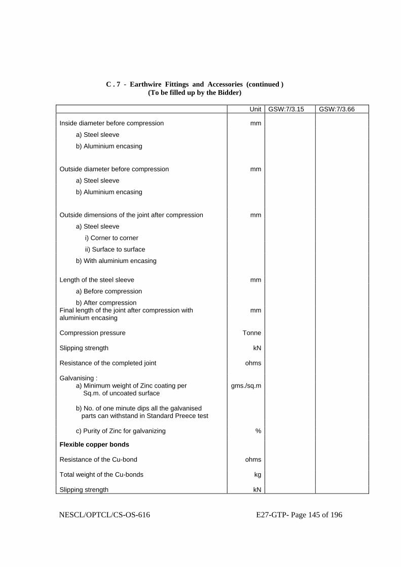
NESCL/OPTCL/CS-OS-616 E27-GTP- Page 145 of 196
C . 7 - Earthwire Fittings and Accessories (continued )
(To be filled up by the Bidder) Unit GSW:7/3.15 GSW:7/3.66 Inside diameter before compression mm
a) Steel sleeve
b) Aluminium encasing
Outside diameter before compression mm
a) Steel sleeve
b) Aluminium encasing
Outside dimensions of the joint after compression mm
a) Steel sleeve
i) Corner to corner
ii) Surface to surface
b) With aluminium encasing
Length of the steel sleeve mm
a) Before compression
b) After compression
Final length of the joint after compression with aluminium encasing
mm
Compression pressure
Tonne
Slipping strength
kN
Resistance of the completed joint
ohms
Galvanising : a) Minimum weight of Zinc coating per Sq.m. of uncoated surface
gms./sq.m
b) No. of one minute dips all the galvanised parts can withstand in Standard Preece test
c) Purity of Zinc for galvanizing % Flexible copper bonds
Resistance of the Cu-bond
ohms
Total weight of the Cu-bonds
kg
Slipping strength kN

NESCL/OPTCL/CS-OS-616 E27-GTP- Page 146 of 196
C . 8 - Conductor(ACSR) Fittings and Accessories
(To be filled up by the Bidder) Unit PANTHER ZEBRA MOOSE Mid-span compression joints for Conductors
Weight of the joints
kgs
Slipping strength
kN
Resistance of the completed joints
ohms
Material of the joints (specify alloy type and its aluminium contents )
Before compression dia. of sleeve mm a) Inner diameter b) Outer diameter
Dimensions after compression mm a) Corner to corner b) Surface to surface
Length of the sleeve mm a) Before compression b) After compression
Compression pressure
Tonne
Whether designed for intermittent or continuous compression
Minimum corona extinction voltage under dry conditions
kV
Radio interference voltage under conditions
Micro Volts

NESCL/OPTCL/CS-OS-616 E27-GTP- Page 147 of 196
C . 8 - Conductor(ACSR) Fittings and Accessories (continued ) (To be filled up by the Bidder)
Unit PANTHER ZEBRA MOOSE Repair sleeve for conductors
Weight of the sleeve
kgs
Before compression dia. of sleeve mm a) Inner diameter b) Outer diameter
Dimensions after compression mm a) Corner to corner b) Surface to surface
Length of the sleeve mm a) Before compression b) After compression
Compression pressure
Tonne
Minimum corona extinction voltage under dry conditions
kV
Radio interference voltage under conditions
Micro Volts
T-connector (only for ACSR MOOSE)
Weight of the T-connector
kgs
Axial tensile strength of the welded portion of the T-connector
kN
Breaking strength of the T-connector
kN
Resistance of the completed T- connection
ohms

NESCL/OPTCL/CS-OS-616 E27-GTP- Page 148 of 196
C . 8 - Conductor(ACSR) Fittings and Accessories (continued ) (To be filled up by the Bidder)
Unit PANTHER ZEBRA MOOSE Before compression dia. of the T-connector
mm
a) Inner diameter b) Outer diameter
Dimensions after compression mm a) Corner to corner b) Surface to surface
Length of the T-connector mm a) Before compression b) After compression
Compression pressure
Tonne
Minimum corona extinction voltage under dry conditions
kV
Radio interference voltage under conditions
Micro Volts

NESCL/OPTCL/CS-OS-616 E27-GTP- Page 149 of 196
C . 9 - Vibration Damper For Conductor and Earthwire ( To be completed by the Bidder )
Vibration Dampers for ACSR PANTHER Unit Total weight of the damper
kgs
Left Right Weight of each damper mass
kgs
Resonance frequencies 1) First frequency Hz 2) Second frequency
Hz
Dimension of each damper mass
mm
Material of : 1) Damper mass 2) Messenger cable
No. of strands in messenger cable
Lay ratio of the messenger cable strands
Min. tensile strength of messenger cable
kg/sq.mm.
Mass pull-off strength
kN
Clamping torque
kg.-m
Slipping strength of the damper clamp kN 1) Before fatigue test 2) After fatigue test
Magnetic power loss per vibration damper
Watts
Min. corona extinction voltage under dry conditions
kV
Radio interference voltage under dry conditions at 1MHz , at 105 kV
Micro Volts
Percentage variation in reactance after fatigue test in comparision with that before the fatigue test
%
Percentage variation in power dissipation after fatigue test in comparision with that before the fatigue test
%

NESCL/OPTCL/CS-OS-616 E27-GTP- Page 150 of 196
C . 9 - Vibration Damper For Conductor and Earthwire (Continued ) ( To be completed by the Bidder )
Vibration Dampers for ACSR PANTHER Unit Galvanising of ferrous parts (if any ) 1) Minimum weight of Zinc coating per Sq.m. of the uncoated surface
gm/sq.m
2) Minimum No. of one minute dips the ferrous parts can withstand in the Standard Preece Test
Nos.
3) Purity of Zinc used for galvanizing % Vibration Dampers for ACSR ZEBRA Total weight of the damper
kgs
Left Right Weight of each damper mass
kgs
Resonance frequencies 1) First frequency Hz 2) Second frequency
Hz
Dimension of each damper mass
mm
Material of : 1) Damper mass 2) Messenger cable
No. of strands in messenger cable
Lay ratio of the messenger cable strands
Min. tensile strength of messenger cable
kg/sq.mm.
Mass pull-off strength
kN
Clamping torque
kg.-m
Slipping strength of the damper clamp kN 1) Before fatigue test 2) After fatigue test

NESCL/OPTCL/CS-OS-616 E27-GTP- Page 151 of 196
C . 9 - Vibration Damper For Conductor and Earthwire (Continued )
( To be completed by the Bidder )
Vibration Dampers for ACSR ZEBRA Unit Magnetic power loss per vibration damper
Watts
Min. corona extinction voltage under dry conditions
kV
Radio interference voltage under dry conditions at 1MHz, at 154 kV
Micro Volts
Percentage variation in reactance after fatigue test in comparision with that before the fatigue test
%
Percentage variation in power dissipation after fatigue test in comparision with that before the fatigue test
%
Galvanising of ferrous parts (if any ) 1) Minimum weight of Zinc coating per Sq.m. of the uncoated surface
gm/sq.m
2) Minimum No. of one minute dips the ferrous parts can withstand in the Standard Preece Test
Nos.
3) Purity of Zinc used for galvanizing % Vibration Dampers for ACSR MOOSE Total weight of the damper
kgs
Left Right Weight of each damper mass
kgs
Resonance frequencies 1) First frequency Hz 2) Second frequency
Hz
Dimension of each damper mass
mm
Material of : 1) Damper mass 2) Messenger cable

NESCL/OPTCL/CS-OS-616 E27-GTP- Page 152 of 196
C . 9 - Vibration Damper For Conductor and Earthwire (Continued )
( To be completed by the Bidder )
Vibration Dampers for ACSR MOOSE Unit No. of strands in messenger cable
Lay ratio of the messenger cable strands
Min. tensile strength of messenger cable
kg/sq.mm.
Mass pull-off strength
kN
Clamping torque
kg.-m
Slipping strength of the damper clamp kN 1) Before fatigue test 2) After fatigue test
Magnetic power loss per vibration damper
Watts
Min. corona extinction voltage under dry conditions
kV
Radio interference voltage under dry conditions at 1MHz , at 305 kV
Micro Volts
Percentage variation in reactance after fatigue test in comparision with that before the fatigue test
%
Percentage variation in power dissipation after fatigue test in comparision with that before the fatigue test
%
Galvanising of ferrous parts (if any ) 1) Minimum weight of Zinc coating per Sq.m. of the uncoated surface
gm/sq.m
2) Minimum No. of one minute dips the ferrous parts can withstand in the Standard Preece Test
Nos.
3) Purity of Zinc used for galvanizing %

NESCL/OPTCL/CS-OS-616 E27-GTP- Page 153 of 196
C . 9 - Vibration Damper For Conductor and Earthwire (Continued )
( To be completed by the Bidder ) Vibration Dampers for 7/3.15mm Earthwire Unit Total weight of the damper
kgs
Left Right Weight of each damper mass
kgs
Resonance frequencies 1) First frequency Hz 2) Second frequency
Hz
Dimension of each damper mass
mm
Material of : 1) Damper mass 2) Messenger cable
No. of strands in messenger cable
Lay ratio of the messenger cable strands
Min. tensile strength of messenger cable
kg/sq.mm.
Mass pull-off strength
kN
Clamping torque
kg.-m
Slipping strength of the damper clamp kN 1) Before fatigue test 2) After fatigue test
Percentage variation in reactance after fatigue test in comparision with that before the fatigue test
%
Percentage variation in power dissipation after fatigue test in comparision with that before the fatigue test
%

NESCL/OPTCL/CS-OS-616 E27-GTP- Page 154 of 196
C . 9 - Vibration Damper For Conductor and Earthwire (Continued )
( To be completed by the Bidder )
Vibration Dampers for 7/3.15mm Earthwire Unit Galvanising of ferrous parts (if any ) 1) Minimum weight of Zinc coating per Sq.m. of the uncoated surface
gm/sq.m
2) Minimum No. of one minute dips the ferrous parts can withstand in the Standard Preece Test
Nos.
3) Purity of Zinc used for galvanizing % Vibration Dampers for 7/3.66mm Earthwire Total weight of the damper
kgs
Left Right Weight of each damper mass
kgs
Resonance frequencies 1) First frequency Hz 2) Second frequency
Hz
Dimension of each damper mass
mm
Material of : 1) Damper mass 2) Messenger cable
No. of strands in messenger cable
Lay ratio of the messenger cable strands
Min. tensile strength of messenger cable
kg/sq.mm.
Mass pull-off strength
kN
Clamping torque
kg.-m
Slipping strength of the damper clamp kN 1) Before fatigue test 2) After fatigue test

NESCL/OPTCL/CS-OS-616 E27-GTP- Page 155 of 196
C . 9 - Vibration Damper For Conductor and Earthwire (Continued ) ( To be completed by the Bidder )
Vibration Dampers for 7/3.66mm Earthwire Unit Percentage variation in reactance after fatigue test in comparision with that before the fatigue test
%
Percentage variation in power dissipation after fatigue test in comparision with that before the fatigue test
%
Galvanising of ferrous parts (if any ) 1) Minimum weight of Zinc coating per Sq.m. of the uncoated surface
gm/sq.m
2) Minimum No. of one minute dips the ferrous parts can withstand in the Standard Preece Test
Nos.
3) Purity of Zinc used for galvanizing %
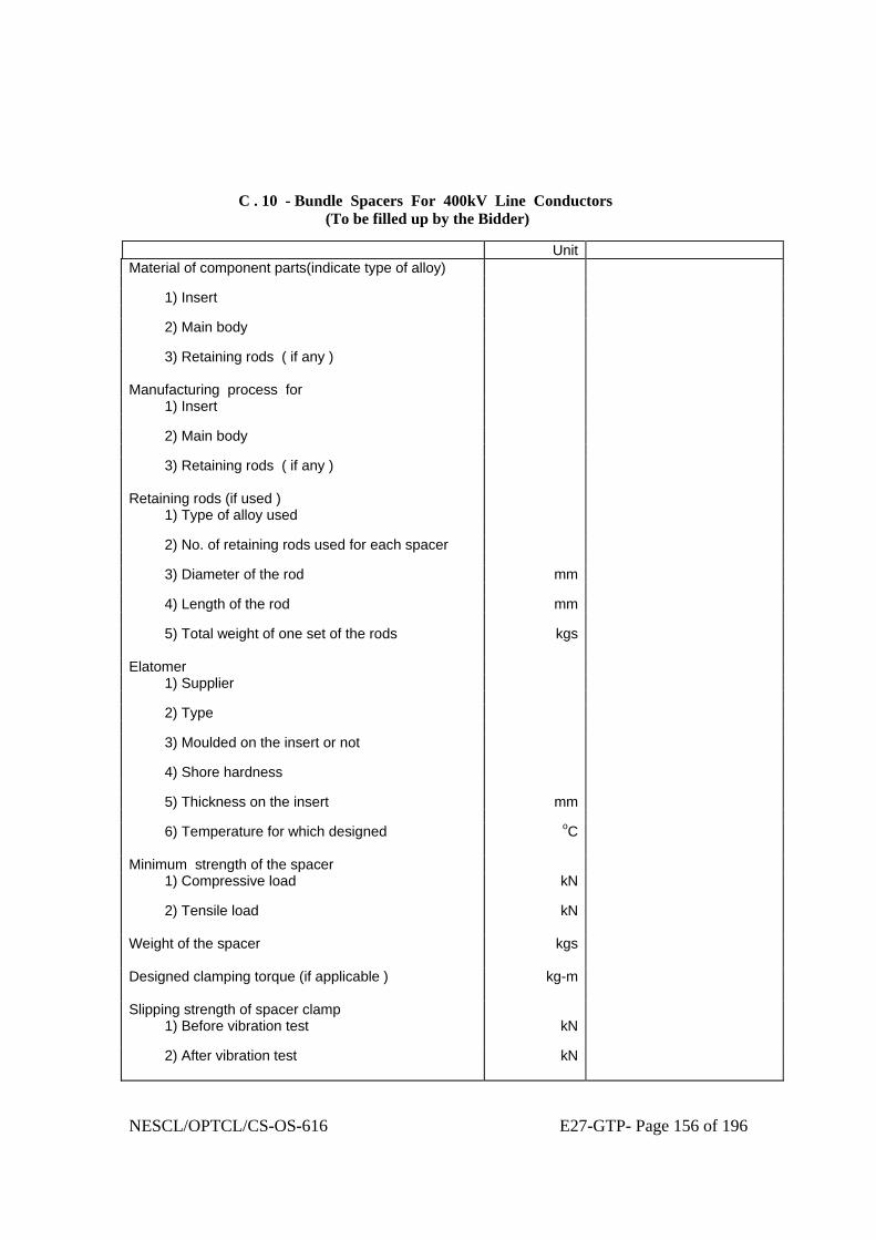
NESCL/OPTCL/CS-OS-616 E27-GTP- Page 156 of 196
C . 10 - Bundle Spacers For 400kV Line Conductors (To be filled up by the Bidder)
Unit Material of component parts(indicate type of alloy) 1) Insert 2) Main body 3) Retaining rods ( if any )
Manufacturing process for 1) Insert 2) Main body 3) Retaining rods ( if any )
Retaining rods (if used ) 1) Type of alloy used 2) No. of retaining rods used for each spacer 3) Diameter of the rod mm 4) Length of the rod mm 5) Total weight of one set of the rods
kgs
Elatomer 1) Supplier 2) Type 3) Moulded on the insert or not 4) Shore hardness 5) Thickness on the insert mm 6) Temperature for which designed
oC
Minimum strength of the spacer 1) Compressive load kN 2) Tensile load
kN
Weight of the spacer
kgs
Designed clamping torque (if applicable )
kg-m
Slipping strength of spacer clamp 1) Before vibration test kN 2) After vibration test
kN

NESCL/OPTCL/CS-OS-616 E27-GTP- Page 157 of 196
C . 10 - Bundle Spacers For 400kV Line Conductors (Continued ) (To be filled up by the Bidder)
Unit Magnetic power loss per spacer Watts Galvanising of ferrous parts (if any ) 1) Minimum weight of Zinc coating per Sq.m. of the uncoated surface
gm/sq.m
2) Minimum No. of one minute dips the ferrous parts can withstand in the Standard Preece Test
Nos.
3) Purity of Zinc used for galvanising % Min. corona extinction voltage under dry conditions
kV
Radio interference voltage under dry conditions
Micro Volts
Electrical resistance of the elastomer cushioned spacer (specify the range )
ohms

NESCL/OPTCL/CS-OS-616 E27-GTP- Page 158 of 196
C.11 - Bundle Spacers For Jumpers Of 400kV Lines
(To be filled up by the Bidder) Unit Material of component parts (indicate type of alloy) 1) Insert 2) Main body
Manufacturing process for 1) Insert 2) Main body
Elatomer 1) Supplier 2) Type 3) Moulded on the insert or not 4) Shore hardness 5) Thickness on the insert mm 6) Temperature for which designed
oC
Minimum strength of the spacer for jumpers 1) Compressive load kN 2) Tensile load
kN
Weight of the spacer for jumpers
kgs
Designed clamping torque for spacer for jumpers
kg-m
Slipping strength of spacer clamp for jumpers
kN
Magnetic power loss per spacer for jumpers
Watts
Galvanising of ferrous parts (if any ) 1) Minimum weight of Zinc coating per Sq.m. of the uncoated surface
gm/sq.m
2) Minimum No. of one minute dips the ferrous parts can withstand in the Standard Preece Test
Nos.
3) Purity of Zinc used for galvanising % Min. corona extinction voltage under dry conditions
kV
Radio interference voltage under dry conditions
MicroVolt
Electrical resistance of the elastomer cushioned spacer for jumpers (specify the range )
ohms

NESCL/OPTCL/CS-OS-616 E27-GTP- Page 159 of 196
C.12 - Spacer Dampers For 400kV Line Conductors (To be filled up by the Bidder)
Unit Material of component parts (indicate type of alloy / rubber component)
1) Insert 2) Main body 3) Retaining rods ( if any ) 4) Damping ball
Manufacturing process for 1) Insert 2) Main body 3) Retaining rods ( if any ) 4) Damping ball
Retaining rods (if used ) 1) Type of alloy used 2) No. of retaining rods used for each unit 3) Diameter of the rod mm 4) Length of the rod mm 5) Total weight of one set of the rods
kgs
Elatomer 1) Supplier 2) Type 3) Moulded on the insert or not 4) Shore hardness 5) Thickness on the insert mm 6) Temperature for which designed
oC
Minimum strength of the spacer damper 1) Compressive load kN 2) Tensile load kN

NESCL/OPTCL/CS-OS-616 E27-GTP- Page 160 of 196
C.12 - Spacer Dampers For 400kV Line Conductors ( Continued ) (To be filled up by the Bidder)
Unit Weight of the spacer damper
kgs
Designed clamping torque (if applicable )
kg-m
Slipping strength of spacer damper clamp 1) Before vibration test kN 2) After vibration test
kN
Galvanising of ferrous parts (if any ) 1) Minimum weight of Zinc coating per Sq.m. of the uncoated surface
gm/sq.m
2) Minimum No. of one minute dips the ferrous parts can withstand in the Standard Preece Test
Nos.
3) Purity of Zinc used for galvanising % Min. corona extinction voltage under dry conditions
kV
Radio interference voltage under dry conditions
Micro Volts
Magnetic power loss per spacer damper
Watts
Electrical resistance of the elastomer cushioned spacer damper (specify the range )
ohms

NESCL/OPTCL/CS-OS-616 E27-GTP- Page 161 of 196
C.13 - Disc Insulator Units ( Standard Type ) (To be filled up by the Bidder)
Unit 70kN 90kN 120kN 160kN Weight of the single disc unit kg Size and designation of the ball pin shank
mm
Diameter of the disc mm Tolerance on the diameter +/-mm Ball to ball spacing between disc mm Tolerance on ball to ball spacing +/-mm Minimum creepage distance of a single disc
mm
Positive tolerance on the minimum creepage distance
+mm
Shell material ( Glass/Porcelain ) Power frequency flashover voltage (rms) of single disc unit
1) Dry kV 2) Wet kV Power frequency withstand voltage (rms) of single disc unit
1) Dry kV 2) Wet kV Power frequency puncture voltage (rms) of single disc unit
kV
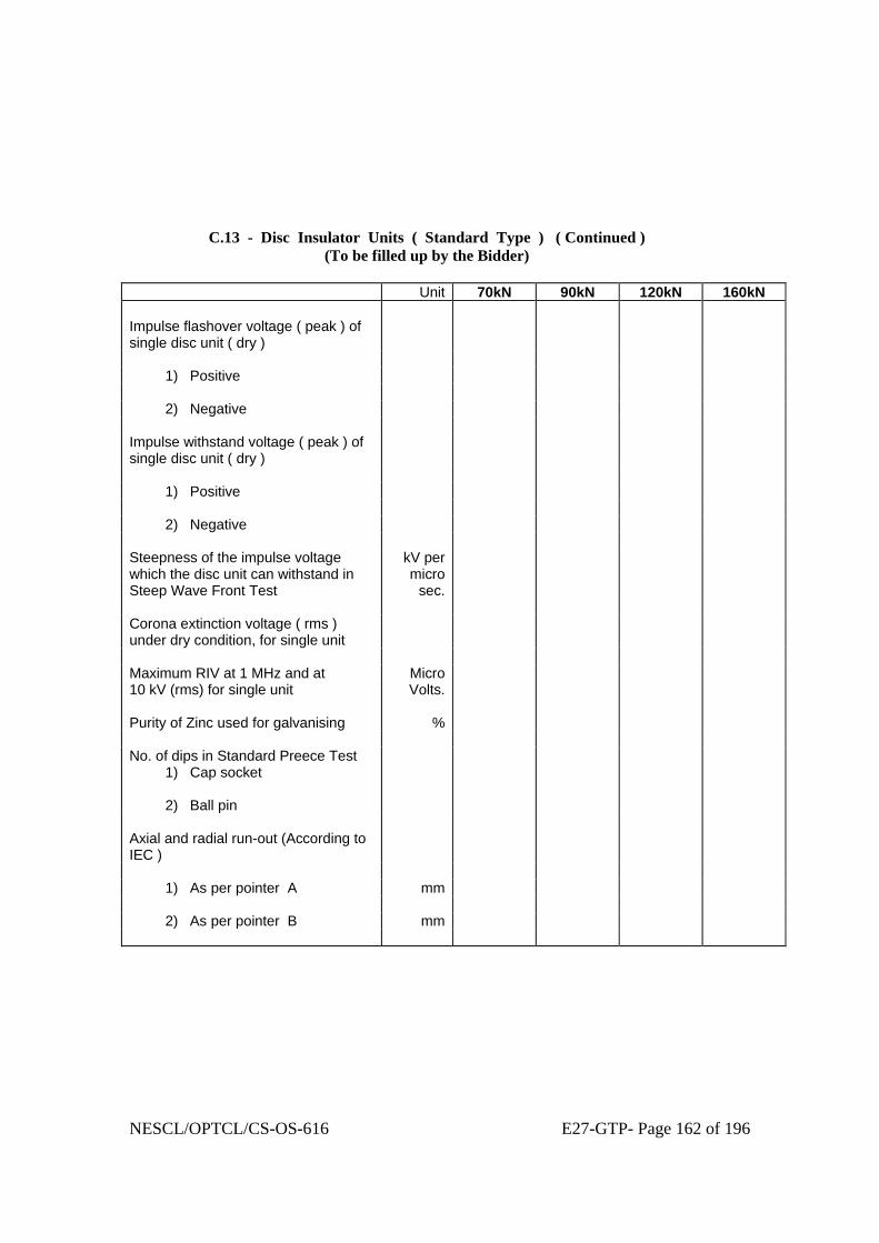
NESCL/OPTCL/CS-OS-616 E27-GTP- Page 162 of 196
C.13 - Disc Insulator Units ( Standard Type ) ( Continued ) (To be filled up by the Bidder)
Unit 70kN 90kN 120kN 160kN Impulse flashover voltage ( peak ) of single disc unit ( dry )
1) Positive 2) Negative Impulse withstand voltage ( peak ) of single disc unit ( dry )
1) Positive 2) Negative Steepness of the impulse voltage which the disc unit can withstand in Steep Wave Front Test
kV per micro
sec.
Corona extinction voltage ( rms ) under dry condition, for single unit
Maximum RIV at 1 MHz and at Micro 10 kV (rms) for single unit Volts. Purity of Zinc used for galvanising % No. of dips in Standard Preece Test 1) Cap socket 2) Ball pin
Axial and radial run-out (According to IEC )
1) As per pointer A mm 2) As per pointer B mm

NESCL/OPTCL/CS-OS-616 E27-GTP- Page 163 of 196
C.13A - Composite Insulator Units ( Standard Type ) (To be filled up by the Bidder)
Unit 70kN 90kN 120kN 160kN Weight of the single insulatort unit kg Size and designation of the ball pin shank / clevis and tongue
mm
Diameter of (along with tolerance) mm
1) central core without housing sleeve cover
2) central core with housing
sleeve cover
3) weather shed Length of single insulator unit mm Tolerance on unit insulator length +/-mm Minimum creepage distance of a single insulator unit
mm
Positive tolerance on the minimum creepage distance
+mm
Core material Shed material Power frequency flashover voltage (rms) of single disc unit
1) Dry kV 2) Wet kV Power frequency withstand voltage (rms) of single disc unit
1) Dry kV 2) Wet kV

NESCL/OPTCL/CS-OS-616 E27-GTP- Page 164 of 196
C.13A - Composite Insulator Units ( Standard Type ) ( Continued ) (To be filled up by the Bidder)
Unit 70kN 90kN 120kN 160kN Impulse flashover voltage ( peak ) of single disc unit ( dry )
1) Positive 2) Negative Impulse withstand voltage ( peak ) of single disc unit ( dry )
1) Positive 2) Negative Steepness of the impulse voltage which the disc unit can withstand in Steep Wave Front Test
kV per micro
sec.
Corona extinction voltage ( rms ) under dry condition, for single unit
Maximum RIV at 1 MHz and at Micro 10 kV (rms) for single unit Volts. Purity of Zinc used for galvanising % No. of dips in Standard Preece Test 1) Cap socket 2) Ball pin
Note : Any other parameters which Bidder feels are necessary to define the offered composite insulator unit, shall be indicated and guaranteed in the above format.

NESCL/OPTCL/CS-OS-616 E27-GTP- Page 165 of 196
C.14 - Disc Insulator Units ( Anti-fog Type ) (To be filled up by the Bidder)
Unit 70kN 90kN 120kN 160kN Weight of the single disc unit kg Size and designation of the ball pin shank
mm
Diameter of the disc mm Tolerance on the diameter +/-mm Ball to ball spacing between disc mm Tolerance on ball to ball spacing +/-mm Minimum creepage distance of a single disc
mm
Positive tolerance on the minimum creepage distance
+mm
Shell material ( Glass/Porcelain ) Power frequency flashover voltage (rms ) of single disc unit
1) Dry kV 2) Wet kV Power frequency withstand voltage (rms ) of single disc unit
1) Dry kV 2) Wet kV Power frequency puncture voltage (rms) of single disc unit
kV

NESCL/OPTCL/CS-OS-616 E27-GTP- Page 166 of 196
C.14 - Disc Insulator Units ( Anti-fog Type ) ( Continued )
(To be filled up by the Bidder)
Unit 70kN 90kN 120kN 160kN Impulse flashover voltage ( peak ) of single disc unit ( dry )
1) Positive 2) Negative Impulse withstand voltage ( peak ) of single disc unit ( dry )
1) Positive 2) Negative Steepness of the impulse voltage which the disc unit can withstand in Steep Wave Front Test
kV per micro
sec.
Corona extinction voltage ( rms ) under dry condition, for single unit
Maximum RIV at 1 MHz and at Micro 10 kV (rms) for single unit Volts. Purity of Zinc used for galvanising % Purity of Zinc used for sleeve % No. of dips in Standard Preece Test 1) Cap socket 2) Ball pin
Axial and radial run-out (According to IEC )
1) As per pointer A mm 2) As per pointer B mm

NESCL/OPTCL/CS-OS-616 E27-GTP- Page 167 of 196
C.14A - Composite Insulator Units ( Anti-fog Type )
(To be filled up by the Bidder) Unit 70kN 90kN 120kN 160kN Weight of the single insulatort unit kg Size and designation of the ball pin shank / clevis and tongue
mm
Diameter of (along with tolerance) mm
1) central core without housing sleeve cover
2) central core with housing
sleeve cover
3) weather shed Length of single insulator unit mm Tolerance on unit insulator length +/-mm Minimum creepage distance of a single insulator unit
mm
Positive tolerance on the minimum creepage distance
+mm
Core material Shed material Power frequency flashover voltage (rms) of single disc unit
1) Dry kV 2) Wet kV Power frequency withstand voltage (rms) of single disc unit
1) Dry kV 2) Wet kV

NESCL/OPTCL/CS-OS-616 E27-GTP- Page 168 of 196
C.14A - Composite Insulator Units ( Anti-fog Type ) ( Continued ) (To be filled up by the Bidder)
Unit 70kN 90kN 120kN 160kN Impulse flashover voltage ( peak ) of single disc unit ( dry )
1) Positive 2) Negative Impulse withstand voltage ( peak ) of single disc unit ( dry )
1) Positive 2) Negative Steepness of the impulse voltage which the disc unit can withstand in Steep Wave Front Test
kV per micro
sec.
Corona extinction voltage ( rms ) under dry condition, for single unit
Maximum RIV at 1 MHz and at Micro 10 kV (rms) for single unit Volts. Purity of Zinc used for galvanising % No. of dips in Standard Preece Test 1) Cap socket 2) Ball pin
Note : Any other parameters which Bidder feels are necessary to define the offered composite insulator unit, shall be indicated and guaranteed in the above format.

NESCL/OPTCL/CS-OS-616 E27-GTP- Page 169 of 196
C . 15 - Insulator Strings (Suspension Sets For 132 kV Lines )
(To be filled up by the Bidder) Unit Single “I”
Suspension Strings
Double “I” Suspension
Strings
Pilot Suspension
Strings Power frequency withstand voltage of the string with arcing horns and corona control rings / grading rings under wet conditions
kV(rms)
Impulse flashover voltage (peak) under dry conditions
1) Positive kV 2) Negative kV Impulse withstand voltage (peak) under dry conditions
1) Positive kV 2) Negative kV Salt-fog pollution withstand voltage (only for strings with anti-fog disc units)
kV(rms)
Minimum corona extinction voltage under dry conditions
kV(rms)
Radio interference voltage under dry conditions at 1MHz, at 105kV
MicroVolts
Mechanical strength of the complete insulator string along with all hardware fittings
kN
Maximum voltage (in percentage ) across any disc in the complete insulator string under phase to earth voltage ( not applicable for string with composite insulator units )
%
Number of insulator units in each string

NESCL/OPTCL/CS-OS-616 E27-GTP- Page 170 of 196
C . 15 - Insulator Strings (Suspension Sets For 132 kV Lines ) ( Continued ) ( To be filled up by the Bidder )
Unit Single “I”
Suspension Strings
Double “I” Suspension
Strings
Pilot Suspension
Strings Overall length of the set including clamp and all fittings (specify the tolerance also )
mm
Weight of the set, complete with all fittings and arcing horns
kg
Weight of the counter-weights kg Minimum arcing gap distance mm Maximum magnetic power loss of the suspension assembly
Watts
Slipping strength of the suspension assembly (clamp torque Vs. slip curve shall be enclosed )
kN
Particulars of Standard/AGS pre-formed armour rod set for suspension assembly
Standard Or,
AGS
Standard Or,
AGS
Standard Or,
AGS 1) No. of rods per set No. 2) Direction of the lay 3) Overall length after fitting on the
conductor mm
4) Actual length of each rod along its helix
mm
5) Diameter of each rod mm 6) Tolerance in a) Diameter of each rod +/- mm b) Length of each rod +/- mm c) Difference of length +/- mm between the longest and shortest rod in a set 7) Type of Aluminium alloy used for manufacture of PA rods
8) UTS of each rod kg/mm 2

NESCL/OPTCL/CS-OS-616 E27-GTP- Page 171 of 196
C . 15 - Insulator Strings (Suspension Sets For 132 kV Lines ) ( Continued )
( To be filled up by the Bidder )
Unit Single “I” Suspension
Strings
Double “I” Suspension
Strings
Pilot Suspension
Strings Particular of Elastomer (for AGS clamps only )
1) Supplier of elastomer 2) Type of elastomer 3) Shore hardness of elastomer 4) Temperature range for which elastomer is designed
oC
5) Moulded on insert yes/no Purity of Zinc used for galvanising % Minimum No. of one minute dips the ferrous parts can withstand in Standard Preece Test
No.
Minimum weight of Zinc coating per Sq.m. of the uncoated surface
gm/sq.m

NESCL/OPTCL/CS-OS-616 E27-GTP- Page 172 of 196
C . 16 - Insulator Strings ( Tension Sets For 132 kV Lines ) ( To be filled up by the Bidder )
Unit Single
Tension Strings
Double Tension Strings
Power frequency withstand voltage of the string with arcing horns and corona control rings / grading rings under wet conditions
kV(rms)
Impulse flashover voltage (peak) under dry conditions
1) Positive kV 2) Negative kV Impulse withstand voltage (peak) under dry conditions
1) Positive kV 2) Negative kV Salt-fog pollution withstand voltage ( only for strings with anti-fog units )
kV (rms)
Minimum corona extinction voltage under dry conditions
kV(rms)
Radio interference voltage under dry conditions at 1MHz, at 105kV
MicroVolts
Mechanical strength of the complete insulator string along with all hardware fittings
kN
Maximum voltage (in percentage ) across any disc in the complete insulator string under phase to earth voltage ( not applicable for string with composite insulator units )
%
Number of insulator units in each string Overall length of the set including clamp and all fittings (specify the tolerance also )
mm

NESCL/OPTCL/CS-OS-616 E27-GTP- Page 173 of 196
C . 16 - Insulator Strings ( Tension Sets For 132 kV Lines ) ( Continued ) ( To be filled up by the Bidder )
Unit Single
Tension Strings
Double Tension Strings
Weight of the set, complete with all fittings and arcing horns
kg
Minimum arcing gap distance mm Electrical resistance of the complete tension assembly along with jumper connection
ohms
Slipping strength of the tension assembly kN Purity of Zinc used for galvanising % Minimum No. of one minute dips the ferrous parts can withstand in Standard Preece Test
No.
Minimum weight of Zinc coating per Sq.m. of the uncoated surface
gm/sq.m
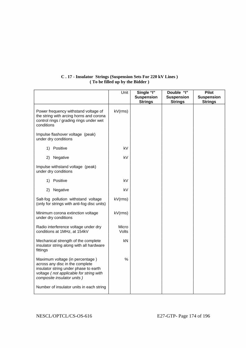
NESCL/OPTCL/CS-OS-616 E27-GTP- Page 174 of 196
C . 17 - Insulator Strings (Suspension Sets For 220 kV Lines ) ( To be filled up by the Bidder )
Unit Single “I”
Suspension Strings
Double “I” Suspension
Strings
Pilot Suspension
Strings Power frequency withstand voltage of the string with arcing horns and corona control rings / grading rings under wet conditions
kV(rms)
Impulse flashover voltage (peak) under dry conditions
1) Positive kV 2) Negative kV Impulse withstand voltage (peak) under dry conditions
1) Positive kV 2) Negative kV Salt-fog pollution withstand voltage (only for strings with anti-fog disc units)
kV(rms)
Minimum corona extinction voltage under dry conditions
kV(rms)
Radio interference voltage under dry conditions at 1MHz, at 154kV
MicroVolts
Mechanical strength of the complete insulator string along with all hardware fittings
kN
Maximum voltage (in percentage ) across any disc in the complete insulator string under phase to earth voltage ( not applicable for string with composite insulator units )
%
Number of insulator units in each string

NESCL/OPTCL/CS-OS-616 E27-GTP- Page 175 of 196
C . 17 - Insulator Strings (Suspension Sets For 220 kV Lines ) ( Continued ) ( To be filled up by the Bidder )
Unit Single “I”
Suspension Strings
Double “I” Suspension
Strings
Pilot Suspension
Strings Overall length of the set including clamp and all fittings (specify the tolerance also )
mm
Weight of the set, complete with all fittings and arcing horns
kg
Weight of the counter-weights kg Minimum arcing gap distance mm Maximum magnetic power loss of the suspension assembly
Watts
Slipping strength of the suspension assembly (clamp torque Vs. slip curve shall be enclosed )
kN
Particulars of Standard/AGS pre-formed armour rod set for suspension assembly
Standard Or,
AGS
Standard Or,
AGS
Standard Or,
AGS 1) No. of rods per set No. 2) Direction of the lay 3) Overall length after fitting on the
conductor mm
4) Actual length of each rod along its helix
mm
5) Diameter of each rod mm 6) Tolerance in a) Diameter of each rod +/- mm b) Length of each rod +/- mm c) Difference of length +/- mm between the longest and shortest rod in a set 7) Type of Aluminium alloy used for manufacture of PA rods
8) UTS of each rod kg/mm 2

NESCL/OPTCL/CS-OS-616 E27-GTP- Page 176 of 196
C . 17 - Insulator Strings (Suspension Sets For 220 kV Lines ) ( Continued ) ( To be filled up by the Bidder )
Unit Single “I”
Suspension Strings
Double “I” Suspension
Strings
Pilot Suspension
Strings Particular of Elastomer (for AGS clamps only )
1) Supplier of elastomer 2) Type of elastomer 3) Shore hardness of elastomer 4) Temperature range for which elastomer is designed
oC
5) Moulded on insert yes/no Purity of Zinc used for galvanising % Minimum No. of one minute dips the ferrous parts can withstand in Standard Preece Test
No.
Minimum weight of Zinc coating per Sq.m. of the uncoated surface
gm/sq.m

NESCL/OPTCL/CS-OS-616 E27-GTP- Page 177 of 196
C . 18 - Insulator Strings ( Tension Sets For 220 kV Lines ) ( To be filled up by the Bidder )
Unit Single
Tension Strings
Double Tension Strings
Power frequency withstand voltage of the string with arcing horns and corona control rings / grading rings under wet conditions
kV(rms)
Impulse flashover voltage (peak) under dry conditions
1) Positive kV 2) Negative kV Impulse withstand voltage (peak) under dry conditions
1) Positive kV 2) Negative kV Salt-fog pollution withstand voltage ( only for strings with anti-fog units )
kV (rms)
Minimum corona extinction voltage under dry conditions
kV(rms)
Radio interference voltage under dry conditions at 1MHz, at 105kV
MicroVolts
Mechanical strength of the complete insulator string along with all hardware fittings
kN
Maximum voltage (in percentage ) across any disc in the complete insulator string under phase to earth voltage ( not applicable for string with composite insulator units )
%
Number of insulator units in each string Overall length of the set including clamp and all fittings (specify the tolerance also )
mm

NESCL/OPTCL/CS-OS-616 E27-GTP- Page 178 of 196
C . 18 - Insulator Strings ( Tension Sets For 220 kV Lines ) ( Continued ) ( To be filled up by the Bidder )
Unit Single
Tension Strings
Double Tension Strings
Weight of the set, complete with all fittings and arcing horns
kg
Minimum arcing gap distance mm Electrical resistance of the complete tension assembly along with jumper connection
ohms
Slipping strength of the tension assembly kN Purity of Zinc used for galvanising % Minimum No. of one minute dips the ferrous parts can withstand in Standard Preece Test
No.
Minimum weight of Zinc coating per Sq.m. of the uncoated surface
gm/sq.m

NESCL/OPTCL/CS-OS-616 E27-GTP- Page 179 of 196
C . 19 - Insulator Strings (Suspension Sets For 400 kV Lines ) ( To be filled up by the Bidder )
Unit Single “I”
Suspension Strings
Pilot Suspension
Strings Power frequency withstand voltage of the string with arcing horns and corona control rings / grading rings under wet conditions
kV(rms)
Switching surge withstand voltage (peak) under wet conditions
1) Positive kV 2) Negative kV Impulse flashover voltage (peak) under dry conditions
1) Positive kV 2) Negative kV Impulse withstand voltage (peak) under dry conditions
1) Positive kV 2) Negative kV Salt-fog pollution withstand voltage ( only for strings with anti-fog units )
kV (rms)
Minimum corona extinction voltage under dry conditions
kV(rms)
Radio interference voltage under dry conditions at 1MHz, at 305kV
MicroVolts
Mechanical strength of the complete insulator string along with all hardware fittings
kN
Maximum voltage (in percentage) across any disc in the complete insulator string under phase to earth voltage ( not applicable for string with composite insulator units )
%
Number of insulator units in each string

NESCL/OPTCL/CS-OS-616 E27-GTP- Page 180 of 196
C . 19 - Insulator Strings (Suspension Sets For 400 kV Lines ) ( Continued ) ( To be filled up by the Bidder )
Unit Single “I”
Suspension Strings
Pilot Suspension
Strings Overall length of the set including clamp and all fittings (specify the tolerance also )
mm
Weight of the set, complete with all fittings and arcing horns
kg
Weight of the counter-weights kg Minimum arcing gap distance mm Maximum magnetic power loss of the suspension assembly
Watts
Slipping strength of the suspension assembly (clamp torque Vs. slip curve shall be enclosed )
kN
Particulars of Standard/AGS pre-formed armour rod set for suspension assembly
Standard Or,
AGS
Standard Or,
AGS 1) No. of rods per set No. 2) Direction of the lay 3) Overall length after fitting on the conductor mm 4) Actual length of each rod along its helix mm 5) Diameter of each rod mm 6) Tolerance in a) Diameter of each rod +/- mm b) Length of each rod +/- mm c) Difference of length +/- mm between the longest and shortest rod in a set 7) Type of Aluminium alloy used for manufacture of PA rods
8) UTS of each rod kg/mm 2

NESCL/OPTCL/CS-OS-616 E27-GTP- Page 181 of 196
C . 19 - Insulator Strings (Suspension Sets For 400 kV Lines ) ( Continued ) ( To be filled up by the Bidder )
Unit Single “I”
Suspension Strings
Pilot Suspension
Strings Particular of Elastomer (for AGS clamps only )
1) Supplier of elastomer 2) Type of elastomer 3) Shore hardness of elastomer 4) Temperature range for which elastomer is designed
oC
5) Moulded on insert yes/no Purity of Zinc used for galvanising % Minimum No. of one minute dips the ferrous parts can withstand in Standard Preece Test
No.
Minimum weight of Zinc coating per Sq.m. of the uncoated surface
gm/sq.m

NESCL/OPTCL/CS-OS-616 E27-GTP- Page 182 of 196
C . 20 - Insulator Strings ( Tension Sets For 400 kV Lines )
( To be filled up by the Bidder ) Unit SingleTension
Strings (Low Duty)
Double Tension Strings
Power frequency withstand voltage of the string with arcing horns and corona control rings / grading rings under wet conditions
kV(rms)
Switching surge withstand voltage (peak) under wet conditions
1) Positive kV 2) Negative kV Impulse flashover voltage (peak) under dry conditions
1) Positive kV 2) Negative kV Impulse withstand voltage (peak) under dry conditions
1) Positive kV 2) Negative kV Salt-fog pollution withstand voltage ( only for strings with anti-fog units )
kV (rms)
Minimum corona extinction voltage under dry conditions
kV(rms)
Radio interference voltage under dry conditions at 1MHz, at 305kV
MicroVolts
Mechanical strength of the complete insulator string along with all hardware fittings
kN
Maximum voltage (in percentage ) across any disc in the complete insulator string under phase to earth voltage ( not applicable for string with composite insulator units )
%
Number of insulator units in each string

NESCL/OPTCL/CS-OS-616 E27-GTP- Page 183 of 196
C . 20 - Insulator Strings ( Tension Sets For 400 kV Lines ) ( Continued ) ( To be filled up by the Bidder )
Unit SingleTension
Strings (Low Duty)
Double Tension Strings
Overall length of the set including clamp and all fittings (specify the tolerance also )
mm
Weight of the set, complete with all fittings and arcing horns
kg
Minimum arcing gap distance mm Electrical resistance of the complete tension assembly along with jumper connection
ohms
Slipping strength of the tension assembly kN Purity of Zinc used for galvanising % Minimum No. of one minute dips the ferrous parts can withstand in Standard Preece Test
No.
Minimum weight of Zinc coating per Sq.m. of the uncoated surface
gm/sq.m

NESCL/OPTCL/CS-OS-616 E27-GTP- Page 184 of 196
C . 21 - Tower Design Particulars : 132 kV Construction (To be filled up by the Bidder)
Unit Maximum tension per phase, for purposes of tower design and application Suspension towers Newton Tension towers Newton Slack span side downleads, `per individual conductor' Newton Maximum uplift per phase on each crossarm for purpose of tension tower design Newton Maximum tension of earth conductor for purpose of tower design and application: Suspension towers Newton Tension towers Newton Earthwire slack span side downleads Newton Maximum uplift of each earth conductor on the tower for purpose of tower design Newton Minimum clearance between live metal and tower steelwork: i. with suspension insulator set swing 0° mm with suspension insulator set swing 15° mm with suspension insulator set swing 30° mm with suspension insulator set swing 45° mm with suspension insulator set swing 60° mm ii. with jumper loop swing 0° mm with jumper loop swing 10° mm with jumper loop swing 20° mm with jumper loop swing 30° mm with jumper loop swing 40° mm Insulator suspension set, unobstructed transverse swing angle degrees from vertical Earth conductor suspension clamps, unobstructed transverse degrees swing angle from vertical Earth conductor maximum shielding angle from vertical at degrees tower attachment point over outer line conductors

NESCL/OPTCL/CS-OS-616 E27-GTP- Page 185 of 196
C . 22 - Tower Design Particulars : 220 kV Construction (To be filled up by the Bidder)
Unit Maximum tension per phase, for purposes of tower design and application Suspension towers Newton Tension towers Newton Slack span side downleads, `per individual conductor' Newton Maximum uplift per phase on each crossarm for purpose of tension tower design Newton Maximum tension of earth conductor for purpose of tower design and application: Suspension towers Newton Tension towers Newton Earthwire slack span side downleads Newton Maximum uplift of each earth conductor on the tower for purpose of tower design Newton Minimum clearance between live metal and tower steelwork: i. with suspension insulator set swing 0° mm with suspension insulator set swing 15° mm with suspension insulator set swing 30° mm with suspension insulator set swing 45° mm with suspension insulator set swing 60° mm ii. with jumper loop swing 0° mm with jumper loop swing 10° mm with jumper loop swing 20° mm with jumper loop swing 30° mm with jumper loop swing 40° mm Insulator suspension set, unobstructed transverse swing angle degrees from vertical Earth conductor suspension clamps, unobstructed transverse degrees swing angle from vertical Earth conductor maximum shielding angle from vertical at degrees tower attachment point over outer line conductors
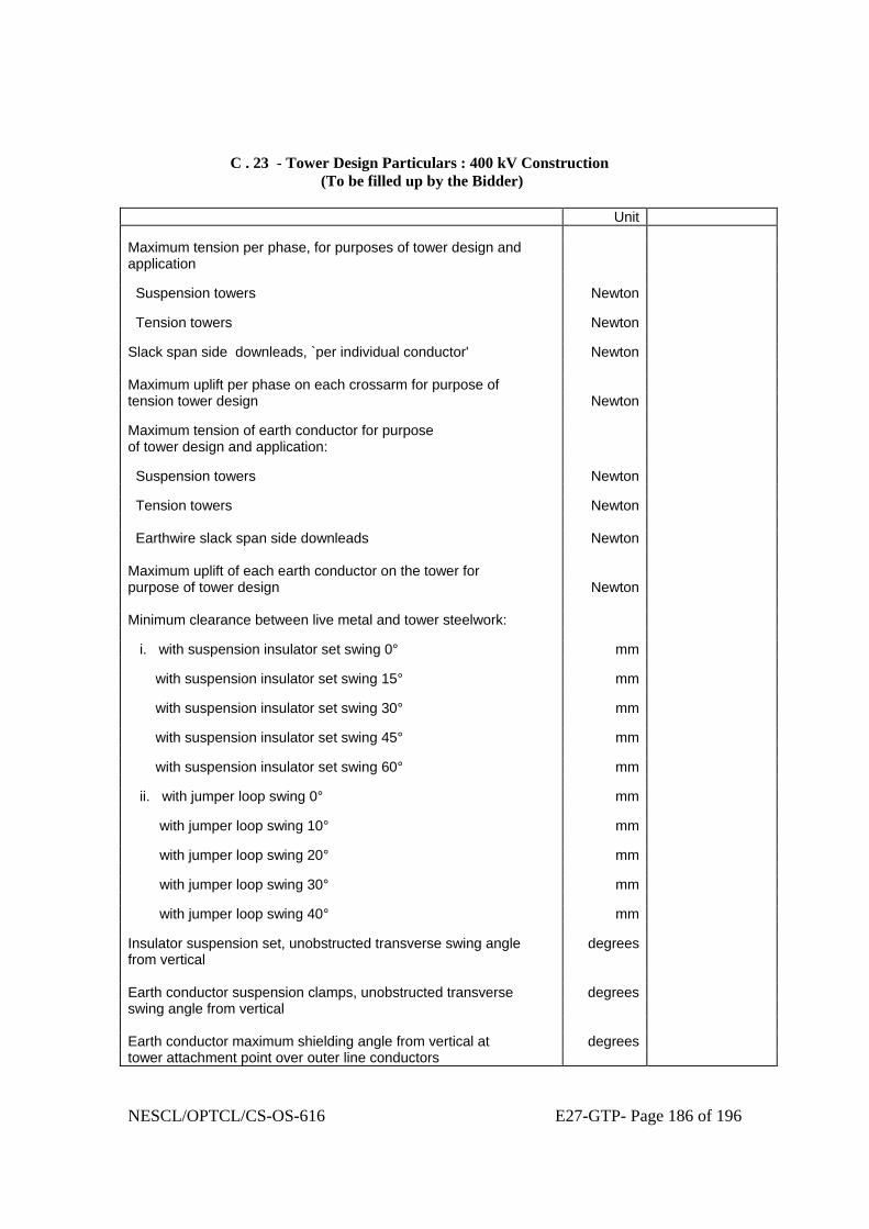
NESCL/OPTCL/CS-OS-616 E27-GTP- Page 186 of 196
C . 23 - Tower Design Particulars : 400 kV Construction (To be filled up by the Bidder)
Unit Maximum tension per phase, for purposes of tower design and application
Suspension towers Newton Tension towers Newton Slack span side downleads, `per individual conductor' Newton Maximum uplift per phase on each crossarm for purpose of tension tower design Newton Maximum tension of earth conductor for purpose of tower design and application: Suspension towers Newton Tension towers Newton Earthwire slack span side downleads Newton Maximum uplift of each earth conductor on the tower for purpose of tower design Newton Minimum clearance between live metal and tower steelwork: i. with suspension insulator set swing 0° mm with suspension insulator set swing 15° mm with suspension insulator set swing 30° mm with suspension insulator set swing 45° mm with suspension insulator set swing 60° mm ii. with jumper loop swing 0° mm with jumper loop swing 10° mm with jumper loop swing 20° mm with jumper loop swing 30° mm with jumper loop swing 40° mm Insulator suspension set, unobstructed transverse swing angle degrees from vertical Earth conductor suspension clamps, unobstructed transverse degrees swing angle from vertical Earth conductor maximum shielding angle from vertical at degrees tower attachment point over outer line conductors

NESCL/OPTCL/CS-OS-616 E27-GTP- Page 187 of 196
C . 24 - Tower Design Particulars (Common for all Towers) (To be filled up by the Bidder)
Unit Maximum ratio of unsupported length of steel compression member to their least radius of gyration: Leg members, ground wire peak members and lower members of the crossarms in compression
Other members carrying computed stresses Redundant members Tension only members Mild High yield steel steel Maximum ultimate stresses, for checking tower designs not subjected to test (unless otherwise approved) : Compression members, Bidder to indicate his design Assumptions N/mm2 Tension members (elastic limit) N/mm2 Shear on bolts N/mm2 Bearing on bolts N/mm2

NESCL/OPTCL/CS-OS-616 E27-GTP- Page 188 of 196
C . 25 - Particulars Of Double Circuit Towers : 132 kV Construction (To be filled up by the Bidder)
TYPE OF TOWER Unit DA DB DC DD Type of insulator sets Suspension Tension Tension Tension Maximum angle of deviation degree Normal span length m Minimum ground clearance of line conductor at 85°C, normal ground m Sag of line conductor in normal span length at 85°C m Maximum distance of line conductor below crossarm m Height above ground of bottom conductor Crossarm m Minimum height of earth conductors above upper line conductor : at tower m : at mid-span m Vertical spacing between line conductors at tower : Minimum m Actual m Overall tower height m Maximum differential foundation movement permitted under ultimate loads mm
Clearance between conductors of one circuit and tower climbing leg of the other circuit :
Minimum m Actual m Horizontal distance, from tower centre line of insulator attachments m Horizontal distance, from tower centre line of earth conductors m

NESCL/OPTCL/CS-OS-616 E27-GTP- Page 189 of 196
C . 25 - Particulars Of Double Circuit Towers : 132 kV Construction ( Continued ) (To be filled up by the Bidder)
TYPE OF TOWER Unit DA DB DC DD Tower body dimensions at bottom crossarm level (transverse x longitudinal) m Overall tower base dimensions at ground line (transverse x longitudinal) : Maximum for standard height towers
m
Actual for standard height towers m Total transverse overturning moment at ground line of standard height tower.
kN-m.
Mass of complete standard height tower above ground line (including bolts/nuts; bolts/nuts to be indicated separately )
kg
Mass of tower body extension above ground line :
3 metre body extension only kg 6 metre body extension only kg 9 metre body extension only kg 12 metre body extension only kg - - - 18 metre body extension only kg - - -

NESCL/OPTCL/CS-OS-616 E27-GTP- Page 190 of 196
C . 26 - Particulars Of Double Circuit Towers : 220 kV Construction (To be filled up by the Bidder)
TYPE OF TOWER Unit DA DB DC DD Type of insulator sets Suspension Tension Tension Tension Maximum angle of deviation degree Normal span length m Minimum ground clearance of line conductor at 85 °C, normal ground m Sag of line conductor in normal span length at 85 °C m Maximum distance of line conductor below crossarm m Height above ground of bottom conductor crossarm m Minimum height of earth conductors above upper line conductor : at tower m : at mid-span m Vertical spacing between line conductors at tower : Minimum m Actual m Overall tower height m Maximum differential foundation movement permitted under ultimate loads mm
Clearance between conductors of one circuit and tower climbing leg of the other circuit :
Minimum m Actual m Horizontal distance, from tower centre line of insulator attachments m Horizontal distance, from tower centre line of earth conductors m

NESCL/OPTCL/CS-OS-616 E27-GTP- Page 191 of 196
C . 26 - Particulars Of Double Circuit Towers : 220 kV Construction ( Continued ) (To be filled up by the Bidder)
TYPE OF TOWER Unit DA DB DC DD Tower body dimensions at bottom crossarm level (transverse x longitudinal) m Overall tower base dimensions at ground line (transverse x longitudinal) Maximum for standard height towers m Actual for standard height towers m Total transverse overturning moment at ground line of standard height tower
kg-m.
Mass of complete standard height tower above ground line (including bolts/nuts; bolts/nuts to be indicated separately )
kg
Mass of tower body extensions above ground line 3 metre body extension only kg 6 metre body extension only kg 9 metre body extension only kg 12 metre body extension only kg - - - 18 metre body extension only kg - - - 25 metre body extension only kg - - -

NESCL/OPTCL/CS-OS-616 E27-GTP- Page 192 of 196
C . 27 - Particulars Of Double Circuit Towers : 400 kV Construction (To be filled up by the Bidder)
TYPE OF TOWER Unit DA DB DC DD Type of insulator sets Suspension Tension Tension Tension Maximum angle of deviation degree Normal span length m Minimum ground clearance of line conductor at 85 °C, normal ground m Sag of line conductor in normal span length at 85 °C m Maximum distance of line conductor below crossarm m Height above ground of bottom conductor crossarm m Minimum height of earth conductors above upper line conductor : at tower m : at mid-span m Vertical spacing between line conductors at tower : Minimum m Actual m Overall tower height m Maximum differential foundation movement permitted under ultimate loads mm
Clearance between conductors of one circuit and tower climbing leg of the other circuit :
Minimum m Actual m Horizontal distance, from tower centre line of insulator attachments m Horizontal distance, from tower centre line of earth conductors m

NESCL/OPTCL/CS-OS-616 E27-GTP- Page 193 of 196
C . 27 - Particulars Of Double Circuit Towers : 400 kV Construction ( Continued ) (To be filled up by the Bidder)
TYPE OF TOWER Unit DA DB DC DD Tower body dimensions at bottom crossarm level (transverse x longitudinal) m Overall tower base dimensions at ground line (transverse x longitudinal) Maximum for standard height towers
m
Actual for standard height towers m Total transverse overturning moment at ground line of standard height tower
kg-m.
Mass of complete standard height tower above ground line (including bolts/nuts; bolts/nuts to be indicated separately )
kg
Mass of tower body extensions above ground line 3 metre body extension only kg 6 metre body extension only kg 9 metre body extension only kg 12 metre body extension only kg - - - 18 metre body extension only kg - - - 25 metre body extension only kg - - -

NESCL/OPTCL/CS-OS-616 E27-GTP- Page 194 of 196
C . 28 - Foundation Design Particulars (To be filled up by the Bidder)
Unit Assumed density of Plain Cement Concrete (PCC) for foundation in dry soil
kg/m3
Assumed density of Plain Cement Concrete (PCC) for foundation in presence of sub-soil water
kg/m3
Assumed density of Re-inforced Cement Concrete (RCC) for foundation in dry soil
kg/m3
Assumed density of Re-inforced Cement Concrete (RCC) for foundation in presence of sub-soil water
kg/m3
28 day concrete cube strength (characteristic strength for M-20 concrete )
N/mm2
28 day concrete cube strength (characteristic strength for M-15 concrete )
N/mm2
Minimum proportion of stub load to be allowed for in the design of stub cleats
%
Density of all type of soils : 1) under dry conditions kg/m3 2) in presence of surface water kg/m3 3) in presence of sub-soil water kg/m3 Ultimate bearing capacity of the soil : 1) normal soil under dry condition kN/m2 2) normal soil in presence of surface as well as sub-soil water kN/m2 3) wet black cotton soil kN/m2 4) fissured rock ( both for dry and wet ) kN/m2 5) hard rock kN/m2 Angle of repose for : 1) dry soil Degree 2) wet soil due to presence of surface/ sub-soil water Degree 3) wet black cotton soil Degree 4) dry fissured rock Degree 5) wet fissured rock Degree Ultimate bond between steel and concrete kN/m2

NESCL/OPTCL/CS-OS-616 E27-GTP- Page 195 of 196
C . 29 - Quality Of Materials (To be filled up by the Bidder)
Particulars Unit Towers: Mild steel High tensile steel Steel Steel nuts Steel Steel nuts members and bolts members and bolts Grade/standard Tensile breaking stress N/mm2 Elongation on breaking % Gauge length of specimen mm Diameter of specimen mm Yield point as percentage of breaking stress Insulators and fittings: Insulator unit metalwork
Phase and earth conductor metal
fittings Steel Malleable
cast iron Insulator
caps Steel Malleable
cast iron Grade/standard Tensile breaking stress N/mm2 Elongation on breaking % Gauge length of specimen mm Diameter of specimen mm Yield point as percentage of breaking stress %