vol. 3, issue 4, april 2014 vlsi architecture of high ... architecture of high performance turbo...
TRANSCRIPT

ISSN (Print) : 2320 – 3765 ISSN (Online): 2278 – 8875
International Journal of Advanced Research in Electrical,
Electronics and Instrumentation Engineering (An ISO 3297: 2007 Certified Organization)
Vol. 3, Issue 4, April 2014
Copyright to IJAREEIE www.ijareeie.com 9228
VLSI Architecture of High Performance Turbo Decoder for Wireless Sensor Networks
Dr.J.M.Mathana1 S.Gunasekar2, S.Jagadish3, R.Karthik4
Professor, Dept. of ECE, S.A Engineering College, Chennai, Tamilnadu, India1
UG Students, Dept. of ECE, S.A. Engineering College, Chennai, Tamilnadu, India2,3,4
ABSTRACT:The sensor nodes of a wireless sensor network (WSN) are typically required to maintain sporadic but reliable data transmissions for extended periods of time. However, in applications the sensor nodes have to be small, preventing the use of bulky batteries. The outstanding forward error correction capabilities of turbo codes made them part of many today’s communications standards. And also turbo codes have recently been considered for energy-constrained wireless communication applications, since they facilitate low transmission energy consumption. In this paper, a new low complexity ACS (add compare and select) architecture is introduced in the proposeddesign.The proposed turbo decoder is based on the LUT-Log-BCJR architecture.Entire decoder architecture is coded using Verilog HDL and it is synthesized using Xilinx EDA with Spartan 3E FPGA. KEYWORDS: BMU, SMU, LCU, ACS, SISO.
I.INTRODUCTION
Wireless Sensors are operated for extended periods of time, while relying on batteries that are small, lightweight and inexpensive. So Wireless Sensor Networks (WSN) can be considered to be energy constrained wireless scenarios. In environmental monitoring WSNs for example, despite employing low transmission duty cycles and low average throughputs of less than 1 Mbit/s [1], [2], the sensors’ energy consumption is dominated by the transmission energy. For this reason, turbo codes have recently found application in these scenarios [3], [4], since their near-capacity coding gain facilitates reliable communication when using reduced transmission energy. The architecture oflow complexity reconfigurable turbo decoder is [5]based on branch metric normalization to improve the speed of operation of the decoder. The power consumption of the device for various constraint lengths is measured; the key power-saving technique in the work is the use of decoder run-time dynamic reconfiguration of different constraint lengths. Scalable system architecture for high-throughput turbo-decoders [6] explores a new design space for Turbo-Decoder both under system design and deep-submicron implementation aspects. Two different parallel architectural approaches in terms of performance and implementation complexity are compared in [7]. Both architectures exploit the well-known windowing scheme. An innovative architecture of a block turbo decoder which enabled the memory blocks between all half-iterations to be removed is presented in [8] 3GPP LTE compliant Turbo decoder accelerator presented in [9] takes advantage of the processing power of GPU to offer fast Turbo decoding throughput. This decoder decode multiple code words simultaneously, divide the workload for a single code word across multiple cores, and pack multiple code words to fit the single instruction multiple data (SIMD) instruction width. Area-Efficient high-throughput MAP Decoder Architectures [10] presented a block-interleaved pipelining (BIP) as a new high-throughput technique for MAP decoders.
II. CONVENTIONAL LUT-LOG-BCJR ARCHITECTURE
The energy consumption of conventional LUT-Log-BCJR architectures cannot be significantly reduced by simply reducing the frequency and throughput. This motivates a new architecture which is specially designed to reduce the hardware complexity and thereby reducing the energy consumption. The turbo decoder structure shown in figure 1 consists of two soft-input soft-output (SISO) decoders and an interleaver / deinterleaver between them. Decoding

ISSN (Print) : 2320 – 3765 ISSN (Online): 2278 – 8875
International Journal of Advanced Research in Electrical,
Electronics and Instrumentation Engineering (An ISO 3297: 2007 Certified Organization)
Vol. 3, Issue 4, April 2014
Copyright to IJAREEIE www.ijareeie.com 9229
process in a turbo decoder is performed iteratively through the two SISO decoders via the interleaver and the deinterleaver.
Figure 1 Iterative Turbo Decoder
The first decoder will decode the sequence and pass the hard decision together with a reliability estimate of this decision to the next decoder after proper interleaving. It is possible to decode Turbo codes by first independently estimating each process and then refining the estimates by iteratively sharing information between two decoders, since the two processes run on the same input data. More specifically, the output of one decoder can be used as the apriori information by the other decoder. It is necessary for each decoder to produce soft-bit decisions in order to take advantage of this iterative decoding scheme. Considerable performance gain can be achieved in this case, by executing multiple iterations of decoding.
Figure 2 Proposed LUT-LOG-BCJR Decoder
The proposed SISO decoder is shown in figure 2. It consists of the forward and backward state metric, LLR computation, and memory (LIFO and FIFO) blocks. LIFO and FIFO memory blocks are used to control the flow of input symbol data .The LIFO 1 and 2, and the FIFO 1 and 2 are used to buffer the input data symbols. The LIFO 3 and 4 are to store the forward state metric and the LLR values, respectively. The SISO decoder has been built with two backward state metric units, β1 and β2, where β1 is ‘dummy logic’. It is used to provide the state metric value to β2, which generates the backward state metric to compute the LLR values. ‘ α’ and ‘γ’ denote the forward state and branch metric units to calculate the forward state and branch metric values.
Each decoder has a number of computational intensive tasks to be done during decoding. There are five main computations to be performed during iteration in the decoding stage as shown in figure 3.

ISSN (Print) : 2320 – 3765 ISSN (Online): 2278 – 8875
International Journal of Advanced Research in Electrical,
Electronics and Instrumentation Engineering (An ISO 3297: 2007 Certified Organization)
Vol. 3, Issue 4, April 2014
Copyright to IJAREEIE www.ijareeie.com 9230
Figure 3 Main Tasks of Iterative Decoding III. BRANCH METRIC UNIT
The proposed BMU computes the branch metric values from the input data symbols. The generated branch metric are converted into absolute values, which are then compared to the maximum or minimum branch metric values to get the normalized value. Conventionally the state metric values are normalized but in the proposed design branch metric values are normalized. The RTL diagram of the proposed BMU is shown in figure 4.
Figure 2.RTL view of BMU
IV. STATE METRIC UNIT
The next step of computation is state metric values. The basic building block of state metric unit (SMU) is ACS.It is a simple Look-Up Table (LUT) is used to minimize the errors caused by the Jacobi approximation.The forward state metric value is ‘α’ given by
훼 (s’) = ∗
→ 훼 (s) + ∑ 훾 , (s, s’)) (1)
where, s – s’ represents the set of all states s that can transition into the state s’. The max* operation is used to represent the Jacobian logarithm detailed in [12], which may be approximated using a Look-Up Table (LUT) [11] for the parameters p and q .
max*(푝, 푞) ≈ max(푝, 푞)
+
0.75 if|푝 − 푞| = 0 0.5 if|푝 − 푞| ∈ {0.25, 0.5 0.75}
0.25 if|푝 − 푞| ∈ {1, 1.25, 1.5, 1.75, 2} 0 otherwise
(2)
The backward state metric 훽 is given by

ISSN (Print) : 2320 – 3765 ISSN (Online): 2278 – 8875
International Journal of Advanced Research in Electrical,
Electronics and Instrumentation Engineering (An ISO 3297: 2007 Certified Organization)
Vol. 3, Issue 4, April 2014
Copyright to IJAREEIE www.ijareeie.com 9231
훽 (s) = ∗
→ 훽 (s’) + ∑ 훾 , (s, s’)) (3)
Observe that Equations (1), (2) and (3) of the LUT-Log-BCJR algorithm comprise only additions, subtractions and the max* calculation of Equation (2). While each addition and subtraction constitutes a single ACS operation, each max* calculation can be considered equivalent to four ACS operations, as shown in Table I.
Table I Decomposition Of Max* Operation
Figure 3 The Proposed ACS The proposed new ACS unit of figure 3 , which performs one ACS operation per clock cycle. The control signals of the ACS unit are provided by the operation code, O ={푂 ,푂 ,푂 ,푂 ,푂 ,푂 } which can be used to perform the functions listed in Table II. The six bits used in the ACS unit are (푂 ,푂 ,푂 ,푂 ,푂 ,푂 ).푂 is the first bit which is given to the positive 0. 푂 is the second bit which is given to the negative 1. The inputs used in this ACS unit are 푝 and 푞. 푐 ,푐 and 푐 are the clock cycles in which 푐 is based on the inputs and 푐 and 푐 are based on the output, these three are connected to the output through an AND gate.First bit 푂 is given to the positive ‘0’. The second bit 푂 is given to the negative ‘1’.The third bit 푂 is given to the AND gate were the clock cycles 푐 , 푐 and 푐 .In the fourth bit 푂 if 푝 ≥ 푞 the result is positive so 퐶 = 0. If 푝 <푞 the result will be negative so 퐶 =1. If the result is negative the above function푟 = 푞 - 푝 will be reduced by 0.25.In the fifth bit 푂 if 푟 ≥ 0 the result is positive so 퐶 = 0. If 푟 < 0 the result is negative so 퐶 = 1. If 푟 < 0 the result is negative so 퐶 = 1.If the result is negative the above function 푟 = 푝 - 푞 will be reduced by 0.25.
ISSN (Print) : 2320 – 3765 ISSN (Online): 2278 – 8875
International Journal of Advanced Research in Electrical,
Electronics and Instrumentation Engineering (An ISO 3297: 2007 Certified Organization)
Vol. 3, Issue 4, April 2014
Copyright to IJAREEIE www.ijareeie.com 9232
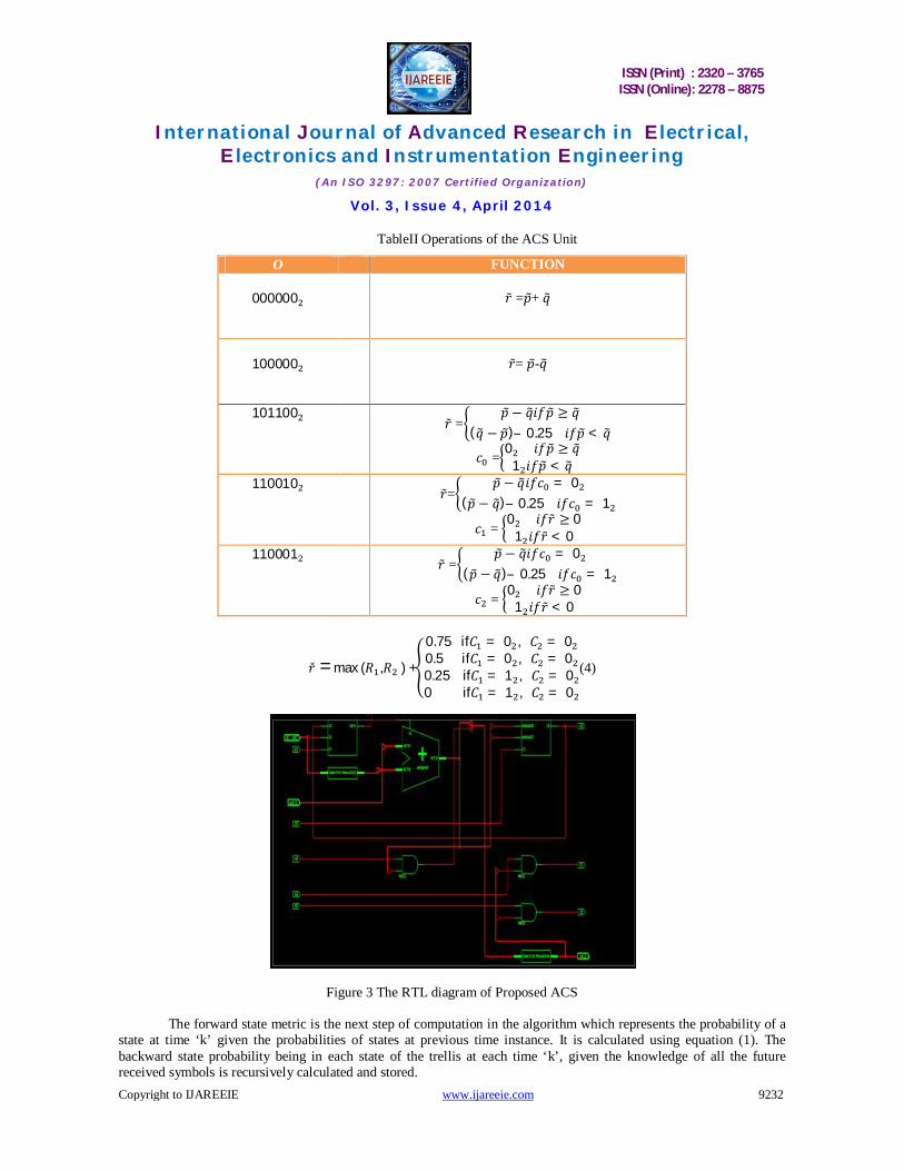
TableII Operations of the ACS Unit
O FUNCTION
000000
푟̃ =푝+ 푞
100000
푟̃= 푝-푞
101100 푟̃ =
푝 − 푞푖푓푝 ≥ 푞(푞 − 푝)– 0.25 푖푓푝 < 푞
푐 =0 푖푓푝 ≥ 푞
1 푖푓푝 < 푞
110010 푟̃=
푝 − 푞푖푓푐 = 0(푝 − 푞)– 0.25 푖푓푐 = 1
푐 = 0 푖푓푟̃ ≥ 0
1 푖푓푟̃ < 0
110001 푟̃ =
푝 − 푞푖푓푐 = 0(푝 − 푞)– 0.25 푖푓푐 = 1
푐 = 0 푖푓푟̃ ≥ 0
1 푖푓푟̃ < 0
푟̌ = max (푅 ,푅 ) +
0.75 if퐶 = 0 , 퐶 = 00.5 if퐶 = 0 , 퐶 = 00.25 if퐶 = 1 , 퐶 = 00 if퐶 = 1 , 퐶 = 0
(4)
Figure 3 The RTL diagram of Proposed ACS
The forward state metric is the next step of computation in the algorithm which represents the probability of a state at time ‘k’ given the probabilities of states at previous time instance. It is calculated using equation (1). The backward state probability being in each state of the trellis at each time ‘k’, given the knowledge of all the future received symbols is recursively calculated and stored.

ISSN (Print) : 2320 – 3765 ISSN (Online): 2278 – 8875
International Journal of Advanced Research in Electrical,
Electronics and Instrumentation Engineering (An ISO 3297: 2007 Certified Organization)
Vol. 3, Issue 4, April 2014
Copyright to IJAREEIE www.ijareeie.com 9233
Figure 4 RTL view of forward SMU
The backward state metric is computed using Equation (3) in the backward direction going from the end to the beginning of the trellis at time instance ‘k-1’, given the probabilities at time instance ‘k’. The backward state metric computation can start only after the completion of the computation by the branch metric unit. State Metric value for a particular node is computed based on the trellis diagram of the encoder. In the SMU, the add compare select (ACS) units are recursively processed to compute the state metrics, through the connection network that allocates the state metrics for the next ACS based on the current constraint length ‘K’ value. For a particular constraint length ‘K’, this state metric allocation must be done before they are fed as input to the ACS in the next clock cycle.
V. LLR COMPUTATIONAL UNIT
Log likelihood ratio is the output of the turbo decoder. The LLR for each symbol at time ‘k’ is calculated using the Equation (5).
Figure 4 RTL diagram of LCU

ISSN (Print) : 2320 – 3765 ISSN (Online): 2278 – 8875
International Journal of Advanced Research in Electrical,
Electronics and Instrumentation Engineering (An ISO 3297: 2007 Certified Organization)
Vol. 3, Issue 4, April 2014
Copyright to IJAREEIE www.ijareeie.com 9234
The main operations involved in LLR computation are comparison, addition and subtraction. Finally these values are de-interleaved at the second decoder output after the required number of iterations to make the hard decision in order to retrieve the information that is transmitted. The sign of the number corresponds to the hard decision while the magnitude gives a reliability estimate. In order to compute LLR value, forward; backward state metric values and branch metric values of all states are required.
01110
111
1
1
)()(),(
)()(),(ln LL
SSss
SSSSL
k k
k k
s skkkk
s skkkk
lr
(5)
The RTL diagram of LCU is shown in figure 4.
VI. RESULT AND DISCUSSION
The Verilog code for the proposed turbo decoder is synthesized using Xilinx EDA tool. The RTL view and the simulation result of SISO decoder is shown in the figure 5.
Figure 5 Proposed SISO decoder
Table III Logic utilizations of various modules of turbo decoder
Figure 6 Graphical representation of Logic Utilization of Various Modules of Turbo Decoder
0
100
200
300
400
500
600
700
BMU ACS SMU LCU
Number of Slices
Number of input LUTs
Number of Bonded Ios
Modules Number of Slices
Number of 4
input LUTs
Number Of Bonded IOs
BMU
72
126
35
ACS
10
19
30
SMU
254
468
186
LCU
363
655
344

ISSN (Print) : 2320 – 3765 ISSN (Online): 2278 – 8875
International Journal of Advanced Research in Electrical,
Electronics and Instrumentation Engineering (An ISO 3297: 2007 Certified Organization)
Vol. 3, Issue 4, April 2014
Copyright to IJAREEIE www.ijareeie.com 9235
It is observed that from the table III that more number of slices are utilized by LCU unit.
Table IV Timing analysis of various modules of turbo decoder
Modules Minimum input arrival time before
clock
Maximum output required time
after clock
Maximum combinational path
delay
BMU
3.627ns
22.039ns
24.196ns
SMU
26.183ns
20.338ns
21.450ns
LCU
22.401 ns
8.960 ns
17.320 ns
From the table IV, it is observed that the critical path delay of the turbo decoder is 24.196 ns and also it is a maximum combinational path delay of BMU. So, the speed of operation of the proposed design is decided by BMU unit.
Table V Comparison between proposed and existing ACS
Logic utilization Existing ACS Proposed ACS
Number of Slices 21 10
Number of 4 input LUTs 38 19
Number of IOs 46 30
Number of bonded IOBs 46 40
Table V shows the comparison between proposed and existing ACS. In the existing design of Turbo decoder 1521 slices were required. But in the proposed design only 720 slices are used .Hence 21.44% of area has been reduced.
Table VI Comparison with existing state-of-the-art turbo decoders
Table VI compares the state of art of various turbo decoders. From the comparison table, it is observed that the throughput of the proposed design is improved .But when compared with M.May’s work the throughput of the proposed work is less, because the number of iterations used in the proposed work is 8, but in M.May’s design only 6 iterations were used.
Parameters Proposed
Turbo Decoder
Conventional Turbo
Decoder
M. A. Bickerstaff L. Davis F.-M. Li M. May
Algorithm Max-Log-Map LUT-Log LUT-Log LUT-Log
LUT-Log
Max-Log
Decoding iterations 8 5 10 8 6.5 6
Throughput (Mb/s) 2.2 1.03 2 10.8 4.17 150

ISSN (Print) : 2320 – 3765 ISSN (Online): 2278 – 8875
International Journal of Advanced Research in Electrical,
Electronics and Instrumentation Engineering (An ISO 3297: 2007 Certified Organization)
Vol. 3, Issue 4, April 2014
Copyright to IJAREEIE www.ijareeie.com 9236
VII. CONCLUSION In energy-constrained applications, achieving low energy consumption has a higher priority than having a high throughput. This motivated our low-complexity energy-efficient architecture, which achieves a low area and hence a low energy consumption by decomposing the LUT-Log-BCJR algorithm into its most fundamental ACS operations.Hence the turbo decoder architecture is designed in such a way that the area is reduced by 21.44% and the speed is improved by 28.1% while the throughput is 2.2 Mbps and thereby reducing the complexity.This entire architecture is implemented in Application Specific Integrated Circuit (ASIC) and this will improve the speed and reduce the area further.
REFERENCES
[1] Dharma PrakashAgarwal& Qing-An Zeng, “Introduction to Wireless and Mobile Systems”, Thomson India Edition, 2nd Ed.,2007. [2] SimonHaykins “Digital Communication”, John Wiley, 2006. [3] M.C.Valenti and j. Sun (2004) “turbo codes in F.Dowla, editor handbook ofRF and wireless technologies”, Pages 375–400, Newnes. [4] J.M.Mathana ,Dr.P.Rangarajan ,“FPGA Implementation of High Speed Architecture for Max Log Map Turbo SISO Decoder”, International Journal of Recent Trends in Engineering, Vol 2, No. 6, November 2009,pp.142- 146. [5] J.M.Mathana ,Dr.P.Rangarajan ,“Low complexity reconfigurable turbo decoder for wireless communication system” ,Arabian Journal of science and Engineering,2013 ,Springer Publications. [6] Michael J. Thul, Frank Gilbert,et all ,”A scalable system architecture for high-throughput turbo-decoders” , Journal of VLSI Signal Processing Systems, Vol 39, January –February 2005,pp.63-77. [7] M.May, C.Neeb, N.Wehn, “Evaluation of High Throughput Turbo-Decoder Architectures”, Circuits and Systems, ISCAS 2007. IEEE International Symposium, 27-30 May 2007,pp.2770-2773 [8] Camille Leroux , Christophe Jégo,“High-throughput Block Turbo Decoding from Full-parallel Architecture to FPGA Prototyping, Journal of Signal Processing Systems”, Springer Publications, Vol53 , March 2009,pp.349 – 361. [9] Mohammad M. Mansour, Naresh R. Shanbhag, “high-throughput LDPC decoders, IEEE Transactions on very large scale integration systems”, Vol.11, No.6, December 2003,pp.976 – 996. [10]Michael Wu, Yang Sun,”Implementation of a High Throughput 3GPPTurbo Decoder on GPU”, Springer Publications August 11,Vol.65,pp.171- 183. [11] P. Robertson, E. Villebrun, and P. Hoeher, “A comparison of optimal and Sub-optimal MAP decoding algorithms operating in the log domain,” in Proceedings of IEEE International Conference of Communication,vol. 2, Seattle, WA, USA, 1995, pp. 1009–1013. [12] A. J. Viterbi, “An Intuitive Justification and a Simplified Implementation of the MAP Decoder for Convolutional Codes,” IEEE Journal on Selected Areas in Communications, vol. 16, no. 2, pp. 162–264, 1998. [13] M.May, T. Ilnseher, N.Wehn, andW. Raab, “A 150 Mbit/s 3GPP LTE turbo code decoder,” in Proc. Design, Autom. Test in Euro. Conf. Exhib. (DATE), 2010, pp. 1420–1425. [14] M. A. Bickerstaff, D. Garrett, T. Prokop, C. Thomas, B. Widdup, G. Zhou, L.M. Davis, G.Woodward, C. Nicoland R.-H. Yan, “A unified turbo/Viterbi channel decoder for 3GPP mobile wireless in 0.18- m CMOS,” IEEE J. Solid-State Circuits, vol. 37, no. 11, pp. 1555–1564, Nov. 2002. [15] M. Bickerstaff, L. Davis, C. Thomas, D. Garrett, and C. Nicol, “A 24 Mb/s radix-4 log-MAP turbo decoder for 3GPP-HSDPA mobile wireless,” in Proc. IEEE Int. Solid-State Circuits Conf., 2003, pp. 150–484.