volume 15, no 10 - october 2010 - home metal shop...
TRANSCRIPT

May 2011 Newsletter
Volume 16 - Number 5
http://www.homemetalshopclub.org/
Since its founding by John Korman in 1996, The Home Metal Shop Club has brought together metal workers from all over the Southeast Texas area.
Our members’ interests include Model Engineering, Casting, Blacksmithing, Gunsmithing, Sheet Metal Fabrication, Robotics, CNC, Welding, Metal Art, and others. Members always like to talk about their craft and shops. Shops range from full machine shops to those limited to a bench vise and hacksaw.
If you like to make things, run metal working machines, or just talk about tools, this is your place. Meetings generally consist of a presentation with Q&A, followed by show and tell where the members can share their work and experiences.
President Vance Burns
Vice President John Hoff
Secretary Martin Kennedy
Treasurer Emmett Carstens
Librarian Dan Harper
Webmaster/Editor Dick Kostelnicek
Photographer Jan Rowland
CNC SIG Dennis Cranston
Casting SIG Tom Moore
Novice SIG Rich Pichler
About the Upcoming June 11 Meeting General meetings are usually held on the second Saturday of each month at 12:00 noon in the meeting room of the Parker Williams County Library, 10851 Scarsdale Boulevard, Houston, TX 77089. This month’s meeting will be held on June 11th. The meeting space has been reserved through August. Visit our website for up-to-the-minute details. At the June Meeting Al Muller will talk about Houston Inventor’s Association. Election of club officers will be held. Don’t be bashful! Nominate yourself or another club member.
Recap of the May 14 General Meeting By Martin Kennedy, with photos by Jan Rowland
Twenty-six of our 53 members and one visitor, Stan Reeves, attended the 12:00 noon meeting at the Parker Williams County Library. President Vance Burns led the meeting. Vance began the meeting with several topics of club business: A casting furnace belonging to the club will is losing its home at Zube Park, and will be kept by John Hoff. The furnace was being kept by Houston Area Live Steamers, who are remodeling the space for other purposes.
About 100 lbs of Petrobond casting sand will be brought to the next club meeting and will be auctioned off to attendees in 20 lb buckets.

May 2011 - Home Metal Shop Club Newsletter - V.16 No.5
2
Dennis Cranston will be hosting a casting workshop at Zube Park in Hockley, TX on June 12th. Dennis mentioned that Houston Area Live Steamers would be hosting their annual Meet over Memorial Day weekend, and invited all to attend. Ray Ethridge of Chappell Hill has been collecting oil field engines, and a trip to view the engines is being arranged. The club officers voted to acquire Dennis Cranston’s Atlas lathe. This is the lathe that is used for the Novice demonstrations. Rich Pichler will store the lathe between meetings. Rich discussed the need to design and build a cart so that he could easily load the lathe into his truck. Contact Rich if you are interested in this project. Vance made an appeal for meeting speakers and articles for the newsletter. If you or someone you know is willing to speak on a topic of interest to our membership, please contact the club vice president, John Hoff. If you want to write an article for the newsletter, contact the webmaster Dick Kostelnicek. A video of the meeting will be available on the club’s web site.
Presentation Adam Burnett , Lab Manager for Oceaneering Space Systems gave the presentation. Adam works at NASA on the Robonaut 2 (R2) program. R2 is the most advanced humanoid form factor robot on the planet. There are two R2’s in existence, one located at Johnson Space Center and one on the International Space Station. R2 is an evolution of Robonaut 1. R1 was a joint project between DARPA and NASA that built a robot for dangerous or
hazardous areas, such as space or for bomb defusing. R1 was equipped with a very complex vision system that proved the concept of telepresence with VR goggles. R2 was developed as an extension of the R1 program in a partnership between General Motors and NASA. R2 was designed to interact with the same items and use the same tools that humans would. The advantage of R2 is that it can operate in a vacuum, it removes risk to humans, and does not require the lengthy process a human does of preparing for working in a vacuum. R2 was rebuilt for certification to go on the space station on the Space Shuttle Discovery with the STS-133 crew. The work was done on a crash program in only six months! It is currently on the space station for testing. R2 runs on 110 volts. Lots of safety features are built in. It has an advanced sensor system using tactile feedback on the fingers and feedback from the motors. R2 was built to human dimensions, albeit a very large, muscular human. Its dimensions correspond to a 7’7” human. R2 has 14 linear actuators in each arm to control its fingers. Its feedback mechanism is so sensitive that it can read Braille with its fingertips! It can detect 1 or 2 grams of force. It can lift up to 20 lbs and hold it indefinitely at the end of a fully extended arm. The limitation of its strength is set by how much it

May 2011 - Home Metal Shop Club Newsletter - V.16 No.5
3
can hold with its fingers, which are connected to Kevlar tendons. It is one of the few robots that can work with soft items such as paper and cloth. R2 can be combined with Centar 2, a four-wheeled mobile platform. With this combination it can move autonomously at speeds up to 20 MPH over rugged terrain. R2 includes machine vision, and can distinguish and identify shapes. It is made of steel and aluminum combined with plastic parts generated on a 3D printer. Its operations are controlled by almost 100 PowerPC processors. It weighs 380 pounds and costs $5M. Adam is currently working at NASA on an XYZ system to simulate weightlessness for R2.
Adam showed two videos on R2. The first described the partnership between GM and NASA, and the second showed a trick the space station personnel played on the R2 team. Adam then talked about Creatorspace, a nonprofit organization that provides workspace, tools (including a MakerBot Thing-O-Matic 3D printer), and contact with like-minded people. They meet every other Tuesday at EPO in Webster, using a 2,500 sq. ft. space donated by EPO. They started meeting just a few weeks ago. Thirty-five people attended the first meeting. They are working towards having a Creator Fair.
Show & Tell Lee Morin showed a work in progress - a stepper motor mount he is building to convert his lathe to CNC (left photo). David Bellinger mentioned that South Bend has begun making hobbyist lathes again with the SB1002 10K lathe, a 10” x 28” that sells for less than $5,000. Stan Reeves showed a bench-mounted turn counter that he built for making coils.
Problems and Solutions A member inquired as to the purpose of using lard, graphite, or sulfur as a coolant. After the meeting Joe Williams commented that lard was a common item in older shops and graphite was added to oil for a lubricant but the sulfur is only used in a sulfur compound along with chlorinated materials to enhance machining. I have never heard of graphite and sulfur being used as a coolant. A graphite and molasses mix is used a joint compound for steam piping while molten sulfur is used to set machinery mounting bolts in concrete. A member showed an aluminum suspension link for his mountain bike that he was trying to duplicate. Several suggestions were made on how to accomplish this.
Novice SIG Activities Rich Pichler and the novice group upgraded the electrical system, lubricated and adjusted the newly acquired Atlas lathe.
Articles
May 2011 - Home Metal Shop Club Newsletter - V.16 No.5
4
Building a Static Phase Converter
By Martin Kennedy
I recently acquired a vintage 1960 Reid Surface Grinder. When I got it, it was set up to run from 3-phase 480V. Like most home shop machinists, this was not readily available in my garage! I needed to adapt the machine to use a more common voltage. Many industrial motors are designed to run either on 480V or 240V, and mine was no exception. I removed the cover plate on the motor, and was confronted with a large tangle of wires. The first thing I did was identified the wires and electrically checked the motor using these instructions. The motor tested fine, and I rewired it for 3-phase 240V . The next part was much more involved. I had single-phase 240V power, but needed it to be 3-phase. I considered three ways to generate 3-phase power for the motor: a Static Phase Converter, a Rotary Phase Converter, and a Variable Frequency Drive. A Static Phase Converter allows a 3-phase motor to run on single-phase power. It is built using capacitors. The primary advantages of a static converter are simplicity and low cost. A disadvantage is that it de-rates the motor to 2/3 of the horsepower (HP), shown on its nameplate. I didn’t think that this would be a problem for the grinder, due to my light duty use. Additionally, a grinder develops a lot of inertia spinning the wheel that lowers the instantaneous demand for HP. A Rotary Phase Converter provides true 3-phase power. Primary components are a large 3-phase motor and a Static Phase Converter. It is helpful to consider a rotary converter as a motor and generator all in one package. The motor is sized larger than the sum of all the equipment that will be run at once, and for a home shop that is on the order of 5-10 HP. The converter’s motor is started and run using a Static Phase Converter as discussed above. It is freewheeling, as nothing is attached its shaft. Since a motor can also act as a generator, the 3rd phase is generated by the motor itself. The primary advantages of a rotary converter are: not needing to de-rate any of the connected 3-phase motors and sharing one system across the entire shop. The disadvantage is the size and cost of the system. Also, it is usually installed remotely (even outdoors), and a mechanism must be included to start and stop it remotely. And, you have to remember to turn it off when you’re finished with it! A Variable Frequency Drive or VFD is a solid-state electrical device that synthesizes 3-phases from either single or 3-phase power. It has the additional capability to produce variable frequency, which can be used for motor speed control. Advantages of VFDs are the small size and the ability to control motor speed. The disadvantage is the cost, although the price of VFDs has come down substantially. They currently cost about twice as much as a Static Phase Converter. You will need to program the VFD to operate with your specific motor, and someone who is computer challenged may consider that a minor disadvantage! I decided to build a Static Converter, mostly due to the availability of surplus oil-filled capacitors. I didn’t pick a rotary converter because I don’t have other devices that need 3-phase power, nor do I have a large 3-phase motor. I didn’t pick a VFD because I have no need for speed control on my grinder. It would have been a consideration on a motor for a lathe or mill, and I am planning on using a VFD on my lathe in a future project. I considered buying a static converter, but built one for the challenge. Here’s the wiring diagram with manual start:

May 2011 - Home Metal Shop Club Newsletter - V.16 No.5
5
First, I had to determine the value of the capacitors that I would use. Each Static Converter must be tweaked to work with your particular motor. There are guidelines of where to start. Suggested capacitor values are plus or minus 50%. They’re not very critical when you just want to get started. You will adjust these values during testing.
Run capacitor = 13 µF / HP Start capacitor = 36 µF / HP Balance capacitor = about half the value of the Run capacitor
Basically, the goal is to have the same AC voltage across all three phases. An imbalance in voltages means an imbalance in current on one or more windings of the motor. If it’s substantial, it could result in the motor overheating or not reaching full speed. Start by using just the Run capacitor, Start capacitor and a pushbutton switch. The Run and Start capacitors are required, while the Balance capacitor is optional. Oil filled capacitors should be used, and are required for heat dissipation. They should be rated for at least 300 V AC. It helps to have a variety of sizes so that they can be combined in series to make smaller values or in parallel to enlarge the value.
Make a table to record the results of the trials as different capacitors are tried. I had three voltmeters, but you can do it with one or two as the main line voltage will not vary. Be careful! 240V can bite you, and things wired incorrectly can do “bad things” to the capacitors and motor. Work with a friend or at least with just one hand around high voltages. I was always told to keep one hand in my pocket, as that prevented me from holding a ground while working. Check the wiring twice or three times before you apply power, and be sure nothing is touching any of the temporary connections that isn’t supposed to! It really helped me to put masking tape on the wires, capacitors, and meters to label the three phases. Otherwise, it’s easy to get the wires and readings mixed up. Here are the trials I went through during testing:
May 2011 - Home Metal Shop Club Newsletter - V.16 No.5
6
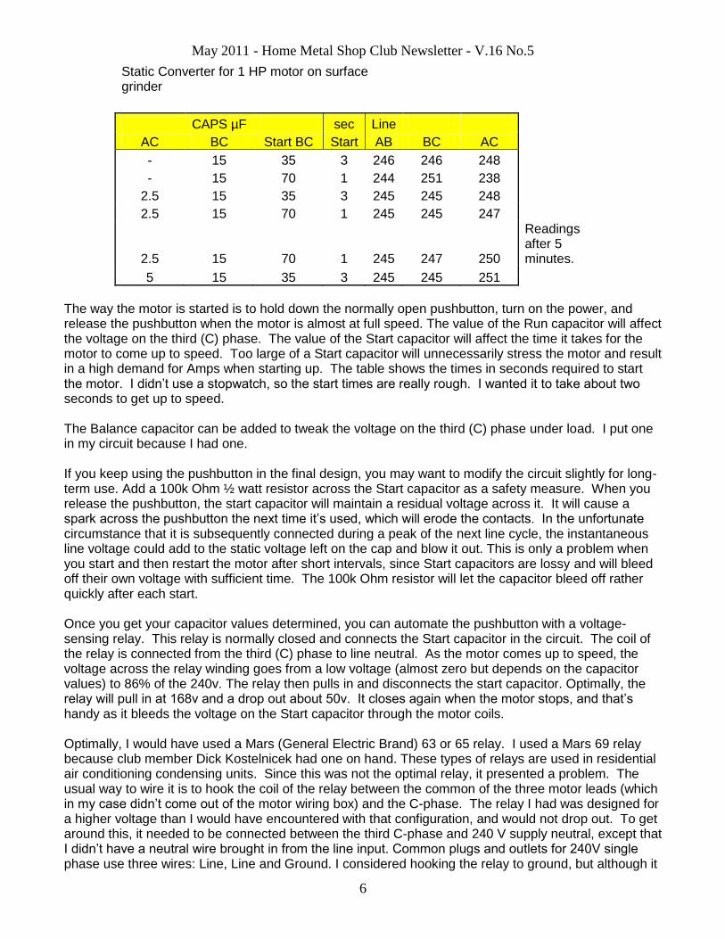
Static Converter for 1 HP motor on surface grinder
CAPS µF sec Line AC BC Start BC Start AB BC AC - 15 35 3 246 246 248 - 15 70 1 244 251 238 2.5 15 35 3 245 245 248 2.5 15 70 1 245 245 247
2.5 15 70 1 245 247 250
Readings after 5 minutes.
5 15 35 3 245 245 251
The way the motor is started is to hold down the normally open pushbutton, turn on the power, and release the pushbutton when the motor is almost at full speed. The value of the Run capacitor will affect the voltage on the third (C) phase. The value of the Start capacitor will affect the time it takes for the motor to come up to speed. Too large of a Start capacitor will unnecessarily stress the motor and result in a high demand for Amps when starting up. The table shows the times in seconds required to start the motor. I didn’t use a stopwatch, so the start times are really rough. I wanted it to take about two seconds to get up to speed. The Balance capacitor can be added to tweak the voltage on the third (C) phase under load. I put one in my circuit because I had one. If you keep using the pushbutton in the final design, you may want to modify the circuit slightly for long-term use. Add a 100k Ohm ½ watt resistor across the Start capacitor as a safety measure. When you release the pushbutton, the start capacitor will maintain a residual voltage across it. It will cause a spark across the pushbutton the next time it’s used, which will erode the contacts. In the unfortunate circumstance that it is subsequently connected during a peak of the next line cycle, the instantaneous line voltage could add to the static voltage left on the cap and blow it out. This is only a problem when you start and then restart the motor after short intervals, since Start capacitors are lossy and will bleed off their own voltage with sufficient time. The 100k Ohm resistor will let the capacitor bleed off rather quickly after each start. Once you get your capacitor values determined, you can automate the pushbutton with a voltage-sensing relay. This relay is normally closed and connects the Start capacitor in the circuit. The coil of the relay is connected from the third (C) phase to line neutral. As the motor comes up to speed, the voltage across the relay winding goes from a low voltage (almost zero but depends on the capacitor values) to 86% of the 240v. The relay then pulls in and disconnects the start capacitor. Optimally, the relay will pull in at 168v and a drop out about 50v. It closes again when the motor stops, and that’s handy as it bleeds the voltage on the Start capacitor through the motor coils. Optimally, I would have used a Mars (General Electric Brand) 63 or 65 relay. I used a Mars 69 relay because club member Dick Kostelnicek had one on hand. These types of relays are used in residential air conditioning condensing units. Since this was not the optimal relay, it presented a problem. The usual way to wire it is to hook the coil of the relay between the common of the three motor leads (which in my case didn’t come out of the motor wiring box) and the C-phase. The relay I had was designed for a higher voltage than I would have encountered with that configuration, and would not drop out. To get around this, it needed to be connected between the third C-phase and 240 V supply neutral, except that I didn’t have a neutral wire brought in from the line input. Common plugs and outlets for 240V single phase use three wires: Line, Line and Ground. I considered hooking the relay to ground, but although it
May 2011 - Home Metal Shop Club Newsletter - V.16 No.5
7
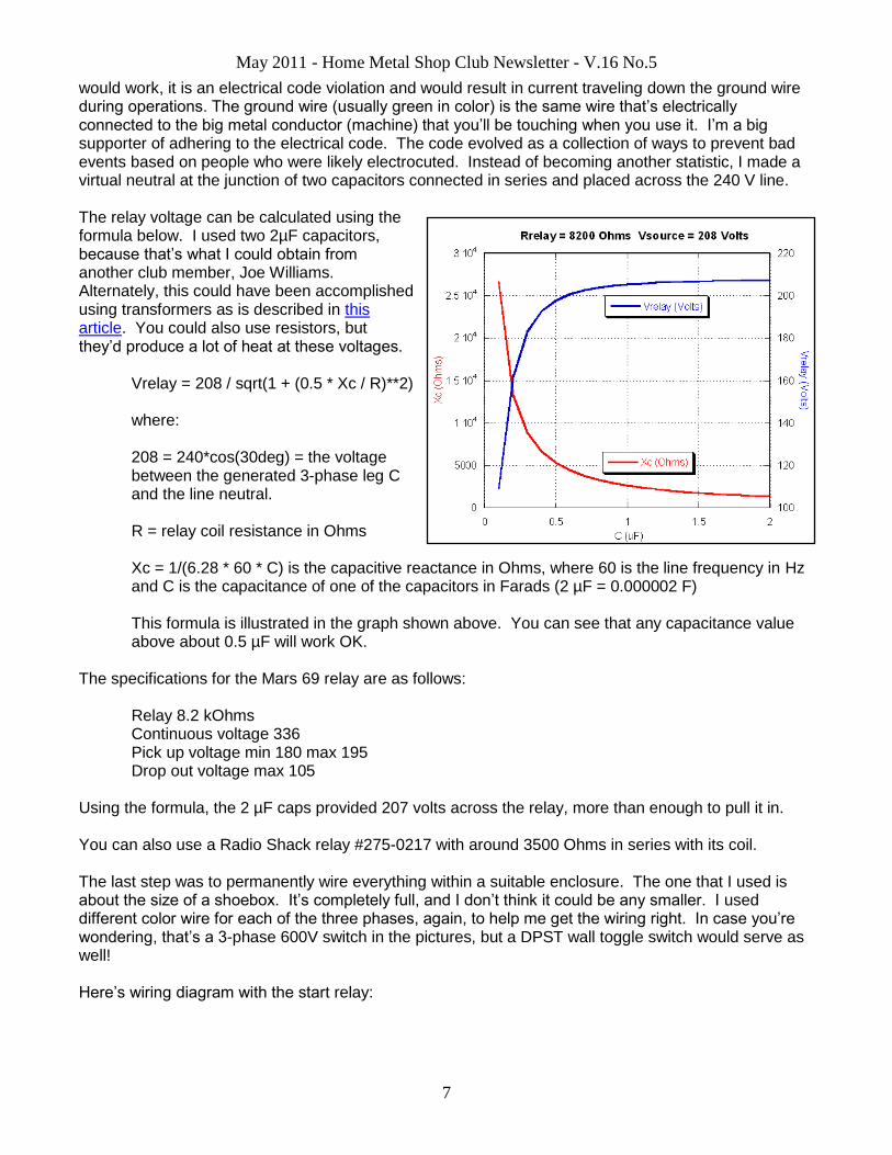
would work, it is an electrical code violation and would result in current traveling down the ground wire during operations. The ground wire (usually green in color) is the same wire that’s electrically connected to the big metal conductor (machine) that you’ll be touching when you use it. I’m a big supporter of adhering to the electrical code. The code evolved as a collection of ways to prevent bad events based on people who were likely electrocuted. Instead of becoming another statistic, I made a virtual neutral at the junction of two capacitors connected in series and placed across the 240 V line. The relay voltage can be calculated using the formula below. I used two 2µF capacitors, because that’s what I could obtain from another club member, Joe Williams. Alternately, this could have been accomplished using transformers as is described in this article. You could also use resistors, but they’d produce a lot of heat at these voltages.
Vrelay = 208 / sqrt(1 + (0.5 * Xc / R)**2) where: 208 = 240*cos(30deg) = the voltage between the generated 3-phase leg C and the line neutral. R = relay coil resistance in Ohms Xc = 1/(6.28 * 60 * C) is the capacitive reactance in Ohms, where 60 is the line frequency in Hz and C is the capacitance of one of the capacitors in Farads (2 µF = 0.000002 F) This formula is illustrated in the graph shown above. You can see that any capacitance value above about 0.5 µF will work OK.
The specifications for the Mars 69 relay are as follows:
Relay 8.2 kOhms Continuous voltage 336 Pick up voltage min 180 max 195 Drop out voltage max 105
Using the formula, the 2 µF caps provided 207 volts across the relay, more than enough to pull it in. You can also use a Radio Shack relay #275-0217 with around 3500 Ohms in series with its coil. The last step was to permanently wire everything within a suitable enclosure. The one that I used is about the size of a shoebox. It’s completely full, and I don’t think it could be any smaller. I used different color wire for each of the three phases, again, to help me get the wiring right. In case you’re wondering, that’s a 3-phase 600V switch in the pictures, but a DPST wall toggle switch would serve as well! Here’s wiring diagram with the start relay:

May 2011 - Home Metal Shop Club Newsletter - V.16 No.5
8
I verified that the relay was working correctly mostly by sound. The relay should click “open” when the motor is nearly up to speed. When the motor slows to a stop, it should click “closed”. If it stays closed all the time, the motor will sound labored when running. If it is always open, the motor may not start (just hum while remaining still) or it will turn very slowly and erratically. That’s it! Good luck building your Static Phase Converter! My thanks to Dick Kostelnicek and Joe Williams for providing help with understanding of the technology and with parts! Electrical schematics and Capacitive Reactance graph courtesy of Dick Kostelnicek.
May 2011 - Home Metal Shop Club Newsletter - V.16 No.5
9
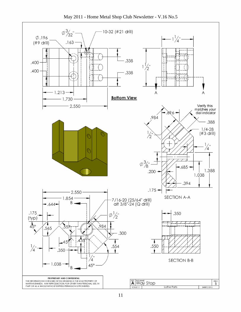
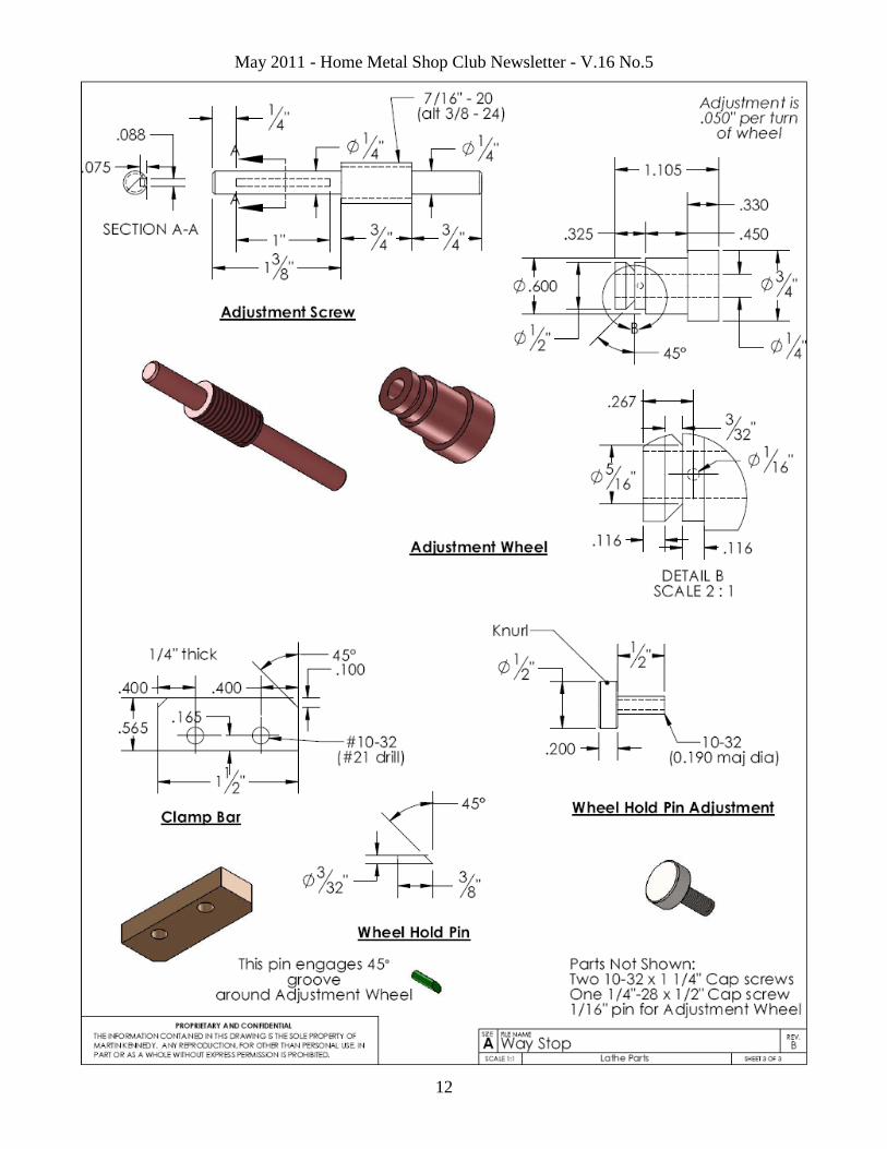
Lathe Carriage Way Stop By Martin Kennedy
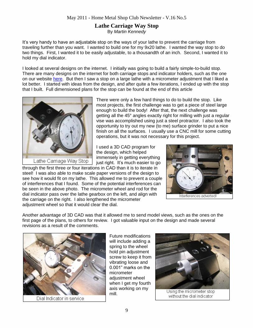
It’s very handy to have an adjustable stop on the ways of your lathe to prevent the carriage from traveling further than you want. I wanted to build one for my 9x20 lathe. I wanted the way stop to do two things. First, I wanted it to be easily adjustable, to a thousandth of an inch. Second, I wanted it to hold my dial indicator. I looked at several designs on the internet. I initially was going to build a fairly simple-to-build stop. There are many designs on the internet for both carriage stops and indicator holders, such as the one on our website here. But then I saw a stop on a large lathe with a micrometer adjustment that I liked a lot better. I started with ideas from the design, and after quite a few iterations, I ended up with the stop that I built. Full dimensioned plans for the stop can be found at the end of this article
There were only a few hard things to do to build the stop. Like most projects, the first challenge was to get a piece of steel large enough to build the body! After that, the next challenge was getting all the 45° angles exactly right for milling with just a regular vise was accomplished using just a steel protractor. I also took the opportunity to try out my new (to me) surface grinder to put a nice finish on all the surfaces. I usually use a CNC mill for some cutting operations, but it was not necessary for this project. I used a 3D CAD program for the design, which helped immensely in getting everything just right. It’s much easier to go
through the first three or four iterations in CAD than it is to iterate in steel! I was also able to make scale paper versions of the design to see how it would fit on my lathe. This allowed me to prevent a couple of interferences that I found. Some of the potential interferences can be seen in the above photo. The micrometer wheel and rod for the dial indicator pass over the lathe gearbox on the left, and align with the carriage on the right. I also lengthened the micrometer adjustment wheel so that it would clear the dial. Another advantage of 3D CAD was that it allowed me to send model views, such as the ones on the first page of the plans, to others for review. I got valuable input on the design and made several revisions as a result of the comments.
Future modifications will include adding a spring to the wheel hold pin adjustment screw to keep it from vibrating loose and 0.001” marks on the micrometer adjustment wheel when I get my fourth axis working on my mill.

May 2011 - Home Metal Shop Club Newsletter - V.16 No.5
10
May 2011 - Home Metal Shop Club Newsletter - V.16 No.5
11
May 2011 - Home Metal Shop Club Newsletter - V.16 No.5
12