volume 16 number 20 28 may 2014 pages 9185–9668 pccp
TRANSCRIPT

PCCPPhysical Chemistry Chemical Physicswww.rsc.org/pccp
ISSN 1463-9076
PERSPECTIVEPhilip N. Bartlett et al.Electrodeposition from supercritical fl uids
Volume 16 Number 20 28 May 2014 Pages 9185–9668

9202 | Phys. Chem. Chem. Phys., 2014, 16, 9202--9219 This journal is© the Owner Societies 2014
Cite this:Phys.Chem.Chem.Phys.,
2014, 16, 9202
Electrodeposition from supercritical fluids
P. N. Bartlett,*a D. A. Cook,a M. W. George,b A. L. Hector,a J. Ke,b W. Levason,a
G. Reid,a D. C. Smithc and W. Zhanga
Recent studies have shown that it is possible to electrodeposit a range of materials, such as Cu, Ag and Ge,
from various supercritical fluids, including hydrofluorocarbons and mixtures of CO2 with suitable co-solvents.
In this perspective we discuss the relatively new field of electrodeposition from supercritical fluids. The
perspective focuses on some of the underlying physical chemistry and covers both practical and scientific
aspects of electrodeposition from supercritical fluids. We also discuss possible applications for supercritical fluid
electrodeposition and suggest some key developments that are required to take the field to the next stage.
1. Introduction
The field of supercritical fluid electrodeposition continues a longhistory of development of materials production and depositionmethods which underpin nearly all modern technology. Theimportance and sophistication of materials deposition techniquescan be seen in the cost of silicon fabrication facilities used toproduce integrated circuits which are measured in billions ofdollars. There now exists a wide range of deposition technologies.Vacuum techniques such as thermal evaporation, sputtering,chemical vapour deposition and molecular beam epitaxy areparticularly suited to the deposition of high quality thin films.Such techniques have enabled the engineering of the fundamentalquantum mechanical states of electrons in semiconductor struc-tures leading to quantum well lasers in DVD players, quantumcascade lasers for chemical sensing, and entirely new fundamentalphysics, e.g. the fractional quantum Hall effect. Spin-coating andprinting are two deposition techniques which have been used for avery long time, but which have been exploited in new ways recently.Much of this renewed interest has come about because of thediscovery and application of organic semiconductors for applica-tions such as flexible electronics. Whilst materials deposition isubiquitous in technology, specific techniques can be found inparticular applications in which their unique characteristics canout perform other techniques. For instance, as supercritical fluidshave no surface tension and improved mass transport over liquidsthey have advantages for thermal deposition into high aspect ratiotrenches and pores.1 Supercritical fluids are also particularly goodat swelling polymers in a controllable manner to allow the deposi-tion of nanoparticles into existing polymers structures.2
In this perspective we will focus on electrodeposition fromsupercritical fluids and in particular on the underlying physicalchemistry of this new field. Since its introduction in the early1800s, electrodeposition has become widely exploited becauseit has a combination of capabilities not found together in otherdeposition techniques.3,4 These include: conformal depositiononto and into large complex objects; spatially defined growthallowing deposition onto complex structures only where requiredand allowing contiguous axial deposition through pores withoutblocking; direct control over the driving force for depositionthrough the applied potential; in operando measurement ofelectrical properties of the deposit during growth allowingactive feedback; highly efficient use of reagents.
This perspective focuses on a relatively new development inthe field of electrodeposition, supercritical fluid electrodeposition(SCFED). Supercritical fluids have a number of key advantages forelectrodeposition. These include (i) a lack of surface tension whichenables electrodeposition onto fragile substrates, (ii) good porepenetration and mass transport allowing deposition into highaspect ratio nanopores1 and small diameter (o4 nm) nanopores,5
(iii) a range of relatively easily accessible supercritical fluids withhigh chemical stability and thus large deposition windows, whichallow the deposition of reactive materials such as germanium,6
and (iv) the possibility to increase the deposition temperaturewith a specific fluid to above the critical temperature. Whilst thetechnique is still in its infancy, it is possible to envisage techno-logical areas in which SCFED may find unique applications.A likely example is in the production of few nanometre diameternanowires and nanowire based devices, e.g. Fig. 1.
There are many, varied reasons for the interest in nanowiresfor applications. These include at the simplest level the possibility offurther miniaturisation of existing electronic7 and data storage8
components. The proximity of the surface to the whole of the bulkof the nanowire makes nanowire chemical and biochemical sensorscapable of single molecule sensitivity.9 In the field of thermoelectric
a Chemistry, The University of Southampton, Southampton SO17 1BJ, UK.
E-mail: [email protected] School of Chemistry, The University of Nottingham, Nottingham NG7 2RD, UKc Physics & Astronomy, The University of Southampton, Southampton SO17 1BJ, UK
Received 23rd November 2013,Accepted 23rd December 2013
DOI: 10.1039/c3cp54955k
www.rsc.org/pccp
PCCP
PERSPECTIVE
Ope
n A
cces
s A
rtic
le. P
ublis
hed
on 2
7 Ja
nuar
y 20
14. D
ownl
oade
d on
4/5
/202
2 8:
55:3
9 A
M.
Thi
s ar
ticle
is li
cens
ed u
nder
a C
reat
ive
Com
mon
s A
ttrib
utio
n 3.
0 U
npor
ted
Lic
ence
.
View Article OnlineView Journal | View Issue

This journal is© the Owner Societies 2014 Phys. Chem. Chem. Phys., 2014, 16, 9202--9219 | 9203
materials nanowires show increased figure of merit over bulkmaterials because of decreased phononic thermal conductivity.10
Other routes by which nanowires could contribute to energyefficiency and generation include photovoltaic nanowire devices11
and piezoelectric nanowires.12 The fact that nanowires are lesssusceptible to defects means that it may be possible to produceultra-strength materials from them.13 Most of the near to marketapplications use nanowires with diameters in excess of 10 nm,however initial investigations of ultrathin nanowires14 suggestthat these may be even more exciting in the medium term.
Supercritical fluids may bring a number of advantages forelectrodeposition and for the electrodeposition of nanowiresand nanostructures. However, there are significant challengesassociated with trying to utilise SCFs for electrochemistry andelectrodeposition. These include dissolution of a sufficientconcentration of ionic species to produce a suitably conductivefluid, identifying sufficiently soluble and stable electrochemicalprecursors to produce useful deposition rates, ensuring theformation of a homogeneous solution and the development ofsafe and practical high pressure apparatus. Below we discussthese issues.
2. Properties of SCFs andmeasurement of solubility andconductivity
A supercritical fluid is defined as a substance above its criticaltemperature (Tc) and critical pressure ( pc), and as such they areunique solvents that combine the properties of liquids andgases, Table 1. SCFs have recently been exploited as green
alternatives to conventional organic solvents in a variety ofapplications including: (i) separation processes such as extraction,sorption processes, chromatography, and drying; (ii) mechanicalprocesses such as extrusion, homogenisation, emulsification,micronisation, crystallisation, impregnation and encapsulation,and (iii) chemical and biochemical reactions.15–21 Many processesutilising sub- and supercritical fluids have been investigated for awide range of industries including agriculture and food, cosmetics,pharmaceuticals, medicine, coatings, textiles, electronics andsemiconductors, and waste treatment.22–27 The properties ofSCFs have received considerable attention, and have beenextensively reviewed.28–33
Unlike conventional solvents, the physical properties ofSCFs can be easily tuned by changing either temperature orpressure, or both. This advantage has been widely exploited insupercritical fluid extraction for separating products andin supercritical fluid reactions for achieving high yield andselectivity.28–33 The tuneable properties of SCFs also haveapplications in processing nano-materials, e.g. supercriticaldrying of highly porous b-chitin structures,35 and preparationof free-standing arrays of CdS nanowires.36
In order to successfully electrodeposit from a supercriticalfluid we must consider their phase behaviour. SCFs are oftenillustrated with a p–T phase diagram of a single-componentsystem. One such diagram is presented in Fig. 2 using trifluoro-methane (CHF3) as an example, for which Tc and pc are 299.1 Kand 4.82 MPa, respectively. The supercritical state is representedby the shaded area in Fig. 2. Density is one of the most importantphysical properties of SCFs; density can be shown as isochores inthe p–T phase diagram, e.g. 7 isochores of CHF3 are depicted inFig. 2, with the density between 0.25 and 1.45 g cm�3. It isworth pointing out that only a certain combination of tempera-ture and pressure within the shaded area can provide thedesired properties for use of SCFs as solvents. For example,consider CHF3 under the conditions of 400 K and 15 MPa,which is B100 K above its Tc, and B10 MPa above its pc. At400 K and 15 MPa CHF3 is in the supercritical state; however itsdensity is only 6.4 mol dm�3 and compared with liquid H2O,having a density of 55.6 mol dm�3 at 298 K, or liquid CHF3,having a density of 20 mol dm�3 at its boiling point, the densityof CHF3 at 400 K and 15 MPa is too low for it to be a goodsolvent for ionic species, and therefore too low for it to be agood solvent for electrodeposition.
The dissolution of ionic species in SCFs is one of the keychallenges to carry out supercritical fluid electrodepositionbecause most of the SCFs with easily accessible critical tempera-tures are non-polar or low polarity molecules and therefore are
Fig. 1 Concept of a device which supercritical fluid electrodepositionmay enable in the future. The concept consists of a multiple resonanttunnel diode memory with element separation of 5 nm. Electrodepositionis particularly suited to the production of axial heterostructures like theSi/Ge quantum dot structure shown here. Using a supercritical fluid as thesolvent would have advantages for pore penetration, deposition of reactivematerials and high temperature deposition for materials quality.
Table 1 Density, viscosity, and diffusion coefficient of SCFs, gases and liquids28,34
State Gas Supercritical fluid Liquid
Temperature/K 298 Tc 298Pressure/MPa 0.1 pc 0.1Density/g cm�3 0.6–2 � 10�3 0.2–0.5 0.6–2Diffusion coefficient/cm2 s�1 0.1–0.4 0.5–4 � 10�3 0.2–2 � 10�5
Viscosity/MPa s 0.01–0.03 0.01–0.03 0.2–20
Perspective PCCP
Ope
n A
cces
s A
rtic
le. P
ublis
hed
on 2
7 Ja
nuar
y 20
14. D
ownl
oade
d on
4/5
/202
2 8:
55:3
9 A
M.
Thi
s ar
ticle
is li
cens
ed u
nder
a C
reat
ive
Com
mon
s A
ttrib
utio
n 3.
0 U
npor
ted
Lic
ence
.View Article Online

9204 | Phys. Chem. Chem. Phys., 2014, 16, 9202--9219 This journal is© the Owner Societies 2014
not good media for ion solvation. Electrostatic interactionscontribute more than 80% of the total ion–solvent interactions.37
Based on the Born equation, the electrostatic solvation energy(DGES), defined as the difference between the electrostatic freeenergy of an ion in vacuo and that in a solution, can be calculatedfrom the ionic charge, ionic radius, and dielectric constant (er).Fig. 3a shows the calculated DGES for a univalent ion with aradius of 0.2 nm in a medium with a dielectric constant rangingfrom 1 to 40. It can be seen that DGES decreases very rapidly withthe increase of er in the low dielectric constant region (er o 7),but decreases rather slowly in the high dielectric constant region(er 4 20). In order for the electrolyte to dissolve and dissociatein the solution er needs to be large enough so that the Gibbsfree energy for solvation, DGES, is sufficiently negative to over-come the lattice energy. On the other hand, for those solventswith dielectric constant greater than 20, the difference in DGES
is rather small so that the effect of dielectric constant on thesolubility is not significant when only the electrostatic solvationenergy is taken into account. The er region between 7 and 20 ishighlighted in Fig. 3. This is why most non-aqueous electrochemistryis carried out in solvents with a dielectric constant above 10 such asacetonitrile (er = 36.6), N, N 0-dimethylformamide (er = 38.3), dimethyl-sulfoxide (er = 47.2) or propylene carbonate (er = 66.1).
Fig. 3b plots the dielectric constant of three fluorinatedhydrocarbons (HFCs) as a function of pressure at temperaturesabove their corresponding Tc. It is clear that the dielectricconstant increases with increasing pressure for all three HFCs,suggesting that the solubility of ionic species is higher at highpressures. In addition, the solubility of ionic species canbe substantially higher in CH2F2 than in the other two HFCs(i.e. CHF3 and CF3CH2F) because the dielectric constant of
CH2F2 reaches 7 when the pressure is over 8 MPa. Hence, theselection of SCFs with high dielectric constant is the key toincreasing the solubility of ionic species.
An alternative method to increase the dielectric constant isthe use of mixed solvents, e.g. adding polar co-solvents intonon-polar SCFs. This has been a widely accepted concept in allsorts of applications of SCFs.45–49 In particular, the enhancementof the solubility of polar substances in CO2 has been extensivelystudied by using acetone, methanol, ethanol, acetonitrile, etc. asco-solvents. Fig. 3c shows the effect of the mole fraction ofCH3CN (er = 36) on the dielectric constant of the binary systemof CO2 + CH3CN. One can see that it is crucial to add 10–18%(mole fraction) of CH3CN into CO2 to achieve a dielectric constantof 7. A much higher concentration of CH3CN (e.g. xCH3CN 4 0.5)may not be necessary because it will not significantly decreaseDGES, but makes the solution more ‘liquid-like’, and henceslows down the mass transport.
High-pressure electrochemistry cells are the key equipmentfor electrodeposition in SCFs. The general design considera-tions include maximum operating temperature and pressure,electrode insulation and installation, material comparability,
Fig. 2 Phase diagram of pure CHF3. K, the critical point of CHF3; m, thetriple point of CHF3; SCF, supercritical fluid, shaded in cyan. The red, greenand blue curves are the gas–liquid, liquid–solid, and gas–solid phaseboundary, respectively. The dashed curves represent the isochores corres-ponding to the density between 0.05 and 1.45 g cm�3. The criticaltemperature (Tc) and critical pressure (pc) are 299.1 K and 4.82 MPa,respectively, indicated by the arrows in the figure.
Fig. 3 (a) Plot of the electrostatic solvation energy (DGES) of a univalention against dielectric constant (er), calculated by the Born equation with theionic radius of 0.2 nm.37 (b) The effect of pressure (p) on er for threefluorinated hydrocarbons at T 4 Tc of each solvent: ,, CHF3 at 335 K; J,CF3CH2F at 383 K; n, CH2F2 at 363 K.38–40 (c) er of the binary system ofCO2 + CH3CN. The dashed line represents the linear interpolation of er as afunction of the mole fraction of CH3CN (xCH3CN).41,42 ’, er of a mixture ofCO2 + CH3CN measured at 25 1C and 5.0 MPa.43 The composition of themixture is interpolated from the vapour–liquid phase equilibrium datareported by Reighard et al.44
PCCP Perspective
Ope
n A
cces
s A
rtic
le. P
ublis
hed
on 2
7 Ja
nuar
y 20
14. D
ownl
oade
d on
4/5
/202
2 8:
55:3
9 A
M.
Thi
s ar
ticle
is li
cens
ed u
nder
a C
reat
ive
Com
mon
s A
ttrib
utio
n 3.
0 U
npor
ted
Lic
ence
.View Article Online
This journal is© the Owner Societies 2014 Phys. Chem. Chem. Phys., 2014, 16, 9202--9219 | 9205
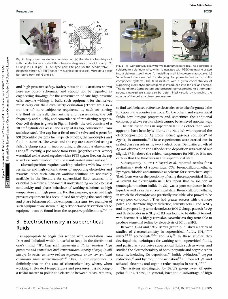
and high-pressure safety. (Safety note: the illustrations shownhere are purely schematic and should not be regarded asengineering drawings for the construction of safe high-pressurecells. Anyone wishing to build such equipment for themselvesmust carry out their own safety evaluation.) There are also anumber of more subjective requirements, such as stirringthe fluid in the cell, dismantling and reassembling the cellfrequently and quickly, and convenience of transferring reagents.One cell design is given in Fig. 4. Briefly, the cell consists of a10 cm3 cylindrical vessel and a cap at its top, constructed fromstainless steel. The cap has a fitted needle valve and 6 ports forSSI (Scientific Systems Inc.) type electrodes, thermocouples andfluid inlet/outlet. The vessel and the cap are assembled using afailsafe clamp system, incorporating a disposable elastomericO-ring.50 Recently, a pot made from PEEK (polyether ether ketone)was added to the vessel, together with a PTFE spacer fixed on the capto reduce contamination from the stainless-steel inner surface.6
Electrodeposition requires working solutions with low ohmicresistance and high concentrations of supporting electrolytes andreagents. Since such data on working solutions are not readilyavailable in the literature for supercritical fluid systems, it isessential to acquire a fundamental understanding on the electricalconductivity and phase behaviour of working solutions at hightemperature and high pressure. For this purpose, specialised highpressure equipment has been utilised for studying the conductivityand phase behaviour of multi-component systems; two examples ofsuch equipment are shown in Fig. 5. The detailed description of theequipment can be found from the respective publications.34,51,52
3. Electrochemistry in supercriticalfluids
It is appropriate to begin this section with a quotation fromDarr and Poliakoff which is useful to keep in the forefront ofone’s mind ‘‘Working with supercritical fluids involves highpressures and sometimes high temperatures. Nearly always, it willalways be easier to carry out an experiment under conventionalconditions than supercritically’’.53 This, in our experience, isdefinitely true in the case of electrochemistry where, whenworking at elevated temperatures and pressures it is no longera trivial matter to polish the electrode between measurements,
to find well-behaved reference electrodes or to take for granted thefunction of the counter electrode. On the other hand supercriticalfluids have unique properties and sometimes the additionalcomplexity allows results which cannot be achieved another way.
The earliest studies in supercritical fluids other than waterappear to have been by Williams and Naiditch who reported theelectrodeposition of Ag from ‘‘dense gaseous solutions’’ ofAgNO3 in ammonia.54 These experiments were carried out insealed glass vessels using two Pt electrodes. Dendritic growth ofAg was observed on the cathode. The deposition was carried outslightly (7 K) above the critical temperature for NH3 so it is notcertain that the fluid was in the supercritical state.
Subsequently in 1981 Silvestri et al. reported results for apreliminary study of supercritical CO2, bromotrifluoromethane,hydrogen chloride and ammonia as solvents for electrochemistry.55
Their focus was on the possibility of using these supercritical fluidsas solvent for electrosynthesis. They report that ‘‘a solution oftetrabutylammonium iodide in CO2 was a poor conductor in theliquid, as well as in the supercritical state. Bromotrifluoromethane,in which the electrolyte was practically insoluble, also proved to bea very poor conductor’’. They had greater success with the morepolar, and therefore higher dielectric, solvents scHCl and scNH3
and they report long-term electrolyses (4000 C charge passed) for Agand Fe electrodes in scNH3. scHCl was found to be difficult to workwith because it is highly corrosive. Nevertheless they were able toproduce elemental iodine by electrolysis of KI in scHCl.
Between 1984 and 1997 Bard’s group published a series ofstudies of electrochemistry in supercritical fluids, NH3,56–58
water,59–62 acetonitrile63,64 and SO2.65 In these studies theydeveloped the techniques for working with supercritical fluids,and particularly corrosive supercritical fluids such as water, andstudied the electrochemistry of both inorganic and organic redoxsystems, including Cu deposition,62 halide oxidation,60 oxygenreduction,60 and hydroquinone oxidation60 all from scH2O, andsolvated electrons and organic redox couples in scNH3.56–58
The systems investigated by Bard’s group were all quitepolar fluids. These, in general, have the disadvantage of high
Fig. 4 High-pressure electrochemistry cell: (a) the electrochemistry cellwith the electrodes installed; (b) schematic diagram, C, cap; CL, clamp; O;O-ring; P, PEEK pot; PO; SSI type port; PN; port for the needle valve; S,magnetic stirrer; SP, PTFE spacer; V, stainless steel vessel. More details canbe found from ref. 6 and 34.
Fig. 5 (a) Conductivity cell with two platinum electrodes. The electrode issoldered to a platinum wire, which is insulated with PEEK tubing and sealedinto a stainless steel holder for installing in a high-pressure autoclave. (b)Variable-volume view cell for studying the phase behaviour of multi-component systems. The fluid mixture with a given concentration ofsupporting electrolyte and reagents is introduced into the cell and sealed.The conditions (temperature and pressure) corresponding to a homoge-neous, single-phase state can be determined visually by changing thevolume of the cell at a given temperature.
Perspective PCCP
Ope
n A
cces
s A
rtic
le. P
ublis
hed
on 2
7 Ja
nuar
y 20
14. D
ownl
oade
d on
4/5
/202
2 8:
55:3
9 A
M.
Thi
s ar
ticle
is li
cens
ed u
nder
a C
reat
ive
Com
mon
s A
ttrib
utio
n 3.
0 U
npor
ted
Lic
ence
.View Article Online

9206 | Phys. Chem. Chem. Phys., 2014, 16, 9202--9219 This journal is© the Owner Societies 2014
critical temperatures and pressures. Although less polar super-critical fluids such as scCO2 are more benign to work with, theypresent the electrochemist with a significant problem in thatthey have very low dielectric constants and it is therefore difficultto achieve sufficient dissolution and dissociation of the electrolyteto achieve reasonable solution conductivity. Thus, for example,Abbott and Harper66 briefly studied the electrochemistry of[Ndodecyl4]2[Ni(mnt)2] (mnt = maleonitrile) in scCO2 usinghydrophobic electrolytes (tetradecylammonium tetraphenyl-borate), they found some conductivity (B10�6 S cm�1) andobtained some, poorly resolved, voltammetry.
One approach to overcome this problem is to use co-solventssuch as methanol or acetonitrile. These mixtures still formsingle phase supercritical systems, although it is of courseessential to characterise the phase behaviour to establish theappropriate conditions in terms of T and p, but the presence ofthe co-solvents increases the solubility of ionic species anddissociation of the electrolyte, and hence the conductivity of thefluid. To increase the conductivity of scCO2 (er = 1.5 at 308 K and10 MPa41), CH3OH and CH3CN have been previously explored asco-solvents.67 A review of electrochemistry in scCO2 and scCO2
with various co-solvent, covering the literature up to 1998, hasbeen provided by Grinberg and Mazin.68
An alternative approach is to use hydrofluorocarbons (HFCs)as supercritical solvents as these are polar and give higherdielectric constant fluids whilst retaining reasonable criticaltemperatures and pressures. Early work in this area was carriedout by Olsen and Tallman69 who studied the electrochemistry offerrocene and the cobalticenium cation at microdisc electrodes inscCHClF2 with millimolar concentrations of [NnBu4][BF4] electrolyte.In addition they also investigated the use of scCHF3 and found goodvoltammetry for ferrocene and the cobalticenium cation with micro-disc electrodes (Fig. 6). Subsequently, in a series of papers, Goldfarband Corti70–72 studied electrochemistry of decamethylferrocene inscCHF3 containing [NnBu4][PF6] electrolyte.
At around the same time Abbott’s group also published aseries of papers on electrochemistry in supercritical hydrofluoro-carbons. Thus they investigated the use of supercritical 1,1,1,2-tetrafluoroethane (CF3CH2F) and scCH2F2 and demonstrated awide potential window for these solvents with [NnBu4][BF4] or[NnBu4][ClO4] electrolytes allowing oxidation of [Cs(18-crown-6)]+
and Xe in liquid CF3CH2F.73 They also used supercritical 1,1,1,2-tetrafluoroethane with [NnBu4][BF4] electrolyte as a solvent forthe electrochemical reduction of CO2 at Pt and Pb electrodes.74
In addition to these studies of electrode reactions there havebeen a limited number of studies of more fundamental issuessuch as diffusion, effects of solvation and the structure of thedouble layer. For example Goldfarb and Corti72 have publishedan in depth study of the diffusion coefficient for decamethyl-ferrocene in scCHF3 with [NnBu4][PF6] electrolyte as a functionof the temperature and pressure, taking account of the effectsof ion pairing and correlating the results on the basis of theStokes–Einstein model. Abbott et al.75 investigated the effectsof solute on the viscosity of scCH2F2 using quartz crystalmicrobalance measurements and showed that the viscositycould be surprisingly high (8–32 fold increase) at pressures
close to the critical value. They also investigated the effects ofion-pairing on the redox potential of ferrocene carboxylic acidin scCH2F2.76 Abbott’s group are also the only ones to investigatethe structure of the double layer in supercritical fluid electro-lytes; scCH2F2 containing [NR4][BF4]77 and scCO2 containinglong chain quaternary ammonium electrolytes.78
4. New electrolytes
One of the enduring challenges of electrochemistry in super-critical fluids is the choice of electrolyte in order to achieve highsolution conductivity and thus reduce iR drop due to theuncompensated solution resistance. This is particularly impor-tant for applications in electrosynthesis or electrodepositionwhere it is necessary to pass larger currents. A number ofstudies have been reported in the literature on the conductivityof supercritical fluid electrolytes.
Olsen and Tallman79 reported values for the equivalentconductivity for [NnBu4][BF4] in scCHClF2 at 388 K between10 and 24 MPa for concentrations between 6 and 13 mM, Fig. 7.They found a non-linear increase in equivalent conductivitywith the square root of electrolyte concentration; behaviourindicative of the formation of triple ions (+)(�)(+) or (�)(+)(�) aspredicted by the Fuoss–Kraus equation.80 Abbott and Eardley81
investigated the conductivity of [NnBu4][BF4] in scCH2F2 andfound similar behaviour with evidence for a contribution fromtriple ions and Goldfarb and Corti,71 in an extensive study, foundsimilar effects for [NnBu4][ClO4] in scCHF3. Jun and Fedkiwreported conductivities in the range 10�5 to 10�4 S cm�1 foralkali-metal salts of trifluoroacetates in scCO2–CH3OH, with
Fig. 6 Comparison of voltammetry of ferrocene and the cobalticeniumcation as a function of pressure in supercritical chlorodifluoromethane.Conditions: 90 mM Fc, 90 mM Cc+, 10.0 mM [NnBu4][BF4]; 388 K; 25 mm-diameter Pt disk electrode; scan rate, 20 mV s�1. For clarity, only theforward sweep of each voltammogram is displayed, with the ferrocenewave recorded first and the cobalticenium cation wave immediately after,each wave originating from �0.20 V. Reprinted with permission fromS. A. Olsen and D. E. Tallman, Anal. Chem., 1996, 68, 2054–2061. Copyright1996 American Chemical Society.
PCCP Perspective
Ope
n A
cces
s A
rtic
le. P
ublis
hed
on 2
7 Ja
nuar
y 20
14. D
ownl
oade
d on
4/5
/202
2 8:
55:3
9 A
M.
Thi
s ar
ticle
is li
cens
ed u
nder
a C
reat
ive
Com
mon
s A
ttrib
utio
n 3.
0 U
npor
ted
Lic
ence
.View Article Online
This journal is© the Owner Societies 2014 Phys. Chem. Chem. Phys., 2014, 16, 9202--9219 | 9207
the highest values in the single phase region obtained for thelithium salt.82 In all cases these commercially available electro-lytes give solutions with reasonable conductivity but, for electro-synthesis and electrodeposition applications, it would bedesirable to find electrolytes with higher conductivity.
The successful development of electrodeposition fromsupercritical fluids requires careful choice of both electrolytesand reagents. The electrolytes must (i) have good solubility inthe SCF, (ii) be dissociated into the constituent ions in the
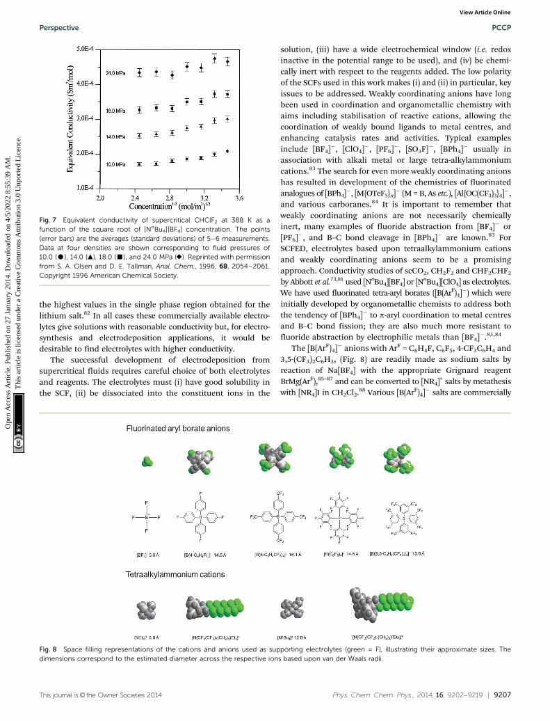
solution, (iii) have a wide electrochemical window (i.e. redoxinactive in the potential range to be used), and (iv) be chemi-cally inert with respect to the reagents added. The low polarityof the SCFs used in this work makes (i) and (ii) in particular, keyissues to be addressed. Weakly coordinating anions have longbeen used in coordination and organometallic chemistry withaims including stabilisation of reactive cations, allowing thecoordination of weakly bound ligands to metal centres, andenhancing catalysis rates and activities. Typical examplesinclude [BF4]�, [ClO4]�, [PF6]�, [SO3F]�, [BPh4]� usually inassociation with alkali metal or large tetra-alkylammoniumcations.83 The search for even more weakly coordinating anionshas resulted in development of the chemistries of fluorinatedanalogues of [BPh4]�, [M{OTeF5}n]� (M = B, As etc.), [Al{OC(CF3)3}4]�,and various carboranes.84 It is important to remember thatweakly coordinating anions are not necessarily chemicallyinert, many examples of fluoride abstraction from [BF4]� or[PF6]�, and B–C bond cleavage in [BPh4]� are known.83 ForSCFED, electrolytes based upon tetraalkylammonium cationsand weakly coordinating anions seem to be a promisingapproach. Conductivity studies of scCO2, CH2F2 and CHF2CHF2
by Abbott et al.73,81 used [NnBu4][BF4] or [NnBu4][ClO4] as electrolytes.We have used fluorinated tetra-aryl borates ([B(ArF)4]�) which wereinitially developed by organometallic chemists to address boththe tendency of [BPh4]� to p-aryl coordination to metal centresand B–C bond fission; they are also much more resistant tofluoride abstraction by electrophilic metals than [BF4]�.83,84
The [B(ArF)4]� anions with ArF = C6H4F, C6F5, 4-CF3C6H4 and3,5-(CF3)2C6H3, (Fig. 8) are readily made as sodium salts byreaction of Na[BF4] with the appropriate Grignard reagentBrMg(ArF),85–87 and can be converted to [NR4]+ salts by metathesiswith [NR4]I in CH2Cl2.88 Various [B(ArF)4]� salts are commercially
Fig. 7 Equivalent conductivity of supercritical CHClF2 at 388 K as afunction of the square root of [NnBu4][BF4] concentration. The points(error bars) are the averages (standard deviations) of 5–6 measurements.Data at four densities are shown corresponding to fluid pressures of10.0 (K), 14.0 (m), 18.0 (’), and 24.0 MPa (E). Reprinted with permissionfrom S. A. Olsen and D. E. Tallman, Anal. Chem., 1996, 68, 2054–2061.Copyright 1996 American Chemical Society.
Fig. 8 Space filling representations of the cations and anions used as supporting electrolytes (green = F), illustrating their approximate sizes. Thedimensions correspond to the estimated diameter across the respective ions based upon van der Waals radii.
Perspective PCCP
Ope
n A
cces
s A
rtic
le. P
ublis
hed
on 2
7 Ja
nuar
y 20
14. D
ownl
oade
d on
4/5
/202
2 8:
55:3
9 A
M.
Thi
s ar
ticle
is li
cens
ed u
nder
a C
reat
ive
Com
mon
s A
ttrib
utio
n 3.
0 U
npor
ted
Lic
ence
.View Article Online

9208 | Phys. Chem. Chem. Phys., 2014, 16, 9202--9219 This journal is© the Owner Societies 2014
available, although very expensive, but we have found that,depending on the metal reagents used, it is often possible torecover the electrolyte after deposition, re-purify it and hencerecycle it.
We also explored the effects of using alkylammoniumcations incorporating fluorous ‘‘ponytails’’ to increase solubility.[CF3(CF2)7(CH2)3NnBu3]I was made by quaternisation of nBu3Nwith CF3(CF2)7(CH2)3I, and [CF3(CF2)7(CH2)3NMe3]I fromCF3(CF2)7(CH2)3NH2 and CH3I, and metathesis with Na[B(ArF)4]in CH2Cl2 gave the appropriate [CF3(CF2)7(CH2)3NR3][B(ArF)4].88
Thermogravimetric analysis studies showed that the cationswere thermally stable up to B180 1C, although subsequentconductivity measurements showed the cations were not signifi-cantly better than [NnBu4]+.88
As stressed above, it is important to fully characterise thephase behaviour of the system since addition of significantconcentrations (410 mM) of electrolyte is likely to alter thephase behaviour. This can be done using a view cell of the typedescribed above. These studies should then be complementedby measurements of the conductivity to characterise the behaviourof the different electrolytes. In our work88 we started by comparingthe behaviour for mixtures of CO2 with [NnBu4][BF4] and eithermethanol (CH3OH) or acetonitrile (CH3CN) as the co-solvent. Theseexperiments showed that at similar temperatures and pressures,the solubility of [NnBu4][BF4] was B5 times higher in CH3CN + CO2
than in CH3OH + CO2.Fig. 9 shows the phase behaviour of a ternary CO2–[NnBu4]-
[BF4]–CH3CN system and illustrates the potential complexity.For the mixture shown in Fig. 9, the three-phase region is asurface with 2 degrees of freedom as required by the phase rulefor a ternary system with three phases (F = 3� 3 + 2 = 2). At highT and p there is a single supercritical phase region which gives wayto two and three phase regions as the pressure is decreased. Thephase transition is a normal bubble-point transition (L1 - L1 + V)when the temperature is below T*. However, when T is above T*,the sequence of the phase transition on decreasing the pressureisothermally is: L1 - L1 + L2 - L1 + L2 + V - L1 + V.
From these phase behaviour studies for different compositionsof the ternary mixture we find that increasing the concentrationof [NnBu4][BF4] increases the pressure required to form a homo-geneous solution at a given temperature, and furthermore thatthe more CO2 there is in the system, the higher the pressure thatis required because CO2 is a poor solvent for the ionic species(in this case [NnBu4][BF4]). Again this illustrates the potentialcomplexity of the phase behaviour of these systems and why it isessential to experimentally establish the conditions required toform a single supercritical phase.
In principle, the addition of the electrochemical reagentsused in the electrodeposition will also alter the phase behaviour.In practice for this system, as shown in Fig. 10, the effectsare much smaller, not least because the concentrations ofthe dissolved reagents are much smaller – the addition of B3.5 �10�4 mole fraction of [Ag(hfac)(cod)] or [Cu(hfac)2] (cod =cycloocta-1,5-diene, hfacH = CF3C(O)CH2C(O)CF3) produces onlyslight shifts in the supercritical phase boundary (o2 MPa atfixed temperature).
In order to improve upon the commercial electrolytes we havesynthesised a range of anions and cations selected to achievegreater solubility in scCO2–CH3CN by increasing the ion size andby increasing the degree of fluorination. In our conductivitystudies we found that the effects of adding a fluorous ponytail(replacing [NnBu4]+ by [NRfMe3]+ or [NRfnBu4]+) to the cation weresmall and did not justify the synthetic effort. This is presumablybecause the fluorous ponytail does not alter the separation in theion pair because it is flexible. A similar effect was found byAbbott and Schiffrin89 for tetrafluoroborate salts of long chainalkylammonium cations in low dielectric solvents, where theinterionic distance in the ion pairs is largely independent of thealkyl chain length due to interpenetration.
Table 2 summarises the data, the structures of the ions andtheir relative sizes are shown in Fig. 8. In terms of the effect ofthe anions on the molar conductivity, the general trend is[BF4]� B [B(4-C6H4F)4]� o [B(4-C6H4CF3)4]� B [B(C6F5)4]� o[B{3,5-C6H3(CF3)2}4]� with the highest molar conductivity,22–26 S cm2 mol�1, achieved using the [B{3,5-C6H3(CF3)2}4]�.
Fig. 9 p–T phase diagram of the mixture of CO2 (1) + CH3CN (2) +[NnBu4][BF4](3) with x1 = 0.871, x2 = 0.129, and x3 = 8.3 � 10�4. (’) and(&), the phase boundary between one-, and two-phase region; (J) and(B) mark the region where three phases are in co-existence (L1L2V). Thepressure difference between the two three-phase boundaries is less than0.3 MPa at 333 K.34
Fig. 10 p–T phase diagram of the mixture CO2 (1) + CH3CN (2) +[NnBu4][BF4](3) with and without metal salts (4). x1 = 0.89, x2 = 0.11 andx3 = 1.34 � 10�3. (J) no metal salt; (n) with [Ag(hfac)(cod)], x4 = 3.4 �10�4, and (&) with [Cu(hfac)2], x4 = 3.6 � 10�4.34
PCCP Perspective
Ope
n A
cces
s A
rtic
le. P
ublis
hed
on 2
7 Ja
nuar
y 20
14. D
ownl
oade
d on
4/5
/202
2 8:
55:3
9 A
M.
Thi
s ar
ticle
is li
cens
ed u
nder
a C
reat
ive
Com
mon
s A
ttrib
utio
n 3.
0 U
npor
ted
Lic
ence
.View Article Online

This journal is© the Owner Societies 2014 Phys. Chem. Chem. Phys., 2014, 16, 9202--9219 | 9209
This is about an order of magnitude improvement over[NnBu4][BF4]. For a solution of 0.07 M [NnBu4][B{3,5-C6H3(CF3)2}4] dissolved in scCO2–CH3CN (molar ratio CH3CN :CO2 B 0.12) at 20 MPa and 328.15 K we obtain a maximummeasured conductivity of B3 mS cm�1.
Studies of the conductivity as a function of concentration,Fig. 12, show an increase in molar conductivity with concen-tration for both [NnBu4][B{3,5-C6H3(CF3)2}4] and [NRfnBu3]-[B{3,5-C6H3(CF3)2}4]. At low electrolyte concentrations, Kohlrausch’slaw predicts that the molar conductivity should decrease withincreasing electrolyte concentration.
L ¼ L0 � Affiffiffi
cp
(1)
where L is the molar conductivity, L0 is the sum of the limitingmolar conductivities of the single ions (A+ and B�), A is aconstant and c the concentration of the electrolyte.
However, for low dielectric constant solutions, such assupercritical fluids, the association of ions to form ion pairsand ion triples becomes significant. According to the Fuoss–Krausmodel80 the conductivity under these conditions is given by
L ¼ L0
ffiffiffiffi
Kpffiffiffi
cp þ l0
ffiffiffiffiffiffi
Kcp
k(2)
where K is the equilibrium constant describing formation ofthe AB ion pairs, l0 is the sum of the limiting molar conduc-tances of the two kinds of triple ions (ABA+ and BAB�) and k isthe equilibrium constant describing the formation of the tripleions (assumed to be the same for both types of triple ion forsimplicity). As we can see from Fig. 12 there is reasonableagreement between the data and the Fuoss–Kraus model at thelower electrolyte concentrations. The simple Fuoss–Krausmodel of eqn (2) neglects the effects of the ion interactions onthe conductivity (the electrophoretic and relaxation effects) andassumes that the activity coefficient is unity. More sophisticatedtreatments have been described in the literature that take theseeffects into account (see for example the work of Goldfarb andCorti71 or Abbott and Schiffrin89 for applications of these) butthese require values for the dielectric constant, viscosity orlimiting molar conductivity which we do not have for thissupercritical system. The results in Fig. 11 and 12 also showthat the fluorous ponytail does not have a significant influence
on the extent of ion pairing. From these experiments it is clearthat triple ions make a significant contribution to conductionin scCO2–CH3CN.
We have carried out similar phase behaviour and conduc-tivity studies for supercritical CHF3, CH2F2, and CH2FCF3
containing [NnBu4][BF4], [NnBu4][B{3,5-C6H3(CF3)2}4] andNa[B{3,5-C6H3(CF3)2}4].52 As we can see from Table 3 thesethree hydrofluorocarbons have reasonably accessible criticaltemperatures and pressures and all have dipole momentsgreater than 1.6 D. Compared to the CO2 + CH3CN system(xCO2
/xCH3CN = 0.14) discussed above, the pressures required toform a homogeneous solution for [NnBu4][BF4] electrolyte aremuch lower (Fig. 13).
Table 2 Molar conductivity of the fluorinated supporting electrolytes in amixed fluid of CO2 (1) + CH3CN (2) with a molar ration of x2/x1 = B0.12 at328.15 K and 20 MPa34
[NnBu4]+ [NRfMe3]+ [NRfnBu3]+
[BF4]� 2.3a,b (2.4)c — —[B(4-C6H4F)4]� — 3.1 (2.2) 3.6 (2.4)[B(4-C6H4CF3)4]� — 8.9 (0.9) 10.6 (1.3)[B(C6F5)4]� 10.6 (2.4) 8.8 (1.0) 6.8 (0.7)[B{3,5-C6H3(CF3)2}4]� 22.7 (2.4) 21.5 (2.4) 26.2 (2.5)
a The supporting electrolyte represented here consists of a cation andan anion which can be found from the column name and rowname respectively. b Molar conductivity in units of S cm2 mol�1. c Thenumbers in brackets represent the concentration of electrolytesin mmol dm�3.
Fig. 11 Conductivity of different supercritical fluid electrolyte solutions.Electrical conductivity of supporting electrolytes in a supercritical fluidmixture of CO2 + CH3CN (xCO2
: xCH3CN = 0.89 : 0.11) at 328.15 K and20.0 MPa. B, [NnBu4][BF4]; *, [NnBu4][B{3,5-C6H3(CF3)2}4]; J, [NRfnBu3]-[B{3,5-C6H3(CF3)2}4]; &, [NnBu4][BF4] in pure CH3CN at ambient condition.5
Fig. 12 Plot of Lffiffiffi
cp
against c for the data shown in Fig. 11: (&) [NnBu4]-[B{3,5-C6H3(CF3)2}4]; and (J) [NRfnBu3][B{3,5-C6H3(CF3)2}4]. The line is thebest fit to the low concentration (below 3 � 10�5 mol cm�3) data.34
Table 3 Physical properties of some hydrofluorocarbons
Physical property CHF3 CH2F2 CH2FCF3
Tc/K 299.29 351.26 374.21pc/MPa 4.832 5.782 4.049rc/kg m�3 526.5 424.00 511.90m/D 1.65 1.98 � 0.02 1.80 � 0.22
Perspective PCCP
Ope
n A
cces
s A
rtic
le. P
ublis
hed
on 2
7 Ja
nuar
y 20
14. D
ownl
oade
d on
4/5
/202
2 8:
55:3
9 A
M.
Thi
s ar
ticle
is li
cens
ed u
nder
a C
reat
ive
Com
mon
s A
ttrib
utio
n 3.
0 U
npor
ted
Lic
ence
.View Article Online
9210 | Phys. Chem. Chem. Phys., 2014, 16, 9202--9219 This journal is© the Owner Societies 2014
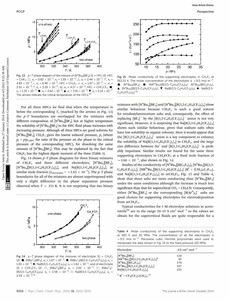
For all three HFCs we find that when the temperature isbelow the corresponding Tc (marked by the arrows in Fig. 13)the p–T boundaries are overlapped for the mixtures withdifferent composition of [NnBu4][BF4] but at higher temperaturethe solubility of [NnBu4][BF4] in the HFC fluid phase increases withincreasing pressure. Although all three HFCs are good solvents for[NnBu4][BF4], CH2F2 gives the lowest reduced pressure, pr (wherepr = p/pc,HFC the ratio of the pressure on the phase to the criticalpressure of the corresponding HFC), for dissolving the sameamount of [NnBu4][BF4]. This may be explained by the fact thatCH2F2 has the highest dipole moment of the three (Table 3).
Fig. 14 shows p–T phase diagrams for three binary mixturesof CH2F2 and three different electrolytes, [NnBu4][BF4],[NnBu4][B{3,5-C6H3(CF3)2}4], and Na[B{3,5-C6H3(CF3)2}4], atsimilar mole fraction (xelectrolyte = B1.65 � 10�3). The p–T phaseboundaries for all of the mixtures are almost superimposed withonly a slight difference in the phase separation pressureobserved when T 4 353 K. It is not surprising that two binary
mixtures with [NnBu4][BF4] and [NnBu4][B{3,5-C6H3(CF3)2}4] showsimilar behaviour because CH2F2 is such a good solventfor tetrabutylammonium salts and, consequently, the effect ofreplacing [BF4]� by the [B{3,5-C6H3(CF3)2}4]� anion is not verysignificant. However, it is surprising that Na[B{3,5-C6H3(CF3)2}4]shows such similar behaviour, given that sodium salts oftenhave low solubility in organic solvents. Here it would appear thatthe [B{3,5-C6H3(CF3)2}4]� anion is a key component to enhancethe solubility of Na[B{3,5-C6H3(CF3)2}4] in CH2F2, and the largesize difference between Na+ and [B{3,5-C6H3(CF3)2}4]� is prob-ably important. Similar results are found for the same threesupporting electrolytes in CH2FCF3 at a fixed mole fraction ofB2.60 � 10�3, also shown in Fig. 14.
Studies of the conductivity of [NnBu4][B(C6F5)4], [NnBu4][B{3,5-C6H3(CF3)2}4], [NRfnBu3][B{3,5-C6H3(CF3)2}4] (Rf = (CH2)3C7F15),and Na[B{3,5-C6H3(CF3)2}4] in scCH2F2, Fig. 15 and Table 4,show that these salts are more conducting than [NnBu4][BF4]under the same conditions although the increase is much lesssignificant than that for supercritical CO2 + CH3CN. Consequently,either [NnBu4][BF4] or the corresponding [B(ArF)4]� salts aregood choices for supporting electrolytes for electrodepositionfrom scCH2F2.
Typical conductivities for 1 M electrolyte solutions in aceto-nitrile90 are in the range 20–55 S cm2 mol�1 so the values weobtain for the supercritical fluids are quite respectable for a
Fig. 13 p–T phase diagram of the mixture of [NnBu4][BF4] (1) + HFC (2). HFC= CHF3: &, x1 = 0.82 � 10�3; x1 = 1.59 � 10�3; n, x1 = 2.44 � 10�3; ,, x1 =4.83 � 10�3; }, x1 = 6.90 � 10�3. HFC = CH2F2: +, x1 = 1.67 � 10�3; �, x1 =2.55 � 10�3; *, x1 = 3.29 � 10�3; ", x1 = 4.17 � 10�3; HFC = CHF2CF3: ’,x1 = 1.33� 10�3; K, x1 = 2.62� 10�3; m, x1 = 3.91� 10�3; ., x1 = 5.14� 10�3.The arrows indicate the critical temperature of the HFCs.52
Fig. 14 p–T phase diagram of the mixtures of electrolyte (1) + CH2F2
(2): ’, [NBun4][BF4], x1 = 1.67 � 10�3; K, [NBun
4][B{3,5-C6H3(CF3)2}4], x1 =1.65 � 10�3;E, Na[B{3,5-C6H3(CF3)2}4], x1 = 1.62 � 10�3; and of electrolyte(1) + CHF2CF3 (2): &, [NBun
4][BF4], x1 = 2.62 � 10�3; J, [NBun4]-
[B{3,5-C6H3(CF3)2}4], x1 = 2.58 � 10�3; B, Na[B{3,5-C6H3(CF3)2}4], x1 =2.59 � 10�3.52
Fig. 15 Molar conductivity of the supporting electrolytes in CH2F2 at363.15 K. The molar concentration of the electrolytes is B9.0 mol m�3.’, [NnBu4][BF4]; K, [NRfnBu3][B{3,5-C6H3(CF3)2}4]; [NnBu4][B(C6F5)4];m, [NnBu4][B{3,5-C6H3(CF3)2}4]; ., Na[B{3,5-C6H3(CF3)2}4]; E, Na[B{3,5-C6H3(CF3)2}4].52
Table 4 Molar conductivity of the supporting electrolytes in CH2F2
at 363 K and 20 MPa. The concentration of all the electrolytes isB9.0 mol m�3. Piecewise cubic Hermite polynomials were used tointerpolate the data shown in Fig. 15 to the fixed pressure (20 MPa)
Electrolyte L/S cm2 mol�1
[NnBu4][BF4] 124[NRfnBu3][B{3,5-C6H3(CF3)2}4]a 95[NnBu4][B(C6F5)4] 170[NnBu4][B{3,5-C6H3(CF3)2}4] 197Na[B{3,5-C6H3(CF3)2}4] 255
a Rf = CF3(CF2)7(CH2)3.52
PCCP Perspective
Ope
n A
cces
s A
rtic
le. P
ublis
hed
on 2
7 Ja
nuar
y 20
14. D
ownl
oade
d on
4/5
/202
2 8:
55:3
9 A
M.
Thi
s ar
ticle
is li
cens
ed u
nder
a C
reat
ive
Com
mon
s A
ttrib
utio
n 3.
0 U
npor
ted
Lic
ence
.View Article Online
This journal is© the Owner Societies 2014 Phys. Chem. Chem. Phys., 2014, 16, 9202--9219 | 9211
non-aqueous electrolyte and sufficient to carry out electro-chemical studies.
5. Reagents
The reagents used in SCFED also require a number of keyproperties. In addition to solubility in the SCF, they need to beboth stable to the electrolyte and at the working temperature, andideally readily synthesised in high purity. Unwanted electrochemicalside reactions which could result in fouling of the electrode orcounter-electrode by the reagents and reactive liberated ligands mustalso be avoided. For example, [Ag(cod)(hfac)]BF4 (cod = cyclo-octadiene; hfac = hexafluoroacetylacetonyl) is unsuitable for Agdeposition, probably because the cod fouls the counter electrode,whilst if [Cu(hfac)2] is used for copper deposition in scCO2–CH3CNthe deposited copper can redissolve due to the reaction91
[Cu(hfac)2] + Cu + 8CH3CN - 2[Cu(CH3CN)4]+ + 2hfac�
(3)
For deposition of transition metals from scCO2–CH3CN thenitrile complexes [M(CH3CN)x][BF4]n (M = Fe, Co, Cu, Ag, etc.)are attractive reagents since the anion can be present in theelectrolyte and the deposition liberates CH3CN which is presentas co-solvent, hence no chemical incompatibilities are presented.5,91
However in scCH2F2, the complexes are unstable in the absence ofadded CH3CN, which limits their usefulness, whilst [Cu(hfac)2] isstable in scCH2F2.52 The nitrile complexes are readily made from themetal powders and NO[BF4] in CH3CN.92,93 In the case of Cu(I),[Cu(CH3CN)4][BF4] is obtainable from Cu2O and aqueous HBF4 inCH3CN, or by refluxing Cu[BF4]2 with copper in CH3CN.94 The nitrilecomplexes can also be converted to [B(ArF)4]� salts to increasesolubility in the SCF if required.92,93 For silver electrodepositionseveral reagents were considered for use in scCO2–CH3CN including[Ag(hfac)(cod)], [Ag(CH3CN)4][BF4], and [CF3(CF2)6CO2Ag(PPh3)2]and [Ag(PPh3)4][BF4], in which the arylphosphine groups and theperfluorocarboxylate ligand were introduced to increase solubilityin hydrofluorocarbons. Of these, [Ag(CH3CN)4][BF4] was found tobe the most suitable for silver deposition from scCO2–CH3CN(see below).95
The choice of reagents to electrodeposit germanium is lessobvious than for copper or silver. Germanium forms compoundsin two oxidation states, Ge(II) and Ge(IV), and the chemical stabilityof its compounds varies widely with the ligands present.6,96
Many Ge(IV) complexes are moisture sensitive, whilst the ther-mal stability of Ge(II) complexes is often poor. Among the Ge(II)complexes explored were the commercially available GeBr2, acomplex of the functionalised diimine [GeCl2(4,40-didecyl-2,20-bipyridyl)],6 the trichlorogermanate(II) salt [NnBu4][GeCl3],made by reduction of GeCl4 in aqueous hydrochloric acid withH3PO2, followed by addition of [NnBu4]Cl,6 and [Ge(12-crown-4)2][CF3SO3]2, made from [GeCl2(dioxane)] and 12-crown-4. Thefirst two proved to be too poorly soluble in scCH2F2, and whilstit was soluble, [Ge(12-crown-4)2][CF3SO3]2 degraded in the samesolvent.6 [NnBu4][GeCl3] was both soluble and stable in scCH2F2
and its electrochemistry is described below. Among the Ge(IV)
reagents assessed were [GeF4(CH3CN)2], made by passing GeF4
gas into dry CH3CN, and [GeF4(Me2NCH2CH2NMe2)], preparedfrom [GeF4(CH3CN)2] and Me2NCH2CH2NMe2 in CH2Cl2.97
These two reagents were chosen as they are thermally relativelystable, and since they are coordinatively saturated, they aremoisture stable solids and relatively resistant to hydrolysis insolution. Unfortunately, they proved to be insufficiently solublein the SCFs. As a non-polar liquid, GeCl4 (B.P. 365 K) wasexpected to be readily miscible with SCFs, but it is moisturesensitive and readily hydrolysed. It is commercially availableand easily dried and purified by distillation from a mixture ofNa2CO3 and CaH2.
6. Electrodeposition
There is very little published work on electrodeposition fromsupercritical fluids. As described above, the earliest work isprobably that of Williams and Naiditch54 in 1976 and the workof Silvestri et al.55 five years later. Finally, MacDonald et al.62 in1986 reported deposition of Cu from CuCl2 under supercritical,or close to supercritical, H2O containing KCl at 573 K and8.2 MPa. Apart from the three papers on electrodeposition ofmetals there are also a few papers which describe the electro-deposition of conducting polymers from supercritical fluids. Thisis slightly different because in this case the neutral solutionspecies (the heterocyclic monomer) is oxidised to produce acharged product (the oxidised polymer) which deposits with thecounter ion on the electrode surface. The first paper claiming toelectrodeposit poly(pyrrole) and poly(aniline) from a supercriticalfluid appeared in 2002.98 This group used CO2 containing 13.1%acetonitrile, 0.16 M pyrrole and 0.16 M [NnBu4][PF6] at 323 K and9.65 MPa. Subsequent work published in 2005 by Yan et al.99
using a view cell showed that under these conditions the systemwas biphasic and not in the supercritical state. Yan et al. were,however, able to deposit poly(pyrrole) films from supercriticalfluid using CO2 containing 13.1% acetonitrile, 0.16 M pyrroleand 0.04 M [NnBu4][PF6] at 323 K and 10 MPa. This illustratesone of the potential pitfalls of working with, or trying to workwith, supercritical fluids. It is not sufficient to rely on the criticaltemperature and critical pressure of the pure fluid, but rather it isessential to properly characterise the phase behaviour of thewhole system. The honour of reporting the first successful electro-polymerisation of a conducting polymer from a supercritical fluidconsequently falls to Atobe et al.100 who, in 2004, reported theelectropolymerisation of poly(pyrrole) and poly(thiophene) fromscCHF3 containing 10 mM pyrrole or thiophene with 40 mM[NnBu4][PF6] at 323 K and 15 MPa.
Before moving on to discuss our recent work, it is appropriate tomention the work of Sone’s group on electrodeposition from denseemulsions of CO2. The group has published extensively, starting in2002,101 on the electrodeposition of Ni from a dense emulsion of anaqueous Ni plating (Watts) bath formed in scCO2 using surfactants(typical conditions 323 K and 15 MPa and 60 vol% of the aqueousplating bath stabilised with 1 vol% surfactant).102 This is not asingle phase supercritical fluid. The advantages of the system
Perspective PCCP
Ope
n A
cces
s A
rtic
le. P
ublis
hed
on 2
7 Ja
nuar
y 20
14. D
ownl
oade
d on
4/5
/202
2 8:
55:3
9 A
M.
Thi
s ar
ticle
is li
cens
ed u
nder
a C
reat
ive
Com
mon
s A
ttrib
utio
n 3.
0 U
npor
ted
Lic
ence
.View Article Online
9212 | Phys. Chem. Chem. Phys., 2014, 16, 9202--9219 This journal is© the Owner Societies 2014
are that it produces high quality Ni films with higher uniformity,smaller (sub 100 nm) grain size and significantly higher Vickershardness than conventional electroplating from aqueoussolution.103 This is attributed, at least in part, to the enhanceddesorption of hydrogen gas bubbles during deposition.104 Thesame group has also applied this approach to the deposition ofpoly(pyrrole)105 and copper.106
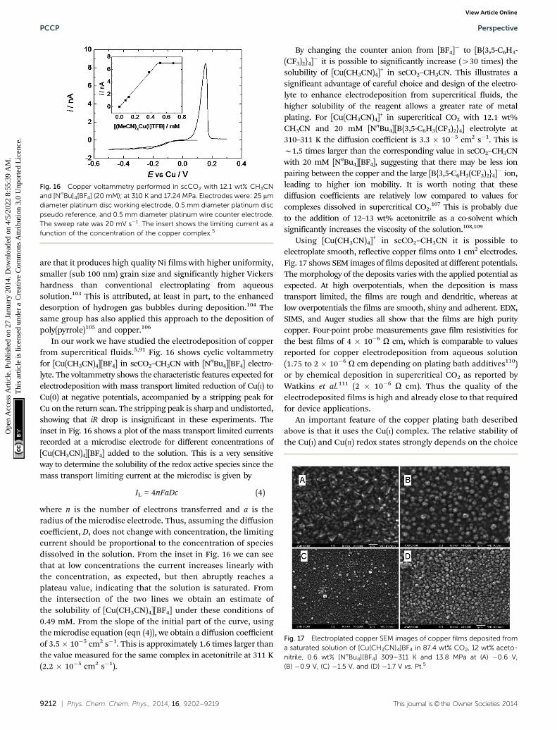
In our work we have studied the electrodeposition of copperfrom supercritical fluids.5,91 Fig. 16 shows cyclic voltammetryfor [Cu(CH3CN)4][BF4] in scCO2–CH3CN with [NnBu4][BF4] electro-lyte. The voltammetry shows the characteristic features expected forelectrodeposition with mass transport limited reduction of Cu(I) toCu(0) at negative potentials, accompanied by a stripping peak forCu on the return scan. The stripping peak is sharp and undistorted,showing that iR drop is insignificant in these experiments. Theinset in Fig. 16 shows a plot of the mass transport limited currentsrecorded at a microdisc electrode for different concentrations of[Cu(CH3CN)4][BF4] added to the solution. This is a very sensitiveway to determine the solubility of the redox active species since themass transport limiting current at the microdisc is given by
IL = 4nFaDc (4)
where n is the number of electrons transferred and a is theradius of the microdisc electrode. Thus, assuming the diffusioncoefficient, D, does not change with concentration, the limitingcurrent should be proportional to the concentration of speciesdissolved in the solution. From the inset in Fig. 16 we can seethat at low concentrations the current increases linearly withthe concentration, as expected, but then abruptly reaches aplateau value, indicating that the solution is saturated. Fromthe intersection of the two lines we obtain an estimate ofthe solubility of [Cu(CH3CN)4][BF4] under these conditions of0.49 mM. From the slope of the initial part of the curve, usingthe microdisc equation (eqn (4)), we obtain a diffusion coefficientof 3.5� 10�5 cm2 s�1. This is approximately 1.6 times larger thanthe value measured for the same complex in acetonitrile at 311 K(2.2 � 10�5 cm2 s�1).
By changing the counter anion from [BF4]� to [B{3,5-C6H3-(CF3)2}4]� it is possible to significantly increase (430 times) thesolubility of [Cu(CH3CN)4]+ in scCO2–CH3CN. This illustrates asignificant advantage of careful choice and design of the electro-lyte to enhance electrodeposition from supercritical fluids, thehigher solubility of the reagent allows a greater rate of metalplating. For [Cu(CH3CN)4]+ in supercritical CO2 with 12.1 wt%CH3CN and 20 mM [NnBu4][B{3,5-C6H3(CF3)2}4] electrolyte at310–311 K the diffusion coefficient is 3.3 � 10�5 cm2 s�1. This isB1.5 times larger than the corresponding value in scCO2–CH3CNwith 20 mM [NnBu4][BF4], suggesting that there may be less ionpairing between the copper and the large [B{3,5-C6H3(CF3)2}4]� ion,leading to higher ion mobility. It is worth noting that thesediffusion coefficients are relatively low compared to values forcomplexes dissolved in supercritical CO2.107 This is probably dueto the addition of 12–13 wt% acetonitrile as a co-solvent whichsignificantly increases the viscosity of the solution.108,109
Using [Cu(CH3CN)4]+ in scCO2–CH3CN it is possible toelectroplate smooth, reflective copper films onto 1 cm2 electrodes.Fig. 17 shows SEM images of films deposited at different potentials.The morphology of the deposits varies with the applied potential asexpected. At high overpotentials, when the deposition is masstransport limited, the films are rough and dendritic, whereas atlow overpotentials the films are smooth, shiny and adherent. EDX,SIMS, and Auger studies all show that the films are high puritycopper. Four-point probe measurements gave film resistivities forthe best films of 4 � 10�6 O cm, which is comparable to valuesreported for copper electrodeposition from aqueous solution(1.75 to 2 � 10�6 O cm depending on plating bath additives110)or by chemical deposition in supercritical CO2 as reported byWatkins et al.111 (2 � 10�6 O cm). Thus the quality of theelectrodeposited films is high and already close to that requiredfor device applications.
An important feature of the copper plating bath describedabove is that it uses the Cu(I) complex. The relative stability ofthe Cu(I) and Cu(II) redox states strongly depends on the choice
Fig. 16 Copper voltammetry performed in scCO2 with 12.1 wt% CH3CNand [NnBu]4[BF4] (20 mM); at 310 K and 17.24 MPa. Electrodes were: 25 mmdiameter platinum disc working electrode, 0.5 mm diameter platinum discpseudo reference, and 0.5 mm diameter platinum wire counter electrode.The sweep rate was 20 mV s�1. The insert shows the limiting current as afunction of the concentration of the copper complex.5
Fig. 17 Electroplated copper SEM images of copper films deposited froma saturated solution of [Cu(CH3CN)4]BF4 in 87.4 wt% CO2, 12 wt% aceto-nitrile, 0.6 wt% [NnBu4][BF4] 309–311 K and 13.8 MPa at (A) �0.6 V,(B) �0.9 V, (C) �1.5 V, and (D) �1.7 V vs. Pt.5
PCCP Perspective
Ope
n A
cces
s A
rtic
le. P
ublis
hed
on 2
7 Ja
nuar
y 20
14. D
ownl
oade
d on
4/5
/202
2 8:
55:3
9 A
M.
Thi
s ar
ticle
is li
cens
ed u
nder
a C
reat
ive
Com
mon
s A
ttrib
utio
n 3.
0 U
npor
ted
Lic
ence
.View Article Online
This journal is© the Owner Societies 2014 Phys. Chem. Chem. Phys., 2014, 16, 9202--9219 | 9213
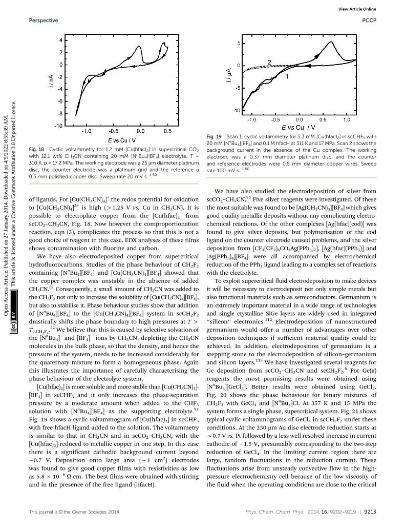
of ligands. For [Cu(CH3CN)4]+ the redox potential for oxidationto [Cu(CH3CN)4]2+ is high (41.25 V vs. Cu in CH3CN). It ispossible to electroplate copper from the [Cu(hfac)2] fromscCO2–CH3CN, Fig. 18. Now however the comproportionationreaction, eqn (3), complicates the process so that this is not agood choice of reagent in this case. EDX analyses of these filmsshows contamination with fluorine and carbon.
We have also electrodeposited copper from supercriticalhydrofluorocarbons. Studies of the phase behaviour of CH2F2
containing [NnBu4][BF4] and [Cu(CH3CN)4][BF4] showed thatthe copper complex was unstable in the absence of addedCH3CN.52 Consequently, a small amount of CH3CN was added tothe CH2F2 not only to increase the solubility of [Cu(CH3CN)4][BF4],but also to stabilise it. Phase behaviour studies show that additionof [NnBu4][BF4] to the [Cu(CH3CN)4][BF4] system in scCH2F2
drastically shifts the phase boundary to high pressures at T 4Tc,CH2F2
.52 We believe that this is caused by selective solvation ofthe [NnBu4]+ and [BF4]� ions by CH3CN, depleting the CH3CNmolecules in the bulk phase, so that the density, and hence thepressure of the system, needs to be increased considerably forthe quaternary mixture to form a homogeneous phase. Againthis illustrates the importance of carefully characterising thephase behaviour of the electrolyte system.
[Cu(hfac)2] is more soluble and more stable than [Cu(CH3CN)4]-[BF4] in scCHF3 and it only increases the phase-separationpressure by a moderate amount when added to the CHF3
solution with [NnBu4][BF4] as the supporting electrolyte.91
Fig. 19 shows a cyclic voltammogram of [Cu(hfac)2] in scCHF3
with free hfacH ligand added to the solution. The voltammetryis similar to that in CH3CN and in scCO2–CH3CN, with the[Cu(hfac)2] reduced to metallic copper in one step. In this casethere is a significant cathodic background current beyond�0.7 V. Deposition onto large area (B1 cm2) electrodeswas found to give good copper films with resistivities as lowas 5.8 � 10�6 O cm. The best films were obtained with stirringand in the presence of the free ligand (hfacH).
We have also studied the electrodeposition of silver fromscCO2–CH3CN.95 Five silver reagents were investigated. Of thesethe most suitable was found to be [Ag(CH3CN)4][BF4] which givesgood quality metallic deposits without any complicating electro-chemical reactions. Of the other complexes [Ag(hfac)(cod)] wasfound to give silver deposits, but polymerisation of the codligand on the counter electrode caused problems, and the silverdeposition from [CF3(CF2)6CO2Ag(PPh3)2], [Ag(hfac)(PPh3)] and[Ag(PPh3)4][BF4] were all accompanied by electrochemicalreduction of the PPh3 ligand leading to a complex set of reactionswith the electrolyte.
To exploit supercritical fluid electrodeposition to make devicesit will be necessary to electrodeposit not only simple metals butalso functional materials such as semiconductors. Germanium isan extremely important material in a wide range of technologiesand single crystalline SiGe layers are widely used in integrated‘‘silicon’’ electronics.112 Electrodeposition of nanostructuredgermanium would offer a number of advantages over otherdeposition techniques if sufficient material quality could beachieved. In addition, electrodeposition of germanium is astepping stone to the electrodeposition of silicon–germaniumand silicon layers.113 We have investigated several reagents forGe deposition from scCO2–CH3CN and scCH2F2.6 For Ge(II)reagents the most promising results were obtained using[NnBu4][GeCl3]. Better results were obtained using GeCl4.Fig. 20 shows the phase behaviour for binary mixtures ofCH2F2 with GeCl4 and [NnBu4]Cl. At 357 K and 15 MPa thesystem forms a single phase, supercritical system. Fig. 21 showstypical cyclic voltammograms of GeCl4 in scCH2F2 under theseconditions. At the 250 mm Au disc electrode reduction starts atB0.7 V vs. Pt followed by a less well resolved increase in currentcathodic of �1.5 V, presumably corresponding to the two-stepreduction of GeCl4. In the limiting current region there arelarge, random fluctuations in the reduction current. Thesefluctuations arise from unsteady convective flow in the high-pressure electrochemistry cell because of the low viscosity ofthe fluid when the operating conditions are close to the critical
Fig. 18 Cyclic voltammetry for 1.2 mM [Cu(hfac)2] in supercritical CO2
with 12.1 wt% CH3CN containing 20 mM [NnBu4][BF4] electrolyte. T =310 K. p = 17.2 MPa. The working electrode was a 25 mm diameter platinumdisc, the counter electrode was a platinum grid and the reference a0.5 mm polished copper disc. Sweep rate 20 mV s�1.50
Fig. 19 Scan 1, cyclic voltammetry for 5.3 mM [Cu(hfac)2] in scCHF3 with20 mM [NnBu4][BF4] and 0.1 M hfacH at 311 K and 17 MPa. Scan 2 shows thebackground current in the absence of the Cu complex. The workingelectrode was a 0.37 mm diameter platinum disc, and the counterand reference electrodes were 0.5 mm diameter copper wires. Sweeprate 100 mV s�1.50
Perspective PCCP
Ope
n A
cces
s A
rtic
le. P
ublis
hed
on 2
7 Ja
nuar
y 20
14. D
ownl
oade
d on
4/5
/202
2 8:
55:3
9 A
M.
Thi
s ar
ticle
is li
cens
ed u
nder
a C
reat
ive
Com
mon
s A
ttrib
utio
n 3.
0 U
npor
ted
Lic
ence
.View Article Online

9214 | Phys. Chem. Chem. Phys., 2014, 16, 9202--9219 This journal is© the Owner Societies 2014
point of CH2F2. We can also see that there is significant iR dropin this case. This is because the conductivity of the [NnBu4]Clsupporting electrolyte is low in scCH2F2. These conditions canbe used for bulk deposition of Ge, the ‘as deposited’ materialwas amorphous, but crystallised under high intensity laserillumination.6
7. Templates
Electrodeposition into small and high aspect ratio pore structuresis a specific advantage of SCFED, and provides opportunities togrow high aspect ratio nanowires or to construct multi-componentdevices in electrically directed locations. Aligned pore struc-tures will need to be used in future to deliver the promise oflinking properties to designed nanostructures.
Electrochemical reaction of aluminium in an acidic environ-ment is well known to produce porous anodic aluminium oxide(AAO) films and well-ordered hexagonal AAO films (Fig. 22a) areachievable if the anodisation conditions are well optimised.114–116
These materials can be produced with pore sizes from around5 nm117 to 500 nm,118 and the resulting templates are electrically
and thermally insulating, optically transparent and robust.Typically they are grown on the surface of a solid aluminiumfoil electrodes, but can also be produced in sputtered aluminiumfilms on other surfaces such as ITO-glass,119 suggesting oppor-tunities to make porous structures on various substrates. Severalauthors have published electrodeposition of metals and othermaterials into these structures from more conventional electro-lytes.120,121 Many of these porous films are now commerciallyproduced, where they are cleaved from the aluminium surface toproduce self-supporting membranes. The chemistry to producesimilar structures in other oxides, especially titanium dioxide, isalso now well developed.122
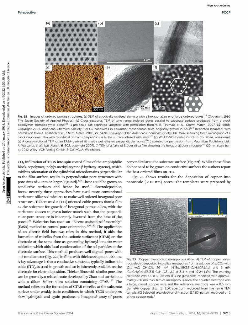
Surfactant- and block copolymer-templated porous films arethe commonest porous materials with small pore sizes, withpores ranging from below 3 nm to above 10 nm. It is possible toproduce a variety of 1-, 2- or 3-dimensional pore structurescontrolled by a combination of surfactant type, concentrationand temperature. Evaporation induced self-assembly (EISA) is aprocess in which the concentration increase that results fromsolvent evaporation during coating drives both the formation ofmicelles from the surfactant and condensation of the silicaspecies in the sol. However, the EISA process is difficult tocontrol. The linear pores that are present in hexagonal phasesilica are particularly attractive hosts for electrodeposition andare the most heavily studied morphology. The alignment of thepores is controlled by the relative strength of the interactionbetween the micelle surfaces and the substrate compared withmicelle–micelle interactions. In most cases the pores are eitherrandomly oriented (referred to as ‘‘worm-like’’) or are parallel tothe substrate.128 Parallel pores can be brought into long rangealignment (Fig. 22b) by the addition of a low molar mass homo-polymer to a block copolymer template film and then infiltrating atetraethylorthosilicate (TEOS) precursor as a supercritical CO2
solution.123 Filling pores in this orientation is very interestingfrom an applications viewpoint due to the anisotropy that ispresent in the plane of the film, but pore access is more limitedthan in films with pores perpendicular to the film surface.
The tendency for pores to align with the substrate surfacehas been used to good effect in formation of mesoporous silicainside AAO membranes.129 These have well-formed larger poresthat are perpendicular to the face of the membrane. When a silicasol containing a surfactant at an appropriate concentration isinfiltrated into one of these membranes the mesopores can beoriented along the length of the host pore (columnar growth) or canform toroidal or helical channels depending on deposition condi-tions. High humidity is frequently the key parameter in obtainingcolumnar growth, which is the most accessible morphology forelectrodeposition (although electrodeposition into the other struc-ture types has also been demonstrated). Copper, silver and telluriumnanowires have already been deposited in larger (P123-templated)columnar pores synthesised in this way (Fig. 22c).124
Thin hexagonal mesoporous films with pores perpendicularto the plane of the film have been grown at an oil–water interfaceusing CTAB (cetyltrimethylammonium bromide) surfactant.130
These films were very thin and not useful as electrodepositionhosts. However, Nagarajan et al. have shown that supercritical
Fig. 20 p–T phase diagrams of the binary mixtures of CH2F2 + A: A =GeCl4 (&), xA = 4.4 � 10�3; and A = [NnBu4]Cl (J), xA = 2.95 � 10�3.6
Fig. 21 Cyclic voltammogram of 0.06 mol dm�3 GeCl4 in scCH2F2 with0.06 mol dm�3 [NnBu4]Cl as the supporting electrolyte. The workingelectrodes were a 250 mm Au microdisc (blue line, scan rate 0.1 V s�1),and a 0.36 cm2 gold-coated glass slide (red line, scan rate 0.1 V s�1). Themeasurements were carried out at 357 K and 15 MPa.6
PCCP Perspective
Ope
n A
cces
s A
rtic
le. P
ublis
hed
on 2
7 Ja
nuar
y 20
14. D
ownl
oade
d on
4/5
/202
2 8:
55:3
9 A
M.
Thi
s ar
ticle
is li
cens
ed u
nder
a C
reat
ive
Com
mon
s A
ttrib
utio
n 3.
0 U
npor
ted
Lic
ence
.View Article Online
This journal is© the Owner Societies 2014 Phys. Chem. Chem. Phys., 2014, 16, 9202--9219 | 9215
CO2 infiltration of TEOS into spin-coated films of the amphiphilicblock copolymer, poly(a-methyl styrene-b-hydroxy styrene), whichexhibits orientation of the cylindrical microdomains perpendicularto the film surface, results in perpendicular pore structures withpore sizes of 20 nm or larger (Fig. 22d).125 These could be grown onconductive surfaces and hence be useful electrodepositionhosts. Recently three approaches have used more conventionalsurfactant–silica sol mixtures to make well-ordered hexagonal porestructures. Tolbert used a (111)-oriented cubic porous titania filmas the substrate for growth of hexagonal porous silica, with thesurfactant chosen to give a lattice match such that the perpendi-cular pore structure is inherently favoured from the base of thepores.131 Walcarius has used an ‘‘Electro-assisted self-assembly’’(EASA) method to control pore orientation.126,132 The applicationof an electric field has two roles in this method, it aids theformation of micelles from the cationic surfactant (CTAB) on theelectrode at the same time as generating hydroxyl ions via wateroxidation which aids local condensation of the sol particles at theelectrode surface. This method produces well-aligned pores withB3 nm diameter (Fig. 22e) in films with thickness up to B100 nm.A key advantage is that a conductive substrate, typically indium tinoxide (ITO), is used in growth and so is inherently available as theelectrode for electrodeposition. Thicker films with similar pore sizecan be grown by a related route developed by Zhao and carried outwith a dilute Stober silica solution containing CTAB.127 Themethod relies on the formation of CTAB micelles at the substratesurface under weakly basic conditions in which TEOS undergoesslow hydrolysis and again produces a hexagonal array of pores
perpendicular to the substrate surface (Fig. 22f). Whilst these filmsdo not need to be grown on conductive surfaces the authors reportthe best ordered films on ITO.
Fig. 23 shows results for the deposition of copper intonanoscale (o10 nm) pores. The templates were prepared by
Fig. 22 Images of ordered porous structures. (a) SEM of anodically oxidised alumina with a hexagonal array of large ordered pores118 (Copyright 1998The Japan Society of Applied Physics). (b) Cross-sectional TEM of long range ordered pores parallel to substrate surface produced from a blockcopolymer–homopolymer blend123 (1 mm scale bar; reprinted (adapted) with permission from V. R. Tirumala et al., Chem. Mater., 2007, 19, 5868.Copyright 2007, American Chemical Society). (c) Cu nanowires in columnar mesoporous silica originally grown in AAO124 (reprinted (adapted) withpermission from A. Keilbach et al., Chem. Mater., 2010, 22, 5430. Copyright 2007, American Chemical Society). (d) Phase scanning force micrograph of ablock copolymer film with cylindrical domains perpendicular to the surface infused with silica125 (r WILEY-VCH Verlag GmbH & Co. KGaA, Weinheim).(e) A cross-sectional TEM of an EASA-derived film with well-aligned perpendicular pores126 (reprinted by permission from Macmillan Publishers Ltd.:A. Walcarius et al., Nat. Mater., 6, 602, copyright 2007). (f) TEM of a flake of Stober silica film showing the hexagonal pore structure127 (20 nm scale bar;r 2012 Wiley-VCH Verlag GmbH & Co. KGaA, Weinheim).
Fig. 23 Copper nanorods in mesoporous silica. (A) TEM of copper nano-rods electrodeposited into silica mesopores from a solution of scCO2 with12.1 wt% CH3CN, 20 mM [NnBu4][B{3,5-C6H3(CF3)2}4], and 2 mM[Cu(CH3CN)4][B{3,5-C6H3(CF3)2}4] at 311 K and 17.24 MPa. The workingelectrode was a 0.8 � 0.5 cm ITO on glass slide modified with approxi-mately 250 nm thick film of mesoporous silica; the counter electrode wasa large, coiled, copper wire and the reference electrode was a 0.5 mmdiameter copper disc. (B) EDX spectrum recorded from the same TEMsample. (C) Selected area electron diffraction (SAED) pattern recorded on 1of the copper rods.5
Perspective PCCP
Ope
n A
cces
s A
rtic
le. P
ublis
hed
on 2
7 Ja
nuar
y 20
14. D
ownl
oade
d on
4/5
/202
2 8:
55:3
9 A
M.
Thi
s ar
ticle
is li
cens
ed u
nder
a C
reat
ive
Com
mon
s A
ttrib
utio
n 3.
0 U
npor
ted
Lic
ence
.View Article Online

9216 | Phys. Chem. Chem. Phys., 2014, 16, 9202--9219 This journal is© the Owner Societies 2014
dip coating ITO slides in a solution of Brij56, TMOS, 0.5 M HCland MeOH (1 : 1.8 : 1 : 3.8 by weight). After calcining, this producesan adherent mesoporous silica film roughly 200 nm thick contain-ing a regular hexagonal array of approximately 3 nm diametercylindrical pores approximately 6 nm apart but randomly alignedwith respect to the substrate. Electrochemical deposition of copperwas carried out from [Cu(CH3CN)4][B{3,5-C6H3(CF3)2}4] in scCO2–CH3CN containing 20 mM [NnBu4][B{3,5-C6H3(CF3)2}4]. The TEMimage in Fig. 23A shows the regular array of cylindrical poresclearly visible in cross section on the left hand side of the image.Evidence that the pores are filled with copper is provided by theEDX analysis, which shows strong copper as well as the expectedsilicon and oxygen signals, Fig. 23B, and by the selected areaelectron diffraction results, Fig. 23C, which show a combi-nation of diffuse rings attributed to silica together with ringsthat are consistent with the expected (111), (200), (220), and(311) diffraction peaks for copper. These results demonstratethe proof-of-principle, but much remains to be done to improvealignment and produce nanowire devices.
8. Conclusions and future prospects
The barriers to successful electrodeposition from a supercriti-cal fluid are significant, but the field has now progressedbeyond the stage of preliminary studies to the point wheregenerally applicable methods for supercritical fluid electro-deposition have been developed. An important contributionhas been to establish a range of supporting electrolytes capableof achieving high ionic conductivities in the low dielectricconstant fluids. Supercritical fluid electrodeposition has beenused to deposit a range of different materials, e.g. Ag, Cu, andGe, from complex ions with different overall charges, differentligand types and with different oxidation states. It has beendemonstrated that a range of supercritical fluids, includingboth those with moderate dielectric constants and those withlow dielectric constant when combined with a suitable co-solvent, can be used to electrodeposit films. Whilst not everycombination of supercritical fluid and target material will bepossible, the existing work clearly indicates that the range ofmaterials that can be deposited could be expanded signifi-cantly, for example to a wider range of metals, semiconductors,binary and ternary compounds and alloys. The work so far hasdemonstrated that, by suitable design and choice of the combi-nation of anion and cation, it is possible to achieve super-critical fluid electrolytes with surprisingly large conductivitiesthat will allow deposition at sufficiently high rates to be useful.The field of supercritical fluid electrodeposition is still at anearly stage but progress has been good and the prospects arevery encouraging. In taking this work forward our increasingknowledge of the underpinning physical chemistry, in terms ofthe phase behaviour of the supercritical fluid mixtures, thesolubility, stability and conductivity of electrolytes and complexreagents in supercritical fluids, the phase behaviour of super-critical fluids in confined spaces, the structure of the doublelayer at the supercritical fluid/electrode interface, the kinetics
of ligand exchange and electron transfer reactions in super-critical fluids, etc., will be very important.
Considerable advances have been achieved in the field ofsupercritical fluid electrodeposition, but it is important not tolose sight of the fact that electrodeposition from a supercriticalfluid will always involve significant practical challenges due tothe high pressures involved. This means that supercritical fluidelectrodeposition will only become technologically important ifthere are very clear advantages and novel applications whichonly supercritical fluid electrodeposition can fulfil. The parti-cular properties of supercritical fluids strongly suggest that justsuch novel applications will exist, most probably in the area ofcomplex and extreme nanostructures. However, as yet definitiveproof of this has not been demonstrated and this has to be oneof the key priorities for the field. What are the most likelycandidates for these novel applications? One way of viewingsupercritical fluid electrodeposition is as an extension of non-aqueous electrodeposition to higher temperature. Whilst lowerdeposition temperatures are often advantageous economically,better material quality, e.g. crystallinity, often requires anelevated deposition temperature. For any specific solventthe critical temperature is a fundamental limit above whichelectrodeposition can only be performed using the supercriticalfluid electrodeposition technique. One area in which super-critical fluids are already showing promise is their ability topenetrate into very small pores. In particular supercritical fluidelectrochemistry has been used to electrodeposit into 3 nmpores within mesoporous silicas.
It will take some time, and more work, to discover whethersupercritical fluid electrodeposition can open up novel areas innanomaterials and structures; however there are a number ofshorter term goals which will enable the field to develop intonew and exciting areas. These include, from a physical chemistryperspective, a better understanding of the structure of thedouble layer and of electrolyte solvation in supercritical fluids,studies of electron transfer kinetics at the electrode supercriticalfluid interface, studies of speciation in supercritical fluids, and agreater understanding of the phase behaviour of supercriticalfluids and supercritical fluid electrolytes in confined spaces. Inaddition there is much scope for practical advances in the designof new cells, in solvent purification and for the application ofsupercritical fluids in electrosynthesis.
In conclusion, supercritical fluid electrochemistry has comea long way in a relatively short time and has achieved a numberof goals which many people thought were not possible. It is anexciting field with significant scientific challenges and we hopethat this perspective will stimulate others to consider howelectrochemistry in supercritical fluids might be applied notonly in materials deposition, but also in other areas.
Acknowledgements
This work is part of the Supercritical Fluid Electrodepositionproject (www.scfed.net) which is a multidisciplinary collabora-tion of British universities investigating the fundamental and
PCCP Perspective
Ope
n A
cces
s A
rtic
le. P
ublis
hed
on 2
7 Ja
nuar
y 20
14. D
ownl
oade
d on
4/5
/202
2 8:
55:3
9 A
M.
Thi
s ar
ticle
is li
cens
ed u
nder
a C
reat
ive
Com
mon
s A
ttrib
utio
n 3.
0 U
npor
ted
Lic
ence
.View Article Online

This journal is© the Owner Societies 2014 Phys. Chem. Chem. Phys., 2014, 16, 9202--9219 | 9217
applied aspects of supercritical fluids funding by a ProgrammeGrant from the EPSRC (EP/I013394/1). MWG gratefullyacknowledges receipt of a Wolfson Merit award. We thankK. Thaller for help in preparation of the manuscript.
References
1 J. M. Blackburn, D. P. Long, A. Cabanas and J. J. Watkins,Science, 2001, 294, 141–145.
2 V. K. Popov, V. N. Bagratashvili, L. I. Krotova,A. O. Rybaltovskii, D. C. Smith, P. S. Timashev, J. Yang,Y. S. Zavorotnii and S. M. Howdle, Green Chem., 2011, 13,2696–2700.
3 M. Schlesinger and M. Paunovic, Modern Electroplating,Wiley, New York, 5th edn, 2010.
4 M. Paunovic and M. Schlesinger, Fundamentals of Electro-chemical Deposition, Wiley, New York, 2006.
5 J. Ke, W. T. Su, S. M. Howdle, M. W. George, D. Cook,M. Perdjon-Abel, P. N. Bartlett, W. Zhang, F. Cheng,W. Levason, G. Reid, J. Hyde, J. Wilson, D. C. Smith,K. Mallik and P. Sazio, Proc. Natl. Acad. Sci. U. S. A.,2009, 106, 14768–14772.
6 J. Ke, P. N. Bartlett, D. Cook, T. L. Easun, M. W. George,W. Levason, G. Reid, D. Smith, W. Su and W. Zhang, Phys.Chem. Chem. Phys., 2012, 14, 1517–1528.
7 W. Lu and C. M. Lieber, Nat. Mater., 2007, 6, 841–850.8 R. Skomski, J. Phys.: Condens. Matter, 2003, 15, R841–R896.9 J. Wang, Biosens. Bioelectron., 2006, 21, 1887–1892.
10 C. J. Vineis, A. Shakouri, A. Majumdar and M. G. Kanatzidis,Adv. Mater., 2010, 22, 3970–3980.
11 B. Tian, T. J. Kempa and C. M. Lieber, Chem. Soc. Rev.,2009, 38, 16–24.
12 Z. L. Wang, Mater. Today, 2007, 10, 20–28.13 T. Zhu and J. Li, Prog. Mater. Sci., 2010, 55, 710–757.14 L. Cademartiri and G. A. Ozin, Adv. Mater., 2009, 21,
1013–1020.15 R. D. Smith, B. W. Wright and C. R. Yonker, Anal. Chem.,
1988, 60, 1323A.16 M. Poliakoff, S. M. Howdle and S. G. Kazarian, Angew.
Chem., Int. Ed. Engl., 1995, 34, 1275–1295.17 R. S. Oakes, A. A. Clifford and C. M. Rayner, J. Chem. Soc.,
Perkin Trans. 1, 2001, 917–941.18 D. J. Cole-Hamilton, Adv. Synth. Catal., 2006, 348, 1341–1351.19 P. Licence and M. Poliakoff, NATO Sci. Ser., II, 2008, 246,
171–191.20 K. P. Johnston and R. P. da Rocha Sandro, J. Supercrit.
Fluids, 2009, 47, 523–530.21 J. Yang, T. Hasell, D. C. Smith and S. M. Howdle, J. Mater.
Chem., 2009, 19, 8560–8570.22 M. Perrut, Ind. Eng. Chem. Res., 2000, 39, 4531–4535.23 M. Herrero, A. Cifuentes and E. Ibanez, Food Chem., 2006,
98, 136–148.24 J. J. A. Barry, M. M. C. G. Silva, V. K. Popov,
K. M. Shakesheff and S. M. Howdle, Philos. Trans. R. Soc.London, Ser. A, 2006, 364, 249–261.
25 M. Banchero, S. Sicardi, A. Ferri and L. Manna, Text. Res. J.,2008, 78, 217–223.
26 J. O’Regan, S. Preston and A. Dunne, 13th EuropeanBiosolids & Organic Resources Conference and Workshop,2008.
27 C. J. Tighe, R. Q. Cabrera, R. I. Gruar and J. A. Darr, Ind.Eng. Chem. Res., 2013, 52, 5522–5528.
28 M. A. McHugh and V. J. Krukonis, Supercritical Fluid Extrac-tion: Principles and Practice, Butterworth, Oxford, 1986.
29 J. F. Brennecke and C. A. Eckert, AIChE J., 1989, 35,1409–1427.
30 E. Kiran and J. F. Brennecke, Supercritical Fluid EngineeringScience: Fundamentals and Applications, ACS Symp. Ser. 514,ACS, 1993.
31 A. A. Clifford, Chromatogr.: Princ. Pract., 1999, 2, 1–14.32 N. R. Foster, F. P. Lucien and R. Mammucari, Handbook of
Green Chemistry, Wiley-VCH, 2010, vol. 4, pp. 77–100.33 M. Skerget, Z. Knez and M. Knez-Hrncic, J. Chem. Eng.
Data, 2011, 56, 694–719.34 P. N. Bartlett, D. C. Cook, M. W. George, J. Ke, W. Levason,
G. Reid, W. Su and W. Zhang, Phys. Chem. Chem. Phys.,2010, 12, 492–501.
35 P. Ratanajiajaroen and M. Ohshima, J. Supercrit. Fluids,2012, 68, 31–38.
36 Y. Liang, C. Zhen, D. Zou and D. Xu, J. Am. Chem. Soc.,2004, 126, 16338–16339.
37 K. Izutsu, Electrochemistry in nonaqueous solutions, JohnWiley & Sons, 2009.
38 A. P. Abbott, C. A. Eardley and R. Tooth, J. Chem. Eng. Data,1999, 44, 112–115.
39 D. Bertolini, M. Cassettari and G. Salvetti, J. Mol. Liq., 1984,28, 175–189.
40 K. Reuter, S. Rosenzweig and E. U. Franck, Physica A, 1989,156, 294–302.
41 F. G. Keyes and J. G. Kirkwood, Phys. Rev., 1930, 36, 754–761.42 G. Ritzoulis, N. Papadopoulos and D. Jannakoudakis,
J. Chem. Eng. Data, 1986, 31, 146–148.43 A. P. Abbott, E. G. Hope, R. Mistry and A. M. Stuart, Green
Chem., 2009, 11, 1530–1535.44 T. S. Reighard, S. T. Lee and S. V. Olesik, Fluid Phase
Equilib., 1996, 123, 215–230.45 A. K. Dillow, J. S. Brown, C. L. Liotta and C. A. Eckert,
J. Phys. Chem. A, 1998, 102, 7609–7617.46 H.-K. Bae, J.-H. Jeon and H. Lee, Fluid Phase Equilib., 2004,
222–223, 119–125.47 M. Caravati, J.-D. Grunwaldt and A. Baiker, Appl. Catal., A,
2006, 298, 50–56.48 J. R. Forero-Mendieta, H. I. Castro-Vargas, F. Parada-
Alfonso and J. A. Guerrero-Dallos, J. Supercrit. Fluids,2012, 68, 64–70.
49 J. Liu, E. L. Regalado, I. Mergelsberg and C. J. Welch, Org.Biomol. Chem., 2013, 11, 4925–4929.
50 D. Cook, P. N. Bartlett, W. Zhang, W. Levason, G. Reid,J. Ke, W. Su, M. W. George, J. Wilson, D. Smith, K. Mallik,E. Barrett and P. Sazio, Phys. Chem. Chem. Phys., 2010, 12,11744–11752.
Perspective PCCP
Ope
n A
cces
s A
rtic
le. P
ublis
hed
on 2
7 Ja
nuar
y 20
14. D
ownl
oade
d on
4/5
/202
2 8:
55:3
9 A
M.
Thi
s ar
ticle
is li
cens
ed u
nder
a C
reat
ive
Com
mon
s A
ttrib
utio
n 3.
0 U
npor
ted
Lic
ence
.View Article Online
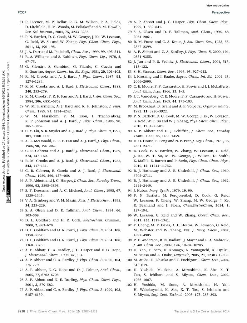
9218 | Phys. Chem. Chem. Phys., 2014, 16, 9202--9219 This journal is© the Owner Societies 2014
51 P. Licence, M. P. Dellar, R. G. M. Wilson, P. A. Fields,D. Litchfield, H. M. Woods, M. Poliakoff and S. M. Howdle,Rev. Sci. Instrum., 2004, 75, 3233–3236.
52 P. N. Bartlett, D. C. Cook, M. W. George, J. Ke, W. Levason,G. Reid, W. Su and W. Zhang, Phys. Chem. Chem. Phys.,2011, 13, 190–198.
53 J. A. Darr and M. Poliakoff, Chem. Rev., 1999, 99, 495–541.54 R. A. Williams and S. Naiditch, Phys. Chem. Liq., 1970, 2,
67–75.55 G. Silvestri, S. Gambino, G. Filardo, C. Cuccia and
E. Guarino, Angew. Chem., Int. Ed. Engl., 1981, 20, 101–102.56 R. M. Crooks and A. J. Bard, J. Phys. Chem., 1987, 91,
1274–1284.57 R. M. Crooks and A. J. Bard, J. Electroanal. Chem., 1988,
240, 253–279.58 R. M. Crooks, F. R. F. Fan and A. J. Bard, J. Am. Chem. Soc.,
1984, 106, 6851–6852.59 W. M. Flarsheim, A. J. Bard and K. P. Johnston, J. Phys.
Chem., 1989, 93, 4234–4242.60 W. M. Flarsheim, Y. M. Tsou, I. Trachtenberg,
K. P. Johnston and A. J. Bard, J. Phys. Chem., 1986, 90,3857–3862.
61 C. Y. Liu, S. R. Snyder and A. J. Bard, J. Phys. Chem. B, 1997,101, 1180–1185.
62 A. C. McDonald, F. R. F. Fan and A. J. Bard, J. Phys. Chem.,1986, 90, 196–202.
63 C. R. Cabrera and A. J. Bard, J. Electroanal. Chem., 1989,273, 147–160.
64 R. M. Crooks and A. J. Bard, J. Electroanal. Chem., 1988,243, 117–131.
65 C. R. Cabrera, E. Garcia and A. J. Bard, J. Electroanal.Chem., 1989, 260, 457–460.
66 A. P. Abbott and J. C. Harper, J. Chem. Soc., Faraday Trans.,1996, 92, 3895–3898.
67 S. F. Dressman and A. C. Michael, Anal. Chem., 1995, 67,1339–1345.
68 V. A. Grinberg and V. M. Mazin, Russ. J. Electrochem., 1998,34, 223–229.
69 S. A. Olsen and D. E. Tallman, Anal. Chem., 1994, 66,503–509.
70 D. L. Goldfarb and H. R. Corti, Electrochem. Commun.,2000, 2, 663–670.
71 D. L. Goldfarb and H. R. Corti, J. Phys. Chem. B, 2004, 108,3358–3367.
72 D. L. Goldfarb and H. R. Corti, J. Phys. Chem. B, 2004, 108,3368–3375.
73 A. P. Abbott, C. A. Eardley, J. C. Harper and E. G. Hope,J. Electroanal. Chem., 1998, 47, 1–4.
74 A. P. Abbott and C. A. Eardley, J. Phys. Chem. B, 2000, 104,775–779.
75 A. P. Abbott, E. G. Hope and D. J. Palmer, Anal. Chem.,2005, 77, 6702–6708.
76 A. P. Abbott and N. E. Durling, Phys. Chem. Chem. Phys.,2001, 3, 579–582.
77 A. P. Abbott and C. A. Eardley, J. Phys. Chem. B, 1999, 103,6157–6159.
78 A. P. Abbott and J. C. Harper, Phys. Chem. Chem. Phys.,1999, 1, 839–841.
79 S. A. Olsen and D. E. Tallman, Anal. Chem., 1996, 68,2054–2061.
80 R. M. Fuoss and C. A. Kraus, J. Am. Chem. Soc., 1933, 55,2387–2399.
81 A. P. Abbott and C. A. Eardley, J. Phys. Chem. B, 2000, 104,9351–9355.
82 J. Jun and P. S. Fedkiw, J. Electroanal. Chem., 2001, 515,113–122.
83 S. H. Strauss, Chem. Rev., 1993, 93, 927–942.84 I. Krossing and I. Raabe, Angew. Chem., Int. Ed., 2004, 43,
2066–2090.85 C. E. Moore, F. P. Cassaretto, H. Posvic and J. J. McLafferty,
Anal. Chim. Acta, 1966, 35, 1–5.86 J. T. Vandeberg, C. E. Moore, F. P. Cassareto and H. Posvic,
Anal. Chim. Acta, 1969, 44, 175–183.87 M. Brookhart, B. Grant and A. F. Volpe Jr., Organometallics,
1992, 11, 3920–3922.88 P. N. Bartlett, D. C. Cook, M. W. George, J. Ke, W. Levason,
G. Reid, W. T. Su and W. J. Zhang, Phys. Chem. Chem. Phys.,2010, 12, 492–501.
89 A. P. Abbott and D. J. Schiffrin, J. Chem. Soc., FaradayTrans., 1990, 86, 1453–1459.
90 H. O. House, E. Feng and N. P. Peet, J. Org. Chem., 1971, 36,2361–2371.
91 D. Cook, P. N. Bartlett, W. Zhang, W. Levason, G. Reid,J. Ke, W. T. Su, M. W. George, J. Wilson, D. Smith,K. Mallik, E. Barrett and P. Sazio, Phys. Chem. Chem. Phys.,2010, 12, 11744–11752.
92 B. J. Hathaway and A. E. Underhill, J. Chem. Soc., 1960,3705–3711.
93 B. J. Hathaway and A. E. Underhill, J. Chem. Soc., 1962,2444–2449.
94 J. Kubas, Inorg. Synth., 1979, 19, 90.95 P. N. Bartlett, M. Perdjon-Abel, D. Cook, G. Reid,
W. Levason, F. Cheng, W. Zhang, M. W. George, J. Ke,R. Beanland and J. Sloan, ChemElectroChem, 2014, 1,187–194.
96 W. Levason, G. Reid and W. Zhang, Coord. Chem. Rev.,2011, 255, 1319–1341.
97 F. Cheng, M. F. Davis, A. L. Hector, W. Levason, G. Reid,M. Webster and W. Zhang, Eur. J. Inorg. Chem., 2007,4897–4905.
98 P. E. Anderson, R. N. Badlani, J. Mayer and P. A. Mabrouk,J. Am. Chem. Soc., 2002, 124, 10284–10285.
99 H. Yan, T. Sato, D. Komago, A. Yamaguchi, K. Oyaizu,M. Yuasa and K. Otake, Langmuir, 2005, 21, 12303–12308.
100 M. Atobe, H. Ohsuka and T. Fuchigami, Chem. Lett., 2004,618–619.
101 H. Yoshida, M. Sone, A. Mizushima, K. Abe, X. T.Tao, S. Ichihara and S. Miyata, Chem. Lett., 2002,1086–1087.
102 H. Yoshida, M. Sone, A. Mizushima, H. Yan,H. Wakabayashi, K. Abe, X. T. Tao, S. Ichihara andS. Miyata, Surf. Coat. Technol., 2003, 173, 285–292.
PCCP Perspective
Ope
n A
cces
s A
rtic
le. P
ublis
hed
on 2
7 Ja
nuar
y 20
14. D
ownl
oade
d on
4/5
/202
2 8:
55:3
9 A
M.
Thi
s ar
ticle
is li
cens
ed u
nder
a C
reat
ive
Com
mon
s A
ttrib
utio
n 3.
0 U
npor
ted
Lic
ence
.View Article Online

This journal is© the Owner Societies 2014 Phys. Chem. Chem. Phys., 2014, 16, 9202--9219 | 9219
103 H. Yan, M. Sone, A. Mizushima, T. Nagai, K. Abe,S. Ichihara and S. Miyata, Surf. Coat. Technol., 2004, 187,86–92.
104 T.-F. M. Chang and M. Sone, Surf. Coat. Technol., 2011, 205,3890–3899.
105 M. Jikei, S. Saitoh, H. Yasuda, H. Itoh, M. Sone, M.-A.Kakimoto and H. Yoshida, Polymer, 2006, 47, 1547–1554.
106 N. Shinoda, T. Shimizu, T.-F. M. Chang, A. Shibata andM. Sone, Thin Solid Films, 2013, 529, 29–33.
107 D. E. Niehaus, M. Philips, A. Michael and R. M. Wightman,J. Phys. Chem., 1989, 93, 6232–6236.
108 K. D. Tilly, N. R. Foster, S. J. Macnaughton andD. L. Tomasko, Ind. Eng. Chem. Res., 1994, 33, 681–688.
109 Y. Houndonougbo, B. B. Laird and K. Kuczera, J. Chem.Phys., 2007, 126, 074507.
110 V. A. Vas’ko, I. Tabakovic, S. C. Riemer and M. T. Kief,Microelectron. Eng., 2004, 75, 71–77.
111 A. Cabanas, X. Shan and J. J. Watkins, Chem. Mater., 2003,15, 2910–2916.
112 M. L. Lee, E. A. Fitzgerald, M. T. Bulsara, M. T. Currie andA. Lochtefeld, J. Appl. Phys., 2005, 97, 011101.
113 R. Al-Salman, S. Z. El Abedin and F. Endres, Phys. Chem.Chem. Phys., 2008, 10, 4650–4657.
114 F. Keller, M. S. Hunter and D. L. Robinson, J. Electrochem.Soc., 1953, 100, 411–419.
115 H. Masuda and K. Fukuda, Science, 1995, 286, 1466–1468.116 K. S. Napolskii, I. V. Roslyakov, A. Y. Romanchuk,
K. O. O. A. S. Mankevich, V. A. Lebedev and A. A. Eliseev,J. Mater. Chem., 2012, 22, 11922–11926.
117 H. de Lira and R. Paterson, J. Membr. Sci., 2002, 206,375–387.
118 H. Masuda, K. Yada and A. Osaka, Jpn. J. Appl. Phys., 1998,37, L1340–L1342.
119 S. Z. Chuz, K. Wada, S. Inoue and S. Todoroki,J. Electrochem. Soc., 2002, 1149, B321–B327.
120 A. N. Belov, S. A. Gavrilov, V. I. Shevyakov andE. N. Redichev, Appl. Phys. A: Mater. Sci. Process., 2011,102, 219–223.
121 M. S. Sander, A. L. Prieto, R. Gronsky, T. Sands andA. M. Stacy, Adv. Mater., 2002, 14, 665–667.
122 A. Ghicov and P. Schmuki, Chem. Commun., 2009,2791–2808.
123 V. R. Tirumala, R. A. Pai, S. Agarwal, J. J. Testa,G. Bhatnagar, A. H. Romang, C. Chandler, B. P. Gorman,R. L. Jones, E. K. Lin and J. J. Watkins, Chem. Mater., 2007,19, 5868–5874.
124 A. Keilbach, J. Moses, R. Kohn, M. Doblinger and T. Bein,Chem. Mater., 2010, 22, 5430–5436.
125 S. Nagarajan, M. Li, R. A. Pai, J. K. Bosworth, P. Busch,D.-M. Smilgies, C. K. Ober, T. P. Russell and J. J. Watkins,Adv. Mater., 2008, 20, 246–251.
126 A. Walcarius, E. Sibbottier, M. Etienne and J. Ghanbaja,Nat. Mater., 2007, 6, 602–608.
127 Z. Teng, G. Zheng, Y. Dou, W. Li, C.-Y. Mou, X. Zhang,A. M. Asiri and D. Zhao, Angew. Chem., Int. Ed., 2012, 51,2173–2177.
128 V. V. Guliants, M. A. Carreon and Y. S. Lin, J. Membr. Sci.,2004, 235, 53–72.
129 P. Platschek, A. Keilbach and T. Bein, Adv. Mater., 2011, 23,2395–2412.
130 S. Schacht, Q. Huo, I. G. Voight-Martin, G. D. Stucky andF. Schuth, Science, 1996, 273, 768–771.
131 E. K. Richman, T. Brezesinski and S. H. Tolbert, Nat.Mater., 2008, 7, 712–717.
132 A. Goux, M. Etienne, E. Aubert, C. Lecomte, J. Ghanbajaand A. Walcarius, Chem. Mater., 2009, 211, 731–741.
Perspective PCCP
Ope
n A
cces
s A
rtic
le. P
ublis
hed
on 2
7 Ja
nuar
y 20
14. D
ownl
oade
d on
4/5
/202
2 8:
55:3
9 A
M.
Thi
s ar
ticle
is li
cens
ed u
nder
a C
reat
ive
Com
mon
s A
ttrib
utio
n 3.
0 U
npor
ted
Lic
ence
.View Article Online