volume 2 task f: drone cyber security assurance methods
TRANSCRIPT
The Application of Unmanned Aerial
Systems In Surface Transportation - Volume II-F: Drone Cyber Security: Assurance Methods and Standards
Charles D. Baker Governor
Karyn E. Polito Lieutenant Governor
Stephanie Pollack MassDOT Secretary & CEO
December 2019 Report No. 19-010
Principal Investigator Dr. Lance Fiondella
University of Massachusetts Dartmouth
Research and Technology Transfer Section
MassDOT Office of Transportation Planning

i
Technical Report Document Page
1. Report No. 19-010
2. Government Accession No. n/a
3. Recipient's Catalog No. n/a
4. Title and Subtitle The Application of Unmanned Aerial Systems In Surface Transportation – Volume II-F:Drone Cyber Security: Assurance Methods and Standards
5. Report Date December 2019 6. Performing Organization Code 19-010
7. Author(s) Bentolhoda Jafary1, Saikath Bhattacharya1, Maskura Nafreen1, Shuai Yuan2, Jingchuan Zhou2, Lina Wu2, Poornima Manjunath2, Tricia Chigan2
, Lance Fiondella1
8. Performing Organization Report No.
9. Performing Organization Name and Address 1. University of Massachusetts, Dartmouth, 285 Old Westport Road, Dartmouth, MA 02747 2. University of Massachusetts, Lowell, 220 Pawtucket St, Lowell, MA 01854
10. Work Unit No. (TRAIS) n/a 11. Contract or Grant No.
12. Sponsoring Agency Name and Address Massachusetts Department of Transportation Office of Transportation Planning Ten Park Plaza, Suite 4150, Boston, MA 02116
13. Type of Report and Period Covered Final Report April 2018- December 2019
14. Sponsoring Agency Code n/a
15. Supplementary Notes Project Champion – Jeffrey DeCarlo, MassDOT Aeronautics Division 16. Abstract Unmanned Aerial Systems (UAS) will inevitably occupy commercial airspace in increasing numbers to provide a range of government and private services. UAS are cyber-physical systems and will therefore be subject to cyberattacks. Hardware, software, communications and data must be protected. To promote cyber risk management, this study examined past research and standards relevant to UAS security. While many of the potential security vulnerabilities have been documented, cyber risk management standards stop short of quantitative methods to characterize, and mitigate risk. We present a stop light chart method for cyber risk assessment adapted from the safety domain. We also propose a quantitative cyber risk management framework that can consider attacks, their likelihood and impact, and alternative deterrent and defensive countermeasures, thereby enabling the comparison of alternative mitigation strategies through a countermeasure allocation problem. The framework supports tradeoff analysis to inform the relative cost and effectiveness of implementing a subset of available countermeasures in order to reduce risk. 17. Key Word UAS, cybersecurity, risk management, standards
18. Distribution Statement unrestricted
19. Security Classif. (of this report) unclassified
20. Security Classif. (of this page) unclassified
21. No. of Pages 76
22. Price n/a
Form DOT F 1700.7 (8-72) Reproduction of completed page authorized

ii
This page left blank intentionally.
iii
The Application of Unmanned Aerial Systems In Surface Transportation – Volume II-F:Drone Cyber
Security: Assurance Methods and Standards
Prepared By:
Principal Investigator Lance Fiondella, Ph.D.
Other Contributors
Bentolhoda Jafary, Ph.D. Saikath Bhattacharya, Ph.D.
Maskura Nafreen, Ph.D. Shuai Yuan, Ph.D.
University of Massachusetts Dartmouth
Co-Principal Investigator Tricia Chigan, Ph.D.
Other Contributors
Jingchuan Zhou, M.S. Lina Wu, M.S.
Poornima Manjunath, M.S. University of Massachusetts Lowell
Prepared For:
Massachusetts Department of Transportation Office of Transportation Planning
Ten Park Plaza, Suite 4150 Boston, MA 02116
December 2019

iv
This page left blank intentionally.
v
Acknowledgments
This study was undertaken as part of the Massachusetts Department of Transportation Research Program with funding from the Federal Highway Administration State Planning and Research funds. The authors are solely responsible for the accuracy of the facts and data, the validity of the study, and the views presented herein. The Project Team would like to acknowledge the efforts of Reed Porada, Scott Uebelhart, and other MassDOT officials who shared their technical expertise and guidance throughout the project. The University of Massachusetts Transportation Center staff was also critical to the success of this project.
Disclaimer
The contents of this report reflect the views of the authors, who are responsible for the facts and the accuracy of the data presented herein. The contents do not necessarily reflect the official view or policies of the Massachusetts Department of Transportation or the Federal Highway Administration. This report does not constitute a standard, specification, or regulation.

vi
This page left blank intentionally.

vii
Executive Summary
This study, Drone Cyber Security: Assurance Methods and Standards, was undertaken as part of the Massachusetts Department of Transportation (MassDOT) Research Program. This program is funded with Federal Highway Administration (FHWA) State Planning and Research (SPR) funds. Through this program, applied research is conducted on topics of importance to the Commonwealth of Massachusetts transportation agencies. Commercial and recreational Unmanned Aerial Systems (UAS) have gained popularity in a wide variety of applications and are anticipated to expand use throughout civilian airspace. Potential applications include but are not limited to panoramic photography, three-dimensional surveying, transportation infrastructure monitoring, surveillance, and damage inspection, search and rescue, agricultural services, and scientific research. UAS are a form of cyber-physical system that are composed of both hardware and software elements and are therefore susceptible to a variety of attacks that could compromise their security and privacy as well as the reliability and safety of individuals and assets in the environments they operate. A risk management strategy that addresses how UAS can be integrated in to our national airspace must consider these technical risks in regulatory policies and procedures. To properly define the impact of cybersecurity on mission risk, it is necessary to assess preflight, inflight, and postflight operations. This includes the selection of a UAS and its payload as well as its configuration, including the mission profile, conduct of mission, potential data acquisition and transmission as well as post processing of data, storage, and reporting. Thus, UAS mission security must consider diverse threats such as attacks on hardware that is compromised by design, software that is compromised intentionally or due to a poor design, websites for mission configuration, mission laptop, wireless communication, and networks and data storage facilities. Formal risk models are needed to quantify the nature and severity of consequences, so that mitigation strategies can be identified, compared, implemented, and validated.

viii
This page left blank intentionally.

ix
Table of Contents Technical Report Document Page ............................................................................................. i Acknowledgments......................................................................................................................v Disclaimer ..................................................................................................................................v Executive Summary ................................................................................................................ vii Table of Contents ..................................................................................................................... ix List of Tables ........................................................................................................................... xi List of Figures ........................................................................................................................ xiii List of Acronyms .....................................................................................................................xv 1.0 Introduction ..........................................................................................................................1 1.1 Scope of Study .................................................................................................................................. 1 1.2 Findings ............................................................................................................................................ 2 1.3 Recommendations ............................................................................................................................ 2 2.0 Representative MassDOT UAS Mission and Cybersecurity Risk .......................................5 2.1 Technical Decomposition of UAS Mission for Risks Identification ................................................ 6 3.0 Risk Assessment and Mitigation ..........................................................................................9 3.1 Cyber Risk Enumeration Example ................................................................................................. 10
3.1.1 Risk Categories ................................................................................................................... 11 3.1.2 Risk Assessment Example .................................................................................................. 11 3.1.3 Cyber Risk Stoplight Charts ............................................................................................... 13
3.2 Countermeasure Portfolio Selection Problem ................................................................................ 13 3.3 Countermeasure selection Illustration ............................................................................................ 15
3.3.1 Cost of Implementing Countermeasures ............................................................................. 16 4.0 Standards ............................................................................................................................19 4.1 Aerial Systems Safety..................................................................................................................... 19
4.1.1 Safety: Department of Defense Standard Practice System Safety 882E............................. 19 4.1.2 Airborne Systems: DO-178C Software Considerations in Airborne Systems and Equipment Certification ............................................................................................................... 20
4.2 UAS Navigation and Communication ............................................................................................ 20 4.2.1 Navigation: RTCA/DO236B Minimum Aviation System Performance Standards ............ 20 4.2.2 Communication: IEEE 1609 - Family of Standards for Wireless Access in Vehicular Environments (WAVE) ............................................................................................................... 21
4.3 Cyber Test and Evaluation and Risk Management ........................................................................ 21 4.3.1 Cyber Test & Evaluation: Department of Defense Cyber Test and Evaluation Guidebook Version 2.0 ................................................................................................................................... 21 4.3.2 Cyber Risk Management: National Institute of Standards and Technology Risk Management Framework (RMF) ................................................................................................. 22
5.0 References ..........................................................................................................................23 6.0 Appendices .........................................................................................................................26 Appendix A: Additional Risk Evaluation Metrics ............................................................................... 26 Appendix B: Risks ................................................................................................................................ 28 Appendix C: Attacks ............................................................................................................................ 37 Appendix D: Countermeasures............................................................................................................. 39 Appendix E: Functional Decomposition and Data-flow ...................................................................... 42 Appendix F: Attacks Categorized According to Mission Stage and Category .................................... 50

x

xi
List of Tables Table 3.1: Risk evaluation metrics for UASs ........................................................................... 9 Table 3.2: Risk ID and name .................................................................................................. 11 Table 3.3: “Fly away” cyber risk evaluation .......................................................................... 12 Table 3.4: Cyber risk assessment matrix ................................................................................ 13 Table 3.5: Interpretation of cyber risk assessment matrix ...................................................... 13 Table 3.6: Various measures for attack and countermeasure ................................................. 16 Table 3.7: Effective risk to cost ratio for countermeasure impact .......................................... 16 Table 3.8: Iterations of greedy algorithm for countermeasure selection ................................ 17 Table A.1: Graphical cyber risk assessment template ............................................................ 26 Table B.1: Fly away ................................................................................................................ 30 Table B.2: Loss of GPS .......................................................................................................... 31 Table B.3: Loss of Data Link .................................................................................................. 32 Table B.4: Crash ..................................................................................................................... 34 Table B.5: Autopilot Software Error/Fail ............................................................................... 35 Table B.6: GCS Failure........................................................................................................... 36 Table C.1: List of attack mechanisms ..................................................................................... 37 Table D.1: Countermeasures ................................................................................................... 39 Table D.2: Mitigation effectiveness notations ........................................................................ 39 Table E.1: Functional modules and potential attacks on Navigation ...................................... 43 Table E.2: Functional modules and potential attacks on data collection ................................ 45 Table E.3: Functional modules and potential attacks on communication .............................. 47 Table E.4: Flight control ......................................................................................................... 49 Table F.1: Preflight software attacks ...................................................................................... 51 Table F.2: Preflight hardware attacks ..................................................................................... 52 Table F.3: Inflight software attacks ........................................................................................ 53 Table F.4: Inflight hardware attacks ....................................................................................... 54 Table F.5: Inflight communications attacks............................................................................ 55 Table F.6: Inflight physical security attacks ........................................................................... 59

xii
This page left blank intentionally.

xiii
List of Figures
Figure 2.1: An example of MassDOT mission ......................................................................... 5 Figure 2.2: Technical decomposition UAS mission for Risk Identification ............................. 7 Figure 3.1: Attack risk model of UASs .................................................................................... 9 Figure 3.2: Graphical cyber risk evaluation of “Fly away” .................................................... 10 Figure 3.3: Graphical representation of countermeasure portfolio selection .......................... 15 Figure 3.4 Fly away risk attack countermeasure dependencies .............................................. 15 Figure 3.5: Risk reduction Pareto front................................................................................... 17 Figure A.1: Graphical cyber risk assessment template ........................................................... 27 Figure E.1: UAS Functional Modules and Data-flow ............................................................ 42 Figure E.2: Functional modules and potential attacks on data collection............................... 44 Figure E.3: Communication module ....................................................................................... 46 Figure E.4: Functional modules and potential attacks on flight control ................................. 48

xiv
This page left blank intentionally.
xv
List of Acronyms
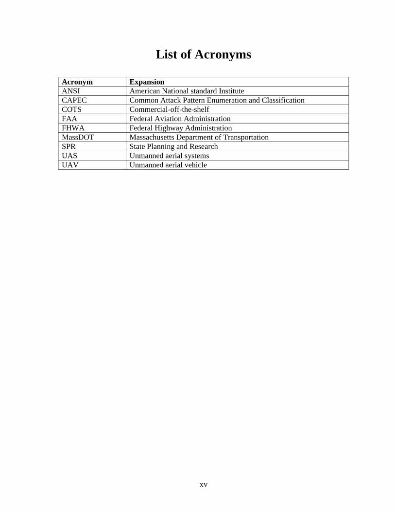
Acronym Expansion ANSI American National standard Institute CAPEC Common Attack Pattern Enumeration and Classification COTS Commercial-off-the-shelf FAA Federal Aviation Administration FHWA Federal Highway Administration MassDOT Massachusetts Department of Transportation SPR State Planning and Research UAS Unmanned aerial systems UAV Unmanned aerial vehicle

xvi
This page left blank intentionally.

1
1.0 Introduction
Commercial and scientific entities are aggressively exploring a variety of Unmanned Aerial System (UAS) applications that would occupy our national airspace, requiring government provide regulatory guidance to protect public and private property as well as to ensure the safety and privacy of individuals. As a form of cyber-physical system, UAS and their supporting computational infrastructure are susceptible to cyberattacks on their hardware, software, communications, and data. Technical gaps and uncertainty have a cascading effect on the clarity and completeness of policy. Cyber risk management can identify threats and quantify their potential impact in the context of an organizations mission and business processes in order to systematically allocate limited resources to reduce the probability and consequences of cyberattacks. In the absence of comprehensive standards, such high-level risk assessment and proactive mitigation planning can inform technology evaluation practices for buy, build, configuration, and maintenance decisions as well as routine test and evaluation procedures intended to inspire confidence in the security of a system or process. Quantitative risk assessment can also support budget justifications for additional work where remediation is most needed.
1.1 Scope of Study
This study focused on technical risks to UAS missions that may be performed by MassDOT or its contractors, but is also relevant to UAS operating within MA airspace and can therefore inform broader regulatory discussion on cyber risk management. A MassDOT UAS mission was attended by UMass researchers to better understand the problem context and best serve MassDOT needs. Primary technical risks considered include UAS hardware, software, and communication as they contribute to functional capabilities employed during missions. Functional decomposition was conducted to identify common attacks and paths within primary UAS modules, including navigation, data collection, communication, and flight control. Moreover, attacks were categorized according to mission stage, including preflight, inflight, and postflight and mapped to the MITRE Common Attack Pattern Enumeration and Classification (CAPEC), a comprehensive dictionary of known patterns of attack employed by adversaries to exploit known weaknesses in cyber-enabled capabilities. Relevant standards were reviewed, including aerial systems safety, navigation and communication, and cyber test and evaluation/risk management. Literature surveyed concentrated on UAS testing, risk modeling, and UAS architectures. A stop light chart method for cyber risk assessment was adapted from the safety domain. The quantitative risk management framework considers attacks, their likelihood and impact, and alternative deterrent and defensive countermeasures. To compare alternative mitigation strategies, a countermeasure allocation problem has been formulated. A high-level discussion places selected UAS commercial-off-the-shelf (COTS) technologies employed by MassDOT in the context of the proposed quantitative risk management framework.
2
1.2 Findings
Risks can be introduced at every stage of the mission and business process. Inflight risks are commonly the focus of attention, due to safety concerns, but pre and post flight risks are equally if not more important. Preflight risks include the acquisition, assembly and configuration of the UAS hardware and software as well as multiple web-based applications that pose both security and privacy threats. Post flight risks include data processing and related storage infrastructure that threaten privacy. The business process helps define the mission process. Therefore, business processes can serve as a gatekeeper to mitigate technical risk before it is introduced. Standards are necessary but not sufficient. Specifically, domain specific standards often fail to recognize the shift toward software-enabled capabilities or prominently emphasize corresponding cybersecurity risks introduced by implementing such functionality in software. As a result, these standards regularly fall short of offering references to quantitative procedures that can enable desired decision support capabilities such as design for security and cyber risk mitigation. We identified the need for simple quantitative procedures to assess cyber risk, compare the effectiveness of alternative countermeasures, and communicate related findings graphically to MassDOT who must also consider the broader business context.
1.3 Recommendations
The primary recommendations are to (1) survey the MassDOT UAS mission portfolio to identify where cyber risk assessment can be applied for the greatest benefit and (2) assess and certify humans and UAS to prevent and close gaps in the mission and business processes of the organization/agency:
• Assess the MassDOT UAS mission portfolio. Risk mitigation must focus limited resources where they will be needed most. No process or system is entirely secure and making oneself a less attractive target is an effective first step toward protection. o Survey present and future trends in the types and frequency of UAS missions to be
carried out by MassDOT and its contractors in order to identify gaps and prioritize cyber risk modeling and mitigation efforts. Concentrate process, elaborating on dimensions where business risks are greatest and the volume of missions is the highest.
• Assess and certify humans and UAS systems. Cybersecurity is both a social and
technical problem. o For the human dimension:
Document best practices in pre, during, and post flight mission operations and develop lightweight training and certification procedures for employees and contractors to ensure best practices are followed and updated periodically.
Consider technologies that enforce good practices as part of the technology assessment process.

3
o For the system dimension: When possible assess, extend, and adapt existing IT security procedures to
UAS and revise existing IT security policies and procedures that involve UAS to ensure consistency and simplicity.
Specify standard mission payloads. Consider using only the technology needed to complete a mission in order to avoid introducing unnecessary risk.
Identify approved/disapproved lists of hardware, software, and services to streamline the UAS certification process.
Conduct cyber risk assessment and mitigation studies based on the MassDOT mission portfolio. Specify single mission platforms where feasible to avoid concentrating risk that would require a more costly and complex portfolio of countermeasures to protect a multi-mission UAS.
• Ensure standards reference cybersecurity clearly before endorsing. MassDOT staff
should consider participating in the working groups of Standards through their affiliated experts to ensure that cyber risk concerns for Massachusetts specific to transportation are adequately represented.

4
This page left blank intentionally.
5
2.0 Representative MassDOT UAS Mission and Cybersecurity Risk
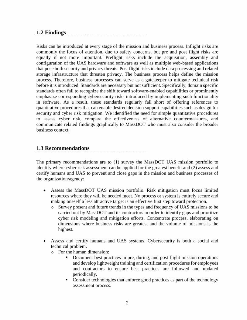
This section describes aerial mapping of approximately 10 acres that captured progress at the New MassDOT District 3 Administration Building construction site in Worcester, Massachusetts. Observing the stages of a MassDOT mission provided insight into the interactions between the UAS and its environment in order to enumerate sources of potential cybersecurity risk for this study. Figure 2.1 llustrates many of the factors associated with UAS mission.
Figure 2.1: An example of MassDOT mission
The thick black vertical bars denote the boundaries between the stages of the mission, including pre-mission (left), mission (center), and post-mission (right). Prior to the mission, hardware and software checklists are followed. The HeliPad at UMass Memorial Worcester was notified. An Inspire 2 UAS was equipped with a Zenmuse X4S Electro-Optical Camera, which can capture images with a ground sampling interval of 0.71 inches per pixel at an elevation of 200 feet above ground level.
6
Software applications to control the UAS: • Define a flight path, including altitude • Image post-processing • Map georectification included DJI GO 4 Drone Deploy, and Pix4D
A default center defined where the aircraft will return to in case of failure or if the signal between the drone and pilot was lost. An aircraft can also perform obstacle detection if equipped with collision avoidance technology, such as vision, ultrasonic, infrared, and LIDAR sensors. The pilot can override the automated mission at any time. The inflight portion of the mission lasted approximately 15 minutes. After ascent the UAS proceeded to follow the pre-programmed route to collect over 300 NADIR pictures. The flight team included a remote pilot in command and a visual, observer monitored the mission site for dynamic hazards that could have been created by the motion of the UAS and obstacles such as an active construction zone, crew members, construction vehicles, temporary buildings, and traffic. During flight, integrated software algorithms and simultaneous localization and mapping (SLAM) technology constructed 3D maps on the pilot’s device, enabling the flight controller or pilot to sense and avoid objects. The 'Internal Compass and Failsafe Function' enables the UAS and pilot's remote-control system to precisely track its location. 'No Fly Zone Drone Technology' can prevent unexpected flight patterns in constrained areas. Post-flight, images captured and their metadata were processed using high-performance computing and communications facilities to produce a geo-rectified orthomosaic image. Activities relevant to data security and privacy included handling of SD cards containing flight data and a Google Drive data processing program server for upload to Pix4D and Drone Deploy.
2.1 Technical Decomposition of UAS Mission for Risks Identification
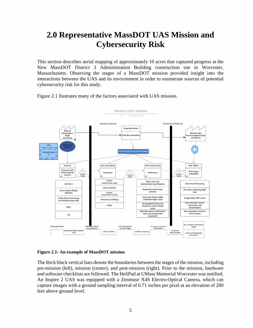
Figure 2.2 shows the decomposition of a UAS mission, which is composed of one or more tasks that rely on functions. Each function is enabled by a combination of hardware, software, and communication and therefore a potential subject to attacks, posing corresponding risks.

7
Figure 2.2: Technical decomposition UAS mission for Risk Identification

8
This page left blank intentionally.

9
3.0 Risk Assessment and Mitigation
This section describes a UAS risk quantification approach and an objective strategy to mitigate risk through technology enhancement or countermeasures. Figure 3.1 illustrates the conceptual structure of the proposed UAS risk model.
Figure 3.1: Attack risk model of UASs
Figure 3.1 contains eight nodes as well as the corresponding relations among them. It indicates that assets provide capabilities. However, they also possess vulnerabilities. Attacks target an asset through its vulnerabilities. Attacks transpire in the operational environment and are successful with a specified likelihood, producing consequences of a specified severity. The severity, likelihood, and operational environment contribute to risk. Table 3.1 lists a set of risk evaluation metrics for UAS.
Table 3.1: Risk evaluation metrics for UASs
Metric Description Range
Impact How much damage can be caused by an attack.
(0,1): where 0 means no impact and 1 asset is completely compromised
Likelihood The probability of successfully exploiting a vulnerability
(0,1): where 0 means impossible and 1 easy to exploit a vulnerability
Impact and likelihood provide the basis for preliminary formulations of risk quantification and risk quantification. Table A.1 in the Appendices enumerates additional metrics that could further enrich the risk assessment and mitigation modeling presented here.
10
3.1 Cyber Risk Enumeration Example
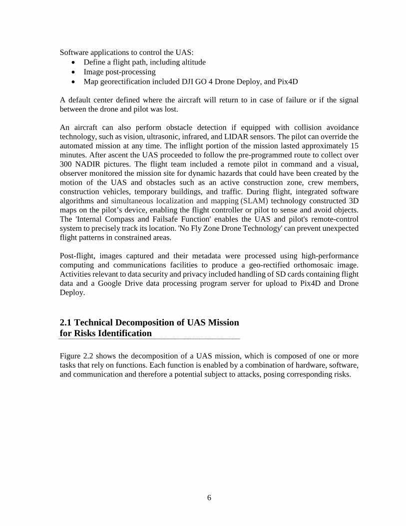
Cyber risk management requires that risks and their potential consequences be identified. Only then is it possible to determine a strategy to mitigate these risks. Figure 3.2 illustrates the “Fly away” risk, where one of several attacks leads to the UAS flying away.
Figure 3.2: Graphical cyber risk evaluation of “Fly away”
The top center of Figure 3.2 indicates that the asset of the drone impacted is drone flight. Sub-assets required for this asset include transmission of mission data and command operations and that countermeasures that can reduce or potentially eliminate the impact of attacks on these
11
sub-assets. The top left of Figure 3.2 indicates the drone operating in an environment, which experiences a unique threat level and threats that could result in the drone flying away, such as: traffic injection, input data manipulation, and fuzzing as well as man-in-the-middle and potentially other attacks. Countermeasures of differing sophistication and cost can lower vulnerability and consequences of an attack, which can reduce the likelihood of an attack succeeding as well as its impact and corresponding severity. Traditional risk models quantify risk as the product of likelihood times impact. Assuming risks to sub-assets are mutually exclusive, allowing to sum over risk estimates for each sub-asset to obtain 𝑅𝑅𝑅𝑅𝑅𝑅𝑅𝑅(𝐹𝐹𝐹𝐹𝐹𝐹 𝑎𝑎𝑎𝑎𝑎𝑎𝐹𝐹) =∑ 𝐿𝐿𝑅𝑅𝑅𝑅𝐿𝐿𝐹𝐹𝑅𝑅ℎ𝑜𝑜𝑜𝑜𝑑𝑑𝑖𝑖 × 𝑅𝑅𝑖𝑖𝑖𝑖𝑎𝑎𝑖𝑖𝑖𝑖𝑖𝑖 𝑖𝑖, incorporating each threat specific to this risk.
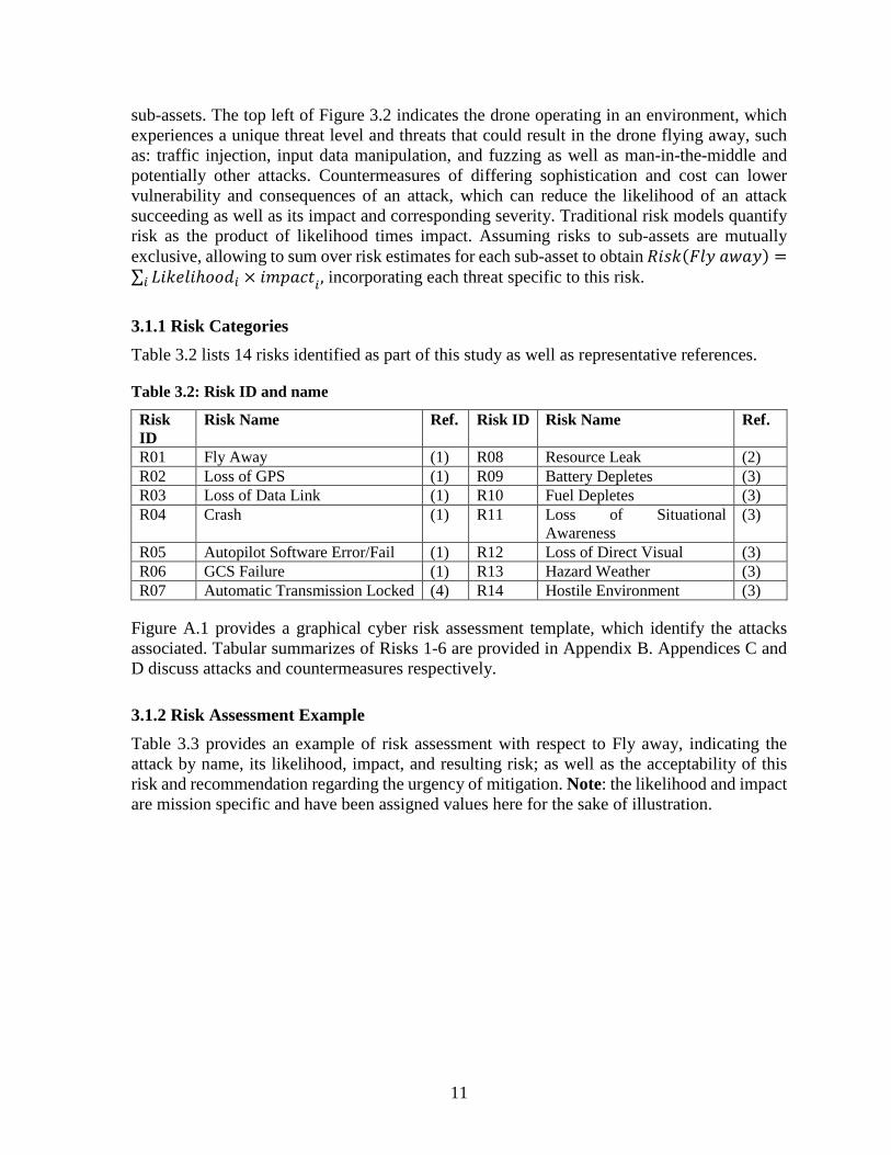
3.1.1 Risk Categories Table 3.2 lists 14 risks identified as part of this study as well as representative references.
Table 3.2: Risk ID and name
Risk ID
Risk Name Ref. Risk ID Risk Name Ref.
R01 Fly Away (1) R08 Resource Leak (2) R02 Loss of GPS (1) R09 Battery Depletes (3) R03 Loss of Data Link (1) R10 Fuel Depletes (3) R04 Crash (1) R11 Loss of Situational
Awareness (3)
R05 Autopilot Software Error/Fail (1) R12 Loss of Direct Visual (3) R06 GCS Failure (1) R13 Hazard Weather (3) R07 Automatic Transmission Locked (4) R14 Hostile Environment (3)
Figure A.1 provides a graphical cyber risk assessment template, which identify the attacks associated. Tabular summarizes of Risks 1-6 are provided in Appendix B. Appendices C and D discuss attacks and countermeasures respectively.
3.1.2 Risk Assessment Example Table 3.3 provides an example of risk assessment with respect to Fly away, indicating the attack by name, its likelihood, impact, and resulting risk; as well as the acceptability of this risk and recommendation regarding the urgency of mitigation. Note: the likelihood and impact are mission specific and have been assigned values here for the sake of illustration.

12
Table 3.3: “Fly away” cyber risk evaluation
Attack ID
Attack Name Likelihood Impact Risk Acceptability Recommendation
A18
Man in the middle attack
3 2 6 Tolerable Mitigate according to best practices
A11 Communication link jamming
3 3 9 Unacceptable Immediate mitigation required
A19 GPS jamming 3 2 6 Tolerable Mitigate according to best practices
A20 Replay attack 3 5 15 Acceptable No action required A8 Sensor Spoofing 3 2 6 Unacceptable Immediate mitigation
required A9 Sensor Jamming 3 2 6 Tolerable Mitigate according to
best practices A brief description of the attacks underlying the fly away risk are as follows.
1. Man in the middle attack (5) targets the communication between two components, typically client and server. Whenever one component attempts to communicate with the other to send data or authenticate, the attacker can observe and/or alter information before passing it to the other component. To overcome lack of trust in communication Common Attack Pattern Enumeration and Classification (CAPEC) recommended countermeasures include: 1) use of a Public Key signed by a Certificate Authority, 2) communication link encryption, 3) strong mutual authentication at both ends of any communications channel, and 4) exchange of public keys using a secure channel.
2. Communication link jamming (6) prevents transmitting or receiving data from the targeted Wi-Fi network. Examples include: 1) flooding the Wi-Fi access point such as the retransmission device with de-authentication frames and 2) transmitting high levels of noise on the radio frequency band used by the Wi-Fi network. Countermeasures disassociate from flooding and radio frequency jamming, but are not standardized and must be supported on both the retransmission device and handset in order to be effective.
3. GPS jamming (5) blocks all GPS communications, preventing the UAS from navigating. A simple type of attack is known as blanket jamming, which outputs noise or false information to saturate the GPS receiver. Countermeasures include retransmission and use of back up channels.
4. Replay attack bypasses security by replaying a requests and can be performed in various ways. Countermeasures include an authentication mechanism that uses fresh message requests in a secure manner prior to data exchange or communication.
5. Sensor spoofing (5) modifies original content, while keeping the source of the content unchanged. A sensor spoofing attack deceives the onboard UAS sensor regarding the environment or situation with the intention of misleading the UAS into taking an undesirable action. Countermeasures include verifying metadata along with the actual data and the use of redundant sensors (7).
6. Sensor jamming (8) can deprive the UAS from information required to operate and act appropriately. Sensors may GPS-based navigation, a camera, IR sensor, barometer, which are also susceptible to jamming. The recommended countermeasure is sensor redundancy.
13
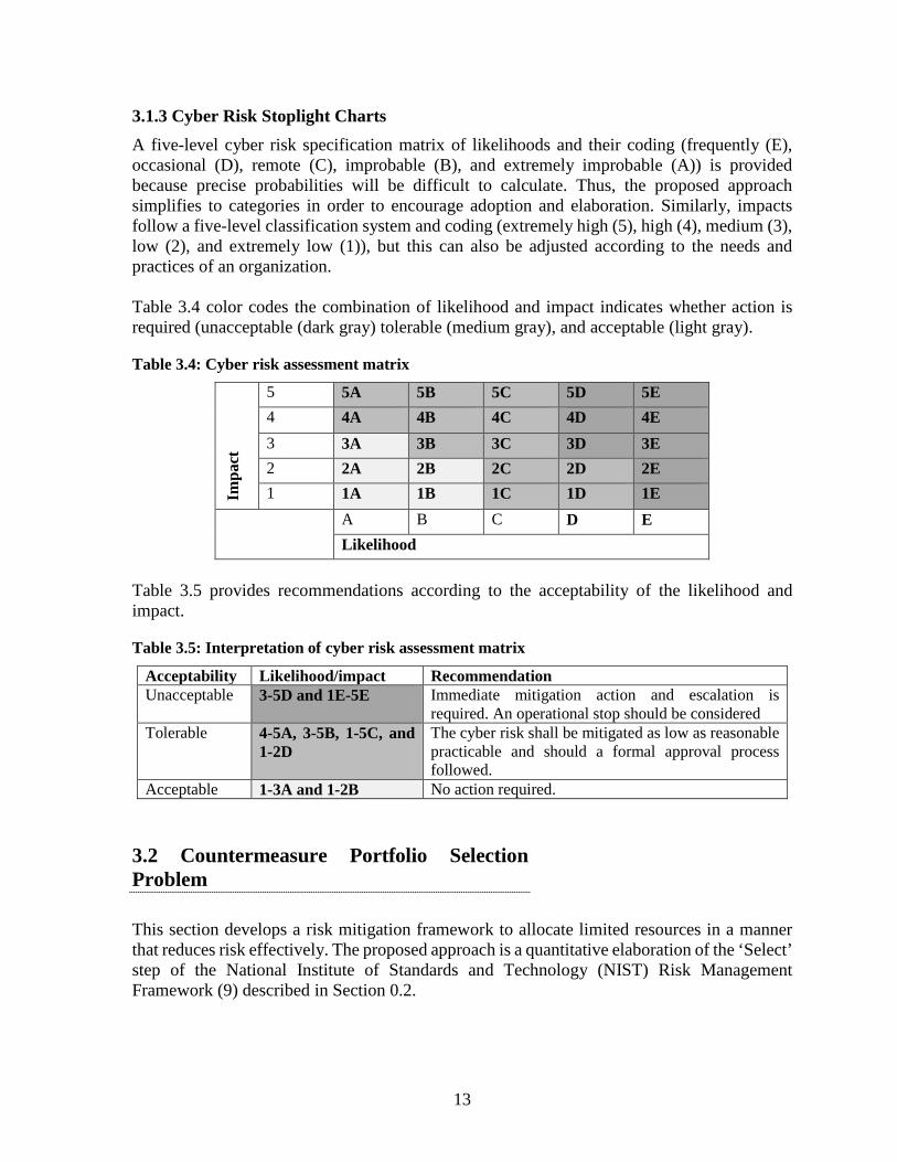
3.1.3 Cyber Risk Stoplight Charts A five-level cyber risk specification matrix of likelihoods and their coding (frequently (E), occasional (D), remote (C), improbable (B), and extremely improbable (A)) is provided because precise probabilities will be difficult to calculate. Thus, the proposed approach simplifies to categories in order to encourage adoption and elaboration. Similarly, impacts follow a five-level classification system and coding (extremely high (5), high (4), medium (3), low (2), and extremely low (1)), but this can also be adjusted according to the needs and practices of an organization. Table 3.4 color codes the combination of likelihood and impact indicates whether action is required (unacceptable (dark gray) tolerable (medium gray), and acceptable (light gray).
Table 3.4: Cyber risk assessment matrix
Impa
ct
5 5A 5B 5C 5D 5E 4 4A 4B 4C 4D 4E 3 3A 3B 3C 3D 3E 2 2A 2B 2C 2D 2E 1 1A 1B 1C 1D 1E
A B C D E Likelihood
Table 3.5 provides recommendations according to the acceptability of the likelihood and impact.
Table 3.5: Interpretation of cyber risk assessment matrix
Acceptability Likelihood/impact Recommendation Unacceptable 3-5D and 1E-5E Immediate mitigation action and escalation is
required. An operational stop should be considered Tolerable 4-5A, 3-5B, 1-5C, and
1-2D The cyber risk shall be mitigated as low as reasonable practicable and should a formal approval process followed.
Acceptable 1-3A and 1-2B No action required.
3.2 Countermeasure Portfolio Selection Problem
This section develops a risk mitigation framework to allocate limited resources in a manner that reduces risk effectively. The proposed approach is a quantitative elaboration of the ‘Select’ step of the National Institute of Standards and Technology (NIST) Risk Management Framework (9) described in Section 0.2.

14
Consider a drone designed to perform 𝑴𝑴 = 𝑀𝑀1, … ,𝑀𝑀|𝑴𝑴| missions. Each mission is defined by a sequence of tasks that determine the hardware, software, and communication functionality the drone must possess to successfully execute that mission. Each function is vulnerable to one or more attacks, which pose corresponding risks. Without loss of generality, let 𝑨𝑨 = 𝐴𝐴1, … ,𝐴𝐴|𝑨𝑨| be the set of all possible attacks that can be carried out against a drone, 𝑹𝑹 = 𝑅𝑅1, … ,𝑅𝑅|𝑹𝑹| the risks posed by these attacks, and 𝑪𝑪 = 𝐶𝐶1, … ,𝐶𝐶|𝑪𝑪| the countermeasures capable of mitigating or eliminating the impacts of the risks incurred by an attack. Not all attacks contribute to each risk. For example, risk R01 (Fly Away) is susceptible to six attacks, namely: man in the middle (A18), communication link jamming (A11), GPS jamming (A19), replay attack (A20), sensor spoofing (A08), and sensor jamming (A09), which we denote Attacks(R02)={A08, A09, A11, A18, A19, A20} or 𝐴𝐴𝑖𝑖𝑖𝑖𝑎𝑎𝑖𝑖𝑅𝑅𝑅𝑅(𝑅𝑅𝑖𝑖) more generally. Similarly, we denote the countermeasures capable of mitigating the ith attack as 𝐶𝐶𝑜𝑜𝐶𝐶𝐶𝐶𝑖𝑖𝐿𝐿𝐶𝐶𝑖𝑖𝐿𝐿𝑎𝑎𝑅𝑅𝐶𝐶𝐶𝐶𝐿𝐿𝑅𝑅(𝐴𝐴𝑖𝑖). Each attack has a corresponding probability (Likelihood) of occurrence (Pr{𝐴𝐴𝑖𝑖}) as well as a corresponding impact (𝐼𝐼𝑖𝑖𝑖𝑖𝑎𝑎𝑖𝑖𝑖𝑖(𝐴𝐴𝑖𝑖)), which is conditional upon the subset of countermeasures 𝑪𝑪′ ∈ 𝑪𝑪, such that the impact of a risk with respect to its corresponding attacks and their impact conditioned on the countermeasures is 𝐼𝐼𝑖𝑖𝑖𝑖𝑎𝑎𝑖𝑖𝑖𝑖(𝑅𝑅𝑖𝑖) = ∑ Pr{𝐴𝐴𝑖𝑖}𝑛𝑛
𝑖𝑖=1 𝐼𝐼𝑖𝑖𝑖𝑖𝑎𝑎𝑖𝑖𝑖𝑖(𝐴𝐴𝑖𝑖|𝑪𝑪′), where 𝐼𝐼𝑖𝑖𝑖𝑖𝑎𝑎𝑖𝑖𝑖𝑖(𝐴𝐴𝑖𝑖|𝑪𝑪1′ ) ≤ 𝐼𝐼𝑖𝑖𝑖𝑖𝑎𝑎𝑖𝑖𝑖𝑖(𝐴𝐴𝑖𝑖|𝑪𝑪2′ ) when 𝑪𝑪2′ ⊆ 𝑪𝑪1′ , meaning that adding additional countermeasures decreases the impact. The overall impact of a set of risk 𝑹𝑹′ ∈ 𝑹𝑹 is therefore the sum of the risks to which the drone is susceptible 𝐼𝐼𝑖𝑖𝑖𝑖𝑎𝑎𝑖𝑖𝑖𝑖(𝑹𝑹′) = ∑ 𝐼𝐼𝑖𝑖𝑖𝑖𝑎𝑎𝑖𝑖𝑖𝑖(𝑅𝑅𝑖𝑖)𝑹𝑹′∈𝑹𝑹 This specification enables the definition of the countermeasure selection problem as the following budget constrained optimization problem
Minimize 𝐼𝐼𝑖𝑖𝑖𝑖𝑎𝑎𝑖𝑖𝑖𝑖(𝑹𝑹′) (1) Subject to
� 𝐼𝐼(𝑪𝑪𝑖𝑖 ∈ 𝑪𝑪’) × 𝐶𝐶𝑜𝑜𝑅𝑅𝑖𝑖(𝑪𝑪𝑖𝑖)𝑪𝑪′∈𝑪𝑪
< 𝐵𝐵 (2)
where the indicator function 𝐼𝐼(𝑪𝑪𝑖𝑖 ∈ 𝑪𝑪’) = 1 if countermeasure 𝐶𝐶𝑖𝑖 is in the set of selected countermeasures and 𝐶𝐶𝑜𝑜𝑅𝑅𝑖𝑖(𝑪𝑪𝑖𝑖) is the cost of the ith countermeasure. Inclusion of a countermeasure in a portfolio is a binary decision, and can, therefore, be represented as a binary string of length |𝑪𝑪|, where a 𝑖𝑖𝑖𝑖 = 1 if the counter measure is in the portfolio and 0 otherwise. Problems such as these can be solved effectively with methods such as the genetic algorithm (GA) and the solution. In the case where the drone performs more than one mission and some risks are unique to 𝑀𝑀1 or 𝑀𝑀2, there is no single optimum countermeasure portfolio to reduce impacts to both missions, requiring a multi-objective solution that gives rise to a Pareto optimal front of solutions, where reducing the impact of 𝑀𝑀1 may adversely affect the impact with respect to 𝑀𝑀2 and vice versa. Figure 3.3: provides a graphical representation of the countermeasure portfolio problem with respect to a single mission.
15
Figure 3.3: Graphical representation of countermeasure portfolio selection
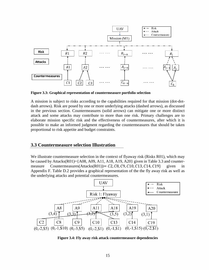
A mission is subject to risks according to the capabilities required for that mission (dot-dot-dash arrows). Risk are posed by one or more underlying attacks (dashed arrows), as discussed in the previous section. Countermeasures (solid arrows) can mitigate one or more distinct attack and some attacks may contribute to more than one risk. Primary challenges are to elaborate mission specific risk and the effectiveness of countermeasures, after which it is possible to make an informed judgment regarding the countermeasures that should be taken proportional to risk appetite and budget constraints.
3.3 Countermeasure selection Illustration
We illustrate countermeasure selection in the context of flyaway risk (Risks R01), which may be caused by Attacks(R01)={A08, A09, A11, A18, A19, A20} given in Table 3.3 and counter-measure Countermeasures(Attacks(R01))= 𝐶𝐶2,𝐶𝐶8,𝐶𝐶9,𝐶𝐶10,𝐶𝐶13,𝐶𝐶14,𝐶𝐶19} given in Appendix F. Table D.2 provides a graphical representation of the the fly away risk as well as the underlying attacks and potential countermeasures.
Figure 3.4: Fly away risk attack countermeasure dependencies
16
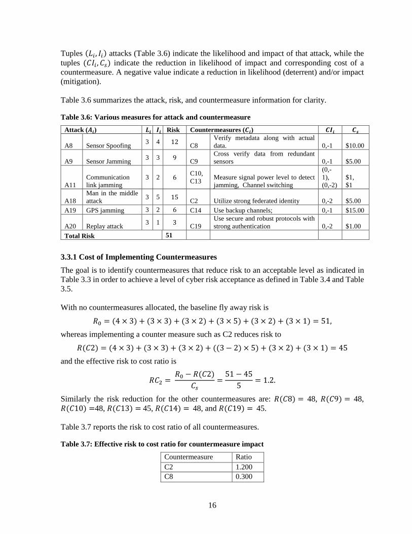
Tuples (𝐿𝐿𝑖𝑖, 𝐼𝐼𝑖𝑖) attacks (Table 3.6) indicate the likelihood and impact of that attack, while the tuples (𝐶𝐶𝐼𝐼𝑖𝑖 ,𝐶𝐶𝑠𝑠) indicate the reduction in likelihood of impact and corresponding cost of a countermeasure. A negative value indicate a reduction in likelihood (deterrent) and/or impact (mitigation). Table 3.6 summarizes the attack, risk, and countermeasure information for clarity.
Table 3.6: Various measures for attack and countermeasure
Attack (𝑨𝑨𝒊𝒊) 𝑳𝑳𝒊𝒊 𝑰𝑰𝒊𝒊 Risk Countermeasures (𝑪𝑪𝒊𝒊) 𝑪𝑪𝑰𝑰𝒊𝒊 𝑪𝑪𝒔𝒔
A8 Sensor Spoofing 3 4 12 C8 Verify metadata along with actual data. 0,-1 $10.00
A9 Sensor Jamming 3 3 9 C9 Cross verify data from redundant sensors 0,-1 $5.00
A11 Communication link jamming
3 2 6 C10, C13 Measure signal power level to detect
jamming, Channel switching
(0,-1), (0,-2)
$1, $1
A18 Man in the middle attack 3 5 15 C2 Utilize strong federated identity 0,-2 $5.00
A19 GPS jamming 3 2 6 C14 Use backup channels; 0,-1 $15.00
A20 Replay attack 3 1 3 C19 Use secure and robust protocols with strong authentication 0,-2 $1.00
Total Risk 51
3.3.1 Cost of Implementing Countermeasures The goal is to identify countermeasures that reduce risk to an acceptable level as indicated in Table 3.3 in order to achieve a level of cyber risk acceptance as defined in Table 3.4 and Table 3.5. With no countermeasures allocated, the baseline fly away risk is
𝑅𝑅0 = (4 × 3) + (3 × 3) + (3 × 2) + (3 × 5) + (3 × 2) + (3 × 1) = 51, whereas implementing a counter measure such as C2 reduces risk to
𝑅𝑅(𝐶𝐶2) = (4 × 3) + (3 × 3) + (3 × 2) + ((3− 2) × 5) + (3 × 2) + (3 × 1) = 45 and the effective risk to cost ratio is
𝑅𝑅𝐶𝐶2 = 𝑅𝑅0 − 𝑅𝑅(𝐶𝐶2)
𝐶𝐶𝑠𝑠=
51 − 455
= 1.2.
Similarly the risk reduction for the other countermeasures are: 𝑅𝑅(𝐶𝐶8) = 48, 𝑅𝑅(𝐶𝐶9) = 48, 𝑅𝑅(𝐶𝐶10) =48, 𝑅𝑅(𝐶𝐶13) = 45, 𝑅𝑅(𝐶𝐶14) = 48, and 𝑅𝑅(𝐶𝐶19) = 45. Table 3.7 reports the risk to cost ratio of all countermeasures.
Table 3.7: Effective risk to cost ratio for countermeasure impact
Countermeasure Ratio C2 1.200 C8 0.300

17
Countermeasure Ratio C9 0.600 C10 3.000 C13 6.000 C14 0.200 C19 6.000
Both C13 and C19 possess the same cost ratio. However, A11 has a higher impact than A20, so C13 for A11 is selected. The ratios are then recomputing with the new total risk baseline of 45. Figure 3.5 shows the total risk as a function of the cumulative cost of countermeasures.
Figure 3.5: Risk reduction Pareto front
This approach enables a decision-maker to identify the risk attainable within a specified budget or the cost required to achieve a desired risk level. This approach can guide countermeasure selection as well as support budget justifications for such countermeasures. Table 3.8 provides the details of the iterations of a greedy algorithm to allocate countermeasures, which produced Figure 3.5 above.
Table 3.8: Iterations of greedy algorithm for countermeasure selection Cost Risk reduction Countermeasure subset Selected Countermeasure
0 51 {C8,C9,C10,C13,C2,C14,C19} 0
1 45 {C8,C9,C10,C2,C14,C19} C13
2 42 {C8,C9,C10,C2,C14} C19
3 42 {C8,C9,C2,C14} C10
8 27 {C8,C9 ,C14} C2
13 18 {C8,C14} C9

18
Cost Risk reduction Countermeasure subset Selected Countermeasure
23 6 {C14} C8
38 0 {0} C14 A more fine-grained approach can consider multiple dimensions by quantifying risk with respect to the failure modes and effects of the various attacks, which would enable countermeasure selection to reduce risk with respect to multiple categories of consequences.
19
4.0 Standards
The ANSI (American National Standards Institute) Unmanned Aerial Systems Standardization Collaborative (UASSC) has developed standardization roadmap (10) and maintains links to UAS Standards (11). Of these links, the American Society for Testing and Materials, ASTM F3201-16 Standard Practice for Ensuring Dependability of Software Used in Unmanned Aerial Systems (UAS) is most relevant to this study, especially security as an enabler of safety. The remainder of this section summarizes prominent standards in the areas of aerial systems safety, UAS navigation and communication, and cyber test and evaluation, and cyber risk management. It is suggested that, before endorsing standards for use within the Commonwealth of Massachusetts, MassDOT should ensure that software and cybersecurity experts provide input on standards to ensure that these standards reference relevant cybersecurity standards and best practices, and that they are kept up to date on a regular basis.
4.1 Aerial Systems Safety
4.1.1 Safety: Department of Defense Standard Practice System Safety 882E MIL-STD-882E is relevant because safety is a concern of MassDOT and cybersecurity vulnerabilities pose threats to system safety. MIL-STD-882E (12) identifies the Department of Defense (DoD) approach for identifying hazards, assessing and mitigating associated risks encountered in the development, test, production, use, and disposal of defense systems MIL-STD-882E defines the risk acceptance authorities. It also defines the system safety requirements throughout the life-cycle for any system and when properly applied, these requirements should enable the identification and management of hazards and their associated risks during system development and engineering sustainment activities. MIL-STD-882E provides four different severity categories starting from a loss of a work day to severe environmental impact, potential death or permanent disability. This standard also categorizes the hazard at a given point of time such as the probability of the hazards. A unified risk assessment matrix is provided. The system safety process consists of managing life-cycle risk, software contribution to system risk, and software assessment. Software safety criticality matrix maps the software controls to severity categories using software criticality indices (SwCI). Task 102 system safety program develops a plan to document the system safety methodology for the identification, classification, and mitigation of safety hazards as part of the overall systems engineering process. MIL-STD-882E also provides software system safety engineering and analysis requirements. This standard mentions that (12) “from the perspective of the system safety engineer and the hazard analysis process, software is considered as a subsystem.” System safety engineers should ensure that software is considered in its contribution to mishap occurrences for the system under analysis, as well as interfacing systems within a systems of systems architecture. The software system safety processes and requirements are based on the identification and

20
establishment of specific and test tasks for each acquisition phase of the software development life-cycle. The software risk assessment should follow the same risk criteria or risk matrix as hardware system.
4.1.2 Airborne Systems: DO-178C Software Considerations in Airborne Systems and Equipment Certification UAS are aerial systems and therefore are covered by DO-178C (13), which is an RCTA (Radio Technical Commission for Aeronautics) standard for demonstrating compliance with applicable airworthiness regulations for software aspects of aerial systems and equipment certification. DO-178C consists of software considerations in Airborne Systems and Equipment Certification, published by RTCA. This standard categorizes the software into five hazard levels based on System Safety Assessment:
• Level A hazards consists of anomalous behavior of the aerial system resulting in catastrophic failure condition. These types of behavior prevent continued safe flight and landing.
• Level B hazards affects safety-critical capabilities and can result in serious or potentially fatal injuries.
• Level C hazards produce a major failure condition, where the hazard results in discomfort to occupants, possibly including injuries.
• Level D hazards result in a minor failure condition and some inconvenience to occupants.
• Level E hazards correspond to safe operational conditions and result in no effect on aircraft operational capability or the pilot.
DO-178C supports the objective verification of output of the software coding and integration process. The recent version of the standard also considers economic impact relative to system certification without compromising system safety. The primary steps for the software safety certification consists of formal methods for verification, object oriented technology, model based development and verification, and tool qualification.
4.2 UAS Navigation and Communication
4.2.1 Navigation: RTCA/DO236B Minimum Aviation System Performance Standards RTCA/DO-236B (14) defines the path the aircraft must use to evaluate performance. The aircraft’s navigation system will also define all vertical paths in the Final Approach Segment (FAS) by a Flight Path Angle (FPA) as a trajectory to a fix and altitude. However, RTCA/DO-236B facilitates airspace design and does not directly equate to obstacle clearance.

21
4.2.2 Communication: IEEE 1609 - Family of Standards for Wireless Access in Vehicular Environments (WAVE) The IEEE 1609 Family of Standards (15) includes several active sub-standards related to cyber security of UAS communication:
1. P1609.0 - IEEE Draft Guide for Wireless Access in Vehicular Environments (WAVE) - Architecture
2. P1609.2b - Standard for Wireless Access in Vehicular Environments--Security Services for Applications and Management Messages Amendment 2: Protocol Data Unit (PDU) Functional Types and Encryption Key Management
3. 1609.0-2013 - IEEE Guide for Wireless Access in Vehicular Environments (WAVE) - Architecture
4. 1609.2-2016 - IEEE Standard for Wireless Access in Vehicular Environments--Security Services for Applications and Management Messages
5. 1609.4-2016 - IEEE Standard for Wireless Access in Vehicular Environments (WAVE) -- Multi-Channel Operation
6. 1609.2a-2017 - IEEE Standard for Wireless Access in Vehicular Environments--Security Services for Applications and Management Messages - Amendment 1
4.3 Cyber Test and Evaluation and Risk Management
4.3.1 Cyber Test & Evaluation: Department of Defense Cyber Test and Evaluation Guidebook Version 2.0 The Cyber Test and Evaluation Guidebook (16) develops data-driven mission-impact-based analysis and assessment methods for cybersecurity test and evaluation (T&E) and supports assessment of cybersecurity, survivability, and resilience within a mission context by encouraging planning for tighter integration with traditional system T&E. Cyber-security T&E starts at acquisition initiation and continues throughout the entire life cycle. A primary objective for test and evaluation is to understand how adversarial attacks affect a cyber physical system and the missions it is designed to perform. Cybersecurity T&E consists of six phases aligned with DOD I5000.02 Operation of the Defense Acquisition System:
1. Phase 1 examines a system’s cybersecurity and resilience requirements in order to develop an initial approach and plan for conducting cybersecurity T&E. This phase is performed during the early design and planning lifecycle.
2. Phase 2 characterizes the attack surface, identifies the vulnerabilities, and avenues of attack an adversary may use to exploit the system. This phase develops the plans to evaluate the impact of attacks on the mission.
3. Phase 3 verifies the cybersecurity and needed counter-measures, which helps stakeholders and designers reduce risk. This phase is conducted during developmental test and evaluation.
4. Phase 4 performs adversarial tests in the context of mission operations to identify residual risks.

22
5. Phase 5 characterizes the cybersecurity and resilience status of a system in a fully operational context and provides reconnaissance on the system. This phase is conducted during operational test and evaluation.
6. Phase 6 characterizes the operational mission effects to critical missions caused by threat-representative cyber activity against a unit trained and equipped with a system as well as the effectiveness of defensive capabilities. This phase is also performed during operational test and evaluation.
4.3.2 Cyber Risk Management: National Institute of Standards and Technology Risk Management Framework (RMF) The NIST Risk Management Framework (9) integrates risk management into the system development lifecycle. It offers a holistic framework and process for determining organizational, mission, and system risk. The framework consists of six steps and three level of organization wide risk management. The six steps are:
1. Categorize: The purpose of this stage is to determine the order of risk criticality and its impact on the organization, mission, or system.
2. Select: This step selects various security controls or countermeasures based on the outputs from Step 1. A risk assessment is performed in this stage. A baseline risk or threat level is also specified.
3. Implement: In this step, the security control or the various countermeasures are implemented within the system or enterprise architecture.
4. Assess: This step determines the effectiveness of the security measures implemented, operational effectiveness, and requirements. This step determines the depth and coverage needed for system assurance. Both hardware and software risk assessment should be conducted.
5. Authorize: In this step, an expert examines the output of step four to determine the effectiveness of the risk management framework implementation.
6. Monitor: The final step involves the continuous monitoring of the system and its operational environment for changes or sign of attack. Monitoring activities should be integrated into the organization network wide.

23
5.0 References
1. User’s Manual from MassDOT: Flight Operation Checklist.
2. Unmanned Aerial System Security using Real-time Autopilot Software Analysis. C. Stracquodaine, A. Dolgikh, M. Davis and V. Skormin. 2016, International Conference on Unmanned Aircraft Systems (ICUAS), pp. 830-839.
3. Unmanned Aerial System (UAS) Flight Operations Manual, City of Los Angeles, Department of Public Works, Bureau of Engineering, Mar. 2017. (53Unmanned Aerial System (UAS) Flight Operations Manual.pdf).
4. Characterization of Potential Security Threats in Modern Automobiles: A Composite Modeling Approach. C. McCarthy, K. Harnett and A. Carter. 2014.
5. MITRE. 1000: Mechanism of attack. [Online] MITRE. https://capec.mitre.org/data/definitions/1000.html.
6. Cyber Attack Vulnerabilities Analysis for Unmanned Aerial Vehicles. A. Kim, B. Wampler, J. Goppert and I. Hwang. Garden Grove, California : s.n., 2012. Infotech@Aerospace.
7. Cyber Security Threat Analysis and Modeling of an Unmanned Aerial Vehicle System. A. Javaid, W. Sun, V. Devabhaktuni, and M Alam. Waltham, MA, USA : s.n., 2012. IEEE Conference on Technologies for Homeland Security (HST).
8. The vulnerability of UAVs to cyber attacks - An approach to the risk assessment. Hartmann, Kim and Steup, Christoph. Tallinn, Estonia : s.n., 2013. International Conference on Cyber Conflict .
9. NIST. Risk Management Framework. [Online] https://csrc.nist.gov/projects/risk-management/risk-management-framework-(RMF)-Overview.
10. American National Standard Institute (ANSI). Standardization roadmap For Unmanned Aircraft Systems, Version 1.0. s.l. : ANSI, 2018.
11. ANSI. Unmaned Aircraft systems (UAS). [Online] 2018. https://webstore.ansi.org/industry/aerospace/unmanned-aircraft-systems.
12. DoD. Department of defense standard practice system safety. [Online] 2012. https://safety.army.mil/Portals/0/Documents/ON-DUTY/ARMYSYSTEMS/POLICYANDREGULATIONS/Standard/MIL-STD_882E.pdf.
13. Rierson, Leanna. Developing Safety-Critical Software, A Practical Guide for Aviation Software and DO-178C Compliance. s.l. : CRC Press, 2013.
14. RTCA. SC-236|RTCA. [Online] March 2019. https://www.rtca.org/content/sc-236.
24
15. IEEE. IEEE Standard for Wireless Access in Vehicular Environment (WAVE). [Online] 2016. https://standards.ieee.org/standard/1609_12-2016.html.
16. DoD. CSTE guidebook v2.0. [Online] 4 2018. https://www.dau.edu/cop/test/DAU%20Sponsored%20Documents/Cybersecurity-Test-and-Evaluation-Guidebook-Version2-change-1.pdf.
17. Risk assessment for application of sensor technologies to overcoming the security risks of unmanned systems. Kelly, T. Waltham, MA : s.n., 2017. IEEE International Symposium on Technologies for Homeland Security (HST).
18. Leccadito, M. A Hierarchical Architectural Framework for Securing Unmanned Aerial Systems. s.l. : Virginia Commonwealth University, PhD Thesis, Aug. 2017.
19. A Review on Cybersecurity Vulnerabilities for Unmanned Aerial Vehicles. C. Krishna and R. Murphy. 2017, IEEE International Symposium on Safety, Security and Rescue Robotics (SSRR), pp. 194-199.
20. Looze, Douglas, Plotnikov, Micheal and Wicks, Ryan. Current Counter-Drone Technology Solutions to Shield Airports and Approach and Departure Corridors. s.l. : Massachusetts Dept. of Transportation, 2016.
21. An Efficient Protocol for UAS Security. Blazy, Olivier, et al. Herndon, VA, DOI: 10.1109/ICNSURV.2017.8011987 : s.n., 2017. Integrated Communications, Navigation and Surveillance Conference.
22. Security, Privacy, and Safety Aspects of Civilian Drones: A Survey. R. Altawy and A. M. Youssef. 2, 2017, ACM Transactions on Cyber-Physical Systems, Vol. 1, pp. 1-25.
23. Security Issues for Civil Unmanned Aircraft Systems. Clothier, R. Seattle, USA : s.n., 2015. SAE AeroTech.
24. Security of unmanned aerial vehicle systems against cyber-physical attacks. Rani, Chaitanya, et al. 3, 2016, The Journal of Defense Modeling and Simulation, Vol. 13, pp. 331-342.
25. Cybersecurity and Mitigations. Cabler, S. Reston, VA. : s.n., 2017. FAA UAS Symposium.
26. Horowitz, Barry. Systems Aware Cybersecurity. s.l. : Systems Engineering Research Center, 2017.
27. Security Testing of an Unmanned Aerial Vehicle (UAV). Hagerman, Seana , Andrews, Anneliese and Oakes, Stephen . Coeur d’Alene, ID : s.n., 2016. Cybersecurity Symposium (CYBERSEC). pp. 26-31.
28. DroneJack: Kiss your drones goodbye! Fournier, Guillaume, et al. Rennes, France : s.n., 2017. Symposium on Information and Communications Security.
25
29. Analyzing the threat of unmanned aerial vehicles (UAV) to nuclear facilities. Solodov, Alexander , et al. 1, 2018, Security Journal, Vol. 31, pp. 305-324.
30. Unmanned Aerial Vehicle Smart Device Ground Control Station Cyber Security Threat Model. Mansfield, Katrina, et al. Waltham, MA : s.n., 2013. IEEE International Conference on Technologies for Homeland Security.
31. UAV-Empowered Edge Computing Environment for Cyber-Threat Detection in Smart Vehicles. Garg, Sahil, et al. 3, 2018, IEEE Networks, Vol. 32, pp. 42-51.
32. Drones for smart cities: Issues in cybersecurity, privacy, and public safety. Vattapparamban, Edwin, et al. Paphos, Cyprus : s.n., 2016. International Wireless Communications and Mobile Computing Conference .
33. Autonomous Vehicle Security: A Taxonomy of Attacks and Defences. Thing, Virzlynn and Wu, Jiaxi. Chengdu,China : s.n., 2016. IEEE International Conference on Internet of Things (iThings) and IEEE Green Computing and Communications (GreenCom) and IEEE Cyber, Physical and Social Computing (CPSCom) and IEEE Smart Data (SmartData).
34. Understanding Security Threats in Consumer Drones Through the Lens of the Discovery Quadcopter Family. Valente, Junia and Cardenas, Alvaro. Dallas, Tx : s.n., 2017. Workshop on Internet of Things Security and Privacy.
35. How to Detect Cyber-attacks in Unmanned Aerial. Sejdjelmaci, Hichem, Senouci, Sidi and Messous, Mohamed. Washington, DC : s.n., 2016. IEEE Global Communication conference (GLOBECOM).
36. UAS security: Encryption key negotiation for partitioned data. Steinmann, Jessica, Babiceanu, Radu and Seker, Remzi. Herndon,VA : s.n., 2016. Integrated Communications Navigation and Surveillance.
37. Intrusion Detection and Ejection Framework Against Lethal Attacks in UAV-Aided Networks: A Bayesian Game-Theoretic Methodology. Sedjelmaci, Hichem, Senouci, Sidi Mohammed and Ansari, Nirwan. 5, 2017, Transactions on Intelligent Transportation Systems, , Vol. 18, pp. 1143-1153.
38. Detection of Fault Data Injection Attack on UAV Using Adaptive Neural Network. Abbaspour, Alireza, et al. Los Angeles, CA : s.n., 2016. Complex Adaptive Systems .
39. Improving communication security of open source UAVs: Encrypting radio control link. Podhradsky, Michal, Coopmans, Calvin and Hoffer, Nathan. Miami, FL : s.n., 2017. International Conference on Unmanned Aircraft Systems.
26
6.0 Appendices
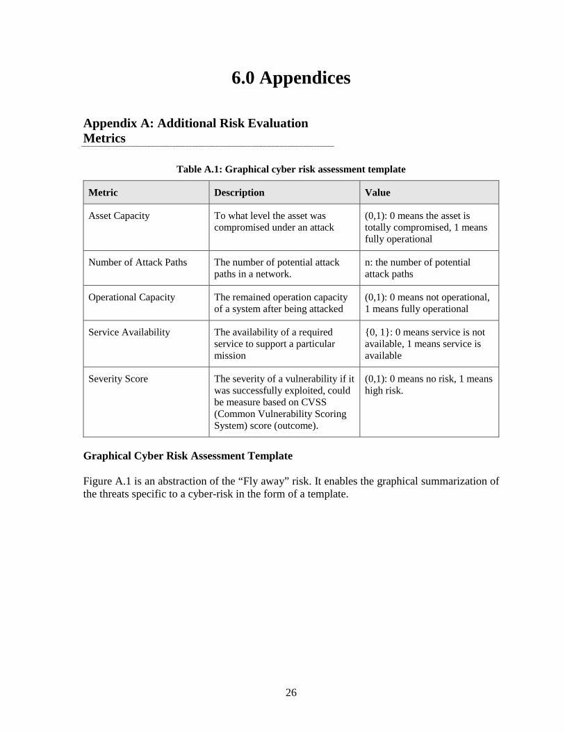
Appendix A: Additional Risk Evaluation Metrics
Table A.1: Graphical cyber risk assessment template
Metric Description Value
Asset Capacity To what level the asset was compromised under an attack
(0,1): 0 means the asset is totally compromised, 1 means fully operational
Number of Attack Paths The number of potential attack paths in a network.
n: the number of potential attack paths
Operational Capacity The remained operation capacity of a system after being attacked
(0,1): 0 means not operational, 1 means fully operational
Service Availability The availability of a required service to support a particular mission
{0, 1}: 0 means service is not available, 1 means service is available
Severity Score The severity of a vulnerability if it was successfully exploited, could be measure based on CVSS (Common Vulnerability Scoring System) score (outcome).
(0,1): 0 means no risk, 1 means high risk.
Graphical Cyber Risk Assessment Template Figure A.1 is an abstraction of the “Fly away” risk. It enables the graphical summarization of the threats specific to a cyber-risk in the form of a template.

27
GoalSecurity objective to
prevent risk
Assets(systems/functions/
protocols/components)
Sub-assets
Environment
Threat Level/Cost
Threats Countermeasures
Consequences
Impact Level Estimation
Vulnerabilities Estimation
Likelihood per successful attack
attack successful
For the ith Sub-asset
Risk Estimation
= �𝐿𝐿𝑅𝑅𝑅𝑅𝐿𝐿𝐹𝐹𝑅𝑅ℎ𝑜𝑜𝑜𝑜𝑑𝑑 × 𝐼𝐼𝑖𝑖𝑖𝑖𝑎𝑎𝑖𝑖𝑖𝑖�
𝑖𝑖 Figure A.1: Graphical cyber risk assessment template
More generally, assets operate in environments, which experience threat levels and therefore pose threats to the sub-assets of an asset. Each sub-asset can be safeguarded with countermeasures to lower the likelihood of a successful attack and potentially the impact of a successful attack. Thus, asset risk is expressed as 𝑅𝑅𝑅𝑅𝑅𝑅𝑅𝑅 = ∑ 𝐿𝐿𝑅𝑅𝑅𝑅𝐿𝐿𝐹𝐹𝑅𝑅ℎ𝑜𝑜𝑜𝑜𝑑𝑑𝑖𝑖 ∙ 𝐼𝐼𝑖𝑖𝑖𝑖𝑎𝑎𝑖𝑖𝑖𝑖𝑖𝑖𝑖𝑖 , where 𝑅𝑅 represents 𝑅𝑅𝑡𝑡ℎ sub-asset.

28
Appendix B: Risks
Risk 1: Fly Away (Operation Phase: Flight & Pre-Flight Operation)

29
Table B.1 identifies the attacks associated with the risk. It also summarizes risk assessment and countermeasures. Attack types are categorized according to the CAPEC and attack mechanisms and the components target specified. Risk assessment specifies the likelihood and impact of attacks. Current and recommended actions to mitigate risk are also identified.

30
Table B.1: Fly away
Attack Identification Attack Types (CAPEC): Communication Channel Manipulation; Obstruction; Protocol
Manipulation; Attack Mechanisms (Attack ID #, Mechanisms, Types):
• 1.1 Man in the middle attack (Communication Channel Manipulation)
• 1.2 Communication link jamming (Obstruction) • 1.3 GPS jamming (Obstruction) • 1.4 Replay attack (Protocol Manipulation) • 1.5 Sensor Spoofing (Protocol Manipulation) • 1.6 Sensor Jamming (Obstruction)
Components Targeted (Components & Attack ID #):
• Hardware Components: • GPS sensor (ID: 1.5, 1.6); Camera sensor (ID: 1.5, 1.6);
Obstacle avoidance sensors (ID: 1.5, 1.6) • Functional Components (software/algorithm + protocol): • Mission data transmission link (ID: 1.1, 1.2, 1.4); GPS
transmission link (ID: 1.3)
Likelihood, Impact, and Risk Assessment
Likelihood of attack (Likelihood & Attack ID #)
• Frequently • Occasional (ID: 1.2, 1.3, 1.6) • Remote (ID: 1.1, 1.4, 1.5) • Improbable • Extremely Improbable
Impact of successful attack (Impact level & Attack ID #):
• High (ID: 1.1-1.4) • Medium (ID: 1.5, 1.6) • Low
Risk Level (Risk level & Attack ID #):
• Unacceptable • Tolerable • Acceptable
Countermeasure-oriented Recommendations Recommendations/actions (in literatures and COTs) for given drone configuration/operation practice: (Recommendations & Attack ID # & Targeted components)
• Current actions: • Checklist activities for handling emergency conditions
(ID: 1.1-1.6) • Manual monitoring of the flight (ID: 1.1-1.6) • Recommended techniques: • Authentication and Encryption mechanisms (ID: 1.1) on
mission data link; • Anti-jamming techniques (ID: 1.2, 1.3) on mission data
link, GPS transmission link; • Verify metadata along with actual data (ID: 1.4, 1.5, 1.6)
on mission data link, GPS sensor, Camera sensor and Obstacle avoidance sensors

31
Risk 2: Loss of GPS
Table B.2: Loss of GPS
Metric Category Category Option Chosen for Current Practice ID #: 2 Operation Phase Flight Operation
Attack Identification Attack Types (CAPEC) Obstruction; Protocol Manipulation; Interception Attack Mechanisms (Attack ID # & Attack Mechanisms & Attack Types)
• 2.1 GPS Spoofing (Protocol Manipulation) • 2.2 GPS jamming (Obstruction) • 2.3 Sensor Sniffing (Interception)
Components Targeted (Components & Attack ID #)
• Hardware Components: • GPS sensor (ID: 2.1-2.3); Camera sensor (ID: 2.1-2.3);
Obstacle avoidance sensors (ID: 2.1-2.3); Magnetometer (ID: 2.1-2.3)
• Functional Components (software/algorithm + protocol): • GPS signal transmission (ID: 2.1-2.3)
Safety Risk Assessment Likelihood of attack (Likelihood & Attack ID #)
• Frequently • Occasional (ID: 2.1, 2.2, 2.3) • Remote • Improbable • Extremely Improbable
Impact level of successful attack (Impact level & Attack ID #)
• High • Medium (ID: 2.1, 2.2, 2.3) • Low
Risk Level (Risk level & Attack ID #)
• Unacceptable • Tolerable • Acceptable
Countermeasure-oriented Recommendations Recommendations/actions (in literatures and COTs) for given drone configuration/operation practice (Recommendations & Attack ID # & Targeted components)
• Current actions: • Checklist activities for handling emergency conditions (ID:
2.1-2.3) • Manual monitoring of the flight (ID: 2.1-2.3) • Recommended techniques: • Verify metadata along with actual data (ID: 2.1) on GPS
sensor, Camera sensor and Obstacle avoidance sensors and Magnetometer
• Measure the signal power level to detect jamming (ID: 2.2) on GPS sensor, Camera sensor and Obstacle avoidance sensors and Magnetometer
• Use efficient cryptographic techniques, lie keys stream, one-time key (ID: 2.3) on GPS sensor, Camera sensor and Obstacle avoidance sensors and Magnetometer
32
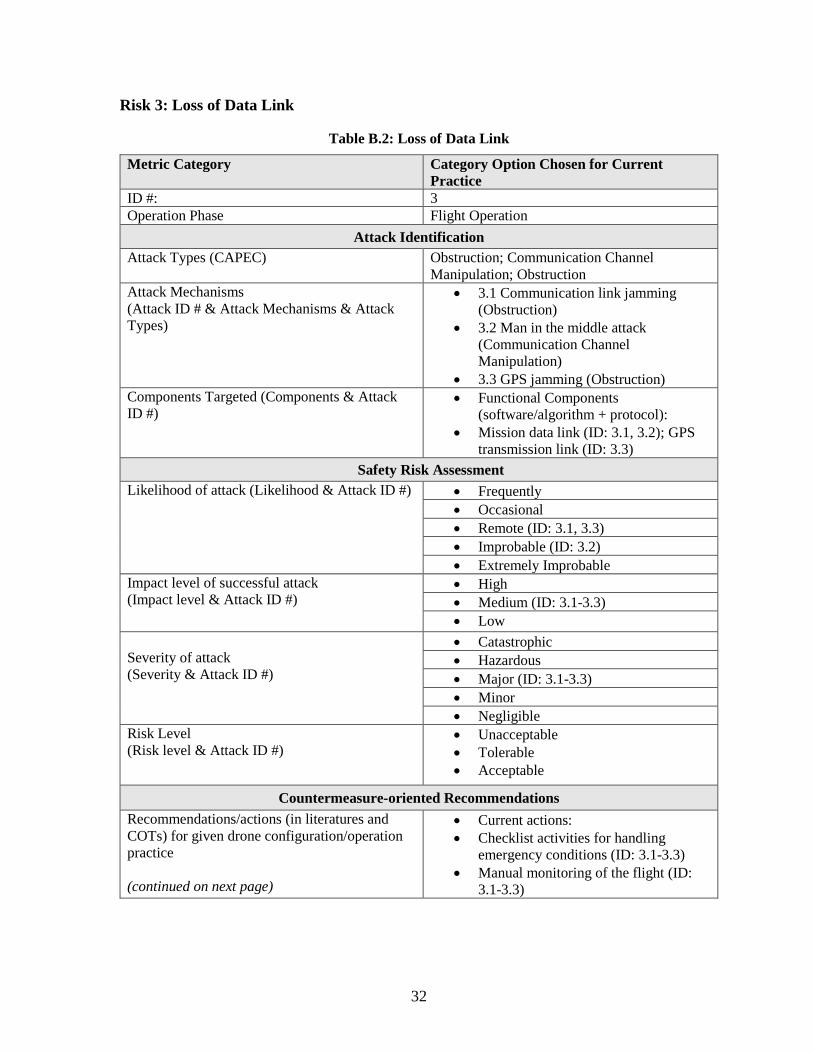
Risk 3: Loss of Data Link
Table B.2: Loss of Data Link
Metric Category Category Option Chosen for Current Practice
ID #: 3 Operation Phase Flight Operation
Attack Identification Attack Types (CAPEC) Obstruction; Communication Channel
Manipulation; Obstruction Attack Mechanisms (Attack ID # & Attack Mechanisms & Attack Types)
• 3.1 Communication link jamming (Obstruction)
• 3.2 Man in the middle attack (Communication Channel Manipulation)
• 3.3 GPS jamming (Obstruction) Components Targeted (Components & Attack ID #)
• Functional Components (software/algorithm + protocol):
• Mission data link (ID: 3.1, 3.2); GPS transmission link (ID: 3.3)
Safety Risk Assessment Likelihood of attack (Likelihood & Attack ID #) • Frequently
• Occasional • Remote (ID: 3.1, 3.3) • Improbable (ID: 3.2) • Extremely Improbable
Impact level of successful attack (Impact level & Attack ID #)
• High • Medium (ID: 3.1-3.3) • Low
Severity of attack (Severity & Attack ID #)
• Catastrophic • Hazardous • Major (ID: 3.1-3.3) • Minor • Negligible
Risk Level (Risk level & Attack ID #)
• Unacceptable • Tolerable • Acceptable
Countermeasure-oriented Recommendations Recommendations/actions (in literatures and COTs) for given drone configuration/operation practice (continued on next page)
• Current actions: • Checklist activities for handling
emergency conditions (ID: 3.1-3.3) • Manual monitoring of the flight (ID:
3.1-3.3)

33
Metric Category Category Option Chosen for Current Practice
ID #: 3 Operation Phase Flight Operation (Recommendations & Attack ID # & Targeted components)
• Recommended techniques: • Anti-jamming techniques (ID: 3.1, 3.3)
on mission data link, GPS transmission link;
• Authentication and Encryption mechanisms (ID: 3.2) on mission data link;
34
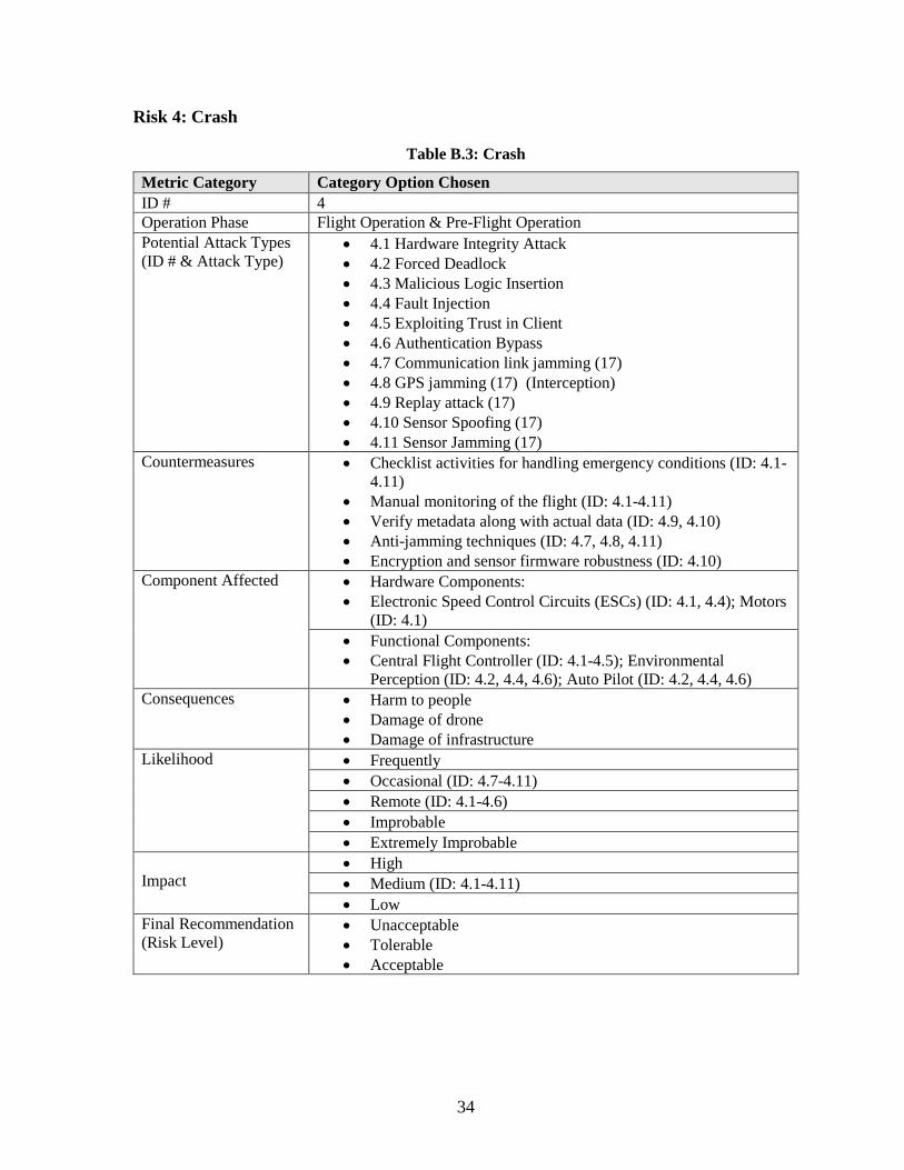
Risk 4: Crash
Table B.3: Crash
Metric Category Category Option Chosen ID # 4 Operation Phase Flight Operation & Pre-Flight Operation Potential Attack Types (ID # & Attack Type)
• 4.1 Hardware Integrity Attack • 4.2 Forced Deadlock • 4.3 Malicious Logic Insertion • 4.4 Fault Injection • 4.5 Exploiting Trust in Client • 4.6 Authentication Bypass • 4.7 Communication link jamming (17) • 4.8 GPS jamming (17) (Interception) • 4.9 Replay attack (17) • 4.10 Sensor Spoofing (17) • 4.11 Sensor Jamming (17)
Countermeasures • Checklist activities for handling emergency conditions (ID: 4.1-4.11)
• Manual monitoring of the flight (ID: 4.1-4.11) • Verify metadata along with actual data (ID: 4.9, 4.10) • Anti-jamming techniques (ID: 4.7, 4.8, 4.11) • Encryption and sensor firmware robustness (ID: 4.10)
Component Affected • Hardware Components: • Electronic Speed Control Circuits (ESCs) (ID: 4.1, 4.4); Motors
(ID: 4.1) • Functional Components: • Central Flight Controller (ID: 4.1-4.5); Environmental
Perception (ID: 4.2, 4.4, 4.6); Auto Pilot (ID: 4.2, 4.4, 4.6) Consequences • Harm to people
• Damage of drone • Damage of infrastructure
Likelihood • Frequently • Occasional (ID: 4.7-4.11) • Remote (ID: 4.1-4.6) • Improbable • Extremely Improbable
Impact
• High • Medium (ID: 4.1-4.11) • Low
Final Recommendation (Risk Level)
• Unacceptable • Tolerable • Acceptable
35
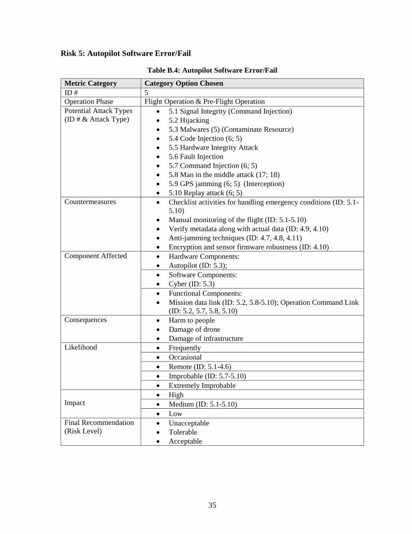
Risk 5: Autopilot Software Error/Fail
Table B.4: Autopilot Software Error/Fail
Metric Category Category Option Chosen ID # 5 Operation Phase Flight Operation & Pre-Flight Operation Potential Attack Types (ID # & Attack Type)
• 5.1 Signal Integrity (Command Injection) • 5.2 Hijacking • 5.3 Malwares (5) (Contaminate Resource) • 5.4 Code Injection (6; 5) • 5.5 Hardware Integrity Attack • 5.6 Fault Injection • 5.7 Command Injection (6; 5) • 5.8 Man in the middle attack (17; 18) • 5.9 GPS jamming (6; 5) (Interception) • 5.10 Replay attack (6; 5)
Countermeasures • Checklist activities for handling emergency conditions (ID: 5.1-5.10)
• Manual monitoring of the flight (ID: 5.1-5.10) • Verify metadata along with actual data (ID: 4.9, 4.10) • Anti-jamming techniques (ID: 4.7, 4.8, 4.11) • Encryption and sensor firmware robustness (ID: 4.10)
Component Affected • Hardware Components: • Autopilot (ID: 5.3); • Software Components: • Cyber (ID: 5.3) • Functional Components: • Mission data link (ID: 5.2, 5.8-5.10); Operation Command Link
(ID: 5.2, 5.7, 5.8, 5.10) Consequences • Harm to people
• Damage of drone • Damage of infrastructure
Likelihood • Frequently • Occasional • Remote (ID: 5.1-4.6) • Improbable (ID: 5.7-5.10) • Extremely Improbable
Impact
• High • Medium (ID: 5.1-5.10) • Low
Final Recommendation (Risk Level)
• Unacceptable • Tolerable • Acceptable

36
Risk 6: GCS Failure
Table B.5: GCS Failure
Metric Category Category Option Chosen ID # 6 Operation Phase Flight Operation Potential Attack Types (ID # & Attack Type)
• 6.1 Spyware (6; 5) • 6.2 Malware (6; 5) • 6.3 Authentication Bypass • 6.4 Exploiting Trust in Client • 6.5 Interception • 6.6 Infrastructure Manipulation
Countermeasures • Checklist activities for handling emergency conditions (ID: 6.1-6.6)
• Manual monitoring of the flight (ID: 6.1-6.6) • Anti-spyware software, firewalls, packet filters [7] (ID: 6.1) • Anti-malware software, packet filters, firewalls [7] (ID: 6.2)
Component Affected • Hardware Components: • GCS (ID: 6.1, 6.2) • Functional Components: • GPS transmission (ID: 6.3-6.6)
Consequences • Harm to people • Damage of drone • Damage of infrastructure
Likelihood • Frequently • Occasional • Remote (ID: 6.3-6.6) • Improbable (ID: 6.1-6.2) • Extremely Improbable
Impact
• High (ID: 6.3-6.6) • Medium (ID: 6.1-6.2) • Low
Final Recommendation (Risk Level)
• Unacceptable • Tolerable • Acceptable

37
Appendix C: Attacks
Table C.1 provides attack ID, the attack name, links to the CAPEC (Common Attack Pattern Enumeration and Classification) ID wherever possible, and references.
Table C.1: List of attack mechanisms
Attack ID
Attack Name (CAPEC ID)
Ref. Attack ID
Attack Name (CAPEC ID)
Ref.
A01 Code Injection (242) (18; 19) A23 Rogue Node (616, 524) (18) A02 Identity Spoofing (151) (7) A24 Theft and Vandalism (507) (7) A03 Sleep Deprivation (18; 2) A25 Rogue Drone Collision
Attack (20)
A04 Hardware Integrity Attack (440)
(20) A26 Firmware Modification (638) (18)
A05 Fault Injection Attack (624)
(21) A27 Supply Chain Attack (522,544)
(18)
A06 Spyware (549) (19) A28 Corruption (22) A07 Malwares (441) (23) A29 Video Replay Attack (19) A08 Sensor Spoofing (148) (2; 23) A30 Root Kits (552) (18) A09 Sensor Jamming (601) (8) A31 Key Loggers (568) (18) A10 Sensor Sniffing (157) (19) A32 Password Cracking (55) (18) A11 Communication Link
Jamming (601) (18) A33 Eavesdropping (651) (7)
A12 Command Injection (248) (18; 24) A34 Scrambling/Distortion A13 False Data Injection (240) (18; 23) A35 Reference Station Attack (18) A14 Fuzzing Attack (28) (18; 20) A36 Signal Delay (236) (18) A15 Network Isolation (18) A37 Address Resolution Protocol
(590) (19)
A16 Black Hole/Gray Hole (18) A38 Hijacking (501) (18) A17 Packet Sniffing (157) (18) A39 Cross Layer Attack (18) A18 Man in the Middle Attack
(94) (18) A40 Multi-Protocol Attack (7)
A19 GPS Signals Jamming (627)
(18; 25) A41 Back Doors (18)
A20 Replay Attack (60) (18; 19) A42 Code Modification (242) (19) A21 Denial of Service (210) (7; 25) A43 External Signal Spoofing (19) A22 De-authentication Attack (19) A44 In-Vehicle Spoofing (19)
Selected literature on UAS testing, risk modeling, and architectural frameworks The cybersecurity literature is vast. Therefore, this selected literature review describes past studies performed in the context of UAS. Specifically, testing, risk modeling and mitigation, and architectural frameworks are considered. Papers focused on a single UAS attack are not discussed here, but can be identified from the references. Both attacks and countermeasures are covered because a comprehensive method to design and test require both perspectives.

38
Altway and Youssef (22) identified security, safety, and privacy aspects of civilian drone operation, including protocols for fail-safe procedures. Horowitz et al. (26) developed architectural decision support, mission-centric analysis and modeling methods to combining inputs from system experts at the design and user levels in support of cybersecurity aware systems engineering. The thesis of Leccadito (18) developed a hierarchical embedded cyber attack detection framework in the context of UAS to ensure security is a testable property that is built into a system. Hagerman et al. (27) described a UAS security testing approach which uses behavioral, attack, and mitigation models. The behavioral and attack models are used to identify attack points. The mitigation model then generates the security test suite. DroneJack (28) allows the user to shutdown a UAS, pilot the UAS, or direct it to GPS coordinates as well as exploit data, including recovery of photo, video, and flight logs. Custom attacks can also be configured and deployed. DroneJack can therefore be used as a testing tool. The Defense Advanced Research Projects Agency (DARPA) High Assurance Cyber Military Systems (HACMS) Program demonstrated that an open-source quadcopter was secured from hijacking despite being given six weeks and full access to the source code of the copter. Krishna and Murphy (19) reviewed UAS cybersecurity vulnerabilities and developed a UAS specific taxonomy of attacks according to attack vector and target. Solodov et al. (29) overviewed UAS technology and potential threats to nuclear facilities, evaluating measures to detect, delay, and neutralize. Mansfield et al. (30) analyzed security vulnerabilities within smart phones and tablets, and software applications to develop a risk model of the threat profile of the Department of Defense Ground Control Station communications. Similarly, Hartmann and Steup (8) developed a risk assessment methodology for UAS which considers physical and environmental factors, communication, storage media, sensors, and fault handling mechanisms. Garg et al. (31) anticipate the role of UAS will play in edge computing, which creates new quality of service requirements to ensure uninterrupted data sharing for what may come to be regarded as mission and life critical services. Toward this end, the authors proposed a data-driven transportation optimization model that also conducts cyber-threat detection. Vattapparamban et al. (32) review aspects of UAS related to cybersecurity, privacy, and public safety. They also provide examples of attacks on UAS as well as UAS as a platform from which to carry out attacks. Kim et al. (6) reviewed general and network systems specific cyberattacks to identify potential threats, vulnerabilities, post-attack behaviors in existing autopilot systems. Stracquodaine et al. (2) presented a comprehensive method to protect a UAS from hardware and software attacks by directly monitoring the autopilot as well as the onboard operating system, enabling dependable operation despite sensor or data spoofing attacks. Given the high potential for cyberattacks on UAS, Blazy et al. (21) proposed an efficient protocol to ensure the confidentiality of data collected, which is independent of the encryption scheme implemented.

39
Appendix D: Countermeasures
Table D.1 lists classes of countermeasure identified according to their ID and name.
Table D.1: Countermeasures
Countermeasure ID Name ID Name
C01 Update firmware C13 Use channel switching C02 Utilize strong federated identity C14 Use backup channels C03 Check for power leakage C15 Perform jamming detection techniques C04 Use intrusion detection
technique C16 Validate user- controllable input
C05 Perform penetration testing C17 Whitelisting/blacklisting the inputs. C06 Use anti-spyware and packet
filters C18 Use Fault detection approach
C07 Use firewalls, anti-malware and packet filters
C19 Use secure and robust protocols with strong authentication
C08 Verify metadata along with actual data.
C20 Utilize redundant communication links
C09 Cross verify data from redundant sensors
C21 Utilize strong passwords
C10 Measure the signal power level to detect jamming
C22 Fail safe/fail loud protocol
C11 Use encryption technique C23 Use physical security techniques C12 Use adaptive transmission C24 Utilize counter-drone techniques
Table D.2 lists general mitigation categories into which specific counter measures can be classified, including: (D)etect, (N)eutralize, (L)imit, and (R)ecover as well as the corresponding effectiveness: (L)ow, (M)edium, (H)igh, and (V)ery high. Classification may depend on system and mission specific factors.
Table D.2: Mitigation effectiveness notations Effectiveness Mitigation Category [49]
Detect Neutralize Limit Recover Very High DV NV LV RV High DH NH LH RH Medium DM NM LM RM Low DL NL LL RL

40
Risk Assessment of selected UAS components utilized by MassDOT Standard practice (23) relies on fail-safe protocols for a UAS to execute scripted behavior such as return to base or hold in cases of jamming or disruption of communications. Hard-coded geofences are still vulnerable to override in the case of spoofing or signal hijacking. Omnidirectional antennas radiate in all directions to improve outdoor performance, but increase eavesdropping risk (18) on the commercial 2.4 and 5.8 GHz bands. The following discusses functionality and some potential vulnerabilities associated with UAS components utilized by MassDOT. However, a detailed mapping to attacks and potential countermeasures enumerated above is not performed here. DJI Inspire 2 is a platform integrating high definition video transmission (Security issues)
• In the past, the SSL Certificate for the DJI website has been compromised. DJI subsequently revoked this certificate and replaced it with a new certificate. Tampering with website content would have been possible.
• An independent security researcher reported that an Amazon Web Services server repository was accessible by unauthorized parties and was fixed in a day. Data could have been stolen or altered.
• The new Local Data Mode stops internet traffic to and from its DJI Pilot app, in order to enhance data privacy. However, this prevents connecting to the Internet and the DJI Pilot app cannot detect the user’s location, display the map and geofencing information such as No Fly Zones and temporary flight restrictions. Moreover, firmware updates will not be available. Telemetry data contained in flight logs such as altitude, distance, and speed will remain stored on the aircraft even if the user deactivates Local Data Mode, preventing utilization of real-time counter measures such as auto-pilot monitoring.
AirMap provides access to airspace advisories, flight plan creation, and enables contact with airspace authorities. (Security issues)
• AirMap features include: an intrusion detection system, log analysis, and a web application firewall, penetration testing and vulnerability assessments, content delivery network, and data security controls. Compromise of these features can enable various attacks that could be executed throughout the mission lifecycle.
Skyward is a drone-management platform
• Skyward’s interactive airspace allows viewing of flight restrictions, marking points of interest and hazards to be avoided. Syncing Skyward with DroneDeploy and DJI GO enables automated log upload, flight path visualization, and battery health monitoring. Compromise of Skyward can introduce vulnerabilities associated with its functionality, while compromise of Skyward while linked to DroneDeploy and DJI GO may enable introduction of vulnerabilities in to all aspects of functionality in DroneDeploy and DJI GO that interact with Skyward.

41
DroneDeploy is a cloud-based software to automate drone flight, capture data, and create maps and 3D models. (Security issues) While DroneDeploy implements many practices in support of data, web, and application security, compromise of these services can introduce corresponding vulnerabilities into the mission lifecycle. Assessment of data related services must consider the types of data transmitted through and stored on these platforms. Web and application security must consider the corresponding capabilities to identify and prioritize potential vulnerabilities.
• Data is encrypted in transit and at rest on DroneDeploy servers. • Data is sent securely to DroneDeploy via the HTTPS protocol using the latest
recommended ciphers and transparent LAN service (TLS). • DroneDeploy is hosted on Amazon Web Services and Google Cloud. • DroneDeploy employees do not have physical access to the Amazon or Google data
centers, servers, network equipment, or storage, which can deter insider data theft. • Annual network and system level penetration tests are conducted by an outside security
vendor. • Each software component undergoes a security risk assessment based on the Open Web
Application Security Project (OWASP) Top 10, which is a list of the ten most critical security risks to web-based applications identified by consensus among web security organization.
• Application security includes password-based logins, and Google single sign-on for all accounts allowing use of Google or GSuite accounts to authenticate users requiring two-factor authentication with mechanisms including access codes or security keys.

42
Appendix E: Functional Decomposition and Data-flow
A UAS may be decomposed into four functional modules (6) 1. Navigation: Analyze sensory data for Autopilot decisions. 2. Data Collection: Collect raw data for mission and UAS status. 3. Communication: Send and receive the control signal and UAS data. 4. Flight Control: Interact with other modules to preserve correct UAS flight state
Navigation Module The navigation module is responsible for correctly stabilizing the UAS and navigating the UAS along a predefined path. Navigation can be performed automatically by the auto-pilot function of the drone or through manual control using a handheld controller over a wireless network setting. The auto-pilot function uses the predefined mission plan and sensing data generated from the navigational sensors noted above to navigate. In manual control, a user controls the navigation using line of sight communication with the UAS. Both the manual and auto-pilot modes are controlled by the central flight controller, which is primarily responsible for processing the sensor data. Figure E.1 shows the decomposition of a UAS into four functional modules (17) and data-flow. Navigation related functions and data flows are highlighted with bold arrows and boxes.
Figure E.1: UAS Functional Modules and Data-flow
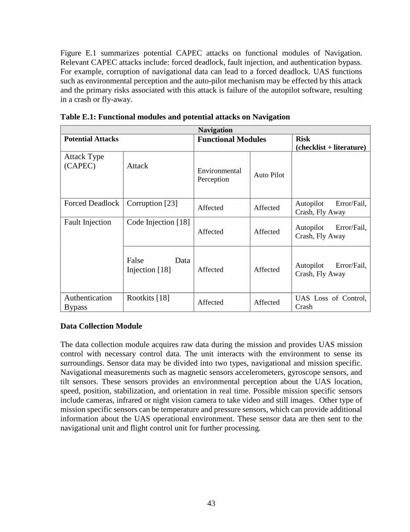
43
Figure E.1 summarizes potential CAPEC attacks on functional modules of Navigation. Relevant CAPEC attacks include: forced deadlock, fault injection, and authentication bypass. For example, corruption of navigational data can lead to a forced deadlock. UAS functions such as environmental perception and the auto-pilot mechanism may be effected by this attack and the primary risks associated with this attack is failure of the autopilot software, resulting in a crash or fly-away.
Table E.1: Functional modules and potential attacks on Navigation Navigation
Potential Attacks Functional Modules Risk (checklist + literature)
Attack Type (CAPEC)
Attack
Environmental Perception Auto Pilot
Forced Deadlock
Corruption [23] Affected Affected Autopilot Error/Fail, Crash, Fly Away
Fault Injection
Code Injection [18] Affected Affected Autopilot Error/Fail,
Crash, Fly Away
False Data Injection [18]
Affected Affected Autopilot Error/Fail, Crash, Fly Away
Authentication Bypass
Rootkits [18] Affected Affected UAS Loss of Control, Crash
Data Collection Module The data collection module acquires raw data during the mission and provides UAS mission control with necessary control data. The unit interacts with the environment to sense its surroundings. Sensor data may be divided into two types, navigational and mission specific. Navigational measurements such as magnetic sensors accelerometers, gyroscope sensors, and tilt sensors. These sensors provides an environmental perception about the UAS location, speed, position, stabilization, and orientation in real time. Possible mission specific sensors include cameras, infrared or night vision camera to take video and still images. Other type of mission specific sensors can be temperature and pressure sensors, which can provide additional information about the UAS operational environment. These sensor data are then sent to the navigational unit and flight control unit for further processing.
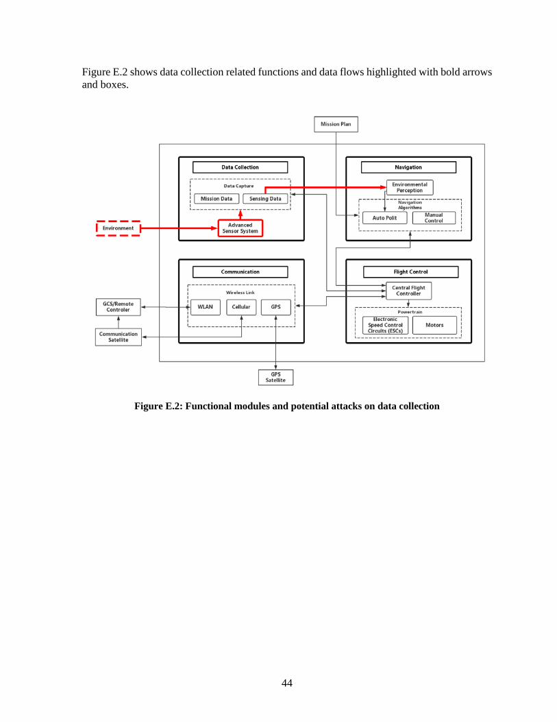
44
Figure E.2 shows data collection related functions and data flows highlighted with bold arrows and boxes.
Figure E.2: Functional modules and potential attacks on data collection
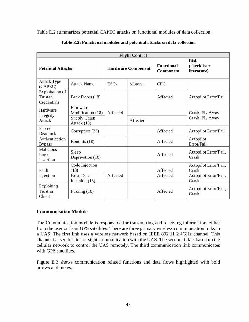
45
Table E.2 summarizes potential CAPEC attacks on functional modules of data collection.
Table E.2: Functional modules and potential attacks on data collection
Flight Control
Potential Attacks Hardware Component Functional Component
Risk (checklist + literature)
Attack Type (CAPEC) Attack Name ESCs Motors CFC
Exploitation of Trusted Credentials
Back Doors (18) Affected Autopilot Error/Fail
Hardware Integrity Attack
Firmware Modification (18) Affected
Crash, Fly Away
Crash, Fly Away Supply Chain Attack (18) Affected
Forced Deadlock Corruption (23) Affected Autopilot Error/Fail
Authentication Bypass Rootkits (18) Affected Autopilot
Error/Fail Malicious Logic Insertion
Sleep Deprivation (18) Affected Autopilot Error/Fail,
Crash
Fault Injection
Code Injection (18)
Affected
Affected Affected
Autopilot Error/Fail, Crash Autopilot Error/Fail, Crash
False Data Injection (18)
Exploiting Trust in Client
Fuzzing (18) Affected Autopilot Error/Fail, Crash
Communication Module The Communication module is responsible for transmitting and receiving information, either from the user or from GPS satellites. There are three primary wireless communication links in a UAS. The first link uses a wireless network based on IEEE 802.11 2.4GHz channel. This channel is used for line of sight communication with the UAS. The second link is based on the cellular network to control the UAS remotely. The third communication link communicates with GPS satellites. Figure E.3 shows communication related functions and data flows highlighted with bold arrows and boxes.

46
Figure E.3: Communication module

47
Table E.3 summarizes potential CAPEC attacks on functional modules of communication.
Table E.3: Functional modules and potential attacks on communication
Communication
Potential Attacks Functional Components
Risk (checklist + literature)
Attack Type (CAPEC) Attack Name Data Tx GPS Tx
Input Data Manipulation Keyloggers (18) Affected Resource Leakage
Authentication Bypass Rootkits (18) Affected Affected Resource Leakage,
GCS failure Exploiting Trust in Client Fuzzing (18) Affected GCS Failure
Interception
Sniffing (19) Affected Affected Resource Leakage
Password Cracking (18) Affected
Resource Leakage, Automatic transmission Locked
Eavesdropping (7) Affected Affected Resource Leakage Scrambling/ Distortion Affected GCS Failure
Infrastructure Manipulation
Reference Station Attack (18) Affected Affected GCS Failure
Signal Delay (18) Affected Affected GCS Failure, Automatic Transmission Locked
Communication Channel Manipulation
Black Hole/Gray Hole (18) Affected GCS Failure, Automatic Transmission Locked
Man-in-the-Middle (18) Affected Resource Leakage, Automatic Transmission Locked, GCS Failure
Protocol Manipulation
Replay Attack (19) Affected Affected GCS Failure Address Resolution Protocol (19) Affected GCS Failure
Spoofing (19) Affected Resource Leakage, GCS Failure
Network Isolation (18) Affected GCS Failure
Rogue Node (18) Affected Resource Leakage, GCS Failure
Hijacking (7) Affected Resource Leakage, GCS Failure
Cross Layer Attack (7) Affected Resource Leakage, GCS Failure

48
Multi-Protocol Attack (7) Affected Resource Leakage, GCS Failure
Traffic Injection Cmmd Injection (18) Affected GCS Failure False Data Injection (18) Affected Affected GCS Failure
Obstruction
Jamming (19) Affected Affected GCS Failure, Loss of Data Link
Deauthentication attack (19) Affected Affected GCS Failure, Loss of Data Link
DoS (19) Affected Affected GCS Failure, Loss of Data Link
Flight Control Module The flight control module consists of a central flight controller, which is responsible for processing the sensor and mission data, mission plan, and wireless communication data into electrical signals for the UAS motors and control circuits. The flight controller provides bi-directional communication between the data collection, communication, and navigation modules. Figure E.4 shows flight control related functions and data flows highlighted with bold arrows and boxes.
Figure E.4: Functional modules and potential attacks on flight control

49
Table E.4 summarizes potential CAPEC attacks on functional modules of Flight Control.
Table E.4: Flight control
Flight Control
Potential Attacks Hardware Component
Functional Component Risk
(checklist +
literature) Attack Type (CAPEC)
Attack Name
ESCs Motors CFC
Exploitation of Trusted Credentials
Back Doors (18)
Affected Autopilot Error/Fail
Hardware Integrity Attack
Firmware Modification (18)
Affected Crash, Fly Away
Supply Chain Attack (18)
Affected Crash, Fly Away
Forced Deadlock
Corruption (23)
Affected Autopilot Error/Fail
Authentication Bypass
Rootkits (18)
Affected Autopilot Error/Fail
Malicious Logic Insertion
Sleep Deprivation (18)
Affected Autopilot Error/Fail, Crash
Fault Injection
Code Injection (18)
Affected Autopilot Error/Fail, Crash
False Data Injection (18)
Affected Affected Autopilot Error/Fail, Crash
Exploiting Trust in Client Fuzzing (18) Affected
Autopilot Error/Fail, Crash

50
Appendix F: Attacks Categorized According to Mission Stage and Category
As noted in Figure 2.1, drone missions may be divided into pre-, in-, and post-flight. Attacks are classified into different categories according to the CAPEC standard developed by the MITRE Corporation (5) and links provided wherever possible. Our study was limited to the pre and inflight stages with emphasis on the inflight stage. Preflight categories considered include software and hardware, while inflight categories include software, hardware, communication, and physical security. Preflight Preflight software attacks Preflight software attacks include fault injection and authentication bypass. The following tables summarize these attacks, alternative names these attacks are known by, the physical component subject to the attack, mechanism of the attack according to the CAPEC, security service attribute affected, risk, current countermeasures taken by MassDOT (present in their checklist), and recommended techniques to mitigate the risk.

51
Table F.1: Preflight software attacks
Attack type [CAPEC]: Fault Injection (624) Attack name Code Injections (18; 19), (Physical) component Firmware Mechanism of attack (CAPEC) Inject unexpected items into the code (152) Security service attribute affected Integrity Risk Crash Autopilot Software Error/Fail Current countermeasure activities [MassDOT checklist]
Firmware updated. COTS related findings: AirMap has an Intrusion detection System [https://www.airmap.com/security/]
Recommended mitigation techniques
Regular patching of software (CAPEC) IDS (33)
Attack type [CAPEC]: Authentication bypass (115)
Attack name Identity Spoofing (7) (Physical) component Software used, e.g, Skyward, AirMap, DroneDeploy Mechanism of attack (CAPEC) Engage in Deceptive Interactions (156) Security service attribute affected Authentication, Confidentiality. Risk Hostile environment Current countermeasure activities [MassDOT checklist]
Flight authorization; Flyaway in airport reviewed and informed to FAA; Map cached, Flight plan is built (setting altitudes, gimble angle). COTS related findings: DroneDeploy provides Google single sign-on for all accounts allowing use of Google or GSuite accounts to authenticate users requiring two-factor authentication. Google logins can be protected by multiple 2FA mechanisms including access codes or security keys. https://support.dronedeploy.com/docs/security-and-compliance.
Recommended mitigation techniques
Strong federated identity such as SAML to encrypt and sign identity tokens in transit. (Ref: CAPEC) Session timeout for all sessions. (Ref: CAPEC) Verify of authenticity of all

52
Table F.2: Preflight hardware attacks
Attack type [CAPEC]: Malicious logic insertion (441) Attack name Sleep deprivation (2; 18) (Physical) component Battery Mechanism of attack (CAPEC) Manipulate System Resources (262) Security service attribute affected Integrity, Availability Risk Battery depletion Current countermeasure activities [MassDOT checklist]
Batteries (controller, display) charged. Communication devices charged. COTS related findings: Syncing Skyward with Drone-Deploy and DJI GO enables visualize battery health. [https://community.skyward.io/s/dji-go-syncing-and-flight-visualizations]
Recommended mitigation techniques Check for power leakage.
Attack type [CAPEC]: Firmware Modification (638) Attack name Hardware Integrity Attack (6) (Physical) component ESC, Camera and other sensors Mechanism of attack (CAPEC) Manipulate System Resources (262) Security service attribute affected Integrity Risk Crash, Autopilot Software Error/Fail Current countermeasure activities [MassDOT checklist]
UAS hardware inspected, registered and packed Rotors inspected, mounted. Camera fixed. Mission limitations and safety (eg. radio interference is checked, hazards/site Assessment) Weather check, Flyaway in airport reviewed and informed to FAA
Recommended mitigation techniques Intrusion detection, (2) (normalcy profiling), CIDS (33) Penetration testing with the Attack tools
Attack type [CAPEC]: Fault Injection (624)
Attack name Fault Injection, Signals like EMP (electromagnetic pulses), laser pulses, clock glitches, etc.) (34)
(Physical) component ESC, Barometer, Gyroscope, Accelerometer, Antenna Mechanism of attack (CAPEC) Inject unexpected items (152) Security service attribute affected Integrity, Availability Risk Crash, Autopilot Software Error/Fail Current countermeasure activities [MassDOT checklist]
UAS hardware inspected, registered and packed Rotors inspected, mounted. Camera fixed. Mission limitations and safety (eg. radio interference is checked, hazards/site Assessment) Weather check, Flyaway in airport reviewed and informed to FAA
Recommended mitigation techniques Intrusion detection, (2) (normalcy profiling), CIDS (33) Penetration testing with the Attack tools
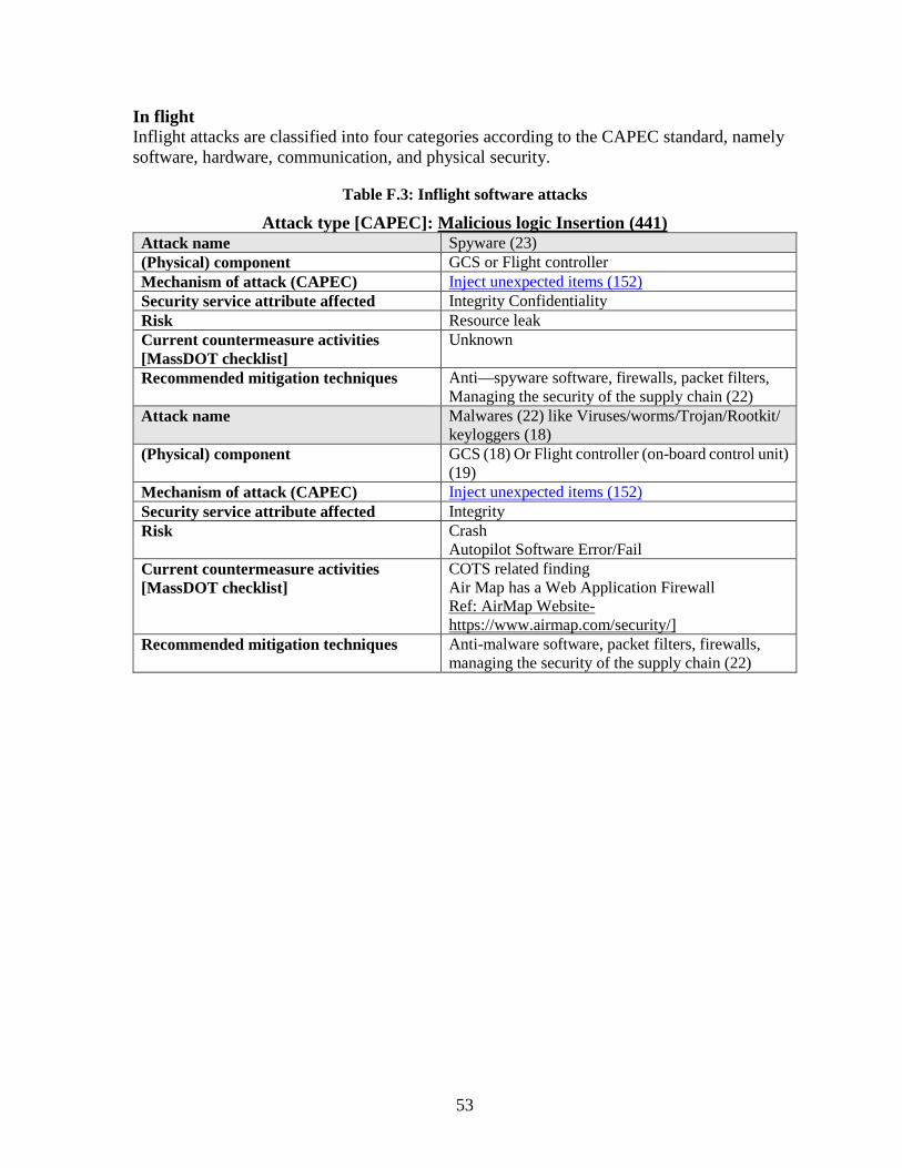
53
In flight Inflight attacks are classified into four categories according to the CAPEC standard, namely software, hardware, communication, and physical security.
Table F.3: Inflight software attacks
Attack type [CAPEC]: Malicious logic Insertion (441) Attack name Spyware (23) (Physical) component GCS or Flight controller Mechanism of attack (CAPEC) Inject unexpected items (152) Security service attribute affected Integrity Confidentiality Risk Resource leak Current countermeasure activities [MassDOT checklist]
Unknown
Recommended mitigation techniques Anti—spyware software, firewalls, packet filters, Managing the security of the supply chain (22)
Attack name Malwares (22) like Viruses/worms/Trojan/Rootkit/ keyloggers (18)
(Physical) component GCS (18) Or Flight controller (on-board control unit) (19)
Mechanism of attack (CAPEC) Inject unexpected items (152) Security service attribute affected Integrity Risk Crash
Autopilot Software Error/Fail Current countermeasure activities [MassDOT checklist]
COTS related finding Air Map has a Web Application Firewall Ref: AirMap Website-https://www.airmap.com/security/]
Recommended mitigation techniques Anti-malware software, packet filters, firewalls, managing the security of the supply chain (22)

54
Table F.4: Inflight hardware attacks
Attack type [CAPEC]: Protocol Manipulation (272) Attack name Sensor Spoofing (2; 18)
(Physical) component GPS sensor, obstacle avoidance sensors, Camera
sensor, other sensors like IR sensor, ultrasonic wave sensor, magnetometer, barometer (22)
Mechanism of attack (CAPEC) Engage in Deceptive Interactions (156) Content spoofing (148)
Security service attribute affected Integrity Risk Loss of GPS, crash, fly away (8; 19), auto pilot
software error, loss of situational awareness Current countermeasure activities [MassDOT checkliist]
Manual monitoring of the flight checklist activities for handling emergency conditions (mentioned in above table.)
Recommended mitigation techniques Verify metadata along with actual data (35), cross verify data from redundant sensors (8), RANSAC algorithms
Attack type [CAPEC]: Obstruction (607)
Attack name Sensor Jamming (8) (Physical) component GPS sensor, obstacle avoidance sensors, camera
sensor, other sensors like IR sensor, ultrasonic wave sensor, magnetometer
Mechanism of attack (CAPEC) Manipulate System Resources (262) Security service attribute affected Integrity, Availability Risk Crash, fly away (8), auto pilot software error,
loss of situational awareness
Recommended mitigation techniques Measure the signal power level to detect jamming. (22), alternative navigation method [INS] (21)(Eg: Multiple camera system like MTS-B (8))
Attack type [CAPEC]: Interception (117)
Attack name Sensor sniffing (19) (Physical) component GPS sensor, obstacle avoidance sensors, camera
sensor, other sensors like IR sensor, ultrasonic wave sensor, magnetometer
Mechanism of attack (CAPEC) Collect and analyze information Security service attribute affected Affected service attribute Risk Resource leak Recommended mitigation techniques Encryption (18) sensor firmware robustness

55
Table F.5: Inflight communications attacks
Attack type [CAPEC]: Obstruction (607) Attack name Communication link Jamming (18) (Physical) component Control transmission and data transmission link Mechanism of attack (CAPEC)
Manipulate System Resources (262) Obstruction (607)
Security service attribute affected
Availability
Risk Loss of data link, Crash, Flyaway, Loss of direct visual Current countermeasure activities [MassDOT checklist]
Manual monitoring of the flight. Handling Emergency situations based on UAS ability to execute scripted behavior (return to base or hold) (23) fail-safe protocol should be implemented. (23)
1. Fly away a. Alert crew b. Press Home button c. Press kill if required
2. Loss of datalink a. Alert crew b. Assess loss type c. Press Home Button
3. Loss of GPS a. Wait in hover for 1 min to reconnect. b. Press Home Button
4. Autopilot Software Error/Fail a. Stabilize aircraft. b. Switch to manual mode, fly towards GCS.
5. Loss of Engine power a. Note the position of aircraft. b. Switch to manual mode. c. Fly to predetermined safe zone. d. If maintaining altitude, fly to home.
6. GCS failure a. Home button pressed. b. Manual mode. c. Fly home. d. Land.
7. Intrusion of Aircraft into UAS airspace a. Land immediately.
8. Crash a. Switch to Manual mode. b. Safety procedures.
Geo-fencing is used. COTS related findings: 1) All data is sent securely to DroneDeploy via the HTTPS protocol using the latest recommended ciphers and TLS protocol.(Ref:https://support.dronedeploy.com/docs/security-and-compliance) 2) DJI has recently launched a new Local Data Mode. This new mode stops internet traffic to and from its DJI Pilot app, in order to provide enhanced data privacy assurances. (Ref: https://www.expoUAS.com/news/latest/solution-cyber-vulnerabilities-dji-drones/)
Recommended mitigation techniques
Adaptive Transmission, Channel switching, Backup channels Jamming detection, Electronic Counter Measure techniques and jamming resistant modulations for security (19).

56
Attack type [CAPEC]: Traffic Injection (594) Attack name Command Injection (18; 36) (Physical) component Control transmission link Mechanism of attack (CAPEC) Inject unexpected items (152) Security service attribute affected Integrity Risk Crash, Autopilot Software Error/Fail Current countermeasure activities [MassDOT checklist]
See Obstruction under Inflight communications attacks above.
Recommended mitigation techniques
User-controllable input should be validated and filtered for potentially unwanted characters. (CAPEC) Whitelisting/blacklisting the inputs. (CAPEC) Location-based authentication (22)A lightweight Public Key Infrastructure (PKI). (22)
Attack name False Data Injection (18; 22) (Physical) component Data transmission link Mechanism of attack (CAPEC) Engage in Deceptive Interactions (156)
Content spoofing (148) Security service attribute affected Integrity Risk Integrity Current countermeasure activities [MassDOT checklist]
See Obstruction under Inflight communications attacks above.
Recommended mitigation techniques
Fault detection approach (6) Checking the meta data along with the data. (19)
Attack type [CAPEC]: Exploiting Trust in Client (22)
Attack name Fuzzing Attack (6; 18) (Physical) component Control transmission and data transmission link Mechanism of attack (CAPEC) Employ Probabilistic Techniques (223), fuzzing(28) Security service attribute affected Authentication Risk Illegal access of UAS which might lead to autopilot
software error. Current countermeasure activities [MassDOT checklist]
See Obstruction under Inflight communications attacks above.
Recommended mitigation techniques
Secure networking protocols. white-box and black-box fuzzing tests (6)
Attack type [CAPEC]: Protocol Manipulation (272)
Attack name Network Isolation (18) (Physical) component Control transmission and data transmission link Mechanism of attack (CAPEC) Manipulate System Resources (262)
Infrastructure manipulation (161) Security service attribute affected Availability Risk Loss of data link (loss of communication) (19) Current countermeasure activities [MassDOT checklist]
See Obstruction under Inflight communications attacks above
Recommended mitigation techniques
Secure networking, Protocols, Redundant links (23)
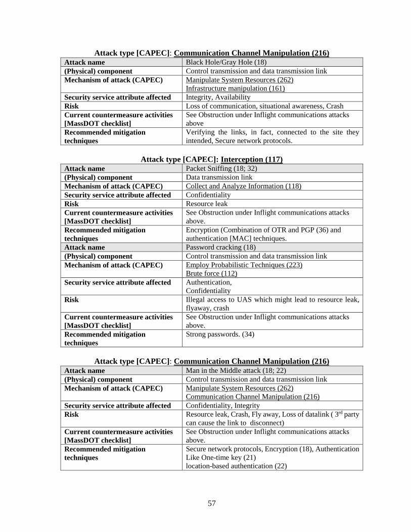
57
Attack type [CAPEC]: Communication Channel Manipulation (216) Attack name Black Hole/Gray Hole (18) (Physical) component Control transmission and data transmission link Mechanism of attack (CAPEC) Manipulate System Resources (262)
Infrastructure manipulation (161) Security service attribute affected Integrity, Availability Risk Loss of communication, situational awareness, Crash Current countermeasure activities [MassDOT checklist]
See Obstruction under Inflight communications attacks above
Recommended mitigation techniques
Verifying the links, in fact, connected to the site they intended, Secure network protocols.
Attack type [CAPEC]: Interception (117)
Attack name Packet Sniffing (18; 32) (Physical) component Data transmission link Mechanism of attack (CAPEC) Collect and Analyze Information (118) Security service attribute affected Confidentiality Risk Resource leak Current countermeasure activities [MassDOT checklist]
See Obstruction under Inflight communications attacks above.
Recommended mitigation techniques
Encryption (Combination of OTR and PGP (36) and authentication [MAC] techniques.
Attack name Password cracking (18) (Physical) component Control transmission and data transmission link Mechanism of attack (CAPEC) Employ Probabilistic Techniques (223)
Brute force (112) Security service attribute affected Authentication,
Confidentiality Risk Illegal access to UAS which might lead to resource leak,
flyaway, crash Current countermeasure activities [MassDOT checklist]
See Obstruction under Inflight communications attacks above.
Recommended mitigation techniques
Strong passwords. (34)
Attack type [CAPEC]: Communication Channel Manipulation (216)
Attack name Man in the Middle attack (18; 22) (Physical) component Control transmission and data transmission link Mechanism of attack (CAPEC) Manipulate System Resources (262)
Communication Channel Manipulation (216) Security service attribute affected Confidentiality, Integrity Risk Resource leak, Crash, Fly away, Loss of datalink ( 3rd party
can cause the link to disconnect) Current countermeasure activities [MassDOT checklist]
See Obstruction under Inflight communications attacks above.
Recommended mitigation techniques
Secure network protocols, Encryption (18), Authentication Like One-time key (21) location-based authentication (22)

58
Attack type [CAPEC]: Obstruction (607) Attack name GPS signals jamming (18; 22) (Physical) component GPS signals jamming (18; 22) Mechanism of attack (CAPEC) Manipulate System Resources (262)
Obstruction (607) Security service attribute affected Availability Risk Loss of GPS, Crash (19), Fly away, Auto Pilot Software
error Current countermeasure activities [MassDOT checklist]
See Obstruction under Inflight communications attacks above.
Recommended mitigation techniques
Anti-Jamming techniques. Jamming detection (22), Electronic Counter Measure techniques and jamming resistant modulations for security. (19)
Attack type [CAPEC]: Authentication Bypass (115)
Attack name De-authentication attack (19; 32) (Physical) component Control transmission and data transmission link Mechanism of attack (CAPEC) Manipulate System Resources (262) Security service attribute affected Flight safety, Availability Risk Loss of Data Link
Drone can go to unexpected state (22), Ungraceful UAS operation shutdown (19; 22)
Current countermeasure activities [MassDOT checklist]
See Obstruction under Inflight communications attacks above.
Recommended mitigation techniques
Strong authentication mechanisms and side channel analysis (22) Use of Physical Unclonable functions (PUF) in authentication. (22)
Attack type [CAPEC]: Protocol Manipulation (272)
Attack name Rogue Node (18) (Physical) component Control transmission and data transmission link Mechanism of attack (CAPEC) Inject unexpected items (152) Security service attribute affected Confidentiality, Integrity, Availability Risk Hostile environment Current countermeasure activities [MassDOT checklist]
See Obstruction under Inflight communications attacks above.
Recommended mitigation techniques
Anomaly-based IDS (21)
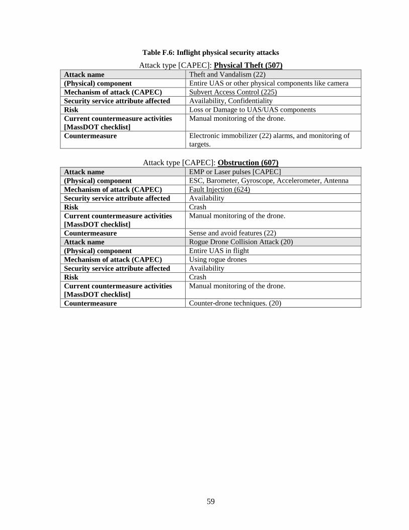
59
Table F.6: Inflight physical security attacks
Attack type [CAPEC]: Physical Theft (507) Attack name Theft and Vandalism (22) (Physical) component Entire UAS or other physical components like camera Mechanism of attack (CAPEC) Subvert Access Control (225) Security service attribute affected Availability, Confidentiality Risk Loss or Damage to UAS/UAS components Current countermeasure activities [MassDOT checklist]
Manual monitoring of the drone.
Countermeasure Electronic immobilizer (22) alarms, and monitoring of targets.
Attack type [CAPEC]: Obstruction (607)
Attack name EMP or Laser pulses [CAPEC] (Physical) component ESC, Barometer, Gyroscope, Accelerometer, Antenna Mechanism of attack (CAPEC) Fault Injection (624) Security service attribute affected Availability Risk Crash Current countermeasure activities [MassDOT checklist]
Manual monitoring of the drone.
Countermeasure Sense and avoid features (22) Attack name Rogue Drone Collision Attack (20) (Physical) component Entire UAS in flight Mechanism of attack (CAPEC) Using rogue drones Security service attribute affected Availability Risk Crash Current countermeasure activities [MassDOT checklist]
Manual monitoring of the drone.
Countermeasure Counter-drone techniques. (20)