volume 7, issue 1, july 2017 transient stability
TRANSCRIPT

ISSN: 2277-3754
ISO 9001:2008 Certified International Journal of Engineering and Innovative Technology (IJEIT)
Volume 7, Issue 1, July 2017
DOI:10.17605/OSF.IO/AV89N Page 18
Abstract— Transient stability is the ability of power system to
maintain synchronism when subjected to a severe disturbance
such as three phase fault on transmission line or large increase in
load or loss of large load as a result of a separation in one of the
transmission lines in the system. The energy storage systems
represented by Static Var Compensator (SVC) and Solar
Photo-voltaic Generator (PVG) are used to improve the transient
stability of the power system. It regulates voltage at its terminal by
controlling the amount of reactive power injected into or absorbed
from power system.
In this paper, the ability of energy storage systems to improve
the transient stability has been studied. The multi-machine system
was studied and IEEE 3-machine 9 bus system is taken as case
study. The simulation is carried out using PSAT software. At the
beginning the system has been simulated under three phase fault
and then under sudden changes in load levels as a result of
separation occurs in one of the transmission lines and without
energy storage systems. Then energy storage system is installed in
the system and its ability to enhance the transient stability has
been investigated.
Keywords: Multi-machine Power Systems, Transient Stability
Improvement, Modern Energy Storage Systems and PSAT
software.
I. INTRODUCTION
Stability is the most significant feature needed in the
modern power system. Stability problem in power system has
been noticed during the recent years, because of the fast
growth in electric and electronic loads. However, the
developments and improvements in generation and
distribution systems have not met yet this fast growing loads
and the increasing in the number of important and sensitive
devices in power system. Disturbances and short outages in
generators or transmission lines always have negative effect
on power system. In addition, a rapid variety in loads in the
plant leads to voltage and frequency fluctuations. These
disturbances and fluctuations that occur during the transient
process cause stability and quality issues in power system [1].
Power system stability is subjected to changes in system or
loads levels that may be sudden or gradual and severe or small
changes. Stability is an important concept that determines the
power system stable operation. In general, rotor angle
stability is taken as index, but the concept of transient
stability, which is the function of operating condition and
disturbances deals with the ability of the system to remain
intact after being subjected to abnormal deviations. A system
is said to be synchronously stable (i.e., retain synchronism)
for a given fault if the system variables settle down to some
steady-state values with time, after the fault is removed [2].
Electric power system stability analysis has been
recognized as an important and challenging problem for
secure system operation. When large disturbances occur in
interconnected power system, the security of these power
systems has to be examined. Power system security depends
on detailed stability studies of system to check and ensure
security. In order to determine the stability status of the power
system for each contingency of any disturbance occurs in
power system, many stability studies are defined. Power
system stability analysis may involve the calculation of
Critical Clearing Time (CCT) for a given fault, which is
defined as the maximum allowable value of the clearing time
for which the system remains to be stable. The power system
shall remain stable if the fault is cleared within this time.
However, if the fault is cleared after the CCT, the power
system is most likely to become unstable. Thus, CCT
estimation is an important task in the transient stability
analysis for a given contingency [3].
Over the past decades, the energy storage technologies
have grown and provided some economic and environmental
benefits for business and the society. The energy storage
system , which is an electrical storage technology, is applied
in many electrical and electronic power applications for
improving and enhancing stability and the performance of
modern power systems [1].
II. POWER SYSTEM STABILITY
Stability of a power system refers to the ability of a system
to return back to its steady state when subjected to a
disturbance. As mentioned before, power is generated by
synchronous generators that operate in synchronism with the
rest of the system. A generator is synchronized with a bus
when both of them have same frequency, voltage and phase
sequence so the power system stability can define as the
ability of the power system to return to steady state without
losing synchronism. Usually power system stability is
categorized into Steady State, Transient and Dynamic
Stability [4].
For a large disturbance, changes in angular differences may
be so large as to cause the machines to fall out of step. This
type of instability is known as transient stability and is a fast
phenomenon usually occurring within 1sec for a generator
Transient Stability Improvement of
Multi-machine Power Systems Using Modern
Energy Storage Systems Dr. Ahmed Nasser B. Alsammak, Abdulrazaq Ahmed M. Al-Nuaimy
Electrical Engineering Department, College of Engineering
University of Mosul, Mosul-Iraq

ISSN: 2277-3754
ISO 9001:2008 Certified International Journal of Engineering and Innovative Technology (IJEIT)
Volume 7, Issue 1, July 2017
DOI:10.17605/OSF.IO/AV89N Page 19
close to the disturbance. Power systems are subjected to a
wide range of disturbances, small and large. Small
disturbances in the form of load changes occur continually;
the system must be able to adjust to the changing conditions
and operate satisfactorily. It must also be able to survive
numerous disturbances of a severe nature, such as a short
circuit on a transmission line or loss of a large generator. A
large disturbance may lead to structural changes due to the
isolation of the faulted elements. At an equilibrium set, a
power system may be stable for a physical disturbance, and
unstable for another. It is impractical and uneconomical to
design power systems to be stable for every possible
disturbance. The design contingencies are selected on the
basis that they have a reasonably high probability of
occurrence. Hence, large-disturbance stability always refers
to a specified disturbance scenario.
The response of the power system to a disturbance may
involve much of the equipment. For instance, a fault on a
critical element followed by its isolation by protective relays
will cause variations in power flows, network bus voltages,
and machine rotor speeds; the voltage variations will actuate
both generator and transmission network voltage regulators;
the generator speed variations will actuate prime mover
governors; and the voltage and frequency variations will
affect the system loads to varying degrees depending on their
individual characteristics [5].
III. EFFECT OF FAULT CLEARING ON
TRANSIANT STABILITY
Transient stability is primarily concerned with the
immediate effects of a transmission line disturbance on
generator synchronism. Fig. (1) illustrates the typical
behavior of a generator in response to a fault condition.
Fig. (1) Transient Stability Illustration.
Starting from the initial operating condition (point 1), a
close-in transmission fault causes the generator electrical
output power Pe to be drastically reduced. The resultant
difference between electrical power and the mechanical
turbine power causes the generator rotor to accelerate with
respect to the system, increasing the power angle (point 2).
When the fault is cleared, the electrical power is restored to a
level corresponding to the appropriate point on the power
angle curve (point 3). Clearing the fault necessarily removes
one or more transmission elements from service and at least
temporarily weakens the transmission system. After clearing
the fault, the electrical power out of the generator becomes
greater than the turbine power. This causes the unit to
decelerate (point 4), reducing the momentum the rotor gained
during the fault. If there is enough retarding torque after fault
clearing to make up for the acceleration during the fault, the
generator will be transiently stable on the first swing and will
move back toward its operating point. If the retarding torque
is insufficient, the power angle will continue to increase until
synchronism with the power system is lost [6].
IV. SWING EQUATIONS [7]
The Swing Equations defining the dynamics of the
synchronous generators connected to the power system. The
trajectories of the swing equations are called swing curves,
and by observing the swing curves for all the synchronous
generators, we can determine the stability of the system.
Consider a single synchronous generator with synchronous
speed ω𝑠𝑚, electromagnetic torque T𝑒, and mechanical
torque T𝑚 means mechanical torque. In steady-state,
T𝑚 = T𝑒 … (1)
When a disturbance occurs, the torque deviates from
steady-state, causing an accelerating (T𝑚>T𝑒) or decelerating
(T𝑚<T𝑒) torque:
T𝑎 (accelerating torque) = T𝑚 - T𝑒 … (2)
Assume J is the combined inertia of generator and prime
mover, neglecting friction and damping torque we have:
J 𝜃𝑚′′= T𝑎 = T𝑚 - T𝑒 ... (3)
Where θ is the angular displacement of the rotor relative
to the stator, the suffix m means generator. The rotor speed
relative to synchronous speed is given by:
𝜃𝑚 = 𝜔𝑠m t + 𝛿𝑚 … (4)
From equation (4), we obtain the angular speed of the
rotor:
𝜔𝑚 = 𝜃𝑚′ = ω𝑠m+ 𝛿𝑚′ … (5)
Where
𝜃𝑚′′ = 𝛿𝑚′′ … (6)
Substituting (6) into (3), we obtain:
J 𝛿𝑚′′= T𝑎 = T𝑚 - T𝑒 ... (7)
Multiply eq. (7) by 𝜔𝑚 :
𝜔𝑚 J 𝛿𝑚′′= 𝜔𝑚 T𝑚 - 𝜔𝑚 T𝑒 = P𝑚 - P𝑒 … (8)
J 𝜔𝑚 is called the constant of inertia, referenced by ―M‖
and associated with W𝑘 (kinetic energy):
W𝑘= 0.5 J𝜔𝑚2 = 0.5M𝜔𝑚 ... (9)

ISSN: 2277-3754
ISO 9001:2008 Certified International Journal of Engineering and Innovative Technology (IJEIT)
Volume 7, Issue 1, July 2017
DOI:10.17605/OSF.IO/AV89N Page 20
or M = (2W𝑘/ω𝑠m) … (10)
For small changes ωm, it is reasonable to assume that M is
constant, so
M= (2Wk)/ (ω𝑠m) ... (11)
Then we obtain the standard from of the swing equation:
M 𝛿𝑚′′ = P𝑚 - P𝑒 .... (12)
V. MODERN ENERGY STORAGE
Modern energy storage originated at the grid scale in the
mid-1920s in the form of pumped hydro storage in order to
provide a means of shifting electricity from periods of low
demand to periods of high demand. Energy storage has
become a proven solution for a variety of commercial end
uses, including demand response, peak demand reduction,
power quality regulation, and emergency response. While
there are several types of technologies that support
facility-scale energy storage, batteries are the most mature
and readily available for smaller applications. The advantages
that batteries offer over competing technologies, such as
generators, are response times on the order of milli-seconds
and highly accurate load-following capability. It is estimated
that once batteries achieve installed costs of $300 per kWh
they will be able to displace generation used for peak power
requirements. Energy storage can provide solutions for grid
stability, power quality, demand management, and
renewables integration. More over Higher levels of energy
storage are required for grid flexibility and grid stability and
to cope with the increasing use of intermittent renewable
energy sources. New energy sources rely mainly on
renewable resources. Consequently, an energy reserve is
required and energy storage devices can be very useful for an
efficient energy management. Energy storage technologies
basically perform two functions:
• Storing the excess energy generated in the system, and
• Providing the stored energy for use whenever demanded
Fig. (2) Projected Annual Stationary Energy Storage
Deployments, Power Capacity and Revenue by Region
2016–2025.
by the system .Different Energy storage technologies—
such as compressed air energy storage, various types of
batteries, flywheels, superconducting capacitors, etc., provide
for multiple applications: energy management, backup power,
load leveling, frequency regulation, voltage support, and grid
stabilization [8]. The Fig.(2) show provides forecasts for new
energy storage capacity and revenue for each of the six major
developing regions identified [9]. In the paper the modern
energy storage systems model is used.
VI. STATIC VAR COMPENSATOR (SVC)
SVC is a shunt connected variable var generator whose
output is adjusted to exchange capacitive or inductive current
to system. SVC regulates voltage at required bus by
controlling amount of reactive power injected into or
absorbed from power system. Most widely used svc
configuration is fixed capacitor- thyristor controlled reactor
(FC-TCR). In this a fixed capacitor is connected in parallel
with thyristor controlled reactor as shown in Fig.(3). The
effective reactance of FC-TCR is varied by firing angle
control of anti-parallel thyristors. The firing angle is
controlled through a proportional integral (PI) controller in
such a way that voltage of bus where svc is connected is
maintained at reference value [10].
Fig. (3): Static VAR Compensator (SVC).
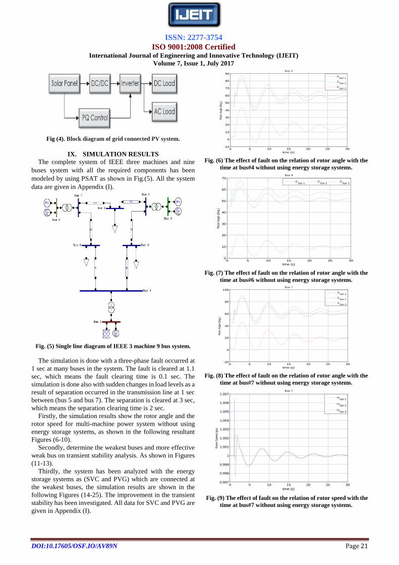
VII. PHOTOVOLTAIC CELLS
The PV system directly converts sun radiation into
electricity. The fundamental of Photovoltaic system is ‗PV
cell‘. These cells are made up from semiconductor structures
as in the computer technologies. This material absorbs
sunrays and electrons are emitted from the atoms. This release
activates a current. Photovoltaic (PV) is process between
radiation absorbed and the electricity induced. Solar power is
converted into the electric power by a common principle
called photo electric effect. The solar cell array or panel
consists of an appropriate number of solar cell modules that
are connected in series or parallel based on the required
current and voltage [11].
VIII. PHOTOVOLTAIC GENERATOR (PVG)
Photovoltaic generator (PVG) is based on semiconductor
device and solid-state synchronous voltage source converter
that is analogous to a synchronous machine except the
rotating part. Voltage source converter in photovoltaic
generator converts a DC input voltage into AC output voltage
and supply active and reactive power to the system. It
generates a balance set of sinusoidal voltage at fundamental
frequency with rapidly controllable amplitude and phase
angle. A block diagram of grid connected PV system is shown
in Fig. (4) [12].
ISSN: 2277-3754
ISO 9001:2008 Certified International Journal of Engineering and Innovative Technology (IJEIT)
Volume 7, Issue 1, July 2017
DOI:10.17605/OSF.IO/AV89N Page 21
Fig (4). Block diagram of grid connected PV system.
IX. SIMULATION RESULTS
The complete system of IEEE three machines and nine
buses system with all the required components has been
modeled by using PSAT as shown in Fig.(5). All the system
data are given in Appendix (I).
Fig. (5) Single line diagram of IEEE 3 machine 9 bus system.
The simulation is done with a three-phase fault occurred at
1 sec at many buses in the system. The fault is cleared at 1.1
sec, which means the fault clearing time is 0.1 sec. The
simulation is done also with sudden changes in load levels as a
result of separation occurred in the transmission line at 1 sec
between (bus 5 and bus 7). The separation is cleared at 3 sec,
which means the separation clearing time is 2 sec.
Firstly, the simulation results show the rotor angle and the
rotor speed for multi-machine power system without using
energy storage systems, as shown in the following resultant
Figures (6-10).
Secondly, determine the weakest buses and more effective
weak bus on transient stability analysis. As shown in Figures
(11-13).
Thirdly, the system has been analyzed with the energy
storage systems as (SVC and PVG) which are connected at
the weakest buses, the simulation results are shown in the
following Figures (14-25). The improvement in the transient
stability has been investigated. All data for SVC and PVG are
given in Appendix (I).
0 5 10 15 20 25 30-10
0
10
20
30
40
50
60
70
80
90
time (s)
Rot
or A
ngle
(Deg
.)
Bus 4
Syn 1
Syn 2
Syn 3
Fig. (6) The effect of fault on the relation of rotor angle with the
time at bus#4 without using energy storage systems.
0 5 10 15 20 25 300
10
20
30
40
50
60
70
time (s)
Rot
or A
ngle
(D
eg.)
Bus 6
Syn 1
Syn 2
Syn 3
Fig. (7) The effect of fault on the relation of rotor angle with the
time at bus#6 without using energy storage systems.
0 5 10 15 20 25 30-20
0
20
40
60
80
100
time (s)
Rot
or A
ngle
(Deg
.)
Bus 7
Syn 1
Syn 2
Syn 3
Fig. (8) The effect of fault on the relation of rotor angle with the
time at bus#7 without using energy storage systems.
0 5 10 15 20 25 300.997
0.998
0.999
1
1.001
1.002
1.003
1.004
1.005
1.006
1.007
time (s)
Roto
r S
peed (
pu)
Bus 7
Syn 1
Syn 2
Syn 3
Fig. (9) The effect of fault on the relation of rotor speed with the
time at bus#7 without using energy storage systems.

ISSN: 2277-3754
ISO 9001:2008 Certified International Journal of Engineering and Innovative Technology (IJEIT)
Volume 7, Issue 1, July 2017
DOI:10.17605/OSF.IO/AV89N Page 22
0 5 10 15 20 25 30-10
0
10
20
30
40
50
60
70
80
90
time (s)
Roto
r Ang
le (D
eg.)
Syn 1
Syn 2
Syn 3
Fig. (10) The effect of the separation occurred in the
transmission line between bus#5 and bus#7 on the relation of
rotor angle with the time without using energy storage systems.
A. V-Q SENSITIVITY ANALYSIS METHOD
After solving the power flow problem, it is possible to
compute and visualize the eigenvalues and the participation
factors of the system. The eigenvalues can be computed for
the state matrix of the dynamic system (small signal stability
analysis), and for three different types of power flow Jacobian
matrices (V-Q sensitivity analysis).
The state matrix [AS] is simply obtained by eliminating the
algebraic variables, and thus implicitly assuming that JLFV is
non-singular (i.e. absence of singularity induced
bifurcations):
AS = Fx – Fy Gy-1
Gx …. (13)
When all the eigenvalues are computed, it is also possible
to obtain the participation factors that are evaluated in the
following way. Let V and W be the right and the left
eigenvector matrices respectively, such that V= WASV and W
= V −1
, then the participation factor pij of the ith
state variable
to the jth
eigenvalue can be defined as: [13]
Pij = ( Wij Vji ) / (Wjt Gj) …. (14)
So in any power system, buses can be arranged from their
weakest bus to the strongest bus using the V-Q sensitivity
method where weak buses have higher participation factors
with smallest eigenvalues. In this work, this V-Q sensitivity
method has been applied to the IEEE 9-bus system to
determination the weakest buses in the system. Figure (11)
depict the weak buses for IEEE 9-buses system.
Fig. (11) Participation Factor for the smallest Eigen value (Eig
JIf7) for IEEE 9-bus sample system.
After determination the weakest bus in the system, modern
energy storage systems should be placed at the weakest bus
(Bus#5) to improve transient stability when exposed to
sudden disturbance due to a fault or sudden change in the
load.
B. Selection more effective weakest buses #5or #8
Fig. (11) shows the weakest buses #5 and #8 respectively.
To determine more effective weakest buses on transient
stability state a new analysis must be do at two buses. Figures
(12) and (13) show the compared simulation results between
added SVC and PVG at bus#5 and bus#8 individually.
0 5 10 15 20 25 30-10
0
10
20
30
40
50
60
70
80
time (s)D
elta
(D
eg
.)
The fault at Bus 7
Syn 1
When SVC at Bus 5
Syn 3
Syn 2
Syn 2
When SVC at Bus 8
Syn 1
Syn 3
Fig. (12) The effect of fault on the relation of rotor angle with
the time at bus#7 when SVC at (bus#5 and bus#8).
0 5 10 15 20 25 30-10
0
10
20
30
40
50
60
70
80
time (s)
De
lta
(D
eg
.)
The fault at Bus 7
Syn 1
When PVG at Bus 5
Syn 2
Syn 3
Syn 2
When PVG at Bus 8
Syn 1
Syn 3
Fig. (13) The effect of fault on the relation of rotor angle with
the time at bus#7 when PVG at (bus#5 and bus#8).
The above simulation results, Figures (12 and 13), show
that bus#8 have more effective weak bus depend on machines
swing curves because it is a second weakest bus and near to
bus#5 (first weakest bus in the system). Result in, the energy
storage systems will be add to bus#8 for improving transient
stability of the given sample power system.
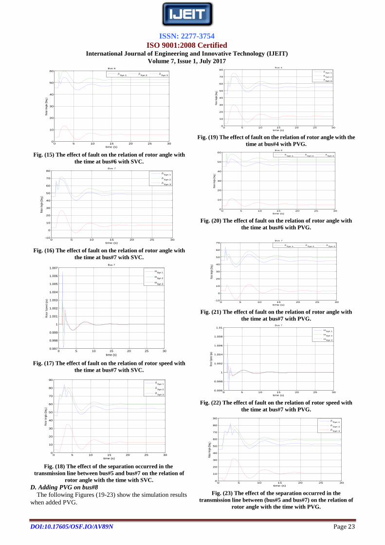
C. Adding SVC on bus#8
The following Figures (14-17) show the simulation results
when added SVC.
0 5 10 15 20 25 300
10
20
30
40
50
60
70
80
time (s)
Rot
or A
ngle
(D
eg.)
Bus 4
Syn 1
Syn 2
Syn 3
Fig. (14) The effect of fault on the relation of rotor angle with
the time at bus#4 with SVC.
1 2 3 4 5 6 7 8 90
0.02
0.04
0.06
0.08
0.1
0.12
0.14
Bus No.
PA
RT
EC
IPA
TIO
N F
AC
TO
RS
The smallest eigenvalues(Eig Jlf 7) = -0.39632 weakest bus
Bus #
Par
tici
pat
ion
Fac
tor
ISSN: 2277-3754
ISO 9001:2008 Certified International Journal of Engineering and Innovative Technology (IJEIT)
Volume 7, Issue 1, July 2017
DOI:10.17605/OSF.IO/AV89N Page 23
0 5 10 15 20 25 300
10
20
30
40
50
60
time (s)
Rot
or A
ngle
(Deg
.)
Bus 6
Syn 1
Syn 2
Syn 3
Fig. (15) The effect of fault on the relation of rotor angle with
the time at bus#6 with SVC.
0 5 10 15 20 25 30-10
0
10
20
30
40
50
60
70
80
time (s)
Roto
r Ang
le (D
eg.)
Bus 7
Syn 1
Syn 2
Syn 3
Fig. (16) The effect of fault on the relation of rotor angle with
the time at bus#7 with SVC.
0 5 10 15 20 25 300.997
0.998
0.999
1
1.001
1.002
1.003
1.004
1.005
1.006
1.007
time (s)
Roto
r S
peed (
pu)
Bus 7
Syn 1
Syn 2
Syn 3
Fig. (17) The effect of fault on the relation of rotor speed with
the time at bus#7 with SVC.
0 5 10 15 20 25 300
10
20
30
40
50
60
70
80
90
time (s)
Rot
or A
ngle
(D
eg.)
Syn 1
Syn 2
Syn 3
Fig. (18) The effect of the separation occurred in the
transmission line between bus#5 and bus#7 on the relation of
rotor angle with the time with SVC.
D. Adding PVG on bus#8
The following Figures (19-23) show the simulation results
when added PVG.
0 5 10 15 20 25 300
10
20
30
40
50
60
70
80
time (s)
Roto
r Ang
le (D
eg.)
Bus 4
Syn 1
Syn 2
Syn 3
Fig. (19) The effect of fault on the relation of rotor angle with the
time at bus#4 with PVG.
0 5 10 15 20 25 300
10
20
30
40
50
60
time (s)Ro
tor A
ngle
(Deg
.)
Bus 6
Syn 1
Syn 2
Syn 3
Fig. (20) The effect of fault on the relation of rotor angle with
the time at bus#6 with PVG.
0 5 10 15 20 25 30-10
0
10
20
30
40
50
60
70
time (s)
Roto
r Ang
le (D
eg.)
Bus 7
Syn 1
Syn 2
Syn 3
Fig. (21) The effect of fault on the relation of rotor angle with
the time at bus#7 with PVG.
0 5 10 15 20 25 300.996
0.998
1
1.002
1.004
1.006
1.008
1.01
time (s)
Rot
or S
peed
(pu)
Bus 7
Syn 1
Syn 2
Syn 3
Fig. (22) The effect of fault on the relation of rotor speed with
the time at bus#7 with PVG.
0 5 10 15 20 25 300
10
20
30
40
50
60
70
80
90
time (s)
Roto
r Ang
le (D
eg.)
Syn 1
Syn 2
Syn 3
Fig. (23) The effect of the separation occurred in the
transmission line between (bus#5 and bus#7) on the relation of
rotor angle with the time with PVG.

ISSN: 2277-3754
ISO 9001:2008 Certified International Journal of Engineering and Innovative Technology (IJEIT)
Volume 7, Issue 1, July 2017
DOI:10.17605/OSF.IO/AV89N Page 24
E. Adding SVC and PVG on bus#8
The following Figures (24) and (25) show the compared
simulation results between added SVC and PVG.
0 5 10 15 20 25 3040
50
60
70
80
90
100
time (s)
De
lta
(D
eg
.)
Bus 7
Syn 2
Without E.S.
Syn 2
With SVC
Syn 2
With PV G.
Fig.(24) Comparison between SVC and PVG for the
rotor angle when the fault occurred at bus#7.
0 5 10 15 20 25 300.998
0.999
1
1.001
1.002
1.003
1.004
1.005
time (s)
Om
eg
a (
pu
)
Bus 7
Syn 2
Without E.S.
Syn 2
With SVC
Syn 2
With PV G.
Fig. (25) Comparison between SVC and PVG for the rotor speed
when the fault occurred at Bus#7.
X. CONCLUSION
In this paper, the effect of conversional and modern energy
storage systems for improving transient stability of
multi-machine power system under 3-phase fault and sudden
changes in load levels as a result of separation occurs in one
of the transmission lines is investigated. The system higher
participation factors with smallest eigenvalues are determined
to find the more effective weakest bus that chosen to add the
energy storage system (SVC and PVG). The results show
higher improvement in the transient stability when adding, on
the selected bus, modern energy storage equipment that is
characterized by the amount of capacity and the speed of
performance and lack of harmonics.
APPENDIX (I)
The system data are given in the following Table (1) while
The SVC and PVG data are given in the Table (2) and (3).
Table (1) The sample system data.
Bus No.
1 2 3
Power Rating (MVA) 247.5 192 128
Machine Model 4 4 4
(p.u) 0.0336 0.0521 0.0742
(p.u) 0 0 0
(p.u) 0.146 0.8958 1.3125
(p.u) 0.0608 0.1198 0.1813
(s) 8.96 6 5.89
(p.u) 0.0969 0.8645 1.2578
(p.u) 0.0969 0.1969 0.25
T’q0(s) 0.31 0.535 0.6
H (s) 23.64 6.4 3.01
D 0 0 0
Table (2) SVC data
Power (MVA) 100
Voltage Rating (KV) 230
Frequency Rating(Hz) 50
Model Type 1
Regulator Gain Kr [p.u./p.u.] 50
Table (3): PVG data
Active Power (MW) 0.05
Voltage Reference (p.u.) 1.045
Invertor response times (Tp, Tq) [s, s] [1 30]
Voltage (kv) 5
PI Controller Gains (ki) 1
REFERENCES [1] Embaiya Salih, Stefan Lachowicz, Octavian Bass and
Daryoush Habibi, "Application of a superconducting
magnetic energy storage unit for power systems stability
improvement", 1st International Conference on Green Energy
(ICGE), pp. 267-272, 2014.
[2] GUNDALA SRINIVASA RAO and Dr. A.Srujana, "
Transient Stability Improvement of Multi-machine Power
System Using Fuzzy Controlled TCSC", International Journal
of Advancements in Research & Technology, Vol. 1,pp.1-11,
Issue 2, July 2012.
[3] Renuka Kamdar, Manoj Kumar and Ganga Agnihotri,"
Transient Stability Analysis and Enhancement of IEEE- 9 Bus
System‖, Electrical & Computer Engineering: An
International Journal (ECIJ), Vol. 3, pp.1-11, No. 2, June
2014.
[4] Rathnasagar Rangu and Poonam Upadhyay ," Study of
Transient Stability Improvement of IEEE 9-Bus System by
using SVC", International Journal of Engineering Trends and
Technology (IJETT), Vol. 27, No. 3, pp. 162-166, Sep.2015.
[5] Rajeev Kumar Verma and Sangeeta Mishra ," A Study on
Transient Stability Improvement of 5-machine 14-bus system
using SVC", International Journal on Recent and Innovation
Trends in Computing and Communication (IJRITCC), Vol.2,
No.4, pp. 214 – 217, April 2014.
[6] Michael J. Basler and Richard C. Schaefer, ―Understanding
Power System Stability‖. IEEE Basler Electric Company,
No.4, pp.34-37, 2007.
[7] Chi Yuan Weng, "Transient Stability Analysis of Power
Ssystems with Energy Sstorage", M.Sc.thesis Cace Western
Reserve University, January 2013.
[8] Kaustav Mallick, Snehashsis Das, Anjana Sengupta and
Shamik Chattaraj, "Modern Mechanical Energy Storage
Systems and Technologies", International Journal of
Engineering Research & Technology (IJERT), Vol. 5 Issue
02, February-2016.
[9] Alex Eller and Dexter Gauntlett, "Energy Storage Trends and
Opportunities in Emerging Markets", International Finance
Corporation (IFC), 2017.
[10] Urmila Bainsla, Mohini, Kiran Rani and Dr. Anju Gupta
,"Transient Stability Enhancement of Multi Machine System
ISSN: 2277-3754
ISO 9001:2008 Certified International Journal of Engineering and Innovative Technology (IJEIT)
Volume 7, Issue 1, July 2017
DOI:10.17605/OSF.IO/AV89N Page 25
Using Static Var Compensator", International Journal of
Engineering Research and General Science , Vol. 3, Issue
3, pp. 1068-1076, May-June, 2015.
[11] P R Sharma and Anirudh Dube," Location of SVC and UPFC
for Real Power Loss Minimization and Stability Enhancement
in a Multi Machine Power System Using Parametric
Approach", International Journal on Advanced Electrical and
Electronics Engineering (IJAEEE), Vol. 1, Issue 1, pp. 84-88,
2012.
[12] Mohammed Masum Siraj Khan, Md. Shamsul Arifin, Ariful
Haque and Nahid-Al-Masood ," Stability analysis of power
system with the penetration of photovoltaic based generation",
International Journal of Energy and Power Engineering , Vol.
2, No. 2, pp. 84-89 , June 2013. Online
(http://www.sciencepublishinggroup.com/j/ijepe).
[13] Federico Milano, "Power System Analysis Toolbox",
Documentation for PSAT version 2.0.0, February 2008.
AUTHOR’S PROFILE
Dr. Ahmed Nasser B Alsammak Received the B.S., M.Sc.
and Ph.D. degrees in electrical engineering (Power and Machine) from
Electrical Engineering Department- College of Engineering- University of
Mosul, Mosul-Iraq in 1997, 1999, and 2007, respectively. He worked on
design and implementation many engineering projects. He is an IEEE
member- IEEE Power & Energy. He is presently Assistant Professor in the
Electrical Engineering Department- College of Engineering- University of
Mosul. He have 12 researches can show on (http://scholar.google.com) all
are interests in electrical power system and machines, power system
stability, modeling, simulation, fuzzy controller, nonlinear circuit and
system theory as related to the electrical power and machine systems.
Abdulrazaq Ahmed M. Al-Nuaimy Received the B.S.
degrees in Electrical Power Engineering Department (Power) from Electrical
Power Techniques Engineering Department- College of Engineering
Technical- University of Mosul, Mosul-Iraq in 2013. He is presently Msc.
student in the Electrical Engineering Department- College of Engineering-
University of Mosul. His research interests are in electrical machines,
modeling, and simulation.