volume cc - continuously reinforced concrete pavement...rigid pavement pavement standard drawings...
TRANSCRIPT
PenTable :
PlotDriver :
FilePath :
Printe
d b
y
3:1
0:4
1 P
Mat
18/0
1/2
016
on
PA
V_
BL
AC
K_
GR
EY.tbl
pav_
A3_pdf.pltcfg
O:\Pave
ments\P
1703 - Rigid P
ave
ment
Construction Sta
ndard Dra
win
gs - C
RC
P\draft4\M
D.R
83.C
C_01
A.d
gn
tetlero
b
PAVEMENT STANDARD DRAWINGS
RIGID PAVEMENT
21ED 4 REV 0
DS2012/001190
REGISTRATION No OF PLANS
ISSUE
SHEET No
No OF SHEETS
© COPYRIGHT ROADS AND MARITIME SERVICES
DATE
CC
VOLUME
01A
MD.R83.CCREGISTRATION No OF PLANS
SUPERSEDED
ASSET MAINTENANCE DIVISION
ENGINEERING SERVICES BRANCH
PAVEMENTS UNIT
PREPARED BY:
SIGNED DATE
APPROVED FOR USE
G. VOROBIEFF
PAVEMENTS AND GEOTECHNICAL
PRINCIPAL ENGINEER,
Volume CC - Continuously Reinforced Concrete Pavement
G. VOROBIEFF
STANDARD DETAILS - CONSTRUCTION
related drawings:
Volume CP - Plain Concrete Pavement
Volume CJ - Jointed Reinforced Concrete Pavement
18/12/2015 18/12/2015
01B
REVISION REGISTER, SHEET INDEX AND NOTES
PenTable :
PlotDriver :
FilePath :
Printe
d b
y
3:1
0:4
2 P
Mat
18/0
1/2
016
on
PA
V_
BL
AC
K_
GR
EY.tbl
pav_
A3_pdf.pltcfg
O:\Pave
ments\P
1703 - Rigid P
ave
ment
Construction Sta
ndard Dra
win
gs - C
RC
P\draft4\M
D.R
83.C
C_01
B.d
gn
tetlero
b
SHEET No
No OF SHEETS
© COPYRIGHT ROADS AND MARITIME SERVICESTHIS SHEET MAY BE PREPARED USING COLOUR AND MAY BE INCOMPLETE IF COPIED
A3 ORIGINALOR AS NOTED.NOT TO SCALE,SCALES: REGISTRATION No OF PLANS
21
ISSUE
ED 4 REV 0 CC
VOLUMEDATE
DS2012/001190ASSET MAINTENANCE DIVISION
ENGINEERING SERVICES BRANCH
PREPARED BY: PAVEMENTS UNIT
APPROVED FOR USE
PAVEMENTS AND GEOTECHNICAL
PRINCIPAL ENGINEER,
FOR AMENDMENTS REFER TO SHEET No 01B
STANDARD DETAILS - CONSTRUCTION
RIGID PAVEMENT
PAVEMENT STANDARD DRAWINGS
CONTINUOUSLY REINFORCED CONCRETE PAVEMENT (CRCP)
G.VOROBIEFF
18/12/2015
18/12/2015
REVISION REGISTER
ED/REV DATE SHEET AMENDMENT DESCRIPTION AUTHORISED
1/0 30/09/1984 ALL Initial issue
2/0 ALL
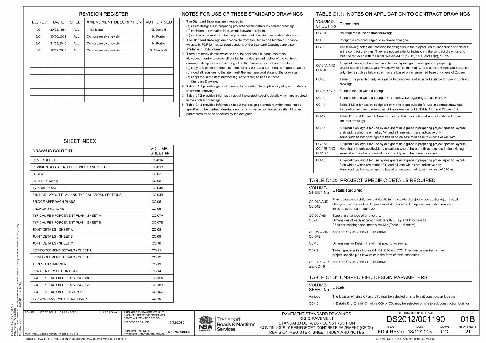
SHEET INDEX
COVER SHEET
LEGEND
Comprehensive revision30/06/2009
G. Donald
K. Porter
K. Porter3/0 ALL Comprehensive revision31/05/2010
ALL Comprehensive revision
CC-01A
CC-01B
BRIDGE APPROACH PLANS
KERBS AND BARRIERS
RURAL INTERSECTION PLAN
TYPICAL PLAN - WITH CRCP RAMP
CC-01B
Suitable for use without change.
Suitable for use without change. See Table C1.2 regarding Details F and H.
Its deletion requires the removal of the reference to it in Table 11.1 and Figure 11.1.
Table 11.5 is for use by designers only and is not suitable for use in contract drawings.
contract drawings.
Table 12.1 and Figure 12.1 are for use by designers only and are not suitable for use in
Various The location of joints C7 and C7d may be selected on site to suit construction logistics.
L F L
*
*
*
TABLE C1.3: UNSPECIFIED DESIGN PARAMETERS
TABLE C1.1: NOTES ON APPLICATION TO CONTRACT DRAWINGS
Not required in the contract drawings.
Items such as bar spacings are based on an assumed base thickness of 240 mm.
Slab widths which are marked " " and all lane widths are indicative only.
A typical plan layout for use by designers as a guide in preparing project-specific layouts.
Items such as bar spacings are based on an assumed base thickness of 240 mm.
Slab widths which are marked " " and all lane widths are indicative only.
A typical plan layout for use by designers as a guide in preparing project-specific layouts.
terminal end and which are of the correct type in the correct location.
Note that it is only applicable to situations where there are three anchors in the existing
A typical plan layout for use by designers as a guide in preparing project-specific layouts.
must be replaced with the label "Reserved": 1(b), 15, 17(a) and 17(b), 19, 25.
in the contract drawings. They are not suitable for inclusion in the contract drawings and
The following notes are intended for designers in the preparation of project-specific details
drawings.
Table 5.1 is provided only as a guide to designers and so is not suitable for use in contract
REVISION REGISTER, SHEET INDEX AND NOTES
PROJECT-SPECIFIC DETAILS REQUIREDTABLE C1.2:
CC-15A
CC-15B
CRCP EXTENSION OF EXISTING CRCP
CRCP EXTENSION OF EXISTING PCP
CC-04A
CC-04B
NOTES (numeric)
JOINT DETAILS - SHEET A
JOINT DETAILS - SHEET B
JOINT DETAILS - SHEET C
REINFORCEMENT DETAILS - SHEET A
REINFORCEMENT DETAILS - SHEET B
4/0
DRAWING CONTENTSHEET No
VOLUME-
SHEET No
VOLUME-Comments
SHEET No
VOLUME-Details Required
SHEET No
VOLUME-Details
NOTES FOR USE OF THESE STANDARD DRAWINGS
parameters must be specified by the designer.
specified in the contract drawings and which may be nominated on site. All other
Table C1.3 provides information about the design parameters which need not be6.
in the contract drawings.
Table C1.2 provides information about the project-specific details which are required5.
to contract drawings.
Table C1.1 provides general comments regarding the applicability of specific sheets4.
Standard Drawings.
adopt the same item number (figure or table) as used in these(c)
cloud all revisions to that item until the final approval stage of the drawings.(b)
copy and paste the entire contents of any particular item (that is, figure or table).(a)
drawings, designers are encouraged, to the maximum extent practicable, to:
However, in order to assist all parties in the design and review of the contract
There are many details which will not be applicable in some contracts.3.
available in DGN format.
website in PDF format. Untitled versions of the Standard Drawings are also
The Standard Drawings are accessible from the Roads and Maritime Services2.
minimise the work required in preparing and checking the contract drawings.(c)
minimise the variation in drawings between projects.(b)
assist designers in preparing project-specific details in contract drawings.(a)
The Standard Drawings are intended to:1.
only. Items such as tiebar spacings are based on an assumed base thickness of 260 mm.
project-specific layouts. Slab widths which are marked " " and all lane widths are indicative
A typical plan layout and sections for use by designers as a guide in preparing
CC-04B
CC-04A AND
CC-04B
CC-04A AND
limits as specified in Table 2.4.
changes in cross-section. Layouts must demonstrate the application of dimensional
Plan layouts and reinforcement details in the standard project cross-section(s) and at all
E5 tiebar spacings and mesh sizes M2 (Table 11.5 refers).
Dimensions of each approach slab length L , L and thickness D .
Type and chainage of all anchors.
Dimensions for Details F and H at specific locations.
project-specific plan layouts or in the form of table schedules.
Tiebar spacings in all joints C1, C2, C2d and F72. They can be marked on the
CC-02
CC-03
CC-05
CC-08, CC-09
CC-10
CC-11
CC-12
CC-14
CC-16
CC-10
CC-12
and CC-16
CC-14, CC-15
CC-13
CC-02
CC-03
CC-05
CC-06
CC-08
CC-09
CC-10
CC-11
CC-12
CC-13
CC-14
CC-16
G. Vorobieff
ANCHOR LAYOUT PLAN AND TYPICAL CROSS SECTIONS
CC-07A
CC-07B
TYPICAL REINFORCEMENT PLAN - SHEET A
TYPICAL REINFORCEMENT PLAN - SHEET B
ANCHOR SECTIONS
CC-15C
CC-15B AND
CC-15A,
See item CC-04A and CC-04B above.
Designers are encouraged to minimise changes.
See item CC-04A and CC-04B above.
In Details K1, K2 and K3, joints C6b or C6c may be selected on site to suit construction logistics.
CC-06
CC-05 AND
CC-07B
CC-07A AND
TYPICAL PLANS
CC-15CCRCP EXTENSION OF NEW PCP
18/12/2015
02
LEGEND
PenTable :
PlotDriver :
FilePath :
Printe
d b
y
3:1
0:4
2 P
Mat
18/0
1/2
016
on
PA
V_
BL
AC
K_
GR
EY.tbl
pav_
A3_pdf.pltcfg
O:\Pave
ments\P
1703 - Rigid P
ave
ment
Construction Sta
ndard Dra
win
gs - C
RC
P\draft4\M
D.R
83.C
C_02.d
gn
tetlero
b
SHEET No
No OF SHEETS
© COPYRIGHT ROADS AND MARITIME SERVICESTHIS SHEET MAY BE PREPARED USING COLOUR AND MAY BE INCOMPLETE IF COPIED
A3 ORIGINALOR AS NOTED.NOT TO SCALE,SCALES: REGISTRATION No OF PLANS
21
ISSUE
ED 4 REV 0 CC
VOLUMEDATE
DS2012/001190ASSET MAINTENANCE DIVISION
ENGINEERING SERVICES BRANCH
PREPARED BY: PAVEMENTS UNIT
APPROVED FOR USE
PAVEMENTS AND GEOTECHNICAL
PRINCIPAL ENGINEER,
FOR AMENDMENTS REFER TO SHEET No 01B
STANDARD DETAILS - CONSTRUCTION
RIGID PAVEMENT
PAVEMENT STANDARD DRAWINGS
CONTINUOUSLY REINFORCED CONCRETE PAVEMENT (CRCP)
G.VOROBIEFF
18/12/2015
18/12/2015
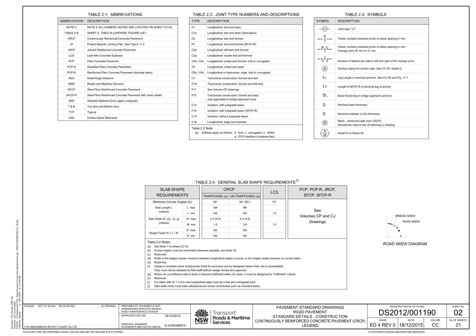
DESCRIPTIONTYPE
C18
C15
C14
C7
C7d
C5
C2d
C2
C1
Isolation: without subgrade beam
Longitudinal: tied and sawn
Longitudinal: tied and formed
Longitudinal: drill-tied and formed
Longitudinal: untied and sawn
TABLE 2.2: JOINT TYPE NUMBERS AND DESCRIPTIONS
Table 2.4 Notes:
LCS
1.0
1.5
CRCP
TRAFFICKED (a) UN-TRAFFICKED (a)
TABLE 2.4: GENERAL SLAB SHAPE REQUIREMENTS
84° 84° (80°)
4.4 (4.5)
W min
Shape Factor R = L / W
L max
W max
R max
L min
R min
Minimum Corner Angles (b)
Table 2.2 Note:
Transverse construction: formed and tied
Transverse construction: formed and drill-tied
Longitudinal: edge and beamed
Isolation: with subgrade beam
C4b / C4c
C6b / C6c
Longitudinal: untied and formed, butt or corrugated
F72
(metres)
Slab Width W (d) , (i), (j)
(f)
F71
only applicable in bridge approach zone
Transverse construction: formed and tied;
C2p Longitudinal: cluster tied and formed
p : PCP interface (clustered ties)
b : butt, c : corrugated, d : drilledSuffixes apply as follows:(a)
See Volume CP drawings
(metres)
Slab Length L NA NA
NA NA
4.3 (4.5)
1.0 0.6
NA
NA
NA
NA
70°
F14 Isolation: with subgrade beam (SFCP-R)
A
B C
TABLE 2.3: SYMBOLS
Joint type: 'C1'
SYMBOL DESCRIPTION
Base thickening in bridge approach anchors.
LL
DL
LF Length of SFCP-R in terminal leg of anchor.
N
05Detail N on Sheet 05.
Leg Length in terminal anchors. See CC-05 and Fig. 11.1.
C1
D Nominal base thickness
S Nominal subbase (LCS) thickness
TABLE 2.1: ABBREVIATIONS
DESCRIPTION
TABLE A.B SHEET A, TABLE B (LIKEWISE "FIGURE A.B")
NOTE 5
Continuously Reinforced Concrete PavementCRCP
JP Project-Specific Jointing Plan. See Figure 11.2
Jointed Reinforced Concrete PavementJRCP
Lean-Mix Concrete SubbaseLCS
PCP Plain Concrete Pavement
Dowelled Plain Concrete PavementPCP-D
PCP-R Reinforced Plain Concrete Pavement (discrete slabs)
RED Relief-Edge Distance
RMS Roads and Maritime Services
Steel Fibre Reinforced Concrete PavementSFCP
SFCP-R Steel Fibre Reinforced Concrete Pavement with mesh added
SMZ Selected Material Zone (upper subgrade)
T & B Top face and Bottom face
TYP Typical
UNO Unless Noted Otherwise
F2 Longitudinal: tied and formed (SFCP-R)
Longitudinal or transverse: edge, butt or corrugated
53
RSometimes used in lieu of hatching or shading.
Mesh - reinforced slab (non-CRCP)
NOTE 5; ALL NUMERIC NOTES ARE LOCATED ON SHEET CC-03.
BRIDGE SKEW
ROAD SKEW
C1a Longitudinal: tied and sawn (alternative)
A Surface stamp for anchor slab. See CC-05, Detail Q.
ROAD SKEW DIAGRAM
REQUIREMENTS
SLAB SHAPE
ABBREVIATION
SFCP, SFCP-R
PCP, PCP-R, JRCP,
Slab width limits must make allowances for stress contributors such as mounted kerbs.(j)
For slabs with W < 3.4 m one longitudinal edge must be a tied and corrugated joint.(i)
Reserved.(h)
Where an un-trafficked slab is likely to become trafficked within 20 years, it must be designed for "trafficked" criteria.(g)
They must not be adopted by field staff without design review and approval.
Values in brackets show compromise limits for exclusive use by designers where their use is unavoidable.(f)
Reserved.(e)
Width is the largest square measure between longitudinal edges or joints, or the largest radial measure on curved slabs.(d)
Reserved.(c)
Corner angles must be maximised wherever possible, see Note 18.(b)
See Note 1 on sheet CC-03.(a)
Drawings
Volumes CP and CJ
See
Tiebar numbers between joints or tiebar spacing in mm.
Change point 'B' mm to 'C' mm.
Tiebar numbers between joints or tiebar spacing in mm.
Number of tiebars per slab to left and right of the change point.
03
NOTES
PenTable :
PlotDriver :
FilePath :
Printe
d b
y
3:1
0:4
3 P
Mat
18/0
1/2
016
on
PA
V_
BL
AC
K_
GR
EY.tbl
pav_
A3_pdf.pltcfg
O:\Pave
ments\P
1703 - Rigid P
ave
ment
Construction Sta
ndard Dra
win
gs - C
RC
P\draft4\M
D.R
83.C
C_03.d
gn
tetlero
b
SHEET No
No OF SHEETS
© COPYRIGHT ROADS AND MARITIME SERVICESTHIS SHEET MAY BE PREPARED USING COLOUR AND MAY BE INCOMPLETE IF COPIED
A3 ORIGINALOR AS NOTED.NOT TO SCALE,SCALES: REGISTRATION No OF PLANS
21
ISSUE
ED 4 REV 0 CC
VOLUMEDATE
DS2012/001190ASSET MAINTENANCE DIVISION
ENGINEERING SERVICES BRANCH
PREPARED BY: PAVEMENTS UNIT
APPROVED FOR USE
PAVEMENTS AND GEOTECHNICAL
PRINCIPAL ENGINEER,
FOR AMENDMENTS REFER TO SHEET No 01B
STANDARD DETAILS - CONSTRUCTION
RIGID PAVEMENT
PAVEMENT STANDARD DRAWINGS
CONTINUOUSLY REINFORCED CONCRETE PAVEMENT (CRCP)
G.VOROBIEFF
18/12/2015
18/12/2015
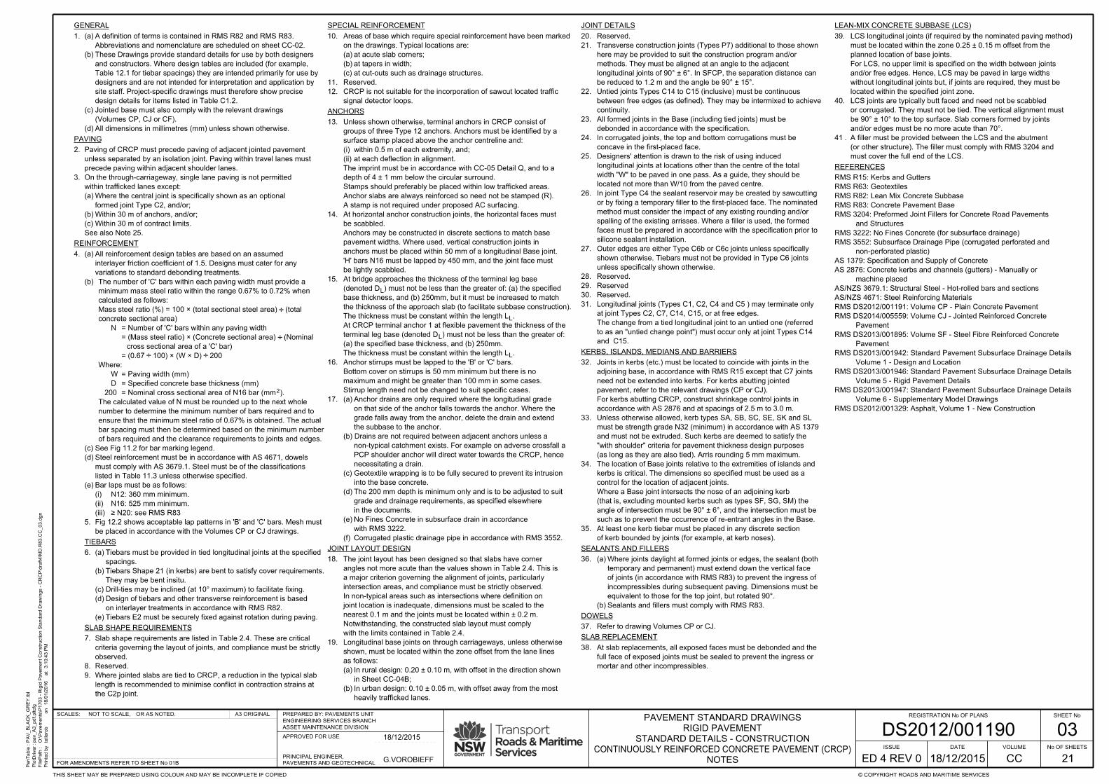
GENERAL
PAVING
REINFORCEMENT
ANCHORS
JOINT LAYOUT DESIGN
with the limits contained in Table 2.4.
Notwithstanding, the constructed slab layout must comply
nearest 0.1 m and the joints must be located within ± 0.2 m.
joint location is inadequate, dimensions must be scaled to the
In non-typical areas such as intersections where definition on
intersection areas, and compliance must be strictly observed.
a major criterion governing the alignment of joints, particularly
angles not more acute than the values shown in Table 2.4. This is
The joint layout has been designed so that slabs have corner18.
JOINT DETAILS
debonded in accordance with the specification.
All formed joints in the Base (including tied joints) must be23.
concave in the first-placed face.
In corrugated joints, the top and bottom corrugations must be24.
located not more than W/10 from the paved centre.
width "W" to be paved in one pass. As a guide, they should be
longitudinal joints at locations other than the centre of the total
Designers' attention is drawn to the risk of using induced25.
unless specifically shown otherwise.
shown otherwise. Tiebars must not be provided in Type C6 joints
Outer edges are either Type C6b or C6c joints unless specifically27.
Reserved29.
SEALANTS AND FILLERS
DOWELS
SLAB REPLACEMENT
mortar and other incompressibles.
full face of exposed joints must be sealed to prevent the ingress or
At slab replacements, all exposed faces must be debonded and the38.
LEAN-MIX CONCRETE SUBBASE (LCS)
REFERENCES
KERBS, ISLANDS, MEDIANS AND BARRIERS
be lightly scabbled.
'H' bars N16 must be lapped by 450 mm, and the joint face must
anchors must be placed within 50 mm of a longitudinal Base joint.
pavement widths. Where used, vertical construction joints in
Anchors may be constructed in discrete sections to match base
be scabbled.
At horizontal anchor construction joints, the horizontal faces must14.
and/or edges must be no more acute than 70°.
be 90° ± 10° to the top surface. Slab corners formed by joints
or corrugated. They must not be tied. The vertical alignment must
LCS joints are typically butt faced and need not be scabbled40.
such as to prevent the occurrence of re-entrant angles in the Base.
angle of intersection must be 90° ± 6°, and the intersection must be
(that is, excluding mounted kerbs such as types SF, SG, SM) the
Where a Base joint intersects the nose of an adjoining kerb
control for the location of adjacent joints.
kerbs is critical. The dimensions so specified must be used as a
The location of Base joints relative to the extremities of islands and34.
of kerb bounded by joints (for example, at kerb noses).
At least one kerb tiebar must be placed in any discrete section35.
must cover the full end of the LCS.
(or other structure). The filler must comply with RMS 3204 and
A filler must be provided between the LCS and the abutment41 .
Reserved.20.
continuity.
between free edges (as defined). They may be intermixed to achieve
Untied joints Types C14 to C15 (inclusive) must be continuous22.
silicone sealant installation.
faces must be prepared in accordance with the specification prior to
spalling of the existing arrisses. Where a filler is used, the formed
method must consider the impact of any existing rounding and/or
or by fixing a temporary filler to the first-placed face. The nominated
In joint Type C4 the sealant reservoir may be created by sawcutting26.
Reserved.28.
Reserved.30.
Refer to drawing Volumes CP or CJ.37.
precede paving within adjacent shoulder lanes.
unless separated by an isolation joint. Paving within travel lanes must
Paving of CRCP must precede paving of adjacent jointed pavement2.
See also Note 25.
Within 30 m of contract limits.(c)
Within 30 m of anchors, and/or;(b)
formed joint Type C2, and/or;
Where the central joint is specifically shown as an optional(a)
within trafficked lanes except:
On the through-carriageway, single lane paving is not permitted3.
Stirrup length need not be changed to suit specific cases.
maximum and might be greater than 100 mm in some cases.
Bottom cover on stirrups is 50 mm minimum but there is no
Anchor stirrups must be lapped to the 'B' or 'C' bars.16.
L
L
The thickness must be constant within the length L .
(a) the specified base thickness, and (b) 250mm.
terminal leg base (denoted D ) must not be less than the greater of:
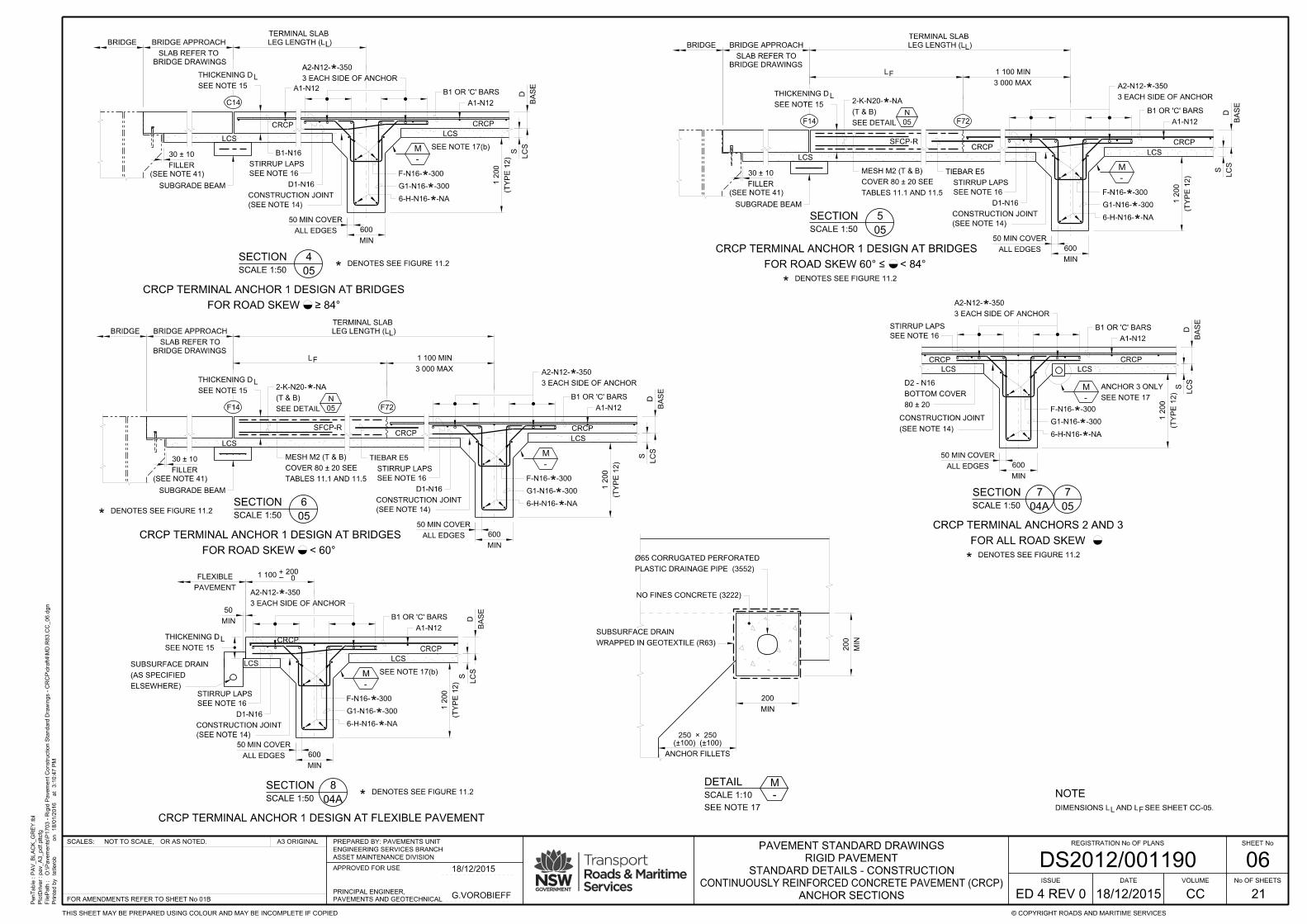
At CRCP terminal anchor 1 at flexible pavement the thickness of the
The thickness must be constant within the length L .
the thickness of the approach slab (to facilitate subbase construction).
base thickness, and (b) 250mm, but it must be increased to match
(denoted D ) must not be less than the greater of: (a) the specified
At bridge approaches the thickness of the terminal leg base15.
L
L
accordance with AS 2876 and at spacings of 2.5 m to 3.0 m.
For kerbs abutting CRCP, construct shrinkage control joints in
pavement, refer to the relevant drawings (CP or CJ).
need not be extended into kerbs. For kerbs abutting jointed
adjoining base, in accordance with RMS R15 except that C7 joints
Joints in kerbs (etc.) must be located to coincide with joints in the32.
and C15.
to as an "untied change point") must occur only at joint Types C14
The change from a tied longitudinal joint to an untied one (referred
at joint Types C2, C7, C14, C15, or at free edges.
Longitudinal joints (Types C1, C2, C4 and C5 ) may terminate only31.
be reduced to 1.2 m and the angle be 90° ± 15°.
longitudinal joints of 90° ± 6°. In SFCP, the separation distance can
methods. They must be aligned at an angle to the adjacent
here may be provided to suit the construction program and/or
Transverse construction joints (Types P7) additional to those shown21.
(as long as they are also tied). Arris rounding 5 mm maximum.
"with shoulder" criteria for pavement thickness design purposes
and must not be extruded. Such kerbs are deemed to satisfy the
must be strength grade N32 (minimum) in accordance with AS 1379
Unless otherwise allowed, kerb types SA, SB, SC, SE, SK and SL33.
All dimensions in millimetres (mm) unless shown otherwise.(d)
(Volumes CP, CJ or CF).
Jointed base must also comply with the relevant drawings(c)
design details for items listed in Table C1.2.
site staff. Project-specific drawings must therefore show precise
designers and are not intended for interpretation and application by
Table 12.1 for tiebar spacings) they are intended primarily for use by
and constructors. Where design tables are included (for example,
These Drawings provide standard details for use by both designers(b)
Abbreviations and nomenclature are scheduled on sheet CC-02.
A definition of terms is contained in RMS R82 and RMS R83.(a)1.
located within the specified joint zone.
without longitudinal joints but, if joints are required, they must be
and/or free edges. Hence, LCS may be paved in large widths
For LCS, no upper limit is specified on the width between joints
planned location of base joints.
must be located within the zone 0.25 ± 0.15 m offset from the
LCS longitudinal joints (if required by the nominated paving method)39.
A stamp is not required under proposed AC surfacing.
Anchor slabs are always reinforced so need not be stamped (R).
Stamps should preferably be placed within low trafficked areas.
depth of 4 ± 1 mm below the circular surround.
The imprint must be in accordance with CC-05 Detail Q, and to a
at each deflection in alignment.(ii)
within 0.5 m of each extremity, and;(i)
surface stamp placed above the anchor centreline and:
groups of three Type 12 anchors. Anchors must be identified by a
Unless shown otherwise, terminal anchors in CRCP consist of13.
heavily trafficked lanes.
In urban design: 0.10 ± 0.05 m, with offset away from the most(b)
in Sheet CC-04B;
In rural design: 0.20 ± 0.10 m, with offset in the direction shown(a)
as follows:
shown, must be located within the zone offset from the lane lines
Longitudinal base joints on through carriageways, unless otherwise19.
Corrugated plastic drainage pipe in accordance with RMS 3552.(f)
with RMS 3222.
No Fines Concrete in subsurface drain in accordance(e)
in the documents.
grade and drainage requirements, as specified elsewhere
The 200 mm depth is minimum only and is to be adjusted to suit(d)
into the base concrete.
(c) Geotextile wrapping is to be fully secured to prevent its intrusion
necessitating a drain.
PCP shoulder anchor will direct water towards the CRCP, hence
non-typical catchment exists. For example on adverse crossfall a
(b) Drains are not required between adjacent anchors unless a
the subbase to the anchor.
grade falls away from the anchor, delete the drain and extend
on that side of the anchor falls towards the anchor. Where the
Anchor drains are only required where the longitudinal grade(a)17.
2
of bars required and the clearance requirements to joints and edges.
bar spacing must then be determined based on the minimum number
ensure that the minimum steel ratio of 0.67% is obtained. The actual
number to determine the minimum number of bars required and to
The calculated value of N must be rounded up to the next whole
= Nominal cross sectional area of N16 bar (mm ). 200
= Specified concrete base thickness (mm)D
= Paving width (mm)W
Where:
= (0.67 100) × (W × D) 200
cross sectional area of a 'C' bar)
= (Mass steel ratio) × (Concrete sectional area) (Nominal
= Number of 'C' bars within any paving widthN
concrete sectional area)
Mass steel ratio (%) = 100 × (total sectional steel area) (total
calculated as follows:
minimum mass steel ratio within the range 0.67% to 0.72% when
The number of 'C' bars within each paving width must provide a(b)
variations to standard debonding treatments.
interlayer friction coefficient of 1.5. Designs must cater for any
All reinforcement design tables are based on an assumed(a)4.
≥ N20: see RMS R83(iii)
N16: 525 mm minimum.(ii)
N12: 360 mm minimum.(i)
Bar laps must be as follows:(e)
listed in Table 11.3 unless otherwise specified.
must comply with AS 3679.1. Steel must be of the classifications
Steel reinforcement must be in accordance with AS 4671, dowels(d)
See Fig 11.2 for bar marking legend.(c)
TIEBARS
SLAB SHAPE REQUIREMENTS
be placed in accordance with the Volumes CP or CJ drawings.
Fig 12.2 shows acceptable lap patterns in 'B' and 'C' bars. Mesh must5.
Tiebars E2 must be securely fixed against rotation during paving.(e)
on interlayer treatments in accordance with RMS R82.
Design of tiebars and other transverse reinforcement is based(d)
Drill-ties may be inclined (at 10° maximum) to facilitate fixing.(c)
They may be bent insitu.
Tiebars Shape 21 (in kerbs) are bent to satisfy cover requirements.(b)
spacings.
Tiebars must be provided in tied longitudinal joints at the specified(a)6.
the C2p joint.
length is recommended to minimise conflict in contraction strains at
Where jointed slabs are tied to CRCP, a reduction in the typical slab9.
Reserved.8.
observed.
criteria governing the layout of joints, and compliance must be strictly
Slab shape requirements are listed in Table 2.4. These are critical7.
SPECIAL REINFORCEMENT
signal detector loops.
CRCP is not suitable for the incorporation of sawcut located traffic12.
Reserved.11.
at cut-outs such as drainage structures.(c)
at tapers in width;(b)
at acute slab corners;(a)
on the drawings. Typical locations are:
Areas of base which require special reinforcement have been marked10.
÷
÷
÷÷
Sealants and fillers must comply with RMS R83.(b)
equivalent to those for the top joint, but rotated 90°.
incompressibles during subsequent paving. Dimensions must be
of joints (in accordance with RMS R83) to prevent the ingress of
temporary and permanent) must extend down the vertical face
Where joints daylight at formed joints or edges, the sealant (both(a)36.
RMS DS2012/001329: Asphalt, Volume 1 - New Construction
Volume 6 - Supplementary Model Drawings
RMS DS2013/001947: Standard Pavement Subsurface Drainage Details
Volume 5 - Rigid Pavement Details
RMS DS2013/001946: Standard Pavement Subsurface Drainage Details
Volume 1 - Design and Location
RMS DS2013/001942: Standard Pavement Subsurface Drainage Details
Pavement
RMS DS2013/001895: Volume SF - Steel Fibre Reinforced Concrete
Pavement
RMS DS2014/005559: Volume CJ - Jointed Reinforced Concrete
RMS DS2012/001191: Volume CP - Plain Concrete Pavement
AS/NZS 4671: Steel Reinforcing Materials
AS/NZS 3679.1: Structural Steel - Hot-rolled bars and sections
machine placed
AS 2876: Concrete kerbs and channels (gutters) - Manually or
AS 1379: Specification and Supply of Concrete
non-perforated plastic)
RMS 3552: Subsurface Drainage Pipe (corrugated perforated and
RMS 3222: No Fines Concrete (for subsurface drainage)
and Structures
RMS 3204: Preformed Joint Fillers for Concrete Road Pavements
RMS R83: Concrete Pavement Base
RMS R82: Lean Mix Concrete Subbase
RMS R63: Geotextiles
RMS R15: Kerbs and Gutters

04A
TYPICAL PLANS
NOTES
*
FLEXIBLE
PCP-R
PCP
CRCP
PAVEMENT TYPES:(b)
REFER TO VOLUME CP DRAWINGS FOR FURTHER PCP DETAILS.(c)
SEE NOTE 1(b).
REINFORCEMENT DETAILS ON THIS SHEET ARE INDICATIVE ONLY.(a)
FOR SLAB DIMENSIONAL LIMITS REFER TO TABLE 2.4.
SLAB WIDTHS MARKED ' ' AND ALL LANE WIDTHS ARE INDICATIVE ONLY.(e)
SEE CC-16 FOR CRCP RAMP ALTERNATIVE.(f)
}SEE VOLUME CP FOR FURTHER DETAILS.
APPROACH SLAB.
C14 MAY BE ORIENTED AT 90° TO CREATE ODD SHAPED BRIDGE(g)
VOLUME 1 - DESIGN AND LOCATION FOR PAVEMENT EDGE DETAILS.
REFER TO RMS STANDARD PAVEMENT SUBSURFACE DRAINAGE DETAILS(d)
PenTable :
PlotDriver :
FilePath :
Printe
d b
y
3:1
0:4
4 P
Mat
18/0
1/2
016
on
PA
V_
BL
AC
K_
GR
EY.tbl
pav_
A3_pdf.pltcfg
O:\Pave
ments\P
1703 - Rigid P
ave
ment
Construction Sta
ndard Dra
win
gs - C
RC
P\draft4\M
D.R
83.C
C_04
A.d
gn
tetlero
b
SHEET No
No OF SHEETS
© COPYRIGHT ROADS AND MARITIME SERVICESTHIS SHEET MAY BE PREPARED USING COLOUR AND MAY BE INCOMPLETE IF COPIED
A3 ORIGINALOR AS NOTED.NOT TO SCALE,SCALES: REGISTRATION No OF PLANS
21
ISSUE
ED 4 REV 0 CC
VOLUMEDATE
DS2012/001190ASSET MAINTENANCE DIVISION
ENGINEERING SERVICES BRANCH
PREPARED BY: PAVEMENTS UNIT
APPROVED FOR USE
PAVEMENTS AND GEOTECHNICAL
PRINCIPAL ENGINEER,
FOR AMENDMENTS REFER TO SHEET No 01B
STANDARD DETAILS - CONSTRUCTION
RIGID PAVEMENT
PAVEMENT STANDARD DRAWINGS
CONTINUOUSLY REINFORCED CONCRETE PAVEMENT (CRCP)
G.VOROBIEFF
18/12/2015
18/12/2015
SL
AB
BA
SE
*
*
SL
AB
BA
SE
*
*
LA
NE
S
E1-N12 TIEBARS
3 9
TYP
BRID
GE
AP
PR
OA
CH
BRID
GE
SEE NOTES 3 AND 25
*
*
*
SL
AB
BA
SE
INDUCED AND TIED
FORMED EDGE
SEE NOTES 3 AND 25
*
*
*
3
SL
AB
BA
SE
*
*
*
NOTE (e)*
2.5
3.5
3.5
4.3
3.8
4.0
3.0
4.0
4.0
2.4
4.3
3.8
2.0
3.5
2.5
1.9
FIGURE 4.1SCALE 1:500
P4 P2
C1
C1C1
C14
C7
FORMED AND CLUSTER TIED8
06
C1 C2
TERMINAL ANCHOR TYPE 12
NOTE (c)TYP
P8
ONLY
SHOULDER
IN PCP
C2p
C6b
TERMINAL ANCHORS TYPE 12
C1 C2
NOTE (c)E3 - N12 CLUSTERED
C7
FORMED AT BREAK IN PAVING
TRANSVERSE CONSTRUCTION JOINT
TYP
3.0
750 750
700 700
950 950
700 700
OPTION A OPTION B
CRCP
CRCP
PCP
600 470
90° ± 6°
3.5
3.5
2.5
0.5 L
AN
ES
1.9
3.8
4.3
P7
P7
P8
P7
P7
PAVEMENT
FLEXIBLE
PAVEMENT
FLEXIBLE
P6b
P6b
P1 SEE NOTE 25P2
P2
P4
P7 E1-N12 TIEBARS
P6b
470 700
E3-N12 CLUSTERED
9 6
A1-N12
A1-N12
C2p
700 600
A1-N12
TYP
3.0TYP
P8
E3-N12 CLUSTERED
C6b
6 3
E3-N12 CLUSTERED TYP
3.0
84° MIN
84° MIN
C2p
7
06
3
5
4
P6b
KERB
7
06
FORMED EDGE
(g)
C7
C7
P7
C2p C2
OR C2
C2
C2
C1
C6
C2C2
5.0 ± 0.5
CRCP TERMINAL ANCHORS
C1
4.3 MAX
1.0 MIN
1.0 MIN
4.3 MAX
5.0 ± 0.5
CRCP TERMINAL ANCHORS
PCP SHOULDER
FLEXIBLE PAVEMENT
1.85 ± 0.35
ANCHOR SEE NOTE (c)
TYPE 12 TERMINAL
P14LANE IT MUST CHANGE TO A
JOINT EXTENDS INTO A TRAFFICKED
WHERE AN UNTIED LONGITUDINAL
C7
C2
OR C2
C2
C2
C1
C6
5.0 ± 0.5
CRCP TERMINAL ANCHORS
C1
FLEXIBLE PAVEMENT
C6b
C2
C1
C6c
4.3
3.8*
*
SL
AB
BA
SE
1.9*
2.5
3.5
3.5
TYPICAL PLAN - TWO LANES
0.5
LA
NE
S
TYPICAL PLAN - THREE LANES
C6c
C2
C1
C2
C6b
0.5
2.5
3.5
3.5
3.5
LA
NE
S
*
*
SL
AB
BA
SE
4.3
3.8
3.5
*
1.9*
FIGURE 4.2
FIGURE 4.3
SCALE 1:500
SCALE 1:500
FORMED AT BREAK IN PAVING
TRANSVERSE CONSTRUCTION JOINT
SLAB
BASE0.5 LANES
FORMED AT BREAK IN PAVING
TRANSVERSE CONSTRUCTION JOINT
FORMED AT BREAK IN PAVING
TRANSVERSE CONSTRUCTION JOINT
C2
C6b
C6c
C2pC2
C7
C1
C2p
P6b
C1
C6b
C6
C6
8
06
8
06
TYP
3.0TYP
P8
2
04B
1
04B
1
04B
1
04B
3
04B
3
04B
9
04B
9
04B
CRCP WITH PCP SHOULDERS AND PCP RAMP
CRCP WITH PCP SHOULDERS AND CRCP RAMP
CRCP WITH CRCP SHOULDERS AND CRCP RAMP
P8
P7
C7
SEE NOTE 9
3.6 ± 0.2 TYP

04B
ALL DIMENSIONS ON THIS SHEET ARE IN METRES (m).(i)
DENOTES LCS JOINT ZONE, SEE NOTE 39(h)
NOTES
ANCHOR LAYOUT PLAN AND TYPICAL CROSS SECTIONS
PenTable :
PlotDriver :
FilePath :
Printe
d b
y
3:1
0:4
5 P
Mat
18/0
1/2
016
on
PA
V_
BL
AC
K_
GR
EY.tbl
pav_
A3_pdf.pltcfg
O:\Pave
ments\P
1703 - Rigid P
ave
ment
Construction Sta
ndard Dra
win
gs - C
RC
P\draft4\M
D.R
83.C
C_04
B.d
gn
tetlero
b
SHEET No
No OF SHEETS
© COPYRIGHT ROADS AND MARITIME SERVICESTHIS SHEET MAY BE PREPARED USING COLOUR AND MAY BE INCOMPLETE IF COPIED
A3 ORIGINALOR AS NOTED.NOT TO SCALE,SCALES: REGISTRATION No OF PLANS
21
ISSUE
ED 4 REV 0 CC
VOLUMEDATE
DS2012/001190ASSET MAINTENANCE DIVISION
ENGINEERING SERVICES BRANCH
PREPARED BY: PAVEMENTS UNIT
APPROVED FOR USE
PAVEMENTS AND GEOTECHNICAL
PRINCIPAL ENGINEER,
FOR AMENDMENTS REFER TO SHEET No 01B
STANDARD DETAILS - CONSTRUCTION
RIGID PAVEMENT
PAVEMENT STANDARD DRAWINGS
CONTINUOUSLY REINFORCED CONCRETE PAVEMENT (CRCP)
G.VOROBIEFF
18/12/2015
18/12/2015
* **
SHOULDER
0.5 MIN
1.9 4.3 3.8
SHOULDER
2.5
TRAVEL LANE
3.5
TRAVEL LANE
3.5
0.5 MIN
0.6 TYP
NOTE 19
0.2 ± 0.1
NOTE 25
C2pP6 C1
* **
SHOULDER
0.5 MIN
NOTE 19
0.2 ± 0.1
0.05 MIN0.05 MIN
0.05 MIN
0.05 MIN0.05 MIN
0.05 MIN
* **
SHOULDER
0.5 MIN
1.9 4.3 3.8
SHOULDER
2.5
TRAVEL LANE
3.5
TRAVEL LANE
3.5
0.5 MIN
0.6 TYP
NOTE 19
0.2 ± 0.1C1
0.05 MIN0.05 MIN
C6cC6b C2
1.9 4.3 3.8 3.5
SHOULDER
2.5
TRAVEL LANE
3.5
TRAVEL LANE
3.5
TRAVEL LANE
3.5
0.5 MIN
0.6 TYP
*
C6cC2C6b
(h)
0.25 ± 0.15
(h)
0.25 ± 0.15 (h)
0.25 ± 0.15
(h)
0.25 ± 0.15
(h)
0.25 ± 0.15
(h)
0.25 ± 0.15
(h)
0.25 ± 0.15
(h)
0.25 ± 0.15 (h)
0.25 ± 0.15
(h)
0.25 ± 0.15
(h)
0.25 ± 0.15
(h)
0.25 ± 0.15(h)
0.25 ± 0.15
(h)
0.25 ± 0.15 (h)
0.25 ± 0.15
(h)
0.25 ± 0.15
C6
(IN SHOULDER ONLY)
PCP
CRCP
LCS
SMZ
CRCP
LCS
SMZ
CRCP
LCS
SMZ
CRCP
LCS
SMZ
P6P6 P1 P2
SHOULDER
2.5
TRAVEL LANE
3.5
SHOULDER
1.0
PREFERRED
1.85 ± 0.35
*
TYPICAL CROSS SECTION
NOTE (e) CC-04A
TYPICAL CROSS SECTION
*
TYPICAL CROSS SECTION
NOTE (e) CC-04A*
TYPICAL CROSS SECTION
NOTE (e) CC-04A
SECTION
SCALE 1:100 04A
1SECTION
SCALE 1:100 04A
2
SECTION
SCALE 1:100 04A
3 SECTION
SCALE 1:100 04A
9
0.5 MIN
0.6 TYPC2C1
SROHCNA ON
BRID
GE
BRIDGES
REFER SHEET CC-05
BRIDGE APPROACH LAYOUTS
PCP
PAVEMENT
FLEXIBLE
PAVEMENT
CRCP
PAVEMENT
CRCP
PAVEMENT
FLEXIBLE
5.0 ± 0.5
5.0 ± 0.5
5.0 ± 0.5
5.0 ± 0.5
5.0 ± 0.5
5.0 ± 0.5SROHCNA ON
5.0 ± 0.5
5.0 ± 0.5
REFER TO VOLUME CP, SHEET CP-13
FOR PCP ANCHOR LAYOUT
FLEXIBLE PAVEMENT
CRCP
SCHEMATIC ONLY - NOT TO SCALE
ANCHORS FOR CRCP
(DIMENSIONS IN METRES)
SCHEMATIC ONLY - NOT TO SCALE
ANCHORS FOR CRCP
TYPE 12
ANCHORS
TERMINAL
THREE
BRIDGE APPROACH LAYOUTS
TYPE 12
ANCHORS
TERMINAL
THREE
TYPE 12 FOR ALL GRADES
THREE TERMINAL ANCHORSTHREE TERMINAL ANCHORS TYPE 12
THREE TERMINAL ANCHORS TYPE 12
THREE TERMINAL ANCHORS TYPE 12
FIGURE 4.4 - PLAN
FIGURE 4.5 - LONGITUDINAL SECTION

05
BRIDGE APPROACH PLANS
NOTES
TABLE 5.1: KEY TO FIGURE 5.2
A suggested setout sequence is as follows:
SYMBOL DIMENSION LIMITS
W1 to W4 Slab Width W1 to W4
Φ° 1 8
T1, T2, T3: Tiebar spacing in type F2 joints
Corner Angles (Φ° to Φ° )
Design as per TABLE 12.1
70° preferred minimum, (60° absolute minimum)
Apply slab widening at point 'C' to achieve the angle limit of 70° minimum.(c)
5 6 7
Table 5.1 Notes:
For reinforcement in SFCP-R terminal slabs and in terminal anchors refer to Tables 11.1 and 11.5.(e)
4.5 m maximum, 1.0 m minimum
Radiate to point 'B' such that the resulting angle at 'B' complies with the target minimum value of 84° minimum.
Locate the Type F72/F71 joint (marked 'A - B' on this diagram). Locate point 'A' according to dimensional limits.(b)
Type C1 / C2 and F2 joints (at points 'D', 'E' and 'F') are specified to avoid reflective corner cracking.
90° ± 6° and approximately equal. Check dimensions 'W1' to 'W4'. The minimum offsets from adjoining
Locate the skewed Type F2 joints, they need not be parallel but angles Φ , Φ and Φ should be approximately(d)
shown in the main carriageway appliy to the shoulder.
The shoulder shown in Figure 5.2 is PCP and this may be replaced by CRCP and the joint details(f)
20.0 m maximum.that is,Check that the dimensional limit on the opposite side is satisfied,
Locate the anchor relative to the approach slab at the closest side (top side in this diagram).(a)
SEE ALSO SHEET CC-04B.(b)
FOR NUMERIC NOTES REFER SHEET CP-03.(a)
PenTable :
PlotDriver :
FilePath :
Printe
d b
y
3:1
0:4
6 P
Mat
18/0
1/2
016
on
PA
V_
BL
AC
K_
GR
EY.tbl
pav_
A3_pdf.pltcfg
O:\Pave
ments\P
1703 - Rigid P
ave
ment
Construction Sta
ndard Dra
win
gs - C
RC
P\draft4\M
D.R
83.C
C_05.d
gn
tetlero
b
SHEET No
No OF SHEETS
© COPYRIGHT ROADS AND MARITIME SERVICESTHIS SHEET MAY BE PREPARED USING COLOUR AND MAY BE INCOMPLETE IF COPIED
A3 ORIGINALOR AS NOTED.NOT TO SCALE,SCALES: REGISTRATION No OF PLANS
21
ISSUE
ED 4 REV 0 CC
VOLUMEDATE
DS2012/001190ASSET MAINTENANCE DIVISION
ENGINEERING SERVICES BRANCH
PREPARED BY: PAVEMENTS UNIT
APPROVED FOR USE
PAVEMENTS AND GEOTECHNICAL
PRINCIPAL ENGINEER,
FOR AMENDMENTS REFER TO SHEET No 01B
STANDARD DETAILS - CONSTRUCTION
RIGID PAVEMENT
PAVEMENT STANDARD DRAWINGS
CONTINUOUSLY REINFORCED CONCRETE PAVEMENT (CRCP)
G.VOROBIEFF
18/12/2015
18/12/2015
L
NTS
ANCHORC
FIGURE 5.1
ISO
LA
TIO
N J
OIN
T
SLAB
APPROACH
BRIDGE
BRIDGE SKEW
ROAD SKEW
C6
C14
PCP-R
C1
L
C1 OR C2
CRCP
CRCP
5 000 ± 5005 000 ± 500
Q
-
4
06
7
06
7
06
AN
CH
OR 1
AN
CH
OR 2
AN
CH
OR 3
P8
90° ± 6°90° ± 6° 90° ± 6°
P6
C2p
3 000 TYP
A
A A
AAA
DRAWINGS
SEE VOLUME CP
± 3001 800
P8
± 3001 800
3 000L 4 000 MIN
L 12 000 MAX
TERMINAL DESIGN AT BRIDGES FOR ROAD SKEW ≥ 84°
PC
P-R
PC
P
NOTE (g) CP-04A
(g)
BUT THEY ARE REQUIRED IN CRCP SHOULDER
ANCHORS 2 AND 3 ARE NOT REQUIRED IN PCP SHOULDER,
6
06
6
06
PCP-R
MIN
1 0
00
MIN
1 0
00
MIN
1 0
00
W2
W3
Φ°
3
2
1
6
7
8
5
SFCP-R
SFCP-R
SFCP-R
A
D
E
F
B
C
SLAB
APPROACH
BRIDGEBRIDGE
SFCP-R
TO ACHIEVE Φ° = 70° MIN
LOCALISED WIDENING
4
84°(+6°,-0°)
NTS
FIGURE 5.2
T3
T2
T1
Φ°
Φ°
F2
F2
F2
P6
A
C2
C6
ORC1
SLAB
APPROACH
BRIDGEBRIDGE
SFCP-R
SFCP-R
SFCP-R
NTS
FIGURE 5.3
F2
A
A
C2p
F2 OR C2C1
PCP-R
CRCP
CRCP
P8
AN
CH
OR 1
PCP
P6
C2p
CRCP
CRCP
90° ± 6°
90° ± 6°
1 800 ± 300
CRCP
CRCP
CRCP
CRCP
AN
CH
OR 1
C2p C2p
P8
N
-
F14
N
-
5
06
5
06
PCP
Q
-
ANCHORC
ANCHORC
W1
F71
F72
90° ± 6°
F14
A
Φ°
Φ°
F72
Φ°
F71 PCP-R
4
1 700 MIN
W4
Φ°
L 4 000 MINL
TERMINAL DESIGN AT BRIDGES FOR ROAD SKEW 60° ≤ < 84°
L 12 000 MAXL
1 800 ± 300
L 1 500 MIN 1 100 MINF
L 10 900 MAX 3 000 MAXF
L 4 000 MIN
L 1 500 MIN 1 100 MIN
L
F
L 20 000 MAXL
L 18 900 MAX 3 000 MAXF
Φ°
TERMINAL DESIGN AT BRIDGES FOR ROAD SKEW < 60°
FOR SHOULDER DETAILS
SEE VOLUME CP DRAWINGS
FOR SHOULDER DETAILS
SEE VOLUME CP DRAWINGS
PCP-R(g)
(g)
Q
-
(Anchors 2 and 3 not shown. See also Table 5.1 and Note (g) CP-04A)
(Anchors 2 and 3 not shown. See note (g) CP-04A)
DETAIL
SCALE 1:50
N
-
OF BOTTOM MESH
MESH AND TOPSIDE
UNDERSIDE OF TOP
BARS TO BE TIED TO
CO
VE
R
80 ± 2
0
FOR SKEW < 84°
IN TERMINAL SLABS
CORNER REINFORCEMENT
SEE TABLE 11.2
2-K-N20 T & B
Ø100 PIN
BEND ON
Φ°/3
Φ°/3
Φ°/3
Φ°
DETAIL
SCALE 1:5
Q
-
90 ± 5
SURFACE STAMP FOR ANCHOR SLABS
50 ± 5
See Note 13
CIRCULAR SURROUND
06
NOTE
L FDIMENSIONS L AND L SEE SHEET CC-05.
ANCHOR SECTIONS
PenTable :
PlotDriver :
FilePath :
Printe
d b
y
3:1
0:4
7 P
Mat
18/0
1/2
016
on
PA
V_
BL
AC
K_
GR
EY.tbl
pav_
A3_pdf.pltcfg
O:\Pave
ments\P
1703 - Rigid P
ave
ment
Construction Sta
ndard Dra
win
gs - C
RC
P\draft4\M
D.R
83.C
C_06.d
gn
tetlero
b
SHEET No
No OF SHEETS
© COPYRIGHT ROADS AND MARITIME SERVICESTHIS SHEET MAY BE PREPARED USING COLOUR AND MAY BE INCOMPLETE IF COPIED
A3 ORIGINALOR AS NOTED.NOT TO SCALE,SCALES: REGISTRATION No OF PLANS
21
ISSUE
ED 4 REV 0 CC
VOLUMEDATE
DS2012/001190ASSET MAINTENANCE DIVISION
ENGINEERING SERVICES BRANCH
PREPARED BY: PAVEMENTS UNIT
APPROVED FOR USE
PAVEMENTS AND GEOTECHNICAL
PRINCIPAL ENGINEER,
FOR AMENDMENTS REFER TO SHEET No 01B
STANDARD DETAILS - CONSTRUCTION
RIGID PAVEMENT
PAVEMENT STANDARD DRAWINGS
CONTINUOUSLY REINFORCED CONCRETE PAVEMENT (CRCP)
G.VOROBIEFF
18/12/2015
18/12/2015
SLAB REFER TO
BRIDGE APPROACH
BRIDGE DRAWINGS
(SEE NOTE 14)
CONSTRUCTION JOINT
SUBGRADE BEAM
FILLER
30 ± 10
(SEE NOTE 41)
L
(TY
PE 1
2)
1 2
00
MIN
600
LCSLCS
L
BA
SE
D
*
***
SLAB REFER TO
BRIDGE APPROACH
BRIDGE DRAWINGS
SUBGRADE BEAM
LCS
L
M
-
SFCP-R
F
FILLER
30 ± 10
(SEE NOTE 41)
(TY
PE 1
2)
1 2
00
LCS
BA
SE
D
**
M
-
*
ALL EDGES
50 MIN COVER
MIN
600
SUBGRADE BEAM
LCS
*
SFCP-R
FILLER
30 ± 10
(SEE NOTE 41)
(TY
PE 1
2)
1 2
00
LCS
**
M
-
*
ALL EDGES
50 MIN COVER
MIN
600
BRIDGE BRIDGE
F14 F72
F14
C14
B1-N16
CRCP
A1-N12
D1-N16
B1 OR 'C' BARS
A1-N12
CRCP
FOR ROAD SKEW ≥ 84°
CRCP TERMINAL ANCHOR 1 DESIGN AT BRIDGES
LC
S
S
LC
S
S
*
CRCPCRCP
SLAB REFER TO
BRIDGE APPROACH
BRIDGE DRAWINGS
LBRIDGE
F
*
BA
SE
DL
CS
S
CRCP
F72
CRCP
FOR ROAD SKEW < 60°
CRCP TERMINAL ANCHOR 1 DESIGN AT BRIDGES
N
05
SEE NOTE 17(b)
(SEE NOTE 14)
CONSTRUCTION JOINT
(TY
PE 1
2)
1 2
00
MIN
600
LCS LCS
*
***
M
-
ALL EDGES
50 MIN COVER
BA
SE
DL
CS
S
05
7
SEE NOTE 17
ANCHOR 3 ONLY
CRCPCRCP
80 ± 20
BOTTOM COVER
D2 - N16
(TY
PE 1
2)
1 2
00
MIN
600
LCS
BA
SE
D
*
***
M
-
ALL EDGES
50 MIN COVER
CRCP
CRCP
LC
S
S
SEE NOTE 17(b)
MIN
50
LCS
ELSEWHERE)
(AS SPECIFIED
SUBSURFACE DRAIN
1 100 0
200
PAVEMENT
FLEXIBLE
CRCP TERMINAL ANCHOR 1 DESIGN AT FLEXIBLE PAVEMENT
SECTION
SCALE 1:50 05
4
SECTION
SCALE 1:50 05
5
SECTION
SCALE 1:50 05
6
TERMINAL SLABTERMINAL SLAB
3 EACH SIDE OF ANCHOR
A2-N12- -350
FOR ROAD SKEW 60° ≤ < 84°
CRCP TERMINAL ANCHOR 1 DESIGN AT BRIDGES
TERMINAL SLAB
3 EACH SIDE OF ANCHOR
A2-N12- -350
3 EACH SIDE OF ANCHOR
A2-N12- -350
F-N16- -300
G1-N16- -300
6-H-N16- -NA
3 EACH SIDE OF ANCHOR
A2-N12- -350
F-N16- -300
G1-N16- -300
6-H-N16- -NA
3 EACH SIDE OF ANCHOR
A2-N12- -350
F-N16- -300
G1-N16- -300
6-H-N16- -NAF-N16- -300
G1-N16- -300
6-H-N16- -NA
SEE DETAIL
(T & B)
2-K-N20- -NA
*N
05SEE DETAIL
(T & B)
2-K-N20- -NA
F-N16- -300
G1-N16- -300
6-H-N16- -NA
B1 OR 'C' BARS
A1-N12
TIEBAR E5SEE NOTE 16
STIRRUP LAPS
SEE NOTE 16
STIRRUP LAPS
D1-N16
(SEE NOTE 14)
CONSTRUCTION JOINT
SEE NOTE 16
STIRRUP LAPS
D1-N16
(SEE NOTE 14)
CONSTRUCTION JOINT
B1 OR 'C' BARS
A1-N12
TIEBAR E5
D1-N16
SEE NOTE 16
STIRRUP LAPS
(SEE NOTE 14)
CONSTRUCTION JOINT
B1 OR 'C' BARS
A1-N12
B1 OR 'C' BARS
A1-N12SEE NOTE 16
STIRRUP LAPS
LEG LENGTH (L )
ALL EDGES
50 MIN COVER
TABLES 11.1 AND 11.5
COVER 80 ± 20 SEE
MESH M2 (T & B)
TABLES 11.1 AND 11.5
COVER 80 ± 20 SEE
MESH M2 (T & B)
LEG LENGTH (L )
L
3 000 MAX
1 100 MIN
3 000 MAX
1 100 MINL
LEG LENGTH (L )
+–
*DENOTES SEE FIGURE 11.2
*DENOTES SEE FIGURE 11.2
*DENOTES SEE FIGURE 11.2
*DENOTES SEE FIGURE 11.2
*DENOTES SEE FIGURE 11.2
SECTION
SCALE 1:50 04A
8
SECTION
SCALE 1:50 04A
7
FOR ALL ROAD SKEW
CRCP TERMINAL ANCHORS 2 AND 3
SEE NOTE 15
THICKENING D
SEE NOTE 15
THICKENING D
SEE NOTE 15
THICKENING D
SEE NOTE 15
THICKENING D
L
L
L
PLASTIC DRAINAGE PIPE (3552)
Ø65 CORRUGATED PERFORATED
NO FINES CONCRETE (3222)
ANCHOR FILLETS
(±100) (±100)
250 × 250
SEE NOTE 17
DETAIL
SCALE 1:10
M
-
MIN
200
MIN
200
WRAPPED IN GEOTEXTILE (R63)
SUBSURFACE DRAIN
NOTES
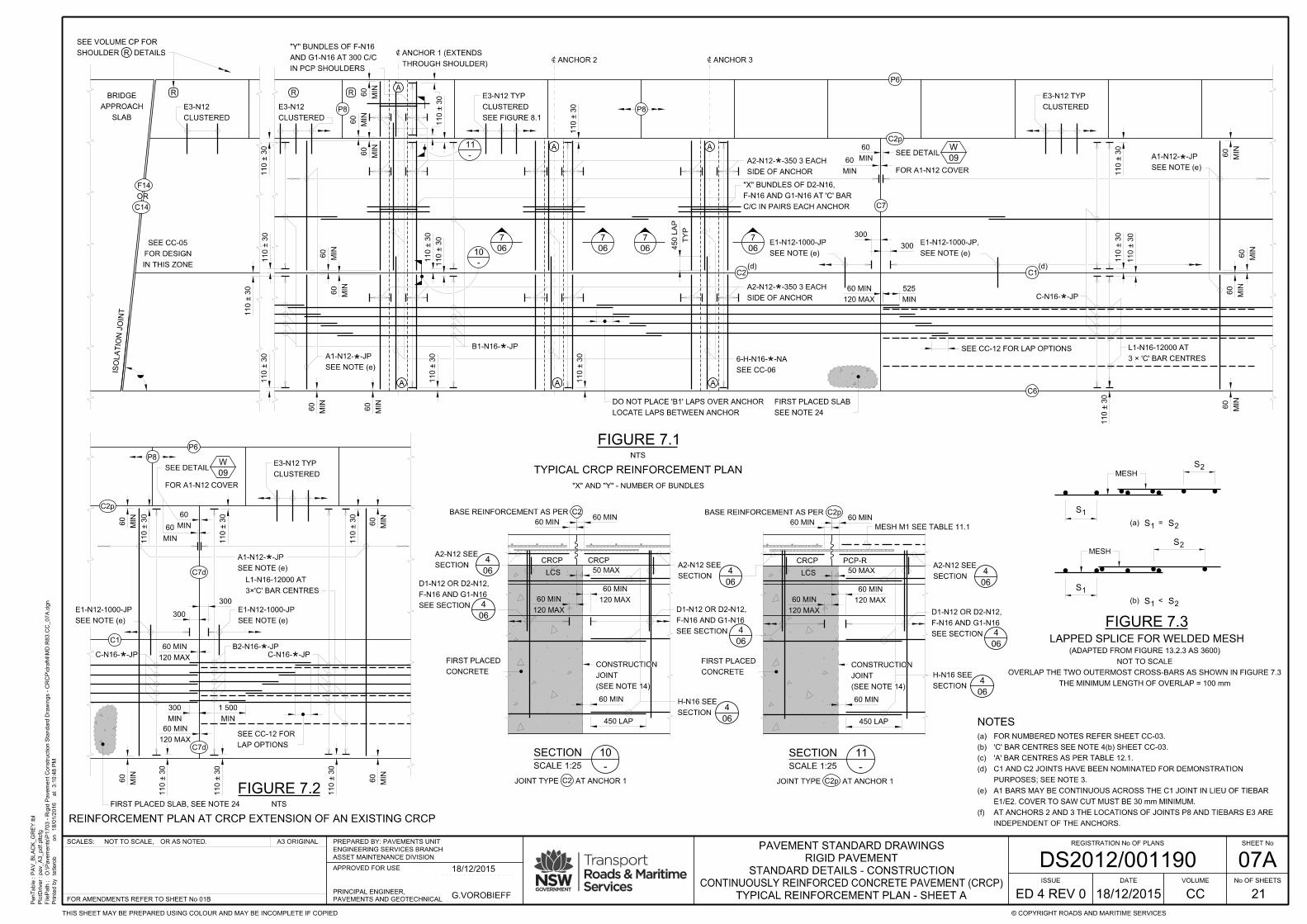
07A
TYPICAL REINFORCEMENT PLAN - SHEET A
INDEPENDENT OF THE ANCHORS.
AT ANCHORS 2 AND 3 THE LOCATIONS OF JOINTS P8 AND TIEBARS E3 ARE(f)
E1/E2. COVER TO SAW CUT MUST BE 30 mm MINIMUM.
A1 BARS MAY BE CONTINUOUS ACROSS THE C1 JOINT IN LIEU OF TIEBAR(e)
PURPOSES; SEE NOTE 3.
C1 AND C2 JOINTS HAVE BEEN NOMINATED FOR DEMONSTRATION(d)
'A' BAR CENTRES AS PER TABLE 12.1.(c)
'C' BAR CENTRES SEE NOTE 4(b) SHEET CC-03.(b)
FOR NUMBERED NOTES REFER SHEET CC-03.(a)
PenTable :
PlotDriver :
FilePath :
Printe
d b
y
3:1
0:4
8 P
Mat
18/0
1/2
016
on
PA
V_
BL
AC
K_
GR
EY.tbl
pav_
A3_pdf.pltcfg
O:\Pave
ments\P
1703 - Rigid P
ave
ment
Construction Sta
ndard Dra
win
gs - C
RC
P\draft4\M
D.R
83.C
C_07
A.d
gn
tetlero
b
SHEET No
No OF SHEETS
© COPYRIGHT ROADS AND MARITIME SERVICESTHIS SHEET MAY BE PREPARED USING COLOUR AND MAY BE INCOMPLETE IF COPIED
A3 ORIGINALOR AS NOTED.NOT TO SCALE,SCALES: REGISTRATION No OF PLANS
21
ISSUE
ED 4 REV 0 CC
VOLUMEDATE
DS2012/001190ASSET MAINTENANCE DIVISION
ENGINEERING SERVICES BRANCH
PREPARED BY: PAVEMENTS UNIT
APPROVED FOR USE
PAVEMENTS AND GEOTECHNICAL
PRINCIPAL ENGINEER,
FOR AMENDMENTS REFER TO SHEET No 01B
STANDARD DETAILS - CONSTRUCTION
RIGID PAVEMENT
PAVEMENT STANDARD DRAWINGS
CONTINUOUSLY REINFORCED CONCRETE PAVEMENT (CRCP)
G.VOROBIEFF
18/12/2015
18/12/2015
SLAB
APPROACH
BRIDGE
ISO
LA
TIO
N J
OIN
T
OR
C14
P8
R R R
P8
C ANCHOR 3C ANCHOR 2
C
THROUGH SHOULDER)
ANCHOR 1 (EXTENDS
CLUSTERED
E3-N12
CLUSTERED
E3-N12
A A
7
06
7
06
7
06
7
06
NTS
FIGURE 7.1
TYPICAL CRCP REINFORCEMENT PLAN
R
C2 C1(d) (d)
C2p
SEE FIGURE 8.1
CLUSTERED
E3-N12 TYP
C7
SEE NOTE 24
FIRST PLACED SLAB
120 MAX
60 MIN
300
*MIN
60 MIN
60
MIN
60
MIN
60
MIN
60
MIN
60
SEE NOTE (e)
A1-N12- -JPMIN
60
MIN
60
MIN
60
MIN
60
300
SEE NOTE (e)
E1-N12-1000-JP
110 ± 3
0
110 ± 3
0
110 ± 3
0
110 ± 3
0
110 ± 3
0
110 ± 3
0
110 ± 3
0
110 ± 3
0
B1-N16- -JP*
TY
P
450 L
AP
*
C/C IN PAIRS EACH ANCHOR
F-N16 AND G1-N16 AT 'C' BAR
"X" BUNDLES OF D2-N16,
A
IN PCP SHOULDERS
AND G1-N16 AT 300 C/C
"Y" BUNDLES OF F-N16
MIN
525
SEE NOTE (e)
E1-N12-1000-JP,
*C-N16- -JP
110 ± 3
0
110 ± 3
0
110 ± 3
0
3 × 'C' BAR CENTRES
L1-N16-12000 AT
P6
C6
SEE NOTE (e)
A1-N12- -JP
*SIDE OF ANCHOR
A2-N12- -350 3 EACH
*
110 ± 3
0
MIN
60
110 ± 3
0
110 ± 3
0
"X" AND "Y" - NUMBER OF BUNDLES
*SIDE OF ANCHOR
A2-N12- -350 3 EACH
CLUSTERED
E3-N12 TYP
LOCATE LAPS BETWEEN ANCHOR
DO NOT PLACE 'B1' LAPS OVER ANCHOR
MIN
60
MIN
60
A A A
F14
IN THIS ZONE
FOR DESIGN
SEE CC-05
SEE CC-12 FOR LAP OPTIONS
SEE CC-06
6-H-N16- -NA
11
-
10
-
W
09
FOR A1-N12 COVER
SEE DETAIL
P8
C2p
P6
C1
C7d
C7d
MIN
60
MIN
60 MIN
60
MIN
60
MIN
60
MIN
60
120 MAX
60 MIN
120 MAX
60 MIN
110 ± 3
0
110 ± 3
0
110 ± 3
0
MIN
300
MIN
1 500
110 ± 3
0
110 ± 3
0
110 ± 3
0
FOR A1-N12 COVER
SEE DETAILW
09 CLUSTERED
E3-N12 TYP
*
3×'C' BAR CENTRES
L1-N16-12000 AT
SEE NOTE (e)
E1-N12-1000-JP
C-N16- -JP*B2-N16- -JP*C-N16- -JP*
LAP OPTIONS
SEE CC-12 FOR
FIRST PLACED SLAB, SEE NOTE 24 NTS
FIGURE 7.2
REINFORCEMENT PLAN AT CRCP EXTENSION OF AN EXISTING CRCP
SEE NOTE (e)
E1-N12-1000-JP
300
300
SEE NOTE (e)
A1-N12- -JP
SHOULDER DETAILS
SEE VOLUME CP FOR
NOT TO SCALE
(ADAPTED FROM FIGURE 13.2.3 AS 3600)
THE MINIMUM LENGTH OF OVERLAP = 100 mm
OVERLAP THE TWO OUTERMOST CROSS-BARS AS SHOWN IN FIGURE 7.3
MESH
S2
S1
(b) S1 S2<
MESH
S2
S1
(a) S1 S2=
LAPPED SPLICE FOR WELDED MESH
FIGURE 7.3
C2 C2p
CONCRETE
FIRST PLACED
(SEE NOTE 14)
JOINT
CONSTRUCTION
60 MINBASE REINFORCEMENT AS PER C2
CRCP CRCP
LCSSECTION
A2-N12 SEE4
06
4
06
SEE SECTION
F-N16 AND G1-N16
D1-N12 OR D2-N12,
50 MAX
120 MAX
60 MIN 120 MAX
60 MIN
SEE SECTION
F-N16 AND G1-N16
D1-N12 OR D2-N12,
4
06
SECTION
A2-N12 SEE4
06
450 LAP
JOINT TYPE AT ANCHOR 1 JOINT TYPE AT ANCHOR 1
SECTION
H-N16 SEE4
06
60 MIN
CONCRETE
FIRST PLACED
(SEE NOTE 14)
JOINT
CONSTRUCTION
BASE REINFORCEMENT AS PER
CRCP
LCS 50 MAX
120 MAX
60 MIN 120 MAX
60 MIN
SEE SECTION
F-N16 AND G1-N16
D1-N12 OR D2-N12,
4
06
SECTION
A2-N12 SEE4
06
450 LAP
SECTION
H-N16 SEE4
0660 MIN
MESH M1 SEE TABLE 11.160 MIN 60 MIN
60 MINC2p
PCP-R
SECTION
SCALE 1:25 -
10 SECTION
SCALE 1:25 -
11

07B
TYPICAL REINFORCEMENT PLAN - SHEET B
PenTable :
PlotDriver :
FilePath :
Printe
d b
y
3:1
0:4
9 P
Mat
18/0
1/2
016
on
PA
V_
BL
AC
K_
GR
EY.tbl
pav_
A3_pdf.pltcfg
O:\Pave
ments\P
1703 - Rigid P
ave
ment
Construction Sta
ndard Dra
win
gs - C
RC
P\draft4\M
D.R
83.C
C_07
B.d
gn
tetlero
b
SHEET No
No OF SHEETS
© COPYRIGHT ROADS AND MARITIME SERVICESTHIS SHEET MAY BE PREPARED USING COLOUR AND MAY BE INCOMPLETE IF COPIED
A3 ORIGINALOR AS NOTED.NOT TO SCALE,SCALES: REGISTRATION No OF PLANS
21
ISSUE
ED 4 REV 0 CC
VOLUMEDATE
DS2012/001190ASSET MAINTENANCE DIVISION
ENGINEERING SERVICES BRANCH
PREPARED BY: PAVEMENTS UNIT
APPROVED FOR USE
PAVEMENTS AND GEOTECHNICAL
PRINCIPAL ENGINEER,
FOR AMENDMENTS REFER TO SHEET No 01B
STANDARD DETAILS - CONSTRUCTION
RIGID PAVEMENT
PAVEMENT STANDARD DRAWINGS
CONTINUOUSLY REINFORCED CONCRETE PAVEMENT (CRCP)
G.VOROBIEFF
18/12/2015
18/12/2015
SLAB
APPROACH
BRIDGE
ISO
LA
TIO
N J
OIN
T
C ANCHOR 3C ANCHOR 2
C
7
06
7
06
7
06
7
06
NTS
FIGURE 7.4
TYPICAL CRCP REINFORCEMENT PLAN
(d) (d)
SEE NOTE 24
FIRST PLACED SLAB
120 MAX
60 MIN
300
*MIN
60 MIN
60
MIN
60
MIN
60
MIN
60
MIN
60
SEE NOTE (e)
A1-N12- -JPMIN
60
MIN
60
MIN
60
MIN
60
300
SEE NOTE (e)
E1-N12-1000-JP
110 ± 3
0
110 ± 3
0
110 ± 3
0
110 ± 3
0
110 ± 3
0
110 ± 3
0
110 ± 3
0
110 ± 3
0
B1-N16- -JP*
TY
P
450 L
AP
*
C/C IN PAIRS EACH ANCHOR
F-N16 AND G1-N16 AT 'C' BAR
"X" BUNDLES OF D2-N16,
IN PCP SHOULDERS
AND G1-N16 AT 300 C/C
"Y" BUNDLES OF F-N16
MIN
525
SEE NOTE (e)
E1-N12-1000-JP,
*C-N16- -JP
110 ± 3
0
110 ± 3
0
110 ± 3
0
3 × 'C' BAR CENTRES
L1-N16-12000 AT
SEE NOTE (e)
A1-N12- -JP
*SIDE OF ANCHOR
A2-N12- -350 3 EACH
*
110 ± 3
0
MIN
60
110 ± 3
0
"X" AND "Y" - NUMBER OF BUNDLES
*SIDE OF ANCHOR
A2-N12- -350 3 EACH
LOCATE LAPS BETWEEN ANCHOR
DO NOT PLACE 'B1' LAPS OVER ANCHOR
MIN
60
MIN
60
A A A
IN THIS ZONE
FOR DESIGN
SEE CC-05
SEE CC-12 FOR LAP OPTIONS
SEE CC-06
6-H-N16- -NA
10
7A
10
7A
W
09
FOR A1-N12 COVER
SEE DETAIL
MIN
60
MIN
60
MIN
60
MIN
60
MIN
60
MIN
60
120 MAX
60 MIN
120 MAX
60 MIN
110 ± 3
0
110 ± 3
0
110 ± 3
0
MIN
300
MIN
1 500
110 ± 3
0
110 ± 3
0
110 ± 3
0
*
3×'C' BAR CENTRES
L1-N16-12000 AT
SEE NOTE (e)
E1-N12-1000-JP
C-N16- -JP*B2-N16- -JP*C-N16- -JP*
LAP OPTIONS
SEE CC-12 FOR
FIRST PLACED SLAB, SEE NOTE 24 NTS
FIGURE 7.5
REINFORCEMENT PLAN AT CRCP EXTENSION OF AN EXISTING CRCP
IN PCP SHOULDERS
AND G1-N16 AT 300 C/C
"Y" BUNDLES OF F-N16
MIN
60
MIN
60
MIN
60
110 ± 3
0
IN PCP SHOULDERS
AND G1-N16 AT 300 C/C
"Y" BUNDLES OF F-N16
MIN
60
MIN
60
MIN
60
110 ± 3
0
ANCHOR 1
SEE NOTE (e)
E1-N12-1000-JP
300
300
SEE NOTE (e)
E1-N12-1000-JP,A A A
300
300
SEE NOTE (e)
E1-N12-1000-JP
MIN
60
FOR A1-N12 COVER
SEE DETAILW
09
C7
C2C2C6
C-N16- -JP*
C2
B1-N16- -JP*
J1-N12-1000-1050
J1-N12-1000-1050
300
300
E1-N12-1000-JP
E1-N12-1000-JP
SEE NOTE (e)
A1-N12- -JP*
E1-N12-1000-JP
SEE NOTE (e)
A1-N12- -JP*
3 × 'C' BAR CENTRES
L1-N16-12000 AT
C7
C6
B1-N16- -JP*C-N16- -JP*
*1-B3-N16-
300
300
300
110 ± 3
0
300
300
MIN
525
120 MAX
60 MIN
110 ± 3
0
110 ± 3
0
300
C6
C2
C7
C2
C1
C6c
C6b
C1a
C6b
C1
C6c
NTS
FIGURE 7.6
C2dOR OR
C2dOR
C2d
F14
OR
C14
C7dSEE NOTE (e)
A1-N12- -JP
E1-N12-1000-JP
300
C7
C6
C6
B1-N16- -JP*
*
E1-N12-1000-JP
MIN
525
1-B3-N16- **1-B3-N16-
300
300
120 MAX
60 MIN
12
-
12
-
LAP OPTIONS
SEE CC-12 FOR
FOR INTEGRAL SLAB DIMENSIONS SEEK5
13
C2OR
C2d C2OR
C2d
J4-N12
J4-N12
BASE
TYPE SA
C-N16
A1-N12
E1-N12-1000-JP 500 ± 75
CRCP
LCS
SEE TABLE 12.3
MIN
50
B1-N16- -JP
SECTION
SCALE 1:20 -
12
*1-B3-N16- **
FOR NOTES REFER TO SHEET CP-07A
C2
OR
C2dJ4-N12
ALL EDGES
50 MIN COVER
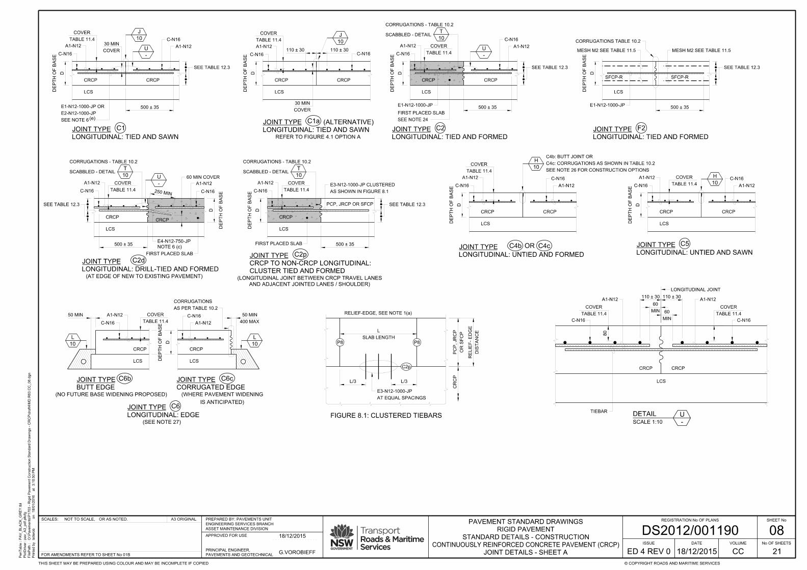
08
JOINT DETAILS - SHEET A
PenTable :
PlotDriver :
FilePath :
Printe
d b
y
3:1
0:5
0 P
Mat
18/0
1/2
016
on
PA
V_
BL
AC
K_
GR
EY.tbl
pav_
A3_pdf.pltcfg
O:\Pave
ments\P
1703 - Rigid P
ave
ment
Construction Sta
ndard Dra
win
gs - C
RC
P\draft4\M
D.R
83.C
C_08.d
gn
tetlero
b
SHEET No
No OF SHEETS
© COPYRIGHT ROADS AND MARITIME SERVICESTHIS SHEET MAY BE PREPARED USING COLOUR AND MAY BE INCOMPLETE IF COPIED
A3 ORIGINALOR AS NOTED.NOT TO SCALE,SCALES: REGISTRATION No OF PLANS
21
ISSUE
ED 4 REV 0 CC
VOLUMEDATE
DS2012/001190ASSET MAINTENANCE DIVISION
ENGINEERING SERVICES BRANCH
PREPARED BY: PAVEMENTS UNIT
APPROVED FOR USE
PAVEMENTS AND GEOTECHNICAL
PRINCIPAL ENGINEER,
FOR AMENDMENTS REFER TO SHEET No 01B
STANDARD DETAILS - CONSTRUCTION
RIGID PAVEMENT
PAVEMENT STANDARD DRAWINGS
CONTINUOUSLY REINFORCED CONCRETE PAVEMENT (CRCP)
G.VOROBIEFF
18/12/2015
18/12/2015
DE
PT
H O
F B
AS
E
D
(e)
J
10
CRCP CRCP
LCS
A1-N12
C-N16
U
-
C-N16
A1-N12
C1
TABLE 11.4
COVER
COVER
30 MIN
DE
PT
H O
F B
AS
E
D
CRCP CRCP
LCS
A1-N12
C-N16
U
-
C-N16
A1-N12
C2
SCABBLED - DETAIL
CORRUGATIONS - TABLE 10.2
T
10
SEE NOTE 24
FIRST PLACED SLAB
C2d
CRCPCRCP
LCS
250 MIN
DE
PT
H O
F B
AS
E
D
SCABBLED - DETAIL
CORRUGATIONS - TABLE 10.2
T
10
A1-N12
C-N16
U
-
C-N16
A1-N12
NOTE 6 (c)
E4-N12-750-JP
DE
PT
H O
F B
AS
E
D
CRCP
LCS
A1-N12
C-N16
TABLE 11.4
COVER
SCABBLED - DETAIL
CORRUGATIONS - TABLE 10.2
T
10
C2p
CLUSTER TIED AND FORMED
CRCP TO NON-CRCP LONGITUDINAL:
JOINT TYPE
AND ADJACENT JOINTED LANES / SHOULDER)
(LONGITUDINAL JOINT BETWEEN CRCP TRAVEL LANES
PCP, JRCP OR SFCP
OR
A1-N12
C-N16
H
10TABLE 11.4
COVER
C-N16
A1-N12
DE
PT
H O
F B
AS
E
D
CRCP
LCS
CRCP
C4b C4c
A1-N12
C-N16H
10TABLE 11.4
COVER
C-N16
A1-N12
DE
PT
H O
F B
AS
E
D
CRCP
LCS
CRCP
C5
DE
PT
H O
F B
AS
E
D
CRCP
LCS
CRCP
LCS
50 MIN
L
10
L
10
TABLE 11.4
COVER
C-N16
A1-N12
A1-N12
C-N16
C6b
(NO FUTURE BASE WIDENING PROPOSED)
C6c
C6
(SEE NOTE 27)
AS PER TABLE 10.2
CORRUGATIONS
FIRST PLACED SLAB
BUTT EDGE
JOINT TYPE
CORRUGATED EDGE
JOINT TYPE
LONGITUDINAL: EDGE
JOINT TYPE
LONGITUDINAL: TIED AND SAWN
JOINT TYPE
LONGITUDINAL: TIED AND FORMED
JOINT TYPE
LONGITUDINAL: DRILL-TIED AND FORMED
JOINT TYPE
LONGITUDINAL: UNTIED AND SAWN
JOINT TYPE
LONGITUDINAL: UNTIED AND FORMED
JOINT TYPE
E1-N12-1000-JP
SEE NOTE 6
E2-N12-1000-JP
E1-N12-1000-JP OR
SEE NOTE 26 FOR CONSTRUCTION OPTIONS
C4c: CORRUGATIONS AS SHOWN IN TABLE 10.2
C4b: BUTT JOINT OR
500 ± 35 500 ± 35
500 ± 35 500 ± 35D
EP
TH O
F B
AS
E
D
J
10
CRCP CRCP
LCS
A1-N12
C-N16
C-N16
TABLE 11.4
COVER
COVER
30 MIN
LONGITUDINAL: TIED AND SAWN
JOINT TYPE
110 ± 30110 ± 30
REFER TO FIGURE 4.1 OPTION A
(AT EDGE OF NEW TO EXISTING PAVEMENT)
AS SHOWN IN FIGURE 8.1
E3-N12-1000-JP CLUSTERED
IS ANTICIPATED)
(WHERE PAVEMENT WIDENING
SEE TABLE 12.3
SEE TABLE 12.3
SEE TABLE 12.3
60 MIN COVER
FIRST PLACED SLAB
TABLE 11.4
COVER
TABLE 11.4
COVER
C1a (ALTERNATIVE)
DE
PT
H O
F B
AS
E
D
LCS
F2
LONGITUDINAL: TIED AND FORMED
JOINT TYPE
E1-N12-1000-JP500 ± 35
SEE TABLE 12.3
MESH M2 SEE TABLE 11.5
CORRUGATIONS TABLE 10.2
SFCP-R
MESH M2 SEE TABLE 11.5
SFCP-R
SEE TABLE 12.3
400 MAX
50 MINMIN
60
110 ± 30
A1-N12
C-N16
TABLE 11.4
COVER
CRCP
LCS
DETAIL
SCALE 1:10
U
-
LONGITUDINAL JOINT
CRCP
TIEBAR
MIN
60
110 ± 30
C-N16
80
TABLE 11.4
COVER
A1-N12
SLAB LENGTH
L
L/3 L/3
P8 P8
C2p
OR S
FC
P
PC
P, JR
CP
CR
CP
AT EQUAL SPACINGS
E3-N12-1000-JP
FIGURE 8.1: CLUSTERED TIEBARS
RELIEF-EDGE, SEE NOTE 1(a)
DIS
TA
NC
E
RE
LIE
F-
ED
GE

09
JOINT DETAILS - SHEET B
PenTable :
PlotDriver :
FilePath :
Printe
d b
y
3:1
0:5
0 P
Mat
18/0
1/2
016
on
PA
V_
BL
AC
K_
GR
EY.tbl
pav_
A3_pdf.pltcfg
O:\Pave
ments\P
1703 - Rigid P
ave
ment
Construction Sta
ndard Dra
win
gs - C
RC
P\draft4\M
D.R
83.C
C_09.d
gn
tetlero
b
SHEET No
No OF SHEETS
© COPYRIGHT ROADS AND MARITIME SERVICESTHIS SHEET MAY BE PREPARED USING COLOUR AND MAY BE INCOMPLETE IF COPIED
A3 ORIGINALOR AS NOTED.NOT TO SCALE,SCALES: REGISTRATION No OF PLANS
21
ISSUE
ED 4 REV 0 CC
VOLUMEDATE
DS2012/001190ASSET MAINTENANCE DIVISION
ENGINEERING SERVICES BRANCH
PREPARED BY: PAVEMENTS UNIT
APPROVED FOR USE
PAVEMENTS AND GEOTECHNICAL
PRINCIPAL ENGINEER,
FOR AMENDMENTS REFER TO SHEET No 01B
STANDARD DETAILS - CONSTRUCTION
RIGID PAVEMENT
PAVEMENT STANDARD DRAWINGS
CONTINUOUSLY REINFORCED CONCRETE PAVEMENT (CRCP)
G.VOROBIEFF
18/12/2015
18/12/2015
DE
PT
H O
F B
AS
E
D
CRCP
A1-N12
SFCP-R
MESH M2 SEE TABLE 11.5
*
120 MAX
60 MINCORRUGATIONS TABLE 10.2
F72
(IN TERMINAL SLABS)
DE
PT
H O
F B
AS
E
D
BRIDGE APPROACH ETC
CRCP OR PCP OR
F
10200
C14 F14
OR IN ROUNDABOUT / INTERSECTION)
(AT JOINT WITH DIFFERENT PAVEMENT TYPE / BRIDGE
DE
PT
H O
F B
AS
E
D
BRIDGE APPROACH ETC
CRCP OR PCP OR
F
10
C15
LCS LCS
ISOLATION, WITHOUT BEAM
JOINT TYPE
(ISOLATION JOINTS IN LIGHT TRAFFIC AREAS ONLY)
DE
PT
H O
F B
AS
E
D
C18
LCS
A1-N12
C-N16
CRCP
VERGE OR FLEXIBLE PAVEMENT
DE
PT
H O
F B
AS
E
D
F
10
OR IN ROUNDABOUT / INTERSECTION)
(AT JOINT WITH DIFFERENT PAVEMENT TYPE / BRIDGE
LCS
CRCP CRCP
CRCP REINFORCEMENT CRCP REINFORCEMENT
SFCP-R
MESH M2 SEE TABLE 11.5
BRIDGE APPROACH
K-N20
80 ± 20 COVER
MESH M3
300 ± 30300 ± 30
STEEL - FLOAT FINISH
N32 CONCRETE WITH
SUBGRADE BEAM GRADE
200
300 ± 30300 ± 30
STEEL - FLOAT FINISH
N32 CONCRETE WITH
SUBGRADE BEAM GRADE
80 ± 20 COVER
MESH M3
600
STEEL - FLOAT FINISH
N32 CONCRETE WITH
SUBGRADE BEAM GRADE
80 ± 20 COVER
MESH M3
TABLE 11.5
E5- -1000-JP500 ± 35
600600
DE
PT
H O
F B
AS
E
DCRCP CRCP
LCS
C7
SEE NOTE 24
FIRST PLACED SLAB
*A1-N12- -JPTHROUGH JOINT)
C-N16 (CONTINUOUS
T
10
12 000 MIN
TRANSVERSE CONSTRUCTION: FORMED AND TIED
JOINT TYPE
(AT START AND STOP OF DAILY PAVING OPERATIONS)
SCABBLED - DETAIL
CORRUGATIONS - TABLE 10.2
DE
PT
H O
F B
AS
E
D
TIED BESIDE OR UNDER C-N16)
(IN SECOND-PLACED SLAB
L1-N16-12 000 AT 3 x 'C' BAR CENTRES
120 MAX
60 MIN
SFCP-CRCP TRANSVERSE CONSTRUCTION: FORMED AND TIED
JOINT TYPE
B-N16 OR C-N16
SEE TABLE 12.3
(AT JOINT WITH SIDE ROAD OR CROSS OVER)
LONGITUDINAL EDGE: FORMED AND BEAMED
JOINT TYPE
W
-
(AT CRCP EXTENSION OF AN EXISTING CRCP)
C7d
TRANSVERSE CONSTRUCTION: FORMED AND DRILL-TIED
JOINT TYPE
NOTE 6 (c)
300 MIN120 MAX
60 MIN
W
-
60 MIN COVER
CRCP CRCP
SEE NOTE 24
FIRST PLACED SLAB
SCABBLED - DETAIL
CORRUGATIONS - TABLE 10.2
T
10
LCS
B2-N16
3 x 'C' BAR CENTRES
L1-N16-12 000 AT
DE
PT
H O
F B
AS
E
D
A1-N12
ISOLATION: WITH SUBGRADE BEAM
JOINT TYPE
ISOLATION: WITH SUBGRADE BEAM (SFCP-R)
JOINT TYPE
REINFORCEMENT
EXISTING
L
10
50 MAX
50 MIN
200
A1-N12
CONSTRUCTION JOINT
TRANSVERSE
CRCP CRCP
LCS
DETAIL
SCALE 1:10
W
-
A1-N12
C7
SEE NOTE 24
FIRST PLACED SLAB
SEE TABLE 12.1
SPACING OF A1 BARS
60 MINIMUM COVER60 MINIMUM COVER
C-N16, B2-N16 AND L1-16 NOT SHOWN FOR CLARITY
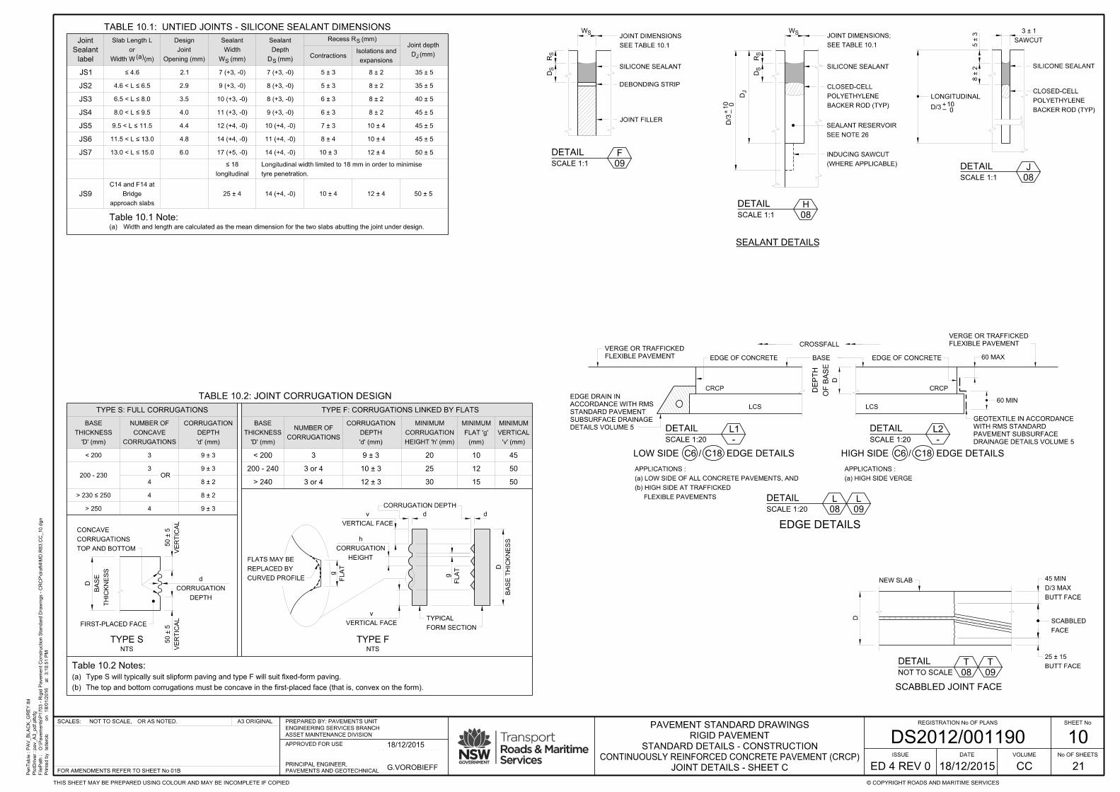
10
JOINT DETAILS - SHEET C
PenTable :
PlotDriver :
FilePath :
Printe
d b
y
3:1
0:5
1 P
Mat
18/0
1/2
016
on
PA
V_
BL
AC
K_
GR
EY.tbl
pav_
A3_pdf.pltcfg
O:\Pave
ments\P
1703 - Rigid P
ave
ment
Construction Sta
ndard Dra
win
gs - C
RC
P\draft4\M
D.R
83.C
C_10.d
gn
tetlero
b
SHEET No
No OF SHEETS
© COPYRIGHT ROADS AND MARITIME SERVICESTHIS SHEET MAY BE PREPARED USING COLOUR AND MAY BE INCOMPLETE IF COPIED
A3 ORIGINALOR AS NOTED.NOT TO SCALE,SCALES: REGISTRATION No OF PLANS
21
ISSUE
ED 4 REV 0 CC
VOLUMEDATE
DS2012/001190ASSET MAINTENANCE DIVISION
ENGINEERING SERVICES BRANCH
PREPARED BY: PAVEMENTS UNIT
APPROVED FOR USE
PAVEMENTS AND GEOTECHNICAL
PRINCIPAL ENGINEER,
FOR AMENDMENTS REFER TO SHEET No 01B
STANDARD DETAILS - CONSTRUCTION
RIGID PAVEMENT
PAVEMENT STANDARD DRAWINGS
CONTINUOUSLY REINFORCED CONCRETE PAVEMENT (CRCP)
G.VOROBIEFF
18/12/2015
18/12/2015
20 10
12
CORRUGATIONS
NUMBER OF
< 200
200 - 240
> 240 3 or 4
3 or 4
3 9 ± 3
10 ± 3
12 ± 3 30
25
15 50
50
45
FL
AT
g
CURVED PROFILE
REPLACED BY
FLATS MAY BE
d
HEIGHT
CORRUGATION
h
VERTICAL FACE
v
VERTICAL FACE
v
d
Table 10.2 Notes:
DEPTH
CORRUGATION
d
VE
RTIC
AL
50 ± 5
VE
RTIC
AL
50 ± 5
BA
SE
D
THIC
KN
ES
S
FIRST-PLACED FACE
CORRUGATIONS
CONCAVE
NUMBER OF
< 200
200 - 230
3 9 ± 3
9 ± 3
8 ± 2
TOP AND BOTTOM
CORRUGATIONS
CONCAVE
TYPE S: FULL CORRUGATIONS
8 ± 2
> 250 9 ± 3
3
4
4
4
OR
TYPE SNTS
'D' (mm)
THICKNESS
BASE
'd' (mm)
DEPTH
CORRUGATION
TABLE 10.2: JOINT CORRUGATION DESIGN
The top and bottom corrugations must be concave in the first-placed face (that is, convex on the form).(b)
Type S will typically suit slipform paving and type F will suit fixed-form paving.(a)
TYPE F: CORRUGATIONS LINKED BY FLATS
> 230 ≤ 250
BA
SE T
HIC
KN
ES
S
D
FL
AT
g'D' (mm)
THICKNESS
BASE
'd' (mm)
DEPTH
CORRUGATION
HEIGHT 'h' (mm)
CORRUGATION
MINIMUM
(mm)
FLAT 'g'
MINIMUM
'v' (mm)
VERTICAL
MINIMUM
FORM SECTION
TYPICAL
CORRUGATION DEPTH
TYPE FNTS
NEW SLAB
FACE
SCABBLED
D
BUTT FACE
D/3 MAX
45 MIN
BUTT FACE
25 ± 15
SCABBLED JOINT FACE
T
09
DETAIL
NOT TO SCALE
T
08
D (mm)
Joint depth
4.6 < L ≤ 6.5
6.5 < L ≤ 8.0
8.0 < L ≤ 9.5
≤ 4.6 2.1
9.5 < L ≤ 11.5
11.5 < L ≤ 13.0
13.0 < L ≤ 15.0
2.9
3.5
4.0
4.4
4.8
6.0
7 (+3, -0)
9 (+3, -0)
10 (+3, -0)
11 (+3, -0)
12 (+4, -0)
14 (+4, -0)
17 (+5, -0) 14 (+4, -0)
11 (+4, -0)
10 (+4, -0)
9 (+3, -0)
8 (+3, -0)
8 (+3, -0)
7 (+3, -0)
25 ± 4 14 (+4, -0)
5 ± 3
5 ± 3
6 ± 3
6 ± 3
7 ± 3
8 ± 4
10 ± 3
8 ± 2
8 ± 2
8 ± 2
8 ± 2
10 ± 4
10 ± 4
12 ± 4
10 ± 4 12 ± 4 50 ± 5
50 ± 5
45 ± 5
45 ± 5
45 ± 5
40 ± 5
35 ± 5
35 ± 5
(a)S S
longitudinal
≤ 18
tyre penetration.
Longitudinal width limited to 18 mm in order to minimise
Contractions
S
J
Recess R (mm)
Width W (m)
or
Slab Length L
Opening (mm)
Joint
Design
W (mm)
Width
Sealant
D (mm)
Depth
Sealant
expansions
Isolations and
TABLE 10.1: UNTIED JOINTS - SILICONE SEALANT DIMENSIONS
DEBONDING STRIP
JOINT FILLER
SW
DS
RS
BACKER ROD (TYP)
POLYETHYLENE
CLOSED-CELL
W S
DJ
DS
RS
SAWCUT
3 ± 1
BACKER ROD (TYP)
POLYETHYLENE
CLOSED-CELL
D/3
LONGITUDINAL
Table 10.1 Note:
approach slabs
Bridge
C14 and F14 at
Width and length are calculated as the mean dimension for the two slabs abutting the joint under design.(a)
(WHERE APPLICABLE)
INDUCING SAWCUT
SEE TABLE 10.1
JOINT DIMENSIONS
SEE TABLE 10.1
JOINT DIMENSIONS;
5 ± 3
8 ± 2
JS1
JS2
JS3
JS4
JS5
JS6
JS7
label
Sealant
Joint
JS9
SEE NOTE 26
SEALANT RESERVOIR
SEALANT DETAILS
DETAIL
SCALE 1:1
H
08
DETAIL
SCALE 1:1
F
09 DETAIL
SCALE 1:1
J
08
SILICONE SEALANT SILICONE SEALANT
D/3
010
+ –
SILICONE SEALANT
010+
–
LOW SIDE / EDGE DETAILS HIGH SIDE
D
OF B
AS
E
DE
PT
H
EDGE OF CONCRETE
EDGE DETAILS
DETAIL
SCALE 1:20
L1
-
DETAIL
SCALE 1:20
L2
-
DETAIL
SCALE 1:20
L
08
CRCP CRCP
LCS LCS
C6 C18
FLEXIBLE PAVEMENTS
(b) HIGH SIDE AT TRAFFICKED
(a) LOW SIDE OF ALL CONCRETE PAVEMENTS, AND
APPLICATIONS :
(a) HIGH SIDE VERGE
APPLICATIONS :
/ EDGE DETAILSC6 C18
L
09
60 MAX
60 MIN
CROSSFALL
EDGE OF CONCRETEBASE
DRAINAGE DETAILS VOLUME 5
PAVEMENT SUBSURFACE
WITH RMS STANDARD
GEOTEXTILE IN ACCORDANCE
DETAILS VOLUME 5
SUBSURFACE DRAINAGE
STANDARD PAVEMENT
ACCORDANCE WITH RMS
EDGE DRAIN IN
FLEXIBLE PAVEMENT
VERGE OR TRAFFICKED
FLEXIBLE PAVEMENT
VERGE OR TRAFFICKED

11
REINFORCEMENT DETAILS - SHEET A
PenTable :
PlotDriver :
FilePath :
Printe
d b
y
3:1
0:5
2 P
Mat
18/0
1/2
016
on
PA
V_
BL
AC
K_
GR
EY.tbl
pav_
A3_pdf.pltcfg
O:\Pave
ments\P
1703 - Rigid P
ave
ment
Construction Sta
ndard Dra
win
gs - C
RC
P\draft4\M
D.R
83.C
C_11.d
gn
tetlero
b
SHEET No
No OF SHEETS
© COPYRIGHT ROADS AND MARITIME SERVICESTHIS SHEET MAY BE PREPARED USING COLOUR AND MAY BE INCOMPLETE IF COPIED
A3 ORIGINALOR AS NOTED.NOT TO SCALE,SCALES: REGISTRATION No OF PLANS
21
ISSUE
ED 4 REV 0 CC
VOLUMEDATE
DS2012/001190ASSET MAINTENANCE DIVISION
ENGINEERING SERVICES BRANCH
PREPARED BY: PAVEMENTS UNIT
APPROVED FOR USE
PAVEMENTS AND GEOTECHNICAL
PRINCIPAL ENGINEER,
FOR AMENDMENTS REFER TO SHEET No 01B
STANDARD DETAILS - CONSTRUCTION
RIGID PAVEMENT
PAVEMENT STANDARD DRAWINGS
CONTINUOUSLY REINFORCED CONCRETE PAVEMENT (CRCP)
G.VOROBIEFF
18/12/2015
18/12/2015
MARK DIA SHAPE LOCATION / DESCRIPTION LENGTH (m) SPACING (mm)
TABLE 11.1: REINFORCEMENT SCHEDULE AND BAR SPACING
N12A2 1 Transverse bars above anchors To suit slab width 350 c/c, 6 per anchor(a)
N12 1.0E1 1 See jointing plan and Table 12.1
E2 N12 7 1.0(b) See jointing plan and Table 12.1
E4 N12 1 or 22 Drilled tiebars (drill-ties) in longitudinal joint C2d 0.75 See jointing plan and Table 12.1
E5 N12 or N16 1 1.0 See Table 11.5
N12E6 1 or 22 0.75
F N16 4 Anchor stirrup -
G1 N16 3 -
H N16 1 Anchor bars 6 per anchor
J1 N12 21 1.0 1 000 ± 50
N12 1.0 1 000 ± 50J2 1
J3 N12 5 Kerb types SF and SM 0.5 500 MAX; See note 35
K N20 6 3.0
M1 MESH - -SL82. PCP-R general -
M2 MESH - - -
Table 11.1 Notes:
6
TABLE 11.2: BAR REINFORCEMENT SHAPES
NOTE (c)
SEE
N
SHAPE
STRENGTH
DUCTILITY
BAR
500
etc
N12, N16
L
MESH
500
RL818 etc
SL82, SL92,
DOWELS FIBRE
2-E1-N12-1000-300
Number of bars in the set. Used only where applicable.
*
L
L/2 L/2 250
175
121
22
5
300
4
250500 500250
400
250
500
3
350 350
500
100
150
50
300300
50
150
500 ± 75500 ± 75
JOINTC
SEE NOTE (d)
30 MIN
7
A1 1 To suit slab widthN12 or N16 CRCP: Transverse bars See Table 12.1
L1 N16 1 at 3 x 'C' bar centres12.0 TYP and MINAdditional C-N16 bars abutting joints C7 and C7d
Kerb types SE and SL longitudinal joints. See Note 6(b).
Kerb types SA, SB, SO and SK longitudinal joints.
Anchor stirrup300Jointed :
at 'C' bar centresCRCP :
300Jointed :
at 'C' bar centresCRCP :
Clustered drill-ties in C2p joints See Note (d) and Figure 12.1
N12 1.0E3 1between CRCP and PCP
Tiebars (clustered) in longitudinal joint C2p
Use E6 if drilled
See Note (d) and Figure 12.1
Tiebars in longitudinal joints alternative to E1 for joint C1
Tiebars in longitudinal joints E2 is acceptable in C1 joints
D2 1
D1 8
N16 CRCP: Anchors 2 and 3 2.0 min at 'C' bar centres
N16 CRCP: Anchor 1 2.0 min at 'C' bar centres
C 1N16 12.0 min
B3 1N16 12.0 min
B2 N16 at 'C' bar centres
B1 1N16 Variable at 'C' bar centres
CRCP: Longitudinal bars Note (c)
CRCP: Transitions in slab width One bar along transition edge
1 or 23 CRCP: Longitudinal bars in C7d joints
CRCP: Longitudinal bars - terminal ends
Bridge approach anchor slabs. Varies with L See Table 11.5L
-
To suit slab width See note 14
FIGURE 11.2: BAR MARKING LEGEND
23
MIN
300
8
700600700
SEE NOTE (e)
TABLE 11.3: REINFORCEMENT NOTATION
'NA' denotes not applicable.●
Fig 4.1 shows a typical jointing plan.●
the spacing from the project-specific jointing plan.
Where 'JP' is used in lieu of a dimension, take●
Spacing.
Where ' ' is shown, refer to Table 11.1.
Bar length in millimetres.
Bar designation, in accordance with Table 11.3.
Bar mark, in accordance with Table 11.1.
DEFORMED
DEFORMED
ROUND OR
CP OR CJ
DRAWINGS
SEE
DRAWINGS
USED IN
NOTATION
TABLE 11.4: REINFORCEMENT COVER
Measure Dimension (mm)
A1, A2
C, L1
B1, B2
D1, D2
Top
Sides and edges
Ends
Top
Sides
Ends
Bottom
Sides
Bar Mark
(a)
Tied under B1, B2, C, L1
(b)
(c)
(d)
100 ± 10D ≥ 200 :
D < 200 : 90 ± 10
110 ± 30
60 MIN
60 MIN
60 MIN, 120 MAX
80 ± 20
110 ± 30(d)
Table 11.4 Notes:
Measured to bar centre.(d)
at a transverse untied joint such as a C14 or C15.
An example of an "end" is where these bars terminate(c)
alongside a transverse joint such as a C7, C14 or C15.
An example of an "end" is where these bars are located(b)
Sides and edges relate to longitudinal orientation.(a)
(m)
L
Length
250 350
(a)F
(b)
< 9.0 300 [550] 300 [550]
300 [550] 225 [400]
250 [450] 175 [300]
200 [350] 125 [225]
> 20.0
9.0 - 11.9
12.0 - 15.9
16.0 - 20.0
Specialist design is required
250 350
(c)
15.0
SL92
16.5
SL81
23.0
SL81
16.5
SL81
23.0
SL81
25.0
SL81 x 3(d)
Table 11.5 Notes:
F
limit on RED (m)
Mesh M2 Upper
Specialist design is required
M3 MESH - - -Subgrade beams. SL92 or L8TM
Tiebars in joints F72
1 500 MIN
VARIES
Variable to suit lap skew, 1.8 min
TY
PE 1
2 : 1
350
Table 11.2 Notes:
slab (mm)
Thickness of terminal(e) slab (mm)
Thickness of terminal(e)
R83
RMS
SEE
All dimensions are to intersections of straight portions at outside of bends.(b)
Bending pin diameter to be 5 times bar diameter.(a)
05
NSee Detail(c)
Offset to match step in subbase if required; see Note 15.(e)
Or as required to meet cover requirements under the sawcut.(d)
Acute corners incl. SFCP-R terminal slabs
SEE NOTE 6(c)
10° MAX
SEE NOTE 6(c)
10° MAXSEE NOTE (f)
500
for definition of corner angle, Φ°
(mm) N12 [N16]
E5 Tiebar spacing F72
2Φ°/3
1 500
1 500
20 for SO and SK=
8 for SA and SB=(f)
Thickness = concrete base + asphalt surfacing.(e)
at top or bottom to suit construction logistics.
Three sheets of mesh are required. The third sheet may be placed(d)
For higher RED a mesh with increased transverse capacity is required.
This is the safe upper limit on RED for the specific cell parameters.(c)
Designers may nominate either bar option.(b)
See Sheets CC-05 and CC-06. L is measured at the longest edge.(a)
BRIDGE APPROACHES; REINFORCEMENT AND TIEBARS
TABLE 11.5: TERMINAL SLAB SFCP-R ATA2 bars need not be continuous across longitudinal joints.(a)
E2 tiebars must be securely fixed against rotation during paving.(b)
For E3 and E6 ties, calculate the number of ties required (Figure. 12.1) then locate them within the middle third of the PCP slab length.(d)
See Note 4(b) Sheet CC-03.(c)
N12 Bent to suit on siteJ4 1 Kerb types SA, SB, SE, SL, SO and SK longitudinal joints. Variable
F
L
OR O
TH
ER R
ELIE
F E
DG
E
L
PAVEMENT
APPROACH
BRIDGE
F L
L
F14
A
A
F72
AN
CH
OR 1
E5 tiebars
FIGURE 11.1
NTS
SEE SHEET CC-06 AND TABLE 11.5 FOR DIMENSIONS L AND L

12
REINFORCEMENT DETAILS - SHEET B
PenTable :
PlotDriver :
FilePath :
Printe
d b
y
3:1
0:5
3 P
Mat
18/0
1/2
016
on
PA
V_
BL
AC
K_
GR
EY.tbl
pav_
A3_pdf.pltcfg
O:\Pave
ments\P
1703 - Rigid P
ave
ment
Construction Sta
ndard Dra
win
gs - C
RC
P\draft4\M
D.R
83.C
C_12.d
gn
tetlero
b
SHEET No
No OF SHEETS
© COPYRIGHT ROADS AND MARITIME SERVICESTHIS SHEET MAY BE PREPARED USING COLOUR AND MAY BE INCOMPLETE IF COPIED
A3 ORIGINALOR AS NOTED.NOT TO SCALE,SCALES: REGISTRATION No OF PLANS
21
ISSUE
ED 4 REV 0 CC
VOLUMEDATE
DS2012/001190ASSET MAINTENANCE DIVISION
ENGINEERING SERVICES BRANCH
PREPARED BY: PAVEMENTS UNIT
APPROVED FOR USE
PAVEMENTS AND GEOTECHNICAL
PRINCIPAL ENGINEER,
FOR AMENDMENTS REFER TO SHEET No 01B
STANDARD DETAILS - CONSTRUCTION
RIGID PAVEMENT
PAVEMENT STANDARD DRAWINGS
CONTINUOUSLY REINFORCED CONCRETE PAVEMENT (CRCP)
G.VOROBIEFF
18/12/2015
18/12/2015
(b)
2.8 3.0 3.2 3.4 3.6 3.8 4.0 4.2 4.4
(d)
(d)
(e)
(e)
(a) (c)
BASE THICKNESS 'D' (mm)
180 200 220 240 260 280
< 3.1
3.1 - 3.5
3.6 - 4.0
4.1 - 4.5
4.6 - 5.0
5.1 - 5.5
5.6 - 6.0
6.1 - 6.5
6.6 - 7.0
7.1 - 7.5
7.6 - 8.0
Tiebar spacing / A1 Bar spacing
300
400
500
600
700
800
900
1000
1100
1200
1300
1400
(a)
Avera
ge Tie
bar Spacin
g (
mm)
Case 1
Case 1
Case 2
Case 2
PCP Slab Length (m)
Maximum allowable spacing 1 400 mm
FIGURE 12.1: TIEBAR NUMBERS IN JOINT C2p AND IN PCP
9
8
7
6
5
4
3
Figure 12.1 Notes:
TABLE 12.1: SPACING OF A1 BARS AND TIEBARS E1 AND E2
Table 12.1 Notes:
(m)
(RED)
Distance
Relief-edge
(mm)
size
Bar
8.1 - 9.0
9.1 - 10.0
10.1 - 11.0
11.1 - 12.0
12.1 - 13.0
13.1 - 14.0
> 14.0
N16
N12
1400 / 750
1400 / 750
850 / 750
600
700
1150 / 750
1400 / 750
700
600
500
700
550
700
850 / 750
500
600
550
600
Specialist design is required
1280 / 750
1130 / 750
1020 / 750
930 / 750
790 / 750
730
680
640
1030 / 750
930 / 750
840 / 750
770 / 750
710
660
1310 / 750
1020 / 750
920 / 750
840 / 750
770 / 750
710
660
610
570
930 / 750
840 / 750
760 / 750
640
1390 / 750
1190 / 750
1040 / 750
930 / 750
840 / 750
760 / 750
640
560
520
840 / 750
760 / 750
690
630
580
540
1280 / 750
1090 / 750
960 / 750
770 / 750
640
590
510
480
770 / 750
630
580
540
1180 / 750
1010 / 750
880 / 750
790 / 750
710
640
590
540
510
470
440
710
640
580
540
490
460
1090 / 750
940 / 750
820 / 750
730
660
510
470
440
410
660
540
460
430
This figure applies also to PCP-R.(d)
in Type P joints: adjust spacings in accordance with the Volume CP to achieve clearance from adjacent P8 joints.(ii)
in C2p joints: the tiebars must be clustered; see CC-08;(i)
Actual tiebar spacings are then adjusted as follows:(c)
5 tiebars per slab.
no futher tolerance is allowed. Where a value falls on a boundary line, the lesser value may apply. For example, Case 2 requires only
The theoretical designs are indicated by the dashed lines. Design tolerances have been applied to derive the shaded zones hence(b)
design is required for PCP where RED exceeds 8.0m.)
"Average" tiebar spacings are determined from Table 12.1 or from Drawing CP-07. (With reference to Table 12.1, note that specialist(a)Designers may nominate alternative A1-N16 bars at spacings which are increased in proportion to the sectional area, that is 200/110=1.8(e)
The value for RED must make allowances for stress contributors such as connected kerbs and future widening. See also Figure 16.2.
Relief-edge distance (RED) is measured from the joint (or section) under design to the nearest relief edge.(d)
Where only one number is provided, it applies to tiebars and to 'A1' bars.(c)
density of reinforced concrete = 2440 kg/m³.
Base Thickness = Concrete Base + asphalt surfacing. Spacing based on 12 mm deformed 500N steel, interlayer friction µ = 1.5 and(b)
'A1' bar spacings are maximised at 750 to meet support criteria for the longitudinal steel.(a)
LONGITUDINAL JOINT
LONGITUDINAL JOINT
600
Table 12.2 Notes:
TABLE 12.2: LAP OPTIONS FOR B1, B2 AND C BARS
This lap pattern is conformingMIN
LAP 525
MIN
LAP 525
MIN
LAP 525
MIN
SPACE 600
TEST BOX
FIGURE 12.2.1: 12-BAR CYCLE FIGURE 12.2.2: 6-BAR CYCLE FIGURE 12.2.3: 3-BAR CYCLE FIGURE 12.2.4: TEST BOX
within a test box as shown in Figure 12.2.4.
the layout must not result in more than one-third of laps falling(f)
patterns may vary across longitudinal and transverse joints;(e)
slab width as bounded by longitudinal joints;
the patterns must be consistent (that is, repeating) within any(d)
drawings;
patterns must be specified (defined) in the approved project(c)
or 525 mm min for N16 bars;
lap lengths must be a minimum of 33 bar diameters,(b)
conditions:
Alternative patterns may be used subject to the following
The three patterns shown left are suggested common layouts.(a)
D
TIEBARMESH M1
T
T
T
B
T
B
MESH ROTATION; SEE NOTE (a)
TABLE 12.3: COVER TO MESH M1 AND TIEBARS
Minimum covers (mm)
Mesh Tiebars
D (mm)
Base depth
T B
180
200
220
240
260
280
60
60
70
70
80
80
80
90
60
70
70
80
90
70
80
90100
110
120
130 100
100
110
120
Table 12.3 Note:
M
Top cover
M
Bottom cover
T BT
Top cover
T
Bottom cover
M
M
mesh cover.
For base depth between values use next thicker base depth for(b)
factors such as lapping requirements.
below the transverse bars, unless the rotation is dictated by other
Mesh M1 can be placed with longitudinal bars either above or(a)
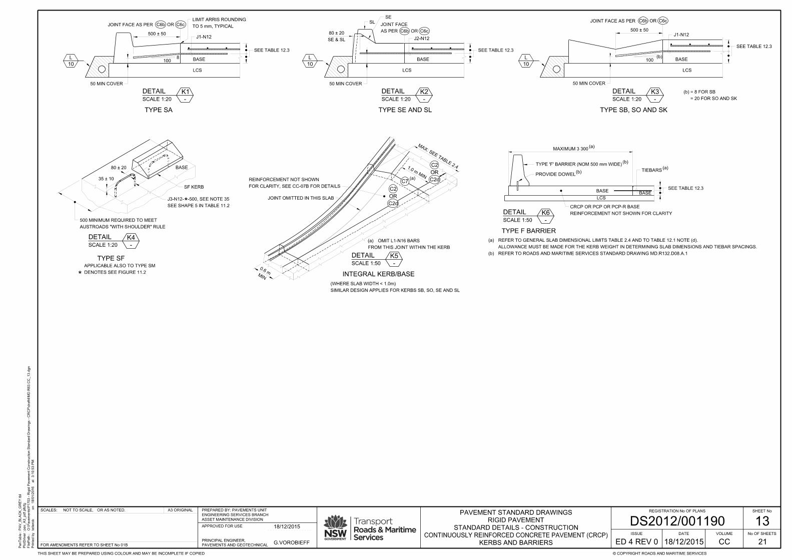
PenTable :
PlotDriver :
FilePath :
Printe
d b
y
3:1
0:5
3 P
Mat
18/0
1/2
016
on
PA
V_
BL
AC
K_
GR
EY.tbl
pav_
A3_pdf.pltcfg
O:\Pave
ments\P
1703 - Rigid P
ave
ment
Construction Sta
ndard Dra
win
gs - C
RC
P\draft4\M
D.R
83.C
C_13.d
gn
tetlero
b
SHEET No
No OF SHEETS
© COPYRIGHT ROADS AND MARITIME SERVICESTHIS SHEET MAY BE PREPARED USING COLOUR AND MAY BE INCOMPLETE IF COPIED
A3 ORIGINALOR AS NOTED.NOT TO SCALE,SCALES: REGISTRATION No OF PLANS
21
ISSUE
ED 4 REV 0 CC
VOLUMEDATE
DS2012/001190ASSET MAINTENANCE DIVISION
ENGINEERING SERVICES BRANCH
PREPARED BY: PAVEMENTS UNIT
APPROVED FOR USE
PAVEMENTS AND GEOTECHNICAL
PRINCIPAL ENGINEER,
FOR AMENDMENTS REFER TO SHEET No 01B
STANDARD DETAILS - CONSTRUCTION
RIGID PAVEMENT
PAVEMENT STANDARD DRAWINGS
CONTINUOUSLY REINFORCED CONCRETE PAVEMENT (CRCP)
G.VOROBIEFF
18/12/2015
18/12/2015
DETAIL
SCALE 1:20
K1
-
BASE
DETAIL
SCALE 1:20
K2
-
TYPE SE AND SL
DETAIL
SCALE 1:20
K3
-
TYPE SB, SO AND SKTYPE SA
L
10
L
10
L
10
BASE
SF KERB
35 ± 10
DETAIL
SCALE 1:20
K4
-
8100 BASE100BASE
SE & SL
80 ± 20
80 ± 20
TO 5 mm, TYPICAL
LIMIT ARRIS ROUNDING
TYPE SF
APPLICABLE ALSO TO TYPE SM
*
LCS LCS LCS
*DENOTES SEE FIGURE 11.2
ORC6b C6c
500 ± 50
JOINT FACE AS PER
SEE TABLE 12.3
SEE TABLE 12.3
SEE TABLE 12.3
(b)
= 20 FOR SO AND SK
= 8 FOR SB(b)
ORC6b C6cJOINT FACE AS PER
500 ± 50ORC6b C6c
SE
AS PER
JOINT FACESL
SEE SHAPE 5 IN TABLE 11.2
J3-N12- -500, SEE NOTE 35
50 MIN COVER50 MIN COVER 50 MIN COVER
AUSTROADS "WITH SHOULDER" RULE
500 MINIMUM REQUIRED TO MEET
J1-N12 J2-N12J1-N12
MAXIMUM 3 300(a)
SEE TABLE 12.3
TIEBARS(a)
BASEBASE
LCS
TYPE 'F' BARRIER (NOM 500 mm WIDE)(b)
PROVIDE DOWEL(b)
TYPE F BARRIER
REFER TO ROADS AND MARITIME SERVICES STANDARD DRAWING MD.R132.D08.A.1(b)
ALLOWANCE MUST BE MADE FOR THE KERB WEIGHT IN DETERMINING SLAB DIMENSIONS AND TIEBAR SPACINGS.
REFER TO GENERAL SLAB DIMENSIONAL LIMITS TABLE 2.4 AND TO TABLE 12.1 NOTE (d).(a)
DETAIL
SCALE 1:50
K6
-
REINFORCEMENT NOT SHOWN FOR CLARITY
CRCP OR PCP OR PCP-R BASE
MIN
0.6 m
JOINT OMITTED IN THIS SLAB
C2
INTEGRAL KERB/BASE
SIMILAR DESIGN APPLIES FOR KERBS SB, SO, SE AND SL
(WHERE SLAB WIDTH < 1.0m)
DETAIL
SCALE 1:50
K5
-
FROM THIS JOINT WITHIN THE KERB
OMIT L1-N16 BARS(a)
(a)C7
1.0 m MIN
MAX: SEE TABLE 2.4
FOR CLARITY, SEE CC-07B FOR DETAILS
REINFORCEMENT NOT SHOWN
OR
C2
C2d
OR
C2d
13
KERBS AND BARRIERS
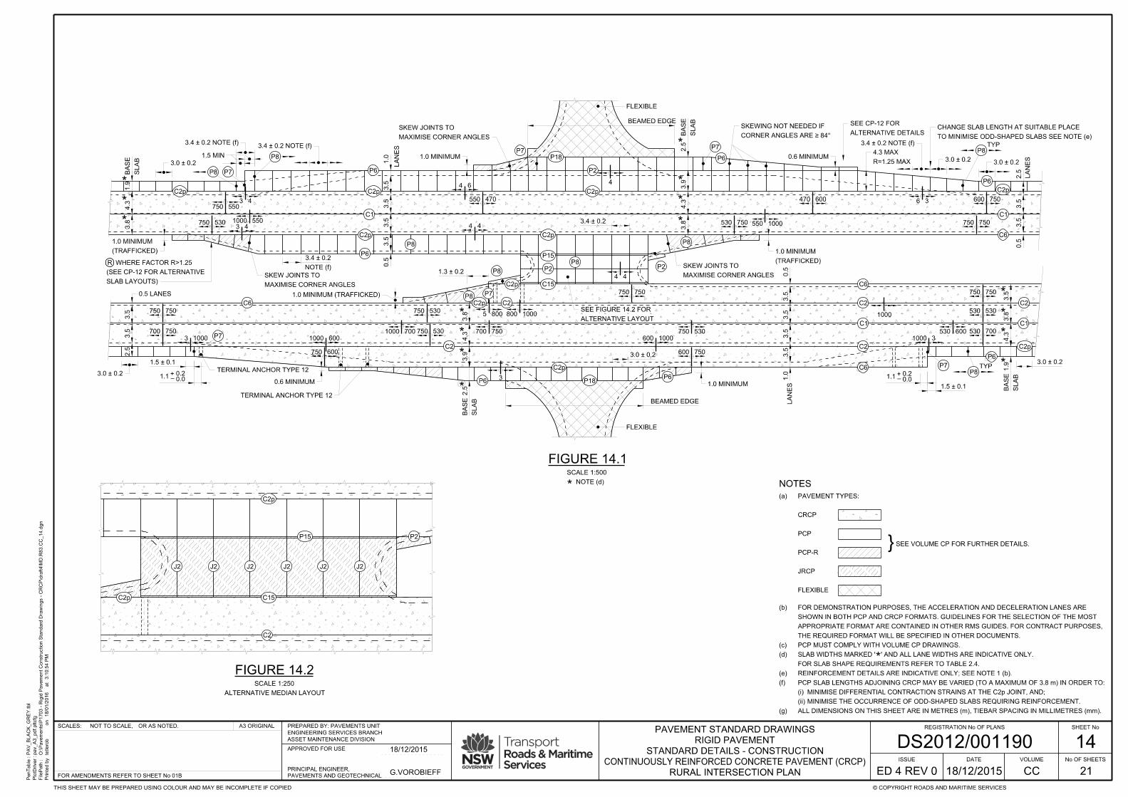
PenTable :
PlotDriver :
FilePath :
Printe
d b
y
3:1
0:5
4 P
Mat
18/0
1/2
016
on
PA
V_
BL
AC
K_
GR
EY.tbl
pav_
A3_pdf.pltcfg
O:\Pave
ments\P
1703 - Rigid P
ave
ment
Construction Sta
ndard Dra
win
gs - C
RC
P\draft4\M
D.R
83.C
C_14.d
gn
tetlero
b
SHEET No
No OF SHEETS
© COPYRIGHT ROADS AND MARITIME SERVICESTHIS SHEET MAY BE PREPARED USING COLOUR AND MAY BE INCOMPLETE IF COPIED
A3 ORIGINALOR AS NOTED.NOT TO SCALE,SCALES: REGISTRATION No OF PLANS
21
ISSUE
ED 4 REV 0 CC
VOLUMEDATE
DS2012/001190ASSET MAINTENANCE DIVISION
ENGINEERING SERVICES BRANCH
PREPARED BY: PAVEMENTS UNIT
APPROVED FOR USE
PAVEMENTS AND GEOTECHNICAL
PRINCIPAL ENGINEER,
FOR AMENDMENTS REFER TO SHEET No 01B
STANDARD DETAILS - CONSTRUCTION
RIGID PAVEMENT
PAVEMENT STANDARD DRAWINGS
CONTINUOUSLY REINFORCED CONCRETE PAVEMENT (CRCP)
G.VOROBIEFF
18/12/2015
18/12/2015
4.3
3.8*
*
1.9*
3.0 ± 0.2
C2p
P7
1.5 MIN
3.4 ± 0.2 NOTE (f)
P8
3.4 ± 0.2 NOTE (f)
C2p
C1
C2p
P6
3.5
3.5
3.5
3.5
0.5
1.0
LA
NE
S
SL
AB
BA
SE
C2p
P7
*
*
3.9
4.3
3.8*
R=1.25 MAX
4.3 MAX
3.4 ± 0.2 NOTE (f)
3.0 ± 0.2
TO MINIMISE ODD-SHAPED SLABS SEE NOTE (e)
CHANGE SLAB LENGTH AT SUITABLE PLACE
3.0 ± 0.2
0.5
LA
NE
S
2.5
3.5
3.5
TYPP8
P6
C6
C1
C2p
600 750
750 750
470 600
550 1000530 750
550 470
4 4
3 4750 550
1000 550750 5303 4
R
SLAB LAYOUTS)
(SEE CP-12 FOR ALTERNATIVE
WHERE FACTOR R>1.25
C2p
P7P8
P8
C2p C15
P2
P15
C2p
P8
3.5
3.5
2.5
3.0 ± 0.2
1.5 ± 0.1
P73 1000
750 750
700 750
0.5 LANES
750 600
1000 600
1000 700
750 530
750 530
C2p
P18
C2
C2
C1
C2p
C2
P6
P7
P8
P8
4 4
P2
P8
5 800 800 1000
750 750 750 750
3.5
3.8
4.3*
*
*
1.9
SL
AB
BA
SE
*
530 530
530 700530 600
1000
1000 3
1.5 ± 0.1
TYPP8
C6
C2
C1
C2
C6
1.0
0.5
LA
NE
S3.5
3.5
3.5
3.5600 750
600 1000
750 530700 750
3
SL
AB
BA
SE
2.5*
3.8
4.3
3.9*
*
*
NOTE (d)*
SCALE 1:500
FIGURE 14.1
3.0 ± 0.2
3.0 ± 0.2
NOTE (f)
3.4 ± 0.2
MAXIMISE CORNER ANGLES
SKEW JOINTS TO
TERMINAL ANCHOR TYPE 12
TERMINAL ANCHOR TYPE 12
ALTERNATIVE LAYOUT
SEE FIGURE 14.2 FOR
MAXIMISE CORNER ANGLES
SKEW JOINTS TO
CORNER ANGLES ARE ≥ 84°
SKEWING NOT NEEDED IF
3.4 ± 0.2
6 3
4 6
P6
P6P6
(TRAFFICKED)
1.0 MINIMUM
ALTERNATIVE DETAILS
SEE CP-12 FOR
1.3 ± 0.2
C6
1.0 MINIMUM (TRAFFICKED)
(TRAFFICKED)
1.0 MINIMUM
BEAMED EDGE
FLEXIBLE
0.6 MINIMUM
1.0 MINIMUM
1.0 MINIMUM
0.6 MINIMUMP7
P2
2.5*
SL
AB
BA
SE
4
MAXIMISE CORNER ANGLES
SKEW JOINTS TO
BEAMED EDGE
FLEXIBLE
P6
P18
+–1.1
0.00.2
+–1.1
0.00.2
SCALE 1:250
FIGURE 14.2
C2p C15
C2p
C2
P2P15
J2 J2 J2 J2 J2 J2
ALTERNATIVE MEDIAN LAYOUT
14
RURAL INTERSECTION PLAN
NOTES
}SEE VOLUME CP FOR FURTHER DETAILS.
FLEXIBLE
JRCP
PCP-R
PCP
CRCP
PAVEMENT TYPES:(a)
*
ALL DIMENSIONS ON THIS SHEET ARE IN METRES (m), TIEBAR SPACING IN MILLIMETRES (mm).(g)
MINIMISE THE OCCURRENCE OF ODD-SHAPED SLABS REQUIRING REINFORCEMENT.(ii)
MINIMISE DIFFERENTIAL CONTRACTION STRAINS AT THE C2p JOINT, AND;(i)
PCP SLAB LENGTHS ADJOINING CRCP MAY BE VARIED (TO A MAXIMUM OF 3.8 m) IN ORDER TO:(f)
REINFORCEMENT DETAILS ARE INDICATIVE ONLY; SEE NOTE 1 (b).(e)
FOR SLAB SHAPE REQUIREMENTS REFER TO TABLE 2.4.
SLAB WIDTHS MARKED ' ' AND ALL LANE WIDTHS ARE INDICATIVE ONLY.(d)
PCP MUST COMPLY WITH VOLUME CP DRAWINGS.(c)
THE REQUIRED FORMAT WILL BE SPECIFIED IN OTHER DOCUMENTS.
APPROPRIATE FORMAT ARE CONTAINED IN OTHER RMS GUIDES. FOR CONTRACT PURPOSES,
SHOWN IN BOTH PCP AND CRCP FORMATS. GUIDELINES FOR THE SELECTION OF THE MOST
FOR DEMONSTRATION PURPOSES, THE ACCELERATION AND DECELERATION LANES ARE(b)
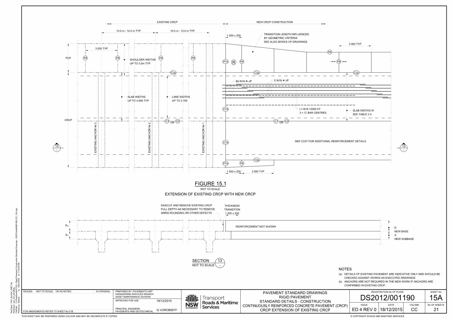
PenTable :
PlotDriver :
FilePath :
Printe
d b
y
3:1
0:5
5 P
Mat
18/0
1/2
016
on
PA
V_
BL
AC
K_
GR
EY.tbl
pav_
A3_pdf.pltcfg
O:\Pave
ments\P
1703 - Rigid P
ave
ment
Construction Sta
ndard Dra
win
gs - C
RC
P\draft4\M
D.R
83.C
C_15
A.d
gn
tetlero
b
SHEET No
No OF SHEETS
© COPYRIGHT ROADS AND MARITIME SERVICESTHIS SHEET MAY BE PREPARED USING COLOUR AND MAY BE INCOMPLETE IF COPIED
A3 ORIGINALOR AS NOTED.NOT TO SCALE,SCALES: REGISTRATION No OF PLANS
21
ISSUE
ED 4 REV 0 CC
VOLUMEDATE
DS2012/001190ASSET MAINTENANCE DIVISION
ENGINEERING SERVICES BRANCH
PREPARED BY: PAVEMENTS UNIT
APPROVED FOR USE
PAVEMENTS AND GEOTECHNICAL
PRINCIPAL ENGINEER,
FOR AMENDMENTS REFER TO SHEET No 01B
STANDARD DETAILS - CONSTRUCTION
RIGID PAVEMENT
PAVEMENT STANDARD DRAWINGS
CONTINUOUSLY REINFORCED CONCRETE PAVEMENT (CRCP)
G.VOROBIEFF
18/12/2015
18/12/2015
C7d
R
13
-
13
-
UP TO 3.0m TYP
SHOULDER WIDTHS
UP TO 3 700
LANE WIDTHS
FIGURE 15.1
UP TO 4 600 TYP
SLAB WIDTHS
S1
D1
NEW BASE
D
NEW SUBBASE
S
NOT TO SCALE
SECTION
NOT TO SCALE -
13
EXIS
TIN
G A
NC
HO
R № 1
C1 C2OR
EXIS
TIN
G A
NC
HO
R № 2
EXIS
TIN
G A
NC
HO
R № 3
EXISTING CRCP
C1 C2OR
C2p
P8P8P8P8
3 000 TYP
CRCP
PCP
10.0 m - 12.0 m TYP 10.0 m - 12.0 m TYP
C7d
P7d
P7d P8 P8
C2pC2p
3 000 TYP
P6
SEE TABLE 2.4
SLAB WIDTHS W
C2p
3 000 TYP1 500 ± 200
NEW CRCP CONSTRUCTION
1 500 ± 200
EXTENSION OF EXISTING CRCP WITH NEW CRCP
B2-N16- -JP*C-N16- -JP*
3 × 'C' BAR CENTRES
L1-N16-12000 AT
P8
TRANSITION
THICKNESS
1 200 ± 200
REINFORCEMENT NOT SHOWN
SEE CC07 FOR ADDITIONAL REINFORCEMENT DETAILS
ARRIS ROUNDING OR OTHER DEFECTS
FULL DEPTH AS NECESSARY TO REMOVE
SAWCUT AND REMOVE EXISTING CRCP
SEE ALSO SERIES CP DRAWINGS.
BY GEOMETRIC CRITERIA
TRANSITION LENGTH INFLUENCED
NOTES
CONFIRMED IN EXISTING CRCP.
ANCHORS ARE NOT REQUIRED IN THE NEW WORK IF ANCHORS ARE(b)
CHECKED AGAINST WORKS-AS-EXECUTED DRAWINGS.
DETAILS OF EXISTING PAVEMENT ARE INDICATIVE ONLY AND SHOULD BE(a)
15A
CRCP EXTENSION OF EXISTING CRCP
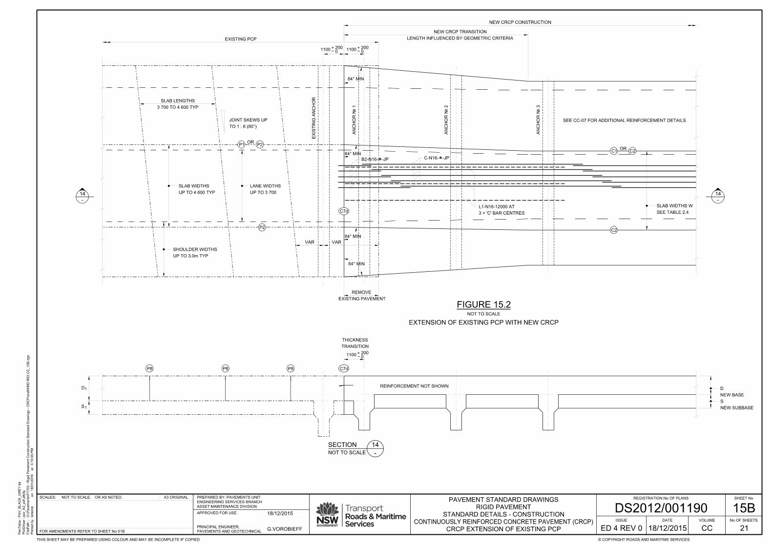
PenTable :
PlotDriver :
FilePath :
Printe
d b
y
3:1
0:5
5 P
Mat
18/0
1/2
016
on
PA
V_
BL
AC
K_
GR
EY.tbl
pav_
A3_pdf.pltcfg
O:\Pave
ments\P
1703 - Rigid P
ave
ment
Construction Sta
ndard Dra
win
gs - C
RC
P\draft4\M
D.R
83.C
C_15
B.d
gn
tetlero
b
SHEET No
No OF SHEETS
© COPYRIGHT ROADS AND MARITIME SERVICESTHIS SHEET MAY BE PREPARED USING COLOUR AND MAY BE INCOMPLETE IF COPIED
A3 ORIGINALOR AS NOTED.NOT TO SCALE,SCALES: REGISTRATION No OF PLANS
21
ISSUE
ED 4 REV 0 CC
VOLUMEDATE
DS2012/001190ASSET MAINTENANCE DIVISION
ENGINEERING SERVICES BRANCH
PREPARED BY: PAVEMENTS UNIT
APPROVED FOR USE
PAVEMENTS AND GEOTECHNICAL
PRINCIPAL ENGINEER,
FOR AMENDMENTS REFER TO SHEET No 01B
STANDARD DETAILS - CONSTRUCTION
RIGID PAVEMENT
PAVEMENT STANDARD DRAWINGS
CONTINUOUSLY REINFORCED CONCRETE PAVEMENT (CRCP)
G.VOROBIEFF
18/12/2015
18/12/2015
+–0
2001100
+–0
2001100
NEW CRCP CONSTRUCTION
EXISTING PCP
C7d
UP TO 3.0m TYP
SHOULDER WIDTHS
UP TO 4 600 TYP
SLAB WIDTHS
UP TO 3 700
LANE WIDTHS
EXIS
TIN
G A
NC
HO
R
TO 1 : 6 (80°)
JOINT SKEWS UP
3 700 TO 4 600 TYP
SLAB LENGTHS
VAR VAR
EXISTING PAVEMENT
REMOVE
P1 P2OR
P2
NOT TO SCALE
EXTENSION OF EXISTING PCP WITH NEW CRCP
C1 C2OR
C2
B2-N16- -JP*C-N16- -JP*
3 × 'C' BAR CENTRES
L1-N16-12000 AT
SEE CC-07 FOR ADDITIONAL REINFORCEMENT DETAILS
SEE TABLE 2.4
SLAB WIDTHS W
AN
CH
OR № 1
AN
CH
OR № 2
AN
CH
OR № 3
LENGTH INFLUENCED BY GEOMETRIC CRITERIA
NEW CRCP TRANSITION
14
-
14
-
SECTION
NOT TO SCALE -
14
TRANSITION
THICKNESS
REINFORCEMENT NOT SHOWN
+–0
2001100
C7dP8P8P8
84° MIN
84° MIN
84° MIN
84° MIN
FIGURE 15.2
NEW BASE
D
NEW SUBBASE
S
S1
D1
15B
CRCP EXTENSION OF EXISTING PCP
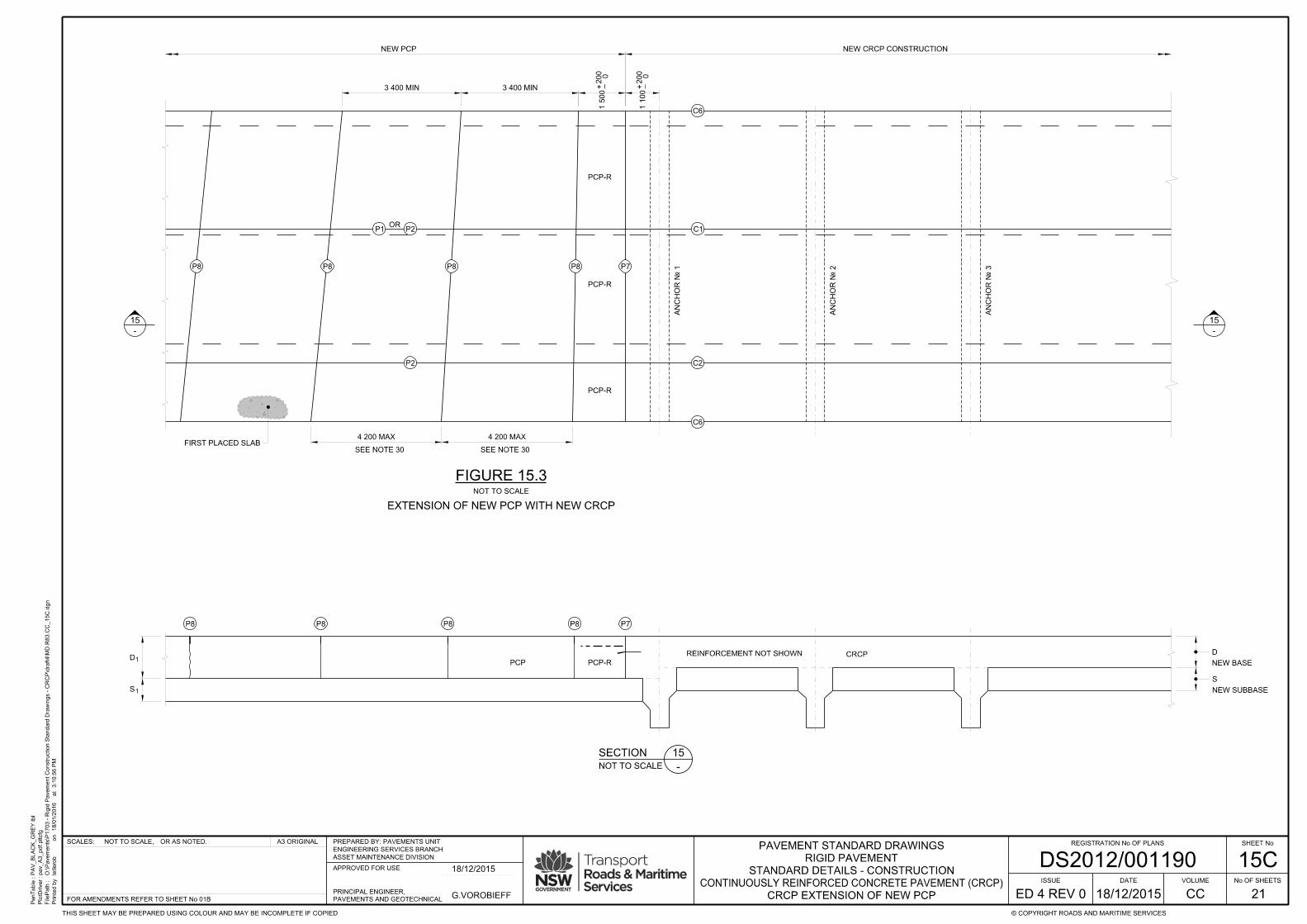
PenTable :
PlotDriver :
FilePath :
Printe
d b
y
3:1
0:5
6 P
Mat
18/0
1/2
016
on
PA
V_
BL
AC
K_
GR
EY.tbl
pav_
A3_pdf.pltcfg
O:\Pave
ments\P
1703 - Rigid P
ave
ment
Construction Sta
ndard Dra
win
gs - C
RC
P\draft4\M
D.R
83.C
C_15
C.d
gn
tetlero
b
SHEET No
No OF SHEETS
© COPYRIGHT ROADS AND MARITIME SERVICESTHIS SHEET MAY BE PREPARED USING COLOUR AND MAY BE INCOMPLETE IF COPIED
A3 ORIGINALOR AS NOTED.NOT TO SCALE,SCALES: REGISTRATION No OF PLANS
21
ISSUE
ED 4 REV 0 CC
VOLUMEDATE
DS2012/001190ASSET MAINTENANCE DIVISION
ENGINEERING SERVICES BRANCH
PREPARED BY: PAVEMENTS UNIT
APPROVED FOR USE
PAVEMENTS AND GEOTECHNICAL
PRINCIPAL ENGINEER,
FOR AMENDMENTS REFER TO SHEET No 01B
STANDARD DETAILS - CONSTRUCTION
RIGID PAVEMENT
PAVEMENT STANDARD DRAWINGS
CONTINUOUSLY REINFORCED CONCRETE PAVEMENT (CRCP)
G.VOROBIEFF
18/12/2015
18/12/2015
P7
+ –1 1
00
0200
0200
1 5
00
–+
NEW CRCP CONSTRUCTION
4 200 MAX 4 200 MAX
3 400 MIN 3 400 MIN
P8P8P8P8
NEW PCP
P2OR
P1
P2
PCP-R
PCP-R
PCP-R
AN
CH
OR № 1
AN
CH
OR № 2
AN
CH
OR № 3
C6
C1
C2
C6
FIGURE 15.3NOT TO SCALE
15
-
15
-
SECTION
NOT TO SCALE -
15
REINFORCEMENT NOT SHOWN
P8P8P8 P7P8
PCP-RPCP
SEE NOTE 30 SEE NOTE 30
CRCP
FIRST PLACED SLAB
NEW BASE
D
NEW SUBBASE
S
S1
D1
EXTENSION OF NEW PCP WITH NEW CRCP
15C
CRCP EXTENSION OF NEW PCP

PenTable :
PlotDriver :
FilePath :
Printe
d b
y
3:1
0:5
6 P
Mat
18/0
1/2
016
on
PA
V_
BL
AC
K_
GR
EY.tbl
pav_
A3_pdf.pltcfg
O:\Pave
ments\P
1703 - Rigid P
ave
ment
Construction Sta
ndard Dra
win
gs - C
RC
P\draft4\M
D.R
83.C
C_16.d
gn
tetlero
b
SHEET No
No OF SHEETS
© COPYRIGHT ROADS AND MARITIME SERVICESTHIS SHEET MAY BE PREPARED USING COLOUR AND MAY BE INCOMPLETE IF COPIED
A3 ORIGINALOR AS NOTED.NOT TO SCALE,SCALES: REGISTRATION No OF PLANS
21
ISSUE
ED 4 REV 0 CC
VOLUMEDATE
DS2012/001190ASSET MAINTENANCE DIVISION
ENGINEERING SERVICES BRANCH
PREPARED BY: PAVEMENTS UNIT
APPROVED FOR USE
PAVEMENTS AND GEOTECHNICAL
PRINCIPAL ENGINEER,
FOR AMENDMENTS REFER TO SHEET No 01B
STANDARD DETAILS - CONSTRUCTION
RIGID PAVEMENT
PAVEMENT STANDARD DRAWINGS
CONTINUOUSLY REINFORCED CONCRETE PAVEMENT (CRCP)
G.VOROBIEFF
18/12/2015
18/12/2015
NOTE (d)*
FIGURE 16.1
AN
CH
OR 1
AN
CH
OR 2
AN
CH
OR 3
*2.4
4.3
3.8
**
C-N16
C-N16
OR C2C1
SEE NOTE (b)
KERB OR BARRIER
FOR RED = 4.0
A1-N12
FOR RED = 8.0
A1-N12
FOR RED = 10.0
A1-N12 FOR RED = 8.0
E1-N12
FOR RED = 9.0
E1-N12
FOR RED = 4.0
E1-N12
FOR RED = 5.0
E1-N12
FOR RED = 4.0
E1-N12
FOR RED = 9.0
A1-N12
FOR RED = 8.0
A1-N12
FOR RED = 8.0
E1-N12
1.5 ± 0.1
3.0 TYP
C2p
P7
C2
C2
C1
FOR RED = 8.1
E1-N12
RED = 2.4
E3-N12 FOR
RED = 5.25
A1-N12 FOR
FOR RED = 8.1
A1-N12
FOR RED = 3.8
A1-N12
FOR RED = 3.8
E1-N12
C-N16
C-N16
PAVEMENT
FLEXIBLE
SEE NOTE (b)
KERB OR BARRIER
V
-
TRANSITIONS IN WIDTHS
FOR REINFORCEMENT AT
SEE DETAIL
FOR RED = 4.8
A1-N12
FOR RED = 3.8
A1-N12
(SEE FIGURE 16.2 FOR GUIDE TO RED)
REINFORCEMENT DESIGN
P8
**
4.0
4.0
1.0*
+–1.10.00.2
5.0 ± 0.5
5.0 ± 0.5
C6
P6
C6
FIGURE 16.2
KERB OR BARRIER
4.8
9.1
C2p
OR C2
C2
C2
C1
C1
3.8
8.1
5.2
55.2
5
2.4
4.3
3.8
**
*
2.4
AP
PR
OX
10.0
AP
PR
OX
10.0
PAVEMENT
FLEXIBLE
8.0
4.0
5.0
9.0
10.0
a - b
RED
DESIGN
UNDER
SECTION
FIGURE 16.2 NOTES:
*
KERB OR BARRIER
KEY:
2
EXAMPLES OF RELIEF - EDGE DISTANCE (RED)
P7
*
**
4.0
4.0
1.0
SLAB AND KERB WIDTHS MARKED ' ' AND ALL LANE WIDTHS ARE INDICATIVE ONLY.(d)
WITHIN THE SLAB (AS BOUNDED BY LONGITUDINAL JOINTS).
REQUIRED FOR THE NEAREST RED AT THE POINT OF HIGHEST STRESS
TRANSVERSE STEEL AND TIEBARS MUST BE NOT LESS THAN THAT(c)
ARE TIED TO, OR LOCATED ON TOP OF THE BASE.(ii)
HAVE CROSS-SECTIONAL AREA OF 0.09 m OR GREATER, AND(i)
RED MUST INCLUDE THE INFLUENCE OF KERBS AND BARRIERS WHICH:(b)
LONGITUDINAL STEEL IS INDEPENDENT OF RED.(a)
A1-N12
E1-N12
COVER
110 ± 30
COVER
110 ± 30MIN
525
MIN
525
MIN
525
*
C-N16
C2
C-N16'S, TYPICAL
LAPS BETWEEN
DETAIL
NOT TO SCALE
V
-
CRCP REINFORCEMENT AT TRANSITIONS IN WIDTH
(SHOWN SEPARATED FOR CLARITY)
TIED UNDER TERMINATING C-N16
FOR FULL LENGTH OF TRANSITION
1-B3-N16-
TYPICAL PLAN - WITH CRCP RAMP
16