volume onedirecttraffic.ca/wp-content/uploads/2014/02/book-81.pdf · guidelines and statements of...
TRANSCRIPT

8
May 2010
Guide and Information SignsVolume One

Ontario Traffic Manual • May 2010 i
Book 8 • Guide and Information Signs – Volume 1
FOREWARD
The Ontario Traffic Manual (OTM) promotes uniformity in the design, application and operation of traffic control devices and systems across Ontario. It consists of a set of guidelines consistent with the intent of the following legislation:
•Highway Traffic Act (HTA), R.S.O. 1990;
•Public Transportation and Highway Improvement Act (PTHIA), R.S.O. 1990; and
•Municipal Act, 2001 S.O, 2001.
The OTM provides a basis for road authorities to generate and update their own standards and guidelines when necessary.
The OTM is made up of a number of books, which are being generated over a period of time, and for which a process of continuous updating is planned. Through the updating process, the OTM will become more comprehensive, representative, and responsive to user needs, in part by including many traffic control devices and applications specific to municipal use.
OTM Book 8 (Guide and Information Signs) contains both new and existing materials from the following sources:
•Ontario Manual of Uniform Traffic Control Devices (OMUTCD);
•King’s Highway Guide Signing Policy Manual (KHGSPM); and
•Ministry of Transportation, Ontario (MTO) and municipal policies, directives, guidelines and statements of practice.
The interpretations, recommendations and guidelines in the OTM provide an understanding of traffic operations. They cover a broad range of situations encountered in practice. They are based on many factors that may determine the specific design and operational effectiveness of traffic control systems. However, no manual can cover every possible field situation.
Every effort should be made to stay as close as possible to the guidelines provided in the OTM but these guidelines should not be used as a substitute for judgment. Some applications may justifiably meet or exceed a guideline, while others might not.
Custodial Office
Ministry of Transportation, Ontario Traffic Office 301 St. Paul Street St. Catharines, Ontario L2R 7R4
Telephone: (905) 704-2960
Fax: (905) 704-2888
E-mail: [email protected]
Book 8 • Guide and Information Signs – Volume 1
Ontario Traffi c Manual • May 2010ii
Acknowledgements
OTM Book 8 was developed with the assistance of an External Technical Advisory Group organized by the MTO, a Working Group of MTO staff , and a Steering Committee composed of MTO senior management representatives, in addition to consultations with various stakeholders external to the MTO.
The OTM Book 8 Project Team would like to gratefully acknowledge the participation of the following stakeholder representatives, and the organizations/positions they represented at the time this document was prepared.
External Technical Advisory Group
Ruth Parkes, Ministry of Tourism, Ontario
Murray Turner, Association of Chiefs of Police
John McNall, Ontario Provincial Police
Frank Hull, Ontario Good Road Association
Steve MacRae, Ontario Traffi c Conference
James Keefe, International Municipal Signals Association
Mark Arsenault, Canadian Automobile Association
Doug Switzer, Ontario Trucking Association
Dave Carroll, Ontario Motor Coach Association
Henry Chu, City of Toronto
Stuart McAllister, Regional Municipality of Durham
Dave Aspinwall, Highway 407 ETR
Vicki Haydon, Town of Mississippi Mills
Shaun Young, Ministry of Municipal Aff airs and Housing, Ontario
Anthony Ching, Municipal Engineers Association
MTO Steering Committee
Brian Gaston, Assistant Deputy Minister, Provincial Highways Management Division
Ray Mantha, Executive Director, Asset Management, Provincial Highways Management Division
Gerry Chaput, Chief Engineer, Highway Standards Branch
Osmo Ramakko, Regional Director, Northeastern Region
MTO Working Group
Ann Quan, Traffi c Offi ce, Southwest Region
Tim Burns, Traffi c Offi ce, Southwest Region
Marcel Pigeon, Traffi c Offi ce, Northeastern Region
Kelly Schmid, Traffi c Offi ce, Northeastern Region
Toby Covell, Traffi c Offi ce, Eastern Region
David Babbs, Traffi c Offi ce, Central Region
Garry Williamson, Road Safety Marketing Offi ce
John Roberto, Maintenance Offi ce
Ontario Traffi c Manual • May 2010 iii
Book 8 • Guide and Information Signs – Volume 1
MTO Head Offi ce, Traffi c Offi ce directed a project consultant team and managed the development of OTM Book 8.
MTO Project Management Team
Harold Doyle, Head, Traffi c Operations and Engineering Section, Traffi c Offi ce
Nick Vukelich, Senior Project Manager, Traffi c Offi ce
Rita Goulet, Senior Project Manager, Traffi c Offi ce
Andrew Beal, Manager, Traffi c Offi ce
Valerie Noyes, Sign Designer
Project Consultant Team
Synectics Transportation Consultants Inc.
Julie Johanis, JLM Studio

Book 8 • Guide and Information Signs – Volume 1
Ontario Traffic Manual • May 2010iv

Ontario Traffic Manual • May 2010 v
Book 8 • Guide and Information Signs – Volume 1
Table of Contents
1. InTrOducTIOn . . . . . . . . . . . . . . . . . . . . . . . . . . . . . . . . . . . . . . . . . . . . . . . . . . . 1
1.1 Purpose, Scope, and content . . . . . . . . . . . . . . . . . . . . . . . . . . . . . . . . . . . . . . . . . . . . . . . 2
1.2 chapter and Guideline Format . . . . . . . . . . . . . . . . . . . . . . . . . . . . . . . . . . . . . . . . . . . . . . 3
1.3 classifications . . . . . . . . . . . . . . . . . . . . . . . . . . . . . . . . . . . . . . . . . . . . . . . . . . . . . . . . . . . 3
1.4 Special Terminologies . . . . . . . . . . . . . . . . . . . . . . . . . . . . . . . . . . . . . . . . . . . . . . . . . . . . . 4
1.5 revisions . . . . . . . . . . . . . . . . . . . . . . . . . . . . . . . . . . . . . . . . . . . . . . . . . . . . . . . . . . . . . . . 6
1.6 Metrication . . . . . . . . . . . . . . . . . . . . . . . . . . . . . . . . . . . . . . . . . . . . . . . . . . . . . . . . . . . . . . 6
1.7 designated Bilingual Areas . . . . . . . . . . . . . . . . . . . . . . . . . . . . . . . . . . . . . . . . . . . . . . . . . 6
1.8 Legal Authority . . . . . . . . . . . . . . . . . . . . . . . . . . . . . . . . . . . . . . . . . . . . . . . . . . . . . . . . . . . 6
1.9 Municipal roadways . . . . . . . . . . . . . . . . . . . . . . . . . . . . . . . . . . . . . . . . . . . . . . . . . . . . . . 7
2. GenerAL PrIncIPLeS . . . . . . . . . . . . . . . . . . . . . . . . . . . . . . . . . . . . . . . . . . . . . . 9
2.1 Guide and Information Signs – Purpose and Limitations . . . . . . . . . . . . . . . . . . . . . . . . 9
2.2 Human Factors . . . . . . . . . . . . . . . . . . . . . . . . . . . . . . . . . . . . . . . . . . . . . . . . . . . . . . . . . . . 9
2.3 road user needs . . . . . . . . . . . . . . . . . . . . . . . . . . . . . . . . . . . . . . . . . . . . . . . . . . . . . . . . 10
Oversize Signing . . . . . . . . . . . . . . . . . . . . . . . . . . . . . . . . . . . . . . . . . . . . . . . . . . . . . . 10
Additional Signing . . . . . . . . . . . . . . . . . . . . . . . . . . . . . . . . . . . . . . . . . . . . . . . . . . . . . 10
Placement of Advance Signs . . . . . . . . . . . . . . . . . . . . . . . . . . . . . . . . . . . . . . . . . . . . . 11
Grouping and Spreading . . . . . . . . . . . . . . . . . . . . . . . . . . . . . . . . . . . . . . . . . . . . . . . . 12
Spacing Between Signs and Assemblies . . . . . . . . . . . . . . . . . . . . . . . . . . . . . . . . . . . 16
Order of Placement . . . . . . . . . . . . . . . . . . . . . . . . . . . . . . . . . . . . . . . . . . . . . . . . . . . . 16
2.4 Technical considerations . . . . . . . . . . . . . . . . . . . . . . . . . . . . . . . . . . . . . . . . . . . . . . . . . 17
Sign Sizing . . . . . . . . . . . . . . . . . . . . . . . . . . . . . . . . . . . . . . . . . . . . . . . . . . . . . . . . . . . 17
Plywood Sign Size Selection . . . . . . . . . . . . . . . . . . . . . . . . . . . . . . . . . . . . . . . . . . . . . 17
Retroreflectivity . . . . . . . . . . . . . . . . . . . . . . . . . . . . . . . . . . . . . . . . . . . . . . . . . . . . . . . 18
Borders . . . . . . . . . . . . . . . . . . . . . . . . . . . . . . . . . . . . . . . . . . . . . . . . . . . . . . . . . . . . . 19
Lettering . . . . . . . . . . . . . . . . . . . . . . . . . . . . . . . . . . . . . . . . . . . . . . . . . . . . . . . . . . . . 19
Symbols . . . . . . . . . . . . . . . . . . . . . . . . . . . . . . . . . . . . . . . . . . . . . . . . . . . . . . . . . . . . 19
Arrows . . . . . . . . . . . . . . . . . . . . . . . . . . . . . . . . . . . . . . . . . . . . . . . . . . . . . . . . . . . . . . 19
Messages . . . . . . . . . . . . . . . . . . . . . . . . . . . . . . . . . . . . . . . . . . . . . . . . . . . . . . . . . . . 19
Supports . . . . . . . . . . . . . . . . . . . . . . . . . . . . . . . . . . . . . . . . . . . . . . . . . . . . . . . . . . . . 19

Book 8 • Guide and Information Signs – Volume 1
Ontario Traffic Manual • May 2010vi
Assemblies . . . . . . . . . . . . . . . . . . . . . . . . . . . . . . . . . . . . . . . . . . . . . . . . . . . . . . . . . . 20
Terminology and Short-Forms . . . . . . . . . . . . . . . . . . . . . . . . . . . . . . . . . . . . . . . . . . . . 20
2.5 Administration . . . . . . . . . . . . . . . . . . . . . . . . . . . . . . . . . . . . . . . . . . . . . . . . . . . . . . . . . . 21
Qualification Criteria . . . . . . . . . . . . . . . . . . . . . . . . . . . . . . . . . . . . . . . . . . . . . . . . . . . 21
Signs Requested By Others . . . . . . . . . . . . . . . . . . . . . . . . . . . . . . . . . . . . . . . . . . . . . 21
3. GuIde And InFOrMATIOn SIGnS AS A SySTeM . . . . . . . . . . . . . . . . . . . . . . 23
3.1 Introduction . . . . . . . . . . . . . . . . . . . . . . . . . . . . . . . . . . . . . . . . . . . . . . . . . . . . . . . . . . . . 23
3.2 Guide and Information Signs . . . . . . . . . . . . . . . . . . . . . . . . . . . . . . . . . . . . . . . . . . . . . . 23
Route Markers and Marker Tabs . . . . . . . . . . . . . . . . . . . . . . . . . . . . . . . . . . . . . . . . . . 23
Roadway Identification Signs . . . . . . . . . . . . . . . . . . . . . . . . . . . . . . . . . . . . . . . . . . . . 23
Services Signs . . . . . . . . . . . . . . . . . . . . . . . . . . . . . . . . . . . . . . . . . . . . . . . . . . . . . . . . 23
Destination Signs . . . . . . . . . . . . . . . . . . . . . . . . . . . . . . . . . . . . . . . . . . . . . . . . . . . . . 24
3.3 confirmation and Assurance Signs . . . . . . . . . . . . . . . . . . . . . . . . . . . . . . . . . . . . . . . . . 24
3.4 Systems considerations for Guide and Information Signs . . . . . . . . . . . . . . . . . . . . . 25
Route Number . . . . . . . . . . . . . . . . . . . . . . . . . . . . . . . . . . . . . . . . . . . . . . . . . . . . . . . . 25
Route Names . . . . . . . . . . . . . . . . . . . . . . . . . . . . . . . . . . . . . . . . . . . . . . . . . . . . . . . . 26
Cardinal Direction . . . . . . . . . . . . . . . . . . . . . . . . . . . . . . . . . . . . . . . . . . . . . . . . . . . . . 26
Destinations . . . . . . . . . . . . . . . . . . . . . . . . . . . . . . . . . . . . . . . . . . . . . . . . . . . . . . . . . 27
Control Cities . . . . . . . . . . . . . . . . . . . . . . . . . . . . . . . . . . . . . . . . . . . . . . . . . . . . . . . . . 27
Major Traffic Generators . . . . . . . . . . . . . . . . . . . . . . . . . . . . . . . . . . . . . . . . . . . . . . . . 28
Municipal Boundaries . . . . . . . . . . . . . . . . . . . . . . . . . . . . . . . . . . . . . . . . . . . . . . . . . . 28
Services . . . . . . . . . . . . . . . . . . . . . . . . . . . . . . . . . . . . . . . . . . . . . . . . . . . . . . . . . . . . 29
3.5 route Selection and Trailblazing . . . . . . . . . . . . . . . . . . . . . . . . . . . . . . . . . . . . . . . . . . . 29
Trailblazing to Provincial Routes, Toll Highways and Expressways . . . . . . . . . . . . . . . . 29
Routes from Intersections and Interchanges to Destinations . . . . . . . . . . . . . . . . . . . 29
4. MArkerS . . . . . . . . . . . . . . . . . . . . . . . . . . . . . . . . . . . . . . . . . . . . . . . . . . . . . . . 31
4.1 Introduction . . . . . . . . . . . . . . . . . . . . . . . . . . . . . . . . . . . . . . . . . . . . . . . . . . . . . . . . . . . . 31
Route Identification . . . . . . . . . . . . . . . . . . . . . . . . . . . . . . . . . . . . . . . . . . . . . . . . . . . . 31
Route Markers (Confirmation) . . . . . . . . . . . . . . . . . . . . . . . . . . . . . . . . . . . . . . . . . . . . 32
Trailblazer “TO” Signs . . . . . . . . . . . . . . . . . . . . . . . . . . . . . . . . . . . . . . . . . . . . . . . . . . 32
Services and Other Points of Interest . . . . . . . . . . . . . . . . . . . . . . . . . . . . . . . . . . . . . . 32
Freeway Composite Services Board . . . . . . . . . . . . . . . . . . . . . . . . . . . . . . . . . . . . . . . 33
Services Marker Boards . . . . . . . . . . . . . . . . . . . . . . . . . . . . . . . . . . . . . . . . . . . . . . . . 33

Ontario Traffic Manual • May 2010 vii
Book 8 • Guide and Information Signs – Volume 1
4.2 route Markers . . . . . . . . . . . . . . . . . . . . . . . . . . . . . . . . . . . . . . . . . . . . . . . . . . . . . . . . . . 33
4.2.1 route Identification using route Markers . . . . . . . . . . . . . . . . . . . . . . . . . . . . . . . . . . . 33
Route Markers with “JCT” or “JUNCTION” Tabs . . . . . . . . . . . . . . . . . . . . . . . . . . . . . 34
Route Marker Assemblies with Arrows and Cardinal Direction Tabs . . . . . . . . . . . . . . . 34
Route Markers - Municipal Expressways and Toll Highways . . . . . . . . . . . . . . . . . . . . . 37
4.2.2 route Markers (confirmation) . . . . . . . . . . . . . . . . . . . . . . . . . . . . . . . . . . . . . . . . . . . . . 37
4.2.3 Trailblazing “TO” Signs . . . . . . . . . . . . . . . . . . . . . . . . . . . . . . . . . . . . . . . . . . . . . . . . . . . 38
“To” Expressways and Toll Highways . . . . . . . . . . . . . . . . . . . . . . . . . . . . . . . . . . . . . . 40
4.3 Services Marker Board . . . . . . . . . . . . . . . . . . . . . . . . . . . . . . . . . . . . . . . . . . . . . . . . . . . 40
Urban Services Marker Boards: . . . . . . . . . . . . . . . . . . . . . . . . . . . . . . . . . . . . . . . . . . 41
Standard Services Marker Boards: . . . . . . . . . . . . . . . . . . . . . . . . . . . . . . . . . . . . . . . . 41
G408 – Services Marker Board – 6-Marker Configuration . . . . . . . . . . . . . . . . . . . . . . . 42
4.4 Marker Tabs . . . . . . . . . . . . . . . . . . . . . . . . . . . . . . . . . . . . . . . . . . . . . . . . . . . . . . . . . . . . . 42
4.5 distance Markers . . . . . . . . . . . . . . . . . . . . . . . . . . . . . . . . . . . . . . . . . . . . . . . . . . . . . . . 47
4.6 Trans canada route Marker . . . . . . . . . . . . . . . . . . . . . . . . . . . . . . . . . . . . . . . . . . . . . . . 49
5. FreewAy InTercHAnGeS – MAInLIne SIGnS . . . . . . . . . . . . . . . . . . . . . . . . 51
5.1 Introduction . . . . . . . . . . . . . . . . . . . . . . . . . . . . . . . . . . . . . . . . . . . . . . . . . . . . . . . . . . . . 51
Design Commonalities - Colour . . . . . . . . . . . . . . . . . . . . . . . . . . . . . . . . . . . . . . . . . . . 53
Overhead Mounting . . . . . . . . . . . . . . . . . . . . . . . . . . . . . . . . . . . . . . . . . . . . . . . . . . . 54
5.2 exit Sign . . . . . . . . . . . . . . . . . . . . . . . . . . . . . . . . . . . . . . . . . . . . . . . . . . . . . . . . . . . . . . . 55
5.3 Turn-Off Signs . . . . . . . . . . . . . . . . . . . . . . . . . . . . . . . . . . . . . . . . . . . . . . . . . . . . . . . . . . 56
Ground-Mounted Turn-Off Signs . . . . . . . . . . . . . . . . . . . . . . . . . . . . . . . . . . . . . . . . . . 56
Overhead Turn-Off Signs . . . . . . . . . . . . . . . . . . . . . . . . . . . . . . . . . . . . . . . . . . . . . . . . 57
Ground-Mounted Turn-Off Signs . . . . . . . . . . . . . . . . . . . . . . . . . . . . . . . . . . . . . . . . . . 57
Overhead Turn-Off Signs . . . . . . . . . . . . . . . . . . . . . . . . . . . . . . . . . . . . . . . . . . . . . . . . 57
5.4 Advance Signs . . . . . . . . . . . . . . . . . . . . . . . . . . . . . . . . . . . . . . . . . . . . . . . . . . . . . . . . . . 59
Application and Installation Ground-Mounted . . . . . . . . . . . . . . . . . . . . . . . . . . . . . . . . . . . . . . . . . . . . . . . . . . . . . . 59
Overhead . . . . . . . . . . . . . . . . . . . . . . . . . . . . . . . . . . . . . . . . . . . . . . . . . . . . . . . . . . . . 59
Exit Panels . . . . . . . . . . . . . . . . . . . . . . . . . . . . . . . . . . . . . . . . . . . . . . . . . . . . . . . . . . . 60
Ground-Mounted Sign . . . . . . . . . . . . . . . . . . . . . . . . . . . . . . . . . . . . . . . . . . . . . . . . . . 60
Overhead Sign . . . . . . . . . . . . . . . . . . . . . . . . . . . . . . . . . . . . . . . . . . . . . . . . . . . . . . . . 61
5.5 Interchange number Tabs . . . . . . . . . . . . . . . . . . . . . . . . . . . . . . . . . . . . . . . . . . . . . . . . . 62
5.6 Freeway composite Services Board (FcSB) . . . . . . . . . . . . . . . . . . . . . . . . . . . . . . . . . . 63

Book 8 • Guide and Information Signs – Volume 1
Ontario Traffic Manual • May 2010viii
5.7 Pre-Advance Signs . . . . . . . . . . . . . . . . . . . . . . . . . . . . . . . . . . . . . . . . . . . . . . . . . . . . . . . 66
5.8 diagrammatic Signs . . . . . . . . . . . . . . . . . . . . . . . . . . . . . . . . . . . . . . . . . . . . . . . . . . . . . 67
5.9 Interchange Sequence Signs . . . . . . . . . . . . . . . . . . . . . . . . . . . . . . . . . . . . . . . . . . . . . . 69
5.10 Pull-Through Signs . . . . . . . . . . . . . . . . . . . . . . . . . . . . . . . . . . . . . . . . . . . . . . . . . . . . . . 70
5.11 Lane exits Sign . . . . . . . . . . . . . . . . . . . . . . . . . . . . . . . . . . . . . . . . . . . . . . . . . . . . . . . . . 71
5.12 Boundary Signs . . . . . . . . . . . . . . . . . . . . . . . . . . . . . . . . . . . . . . . . . . . . . . . . . . . . . . . . . 72
Multiple Interchange Boundary Signs . . . . . . . . . . . . . . . . . . . . . . . . . . . . . . . . . . . . . . 73
Boundary Signs for Upper-Tier, Lower-Tier and Single-Tier Municipalities . . . . . . . . . . 74
Formerly Incorporated Municipalities . . . . . . . . . . . . . . . . . . . . . . . . . . . . . . . . . . . . . . 74
First Nations . . . . . . . . . . . . . . . . . . . . . . . . . . . . . . . . . . . . . . . . . . . . . . . . . . . . . . . . . 74
Multiple Interchange Boundary Signs . . . . . . . . . . . . . . . . . . . . . . . . . . . . . . . . . . . . . . 74
Enhanced Boundary Signs . . . . . . . . . . . . . . . . . . . . . . . . . . . . . . . . . . . . . . . . . . . . . . 75
5.13 downtown, city centre and Business Area Signs . . . . . . . . . . . . . . . . . . . . . . . . . . . . . 77
5.14 Port and Industrial Area Signs . . . . . . . . . . . . . . . . . . . . . . . . . . . . . . . . . . . . . . . . . . . . . 78
5.15 To downtown from Airport Signs . . . . . . . . . . . . . . . . . . . . . . . . . . . . . . . . . . . . . . . . . . 79
5.16 decorative Municipal display Signs . . . . . . . . . . . . . . . . . . . . . . . . . . . . . . . . . . . . . . . . 80
5.17 Assurance Signs . . . . . . . . . . . . . . . . . . . . . . . . . . . . . . . . . . . . . . . . . . . . . . . . . . . . . . . . 82
5.18 Supplementary destination Signs . . . . . . . . . . . . . . . . . . . . . . . . . . . . . . . . . . . . . . . . . . 84
5.19 roadway Identification (Grade Separation) Signs . . . . . . . . . . . . . . . . . . . . . . . . . . . . 86
5.20 natural Feature Identification Signs . . . . . . . . . . . . . . . . . . . . . . . . . . . . . . . . . . . . . . . . 87
6. FreewAy InTercHAnGeS – On-rAMPS . . . . . . . . . . . . . . . . . . . . . . . . . . . . . 89
6.1 On-ramp Signs . . . . . . . . . . . . . . . . . . . . . . . . . . . . . . . . . . . . . . . . . . . . . . . . . . . . . . . . . 89
Purpose and Background . . . . . . . . . . . . . . . . . . . . . . . . . . . . . . . . . . . . . . . . . . . . . . . . 89
Qualification Criteria . . . . . . . . . . . . . . . . . . . . . . . . . . . . . . . . . . . . . . . . . . . . . . . . . . . 89
Application and Installation . . . . . . . . . . . . . . . . . . . . . . . . . . . . . . . . . . . . . . . . . . . . . . 89
Overhead On-Ramp Sign Installation . . . . . . . . . . . . . . . . . . . . . . . . . . . . . . . . . . . . . . 89
Design Guidance . . . . . . . . . . . . . . . . . . . . . . . . . . . . . . . . . . . . . . . . . . . . . . . . . . . . . . 90
Other Considerations . . . . . . . . . . . . . . . . . . . . . . . . . . . . . . . . . . . . . . . . . . . . . . . . . . 92
7. FreewAy InTercHAnGeS – OFF-rAMPS . . . . . . . . . . . . . . . . . . . . . . . . . . . . . 93
7.1 Off-ramp Signs . . . . . . . . . . . . . . . . . . . . . . . . . . . . . . . . . . . . . . . . . . . . . . . . . . . . . . . . . 93
Grouping Information in Assemblies . . . . . . . . . . . . . . . . . . . . . . . . . . . . . . . . . . . . . . . 93
Placement and Configuration . . . . . . . . . . . . . . . . . . . . . . . . . . . . . . . . . . . . . . . . . . . . 95
Additional Information . . . . . . . . . . . . . . . . . . . . . . . . . . . . . . . . . . . . . . . . . . . . . . . . . . 95

Ontario Traffic Manual • May 2010 ix
Book 8 • Guide and Information Signs – Volume 1
Sign Locations . . . . . . . . . . . . . . . . . . . . . . . . . . . . . . . . . . . . . . . . . . . . . . . . . . . . . . . . 95
Roadway Identification Signs . . . . . . . . . . . . . . . . . . . . . . . . . . . . . . . . . . . . . . . . . . . . 96
Street Name Blades and Low-Speed Roadway Identification Signs at Ramp
Terminals (Optional) . . . . . . . . . . . . . . . . . . . . . . . . . . . . . . . . . . . . . . . . . . . . . . . . . . . . 96
Destination Signs . . . . . . . . . . . . . . . . . . . . . . . . . . . . . . . . . . . . . . . . . . . . . . . . . . . . . 97
Service Markers . . . . . . . . . . . . . . . . . . . . . . . . . . . . . . . . . . . . . . . . . . . . . . . . . . . . . . 97
8. HIGHwAy InTerSecTIOn SIGnS . . . . . . . . . . . . . . . . . . . . . . . . . . . . . . . . . . . 101
8.1 Introduction . . . . . . . . . . . . . . . . . . . . . . . . . . . . . . . . . . . . . . . . . . . . . . . . . . . . . . . . . . 101
Special Terminologies . . . . . . . . . . . . . . . . . . . . . . . . . . . . . . . . . . . . . . . . . . . . . . . . . 101
Route Markers. . . . . . . . . . . . . . . . . . . . . . . . . . . . . . . . . . . . . . . . . . . . . . . . . . . . . . . 101
Destination Signs . . . . . . . . . . . . . . . . . . . . . . . . . . . . . . . . . . . . . . . . . . . . . . . . . . . . 102
Spacing Between Successive Signs . . . . . . . . . . . . . . . . . . . . . . . . . . . . . . . . . . . . . . 103
Non-Intersection Signs . . . . . . . . . . . . . . . . . . . . . . . . . . . . . . . . . . . . . . . . . . . . . . . . 103
8.2 Guide and Information Sign Assemblies . . . . . . . . . . . . . . . . . . . . . . . . . . . . . . . . . . . . 107
8.3 Street name Blade Signs . . . . . . . . . . . . . . . . . . . . . . . . . . . . . . . . . . . . . . . . . . . . . . . . 109
8.4 Low-Speed roadway Identification Signs . . . . . . . . . . . . . . . . . . . . . . . . . . . . . . . . . . 110
Sign Assembly using two Roadway ID signs. . . . . . . . . . . . . . . . . . . . . . . . . . . . . . . . .111
Sign Assembly using two Roadway ID signs. . . . . . . . . . . . . . . . . . . . . . . . . . . . . . . . .111
8.5 High-Speed roadway Identification Signs . . . . . . . . . . . . . . . . . . . . . . . . . . . . . . . . . . 112
Turn-Off High-Speed Roadway Identification Signs . . . . . . . . . . . . . . . . . . . . . . . . . . . 112
Advance High-Speed Roadway Identification Signs . . . . . . . . . . . . . . . . . . . . . . . . . . 112
8.5.1 Turn-off High-Speed roadway Identification Signs . . . . . . . . . . . . . . . . . . . . . . . . . . . 112
Examples: . . . . . . . . . . . . . . . . . . . . . . . . . . . . . . . . . . . . . . . . . . . . . . . . . . . . . . . . . . 114
8.5.2 Advance High-Speed roadway Identification Signs . . . . . . . . . . . . . . . . . . . . . . . . . . 117
8.6 destination Signs . . . . . . . . . . . . . . . . . . . . . . . . . . . . . . . . . . . . . . . . . . . . . . . . . . . . . . 122
8.7 downtown, city centre and Business Area Signs . . . . . . . . . . . . . . . . . . . . . . . . . . . . 124
8.8 Port and Industrial Area Signs . . . . . . . . . . . . . . . . . . . . . . . . . . . . . . . . . . . . . . . . . . . . 126
8.9 Services Marker Boards . . . . . . . . . . . . . . . . . . . . . . . . . . . . . . . . . . . . . . . . . . . . . . . . . 127
8.10 Boundary Signs . . . . . . . . . . . . . . . . . . . . . . . . . . . . . . . . . . . . . . . . . . . . . . . . . . . . . . . . 128
Formerly Incorporated Municipalities and Hamlets . . . . . . . . . . . . . . . . . . . . . . . . . . . 130
First Nations . . . . . . . . . . . . . . . . . . . . . . . . . . . . . . . . . . . . . . . . . . . . . . . . . . . . . . . . 131
Enhanced Boundary Signs . . . . . . . . . . . . . . . . . . . . . . . . . . . . . . . . . . . . . . . . . . . . . 131
8.11 To downtown From Airport Signs . . . . . . . . . . . . . . . . . . . . . . . . . . . . . . . . . . . . . . . . . 133
8.12 Assurance Signs . . . . . . . . . . . . . . . . . . . . . . . . . . . . . . . . . . . . . . . . . . . . . . . . . . . . . . . 134

Book 8 • Guide and Information Signs – Volume 1
Ontario Traffic Manual • May 2010x
8.13 Auxiliary Assurance Signs . . . . . . . . . . . . . . . . . . . . . . . . . . . . . . . . . . . . . . . . . . . . . . . . 135
8.14 natural Feature Identification Signs . . . . . . . . . . . . . . . . . . . . . . . . . . . . . . . . . . . . . . . 136
8.15 Private roadway Signs . . . . . . . . . . . . . . . . . . . . . . . . . . . . . . . . . . . . . . . . . . . . . . . . . . 137
8.16 Personal direction Fingerboard . . . . . . . . . . . . . . . . . . . . . . . . . . . . . . . . . . . . . . . . . . . 137
8.17 destination Fingerboard . . . . . . . . . . . . . . . . . . . . . . . . . . . . . . . . . . . . . . . . . . . . . . . . . 138
8.18 Passing Lane Signs . . . . . . . . . . . . . . . . . . . . . . . . . . . . . . . . . . . . . . . . . . . . . . . . . . . . . 139
8.19 decorative Municipal display Signs . . . . . . . . . . . . . . . . . . . . . . . . . . . . . . . . . . . . . . . 143
Northeast Region . . . . . . . . . . . . . . . . . . . . . . . . . . . . . . . . . . . . . . . . . . . . . . . . . . . . 143
West Region . . . . . . . . . . . . . . . . . . . . . . . . . . . . . . . . . . . . . . . . . . . . . . . . . . . . . . . . 143
Decorative Municipal Display Signs are applicable to: . . . . . . . . . . . . . . . . . . . . . . . . 144
9. SeLecTInG deSTInATIOnS . . . . . . . . . . . . . . . . . . . . . . . . . . . . . . . . . . . . . . . 147
9.1 destinations Identified on Provincial Freeways . . . . . . . . . . . . . . . . . . . . . . . . . . . . . . 147
Use of Control Cities Approaching Interchanges on the Freeway Mainline . . . . . . . . 147
Use of Other Qualified Destinations Approaching Interchanges on the Freeway
Mainline . . . . . . . . . . . . . . . . . . . . . . . . . . . . . . . . . . . . . . . . . . . . . . . . . . . . . . . . . . . . 147
9.2 destinations Identified on Provincial Highways . . . . . . . . . . . . . . . . . . . . . . . . . . . . . . 149
Use of Control Cities Approaching Intersections on Provincial Highways . . . . . . . . . . 149
Use of Other Qualified Destinations Approaching Intersections on Provincial
Highways . . . . . . . . . . . . . . . . . . . . . . . . . . . . . . . . . . . . . . . . . . . . . . . . . . . . . . . . . . . 149
Use of Control Cities and Other, Qualified Destinations Beyond Intersections
on Provincial Highways . . . . . . . . . . . . . . . . . . . . . . . . . . . . . . . . . . . . . . . . . . . . . . . . 149
Distance (Assurance) Signs . . . . . . . . . . . . . . . . . . . . . . . . . . . . . . . . . . . . . . . . . . . . . 150
10. eMerGency deTOur rOuTe (edr) SIGnS . . . . . . . . . . . . . . . . . . . . . . . . . 153
Provincial Freeways . . . . . . . . . . . . . . . . . . . . . . . . . . . . . . . . . . . . . . . . . . . . . . . . . . . 154
EDR Trailblazer sign . . . . . . . . . . . . . . . . . . . . . . . . . . . . . . . . . . . . . . . . . . . . . . . . . . 154
EDR Trailblazer A – OPEN design: . . . . . . . . . . . . . . . . . . . . . . . . . . . . . . . . . . . . . . . . 154
EDR Trailblazer B – FLIP-OPEN design: . . . . . . . . . . . . . . . . . . . . . . . . . . . . . . . . . . . . 155
11. eMerGency SerVIceS IdenTIFIcATIOn SIGnS . . . . . . . . . . . . . . . . . . . . . . 157
11.1 911 Signs . . . . . . . . . . . . . . . . . . . . . . . . . . . . . . . . . . . . . . . . . . . . . . . . . . . . . . . . . . . . . 157
Grid Reference or Street Address Information on Provincial Highways . . . . . . . . . . . 157
Property Identification Markers . . . . . . . . . . . . . . . . . . . . . . . . . . . . . . . . . . . . . . . . . . 157
Property Identification Markers . . . . . . . . . . . . . . . . . . . . . . . . . . . . . . . . . . . . . . . . . . 158

Ontario Traffic Manual • May 2010 xi
Book 8 • Guide and Information Signs – Volume 1
11.2 Hospital Markers . . . . . . . . . . . . . . . . . . . . . . . . . . . . . . . . . . . . . . . . . . . . . . . . . . . . . . . 158
Provincial Freeways . . . . . . . . . . . . . . . . . . . . . . . . . . . . . . . . . . . . . . . . . . . . . . . . . . 159
Provincial Highways . . . . . . . . . . . . . . . . . . . . . . . . . . . . . . . . . . . . . . . . . . . . . . . . . . 159
11.3 emergency Helipad Markers . . . . . . . . . . . . . . . . . . . . . . . . . . . . . . . . . . . . . . . . . . . . . . 160
Provincial Freeways . . . . . . . . . . . . . . . . . . . . . . . . . . . . . . . . . . . . . . . . . . . . . . . . . . 161
Provincial Highways . . . . . . . . . . . . . . . . . . . . . . . . . . . . . . . . . . . . . . . . . . . . . . . . . . 161
11.4 Police Markers . . . . . . . . . . . . . . . . . . . . . . . . . . . . . . . . . . . . . . . . . . . . . . . . . . . . . . . . . 162
Provincial Freeways . . . . . . . . . . . . . . . . . . . . . . . . . . . . . . . . . . . . . . . . . . . . . . . . . . 162
Provincial Highways . . . . . . . . . . . . . . . . . . . . . . . . . . . . . . . . . . . . . . . . . . . . . . . . . . 162
11.5 collision/Police reporting centre Markers . . . . . . . . . . . . . . . . . . . . . . . . . . . . . . . . . . 163
Provincial Freeways . . . . . . . . . . . . . . . . . . . . . . . . . . . . . . . . . . . . . . . . . . . . . . . . . . 164
Provincial Highways . . . . . . . . . . . . . . . . . . . . . . . . . . . . . . . . . . . . . . . . . . . . . . . . . . . 164
11.6 Public Telephone Markers . . . . . . . . . . . . . . . . . . . . . . . . . . . . . . . . . . . . . . . . . . . . . . . . 165
Provincial Freeways . . . . . . . . . . . . . . . . . . . . . . . . . . . . . . . . . . . . . . . . . . . . . . . . . . 165
Provincial Highways . . . . . . . . . . . . . . . . . . . . . . . . . . . . . . . . . . . . . . . . . . . . . . . . . . 165
11.7 Local radio Station Signs . . . . . . . . . . . . . . . . . . . . . . . . . . . . . . . . . . . . . . . . . . . . . . . . 166
11.8 Fire Hydrant Markers . . . . . . . . . . . . . . . . . . . . . . . . . . . . . . . . . . . . . . . . . . . . . . . . . . . . 167
12. PuBLIc TrAnSPOrTATIOn SerVIceS SIGnS And MArkerS . . . . . . . . . . . 169
12.1 Bus Stop Markers . . . . . . . . . . . . . . . . . . . . . . . . . . . . . . . . . . . . . . . . . . . . . . . . . . . . . . 169
12.2 Bus, Train, Subway Station Markers . . . . . . . . . . . . . . . . . . . . . . . . . . . . . . . . . . . . . . . . 170
Provincial Freeways . . . . . . . . . . . . . . . . . . . . . . . . . . . . . . . . . . . . . . . . . . . . . . . . . . . 170
Provincial Highways . . . . . . . . . . . . . . . . . . . . . . . . . . . . . . . . . . . . . . . . . . . . . . . . . . . 170
12.3 Airport Signs and Markers . . . . . . . . . . . . . . . . . . . . . . . . . . . . . . . . . . . . . . . . . . . . . . . 172
Major Airports . . . . . . . . . . . . . . . . . . . . . . . . . . . . . . . . . . . . . . . . . . . . . . . . . . . . . . . 173
Provincial Freeways . . . . . . . . . . . . . . . . . . . . . . . . . . . . . . . . . . . . . . . . . . . . . . . . . . 173
Provincial Highways . . . . . . . . . . . . . . . . . . . . . . . . . . . . . . . . . . . . . . . . . . . . . . . . . . . 173
Secondary and Local Airport . . . . . . . . . . . . . . . . . . . . . . . . . . . . . . . . . . . . . . . . . . . . .174
Provincial Freeways . . . . . . . . . . . . . . . . . . . . . . . . . . . . . . . . . . . . . . . . . . . . . . . . . . . .174
Provincial Highways . . . . . . . . . . . . . . . . . . . . . . . . . . . . . . . . . . . . . . . . . . . . . . . . . . . .174
Major Airports . . . . . . . . . . . . . . . . . . . . . . . . . . . . . . . . . . . . . . . . . . . . . . . . . . . . . . . .174
Secondary Airports . . . . . . . . . . . . . . . . . . . . . . . . . . . . . . . . . . . . . . . . . . . . . . . . . . . 175
Local Airports . . . . . . . . . . . . . . . . . . . . . . . . . . . . . . . . . . . . . . . . . . . . . . . . . . . . . . . 176
12.4 Ferry Signs and Markers . . . . . . . . . . . . . . . . . . . . . . . . . . . . . . . . . . . . . . . . . . . . . . . . 176
Provincial Freeways . . . . . . . . . . . . . . . . . . . . . . . . . . . . . . . . . . . . . . . . . . . . . . . . . . . 177

Book 8 • Guide and Information Signs – Volume 1
Ontario Traffic Manual • May 2010xii
Provincial Highways . . . . . . . . . . . . . . . . . . . . . . . . . . . . . . . . . . . . . . . . . . . . . . . . . . . 177
12.5 carpool Lot Markers . . . . . . . . . . . . . . . . . . . . . . . . . . . . . . . . . . . . . . . . . . . . . . . . . . . . 178
Provincial Freeways . . . . . . . . . . . . . . . . . . . . . . . . . . . . . . . . . . . . . . . . . . . . . . . . . . . 179
Provincial Highways . . . . . . . . . . . . . . . . . . . . . . . . . . . . . . . . . . . . . . . . . . . . . . . . . . . 179
13. rOAd uSer SerVIceS . . . . . . . . . . . . . . . . . . . . . . . . . . . . . . . . . . . . . . . . . . . 181
13.1 Freeway Service centre Signs . . . . . . . . . . . . . . . . . . . . . . . . . . . . . . . . . . . . . . . . . . . . 181
Provincial Freeways . . . . . . . . . . . . . . . . . . . . . . . . . . . . . . . . . . . . . . . . . . . . . . . . . . . 181
Provincial Highways . . . . . . . . . . . . . . . . . . . . . . . . . . . . . . . . . . . . . . . . . . . . . . . . . . . 182
13.3 Travel Information centre Signs . . . . . . . . . . . . . . . . . . . . . . . . . . . . . . . . . . . . . . . . . . . 187
13.4 Picnic Area Signs . . . . . . . . . . . . . . . . . . . . . . . . . . . . . . . . . . . . . . . . . . . . . . . . . . . . . . . 187
13.5 Scenic Lookout Signs . . . . . . . . . . . . . . . . . . . . . . . . . . . . . . . . . . . . . . . . . . . . . . . . . . . 189
13.6 Public Boat Launch Sign . . . . . . . . . . . . . . . . . . . . . . . . . . . . . . . . . . . . . . . . . . . . . . . . . 190
13.7 waste Facility Signs . . . . . . . . . . . . . . . . . . . . . . . . . . . . . . . . . . . . . . . . . . . . . . . . . . . . 191
13.8 Heritage Site/Plaque Signs . . . . . . . . . . . . . . . . . . . . . . . . . . . . . . . . . . . . . . . . . . . . . . . 192
13.9 Area Maintenance contractor Signs . . . . . . . . . . . . . . . . . . . . . . . . . . . . . . . . . . . . . . . 194
13.10 Highway conditions and construction Information Sign . . . . . . . . . . . . . . . . . . . . . . 195
13.11 Highway Advisory radio Signs . . . . . . . . . . . . . . . . . . . . . . . . . . . . . . . . . . . . . . . . . . . 195
14. SAFeTy MeSSAGe SIGn . . . . . . . . . . . . . . . . . . . . . . . . . . . . . . . . . . . . . . . . . . 197
14.1 community Safety Program Signs . . . . . . . . . . . . . . . . . . . . . . . . . . . . . . . . . . . . . . . . 197
Crime Stoppers Community Signs . . . . . . . . . . . . . . . . . . . . . . . . . . . . . . . . . . . . . . . 198
Neighbourhood Watch/Rural Watch Community Signs . . . . . . . . . . . . . . . . . . . . . . . . 198
Road Watch Signs . . . . . . . . . . . . . . . . . . . . . . . . . . . . . . . . . . . . . . . . . . . . . . . . . . . . 198
Block Parent Signs . . . . . . . . . . . . . . . . . . . . . . . . . . . . . . . . . . . . . . . . . . . . . . . . . . . 199
14.2 community Safety Program Board . . . . . . . . . . . . . . . . . . . . . . . . . . . . . . . . . . . . . . . . 199
14.3 Safety Information Signs . . . . . . . . . . . . . . . . . . . . . . . . . . . . . . . . . . . . . . . . . . . . . . . . 200
Speed Fine Messages . . . . . . . . . . . . . . . . . . . . . . . . . . . . . . . . . . . . . . . . . . . . . . . . . 201
14.4 Temporary community road Safety campaign Signs . . . . . . . . . . . . . . . . . . . . . . . . . 202
14.5 use of Seat Belts Signs . . . . . . . . . . . . . . . . . . . . . . . . . . . . . . . . . . . . . . . . . . . . . . . . . 204
15. MAjOr TrAFFIc GenerATOrS . . . . . . . . . . . . . . . . . . . . . . . . . . . . . . . . . . . . 207
15.1 university and college Markers . . . . . . . . . . . . . . . . . . . . . . . . . . . . . . . . . . . . . . . . . . . 207
Provincial Freeways . . . . . . . . . . . . . . . . . . . . . . . . . . . . . . . . . . . . . . . . . . . . . . . . . . . 207
Provincial Highways . . . . . . . . . . . . . . . . . . . . . . . . . . . . . . . . . . . . . . . . . . . . . . . . . . . 207
Ontario Traffic Manual • May 2010 xiii
Book 8 • Guide and Information Signs – Volume 1
15.2 Special events . . . . . . . . . . . . . . . . . . . . . . . . . . . . . . . . . . . . . . . . . . . . . . . . . . . . . . . . . 209
Special Event Classification: . . . . . . . . . . . . . . . . . . . . . . . . . . . . . . . . . . . . . . . . . . . . 209
Provincial Freeways . . . . . . . . . . . . . . . . . . . . . . . . . . . . . . . . . . . . . . . . . . . . . . . . . . . 210
Provincial Highways . . . . . . . . . . . . . . . . . . . . . . . . . . . . . . . . . . . . . . . . . . . . . . . . . . . 211
15.3 Major Attraction Signs . . . . . . . . . . . . . . . . . . . . . . . . . . . . . . . . . . . . . . . . . . . . . . . . . . 212
Provincial Freeways . . . . . . . . . . . . . . . . . . . . . . . . . . . . . . . . . . . . . . . . . . . . . . . . . . . 212
Provincial Highways . . . . . . . . . . . . . . . . . . . . . . . . . . . . . . . . . . . . . . . . . . . . . . . . . . . 213
16. SPecIAL SIGnS . . . . . . . . . . . . . . . . . . . . . . . . . . . . . . . . . . . . . . . . . . . . . . . . . . 215
16.1 Adopt-A-Highway Signs . . . . . . . . . . . . . . . . . . . . . . . . . . . . . . . . . . . . . . . . . . . . . . . . . 215
Provincial Freeways and Provincial Highways . . . . . . . . . . . . . . . . . . . . . . . . . . . . . . . 216
17. AdMInISTrATIVe nOTIFIcATIOn SIGnS . . . . . . . . . . . . . . . . . . . . . . . . . . . . . 219
17.1 route numbering change Signs . . . . . . . . . . . . . . . . . . . . . . . . . . . . . . . . . . . . . . . . . . 219
Route Numbering Change Sign – Numbered Route to Numbered Route . . . . . . . . . . 219
Route Numbering Change Sign – Numbered Route to Local Road Name . . . . . . . . . 219
Route Numbering Change Sign – Local Road Designation to Route Number . . . . . . . 220
17.2 king’s Highway notice Signs . . . . . . . . . . . . . . . . . . . . . . . . . . . . . . . . . . . . . . . . . . . . . 221
17.3 controlled Access Highway notice Signs . . . . . . . . . . . . . . . . . . . . . . . . . . . . . . . . . . . 223
17.4 road closing notice Sign . . . . . . . . . . . . . . . . . . . . . . . . . . . . . . . . . . . . . . . . . . . . . . . . 224
17.5 road closed Sign . . . . . . . . . . . . . . . . . . . . . . . . . . . . . . . . . . . . . . . . . . . . . . . . . . . . . . 225
17.6 road not Maintained Sign . . . . . . . . . . . . . . . . . . . . . . . . . . . . . . . . . . . . . . . . . . . . . . . 226
17.7 Private road Sign . . . . . . . . . . . . . . . . . . . . . . . . . . . . . . . . . . . . . . . . . . . . . . . . . . . . . . 227
17.8 unassumed road Sign . . . . . . . . . . . . . . . . . . . . . . . . . . . . . . . . . . . . . . . . . . . . . . . . . . 228
17.9 road extension notice Sign . . . . . . . . . . . . . . . . . . . . . . . . . . . . . . . . . . . . . . . . . . . . . . 229

Book 8 • Guide and Information Signs – Volume 1
Ontario Traffic Manual • May 2010xiv

Ontario Traffic Manual • May 2010 xv
Book 8 • Guide and Information Signs – Volume 1
FiguresFigure 2.1: Pre-Advance, Advance and Turn-off Signs (Freeway Ground-Mounted) . . . . . . . . . . . . . 13
Figure 2.2: Grouping of Information by route choice (non-Freeway – Ground-Mounted) . . . . . . . 14
Figure 2.3: Grouping of Information by Subject Area (non-Freeway – Ground-Mounted) . . . . . . . . 15
Figure 4.1: route Markers . . . . . . . . . . . . . . . . . . . . . . . . . . . . . . . . . . . . . . . . . . . . . . . . . . . . . . . . . . . . 35
Figure 4.2: Trailblazer route Markers to Provincial routes . . . . . . . . . . . . . . . . . . . . . . . . . . . . . . . . 39
Figure 4.3: Services Marker Boards . . . . . . . . . . . . . . . . . . . . . . . . . . . . . . . . . . . . . . . . . . . . . . . . . . . . 42
Figure 4.4: junction Tabs . . . . . . . . . . . . . . . . . . . . . . . . . . . . . . . . . . . . . . . . . . . . . . . . . . . . . . . . . . . . 44
Figure 4.5: directional Arrow Tabs . . . . . . . . . . . . . . . . . . . . . . . . . . . . . . . . . . . . . . . . . . . . . . . . . . . . . 44
Figure 4.6: cardinal direction Tabs . . . . . . . . . . . . . . . . . . . . . . . . . . . . . . . . . . . . . . . . . . . . . . . . . . . . . 44
Figure 4.7: Miscellaneous Tabs . . . . . . . . . . . . . . . . . . . . . . . . . . . . . . . . . . . . . . . . . . . . . . . . . . . . . . . . 45
Figure 4.8: distance and directional Tabs . . . . . . . . . . . . . . . . . . . . . . . . . . . . . . . . . . . . . . . . . . . . . . . 46
Figure 4.9: M801 – distance Markers . . . . . . . . . . . . . . . . . . . . . . . . . . . . . . . . . . . . . . . . . . . . . . . . . . . 48
Figure 4.10: M111 – Trans canada route Marker . . . . . . . . . . . . . . . . . . . . . . . . . . . . . . . . . . . . . . . . . . . 50
Figure 5.1: exit Signs . . . . . . . . . . . . . . . . . . . . . . . . . . . . . . . . . . . . . . . . . . . . . . . . . . . . . . . . . . . . . . . 55
Figure 5.2: G101 – Freeway Turn-Off Sign (Ground-Mounted) . . . . . . . . . . . . . . . . . . . . . . . . . . . . . . . 57
Figure 5.3: Overhead Turn-Off Signs . . . . . . . . . . . . . . . . . . . . . . . . . . . . . . . . . . . . . . . . . . . . . . . . . . . 58
Figure 5.4: G100 – Freeway Advance Sign (Ground-Mounted) . . . . . . . . . . . . . . . . . . . . . . . . . . . . . . 60
Figure 5.5: Overhead Advance Signs . . . . . . . . . . . . . . . . . . . . . . . . . . . . . . . . . . . . . . . . . . . . . . . . . . 61
Figure 5.6: Interchange number Tabs . . . . . . . . . . . . . . . . . . . . . . . . . . . . . . . . . . . . . . . . . . . . . . . . . . 63
Figure 5.7: Freeway composite Services Board (FcSB) . . . . . . . . . . . . . . . . . . . . . . . . . . . . . . . . . . . 65
Figure 5.8: G416 – “next exit” Tab . . . . . . . . . . . . . . . . . . . . . . . . . . . . . . . . . . . . . . . . . . . . . . . . . . . . . 65
Figure 5.9: G417 – “Second exit” Tab . . . . . . . . . . . . . . . . . . . . . . . . . . . . . . . . . . . . . . . . . . . . . . . . . . . 65
Figure 5.10: G418 – “Via (road name)” Tab . . . . . . . . . . . . . . . . . . . . . . . . . . . . . . . . . . . . . . . . . . . . . . 65
Figure 5.11: Pre-Advance Signs . . . . . . . . . . . . . . . . . . . . . . . . . . . . . . . . . . . . . . . . . . . . . . . . . . . . . . . . 66
Figure 5.12: G102 – Freeway diagrammatic Pre-Advance/ Advance Sign . . . . . . . . . . . . . . . . . . . . . . 68
Figure 5.13: G112 – Freeway Interchange Sequence Sign . . . . . . . . . . . . . . . . . . . . . . . . . . . . . . . . . . 69
Figure 5.14: G113 – Freeway Pull-Through Sign . . . . . . . . . . . . . . . . . . . . . . . . . . . . . . . . . . . . . . . . . . . 70
Figure 5.15: example Freeway Lane exits Sign . . . . . . . . . . . . . . . . . . . . . . . . . . . . . . . . . . . . . . . . . . . 71
Figure 5.16: G318 – Boundary Sign – upper Tier - 3 lines (Basic) . . . . . . . . . . . . . . . . . . . . . . . . . . . . . 74
Figure 5.17: G314 – Boundary Sign – Single-Tier/Lower-Tier (Basic) . . . . . . . . . . . . . . . . . . . . . . . . . . 74
Figure 5.18: G310 – Boundary Sign – Formerly Incorporated Municipality (Basic) . . . . . . . . . . . . . . . 74
Figure 5.19: G320 – Boundary Sign – First nations (Basic) . . . . . . . . . . . . . . . . . . . . . . . . . . . . . . . . . . 74
Figure 5.20: G312 – Multiple Interchange Boundary Sign (1-9 Interchanges) (Basic) . . . . . . . . . . . . . 75

Book 8 • Guide and Information Signs – Volume 1
Ontario Traffic Manual • May 2010xvi
Figure 5.21: enhanced Boundary Signs . . . . . . . . . . . . . . . . . . . . . . . . . . . . . . . . . . . . . . . . . . . . . . . . . . 76
Figure 5.22: G322 – downtown, city centre or Business Area Signs . . . . . . . . . . . . . . . . . . . . . . . . . . 78
Figure 5.23: G328 – Port or Industrial Area Sign . . . . . . . . . . . . . . . . . . . . . . . . . . . . . . . . . . . . . . . . . . . 79
Figure 5.24: G323 – To downtown or city centre from Airport Sign . . . . . . . . . . . . . . . . . . . . . . . . . . 80
Figure 5.25: decorative Municipal display - Freeway . . . . . . . . . . . . . . . . . . . . . . . . . . . . . . . . . . . . . . 82
Figure 5.26: Assurance Signs . . . . . . . . . . . . . . . . . . . . . . . . . . . . . . . . . . . . . . . . . . . . . . . . . . . . . . . . . . 84
Figure 5.27: G309 – Supplementary destination Sign . . . . . . . . . . . . . . . . . . . . . . . . . . . . . . . . . . . . . 85
Figure 5.28: G220 – roadway Identification (Grade Separation) Sign . . . . . . . . . . . . . . . . . . . . . . . . . 86
Figure 5.29: G331 – natural Feature Identification Sign . . . . . . . . . . . . . . . . . . . . . . . . . . . . . . . . . . . . 87
Figure 6.1: Freeway On-ramp Advance Signs . . . . . . . . . . . . . . . . . . . . . . . . . . . . . . . . . . . . . . . . . . . 90
Figure 6.2: Freeway On-ramp Turn Off Signs . . . . . . . . . . . . . . . . . . . . . . . . . . . . . . . . . . . . . . . . . . . . 90
Figure 6.3: Alternative Special Oversize route Markers . . . . . . . . . . . . . . . . . . . . . . . . . . . . . . . . . . . 91
Figure 7.1: Guide and Information Sign Assembly examples . . . . . . . . . . . . . . . . . . . . . . . . . . . . . . . 94
Figure 7.2: examples of roadway Identification Signs . . . . . . . . . . . . . . . . . . . . . . . . . . . . . . . . . . . . 97
Figure 7.3: example of destination Signs . . . . . . . . . . . . . . . . . . . . . . . . . . . . . . . . . . . . . . . . . . . . . . 98
Figure 7.4: example of a Services Marker Board . . . . . . . . . . . . . . . . . . . . . . . . . . . . . . . . . . . . . . . . . 99
Figure 8.1: Typical Guide and Information Sign Assemblies . . . . . . . . . . . . . . . . . . . . . . . . . . . . . . . 108
Figure 8.2: G216 – road Id – Street name Blade . . . . . . . . . . . . . . . . . . . . . . . . . . . . . . . . . . . . . . . 109
Figure 8.3: Turn-Off Low-Speed roadway Identification Signs . . . . . . . . . . . . . . . . . . . . . . . . . . . . 111
Figure 8.4: Advance Low-Speed roadway Identification Signs . . . . . . . . . . . . . . . . . . . . . . . . . . . . 111
Figure 8.5: Turn-Off High-Speed roadway Identification Signs for Provincial Highways . . . . . . . . 115
Figure 8.6: Turn-Off roadway Identification Signs for non-Provincial roadways (Street name
with route #) . . . . . . . . . . . . . . . . . . . . . . . . . . . . . . . . . . . . . . . . . . . . . . . . . . . . . . . . . . . 115
Figure 8.7: Turn-Off roadway Identification Signs for non-Provincial roadways (route #
written Out as name) . . . . . . . . . . . . . . . . . . . . . . . . . . . . . . . . . . . . . . . . . . . . . . . . . . . . 116
Figure 8.8: Turn-Off roadway Identification Signs for non-Provincial roadways (Street name
Only) . . . . . . . . . . . . . . . . . . . . . . . . . . . . . . . . . . . . . . . . . . . . . . . . . . . . . . . . . . . . . . . . 116
Figure 8.9: Advance High-Speed roadway Identification Signs for Provincial Highways . . . . . . . 119
Figure 8.10: Advance High-Speed roadway Identification Signs (Street name with route #) . . . . 120
Figure 8.11: Advance High-Speed roadway Identification Signs (route # written Out as name) . 121
Figure 8.12: Advance High-Speed roadway Identification Signs – road (Street name Only) . . . . 121
Figure 8.13: Turn-Off destination Signs . . . . . . . . . . . . . . . . . . . . . . . . . . . . . . . . . . . . . . . . . . . . . . . . 122
Figure 8.14: Advance destination Signs . . . . . . . . . . . . . . . . . . . . . . . . . . . . . . . . . . . . . . . . . . . . . . . . 123
Figure 8.15: G324 – downtown, city centre or Business Section Tabs (Advance/Turn-Off) . . . . . . 125
Figure 8.16: remote downtown Signs . . . . . . . . . . . . . . . . . . . . . . . . . . . . . . . . . . . . . . . . . . . . . . . . . 125

Ontario Traffic Manual • May 2010 xvii
Book 8 • Guide and Information Signs – Volume 1
Figure 8.17: Port and Industrial Area Signs . . . . . . . . . . . . . . . . . . . . . . . . . . . . . . . . . . . . . . . . . . . . . . 126
Figure 8.18: Basic Boundary Sign (upper Tier) . . . . . . . . . . . . . . . . . . . . . . . . . . . . . . . . . . . . . . . . . . . 130
Figure 8.19: G314 – Basic Boundary Sign (Lower-Tier or Single-Tier Municipalities) . . . . . . . . . . . . 130
Figure 8.20: G-310 – Basic Boundary Sign (Formerly Incorporated Municipalities, Hamlets and
unincorporated communities in unorganized Areas) . . . . . . . . . . . . . . . . . . . . . . . . . . 130
Figure 8.21: G320 – Basic Boundary Sign - First nations . . . . . . . . . . . . . . . . . . . . . . . . . . . . . . . . . . 131
Figure 8.22: enhanced Boundary Signs . . . . . . . . . . . . . . . . . . . . . . . . . . . . . . . . . . . . . . . . . . . . . . . . . 132
Figure 8.23: G323 – To downtown or city centre Sign (From Airport) . . . . . . . . . . . . . . . . . . . . . . . . 133
Figure 8.24: Assurance Sign . . . . . . . . . . . . . . . . . . . . . . . . . . . . . . . . . . . . . . . . . . . . . . . . . . . . . . . . . 135
Figure 8.25: G303 – Auxiliary Assurance Sign . . . . . . . . . . . . . . . . . . . . . . . . . . . . . . . . . . . . . . . . . . . 135
Figure 8.26: G331 – natural Feature Identification Sign . . . . . . . . . . . . . . . . . . . . . . . . . . . . . . . . . . . 136
Figure 8.27: G217 – Private roadway Sign . . . . . . . . . . . . . . . . . . . . . . . . . . . . . . . . . . . . . . . . . . . . . . 137
Figure 8.28: G308 – Personal direction Fingerboard . . . . . . . . . . . . . . . . . . . . . . . . . . . . . . . . . . . . . . 138
Figure 8.29: G307 – destination Fingerboard Sign . . . . . . . . . . . . . . . . . . . . . . . . . . . . . . . . . . . . . . . 139
Figure 8.30: Passing Lane Ahead Signs . . . . . . . . . . . . . . . . . . . . . . . . . . . . . . . . . . . . . . . . . . . . . . . . 140
Figure 8.31: Passing Lane Signs – Single direction . . . . . . . . . . . . . . . . . . . . . . . . . . . . . . . . . . . . . . . 141
Figure 8.32: Passing Lane Signs – Both directions . . . . . . . . . . . . . . . . . . . . . . . . . . . . . . . . . . . . . . . 142
Figure 10.1: G703 – edr Mainline Sign . . . . . . . . . . . . . . . . . . . . . . . . . . . . . . . . . . . . . . . . . . . . . . . . 154
Figure 10.2: Sample of edr Trailblazer OPen sign assembly . . . . . . . . . . . . . . . . . . . . . . . . . . . . . . . 155
Figure 10.3: edr Trailblazer B sign . . . . . . . . . . . . . . . . . . . . . . . . . . . . . . . . . . . . . . . . . . . . . . . . . . . . 155
Figure 10.4: G709 – edr educational Sign . . . . . . . . . . . . . . . . . . . . . . . . . . . . . . . . . . . . . . . . . . . . . . 156
Figure 11.1: example of Turn-Off Sign with 911 Information . . . . . . . . . . . . . . . . . . . . . . . . . . . . . . . 158
Figure 11.2: G219 – emergency Services Tab . . . . . . . . . . . . . . . . . . . . . . . . . . . . . . . . . . . . . . . . . . . . 158
Figure 11.3: G218 – emergency Services Property Identification Marker . . . . . . . . . . . . . . . . . . . . . 158
Figure 11.4: M401 – Hospital Marker . . . . . . . . . . . . . . . . . . . . . . . . . . . . . . . . . . . . . . . . . . . . . . . . . . 160
Figure 11.5: M400 – emergency Helipad Marker . . . . . . . . . . . . . . . . . . . . . . . . . . . . . . . . . . . . . . . . . 161
Figure 11.6: M404 – Police Marker (OPP) . . . . . . . . . . . . . . . . . . . . . . . . . . . . . . . . . . . . . . . . . . . . . . . . 163
Figure 11.7: M403 – Police Marker (Local) . . . . . . . . . . . . . . . . . . . . . . . . . . . . . . . . . . . . . . . . . . . . . . 163
Figure 11.8: M405 – collision/Police reporting centre Marker . . . . . . . . . . . . . . . . . . . . . . . . . . . . . 164
Figure 11.9: M406 – Public Telephone Marker . . . . . . . . . . . . . . . . . . . . . . . . . . . . . . . . . . . . . . . . . . . . 166
Figure 11.10: G702 – Local radio Station Sign . . . . . . . . . . . . . . . . . . . . . . . . . . . . . . . . . . . . . . . . . . . 167
Figure 11.11: M408 – Fire Hydrant Marker . . . . . . . . . . . . . . . . . . . . . . . . . . . . . . . . . . . . . . . . . . . . . . . 168
Figure 12.1: M506 – Bus Station (Generic) Marker . . . . . . . . . . . . . . . . . . . . . . . . . . . . . . . . . . . . . . . 171
Figure 12.2: M509 –Train Station (Generic) Marker . . . . . . . . . . . . . . . . . . . . . . . . . . . . . . . . . . . . . . . 171
Figure 12.3: M510 – Train Station Marker with Station Id . . . . . . . . . . . . . . . . . . . . . . . . . . . . . . . . . . 171

Book 8 • Guide and Information Signs – Volume 1
Ontario Traffic Manual • May 2010xviii
Figure 12.4: example of a Ground-Mounted Major Airport Sign (Freeway) . . . . . . . . . . . . . . . . . . . . 174
Figure 12.5: Major Airport Markers . . . . . . . . . . . . . . . . . . . . . . . . . . . . . . . . . . . . . . . . . . . . . . . . . . . . 175
Figure 12.6: Secondary Airport Marker . . . . . . . . . . . . . . . . . . . . . . . . . . . . . . . . . . . . . . . . . . . . . . . . . 175
Figure 12.7: Local Airport Marker . . . . . . . . . . . . . . . . . . . . . . . . . . . . . . . . . . . . . . . . . . . . . . . . . . . . . . 176
Figure 12.8: M508 – Ferry Marker . . . . . . . . . . . . . . . . . . . . . . . . . . . . . . . . . . . . . . . . . . . . . . . . . . . . . 178
Figure 12.9: G413 – Ferry Sign – Advance (Freeway) . . . . . . . . . . . . . . . . . . . . . . . . . . . . . . . . . . . . . . 178
Figure 12.10: G412 – Ferry Sign – Advance (Provincial Highway) . . . . . . . . . . . . . . . . . . . . . . . . . . . . 178
Figure 12.11: M507 – carpool Marker . . . . . . . . . . . . . . . . . . . . . . . . . . . . . . . . . . . . . . . . . . . . . . . . . . . 179
Figure 13.1: Freeway Service centre Signing – Typical Layout . . . . . . . . . . . . . . . . . . . . . . . . . . . . . . 183
Figure 13.3: G406 – Freeway Service centre Turn-Off Sign . . . . . . . . . . . . . . . . . . . . . . . . . . . . . . . . . 184
Figure 13.4: G405 – next Freeway Service centre Sign . . . . . . . . . . . . . . . . . . . . . . . . . . . . . . . . . . . . 184
Figure 13.5: G402 – corporate Freeway composite Services Board . . . . . . . . . . . . . . . . . . . . . . . . . . 184
Figure 13.6: G403 – Generic Freeway composite Services Board . . . . . . . . . . . . . . . . . . . . . . . . . . . 184
Figure 13.7: G409 – Service club composite Board . . . . . . . . . . . . . . . . . . . . . . . . . . . . . . . . . . . . . . 187
Figure 13.8: M714 – Picnic Area Marker . . . . . . . . . . . . . . . . . . . . . . . . . . . . . . . . . . . . . . . . . . . . . . . . . 188
Figure 13.9: M719 – Scenic Lookout Marker . . . . . . . . . . . . . . . . . . . . . . . . . . . . . . . . . . . . . . . . . . . . . 189
Figure 13.10: M717 – Public Boat Launch Marker . . . . . . . . . . . . . . . . . . . . . . . . . . . . . . . . . . . . . . . . . . 190
Figure 13.11: waste Management Facility Sign and Optional Tab . . . . . . . . . . . . . . . . . . . . . . . . . . . . 191
Figure 13.12: Heritage Site Plaques/Signs . . . . . . . . . . . . . . . . . . . . . . . . . . . . . . . . . . . . . . . . . . . . . . . 193
Figure 14.1: G510 – crime Stoppers community Sign . . . . . . . . . . . . . . . . . . . . . . . . . . . . . . . . . . . . . 198
Figure 14.2: G512 – neighourhood watch/rural watch community Sign . . . . . . . . . . . . . . . . . . . . 198
Figure 14.3: G513 – road watch Sign . . . . . . . . . . . . . . . . . . . . . . . . . . . . . . . . . . . . . . . . . . . . . . . . . . 198
Figure 14.4: G511 – Block Parent Sign . . . . . . . . . . . . . . . . . . . . . . . . . . . . . . . . . . . . . . . . . . . . . . . . . . 199
Figure 14.5: G506 – community Safety Program Board . . . . . . . . . . . . . . . . . . . . . . . . . . . . . . . . . . . 200
Figure 14.6: G500 – Safety Information Sign . . . . . . . . . . . . . . . . . . . . . . . . . . . . . . . . . . . . . . . . . . . . 201
Figure 14.7: G503 – Safety Information Sign - Speed Fines . . . . . . . . . . . . . . . . . . . . . . . . . . . . . . . . 202
Figure 14.8: Temporary community road Safety campaign Sign . . . . . . . . . . . . . . . . . . . . . . . . . . 204
Figure 14.9: G505 – use of Seat Belts Sign . . . . . . . . . . . . . . . . . . . . . . . . . . . . . . . . . . . . . . . . . . . . . . 205
Figure 15.1: M602 – university Marker . . . . . . . . . . . . . . . . . . . . . . . . . . . . . . . . . . . . . . . . . . . . . . . . . 208
Figure 15.2: M600 – college Marker . . . . . . . . . . . . . . . . . . . . . . . . . . . . . . . . . . . . . . . . . . . . . . . . . . . 208
Figure 15.3: M603 – university Marker (with name) . . . . . . . . . . . . . . . . . . . . . . . . . . . . . . . . . . . . . . 208
Figure 15.4: M601 – college Marker (with name) . . . . . . . . . . . . . . . . . . . . . . . . . . . . . . . . . . . . . . . . 208
Figure 15.5: G424 – Temporary Special event Sign (Freeway) . . . . . . . . . . . . . . . . . . . . . . . . . . . . . . . 212
Figure 15.6: G425 – Temporary Special event Sign (Highway) . . . . . . . . . . . . . . . . . . . . . . . . . . . . . . 212
Figure 15.7: G426 – Major Attraction Sign (Freeway). . . . . . . . . . . . . . . . . . . . . . . . . . . . . . . . . . . . . . 214

Ontario Traffic Manual • May 2010 xix
Book 8 • Guide and Information Signs – Volume 1
Figure 15.8: G427 – Major Attraction Sign (Highway) . . . . . . . . . . . . . . . . . . . . . . . . . . . . . . . . . . . . . 214
Figure 16.1: Adopt-A-Highway Sign . . . . . . . . . . . . . . . . . . . . . . . . . . . . . . . . . . . . . . . . . . . . . . . . . . . 216
Figure 16.2: G603 – Planting Partnership Sign . . . . . . . . . . . . . . . . . . . . . . . . . . . . . . . . . . . . . . . . . . . 218
Figure 16.3: G604 – name recognition Tab . . . . . . . . . . . . . . . . . . . . . . . . . . . . . . . . . . . . . . . . . . . . . . 218
Figure 16.4: Planting Partnership Multi-Sponsor name recognition Signs . . . . . . . . . . . . . . . . . . . 218
Figure 17.1: G713 – Highway numbering change (route # to route #) . . . . . . . . . . . . . . . . . . . . . . . 220
Figure 17.2: G714 – Highway numbering change (route # to Local road) . . . . . . . . . . . . . . . . . . . . 221
Figure 17.3: G715 – Highway numbering change (Local road to route #) . . . . . . . . . . . . . . . . . . . . 221
Figure 17.4: G716 – notice – Proposed king’s Highway . . . . . . . . . . . . . . . . . . . . . . . . . . . . . . . . . . . 222
Figure 17.5: G717 – notice – king’s Highway Sign . . . . . . . . . . . . . . . . . . . . . . . . . . . . . . . . . . . . . . . . 222
Figure 17.6: G718 – notice – Proposed controlled Access Highway . . . . . . . . . . . . . . . . . . . . . . . . . 224
Figure 17.7: G719 – notice – controlled Access Highway . . . . . . . . . . . . . . . . . . . . . . . . . . . . . . . . . . 224
Figure 17.8: G720 – notice – road closing . . . . . . . . . . . . . . . . . . . . . . . . . . . . . . . . . . . . . . . . . . . . . 225
Figure 17.9: G725 – notice – road closed (with date) . . . . . . . . . . . . . . . . . . . . . . . . . . . . . . . . . . . . 226
Figure 17.10: G723 – notice – road not Maintained Sign . . . . . . . . . . . . . . . . . . . . . . . . . . . . . . . . . . 227
Figure 17.11: G724 – notice – Private road Sign . . . . . . . . . . . . . . . . . . . . . . . . . . . . . . . . . . . . . . . . . . 228
Figure 17.12: G726 – notice – unassumed road . . . . . . . . . . . . . . . . . . . . . . . . . . . . . . . . . . . . . . . . . 229
Figure 17.13: G722 – notice – road extension . . . . . . . . . . . . . . . . . . . . . . . . . . . . . . . . . . . . . . . . . . . 230

Book 8 • Guide and Information Signs – Volume 1
Ontario Traffic Manual • May 2010xx

Ontario Traffic Manual • May 2010 xxi
Book 8 • Guide and Information Signs – Volume 1
TablesTable 5.1: Population Figures rounding Formula . . . . . . . . . . . . . . . . . . . . . . . . . . . . . . . . . . . . 73
Table 8.1: roadway Identification Sign Selection . . . . . . . . . . . . . . . . . . . . . . . . . . . . . . . . . . . 105
Table 8.2: recommended distances for roadway Identification Sign Placement . . . . . . . . . 106
Table 8.3: Population Figures rounding Formula . . . . . . . . . . . . . . . . . . . . . . . . . . . . . . . . . . . 129
Table 9.1: destination Selection for roadway Identification Signs . . . . . . . . . . . . . . . . . . . . . 151
Table 9.2: destination Selection for Assurance Signs . . . . . . . . . . . . . . . . . . . . . . . . . . . . . . . . 152


Ontario Traffic Manual • May 2010 1
Book 8 • Guide and Information Signs – Volume 1
1. Introduction
OTM Book 8 (Guide and Information Signs) is one in a series of volumes that makes up the Ontario Traffic Manual (OTM). Other books in the OTM series provide practical guidance on a full range of traffic control devices and their application. The following books should be of particular interest to users of this book.
OTM Book 1 (Introduction to the Ontario Traffic Manual) and its appendices provide:
•Essential information about the fundamental principles underlying the design and application of traffic control signs, signals, markings and delineation devices;
•A complete listing of the planned and currently available volumes, as well as the tables of contents of all books;
•Information on individual sign designs may be found in Appendix 1b (Sign Design Principles); and
•An overview of how traffic control devices, the road, and the vehicle interact with the driver may be found in Appendix 1c (Positive Guidance Toolkit).
OTM Book 2 (Sign Patterns and Fabrication) contains information on individual sign construction and fabrication requirements as well as standardized pattern files (Master Sign Library (MSL)).
The MSL is intended for sign specification development and sign production including detailed design and dimensioning information not presented in OTM Book 2. The MSL is available as part of OTM Book 2, in electronic
format, from the Ministry of Transportation, Ontario’s (MTO) current publishing agent. Alternatively, the electronic version of the MSL may be purchased separately from OTM Book 2.
OTM Book 3 (Sign Support and Installation) will provide information on sign installation requirements (publication pending – refer to MTO Sign Support Manual in the interim).
OTM Book 4 (Sign Maintenance) will provide information on sign maintenance requirements (publication pending – refer to MTO Maintenance Manual in the interim).
Signs for services and attractions that are not included in this OTM book are generally provided under the province’s Tourism-Oriented Directional Signs (TODS) program or under the Province’s Logo Signs program (OTM Book 9 – publication pending). Information on both the TODS and Logo sign programs are available from the province’s Authorized Delivery Agent (ADA). For the current ADA please contact:
Ministry of Transportation, Ontario Traffic Office 301 St. Paul Street St. Catharines, Ontario L2R 7R4
Telephone: (905) 704-2960
Fax: (905) 704-2888
E-mail: [email protected]

Book 8 • Guide and Information Signs – Volume 1
Ontario Traffic Manual • May 20102
1.1 Purpose, Scope, and Content
OTM Book 8 is published as a two-volume set:
•Volume 1: Guidelines; and
•Volume 2: Typical Layouts.
Volume 1 is organized by subject area, as outlined below, and Volume 2 is designed to be read in conjunction with Volume 1.
Format for Volume 1 – Guidelines
Chapter 1
•Introduction
Chapter 2
•General Principles
Chapter 3
•Guide and Information Signs as a System
Chapter 4
•Markers
Chapter 5
•Freeway Interchanges – Mainline Signs
Chapter 6
•Freeway Interchanges - On-Ramps
Chapter 7
•Freeway Interchanges - Off-Ramps
Chapter 8
•Highway Intersections
Chapter 9
•Selecting Destinations
Chapter 10
•Emergency Detour Route Signs
Chapter 11
•Emergency Services Identification Signs
Chapter 12
•Public Transportation Services Signs
Chapter 13
•Road User Services Identification Signs
Chapter 14
• Safety Message Signs
Chapter 15
•Major Traffic Generators
Chapter 16
•Special Signs
Chapter 17
•Administrative Notification Signs

Ontario Traffic Manual • May 2010 3
Book 8 • Guide and Information Signs – Volume 1
1.2 chapter and Guideline Format
Chapters 4 - 17 are organized with the same set of headings. Where a heading is not applicable, the statement “This Section Not Used” is shown.
These headings are:
•Purpose and Background;
•Qualification Criteria;
•Application and Installation;
•Design Guidance; and
•Other Considerations.
1.3 Classifications
Freeways are defined as:
•Having high-speeds (posted 90 km/h or greater);
•Having multiple lanes;
•Divided with a continuous median; and
•Fully access-controlled (no entrances or at-grade intersections).
Non-Freeway Facilities are defined as all other roadways that do not meet the criteria of a freeway. Non-Freeway facilities include:
•Expressways that do not meet the definition of a freeway (e.g. with at-grade intersections);
•Provincial Highways;
•Municipal Roadways;
•Arterial Roads;
•Collector Roads; and
•Local Streets.
Surrounding Environment
The environment surrounding roadways may be classified as either urban or rural.
•Urban – largely developed and used primarily for residential, commercial and/or industrial purposes; or
•Rural – largely undeveloped or developed primarily for agricultural or resource purposes.
The Road Authority
The “Road Authority” is a generic term used to describe an entity responsible for public roads.
For the purposes of this OTM book, the following are considered under the jurisdiction of the MTO:
•Provincial Freeways;
•Provincial Staged Freeways;
•King’s Highways;
•Secondary Provincial Highways; and
•Tertiary Roads.
Toll highway operators are considered as road authorities.

Book 8 • Guide and Information Signs – Volume 1
Ontario Traffic Manual • May 20104
Other public roadways in organized areas may be under the jurisdiction of the municipality. Roadways on First Nations lands may be under the jurisdiction of the local aboriginal government.
Under the Local Roads Boards Act, 2004 Local Roads Boards may manage roadways in a territory without municipal organization and are considered as road authorities.
Jurisdiction
Effective January 1, 2003, the Municipal Act, 2001 differentiates municipal status as upper-tier, lower-tier or single-tier.
For information on the status of individual municipalities, refer to the Ministry of Municipal Affairs and Housing website: www.mah.gov.on.ca/Page1591.aspx
For the purpose of this OTM book:
•First Nations communities are considered as single-tier municipalities;
•Hamlets are unincorporated centres of population within the boundaries of organized municipalities and centres of population in territories without municipal organization. To qualify as a hamlet, a centre of population must contain at least five residences, provide at least one essential motorist service (food, fuel or accommodations) and have a Boundary Sign installed by the road authority having jurisdiction over the roadway at the limits of the built-up area. Hamlet names shall be as approved by the Ontario Geographic Names Board.
As an outcome of the most recent municipal restructuring (effective January 1, 1997), formerly incorporated municipalities may exist within restructured municipal entities. The current status of these communities is comparable to that of hamlets, but in recognition of their former status they may receive special consideration for inclusion on wayfinding signs as destinations.
Official names of geographic features, incorporated communities and hamlets to be used on Guide and Information Signs shall be sourced from those approved by the Ontario Geographic Names Board’s geo-index at:
www.onterm.gov.on.ca/geo/entry_e.asp
Only those features and communities with approved names may be considered for signs.
1.4 Special Terminologies
Approaching roadway is the roadway, viewed from the road user’s perspective, entering an intersection or interchange.
Control Cities are municipalities and other centres of population that are located on or near provincial routes that are designated by the MTO as interim end-of-routes or end-of routes for the purpose of orienting road users.
They may be included on any of the following signs:
•Pre-Advance;
•Advance;
•Turn-Off; and
•Diagrammatic.

Ontario Traffic Manual • May 2010 5
Book 8 • Guide and Information Signs – Volume 1
crossing roadway(s) are the roadways, viewed from the road user’s perspective, that intersect the approaching roadway. Crossing roadways to the left and right may have the same or different designations.
departing roadway(s) are roadways, viewed from the road users perspective, that represent potential route choices .
expressway is used to refer to municipal facilities that are either fully or partially access-controlled. For the purposes of this OTM book, expressways shall be treated as freeways, if they generally meet the definition of freeways, and shall be treated as roadways if they do not.
Guide and Information Sign Assemblies are groups of Roadway Identification Signs, Destination Signs and/or Services Marker Boards combined together to present multiple messages in an orderly manner.
Highway is a general term used to refer to provincial routes and municipal roads.
Interchange is a system of interconnecting roadways, in conjunction with one or more grade separations, providing for the movement of traffic between two or more roadways at different grades.
Intersection is the at-grade meeting of two or more roadways.
Markers generally display a single symbol, graphic, numeral or word. They may be stand-alone signs, or components of a Freeway Composite Services Board (FCSB), an assembly, or placed on a Services Marker Board. They are typically small metal signs.
Marker Assemblies are groups of independent markers and/or their tabs combined together to present multiple messages in an orderly manner.
Marker Tabs are appended below markers to provide supplementary information.
Municipal roadway is used to refer to all roadways and streets, other than provincial routes.
Provincial Freeway is used to refer to all freeways under the authority of the MTO.
Provincial Highway is used to refer to all highways, other than freeways, under the authority of the MTO.
Provincial routes is an all-inclusive term used to refer to all provincial freeways and provincial highways (including secondary highways and tertiary roads) under the authority of the MTO.
Reading Distance is the minimum distance required for a road user to read, interpret and respond to information displayed on a sign.
Remote Areas are centres of population that are generally more than 40 km apart and eligible for signing as destinations along a route.
roadway is a generic term applying to any public roadway.
roadway Identification Signs are used in roadway mainline applications to display the name of the upcoming crossing roadway, and may provide additional information such as the route number, applicable destinations, cardinal directions, etc.

Book 8 • Guide and Information Signs – Volume 1
Ontario Traffic Manual • May 20106
Secondary Provincial Highway is used to refer to all 500, 600 and 700-series highways under the authority of the MTO.
Services Marker Boards are used to present multiple markers and/or their tabs on one board. Services Marker Boards can be stand-alone or form part of a Guide and Information Sign Assembly.
Signs display one or more symbols, graphics, numerals or words to convey a complete message.
Staged Freeway is a highway classification unique to the MTO. A staged freeway is a provincial highway that is planned as a future freeway, or is in the process of being upgraded to a full freeway design. For the purposes of this OTM book, staged freeways shall be treated as provincial freeways if they generally meet the definition of provincial freeways, and shall be treated as provincial highways if they do not.
Tabs may be appended below markers or signs to provide supplementary information.
Tertiary road is used to refer to all 800-series highways under the authority of the MTO.
Toll Highway is used to refer to highways that are operated by private sector entities. For the purposes of this OTM book, toll highways shall be treated as freeways, if they generally meet the definition of freeways, and shall be treated as highways if they do not.
Trailblazing involves the use of markers to guide road users from an intersection or interchange to a destination along a predetermined route.
1.5 Revisions
OTM Book 8 replaces the King’s Highway Guide Signing Policy Manual (KHGSPM) and the information section, Division A.4, of the Ontario Manual of Uniform Traffic Control Devices (OMUTCD).
1.6 Metrication
All sign dimensions are shown in millimetres. This practice, introduced in OTM Book 2, is consistent with prevailing practice in most engineering disciplines where dimensions are shown in either millimetres or metres.
1.7 Designated Bilingual Areas
Signs with text in both English and French are installed on provincial routes in designated areas in conformance with the French Language Service Act and provincial and municipal policies. Refer to OTM Book 1 for information on bilingual signing policy.
1.8 Legal Authority
Guide and Information Signs installed within the rights-of-way of public roadways are considered traffic control devices under the Highway Traffic Act, the Municipal Act, 2001, and the Public Transportation and Highway Improvement Act. Only road authorities, or those authorized by them, may install signs within the right-of-way.
For information regarding the legal authority to install traffic control devices, refer to OTM Book 1.
Ontario Traffic Manual • May 2010 7
Book 8 • Guide and Information Signs – Volume 1
1.9 Municipal roadways
OTM Book 8 was prepared based on the underlying assumption that the principles governing Guide and Information Signs on provincial routes are generally applicable to the municipal roadway environment, subject to traffic engineering judgement.

Book 8 • Guide and Information Signs – Volume 1
Ontario Traffic Manual • May 20108

Ontario Traffic Manual • May 2010 9
Book 8 • Guide and Information Signs – Volume 1
2. General Principles
2.1 Guide and Information Signs – Purpose and Limitations
Guide and Information Signs are essential to:
•Direct road users along roadways;
•Identify intersecting routes;
•Provide direction to centres of population and other destinations;
•Identify emergency services, public transportation services and essential road user services;
•Support road safety initiatives; and
•Provide administrative notifications.
In this manner they aid road users in reaching their destination. They cannot however, be relied on as the only source of information in making a trip or navigating to a specific destination.
A fundamental assumption in the provision of Guide and Information Signs is that road users have consulted a map and planned their route prior to undertaking a journey.
2.2 Human Factors
One of the many critical tasks that road users must complete is to collect, understand, make decisions about, and react to information obtained from various sources, including Guide and Information Signs.
To assist road users with these critical tasks, Guide and Information Signs must present needed information quickly, effectively, and in a timely manner. This must be accomplished without overloading, confusing, pre-occupying, or distracting the road user.
Guide and Information Signs must be engineered to support rapid, error-free decision-making.
More than any other class of traffic control device, Guide and Information Signs must be designed and used as elements of a coordinated information system.
The selection, design, installation and maintenance of Guide and Information Signs must reflect the capabilities, limitations, and information needs of road users.
Consideration should be given to ensure that all Guide and Information Signs are appropriate and conform to approved roadway standards.
Road users navigate by either of two primary methods:
•By a sequence of route numbers, names and cardinal directions; or
•By a series of interim destinations leading from their point of origin to their final destination.
Guide and Information Sign systems are designed to support both of these navigational strategies.
Book 8 • Guide and Information Signs – Volume 1
Ontario Traffic Manual • May 201010
2.3 road user needs
Navigational information is generally provided to road users via Guide and Information Signs located before, at, and beyond intersections and interchanges. This is especially true when approaching intersections and interchanges on roadways with:
•Higher-speeds;
•Multiple through lanes;
•Grade-separated access;
•Auxiliary lanes; or
•Channelization.
Road users need three basic types of information to navigate through an intersection and interchange. They are: directional guidance, confirmation and assurance.
•At or approaching an interchange or intersection, they need directional guidance information about the route choices available;
•Departing an interchange or intersection, they need confirmation about the route they are now on, to verify that the correct route has been chosen; and
•As they progress along a route they need an Assurance Sign that allows them to make sure that they have stayed on the correct route, and which will help them track their progress.
Providing this needed information in higher-speed or more complex environments may be accomplished by:
•Providing larger, oversize signs;
•Providing additional signs (e.g. Pre-Advance, Advance and Turn-Off);
•Grouping information on signs;
•Grouping markers into Marker Assemblies, or arranging them on a Services Marker Board; and
•Spreading information across multiple signs.
Oversize Signing
Larger, easier-to-read signs at the intersection or interchange may be provided. Specific guidelines on dimensioning options for varying sign sizes are contained within Chapters 4 –17 and in the Master Sign Library (MSL).
Additional Signing
Pre-Advance Signs
On freeways where speeds and traffic volumes are generally high, Pre-Advance Signs may be used to ensure that road users have enough time and information to react before reaching an exit. This concept is illustrated in Figure 2.1.
Conditions requiring the use of Pre-Advance Signs may exist where:
•Sign size limits reading distance;
•Sign placement, road geometry or the surrounding environment limits viewing distance; or

Ontario Traffic Manual • May 2010 11
Book 8 • Guide and Information Signs – Volume 1
•Travel speeds result in insufficient perception-reaction time, based on the two previous constraints outlined above.
Advance Signs
The use of Advance Signs should be considered whenever one or more of the following conditions is met:
•The physical size of the sign limits reading distance to 60 m or less;
•The location of the sign is only visible to an approaching road user from a distance of 60 m or less; or
•The posted speed limit is 60 km/h or greater.
Placement of Advance Signs
Specific guidance justifying the advance placement of signs, or the use of a combination of Advance and Turn-Off Signs, is often provided within individual guidelines contained in this OTM book (Chapters 4 – 17). Where provided, such guidance takes precedence.
When placement of advance signs are required, but cannot be installed at the distances specified in this OTM book (Chapters 4 – 17), the information below should be taken into consideration.
A road user traveling at the posted or statutory speed limit requires approximately ten seconds of travel time between the Advance Sign to the decision-point.
The relationship between approach speed and time is as follows:
D = 10(V/3.6)
where:
•D is the advance posting distance (m);
•10 is the number of seconds of travel time (s);
•V is the velocity or speed (km/h); and
•3.6 is a constant (3600 s/h divided by 1000 m/km).
Calculated values should be rounded up to the nearest five metres.
For example: An approaching roadway has a posted speed limit of 80 km/h. In the absence of more specific guidance, how far in advance should an Advance Sign, identifying the crossing roadway, be placed?
D = 10(80/3.6) D = 222 m \ D = 225 m
The Advance Sign should be a minimum of 225 m (rounded up to the nearest five metres) from the intersection.
This interval assumes that the sign has been designed in compliance with the applicable guidelines outlined in OTM Book 2, and there is sufficient time for the sign to be read and understood as the road user approaches it.
For example, when approaching an at-grade intersection, the driver’s navigational task involves:

Book 8 • Guide and Information Signs – Volume 1
Ontario Traffic Manual • May 201012
•Determining the name, route number and/or cardinal direction of the crossing roadway;
•Considering whether this roadway forms part of his or her intended route and, if so, determining whether a turn is required; and
•Decelerating, changing lanes and positioning the vehicle in order to complete the turn.
To successfully accomplish this task, the driver must:
•Notice the sign;
•Read the message;
•Understand it in the context of the road environment and their intended route;
•Make a decision; and
•Put that decision into action.
Grouping and Spreading
Guide and Information Signs approaching intersections or interchanges may be classified as either:
•Navigationally-related (e.g. crossing roadway, cardinal direction or destination identification);
•Services-related (e.g. emergency, public transportation, road user or essential motorist services identification); or
•Supplementary (e.g. not immediately related to the upcoming decision-point).
Grouping or spreading of these signs may be necessary to limit the information relayed to the road users. This can be accomplished either by grouping the information signs via boards or assemblies or by spreading the information over several signs along the roadway approaching an intersection or interchange.
Figure 2.2 illustrates how navigational information can be grouped by route choice and spread over two or more signs. Figure 2.3 illustrates similar grouping and spreading by subject area.
Most road users prefer navigational information grouped by route choice. This is the practice generally followed by the MTO for Guide and Information Signs.
Services are generally grouped together and presented by subject area. These signs are usually separate from navigational information, particularly in freeway applications.
Supplementary information is generally located away from the approach. This is done to reduce the amount of information imposed on road users.
Once a grouping or spreading strategy is decided upon, limiting the total amount of information displayed on any one sign or assembly must also be considered.
In all cases, the goal is to present the road user with information that will assist them in making a clear and decisive route choice early enough to permit actions to be undertaken before reaching the intersection or interchange.

Ontario Traffic Manual • May 2010 13
Book 8 • Guide and Information Signs – Volume 1
Figure 2.1: Pre-Advance, Advance and Turn-off Signs (Freeway Ground-Mounted)

Book 8 • Guide and Information Signs – Volume 1
Ontario Traffic Manual • May 201014
Figure 2.2: Grouping of Information by route choice (non-Freeway – Ground-Mounted)

Ontario Traffic Manual • May 2010 15
Book 8 • Guide and Information Signs – Volume 1
Figure 2.3: Grouping of Information by Subject Area (non-Freeway – Ground-Mounted)

Book 8 • Guide and Information Signs – Volume 1
Ontario Traffic Manual • May 201016
Spacing Between Signs and Assemblies
Where operational requirements dictate the placement of multiple signs at, or in advance of intersections or interchanges, and grouping and/or spreading of the information requires more than one sign installation or assembly, a minimum spacing between successive signs should be provided.
Minimum spacing between Guide and Information Signs or assemblies should be maintained as follows:
On and Off-Ramp Signs 60 m
Provincial Highway Signs 100 m
Provincial Freeway Ground-Mounted Signs
200 m
Provincial Freeway Overhead Signs 460 m
Where sign space is limited, small metal Regulatory, Warning and Trailblazer Signs may be placed between larger Guide and Information Signs. This is permissible only where Guide and Information Signs are spaced according to the above criteria. When placed in this manner, the small metal Regulatory, Warning and Trailblazer Signs and the larger Guide and Information Signs should not restrict one another’s visibility.
Order of Placement
For an interchange or intersection, it is important that the following items are addressed when considering the placement of signs:
•All information deemed necessary is presented;
•Placement is consistent with the operational characteristics of the roadway;
•Information is grouped or spread to ease understanding, manage road user workload, and provide sufficient time for decisions/action; and
•Minimum advance placement and sign/assembly spacing criteria are considered and appropriately applied, given prevailing constraints.
Ideally, the information most critical to route selection should be placed closest to the intersection or interchange so that it can be read last. It should be placed at an appropriate distance to allow the road user sufficient time and distance to perceive and react to the message.
When installed as part of an assembly, the most critical information should be placed at the top.
Supplemental information about routes to major traffic generators, and other destinations of interest, should be placed further in advance of the intersection or interchange while continuing to meet sign spacing criteria applicable to the operational characteristics of the roadway.
Additional guidance on the order of placement of various Guide and Information Signs is illustrated in Volume 2 - Typical Layouts.

Ontario Traffic Manual • May 2010 17
Book 8 • Guide and Information Signs – Volume 1
2.4 Technical considerations
Sign Sizing
Messages on Guide and Information Signs (e.g. road and destination names) vary in width and message layout, which can change the overall size of the sign.
To make signs easy to read in different operating conditions, different fonts, letter heights and spacing criteria must be met.
The width of ground-mounted signs may be limited by the available lateral clearance on the right-of-way at the intended installation location.
Height may be governed by the supporting structure available and the need for that structure to be crashworthy. The width of signs mounted over a highway lane may be limited by a need to place other signs over adjacent lanes, or by the need to position the message entirely over one lane for clarity.
Two or more individual signs, grouped into an assembly, should be designed to the width of the longest message, for ease of installation and to preserve the aesthetics of the assembly.
Smaller, ground-mounted Guide and Information Signs are designed to fit on panels made from standard plywood sheets.
Large ground-mounted and overhead signs are normally built from extruded aluminum panels. Extruded aluminum panels and aluminum overlay panels are manufactured in stock sizes.
Plywood Sign Size Selection
Individual plywood signs are generally larger than 900 mm x 900 mm and up to 1200 mm x 2400 mm.
Extruded Aluminum Sign Size Selection
Extruded aluminum signs are generally larger than 1200 mm x 2400 mm.
Panels are available in stock sizes, and may be combined to construct signs of various heights and widths.
Each extruded aluminum panel is fabricated to a standard height of 300 mm.
Panel widths are available in the following stock sizes: 900 mm, 1200 mm, 1500 mm and in 600 mm increments starting at 2400 mm to a maximum of 7800 mm. Where necessary, extruded aluminum panels may be butted end-to-end to produce wider signs, however each of the individual components should not be less that 2400 mm.
Marker Size Selection
Generally, there are three sizes of markers, as follows:
•Urban 450 mm x 450 mm
•Standard 600 mm x 600 mm
•Oversize 900 mm x 900 mm

Book 8 • Guide and Information Signs – Volume 1
Ontario Traffic Manual • May 201018
They are generally applied as follows:
•Urban - in areas with posted speed of 60 km/h or less, and on Urban Services Marker Boards;
•Standard – in areas with posted speed of 70 km/h – 90 km/h, and on Standard Services Marker Boards;
•Oversize – in areas with posted speed of 90 km/h or greater (freeway applications), and on Freeway Composite Services Boards (FCSB); and
Unless indicated otherwise, tab size is dictated by the size of the marker to which the tab is appended. Tabs are the same width as the marker.
Standard tab sizes are as follows:
•300 mm x 450 mm – for use with 450 mm x 450 mm markers;
•450 mm x 600 mm – for use with 600 mm x 600 mm markers;
•600 mm x 900 mm – for use with 900 mm x 900 mm markers; and
In situations where the tab shows both the cardinal direction and a directional arrow, the tab should have the same dimensions as the marker.
For example:
•Use a 450 mm x 450 mm tab with a 450 mm x 450 mm marker;
•Use a 600 mm x 600 mm tab with a 600 mm x 600 mm marker;
•Use a 900 mm x 900 mm tab with a 900 mm x 900 mm marker; or
Retroreflectivity
Unless stated otherwise, the required minimum retroreflectivity for Guide and Information Signs shall conform to the ASTM (American Society for Testing and Materials) Standard for Retroreflective Sheeting – Type I (Engineering Grade).
Higher-efficiency sheeting materials are capable of returning a greater proportion of illumination towards its source. This assists drivers in reading the signs at night.
Colours
Colour codes are used extensively in conjunction with roadway signs to classify information.
Green retroreflective background should be used for all ground-mounted and overhead Roadway Identification Signs, Street Name Blades, Destination Signs, On-Ramp and Off-Ramp Signs, and for Assurance Signs.
Blue retroreflective background with white retroreflective lettering should be used for Roadway Identification Signs in the collector lanes of freeways , on Highway 407 Express Toll Route (ETR) and on some signs to identify municipal boundaries.
White retroreflective background, with black numerals, is recommended for Route Marker Signs shown on Advance and Turn-Off Roadway Identification Signs.

Ontario Traffic Manual • May 2010 19
Book 8 • Guide and Information Signs – Volume 1
Borders
Sign borders improve the target value of signs, particularly at night. They frame the message content making it easier to read especially when displayed in an assembly. Non-retroreflective borders (e.g. black) should be inset. Retroreflective borders may either be inset or edge borders, in accordance with specific sign specifications.
Lettering
Sign letter height and font determines how easily a sign may be read from a given distance. Font size is governed by the operating conditions of the roadway.
Upper/lower case lettering also improves readability and allows road users to recognize a word by its shape before the individual letters are readable.
All uppercase fonts are used for emphasis on specific messages, such as cardinal direction information.
Numerals presented inside of route markers (e.g. crowns and shields), should also meet letter height and font requirements determined by operating conditions.
Symbols
Symbols are capable of communicating complex information at a glance and are more efficient than text, but only if they are recognizable and understood by the road user. Wherever possible, standard symbols should be used in place of text, particularly in bilingual areas, to reduce the sign reading workload on road users.
Arrows
Arrows are used for a variety of purposes, including:
•Providing turn information;
•Graphically describing lane arrangements; and
•Designating lanes.
On Advance Overhead Roadway Identification Signs and Ground-Mounted Lane Configuration Signs, arrows pointing upwards are used to show the lane arrangement at the interchange.
On Turn-Off Overhead Roadway Identification Signs, arrows pointing downwards are used to show which lane or lanes the message applies to.
Messages
Messages should be brief and explicit, use standard terminology, and should generally not exceed six major symbols and/or words per sign.
Supports
Sign supports located within the roadway clear zone should be crashworthy or should be shielded from traffic.
Smaller timber supports may be made crashworthy by selectively weakening them so they break away upon impact.
Steel supports are designed with slip-bases and hinge points so that they break away upon impact.

Book 8 • Guide and Information Signs – Volume 1
Ontario Traffic Manual • May 201020
Refer to OTM Book 3 (pending publication), the MTO Sign Support Manual and the MTO Roadside Safety Manual for additional details.
Overhead sign supports (freeway truss-type) are generally limited to 42 m2 (450 ft2) of sign surface area, and a maximum sign height of 2.75 m (9 ft), due to wind loading. Larger signs are possible but require an appropriately engineered support structure.
Assemblies
Assemblies should be constructed following these general principles:
•Information should be presented in descending order of importance;
•Information about the through movement should generally be presented first, followed by information about the left, then the right movement, where applicable;
•Marker Assemblies generally should not exceed a total of five markers and Marker Tabs;
•Markers in Marker Assemblies should be arranged in two columns of up to three rows;
•Guide and Information Sign Assemblies generally should not exceed four signs;
•All signs should be of the same width;
•Guide and Information Markers may be installed as a standalone sign, mounted in an assembly with other markers or placed on a Services Marker Board. All
markers, when mounted in any of the above fashions, should be the same size;
•Each Services Marker Board in a Guide and Information Sign Assembly shall consist of a maximum of three markers and their tabs,
•Only two Services Marker Boards per Guide and Information Sign Assembly shall be permitted; and
•Services Marker Boards should be white retroreflective with a brown retroreflective border.
Terminology and Short-Forms
The term “via” meaning “follow” has become a part of the Guide and Information Sign lexicon. It is a Latin word adopted into both English and French, with the same meaning in both languages. It efficiently replaces the bilingual message “follow/suivre”.
Numerous standard short forms for commonly used modifiers such as “Road”, “Street”, and “Avenue” are documented in OTM Book 2, and should be used consistently. For example, Keele Street may be shortened to “Keele St”.
In designated bilingual areas, the official roadway name is displayed on all directional signs. Standardized bilingual short forms may be used. For example, Chemin Taylor Road may be shortened to:
Ch. Taylor Rd.
For detailed information about sign design requirements, refer to OTM Book 2.
Ontario Traffic Manual • May 2010 21
Book 8 • Guide and Information Signs – Volume 1
For guidance in the design of a specific, standard sign refer to the applicable Sign Template in the Master Sign Library.
2.5 Administration
Qualification Criteria
Only roadways, geographic features, communities, destinations and services, which qualify under the guidelines outlined within this book, should receive signs. Qualification should be periodically revisited. Where qualification criteria are no longer met, signs should be removed. Where more qualified entities are identified, and sign space is limited, it should be re-allocated in accordance with the qualification criteria.
Signs Requested By Others
Signs installed within the right-of-way by third parties, or at their request, may require a permit and are subject to comply with approved policies and/or procedures as identified by the road authority.
Road authorities should establish measures to manage these requests through an inventory and/or permit system that will ensure third-party signs meet the same design, installation and maintenance requirements as other traffic control devices.

Book 8 • Guide and Information Signs – Volume 1
Ontario Traffic Manual • May 201022

Ontario Traffic Manual • May 2010 23
Book 8 • Guide and Information Signs – Volume 1
3. Guide and Information Signs as a System
3.1 Introduction
Guide and Information Signs provide road users with:
•Directional guidance;
•Information on: – Route selection. – Destinations; – Services; and
•Confirmation and Assurance.
These signs are located in advance, at or departing an intersection or interchange.
Signing should be consistent and provided in a coordinated fashion, rather than as individual elements, so that the information relayed to the road user is easily understood.
3.2 Guide and Information Signs
Guide and Information Signs help the road user:
•Choose a route; and
•Identify intermediate destinations and services.
Guide Signs include some of the following:
•Route Markers and Marker Tabs;
•Roadway Identification Signs;
•Services Signs;
•Destination Signs; and
•Trailblazer Route Markers.
Route Markers and Marker Tabs
Route Markers and Marker Tabs are used to identify the intersection of numbered crossing roadways. They are used to confirm numbered routes and may also provide cardinal direction information immediately beyond an intersection or interchange, allowing the road user to be sure they are on the correct route (refer to Section 3.3).
Roadway Identification Signs
Roadway Identification Signs identify route options by some or all of the following methods:
•Route name and/or number;
•Cardinal direction information; and
•Identifying destinations.
Where destination information is required but not displayed on a Roadway Identification Sign, separate Destination Signs should be used (refer to Chapter 8).
Services Signs
Services signs are composed of Services Markers and Marker Tabs. Their function is to guide road users to:
•Emergency services (e.g. hospital, police stations, public telephones);

Book 8 • Guide and Information Signs – Volume 1
Ontario Traffic Manual • May 201024
•Public transportation services (e.g. bus, train and subway stations, airports, ferries); and
•Road user services (e.g. freeway service centres, travel information centres).
Depending on the number of services to be identified at an intersection or interchange, these signs may be installed as stand-alone signs, incorporated into an assembly, or placed onto a Services Marker Board.
Services Markers and Marker Tabs may be used to trailblaze the route between the intersection or interchange and the identified facility.
Destination Signs
Destination Signs are used to inform road users of locations, adjacent to or near the roadway, that meet a pre-determined qualification criteria.
There are several different types of Destination Signs, some of which are listed below.
•Boundary Signs identify municipal jurisdictional boundaries. They also identify the built-up areas of unorganised communities where they cross the roadway.
•Downtown, City Centre, Business Area Signs guide road users to these areas. Trailblazer Signs may be provided.
•Port and Industrial Area Signs guide road users, particularly commercial vehicles, to industrial centres. Trailblazer Signs may be provided.
•Decorative Municipal Displays allow communities to identify themselves to road users in a manner that is unique and aesthetically pleasing using natural features.
•Downtown from Airports Signs direct unfamiliar road users arriving by air to the downtown area. Trailblazer Signs may be provided.
•Major Attraction Signs identify facilities not otherwise identified on Guide and Information Signs as destinations. Trailblazer Signs may be provided.
•Major Traffic Generator Signs guide road users to colleges, universities, and temporary special event sites within municipalities or communities. Trailblazer Signs may be provided.
•Supplementary Destination Signs are placed on provincial freeways, between centres of population. Typically, Supplementary Destination Signs list a centre of population qualified as a destination that is located up to 40 km off the provincial route.
3.3 Confirmation and Assurance Signs
Confirmation and Assurance Signs provide verification to the road user that they are on the correct route. This group of signs consists of Route Markers and Marker Tabs, Assurance Signs and Auxiliary Assurance Signs.
Route Markers and Marker Tabs identify the intersection of numbered crossing roadways. They are placed immediately beyond an intersection or interchange.

Ontario Traffic Manual • May 2010 25
Book 8 • Guide and Information Signs – Volume 1
Assurance Signs list up to three qualified centres of population, and the distance to them in kilometres. They are placed on provincial routes, generally downstream of the last intersection or interchange serving a centre of population that qualifies as a destination.
Auxiliary Assurance Signs are used in addition to Assurance Signs to reassure motorists, travelling on long sections of highway in remote areas, that they are on the correct route. Auxiliary Assurance Signs list a single control city destination served by the provincial route.
3.4 Systems considerations for Guide and Information Signs
At, or approaching, interchanges and intersections, route choices are generally presented using one or more of the following means:
•Route number;
•Route name;
•Cardinal direction; and
•Destinations along each route choice, including: – Incorporated municipalities; – Other centres of population; – Downtowns, city centres, or business areas; – Industrial areas; – Control cities; – Major traffic generators and attractions accessible via each route choice;
•Jurisdictional Boundaries; and
•Services.
Route Number
Using route numbers is the primary method of identifying routes; it is the simplest to sign and the easiest for road users to follow.
Route numbers provide a consistent way of identifying routes intended for long-distance travel. Route numbers take less time to read and are easily referenced on maps.
Route numbers displayed on signs are generally used:
•At, or in advance of, intersections or interchanges for route selection;
•Immediately upon departing an intersection or interchange, for route confirmation; and
•Spaced along the route, for assurance.
Provincial routes are numbered according to their classification, as follows:
•Provincial freeways are given a 400-series designation and are identified in a Route Marker Crown or Shield (excluding the Queen Elizabeth Way and toll highways);
•The Queen Elizabeth Way is identified as a provincial freeway by the letters “QEW” in a Route Marker Crown or Shield;
•Staged freeways may retain their provincial highway number until they are fully reconfigured as freeways;
•Toll routes serving as provincial routes are not identified by either Shields and/or Crowns;

Book 8 • Guide and Information Signs – Volume 1
Ontario Traffic Manual • May 201026
•Primary provincial highways are numbered sequentially, starting with Highway 2, and are identified in a Route Marker Crown or Shield;
•Secondary provincial highways are given a 500 or 600 series designation and are identified in a trapezoidal Route Marker;
•Tertiary roads that are also classed as provincial highways, are given an 800-series designation and are identified in a rectangular Route Marker;
•Numbered municipal routes intersecting provincial routes are identified at interchanges and intersections using an inverted trapezoidal Route Marker; and
•7000-series highways are given a local road name and are identified using Roadway ID signs.
Road authorities responsible for a network of numbered routes may establish a similar system of classification.
In its simplest form, route-numbering information is provided through the use of Route Markers. These signs are installed alone, or in groups in the form of a Marker Assembly.
Markers may be accompanied by Marker Tabs, which provides supplemental information such as direction arrows and/or cardinal direction. Marker Tabs are placed immediately below the Route Marker. (Chapter 4).
Markers are generally used on each approach, one in advance and one at the intersection.
Route Markers are only suited for intersections of numbered routes. At locations where Route Markers are not sufficiently visible or
legible, Roadway Identification Signs displaying route numbers may be used to supplement or replace them, and to provide information about destinations. (Refer to Volume 2 - Typical Layouts).
Destinations may also be identified on separate signs at intersections signed with Route Markers.
Route Names
Route names are primarily used to identify local streets. Numbered routes may be known by a route name in addition to their number.
Where one or more roadways, at an intersection and interchange, are known by both a route number and a route name, or by a route name only, Route Markers are no longer applicable and must be replaced by Roadway Identification Signs. (Refer to Volume 2 - Typical Layouts).
Cardinal Direction
Cardinal direction is used on provincial routes to orient the road user in a northerly, southerly, easterly, or westerly direction.
Cardinal direction information, when used, shall be based on the orientation of the referenced route rather than the direction the road user is facing as they read the sign.
The Queen Elizabeth Way (QEW) is an exception to the use of cardinal direction in orienting the road user. Its route around the western limits of Lake Ontario makes the use of cardinal directions more confusing than helpful. Accordingly, control city destinations are used in place of cardinal directions.
Ontario Traffic Manual • May 2010 27
Book 8 • Guide and Information Signs – Volume 1
Cardinal direction information is used on provincial routes and is displayed via Route Markers and Roadway Identification Signs, and may also be used on other numbered routes.
Most provincial routes run either north-south, or east-west. East-west routes start at their western-most point. North-south routes start at their southern-most point.
Destinations
Destinations serve as wayfinding points along a planned route and may also be easily located on maps.
Destinations selected to be displayed on directional signs are chosen based on their likelihood of being a destination for a proportion of road users, combined with the availability of essential motorist services.
Destinations eligible for directional signing include the following:
•Municipalities, including First Nations communities;
•Defined areas within organized municipalities, including downtowns, city centres and business areas;
•Formerly incorporated municipalities within the boundaries of a restructured, organized municipality offering essential motorist services and known by a recognized local name;
•Supplemental destinations;
•Major traffic generators/attractions;
•Ports and industrial areas within organized municipalities; and
•Unincorporated communities (hamlets) within either an organized municipality or unorganized area, offering essential motorist services and known by a recognized local name.
Destination information may be provided:
•At, or approaching, intersections and interchanges;
•Beyond intersections and interchanges, to provide assurance of route choice; and
•Between widely spaced intersections in remote areas, to provide auxiliary assurance of route choice, and the likely availability of essential motorist services.
There are limitations as to how many destinations can reasonably be signed approaching an interchange or intersection. To keep information about destinations consistent, several guidelines and conventions have been adopted (Chapter 9).
Control Cities
Provincial routes are divided into segments that begin and end at major population centres. These population centres are referred to as Control Cities.
Within provincial route corridors, control cities provide consistency when using municipalities to orient the road user.

Book 8 • Guide and Information Signs – Volume 1
Ontario Traffic Manual • May 201028
Municipal Boundaries
Municipal boundaries are identified on provincial routes through the installation of Boundary Signs, generally at the municipal limits where the provincial route passes through the municipality, and serves it at one or more intersections or interchanges.
Qualified municipalities served by multiple intersections or interchanges may also be eligible for signs directing road users to the:
•Downtown, city centre or business area; and
•Port and industrial areas.
Formerly incorporated municipalities may also be eligible for boundary signs. The boundaries of formerly incorporated municipalities are at the limits of their built-up area. Such boundaries are to be identified only where the provincial route:
•Passes through the built-up area; and
•The provincial route serves the built-up area at an intersection or interchange.
Hamlets do not qualify for Boundary Signs on provincial freeways. Where provincial highways pass through the built-up areas of hamlets, boundary signs may be provided at the limits of the built-up area, provided they:
•Are known by a recognized local name; and
•Provide essential motorist services.
On provincial routes that serve as inter-provincial and international routes, the use of control cities outside of the geographic limits of Ontario may be appropriate.
Control cities are consistently referenced at the following locations:
•Intersections or interchanges between two or more provincial routes;
•The point of separation of two or more overlapping provincial routes;
•On-ramps to provincial freeways;
•Pull-Through Signs at provincial freeway interchanges; and
•Assurance and Auxiliary Assurance Signs.
When a control city can be accessed by two provincial routes, only the most direct route should be signed as serving that destination.
Major Traffic Generators
Qualified major traffic generators and facilities that attract significant traffic volumes may be signed as destinations, under specific sign policies. Major traffic generators are:
•Colleges and/or Universities;
•Special temporary events; and
•Major attractions.

Ontario Traffic Manual • May 2010 29
Book 8 • Guide and Information Signs – Volume 1
Services
Facilities that offer certain emergency services, public transportation services or road user services (Chapters 11, 12 and 13) may be signed under specific guidelines. Trailblazer Signs may be provided.
3.5 route Selection and Trailblazing
Many destinations eligible for signs at intersections or interchanges require the road user to follow a specific route to reach them.
The concept of trailblazing involves linking a graphic or symbol with the name of a destination, and then using that symbol as a route marker, along with directional arrows, to provide guidance and/or assurance at decision-points along the route.
The road user initially sees a primary sign that names the destination and then links it with the symbol. The sign informs the road user to follow the symbol and the directions provided to the destination. The primary sign may also provide distance information for assurance.
Trailblazing to Provincial Routes, Toll Highways and Expressways
The purpose of Trailblazer “TO” Signs is to direct road users to provincial routes, toll highways and expressways from local roadways, along a pre-selected route. These Trailblazer Route Markers generally use different colours to distinguish them from Route Markers (i.e. “TO 401” uses white lettering on a green background).
Like other Trailblazer Signs, Arrow Tabs are used to give directions at decision points.
Routes from Intersections and Interchanges to Destinations
The most appropriate route from an intersection or interchange to a destination shall be determined:
•Through consultations with affected municipal road authorities, in consideration of the volume and type of traffic likely to use the route (e.g. buses, commercial vehicles and unfamiliar road users);
•Through consultations with the proponent of the destination about where traffic to the destination is coming from; and
•Based on the shortest road distance from the intersection or interchange to the destination and/or the most direct route (e.g. the route requiring the fewest turns).

Book 8 • Guide and Information Signs – Volume 1
Ontario Traffic Manual • May 201030

Ontario Traffic Manual • May 2010 31
Book 8 • Guide and Information Signs – Volume 1
4. Markers
4.1 Introduction
Markers are small signs that identify numbered routes, services, and other destinations of interest by means of numbers, symbols and/or logos.
There are several different types of markers, which are used for the following purposes:
•Route Markers identify numbered routes;
•Services Markers identify services;
•Trailblazer Route Markers direct road users along a pre-selected route to other roadways or services; and
•Marker Tabs are used to provide supplementary information and must be used in conjunction with markers.
On freeway off-ramps and at intersecting roadways; markers, or markers with an attached tab, may be installed as a standalone sign.
When more than one Route Marker and its associated tab is to be installed at the same location, they should be grouped together to form a Marker Assembly.
When more than one Services Marker and its associated tab are to be installed at the same location, they may either be grouped together to form a marker assembly or be placed on a Services Marker Board to make them more conspicuous and easier to read.
Route Markers and Services Markers shall not be grouped together in any configuration.
On freeways, markers identifying services should be grouped together on a Freeway Composite Service Board (FCSB) to make them more conspicuous and easier to read.
Route Identification
There are four methods of identifying roadways at intersections or interchanges. They are as follows:
•Route Markers;
•Street Name Blade Signs;
•Low-Speed Roadway Identification Signs; and
•High-Speed Roadway Identification Signs
When a through roadway has a different name and/or route number on the far side of the intersection, the new road name should be identified.
Route Markers are generally used when the intersecting roadway is a numbered route.
Street Name Blade Signs are adequate for low-speed residential areas and for pedestrian use at higher-speed intersections.
Low-Speed Roadway Identification Signs are generally adequate for collector and arterial roadways in urban areas with a posted speed limit of 60 km/h or less.

Book 8 • Guide and Information Signs – Volume 1
Ontario Traffic Manual • May 201032
High-Speed Roadway Identification Signs are generally used on roadways with a posted speed limit of 70 km/h or greater.
Refer to Chapter 8 for additional details on Roadway Identification Signs.
On single lane STOP-controlled low-volume municipal roadways approaching provincial highways, Route Markers (Confirmation) are installed on the departing legs of the provincial highway for both directions of travel.
Route Markers with “JCT” or “JUNCTION” Tabs may be used on low-volume municipal roadways to identify the upcoming intersection of a numbered roadway.
Advance and Turn-Off Route Markers may be used on low-volume provincial highways to identify the upcoming intersection of a numbered route.
Advance Route Markers should be used in conjunction with Roadway Identification Signs at the intersection of two provincial highways.
Route Markers should also be placed on the departing legs of numbered roadways for confirmation purposes.
Roadway Identification Signs are required on:
•Provincial freeways;
•Staged freeways;
•Toll highways;
•Expressways;
•Provincial highways; and
•Named municipal route (Chapter 8, Table 8.1)
Roadway Identification Signs may supplement Route Markers on secondary and tertiary provincial routes, and on numbered municipal roadways, where additional guidance is required.
For additional information about Roadway Identification Signs, refer to Chapter 8.
Route Markers (Confirmation)
Beyond intersections or interchanges, a Route Marker is provided on the departing legs of numbered routes, allowing road users to confirm that they are on the correct route.
Route Markers used for confirmation purposes will be denoted in this OTM book as “Route Markers (Confirmation)”.
Trailblazer “TO” Signs
Trailblazer “TO” Signs have a “TO” message added above the number symbols and/or logo to distinguish it from other Route Markers.
Trailblazing with “TO” Route Markers are only used to direct road users to other roadways.
Services and Other Points of Interest
Markers and tabs are used to identify routes to services, attractions and other points of interest.
For information pertaining to the specific design and application of individual markers identifying emergency services, public transportation services, road user services, attractions and other points of interest, refer to Chapter 11 –
Ontario Traffic Manual • May 2010 33
Book 8 • Guide and Information Signs – Volume 1
Emergency Services Signs, Chapter 12 – Public Transportation Services Signs, Chapter 13 – Road User Services Signs, and Chapter 15 – Major Traffic Generators for more detail.
Freeway Composite Services Board
Freeway Composite Services Boards are used to display individual markers of qualified services available at an upcoming interchange. (Chapter 5).
Services Marker Boards
At freeway off-ramps and highway intersections, emergency services, public transportation services, and road user services markers and their applicable tabs may be installed as a standalone sign, placed in a marker assembly or placed on Services Marker Boards. (Chapter 7 and Chapter 8).
4.2 Route Markers
Route Markers are used for three main purposes:
•To identify a numbered route;
•To provide confirmation to the road user that they are on the correct route; and
•To trailblaze to municipal/provincial freeways and other numbered roadways.
4.2.1 route Identification using route Markers
Purpose and Background
Route Markers should be used to identify an intersecting roadway when the roadway is a numbered route. Presenting this information in advance of decision points provides road users with adequate time to make appropriate route selections.
Qualification Criteria
Route Markers are typically used on lower speed roadways approaching intersections of numbered routes. In addition, an Advance Route Marker Assembly is installed at the intersection of two provincial highways. (Refer to Volume 2 – Typical Layouts).
Application and Installation
Route Markers used for identification purposes are generally placed in advance of the intersection. They may be installed as a pair (Advance and Turn-Off Signs) or alone as either an Advance or Turn-Off Marker.
The following two sections outline the application and installation of:
•Route Markers with “JCT” or “JUNCTION” Tabs; and
•Marker Assemblies with Arrows and Cardinal Direction Tabs.

Book 8 • Guide and Information Signs – Volume 1
Ontario Traffic Manual • May 201034
Route Markers with “JCT” or “JUNCTION” Tabs
Route Markers with “JCT” or “JUNCTION” Tabs installed above the marker should only be used on low-volume, municipal roadways to identify the upcoming intersection of a numbered route. (Refer to Volume 2 – Typical Layouts).
Where additional guidance is required, route markers with arrows and/or cardinal direction information may be used.
Route Markers with “JCT” or “JUNCTION” Tabs shall be installed a minimum of 30 m in advance of the intersection on all approaches.
Route Marker Assemblies with Arrows and Cardinal Direction Tabs
Route Markers may replace Roadway Identification Signs under the following conditions:
•Municipal roadways with auxiliary turn lanes approaching provincial highways or numbered municipal routes (Advance and Turn-off Markers recommended);
•Signal controlled municipal roadways approaching provincial highways or numbered municipal routes (Advance and Turn-off Markers recommended);
•On single lane STOP-controlled paved surface municipal roadways intersecting provincial highways, Turn-Off Route Markers are installed on the far side of the intersection facing approaching traffic;
•On single lane STOP-controlled gravel surface municipal roadways intersecting provincial highways, Route Markers (Confirmation) with Cardinal Direction Tabs are installed on the departing legs of the provincial highway for both directions of travel; and
•Low volume provincial highways with single lane approaches on all directions (no auxiliary lanes), intersecting another provincial highway or a numbered municipal route (Advance and Turn-off Markers recommended).
Advance Marker Assemblies should be located in accordance with the guidance outlined for advance placement in Chapter 2. (Refer to Volume 2 – Typical Layouts).
Turn-Off Marker Assemblies should be located a minimum of 30 m in advance of the intersection. Where the approaching roadway forms the stem of a “T” intersection without auxiliary lanes or channelization and is STOP-controlled, the Turn-Off Route Marker Assembly may alternatively be located on the far right side of the intersection.
Marker Assemblies should contain no more than five markers along with their tabs.
•When two directions are to be shown, the markers and tabs shall be placed side-by-side, with the Cardinal Direction Tabs affixed to the bottom of the marker.
•Where three or more directions are to be shown, the marker and tab for the through movement shall be placed on top of the markers and tabs for the turning movement(s), where appropriate; and
•All Cardinal Direction Tabs should be affixed to the bottom of the markers.

Ontario Traffic Manual • May 2010 35
Book 8 • Guide and Information Signs – Volume 1
Where one route ends and another begins, markers are to be placed side-by-side, with the appropriate “BEGINS” or “ENDS” Tab affixed below the marker.
For information pertaining to Marker Tabs, refer to Section 4.4 of this chapter.
Design Guidance
Four types of markers are used to depict provincial routes (Figure 4.1):
•Provincial Route Marker Shield;
•Provincial Route Marker Crown;
•Secondary Provincial Route Marker; and
•Tertiary Road Marker (Provincial Route).
The Trans Canada Highway Route Marker is installed beside Provincial Route Markers when the provincial highway forms part of the Trans Canada Highway route. (For additional details refer to Section 4.6).
Municipal Route Markers are used to identify numbered municipal routes.
The size, shape and layout of Municipal Route Markers are fixed, however the name of the jurisdiction and its jurisdictional status may be changed. The markers should be designed using simple graphics that are easy to read, consist of contrasting colours and be retroreflective.
Figure 4.1: Route Markers
(a) M100 – Provincial route Marker Shield
457 mm x 727 mm
(b) M101 – Qew route Marker Shield
457 mm x 727 mm

Book 8 • Guide and Information Signs – Volume 1
Ontario Traffic Manual • May 201036
(c) M104 – Provincial route Marker Crown
450 mm x 450 mm600 mm x 600 mm900 mm x 900 mm
(d) M107 – Secondary Provincial route Marker
450 mm x 450 mm900 mm x 900 mm
(e) M109 – Tertiary road Marker
300 mm x 450 mm
(f) M110 – country road Marker
450 mm x 450 mm
(g) M111 – Trans canada Highway Marker
450 mm x 600 mm
Marker Tabs (Section 4.4 of this chapter) shall be the same width and shall be shown in the same colour scheme as the Trailblazer Route Marker to which they are attached.
Ontario Traffic Manual • May 2010 37
Book 8 • Guide and Information Signs – Volume 1
Route Markers - Municipal Expressways and Toll Highways
Markers for municipal expressways and toll highways should be jurisdictionally consistent, contain simple graphics that are easy to read, use contrasting colours and be retroreflective.
Special markers for municipal expressways and toll highways may be approved for use on provincial routes.
Provincial Shields and Crowns are not to be used as markers to identify municipal expressways or toll highways.
Other considerations
Advance route markers should be used in conjunction with Roadway Identification Signs at the intersection of two provincial highways.
4.2.2 route Markers (confirmation)
Purpose and Background
Route Markers (Confirmation) are installed beyond intersections and interchanges of numbered routes to provide confirmation to road users that they are on the correct route.
Qualification Criteria
Route Markers (Confirmation) are used on all numbered routes.
Application and Installation
Route Markers (Confirmation) should be located beyond the right shoulder, 30 m beyond major intersections, and at the end of the acceleration lane at interchange on-ramps.
These markers may also be considered:
•Beyond the intersection of a minor route, when there is no other form of identifying the through roadway on the minor route; and
•At other locations where it is necessary to provide such information to assist/direct road users in the most simple and direct method possible.
A Cardinal Direction Tab may be attached below the Route Marker (Confirmation) at locations where directional guidance is deemed necessary, and at complex interchanges or intersections.
Design Guidance
These signs consist of a Route Marker (King’s Highway Shield, Secondary Highway Marker, Tertiary Road Marker, Expressway Marker, Toll Highway Marker, or Municipal Route Marker, as applicable) and may include a Cardinal Direction Tab.
Three types of confirmation markers are used on provincial routes:
•Provincial Route Marker Shield;
•Secondary Provincial Route Marker; and
•Tertiary Road Marker (Provincial Route).
Book 8 • Guide and Information Signs – Volume 1
Ontario Traffic Manual • May 201038
On non-provincial routes, The Municipal Route Marker is used in place of Provincial Route Markers.
Refer to Section 4.2.1 of this chapter and Figure 4.1 for additional design guidance.
For information pertaining to Marker Tabs, refer to Section 4.4 of this chapter.
Other considerations
This Section Not Used.
4.2.3 Trailblazing “TO” Signs
Purpose and Background
The purpose of the trailblazing “TO” sign is to guide road users from adjacent provincial or municipal roadways to other provincial routes, municipal expressways and/or toll highways.
Qualification Criteria
Trailblazing “TO” Route Markers may be used to direct road users to provincial routes, municipal expressways and/or toll highways wherever the provision of such guidance may be justified by the navigational needs of the road users.
Trailblazing shall not be provided on provincial freeways, municipal expressways or toll highways.
Application and Installation
Road authorities may elect to provide directional guidance from roads under their jurisdiction to major routes in the vicinity.
In situations where more than one road authority is involved, the road authorities should work together to provide appropriate Trailblazer “TO” Route Markers.
Trailblazer “TO” markers are installed at strategic locations to indicate the direction to the nearest or most convenient point of access. The “TO” message on the sign informs motorists that they are not on the indicated route, rather that they are being directed progressively to the route.
The point of origin of a trailblazed route should be a major intersection in the vicinity of the facility being identified, generally not more than 5 km distant from the nearest or most convenient point of access.
Trailblazer “TO” Route Markers should be provided along the route wherever a turn is required, and beyond major intersections as assurance.
Advance and Turn-Off Trailblazer “TO” Route Markers should be considered where operating speeds, roadway complexity, or the amount of information to be presented provides justification.
Where appropriate, Trailblazer “TO” Route Markers may also include a Cardinal Direction and/or Directional Arrow Tabs.
For information pertaining to Marker Tabs, refer to Section 4.4 of this chapter.

Ontario Traffic Manual • May 2010 39
Book 8 • Guide and Information Signs – Volume 1
Design Guidance
Figure 4.2 depicts Trailblazer “TO” Route Markers (King’s Highway Shield, Secondary Highway Marker, Tertiary Road Marker, as applicable).
Figure 4.2: Trailblazer route Markers to Provincial routes
(a) M102 - “TO” Provincial route Highway Shield
457 mm x 727 mm
(b) M106 - “TO” Provincial route crown Marker
450 mm x 450 mm600 mm x 600 mm900 mm x 900 mm
(c) M103 – “TO” Qew Shield
457 mm x 727 mm
(d) M105 – “TO” Qew crown Marker
450 mm x 450 mm600 mm x 600 mm900 mm x 900 mm
(e) M108 – “TO” Secondary Provincial Route Marker
450 mm x 450 mm
Marker Tabs (Refer to Section 4.4 of this chapter) shall be the same width and shall be shown in the same colour scheme as the Trailblazer Route Marker to which they are attached.
Book 8 • Guide and Information Signs – Volume 1
Ontario Traffic Manual • May 201040
“To” Expressways and Toll Highways
A number of expressways and toll highways under municipal or private authority, although not numbered routes, rely on a system of markers combining unique text and/or graphics, and tabs, to provide directional guidance and confirmation.
Trailblazer “TO” Route Markers for expressways and toll highways shall incorporate the same unique text and/or graphics used on the Expressway Route Marker or Toll Highway Route Marker, as applicable, along with the legend “TO”. They shall be retroreflective.
Other considerations
This Section Not Used.
4.3 Services Marker Board
Purpose and Background
Services Marker Boards display groups of service markers and directional arrow tabs at, or approaching, freeway ramp terminals and highway intersections, making them more conspicuous and easier to read.
Qualification Criteria
Services Marker Boards may be used to display two or more service markers and their tabs at provincial freeway off-ramps, provincial highway intersections and intersections of major municipal roads. The following markers may be displayed at provincial freeway off-ramps:
•Markers displayed on the Freeway Composite Services Board (FCSB) (Chapter 5); and
•Trailblazer markers for eligible major attractions (Chapter 15).
The following markers may be displayed at a provincial highway intersection:
•Markers for eligible emergency, public transportation, road user services, and colleges and universities (refer to Chapters 11, 12, 13 and 15 for individual criteria); and
•Trailblazer markers for eligible major attractions (Chapter 15).
The proponent is responsible for all aspects including arranging, installing and maintaining all required trailblazer signs on non-provincial routes.
These signs must be in place prior to the installation of any signs on provincial highways.
Application and Installation
Services Marker Boards may be attached to Roadway Identification Signs, Destination Signs or placed as standalone signs. In all cases, advance and turn-off markers should be used to identify services approaching intersections.
Refer to Chapter 8 for additional details and Volume 2 – Typical Layouts.
When placing markers on the board(s) similar turning movements should be grouped together, from left to right, as follows: through movements, left turn movements, right turn movements, as applicable.

Ontario Traffic Manual • May 2010 41
Book 8 • Guide and Information Signs – Volume 1
At locations where service providers are frequently changing, road authorities should weigh the benefits of grouping services by direction of turn with the costs associated with frequent updating to determine if this practice is acceptable.
Directional Arrow Tabs (refer to Section 4.4 of this chapter) shall be the same width and shall be shown in the same colour scheme as the marker to which they are attached.
Unlike other forms of Guide and Information Signs, signs on off-ramps do not provide advance and turn-off information due to space limitations. As such, only turn-off markers are used to identify services accessible via off-ramps. For additional application and installation guidance at provincial freeway off-ramps, refer to Chapter 7.
For additional application and installation guidance at provincial highway intersections, refer to Chapter 8.
Design Guidance
Services Marker Boards shall have a white retroreflective background and a brown inset border.
All markers on a board shall be of the same size.
Marker sizing criteria (Chapter 2) shall govern the minimum size of the Services Marker Board selected.
Two types of Services Marker Boards are available, as follows:
•Urban Services Marker Boards; and
•Standard Services Marker Boards.
Urban Services Marker Boards:
3 Marker Configuration:
Board Size: 900 mm x 1800 mm
Marker Size: 450 mm x 450 mm
Tab Size: 300 mm x 450 mm
6 Marker Configuration:
Board Size: 1800 mm x 1800 mm
Marker Size: 450 mm x 450 mm
Tab Size: 300 mm x 450 mm
Standard Services Marker Boards:
3 Marker Configuration:
Board Size: 1200 mm x 2400 mm
Marker Size: 600 mm x 600 mm
Tab Size: 450 mm x 600 mm
6 Marker Configuration:
Board Size: 2400 mm x 2400 mm
Marker Size: 600 mm x 600 mm
Tab Size: 450 mm x 600 mm

Book 8 • Guide and Information Signs – Volume 1
Ontario Traffic Manual • May 201042
An Urban Services Marker Board may replace a Standard Services Marker Board when there is insufficient lateral space.
Figure 4.3: Services Marker Boards
(a) G407 – Services Marker Board – 3-Marker configuration
900 mm x 1800 mm (Urban)1200 mm x 2400 mm (Standard)
(b) G408 – Services Marker Board – 6-Marker configuration
130600 600600 130
1800 mm x 1800 mm (Urban)2400 mm x 2400 mm (Standard)
Other considerations
This Section Not Used.
4.4 Marker Tabs
Purpose and Background
Marker Tabs provide supplementary information such as directional arrows, cardinal direction, or distance.
Qualification Criteria
Marker Tabs may be used in conjunction with Route Markers, Services Markers and Trailblazer Markers. They are applicable to all classes of roadways.

Ontario Traffic Manual • May 2010 43
Book 8 • Guide and Information Signs – Volume 1
Application and Installation
“JUNCTION” Tabs may be placed above Municipal Route Markers and installed in advance of the intersection of two or more numbered routes. They are not required where Route Markers and Directional Arrow Tabs are used to identify the intersection.
Where one route joins or intersects an approaching roadway, the “JCT” Tab shall be used. Where two or more routes join or intersect, the “JUNCTION” Tab shall be used.
Directional Arrow Tabs may be placed below Route Markers to indicate the general direction that the route follows. They may also be placed below other markers to provide directional information to qualified services.
Cardinal Direction Tabs may be attached below Route Markers to indicate the directional designation of the route and at locations where directional guidance is deemed necessary, such as at complex intersections or interchanges.
Cardinal Direction with Directional Arrow Tabs are used in conjunction with Route Markers at intersections of two or more roadways to indicate cardinal directions and turning options.
Destination Markers are used in place of Cardinal Direction Tabs to provide directional guidance in relation to the Queen Elizabeth Way (QEW). They shall only show the following control cities:
•Toronto;
•Hamilton;
•Niagara; or
•Fort Erie.
A “BUSINESS” Route Tab temporarily designates the business route to a municipality for a two-year period, where a by-pass has been constructed and the existing route through the municipality has been given a “B” designation. At the conclusion of the two-year period, it shall be removed.
The “BEGINS” Tab is mounted below a Route Marker to indicate the beginning of a numbered route.
The “ENDS” Tab is mounted below a Route Marker to indicate the end of a numbered route.
The “FORMERLY” Tab indicates the previous route number of a provincial route or other numbered route for which a new route number (provincial or other) has been assigned. The tab shall be displayed for a minimum of two years following renumbering of provincial highways. (Chapter 17).
Distance, or Combined Distance and Directional Arrow Tabs may be used with a marker for assurance purposes where road users require additional distance/directional guidance.
Design Guidance
Tabs shall be the same width and shall be shown in the same colour scheme as the marker to which they are attached. Tabs shall not be installed independently of markers.

Book 8 • Guide and Information Signs – Volume 1
Ontario Traffic Manual • May 201044
Figure 4.4: junction Tabs
(a) M208 – “jcT” Tab
300 mm x 450 mm
(b) M207 – junction (Multiple) Tab
300 mm x 900 mm
Figure 4.5: Directional Arrow Tabs
(a) M300 – Advance Arrow Tab (Through, Left, right, or channelized Turn)
300 mm x 450 mm450 mm x 600 mm600 mm x 900 mm
(b) M301 –Turn-Off Arrow Tab (Through, Left, right, or channelized Turn)
300 mm x 450 mm450 mm x 600 mm600 mm x 900 mm
Figure 4.6: Cardinal Direction Tabs
(a) M302 (nOrTH); M305 (SOuTH); M309 (eAST); M312 (weST) - cardinal Direction Tabs
300 mm x 450 mm600 mm x 900 mm

Ontario Traffic Manual • May 2010 45
Book 8 • Guide and Information Signs – Volume 1
(b) M303 (nOrTH); M306 (SOuTH); M310 (eAST); M313 (weST) - cardinal direction with Advance Arrow Tab
450 mm x 450 mm900 mm x 900 mm
(c) M304 (nOrTH); M307 (SOuTH); M311 (eAST); M314 (weST) - cardinal direction with Turn Off Arrow Tab
450 mm x 450 mm900 mm x 900 mm
(d) M308 (nOrTH-SOuTH); M315 (eAST-weST) - combined cardinal direction with Arrow Tabs
450 mm x 450 mm
Figure 4.7: Miscellaneous Tabs
(a) M203 – BuSIneSS Tab
300 mm x 450 mm
(b) M204 – roadway endS Tab
300 mm x 450 mm 450 mm x 600 mm
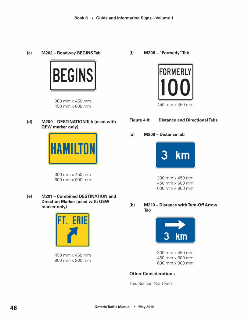
Book 8 • Guide and Information Signs – Volume 1
Ontario Traffic Manual • May 201046
(c) M202 – roadway BeGInS Tab
300 mm x 450 mm 450 mm x 600 mm
(d) M200 – deSTInATIOn Tab (used with Qew marker only)
300 mm x 450 mm600 mm x 900 mm
(e) M201 – combined deSTInATIOn and direction Marker (used with Qew marker only)
450 mm x 450 mm900 mm x 900 mm
(f) M206 – “Formerly” Tab
450 mm x 450 mm
Figure 4.8: Distance and Directional Tabs
(a) M209 – distance Tab
300 mm x 450 mm450 mm x 600 mm600 mm x 900 mm
(b) M210 – distance with Turn-Off Arrow Tab
300 mm x 450 mm450 mm x 600 mm600 mm x 900 mm
Other considerations
This Section Not Used.

Ontario Traffic Manual • May 2010 47
Book 8 • Guide and Information Signs – Volume 1
4.5 Distance Markers
Purpose and Background
These signs provide road users with travel distance information along a route. They also provide a means of location referencing for incidents/collisions and maintenance activities.
Qualification Criteria
These signs are used on longer distance freeways and may be considered on toll highways and expressways.
Distance Markers may also be used on provincial highways at the discretion of the MTO Head, Regional Traffic Office.
Application and Installation
Distance Markers shall be installed with distances beginning at the:
•Southern end of a route; or
•Western end of a route.
They shall be provided for both the express and collector lanes of complex freeways.
Distances shown should be the same for either direction of travel, with distances ascending in one direction and descending in the opposite direction. Alternatively, where providing the direction of travel is of benefit to the road authority, distance markers can be installed using even numbers for eastbound traffic (100.0, 100.2, 100.4, etc.) and westbound traffic would see odd numbers (100.1, 100.3, 100.5, etc).
When used, they shall be continuously applied along the entire length of a route at intervals of no greater than 2 km. In built up areas, they may be placed at more frequent intervals, but not less than 0.1 km (100 metres).
Where two routes overlap, only one route shall be signed along the overlap. A number of factors should be considered when determining which route to sign, such as:
•Provincial freeways generally have precedence over provincial highways;
•Lower numbered provincial freeways generally have precedence over higher numbered provincial freeways;
•When one route has more continuity than the other, the more continuous route should take precedence; and
•On provincial highways, the longer of the two routes will generally have precedence over the shorter route.
Where numbered routes overlap, continuity of distance marking and interchange numbering shall be maintained based on the distance marking and interchange numbering of the lower-numbered route.
Where overlapping routes split, distance marking on the route not referenced throughout the overlap will be resumed. The distances

Book 8 • Guide and Information Signs – Volume 1
Ontario Traffic Manual • May 201048
shown beyond the overlap shall reflect the total distance from the beginning point of the route, and shall include the distance covered by the overlap.
On simple freeways and highways, signs shall be installed beyond the right shoulder.
On complex freeways (express and collector systems), signs shall be installed on the express-collector separators for both direction of travel. Additional Distance Markers may be used on the right shoulder of the collector lanes where there is a significant distance between the express and collector lanes.
Interchange numbers coincide with the distance shown on the nearest Distance Marker to the interchange.
Design Guidance
Distances shall be shown in kilometres, to the nearest tenth of a kilometre (e.g. 520 km, 520.1 km, etc.).
The upper section of the Distance Marker shall have a green retroreflective background with white retroreflective text. Text on the upper section consists of “km” and the appropriate distance using a maximum of four digits placed vertically on the sign.
The lower section of the Distance Marker shall have a white retroreflective background with black text (Figure 4.5). Text on the lower section consists of a numerical distance to the nearest tenth of a kilometre.
Figure 4.9: M801 – distance Markers
200 mm x 900 mm
Ontario Traffic Manual • May 2010 49
Book 8 • Guide and Information Signs – Volume 1
Other considerations
In the case of provincial freeways, the QEW is considered to be the lower-numbered route, relative to all other 400-series freeways. Distance Marker numbering starts in Fort Erie.
It is recommended that the colour of the distance markers be the same as the Roadway Identification Signs.
4.6 Trans Canada Route Marker
Purpose and Background
The Trans Canada Route Marker identifies provincial routes designated as part of the Trans Canada Highway network.
Qualification Criteria
In Ontario, the following routes have been designated:
•Hwy 7: Hwy 417 to Hwy 12
•Hwy 11: Hwy 17 to Hwy 71
•Hwy 11: Hwy 17 North Bay to Hwy 17, Lake Helen (Up through Kapuskasing and Hearst)
•Hwy 11/17: Lake Helen to Shabaqua Corners
•Hwy 12: Hwy 7 to Hwy 400
•Hwy 17: Hwy 11 North Bay to Hwy 11, Lake Helen
•Hwy 17: Hwy 417 to Hwy 11, North Bay
•Hwy 17: Hwy 11 to Ontario-Manitoba Border
•Hwy 66: Hwy 11 to Quebec Border (Near Kirkland Lake)
•Hwy 69: Hwy 400 to Hwy 17, Sudbury
•Hwy 71: Hwy 11 to Hwy 17
•Hwy 400: Hwy 12 to Hwy 69
•Hwy 417: Quebec-Ontario border to western terminus
Application and Installation
The Trans Canada Route Marker may be installed below advance, turn-off and confirmation provincial route markers when the provincial highway forms part of the route.
Design Guidance
The Trans Canada Route Marker shall consist of a green retroreflective background and text and white retroreflective symbols and border. The marker shall be a minimum of 450 mm x 600 mm in size.
Tabs, when used, shall be the same colour as the marker to which it is attached.

Book 8 • Guide and Information Signs – Volume 1
Ontario Traffic Manual • May 201050
Figure 4.10: M111 – Trans canada route Marker
450 mm x 600 mm
Other considerations
This Section Not Used.

Ontario Traffic Manual • May 2010 51
Book 8 • Guide and Information Signs – Volume 1
5. Freeway Interchanges – Mainline Signs
5.1 Introduction
This chapter addresses the use and application of Guide and Information Signs located on the mainline of provincial freeways, including toll highways and expressways with freeway characteristics.
It should be read in conjunction with Volume 2 – Typical Layouts.
For signing purposes, freeways are generally classified as either being “urban” or “rural”.
An “urban” freeway meets some or all of the following criteria:
•Main roadways with two or more lanes in each direction;
•High traffic volumes on through roadways;
•High volumes of traffic entering and exiting at certain interchanges;
•Closely spaced interchanges;
•Interchange and/or roadway lighting;
•Generally has multiple interchanges serving a municipality;
•Any of the above characteristics may require the use of the following procedures:
– Interchange sequence signs; – Elimination of service signing; – Reduction of post interchange signs; – Overhead signs on roadway structures and on independent sign supports; and – Diagrammatic Signs in advance of interchanges that require complex or unusual manoeuvres.
A “rural” freeway meets some or all of the following criteria:
•Main roadways generally having two lanes in each direction;
•Lower traffic volumes on through roadways;
•Lower volumes of traffic entering and exiting at interchanges;
•Interchanges are located at a considerable distance apart, which allows for a sequence of signs to be adequately spaced on the approach and departure from each interchange;
•Partial lighting at interchanges or major decision points; and
•Higher speed traffic.
Road users of “rural” freeways generally travel longer distances, and may be more unfamiliar with local areas.
Guide and Information Signs are primarily located at, approaching, and/or beyond the following highway features:

Book 8 • Guide and Information Signs – Volume 1
Ontario Traffic Manual • May 201052
•Interchanges with other highways;
•Transfer lanes on complex freeways; and,
•Grade separations with no access to the freeway mainline.
In the case of left exits, warnings should be given at least 3 km in advance, specifying that there is a left exit at that distance.
Roadway Identification Signs approaching interchanges and transfers generally consist of the following:
•Advance Sign with Interchange Number Tab attached, where applicable;
•Turn-Off Sign; and
•Exit Sign.
Where necessary, this basic arrangement of signs may be supplemented or replaced by the following additional devices:
•Lane Exits Warning Signs;
•Pre-Advance Signs;
•Advance or Pre-Advance Diagrammatic Signs;
•Interchange Sequence Signs; and
•Pull-Through Signs.
Roadway Identification Signs use a combination of roadway names and/or numbers, cardinal directions, and a limited number of destinations served by the interchange to orient the road user. Applicable destinations are selected on the basis of relevance (Chapter 9).
The following markers may be displayed on Freeway Composite Services Boards (FCSB):
•Emergency Services (Chapter 11);
•Public Transportation Services (Chapter 12)
•Road User Services (Chapter 13); and
•Selected major traffic generators (i.e. colleges and universities – Chapter 15).
Other major attractions may be identified on separate signs approaching the interchange.
Temporary signs for special events may also be present (Chapter 15).
Corporate logos for qualified businesses providing essential motorist services are displayed on Logo Boards. In situations where space is limited, this information may be represented by generic icons and combined with other services markers on the FCSB.
Tourist attractions and services, meeting pre-determined qualification criteria, may be displayed on Tourism-Oriented Destination Signs (TODS).
Boundary Signs and Promotional Information Tabs identify the jurisdictional limits of upper-tier, lower-tier and single-tier municipalities, First Nations territories, and the built-up limits of formerly incorporated municipalities that the freeway passes through.
Downtown, City Centre and Business Area Signs; and Port and Industrial Area Signs identify routes from the freeway to these features located within the boundaries of lower-tier and single-tier municipalities, and First Nations territories.

Ontario Traffic Manual • May 2010 53
Book 8 • Guide and Information Signs – Volume 1
Decorative Municipal Displays identify qualified upper-tier, lower-tier and single-tier municipalities, First Nations territories, and formerly incorporated municipalities adjacent to the freeway.
Route Marker (Confirmation) Signs and Distance (Assurance) Signs are placed beyond interchanges to inform road users that they are on the correct route.
Supplementary Destination Signs may be provided to identify significant communities accessible via crossing roadways.
Distance Markers provide location referencing along the freeway mainline and coordinate with interchange numbering as a map reference.
Natural features are identified for the interest of road users.
For all signs that provide direction to exit at a specific interchange, additional directional signs will be provided on the off-ramp (Chapter 7).
Design Commonalities - Colour
The following sign examples should be shown with a white retroreflective message and border on a green retroreflective background, except when used in the collector lanes of complex freeways, or on Highway 407 Express Toll Route (ETR) where the background shall be retroreflective blue:
•Exit Sign;
•Advance Sign;
•Turn-Off Sign;
•Interchange Number Tab;
•Pre-Advance Sign;
•Pre-Advance Diagrammatic Sign;
•Interchange Sequence Sign;
•Pull-Through Sign;
•Assurance Sign;
•Auxiliary Assurance Sign;
•Supplementary Destination Sign;
•Natural Feature Identification Sign; and
•Roadway Identification (Grade Separation) Sign.
The following sign examples should be shown with a white retroreflective message on a blue retroreflective background:
•Boundary Sign;
•Downtown, City Centre and Business Area Sign;
•Port and Industrial Area Sign; and
•“TO” Downtown from Airport Sign.
For signs displaying text, sign width should be determined by the spacing requirements of the longest line of text.

Book 8 • Guide and Information Signs – Volume 1
Ontario Traffic Manual • May 201054
Route Markers, when shown on freeway mainline signs, shall have a white retroreflective background, with black numerals, with all other text omitted.
On provincial freeways, Route Marker Shields shall only be used as Route Marker (Confirmation) Signs. Route Marker Crowns shall be used in all other applications.
Marker Tabs, when used, shall be the same width and shall be the same colour(s) as the sign to which they are attached.
Overhead Mounting
On advance, overhead Roadway Identification Signs and Ground-Mounted Lane Configuration Signs, arrows pointing upwards are used to show the lane arrangement at the interchange.
On turn-off, overhead Roadway Identification Signs, arrows pointing downwards are used to show which lanes the message applies to.
Signs eligible for overhead mounting include the following:
•Advance Sign;
•Turn-Off Sign;
•Pre-Advance Sign;
•Pre-Advance Diagrammatic Sign;
•Interchange Sequence Sign; and
•Pull-Through Sign.
Overhead signs should be considered where any of the following conditions apply at an interchange:
•The freeway has three or more lanes in one direction;
•The interchange design is atypical or unusually complex; including multi-lane exits, left exits and must exit situations (e.g. lane drops);
•A Diagrammatic Sign is required;
•Sight distance is restricted in advance of the interchange;
•Interchanges are spaced less than 3 km apart, particularly in urban areas;
•Consistency in sign location through a series of closely spaced interchanges is desired;
•Average Annual Daily Traffic (AADT) exceeds 120,000 vehicles (AADT is the combined average volume for both directions of travel over a 24 hour period); or
•Where an analysis of human factors considerations indicates that overhead mounting is desirable.

Ontario Traffic Manual • May 2010 55
Book 8 • Guide and Information Signs – Volume 1
5.2 exit Sign
Purpose and Background
Exit Signs identify the place of departure from the freeway mainline.
Qualification Criteria
Exit Signs are used on all freeway, toll highway and expressway interchanges.
Exits Signs are not used at transfer lanes on complex freeways or where a freeway terminates at another freeway.
Note: At transfer lanes and freeway termination points an Oversized Object Marker (Wa-133) (OTM Book 6) is substituted for the Exit Sign.
Application and Installation
The Exit Sign or Oversize Object Marker should be located within the physical gore area formed by the mainline roadway and the ramp. It should be placed approximately 3 m behind the start of the physical gore on a breakaway support.
Design Guidance
The Exit Sign shall show the interchange number. Where no interchange number is used, the word “EXIT” shall be used to replace the interchange number.
The Exit Sign shall include a directional arrow to show whether the exit is to the left or right.
Figure 5.1: exit Signs
(a) G121 – Freeway exit Sign (Ground-Mounted)
1200 mm x 1500 mm
(b) G122 – Freeway exit (numbered) Sign (Ground-Mounted)
1200 mm x 1500 mm

Book 8 • Guide and Information Signs – Volume 1
Ontario Traffic Manual • May 201056
(c) G123 – Freeway exit (number & Suffix) Sign (Ground-Mounted)
1200 mm x 1800 mm
Other considerations
This Section Not Used.
5.3 Turn-Off Signs
Purpose and Background
In freeway mainline applications, Turn-Off Signs provide road users with some or all of the following information at interchanges and transfers:
•Name and/or route number of crossing roadways;
•Cardinal direction(s) and/or destination(s) served;
•Location of the exit (left or right); and
•Lane configuration at the exit (overhead applications only).
Qualification Criteria
Turn-Off Signs are used on all freeway, toll highway and expressway interchanges, as well as at transfer points on complex freeways.
Application and Installation
At interchanges, one destination for each direction of travel on the crossing roadway is generally shown (refer to Chapter 9 for destination selection criteria). In urban areas where municipalities are served by multiple interchanges, and at other locations where no applicable destinations exist, this information may be omitted.
The destination geographically located to the left of the road user reading the sign should be listed first.
At multi-exit interchanges (e.g. cloverleaf interchanges), two Turn-Off Signs, one for each direction of travel on the crossing roadway, shall be provided.
Ground-Mounted Turn-Off Signs
Turn-Off Signs are typically located opposite the start of the painted gore area.
For multi-exit interchanges, the first Turn-Off Sign is located opposite the start of the painted gore area of the first (upstream) exit ramp. A second Turn-Off Sign shall be located near the painted gore of the second or downstream exit. The second sign may be ground-mounted or alternatively placed overhead on a structure, where applicable.

Ontario Traffic Manual • May 2010 57
Book 8 • Guide and Information Signs – Volume 1
Overhead Turn-Off Signs
Overhead Turn-Off Signs should be located at the point where the painted gore reaches a width of 1.2 m. Signs should be placed directly above the lanes to which they apply.
A yellow down arrow panel is used to indicate all exit lanes departing the freeway mainline (refer to Figure 5.3).
Where one freeway terminates at another, a yellow down arrow panel is used to identify all exit options.
At transfers on complex freeways:
•Turn-Off Signs in the express lanes (Figure 5.3 (c)) indicate the name and/or route number of the crossing roadways served by the upcoming transfer;
•Turn-Off Signs in the collector lanes (Figure 5.3 (d)) display the text “Express”.
Design Guidance
Ground-Mounted Turn-Off Signs
Ground-mounted Turn-Off Signs shall indicate:
The route number of the crossing roadway (if applicable);
•The name of the crossing roadway (if applicable);
•The cardinal direction, if required (e.g. multi-exit interchanges);
•A maximum of two destinations served by the crossing roadway; and
•A directional arrow.
Destinations shown on Turn-Off Signs shall be the same as those shown on Advance Signs.
The first line of text, indicating the name of the crossing roadway, is to be left aligned. Additional lines of text showing destinations are to be centred under first line of text. (Figure 5.2).
Figure 5.2: G101 – Freeway Turn-Off Sign (Ground-Mounted)
2100 mm x Variable Width
Overhead Turn-Off Signs
Overhead Turn-Off Signs shall indicate:
•The route number of the crossing roadway (if applicable);
•The name of the crossing roadway (if applicable);
•The cardinal direction, if required (e.g. multi-exit interchanges);
•A maximum of two destinations served by the crossing roadway; and
•A yellow down arrow panel, indicating all exit lanes.
Destinations shown on Turn-Off Signs shall be the same as those shown on Advance Signs.

Book 8 • Guide and Information Signs – Volume 1
Ontario Traffic Manual • May 201058
Text on the sign is to be centred (Figure 5.3).
Figure 5.3: Overhead Turn-Off Signs
(a) G110 - Freeway Turn-Off Sign - road name Only (Overhead)
2100 mm x Variable Width2400 mm x Variable Width
(b) G111 – Freeway Turn-Off Sign with destinations (Overhead)
2700 mm x Variable Width
(c) G114 – Freeway Turn-Off Sign – express to collector Transfer (Overhead)
2700 mm x Variable Width
(d) G117 – Freeway Turn-Off Sign – collector to express Transfer (Overhead)
2100 mm x Variable Width
Other considerations
This Section Not Used.
Ontario Traffic Manual • May 2010 59
Book 8 • Guide and Information Signs – Volume 1
5.4 Advance Signs
Purpose and Background
In freeway mainline applications, Advance Signs provide road users with some or all of the following information prior to reaching an interchange:
•Crossing roadway identification (name and/or route number);
•Cardinal directions and/or destinations served;
•Interchange number (where applicable);
•Location of the exit (left or right);
•Configuration of the exit (single or multiple ramps – A-B type);
•Lane configuration at the exit (overhead applications only);
•Mandatory exit lanes (overhead applications only); and
•Distance to the interchange (ground-mounted applications only).
Qualification Criteria
Advance Signs are used on all freeway, toll highway and expressway interchanges, as well as at transfer points on complex freeways.
Application and Installation Ground-Mounted
Ground-mounted Advance Signs should be located beyond the right shoulder of the roadway, 1 km in advance of the start of the painted exit gore. In cases where it is not desirable, or possible, to locate the sign at the exact 1 km point, the actual distance on the sign should be shown:
•to the nearest 100 m when the sign is located less than 1 km in advance (e.g. 700 m), or
•To the nearest tenth of a kilometre when the sign is located more than 1 km in advance (e.g. 1.2 km)
Overhead
Overhead Advance Signs should be located 460 m (generally not more than 1 km) in advance of the Turn-Off Sign. Where this minimum requirement cannot be met, Interchange Sequence Signs (Section 5.9) may be considered.
Overhead Advance Signs should be right or left justified so that the arrow graphics approximately line up with the appropriate lanes.
Arrows on the overhead signs shall show the lane arrangement at the interchange, including all optional and/or mandatory exiting lanes. The arrow graphic shall be placed on the right side of the sign for right-hand exits, and on the left-hand side of the sign for left-hand exits.
Where an optional lane is provided (an either/or lane) it should be shown using a forked arrow.

Book 8 • Guide and Information Signs – Volume 1
Ontario Traffic Manual • May 201060
Where a freeway terminates at another freeway, Advance Signs identify all exit options.
At transfers on complex freeways:
•Advance Signs in the express lanes (Figure 5.5 (b)) indicate the route number and/or name of the crossing roadways served by the upcoming transfer, and the lane configuration at the transfer; and
•Advance Signs in the collector lanes (Figure 5.5(c)) display the text “Express” as well as the lane configuration at the transfer.
Interchange Number Tabs shall not be used at transfers on complex freeways.
Exit Panels
Exit Panels on overhead Advance Signs shall only be placed below the applicable lane configuration arrows where:
• Traffic in one or more of the through lanes of the freeway mainline must exit; or
•Where traffic in an (on-off type) auxiliary lane must exit.
Exit Panels should be used in situations where a motorist traveling for some distance/time in a lane will be required, or forced, to exit the freeway.
An Exit Panel should not be used when a standard deceleration lane is developed and motorists are required to make a lane change in order to exit the freeway. (Figure 5.5 (d))
Design Guidance
Ground-Mounted Sign
The ground-mounted Advance Sign (Figure 5.4) shall typically indicate:
•The name of the crossing roadway and the route number (if applicable);
•A maximum of two destinations served by the crossing roadway (Chapter 9);
•The distance to the interchange; and
•The interchange number (if applicable), using the Interchange Number Tab.
Generally, one destination for each direction of travel on the crossing roadway should be shown. The destination geographically located to the left of the road user reading the sign should be listed first. Text on the sign is to be centred.
Figure 5.4: G100 – Freeway Advance Sign (Ground-Mounted)
2700 mm x Variable Width
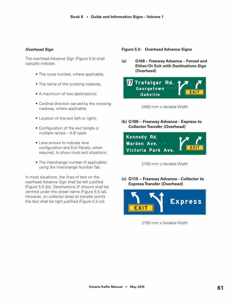
Ontario Traffic Manual • May 2010 61
Book 8 • Guide and Information Signs – Volume 1
Overhead Sign
The overhead Advance Sign (Figure 5.5) shall typically indicate:
•The route number, where applicable;
•The name of the crossing roadway;
•A maximum of two destinations;
•Cardinal direction served by the crossing roadway, where applicable;
•Location of the exit (left or right);
•Configuration of the exit (single or multiple ramps – A-B type);
•Lane arrows to indicate lane configuration and Exit Panels, when required, to show must exit situations;
•The interchange number (if applicable), using the Interchange Number Tab.
In most situations, the lines of text on the overhead Advance Sign shall be left justified (Figure 5.5 (b)). Destinations (if shown) shall be centred under the street name (Figure 5.5 (a)). However, on collector lanes at transfer points the text shall be right justified (Figure 5.5 (c)).
Figure 5.5: Overhead Advance Signs
(a) G108 – Freeway Advance – Forced and either/Or exit with destinations Sign (Overhead)
2400 mm x Variable Width
(b) G109 – Freeway Advance - express to collector Transfer (Overhead)
2700 mm x Variable Width
(c) G115 – Freeway Advance - collector to express Transfer (Overhead)
2100 mm x Variable Width

Book 8 • Guide and Information Signs – Volume 1
Ontario Traffic Manual • May 201062
(d) G106 – Freeway Advance – no Forced exit (Overhead)
2100 mm x Variable Width
Other considerations
When Exit Panels are used on an Advance Sign, two ground-mounted Lane Exits Signs are required (Section 5.11).
5.5 Interchange number Tabs
Purpose and Background
Interchange Number Tabs are installed with Advance Signs to indicate the number of the upcoming interchange.
Qualification Criteria
Interchange Number Tabs are used on all freeway, toll highway and expressway interchanges when an interchange numbering system is in use.
Application and Installation
On freeways where interchanges are identified by means of a numbering system, the number identified on the sign should be the distance (rounded to the nearest whole number) as measured from the start of the route to the centreline of the crossing roadway.
Both distances and interchange sequence should be integrated in such a manner that the interchange number relates to the nearest distance marker.
Where interchange numbering is provided, Interchange Number Tabs are added to ground-mounted and overhead Advance Signs.
Interchange Numbers Tabs may also be added to other Advance Signs (e.g. Freeway Service Composite Boards (FSCB), Tourism Oriented Destination Signs (TODS) and Logo Signs), where applicable.
The Interchange Number Tab shall not be used with Pre-Advance, Diagrammatic or Turn-Off Signs.
The number shown on the Interchange Number Tabs should be the same as the number displayed on the Numbered Exit Sign(s). Where an interchange has separate exits for each direction of travel on the crossing roadway, the suffix “A” or “B” shall be added to the interchange number on the Interchange Number Tab and wherever it is displayed.
Design Guidance
The Interchange Number Tab shall show the interchange number, where applicable and be located above the primary sign, flush with its right edge.
The word “EXIT” shall not be used with these tabs.
The colour of the Interchange Number Tab shall match that of the primary sign to which it is attached.

Ontario Traffic Manual • May 2010 63
Book 8 • Guide and Information Signs – Volume 1
Figure 5.6: Interchange number Tabs
(a) G118 – Interchange number Tab
600 mm x 1500 mm
(b) G119 – Interchange number Tab - A-Type Interchanges
600 mm x 2400 mm
(c) G120 – Interchange number Tab - A-B Type Interchanges
600 mm x 3000 mm
Other considerations
This Section Not Used.
5.6 Freeway composite Services Board (FcSB)
Purpose and Background
The Freeway Composite Services Board (FCSB) is used in advance of freeway exits to provide information about services available on the intersecting roadway. The following services may be displayed on the FCSB:
•Emergency Services (Chapter 11);
•Road User Services (Chapter 12); and
•Public Transportation Services (Chapter 13).
The services are identified on the FCSB using markers. FCSB may also be used to provide information about the availability of essential motorist services where there is insufficient roadside space to accommodate Logo Signs.
Qualification Criteria
Services eligible for display on the FCSB are identified below, in descending order of importance. Separate guidelines detailing qualification criteria for each service are provided within this OTM book.
•Police (OPP, Municipal Police, or First Nations Police);
•Hospital (unless displayed at the Advance and Turn-Off Sign locations);
•Generic Airports Markers (unless made redundant by stand-alone signs);

Book 8 • Guide and Information Signs – Volume 1
Ontario Traffic Manual • May 201064
•Generic Public Transportation Services Marker;
•Carpool Parking;
•Travel Information Centres;
•University or College;
•Generic Police/Collision Reporting Centre Marker;
•Corporate Logos for Public Transportation Services (e.g. Go Transit, Via Rail, Ontario Northland Train Station, Toronto Transit Commission (subway stations));
•Emergency Helipad; and
•Public Telephone
Corporate Logos may replace generic Public Transportation Services Markers on FCSB where space is not required for other qualified services.
Where there is insufficient space on the freeway mainline to install a full Logo Sign system, generic markers for food, fuel and accommodations shall occupy the first three spots on the FCSB, if one exists.
Application and Installation
One to six service markers may be shown on the FCSB. Generally one FCSB is installed for each direction of travel on the mainline.
In all applications, markers shown on the FCSB are repeated, along with directional information on the off-ramp (Chapter 7).
The FCSB should be ground-mounted beyond the right shoulder of the roadway, a minimum of 200 m in advance of the ground-mounted or overhead Advance Sign.
Design Guidance
The FCSB shall display one to six 900 mm x 900 mm markers.
On freeways with a numbering system, an Interchange Number Tab shall be attached to the top of the FCSB, flush with the right edge of the FCSB.
On freeways where an interchange numbering system has not been assigned, the following message tabs may be attached to the bottom of the primary sign:
•“Next Exit”;
•“Second Exit”; or
•“Via (Road Name).
The “Next Exit” Tab shall be used for the first upcoming exit ramp following the FCSB (Figure 5.8).
The “Second Exit” Tab may be used when signing directional A-B ramps. This tab may also be used to sign A-B ramps where interchange numbers have been assigned (Figure 5.9).
The “Via (Road Name)” Tab may be used when there is insufficient space at the preferred interchange for a FCSB. The sign is installed in advance of the preceding interchange (Figure 5.10).

Ontario Traffic Manual • May 2010 65
Book 8 • Guide and Information Signs – Volume 1
Tabs shall be shown in the same colour as the FCSB, and shall be retroreflective.
Text on the tabs is to be centred.
Figure 5.7: Freeway composite Services Board (FcSB)
(a) G400 – Freeway composite Services Board (3-Markers)
1200 mm x 3600 mm
(b) G401 – Freeway composite Services Board (6-Markers)
2400 mm x 3600 mm
Figure 5.8: G416 – “next exit” Tab
600 mm x 3600 mm
Figure 5.9: G417 – “Second exit” Tab
600 mm x 3600 mm
Figure 5.10: G418 – “Via (road name)” Tab
600 mm x 3600 mm
Other considerations
This Section Not Used.

Book 8 • Guide and Information Signs – Volume 1
Ontario Traffic Manual • May 201066
5.7 Pre-Advance Signs
Purpose and Background
Pre-Advance Signs are used to supplement existing roadway identification signs wherever road users require greater forewarning of an upcoming decision point.
Qualification Criteria
Pre-Advance Signs are applicable to freeways, toll highways and expressways.
Application and Installation
These signs are generally placed overhead, consistent with other signs in the vicinity and shall be centred over the through lanes.
When used, they identify the crossing roadway(s) at the next interchange(s), and indicate the distance(s) to that interchange(s).
Pre-Advance Signs may be placed:
•Adjacent to the overhead Turn-Off Sign at the preceding interchange; or
•Overhead on a separate structure, a minimum of 1 km in advance of the Advance Sign.
On simple freeways, additional Pre-Advance Signs may be used. All subsequent Pre-Advance Signs are installed on a separate structure and should be spaced a minimum of 1 km apart. The signs should not be located in advance of the preceding interchange, except when placed adjacent to the overhead Turn-Off Sign, as noted above.
At transfers on complex freeways these signs may be used in the express lanes in advance of a transfer point to indicate the route name and/or number of the crossing roadways served by the upcoming transfer. The only distance indicated on the sign should be the distance from the sign location to the transfer point (Figure 5.11(b)).
Pre-Advance signs may also be used in the collector lanes to identify up to three upcoming interchanges. The distances shown on these signs shall be from the sign location to each crossing roadway (Figure 5.11(c)).
Interchange Number Tabs and destinations shall not be used with Pre-Advance Signs.
Design Guidance
When down arrows are used, they should be placed directly above the continuous through lanes of the freeway mainline to which they apply. (Figure 5.11(c))
Figure 5.11: Pre-Advance Signs
(a) G103 – Freeway Pre-Advance Sign
2100 mm x Variable Width

Ontario Traffic Manual • May 2010 67
Book 8 • Guide and Information Signs – Volume 1
(b) G104 – Freeway Pre-Advance (express to collector) Sign
2400 mm x Variable Width
(c) G116 – Freeway Pre-Advance (collector Lanes) Sign
2100 mm x Variable Width
Other considerations
This Section Not Used.
5.8 Diagrammatic Signs
Purpose and Background
Diagrammatic Signs allow road users to more easily interpret upcoming complex decision points by graphically representing the decision point on the sign.
Qualification Criteria
Diagrammatic Signs are used on freeways, toll highways and expressways.
Application and Installation
The use of Diagrammatic Signs should be considered under the following circumstances:
•Left exits;
•At the location of two sequential right exits, where the space between them is insufficient for conventional signs;
•Freeway-to-freeway interchanges, which may include: – Freeway-to-freeway splits, where the centre lane is an optional lane (either/ or); – Freeway-to-freeway splits, where a freeway terminates at another freeway; and – Freeway-to-freeway splits, where a freeway begins at another freeway.
These signs are not recommended at the following types of interchanges:
•Standard right lane exits;
•Common cloverleaf interchanges;
•Interchanges with double lane drops followed by a fork (multiple split ramps); and
•Very complex interchanges where it is virtually impossible to design graphics that would be simple and accurate enough to portray the geometry of the interchange.
Diagrammatic Signs may replace Advance Signs under exceptional circumstances, but shall not be used for turn-off or pull-through applications.

Book 8 • Guide and Information Signs – Volume 1
Ontario Traffic Manual • May 201068
Diagrammatic Signs are most effective when used as a pre-advance message, located a minimum of 1 km in advance of the applicable Advance Sign.
For overhead applications, a Freeway Diagrammatic Sign should be centred over the through lanes of the roadway.
Interchange Number Tabs shall not be used with Diagrammatic Signs.
Design Guidance
The graphics should be simple and provide road users with a plan view of the decision point.
The graphical representation of the roadway must be retroreflective white. Lane lines, where applicable, must be included on the graphic and shown in black.
The graphic components should be designed so that the through route is the visually dominant portion of the graphic (except for the fork).
Deceleration lanes should not be shown on the graphic components.
Route Markers and destinations and/or street names shall be placed on the sign so that they correspond clearly with the movements shown by the graphic.
When two route symbols are required for the same destination, they should be positioned in a horizontal line with each other.
The information on the sign should be limited to two arrows. No more than one destination for each movement should be shown.
Exiting information should not be placed above the route symbol.
Exit Panels or Down Arrow Panels shall not be used on Diagrammatic Signs.
Figure 5.12: G102 – Freeway diagrammatic Pre-Advance/ Advance Sign
2700 mm x Variable Width
Other considerations
This Section Not Used.

Ontario Traffic Manual • May 2010 69
Book 8 • Guide and Information Signs – Volume 1
5.9 Interchange Sequence Signs
Purpose and Background
The Interchange Sequence Sign replaces the Advance Signs for up to three closely spaced interchanges.
Qualification Criteria
Interchange Sequence Signs are used on freeways, toll highways and expressways where the spacing of successive interchanges is insufficient to permit the installation of Advance Signs for each successive interchange.
Application and Installation
The Interchange Sequence Sign should be used on freeways where there is insufficient space to install separate Advance Signs for closely spaced, consecutive interchanges that have direct access to the freeway. In this situation one Interchange Sequence Sign effectively replaces all Advance Signs in the sequence and is located in advance of the first interchange. Each crossing roadway in the sequence will have a separate Turn-Off Sign.
A maximum of three road names may be displayed on the sign.
For overhead applications, an Interchange Sequence Sign should be centred over the through lanes of the roadway.
Interchange Number Tabs shall not be used with these signs.
Design Guidance
These signs should only indicate the route number and/or name of up to three downstream crossing roadways, and the distance to them. Road names are to be left justified and distances are to be right justified (Figure 5.13).
Figure 5.13: G112 – Freeway Interchange Sequence Sign
2100 mm x Variable Width
Other considerations
This Section Not Used.
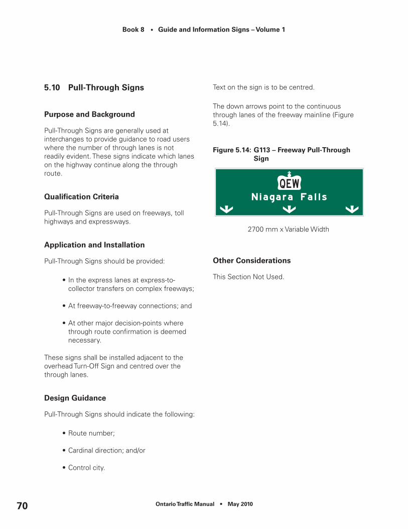
Book 8 • Guide and Information Signs – Volume 1
Ontario Traffic Manual • May 201070
5.10 Pull-Through Signs
Purpose and Background
Pull-Through Signs are generally used at interchanges to provide guidance to road users where the number of through lanes is not readily evident. These signs indicate which lanes on the highway continue along the through route.
Qualification Criteria
Pull-Through Signs are used on freeways, toll highways and expressways.
Application and Installation
Pull-Through Signs should be provided:
•In the express lanes at express-to-collector transfers on complex freeways;
•At freeway-to-freeway connections; and
•At other major decision-points where through route confirmation is deemed necessary.
These signs shall be installed adjacent to the overhead Turn-Off Sign and centred over the through lanes.
Design Guidance
Pull-Through Signs should indicate the following:
•Route number;
•Cardinal direction; and/or
•Control city.
Text on the sign is to be centred.
The down arrows point to the continuous through lanes of the freeway mainline (Figure 5.14).
Figure 5.14: G113 – Freeway Pull-Through Sign
2700 mm x Variable Width
Other considerations
This Section Not Used.

Ontario Traffic Manual • May 2010 71
Book 8 • Guide and Information Signs – Volume 1
5.11 Lane exits Sign
Purpose and Background
The purpose of the Lane Exits Sign is to provide advance warning that one or more lanes exit the mainline of the freeway.
Lane Exits Signs supplement information about mandatory and optional exit lanes.
Qualification Criteria
Lane Exits Signs are used on freeways, toll highways and expressways.
Application and Installation
Lane Exits Signs shall be used in conjunction with overhead Advance Signs when a lane-specific Exit Panel is shown on the overhead sign.
Signs are located on the right or left shoulder, according to the exit configuration. These signs are installed in pairs as outlined in OTM Book 6, Chapter 5 – Divided Road Transition Signs – Lane Exits Signing (Freeway).
Design Guidance
Refer to OTM Book 6, Chapter 5 – Divided Road Transition Signs – Lane Exits Signing (Freeway).
Figure 5.15: example Freeway Lane exits Sign
Wa-50R – Freeway Lane Exits (Right) Sign 900 mm x 1200 mm
Other considerations
This Section Not Used.

Book 8 • Guide and Information Signs – Volume 1
Ontario Traffic Manual • May 201072
5.12 Boundary Signs
Purpose and Background
Boundary Signs inform road users that they are entering an organized municipality, First Nations territory, or formerly incorporated municipality.
Qualification Criteria
These signs are used on freeways, toll highways and expressways.
When used on provincial freeways, Boundary Signs identify the following qualified communities:
•Upper-tier, lower-tier, or single-tier municipalities;
•First Nations territories; or
•Formerly incorporated municipalities eliminated under municipal restructuring on, or after, January 1, 1997.
To obtain Boundary Signs, formerly incorporated municipalities require the approval of the Municipal Council of the upper, lower or single-tier municipality in which they are situated.
Hamlets are not eligible for Boundary Signs on freeways.
To be eligible for a Boundary Sign:
•The freeway shall pass through a community; or
•The freeway forms part of a community’s boundary; and
•There shall be one or more freeway interchanges servicing the community.
When two or more municipalities, formerly incorporated municipalities or First Nations communities abut the freeway on either side, and when the freeway forms part of the boundary, the abutting communities do not qualify for a Boundary Sign. Instead, consideration should be given to provide Destination Signs at one interchange, typically the one serving their main population centre. Refer to Chapter 9 for additional details.
Application and Installation
Two signs shall be installed, one for each direction of travel on the freeway.
Where the municipal boundary intersects the freeway at an interchange, a Boundary Sign shall be located in advance of the interchange.
Where the boundary lies between interchanges, a Boundary Sign should be located near the actual boundary line.
Where boundaries overlap, they are to be signed individually in the following order, as applicable:
•Upper-tier or single-tier municipalities;
•Lower-tier municipalities; then
•Formerly incorporated municipalities.
On freeways, the larger sign size will be used.
Population figures shall only be shown for single-tier and lower-tier municipalities and First Nations territories (when requested).

Ontario Traffic Manual • May 2010 73
Book 8 • Guide and Information Signs – Volume 1
Population figures shall not be shown for upper-tier municipalities or formerly incorporated municipalities.
Population figures are to be based on Statistics Canada population data (www.statscan.ca). Statistics Canada provides official population counts every five years for all incorporated municipalities in the Province of Ontario. MTO shall be responsible for updating all population figures on Boundary Signs, as necessary, following the publication of each census.
As an alternate source of data, communities may request the use of population data from the Municipal Property Assessment Corporation (MPAC).
Communities may request that the population on their Boundary Sign be updated annually. However, all costs associated with this request will be the responsibility of the municipality.
Population figures are to be posted on Boundary Signs according to the following rounding formula shown in Table 5.1.
Table 5.1: Population Figures rounding Formula
Population Figure to be Shown
Less than 5000 Round actual population up
to the next highest 100
Population Figure to be Shown
More than 5000 but less than 25,000
Round actual population up
to the next highest 500
More than 25,000
Round actual population up
to the next highest 1000
Multiple Interchange Boundary Signs
When the number of interchanges servicing a lower-tier or single-tier municipality or First Nations territory is more than one but fewer than nine, then the number of interchanges for that community shall be listed on the Boundary Sign.
The number of interchanges serving an upper-tier municipality or a formerly incorporated municipality shall not be shown.
Design Guidance
Names shall be shown in upper/lower case lettering, conforming to design standards laid out in the applicable Master Sign Template.
When population information is shown, it shall be placed on a separate line (Figure 5.17).
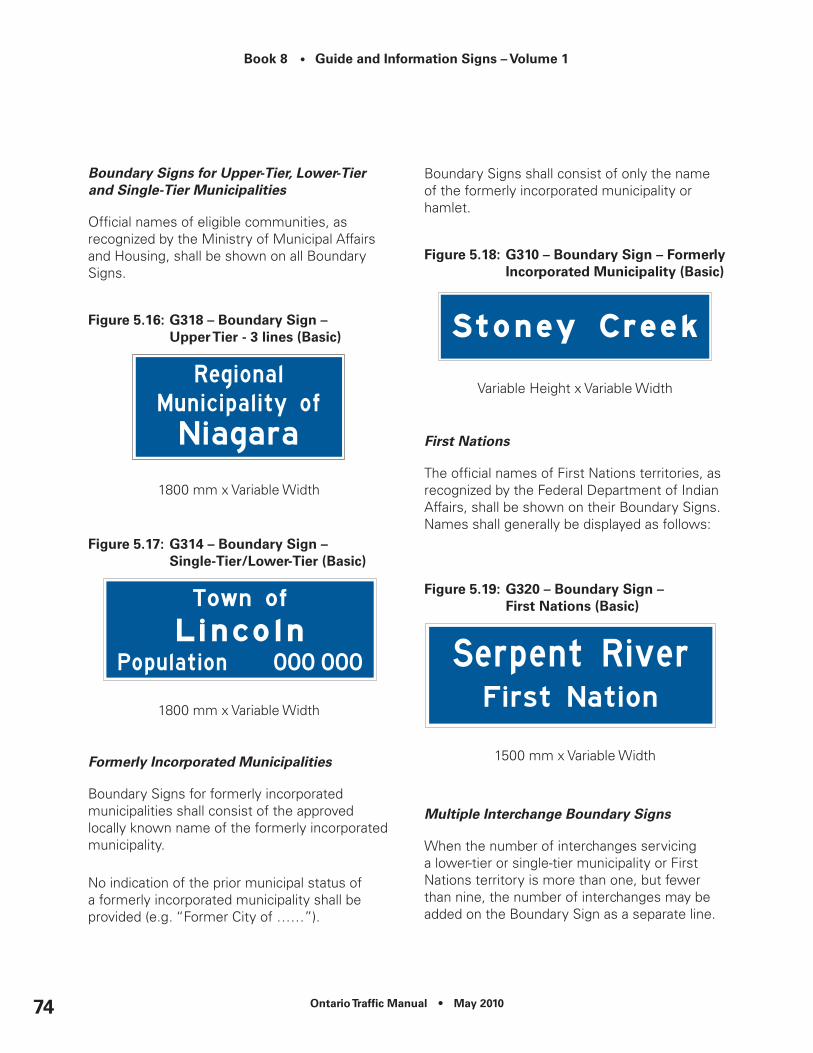
Book 8 • Guide and Information Signs – Volume 1
Ontario Traffic Manual • May 201074
Boundary Signs for Upper-Tier, Lower-Tier and Single-Tier Municipalities
Official names of eligible communities, as recognized by the Ministry of Municipal Affairs and Housing, shall be shown on all Boundary Signs.
Figure 5.16: G318 – Boundary Sign – upper Tier - 3 lines (Basic)
1800 mm x Variable Width
Figure 5.17: G314 – Boundary Sign – Single-Tier/Lower-Tier (Basic)
1800 mm x Variable Width
Formerly Incorporated Municipalities
Boundary Signs for formerly incorporated municipalities shall consist of the approved locally known name of the formerly incorporated municipality.
No indication of the prior municipal status of a formerly incorporated municipality shall be provided (e.g. “Former City of ……”).
Boundary Signs shall consist of only the name of the formerly incorporated municipality or hamlet.
Figure 5.18: G310 – Boundary Sign – Formerly Incorporated Municipality (Basic)
Variable Height x Variable Width
First Nations
The official names of First Nations territories, as recognized by the Federal Department of Indian Affairs, shall be shown on their Boundary Signs. Names shall generally be displayed as follows:
Figure 5.19: G320 – Boundary Sign – First nations (Basic)
1500 mm x Variable Width
Multiple Interchange Boundary Signs
When the number of interchanges servicing a lower-tier or single-tier municipality or First Nations territory is more than one, but fewer than nine, the number of interchanges may be added on the Boundary Sign as a separate line.

Ontario Traffic Manual • May 2010 75
Book 8 • Guide and Information Signs – Volume 1
Figure 5.20: G312 – Multiple Interchange Boundary Sign (1-9 Interchanges) (Basic)
1800 mm x Variable Width
Enhanced Boundary Signs
All communities that qualify for boundary signs may choose to participate in the Enhanced Boundary Sign Program.
The communities will be responsible for any additional cost associated with the manufacturing, installation and maintenance of the Enhanced Boundary Sign.
The Enhanced Boundary Sign will include all of the elements of a “basic” Boundary Sign plus any of the following:
•A coat-of-arms or community logo; and/or
•A community welcoming message or slogan profiling a unique feature.
The community logo, crest or coat-of-arms may be shown in colour. This portion of the sign should use contrasting colours and shall be retroreflective. The size of a logo, crest or coat-of-arms shall be limited to that specified in the Master Sign Template. The logo, crest or coat-of-arms shall be placed either to the left or to the right of the community name.
The slogan or welcoming message shall be limited to one line of text, shown at the bottom of the sign using blue text on a white retroreflective background. Letter height and borders shall conform to specifications in the applicable Master Sign Template.
Internet addresses, telephone numbers and other similar messages shall not be permitted on the sign.
Message content is subject to the Charter of Rights and Freedoms.
Messages that attempt to direct or control traffic are not permitted.
Logos cannot be used as a trailblazer symbol to direct road users to a destination within the municipality’s boundary.
Commercial content (e.g. sponsorship by, or promotion of, a commercial enterprise) is not permitted.
Messages referencing another community outside the boundaries of the applicable community are not permitted.
The logo, crest, coat-of-arm and/or slogan or welcoming message should be chosen and officially endorsed by Municipal Council.
An equivalent French Language version of the slogan or welcoming message is required in Designated Bilingual Areas.
Hamlets do not qualify for Enhanced Boundary Signs on freeways.

Book 8 • Guide and Information Signs – Volume 1
Ontario Traffic Manual • May 201076
Figure 5.21: enhanced Boundary Signs
(a) G317 – Boundary Sign – upper Tier 2 lines (enhanced)
1800 mm x Variable Width(2-line community name)
(b) G319 – Boundary Sign – upper Tier 3 lines (enhanced)
2400 mm x Variable Width(3-line community name)
(c) G315 – Boundary Sign – Single-Tier/Lower-Tier (enhanced)
2100 mm x Variable Width
(d) G311 – Boundary Sign – Formerly Incorporated Municipality (enhanced)
1800 mm x Variable Width
(e) G321 – Boundary Sign – First nations (enhanced)
1800 mm x Variable Width
(f) G313 – Boundary Sign – Multiple Interchanges (enhanced)
2400 mm x Variable Width
Other considerations
This Section Not Used.

Ontario Traffic Manual • May 2010 77
Book 8 • Guide and Information Signs – Volume 1
5.13 downtown, city centre and Business Area Signs
Purpose and Background
These signs are used to provide road users with directional guidance to downtowns, city centres and business areas.
Qualification Criteria
These signs may be used on freeways, toll highways and expressways.
These signs are not permitted on the express lanes of a complex freeway and shall not be used to direct traffic from one provincial freeway to another provincial freeway.
Lower-tier and single-tier municipalities and First Nations territories qualify for these signs if:
•The municipality is served by two or more freeway interchanges;
•The downtown, city centre or business area is accessible from the freeway; and
•The downtown, city centre or business area is designated within the municipality’s Official Plan.
Upper-tier municipalities, formerly incorporated municipalities and hamlets do not qualify for these signs.
Application and Installation
Municipalities may select the term “Downtown”, “City Centre” or “Business Area” to describe the area being signed.
The term “City Centre” is not to be used when a commercial facility within the community is known by the same name.
The term “Business Section” should be avoided where a municipality contains multiple business areas.
The municipality may choose to sign either the same exit or a different exit for each direction, but only one exit will be signed per direction of travel.
The sign should be placed a minimum of 200 m downstream of the applicable Boundary Sign.
Only one downtown, city centre or business area should be signed within any one municipality or First Nations territory, however they may qualify for signs on more than one freeway.
The downtown, city centre or business area must be included on a Destination Sign at the freeway off-ramp. (Chapter 7).
Trailblazing is to be provided by the municipality on its roadways, as needed.
When two or more qualified communities abut the freeway on both sides, or when the freeway forms part of the boundary, the abutting communities do not qualify for Downtown, City Centre and Business Area Signs. Instead, consideration should be given to provide Destination Signs at one interchange, typically the one serving their main population centre. Refer to Chapter 9 for additional details.
Design Guidance
Text on the sign is to be centred.

Book 8 • Guide and Information Signs – Volume 1
Ontario Traffic Manual • May 201078
Figure 5.22: G322 – downtown, city centre or Business Area Signs
2400 mm x Variable Width
Other considerations
This Section Not Used.
5.14 Port and Industrial Area Signs
Purpose and Background
These signs are used to provide road users with directional guidance to ports and industrial areas.
Qualification Criteria
These signs may be used on freeways, toll highways and expressways.
These signs are not permitted on the express lanes of a complex freeway and shall not be used to direct traffic from one provincial freeway to another provincial freeway.
Lower-tier and single-tier municipalities and First Nations territories qualify for these signs if:
•The municipality is served by two or more freeway interchanges;
•The port or industrial area is accessible from the freeway; and
•The port or industrial area is designated within the municipality’s Official Plan.
Upper-tier municipalities, formerly incorporated municipalities and hamlets do not qualify for these signs.
Application and Installation
The term “Industrial Park” may be substituted for “Industrial Area”, where applicable.
The municipality may choose to sign either the same exit or a different exit for each direction, but only one exit will be signed per direction of travel.
The sign should be placed a minimum of 200 m downstream of the applicable community Boundary Sign and/or Downtown, City Centre or Business Area Sign.
Only one industrial area and one port should be signed within any one community. However, the industrial area or port may qualify for signs on more than one freeway.
The port and/or industrial area must be included on the Destination Signs provided at the freeway off-ramp (Chapter 7).
Trailblazing is to be provided by the municipality on its roadways, as needed.

Ontario Traffic Manual • May 2010 79
Book 8 • Guide and Information Signs – Volume 1
Design Guidance
The officially recognized name of the port or industrial area, or the official name of the municipality where the port or industrial area is located, may be displayed on the sign. Text on the sign is to be centred.
Figure 5.23: G328 – Port or Industrial Area Sign
2400 mm x Variable Width
Other considerations
This Section Not Used.
5.15 To downtown from Airport Signs
Purpose and Background
Signs to downtowns provide unfamiliar road users with directional guidance to downtown centres from major airports.
Qualification Criteria
These signs are used on freeways and may be considered for use on toll highways and expressways.
Signs are applicable to major airports only (Chapter 12).
Only the downtown of the largest municipality in the vicinity served by a freeway, or by a crossing roadway that intersects with a freeway, should be signed.
Signs should not be installed where other information, such as Guide and Information, Destination or Assurance Signs serve the same purpose.
Application and Installation
The sign may be installed on the roadway exiting the airport, prior to the first decision-point that forms part of the intended route to the downtown. Additional signs may be provided in advance of subsequent decision points, where required.
Only one route to the downtown from the airport shall be signed.
Trailblazing is to be provided by the municipality on its roadways, as needed.
Design Guidance
Where necessary, a maximum of two successive routes may be identified on the sign (e.g. Follow 427 South/Gardiner East).
The term “City Centre” may be substituted for the term “Downtown”, where applicable.
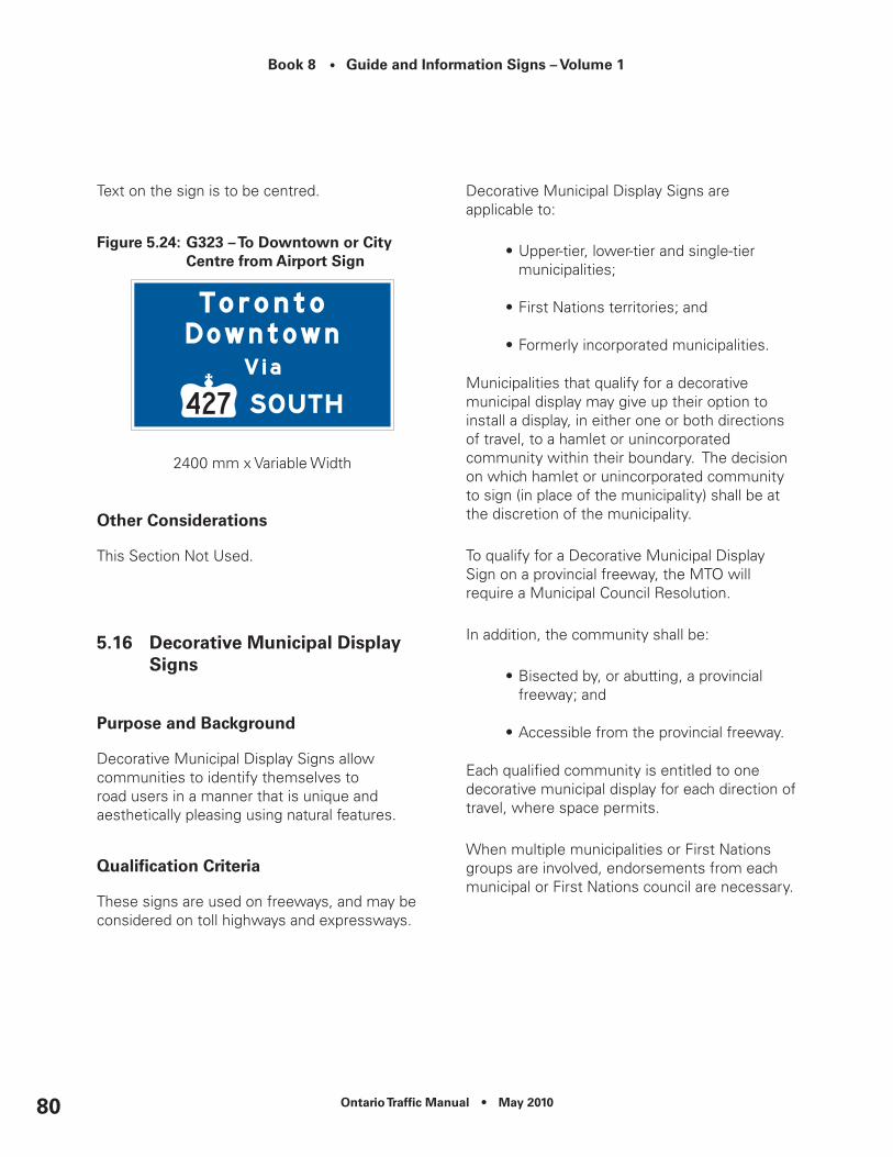
Book 8 • Guide and Information Signs – Volume 1
Ontario Traffic Manual • May 201080
Text on the sign is to be centred.
Figure 5.24: G323 – To downtown or city centre from Airport Sign
2400 mm x Variable Width
Other considerations
This Section Not Used.
5.16 decorative Municipal display Signs
Purpose and Background
Decorative Municipal Display Signs allow communities to identify themselves to road users in a manner that is unique and aesthetically pleasing using natural features.
Qualification Criteria
These signs are used on freeways, and may be considered on toll highways and expressways.
Decorative Municipal Display Signs are applicable to:
•Upper-tier, lower-tier and single-tier municipalities;
•First Nations territories; and
•Formerly incorporated municipalities.
Municipalities that qualify for a decorative municipal display may give up their option to install a display, in either one or both directions of travel, to a hamlet or unincorporated community within their boundary. The decision on which hamlet or unincorporated community to sign (in place of the municipality) shall be at the discretion of the municipality.
To qualify for a Decorative Municipal Display Sign on a provincial freeway, the MTO will require a Municipal Council Resolution.
In addition, the community shall be:
•Bisected by, or abutting, a provincial freeway; and
•Accessible from the provincial freeway.
Each qualified community is entitled to one decorative municipal display for each direction of travel, where space permits.
When multiple municipalities or First Nations groups are involved, endorsements from each municipal or First Nations council are necessary.

Ontario Traffic Manual • May 2010 81
Book 8 • Guide and Information Signs – Volume 1
Application and Installation
The preferred location for the Decorative Municipal Display Sign is within the right-of-way of an interchange that provides the most direct route to the community. Where there is insufficient space at the preferred location due to physical, geometric or safety concerns, the display may be located immediately upstream if sufficient space exists within the right-of-way.
The displays must not compromise sight distance for merging and/or diverging traffic.
Decorative Municipal Display Signs must be located within the boundaries of the municipality to which they refer.
Where multiple proponents within an area wish to have a decorative municipal display, one themed display may be used for the whole area if all participating municipalities are able to reach agreement, including the design and placement of the display.
When the boundaries of two or more communities overlap at a common point, the Upper-Tier municipality shall be identified first in advance of the interchange serving their municipality, with other qualified communities within the Upper-Tier municipality being signed at successive interchanges for the same direction of travel.
When two or more communities abut the freeway on both sides, or when the freeway forms part of the formal or informal boundary, each of the abutting communities may have one Decorative Municipal Display placed on the right-hand side of the roadway in opposing directions.
These signs are not permitted within a freeway-to-freeway interchange, freeway medians, divided highway medians, or between the express and collector lanes.
When installed within the right-of-way, they must be placed outside of the clear zone.
Municipalities will be responsible for all costs associated with the manufacturing, installation and maintenance of the sign displays, including any damage after installation, no matter how it occurs. Municipalities are also responsible for the protection of all utilities presently existing on the right-of-way in the area of the sign display.
If problems develop after the display is in place, the Ministry reserves the right to insist the problem be corrected or the display removed.
If the display ceases to be maintained, the Ministry will arrange for the removal or repair and the municipality will be responsible for payment of all costs.
Municipalities should be informed that the display may be removed because of highway reconstruction and all costs will be the responsibility of the municipality.
Design Guidance
Decorative Municipal Display Signs are intended primarily as landscape features. They may be created using any combination of natural materials such as:
•Plantings;
•Wood;
•Rocks;

Book 8 • Guide and Information Signs – Volume 1
Ontario Traffi c Manual • May 201082
• Earth berms; and
• Mounted lettering.
The message presented by the Decorative Municipal Display is restricted to the name of the community and/or an approved municipal logo or slogan.
Messages that attempt to control or direct traffi c are not permitted. Logos cannot be used as a trailblazer symbol to direct road users to a destination within the municipality’s boundary. Commercial content is not permitted. Internet addresses, telephone numbers and other similar messages are not permitted on the sign.
Municipalities must submit a detailed construction plan, including the preferred location, to the Ministry for approval. Any deviation is to receive prior approval from the Ministry before commencing that portion of the work.
Whenever possible, construction and/or maintenance of the display should be carried out from an adjacent road or street, rather than from the travelled portion of the provincial route.
The height of the display is not to exceed 3 m, measured from the surrounding grade to the top of the tallest element of the display. Existing roadway slopes and drainage patterns must not be altered, except as approved.
Displays are limited to no more than 6 m in width/length.
Illumination of the display is permitted, provided the illumination design includes adequate shielding to avoid light trespass and/or glare on any adjacent roadway.
Figure 5.25: Decorative Municipal Display - Freeway
Municipal Name
Other ConsiderationsAny work occurring on the right-of-way of a provincial route must be conducted in conformance with the OTM Book 7 Temporary Conditions, and the Occupational Health and Safety Act.
All activities, including material and equipment stored within the right-of-way, must be in accordance with the MTO Roadside Safety Manual.
5.17 Assurance Signs
Purpose and Background
These signs provide assurance to motorists that they are on the correct route by displaying the name and distances, of up to three signifi cant downstream destinations, which the freeway passes near or through.

Ontario Traffic Manual • May 2010 83
Book 8 • Guide and Information Signs – Volume 1
Qualification Criteria
These signs are used on freeways, and may be considered on toll highways and expressways.
Only control cities and qualified communities (Chapter 9) shall be shown on Assurance Signs as destinations.
No more than three downstream destinations, and the distances to them, should be displayed.
Application and Installation
Assurance Signs are to be provided as follows:
•Downstream of the last interchange serving a community; and
•Beyond freeway-to-freeway, freeway-to-toll highway, freeway-to-expressway and freeway-to-provincial highway interchanges.
•At other major interchanges where large volumes of traffic are entering the freeway facility.
When the sign is located beyond the last interchange serving a community, it should be located a minimum of 150 m beyond the Route Marker (Confirmation).
Destinations are to be depicted in the following order:
•(Line 1) The next qualified community;
•(Line 2) The intermediate end-of-route control city; and
•(Line 3) The end-of-route control city.
Where the intermediate end-of-route becomes the next closest community, it should be displayed on line 1, with the next intermediate end-of-route shown on line 2, and the end-of-route shown on line 3.
Where no intermediate end-of-route control city is present, the second qualified community downstream is to be displayed on line 2.
Where the demand for signs amongst qualified communities within a particular road segment exceeds the maximum permitted, destinations on the signs should be selected based on the criteria outlined in Chapter 9.
Distances shown on the sign shall be measured from the sign location to the applicable seat of government (town or city hall) or, if none, the geographic centre of the built-up area.
Distances shall be shown in kilometres, rounded up to the nearest whole number.

Book 8 • Guide and Information Signs – Volume 1
Ontario Traffic Manual • May 201084
Design Guidance
Figure 5.26: Assurance Signs
(a) G300 – Assurance Sign – One Destination
900 mm x Variable Width
(b) G301 – Assurance Sign – Two Destinations
1500 mm x Variable Width
(c) G302 – Assurance Sign – Three Destinations
2100 mm x Variable Width
Other considerations
This Section Not Used.
5.18 Supplementary destination Signs
Purpose and Background
These signs identify and provide directional information to municipal destinations not on or immediately adjacent to the provincial freeway.
Qualification Criteria
These signs are used on provincial freeways, and may be considered on toll highways and expressways.
The signs identify a lower-tier, single-tier or formerly incorporated municipality that is:
•Not on, or immediately adjacent to the provincial freeway,
•Not displayed on a freeway Assurance Sign;
•Not displayed on Advance and Turn-Off Signs at an interchange;
•Located within a 40 km road distance of the provincial freeway;
•Accessed by a crossing roadway from a freeway interchange;
•Located on or immediately adjacent to the crossing roadway;
•Not located beyond another provincial freeway; andAble to provide a range of essential road users services (e.g. food, fuel and accommodation).

Ontario Traffic Manual • May 2010 85
Book 8 • Guide and Information Signs – Volume 1
Any community identified on a Supplemental Destination Sign must have a Boundary Sign in place on the roadway leading to the community.
Where more than one destination qualifies for supplemental signing at an interchange, the municipality with the largest official population will be selected.
Formerly incorporated municipalities must have the approval of the municipal council of the upper, lower or single-tier municipality in which they are situated, in order to qualify for the sign.
Application and Installation
Only one sign will be installed between interchanges and will show the name of only one destination. Signs shall only be installed in advance of the interchange that forms part of the most direct and appropriate route to the municipality.
The sign will not be installed where space is not available at the above noted location.
The shortest, most direct route available should be signed. The route may be different for each direction of travel. Only one route shall be signed for each direction of travel from a provincial freeway.
The supplementary destination must be included on a Destination Sign at the freeway off-ramp and in advance of decision points leading to the destination.
Auxiliary Assurance Sign(s) must be installed by the appropriate road authority(s) along the main route leading to the municipality prior to any signs being installed on a provincial freeway.
Distances on the Auxiliary Assurance Sign(s) shall be measured from the sign location to the applicable seat of government (town or city hall) or, if none, the geographic centre of the built-up area. Distances shall be shown in kilometres, rounded up to the nearest whole number.
The signs shall not be used to direct road users from one provincial freeway to another.
Municipalities will be responsible for all costs associated with the manufacturing, installation and maintenance of these signs, including any damage after installation, no matter how it occurs.
Design Guidance
Message content shall include only the official name of the destination, the term “Via” and the appropriate crossing roadway.
Interchange Number Tabs shall be used where appropriate.
Figure 5.27: G309 – Supplementary Destination Sign
1800 mm x Variable Width
Other considerations
In no case shall the sign be installed upstream of the preceding interchange.

Book 8 • Guide and Information Signs – Volume 1
Ontario Traffic Manual • May 201086
5.19 roadway Identification (Grade Separation) Signs
Purpose and Background
Roadway Identification (Grade Separation) Signs identify the name or number of a roadway that is separated from the freeway with an overpass or underpass, but has no connection to the freeway.
Qualification Criteria
These signs are used on freeways, and may be considered on toll highways and expressways.
Application and Installation
One Roadway Identification (Grade Separation) Sign shall be installed for each direction of travel, immediately in advance of the overpass or underpass beyond the right shoulder.
Design Guidance
Figure 5.28: G220 – roadway Identification (Grade Separation) Sign
600 mm x 1200 mm600 mm x 1500 mm600 mm x 1800 mm
Other considerations
This Section Not Used.

Ontario Traffic Manual • May 2010 87
Book 8 • Guide and Information Signs – Volume 1
5.20 natural Feature Identification Signs
Purpose and Background
These signs identify natural features which are either adjacent to, or which the freeway passes through.
Qualification Criteria
These signs are used on freeways, and may be considered on toll highways and expressways.
Official names of geographic features used on Natural Feature Identification Signs shall be sourced from those approved by the Ontario Ministry of Natural Resources Geographic Names Board’s geo-index at:
www.onterm.gov.on.ca/geo/entry_e.asp
Application and Installation
Natural Feature Identification Signs may be installed on all provincial freeways to identify the following watercourses and bodies of water:
•Lakes;
•Rivers;
•Creeks;
•Ponds; and
•Bays.
In addition, they may be installed to identify other geographic features.
Where the roadway physically crosses a feature or is adjacent to it, one sign may be provided at the feature for each direction of travel.
Design Guidance
Only those features with approved names may be considered for signs.
Words such as “RIVER” and “LAKE” may be abbreviated to “R.” and “L.”, as appropriate.
Figure 5.29: G331 – natural Feature Identification Sign
300 mm x 1200 mm300 mm x 1500 mm300 mm x 1800 mm
Other considerations
This Section Not Used.

Book 8 • Guide and Information Signs – Volume 1
Ontario Traffic Manual • May 201088

Ontario Traffic Manual • May 2010 89
Book 8 • Guide and Information Signs – Volume 1
6. Freeway Interchanges – On-ramps
6.1 On-ramp Signs
Purpose and Background
This policy establishes the installation requirements for signs at on-ramps to provincial freeways.
Signs at freeway on-ramps provide information about the freeway route, cardinal direction and may provide information about the control city destination served by the route.
Qualification Criteria
These signs are applicable to provincial freeway on-ramps, and may be considered for on-ramps to toll highways and expressways.
Application and Installation
An Advance and a Turn-Off Sign for each direction of travel shall be installed on the crossing roadway.
Advance Signs shall be located in advance of the applicable turn, consistent with the guidance provided in Chapter 2.
Arrows on the signs (e.g. channelized right turn advance, right turn advance, or left turn advance) shall conform to the applicable interchange configuration.
Turn-Off Signs shall be located as follows:
•Left turns: Immediately beyond the right shoulder, opposite the on-ramp;
•Right turns: Immediately beyond the right shoulder, immediately in advance of the on-ramp; and
•Channelized right turns: Immediately beyond the right shoulder, at the point where the painted gore reaches a width of 1.25 m.
Control city information may be omitted from On-Ramp Signs in urban areas served by multiple interchanges along the same freeway.
Oversize markers and tabs (Route Markers, Cardinal Direction Tabs, Directional Arrow Tabs and Combined Cardinal Direction and Directional Arrow Tabs) may be used in place of On-Ramp Signs in urban areas, where lateral sign space is restricted.
Cardinal direction information and control city destinations shown on On-Ramp Signs shall be consistent with those indicated on downstream Assurance and Pull-Through signs, located on the freeway mainline.
For more detail refer to Volume 2 – Typical Layouts.
Overhead On-ramp Sign Installation
Advance and Turn-Off Signs may be located overhead, where roadway complexity and traffic conditions justify.

Book 8 • Guide and Information Signs – Volume 1
Ontario Traffic Manual • May 201090
Design Guidance
Signs on crossing roadways approaching freeway interchanges identify the freeway facility by any or all of the following information:
•Route number;
•Cardinal direction; and
•Control city destination.
Figure 6.1: Freeway On-ramp Advance Signs
(a) G124 – Advance Sign – no destination
900 mm x 1800 mm900 mm x 2100 mm900 mm x 2400 mm
(b) G127 – Advance Sign – with Destination
900 mm x 1800 mm900 mm x 2100 mm900 mm x 2400 mm
Figure 6.2: Freeway On-ramp Turn Off Signs
(a) G129 – Turn Off Sign – no destination
900 mm x 1800 mm900 mm x 2100 mm900 mm x 2400 mm

Ontario Traffic Manual • May 2010 91
Book 8 • Guide and Information Signs – Volume 1
(b) G130 – Turn Off Sign – with Destination
900 mm x 1800 mm900 mm x 2100 mm900 mm x 2400 mm
(c) G128 – Turn Off Sign (Left) – with Destination
1200 mm x 1800 mm1200 mm x 2100 mm1200 mm x 2400 mm
Figure 6.3: Alternative Special Oversize Route Markers
(a) M112 - combination Marker - Provincial crown and Arrow
450 mm x 750 mm600 mm x 1050 mm900 mm x 1500 mm

Book 8 • Guide and Information Signs – Volume 1
Ontario Traffic Manual • May 201092
(b) M114 - combination Marker - Provincial crown with cardinal Direction and Arrow
450 mm x 900 mm600 mm x 1200 mm900 mm x 1800 mm
(c) M115 - combination Marker (x2) - Provincial crowns with cardinal Directions and Arrows
900 mm x 900 mm1200 mm x 1200 mm1800 mm x 1800 mm
Other considerations
This Section Not Used.
Ontario Traffic Manual • May 2010 93
Book 8 • Guide and Information Signs – Volume 1
7. Freeway Interchanges – Off-ramps
7.1 Off-ramp Signs
Purpose and Background
This policy sets out the requirements for the identification of the following on provincial freeway off-ramps:
•Crossing roadways at the ramp terminal;
•Destinations identified on the freeway mainline that are accessible via the off-ramp; and
•Services and other attractions identified on the freeway mainline that are accessible via the off-ramp.
Qualification Criteria
Roadways, destinations and services may be identified on provincial freeway off-ramps, except at freeway-to-freeway connections.
All crossing roadways shall be identified at the ramp terminals.
All destinations identified on the freeway mainline shall also be signed on the freeway off-ramp. These may consist of any or all of the following:
•Destinations identified on Advance and Turn-Off Signs (Chapter 5);
•Downtowns, City Centres, and Business Areas (Chapter 5);
•Ports and Industrial Areas (Chapter 5); and
•Destinations shown on Supplemental Destination Signs (Chapter 5).
All services identified on the freeway mainline should be repeated on the freeway off-ramp. On freeway off-ramps, Service Markers with directional arrow tabs can be installed independently, or grouped together on either an assembly or placed on a Services Marker Board. Services Marker Boards may be standalone or combined with other signs on a Guide and Information Sign Assembly (Chapter 8).
Application and Installation
Grouping Information in Assemblies
Roadway Identification Signs, Destination Signs or Services Marker Boards may be either standalone signs, grouped independently to form separate assemblies, or combined to form a Guide and Information Sign Assembly. (Figure 7.1)
When combining signs, a maximum of four signs may be included in any one off-ramp assembly. Each Guide and Information Sign Assembly may consist of any combination of Roadway Identification Signs, Destination Signs and may include a Services Marker Board (up to 3 services).
When combining individual signs into an assembly, the widest sign shall determine the overall width.
Each Roadway Identification Sign, Destination Sign and Services Marker Board counts as one of the four permitted signs within an assembly.
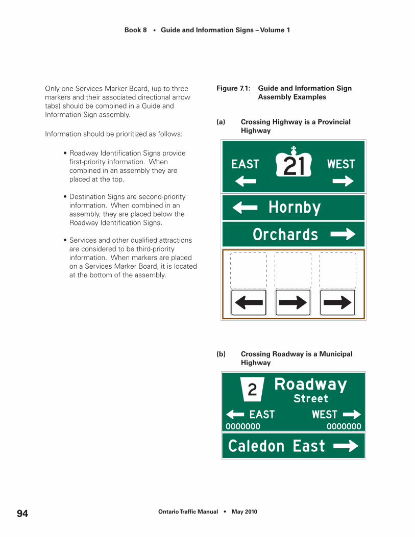
Book 8 • Guide and Information Signs – Volume 1
Ontario Traffic Manual • May 201094
Only one Services Marker Board, (up to three markers and their associated directional arrow tabs) should be combined in a Guide and Information Sign assembly.
Information should be prioritized as follows:
•Roadway Identification Signs provide first-priority information. When combined in an assembly they are placed at the top.
•Destination Signs are second-priority information. When combined in an assembly, they are placed below the Roadway Identification Signs.
•Services and other qualified attractions are considered to be third-priority information. When markers are placed on a Services Marker Board, it is located at the bottom of the assembly.
Figure 7.1: Guide and Information Sign Assembly examples
(a) crossing Highway is a Provincial Highway
(b) crossing roadway is a Municipal Highway

Ontario Traffic Manual • May 2010 95
Book 8 • Guide and Information Signs – Volume 1
(c) Services Marker Board (Optional – may be added to assembly)
Placement and Configuration
Ramp configuration, and the amount of information to be displayed, determines the number of signs and/or assemblies required, along with their placement and configuration.
For the purposes of organizing and presenting information in this section, ramps are grouped according to their configuration, as follows:
•A-B Configuration (directional ramps);
•Unchannelized; or
•Channelized.
Placement, based on ramp configuration, should be as follows:
•At directional ramps, only one movement is permitted and no ramp signs are required; and
•At unchannelized ramp terminals, through movement is presented first, followed by the left-turn movement and then the right-turn movement.
•At channelized ramp terminals, the right-turn movement is presented first, followed by the through movement and then the left-turn movement, respectively.
Additional Information
Refer to Volume 2 - Typical Layouts.
Sign Locations
Unlike other forms of Guide and Information Signs, signs on off-ramps do not provide advance and turn-off information. This is due to space limitations.
On single-lane ramps that end in a simple, STOP-controlled “T” intersection, a standalone sign(s) or sign assemblies should be placed opposite the stem of the “T”. For this situation, the crossing roadway is generally identified as follows:
•Where the crossing roadway is a provincial route, a Route Marker Assembly should be installed. Refer to Chapter 4; and
•Where the crossing roadway is a non-provincial route, a Low-Speed Roadway Identification Sign should be installed (Chapter 8).
For all other ramp configurations (e.g. multi-lane, right-turn channelized), and for ramps terminating at a traffic control signal, advance sign placement is required. In these situations the crossing roadway is identified using a High-Speed Roadway Identification Sign (Chapter 8).
Book 8 • Guide and Information Signs – Volume 1
Ontario Traffic Manual • May 201096
The first sign or assembly in the sequence should be located beyond the right shoulder, a minimum of 60 m downstream of the physical bullnose between the ramp and the freeway mainline.
For ramps without channelization, and where multiple signs or assemblies are required, the last sign or assembly in the sequence should be located beyond the right shoulder a minimum of 30 m in advance of the ramp terminal, unless placement opposite the stem of the “T” is permissible.
For ramps with a right turn channelization, any signs or assemblies displaying information about the right turn movement should be placed beyond the right shoulder a minimum of 60 m in advance of the physical bullnose of the channelization.
Where multiple assemblies are used, they should be spaced at 60 m intervals.
Other signs placed beyond the right shoulder, such as TODS Signs, may be interspersed between the assemblies, at 60 m intervals.
Where sign space is limited, small metal Regulatory, Warning and Trailblazer Signs may be placed between larger Guide and Information Signs. This is permissible only where Guide and Information Signs are spaced according to the above criteria.
When placed in this manner, small metal and larger Guide and Information Signs should not restrict one another’s visibility.
Roadway Identification Signs
Two Roadway Identification Signs may be required, (one to identify the crossing roadway and one to identify the connecting roadway) depending on the configuration of roadways at the ramp terminal. These signs should identify each roadway by the following:
•Route name and/or number;
•Cardinal direction(s); and
•Directional arrow(s).
Overhead mounting of Roadway Identification Signs on off-ramps may be considered where the complexity of the ramp configuration, traffic volumes, or operational considerations identified through an engineering review and/or a human factors assessment justifies such placement.
Street Name Blades and Low-Speed Roadway Identification Signs at Ramp Terminals (Optional)
These signs are used to supplement the High-Speed Roadway Identification Signs, where road users may require additional confirmation of crossing roadway names.
At unsignalized intersections, supplemental Street Name Blades or Low-Speed Roadway Identification Signs should be located on the far-side right of the intersection formed by the ramp and the crossing roadway.
At signalized intersections, supplemental Street Name Blades or Low-Speed Roadway Identification Signs should be located on or adjacent to the primary traffic control signal mast-arm (on the far-side right of the intersection).

Ontario Traffic Manual • May 2010 97
Book 8 • Guide and Information Signs – Volume 1
Destination Signs
These signs are used to indicate the names and directions to municipalities and other qualified destinations (Chapter 8).
A destination should be identified as indicated below:
•“Official Name”;
•“Downtown”;
•“City Centre”;
•“Business Area”;
•“Port of (Community Name)” (with no jurisdictional status); or
•“Industrial Area” or “Industrial Park”.
Service Markers
All Service Markers identified on the freeway mainline should be repeated on the freeway off-ramp. On freeway off-ramps, Service Markers with directional arrow tabs can be installed independently, or grouped together on either an assembly or placed on a Services Marker Board. Services Marker Boards may be standalone or combined with other signs on a Guide and Information Sign Assembly.
For additional information and guidelines on assembly requirements, refer to Chapter 8. For information on Service Markers and Services Marker Board sizes, refer to Chapter 4.
Design Guidance
The following are examples of Roadway Identification and Destination Signs used at Freeway Off-Ramps. For more information on the selection and design of Roadway Identification and Destination Signs, refer to Chapter 8.
Figure 7.2: examples of roadway Identification Signs
(a) G206 – Street name with cardinal Directions
600 mm x variable width (Single Lane STOP-controlled exit)
900 mm x variable width(Multi-lane, right turn chanellized, traffic control
signal exits)
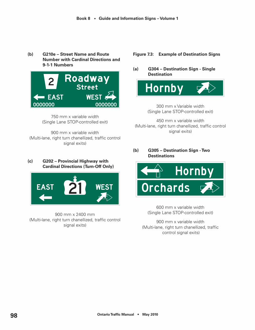
Book 8 • Guide and Information Signs – Volume 1
Ontario Traffic Manual • May 201098
(b) G210e – Street name and route number with cardinal directions and 9-1-1 numbers
750 mm x variable width(Single Lane STOP-controlled exit)
900 mm x variable width(Multi-lane, right turn chanellized, traffic control
signal exits)
(c) G202 – Provincial Highway with cardinal directions (Turn-Off Only)
900 mm x 2400 mm(Multi-lane, right turn chanellized, traffic control
signal exits)
Figure 7.3: example of destination Signs
(a) G304 – destination Sign - Single Destination
300 mm x Variable width (Single Lane STOP-controlled exit)
450 mm x variable width(Multi-lane, right turn chanellized, traffic control
signal exits)
(b) G305 – destination Sign - Two Destinations
600 mm x variable width(Single Lane STOP-controlled exit)
900 mm x variable width(Multi-lane, right turn chanellized, traffic
control signal exits)

Ontario Traffic Manual • May 2010 99
Book 8 • Guide and Information Signs – Volume 1
(c) G306 – destination Sign - Three Destinations
900 mm x variable width(Single Lane STOP-controlled exit)
1200 mm x variable width(Multi-lane, right turn chanellized, traffic control
signal exits)
Figure 7.4: example of a Services Marker Board
Refer to Chapter 4 for design details.
Other considerations
This section not used.

Book 8 • Guide and Information Signs – Volume 1
Ontario Traffic Manual • May 2010100

Ontario Traffic Manual • May 2010 101
Book 8 • Guide and Information Signs – Volume 1
8. Highway Intersection Signs
8.1 Introduction
This chapter addresses the application and installation of Guide and Information Signs on all classes of provincial and municipal roadways.
The familiarity of the road users with the road should be considered in determining the need for guide signs on low-volume roads. Low-volume roads generally do not require guide signs to the extent that they are needed on higher classes of roads. Because guide signs are typically only beneficial as a navigational aid for road users who are unfamiliar with a low-volume road, guide signs might not be needed on low-volume roads that serve only local traffic.
This chapter should be read in conjunction with Volume 2 – Typical Layouts.
For signs identifying interchange on-ramps to provincial freeways, toll highways and expressways from highways, refer to Chapter 6.
Highway intersection signs may identify some or all of the following:
•Roadways;
•Destinations;
•Services and major traffic generators; and
•Trailblazed routes that either begin at or pass through the intersection.
Special Terminologies
Guide and Information Sign Assemblies are groups of Roadway Identification Signs, Destination Signs and/or Services Marker Boards combined together to present multiple messages in an ordered manner.
Marker Assemblies are groups of independent markers and/or their tabs combined together to present multiple messages in an ordered manner.
Services Marker Boards are used to display multiple markers and/or their tabs on one board. Services Marker Boards can be standalone or form part of a Guide and Information Sign Assembly.
Roadway Identification
There are four methods of identifying roadways at an intersection:
•Route Marker (Chapter 4);
•Street Name Blade Signs;
•Low-Speed Roadway Identification Signs; and
•High-Speed Roadway Identification Signs.
Route Markers
Route Markers are used at intersections to identify numbered routes where applicable.
Street Name Blade Sign
Street Name Blade Signs are adequate for low-speed residential areas and for pedestrian use at higher-speed intersections.
Book 8 • Guide and Information Signs – Volume 1
Ontario Traffic Manual • May 2010102
Table 8.1 provides guidance as to when Street Name Blades are recommended.
Low-Speed Roadway Identification Signs
Low Speed Roadway Identification Signs are generally adequate for collector and arterial type roadways in urban or rural areas with a posted speed limit of 60 km/h or less.
Table 8.1 provides guidance as to when Low-Speed Roadway Identification Signs are recommended.
Table 8.2 provides recommended placement distances for roadway identifications signs approaching intersections.
High-Speed Roadway Identification Signs
Roadway Identification Signs may consist of a Turn-Off Sign, or an Advance and a Turn-Off Sign pair, depending on the posted speed limit of the approaching roadway and traffic control at the intersection (refer to Table 8.1).
Roadway Identification Signs may be used to supplement or replace Route Markers at intersections between numbered routes, where greater conspicuity is required (refer to Chapter 4).
When a through roadway has a different name and/or route number on the far side of the intersection, the new road name should be identified.
Destination Signs
Destinations are generally identified at:
•Major intersections in rural areas; and
•Intersections between two or more provincial highways in both urban and rural areas.
Destination selection criteria are provided in Chapter 9.
Services Signs
Services that qualify for signing on highways include:
•Emergency services (e.g. hospital, police stations, public telephones);
•Public transportation services (e.g. bus, train and subway stations, airports, ferries); and
•Other road user services (e.g. travel information centres, colleges/universities).
Depending on the number of services to be identified at an intersection, service signs may be installed independently, or grouped together on either an assembly or placed on a Services Marker Board. Services Marker Boards may be standalone or combined with other signs on a Guide and Information Sign Assembly.
Trailblazing
Trailblazed routes that either begin at, or pass through an intersection direct road users towards a service or other transportation facility.

Ontario Traffic Manual • May 2010 103
Book 8 • Guide and Information Signs – Volume 1
Spacing Between Successive Signs
Minimum spacing between Guide and Information Signs/Assemblies on highways should be 100 m.
Where sign space is limited, small metal Regulatory, Warning and Trailblazer Signs may be placed between larger Guide and Information Signs, as long as the Guide and Information Signs are spaced 100 m apart and all signs do not restrict one another’s visibility.
Other Signs Located at Intersections
On numbered routes, departing an intersection, Route Markers (Confirmation) are provided to confirm the highway number to road users (Chapter 4).
Private Road Signs are used to identify the name of a private roadways or entrances that intersect the highway.
Other signs located at an intersection may include:
•Tourism Oriented Destination Signs (TODS);
•Signs for major traffic generators; and
•Special Events Temporary Signs.
Non-Intersection Signs
Boundary Signs identify the jurisdictional limits of upper-tier, lower-tier and single-tier municipalities, First Nations territories, built-up limits of formerly incorporated municipalities and hamlets.
Downtown, City Centre and Business Area Signs, Port and Industrial Area Signs identify routes from the highway to these features located within the boundaries of lower-tier and single-tier municipalities, and First Nations territories.
Natural features are identified for the interest of road users.
Assurance Signs display the name and distances of up to three significant downstream destinations that the highway passes near or through. The information on these signs assures motorists that they are on the correct path.
Between centres of population in remote areas, Auxiliary Assurance Signs may be provided to guide road users to control cities served by the provincial highway.
Design Commonalities
On provincial highways, the following signs shall be shown on a green retroreflective background with a white retroreflective message and border:
•Street Name Blade Sign;
•Turn-Off Roadway Identification Sign;
•Advance Roadway Identification Sign;
•Destination Sign;
•Private Road Sign;
•Assurance Sign; and
•Auxiliary Assurance Sign.

Book 8 • Guide and Information Signs – Volume 1
Ontario Traffic Manual • May 2010104
On provincial highways, the following signs shall be shown on a blue retroreflective background with a white retroreflective message:
•Boundary Signs;
•Downtown, City Centre and Business Area Signs (Remote);
•Port and Industrial Area Signs; and
•Downtown from Airport.
For signs displaying text, sign width shall be determined by the spacing requirements of the longest line of text.
Route Markers, when shown on Roadway Identification Signs, shall be white retroreflective with black numerals, and all other text omitted.

Ontario Traffic Manual • May 2010 105
Book 8 • Guide and Information Signs – Volume 1
Tab
le 8
.1:
ro
adw
ay Id
enti
fica
tio
n S
ign
S
elec
tio
n

Book 8 • Guide and Information Signs – Volume 1
Ontario Traffic Manual • May 2010106
Tab
le 8
.2:
Rec
om
men
ded
Dis
tan
ces
for
ro
adw
ay Id
enti
fica
tio
n S
ign
P
lace
men
t
Ontario Traffic Manual • May 2010 107
Book 8 • Guide and Information Signs – Volume 1
8.2 Guide and Information Sign Assemblies
Guide and Information Sign Assemblies are groups of Roadway Identification Signs, Destination Signs and/or Services Marker Boards combined together to present multiple messages in an ordered manner.
Guidelines for Guide and Information Sign Assemblies
Information on Roadway Identification Sign approaching intersections may be grouped or spread into one or more assemblies. The purpose is to assist road users in locating needed information and to efficiently use sign space.
Grouping and spreading should respect the priorities and adhere to the limitations regarding the number of signs to be placed in any one assembly, and the spacing required between assemblies, as outlined in this guideline.
A maximum of four signs may be included in any one Guide and Information Sign Assembly. Each Guide and Information Sign Assembly may consist of any combination of Roadway Identification Signs, Destination Signs or Services Marker Boards (refer to Chapter 2).
Each Roadway Identification Sign, Destination Sign and Services Marker Board counts as one of the four permitted signs within an assembly.
Each Services Marker Board (up to three markers and their associated tabs) counts as one sign within the assembly. Only one Services Marker Board (up to 3 services) per assembly shall be permitted.
Roadway Identification Signs provide first-priority information. When combined in a Guide and Information Sign Assembly they are placed at the top.
Destination Signs are second-priority information. When combined in an assembly, they are placed below the Roadway Identification Signs. A maximum of three destinations may be signed at any intersection.
Destinations include the following:
•Qualified communities (Chapter 9);
•Downtowns, City Centres, Business Areas; and
•Ports or Industrial Areas.
Services are considered to be third-priority information and are placed at the bottom of the assembly.

Book 8 • Guide and Information Signs – Volume 1
Ontario Traffic Manual • May 2010108
For guidance on advance and turn-off sign placement, refer to Table 8.2.
Alternatively Roadway Identification Signs, Destination Signs and Services Marker Boards may be grouped independently to form separate assemblies.
Where more than one assembly is required, placement of the last assembly in the sequence should meet or exceed the recommended distances as outlined in Table 8.2. Minimum spacing between any additional Guide and Information Signs/Assemblies on highways should be 75 m.
Figure 8.1: Typical Guide and Information Sign Assemblies
(a) Advance Guide and Information Sign Assembly with roadway Identification, destination and Services Marker Board
(b) Turn-Off Guide and Information Sign Assembly with roadway Identification, destination and Services Marker Board
(c) Advance Guide and Information Sign Assembly with roadway Identification, destination and Services Marker Board

Ontario Traffic Manual • May 2010 109
Book 8 • Guide and Information Signs – Volume 1
(d) Turn-Off Guide and Information Sign Assembly with roadway Identification and Services Marker Board
8.3 Street name Blade Signs
Purpose and Background
These signs are installed at low-speed, local intersections to identify the name(s) of the crossing roadway(s). They may also be used as supplementary signs at intersections between higher-speed roadways for the benefit of pedestrians.
Qualification Criteria
Applicable to all named roadways as outlined in Tables 8.1 and 8.2.
Application and Installation
Street Name Blade Signs should be used:
•In residential areas on lower speed roadways. The signs should be placed in one quadrant of the intersection,
however consideration may be given to providing additional signs where deemed appropriate.
•On lower speed collector/arterial through roadways with single lane approaches.
•On all approaches with higher speed roadways where signing for pedestrians is desirable.
Regardless of the signing method chosen, consistency in sign placement and type should be carried out throughout the road network.
Design Guidance
On municipal roads, municipal logos or symbols identifying unique communities or areas within the municipality may be considered.
Figure 8.2: G216 – road Id – Street name Blade
200 mm x Variable Width
Other considerations
This Section Not Used.
Book 8 • Guide and Information Signs – Volume 1
Ontario Traffic Manual • May 2010110
8.4 Low-Speed roadway Identification Signs
Purpose and Background
These signs identify crossing roadway(s), and are generally installed at intersections of collector/arterial type roadways.
Low-Speed Roadway Identification Signs may consist of a Turn-Off Sign only, or may be installed in pairs: an Advance Sign coupled with a Turn-Off sign. The use of these signs are governed by the number of lanes and posted speed limit of the roadway.
Low-Speed Roadway Identification Signs may replace High-Speed Roadway Identification Signs where the approaching roadway is single lane STOP-controlled.
Qualification Criteria
Applicable to all named roadways as outlined in Tables 8.1 and 8.2. To identify numbered routes only, Route Markers may be used (Chapter 4).
Application and Installation
Turn-Off Low-Speed Roadway Identification Signs should be used:
•On lower speed collector/arterial roadways with multi-lane approaches; or
•On roadways with a posted speed limit of 60 km/h or less.
Turn-Off Low-Speed Roadway Identification Signs should be installed on the near right side approximately 30 m in advance of the intersection.
When the approaching roadway is STOP-controlled, the sign may be placed at the far-side right of the intersection.
Alternatively at signalized intersections, the Low-Speed Roadway Identification Signs may be placed on or adjacent to the primary traffic control signal mast-arm.
The use of an Advance Low-Speed Roadway Identification Signs is recommended on multi-lane roadways with a posted speed limit of 60 km/h. When used, the Advance Sign should be located 100 m in advance of the intersection.
Design Guidance
Where the crossing roadway to the left and right are the same, the advance sign should include a distance. Where the crossing roadway is different, a combination of advance and turn-off arrows may be used on the signs as appropriate.
On municipal roads, municipal logos or symbols identifying unique communities or areas within the municipality may be considered.
Arrows
Arrows may depict a through movement, a left or right turn movement, or a channelized right turn movement.
Where the name or number of the crossing roadway is the same on both sides of the intersection, arrows are generally not required.
Cardinal Direction
Cardinal direction information may be considered at intersections with other major municipal roads where cardinal direction information is provided on the municipal road.

Ontario Traffic Manual • May 2010 111
Book 8 • Guide and Information Signs – Volume 1
Figure 8.3: Turn-Off Low-Speed roadway Identification Signs
(a) G207 – road Id – Street name (same roadway identification to the left and right)
450 mm x Variable Width
(b) different roadway identification to the left and right.
Sign Assembly using two Roadway ID signs.
Figure 8.4: Advance Low-Speed roadway Identification Signs
(a) G204 – Advance Low-Speed roadway Identification Sign with distance
600 mm x Variable Width
(b) Advance Low-Speed roadway Identification Signs - different roadway to the left and right.
Sign Assembly using two Roadway ID signs.
Other considerations
This Section Not Used.

Book 8 • Guide and Information Signs – Volume 1
Ontario Traffic Manual • May 2010112
8.5 High-Speed roadway Identification Signs
Purpose and Background
These signs are used to identify crossing roadways and are generally installed in pairs: an Advance Sign coupled with a Turn-Off Sign.
High-Speed Roadway Identification Signs are larger than Street Name Blade Signs and Low-Speed Roadway Identification Signs, making them more suited for use on higher speed roadways.
Turn-Off High-Speed Roadway Identification Signs
These signs are located immediately in advance of the intersection confirming the information displayed on the Advance Signs.
The following information may be displayed on the signs.
•Crossing roadway identification (name and/or route number);
•Directional arrows;
•Cardinal direction; and/or
•9-1-1 Information.
Advance High-Speed Roadway Identification Signs
These signs provide information in advance of the intersection giving road users additional time to read, interpret, and react to the information on the sign before reaching the decision point.
The following information may be displayed on the signs.
•Crossing roadway identification (name and/or route number);
•Directional arrows;
•Cardinal directions; and/or
•Distance to the intersection.
8.5.1 Turn-off High-Speed roadway Identification Signs
Qualification Criteria
Applicable to all named and numbered roadways as outlined in Tables 8.1 and 8.2.
In some situations, to identify numbered routes only, Route Markers may be used (Chapter 4).
Application and Installation
Turn-Off High-Speed Roadway Identification Signs should be used on roadways with a posted speed limit of 70 km/h or greater.
Depending on the configuration of the intersection and the name or number of the intersecting roadways, up to three Turn-Off High-Speed Roadway Identification Signs may be required as follows:
•One sign to identify the intersecting roadway opposite the approach, where its name or number is different from that of the approaching roadway;

Ontario Traffic Manual • May 2010 113
Book 8 • Guide and Information Signs – Volume 1
•One sign to identify the roadway to the left if it is different from the roadway to the right; and
•One sign to identify the roadway to the right if it is different from the roadway to the left.
Turn-Off High-Speed Roadway Identification Signs are generally located 30 to 75m in advance of an intersection, except where right turn channelization exists, in which case the sign should be located opposite the start of the painted gore (1.25 m) of the channelization. In all cases, the signs are located beyond the right shoulder of the roadway.
Turn-Off High-Speed Roadway Identification Signs should be replaced by Turn-Off Low-Speed Roadway Identification Signs where:
•There is only one approach lane, with no channelization; and
•The approaching roadway is STOP-controlled.
The Turn-Off Low-Speed Roadway Identification Signs should be located on the far side of the crossing roadway.
Turn-Off High-Speed Roadway Identification Signs may be located overhead where road geometry, traffic conditions, or operational considerations identified through an engineering review and/or a human factors assessment justifies such placement.
For guidance regarding the placement of Turn-Off High-Speed Roadway Identification Signs on Guide and Information Assemblies refer to Section 8.2.
Design Guidance
Intersection geometry and the name or number of the roadway(s) at the intersection, determines the message content and layout of the Turn-Off High-Speed Roadway Identification Signs.
Arrows
Arrows may depict a through movement, a left or right turn movement, or a channelized right turn movement.
Where the name or number of the crossing roadway is the same on both sides of the intersection, arrows are generally not required.
Arrows should be provided on Turn-Off High-Speed Roadway Identification Signs whenever cardinal direction is provided and at the intersection of two provincial highways.
Cardinal Direction
Cardinal direction information is required on Turn-Off High-Speed Roadway Identification Signs at the intersection of two or more provincial highways, where:
•more than one direction of travel is accessible on the intersecting provincial route; or
•road users, in transferring from one route to another, may become confused as to the direction the intersected route would take them.
Cardinal direction information may be omitted if only one direction of travel is accessible, such as at the beginning of a provincial highway that runs off the “T” of another highway.
Book 8 • Guide and Information Signs – Volume 1
Ontario Traffic Manual • May 2010114
Cardinal direction information may be considered at intersections with other major municipal roads where cardinal direction information is provided on the municipal road.
Provincial Highway Identification
When a provincial highway number is identified on Turn-Off High-Speed Roadway Identification Signs, the number is presented within a Crown, Secondary Highway Marker or Tertiary Road Marker. (Figure 8.5)
Non-Provincial Roadway Identification
Roadways may be identified by any of the following ways:
1. As a municipal route number (presented in a Municipal Route Marker symbol) and by a local name presented alongside the marker (Figure 8.6)
2. As a municipal route number written out as a two-line message. The first line should consist of either the generic jurisdictional classification (e.g. Regional, District, County, etc.) or the official name of the municipality (e.g. Niagara, Wellington, Alice Twp. etc.). The second line should consist of the road classification (e.g. Road, Avenue, Street) followed by its designated number (e.g. Road 23, Avenue 23, Street 23, etc.) (Figure 8.7).
Examples:
(a) Regional (b) York Road 23 Road 23
(c) York Region Road 23
The preferred text for a numbered “Concession” or “Line” is written as follows:
(d) Alice Twp. (e) Alice Twp. Con. 9 Line 10
3. When a non-provincial roadway does not have a number designation, the roadway can be identified by a local name written out as either a one or two-line message. For a two-line message, the first line should consist of the official name of the road (e.g. Bowesville) and the second line should be the roadway designation (e.g. Road, Drive, Avenue, etc.) (Figure 8.8).

Ontario Traffic Manual • May 2010 115
Book 8 • Guide and Information Signs – Volume 1
Figure 8.5: Turn-Off High-Speed roadway Identification Signs for Provincial Highways
Used on 70 – 90 km/h roads. For low-speed roads, markers may be used.
(a) G201 – roadway Id – Provincial Highway with directional Arrows
900 mm x 1800 mm
(b) G202 – roadway Id – Provincial Highway with cardinal directions
900 mm x 2400 mm
Figure 8.6: Turn-Off roadway Identification Signs for non-Provincial roadways (Street name with route #)
(a) G211e – roadway Id – Street name & route number with 911 numbers
750 mm x Variable Width
(b) G209 – roadway Id – Street name & route number with directional Arrows
600 mm x Variable Width

Book 8 • Guide and Information Signs – Volume 1
Ontario Traffic Manual • May 2010116
(c) G210 – roadway Id – Street name & route number with cardinal Directions
900 mm x Variable Width
Figure 8.7: Turn-Off roadway Identification Signs for non-Provincial roadways (route # written Out as name)
(a) G215 – roadway Id – route name
600 mm x Variable Width
(b) G213 – roadway Id – route name with directional Arrows
600 mm x variable width
Figure 8.8: Turn-Off roadway Identification Signs for non-Provincial roadways (Street name Only)
(a) G207 – roadway Id – Street name
600 mm x Variable Width

Ontario Traffic Manual • May 2010 117
Book 8 • Guide and Information Signs – Volume 1
(b) G205 – roadway Id – Street name with directional Arrows
600 mm x Variable Width
Other considerations
This Section Not Used.
8.5.2 Advance High-Speed roadway Identification Signs
Qualification Criteria
Applicable to all named and numbered roadways as outlined in Tables 8.1 and 8.2.
In some situations, to identify numbered routes only, Route Markers may be used (Chapter 4).
Application and Installation
Advance High-Speed Roadway Identification Signs should be used on all roadways with a posted speed limit of 80 km/h and above. They should also be used on multi-lane approach roadways with a posted speed limit of 70 km/h.
The application of Advance High-Speed Roadway Identification Signs is justified on the basis of:
•Road geometry (e.g. cross-section, lane configuration, sight distance, etc.);
•Viewing distance constraints involving sign placement and the surrounding environment; and
•Posted speed limit.
For installation details refer to Tables 8.1 and 8.2.
Depending on the configuration of the intersection and the name or number of the departing roadways, up to three Advance High-Speed Roadway Identification Signs may be required as follows:
•One sign to identify the intersecting roadway opposite the approach, where its name or number is different from that of the approaching roadway;
•One sign to identify the roadway to the left if it is different from the roadway to the right; and
•One sign to identify the roadway to the right if it is different from the roadway to the left.
Advance High-Speed Roadway Identification Signs Roadway Identification Signs are generally located 500 m in advance of the intersection, beyond the right shoulder of the roadway.
Advance High-Speed Roadway Identification Signs may be located overhead where road geometry, traffic conditions, or operational considerations identified through an engineering review and/or a human factors assessment justifies such placement.

Book 8 • Guide and Information Signs – Volume 1
Ontario Traffic Manual • May 2010118
For guidance regarding the configuration of Advance Signs into Guide and Information Assemblies, refer to Section 8.2.
Design Guidance
Intersection geometry and the name or number of the roadway(s) departing the intersection determines the message content and layout of Advance High-Speed Roadway Identification Signs.
Arrows
Where the name or number of the intersecting roadway opposite the approaching roadway is different, then its name or number is displayed with a through arrow.
Arrows may depict an advance through movement; an advance left or right turn movement, or an advanced channelized right turn movement.
Where the crossing roadway has a different name or number to the left and right, arrows are required.
When distance information is displayed, arrows are omitted.
Distances
Distance information is used to indicate the distance to the intersection, along with identification information when the roadway has the same name or number to the left and to the right.
When arrows are used, distance information is omitted.
Cardinal Direction
Cardinal direction information may be used on Advance High-Speed Roadway Identification Signs approaching the intersection of two or more provincial roadways, where:
•more than one direction of travel is accessible on the intersecting provincial route; or
•road users in transferring from one route to another may become confused as to the direction the intersected route would take them.
Cardinal direction information may be omitted if only one direction of travel is accessible, such as at the beginning of a provincial highway that runs off the “T” of another highway.
Cardinal direction information may be considered at intersections with other major municipal roads where cardinal direction information is provided on the municipal road.
Provincial Highway Identification
When a provincial highway number is identified on an Advance High-Speed Roadway Identification Signs, the number is presented within a Crown, Secondary Highway Marker or Tertiary Road Marker, as applicable. (Figure 8.9)
Non-Provincial Roadway Identification
Roadways may be identified by any of the following ways:
1. As a municipal route number (presented in a Municipal Route Marker symbol) and by a local name presented alongside the marker (Figure 8.10).

Ontario Traffic Manual • May 2010 119
Book 8 • Guide and Information Signs – Volume 1
2. As a municipal route number written out as a two-line message. The first line should consist of either the generic jurisdictional classification (e.g. Regional, District, County, etc.) or the official name of the municipality (e.g. Niagara, Wellington, Alice Twp. etc.). The second line should consist of the road classification (e.g. Road, Avenue, Street) followed by its designated number (e.g. Road 23, Avenue 23, Street 23, etc.) (Figure 8.11). Examples:
(a) Regional (b) York Road 23 Road 23
(c) York Region Road 23
The preferred text for a numbered “Concession” or “Line” is written as follows:
(d) Alice Twp. (e) Alice Twp. Con. 9 Line 10
3. When a non-provincial roadway does not have a number designation, the roadway can be identified by a local name written out as either a one or two-line message. For a two-line message, the first line should consist of the official name of the road (e.g. Bowesville) and the second line should be the roadway designation (e.g. Road, Drive, Avenue, etc.) (Figure 8.12).
Figure 8.9: Advance High-Speed roadway Identification Signs for Provincial Highways
(a) G200 – roadway Id – Provincial Highway with distance
900 mm x 1800 mm
(b) G201 – roadway Id – Provincial Highway with directional Arrows
900 mm x 1800 mm

Book 8 • Guide and Information Signs – Volume 1
Ontario Traffic Manual • May 2010120
(c) G202 - roadway Id - Provincial Highway with cardinal directions
900 mm x 2400 mm
Figure 8.10: Advance High-Speed roadway Identification Signs (Street name with route #)
(a) G208 – roadway Id – Street name & route number with distance
900 mm x Variable Width
(b) G209 – roadway Id – Street name & route number with directional Arrows
600 mm x Variable Width
(c) G210 - roadway Id - Street name & route number with cardinal Directions
900 mm x Variable Width

Ontario Traffic Manual • May 2010 121
Book 8 • Guide and Information Signs – Volume 1
Figure 8.11: Advance High-Speed roadway Identification Signs (route # written Out as name)
(a) G212 – roadway Id – route name with distance
900 mm x Variable Width
(b) G213 – roadway Id – route name with directional Arrows
600 mm x Variable Width
Figure 8.12: Advance High-Speed roadway Identification Signs – Road (Street name Only)
(a) G204 – roadway Id – Street name with distance
900 mm x Variable Width
(b) G205 – roadway Id – Street name with directional Arrows
600 mm x Variable Width
Other considerations
This Section Not Used.
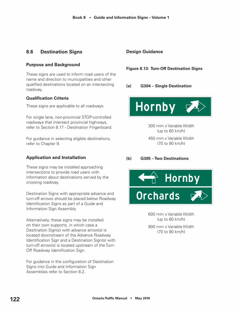
Book 8 • Guide and Information Signs – Volume 1
Ontario Traffic Manual • May 2010122
8.6 Destination Signs
Purpose and Background
These signs are used to inform road users of the name and direction to municipalities and other qualified destinations located on an intersecting roadway.
Qualification Criteria
These signs are applicable to all roadways.
For single lane, non-provincial STOP-controlled roadways that intersect provincial highways, refer to Section 8.17 - Destination Fingerboard.
For guidance in selecting eligible destinations, refer to Chapter 9.
Application and Installation
These signs may be installed approaching intersections to provide road users with information about destinations served by the crossing roadway.
Destination Signs with appropriate advance and turn-off arrows should be placed below Roadway Identification Signs as part of a Guide and Information Sign Assembly.
Alternatively, these signs may be installed on their own supports, in which case a Destination Sign(s) with advance arrow(s) is located downstream of the Advance Roadway Identification Sign and a Destination Sign(s) with turn-off arrow(s) is located upstream of the Turn-Off Roadway Identification Sign.
For guidance in the configuration of Destination Signs into Guide and Information Sign Assemblies refer to Section 8.2.
Design Guidance
Figure 8.13: Turn-Off destination Signs
(a) G304 – Single destination
300 mm x Variable Width(up to 60 km/h)
450 mm x Variable Width(70 to 90 km/h)
(b) G305 – Two destinations
600 mm x Variable Width(up to 60 km/h)
900 mm x Variable Width(70 to 90 km/h)
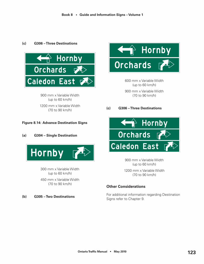
Ontario Traffic Manual • May 2010 123
Book 8 • Guide and Information Signs – Volume 1
(c) G306 – Three destinations
900 mm x Variable Width(up to 60 km/h)
1200 mm x Variable Width(70 to 90 km/h)
Figure 8.14: Advance Destination Signs
(a) G304 – Single destination
300 mm x Variable Width(up to 60 km/h)
450 mm x Variable Width(70 to 90 km/h)
(b) G305 – Two destinations
600 mm x Variable Width(up to 60 km/h)
900 mm x Variable Width(70 to 90 km/h)
(c) G306 – Three destinations
900 mm x Variable Width(up to 60 km/h)
1200 mm x Variable Width(70 to 90 km/h)
Other considerations
For additional information regarding Destination Signs refer to Chapter 9.

Book 8 • Guide and Information Signs – Volume 1
Ontario Traffic Manual • May 2010124
8.7 downtown, city centre and Business Area Signs
Purpose and Background
Destination Signs to downtowns, city centres (or town centre) and business areas provide road users with directional guidance to these features.
Qualification Criteria
These signs are applicable to provincial highways and may be considered for use on other roadways when the downtown, city centre (or town centre) or business area is located off the roadway and is accessible via a crossing roadway.
These signs shall not be used to direct traffic from one provincial highway to another.
Lower-tier and single-tier municipalities, First Nations territories, and formerly incorporated municipalities qualify for these signs if they are served by two or more intersections on the same roadway, have a designated downtown, city centre or business area within the municipality, and have official boundary signs in place.
Application and Installation
Municipalities are free to choose whether to use the term “Downtown”, “City Centre”, “Town Centre”, or “Business Section” to describe the area being signed.
The term “City Centre” is not to be used when a commercial facility within the municipality is known by the same name.
The term “Business Section” is to be avoided where a municipality contains multiple business sections.
Only one downtown, city centre (or town centre) or business section may be signed within a municipality. The municipality will choose the route to be signed. It may choose to sign the same intersection or a different intersection for each direction, but only one route will be signed for each direction of travel.
The downtown signs with appropriate advance and turn-off arrows should be placed below the Roadway Identification Signs as part of a Guide and Information Sign Assembly.
Alternatively, these signs may either be grouped with other Destination Signs or installed on their own supports.
When installing the signs on their own supports, a Downtown Sign with an advance arrow is located downstream of the Advance Roadway Identification Sign and a Downtown Sign with a turn-off arrow is located upstream of the Turn-Off Roadway Identification Sign.
Trailblazing is to be provided by the municipality on its roadways, as needed.

Ontario Traffic Manual • May 2010 125
Book 8 • Guide and Information Signs – Volume 1
Design Guidance
Figure 8.15: G324 – downtown, city centre or Business Section Tabs (Advance/Turn-Off)
300 mm x Variable Width(up to 60 km/h)
450 mm x Variable Width(70 to 90 km/h)
Other considerations
Where the downtown, city centre or business area of the municipality is remote from the municipal limits, a Remote Downtown – Off Highway Sign or Remote Downtown – On Highway Sign may be used respectively under the following conditions:
•To supplement the Destination Sign when the downtown, city centre, town centre or business area is located off the highway and is accessible via a crossing roadway; or
•Used on its own when the remote downtown, city centre, town centre or business area is located on the highway.
When used, Remote Downtown Signs should be located 150 m downstream of the Municipal Boundary Sign.
Figure 8.16: Remote Downtown Signs
(a) G326 – remote downtown – On Highway
1200 mm x 2400 mm
(b) G325 – remote downtown – Off High
1200 mm x 2400 mm

Book 8 • Guide and Information Signs – Volume 1
Ontario Traffic Manual • May 2010126
8.8 Port and Industrial Area Signs
Purpose and Background
Destination Signs to ports and industrial areas are used to direct commercial vehicles along designated routes to these facilities.
Qualification Criteria
Lower-tier and single-tier municipalities and First Nations territories qualify for these signs if they meet the following criteria:
•They have a designated port and/or industrial area within their Official Plan;
•They have a designated truck route leading to these facilities; and
•There is more than one exit serving the community.
These signs shall not be used to direct traffic from one provincial highway to another.
Formerly incorporated municipalities and hamlets do not qualify for these signs.
Application and Installation
Municipalities are free to choose whether to use the term “Industrial Area”, “Industrial Park”, or “Port” to describe the area being signed.
Only one industrial area and one port may be signed within a municipality. The municipality will choose the route to be signed. It may choose to sign the same intersection or a different intersection for each direction, but only one route will be signed for each direction of travel.
The industrial area or port signs with appropriate advance and turn-off arrows should be placed below the Roadway Identification Signs as part of a Guide and Information Sign Assembly.
Alternatively, these signs may either be grouped with other Destination Signs into an assembly or installed on their own supports.
When installing the signs on their own supports, a Port and/or Industrial Area Sign with an advance arrow is located downstream of the Advance Roadway Identification Sign and a Port and/or Industrial Area Sign with a turn-off arrow is located upstream of the Turn-Off Roadway Identification Sign.
Trailblazing is to be provided by the municipality on its roadways, as needed.
Design Guidance
Figure 8.17: Port and Industrial Area Signs
(a) G330 – Port Sign (Advance/Turn-Off)
450 mm x Variable Width(up to 60 km/h)
600 mm x Variable Width(70 to 90 km/h)

Ontario Traffic Manual • May 2010 127
Book 8 • Guide and Information Signs – Volume 1
(b) G327 – Industrial Area Tab (Advance/Turn-Off)
300 mm x Variable Width(up to 60 km/h)
450 mm x Variable Width(70 to 90 km/h)
Other considerations
This Section Not Used.
8.9 Services Marker Boards
Purpose and Background
Services Marker Boards are used to display groups of markers and tabs at or approaching intersections, making them more conspicuous and easier to read.
Individual Service Markers are attached to Services Marker Boards to provide road users with information about services, major attractions and major traffic generators served by the crossing roadway.
Qualification Criteria
Applicable to all named and numbered roadways.
The following markers are eligible for display on the Services Marker Board:
•Emergency Services Identification Markers (Chapter 11);
•Public Transportation Services Identification Markers (Chapter 12);
•Road User Services Markers (Chapter 13);and
•Major Traffic Generator Markers (Chapter 15).
Markers placed on the Services Marker Board may indicate the start of a route or be used as a Trailblazer Marker at key decision-points along a route.
Application and Installation
Services Marker Boards are applicable where two or more markers pertaining to services, major attractions and/or destinations are required.
Markers should be grouped by direction of turn (through, left, right, as applicable).
Services Marker Boards incorporating the appropriate advance and turn-off markers should be placed below Roadway Identification Signs and/or Destination Signs to form a Guide and Information Sign Assembly.
Alternatively, these boards may be installed on their own supports.
When installing the boards on their own supports, a Services Marker Board using advance arrow tabs is located downstream of

Book 8 • Guide and Information Signs – Volume 1
Ontario Traffic Manual • May 2010128
the Advance Roadway Identification Sign and a Services Marker Board using turn-off arrows is located upstream of the Turn-Off Roadway Identification Sign.
For guidance in configuring Services Marker Boards into Guide and Information Sign Assemblies, refer to Section 8.2.
Design Guidance
Up to six markers and their tabs may be displayed on one Services Marker Board.
Refer to Chapter 4 for additional design guidance.
Other considerations
In urban areas, where lateral space is constrained, Urban Services Marker Board Signs may be used. Refer to Chapter 4 for design guidance.
8.10 Boundary Signs
Purpose and Background
These signs inform road users that they are entering an organized municipality, First Nations territory, formerly incorporated municipality or hamlet.
Qualification Criteria
These signs are used to identify the following qualified communities:
•Upper-tier, lower -tier, and single-tier municipalities;
•First Nations territories;
•Formerly incorporated municipality eliminated under the restructuring on or after January 1st, 1997; and
•Hamlets (centre of population within either an organized or unorganized territory) providing at least one other essential motorist service (fuel, food or accommodations).
To qualify for Boundary Signs, the roadway shall pass through the community.
Both formerly incorporated municipalities and hamlets require the approval of the Municipal Council of the upper-tier, lower -tier, or single-tier municipalities in which they are situated in order to obtain a Boundary Sign. Centres of population within unorganized territories require the approval of their Local Roads Board.
When two or more municipalities, formally incorporated municipalities or First Nations communities abut the roadway on either side, and when the roadway forms part of the boundary, the abutting communities do not qualify for a Boundary Sign. Instead, consideration should be given to provide Destination Signs at one intersection, typically the one serving their main population centre. Refer to Chapter 9 for additional details.
Application and Installation
Two signs shall be installed, one for each direction of travel on the roadway.
Boundary Signs are installed, as close as practicable, to where the limits of the municipality cross the roadway.

Ontario Traffic Manual • May 2010 129
Book 8 • Guide and Information Signs – Volume 1
Where boundaries overlap, they are to be signed individually in the following order, as applicable:
•Upper-tier, single-tier municipalities or First Nations Territories;
•Lower-tier municipalities; then
•Formerly incorporated municipalities or hamlets.
Population figures shall only be shown for single-tier and lower-tier municipalities and First Nations territories (when requested). Population figures shall not be shown for upper-tier municipalities, formerly incorporated municipalities, or hamlets.
Population figures are to be based on Statistics Canada population data (www.statscan.ca). Statistics Canada provides official population counts every five years for all incorporated municipalities in the Province of Ontario. MTO shall be responsible for updating all population figures every five years, as necessary, on Boundary Signs located on provincial highways.
As an alternate source of data, communities may request the use of population data from the Municipal Property Assessment Corporation (MPAC).
Communities may request an annual updating of their population figures at their own cost.
Population figures are to be posted on Boundary Signs according to the following rounding formula shown in Table 8.3.
Table 8.3: Population Figures rounding Formula
Design Guidance
Names shall be shown in upper/lower case lettering, conforming to design standards laid out in the applicable Master Sign Template.
When population information is shown, it shall be placed on a separate line.
Boundary Signs for Upper-Tier, Lower-Tier and Single-Tier Municipalities
Official names of organized municipalities, as recognized by the Ministry of Municipal Affairs and Housing, shall be shown on all Boundary Signs.

Book 8 • Guide and Information Signs – Volume 1
Ontario Traffic Manual • May 2010130
Figure 8.18: Basic Boundary Sign (upper Tier)
(a) G316 – Basic Boundary Sign – upper Tier (2-line message)
750 mm x Variable Width
(b) G318 – Basic Boundary Sign – upper Tier (3-line message)
900 mm x Variable Width
Figure 8.19: G314 – Basic Boundary Sign (Lower-Tier or Single-Tier Municipalities)
900 mm x Variable Width
Formerly Incorporated Municipalities and Hamlets
For formerly incorporated municipalities and hamlets, the locally known name, as approved by the Municipal Council of the upper-tier or single-tier municipality in which they are situated, or the Local Roads Board in unorganized territories, shall be shown on their Boundary Signs.
No indication of the prior municipal status of a formerly incorporated municipality shall be provided (e.g. “Former City of ……”).
Boundary Signs shall consist of only the name of the formerly incorporated municipality or hamlet.
The sign used for formerly incorporated municipalities and hamlets may also be used to identify unincorporated communities within unorganized areas.
Figure 8.20: G-310 – Basic Boundary Sign (Formerly Incorporated Municipalities, Hamlets and unincorporated communities in unorganized Areas)
600 mm x Variable Width

Ontario Traffic Manual • May 2010 131
Book 8 • Guide and Information Signs – Volume 1
First Nations
The official names of First Nations territories, as recognized by the Federal Department of Indian Affairs, shall be shown on their Boundary Signs. Names shall generally be displayed as follows:
First Nations Community Name First Nation
Figure 8.21: G320 – Basic Boundary Sign - First nations
750 mm x Variable Width
Enhanced Boundary Signs
All communities that qualify for boundary signs may choose to participate in an Enhanced Boundary Sign program at their own cost. Cost will include sign manufacturing, installation and maintenance. All design elements of a ‘basic’ Boundary Sign will be included on an Enhanced Boundary Sign in addition to the following:
•A coat of arms or community logo included on the sign; and/or
•A welcoming message or slogan profiling a unique feature.
The community logo, crest or coat-of-arms, may be shown in colour and shall be retroreflective. The size of a logo, crest or cost-of-arms shall be limited to that specified in the Master Sign Template.
The logo, crest or coat-of-arms, shall be placed either to the left or to the right of the community name.
The slogan or welcoming message shall be limited to one line of text, shown at the bottom of the sign using blue text on a white retroreflective background. Letter height and borders shall conform to specifications in the applicable Master Sign Template.
Internet addresses, telephone numbers and other similar messages shall not be permitted on the sign.
Message content is subject to the Charter of Rights and Freedoms.
Messages that attempt to direct or control traffic are not permitted.
Logos cannot be used as a trailblazer symbol to direct road users to a destination within the municipality’s boundary.
Commercial content (e.g. sponsorship by, or promotion of, a commercial enterprise) is not permitted.
Messages referencing another community outside of the boundaries of the applicable community are not permitted.
The logo, crest, coat-of-arms and/or slogan or welcoming message should be chosen and officially endorsed by Municipal Council.
An equivalent French Language version of the slogan or welcoming message is required in Designated Bilingual Areas.

Book 8 • Guide and Information Signs – Volume 1
Ontario Traffic Manual • May 2010132
Figure 8.22: enhanced Boundary Signs
(a) G317 – enhanced Boundary Sign – upper Tier (2 lines)
1200 mm x Variable Width(2-line community name)
(b) G319 – enhanced Boundary Sign – upper Tier (3 lines)
1200 mm x Variable Width (3-line community name)
(c) G315 – enhanced Boundary Sign – Single-Tier/Lower-Tier
1200 mm x Variable Width
(d) G311 – enhanced Boundary Sign – Formerly Incorporated Municipality or Hamlet
1200 mm x Variable Width
(e) G321 – enhanced Boundary Sign – First nations
1200 mm x Variable Width
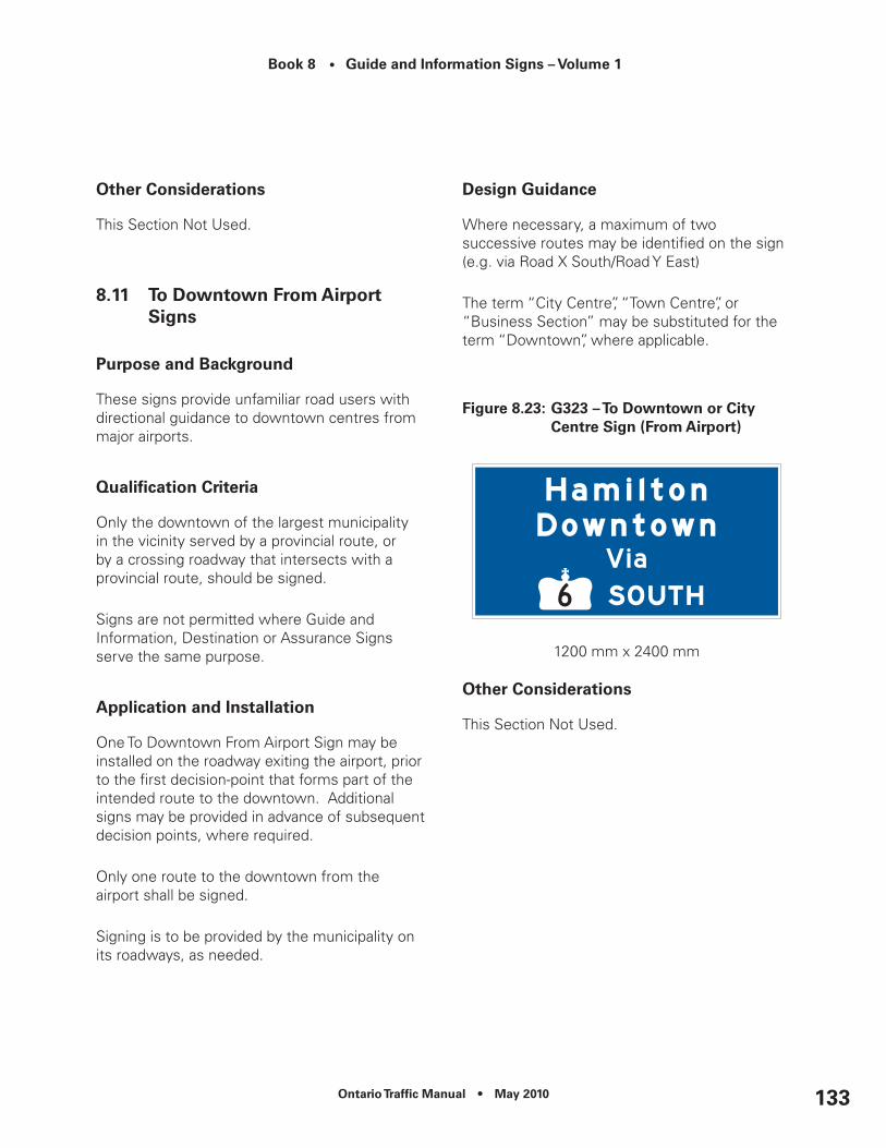
Ontario Traffic Manual • May 2010 133
Book 8 • Guide and Information Signs – Volume 1
Other considerations
This Section Not Used.
8.11 To downtown From Airport Signs
Purpose and Background
These signs provide unfamiliar road users with directional guidance to downtown centres from major airports.
Qualification Criteria
Only the downtown of the largest municipality in the vicinity served by a provincial route, or by a crossing roadway that intersects with a provincial route, should be signed.
Signs are not permitted where Guide and Information, Destination or Assurance Signs serve the same purpose.
Application and Installation
One To Downtown From Airport Sign may be installed on the roadway exiting the airport, prior to the first decision-point that forms part of the intended route to the downtown. Additional signs may be provided in advance of subsequent decision points, where required.
Only one route to the downtown from the airport shall be signed.
Signing is to be provided by the municipality on its roadways, as needed.
Design Guidance
Where necessary, a maximum of two successive routes may be identified on the sign (e.g. via Road X South/Road Y East)
The term “City Centre”, “Town Centre”, or “Business Section” may be substituted for the term “Downtown”, where applicable.
Figure 8.23: G323 – To downtown or city centre Sign (From Airport)
1200 mm x 2400 mm
Other considerations
This Section Not Used.
Book 8 • Guide and Information Signs – Volume 1
Ontario Traffic Manual • May 2010134
8.12 Assurance Signs
Purpose and Background
These signs provide assurance to motorists that they are on the correct route by displaying the name and distances, of up to three significant downstream destinations, which the highway passes near or through.
Qualification Criteria
These signs are applicable to provincial highways.
Only control cities and qualified communities shall be shown on Assurance Signs as destinations (refer to Chapter 9).
No more than three downstream destinations, and the distances to them, should be displayed.
Application and Installation
Assurance Signs are to be provided as follows:
•Downstream of the municipal boundary for the benefit of motorists leaving that municipality; and
•Downstream of the intersection of two or more provincial highways; and
•At other major intersections where large volume of traffic are entering the highway facility; and
•Within an expanded municipality having a large rural area, this sign is to be installed either beyond: 1. The build-up area of the major population centre, or
2. The last entrance to the major population centre in the case where the major population centre is located off the highway. Where points (1) or (2) apply, Assurance Signs are not required at the expanded municipal boundary limits.
These signs are to be located 75 m beyond the Route Marker (Confirmation).
Destinations are to be depicted in the following order:
•(Line 1) The next qualified community;
•(Line 2) The intermediate end-of-route control city; and
•(Line 3) The end-of-route control city.
Where the intermediate end-of-route becomes the next closest municipality, it should be displayed on Line 1, with the next intermediate end-of-route shown on Line 2, and the end-of-route shown on Line 3.
Where no intermediate end-of-route control city is present, the second qualified community downstream may be displayed on Line 2.
Where the demand for signs amongst qualified communities within a particular road segment exceeds the maximum permitted, destinations on the signs should be selected based on the criteria outlined in Chapter 9.
Distances shown on the sign shall be measured from the sign location to the applicable seat of government (town or city hall) or, if none, the geographic centre of the built-up area.

Ontario Traffic Manual • May 2010 135
Book 8 • Guide and Information Signs – Volume 1
Distances shall be shown in kilometres, rounded up to the nearest whole number.
Design Guidance
Figure 8.24: Assurance Sign
G300 – 1 Destination600 mm x Variable Width
G301 – 2 Destinations900 mm x Variable Width
G302 – 3 Destinations1200 mm x Variable Width
Other considerations
Assurance Signs shall be stand-alone, and not be combined with other signs.
8.13 Auxiliary Assurance Signs
Purpose and Background
Auxiliary Assurance Signs are used in addition to Assurance Signs to reassure motorists, traveling on long sections of highway in remote areas that they are on the correct route.
These signs provide road users with auxiliary destination and distance information for control cities.
Qualification Criteria
These signs are generally only installed on provincial highways in remote areas.
Application and Installation
Auxiliary Assurance Signs should be installed at 20 km intervals along routes through remote areas where the distance between qualifying communities is 50 km or greater.
Only the next downstream qualified community shall be shown on an Auxiliary Assurance Sign, as per the first line of text on the Assurance Sign.
Distances shown shall be measured from the sign location to the applicable seat of government (town or city hall) or, if none, the geographic centre of the downstream city.
Distances shall be shown in kilometres, rounded up to the nearest whole number.
Design Guidance
Figure 8.25: G303 – Auxiliary Assurance Sign
450 mm x Variable Width

Book 8 • Guide and Information Signs – Volume 1
Ontario Traffic Manual • May 2010136
Other considerations
Auxiliary Assurance Signs shall be stand-alone, and shall not be combined with other signs to form assemblies.
8.14 natural Feature Identification Signs
Purpose and Background
These signs identify natural features which are either adjacent to, or which the highway crosses.
Qualification Criteria
These signs are applicable to provincial highways.
Official names of geographic features used on Natural Feature Identification Signs shall be sourced from those approved by the Ontario Ministry of Natural Resources Geographic Names Board’s geo-index at:
http://www.onterm.gov.on.ca/geo/entry_e.asp
Application and Installation
Natural Feature Identification Signs may be installed on all provincial routes to identify the following watercourses and bodies of water:
•Lakes;
•Rivers;
•Creeks;
•Ponds; and
•Bays.
In addition, they may be installed to identify other geographic features.
Where the roadway physically crosses a feature or is adjacent to it, one sign may be provided at the feature for each direction of travel.
Design Guidance
Only those features with approved names may be considered for signs.
Words such as “RIVER” and “LAKE” may be abbreviated to “R.” and “L.”, as appropriate (Figure 8.28).
Figure 8.26: G331 – natural Feature Identification Sign
300 mm x 1200 mm300 mm x 1500 mm300 mm x 1800 mm
Other considerations
This Section Not Used.

Ontario Traffic Manual • May 2010 137
Book 8 • Guide and Information Signs – Volume 1
8.15 Private roadway Signs
Purpose and Background
These signs are used to identify private roadways or entrances that intersect a provincial route.
Qualification Criteria
These signs are permitted on provincial highways, secondary highways and tertiary roads.
Application and Installation
They may display one of the following, in descending order of preference:
•Local name of roadway, where one exists;
•Name of geographic feature (e.g. Lake, River) served by the highway; or
•Name chosen by written consensus of the affected residents.
These signs shall not display the name of an individual, establishment or identifiable group, unless the personal name, name of the establishment or identifiable group is the same as the name of the lake, river, etc. serviced by the road.
If an agreement for naming the roadway cannot be reached, only a “THIS IS A PRIVATE ROAD” Sign (Chapter 17) shall be installed.
These signs should be installed approximately 30 m from the intersection on each approach to the private road or entrance.
These signs may not be used at intersections of two provincial routes or a provincial route and another public roadway.
Design Guidance
Figure 8.27: G217 – Private roadway Sign
300 mm x 900 mm300 mm x 1200 mm300 mm x 1500 mm
Other considerations
This Section Not Used.
8.16 Personal direction Fingerboard
Purpose and Background
These signs are used on provincial highways to show the name and direction of a private establishment (cottage, private club, children’s camp, etc.) located along a private road.

Book 8 • Guide and Information Signs – Volume 1
Ontario Traffic Manual • May 2010138
Qualification Criteria
These signs are permitted on provincial highways, secondary highways and tertiary roads.
Application and Installation
These signs should be installed approximately 15 m from the intersection on each approach to the private road or entrance.
These signs shall not be used:
•At the intersection of two provincial highways;
•At channelized intersections of a provincial highway and a public roadway;
•When there is a Private Roadway Sign installed at the intersection; and
•When there is a Roadway Identification Sign installed at the intersection.
When more than three applications for Personal Direction Fingerboards are received, or if three Personal Direction Fingerboards are already installed at the intersection and a fourth application is received, the fourth applicant must contact the owners of the other three signed establishments and, as a group, they must submit an application for a Private Roadway Sign (and, therefore, must choose collectively a road name). The Private Roadway Sign will effectively replace the existing three Personal Direction Fingerboards.
Design Guidance
Figure 8.28: G308 – Personal direction Fingerboard
300 mm x 1200 mm300 mm x 1500 mm
Other considerations
This Section Not Used.
8.17 Destination Fingerboard
Purpose and Background
These signs are used on single lane, non-provincial STOP-controlled roadways that intersect provincial highways to provide road users on the approaching roadway with direction and distance to nearby communities located along the provincial highway.
Qualification Criteria
These signs are applicable to a roadway approaching the intersection of provincial highway, and may also be considered at an approach to another municipal road.

Ontario Traffic Manual • May 2010 139
Book 8 • Guide and Information Signs – Volume 1
Application and Installation
One community for each direction of travel along the provincial highway and the distance to it shall be identified. The community to be identified shall be the closest qualified centre of population (Refer to Chapter 9) for each direction of travel. Where no suitable community exists, the sign shall be omitted.
These signs should be installed on the far right side of the intersection, beyond the shoulder, facing the approaching roadway at single-lane STOP-controlled intersections.
Design Guidance
Figure 8.29: G307 – destination Fingerboard Sign
300 mm x 900 mm300 mm x 1200 mm300 mm x 1500 mm
Other considerations
This Section Not Used.
8.18 Passing Lane Signs
Purpose and Background
The purpose of Passing Lane Signs is to inform motorists of either the start of or an upcoming opportunity to pass slower-moving vehicles.
The signs are intended to discourage risky passing maneuvers on highway sections with restricted sight distances.
Qualification Criteria
The Passing Lane Begins Sign and the Passing Lane Ahead 2 km, 5 km and 10 km Signs are used on two-lane roads, at the start of and in advance of locations where a third intermittent lane (taper) has been added for passing (e.g., a truck climbing lane or another passing lane).
These signs shall only be installed for the direction of travel where the lane has been added.
Application and Installation
The Passing Lane 2 km, 5 km and 10 km Ahead Signs should be installed at the appropriate distance upstream of the beginning of the taper, to indicate the distance to the next passing lane.
The signs should only be used where there is adequate road distance between the sign and the beginning of the taper for the truck climbing lane or passing lane.
The Passing Lane Ahead Sign (no distance) is installed at the beginning of the taper, to indicate to motorists the start of a passing lane.

Book 8 • Guide and Information Signs – Volume 1
Ontario Traffic Manual • May 2010140
The signs shall not be installed within the limits of an existing truck climbing or passing lane.
Design Guidance
Signs must conform to the applicable Master Sign Template.
Figure 8.30: Passing Lane Ahead Signs
(a) rb-30A – Passing Lane Sign
900 mm x 900 mm
(b) rb-30 – Passing Lane Ahead Sign (with distance)
900 mm x 1200 mm
Other considerations
This section not used.

Ontario Traffic Manual • May 2010 141
Book 8 • Guide and Information Signs – Volume 1Fi
gu
re 8
.31:
Pas
sin
g L
ane
Sig
ns
– S
ing
le d
irec
tio
n
Two
-Lan
e H
igh
way
wit
h A
dd
edTr
uck
clim
bin
g L
ane
or
Pass
ing
Lan
e (S
ing
le d
irec
tio
n)

Book 8 • Guide and Information Signs – Volume 1
Ontario Traffic Manual • May 2010142
Fig
ure
8.3
2: P
assi
ng
Lan
e S
ign
s –
Bo
th d
irec
tio
ns
Two
-Lan
e H
igh
way
wit
h A
dd
edTr
uck
clim
bin
g L
ane
or
Pass
ing
Lan
e (B
oth
dir
ecti
on
s)

Ontario Traffic Manual • May 2010 143
Book 8 • Guide and Information Signs – Volume 1
8.19 decorative Municipal display Signs
Purpose and Background
Decorative Municipal Display Signs allow communities to identify themselves to road users in a manner that is unique and aesthetically pleasing using natural features.
Qualification Criteria
For use of Decorative Municipal Displays on private property adjacent all highways, please refer to the Corridor Procedures Manual, Chapter 6 – Corridor Signing Policy.
Decorative Municipal Displays within the right-of-way on King’s highways are only permitted on Class 3, 4 and 5 provincial highways that have been designated as Bush Country highways as listed below:
Central Region
No highways have been designated.
Eastern Region
Only the following highways have been designated:
•Highway 28 from Lakefield northerly to Highway 41
•Highway 35 northerly from Fenelon Falls
•Highway 41 from Kaladar northerly Highway 60 (north junction)
•Highway 60 easterly to Killaloe
•Highway 62 from Madoc northerly to Highway 127
•Highway 118 westerly from Highway 28
•Highway 127 from Maynooth northerly to Highway 60
•Highway 523 from Highway 60 southerly to limit of Hastings County
Northeast Region
All highways have been designated.
Northwest Region
All highways have been designated except the following:
•Thunder Bay Expressway composed of Highway 61, from Chippewa Road northerly to Highway 11/17, and Highway 11/17, from Highway 61 easterly to Lakeshore Road
•Highway 11/17 (New) from Vibert Road easterly to the Harbour Expressway
•Highway 17A - Kenora Bypass
West Region
No highways have been designated except:
•Highway 6, from Wiarton northerly to Tobermory
Book 8 • Guide and Information Signs – Volume 1
Ontario Traffic Manual • May 2010144
Decorative Municipal Display Signs are applicable to:
•Upper-tier, lower-tier and single-tier municipalities;
•First Nation’s territories;
•Formerly incorporated municipalities; and
••Hamlets
To qualify for a Decorative Municipal Display Sign on a provincial highway that has been designated as a Bush Country highway, the Ministry will require the endorsement of Municipal council.
In addition, the community shall be:
•Bisected by, or abutting, a provincial route; and
•Accessible from the provincial route.
Each qualified community is entitled to one decorative municipal display for each direction of travel, where space permits.
When multiple municipalities or First Nation’s groups are involved, endorsements from each municipal or First Nation’s council are necessary.
Application and Installation
The preferred location for the Decorative Municipal Display Sign is within the right-of-way that provides the most direct route to the community. Where there is insufficient space at the preferred location due to physical, geometric or safety concerns, the display may be located off the right-of-way (refer to MTO’s Commercial Signing Policy).
The displays must not compromise sight distance for merging and/or diverging traffic. Decorative Municipal Display Signs must be located within the boundaries of the municipality to which they refer.
Where multiple proponents within an area wish to have a decorative municipal display, one themed display may be used for the whole area if all participating municipalities are able to reach agreement, including the design and placement of the display.
When the boundaries of two or more communities overlap at a common point, the Upper-Tier municipality shall be identified first in advance of the intersection serving their municipality, with other qualified communities within the Upper-Tier municipality being signed at successive intersections for the same direction of travel. A minimum interval of 1 km is to be maintained between successive displays for the same direction of travel.
When two or more communities abut the highway on both sides, or when the highway forms part of the formal or informal boundary, each abutting community may have one Decorative Municipal Display placed on the right-hand side of the roadway in opposing directions.
Municipalities will be responsible for all costs associated with the manufacturing, installation and maintenance of the sign displays, including any damage after installation, no matter how it occurs. Municipalities are also responsible for the protection of all utilities presently existing on the right-of-way in the area of the sign display.
If problems develop after the display is in place the Ministry reserves the right to insist the problem be corrected or the display removed.

Ontario Traffi c Manual • May 2010 145
Book 8 • Guide and Information Signs – Volume 1
If the display ceases to be maintained, the Ministry will arrange for the removal or repair and the municipality will be responsible for payment of all costs.
Municipalities should be informed that the display may be removed because of highway reconstruction and all costs will be the responsibility of the municipality.
Design Guidance
Decorative Municipal Display Signs are intended primarily as landscape features. They may be created using any combination of natural materials such as:
• Plantings;
• Wood;
• Rocks;
• Earth berms; and
• Mounted lettering.
The message presented by the Decorative Municipal Display is restricted to the name of the community and/or an approved municipal logo or slogan.
Messages that attempt to control or direct traffi c are not permitted. Logos cannot be used as a trailblazer symbol to direct road users to a destination within the municipality’s boundary. Commercial content is not permitted. Internet addresses, telephone numbers and other similar messages are not permitted on the sign.
Municipalities must submit a detailed construction plan, including the preferred location, to the Ministry for approval. Any deviation is to receive prior approval from the Ministry before commencing that portion of the work.
Whenever possible, construction and/or maintenance of the display should be carried out from an adjacent road or street, rather than from the travelled portion of the provincial route.
The height of the display is not to exceed 3 m, measured from the surrounding grade to the top of the tallest element of the display. Existing roadway slopes and drainage patterns must not be altered, except as approved.
Displays are limited to no more than 6 m in width/length.
Illumination of the display is permitted, provided the illumination design includes adequate shielding to avoid light trespass and/or glare on any adjacent roadway.

Book 8 • Guide and Information Signs – Volume 1
Ontario Traffic Manual • May 2010146
Figure 8.33: Figure decorative Municipal display - Highway
Other considerations
Any work occurring on right-of-way of a provincial route must be conducted in conformance with the OTM Book 7, Temporary Conditions, and the Occupational Health and Safety Act.
All activities, including material and equipment stored within the right-of-way, must be in accordance with the MTO Roadside Safety Manual.
Ontario Traffic Manual • May 2010 147
Book 8 • Guide and Information Signs – Volume 1
9. Selecting destinations
For the purposes of this guideline, the following shall be referred to collectively as “communities”:
•Single Tier Municipalities;
•Lower Tier Municipalities;
•First Nations Territories;
•Formerly Incorporated Municipalities (which ceased to exist on or after January 01, 1997); and
•Hamlets.
The boundaries of communities are defined as follows:
•Incorporated communities – official boundary; and
•Unincorporated communities – limits of their built-up area.
9.1 Destinations Identified on Provincial Freeways
Purpose and Background
The following provides guidance in the selection of Destinations approaching, at and beyond provincial freeway interchanges.
Destinations are used along with roadway names and/or numbers; cardinal direction information; and interchange numbers, to orient the road user approaching, at, and beyond interchanges.
Qualification Criteria
Use of Control Cities Approaching Interchanges on the Freeway Mainline
On provincial freeways, only Control Cities are identified as destinations at the following locations:
•Freeway-to-freeway interchanges, as both exit and pull-though information;
•Freeway interchanges with other provincial highways, as both exit and pull-through information;
•Freeway interchanges with other highways, as pull-through information only (when required); and
•Express-to-collector transfer lanes, as pull-though information in the express lanes.
Use of Other Qualified Destinations Approaching Interchanges on the Freeway Mainline
On the freeway mainline, qualified destinations other than Control Cities, accessible via crossing roadways, are identified at freeway interchanges with roadways other than provincial highways. In urban areas, this information may be omitted.
For selecting destinations approaching freeway interchanges, refer to Table 9.1.

Book 8 • Guide and Information Signs – Volume 1
Ontario Traffic Manual • May 2010148
Use of Control Cities and Other, Qualified Destinations Beyond Interchanges on the Freeway Mainline
Beyond freeway interchanges, Control Cities and other qualified downstream destinations are displayed on Assurance signs, along with distance information (Refer to Chapter 5).
Use of Control Cities Approaching Freeway Interchanges on Crossing Roadways
On crossing roadways, approaching freeway on-ramps, only Control Cities are identified as destinations for each direction of travel on the freeway. In urban areas, this information may be omitted (Chapter 6)
Qualifications - General
Upper-Tier Municipalities shall not be shown as destinations on the freeway mainline at, approaching, or beyond freeway interchanges.
Communities that have Boundary Signs installed on the freeway are not eligible for destination signing at interchanges located within their municipal boundaries.
Formerly Incorporated Municipalities and Hamlets located within Single-Tier or Lower-Tier Municipalities may be eligible for destination signing at interchanges located within these municipal boundaries if approved by municipal council.
Communities that abut a provincial freeway, which serves as their boundary, and are served by one or more interchanges, may be shown as destinations on interchange signs at or approaching the one interchange serving
their downtown or built-up area only. These communities do not receive boundary signs on the freeway mainline.
Communities may be shown as destinations on Assurance signs, beyond freeway interchanges, subject to further qualification based on priority (Table 9.2).
Application and Installation
A maximum of two (2) destinations may be identified on Turn-Off and Advance signs (Chapter 5). The destination geographically to the left of the road user reading the sign should be listed first.
Where there is no qualified destination in one direction, two destinations in the other direction may be displayed, with the closest qualified destination being displayed first.
Destinations identified on the freeway mainline approaching interchanges must be repeated on the Off-Ramp signs (Chapter 7).
Only those destinations identified on the freeway mainline are to be signed on the off-ramp.
Up to three (3) destinations may be identified on Assurance signs beyond freeway interchanges (Chapter 5).
Design Guidance
For design guidance pertaining to Freeway Mainline and Assurance signs, refer to Chapter 5.
For design guidance pertaining to On-Ramp signs, refer to Chapter 6.

Ontario Traffic Manual • May 2010 149
Book 8 • Guide and Information Signs – Volume 1
For design guidance pertaining to Off-Ramp signs, refer to Chapter 7.
Other considerations
This Section Not Used.
9.2 Destinations Identified on Provincial Highways
Purpose and Background
The following provides guidance in the selection of destinations approaching, at and beyond provincial highway intersections.
Destinations are used along with highway names and/or numbers and cardinal direction information to orient the road user approaching, at, and beyond intersections.
Qualification Criteria
Use of Control Cities Approaching Intersections on Provincial Highways
Only Control Cities are identified as destinations at the intersection of two or more provincial highways.
Use of Other Qualified Destinations Approaching Intersections on Provincial Highways
Qualified destinations other than Control Cities, accessible via the crossing and/or connecting roadways, are identified at intersections with non-provincial roadways. In urban areas, this information may be omitted.
For selecting destinations approaching highway intersections, refer to Table 9.1.
Use of Control Cities and Other, Qualified Destinations Beyond Intersections on Provincial Highways
Beyond intersections, Control Cities and other, qualified downstream destinations are displayed on Assurance signs, along with distance information (Chapter 8).
Use of Destinations Approaching Provincial Highway Intersections on Crossing Roadways
On non-provincial roadways in rural areas approaching provincial highways, destinations for each direction of travel on the provincial highway are identified. In urban areas, this information may be omitted (Refer to Chapter 8)
Qualifications - General
Upper-Tier Municipalities shall not be shown as destinations on provincial highways at, approaching, or beyond intersections.
Communities that have Boundary Signs installed on the highway are not eligible for destination signing at intersections located within their municipal boundaries.
Formerly Incorporated Municipalities and Hamlets located within Single-Tier or Lower-Tier Municipalities may be eligible for destination signing at intersections located within these municipal boundaries if approved by municipal council.
Communities that abut a provincial highway, which serves as their boundary, and are served by one or more intersections, may be
Book 8 • Guide and Information Signs – Volume 1
Ontario Traffic Manual • May 2010150
shown as destinations on intersections signs at or approaching the one intersection serving their downtown or built-up area only. These communities do not receive boundary signs on the highway mainline.
Communities may be shown as destinations on Crossing/Connecting Highway Identification signs at or approaching intersections, subject to further qualification based on priority.
Communities may be shown as destinations on Assurance signs, beyond intersections, subject to further qualification based on priority (Table 9.2).
Application and Installation
A maximum of three (3) qualified communities may be identified approaching an intersection.
The most qualified destinations to the left and to the right should be selected. Where there is no qualified destination in one direction, up to three destinations in the remaining direction may be displayed.
Qualified destinations on the connecting roadway (opposite the approaching roadway) are to be identified only in the following circumstances:
•The location is the intersection of two or more provincial highways;
•The approaching roadway is a provincial highway, and there is a non-provincial roadway opposite that serves a qualified destination.
Additional destinations, as follows, may also be shown, where applicable, if sufficient space is available:
•Downtowns/City Centres and Business Areas; and
•Ports and Industrial Areas.
Distance (Assurance) Signs
Assurance signs on the provincial highway may display the next three qualified destinations as follows,
•next qualified community,
•the intermediate end-of-route control city(where applicable), and
•the end-of-route control city
A maximum of three (3) destinations may be displayed on any sign.
For further information on application and installation, refer to Chapter 8.
Design Guidance
For design guidance, refer to Chapter 8.
Other considerations
This Section Not Used

Ontario Traffic Manual • May 2010 151
Book 8 • Guide and Information Signs – Volume 1
Table 9.1: destination Selection for roadway Identification Signs
The following shall be considered, in order of priority, as qualified destinations at freeway interchanges, and highway/roadway intersections:
Communities that abut a provincial freeway/highway, which serves as their boundary,may be shown as destinations on interchange/intersection signs at or approaching the one interchange/intersection serving their downtown or built-up area only. Thesecommunities do not receive boundary sign on the freeway/highway mainline.
The closest Control Cities are to be used at all interchanges/intersections of two provincial highways.The cloest Single Tier Municipality, Lower Tier Municipality, or First Nations Territory located on the non-provincial crossing roadway within 50 km of the interchange/intersection.
The closest Formerly-Incorporated Municipality or Hamlet located on the non-provincial crossing roadway within 50 km of the interchange/intersection and is able to provide a range of essential road user services (e.g. food, fuel, and accommodation).
The cloest Single Tier Municipality, Lower Tier Municipality, First Nations Territory, Formerly-Incorporated Municipality or Hamlet (able to provide a range of essential road users services) located immediately adjacent to the non-provincial crossing roadway within 50 km of the interchange/intersection.
note:
A. Communities are only to be identified at one interchange/intersection in each direction of travel.
B. Communities shall not be located beyond another provincial highway.
C. Under certain circumstances, it may be desirable to sign a Formerly-Incorporated Municipality or Hamlet with a large centre of population (providing essential road users services) in place of the Single Tier or Lower Tier Municipality in which they are now located. Consultation with the appropriate municipality should take place prior to selecting the destination to be signed.
D. Any community identified as a destination must have boundary signs in place on the roadway leading to the community.

Book 8 • Guide and Information Signs – Volume 1
Ontario Traffic Manual • May 2010152
Table 9.2: Destination Selection for Assurance Signs
In order to qualify as the next downstream community on an Assurance Sign, the community must be a Single Tier Municipality or Lower Tier Municipality and meet all of the following criteria.
Must be the closest municipality located on or immediately adjacent to the provincial freeway/highwayMust have direct access from the freeway/highwayMust be able to provide a range of essential road users services (e.g. food, fuel, and accommodation)
note:
Under certain circumstances, it may be desirable to sign Formerly-Incorporated Municipalities or Hamlets with large centres of population (providing essential road users services) in place of the Single Tier or Lower Tier Municipality in which they are now located. Consultation with the appropriate municipality should take place prior to selecting the destinations to be signed.
The destination shown on the Assurance Sign must have a Boundary Sign or be followed up as a destination on the Advance and Turn-Off Sign for the exit leading to the destination.

Ontario Traffic Manual • May 2010 153
Book 8 • Guide and Information Signs – Volume 1
10. emergency detour route (edr) Signs
Purpose and Background
To alleviate the impacts on road users and communities resulting from emergency highway closures, the Ministry of Transportation (MTO), Ontario Good Roads Association (OGRA), Ontario Provincial Police (OPP), and representatives from various municipalities in Ontario comprised a task force to develop Guidelines and Best Practices detailing the technical aspects of Emergency Detour Routes (EDR) such as signs, roles and responsibilities, and route selections which allow a safe and orderly control of traffic on EDRs. The document is maintained by:
Ministry of TransportationHighway Standards BranchTraffic Office301 St. Paul StreetSt. Catharines, OntarioL2R 7R4
While this guideline deals explicitly with EDR signs, the Guidelines and Best Practices document should be referred to when EDR are being considered. EDR signs are used to direct traffic off of a highway, around the emergency closure, and back onto the highway.
Qualification Criteria
Municipal road authorities located adjacent to a provincial highway requesting the establishment of an EDR should work together with OPP, local police services (if one exists), other affected municipal road authorities and the MTO to perform the following tasks:
•Develop a detail plan which indicates all EDRs within the municipality;
•Develop a detail plan which shows locations of all EDR signs, including trailblazing in advance of all decision points;
•Identify routes to be considered for implementation of signal timing priority plans (if applicable);
•Develop a 24-hour Emergency Contact List with names and numbers for Local Police Communications Centre, and various municipal contacts including: Traffic Signals Technician, Area Roads Superintendent, By-Law Officer and other affected municipal road authorities;
•Agreement from local police services, area municipal road authorities, and MTO on the roles and responsibilities as outlined in MTO’s Emergency Detour Route Guideline and Best Practices document (February 2004).
All EDRs using municipal roads must be approved by the municipal council.
Application and Installation
The concept of EDR signing involves linking a symbol that has been installed on a mainline sign and using that symbol as a route marker, along with directional arrows, to provide guidance and assurance at decision points along the route.
EDR Educational Signs (Figure 10.4) can be installed at strategic locations to bring awareness to motorists of the EDR signing initiative.

Book 8 • Guide and Information Signs – Volume 1
Ontario Traffic Manual • May 2010154
Provincial Freeways
An EDR mainline sign should generally be installed opposite the gore area to provide road users with adequate advance notification of an upcoming EDR when diverted off of the facility.
An EDR trailblazer with directional arrow should be installed in advance of the ramp channelization and/or at the ramp terminal to indicate the direction of the route.
Municipal Roads
Trailblazer Route Markers and directional tabs should be provided along the route wherever a turn is required, and beyond major intersections, as assurance.
Design Guidance
EDR Mainline sign
EDR mainline signs shall have a black border on a white and fluorescent yellow background, using a combination of black and white text. White text shall be used within the crown and EDR symbols, and black text shall be used for all other text messages. The crown symbol shall be green, and the EDR symbol shall have a black border and circular symbol on a fluorescent yellow background. Refer to Figure 10.1.
Figure 10.1: G703 – edr Mainline Sign
1200 mm x 2400 mm
EDR Trailblazer sign
There are two options for EDR trailblazer signs depending on whether the EDR signing plan calls for OPEN or FLIP-OPEN EDR signs as described in the section Other Considerations.
EDR Trailblazer A – OPEN design:
The first option shall consist of three (3) 300 x 450 mm tabs combined vertically as a single assembly. Refer to Figure 10.2.

Ontario Traffic Manual • May 2010 155
Book 8 • Guide and Information Signs – Volume 1
Figure 10.2: Sample of edr Trailblazer OPen sign assembly
Top of AssemblyG705 – EDR Tab
300 mm x 450 mm
Middle of AssemblyG706 – EDR Provincial Crown Tab
300 mm x 450 mm
Bottom of AssemblyM301 – Directional Arrow Tab
300 mm x 450 mm
EDR Trailblazer B – FLIP-OPEN design:
The second option shall consist of two (2) 450 x 600 mm tabs combined as a single assembly.
In the OPEN position, the top tab displays the EDR symbol and Provincial Crown, the bottom tab displays the directional arrow.
When this trailblazer is CLOSED, only the Seatbelt symbol will be visible to motorists. The Seatbelt symbol is installed on the back of the directional arrow tab. Refer to Figure 10.3.
Figure 10.3: edr Trailblazer B sign
Top of Assembly (only visible when OPEN)G707 – EDR Symbol and Provincial Crown Tab
450 mm x 600 mm
Bottom of Assembly (only visible when OPEN)G708 – EDR Directional Arrow Tab
450 mm x 600 mm
When closed, only the Seatbelt symbol is visible to motorists.
(keep the text in the same format - i.e. - centred under the sign image.)

Book 8 • Guide and Information Signs – Volume 1
Ontario Traffic Manual • May 2010156
Figure 10.4: G709 – edr educational Sign
2700 mm x 6000 mm
Other considerations
All EDR signs have been designed with an option to be of either of the OPEN type design or FLIP-OPEN type design. During the planning stages of EDR selection, road authorities must determine the level of resources available for sign activation. In instances where resources are not available to open EDR mainline and/or trailblazer signs during an emergency closure, the sign designs should be of the OPEN type, which after installation are visible 24/7. For road authorities with available resources to open all EDR signs during an emergency closure, it is recommended that the FLIP-OPEN type signs be used.
For further information regarding roles and responsibilities, reference should be made to the Ministry of Transportation’s Emergency Detour Route Guideline and Best Practices document (February 2004).
Ontario Traffic Manual • May 2010 157
Book 8 • Guide and Information Signs – Volume 1
11. emergency Services Identification Signs
11.1 911 Signs
Purpose and Background
Municipalities may request the addition of grid reference or street address information to Turn-Off signs at provincial highway intersections in rural areas. This information assists emergency response personnel in wayfinding when responding to requests for emergency services.
Property Identification Markers are used in rural areas to assist emergency response personnel in identifying individual properties.
Qualification Criteria
To qualify for 911 Signs:
•Municipal council resolution supporting the 911 system; including a proposed plan that lists all roadways involved by name and emergency route numbering is required.
•Endorsement of “grid” system by local emergency services.
•Acknowledgement from surrounding municipalities and emergency services that they are aware of the proposed grid system.
•If application is made by an interested civic group, application shall also include council resolution from the involved municipality.
Grid reference or street address information is not permitted on the main line of Provincial Freeways but may be permitted at off-ramps (Chapter 7) in rural areas. Grid reference or street address information is permitted at provincial highway intersections (Chapter 8) in rural areas.
Property Identification Markers may be used along Provincial Highways in rural areas to provide property address information.
All aspects of the 911 System, including the installation of Property Identification Markers, must be put in place by the municipality prior to MTO adding the grid reference or street address information to the Turn-Off, Roadway Identification Signs.
Application and Installation
Grid Reference or Street Address Information on Provincial Highways
When used, grid reference or street address information shall be displayed at the bottom of the Turn-Off Roadway Identification Sign.
Alternatively, the information may be shown on a tab and placed below the Roadway Identification Sign.
This information is not shown on the advance sign.
Property Identification Markers
Property Identification Markers should be installed at the property line. Installation in the right-of-way may be allowed if there is a

Book 8 • Guide and Information Signs – Volume 1
Ontario Traffic Manual • May 2010158
restriction to private property placement. They shall be placed at right angles to the highway so they may be read from both directions of travel.
Design Guidance
Grid Reference or Street Address Information
Tabs, when used, shall be the same width and colour as the Turn-Off sign they are placed beneath.
Figure 11.1: example of Turn-Off Sign with 911 Information
Refer to Chapter 8 for additional design guidance.
Figure 11.2: G219 – emergency Services Tab
200 mm x Variable Width
Property Identification Markers
Figure 11.3: G218 – emergency Services Property Identification Marker
300 mm x 450 mm300 mm x 600 mm
Other considerations
This section not used.
11.2 Hospital Markers
Purpose and Background
These signs provide direction to hospitals where an emergency unit is available 24 hr/7 days a week.
Qualification Criteria
To qualify for Hospital signs:
•The Hospital must provide written confirmation that the emergency unit within the Hospital provides emergency medical services and is specifically designated, staffed and equipped to care for persons requiring immediate or urgent assessment, diagnosis, and treatment of illness and injury and is open to the public 24hr/7days a week (as defined by the Ministry of Health and Long-Term Care);
Ontario Traffic Manual • May 2010 159
Book 8 • Guide and Information Signs – Volume 1
•The Hospital shall provide one or more blue “H” signs on the exterior of the facility within view of the highway; and
•The road distance from the nearest Provincial Route, as measured along the most direct and appropriate route, should be no more than: - 10 km; or - 20 km in remote areas.
Application and Installation
All hospitals wanting to have the sign installed on a provincial highway must submit an “Application for Hospital Markers” (PH-M-122 90-07) to the Head, Regional Traffic Office in the appropriate region for approval.
In urban areas, when more than one hospital is qualified, a review of routes to each hospital should be made to ensure that road users are directed to the most appropriate hospital.
Provincial Freeways
In areas with overhead signing, oversize hospital markers should be used. The markers are placed overhead on the right side of the structures adjacent to both the Advance and Turn-Off signs where space permits. Alternatively they may be placed on the right-hand vertical support of the sign structures.
In areas with ground-mounted signing, the hospital marker should be placed on the Freeway Composite Services Board (FCSB), where present. Where there is no FCSB present, markers may be installed independently or grouped together to form a marker assembly.
Trailblazing to the hospital is provided starting on the Freeway Off-Ramp. The first trailblazer marker should include a distance tab (Chapter 4) displaying the distance to the Hospital.
Hospital markers are not permitted on the express lanes of freeways.
Provincial Highways
Hospital markers are generally installed for both directions of travel, in pairs as Advance and Turn-Off Markers, as follows:
•When the hospital has direct access from the roadway, the advance marker is installed 500 m in advance of the entrance. The turn-off marker is installed at the entrance.
•Where the hospital is located on an intersecting road, the advance marker is installed 500 m in advance of the intersection. The turn-off marker is installed at the intersection.
Trailblazing leading motorists to the facility shall be in place on all municipal roadways prior to any markers being installed on the provincial highway. The first trailblazer marker should include a distance tab (Chapter 4) displaying the distance to the Hospital.
The Hospital is responsible for making arrangements with the municipality for the installation of all required trailblazing on municipal roads.
Where more than one service marker is to be displayed on the Provincial Highway approaching an intersection, markers and their tabs may be placed as stand-alone signs, grouped together
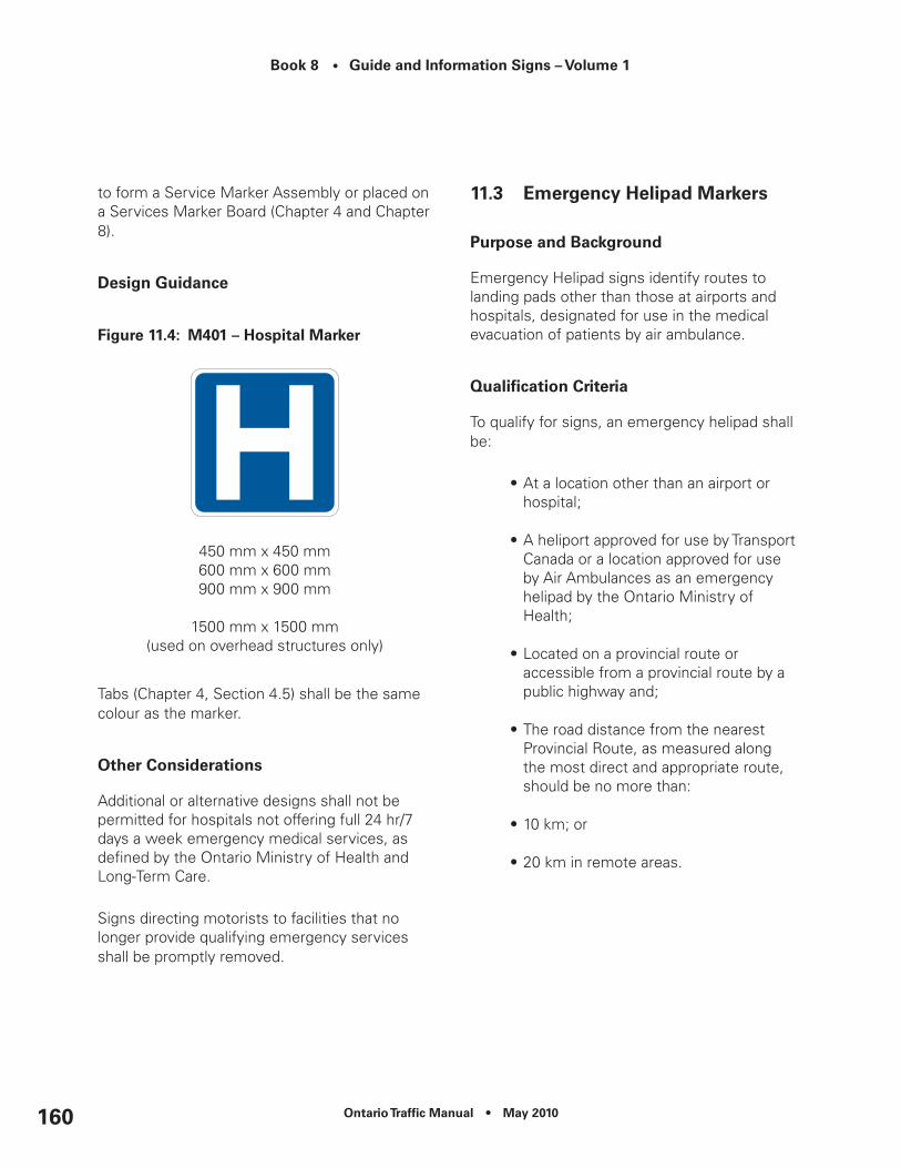
Book 8 • Guide and Information Signs – Volume 1
Ontario Traffic Manual • May 2010160
to form a Service Marker Assembly or placed on a Services Marker Board (Chapter 4 and Chapter 8).
Design Guidance
Figure 11.4: M401 – Hospital Marker
450 mm x 450 mm600 mm x 600 mm900 mm x 900 mm
1500 mm x 1500 mm(used on overhead structures only)
Tabs (Chapter 4, Section 4.5) shall be the same colour as the marker.
Other considerations
Additional or alternative designs shall not be permitted for hospitals not offering full 24 hr/7 days a week emergency medical services, as defined by the Ontario Ministry of Health and Long-Term Care.
Signs directing motorists to facilities that no longer provide qualifying emergency services shall be promptly removed.
11.3 emergency Helipad Markers
Purpose and Background
Emergency Helipad signs identify routes to landing pads other than those at airports and hospitals, designated for use in the medical evacuation of patients by air ambulance.
Qualification Criteria
To qualify for signs, an emergency helipad shall be:
•At a location other than an airport or hospital;
•A heliport approved for use by Transport Canada or a location approved for use by Air Ambulances as an emergency helipad by the Ontario Ministry of Health;
•Located on a provincial route or accessible from a provincial route by a public highway and;
•The road distance from the nearest Provincial Route, as measured along the most direct and appropriate route, should be no more than:
•10 km; or
•20 km in remote areas.

Ontario Traffic Manual • May 2010 161
Book 8 • Guide and Information Signs – Volume 1
Application and Installation
Provincial Freeways
Emergency Helipad markers should be displayed on the Freeway Composite Services Board (FCSB) where present. Where there is no FCSB present, markers may be installed independently or grouped together to form a marker assembly.
Trailblazing is provided starting on the freeway off-ramp.
Emergency Helipad signs are not permitted in the express lanes of freeways.
Provincial Highways
Emergency Helipad markers are generally installed for both directions of travel, in pairs as Advance and Turn-Off Markers, as follows:
•When the helipad has direct access from the roadway, the advance marker is installed 500m in advance of the entrance. The turn-off marker is installed at the entrance.
•Where the helipad is located on an intersecting road, the advance marker is installed 500 m in advance of the intersection. The turn-off marker is installed at the intersection.
Trailblazing leading motorists to the facility shall be in place on all municipal roadways prior to any signs being installed on the provincial highway.
Where more than one service marker is to be displayed on the provincial highway approaching an intersection, markers and their tabs may be
placed as stand-alone signs, grouped together to form a Service Marker Assembly or placed on a Services Marker Board (Chapter 4 and Chapter 8).
Design Guidance
Figure 11.5: M400 – emergency Helipad Marker
450 mm x 450 mm600 mm x 600 mm900 mm x 900 mm
Tabs (Chapter 4) shall be the same colour as the marker.
Other considerations
Any emergency helipads, or signed routes to emergency helipads, that are no longer intended for use shall have all signs promptly removed.

Book 8 • Guide and Information Signs – Volume 1
Ontario Traffic Manual • May 2010162
11.4 Police Markers
Purpose and Background
This policy sets out the requirements for providing directional signing to motorists along the most direct route to Police Stations on Provincial Routes.
Qualification Criteria
To qualify, a police station:
•Shall provide emergency police services with at least one police officer present 24hr/7days a week; and
•Should be within 5 km road distance from the nearest provincial route.
Application and Installation
Provincial Freeways
Police markers should be displayed on the Freeway Composite Services Board (FCSB) where present. Where no FCSB is present, markers may be installed independently or grouped together to form a marker assembly.
Trailblazing is provided starting on the off-ramp.
Police signs are not permitted in the express lanes of freeways.
Provincial Highways
Police markers are generally installed for both directions of travel, in pairs as Advance and Turn-Off Markers, as follows:
•When the station has direct access from the roadway, the advance marker is installed 500 m in advance of the entrance. The turn-off marker is installed at the entrance.
•Where the station is located on an intersecting road, the advance marker is installed 500 m in advance of the intersection. The turn-off marker is installed at the intersection.
Trailblazing leading motorists to the facility shall be in place on all municipal roadways prior to any signs being installed on the provincial highway.
Where more than one service marker is to be displayed on the provincial highway approaching an intersection, markers and their tabs may be placed as stand-alone signs, grouped together to form a Service Marker Assembly or placed on a Services Marker Board (Chapter 4 and Chapter 8).
Design Guidance
Tabs (Chapter 4) shall be the same colour as the marker.
For Police Services other than OPP, the Police Service shall provide artwork of their logo for reproduction.

Ontario Traffic Manual • May 2010 163
Book 8 • Guide and Information Signs – Volume 1
Figure 11.6: M404 – Police Marker (OPP)
450 mm x 450 mm600 mm x 600 mm900 mm x 900 mm
Figure 11.7: M403 – Police Marker (Local)
450 mm x 450 mm600 mm x 600 mm900 mm x 900 mm
Other considerations
This Section Not Used.
11.5 collision/Police reporting Centre Markers
Purpose and Background
This policy sets out the requirements for providing directional signing to motorists along the most direct route to Collision/Police Reporting Centres where minor collisions may be self-reported. These centres are usually operated or contracted out to others by the Ontario Provincial Police or Municipal Police Services.
The centres may be joint use facilities offering multiple amenities to collision-involved motorists such as claims adjusters and car rental services and they may also serve overlapping jurisdictions (i.e. Ontario Provincial Police and Toronto Police Service).
Qualification Criteria
Collision/Police Reporting Centres shall:
•Be capable of accepting reports of property damage collisions;
•Be authorized by the police service(s) having jurisdiction over the area;
•Be open 7 days a week for a minimum 8 hours per day; and,
•Clearly post the hours of operation on the exterior of the Centre.
Collision/Police Reporting Centres should be located within:
•5 km of a Provincial Route.
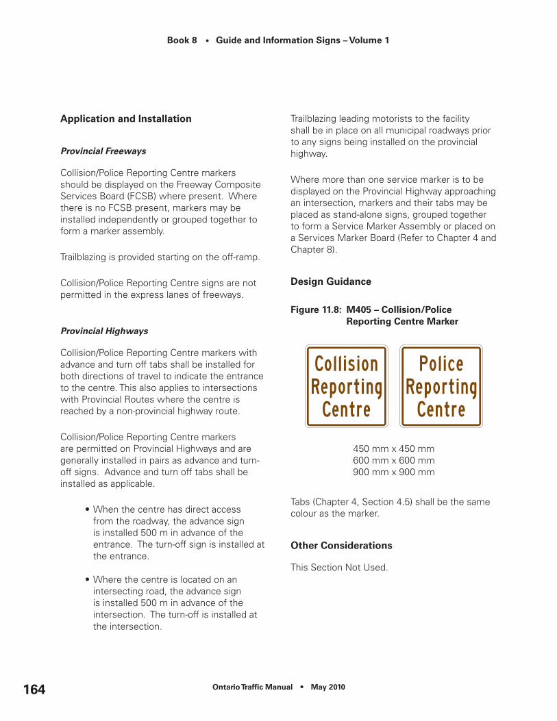
Book 8 • Guide and Information Signs – Volume 1
Ontario Traffic Manual • May 2010164
Application and Installation
Provincial Freeways
Collision/Police Reporting Centre markers should be displayed on the Freeway Composite Services Board (FCSB) where present. Where there is no FCSB present, markers may be installed independently or grouped together to form a marker assembly.
Trailblazing is provided starting on the off-ramp.
Collision/Police Reporting Centre signs are not permitted in the express lanes of freeways.
Provincial Highways
Collision/Police Reporting Centre markers with advance and turn off tabs shall be installed for both directions of travel to indicate the entrance to the centre. This also applies to intersections with Provincial Routes where the centre is reached by a non-provincial highway route.
Collision/Police Reporting Centre markers are permitted on Provincial Highways and are generally installed in pairs as advance and turn-off signs. Advance and turn off tabs shall be installed as applicable.
•When the centre has direct access from the roadway, the advance sign is installed 500 m in advance of the entrance. The turn-off sign is installed at the entrance.
•Where the centre is located on an intersecting road, the advance sign is installed 500 m in advance of the intersection. The turn-off is installed at the intersection.
Trailblazing leading motorists to the facility shall be in place on all municipal roadways prior to any signs being installed on the provincial highway.
Where more than one service marker is to be displayed on the Provincial Highway approaching an intersection, markers and their tabs may be placed as stand-alone signs, grouped together to form a Service Marker Assembly or placed on a Services Marker Board (Refer to Chapter 4 and Chapter 8).
Design Guidance
Figure 11.8: M405 – collision/Police reporting centre Marker
450 mm x 450 mm600 mm x 600 mm900 mm x 900 mm
Tabs (Chapter 4, Section 4.5) shall be the same colour as the marker.
Other considerations
This Section Not Used.
Ontario Traffic Manual • May 2010 165
Book 8 • Guide and Information Signs – Volume 1
11.6 Public Telephone Markers
Purpose and Background
This policy sets out the requirements for signing the availability of public telephone (pay phone) locations.
Most public telephones are provided at locations where other motorist services are available, such as carpool lots, gas stations, hotels, motels, convenience stores, etc.
Qualification Criteria
Used to indicate the presence of a public telephone on or immediately adjacent to a provincial route in remote areas.
They may also be installed at Service Centres located on freeways and MTO operated vehicle inspections stations.
To qualify for signing, telephones shall be:
•Available to the public;
•Operational 24hr/7days a week; and
•Considered the closest available telephone to the route.
These signs will not be used where the telephone is located in or near a service station, restaurant, etc. which fronts on the highway.
Application and Installation
Where it is used to indicate the presence of a public telephone at a government operated inspection station, the advance sign will be installed approximately 200 m in advance of
the Rb-71 Truck Inspection Station Sign. An additional sign illustrating the appropriate turn arrow will be installed at the turn off.
Provincial Freeways
Public Telephone markers should be displayed on the Freeway Composite Services Board (FCSB) where present. Where there is no FCSB present, markers may be installed independently or grouped together to form a marker assembly.
Where the phone is located within a Freeway Service Centre, the telephone marker should be placed on the (Gf-20, 3 km) Freeway Service Centre Composite Sign.
Trailblazing is provided beginning on the off-ramp.
Provincial Highways
Public Telephone markers are generally installed for both directions of travel, in pairs as Advance and Turn-Off Markers, as follows:
•Where the telephone has direct access from the roadway, the advance marker is installed 500 m in advance of the entrance. The turn-off marker is installed at the entrance.
•Where the telephone is located on an intersecting road, the advance marker is installed is installed 500 m in advance of the intersection. The turn-off marker is installed at the intersection.
Trailblazing leading motorists to the facility shall be in place on all municipal roadways prior to any signs being installed on the provincial highway.

Book 8 • Guide and Information Signs – Volume 1
Ontario Traffic Manual • May 2010166
Where more than one service marker is to be displayed on the Provincial Highway approaching an intersection, markers and their tabs may be placed as stand-alone signs, grouped together to form a Service Marker Assembly or placed on a Services Marker Board (Chapter 4 and Chapter 8).
Design Guidance
Tabs (Chapter 4) shall be the same colour as the marker.
Figure 11.9: M406 – Public Telephone Marker
450 mm x 450 mm600 mm x 600 mm900 mm x 900 mm
900 mm x 1200 mm (used on Freeway Service Centre Signs only)
Other considerations
This Section Not Used.
11.7 Local radio Station Signs
Purpose and Background
Local Radio Station signs inform road users in remote areas of the frequencies of radio stations that provide regular weather and road condition information.
Qualification Criteria
Local Radio Station Signs are not permitted on provincial freeways, expressways, and toll highways.
To qualify, the radio station shall provide weather and road information at a minimum of 30 minute intervals during the day throughout periods of inclement weather.
Application and Installation
On Provincial Routes, Local Radio Station signing is permitted only in remote areas and should not be installed within 30 km of an urban Municipality’s centre (as defined by the location of the city or town hall) with a population of 20,000 or more.
These signs should be installed:
•Within the outer limit of the radio station’s range approximately where it crosses the provincial routes;
•At a non-intersection location; and
•At intervals not less than 20 km.

Ontario Traffic Manual • May 2010 167
Book 8 • Guide and Information Signs – Volume 1
Design Guidance
Only station frequencies such as AM 910 or FM 95.2 shall be shown on the sign. Station “call letters” (i.e. CABC) shall not be used.
French stations may be identified by (Fr.) beside their frequency.
Figure 11.10: G702 – Local radio Station Sign
900 mm x 1500 mm
Other considerations
Radio station information should be combined on one sign at a point where two or more stations can be received. A maximum of 3 radio station frequencies may be shown on the sign.
11.8 Fire Hydrant Markers
Purpose and Background
Informs fire crews that a fire hydrant may be found off the freeway behind the marker.
Qualification Criteria
These markers are only used on freeways to identify fire hydrants that are generally not visible from the freeway and are required by fire crews responding to emergency situations on or immediately adjacent to the freeway.
Application and Installation
The Fire Hydrant marker may be installed where fire hydrants are present and their location is obscured from view (e.g. sound barrier walls, fencing, etc.).
The Fire Hydrant marker should be located at or close to the fire hydrant, parallel to and facing the route.
Where the installation is on a sound barrier, installation shall be at an opening from which a fire hydrant is accessible.

Book 8 • Guide and Information Signs – Volume 1
Ontario Traffic Manual • May 2010168
Design Guidance
Figure 11.11: M408 – Fire Hydrant Marker
300 mm x 300 mm
Other considerations
This Section Not Used.

Ontario Traffic Manual • May 2010 169
Book 8 • Guide and Information Signs – Volume 1
12. Public Transportation Services Signs and Markers
12.1 Bus Stop Markers
Purpose and Background
Bus Stop markers identify the location of scheduled stops serviced by a transit authority.
Qualification Criteria
Requests for Bus Stop markers are made in writing by the transit authority to the appropriate road authority.
The transit authority shall provide the following to the road authority:
•Valid operating license;
•Map(s) showing the proposed location of the bus stops on the Provincial Highway;
•Schedule(s) showing times and days of the week that the bus will stop at the identified locations;
•Proposed design of the Bus Stop marker indicating the dimensions, shape, colour, sheeting material, as well as any symbols or text.
Only transit authorities that have regularly scheduled routes may receive Bus Stop markers.
In the event that a bus route is altered, the bus stop is no longer in use, or a bus no longer makes regularly scheduled stops at the location, the Transit Authority shall notify the road authority in writing, and the Bus Stop marker shall be removed.
Application and Installation
Bus Stop markers are permitted on Provincial Highways. At their discretion, other road authorities may adopt and follow this policy in regard to roads under their jurisdiction.
Bus stop locations should be determined through consultations between the transit authority and the road authority.
Bus Stop markers shall be installed without interference of other official signs and signals, and shall not pose a hazard to pedestrians, cyclists, or vehicles.
Bus Stop markers are not permitted on Provincial Freeways, except at interchanges with transit interface facilities and at Car Pool Lots.
Design Guidance
Bus Stop markers shall be retroreflective, in the primary colours of the transit service.
Bus Stop markers for a particular transit authority shall be consistent in their overall appearance. Markers should identify the transit authority serving the stop by means of either text and/or a logo.

Book 8 • Guide and Information Signs – Volume 1
Ontario Traffic Manual • May 2010170
Other information that may appear on a Bus Stop marker:
•Route number;
•Route name/direction and final destination; and
•Phone number or code for obtaining information about routes and schedules.
Other considerations
This Section Not Used.
12.2 Bus, Train, Subway Station Markers
Purpose and Background
These markers direct road users to transit facilities with intercity service, and subway stations.
Qualification Criteria
These markers shall only be permitted where a transit facility or subway station has parking and/or kiss-and-ride services.
Transit, facilities shall have regularly scheduled transit between municipal centres.
The facility should be within 10 km of a Provincial Route or within 20 km in remote areas, as measured along the most direct and appropriate route.
Application and Installation
Provincial Freeways
Markers should be displayed on the Freeway Composite Services Board (FCSB) where present. Where there is no FCSB present, markers may be installed independently or grouped together to form a marker assembly.
Specific markers of multiple, qualified service providers shall be replaced by a generic marker where space on the FCSB is limited.
Trailblazing is provided starting at the off-ramp.
Bus, Train, Subway Station markers are not permitted on the express lanes of freeways.
Provincial Highways
Bus, Train, Subway Station markers are generally installed for both directions of travel, in pairs as Advance and Turn-Off Markers, as follows:
•When the facility has direct access from the roadway, the advance marker is installed 500m in advance of the entrance. The turn-off marker is installed at the entrance.
•Where the facility is located on an intersecting road, the advance marker is installed 500 m in advance of the intersection. The turn-off marker is installed at the intersection.
Trailblazing leading motorists to the facility shall be in place on all municipal roadways prior to any markers being installed on the provincial highway.

Ontario Traffic Manual • May 2010 171
Book 8 • Guide and Information Signs – Volume 1
Where more than one service marker is to be displayed on the provincial highway approaching an intersection, markers and their tabs may be placed as stand-alone markers, grouped together to form a Service Marker Assembly or placed on a Services Marker Board (Chapter 4 and Chapter 8).
Design Guidance
Figure 12.1: M506 – Bus Station (Generic) Marker
450 mm x 450 mm600 mm x 600 mm900 mm x 900 mm
Figure 12.2: M509 –Train Station (Generic) Marker
450 mm x 450 mm600 mm x 600 mm900 mm x 900 mm
Tabs (Chapter 4) shall be the same colour as the marker.
Specific markers for Bus, Train and Subway service providers shall be retroreflective and in the primary colours of the applicable transit service.
Other considerations
Where more than one bus or train station is in the immediate vicinity, a non-generic station marker may be used to identify the station by name (Figure 12.3).
Figure 12.3: M510 – Train Station Marker with Station ID
450 mm x 450 mm600 mm x 600 mm900 mm x 900 mm

Book 8 • Guide and Information Signs – Volume 1
Ontario Traffic Manual • May 2010172
12.3 Airport Signs and Markers
Purpose and Background
These signs direct road users to Major, Secondary, and Local airports that have regularly scheduled and/or chartered flights.
This policy does not address signs within an airport that direct road users to the correct terminal within the airport facility.
Qualification Criteria
Only airports that are listed in Navcanada’s Canada Flight Supplement may qualify for airport signing.
To qualify for a Major Airport sign, an airport shall:
•Provide daily scheduled commercial passenger service using aircraft with a capacity of 60 or more passengers;
•Provide daily scheduled international flights;
•Be located within 20 km road distance from the nearest Provincial Route as measured along the most direct or appropriate route;
•Exceeding the 20 km limit on freeways may be desirable under certain conditions as described in “Application and Installation”.
•Have a runway length of not less than 1800 metres (6000 feet).
To qualify for a Secondary Airport sign, an airport shall:
•Provide daily scheduled commercial passenger service using aircraft with a capacity of 12 or more passengers;
•Be within 20 km road distance from the nearest Provincial Route as measured along the most direct or appropriate route; and
•Have a runway length of not less than 1200 metres (4000 feet).
To qualify for a Local Airport sign, an airport should:
•Be open to the public;
•Primary function is to serve the public in the local area;
•Be within 10 km road distance from the nearest Provincial Route, as measured along the most direct or appropriate route.
Application and Installation
Signs for Major and Secondary Airports are permitted on all Provincial Routes. Signs for Local Airports are not permitted on complex (express/collector) Provincial Freeways.

Ontario Traffic Manual • May 2010 173
Book 8 • Guide and Information Signs – Volume 1
MAJOR AIRPORTS
Due to the amount of traffic being generated by Major Airports, road authorities should evaluate the signing needs of motorists who, in many instances, will have little or no knowledge of the local road network.
Signing plans should be developed identifying strategic locations where signs are required throughout the road network such as at freeway-to-freeway interchanges.
This evaluation should consider:
•The number and type of Major Airport signs;
•The number and type of routes leading to the Major Airport; and
•The limits of where the route to the Major Airport originates.
Major Airports Signs include the Major Airport symbol, the name of the airport, and directional information. These signs are used exclusively for Major Airports. (Figure 12.4).
Provincial Freeways
Major airports are identified through the use of Major Airport Signs upstream of the crossing roadway identification signs that lead road users to the airport.
In addition to Major Airport signs, a Major Airport symbol may be shown on overhead or groundmount advance and turn-off crossing roadway identification signs.
Where overhead signing is used, a Major Airport marker may be placed on the right side of the overhead structure, adjacent to the advance and turn-off crossing roadway identification signs.
Major Airport markers may be displayed on the Freeway Composite Services Board (FCSB) where their use does not prevent other qualified services from being signed.
Trailblazing is provided starting on the off-ramp.
Provincial Highways
Major Airport Signs are generally installed in both directions of travel in advance of the airport. These signs are followed up with Turn-Off markers, as follows:
•When the Major Airport has direct access from the roadway, the advance Major Airport Sign is installed 500 m in advance of the entrance. The Turn-Off Marker is installed at the entrance.
•Where the Major Airport is located on an intersecting road, the advance Major Airport Sign is installed 500 m in advance of the intersection. The Turn-Off Marker is installed at the intersection.
Trailblazing leading motorists to the facility shall be in place on all municipal roadways prior to any markers being installed on the provincial highway.
Where more than one service marker is to be displayed on the provincial highway approaching an intersection, markers and their tabs may be placed as stand-alone signs, grouped together to form a Service Marker Assembly or placed on a Services Marker Board (Chapter 4 and Chapter 8).

Book 8 • Guide and Information Signs – Volume 1
Ontario Traffic Manual • May 2010174
SECONDARY AND LOCAL AIRPORTS
Provincial Freeways
Secondary and Local Airport markers should be displayed on the Freeway Composite Services Board (FCSB) where present. Where there is no FCSB present, markers may be installed independently or together to form a marker assembly.
In all cases, trailblazing leading motorists to the airport shall be in place on all municipal roadways prior to any signs being installed on the provincial freeway.
Provincial Highways
Secondary and Local Airport markers are generally installed in both directions of travel in advance of the airport. These signs are followed up with Turn-Off Markers, as follows:
•When the Airport has direct access from the roadway, the advance marker is installed 500 m in advance of the entrance. The turn-off marker is installed at the entrance.
•Where the Airport is located on a crossing road, the advance marker is installed 500 m in advance of the intersection. The turn-off marker is installed at the intersection.
Trailblazing leading motorists to the facility shall be in place on all municipal roadways prior to any markers being installed on the provincial highway.
Where more than one service marker is to be displayed on the Provincial Highway approaching an intersection, markers and their tabs may be placed as stand-alone signs, grouped together to form a Service Marker Assembly or placed on a Services Marker Board (Chapter 4 and Chapter 8).
Design Guidance
MAJOR AIRPORTS
Major Airport signs should include the Major Airport symbol, name of the airport and directional information (Figure 12.4).
Figure 12.4: example of a Ground-Mounted Major Airport Sign (Freeway)
G410 - Major Airport Sign - FreewayG411 - Major Airport Sign - Highway

Ontario Traffic Manual • May 2010 175
Book 8 • Guide and Information Signs – Volume 1
Figure 12.5: Major Airport Markers
M502 – Major Airport Marker (Generic)
M503 – Major Airport Marker (with ID)
450 mm x 450 mm600 mm x 600 mm900 mm x 900 mm
1500 mm x 1500 mm(used on overhead structures only)
SECONDARY AIRPORTS
The Secondary Airport Marker should incorporate the name of the airport below the Secondary Airport symbol and is limited to one line of text due to legibility constraints.
Figure 12.6: Secondary Airport Marker
M504 – Secondary Airport Marker (Generic)
M505 – Secondary Airport Marker (with ID)
450 mm x 450 mm600 mm x 600 mm900 mm x 900 mm

Book 8 • Guide and Information Signs – Volume 1
Ontario Traffic Manual • May 2010176
LOCAL AIRPORTS
The Local Airport Marker should incorporate the name of the airport below the Local Airport symbol and is limited to one line of text due to legibility constraints.
Figure 12.7: Local Airport Marker
M500 – Local Airport Marker (Generic)
M501 – Local Airport Marker (with ID)
450 mm x 450 mm600 mm x 600 mm900 mm x 900 mm
Tabs (Chapter 4) shall be the same colour as the marker.
Other considerations
The name of the airport may be displayed on airport markers appended to Freeway Composite Services Boards, Services Marker Boards.
The name of the airport shall not be displayed as part of the symbol on Major Airport Signs.
In all other cases, the airport name should be displayed as part of the airport marker.
12.4 Ferry Signs and Markers
Purpose and Background
These signs direct road users to terminals providing ferry service for water crossings by vehicles and pedestrians.
Qualification Criteria
To qualify for a Ferry sign, the operation shall:
•Provide regular scheduled service during at least part of the year;
•Carry passenger vehicles and ;
•Be located within 20 km road distance from the nearest Provincial Route as measured along the most direct or appropriate route; and
• Exceeding the 20 km limit on freeways may be desirable under certain conditions as described in “Application and Installation”.

Ontario Traffic Manual • May 2010 177
Book 8 • Guide and Information Signs – Volume 1
Application and Installation
Provincial Freeways
On freeways, the ferry terminal is identified through the use of Ferry Terminal signs located in advance of the crossing roadway identification signs.
In instances where the most direct or logical route to direct road users to the ferry facility exceeds the 20 km limit, considerations may be given to signing beyond the limit, but should be based on demonstrated needs of a local situation.
Ferry markers may be displayed on the Freeway Composite Services Board (FCSB) where their use does not prevent other qualified services from being signed.
Trailblazing is provided starting on the off-ramp.
Ferry signs are not permitted in the express lanes of complex freeways.
Provincial Highways
Ferry Signs are generally installed in both directions of travel in advance of the ferry terminal. These signs are followed up with Turn-Off Markers, as follows:
•When the terminal has direct access from the roadway, the advance sign is installed 500 m in advance of the entrance. The turn-off marker is installed at the entrance.
•Where the terminal is located on an intersecting road, the advance sign is installed 500 m in advance of the intersection. The turn-off marker is installed at the intersection.
Trailblazing leading motorists to the terminal shall be in place on all municipal roadways prior to any signs being installed on the provincial highway.
Where more than one service marker is to be displayed on the provincial highway approaching an intersection, markers and their tabs may be placed as stand-alone signs, grouped together to form a Service Marker Assembly or placed on a Services Marker Board (Chapter 4, Chapter 8).
Design Guidance
Ferry signs should include the Ferry symbol, name of the Ferry and directional information (Figure 12.9 and 12.10).
On freeways with a numbering system, an Interchange Number Tab shall be attached to the top of the sign, flush with the right edge of the sign.
On freeways where an interchange numbering system has not been assigned, the following message tabs may be attached to the bottom of the primary sign:
•“Next Exit”;
•“Second Exit”; or
•“Via (Road Name).
Tabs (Chapter 4) shall be the same colour as the marker.

Book 8 • Guide and Information Signs – Volume 1
Ontario Traffic Manual • May 2010178
Figure 12.8: M508 – Ferry Marker
450 mm x 450 mm600 mm x 600 mm900 mm x 900 mm
Figure 12.9: G413 – Ferry Sign – Advance (Freeway)
1800 mm x Variable Width
Figure 12.10: G412 – Ferry Sign – Advance (Provincial Highway)
900 mm x 2400 mm
Where seasonal service is provided, the sign design shall include a tab indicating either:
•the operating dates of the service, or
•“OPEN” or “CLOSED” as applicable.
Where this option is selected, the operator of the ferry service is required to notify the road authority in writing at least two weeks prior to the opening and closing dates of the service.
Letter size, fonts and colours shall be the same as used in the primary sign.
Other considerations
When more than one ferry terminal is in the immediate vicinity, a tab may be used beneath the trailblazer marker to identify the ferry terminal by name.
12.5 carpool Lot Markers
Purpose and Background
These markers identify the location of parking areas that can be used for carpooling.
Qualification Criteria
To qualify for markers, carpool lots shall:
•Be free of charge to patrons;
•Be maintained by the road authority;
•Be illuminated during hours of darkness;
•Have a public telephone; and

Ontario Traffic Manual • May 2010 179
Book 8 • Guide and Information Signs – Volume 1
•Be paved.
Application and Installation
Provincial Freeways
Carpool Lot markers are not permitted on express lanes of complex Freeways.
Carpool Lot markers should be displayed on the Freeway Composite Services Board (FCSB), where present. Where there is no FCSB present, markers may be installed independently or grouped together to form a marker assembly.
Trailblazing is provided starting at the Off-Ramp.
Provincial Highways
Carpool Lot Markers are generally installed in both directions of travel in advance of the Carpool Lot. These markers are followed up with Turn-Off Markers, as follows:
•When the lot has direct access from the roadway, the advance marker is installed in 500 m in advance of the entrance. The turn-off marker is installed at the entrance.
•Where the lot is located on an intersecting road, the advance marker is installed 500 m in advance of the intersection. The turn-off marker is located at the intersection.
Trailblazing leading motorists to the lot shall be in place on all municipal roadways prior to any markers being installed on the provincial highway.
Where more than one service marker is to be displayed on the Provincial Highway approaching an intersection, markers and their tabs may be placed as stand-alone markers, grouped together to form a Service Marker Assembly or placed on a Services Marker Board (Chapter 4 and Chapter 8).
Design Guidance
Figure 12.11: M507 – carpool Marker
600 mm x 600 mm900 mm x 900 mm
Tabs (Chapter 4) shall be the same colour as the marker.
Other considerations
This Section Not Used.

Book 8 • Guide and Information Signs – Volume 1
Ontario Traffic Manual • May 2010180
Ontario Traffic Manual • May 2010 181
Book 8 • Guide and Information Signs – Volume 1
13. road user Services
13.1 Freeway Service centre Signs
Purpose and Background
Freeway Service Centre signs provide road users with distances to Freeway Service Centre exits and information about the services provided at these facilities.
Qualification Criteria
This policy only applies to Service Centres, operated on behalf of the Ministry of Transportation, that have direct access to and from a 400-series provincial freeway.
Facilities that provide fuel and food that are located off the freeway, on a crossing roadway do not qualify for signing under this policy. Reference should be made to the Logo signing policy for these situations.
Application and Installation
Provincial Freeways
Freeway Service Centre signs are not permitted on complex Freeways.
Installation details are shown in Figure 13.1.
The Freeway Service Centre Exit sign (Figure 13.2) indicates the exact location of the Service Centre turn-off and is installed between the Freeway main line and the Service Centre
ramp, 3 metres behind the bullnose, so as to be seen by all motorists wishing to exit from the freeway.
The Freeway Service Centre Turn-Off sign (Figure 13.3) indicates the start of the turn-off from the freeway to the Service Centre, it shall be installed beyond the right shoulder, at the beginning of the deceleration lane.
The Next Service Centre sign (Figure 13.4) indicates the distance to the next downstream Service Centre thereby allowing motorists to choose either to exit at the upcoming Service Centre or continue further to the next Service Centre.
This sign shall be installed approximately 1 km in advance of the Freeway Service Centre exit (measured from the beginning of the deceleration lane), beyond the right shoulder of the Freeway.
The Corporate Freeway Composite Services Board (Figure 13.5) shall be installed 2 km in advance of the exit (measured from the beginning of the deceleration lane) beyond the right shoulder of the Freeway. The sign shall include a tab indicating the distance to the centre. The tab is located above the board, flush with it’s right edge.
This board displays the Service Centre Lessee logo and the corporate logos of services that are available at the Centre. A maximum of 6 services, in addition to the Service Centre Lessee logo, may be displayed on the sign. The Service Centre Lessee will have the option of choosing what logos are displayed as long as the services are provided and are approved by MTO as acceptable services. All logos/icons will be of equal size (900 mm x 1200 mm).

Book 8 • Guide and Information Signs – Volume 1
Ontario Traffic Manual • May 2010182
A second Corporate Freeway Composite Services Board (Figure 13.5) is also installed at an advantageous location, generally within a 30 minute drive or approximately 30-40 km in advance of a Service Centre, to inform motorists the distance to and the services available at the upcoming Service Centre. Both installations (2 km and 30-40 km) must display the identical set of corporate logos, in the identical position on the boards. The sign shall include a tab indicating the distance to the centre. The tab is located above the board, flush with it’s right edge.
The Generic Freeway Service Centre Composite Board (Figure 13.6) shall be installed 3 km in advance of the exit (measured from the beginning of the deceleration lane) beyond the right shoulder of the Freeway. The sign shall include a tab indicating the distance to the centre. The tab is located above the board, flush with it’s right edge.
This board displays the Service Centre Lessee logo and a maximum of 6 generic service markers. These generic markers are selected by MTO and may include the following:
•Wheel Chair
•Travel Information
•Fuel Marker (Diesel, Propane & Natural Gas)
•Truck Key-Lock
•Picnic Area
•Trailer Pump Out
•Telephone
•Washroom
Individual logos for each fuel type may replace the fuel combination (diesel, propane and natural gas) logo, where space permits.
Services not offered year-round shall be identified by one of the following means:
1. The text ‘SEASONAL’ shall be included within the logo or icon panel. Letter height shall be a minimum of 150 mm; or
2. The logo or icon shall be removed, covered or supplemented with a ‘CLOSED’ tab when the service is not available.
If the number of qualified generic or corporate facilities/services available exceeds six, priority shall be given to those services that are provided on a 24-hour basis, year-round.
Provincial Highways
Freeway Service Centre signs are not permitted on Provincial Highways.

Ontario Traffic Manual • May 2010 183
Book 8 • Guide and Information Signs – Volume 1
Figure 13.1: Freeway Service centre Signing – Typical Layout
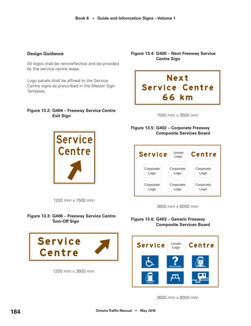
Book 8 • Guide and Information Signs – Volume 1
Ontario Traffic Manual • May 2010184
Design Guidance
All logos shall be retroreflective and be provided by the service centre lesee.
Logo panels shall be affixed to the Service Centre signs as prescribed in the Master Sign Template.
Figure 13.2: G404 – Freeway Service centre exit Sign
1200 mm x 1500 mm
Figure 13.3: G406 – Freeway Service centre Turn-Off Sign
1200 mm x 3600 mm
Figure 13.4: G405 – next Freeway Service Centre Sign
1500 mm x 3600 mm
Figure 13.5: G402 – corporate Freeway composite Services Board
3600 mm x 6000 mm
Figure 13.6: G403 – Generic Freeway composite Services Board
3600 mm x 6000 mm

Ontario Traffic Manual • May 2010 185
Book 8 • Guide and Information Signs – Volume 1
Other considerations
Requests for new signing or changes to existing signs from Service Centre Lessees will be forwarded to the Service Centre Contract Administrator in the Operations Office for processing.
The Service Centre Contract Administrator in the Operations Office approves all new or revised sign layouts. Once a sign layout has been approved, the Head of the Regional Traffic Office initiates installation of signs.
Areas designated by the French Language Services Act will have bilingual signing.
The MTO will manufacture, install and maintain the following Service Centre signs:
G404 – Freeway Service Centre Exit
G406 – Freeway Service Centre Turn-Off
G405 – Next Freeway Service Centre
G402 – Corporate Freeway Composite Services Board
G403 – Generic Freeway Composite Services Board
The Service Centre Lessee will be responsible for all costs associated with the manufacture, installation, maintenance and/or removal of all Service Centre signs, including signs located within the Service Centre.
Note: The Service Centre Lessee will be responsible for providing the actual 900 mm x 1200 mm corporate logos, or paying for the actual production costs (to the Lessee’s specifications) of the corporate logos if manufactured by MTO.
All corporate logos must be retro-reflective.
Where a Freeway Service Centre is visible to motorists travelling in the opposite direction, (and they are unable to see the upcoming Service Centre on their side of the freeway) a “Next Service Centre” sign should be installed adjacent to the Service Centre to ensure motorists are made aware of the distance to the upcoming Service Centre in their direction of travel.
In this situation, the sign aims at deterring motorists from stopping on the shoulder of the road and crossing the highway by foot to access the Service Centre located on the opposite side of the freeway.
13.2 Service club composite Board
Purpose and Background
The Service Club Composite Boards may be used on highways to inform the traveling public of the existence of local branches of service clubs within a community.
Qualification Criteria
Service Club Composite Boards are not permitted on provincial freeways, expressways and toll highways.
Single-tier and lower-tier municipalities, as well as hamlets and formerly incorporated municipalities may qualify for Service Club Composite Boards.

Book 8 • Guide and Information Signs – Volume 1
Ontario Traffic Manual • May 2010186
All requests must be submitted to, and approved by, the single-tier or lower-tier municipality in which they are situated, who will then submit a request to the appropriate road authority for a Service Club Composite Board on their behalf.
The municipality shall provide the road authority with:
•Written confirmation of all approved service clubs and their respective logos that they would like displayed on the board;
•All graphical elements of the logo design, including crests, coat-of-arm, etc.;
•The approximate road location where the municipality would like the board to be placed; and
•Written confirmation for the addition of future service club markers, or removal/alteration of existing markers.
A Service Club is generally defined as any group or organization within the community that:
•Actively provide services to the community on a volunteer basis; and
•Meet on a regular basis at a location within the community.
Application and Installation
Municipalities will be responsible for all costs associated with the manufacturing, installation and maintenance of Service Club Composite Boards.
All costs associated with the addition of future service club logos, or the removal/alteration of existing logos will be the responsibility of the municipality.
Service Club Composite Boards should be installed beyond the right shoulder, near the municipal boundary or the edge of the built-up area.
A maximum of nine service clubs logos may appear on a single sign. Signs may be configured to display three, six or nine logos, as necessary. When there are more than nine qualifying clubs in a community, a second Service Club Composite Board may be installed approximately 100 m downstream from the first.
Design Guidance
Each Service Club Composite Board shall be displayed as follows:
•Upper Panel – Community name and a slogan/welcoming message (an equivalent French Language version must be used on provincial highways in designated bilingual areas);
•Lower Panel(s) – One, two or three rows of Service Club logos. Each row will display up to a maximum of three Service Clubs logos.
All components of the sign shall be retroreflective. (Figure 13.7).
The Service Club logos shall be a maximum 600 mm x 600 mm in size, however they do not need to be square. No part of a marker shall extend beyond the designated space.

Ontario Traffic Manual • May 2010 187
Book 8 • Guide and Information Signs – Volume 1
Additional text indicating meeting locations and times, internet addresses, telephone numbers and other similar messages shall not be permitted on the sign.
When there is a Boundary Sign and a Service Club Composite Board, the community name on them shall be the same.
Figure 13.7: G409 – Service club composite Board
2400 mm x 2700 mm
Other considerations
This Section Not Used.
13.3 Travel Information Centre Signs
THIS POLICY IS UNDER DEVELOPMENT
13.4 Picnic Area Signs
Purpose and Background
Picnic area signs direct road users to picnic areas and roadside tables maintained by road authorities.
Qualification Criteria
Picnic Area signs are not permitted on Provincial Freeways, Expressways and Toll Highways, other than at Freeway Service Centres.
To qualify, the picnic area shall:
•Be accessible free of charge to the public;
•Provide tables, waste receptacles and toilets;
•Provide adequate parking;
•Be located outside of built-up areas (from a visual perspective);
•Not be privately owned and operated (e.g. restaurant with adjacent picnic area);
•With the exception of freeway service centres, have no commercial enterprises of any type operating directly on the site;

Book 8 • Guide and Information Signs – Volume 1
Ontario Traffic Manual • May 2010188
•Be identified by a location sign (not larger than 1200 mm x 2400 mm, installed outside of the right-of-way of the Provincial Route, and conforming to applicable standards) installed on the site by the operators, identifying the operator and a contact telephone number, for public inquiries or complaints; and
•Have direct access from the roadway or be located within 1 km driving distance on an intersecting roadway.
Application and Installation
Picnic Area markers are generally installed for both directions of travel, in pairs as Advance and Turn-Off Markers, as follows:
•When the facility has direct access from the roadway, the advance marker is installed 500 m in advance of the entrance. The turn-off marker is installed at the entrance.
•Where the facility is located on an intersecting road, the advance marker is installed 500 m in advance of the intersection. The turn-off marker is installed at the intersection.
Trailblazing leading motorists to the facility shall be in place on all municipal roadways prior to any markers being installed on the provincial highway.
Where more than one service marker is to be displayed on the provincial highway approaching an intersection, markers and their tabs may be placed as stand-alone signs, grouped together to form a Service Marker Assembly or placed on a Services Marker Board (Chapter 4).
Design Guidance
Tabs (Chapter 4) shall be the same colour as the marker.
Corporate logos shall not be included on any Picnic Area marker or its supports.
Figure 13.8: M714 – Picnic Area Marker
450 mm x 450 mm600 mm x 600 mm900 mm x 900 mm
900mm x 1200 mm(used on Freeway Service Centre Signs only)
Other considerations
Picnic Area Markers shall be removed, covered or modified with a “CLOSED” tab during the winter months or during any other period when the site is not operational.

Ontario Traffic Manual • May 2010 189
Book 8 • Guide and Information Signs – Volume 1
•Where the facility is located on an intersecting road, the advance marker is installed 500 m in advance of the intersection. The turn-off marker is installed at the intersection.
Trailblazing leading motorists to the facility shall be in place on all municipal roadways prior to any markers being installed on the provincial highway.
Where more than one service marker is to be displayed on the provincial highway approaching an intersection, markers and their tabs may be placed as stand-alone signs, grouped together to form a Service Marker Assembly or placed on a Services Marker Board (Chapter 4).
Design Guidance
Figure 13.9: M719 – Scenic Lookout Marker
450 mm x 450 mm600 mm x 600 mm900 mm x 900 mm
Tabs (Chapter 4) shall be the same colour as the marker.
Other considerations
This Section Not Used.
13.5 Scenic Lookout Signs
Purpose and Background
Scenic Lookout signs identify locations where road users may safely pull off of a highway and observe scenic vistas.
Qualification Criteria
Scenic Lookout signs are not permitted on Provincial Freeways, Expressways and Toll Highways.
To qualify, the scenic lookout shall:
•Be open and free of charge to the public;
•Provide off-road parking facilities;
•Provide waste receptacles;
•Be maintained to appropriate standards, as established by the road authority; and
•Have direct access from the roadway or be located within 1 km driving distance on an intersecting roadway.
Application and Installation
Scenic Lookout markers are generally installed for both directions of travel, in pairs as Advance and Turn-Off Markers, as follows:
•When the facility has direct access from the roadway, the advance marker is installed 500 m in advance of the entrance. The turn-off marker is installed at the entrance.

Book 8 • Guide and Information Signs – Volume 1
Ontario Traffic Manual • May 2010190
13.6 Public Boat Launch Sign
Purpose and Background
These signs are provided to direct road users to public boat launch locations.
Qualification Criteria
Public Boat Launch signs are not permitted on Provincial Freeways, Expressways and Toll Highways.
To qualify, the boat launch ramp shall:
•Be within 10 km distance by road from the provincial route;
•Accommodate the launching of typical pleasure craft from road trailers;
•Allow public access;
•Not charge a user fee; and
•Have an adequate supply of parking, including space for boat trailers, to accommodate expected usage.
Application and Installation
Public Boat Lauch markers are generally installed for both directions of travel, in pairs as Advance and Turn-Off Markers, as follows:
•When the facility has direct access from the roadway, the advance marker is installed 500 m in advance of the entrance. The turn-off marker is installed at the entrance.
•Where the facility is located on an intersecting road, the advance marker is installed 500 m in advance of the intersection. The turn-off marker is installed at the intersection.
Trailblazing leading motorists to the facility shall be in place on all municipal roadways prior to any markers being installed on the provincial highway.
Where more than one service marker is to be displayed on the provincial highway approaching an intersection, markers and their tabs may be placed as stand-alone signs, grouped together to form a Service Marker Assembly or placed on a Services Marker Board (Chapter 4).
Design Guidance
Figure 13.10: M717 – Public Boat Launch Marker
450 mm x 450 mm600 mm x 600 mm900 mm x 900 mm
Tabs (Chapter 4) shall be the same colour as the marker.
Other considerations
This Section Not Used.

Ontario Traffic Manual • May 2010 191
Book 8 • Guide and Information Signs – Volume 1
13.7 waste Facility Signs
Purpose and Background
These signs direct road users to waste management facilities operated by a municipality or on their behalf.
Qualification Criteria
Waste Facility signs are not permitted on Provincial Freeways, Expressways and Toll Highways.
To qualify, a waste facility shall:
•Have the appropriate operating license from the Ontario Ministry of the Environment;
•Be open to receive waste from the general public;
•Be located within 10 km road distance of the provincial route, as measured along the most direct or appropriate route; and
•Have Municipal Council approval.
Application and Installation
Waste Facility signs are generally installed for both directions of travel, in pairs as Advance and Turn-Off Signs, as follows:
•When the facility has direct access from the roadway, the advance sign is installed 500 m in advance of the entrance. The turn-off sign is installed at the entrance.
•Where the facility is located on an intersecting road, the advance sign is installed 500 m in advance of the intersection. The turn-off sign is installed at the intersection.
Trailblazing leading motorists to the facility shall be in place on all municipal roadways prior to any signs being installed on the provincial highway.
Where the facility accepts specific materials or provides specific services, the type of service (i.e. “Recycling” or “Garbage”) may be included on the directional arrow tab.
Design Guidance
Figure 13.11: waste Management Facility Sign and Optional Tab
M805 – Waste Management Facility Sign900 mm x 1200 mm
M805t – Waste Management Facility Tab 600 mm x 900 mm

Book 8 • Guide and Information Signs – Volume 1
Ontario Traffic Manual • May 2010192
Other considerations
This Section Not Used.
13.8 Heritage Site/Plaque Signs
Purpose and Background
Heritage Site/Plaque signs are used to identify site/plaque locations that do not qualify for signs under the TODS program.
The purpose of the site/plaque program is to promote an understanding of Ontario’s past by interpreting significant heritage subjects at sites across the province.
Heritage plaques are installed and maintained by the Ontario Heritage Foundation (OHF), a non-profit agency of the Government of Ontario.
The Historic Sites and Monuments Board of Canada (HSMBC) install commemorative plaques for locations and events of national significance.
Qualification Criteria
Heritage Site/Plaque signs are not permitted on any Provincial Freeways, Expressways or Toll Highways.
To qualify for a Heritage Site/Plaque sign, the following criteria shall be met:
•The site/plaque has been endorsed by the OHF or HSMBC;
•Vehicle and pedestrian activity at the site will not create a safety concern; and
•The site/plaque is not part of a park, museum, historical site or historical district that would qualify for TODS or other guide signing.
Application and Installation
Heritage Site/Plaque signs are generally installed for both directions of travel, in pairs as Advance and Turn-Off Markers, as follows:
•When the site has direct access from the roadway, the advance marker is installed 500 m in advance of the entrance. The turn-off marker is installed at the entrance.
•Where the site is located on an intersecting road, the advance marker is installed 500 m in advance of the intersection. The turn-off marker is installed at the intersection.
Trailblazing leading motorists to the site shall be in place on all municipal roadways prior to any markers being installed on the provincial highway.
If the site or plaque is not on the provincial highway, the turn-off sign should indicate the road distance to the plaque. Signing to the site/plaque will be provided from the nearest provincial highway only.
All costs associated with the manufacture, installation and maintenance of Heritage Site/Plaque signs is the responsibility of the Ontario Heritage Foundation (OHF).
All costs associated with the manufacture, installation and maintenance of commemorative plaques for locations and events of national significance is the responsibility of The Historic Sites and Monuments Board of Canada (HSMBC).

Ontario Traffic Manual • May 2010 193
Book 8 • Guide and Information Signs – Volume 1
Design Guidance
Signs leading to Provincial plaques shall include a full-colour Ontario Coat of Arms logo on all Advance and Turn-Off signs.
Signs leading to Federal plaques shall include a Parks Canada Beaver logo on all Advance and Turn-Off signs.
No more than two plaques shall be listed on one sign.
Where two historic sites or historical plaques are to be signed at the same turn-off, the advance and turn-off signs may indicate both names on one sign and the legend would read ‘HISTORICAL PLAQUES’ or ‘HISTORIC SITES’.
Figure 13.12: Heritage Site Plaques/Signs
(a) G610 – Historic Site Plaque - Advance
750 mm x 900 mm 750 mm x 1200 mm750 mm x 1500 mm
(b) G611 – Historic Site Plaque – Turn-Off
900 mm x 900 mm900 mm x 1200 mm900 mm x 1500 mm
(c) G609 – Historic Site route Marker
450 mm x 450 mm
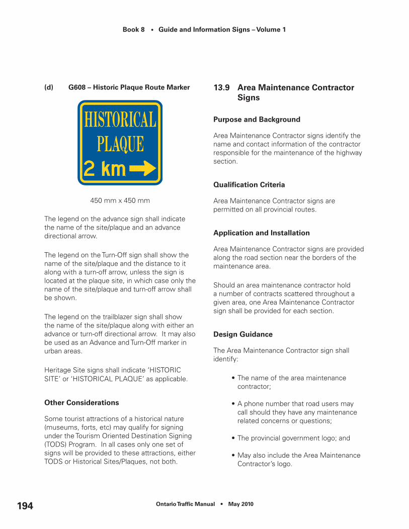
Book 8 • Guide and Information Signs – Volume 1
Ontario Traffic Manual • May 2010194
(d) G608 – Historic Plaque route Marker
450 mm x 450 mm
The legend on the advance sign shall indicate the name of the site/plaque and an advance directional arrow.
The legend on the Turn-Off sign shall show the name of the site/plaque and the distance to it along with a turn-off arrow, unless the sign is located at the plaque site, in which case only the name of the site/plaque and turn-off arrow shall be shown.
The legend on the trailblazer sign shall show the name of the site/plaque along with either an advance or turn-off directional arrow. It may also be used as an Advance and Turn-Off marker in urban areas.
Heritage Site signs shall indicate ‘HISTORIC SITE’ or ‘HISTORICAL PLAQUE’ as applicable.
Other considerations
Some tourist attractions of a historical nature (museums, forts, etc) may qualify for signing under the Tourism Oriented Destination Signing (TODS) Program. In all cases only one set of signs will be provided to these attractions, either TODS or Historical Sites/Plaques, not both.
13.9 Area Maintenance Contractor Signs
Purpose and Background
Area Maintenance Contractor signs identify the name and contact information of the contractor responsible for the maintenance of the highway section.
Qualification Criteria
Area Maintenance Contractor signs are permitted on all provincial routes.
Application and Installation
Area Maintenance Contractor signs are provided along the road section near the borders of the maintenance area.
Should an area maintenance contractor hold a number of contracts scattered throughout a given area, one Area Maintenance Contractor sign shall be provided for each section.
Design Guidance
The Area Maintenance Contractor sign shall identify:
•The name of the area maintenance contractor;
•A phone number that road users may call should they have any maintenance related concerns or questions;
•The provincial government logo; and
•May also include the Area Maintenance Contractor’s logo.

Ontario Traffic Manual • May 2010 195
Book 8 • Guide and Information Signs – Volume 1
Figure 13.13: G701 – Area Maintenance Contractor Sign
1200 mm x 2400 mm
Other considerations
This Section Not Used.
13.10 Highway conditions and Construction Information Sign
Purpose and Background
The purpose of Highway Conditions and Construction Information sign is to provide a means for road users to obtain further information regarding the highway.
The sign lists contact information for the purposes of motorists calling with questions, problems and/or concerns regarding:
•Weather conditions;
•Roadway conditions; and
•Construction work.
Qualification Criteria
Signs are not permitted in the express lanes of complex freeways.
Application and Installation
This sign is generally installed on provincial routes at intervals of not less than 20 km, and approaching long-duration construction zones where road user delays may be expected.
Design Guidance
Figure 13.14: G700 – Highway conditions and Construction Information Sign
1200 mm x 2400 mm (main sign)450 mm x 2400 mm (tab)
Other considerations
This Section Not Used.
13.11 Highway Advisory radio Signs
THIS POLICY IS UNDER DEVELOPMENT

Book 8 • Guide and Information Signs – Volume 1
Ontario Traffic Manual • May 2010196

Ontario Traffic Manual • May 2010 197
Book 8 • Guide and Information Signs – Volume 1
14. Safety Message Sign
14.1 community Safety Program Signs
Purpose and Backround
Community Safety Program signs inform road users that they are entering an area where a community-based safety/security program is in operation.
Included are the following programs:
•Crime Stoppers;
•Neighbourhood Watch;
•Rural Watch;
•Road Watch; and
•Block Parent.
Qualification Criteria
Community Safety Program signs are not permitted on provincial freeways.
To qualify for Community Safety Program signs, the following criteria shall be met:
•A recognized Community Safety Program is active within the whole community, or a portion of the community;
•Endorsement of the program has been obtained from the local Municipal Council; and
•There is a written commitment to active involvement in receiving, reviewing and following up on reports by the police service having jurisdiction over the roadways within the community.
Application and Installation
Community Safety Program signs should be installed beyond the right shoulder at the following locations where the program is in effect:
•At all locations where motorists are entering the limits of the program area;
•On crossing roadways downstream of freeway interchanges; and
•At the exits of major intermodal transfer points (transit stations, airports, ferry docks, etc.).
When a program is in effect throughout the entire community, signs should be installed at the municipal boundary on all roadways entering the municipality.
In instances where a program is only in effect at select locations throughout a community, signs should be installed at the actual limits of the program area.
Where multiple programs cover the same area, Community Safety Program signs for each of the programs may be installed on a Community Safety Program Board (Section 14.2).
Road Watch signs may be repeated beyond major intersections, at intervals of 5 km or greater.

Book 8 • Guide and Information Signs – Volume 1
Ontario Traffic Manual • May 2010198
Design Guidance
Signs shall not include commercial messages or slogans or other messages of a commercial nature.
Crime Stoppers Community Signs
Signs shall include the message “A Crime Stoppers Community”. Logo for local Crime Stopper programme to be provided by proponent.
Figure 14.1: G510 – crime Stoppers community Sign
600 mm x 900 mm
Neighbourhood Watch/Rural Watch Community Signs
Figure 14.2: G512 – neighourhood watch/rural watch community Sign
600 mm x 900 mm
Rural Watch signs shall have the same overall colours and appearance with the exception that the word “Neighbourhood” is replaced by the word “Rural”.
Road Watch Signs
Figure 14.3: G513 – road watch Sign
600 mm x 600 mm

Ontario Traffic Manual • May 2010 199
Book 8 • Guide and Information Signs – Volume 1
Block Parent Signs
Figure 14.4: G511 – Block Parent Sign
600 mm x 900 mm
Other considerations
This section not used.
14.2 community Safety Program Board
Purpose and Background
This Board is intended to increase the conspicuity of individual Community Safety Program signs by placing them on a common board.
Qualification Criteria
Community Safety Program Boards are not permitted on Provincial Freeways, Expressways and Toll Highways.
Community Safety Program Boards may be used to display two or more community safety signs on provincial highways and municipal roads.
The following signs may be displayed on the board:
•Crime Stoppers;
•Neighbourhood Watch;
•Rural Watch;
•Road Watch; and
•Block Parent.
Application and Installation
Community Safety Program Boards should be installed beyond the right shoulder of the highway at the following locations where the programs are in effect:
•At all locations where motorists are entering the limits of the program area;
•On crossing roadways downstream of freeway interchanges; and
•At the exits of major intermodal transfer points (transit stations, airports, ferry docks, etc.).
When the programs are in effect throughout the entire community, the board should be installed at the municipal boundary on all roadways entering the municipality.
In instances where programs are only in effect at select locations throughout a community, the board should be installed at the actual limits of the programs area.
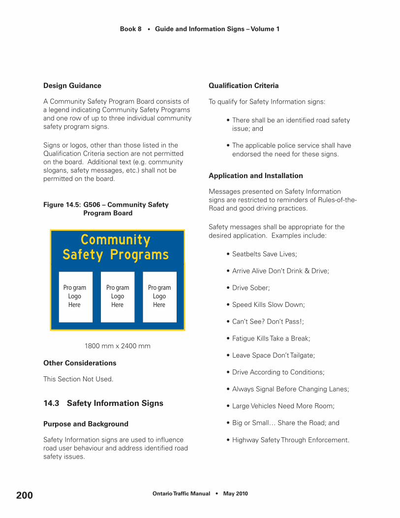
Book 8 • Guide and Information Signs – Volume 1
Ontario Traffic Manual • May 2010200
Design Guidance
A Community Safety Program Board consists of a legend indicating Community Safety Programs and one row of up to three individual community safety program signs.
Signs or logos, other than those listed in the Qualification Criteria section are not permitted on the board. Additional text (e.g. community slogans, safety messages, etc.) shall not be permitted on the board.
Figure 14.5: G506 – community Safety Program Board
1800 mm x 2400 mm
Other considerations
This Section Not Used.
14.3 Safety Information Signs
Purpose and Background
Safety Information signs are used to influence road user behaviour and address identified road safety issues.
Qualification Criteria
To qualify for Safety Information signs:
•There shall be an identified road safety issue; and
•The applicable police service shall have endorsed the need for these signs.
Application and Installation
Messages presented on Safety Information signs are restricted to reminders of Rules-of-the-Road and good driving practices.
Safety messages shall be appropriate for the desired application. Examples include:
•Seatbelts Save Lives;
•Arrive Alive Don’t Drink & Drive;
•Drive Sober;
•Speed Kills Slow Down;
•Can’t See? Don’t Pass!;
•Fatigue Kills Take a Break;
•Leave Space Don’t Tailgate;
•Drive According to Conditions;
•Always Signal Before Changing Lanes;
•Large Vehicles Need More Room;
•Big or Small… Share the Road; and
•Highway Safety Through Enforcement.

Ontario Traffic Manual • May 2010 201
Book 8 • Guide and Information Signs – Volume 1
Safety messages shall not:
•Present statistics on the occurrence of collisions, fatalities, etc.;
•Be used to repeat or replace messages that are or can be provided by regulatory or warning signs;
•Include collision victim memorial messages (e.g. “In Memory of…”); or
•Include slogans or other messages of a commercial nature.
Signs shall be installed at the edge of the identified area.
Design Guidance
The information presented on Safety Information signs shall provide a clear, brief safety message.
•Safety messages shall use yellow lettering on a blue background, however in instances where emphasizing a component of the message is desired, the use of a reverse colour scheme may be considered; and
•Messages should not exceed six major words presented on two lines, or three symbols presented on one line.
Figure 14.6: G500 – Safety Information Sign
1200 mm x 2400 mm (Hwy)1500 mm x 3600 mm (Fwy)
Speed Fine Messages
Speed fine information may be shown as either the fines or demerit points associated with a maximum of three speeds.
If both fines and demerit point information is to be provided, two separate signs may be used, posted in sequence.
All Safety Information signs with speed fine information may have up to five lines of text.
The range of speeds shown on the sign shall not be in increments of less than 10 km/h, with no more than three speeds shown.
The fines and demerit points associated with each speed should be calculated in accordance with the Highway Traffic Act and applicable Regulations, and should be updated each time the regulations are amended.
The first line shall be blue lettering on a yellow background. All other lines shall be yellow lettering on a blue background.

Book 8 • Guide and Information Signs – Volume 1
Ontario Traffic Manual • May 2010202
Figure 14.7: G503 – Safety Information Sign - Speed Fines
3600 mm x 6000 mm
Other considerations
This Section Not Used.
14.4 Temporary community road Safety campaign Signs
Purpose and Background
These signs inform road users that they are entering an area in which a co-operative community/police/road authority program is underway to address a specific, identified driver road safety issue.
The installation of these signs must not be the sole objective or focal point of the highway safety initiative. Signs should function as only one facet of a coordinated effort for each campaign.
A Road Authority’s involvement in the campaign should be as a safety partner in conjunction with police services and the local Community Based Road Safety Organization.
Determining what constitutes a driver road safety concern on provincial highways is the responsibility of MTO’s Road Safety Marketing Office (RSMO), working in conjunction with appropriate enforcement agencies and Regional Traffic Offices.
Qualification Criteria
Safety Campaign signs are not permitted on provincial freeways.
On provincial highways, the safety campaign must be initiated, endorsed and supported by a Community Based Road Safety Organization.
Additional local initiatives must be planned and committed to, or be in place before signing is considered. Any potential opposition or controversy related to the campaign shall be identified during the planning stages.
On provincial highways, the Community Based Road Safety Organization shall seek support from the RSMO, enforcement agencies, Regional Traffic Offices and the municipality/regional government prior to any signs being installed.
To qualify, Safety Campaigns shall:
•Focus on a specific driver road safety issue that is susceptible to correction or improvement through targeted education and enforcement;
•Have defined goals and objectives;
•Have limited geographic boundaries;
•Be time-limited;

Ontario Traffic Manual • May 2010 203
Book 8 • Guide and Information Signs – Volume 1
•Be endorsed by the applicable police service; and
•Be endorsed by municipal council resolution.
Application and Installation
Public agencies and/or private sector partners, in accordance with their organization’s policy, may sponsor the Safety Campaign.
Messages presented on Safety Campaign signs are restricted to giving notice regarding the safety campaign underway. They shall not be used to present:
•Statistics on the occurrence of collisions, fatalities, etc.;
•Messages that are or can be conveyed by regulatory or warning signs;
•Collision victim memorial messages (e.g. “In Memory of…”); or
•Commercial messages or slogans or other messages of a commercial nature.
All Safety Campaign signs shall be static and must be removed at the conclusion of the Safety Campaign.
Safety Campaign signs should be posted beyond the right shoulder of the highway at the following suggested locations where the campaign is in effect:
•At all locations where motorists are entering the limits of the campaign area;
•On crossing roadways downstream of freeway interchanges; and
•At the exits of major intermodal transfer points (transit stations, airports, ferry docks, etc.).
When a campaign is in effect throughout the entire community, signs should be installed in highly visible locations within and entering the municipality.
In instances where a campaign is only in effect at select locations throughout a community, signs should be installed at the actual limits of the campaign area.
Design Guidance
The information presented on Safety Campaign signs shall provide a clear, brief safety message. Sponsors may be identified at the bottom of the sign on a separate tab.
In the safety campaign message area:
•Symbols may be used only if they are standard symbols included in any of the OTM Books;
•Text shall use contrasting colours; and
•Messages should not exceed six major words presented on two lines, or three symbols presented on one line.
In the sponsor identification area:
• The sponsor identification area shall be white with a contrasting border, containing logos of the sponsor; and
• Up to three sponsoring group logos or agencies logos may be placed at the bottom of the sign.
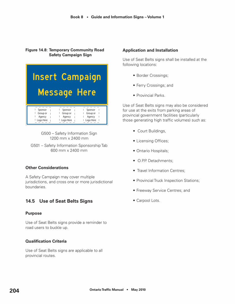
Book 8 • Guide and Information Signs – Volume 1
Ontario Traffic Manual • May 2010204
Figure 14.8: Temporary community road Safety campaign Sign
G500 – Safety Information Sign1200 mm x 2400 mm
G501 – Safety Information Sponsorship Tab600 mm x 2400 mm
Other considerations
A Safety Campaign may cover multiple jurisdictions, and cross one or more jurisdictional boundaries.
14.5 use of Seat Belts Signs
Purpose
Use of Seat Belts signs provide a reminder to road users to buckle up.
Qualification Criteria
Use of Seat Belts signs are applicable to all provincial routes.
Application and Installation
Use of Seat Belts signs shall be installed at the following locations:
•Border Crossings;
•Ferry Crossings; and
•Provincial Parks.
Use of Seat Belts signs may also be considered for use at the exits from parking areas of provincial government facilities (particularly those generating high traffic volumes) such as:
• Court Buildings,
•Licensing Offices;
•Ontario Hospitals;
• O.P.P. Detachments;
• Travel Information Centres;
•Provincial Truck Inspection Stations;
•Freeway Service Centres; and
•Carpool Lots.

Ontario Traffic Manual • May 2010 205
Book 8 • Guide and Information Signs – Volume 1
Design Guidance
Figure 14.9: G505 – use of Seat Belts Sign
1200 mm x 2400 mm
Other considerations
This Section Not Used.

Book 8 • Guide and Information Signs – Volume 1
Ontario Traffic Manual • May 2010206

Ontario Traffic Manual • May 2010 207
Book 8 • Guide and Information Signs – Volume 1
15. Major Traffic Generators
15.1 university and college Markers
Purpose and Background
These markers direct road users to eligible University and College campuses.
Qualification Criteria
University and College markers are applicable to all provincial routes.
To qualify for markers, a university or college must be a post-secondary institution and shall:
•Be publicly funded and recognized as an institution by the Ontario Ministry of Training, Colleges and Universities;
•Have a minimum registered annual attendance (full-time and/or part-time) of 1000 students; and
•Be within 20 km road distance from the nearest provincial route, as measured along the most direct or appropriate route.
Where a university or college operates facilities at multiple locations, additional campuses may be considered eligible for signing, provided the additional campus meets all aspects of the criteria on its own merit.
Application and Installation
Provincial Freeways
University and College markers should be displayed on the Freeway Composite Services Board (FCSB) where present. Where there is no FCSB present, markers may be installed independently or grouped together to form a marker assembly.
Trailblazing is provided starting on the off-ramp.
University and College markers are not permitted in the express lanes of freeways.
Provincial Highways
University and College markers are generally installed for both directions of travel, in pairs as Advance and Turn-Off Markers, as follows:
•When the facility has direct access from the roadway, the advance marker is installed 500 m in advance of the entrance. The turn-off marker is installed at the entrance.
•Where the facility is located on an intersecting road, the advance marker is installed 500 m in advance of the intersection. The turn-off marker is installed at the intersection.
Trailblazing leading motorists to the facility shall be in place on all municipal roadways prior to any markers being installed on the provincial highway.
Where more than one service marker is to be displayed on the provincial highway approaching an intersection, markers and their tabs may be

Book 8 • Guide and Information Signs – Volume 1
Ontario Traffic Manual • May 2010208
placed as stand-alone signs, grouped together to form a Service Marker Assembly or placed on a Services Marker Board (Chapter 4).
Design Guidance
Figure 15.1: M602 – university Marker
450 mm x 450 mm600 mm x 600 mm900 mm x 900 mm
Figure 15.2: M600 – college Marker
450 mm x 450 mm600 mm x 600 mm900 mm x 900 mm
To avoid confusion, where there are two or more facilities located within the same general area, University and College markers may include the name of the institution. (Figures 15.3 and 15.4).
Figure 15.3: M603 – university Marker (with name)
450 mm x 450 mm600 mm x 600 mm900 mm x 900 mm
Figure 15.4: M601 – college Marker (with name)
450 mm x 450 mm600 mm x 600 mm900 mm x 900 mm
Tabs (Chapter 4) shall be the same colour as the marker.

Ontario Traffic Manual • May 2010 209
Book 8 • Guide and Information Signs – Volume 1
Other considerations
Qualified universities and colleges are not eligible for signing at the following locations:
•Highway 401 from interchange 336 easterly to interchange 399.
•Highway 400 from the 400/401 interchange north to interchange 35.
•Highway 403 from the Queen Elizabeth Way easterly to Highway 401.
•All interchanges on Highway 410 and Highway 427.
•Highway 417 from interchange 104 westerly to interchange 134 and Highway 416.
•Highway 417 from interchange 113 easterly to Champlain Street on Highway 17.
The large number of Universities/Colleges located in these areas and/or the priority of directional signing does not permit these additional markers.
Universities/Colleges shall only be signed from one exit for each direction of travel. This may or may not be the same exit for each direction of travel.
15.2 Special events
Purpose and Background
These signs guide road users to temporary, special events, or to an off-site marshalling area, in an effort to keep affected roads operating efficiently and safely.
Qualification Criteria
Special Events Signs are applicable to all Provincial Routes.
To qualify for signs, a Special Event shall be:
•A Local, Regional or National/International event;
•Unique, date specific, time limited, annual, or seasonal event;
•Open to the general public;
•Located within 30 km road distance from the nearest provincial route, as measured along the most direct or appropriate route;
•Anticipated to generate a significant amount of vehicular traffic over and above that which normally occurs on roads leading to the event; and
•Not otherwise provided with sufficient directional signs to ensure that relatively safe and efficient operations will likely be maintained, given the anticipated attendance (i.e. TODS, directional guide signs).
Special Event Classification:
For the purposes of this policy, Special Events have been classed as being a Local, Regional or National/International Event as defined below.
Local Events – Events that take place within one municipality and are generally confined to a single location. These events are local in
Book 8 • Guide and Information Signs – Volume 1
Ontario Traffic Manual • May 2010210
nature, whereby the majority of attendees are local residents with limited requirements for directional signs.
Regional Events – Events that either take place within a single municipality, within several distinguished areas of a municipality or within multiple municipalities. These events are regional in nature, whereby the majority of attendees do not necessarily reside in the municipality in which the special event is being held and as such are dependant to some degree on directional signs.
National or International Events – Events that generally take place at more than one location, whose scope is on a national and international scale in terms of anticipated attendees and their directional signing needs. Attendees are expected to travel across municipal, regional, provincial and international boundaries, having little or no knowledge of Ontario’s road network and as such require a higher level of directional signs. National or International events generally provide economic benefits to the entire province.
Application and Installation
The installation of highway signs must not be the sole objective or focal point of the special event. Signs should function as only one facet of a coordinated effort for each event.
Special Events signs should function with, and take advantage of, the presence of existing, permanent directional signs. Road users may be “transitioned” from permanent directional signs to special event temporary signs, in advance of and at critical decision points.
A review of existing guide signs directing road users to the location where the special event will be held, should be undertaken by the road authority to determine the number, type and location of signs required.
Signs are installed in advance of the special event as follows:
•Local Event – Two weeks prior to the event
•Regional Event – Four weeks prior to the event
•National/International Event – Up to one year prior to the event.
All Special Events signs shall be removed from the right-of-way immediately following the completion of an event.
Trailblazer signs incorporating the event logo should be used at decision-points along the route leading to the event and shall be in place on all municipal roadways prior to any signs being installed on the provincial highway.
Provincial Freeways
Signs are not permitted in the express lanes of complex freeways.
Signs directing road users from one provincial freeway to another are not permitted.
Signs directing road users from a provincial freeway to a provincial highway, or municipal roadway may be permitted if they form part of the most appropriate and direct route to the event.

Ontario Traffic Manual • May 2010 211
Book 8 • Guide and Information Signs – Volume 1
One sign is installed for each direction of travel, in advance of an interchange providing the most direct and appropriate route to the venue. The sign should be placed in advance of all signs relating to the interchange.
Trailblazer signs incorporating the event logo should begin at the freeway off-ramp and be used at decision-points along the route leading to the event.
Provincial Highways
Special Event signs are generally installed for both directions of travel, in pairs as Advance and Turn-Off signs, as follows:
•When there is direct access to the event from the roadway, the advance sign is installed 500 m in advance of the entrance. The turn-off sign is installed at the entrance.
•Where the event is located on an intersecting road, the advance sign is installed 500 m in advance of the intersection. The turn-off sign is installed at the intersection.
Signs directing road users from a provincial highway to another provincial highway, or municipal roadway may be permitted if they form part of the most appropriate or direct route to the event.
Proponents will be responsible for all costs associated with the manufacturing, installation and maintenance of the signs.
Design Guidance
The road authority shall approve the proposed official event logo prior to its use. The logo must not mimic a traffic control device and shall be fully retroreflective.
Information presented on the sign should be limited to the event name and event logo, the beginning and ending dates of the event, and directional information in the form of text and/or arrows. Logos of event sponsors and contributors are not permitted on the sign. Commercial content or slogans of any nature are not permitted on the sign.
For Special Temporary Event signs on provincial freeways, an interchange Exit Number Tab shall be appended to the top right of the sign, where applicable. Where an interchange numbering system is not in place, the sign shall include a tab indicating either “Next Exit” or “Via”.
For Special Temporary Event signs on highways, the appropriate advance and turn-off arrows should be incorporated on the sign. The signs shall include a tab indicating the beginning and ending dates of the event.
For National/Provincial events, consideration may be given to using larger signs.
Tabs shall be the same colour as the primary sign.

Book 8 • Guide and Information Signs – Volume 1
Ontario Traffic Manual • May 2010212
Figure 15.5: G424 – Temporary Special event Sign (Freeway)
1200 mm x 2400 mm
Figure 15.6: G425 – Temporary Special event Sign (Highway)
1200 mm x 2400 mm
300 mm x 2400 mm (tab)(see G416 to G418)
Other considerations
This section not used.
15.3 Major Attraction Signs
Purpose and Background
These signs provide unfamiliar road users with directional guidance to destinations not identified by other Guide and Information Signs, including TODS and Logo Signs.
Qualification Criteria
Significant attractors, not otherwise identified by signs may, on a case-by-case basis, receive signs following an assessment of their potential traffic operation and road user wayfinding benefits, at the discretion of the road authority.
For provincial highways, the MTO Regional Traffic Offices will determine the need for signs on the basis of individual merit and available sign space.
For municipal roadways, the appropriate road authority will determine if an attraction is signed.
Signs are not permitted where other information, including commercial advertising signs, which are visible from the highway, serve the same purpose.
Application and Installation
Provincial Freeways
Signs are not permitted in the express lanes of complex freeways.
Only one Major Attraction shall be signed per interchange for each direction of travel.

Ontario Traffic Manual • May 2010 213
Book 8 • Guide and Information Signs – Volume 1
Signs directing road users from one provincial freeway to another are not permitted.
Signs directing road users from a provincial freeway to a provincial highway, or municipal roadway may be permitted if they form part of the most appropriate and direct route to the event.
One sign is installed for each direction of travel, in advance of an interchange providing the most direct and appropriate route to the attraction. The sign should be placed in advance of all signs relating to the interchange.
Where sign space is not available, a Major Attraction sign may be relocated upstream of the preceding interchange, providing no other Major Attraction sign is installed at that location.
In this situation a “Next Exit” or “Via” (Road Name) tab should be added to the sign.
Trailblazer signs incorporating the major attraction logo should begin at the freeway off-ramp and be used at decision-points along the route leading to the attraction. Trailblazers shall be in place on all municipal roadways prior to any signs being installed on the provincial highway.
Provincial Highways
Major Attraction signs are generally installed for both directions of travel, in pairs as Advance and Turn-Off signs, as follows:
•When there is direct access to the attraction from the roadway, the advance sign is installed 500 m in advance of the entrance. The turn-off sign is installed at the entrance.
•Where the attraction is located on an intersecting road, the advance sign is installed 500 m in advance of the intersection. The turn-off sign is installed at the intersection.
Trailblazer signs incorporating the major attraction logo should be used at decision-points along the route leading to the attraction and shall be in place on all municipal roadways prior to any signs being installed on the provincial highway.
Signs directing road users from a provincial highway to another provincial highway, or municipal roadway may be permitted if they form part of the most appropriate or direct route to the attraction.
Proponents will be responsible for all costs associated with the manufacturing, installation and maintenance of the signs.

Book 8 • Guide and Information Signs – Volume 1
Ontario Traffic Manual • May 2010214
Design Guidance
On provincial routes, the major attraction sign must include a logo.
The road authority shall approve the proposed official attraction logo prior to its use. The logo must not mimic a traffic control device and shall be fully retroreflective.
Information presented on the sign should be limited to the attraction name, logo and directional information in the form of text and/or arrows. Commercial content or slogans of any nature are not permitted on the sign.
For Major Attraction signs on provincial freeways, an interchange Exit Number Tab shall be appended to the top right of the sign, where applicable. Where an interchange numbering system is not in place, the sign shall include a tab indicating either “Next Exit” or “Via”.
For Major Attraction signs on highways, the appropriate advance and turn-off arrows should be incorporated on the sign.
Tabs shall be the same colour as the primary sign.
Figure 15.7: G426 – Major Attraction Sign (Freeway)
1800 mm x Variable Width
Figure 15.8: G427 – Major Attraction Sign (Highway)
1200 x 2400 mm
Other considerations
This section not used.

Ontario Traffic Manual • May 2010 215
Book 8 • Guide and Information Signs – Volume 1
16. Special Signs
16.1 Adopt-A-Highway Signs
Purpose and Background
These signs make road users aware of the Adopt-A-Highway Program, which has been established as a public service program for volunteers to enhance the roadside activities of participating road authorities along the highway right-of-way (i.e., litter collection, tree/shrub/wildflower planting, vegetation control, etc.).
It is a way for environmentally concerned groups and individuals to contribute to a cleaner and more beautiful highway system and provides recognition to groups or individuals who have contributed to the program.
These signs are not intended to be used as an advertising medium.
Qualification Criteria
Groups and individuals wishing to participate in the Adopt-A-Highway program shall complete and submit an Adopt-A-Highway Application to the applicable road authority.
For provincial highways, all applications and sign locations are to be approved by the Head, Regional Traffic Office prior to manufacture and installation of the sign(s).
The Regional Traffic Office shall maintain a registry of applications that have been approved, denied or are outstanding.
All volunteers shall agree to the Terms and Conditions of an Adopt-A-Highway Volunteer Agreement.
Graphics and/or commercial advertising are not permitted on any part of the individual sign components. Telephone number or web sites are also not permitted.
The following criteria apply to text shown on the Recognition Panels:
•The panel may recognize an individual and their title, or their formal business name, but not both;
•Only the official (registered) name of an organization is permitted on the sign. Slogans or messaging relating to the organization are not permitted (i.e. – MADD is permitted, “Don’t Drink and Drive” is not permitted);
•Non-unique business names may have one additional descriptive term added to the adoption panel, upon approval by the road authority (e.g. McDonald’s Ontario Street);
•Political parties shall not be referenced, however, the name only of an elected official, appointed official, or political candidate may be used;
•Any messaging indicating or implying a memorial dedication (e.g. – “In Memory Of”) is not permitted on the sign. A message such as “Family Of” can be used in its place; and
• Written consent is required from any organization or individual identified on the recognition panel; and

Book 8 • Guide and Information Signs – Volume 1
Ontario Traffic Manual • May 2010216
•In the case of a deceased individual, written consent is required from immediate family members of the individual being identified on the recognition panel.
Application and Installation
Provincial Freeways and Provincial Highways
Freeway and highway sections adopted under the program shall be not less than 1 km in length.
One Adopt-A-Highway sign shall be installed within the section for each direction of travel, generally at the upstream end of the section.
Groups may adopt multiple, non-adjacent sections. Non-adjacent sections are eligible for signing on an individual basis.
Signs should be installed independently of other traffic control devices, on their own support.
All costs associated with manufacture, installation and maintenance of the signs shall be paid for by the applicant(s).
Design Guidance
The Adopt-A-Highway sign consists of three separate panels:
•Top: Adopt-A-Highway panel;
•Centre: Recognition panel; and
•Bottom: Folding panel displaying a slogan as selected by the road authority (when closed) and displaying “Road Work” (TC-2A) when open.
Figure 16.1: Adopt-A-Highway Sign
Top of AssemblyG600 – Adopt-A-Highway Panel
600 mm x 600 mm
Middle of AssemblyG602 – Adopt-A-Highway Group Name
300 mm x 600 mm (1-line)450 mm x 600 mm (2-line)600 mm x 600 mm (3-line)
Bottom of AssemblyG601 – Adopt-A-Highway Folding Panel
300 mm x 600 mm (closed position - displaying slogan)

Ontario Traffic Manual • May 2010 217
Book 8 • Guide and Information Signs – Volume 1
600 mm x 600 mm (open position - displaying TC-2A)
Other considerations
Safety is of primary importance in all decisions related to the Adopt-A-Highway Program. The road authority may refuse to grant a request to adopt a section if, in its opinion, granting the request would jeopardize the program, be counter-productive to its purpose, create a public safety hazard, or be in conflict with its policies.
While volunteers are carrying out work alongside the roadside as part of an Adopt-A-Highway program, they must be in compliance with OTM Book 7 by means of using temporary traffic control devices and appropriate personal protective equipment, in accordance with the Occupational Health and Safety Act.
16.2 Planting Partnership Signs
Purpose and Background
These signs make road users aware of the Planting Partnership program which has been established as a public service program for volunteers to enhance the local planting activities of participating road authorities by establishing trees, shrubs and wildflowers on the highway right-of-way and in rest areas.
It is a way for environmentally concerned groups and individuals to contribute to a more beautiful highway system and provides recognition to organizations that have contributed to the Planting Partnership program.
Qualification Criteria
On provincial highways, groups and individuals wishing to participate in the Planting Partnership program shall complete and submit an application to MTO.
All volunteers shall agree to the Terms and Conditions of the agreement.
Road authorities generally establish a minimum dollar amount associated with the planting program either as part of the Terms and Conditions of the agreement or as a separate condition.
Application and Installation
Groups choosing to carry out such a program should meet with the appropriate road authority representative to discuss the nature and location of the work.
One Planting Partnership sign may be displayed as close as possible upstream of the actual location of the roadside planting for each direction of travel.
Plantings in the medians of divided highways are not permitted.
Where there is only one sponsoring group, the name of the group may appear on a Name Recognition Tab beneath the Planting Partnership sign.
Where there is more than one sponsoring group, they are to appear on a separate Multi-Sponsor Name Recognition sign. A maximum of four groups may be displayed.
Where a Planting Partnership sign and a Multi-Sponsor Name Recognition sign are being used, the appropriate distance between

Book 8 • Guide and Information Signs – Volume 1
Ontario Traffic Manual • May 2010218
the two signs based on posted speed and operating characteristics of the highway must be maintained.
A minimum distance of 5 km shall be maintained between Planting Partnership Signs.
All costs associated with manufacture, installation and maintenance of the signs shall be paid for by the applicant(s).
Design Guidance
Figure 16.2: G603 – Planting Partnership Sign
1200 mm x 2400 mm
Figure 16.3: G604 – name recognition Tab
450 mm x 2400 mm
Figure 16.4: Planting Partnership Multi-Sponsor name recognition Signs
G605 – Two Sponsors1500 mm x 2400 mm
G606 – Three Sponsors1800 mm x 2400 mm
G607 – Four Sponsors2100 mm x 2400 mm
Other considerations
While individuals are carrying out work in relation to the planting partnership, they must be in compliance with OTM Book 7 by means of using temporary traffic control devices and appropriate protective gear in accordance with the Occupational Health and Safety Act.

Ontario Traffic Manual • May 2010 219
Book 8 • Guide and Information Signs – Volume 1
17. Administrative notification Signs
Administrative Notification signs provide owners and prospective owners of properties adjacent to roadways with basic information about permit requirements, land use restrictions and planned road extensions.
They are also used to provide road users with advance notifications of road closures, route numbering changes and information on the current administrative/maintenance status of the road.
17.1 route numbering change Signs
Purpose and Background
The purpose of this guideline is to set out application, design and installation criteria for signs informing road users of changes in route numbering and/or designation.
Qualification Criteria
These signs are applicable to all classes of roadways.
Application and Installation
Route Numbering Change Sign – Numbered Route to Numbered Route
These signs are used to provide advance notice to road users when a route number is being altered.
Signs are installed for both directions of travel on the affected route, generally one year prior to the number change at the following locations:
•Near the beginning, in each direction of travel, of the affected highway;
•Near junctions with all other provincial routes;
•At approximate intervals of 15-30 km, depending on the length of the affected highway;
•Near the limits of municipalities, leaving the municipality;
•Within a municipality at approximate intervals of 5 km at locations where sign space is available, and municipal permission has been obtained.
Once the route number change has been implemented, the old route number marker is replaced with the new route number marker. “Formerly” markers (Chapter 4) showing the old route number, are installed below the new route number marker and retained for not less than two years.
Route Numbering Change Sign –Numbered Route to Local Road Name
These signs are used to provide advance notice to road users when:
•a highway is being transferred to a municipality;
•a regional route number is being changed to a road name; or

Book 8 • Guide and Information Signs – Volume 1
Ontario Traffic Manual • May 2010220
•the Ministry of Transportation retains a Provincial Route permanently or temporarily as a 7000-series numbered highway, (should be identified as a local road name obtained from the municipality)
Signs are installed for both directions of travel on the affected route, generally one year prior to the transfer date or route number to name change at the following locations:
•Near the beginning, in each direction of travel, of the affected highway;
•Near junctions with all other provincial routes;
•At approximate intervals of 15-30 km, depending on the length of the affected highway;
•Near the limits of municipalities, leaving the municipality.
Route Numbering Change Sign – Local Road Designation to Route Number
These signs are used to provide advance notice to road users when a road name is being changed to a route number.
Signs are installed for both directions of travel on the affected route, generally one year prior to the number change at the following locations:
•Near the beginning, in each direction of travel, of the affected highway;
•Near junctions with all other provincial routes;
•At approximate intervals of 15-30 km, depending on the length of the affected highway;
•Near the limits of municipalities, leaving the municipality;
•Within a municipality at approximate intervals of 5 km at locations where sign space is available, and municipal permission has been obtained.
Design Guidance
Figure 17.1: G713 – Highway numbering change (route # to route #)
900 mm x 1200 mm
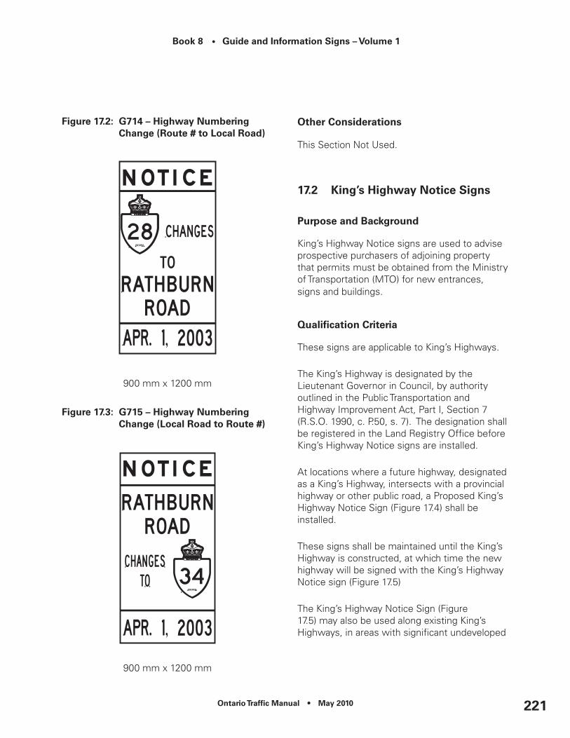
Ontario Traffic Manual • May 2010 221
Book 8 • Guide and Information Signs – Volume 1
Figure 17.2: G714 – Highway numbering change (route # to Local road)
900 mm x 1200 mm
Figure 17.3: G715 – Highway numbering change (Local road to route #)
900 mm x 1200 mm
Other considerations
This Section Not Used.
17.2 king’s Highway notice Signs
Purpose and Background
King’s Highway Notice signs are used to advise prospective purchasers of adjoining property that permits must be obtained from the Ministry of Transportation (MTO) for new entrances, signs and buildings.
Qualification Criteria
These signs are applicable to King’s Highways.
The King’s Highway is designated by the Lieutenant Governor in Council, by authority outlined in the Public Transportation and Highway Improvement Act, Part I, Section 7 (R.S.O. 1990, c. P.50, s. 7). The designation shall be registered in the Land Registry Office before King’s Highway Notice signs are installed.
At locations where a future highway, designated as a King’s Highway, intersects with a provincial highway or other public road, a Proposed King’s Highway Notice Sign (Figure 17.4) shall be installed.
These signs shall be maintained until the King’s Highway is constructed, at which time the new highway will be signed with the King’s Highway Notice sign (Figure 17.5)
The King’s Highway Notice Sign (Figure 17.5) may also be used along existing King’s Highways, in areas with significant undeveloped

Book 8 • Guide and Information Signs – Volume 1
Ontario Traffic Manual • May 2010222
land. The responsible area corridor management representative shall determine the need for the signs.
Application and Installation
The Proposed King’s Highway Notice sign (Figure 17.4) shall be installed at the approximate location of the future King’s Highway, at right angles to intersecting provincial highways or other public roads and close to the right-of-way fence.
One sign shall be installed for each direction of travel on the intersecting roadway.
The King’s Highway Notice sign (Figure 17.5) shall be installed parallel to the roadway, close to the right-of-way fence. Signs should be spaced approximately 1 km apart, and should alternate from one side of the roadway to the other.
King’s Highway Notice signs are intended to be read from a stopped vehicle, or by a person on foot. Signs shall not be installed where a stopped vehicle would encroach on travelled lanes or otherwise create a hazard.
Design Guidance
The location (Municipality) and telephone number of the relevant MTO Office shall be shown on the signs (in place of the dashes).
Figure 17.4: G716 – notice – Proposed king’s Highway
450 mm x 750 mm
Figure 17.5: G717 – notice – king’s Highway Sign
450 mm x 750 mm

Ontario Traffic Manual • May 2010 223
Book 8 • Guide and Information Signs – Volume 1
Other considerations
This Section Not Used.
17.3 controlled Access Highway notice Signs
Purpose and Background
Controlled Access Highway Notice signs are used to advise prospective purchasers of adjoining property that permits must be obtained from the Ministry of Transportation (MTO) for new entrances, signs and buildings.
Qualification Criteria
These signs are applicable to freeways, expressways, staged freeways and controlled access highways.
Controlled Access Highways are designated by the Lieutenant Governor in Council under the Public Transportation and Highway Improvement Act, Part II, Section 36 (R.S.O. 1990, c. P.50, s. 36). The designation shall be registered in the appropriate Land Registry Office before Controlled Access Highway Notice signs are installed.
At locations where a future highway, designated as a Controlled Access Highway, intersects with a provincial highway or other public road, a Proposed Controlled Access Highway Notice Sign (Figure 17.6) shall be installed.
These signs shall be maintained until the Controlled Access Highway is constructed, at which time the new highway will be signed with the Controlled Access Highway Notice sign (Figure 17.7)
The Controlled Access Highway Notice Sign (Figure 17.7) may also be used along existing Controlled Access Highways, in areas with significant undeveloped land. The responsible area corridor management representative shall determine the need for the signs.
Application and Installation Guidance
The Proposed Controlled Access Highway Notice sign (Figure 17.6) shall be installed at the approximate location of the future Controlled Access Highway, at right angles to intersecting provincial highways or other public roads and close to the right-of-way fence.
One sign shall be installed for each direction of travel on the intersecting roadway.
The Controlled Access Highway Notice sign (Figure 17.7) shall be installed parallel to the roadway, close to the right-of-way fence. Signs should be spaced approximately 1 km apart, and should alternate from one side of the roadway to the other.
Controlled Access Highway Notice signs are intended to be read from a stopped vehicle, or by a person on foot. Signs shall not be installed where a stopped vehicle would encroach on travelled lanes or otherwise create a hazard.
Design Guidance
The location (Municipality) and telephone number of the relevant MTO Office shall be shown on the signs (in place of the dashes).
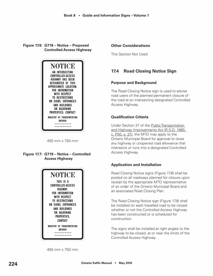
Book 8 • Guide and Information Signs – Volume 1
Ontario Traffic Manual • May 2010224
Figure 17.6: G718 – notice – Proposed controlled Access Highway
450 mm x 750 mm
Figure 17.7: G719 – notice – controlled Access Highway
450 mm x 750 mm
Other considerations
This Section Not Used.
17.4 road closing notice Sign
Purpose and Background
The Road Closing Notice sign is used to advise road users of the planned permanent closure of the road at an intersecting designated Controlled Access Highway.
Qualification Criteria
Under Section 37 of the Public Transportation and Highway Improvements Act (R.S.O. 1990, c. P.50, s. 37), the MTO may apply to the Ontario Municipal Board for approval to close any highway or unopened road allowance that intersects or runs into a designated Controlled Access Highway.
Application and Installation
Road Closing Notice signs (Figure 17.8) shall be posted on all roadways planned for closure upon receipt by the appropriate MTO representative of an order of the Ontario Municipal Board and an associated Road Closing Plan.
The Road Closing Notice sign (Figure 17.8) shall be installed on each travelled road to be closed whether or not the Controlled Access Highway has been constructed or is scheduled for construction.
The signs shall be installed at right angles to the highway to be closed, at or near the limits of the Controlled Access Highway.
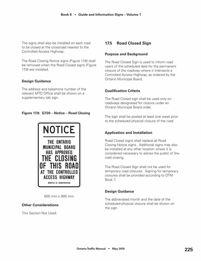
Ontario Traffic Manual • May 2010 225
Book 8 • Guide and Information Signs – Volume 1
The signs shall also be installed on each road to be closed at the crossroad nearest to the Controlled Access Highway.
The Road Closing Notice signs (Figure 17.8) shall be removed when the Road Closed signs (Figure 17.9) are installed.
Design Guidance
The address and telephone number of the relevant MTO Office shall be shown on a supplementary tab sign.
Figure 17.8: G720 – notice – road closing
600 mm x 900 mm
Other considerations
This Section Not Used.
17.5 Road Closed Sign
Purpose and Background
The Road Closed Sign is used to inform road users of the scheduled date for the permanent closure of the roadway where it intersects a Controlled Access Highway, as ordered by the Ontario Municipal Board.
Qualification Criteria
The Road Closed sign shall be used only on roadways designated for closure under an Ontario Municipal Board order.
The sign shall be posted at least one week prior to the scheduled physical closure of the road.
Application and Installation
Road Closed signs shall replace all Road Closing Notice signs. Additional signs may also be installed at any other location where it is considered necessary to advise the public of the road closing.
The Road Closed Sign shall not be used for temporary road closures. Signing for temporary closures shall be provided according to OTM Book 7.
Design Guidance
The abbreviated month and the date of the scheduled physical closure shall be shown on the sign.
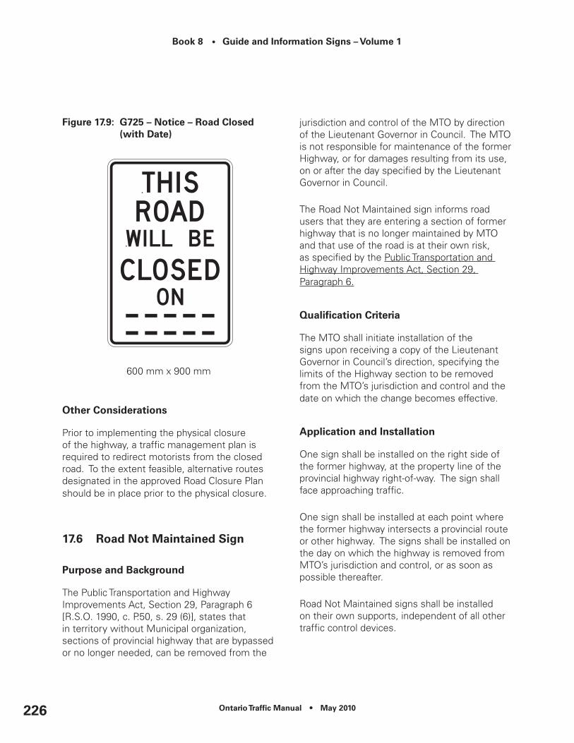
Book 8 • Guide and Information Signs – Volume 1
Ontario Traffic Manual • May 2010226
Figure 17.9: G725 – notice – road closed (with date)
600 mm x 900 mm
Other considerations
Prior to implementing the physical closure of the highway, a traffic management plan is required to redirect motorists from the closed road. To the extent feasible, alternative routes designated in the approved Road Closure Plan should be in place prior to the physical closure.
17.6 road not Maintained Sign
Purpose and Background
The Public Transportation and Highway Improvements Act, Section 29, Paragraph 6 [R.S.O. 1990, c. P.50, s. 29 (6)], states that in territory without Municipal organization, sections of provincial highway that are bypassed or no longer needed, can be removed from the
jurisdiction and control of the MTO by direction of the Lieutenant Governor in Council. The MTO is not responsible for maintenance of the former Highway, or for damages resulting from its use, on or after the day specified by the Lieutenant Governor in Council.
The Road Not Maintained sign informs road users that they are entering a section of former highway that is no longer maintained by MTO and that use of the road is at their own risk, as specified by the Public Transportation and Highway Improvements Act, Section 29, Paragraph 6.
Qualification Criteria
The MTO shall initiate installation of the signs upon receiving a copy of the Lieutenant Governor in Council’s direction, specifying the limits of the Highway section to be removed from the MTO’s jurisdiction and control and the date on which the change becomes effective.
Application and Installation
One sign shall be installed on the right side of the former highway, at the property line of the provincial highway right-of-way. The sign shall face approaching traffic.
One sign shall be installed at each point where the former highway intersects a provincial route or other highway. The signs shall be installed on the day on which the highway is removed from MTO’s jurisdiction and control, or as soon as possible thereafter.
Road Not Maintained signs shall be installed on their own supports, independent of all other traffic control devices.

Ontario Traffic Manual • May 2010 227
Book 8 • Guide and Information Signs – Volume 1
All other traffic control devices associated with the former highway shall be removed when the Road Not Maintained signs are installed.
Design Guidance
Figure 17.10: G723 – notice – road not Maintained Sign
450 mm x 750 mm
Other considerations
When a highway section is removed from MTO’s jurisdiction and control, Road Not Maintained signs should be posted only if it is not feasible to transfer the former highway to private ownership or physically prevent public access to it.
17.7 Private road Sign
Purpose and Background
The Private Road sign is used to inform road users that the road is not a public road and is not maintained by the MTO or local road authority.
Qualification Criteria
The road authority may provide a Private Road sign on application from the owner of a private road.
The road authority may also install a Private Road sign without application from the owner in locations where:
•The configuration of the private road may create the impression that it is a public road;
•There is evidence of significant public use of the road; or
•There is a history of enquiries/ complaints to the road authority due to public use of the private road.
Application and Installation
One sign shall be installed on the right side of the private road, at the property line of the public roadway right-of-way. The sign shall face approaching traffic.
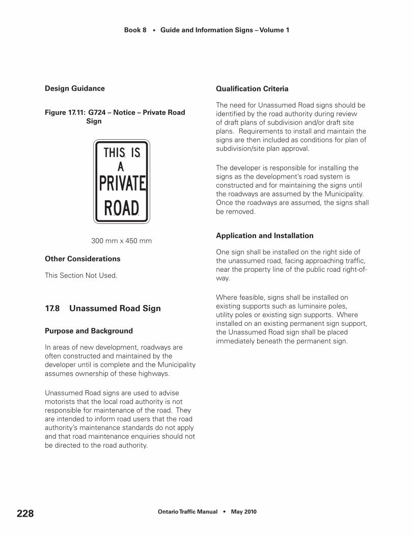
Book 8 • Guide and Information Signs – Volume 1
Ontario Traffic Manual • May 2010228
Design Guidance
Figure 17.11: G724 – notice – Private road Sign
300 mm x 450 mm
Other considerations
This Section Not Used.
17.8 unassumed road Sign
Purpose and Background
In areas of new development, roadways are often constructed and maintained by the developer until is complete and the Municipality assumes ownership of these highways.
Unassumed Road signs are used to advise motorists that the local road authority is not responsible for maintenance of the road. They are intended to inform road users that the road authority’s maintenance standards do not apply and that road maintenance enquiries should not be directed to the road authority.
Qualification Criteria
The need for Unassumed Road signs should be identified by the road authority during review of draft plans of subdivision and/or draft site plans. Requirements to install and maintain the signs are then included as conditions for plan of subdivision/site plan approval.
The developer is responsible for installing the signs as the development’s road system is constructed and for maintaining the signs until the roadways are assumed by the Municipality. Once the roadways are assumed, the signs shall be removed.
Application and Installation
One sign shall be installed on the right side of the unassumed road, facing approaching traffic, near the property line of the public road right-of-way.
Where feasible, signs shall be installed on existing supports such as luminaire poles, utility poles or existing sign supports. Where installed on an existing permanent sign support, the Unassumed Road sign shall be placed immediately beneath the permanent sign.

Ontario Traffic Manual • May 2010 229
Book 8 • Guide and Information Signs – Volume 1
Design Guidance
Figure 17.12: G726 – notice – unassumed Road
450 mm x 600 mm
Other considerations
Periodic inspections by the road authority are recommended to ensure that the Unassumed Road signs are installed and maintained until ownership of the roadway is assumed by the road authority.
17.9 road extension notice Sign
Purpose and Background
Construction sequencing in areas of new development often requires the use of temporary cul-de-sacs or “stub-end” highways at construction phase boundaries or the limits of an individual subdivision within a larger development area.
Buyers of properties on these roadways are sometimes unaware of the planned ultimate status of the road, particularly when years pass between initial construction and extension.
Road Extension Notice signs are used at temporary cul-de-sacs in new development areas to inform prospective purchasers of nearby properties that the roadway will be extended in the future.
Qualification Criteria
The need for Road Extension Notice signs should be identified by the road authority during review of draft plans of subdivision and/or draft site plans. Requirements to install and maintain the signs are then included as conditions for plan of subdivision/site plan approval.
The developer is responsible for installing the signs as the development’s road system is constructed and for maintaining the signs until the roadways are assumed by the Municipality. Once the roadways are assumed, the road authority is responsible for maintaining the signs.
Application and Installation
One sign shall be installed in a prominent location, facing approaching traffic, at the end of each temporary cul-de-sac.
The Road Extension Notice sign shall be installed as soon as possible following construction of the temporary cul-de-sac. The sign shall be maintained until the road extension is either constructed or deleted from the plan, at which time it shall be removed.

Book 8 • Guide and Information Signs – Volume 1
Ontario Traffic Manual • May 2010230
Road Extension Notice signs should be applied uniformly throughout a municipality, because prospective property purchasers may assume that all new cul-de-sacs without signs will not be extended.
Design Guidance
The text of the sign shall include sufficient information to allow prospective purchasers of property to obtain additional information about the planned road extension (typically the name and phone number of the responsible Municipal Planning Department and a file number for the development).
The text of the sign may be modified as necessary to provide additional relevant information; for example:
•“This road will be extended to serve future commercial development”;
•“This street will be extended to connect with Side Street at Main Street”; or
•“An extension of this road to Major Road is designated in the municipal Official Plan”.
Figure 17.13: G722 – notice – road extension
450 mm x 750 mm
Other considerations
Periodic inspections by the road authority are recommended to ensure that the Road Extension Notice signs remain in place throughout the construction of the development.


8
May 2010