volume-i consultants - rites · and vertical openings and span arrangement for railway bridge...
TRANSCRIPT
P W D
TENDER NOTICE NO.RITES/GGM/NGP/26-2011,DATED 23/12/2011
Name of work: Construction of Road Over Bridge at Km.728/9-11 on Howrah-Mumbai main line near Chakrabhata LC No.370 on Bilaspur-Baloda Bazar Road,Bilaspur (C.G).
VOLUME-I
Consultants
RITES LTD1, RITES BHAVAN, KADBI CHOWK,
NAGPUR-440 004
Tender Document issued to:_________________________ (Name of Tenderer)_________________________ (Address of Tenderer)
Signature of Officer issuing the document with Designation & Date of Issue.

SEAL AND SIGNATURE OF BIDDER2
RITES LTD.
TENDER AND CONTRACT DOCUMENT
CONTENTS
S.No. Details Page
PART – 1 (Technical Bid)
SECTION No 1 Notice Inviting Tender and Instructions toBidders.
SECTION No 2 Tender and Contract FormSECTION No 3 Special ConditionsSECTION No 4 Schedules A to FSECTION No 5 Technical SpecificationsSECTION No 6 Drawings
PART – 2 (Financial Bid) SCHEDULE (BILL) OF QUANTITIES
ITEM RATE TENDER ABSTRACT OF COST OF ALLSCHEDULESDETAILS OF QUOTED UNIT RATESAND AMOUNT – SCHEDULEWISE -SCHEDULES I TO X
PART -3 General Conditions of Contract *
SECTION No 7 Conditions of ContractSECTION No 8 Clauses of ContractSECTION No 9 RITES Safety CodeSECTION No 10 RITES Model Rules for Protection of
Health and Sanitary Arrangements forWorkers
SECTION No 11 RITES Contractor’s Labour Regulations*General Conditions of Contract 2011 (Compilation of Sections 7 to 11) is available withall correction slips upto date, in RITES website www.rites.com

SEAL AND SIGNATURE OF BIDDER3
PART 1
TECHNICAL BID

SEAL AND SIGNATURE OF BIDDER4
Section - 1
NOTICE INVITING TENDER ANDINSTRUCTIONS TO TENDERERS

SEAL AND SIGNATURE OF BIDDER5
SECTION 1
NOTICE INVITING TENDER AND INSTRUCTIONS TO TENDERERS
1.0 GENERAL1.1 Tender Notice
Tenders are invited by RITES Ltd., a Public Sector Enterprise under the Ministry of Railways,acting for and on behalf of PWD, Bridge Construction Division, Bilaspur as an Agent/Power ofAttorney Holder, from working contractors (including contractors who have executed workswithin the last five years reckoned from the scheduled date of opening of tender) of Railways,CPWD, MES, DOT, RITES, State PWD or any other Central / State Government Undertaking,Municipal Body, Autonomous Body of Central/State Governments or Public Ltd., Co. listed onBSE/NSE for the work of Construction of Road Over Bridge at Km.728/9-11 on Howrah-Mumbai main line near Chakrabhata LC No.370 on Bilaspur-Baloda Bazar Road, Bilaspur(C.G).
(Note : Throughout these bidding documents, the terms ‘bid’ and ‘tender’ and their derivativesare synonymous).1.2 Estimated Cost of Work
The work is estimated to cost Rs.425.24 Lakhs (Rupees Four hundred twenty five lakhs andtwenty four thousand). This Estimate, however, is given merely as a rough guide.
1.3 Time for Completion
The time allowed for completion will be 15 months (including monsoon) from the date of startwhich is defined in Schedule F under Clause 5.1a of Clauses of Contract.
1.4 Brief Scope of Work
Construction of Road Over Bridge at Km.728/9-11 on Howrah-Mumbai main line nearChakrabhata LC No.370 on Bilaspur-Baloda Bazar Road, Bilaspur (C.G).
The project envisages Design and construction of ROB(Railway Portion) at RailwayKm. 728/9-11 of Mumbai-Howrah Rail line of South East Central Railway nearChakrabhata LC No. 370. For guidance of bidders, outline drawings showing thearrangement of the road over bridge contemplated by the Employer are attached(drawing). However the tender is to be awarded only on the bidder’s own designcomplying with the various requirements indicated in this section as well as in thechapter on design criteria. For this purpose, details shown in the typical outlinedrawings enclosed are to be taken as indicative except for certain salient parameters,which have been specified in this section and the chapter on design criteria. Theseoutline also specify the minimum acceptable mix, specifications and sizes fordifferent components and the bidder’s design shall provide for comparablespecifications and in any case not inferior to those for corresponding components. Ifthe various items and activities as per scope of work of the bid document are notfound to be included in the contractor’s technical proposal, drawing & technical note,even then the offer quoted by the contractor shall be presumed to be inclusive of allsuch items & activities as per scope of work of the tender documents & no extra

SEAL AND SIGNATURE OF BIDDER6
payment shall be paid for the same. The arrangement of road top level, horizontaland vertical openings and span arrangement for Railway bridge portions isobligatory. However, Railways reserve their right for making any changes in railwayportion during execution. No claim whatsoever shall be payable if changes are madeby railways while execution within the same alignment and within the shownclearances. The opening at road crossing/junction shall not be less than those asshown in departmental drawings. The Contractor will have to design & execute theROB (Railway boundary only) and any other diversion as directed and approved bythe Engineer.
1.4.1 The item rate offer offer as per enclosed schedule quoted by the Contractors shallbroadly include the following items & shall be executed in accordance with designcriteria & design data as given in the Tender documents.
a) Preparation of detailed structural design and drawings based on approved GAD,proof checking of designs by nominated agency i.e. VNIT/IIT and obtaining approvalfrom Railways for all the works of ROB.
b) Design and construction of ROB, viaduct including construction of diversion andallied works as indicated in this scope of work including crash barrier.
c) Design and construction of pier considering the load of the larger adjoining span ofnon-railway portion of ROB.
d) Providing & erecting street lighting system for ROB, viaduct.e) Any other works indicated in the Departmental drawings attached to the Tender
document.
1.4.2 Width and Cross Section:Width of the Road Over Bridge and the requirements of carriageway shall be asindicated in the attached departmental drawing.
1.4.3 Length of Bridge:(a) Railway Bridge Portion as indicated in departmental drawing (CEs Drg. No.
BR/R/CHBT/OB/886/2010, Sheet No. 1 & 2) :i) Two spans of 27.00 M withComposite girder slab (Steel girderwith RCC slab)ii) One span of 14.00M withComposite girder slab (Steel girderwith RCC slab)
Total length of Bridge in Railway portion is 68.00 M.
1.4.4 Length of ROB and Viaduct:The contractor’s proposal shall provide the length of the Road Over Bridge, viaductstrictly as per departmental drawing attached with the tender to suit the requirementsof minimum horizontal i.e. clear span and vertical clearance i.e. rail top to sofit ofsuperstructure as indicated for Railway Bridge portion and viaduct as per GAD andgradient not steeper than those shown on the departmental drawing. The spanarrangement shown in GAD bearing CE’s No. BR/R/CHBT/OB/886/2010 forRailway portion is obligatory. The contractor shall provide the Road Over Bridge toconfirm to these requirements and including properly designed vertical and
SEAL AND SIGNATURE OF BIDDER7
horizontal curves for a design speed of 65 km/h (Summit curve in the central portionand valley curve on either ends).
1.4.5 Camber and Super elevation:Minimum camber to be provided to the carriageway shall be 2.5% as shown in thedepartmental drawing. Super elevation where required shall be as per actual design(subject to a maximum of 4% if super elevation needs to be provided in structuralportion).
1.4.6 Traffic Diversion :The contractor may adopt a suitable scheme of construction, which shall be gotapproved from Railway Authorities, Traffic (Police) Department. The responsibility ofobtaining the permissions for scheme to be adopted from concerned authorities e.g.Railways, Traffic (Police) shall be that of the contractor. No extra cost will be paid onaccount of such diversion.
In situ staging for construction of superstructure is not permitted over the Railwayspan. End launching or any other method (acceptable to Railway) shall only bepermitted. For deck slab shuttering / staging from girders can be permitted.
1.4.6.1 Programme of construction of railway bridge portion shall be arranged in such a waythat it is complete in the shortest time period.
1.4.6.2 Interim support at minor bridges/CD works on the existing road shall not be allowedfor construction superstructure.
1.4.7 Site Clearance / Setting out :1.4.7.1 Making out the center line of the ROB and various components and complete lining out
with masonry and concrete pillars for proper lines and levels with precision theodolitesurvey including constructing theodolite stations, bench marks etc., as directed. Thisincludes all the allied works like clearing the road side line removing and stacking ofthe existing kerb stones, obstructing bushes, trees etc. The surveying instrument usedon the works shall be modern electronic equipment.
1.4.7.2 Providing all documentation such as audio/video cassettes or CDs/photographs, recorddrawings etc., as specified in tender.
1.4.8 Foundation –
1.4.8.1 Pile Foundation – In case of pile foundations providing MS liners of (i) 8mm thick forthe Railway bridge portion (foundation covering span over the railway boundary)including coal tar epoxy anticorrosive paint of zinc rich epoxy primer and two coats ofcoal tar epoxy paint (total dry film thickness = 50 + 80 + 80 = 210 micron) to the mildsteel liners on surface in contact with earth. The bottom shoe of liner of 12 mm thickshall attain minimum height provided and placed in position prior to driving 8mm thickMS liner. These MS liners are to be provided up to refusal.
SEAL AND SIGNATURE OF BIDDER8
1.4.8.2 Load test on pile (Initial) – Providing and casting test pile and carrying out load testas per design criteria for initial load test.
1.4.8.3 Load test on pile (Routine) – Carrying out routine load test on pile conforming todesign criteria.
Pile Cap – Providing RCC pile cap : The top of the pile caps shall be atleast 0.5mbelow ground level.
1.4.9 Substructure :Providing sub structure of piers, abutments, returns etc., as per design criteria withsuitable RCC caps.
1.4.10 Super Structure:Providing superstructure and decking shall be conforming to the design criteria suitablefor roadway particulars shown in the departmental drawings. Only Steel andcomposite superstructure are allowed. Steel and composite superstructures are notallowed. For Railway portion only steel girders are allowed as per GAD approved byRailways. However, RCC superstructure upto the span of 20.00M is permissible. Thepier shall be designed considering the load of the adjoining larger span of non-railwayportion of ROB.
1.4.11 Bearings, expansion joints, wearing coat etc. :1.4.11.1 Providing necessary bearings, pedestals for bearings, expansion joints water spouts,
mastic layer on the deck wearing coat, anti crash barriers etc., as per design criteria.Anti crash barrier for the ROB & viaduct portion shall be as per section indicated inMORTH Specification of concrete grade of deck slab. The design shall be approvedby the Engineer.
1.4.11.2 Drainage:Providing minimum 150mm GI water spouts CIMS grating and 150mm GI runnerpipes and down take pipes at each pier and location. The GI pipes shall be painted withoil paint in three coats.
1.4.11.3 Providing wearing coat over the bridge superstructure as follows:
(a) Dense graded Bituminous Macadam 50 mm average thicknessas per job mix design (Asphalt Grade 30/40)with minimum 4.5% bitumenby wt. including tack coat @ 5Kgper 10sqm.with vibratory roller
(b) Mastic Asphalt with primer coat 12 mm thick (Grade 10/20)over top of deck.
Profile correction for camber, super elevation and vertical curve shall be provided indeck, itself.
SEAL AND SIGNATURE OF BIDDER9
1.4.11.4 All known overhead utility services like electric poles & lines, the telephone poles &lines and known underground service pipe lines, cables etc., falling in the alignment ofROB proper shall be shifted at appropriate locations. The actual cost estimated byrespective departments or approved by Engineer for shifting of known service aboveincluding fees / charges of respective departments will be reimbursed by PWD, Raipuron submission of bills for such utility shifting separately by the Contractor andrecommended by the RITES Site Engineer.
If during the course of execution unknown all sorts of utilities as stated above areencountered then the contractor shall redesign the foundation system or shall shiftutilities after obtaining necessary permission from respective departments atappropriate locations at his own cost and no extra payment will be made to theContractor.
1.4.11.5 Soil Investigation: Soil investigation shall be carried out as required for designing andto confirm the soil investigation report attached and as directed by Engineer in charge.
1.4.12 Anticorrosive treatment, Painting, Fixtures etc.
1.4.12.1 Painting/anticorrosive treatment – Providing protective painting to the concretesurface for foundation by bituminous paint and the substructure and superstructure etc.,shall be painted with three coats of water proof cement paint.
1.4.12.2 Fixtures – Procurement and Fixing the fittings and fixtures, instrumentation as may berequired as per site at specified location on bridge structure for certain amenities suchas lighting arrangement on ROB and providing items including Poles, cables, earthingetc. complete to make the lighting functional in every respect as per specifications andas directed by Engineer in charge. In case feeder piller if required as per site shall alsobe procured and fixed as per specifications and laid down under Electrical code.
1.4.13 Laboratory :1.4.13.1 Providing and maintaining an adequately equipped field laboratory as required for site
control on the quality of material and the works. It shall have adequate area for theentire equipment and working as directed by the Engineer.
14.2 The field laboratory of not less then 30.00 sqm. floor area shall be located on the siteas shown or as directed and approved by the Engineer. It shall be provided with allamenities like water supply, electric supply etc.
1.4.14 Blasting of Rock :Blasting of Rock/Boulder etc., is not permitted. Only chiseling should be resorted to.
1.4.15 Documentation :
SEAL AND SIGNATURE OF BIDDER10
Providing documentation such as videocassettes, CDs, photographs as built drawingsetc., as specified in the tender. All drawings shall be on Auto CAD of latest version.
1.4.16 Construction phasing :The contractor has to prepare detailed work plan with his bid which shall take intoaccount, the traffic position, milestones specified in the tender, availability of men,material, machinery and shuttering material with him.
1.4.17 Waterproof cement based paint shall be provided to the finish surface of the Road OverBridge.
1.4.18 Specification for expansion joints shall be as per MORT&H Specifications 4thRevision of August 2001.
1.4.19 Thermoplastic road marking – Yellow and white continuous lane marking at 3locations per lane carriage as directed by the Engineer for entire length of the work asapproved by the Engineer.
1.4.20 Cat-eyes as approved by Engineer for ROB.
1.5 Availability of Site
The site for the work is available.
2.0 QUALIFICATION CRITERIA TO BE SATISFIED
2.1 The Qualification Criteria to be satisfied are given at Annexure I enclosed.
2.2 The Qualification Criteria to be satisfied will depend on the category of works, whetherNormal or Large. Normal Works are those costing upto Rs.30 Crores each and LargeWorks are those costing more than Rs.30 Crores. The work for which the Tender isbeing invited falls under the category of Normal.
2.3 The Qualification Criteria to be satisfied will also depend on whether the Work falls inNormal area or Difficult area. Difficult area includes North East States, Jammu &Kashmir, Jharkhand, Chattisgarh and Andaman & Nicobar Islands. Normal area coversall areas other than Difficult area. The work for which this Tender has been invited fallsunder Difficult.
2.4 In this Tender Joint Venture is not allowed.
2.5 The documents to be furnished by the Bidder to prove that he is satisfying theQualification Criteria laid down should all be in the Bidder’s name, except in cases wherethough the name has changed, the owners continued to remain the same and in cases ofamalgamation of entities.

SEAL AND SIGNATURE OF BIDDER11
3.0 FORMAT AND CHECK LIST FOR SUBMISSION OF INFORMATION ONQUALIFICATION CRITERIA
3.1 Other than Joint Ventures
The Tenderer shall furnish a Letter of Transmittal as given in Annexure II A enclosingthe documents mentioned therein/listed in para 1(a) of Annexure IA.
3.2 Joint Ventures (For Large Works)
Not Applicable.
3.3 Joint ventures (For Normal Works)
Not Applicable.
4.0 CONTENTS OF TENDER DOCUMENT
4.1 Each set of Tender or Bidding Document will comprise the Documents listed below andaddenda issued in accordance with para 7 :
PART – 1 :- Technical Bid Packet
Section 1 Notice Inviting Tender and Instructions to Tenderers.Section 2 Tender and Contract Form.Section 3 Special Conditions.Section 4 Schedules A to FSection 5 Technical SpecificationsSection 6 Drawings
PART – 2 :- Financial Bid Packet
Schedule of Quantities (Bill of Quantities)
PART – 3:- General Conditions of Contract(read with correction Slip Nos. 1 )
Section 7 Conditions of ContractSection 8 Clauses of ContractSection 9 RITES Safety CodeSection 10 RITES Model Rules for protection of Health and Sanitary arrangements
forWorkers
Section 11 RITES Contractor’s Labour Regulations
4.2 General Conditions of Contract (Compilation of Sections 7 to 11) with upto datecorrection slips is also available in RITES website <www.rites.com>

SEAL AND SIGNATURE OF BIDDER12
5.0 ISSUE OF TENDER DOCUMENT
5.1 A complete set of Tender Document (Technical and Financial Bid) described in Para 4.1above can be seen in the office of the Group General Manager (P), RITES Ltd., 1, RITESBhawan Kadbi Chowk, Nagpur between hours of 11.00 AM and 4.00 PM every dayexcept on Saturdays, Sundays and Public Holidays.
5.2 One set of Tender Document may be purchased from the office of Group GeneralManager (P), RITES Ltd., 1, RITES Bhawan Kadbi Chowk, Nagpur from 26/12/2011 to06/01/2012 for a non refundable fee per set of Rs.6000/- (Rupees Six thousand only) inthe form of Demand Draft/ Pay Order/ Banker’s cheque drawn on any Scheduled Bankpayable at Nagpur in favour of RITES Ltd. Nagpur, on submission of an application.
5.3 Tender Documents including drawings can also be downloaded from RITES Website(www.rites.com) and in such a case, the Tenderer shall deposit the cost of tenderdocuments along with submission of tender, failing which his tender shall not be opened.The cost of tender documents shall be deposited in the form of a separate Banker’scheque / Demand Draft / Pay Order and enclosed in the envelope containing the EarnestMoney Deposit. The amendments / clarifications to the Tender documents will also beavailable on the above website.
5.4 Tender Documents downloaded from RITES website shall be considered valid forparticipating in the tender process. During the scrutiny of downloaded tender document,if any modification / correction etc. is noticed as compared to the original documentsposted on the website, the bid submitted by such a Tenderer is liable to be rejected. Incase the bid of a Tenderer who has downloaded the document from website is acceptedthe contract shall be executed in the original / manual tender document issued by theconcerned RITES officer.
5.5 Clarifications on Tender Documents
A prospective Tenderer requiring any clarification on the Tender Document may notifyDGM/Tender (The official nominated for this purpose) in writing or by telefax/ or by E-mail at the following Postal Address/ Fax No./E-mail address:
Office of Group General Manager (P), RITES Ltd., 1, RITES Bhawan, Kadbi Chowk,Nagpur.
Fax NO. 0712-2527673
E-mail: [email protected]
In cases where Pre-Bid Meeting is not proposed to be held, request for clarificationsincluding request for Extension of Time for submission of Bid, if any, must be receivednot later than 10 (ten) days prior to the deadline for submission of tenders. Details ofsuch questions raised and clarifications furnished will be uploaded in RITES websitewithout identifying the names of the Bidders who had raised the questions. Anymodification of the Tender Document arising out of such clarifications will also beuploaded on RITES website only.

SEAL AND SIGNATURE OF BIDDER13
In cases where Pre-Bid Meeting is proposed to be held, provisions in para 6.0 below maybe referred to.
6.0 PRE-BID MEETING
No Pre-bid meeting.
7.0 AMENDMENT OF TENDER DOCUMENT
7.1 Before the deadline for submission of tenders, the Tender Document may be modified byRITES Ltd. by issue of addenda/corrigendum. Issue of addenda / corrigenda willhowever be stopped 7 days prior to the deadline for submission of tenders as finallystipulated.
7.2 Addendum/corrigendum, if any, will be hosted on website only and shall become a partof the tender document. All Tenderers are advised to see the website for addendum/corrigendum to the tender document which may be uploaded upto 7 days prior to thedeadline for submission of Tender as finally stipulated.
7.3 To give prospective Tenderers reasonable time in which to take the addenda/ corrigendainto account in preparing their tenders, extension of the deadline for submission oftenders may be given as considered necessary by RITES.
8.0 TENDER VALIDITY
8.1 The Tender shall be valid for a period of 90 days from the due date for submission ofTender or any extended date as indicated in sub para below.
8.2 In exceptional circumstances, during the process of evaluation of tenders and prior to theexpiry of the original time limit for Tender Validity, the Employer may request that theTenderers may extend the period of validity for a specified additional period. Therequest and the tenderer’s response shall be made in writing. A Tenderer may refuse therequest without forfeiting his Earnest Money. A Tenderer agreeing to the request will notbe permitted to modify his Financial Bid to a higher amount but will be required toextend the validity of the Earnest Money for the period of the extension.
9.0 EARNEST MONEY
9.1 The Tender should be accompanied by Earnest Money of Rs.4.25 Lakhs (Rupees fourlakhs twenty five thousand only) in any of the forms given below:-Banker’s Cheque / Pay Order/ Demand Draft payable at Nagpur, drawn in favour ofRITES Ltd.
9.2 Any Tender not accompanied by Earnest Money in an acceptable form shall be rejectedby the Employer as non-responsive.

SEAL AND SIGNATURE OF BIDDER14
9.3 Refund of Earnest Money
a) Two Packet System
The Earnest Money of the Tenderers whose Technical Bid is found not acceptable will bereturned without interest soon after scrutiny of Technical Bid has been completed by theEmployer subject to provisions of Para 9.4 (b). The Earnest Money of the Tendererswhose Technical Bid is found acceptable but Financial Bid is rejected will be returnedwithout interest within 28 days of the end of Tender Validity Period subject to provisionsof Para 9.4 (b).
b) Single Packet System
After evaluation of the Financial Bids, the Earnest Money of unsuccessful Tenderers willbe returned without interest within 28 days of the end of Tender Validity Period subjectto provisions of Para 9.4 (b).
c) In case of both Two Packet and Single Packet System, the Earnest Money of thesuccessful Tenderer, without any interest, will be adjusted as a part of the SecurityDeposit payable in terms of provisions in the General Conditions of Contract (Clause 1Aof Clauses of Contract).
9.4 The Earnest Money is liable to be forfeited
a) if after bid opening, but before expiry of bid validity or issue of Letter ofAcceptance, whichever is earlier, any Tenderer
i) withdraws his tender or
ii) makes any modification in the terms and conditions of the tender whichare not acceptable to the Employer.
b) in case any statement/information/document furnished by the Tenderer is found tobe incorrect or false.
c) in the case of a successful Tenderer, if the Tenderer
i) fails to furnish the Performance Guarantee within the period specifiedunder Clause 1 of “Clauses of Contract”. or
ii) fails to commence the work without valid reasons within the period asspecified in Schedule F after the date of issue of Letter of Acceptance orfrom the first date of handing over of the site, whichever is later.

SEAL AND SIGNATURE OF BIDDER15
In case of forfeiture of E.M. as prescribed hereinabove, the Tenderer shall not be allowedto participate in the retendering process of the work.
10.0 ALTERNATIVE PROPOSALS BY THE TENDERERS
The Tenderers shall submit offers which comply strictly with the requirements of theTender Document as amended from time to time as indicated in Para 7.0 above.Alternatives or any modifications shall render the Tender invalid.
11.0 SUBMISSION OF TENDER
11.1 Two Packet System and Single Packet System
(a) Two Packet System
The tenderer shall submit the Tender in original in two packets as under:-
PACKET A :- TECHNICAL BID
Envelope 1 Earnest Money & Cost of Tender Document if the bid issubmitted on the document downloaded from RITESwebsite
Envelope 2 “Authority to Sign”, ‘Integrity Pact’ (when applicable) andQualification Information along with all enclosures /documents as per Letter of Transmittal/ Checklist given inAnnexure II A/ II B (L)/IIB(N). As regards “Authority toSign” Para 11.2 below may be referred to. As regards‘Integrity Pact’, para 11.7 below may be referred to.
Technical Bid (Part 1 and Part 3) (Refer Para 4.1) includingsignature on Tender Form (Section 2) duly witnessed afterfilling up blanks therein.Each page of the above documents including all Drawingsshould bear the dated initials of the Tenderer along with theseal of the Company, in token of confirmation of havingunderstood the Contents.
PACKET B :- FINANCIAL BID
Envelope 3 Schedule/Bill of Quantities.
Each page of the Financial Bid (Part 2 – Refer Para 4.1) should be signed by the Tendereralong with the seal of the company. In the last page of Financial Bid, at the end, the Tenderershould sign in full with the name of the Company, Seal of the Company and Date.
All rates and amounts, whether in figures or words, must be written in indelible ink.Each Correction, Cutting, addition and overwriting should be initialed by the Tenderer.

SEAL AND SIGNATURE OF BIDDER16
The rates must be quoted in decimal coinage. Amounts must be quoted in full rupees byignoring fifty paise and less and considering more than fifty paise as rupee one. If thesame item figures in more than one section/part of Schedule of Quantities, the Tenderershould quote the same rate for that item in all sections/parts. If different rates are quotedfor the same item, the least of the different rates quoted only shall be considered forevaluation of that item in all sections/parts of the Schedule of Quantities.
Instructions contained in subsequent Para 17.6 (a) on “Item rate tender” and 17.6 (b) on“Percentage rate tender” may be carefully studied and complied with.
b) Single Packet System : Deleted.
11.2 Authority to Sign
a) If the applicant is an individual, he should sign above his full type written nameand current address.
b) If the applicant is a proprietary firm, the Proprietor should sign above his full typewritten name and the full name of his firm with its current address.
c) If the applicant is a firm in partnership, the Documents should be signed by all thepartners of the firm above their full type written names and current addresses.Alternatively the Documents should be signed by the person holding Power ofAttorney for the firm in the Format at Annexure IV.
d) If the applicant is a limited Company, or a Corporation, the Documents shall besigned by a duly authorized person holding Power of Attorney for signing theDocuments in the Format at Annexure IV.
e) If the applicant is a Joint Venture, the Documents shall be signed by the LeadMember holding Power of Attorney for signing the Document in the Format atAnnexure V. The signatory on behalf of such Lead Partner shall be the oneholding the Power of Attorney in the Format at Annexure IV.
11.3 Items to be kept in mind while furnishing details
While filling in Qualification Information documents and the Financial Bid, followingshould be kept in mind:
i) There shall be no additions or alterations except those to comply with theinstructions issued by the Employer or as necessary to correct errors, if any, madeby the Tenderers.
ii) Conditional Offer/ Tender will be rejected. Unconditional rebate/ discounts in theFinancial offer will however be accepted.
iii) The Employer reserves the right to accept or reject any conditionalrebate/discounts. While evaluating the Bid Price, the conditionalrebates/discounts which are in excess of the requirements of the bidding

SEAL AND SIGNATURE OF BIDDER17
documents or otherwise result in accrual of unsolicited benefits to the Employer,shall not be taken into account.
11.4 Sealing and Marking of Tenders
11.4.1 Two Packet System
(a) PACKET A – TECHNICAL BID
Envelopes 1 & 2 as described in Para 11.1 (a) above should be sealed separatelysuperscribing “Technical Bid” with Envelope Number, Name of the work and Nameof the tenderer. In addition, the following should also be superscribed on the respectiveenvelopes.
Envelope 1 i) Earnest Moneyii) Cost of Tender Document if the Bid is submittedon the document downloaded from RITES website.
Envelope 2 i) Authority to Sign, ‘Integrity Pact’ (whenapplicable as per para 11.7 below) and QualificationInformation/ documents as per checklist inAnnexure IIA / IIB(L)/ II B (N).ii) Technical Bid including Drawings
Both the envelopes should be put in a packet which should be sealed. The followingshould be superscribed on the packet:
i) Packet A – Technical Bidii) Name of the Workiii) Name of the Tenderer
(b) PACKET B – FINANCIAL BID
Envelope 3 – Financial Bid should be put in Packet B which should be sealed. Thefollowing should be superscribed on the packet.
i) Packet B - Financial Bid
ii) Name of the work
iii) Name of the tenderer
(c) Both packets A and B should be put inside an outer envelope and sealed. This envelopeshould be superscribed with the following details:

SEAL AND SIGNATURE OF BIDDER18
i) Tender for (Name of work)
ii) Tender number
iii) Date and time of opening of Tender
iv) From (Name of Tenderer)
v) Addressed to ---- (RITES Officer inviting the Tender)Office of Group General Manager (P), RITES Ltd., 1, RITES Bhawan, KadbiChowk, Nagpur.
11.4.2 Single Packet System
Deleted.
11.4.3 If the envelopes and packets are not superscribed and sealed as indicated in Paras 11.4.1/11.4.2 above, the Employer will assume no responsibility for the misplacement orpremature opening of the Tender.
11.5 Deadline for submission of Tender
11.5.1 Tenders must be received by the Employer at the following address not later than 15.00Hrs. on 09/01/2012. In the event of the specified date for the submission of the Tenderbeing declared a holiday due to Strike/Bandh or on any account by the Employer, theTenders will be received up to the appointed time on the next working day.
Address for submission of Tender:Office of Group General Manager (P), RITES Ltd., 1, RITES Bhawan Kadbi Chowk,Nagpur.
11.5.2 The Employer may extend the deadline for submission of Tenders by issuing anamendment in writing in accordance with Para 7.3 in which case all rights andobligations of the Employer and the Tenderer previously subject to the original deadlinewill be subject to new deadline.
11.6 Late Tender / Delayed Tender
Any Tender received by the Employer after the specified date and time of receipt ofTender will be returned unopened to the Tenderer.
11.7 Integrity Pact (Not Applicable)
(i) The Bidder/Contractor is required to enter into an Integrity Pact with theEmployer, in the Format at Annexure VIII. The Integrity Pact enclosed asAnnexure VIII will be signed by RITES for and on behalf of Employer as its

SEAL AND SIGNATURE OF BIDDER19
Agent/Power of Attorney Holder at the time of execution of Agreement with thesuccessful Bidder. While submitting the Bid, the Integrity Pact shall be signed bythe duly authorized signatory of the Bidder/Lead Member of JV. In case offailure to submit the Integrity Pact duly signed and witnessed, along with the Bid,the Bid is likely to be rejected.
(ii) In case of any contradiction between the Terms and Conditions of the BidDocument and the Integrity Pact, the former will prevail.
Provided always that provision of this para 11.7 – Integrity Pact, shall beapplicable only when so provided in para 11.7A below which will also stipulatethe name and address of the Independent External Monitor as well as the Name,designation and address of the official nominated by the Employer to act as theLiaison Officer between the Independent External Monitor and the Engineer-in-Charge as well as the Contractor.
11.7A Whether para 11.7 (Integrity Pact) shall be applicable NO
If Yes, Name and Address of the Independent ExternalMonitor (In case value of contract is Rs.10 crores or more) Not applicable.
Name, Designation and Address of RITES’ Liaison Not applicable.Officer
11.8 Modification and Withdrawal of Bids
11.8.1 Tenderers may modify or withdraw their bids by giving notice in writing before thedeadline prescribed in para 11.5 for submission of Bids.
11.8.2 Each modification or withdrawal notice shall be prepared, sealed, marked and deliveredin accordance with paras 11.1, 11.2 and 11.4 with the outer envelopes additionallymarked ‘Modification’ or ‘Withdrawal’ as appropriate.
The envelopes for modifications on ‘Technical Bid’ and ‘Financial Bid’ shall besubmitted in separate sealed envelopes and marked as ‘Modifications of Technical Bid’or ‘Modifications of Financial Bid’ as the case may be.
11.8.3 No bid may be modified after the deadline for submission of Bids except as indicatedbelow. If a Bidder makes a suo moto offer of rebate / discount in his Financial Bid afterthe deadline for submission of Bids, such offer will not be considered for Financialevaluation of Tenders. But if the Tenderer is successful in the Bid based on his originaloffer without considering the suo moto offer, the rebate / discount offered will be takeninto account for incorporation in the Contract Agreement.

SEAL AND SIGNATURE OF BIDDER20
11.8.4 Withdrawal or modification of a Bid, subject to provisions in Para 11.8.3 above, after thedeadline for submission of Bids shall result in forfeiture of the Earnest Money.
12.0 TENDER OPENING, EVALUATION AND CLARIFICATIONS OFAPPLICATIONS
12.1 The Employer will open all the Tenders received (except those received late ordelayed)as described in para 12.2/12.3 below, in the presence of the Tenderers or theirrepresentatives who choose to attend at 15.30 Hrs. on 09/01/2012 in the office of GroupGeneral Manager (P), RITES Ltd., 1, RITES Bhawan Kadbi Chowk, Nagpur. In theevent of the specified date of the opening being declared a holiday by the Employer, theTenders will be opened at the appointed time and location on the next working day.
12.2 Two Packet System
(a) (i) The PACKET A will be opened and Envelope 1 containing Earnest Money and Costof Tender Document (where Bid is submitted in the document downloaded fromRITES website) of all the Tenderers will be opened first and checked. If the EarnestMoney furnished is not for the stipulated amount or is not in an acceptable form andwhere applicable, the cost of Tender Document has not been enclosed for the correctamount and in an acceptable form, the Envelope 2 of PACKET A (TECHNICALBID) and PACKET B will be returned to the Tenderer concerned unopened at thetime of opening of the Tender itself. The Envelopes 2 of PACKET A (TECHNICALBID) of other Tenderers who have furnished Earnest Money of correct amount inacceptable form and where applicable the cost of Tender Document for the correctamount and in an acceptable form will then be opened. The Tenderer’s name, thepresence of Earnest Money and Authority to sign and such other details as theEmployer may consider appropriate will be announced by the Employer at the timeof opening of Packet A. PACKET B (FINANCIAL BID) of the Tenderers whoseTechnical Bids have been accepted for evaluation will be checked to see if the sealsare intact. All such PACKETS B will be put in an envelope and sealed. TheEmployer’s official opening the Tender will sign on this envelope and will also takethe signatures of preferably atleast two Tenderers or their representatives present.This envelope will be kept in safe custody by the Employer.
(b) The Employer will scrutinise the Technical Bids accepted for evaluation to determinewhether each Tenderer
(i) has submitted `Authority to sign’ as per para 11.2 above and Integrity Pact (whereapplicable) duly signed and witnessed as per para 11.7 above;
(ii) meets the Qualification Criteria stipulated in Para 2.0; and(iii) conforms to all terms, conditions and specifications of the Tender Document
without any modifications or conditions.
(c) If required, the Employer may ask any such Tenderer for clarifications on his TechnicalBid. The request for clarification and the response from the Tenderer will be in writing.If a Tenderer does not submit the clarification/document requested, by the date and time

SEAL AND SIGNATURE OF BIDDER21
set in the Employer’s request for clarification, the bid of such Tenderer is likely to berejected. Tenderers whose Technical Bids are not found acceptable will be advised ofthe same and their Earnest Money and PACKET B (FINANCIAL BID) will be returnedunopened. Tenderers whose Technical Bids are found acceptable will be advisedaccordingly and will also be intimated in writing of the time and date and place whereand when the PACKET B (Financial Bid) will be opened.
(d) At the appointed place, time and date, in the presence of the Tenderers or theirrepresentatives who choose to be present, the Employer will open the envelopescontaining the PACKET B (FINANCIAL BID). The Tenderer’s name, the tender amountquoted and such other details as the Employer may consider appropriate will beannounced by the Employer.
12.3 Single Packet System
Not Applicable.
13.0 INSPECTION OF SITE BY THE TENDERERS
Tenderers are advised to inspect and examine the site and its surroundings and satisfythemselves before submitting their Tenders, as to the nature of the ground and sub-soil(as far as is practicable), the form and nature of the site, the means of access to the site,the accommodation they may require and in general shall themselves obtain all necessaryinformation as to risks, contingencies and other circumstances which may influence oraffect their Tender. A Tenderer shall be deemed to have full knowledge of the sitewhether he inspects it or not and no extra charges consequent on any misunderstanding orotherwise shall be allowed. The Tenderer shall be responsible for arranging andmaintaining at his own cost all materials, tools & plants, water, electricity, access,facilities for workers and all other services required for executing the work unlessotherwise specifically provided for in the contract documents. Submission of a tender bya Tenderer implies that he has read this notice and all other contract documents and hasmade himself aware of the scope and specifications of the work to be done and ofconditions and rates at which stores, tools and plant etc. will be issued to him by theEmployer and local conditions and other factors having a bearing on the execution of thework.
14.0 EMPLOYER’S RIGHT ON ACCEPTANCE OF ANY TENDER
(i) If required, the Employer may ask any Tenderer the breakdown of unit rates. If theTenderer does not submit the clarification by the date and time set in the Employersrequest for clarification, such Tender is likely to be rejected.
(ii) The competent authority on behalf of the Employer does not bind himself to acceptthe lowest or any other Tender and reserves to himself the authority to reject any orall the Tenders received without the assignment of any reason. All Tenders in whichany of the prescribed conditions is not fulfilled or any condition is put forth by theTenderer shall be summarily rejected.

SEAL AND SIGNATURE OF BIDDER22
15.0 CANVASSING PROHIBITEDCanvassing whether directly or indirectly, in connection with tenders is strictlyprohibited and the tenders submitted by the Contractors who resort to canvassing will beliable to rejection.
16.0 EMPLOYER’s RIGHT TO ACCEPT WHOLE OR PART OF THE TENDERThe competent authority on behalf of the Employer reserves to himself the right ofaccepting the whole or any part of the tender and the Tenderer shall be bound to performthe same at the rates quoted.
17.0 MISCELLANEOUS RULES AND DIRECTIONS
17.1 The Tenderer shall not be permitted to tender for works if his near relative is posted asAssociated Finance Officer between the grades of AGM(F) and J.M (F) in the concerned
SBU Unit of RITES or as an officer in any capacity between the grades of GGM/GM andEngineer (both inclusive) of the concerned SBU of the Employer. He shall also intimate thenames of persons who are working with him in any capacity or are subsequently employed byhim and who are near relatives to any Gazetted officer in the organization of the Employer. Anybreach of this condition by the Tenderer would render his Tender to be rejected.
No Engineer of Gazetted rank or other Gazetted Officer employed in Engineering orAdministrative duties in an Engineering Department of the Organisation of the Employeris allowed to work as a contractor for a period of one year after his retirement from theEmployer’s service without the previous permission of the Employer in writing. Thecontract is liable to be cancelled if either the Contractor or any of his employees is foundany time to be such a person who had not obtained the permission of the Employer asaforesaid before submission of the tender or engagement in the Contractor’s service.
17.2 If required by the Employer, the Tenderers shall sign a declaration under the officialsSecret Act 1923, for maintaining secrecy of the tender documents drawings or otherrecords connected with the work given to them. The unsuccessful Tenderers shall returnall the drawings given to them.
17.3 Use of correcting fluid anywhere in tender document is not permitted. Such tender isliable for rejection.
17.4 a) In the case of Item Rate Tenders, only rates quoted shall be considered. Any tendercontaining percentage below/above the rates quoted is liable to be rejected. Rates quotedby the Tenderer in item rate tender in figures and words shall be accurately filled in sothat there is no discrepancy in the rates written in figures and words. However, if adiscrepancy is found, the rates which correspond with the amount worked out by theTenderer shall unless otherwise proved be taken as correct. If the amount of an item isnot worked out by the Tenderer or it does not correspond with the rates written either infigures or in words then the rates quoted by the Tenderer in words shall be taken ascorrect. Where the rates quoted by the Tenderer in figures and in words tally but theamount is not worked out correctly, the rates quoted by the Tenderer will, unlessotherwise provided, be taken as correct and not the amount. In the event that no rate hasbeen quoted for any item(s), leaving space both in figure (s) or word(s) and the amount

SEAL AND SIGNATURE OF BIDDER23
blank, it will be presumed that the Tenderer has included the cost of this/ these item (s) inother items and rate for such item (s) will be considered as zero and work will be requiredto be executed accordingly.
b) In case of percentage Rate Tender only percentage quoted shall be considered. Anytender containing item rates is liable to be rejected. Percentage quoted by the Tenderer inpercentage rate tender shall be accurately filled in figures and words so that there is nodiscrepancy. If, for any Schedule in Financial Bid, the total amount has been indicatedby the Tenderer and if discrepancy is noticed in the percentages quoted in words andfigures, then the percentage which corresponds with the total amount, shall, unlessotherwise proved be taken as correct. If the total amount is not worked out or if workedout, it does not correspond with the percentages written either in figures or in words, thenthe percentage quoted by Tenderer in words shall be taken as correct. When thepercentages quoted by the Tenderer in figures and in words tally but the total amount isnot worked out correctly, the percentage quoted by the Tenderes shall be taken as correct,unless proved otherwise and the total amount worked out accordingly.
17.5 In the case of any Item rate tender where unit rate of any item/items appears unrealistic,such tender will be considered as unbalanced and in case the Tenderer is unable toprovide satisfactory explanation, such a tender is liable to be disqualified and rejected.
17.6 (a) In Item rate Tender, all rates shall be quoted on the tender form. The amount for eachitem should be worked out and requisite totals given. Special care should be taken towrite the rates in figures as well as in words and the amount in figures only, in such away that interpolation is not possible. The total amount in each Schedule should bewritten both in figures and in words. In case of figures, the word ‘Rs.’ should be writtenbefore the figure of rupees and word ‘P’ after the decimal figures, e.g. Rs.2.15 P and incase of words, the word, ‘Rupees’ should precede and the word ‘Paise’ should be writtenat the end. Unless the rate is in whole rupees and followed by the word ‘only’ it shouldinvariably be up to two decimal places. While quoting the rate in schedule of quantities,the word ‘only’ should be written closely following the amount and it should not bewritten in the next line.
(b) In Percentage Rate Tender, the Tenderer shall quote percentage below / above (infigures as well as in words) at which he will be willing to execute the work. He shall alsowork out the total amount of his offer and the same should be written in figures as well asin words in such a way that no interpolation is possible. In case of figures, the word “Rs”should be written before the figure rupees and word ‘P’ after the decimal figures (eg.)Rs.2.15 P and in case of words the word “Rupees” should precede and the word “Paisa”should be written at the end.
17.7 Sales-tax/VAT (except Service Tax), purchase tax, turnover tax or any other tax/ Cess onmaterial, labour and Works in respect of this Contract shall be payable by the Contractorand the Employer will not entertain any claim whatsoever in respect of the same.However, in respect of Service Tax, same shall be paid by the Contractor to theconcerned department on demand and it will be reimbursed to him by the Engineer-in-Charge after satisfying that it has been actually and genuinely paid by the Contractor.

SEAL AND SIGNATURE OF BIDDER24
17.8 Each Bidder shall submit only one Bid either as an individual or as a Proprietor in aProprietary firm or as a Partner in a Partnership firm or as a Director of a limitedCompany/Corporation or as a Partner in a Joint Venture. Any Bidder who has submitteda Bid for a work, shall not be a witness for any other Bidder for the same work. Failureto observe the above stipulations would render all such Tenders submitted as a Bidderand / or as a witness, liable to summary rejection.
17.9 The Contractor shall be fully responsible for all matters arising out of the Performance ofthe Contract and shall, at his own expense, comply with all laws/ acts/ enactments/orders/ regulations/ obligations whatsoever of the Government of India, StateGovernment, Local Body and any Statutory Authority.
18.0 SIGNING OF CONTRACT AGREEMENT
18.1 The Tenderer whose tender has been accepted will be notified of the award by theEmployer by issue of a `Letter of Acceptance’ ‘ prior to expiration of the Bid Validityperiod, in the form at Annexure VI.
The Letter of Acceptance will be sent to the Contractor in two copies one of which heshould return promptly, duly signed and stamped. The Letter of Acceptance will be abinding Contract between the Employer and the Contractor till the formal ContractAgreement is executed.
18.2 Within the period as specified in Clause 1 of `Clause of Contract’, of the date of issue ofLetter of Acceptance, the successful Tenderer shall deliver to the Employer, PerformanceGuarantee and Additional Performance Guarantee (where applicable) in the formatprescribed.
18.3 The Tenderer whose Tender is accepted shall be required to submit at his cost stamppapers of appropriate value as per the provisions of Indian Stamp Act within 15 days ofthe date of issue of Letter of Acceptance.
18.4 At the same time the Employer notifies the successful Tenderer that his Tender has beenaccepted, the Employer will direct him to attend the Employer’s office within 28 days ofissue of Letter of Acceptance for signing the Agreement in the proforma at AnnexureVII. The Agreement will however be signed only after the Contractor furnishesPerformance Guarantee and Additional Performance Guarantee (where applicable) andhence, where justified, the period of 28 days stipulated above will be extended suitably.

SEAL AND SIGNATURE OF BIDDER25
ANNEXURE – I
QUALIFYING CRITERIA FOR WORKS CONTRACTS
1. Annual Financial Turnover
The bidder should have achieved a minimum annual financial turnover of Rs.170 Lakhsin any one of the last 5 Financial Years.
- which the Tender is being opened in Financial Year 2011-12, the last five FinancialYears shall be 2010-11, 2009-10, 2008-09, 2007-08 and 2006-07. For a Tender openedon (say) 09/01/2012 (F.Y. 2011-12), with weightage of 5% compounded annually, theweightages to be applied on the Turnover of the previous five Financial Years will be :F.Y. 2010-11 = 1.050; F.Y. 2009-10 = 1.103; F.Y. 2008-09 = 1.158; F.Y. 2007-08 =1.216; F.Y. 2006-07 = 1.276.
- The Bidder should furnish Annual Financial Turnover for each of the last 5 FinancialYears in tabular form and give reference of the document (with page no.) relied upon insupport of meeting the Qualification Criterion.
- The Bidder should submit self attested copy of Auditor’s Report along with BalanceSheet and Profit and Loss Statement along with Schedules for the relevant Financial Yearin which the minimum criterion is met. Provisional audit reports or certified statementswill not be accepted.
- If the Audited Balance Sheet for the immediately preceding year is not available in caseof tender opened before 30th Sept., audited Balance Sheets, Profit and Loss Statementsand other financial statements of the five Financial Years immediately preceding theprevious Financial Year may be adopted for evaluating the credentials of the Bidder.
2. WORK EXPERIENCE
a) Similar Works Experience
For works in difficult areas (North East States, J&K, Jharkhand,Chattisgarh and Andaman & Nicobar Islands)
The Bidder should have satisfactorily completed in his own name orproportionate share as a member of a Joint Venture, at least one similarwork of minimum value of Rs. 213 Lakhs OR at least two similar workseach of minimum value of Rs. 170 Lakhs during the last 5 (five) yearsprior to the last stipulated date for submission of the Bid. Workscompleted prior to the cut off date shall not be considered.
Similar Works

SEAL AND SIGNATURE OF BIDDER26
Similar Works shall mean the work of any Civil Engineering construction work involvingbridges.
Notes :- A weightage of 5% (compounded annually from the date of completion of the work to the
submission of the Bid) shall be given for equating the value of works of the previousyears to the current year.
- Only such works shall be considered where physical completion of entire work is over orcommissioning of work has been done, whichever is earlier.
- The Bidder should submit the details of such similar completed works as per the formatat Proforma-1 enclosed.
- Works carried out by another Contractor on behalf of the Bidder on a back to back basiswill not be considered for satisfaction of the Qualification Criterion by the Bidder.
- Credential certificates issued by Govt. Organizations/ Semi Govt. Organizations/ PublicSector Undertakings/ Autonomous bodies of Central State Governments / Municipalbodies/ Public Ltd. Cos. Listed in stock Exchange in India or abroad shall only beaccepted for assessing the eligibility of a Tenderer.
- The cut off date shall be calculated backwards from the last stipulated date forsubmission/ opening of Tender i.e. for a Tender which is being opened on 09.01.2012,the cut off date shall be 10.01.07.
b) Construction Experience in key activities/specified components
To qualify for award of the contract, each Bidder in his own name or as a member of aJoint Venture should have, in the last five Years prior to the last stipulated date forsubmission of the Bid, executed the following key activities in any one work.
The bidder should have executed minimum quantity of 450 Cum of concrete in any of thePSC/RCC bridge /culvert design and construction under the running Railway trafficcondition.
Notes:
- The work satisfying the criterion for a particular key activity may be differentfrom a work satisfying the criterion for another key activity.
- The Bidder should furnish with his Bid a tabular statement giving contract-wisequantities of key activities / specialised components executed in the last 5 yearswhich meet the Qualification Criterion along with documentary proof in supportthereof (indicating page nos.).
- Even if a work has not been completed but if the specified quantity of the keyactivity has been completed, the same shall be taken into consideration for thepurpose of this criterion.
- Any work executed by the Bidder as a member of a Joint Venture will beaccepted provided there is documentary proof in support of the same either in the
SEAL AND SIGNATURE OF BIDDER27
MOU/ Agreement of the JV or in a declaration by the other Members of that JVor the Client confirming that the specialized work was actually executed by theBidder.
3. SOLVENCY CERTIFICATE
A Solvency Certificate of minimum solvency of Rs.170 Lakhs (suggested format atProforma 2) from a Scheduled Bank issued not earlier than 6 months from the last datefor submission of tender is required to be submitted by the bidder.
Notes:
- The certificate so produced by the Bidder may be got verified from the issuing
Bank.
4. PROFITABILITYThe applicant firm shall be a profit (net) making firm and shall have made profit in eachof the last two Financial Years and in atleast one out of the three Financial Yearsimmediately preceding the last two Financial Years.
The Bidder should furnish figures of net profit of last 5 years in a tabular form andsubmit attested copies of Auditor’s Reports along with audited Balance Sheets and Profitand Loss Statements for the last Five Financial Years. In case the firm is profit makingfor the last three Financial Years continuously, the Bidder may submit the abovedocuments for last three Financial Years only. Specific reference with page no. ofdocument which proves satisfaction of this Qualifying Criterion should be indicated inthe tabular statement.
5. POINTS TO NOTE ON SATISFACTION OF QUALIFYING CRITERIA IN CASEOF BOTH LARGE AND NORMAL WORKS
a) Sub-Contractor’s Experiences and Resources
Sub-Contractors’ Experiences and Resources will not be taken into account indetermining the Bidder’s compliance with the qualifying criteria.
b) Experiences and Resources of the Parent Company and other subsidiarycompanies
If the Bidder is a wholly owned subsidiary of a company, the experience andresources of the owner/parent company or its other subsidiaries will not be takeninto account. However, if the Bidder is a Company, the Experience andResources of its subsidiaries will be taken into consideration.
6. DECLARATION BY THE BIDDER

SEAL AND SIGNATURE OF BIDDER28
Even though the Bidders may meet the above qualifying criteria, they are subject to bedisqualified if they have
a) Made misleading or false representation in the forms, statements and attachmentsin proof of the qualification requirements. In such a case, besides Tenderer’sliability to action under para 9.4 of Instructions to Tenderers, the Tenderer isliable to face the penalty of banning of business dealings with him by RITES.
b) Records of poor performance such as abandoning the work, not properlycompleting the contract, inordinate delays in completion, litigation history orfinancial failures etc.
c) Their business banned or suspended by any Central/State GovernmentDepartment/ Public Undertaking or Enterprise of Central/State Government andsuch ban is in force.
d) Not submitted all the supporting documents or not furnished the relevant detailsas per the prescribed format.
A declaration to the above effect in the form of affidavit on stamp paper of Rs. 10/- dulyattested by Notary/Magistrate should be submitted as per format given in Proforma 3enclosed.

SEAL AND SIGNATURE OF BIDDER29
Proforma-1
LIST OF SIMILAR WORKS SATISFYING QUALIFICATION CRITERIONCOMPLETED DURING THE LAST 5 YEARS
S.No.
Client'sNameand
Address
Name ofthe Work &
Location
Scope ofwork
carriedout by
theBidder
Agreement/ Letter ofAward No.
and date
Contract Value Date of start Date of Completion Reasons fordelay in
completionif any
Ref. ofdocument(with page
no.) in supportof meeting
QualificationCriterion
Awarded Actual oncompletion
As perLOA/Agreement
Actual
SEAL AND SIGNATURE OF THE BIDDER
Note :
1. In support of having completed above works, attach self attested copies of the completioncertificate from the owner/client or Executing Agency / Consultant appointed by owner /Client indicating the name of work, the description of work done by the Bidder, date ofstart, date of completion (contractual & actual) and contract value as awarded and asexecuted by the Bidder . “Contract Value” shall mean gross value of the completed workincluding cost of materials supplied by the owner/client but excluding those supplied freeof cost.
2. Such Credential certificates issued by Govt. Organizations/ Semi Govt. Organizations /Public Sector Undertakings / Autonomous bodies of Central or State Government /Municipal Bodies / Public Ltd. Co. listed on BSE/NSE shall only be accepted forassessing the eligibility of a Tenderer.

SEAL AND SIGNATURE OF BIDDER30
In case of a Certificate from a Public Limited Co., the Bidder should also submitdocumentary proof that the Public Ltd. Co., was listed on BSE or NSE when the workwas executed for it.
3. Information must be furnished for works carried out by the Bidder in his own name orproportionate share as member of a Joint Venture. In the latter case details of contractvalue including extent of financial participation by partners in that work should befurnished.
4. If a Bidder has got a work executed through a Subcontractor on a back to back basis, theBidder cannot include such a work for his satisfying the Qualification Criterion even ifthe Client has issued a Completion Certificate in favour of that Bidder.
5. Use a separate sheet for each partner in case of a Joint Venture.
6. Only similar works completed during the last 5 years prior to the last stipulated date forsubmission of Bid, which meet the Qualification Criterion need be included in this list.

SEAL AND SIGNATURE OF BIDDER31
Proforma 2
SOLVENCY CERTIFICATE FROM A NATIONALISEDOR A SCHEDULED BANK
This is to certify that to the best of our knowledge and information, M/s____________________, having their registered office at _____________, a customer of ourBank, is a reputed company with a good financial standing and can be treated as solvent to theextent of Rs. ___________. This certificate is issued without any guarantee or risk andresponsibility on the Bank or any of its officers.
Signature with dateSenior Bank Manager (Name of Officer issuing the
Certificate)Name, address & Seal of the Bank/ Branch
Note:
Banker’s Certificate should be on letter head of the Bank.

SEAL AND SIGNATURE OF BIDDER32
Proforma 3
DECLARATION BY THE BIDDER
(Affidavit on Non-Judicial Stamp Paper of Rs.10/- duly attested by Notary / Magistrate)
This is to certify that We, M/s. __________________________, in submission of this offerconfirm that:-
i) We have not made any misleading or false representation in the forms, statements andattachments in proof of the qualification requirements;
ii) We do not have records of poor performance such as abandoning the work, not properlycompleting the contract, inordinate delays in completion, litigation history or financialfailures etc.
iii) No Central / State Government Department/ Public Sector Undertaking or Enterprise ofCentral / State Government has banned/suspended business dealings with us as on date.
iv) We have submitted all the supporting documents and furnished the relevant details as perprescribed format.
v) List of Similar Works satisfying Qualification Criterion indicated in Proforma 1 does notinclude any work which has been carried out by us through a Subcontractor on a back toback basis.
vi) The information and documents submitted with the Tender and those to be submittedsubsequently by way of clarifications / making good deficient documents are correct andwe are fully responsible for the correctness of the information and documents submittedby us.
vii) We understand that in case any statement/information/document furnished by us or to befurnished by us in connection with this offer, is found to be incorrect or false, our EMDin full will be forfeited and business dealings will be banned.
SEAL, SIGNATURE & NAME OF THE BIDDER
signing this document
SEAL AND SIGNATURE OF BIDDER33
ANNEXURE I A
CHECK LIST OF DOCUMENTS TO BE SUBMITTED
1. a) BY BIDDERS OTHER THAN JOINT VENTURES
i) Annual Financial Turnover
- Annual financial turnover for each of the last 5 Financial Years in tabularform.
- Self attested copies of Auditor’s Report along with the Balance Sheet andProfit and Loss Statement for the relevant Financial Year in which theminimum criterion is met (Refer Notes under Para 1 of Annexure I).
ii) Work Experience
- Similar Work Experience : Proforma 1 of Annexure I with details of 1, 2or 3 works as the case may be, which satisfy requisite qualificationcriterion with self attested copies of supporting document (Refer Para 2aof Annexure I).
- Construction Experience in Key Activities/Specialised Components:Tabular Statement giving contract-wise quantities executed in last 5 yearsalong with documentary proof in support of having met the criterion(Refer Para 2b of Annexure I).
iii) Solvency Certificate.
Suggested format at Proforma 2 of Annexure I (Refer Para 3 of Annexure I)
iv) Profitability
- Net profit of last 5 Financial Years in tabular form.- Self attested copies of Auditor’s Report along with the Balance Sheets and
Profit and Loss Statements for last 5 or 3 Financial Years, as the case maybe (Refer Para 4 of Annexure I).
v) Declaration by Bidder
Proforma 3 (Refer Para 6 of Annexure I)
vi) Integrity Pact (where applicable) : duly signed and witnessed in the format atAnnexure VIII (Refer para 11.7 of NIT & Instructions to Tenderers)Not Applicable.
b) BY JOINT VENTURE PARTNERS FOR “LARGE WORKS”

SEAL AND SIGNATURE OF BIDDER34
Not Applicable.
c) BY JOINT VENTURE PARTNERS FOR “NORMAL WORKS”
Not Applicable.
SEAL AND SIGNATURE OF BIDDER35
ANNEXURE II A
QUALIFICATION INFORMATION/CHECKLIST OF DOCUMENTS--LETTER OF TRANSMITTAL BY OTHER THAN JOINT VENTURES
(on letter head of the Applicant)
From To_____________ RITES Ltd._________
(Authority Inviting Tender)Sir,
Sub: Submission of Qualification information /documents as per Checklist.
1. I/We hereby submit the following documents in support of my/our satisfying theQualification Criteria laid down for the work:-
a) Self attested copy of a certificate, confirming that the applicant is a workingcontractor or has executed any work within the last five years reckoned from the dateof opening of Tender, issued by Railways, CPWD, MES, DOT, RITES, State PWDor any other Central/State Government Undertaking, Municipal Body, AutonomousBody of Central or State Government or Public Limited Company listed onNSE/BSE.
b) Annual Financial Turnover
(i) Annual financial turnover for each of the last 5 Financial Years in a tabular form.(ii) Self attested copy of Auditor’s Report along with the Balance Sheet and Profit
and Loss Statement and Schedules for the relevant Financial Year in which theminimum criterion is met, with calculations in support of the same.
c) Work Experiencei) Similar Work Experience :- In Proforma 1 with details of 1 / 2 / 3 works
as applicable and self attested copies of supporting documents asmentioned therein.
ii) Construction experience in key activities / specialised components:Tabular Statement giving contract wise quantities executed in last 5 yearswith documentary proof.
d) Solvency Certificate - Proforma 2.e) Profitability - Net profit of last 5 Financial years in tabular form with self attested
copies of Profit and Loss Statements for the last 5 or 3 Financial Years asapplicable.
2. In addition the following supporting documents are also enclosed.
a) Self attested copy of Partnership Deed/Memorandum and Articles of Associationof the Firm.

SEAL AND SIGNATURE OF BIDDER36
b) Self attested copies of PAN/TAN issued by the Income Tax Department.c) Declaration – Proforma 3d) Self attested copy of Sales Tax, Works Contract Tax, Service Tax Registration
Certificate (as applicable).e) Self attested copy of Registration under Labour Laws, like PF, ESI etc.f) Self attested copy of ISO 9000 Certificate ( if any)g) Integrity Pact (where applicable) : duly signed and witnessed.
3. I authorize you to approach any Bank, Individual, Employer, Firm or Corporation,whether mentioned in the enclosed documents or not, to verify our competence andgeneral reputation.
4. I also enclose written Power of Attorney of the signatory of the Tender on behalf of theTenderer.
Yours faithfully,
Encl: As in Paras 1, 2 & 4Signature of
Applicantwith Name _________________Date with seal
SEAL AND SIGNATURE OF BIDDER37
ANNEXURE II B (L)
QUALIFICATION INFORMATION /CHECKLIST OF DOCUMENTS– LETTER OF TRANSMITTAL BY JOINT VENTURE
(FOR LARGE WORKS COSTING OVER Rs.30 CRORES)(To be signed by the Lead Member on his Letter Head)
Not Applicable.ANNEXURE II B (N)
QUALIFICATION INFORMATION /CHECKLIST OF DOCUMENTS- LETTER OF TRANSMITTAL BY JOINT VENTURE
(FOR NORMAL WORKS COSTING BETWEEN Rs.1 CRORE and Rs.30 CRORES)(To be signed by the Lead Member in his Letter Head)
Not Applicable.ANNEXURE III
DRAFT MEMORANDUM OF UNDERSTANDINGEXECUTED BY MEMBERS OF THE CONSORTIUM / JOINT VENTURE
(On each firm’s Letter Head)
Not Applicable.
SEAL AND SIGNATURE OF BIDDER38
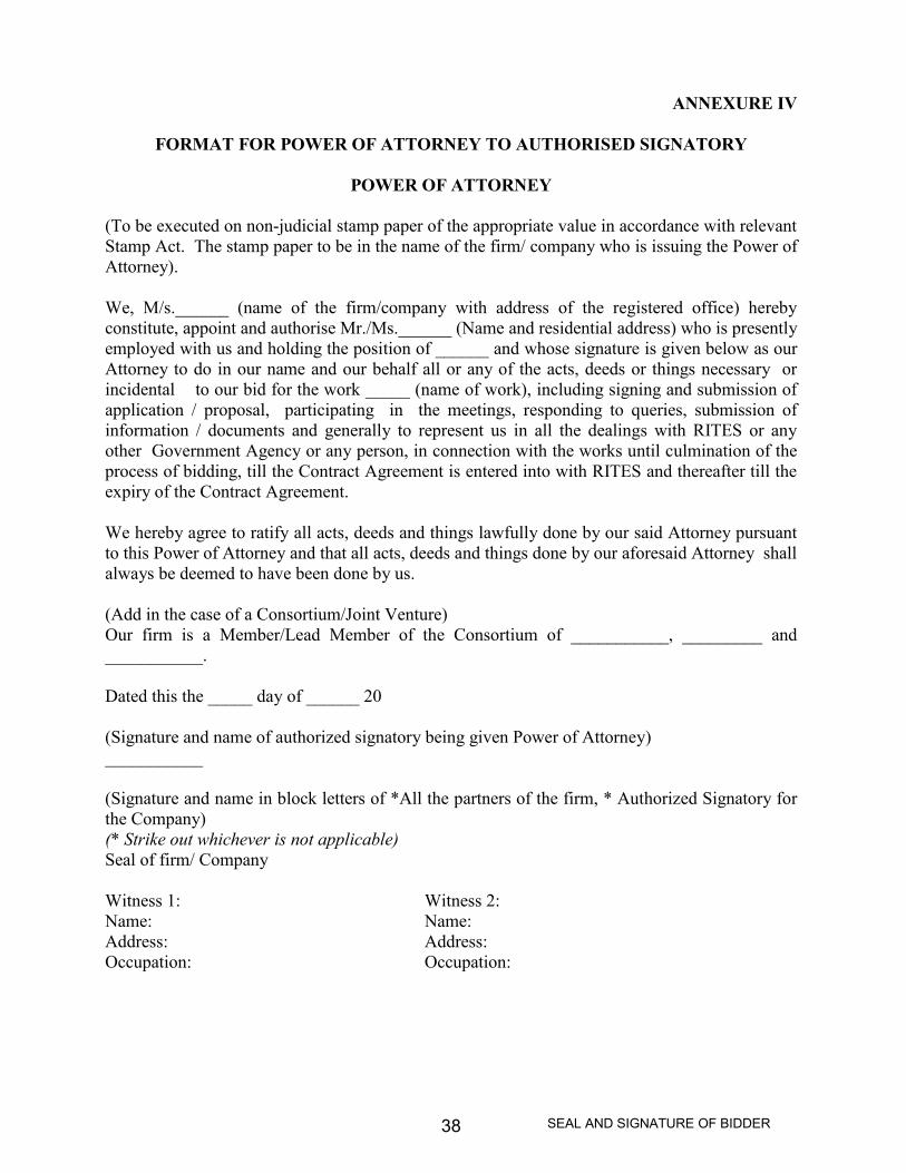
ANNEXURE IV
FORMAT FOR POWER OF ATTORNEY TO AUTHORISED SIGNATORY
POWER OF ATTORNEY
(To be executed on non-judicial stamp paper of the appropriate value in accordance with relevantStamp Act. The stamp paper to be in the name of the firm/ company who is issuing the Power ofAttorney).
We, M/s.______ (name of the firm/company with address of the registered office) herebyconstitute, appoint and authorise Mr./Ms.______ (Name and residential address) who is presentlyemployed with us and holding the position of ______ and whose signature is given below as ourAttorney to do in our name and our behalf all or any of the acts, deeds or things necessary orincidental to our bid for the work _____ (name of work), including signing and submission ofapplication / proposal, participating in the meetings, responding to queries, submission ofinformation / documents and generally to represent us in all the dealings with RITES or anyother Government Agency or any person, in connection with the works until culmination of theprocess of bidding, till the Contract Agreement is entered into with RITES and thereafter till theexpiry of the Contract Agreement.
We hereby agree to ratify all acts, deeds and things lawfully done by our said Attorney pursuantto this Power of Attorney and that all acts, deeds and things done by our aforesaid Attorney shallalways be deemed to have been done by us.
(Add in the case of a Consortium/Joint Venture)Our firm is a Member/Lead Member of the Consortium of ___________, _________ and___________.
Dated this the _____ day of ______ 20
(Signature and name of authorized signatory being given Power of Attorney)___________
(Signature and name in block letters of *All the partners of the firm, * Authorized Signatory forthe Company)(* Strike out whichever is not applicable)Seal of firm/ Company
Witness 1: Witness 2:Name: Name:Address: Address:Occupation: Occupation:

SEAL AND SIGNATURE OF BIDDER39
Notes:
- In case the Firm / Company is a Member of a Consortium/ JV, the authorized signatoryhas to be the one employed by the Lead Member.
- The mode of execution of the Power of Attorney should be in accordance with theprocedure, if any, laid down by the applicable law and the charter documents of theexecutant(s) and when it is so required the same should be under common seal affixed inaccordance with the required procedure.

SEAL AND SIGNATURE OF BIDDER40
ANNEXURE V
FORMAT FOR POWER OF ATTORNEY TO LEAD MEMBER OF CONSORTIUM /JOINT VENTURE
Not Applicable.
SEAL AND SIGNATURE OF BIDDER41
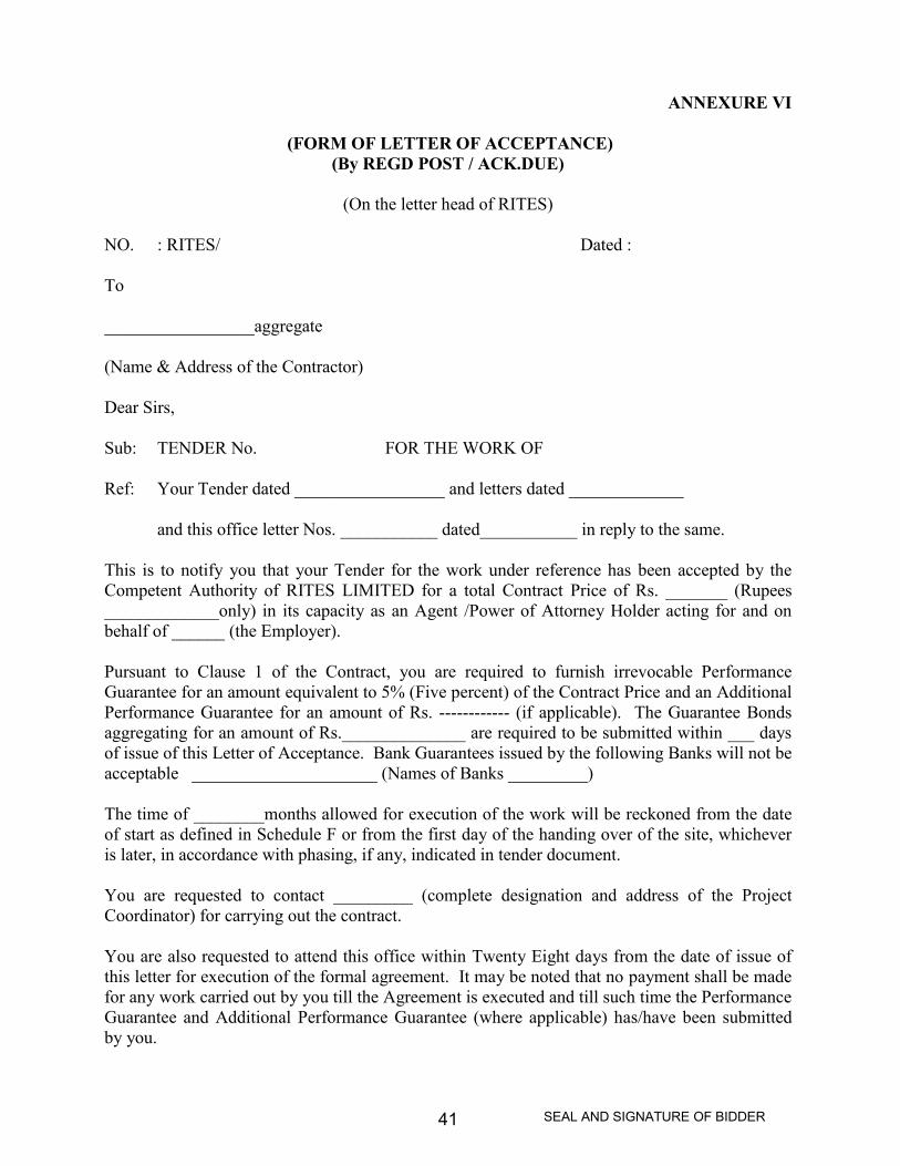
ANNEXURE VI
(FORM OF LETTER OF ACCEPTANCE)(By REGD POST / ACK.DUE)
(On the letter head of RITES)
NO. : RITES/ Dated :
To
_________________aggregate
(Name & Address of the Contractor)
Dear Sirs,
Sub: TENDER No. FOR THE WORK OF
Ref: Your Tender dated _________________ and letters dated _____________
and this office letter Nos. ___________ dated___________ in reply to the same.
This is to notify you that your Tender for the work under reference has been accepted by theCompetent Authority of RITES LIMITED for a total Contract Price of Rs. _______ (Rupees_____________only) in its capacity as an Agent /Power of Attorney Holder acting for and onbehalf of ______ (the Employer).
Pursuant to Clause 1 of the Contract, you are required to furnish irrevocable PerformanceGuarantee for an amount equivalent to 5% (Five percent) of the Contract Price and an AdditionalPerformance Guarantee for an amount of Rs. ------------ (if applicable). The Guarantee Bondsaggregating for an amount of Rs.______________ are required to be submitted within ___ daysof issue of this Letter of Acceptance. Bank Guarantees issued by the following Banks will not beacceptable _____________________ (Names of Banks _________)
The time of ________months allowed for execution of the work will be reckoned from the dateof start as defined in Schedule F or from the first day of the handing over of the site, whicheveris later, in accordance with phasing, if any, indicated in tender document.
You are requested to contact _________ (complete designation and address of the ProjectCoordinator) for carrying out the contract.
You are also requested to attend this office within Twenty Eight days from the date of issue ofthis letter for execution of the formal agreement. It may be noted that no payment shall be madefor any work carried out by you till the Agreement is executed and till such time the PerformanceGuarantee and Additional Performance Guarantee (where applicable) has/have been submittedby you.
SEAL AND SIGNATURE OF BIDDER42
This Letter of Acceptance is being sent to you in duplicate and you are requested to returnwithout delay one copy of the letter duly signed and stamped, as a token of youracknowledgement.
Kindly note that this Letter of Acceptance thereof shall constitute a binding Contract between uspending execution of formal Agreement.
Your letters as well as this office letters referred to above shall form part of the Contract.
Yours faithfully,
RITES LIMITED
Agent / Power of Attorney Holder
For and on behalf of______ (The Employer)
Copy to :
1. ___________ (The Employer) for information.
(To be included on the Original sent to the Contractor)
2. Project Coordinator (Complete designation and address)
3. Associated Finance (Not in original)

SEAL AND SIGNATURE OF BIDDER43
ANNEXURE VII
FORM OF AGREEMENT
(ON NON JUDICIAL STAMP PAPER OF APPROPRIATE VALUE)Agreement No. ________ dated _________
THIS AGREEMENT is made on ________ day of ______ Two thousand ________ betweenRITES Ltd. a Government of India Enterprise and a Company registered under Companies Act,1956 having its registered office at SCOPE Minar, Laxmi Nagar, Delhi - 110092 and itsCorporate Office at RITES BHAWAN, Plot No.1, Sector 29, Gurgaon (Haryana) representingthrough ____________, RITES LIMITED acting for and on behalf of and as an Agent /Power ofAttorney Holder of _____ hereinafter called the Employer (which expression shall, wherever thecontext so demands or requires, include their successors in office and assigns) on one part andM/s.______ hereinafter called the Contractor (which expression shall wherever the context sodemands or requires, include his/ their successors and assigns) of the other part.
WHEREAS the Employer is desirous that certain works should be executed viz.___________(brief description of the work) and has by Letter of Acceptance dated ____ accepted a tendersubmitted by the Contractor for the execution, completion, remedying of any defects therein andmaintenance of such works at a total Contract Price of Rs. ______ (Rupees ______________only)
NOW THIS AGREEMENT WITNESSETH as follows:-
1. In this Agreement words and expressions shall have the same meaning as are respectivelyassigned to them in the Conditions of Contract hereinafter referred to.
2. The following documents in conjunction with addenda/ corrigenda to Tender Documentsshall be deemed to form and be read and construed as part of this agreement viz.
The Letter of Acceptance dated______.Priced Schedule (Bill) of QuantitiesNotice Inviting Tender and Instructions to Tenderers.RITES Tender and Contract FormSpecial ConditionsSchedules A to F.Technical SpecificationsDrawingsAmendments to Tender Documents (List enclosed)General Conditions of Contract (read with Correction Slip Nos. 1 to --) comprising of
(i) Conditions of Contract(ii) Clauses of Contract(iii) RITES Safety Code(iv) RITES - Model Rules for the protection of Health and Sanitary
arrangements for Workers(v) RITES – Contractor's Labour Regulations.

SEAL AND SIGNATURE OF BIDDER44
3. In consideration of the payment to be made by the Employer to the Contractor ashereinafter mentioned, the Contractor hereby covenants with the Employer to execute,complete, remedy defects therein and maintain the works in conformity in all respectswith the provisions of the Contract.
4. The Employer hereby covenants to pay to the Contractor in consideration of theexecution, completion, remedying of any defects therein and maintenance of the works,the contract price or such other sum as may become payable under the provisions of thecontract at the time and in the manner prescribed by the Contract.
IN WITNESS whereof the parties hereto have caused their respective common seals to behereinto affixed (or have herewith set their respective hands and seals) the day and year firstabove written.
SIGNED, SEALED AND DELIVERED BY
____________________________In the capacity of _____
On behalf of M/s. _________
(The Contractor)
In the presence of
Witnesses (Signature, Name &Designation)
1.
2.
______________________________representing RITES LIMITEDIn the capacity of Agent / Power ofAttorney Holder
For and on behalf of _________
(The Employer)
In the presence of
Witnesses (Signature, Name &Designation)
1.
2.

SEAL AND SIGNATURE OF BIDDER45
ANNEXURE VIII
INTEGRITY PACT
Not Applicable.

SEAL AND SIGNATURE OF BIDDER46
ANNEX-A
Guidelines on Banning of Business Dealings
1. Introduction
1.1 RITES, being a Public Sector Enterprise and ‘State’, within the meaning of Article 12 ofConstitution of India, has to ensure preservation of rights enshrined in Chapter III of theConstitution. RITES has also to safeguard its commercial interests. It is not in the interestof RITES to deal with Agencies who commit deception, fraud or other misconduct in theexecution of contracts awarded / orders issued to them. In order to ensure compliancewith the constitutional mandate, it is incumbent on RITES to observe principles of naturaljustice before banning the business dealings with any Agency.
1.2 Since banning of business dealings involves civil consequences for an Agency concerned,it is incumbent that adequate opportunity of hearing is provided and the explanation, iftendered, is considered before passing any order in this regard keeping in view the facts andcircumstances of the case.
2. Scope
2.1 The procedure of (i) Suspension and (ii) Banning of Business Dealing with Agencies, hasbeen laid down in these guidelines.
2.2 It is clarified that these guidelines do not deal with the decision of the Management not toentertain any particular Agency due to its poor / inadequate performance or for any otherreason.
2.3 The banning shall be with prospective effect, i.e., future business dealings.
3. Definitions
In these Guidelines, unless the context otherwise requires:
i) `Bidder / Contractor / Supplier' in the context of these guidelines is indicated as‘Agency’.
ii) ‘Competent Authority’ and ‘Appellate Authority’ shall mean the following:
a) The Director shall be the ‘Competent Authority’ for the purpose of theseguidelines. MD, RITES shall be the ‘Appellate Authority’ in respect ofsuch cases.
b) MD, RITES shall have overall power to take suo-moto action on anyinformation available or received by him and pass such order(s) as he maythink appropriate, including modifying the order(s) passed by anyauthority under these guidelines.

SEAL AND SIGNATURE OF BIDDER47
iii) ‘Investigating Department’ shall mean any Department, Division or Unitinvestigating into the conduct of the Agency and shall include the VigilanceDepartment, Central Bureau of Investigation, the State Police or any otherdepartment set up by the Central or State Government having powers toinvestigate.
4. Initiation of Banning / Suspension:
Action for banning / suspension business dealings with any Agency should be initiated bythe department/ unit having business dealings with them after noticing the irregularitiesor misconduct on their part.
5. Suspension of Business Dealings
5.1 If the conduct of any Agency dealing with RITES is under investigation by anydepartment, the Competent Authority may consider whether the allegations underinvestigation are of a serious nature and whether pending investigation, it would beadvisable to continue business dealing with the Agency. If the Competent Authority, afterconsideration of the matter including the recommendation of the InvestigatingDepartment/Unit, if any, decides that it would not be in the interest to continue businessdealings pending investigation, it may suspend business dealings with the Agency. Theorder to this effect may indicate a brief of the charges under investigation. The order ofsuch suspension would operate for a period not more than six months and may becommunicated to the Agency as also to the Investigating Department.
The Investigating Department/Unit may ensure that their investigation is completed andwhole process of final order is over within such period.
5.2 As far as possible, the existing contract(s) with the Agency may be continued unless theCompetent Authority, having regard to the circumstances of the case, decides otherwise.
5.3 If the Agency concerned asks for detailed reasons of suspension, the Agency may beinformed that its conduct is under investigation. It is not necessary to enter intocorrespondence or argument with the Agency at this stage.
5.4 It is not necessary to give any show-cause notice or personal hearing to the Agencybefore issuing the order of suspension. However, if investigations are not complete in sixmonths time, the Competent Authority may extend the period of suspension by anotherthree months, during which period the investigations must be completed.
6. Grounds on which Banning of Business Dealings can be initiated

SEAL AND SIGNATURE OF BIDDER48
6.1 If the security consideration, including questions of loyalty of the Agency to the State, sowarrants;
6.2 If the Director / Owner of the Agency, proprietor or partner of the firm, is convicted by aCourt of Law for offences involving moral turpitude in relation to its business dealingswith the Government or any other public sector enterprises or RITES, during the last fiveyears;
6.3 If there is strong justification for believing that the Directors, Proprietors, Partners, ownerof the Agency have been guilty of malpractices such as bribery, corruption, fraud,substitution of tenders, interpolations, etc;
6.4 If the Agency employs a public servant dismissed / removed or employs a personconvicted for an offence involving corruption or abetment of such offence;
6.5 If business dealings with the Agency have been banned by the Govt. or any other publicsector enterprise;
6.6 If the Agency has resorted to Corrupt, fraudulent practices includingmisrepresentation of facts;
6.7 If the Agency uses intimidation / threatening or brings undue outside pressure on theCompany (RITES) or its official in acceptance / performances of the job under thecontract;
6.8 If the Agency indulges in repeated and / or deliberate use of delay tactics in complyingwith contractual stipulations;
6.9 Based on the findings of the investigation report of CBI / Police against the Agency formalafide / unlawful acts or improper conduct on his part in matters relating to theCompany (RITES) or even otherwise;
6.10 Established litigant nature of the Agency to derive undue benefit;
6.11 Continued poor performance of the Agency in several contracts;
(Note: The examples given above are only illustrative and not exhaustive. The CompetentAuthority may decide to ban business dealing for any good and sufficient reason).
7. Banning of Business Dealings
7.1 A decision to ban business dealings with any Agency shall apply throughout theCompany.

SEAL AND SIGNATURE OF BIDDER49
7.2 If the Competent Authority is prima-facie of view that action for banning businessdealings with the Agency is called for, a show-cause notice may be issued to the Agencyas per paragraph 8.1 and an enquiry held accordingly.
8. Show-cause Notice
8.1 In case where the Competent Authority decides that action against an Agency is calledfor, a show-cause notice has to be issued to the Agency. Statement containing theimputation of misconduct or mis-behaviour may be appended to the show-cause noticeand the Agency should be asked to submit within 30 days a written statement in itsdefence. If no reply is received, the decision may be taken ex-parte.
8.2 If the Agency requests for inspection of any relevant document in possession of RITES,necessary facility for inspection of documents may be provided.
8.3 After considering the reply of the Agency and other circumstances and facts of the case, afinal decision for Company-wide banning shall be taken by the Competent Authority.The Competent Authority may consider and pass an appropriate speaking order:
a) For exonerating the Agency if the charges are not established;b) For banning the business dealing with the Agency.
8.4 The decision should be communicated to the Agency concerned along with a reasonedorder. If it decided to ban business dealings, the period for which the ban would beoperative may be mentioned.
9. Appeal against the Decision of the Competent Authority
9.1 The Agency may file an appeal against the order of the Competent Authority banningbusiness dealing, etc. The appeal shall lie to Appellate Authority. Such an appeal shall bepreferred within one month from the date of receipt of the order banning businessdealing, etc.
9.2 Appellate Authority would consider the appeal and pass appropriate order which shall becommunicated to the Agency as well as the Competent Authority.
10. Review of the Decision by the Competent Authority
Any petition / application filed by the Agency concerning the review of the banning orderpassed originally by Competent Authority under the existing guidelines either before orafter filing of appeal before the Appellate Authority or after disposal of appeal by theAppellate Authority, the review petition can be decided by the Competent Authority upondisclosure of new facts /circumstances or subsequent development necessitating suchreview.

SEAL AND SIGNATURE OF BIDDER50
11. Circulation of the names of Agencies with whom Business Dealings have beenbanned.
11.1 Depending upon the gravity of misconduct established, the Competent Authority ofRITES may circulate the names of Agency with whom business dealings have beenbanned, to the Ministry of Railways and PSUs of Railways, for such action as they deemappropriate.
11.2 If Ministry of Railways or a Public Sector Undertaking of Railways request for moreinformation about the Agency with whom business dealings have been banned a copy ofthe report of Inquiring Authority together with a copy of the order of the CompetentAuthority/ Appellate Authority may be supplied.
12. Restoration
12.1 The validity of the banning order shall be for a specific time & on expiry of the same, thebanning order shall be considered as "withdrawn".
12.2 In case any agency applies for restoration of business prior to the expiry of the ban order,depending upon merits of each case, the Competent Authority which had passed theoriginal banning orders may consider revocation of order of suspension ofbusiness/lifting the ban on business dealings at an appropriate time. Copies of therestoration orders shall be sent to all those offices where copies of Ban Orders had beensent.

SEAL AND SIGNATURE OF BIDDER51
Section - 2
TENDER & CONTRACT FORM

SEAL AND SIGNATURE OF BIDDER52
SECTION 2
TENDER AND CONTRACT FORM FOR WORKS
To
Group General Manager (P),RITES Ltd., Nagpur.[Refer Schedule F (Conditions of Contract)]Name, Designation / Address
Sub: TENDER FOR THE WORK OF Construction of Road Over Bridge atKm.728/9-11 on Howrah-Mumbai main line near Chakrabhata LC No.370 onBilaspur-Baloda Bazar Road, Bilaspur (C.G)
(TENDER No.: RITES/GGM/NGP/26-2011,DATED 23/12/2011 ISSUED BY____________)
TENDER
1. I/We have read and examined the Notice Inviting Tender and Instructions to Tenderers,Special Conditions, Schedules A to F, Technical Specifications, Drawings, Schedule /Bill of Quantities and General Conditions of Contract as well as other documents andrules referred to in GCC and all the details contained in the Tender Document for thework.
2. I/We hereby tender for the execution and completion of the work and remedy any defectstherein, specified in the Schedule of Quantities within the time specified in Schedule “F”,and in accordance in all respects with the specifications, designs, drawings andinstructions in writing referred to in Notice Inviting Tender and Instructions to Tenderersand in Clause 11 of the Clauses of Contract and with such materials as are provided for,by, and in respects in accordance with, such conditions so far as applicable.
3. We agree that our tender shall remain valid for a period of 90 days from the due date forsubmission of bid or extended date as stipulated and not to make any modifications in itsterms and conditions.
4. A sum of Rs. ___________ (Rupees _________ only) is hereby forwarded in the form ofBanker’s cheque/Pay Order /Demand Draft issued in favour of RITES Ltd., payable at_________ as the Earnest Money.
5. If I/We withdraw my/our tender during the period of tender validity or before issue ofLetter of Acceptance which ever is earlier or make modifications in the Terms and

SEAL AND SIGNATURE OF BIDDER53
Conditions of the Tender which are not acceptable to the Employer, then the Employershall, without prejudice to any other right or remedy, be at liberty to forfeit entire EarnestMoney absolutely.
6. If I/We fail to furnish the prescribed Performance Guarantee and Additional PerformanceGuarantee (if applicable) within prescribed period, I/We agree that the said Employershall, without prejudice to any other right or remedy, be at liberty to forfeit the saidEarnest Money absolutely.
7. If, I/We fail to commence the work within the specified period, I/We agree that theEmployer shall, without prejudice to any other right or remedy available in law, be atliberty to forfeit the Earnest Money and Performance Guarantee and AdditionalPerformance Guarantee (if applicable) absolutely.
8. Further, I/We hereby agree that in case of forfeiture of Earnest Money or both EarnestMoney & Performance Guarantee and Additional Performance Guarantee (if applicable)as aforesaid in paras 5 to 7, I/We shall be debarred from participation in re-tenderingprocess of the work.
9. On issue of Letter of Acceptance by the Employer, I/We agree that the said EarnestMoney shall be retained by the Employer towards Security Deposit, to execute all theworks referred to in the Tender document upon the Terms and Conditions contained orreferred to therein and to carry out such deviations as may be ordered, upto maximum ofthe percentage mentioned in Schedule F at rates as stipulated in relevant Clauses ofcontract and those in excess of that limit at the rates to be determined in accordance withthe provisions contained in Clauses 12.2 and 12.3 of the tender form.
10. I/We hereby agree that I/ We shall sign the Formal Agreement with the Employer within28 days from the date of issue of Letter of Acceptance. In case of any delay, I/We agreethat we shall not submit any Bill for Payment till the Contract Agreement is signed.
11. I/We hereby declare that I/We shall treat the tender documents, drawings and otherrecords connected with the work as secret/confidential documents and shall notcommunicate information derived there from to any person other than a person to whomI/We am/are authorized to communicate the same or use the information in any mannerprejudicial to the safety of the Employer/State.
12. I/We hereby declare that I/We have not laid down any condition/deviation to any contentof Technical Bid and/or Financial Bid. I/We agree that in case any condition is found tobe quoted by us in the Technical and/or Financial Bid, my/our Tender may be rejected.
13. I/We understand that the Employer is not bound to accept the lowest or any tender hemay receive. I/We also understand that the Employer reserves the right to accept thewhole or any part of the tender and I/We shall be bound to perform the same at the ratesquoted.

SEAL AND SIGNATURE OF BIDDER54
14. Until a formal agreement is prepared and executed, this bid together with our writtenacceptance thereof shall constitute a binding contract between us and RITES.
15. I am/We are signing this Tender offer in my / our capacity as one/those authorized to signon behalf of my/our company/as one holding the Power of Attorney issued in my favouras Lead Member by the Members of the Joint Venture.
Signature of Authorized Person/sDateName/s & Title of SignatoryName of TendererPostal Address
Seal
WitnessSignatureNamePostal AddressOccupation

SEAL AND SIGNATURE OF BIDDER55
Section - 3
SPECIAL CONDITIONS
SEAL AND SIGNATURE OF BIDDER56
SECTION 3
SPECIAL CONDITIONS
1.0 Precautions while working in the vicinity of Railway Track.
(a) When the work is required to be done along or near existing railway track, thecontractor(s) shall take steps as are necessary for the safety of the track labour working atsite. He / They will also be required to make Programme of his/their work so as not tointerfere with the movement of trains. No extra payment shall be allowed for theseprecautions and also for crossing track/tracks required during execution of the work. Itshould be ensured that the ballast of the railway track(s) is not spoiled or mixed withearth or disturbed.
(b) In addition to the precautions taken by the contractor for the safety of the track andlabour, it may be necessary to post flagmen in some locations as an additional safetymeasure. The contractor(s) shall be fully responsible for any damage to or trespasscaused by his/their men to surrounding structure, RITES/PWD,Bilaspur bears no liabilitywhatsoever on this account.
(c) Instruction given by Railway Authority regarding safety shall be strictly followed duringexecution of work.
2.0 SAFETY PRECAUTIONS :
2.1 The Contractor/s shall at all times adopt such safe methods to work as will ensure safety ofstructure, equipment and labour. If at any time the RITES/PWD, Bilaspur finds the safetyarrangements unsafe, the contractor/s shall take immediate corrective action as directed bythe RITES/PWD, Bilaspur in the matter. This shall in no way absolve the contractor/s ofhis/their sole responsibility to adopt safe working methods.
2.2 The Contractor/s shall design and execute temporary works such as formwork and supports,so as to ensure absolute safety of contractor/s personnel as well as RITES/PWD, Bilaspurstaff and personnel engaged on the work. The Contractor/s should indemnify theRITES/PWD, Bilaspur against damages and injury to workmen. RITES/PWD, Bilaspurreserves the right to enforce safety regulations on the contractor/s and recover any cost,which may be incurred for the purpose.
2.3 Whenever a lorry or any other form of road transport if required to ply along or in thevicinity of a running line or any other railway track where railway Engines or trains arescheduled to move, the contractor shall inform the Engineer in writing of such
SEAL AND SIGNATURE OF BIDDER57
requirement specifying the locations and the duration of time over which such specifiedroad vehicles have to operate in the area (for loading, leading or unloading of earth,ballast or any other material, plant or equipment) without any obstruction or dislocationto the running of trains. The contractor also should furnish the particulars of vehicles andthe name and photograph of drivers and attended retained for each legal to enable theengineer to issue necessary along the holder to operate the vehicles, with such restrictionsregarding the durations and / or locations as are considered necessary. Such permit shallbe returned to the engineer as soon as the work for which it is issued is over.
2.4 The contractor shall execute a bond undertaking to ply to road vehicles in a safe andsatisfactory manner and strictly in accordance with the stipulations and other conditionsspecified by the engineer and to engage and retain only the permit holder to be thecontractor agent in charge of the vehicles, while driving or a rest. The person in chargeof the vehicles in the attendant shall at all times be vigilant and on the look out for signalsfrom the look out men, flagmen or other personnel available at site with a view to stop forregulate the road movement so as to ensure adequate margin of safety for the timelypassage of an approaching train or railway engine, without any delay or detention.
2.5 The contractor shall also be bound by the provision of this agreement, to ply the roadvehicles only with adequate margin of safety, well clear of the fixed structure profile ofinfringement, as stipulated in the rules made under the Indian Railway Act and to seekand be guided by the signal and other directions of any lookout men for other personnelretained for the purpose of ensuring safety, and to ensure care and vigilance whileturning, reversing or moving the road vehicle in any other manner, at an inclination to therunning railway track or the siding, as the case may be.
2.6 The contractor also undertakes to make good at his own cost any inconvenience, loss,damage, or other expenses caused to or incurred by the railway administration and to paysuch amount as determined by the engineer to be recoverable from the contractor aspenalty or damage for any omission, negligence, careless, oversight or accidents on thepart of any of the contractor’s agents, drivers or attendant or any person to whom theservices of the holder of the permit (issued by the Engineer) has been lent other wisemade accessible or available.
2.7 Any breach of these conditions by the contractor and/or his agent affecting the safety ofmovements of trains, engines or other rolling stock of the Railway shall constitute abreach of contract by the contractor entailing liability for termination of contract fordefault on the part of the contractor.

SEAL AND SIGNATURE OF BIDDER58
2.8 The Tenderer/s will be permitted to make use of the level crossing for crossing the trackafter observing the standard railway safety precaution. If such precautions are not takenthese will be enforced by the railway by adequate arrangements and the cost thereof shallbe recovered from the contractor.
2.9 The contractor/s shall inspect the proposed site of work and acquaint himself /themselves with site conditions working hours storing spaces for materials, approach road/ pathway available etc. and all relevant items connected with the execution of work.No. claim shall be entertained from contractor/s and shall make his own arrangements forapproach/approach roads from out side railway land and contractor will bear entireexpenses such as road taxes payment on right of way etc. to outsiders.
3.0 PROTECTION AT THE WORKS SITE :
3.1 On Railway track where the train traffic will be operational during the execution of thecontract work, the protection of the works site as considered appropriate and adequate shallbe arranged by the contractor at his own cost.
3.2 Notwithstanding the aforementioned protection at the works site provided by the Engineer’srepresentative, the contractor shall be responsible for providing appropriate and adequatesystem for warning the contractor’s workmen about the train traffic on or in the vicinity ofthe site of work. The decision of the Engineer’s representative whether the facilitiesprovided by the contractor in this regard are appropriate and adequate or not, shall be finaland conclusive.
4.0 WORKS DURING BLOCK PERIOD
For excavation nearer to the Railway track proper shoring and strutting shall be used,shoring and strutting arrangement shall be approved by the Railways.
5.0 Incase of any accident during construction due to which the Railway undergone monetaryor structural losses, it is the responsibility of the contractor to bear such losses. Anyassessment made by the Railway shall be binding on the contractor.
6.0 Supervision of the works within the Railway boundary shall be done by the Railway aswell. Any instructions given by the Railways regarding the works shall be binding on thecontractor. Contractor shall arrange for the necessary conveyance for the officers ofRailways for the supervision/inspection of the portion of works within the Railwayboundary.

SEAL AND SIGNATURE OF BIDDER59
7.0 Precast concrete panel for shuttering below the deck slab is not permitted for the workswithin the Railway boundary. Necessary removable shuttering shall be provided by thecontractor. Arrangements for shuttering for deck slab shall be planned and designed bythe contractor by providing sleeve holes into the web of the girder.
8.0 BLOCK CHARGES
8.1 It is the responsibility of contractor to arrange necessary blocks from Railways duringlaunching operation or any other activity required blocks. The necessary charges payableto Railways in this regard will be reimbursed by RITES/PWD, Bilaspur on submission ofpaid vouchers accompanied with demand note issued by Railways.
8.2 The contractor shall ensure that block period sanctioned is not violated. The contractorshall be liable for penalty for each block bursting for a minimum amount of Rs. 5000/- tothe amount as claimed by Railways towards bursting of block. However, prolongation ofcaution order than the agreed programme will also be liable for penalty @Rs.5000/- or aslevied by the Railways whichever is higher for each day. These penalty charges will notbe reimbursed by RITES/PWD, Bilaspur.

SEAL AND SIGNATURE OF BIDDER60
DESIGN DATA FOR ROB NEAR CHAKRABHATA LC NO. 370 ON BILASPUR-BALOD BAZAR ROAD
DETAILS FOR CARRIAGE WAY
1. Carriageway Width : 7.50 Mtrs.
Railway Portion : 2x27.00 Mtrs.+ 1x14.00Mtrs.
(Composite)
2. Width of Footpath : 2x2.125 Mtrs (4.25 Mtrs)
3. Overall Width of Bridge : 11.75 Mtrs (with footpath)
Railway Portion : 11.75 Mtrs.(outer to outer)
4. Seismic Effects
a) Seismic Zone : III
b) Basic Horizontal Seismic Coeff. (α) : As per IRC-6-2000
c) Importance Factor (λ) : 1.50
5. Design Speed of Vehicles : 65 kmph.
6. Longitudinal Gradient : As shown in departmental drawing
attached
7. Exposure Condition : Moderate
(Moderate or Severe)
8. Loading due to service : As mentioned in Design Criteria
Volume-I
9. Temperature range : Max. Temp.= 470 c, Min. Temp.=60 c.

SEAL AND SIGNATURE OF BIDDER61
10. Underground Water Table : As per site conditions
11. For Design of Temperature effects, : Moderate
atmospheric exposure condition
14. Live load on Footpath : 500 kg. per mtrs. square
15. Configuration of wearing coat :
(a) For ROB : 12mm thick mastic asphalt wearing
coat

SEAL AND SIGNATURE OF BIDDER62
DESIGN CRITERIA FOR ROB
1. GENERAL REQUIREMENTS :
In order that the tenderer's alternative proposal qualifies as an alternative design, it shallgenerally satisfy the following requirements: -(i) It shall ensure soundness of the structure, its durability and architectural beauty as
a whole in harmony with the surroundings.
(ii) It shall ensure speedy construction and lead to appreciable economy.
(iii) It shall be accompanied by preliminary but fairly detailed drawings and detaileddescription of work and specification of materials and items. If called upon,tenderer shall furnish any additional information necessary for appreciation andcomparison with other alternative proposals received from other tenderers.
(iv) At the time of detail design the contractor shall not normally deviate from thebasic scheme proposed by him for the purpose of tender.
(v) The superstructure shall have minimum number of expansion joints for betterriding surface.
(vi) As far as possible proper bridge shall have uniform aesthetical appearance toenhance the overall look of bridge and thereby the vicinity.
(vii) All the substructure shall be of uniform type except otherwise necessary.(viii) For super structure only steel girders with RCC deck slab is permitted.
2. RESTRICTIONS ON TYPE OF STRUCTURES :The following types of structural arrangements shall not be permitted:
(i) Structures sensitive to unequal settlement of foundations, indeterminate structureslike continuous, rigid frames, etc. on yielding type of foundations.
(ii) A design in which stability of one or more span is endangered due to failure ofsome other span or spans.
(iii) Superstructure with joints at the tip of long cantilevers with hinges, gap slab andshort suspended spans.
(iv) Structures with continuity only in deck slab, in transverse direction. (WiderSuperstructure more than 4 lane resting on independent foundations should not beinterconnected.)
(v) Piers in the form of multiple columns with isolated/separate footings resting onyielding type strata.

SEAL AND SIGNATURE OF BIDDER63
(vi) Superstructures with which the roadway cannot be easily widened in future, suchas bowstring girders, through trusses, etc.
(vii) Two girder system for superstructure.
(viii) Unprotected hollow piers for spans, which are susceptible to impact of vehicles.
(ix) R.C.C. Box or R.C.C. girders for spans more than 20 m.
3. SPECIFICATIONS FOR DESIGN AND CODES TO BE FOLLOWED :
3.1 The design of structural components shall conform to the criteria laid down in the latesteditions of the following codes of Practice and Standard specifications published upto 3months prior to last date of issue of tender form and subject to the departures stipulated inthese tender documents.
(A) Indian Railway Standard -1. Code of practice for composite Girder for general Bridge construction
2. Code of Practice for the design of sub-structures and foundations of bridges.(Bridge Sub-structures & Foundation code)
(B) I.R.C. Standard Specifications and Codes of Practice for Road Bridges. :Section - I I.R.C. 5 General features of design.Section -II I.R.C. 6 Loads and stresses.Section -III I.R.C.21 Cement concrete plain and
Reinforced (Second Revision).Section - V I.R.C.24 Steel road bridges for permissible
stress only.(Other provisions as per AASHTOCode).
Section -VI I.R.C.22 Composite construction for roadbridges (for permissible stresses only)(Other provisions as per B.S.5400part 3,5,6/ ASHTO Code).
Section -VII I.R.C.78 Foundation and substructure.Section -IX I.R.C.83 (Part-I) Metallic Bearings.Section -IX I.R.C.83 (Part-III) POT, POT CUM
PTFE PIN AND METALLICGUIDE BEARINGS.
I.R.C: 18 Design criteria for prestressed concrete Road Bridges (Posttensioned concrete).MOST specifications for Road and Bridge Work-2001

SEAL AND SIGNATURE OF BIDDER64
(C) Any I.R.C. standard specifications and codes of practice or criteria for road bridges otherthan "B" above, but published 3 months prior to last date of issue of tender form.
(D) For any item not covered by A, B & C above, specification for Road and Bridge workspublished by I.R.C. for Ministry of Road Transport and Highways, Government of India.
(E) For items not covered by any of the A, B, C & D above relevant provisions of IS codes ofpractice.
(F) For any item not covered by A, B, C, D & E above, the relevant provisions from B.S. andAASHTO Codes of Practice.
(G) For items not covered by any of the above Standards and Specifications soundEngineering practice and provisions in the Departmental design and provisions of relevantCodes of other nation shall be referred. In this regard decision of the General Manager(P), RITES Ltd., Nagpur shall be final and binding.
4. DESCRIPTION OF WORK AND OBLIGATORY PROVISIONS FORALTERNATIVE PROPOSALS
4.1 Alignment and location :-
Alignment and location of the ROB shall be as shown in the GAD bearing CE’s No.BR/R/CSBT/OB/886/2010 SHEET NO. 1 &2.
4.2 The length of ROB and Viaduct :-
The length of the ROB and via –duct shall satisfy the following criteria.
(a) Maximum height at abutment location shall not be more than those shown indepartmental drawing.
(b) Longitudinal gradient shall not be steeper than those shown in departmental drawings.(c) Any other criteria shown on the departmental drawings / supplementary data.(d) In case of ROB, the minimum vertical and horizontal clearances under the Railway
Bridge Portion shall not be less than those shown in departmental drawing i.e.approved GAD from Railways. Span arrangement shown in railway portion indepartmental drawing is obligatory.
4.3 Road Level on the ROB and Roadway Particulars:
(a) Roadway particulars including RTL and carriageway widths shall be as perrelevant Departmental drawing.
4.4 Supplementary data for design shall be as per Design Data.
5. DESIGN LOADS: -

SEAL AND SIGNATURE OF BIDDER65
5.1 Live Loads :
5.1.1 The bridge shall be designed to carry combination of I.R.C loadings, as per clause207.4 (IRC: 6-2000) whichever produces worst effect.
While checking for one span off condition, live load of IRC Class-A one lane pertwo lanes without impact shall be taken into account and this will not beconsidered in conjunction with seismic / wind force / Barge impact. Braking forceis not to be considered.
5.1.2 The flyovers/ROBs which are lying in Seismic Zone III and IV having total lengthless than 60 m but individual span length more than 20 m shall also be designedfor seismic forces.
5.1.3 For Railway portion – As per IRC:6-2000 OR as approved by Railway Authoritywhichever produces worst effect.
5.2 Wind Forces :-
5.2.1 Wind forces shall be considered in the following two ways. The design shall begoverned by the one producing the worst effect.
(i) Full wind force at right angles to the superstructure.(ii) 65 % of wind force as calculated in (i) above acting perpendicular to the
superstructure and 35 % acting in traffic direction.
5.3 Temperature-Range :-
(i) For design of structure to account for temperature in formula L = xL x t, the value of "t" shall be 350 centigrade for extreme atmospheric exposurecondition and 250 centigrade for moderate atmospheric exposure condition.
(Note:- The temperatures indicated are total expansion / contraction aggregate valuei.e. ± 17.50 and ± 12.50. is the Coefficient of Expansion or Contraction and L is thelength of the member and L is the expansion or contraction due to a variation oftemperature in appropriate units.)
(ii) The superstructure shall also be designed for effects of distribution of temperatureacross the deck depth as per IRC:6-2000. For calculation of thermal forces effect of 'E'value of concrete should be taken as 50 % of the instantaneous value so as to accountfor effects of creep on thermal strains.
6. PERMISSIBLE STRESSES :-
6.1 Allowable stresses for plain reinforced and prestressed concrete shall be as perIRC-21 & IRC-18 respectively.

SEAL AND SIGNATURE OF BIDDER66
6.2 The permissible shear stresses shall be as per IRC-21
6.3 Shear Reinforcementi) Where the design shear stress T exceeds the shear stress carried by concrete Tc
shear reinforcement shall be provided as per the following equation in Clause304.7.1.4 of IRC:21-2000
(ii) The type of shear reinforcement shall be in accordance with Cl.304.7.1.5 ofIRC:21-2000.
6.3.1 Minimum Shear ReinforcementThe minimum shear reinforcement shall be as per IRC-21.
6.3.2 In no case the design shear stress calculated shall exceed the maximum permissibleshear stress as per Clause 304.7.1.2 of IRC: 21-2000
7. DURABILITY :-
7.1 Minimum Concrete Grade
7.1.1 Minimum grade of concrete shall be as per Clause 302.6 Table No. 5 (A) of IRC:21-2000 for exposure as per Design Data.
7.1.2 Minimum grade of concrete for the ROB within Railway Bridge portion shall be asper specifications of South East Central Railway.
7.2 Minimum Cement Content
7.2.1 For both plain and reinforced concrete, the value given below regarding minimumcement content and maximum water-cement ratio shall be as per Clause 302.6 TableNo. 5(A) of IRC:21-2000
7.2.2 High strength ordinary Portland cement conforming to I.S. 12269/ PSC conforming toI.S.8112 will also be permitted.
7.3 The minimum nominal dia. of reinforcement shall be as follows.
7.3.1 As per Clause 304.4 of IRC: 21-2000.
7.3.2 Minimum nominal dia of reinforcement for the ROB within Railway Bridge portionshall be as per specifications of South East Central Railway.
7.4 Minimum clear cover to reinforcement for all grades of concrete7.4.1 Shall be as per Clause 304.3 IRC:21-2000
7.4.2 Minimum clear cover for the ROB within Railway Bridge portion shall be as perspecifications of South East Central Railway.
7.5 The strands to be used for P.S.C. structures shall confirm to Class-II of latest IS: 6006.Low relaxation steel conforming to latest IS:14268: is also permitted.

SEAL AND SIGNATURE OF BIDDER67
8. BORING DATA AND SOIL AT SITE :
8.1 The details of the borings with tentative rock levels & their locations are shown on theGAD bearing CE’s No. BR/R/CSBT/OB/886/2010 SHEET NO. 1 &2. In the absenceof definitive test data the S.B.C. of hard rock is 200 T/m2 and of soft rock shall betaken as 100 T/m2 for open foundation. The interpolated levels of founding stratashown in the departmental drawing / Design Data will form the basis of variationclause. Appropriate embedment for open or pile foundation shall be provided belowthis level and this embedment shall be included in the quoted price.
8.2 The contractor shall have to take borings by double tube boring machine at the finallocation of each pier and abutment prior to the commencement of the work toascertain the rock levels/quality at the location of the foundations and this shall formpart of the contract and no payments will be made by the Department for boring, soilsampling and testing etc.
(a) During execution of the work, the samples from the bore taken at each foundationshall be tested and analyzed in the laboratory approved by the department forestablishing design parameters. Tests such as standard penetration test, compressionand shear test on undisturbed soil samples, etc., shall be carried out in conformity withthe specifications. The Contractor shall submit the entire data to the Engineer alongwith his own/laboratory recommendations and obtain approval to the design-parameters. Necessary interpretation of the result of tests shall be furnished to theEngineer for scrutiny of design of foundations.
(b) The cost of these test and interpretation of the test results shall be included in thetendered amount. No payment will be made separately for the testing of soil or rock.
(c) While checking the stresses at the base of foundations it shall be ensured that underthe worst combination of forces there is no tension except where founded on rock. TheS.B.C. at the foundation level shall be verified during construction so as to ensure thatthe stresses imposed on the foundation strata are within permissible limit. However, ifsome additional borings are required by the department such requirement shall beordered in writing and shall be deemed to be an additional work. No extra payment forboring, soil sampling, Geotechnical investigation.
9. FOUNDATIONS :
9.1 Piers:
9.1.1 For bidding and for the purpose of tender drawing, general foundation levels proposedfor the piers shall not be higher than those proposed in the Employers design. Wherepier positions differ from the departmental design, the levels shall be interpolated forthe purpose of this clause. For pile foundation, founding levels shall be considered asmentioned in the Design Data.
9.1.2 While checking the stresses at the base of foundations it shall be ensured that underworst combination of forces there are no tension except where founded on rock.

SEAL AND SIGNATURE OF BIDDER68
9.1.3 For various combinations of loads and forces the permissible reduced area of contactand redistribution pressure shall be as per IRC: 78-2000.
9.1.4 Buoyancy to be considered: 50% for hard rock , 100% for strata other thanhard rock.
9.2 Pile foundations :The pile foundation shall be designed as per the latest edition of I.R.C.78. Thefollowing criteria shall be considered for deciding the length of embedment. Thepiling shall be done preferably by rotary drilling.
9.2.1 For percussion boring the following criteria for depth of embedment of piles into rockand assessment of safe bearing capacity of the founding hard strata based on theEnergy level concept is acceptable.
A. Energy imparted to the strata can be worked out by the formula:
W x h x n x NE.L. = ----------------- tm/ m² /cm
d x Ap
Where, W = Wt. of the chisel in t. (1 to 2 T)h = drop of the chisel in m. (2 to 3)n = efficiency factor (0.7)N = No. of blows in half an hour duration.Ap = Area of pile cross section In m2.d = depth of penetration in cm.E.L. = Energy Level
B. Minimum embedment into rock and pile capacity on the strata shall be consideredas follows:------------------------------------------------------------------------------------------Energy level Min. Embedment in rock Pile Capacity(TM/SQM/cm) of given energy level------------------------------------------------------------------------------------------Min 100-200 3 x Dia of pile 175 T/m2Min.200 - 300 1.5 x Dia.of pile 250 t/m2More than 300 1.0 x Dia.of pile 300 t/m2------------------------------------------------------------------------------------------
C. The values of pile capacity given above consider the effect of friction etc. and theglobal behavior of the pile is also considered and hence friction resistance of pileshall not be further added.
D. In case hydraulically operated rotary drill machines or such similar equipment isused for piling, wherein the above mentioned energy criteria may not beapplicable, the rock strata shall be properly identified, confirmed and the necessary

SEAL AND SIGNATURE OF BIDDER69
embedment length provided as per design requirement. The minimum embedmentof piles in hard (basalt) rock shall be not less than 1.25 diameter, while the same insoft or weathered rock (tuff, breccias, etc.) it shall be not less than 3.0 diameter.The pile capacity in soft or weathered rock shall be restricted to 250 t/m2 and thatin hard rock shall be restricted to 300 t/m2, inclusive of all effects as clarified inpara 3 above.
E. The piles shall be considered as fixed at the founding level with the specifiedminimum embedment
9.2.2 The pile capacity shall be confirmed by pile load test as per IS-2911 (Part IV).
A. The design capacity assumed for the piles shall be verified by the initial loadtesting of test piles in non-working areas, in the vicinity of the bridge site. Thesepiles shall be tested for 2.5 times the design load and number of such tests shall beone per diameter. Additional one pile per dia., which is actually going to be usedfor piers and abutments shall be tested for 1.5 times the design load. These testsand the routine tests shall be as per I.R.C. 78 (Latest edition).
B. The minimum dia. of piles shall be as per Clause 709.1.7 of IRC:78-2000 forother than Railway Bridge portion and 1000 mm dia for Railway bridge Portion.
C. Annular piles filled or unfilled shall not be accepted.
D. Design with single row of piles shall not be accepted.
E. For Railway bridge portion the minimum thickness of permanent M.S. Liner forpiles shall be 8 mm.
F. Use of High performance concrete for piles is not permitted.
G. NDT Tests at regular intervals as directed by the Engineer for at least 10% of totalnumber of piles shall have to be carried out by the contractor with no cost to theemployer.
H. The cost of all above tests shall be borne by the contractor and no extra paymentwill be made to the contractor.
I. Only bored cast in situ Piles shall be accepted.
10. SUBSTRUCTURE :
For continuous spans pier, with fixed bearing shall be designed to take all thehorizontal forces.
10.1 Minimum dimensions:

SEAL AND SIGNATURE OF BIDDER70
10.1.1 Dimension of any element of substructure shall not be less than 300 mm.
10.1.2 Hollow or cellular R.C.C. piers are allowed subject to condition that minimumthickness of wall measured at right angle to surface of pier shall not be less than thatas required as per IRC codes.
10.2 Scope for accessibility for inspection and arrangement for lifting of the superstructurefor future replacement of bearings shall be provided for in the design of substructure.The positions of jacks shall be distinctly marked on the drawing and at site.
10.3 The height of pedestals shall be limited to 500 mm and shall not be less than 300 mm.
10.4 Slender piers shall be checked for deflection under horizontal and eccentric forces andpier, bearings and expansion joints shall be suitably designed.
10.5 One span dislodged condition shall be considered as erection condition (loadcombination VI, VII of IRC-6) for the purpose of design.
11. SUPERSTRUCTURE:General:
(a) Deck slab thickness shall not be less than 240 mm and not less than 200 mm at tip ofcantilever. Stage construction of deck slab is not allowed.
(b) Superstructures designed for continuity only under live loads shall be permitted.(c) Superstructure shall be designed for 10 mm differential lifting at bearing location.
This shall be considered as an erection condition.(d) It shall be obligatory to carry out design based on longitudinal and transverse analysis.
11.1 For R.C.C.BoxDeleted
11.1.1 Prestressed concrete box :
Deleted.
11.1.2 Prestressed Concrete:
(a) Trumpet junctions are not permitted.
(b) Use of concrete anchorage is permitted only with wires as prestressing steel. Use ofconcrete anchorage with strands as prestressing steel will be permitted provided theanchorages are tested for dynamics loads.
(c) Permissible stress in concrete during service shall be as per Clause 7.2 IRC:18-2000.
(d) All prestressed members shall have spare cables laid to the profiles approved by theDepartment. The number of spare cables shall be 5% of the cables required as per

SEAL AND SIGNATURE OF BIDDER71
design, subject to a minimum of one cable per girder/web. These cables shall be per-mitted to be removed fully or partly after the final stage of prestressing, if they are notrequired and holes grouted. In case of saline atmosphere these cable holes shall not begrouted but only ends shall be closed properly.
(e) The provision for imparting 20% of design prestress at a future date shall be made inthe deck and suitable anchorages; bulkheads diaphragms etc. shall be constructed forthe purpose. Arrangement for external prestressing shall be got approved from theEngineer.
12. BEARINGS BELOW SUPERSTRUCTURE :
(a) Type of bearings shall be permitted: -Shall be as per Railway approved drawing
(b) The bearings shall be easily accessible for inspection.
(c) Scope for lifting the superstructure for future replacement of bearings shall beprovided for in the design of bearing. The scheme of lifting shall be indicated onthe drawing to be submitted at the time of tendering.
(d) The contact surface of superstructure shall project beyond the edge of the bearingplate by a minimum distance of 100 mm at any location.
13. EXPANSION JOINTS:13.1 Only strip seal / modular strip joints shall be permitted, conformation to modified
interium specifications for expansion joints shall be allowed.
13.2 The expansion joints should generally be spaced at not less than 100 m. except in caseof unavoidable circumstances.
13.3 Expansion joints shall conform to MORTH specifications.
14. CRASH BARRIERS:
14.1 Anti crash barriers shall be provided for ROBs with footpaths / without footpaths asper MORTH.
15. WATER SPOUTS :
Water spouts as per MOST Type design No.SD/303 shall be provided. However, thedia of pipe shall be 150 mm.
Waterspout shall be connected to runner pipe of suitable diameter (Minimum150 mm) on either side of roadway and taken down by down take pipes of suitablediameter at approved locations.
16. WEARING COAT :

SEAL AND SIGNATURE OF BIDDER72
A wearing coat of uniform thickness shall be provided for riding surface. Theconfiguration of wearing coat shall be as per the Design Data.
17. RCC STAIR CASE FOR ROB: DELETED
18. SPECIFICATIONS FOR SHEATHING DUCT JOINTS :
The specifications for sheathing duct shall be as per MORTH specification.
19. ANTICORROSIVE TREATMENT: -
Anti-corrosive protective paint as mentioned below and approved by the Engineershall be provided. This paint shall be got tested from the approved laboratory and shallbe of approved quality, colour and shade.
The protective coating shall consist of :
(a) Mild steel liner to piles : One coat of Zinc-rich Epoxy Primer and two coats of coal tarepoxy.(Total dry film thickness 50 + 80 + 80 = 210 microns)
(b) Steel for Railway Bridge Portion shall be provided with anti-corrosive treatment oftruncated inhibited special cement slurry coating as per specification of South EastCentral Railway..
(c) Part of substructure exposed to atmosphere - Water proof cement based paint ofapproved quality and colour in three coats.
(d) Part of substructure in contact with earth upto GL – one coat of primer and two coatsof coal tar epoxy.
(e) The superstructure shall be treated with following protective coatings.
(i) Parapets/ Railings / Crash BarriersWaterproof cement based paint of approved quality and colour in three coats.
(ii) Deck/Girder/box and inside of Composite girder.
Waterproof cement based paint in three coats of approved quality and colour or as perspecification of steel structure.
(f) In case of marine and severe environment for superstructure (Deck / Girder / Box),Epoxy based paint of approved quality and colour with one primer coat and furthertwo coats to the entire external surfaces of box girders including sides and soffit of thecantilever deck slab, median verge, cantilever slab for service line etc; but exceptingtop surface. Epoxy shall be got tested from the approved laboratory.

SEAL AND SIGNATURE OF BIDDER73
(g) In case of marine & severe environment, the anticorrosive treatment to reinforcingsteel shall be C.P.C.C. developed by C.E.C.R.I. KARAIKUDI.
OR
Shall be of Fusion bonded epoxy coating (FBEC) as per specifications of IS 13620-1994. The anchorage bond length in case of FBEC bars shall be increased by 50% ofnormal values specified in IRC Codes.
20. LOAD TEST :
20.1 In case a structure or a component of structures proposed by the contractor, in theopinion of the Engineer is of unusual nature, then the Engineer shall have the right tocall upon the contractor to carryout model testing and/or load testing of the structureor component to prove its suitability. The cost of such test shall be borne equally bythe contractor and the department if the test results are satisfactory. In case the testresults are not satisfactory, the cost of testing shall be entirely borne by the contractor.
20.2.1 If required by the Department the Contractor shall have to carryout a load test on anyone unit of the structure for the design static loads or their equivalent and in a manneras may be decided by the Engineer.
20.2.2 If the load test is to be made for any one or more reasons mentioned in clause abovethe cost of the same shall be reimbursable to the contractor at the rate tendered by him,provided the test results thereof are found to be satisfactory.
20.2.3 In the event of load testing being ordered the contractor shall:
(i) Prepare well in time all necessary calculations and details of arrangements for suchload testing, e.g. the magnitude of the test load, mode and method of caring out thetest, the application of loads, duration of keeping the load, the equipments to beprovided and observations to be made during and after placing the loads in positionetc.
(ii) Make all necessary arrangements for observations, centering, equipments etc., thatmay be needed for measuring the settlement, deflections etc., required for the test, tothe entire satisfaction of the Engineer and
(iii) Provide labour and make all observations during the test
20.2.4 After the test, the contractor shall submit a report on the results of the tests. TheEngineer shall then communicate as to whether the test has been satisfactory or not.Any further tests or reconstruction or strengthening as may be necessary shall bedecided.

SEAL AND SIGNATURE OF BIDDER74
20.2.5 When the tests are declared by the Engineer as having been completed, the contractorshall remove all loading which might still be on the bridge as well as in the surround-ings.
20.2.6 Only design load is to be super imposed for prestressed concrete superstructure.
20.2.7 Any defect noticed in the structure or any damage done to the bridge at the time oftesting, which affects or is likely to affect the strength of the bridge shall be rectifiedby contractor at his own cost by remedial measures or replacement as approved by theEngineer.
20.2.8 The test shall be carried out in the presence of Engineer.20.2.9 Acceptance Criteria for Load Test:
20.2.9.1 The criterion of acceptance is based on recovery of deflection after removal of testload. The following tables gives the criteria for steel, P.S.C. and R.C.C.superstructures.
Sr.No.
Type ofBridge
LoadIntensity
forTesting
Duration ofretention oftest loads(hours)
Maximumdeflection
Minimumpercentagerecovery ofdeflectionafter 24hours
1 Reinforcedconcrete
1.0 D +1.1 L
24 40l2 x 10-6/d 75
2 Prestressedconcrete
1.0 D +1.15 L
24 4012 x 10-6/d 80
3 Steel orcomposite
1.0 D +1.20 L
24 As peranalysis
85
Where 1- Length of span (mm) D - Dead load.d – Depth of main beam (mm) L - Live load without impact
It should be ensured that moment generated by the test load is equal to design liveload moment.
20.2.9.2 The test load on bridge shall be applied in not less than 4 approximately equalincrements so that no untoward distress occurs in the structure. Assuming that themaximum of 100% of the design live load is be applied, the 1st stage of loading(including the dead load of stacking platform) could be 60% which can be increased insteps of 70%, 80%, 90%, 100% done in the same stages. It shall be ensured that thetotal duration of loading and unloading operations is same.
21. DOCUMENTATION, INSTRUMENTATION :
The following items shall be deemed to be included in the tendered cost.

SEAL AND SIGNATURE OF BIDDER75
(a) All final drawings and Microfilms and Compact Discs of all approved drawings and“as built” drawings and calculations shall be supplied by the Contractor free of cost.
(b) Three Video film cassettes of 60 minute duration each and coloured photographs inthree sets of photo-albums (photo size not less than 4” x 6”) of the bridge covering thedifferent phases of construction from start to finish shall be supplied by the Contractorfree of cost.
(c) A “Maintenance Manual” describing access arrangements, important obligatoryprecautions from the point of view of structural safety, and procedure for minor andmajor repairs of each component of the bridge, renewals of finishes and treatmentsperiodically shall be supplied by the Contractor free of cost.
(d) A “Quality Assurance Manual” covering all aspects of designs and drawings, mix-designs, materials, testing, soil and rock properties, statistical quality control, etc. shallbe prepared by the Contractor free of cost well before starting the work.
(e) A “Construction manual” covering various aspects of construction methods,difficulties faced and how they were overcome during execution etc. shall be suppliedby the contractor free of cost at the time of finalization of work.
(f) The Contractor shall install fixtures and fastenings provided by the Railways and theDepartment for housing any instrumentation that may be useful for the Department athis cost.
(g) Fixing arrangement for internal and external lighting shall be got approved fromcompetent authority and executed.
22. SUBMISSION & APPROVAL OF DESIGNS & DRAWINGS:The design should be submitted in sufficient details and as lucidly as possible so as toenable quick proof checking. All design calculations shall be submitted along withdrawings. Only drawings will be approved and corrections to the designs shall becarried out after approval to all drawings if completed. These designs are expected tobe submitted as record designs within 15 days of approvals of the drawings. If therecord designs are not submitted within this time frame then a penalty at the rate ofRs.5000/- per day shall be charged for every day of delay in submission of the recorddesigns. The design would be cleared after compliance of all points are received. Anyother component which requires redesigning on account of exigencies of the site likeredesigning the foundations for utilities, etc. during the duration of the works shall beapproved as expeditiously as possible. Such designs should be submitted within 10days of taking a decision to redesign the component.
If computer is used for design or analysis, the contractor shall submit with design, thedetailed description of method of analysis with explanatory notes and manually donesample calculations for adequate number of typical cases. The Computer Programmeas submitted will be further tested by comparison with solutions of worked examples.
Drawings and designs shall be in metric units. Calculations shall be neat and clearand supplemented by full explanatory notes and sketches wherever required. Thedrawings of initial submissions and final approval shall be stenciled and in A-1 sizeonly.

SEAL AND SIGNATURE OF BIDDER76
If during the scrutiny of detailed design calculations and working drawings, anychanges therein which are found necessary in the opinion of Competent Authorityshall be incorporated without altering the lump sum quotations. It is entirely theresponsibility of the contractor to submit properly prepared designs in good time toenable the competent authority to approve them in time.
Schedule of reinforcement and rate of reinforcement per Cum. of concrete quantity(and also percentage with respect to gross cross sectional area of the component)should also be shown on each drawing.
Six sets of approved working drawings including one set on reproduction tracing filmand 4 sets of approved design calculations shall then be supplied by the contractorwhich will be formally authenticated by the Competent Authority (5 copies ofdrawings and one set of design calculations for field officers, one set to be returned tothe contractor and three to be retained by the competent authority). These drawingsshall be submitted in approved plastic folders and calculations in approved plastic filesfree of cost.
After completion of each stage of work, 3 sets of record plans and one set of finaldesign calculations based on the work as actually executed on site, shall be suppliedby the Contractor in bound volumes, to the Engineer.
Approval to drawings and designs and design calculations by the Railways shall not inany way relieve the Contractor of his responsibility for their correctness andsoundness, structural stability and safety of the structure.
The approved drawings and the design calculations of the bridge shall be the propertyof the PWD, Bridge Construction Division, Raipur (C.G).
The Contractor’s designer or consultant shall attend all the review meetings conductedby competent authority from time to time without any extra cost and shall also remainpresent as and when required during the checking of designs.
23. DISPUTES:
In case of disputes arising between the Contractor’s design and Proof Consultant thematter may be referred to the Engineer-in-charge. The decision of the Engineer-in-charge shall be final and binding on the contractor.

SEAL AND SIGNATURE OF BIDDER77
SPECIFICATION FOR STEEL STRUCTURE
SEAL AND SIGNATURE OF BIDDER78
SPECIFICATION FOR STEEL SUPER STRUCTURE
1.0 MATERIAL, FABRICATION AND ERECTION
The material of structural steel, weld, rivet, casting & forgings, fasteners etc. andfabrication and erection of the girder shall confirm to the provisions of:
(a) Specifications for road and bridge works of MORTH- section no. 1900 – structural steel.
(b) Indian railway standard code of practice for the design of steel or wrought iron bridgecarrying rail, road or pedestrian traffic and other relevant IRS codes/manuals.
(c) Unless otherwise specified, paints shall conform to the relevant IS specifications given in therelevant IS codes shall be used
Weight test (weight for 10 litres of paint, thoroughly mixed) Drying time Consistency Dry thickness and rate of consumption.
2.0 FABRICATION2.1 General
All work shall be in accordance with the drawings and specifications with care beingtaken that all parts of an assembly fits accurately together. All members shall carry marknumber and item number and if required, serial number.
All structural steel members and parts shall have straight edges and blunt surfaces. Ifnecessary, they shall be straightened or flattened by pressure unless they are required to becurvilinear forms. They shall also be free from twist. Pressure applied for straightening orflattening shall be such as would not injure the materials. Hammering shall not bepermitted. Adjacent surfaces or edges shall be in close contact or at uniform distancethroughout.
The contractor shall submit his programme of work to the Engineer for his approval atleast 15 days before the commencement of fabrication. This program shall include theproposed system of identification and erection marks together with complete details offabrication and welding procedures.
The contractor shall prepare shop drawings for fabricating any member and obtainapproval of the Engineer before that start of work. Complete information regarding thelocation, type, size and extent of all welds shall be clearly shown on the shop drawings.These drawings shall distinguish between shop and filed welds.
2.2 Preparation off Edge and EndsAll structural steel –parts, where required, shall be sheared, cropped, sawn or flume cutground accurately to the required dimension and shape.
SEAL AND SIGNATURE OF BIDDER79
End/edge planning and cutting shall be done by one of the following prescribed methods orleft as rolled: Shearing, cropping, sawing, machining, machine lame cutting. Hand flame cutting with subsequent grinding to a smooth edge. Sheared edges of plate not more than 16mm thick with subsequent grinding to smooth
profile, which are for secondary use such as stiffeners and gussets.
If ends of stiffener are required to be fitted, they shall be ground, so that the maximum gapover 60 percent of the contact area does not exceed 0.25 mm.Where flame cutting or shearing is used, at least one of the following requirements shall besatisfied:
a) The cut edge is not subjected to applied stress.b) The edge is incorporated in weld.c) The hardness of cut edge does not exceed 350 HV30.d) The material is removed from edge to the extent of 2mm or minimum necessary, so that
the hardness is less than 350 HV30.e) Edge is suitably heat treated by approved method to the satisfaction of the Engineer and
shown that cracks had not developed by dye penetrant or magnetic particle.f) Thickness of plate is less than 40mm for machine flame cutting for materials conforming
to IS : 226 and IS : 2062. The requirement of hardness below 350 HV 30 of flame cutedges should be specified by the Engineer.Wherever specified by the Engineer, The flame cut edges shall be ground or machinedover and above the requirement (a) to (f).Where machining for edge preparation in butt joint is specified, the ends shall bemachined after the members have been fabricated.Outside edges of plate and section, which are prone to corrosion, shall be smoothed bygrinding or filling.In the case of high tensile steel at least 6mm of the material from the flame cut edge shallbe removed by machining.Longitudinal edges of all plates and cover plated in plate girders and built – up membersshall be machined except in the following cases:
a) Rolled edges of single universal plates or flats may not be machined.b) Covers to single flange plates may be left unmachined.c) Machine flame cutting instead of machining is acceptable for edges of single plates in
compression and for edges of single plates, 25 mm or less thick, in-tension.d) Edges of single shaped plates over 25mm thick not capable of being machined by
ordinary method may be machine flame cut and the end surface ground.e) Edges of universal plates or flats of the same nominal width used in tiers may be left
unmachined, if so authorized by the Engineer.
All edges of splice and gusset plates 12mm thick and over shall be machined and thoseless than 12mm thick may be sheared and ground.The ends of plates and sections forming the main components of plate girders or of built-up members shall be machined, machine flame cut, sawn or hand flame cut and ground.Where ends of stiffeners are required to be fitted, they shall be machined machine flamecut, sawn, sheared and ground, or hand flame cut and ground.The ends of lacing bar shall be rounded unless otherwise required.

SEAL AND SIGNATURE OF BIDDER80
Other edges and ends of mild steel parts may be sheared and any burrs at edges shall beremoved.
2.3 Preparation of HolesDrilling and punching: Holes for rivets, black bolts, high strength bolts and countersunk,bolts/rivets (excluding close tolerance and turn fitted bolts) shall be either punched ordrilled. The diameter of holes shall be 1.5 mm larger for bolts/rivets less than 25mm diaand 2.0 mm for more than equal to 25mm.All holes shall be drilled except for secondary members such as floor plate, hand rails etc.members which do not carry the main load can be punched subject to the thickness ofmember not exceeding 12mm for material conforming to IS: 2062.Holes through more than one thickness of material or when any of the main materialthickness exceeds 20mm for steel conforming to IS:2062 or 16mm for steel conforming toIS:901, IS:8500, shall either be sub-drilled or sub-punched to a diameter of 3mm less thanthe required sized and then reamed to the required size. The reaming of material morethan one thickness shall be done after assembly.Where several plates or sections form a compound member, they shall, where practicable,be firmly connected together by clamps or tacking bolts and the holes be drilled throughthe group in one operation. Alternatively, and in the case of repetition work, the plates andsections may be drilled separately form jigs and templates, Jigs and templates shall bechecked at least once after every 25 operations. All burrs shall be removed.In the case of repetition of spans, the erection of every span shall not be insisted upon,expect where close tolerance or turned bolts are used, provided that methods are adoptedto ensure strict interchangeability. In such cases, one span in ten or any number less thanthen of each type shall be erected from pieces selected at random by the Engineer andshould there by any failure of the pieces to fit, all similar spans shall be erected complete,In the event of span being proved completely interchangeable, all corresponding partsshall carry the same mark so that sorting of the materials at site is facilitated.
Block drilling: Where then umber of plates to be riveted exceeds, three or the totalthickness is 90 mm or more, the rivet holes, unless they have been drilled through steelbushed jigs, shall be drilled out in place 3mm all round after assembling. In such cases,the work shall be thoroughly bolted together.
Size of holes: The size of holes in millimeters are given in the table -1 below:-
TABLE 1 : DIAMETER OF HOLES FOR RIVETSNominal dia of Rivets (mm) Dia of Holes (mm)
12 13.514 15.516 17.518 19.520 21.522 23.524 25.527 29.030 32.033 35.0

SEAL AND SIGNATURE OF BIDDER81
Close tolerance bolts and barrel bolts: Holes for close tolerance and turn fitted bolts.The diameter of the holes shall be equal to the nominal diameter of the bolt shank minus0.15 mm to 0.0 mm.The members to be connected with close tolerance or turn fitted bolts shall be firmly heldtogether by service bolts or clamped and drilled through all thickness in one operation andsubsequently reamed to required sized within specified limit of accuracy in IS : 919tolerance grace H8.
The holes not drilled through all thickness at one operation shall be drilled to smallersized and reamed after assembly.Holes for high strength friction grip bolts: All holes shall be drilled after removal of burrs.Where the number of piles in the grip does not exceed three, the diameters of holes shallbe 1.6mm larger than those bolts and for more than three plies in grip, the diameter ofhole in outer plies shall be as above and dia of holes in inner plies shall not be less than1.6mm and not more than 3.2 mm larger than those in bolts, unless otherwise specified bythe Engineer.Removal of burrs: The work shall be taken after drilling and all burrs left by drilling andthe sharp edges of all rivet holes completely removed.
2.4 Rivet and RivetingThe diameter of rivets shown on the drawings shall be the size before heating. Each rivetshall be of sufficient length to form a head of the standard dimensions as given in IShandbook on steel section, part I. it shall be free from burrs on the underside of the head.When countersunk heads are required, the heads shall fill the countersunk. The includedangle of the head shall be as follows:a) For plates over 14mm thickness 90 degreesb) For plates up to and including 14mm thickness 120 degreesThe tolerance on the diameter of rivets shall be in accordance with IS: 1148 and IS: 1149form mild steel rivets and high tensile steel rivets respectively and unless otherwisespecified, the tolerance shall be minus tolerance.Rivets shall be driven when hot so as to fill the hole as completely as possible and shall beof sufficient length to form a head of standard dimension. When counter-sunk head isrequired, the head shall fill the counter-sunk hole. Projection after counter-sinking shall beground off wherever necessary.Rivets shall be heated uniformly to a “light cherry red” color between 650 degrees Celsiusto 700 degrees Celsius for hydraulic riveting of mold steel rivets and shall be red hotfrom head to the point when inserted and shall be upset in its entire length so as to fill thehole as completely as possible when hot. Rivets, after being heated and before beinginserted in the hole shall be made free from scale by striking the hot rivet on a hardsurface.Wherever possible, the rivets shall be machine driven, preferably by direct acting riveters.The driving pressure shall be maintained on the rivet for a short time after the upsetting iscompleted. High tensile steel drivers shall be heated up to 1100 degrees Celsius. Anyrivet, whose point is heated more than prescribed, shall not be driven.
Where flush surface is required, any projecting metal shall be chipped or ground off.Before riveting is commenced, all work shall be properly bolted up do that the varioussections and plates are in close contact through out.

SEAL AND SIGNATURE OF BIDDER82
Drifts shall only be used for drawing the work into position and shall not be used to suchan extent as to distort the holes. Drifts of a larger size than the normal diameter of the holeshall not be used. The riveting shall be done by hydraulic or pneumatic machine unlessotherwise specified by the Engineer.Driven rivets, when struck sharply on the head by a quarter pound rivet testing hammer,shall be free from movement and vibrations. Assembled riveted joint surfaces, includingthose adjacent to the rivet heads shall be free from scale, dirt loose scale, burrs, otherforeign, materials and defects that would prevent solid seating of parts.
All loose or burnt rivets and rivets with cracked or badly formed defective heads or withheads which are unduly eccentric with the shanks, shall be removed and replaced. Inremoving rivets, the head shall be sheared off and the rivet punched out so as not to injurethe adjacent metal and, if necessary, they shall be drilled out. Recupping or recaulkingshall not be permitted. The parts not completely riveted in the shop shall be secured bybolts to prevent damage during transport and handling.
2.5 Bolts, Nuts and WashersBlack bolts (black all over): Black bolts are forged bolts in which the shanks, heads andnuts do not receive and further treatment except cutting of screw threads. They shall betrue to shape and size and shall have the standard dimensions as shown on the drawing.Close tolerance bolts: Close tolerance bolts shall be faced under the head and turned onthe shank.Turned barrel bolts: The diameter of the screwed portion of turned barrel bolts shall be1.5mm smaller than the diameter of the barrel unless otherwise specified by the Engineer.The diameter of the bolts as given on the drawing shall be the nominal diameter of thebarrel. The length of the barrel shall be such that it bears fully on all the pans connected.The threaded portion of each bolt shall project through the nut by at least one thread.Faces of heads and nuts bearing on steel work shall be machined.High strength friction bolts and bolted connections: The general requirement shall beas per relevant IS specifications mentioned in clause 5.3 of (Fasteners) of IRC: 24, unlessotherwise specified by the Engineer, bolted connections of structural joints using hightensile friction grip bolts shall comply with requirements mentioned in IS: 4000.
Washers: In all the cases where the full bearing area of the bolts is to be developed, thebolts shall be provided with a steel washer under the nut of sufficient thickness to avoidany threaded portion of the bolt being within the thickness of the parts bolted together andto prevent the nut when screwed up, from bearing on the bolt.For close tolerance or turned barrel bolts, steel washers whose faces give a true bearingshall be provided under the nut. The washer shall have a hole diameter not les than 1.5mm larger than the barrel and a thickness of not less than 6 mm so that the nut whenscrewed up, will not bear on the shoulder of the bolt.Taper washers with correct angel of taper shall be proved under all heads and nuts bearingon beveled surfaces.Spring washers may be used under nuts to prevent slackening of the nuts when excessivevibrations occur.Where the heads or nuts bear on timber, square washers having a length of each side notless than three times the diameter of bolts or round washers having a diameter of 3V,

SEAL AND SIGNATURE OF BIDDER83
times the diameter of bolts and with the thickness not less than one quarter of diametershall be providedStuds: Ordinary studs may be used for holding parts together the holes in one of the partsbeing tapped to take the tread of the stud. Counter –sunk may be used for makingconnections where the surfaces are required to be clear of all obstruction, such asprotruding heads of bolts or rivets, studs may also be welded on the steel work in thepositions required.Service bolts: service bolts shall have the same clearance as black bolts and where it isrequired that there should be no movement prior to final riveting, sufficient drifts or closetolerance bolts shall be used to locate the work.Tightening bolts: Bolted connection joints with black and high strength bolts shall beinspected for compliance of codal requirements.The Engineer shall observe the installation and the tightening of bolts to ensure thatcorrect tightening procedure is used and shall determine that all bolts are tightened.Regardless of tightening method used, tightening of bolts in a joint should commence atmost rigidly fixed or stiffest point and progress towards the free edges, both in initialsnugging and in final tightening.The tightness of bolts in connection shall be checked by inspection wrench, which can betorque wrench, power wrench or calibrated wrench.Tightness of 10 percent bolts, but not less than two bolts, selected at random in eachconnection shall be checked by applying inspection torque. If not nut or bolt head isturned by this application, connection can be accepted as properly tightened, but if any notor head has turned all bolts shall be checked and, if necessary, retightened.
2.6 DriftsThe barrel shall be drawn or machined to the required diameter for a length of not lessthan one diameter over the combined thickness of the metal through which the drifts haveto pass. The diameter of the parallel barrel shall be equal to the nominal diameter of thehole subjected to a tolerance of +0 mm and 0.125 mm. Both ends of the drift for a lengthequal to 1 ½ times the diameter of the parallel portion of the bar shall be turned down witha taper to a diameter at the end equal to one-half that of parallel portion.
2.7 Pins and Pin HolesPins: the pins shall be parallel throughout and shall have a smooth surface free fromflows. They shall be o sufficient length to ensure that all parts connected thereby shallhave a full hearing on them. Where the ends are threaded, they hall be turned to a smallerdiameter at the ends for the thread and shall be provided with a pilot nut where necessary,to protect the thread when being drawn to place.Pins more than 175 mm in length or diameter shall be forged and annealed.Pin holes: Pin holes shall be bored true to gauge, smooth, straight at right angles to theaxis of the member and parallel with each other, unless otherwise required. The tolerancein the length of tension members from outside to outside of pin holes and of compressionmembers from inside to inside of pin holes shall be one millimeter. In built up membersthe boring shall be done after the members have been riveted or welded.The specified diameter of the pin holes shall be its minimum diameter. The resultingclearance between the pin and the hole shall not be less than 0.5mm and not more than 1.0mm.
2.8 Shop Erection and Match MarkingBefore being dispatched, the steel work shall be temporarily erected in the fabricationshop for inspection by the Engineer either wholly or in such portion as the Engineer may

SEAL AND SIGNATURE OF BIDDER84
require so that the may be satisfied both in respect of the alignment and fit of allconnections. For this purpose, sufficient number of parallel drifts and service bolts tightlyscrewed up shall be employed. All parts shall fit accurately and be in accordance withdrawings and specifications.The steel work shall be temporarily assembled at place of fabrications.Assembly shall be of full truss or girder, unless progressive truss or girder assembly, fullchord assemble, progressive chord assembly or special complete structure assembly isspecified by the Engineer.The field connections of main members of trusses, aches, continuous beams, spans, bends,plate girders and rigid frame assembled, aligned, accuracy of holes and camber shall bechecked by Engineer and than only reaming of sub size holed to specified size shall betaken up.
After the work has passed by the Engineer and before it is dismantled, each part shall becarefully marked for re-erection with distinguishing marks and stamped with durablemarkings. Drawings showing these markings correctly shall be supplied to the Engineer.Unloading handling and storage of steel work as per the specifications shall bet heresponsibility of the contractor/s. The cost of repairs or of rejected materials, its removaland the cost of transporting replacement material to the site shall be borne by theContractor.Where close tolerance or turned barrel bolts are used for those cases whereinterchangeability is not insisted upon each span shall be erected and members of eachspan marked distinctly.
2.9 WeldingAll welding shall be done with the prior approval of the Engineer and the workmanshipshall conform to the specifications of IS: 823 Surfaces or other relevant Indian Standardsas appropriate.When material thickness is 20mm or more, special precautions like preheating shall betaken as laid down in IS:823 Surfaces and edges to be welded shall be smooth, uniformand free from fins, tears, cracks and other discontinuities. Surface shall also be free fromloose or thick scale, slag rust, moisture, oil and other foreign materials. Surfaces within50mm of any weld location shall be free from any paint or other material that may preventproper welding or cause objectionable fumes during welding.The general welding procedures including particular of the preparation of fusion faces ofmetal are welding shall be carried out in accordance with IS:9595.The welding procedures for shop and site welds including edge preparation of fusion facesshall be submitted in writing in accordance with Clause 22 of IS:9595 for the approval ofthe Engineer before connecting fabrication and shall be as per details shown on thedrawings. Any deviation from above has to be approved by Engineer. Preparation ofedges shall, wherever practicable, be done by machine methods.Machine flame cut edges shall be substantially as smooth and regular as those producedby edge planning and shall be left free of slag. Manual flame cutting shall be permitted bythe Engineer only where machine cutting is not practicable.Electrodes to be used for metal are welding shall comply with relevant IS specificationsmentioned in IRC: 24. Procedure test shall be carried out as per IS: 8613 to find outsuitable wire- flux combination for welded joint.Assembly of parts for welding shall be in accordance with provisions of IS: 9595.

SEAL AND SIGNATURE OF BIDDER85
The welded temporary attachment should be avoided as far as possible. Otherwise themethod of making any temporary attachment shall be approved by the Engineer. Anyscares from temporary attachment shall be removed by cutting, chipping and surfacesshall be finished smooth by grinding to the satisfaction of the Engineer.
Welding shall not be done when the air temperature is less than 10 degrees Celsius.Welding shall not be done where the surfaces are moist, during periods of strong winds orin snowy weather unless the work and the welding operations are adequately protected.For welding of any particular type of joint, welders shall qualify to the satisfaction ofEngineer in accordance with appropriate welder qualifications test as prescribed in any ofthe Indian Standards IS: 817,Is: 1966,IS: 1393, IS:7379(part I), and IS:7310(part I) andIS:7318(part I) as relevant.In assembling and joining parts of a structure or of built- up members, the procedure andsequence of welding shall be such as to avoid distortion and minimize shrinkage stress.All requirements regarding pre-heating of parent material, and interpass temperature shallbe in accordance with provision of IS: 9595.Peening weld shall be carried out wherever specified by the Engineer:
a) If specified, peening may be employed to be effective one each weld layer except first.b) The peening should be carried out after weld has cooled by light blows form a power
hammer using a round tool care shall be taken to prevent scaling or flaking of weld andbase metal form over peening.Where the Engineer has specified the butt welds are to be ground flush. The loss of parentmetal shall not be greater than that allowed for minor surface defects. The ends of buttjoints shall be welded so as to provide full throat thickness. This may be done by use ofextension pieces, cross runs or other means approved by the Engineer. Extension piecesshall be removed after the joint has cooled and the ends of the welds shall be finishedsmooth and flush with the faces of the abutting parts.The joints and welds listed below are prohibited type, which do not perform well undercyclic loading,a) Butt joints not fully welded throughout their cross-sectiona) Groove welds made from one-side only without any backing gripc) Intermittent groove weldsd) Intermittent fillet weldse) Bevel – grooves and j-grooves in butt joins for other than horizontal position.f) Plug and slot welds.The run-on and run – off plate extension shall be used providing full throat thickness atthe end of built welded joints. These plates shall comply with the following requirements:
i) One pair of “run-on” and one pair of “run-off” plates prepared from same thickness andprofile as the parent metal shall be attached to start and finish of all butt welds preferablyby clamps.ii) When “run-on” and “run-off” plates shall be removed by flame cutting, it should be cutat more than 3mm from parent metal and remaining metal shall be removed by grinding orby another method approved by the Engineer.Welding of stud shear connectors:The stud shear connectors shall be welded in accordance with the manufacture instructionincluding preheating.
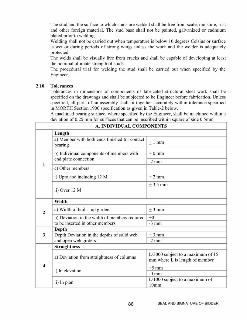
SEAL AND SIGNATURE OF BIDDER86
The stud and the surface to which studs are welded shall be free from scale, moisture, rustand other foreign material. The stud base shall not be painted, galvanized or cadmiumplated prior to welding.Welding shall not be carried out when temperature is below 10 degrees Celsius or surfaceis wet or during periods of strong wings unless the work and the welder is adequatelyprotected.The welds shall be visually free from cracks and shall be capable of developing at leastthe nominal ultimate strength of studs.The procedural trial for welding the stud shall be carried out when specified by theEngineer.
2.10 TolerancesTolerances in dimensions of components of fabricated structural steel work shall bespecified on the drawings and shall be subjected to be Engineer before fabrication. Unlessspecified, all parts of an assembly shall fit together accurately within tolerance specifiedin MORTH Section 1900 specification as given in Table-2 below.A machined bearing surface, where specified by the Engineer, shall be machined within adeviation of 0.25 mm for surfaces that can be inscribed within square of side 0.5mm
A. INDIVIDUAL COMPONENTS
1
Lengtha) Member with both ends finished for contactbearing + 1 mm
b) Individual components of members withend plate connection
+ 0 mm
-2 mmc) Other members
i) Upto and including 12 M + 2 mm
ii) Over 12 M+ 3.5 mm
2
Widtha) Width of built - up girders + 3 mm
b) Deviation in the width of members requiredto be inserted in other members
+0-3 mm
3DepthDepth Deviation in the depths of solid weband open web girders
+ 3 mm-2 mm
4
Straightness
a) Deviation from straightness of columns L/3000 subject to a maximum of 15mm where L is length of member
i) In elevation +5 mm-0 mm
ii) In plan L/1000 subject to a maximum of10mm
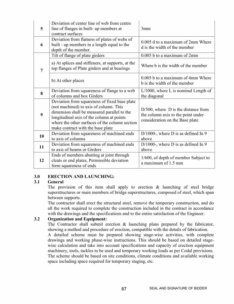
SEAL AND SIGNATURE OF BIDDER87
5Deviation of center line of web from centreline of flanges in built- up members atcontract surfaces
3mm
6Deviation from flatness of plates of webs ofbuilt - up members in a length equal to thedepth of the member.
0.005 d to a maximum of 2mm Whered is the width of the member
7
Tilt of flange of plate girders 0.005 b to a maximum of 2mma) At splices and stiffeners, at supports, at thetop flanges of Plate girders and at bearings Where b is the width of the member
b) At other places 0.005 b to a maximum of 4mm Whereb is the width of the member
8 Deviation from squareness of flange to a webof columns and box Girders
L/1000, where L is nominal Length ofthe diagonal
9
Deviation from squareness of fixed base plate(not machined) to axis of column. Thisdimension shall be measured parallel to thelongitudinal axis of the column at pointswhere the other surfaces of the column sectionmake contract with the base plate
D/500, where D is the distance fromthe column axis to the point underconsideration on the Base plate
10 Deviation from squareness of machined endsto axis of columns
D/1000-, where D is as defined In 9above
11 Deviation from squareness of machined endsto axis of beams or Girders
D/1000-, where D is as defined In 9above
12Ends of members abutting at joint throughcleats or end plates, Permissible deviationform squareness of ends
1/600, of depth of member Subject toa maximum of 1.5 mm
3.0 ERECTION AND LAUNCHING:3.1 General
The provision of this item shall apply to erection & launching of steel bridgesuperstructures or main members of bridge superstructures, composed of steel, which spanbetween supports.The contractor shall erect the structural steel, remove the temporary construction, and doall the work required to complete the construction included in the contract in accordancewith the drawings and the specifications and to the entire satisfaction of the Engineer.
3.2 Organization and Equipment:The Contractor shall submit erection & launching plans prepared by the fabricator,showing a method and procedure of erection, compatible with the details of fabrication.A detailed scheme must be prepared showing stage-wise activities, with completedrawings and working phase-wise instructions. This should be based on detailed stage-wise calculation and take into account specifications and capacity of erection equipmentmachinery, tools, tackles to be used and temporary working loads as per Codal provisions.The scheme should be based on site conditions, climate conditions and available workingspace including space required for temporary staging, etc.
SEAL AND SIGNATURE OF BIDDER88
The scheme should indicate precisely the type of temporary fasteners to be used as alsothe minimum percentage of permanent fasteners to be fitted during the stage erection. Theworking drawings should give clearly the temporary jigs, fixtures, clamps, spacersupports, etc.Unless otherwise provided in the contract, the contractor shall supply and erect allnecessary false work and staging and shall supply all labour, tools, erection plant andother materials necessary to carry out the work complete in all respects.Prior to actual commencement of erection and launching all equipment, machinery, tools,tackles, ropes, etc. Need to be tested to ensure their efficient working. Frequent visualinspection is essential in vulnerable areas to detect displacements, distress, drainages, etc.Deflection and vibratory tests shall be conducted in respect of supporting structures,launching truss as also the structure under erection and unusual observations reviewedlooseness of fittings are to be noted.For welded structures, welders’ qualifications and skill are to be checked as per standardnorms. Non-destructive tests of joints as per designers’ directives are to be carried out.Precision non-destructive testing instruments available in the market should be used fornoting various important parameters of the structures frequently and systematic record isto be kept.Erection work should start with complete resources mobilized as per latest approveddrawings and after a thorough survey of foundations and other related structural work. Incase of work of magnitude, maximum mechanization is to be adoptedThe structure should be divided into erectable modules as per the scheme. This should bepre-assembled in a suitable yard/platform and its matching with members of the adjacentmodule checked by trial assembly before erection.The structure shall be set out to be required lines and levels. The stocks and masses are tobe carefully preserved. The steel work should be erected, adjusted and completed in therequired, position to the specified line and levels with sufficient drifts and bolts. Packingmaterials are to be available to maintain this condition. Organized “Quality Surveillance”checks need to be exercised frequently.Before starting work the Contractor/s shall obtain necessary approval of the Engineer as tothe method adopted for erection & launching, the number and character of tools andplants. The approval of the Engineer shall not relieve the Contractor/s of his responsibilityfor the safety of his method or equipment or from carrying out the work fully inaccordance with the drawings and specification.During the progress of work, the Contractor/s shall have a competent engineer or foremanin charge of the work, who shall be adequately experienced in steel erection andacceptable to the Engineer.
3.3 Formwork:The formwork shall be properly designed, substantially built and maintained for allanticipated loads. The Contractor, if required, shall submit plans for approval to theEngineer. Approval of the plans, however, shall not relieve the Contractor of hisresponsibility.
3.4 Straightening Bend Material:The straightening of plates, angles and other shapes shall be done by methods not likely toproduce fracture or any injury. the metal shall not be heated unless permitted by the

SEAL AND SIGNATURE OF BIDDER89
Engineer for special cases, when the heating shall not be to a temperature higher than thatproducing a dark “cherry red” color, followed by as slow cooling as possible. Followingthe straightening of a bend or buckle the surface shall be carefully investigated forevidence of fracture. Sharp kinks and bends may be cause for rejection of material.
3.5 Assembling Steel:The parts shall be accurately assembled as shown on the drawings and match marks shallbe followed. The material shall be carefully handled so that no parts will be bent, brokenor otherwise damaged.Hammering which will injure or distort them embers shall not be done. Bearing surface orsurfaces to be in permanent contact shall be cleaned, before the members are assembled.The truss spans shall be erected on blocking so placed as to give the proper camber. Theblocking shall be left in place until the tendon chord splices are fully riveted and all othertruss connections pinned and bolted. Rivets in splices of butt joints of compressionmembers and rivets in railing shall be driven until the span has been swung.All joints surface for bolted connections including bolts, nuts, washers shall be free fromscale, dirt, burrs, other foreign materials and defects that would prevent solid seating ofparts. The slope of surface of bolted parts in contact with bolt head and nut shall notexceed 1 in 20, plane normal to bolt axis, otherwise suitable tapered washer shall be used.All fasteners shall have a washer under not or bolt head whichever is turned in tightening.Any connection to be riveted or bolted shall be secured in close contract with service boltsor with a sufficient number of permanent bolts before the rivets are driven or before theconnections are finally bolted. Joints shall normally be made by filling not less than 50percent of holes with service bolts and barrel drifts in the ratio 4:1. The service bolts areto be fully tightened up as soon as the joint is assembled. Connections to be made by closetolerance or barrel bolts shall be completed as soon as practicable after assembly.Any connection to be site welded shall be securely held in position by approved methodsto ensure accurate alignment, camber and elevation before welding is commenced.
The field riveting, welding, bolted and pin connection shall conform to the requirementsof Clause 1904 as appropriate.The correction of minor misfits involving harmless amounts of reaming, cutting andchipping will be considered a legitimate pan of erection. However, any error in the shopfabrication or deformation resulting from handling and transportation which preventsproper assembling and fitting up of parts by moderate use of drifts(by a moderate amountof reaming and slight chipping or cutting shall be reported immediately to the Engineerand his approval of the method of correction obtained,. The correction shall be made inthe presence of the Engineer.
3.6 Field InspectionAll materials, equipment and work of erection shall be subject to the inspection of theEngineer who shall be provided with all facilities including labour and tools required at allreasonable times. Any work found defective is liable to be rejected.No protective treatment shall be applied to the work until the appropriate inspection andtesting has been carried out. The stage inspection shall be carried out for all operations soas to ensure the correctness of fabrication and good quality. Girder dimensions andcamber shall not be finally checked until all welding and heating operations are completedand the member has cooled to a uniform temperature.

SEAL AND SIGNATURE OF BIDDER90
(a) Testing of material : Structural steel shall be tested for mechanical and chemicalproperties as per various IS codes as may be applicable and shall conform to requirementsspecified in IS:226, IS:2062, IS:11587, IS:1977, IS:8500 and IS:961 etc.Rivets, bolts, nuts, washers, welding consumables, steel forging, casting and stainlesssteel shall be tested for mechanical and chemical properties in the appropriate IS : Code.Rolling and cutting tolerance shall be as per IS: 1852. The thickness tolerance checkmeasurements for the plate and rolled sections shall be taken at not less than 15mm fromedge.Laminations in plates shall be carried out by ultra-sonic testing or any other specifiedmethods.Steel work shall be inspected for surface defects and exposed edge laminations duringfabrication and blast cleaning. Significant edge laminations found shall be reported to theEngineer for his decision.Clipping, grinding, machining or ultrasonic testing shall be used to determine depth ofimperfection.
(b) Bolted connections: Bolts and bolted connection joints with high strength friction gripbolts shall be inspected and tested according to IS: 4000.Rivets and riveted connection s shall be inspected and tested for compliance of codalrequirements.The firmness of joint shall be checked by 0.2 mm filler gauge, which shall not go insideunder the rivet head by more than 3mm. There shall not be any gap between members tobe riveted.Driven rivets shall be checked with rivet testing hammer. When struck sharply on headwith rivet testing hammer, rivet shall be free from movement and vibration.All loose rivets and rivets with cracks, badly formed or deficient heads or with headswhich are eccentric with shanks, shall be cut out and replaced.The alignment of plates at all bolted splice joints and welded butt joints shall be checkedfor compliance with codal requirements.Testing of flame cut and sheared edges is to be done, where the hardness criteria given inthe code are adopted. Hardness testing shall be carried out on six specimens.
(c) Welding and welding consumables: Welding procedures, welded connection and testingshall be in compliance with codal requirements.All facilities necessary for stage inspection during welding and on completion shall beprovided to the Engineer or their inspecting Authority by manufacture.Adequate means of identification either by identification mark or other record shall beprovided to enable each weld to be traced to the welder(s) by whom it is carried out.All metal welding shall be in compliance with IS: 9595 provisions.The method of inspection shall be in accordance with IS: 822 and extent of inspection andtesting shall be in accordance with the relevant standards or in the absence of such astandard, as agreed with the Engineer, Procedure tests.The Destructive and Non-Destructive test of weld shall be carried out according to IS:7307 (part I).Non Destructive Testing WeldsOne or more of the following methods may be applied for inspection or testing of weld:
(I) Visual Inspection: All welds shall be visually inspected, which should cover all defects ofweld such as size, porosity, crack in the weld or in the HAZ (Heat Affected Zone) etc.suitable magnifying glass may be used for visual inspection. A weld shall be acceptableby visual inspection if it shows that:

SEAL AND SIGNATURE OF BIDDER91
a) The weld has no cracks.b) Through fusion exists between weld and base metal and between adjacent layers
of weld metal.c) Weld profiles are in accordance with requisite clauses of IS: 9595 or as agreed
with the Engineer.d) The weld shall be of full cross section, expect for the ends of intermittent fillet
welds outside their effective length.e) When weld is transverse to the primary stress, undercut shall not be more than
0.25 mm deep in the part that is undercut and shall not be more than 0.8mm deepwhen the weld is parallel to the primary stress in the pan that is undercut.
f) The fillet weld in any single continuous weld shall be permitted to under run thenominal fillet weld size specified by 1.6 run without correction provided thatundersize portion of the weld does not exceed 10 percent of the length of theweld. On the web-to-flange welds on girders, no under-run is permitted at the endsfor a length equal to twice the width on the flange.
g) The piping porosity in fillet welds shall not exceed one in each 100 mm of weldlength and the maximum diameter shall not exceed 2.4mm, except for fillet weldsconnecting stiffeners to web where the sum of diameter shall not exceed 9.5mm inany 25 mm length of weld and shall not exceed 19mm in any 300 mm length ofweld.
h) The full penetration groove weld in butt joints transverse to the direction ofcomputed tensile stress shall have no piping porosity. For all other groove welds,the piping porosity shall not exceed one in 100 mm of length and the maximumdiameters shall not exceed 2.4 mm.
(ii) Magnetic Panicle and Radiographic Inspection: Welds that are subject to radio-graphic ormagnetic panicle testing in addition to visual inspection shall have no crack.Magnetic panicle test shall be carried out for detection of crack and other discontinuity inthe weld according to IS: 5334Radiographic test shall be carried out for detection of internal flaws in the weld such ascrack, piping porosity inclusion, lack of fusion, incomplete penetration, etc, This test mustbe carried out as per :182 and IS: 4853Acceptance Criteria: The weld shall be unacceptable if radiographic or magnetic panicletesting shows any of the type of discontinuities indicated in the code.
(iii) Ultrasonic Inspection: The Ultrasonic testing in addition to visual inspection shall becarried out for detection of internal flaws in the weld such as cracks, piping porosityinclusion, lack of fusion, incomplete penetration, etc. Acceptance criteria shall be as perIS: 4260 or any other relevant IS Specification and as agreed to by the Engineer.
(iv) Liquid Penetration Inspection: The liquid penetration test shall be carried out fordetection of surface defect in the weld, as- per IS: 3658, in addition to visual inspection.The non-destructive testing of following welds be carried out using one of the method
or; methods described at (ii), (iii) and (iv) above, as may be agreed to by the Engineer.a) All transverse butt welds in tension flange.b) 10 percent of the length of the longitudinal and transverse butt welds in
compression flanges.

SEAL AND SIGNATURE OF BIDDER92
c) 5 per cent of the length of longitudinal and transverse butt welds in compressionflanges.
d) All transverse butt welds in webs adjacent to tension flanges as specified by theEngineer.
The particular length of welds in webs to be tested shall be agreed with the Engineer, incase of (b) or (c).Where specified by the Engineer, bearing stiffeners or bearing diaphragms adjacent towelds, flange pates adjacent to web/flange welds at cruciform welds, plates in box girderconstruction adjacent to comer welds or other details shall be ultrasonically tested afterfabrication.for his decision.(d) Testing of Welding for Cast Steel: The testing of weld for cast steel shall be carried
out as may be agreed to by the Engineer.(e) Stud Shear Connectors: Stud Shear connectors shall be subjected to the following
tests:(i) The fixing of studs after being welded in position shall be tested by striking the side of the
head of the stud with a 2 kg. Hammer to the satisfaction of the Engineer.(ii) The selected stud head stroked with 6 kg. Hammer shall be capable of lateral
displacement of approximately 0.25 the height of the stud from its original position. Thestud weld shall not show any sign of crack or lack of fusion.The studs whose welds have failed the test given in (a) and (b) shall be replaced.
(f) Inspection requirement: The fabricated member/component made out of rolled and built-up section shall be checked for compliance of the tolerances given in Table-2. Inspectionof member/components for compliance with tolerances, and the check for deviations shallbe made over the full length.During checking, the inspection requirement shall be placed in manner that local surfaceirregularities do not influence the result.For plate, out of plane deviation shall be checked at right angle to the surface over the fullarea of the plate.The relative cross-girder or cross frame deviation shall be checked over the middle thirdof length of the cross girder of frame between each pair of webs and for cantilever at theend of member.The web of rolled beam or channel section shall be checked for out-of-plane deviation inlongitudinal direction equal to the depth of the section.During inspection, the component /member shall not have any load or external restraint.Inspection Stages: The inspection to be carried out for compliance of tolerances shallinclude but not be limited to the following stages:
i) For completed parts, component/members on completion of fabrication and before anysubsequent operation such as surface preparation, painting, transportation, and erection.
ii) For webs of plate and box girder, longitudinal compression flange stiffeners in box girdersand orthotropic decks and all web stiffeners at site joints, on completion of site joint.
iii) For cross girders and frames, cantilevers in orthotropic decks and other parts in whichdeviations have apparently increased on completion of site assembly.
Where, on checking member/component for the deviations in respect of out of plane prout of straightness at right angles to the plate surface, any other instances, exceedtolerance, the maximum deviation shall be measured and recorded. The recorded

SEAL AND SIGNATURE OF BIDDER93
measurements shall be submitted to the Engineer who will determine whether thecomponent/member may be accepted without rectification, with rectification or rejected.
4.0 OILING AND PAINTING:
4.1. No part of the work is to be painted or coated, packed or dispatched until it has beenfinally inspected and approved by the inspecting officer.
4.2. The whole of the work except machined surfaces shall be painted using one of the systemsof painting given below. Prior to painting, the surfaces shall be carefully preparedremoving mill scale, rust, etc, using wire brushes, sander or short blasting as approved bythe Engineer/Inspecting Officer.a) Priming coat:i. The coats of ready mixed Paint red lead priming to IS: 102. ,
ORii. One coat of ready mixed zinc chrome priming to IS: 104 followed by one coat of zincchrome red oxide priming to IS: 2074. The dry film thickness should e 40 microns (Eachcoat of 20 microns)
b) Finishing coats:Two coats of aluminum paint to IS: 2339 shall be applied over the primer coats. One coatshall be applied before the fabricated steel work leaves the shop. After the steel work iserected at site the second coat shall be given after touching up the primer and the covercoat if damaged in-transit. The dry film thickness shall be 3o microns (Each coat of15microns)
4.3 Surfaces which are inaccessible for cleaning and painting after fabrication shall be paintedas specified in before assembled for riveting.
4.4 All rivets, bolts, nuts, washers, etc, are to be thoroughly cleaned and dipped into boilinglinseed oil to IS:77
4.5 All machined surfaces are to be well coated with a mixture of white lead to IS: 34 andMutton tallow to IS: 887
4.6 For site paintings the whole of the steel work shall be given the second cover coat afterfinally passing and after touching up the Primer and Cover Coats, if damaged in- transit.
5.0 TEST AND STANDARDS OF ACCEPTANCEThe materials shall be tested in accordance with relevant IS specifications and necessarytest certificates shall be furnished. Additional tests, if required, shall be got carried out bythe Contractor at his own cost.The fabrication, furnishing, erecting, painting of structural steel work shall be inaccordance with these specifications and shall be checked and accepted by the Engineer.
6.0 MEASUREMENTS FOR PAYMENTThe measurements of this shall be in tones based on the net weight of metal in thefabricated structure computed on the basis of nominal weight of materials.The weight of rolled and cast steel and cast iron shall be determined from the determineshown on the drawings on the following basis:
Rolled or cast steel: 7.84X10⁻³ kg/cu.cm. Cost Iron: 7.21 X10⁻³ kg/cu.cm.Weight of structural sections shall be nominal weight.

SEAL AND SIGNATURE OF BIDDER94
Weight of weld fillets and weight of protective coating shall not be included.Weight of rivet heads shall be computed by taking the weight of 100 snap heads as given inTable-3.TABLE-3 : WEIGHT OF RIVET HEADS
Dia of Rivets asmanufactured
Weight of 100 snapheads
mm kg12 1.314 2.116 3.418 4.4520 6.122 8.124 10.527 1530 20.533 27.5
The Contractor shall supply detailed calculations sheets for the weight of the metal in thefabricated structure.No additions shall be made for the weight of protective coating or weld fillets.Where computed weight forms the basis for payment, the weight shall be calculated forexact cut sizes of members used in the structure, deductions being made for all cuts,except for rivet holes. Additions shall be made for the rivet heads as mentioned above.
7.0 RATE:The Contract unit rate for the completed structural steel work shall included the cost of allmaterials, labour, tools, plant and equipment required for fabrication, connections, oiling,painting, temporary erection, inspection, tests and compete final erection as shown on thedrawings and as specified in these specifications.
8.0 ELASTOMETRIC BEARING:(I) The elastomeric bearing should be of approved make and should confirm provisions of
UIC-772 R/IRC-83 part I & II specification. It should be fully moulded(II) It should be made of natural or synthetic rubber, should conform railways approved
drawing and should have following properties.Shore Hardness - 60+ 5Shear Modules - 8 Kg/Cm2
(III) Any adhesive used to bond together steel plates and the rubber pads must possess thesame shear strength as that of rubber used. It must also be fully resistant to the action ofoils, weather, atmosphere Ozone, biological agents and extreme temperatures, to whichthe bearings may be subjected.
(IV) The bearing shall have a side cover of at least 6 mm thick elastomer to protect the ends ofsteel plates.
(V) Bearing shall be placed on concrete surface to the correct level and position and bonded tothe surface with approved bonding material. As far as possible the bearings shall be

SEAL AND SIGNATURE OF BIDDER95
loaded only when the ambient temperature is the mean of the annual variation oftemperature in that area.

SEAL AND SIGNATURE OF BIDDER96
Section - 4
SCHEDULES A TO F

SEAL AND SIGNATURE OF BIDDER97
SECTION 4
PROFORMA OF SCHEDULES
(Operative Schedules to be supplied separately to each intendingTenderer)
SCHEDULE ‘A’
Schedule of quantities ( As per Bill of Quantities attached)
(BOQ to be attached with Financial Bid)
SCHEDULE ‘B’ –
Schedule of materials to be issued to the contractor. (Refer Clause 10 of Clauses of Contract)
S.No Description ofitems
Quantity Rates in Figures & words atwhich the material will becharged to the contractor
Place of Issue
1 2 3 4 5
- Not Applicable -
SCHEDULE ‘C’ –
Tools and plants to be hired to the contractor. (Refer clause 34 of Clauses of Contract).
S.No Description Hire charges per day Place of Issue1 2 3 4
- Not Applicable -
SCHEDULE ‘D’
Extra schedule for specific requirements/documents for the work, if any.
- Not Applicable -

SEAL AND SIGNATURE OF BIDDER98
SCHEDULE ‘E’ –
Schedule of components of Cement, Steel, other materials, POL,Labour etc .for price escalation. (Refer Clause 10CC of Clausesof Contract).
CLAUSE 10 CC
Component of Cement (Xc)
expressed as percent of total value of work 05%
Component of steel (X5)
expressed as percent of total value of work 30%
Component of other materials (XM) (except cement & steel)
expressed as per cent of total value of work 35%
Component of labour (Y)
expressed as percent of total value of work 25%
Component of P.O.L (Z)
expressed as percent of total value of work 05%
______________
Total 100 %_
SCHEDULE ‘F’
Reference to General Conditions of Contract
Name of Work: Construction of Road Over Bridge at Km.728/9-11 on Howrah-Mumbai mainline near Chakrabhata LC No.370 on Bilaspur-Baloda Bazar Road, Bilaspur (C.G).
Estimated cost of work: Rs.425.24 Lakhs (Rupees Four hundred twenty five lakhs and twenty
four thousand).
Earnest money : Rs.4.25 Lakhs
Performance Guarantee (Ref. Clause 1) 5% of Tendered value.
Security Deposit: (Refer clause 1A) 5% of Tendered value
Notice Inviting Tender and Instruction to TenderersOfficer inviting tender : Addl. General Manager (C), RITES Ltd.
For & on behalf of PWD, BridgeConstruction Division, Bilaspur.
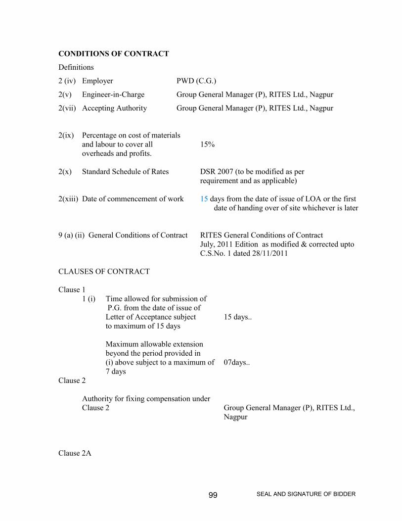
SEAL AND SIGNATURE OF BIDDER99
CONDITIONS OF CONTRACT
Definitions
2 (iv) Employer PWD (C.G.)
2(v) Engineer-in-Charge Group General Manager (P), RITES Ltd., Nagpur
2(vii) Accepting Authority Group General Manager (P), RITES Ltd., Nagpur
2(ix) Percentage on cost of materialsand labour to cover all 15%overheads and profits.
2(x) Standard Schedule of Rates DSR 2007 (to be modified as perrequirement and as applicable)
2(xiii) Date of commencement of work 15 days from the date of issue of LOA or the firstdate of handing over of site whichever is later
9 (a) (ii) General Conditions of Contract RITES General Conditions of ContractJuly, 2011 Edition as modified & corrected uptoC.S.No. 1 dated 28/11/2011
CLAUSES OF CONTRACT
Clause 11 (i) Time allowed for submission of
P.G. from the date of issue ofLetter of Acceptance subject 15 days..to maximum of 15 days
Maximum allowable extensionbeyond the period provided in(i) above subject to a maximum of 07days..7 days
Clause 2
Authority for fixing compensation underClause 2 Group General Manager (P), RITES Ltd.,
Nagpur
Clause 2A
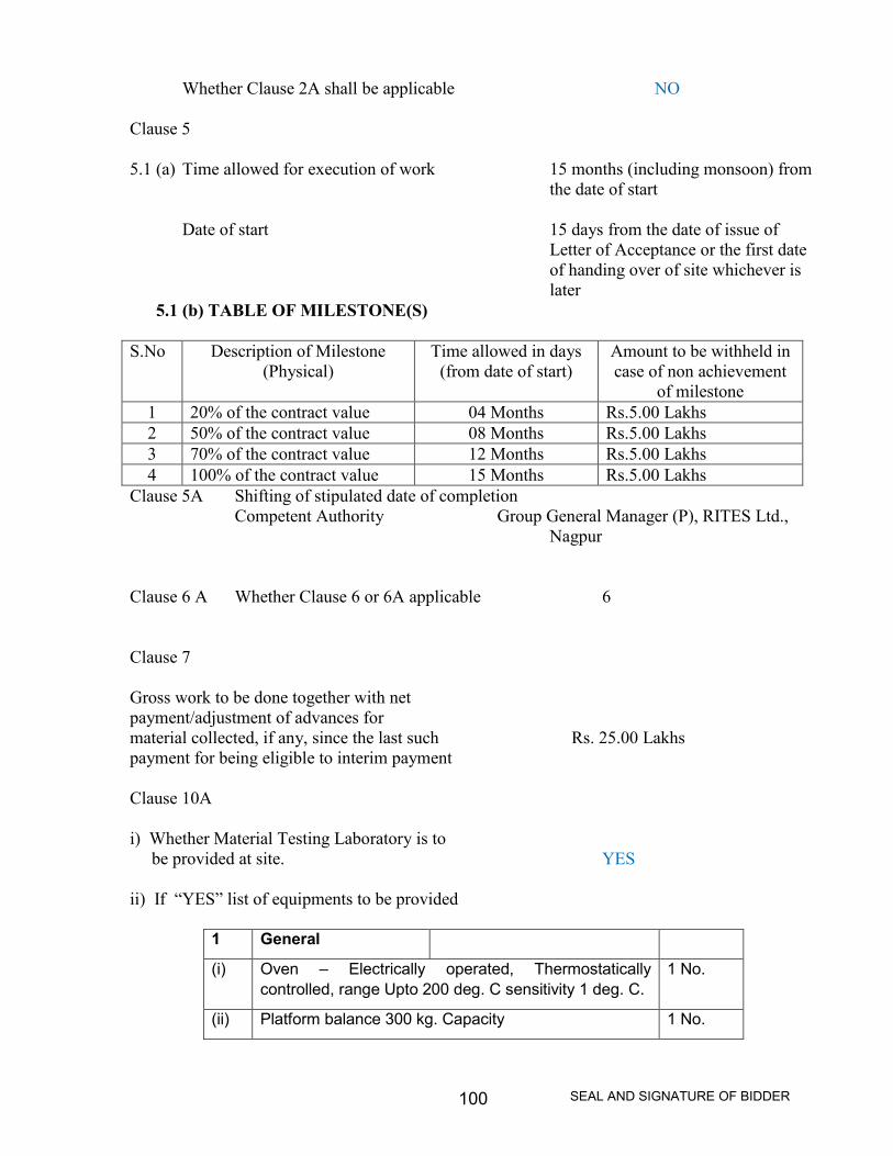
SEAL AND SIGNATURE OF BIDDER100
Whether Clause 2A shall be applicable NO
Clause 5
5.1 (a) Time allowed for execution of work 15 months (including monsoon) fromthe date of start
Date of start 15 days from the date of issue ofLetter of Acceptance or the first dateof handing over of site whichever islater
5.1 (b) TABLE OF MILESTONE(S)
S.No Description of Milestone(Physical)
Time allowed in days(from date of start)
Amount to be withheld incase of non achievement
of milestone1 20% of the contract value 04 Months Rs.5.00 Lakhs2 50% of the contract value 08 Months Rs.5.00 Lakhs3 70% of the contract value 12 Months Rs.5.00 Lakhs4 100% of the contract value 15 Months Rs.5.00 Lakhs
Clause 5A Shifting of stipulated date of completionCompetent Authority Group General Manager (P), RITES Ltd.,
Nagpur
Clause 6 A Whether Clause 6 or 6A applicable 6
Clause 7
Gross work to be done together with netpayment/adjustment of advances formaterial collected, if any, since the last such Rs. 25.00 Lakhspayment for being eligible to interim payment
Clause 10A
i) Whether Material Testing Laboratory is tobe provided at site. YES
ii) If “YES” list of equipments to be provided
1 General
(i) Oven – Electrically operated, Thermostaticallycontrolled, range Upto 200 deg. C sensitivity 1 deg. C.
1 No.
(ii) Platform balance 300 kg. Capacity 1 No.

SEAL AND SIGNATURE OF BIDDER101
(iii) Balance 20 kg. Capacity 1 No.
(iv) Electronic Balance 5 kg. Capacity accuracy 0.5g. 1 No.
(v) Water bath-electrically operated and Thermostaticallycontrolled with adjustable shelves sensitivity 1 deg. C.
1 No.
(vi) Thermometers Mercury-in-glass thermometer range 0deg. C to 250 deg. C
Mercury-in-steel thermometer with 30 cm. Stem, rangeupto 300 deg. C.
2Nos.
(vii) Kerosene or gas stove or electric hot plate 1 Nos.
(viii) Glasswares, spatulas, wire gauges, steel scales,measuring tape, casseroles, Karahis, enameled traysof assorted sizes, pestle-mortar, porcelain dishes,gunny bags, plastic bags, chemicals, digging tools likepickaxes, shovels etc.
Asrequired
(ix) Set of IS sieves with lid and pan :For sieve analysis of course and fine aggregate usedfor concrete.
1 Set
(x) Water testing kit 1 Set
(xi) First aid box 1 Set
(xii) Aggregate impact value test apparatus / Loss AngelesAbrasion Test apparatus
1 Set
(xiii) Flakiness and Elongation Test Gauges 1 Set
(xiv) Standard measures of 30, 15 and 3 litres Capacityalong with standard tamping rod.
1 Set
2. For Cement and Cement Concrete
(i) Vicat apparatus for testing setting times 1 Set
(ii) Slump testing apparatus 2 Sets
(iii) Compression and flexural strength testing machine of200 tonne capacity with additional dial for flexuraltesting
1 Set
(iv) Needle Vibrator 2 Set
(v) Measuring jar for silt & bulkage 5 Nos.
(vi) Cube moulds for cement and concrete tests 18 Nos.
(vii) Spring balance 1 No.
Clause 10 B
Whether Clause 10 B(ii) to (v) applicable YES
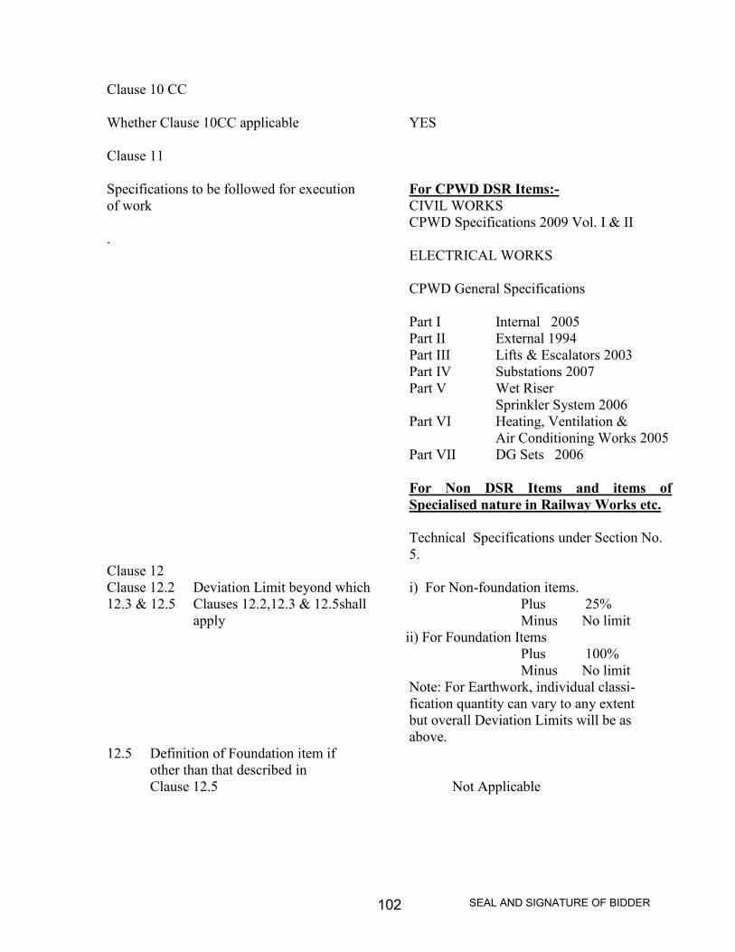
SEAL AND SIGNATURE OF BIDDER102
Clause 10 CC
Whether Clause 10CC applicable YES
Clause 11
Specifications to be followed for execution For CPWD DSR Items:-of work CIVIL WORKS
CPWD Specifications 2009 Vol. I & II.
ELECTRICAL WORKS
CPWD General Specifications
Part I Internal 2005Part II External 1994Part III Lifts & Escalators 2003Part IV Substations 2007Part V Wet Riser
Sprinkler System 2006Part VI Heating, Ventilation &
Air Conditioning Works 2005Part VII DG Sets 2006
For Non DSR Items and items ofSpecialised nature in Railway Works etc.
Technical Specifications under Section No.5.
Clause 12Clause 12.2 Deviation Limit beyond which i) For Non-foundation items.12.3 & 12.5 Clauses 12.2,12.3 & 12.5shall Plus 25%
apply Minus No limitii) For Foundation Items
Plus 100%Minus No limit
Note: For Earthwork, individual classi-fication quantity can vary to any extentbut overall Deviation Limits will be asabove.
12.5 Definition of Foundation item ifother than that described inClause 12.5 Not Applicable
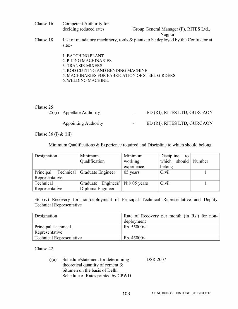
SEAL AND SIGNATURE OF BIDDER103
Clause 16 Competent Authority fordeciding reduced rates Group General Manager (P), RITES Ltd.,
NagpurClause 18 List of mandatory machinery, tools & plants to be deployed by the Contractor at
site:-
1. BATCHING PLANT2. PILING MACHINARIES3. TRANSIR MIXERS4. ROD CUTTING AND BENDING MACHINE5. MACHINARIES FOR FABRICATION OF STEEL GIRDERS6. WELDING MACHINE.
Clause 2525 (i) Appellate Authority - ED (RI), RITES LTD, GURGAON
Appointing Authority - ED (RI), RITES LTD, GURGAON
Clause 36 (i) & (iii)
Minimum Qualifications & Experience required and Discipline to which should belong
Designation MinimumQualification
Minimumworkingexperience
Discipline towhich shouldbelong
Number
Principal TechnicalRepresentative
Graduate Engineer 05 years Civil 1
TechnicalRepresentative
Graduate Engineer/Diploma Engineer
Nil/ 05 years Civil 1
36 (iv) Recovery for non-deployment of Principal Technical Representative and DeputyTechnical Representative
Designation Rate of Recovery per month (in Rs.) for non-deployment
Principal TechnicalRepresentative
Rs. 55000/-
Technical Representative Rs. 45000/-
Clause 42
i)(a) Schedule/statement for determining DSR 2007theoretical quantity of cement &bitumen on the basis of DelhiSchedule of Rates printed by CPWD
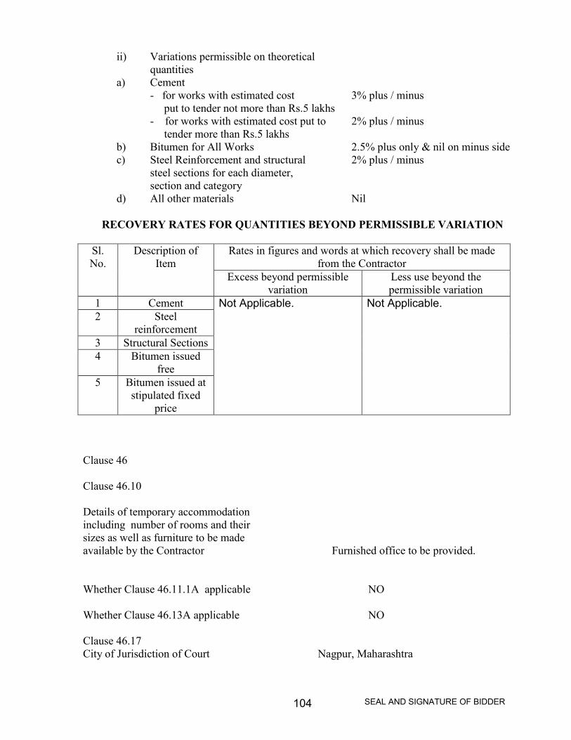
SEAL AND SIGNATURE OF BIDDER104
ii) Variations permissible on theoreticalquantities
a) Cement- for works with estimated cost 3% plus / minus
put to tender not more than Rs.5 lakhs- for works with estimated cost put to 2% plus / minus
tender more than Rs.5 lakhsb) Bitumen for All Works 2.5% plus only & nil on minus sidec) Steel Reinforcement and structural 2% plus / minus
steel sections for each diameter,section and category
d) All other materials Nil
RECOVERY RATES FOR QUANTITIES BEYOND PERMISSIBLE VARIATION
Sl.No.
Description ofItem
Rates in figures and words at which recovery shall be madefrom the Contractor
Excess beyond permissiblevariation
Less use beyond thepermissible variation
1 Cement Not Applicable. Not Applicable.2 Steel
reinforcement3 Structural Sections4 Bitumen issued
free5 Bitumen issued at
stipulated fixedprice
Clause 46
Clause 46.10
Details of temporary accommodationincluding number of rooms and theirsizes as well as furniture to be madeavailable by the Contractor Furnished office to be provided.
Whether Clause 46.11.1A applicable NO
Whether Clause 46.13A applicable NO
Clause 46.17City of Jurisdiction of Court Nagpur, Maharashtra

SEAL AND SIGNATURE OF BIDDER105
Clause 47.2.1Sum for which Third Party Rs. 5.00 Lakhs per occurrenceInsurance to be obtained. with the number of occurrences limited to four.
Clause 55Whether clause 55 shall NObe applicable.
If yes, time allowed for completion _______________ months fromof sample floor/unit. Date of start of work
(Not Applicable)

SEAL AND SIGNATURE OF BIDDER106
Section – 5
TECHNICAL SPECIFICATIONS

SEAL AND SIGNATURE OF BIDDER107
SECTION 5
TECHNICAL SPECIFICATIONS
1.0 STANDARD SPECIFICATIONS ISSUED BY CPWD
1.1 Civil Engineering Works
CPWD Specification 2009 Vol. I & II. These Specifications have replaced CPWDSpecifications 1996 along with Correction Slips issued on them. These Specificationscover all types of Building Works. The specifications are available as a printed documentissued by CPWD and also in soft copy PDF Format in CPWD website.
1.2 Electrical Engineering Works
Part No. Description Year of issue
I Internal 2005II External 1994III Lifts and Escalators 2003IV Sub Stations 2007V Wet Riser and Sprinkler Systems 2006VI Heating, Ventilations & Air
Conditioning Works 2005VII D.G.Sets 2006
The above documents are available as Priced Document issued by CPWD and in soft copyPDF Format in CPWD website.
2.0 STANDARD SPECIFICATIONS ISSUED BY MINISTRY OF SURFACETRANSPORT
Specifications for Road and Bridge works (Fourth Revision) August 2001 have beenpublished by Indian Road Congress as a priced document. These Specification coverexhaustively various Road and Bridge works.
3.0 STANDARD SPECIFICATIONS ISSUED BY INDIAN RAILWAYS
Railway Board vide their letter No. 2009/LMD/01/03 dated 14/01/2010 have advised thatthey have approved issue of “Indian Railways Unified Standard Specifications orMaterials and works with corresponding Indian Railways Unified Standard Schedule ofitems (for rates of Materials and works)”. These documents are to be published byNorthern Railway on behalf of Railway Board after the Zonal Railways have made out

SEAL AND SIGNATURE OF BIDDER108
“Schedule of Rates” as applicable to them based on “Standard Analysis of Rates ofitems”. These Specification however cover only Building and Road works generally onthe lines of CPWD and Ministry of Surface Transport. They do not cover Track workswhich are governed by Manuals and RDSO/Indian Railway Specifications. Pendingpublication of Unified Standard Specifications, the specifications issued by the zonalRailways will be applicable.
4.0 SPECIAL SPECIFICATIONS (NOT COVERED BY ANY STANDARDSPECIFICATIONS)

SEAL AND SIGNATURE OF BIDDER109
Section - 6
DRAWINGS

SEAL AND SIGNATURE OF BIDDER110
LIST OF DRAWINGS ENCLOSED
(i) GAD of ROB