voluntary specification, performance requirements … · voluntary specification, performance ......
TRANSCRIPT

FMC Finishes Committee Approval FSC Approval Product Group Approval
Approved via Ballot #17-1003 Approved via Ballot 17-1004 Out for Ballot (#17-1006)
PUBLICATION NO.
AAMA 623-XX
Draft #17
Dated 11/30/17
Voluntary Specification, Performance Requirements and Test Procedures for Organic Coatings on Fiber Reinforced
Thermoset Profiles
This voluntary specification was developed by representative members of AAMA as advisory information and published as a public service. AAMA disclaims all liability for the use, application or adaptation of materials published herein.
© Copyright 2018 American Architectural Manufacturers Association
1900 East Gold Road, Suite 1250, Schaumburg, IL 60173 Phone: 847/303-5664
E-Mail: [email protected] Web Site: www.aamanet.org
AAMA 623-XX, Draft #17, Dated 11/30/17 Page i
TABLE OF CONTENTS
0.0 PREFACE ............................................................................................................................................... 1
1.0 SCOPE .................................................................................................................................................... 1
2.0 PURPOSE ............................................................................................................................................... 1
3.0 REFERENCED STANDARDS ................................................................................................................ 1
4.0 DEFINITIONS ......................................................................................................................................... 3
5.0 GENERAL ............................................................................................................................................... 3
6.0 TEST SPECIMENS ................................................................................................................................. 5
7.0 TESTS ..................................................................................................................................................... 5
8.0 Test Report And Results ....................................................................................................................... 19

AAMA 623-XX, Draft #17, Dated 11/30/17 Page 1
0.0 PREFACE
The architectural community has recognized the outstanding attributes associated with fiber reinforced thermoset
profiles for windows, doors and other related building products. Many of these profiles have organic applied coatings
to provide selected colors and enhance the durability. There are three performance specifications for applied
organic coatings on fiber reinforced thermoset profiles:
AAMA 623, Voluntary Specification, Performance Requirements and Test Procedures for Organic Coatings on Fiber
Reinforced Thermoset Profiles;
AAMA 624, Voluntary Specification, Performance Requirements and Test Procedures for High Performance
Organic Coatings on Fiber Reinforced Thermoset Profiles; and
AAMA 625, Voluntary Specification, Performance Requirements and Test Procedures for Superior Performance
Organic Coatings on Fiber Reinforced Thermoset Profiles.
1.0 SCOPE
1.1 This specification describes test procedures and performance requirements for organic coatings applied to fiber
reinforced thermoset profiles for windows, doors and similar other related building products.
1.2 This specification covers factory applied coatings.
1.3 The primary units of measure in this document are metric. The values stated in SI units are to be regarded as
the standard. The values given in parentheses are for reference only.
1.4 This document was developed in an open and consensus process and is maintained by representative members
of AAMA as advisory information.
2.0 PURPOSE
This specification is intended to assist the architect, owner and contractor to specify and obtain factory applied
organic coatings which will provide a good level of performance in terms of film integrity, exterior durability and
general appearance over a period of many years.
3.0 REFERENCED STANDARDS

AAMA 623-XX, Draft #17, Dated 11/30/17 Page 2
3.1 References to the standards listed below shall be to the edition indicated. Any undated reference to a code or
standard appearing in the requirements of this standard shall be interpreted as to referring to the latest edition of
that code or standard.
3.2 American Architectural Manufacturers Association (AAMA)
AAMA 624-10, Voluntary Specification, Performance Requirements and Test Procedures for High Performance
Organic Coatings on Fiber Reinforced Thermoset Profiles
AAMA 625-10, Voluntary Specification, Performance Requirements and Test Procedures for Superior Performance
Organic Coatings on Fiber Reinforced Thermoset Profiles
AAMA 800-10, Voluntary Specification and Test Method for Sealants
AAMA AG-0913, AAMA Glossary
3.3 ASTM International (ASTM)
ASTM C207-06(2011), Standard Specification for Hydrated Lime for Masonry Purposes
ASTM D523-0814, Standard Test Method for Specular Gloss
ASTM D659-86, Standard Test Method of Evaluating Degree of Chalking of Exterior Paints
ASTM D714-02 (2009), Standard Test Method for Evaluating Degree of Blistering of Paints
ASTM D1729 -1696(2009), Standard Practice for Visual Appraisal of Colors and Color Differences of Diffusely-
Illuminated Opaque Materials,
ASTM D2244-09b15e115a, Standard Practice for Calculation of Color Tolerances and Color Differences from
Instrumentally Measured Color Coordinates
ASTM D2247-101115, Standard Practice for Testing Water Resistance of Coatings in 100% Relative Humidity
ASTM D2248- 01a(20072013), Standard Practice for Detergent Resistance of Organic Finishes
ASTM D3359-09e02, Standard Test Methods for Measuring Adhesion by Tape Test
ASTM D3363-05(2011)e2, Standard Test Method for Film Hardness by Pencil Test

AAMA 623-XX, Draft #17, Dated 11/30/17 Page 3
ASTM D4138-07a(2013), Standard Test Method for Measurement of Dry Film Thickness of Protective Coating
Systems by Destructive, Cross-Sectioning Means
ASTM D4214-07(2015), Standard Test Methods for Evaluating the Degree of Chalking of Exterior Paint Films
ASTM D4541-09e1, Standard Test Method for Pull-Off Strength of Coatings Using Portable Adhesion Testers
ASTM D4585/D4585M-13-07, Standard Practice for Testing the Water Resistance of Coatings Using Controlled
Condensation
ASTM D5179-02 (2008), Standard Test Method for Measuring Adhesion of Organic Coatings to Plastic Substrates
by Direct Tensile Testing
ASTM D5420- 10, Standard Test Method for Impact Resistance of Flat, Rigid Plastic Specimen by Means of a
Striker Impacted by a Falling Weight (Gardner Impact)
ASTM G90-10, Standard Practice for Performing Accelerated Outdoor Weathering of Nonmetallic Materials Using
Concentrated Natural Sunlight
ASTM G179-04(2011), Standard Specification for Metal Black Panel and White Panel Temperature Devices for
Natural Weathering Tests
4.0 DEFINITIONS
4.1 The terms "film" and "coating" are used interchangeably in this specification and are defined as meaning the
layer of organic material applied to the surface of the fiber reinforced thermoset profiles.
4.2 Checking – A kind of coating failure in which many small cracks appear in the surface of the coating.
4.3 Crazing - aA network of checks or cracks appearing on a coated surface. Crazing is a phenomenon that
frequently precedes fracture in some glassy thermoplastic polymers. Crazing happens when a glaze or coating is
under tension.
4.2 4 For all additional definitions, please refer to the AAMA Glossary (AG-09132).
5.0 GENERAL
5.1 To qualify as meeting this specification, products tested shall meet all requirements as specified herein.
AAMA 623-XX, Draft #17, Dated 11/30/17 Page 4
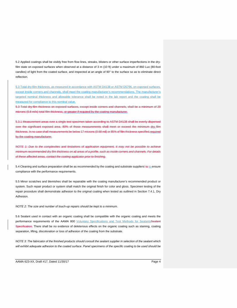
5.2 Applied coatings shall be visibly free from flow lines, streaks, blisters or other surface imperfections in the dry-
film state on exposed surfaces when observed at a distance of 3 m (10 ft) under a maximum of 860 Lux (80-foot
candles) of light from the coated surface, and inspected at an angle of 90° to the surface so as to eliminate direct
reflection.
5.3 Total dry-film thickness, as measured in accordance with ASTM D4138 or ASTM D5796, on exposed surfaces,
except inside corners and channels, shall meet the coating manufacturer’s recommendations. The manufacturer’s
targeted nominal thickness and allowable tolerance shall be noted in the lab report and the coating shall be
measured for compliance to this nominal value.
5.3 Total dry-film thickness on exposed surfaces, except inside corners and channels, shall be a minimum of 20
microns (0.8 mils) total film thickness, or greater if required by the coating manufacturer.
5.3.1 Measurement areas over a single test specimen taken according to ASTM D4138 shall be evenly dispersed
over the significant exposed area. 80% of those measurements shall meet or exceed the minimum dry film
thickness. In no case shall measurements be below 17 microns (0.68 mil) or 85% of film thickness specified.required
by the coating manufacturer.
NOTE 1: Due to the complexities and limitations of application equipment, it may not be possible to achieve
minimum recommended dry film thickness on all areas of a profile, such as inside corners and channels. For details
of these affected areas, contact the coating applicator prior to finishing.
5.4 Cleaning and surface preparation shall be as recommended by the coating and substrate suppliers’ to to ensure
compliance with the performance requirements.
5.5 Minor scratches and blemishes shall be repairable with the coating manufacturer’s recommended product or
system. Such repair product or system shall match the original finish for color and gloss. Specimen testing of the
repair procedure shall demonstrate adhesion to the original coating when tested as outlined in Section 7.4.1, Dry
Adhesion.
NOTE 2: The size and number of touch-up repairs should be kept to a minimum.
5.6 Sealant used in contact with an organic coating shall be compatible with the organic coating and meets the
performance requirements of the AAMA 800 Voluntary Specifications and Test Methods for SealantsSealant
Specification. There shall be no evidence of deleterious effects on the organic coating such as staining, coating
separation, lifting, discoloration or loss of adhesion of the coating from the substrate.
NOTE 3: The fabricator of the finished products should consult the sealant supplier in selection of the sealant which
will exhibit adequate adhesion to the coated surface. Panel specimens of the specific coating to be used should be
AAMA 623-XX, Draft #17, Dated 11/30/17 Page 5
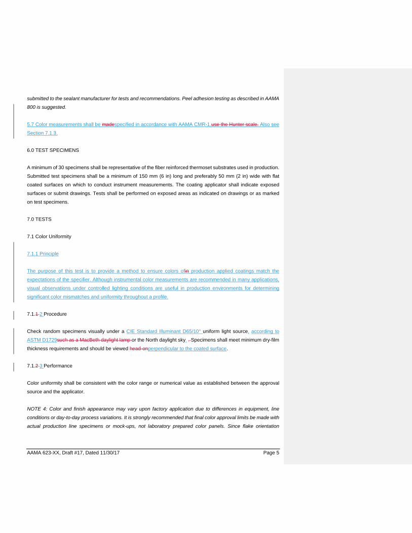
submitted to the sealant manufacturer for tests and recommendations. Peel adhesion testing as described in AAMA
800 is suggested.
5.7 Color measurements shall be madespecified in accordance with AAMA CMR-1.use the Hunter scale. Also see
Section 7.1.3.
6.0 TEST SPECIMENS
A minimum of 30 specimens shall be representative of the fiber reinforced thermoset substrates used in production.
Submitted test specimens shall be a minimum of 150 mm (6 in) long and preferably 50 mm (2 in) wide with flat
coated surfaces on which to conduct instrument measurements. The coating applicator shall indicate exposed
surfaces or submit drawings. Tests shall be performed on exposed areas as indicated on drawings or as marked
on test specimens.
7.0 TESTS
7.1 Color Uniformity
7.1.1 Principle
The purpose of this test is to provide a method to ensure colors ofin production applied coatings match the
expectations of the specifier. Although instrumental color measurements are recommended in many applications,
visual observations under controlled lighting conditions are useful in production environments for determining
significant color mismatches and uniformity throughout a profile.
7.1.1 2 Procedure
Check random specimens visually under a CIE Standard Illuminant D65/10° uniform light source, according to
ASTM D1729such as a MacBeth daylight lamp or the North daylight sky. . Specimens shall meet minimum dry-film
thickness requirements and should be viewed head-onperpendicular to the coated surface.
7.1.2 3 Performance
Color uniformity shall be consistent with the color range or numerical value as established between the approval
source and the applicator.
NOTE 4: Color and finish appearance may vary upon factory application due to differences in equipment, line
conditions or day-to-day process variations. It is strongly recommended that final color approval limits be made with
actual production line specimens or mock-ups, not laboratory prepared color panels. Since flake orientation

AAMA 623-XX, Draft #17, Dated 11/30/17 Page 6
contributes to color uniformity, pearlescent, mica and metallic flake colors do present the need for more stringent
control in application and consideration during project design and installation.
7.2 Specular Gloss
7.2.1 Principle
Gloss represents the ability of a surface to reflect light at the same angle of incidence as the incoming source. High
gloss surfaces scatter less light than low gloss surfaces. A gloss specification can be important because visual
perception of color can be significantly affected by the glossiness of the surface. Furthermore, change in gloss of a
surface over time may be an early indicator of degradation of, or physical damage to the finish.
7.2.1 2 Procedure
Measure the gloss in accordance with ASTM D523, using a 60° Gloss Meter and using reflective specular included
readings (RSIN).
7.2.2 3Performance
Gloss values shall fall within the range established between the approval source and the applicator, or +/- 5 units
of the average if no range is provided.
Gloss values on the test specimens shall be within ± 5 units of manufacturer’s recommended values.
NOTE 35: Standard Gloss Range Reference Values are:
Gloss Specular Gloss Units High 80 - Over Medium 20 -79 Low 19 or less
7.3 Dry Film Hardness
7.3.1 Principle
ASTM D3363 describes a procedure for determining the dry film hardness of a coating by using a series of standard
pencil leads of varying hardness to attempt to scratch the surface. The film hardness rating is determined by the
hardest highest rated pencil lead that fails to penetrate or gouge the coating film all the way to the substrate. This
is a different rating from a scratch rating which is determined by the hardest highest rated pencil lead that fails to
scratch or indent the surface.
7.3.21 Procedure

AAMA 623-XX, Draft #17, Dated 11/30/17 Page 7
Perform testing on a flat portion of the profile specimen. Ensure the specimen is firmly held in place.When testing
profiles, either cut a section of the specimen to create a flat area for testing or support the specimen such that it is
held firmly in place. Perform the test according to ASTM D3363. For certification purposes, ambient conditions in
ASTM D3363 shall apply; for quality control purposes, ambient conditions of approximately 18oC to 27oC (65oF to
80oF) are acceptable.
Wood pencils or sticks of leads with a holder may be used. A range of lead hardness will be used. Maximum hardness
should consider the dry film hardness represented by the coating manufacturer. Expose approximately 5 to 6 mm (3/16 to
1/4 in) of undisturbed, unmarked, smooth cylindrical lead from the pencil or lead holder. To prepare the tip, place the lead
at an angle of 90° to abrasive paper (grit No. 400) and rub the lead until a flat, smooth, and circular cross-section is
obtained, free of chips or nick in the edge of the cross-section.
Place the coated substrate on a level, firm, horizontal surface. Assure 5 to 6 mm of the lead is exposed beyond
the holder or the wood of the pencil. Beginning with the hardest lead, hold the pencil firmly with the lead against
the coating film at a 45° angle (point away from the operator) and push away from the operator. The suggested
length of the stroke is 6.5 mm (0.25 in).
Exert sufficient uniform pressure downward and forward either to cut or scratch the coating film or to crumble the
edge of the lead. Repeat the process down the hardness scale until a pencil is found that will not cut through the
film to the substrate for a distance of at least 3 mm (1/8 in). Record the lead hardness. Minimum allowable
hardness for this test is grade “H.”
Make a minimum of two determinations of the lead hardness for both scratch and gouge. (ReferencASTM
D3363.)
Strip wood from Berol Eagle Turquoise Pencil, or equivalent grade H minimum hardness, leaving a full diameter
of lead exposed to length of 6 mm (1/4 in) minimum to 10 mm (3/8 in) maximum. Flatten the end of the lead 90° to
pencil axis using fine-grit sand or emery paper. Hold the pencil at a 45° angle to the film surface and push forward
about 6 mm (1/4 in) using as much downward pressure as can be applied without breaking the lead. (Reference
ASTM D3363.)
7.3.32 Performance
There shall be no rupture of through the film to the substrate when conducting the test with an H rated lead. Report
the make and grade of the pencil, or lead used in testing., Reportfor both the gouge or cut and scratch hardness.
7.4 Film Adhesion
7.4.1 Principle

AAMA 623-XX, Draft #17, Dated 11/30/17 Page 8
ASTM D3359 describes test procedures to determine how well a coating film adheres to its substrate. Method B
requires cutting parallel lines with a sharp blade and adhering a specific tape to the resulting grid pattern, which is
often referred to as a cross hatch. The tape is pulled off at a specified angle. Any loss of coating film within the grid
is quantified and a rating made accordingly. This method is used for coating thicknesses less than 125 micron (5.0
mils), referred to hereafter as thin coatings.
For coating film thicknesses of 125 microns (5.0 mils) or greater, referred to hereafter as thick coatings, testing is
performed according to ASTM D4541 or D5179, which describe similar test procedures to determine how well a
coating film adheres to its substrate using a dolly pull method. A round metal plug (dolly) is adhered to the surface
with a strong adhesive. In the method referenced in this document, a pulling force is applied to the dolly until material
delaminates from the specimen. For a coating to pass this test, the surface area adhered to the dolly must contain
substrate material and not solely the coating film.
7.4.12 Dry Adhesion Procedure for Thin and Thick Coatings
7.4.12.1 Dry Adhesion Procedure for Thin Coatings
7.4.2.1.1
When testing profiles, either cut a section of the specimen to create a flat area for testing or support the specimen
such that it is held firmly in place while making the cuts
7.4.2.1.2
For coating thicknesses less than 125 micron (5.0 mils), perform the test according to ASTM D3359 Method B. For
coatings with a total dry film thickness of 50 microns (2.0 mils) or less, make 11 parallel cuts, 1 mm (.039 inches)
apart through the film; then make 11 similar cuts at a 90 degree angle to and across the first 11. For coatings with
a total dry film thickness between 50 micron (2.0 mils) and 125 micron (5.0 mils), space the cuts 2 mm (0.079 in)
apart and make six parallel cuts through the film; then make six similar cuts at a 90 degree angle to and across the
first six.
7.4.2.1.3
The following exceptions and clarifications to ASTM D3359 Method B apply. When making the cuts, cut at a 45
degree orientation to the fibers and cut with sufficient pressure to penetrate to the substrate while minimizing scoring
of the substrate. Pull the tape at a 90 degree angle relative to the specimen instead of the angle specified in ASTM
D3359. For certification purposes, ambient conditions in ASTM D3359 shall apply; for quality control purposes,
ambient conditions of approximately 18°C to 27°C (65°F to 80°F) are acceptable.
For coatings with a total dry film thickness of 50 microns (2.0 mils) or less, make 11 parallel cuts, 1 mm(.039 inches)
(1/160.039 in) apart through the film at 45 degree orientation to the fibers with a razor sharp blade cutting device
and with sufficient pressure to cut coating and minimize scoring of substrate.. Make 11 similar cuts at a 90° angle
to and crossing the first 11 cuts. Apply tape (CHT-1 or agreed upon ASTM equivalent) over area of the cuts by
AAMA 623-XX, Draft #17, Dated 11/30/17 Page 9
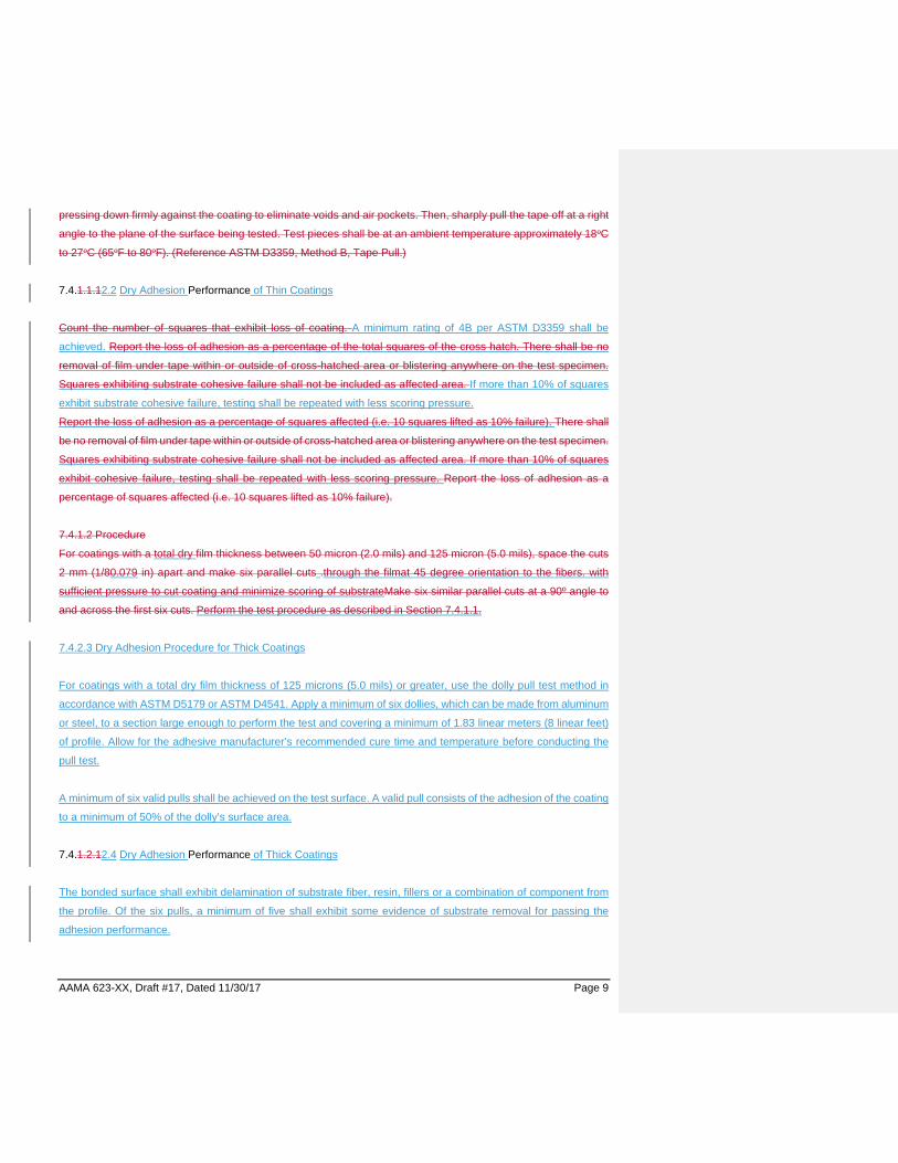
pressing down firmly against the coating to eliminate voids and air pockets. Then, sharply pull the tape off at a right
angle to the plane of the surface being tested. Test pieces shall be at an ambient temperature approximately 18oC
to 27oC (65oF to 80oF). (Reference ASTM D3359, Method B, Tape Pull.)
7.4.1.1.12.2 Dry Adhesion Performance of Thin Coatings
Count the number of squares that exhibit loss of coating. A minimum rating of 4B per ASTM D3359 shall be
achieved. Report the loss of adhesion as a percentage of the total squares of the cross hatch. There shall be no
removal of film under tape within or outside of cross-hatched area or blistering anywhere on the test specimen.
Squares exhibiting substrate cohesive failure shall not be included as affected area. If more than 10% of squares
exhibit substrate cohesive failure, testing shall be repeated with less scoring pressure.
Report the loss of adhesion as a percentage of squares affected (i.e. 10 squares lifted as 10% failure). There shall
be no removal of film under tape within or outside of cross-hatched area or blistering anywhere on the test specimen.
Squares exhibiting substrate cohesive failure shall not be included as affected area. If more than 10% of squares
exhibit cohesive failure, testing shall be repeated with less scoring pressure. Report the loss of adhesion as a
percentage of squares affected (i.e. 10 squares lifted as 10% failure).
7.4.1.2 Procedure
For coatings with a total dry film thickness between 50 micron (2.0 mils) and 125 micron (5.0 mils), space the cuts
2 mm (1/80.079 in) apart and make six parallel cuts .through the filmat 45 degree orientation to the fibers. with
sufficient pressure to cut coating and minimize scoring of substrateMake six similar parallel cuts at a 90º angle to
and across the first six cuts. Perform the test procedure as described in Section 7.4.1.1.
7.4.2.3 Dry Adhesion Procedure for Thick Coatings
For coatings with a total dry film thickness of 125 microns (5.0 mils) or greater, use the dolly pull test method in
accordance with ASTM D5179 or ASTM D4541. Apply a minimum of six dollies, which can be made from aluminum
or steel, to a section large enough to perform the test and covering a minimum of 1.83 linear meters (8 linear feet)
of profile. Allow for the adhesive manufacturer’s recommended cure time and temperature before conducting the
pull test.
A minimum of six valid pulls shall be achieved on the test surface. A valid pull consists of the adhesion of the coating
to a minimum of 50% of the dolly’s surface area.
7.4.1.2.12.4 Dry Adhesion Performance of Thick Coatings
The bonded surface shall exhibit delamination of substrate fiber, resin, fillers or a combination of component from
the profile. Of the six pulls, a minimum of five shall exhibit some evidence of substrate removal for passing the
adhesion performance.

AAMA 623-XX, Draft #17, Dated 11/30/17 Page 10
Report the loss of adhesion as a percentage of squares affected (i.e. as a percentage of the 25 squares).There
shall be no removal of film under tape within or outside of cross-hatched area or blistering anywhere on test
specimen. Squares exhibiting substrate cohesive failure shall not be included as affected area. If more than 10%
of squares exhibit cohesive failure, testing shall be repeated with less scoring pressure.Report the loss of adhesion
as a percentage of squares affected (i.e. as a percentage of the 25 squares).
7.4.1.3 Procedure
For coatings with a total dry film thicknesses at and overof 125 microns (5.0 mils) or greater, use the dolly pull test
method in accordance with ASTM D5179 and ASTM D4541. Use a suitable adhesive to bond the test dollies, which
can be made of aluminum or stainless steel, to the surface of the coating and providing a bond strength greater
than the adhesive force of the coating to the substrate. Apply a minimum of six dollies to a section capable in size
to perform the test and covering a minimum of 1.83 linear meters (8 linear feet) of profile. Allow for the adhesive
manufacturer’s recommended cure time and temperature before conducting the pull test.
7.4.1.3.1 Performance
A minimum of six valid pulls shall be achieved on the test surface. A valid pull consists of the adhesion of the coating
to a minimum of 50% of the dolly’s surface area. Any adhesive failure in the bond between the dolly and coating
shall not be in excessive of 50% of the dolly surface area. The bonded surface shall exhibit delamination of substrate
fiber, resin, fillers or a combination of component from the profile. Of the six pulls, a minimum of five shall exhibit
some evidence of substrate removal for passing the adhesion performance.
7.4.2 3 Wet Adhesion
7.4.23.1 Wet Adhesion Procedure for Thin and Thick Coatings
Immerse the specimen in distilled or deionized water at 38oC (100°F) for 24 hours. Remove and wipe specimen
dry. Repeat the adhesion test specified in Section 7.4.2.1 or Section 7.4.2.3 within fivethirty30 minutes of the
specimen being dryremoved from water.
Immerse the specimen in distilled or deionized water at 38oC (100°F) for 24 hours. Remove and wipe specimen
dry. Repeat the adhesion test specified in Section 7.4.1.1, Section 7.4.1.2 or Section 7.4.1.3 within five minutes of
the specimen being dry.
7.4.23.1.1 Wet Adhesion Performance of Thin Coatings
For coatings with a total dry film thickness of 50 microns (2.0 mils) or less, there shall be no removal of film under
the tape within or outside of the cross-hatched area or blistering anywhere on the test specimen. Report the loss of
adhesion as a percentage of squares affected (i.e. 10 squares lifted as 10% failure).
Performance shall meet requirements specified in Section 7.4.2.2.
Commented [TBaskin1]: Should read 38oC ±2º C?

AAMA 623-XX, Draft #17, Dated 11/30/17 Page 11
7.4.2.1.2 Performance
For coatings with a total dry film thickness between 50 microns (2.0 mils) and 125 microns (5.0 mils), there shall be
no removal of film under the tape with or outside to the cross hatched area or blistering anywhere on the test
specimen. Report the loss of adhesion as a percentage of the 25 squares.
7.4.23.1.32 Wet Adhesion Performance for Thick Coatings
Performance shall meet requirements specified in Section 7.4.2.4.
For coatings with a total dry film thicknessat andofover 125 microns (5 mils) or greater, a minimum of five test pulls
of six valid test dollies shall exhibit substrate removal per Section 7.4.1.3.1
NOTE 5: Fractured substrate adhering to the back of the coating should not be considered a coating failure when
the tape test is used.
NOTE 6: Color change may occur and is not part of this test.
7.5 Direct Impact
7.5.1 Principle ASTM D5420 describes a method to compare relative ability of a material to resist deformation caused by physical
impact on a small area. In finishes standards, this test is useful in determining the ability of a coating or laminate to
maintain adhesion to the substrate after impact and applying a tape pull off test.
7.5.1 2 Procedure
Perform the test using a falling weight impactor, such as a Gardner Impact tester, with a 18 N-m (160 in-lb) range.
Useing a 16 mm (5/8 in) diameter round-nosed impact tester tup, and a 16.3 mm support plate. This corresponds
to geometry GC in Table 1 of ASTM D5420. ,Using a 1.8 kg (4 lb) weight, aAapply a 9 N-m (80 in-lb) load directly
to the coated surface of the test specimen. Apply tape specified in sSection 7.4 to the coating (of sufficient size to
cover the test area) by pressing down firmly against the area to be tested to eliminate voids and air pockets. Sharply
pull the tape off at a right angle to the plane of the surface being tested. The test specimen temperature shall be
18oC to 27oC (65oF to 80oF).
7.5.2 3 Performance
There shall be no removal of film from substrate.
NOTE 76: Minute cracking at the perimeter of the impact area of the test specimen is permissible, but no coating
pick-off should be apparent. Performance does not include substrate fracture.
AAMA 623-XX, Draft #17, Dated 11/30/17 Page 12
Note: There is not enough specificity in the above paragraph to run the test. It needs to specify the height and
weight and not just the load (you can get the same load with different weight and height combinations--2 lb, 4 lb, 8
lb are common weights) and the diameter of the specimen support plate
7.6 Chemical Resistance
7.6.1 Muriatic Acid Resistance (15 Minute Spot Test)
7.6.1.1 Principle:
This test is designed to ensure coatings are resistant to cleaning products containing acids used to remove mineral
deposits or construction mortars. Specimens are exposed to muriatic (hydrochloric) acid, rinsed, and evaluated for
loss of adhesion and degraded color and gloss.
7.6.1.21 Procedure
Apply 10 drops of 10% (by volume) solution of muriatic acid (37% commercial grade hydrochloric acid) in tap water
on the specimen and cover with a watch glass, convex side up. Acid solution and test shall be conducted at 18oC
to 27oC (65oF to 80oF). After 15 minute exposure, wash off with running tap water. Conduct a minimum of four tests.
7.6.1.32 Performance
There shall be no blistering. When comparing the exposed paintedfinish surface to the unexposed surface, there
shall be a minimum 90% gloss retention and a maximum color change of 5 ∆ E Units calculated in accordance with
ASTM D2244.
7.6.2 Mortar Resistance (24 Hour Pat Test)
7.6.2.1 Principle
Because finishes may be exposed to mortar during building construction or maintenance, this method was
developed to determine how well a finish resists permanent adhesion of mortar and changes in appearance upon
removal of mortar. In the test, mortar is applied and allowed to condition at high humidity before it is removed from
the surface by a damp cloth and a mild acid solution. Then the appearance is evaluated for loss of gloss and color
change.
7.6.2.1 2 Procedure
AAMA 623-XX, Draft #17, Dated 11/30/17 Page 13
Prepare mortar by mixing 75 g (2.6 oz) of building lime (see ASTM C207) and 225 g (8 oz) of dry sand, both passing
through a 10-mesh wire screen and sufficient water, approximately 100 g (3.5 oz), to make a soft paste. Immediately
apply wet pats of mortar about 1300 mm2 (2 in2) in area and 12 mm (1/2 in) in thickness to coated specimens which
have been properly cured per the supplier’s recommendation. Immediately expose test sections for 24 hours to
>95100% relative humidity at 38°C±2º C (100oF). Conduct a minimum of four tests.
7.6.2.2 3 Performance
Mortar shall dislodge easily from paintedfinish surface, and any residue shall be removable with a damp cloth. Any
lime residue shall be easily removed with the 10% muriatic acid solution described in Section 7.6.1.21. There shall
be no visible loss of film adhesion, i.e. blistering, delamination and/or bubbling. When comparing the exposed
paintedfinished surface to the unexposed surface, there shall be a minimum of 90% gloss retention and a maximum
color change of 5 ∆ E Units calculated in accordance with ASTM D2244.
NOTE 7: Reference earlier sections for methods of measuring gloss and color.
7.7 Detergent Resistance
7.7.1 Principle
This test, described in ASTM D2248, is used to determine the ability of a finish to maintain adhesion to the substrate
and to resist color and gloss change when subjected to a standardized detergent. This test is designed to accelerate
the effects of repeated cleaning of a finish on a fenestration product.
7.7.1 2 Procedure
Prepare a 3% (by weight) solution of detergent as prescribed in ASTM D2248 and distilled water. Immerse 50% of
the surface of at least two test specimens in the detergent solution at 38°±12º C C (100°F) for 72 hours. Withdrawn
the specimens, wash with distilled water, and allow the specimens to dry. Immediately apply tape (CHT-1 or agreed
upon ASTM equivalent) 20 mm (3/4 in) wide by pressing down firmly against the coating to eliminate voids and air
pockets. Place the tape longitudinally along the entire length of the test specimens. If blisters are visible, then the
blistered area shall be taped and rated. Sharply pull the tape off at a right angle to the plane of the surface being
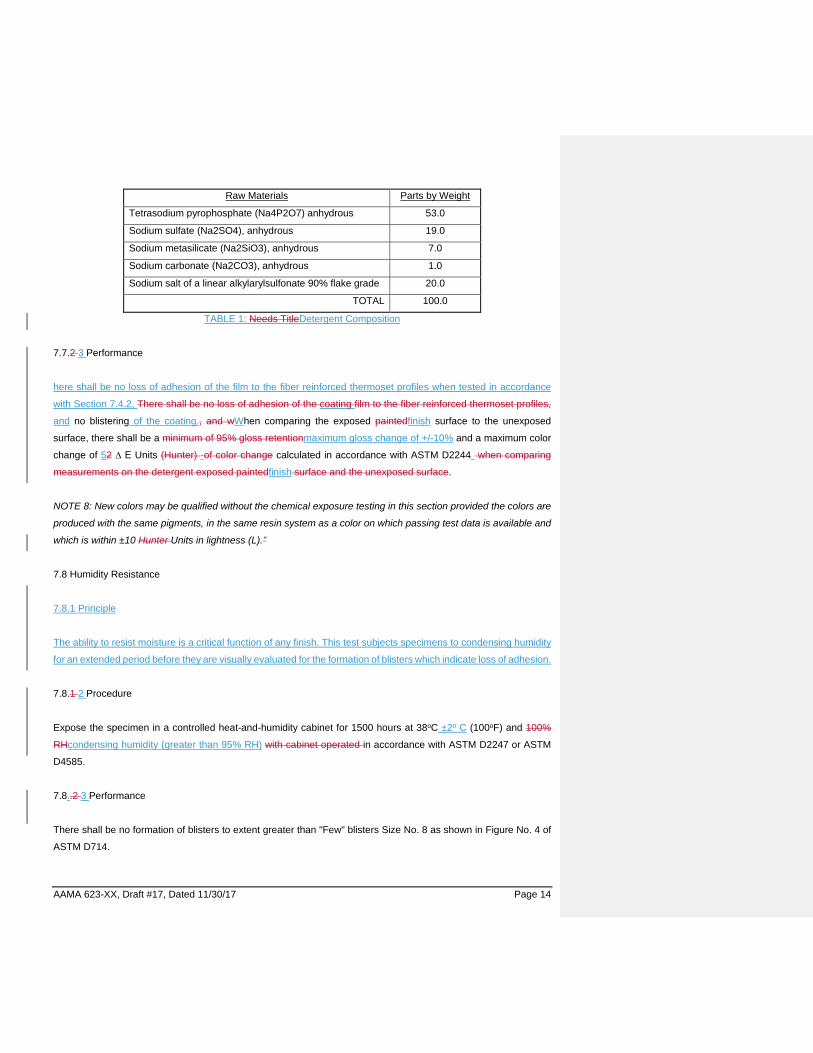
tested, per ASTM D3359. A typical solid detergent composition is as follows.
AAMA 623-XX, Draft #17, Dated 11/30/17 Page 14
Raw Materials Parts by Weight
Tetrasodium pyrophosphate (Na4P2O7) anhydrous 53.0
Sodium sulfate (Na2SO4), anhydrous 19.0
Sodium metasilicate (Na2SiO3), anhydrous 7.0
Sodium carbonate (Na2CO3), anhydrous 1.0
Sodium salt of a linear alkylarylsulfonate 90% flake grade 20.0
TOTAL 100.0
TABLE 1: Needs TitleDetergent Composition
7.7.2 3 Performance
here shall be no loss of adhesion of the film to the fiber reinforced thermoset profiles when tested in accordance
with Section 7.4.2, There shall be no loss of adhesion of the coating film to the fiber reinforced thermoset profiles,
and no blistering of the coating., and wWhen comparing the exposed paintedfinish surface to the unexposed
surface, there shall be a minimum of 95% gloss retentionmaximum gloss change of +/-10% and a maximum color
change of 52 ∆ E Units (Hunter) -of color change calculated in accordance with ASTM D2244 when comparing
measurements on the detergent exposed paintedfinish surface and the unexposed surface.
NOTE 8: New colors may be qualified without the chemical exposure testing in this section provided the colors are
produced with the same pigments, in the same resin system as a color on which passing test data is available and
which is within ±10 Hunter Units in lightness (L).”
7.8 Humidity Resistance
7.8.1 Principle
The ability to resist moisture is a critical function of any finish. This test subjects specimens to condensing humidity
for an extended period before they are visually evaluated for the formation of blisters which indicate loss of adhesion.
7.8.1 2 Procedure
Expose the specimen in a controlled heat-and-humidity cabinet for 1500 hours at 38oC ±2º C (100oF) and 100%
RHcondensing humidity (greater than 95% RH) with cabinet operated in accordance with ASTM D2247 or ASTM
D4585.
7.8..2 3 Performance
There shall be no formation of blisters to extent greater than "Few" blisters Size No. 8 as shown in Figure No. 4 of
ASTM D714.
AAMA 623-XX, Draft #17, Dated 11/30/17 Page 15
7.9 Cold Crack Cycle
7.9.1 Principle
This test determines the effect of freezing and thawing on a finish. Specimens are placed in a condensing humidity
environment for a day24 hours, then transferred to a freezer at -23°C. Specimens are then allowed to thaw for 4
hours. This cycle is repeated 15 times and then specimens are evaluated visually for cracks, blisters, or any other
signs of degradation.
7.9.1 2 Procedure
7.9.12.1 Support the specimens so that they will be held in a position 0 to 30° from the vertical and in such a manner
as to prevent contact between the panels during the test.
7.9.12.2 Place the specimens in a humidity cabinet operated in accordance with ASTM D2247 or ASTM D4585 at
38°C (100°F) ± 2°C ( x°F) and 100%condensing humidity (greater than 95 % relative humidity RH) for a period of
24 ± ½ hours. Then transfer them to the cold box at -23°C ± 1.52°C (-10°F ± 3°F) allowing a maximum of 30 seconds
for the transfer. Leave the specimens in the cold box for a period of 20 ± 1/2 hours.
7.9.12.3 Remove the specimens and allow them to remain at room temperature for a period of 4 ± ½ hours., during
which they shall be time rated., Tthis constitutes one cycle. Run the test for 15 cycles. During any interruption of
the normal cycling, as on weekends, always leave the specimens in the cold box.
7.9.2 3 Performance
There shall be no loss of adhesion of the film to the fiber reinforced thermoset profiles when tested in accordance
with Section 7.4.2.
There shall be no cracking, loss of adhesionblistering, change of color or other detrimental effects, including visual
differences to the coating.
7.10 Oven Aging
7.10.1 Principle
This test determines the ability of a finish to resist degradation due to high temperatures and high humidity for an
extended period of time. Specimens are placed in an oven controlled at 60oC and then placed in an environment of
condensing humidity. Then they are evaluated for pencil hardness and loss of adhesion.

AAMA 623-XX, Draft #17, Dated 11/30/17 Page 16
7.10.1 2 Procedure
Insert two sets of test specimens in an air circulating oven at 60oC ± 2°C (140oF) for seven days. Within one hour
of removal from oven Remove place the specimens and place them in 100%condensing humidity (at 38°C and
greater than 95% humidityRH)(note: at what temperature?) for 96 hours. Allow the specimens to cool to room
temperature. Test Set 1 for film hardness as per Section 7.3.21, and test Set 2 for film adhesion as per Section
7.4.12.
7.10.2 3 Performance
Film hardness shall be an F minimum. There shall be no loss of adhesion of the film to the fiber reinforced thermoset
profiles when tested in accordance with Section 7.4.2There shall be no loss of adhesion.
7.11 Weather Exposure
7.11.1 Principle
Sunlight, temperature, and moisture in the outdoor environment degrades materials such as coatings, polymeric
profiles, and others used in fenestration products. South Florida is considered a global benchmark location for
outdoor weathering tests, due to its constant high levels of sunlight, heat, and moisture. In the vast majority of
cases, a material that performs well in this environment will perform well in major international markets. An
alternative method in this document uses sunlight concentrators located in Arizona, as described in ASTM G90, to
accelerate the effects of multiple years of equivalent radiation as is experienced in South Florida. The Nighttime
Wetting (NTW) cycle sprays water on samples at cycle frequencies specified by ASTM G90. The device is
oriented in such a way that a sample surface angle of 5 degrees is achieved so that wetting may better simulate
South Florida conditions for materials sensitive to moisture.Nightime Wetting spray (NTW) sprays water on
samples at cycle frequencies specified by ASTM G90. The device is angle in such a way that a sample surface
angle of 5 degrees is achieved so wetting may better simulate South Florida moisture condition for moisture
sensitive materials.12
These devices include water spray to introduce moisture cycling in an effort to cause moisture uptake such as
that is experienced in South Florida. Specimens are sprayed at night time to mimic specimen wetting after sunset
in Florida. After weathering exposure, specimens may be evaluated for a number of appearance and physical
properties, including color, gloss, cracking, tape adhesion, and others.

AAMA 623-XX, Draft #17, Dated 11/30/17 Page 17
7.11.1 2 Exposure
Actual South Florida Exposure at an acceptable site. Test sites and duration for on-fence testing are acceptable as
follows: Florida Exposure south of Latitude 27° North at a 45° angle facing south for a minimum of one year.
Accelerated outdoor weathering using concentrated natural sunlight with night time wetting (NTW) for 290 MJ Total
Ultra-Violet Radiation (TUVR) will be an approved alternative to the South Florida testing.
The coating shall maintain its film integrity and at a minimum meet the following color retention, chalk resistance,
gloss retention and erosion resistance properties. Time elapsed when the coating is off the test fence for evaluation,
or other purposes, shall not be counted as part of the exposure minimum. The architect, owner or contractor shall
request data relative to the long-term durability of the color(s) selected. Access to exposure panels must be made
available to the architect and/or owner upon request.
7.11.12.1 Test requirements for concentrated outdoor weathering with natural sunlight are acceptable as follows:
Arizona hot desert exposure at approximately Latitude 34º North using concentrated natural sunlight exposure
device manufactured, maintained and operated in accordance with ASTM G90 for a minimum of 290 MJ TUVR. To
simulate daytime temperatures observed in the summer in South Florida, the daytime black-panel temperature shall
be controlled at a set-point of 70ºC, (158ºF) with an allowable operational fluctuation of ± 5ºC (± 9ºF) under clear
sky conditions. Refer to ASTM G179 for guidance on the construction, calibration, and maintenance of black- or
white- panels. To simulate the South Florida Environment, Cycle 3, consisting of four hourly cycles of spraying with
deionized water for three minutes, followed by a dry time of 12 minutes as specified in Table 1 of ASTM G90, shall
be used.
The spray cycle shall be performed nightly from 7:00 PM to 5:00 AM. The specimens shall be exposed using the
non-insulated specimen mounting configuration in accordance with ASTM G90.
NOTE 9: This specification recognizes that accelerated outdoor weathering using concentrated natural sunlight
testing and the direct South Florida exposure testing have no direct correlation. At their discretion, the manufacturer
may test to either or both test methods.
NOTE 10: Radiant exposure is measured using the pyranometers, pyrheliometers, and ultraviolet radiometers as
described in ASTM G90, or as otherwise agreed to with the customer. By varying the irradiance to a percentage of
the maximum value, lower specimen and black-panel temperatures can be achieved.
7.11.2 3 Film Integrity
7.11.23.1 Performance

AAMA 623-XX, Draft #17, Dated 11/30/17 Page 18
There shall be no checking, crazing of the coating film and no loss of adhesion after the tape pull test outlined in
Section 7.4.1.2.
NOTE 11: Evidence of crazing will be most visible on clear or light color samples.
7.11.3 4 Color Retention
7.11.4.1 Procedure
After weathering exposure (per Section 7.1311.2), measure the exposed coated surface and the control specimen
using a spectrophotometer . The procedure shall be in accordance with ASTM D2244, Section 6.3 and using the
reflectance-specular included (RSIN) method. Corresponding values shall be measured on the original retained
specimen or the unexposed area of the specimen. A portion of the exposed area specimen shall be washed lightly
to remove surface dirt only using clear water and a soft cloth. Heavy scrubbing or any polishing to remove chalk
formation or restore the surface is not permitted where color measurements are made.
7.11.34.21 Performance
There shall be a maximum ofless than 5 ∆ E Units (Hunter) of color change using CIE Standard Illuminant D65 with
10° Observer as calculated in accordance with ASTM D2244, after the minimum one year of exposure test per
Section 7.11.23.2 Color change shall be measured using specular included readings on the exposed paintedfinish
surface which has been cleaned of external deposits with clear water and a soft cloth. Tests started under the
previous version of this standard (prior to the publication of this specification revision) using a different illuminant,
observer or specular component shall continue to use those original parameters until the completion of the tests.
Corresponding values shall be measured on the original retained specimen or the unexposed area of the specimen.
A portion of the exposed specimen may be washed lightly to remove surface dirt only. Heavy scrubbing or any
polishing to remove chalk formation or restore the surface is not permitted where color measurements are made.
NOTE 1112: New colors, whether formulated by a coatings manufacturer or blended by an applicator, according to
a coating manufacturer’s specifications, may be qualified without the exposure test per Section 7.11, provided they
are:
1. produced with the same pigments in the same coating resin system as a color on which acceptable one
year test data is available and;
2. within the ± 10 Hu Units in lightness (L) of that color in accordance with ASTM D2244.
7.11.4 5 Chalk Resistance
AAMA 623-XX, Draft #17, Dated 11/30/17 Page 19
7.11.45.1 Performance
Chalk rating shall be greater than or equal to no more thanthat represented by a No. 8 rating for colors, and No. 6
for whites, based on ASTM D4214, Test Method A (Method ASTM D659) after exposure at the test site per Section
7.11.
8.0 TEST REPORT AND RESULTS
8.1 Test report shall include the following information:
8.1.1 Date when tests were performed and date of issue of report.
8.1.2 Identification of organic coating and/or coating system tested, including production date, lot number, cure
conditions and pretreatment data, manufacturer thereof and name of company submitting coated specimens used
in the test.
8.1.3 Copy of drawings submitted showing exposed surfaces.
8.1.4 Test results.
8.1.5 A statement indicating that organic coating and/or coating system tested passed all tests or failed one or more.
8.1.6 In case of failure, which test(s) and description of failure(s).
8.1.7 Statement that all tests were conducted in accordance with this standard.
8.1.8 Name and address of the laboratory which conducted tests and issued report.