voluson® 730pro/prov (bt05, bt08) - МедСенсор -...
TRANSCRIPT

GE Healthcare
(OCTOBER 3, 2012)PROV730_COVER.FMP R E L I M I N A R Y
Voluson® 730Pro/ProV (BT05, BT08)
Service Manual
• Voluson® 730Pro/ProV systems with Serial number A34001 - A34500, A35001 -• Voluson® 730Pro/ProV systems with Software version SW 5.0.x or higher (BT05)• Voluson® 730Pro/ProV systems with Software version SW 5.4.x onwards (BT08)
Part Number: KTI105991Revision: 5
0123


GE HEALTHCARE VOLUSON® 730PRO/PROV (BT05, BT08)DIRECTION KTI105991, REVISION 5 SERVICE MANUAL
- i
Important Precautions
TRANSLATION POLICY
THIS SERVICE MANUAL IS AVAILABLE IN ENGLISH ONLY.• IF A CUSTOMER’S SERVICE PROVIDER REQUIRES A LANGUAGE OTHER
THAN ENGLISH, IT IS THE CUSTOMER’S RESPONSIBILITY TO PROVIDE TRANSLATION SERVICES.
• DO NOT ATTEMPT TO SERVICE THE EQUIPMENT UNLESS THIS SERVICE MANUAL HAS BEEN CONSULTED AND IS UNDERSTOOD.
• FAILURE TO HEED THIS WARNING MAY RESULT IN INJURY TO THE SERVICE PROVIDER, OPERATOR OR PATIENT FROM ELECTRIC SHOCK, MECHANICAL OR OTHER HAZARDS.
CE MANUEL DE MAINTENANCE N’EST DISPONIBLE QU’EN ANGLAIS.• SI LE TECHNICIEN DU CLIENT A BESOIN DE CE MANUEL DANS UNE AUTRE
LANGUE QUE L’ANGLAIS, C’EST AU CLIENT QU’IL INCOMBE DE LE FAIRE TRADUIRE.
• NE PAS TENTER D’INTERVENTION SUR LES ÉQUIPEMENTS TANT QUE LE MANUEL SERVICE N’A PAS ÉTÉ CONSULTÉ ET COMPRIS.
• LE NON-RESPECT DE CET AVERTISSEMENT PEUT ENTRAÎNER CHEZ LE TECHNICIEN, L’OPÉRATEUR OU LE PATIENT DES BLESSURES DUES À DES DANGERS ÉLECTRIQUES, MÉCANIQUES OU AUTRES.
DIESES KUNDENDIENST-HANDBUCH EXISTIERT NUR IN ENGLISCHER SPRACHE.• FALLS EIN FREMDER KUNDENDIENST EINE ANDERE SPRACHE BENÖTIGT,
IST ES AUFGABE DES KUNDEN FÜR EINE ENTSPRECHENDE ÜBERSETZUNG ZU SORGEN.
• VERSUCHEN SIE NICHT, DAS GERÄT ZU REPARIEREN, BEVOR DIESES KUNDENDIENST-HANDBUCH NICHT ZU RATE GEZOGEN UND VERSTANDEN WURDE.
• WIRD DIESE WARNUNG NICHT BEACHTET, SO KANN ES ZU VERLETZUNGEN DES KUNDENDIENSTTECHNIKERS, DES BEDIENERS ODER DES PATIENTEN DURCH ELEKTRISCHE SCHLÄGE, MECHANISCHE ODER SONSTIGE GEFAHREN KOMMEN.
WARNING(EN)
AVERTISSEMENT(FR)
WARNUNG(DE)
GE HEALTHCARE VOLUSON® 730PRO/PROV (BT05, BT08)DIRECTION KTI105991, REVISION 5 SERVICE MANUAL
ii -
ESTE MANUAL DE SERVICIO SÓLO EXISTE EN INGLÉS.• SI ALGÚN PROVEEDOR DE SERVICIOS AJENO A GEHC SOLICITA UN IDIOMA
QUE NO SEA EL INGLÉS, ES RESPONSABILIDAD DEL CLIENTE OFRECER UN SERVICIO DE TRADUCCIÓN.
• NO SE DEBERÁ DAR SERVICIO TÉCNICO AL EQUIPO, SIN HABER CONSULTADO Y COMPRENDIDO ESTE MANUAL DE SERVICIO.
• LA NO OBSERVANCIA DEL PRESENTE AVISO PUEDE DAR LUGAR A QUE EL PROVEEDOR DE SERVICIOS, EL OPERADOR O EL PACIENTE SUFRAN LESIONES PROVOCADAS POR CAUSAS ELÉCTRICAS, MECÁNICAS O DE OTRA NATURALEZA.
ESTE MANUAL DE ASSISTÊNCIA TÉCNICA SÓ SE ENCONTRA DISPONÍVEL EM INGLÊS.• SE QUALQUER OUTRO SERVIÇO DE ASSISTÊNCIA TÉCNICA, QUE NÃO A
GEHC, SOLICITAR ESTES MANUAIS NOUTRO IDIOMA, É DA RESPONSABILIDADE DO CLIENTE FORNECER OS SERVIÇOS DE TRADUÇÃO.
• NÃO TENTE REPARAR O EQUIPAMENTO SEM TER CONSULTADO E COMPREENDIDO ESTE MANUAL DE ASSISTÊNCIA TÉCNICA.
• O NÃO CUMPRIMENTO DESTE AVISO PODE POR EM PERIGO A SEGURANÇA DO TÉCNICO, OPERADOR OU PACIENTE DEVIDO A‘ CHOQUES ELÉTRICOS, MECÂNICOS OU OUTROS.
ESTE MANUAL DE ASSISTÊNCIA ESTÁ DISPONÍVEL APENAS EM INGLÊS.• SE QUALQUER OUTRO SERVIÇO DE ASSISTÊNCIA TÉCNICA, QUE NÃO A
GEHC, SOLICITAR ESTES MANUAIS NOUTRO IDIOMA, É DA RESPONSABILIDADE DO CLIENTE FORNECER OS SERVIÇOS DE TRADUÇÃO.
• NÃO TENTE EFECTUAR REPARAÇÕES NO EQUIPAMENTO SEM TER CONSULTADO E COMPREENDIDO PREVIAMENTE ESTE MANUAL.
• A INOBSERVÂNCIA DESTE AVISO PODE RESULTAR EM FERIMENTOS NO TÉCNICO DE ASSISTÊNCIA, OPERADOR OU PACIENTE EM CONSEQUÊNCIA DE CHOQUE ELÉCTRICO, PERIGOS DE ORIGEM MECÂNICA, BEM COMO DE OUTROS TIPOS.
IL PRESENTE MANUALE DI MANUTENZIONE È DISPONIBILE SOLTANTO IN INGLESE.• SE UN ADDETTO ALLA MANUTENZIONE ESTERNO ALLA GEHC RICHIEDE IL
MANUALE IN UNA LINGUA DIVERSA, IL CLIENTE È TENUTO A PROVVEDERE DIRETTAMENTE ALLA TRADUZIONE.
• SI PROCEDA ALLA MANUTENZIONE DELL’APPARECCHIATURA SOLO DOPO AVER CONSULTATO IL PRESENTE MANUALE ED AVERNE COMPRESO IL CONTENUTO.
• NON TENERE CONTO DELLA PRESENTE AVVERTENZA POTREBBE FAR COMPIERE OPERAZIONI DA CUI DERIVINO LESIONI ALL’ADDETTO ALLA MANUTENZIONE, ALL’UTILIZZATORE ED AL PAZIENTE PER FOLGORAZIONE ELETTRICA, PER URTI MECCANICI OD ALTRI RISCHI.
AVISO(ES)
ATENÇÃO(PT-Br)
(PT-pt)AVISO
AVVERTENZA(IT)

GE HEALTHCARE VOLUSON® 730PRO/PROV (BT05, BT08)DIRECTION KTI105991, REVISION 5 SERVICE MANUAL
- iii
KÄESOLEV TEENINDUSJUHEND ON SAADAVAL AINULT INGLISE KEELES.• KUI KLIENDITEENINDUSE OSUTAJA NÕUAB JUHENDIT INGLISE KEELEST
ERINEVAS KEELES, VASTUTAB KLIENT TÕLKETEENUSE OSUTAMISE EEST. • ÄRGE ÜRITAGE SEADMEID TEENINDADA ENNE EELNEVALT KÄESOLEVA
TEENINDUSJUHENDIGA TUTVUMIST JA SELLEST ARU SAAMIST.• KÄESOLEVA HOIATUSE EIRAMINE VÕIB PÕHJUSTADA TEENUSEOSUTAJA,
OPERAATORI VÕI PATSIENDI VIGASTAMIST ELEKTRILÖÖGI, MEHAANILISE VÕI MUU OHU TAGAJÄRJEL.
TÄMÄ HUOLTO-OHJE ON SAATAVILLA VAIN ENGLANNIKSI.• JOS ASIAKKAAN PALVELUNTARJOAJA VAATII MUUTA KUIN
ENGLANNINKIELISTÄ MATERIAALIA, TARVITTAVAN KÄÄNNÖKSEN HANKKIMINEN ON ASIAKKAAN VASTUULLA.
• ÄLÄ YRITÄ KORJATA LAITTEISTOA ENNEN KUIN OLET VARMASTI LUKENUT JA YMMÄRTÄNYT TÄMÄN HUOLTO-OHJEEN.
• MIKÄLI TÄTÄ VAROITUSTA EI NOUDATETA, SEURAUKSENA VOI OLLA PALVELUNTARJOAJAN, LAITTEISTON KÄYTTÄJÄN TAI POTILAAN VAHINGOITTUMINEN SÄHKÖISKUN, MEKAANISEN VIAN TAI MUUN VAARATILANTEEN VUOKSI.
ΤΟ ΠΑΡΟΝ ΕΓΧΕΙΡΙΔΙΟ ΣΕΡΒΙΣ ΔΙΑΤΙΘΕΤΑΙ ΣΤΑ ΑΓΓΛΙΚΑ ΜΟΝΟ.• ΕΑΝ ΤΟ ΑΤΟΜΟ ΠΑΡΟΧΗΣ ΣΕΡΒΙΣ ΕΝΟΣ ΠΕΛΑΤΗ ΑΠΑΙΤΕΙ ΤΟ ΠΑΡΟΝ ΕΓΧΕΙΡΙΔΙΟ ΣΕ ΓΛΩΣΣΑ ΕΚΤΟΣ ΤΩΝ ΑΓΓΛΙΚΩΝ, ΑΠΟΤΕΛΕΙ ΕΥΘΥΝΗ ΤΟΥ ΠΕΛΑΤΗ ΝΑ ΠΑΡΕΧΕΙ ΥΠΗΡΕΣΙΕΣ ΜΕΤΑΦΡΑΣΗΣ.
• ΜΗΝ ΕΠΙΧΕΙΡΗΣΕΤΕ ΤΗΝ ΕΚΤΕΛΕΣΗ ΕΡΓΑΣΙΩΝ ΣΕΡΒΙΣ ΣΤΟΝ ΕΞΟΠΛΙΣΜΟ ΕΚΤΟΣ ΕΑΝ ΕΧΕΤΕ ΣΥΜΒΟΥΛΕΥΤΕΙ ΚΑΙ ΕΧΕΤΕ ΚΑΤΑΝΟΗΣΕΙ ΤΟ ΠΑΡΟΝ ΕΓΧΕΙΡΙΔΙΟ ΣΕΡΒΙΣ.
• ΕΑΝ ΔΕ ΛΑΒΕΤΕ ΥΠΟΨΗ ΤΗΝ ΠΡΟΕΙΔΟΠΟΙΗΣΗ ΑΥΤΗ, ΕΝΔΕΧΕΤΑΙ ΝΑ ΠΡΟΚΛΗΘΕΙ ΤΡΑΥΜΑΤΙΣΜΟΣ ΣΤΟ ΑΤΟΜΟ ΠΑΡΟΧΗΣ ΣΕΡΒΙΣ, ΣΤΟ ΧΕΙΡΙΣΤΗ Ή ΣΤΟΝ ΑΣΘΕΝΗ ΑΠΟ ΗΛΕΚΤΡΟΠΛΗΞΙΑ, ΜΗΧΑΝΙΚΟΥΣ Ή ΑΛΛΟΥΣ ΚΙΝΔΥΝΟΥΣ.
EZEN KARBANTARTÁSI KÉZIKÖNYV KIZÁRÓLAG ANGOL NYELVEN ÉRHETŐ EL.• HA A VEVŐ SZOLGÁLTATÓJA ANGOLTÓL ELTÉRŐ NYELVRE TART IGÉNYT,
AKKOR A VEVŐ FELELŐSSÉGE A FORDÍTÁS ELKÉSZÍTTETÉSE.• NE PRÓBÁLJA ELKEZDENI HASZNÁLNI A BERENDEZÉST, AMÍG A
KARBANTARTÁSI KÉZIKÖNYVBEN LEÍRTAKAT NEM ÉRTELMEZTÉK.• EZEN FIGYELMEZTETÉS FIGYELMEN KÍVÜL HAGYÁSA A SZOLGÁLTATÓ,
MŰKÖDTETŐ VAGY A BETEG ÁRAMÜTÉS, MECHANIKAI VAGY EGYÉB VESZÉLYHELYZET MIATTI SÉRÜLÉSÉT EREDMÉNYEZHETI.
HOIATUS (ET)
VAROITUS (FI)
ΠΡΟΕΙΔΟΠΟΙΗΣΗ (EL)
FIGYELMEZTETÉS (HU)
GE HEALTHCARE VOLUSON® 730PRO/PROV (BT05, BT08)DIRECTION KTI105991, REVISION 5 SERVICE MANUAL
iv -
ÞESSI ÞJÓNUSTUHANDBÓK ER EINGÖNGU FÁANLEG Á ENSKU.• EF ÞJÓNUSTUAÐILI VIÐSKIPTAMANNS ÞARFNAST ANNARS TUNGUMÁLS EN
ENSKU, ER ÞAÐ Á ÁBYRGÐ VIÐSKIPTAMANNS AÐ ÚTVEGA ÞÝÐINGU.• REYNIÐ EKKI AÐ ÞJÓNUSTA TÆKIÐ NEMA EFTIR AÐ HAFA SKOÐAÐ OG
SKILIÐ ÞESSA ÞJÓNUSTUHANDBÓK.• EF EKKI ER FARIÐ AÐ ÞESSARI VIÐVÖRUN GETUR ÞAÐ VALDIÐ MEIÐSLUM
ÞJÓNUSTUVEITANDA, STJÓRNANDA EÐA SJÚKLINGS VEGNA RAFLOSTS, VÉLRÆNNAR EÐA ANNARRAR HÆTTU.
TENTO SERVISNÍ NÁVOD EXISTUJE POUZE V ANGLICKÉM JAZYCE.• V PŘÍPADĚ, ŽE POSKYTOVATEL SLUŽEB ZÁKAZNÍKŮM POTŘEBUJE NÁVOD
V JINÉM JAZYCE, JE ZAJIŠTĚNÍ PŘEKLADU DO ODPOVÍDAJÍCÍHO JAZYKA ÚKOLEM ZÁKAZNÍKA.
• NEPROVÁDĚJTE ÚDRŽBU TOHOTO ZAŘÍZENÍ, ANIŽ BYSTE SI PŘEČETLI TENTO SERVISNÍ NÁVOD A POCHOPILI JEHO OBSAH.
• V PŘÍPADĚ NEDODRŽOVÁNÍ TÉTO VÝSTRAHY MŮŽE DOJÍT ÚRAZU ELEKTRICKÁM PROUDEM PRACOVNÍKA POSKYTOVATELE SLUŽEB, OBSLUŽNÉHO PERSONÁLU NEBO PACIENTŮ VLIVEM ELEKTRICKÉHOP PROUDU, RESPEKTIVE VLIVEM K RIZIKU MECHANICKÉHO POŠKOZENÍ NEBO JINÉMU RIZIKU.
DENNE SERVICEMANUAL FINDES KUN PÅ ENGELSK.• HVIS EN KUNDES TEKNIKER HAR BRUG FOR ET ANDET SPROG END
ENGELSK, ER DET KUNDENS ANSVAR AT SØRGE FOR OVERSÆTTELSE.• FORSØG IKKE AT SERVICERE UDSTYRET MEDMINDRE
DENNE SERVICEMANUAL ER BLEVET LÆST OG FORSTÅET.• MANGLENDE OVERHOLDELSE AF DENNE ADVARSEL KAN MEDFØRE SKADE
PÅ GRUND AF ELEKTRISK, MEKANISK ELLER ANDEN FARE FOR TEKNIKEREN, OPERATØREN ELLER PATIENTEN.
DEZE ONDERHOUDSHANDLEIDING IS ENKEL IN HET ENGELS VERKRIJGBAAR.• ALS HET ONDERHOUDSPERSONEEL EEN ANDERE TAAL VEREIST, DAN IS DE
KLANT VERANTWOORDELIJK VOOR DE VERTALING ERVAN.• PROBEER DE APPARATUUR NIET TE ONDERHOUDEN VOORDAT DEZE
ONDERHOUDSHANDLEIDING WERD GERAADPLEEGD EN BEGREPEN IS.• INDIEN DEZE WAARSCHUWING NIET WORDT OPGEVOLGD, ZOU HET
ONDERHOUDSPERSONEEL, DE OPERATOR OF EEN PATIËNT GEWOND KUNNEN RAKEN ALS GEVOLG VAN EEN ELEKTRISCHE SCHOK, MECHANISCHE OF ANDERE GEVAREN.
VIÐVÖRUN(IS)
VÝSTRAHA(CS)
ADVARSEL(DA)
WAARSCHUWING(NL)

GE HEALTHCARE VOLUSON® 730PRO/PROV (BT05, BT08)DIRECTION KTI105991, REVISION 5 SERVICE MANUAL
- v
ŠĪ APKALPES ROKASGRĀMATA IR PIEEJAMA TIKAI ANGĻU VALODĀ.• JA KLIENTA APKALPES SNIEDZĒJAM NEPIECIEŠAMA INFORMĀCIJA CITĀ
VALODĀ, NEVIS ANGĻU, KLIENTA PIENĀKUMS IR NODROŠINĀT TULKOŠANU.• NEVEICIET APRĪKOJUMA APKALPI BEZ APKALPES ROKASGRĀMATAS
IZLASĪŠANAS UN SAPRAŠANAS.• ŠĪ BRĪDINĀJUMA NEIEVĒROŠANA VAR RADĪT ELEKTRISKĀS STRĀVAS
TRIECIENA, MEHĀNISKU VAI CITU RISKU IZRAISĪTU TRAUMU APKALPES SNIEDZĒJAM, OPERATORAM VAI PACIENTAM.
ŠIS EKSPLOATAVIMO VADOVAS YRA IŠLEISTAS TIK ANGLŲ KALBA.• JEI KLIENTO PASLAUGŲ TEIKĖJUI REIKIA VADOVO KITA KALBA – NE ANGLŲ,
VERTIMU PASIRŪPINTI TURI KLIENTAS.• NEMĖGINKITE ATLIKTI ĮRANGOS TECHNINĖS PRIEŽIŪROS DARBŲ, NEBENT
VADOVAUTUMĖTĖS ŠIUO EKSPLOATAVIMO VADOVU IR JĮ SUPRASTUMĖTE• NEPAISANT ŠIO PERSPĖJIMO, PASLAUGŲ TEIKĖJAS, OPERATORIUS AR
PACIENTAS GALI BŪTI SUŽEISTAS DĖL ELEKTROS SMŪGIO, MECHANINIŲ AR KITŲ PAVOJŲ.
DENNE SERVICEHÅNDBOKEN FINNES BARE PÅ ENGELSK.• HVIS KUNDENS SERVICELEVERANDØR TRENGER ET ANNET SPRÅK, ER DET
KUNDENS ANSVAR Å SØRGE FOR OVERSETTELSE.• IKKE FORSØK Å REPARERE UTSTYRET UTEN AT DENNE
SERVICEHÅNDBOKEN ER LEST OG FORSTÅTT.• MANGLENDE HENSYN TIL DENNE ADVARSELEN KAN FØRE TIL AT
SERVICELEVERANDØREN, OPERATØREN ELLER PASIENTEN SKADES PÅ GRUNN AV ELEKTRISK STØT, MEKANISKE ELLER ANDRE FARER.
NINIEJSZY PODRĘCZNIK SERWISOWY DOSTĘPNY JEST JEDYNIE W JĘZYKU ANGIELSKIM.• JEŚLI FIRMA ŚWIADCZĄCA KLIENTOWI USłUGI SERWISOWE WYMAGA
UDOSTĘPNIENIA PODRĘCZNIKA W JĘZYKU INNYM NIŻ ANGIELSKI, OBOWIĄZEK ZAPEWNIENIA STOSOWNEGO TłUMACZENIA SPOCZYWA NA KLIENCIE.
• NIE PRÓBOWAĆ SERWISOWAĆ NINIEJSZEGO SPRZĘTU BEZ UPRZEDNIEGO ZAPOZNANIA SIĘ Z PODRĘCZNIKIEM SERWISOWYM.
• NIEZASTOSOWANIE SIĘ DO TEGO OSTRZEŻENIA MOżE GROZIĆ OBRAŻENIAMI CIAłA SERWISANTA, OPERATORA LUB PACJENTA W WYNIKU PORAŻENIA PRĄDEM, URAZU MECHANICZNEGO LUB INNEGO RODZAJU ZAGROŻEŃ.
BRĪDINĀJUMS(LV)
ĮSPĖJIMAS(LT)
ADVARSEL(NO)
OSTRZEŻENIE(PL)
GE HEALTHCARE VOLUSON® 730PRO/PROV (BT05, BT08)DIRECTION KTI105991, REVISION 5 SERVICE MANUAL
vi -
ACEST MANUAL DE SERVICE ESTE DISPONIBIL NUMAI ÎN LIMBA ENGLEZĂ.• DACĂ UN FURNIZOR DE SERVICII PENTRU CLIENŢI NECESITĂ O ALTĂ LIMBĂ
DECÂT CEA ENGLEZĂ, ESTE DE DATORIA CLIENTULUI SĂ FURNIZEZE O TRADUCERE.
• NU ÎNCERCAŢI SĂ REPARAŢI ECHIPAMENTUL DECÂT ULTERIOR CONSULTĂRII ŞI ÎNŢELEGERII ACESTUI MANUAL DE SERVICE.
• IGNORAREA ACESTUI AVERTISMENT AR PUTEA DUCE LA RĂNIREA DEPANATORULUI, OPERATORULUI SAU PACIENTULUI ÎN URMA PERICOLELOR DE ELECTROCUTARE, MECANICE SAU DE ALTĂ NATURĂ.
ДАННОЕ РУКОВОДСТВО ПО ОБСЛУЖИВАНИЮ ПРЕДОСТАВЛЯЕТСЯ ТОЛЬКО НА АНГЛИЙСКОМ ЯЗЫКЕ.• ЕСЛИ СЕРВИСНОМУ ПЕРСОНАЛУ КЛИЕНТА НЕОБХОДИМО РУКОВОДСТВО НЕ НА АНГЛИЙСКОМ ЯЗЫКЕ, КЛИЕНТУ СЛЕДУЕТ САМОСТОЯТЕЛЬНО ОБЕСПЕЧИТЬ ПЕРЕВОД.
• ПЕРЕД ОБСЛУЖИВАНИЕМ ОБОРУДОВАНИЯ ОБЯЗАТЕЛЬНО ОБРАТИТЕСЬ К ДАННОМУ РУКОВОДСТВУ И ПОЙМИТЕ ИЗЛОЖЕННЫЕ В НЕМ СВЕДЕНИЯ.
• НЕСОБЛЮДЕНИЕ УКАЗАННЫХ ТРЕБОВАНИЙ МОЖЕТ ПРИВЕСТИ К ТОМУ, ЧТО СПЕЦИАЛИСТ ПО ТЕХОБСЛУЖИВАНИЮ, ОПЕРАТОР ИЛИ ПАЦИЕНТ ПОЛУЧАТ УДАР ЗЛЕКТРИЧЕСКИМ ТОКОМ, МЕХАНИЧЕСКУЮ ТРАВМУ ИЛИ ДРУГОЕ ПОВРЕЖДЕНИЕ.
ТОВА СЕРВИЗНО РЪКОВОДСТВО Е НАЛИЧНО САМО НА АНГЛИЙСКИ ЕЗИК.• АКО ДОСТАВЧИКЪТ НА СЕРВИЗНИ УСЛУГИ НА КЛИЕНТ СЕ НУЖДАЕ ОТ ЕЗИК, РАЗЛИЧЕН ОТ АНГЛИЙСКИ, ЗАДЪЛЖЕНИЕ НА КЛИЕНТА Е ДА ПРЕДОСТАВИ ПРЕВОДАЧЕСКА УСЛУГА.
• НЕ СЕ ОПИТВАЙТЕ ДА ИЗВЪРШВАТЕ СЕРВИЗНО ОБСЛУЖВАНЕ НА ТОВА ОБОРУДВАНЕ, ОСВЕН ВСЛУЧАЙ, ЧЕ СЕРВИЗНОТО РЪКОВОДСТВО Е ПРОЧЕТЕНО И СЕ РАЗБИРА.
• НЕСПАЗВАНЕТО НА ТОВА ПРЕДУПРЕЖДЕНИЕ МОЖЕ ДА ДОВЕДЕ ДО НАРАНЯВАНЕ НА ДОСТАВЧИКА НА СЕРВИЗНИ УСЛУГИ, НА ОПЕРАТОРА ИЛИ ПАЦИЕНТА ВСЛЕДСТВИЕНА ТОКОВ УДАР, МЕХАНИЧНИ ИЛИ ДРУГИ РИСКОВЕ.
OVAJ PRIRUČNIK ZA SERVISIRANJE DOSTUPAN JE SAMO NA ENGLESKOM JEZIKU.• AKO KLIJENTOV SERVISER ZAHTEVA JEZIK KOJI NIJE ENGLESKI,
ODGOVORNOST JE NA KLIJENTU DA PRUŽI USLUGE PREVOĐENJA.• NEMOJTE POKUŠAVATI DA SERVISIRATE OPREMU AKO NISTE PROČITALI I
RAZUMELI PRIRUČNIK ZA SERVISIRANJE.• AKO NE POŠTUJETE OVO UPOZORENJE, MOŽE DOĆI DO POVREĐIVANJA
SERVISERA, OPERATERA ILI PACIJENTA UZROKOVANOG ELEKTRIČNIM UDAROM, MEHANIČKIM I DRUGIM OPASNOSTIMA.
ATENŢIE(RO)
ОСТОРОЖНО!(RU)
(BG)ПРЕДУПРЕЖДЕНИЕ
UPOZORENJE(SR)

GE HEALTHCARE VOLUSON® 730PRO/PROV (BT05, BT08)DIRECTION KTI105991, REVISION 5 SERVICE MANUAL
- vii
TA SERVISNI PRIROČNIK JE NA VOLJO SAMO V ANGLEŠČINI.• ČE PONUDNIK SERVISNIH STORITEV ZA STRANKO POTREBUJE NAVODILA V
DRUGEM JEZIKU, JE ZA PREVOD ODGOVORNA STRANKA SAMA.• NE POSKUŠAJTE SERVISIRATI OPREME, NE DA BI PREJ PREBRALI IN
RAZUMELI SERVISNI PRIROČNIK.• ČE TEGA OPOZORILA NE UPOŠTEVATE, OBSTAJA NEVARNOST
ELEKTRIČNEGA UDARA, MEHANSKIH ALI DRUGIH NEVARNOSTI IN POSLEDIČNIH POŠKODB PONUDNIKA SERVISNIH STORITEV, UPORABNIKA OPREME ALI PACIENTA.
OVAJ SERVISNI PRIRUČNIK DOSTUPAN JE SAMO NA ENGLESKOM JEZIKU.• AKO KLIJENTOV SERVISER ZAHTIJEVA JEZIK KOJI NIJE ENGLESKI,
ODGOVORNOST KLIJENTA JE PRUŽITI USLUGE PREVOĐENJA.• NEMOJTE POKUŠAVATI SERVISIRATI OPREMU AKO NISTE PROČITALI I
RAZUMJELI SERVISNI PRIRUČNIK.• AKO NE POŠTUJETE OVO UPOZORENJE, MOŽE DOĆI DO OZLJEDE
SERVISERA, OPERATERA ILI PACIJENTA PROUZROČENE STRUJNIM UDAROM, MEHANIČKIM I DRUGIM OPASNOSTIMA.
TÁTO SERVISNÁ PRÍRUČKA JE K DISPOZÍCII LEN V ANGLIČTINE.• AK ZÁKAZNÍKOV POSKYTOVATEĽ SLUŽIEB VYŽADUJE INÝ JAZYK AKO
ANGLIČTINU, POSKYTNUTIE PREKLADATEĽSKÝCH SLUŽIEB JE ZODPOVEDNOSŤOU ZÁKAZNÍKA.
• NEPOKÚŠAJTE SA VYKONÁVAŤ SERVIS ZARIADENIA SKÔR, AKO SI NEPREČÍTATE SERVISNÚ PRÍRUČKU A NEPOROZUMIETE JEJ.
• ZANEDBANIE TOHTO UPOZORNENIA MÔŽE VYÚSTIŤ DO ZRANENIA POSKYTOVATEĽA SLUŽIEB, OBSLUHUJÚCEJ OSOBY ALEBO PACIENTA ELEKTRICKÝM PRÚDOM, PRÍPADNE DO MECHANICKÉHO ALEBO INÉHO NEBEZPEČENSTVA.
DEN HÄR SERVICEHANDBOKEN FINNS BARA TILLGÄNGLIG PÅ ENGELSKA.• OM EN KUNDS SERVICETEKNIKER HAR BEHOV AV ETT ANNAT SPRÅK ÄN
ENGELSKA ANSVARAR KUNDEN FÖR ATT TILLHANDAHÅLLA ÖVERSÄTTNINGSTJÄNSTER.
• FÖRSÖK INTE UTFÖRA SERVICE PÅ UTRUSTNINGEN OM DU INTE HAR LÄST OCH FÖRSTÅR DEN HÄR SERVICEHANDBOKEN.
• OM DU INTE TAR HÄNSYN TILL DEN HÄR VARNINGEN KAN DET RESULTERA I SKADOR PÅ SERVICETEKNIKERN, OPERATÖREN ELLER PATIENTEN TILL FÖLJD AV ELEKTRISKA STÖTAR, MEKANISKA FAROR ELLER ANDRA FAROR.
OPOZORILO(SL)
UPOZORENJE(HR)
UPOZORNENIE(SK)
VARNING(SV)

GE HEALTHCARE VOLUSON® 730PRO/PROV (BT05, BT08)DIRECTION KTI105991, REVISION 5 SERVICE MANUAL
viii -
BU SERVİS KILAVUZU YALNIZCA İNGİLİZCE OLARAK SAĞLANMIŞTIR.• EĞER MÜŞTERİ TEKNİSYENİ KILAVUZUN İNGİLİZCE DIŞINDAKİ BİR DİLDE
OLMASINI İSTERSE, KILAVUZU TERCÜME ETTİRMEK MÜŞTERİNİN SORUMLULUĞUNDADIR.
• SERVİS KILAVUZUNU OKUYUP ANLAMADAN EKİPMANLARA MÜDAHALE ETMEYİNİZ.
• BU UYARININ GÖZ ARDI EDİLMESİ, ELEKTRİK ÇARPMASI YA DA MEKANİK VEYA DİĞER TÜRDEN KAZALAR SONUCUNDA TEKNİSYENİN, OPERATÖRÜN YA DA HASTANIN YARALANMASINA YOL AÇABİLİR.
DİKKAT(TR)
(JA)
TraditionalChinese

GE HEALTHCARE VOLUSON® 730PRO/PROV (BT05, BT08)DIRECTION KTI105991, REVISION 5 SERVICE MANUAL
- ix
(ZH-CN)
(KO)

GE HEALTHCARE VOLUSON® 730PRO/PROV (BT05, BT08)DIRECTION KTI105991, REVISION 5 SERVICE MANUAL
x -
DAMAGE IN TRANSPORTATION - FOR USA ONLYAll packages should be closely examined at time of delivery. If damage is apparent write “Damage In Shipment” on ALL copies of the freight or express bill BEFORE delivery is accepted or “signed for” by a GE representative or hospital receiving agent. Whether noted or concealed, damage MUST be reported to the carrier immediately upon discovery, or in any event, within 14 days after receipt, and the contents and containers held for inspection by the carrier. A transportation company will not pay a claim for damage if an inspection is not requested within this 14 day period.
CERTIFIED ELECTRICAL CONTRACTOR STATEMENT - FOR USA ONLYAll electrical Installations that are preliminary to positioning of the equipment at the site prepared for the equipment shall be performed by licensed electrical contractors. Other connections between pieces of electrical equipment, calibrations and testing shall be performed by qualified GE Healthcare personnel. In performing all electrical work on these products, GE will use its own specially trained field engineers. All of GE’s electrical work on these products will comply with the requirements of the applicable electrical codes.
The purchaser of GE equipment shall only utilize qualified personnel (i.e., GE’s field engineers, personnel of third-party service companies with equivalent training, or licensed electricians) to perform electrical servicing on the equipment.
OMISSIONS & ERRORSIf there are any omissions, errors or suggestions for improving this documentation, please contact the GE Healthcare Global Documentation Group with specific information listing the system type, manual title, part number, revision number, page number and suggestion details.
Mail the information to:
GE Healthcare Austria GmbH & Co. OGTiefenbach 15A-4871 ZipfAustria - EuropeAttn.: “Service Documentation”
GE Healthcare employees should contact the product's Lead Service Integrator (LSI) to report service documentation issues. DO NOT use TrackWise for this purpose. The LSI will then use the internal problem reporting tool to communicate these issues to the writer.
SERVICE SAFETY CONSIDERATIONS
For a complete review of all safety requirements, see the Chapter 1, Safety Considerations section in the Service Manual.
DANGER!! DANGER:
DANGEROUS VOLTAGES, CAPABLE OF CAUSING DEATH, ARE PRESENT IN THIS EQUIPMENT. USE EXTREME CAUTION WHEN HANDLING, TESTING AND ADJUSTING.
WARNINGWARNING!! WARNING:
Use all Personal Protection Equipment (PPE) such as gloves, safety shoes, safetyglasses, and kneeling pad, to reduce the risk of injury.

GE HEALTHCARE VOLUSON® 730PRO/PROV (BT05, BT08)DIRECTION KTI105991, REVISION 5 SERVICE MANUAL
- xi
LEGAL NOTES
The contents of this publication may not be copied or duplicated in any form, in whole or in part, without prior written permission of GE Medical Systems.
GE Healthcare may revise this publication from time to time without written notice.
TRADEMARKSAll products and their name brands are trademarks of their respective holders.
COPYRIGHTSAll Material Copyright© 2004 and 2012 by General Electric Inc. All Rights Reserved.

GE HEALTHCARE VOLUSON® 730PRO/PROV (BT05, BT08)DIRECTION KTI105991, REVISION 5 SERVICE MANUAL
xii -
Revision History
List of Effected Pages
Revision Date Reason for change1 July 01, 2005 Initial Release (from Software Version 5.0.x onwards)
2 Jannuary 31, 2007 Special regulation for Korea
3 November, 2007 Implementation of new parts, release of BT08 software version (SW 5.4.x)
4 June, 2009Implementation of new parts,
release of BT08 software version (SW5.4.1 or higher),Implementation of Appendix A (Acoustic Output & Index Determination Tables)
5 September, 2012 General Update
Pages Revision Pages Revision Pages Revision
Title Page 5Chapter 3 - Setup Instructionspages 3-1 to 3-74 5
Chapter 9 - Renewal Partspages 9-1 to 9-40 5
Important Precautions (incl. Legal Notes)pages i to xi
5Chapter 4 - Functional Checkspages 4-1 to 4-46 5
Chapter 10 - Care & Maintenancepages 10-1 to 10-24 5
Rev History/LOEPpage xii 5
Chapter 5 - Components and Functions (Theory)pages 5-1 to 5-62
5
Chapter A - Acoustic Output & Index Determination Tablespages A-1 to A-106
5
Table of Contentspages xiii to xxxii 5
Chapter 6 - Service Adjustmentspages 6-1 to 6-10 5
Indexpages I to VIII 5
Chapter 1 - Introductionpages 1-1 to 1-16 5
Chapter 7 - Diagnostics/Troubleshootingpages 7-1 to 7-30
5Back Cover
5
Chapter 2 - Site Preparationpages 2-1 to 2-8 5
Chapter 8 - Replacement Procedurespages 8-1 to 8-28
5

GE HEALTHCARE VOLUSON® I / VOLUSON® E (BT05, BT08)DIRECTION KTI105991, REVISION 5 SERVICE MANUAL
xiii Table of Contents
Table of ContentsCHAPTER 1Introduction
Overview . . . . . . . . . . . . . . . . . . . . . . . . . . . . . . . . . . . . . . . . . . . . . . . . . . . . . . . . . 1 - 1Purpose of Chapter 1 . . . . . . . . . . . . . . . . . . . . . . . . . . . . . . . . . . . . . . . . . . 1 - 1Purpose of Service Manual . . . . . . . . . . . . . . . . . . . . . . . . . . . . . . . . . . . . . 1 - 1Typical Users of the Basic Service Manual . . . . . . . . . . . . . . . . . . . . . . . . . 1 - 2Voluson® 730Pro/ProV Models Covered by this Manual . . . . . . . . . . . . . . . 1 - 2System History - Hardware and Software Versions . . . . . . . . . . . . . . . . . . . 1 - 3Purpose of Operator Manual(s) . . . . . . . . . . . . . . . . . . . . . . . . . . . . . . . . . . 1 - 3
Important Conventions. . . . . . . . . . . . . . . . . . . . . . . . . . . . . . . . . . . . . . . . . . . . . . . 1 - 4Conventions Used in Book . . . . . . . . . . . . . . . . . . . . . . . . . . . . . . . . . . . . . . 1 - 4Standard Hazard Icons . . . . . . . . . . . . . . . . . . . . . . . . . . . . . . . . . . . . . . . . 1 - 5Product Labels and Icons . . . . . . . . . . . . . . . . . . . . . . . . . . . . . . . . . . . . . . . 1 - 6
Safety Considerations . . . . . . . . . . . . . . . . . . . . . . . . . . . . . . . . . . . . . . . . . . . . . . . 1 - 9Introduction . . . . . . . . . . . . . . . . . . . . . . . . . . . . . . . . . . . . . . . . . . . . . . . . . 1 - 9Human Safety . . . . . . . . . . . . . . . . . . . . . . . . . . . . . . . . . . . . . . . . . . . . . . . 1 - 9Mechanical Safety . . . . . . . . . . . . . . . . . . . . . . . . . . . . . . . . . . . . . . . . . 1 - 9Electrical Safety . . . . . . . . . . . . . . . . . . . . . . . . . . . . . . . . . . . . . . . . . . . . . . 1 - 10
Safe Practices . . . . . . . . . . . . . . . . . . . . . . . . . . . . . . . . . . . . . . . . . . 1 - 10Probes . . . . . . . . . . . . . . . . . . . . . . . . . . . . . . . . . . . . . . . . . . . . . . . . 1 - 10
Auxiliary Devices Safety . . . . . . . . . . . . . . . . . . . . . . . . . . . . . . . . . . . . . . . 1 - 11Labels Locations . . . . . . . . . . . . . . . . . . . . . . . . . . . . . . . . . . . . . . . . . . . . . 1 - 12Dangerous Procedure Warnings . . . . . . . . . . . . . . . . . . . . . . . . . . . . . . . . . 1 - 13Lockout/Tagout Requirements (For USA Only) . . . . . . . . . . . . . . . . . . . . . . 1 - 13Returning/Shipping Probes and Repair Parts . . . . . . . . . . . . . . . . . . . . . . . 1 - 13
Electromagnetic Compatibility (EMC) . . . . . . . . . . . . . . . . . . . . . . . . . . . . . . . . . . . 1 - 14What is EMC? . . . . . . . . . . . . . . . . . . . . . . . . . . . . . . . . . . . . . . . . . . . . . . . 1 - 14Compliance . . . . . . . . . . . . . . . . . . . . . . . . . . . . . . . . . . . . . . . . . . . . . . . . . 1 - 14Electrostatic Discharge (ESD) Prevention . . . . . . . . . . . . . . . . . . . . . . . . . 1 - 14
Customer Assistance . . . . . . . . . . . . . . . . . . . . . . . . . . . . . . . . . . . . . . . . . . . . . . . . 1 - 15Contact Information . . . . . . . . . . . . . . . . . . . . . . . . . . . . . . . . . . . . . . . . . . . 1 - 15System Manufacturer . . . . . . . . . . . . . . . . . . . . . . . . . . . . . . . . . . . . . . . . . 1 - 15

GE HEALTHCARE VOLUSON® 730PRO/PROVDIRECTION KTI105991, REVISION 5 SERVICE MANUAL
xiv -
CHAPTER 2Site Preparation
Overview . . . . . . . . . . . . . . . . . . . . . . . . . . . . . . . . . . . . . . . . . . . . . . . . . . . . . . . . . 2 - 1Purpose of Chapter 2 . . . . . . . . . . . . . . . . . . . . . . . . . . . . . . . . . . . . . . . . . . 2 - 1
General Console Requirements. . . . . . . . . . . . . . . . . . . . . . . . . . . . . . . . . . . . . . . . 2 - 1Environmental Requirements . . . . . . . . . . . . . . . . . . . . . . . . . . . . . . . . . . . 2 - 1
Cooling . . . . . . . . . . . . . . . . . . . . . . . . . . . . . . . . . . . . . . . . . . . . . . . 2 - 1Lighting . . . . . . . . . . . . . . . . . . . . . . . . . . . . . . . . . . . . . . . . . . . . . . . 2 - 1
Electrical Requirements . . . . . . . . . . . . . . . . . . . . . . . . . . . . . . . . . . . . . . . . 2 - 2Voluson® 730Pro/ProV Power Requirements . . . . . . . . . . . . . . . . . 2 - 2Inrush Current . . . . . . . . . . . . . . . . . . . . . . . . . . . . . . . . . . . . . . . . . . 2 - 2Site Circuit Breaker . . . . . . . . . . . . . . . . . . . . . . . . . . . . . . . . . . . . . . 2 - 2Site Power Outlets . . . . . . . . . . . . . . . . . . . . . . . . . . . . . . . . . . . . . . . 2 - 2Main Power Plug . . . . . . . . . . . . . . . . . . . . . . . . . . . . . . . . . . . . . . . . 2 - 2
EMI Limitations . . . . . . . . . . . . . . . . . . . . . . . . . . . . . . . . . . . . . . . . . . . . . . . 2 - 3Probe Environmental Requirements . . . . . . . . . . . . . . . . . . . . . . . . . . . . . . 2 - 4Time and Manpower Requirements . . . . . . . . . . . . . . . . . . . . . . . . . . . . . . . 2 - 4System Specifications . . . . . . . . . . . . . . . . . . . . . . . . . . . . . . . . . . . . . . . . . 2 - 4
Physical Dimensions of Voluson® 730Pro/ProV . . . . . . . . . . . . . . . . 2 - 4Weight without Monitor and Peripherals . . . . . . . . . . . . . . . . . . . . . . 2 - 4Acoustic Noise Output . . . . . . . . . . . . . . . . . . . . . . . . . . . . . . . . . . . . 2 - 4Electrical Specifications . . . . . . . . . . . . . . . . . . . . . . . . . . . . . . . . . . . 2 - 4
Facility Needs . . . . . . . . . . . . . . . . . . . . . . . . . . . . . . . . . . . . . . . . . . . . . . . . . . . . . 2 - 5Purchaser Responsibilities . . . . . . . . . . . . . . . . . . . . . . . . . . . . . . . . . . . . . . 2 - 5Mandatory Site Requirements . . . . . . . . . . . . . . . . . . . . . . . . . . . . . . . . . . . 2 - 6Site Recommendations . . . . . . . . . . . . . . . . . . . . . . . . . . . . . . . . . . . . . . . . 2 - 6
Recommended Ultrasound Room Layout . . . . . . . . . . . . . . . . . . . . . 2 - 7Networking Pre-installation Requirements . . . . . . . . . . . . . . . . . . . . . . . . . . 2 - 8
Purpose of the DICOM Network Function . . . . . . . . . . . . . . . . . . . . . 2 - 8DICOM Option Pre-installation Requirements . . . . . . . . . . . . . . . . . . 2 - 8

GE HEALTHCARE VOLUSON® 730PRO/PROVDIRECTION KTI105991, REVISION 5 SERVICE MANUAL
- xv
CHAPTER 3Setup Instructions
Overview. . . . . . . . . . . . . . . . . . . . . . . . . . . . . . . . . . . . . . . . . . . . . . . . . . . . . . . . . 3 - 1The Purpose of Chapter 3 . . . . . . . . . . . . . . . . . . . . . . . . . . . . . . . . . . . . . 3 - 1
Set Up Reminders . . . . . . . . . . . . . . . . . . . . . . . . . . . . . . . . . . . . . . . . . . . . . . . . . 3 - 2Average Installation Time . . . . . . . . . . . . . . . . . . . . . . . . . . . . . . . . . . . . . . 3 - 2Installation Warnings . . . . . . . . . . . . . . . . . . . . . . . . . . . . . . . . . . . . . . . . . 3 - 2
System Acclimation Time . . . . . . . . . . . . . . . . . . . . . . . . . . . . . . . . . 3 - 3Control Panel Position . . . . . . . . . . . . . . . . . . . . . . . . . . . . . . . . . . . 3 - 3Brake Pedal Operation . . . . . . . . . . . . . . . . . . . . . . . . . . . . . . . . . . . 3 - 3
Safety Reminders . . . . . . . . . . . . . . . . . . . . . . . . . . . . . . . . . . . . . . . 3 - 4
Receiving and Unpacking the Equipment. . . . . . . . . . . . . . . . . . . . . . . . . . . . . . . . 3 - 5
Preparing for Installation. . . . . . . . . . . . . . . . . . . . . . . . . . . . . . . . . . . . . . . . . . . . . 3 - 7Verify Customer Order . . . . . . . . . . . . . . . . . . . . . . . . . . . . . . . . . . . . . . . . 3 - 7System Voltage Settings . . . . . . . . . . . . . . . . . . . . . . . . . . . . . . . . . . . . . . . 3 - 8EMI Protection . . . . . . . . . . . . . . . . . . . . . . . . . . . . . . . . . . . . . . . . . . . . . . 3 - 8
Connection of Auxiliary Devices . . . . . . . . . . . . . . . . . . . . . . . . . . . . . . . . . . . . . . . 3 - 9Preparations . . . . . . . . . . . . . . . . . . . . . . . . . . . . . . . . . . . . . . . . . . . . . . . . 3 - 9Monitor Connection . . . . . . . . . . . . . . . . . . . . . . . . . . . . . . . . . . . . . . . . . . . 3 - 11Foot Switch Connection . . . . . . . . . . . . . . . . . . . . . . . . . . . . . . . . . . . . . . . 3 - 11ECG-preamplifier Connection . . . . . . . . . . . . . . . . . . . . . . . . . . . . . . . . . . 3 - 11Global Modem Connection . . . . . . . . . . . . . . . . . . . . . . . . . . . . . . . . . . . . 3 - 12S-VHS Video Recorder Connection . . . . . . . . . . . . . . . . . . . . . . . . . . . . . . 3 - 13
Mitsubishi HS-MD3000 . . . . . . . . . . . . . . . . . . . . . . . . . . . . . . . . . . 3 - 13Sony SVO-9500MD . . . . . . . . . . . . . . . . . . . . . . . . . . . . . . . . . . . . 3 - 14
DVD Recorder (DVR) Connection . . . . . . . . . . . . . . . . . . . . . . . . . . . . . . 3 - 15Adjustment of the DVD Recorder Settings . . . . . . . . . . . . . . . . . . . . 3 - 16
Changing TV System (Video Format) . . . . . . . . . . . . . . . . . . 3 - 16Change the Region Code . . . . . . . . . . . . . . . . . . . . . . . . . . . 3 - 18
B/W Video Printer Connection . . . . . . . . . . . . . . . . . . . . . . . . . . . . . . . . . 3 - 19Sony UP-D897 (digital) . . . . . . . . . . . . . . . . . . . . . . . . . . . . . . . . . . 3 - 20
Line Printer Connection . . . . . . . . . . . . . . . . . . . . . . . . . . . . . . . . . . . . . . . 3 - 21Digital Color Printer Connection . . . . . . . . . . . . . . . . . . . . . . . . . . . . . . . . . 3 - 22Bluetooth Printer Connection . . . . . . . . . . . . . . . . . . . . . . . . . . . . . . . . . . . 3 - 23
HP 5600/5900 Series . . . . . . . . . . . . . . . . . . . . . . . . . . . . . . . . . 3 - 23Canon Pixma MP600/MP610 . . . . . . . . . . . . . . . . . . . . . . . . . . . . 3 - 24
Worldwide 19’’ secondary “Patient” Monitor kit . . . . . . . . . . . . . . . . . . . . . . 3 - 25Mounting the Monitor . . . . . . . . . . . . . . . . . . . . . . . . . . . . . . . . . . . . 3 - 25Preparation . . . . . . . . . . . . . . . . . . . . . . . . . . . . . . . . . . . . . . . . . . . 3 - 26
GE HEALTHCARE VOLUSON® 730PRO/PROVDIRECTION KTI105991, REVISION 5 SERVICE MANUAL
xvi -
Monitor bracket mount . . . . . . . . . . . . . . . . . . . . . . . . . . . . . . . . . . . . 3 - 26Sandwichplate . . . . . . . . . . . . . . . . . . . . . . . . . . . . . . . . . . . . . . . . . . 3 - 26Wall Bracket Mount . . . . . . . . . . . . . . . . . . . . . . . . . . . . . . . . . . . . . . 3 - 27Mounting and Locking Procedure . . . . . . . . . . . . . . . . . . . . . . . . . . . 3 - 28Mounting the Transformer . . . . . . . . . . . . . . . . . . . . . . . . . . . . . . . . 3 - 29Rewiring . . . . . . . . . . . . . . . . . . . . . . . . . . . . . . . . . . . . . . . . . . . . . . 3 - 30Final check . . . . . . . . . . . . . . . . . . . . . . . . . . . . . . . . . . . . . . . . . . . . 3 - 31
External USB-Devices . . . . . . . . . . . . . . . . . . . . . . . . . . . . . . . . . . . . . . . . . 3 - 32External USB Devices - Connection . . . . . . . . . . . . . . . . . . . . . . . . . 3 - 32External USB Devices - Disconnection . . . . . . . . . . . . . . . . . . . . . . . 3 - 32
Completing the Set Up. . . . . . . . . . . . . . . . . . . . . . . . . . . . . . . . . . . . . . . . . . . . . . . 3 - 34Connecting the Unit to a Power Source . . . . . . . . . . . . . . . . . . . . . . . . . . . . 3 - 34Power On / Boot Up . . . . . . . . . . . . . . . . . . . . . . . . . . . . . . . . . . . . . . . . . . . 3 - 34
Scanner Power On . . . . . . . . . . . . . . . . . . . . . . . . . . . . . . . . . . . . . . 3 - 34Back-end Processor Boot Up . . . . . . . . . . . . . . . . . . . . . . . . . . . . . . 3 - 35
Power Off/ Shutdown . . . . . . . . . . . . . . . . . . . . . . . . . . . . . . . . . . . . . . . . . 3 - 36Back-end Processor Power Down . . . . . . . . . . . . . . . . . . . . . . . . . . . 3 - 36Scanner Shutdown . . . . . . . . . . . . . . . . . . . . . . . . . . . . . . . . . . . . . . 3 - 36
Transducer Connection . . . . . . . . . . . . . . . . . . . . . . . . . . . . . . . . . . . . . . . . 3 - 37
Printer Installation . . . . . . . . . . . . . . . . . . . . . . . . . . . . . . . . . . . . . . . . . . . . . . . . . . 3 - 38Installing Line Printer HP 990cxi or HP 995c . . . . . . . . . . . . . . . . . . . . . . . . 3 - 39
Install the HP 990cxi or HP 995c printer software/driver . . . . . . . . . . 3 - 39Installing Digital Color Printer Sony UP-D23MD or UP-D25MD . . . . . . . . . . 3 - 41
Install the UP-D23MD / UP-D25MD printer software/driver . . . . . . . 3 - 41Installing Digital Black & White Printer Sony UP-D897 . . . . . . . . . . . . . . . . 3 - 43
Install the UP-D897 printer software/driver . . . . . . . . . . . . . . . . . . . . 3 - 43Installing Mitsubishi B&W P95 and Color Printer CP30 . . . . . . . . . . . . . . . . 3 - 45Printer Installation manually . . . . . . . . . . . . . . . . . . . . . . . . . . . . . . . . . . . . . 3 - 47Adjustment of Printer Settings . . . . . . . . . . . . . . . . . . . . . . . . . . . . . . . . . . . 3 - 52
HP 990cxi / HP 995c- Printer Settings . . . . . . . . . . . . . . . . . . . . . . . 3 - 53UP-D23MD / UP-D25MD - Printer Settings . . . . . . . . . . . . . . . . . . . . 3 - 54Mitsubishi Printer - Settings . . . . . . . . . . . . . . . . . . . . . . . . . . . . . . . . 3 - 56
Color Printer CP30 . . . . . . . . . . . . . . . . . . . . . . . . . . . . . . . . . 3 - 56B&W Printer P95 . . . . . . . . . . . . . . . . . . . . . . . . . . . . . . . . . . 3 - 56
UP-D897 - Printer Settings . . . . . . . . . . . . . . . . . . . . . . . . . . . . . . . . 3 - 57Bluetooth Deskjet - Printer Settings . . . . . . . . . . . . . . . . . . . . . . . . . 3 - 58
Remote Control Selection . . . . . . . . . . . . . . . . . . . . . . . . . . . . . . . . . . . . . . 3 - 59
System Configuration. . . . . . . . . . . . . . . . . . . . . . . . . . . . . . . . . . . . . . . . . . . . . . . . 3 - 60System Setup . . . . . . . . . . . . . . . . . . . . . . . . . . . . . . . . . . . . . . . . . . . . . . . . 3 - 60
To invoke the Setup procedure: . . . . . . . . . . . . . . . . . . . . . . . . . . . . 3 - 60How to enter Date and Time . . . . . . . . . . . . . . . . . . . . . . . . . . . . . . . 3 - 61How to enter Hospital Name . . . . . . . . . . . . . . . . . . . . . . . . . . . . . . . 3 - 61How to change Language and the EUM Language . . . . . . . . . . . . . 3 - 61
GE HEALTHCARE VOLUSON® 730PRO/PROVDIRECTION KTI105991, REVISION 5 SERVICE MANUAL
- xvii
How to activate Screen Lock . . . . . . . . . . . . . . . . . . . . . . . . . . . . . . 3 - 62How to change Video Norm . . . . . . . . . . . . . . . . . . . . . . . . . . . . . . . 3 - 63How to change the Keyboard Layout . . . . . . . . . . . . . . . . . . . . . . . . 3 - 63
On-Board Optional Peripherals . . . . . . . . . . . . . . . . . . . . . . . . . . . . . . . . . . 3 - 64External I/O Connection Panel (GES) . . . . . . . . . . . . . . . . . . . . . . . . . . . . 3 - 65
External I/O Pin Outs . . . . . . . . . . . . . . . . . . . . . . . . . . . . . . . . . . . . 3 - 66Video Specification . . . . . . . . . . . . . . . . . . . . . . . . . . . . . . . . . . . . . . . . . . . 3 - 67
Available Probes. . . . . . . . . . . . . . . . . . . . . . . . . . . . . . . . . . . . . . . . . . . . . . . . . . . 3 - 68
Software/Option Configuration . . . . . . . . . . . . . . . . . . . . . . . . . . . . . . . . . . . . . . . . 3 - 68
Network IP Address Configuration . . . . . . . . . . . . . . . . . . . . . . . . . . . . . . . . . . . . . 3 - 69Map Network Drive . . . . . . . . . . . . . . . . . . . . . . . . . . . . . . . . . . . . . . . . . . . 3 - 70
Connectivity Setup Worksheet . . . . . . . . . . . . . . . . . . . . . . . . . . . . . . . . . . . . . . . 3 - 71
Paperwork . . . . . . . . . . . . . . . . . . . . . . . . . . . . . . . . . . . . . . . . . . . . . . . . . . . . . . . 3 - 73Product Locator Installation . . . . . . . . . . . . . . . . . . . . . . . . . . . . . . . . . . . . 3 - 73User Manual(s) . . . . . . . . . . . . . . . . . . . . . . . . . . . . . . . . . . . . . . . . . . . . . . 3 - 73

GE HEALTHCARE VOLUSON® 730PRO/PROVDIRECTION KTI105991, REVISION 5 SERVICE MANUAL
xviii -
CHAPTER 4Functional Checks
Overview . . . . . . . . . . . . . . . . . . . . . . . . . . . . . . . . . . . . . . . . . . . . . . . . . . . . . . . . . 4 - 1Purpose of Chapter 4 . . . . . . . . . . . . . . . . . . . . . . . . . . . . . . . . . . . . . . . . . . 4 - 1
Required Equipment . . . . . . . . . . . . . . . . . . . . . . . . . . . . . . . . . . . . . . . . . . . . . . . . 4 - 1
General Procedure . . . . . . . . . . . . . . . . . . . . . . . . . . . . . . . . . . . . . . . . . . . . . . . . . 4 - 2Power On / Boot Up . . . . . . . . . . . . . . . . . . . . . . . . . . . . . . . . . . . . . . . . . . 4 - 2
Scanner Power On . . . . . . . . . . . . . . . . . . . . . . . . . . . . . . . . . . . . . . 4 - 2Power Off / Shutdown . . . . . . . . . . . . . . . . . . . . . . . . . . . . . . . . . . . . . . . . . 4 - 3
Scanner Shutdown . . . . . . . . . . . . . . . . . . . . . . . . . . . . . . . . . . . . . . 4 - 3System Features . . . . . . . . . . . . . . . . . . . . . . . . . . . . . . . . . . . . . . . . . . . . . 4 - 4
Control Panel . . . . . . . . . . . . . . . . . . . . . . . . . . . . . . . . . . . . . . . . . . 4 - 4Menu Control . . . . . . . . . . . . . . . . . . . . . . . . . . . . . . . . . . . . . . . . . . 4 - 5Monitor Display . . . . . . . . . . . . . . . . . . . . . . . . . . . . . . . . . . . . . . . . . 4 - 6
Functional Checks . . . . . . . . . . . . . . . . . . . . . . . . . . . . . . . . . . . . . . . . . . . . . . . . . . 4 - 72D Mode Checks . . . . . . . . . . . . . . . . . . . . . . . . . . . . . . . . . . . . . . . . . . . . . 4 - 8M Mode Checks . . . . . . . . . . . . . . . . . . . . . . . . . . . . . . . . . . . . . . . . . . . . . 4 - 11
MCFM Mode Check . . . . . . . . . . . . . . . . . . . . . . . . . . . . . . . . . . . . . 4 - 12MTD Mode Check . . . . . . . . . . . . . . . . . . . . . . . . . . . . . . . . . . . . . . 4 - 12
Spectral Doppler Mode Checks . . . . . . . . . . . . . . . . . . . . . . . . . . . . . . . . . 4 - 13Color Doppler Mode Checks . . . . . . . . . . . . . . . . . . . . . . . . . . . . . . . . . . . . 4 - 15Volume Mode Checks . . . . . . . . . . . . . . . . . . . . . . . . . . . . . . . . . . . . . . . . 4 - 17
Pre-Volume Mode Functions . . . . . . . . . . . . . . . . . . . . . . . . . . . . . . . 4 - 17Functions after the 3D Acquisition . . . . . . . . . . . . . . . . . . . . . . . . . . . 4 - 19Sub Menu . . . . . . . . . . . . . . . . . . . . . . . . . . . . . . . . . . . . . . . . . . . . . 4 - 21
Using Cine . . . . . . . . . . . . . . . . . . . . . . . . . . . . . . . . . . . . . . . . . . . . . . . . . . 4 - 22Activating Cine . . . . . . . . . . . . . . . . . . . . . . . . . . . . . . . . . . . . . . . . . 4 - 22Cine-Split Function (Multiple Format) . . . . . . . . . . . . . . . . . . . . . . . . 4 - 22Activating 2D Auto Cine . . . . . . . . . . . . . . . . . . . . . . . . . . . . . . . . . . 4 - 22Spectral Doppler- or M Cine Loop . . . . . . . . . . . . . . . . . . . . . . . . . . . 4 - 22Activating 3D Rotation Cine . . . . . . . . . . . . . . . . . . . . . . . . . . . . . . . 4 - 22Activating Volume Cine . . . . . . . . . . . . . . . . . . . . . . . . . . . . . . . . . . . 4 - 22Activating 4D Cine . . . . . . . . . . . . . . . . . . . . . . . . . . . . . . . . . . . . . . . 4 - 22
Generic Measurements . . . . . . . . . . . . . . . . . . . . . . . . . . . . . . . . . . . . . . . . 4 - 23Distance and Tissue Depth Measurements (2D and M Mode) . . . . . 4 - 23Circumference/Area Measurements . . . . . . . . . . . . . . . . . . . . . . . . . 4 - 24Volume Measurements . . . . . . . . . . . . . . . . . . . . . . . . . . . . . . . . . . . 4 - 24
Multiplane Measurements . . . . . . . . . . . . . . . . . . . . . . . . . . . 4 - 24Measurements in Spectral Doppler Mode . . . . . . . . . . . . . . . . . . . . . 4 - 25
Auto Trace . . . . . . . . . . . . . . . . . . . . . . . . . . . . . . . . . . . . . . . 4 - 25Manual Trace . . . . . . . . . . . . . . . . . . . . . . . . . . . . . . . . . . . . . 4 - 25

GE HEALTHCARE VOLUSON® 730PRO/PROVDIRECTION KTI105991, REVISION 5 SERVICE MANUAL
- xix
Heart Rate . . . . . . . . . . . . . . . . . . . . . . . . . . . . . . . . . . . . . . . 4 - 25Calculations . . . . . . . . . . . . . . . . . . . . . . . . . . . . . . . . . . . . . . . . . . . . . . . . 4 - 26
Worksheet (Report) Pages . . . . . . . . . . . . . . . . . . . . . . . . . . . . . . . 4 - 26Probe/Connectors Usage . . . . . . . . . . . . . . . . . . . . . . . . . . . . . . . . . . . . . . 4 - 27
Connecting a probe . . . . . . . . . . . . . . . . . . . . . . . . . . . . . . . . . . . . . 4 - 27Activating the probe . . . . . . . . . . . . . . . . . . . . . . . . . . . . . . . . . . . . . 4 - 27Deactivating the probe . . . . . . . . . . . . . . . . . . . . . . . . . . . . . . . . . . . 4 - 27Disconnecting the probe . . . . . . . . . . . . . . . . . . . . . . . . . . . . . . . . . 4 - 27
Image Management (Sonoview) . . . . . . . . . . . . . . . . . . . . . . . . . . . . . . . . 4 - 28Using the MOD (Magneto-Optical Drive) . . . . . . . . . . . . . . . . . . . . . . . . . . 4 - 29
Formatting Media . . . . . . . . . . . . . . . . . . . . . . . . . . . . . . . . . . . . . . 4 - 30Adjusting the Write Speed of the DVD/CD Recorder . . . . . . 4 - 31
Backup and Restore Database, Preset Configurations and Images . . . . . . . . . . . 4 - 32Save User Settings Only (Application Settings) . . . . . . . . . . . . . . . . . . . . . 4 - 33Load User Settings Only (Application Settings) . . . . . . . . . . . . . . . . . . . . . 4 - 34Save Full Backup (Presets, Configurations & Application Settings) . . . . . . 4 - 36Load Full Backup (Presets, Configurations & Application Settings) . . . . . 4 - 38Delete Full Backup (Presets, Configurations & Application Settings) . . . . . 4 - 40Archiving Images . . . . . . . . . . . . . . . . . . . . . . . . . . . . . . . . . . . . . . . . . . . . 4 - 41
Software Configuration Checks . . . . . . . . . . . . . . . . . . . . . . . . . . . . . . . . . . . . . . . 4 - 42
Peripheral Checks . . . . . . . . . . . . . . . . . . . . . . . . . . . . . . . . . . . . . . . . . . . . . . . . . 4 - 43ECG Check Out . . . . . . . . . . . . . . . . . . . . . . . . . . . . . . . . . . . . . . . . . . . . . 4 - 43Power Supply Adjustment . . . . . . . . . . . . . . . . . . . . . . . . . . . . . . . . . . . . . . 4 - 43
Mechanical Function Checks . . . . . . . . . . . . . . . . . . . . . . . . . . . . . . . . . . . . . . . . . 4 - 44Rotation of the Control Console . . . . . . . . . . . . . . . . . . . . . . . . . . . . . . . . . 4 - 44Brakes and Direction Locks . . . . . . . . . . . . . . . . . . . . . . . . . . . . . . . . . . . . 4 - 44
Site Log . . . . . . . . . . . . . . . . . . . . . . . . . . . . . . . . . . . . . . . . . . . . . . . . . . . . . . . . . 4 - 45Site Log - System (Service Database) . . . . . . . . . . . . . . . . . . . . . . . . . . . . 4 - 45Site Log - Paper Documentation . . . . . . . . . . . . . . . . . . . . . . . . . . . . . . . . 4 - 46

GE HEALTHCARE VOLUSON® 730PRO/PROVDIRECTION KTI105991, REVISION 5 SERVICE MANUAL
xx -
CHAPTER 5Components and Functions (Theory)
Overview . . . . . . . . . . . . . . . . . . . . . . . . . . . . . . . . . . . . . . . . . . . . . . . . . . . . . . . . . 5 - 1Purpose of Chapter 5 . . . . . . . . . . . . . . . . . . . . . . . . . . . . . . . . . . . . . . . . . . 5 - 1
General Information . . . . . . . . . . . . . . . . . . . . . . . . . . . . . . . . . . . . . . . . . . . . . . . . . 5 - 2Description of Voluson® 730Pro/ProV Operating Modes . . . . . . . . . . . . . . 5 - 6
B-Mode or 2D-Mode . . . . . . . . . . . . . . . . . . . . . . . . . . . . . . . . . . . . . 5 - 6Coded Harmonic Imaging (HI) . . . . . . . . . . . . . . . . . . . . . . . . 5 - 6
M-Mode . . . . . . . . . . . . . . . . . . . . . . . . . . . . . . . . . . . . . . . . . . . . . . . 5 - 6MCFM Mode (M Mode + Color Flow Mode) . . . . . . . . . . . . . . 5 - 6
Color Doppler Modes . . . . . . . . . . . . . . . . . . . . . . . . . . . . . . . . . . . . 5 - 7Color Flow Mode . . . . . . . . . . . . . . . . . . . . . . . . . . . . . . . . . . 5 - 7Power Doppler . . . . . . . . . . . . . . . . . . . . . . . . . . . . . . . . . . . . 5 - 7Tissue Doppler . . . . . . . . . . . . . . . . . . . . . . . . . . . . . . . . . . . . 5 - 7
Pulsed (PW) Doppler . . . . . . . . . . . . . . . . . . . . . . . . . . . . . . . . . . . . . 5 - 73D Imaging . . . . . . . . . . . . . . . . . . . . . . . . . . . . . . . . . . . . . . . . . . . . . . . . . . 5 - 8
3D Data Collection and Reconstruction . . . . . . . . . . . . . . . . . . . . . . 5 - 83D Image Presentation . . . . . . . . . . . . . . . . . . . . . . . . . . . . . . . . . . . 5 - 83D Rendering . . . . . . . . . . . . . . . . . . . . . . . . . . . . . . . . . . . . . . . . . . 5 - 8
Block diagram Voluson® 730Pro/ProV . . . . . . . . . . . . . . . . . . . . . . . . . . . . 5 - 9Data Flow Control Description . . . . . . . . . . . . . . . . . . . . . . . . . . . . . . . . . . . 5 - 11
B-Mode . . . . . . . . . . . . . . . . . . . . . . . . . . . . . . . . . . . . . . . . . . . . . . . 5 - 11Special B-Mode Techniques 12
M-Mode . . . . . . . . . . . . . . . . . . . . . . . . . . . . . . . . . . . . . . . . . . . . . . . 5 - 12D-Mode (Pulsed Wave- and Continuous Wave Doppler) . . . . . . . . . 5 - 13D-Mode Autotrace (draws PC-calculated envelope to D-Spectrum) . 5 - 13CFM-Mode (Color Flow Mode) . . . . . . . . . . . . . . . . . . . . . . . . . . . . . 5 - 143D-Mode (Freezes after 1 volume sweep) . . . . . . . . . . . . . . . . . . . . 5 - 14Real Time 4D-Mode (nonstop volume rendering) . . . . . . . . . . . . . . . 5 - 14XBeam CRI-Mode (CrossBeam Compound Resolution Imaging) . . . 5 - 14Extern-Video-Mode (display Video from Video-Recorder) . . . . . . . . 5 - 14Sonoview write mode (store Image to Sonoview) . . . . . . . . . . . . . . . 5 - 15
Description of Software Options . . . . . . . . . . . . . . . . . . . . . . . . . . . . . . . . . 5 - 15Real Time 4D . . . . . . . . . . . . . . . . . . . . . . . . . . . . . . . . . . . . . . . . . . 5 - 16DICOM . . . . . . . . . . . . . . . . . . . . . . . . . . . . . . . . . . . . . . . . . . . . . . . 5 - 16Real Time 4D-Biopsy * . . . . . . . . . . . . . . . . . . . . . . . . . . . . . . . . . . . 5 - 16VOCAL II* - Virtual Organ Computer-aided Analysis . . . . . . . . . . . . 5 - 16XTD-View (Extended View) . . . . . . . . . . . . . . . . . . . . . . . . . . . . . . . . 5 - 16STIC* (Spatio-Temporal Image Correlation) . . . . . . . . . . . . . . . . . . . 5 - 17VCI* - Volume Contrast Imaging . . . . . . . . . . . . . . . . . . . . . . . . . . . . 5 - 17SRI* - Speckle Reduction Imaging . . . . . . . . . . . . . . . . . . . . . . . . . . 5 - 17SRI II*- Speckle Reduction Imaging . . . . . . . . . . . . . . . . . . . . . . . . . 5 - 17T.U.I* - Tomographic Ultrasound Imaging . . . . . . . . . . . . . . . . . . . . . 5 - 18
Description of Hardware Options . . . . . . . . . . . . . . . . . . . . . . . . . . . . . . . . 5 - 19

GE HEALTHCARE VOLUSON® 730PRO/PROVDIRECTION KTI105991, REVISION 5 SERVICE MANUAL
- xxi
CW - Continuous Wave Doppler . . . . . . . . . . . . . . . . . . . . . . . . . . . 5 - 19ECG Preamplifier . . . . . . . . . . . . . . . . . . . . . . . . . . . . . . . . . . . . . . . 5 - 19MOD (Magneto-Optical Drive) . . . . . . . . . . . . . . . . . . . . . . . . . . . . . 5 - 19Scan/Freeze Footswitch . . . . . . . . . . . . . . . . . . . . . . . . . . . . . . . . . 5 - 19Global Modem . . . . . . . . . . . . . . . . . . . . . . . . . . . . . . . . . . . . . . . . . 5 - 19
Location in the Unit 20LEDs . . . . . . . . . . . . . . . . . . . . . . . . . . . . . . . . . . . . . . . . . . . 5 - 20
Main board Chassis - GEZ Module . . . . . . . . . . . . . . . . . . . . . . . . . . . . . . . . . . . . 5 - 21
FrontEnd Processor . . . . . . . . . . . . . . . . . . . . . . . . . . . . . . . . . . . . . . . . . . . . . . . . 5 - 22FrontEnd - Board Descriptions . . . . . . . . . . . . . . . . . . . . . . . . . . . . . . . . . . 5 - 23
CPV - Probe Connector Board . . . . . . . . . . . . . . . . . . . . . . . . . . . . . 5 - 23CPR - Beamformer-Motherboard . . . . . . . . . . . . . . . . . . . . . . . . . . . 5 - 23CPD - Beamformer Sub-board . . . . . . . . . . . . . . . . . . . . . . . . . . . . . 5 - 24CRW - CW-Doppler Board (optional) . . . . . . . . . . . . . . . . . . . . . . . . 5 - 25CPZ - Cover Board . . . . . . . . . . . . . . . . . . . . . . . . . . . . . . . . . . . . . 5 - 25CPK - Motherboard of GEZ-Module . . . . . . . . . . . . . . . . . . . . . . . . . 5 - 25CRS - Signal Processor Board . . . . . . . . . . . . . . . . . . . . . . . . . . . . 5 - 26CPP - Power Supply Secondary Board + Motor Power stage . . . . . 5 - 27
BackEnd Processor . . . . . . . . . . . . . . . . . . . . . . . . . . . . . . . . . . . . . . . . . . . . . . . . 5 - 28Block diagram CKV . . . . . . . . . . . . . . . . . . . . . . . . . . . . . . . . . . . . . . . . . . 5 - 29BackEnd - Board Descriptions . . . . . . . . . . . . . . . . . . . . . . . . . . . . . . . . . . 5 - 30
SBC - Single Board Computer . . . . . . . . . . . . . . . . . . . . . . . . . . . . . 5 - 30ADD2-DVI (Add-On) Graphic Adapter Card . . . . . . . . . . . . . . . . . . 5 - 30CKV - DMA-Controller / Video-Card . . . . . . . . . . . . . . . . . . . . . . . . 5 - 30Hard Disk Drive . . . . . . . . . . . . . . . . . . . . . . . . . . . . . . . . . . . . . . . . 5 - 30CPE - Back Panel I/O-Card . . . . . . . . . . . . . . . . . . . . . . . . . . . . . . . 5 - 30CPP - Power Supply Secondary Board + Motor Power stage . . . . . 5 - 31
Internal I/O . . . . . . . . . . . . . . . . . . . . . . . . . . . . . . . . . . . . . . . . . . . . . . . . . . . . . . . 5 - 32Internal I/O - if “Kontron ATX” SBC-board is installed . . . . . . . . . . . . . . . . 5 - 33Internal I/O - if “Tyan” SBC-board is installed . . . . . . . . . . . . . . . . . . . . . . 5 - 35Internal I/O - if “Kontron Flex” SBC-board is installed . . . . . . . . . . . . . . . . 5 - 37Internal I/O - if “DFI ATX” SBC-board is installed . . . . . . . . . . . . . . . . . . . 5 - 39
Top Console . . . . . . . . . . . . . . . . . . . . . . . . . . . . . . . . . . . . . . . . . . . . . . . . . . . . . . 5 - 41
Monitor . . . . . . . . . . . . . . . . . . . . . . . . . . . . . . . . . . . . . . . . . . . . . . . . . . . . . . . . . . 5 - 46
External I/O . . . . . . . . . . . . . . . . . . . . . . . . . . . . . . . . . . . . . . . . . . . . . . . . . . . . . . 5 - 47
Peripherals . . . . . . . . . . . . . . . . . . . . . . . . . . . . . . . . . . . . . . . . . . . . . . . . . . . . . . 5 - 48General Information . . . . . . . . . . . . . . . . . . . . . . . . . . . . . . . . . . . . . . . . . . 5 - 48ECG-preamplifier (MAN6 - optional) . . . . . . . . . . . . . . . . . . . . . . . . . . . . . . 5 - 48

GE HEALTHCARE VOLUSON® 730PRO/PROVDIRECTION KTI105991, REVISION 5 SERVICE MANUAL
xxii -
DVD/CD+(R)W Drive . . . . . . . . . . . . . . . . . . . . . . . . . . . . . . . . . . . . . . . . . . 5 - 48Magneto-Optical Drive (optional) . . . . . . . . . . . . . . . . . . . . . . . . . . . . . . . . . 5 - 48
Power Distribution . . . . . . . . . . . . . . . . . . . . . . . . . . . . . . . . . . . . . . . . . . . . . . . . . . 5 - 49CPN - Primary Power Module . . . . . . . . . . . . . . . . . . . . . . . . . . . . . . . . . . . 5 - 49
Mechanical Concept and Overview . . . . . . . . . . . . . . . . . . . . . . . . . . 5 - 49Major Functions of CPN . . . . . . . . . . . . . . . . . . . . . . . . . . . . . . . . . . 5 - 49Fuses on Rear Panel . . . . . . . . . . . . . . . . . . . . . . . . . . . . . . . . . . . . 5 - 50Fuses inside CPN . . . . . . . . . . . . . . . . . . . . . . . . . . . . . . . . . . . . . . . 5 - 50
Disk Drive Module (GEM) . . . . . . . . . . . . . . . . . . . . . . . . . . . . . . . . . . . . . . 5 - 50Fuses on CPE-Board for Disk Drive Module (GEM) . . . . . . . . . . . . . 5 - 50
Mechanical Descriptions . . . . . . . . . . . . . . . . . . . . . . . . . . . . . . . . . . . . . . . . . . . . . 5 - 51Physical Dimensions . . . . . . . . . . . . . . . . . . . . . . . . . . . . . . . . . . . . . . . . . . 5 - 51Monitor . . . . . . . . . . . . . . . . . . . . . . . . . . . . . . . . . . . . . . . . . . . . . . . . . . . . . 5 - 52Top Console Positioning . . . . . . . . . . . . . . . . . . . . . . . . . . . . . . . . . . . . . . . 5 - 52Rotation of the Control Console . . . . . . . . . . . . . . . . . . . . . . . . . . . . . . . . . . 5 - 52Assembly Drawing GW & GEU & Monitor . . . . . . . . . . . . . . . . . . . . . . . . . . 5 - 53
Air Flow Control . . . . . . . . . . . . . . . . . . . . . . . . . . . . . . . . . . . . . . . . . . . . . . . . . . . . 5 - 54Air Flow Distribution . . . . . . . . . . . . . . . . . . . . . . . . . . . . . . . . . . . . . . . . . . . 5 - 54
Air Flow Distribution Overview . . . . . . . . . . . . . . . . . . . . . . . . . . . . . 5 - 54
Service Platform. . . . . . . . . . . . . . . . . . . . . . . . . . . . . . . . . . . . . . . . . . . . . . . . . . . . 5 - 55Introduction . . . . . . . . . . . . . . . . . . . . . . . . . . . . . . . . . . . . . . . . . . . . . . . . . 5 - 55Access / Security . . . . . . . . . . . . . . . . . . . . . . . . . . . . . . . . . . . . . . . . . . . . . 5 - 55iLinq Interactive Platform . . . . . . . . . . . . . . . . . . . . . . . . . . . . . . . . . . . . . . . 5 - 56
Service Page . . . . . . . . . . . . . . . . . . . . . . . . . . . . . . . . . . . . . . . . . . . . . . . . . . . . . . 5 - 57Introduction . . . . . . . . . . . . . . . . . . . . . . . . . . . . . . . . . . . . . . . . . . . . . . . . . 5 - 57Access / Security . . . . . . . . . . . . . . . . . . . . . . . . . . . . . . . . . . . . . . . . . . . . . 5 - 57Service Login . . . . . . . . . . . . . . . . . . . . . . . . . . . . . . . . . . . . . . . . . . . . . . . . 5 - 57
Auto Tester File . . . . . . . . . . . . . . . . . . . . . . . . . . . . . . . . . . . . . . . . . 5 - 58Video Norm . . . . . . . . . . . . . . . . . . . . . . . . . . . . . . . . . . . . . . . . . . . . 5 - 58Video out VHS2 . . . . . . . . . . . . . . . . . . . . . . . . . . . . . . . . . . . . . . . . . 5 - 58Process Logger . . . . . . . . . . . . . . . . . . . . . . . . . . . . . . . . . . . . . . . . . 5 - 58Keyboard Layout . . . . . . . . . . . . . . . . . . . . . . . . . . . . . . . . . . . . . . . . 5 - 58TCP/IP Buffersize . . . . . . . . . . . . . . . . . . . . . . . . . . . . . . . . . . . . . . . 5 - 59Service Viewer . . . . . . . . . . . . . . . . . . . . . . . . . . . . . . . . . . . . . . . . . 5 - 59Delete all Patients . . . . . . . . . . . . . . . . . . . . . . . . . . . . . . . . . . . . . . . 5 - 59Export System Data . . . . . . . . . . . . . . . . . . . . . . . . . . . . . . . . . . . . . 5 - 59Maintenance Report . . . . . . . . . . . . . . . . . . . . . . . . . . . . . . . . . . . . . 5 - 60Monitor Test . . . . . . . . . . . . . . . . . . . . . . . . . . . . . . . . . . . . . . . . . . . 5 - 60Printer . . . . . . . . . . . . . . . . . . . . . . . . . . . . . . . . . . . . . . . . . . . . . . . . 5 - 61Update . . . . . . . . . . . . . . . . . . . . . . . . . . . . . . . . . . . . . . . . . . . . . . . . 5 - 61

GE HEALTHCARE VOLUSON® 730PRO/PROVDIRECTION KTI105991, REVISION 5 SERVICE MANUAL
- xxiii
CHAPTER 6Service Adjustments
Overview. . . . . . . . . . . . . . . . . . . . . . . . . . . . . . . . . . . . . . . . . . . . . . . . . . . . . . . . . 6 - 1Purpose of Chapter 6 . . . . . . . . . . . . . . . . . . . . . . . . . . . . . . . . . . . . . . . . . 6 - 1
Regulatory . . . . . . . . . . . . . . . . . . . . . . . . . . . . . . . . . . . . . . . . . . . . . . . . . . . . . . . 6 - 1
Monitor Adjustment. . . . . . . . . . . . . . . . . . . . . . . . . . . . . . . . . . . . . . . . . . . . . . . . . 6 - 2Monitor Calibration . . . . . . . . . . . . . . . . . . . . . . . . . . . . . . . . . . . . . . . . . . . 6 - 2
Degauss . . . . . . . . . . . . . . . . . . . . . . . . . . . . . . . . . . . . . . . . . . . . . . 6 - 3Color Temp - Calibration . . . . . . . . . . . . . . . . . . . . . . . . . . . . . . . . . 6 - 3Contrast and Brightness . . . . . . . . . . . . . . . . . . . . . . . . . . . . . . . . . 6 - 4Geometry . . . . . . . . . . . . . . . . . . . . . . . . . . . . . . . . . . . . . . . . . . . . . 6 - 4Convergence . . . . . . . . . . . . . . . . . . . . . . . . . . . . . . . . . . . . . . . . . . 6 - 4Color temperature . . . . . . . . . . . . . . . . . . . . . . . . . . . . . . . . . . . . . . 6 - 4B-Mode Quality . . . . . . . . . . . . . . . . . . . . . . . . . . . . . . . . . . . . . . . . 6 - 4Screen Saver . . . . . . . . . . . . . . . . . . . . . . . . . . . . . . . . . . . . . . . . . . 6 - 4
Control Console, Transport Lock . . . . . . . . . . . . . . . . . . . . . . . . . . . . . . . . . . . . . . 6 - 5Control Console . . . . . . . . . . . . . . . . . . . . . . . . . . . . . . . . . . . . . . . . . . . . . 6 - 5Transport Lock . . . . . . . . . . . . . . . . . . . . . . . . . . . . . . . . . . . . . . . . . . . . . . 6 - 5
Trackball Adjustment . . . . . . . . . . . . . . . . . . . . . . . . . . . . . . . . . . . . . . . . . . . . . . . 6 - 6
Modification of Keyboard Layout . . . . . . . . . . . . . . . . . . . . . . . . . . . . . . . . . . . . . . 6 - 7Setup the Voluson® 730Pro/ProV Keyboard Language Layout . . . . . . . . . 6 - 7
Daylight Saving Time (DST) - New Dates . . . . . . . . . . . . . . . . . . . . . . . . . . . . . . . 6 - 9

GE HEALTHCARE VOLUSON® 730PRO/PROVDIRECTION KTI105991, REVISION 5 SERVICE MANUAL
xxiv -
CHAPTER 7Diagnostics/Troubleshooting
Overview . . . . . . . . . . . . . . . . . . . . . . . . . . . . . . . . . . . . . . . . . . . . . . . . . . . . . . . . . 7 - 1Purpose of Chapter 7 . . . . . . . . . . . . . . . . . . . . . . . . . . . . . . . . . . . . . . . . . . 7 - 1Overview . . . . . . . . . . . . . . . . . . . . . . . . . . . . . . . . . . . . . . . . . . . . . . . . . . . 7 - 1
Collect Vital System Information . . . . . . . . . . . . . . . . . . . . . . . . . . . . . . . . . . . . . . . 7 - 2
Check Points Voltages. . . . . . . . . . . . . . . . . . . . . . . . . . . . . . . . . . . . . . . . . . . . . . . 7 - 3How to check power . . . . . . . . . . . . . . . . . . . . . . . . . . . . . . . . . . . . . . . . . . 7 - 3
Screen Captures and Logs . . . . . . . . . . . . . . . . . . . . . . . . . . . . . . . . . . . . . . . . . . . 7 - 4Capturing a screen . . . . . . . . . . . . . . . . . . . . . . . . . . . . . . . . . . . . . . . . . . . . 7 - 4Export Log’s and System Data . . . . . . . . . . . . . . . . . . . . . . . . . . . . . . . . . . . 7 - 4
Export System Data (by pressing the ALT + D key) . . . . . . . . . . . . . 7 - 5Export Log´s and System Data (via Service Page) . . . . . . . . . . . . . . 7 - 6
Dump-file . . . . . . . . . . . . . . . . . . . . . . . . . . . . . . . . . . . . . . . . 7 - 6
How to use the Auto Tester program . . . . . . . . . . . . . . . . . . . . . . . . . . . . . . . . . . . . 7 - 7Limitation of the Auto Tester . . . . . . . . . . . . . . . . . . . . . . . . . . . . . . . . . . . . 7 - 9
Minimum Configuration to Scan. . . . . . . . . . . . . . . . . . . . . . . . . . . . . . . . . . . . . . . . 7 - 10
Troubleshooting Trees, Instructions and Tech Tips. . . . . . . . . . . . . . . . . . . . . . . . . 7 - 12System Does Not Power On / Boot Up . . . . . . . . . . . . . . . . . . . . . . . . . . . . 7 - 12Noise disturbs the Image . . . . . . . . . . . . . . . . . . . . . . . . . . . . . . . . . . . . . . 7 - 13Trackball . . . . . . . . . . . . . . . . . . . . . . . . . . . . . . . . . . . . . . . . . . . . . . . . . . . 7 - 14System Does Not Power Off / Shutdown . . . . . . . . . . . . . . . . . . . . . . . . . . 7 - 15Monitor Troubleshooting . . . . . . . . . . . . . . . . . . . . . . . . . . . . . . . . . . . . . . . 7 - 16Unable to Record to VCR . . . . . . . . . . . . . . . . . . . . . . . . . . . . . . . . . . . . . . 7 - 17Printer Troubleshooting . . . . . . . . . . . . . . . . . . . . . . . . . . . . . . . . . . . . . . . . 7 - 18DVD/CD-(R)W Troubleshooting (DVD/CD Drive) . . . . . . . . . . . . . . . . . . . . 7 - 20MOD Troubleshooting . . . . . . . . . . . . . . . . . . . . . . . . . . . . . . . . . . . . . . . . . 7 - 20Network Troubleshooting . . . . . . . . . . . . . . . . . . . . . . . . . . . . . . . . . . . . . . . 7 - 20
No Connection to the Network at All . . . . . . . . . . . . . . . . . . . . . . . . . 7 - 20
Error Messages . . . . . . . . . . . . . . . . . . . . . . . . . . . . . . . . . . . . . . . . . . . . . . . . . . . . 7 - 21
GE HEALTHCARE VOLUSON® 730PRO/PROVDIRECTION KTI105991, REVISION 5 SERVICE MANUAL
- xxv
CHAPTER 8Replacement Procedures
Overview. . . . . . . . . . . . . . . . . . . . . . . . . . . . . . . . . . . . . . . . . . . . . . . . . . . . . . . . . 8 - 1Purpose of Chapter 8 . . . . . . . . . . . . . . . . . . . . . . . . . . . . . . . . . . . . . . . . . 8 - 1Returning/Shipping Probes and Repair Parts . . . . . . . . . . . . . . . . . . . . . . . 8 - 3
Ultrasound Application Software (UIS) Installation Procedure . . . . . . . . . . . . . . . . 8 - 3Introduction . . . . . . . . . . . . . . . . . . . . . . . . . . . . . . . . . . . . . . . . . . . . . . . . 8 - 3Manpower . . . . . . . . . . . . . . . . . . . . . . . . . . . . . . . . . . . . . . . . . . . . . . . . . . 8 - 3Tools . . . . . . . . . . . . . . . . . . . . . . . . . . . . . . . . . . . . . . . . . . . . . . . . . . . . . . 8 - 3Preparations . . . . . . . . . . . . . . . . . . . . . . . . . . . . . . . . . . . . . . . . . . . . . . . . 8 - 4Software - Installation Procedure (via Service Page) . . . . . . . . . . . . . . . . . 8 - 7
User Settings Only (Application Settings) Loading Procedure . . . . . . . . . . . . . . . . 8 - 10Introduction . . . . . . . . . . . . . . . . . . . . . . . . . . . . . . . . . . . . . . . . . . . . . . . . . 8 - 10Loading Procedure . . . . . . . . . . . . . . . . . . . . . . . . . . . . . . . . . . . . . . . . . . . 8 - 10
Full Backup (Presets, Configurations & Appl. Settings) Loading Procedure . . . . . 8 - 10Introduction . . . . . . . . . . . . . . . . . . . . . . . . . . . . . . . . . . . . . . . . . . . . . . . . . 8 - 10Loading Procedure . . . . . . . . . . . . . . . . . . . . . . . . . . . . . . . . . . . . . . . . . . . 8 - 10
Service Platform (SSW) Upgrade Procedure . . . . . . . . . . . . . . . . . . . . . . . . . . . . . 8 - 11Manpower . . . . . . . . . . . . . . . . . . . . . . . . . . . . . . . . . . . . . . . . . . . . . . . . . . 8 - 11Tools . . . . . . . . . . . . . . . . . . . . . . . . . . . . . . . . . . . . . . . . . . . . . . . . . . . . . . 8 - 11Upgrade Procedure . . . . . . . . . . . . . . . . . . . . . . . . . . . . . . . . . . . . . . . . . . 8 - 11
Electronic User Manual (EUM) Upgrade Procedure. . . . . . . . . . . . . . . . . . . . . . . . 8 - 13Manpower . . . . . . . . . . . . . . . . . . . . . . . . . . . . . . . . . . . . . . . . . . . . . . . . . . 8 - 13Tools . . . . . . . . . . . . . . . . . . . . . . . . . . . . . . . . . . . . . . . . . . . . . . . . . . . . . . 8 - 13Preparations . . . . . . . . . . . . . . . . . . . . . . . . . . . . . . . . . . . . . . . . . . . . . . . . 8 - 13EUM - Upgrade Procedure . . . . . . . . . . . . . . . . . . . . . . . . . . . . . . . . . . . . . 8 - 14
Software and Functional Checks after the Upgrade. . . . . . . . . . . . . . . . . . . . . . . . 8 - 16
Replacement or Activation of Options . . . . . . . . . . . . . . . . . . . . . . . . . . . . . . . . . . 8 - 17Operation for activating Options . . . . . . . . . . . . . . . . . . . . . . . . . . . . . . . . . 8 - 17
Operation for installing a “Demo Key” or a “Permanent Key”: . . . . . 8 - 18
Transfer of Patient Database and Images from System-to-System . . . . . . . . . . . . 8 - 19Introduction . . . . . . . . . . . . . . . . . . . . . . . . . . . . . . . . . . . . . . . . . . . . . . . . 8 - 19Transfer of Patient Database and Images via Sonoview . . . . . . . . . . . . . . 8 - 20
Introduction . . . . . . . . . . . . . . . . . . . . . . . . . . . . . . . . . . . . . . . . . . . 8 - 20Manpower . . . . . . . . . . . . . . . . . . . . . . . . . . . . . . . . . . . . . . . . . . . . 8 - 20

GE HEALTHCARE VOLUSON® 730PRO/PROVDIRECTION KTI105991, REVISION 5 SERVICE MANUAL
xxvi -
Tools . . . . . . . . . . . . . . . . . . . . . . . . . . . . . . . . . . . . . . . . . . . . . . . . . 8 - 20Backup all Exams of the “old” system . . . . . . . . . . . . . . . . . . . . . . . . 8 - 20Restore all Exams (of the “old” system) to the “new” system . . . . . . 8 - 21
Replacement of the Monitor Task Lamp . . . . . . . . . . . . . . . . . . . . . . . . . . . . . . . . . 8 - 24Manpower . . . . . . . . . . . . . . . . . . . . . . . . . . . . . . . . . . . . . . . . . . . . . . . . . . 8 - 24Tools . . . . . . . . . . . . . . . . . . . . . . . . . . . . . . . . . . . . . . . . . . . . . . . . . . . . . . 8 - 24Preparations . . . . . . . . . . . . . . . . . . . . . . . . . . . . . . . . . . . . . . . . . . . . . . . . . 8 - 24Task Lamp - Removal Procedure . . . . . . . . . . . . . . . . . . . . . . . . . . . . . . . . 8 - 24Task Lamp - Installation Procedure . . . . . . . . . . . . . . . . . . . . . . . . . . . . . . . 8 - 24
Replacement of the Trackball top fixation ring. . . . . . . . . . . . . . . . . . . . . . . . . . . . . 8 - 25Manpower . . . . . . . . . . . . . . . . . . . . . . . . . . . . . . . . . . . . . . . . . . . . . . . . . . 8 - 25Trackball top fixation ring - Replacement Procedure . . . . . . . . . . . . . . . . . . 8 - 25
Replacement of Digipots and TGC Slider controls . . . . . . . . . . . . . . . . . . . . . . . . . 8 - 25Manpower . . . . . . . . . . . . . . . . . . . . . . . . . . . . . . . . . . . . . . . . . . . . . . . . . . 8 - 25Tools . . . . . . . . . . . . . . . . . . . . . . . . . . . . . . . . . . . . . . . . . . . . . . . . . . . . . . 8 - 25Cap and/or Spring - Replacement Procedure . . . . . . . . . . . . . . . . . . . . . . . 8 - 25
Replacement of the Probe Holder . . . . . . . . . . . . . . . . . . . . . . . . . . . . . . . . . . . . . . 8 - 25Manpower . . . . . . . . . . . . . . . . . . . . . . . . . . . . . . . . . . . . . . . . . . . . . . . . . . 8 - 25Probe Holder - Replacement Procedure . . . . . . . . . . . . . . . . . . . . . . . . . . . 8 - 25
Replacement of Key Caps (by special native language keys) . . . . . . . . . . . . . . . . 8 - 26Manpower . . . . . . . . . . . . . . . . . . . . . . . . . . . . . . . . . . . . . . . . . . . . . . . . . . 8 - 26Tools . . . . . . . . . . . . . . . . . . . . . . . . . . . . . . . . . . . . . . . . . . . . . . . . . . . . . . 8 - 26Preparations . . . . . . . . . . . . . . . . . . . . . . . . . . . . . . . . . . . . . . . . . . . . . . . . . 8 - 26Key Caps - Removal Procedure . . . . . . . . . . . . . . . . . . . . . . . . . . . . . . . . . . 8 - 26Key Caps - Installation Procedure . . . . . . . . . . . . . . . . . . . . . . . . . . . . . . . . 8 - 26
Replacing optional Peripherals / How to mount Peripherals at a later date. . . . . . . 8 - 27Mounting/Replacing the 19’’ LCD secondary “Patient” Monitor . . . . . . . . . . 8 - 28

GE HEALTHCARE VOLUSON® 730PRO/PROVDIRECTION KTI105991, REVISION 5 SERVICE MANUAL
- xxvii
CHAPTER 9Renewal Parts
Overview. . . . . . . . . . . . . . . . . . . . . . . . . . . . . . . . . . . . . . . . . . . . . . . . . . . . . . . . . 9 - 1Purpose of Chapter 9 . . . . . . . . . . . . . . . . . . . . . . . . . . . . . . . . . . . . . . . . . 9 - 1
List of Abbreviations . . . . . . . . . . . . . . . . . . . . . . . . . . . . . . . . . . . . . . . . . . . . . . . 9 - 2
Parts List Groups . . . . . . . . . . . . . . . . . . . . . . . . . . . . . . . . . . . . . . . . . . . . . . . . . . 9 - 3
Housing (GW) and additional Console Hardware. . . . . . . . . . . . . . . . . . . . . . . . . . 9 - 4
User Interface (GEU Top Console) . . . . . . . . . . . . . . . . . . . . . . . . . . . . . . . . . . . . 9 - 6
Monitor + Monitor replacement parts . . . . . . . . . . . . . . . . . . . . . . . . . . . . . . . . . . . 9 - 8
Disk Drives (GEM) . . . . . . . . . . . . . . . . . . . . . . . . . . . . . . . . . . . . . . . . . . . . . . . . . 9 - 9
Main Power Module (CPN) . . . . . . . . . . . . . . . . . . . . . . . . . . . . . . . . . . . . . . . . . . 9 - 10
Main Board Module (GEZ) . . . . . . . . . . . . . . . . . . . . . . . . . . . . . . . . . . . . . . . . . . . 9 - 11FrontEnd (US-Part) . . . . . . . . . . . . . . . . . . . . . . . . . . . . . . . . . . . . . . . . . . 9 - 12BackEnd Processor (PC-Part) . . . . . . . . . . . . . . . . . . . . . . . . . . . . . . . . . . 9 - 14
Options and Upgrades . . . . . . . . . . . . . . . . . . . . . . . . . . . . . . . . . . . . . . . . . . . . . . 9 - 16
Miscellaneous Cables. . . . . . . . . . . . . . . . . . . . . . . . . . . . . . . . . . . . . . . . . . . . . . . 9 - 19
Optional Peripherals and Accessories . . . . . . . . . . . . . . . . . . . . . . . . . . . . . . . . . . 9 - 26Recording Tools . . . . . . . . . . . . . . . . . . . . . . . . . . . . . . . . . . . . . . . . . . . . . 9 - 26Printers . . . . . . . . . . . . . . . . . . . . . . . . . . . . . . . . . . . . . . . . . . . . . . . . . . . 9 - 27Optional Equipment . . . . . . . . . . . . . . . . . . . . . . . . . . . . . . . . . . . . . . . . . . 9 - 29
System Manuals . . . . . . . . . . . . . . . . . . . . . . . . . . . . . . . . . . . . . . . . . . . . . . . . . . 9 - 31
Probes . . . . . . . . . . . . . . . . . . . . . . . . . . . . . . . . . . . . . . . . . . . . . . . . . . . . . . . . . . 9 - 332D-Probes . . . . . . . . . . . . . . . . . . . . . . . . . . . . . . . . . . . . . . . . . . . . . . . . . 9 - 33Real-Time 4D Volume Probes . . . . . . . . . . . . . . . . . . . . . . . . . . . . . . . . . . 9 - 35CW-Pencil Probes . . . . . . . . . . . . . . . . . . . . . . . . . . . . . . . . . . . . . . . . . . . 9 - 37
Biopsy Needle Guides . . . . . . . . . . . . . . . . . . . . . . . . . . . . . . . . . . . . . . . . . . . . . . 9 - 38

GE HEALTHCARE VOLUSON® 730PRO/PROVDIRECTION KTI105991, REVISION 5 SERVICE MANUAL
xxviii -
CHAPTER 10Care & Maintenance
Overview . . . . . . . . . . . . . . . . . . . . . . . . . . . . . . . . . . . . . . . . . . . . . . . . . . . . . . . . . 10 - 1Periodic Maintenance Inspections . . . . . . . . . . . . . . . . . . . . . . . . . . . . . . . . 10 - 1Purpose of Chapter 10 . . . . . . . . . . . . . . . . . . . . . . . . . . . . . . . . . . . . . . . . . 10 - 1
Why do Maintenance . . . . . . . . . . . . . . . . . . . . . . . . . . . . . . . . . . . . . . . . . . . . . . . . 10 - 2Keeping Records . . . . . . . . . . . . . . . . . . . . . . . . . . . . . . . . . . . . . . . . . . . . . 10 - 2Quality Assurance . . . . . . . . . . . . . . . . . . . . . . . . . . . . . . . . . . . . . . . . . . . . 10 - 2
Maintenance Task Schedule . . . . . . . . . . . . . . . . . . . . . . . . . . . . . . . . . . . . . . . . . . 10 - 2How often should care & maintenance tasks be performed? . . . . . . . . . . . . 10 - 2
Tools Required. . . . . . . . . . . . . . . . . . . . . . . . . . . . . . . . . . . . . . . . . . . . . . . . . . . . . 10 - 5Special Tools, Supplies and Equipment used for Maintenance . . . . . . . . . 10 - 5
System Maintenance . . . . . . . . . . . . . . . . . . . . . . . . . . . . . . . . . . . . . . . . . . . . . . . . 10 - 6Preliminary Checks . . . . . . . . . . . . . . . . . . . . . . . . . . . . . . . . . . . . . . . . . . . 10 - 6Functional Checks . . . . . . . . . . . . . . . . . . . . . . . . . . . . . . . . . . . . . . . . . . . . 10 - 7
System Checks . . . . . . . . . . . . . . . . . . . . . . . . . . . . . . . . . . . . . . . . 10 - 7Peripheral/Option Checks . . . . . . . . . . . . . . . . . . . . . . . . . . . . . . . . . 10 - 8Mains Cable Inspection . . . . . . . . . . . . . . . . . . . . . . . . . . . . . . . . . . 10 - 8Optional Diagnostic Checks . . . . . . . . . . . . . . . . . . . . . . . . . . . . . . . 10 - 8
Physical Inspection . . . . . . . . . . . . . . . . . . . . . . . . . . . . . . . . . . . . . . . . . . 10 - 9Cleaning . . . . . . . . . . . . . . . . . . . . . . . . . . . . . . . . . . . . . . . . . . . . . . . . . . . . 10 - 9
General Cleaning . . . . . . . . . . . . . . . . . . . . . . . . . . . . . . . . . . . . . . . 10 - 9Probe Maintenance . . . . . . . . . . . . . . . . . . . . . . . . . . . . . . . . . . . . . . . . . . . 10 - 10
Probe Related Checks . . . . . . . . . . . . . . . . . . . . . . . . . . . . . . . . . . . 10 - 10Basic Probe Care . . . . . . . . . . . . . . . . . . . . . . . . . . . . . . . . . . . . . . . 10 - 10Basic Probe Cleaning and/or Disinfection . . . . . . . . . . . . . . . . . . . . . 10 - 10Disinfection by means of the RIC-Holder . . . . . . . . . . . . . . . . . . . . . 10 - 11
Using a Phantom . . . . . . . . . . . . . . . . . . . . . . . . . . . . . . . . . . . . . . . . . . . . . . . . . . . 10 - 12
Electrical Safety Tests . . . . . . . . . . . . . . . . . . . . . . . . . . . . . . . . . . . . . . . . . . . . . . . 10 - 12Safety Test Overview . . . . . . . . . . . . . . . . . . . . . . . . . . . . . . . . . . . . . . . . . . 10 - 12Leakage Current Limits . . . . . . . . . . . . . . . . . . . . . . . . . . . . . . . . . . . . . . . . 10 - 13Outlet Test - Wiring Arrangement - USA & Canada . . . . . . . . . . . . . . . . . . . 10 - 14Grounding Continuity . . . . . . . . . . . . . . . . . . . . . . . . . . . . . . . . . . . . . . . . . 10 - 15
Meter Procedure . . . . . . . . . . . . . . . . . . . . . . . . . . . . . . . . . . . . . . . . 10 - 15Chassis Leakage Current Test . . . . . . . . . . . . . . . . . . . . . . . . . . . . . . . . . . 10 - 16
Definition . . . . . . . . . . . . . . . . . . . . . . . . . . . . . . . . . . . . . . . . . . . . . . 10 - 16Generic Procedure . . . . . . . . . . . . . . . . . . . . . . . . . . . . . . . . . . . . . . 10 - 16Data Sheet for Enclosure/Chassis Leakage Current . . . . . . . . . . . . . 10 - 17

GE HEALTHCARE VOLUSON® 730PRO/PROVDIRECTION KTI105991, REVISION 5 SERVICE MANUAL
- xxix
Isolated Patient Lead (Source) Leakage-Lead to Ground . . . . . . . . . . . . . 10 - 18Definition . . . . . . . . . . . . . . . . . . . . . . . . . . . . . . . . . . . . . . . . . . . . . 10 - 18Generic Procedure . . . . . . . . . . . . . . . . . . . . . . . . . . . . . . . . . . . . . . 10 - 18
Isolated Patient Lead (Source) Leakage–Lead to Lead . . . . . . . . . . . . . . . 10 - 19Lead to Lead Leakage Test Record . . . . . . . . . . . . . . . . . . . . . . . . . 10 - 19
Isolated Patient Lead (Sink) Leakage-Isolation Test . . . . . . . . . . . . . . . . . 10 - 20Isolated Lead (sink) Leakage Test Record . . . . . . . . . . . . . . . . . . . 10 - 20
Probe Leakage Current Test . . . . . . . . . . . . . . . . . . . . . . . . . . . . . . . . . . . 10 - 21Definition . . . . . . . . . . . . . . . . . . . . . . . . . . . . . . . . . . . . . . . . . . . . . 10 - 21Tools . . . . . . . . . . . . . . . . . . . . . . . . . . . . . . . . . . . . . . . . . . . . . . . . 10 - 21Generic Procedure on Probe Leakage Current . . . . . . . . . . . . . . . . 10 - 21
When There's Too Much Leakage Current... . . . . . . . . . . . . . . . . . . . . . . . . . . . . . 10 - 22Chassis Fails . . . . . . . . . . . . . . . . . . . . . . . . . . . . . . . . . . . . . . . . . . . . . . . 10 - 22Probe Fails . . . . . . . . . . . . . . . . . . . . . . . . . . . . . . . . . . . . . . . . . . . . . . . . . 10 - 22Peripheral Fails . . . . . . . . . . . . . . . . . . . . . . . . . . . . . . . . . . . . . . . . . . . . . . 10 - 22Still Fails . . . . . . . . . . . . . . . . . . . . . . . . . . . . . . . . . . . . . . . . . . . . . . . . . . . 10 - 22New Unit . . . . . . . . . . . . . . . . . . . . . . . . . . . . . . . . . . . . . . . . . . . . . . . . . . . 10 - 22ECG Fails . . . . . . . . . . . . . . . . . . . . . . . . . . . . . . . . . . . . . . . . . . . . . . . . . . 10 - 22In case of using an UPS (Uninterruptable Power Supply) . . . . . . . . . . . . . 10 - 22
Ultrasound Equipment Quality Check (EQC) . . . . . . . . . . . . . . . . . . . . . . . . . . . . . 10 - 23
Electrical Safety Test Form . . . . . . . . . . . . . . . . . . . . . . . . . . . . . . . . . . . . . . . . . . 10 - 24
GE HEALTHCARE VOLUSON® 730PRO/PROVDIRECTION KTI105991, REVISION 5 SERVICE MANUAL
xxx -
APPENDIX AAcoustic Output & Index Determination Tables
Overview . . . . . . . . . . . . . . . . . . . . . . . . . . . . . . . . . . . . . . . . . . . . . . . . . . . . . . . . . A - 2Table for AB 2-7 at 2 D Mode (B-Mode) . . . . . . . . . . . . . . . . . . . . . . . . . . . A - 6Table for AB 2-7 at Color Flow Mode (CFM-Mode) . . . . . . . . . . . . . . . . . . . A - 7Table for AB 2-7 at Motion Mode (M-Mode) . . . . . . . . . . . . . . . . . . . . . . . . . A - 8Table for AB 2-7 at Color Motion Mode (Mc-Mode) . . . . . . . . . . . . . . . . . . . A - 9Table for AB 2-7 at Pulsed Wave Doppler (PW-Mode) . . . . . . . . . . . . . . . . A - 10Table for AC2-5 at 2 D Mode (B-Mode) . . . . . . . . . . . . . . . . . . . . . . . . . . . . A - 11Table for AC2-5 at Color Flow Mode (CFM-Mode)) . . . . . . . . . . . . . . . . . . . A - 12Table for AC2-5 at Motion Mode (M-Mode) . . . . . . . . . . . . . . . . . . . . . . . . . A - 13Table for AC2-5 at Color Motion Mode (Mc-Mode) . . . . . . . . . . . . . . . . . . . A - 14Table for AC2-5 at Pulsed Wave Doppler (PW-Mode) . . . . . . . . . . . . . . . . . A - 15Table for 4C-A at 2 D Mode (B-Mode) . . . . . . . . . . . . . . . . . . . . . . . . . . . . . A - 16Table for 4C-A at Color Flow Mode (CFM-Mode) . . . . . . . . . . . . . . . . . . . . A - 17Table for 4C-A at Continuous Wave Doppler (CW-Mode) . . . . . . . . . . . . . . A - 18Table for 4C-A at Motion Mode (M-Mode) . . . . . . . . . . . . . . . . . . . . . . . . . . A - 19Table for 4C-A at Color Motion Mode (Mc-Mode) . . . . . . . . . . . . . . . . . . . . A - 20Table for 4C-A at Pulsed Wave Doppler (PW-Mode) . . . . . . . . . . . . . . . . . . A - 21Table for IC5-9 at 2 D Mode (B-Mode) . . . . . . . . . . . . . . . . . . . . . . . . . . . . . A - 22Table for IC5-9 at Color Flow Mode (CFM-Mode) . . . . . . . . . . . . . . . . . . . . A - 23Table for IC5-9 at Motion Mode (M-Mode) . . . . . . . . . . . . . . . . . . . . . . . . . . A - 24Table for IC5-9 at Color Motion Mode (Mc-Mode) . . . . . . . . . . . . . . . . . . . . A - 25Table for IC5-9 at Pulsed Wave Doppler (PW-Mode) . . . . . . . . . . . . . . . . . A - 26Table for IC5-9H at 2 D Mode (B-Mode) . . . . . . . . . . . . . . . . . . . . . . . . . . . A - 27Table for IC5-9H at Color Flow Mode (CFM-Mode) . . . . . . . . . . . . . . . . . . . A - 28Table for IC5-9H at Motion Mode (M-Mode) . . . . . . . . . . . . . . . . . . . . . . . . A - 29Table for IC5-9H at Color Motion Mode (Mc-Mode)) . . . . . . . . . . . . . . . . . . A - 30Table for IC5-9H at Pulsed Wave Doppler (PW-Mode) . . . . . . . . . . . . . . . . A - 31Table for SP4-10 at 2 D Mode (B-Mode) . . . . . . . . . . . . . . . . . . . . . . . . . . . A - 32Table for SP4-10 at Color Flow Mode (CFM-Mode) . . . . . . . . . . . . . . . . . . A - 33Table for SP4-10 at Pulsed Wave Doppler (PW-Mode) . . . . . . . . . . . . . . . . A - 34Table for SP4-10 at Motion Mode (M-Mode) . . . . . . . . . . . . . . . . . . . . . . . . A - 35Tables for SP6-12 at 2 D Mode (B-Mode) . . . . . . . . . . . . . . . . . . . . . . . . . . A - 36Tables for SP6-12 at Color Flow Mode (CFM-Mode) . . . . . . . . . . . . . . . . . . A - 37Tables for SP6-12 at Motion Mode (M-Mode) . . . . . . . . . . . . . . . . . . . . . . . A - 38Tables for SP6-12 at Pulsed Wave Doppler (PW-Mode) . . . . . . . . . . . . . . . A - 39Tables for SP10-16 at 2 D Mode (B-Mode) . . . . . . . . . . . . . . . . . . . . . . . . . A - 40Tables for SP10-16 at Color Flow Mode (CFM-Mode) . . . . . . . . . . . . . . . . . A - 41Tables for SP10-16 at Motion Mode (M-Mode) . . . . . . . . . . . . . . . . . . . . . . A - 42

GE HEALTHCARE VOLUSON® 730PRO/PROVDIRECTION KTI105991, REVISION 5 SERVICE MANUAL
- xxxi
Tables for SP10-16 at Pulsed Wave Doppler (PW-Mode) . . . . . . . . . . . . . A - 43Table for PA2-5P at 2 D Mode (B-Mode) . . . . . . . . . . . . . . . . . . . . . . . . . . A - 44Table for PA2-5P at Color Flow Mode (CFM-Mode) . . . . . . . . . . . . . . . . . . A - 45Table for PA2-5P at Color Motion Mode (Mc-Mode) . . . . . . . . . . . . . . . . . A - 46Table for PA2-5P at Pulsed Wave Doppler (PW-Mode) . . . . . . . . . . . . . . . A - 47Table for PA2-5P at Motion Mode (M-Mode)) . . . . . . . . . . . . . . . . . . . . . . . A - 48Table for PA6-8 at 2 D Mode (B-Mode) . . . . . . . . . . . . . . . . . . . . . . . . . . . A - 49Table for PA6-8 at Color Flow Mode (CFM-Mode) . . . . . . . . . . . . . . . . . . . A - 50Table for PA6-8 at Continuous Wave Doppler (CW-Mode) . . . . . . . . . . . . A - 51Table for PA6-8 at Color Motion Mode (Mc-Mode) . . . . . . . . . . . . . . . . . . . A - 52Table for PA6-8 at Pulsed Wave Doppler (PW-Mode) . . . . . . . . . . . . . . . . A - 53Table for PA6-8 at Motion Mode (M-Mode) . . . . . . . . . . . . . . . . . . . . . . . . A - 54Table for PCW4.0 at Continuous Wave Doppler (CW-Mode) . . . . . . . . . . . A - 55Table for SCW2.0 at Continuous Wave Doppler (CW-Mode) . . . . . . . . . . . A - 56Table for RAB2-5L at 2 D Mode (B-Mode) . . . . . . . . . . . . . . . . . . . . . . . . . A - 57Table for RAB2-5L at Color Flow Mode (CFM-Mode) . . . . . . . . . . . . . . . . A - 58Table for RAB2-5L at Motion Mode (M-Mode) . . . . . . . . . . . . . . . . . . . . . . A - 59Table for RAB2-5L at Color Motion Mode (Mc-Mode) . . . . . . . . . . . . . . . . A - 60Table for RAB2-5L at Pulsed Wave Doppler (PW-Mode) . . . . . . . . . . . . . . A - 61Table for RAB4-8L at 2 D Mode (B-Mode) . . . . . . . . . . . . . . . . . . . . . . . . . A - 62Table for RAB4-8L at Color Flow Mode (CFM-Mode) . . . . . . . . . . . . . . . . A - 63Table for RAB4-8L at Motion Mode (M-Mode) . . . . . . . . . . . . . . . . . . . . . . A - 64Table for RAB4-8L at Color Motion Mode (Mc-Mode) . . . . . . . . . . . . . . . . A - 65Table for RAB4-8L at Power Wave Doppler (PW-Mode) . . . . . . . . . . . . . . A - 66Table for RAB2-5 at 2 D Mode (B-Mode) . . . . . . . . . . . . . . . . . . . . . . . . . . A - 67Table for RAB2-5 at Color Flow Mode (CFM-Mode) . . . . . . . . . . . . . . . . . A - 68Table for RAB2-5 at Motion Mode (M-Mode) . . . . . . . . . . . . . . . . . . . . . . . A - 69Table for RAB2-5 at Color Motion Mode (Mc-Mode) . . . . . . . . . . . . . . . . . A - 70Table for RAB2-5 at Pulsed Wave Doppler (PW-Mode) . . . . . . . . . . . . . . . A - 71Table for RAB4-8P at 2 D Mode (B-Mode) . . . . . . . . . . . . . . . . . . . . . . . . . A - 72Table for RAB4-8P at Color Flow Mode (CFM-Mode) . . . . . . . . . . . . . . . . A - 73Table for RAB4-8P at Motion Mode (M-Mode) . . . . . . . . . . . . . . . . . . . . . . A - 74Table for RAB4-8P at Color Motion Mode (Mc-Mode) . . . . . . . . . . . . . . . . A - 75Table for RAB4-8P at Pulsed Wave Mode (PW-Mode) . . . . . . . . . . . . . . . A - 76Table for RIC5-9 at 2 D Mode (B-Mode) . . . . . . . . . . . . . . . . . . . . . . . . . . . A - 77Table for RIC5-9 at Color Flow Mode (CFM-Mode) . . . . . . . . . . . . . . . . . . A - 78Table for RIC5-9 at Motion Mode (M-Mode) . . . . . . . . . . . . . . . . . . . . . . . . A - 79Table for RIC5-9 at Color Motion Mode (Mc-Mode) . . . . . . . . . . . . . . . . . . A - 80Table for RIC5-9 at Pulsed Wave Doppler (PW-Mode) . . . . . . . . . . . . . . . A - 81Table for RIC5-9H at 2 D Mode (B-Mode) . . . . . . . . . . . . . . . . . . . . . . . . . A - 82Table for RIC5-9H at Color Flow Mode (CFM-Mode) . . . . . . . . . . . . . . . . . A - 83Table for RIC5-9H at Motion Mode (M-Mode) . . . . . . . . . . . . . . . . . . . . . . A - 84
GE HEALTHCARE VOLUSON® 730PRO/PROVDIRECTION KTI105991, REVISION 5 SERVICE MANUAL
xxxii -
Table for RIC5-9H at Color Motion Mode (Mc-Mode) . . . . . . . . . . . . . . . . . A - 85Table for RIC5-9H at Pulsed Wave Doppler (PW-Mode) . . . . . . . . . . . . . . . A - 86Tables for RIC5-9W at 2 D Mode (B-Mode) . . . . . . . . . . . . . . . . . . . . . . . . . A - 87Tables for RIC5-9W at Color Flow Mode (CFM-Mode) . . . . . . . . . . . . . . . . A - 88Tables for RIC5-9W at Motion Mode (M-Mode) . . . . . . . . . . . . . . . . . . . . . . A - 89Tables for RIC5-9W at Color Motion Mode (Mc-Mode) . . . . . . . . . . . . . . . . A - 90Tables for RIC5-9W at Pulsed Wave Doppler (PW-Mode) . . . . . . . . . . . . . A - 91Table for RSP5-12 at 2 D Mode (B-Mode) . . . . . . . . . . . . . . . . . . . . . . . . . . A - 92Table for RSP5-12 at Color Flow Mode (CFM-Mode) . . . . . . . . . . . . . . . . . A - 93Table for RSP5-12 at Pulsed Wave Doppler (PW-Mode) . . . . . . . . . . . . . . A - 94Table for RSP5-12 at Motion Mode (M-Mode) . . . . . . . . . . . . . . . . . . . . . . . A - 95Table for RSP6-16 at 2 D Mode (B-Mode) . . . . . . . . . . . . . . . . . . . . . . . . . . A - 96Table for RSP6-16 at Color Flow Mode (CFM-Mode) . . . . . . . . . . . . . . . . . A - 97Table for RSP6-16 at Motion Mode (M-Mode) . . . . . . . . . . . . . . . . . . . . . . . A - 98Table for RSP6-16 at Pulsed Wave Doppler (PW-Mode) . . . . . . . . . . . . . . A - 99Table for RNA5-9 at 2 D Mode (B-Mode) . . . . . . . . . . . . . . . . . . . . . . . . . . . A - 100Table for RNA5-9 at Color Flow Mode (CFM-Mode) . . . . . . . . . . . . . . . . . . A - 101Table for RNA5-9 at Continuous Wave Doppler (CW-Mode) . . . . . . . . . . . . A - 102Table for RNA5-9 at Motion Mode (M-Mode) . . . . . . . . . . . . . . . . . . . . . . . . A - 103Table for RNA5-9 at Color Motion Mode (Mc-Mode) . . . . . . . . . . . . . . . . . . A - 104Table for RNA5-9 at Pulsed Wave Doppler (PW-Mode) . . . . . . . . . . . . . . . A - 105

GE HEALTHCARE VOLUSON® 730PRO/PROV (BT05, BT08)DIRECTION KTI105991, REVISION 5 SERVICE MANUAL
Chapter 1 - Introduction 1-1
Chapter 1Introduction
Section 1-1Overview
1-1-1 Purpose of Chapter 1This chapter describes important issues related to safely servicing the Voluson® 730Pro/ProV scanner. The service provider must read and understand all the information presented in this manual before installing or servicing a unit.Always observe the instructions given in the manual of the peripheral/auxiliary device.
Under consideration of general maintenance requirements a minimum lifetime of 7 years for the equipment and 5 years for the probes may be expected. Have the system checked and serviced in regular intervals (once per year) by authorized service personnel.
1-1-2 Purpose of Service ManualThis Service Manual provides installation and service information for the Voluson® 730Pro/ProV Ultrasound Scanning System and contains the following chapters:
1.) Chapter 1 - Introduction: Contains a content summary and warnings.2.) Chapter 2 - Site Preparation: Contains pre-installation requirements for the Voluson® 730Pro/ProV.3.) Chapter 3 - Setup Instructions: Contains installation procedures.4.) Chapter 4 - Functional Checks: Contains functional checks that are recommended as part of the installation,
or as required during servicing and periodic maintenance.5.) Chapter 5 - Components and Functions (Theory): Contains block diagrams and functional explanations of
the electronics.6.) Chapter 6 - Service Adjustments: Contains instructions on how to make available adjustments to the
Voluson® 730Pro/ProV.7.) Chapter 7 - Diagnostics/Troubleshooting: Provides procedures for running diagnostic or related routines for
the Voluson® 730Pro/ProV.8.) Chapter 8 - Replacement Procedures: Provides disassembly procedures and reassembly procedures for all
changeable Field Replaceable Units (FRU).9.) Chapter 9 - Renewal Parts: Contains a complete list of field replaceable parts for the Voluson® 730Pro/ProV.10.) Chapter 10 - Care & Maintenance: Provides periodic maintenance procedures for the
Voluson® 730Pro/ProV.
Table 1-1 Contents in Chapter 1
Section Description Page Number
1-1 Overview 1-1
1-2 Important Conventions 1-4
1-3 Safety Considerations 1-9
1-4 Electromagnetic Compatibility (EMC) 1-14
1-5 Customer Assistance 1-15

GE HEALTHCARE VOLUSON® 730PRO/PROV (BT05, BT08)DIRECTION KTI105991, REVISION 5 SERVICE MANUAL
1-2 Section 1-1 - Overview
1-1-3 Typical Users of the Basic Service Manual• Service Personnel (installation, maintenance, etc.).• Hospital’s Service Personnel• Contractors (Some parts of Chapter 2 - Pre-Installation)
1-1-4 Voluson® 730Pro/ProV Models Covered by this Manual
Table 1-2 Voluson® 730Pro Model Designations
Part Number Description BT version
H48651FF Voluson® 730Pro Console 230V/50Hz BT05
H48651FG Voluson® 730Pro Console 115V USA BT05
H48651FH Voluson® 730Pro Console 115V BT05
H48651FJ Voluson® 730Pro Console 100V JAPAN BT05
H48651FK Voluson® 730Pro Console 230V KOREA BT05
H48651FL Voluson® 730Pro Console 230V CHINA BT05
H48651FM Voluson® 730Pro Console 230V AUSTRALIA BT05
H48651FN Voluson® 730Pro Console 230V INDIA BT05
H48671DH Voluson® 730Pro Console 230V/50Hz BT08
H48671DJ Voluson® 730Pro Console 115V USA BT08
H48671DL Voluson® 730Pro Console 100V JAPAN BT08
H48671DM Voluson® 730Pro Console 230V KOREA BT08
H48671DN Voluson® 730Pro Console 230V CHINA BT08
H48671DP Voluson® 730Pro Console 230V AUSTRALIA BT08
H48671DR Voluson® 730Pro Console 230V INDIA BT08
NOTICE!! NOTICE:
The Voluson® 730Pro/ProV V is a downgraded version of the Voluson® 730Pro/ProV.That means not all options are available on the Voluson® 730Pro/ProV(marked with * in the sections of the Manuals).The Voluson® 730Pro/ProV V is only distinguished by the System type, see: Figure 7-1: System Setup - System Info page (e.g. V730 Pro) on page 7-2; it has NO own serial number!
Table 1-3 Voluson® 730ProV Model Designations
Part Number Description BT version
H48651GL Voluson® 730ProV Console 230V/50Hz BT05
H48651GM Voluson® 730ProV Console 115V USA BT05
H48651GN Voluson® 730ProV Console 115V BT05
H48651GP Voluson® 730ProV Console 100V JAPAN BT05
H48651GR Voluson® 730ProV Console 230V KOREA BT05
H48651GS Voluson® 730ProV Console 230V CHINA BT05
H48651GT Voluson® 730ProV Console 230V AUSTRALIA BT05
H48651GW Voluson® 730ProV Console 230V INDIA BT05

GE HEALTHCARE VOLUSON® 730PRO/PROV (BT05, BT08)DIRECTION KTI105991, REVISION 5 SERVICE MANUAL
Chapter 1 - Introduction 1-3
1-1-5 System History - Hardware and Software VersionsThis manual applies to Voluson® 730Pro/ProV systems with Serial number A34001 - A34500 and/or A35001 - (onwards), with:
- Software version 5.0.x (BT05) installed- Software version 5.1.x (BT05) installed- Software version 5.2.x (BT05) installed- Software version 5.3.x (BT05) installed- Software version 5.4.x (BT08) installed
1-1-6 Purpose of Operator Manual(s)The Operator Manual(s) should be fully read and understood before operating theVoluson® 730Pro/ProV and also kept near the unit for quick reference.
H48671B Voluson® 730ProV Console 230V/50Hz BT08
H48671BA Voluson® 730ProV Console 115V USA BT08
H48671BD Voluson® 730ProV Console 100V JAPAN BT08
H48671BE Voluson® 730ProV Console 230V KOREA BT08
H48671BF Voluson® 730ProV Console 230V CHINA BT08
H48671BG Voluson® 730ProV Console 230V AUSTRALIA BT08
H48671BJ Voluson® 730ProV Console 230V INDIA BT08
NOTICE!! NOTICE:
Voluson® 730Pro/ProV systems that were upgraded to BT05 (serial number less than < A34000) have different hardware installed. For upgraded systems, please refer to BT04 manual (KTI105947).
Table 1-3 Voluson® 730ProV Model Designations
Part Number Description BT version
GE HEALTHCARE VOLUSON® 730PRO/PROV (BT05, BT08)DIRECTION KTI105991, REVISION 5 SERVICE MANUAL
1-4 Section 1-2 - Important Conventions
Section 1-2Important Conventions
1-2-1 Conventions Used in BookModel Designations
This manual covers the Voluson® 730Pro/ProV ultrasound units listed in Table 1-2 on page 1-2 respectively Table 1-3 on page 1-2.
Icons
Pictures, or icons, are used wherever they reinforce the printed message. The icons, labels and conventions used on the product and in the service information are described in this chapter.
Safety Precaution Messages
Various levels of safety precaution messages may be found on the equipment and in the service information. The different levels of concern are identified by a flag word that precedes the precautionary message. Known or potential hazards are labeled in one of following ways:
NOTE: Notes provide important information about an item or a procedure. Information contained in a NOTE can often save you time or effort.
DANGER!! DANGER:
INDICATES THE PRESENCE OF A HAZARD THAT WILL CAUSE SEVERE PERSONAL INJURY OR DEATH IF THE INSTRUCTIONS ARE IGNORED.
WARNINGWARNING!! WARNING:
INDICATES THE PRESENCE OF A HAZARD THAT CAN CAUSE SEVERE PERSONAL INJURY AND PROPERTY DAMAGE IF INSTRUCTIONS ARE IGNORED.
CAUTION!! CAUTION:
Indicates the presence of a hazard that will or can cause minor personal injury and property damage if instructions are ignored.
NOTICE!! NOTICE:
Equipment Damage PossibleNotice is used when a hazard is present that can cause property damage but has absolutely no personal injury risk. Example: Disk drive will crash.
BT Version:BT-Version:
Is used when options or features are specific for BT-Software versions.
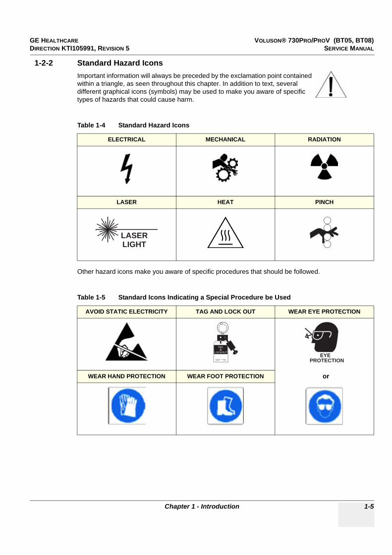
GE HEALTHCARE VOLUSON® 730PRO/PROV (BT05, BT08)DIRECTION KTI105991, REVISION 5 SERVICE MANUAL
Chapter 1 - Introduction 1-5
1-2-2 Standard Hazard IconsImportant information will always be preceded by the exclamation point contained within a triangle, as seen throughout this chapter. In addition to text, several different graphical icons (symbols) may be used to make you aware of specific types of hazards that could cause harm.
Other hazard icons make you aware of specific procedures that should be followed.
Table 1-4 Standard Hazard Icons
ELECTRICAL MECHANICAL RADIATION
LASER HEAT PINCH
Table 1-5 Standard Icons Indicating a Special Procedure be Used
AVOID STATIC ELECTRICITY TAG AND LOCK OUT WEAR EYE PROTECTION
WEAR HAND PROTECTION WEAR FOOT PROTECTION
LASERLIGHT
Signed Date
TAG &
LOCKOUT
EYEPROTECTION
or
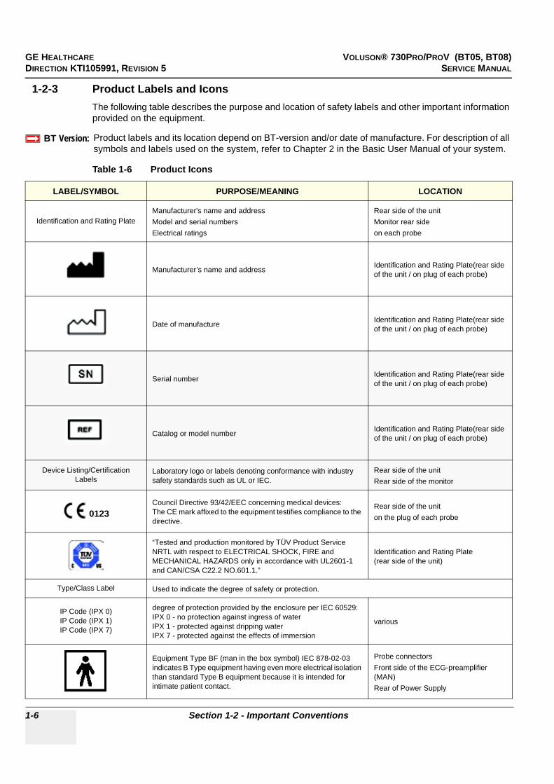
GE HEALTHCARE VOLUSON® 730PRO/PROV (BT05, BT08)DIRECTION KTI105991, REVISION 5 SERVICE MANUAL
1-6 Section 1-2 - Important Conventions
1-2-3 Product Labels and IconsThe following table describes the purpose and location of safety labels and other important information provided on the equipment.
BT Version:BT-Version:
Product labels and its location depend on BT-version and/or date of manufacture. For description of all symbols and labels used on the system, refer to Chapter 2 in the Basic User Manual of your system.
Table 1-6 Product Icons
LABEL/SYMBOL PURPOSE/MEANING LOCATION
Identification and Rating PlateManufacturer's name and addressModel and serial numbersElectrical ratings
Rear side of the unitMonitor rear sideon each probe
Manufacturer’s name and address Identification and Rating Plate(rear side of the unit / on plug of each probe)
Date of manufacture Identification and Rating Plate(rear side of the unit / on plug of each probe)
Serial number Identification and Rating Plate(rear side of the unit / on plug of each probe)
Catalog or model number Identification and Rating Plate(rear side of the unit / on plug of each probe)
Device Listing/Certification Labels
Laboratory logo or labels denoting conformance with industry safety standards such as UL or IEC.
Rear side of the unitRear side of the monitor
Council Directive 93/42/EEC concerning medical devices: The CE mark affixed to the equipment testifies compliance to the directive.
Rear side of the uniton the plug of each probe
“Tested and production monitored by TÜV Product Service NRTL with respect to ELECTRICAL SHOCK, FIRE and MECHANICAL HAZARDS only in accordance with UL2601-1 and CAN/CSA C22.2 NO.601.1.”
Identification and Rating Plate(rear side of the unit)
Type/Class Label Used to indicate the degree of safety or protection.
IP Code (IPX 0)IP Code (IPX 1)IP Code (IPX 7)
degree of protection provided by the enclosure per IEC 60529:IPX 0 - no protection against ingress of waterIPX 1 - protected against dripping waterIPX 7 - protected against the effects of immersion
various
Equipment Type BF (man in the box symbol) IEC 878-02-03 indicates B Type equipment having even more electrical isolation than standard Type B equipment because it is intended for intimate patient contact.
Probe connectors Front side of the ECG-preamplifier (MAN)Rear of Power Supply
0123

GE HEALTHCARE VOLUSON® 730PRO/PROV (BT05, BT08)DIRECTION KTI105991, REVISION 5 SERVICE MANUAL
Chapter 1 - Introduction 1-7
To identify a defibrillation-proof type CF (heart in box with “electrodes”, symbol IEC 60878-5336) applied part complying with IEC 60601-1.
Front side of the ECG-preamplifier
“CAUTIONThis unit weighs...
Special care must be used to avoid..." This precaution is intended to prevent injury that may result if one
person attempt to move the unit considerable distances or on an incline due to the weight of the unit.
Used in the Service and User Manual which should be adjacent to equipment at all times for quick reference.
Pushing prohibited.Do not lean on the system. Tipping danger.Take special care when moving the system
various
Loading prohibited.Do not put any items on this shelf. Danger of breaking.Also items might be crushed when lowering the user interface.
at top cover of the system
“ATTENTION” - Read and understand all instructions for use”This symbol advises the reader to consult the accompanyingdocuments (operator manual or other instructions).
rear side of the unit
"DANGER -Risk of explosion used in..."
The system is not designed for use with flammable anesthetic gases. Indicated in the Service Manual.
"CAUTION" The equilateral triangle is usually used in combination with other symbols to advise or warn the user. various
ATTENTION - Consult accompanying documents " is intended to alert the user to refer to the operator manual or other instructions when complete information cannot be provided on the label.
Rear side of Power Supply
"CAUTION - Dangerous voltage" (the lightning flash with arrowhead in equilateral triangle) is used to indicate electric shock hazards.
Rear side of Monitor
"Mains OFF" Indicates the power off position of the mains power switch.
rear of system at mains switch (on primary power supply - RTN)
"OFF/Standby" Indicates the power off/standby position of the power switch.CAUTIONThis Power Switch DOES NOT ISOLATE Mains Supply
Adjacent to On-Off/Standby switch left below the Control panel.
Table 1-6 Product Icons (Continued)
LABEL/SYMBOL PURPOSE/MEANING LOCATION
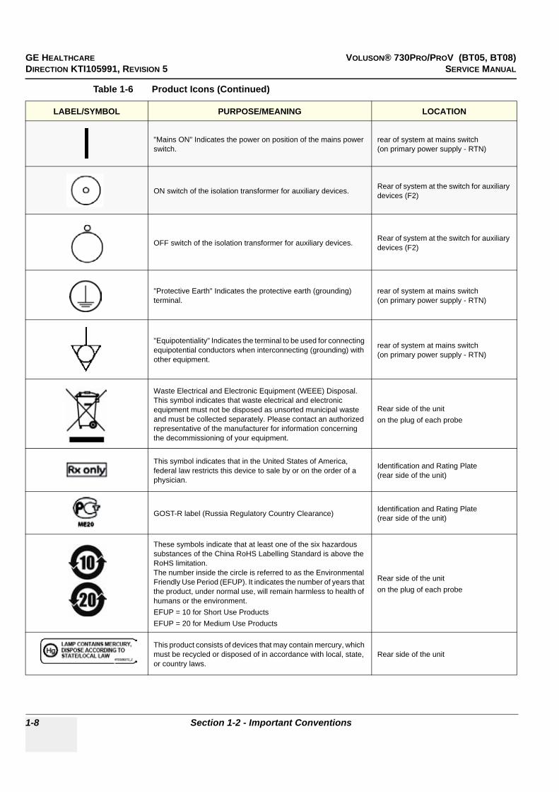
GE HEALTHCARE VOLUSON® 730PRO/PROV (BT05, BT08)DIRECTION KTI105991, REVISION 5 SERVICE MANUAL
1-8 Section 1-2 - Important Conventions
"Mains ON" Indicates the power on position of the mains power switch.
rear of system at mains switch (on primary power supply - RTN)
ON switch of the isolation transformer for auxiliary devices. Rear of system at the switch for auxiliary devices (F2)
OFF switch of the isolation transformer for auxiliary devices. Rear of system at the switch for auxiliary devices (F2)
"Protective Earth" Indicates the protective earth (grounding) terminal.
rear of system at mains switch (on primary power supply - RTN)
"Equipotentiality" Indicates the terminal to be used for connecting equipotential conductors when interconnecting (grounding) with other equipment.
rear of system at mains switch (on primary power supply - RTN)
Waste Electrical and Electronic Equipment (WEEE) Disposal.This symbol indicates that waste electrical and electronic equipment must not be disposed as unsorted municipal waste and must be collected separately. Please contact an authorized representative of the manufacturer for information concerning the decommissioning of your equipment.
Rear side of the uniton the plug of each probe
This symbol indicates that in the United States of America, federal law restricts this device to sale by or on the order of a physician.
Identification and Rating Plate(rear side of the unit)
GOST-R label (Russia Regulatory Country Clearance) Identification and Rating Plate(rear side of the unit)
These symbols indicate that at least one of the six hazardous substances of the China RoHS Labelling Standard is above the RoHS limitation. The number inside the circle is referred to as the Environmental Friendly Use Period (EFUP). It indicates the number of years that the product, under normal use, will remain harmless to health of humans or the environment.EFUP = 10 for Short Use ProductsEFUP = 20 for Medium Use Products
Rear side of the uniton the plug of each probe
This product consists of devices that may contain mercury, which must be recycled or disposed of in accordance with local, state, or country laws.
Rear side of the unit
Table 1-6 Product Icons (Continued)
LABEL/SYMBOL PURPOSE/MEANING LOCATION

GE HEALTHCARE VOLUSON® 730PRO/PROV (BT05, BT08)DIRECTION KTI105991, REVISION 5 SERVICE MANUAL
Chapter 1 - Introduction 1-9
Section 1-3Safety Considerations
1-3-1 IntroductionThe following safety precautions must be observed during all phases of operation, service and repair of this equipment. Failure to comply with these precautions or with specific warnings elsewhere in this manual, violates safety standards of design, manufacture and intended use of the equipment.
1-3-2 Human SafetyOperating personnel must not remove the system covers. Servicing should be performed by authorized personnel only. Only personnel who have participated in a Voluson® 730Pro/ProV Training are authorized to service the equipment.
1-3-3 Mechanical Safety
NOTE: Special care should be taken when transporting the unit in a vehicle:
• Secure the systems with straps in an upright position and lock the caster wheels (brake).• DO NOT use the Control Panel as an anchor point.• Place the probes in their carrying case.• Eject any DVD, CD or Magneto Optical disk (MOD) from their drive. • Ensure that the Voluson® 730Pro/ProV system is firmly secured while inside the vehicle.• Prevent vibration damage by driving cautiously.
Avoid unpaved roads, excessive speeds, and erratic stops or starts.
WARNINGWARNING!! WARNING:
USE EXTREME CAUTION WHEN ELEVATING THE UNIT, OR IF IT IS RAISED FOR A REPAIR OR MOVED ALONG ANY INCLINE. IT MAY BECOME UNSTABLE WHICH COULD CAUSE THE UNIT TO TIP OVER.
WARNINGWARNING!! WARNING:
ULTRASOUND PROBES ARE HIGHLY SENSITIVE MEDICAL INSTRUMENTS THAT CAN EASILY BE DAMAGED BY IMPROPER HANDLING. USE CARE WHEN HANDLING AND PROTECT FROM DAMAGE WHEN NOT IN USE. DO NOT USE A DAMAGED OR DEFECTIVE PROBE. FAILURE TO FOLLOW THESE PRECAUTIONS CAN RESULT IN SERIOUS INJURY AND EQUIPMENT DAMAGE.
WARNINGWARNING!! WARNING:
NEVER USE A PROBE THAT HAS FALLEN TO THE FLOOR. EVEN IF IT LOOKS OK, IT MAY BE DAMAGED.
CAUTION!! CAUTION:
Always lower and center the Operator I/O Panel before moving the scanner.
CAUTION!! CAUTION:
The Voluson® 730Pro/ProV weighs 136 kg or more, depending on installed peripherals, (300 lbs., or more) when ready for use. Care must be used when moving it or replacing its parts. Failure to follow the precautions listed could result in injury, uncontrolled motion and costly damage.ALWAYS:• Use the handle to move the system. • Be sure the pathway is clear. • Use slow, careful motions. • Do not let the system strike walls or door frames.Two people are required when moving on inclines or lifting more than 16 kg (35 lbs).
CAUTION!! CAUTION:
Keep the heat venting holes on the monitor unobstructed to avoid overheating of the monitor.

GE HEALTHCARE VOLUSON® 730PRO/PROV (BT05, BT08)DIRECTION KTI105991, REVISION 5 SERVICE MANUAL
1-10 Section 1-3 - Safety Considerations
1-3-4 Electrical Safety
1-3-4-1 Safe PracticesTo minimize shock hazard, the equipment chassis must be connected to an electrical ground.The system is equipped with a three-conductor AC power cable. This must be plugged into an approved electrical outlet with safety ground. If an extension cord is used with the system, make sure that the total current rating of the system does not exceed the extension cord rating.
The power outlet used for this equipment should not be shared with other types of equipment.
Both the system power cable and the power connector meet international electrical standards.
1-3-4-2 ProbesAll the probes for the Voluson® 730Pro/ProV are designed and manufactured to provide trouble-free, reliable service. To ensure this, correct handling of probes is important and the following points should be noted:
• Do not drop a probe or strike it against a hard surface, as this may damage the transducer elements, acoustic lens, or housing.
• Inspect the probe prior to each use for damage or degradation to the Housing, Cable strain relief, Lens and Seal.
• Do not use a cracked or damaged probe. In this event, call your field service representative immediately to obtain a replacement.
• Avoid pulling, pinching or kinking the probe cable, since a damaged cable may compromise the electrical safety of the probe.
• To avoid the risk of a probe accidentally falling, do not allow the probe cables to become entangled, or to be caught in the machine’s wheels.
• Never immerse the probe connector or adapter into any liquid.
NOTE: For detailed information on handling probes, refer to the Voluson® 730Pro/ProV Basic User Manual and the care card supplied with the probe.
WARNINGWARNING!! WARNING:
CONNECTING A VOLUSON® 730PRO/PROV SCANNER TO THE WRONG VOLTAGE LEVEL WILL MOST LIKELY DESTROY THE SCANNER.
GE HEALTHCARE VOLUSON® 730PRO/PROV (BT05, BT08)DIRECTION KTI105991, REVISION 5 SERVICE MANUAL
Chapter 1 - Introduction 1-11
1-3-5 Auxiliary Devices Safety
The Voluson® 730Pro/ProV is equipped with an isolation transformer to provide the required separation from mains for both, the system and the auxiliary devices.One AUX main outlet is located at the primary power supply. It is used for connecting the threefold splitter whose outlets are led to the shelves intend for auxiliary devices (e.g., printers) and the AUX main outlet that is accessible on the back of the control console.
The IEC 60601-1-1 standard provides a guideline for safely interconnecting medical devices in systems. “Equipment connected to the analog or digital interface must comply with the respective IEC/UL standards (e.g. IEC 60950 / UL 60950 for data processing equipment and IEC 60601-1 / UL 60601-1 for medical equipment). Everybody who connects additional equipment to the signal input portion or signal output portion configures a medical system, and is therefore responsible that the system complies with the requirements of the system standard IEC 60601-1-1.
Special care has to be taken, if the device is connected to computer network (e.g., Ethernet), because other devices could be connected without any control. There could be a potential difference between the protective earth and any line of the computer network including the shield.
In this case the only way to operate the system safely is to use an isolated signal link with minimum 4mm creepage distance, 2.5mm air clearance of the isolation device. For computer networks there are media converters available which convert the electrical to optical signals. Please consider that this converter has to comply with IEC xxx standards* and is battery operated.
* IEC xxx stands for standards such as:
• IEC 60601 for medical devices• IEC 60950 for information technology equipment etc.
WARNINGWARNING!! WARNING:
Power Supplies for additional equipment MUST comply with IEC 60601-1.
WARNINGWARNING!! WARNING:
DO NOT attempt to use different peripherals and accessories (brand and model; con-nected via the PCMCIA or USB ports) other than approved and provided byGE Healthcare! The ultrasound system is an extremely sensitive and complex medical system. Any unauthorized peripherals may cause system failure or damage!
NOTICE!! NOTICE:
The system integrator (any person connecting the medical device to other devices) is responsible that the connections are safe.If in doubt, consult the technical service department or your local representative.
CAUTION!! CAUTION:
The leakage current of the entire system including any / all auxiliary equipment must not exceed the limit values as per EN 60601-1-1:1990 (IEC 60601-1-1) respectively other valid national or in-ternational standards. All equipment must comply with UL, CSA and IEC requirements.
CAUTION!! CAUTION:
Please observe that some printers may not be medical devices! If the Bluetooth Printer and/or Line Printers are no medical devices, they have to be located outside of the patient environment (according to IEC 60601-1 / UL 60601-1).

GE HEALTHCARE VOLUSON® 730PRO/PROV (BT05, BT08)DIRECTION KTI105991, REVISION 5 SERVICE MANUAL
1-12 Section 1-3 - Safety Considerations
1-3-5 Auxiliary Devices Safety (cont’d)
For hardware installation procedures see: Section 3-5 "Connection of Auxiliary Devices" on page 3-9.
1-3-6 Labels LocationsThe Voluson® 730Pro/ProV system comes equipped with product labels and icons.These labels and icons represent pertinent information regarding the operation of the unit.
1.)Caution2.)WEEE Disposal Icon3.)CE Label4.)UL Label (not on all systems, depend on date and location of manufacturing)5.)Identification “Main” Label6.)CW-Doppler (only if the CW-Doppler option is installed)7.)Rating Label (only at systems made in Korea)8.)Quality Control Label9.)place for addtional label (e.g., “Homologation label” for Japan or China only)
CAUTION!! CAUTION:
Auxiliary equipment must only be connected to the main console with the special main outlet provided for the electrical safety of the system.
WARNINGWARNING!! WARNING:
After each installation, the leakage currents have to be measured according toIEC 60601-1 respectively UL 60601-1 (see: Section 10-7-2 on page 10-16).
NOTICE All peripherals mounted on the Voluson® 730Pro/ProV system chassis must be firmly securedin position.
BT Version: Product labels and its location depend on BT-version and/or date of manufacture.Refer to Section 1-2-3 on page 1-6 and Chapter 2 in the Basic User Manual of your system.
Figure 1-1 Labeling
1
3 4 5 7 82 6
9

GE HEALTHCARE VOLUSON® 730PRO/PROV (BT05, BT08)DIRECTION KTI105991, REVISION 5 SERVICE MANUAL
Chapter 1 - Introduction 1-13
1-3-7 Dangerous Procedure WarningsWarnings, such as the examples below, precede potentially dangerous procedures throughout this manual. Instructions contained in the warnings must be followed.
1-3-8 Lockout/Tagout Requirements (For USA Only)Follow OSHA Lockout/Tagout requirements to protect service personnel from injuries caused by unexpected energizing or start-up of equipment during service, repair, or maintenance.
1-3-9 Returning/Shipping Probes and Repair PartsEquipment being returned must be clean and free of blood and other infectious substances.
GEMS policy states that body fluids must be properly removed from any part or equipment prior to shipment. GEMS employees, as well as customers, are responsible for ensuring that parts/equipment have been properly decontaminated prior to shipment. Under no circumstance should a part or equipment with visible body fluids be taken or shipped from a clinic or site (for example, body coils or and ultrasound probe).
The purpose of the regulation is to protect employees in the transportation industry, as well as the people who will receive or open this package.
NOTE: The US Department of Transportation (DOT) has ruled that “items what were saturated and/or dripping with human blood that are now caked with dried blood; or which were used or intended for use in patient care” are “regulated medical waste” for transportation purpose and must be transported as a hazardous material.
DANGER!! DANGER:
DANGEROUS VOLTAGES, CAPABLE OF CAUSING DEATH, ARE PRESENT IN THIS EQUIPMENT. USE EXTREME CAUTION WHEN HANDLING, TESTING AND ADJUSTING.
WARNINGWARNING!! WARNING:
EXPLOSION WARNINGDO NOT OPERATE THE EQUIPMENT IN AN EXPLOSIVE ATMOSPHERE. OPERATION OF ANY ELECTRICAL EQUIPMENT IN SUCH AN ENVIRONMENT CONSTITUTES A DEFINITE SAFETY HAZARD.
WARNINGWARNING!! WARNING:
DO NOT SUBSTITUTE PARTS OR MODIFY EQUIPMENTBECAUSE OF THE DANGER OF INTRODUCING ADDITIONAL HAZARDS, DO NOT INSTALL SUBSTITUTE PARTS OR PERFORM ANY UNAUTHORIZED MODIFICATION OF THE EQUIPMENT.
NOTICE!! NOTICE:
Energy Control and Power Lockout for Voluson® 730Pro/ProV.When servicing parts of the system where there is exposure to voltage greater than 30 Volts:Unplug the systemMaintain control of the system power plugThere are no test points to verify isolation, you must wait for at least 20 seconds for capacitors to discharge.Beware that the Power Supply (CPN), Front End Processor and Back End Processor may be energized even if the power is turned off when the cord is still plugged into the AC Outlet.UT
Signed Date
TAG &
LOCKOUT
GE HEALTHCARE VOLUSON® 730PRO/PROV (BT05, BT08)DIRECTION KTI105991, REVISION 5 SERVICE MANUAL
1-14 Section 1-4 - Electromagnetic Compatibility (EMC)
Section 1-4Electromagnetic Compatibility (EMC)
1-4-1 What is EMC?Electromagnetic compatibility describes a level of performance of a device within its electromagnetic environment. This environment consists of the device itself and its surroundings including other equipment, power sources and persons with which the device must interface. Inadequate compatibility results when a susceptible device fails to perform as intended due interference from its environment or when the device produces unacceptable levels of emission to its environment. This interference is often referred to as radio–frequency or electromagnetic interference (RFI/EMI) and can be radiated through space or conducted over interconnecting power of signal cables. In addition to electromagnetic energy, EMC also includes possible effects from electrical fields, magnetic fields, electrostatic discharge and disturbances in the electrical power supply.
For applicable standards refer to Chapter 2 in the Basic User Manual of the Voluson® 730Pro/ProV.
1-4-2 ComplianceThe Voluson® 730Pro/ProV unit conforms to all applicable conducted and radiated emission limits and to immunity from electrostatic discharge, radiated and conducted RF fields, magnetic fields and power line transient requirements.
NOTE: For CE Compliance, it is critical that all covers, screws, shielding, gaskets, mesh, clamps, are in good condition, installed tightly without skew or stress. Proper installation following all comments noted in this service manual is required in order to achieve full EMC performance.
1-4-3 Electrostatic Discharge (ESD) Prevention
WARNINGWARNING!! WARNING:
DO NOT touch any boards with integrated circuits prior to taking the necessary ESD precautions: 1.) When installing boards, ESD may cause damage to a board.
ALWAYS connect yourself, via an arm-wrist strap, to the advised ESD connectionpoint located on the rear of the system (to the right of the power connector).
2.) Follow general guidelines for handling of electrostatic sensitive equipment.
WARNINGWARNING!! WARNING:
Risk of electrical shock, system must be turned off. Avoid all contact with electrical contacts, conductors and components. Always use non-conductive handles designed for the removal and replacement of ESD sensitive parts. All parts that have the potential for storing energy must be discharged or isolated before making contact.

GE HEALTHCARE VOLUSON® 730PRO/PROV (BT05, BT08)DIRECTION KTI105991, REVISION 5 SERVICE MANUAL
Chapter 1 - Introduction 1-15
Section 1-5Customer Assistance
1-5-1 Contact InformationIf this equipment does not work as indicated in this service manual or in the Basic User Manual, or if you require additional assistance, please contact the local distributor or appropriate support resource, as listed below.
NOTE: Prepare vital system information (see: Section 7-2 on page 7-2) before you call:
• System Type• System Serial number (also visible on label on back of the system)• Application Software version• Backup version• additional information about installed software
1-5-2 System Manufacturer
Table 1-7 Phone Numbers for Customer Assistance
Location Phone Number
USAGE Medical SystemsUltrasound Service Engineering9900 Innovation Drive (RP-2123)Wauwatosa, WI 53226, USA
Service: On-site
Service Parts
Applications Support
1-800-437-1171
1-800-558-2040
1-800-682-5327 or 1-262-524-5698
Canada 1-800-668-0732
Latin AmericaServiceApplications support
1-800-321-79371-262-524-5698
EuropeGE Ultraschall Deutschland GmbHBeethovenstraße 239Postfach 11 05 60, D-42655 SolingenGermany
OLC - EMEA (Europe, Middle East & Africa)Phone: +49 (0)212 2802 - 652 (OLC)
+33 1 3083 1300 (English/German all segments incl. train-ing)
Online Services Ultrasound AsiaAustraliaChinaIndiaJapanKoreaSingapore
Phone: +(61) 1-800-647-855+(86) 800-810-8188+(91) 1800-425-8025+(81) 42-648-2940+(82) 2620 13585+(95) 6277-3444
Table 1-8 System Manufacturer
Manufacturer Telephone FAX
GE Healthcare Austria GmbH & Co OGTiefenbach 15A-4871 ZipfAustria
+43 (0) 7682-3800-0 +43 (0) 7682-3800-47

GE HEALTHCARE VOLUSON® 730PRO/PROV (BT05, BT08)DIRECTION KTI105991, REVISION 5 SERVICE MANUAL
1-16 Section 1-5 - Customer Assistance
This page was intentionally left blank.

GE HEALTHCARE VOLUSON® 730PRO/PROV (BT05, BT08)DIRECTION KTI105991, REVISION 5 SERVICE MANUAL
Chapter 2 - Site Preparation 2-1
Chapter 2Site Preparation
Section 2-1Overview
2-1-1 Purpose of Chapter 2This chapter provides the information required to plan and prepare the installation of a Voluson® 730Pro/ProV ultrasound unit. Included are descriptions of the facility and electrical needs to be met by the purchaser of the unit.
Section 2-2General Console Requirements
2-2-1 Environmental Requirements
2-2-1-1 CoolingThe cooling requirement for the Voluson® 730Pro/ProV is 3446 BTU/hr. This figure does not include cooling needed for lights, people, or other equipment in the room.
NOTE: Each person in the room places an additional 300 BTU/hr. demand on the cooling system.
2-2-1-2 LightingBright light is needed for system installation, updates and repairs. However, operator and patient comfort may be optimized if the room light is subdued and indirect. Therefore a combination lighting system (dim/bright) is recommended. Keep in mind that lighting controls and dimmers can be a source of EMI which could degrade image quality. These controls should be selected to minimize possible interference.
Table 2-1 Contents in Chapter 2
Section Description Page Number
2-1 Overview 2-1
2-2 General Console Requirements 2-1
2-3 Facility Needs 2-5
Table 2-2 Environmental Requirements
Operating Temperature
OperatingHumidity Heat Dissipation
Storage Temperature Storage Humidity
10 to 30oC (50 to 104oF)
30 to 80% rH non-condensing 3446 BTU pr hour -10 to 40 oC
(14 to 104oF)< 90% rH non-
condensing
CAUTION!! CAUTION:
If the system has been in storage or has been transported, please see the acclimation requirements before powering ON and/or using the system (see: Section 3-2-2 "Installation Warnings" on page 3-2).

GE HEALTHCARE VOLUSON® 730PRO/PROV (BT05, BT08)DIRECTION KTI105991, REVISION 5 SERVICE MANUAL
2-2 Section 2-2 - General Console Requirements
2-2-2 Electrical Requirements
NOTE: GE Medical Systems requires a dedicated power and ground for the proper operation of its Ultrasound equipment. This dedicated power shall originate at the last distribution panel before the system.
The dedicated line shall consist of one phase, a neutral (not shared with any other circuit), and a full size Ground wire from the distribution panel to the Ultrasound outlet.
NOTE: Please note that image artifacts can occur, if at any time within the facility, the Ground from the main facility's incoming power source to the Ultrasound unit is only a conduit.
2-2-2-1 Voluson® 730Pro/ProV Power Requirements
Power Consumption nominal 920 VA including all options.Mains outlets: Mains socket ST1, ST2, ST3, ST4, ST5 for accessories.All mains outlets are co-switched by the unit’s mains switch via built-in isolation transformer.Output voltage for: ST1 - ST5: 115V or 230V.
2-2-2-2 Inrush CurrentInrush current isn’t a factor to consider due to the inrush current limiting properties of the power supplies
2-2-2-3 Site Circuit BreakerIt is recommended that the branch circuit breaker for the machine be readily accessible.
2-2-2-4 Site Power OutletsA dedicated AC power outlet must be within reach of the unit without extension cords. Other adequate outlets for the external peripherals, medical and test equipment needed to support this unit must also be present within 1 m (3.2 ft.) of the unit. Electrical installation must meet all current local, state, and national electrical codes.
2-2-2-5 Main Power PlugThe Voluson® 730Pro/ProV is supplied with a main power plug, as standard.In the event that the unit arrives without a power plug, or with the wrong plug, contact your GE dealer. When necessary, the installation engineer will supply the appropriate power plug to meet the applicable local regulations.
Table 2-3 Electrical Specifications for Voluson® 730Pro/ProV
Voltage Tolerances Current Frequency
100 VAC ±10% 9,2 A 50, 60 Hz (±2%)
115 VAC ±10% 8.00 A 50, 60 Hz (±2%)
130 VAC ±10% 7.10 A 50, 60 Hz (±2%)
230 VAC ±10% 4.00 A 50, 60 Hz (±2%)
240 VAC ±10% 3,85 A 50, 60 Hz (±2%)
CAUTION!! CAUTION:
Modification of voltage setting only by an authorized service person! The maximum power consumption of equipment (inclusive color video monitor) connected to these outlets must not exceed 350VA!
CAUTION!! CAUTION:
POWER OUTAGE MAY OCCUR. The Voluson® 730Pro/ProV requires a dedicated single branch circuit. To avoid circuit overload and possible loss of critical care equipment, make sure you DO NOT have any other equipment operating on the same circuit.

GE HEALTHCARE VOLUSON® 730PRO/PROV (BT05, BT08)DIRECTION KTI105991, REVISION 5 SERVICE MANUAL
Chapter 2 - Site Preparation 2-3
2-2-3 EMI LimitationsUltrasound machines are susceptible to Electromagnetic Interference (EMI) from radio frequencies, magnetic fields, and transients in the air or wiring. Ultrasound machines also generate EMI. The Voluson® 730Pro/ProV complies with limits as stated on the EMC label. However, there is no guarantee that interference will not occur in a particular installation.
Electrical and electronic equipment may produce EMI unintentionally as the result of a defect. These sources include:
• medical lasers• scanners• cauterizing guns• computers• monitors• fans• gel warmers• microwave oven• light dimmers • portable phones• broadcast stations and mobile broadcasting machines
NOTICE!! NOTICE:
Possible EMI sources should be identified before the unit is installed.
Table 2-4 EMI Prevention/Abatement
EMI Rule Details
Be aware of RF sources.Keep the unit at least 5 meters (16.4 feet) away from other EMI sources. Special shielding may be required to eliminate interference problems caused by high frequency, high powered radio or video broadcast signals.
Ground the unit. Poor grounding is the most likely reason a unit will have noisy images. Check grounding of the power cord and power outlet.
Replace and/or reassemble all screws, RF gaskets, covers and cores.
After you finish repairing or updating the system, replace all covers and tighten all screws.Any cable with an external connection requires a magnet wrap at each end.Install the shield over the front of card cage. Loose or missing covers or RF gaskets allow radio frequencies to interfere with the ultrasound signals.
Replace broken RF gaskets. If more than 20% or a pair of the fingers on an RF gasket are broken, replace the gasket. Do not turn ON the unit until any loose metallic part is removed and replaced, if required.
Do not place labels where RF gaskets touch metal.
Never place a label where RF gaskets meet the unit. Otherwise, the gap created will permit RF leakage. In case a label has been found in such a location, move the label to a different, appropriate location.
Use GE- specified harnesses and peripherals.
The interconnect cables are grounded and require ferrite beads and other shielding. Cable length, material, and routing are all important; do not make any changes that do not meet all specifications.
Take care with cellular phones. Cellular phones may transmit a 5 V/m signal that causes image artifacts.
Properly dress peripheral cables.
Do not allow cables to lie across the top of the card cage or hang out of the peripheral bays.Loop the excess length for peripheral cables inside the peripheral bays.Attach the monitor cables to the frame.

GE HEALTHCARE VOLUSON® 730PRO/PROV (BT05, BT08)DIRECTION KTI105991, REVISION 5 SERVICE MANUAL
2-4 Section 2-2 - General Console Requirements
2-2-4 Probe Environmental RequirementsOperation: Ambient temperature 18° to 30° C
Storage: -10° to 50° C
NOTE: Temperature in degrees C. Conversion to degrees F = °C (9/5) + 32).
2-2-5 Time and Manpower RequirementsSite preparation takes time. Begin Pre-installation checks as soon as possible. If possible, allow six weeks before delivery, for enough time to make necessary changes.
2-2-6 System Specifications
2-2-6-1 Physical Dimensions of Voluson® 730Pro/ProVThe physical dimensions of the Voluson® 730Pro/ProV unit are summarized in Table 2-5.Table 2-6 lists the size of Voluson® 730Pro/ProV, with monitor and without on-board peripherals.
2-2-6-2 Weight without Monitor and Peripherals
2-2-6-3 Acoustic Noise Outputmax. 57dB(A)
2-2-6-4 Electrical SpecificationsPlease refer to Section 2-2-2-1 "Voluson® 730Pro/ProV Power Requirements" on page 2-2.
NOTICE!! NOTICE:
SYSTEMS AND ELECTRONIC PROBES ARE DESIGNED FOR STORAGE TEMPERATURES OF-10 TO + 50 degrees C. WHEN EXPOSED TO LARGE TEMPERATURE VARIATIONS, THE PRODUCT SHOULD BE KEPT IN ROOM TEMPERATURE FOR 10 HOURS BEFORE USE.
CAUTION!! CAUTION:
Have two people available to deliver and unpack the Voluson® 730Pro/ProV.Attempts to move the unit considerable distances or on an incline by one person alone, could result in injury or damage or both.
Table 2-5 Physical Dimensions of Voluson® 730Pro/ProV
Height Width Depth
142 cm / 55.9 inches 68 cm / 26.8 inches 100 cm / 39.4 inches
Table 2-6 Weight of Voluson® 730Pro/ProV with Monitor and without other Peripherals
Model Weight [kg] Weight [lbs.]
Voluson® 730Pro/ProV 136 300

GE HEALTHCARE VOLUSON® 730PRO/PROV (BT05, BT08)DIRECTION KTI105991, REVISION 5 SERVICE MANUAL
Chapter 2 - Site Preparation 2-5
Section 2-3Facility Needs
2-3-1 Purchaser ResponsibilitiesThe work and materials needed to prepare the site is the responsibility of the purchaser. Delay, confusion, and waste of manpower can be avoided by completing pre installation work before delivery.
Use the Pre-installation checklist (provided in Table 2-7) to verify that all needed steps have been taken.
Purchaser responsibility includes:
• Procuring the materials required.• Completing the preparations before delivery of the ultrasound system.• Paying the costs for any alterations and modifications not specifically provided in the sales contract.
NOTE: All electrical installations that are preliminary to the positioning of the equipment at the site prepared for the equipment must be performed by licensed electrical contractors. Other connections between pieces of electrical equipment, calibrations, and testing must also be performed by qualified personnel. The products involved (and the accompanying electrical installations) are highly sophisticated and special engineering competence is required. All electrical work on these products must comply with the requirements of applicable electrical codes. The purchaser of GE equipment must only utilize qualified personnel to perform electrical servicing on the equipment.
The desire to use a non–listed or customer provided product or to place an approved product further from the system than the interface kit allows presents challenges to the installation team. To avoid delays during installation, such variances should be made known to the individuals or group performing the installation at the earliest possible date (preferably prior to the purchase).
The ultrasound suite must be clean prior to delivery of the machine. Carpet is not recommended because it collects dust and creates static. Potential sources of EMI (electromagnetic interference) should also be investigated before delivery. Dirt, static, and EMI can negatively impact system reliability.
Table 2-7 Voluson® 730Pro/ProV Pre-Installation Check List
Action Yes No
Schedule at least 3 hours for installation of the system.
Notify installation team of the existence of any variances from the basic installation.
Make sure system and probes have been subject to acclimation period.
Environmental cooling is sufficient.
Lighting is adjustable to adapt to varying operational conditions of the scanner.
Electrical facilities meet system requirements.
EMI precautions have been taken and all possible sources of interference have been removed.
Mandatory site requirements have been met.
If a network is used, IP address has been set for the system and a dedicated network outlet is available.
GE HEALTHCARE VOLUSON® 730PRO/PROV (BT05, BT08)DIRECTION KTI105991, REVISION 5 SERVICE MANUAL
2-6 Section 2-3 - Facility Needs
2-3-2 Mandatory Site Requirements
NOTE: GE Medical Systems requires a dedicated power and ground for the proper operation of its Ultrasound equipment. This dedicated power shall originate at the last distribution panel before the system. The dedicated line shall consist of one phase, a neutral (not shared with any other circuit), and a full size ground wire from the distribution panel to the Ultrasound outlet. Please note that image artifacts can occur, if at any time within the facility, the ground from the main facility's incoming power source to the Ultrasound unit is only a conduit.
The following are mandatory site requirements. Additional (optional) recommendations, as well as a recommended ultrasound room layout, are provided in Section 2-3-3 "Site Recommendations" .
• Door opening is at least 76 cm (30 in) wide.• Proposed location for unit is at least 0.3 m (1 ft.) from the wall for cooling• Clean and protected space for storage of probes (either in their case or on a rack).• Material to safely clean probes (performed using a plastic container, never metal).• Power outlet and place for any external peripheral are within 2 m (6.5 ft) of each other with
peripheral within 1 m of the unit to connect cables.
NOTE: The Voluson® 730Pro/ProV has four outlets inside the unit. One is for the monitor and three for on board peripherals.
In case of network option:
• An active network outlet in the vicinity of the ultrasound unit.• A network cable of appropriate length (regular Pin-to-Pin network cable).• An IT administrator who will assist in configuring the unit to work with your local network.
A fixed IP address is required. Refer to the form provided in Figure 3-89 on page 3-72 for network details that are required.
NOTE: All relevant preliminary network port installations at the prepared site must be performed by authorized contractors. The purchaser of GE equipment must utilize only qualified personnel to perform servicing of the equipment.
2-3-3 Site RecommendationsThe following are (optional) site recommendations. Mandatory site requirements are provided in the Mandatory Site Requirements section, above.
• Door is at least 90 cm (3 ft.) wide• Circuit breaker for dedicated power outlet is easily accessible• Sink with hot and cold water• Receptacle for bio–hazardous waste, like used probe sheaths• Emergency oxygen supply• Storage for linens and equipment• Nearby waiting room, lavatory, and dressing room• Dual level lighting (bright and dim)• Lockable cabinet ordered by GE for its software and proprietary manuals

GE HEALTHCARE VOLUSON® 730PRO/PROV (BT05, BT08)DIRECTION KTI105991, REVISION 5 SERVICE MANUAL
Chapter 2 - Site Preparation 2-7
2-3-3-1 Recommended Ultrasound Room LayoutFigure 2-1 below shows a floor plan illustrating the recommended layout of the Ultrasound Room and depicting the minimal room layout requirements.
Figure 2-1 Recommended Floor Plan 4.3m x 5.2m (14ft x 17ft)
35.5 IN. (92 CM)
Dedicated Power Outlets
Hospital Network
Cabinet forSoftware and Manuals(optional)
VOLUSON

GE HEALTHCARE VOLUSON® 730PRO/PROV (BT05, BT08)DIRECTION KTI105991, REVISION 5 SERVICE MANUAL
2-8 Section 2-3 - Facility Needs
2-3-4 Networking Pre-installation Requirements
2-3-4-1 Purpose of the DICOM Network FunctionDICOM (Digital Imaging and Communications in Medicine) services provide the operator with clinically useful features for moving images and patient information over a hospital network. Examples of DICOM services include the transfer of images to workstations for viewing or transferring images to remote printers. As an added benefit, transferring images in this manner frees up the on-board monitor and peripherals, enabling viewing to be done while scanning continues. With DICOM, images can be archived, stored, and retrieved faster, easier, and at a lower cost.
2-3-4-2 DICOM Option Pre-installation RequirementsTo configure the Voluson® 730Pro/ProV to work with other network connections, the site’s network administrator must provide some necessary information.
To configure the Voluson® 730Pro/ProV ultrasound unit to work with other network connections, the network administrator must provide some necessary information.
Use the Connectivity Setup Worksheet on page 3-71 to record required information that must include:
Installation see: Section 3-11 "Network IP Address Configuration" on page 3-69.
• Voluson® 730Pro/ProV Details: DICOM network details for the Voluson® 730Pro/ProV unit, incl. the host name, local port, IP address, AE title and net mask.
• Routing Information: IP addresses for the default gateway and other routers in use at the site.
• DICOM Application Information: Details of DICOM devices in use at the site, including DICOM host name, AE title, DICOM port number and IP addresses.
GE HEALTHCARE VOLUSON® 730PRO/PROV (BT05, BT08)DIRECTION KTI105991, REVISION 5 SERVICE MANUAL
Chapter 3 - Setup Instructions 3-1
Chapter 3Setup Instructions
Section 3-1Overview
3-1-1 The Purpose of Chapter 3This chapter contains information needed to setup the Voluson® 730Pro/ProV unit. Included are procedures to receive, unpack and configure the equipment. A worksheet is provided (see: page 3-71 to page 3-72) to help ensure that all the required information is available, prior to setup the system.
Table 3-1 Contents in Chapter 3
Section Description Page Number
3-1 Overview 3-1
3-2 Set Up Reminders 3-2
3-3 Receiving and Unpacking the Equipment 3-5
3-4 Preparing for Installation 3-7
3-5 Connection of Auxiliary Devices 3-9
3-6 Completing the Set Up 3-34
3-7 Printer Installation 3-38
3-8 System Configuration 3-60
3-9 Available Probes 3-68
3-10 Software/Option Configuration 3-68
3-11 Network IP Address Configuration 3-69
3-12 Connectivity Setup Worksheet 3-71
3-13 Paperwork 3-73

GE HEALTHCARE VOLUSON® 730PRO/PROV (BT05, BT08)DIRECTION KTI105991, REVISION 5 SERVICE MANUAL
3-2 Section 3-2 - Set Up Reminders
Section 3-2Set Up Reminders
3-2-1 Average Installation TimeThe Voluson® 730Pro/ProV installation and functional checkout will take approximately one hour;Voluson® 730Pro/ProV consoles with optional equipment may take slightly longer.
Once the site has been prepared, the average installation time require is shown in Table 3-2 below.
3-2-2 Installation Warnings1.) Since the Voluson® 730Pro/ProV weighs approximately 136 kg (300 lb.) without options, two
people are required to unpack it. Two people are required for installing any additional items in excess of 16kg / 35 pounds (e.g., Monitor).
2.) There are no operator serviceable components. To prevent shock, do not remove any covers or panels. Should problems or malfunctions occur, unplug the power cord. Only qualified service personnel should carry out servicing and troubleshooting.
Moving/Lifting the System
Table 3-2 Average Installation Time
Description Average Installation Time Comments
Unpacking the scanner 0.5 hours
Scanner /options / printers 0.5 to 1.5 hours Dependant on the required configuration
DICOM Option 0.5 - 1.5 hours Dependant on the configuration amount
Figure 3-1 moving or lifting the system
When pulling, moving or lifting the system, grasp it only at the rear handle of the trolley and the handle underneath the foot rest.
Do NOT pull or lift the system with the front handleof the user interface (operator panel).
WARNINGWARNING
Move the system forward or backward when goingup or down incline.Do not move the system sideways or diagonally.

GE HEALTHCARE VOLUSON® 730PRO/PROV (BT05, BT08)DIRECTION KTI105991, REVISION 5 SERVICE MANUAL
Chapter 3 - Setup Instructions 3-3
3-2-2-1 System Acclimation TimeAfter being transported, the Voluson® 730Pro/ProV system may be very cold or hot.It requires one hour for each 2.5°C increment it's temperature is below 10°C or above 40°C.
3-2-2-2 Control Panel PositionIf weight is placed on the Operator I/O Panel in it’s extended position the console could tip over.
3-2-2-3 Brake Pedal Operation
CAUTION!! CAUTION:
Equipment damage possibility. Turning the system on without acclimation after arriving at site may cause the system to be damaged.
Table 3-3 Acclimation Time
°C 60 55 50 45 40 35 30 25 20 15 10 5 0 -5 -10 -15 -20 -25 -30 -35 -40
°F 140 131 122 113 104 96 86 77 68 59 50 41 32 23 14 5 -4 -13 -22 -31 -40
hrs 8 6 4 2 0 0 0 0 0 0 0 2 4 6 8 10 12 14 16 18 20
WARNINGWARNING!! WARNING:
The system should NOT be moved with the Control Panel (UI) extended. Move the Control Panel to it’s centered and locked position. Refer to Section 6-4 on page 5.
WARNINGWARNING!! WARNING:
Monitor mounting mechanism may break if not properly supported (e.g., with packing foam) during transportation.
WARNINGWARNING!! WARNING:
REMEMBER: If the front wheels are engaged for transportation, pressing the release brake pedals (brakes on front wheels under the foot rest) once disengages the lock.

GE HEALTHCARE VOLUSON® 730PRO/PROV (BT05, BT08)DIRECTION KTI105991, REVISION 5 SERVICE MANUAL
3-4 Section 3-2 - Set Up Reminders
3-2-3 Safety Reminders
DANGER!! DANGER:
WHEN USING ANY TEST INSTRUMENT THAT IS CAPABLE OF OPENING THE AC GROUND LINE (I.E., METER’S GROUND SWITCH IS OPEN), DON’T TOUCH THE UNIT!
CAUTION!! CAUTION:
Two people should unpack the unit because of its weight. Two people are required whenever a part weighing 16kg (35 lb.) or more must be lifted.
CAUTION!! CAUTION:
If the unit is very cold or hot, do NOT turn on its power until it has had sufficient time to acclimate to its operating environment.
CAUTION!! CAUTION:
To prevent electrical shock, connect the unit to a properly grounded power outlet. Do not use a three to two prong adapter. This defeats safety grounding.
CAUTION!! CAUTION:
Do NOT wear the ESD wrist strap when you work on live circuits and more than 30 V peak is present.
CAUTION!! CAUTION:
Do not use a 20 Amp to 15 Amp adapter on the 120 Vac unit’s power cord.This unit requires a dedicated 16 A circuit.
CAUTION!! CAUTION:
DO NOT operate this unit unless all board covers and frame panels are securely in place, to ensure optimal system performance and cooling. (When covers are removed, EMI may be present).
CAUTION!! CAUTION:
OPERATOR MANUAL(S) The User Manual(s) should be fully read and understood before operating theVoluson® 730Pro/ProV and kept near the unit for quick reference.
CAUTION!! CAUTION:
ACOUSTIC OUTPUT HAZARDAlthough the ultrasound energy transmitted from the Voluson® 730Pro/ProV probe is within FDA limits, avoid unnecessary exposure. Ultrasound energy can produce heat and mechanical damage.
Figure 3-2 Environmental Labels

GE HEALTHCARE VOLUSON® 730PRO/PROV (BT05, BT08)DIRECTION KTI105991, REVISION 5 SERVICE MANUAL
Chapter 3 - Setup Instructions 3-5
Section 3-3Receiving and Unpacking the Equipment
CAUTION!! CAUTION:
Transport only with forklift or stracker truck.During transport pay attention to the point of gravity (“tilt and drop” indicator)!
Have two people available to unpack the Voluson® 730Pro/ProV. Attempts to move the unit considerable distances or on an incline by one person could result in injury or damage or both.
Figure 3-3 envelope at front panel of the crate
NOTICE!! NOTICE:
The device must only be transported in the original packaging!Unpack the devices such a way that packaging can be reused.A drill with size 20 torx bit and/or a Phillips 2 screwdriver is needed to open the crate.
Table 3-4 Unpacking Procedure
Step Task
1. Loosen the screws and remove top panel from crate; top panel is used for the ramp.
Check whether delivery is complete (according to packing list) and check visual damage!
The envelope with delivery address, packing list andinvoice is located on the front panel of the crate.
tilt and dropindicator
center
gravityof
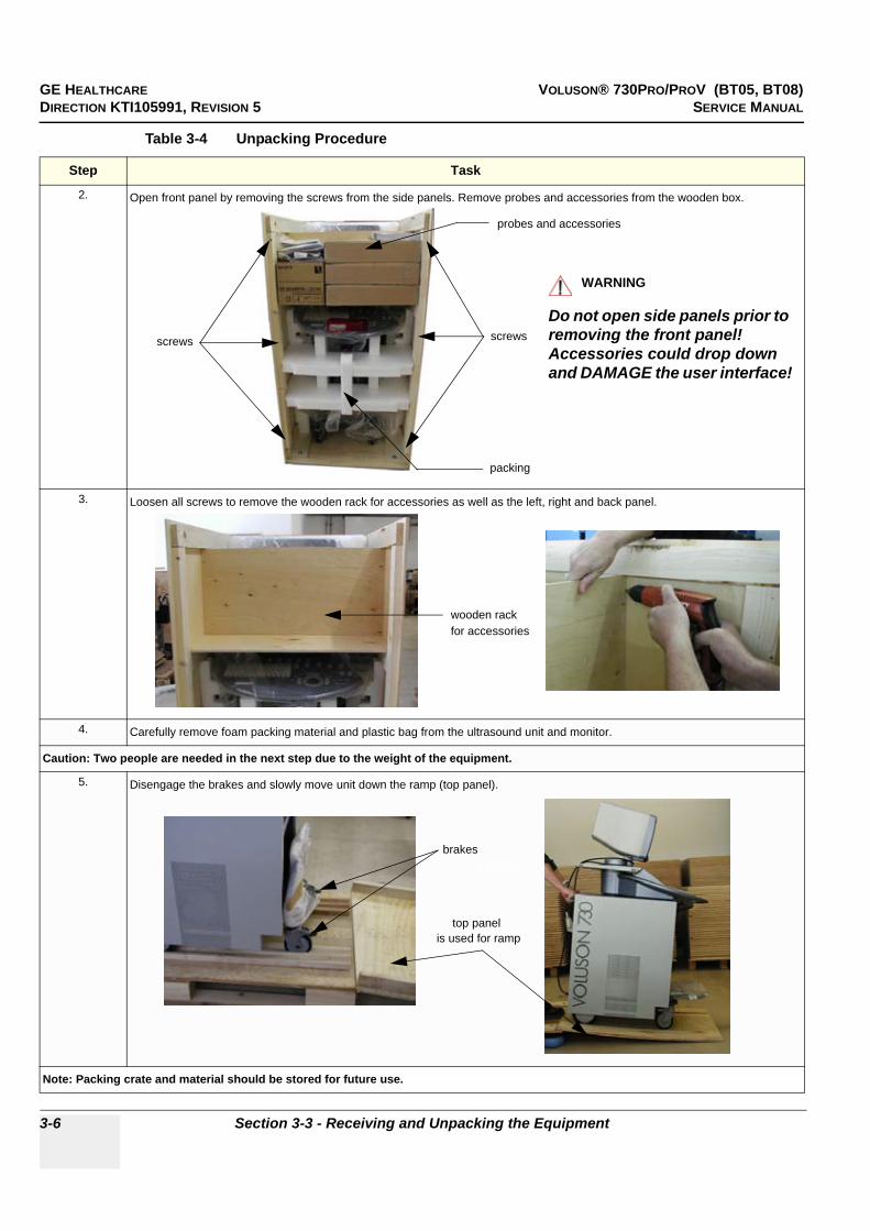
GE HEALTHCARE VOLUSON® 730PRO/PROV (BT05, BT08)DIRECTION KTI105991, REVISION 5 SERVICE MANUAL
3-6 Section 3-3 - Receiving and Unpacking the Equipment
2. Open front panel by removing the screws from the side panels. Remove probes and accessories from the wooden box.
3. Loosen all screws to remove the wooden rack for accessories as well as the left, right and back panel.
4. Carefully remove foam packing material and plastic bag from the ultrasound unit and monitor.
Caution: Two people are needed in the next step due to the weight of the equipment.
5. Disengage the brakes and slowly move unit down the ramp (top panel).
Note: Packing crate and material should be stored for future use.
Table 3-4 Unpacking Procedure
Step Task
screwsscrews
probes and accessories
packing
WARNINGWARNING!! WARNING:
Do not open side panels prior to removing the front panel!Accessories could drop down and DAMAGE the user interface!
for accessorieswooden rack
Brakesbrakes
top panel is used for ramp

GE HEALTHCARE VOLUSON® 730PRO/PROV (BT05, BT08)DIRECTION KTI105991, REVISION 5 SERVICE MANUAL
Chapter 3 - Setup Instructions 3-7
Section 3-4Preparing for Installation
3-4-1 Verify Customer Order1.) After unpacking the equipment, it is important to verify that all items ordered by the customer have
been received. Compare all items listed on the packing slip (delivery note) with those received.
2.) Visually inspect the system components using the following checklist.
NOTE: Report any items that are missing, back-ordered, or damaged, to your GE Healthcare sales representative. The contact address is shown in Contact Information on page 1-15.
NOTICE!! NOTICE:
It is recommended to keep and store the shipping carton and all other packing materials (including the support foams, anti-static plastic cover, etc.), in case the unit has to be moved to a different location. Unpack the devices such a way that packaging can be reused.For warranty purposes, storage of the above is required for one year from date of purchase.
Table 3-5 Damage Inspection Checklist - Voluson® 730Pro/ProV System
Step Item Recommended Procedure
1 Main label Enter Serial Number: __________________________ (printed on main label on back of the system)
2 Console Verify that the system is switched OFF and unplugged. Clean the console and control panel.
3 Control Console Physically inspect the control console for missing or damaged items. After switching on the system, verify the proper illumination of all the control panel buttons.
4 ProbesCheck all probes for wear and tear on the lens, cable, and connector. Look for bent or damaged pins on the connector and in the connector socket on the unit. Verify that the EMI fingers around the probe connector socket housing are intact. Check the probe locking mechanism and probe switch.
5 LCD Display Clean the LCD display by gently wiping with a dry, soft, lint-free non-abrasive folded cloth. Inspect the monitor for scratches and raster burn.
6 Fans Verify that the system’s cooling fans and peripheral fans are operating.
7 Rear Panel Check the rear panel connectors for bent pins, loose connections and loose or missing hardware. Screw all the cable connectors tightly to the connector sockets on the panel. Verify that the labeling is in good condition.
8 Covers Check that all screws are tightly secured in place, that there are no dents or scratches and that no internal parts are exposed.
9 Peripherals Check and clean the peripherals in accordance with the manufacturer’s directions.To prevent EMI or system overheating, dress the peripheral cables inside the peripheral cover.
10 Power Cord Check the power cord for cuts, loose hardware, tire marks, exposed insulation, or any deterioration. Verify continuity. Replace the power cord, as required.
11 System Voltagesetting
Verify that the Voluson® 730Pro/ProV is set to the correct voltage.see: Section 3-4-2 "System Voltage Settings" on page 3-8
b

GE HEALTHCARE VOLUSON® 730PRO/PROV (BT05, BT08)DIRECTION KTI105991, REVISION 5 SERVICE MANUAL
3-8 Section 3-4 - Preparing for Installation
3-4-2 System Voltage SettingsVerify that the scanner is set to the correct voltage. The Voltage settings for the Voluson® 730Pro/ProV Scanner is found on the identification plate, on the rear of the system.
3-4-3 EMI ProtectionThis unit has been designed to minimize the effects of Electo-Magnetic Interference (EMI). Many of the covers, shields, and screws are provided primarily to protect the system from image artifacts caused by this interference. For this reason, it is imperative that all covers and hardware are installed and secured before the unit is put into operation.
Ensure that the system is protected from electromagnetic interference (EMI), as follows:
• Operate the system at least 15 feet away from equipment that emits strong electromagnetic radiation.
• Operate the system in an area enclosed by walls, floors and ceilings comprised of wood, plaster or concrete, which help prevent EMI.
• Shield the system when operating it in the vicinity of radio broadcast equipment, if necessary.
• Do not operate mobile phones or other EMI emitting devices in the ultrasound room.
• Verify that all EMI rules listed in the following table are followed:The Voluson® 730Pro/ProV ultrasound unit is approved for use in hospitals, clinics and other environmentally qualified facilities, in terms of the prevention of radio wave interference. Operation of the ultrasound unit in an inappropriate environment can cause electronic interference to radios and television sets situated near the medical equipment. For further details and EMI Prevention/Abatement refer to Section 2-2-3 "EMI Limitations" on page 2-3.
Figure 3-4 Identification Plate
WARNINGWARNING!! WARNING:
CONNECTING A Voluson® 730Pro/ProV SCANNER TO THE WRONG VOLTAGE LEVEL WILL MOST LIKELY DESTROY THE SCANNER.
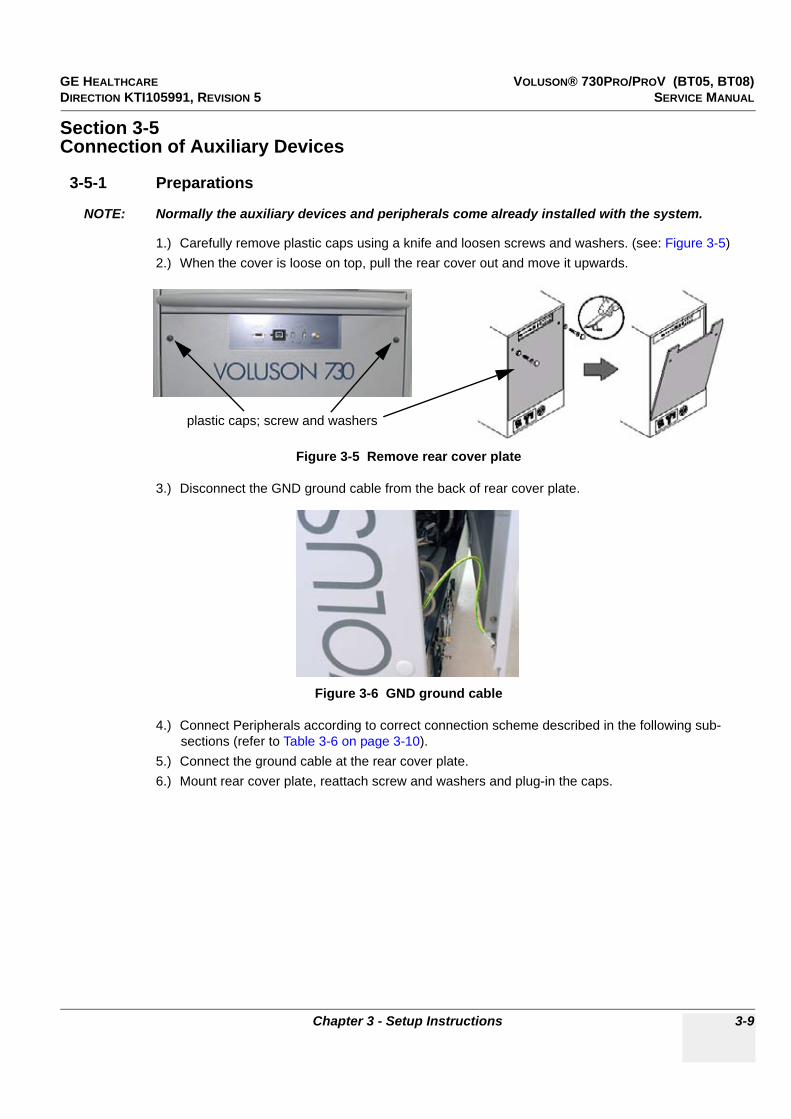
GE HEALTHCARE VOLUSON® 730PRO/PROV (BT05, BT08)DIRECTION KTI105991, REVISION 5 SERVICE MANUAL
Chapter 3 - Setup Instructions 3-9
Section 3-5Connection of Auxiliary Devices
3-5-1 Preparations
NOTE: Normally the auxiliary devices and peripherals come already installed with the system.
1.) Carefully remove plastic caps using a knife and loosen screws and washers. (see: Figure 3-5)2.) When the cover is loose on top, pull the rear cover out and move it upwards.
3.) Disconnect the GND ground cable from the back of rear cover plate.
4.) Connect Peripherals according to correct connection scheme described in the following sub-sections (refer to Table 3-6 on page 3-10).
5.) Connect the ground cable at the rear cover plate.6.) Mount rear cover plate, reattach screw and washers and plug-in the caps.
Figure 3-5 Remove rear cover plate
Figure 3-6 GND ground cable
plastic caps; screw and washers

GE HEALTHCARE VOLUSON® 730PRO/PROV (BT05, BT08)DIRECTION KTI105991, REVISION 5 SERVICE MANUAL
3-10 Section 3-5 - Connection of Auxiliary Devices
3-5-1 Preparations (cont’d)
Table 3-6 below outlines Voluson® 730Pro/ProV hardware installation procedures described in the sub-sections.
NOTE: For more detailed Safety Considerations when connecting auxiliary devices to theVoluson® 730Pro/ProV system, please review: Chapter 1 - Auxiliary Devices Safety.
Table 3-6 Connection Procedures
Sub-section Description Page Number
3-5-2 Monitor Connection 3-11
3-5-3 Foot Switch Connection 3-11
3-5-4 ECG-preamplifier Connection 3-11
3-5-5 Global Modem Connection 3-12
3-5-6 S-VHS Video Recorder Connection 3-13
3-5-7 DVD Recorder (DVR) Connection 3-15
3-5-8 B/W Video Printer Connection 3-19
3-5-9 Line Printer Connection 3-21
3-5-10 Digital Color Printer Connection 3-22
3-5-11 Bluetooth Printer Connection 3-23
3-5-12 Worldwide 19’’ secondary “Patient” Monitor kit 3-25
3-5-13 External USB-Devices 3-32
WARNINGWARNING!! WARNING:
DO NOT attempt to use different peripherals and accessories other than approved and provided by GE Healthcare!Any unauthorized peripherals may cause system failure or damage!
WARNINGWARNING After each installation, the leakage currents have to be measured according to IEC 60601-1 respectively UL 60601-1.
CAUTION!! CAUTION:
Please observe that some printers may not be medical devices! If the Bluetooth Printer and/or Line Printers are not medical devices, they have to be located outside of the patient environment (according to IEC 60601-1 / UL 60601-1).
2,5 m 1,5 m
1,5 m1,5 m
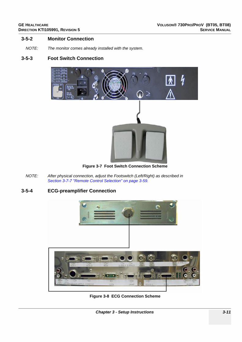
GE HEALTHCARE VOLUSON® 730PRO/PROV (BT05, BT08)DIRECTION KTI105991, REVISION 5 SERVICE MANUAL
Chapter 3 - Setup Instructions 3-11
3-5-2 Monitor Connection
NOTE: The monitor comes already installed with the system.
3-5-3 Foot Switch Connection
NOTE: After physical connection, adjust the Footswitch (Left/Right) as described inSection 3-7-7 "Remote Control Selection" on page 3-59.
3-5-4 ECG-preamplifier Connection
Figure 3-7 Foot Switch Connection Scheme
Figure 3-8 ECG Connection Scheme

GE HEALTHCARE VOLUSON® 730PRO/PROV (BT05, BT08)DIRECTION KTI105991, REVISION 5 SERVICE MANUAL
3-12 Section 3-5 - Connection of Auxiliary Devices
3-5-5 Global Modem Connection
Figure 3-9 Global Modem Connection Scheme
WARNINGWARNING!! WARNING:
Never install the telephone wiring, or use the modem during an electric storm; there may be a remote risk of electrical shock from lightning.
CAUTION!! CAUTION:
Use only the power adapter supplied with the modem and connect it as shown. Use of any other power adapter will void the warranty and could damage the modem.

GE HEALTHCARE VOLUSON® 730PRO/PROV (BT05, BT08)DIRECTION KTI105991, REVISION 5 SERVICE MANUAL
Chapter 3 - Setup Instructions 3-13
3-5-6 S-VHS Video Recorder Connection
NOTE: Please refer to connection scheme belonging to the used VCR type: • Section 3-5-6-1 "Mitsubishi HS-MD3000" on page 3-13• Section 3-5-6-2 "Sony SVO-9500MD" on page 3-14
3-5-6-1 Mitsubishi HS-MD3000
NOTE: There are two types of Mitsubishi HS-MD3000 VCR (PAL and NTSC) approved by GE Healthcare. Use the standard VCR type (PAL or NTSC) that is suited to your region.
CAUTION!! CAUTION:
ONLY the specific GE - Kretztechnik Version of this video recorder type may be used in connection with the system!
Figure 3-10 Mitsubishi - Video Recorder Connection Scheme
NOTICE!! NOTICE:
Please use the proper connection set and remote cable.see: Section 9-12 "Optional Peripherals and Accessories" on page 9-26.

GE HEALTHCARE VOLUSON® 730PRO/PROV (BT05, BT08)DIRECTION KTI105991, REVISION 5 SERVICE MANUAL
3-14 Section 3-5 - Connection of Auxiliary Devices
3-5-6-2 Sony SVO-9500MD
Figure 3-11 Video Recorder Connection Scheme
Figure 3-12 DIP Switches
NOTICE!! NOTICE:
Please use the proper connection set and remote cable.see: Section 9-12 "Optional Peripherals and Accessories" on page 9-26.
Set DIP Switches on back of the VCR as shown:Switch 1: OFF-Audio is muted during fast playbackSwitch 2: OFF-FF/REW mode is used during searches.Switch 3: ON-VCR counter is reset upon cassette ejection.Switch 4: OFF-The VCR can be controlled by the system.Switch 5 + 6: ON-The Baud rate is set to 19200 bit/sec
(must be the same as Voluson® 730Pro/ProV)

GE HEALTHCARE VOLUSON® 730PRO/PROV (BT05, BT08)DIRECTION KTI105991, REVISION 5 SERVICE MANUAL
Chapter 3 - Setup Instructions 3-15
3-5-7 DVD Recorder (DVR) Connection
When all power and signal cables are connected to the system and DVD recorder, proceed as follows:
• Adjust the DVD Recorder settings as described in Section 3-5-7-1 on page 3-16.• Check and if necessary change the Video Norm, see: Section 3-8-1-6 on page 3-63.• Check and if necessary change the Record Type + VCR Source, see: Section 3-7-7 on page 3-59.
NOTICE!! NOTICE:
Regardless of what other peripherals are installed, the DVD Recorder needs to be put on the lower shelf for easy access to the DVD tray.
NOTICE!! NOTICE:
The Sony DVO-1000MD DVD recorder is only able to read and write on DVD+RW (ReWriteable) media! Please check on your DVD case before using.
Figure 3-13 DVD Recorder - Connection Scheme
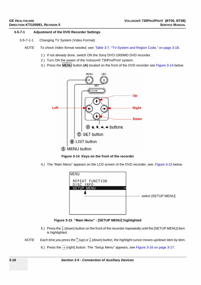
GE HEALTHCARE VOLUSON® 730PRO/PROV (BT05, BT08)DIRECTION KTI105991, REVISION 5 SERVICE MANUAL
3-16 Section 3-5 - Connection of Auxiliary Devices
3-5-7-1 Adjustment of the DVD Recorder Settings
3-5-7-1-1 Changing TV System (Video Format)
NOTE: To check Video format needed, see: Table 3-7, “TV-System and Region Code,” on page 3-18.
1.) If not already done, switch ON the Sony DVO-1000MD DVD recorder.2.) Turn ON the power of the Voluson® 730Pro/ProV system.3.) Press the MENU button (A) located on the front of the DVD recorder see Figure 3-14 below.
4.) The “Main Menu” appears on the LCD screen of the DVD recorder, see: Figure 3-15 below.
5.) Press the ↓ (down) button on the front of the recorder repeatedly until the [SETUP MENU] item is highlighted.
NOTE: Each time you press the ↑ (up) or ↓ (down) button, the highlight cursor moves up/down item by item.
6.) Press the → (right) button. The “Setup Menu” appears, see Figure 3-16 on page 3-17.
Figure 3-14 Keys on the front of the recorder
Figure 3-15 “Main Menu” - [SETUP MENU] highlighted
Up
Down
RightLeft
select [SETUP MENU]

GE HEALTHCARE VOLUSON® 730PRO/PROV (BT05, BT08)DIRECTION KTI105991, REVISION 5 SERVICE MANUAL
Chapter 3 - Setup Instructions 3-17
3-5-7-1-1 Changing TV System (Video Format) (cont’d)7.) Press the ↓ (down) button repeatedly, until [MENU GRADE] is highlighted.
8.) Press the → (right) button and select [ENHANCED].9.) Press the ← (left) button, to exit the “Menu Grade” menu.
NOTE: Now additional items (see: Figure 3-17 on page 3-17) are displayed in the “Setup Menu”.
10.)Select [TV SYSTEM] by pressing the ↓ (down) button.
11.)Press the → (right) button. The “TV System” Sub menu appears.12.)Select the appropriate video signal by pressing the ↑ (up) or ↓ (down) button respectively.
To check the video signal, see: Table 3-7, “TV-System and Region Code,” on page 3-18.13.)Press the SET button (C).
The message “Now loading...” appears and the unit starts to save the settings.14.)When “Power off” appears on the display, press the POWER switch on the front of the DVD
recorder to turn power off.15.)Press the POWER switch again to turn power on.
Figure 3-16 “Setup Menu” - [MENU GRADE] highlighted
Figure 3-17 “Setup Menu” - [TV SYSTEM] highlighted
change MENU GRADEto ENHANCED
Menu Grade: ENHANCED
TV SYSTEM
REGION CODE
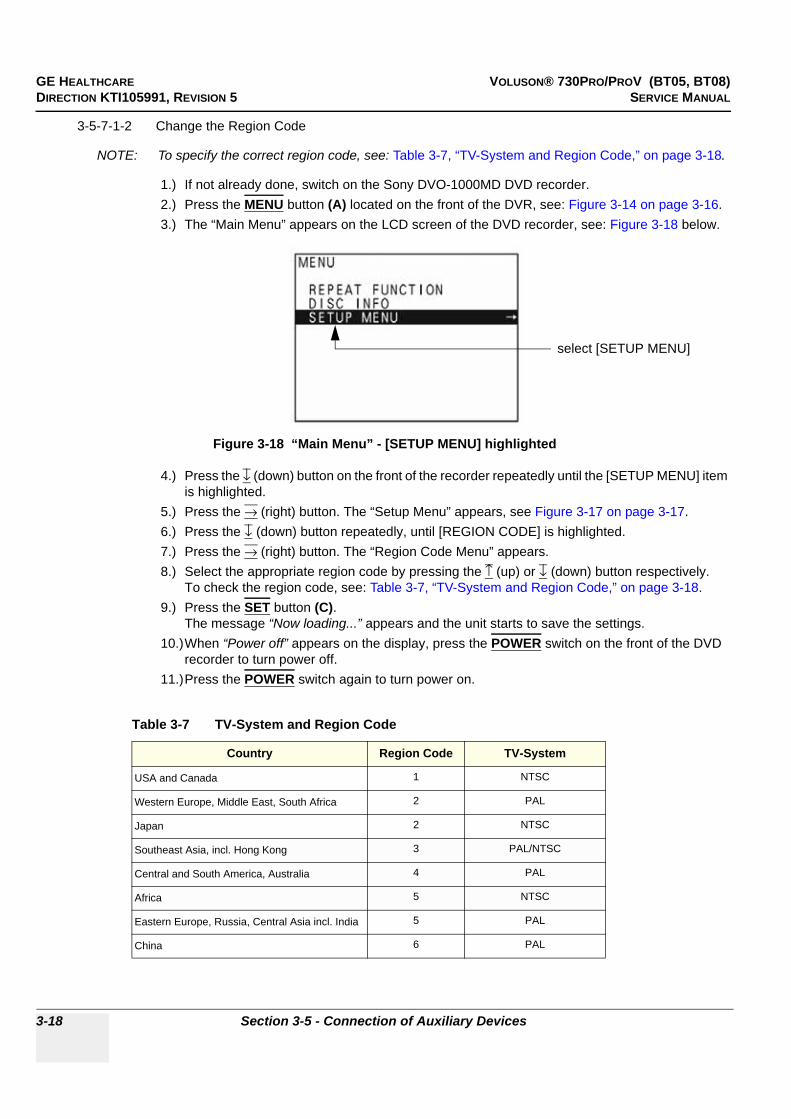
GE HEALTHCARE VOLUSON® 730PRO/PROV (BT05, BT08)DIRECTION KTI105991, REVISION 5 SERVICE MANUAL
3-18 Section 3-5 - Connection of Auxiliary Devices
3-5-7-1-2 Change the Region Code
NOTE: To specify the correct region code, see: Table 3-7, “TV-System and Region Code,” on page 3-18.
1.) If not already done, switch on the Sony DVO-1000MD DVD recorder.2.) Press the MENU button (A) located on the front of the DVR, see: Figure 3-14 on page 3-16.3.) The “Main Menu” appears on the LCD screen of the DVD recorder, see: Figure 3-18 below.
4.) Press the ↓ (down) button on the front of the recorder repeatedly until the [SETUP MENU] item is highlighted.
5.) Press the → (right) button. The “Setup Menu” appears, see Figure 3-17 on page 3-17.6.) Press the ↓ (down) button repeatedly, until [REGION CODE] is highlighted.7.) Press the → (right) button. The “Region Code Menu” appears.8.) Select the appropriate region code by pressing the ↑ (up) or ↓ (down) button respectively.
To check the region code, see: Table 3-7, “TV-System and Region Code,” on page 3-18.9.) Press the SET button (C).
The message “Now loading...” appears and the unit starts to save the settings.10.)When “Power off” appears on the display, press the POWER switch on the front of the DVD
recorder to turn power off.11.)Press the POWER switch again to turn power on.
Figure 3-18 “Main Menu” - [SETUP MENU] highlighted
Table 3-7 TV-System and Region Code
Country Region Code TV-System
USA and Canada 1 NTSC
Western Europe, Middle East, South Africa 2 PAL
Japan 2 NTSC
Southeast Asia, incl. Hong Kong 3 PAL/NTSC
Central and South America, Australia 4 PAL
Africa 5 NTSC
Eastern Europe, Russia, Central Asia incl. India 5 PAL
China 6 PAL
select [SETUP MENU]

GE HEALTHCARE VOLUSON® 730PRO/PROV (BT05, BT08)DIRECTION KTI105991, REVISION 5 SERVICE MANUAL
Chapter 3 - Setup Instructions 3-19
3-5-8 B/W Video Printer Connection
Figure 3-19 B/W Video Printer (Sony UP-895MD) - Connection Scheme
Set DIP Switches on back of the Black/White printer as shown in the image (all DOWN).
NOTICE!! NOTICE:
Please use the proper connection set.see: Section 9-12 "Optional Peripherals and Accessories" on page 9-26.

GE HEALTHCARE VOLUSON® 730PRO/PROV (BT05, BT08)DIRECTION KTI105991, REVISION 5 SERVICE MANUAL
3-20 Section 3-5 - Connection of Auxiliary Devices
3-5-8-1 Sony UP-D897 (digital)
NOTE: For further installation instructions see:Section 3-7-3 "Installing Digital Black & White Printer Sony UP-D897" on page 3-43.
Figure 3-20 B/W Video Printer (Sony UP-D897) - Connection Scheme
NOTICE!! NOTICE:
The switch of the printer has to be in ON position before starting the system.Leave printer switch always in the ON position.

GE HEALTHCARE VOLUSON® 730PRO/PROV (BT05, BT08)DIRECTION KTI105991, REVISION 5 SERVICE MANUAL
Chapter 3 - Setup Instructions 3-21
3-5-9 Line Printer Connection
NOTE: For further installation instructions see:Section 3-7-1 "Installing Line Printer HP 990cxi or HP 995c" on page 3-39.
Figure 3-21 Line Printer Connection Scheme
CAUTION!! CAUTION:
Please observe that the Line Printer (HP 990cxi or HP 995c) has to be located outside of the patient environment (acc. IEC 60601-1 / UL 2601-1).
NOTICE!! NOTICE:
The switch of the printer has to be in ON position before starting the system.Leave printer switch always in the ON position.
NOTICE!! NOTICE:
Please use the proper connection set.
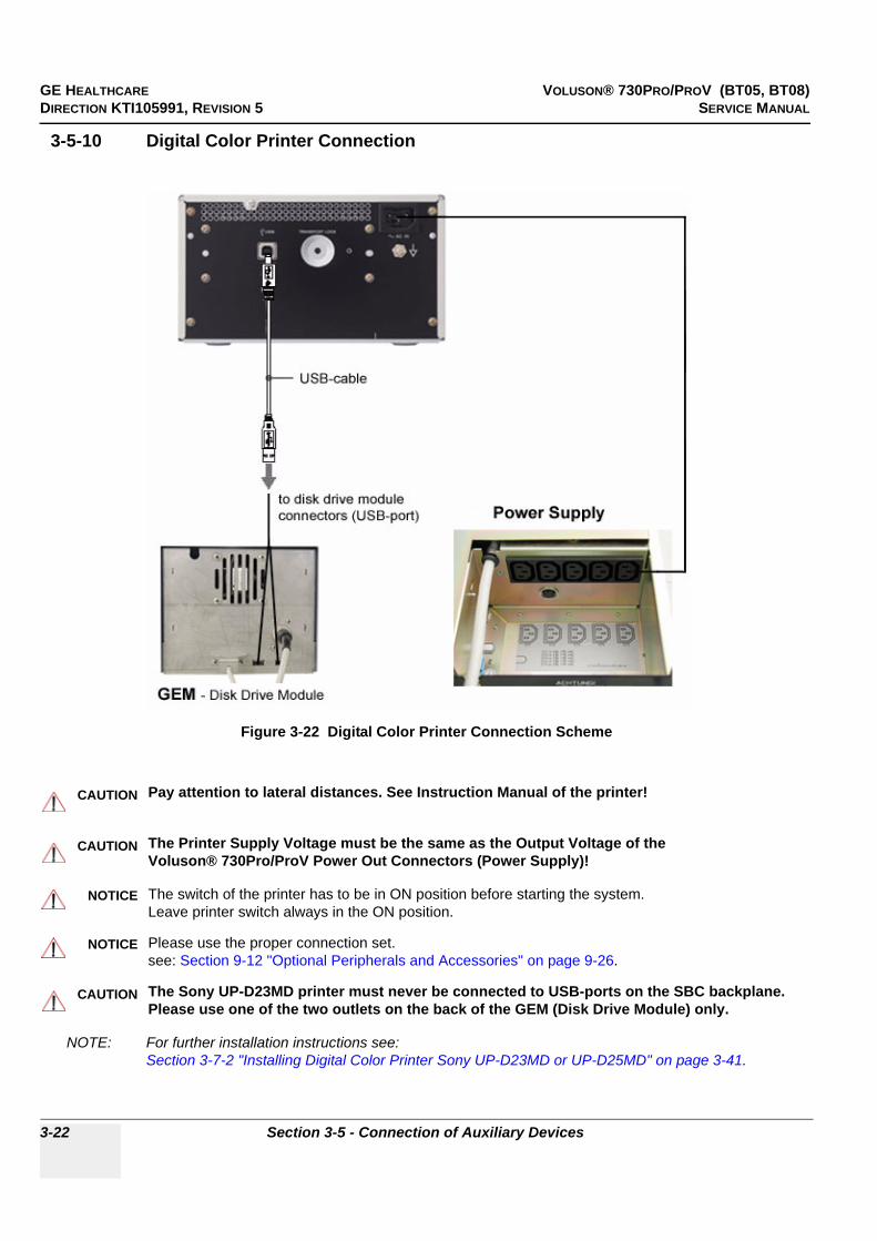
GE HEALTHCARE VOLUSON® 730PRO/PROV (BT05, BT08)DIRECTION KTI105991, REVISION 5 SERVICE MANUAL
3-22 Section 3-5 - Connection of Auxiliary Devices
3-5-10 Digital Color Printer Connection
NOTE: For further installation instructions see:Section 3-7-2 "Installing Digital Color Printer Sony UP-D23MD or UP-D25MD" on page 3-41.
Figure 3-22 Digital Color Printer Connection Scheme
CAUTION!! CAUTION:
Pay attention to lateral distances. See Instruction Manual of the printer!
CAUTION!! CAUTION:
The Printer Supply Voltage must be the same as the Output Voltage of theVoluson® 730Pro/ProV Power Out Connectors (Power Supply)!
NOTICE!! NOTICE:
The switch of the printer has to be in ON position before starting the system.Leave printer switch always in the ON position.
NOTICE!! NOTICE:
Please use the proper connection set.see: Section 9-12 "Optional Peripherals and Accessories" on page 9-26.
CAUTION!! CAUTION:
The Sony UP-D23MD printer must never be connected to USB-ports on the SBC backplane. Please use one of the two outlets on the back of the GEM (Disk Drive Module) only.

GE HEALTHCARE VOLUSON® 730PRO/PROV (BT05, BT08)DIRECTION KTI105991, REVISION 5 SERVICE MANUAL
Chapter 3 - Setup Instructions 3-23
3-5-11 Bluetooth Printer Connection
NOTE: Please refer to connection scheme belonging to the used B/W Printer type: • Section 3-5-11-1 "HP 5600/5900 Series" on page 3-23• Section 3-5-11-2 "Canon Pixma MP600/MP610" on page 3-24
3-5-11-1 HP 5600/5900 Series
Figure 3-23 HP Bluetooth Printer - Connection Scheme
CAUTION!! CAUTION:
Please observe that the complete Bluetooth Printer Assembly has to be located outside of the patient environment (acc. IEC 60601-1 / UL 60601-1).
CAUTION!! CAUTION:
The printer being used may not be a medical device. The Bluetooth Printer Set and the Power Supply of the Bluetooth Printer Adapter is also not a medical device.The equipment meets the requirements of the EN60950 Standard.
NOTICE!! NOTICE:
The switch of the printer has to be in ON position before starting the system.Leave printer switch always in the ON position.
NOTICE!! NOTICE:
Please use the proper Bluetooth Printer Connection set.see: Section 9-12 "Optional Peripherals and Accessories" on page 9-26.

GE HEALTHCARE VOLUSON® 730PRO/PROV (BT05, BT08)DIRECTION KTI105991, REVISION 5 SERVICE MANUAL
3-24 Section 3-5 - Connection of Auxiliary Devices
3-5-11-2 Canon Pixma MP600/MP610
Figure 3-24 Canon Bluetooth Printer - Connection Scheme
CAUTION!! CAUTION:
Please observe that the complete Bluetooth Printer Assembly has to be located outside of the patient environment (acc. IEC 60601-1 / UL 60601-1).
CAUTION!! CAUTION:
The Printer and the Bluetooth Printer Adapter used may not be a medical device.The equipment meets the requirements of the EN60950 Standard.
NOTICE!! NOTICE:
The switch of the printer has to be in ON position before starting the system.Leave printer switch always in the ON position.
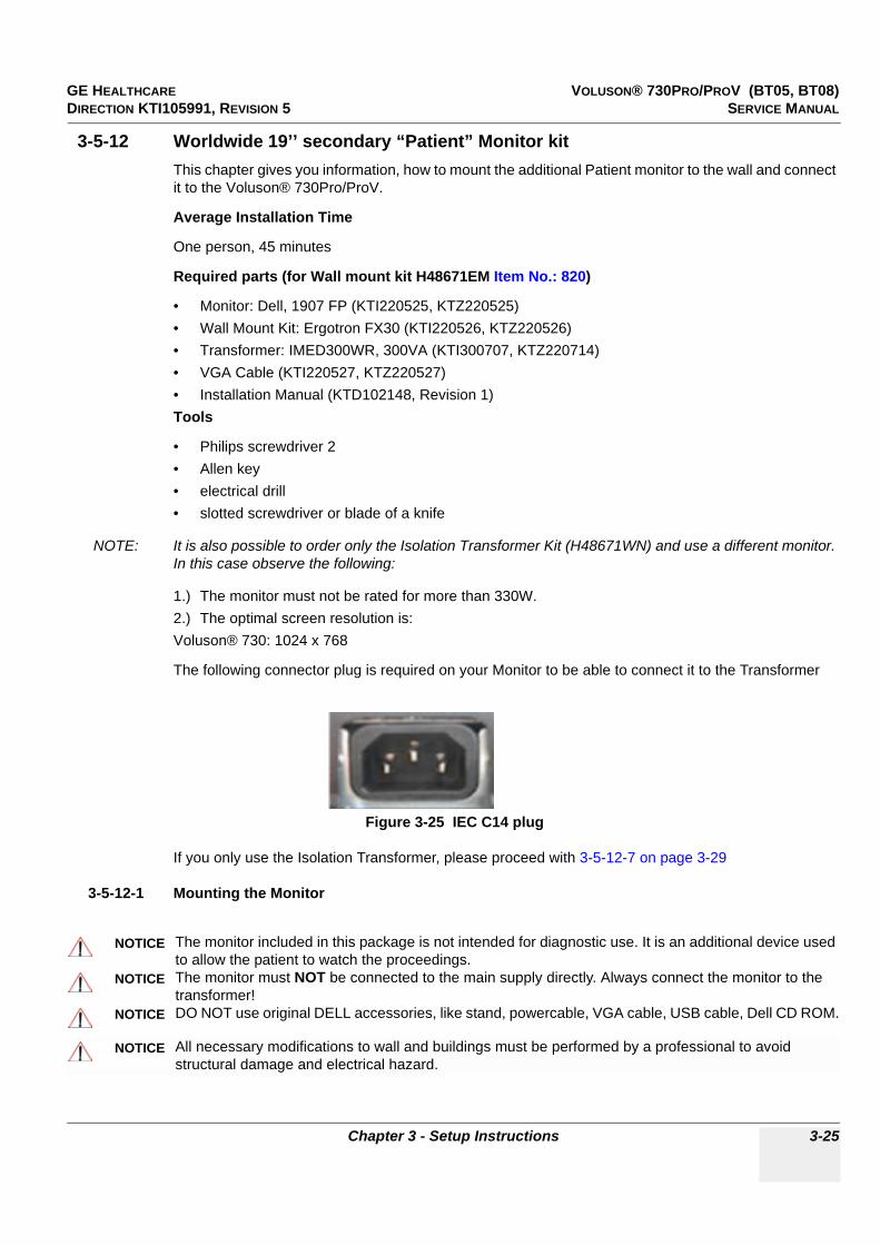
GE HEALTHCARE VOLUSON® 730PRO/PROV (BT05, BT08)DIRECTION KTI105991, REVISION 5 SERVICE MANUAL
Chapter 3 - Setup Instructions 3-25
3-5-12 Worldwide 19’’ secondary “Patient” Monitor kitThis chapter gives you information, how to mount the additional Patient monitor to the wall and connect it to the Voluson® 730Pro/ProV.
Average Installation Time
One person, 45 minutes
Required parts (for Wall mount kit H48671EM Item No.: 820)
• Monitor: Dell, 1907 FP (KTI220525, KTZ220525)• Wall Mount Kit: Ergotron FX30 (KTI220526, KTZ220526)• Transformer: IMED300WR, 300VA (KTI300707, KTZ220714)• VGA Cable (KTI220527, KTZ220527)• Installation Manual (KTD102148, Revision 1)Tools
• Philips screwdriver 2• Allen key• electrical drill• slotted screwdriver or blade of a knife
NOTE: It is also possible to order only the Isolation Transformer Kit (H48671WN) and use a different monitor. In this case observe the following:
1.) The monitor must not be rated for more than 330W.2.) The optimal screen resolution is:Voluson® 730: 1024 x 768
The following connector plug is required on your Monitor to be able to connect it to the Transformer
If you only use the Isolation Transformer, please proceed with 3-5-12-7 on page 3-29
3-5-12-1 Mounting the Monitor
Figure 3-25 IEC C14 plug
NOTICE The monitor included in this package is not intended for diagnostic use. It is an additional device used to allow the patient to watch the proceedings.
NOTICE The monitor must NOT be connected to the main supply directly. Always connect the monitor to the transformer!
NOTICE DO NOT use original DELL accessories, like stand, powercable, VGA cable, USB cable, Dell CD ROM.
NOTICE All necessary modifications to wall and buildings must be performed by a professional to avoid structural damage and electrical hazard.
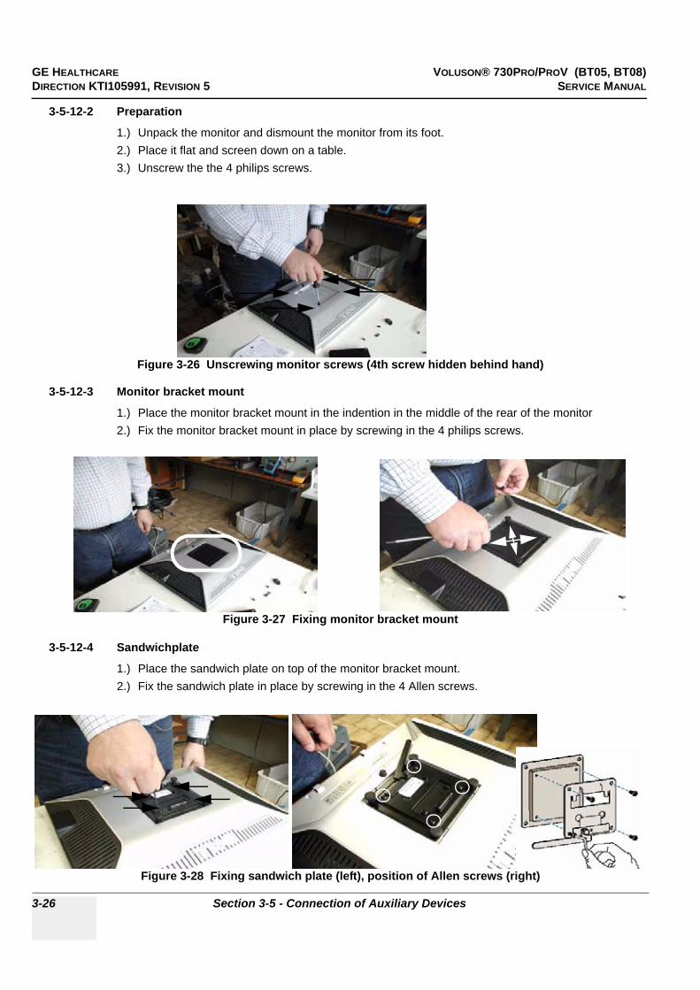
GE HEALTHCARE VOLUSON® 730PRO/PROV (BT05, BT08)DIRECTION KTI105991, REVISION 5 SERVICE MANUAL
3-26 Section 3-5 - Connection of Auxiliary Devices
3-5-12-2 Preparation
1.) Unpack the monitor and dismount the monitor from its foot.2.) Place it flat and screen down on a table.3.) Unscrew the the 4 philips screws.
3-5-12-3 Monitor bracket mount
1.) Place the monitor bracket mount in the indention in the middle of the rear of the monitor2.) Fix the monitor bracket mount in place by screwing in the 4 philips screws.
3-5-12-4 Sandwichplate
1.) Place the sandwich plate on top of the monitor bracket mount.2.) Fix the sandwich plate in place by screwing in the 4 Allen screws.
Figure 3-26 Unscrewing monitor screws (4th screw hidden behind hand)
Figure 3-27 Fixing monitor bracket mount
Figure 3-28 Fixing sandwich plate (left), position of Allen screws (right)
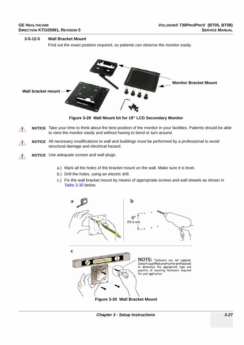
GE HEALTHCARE VOLUSON® 730PRO/PROV (BT05, BT08)DIRECTION KTI105991, REVISION 5 SERVICE MANUAL
Chapter 3 - Setup Instructions 3-27
3-5-12-5 Wall Bracket MountFind out the exact position required, so patients can observe the monitor easily.
a.) Mark all the holes of the bracket mount on the wall. Make sure it is level.b.) Drill the holes, using an electric drill.c.) Fix the wall bracket mount by means of appropriate screws and wall dowels as shown in
Table 3-30 below.
Figure 3-29 Wall Mount kit for 19” LCD Secondary Monitor
NOTICE Take your time to think about the best position of the monitor in your facilities. Patients should be able to view the monitor easily and without having to bend or turn around.
NOTICE All necessary modifications to wall and buildings must be performed by a professional to avoid structural damage and electrical hazard.
NOTICE Use adequate screws and wall plugs.
Figure 3-30 Wall Bracket Mount
Wall bracket mount
Monitor Bracket Mount

GE HEALTHCARE VOLUSON® 730PRO/PROV (BT05, BT08)DIRECTION KTI105991, REVISION 5 SERVICE MANUAL
3-28 Section 3-5 - Connection of Auxiliary Devices
3-5-12-6 Mounting and Locking Procedure
1.) Place the hook of the monitor bracket mount in the indention of the wallbracket mount to suspend the monitor.
2.) Rotate the locking lever until it is vertical. Now the monitor is mounted and secure.
NOTICE To rotate the lever to its locking position you need to press the unlock button of the monitor, as seen in Figure 3-31 below.
Figure 3-31 Mounting and Locking Procedure
Figure 3-32 Removal Procedure
LeverUnlockbutton
Hook of Monitor Bracket mount

GE HEALTHCARE VOLUSON® 730PRO/PROV (BT05, BT08)DIRECTION KTI105991, REVISION 5 SERVICE MANUAL
Chapter 3 - Setup Instructions 3-29
3-5-12-7 Mounting the Transformer
1.) Place the isolation transformer on the floor. The transformer must be out of the reach of the patient, however, it needs to be within cablelength from the monitor and a socket.
2.) Before using the Isolation Transformer you must check the input Voltage settings to meet the ratings of the line power available in your location or country.
3.) For changing the input voltage, open the power inlet block with a small screwdriver and remove the red fuse holder.
4.) By turning the fuse holder you can switch between 115V and 230V. Consider that changing the input voltage also requires to change the fuses!
5.) The adjusted voltage can be seen in the viewing window after closing the fuse box.
NOTICE The transformer is IPX 0. There is no protection against ingress of liquids!
Figure 3-33 Isolation Transformer kit for 19’’ LCD Secondary Monitor
Figure 3-34 changing input voltage
Figure 3-35 input voltage setting
Monitor Power cable
Fuses 2AT, 4AT
isolation Transformer
Power Cord set
115V (100-130V) -> 4AT230V (220-240V) -> 2AT

GE HEALTHCARE VOLUSON® 730PRO/PROV (BT05, BT08)DIRECTION KTI105991, REVISION 5 SERVICE MANUAL
3-30 Section 3-5 - Connection of Auxiliary Devices
3-5-12-7 Mounting the Transformer (cont’d)6.) The output voltage must also be changed by the turn-switch, which is located on the right side.7.) For that purpose use an appropriate screwdriver and make sure the the transformer is switched off.
8.) Assure that the connected loads can be operated with the chosen voltage.
3-5-12-8 RewiringThe VGA cable needs to be connected
Figure 3-36 output voltage setting
Figure 3-37 VGA Cable Connection Voluson® 730
NOTICE Do NOT try to connect the monitor to the systems via USB cable. Use the VGA cable.
NOTICE The monitor must NOT be connected to the main supply directly. Always connect the monitor to the transformer!
NOTICE The monitor is the only item to be connected to the transformer.
For an Input-Voltage Range of 100-130Vset to position A.For an Input-Voltage Range of 220-240Vset to position B.
Rear Side of V730
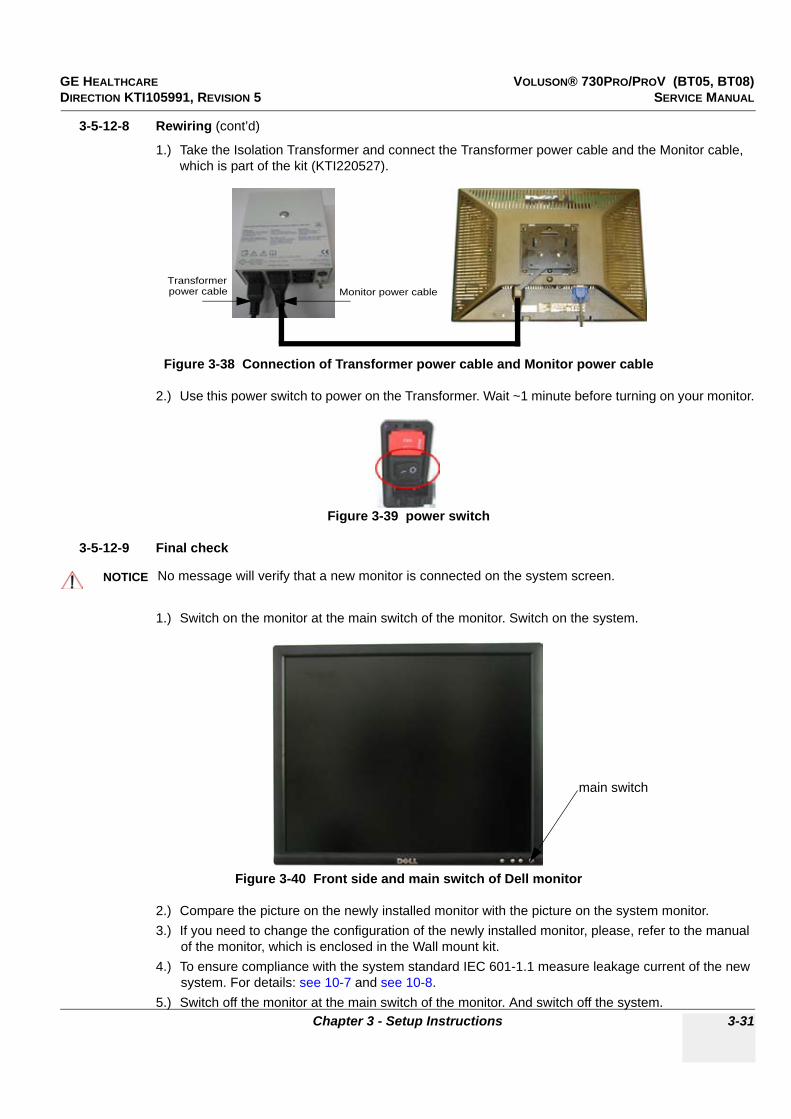
GE HEALTHCARE VOLUSON® 730PRO/PROV (BT05, BT08)DIRECTION KTI105991, REVISION 5 SERVICE MANUAL
Chapter 3 - Setup Instructions 3-31
3-5-12-8 Rewiring (cont’d)
1.) Take the Isolation Transformer and connect the Transformer power cable and the Monitor cable, which is part of the kit (KTI220527).
2.) Use this power switch to power on the Transformer. Wait ~1 minute before turning on your monitor.
3-5-12-9 Final check
1.) Switch on the monitor at the main switch of the monitor. Switch on the system.
2.) Compare the picture on the newly installed monitor with the picture on the system monitor.3.) If you need to change the configuration of the newly installed monitor, please, refer to the manual
of the monitor, which is enclosed in the Wall mount kit.4.) To ensure compliance with the system standard IEC 601-1.1 measure leakage current of the new
system. For details: see 10-7 and see 10-8.5.) Switch off the monitor at the main switch of the monitor. And switch off the system.
Figure 3-38 Connection of Transformer power cable and Monitor power cable
Figure 3-39 power switch
NOTICE No message will verify that a new monitor is connected on the system screen.
Figure 3-40 Front side and main switch of Dell monitor
Monitor power cableTransformerpower cable
main switch

GE HEALTHCARE VOLUSON® 730PRO/PROV (BT05, BT08)DIRECTION KTI105991, REVISION 5 SERVICE MANUAL
3-32 Section 3-5 - Connection of Auxiliary Devices
3-5-13 External USB-Devices
3-5-13-1 External USB Devices - ConnectionWhen an external USB-storage device (such as a USB-memory stick or external hard disk) is connected to the Voluson® 730Pro/ProV system, Windows detects the device and automatically installs a driver. During this process, several dialogs may pop up, starting with the „Found New Hardware“ dialog.
The device is then accessible using the drive letter the system assigned to it.
3-5-13-2 External USB Devices - DisconnectionBefore an external USB-device (e.g., USB-memory stick) can be disconnected, the system has to be informed about the removal of the device! For this purpose the System Setup - BACKUP page (see: Figure 4-22 on page 4-32) has a STOP USB DEVICES button.
By clicking the STOP USB DEVICES button, the „Unplug or Eject Hardware“ dialog is started.Using this dialog, the USB-devices can be stopped before they are physically disconnected.
WARNINGWARNING!! WARNING:
Do not connect or disconnect any external USB-devices to or from the system while scanning a patient! The appearing dialogs could distract you from the scan!
Figure 3-41 Found New Hardware - USB Device
NOTICE!! NOTICE:
When connecting external USB devices, be sure to execute Safety Directions found in Chapter 2 of the Voluson® 730Pro/ProV Basic User Manual.
CAUTION!! CAUTION:
Unplugging or ejecting USB devices without first stopping them can often cause the system to crash and possibly result in loss of valuable data.
Figure 3-42 Unplug or Eject Hardware

GE HEALTHCARE VOLUSON® 730PRO/PROV (BT05, BT08)DIRECTION KTI105991, REVISION 5 SERVICE MANUAL
Chapter 3 - Setup Instructions 3-33
3-5-13-2 External USB Devices - Disconnection (cont’d) The „Unplug or Eject Hardware“ dialog shows all USB-devices that are connected to the system. On every system is an USB mass storage device, the DVD/CD writer, which has the drive letter (F:). If the system has an optional MO-drive installed as well, it is listed too, and has the drive letter (E:).
To stop the external device, select it and click the STOP button. A dialog shows which components will be stopped. To finish the process, click [OK].
Finally, a dialog shows that the device was stopped successfully.The device can now be safely disconnected from the system.
By clicking OK, the „Unplug or Eject Hardware“ dialog is active again.
Close this dialog by clicking CLOSE.
Afterwards select OK to reboot the system.
Figure 3-43 Stop a Hardware device
Figure 3-44 Safe to Remove Hardware
CAUTION!! CAUTION:
If the system’s DVD/CD writer or (optional) MO-drive was stopped by accident, simply stop the external device as well and reboot the system. During reboot, the DVD/CD writer and the MO-drive will be installed again.

GE HEALTHCARE VOLUSON® 730PRO/PROV (BT05, BT08)DIRECTION KTI105991, REVISION 5 SERVICE MANUAL
3-34 Section 3-6 - Completing the Set Up
Section 3-6Completing the Set Up
3-6-1 Connecting the Unit to a Power SourceThe connection of the Voluson® 730Pro/ProV ultrasound unit to a power source should be performed by a qualified person who has completed basic Voluson® 730Pro/ProV System User Training. Use only the power cords, cables and plugs provided by or designated by GE Healthcare to connect the unit to the power source.
3-6-2 Power On / Boot Up
3-6-2-1 Scanner Power On
1.) Connect the Power Cable to the back of the system.2.) Connect the Main Power Cable to a hospital grade power receptacle with the proper rated voltage.
Never use an adapter that would defeat the safety ground. 3.) Switch ON the Circuit Breaker at the rear of the system.
CAUTION!! CAUTION:Prior to
Prior to connect the Voluson® 730Pro/ProV unit to a power source, verify compliance with all electrical and safety requirements. Check the power cord to verify that it is intact and of hospital-grade. Products equipped with a power source (wall outlet) plug should be connected to the fixed power socket that has a protective grounding conductor. Never use an adapter or converter to connect with a power source plug (for example, a three-prong to two-prong converter).
WARNINGWARNING!! WARNING:
The unit’s power must be supplied from a separate, properly rated outlet to avoid risk of fire. Refer to Section 2-2-2-1 "Voluson® 730Pro/ProV Power Requirements" on page 2-2 for rating information. The power cord should not, under any circumstances, be altered to a configuration rated less than that specified for the current.
CAUTION!! CAUTION:
Whenever disconnecting the Voluson® 730Pro/ProV unit from the electrical outlet, always observe the safety precautions. First unplug the main power cable from the wall outlet socket, then from the unit itself. Remove by pulling on the cable connector - DO NOT pull on the cable.
CAUTION!! CAUTION:
The Voluson® 730Pro/ProV requires all covers!Operate this system only when all board covers and frame panels are securely in place.The covers are required for safe operation, good system performance and cooling purposes.
Figure 3-45 Circuit Breaker at rear of system
NOTICE!! NOTICE:
When AC power is applied to the scanner, the ON/OFF switch on the control panel is illuminated, indicating that the System (including the Back-end Processor) is in standby mode.
Circuit Breaker
Connector forMains Power Cable

GE HEALTHCARE VOLUSON® 730PRO/PROV (BT05, BT08)DIRECTION KTI105991, REVISION 5 SERVICE MANUAL
Chapter 3 - Setup Instructions 3-35
3-6-2-2 Back-end Processor Boot UpPress the ON/OFF Standby switch left below the Control Panel.
NOTE: The mains outlet of the system for peripheral auxiliary equipment are commonly switched with the Standby switch. The switch of printers has to be in ON position before starting the system.However, be aware some auxiliary equipment may switch itself to standby mode when Standby power is on (e.g., Color video printer) and must therefore be switched on separately.
When the ON/OFF Standby switch left below the Control Panel is pressed, the System (including the Back-end Processor) starts and the operating system is loaded which then leads the application software to activate the scanner.
The system automatically performs an initialization sequence which includes the following:
- Loading the operating system.- Running a quick diagnostic check of the system.- Detecting connected probes
As soon as the software has been loaded, the system enters 2D-Mode with the probe and application that were used before the system was shut down.
NOTE: Total time used for start-up is about 2 minutes.
Figure 3-46 ON/OFF Standby Switch
ON/OFF Standby Switch
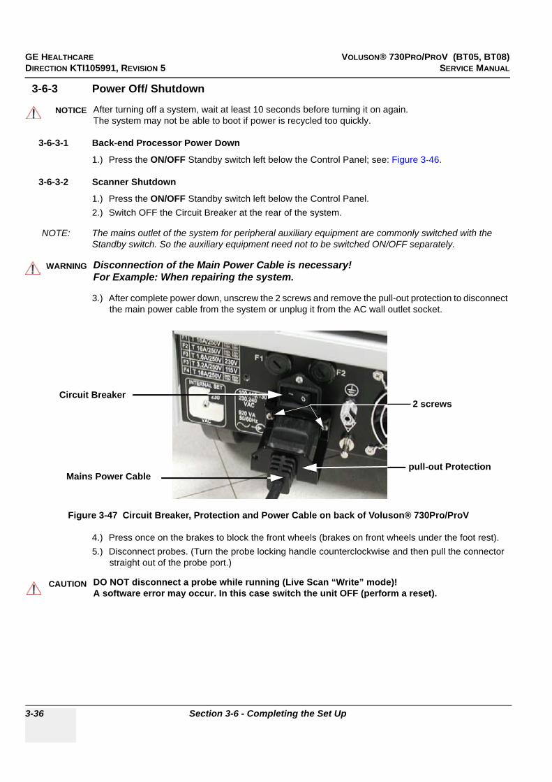
GE HEALTHCARE VOLUSON® 730PRO/PROV (BT05, BT08)DIRECTION KTI105991, REVISION 5 SERVICE MANUAL
3-36 Section 3-6 - Completing the Set Up
3-6-3 Power Off/ Shutdown
3-6-3-1 Back-end Processor Power Down
1.) Press the ON/OFF Standby switch left below the Control Panel; see: Figure 3-46.
3-6-3-2 Scanner Shutdown
1.) Press the ON/OFF Standby switch left below the Control Panel.2.) Switch OFF the Circuit Breaker at the rear of the system.
NOTE: The mains outlet of the system for peripheral auxiliary equipment are commonly switched with the Standby switch. So the auxiliary equipment need not to be switched ON/OFF separately.
3.) After complete power down, unscrew the 2 screws and remove the pull-out protection to disconnect the main power cable from the system or unplug it from the AC wall outlet socket.
4.) Press once on the brakes to block the front wheels (brakes on front wheels under the foot rest).5.) Disconnect probes. (Turn the probe locking handle counterclockwise and then pull the connector
straight out of the probe port.)
NOTICE!! NOTICE:
After turning off a system, wait at least 10 seconds before turning it on again. The system may not be able to boot if power is recycled too quickly.
WARNINGWARNING!! WARNING:
Disconnection of the Main Power Cable is necessary! For Example: When repairing the system.
Figure 3-47 Circuit Breaker, Protection and Power Cable on back of Voluson® 730Pro/ProV
CAUTION!! CAUTION:
DO NOT disconnect a probe while running (Live Scan “Write” mode)! A software error may occur. In this case switch the unit OFF (perform a reset).
Circuit Breaker
Mains Power Cablepull-out Protection
2 screws
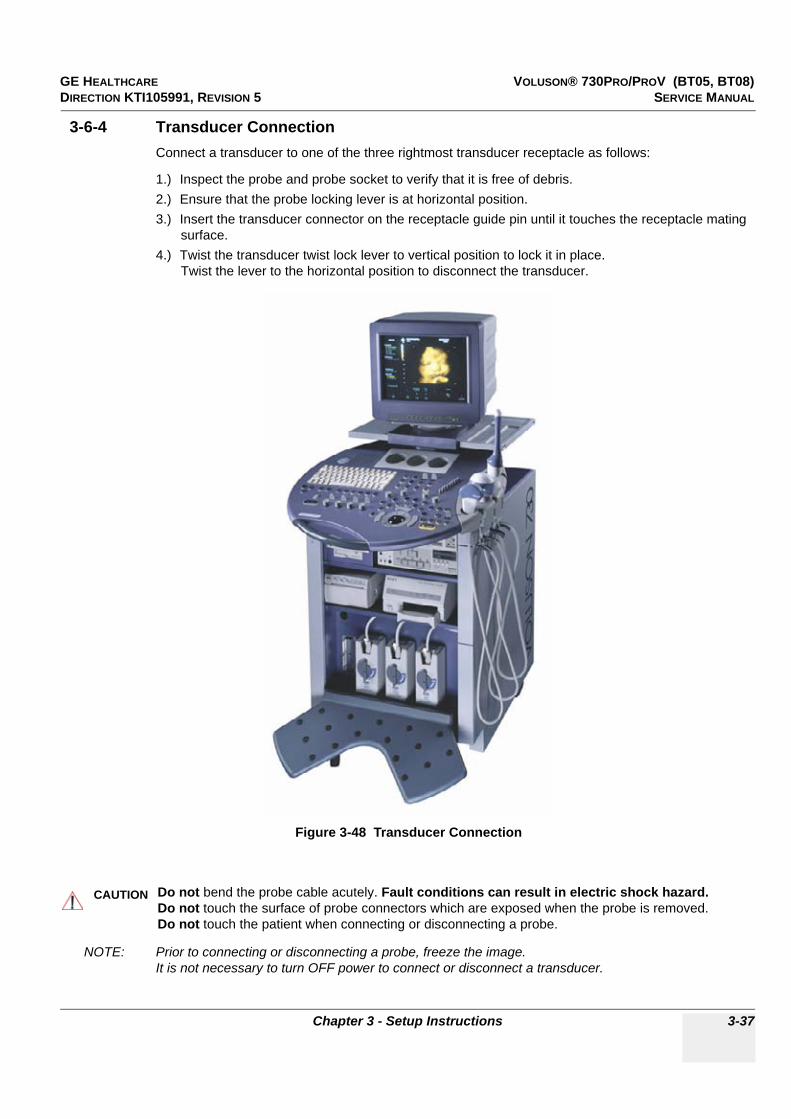
GE HEALTHCARE VOLUSON® 730PRO/PROV (BT05, BT08)DIRECTION KTI105991, REVISION 5 SERVICE MANUAL
Chapter 3 - Setup Instructions 3-37
3-6-4 Transducer ConnectionConnect a transducer to one of the three rightmost transducer receptacle as follows:
1.) Inspect the probe and probe socket to verify that it is free of debris.2.) Ensure that the probe locking lever is at horizontal position.3.) Insert the transducer connector on the receptacle guide pin until it touches the receptacle mating
surface.4.) Twist the transducer twist lock lever to vertical position to lock it in place.
Twist the lever to the horizontal position to disconnect the transducer.
NOTE: Prior to connecting or disconnecting a probe, freeze the image. It is not necessary to turn OFF power to connect or disconnect a transducer.
Figure 3-48 Transducer Connection
CAUTION!! CAUTION:
Do not bend the probe cable acutely. Fault conditions can result in electric shock hazard.Do not touch the surface of probe connectors which are exposed when the probe is removed.Do not touch the patient when connecting or disconnecting a probe.
GE HEALTHCARE VOLUSON® 730PRO/PROV (BT05, BT08)DIRECTION KTI105991, REVISION 5 SERVICE MANUAL
3-38 Section 3-7 - Printer Installation
Section 3-7Printer Installation
NOTE: For Connection schemes refer to Section 3-5 "Connection of Auxiliary Devices" on page 3-9.
For further installation instructions see:
• Section 3-7-1 "Installing Line Printer HP 990cxi or HP 995c" on page 3-39.• Section 3-7-2 "Installing Digital Color Printer Sony UP-D23MD or UP-D25MD" on page 3-41.• Section 3-7-3 "Installing Digital Black & White Printer Sony UP-D897" on page 3-43• Section 3-7-4 "Installing Mitsubishi B&W P95 and Color Printer CP30" on page 3-45• Section 3-7-5 "Printer Installation manually" on page 3-47.• Section 3-7-6 "Adjustment of Printer Settings" on page 3-52.
CAUTION!! CAUTION:
The Bluetooth Printer Connection set as well as the Color Deskjet printer MUST NOT be installed by the user! For installation please contact your local distributor or GE service representative.

GE HEALTHCARE VOLUSON® 730PRO/PROV (BT05, BT08)DIRECTION KTI105991, REVISION 5 SERVICE MANUAL
Chapter 3 - Setup Instructions 3-39
3-7-1 Installing Line Printer HP 990cxi or HP 995c1.) Power off/Shutdown the system as described in: Section 3-6-3 on page 3-36.2.) Connect the printer as described on page 3-9 and reinstall the rear cover plate.
NOTE: For connection schemes refer to Section 3-5-9 on page 3-21.
NOTE: “Mouse functions” can be performed by using the trackball for moving the cursor. “Normal select” (Click) = left/right trackball key ; “Opening a context menu” = upper trackball key
3.) Turn ON the printer, then switch ON the power of the system and wait till the system has booted.
NOTE: The power switch of the printer has to be in ON position before starting the system!
3-7-1-1 Install the HP 990cxi or HP 995c printer software/driverPerform the following steps if this printer was never installed on the Voluson® 730Pro/ProV!
4.) Connect the USB cable to the printer and the system. The windows ‘Searching for Drivers …’, ‘Found new Hardware …’ and finally the following windows appear.
NOTICE!! NOTICE:
Do not connect the USB-cable to the printer!
Figure 3-49 Found New Hardware Wizard
select “Search for a suitable driver for my device (recommended)”
Click on “Specify a location”
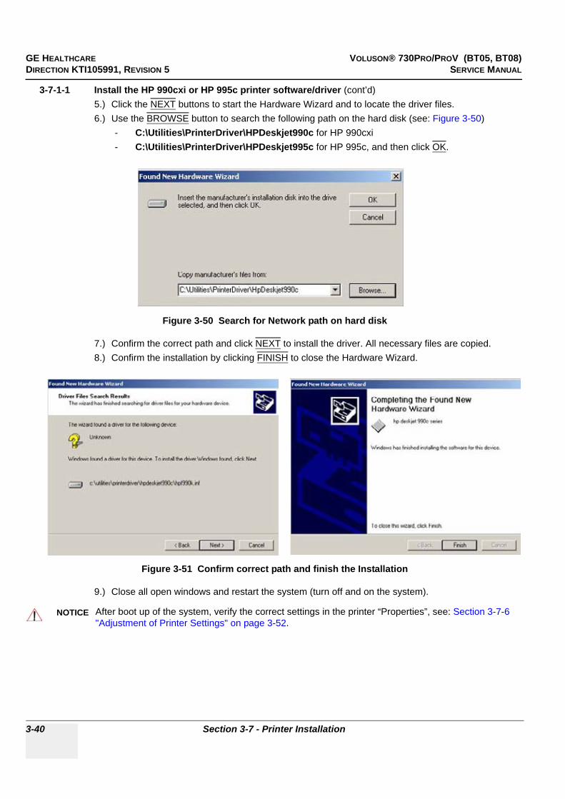
GE HEALTHCARE VOLUSON® 730PRO/PROV (BT05, BT08)DIRECTION KTI105991, REVISION 5 SERVICE MANUAL
3-40 Section 3-7 - Printer Installation
3-7-1-1 Install the HP 990cxi or HP 995c printer software/driver (cont’d)5.) Click the NEXT buttons to start the Hardware Wizard and to locate the driver files. 6.) Use the BROWSE button to search the following path on the hard disk (see: Figure 3-50)
- C:\Utilities\PrinterDriver\HPDeskjet990c for HP 990cxi- C:\Utilities\PrinterDriver\HPDeskjet995c for HP 995c, and then click OK.
7.) Confirm the correct path and click NEXT to install the driver. All necessary files are copied.8.) Confirm the installation by clicking FINISH to close the Hardware Wizard.
9.) Close all open windows and restart the system (turn off and on the system).
Figure 3-50 Search for Network path on hard disk
Figure 3-51 Confirm correct path and finish the Installation
NOTICE!! NOTICE:Ver
After boot up of the system, verify the correct settings in the printer “Properties”, see: Section 3-7-6 "Adjustment of Printer Settings" on page 3-52.
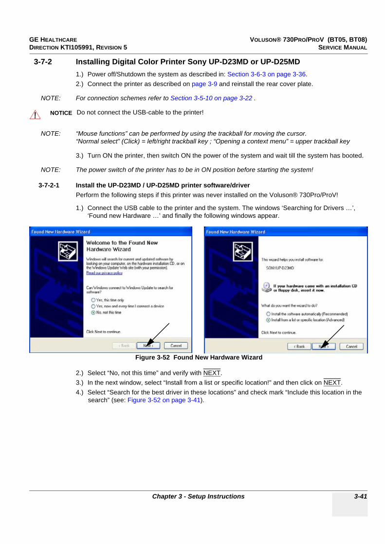
GE HEALTHCARE VOLUSON® 730PRO/PROV (BT05, BT08)DIRECTION KTI105991, REVISION 5 SERVICE MANUAL
Chapter 3 - Setup Instructions 3-41
3-7-2 Installing Digital Color Printer Sony UP-D23MD or UP-D25MD1.) Power off/Shutdown the system as described in: Section 3-6-3 on page 3-36.2.) Connect the printer as described on page 3-9 and reinstall the rear cover plate.
NOTE: For connection schemes refer to Section 3-5-10 on page 3-22 .
NOTE: “Mouse functions” can be performed by using the trackball for moving the cursor. “Normal select” (Click) = left/right trackball key ; “Opening a context menu” = upper trackball key
3.) Turn ON the printer, then switch ON the power of the system and wait till the system has booted.
NOTE: The power switch of the printer has to be in ON position before starting the system!
3-7-2-1 Install the UP-D23MD / UP-D25MD printer software/driverPerform the following steps if this printer was never installed on the Voluson® 730Pro/ProV!
1.) Connect the USB cable to the printer and the system. The windows ‘Searching for Drivers …’, ‘Found new Hardware …’ and finally the following windows appear.
2.) Select “No, not this time” and verify with NEXT.3.) In the next window, select “Install from a list or specific location!" and then click on NEXT.4.) Select “Search for the best driver in these locations” and check mark “Include this location in the
search” (see: Figure 3-52 on page 3-41).
NOTICE!! NOTICE:
Do not connect the USB-cable to the printer!
Figure 3-52 Found New Hardware Wizard
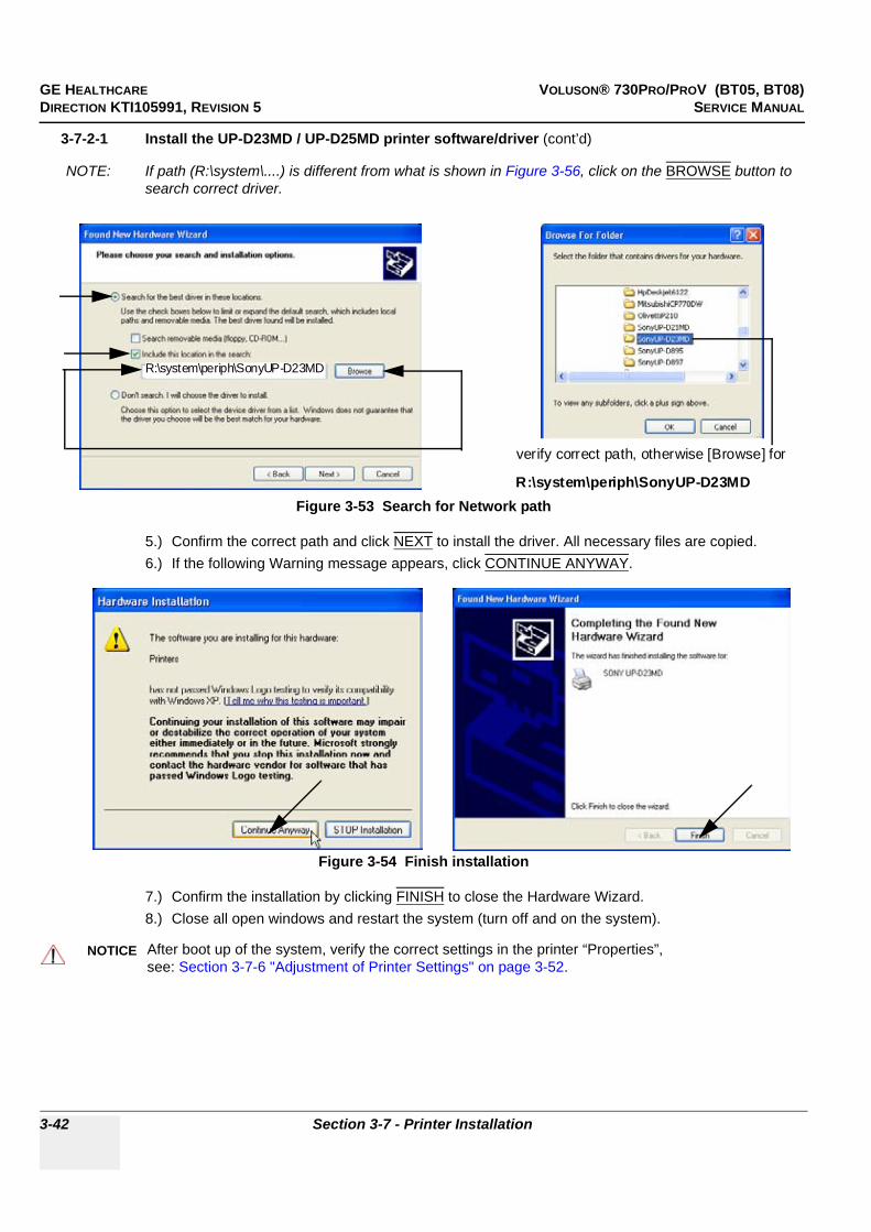
GE HEALTHCARE VOLUSON® 730PRO/PROV (BT05, BT08)DIRECTION KTI105991, REVISION 5 SERVICE MANUAL
3-42 Section 3-7 - Printer Installation
3-7-2-1 Install the UP-D23MD / UP-D25MD printer software/driver (cont’d)
NOTE: If path (R:\system\....) is different from what is shown in Figure 3-56, click on the BROWSE button to search correct driver.
5.) Confirm the correct path and click NEXT to install the driver. All necessary files are copied.6.) If the following Warning message appears, click CONTINUE ANYWAY.
7.) Confirm the installation by clicking FINISH to close the Hardware Wizard.8.) Close all open windows and restart the system (turn off and on the system).
Figure 3-53 Search for Network path
Figure 3-54 Finish installation
NOTICE!! NOTICE:Ver
After boot up of the system, verify the correct settings in the printer “Properties”,see: Section 3-7-6 "Adjustment of Printer Settings" on page 3-52.
R:\system\periph\SonyUP-D23MD
verify correct path, otherwise [Browse] for
R:\system\periph\SonyUP-D23MD
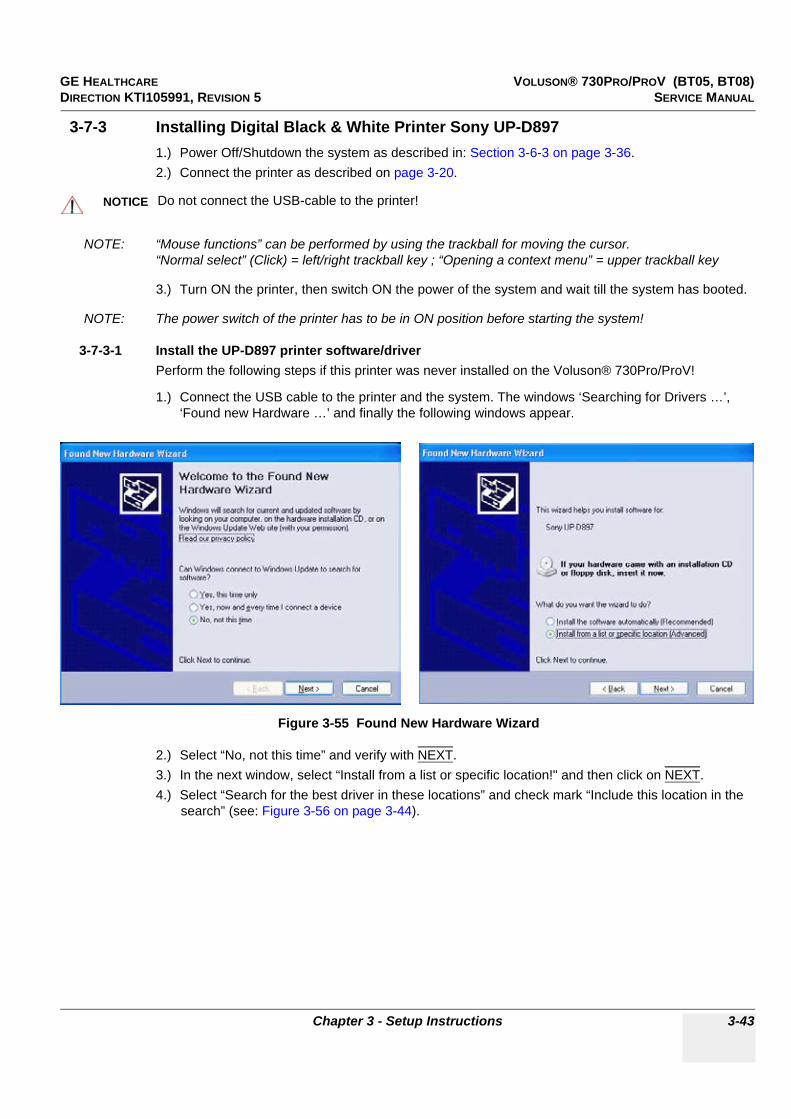
GE HEALTHCARE VOLUSON® 730PRO/PROV (BT05, BT08)DIRECTION KTI105991, REVISION 5 SERVICE MANUAL
Chapter 3 - Setup Instructions 3-43
3-7-3 Installing Digital Black & White Printer Sony UP-D8971.) Power Off/Shutdown the system as described in: Section 3-6-3 on page 3-36.2.) Connect the printer as described on page 3-20.
NOTE: “Mouse functions” can be performed by using the trackball for moving the cursor. “Normal select” (Click) = left/right trackball key ; “Opening a context menu” = upper trackball key
3.) Turn ON the printer, then switch ON the power of the system and wait till the system has booted.
NOTE: The power switch of the printer has to be in ON position before starting the system!
3-7-3-1 Install the UP-D897 printer software/driverPerform the following steps if this printer was never installed on the Voluson® 730Pro/ProV!
1.) Connect the USB cable to the printer and the system. The windows ‘Searching for Drivers …’, ‘Found new Hardware …’ and finally the following windows appear.
2.) Select “No, not this time” and verify with NEXT.3.) In the next window, select “Install from a list or specific location!" and then click on NEXT.4.) Select “Search for the best driver in these locations” and check mark “Include this location in the
search” (see: Figure 3-56 on page 3-44).
NOTICE!! NOTICE:
Do not connect the USB-cable to the printer!
Figure 3-55 Found New Hardware Wizard
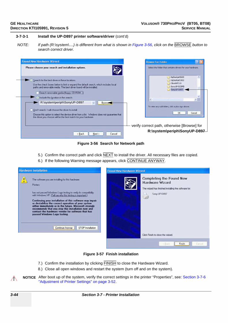
GE HEALTHCARE VOLUSON® 730PRO/PROV (BT05, BT08)DIRECTION KTI105991, REVISION 5 SERVICE MANUAL
3-44 Section 3-7 - Printer Installation
3-7-3-1 Install the UP-D897 printer software/driver (cont’d)
NOTE: If path (R:\system\....) is different from what is shown in Figure 3-56, click on the BROWSE button to search correct driver.
5.) Confirm the correct path and click NEXT to install the driver. All necessary files are copied.6.) If the following Warning message appears, click CONTINUE ANYWAY.
7.) Confirm the installation by clicking FINISH to close the Hardware Wizard.8.) Close all open windows and restart the system (turn off and on the system).
Figure 3-56 Search for Network path
Figure 3-57 Finish installation
NOTICE!! NOTICE:
After boot up of the system, verify the correct settings in the printer “Properties”, see: Section 3-7-6 "Adjustment of Printer Settings" on page 3-52.
verify correct path, otherwise [Browse] forR:\system\periph\SonyUP-D897
R:\system\periph\SonyUP-D897

GE HEALTHCARE VOLUSON® 730PRO/PROV (BT05, BT08)DIRECTION KTI105991, REVISION 5 SERVICE MANUAL
Chapter 3 - Setup Instructions 3-45
3-7-4 Installing Mitsubishi B&W P95 and Color Printer CP30
NOTE: Mouse functions" can be performed by using the trackball for moving the cursor."Normal select" (Click) = left/right trackball key; "Opening a context menu" = upper trackball key
NOTE: To use the Mitsubishi Printer with older Systems and Software versions a printer driver has to be installed. A printer driver disk is included with the new printer.
NOTE: If you use the Printer, please always take the same USB port.
NOTE: If the same system software version (where Mitsubishi driver installation was performed) is re-installed by performing "Restore", "Initialize" and "New Disk" via LINUX, this printer will be found again as a new hardware device when connecting it to the system. The printer driver will have to be installed again via hardware wizard. Please be sure to leave the printer driver disk at the customer site with the other current software discs.
NOTE: Dip-Switch Settings for the Color Printer (KTZ302616); 1 and 2 ON; 3, 4, 5, 6, 7 and 8 OFF.
NOTE: If you use the B&W Printer (KTZ302617) you must first activate USB Serial number.1.) The Printer must be switched OFF.2.) Press the "COPY" and "CONT" button together and switch ON the Printer. When the display shows "S1" let off the both button.3.) Press the "FUNC" button; the display shows "U0".4.) Adjust to "U2" by using the turning knob.5.) Press the "FUNC" button again and then switch OFF the Printer.
1.) Connect the printer to the system.2.) Switch ON the power of the system and wait till the system has booted and then turn ON the printer.3.) The "Found New Hardware Wizard" window appears.
4.) Select "Install from a list or specific location" and click on NEXT.
Figure 3-58 Found New Hardware Wizard / select "Install from ..."

GE HEALTHCARE VOLUSON® 730PRO/PROV (BT05, BT08)DIRECTION KTI105991, REVISION 5 SERVICE MANUAL
3-46 Section 3-7 - Printer Installation
3-7-4 Installing Mitsubishi B&W P95 and Color Printer CP30 (cont’d)
5.) In the next window select "Search for the best driver in these locations", select "Include this location in the search:" and browse for the right path."R:\system\periph\Mitsubishi P95D" for the B&W Printer and "R:\system\periph\Win2000_XP" for the Color Printer or "C:\Utilities\PrinterDriver\Mitsubishi PD95" for the B&W Printer and "C:\Utilities\PrinterDriver\Win2000_XP" for the Color Printer. Path depeD95 or F:\Win2000_XP.(where F: stands for CD/DVD Drive) Then click on NEXT.
NOTE: If the "Printer Driver" Disk is defective or not available, download driver from GE folders http://libraries.ge.com/foldersIndex.do?entity_id=15869258101&sid=101&SF=1and extract files to CD or USB disk.
6.) Confirm the installation by clicking FINISH to close the Hardware Wizard.
7.) Close all open windows and verify the correct settings in the printer "Properties",see: Section 3-7-6 "Adjustment of Printer Settings" on page 3-52.
Figure 3-59 select "Search for the ..." and "Include this location ..."
Figure 3-60 Finish installation
“Search for the best driver in these location”
“Include this location in the search”

GE HEALTHCARE VOLUSON® 730PRO/PROV (BT05, BT08)DIRECTION KTI105991, REVISION 5 SERVICE MANUAL
Chapter 3 - Setup Instructions 3-47
3-7-5 Printer Installation manually1.) On the control panel, press the UTILITIES key.2.) In the “Utilities” menu on the left side of the screen, select SYSTEM to invoke the setup desktop.3.) Select the SERVICE page. The “password window” appears automatically.
4.) Enter the password SHE and click the ACCEPT button to display the Service Tools window.
5.) Click on the PRINTER button.
Figure 3-61 System Setup Service page
Figure 3-62 Service Tools window
“Printer” button

GE HEALTHCARE VOLUSON® 730PRO/PROV (BT05, BT08)DIRECTION KTI105991, REVISION 5 SERVICE MANUAL
3-48 Section 3-7 - Printer Installation
3-7-5 Printer Installation manually (cont’d)
6.) Click the ADD PRINTER button. A warning message appears:Please read this message carefully and click YES if you have skills to do this.
7.) Click the NEXT button to start the Add Printer Wizard.8.) Select the ‘Local Printer‘, deselect “Automatically install Plug and Play printer” and then click NEXT.
Figure 3-63 Add Printer and Printer Installation/Properties
Figure 3-64 Add Printer Wizard

GE HEALTHCARE VOLUSON® 730PRO/PROV (BT05, BT08)DIRECTION KTI105991, REVISION 5 SERVICE MANUAL
Chapter 3 - Setup Instructions 3-49
3-7-5 Printer Installation manually (cont’d)
9.) Select the corresponding Printer Port (e.g., Figure 3-65 = USB001) and click NEXT.
10.)In the following window select the HAVE DISK button.
11.)Use the BROWSE button to search the Printer Driver path (C:\Utilities\PrinterDriver\xxxx).
Figure 3-65 Select Printer Port
Figure 3-66 Have Disk...
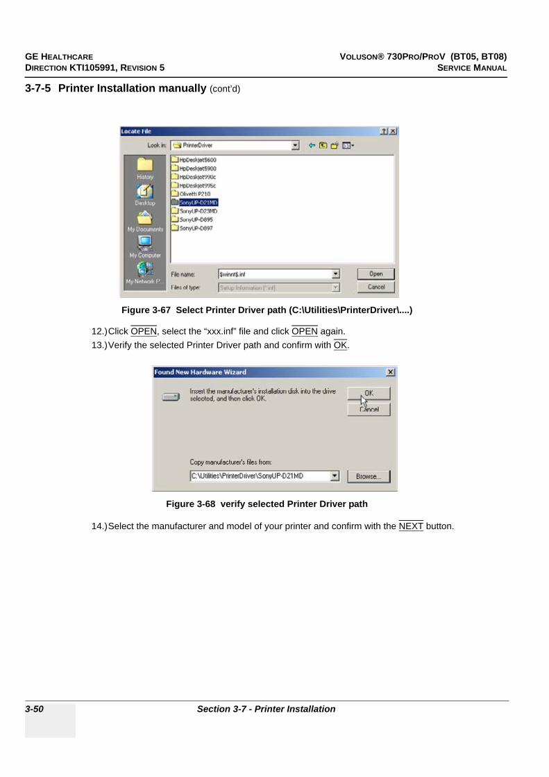
GE HEALTHCARE VOLUSON® 730PRO/PROV (BT05, BT08)DIRECTION KTI105991, REVISION 5 SERVICE MANUAL
3-50 Section 3-7 - Printer Installation
3-7-5 Printer Installation manually (cont’d)
12.)Click OPEN, select the “xxx.inf” file and click OPEN again.13.)Verify the selected Printer Driver path and confirm with OK.
14.)Select the manufacturer and model of your printer and confirm with the NEXT button.
Figure 3-67 Select Printer Driver path (C:\Utilities\PrinterDriver\....)
Figure 3-68 verify selected Printer Driver path

GE HEALTHCARE VOLUSON® 730PRO/PROV (BT05, BT08)DIRECTION KTI105991, REVISION 5 SERVICE MANUAL
Chapter 3 - Setup Instructions 3-51
3-7-5 Printer Installation manually (cont’d)
15.)Assign a name, decide if the printer should be used as default printer and confirm with NEXT. see: Figure 3-69.
16.)Select ‘Do not share this printer‘ and confirm the “Printer Sharing” window (Figure 3-69) by clicking NEXT.
17.)The “Complete the Add Printer Wizard” window appears on the screen.
18.)Complete the manual Printer Installation with the FINISH button.19.)Close all open windows, close the “System Setup” with SAVE & EXIT and restart the system
(turn off and on the system).
Figure 3-69 Assign name and select Printer Sharing - no
Figure 3-70 Complete manual Printer Installation
NOTICE!! NOTICE:Ver
After boot up of the system, verify the correct settings in the printer “Properties”, see: Section 3-7-6 "Adjustment of Printer Settings" on page 3-52.

GE HEALTHCARE VOLUSON® 730PRO/PROV (BT05, BT08)DIRECTION KTI105991, REVISION 5 SERVICE MANUAL
3-52 Section 3-7 - Printer Installation
3-7-6 Adjustment of Printer Settings1.) After system restart, press the UTILITIES key, and then select SYSTEM from the menu area.2.) Select the SERVICE page. The “password window” appears automatically.3.) Enter the password SHE and click the ACCEPT button.4.) Click on the PRINTER button.5.) Select the desired printer from the pull-down menu and click the EDIT SETTINGS button.6.) Confirm the warning message with the YES button. The “Printer Properties” appear.
To adjust the Line Printer see: Section 3-7-6-1 "HP 990cxi / HP 995c- Printer Settings" .
To adjust the Color Printer see: Section 3-7-6-2 "UP-D23MD / UP-D25MD - Printer Settings" .
To adjust the CP30D Color Printer see: Section 3-7-6-3 "Mitsubishi Printer - Settings"
To adjust the Black&White Printer see: Section 3-7-6-4 "UP-D897 - Printer Settings" .
To adjust the Bluetooth printer see: Section 3-7-6-5 "Bluetooth Deskjet - Printer Settings"
Figure 3-71 Select the desired printer
WARNINGWARNING!! WARNING:
After each printer installation, the leakage currents have to be measured acc. IEC 60601-1 resp. UL2601-1.
select the desired printer from the pull-down menu
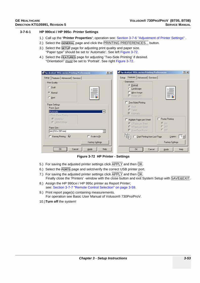
GE HEALTHCARE VOLUSON® 730PRO/PROV (BT05, BT08)DIRECTION KTI105991, REVISION 5 SERVICE MANUAL
Chapter 3 - Setup Instructions 3-53
3-7-6-1 HP 990cxi / HP 995c- Printer Settings
1.) Call up the ‘Printer Properties’; operation see: Section 3-7-6 "Adjustment of Printer Settings" .2.) Select the GENERAL page and click the PRINTING PREFERENCES... button.3.) Select the SETUP page for adjusting print quality and paper size.
“Paper type” should be set to ‘Automatic’. See left Figure 3-72.4.) Select the FEATURES page for adjusting ‘Two-Side Printing’ if desired.
“Orientation” must be set to ‘Portrait’. See right Figure 3-72.
5.) For saving the adjusted printer settings click APPLY and then OK.6.) Select the PORTS page and selct/verify the correct USB printer port.7.) For saving the adjusted printer settings click APPLY and then OK.
Finally close the ‘Printers’ -window with the close button and exit System Setup with SAVE&EXIT.8.) Assign the HP 990cxi / HP 995c printer as Report Printer;
see: Section 3-7-7 "Remote Control Selection" on page 3-59.9.) Print report page(s) containing measurements.
For operation see Basic User Manual of Voluson® 730Pro/ProV.10.)Turn off the system!
Figure 3-72 HP Printer - Settings
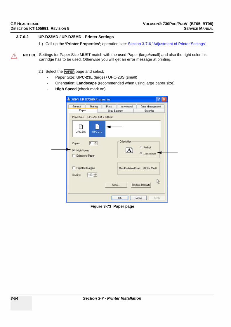
GE HEALTHCARE VOLUSON® 730PRO/PROV (BT05, BT08)DIRECTION KTI105991, REVISION 5 SERVICE MANUAL
3-54 Section 3-7 - Printer Installation
3-7-6-2 UP-D23MD / UP-D25MD - Printer Settings
1.) Call up the ‘Printer Properties’; operation see: Section 3-7-6 "Adjustment of Printer Settings" .
2.) Select the PAPER page and select: - Paper Size: UPC-23L (large) / UPC-23S (small)- Orientation: Landscape (recommended when using large paper size)- High Speed (check mark on)
NOTICE!! NOTICE:
Settings for Paper Size MUST match with the used Paper (large/small) and also the right color ink cartridge has to be used. Otherwise you will get an error message at printing.
Figure 3-73 Paper page

GE HEALTHCARE VOLUSON® 730PRO/PROV (BT05, BT08)DIRECTION KTI105991, REVISION 5 SERVICE MANUAL
Chapter 3 - Setup Instructions 3-55
3-7-6-2 UP-D23MD / UP-D25MD - Printer Settings (cont’d)3.) Select the GRAPHICS page. From the “Color Adjust” pop-up menu select:
a.) Color Balance: Cyan = 0; Magenta = 0; Yellow = 0b.) Gamma Select: Gamma 1
c.) Color Correction: set Printer Hardware Color Correctiond.) Lightness: Sharpness = 7 or 8; Dark = 0; Gamma = -12; Light = 8
4.) For saving the adjusted printer settings click APPLY and then OK.Finally close the ‘Printers’-window with the close button and exit System Setup with SAVE&EXIT.
5.) Assign the Printer to remote keys PRINT A and/or PRINT B; see: Section 3-7-7 on page 3-59.
Figure 3-74 Graphics page (Color Balance + Gamma Select)
Figure 3-75 Graphics page (Color Correction + Lightness)
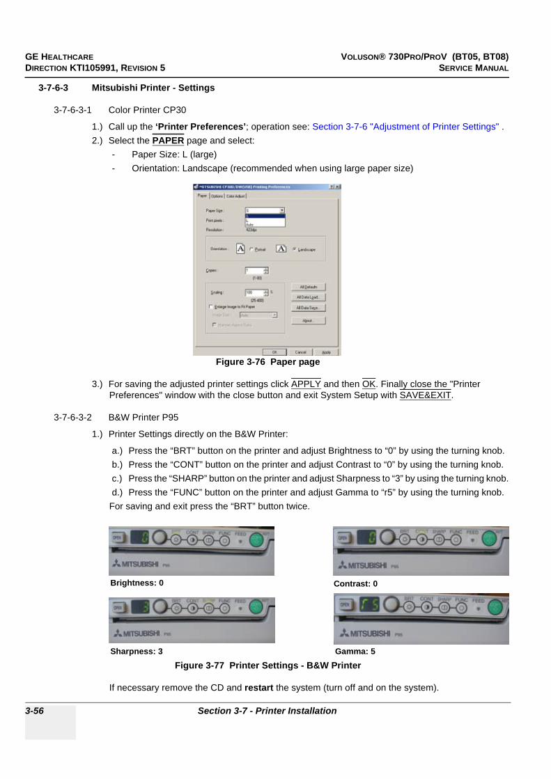
GE HEALTHCARE VOLUSON® 730PRO/PROV (BT05, BT08)DIRECTION KTI105991, REVISION 5 SERVICE MANUAL
3-56 Section 3-7 - Printer Installation
3-7-6-3 Mitsubishi Printer - Settings
3-7-6-3-1 Color Printer CP30
1.) Call up the ‘Printer Preferences’; operation see: Section 3-7-6 "Adjustment of Printer Settings" .2.) Select the PAPER page and select:
- Paper Size: L (large)- Orientation: Landscape (recommended when using large paper size)
3.) For saving the adjusted printer settings click APPLY and then OK. Finally close the "Printer Preferences" window with the close button and exit System Setup with SAVE&EXIT.
3-7-6-3-2 B&W Printer P95
1.) Printer Settings directly on the B&W Printer:
a.) Press the “BRT” button on the printer and adjust Brightness to “0” by using the turning knob.b.) Press the “CONT” button on the printer and adjust Contrast to “0” by using the turning knob.c.) Press the “SHARP” button on the printer and adjust Sharpness to “3” by using the turning knob.d.) Press the “FUNC” button on the printer and adjust Gamma to “r5” by using the turning knob.
For saving and exit press the “BRT” button twice.
If necessary remove the CD and restart the system (turn off and on the system).
Figure 3-76 Paper page
Figure 3-77 Printer Settings - B&W Printer
Brightness: 0
Sharpness: 3
Contrast: 0
Gamma: 5
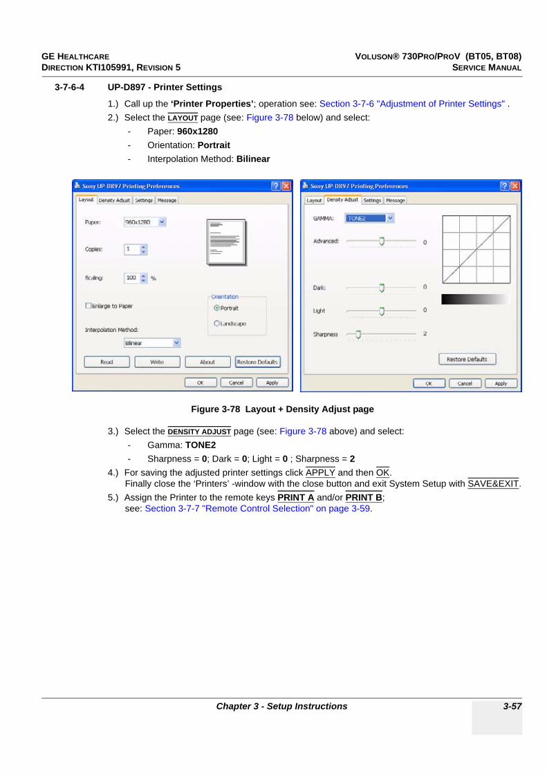
GE HEALTHCARE VOLUSON® 730PRO/PROV (BT05, BT08)DIRECTION KTI105991, REVISION 5 SERVICE MANUAL
Chapter 3 - Setup Instructions 3-57
3-7-6-4 UP-D897 - Printer Settings
1.) Call up the ‘Printer Properties’; operation see: Section 3-7-6 "Adjustment of Printer Settings" .2.) Select the LAYOUT page (see: Figure 3-78 below) and select:
- Paper: 960x1280- Orientation: Portrait- Interpolation Method: Bilinear
3.) Select the DENSITY ADJUST page (see: Figure 3-78 above) and select: - Gamma: TONE2- Sharpness = 0; Dark = 0; Light = 0 ; Sharpness = 2
4.) For saving the adjusted printer settings click APPLY and then OK.Finally close the ‘Printers’ -window with the close button and exit System Setup with SAVE&EXIT.
5.) Assign the Printer to the remote keys PRINT A and/or PRINT B; see: Section 3-7-7 "Remote Control Selection" on page 3-59.
Figure 3-78 Layout + Density Adjust page

GE HEALTHCARE VOLUSON® 730PRO/PROV (BT05, BT08)DIRECTION KTI105991, REVISION 5 SERVICE MANUAL
3-58 Section 3-7 - Printer Installation
3-7-6-5 Bluetooth Deskjet - Printer Settings
1.) Call up the ‘Printer Properties’; operation see: Section 3-7-6 "Adjustment of Printer Settings" .2.) Select the GENERAL page and click the PRINTING PREFERENCES... button.3.) Select the PAPER/QUALITY page and select the adequate paper size.
4.) For saving the adjusted paper size settings click APPLY and then OK.5.) In the next window, click OK again.
Finally close the ‘Printers’ -window with the close button and exit System Setup with SAVE&EXIT.6.) Assign the Deskjet printer as Report Printer;
see: Section 3-7-7 "Remote Control Selection" on page 3-59.7.) Print report page(s) containing measurements.
For operation see Basic User Manual of Voluson® 730Pro/ProV.8.) Turn off the system!
CAUTION!! CAUTION:
The Bluetooth Connection Set as well as the color printer MUST NOT be installed by the user! For installation please contact your local distributor or GE service representative.
Figure 3-79 Paper/Quality page

GE HEALTHCARE VOLUSON® 730PRO/PROV (BT05, BT08)DIRECTION KTI105991, REVISION 5 SERVICE MANUAL
Chapter 3 - Setup Instructions 3-59
3-7-7 Remote Control SelectionTo assign an auxiliary device (e.g., printer) to the remote keys PRINT A and/or PRINT B, or to adjust Record Type, Foot switch, etc.:
1.) On the control panel, press the UTILITIES key.2.) In the “Utilities” menu on the left side of the screen select SYSTEM to invoke the setup desktop.3.) Select the PERIPHERALS page.
• Record Type: Select whether you use a VCR (Video Cassette Recorder) or DVR (DVD Recorder).• VCR Source: Select S-VHS.
• Remote Print A: Select the desired Printer for the remote control PRINT A key.• Remote Print B: Select the desired Printer for the remote control PRINT B key.
NOTE: Optionally the Remote Control can be done by Foot switches.Therefore select “Print A” or “Print B” in “Foot Switch Left” or “Foot Switch Right” - section.
• Report Printer: Select the desired Report Printer from the drop-down menu.
• Foot Switch Left/Right: Select desired function of the Foot switch Left and Right.After adjustment, click SAVE&EXIT to save Settings and exit System Setup.
Figure 3-80 Peripherals page
NOTICE!! NOTICE:
The selected Report Printer is usually used for printing reports and images from Sonoview.
Foot SwitchRemote Control
Report Printer
Print APrint B
Record Type
VCR Source

GE HEALTHCARE VOLUSON® 730PRO/PROV (BT05, BT08)DIRECTION KTI105991, REVISION 5 SERVICE MANUAL
3-60 Section 3-8 - System Configuration
Section 3-8System Configuration
3-8-1 System SetupModifications of system parameters are supported by diverse dialog pages and windows on the system setup desktop:
• General - Date, Time, Clinic Name, Language, Screen saver, etc.• User Settings - to save User programs, 3D/4D programs, Auto Text, Doppler 2D Refresh, etc.• Peripherals - to adjust assignment of PRINT keys, Foot Switch, selection of Save Destination, etc.• Option - shows which options are installed in the system• Service - enter the password to get access to the Service Tools functions• Backup - Save/Load User Settings Only, Save/Load/Delete Full Backup• Network - to set up all DICOM, Sonoview and Network configuration nodes• System Info - shows which Software/Hardware version is installed in the system
3-8-1-1 To invoke the Setup procedure:
In general operations are done with the trackball and the trackball keys (mouse emulation).
NOTICE!! NOTICE:
More detailed information pertaining System Setup adjustments is found in the Voluson® 730Pro/ProV Basic User Manual; see: Table 9-19, “System Manuals,” on page 9-31.
1.) Press the UTILITIES key on the Control Panel. The menu area changes to the Utilities menu.2.) Select the SYSTEM item to activate the setup desktop screen.
Trackball (mouse position):positions the pointing device (arrow) on the desktop
left trackball key (left mouse button):sets, fixates markers and activates pages/buttons etc. marked by the pointing device
upper trackball key (right mouse button):no function in system desktop
right trackball key (left mouse button):sets, fixates markers and activates pages/buttons etc. marked by the pointing device
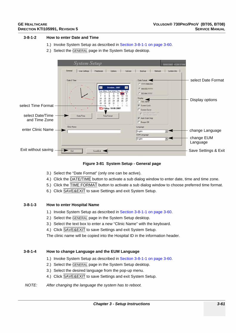
GE HEALTHCARE VOLUSON® 730PRO/PROV (BT05, BT08)DIRECTION KTI105991, REVISION 5 SERVICE MANUAL
Chapter 3 - Setup Instructions 3-61
3-8-1-2 How to enter Date and Time
1.) Invoke System Setup as described in Section 3-8-1-1 on page 3-60.2.) Select the GENERAL page in the System Setup desktop.
3.) Select the “Date Format” (only one can be active).4.) Click the DATE/TIME button to activate a sub dialog window to enter date, time and time zone.5.) Click the TIME FORMAT button to activate a sub dialog window to choose preferred time format.6.) Click SAVE&EXIT to save Settings and exit System Setup.
3-8-1-3 How to enter Hospital Name
1.) Invoke System Setup as described in Section 3-8-1-1 on page 3-60.2.) Select the GENERAL page in the System Setup desktop.3.) Select the text box to enter a new “Clinic Name” with the keyboard.4.) Click SAVE&EXIT to save Settings and exit System Setup.The clinic name will be copied into the Hospital ID in the information header.
3-8-1-4 How to change Language and the EUM Language
1.) Invoke System Setup as described in Section 3-8-1-1 on page 3-60.2.) Select the GENERAL page in the System Setup desktop.3.) Select the desired language from the pop-up menu.4.) Click SAVE&EXIT to save Settings and exit System Setup.
NOTE: After changing the language the system has to reboot.
Figure 3-81 System Setup - General page
select Date Format
change Language
Save Settings & Exit
select Time Format
select Date/Timeand Time Zone
enter Clinic Name
Exit without saving
Display options
change EUMLanguage
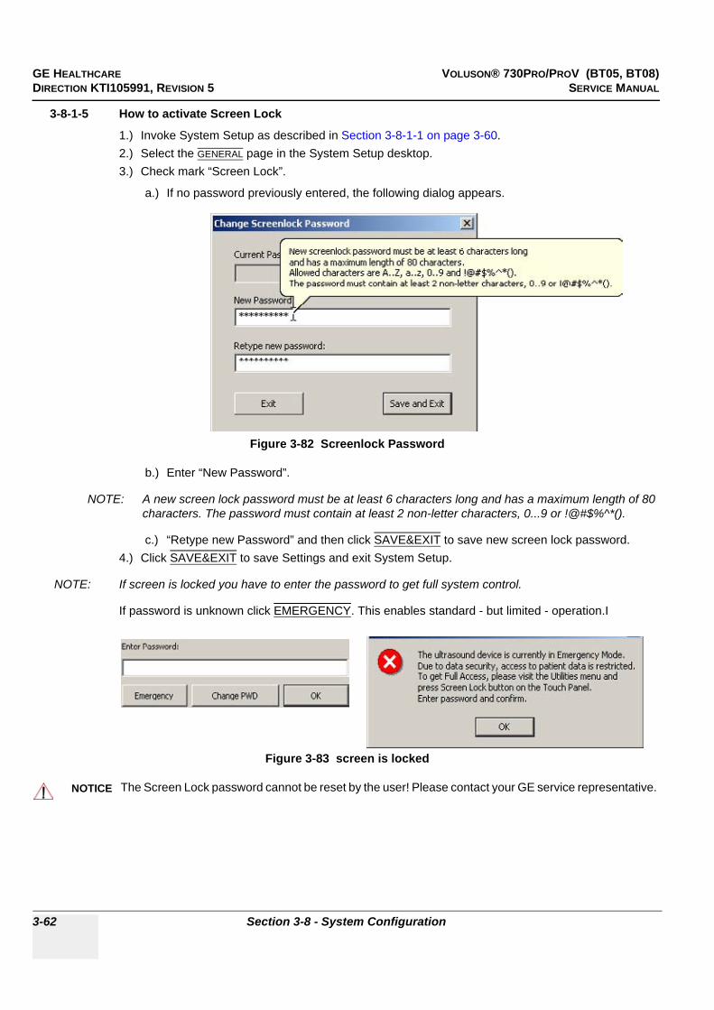
GE HEALTHCARE VOLUSON® 730PRO/PROV (BT05, BT08)DIRECTION KTI105991, REVISION 5 SERVICE MANUAL
3-62 Section 3-8 - System Configuration
3-8-1-5 How to activate Screen Lock
1.) Invoke System Setup as described in Section 3-8-1-1 on page 3-60.2.) Select the GENERAL page in the System Setup desktop.3.) Check mark “Screen Lock”.
a.) If no password previously entered, the following dialog appears.
b.) Enter “New Password”.
NOTE: A new screen lock password must be at least 6 characters long and has a maximum length of 80 characters. The password must contain at least 2 non-letter characters, 0...9 or !@#$%^*().
c.) “Retype new Password” and then click SAVE&EXIT to save new screen lock password.4.) Click SAVE&EXIT to save Settings and exit System Setup.
NOTE: If screen is locked you have to enter the password to get full system control.
If password is unknown click EMERGENCY. This enables standard - but limited - operation.I
Figure 3-82 Screenlock Password
Figure 3-83 screen is locked
NOTICE!! NOTICE:
The Screen Lock password cannot be reset by the user! Please contact your GE service representative.

GE HEALTHCARE VOLUSON® 730PRO/PROV (BT05, BT08)DIRECTION KTI105991, REVISION 5 SERVICE MANUAL
Chapter 3 - Setup Instructions 3-63
3-8-1-6 How to change Video Norm
1.) Press the UTILITIES key on the Control Panel.2.) Select the SYSTEM item from the “Utilities” menu - which is shown in the menu area on the left side
of the screen - to activate the setup desktop screen.3.) Select the SERVICE page in the System Setup, enter the password SHE and then click ACCEPT.
4.) If not currently selected, click the desired field PAL (50Hz) or NTSC (60Hz).
NOTE: The Adjustment of the Video Norm will take about 3 minutes!
5.) Click SAVE&EXIT to exit System Setup.6.) The system will reboot.
3-8-1-7 How to change the Keyboard Layoutsee: Chapter 6 - Modification of Keyboard Layout
Figure 3-84 Service Functions window
selectVideo Norm
Save Settings & Exit
Exit withoutsaving
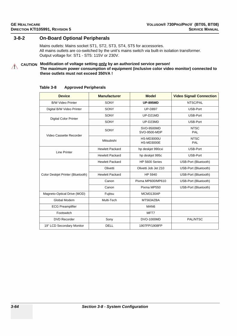
GE HEALTHCARE VOLUSON® 730PRO/PROV (BT05, BT08)DIRECTION KTI105991, REVISION 5 SERVICE MANUAL
3-64 Section 3-8 - System Configuration
3-8-2 On-Board Optional PeripheralsMains outlets: Mains socket ST1, ST2, ST3, ST4, ST5 for accessories.All mains outlets are co-switched by the unit’s mains switch via built-in isolation transformer.Output voltage for: ST1 - ST5: 115V or 230V.
CAUTION!! CAUTION:
Modification of voltage setting only by an authorized service person! The maximum power consumption of equipment (inclusive color video monitor) connected to these outlets must not exceed 350VA !
Table 3-8 Approved Peripherals
Device Manufacturer Model Video Signal/ Connection
B/W Video Printer SONY UP-895MD NTSC/PAL
Digital B/W Video Printer SONY UP-D897 USB-Port
Digital Color PrinterSONY UP-D21MD USB-Port
SONY UP-D23MD USB-Port
Video Cassette RecorderSONY SVO-9500MD
SVO-9500-MDPNTSCPAL
Mitsubishi HS-MD3000UHS-MD3000E
NTSCPAL
Line Printer Hewlett Packard hp deskjet 990cxi USB-Port
Hewlett Packard hp deskjet 995c USB-Port
Color Deskjet Printer (Bluetooth)
Hewlett Packard HP 5600 Series USB-Port (Bluetooth)
Olivetti Olivetti Job Jet 210 USB-Port (Bluetooth)
Hewlett Packard HP 5940 USB-Port (Bluetooth)
Canon Pixma MP600/MP610 USB-Port (Bluetooth)
Canon Pixma MP550 USB-Port (Bluetooth)
Magneto-Optical Drive (MOD) Fujitsu MCM3130AP
Global Modem Multi-Tech MT5634ZBA
ECG Preamplifier MAN6
Footswitch MFT7
DVD Recorder Sony DVO-1000MD PAL/NTSC
19” LCD Secondary Monitor DELL 1907FP/1908FP

GE HEALTHCARE VOLUSON® 730PRO/PROV (BT05, BT08)DIRECTION KTI105991, REVISION 5 SERVICE MANUAL
Chapter 3 - Setup Instructions 3-65
3-8-3 External I/O Connection Panel (GES)
Figure 3-85 External I/O Panel Connectors
Table 3-9 External I/O Connector Descriptions
Item Connector Name Table Number Description
1 VGA OUT Table 3-10 print out VGA signal with monitor/printer
2 MODEM Table 3-11 RJ-11 with global adapter kit for modem connection
3 NETWORK Table 3-12 DICOM input/outputtwisted pair RJ-45 10/100 megabit/s
4 USB-1 Table 3-13 USB port
5 USB-2 Table 3-13 USB port
6 COMP VIDEO OUT Table 3-14 BNC Connector, Color Video Output
1 2 3 4 5 6

GE HEALTHCARE VOLUSON® 730PRO/PROV (BT05, BT08)DIRECTION KTI105991, REVISION 5 SERVICE MANUAL
3-66 Section 3-8 - System Configuration
3-8-3-1 External I/O Pin Outs
Table 3-10 VGA OUT Connector, Sub-D 15 Pin
Pin No Output Signal Description
1 VGA OUT1 R Red
2 VGA OUT1 G Green
3 VGA OUT1 B Blue
4, 9,11,12,15 N/C N/C
5, 6, 7, 8, 10 GND GND
13 VGA OUT1 HS H Sync
14 VGA OUT1 VS V Sync
Table 3-11 Modem, RJ-11 Modular 6 Pin
Pin No Output Signal Description
2 TEL L4 Telephone L4
3 TEL L2 Telephone L2
4 TEL L1 Telephone L1
5 TEL L3 Telephone L3
Others NC Non-connection
Table 3-12 Network Connector, RJ45 Modular 8 Pin
Pin No Output Signal Description
1 ETHER TD Ethernet RD+
2 ETHER TD Ethernet RD-
3 ETHER RD Ethernet TD+
6 ETHER RD Ethernet TD-
Others NC Non-connection
Table 3-13 USB 1, 2 Connectors
Pin No Output Signal Description
1 VCC USB Power Supply
2 - Data USB Data (-)
3 + Data USB Data (+)
4 GND USB Power Ground

GE HEALTHCARE VOLUSON® 730PRO/PROV (BT05, BT08)DIRECTION KTI105991, REVISION 5 SERVICE MANUAL
Chapter 3 - Setup Instructions 3-67
3-8-4 Video SpecificationVideo specifications may be needed to be able to connect laser cameras or other devices to the Voluson® 730Pro/ProV.
Table 3-14 COMP VIDEO OUT Connector
Pin No Signal Description
1 (Center Pin) Signal
2 (Coax Pin) Signal GND
Table 3-15 Footswitch Connector (located at Power Supply Module CPN - rear side)
Pin No Input Signal Description
1 Signal GND
2 right switch normally open
3 left switch normally open
4 not connected not connected
Table 3-16 Video Specifications VGA Connector
Timing Parameter Value
Visible Resolution 800 x 600
Horizontal Rate [kHz] 47.20
H Total cycle time [µs] 21.20
H Sync width [µs] 1.50
H Back Porch [µs] 2.94
H Active Video Time [µs] 16.15
H Front Porch [µs] 0.616
Horizontal +/- pos
Vertical Rate [Hz] 75.00
Vertical Total cycle time [ms] 13.30
V Sync Width [ms] 0.170
V Back Porch [ms] 0.276
V Active Video Time [ms] 12.68
V Front Porch [ms] 0.174
Dot Clock [MHz] 49.54

GE HEALTHCARE VOLUSON® 730PRO/PROV (BT05, BT08)DIRECTION KTI105991, REVISION 5 SERVICE MANUAL
3-68 Section 3-9 - Available Probes
3-8-4 Video Specification (cont’d) Electrical Specifications on VGA Connector
• Signal Level: 700 mV at 75 Ohm• H/V Sync: TTL Level
Section 3-9Available Probes
See Chapter 9 - System Manuals, for part numbers to be used when ordering new or replacement service probes.
Section 3-10Software/Option Configuration
For description refer to:
• Section 3-8-1 "System Setup" on page 3-60
Table 3-17 Video Specifications for Composite, Video Connector
S-Video Output set to: Timing Parameter
PAL50Hz
NTSC60Hz
Visible Resolution 800 x 600 800 x 600
Pixel Clock 17.734475 MHz = 4* ft 14.318 MHz = 4* ft
Horizontal Total Line 64µs / 1135 Pixel 63.56µs / 910 Pixel
Horizontal Active Display 50.50µs / 902 Pixel 52.50µs / 752 Pixel
Horizontal Front Porch 1.96µs / 35 Pixel 1.62µs / 23 Pixel
Horizontal Sync Width 4.62µs / 82 Pixel 4.68µs / 67 Pixel
Horizontal Back Porch 6.52µs / 116 Pixel 4.76µs / 68 Pixel
Vertical Total Lines 20ms / 312.50 Lines 16.68ms / 262.50 Lines
Vertical Active Lines 18.18ms / 284 Lines 15.22ms / 239.50 Lines
Vertical Front Porch 256us 4 Lines 381us / 6 Lines
Vertical Sync 160us / 2.50 Lines 190us 7 3 Lines
Vertical Back Porch 1408us / 22 Lines 890us / 14 Lines
Serration Pulses 5 6
Interlaced yes yes
Aspect Ratio pixel size 14.75 (H) : 17.734475 (V) 14.75 (H) : 14.318 (V)
Video levels on 75 Ohm:
white level 1020mV 1020mV
black level 370mV 370mV
blanking level 320mV 320mV
sync level* 20mV 20mV
NOTICE!! NOTICE:
More detailed information pertaining System Setup and Measure Setup adjustments is found in the Voluson® 730Pro/ProV Basic User Manual, which is available in different languages.

GE HEALTHCARE VOLUSON® 730PRO/PROV (BT05, BT08)DIRECTION KTI105991, REVISION 5 SERVICE MANUAL
Chapter 3 - Setup Instructions 3-69
Section 3-11Network IP Address Configuration
NOTE: Following Information must be provided by customer or hospital engineer before you can start: A Station name, AE Title, IP address and Port Number for the Voluson® 730Pro/ProV. The IP addresses for the default gateway and other routers at the site for ROUTING INFORMATION. Only if necessary (e.g. for Internet access).
1.) Press the UTILITIES key on the Control panel once to display the Utilities menu.2.) Select SYSTEM and then open the NETWORK page on the System Setup desktop screen.3.) Click the NETWORK CONFIGURATION button, read the message and confirm with YES.
4.) The “Internet Protocol (TCP/IP) Properties” dialog page appears.
To specify a DICOM Address, follow the instructions of described in the Basic User Manual, Chapter 17 of the Voluson® 730Pro/ProV.
Figure 3-86 Network Configuration
Figure 3-87 Internet Protocol (TCP/IP)
click Network Configuration button, readmessage and afterwards confirm with Yes
You can get IP settings assigned automatically if your network supports this capability.You need to ask your network administrator forthe appropriate settings.
Type in:• IP address• Subnet mask• Default gateway
NOTE:This example shows fictional numbers!

GE HEALTHCARE VOLUSON® 730PRO/PROV (BT05, BT08)DIRECTION KTI105991, REVISION 5 SERVICE MANUAL
3-70 Section 3-11 - Network IP Address Configuration
3-11-1 Map Network Drive 1.) Select the MAP NETWORK DRIVE button (in the System Setup - Network page, see: Figure 3-86)
to open a dialog where the system can be connected to a shared network drive of another server.
2.) Enter the name of the shared network folder in the „Network Folder Name“ field.3.) Supply a valid user name and a password for this folder.
NOTE: If you check the „Automatic Reconnect“ box, the system tries to establish the connection again when starting up. Otherwise, the connection must be re-established manually after a shutdown or reboot.
4.) Select the CONNECT button to establish the connection to the remote machine.If successful, the DISCONNECT button becomes active.
Figure 3-88 Map Network Drive window
NOTICE!! NOTICE:
If there is an error during the connection, a warning message appears inside the dialog.In this case, please verify the data in the dialog.
NOTICE!! NOTICE:
If there already is a connection to the remote server, the CONNECT button is grayed.To change the existing connection, first click on DISCONNECT and then enter the new settings.
WARNINGWARNING!! WARNING:
Please make sure that the server you are connecting to is trustworthy and reliable. For details, contact your local system administrator. If you backup Sonoview data to this server, all the patients’ demographic data will be copied to this server!
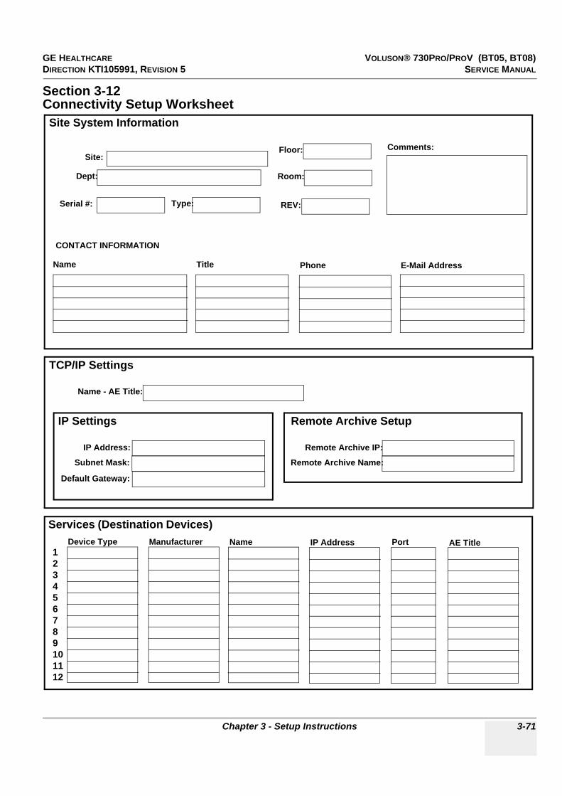
GE HEALTHCARE VOLUSON® 730PRO/PROV (BT05, BT08)DIRECTION KTI105991, REVISION 5 SERVICE MANUAL
Chapter 3 - Setup Instructions 3-71
Section 3-12Connectivity Setup Worksheet
Site System Information
Services (Destination Devices)
TCP/IP Settings
Device Type Manufacturer Name IP Address Port AE Title123456789101112
Name - AE Title:
Dept:
Serial #: Type:
Floor:
Room:
REV:
Comments:
CONTACT INFORMATION
Name Title Phone E-Mail Address
Site:
IP Settings
IP Address:
Subnet Mask:
Default Gateway:
Remote Archive Setup
Remote Archive IP:
Remote Archive Name:

GE HEALTHCARE VOLUSON® 730PRO/PROV (BT05, BT08)DIRECTION KTI105991, REVISION 5 SERVICE MANUAL
3-72 Section 3-12 - Connectivity Setup Worksheet
Section 3-12 Connectivity Setup Worksheet (cont’d)
Figure 3-89 Worksheet for DICOM Network Information
Voluson® 730Pro/ProV
Host Name
AE Title
Local Port IP Address
Net Mask
.. .
.. .
ROUTING INFORMATION
ROUTER2ROUTER3
ROUTER1
.. .
.. .
.. .
.. .
.. .
.. .
.. .
Destination IP Addresses
GATEWAY IP Addresses
Default
DICOM APPLICATION INFORMATION
NAME
Store 2
Store 3D_1
Store 1
MAKE/REVISION IP ADDRESSES PORTAE TITLE
Worklist
Store 3D_2
Storage Commit
MPPS
Structured Reporting
.. .
.. .
.. .
.. .
.. .
.. .
.. .
.. .
.. .
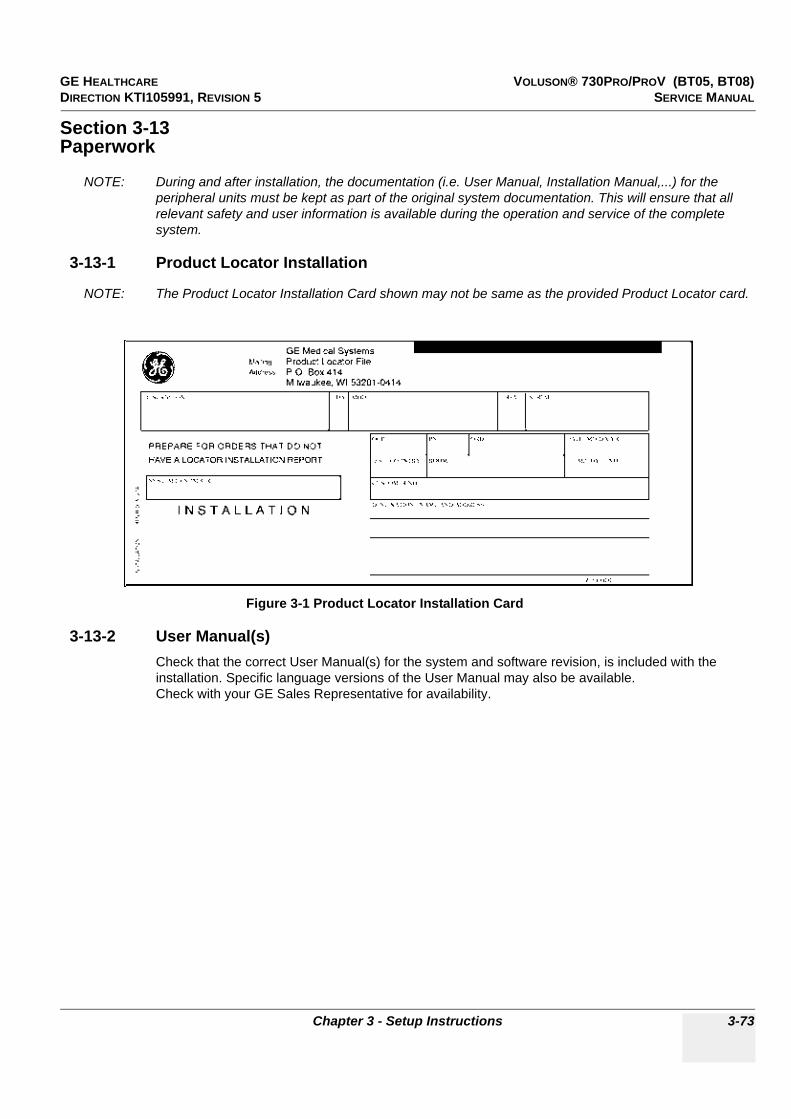
GE HEALTHCARE VOLUSON® 730PRO/PROV (BT05, BT08)DIRECTION KTI105991, REVISION 5 SERVICE MANUAL
Chapter 3 - Setup Instructions 3-73
Section 3-13Paperwork
NOTE: During and after installation, the documentation (i.e. User Manual, Installation Manual,...) for the peripheral units must be kept as part of the original system documentation. This will ensure that all relevant safety and user information is available during the operation and service of the complete system.
3-13-1 Product Locator Installation
NOTE: The Product Locator Installation Card shown may not be same as the provided Product Locator card.
3-13-2 User Manual(s)Check that the correct User Manual(s) for the system and software revision, is included with the installation. Specific language versions of the User Manual may also be available. Check with your GE Sales Representative for availability.
Figure 3-1 Product Locator Installation Card

GE HEALTHCARE VOLUSON® 730PRO/PROV (BT05, BT08)DIRECTION KTI105991, REVISION 5 SERVICE MANUAL
3-74 Section 3-13 - Paperwork
This page was intentionally left blank.

GE HEALTHCARE VOLUSON® 730PRO/PROV (BT05, BT08)DIRECTION KTI105991, REVISION 5 SERVICE MANUAL
Chapter 4 - Functional Checks 4-1
Chapter 4Functional Checks
Section 4-1Overview
4-1-1 Purpose of Chapter 4This chapter provides procedures for quickly checking major functions of the Voluson® 730Pro/ProV scanner diagnostics by using the built-in service software, and power supply adjustments.
Section 4-2Required Equipment
• An empty (blank) DVD/CD+(R)W or MO Disk.• At least one transducer. See ”System Manuals” on page 9-31 for an overview.
(normally you should check all the transducers used on the system)
Table 4-1 Contents in Chapter 4
Section Description Page Number
4-1 Overview 4-1
4-2 Required Equipment 4-1
4-3 General Procedure 4-2
4-4 Functional Checks 4-7
4-5 Backup and Restore Database, Preset Configurations and Images 4-32
4-6 Software Configuration Checks 4-42
4-7 Peripheral Checks 4-43
4-8 Mechanical Function Checks 4-44
4-9 Site Log 4-45
NOTICE!! NOTICE:
Most of the information pertaining to this Functional Checks chapter is found in the Voluson® 730Pro/ProV (BT05, BT08) Basic User Manual; see: Table 9-19, “System Manuals,” on page 9-31.

GE HEALTHCARE VOLUSON® 730PRO/PROV (BT05, BT08)DIRECTION KTI105991, REVISION 5 SERVICE MANUAL
4-2 Section 4-3 - General Procedure
Section 4-3General Procedure
4-3-1 Power On / Boot Up
4-3-1-1 Scanner Power On
1.) Connect the Power Cable to the back of the system.2.) Screw on the pull-out protection of the mains power cable with the 2 screws.3.) Connect the Power Cable to an appropriate mains power outlet.4.) Switch ON the Circuit Breaker at the rear of the system.
CAUTION!! CAUTION:
SYSTEM REQUIRES ALL COVERSOperate this unit only when all board covers and frame panels are securely in place. The covers are required for safe operation, good system performance and cooling purposes.
NOTICE!! NOTICE:
Lockout/Tagout Requirements (For USA only)Follow OSHA Lockout/Tagout requirements by ensuring you are in total control of the Power Cable on the system.
NOTICE After turning off a system, wait at least 10 seconds before turning it on again. The system may not be able to boot if power is recycled too quickly.
Figure 4-1 Circuit Breaker, Protection and Power Cable on back of Voluson® 730Pro/ProV
NOTICE!! NOTICE:
When AC power is applied to the scanner, the ON/OFF switch on the Control panel illuminates amber, indicating the System (including the Back-end Processor) is in standby mode.
Signed Date
TAG &
LOCKOUT
Circuit Breaker
Mains Power Cablepull-out Protection
2 screws

GE HEALTHCARE VOLUSON® 730PRO/PROV (BT05, BT08)DIRECTION KTI105991, REVISION 5 SERVICE MANUAL
Chapter 4 - Functional Checks 4-3
4-3-1-1 Scanner Power On (cont’d)5.) Press the ON/OFF Standby switch left below the control panel.
NOTE: The mains outlet of the system for peripheral auxiliary equipment are commonly switched with the Standby switch. So the auxiliary equipment need not to be switched ON/OFF separately.
When the ON/OFF Stand-By switch left below the control panel is pressed, the System (including the Back-end Processor) starts and the software code is distributed to initiate the scanner.
As soon as the software has been loaded, the system enters 2D-Mode with the probe and application that were used before the system was shut down. Depending on the BIOS-Version no status messages are displayed during this process. Boot up time is about 2 minutes.
4-3-2 Power Off / Shutdown
4-3-2-1 Scanner Shutdown
1.) Press the ON/OFF Standby switch left below the Control Panel.2.) Switch OFF the Circuit Breaker at the rear of the system.
NOTE: The mains outlet of the system for peripheral auxiliary equipment are commonly switched with the Standby switch. So the auxiliary equipment need not to be switched ON/OFF separately.
3.) After complete power down, unscrew the 2 screws and remove the pull-out protection to disconnect the main power cable from the system or unplug it from the AC wall outlet socket.Refer to Figure 4-1 on page 4-2.
4.) Press once on the brakes to block the front wheels (brakes on front wheels under the foot rest).5.) Disconnect probes. (Turn the probe locking handle counterclockwise and then pull the connector
straight out of the probe port.)
Figure 4-2 ON/OFF Standby Switch
NOTICE After turning off a system, wait at least ten seconds before turning it on again. The system may not be able to boot if power is recycled too quickly.
WARNINGWARNING!! WARNING:
Disconnection of the Main Power Cable is necessary! For Example: When repairing the system.
CAUTION!! CAUTION:
DO NOT disconnect a probe while running (Live Scan “Write” mode)! A software error may occur. In this case switch the unit OFF (perform a reset).
ON/OFF Standby switch

GE HEALTHCARE VOLUSON® 730PRO/PROV (BT05, BT08)DIRECTION KTI105991, REVISION 5 SERVICE MANUAL
4-4 Section 4-3 - General Procedure
4-3-3 System Features
4-3-3-1 Control Panel
1.) Ultrasound scanning gel holder2.) Sonoview (Image Management) key3.) VCR Remote Control key4.) TGC - Slider Controls5.) Mode/Gain keys6.) 3D Volume Mode, 4D Volume Mode and Harmonic Imaging key7.) Inter memory keys to save to Sonoview or send to DICOM server8.) Print A-, Print B-Trigger key9.) Freeze / Run key10.)Trackball and Trackball keys11.)Trackball Menu Navigation key12.)Annotation and Measurement keys13.)Menu Control digipots and toggle switch controls14.)Exit key15.)Navigation wheel (Menu control element)16.)Probe key17.)Patient Data Entry key18.)Utilities key19.)Keyboard with shortcut function keys and F1 key to invoke the Electronic User Manual (EUM)
Figure 4-3 Control Panel Tour
1 2 3
5
6
7
8
912 11 10
15
17
18
19
4
1314
16
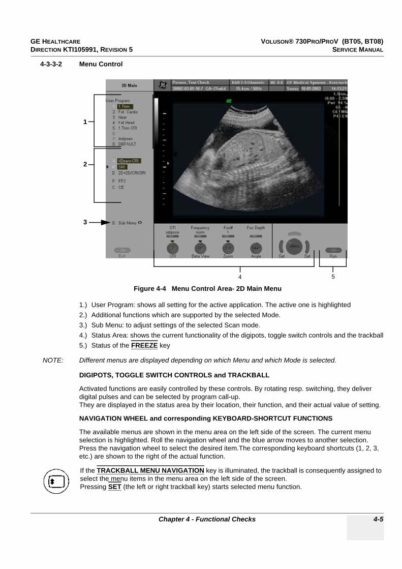
GE HEALTHCARE VOLUSON® 730PRO/PROV (BT05, BT08)DIRECTION KTI105991, REVISION 5 SERVICE MANUAL
Chapter 4 - Functional Checks 4-5
4-3-3-2 Menu Control
1.) User Program: shows all setting for the active application. The active one is highlighted2.) Additional functions which are supported by the selected Mode.3.) Sub Menu: to adjust settings of the selected Scan mode.4.) Status Area: shows the current functionality of the digipots, toggle switch controls and the trackball5.) Status of the FREEZE key
NOTE: Different menus are displayed depending on which Menu and which Mode is selected.
DIGIPOTS, TOGGLE SWITCH CONTROLS and TRACKBALL
Activated functions are easily controlled by these controls. By rotating resp. switching, they deliver digital pulses and can be selected by program call-up.They are displayed in the status area by their location, their function, and their actual value of setting.
NAVIGATION WHEEL and corresponding KEYBOARD-SHORTCUT FUNCTIONS
The available menus are shown in the menu area on the left side of the screen. The current menu selection is highlighted. Roll the navigation wheel and the blue arrow moves to another selection. Press the navigation wheel to select the desired item.The corresponding keyboard shortcuts (1, 2, 3, etc.) are shown to the right of the actual function.
Figure 4-4 Menu Control Area- 2D Main Menu
If the TRACKBALL MENU NAVIGATION key is illuminated, the trackball is consequently assigned to select the menu items in the menu area on the left side of the screen.Pressing SET (the left or right trackball key) starts selected menu function.
1
2
3
4 5

GE HEALTHCARE VOLUSON® 730PRO/PROV (BT05, BT08)DIRECTION KTI105991, REVISION 5 SERVICE MANUAL
4-6 Section 4-3 - General Procedure
4-3-3-3 Monitor Display
Figure 4-5 Monitor Display Tour
Table 4-2 Monitor Display Features
1. Logo 14. Image Area
2. Patient Name (Last-, First-, Middle Name) 15. Measurement results
3. Patient ID-number ; GA (Gestational Age) 16. Status (volume box, saved images, gray map)
4. Probe / Application 17. Status area of the Freeze key
5. Depth / Frame rate 18. Status area of the trackball
6. Mechanical Index 19. Status area of digipots and flip switch controls
7. Thermal Index 20. Menu (Softkey) area
8. Sonographers Name 21. Bodymarks
9. Hospital Name (Identification) 22. Depth scale markers
10. Date 23. Gray scale wedge
11. Time 24. Focal zone marker(s)
12. Image Info 25. Orientation marker
13. TGC curve

GE HEALTHCARE VOLUSON® 730PRO/PROV (BT05, BT08)DIRECTION KTI105991, REVISION 5 SERVICE MANUAL
Chapter 4 - Functional Checks 4-7
Section 4-4Functional Checks
For a basic functional check of the system’s different modes, following pages will familiarize you with image optimization for:
• 2D Mode (B Mode), see: Section 4-4-1 on page 4-8• M Mode, see: Section 4-4-2 on page 4-11
- MCFM Mode- MTD Mode
• Spectral Doppler Modes, see: Section 4-4-3 on page 4-13- PW - Pulsed Wave Doppler- CW - Continuous Wave Doppler
• Color Doppler Modes, see: Section 4-4-4 on page 4-15- CFM - Color Flow Mode- PD - Power Doppler- TD - Tissue Doppler
• Volume Modes, see: Section 4-4-5 on page 4-17- 3D Static- 4D Real Time- 4D Biopsy*- VCI* Volume Contrast Imaging (A-Plane, C-Plane and VCI Static)- STIC*- T.U.I.* (Tomographic Ultrasound Imaging)- VOCAL II*
NOTE: Some software may be considered standard depending upon system configuration.If any Modes or Options are not part of the system configuration, the check can be omitted.
NOTE: Different menus are displayed depending on which Menu and which Mode is selected.Some function only appear in the menu area and the status area of the digipots and flip switch controls if they are available for the selected Probe.
NOTICE!! NOTICE:
Not all Options are available on the Voluson® 730Pro V (marked with * in this manual).
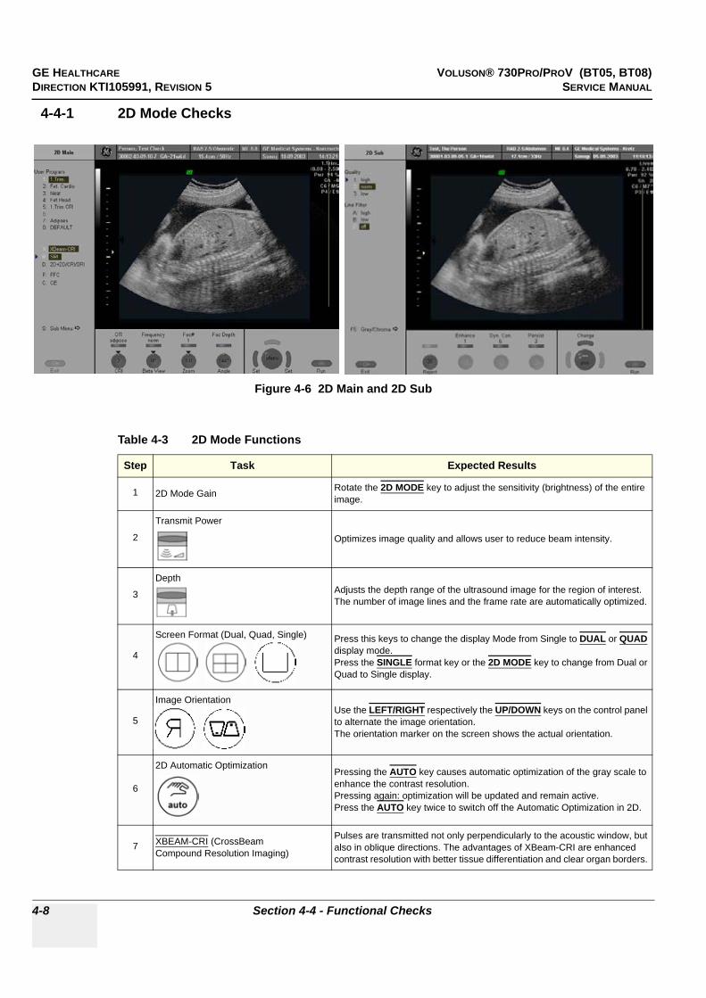
GE HEALTHCARE VOLUSON® 730PRO/PROV (BT05, BT08)DIRECTION KTI105991, REVISION 5 SERVICE MANUAL
4-8 Section 4-4 - Functional Checks
4-4-1 2D Mode Checks
Figure 4-6 2D Main and 2D Sub
Table 4-3 2D Mode Functions
Step Task Expected Results
1 2D Mode Gain Rotate the 2D MODE key to adjust the sensitivity (brightness) of the entire image.
2
Transmit Power
Optimizes image quality and allows user to reduce beam intensity.
3
Depth Adjusts the depth range of the ultrasound image for the region of interest. The number of image lines and the frame rate are automatically optimized.
4
Screen Format (Dual, Quad, Single) Press this keys to change the display Mode from Single to DUAL or QUAD display mode.Press the SINGLE format key or the 2D MODE key to change from Dual or Quad to Single display.
5
Image OrientationUse the LEFT/RIGHT respectively the UP/DOWN keys on the control panel to alternate the image orientation.The orientation marker on the screen shows the actual orientation.
6
2D Automatic OptimizationPressing the AUTO key causes automatic optimization of the gray scale to enhance the contrast resolution. Pressing again: optimization will be updated and remain active.Press the AUTO key twice to switch off the Automatic Optimization in 2D.
7 XBEAM-CRI (CrossBeam Compound Resolution Imaging)
Pulses are transmitted not only perpendicularly to the acoustic window, but also in oblique directions. The advantages of XBeam-CRI are enhanced contrast resolution with better tissue differentiation and clear organ borders.

GE HEALTHCARE VOLUSON® 730PRO/PROV (BT05, BT08)DIRECTION KTI105991, REVISION 5 SERVICE MANUAL
Chapter 4 - Functional Checks 4-9
8 SRI * (Speckle Reduction Imaging)Speckle Reduction Imaging is a smoothing type filter to reduce speckle in the ultrasound image.
9 2D+2D/SRI *Changes the Single image display to two simultaneous half images. The left frame shows only the 2D Mode image. The right frame shows the 2D Mode image with SRI information.
10 2D+2D/CRI/SRI *Changes the Single image display to two simultaneous half images. The left frame shows only the 2D Mode image. The right frame shows the 2D Mode image with XBEAM CRI and SRI information.
11 FFC (Focus and Frequency Composite)FFC combines a low frequency to increase the penetration and higher frequency to keep a high resolution.It reduces speckle and artifacts in the 2D image.
12 CE (Coded Excitation) Coded Excitation improves image resolution and penetration in the far field. This allows to use a higher frequency on technically difficult patients.
13 LINEAR / TRAPEZOID Advantage of the Trapezoid Mode: The scan area is very increased in relation to the linear display by steering the ultrasound lines in the border of the probe.
14
High Resolution Zoom Press this key in write mode. The displayed zoom box can be placed over the entire 2D image area, also the size and position of the zoom box can be changed. Press the HR-ZOOM key again to activate the zoom and again to exit the High Resolution Zoom function.
15
Harmonic Imaging
Press the HI key on the control panel to switch on/off the Coded Harmonic Imaging function in 2D Mode provided the active probe allows this function.
16
XTD ViewPress the BX key on the control panel to activate or deactivate the XTD-View mode. A blue box is displayes at the border of the 2D image. Start and Stop the XTD-image acquisition with the RIGHT TRACKBALL KEY.
17 FREQUENCY resp.HARM.FREQU. in case of Harm. Imaging
To adjust the range of the receive frequency. high resolution / lower penetration, mid resolution / mid penetration, orlower resolution / high penetration
18 OTI (Otimized Tissue Imaging) OTI™ allows to “fine tune” the system for scanning different kinds of tissue.
19 FOC # Increases the number of transmit focal zone, so that you can tighten up the beam for a specific area.
20 FOC DEPTH To select the depth position of the actual focus zone(s). Arrows at the left edge of the 2D image mark the active focal zone(s) by their depth position.
21 ANGLEUse this control to select a part of interest of the 2D image. The advantage of the decreased field-of-view is an increased 2D frame rate due to the smaller sector width.
22 BETA VIEWThis function allows the adjustment of the Volume O-Axis position of 3D probes in 2D Mode. The green line in the displayed symbol indicates the position of the acoustic block.
23 ZOOM Image magnification (Pan Zoom) in read-/ and write mode.
24 QUALITY Control to improve the resolution by reducing the frame rate. Respectively reducing the resolution by increasing the image frame rate.
Table 4-3 2D Mode Functions
Step Task Expected Results

GE HEALTHCARE VOLUSON® 730PRO/PROV (BT05, BT08)DIRECTION KTI105991, REVISION 5 SERVICE MANUAL
4-10 Section 4-4 - Functional Checks
For further details refer to the Voluson® 730Pro/ProV Basic User Manual, Chapter 5, 2D Mode.
25 LINE FILTER
The signals of the neighboring pulses are less weighted for the display of the actual pulse which considerably improves the detail lateral resolution and signal-to-noise ratio.This function is only available if CRI is switched off.
26 ENHANCEEnhance brings out subtle tissue differences and boundaries by enhancing the gray scale differences corresponding to the edges of structures. Adjustments to M Mode's edge enhancement affects the M Mode only.
27 DYN.CON. Dynamic Range controls how echo intensities are converted to shades of gray, thereby increasing the adjustable range of contrast.
28 PERSIST.Persistence is a temporal filter that averages frames together. This has the effect of presenting a smoother, softer image.This function is only available if CRI is switched off.
29 CRI ENHANCE *If this filter is set to “high”, the XBeam-CRI image is smoothed.CRI Enhance setting “off” leads to a sharper impression of the XBeam-CRI image. This function is only available if X-BEAMCRI is switched on.
30 REJECT Selects a level below which echoes will not be amplified (an echo must have a certain minimum amplitude before it will be processed).
31 EXIT Press the EXIT key on the control panel to exit the 2D Sub menu.
Table 4-3 2D Mode Functions
Step Task Expected Results

GE HEALTHCARE VOLUSON® 730PRO/PROV (BT05, BT08)DIRECTION KTI105991, REVISION 5 SERVICE MANUAL
Chapter 4 - Functional Checks 4-11
4-4-2 M Mode Checks
For further details refer to the Voluson® 730Pro/ProV Basic User Manual, Chapter 6, M Mode.
Figure 4-7 M Main and M Sub
Table 4-4 M Mode Functions
Step Task Expected Results
1 Cursor Position Adjust the M Cursor position with the TRACKBALL in the 2D Single image.
2 Activation of M Mode Press the right or left trackball key to activate both Modes (2D/M).
3 M Mode Gain Rotate the M MODE key to adjust the sensitivity (brightness) of the entire M image.
4 M Mode Depth Common with 2D Mode Depth.
5
Invert
This function inverts the M mode trace from up to down in the M mode display area.(The Invert function is only available with endovaginal probes.)
6 SPEED By touching up or down, four different sweep speeds can be selected.
7 FREQUENCY Common with 2D Mode Frequency resp. Harm.Frequ. in case of Harm. Imaging.
8 FORMAT For selection of three different rations of display format.
9 DYN.CON. Dynamic Range enhances a part of the grayscale to make it easier to display pathology.
10 ENHANCE Due to this function a finer, sharper impression of the image is produced.
11 REJECT It determines the amplitude-level below which echoes are suppressed (rejected).
12Exit
Press the EXIT key on the control panel to exit the M Sub menu.

GE HEALTHCARE VOLUSON® 730PRO/PROV (BT05, BT08)DIRECTION KTI105991, REVISION 5 SERVICE MANUAL
4-12 Section 4-4 - Functional Checks
4-4-2-1 MCFM Mode Check
For further details refer to the Voluson® 730Pro/ProV Basic User Manual, Chapter 6.4.
4-4-2-2 MTD Mode Check
For further details refer to the Voluson® 730Pro/ProV Basic User Manual, Chapter 6.5.
By pressing the M control and the C control, the MCFM mode is switched on in the preparation mode.The M-cursor with M-Color window appears on the active 2D image.
Figure 4-8 MCFM Main and MCFM Sub Menu
By pressing the M control and the TD control, the MTD mode is switched on in the preparation mode. The M-cursor with M-Color window appears on the active 2D image.
Figure 4-9 MTD Main and MTD Sub Menu
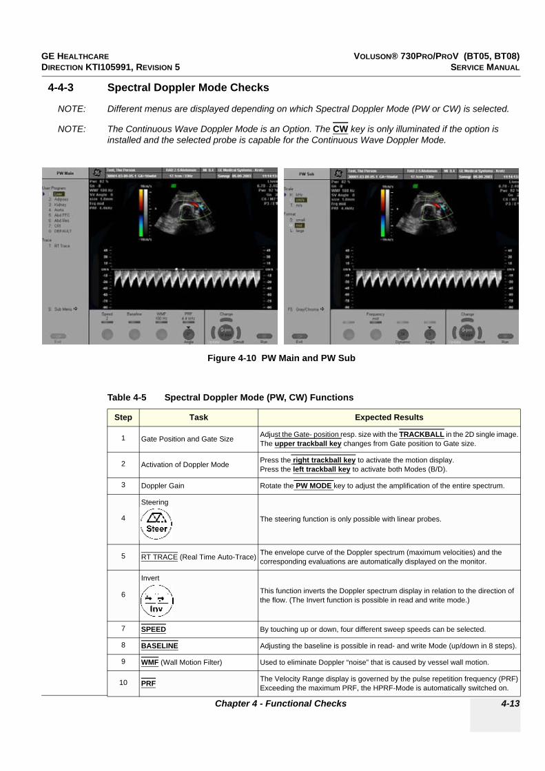
GE HEALTHCARE VOLUSON® 730PRO/PROV (BT05, BT08)DIRECTION KTI105991, REVISION 5 SERVICE MANUAL
Chapter 4 - Functional Checks 4-13
4-4-3 Spectral Doppler Mode Checks
NOTE: Different menus are displayed depending on which Spectral Doppler Mode (PW or CW) is selected.
NOTE: The Continuous Wave Doppler Mode is an Option. The CW key is only illuminated if the option is installed and the selected probe is capable for the Continuous Wave Doppler Mode.
Figure 4-10 PW Main and PW Sub
Table 4-5 Spectral Doppler Mode (PW, CW) Functions
Step Task Expected Results
1 Gate Position and Gate Size Adjust the Gate- position resp. size with the TRACKBALL in the 2D single image.The upper trackball key changes from Gate position to Gate size.
2 Activation of Doppler Mode Press the right trackball key to activate the motion display.Press the left trackball key to activate both Modes (B/D).
3 Doppler Gain Rotate the PW MODE key to adjust the amplification of the entire spectrum.
4
Steering
The steering function is only possible with linear probes.
5 RT TRACE (Real Time Auto-Trace) The envelope curve of the Doppler spectrum (maximum velocities) and the corresponding evaluations are automatically displayed on the monitor.
6
Invert
This function inverts the Doppler spectrum display in relation to the direction of the flow. (The Invert function is possible in read and write mode.)
7 SPEED By touching up or down, four different sweep speeds can be selected.
8 BASELINE Adjusting the baseline is possible in read- and write Mode (up/down in 8 steps).
9 WMF (Wall Motion Filter) Used to eliminate Doppler “noise” that is caused by vessel wall motion.
10 PRF The Velocity Range display is governed by the pulse repetition frequency (PRF)Exceeding the maximum PRF, the HPRF-Mode is automatically switched on.

GE HEALTHCARE VOLUSON® 730PRO/PROV (BT05, BT08)DIRECTION KTI105991, REVISION 5 SERVICE MANUAL
4-14 Section 4-4 - Functional Checks
For further details see: Voluson® 730Pro/ProV Basic User Manual, Chapter 7, Spectral Doppler Mode.
11 ANGLE The angle cursor can be turned in both directions without stop. By pressing the angle knob repeatedly the angle correction switches from +60° to 0° and to -60°.
12 SCALE To select the displayed measuring unit (in relation to the zero-line).
13 FORMAT For selection of either one of three formats.
14 FREQUENCY Serves for selection of the required transmit frequency for actual gate position.
15 DYNAMIC Dynamic Range adjusts the display cutoff of the Doppler analysis waveform.
16Exit
Press the EXIT key on the control panel to exit the PW or CW Sub menu.
Table 4-5 Spectral Doppler Mode (PW, CW) Functions
Step Task Expected Results
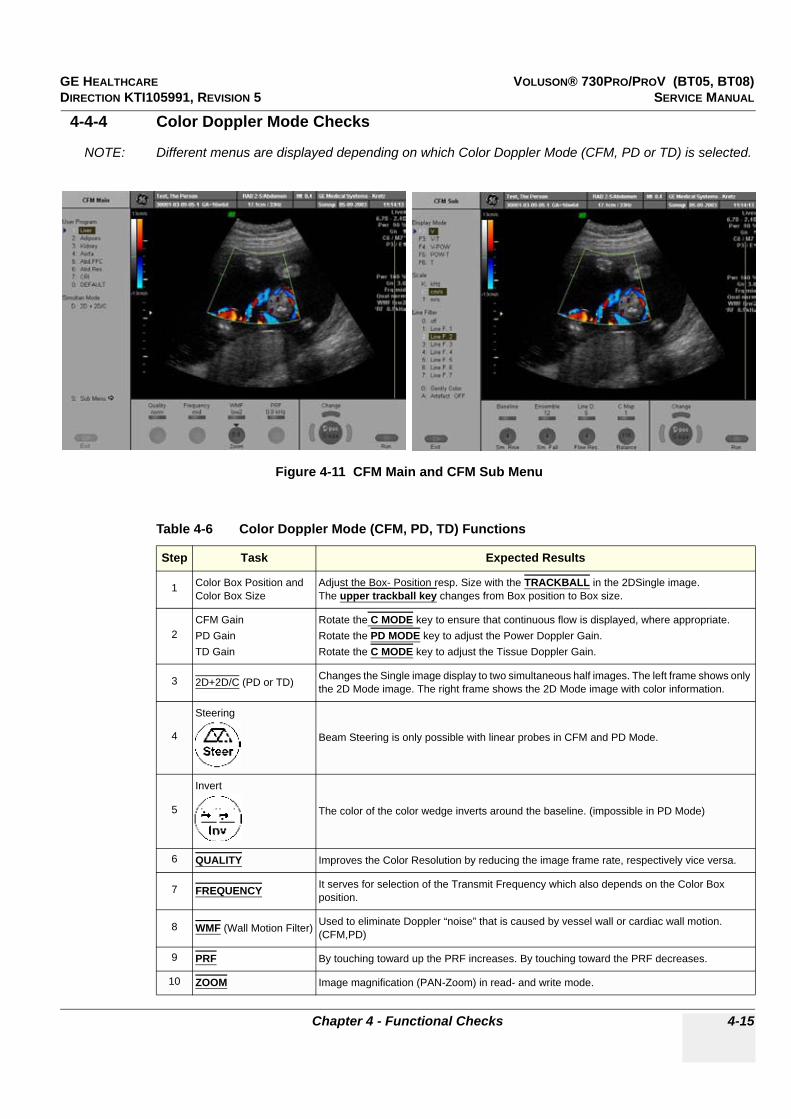
GE HEALTHCARE VOLUSON® 730PRO/PROV (BT05, BT08)DIRECTION KTI105991, REVISION 5 SERVICE MANUAL
Chapter 4 - Functional Checks 4-15
4-4-4 Color Doppler Mode Checks
NOTE: Different menus are displayed depending on which Color Doppler Mode (CFM, PD or TD) is selected.
Figure 4-11 CFM Main and CFM Sub Menu
Table 4-6 Color Doppler Mode (CFM, PD, TD) Functions
Step Task Expected Results
1 Color Box Position and Color Box Size
Adjust the Box- Position resp. Size with the TRACKBALL in the 2DSingle image.The upper trackball key changes from Box position to Box size.
2CFM GainPD GainTD Gain
Rotate the C MODE key to ensure that continuous flow is displayed, where appropriate.Rotate the PD MODE key to adjust the Power Doppler Gain.Rotate the C MODE key to adjust the Tissue Doppler Gain.
3 2D+2D/C (PD or TD) Changes the Single image display to two simultaneous half images. The left frame shows only the 2D Mode image. The right frame shows the 2D Mode image with color information.
4
Steering
Beam Steering is only possible with linear probes in CFM and PD Mode.
5
Invert
The color of the color wedge inverts around the baseline. (impossible in PD Mode)
6 QUALITY Improves the Color Resolution by reducing the image frame rate, respectively vice versa.
7 FREQUENCY It serves for selection of the Transmit Frequency which also depends on the Color Box position.
8 WMF (Wall Motion Filter) Used to eliminate Doppler “noise” that is caused by vessel wall or cardiac wall motion. (CFM,PD)
9 PRF By touching toward up the PRF increases. By touching toward the PRF decreases.
10 ZOOM Image magnification (PAN-Zoom) in read- and write mode.
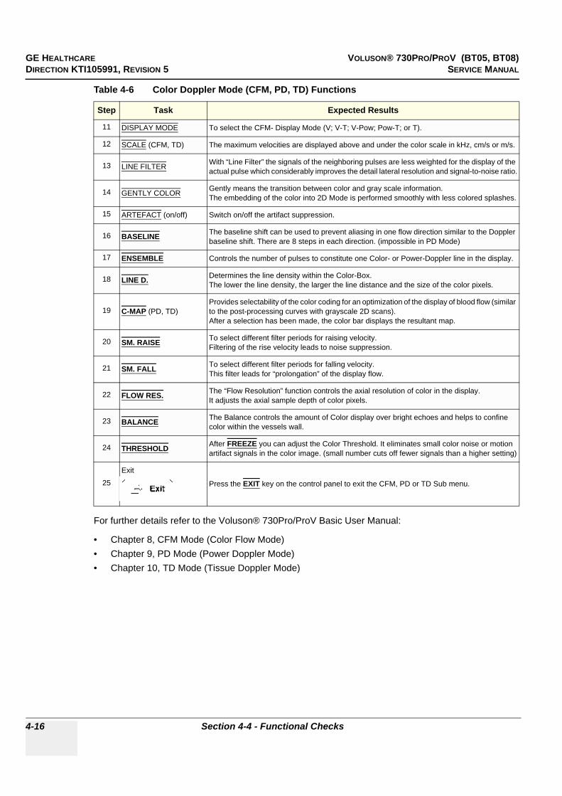
GE HEALTHCARE VOLUSON® 730PRO/PROV (BT05, BT08)DIRECTION KTI105991, REVISION 5 SERVICE MANUAL
4-16 Section 4-4 - Functional Checks
For further details refer to the Voluson® 730Pro/ProV Basic User Manual:
• Chapter 8, CFM Mode (Color Flow Mode)• Chapter 9, PD Mode (Power Doppler Mode)• Chapter 10, TD Mode (Tissue Doppler Mode)
11 DISPLAY MODE To select the CFM- Display Mode (V; V-T; V-Pow; Pow-T; or T).
12 SCALE (CFM, TD) The maximum velocities are displayed above and under the color scale in kHz, cm/s or m/s.
13 LINE FILTER With “Line Filter” the signals of the neighboring pulses are less weighted for the display of the actual pulse which considerably improves the detail lateral resolution and signal-to-noise ratio.
14 GENTLY COLOR Gently means the transition between color and gray scale information.The embedding of the color into 2D Mode is performed smoothly with less colored splashes.
15 ARTEFACT (on/off) Switch on/off the artifact suppression.
16 BASELINE The baseline shift can be used to prevent aliasing in one flow direction similar to the Doppler baseline shift. There are 8 steps in each direction. (impossible in PD Mode)
17 ENSEMBLE Controls the number of pulses to constitute one Color- or Power-Doppler line in the display.
18 LINE D. Determines the line density within the Color-Box. The lower the line density, the larger the line distance and the size of the color pixels.
19 C-MAP (PD, TD)Provides selectability of the color coding for an optimization of the display of blood flow (similar to the post-processing curves with grayscale 2D scans).After a selection has been made, the color bar displays the resultant map.
20 SM. RAISE To select different filter periods for raising velocity.Filtering of the rise velocity leads to noise suppression.
21 SM. FALL To select different filter periods for falling velocity.This filter leads for “prolongation” of the display flow.
22 FLOW RES. The “Flow Resolution” function controls the axial resolution of color in the display. It adjusts the axial sample depth of color pixels.
23 BALANCE The Balance controls the amount of Color display over bright echoes and helps to confine color within the vessels wall.
24 THRESHOLD After FREEZE you can adjust the Color Threshold. It eliminates small color noise or motion artifact signals in the color image. (small number cuts off fewer signals than a higher setting)
25Exit
Press the EXIT key on the control panel to exit the CFM, PD or TD Sub menu.
Table 4-6 Color Doppler Mode (CFM, PD, TD) Functions
Step Task Expected Results

GE HEALTHCARE VOLUSON® 730PRO/PROV (BT05, BT08)DIRECTION KTI105991, REVISION 5 SERVICE MANUAL
Chapter 4 - Functional Checks 4-17
4-4-5 Volume Mode Checks
NOTE: Different menus are displayed depending on which Menu and which Volume Mode is selected.
4-4-5-1 Pre-Volume Mode Functions
NOTICE!! NOTICE:
Real Time 4D (freeware on Voluson® 730ProV), RT_4D_Biopsy*, VCI*, STIC*, TUI* and VOCAL II* are Options. If these options is not a part of the system configuration, the appendant checks can be omitted.
BT Version:BT-Version:
“VCI” is optional at BT05 Voluson® 730Pro systems. However, at Voluson® 730Pro systems with BT08 software (SW 5.4.x), this feature is standard.
Figure 4-12 Pre-Volume Mode menus
Volume Acquisition: Static 3D
4. Start the Volume Acquisition with the Freeze key resp. the right trackball key.
Volume Acquisition: Real Time 4D
1. select the desired Volume Acquisition Mode:
The Volume Mode function is switched on, the “3D Pre” respectively “4D Pre” menu appears on the screen (write mode) and the volume box appears on the Image area.
2. select Acquisition and/or
3. select an User Program
Visualization Mode

GE HEALTHCARE VOLUSON® 730PRO/PROV (BT05, BT08)DIRECTION KTI105991, REVISION 5 SERVICE MANUAL
4-18 Section 4-4 - Functional Checks
Table 4-7 Pre-Volume Mode Functions
Step Task Expected Results
1 AQUISITION:
• 4D REAL TIME Real Time 4D - continuous volume acquisition and parallel calculation of 3D rendered images
• 4D BIOPSY * Real Time 4D Biopsy - continuous volume acquisition and parallel calculation of 3D rendered image.
• VCI A-PLANE * Volume Contrast Imaging - improves the contrast resolution and the signal / noise ratio and therefore facilitates finding of diffuse lesions in organs
• VCI C-PLANE * Volume Contrast Imaging (coronal plane) - improves the contrast resolution and the signal / noise ratio and therefore facilitates finding of diffuse lesions in organs
• STIC * With this acquisition method the fetal heart or an artery can be visualized in 4D.(also in combination with PD or CFM Mode)
2 VISUALIZATION:
• 3D RENDERING3D Static volume acquisition + rendered 3D image (also in combination with PD or CFM Mode)After the 3D acquisition the system switches automatically to the read menu. The selected format will be present on the monitor (e.g., A, B, C + rendered 3D image).
• 4D RENDERING Continuous volume acquisition + calculation of rendered 3D image in real time
• SECT. PLANES 3D Static volume acquisition resp. 4D volume acquisition without rendered 3D image (also in combination with PD or CFM)
• NICHE Parts of orthogonal sections A, B and C are compiled to a 3D-section aspect. The name “Niche” has been chosen because the aspect shows a quasi spatial cut into the reference image.
• T.U.I. * This method of visualization is consistent with the way other medical systems such as CT or MRI, present the data to the user (slices through the data set, which are parallel to each other).
• VCI STATIC * The data set is represented such as in Static 3D - Sectional Planes. However, the three planes are VCI renderings (tissue information of a thick slice), computed from the 3D dataset.
3- Quarter size display of Sectional Planes without 3D image or - Quarter size display of Sectional Planes + rendered 3D image(Note: The display depends on selected Acquisition- and Visualization Mode!)
4Dual size display of Sectional Planes + rendered 3D image. (Note: The display depends on selected Acquisition- and Visualization Mode! This format is not possible for Static 3D Acquisition)
5- Full size display of a the reference image or - Full size display of the rendered 3D image.(Note: The display depends on selected Acquisition- and Visualization Mode!)
6 Volume Box Position and Volume Box Size
Adjust the Volume Box (ROI) Position resp. Size with the TRACKBALL in the 2D Single image. The upper trackball key to change the Trackball function from Box Position to Box Size.
7 QUALITY Changes the line density against the acquisition speed (low, mid1, mid2, high1, high2).
8 VOL. ANGLE To select the Volume Sweep Angle.
9 Start Acquisition Press the FREEZE key resp. the right trackball key to start the Volume acquisition.

GE HEALTHCARE VOLUSON® 730PRO/PROV (BT05, BT08)DIRECTION KTI105991, REVISION 5 SERVICE MANUAL
Chapter 4 - Functional Checks 4-19
4-4-5-2 Functions after the 3D Acquisition
Figure 4-13 3D/4D Main - Sectional Planes and Image Rendering
Table 4-8 Functions after the 3D Acquisition
Step Task Expected Results
1X-ROT: Rotation about X-axis of the reference image.Y-ROT: Rotation about the Y-axis of the reference image.Z-ROT:Rotation about the Z-axis of the reference image.
2 PAR. SHIFT: Movement along Z-axis of the reference image.TRACKBALL: Movement along X- and Y-axis of the reference image.
3 NICHE Parts of the orthogonal sections A, B and C are complied to a 3D section aspect.The aspect shows quasi a spatial cut into the reference image.
4 VOCAL *The basic idea behind VOCAL II is the combination of 3D ultrasound tissue (presented as voxels) and the geometric information of surfaces in a 3D dataset. After definition of contour in 3D space (semi-automatically, manually or spherical) a wide range of functionality is given.
5 O.H. GRAPHIC Display of orientation help image figure.
6
Choosing a reference imagePress the left trackball key repeatedly to choose the Reference image among A, B or C.Choosing a reference image automatically determines the control functions of the rotary controls and the trackball for the liberal adjustment of a sectional plane.
7
Initial ConditionResets the rotations and translations of a volume section to the initial (start) position.

GE HEALTHCARE VOLUSON® 730PRO/PROV (BT05, BT08)DIRECTION KTI105991, REVISION 5 SERVICE MANUAL
4-20 Section 4-4 - Functional Checks
8
3D Image Orientation
To change the image orientation of the rendered 3D image.
9 ZOOM The 3D image as well as the sectional planes can be varied by their aspect ratio.
10 S.TXT/S.SM. MIX To adjust the mix ratio between two calculated modes.
11 TH. LOW respectivelyPD LOW in case of 3D+PD
All echoes below the level will be disregarded for calculation of the surface.All color values below the level will be disregarded for calculation of the surface.
12 MAGI CUT Ability to electronically manipulate the images and cut way “3D artifacts”.
13 RENDER PARAM. To select the Render Mode (Basic Mode and Render Algorithm)
14 RESET CURVE Reset the curvature of render start to default position
Table 4-8 Functions after the 3D Acquisition
Step Task Expected Results
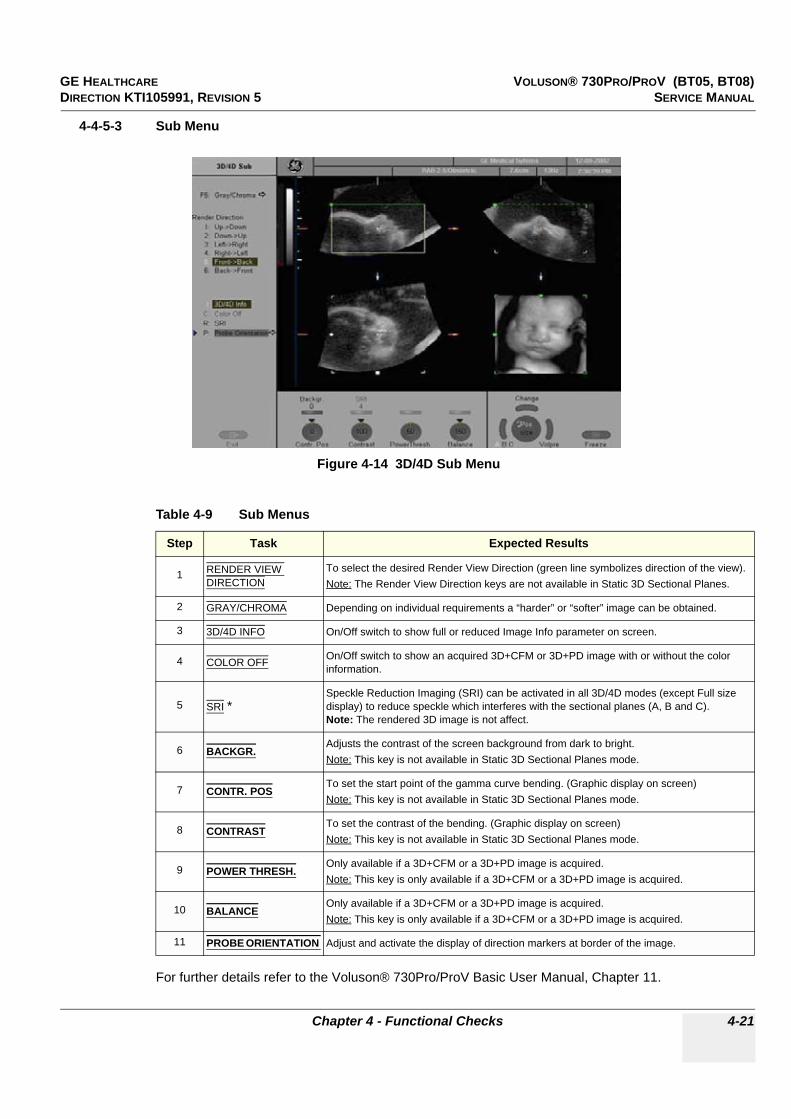
GE HEALTHCARE VOLUSON® 730PRO/PROV (BT05, BT08)DIRECTION KTI105991, REVISION 5 SERVICE MANUAL
Chapter 4 - Functional Checks 4-21
4-4-5-3 Sub Menu
For further details refer to the Voluson® 730Pro/ProV Basic User Manual, Chapter 11.
Figure 4-14 3D/4D Sub Menu
Table 4-9 Sub Menus
Step Task Expected Results
1 RENDER VIEW DIRECTION
To select the desired Render View Direction (green line symbolizes direction of the view).Note: The Render View Direction keys are not available in Static 3D Sectional Planes.
2 GRAY/CHROMA Depending on individual requirements a “harder” or “softer” image can be obtained.
3 3D/4D INFO On/Off switch to show full or reduced Image Info parameter on screen.
4 COLOR OFF On/Off switch to show an acquired 3D+CFM or 3D+PD image with or without the color information.
5 SRI *Speckle Reduction Imaging (SRI) can be activated in all 3D/4D modes (except Full size display) to reduce speckle which interferes with the sectional planes (A, B and C).Note: The rendered 3D image is not affect.
6 BACKGR.Adjusts the contrast of the screen background from dark to bright.Note: This key is not available in Static 3D Sectional Planes mode.
7 CONTR. POSTo set the start point of the gamma curve bending. (Graphic display on screen)Note: This key is not available in Static 3D Sectional Planes mode.
8 CONTRASTTo set the contrast of the bending. (Graphic display on screen)Note: This key is not available in Static 3D Sectional Planes mode.
9 POWER THRESH.Only available if a 3D+CFM or a 3D+PD image is acquired.Note: This key is only available if a 3D+CFM or a 3D+PD image is acquired.
10 BALANCEOnly available if a 3D+CFM or a 3D+PD image is acquired.Note: This key is only available if a 3D+CFM or a 3D+PD image is acquired.
11 PROBE ORIENTATION Adjust and activate the display of direction markers at border of the image.

GE HEALTHCARE VOLUSON® 730PRO/PROV (BT05, BT08)DIRECTION KTI105991, REVISION 5 SERVICE MANUAL
4-22 Section 4-4 - Functional Checks
4-4-6 Using Cine
4-4-6-1 Activating CinePress FREEZE, then roll the TRACKBALL to display the images of the stored sequence one by one.
4-4-6-2 Cine-Split Function (Multiple Format)After FREEZE of a sequence in 2D Mode two or four different images of the sequence can be displayed simultaneously in Dual respectively Quad Display Mode.
Move the TRACKBALL to display the images of the stored sequence. Use the FORMAT keys to change to the next (part of) frozen 2D image sequence to play back the cine memory.
NOTE: The Cine-Split function (multiple format) is also possible in 2D Auto Cine mode.
4-4-6-3 Activating 2D Auto Cine
1.) After Freeze press the LEFT TRACKBALL KEY.2.) Select the start image of the sequence by rotating the START digipot. The selected image is
simultaneously displayed.3.) Turn the END digipot to the end image of the sequence. The selected image is displayed.4.) Select the review SPEED and the read ZOOM factor.5.) Select the Cine Mode review direction.6.) To start/stop the Cine Loop playback press the RIGHT OR LEFT TRACKBALL KEY. After stopping the sequence, move the TRACKBALL to display the images one by one.
4-4-6-4 Spectral Doppler- or M Cine LoopPress FREEZE, then roll the TRACKBALL to display the Cine / Loop one by one.
The UPPER TRACKBALL KEY changes from the 2D Cine to the D Loop (respectively M Loop).
NOTE: The active Cine is displayed on the screen: Cine xxx/Loop or Cine/Loop xxx.
4-4-6-5 Activating 3D Rotation Cine
1.) After 3D Volume acquisition select the 3D ROT. CINE item from the menu area.2.) Select the ROTATION ANGLE from the menu area or manually with START / END rotary controls.3.) Select the STEP ANGLE and the ROTATION AXIS.4.) Select CALCULATE or press the RIGHT OR LEFT TRACKBALL KEY to start the calculation.5.) To start/stop the 3D Rotation Cine sequence press the RIGHT OR LEFT TRACKBALL KEY.
4-4-6-6 Activating Volume Cine
1.) After Real Time 4D acquisition move the TRACKBALL horizontally to display the Volumes of the stored sequence one by one. (Alternative use the VOL CINE # control to select the desired volume.)For further details refer to the Voluson® 730Pro/ProV Basic User Manual, Chapter 11.
4-4-6-7 Activating 4D Cine
1.) After Real Time 4D acquisition press UPPER TRACKBALL KEY to display the “4D Cine” menu.2.) Press the LEFT TRACKBALL KEY (Toggle function: Start/Stop).3.) Select the Cine Mode direction and the review SPEED.4.) To start/stop the Real Time 4D Cine sequence press the LEFT TRACKBALL KEY.
NOTE: After stopping a sequence, move the TRACKBALL to display the images / volumes one by one.
GE HEALTHCARE VOLUSON® 730PRO/PROV (BT05, BT08)DIRECTION KTI105991, REVISION 5 SERVICE MANUAL
Chapter 4 - Functional Checks 4-23
4-4-7 Generic Measurements
NOTE: Different menus are displayed depending on: • the currently selected Application and Display Mode,• the selected “Study”, • and the settings in the Measure Setup - MEASURE & CALC page.
For further details refer to the Voluson® 730Pro/ProV Basic User Manual, Chapter 13.
NOTE: The following instructions assume that you first scan the patient and then press FREEZE.
4-4-7-1 Distance and Tissue Depth Measurements (2D and M Mode)
1.) Press the CALIPER key and then select the GENERIC DIST. in the menu area.2.) Select the appropriate item from the menu area. An active cursor appears.3.) To position the active cursor at the start point (distance) or the most anterior point (tissue
depth), move the TRACKBALL.4.) To fix the start point, press SET (the right or left trackball key).
The system fixes the first cursor and displays a second active caliper.5.) To position the second active caliper at the end point (distance) or the most posterior point
(tissue depth), move the TRACKBALL.6.) To complete the measurement, press SET.
The system displays the distance or tissue depth value in the measurement results window.Before you complete a measurement:
To toggle between active calipers, or to re-adjust the traced line, press the upper trackball key.
To erase results, press the CLEAR ALL key on the control panel or the DELETE MEAS. key on the keyboard.
NOTE: To alternate the control from one cursor to the other, press CHANGE (the upper trackball key).To re-adjust a traced line, press UNDO (the upper trackball key) repeatedly.
•
General remarks to perform Generic Measurements:• By pressing the CALIPER key on the control panel the Generic Measurement function is switched on.• Selection of the desired measurement marks is done with the NAVIGATION WHEEL or by pressing
the corresponding keyboard shortcuts.• If the TRACKBALL MENU NAVIGATION key is illuminated, the trackball is consequently assigned
to select the menu items in the menu area on the left side of the screen.• Positioning of measurement marks is done with the TRACKBALL.• Entering and storage of measuring marks is done with SET (right or left trackball key).• To change measuring marks before completion press CHANGE (upper trackball key).• Depending on the setting in the Measure Setup, also the FREEZE key can be used for confirming the
last measuring mark of the currently performed measurement.• To cancel the measurement of the currently selected item, select CANCEL or press BACKSPACE.• To delete the results of the last measured item, select DELETE or press BACKSPACE.• To delete all measurement results of the selected “Study” from the monitor as well as from the
corresponding Worksheet, select the CLEAR GROUP or press the DELETE key.• All measurement results will be automatically included in the “Generic” patient worksheet.• To erase measurement results, press the CLEAR ALL key on the control panel or the
DELETE MEAS. key on the keyboard.• To exit from Generic measurements, press the CALIPER key or the EXIT key on the control panel.
GE HEALTHCARE VOLUSON® 730PRO/PROV (BT05, BT08)DIRECTION KTI105991, REVISION 5 SERVICE MANUAL
4-24 Section 4-4 - Functional Checks
4-4-7 Generic Measurements (cont’d)
4-4-7-2 Circumference/Area Measurements
1.) Press the CALIPER key and then select the GENERIC AREA in the menu area.2.) Select the corresponding item from the menu area. An active cursor displays.3.) To position the active cursor, move the TRACKBALL.4.) To fix the start point, press SET (the right or left trackball key). The system fixes the first cursor
and displays a second active caliper.5.) To position the second caliper, move the TRACKBALL and press SET (Rt. / Lt. trackball key).
NOTE: If you have selected a “trace” item, the measurement is finished and the area and circumference results appear on the screen.
6.) An ellipse appears the axis of which is defined by these two points.To adjust the width of the ellipse, move the TRACKBALL.
7.) To toggle between calipers, or to readjust a traced line, press the upper trackball key.8.) To complete the measurement, press SET (right or left trackball key). The system displays the
circumference and area in the measurement results area.Before you complete a measurement:
- To erase the ellipse resp. trace and the current data measured, select DELETE or press the BACKSPACE key on the keyboard. The original caliper is displayed to restart the measurement.
- To exit the measurement function, press the CALIPER key or EXIT key on the control panel.
4-4-7-3 Volume Measurements
1.) Press the CALIPER key and then select the GENERIC VOLUME in the menu area.2.) Select the appropriate item.3.) Perform the measurement(s) using the TRACKBALL and SET (right or left trackball key).
For further details: see 4-4-7-1 and 4-4-7-2.
4-4-7-3-1 Multiplane Measurements
NOTE: This volume measurement is only possible in 3D Mode.
1.) Select the reference image in which the measurement is to be performed (A, B or C).2.) Press the CALIPER key once and then select the MULTIPLANE item in the menu area.3.) Select the first section through the body by rotating the REF.SLICE digipot (first section should
be set at the edge of the object).4.) Position the start dot of the area which should be surrounded and store it with SET. 5.) Surround the area with the trackball, then press SET (right or left trackball key). The area is
calculated and displayed. It may even be “zero”. Press the SET key twice.6.) Select the next parallel section with the REF. SLICE digipot and measure the area.7.) Repeat 5. and 6. until the edge of the measured object is reached.
NOTE: The contour of the measured area is not erased if a new section is adjusted. To call back the measured areas touch the PREV / NEXT flip switch control.
NOTE: To erase the results, select the INIT item at the menu area.

GE HEALTHCARE VOLUSON® 730PRO/PROV (BT05, BT08)DIRECTION KTI105991, REVISION 5 SERVICE MANUAL
Chapter 4 - Functional Checks 4-25
4-4-7 Generic Measurements (cont’d)
4-4-7-4 Measurements in Spectral Doppler Mode
NOTE: The Spectral Doppler image is displayed based on time (X-axis) and velocity (Y-axis).
4-4-7-4-1 Auto Trace
1.) Press the CALIPER key.2.) Select AUTO TRACE item from the menu area on the left side of the screen.
It traces the Spectral Doppler image automatically and displays the results.3.) Select the SENSITIVITY of the envelope curve (to eliminate artifacts).4.) Select the TRACE MODE channel of the envelope curve (upper, both, lower).5.) If necessary, select the Angle and the Baseline.6.) Press the right or left trackball key SET to finish the measurement.
Before you complete the measurement:
- To readjust the start cycle (vertical yellow line), press CHANGE (upper trackball key). Press SET (right or left trackball key) to fix the line.
- Press the CHANGE key again to readjust the end cycle (vertical green line).Press SET to fix the line.
NOTE: The determination of the envelope curve requires a clear and low-noise record of the Doppler spectrum. Otherwise the reliability of the displayed measurement results may not be ensured!
4-4-7-4-2 Manual Trace
1.) Press the CALIPER key.2.) Select the MANUAL TRACE item from the menu area. A cursor appears on the screen.3.) Move the cursor with the TRACKBALL to the start point of the measurement and press SET
(right or left trackball key) to fix the marker.4.) Trace to the end of the period and press the SET key again to fix the mark.
The measurement results appear on the screen.Before you complete the measurement:
To readjust the traced line, press UNDO (upper trackball key) repeatedly.
4-4-7-4-3 Heart Rate
1.) Press the CALIPER key.2.) Select the HR item from the menu area. A line appears on the screen.3.) Move the line with the TRACKBALL to the start point of the period and press SET (right or left
trackball key). A second line appears.4.) Move the second line to the end point of the period.5.) Select the number of “HR cycles” for the measurement with the digipot.6.) Press the SET (right or left trackball key) again to fix the line. The Heart Rate is displayed.
NOTE: For further Doppler Measuements and other details refer to the Voluson® 730Pro/ProV Basic User Manual, Chapter 13
GE HEALTHCARE VOLUSON® 730PRO/PROV (BT05, BT08)DIRECTION KTI105991, REVISION 5 SERVICE MANUAL
4-26 Section 4-4 - Functional Checks
4-4-8 Calculations The Voluson® 730Pro/ProV system supports calculation packages and application-oriented patient Worksheets (Reports) for following applications:
• Abdomen Calculations• Small Parts Calculations• Obstetric Calculations• Cardiology Calculations• Urology Calculations• Vascular Calculations• Gynecology Calculations• Pediatric Calculations• Neurology Calculations• Orthopedics Calculations
NOTE: Confirm that the patient information is correct and the probe and application are selected properly.
NOTE: Different menus are displayed depending on: • the currently choosen Application• the selected Display Mode,• the selected “Study”, • and the settings in the Measure Setup - MEASURE & CALC page.
For further details refer to the Voluson® 730Pro/ProV Basic User Manual, Chapter 14
4-4-8-1 Worksheet (Report) Pages
General remarks to perform Calculations:• By pressing the CALC key on the control panel the Calculation function is switched on.• Selection of the desired measurement marks is done with the NAVIGATION WHEEL or by pressing
the corresponding keyboard shortcuts.• If the TRACKBALL MENU NAVIGATION key is illuminated, the trackball is consequently assigned
to select the menu items in the menu area on the left side of the screen.• Positioning of measurement marks is done with the TRACKBALL.• Entering and storage of measuring marks is done with SET (right or left trackball key).• To change measuring marks before completion press CHANGE (upper trackball key). • Depending on the setting in the Measure Setup, also the FREEZE key can be used for confirming the
last measuring mark of the currently performed measurement.• To cancel the measurement of the currently selected item, select CANCEL or press BACKSPACE.• To delete the results of the last measured item, select DELETE or press BACKSPACE.• To delete all measurement results of the selected “Study” from the monitor as well as from the
corresponding Worksheet, select the CLEAR GROUP or press the DELETE key.• All measurement results will be automatically included in the “Generic” patient worksheet.• To erase measurement results, press the CLEAR ALL key on the control panel or the
DELETE MEAS. key on the keyboard.• To exit from Generic measurements, press the CALIPER key or the EXIT key on the control panel.
Press the WORKSHEET key on the control panel to view the “application dependent” patient worksheet pages that contain the results of calculations and measurements. Any stored patient worksheet can be edited, printed, transferred, saved to Sonoview or sent to DICOM server.

GE HEALTHCARE VOLUSON® 730PRO/PROV (BT05, BT08)DIRECTION KTI105991, REVISION 5 SERVICE MANUAL
Chapter 4 - Functional Checks 4-27
4-4-9 Probe/Connectors Usage
4-4-9-1 Connecting a probe
1.) Place the probe's carrying case on a stable surface and open the case.2.) Carefully remove the probe and unwrap the probe cable.3.) DO NOT allow the probe head to hang free. Impact to the probe head could result in irreparable
damage.4.) Turn the connector locking handle counterclockwise.5.) Align the connector with the probe port and carefully push into place.6.) Turn the connector locking handle clockwise to secure the probe connector.7.) Open the right-hand side door, lay the cable into the intended cable holders and close the door.
So it is free to move, but not resting on the floor.
4-4-9-2 Activating the probe
1.) Press the PROBE key to activate the “Probe Select” menu. 2.) Select the appropriate probe using the TRACKBALL and the TRACKBALL KEYS. 3.) Upon selection of an “Application”, the programmed user presets appear.4.) Clicking a “Setting” field causes loading of the preset.
The probe is initialized, the main menu (2D mode) and the ultrasound image appears on the monitor in write mode (real time display).
4-4-9-3 Deactivating the probeWhen deactivating the probe, the probe is automatically placed in standby mode (read mode).
1.) Press the FREEZE key.2.) Gently wipe the excess gel from the face of the probe. (Refer to the Basic User Manual of
Voluson® 730Pro/ProV for complete cleaning instructions.)3.) Carefully slide the probe around the right side of the keyboard, toward the probe holder.
Ensure that the probe is placed gently in the probe holder.
4-4-9-4 Disconnecting the probePrior to disconnect a probe freeze the image. It is unnecessary to switch the unit off.
1.) Open the right-hand side door, remove the cable from the cable holder and close the door.2.) Turn the probe locking handle counterclockwise. Pull the probe and connector straight out of
the probe port.3.) Carefully slide the probe and connector away from the probe port and around the right side of
the keyboard. Ensure the cable is free.
CAUTION!! CAUTION:
If a probe is disconnected while running (write mode) a software error may occur. In this case switch the unit OFF (perform a reset).

GE HEALTHCARE VOLUSON® 730PRO/PROV (BT05, BT08)DIRECTION KTI105991, REVISION 5 SERVICE MANUAL
4-28 Section 4-4 - Functional Checks
4-4-10 Image Management (Sonoview) For Sonoview - Image Management functionality refer to Chapter 15 in the Basic User Manual of Voluson® 730Pro/ProV. It talks about several topics:
• Clipboard• Sending Exams• Printing Exams / Images• Export Exams / Images• Backup Exams• Restore the Backup Exams• DICOM Print / Send• Verifying and Pinging a Device• Sending Images via e-mail• Browsing and Managing an Exam’s stored Image• Connectivity, and Dataflow Concept and Creation• Configuring Connectivity• Services (Destinations)• Input of comments and voice annotations• Measure Distance and Ellipse• Buttons• Views• DVD/CD+(R)W and MO Erasing/Formatting• Changing Backup Folder on mapped Network Drive• etc.
Figure 4-15 Sonoview

GE HEALTHCARE VOLUSON® 730PRO/PROV (BT05, BT08)DIRECTION KTI105991, REVISION 5 SERVICE MANUAL
Chapter 4 - Functional Checks 4-29
4-4-11 Using the MOD (Magneto-Optical Drive)
The optional 3.5 inch Magneto-Optical disk drive supports the following medias:
1.3GB; 640MB; 540MB; 230MB and 128MB
1.) Before installing an MO disk in the MOD, check the MO disk for loose hardware or damaged labels which could jam inside the MOD. Also, ensure that the slide switch in one corner of the disk is set so that the disk is write enabled (disk hole closed).
2.) Insert the disk into the MOD with the label facing up.
3.) There are different methods to eject a disk from the MOD. Manual ejection methods are listed below in preferred order from best (1) to worst (3).a.) Press the EJECT switch on the MOD while system is ON.b.) Press and hold the EJECT switch while the system is booting.c.) Mechanical ejection. Insert the end of a paper clip into the hole next to the EJECT switch while
system power is OFF.
NOTICE!! NOTICE:
The MOD (Magneto-Optical Drive) is an Option.
Figure 4-16 Magneto-Optical Drive
NOTICE!! NOTICE:
Never move the unit with a disk in the MOD because the drive actuator will not be locked and the MOD could break.
NOTICE!! NOTICE:
Avoid mechanical ejection whenever possible. Mechanical ejection leaves the actuator unlocked and the MOD susceptible to damage if moved. If forced to use this method, reboot the system, then insert and eject a known good disk using one of the other manual ejection methods.
Eject ButtonMagneto-Optical Drive(MOD)

GE HEALTHCARE VOLUSON® 730PRO/PROV (BT05, BT08)DIRECTION KTI105991, REVISION 5 SERVICE MANUAL
4-30 Section 4-4 - Functional Checks
4-4-11-1 Formatting Media
a.) Select the “DVD/CD+(R)W and MO Formatting” tool on the left side of the Sonoview screen.b.) Insert the medium and select the DVD/CD+(R)W or the MO icon.
By selecting MO cartridge the unit displays the “MO Disk Formatter” window as shown in Figure 4-17.
1.) Select a Format Type from the drop down menu. If desired, mark the Low Level Format icon.2.) Click the START button to start the formatting process.
3.) A message box appears on the screen. Confirm with OK.4.) When the formatting has been completed, click OK to continue.
5.) Select the CLOSE button and press the EXIT key on the control panel to return to the Scan Mode.
To erase/format the backup media, DVD/CD+(R)W or MOD, press the SONOVIEW key on the Control panel.
The Sonoview screen appears on the monitor; see: Figure 4-15 on page 4-28.
Figure 4-17 MO Disk Formatter Window
Figure 4-18 MO Disk Formatter messages
DVD/CD+(R)W icon
MO and DVD/CD+(R)W Formatting tool
MO icon
Format Type Selection
Low Level Format Selection
Start Formatting Process

GE HEALTHCARE VOLUSON® 730PRO/PROV (BT05, BT08)DIRECTION KTI105991, REVISION 5 SERVICE MANUAL
Chapter 4 - Functional Checks 4-31
4-4-11-1 Formatting Media (cont’d)By selecting DVD/CD the unit displays the “Erase DVD/CD” window as shown in Figure 4-19.
1.) Select the “Erase Mode” and click the [OK] button to start the process.
2.) During erasing the Ultrasound system displays following message.
3.) Press the EXIT key on the control panel to return to the Scan Mode.
4-4-11-1-1 Adjusting the Write Speed of the DVD/CD Recorder
1.) Click the SETTINGS icon on the left side of the Sonoview screen.2.) Select DVD/CD RECORDER from the tool bar.
3.) Choose the “Write Speed” from the corresponding pop-up menu.
NOTICE!! NOTICE:
It is highly recommended to use the complete erase mode, to avoid problems with the CD-(R)W or DVD-(R)W! When using a DVD-(R)W, the complete erase mode is not possible.
Figure 4-19 Erase DVD/CD Window
Figure 4-20 Erasing disk
Figure 4-21 Settings of the DVD/CD Recorder
Settingsicon

GE HEALTHCARE VOLUSON® 730PRO/PROV (BT05, BT08)DIRECTION KTI105991, REVISION 5 SERVICE MANUAL
4-32 Section 4-5 - Backup and Restore Database, Preset Configurations and Images
Section 4-5Backup and Restore Database, Preset Configurations and Images
1.) Press the UTILITIES key on the control panel. The menu area changes to the Utilities menu.2.) Select the SYSTEM item from the menu area to activate the setup desktop screen.3.) Select the BACKUP page.
The “Backup” page is subdivided in two main groups:
A.) User Settings Only• Section 4-5-1 "Save User Settings Only (Application Settings)" on page 4-33• Section 4-5-2 "Load User Settings Only (Application Settings)" on page 4-34B.) Full Backup• Section 4-5-3 "Save Full Backup (Presets, Configurations & Application Settings)" on page 4-36• Section 4-5-4 "Load Full Backup (Presets, Configurations & Application Settings)" on page 4-38• Section 4-5-5 "Delete Full Backup (Presets, Configurations & Application Settings)" on page 4-40
The User Settings and/or Full Backup can be saved to the following destinations:
• D: partition of internal hard disk• DVD/CD+(R)W• MOD (if present)• Mapped Network Drive Z:
see: Section 3-11-1 "Map Network Drive" on page 3-70• USB-Stick• Any other drive connected to the system (e.g.; an external USB-hard disk)
Note: This function is only available in the Full Backup utility.For further details review: Section 3-5-13 "External USB-Devices" on page 3-32.
Figure 4-22 System Setup - Backup page
NOTICE!! NOTICE:
When connecting external USB devices, be sure to execute Safety Directions found in Chapter 2 of the Voluson® 730Pro/ProV (BT05, BT08) Basic User Manual.
Stop USB Devices
“Full Backup” group“User Settings Only”group

GE HEALTHCARE VOLUSON® 730PRO/PROV (BT05, BT08)DIRECTION KTI105991, REVISION 5 SERVICE MANUAL
Chapter 4 - Functional Checks 4-33
4-5-1 Save User Settings Only (Application Settings) The User Settings contains:
• Application Settings• User Programs• Auto Text• 3D/4D Programs
1.) Insert a DVD/CD+(R)W or MO (Magneto-Optical Disk) into the drive.2.) Press the UTILITIES key on the control panel. The menu area changes to the Utilities menu.3.) Select the SYSTEM item from the menu area to activate the setup desktop screen.4.) Select the BACKUP page.5.) Click the SAVE button of the “User Settings Only” group.
6.) Choose the media (e.g., DVD/CD+RW) and click the SAVE button.7.) Select the NEW FILE... key and enter a file name (without extension).8.) Click the OK key to start the process. When the saving has been completed, click OK.
Figure 4-23 User Settings Only - Save window
Choose the mediaand
then click Save

GE HEALTHCARE VOLUSON® 730PRO/PROV (BT05, BT08)DIRECTION KTI105991, REVISION 5 SERVICE MANUAL
4-34 Section 4-5 - Backup and Restore Database, Preset Configurations and Images
4-5-2 Load User Settings Only (Application Settings)
1.) Insert the DVD/CD+(R)W or MO (Magneto-Optical Disk) into the drive.2.) Press the UTILITIES key on the control panel. The menu area changes to the Utilities menu.3.) Select the SYSTEM item from the menu area to activate the setup desktop screen.4.) Select the BACKUP page and click the LOAD button of the “User Settings Only” group.
5.) Choose the media (e.g., DVD/CD+RW) and click the LOAD key.6.) Select the appropriate file and click OK. The “Load Backup Data” window appears.
CAUTION!! CAUTION:
The loading procedure overwrites the existing application settings on the local hard drive. Make sure to insert the correct DVD/CD or MO. Additionally you can load the backup from D:\User Settings.
Figure 4-24 User Settings Only - Load window
NOTICE!! NOTICE:
It is highly recommend to use Application settings which are adapted for the systems software version!
Figure 4-25 Load Backup Data
Choose the mediaandthen click Load
>> button
Load button
Complete Backup

GE HEALTHCARE VOLUSON® 730PRO/PROV (BT05, BT08)DIRECTION KTI105991, REVISION 5 SERVICE MANUAL
Chapter 4 - Functional Checks 4-35
4-5-2 Load User Settings Only (Application Settings) (cont’d) 7.) Select the Complete Backup (marked blue; see: Figure 4-25) and click the >> button to copy the
Complete Backup into the Load Data field.8.) Click the LOAD button to start the loading procedure of the complete backup into the system.
NOTE: Also only parts of a User Settings Only “Backup” can be loaded into the database to overwrite, restore, copy, etc.... the database in the system.
1.) Click the + sign to open the content tree.
2.) Click the >> button to copy the selected item into the Load Data field.
NOTE: To return selected items from the Load Data field to Backup Data field select the << button.
3.) Click the LOAD button to start loading procedure of the selected Backup item into the system.
Figure 4-26 Load only parts of the Backup
sign to open thecontent tree
>> button
<< button
Load button
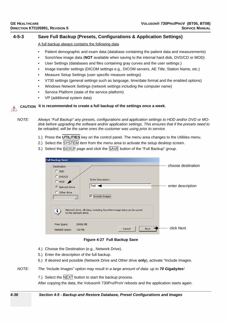
GE HEALTHCARE VOLUSON® 730PRO/PROV (BT05, BT08)DIRECTION KTI105991, REVISION 5 SERVICE MANUAL
4-36 Section 4-5 - Backup and Restore Database, Preset Configurations and Images
4-5-3 Save Full Backup (Presets, Configurations & Application Settings)A full backup always contains the following data
• Patient demographic and exam data (database containing the patient data and measurements)• SonoView image data (NOT available when saving to the internal hard disk, DVD/CD or MOD)• User Settings (databases and files containing gray curves and the user settings.)• Image transfer settings (DICOM settings e.g., DICOM servers, AE Title, Station Name, etc.)• Measure Setup Settings (user specific measure settings)• V730 settings (general settings such as language, time/date format and the enabled options)• Windows Network Settings (network settings including the computer name)• Service Platform (state of the service platform)• VP (additional system data)
NOTE: Always “Full Backup” any presets, configurations and application settings to HDD and/or DVD or MO-disk before upgrading the software and/or application settings. This ensures that if the presets need to be reloaded, will be the same ones the customer was using prior to service.
1.) Press the UTILITIES key on the control panel. The menu area changes to the Utilities menu.2.) Select the SYSTEM item from the menu area to activate the setup desktop screen.3.) Select the BACKUP page and click the SAVE button of the “Full Backup” group.
4.) Choose the Destination (e.g., Network Drive).5.) Enter the description of the full backup.6.) If desired and possible (Network Drive and Other drive only), activate “Include Images.
NOTE: The “Include Images” option may result in a large amount of data: up to 70 Gigabytes!
7.) Select the NEXT button to start the backup process.After copying the data, the Voluson® 730Pro/ProV reboots and the application starts again.
CAUTION!! CAUTION:
It is recommended to create a full backup of the settings once a week.
Figure 4-27 Full Backup Save
choose destination
enter description
click Next

GE HEALTHCARE VOLUSON® 730PRO/PROV (BT05, BT08)DIRECTION KTI105991, REVISION 5 SERVICE MANUAL
Chapter 4 - Functional Checks 4-37
4-5-3 Save Full Backup (Presets, Configurations & Application Settings) (cont’d)
When the Full Backup is stored on a network drive (to map a network drive see: Section 3-11-1 "Map Network Drive" on page 3-70), it may be desirable to move the data (e.g., for backup or maintenance).
The backups reside in sub folders of the main “fullbackup” -folder found at the root of the drive.For Example: Backups on the mapped Network Drive are below path Z:\fullbackup.
The directory structure of the full backup data is as follows:
For further details review: Section 3-5-13 "External USB-Devices" on page 3-32.
Figure 4-28 directory structure of full backup data
Figure 4-29 “Other drive” drop down menu
NOTICE!! NOTICE:
When the backup is saved to an external USB-device, the system has to be informed about the removal of the hardware. For this purpose every last dialog of "Full Backup Save" and "Full Backup Delete" has a STOP USB DEVICES button (see: Figure 4-30).
Figure 4-30 Please stop USB Devices before unplugging!
The sub folders have the names fbX where X is a number (e.g., Z:\fullbackup\fb1). The data resides within a directory structure within these sub folders.It is possible to move the fbX sub folders, even leaving gaps in the numeration sequence.However, NO change MUST be made to the contents of the fbX folders itself, otherwise the backup data cannot be restored!
If the destination „Other drive“ is selected, the available drives (e.g., external USB-memory stick) can be chosen from the drop down menu.

GE HEALTHCARE VOLUSON® 730PRO/PROV (BT05, BT08)DIRECTION KTI105991, REVISION 5 SERVICE MANUAL
4-38 Section 4-5 - Backup and Restore Database, Preset Configurations and Images
4-5-4 Load Full Backup (Presets, Configurations & Application Settings)
WARNINGWARNING!! WARNING:
Always backup any data before an upgrade; see: Section 4-5-3 on page 4-36.The “Full Backup” loading procedure replaces (overwrites) ALL the existing data on the local hard drive of the Voluson® 730Pro/ProV system!
CAUTION!! CAUTION:
There are circumstances where it is not possible to load (restore) all the data. The following rules specify the restrictions:
1.) Generally, only restoring data from an older to a newer software version is possible. Loading a backup into a system that has a lower software version than the system the backup was created on is prohibited.
2.) Options can only be restored on the same Voluson® 730Pro/ProV system within the same major software version.
3.) When loading a backup into a system with a software version that has a higher major number (2.x.x -> 3.x.x -> 4.x.x -> 5.x.x), the following items will not be restored:
A.) User SettingsB.) OptionsC.) State of the Service Platform (new model type necessary for VOLC)
4.) The user is only allowed to restore data to a different system if and only if the software version on this system is the same as in the backup.
5.) The user is only allowed to restore data onto the same system if and only if the software version on this system is equal or higher than the version in the backup.
6.) The user is not allowed to restore the following items to a different system:
A.) Windows Network SettingsB.) OptionsC.) DICOM AE TitleD.) DICOM Station NameE.) State of the Service Platform

GE HEALTHCARE VOLUSON® 730PRO/PROV (BT05, BT08)DIRECTION KTI105991, REVISION 5 SERVICE MANUAL
Chapter 4 - Functional Checks 4-39
4-5-4 Load Full Backup (Presets, Configurations & Application Settings) (cont’d)
1.) Press the UTILITIES key on the control panel. The menu area changes to the Utilities menu.2.) Select the SYSTEM item from the menu area to activate the setup desktop screen.3.) Select the BACKUP page and click the LOAD button of the “Full Backup” group.
4.) Choose the Destination (e.g., Network Drive).5.) Click on the backup to be restored (additional information is displayed in the table).6.) Select the NEXT button. The following window will be displayed.
7.) Select the data to be restored to the Voluson® 730Pro/ProV system and then click on NEXT.
NOTE: For description of the check box names review: A full backup always contains the following data
Figure 4-31 Full Backup Load
Figure 4-32 Select Data to be restored
choose destination
select backup
click Next

GE HEALTHCARE VOLUSON® 730PRO/PROV (BT05, BT08)DIRECTION KTI105991, REVISION 5 SERVICE MANUAL
4-40 Section 4-5 - Backup and Restore Database, Preset Configurations and Images
4-5-4 Load Full Backup (Presets, Configurations & Application Settings) (cont’d)
8.) Select YES to start, or NO to cancel the restore procedure.
After restoring the data, the Voluson® 730Pro/ProV reboots and the application starts again.
4-5-5 Delete Full Backup (Presets, Configurations & Application Settings)1.) Press the UTILITIES key on the control panel. The menu area changes to the Utilities menu.2.) Select the SYSTEM item from the menu area to activate the setup desktop screen.3.) Select the BACKUP page and click the DELETE button of the “Full Backup” group.
4.) Choose the Destination (e.g., HDD = Hard disk).5.) Click on the backup to be deleted (additional information is displayed in the table).6.) Select the DELETE button.
Figure 4-33 Start Restore Backup now?
WARNINGWARNING!! WARNING:
When clicking “YES”, the current data on the system will be permanently replaced by the data of the backup and can not be restored!
Figure 4-34 Full Backup Delete
WARNINGWARNING!! WARNING:
There is no “ UNDO” function for this action!
choose destination
select backup
select Delete

GE HEALTHCARE VOLUSON® 730PRO/PROV (BT05, BT08)DIRECTION KTI105991, REVISION 5 SERVICE MANUAL
Chapter 4 - Functional Checks 4-41
4-5-6 Archiving Images1.) Press the SONOVIEW key on the control panel.2.) Insert the DVD/CD+(R)W or MOD into drive.
If required, format/erase the media, see Section 4-4-11-1 "Formatting Media" on page 4-30. 3.) When you click the OPEN button on the upper left side of the screen, a list of all the exams is
displayed see Figure 4-35.
4.) Select the exam(s) using the TRACKBALL, the CTRL or SHIFT key on the alphanumeric keyboard and the right trackball key SET.
The number of all exams, the number of currently selected exams, the number of images and the capacity of selected images are displayed automatically at the right and upper corner of the exams list.
5.) Click the BACKUP button.6.) Select the destination for the backup.
NOTE: For destination NET perform Section 3-11-1 "Map Network Drive" on page 3-70 first.
7.) After finishing the backup, select whether the selected exam(s) is to be deleted or not.
For further information refer to Chapter 15 in the Basic User Manual of Voluson® 730Pro/ProV.
Figure 4-35 Sonoview Screen
Figure 4-36 Backup windows
NOTICE!! NOTICE:
If you select to delete the exam after finishing the backup, it will be absolutely deleted from the hard disk of the ultrasound scanner Voluson® 730Pro/ProV!
Open button
Backup
capacityof selectedexams
button

GE HEALTHCARE VOLUSON® 730PRO/PROV (BT05, BT08)DIRECTION KTI105991, REVISION 5 SERVICE MANUAL
4-42 Section 4-6 - Software Configuration Checks
Section 4-6Software Configuration Checks
Press the UTILITIES key and select the SYSTEM item from the “Utilities” menu - which is shown in the menu area on the left side of the screen. The System Setup desktop offers different pages to check:
Press the UTILITIES key and select the MEASURE item from the “Utilities” menu - which is shown in the menu area on the left side of the screen. The Measure Setup desktop offers three different pages to check.
Table 4-10 Software Configuration (System Setup) Checks
Step Task Expected Result(s)
1 General: Check Date and Time setting Date and Time are correct
2 General: Check that Location (Clinic Name) is correct Location Name is correct
3 General: Check Language settings desired Language is displayed
4 General: Check EUM Language settings desired EUM Language is displayed
5 User Setting: Check all the User Settings settings assigned as desired by the customer
6 User Settings: Check settings of the “Patient ID” field settings assigned as desired by the customer
7 Peripherals: Check assignment of Printer keys Print A and Print B keys are assigned as desired by the customer
8 Peripherals: Check assignment of Foot switch Foot Switch left and right are assigned as desired by the customer
9 Peripherals: Check Save Destination assignment assigned as desired by the customer
10 Peripherals: Check 2D Save key assignment assigned as desired by the customer
11 Peripherals: Check Remote Print A, Remote Print B, Report Printer and DICOM Print Job assignment settings assigned as desired by the customer
12 Option: Check that all options are set up correct D = Demo , I = Inactive , P = Permanent
13 Network:Check DICOM, Sonoview and Network configurations settings assigned as desired by the customer
14 Service: Check the Video Norm standard as described in Section 3-8-1-6 on page 3-63 settings assigned as required for the country
NOTICE!! NOTICE:
Parameters and possible adjustments depend on the selected Application.To view, add, delete, reorder, edit or when creating a new parameter (in the MEASURE & CALC page), it is very important that all items are chosen correctly and that the relevant item is highlighted.For further information refer to Chapter 18 in the Basic User Manual of Voluson® 730Pro/ProV.
Table 4-11 Measurement Setup Checks
Step Task Expected Result(s)
11 Measure & Calc: Check all settings for all applications setting assigned as desired by the customer
2 Application Parameters: Check all settings for all applications setting assigned as desired by the customer
3 Global Parameters: Check all settings setting assigned as desired by the customer

GE HEALTHCARE VOLUSON® 730PRO/PROV (BT05, BT08)DIRECTION KTI105991, REVISION 5 SERVICE MANUAL
Chapter 4 - Functional Checks 4-43
Section 4-7Peripheral Checks
Check that peripherals work as described below:
4-7-1 ECG Check Out Connect the ECG preamplifier MAN and check:
4-7-2 Power Supply AdjustmentThere are no adjustments on the power supplies. The DC Power is self-regulated. If a voltage is outside the specified range, it means that something is wrong, either with the power supply itself or with a component connected to that specific power outlet.
Table 4-12 Peripheral Checks
Step Task to do Expected Result(s)
1 Press the FREEZE key. Stop image acquisition.
2 Press the PRINT A or PRINT B key on the Control Panel.
The image displayed on the screen is printed on printer, depending on the key assignment configuration
3 Press the VCR key on the Control Panel twice. VCR resp.DVR starts recording (REC - will be displayed on the screen)
4 Press the VCR key twice again. VCR resp.DVR stops recording
5 Press the VCR key on the Control Panel once. The “VCR resp.DVR Remote Control” menu is displayed in the menu area as well as the status area on the screen.
6 Press the RECORD digipot or select the RECORD item from the menu area.
to start recordingA red dot is displayed in the VCR/DVR status area on the Title bar to indicate that recording has begun.
7 Press the STOP digipot or select the STOP item from the menu area.
To Stop recordingThe video status icon is changed to (Pause)
8 Press the PLAY digipot or select the PLAY item from the menu area. To start, Play back an examination
9 Press the EXIT key on the control panel. to return to the scanning mode
10
Use the assignable keys on the control panel (their functions are shown in the status area) or select the corresponding item from the menu area on the screen.
to perform actions on the recorded session, such as stop, pause, rewind or fast forward.The video status icon is updated accordingly.
Table 4-13 ECG preamplifier Check
Step Task Expected Result(s)
1Connect the ECG at the Connector on the rear panel of the scanner. Press the ECG key on the control panel to display the “ECG” menu on in the screen.
It will display a curve along the bottom edge of the image sector
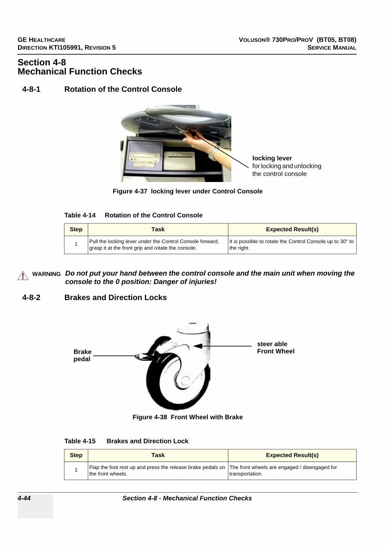
GE HEALTHCARE VOLUSON® 730PRO/PROV (BT05, BT08)DIRECTION KTI105991, REVISION 5 SERVICE MANUAL
4-44 Section 4-8 - Mechanical Function Checks
Section 4-8Mechanical Function Checks
4-8-1 Rotation of the Control Console
4-8-2 Brakes and Direction Locks
Figure 4-37 locking lever under Control Console
Table 4-14 Rotation of the Control Console
Step Task Expected Result(s)
1 Pull the locking lever under the Control Console forward, grasp it at the front grip and rotate the console.
It is possible to rotate the Control Console up to 30° to the right.
WARNINGWARNING!! WARNING:
Do not put your hand between the control console and the main unit when moving the console to the 0 position: Danger of injuries!
Figure 4-38 Front Wheel with Brake
Table 4-15 Brakes and Direction Lock
Step Task Expected Result(s)
1 Flap the foot rest up and press the release brake pedals on the front wheels.
The front wheels are engaged / disengaged for transportation.
locking leverfor locking and unlocking the control console
Brakepedal
steer ableFront Wheel
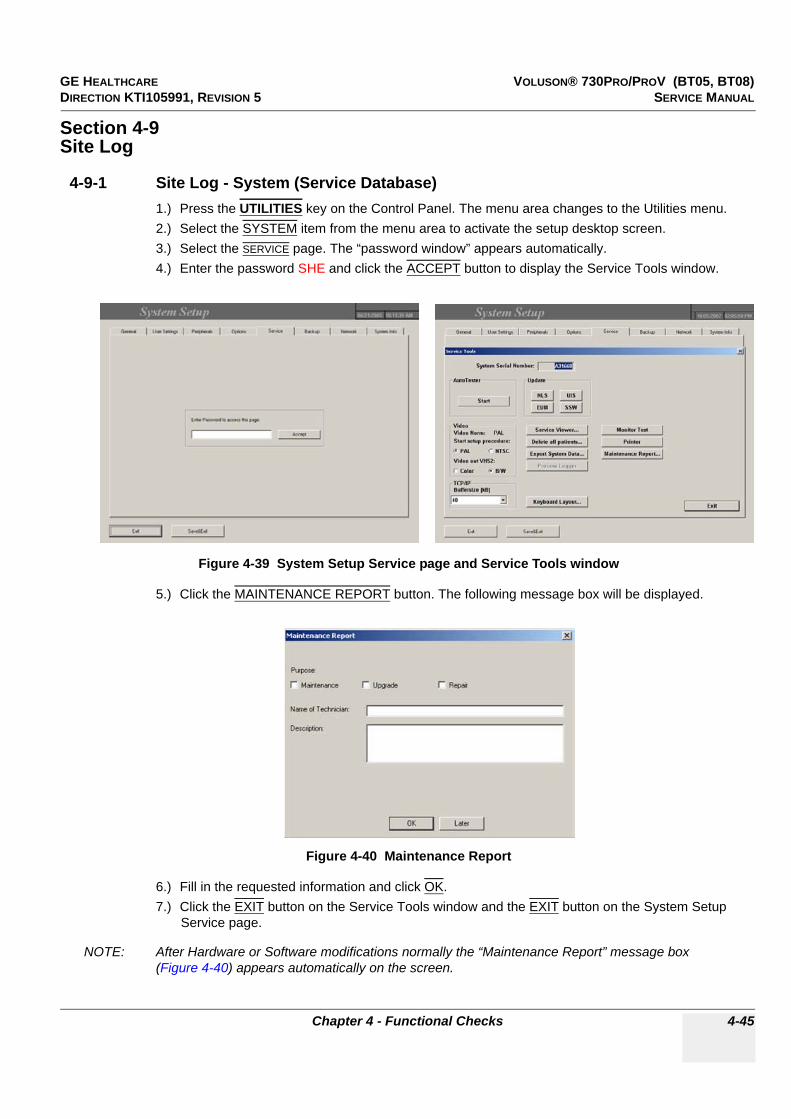
GE HEALTHCARE VOLUSON® 730PRO/PROV (BT05, BT08)DIRECTION KTI105991, REVISION 5 SERVICE MANUAL
Chapter 4 - Functional Checks 4-45
Section 4-9Site Log
4-9-1 Site Log - System (Service Database)1.) Press the UTILITIES key on the Control Panel. The menu area changes to the Utilities menu.2.) Select the SYSTEM item from the menu area to activate the setup desktop screen.3.) Select the SERVICE page. The “password window” appears automatically.4.) Enter the password SHE and click the ACCEPT button to display the Service Tools window.
5.) Click the MAINTENANCE REPORT button. The following message box will be displayed.
6.) Fill in the requested information and click OK.7.) Click the EXIT button on the Service Tools window and the EXIT button on the System Setup
Service page.
NOTE: After Hardware or Software modifications normally the “Maintenance Report” message box (Figure 4-40) appears automatically on the screen.
Figure 4-39 System Setup Service page and Service Tools window
Figure 4-40 Maintenance Report

GE HEALTHCARE VOLUSON® 730PRO/PROV (BT05, BT08)DIRECTION KTI105991, REVISION 5 SERVICE MANUAL
4-46 Section 4-9 - Site Log
4-9-2 Site Log - Paper Documentation
Table 4-16 Site Log
Date Service person Problem Comments

GE HEALTHCARE VOLUSON® 730PRO/PROV (BT05, BT08)DIRECTION KTI105991, REVISION 5 SERVICE MANUAL
Chapter 5 - Components and Functions (Theory) 5-1
Chapter 5Components and Functions (Theory)
Section 5-1Overview
5-1-1 Purpose of Chapter 5This chapter explains Voluson® 730Pro/ProV’s system concepts, component arrangement, and subsystem function. It also describes the Power Distribution System (PDS) and probes.
Table 5-1 Contents in Chapter 5
Section Description Page Number
5-1 Overview 5-1
5-2 General Information 5-2
5-3 Main board Chassis - GEZ Module 5-21
5-4 FrontEnd Processor 5-22
5-5 BackEnd Processor 5-28
5-6 Internal I/O 5-32
5-7 Top Console 5-41
5-8 Monitor 5-46
5-9 External I/O 5-47
5-10 Peripherals 5-48
5-11 Power Distribution 5-49
5-12 Mechanical Descriptions 5-51
5-13 Air Flow Control 5-54
5-14 Service Platform 5-55
5-15 Service Page 5-57

GE HEALTHCARE VOLUSON® 730PRO/PROV (BT05, BT08)DIRECTION KTI105991, REVISION 5 SERVICE MANUAL
5-2 Section 5-2 - General Information
Section 5-2General Information
Voluson® 730Pro/ProV is a digital beamforming curved-, linear- and phased array ultrasound imaging system. It has provisions for analog input sources like ECG and Phono. A CW-Doppler probe may also be connected and used.
The system can be used for:
• 2D Mode and Color Doppler Imaging (CFM, PD and TD)• M Mode + MCFM Imaging• Doppler (PW, CW)• 3D Mode and Real Time 4D Imaging• Different combinations of the above modes
Figure 5-1 Voluson® 730Pro/ProV Major Components
Monitor
TGC - Slider Controls
Monitor Controls
Control Console
Front Grip
Lever to rotate and lock the Control Console(mounted at the front below the Console)
Probe Connectors part
Foot rest
Brakes to block the front wheels (under the foot rest)
Name Plate
Place for ECG Module
Stand By switch
3.5” MOD Drive
DVD/CD+(R)W Drive
Gel Holder
incl. CW Connector andProbe storage connector(not active for scanning)
(optional)
Place for B/W and/orColor printer and/or Video Recorder (VCR)

GE HEALTHCARE VOLUSON® 730PRO/PROV (BT05, BT08)DIRECTION KTI105991, REVISION 5 SERVICE MANUAL
Chapter 5 - Components and Functions (Theory) 5-3
Section 5-2 General Information (cont’d)
Major System Components:
• GEZ: Main Board Chassis: Section 5-3 on page 5-21- Front-End processor: Section 5-4 on page 5-22- Back-End processor: Section 5-5 on page 5-28
• GEU: Top Console User interface (System I/O with hard keys) Section 5-7 on page 5-41
• Monitor: Section 5-8 on page 5-46• GES: External I/O Connection Module Section 5-8 on page 5-46• GEM: Removable Disk drive module (MO-Drive and ECG-preamplifier - optional)
Section 5-10 on page 5-48• CPN: Primary Power supply and Isolation transformer for the peripherals Section 5-11 on page 5-49• GW: System mechanical chassis, stand alone trolley to keep all major components
Section 5-12 on page 5-51
Figure 5-2 Major System Components
GWwithout GEU
GES
GEZ
CPN
Monitor
GEU
GEM
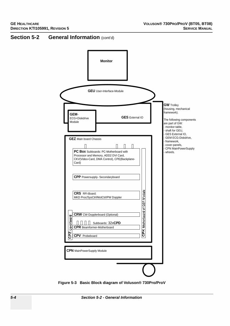
GE HEALTHCARE VOLUSON® 730PRO/PROV (BT05, BT08)DIRECTION KTI105991, REVISION 5 SERVICE MANUAL
5-4 Section 5-2 - General Information
Section 5-2 General Information (cont’d)
Figure 5-3 Basic Block diagram of Voluson® 730Pro/ProV
CPV Probeboard
CPR Beamformer-Motherboard
CRW CW-Dopplerboard (Optional)
CRS RFI-Board:MKD Proc/SysCtrl/MotCtrl/PW Doppler
PC Box Subboards: PC-Motherboard withProcessor and Memory, ADD2 DVI Card,CKV(Video-Card, DMA Control), CPE(Backplane-Card)
CPP Powersupply- Secondaryboard
GEU User-Interface-Module
Monitor
GES External IO
GEZ Main board Chassis
CPN MainPowerSupply Module
Subboards: 32xCPD
GEM-ECG+DiskdriveModule
GW Trolley(housing, mechanicalframework).
The following componentsare part of GW:- monitor-table,- shaft for GEU,- GES External IO,- GEM ECG-Diskdrive,- framework,- cover-panels,- CPN MainPowerSupply- wheels.

GE HEALTHCARE VOLUSON® 730PRO/PROV (BT05, BT08)DIRECTION KTI105991, REVISION 5 SERVICE MANUAL
Chapter 5 - Components and Functions (Theory) 5-5
Section 5-2 General Information (cont’d)
The Voluson® 730Pro/ProV used digital beamforming technology which provides high resolution and high penetration performance. It is a general purpose, mobile, software controlled diagnostic ultrasound scanner. Its function is to acquire ultrasound data and to display the data of different modes.Voluson® 730Pro/ProV gives the operator the ability to measure anatomical structures and offers analysis packages that provide information that is used to make a diagnosis by competent health care professionals.
The Calculation and Report function supports following application packages:
• Abdomen (ABD)• Obstetrics (OB)• Gynecology (GYN)• Cardiology (CARD)• Urology (URO)• Vascular (VAS)• Neurology (NEURO)• Small Parts (SM P)• Pediatrics (PED)• Orthopedics (ORTHO)
The Voluson® 730Pro/ProV supports a variety of linear-, curved-, phased array and pencil probes for various clinical applications. Any 3 probes may be connected at the same time (+ 1 pencil CW-probe).
Medical application fields include:
• Obstetrics• Gynecology and Fertility• Radiology• Internal Medicine• Neurology• Cardiology• Oncology• Urology• Orthopedics• PediatricsThe system is designed for follow-up expansion.
In addition to the initial operational settings for each transducer pre-programmed in the system, user-customized parameter settings for each transducer may be inserted by the operator and stored for recall as needed via the system control panel. System configuration is stored on the hard drive and all necessary software is loaded from the hard drive on power up.
Biopsy guidelines are provided on screen to assist in the collection of tissue samples, using biopsy guide adapters offered as an optional accessory.
The system provides the ability to perform remote viewing of images without compression, via DICOM 3.0 compatible output. Management of patient history is possible by “Sonoview” image-filing function. High-resolution images are provided by utilizing a technology called digital dynamic receive focusing.

GE HEALTHCARE VOLUSON® 730PRO/PROV (BT05, BT08)DIRECTION KTI105991, REVISION 5 SERVICE MANUAL
5-6 Section 5-2 - General Information
Section 5-2 General Information (cont’d)
Signal flow travels from the Probe Connector Panel to the Front End Electronics, to the Back-End Processor, and finally displayed on the monitor and peripherals.
For more detailed explanations of functions and controls refer to the Voluson® 730Pro/ProV Basic User Manual.
5-2-1 Description of Voluson® 730Pro/ProV Operating Modes
5-2-1-1 B-Mode or 2D-ModeB-Mode or 2D-mode is a two-dimensional image of the amplitude of the echo signal. It is used for location and measurement of anatomical structures and for spatial orientation during operation of other modes. In 2D-mode, a two-dimensional cross-section of a three-dimensional soft tissue structure such as the heart is displayed in real time. Ultrasound echoes of different intensities are mapped to different gray scale or color values in the display. The outline of the 2D cross-section may be a rectangle, parallelogram, sector or 360-degree circle, depending on the particular transducer used. 2D-mode can be used in combination with any other mode.
5-2-1-1-1 Coded Harmonic Imaging (HI)In Harmonic Imaging, acoustic aberrations due to tissue are minimized by receiving and processing the second harmonic signal that is generated within the insonified tissue. Voluson® 730Pro/ProV´s high performance HI provides superb detail resolution and penetration, outstanding contrast resolution, excellent acoustic clutter rejection and an easy to operate user interface.Coded Harmonics enhances near field resolution for improved small parts imaging as well as far field penetration. It diminishes low frequency amplitude noise and improves imaging technically difficult patients. It may be especially beneficial when imaging isoechoic lesions in shallow-depth anatomy in the breast, liver and hard-to-visualize fetal anatomy. Coded Harmonics may improve the B-Mode image quality without introducing a contrast agent.
5-2-1-2 M-ModeIn M-mode, soft tissue structure is presented as scrolling display, with depth on the Y-axis and time on the X-axis. It is used primarily for cardiac measurements such as value timing on septal wall thickness when accurate timing information is required. M-mode is also known as T-M mode or time-motion mode. Ultrasound echoes of different intensities are mapped to different gray scale values in the display. M-mode displays time motion information of the ultrasound data derived from a stationary beam. Depth is arranged along the vertical axis with time along the horizontal axis. M-mode is normally used in conjunction with a 2D image for spatial reference. The 2D image has a graphical line (M-line) superimposed on the 2D image indicating where the M-mode beam is located.
5-2-1-2-1 MCFM Mode (M Mode + Color Flow Mode)Color Flow Mode and Color M Mode are Doppler modes intended to add color-coded qualitative information concerning the relative velocity and direction of fluid motion within the 2D mode or M mode image. Color Flow overlays color on the M mode trace using velocity and variance color maps. The Color Flow wedge overlays the 2D mode image and M mode timeline.

GE HEALTHCARE VOLUSON® 730PRO/PROV (BT05, BT08)DIRECTION KTI105991, REVISION 5 SERVICE MANUAL
Chapter 5 - Components and Functions (Theory) 5-7
5-2-1-3 Color Doppler Modes
Color Doppler is used to detect motion presented as a two-dimensional display. There are following applications of this technique:
• Color Flow Mode (C) - used to visualize blood flow velocity and direction• Power Doppler (PD) - used to visualize the spatial distribution of blood• Tissue Doppler (TD) - used to visualize tissue motion direction and velocity
5-2-1-3-1 Color Flow ModeA real-time two-dimensional cross-section image of blood flow is displayed. The 2D cross-section is presented as a full color display, with various colors being used to represent blood flow (velocity, variance, power and/or direction). Often, to provide spatial orientation, the full color blood flow cross-section is overlaid on top of the grayscale cross-section of soft tissue structure (2D echo). For each pixel in the overlay, the decision of whether to display color (Doppler), gray scale (echo) information or a blended combination is based on the relative strength of return echoes from the soft tissue structures and from the red blood cells. Blood velocity is the primary parameter used to determine the display colors, but power and variance may also used. A high pass filter (wall filter) is used to remove the signals from stationary or slowly moving structures. Tissue motion is discriminated from blood flow by assuming that blood is moving faster than the surrounding tissue, although additional parameters may also be used to enhance the discrimination. Color flow can be used in combination with 2D and Spectral Doppler modes as well as with 3D mode.
5-2-1-3-2 Power DopplerA real-time two dimensional cross-section of blood flow is displayed. The 2D cross-section is presented as a full color display, with various colors being used to represent the power in blood flow echoes. Often, to provide spatial orientation, the full color blood flow cross-section is overlaid on top of the gray scale cross-section of soft tissue structure (2D echo). For each pixel in the overlay, the decision of whether to display color (Doppler power), gray scale (echo) information or a blended combination is based on the relative strength of return echoes from the soft-tissue structures and from the red blood cells. A high pass filter (wall filter) is used to remove the signals from stationary or slowly moving structures. Tissue motion is discriminated from blood flow by assuming that blood is moving faster than the surrounding tissue, although additional parameters may also be used to enhance the discrimination. The power in the remaining signal after wall filtering is then averaged over time (persistence) to present a steady state image of blood flow distribution. Power Doppler can be used in combination with 2D and Spectral Doppler modes as well as with 3D mode.
5-2-1-3-3 Tissue DopplerThe Tissue Color Doppler Imaging is used for color encoded evaluation of heart movements. The TD image provides information about tissue motion direction and velocity.
5-2-1-4 Pulsed (PW) DopplerPW Doppler processing is one of two spectral Doppler modalities, the other being CW Doppler. In spectral Doppler, blood flow is presented as a scrolling display, with flow velocity on the Y-axis and time on the X-axis. The presence of spectral broadening indicates turbulent flow, while the absence of spectral broadening indicates laminar flow. PW Doppler provides real time spectral analysis of pulsed Doppler signals. This information describes the Doppler shifted signal from the moving reflectors in the sample volume. PW Doppler can be used alone but is normally used in conjunction with a 2D image with an M-line and sample volume marker superimposed on the 2-D image indicating the position of the Doppler sample volume. The sample volume size and location are specified by the operator. Sample volume can be overlaid by a flow direction cursor which is aligned, by the operator, with the direction of flow in the vessel, thus determining the Doppler angle. This allows the spectral display to be calibrated in flow velocity (m/sec.) as well as frequency (Hz). PW Doppler also provides the capability of performing spectral analysis at a selectable depth and sample volume size. PW Doppler can be used in combination with 2D and Color Flow modes.
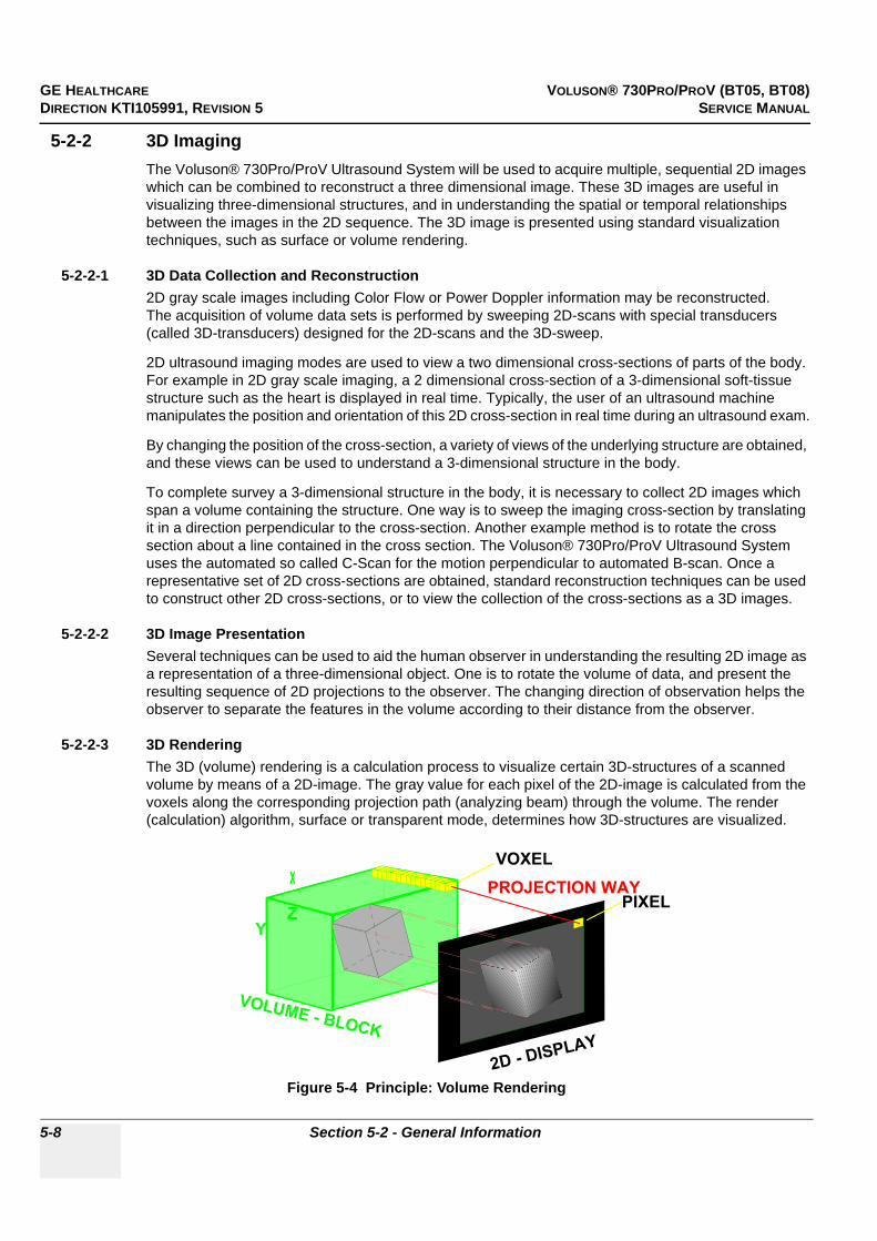
GE HEALTHCARE VOLUSON® 730PRO/PROV (BT05, BT08)DIRECTION KTI105991, REVISION 5 SERVICE MANUAL
5-8 Section 5-2 - General Information
5-2-2 3D ImagingThe Voluson® 730Pro/ProV Ultrasound System will be used to acquire multiple, sequential 2D images which can be combined to reconstruct a three dimensional image. These 3D images are useful in visualizing three-dimensional structures, and in understanding the spatial or temporal relationships between the images in the 2D sequence. The 3D image is presented using standard visualization techniques, such as surface or volume rendering.
5-2-2-1 3D Data Collection and Reconstruction2D gray scale images including Color Flow or Power Doppler information may be reconstructed.The acquisition of volume data sets is performed by sweeping 2D-scans with special transducers (called 3D-transducers) designed for the 2D-scans and the 3D-sweep.
2D ultrasound imaging modes are used to view a two dimensional cross-sections of parts of the body. For example in 2D gray scale imaging, a 2 dimensional cross-section of a 3-dimensional soft-tissue structure such as the heart is displayed in real time. Typically, the user of an ultrasound machine manipulates the position and orientation of this 2D cross-section in real time during an ultrasound exam.
By changing the position of the cross-section, a variety of views of the underlying structure are obtained, and these views can be used to understand a 3-dimensional structure in the body.
To complete survey a 3-dimensional structure in the body, it is necessary to collect 2D images which span a volume containing the structure. One way is to sweep the imaging cross-section by translating it in a direction perpendicular to the cross-section. Another example method is to rotate the cross section about a line contained in the cross section. The Voluson® 730Pro/ProV Ultrasound System uses the automated so called C-Scan for the motion perpendicular to automated B-scan. Once a representative set of 2D cross-sections are obtained, standard reconstruction techniques can be used to construct other 2D cross-sections, or to view the collection of the cross-sections as a 3D images.
5-2-2-2 3D Image PresentationSeveral techniques can be used to aid the human observer in understanding the resulting 2D image as a representation of a three-dimensional object. One is to rotate the volume of data, and present the resulting sequence of 2D projections to the observer. The changing direction of observation helps the observer to separate the features in the volume according to their distance from the observer.
5-2-2-3 3D RenderingThe 3D (volume) rendering is a calculation process to visualize certain 3D-structures of a scanned volume by means of a 2D-image. The gray value for each pixel of the 2D-image is calculated from the voxels along the corresponding projection path (analyzing beam) through the volume. The render (calculation) algorithm, surface or transparent mode, determines how 3D-structures are visualized.
Figure 5-4 Principle: Volume Rendering
PIXEL
VOXEL
Y
X
Z
PROJECTION WAY
2D - DISPLAY
VOLUME - BLOCK
X
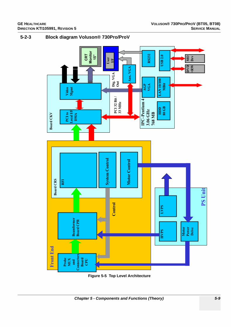
GE HEALTHCARE VOLUSON® 730PRO/PROV (BT05, BT08)DIRECTION KTI105991, REVISION 5 SERVICE MANUAL
Chapter 5 - Components and Functions (Theory) 5-9
5-2-3 Block diagram Voluson® 730Pro/ProV
Figure 5-5 Top Level Architecture
PC
I to
Lo
cal
I/F
DM
A
IPC
–P
enti
um
4
3.0
6 G
Hz
76
8 M
BPC
I 32 B
it /
33 M
Hz
CR
T
Mo
nit
or
15”
Vid
eo
Mg
mt D
ig. V
GA
Ou
t
US
B 2
.0H
DD
80 G
B
DV
D
+R
W
MO
Drv
LA
N 1
0/1
00
MB
it
AG
P
VG
AR
S23
2
Au
x. V
GA
Use
r
I/F
PS
Un
it
Pro
be
MU
X
an
d
Con
nec
tors
Boa
rd
CP
U
HV
PS
Mo
tor
Pow
er
Dri
ve
LV
PS
Fro
nt
En
dB
oa
rd C
KV
Boa
rd C
RS
RF
I
Bea
mfo
rmer
Boa
rd C
PR
Sy
stem
Co
ntr
ol
Co
ntr
ol
Mo
tor
Co
ntr
ol
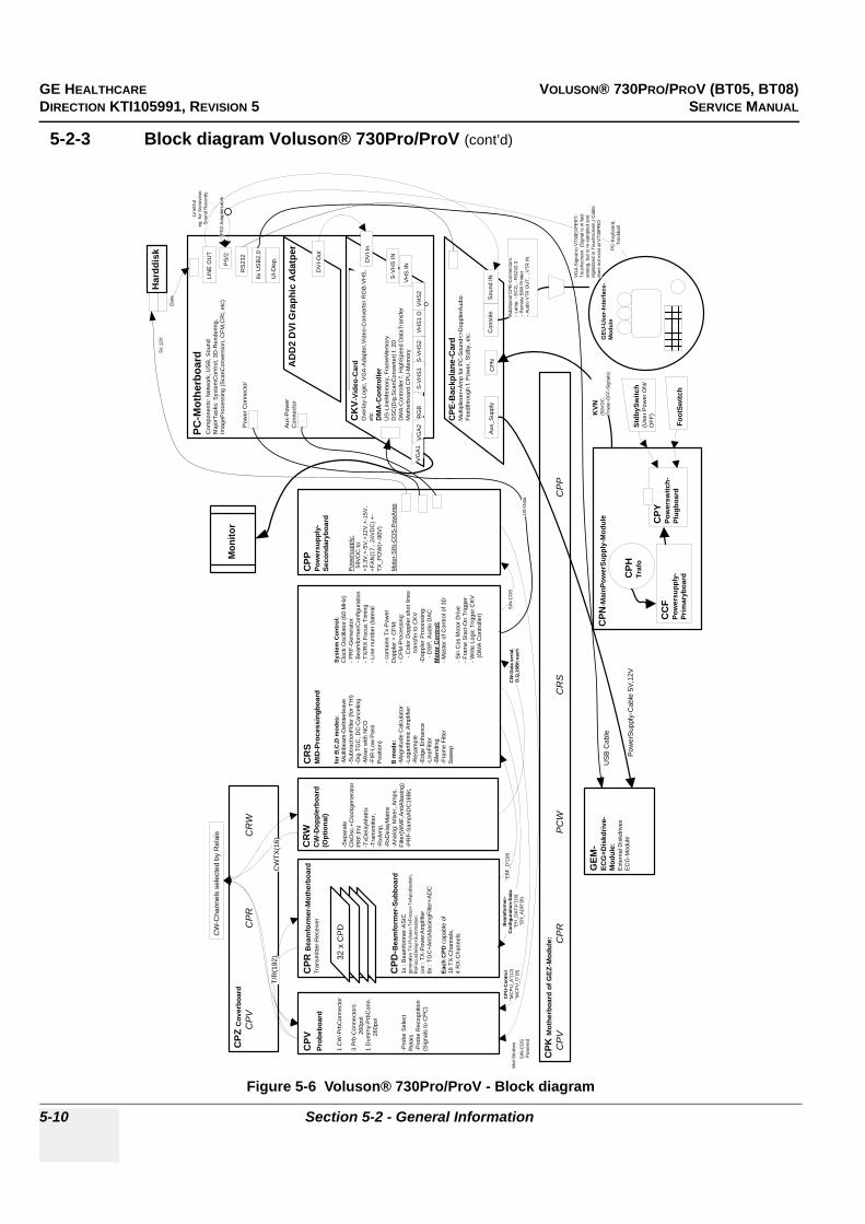
GE HEALTHCARE VOLUSON® 730PRO/PROV (BT05, BT08)DIRECTION KTI105991, REVISION 5 SERVICE MANUAL
5-10 Section 5-2 - General Information
5-2-3 Block diagram Voluson® 730Pro/ProV (cont’d)
Figure 5-6 Voluson® 730Pro/ProV - Block diagram
CPP
Pow
ersu
pply
-Se
cond
aryb
oard
Pow
ersu
pply
: 5
9VD
C to
:+3
.3V
,+-5
V,+
12V
,+-1
5V,
+FA
N(1
7...2
4VD
C) +
-TX
_PO
W(+
-90V
)
Mot
or-S
IN-C
OS
-Pow
Am
p
PC-M
othe
rboa
rd
CPK
Mot
herb
oard
of G
EZ-M
odul
e: C
PV
C
PR
P
CW
CR
S
C
PP
CPN
-Mai
nPow
erSu
pply
-Mod
ule
CPZ
Cov
erbo
ard
CP
V
CP
R
CR
W
CPV
Prob
eboa
rd
1 C
W-P
rbC
onne
ctor
3 P
rb-C
onne
ctor
s
260
pol
1 D
umm
y-Pr
bCon
n.
260p
ol
-Pro
be S
elec
t R
elai
s-P
robe
Rec
ogni
tion
(Sig
nals
to C
PC
)
CPR
Bea
mfo
rmer
-Mot
herb
oard
Tran
smitt
er-R
ecei
ver
CPD
-Bea
mfo
rmer
-Sub
boar
d1x
: B
eam
form
er-A
SIC
ge
nera
tes
TX-P
ulse
s+Tx
Focu
s+Tx
Apo
disa
tion,
R
xFoc
usD
elay
+Sum
mat
ion.
16x
: TX
-Pow
erA
mpl
ifier
8x :
TGC
+Ant
iAlia
sing
Filte
r+A
DC
Each
CPD
cap
able
of
16 T
X-C
hann
els,
4 R
X-C
hann
els
AD
D2
DVI
Gra
phic
Ada
tper
CW
-Cha
nnel
s se
lect
ed b
y R
elai
s
T/R
(192
)C
WTX
(16)
CPY
Pow
ersw
itch-
Plug
boar
dC
CF
Pow
ersu
pply
-Pr
imar
yboa
rd
Con
sole
CP
N
GEM
-EC
G+D
iskd
rive-
Mod
ule:
Ext
erna
l Dis
kdriv
esE
CG
-Mod
ule
Aux_
Supp
ly
PS
/2
6x U
SB
2.0
KVN
(59V
DC
,P
ower
-OFF
-Sig
nals
)
Pow
erS
uppl
y-C
able
5V
,12V
"EB
F_D
"(18
)C
W-D
ata
seria
l,D
,Q,1
6Bit
each
CPU
-Con
trol
"MC
PU
_A"(
12)
"MC
PU_D
"(8)
Bea
mfo
rmer
-C
onfig
urat
ion-
Dat
a:"E
H_D
ATA
"(16
)"E
H_A
DR
"(8)
CR
WC
W-D
oppl
erbo
ard
(Opt
iona
l)
-Sep
arat
e C
lkO
sc.+
Clo
ckge
nera
tor
PR
F,FN
-T
xDel
ayM
atrix
-T
rans
mitt
er,
-RxA
mp,
-R
xDel
ayM
atrix
-Ana
log:
Mix
er, A
mps
, Fi
lter(W
MF,
Ant
iAlia
sing
)-P
RF-
Sam
pAD
C16
Bit,
Har
ddis
k5V
,12V
Dat
a
Add
ition
al C
PE
-Con
nect
ors:
-Lam
p, -
EC
G, -
RS2
32-3
-Rem
ote
B/W
Prin
ter
-Aud
io V
TR O
UT,
...V
TR IN
LIN
E O
UT
Sou
nd IN
Line
Out
eg. f
or S
onov
iew
-So
und
Rec
ords
USB
Cab
le
Mot
-Stro
bes
SIN
-CO
S P
ower
ed
RS
232
PC
-Key
boar
d,Tr
ackb
all
VG
A-S
igna
l to
V73
0EX
PER
T-To
uchs
cree
n. (S
igna
l is
in fa
ct
anal
og, b
ut is
re-s
ampl
ed a
nd
digi
taliz
ed in
Tou
chsc
reen
.) C
able
do
es n
ot e
xist
at V
730P
RO
PS
2-A
dapt
erca
ble
32 x
CPD
CR
SM
ID-P
roce
ssin
gboa
rd
for B
,C,D
mod
es:
Syst
em C
ontr
ol:
-Mul
tibea
m-D
eInt
erle
ave
Clo
ck O
scill
ator
(60
MH
z)-S
ubtra
ctio
nFilt
er (f
or T
HI)
-PR
F-G
ener
ator
-Dig
.TG
C, D
C-C
ance
ling
-Bea
mfo
rmer
Con
figur
atio
n-M
ixer
with
NC
O-T
X/R
X F
ocus
Tim
ing
-FIR
-Low
Pas
s-L
ine
num
ber (
late
ral
Pos
ition
)-c
onta
ins
Tx-P
ower
B m
ode:
Dop
pler
+ C
FM:
-Mag
nitu
de C
alcu
lato
r-C
FM-P
roce
ssin
g:-L
ogar
ithm
ic A
mpl
ifier
-Col
or D
oppl
er s
hot l
ines
-Res
ampl
e
tra
nsfe
r to
CK
V-E
dge
Enha
nce
-Dop
pler
Pro
cess
ing:
-Lin
eFilt
er-D
SP, A
udio
DA
C-B
lend
ing
Mot
or C
ontr
ol:
-Fra
me
Filte
r-M
aste
r of C
ontro
l of 3
D
Swee
p-S
in C
os M
otor
Driv
e-F
ram
e S
tart-
On
Trig
ger
-Writ
e Lo
gic
Trig
ger C
KV
(D
MA
Con
trolle
r)
SIN
-CO
S
CPH
Traf
o
GEU
-Use
r-In
terf
ace-
Mod
ule
Com
pone
nts:
Net
wor
k, U
SB
, Sou
ndM
ajor
Task
s: S
yste
mC
ontro
l, 3D
-Ren
derin
g,
Imag
ePro
cess
ing
(Sca
nCon
vers
ion,
CFM
,CR
I, et
c)
DV
I-Out
CK
V-Vi
deo-
Car
dO
verla
y-Lo
gic,
VG
A-A
dapt
er,V
ideo
-Con
verte
r RG
B-V
HS
, et
cD
MA
-Con
trol
ler
US-
Line
Mem
ory,
Fra
meM
emor
yD
SC
(Dig
.Sca
nCon
verte
r) f.
2D
DM
A-C
ontro
ller f
. Hig
hSpe
ed D
ataT
rans
fer
Mot
herb
oard
CP
U-M
emor
yV
HS
IN
S-V
HS
IN
VG
A1
VG
A2
S-V
HS
2V
HS
1 O
VH
S2
OR
GB
S-V
HS
1
DV
I-In
US
-Dat
a
CPE
-Bac
kpla
ne-C
ard
Mul
tiple
xer+
Am
p fo
r PC
-Sou
nd<>
Dop
pler
Aud
ioFe
edth
roug
h f.
Pow
er, S
tdby
, etc
.
Stdb
ySw
itch
(Use
r Pow
er O
N/
OFF
)
Foot
Switc
h
UI-D
isp.
Mon
itor
Pow
er C
onne
ctor
Aux-
Pow
er
Con
nect
or

GE HEALTHCARE VOLUSON® 730PRO/PROV (BT05, BT08)DIRECTION KTI105991, REVISION 5 SERVICE MANUAL
Chapter 5 - Components and Functions (Theory) 5-11
5-2-4 Data Flow Control DescriptionThis section describes functions of Voluson® 730Pro/ProV Boards vs different Operation Modes.
• CPR - Beam former Board• CRS - Mid-Processor, System Control and Spectral Doppler Audio Board• CKV - DMA Controller / Video Management Board
(CKV-Block diagram) see Figure 5-16 on page 5-29
5-2-4-1 B-Mode
1.) CRSThe CRS contains the Clock-Oszillator(60MHz) and PRF-Generator. It generates(drives) BF(=Beamformer)-ASIC-Clock(60MHz) and Shot-Trigger for the CPR. Configures CPV (Probe board) and Beamformer (CPD-Subboards on CPR) with TX-Frequ, TX-Focus, RX-Focus, LineNo (lateral Position), TX- Apodisation, RX-Apodisation, Multibeam, etc.CRS also contains the TX-Power-Reference-DAC.
Furthermore it contains Multibeam-DeInterleave, Subtraction Filter (for HI-Mode, see: Section 5-2-4-1-1 "Special B-Mode Techniques" on page 5-12, DigitalTGC, DC-Canceler, Mixer (Part of Demodulator), LowPassFilter, Decimation (Pixel rate Conversion), Magnitude Calculator (Part of Demodulator), Logarithmic Amplifier, Re-Sample, Edge Enhance (Contrast Enhancement through differentiation), LineFilter, Blending (adapting Brightness in order to perfectly combine Nearfield-Frame with Farfield-Frame in FFC-Mode, see: Section 5-2-4-1-1 "Special B-Mode Techniques" on page 5-12, FrameFilter.
Multibeam-DeInterleave means: Incoming Pixel order shot1pix1-shot2pix1-shot3pix1-shot4pix1 -shot1pix2-shot2pix2-shot3pix2-shot4pix2... is converted to the new order:shot1pix1-shot1pix2-shot1pix3..... - shot2pix1-shot2pix2-shot2pix3.....
After DC-cancelling the signal is mixed with RX-Frequency and brought to LF-Spectrum, where the LowPassFilter cuts HF. Mixer and Magnitude-Calculator arrange Complex Demodulation, and Logarithmic Amplifier arrange the conversion from High-Dynamic LinearSignal to the Low-Dynamik(e.g.8Bit) Log-Signal. Several Postprocessing steps (LineFilter, FrameFilter, ReSample, Edge Enhance) enable smooth image quality while keeping contrast high.
2.) CPRContains 32 CPD (Beamformer-Subboards). The CPD consists of Beamformer-ASIC, TX-Amplifier, RX-TGC-Amplifier, Signal-ADC. Each CPD can support 8 TX-Channels and 4 RX-Channels.
- TX-Channel: ASIC generates TX-Freq through dividing 60MHz by 2,3,4,5,... and TX-Focus.- RX-Channel: ASIC generates Sample-Clocks for the ADC, manages RX-Focus (Delay and
Chain-Adder) and Apodization.3.) CKV - Direct Memory Access (DMA) section
B-mode-Data from CRS is written via Signal Processor (SP) Channel 0 into SDRAM Fifo Buffer memory. DMA Controller 0 transfers the data into PC main memory where scan conversion is performed per software. Cine Mode: Reserved area in PC main memory is used.
4.) CKV - Video sectionVideo Information is provided by the PC on the DVI (Digital Visual Interface) output connector.The signal is connected to CKV, where the analog VGA signals for the monitor and standard video timing outputs are generated.

GE HEALTHCARE VOLUSON® 730PRO/PROV (BT05, BT08)DIRECTION KTI105991, REVISION 5 SERVICE MANUAL
5-12 Section 5-2 - General Information
5-2-4-1-1 Special B-Mode Techniques
a.) HI (Coded Harmonic Imaging):In one method of HI the RX-Frequency is doubled, so that the radial resolution is increased due to the higher RX-Frequency. The second method of HI is pulse-inversion: 2 TX-Beams are shot to the same Tissue-location, one with positive, one with negative polarity. The subtraction of both shots (Subtraction Filter) brings to bear the nonlinear-echo-reflection-properties of the tissue (especially in usage of Contrast-medias), which is very useful with extremely difficult-to-image patients.
b.) FFC (Frequency and Focus Composite):2 or more TX-Beams are shot to the same Tissue-location. The Beams have different TX-foci. By means of Blending (adaption of Brightnesses) they are composed to one whole RX-Line.
c.) XBEAM CRI (CrossBeam - Compound Resolution Imaging):Does not need any special functions of CRS.Image is composed of more than one different-direction-steered images. PC-calculated.
5-2-4-2 M-Mode
1.) CRSsee: 5-2-4-1 B-Mode
2.) CPRsee: 5-2-4-1 B-Mode
3.) CKV - DMA sectionB-mode-Data from CRS is written via SP0 into SDRAM Fifo Buffer memory. DMA Controller 1 transfers the data into PC main memory where scan conversion is performed per software, i.e. the sweep image is generated (scaling and interpolation between lines).CineMode: CineMode-Memory is the PC main memory.CineMode with ECG: CineMode-Memory for the ECG-Curve is inside PC-Memory. Software has to take care that M-Mode-Image and ECG-Curve are placed exactly one upon the other, means: have the same Cine-Shift.
4.) CKV - Video sectionsee: 5-2-4-1 B-Mode

GE HEALTHCARE VOLUSON® 730PRO/PROV (BT05, BT08)DIRECTION KTI105991, REVISION 5 SERVICE MANUAL
Chapter 5 - Components and Functions (Theory) 5-13
5-2-4-3 D-Mode (Pulsed Wave- and Continuous Wave Doppler)
1.) CRS- PRF-generator; see: 5-2-4-1 B-Mode- After DC-cancelling the signal is mixed with RX-Frequency and brought to LF-Spectrum,
where the LowPassFilter cuts HF. Mixer and Magnitude-Calculator arrange Complex Demodulation.
- D-Mode Data uses the dedicated 16-bit Bus SP0 to the CKV.2.) CPR
see: 5-2-4-1 B-Mode
3.) CKV - DMA sectionD-mode-Data from CRS is written via SP0 into SDRAM Fifo Buffer memory. DMA Controller 1 transfers the data into PC main memory where FFT and scan conversion is performed per software, i.e. the sweep image is generated (scaling and interpolation between lines).CineMode: CineMode-Memory is the PC main memory.CineMode with ECG: CineMode-Memory for the ECG-Curve is inside PC-Memory. Software has to take care that D-Mode-Image and ECG-Curve are placed exactly one upon the other, means: have the same Cine-Shift.
4.) CKV - Video sectionsee: 5-2-4-1 B-Mode
5-2-4-4 D-Mode Autotrace (draws PC-calculated envelope to D-Spectrum)(ECG-Curve is similar to Autotrace-Curve)
1.) CRS- PRF-generator; see: 5-2-4-1 B-Mode- After DC-cancelling the signal is mixed with RX-Frequency and brought to LF-Spectrum,
where the LowPassFilter cuts HF. Mixer and Magnitude-Calculator arrange Complex Demodulation.
- D-Mode Data use the dedicated 16-bit Bus SP0 to the CKV.2.) CPR
see: 5-2-4-1 B-Mode
3.) CKV - DMA sectionD-mode-Data from CRS is written via SP0 into SDRAM Fifo Buffer memory.PC calculates Autotrace-Curve from D-Mode data.Cine Mode with Autotrace/ECG: Cine Mode-Memory for the Autotrace/ECG-Curve is inside PC-Memory.Software has to take care that D-Spectrum and Autotrace/ECG-Curve are placed exactly one upon the other, means: have the same Cine-Shift.
4.) CKV - Video sectionsee: 5-2-4-1 B-Mode
GE HEALTHCARE VOLUSON® 730PRO/PROV (BT05, BT08)DIRECTION KTI105991, REVISION 5 SERVICE MANUAL
5-14 Section 5-2 - General Information
5-2-4-5 CFM-Mode (Color Flow Mode)
1.) CRS- PRF-generator; see: 5-2-4-1 B-Mode- After DC-cancelling the signal is mixed with RX-Frequency and brought to LF-Spectrum,
where the LowPassFilter cuts HF. Mixer and Magnitude-Calculator arrange Complex Demodulation.
2.) CPRsee: 5-2-4-1 B-Mode
3.) CKV - DMA sectionsee: 5-2-4-1 B-Mode
4.) CKV - Video sectionsee: 5-2-4-1 B-Mode
5-2-4-6 3D-Mode (Freezes after 1 volume sweep)see: 5-2-4-1 B-Mode
5-2-4-7 Real Time 4D-Mode (nonstop volume rendering)see: 5-2-4-1 B-Mode
5-2-4-8 XBeam CRI-Mode (CrossBeam Compound Resolution Imaging)see: 5-2-4-1 B-Mode
5-2-4-9 Extern-Video-Mode (display Video from Video-Recorder)
1.) CRSNot used for Signal-Processing
2.) CPRNot used for Signal-Processing
3.) CKV - DMA sectionNot used for Signal-Processing
4.) CKV - Video sectionAnalog input from an external video source (YC or CVBS) is converted to a digital RGB data stream by a video decoder. It is mixed with the DVI video output from PC in an overlay unit (Chroma keying mechanism). Generation of analog VGA signals for the monitor and standard video timing outputs follows this block.
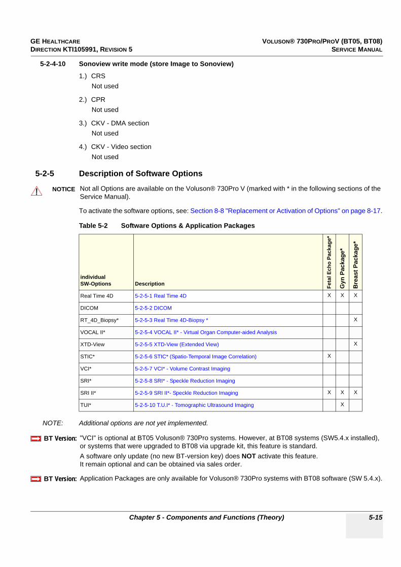
GE HEALTHCARE VOLUSON® 730PRO/PROV (BT05, BT08)DIRECTION KTI105991, REVISION 5 SERVICE MANUAL
Chapter 5 - Components and Functions (Theory) 5-15
5-2-4-10 Sonoview write mode (store Image to Sonoview)
1.) CRSNot used
2.) CPRNot used
3.) CKV - DMA sectionNot used
4.) CKV - Video sectionNot used
5-2-5 Description of Software Options
To activate the software options, see: Section 8-8 "Replacement or Activation of Options" on page 8-17.
NOTE: Additional options are not yet implemented.
NOTICE Not all Options are available on the Voluson® 730Pro V (marked with * in the following sections of the Service Manual).
Table 5-2 Software Options & Application Packages
individual SW-Options Description Fe
tal E
cho
Pack
age*
Gyn
Pac
kage
*
Bre
ast P
acka
ge*
Real Time 4D 5-2-5-1 Real Time 4D X X X
DICOM 5-2-5-2 DICOM
RT_4D_Biopsy* 5-2-5-3 Real Time 4D-Biopsy * X
VOCAL II* 5-2-5-4 VOCAL II* - Virtual Organ Computer-aided Analysis
XTD-View 5-2-5-5 XTD-View (Extended View) X
STIC* 5-2-5-6 STIC* (Spatio-Temporal Image Correlation) X
VCI* 5-2-5-7 VCI* - Volume Contrast Imaging
SRI* 5-2-5-8 SRI* - Speckle Reduction Imaging
SRI II* 5-2-5-9 SRI II*- Speckle Reduction Imaging X X X
TUI* 5-2-5-10 T.U.I* - Tomographic Ultrasound Imaging X
BT Version:BT-Version:
"VCI" is optional at BT05 Voluson® 730Pro systems. However, at BT08 systems (SW5.4.x installed), or systems that were upgraded to BT08 via upgrade kit, this feature is standard. A software only update (no new BT-version key) does NOT activate this feature. It remain optional and can be obtained via sales order.
BT Version:BT-Version:
Application Packages are only available for Voluson® 730Pro systems with BT08 software (SW 5.4.x).

GE HEALTHCARE VOLUSON® 730PRO/PROV (BT05, BT08)DIRECTION KTI105991, REVISION 5 SERVICE MANUAL
5-16 Section 5-2 - General Information
5-2-5-1 Real Time 4D
Real Time 4D mode is obtained through continuous volume acquisition and parallel calculation of 3D rendered images. In Real Time 4D mode the volume acquisition box is at the same time the render box. All information in the volume box is used for the render process. In Real Time 4D mode a “frame rate” of up 16 volumes/second (at Voluson® 730Pro V up to 10 volumes/second) is possible. By freezing the acquired volumes, size can be adjusted, manipulated manually as known from the Voluson 3D Mode.
5-2-5-2 DICOMVoluson® 730Pro/ProV software package providing following DICOM functionality:
• Storage Service Class• Print Management Service Class• Modality Worklist Management Service Class• Structured Reporting Service Class• Storage Commit Service Class• Modality Performed Procedure Step Service Class Sending of reports - Additionally all OB/Gyn measurements can be sent to a PC*. Receiving of these reports is supported by ViewPoint workstation “PIA” only. All other workstations can be adapted individually.* Without using structured reporting.
5-2-5-3 Real Time 4D-Biopsy *For minimal invasive procedures like biopsies, ultrasound is a widely used method to visualize and guide the needle during puncture. The advantage in comparison with other imaging methods is the real-time display, quick availability and easy access to any desired region of the patient. The 4D biopsy allows for real time control of the biopsy needle in 3D multi-planar display during the puncture. The user is able to see the region of interest in three perpendicular planes (longitudinal, transversal and frontal section) and can guide the biopsy needle accurately into the centre of the lesion.
5-2-5-4 VOCAL II* - Virtual Organ Computer-aided AnalysisDiagnosis and therapy of cancer is one of the most important issues in medical care.The VOCAL II - Imaging program allows completely new possibilities in cancer diagnosis, therapy planning and follow-up therapy control.
VOCAL II offers additional functions:
• Manual or Semi automatic Contour detection of structures (such as tumor lesion, cyst, prostate, etc.) and subsequent volume calculation. The accuracy of the process can be visually controlled by the examiner in multi-planar display.
• Construction of a virtual shell around the contour of the lesion. The wall thickness of the shell can be defined. The shell can be imagined as a layer of tissue around the lesion, where the tumor vascularization takes place.
• Automatic calculation of the vascularization within the shell by 3D color histogram by comparing the number of color voxels to the number of grayscale voxels.
5-2-5-5 XTD-View (Extended View)XTD-View provides the ability to construct and view a static 2D image which is wider than the field of view of a given transducer. This feature allows viewing and measurement of anatomy that is larger than what would fit in a single image. XTD-View constructs the extended image from individual image frames as the operator slides the transducer along the surface of the skin in direction of the scan plane.Examples include scanning of vascular structures and connective tissues in the arms and legs.
NOTE: XTD is only working together with BT05 HW.

GE HEALTHCARE VOLUSON® 730PRO/PROV (BT05, BT08)DIRECTION KTI105991, REVISION 5 SERVICE MANUAL
Chapter 5 - Components and Functions (Theory) 5-17
5-2-5-6 STIC* (Spatio-Temporal Image Correlation)
With this acquisition method the fetal heart or an artery can be visualized in 4D.It is not a Real Time 4D technique, but a post processed 3D acquisition.
In order to archive a good result, try to adjust the size of the volume box and the sweep angle to be as small as possible. The longer the acquisition time, the better the spatial resolution will be.A good STIC, STIC CFM (2D+CFM), or STIC PD (2D+PD) data set shows a regular and synchronous pumping of the fetal heart or of an artery.
The user must be sure that there is minimal movement of the participating persons (e.g., mother and fetus), and that the probe is held absolutely still throughout the acquisition period. Movement will cause a failure of the acquisition. The acquired images are post processed to calculate a 4D Volume Cine sequence. Please make sure that the borders of the fetal heart or the artery are smooth and there are no sudden discontinuities. If the user (trained operator) clearly recognizes a disturbance during the acquisition period, the acquisition has to be cancelled.
• STIC - Fetal Cardio is only available on RAB & RIC probes in the OB/GYN application.• STIC - Vascular is only available on the RSP probe in the Peripheral Vascular application.
5-2-5-7 VCI* - Volume Contrast ImagingVolume Contrast Imaging utilizes 4D transducers to automatically scan multiple adjacent slices and delivers a real-time display of the ROI. This image results from a special rendering mode consisting of texture and transparency information. VCI improves the contrast resolution and therefore facilitates finding of diffuse lesions in organs. VCI has more information (from multiple slices) and is of advantage in gaining contrast due to improved signal/noise ratio.
Static VCI is a part of the VCI option, which allow to apply the contrast enhancing VCI method to 3D data sets after the acquisition.
5-2-5-8 SRI* - Speckle Reduction ImagingSpeckle Reduction Imaging (SRI) is a smoothing type filter to reduce speckle in the ultrasound image.It may be used when image speckle interferes with the desired image detail.
5-2-5-9 SRI II*- Speckle Reduction ImagingA type of image noise or interference is generally considered undesirable and can obscure the quality or interpretation of B-mode images. Although somewhat associated with the underlying echogenicity of tissue scatters, image speckle characteristics such as brightness, density or size have no apparent value in determining tissue structure or related properties. The elimination of or significant reduction in speckle improves the quality or diagnostic potential of the image.The method applied in the subject modification utilizes a nonlinear diffusion filtering technique that permits effective speckle reduction in real time. The speckle reduction filter is available to the user in all B-mode imaging, independent of the transducer used.
BT Version:BT-Version:
"VCI" is optional at BT05 Voluson® 730Pro systems. However, at BT08 systems (SW5.4.x installed), or systems that were upgraded to BT08 via upgrade kit, this feature is standard.A software only update (no new BT-version key) does NOT activate this feature. It remain optional and can be obtained via sales order.
NOTICE Software 5.0.3 or higher is required.
GE HEALTHCARE VOLUSON® 730PRO/PROV (BT05, BT08)DIRECTION KTI105991, REVISION 5 SERVICE MANUAL
5-18 Section 5-2 - General Information
5-2-5-10 T.U.I* - Tomographic Ultrasound Imaging
TUI is a new visualisation mode for 3D and 4D data sets. The data is presented as slices through the data set which are parallel to each other. An overview image, which is orthogonal to the parallel slices, shows which parts of the volume are displayed in the parallel planes. This method of visualisation is consistent with the way other medical systems such as CT or MRI, present the data to the user. The distance between the different planes can be adjusted to the requirements of the given data set. In addition it is possible to set the number of planes. The planes and the overview image can also be printed to a DICOM printer, for easier comparison of the ultrasound data with CT and/or MRI data.
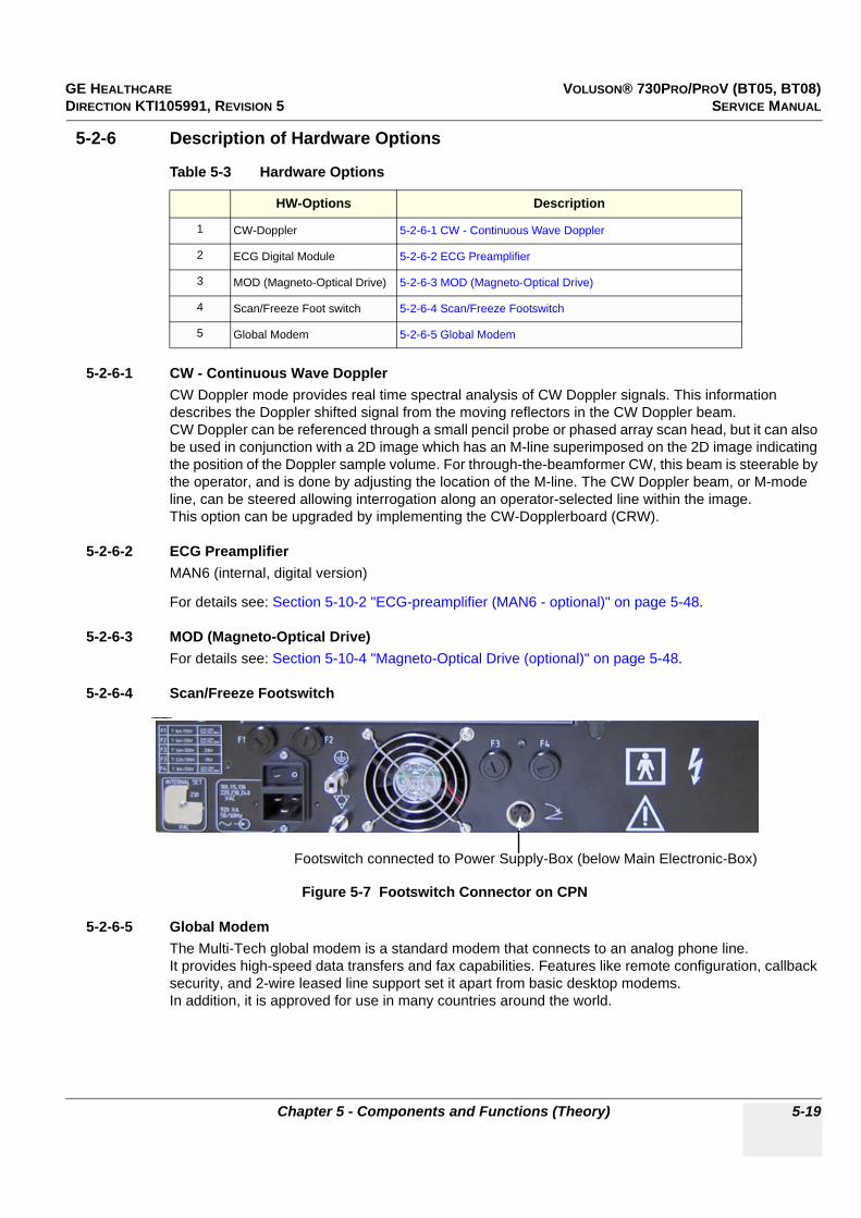
GE HEALTHCARE VOLUSON® 730PRO/PROV (BT05, BT08)DIRECTION KTI105991, REVISION 5 SERVICE MANUAL
Chapter 5 - Components and Functions (Theory) 5-19
5-2-6 Description of Hardware Options
5-2-6-1 CW - Continuous Wave Doppler CW Doppler mode provides real time spectral analysis of CW Doppler signals. This information describes the Doppler shifted signal from the moving reflectors in the CW Doppler beam. CW Doppler can be referenced through a small pencil probe or phased array scan head, but it can also be used in conjunction with a 2D image which has an M-line superimposed on the 2D image indicating the position of the Doppler sample volume. For through-the-beamformer CW, this beam is steerable by the operator, and is done by adjusting the location of the M-line. The CW Doppler beam, or M-mode line, can be steered allowing interrogation along an operator-selected line within the image.This option can be upgraded by implementing the CW-Dopplerboard (CRW).
5-2-6-2 ECG PreamplifierMAN6 (internal, digital version)
For details see: Section 5-10-2 "ECG-preamplifier (MAN6 - optional)" on page 5-48.
5-2-6-3 MOD (Magneto-Optical Drive)For details see: Section 5-10-4 "Magneto-Optical Drive (optional)" on page 5-48.
5-2-6-4 Scan/Freeze Footswitch
5-2-6-5 Global ModemThe Multi-Tech global modem is a standard modem that connects to an analog phone line.It provides high-speed data transfers and fax capabilities. Features like remote configuration, callback security, and 2-wire leased line support set it apart from basic desktop modems. In addition, it is approved for use in many countries around the world.
Table 5-3 Hardware Options
HW-Options Description
1 CW-Doppler 5-2-6-1 CW - Continuous Wave Doppler
2 ECG Digital Module 5-2-6-2 ECG Preamplifier
3 MOD (Magneto-Optical Drive) 5-2-6-3 MOD (Magneto-Optical Drive)
4 Scan/Freeze Foot switch 5-2-6-4 Scan/Freeze Footswitch
5 Global Modem 5-2-6-5 Global Modem
Figure 5-7 Footswitch Connector on CPN
Footswitch connected to Power Supply-Box (below Main Electronic-Box)

GE HEALTHCARE VOLUSON® 730PRO/PROV (BT05, BT08)DIRECTION KTI105991, REVISION 5 SERVICE MANUAL
5-20 Section 5-2 - General Information
5-2-6-5-1 Location in the Unit
5-2-6-5-2 LEDsThe Modem has 10 LEDs on its front.
Figure 5-8 Modem (placed on the GEZ-box)
Figure 5-9 LEDs on Modem’s Front Panel
Table 5-4 LEDs on Modem
LED Color Description Normally State
- Red TD (Transmit Data) Flashes during use.
- Red RD (Receive Data) Flashes during use.
- Red CD (Carrier Detect)ON when detecting a carrier from another modem and during communication.
OFF indicates no or broken connection.
- Red 56 (56K Mode) During Power On: Briefly FlashingThese LEDs indicates communication speeds above 14 kbs. If one of this LEDs
are ON during communication, it will stay ON until the modem is reset or connected the next time.
At speeds below 14 kbs, these LEDs are OFF.
- Red 33 (V.34 Mode)
- Red 14 (V.32bis Mode)
- Red OH (Off hook)ON when dialing, online, or answering a call
Flashes if puls dialingOff when modem not in use
- Red TR (Terminal Ready)
ON when the system initializes the modem. It indicates that the modem is ready for an outgoing or incoming call.
OFF indicates that communication on the RS232 (COM) port has been broken. The connected (remote) modem will disconnect.
- RedEC (Error Correction
(V.42))
ON: Error Correction (V42) is turned ONBlinking: Compression turned ON
OFF: Normal operation.
- Red FX (Fax) Always OFF
14 OH TR EC FXCD 56 33TD RD
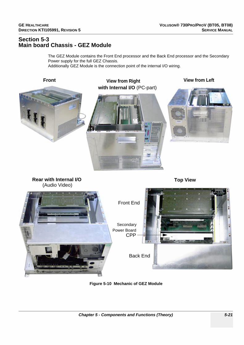
GE HEALTHCARE VOLUSON® 730PRO/PROV (BT05, BT08)DIRECTION KTI105991, REVISION 5 SERVICE MANUAL
Chapter 5 - Components and Functions (Theory) 5-21
Section 5-3Main board Chassis - GEZ Module
The GEZ Module contains the Front End processor and the Back End processor and the Secondary Power supply for the full GEZ Chassis.Additionally GEZ Module is the connection point of the internal I/O wiring.
Figure 5-10 Mechanic of GEZ Module
Front End
Secondary
CPP
Back End
Front
Rear with Internal I/O
View from Right with Internal I/O (PC-part)
Top View
Power Board
(Audio Video)
View from Left

GE HEALTHCARE VOLUSON® 730PRO/PROV (BT05, BT08)DIRECTION KTI105991, REVISION 5 SERVICE MANUAL
5-22 Section 5-4 - FrontEnd Processor
Section 5-4FrontEnd Processor
Figure 5-11 Front End Processor - Block diagram
CPP
Pow
ersu
pply
-Se
cond
aryb
oard
Pow
ersu
pply
: 5
9VD
C to
:+3
.3V
,+-5
V,+
12V
,+-1
5V,
+FA
N(1
7...2
4VD
C) +
-TX
_PO
W(+
-90V
)
Mot
or-S
IN-C
OS
-Pow
Am
p
CPK
Mot
herb
oard
of G
EZ-M
odul
e: C
PV
C
PR
P
CW
CR
S
C
PP
CPZ
Cov
erbo
ard
CP
V
CP
R
CR
W
CPV
Prob
eboa
rd
1 C
W-P
rbC
onne
ctor
3 P
rb-C
onne
ctor
s
260
pol
1 D
umm
y-Pr
bCon
n.
260p
ol
-Pro
be S
elec
t R
elai
s-P
robe
Rec
ogni
tion
(Sig
nals
to C
PC
)
CPR
Bea
mfo
rmer
-Mot
herb
oard
Tran
smitt
er-R
ecei
ver
CPD
-Bea
mfo
rmer
-Sub
boar
d1x
: B
eam
form
er-A
SIC
ge
nera
tes
TX-P
ulse
s+Tx
Focu
s+Tx
Apo
disa
tion,
R
xFoc
usD
elay
+Sum
mat
ion.
16x
: TX
-Pow
erA
mpl
ifier
8x :
TGC
+Ant
iAlia
sing
Filte
r+A
DC
Each
CPD
cap
able
of
16 T
X-C
hann
els,
4 R
X-C
hann
elsC
W-C
hann
els
sele
cted
by
Rel
ais
T/R
(192
)C
WTX
(16)
"EB
F_D
"(18
)C
W-D
ata
seria
l,D
,Q,1
6Bit
each
CPU
-Con
trol
"MC
PU
_A"(
12)
"MC
PU_D
"(8)
Bea
mfo
rmer
-C
onfig
urat
ion-
Dat
a:"E
H_D
ATA
"(16
)"E
H_A
DR
"(8)
CR
WC
W-D
oppl
erbo
ard
(Opt
iona
l)
-Sep
arat
e C
lkO
sc.+
Clo
ckge
nera
tor
PR
F,FN
-T
xDel
ayM
atrix
-T
rans
mitt
er,
-RxA
mp,
-R
xDel
ayM
atrix
-Ana
log:
Mix
er, A
mps
, Fi
lter(W
MF,
Ant
iAlia
sing
)-P
RF-
Sam
pAD
C16
Bit,
Mot
-Stro
bes
SIN
-CO
S P
ower
ed
32 x
CPD
CR
SM
ID-P
roce
ssin
gboa
rd
for B
,C,D
mod
es:
Syst
em C
ontr
ol:
-Mul
tibea
m-D
eInt
erle
ave
Clo
ck O
scill
ator
(60
MH
z)-S
ubtra
ctio
nFilt
er (f
or T
HI)
-PR
F-G
ener
ator
-Dig
.TG
C, D
C-C
ance
ling
-Bea
mfo
rmer
Con
figur
atio
n-M
ixer
with
NC
O-T
X/R
X F
ocus
Tim
ing
-FIR
-Low
Pas
s-L
ine
num
ber (
late
ral
Pos
ition
)-c
onta
ins
Tx-P
ower
B m
ode:
Dop
pler
+ C
FM:
-Mag
nitu
de C
alcu
lato
r-C
FM-P
roce
ssin
g:-L
ogar
ithm
ic A
mpl
ifier
-Col
or D
oppl
er s
hot l
ines
-Res
ampl
e
tra
nsfe
r to
CK
V-E
dge
Enha
nce
-Dop
pler
Pro
cess
ing:
-Lin
eFilt
er-D
SP, A
udio
DA
C-B
lend
ing
Mot
or C
ontr
ol:
-Fra
me
Filte
r-M
aste
r of C
ontro
l of 3
D
Swee
p-S
in C
os M
otor
Driv
e-F
ram
e S
tart-
On
Trig
ger
-Writ
e Lo
gic
Trig
ger C
KV
(D
MA
Con
trolle
r)
SIN
-CO
S
US
-Dat
a
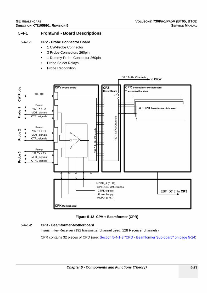
GE HEALTHCARE VOLUSON® 730PRO/PROV (BT05, BT08)DIRECTION KTI105991, REVISION 5 SERVICE MANUAL
Chapter 5 - Components and Functions (Theory) 5-23
5-4-1 FrontEnd - Board Descriptions
5-4-1-1 CPV - Probe Connector Board• 1 CW-Probe Connector• 3 Probe-Connectors 260pin• 1 Dummy-Probe Connector 260pin• Probe Select Relays• Probe Recognition
5-4-1-2 CPR - Beamformer-MotherboardTransmitter-Receiver (192 transmitter channel used, 128 Receiver channels)
CPR contains 32 pieces of CPD (see: Section 5-4-1-3 "CPD - Beamformer Sub-board" on page 5-24)
Figure 5-12 CPV + Beamformer (CPR)
Power
192 TX / RX
MOT_signals
CTRL-signals
CPV Probe Board
Power
192 TX / RX
MOT_signals
CTRL-signals
Power
192 TX / RX
MOT_signals
CTRL-signals
TX / RX
Pro
be
1P
ro
be
2P
ro
be
3C
W P
ro
be
CPK Motherboard
PowerSupply
SIN-COS, Mot-Strobes
CTRL-signals
MCPU_A [0..12]
MCPU_D [0..7]
CPZ
Cover Board
32 * CPD Beamformer Subboard
CPR Beamformer Motherboard
Transmitter/Receiver
to CRW
192 *
Tx/R
x C
hannels
32 * Tx/Rx Channels
EBF_D(18) to CRS
192 *
Tx/R
x C
hannels

GE HEALTHCARE VOLUSON® 730PRO/PROV (BT05, BT08)DIRECTION KTI105991, REVISION 5 SERVICE MANUAL
5-24 Section 5-4 - FrontEnd Processor
5-4-1-3 CPD - Beamformer Sub-board
1x : Beamformer-ASICgenerates TX-Pulses + TX-Focus +TX-Apodization, Rx Focus Delay and Summation
16x : TX-Power Amplifier
4x : TGC + Anti Aliasing Filter + Analogue Digital Conversion (ADC)
Each CPD is capable of 16 TX-Channels and 4 RX-Channels
Figure 5-13 Block diagram CPD
Sep.
8 * 2 * Pushpull
Output stage
ASIC
BFIC
2:1
Mux
Antialiasing-FilterTGC ADC
10 Bit
Antialiasing-
Filter
Antialiasing-
Filter
8 *
Sep.
Sep.
Sep.
8 *
El_0
El_128
El_3
El_131
Tx_0p
Tx_0n
Rx_0
Rx_1
Rx_2
Rx_3
2:1
Mux
2:1
Mux
2:1
Mux
Tx_0
Tx_1
Tx_6
Tx_7
El_1
El_129
El_2
El_130
to ASIC(n+1)
From ASIC(n-1)
Driver
Driver
EN_A
EN_B
Driver
Driver
EN_A
EN_B
Tx_1p
Tx_1n
Driver
Driver
EN_A
EN_B
Driver
Driver
EN_A
EN_B
Tx_6p
Tx_6n
Driver
Driver
EN_A
EN_B
Driver
Driver
EN_A
EN_B
Tx_7p
Tx_7n
Driver
Driver
EN_A
EN_B
Driver
Driver
EN_A
EN_B
Antialiasing-Filter
TGC
TGC
TGC
+TX_POW1/-TX POW1
+TX_POW2/-TX POW2
ADC10 Bit
ADC10 Bit
ADC10 Bit

GE HEALTHCARE VOLUSON® 730PRO/PROV (BT05, BT08)DIRECTION KTI105991, REVISION 5 SERVICE MANUAL
Chapter 5 - Components and Functions (Theory) 5-25
5-4-1-4 CRW - CW-Doppler Board (optional)
• Separate Clock Oscillator + Clock generator PRF, FN• TxDelayMatrix• Transmitter,• Receiver Amplifiers (RxAmp),• Receiver Delay matrix (RxDelayMatrix)• Analogue: Mixer, Amplifier, Filter (WMF, Anti Aliasing)• PRF-SampADC16Bit,
5-4-1-5 CPZ - Cover BoardTransfers the analogue transmitting / receiving signals between the following boards:
• CPV• CPR• CRW192 Transmitter-, 128 Receiver channels, 16 CW-Doppler channels - switched by relays at CPZ
5-4-1-6 CPK - Motherboard of GEZ-ModuleFollowing boards are direct connected to the CPK:
• CPV - Probe connector Board• CPR - Beam former Board• CRW - CW-Doppler Board• CRS - Signal Processing Board• CPP - Power Supply Board
GE HEALTHCARE VOLUSON® 730PRO/PROV (BT05, BT08)DIRECTION KTI105991, REVISION 5 SERVICE MANUAL
5-26 Section 5-4 - FrontEnd Processor
5-4-1-7 CRS - Signal Processor Board
A.) MID-Processor:
1.) For B, C, D modes:- Multi Beam-DeInterleave- Subtraction Filter (for HI)- Digital TGC, DC-Cancelling- Mixer with NCO- FIR-Low Pass2.) For B mode only:- Magnitude Calculator- Logarithmic Amplifier- Resample- Edge Enhance- Line Filter- Blending- Frame Filter
B.) System Control:- Clock Oscillator (60MHz)- PRF (Pulse Repetition Frequency) Generator- Beamformer Configuration:- Tx (transmitting Frequency, TxRx (transmitting/receiving) Focus timing- TxRx (transmitting/receiving) Apodization- Line number (lateral Position)- contains TX-Power-DAC
C.) Doppler + CFM:
1.) CFM-processing:- Color-Doppler shot lines transfer to CKV2.) Doppler-Processing:- DSP, Audio DAC3.) Beamformer- Configuration-Data:- "EH_DATA"(16)- "EH_ADR"(8)- B-Mode-Data
D.) Motor Control:- Master of Control of 3D-Sweep- Drives Motor via SIN-COS- Triggers Frame-start on CPR (Beamformer)- Triggers Write-Logic on CKV (DMA-Controller)

GE HEALTHCARE VOLUSON® 730PRO/PROV (BT05, BT08)DIRECTION KTI105991, REVISION 5 SERVICE MANUAL
Chapter 5 - Components and Functions (Theory) 5-27
5-4-1-8 CPP - Power Supply Secondary Board + Motor Power stage
used for Supply of both FrontEnd and BackEnd DC-DC-Converter:
59VDC to following output voltages:
+ 3.3V, +/-5V, +12V, +/-15V,
+ FAN (10 -24V / 15 Watt; adjustable by software)
• +TX_POW (+/-90V)• -TX_POW (+/-90V)• +TX_POW2• -TX_POW2
Figure 5-14 Block diagram CPP
TRAFO920VA
PFC59V8A
EXTERNALAC DEVICESmax. 350VA
INRUSH-CURRENTLIMITER
AC -INPUT
5V 150 W
15V 30W
15V 50W
MOT_Voltage+/- 10-32V/50W
12V 150W
MOTORDRIVER
FAN
5V/12,5A
-15V/3A
3V3/18A
BLOCKDIAGRAMMPOWERSUPPLY CPP90
10-24V
3,3 V 150W
TX_MUX +/- 100V / 2W
15V/2A
12V/13A
+/- 100V
SWITCH FAN
FAN
POWER-BOX
CONVERTER-BOARD
+/- 5V_RX -5V/1.5A
FAN 10-24V
FAN
STANDBY-CTRL
TX_POW1 +/- 0-80V / 40W +/-10 - 90V
TX_POW2 +/- 0-80V / 40W +/-10 - 90V
5V/12,5A
3V3/24A

GE HEALTHCARE VOLUSON® 730PRO/PROV (BT05, BT08)DIRECTION KTI105991, REVISION 5 SERVICE MANUAL
5-28 Section 5-5 - BackEnd Processor
Section 5-5BackEnd Processor
Figure 5-15 BackEnd Processor - Block diagram
CPP
Pow
ersu
pply
-Se
cond
aryb
oard
Pow
ersu
pply
: 5
9VD
C to
:+3
.3V
,+-5
V,+
12V
,+-1
5V,
+FA
N(1
7...2
4VD
C) +
-TX
_PO
W(+
-90V
)
Mot
or-S
IN-C
OS
-Pow
Am
p
PC-M
othe
rboa
rd
C
PP
CPN
-Mai
nPow
erSu
pply
-Mod
ule
AD
D2
DVI
Gra
phic
Ada
tper
CPY
Pow
ersw
itch-
Plug
boar
dC
CF
Pow
ersu
pply
-Pr
imar
yboa
rd
Con
sole
CP
N
GEM
-EC
G+D
iskd
rive-
Mod
ule:
Ext
erna
l Dis
kdriv
esE
CG
-Mod
ule
Aux_
Supp
ly
PS
/2
6x U
SB
2.0
KVN
(59V
DC
,P
ower
-OFF
-Sig
nals
)
Pow
erS
uppl
y-C
able
5V
,12V
Har
ddis
k5V
,12V
Dat
a
Add
ition
al C
PE
-Con
nect
ors:
-Lam
p, -
EC
G, -
RS2
32-3
-Rem
ote
B/W
Prin
ter
-Aud
io V
TR O
UT,
...V
TR IN
LIN
E O
UT
Sou
nd IN
Line
Out
eg. f
or S
onov
iew
-So
und
Rec
ords
USB
Cab
le
RS
232
PC
-Key
boar
d,Tr
ackb
all
VG
A-S
igna
l to
V73
0EX
PER
T-To
uchs
cree
n. (S
igna
l is
in fa
ct
anal
og, b
ut is
re-s
ampl
ed a
nd
digi
taliz
ed in
Tou
chsc
reen
.) C
able
do
es n
ot e
xist
at V
730P
RO
PS
2-A
dapt
erca
ble
CPH
Traf
o
GEU
-Use
r-In
terf
ace-
Mod
ule
Com
pone
nts:
Net
wor
k, U
SB
, Sou
ndM
ajor
Task
s: S
yste
mC
ontro
l, 3D
-Ren
derin
g,
Imag
ePro
cess
ing
(Sca
nCon
vers
ion,
CFM
,CR
I, et
c)
DV
I-Out
CK
V-Vi
deo-
Car
dO
verla
y-Lo
gic,
VG
A-A
dapt
er,V
ideo
-Con
verte
r RG
B-V
HS
, et
cD
MA
-Con
trol
ler
US-
Line
Mem
ory,
Fra
meM
emor
yD
SC
(Dig
.Sca
nCon
verte
r) f.
2D
DM
A-C
ontro
ller f
. Hig
hSpe
ed D
ataT
rans
fer
Mot
herb
oard
CP
U-M
emor
yV
HS
IN
S-V
HS
IN
VG
A1
VG
A2
S-V
HS
2V
HS
1 O
VH
S2
OR
GB
S-V
HS
1
DV
I-In
US
-Dat
a
CPE
-Bac
kpla
ne-C
ard
Mul
tiple
xer+
Am
p fo
r PC
-Sou
nd<>
Dop
pler
Aud
ioFe
edth
roug
h f.
Pow
er, S
tdby
, etc
.
Stdb
ySw
itch
(Use
r Pow
er O
N/
OFF
)
Foot
Switc
h
UI-D
isp.
Mon
itor
Pow
er C
onne
ctor
Aux-
Pow
er
Con
nect
or

GE HEALTHCARE VOLUSON® 730PRO/PROV (BT05, BT08)DIRECTION KTI105991, REVISION 5 SERVICE MANUAL
Chapter 5 - Components and Functions (Theory) 5-29
5-5-1 Block diagram CKV
Figure 5-16 Block diagram CKV
DMA Controller
PCI Bus 32 Bit / 33MHz
Signal Proc. No. 0
data
16 Bit / 30 MHz
(B/MB/C/MC)
Signal Proc.
Channel No.1
data
8 Bit / 30 MHz
(PW/CW)
SP0
I/F
SP1
I/F
1 us
Write slot 1
1 us
Write slot 0
DMA 0
(Demand
Mode)
2 us
Read slot
UART
16C550
Ext.
Bus
I/F
DMA 1
(Block
Mode)
Local Bus
32 Bit /
33MHz
VGA
Retrace
Interrupt
B / MB / C-IQ / MC -IQ /
PW / CW
Read/Write
Address generator
DMA 0
I/F
B / C
DMA 1
I/F
MB/MC/
PW/CW
Host PC
Access
PLX PCI 9054
Fifo Buffer Memory
SDRAM 32 Bit / 66 MHz
VCR
Remote
To/From
U/S Front-
end H/W
32 Bit /
16.7 MHz
Video I/O
FPGA
RAM
DVI TMDS I/F
CVBS
YC Video
Decoder
Scaler +
Deflicker Video
Encoder
DAC
RAM
Scaler
Overlay
(ext. Video)
Local Bus
32 Bit /
33MHz
Boot
FLASH
VGA
VGA
RGB
CVBS
(C)VBS
YC
YC
GE HEALTHCARE VOLUSON® 730PRO/PROV (BT05, BT08)DIRECTION KTI105991, REVISION 5 SERVICE MANUAL
5-30 Section 5-5 - BackEnd Processor
5-5-2 BackEnd - Board Descriptions
5-5-2-1 SBC - Single Board ComputerBuilt in or external Components:
- On Board VGA- 1 Gbit LAN - USB 2.0- Sound
Major Tasks:
- System Control- 2D / 3D-Image processing and Rendering- RS232 (User Interface)- PS2 (User Interface PC-Keyboard, Mouse as Trackball)- Control GEM drives (USB)
5-5-2-2 ADD2-DVI (Add-On) Graphic Adapter CardDVI graphic extension card which supplies CKV (Video manager) board with DVI Video
5-5-2-3 CKV - DMA-Controller / Video-Card• DMA-Controller f. High Speed Data Transfer into Slot-CPU-Memory• VGA- Output (2 Channels) for the System Main Monitor and external device• Video-Converter VGA RGB to: VHS, S-VHS, RGB• Display External Playback Video and adding Overlay graphics to it.see also: Figure 5-16: Block diagram CKV on page 5-29
5-5-2-4 Hard Disk DriveMinimum 80GB; IDE
Stores the system programs and Image filing (patient data, Report files)
5-5-2-5 CPE - Back Panel I/O-CardMultiplexer +Amplifier for PC-Sound<>Doppler Audio
Feed through for DC- Power and signals and for built in Peripherals (User Interface, Disk drive module, ECG, etc.)
GE HEALTHCARE VOLUSON® 730PRO/PROV (BT05, BT08)DIRECTION KTI105991, REVISION 5 SERVICE MANUAL
Chapter 5 - Components and Functions (Theory) 5-31
5-5-2-6 CPP - Power Supply Secondary Board + Motor Power stage
used for Supply of both FrontEnd and BackEnd
DC-DC-Converter:
59VDC to following output voltages:
+ 3.3V, +/-5V, +12V, +/-15V,
+ FAN (10 -24V / 15 Watt; adjustable by software)
• +TX_POW (+/-90V)• -TX_POW (+/-90V)• Motor Sinus2 Powerstage Amplifier• Motor Cosinus2 Powerstage Amplifier• +TX_POW2• -TX_POW2see also: Section 5-4-1-8 on page 5-27

GE HEALTHCARE VOLUSON® 730PRO/PROV (BT05, BT08)DIRECTION KTI105991, REVISION 5 SERVICE MANUAL
5-32 Section 5-6 - Internal I/O
Section 5-6Internal I/O
Internal I/O depends on the SBC-board installed.
- If “Kontron ATX” SBC-board is installed, see: Section 5-6-1 on page 5-33.- If “Tyan” SBC-board is installed, see: Section 5-6-2 on page 5-35.- If “Kontron Flex” SBC-board is installed, see: Section 5-6-3 on page 5-37.- If “ DFI ATX” SBC-board is installed, see: Section 5-6-4 on page 5-39.
However, connectors on the Main Module of the GEZ-box are the same (independent of installed SBC).
Figure 5-17 Connectors on the Main Module of the GEZ
Item Connector Name Description1 VGA1 Connector for the internal color video monitor
2 VGA2 Connector for an external color monitor
3 RGB Output for color video printer
4 S-VHS 1 S-VHS 1 OUT
5 S-VHS 2 S-VHS 2 OUT
6 VHS 1 Video 1 OUT: 1Vss @ 75 Ohm, PAL ; 1Vss @ 75 Ohm, NTSC
7 VHS 2 Video 2 OUT: 1Vss @ 75 Ohm, CCIR ; 1Vss @ 75 Ohm, FCC
8 VHS Video IN: 1Vss @ 75 Ohm, PAL / CCIR ; 1Vss @ 75 Ohm, NTSC / FCC
9 S-VHS S-VHS IN
10 Audio IN Sound Audio IN R/L Sound
11 Remote BW Printer Remote control for BW Printer
12 AUX Supply Power Supply for Module GEM
13 Console Connector for Console
14 CPN Connector for Power Supply (CPN) input
15 Lamp Connector for external lamp
16 RS232-3 Remote control for Video or DVD Recorder
17 ECG Connector for MAN (ECG-preamplifier)
18 --------------- Diagnostic LED´s (for voltage check; see: Section 7-3-1 on page 7-3) 1 = +15V ; 2 = -15V ; 3 = Fan ; 4 = +12V ; 5 = +5V ; 6 = +3.3V
19 Audio OUT / VTR Audio OUT / R/L Video Recorder
20 Audio IN / VTR Audio IN / R/L Video Recorder
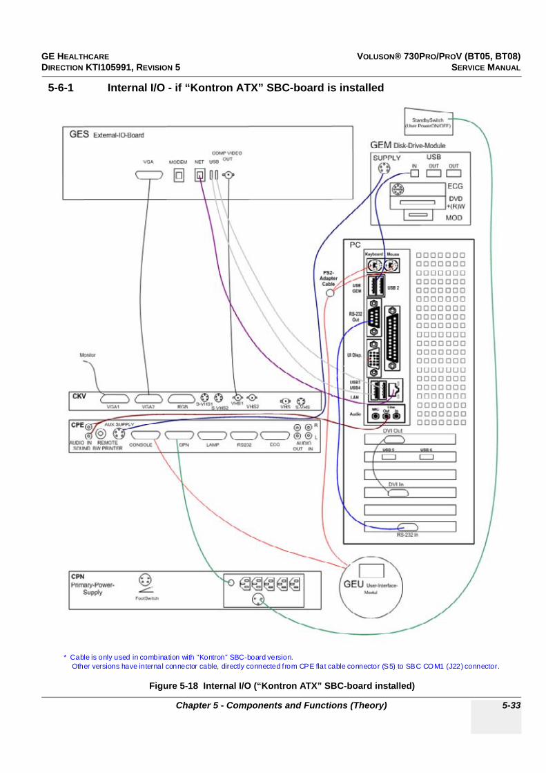
GE HEALTHCARE VOLUSON® 730PRO/PROV (BT05, BT08)DIRECTION KTI105991, REVISION 5 SERVICE MANUAL
Chapter 5 - Components and Functions (Theory) 5-33
5-6-1 Internal I/O - if “Kontron ATX” SBC-board is installed
Figure 5-18 Internal I/O (“Kontron ATX” SBC-board installed)
* Cable is only used in combination with “Kontron” SBC-board version.Other versions have internal connector cable, directly connected f rom CPE flat cable connector (S5) to SBC COM1 (J22) connector.

GE HEALTHCARE VOLUSON® 730PRO/PROV (BT05, BT08)DIRECTION KTI105991, REVISION 5 SERVICE MANUAL
5-34 Section 5-6 - Internal I/O
5-6-1 Internal I/O - if “Kontron ATX” SBC-board is installed (cont’d)
Figure 5-19 Connectors on PC-part of the GEZ (“Kontron ATX” SBC-board installed)
Item Connector Name Description
1 PS2 Kbd. Connector for Keyboard
2 PS2 Mouse Connector for Mouse
3 USB GEM Connector for Disk Drive Module GEM
4 USB 2 USB port connector
5 RS-232 Out Electrical-Signal-Connection between CPS and PIC_MG_Slot-CPU
6 UI Disp. Connector for User Interface DisplayNOT used at: Voluson® 730Pro/ProV
7 Parallel Port Parallel Port for PC-Line Printer
8 USB 3 and USB 4 USB port connectors
9 LAN Connector for Network twisted pair RJ-45 10/100 megabits/s
10 Audio MIC = Connector for MicrophoneLine-Out = Connector for Sound card (green connector)
11 DVI Out Digital Visual Interface (TMDS cable) / Out
12 USB 5 and USB 6 USB port connectors
13 DVI In Digital Visual Interface (TMDS cable) / In
14 RS-232 In Electrical-Signal-Connection between CKV and PC-Board (SBC)
2
7
4
9
1
3
13
14
5
6
8
12
11
10

GE HEALTHCARE VOLUSON® 730PRO/PROV (BT05, BT08)DIRECTION KTI105991, REVISION 5 SERVICE MANUAL
Chapter 5 - Components and Functions (Theory) 5-35
5-6-2 Internal I/O - if “Tyan” SBC-board is installed
Figure 5-20 Internal I/O (“Tyan” SBC-board installed)
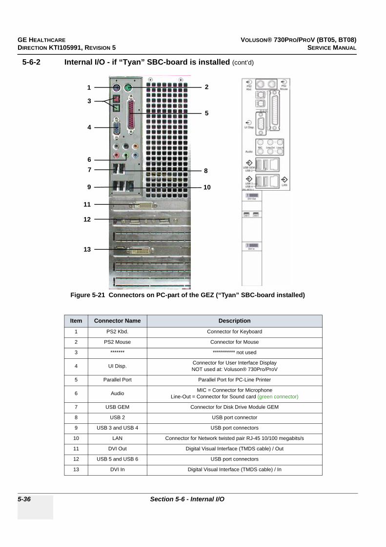
GE HEALTHCARE VOLUSON® 730PRO/PROV (BT05, BT08)DIRECTION KTI105991, REVISION 5 SERVICE MANUAL
5-36 Section 5-6 - Internal I/O
5-6-2 Internal I/O - if “Tyan” SBC-board is installed (cont’d)
Figure 5-21 Connectors on PC-part of the GEZ (“Tyan” SBC-board installed)
Item Connector Name Description
1 PS2 Kbd. Connector for Keyboard
2 PS2 Mouse Connector for Mouse
3 ******* *********** not used
4 UI Disp. Connector for User Interface DisplayNOT used at: Voluson® 730Pro/ProV
5 Parallel Port Parallel Port for PC-Line Printer
6 Audio MIC = Connector for MicrophoneLine-Out = Connector for Sound card (green connector)
7 USB GEM Connector for Disk Drive Module GEM
8 USB 2 USB port connector
9 USB 3 and USB 4 USB port connectors
10 LAN Connector for Network twisted pair RJ-45 10/100 megabits/s
11 DVI Out Digital Visual Interface (TMDS cable) / Out
12 USB 5 and USB 6 USB port connectors
13 DVI In Digital Visual Interface (TMDS cable) / In
2
7
5
10
1
3
13
4
68
12
11
9

GE HEALTHCARE VOLUSON® 730PRO/PROV (BT05, BT08)DIRECTION KTI105991, REVISION 5 SERVICE MANUAL
Chapter 5 - Components and Functions (Theory) 5-37
5-6-3 Internal I/O - if “Kontron Flex” SBC-board is installed
Figure 5-22 Internal I/O (“Kontron Flex” SBC-board installed)

GE HEALTHCARE VOLUSON® 730PRO/PROV (BT05, BT08)DIRECTION KTI105991, REVISION 5 SERVICE MANUAL
5-38 Section 5-6 - Internal I/O
5-6-3 Internal I/O - if “Kontron Flex” SBC-board is installed (cont’d)
Figure 5-23 Connectors on PC-part of the GEZ (“Kontron Flex” SBC-board is installed)
Item Connector Name Description
1 PS2 Kbd. Connector for Keyboard
2 PS2 Mouse Connector for Mouse
3 UI Disp. Connector for User Interface DisplayNOT used at: Voluson® 730Pro/ProV
4 USB GEM Connector for Disk Drive Module GEM
5 USB 2 USB port connector
6 USB 3 and USB 4 USB port connectors
7 LAN Connector for Network twisted pair RJ-45 10/100 megabits/s
8 USB 5 and USB 6 USB port connectors
9 Audio MIC = Connector for MicrophoneLine-Out = Connector for Sound card (green connector)
10 DVI Out Digital Visual Interface (TMDS cable) / Out
11 DVI In Digital Visual Interface (TMDS cable) / In
12 ******* ***************not used
2
3
4 5
6 7
8
9
10
11
12
1

GE HEALTHCARE VOLUSON® 730PRO/PROV (BT05, BT08)DIRECTION KTI105991, REVISION 5 SERVICE MANUAL
Chapter 5 - Components and Functions (Theory) 5-39
5-6-4 Internal I/O - if “DFI ATX” SBC-board is installed
Figure 5-24 Internal I/O (“DFI ATX” SBC-board installed)

GE HEALTHCARE VOLUSON® 730PRO/PROV (BT05, BT08)DIRECTION KTI105991, REVISION 5 SERVICE MANUAL
5-40 Section 5-6 - Internal I/O
5-6-4 Internal I/O - if “DFI ATX” SBC-board is installed (cont’d)
Figure 5-25 Connectors on PC-part of the GEZ (“DFI ATX” SBC-board is installed)
Item Connector Name Description
1 PS2 Kbd. Connector for Keyboard
2 PS2 Mouse Connector for Mouse
3 ******* *********** not used
4 UI Disp. Connector for User Interface DisplayNOT used at: Voluson® 730Pro/ProV
5 USB GEM Connector for Disk Drive Module GEM
6 USB 2 USB port connector
7 USB 3 and USB 4 USB port connectors
8 LAN Connector for Network twisted pair RJ-45 10/100 megabits/s
9 Audio MIC = Connector for MicrophoneLine-Out = Connector for Sound card (green connector)
10 DVI Out Digital Visual Interface (TMDS cable) / Out
11 USB 5 and USB 6 USB port connectors
12 DVI In Digital Visual Interface (TMDS cable) / In
1 2
3
4
5 6
7 8
9
10
12
11

GE HEALTHCARE VOLUSON® 730PRO/PROV (BT05, BT08)DIRECTION KTI105991, REVISION 5 SERVICE MANUAL
Chapter 5 - Components and Functions (Theory) 5-41
Section 5-7Top Console
The Voluson® 730Pro/ProV Operator Control Panel (OCP) consists of the following electronic subassemblies and/or functional components:
• Console module:- C515 micro controller- Atmel micro controller- Slide pots TGC with zero raster position)- Rotary Encoders with integrated push buttons- PS/2 compatible Trackball (2”) with standard PC interface- PS/2 compatible Qwerty Keyboard with standard PC interface- LED indicators with 3 intensity levels (off, 50%,100%)- 2 Speaker, used for Doppler and voice replay
• DC/DC Converter:- Converts 12V DC input voltage to 5V DC output voltage for supplying UI components
Figure 5-26 Top Console
C515 Beeper
LED's and Hardkeys
DC/DCConverter 5V
12V
25
pol.
Con
ne
cto
r
Atmel
PS2
Trackball
Keyboard
SpeakerTGC- Slider
RS232
Hardkey Board
Loudspeaker forTop Console
Alpha-numeric keyboard
Trackball Kit

GE HEALTHCARE VOLUSON® 730PRO/PROV (BT05, BT08)DIRECTION KTI105991, REVISION 5 SERVICE MANUAL
5-42 Section 5-7 - Top Console
Section 5-7 Top Console (cont’d)
Figure 5-27 Voluson® 730Pro/ProV - Control Console
Mic
EC
G
Fre
eze
PW
M
C
2D
Me
nu
AB
Uti
l.
1 2 3
Init
Ste
er
Inv
Ex
itA
bc
3D
/4D
BA
2D
Ab
c
Calc
3D
4D
HI
PD
CW
au
to
BX
TD
! 1@ 2
# 3$ 4
% 5^ 6
& 7* 8
( 9) 0
_ -+ =
<--
-B
ack-
spa
ce
Esc
F1
F2
F3
F4
F5
F6
F7
De
lete
Lin
e
De
lete
Ab
c
De
lete
Arro
w
De
lete
Me
as
.
PrtS
cP
au
se
|<--
-->
|T
ab
QW
ER
TY
UI
OP
[ ]
| \
Ca
ps
Lo
ck
AS
DF
GH
JK
L: ;
" ´E
nte
r
Sh
ift
ZX
CV
BN
M< ,
> .? /
Shift
Ctr
lF
nA
lt~ `
Ins
De
l
101 10
210
310
4
106
107
109
110
111
120
121
122
123
124
126
127
128
131
132
133
134
135
138
140
141
142
144
146
148
153
155
156
157
158
159
162
163
105
136
151
145
160
164
165
166
167
168
169
170
172
173
174
175
177
178
179
180
181
182
183
184
185
186
187
188
189
190
191
192

GE HEALTHCARE VOLUSON® 730PRO/PROV (BT05, BT08)DIRECTION KTI105991, REVISION 5 SERVICE MANUAL
Chapter 5 - Components and Functions (Theory) 5-43
Table 5-5 Voluson® 730Pro/ProV - key codes
key code Description Voluson® 730Pro/ProV - Functionality X X X
101 PID (patient identification) call-up of the patient data entry menu
102 Probe call-up of the probe program menu
103 Indicator displays a pointer arrow or hand
104 End Exam Patient and measurement data are stored in the “Data manager”
105 Print_b Remote printer trigger key B
106 Sonoview to shift from scan mode to Sonoview
107 Report call-up of the Patient report page
109 Quad Format Quad-Screen format
110 Dual Format (V) Dual-Screen format (vertical distribution)
111 Dual Format (H) Dual-Screen format (horizontal distribution) - not yet implemented
120 Mode_Switch1 M-Mode (Motion mode)
121 Mode_Switch2 PD-Mode (Power Doppler) and HD-Mode (Bi-Directional Angio)
122 Mode_Switch3 PW-Mode (Pulsed Wave Doppler)
123 CW Continuous Wave Doppler
124 HI Harmonic Imaging
126 Text Image documentation - to write onto the screen
127 Bodymark Bodymark display - to enter Bodymark symbols
128 ClrScreen to clear graphics, measurements and annotations on the screen
131 MeasCalcs Calculation tables
132 HR_Zoom High Resolution Zoom
133 Trball_b left trackball key
134 Trball_a upper trackball key
135 Trball_c right trackball key
136 B_Depth UP - penetration depth of the B-image
138 AcousticPWr UP - acoustic output (Power)
140 VtrRec call-up of the VCR Remote control menu
141 Print_a Remote printer trigger key A
142 Freeze Read/Write (Freeze/Run)
144 Mode_Switch4 C-Mode (Color Flow mode)
145 Mode_Switch5 2D-Mode (B mode)

GE HEALTHCARE VOLUSON® 730PRO/PROV (BT05, BT08)DIRECTION KTI105991, REVISION 5 SERVICE MANUAL
5-44 Section 5-7 - Top Console
146 B_Depth DOWN - penetration depth of the B-image
148 AcousticPWr DOWN - acoustic output (Power)
151 ECG ECG line ON/OFF
152 Trackball Navigation Trackball menu Navigation
153 MIC Microphone
155 Single Format Single-Screen format
156 Speaker Volume UP - speaker volume
157 Speaker Volume DOWN - speaker volume
158 SieScape XTD-View (Extended View)
159 BiFlow B-Flow
160 Save 2D to save/send 2D images and sequences
161 Save Menu Save Menu - to save/send images (volumes)
162 NOT USED
163 Exit Exit
164 Utilities Utilities Menu
165 Invert Invert
166 Left/Right image orientation of 3D-image
167 UP/Down up/down image orientation
168 Mirror left/right image orientation
169 Init reset to initial position in volume mode
170 Steering Beam steering
172 NOT USED
173 OTO Automatic Optimization
174 4D-Mode 4D-Mode ON/OFF
175 3D-Mode 3D-Mode ON/OFF
177 Save 3D/4D to save/send 3D and 4D images and sequences
178 Soft 1 Soft_Switch 1
179 Soft 2 Soft_Switch 2
180 Soft 3 Soft_Switch 3
181 Soft 4 Soft_Switch 4
182 Soft_Flip 1 UP - Soft Flip 1 (Toggle switch function)
Table 5-5 Voluson® 730Pro/ProV - key codes
key code Description Voluson® 730Pro/ProV - Functionality X X X
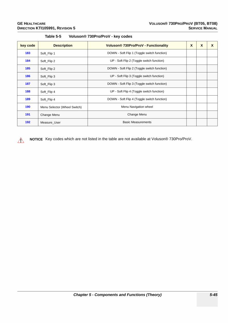
GE HEALTHCARE VOLUSON® 730PRO/PROV (BT05, BT08)DIRECTION KTI105991, REVISION 5 SERVICE MANUAL
Chapter 5 - Components and Functions (Theory) 5-45
183 Soft_Flip 1 DOWN - Soft Flip 1 (Toggle switch function)
184 Soft_Flip 2 UP - Soft Flip 2 (Toggle switch function)
185 Soft_Flip 2 DOWN - Soft Flip 2 (Toggle switch function)
186 Soft_Flip 3 UP - Soft Flip 3 (Toggle switch function)
187 Soft_Flip 3 DOWN - Soft Flip 3 (Toggle switch function)
188 Soft_Flip 4 UP - Soft Flip 4 (Toggle switch function)
189 Soft_Flip 4 DOWN - Soft Flip 4 (Toggle switch function)
190 Menu Selector (Wheel Switch) Menu Navigation wheel
191 Change Menu Change Menu
192 Measure_User Basic Measurements
NOTICE!! NOTICE:
Key codes which are not listed in the table are not available at Voluson® 730Pro/ProV.
Table 5-5 Voluson® 730Pro/ProV - key codes
key code Description Voluson® 730Pro/ProV - Functionality X X X

GE HEALTHCARE VOLUSON® 730PRO/PROV (BT05, BT08)DIRECTION KTI105991, REVISION 5 SERVICE MANUAL
5-46 Section 5-8 - Monitor
Section 5-8Monitor
For further details refer to: Section 6-3 "Monitor Adjustment" on page 6-2.
Figure 5-28 Monitor Adjustment buttons
NOTE: There is no function of microphone.
LEFT RIGHT
KEY FUNCTION
a. MENU KEY This button will enable the On Screen Display.This button is also used to select the function in the Main Menu or to save the setting in the Sub Menu. (Push for 3sec)
b. DECREASE [LEFT] Use this button to move down the OSD selection menu and adjust the attribute of the monitor while in OSD mode. Pressing this button out of the OSD menu allows you to decrease the level of contrast of the display screen.
c. INCREASE [RIGHT] Use this button to move up the OSD selection menu and adjust the attribute of the monitor while in OSD mode. Pressing this button out of the OSD menu allows you to increase the level of contrast of the display screen.
d. LAMP ON/OFF Lamp ON/OFF S/W
e. MICROPHONE Allows to record voice

GE HEALTHCARE VOLUSON® 730PRO/PROV (BT05, BT08)DIRECTION KTI105991, REVISION 5 SERVICE MANUAL
Chapter 5 - Components and Functions (Theory) 5-47
Section 5-9External I/O
Figure 5-29 External I/O Panel Connectors
Table 5-6 External I/O Connector Description
Item Connector Name Description
1 VGA OUT print out VGA signal with monitor/printer
2 MODEM RJ-11 with global adapter kit for modem connection
3 NETWORK DICOM input/outputtwisted pair RJ-45 10/100 megabit/s
4 USB-1 USB port
5 USB-2 USB port
6 COMP VIDEO OUT BNC Connector, Color Video Output
1 2 3 4 5 6

GE HEALTHCARE VOLUSON® 730PRO/PROV (BT05, BT08)DIRECTION KTI105991, REVISION 5 SERVICE MANUAL
5-48 Section 5-10 - Peripherals
Section 5-10Peripherals
5-10-1 General InformationThe GEM Module contains the DVD/CD+(R)W Drive.Additionally the Magneto Optical Drive and the ECG-preamplifier (MAN6) can be installed as an Option.
5-10-2 ECG-preamplifier (MAN6 - optional)The ECG-preamplifier is used for acquiring an ECG-signal to be displayed with the ultrasound image. This optional peripheral serves for gaining an ECG-signal to mark the systolic and end diastolic moments in M-Mode and Doppler evaluations.
The ECG-preamplifier must not be used for ECG-diagnostics. It is not intended for use as a cardiac monitor and must not be used for an intraoperative application on the heart.
5-10-3 DVD/CD+(R)W DriveThe DVD/CD+(R)W Drive (Writer) is used to backup images and reports. In addition, it is used as the main source of software upgrades and other service utility operations. The DVD/CD+(R)W Drive can read/write CD´s and DVD´s.
5-10-4 Magneto-Optical Drive (optional)Storage capacity by disk: 1.3GB, 640MB, 540MB, 230MB, 128MB
The MO-Drive allows to read and write any GIGAMO standard 1.3GB disk at twice the liner bit density. Additionally it retains full read/write compatibility with ISO/IEC 3.5 - inch disks ranging from original 128MB to current 640MB.
MO disks are nearly indestructible and immune from the problems that plague magnetic media.MO disks can be rewritten an unlimited number of times.
Figure 5-30 GEM incl. optional MOD and ECG
optional ECG (MAN6)
DVD+(R)W Drive
optional Magneto-Optical Drive (MOD)

GE HEALTHCARE VOLUSON® 730PRO/PROV (BT05, BT08)DIRECTION KTI105991, REVISION 5 SERVICE MANUAL
Chapter 5 - Components and Functions (Theory) 5-49
Section 5-11Power Distribution
5-11-1 CPN - Primary Power Module
5-11-1-1 Mechanical Concept and OverviewThe AC Power’s main tasks are to supply the various internal subsystems with AC power and to galvanically isolate the scanner from the on site Mains Power System. To reduce inrush current, an inrush current limiter is implemented. Voltage to peripherals can be configured to either 115 VAC or 230 VAC.
The mains cord has plugs in both ends. A female plug connects to the scanner and a male plug to the mains outlet on site.
From the Mains Power Input module, the AC power is routed via an Inrush Current Limiter to a internal outlet connector for the Mains Transformer.
5-11-1-2 Major Functions of CPN• Inrush Current limiter • Power factor correction transformer for Sinus load for the mains voltage• Power down Circuitry + Standby-Switch • The CPN module generates 57VDC (+/-2V) as an input voltage for the Secondary Power supply of
the GEZ module. • The CPN module contains also the isolation transformer for the peripherals.
(Maximum load: 350VA) see: Basic User Manual Chapter 23 Technical Data/Information
NOTE: All DC-supply voltages for built in peripherals are generated in GEZ-module not inside CPN.
NOTE: The system mains supply input voltage can be set to: 100V, 115V, 130V, 230V, 240V. The output voltages may be set to 115V or 230VAC (independent from the input voltages).
Figure 5-31 Primary Power Module - CPN

GE HEALTHCARE VOLUSON® 730PRO/PROV (BT05, BT08)DIRECTION KTI105991, REVISION 5 SERVICE MANUAL
5-50 Section 5-11 - Power Distribution
5-11-1-3 Fuses on Rear Panel
F1 + F2: The main Input voltage is fused by two 16 Ampere fuses (rated current 16A) labeled F1 and F2.
F3: The AC Output voltage (115/230V) is fused by either:• a 1.6 Ampere / 250V fuse for auxiliary output voltage 230 VAC• a 3.2 Ampere / 250V fuse for auxiliary output voltage 115 VAC
F4: 16 Ampere fuse for the input voltage for the switching power supply generating the DC-Supply voltage for the Secondary power supply inside GEZ-Module
5-11-1-4 Fuses inside CPN F1 on CCF board: fuses the surge current limiter circuit.
NOTE: If this fuse is blown, the NTC (limiting the surge current will remain hot during system operation and if the system is switched off/on within a few seconds the surge current could be to high.Because of this reason Fuse F1 on CPN Rear Panel or the Hospital circuit fuse could be blown.
5-11-2 Disk Drive Module (GEM)The check points for the drives voltages can be found at the AUX Supply connector (= GEM Power connector) on Backpanel of GEZ-Box; see: Section 7-3 "Check Points Voltages" on page 7-3.
• MO drive is supplied by +5V only • DVD/CD drive is supplied by both +5V and +12 V • Fan on the GEM module needs only 12 V power.
5-11-2-1 Fuses on CPE-Board for Disk Drive Module (GEM)Description of fuses: 5A / 250V / slow-blow fuse / 5 x 20 mm
Figure 5-32 Fuses of CPN
Figure 5-33 fuses for disk drives
F1 F2+12V +5V

GE HEALTHCARE VOLUSON® 730PRO/PROV (BT05, BT08)DIRECTION KTI105991, REVISION 5 SERVICE MANUAL
Chapter 5 - Components and Functions (Theory) 5-51
Section 5-12Mechanical Descriptions
5-12-1 Physical Dimensions
Figure 5-34 Physical Dimensions
678,3
851.5
1041,11415
337,5399,5607,6
668516456
560,5

GE HEALTHCARE VOLUSON® 730PRO/PROV (BT05, BT08)DIRECTION KTI105991, REVISION 5 SERVICE MANUAL
5-52 Section 5-12 - Mechanical Descriptions
5-12-2 Monitor• Tilt: 11° forwards and backwards• Swivel: +/-90° rotation.
5-12-3 Top Console Positioning
5-12-4 Rotation of the Control Console
• Horizontal Access: The control panel offers 30° of horizontal adjustment to the right.
Figure 5-35 Top Console Positioning
Figure 5-36 Locking lever under Control Console
30°
Locking Leverfor locking and unlocking the control console
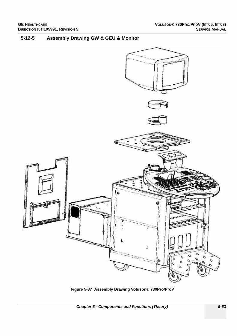
GE HEALTHCARE VOLUSON® 730PRO/PROV (BT05, BT08)DIRECTION KTI105991, REVISION 5 SERVICE MANUAL
Chapter 5 - Components and Functions (Theory) 5-53
5-12-5 Assembly Drawing GW & GEU & Monitor
Figure 5-37 Assembly Drawing Voluson® 730Pro/ProV

GE HEALTHCARE VOLUSON® 730PRO/PROV (BT05, BT08)DIRECTION KTI105991, REVISION 5 SERVICE MANUAL
5-54 Section 5-13 - Air Flow Control
Section 5-13Air Flow Control
5-13-1 Air Flow DistributionThe fans at the right side of the Main Board Chassis draw air into the scanner, through the filter grid, and pushes it through the card rack.
Air holes in the left and right side of the rack allow the air to move down through the card rack. Air exits the scanner through holes the Main Air Outlet at the left side panel.
5-13-1-1 Air Flow Distribution Overview
Figure 5-38 Console Views
Figure 5-39 Air Flow Control
CPN Air Outlet
Main AirInlet ( Filter grid)Outlet
Main Air
Main Air Outlet
PC F
an
Fan
CPP
Fan 1Fan 2
Main Air Inlet
Fan 1: for CPP and CRSFan 2: for CRW and CPR

GE HEALTHCARE VOLUSON® 730PRO/PROV (BT05, BT08)DIRECTION KTI105991, REVISION 5 SERVICE MANUAL
Chapter 5 - Components and Functions (Theory) 5-55
Section 5-14Service Platform
5-14-1 IntroductionThe Service Platform will increase service productivity and reduce training and service costs.This web-enabled technology provides linkage to e-Services, e-Commerce, and the iCenter, making GE’s scanners more e-enabled than ever.
The Service Platform contains:
• specific software/hardware test modules, system setup, update, etc. for Voluson systems; see: Section 5-15 "Service Page" on page 5-57.
5-14-2 Access / SecurityThe Service Platform has different access and security user levels.Each user is only granted access to the tools that are authorized for their use.

GE HEALTHCARE VOLUSON® 730PRO/PROV (BT05, BT08)DIRECTION KTI105991, REVISION 5 SERVICE MANUAL
5-56 Section 5-14 - Service Platform
5-14-3 iLinq Interactive PlatformMany of the services of the Service Platform come from its integration with iLinq.
If an iLinq checkout was performed on the Voluson® 730Pro/ProV, the ILINQ selection item is available in the menu area (on the left side of the screen) of the “Utilities” menu. By selecting this item, the Netscape® browser starts the “iLinq Home Page”.
Figure 5-40 iLinq Home Page
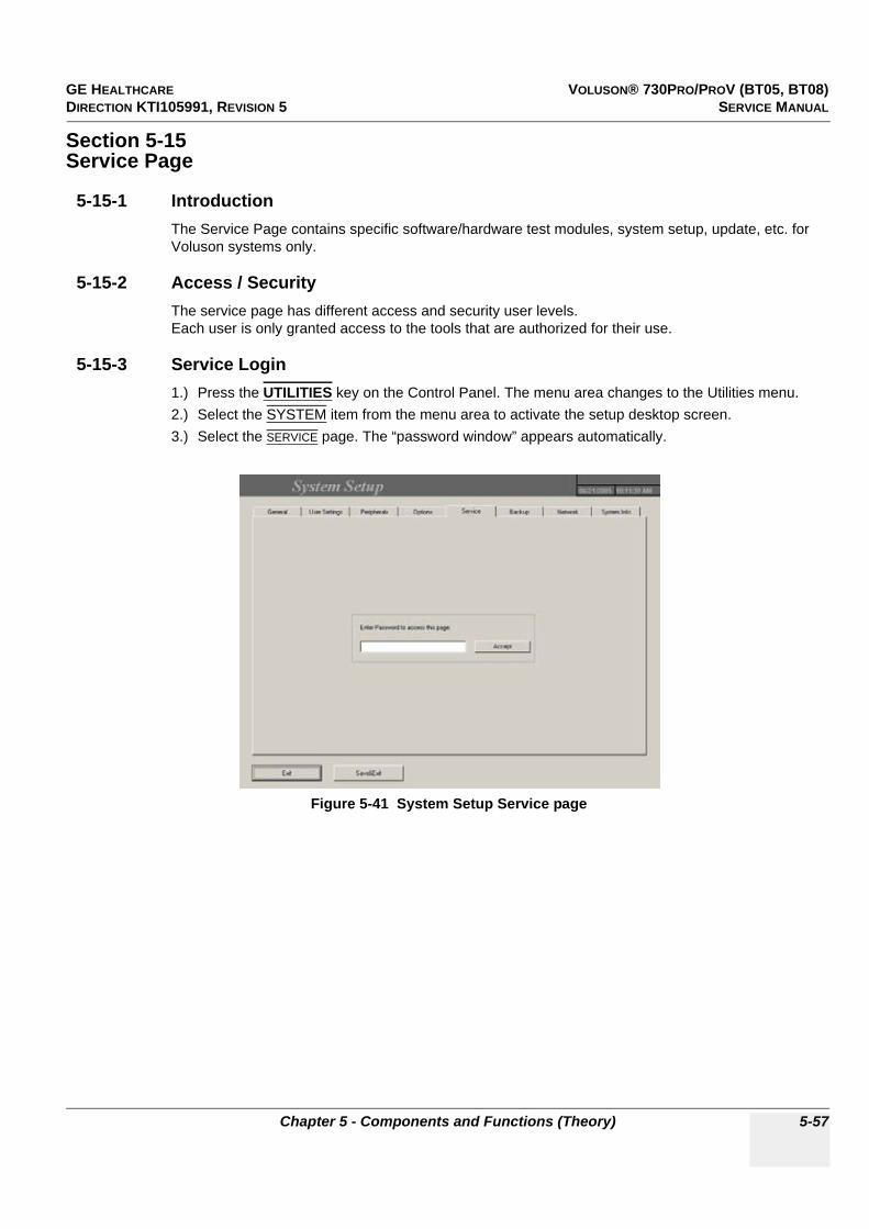
GE HEALTHCARE VOLUSON® 730PRO/PROV (BT05, BT08)DIRECTION KTI105991, REVISION 5 SERVICE MANUAL
Chapter 5 - Components and Functions (Theory) 5-57
Section 5-15Service Page
5-15-1 IntroductionThe Service Page contains specific software/hardware test modules, system setup, update, etc. for Voluson systems only.
5-15-2 Access / SecurityThe service page has different access and security user levels.Each user is only granted access to the tools that are authorized for their use.
5-15-3 Service Login1.) Press the UTILITIES key on the Control Panel. The menu area changes to the Utilities menu.2.) Select the SYSTEM item from the menu area to activate the setup desktop screen.3.) Select the SERVICE page. The “password window” appears automatically.
Figure 5-41 System Setup Service page
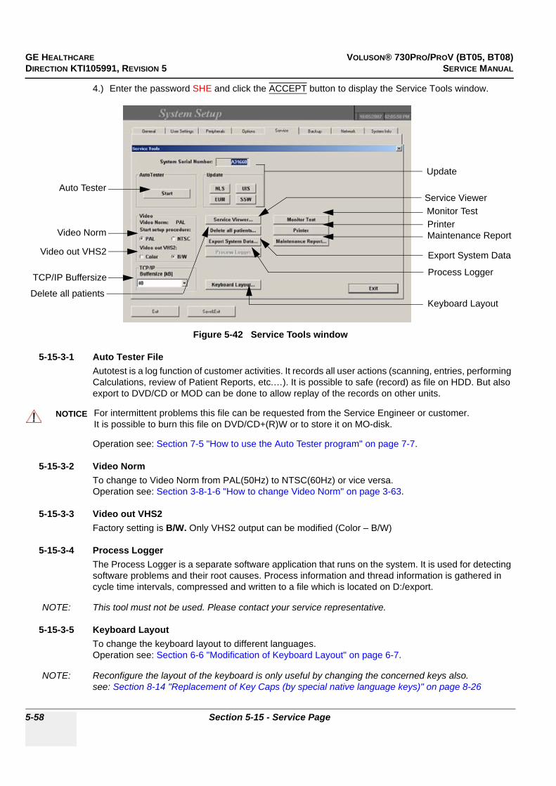
GE HEALTHCARE VOLUSON® 730PRO/PROV (BT05, BT08)DIRECTION KTI105991, REVISION 5 SERVICE MANUAL
5-58 Section 5-15 - Service Page
4.) Enter the password SHE and click the ACCEPT button to display the Service Tools window.
5-15-3-1 Auto Tester FileAutotest is a log function of customer activities. It records all user actions (scanning, entries, performing Calculations, review of Patient Reports, etc.…). It is possible to safe (record) as file on HDD. But also export to DVD/CD or MOD can be done to allow replay of the records on other units.
Operation see: Section 7-5 "How to use the Auto Tester program" on page 7-7.
5-15-3-2 Video Norm To change to Video Norm from PAL(50Hz) to NTSC(60Hz) or vice versa. Operation see: Section 3-8-1-6 "How to change Video Norm" on page 3-63.
5-15-3-3 Video out VHS2Factory setting is B/W. Only VHS2 output can be modified (Color – B/W)
5-15-3-4 Process LoggerThe Process Logger is a separate software application that runs on the system. It is used for detecting software problems and their root causes. Process information and thread information is gathered in cycle time intervals, compressed and written to a file which is located on D:/export.
NOTE: This tool must not be used. Please contact your service representative.
5-15-3-5 Keyboard LayoutTo change the keyboard layout to different languages.Operation see: Section 6-6 "Modification of Keyboard Layout" on page 6-7.
NOTE: Reconfigure the layout of the keyboard is only useful by changing the concerned keys also.see: Section 8-14 "Replacement of Key Caps (by special native language keys)" on page 8-26
Figure 5-42 Service Tools window
NOTICE!! NOTICE:
For intermittent problems this file can be requested from the Service Engineer or customer.It is possible to burn this file on DVD/CD+(R)W or to store it on MO-disk.
Service Viewer
Maintenance Report
Export System Data
Auto Tester
Monitor Test
Delete all patients
Printer
Update
Video Norm
Video out VHS2
Process LoggerTCP/IP Buffersize
Keyboard Layout

GE HEALTHCARE VOLUSON® 730PRO/PROV (BT05, BT08)DIRECTION KTI105991, REVISION 5 SERVICE MANUAL
Chapter 5 - Components and Functions (Theory) 5-59
5-15-3-6 TCP/IP BuffersizeThe TCP/IP Buffersize selects the amount of buffer memory used for DICOM transfers (both directions).
5-15-3-7 Service ViewerProvides common information about System Temperature, Probes, Working hours of system components and probes.
1.) Select the SERVICE VIEWER button to get access to the E-Service page.
5-15-3-8 Delete all Patients
1.) Click the DELETE ALL PATIENTS button. Following WARNING message appears on the screen.
5-15-3-9 Export System DataSelect the EXPORT SYSTEM DATA button on the “Service Tools” page to export dump-files and text files, the full Service Database informations about probes, boards, Software, Options, Service Actions and the Event Log File to the DVD/CD Drive (or the optional MO Drive).Operation see: Section 7-4-2 "Export Log’s and System Data" on page 7-4.
Figure 5-43 Kretztechnik E-Service
Figure 5-44 Warning message
WARNINGWARNING!! WARNING:
If you select the YES button, all patients data, studies, images and measure report data will be deleted permanently from the hard disk and cannot be recovered!

GE HEALTHCARE VOLUSON® 730PRO/PROV (BT05, BT08)DIRECTION KTI105991, REVISION 5 SERVICE MANUAL
5-60 Section 5-15 - Service Page
5-15-3-10 Maintenance Report
Any modification upgrade and maintenance action should be entered in this report to get a history of all service actions.
1.) Click the MAINTENANCE REPORT button. The following message box will be displayed.
2.) Fill in the requested information and click OK.3.) Click the EXIT button on the Service Tools window and the EXIT button on the System Setup
Service page.
NOTE: After Hardware or Software modifications normally the “Maintenance Report” message box (see: Figure 5-45) appears automatically on the screen.
5-15-3-11 Monitor Test
1.) To perform the Monitor test, select the MONITOR TEST button. The following message appears on the screen.
2.) Read the displayed instructions. Afterwards confirm with YES.
Figure 5-45 Maintenance Report
Figure 5-46 Monitor Test - Instructions

GE HEALTHCARE VOLUSON® 730PRO/PROV (BT05, BT08)DIRECTION KTI105991, REVISION 5 SERVICE MANUAL
Chapter 5 - Components and Functions (Theory) 5-61
The Monitor Test main menu appears on the screen.
3.) Open the desired test page: select the respective icon and press the right/left trackball key.4.) To return to the Main menu, press the upper trackball key.5.) To exit the Monitor Test program, click the “Exit” icon.
5-15-3-12 PrinterPrinter installation is possible without entering the Windows Desktop.Operation see: 3-7-5 "Printer Installation manually" on page 3-47.
5-15-3-13 Update
.
Figure 5-47 Monitor Test - Main menu
WARNINGWARNING!! WARNING:
Only accessories explicitly recognized and released by the system manufacturer GE Medical Systems - Kretztechnik may be used in connection with the system.
NLS Reserved for loading Software patches.
EUM is for updating the Electronic User Manual Operation see: Section 8-6 "Electronic User Manual (EUM) Upgrade Procedure" on page 8-13.
UIS is for updating the Ultrasound Application SoftwareOperation see: Section 8-2-5 "Software - Installation Procedure (via Service Page)" on page 8-7.
SSW is for updating the Service SoftwareOperation see: Section 8-5 "Service Platform (SSW) Upgrade Procedure" on page 8-11.
EXIT

GE HEALTHCARE VOLUSON® 730PRO/PROV (BT05, BT08)DIRECTION KTI105991, REVISION 5 SERVICE MANUAL
5-62 Section 5-15 - Service Page
This page was intentionally left blank.

GE HEALTHCARE VOLUSON® 730PRO/PROV (BT05, BT08)DIRECTION KTI105991, REVISION 5 SERVICE MANUAL
Chapter 6 - Service Adjustments 6-1
Chapter 6Service Adjustments
Section 6-1Overview
6-1-1 Purpose of Chapter 6This chapter describes how to test and adjust the mechanical capabilities of a scanner that may be out of specification. Although some tests may be optional they should only be performed by qualified personnel.
Section 6-2Regulatory
Verify, where applicable, that any regulatory information or tests required by national law are present and accounted for, and any regulatory tests required by national law are performed and documented.
Table 6-1 Chapter 6 Contents
Section Description Page Number
6-1 Overview 6-1
6-2 Regulatory 6-1
6-3 Monitor Adjustment 6-2
6-4 Control Console, Transport Lock 6-5
6-5 Trackball Adjustment 6-6
6-6 Modification of Keyboard Layout 6-7
6-7 Daylight Saving Time (DST) - New Dates 6-9

GE HEALTHCARE VOLUSON® 730PRO/PROV (BT05, BT08)DIRECTION KTI105991, REVISION 5 SERVICE MANUAL
6-2 Section 6-3 - Monitor Adjustment
Section 6-3Monitor Adjustment
The Monitor can be tilted or rotated.
• Tilt angle: up/down 11°• Rotation angle: right/left 90°The digital control panel is located at the front of the color monitor. If you are not satisfied with the factory settings, use these controls to program those you prefer in each resolution. Then, these adjusted settings are kept in memory even if you change the resolution or turn off the monitor.
• Menu key:This button will enable the On Screen Display (OSD-instructions). This button is also used to select the function in the Main Menu or to save the settings in the Sub Menu. (Push for 3 sec.)
• Decrease (Left):Use this button to move down the OSD selection menu and adjust the attribute of the monitor while in OSD menu. Pressing this button out of the OSD menu allows you to decrease the level of contrast of the display screen.
• Increase (Right):Use this button to move down the OSD selection menu and adjust the attribute of the monitor while in OSD menu. Pressing this button out of the OSD menu allows you to increase the level of contrast of the display screen.
6-3-1 Monitor Calibration
NOTE: Please warm up the monitor for 5-10 minutes before starting calibration.
This procedure consists of 7 parts:
1.) Degauss2.) Color Temp - Calibration3.) Contrast and Brightness4.) Geometry5.) Convergence6.) Color temperature7.) B-Mode Quality
Figure 6-1 Monitor Adjustment buttons
MenuIncreaseDecrease(Right)(Left)

GE HEALTHCARE VOLUSON® 730PRO/PROV (BT05, BT08)DIRECTION KTI105991, REVISION 5 SERVICE MANUAL
Chapter 6 - Service Adjustments 6-3
6-3-1-1 DegaussDegaussing refers to the process of removing magnetic-field effects from the monitor. Operation of the monitor within a magnetic field may adversely effect color purity. Degaussing can be used to correct the problem.
1.) Press and hold the MENU (middle) key (see: Figure 6-1) on the monitor controls for approximately 4 seconds till the OSD menu appears on the screen.
2.) Press the RIGHT button 2 times to the DEGAUSS and then press the MENU key again to select it.3.) Wait till DEGAUSS is completed.
6-3-1-2 Color Temp - Calibration
1.) On the control panel, press the UTILITIES key.2.) In the “Utilities” menu on the left side of the screen, select SYSTEM to invoke the setup desktop.3.) Select the SERVICE page, enter the password SHE and click the ACCEPT button.4.) Select the MONITOR TEST button in the “Service Tools” menu.5.) Confirm the “Monitor Test” message with YES.The Monitor Test main menu appears on the screen.
6.) Select the “Color calibration” icon and press the right/left trackball key once (monitor is white).7.) Press and hold the MENU (middle) key on the monitor controls for approximately 4 seconds till the
OSD menu appears on the screen.8.) Press the RIGHT button 3 times to the COLOR TEMP and then press the MENU key to select it.9.) Press the RIGHT button until CALIBRATION is highlighted and then press the MENU key again.
NOTE: The calibration cycle will immediately start for Red, Green and Blue. Wait till it´s completion message “It has completed...” appears. During the Calibration process do not touch any key.
10.)To return to the Main menu, press the upper trackball key 2 times.
NOTE: Contrast and Brightness (see: 6-3-1-3) has to be adjusted after color calibration.
NOTICE!! NOTICE:
The monitor should automatically degauss itself each time power is applied if you wait at least 10 seconds before you turn power back ON.
Figure 6-2 Monitor Test - Main menu
EXIT
Color calibration icon
raster lines
gray scale
color barscolor bars
GE HEALTHCARE VOLUSON® 730PRO/PROV (BT05, BT08)DIRECTION KTI105991, REVISION 5 SERVICE MANUAL
6-4 Section 6-3 - Monitor Adjustment
6-3-1-3 Contrast and BrightnessAdjusting the monitor´s contrast and brightness is one of the most important factors for proper image quality. If these controls are set incorrectly, the Gain, TGC, Dynamic Range and even Acoustic Output may have to be changed more often than necessary to compensate.
The proper setup displays a complete gray scale. The lowest level of black should just disappear into the background and the highest white should be bright, but not saturated.
NOTE: Brightness and Contrast should be adjusted at examination room light conditions.Typically values for Contrast and Brightness are 70 to 75, depending on the operator!
1.) Press the MENU (middle) key (see: Figure 6-1) on the monitor controls (= toggle button for contrast and brightness).
2.) Adjust the CONTRAST by pressing the LEFT or RIGHT button to decrease/increase the value.3.) Press the MENU key again to toggle to brightness.4.) Adjust the BRIGHTNESS by pressing the LEFT or RIGHT button to decrease/increase the value.
6-3-1-4 GeometryCheck the raster lines of the test pattern by referring to Figure 6-2.Expected results:
1.) Squares are not distorted.2.) Raster lines are straight.3.) No keystone and pincushion distortion.4.) Horizontal and vertical width is correct.
6-3-1-5 ConvergenceCheck the color of the raster lines (see: Figure 6-2).Expected result:
Raster lines have only one color.
6-3-1-6 Color temperatureCheck the grey scale and the color bars of the test pattern (see: Figure 6-2).Expected results:
1.) “White“ is displayed without a tint (discolor).2.) Colors are displayed correctly.3.) To exit the Monitor Test program, touch EXIT.
6-3-1-7 B-Mode QualityConnect an abdominal probe (AB or RAB), press the PROBE key, select the “Abdomen“ application and start the “Default“ program. Record a B-Image of the liver.
If there is no abdominal probe, record a B-Image of the Thyroid by using a small parts probe (SP6-12 or SP4-10) and the corresponding program.Expected result:
Regular and homogenous B-Image without tint.
6-3-1-8 Screen SaverIf you install SW 5.4.x or higher, please adjust the better screensaver.

GE HEALTHCARE VOLUSON® 730PRO/PROV (BT05, BT08)DIRECTION KTI105991, REVISION 5 SERVICE MANUAL
Chapter 6 - Service Adjustments 6-5
Section 6-4Control Console, Transport Lock
6-4-1 Control ConsoleThe control console can be rotated 30° to the right.
When rotating the control console grasp it only the front grip.
1.) Push the lever under the control console forward.2.) Rotate the console to wanted position.
6-4-2 Transport LockThere is a locking lever for locking and unlocking the control console, mounted at the front below the control console. When preparing the system for transport, the lock has to be engaged in order to secure the console against uncontrolled rotation. The lock catches in when the console is rotated to its center 0° position.
Figure 6-3 Locking Lever under Control Console
WARNINGWARNING!! WARNING:Do no
Do not put your hand between the control console and the Main unit when moving the console to the 0 position: Danger of injuries!
locking leverfor locking and unlocking the control console
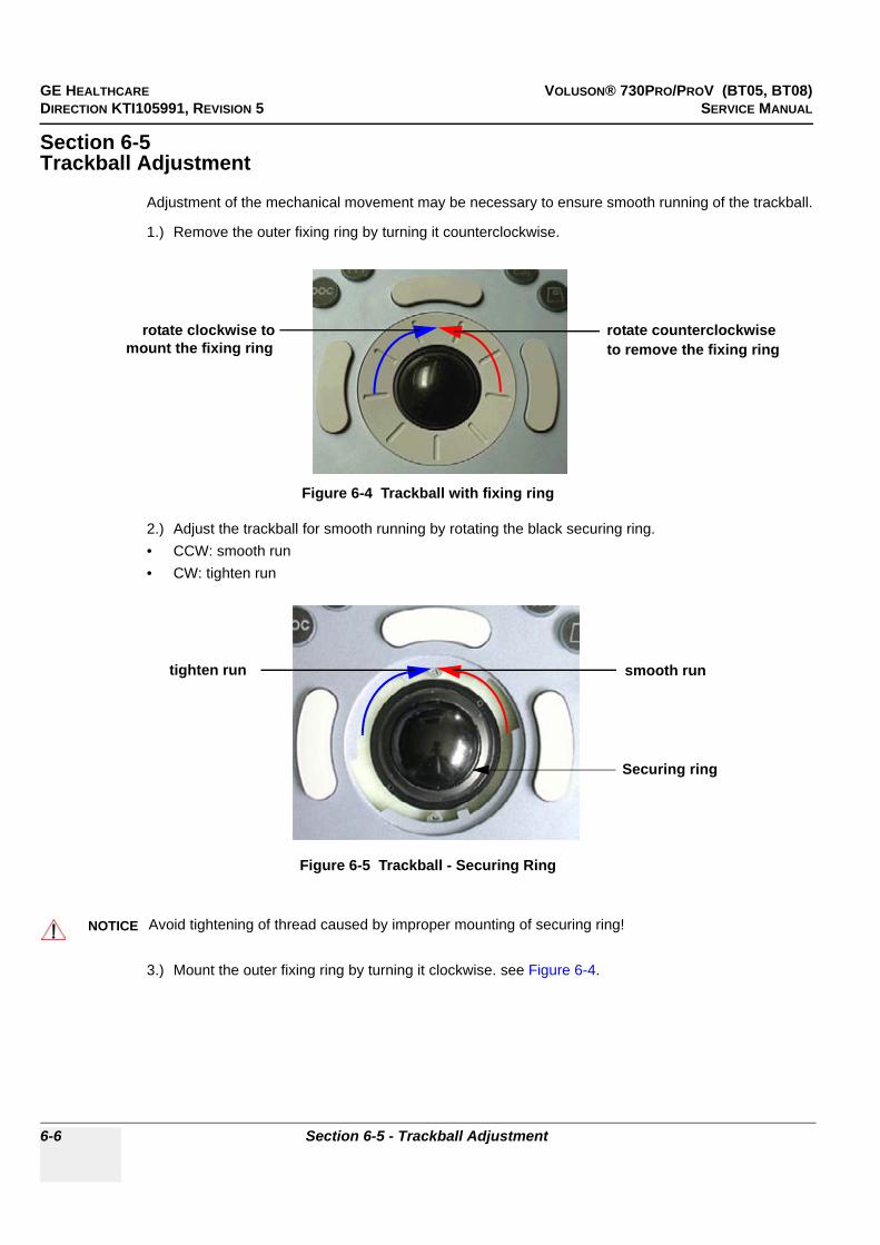
GE HEALTHCARE VOLUSON® 730PRO/PROV (BT05, BT08)DIRECTION KTI105991, REVISION 5 SERVICE MANUAL
6-6 Section 6-5 - Trackball Adjustment
Section 6-5Trackball Adjustment
Adjustment of the mechanical movement may be necessary to ensure smooth running of the trackball.
1.) Remove the outer fixing ring by turning it counterclockwise.
2.) Adjust the trackball for smooth running by rotating the black securing ring.• CCW: smooth run• CW: tighten run
3.) Mount the outer fixing ring by turning it clockwise. see Figure 6-4.
Figure 6-4 Trackball with fixing ring
Figure 6-5 Trackball - Securing Ring
NOTICE!! NOTICE:
Avoid tightening of thread caused by improper mounting of securing ring!
rotate counterclockwiseto remove the fixing ring
rotate clockwise tomount the fixing ring
Securing ring
smooth runtighten run

GE HEALTHCARE VOLUSON® 730PRO/PROV (BT05, BT08)DIRECTION KTI105991, REVISION 5 SERVICE MANUAL
Chapter 6 - Service Adjustments 6-7
Section 6-6Modification of Keyboard Layout
NOTE: Configuring the layout of the keyboard is only useful by changing the concerned keys also.see: Section 8-14 "Replacement of Key Caps (by special native language keys)" on page 8-26.
6-6-1 Setup the Voluson® 730Pro/ProV Keyboard Language Layout1.) Press the UTILITIES key on the Control Panel. The menu area changes to the Utilities menu.2.) Select the SYSTEM item from the menu area to activate the setup desktop screen.3.) Select the SERVICE page in the System Setup desktop.4.) Enter the password SHE and click the ACCEPT button to display the Service Tools window.
5.) Click the KEYBOARD LAYOUT button on the service window.
Figure 6-6 Service Page
[Keyboard Layout]button
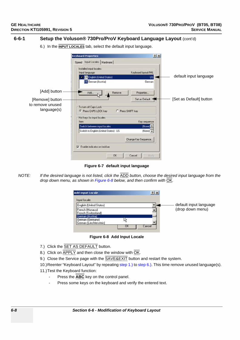
GE HEALTHCARE VOLUSON® 730PRO/PROV (BT05, BT08)DIRECTION KTI105991, REVISION 5 SERVICE MANUAL
6-8 Section 6-6 - Modification of Keyboard Layout
6-6-1 Setup the Voluson® 730Pro/ProV Keyboard Language Layout (cont’d)
6.) In the INPUT LOCALES tab, select the default input language.
NOTE: If the desired language is not listed, click the ADD button, choose the desired input language from the drop down menu, as shown in Figure 6-8 below, and then confirm with OK.
7.) Click the SET AS DEFAULT button.8.) Click on APPLY and then close the window with OK.9.) Close the Service page with the SAVE&EXIT button and restart the system.10.)Reenter “Keyboard Layout” by repeating step 1.) to step 6.). This time remove unused language(s).11.)Test the Keyboard function:
- Press the ABC key on the control panel.- Press some keys on the keyboard and verify the entered text.
Figure 6-7 default input language
Figure 6-8 Add Input Locale
default input language
[Add] button
to remove unusedlanguage(s)
[Remove] button [Set as Default] button
default input language(drop down menu)
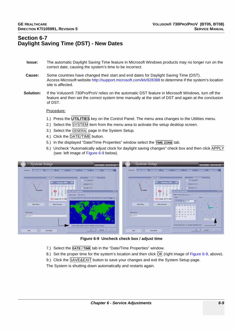
GE HEALTHCARE VOLUSON® 730PRO/PROV (BT05, BT08)DIRECTION KTI105991, REVISION 5 SERVICE MANUAL
Chapter 6 - Service Adjustments 6-9
Section 6-7Daylight Saving Time (DST) - New Dates
Procedure:
1.) Press the UTILITIES key on the Control Panel. The menu area changes to the Utilities menu.2.) Select the SYSTEM item from the menu area to activate the setup desktop screen.3.) Select the GENERAL page in the System Setup.4.) Click the DATE/TIME button.5.) In the displayed “Date/Time Properties” window select the TIME ZONE tab.6.) Uncheck “Automatically adjust clock for daylight saving changes” check box and then click APPLY
(see: left image of Figure 6-9 below).
7.) Select the DATE / TIME tab in the “Date/Time Properties” window.8.) Set the proper time for the system’s location and then click OK (right image of Figure 6-9, above).9.) Click the SAVE&EXIT button to save your changes and exit the System Setup page.The System is shutting down automatically and restarts again.
Issue: The automatic Daylight Saving Time feature in Microsoft Windows products may no longer run on the correct date, causing the system’s time to be incorrect.
Cause: Some countries have changed their start and end dates for Daylight Saving Time (DST).Access Microsoft website http://support.microsoft.com/kb/928388 to determine if the system’s location site is affected.
Solution: If the Voluson® 730Pro/ProV relies on the automatic DST feature in Microsoft Windows, turn off the feature and then set the correct system time manually at the start of DST and again at the conclusion of DST.
Figure 6-9 Uncheck check box / adjust time

GE HEALTHCARE VOLUSON® 730PRO/PROV (BT05, BT08)DIRECTION KTI105991, REVISION 5 SERVICE MANUAL
6-10 Section 6-7 - Daylight Saving Time (DST) - New Dates
This page was intentionally left blank.

GE HEALTHCARE VOLUSON® 730PRO/PROV (BT05, BT08)DIRECTION KTI105991, REVISION 5 SERVICE MANUAL
Chapter 7 - Diagnostics/Troubleshooting 7-1
Chapter 7Diagnostics/Troubleshooting
Section 7-1Overview
7-1-1 Purpose of Chapter 7This section describes how to setup and run the tools and software that help maintain image quality and system operation. Basic host, system, and board level diagnostics are run whenever power is applied. Some Service Tools may be run at the application level.
7-1-2 OverviewThere may be a time when it would be advantageous to capture trouble images and system data (logs) for acquisition through remote diagnostics (InSite) or to be sent back to the manufacturer for analysis. There are different options to acquire this data that would give different results.
Table 7-1 Contents in Chapter 7
Section Description Page Number
7-1 Overview 7-1
7-2 Collect Vital System Information 7-2
7-3 Check Points Voltages 7-3
7-4 Screen Captures and Logs 7-4
7-5 How to use the Auto Tester program 7-7
7-6 Minimum Configuration to Scan 7-10
7-7 Troubleshooting Trees, Instructions and Tech Tips 7-12
7-8 Error Messages 7-21
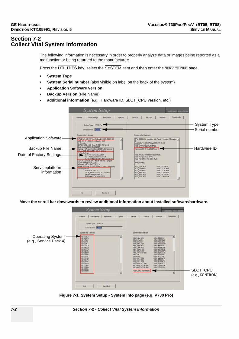
GE HEALTHCARE VOLUSON® 730PRO/PROV (BT05, BT08)DIRECTION KTI105991, REVISION 5 SERVICE MANUAL
7-2 Section 7-2 - Collect Vital System Information
Section 7-2Collect Vital System Information
The following information is necessary in order to properly analyze data or images being reported as a malfunction or being returned to the manufacturer:
Press the UTILITIES key, select the SYSTEM item and then enter the SERVICE INFO page.
• System Type• System Serial number (also visible on label on the back of the system)• Application Software version• Backup Version (File Name)• additional information (e.g., Hardware ID, SLOT_CPU version, etc.)
Figure 7-1 System Setup - System Info page (e.g. V730 Pro)
Serial number
Application Software
Move the scroll bar downwards to review additional information about installed software/hardware.
Serviceplatforminformation
Operating System
Backup File Name
System Type
Date of Factory SettingsHardware ID
(e.g., Service Pack 4)
SLOT_CPU(e.g., KONTRON)

GE HEALTHCARE VOLUSON® 730PRO/PROV (BT05, BT08)DIRECTION KTI105991, REVISION 5 SERVICE MANUAL
Chapter 7 - Diagnostics/Troubleshooting 7-3
Section 7-3Check Points Voltages
7-3-1 How to check power
Figure 7-2 Diagnostic LED´s and corresponding voltage check points
DVM
Additionally check 59V/DC(Power connection-cable
LED 6
LED 5
LED 4
LED 1
LED 2
LED 3
In case of problems, check the above voltages with a Digital Volt Meter (DVM) to Ground.
(+15V)
(-15V)
(+3.3V)
(+5V)
(+12V)
LED 1, 2 and 5ECG connector
81
915
Pin 15(+5V)
Pin 13(+15V)
Pin 11(-15V)
LED 4AUX Supply (= GEM Power connector)on Backpanel of GEZ-Box
Pin 1(+12V)
(Fan)
Pin 4(+5V)
Location of fuses on CPE;see: Section 5-11-2-1 on page 5-50
on Backpanel of GEZ-Boxfrom CPN to GEZ)
(Pin 2 and 3 = +3.3V ; Pin 1 = GND)
23
1
LED 6Footswitch connector on Power Supply Module (CPN)
3
LED orangevisual check for 59V: orange LED(at CPN power supply) is lightening 1
23
Open the locking on the back of theVoluson® 730Pro/ProV and remove the service lid.Check the status of the Diagnostic LED´s.
GE HEALTHCARE VOLUSON® 730PRO/PROV (BT05, BT08)DIRECTION KTI105991, REVISION 5 SERVICE MANUAL
7-4 Section 7-4 - Screen Captures and Logs
Section 7-4Screen Captures and Logs
There may be times when the customer or field engineer will want to capture a presentation on the screen so it may be recovered by the OnLine Center.
This is accomplished by saving the image(s):
A.) to SonoView and export them (as jpg, bmp or tiff ) to DVD/CD+(R)W or MO-diskB.) as jpg and bmp to D:\export by pressing the ALT + P key on the alphanumeric keyboardC.) creates one snapshot (Alt-D.bmp) + “Full Backup” of the System state (fullbackup -> fb1) saved on
D:\export by pressing the ALT + D key on the alpha-numeric keyboard.
7-4-1 Capturing a screenThe following is the generic process to capture any screen from the scanner.
3.) Select the stored image(s) in Sonoview (Exam List) and EXPORT the image(s) to DVD/CD+(R)W or MO-Disk (jpg, bmp or tiff).
7-4-2 Export Log’s and System DataThere are two possibilities to export system data (and log´s):
1.) by pressing the ALT + D key to save a snapshot and “Full Backup” of the System state; see: Section 7-4-2-1 on page 7-5
2.) via the EXPORT SYSTEM DATA button in the System Setup SERVICE page; see: Section 7-4-2-2 on page 7-6
1.) Navigate to and display the image/screen to be captured.
2.) Press the SAVE 2D key on the control panel and save the image to Sonoview.

GE HEALTHCARE VOLUSON® 730PRO/PROV (BT05, BT08)DIRECTION KTI105991, REVISION 5 SERVICE MANUAL
Chapter 7 - Diagnostics/Troubleshooting 7-5
7-4-2-1 Export System Data (by pressing the ALT + D key)
ALT + D uses “Full Backup” to gather data from the system. In addition it creates one screenshot(Alt-D.bmp) of the point in time when ALT + D was pressed. The main use is when R&D or OLC need detailed information about the system (e.g., when experiencing strange behaviour or when the problem should be investigated by R&D). It is not intended to replace or enhance the existing Full Backup functionality.
Data can be stored on the hard disk (D:\export\fullbackup\fb1), or you can export them to DVD/CD (including the D:\export folder, which contains logs and dump-files; for details see: Section 7-4-2-2-1).
NOTE: Successive ALT + D keystrokes overwrite existing snapshots at destination HDD.
1.) Press the ALT + TAB key on the keyboard. simultaneously.
2.) Select the destination of the “System state” backup among HDD or DVD/CD.3.) Select the NEXT button to start the backup process.After saving the data, the Voluson® 730Pro/ProV reboots and the application starts again.
Figure 7-3 select destination for “System state” backup
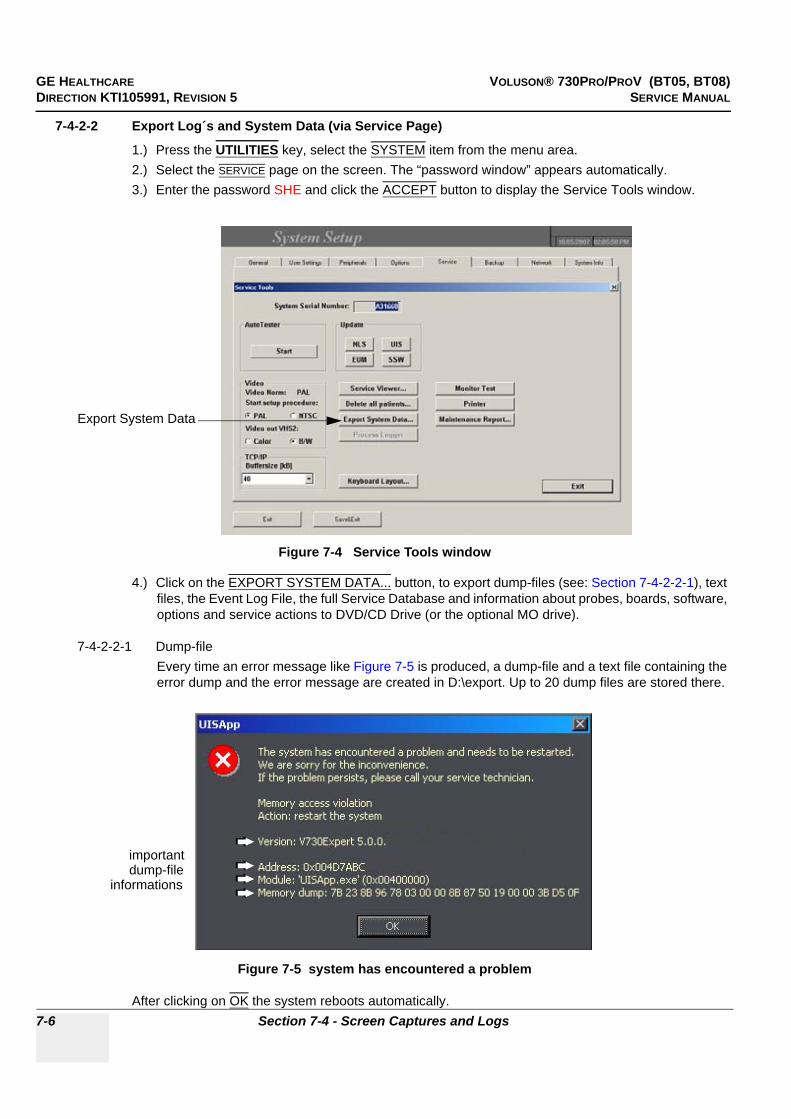
GE HEALTHCARE VOLUSON® 730PRO/PROV (BT05, BT08)DIRECTION KTI105991, REVISION 5 SERVICE MANUAL
7-6 Section 7-4 - Screen Captures and Logs
7-4-2-2 Export Log´s and System Data (via Service Page)
1.) Press the UTILITIES key, select the SYSTEM item from the menu area.2.) Select the SERVICE page on the screen. The “password window” appears automatically.3.) Enter the password SHE and click the ACCEPT button to display the Service Tools window.
4.) Click on the EXPORT SYSTEM DATA... button, to export dump-files (see: Section 7-4-2-2-1), text files, the Event Log File, the full Service Database and information about probes, boards, software, options and service actions to DVD/CD Drive (or the optional MO drive).
7-4-2-2-1 Dump-fileEvery time an error message like Figure 7-5 is produced, a dump-file and a text file containing the error dump and the error message are created in D:\export. Up to 20 dump files are stored there.
After clicking on OK the system reboots automatically.
Figure 7-4 Service Tools window
Figure 7-5 system has encountered a problem
Export System Data
importantdump-file
informations

GE HEALTHCARE VOLUSON® 730PRO/PROV (BT05, BT08)DIRECTION KTI105991, REVISION 5 SERVICE MANUAL
Chapter 7 - Diagnostics/Troubleshooting 7-7
Section 7-5How to use the Auto Tester program
NOTE: Startup the system. Before starting an exam Auto Tester must be turned on.Immediately after occurrence of the issue you need to stop the Auto Tester and save the results!In case of a system shut down, the Auto Tester stops automatically and the results will not be saved!
1.) Press the UTILITIES key, and then select SYSTEM from the menu area.2.) Select the SERVICE page on the screen. The “password window” appears automatically.3.) Enter the password SHE and click the ACCEPT button to display the Service Tools window.
4.) Activate the “Auto Tester” program by clicking the START button.The following message box appears.
5.) Click OK.6.) Press the ALT GR key on the alphanumeric keyboard.
Figure 7-6 Service Tools window
Figure 7-7 Message Box
Start Auto Tester
Alt Grkey on theright lower corner of the keyboard
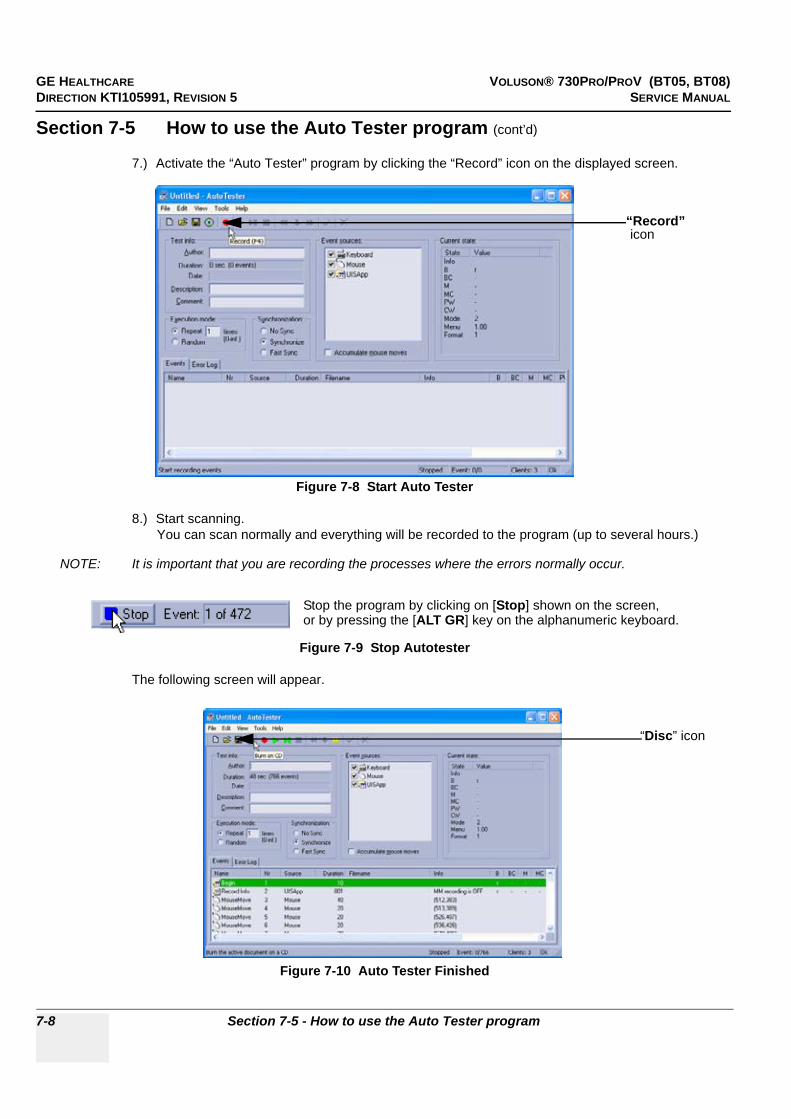
GE HEALTHCARE VOLUSON® 730PRO/PROV (BT05, BT08)DIRECTION KTI105991, REVISION 5 SERVICE MANUAL
7-8 Section 7-5 - How to use the Auto Tester program
Section 7-5 How to use the Auto Tester program (cont’d)
7.) Activate the “Auto Tester” program by clicking the “Record” icon on the displayed screen.
8.) Start scanning.You can scan normally and everything will be recorded to the program (up to several hours.)
NOTE: It is important that you are recording the processes where the errors normally occur.
The following screen will appear.
Figure 7-8 Start Auto Tester
Figure 7-9 Stop Autotester
Figure 7-10 Auto Tester Finished
“Record”icon
Stop the program by clicking on [Stop] shown on the screen,or by pressing the [ALT GR] key on the alphanumeric keyboard.
“Disc” icon
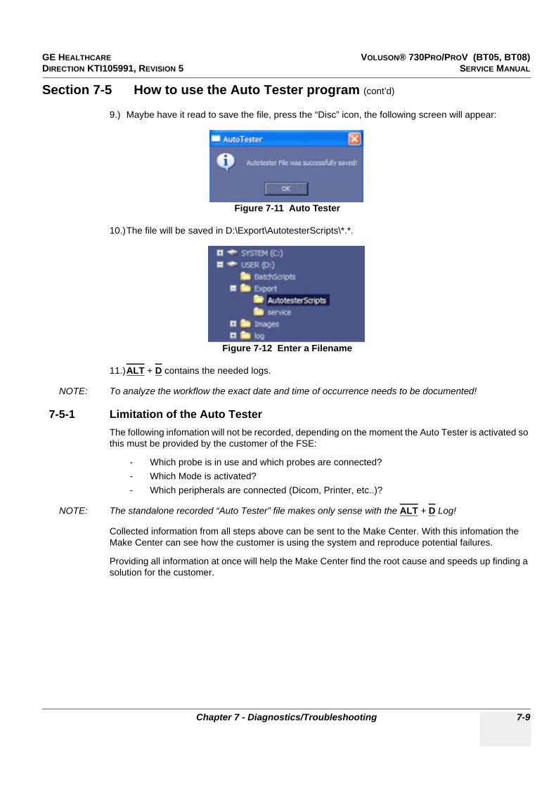
GE HEALTHCARE VOLUSON® 730PRO/PROV (BT05, BT08)DIRECTION KTI105991, REVISION 5 SERVICE MANUAL
Chapter 7 - Diagnostics/Troubleshooting 7-9
Section 7-5 How to use the Auto Tester program (cont’d)
9.) Maybe have it read to save the file, press the “Disc” icon, the following screen will appear:
10.)The file will be saved in D:\Export\AutotesterScripts\*.*.
11.)ALT + D contains the needed logs.
NOTE: To analyze the workflow the exact date and time of occurrence needs to be documented!
7-5-1 Limitation of the Auto TesterThe following infomation will not be recorded, depending on the moment the Auto Tester is activated so this must be provided by the customer of the FSE:
- Which probe is in use and which probes are connected?- Which Mode is activated?- Which peripherals are connected (Dicom, Printer, etc..)?
NOTE: The standalone recorded “Auto Tester” file makes only sense with the ALT + D Log!
Collected information from all steps above can be sent to the Make Center. With this infomation the Make Center can see how the customer is using the system and reproduce potential failures.
Providing all information at once will help the Make Center find the root cause and speeds up finding a solution for the customer.
Figure 7-11 Auto Tester
Figure 7-12 Enter a Filename

GE HEALTHCARE VOLUSON® 730PRO/PROV (BT05, BT08)DIRECTION KTI105991, REVISION 5 SERVICE MANUAL
7-10 Section 7-6 - Minimum Configuration to Scan
Section 7-6Minimum Configuration to Scan
Following cables must be connected to scan; see: Figure 7-13 and/or Figure 7-14
a.) PS2 (connector for Mouse/Keyboard)b.) UI Disp. (connector for User Interface Display) - NOT used at Voluson® 730Pro/ProVc.) DVI (Digital Video Cable from ADD-On DVI Output to CKV-board)d.) VGA (Monitor)e.) Consolef.) CPN (Primary Power Supply)g.) Standby switchh.) Monitor (Power Supply)
*** RS-232 Serial Interface for Console (GEU)
Figure 7-13 cable- minimum configuration Tyan and Kontron ATX
ab
c
d
f
g
e
h
a
b
c
d
f
e
***This connection is only necessary, if “Kontron” SBC-board version is installed.Other versions have internal connector cable, directly connected from CPE flat cable connector to SBC COM1 connector.
“Tyan” SBC-board
installed(similar is DFI ATX)
“Kontron ATX” SBC-board
installed

GE HEALTHCARE VOLUSON® 730PRO/PROV (BT05, BT08)DIRECTION KTI105991, REVISION 5 SERVICE MANUAL
Chapter 7 - Diagnostics/Troubleshooting 7-11
Section 7-6Minimum Configuration to Scan (cont’d)
Connect mains power cable to the system and to an appropriate mains power outlet.
Connect a probe, boot up the system and start an User program.
Figure 7-14 cable- minimum configuration Kontron Flex
a
b
cd
e
f

GE HEALTHCARE VOLUSON® 730PRO/PROV (BT05, BT08)DIRECTION KTI105991, REVISION 5 SERVICE MANUAL
7-12 Section 7-7 - Troubleshooting Trees, Instructions and Tech Tips
Section 7-7Troubleshooting Trees, Instructions and Tech Tips
7-7-1 System Does Not Power On / Boot Up
Figure 7-15 System does not boot up
Is the scanner plugged in?
Is there AC at the wall outlet?
Make sure the Scanner isn't plugged into
emergency power (red outlet)
Yes
Is the circuit breaker on
Yes
+ These three condidtions should be the first items checked ifthe scanner doesn't boot up.
+ If all three conditions are present, the scanner should be ina standby mode with the ON/OFF switch illuminated with ambercolor.
+ Follow the flow chart to determine the reason the scanner doesn't boot up.
No
No
Switch in ON Position
Fan Noise ?
Yes+ Check if the power switch over the mains plug of the Primary Power Supply isn't switched off.
+ Check the connections to and from the Power Supply.
+ Check the power of the cable which connects the Power Supply with the GEF module. (description Check Points Voltages)
+ If ther is no power and the connections are O.K., replace the Primary Power Supply.
No
Yes
System is on and ready for use
Section 7-3

GE HEALTHCARE VOLUSON® 730PRO/PROV (BT05, BT08)DIRECTION KTI105991, REVISION 5 SERVICE MANUAL
Chapter 7 - Diagnostics/Troubleshooting 7-13
7-7-2 Noise disturbs the Image
Figure 7-16 Noise disturbs the Image - Troubleshooting
Noise is shown in Image.
YES
NO
Is there any electrical devices that affect the
Scanner?
Keep the Scanner away from those electrical devices.
use another wallsocket
Check probes.

GE HEALTHCARE VOLUSON® 730PRO/PROV (BT05, BT08)DIRECTION KTI105991, REVISION 5 SERVICE MANUAL
7-14 Section 7-7 - Troubleshooting Trees, Instructions and Tech Tips
7-7-3 Trackball
Figure 7-17 Trackball - Troubleshooting
The trackball is low sensitive!
Remove the ball from the Trackball unit, and clean it.
YES
NO
Does the trackball move at all?
Replace the trackball unit.
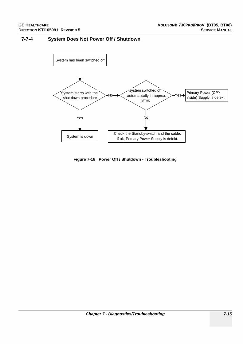
GE HEALTHCARE VOLUSON® 730PRO/PROV (BT05, BT08)DIRECTION KTI105991, REVISION 5 SERVICE MANUAL
Chapter 7 - Diagnostics/Troubleshooting 7-15
7-7-4 System Does Not Power Off / Shutdown
Figure 7-18 Power Off / Shutdown - Troubleshooting
System has been switched off
System starts with the shut down procedure
System is down
Yes
system switched off automatically in approx.
3min.
Primary Power (CPY inside) Supply is defekt
Check the Standby-switch and the cable. If ok, Primary Power Supply is defekt.
No Yes
No
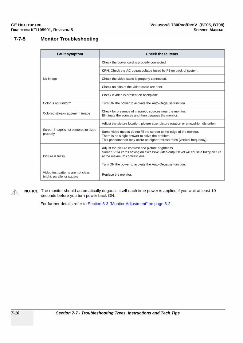
GE HEALTHCARE VOLUSON® 730PRO/PROV (BT05, BT08)DIRECTION KTI105991, REVISION 5 SERVICE MANUAL
7-16 Section 7-7 - Troubleshooting Trees, Instructions and Tech Tips
7-7-5 Monitor Troubleshooting
For further details refer to Section 6-3 "Monitor Adjustment" on page 6-2.
Fault symptom Check these items
No image
Check the power cord is properly connected.
CPN: Check the AC output voltage fused by F3 on back of system.
Check the video cable is properly connected.
Check no pins of the video cable are bent.
Check if video is present on backplane.
Color is not uniform Turn ON the power to activate the Auto-Degauss function.
Colored streaks appear in image Check for presence of magnetic sources near the monitor.Eliminate the sources and then degauss the monitor.
Screen image is not centered or sized properly
Adjust the picture location, picture size, picture rotation or pincushion distortion.
Some video modes do not fill the screen to the edge of the monitor. There is no single answer to solve the problem. This phenomenon may occur on higher refresh rates (vertical frequency).
Picture is fuzzy
Adjust the picture contrast and picture brightness.Some SVGA cards having an excessive video output level will cause a fuzzy picture at the maximum contrast level.
Turn ON the power to activate the Auto-Degauss function.
Video test patterns are not clear, bright, parallel or square Replace the monitor.
NOTICE!! NOTICE:
The monitor should automatically degauss itself each time power is applied if you wait at least 10 seconds before you turn power back ON.
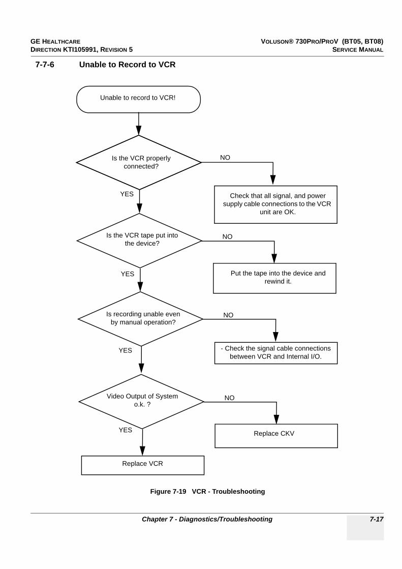
GE HEALTHCARE VOLUSON® 730PRO/PROV (BT05, BT08)DIRECTION KTI105991, REVISION 5 SERVICE MANUAL
Chapter 7 - Diagnostics/Troubleshooting 7-17
7-7-6 Unable to Record to VCR
Figure 7-19 VCR - Troubleshooting
Unable to record to VCR!
Check that all signal, and power supply cable connections to the VCR
unit are OK.
YES
NOIs the VCR properly connected?
Is the VCR tape put into the device?
Put the tape into the device and rewind it.
NO
YES
Replace VCR
Is recording unable even by manual operation?
YES - Check the signal cable connections between VCR and Internal I/O.
NO
YES
Video Output of System o.k. ?
Replace CKV
NO

GE HEALTHCARE VOLUSON® 730PRO/PROV (BT05, BT08)DIRECTION KTI105991, REVISION 5 SERVICE MANUAL
7-18 Section 7-7 - Troubleshooting Trees, Instructions and Tech Tips
7-7-7 Printer Troubleshooting
Figure 7-20 Printer - Troubleshooting
Unable to use Printer(s)!
Check that all signal, and power supply cable connections between
Printer and Scanner are OK.
YES
NOIs the printer(s) properly connected?
Are there print papers left?
Insert the printer papers.
NO
YES
Is proper configuration for the Print key(s) set?
Configure the Print key(s).
NO
See next page.

GE HEALTHCARE VOLUSON® 730PRO/PROV (BT05, BT08)DIRECTION KTI105991, REVISION 5 SERVICE MANUAL
Chapter 7 - Diagnostics/Troubleshooting 7-19
7-7-7 Printer Troubleshooting (cont’d)
Figure 7-21 Printer Troubleshooting (cont’d)
Still unable to use the Printer(s)!
Check the signal cables between GEZ and Backpanel.
YES
NOIs printing unavailable even by manual
operation?
Still no image on the print out
Video Output of System o.k.?
NO
YES
Printer o.k.
Replace the Printer
Replace CKV
NO
YES

GE HEALTHCARE VOLUSON® 730PRO/PROV (BT05, BT08)DIRECTION KTI105991, REVISION 5 SERVICE MANUAL
7-20 Section 7-7 - Troubleshooting Trees, Instructions and Tech Tips
7-7-8 DVD/CD-(R)W Troubleshooting (DVD/CD Drive)1.) Insert an empty DVD/CD-(R)W into the Drive.2.) Enter “Sonoview” by pressing the SONOVIEW key on the control panel; see Figure 7-22.3.) Click the “Open” icon to display the list of exams.4.) Select exam(s) and backup them to DVD/CD-(R)W.5.) Choose “DVD/CD” Drive.6.) The images, which you have choosen during backup should be visible.
7-7-9 MOD Troubleshooting1.) Insert an empty MO into the Drive.2.) Enter “Sonoview” by pressing the SONOVIEW key on the control panel; see Figure 7-22.3.) Click the “Open” icon to display the list of exams.4.) Select exam(s) and backup them to MO.5.) Choose “MO” Drive.6.) The images, which you have chosen during backup should be visible.
7-7-10 Network Troubleshooting
7-7-10-1 No Connection to the Network at All
1.) Check that the network cable between the scanner and the wall network is connected and well seated in both ends. (Use a network cable that is known to be OK.)
2.) Check the cable from network-connector on the Back Panel to the LAN-connector on the GEZ.3.) Connect a network cable between your Scanner and your PC. Try to ping from the Scanner to the
IP address on the PC. If OK, the hardware connection inside the Scanner is OK.
Figure 7-22 To backup exams to DVD/CD+(R)W resp. MO-Disk
NOTICE!! NOTICE:
In case of any problems, check status of the Diagnostic LED´s and voltages of the AUX Supply connector (= Disk Drive Module power connector) on the backpanel of the GEZ-Box;see: Section 7-3 "Check Points Voltages" on page 7-3
NOTICE!! NOTICE:
In case of any problems, check status of the Diagnostic LED´s and voltages of the AUX Supply connector (= Disk Drive Module power connector) on the backpanel of the GEZ-Box;see: Section 7-3 "Check Points Voltages" on page 7-3
1. Press Sonoview key 2. Click “Open” iconand backup exams
3. After Backup,choose DVD/CD(resp. MO)
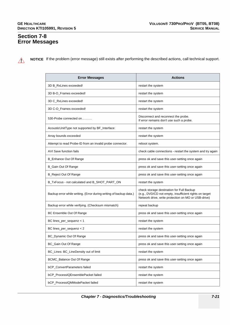
GE HEALTHCARE VOLUSON® 730PRO/PROV (BT05, BT08)DIRECTION KTI105991, REVISION 5 SERVICE MANUAL
Chapter 7 - Diagnostics/Troubleshooting 7-21
Section 7-8Error Messages
NOTICE!! NOTICE:
If the problem (error message) still exists after performing the described actions, call technical support.
Error Messages Actions
3D B_RxLines exceeded! restart the system
3D B-O_Frames exceeded! restart the system
3D C_RxLines exceeded! restart the system
3D C-O_Frames exceeded! restart the system
530-Probe connected on………. Disconnect and reconnect the probe. If error remains don't use such a probe.
AcousticUnitType not supported by BF_Interface: restart the system
Array bounds exceeded restart the system
Attempt to read Probe-ID from an invalid probe connector. reboot system.
AVI Save function fails check cable connections - restart the system and try again
B_Enhance Out Of Range press ok and save this user-setting once again
B_Gain Out Of Range press ok and save this user-setting once again
B_Reject Out Of Range press ok and save this user-setting once again
B_TxFocus - not calculated and B_SHOT_PART_ON restart the system
Backup error while writing. (Error during writing of backup data.)check storage destination for Full Backup (e.g., DVD/CD not empty, insufficient rights on target Network drive, write protection on MO or USB-drive)
Backup error while verifying. (Checksum mismatch) repeat backup
BC Ensemble Out Of Range press ok and save this user-setting once again
BC lines_per_sequenz < 1 restart the system
BC lines_per_sequenz < 2 restart the system
BC_Dynamic Out Of Range press ok and save this user-setting once again
BC_Gain Out Of Range press ok and save this user-setting once again
BC_Lines: BC_LineDensity out of limit restart the system
BCMC_Balance Out Of Range press ok and save this user-setting once again
bCP_ConvertParameters failed restart the system
bCP_ProcessIQEnsemblePacket failed restart the system
bCP_ProcessIQMModePacket failed restart the system
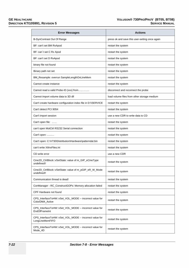
GE HEALTHCARE VOLUSON® 730PRO/PROV (BT05, BT08)DIRECTION KTI105991, REVISION 5 SERVICE MANUAL
7-22 Section 7-8 - Error Messages
B-DynContrast Out Of Range press ok and save this user-setting once again
BF: can't set BM RxApod restart the system
BF: can´t set C Rx Apod restart the system
BF: can't set D RxApod restart the system
binary file not found restart the system
Binary path not set restart the system
BM_Resample: overrun SampleLengthOnLineMem restart the system
Cannot create instance restart the system
Cannot read a valid Probe-ID (xxx) from…………. disconnect and reconnect the probe
Cannot import volume data to 3D dll load volume files from other storage medium
Can't create hardware configuration index file in D:\\SERVICE restart the system
Can't detect PCI 9054 restart the system
Can't import session use a new CDR to write data to CD
Can't open file: …… restart the system
can't open MotCtrl RS232 Serial connection restart the system
Can't open: .......... restart the system
Can't open: C:\V730\Distribution\Hardware\patterndat.bin restart the system
can't write XilinxFiles.ini restart the system
CD write error use a new CDR
Cine2D_CtrlBlock::vSetState: value of m_GIP_eCineType undefined!! restart the system
Cine2D_CtrlBlock::vSetState: value of m_pGIP_eR_W_Mode undefined!! restart the system
Communication thread is dead! restart the system
ConManager - RC_ConstructGOPs: Memory allocation failed restart the system
CPF Hardware not found restart the system
CPS_InterfaceToHW::vSet_VOL_MODE -- incorrect value for ColorDMA_Active restart the system
CPS_InterfaceToHW::vSet_VOL_MODE -- incorrect value for EndOfFrameInt restart the system
CPS_InterfaceToHW::vSet_VOL_MODE -- incorrect value for LongLineMemFIFO restart the system
CPS_InterfaceToHW::vSet_VOL_MODE -- incorrect value for Mode_4D restart the system
Error Messages Actions

GE HEALTHCARE VOLUSON® 730PRO/PROV (BT05, BT08)DIRECTION KTI105991, REVISION 5 SERVICE MANUAL
Chapter 7 - Diagnostics/Troubleshooting 7-23
CtrlMvGrpRepresentations::isInWriteMode not supported for mode nr xx restart the system
CW quant TX Frequ out of range restart the system
CW_BaseLinePos Out Of Range press ok and save this user-setting once again
CW_Gain Out Of Range press ok and save this user-setting once again
CW-hardware doesn't support pencil probe + CW-Hardware not available->HW problem
CW-HW-PRF == 0 restart the system
CW-TxFrequency == 0 restart the system
CW-TxPower Out Of Range press ok and save this user-setting once again
D:\\SERVICE\\ConfIndexFile is corrupt restart the system
Datatype misalignment restart the system
Delete error (Backup data could not be deleted.)check storage destination of Full Backup(e.g., DVD/CD, insufficient rights on target Network drive, write protection on MO or USB-drive)
Density Out Of Range press ok and save this user-setting once again
Different software error (Backup data was made on another system with a different software version.) This backup cannot be restored by the user.
Disc full! use a new CDR for writing data to CD
Display:Rect Region fails restart the system
Division by zero restart the system
done is low! restart the system
Downgrade error (Backup data was made with a software version higher than the installed version.) load appropriate backup for installed version
DSP - Gamma Corr - Load Data Timeout restart the system
DSP - HilbertCoeff - Load Data Timeout restart the system
DSP - Low Pass Coeff - Load Data Timeout restart the system
DSP - SetFFT_Para - Load Data Timeout restart the system
DSP - SetWMF_Koeff - Load Data Timeout restart the system
DSP/MSE:Hanning-Window Load Data Timeout restart the system
ECG_InterfaceToHW::vLookupForNewSamples() allocating expanded buffer[xxx] for TimeStamps failed!! restart the system
Electronic user manual not installed. Please install. install Electronic User Manual (EUM) and try it again
End Bandwidth too big restart the system
End ET too big restart the system
End frequency too big restart the system
Error Messages Actions

GE HEALTHCARE VOLUSON® 730PRO/PROV (BT05, BT08)DIRECTION KTI105991, REVISION 5 SERVICE MANUAL
7-24 Section 7-8 - Error Messages
Enhance Out Of Range press ok and save this user-setting once again
Ensemble Out Of Range press ok and save this user-setting once again
Error in CreateCineImage try to store again; restart the system
Error in File: …. restart the system
Error in Select Tx-channel for B-mode restart the system
Error in Select Tx-channel for C-mode restart the system
Error in Select Tx-channel for CW-mode restart the system
Error in Select Tx-channel for PW-mode restart the system
Error no HW present restart the system
Error not enough time for BC shot! restart the system
Error on LoadBootMem Page: xx, Addr: xx restart the system
Error programming Flashcomplette restart the system
Error setting state restart the system
ERROR_MSG_INIT_FAILED Check connection from US machine to VCR, VCR has power and is on.
ERROR_MSG_NO_ACK check VCR cables and try again
ERROR_MSG_NO_CASSETTE put cassette into drive of VCR
ERROR_MSG_NO_RESPONSE check VCR cables, casette,... and try again
ERROR_MSG_WRITE_PROTECTED remove cassette from VCR and put writeable cassette into drive of VCR.
Execute privileged instruction restart the system
FallSmooth Out Of Range press ok and save this user-setting once again
File Could not CRC Check load volume files from other storage medium
File CRC Error load volume files from other storage medium
File CRC Missing load volume files from other storage medium
File Data Missing load volume files from other storage medium
File Datalength Not Consistent load volume files from other storage medium
File Decompress Error load volume files from other storage medium
File Decompress method Unknown load volume files from other storage medium
File End Error load volume files from other storage medium
File Execute Error load volume files from other storage medium
File Memory Missing load volume files from other storage medium
File Not Found load volume files from other storage medium
Error Messages Actions

GE HEALTHCARE VOLUSON® 730PRO/PROV (BT05, BT08)DIRECTION KTI105991, REVISION 5 SERVICE MANUAL
Chapter 7 - Diagnostics/Troubleshooting 7-25
File Pos load volume files from other storage medium
File Read Error load volume files from other storage medium
File Type Unknown load volume files from other storage medium
File Volume size not consistent load volume files from other storage medium
FLT: Denormal operand restart the system
FLT: Divide by zero restart the system
FLT: Invalid operation restart the system
FLT: Stack overflow restart the system
FLT: Underflow restart the system
FrameUp - TempBuffer: Memory allocation failed restart the system
GeoDescription3D_TissueCF::operator=: handed over argument is not of same type, dynamic cast failed!! restart the system
GeoDescriptionMotion Constructor: unknown mode Parameter handed over restart the system
GeoDescriptionMotion::operator=: handed over argument is not of same type, dynamic cast failed!! restart the system
GeoDescriptionPWMode::operator=: handed over argument is not of same type, dynamic cast failed!! restart the system
GeoDescriptionTissueCF Constructor: unknown mode Parameter handed over restart the system
GeoDescriptionTissueCF::operator=: handed over argument is not of same type, dynamic cast failed!! restart the system
Hardware doesn't support CW-mode pencil probe + CW-Hardware not available->HW problem
hardware error on restart the system
HardwareRelatedSoftware_Windows in write have different ProbeAcousticUnitIDs
disconnect all connected probes and connect them again;if not ok restart the system
HardwareRelatedSoftware_Windows in write have different ProbeScanFuncIDs
disconnect all connected probes and connect them again;if not ok restart the system
IBegrenzer.cpp Bshots TxMultiFocus problem restart the system
IBegrenzer.cpp Mshots TxMultiFocus problem restart the system
In the 3D Image Measure is not allowed change to another format than 3D Fullscreen mode
incorrect VersionByte, xx of xx cycles OK contact technical support
iSetVideoSource(eVideoIntern) function fails reboot the system
iSetVideoSource(eVideoIntern) function fails the system will restart itself by pressing OK
LineFilt Out Of Range press ok and save this user-setting once again
LP_KoefBlock: SamplePRF too big restart the system
Error Messages Actions

GE HEALTHCARE VOLUSON® 730PRO/PROV (BT05, BT08)DIRECTION KTI105991, REVISION 5 SERVICE MANUAL
7-26 Section 7-8 - Error Messages
M_Gain Out Of Range press ok and save this user-setting once again
M_Reject Out Of Range press ok and save this user-setting once again
MC Ensemble Out Of Range press ok and save this user-setting once again
MC_Balance Out Of Range press ok and save this user-setting once again
MC_BaseLinePos Out Of Range press ok and save this user-setting once again
MC_Dynamic Out Of Range press ok and save this user-setting once again
MC_FallSmooth Out Of Range press ok and save this user-setting once again
MC_Gain Out Of Range press ok and save this user-setting once again
MC_RiseSmooth Out Of Range press ok and save this user-setting once again
M-DynContrast Out Of Range+ press ok and save this user-setting once again
Memory access violation restart the system
memory allocation error restart the system
missing BCMCPW_TxFocusData restart the system
missing BM_TxFocusData restart the system
missing CW_TxFocusData restart the system
missing ProbeAcousticUnit, wrong ProbeAcousticUnitID. restart the system
missing ProbeGeneral data - wrong ProbeID restart the system
missing ProbeScanFunc - wrong ProbeScanFuncID restart the system
MotCtrl RS232 communication timeout restart the system
MotCtrl: No Referenzposition signal!
Confirm the message by pressing the OK button, disconnect and reconnect the active probe and use it again. If the message appears again, usually the probe itself has an defect, so you should contact the service
MotionColor-DSC 1st:Memory allocation failed restart the system
MotionColor-DSC 2nd:Memory allocation failed restart the system
Motion-DSC:Memory allocation failed restart the system
MoveVolumeAxis only supported by RealTime-probes ! look into the System Setup to see the current MotCtrl version and contact technical support
MoveVolumeAxis only supported by RealTime-probes (RRE) look into the System Setup to see the current MotCtrl version and contact technical support
No CD Writer found check the connection and the Power cable - plug the cable off and on and try again. (restart the system)
No disc in drive insert disk, if fails again reboot and try again (with another disk)
Not enough space. (Not enough space on destination to hold the backup data.) select another destination to save Full Backup
Error Messages Actions
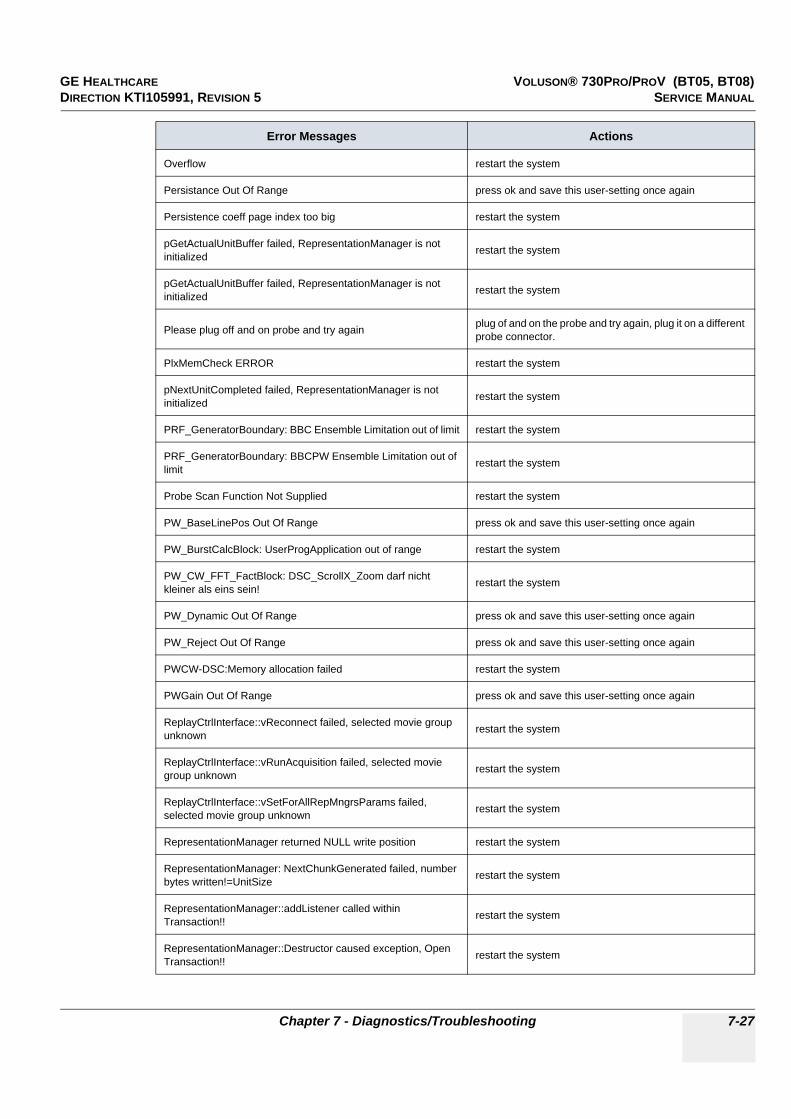
GE HEALTHCARE VOLUSON® 730PRO/PROV (BT05, BT08)DIRECTION KTI105991, REVISION 5 SERVICE MANUAL
Chapter 7 - Diagnostics/Troubleshooting 7-27
Overflow restart the system
Persistance Out Of Range press ok and save this user-setting once again
Persistence coeff page index too big restart the system
pGetActualUnitBuffer failed, RepresentationManager is not initialized restart the system
pGetActualUnitBuffer failed, RepresentationManager is not initialized restart the system
Please plug off and on probe and try again plug of and on the probe and try again, plug it on a different probe connector.
PlxMemCheck ERROR restart the system
pNextUnitCompleted failed, RepresentationManager is not initialized restart the system
PRF_GeneratorBoundary: BBC Ensemble Limitation out of limit restart the system
PRF_GeneratorBoundary: BBCPW Ensemble Limitation out of limit restart the system
Probe Scan Function Not Supplied restart the system
PW_BaseLinePos Out Of Range press ok and save this user-setting once again
PW_BurstCalcBlock: UserProgApplication out of range restart the system
PW_CW_FFT_FactBlock: DSC_ScrollX_Zoom darf nicht kleiner als eins sein! restart the system
PW_Dynamic Out Of Range press ok and save this user-setting once again
PW_Reject Out Of Range press ok and save this user-setting once again
PWCW-DSC:Memory allocation failed restart the system
PWGain Out Of Range press ok and save this user-setting once again
ReplayCtrlInterface::vReconnect failed, selected movie group unknown restart the system
ReplayCtrlInterface::vRunAcquisition failed, selected movie group unknown restart the system
ReplayCtrlInterface::vSetForAllRepMngrsParams failed, selected movie group unknown restart the system
RepresentationManager returned NULL write position restart the system
RepresentationManager: NextChunkGenerated failed, number bytes written!=UnitSize restart the system
RepresentationManager::addListener called within Transaction!! restart the system
RepresentationManager::Destructor caused exception, Open Transaction!! restart the system
Error Messages Actions
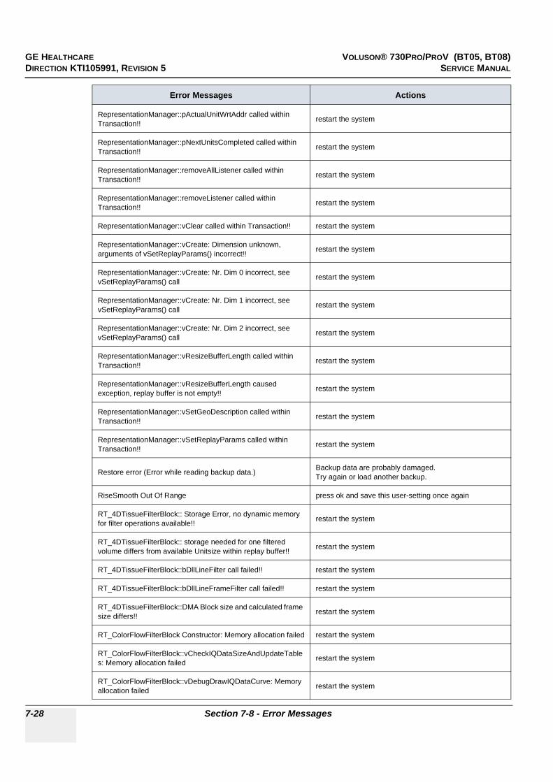
GE HEALTHCARE VOLUSON® 730PRO/PROV (BT05, BT08)DIRECTION KTI105991, REVISION 5 SERVICE MANUAL
7-28 Section 7-8 - Error Messages
RepresentationManager::pActualUnitWrtAddr called within Transaction!! restart the system
RepresentationManager::pNextUnitsCompleted called within Transaction!! restart the system
RepresentationManager::removeAllListener called within Transaction!! restart the system
RepresentationManager::removeListener called within Transaction!! restart the system
RepresentationManager::vClear called within Transaction!! restart the system
RepresentationManager::vCreate: Dimension unknown, arguments of vSetReplayParams() incorrect!! restart the system
RepresentationManager::vCreate: Nr. Dim 0 incorrect, see vSetReplayParams() call restart the system
RepresentationManager::vCreate: Nr. Dim 1 incorrect, see vSetReplayParams() call restart the system
RepresentationManager::vCreate: Nr. Dim 2 incorrect, see vSetReplayParams() call restart the system
RepresentationManager::vResizeBufferLength called within Transaction!! restart the system
RepresentationManager::vResizeBufferLength caused exception, replay buffer is not empty!! restart the system
RepresentationManager::vSetGeoDescription called within Transaction!! restart the system
RepresentationManager::vSetReplayParams called within Transaction!! restart the system
Restore error (Error while reading backup data.) Backup data are probably damaged.Try again or load another backup.
RiseSmooth Out Of Range press ok and save this user-setting once again
RT_4DTissueFilterBlock:: Storage Error, no dynamic memory for filter operations available!! restart the system
RT_4DTissueFilterBlock:: storage needed for one filtered volume differs from available Unitsize within replay buffer!! restart the system
RT_4DTissueFilterBlock::bDllLineFilter call failed!! restart the system
RT_4DTissueFilterBlock::bDllLineFrameFilter call failed!! restart the system
RT_4DTissueFilterBlock::DMA Block size and calculated frame size differs!! restart the system
RT_ColorFlowFilterBlock Constructor: Memory allocation failed restart the system
RT_ColorFlowFilterBlock::vCheckIQDataSizeAndUpdateTables: Memory allocation failed restart the system
RT_ColorFlowFilterBlock::vDebugDrawIQDataCurve: Memory allocation failed restart the system
Error Messages Actions

GE HEALTHCARE VOLUSON® 730PRO/PROV (BT05, BT08)DIRECTION KTI105991, REVISION 5 SERVICE MANUAL
Chapter 7 - Diagnostics/Troubleshooting 7-29
RT_ConnectionMngr::vAssembleRTSet: no RT_TissueFilterBlock found for TISSUE3D Blocks restart the system
RT_ECG_Block::bStart ECGInterface failed!! restart the system
RT_MColorFilterBlock::RT_MColorFilterBlock: Memory allocation failed restart the system
RT_MColorFilterBlock::vCheckIQDataSizeAndUpdateBuffer: Memory allocation failed restart the system
RT_MColorFilterBlock::vDebugDrawIQDataCurve: Memory allocation failed restart the system
RT_MotionMBlock::execute caused exception:: Addr from DMA= xx, ReplayBuffAddr= xx, (Line+Header)Size= xx, blockLength= xx, value i= xx!!
restart the system
RT_PWorCW_Block::replay buffer size smaller than expected restart the system
RT_PWorCW_Block::execute caused exception:: Addr from DMA= xx, ReplayBuffAddr= xx, (Line+Header)Size= xx, blockLength= xx, line index= xx!!
restart the system
RT_PWorCW_Block::execute: Error, length of DMA block 2 [xx] is not aligned to linesize!! restart the system
Start Bandwidth too small restart the system
Start ET too small restart the system
Start frequency too small restart the system
StoragePool: Not sufficient replay storage for B & CF Mode available restart the system
StoragePool: Not sufficient replay storage for ECG available restart the system
StoragePool: Not sufficient replay storage for M Mode available restart the system
StoragePool: Not sufficient replay storage for MC or PW Mode available restart the system
System detected severe error, please call technical support. restart the system, call technical support
System detected severe error. Some components like Touch Panel server may not be registered. Please register Touch Panel server and restart.
restart the system, call technical support
The Database UserPrograms Corrupted restart the system
The Date format not stored properly close registry, restart, try again
The Handle Unregistered close registry, restart, try again
The Registry not closed restart the system
The System detected a problem with your harddisk. Please do not reboot or shut down the machine!Please contact your service department as soon as possible.
if possible, • save “Full Backup” (see: Section 4-5-3 on page 4-36) to “DVD/CD”, “Network”, or “Other drive” (including images)• if not currently done, save all images via Sonoview (see: Section 4-5-6 on page 4-41) , • call technical support
Error Messages Actions

GE HEALTHCARE VOLUSON® 730PRO/PROV (BT05, BT08)DIRECTION KTI105991, REVISION 5 SERVICE MANUAL
7-30 Section 7-8 - Error Messages
Thickness mismatch xx - GIP xx restart 3D (go to 2D); restart the system
UI_BBC_Wnd::vSet() has an wrong ImageType restart the system
UI_BBC_Wnd::vSet() will change from eB_Wnd to wrong ImageType restart the system
UI_BBC_Wnd::vSet() will change from eBBC_Wnd to wrong ImageType restart the system
UI_Manager::vDestroyWnd: dynamic cast to UI_MMC_Wnd* failed restart the system
UI_Manager::vDestroyWnd: dynamic cast to UI_PW_Wnd* failed restart the system
UI_Manager::vHRS_Execute multiple call restart the system
Unable to save... restart the system
undefined CW ADC_Clk-Teiler restart the system
Unknown Error load volume files from other storage medium
unknown Xilinx-Version restart the system
unrecordable disc in drive try again with another disk
Unsupported color mode restart the system
Verify error (Error while checking backup data.) Backup data are probably damaged.Try again or load another backup.
ViewerConMngr::vAssembleCF_DFE: attempt to get ECG_Consumer_2D- or ECG_Draw_2D-Block from ECGViewer Objects failed!!
restart the system
ViewerConMngr::vAssembleM_DFE: attempt to get ECG_Consumer_2D- or ECG_Draw_2D-Block or ECG-CalcHR-Block from ECGViewer Objects failed!!
restart the system
Volume_dB Out Of Range press ok and save this user-setting once again
WMF_KoefBlock: SamplePRF too big restart the system
XTD - pucBackScaledBImage: Memory allocation failed restart the system
XTD - pucDSCBImage: Memory allocation failed restart the system
XTDTrackballCtrlState::No frame to trackball position found, internal failure!! restart the system
Error Messages Actions

GE HEALTHCARE VOLUSON® 730PRO/PROV (BT05, BT08)DIRECTION KTI105991, REVISION 5 SERVICE MANUAL
Chapter 8 - Replacement Procedures 8-1
Chapter 8Replacement Procedures
Section 8-1Overview
8-1-1 Purpose of Chapter 8This chapter contains replacement procedures for different modules and their subsystems.
NOTICE!! NOTICE:
The Manpower, time and Tools indicated in the Sub-sections include all requirements from Preparations to Installation Procedures.
WARNINGWARNING!! WARNING:
No covers or panels should be removed from the system (high-voltage risk). Service and repairs must only be performed by authorized personal. Attempting do-it-yourself repairs invalidate warranty and are an infringement to regulations and are inadmissible acc. to IEC 60601-1.
The waste of electrical and electronic equipment must not be disposed as unsorted municipal waste and must be collected separately. Please contact the manufacturer or other authorized disposal company for information concerning the decommission of your equipment.

GE HEALTHCARE VOLUSON® 730PRO/PROV (BT05, BT08)DIRECTION KTI105991, REVISION 5 SERVICE MANUAL
8-2 Section 8-1 - Overview
Table 8-1 Chapter 8 Contents
Section Description Page Number
8-1 Overview 8-1
8-2 Ultrasound Application Software (UIS) Installation Procedure 8-3
8-3 User Settings Only (Application Settings) Loading Procedure 8-10
8-4 Full Backup (Presets, Configurations & Appl. Settings) Loading Procedure 8-10
8-5 Service Platform (SSW) Upgrade Procedure 8-11
8-6 Electronic User Manual (EUM) Upgrade Procedure 8-13
8-7 Software and Functional Checks after the Upgrade 8-16
8-8 Replacement or Activation of Options 8-17
8-9 Transfer of Patient Database and Images from System-to-System 8-19
8-10 Replacement of the Monitor Task Lamp 8-24
8-11 Replacement of the Trackball top fixation ring 8-25
8-12 Replacement of Digipots and TGC Slider controls 8-25
8-13 Replacement of the Probe Holder 8-25
8-14 Replacement of Key Caps (by special native language keys) 8-26
8-15 Replacing optional Peripherals / How to mount Peripherals at a later date 8-27
8-15-1 Mounting/Replacing the 19’’ LCD secondary “Patient” Monitor 8-28

GE HEALTHCARE VOLUSON® 730PRO/PROV (BT05, BT08)DIRECTION KTI105991, REVISION 5 SERVICE MANUAL
Chapter 8 - Replacement Procedures 8-3
8-1-2 Returning/Shipping Probes and Repair PartsEquipment being returned must be clean and free of blood and other infectious substances.
GEMS policy states that body fluids must be properly removed from any part or equipment prior to shipment. GEMS employees, as well as customers, are responsible for ensuring that parts/equipment have been properly decontaminated prior to shipment. Under no circumstance should a part or equipment with visible body fluids be taken or shipped from a clinic or site (for example, body coils or and ultrasound probe).
The purpose of the regulation is to protect employees in the transportation industry, as well as the people who will receive or open this package.
NOTE: The US Department of Transportation (DOT) has ruled that “items what were saturated and/or dripping with human blood that are now caked with dried blood; or which were used or intended for use in patient care” are “regulated medical waste” for transportation purpose and must be transported as a hazardous material.
Section 8-2Ultrasound Application Software (UIS) Installation Procedure
8-2-1 Introduction
8-2-2 ManpowerOne Person, 20 min.
8-2-3 ToolsSystem DVD
NOTICE!! NOTICE:
It is possible to update the Ultrasound Application Software via the UPDATE button in the System Setup SERVICE page; see: Section 8-2-5 on page 8-7.

GE HEALTHCARE VOLUSON® 730PRO/PROV (BT05, BT08)DIRECTION KTI105991, REVISION 5 SERVICE MANUAL
8-4 Section 8-2 - Ultrasound Application Software (UIS) Installation Procedure
8-2-4 PreparationsBefore performing the Software Update/Upgrade:
A.) make sure that all system functions are working correctB.) check the current Software Version and installed Options
1.) Press the UTILITIES key on the control panel once to display the Utilities menu.2.) Select the SYSTEM item from the Utilities menu - which is displayed on the left side of the screen.3.) Select the SYSTEM INFO page on the System Setup desktop screen to see which Software/Hardware
version is installed in the unit.
Figure 8-1 Version check
currently installed Software version

GE HEALTHCARE VOLUSON® 730PRO/PROV (BT05, BT08)DIRECTION KTI105991, REVISION 5 SERVICE MANUAL
Chapter 8 - Replacement Procedures 8-5
8-2-4 Preparations (cont’d)
4.) Select the OPTION page on the System Setup desktop screen to see which Options are installed.
5.) Select the NETWORK page on the System Setup desktop screen.
a.) Click on the DICOM / SONOVIEW CONFIGURATION button in the NETWORK page.
Figure 8-2 Option page (e.g. V730 Pro)
NOTICE!! NOTICE:
Please print out the OPTION page or write down the “Permanent Key”!
Figure 8-3 DICOM Configuration
NOTICE!! NOTICE:
Please print out the “DICOM Configuration” dialog page or write down the DICOM designations(AE Title, Station name, Retry Count, Retry Interval).
D = Demo
on the date shown in the “Valid” column)(Option is activated for demo and expires
I = Inactive(Option is not activated)
P = Permanent(Option is permanently activated [purchased]) Permanent Key
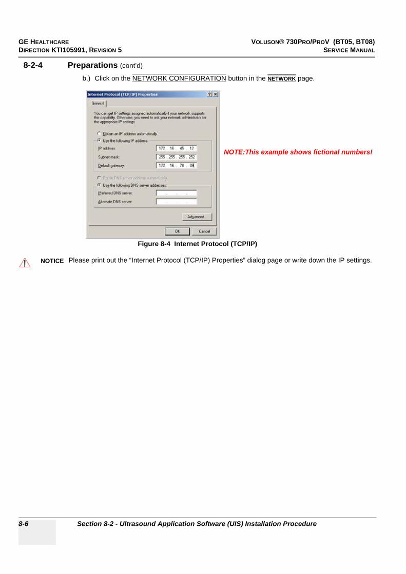
GE HEALTHCARE VOLUSON® 730PRO/PROV (BT05, BT08)DIRECTION KTI105991, REVISION 5 SERVICE MANUAL
8-6 Section 8-2 - Ultrasound Application Software (UIS) Installation Procedure
8-2-4 Preparations (cont’d)
b.) Click on the NETWORK CONFIGURATION button in the NETWORK page.
Figure 8-4 Internet Protocol (TCP/IP)
NOTICE!! NOTICE:
Please print out the “Internet Protocol (TCP/IP) Properties” dialog page or write down the IP settings.
NOTE:This example shows fictional numbers!
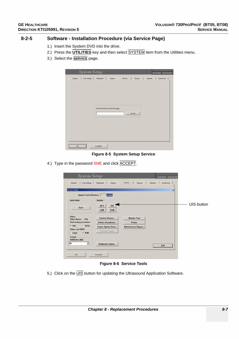
GE HEALTHCARE VOLUSON® 730PRO/PROV (BT05, BT08)DIRECTION KTI105991, REVISION 5 SERVICE MANUAL
Chapter 8 - Replacement Procedures 8-7
8-2-5 Software - Installation Procedure (via Service Page)1.) Insert the System DVD into the drive.2.) Press the UTILITIES key and then select SYSTEM item from the Utilities menu.3.) Select the SERVICE page.
4.) Type in the password SHE and click ACCEPT.
5.) Click on the UIS button for updating the Ultrasound Application Software.
Figure 8-5 System Setup Service
Figure 8-6 Service Tools
UIS button

GE HEALTHCARE VOLUSON® 730PRO/PROV (BT05, BT08)DIRECTION KTI105991, REVISION 5 SERVICE MANUAL
8-8 Section 8-2 - Ultrasound Application Software (UIS) Installation Procedure
8-2-5 Software - Installation Procedure (via Service Page) (cont’d)
6.) Confirm the following message with YES.
7.) A new window pops up on the screen and the InstallShield starts extracting files.
8.) Click the NEXT button In the “Welcome to Kretz V730 Software Installation” window.
The contents of the Software package are being extracted.
Figure 8-7 Update UIS message
Figure 8-8 Install Shield Wizard - Extracting Files
Figure 8-9 Welcome to ... Software Installation
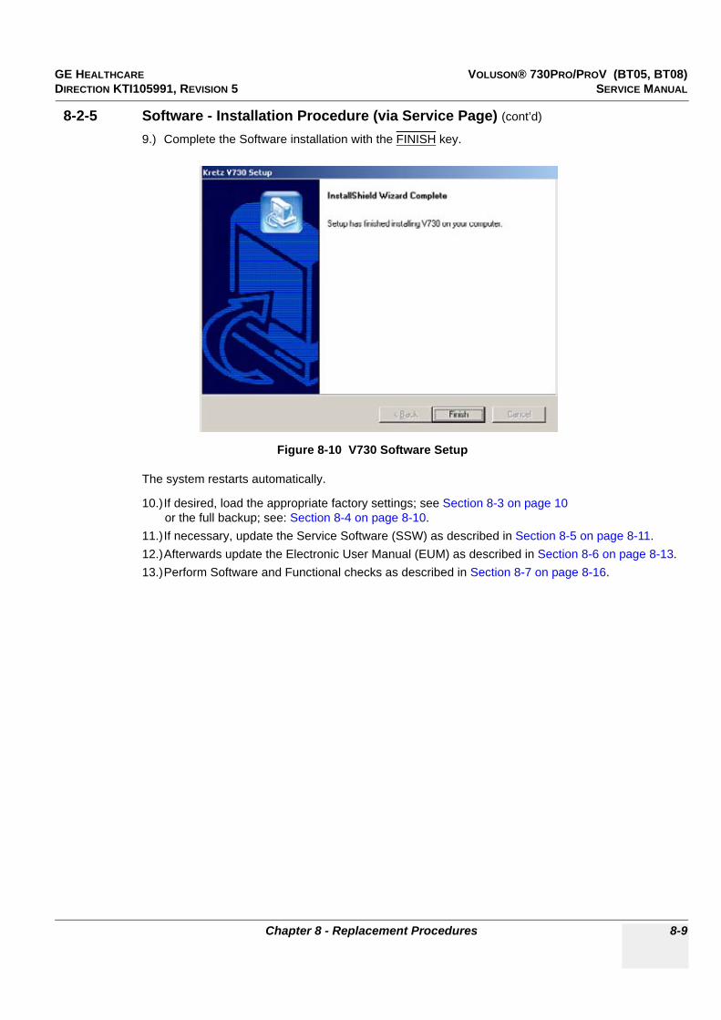
GE HEALTHCARE VOLUSON® 730PRO/PROV (BT05, BT08)DIRECTION KTI105991, REVISION 5 SERVICE MANUAL
Chapter 8 - Replacement Procedures 8-9
8-2-5 Software - Installation Procedure (via Service Page) (cont’d)
9.) Complete the Software installation with the FINISH key.
The system restarts automatically.
10.)If desired, load the appropriate factory settings; see Section 8-3 on page 10or the full backup; see: Section 8-4 on page 8-10.
11.)If necessary, update the Service Software (SSW) as described in Section 8-5 on page 8-11.12.)Afterwards update the Electronic User Manual (EUM) as described in Section 8-6 on page 8-13.13.)Perform Software and Functional checks as described in Section 8-7 on page 8-16.
Figure 8-10 V730 Software Setup

GE HEALTHCARE VOLUSON® 730PRO/PROV (BT05, BT08)DIRECTION KTI105991, REVISION 5 SERVICE MANUAL
8-10 Section 8-3 - User Settings Only (Application Settings) Loading Procedure
Section 8-3User Settings Only (Application Settings) Loading Procedure
8-3-1 IntroductionThe User Settings contains:
• Application Settings• User Programs• Auto Text• 3D/4D Programs
8-3-2 Loading Proceduresee: Section 4-5-2 "Load User Settings Only (Application Settings)" on page 4-34
Section 8-4Full Backup (Presets, Configurations & Appl. Settings) Loading Procedure
8-4-1 Introduction
The Full Backup contains following data:
• Patient demographic and exam data (database containing the patient data and measurements)• SonoView image data (NOT available when saving to the internal hard disk, DVD/CD or MOD)• User Settings (databases and files containing gray curves and the user settings.)• Image transfer settings (DICOM settings e.g., DICOM servers, AE Title, Station Name, etc.)• Measure Setup Settings (user specific measure settings)• V730 settings (general settings such as language, time/date format and the enabled options)• Windows Network Settings (network settings including the computer name)• Service Platform (state of the service platform)• VP (additional system data)
8-4-2 Loading Proceduresee: Section 4-5-4 "Load Full Backup (Presets, Configurations & Application Settings)" on page 4-38

GE HEALTHCARE VOLUSON® 730PRO/PROV (BT05, BT08)DIRECTION KTI105991, REVISION 5 SERVICE MANUAL
Chapter 8 - Replacement Procedures 8-11
Section 8-5Service Platform (SSW) Upgrade Procedure
8-5-1 ManpowerOne Person, 10 min.
8-5-2 ToolsSystem DVD or Upgrade CD
8-5-3 Upgrade Procedure1.) Insert the System DVD or Upgrade CD into the drive.2.) Press the UTILITIES key on the control panel once to display the Utilities menu.3.) Select the SYSTEM item from the Utilities menu - which is displayed on the left side of the screen.4.) Select the SERVICE page.5.) Enter the password SHE, and click the ACCEPT.6.) The “Service Tools” menu appears on the screen.
7.) Click on the SSW button for updating the Service Platform Software.
Figure 8-11 Service Tools
SSW button
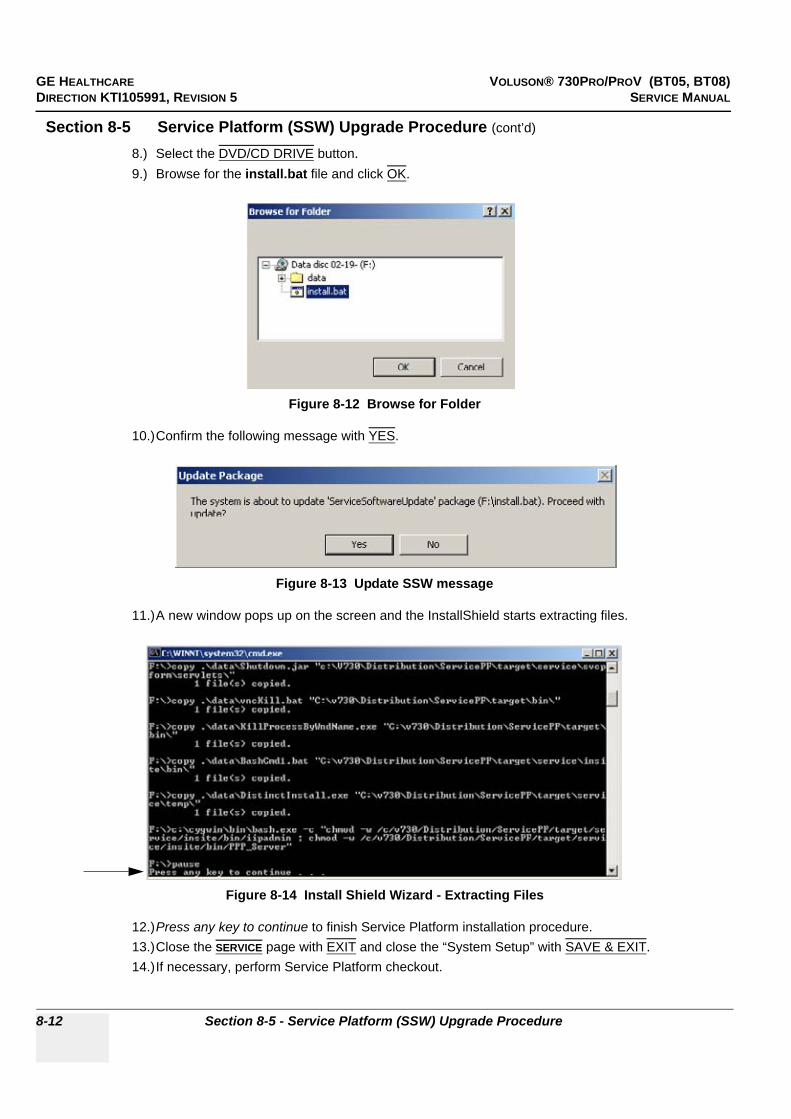
GE HEALTHCARE VOLUSON® 730PRO/PROV (BT05, BT08)DIRECTION KTI105991, REVISION 5 SERVICE MANUAL
8-12 Section 8-5 - Service Platform (SSW) Upgrade Procedure
Section 8-5 Service Platform (SSW) Upgrade Procedure (cont’d)
8.) Select the DVD/CD DRIVE button.9.) Browse for the install.bat file and click OK.
10.)Confirm the following message with YES.
11.)A new window pops up on the screen and the InstallShield starts extracting files.
12.)Press any key to continue to finish Service Platform installation procedure.13.)Close the SERVICE page with EXIT and close the “System Setup” with SAVE & EXIT.14.)If necessary, perform Service Platform checkout.
Figure 8-12 Browse for Folder
Figure 8-13 Update SSW message
Figure 8-14 Install Shield Wizard - Extracting Files

GE HEALTHCARE VOLUSON® 730PRO/PROV (BT05, BT08)DIRECTION KTI105991, REVISION 5 SERVICE MANUAL
Chapter 8 - Replacement Procedures 8-13
Section 8-6Electronic User Manual (EUM) Upgrade Procedure
8-6-1 ManpowerOne Person, 15 min.
8-6-2 ToolsSystem DVD or Upgrade CD
8-6-3 Preparations1.) Restart the system (turn off and on the system).
2.) Insert the System DVD or Upgrade CD into the drive.3.) Press the UTILITIES key on the control panel once to display the Utilities menu.4.) Select the SYSTEM item from the menu area to invoke the setup desktop on the screen.5.) Select the SERVICE page.6.) Enter the password SHE, and click the ACCEPT.7.) The “Service Tools” menu appears on the screen.
NOTICE!! NOTICE:
The electronic user manual (EUM) must never be opened (by pressing the F1 key on the keyboard) after last restart! Even if closed again before installing the new EUM.
Figure 8-15 Service Tools
EUM button

GE HEALTHCARE VOLUSON® 730PRO/PROV (BT05, BT08)DIRECTION KTI105991, REVISION 5 SERVICE MANUAL
8-14 Section 8-6 - Electronic User Manual (EUM) Upgrade Procedure
8-6-4 EUM - Upgrade Procedure1.) Click the EUM button. The “Update Software” dialog appears.2.) Select the DVD/CD DRIVE button.3.) Browse for the EUMSetup_en_V730Pro.exe file and click OK.
4.) Confirm the following message with YES to proceed the update.
The contents of this package are being extracted.
5.) Confirm the following warning message with OK to proceed the update.
6.) Confirm the “Maintenance Complete” message: «InstallShield Wizard has finished performing maintenance operations on V730 Pro User Manual» with the FINISH button.
Figure 8-16 Browse for Folder
Figure 8-17 Update Package
Figure 8-18 confirm warning message

GE HEALTHCARE VOLUSON® 730PRO/PROV (BT05, BT08)DIRECTION KTI105991, REVISION 5 SERVICE MANUAL
Chapter 8 - Replacement Procedures 8-15
8-6-4 EUM - Upgrade Procedure (cont’d)
7.) Click the EUM button again to install the new EUM.8.) Select the MO DRIVE or the DVD/CD DRIVE button, depending on the storage medium you use.9.) Browse for the EUMSetup_en_V730Pro.exe file again and click OK.10.)Confirm the following message with YES to proceed the update.The contents of this package are being extracted.
11.)Follow the instructions of the “InstallShield Wizard” (confirm the messages with the NEXT key).12.)After successfully installation of the Electronic User Manual, click FINISH to exit the wizard.
13.)Close the SERVICE page with EXIT and close the “System Setup” with SAVE & EXIT.14.)Restart the system (turn off and on the system).15.)After rebooting the system, fill in the requested information into the “System Status Messenger” box
and click OK.16.)Press the F1 key on the keyboard to invoke the electronic user manual.17.)Press the EXIT key to exit the EUM.
NOTE: If desired, change the EUM Language as described in Section 3-8-1-4 on page 3-61.
Figure 8-19 Complete Installation

GE HEALTHCARE VOLUSON® 730PRO/PROV (BT05, BT08)DIRECTION KTI105991, REVISION 5 SERVICE MANUAL
8-16 Section 8-7 - Software and Functional Checks after the Upgrade
Section 8-7Software and Functional Checks after the Upgrade
1.) Press the UTILITIES key on the control panel once to display the Utilities menu.2.) Select the SYSTEM item from the Utilities menu - which is displayed on the left side of the screen.3.) Select SYSTEM INFO to see which Software/Hardware version is installed in the unit.
4.) Verify the correct settings of the OPTION page; see: Figure 8-2 on page 8-5.If necessary, customize the settings according to the printout.
5.) Check and (if necessary) match the NETWORK page settings according to the printout:• “DICOM Configuration” dialog page; see: Figure 8-3 on page 8-5• “Network Configuration” dialog page; see: Figure 8-4 on page 8-6
6.) Restart the system and perform basic functional checks to ensure system is functioning normally.
Figure 8-20 System Setup - System Info page
Serial number
Application Software
Move the scroll bar downwards to review additional information about installed software/hardware.
Serviceplatforminformation
Operating System
Backup File Name
System Type
Date of Factory SettingsHardware ID
(e.g., Service Pack 4)
SLOT_CPU(e.g., KONTRON)

GE HEALTHCARE VOLUSON® 730PRO/PROV (BT05, BT08)DIRECTION KTI105991, REVISION 5 SERVICE MANUAL
Chapter 8 - Replacement Procedures 8-17
Section 8-8Replacement or Activation of Options
Following Options are available:
NOTE: Additional option fields are not yet implemented in the Voluson® 730Pro/ProV.
8-8-1 Operation for activating Options1.) Press the UTILITIES key on the control panel once to display the Utilities menu.2.) Select the SYSTEM item from the menu area to invoke the setup desktop on the screen.3.) Select the OPTION page where you can see which options are installed in the system.
NOTICE!! NOTICE:
Not all Options are available on the Voluson® 730ProV (marked with * in this manual).
at BT05 systems (SW 5.0.x - 5.3.x) at BT08 systems (SW 5.4.x onwards)Real Time 4D Real Time 4D
DICOM DICOM
Real Time 4D Biopsy* Real Time 4D Biopsy*
VOCAL II* VOCAL II*
Tomographic Ultrasound Imaging‘* (T.U.I.) Tomographic Ultrasound Imaging* (T.U.I.)
SRI II* (Speckle Reduction Imaging) Enhanced version(Software 5.0.3 or higher is required)
SRI II* (Speckle Reduction Imaging) Enhanced version
VCI* (Volume Contrast Imaging)
SRI* (Speckle Reduction Imaging) SRI* (Speckle Reduction Imaging)
STIC* (Spatio-Temporal Image Correlation) STIC* (Spatio-Temporal Image Correlation)
XTD View (Extended View)(Software 5.2.0 or higher is required)
XTD View (Extended View)
Figure 8-21 Option page in the System Setup (Voluson® 730Pro - BT08)
D = Demo
on the date shown in the “Valid” column)(Option is activated for demo and expires
I = Inactive(Option is not activated)
P = Permanent(Option is permanently activated [purchased])

GE HEALTHCARE VOLUSON® 730PRO/PROV (BT05, BT08)DIRECTION KTI105991, REVISION 5 SERVICE MANUAL
8-18 Section 8-8 - Replacement or Activation of Options
8-8-1 Operation for activating Options (cont’d)
NOTE: For more detailed description of Software Options and Application Packages (Voluson® 730Pro BT08 only) refer to: Description of Software Options on page 5-15.
8-8-1-1 Operation for installing a “Demo Key” or a “Permanent Key”:
1.) Position the cursor inside the input field desired and press the right/left trackball key.2.) If one exists, clear/edit the current key code.3.) Enter the encrypted serial code with the keyboard and click on SUBMIT. (Code will be checked.)4.) Click the SAVE&EXIT button.
NOTE: After activating a key code, restart (turn of and on) the Voluson® 730Pro/ProV system.
Figure 8-22 Option page in the System Setup (Voluson® 730ProV - BT08)
D = Demo
on the date shown in the “Valid” column)(Option is activated for demo and expires
I = Inactive(Option is not activated)
P = Permanent(Option is permanently activated [purchased])
GE HEALTHCARE VOLUSON® 730PRO/PROV (BT05, BT08)DIRECTION KTI105991, REVISION 5 SERVICE MANUAL
Chapter 8 - Replacement Procedures 8-19
Section 8-9Transfer of Patient Database and Images from System-to-System
8-9-1 Introduction
NOTICE!! NOTICE:
It is possible to backup Sonoview Image data to a Mapped Network Drive (Z:\)

GE HEALTHCARE VOLUSON® 730PRO/PROV (BT05, BT08)DIRECTION KTI105991, REVISION 5 SERVICE MANUAL
8-20 Section 8-9 - Transfer of Patient Database and Images from System-to-System
8-9-2 Transfer of Patient Database and Images via Sonoview
8-9-2-1 IntroductionThis section describes how to transfer the complete patient database and images from one system (= “old” system) to another system (= “new” system) via “Network” drive in Sonoview.
Thus in addition, the patient database and images can be shared between different systems within the same network.
8-9-2-2 ManpowerOne Person, time depends on amount of stored images
8-9-2-3 Tools• Mapped Network Drive Z: (see: Section 3-11-1 "Map Network Drive" on page 3-70)
8-9-2-4 Backup all Exams of the “old” system
1.) On the system (= “old” system) from which the data should be transferred, press the SONOVIEW key on the Control panel.
2.) Click on the OPEN icon on the upper left side of the screen and verify that “Drive HDD” is selected.3.) Using the TRACKBALL, and the right trackball key SET, select the first exam of the list.4.) To select all available exams, click on SELECT TO END and then on the BACKUP button.
5.) In the “Backup” window select the destination NET. 6.) After finishing the backup, select whether the selected exam(s) is to be deleted or not.
NOTICE!! NOTICE:• •
Both systems MUST be capable to BACKUP the Sonoview exams to the mapped network drive (Z:\). This means that both systems have to be:• a BT´04 or a BT´05,• a BT´03, with at least Software Version 3.1.x installed and/or• a BT´02, with at least Software Version 2.2.x installed
Figure 8-23 Step 1.) to 5.)
NOTICE!! NOTICE:
If you select to delete the exams after finishing the backup, they will be absolutely deleted from the hard disk of the ultrasound scanner Voluson® 730Pro/ProV!
Open
Backup button
Selectto Endbutton
Sonoviewkey button
“Drive HDD”
all exams are selected
Closebutton

GE HEALTHCARE VOLUSON® 730PRO/PROV (BT05, BT08)DIRECTION KTI105991, REVISION 5 SERVICE MANUAL
Chapter 8 - Replacement Procedures 8-21
8-9-2-4 Backup all Exams of the “old” system (cont’d)7.) Click on the close button and then select the SETTINGS icon on the left side of the screen.8.) In the displayed window click on the CHANGE BACKUP FOLDER ON NETWORK DRIVE button.The first line in the dialog (see: Figure 8-24) displays the name (e.g., serial number A09008) of the “Backup Folder” used for storing data on, and reading data from the network drive.
9.) Notice this name of the “old” system´s Backup Folder (e.g., A09008) and then click CANCEL.
8-9-2-5 Restore all Exams (of the “old” system) to the “new” system
1.) On the system (= "new" system), that should receive data and images, press the SONOVIEW key on the Control panel.
2.) Select the SETTINGS icon on the left side of the screen.3.) In the displayed window click on the CHANGE BACKUP FOLDER ON NETWORK DRIVE button.
4.) Choose folder of the “old” system (e.g., A09008) from the drop-down list and click on RENAME.
Figure 8-24 Backup Folder on Network Drive
Figure 8-25 Step 1.) to 3.)
Figure 8-26 Select folder of “old” system and rename it
Name of theBackup Folder on
Network Drive
Sonoviewkey
Settingsicon
Change Backup Folder on Network Drive
Renamebutton
choose folder of “old” systeme.g., A09008

GE HEALTHCARE VOLUSON® 730PRO/PROV (BT05, BT08)DIRECTION KTI105991, REVISION 5 SERVICE MANUAL
8-22 Section 8-9 - Transfer of Patient Database and Images from System-to-System
8-9-2-5 Restore all Exams (of the “old” system) to the “new” system (cont’d)
5.) Close the “Settings” window with the OK button.6.) Click on the OPEN icon on the upper left side of the screen and choose “Drive Network”.7.) Using the TRACKBALL, and the right trackball key SET, select the first exam of the list.8.) To select all available exams, click on the SELECT TO END button.9.) Click on the BACKUP / RESTORE button.
10.)In the “Backup / Restore” window click on the RESTORE button.
NOTICE!! NOTICE:
The folder which is selected to be renamed (e.g., A09008, that contains the backup data from a different system - in this case the backup data of the “old” system), it is not copied, but simply renamed.Thus, the same data can be shared between two systems by renaming the respective backup folders to the serial number of the accessing system (in this case the “new” system).
Figure 8-27 Step 5.) to 9.)
NOTICE!! NOTICE:
If an exam is about to be restored that already exists on the hard disk of the “new” system, a dialog shows the Patient Name and Patient ID and asks for the action to be taken.
Figure 8-28 Identical exam already exists
Open
Backup / Restorebutton
Selectto Endbuttonbutton
“Drive Network”
all exams are selected
Closebutton

GE HEALTHCARE VOLUSON® 730PRO/PROV (BT05, BT08)DIRECTION KTI105991, REVISION 5 SERVICE MANUAL
Chapter 8 - Replacement Procedures 8-23
8-9-2-5 Restore all Exams (of the “old” system) to the “new” system (cont’d)
11.)Select the desired action:
12.)After finishing the restore, select whether the selected exam(s) is to be deleted or not.
Yes The exam on the hard disk is replaced with the exam in the backup. The system will ask again if another identical exam is found during the restore process.
Yes to all All identical exams are replaced without further notice.
No The exam on the hard disk is not replaced by the exam in the backup. The system will ask again if another identical exam is found during the restore process.
No to all No identical exams are replaced with the exams in the backup.
NOTICE!! NOTICE:
If you select to delete the exams after finishing the restore, they will be absolutely deleted from the network drive!
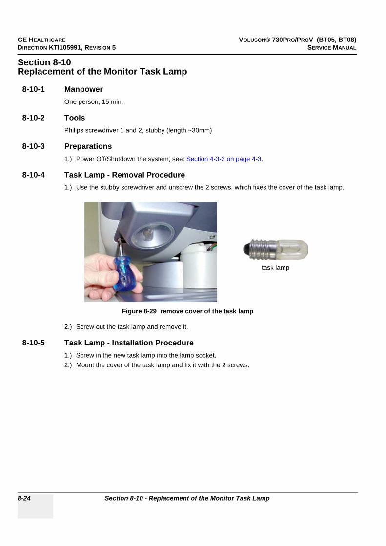
GE HEALTHCARE VOLUSON® 730PRO/PROV (BT05, BT08)DIRECTION KTI105991, REVISION 5 SERVICE MANUAL
8-24 Section 8-10 - Replacement of the Monitor Task Lamp
Section 8-10Replacement of the Monitor Task Lamp
8-10-1 ManpowerOne person, 15 min.
8-10-2 ToolsPhilips screwdriver 1 and 2, stubby (length ~30mm)
8-10-3 Preparations1.) Power Off/Shutdown the system; see: Section 4-3-2 on page 4-3.
8-10-4 Task Lamp - Removal Procedure1.) Use the stubby screwdriver and unscrew the 2 screws, which fixes the cover of the task lamp.
2.) Screw out the task lamp and remove it.
8-10-5 Task Lamp - Installation Procedure1.) Screw in the new task lamp into the lamp socket.2.) Mount the cover of the task lamp and fix it with the 2 screws.
Figure 8-29 remove cover of the task lamp
task lamp

GE HEALTHCARE VOLUSON® 730PRO/PROV (BT05, BT08)DIRECTION KTI105991, REVISION 5 SERVICE MANUAL
Chapter 8 - Replacement Procedures 8-25
Section 8-11Replacement of the Trackball top fixation ring
8-11-1 ManpowerOne person, 5 min.
8-11-2 Trackball top fixation ring - Replacement Procedure1.) Remove the fixation ring by turning it counterclockwise.
2.) Mount the fixation ring by turning it clockwise.
Section 8-12Replacement of Digipots and TGC Slider controls
8-12-1 ManpowerOne person, 5 min.
8-12-2 Toolssmall-sized slotted screwdriver or tweezers
8-12-3 Cap and/or Spring - Replacement Procedure1.) Remove the cap (for Rotation digipots or for Slider-potentiometer TGC).2.) Mount the cap (for Rotation digipots or for Slider-potentiometer TGC).
Section 8-13Replacement of the Probe Holder
8-13-1 ManpowerOne person, 1 min.
8-13-2 Probe Holder - Replacement Procedure1.) Remove the probe holder from the bottom housing of the User Interface.2.) Place the new probe holder on the bottom housing.
Figure 8-30 Trackball with top fixation ring
rotate counterclockwiseto remove the fixing ring
rotate clockwise tomount the fixing ring

GE HEALTHCARE VOLUSON® 730PRO/PROV (BT05, BT08)DIRECTION KTI105991, REVISION 5 SERVICE MANUAL
8-26 Section 8-14 - Replacement of Key Caps (by special native language keys)
Section 8-14Replacement of Key Caps (by special native language keys)
8-14-1 ManpowerOne person, 30 minutes
8-14-2 ToolsUse the removal tool which is part of the key cap kits, a commercial key removal tool, or a small-sized slotted screwdriver or tweezers.
8-14-3 Preparations1.) Power Off/Shutdown the system; see: Section 4-3-2 on page 4-3.
8-14-4 Key Caps - Removal Procedure1.) Carefully place the removal tool or a small flat screwdriver between the key cap you wish to remove
and its neighboring key cap (as shown in Figure 8-31 below). 2.) Gently lift the key cap, until it is completely loosened from its base.3.) Remove the key cap.
8-14-5 Key Caps - Installation Procedure1.) Carefully place the appropriate key cap in positionon the keyboard, taking care to place the plastic
alignment pin in the correct position so that the key cap is the right way up and reads correctly.2.) Push the key cap down until it snaps into position.3.) Power On/Boot Up the system; see: Section 4-3-1 on page 4-2.4.) Setup the Keyboard Language Layout as described in Section 6-6 on page 6-7 and then type with
the keyboard to check the function of each key.
NOTICE!! NOTICE:
Table 9-12 on page 9-16 shows the available Key Cap Kits. Keys to be removed depend on the (special native) language kit.
Figure 8-31 removal tool in place
GE HEALTHCARE VOLUSON® 730PRO/PROV (BT05, BT08)DIRECTION KTI105991, REVISION 5 SERVICE MANUAL
Chapter 8 - Replacement Procedures 8-27
Section 8-15Replacing optional Peripherals / How to mount Peripherals at a later date
NOTICE!! NOTICE:
Normally auxiliary devices and peripherals come pre-installed with the Voluson® 730Pro/ProV system.

GE HEALTHCARE VOLUSON® 730PRO/PROV (BT05, BT08)DIRECTION KTI105991, REVISION 5 SERVICE MANUAL
8-28 Section 8-15 - Replacing optional Peripherals / How to mount Peripherals at a later date
8-15-1 Mounting/Replacing the 19’’ LCD secondary “Patient” Monitor
CAUTION!! CAUTION:
The 19’’ LCD secondary “Patient” Monitor MUST NEVER be connected to the Voluson® 730Pro/ProV ultrasound Systems mains supply directly! Always connect it to the supplied Isolation Transformer! The Secondary Monitor is the only item to be connected to the Transformer!
NOTICE The 19’’ LCD secondary “Patient” Monitor is NOT intended for diagnostic use. It is an additional device used to allow the patient to watch the proceedings. Take your time to think about the best position of the monitor in your facilities. Patients should be able to view the monitor easily and without having to bend or turn around.
NOTICE DO NOT connect the 19’’ LCD secondary “Patient” Monitor to the Voluson® 730Pro/ProV via USB cable. Use the supplied VGA cable.
NOTICE For more detailed description, how to mount/replace the 19’’ LCD secondary “Patient” Monitor refer to:Section 3-5-12 "Worldwide 19’’ secondary “Patient” Monitor kit" on page 3-25

GE HEALTHCARE VOLUSON® 730PRO/PROV (BT05, BT08)DIRECTION KTI105991, REVISION 5 SERVICE MANUAL
Chapter 9 - Renewal Parts 9-1
Chapter 9Renewal Parts
Section 9-1Overview
9-1-1 Purpose of Chapter 9This chapter gives you an overview of Spare Parts available for the Voluson® 730Pro/ProV.
NOTE: Furthermore refer to SN79040, which is the best source for new FRU parts that are not yet implemented in this Service Manual.
Table 9-1 Contents in Chapter 9
Section Description Page Number
9-1 Overview 9-1
9-2 List of Abbreviations 9-2
9-3 Parts List Groups 9-3
9-4 Housing (GW) and additional Console Hardware 9-4
9-5 User Interface (GEU Top Console) 9-6
9-6 Monitor + Monitor replacement parts 9-8
9-7 Disk Drives (GEM) 9-9
9-8 Main Power Module (CPN) 9-10
9-9 Main Board Module (GEZ) 9-11
9-10 Options and Upgrades 9-16
9-11 Miscellaneous Cables 9-19
9-12 Optional Peripherals and Accessories 9-26
9-13 System Manuals 9-31
9-14 Probes 9-33
9-15 Biopsy Needle Guides 9-38

GE HEALTHCARE VOLUSON® 730PRO/PROV (BT05, BT08)DIRECTION KTI105991, REVISION 5 SERVICE MANUAL
9-2 Section 9-2 - List of Abbreviations
Section 9-2List of Abbreviations
AC Alternating CurrentADC Analog to Digital ConverterASIC Application Specific Integrated CircuitAssy AssemblyBEP Back End ProcessorCKV Video Converter BoardCPD Sub-Board on Beamformer (CPR)CPE Motherboard Extension (Backpanel I/O-Card)CPK Motherboard of GEZ-ModuleCPN Primary Power Supply ModuleCPP Power Supply Secondary Board + Motor Power stageCPR Beamformer MotherboardCPU Central Processing UnitCPV Probe Connector BoardCPY Power Switch BoardCPZ Cover BoardCRB USB to IDE Converter BoardCRS Signal Processing Board--/CRU Customer Replaceable UnitCRW CW-Doppler Board (optional)CSD Common Service DesktopDAC Digital to Analog ConverterDC Direct CurrentDSP Digital Signal ProcessingEUM Electronic User ManualFRU 1 Replacement part available in parts hubFRU 2 Replacement part available from the manufacturer (lead time involved)GEB PC-Box (Backend Processor)GEM Disk Drive module (with or without MO-Drive and MAN)GES I/O-Interface (User accessible)GEU User interface: Keyboard, EL-Display, TGC UnitGEZ Main Board Module (Ultrasound (FrontEnd) and PC-Board (Backend Processor))GW Console housing (except GEU and GEM)HDD Hard Disk DriveInt InternalI/O Input/OutputLCD Liquid Crystal DisplayMAN ECG moduleMOD Magneto Optical DiskSBC Single Board Computer (PC-Board)SMBus System Management BusSSW Service Software (Service Platform)UIS Ultrasound Application Software
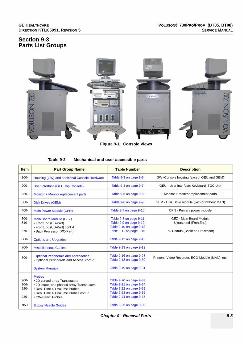
GE HEALTHCARE VOLUSON® 730PRO/PROV (BT05, BT08)DIRECTION KTI105991, REVISION 5 SERVICE MANUAL
Chapter 9 - Renewal Parts 9-3
Section 9-3Parts List Groups
Figure 9-1 Console Views
Table 9-2 Mechanical and user accessible parts
Item Part Group Name Table Number Description
100- Housing (GW) and additional Console Hardware Table 9-3 on page 9-5 GW -Console housing (except GEU and GEM)
200- User Interface (GEU Top Console) Table 9-4 on page 9-7 GEU - User interface: Keyboard, TGC Unit
250- Monitor + Monitor replacement parts Table 9-5 on page 9-8 Monitor + Monitor replacement parts
300- Disk Drives (GEM) Table 9-6 on page 9-9 GEM - Disk Drive module (with or without MAN)
400- Main Power Module (CPN) Table 9-7 on page 9-10 CPN - Primary power module
500-510-
570-
Main Board Module (GEZ)• FrontEnd (US-Part)• FrontEnd (US-Part) cont´d• Back Processor (PC-Part)
Table 9-8 on page 9-11Table 9-9 on page 9-12
Table 9-10 on page 9-13Table 9-11 on page 9-15
GEZ - Main Board ModuleUltrasound (FrontEnd)
PC-Boards (Backend Processor)
600- Options and Upgrades Table 9-12 on page 9-16
700- Miscellaneous Cables Table 9-13 on page 9-19
800- Optional Peripherals and Accessories• Optional Peripherals and Access. cont´d
Table 9-16 on page 9-28Table 9-18 on page 9-30 Printers, Video Recorder, ECG-Module (MAN), etc.
System Manuals Table 9-19 on page 9-31
900-906-920-
930-
Probes• 2D curved array Transducers• 2D linear- and phased array Transducers• Real-Time 4D Volume Probes• Real-Time 4D Volume Probes cont´d• CW-Pencil Probes
Table 9-20 on page 9-33Table 9-21 on page 9-34Table 9-22 on page 9-35Table 9-23 on page 9-36Table 9-24 on page 9-37
950 Biopsy Needle Guides Table 9-25 on page 9-39
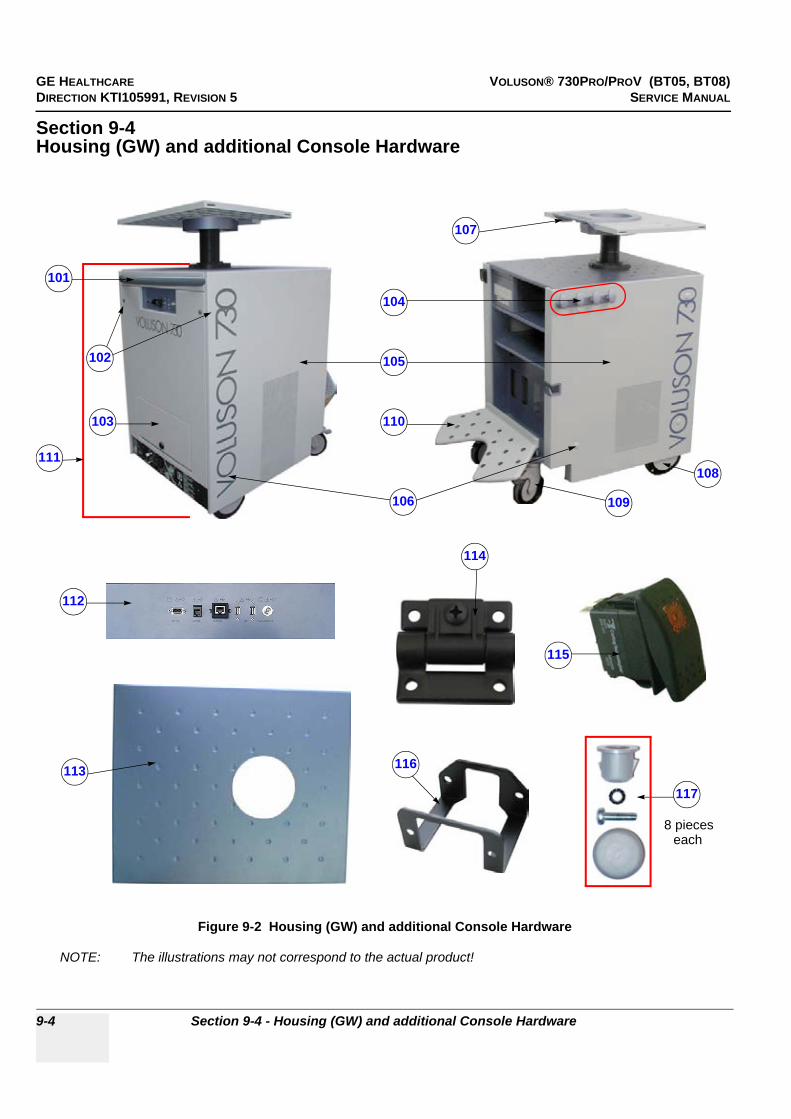
GE HEALTHCARE VOLUSON® 730PRO/PROV (BT05, BT08)DIRECTION KTI105991, REVISION 5 SERVICE MANUAL
9-4 Section 9-4 - Housing (GW) and additional Console Hardware
Section 9-4Housing (GW) and additional Console Hardware
NOTE: The illustrations may not correspond to the actual product!
Figure 9-2 Housing (GW) and additional Console Hardware
101
102
103
104
105
106
107
108
109
110
111
112
113
114
115
116
8 pieceseach
117

GE HEALTHCARE VOLUSON® 730PRO/PROV (BT05, BT08)DIRECTION KTI105991, REVISION 5 SERVICE MANUAL
Chapter 9 - Renewal Parts 9-5
Table 9-3 Housing (GW) and additional Console Hardware
Item Part Name Part Number Description Qty CRU FRU
101 Rear Handle for Trolley KTZ134468 Rear Handle for Trolley 1 Y 1
102 Blind Cap for rear screws KTZ208109 covers housing screws to make them invisible (1 pcs.) 2 Y 1
103 Rear Metal Cover Plate KTZ154728 Rear metal cover plate complete 1 N 2
104 Guide for Probe cables KTZ154736 Guide for Probe cables - optional(includes 4 hooks and mounting rail) 1 Y 1
105 Side panel Kit (left an right) KTZ154735 Side panel Kit (left and right side panel) including guide for probe cables and plastic guide 1 N 2
106 Cap Rubber (8 pcs.) KTZ154737 Cap Rubber (set includes 8 pieces) 8 Y 1
107 Monitor Mounting PlateVoluson® 730Pro/ProV
KTZ134111 Monitor mounting plate 1 N 1
108 Rear Wheel (Ø175 mm x 32) KTZ211081 Rear wheel non-steerable (1 pcs.) 2 Y 1
109 Steerable Wheel KTZ211080 Front wheel steerable (1 pcs.) 2 Y 1
110 Foot rest KTZ134467 Foot rest 1 Y 1
111 GW140 TrolleyVoluson® 730Pro/ProV
KTZ154734Housing with wheels, Power Supply (CPN), Disk Drive
Module (GEM), backpanel with connectors (GES)and cables
1 N 2
112 GES8 I/O Connection Panel KTZ195901External Rear Panel with electrical Signal- and Supply-Connection-Cables to the systems main unit (internal)
Rear-Panel.1 N 1
113 Top Cover of Trolley KTZ208119 Top Cover of Trolley 1 N 1
114 Hinge for Foot rest KTZ220018 Hinge for Foot rest (1 pcs.) 2 N 1
115 Standby Switch KTZ207125 Standby Switch left below the control panel 1 N 1
116 Pull-out Protection for Mains Power cable
KTZ154717 Pull-out Protection for Mains Power cable (incl. screws) 1 N 1
117 Side Panels Mounting Kit KTZ280046“odds and ends” side panels mounting kit incl.
sockets, lock washers, screws and rubber caps (8 pieces. each)
- Y 1
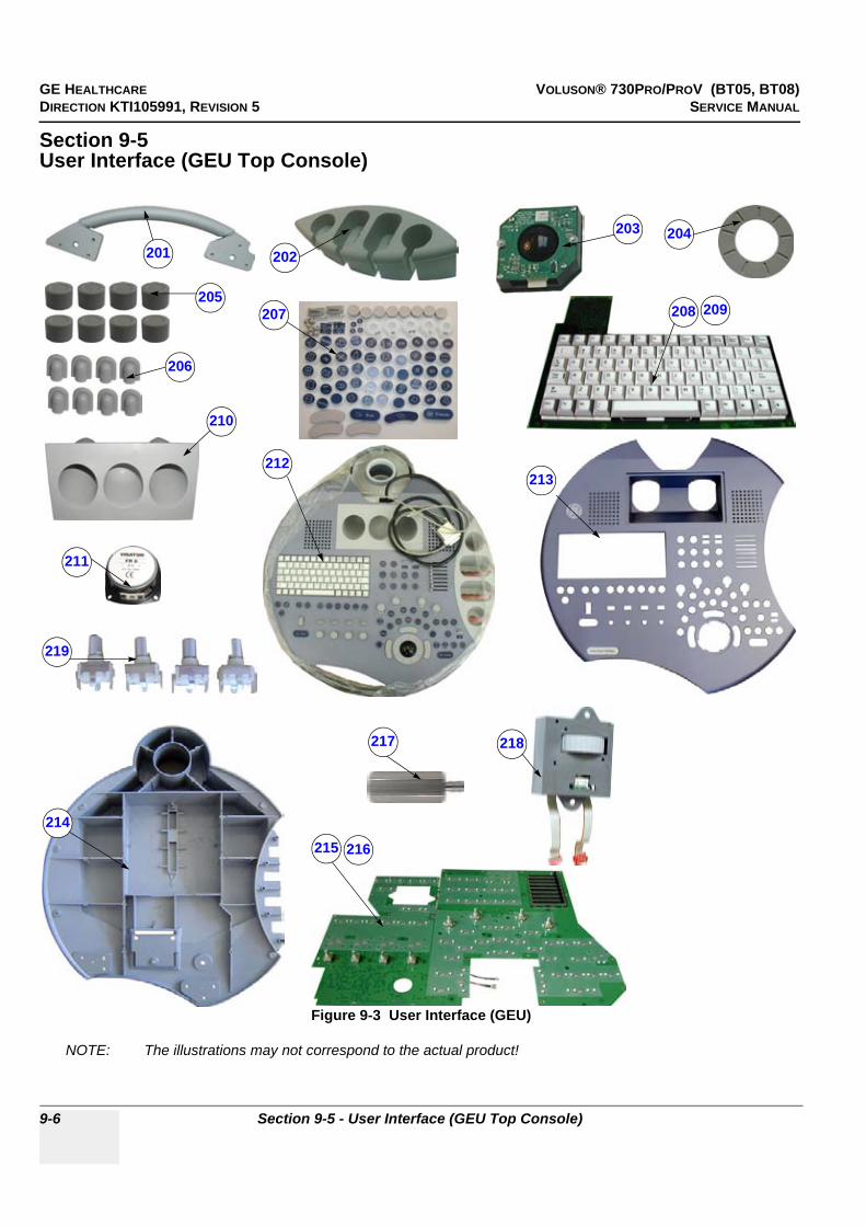
GE HEALTHCARE VOLUSON® 730PRO/PROV (BT05, BT08)DIRECTION KTI105991, REVISION 5 SERVICE MANUAL
9-6 Section 9-5 - User Interface (GEU Top Console)
Section 9-5User Interface (GEU Top Console)
NOTE: The illustrations may not correspond to the actual product!
Figure 9-3 User Interface (GEU)
202204
205
206
207 208 209
210
211
212213
214
215 216
203201
217 218
219

GE HEALTHCARE VOLUSON® 730PRO/PROV (BT05, BT08)DIRECTION KTI105991, REVISION 5 SERVICE MANUAL
Chapter 9 - Renewal Parts 9-7
Table 9-4 User Interface (GEU)
Item Part Name Part Number Description Qty CRU FRU
201 Front Handle User Interface KTZ209344 Voluson® 730Pro/ProV Front Handle, silver 1 Y 1
202 Probe Holder Kit V730 KTZ209346 right hand Probe holder part, removable 1 Y 1
203 Trackball Kit V730 KTZ208264 generates X-Y-Coordinates of Trackball-Movements like moving a PC-Mouse 1 N 1
204 Trackball top fixation ring KTZ208256 Trackball for top fixation ring 1 Y 1
205 Caps for Rotation digipots (8 pcs.) KTZ214798 Caps for Rotation digipots (set includes 8 pieces with premounted brackets)
8 Y 1
206 Caps for TGC Slide-pot. (8 pcs.) KTZ214818 Caps for TGC Slide-pot. (set includes 8 pieces with premounted brackets)
8 Y 1
207 Keytop Kit Voluson® 730Pro/ProV KTZ207558 Keytop Kit Voluson® 730Pro/ProV 1 N 1
208 Alpha-numeric keyboardV730Pro/ ProV (English)
KTZ208217
Alpha-numeric keyboard forVoluson® 730Pro/ProV English
Compatibility: can be replaced by KTZ300100, if the Hardkey board is also exchanged
1 N 1
209 Alpha-numeric keyboardV730Pro / ProV GEU70 (English)
KTZ300100
Alpha-numeric keyboard for Voluson® 730Pro/ProV English (check if special key cap kit is needed;
see: Table 9-12 on page 9-16)Compatibility: can replace KTZ208217, if the
Hardkey board is also exchanged
1 N 1
210 Gel holder Voluson® 730Pro/ProV KTZ134521 Gel holder Voluson® 730Pro/ProV 1 Y 1
211 Loudspeaker for Top Console KTZ208132 Loudspeaker on GEU User Interface (1 pcs.) 2 N 1
212 GEU70 User InterfaceVoluson® 730Pro/ProV
KTZ154730
English keyboard, trackball, special knobs, and switches (check if special key cap kit is needed;
see: Table 9-12 on page 9-16)Pay attention to use lower FRU’s like trackball, A/N
keyboard, Hardkey board, etc.
1 N 1
213 Top housing of GEU70, painted KTZ214819 Top housing of GEU70, painted, empty 1 N 1
214 Bottom housing of GEU, painted KTZ214799 Bottom housing of GEU, painted, without interior 1 N 1
215 Hard key Board for V730Pro / ProV KTZ208284
Hardkey Board(s) for Voluson® 730Pro/ProV(large board - Part A ; small board - Part B)
Compatibility: can be replaced by KTZ300098, if thealpha-numeric keyboard is also exchanged
1 N 1
216 Hard key Board for V730Pro / ProV- GEU 70
KTZ300098
Hardkey Board(s) for Voluson® 730Pro/ProV(large board - Part A ; small board - Part B)
Compatibility: can replace KTZ208284, if the alpha-numeric keyboard is also exchanged
1 N 1
217 Distance Rod for GEU KTZ14B596 Distance Rod for GEU8 1 N 1
218 Wheel control for V730Pro / ProV KTZ208257 Wheel control for Voluson® 730Pro/ProV 1 N 1
219 Digipot Set 4 pcs. KTZ280105 Digipot Set 4 pcs. 1 N 1

GE HEALTHCARE VOLUSON® 730PRO/PROV (BT05, BT08)DIRECTION KTI105991, REVISION 5 SERVICE MANUAL
9-8 Section 9-6 - Monitor + Monitor replacement parts
Section 9-6Monitor + Monitor replacement parts
NOTE: The illustrations may not correspond to the actual product!
Figure 9-4 Monitor + Monitor replacement parts
Table 9-5 Monitor + Monitor replacement parts
Item Part Name Part Number Description Qty CRU FRU
250 Color Monitor 15” Painted KTZ212115 AY-15CUI Color Image Monitor, lacquered 1 N 1
251 Monitor Base Cover KTZ134474 Monitor Base Cover, silver colored 1 N 1
252 Monitor Mounting Set KTZ154713 Monitor Mounting Set (fixing part for Monitor) 1 N 1
253 Set Monitor Front Housing KTZ208445 Set Monitor Front Housing (incl. cover of task lamp) 1 N 1
254 Set Monitor Housing KTZ208446 Set Monitor Housing (left-, right-, and top cover) 1 N 1
255 Monitor Switch Assembly 2300008 Common part with L5 and L3 1 N 1
256 Task Lamp 2317347 Common part with L5 and L3 1 N 1
250 251
253
254255
256
252
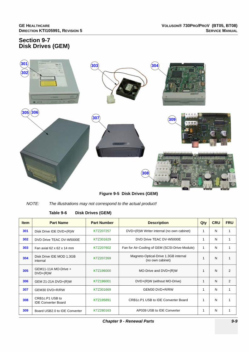
GE HEALTHCARE VOLUSON® 730PRO/PROV (BT05, BT08)DIRECTION KTI105991, REVISION 5 SERVICE MANUAL
Chapter 9 - Renewal Parts 9-9
Section 9-7Disk Drives (GEM)
NOTE: The illustrations may not correspond to the actual product!
Figure 9-5 Disk Drives (GEM)
Table 9-6 Disk Drives (GEM)
Item Part Name Part Number Description Qty CRU FRU
301 Disk Drive IDE DVD+(R)W KTZ207257 DVD+(R)W Writer internal (no own cabinet) 1 N 1
302 DVD Drive TEAC DV-W5000E KTZ301629 DVD Drive TEAC DV-W5000E 1 N 1
303 Fan axial 62 x 62 x 14 mm KTZ207602 Fan for Air-Cooling of GEM (SCSI-Drive-Module) 1 N 1
304 Disk Drive IDE MOD 1.3GB internal
KTZ207269 Magneto-Optical-Drive 1.3GB internal(no own cabinet) 1 N 1
305 GEM11-11A MO-Drive + DVD+(R)W
KTZ196000 MO-Drive and DVD+(R)W 1 N 2
306 GEM 21-21A DVD+(R)W KTZ196001 DVD+(R)W (without MO-Drive) 1 N 2
307 GEM30 DVD+R/RW KTZ301669 GEM30 DVD+R/RW 1 N 1
308 CRB1c.P1 USB to IDE Converter Board
KTZ195891 CRB1c.P1 USB to IDE Converter Board 1 N 1
309 Board USB2.0 to IDE Converter KTZ280163 AP039 USB to IDE Converter 1 N 1
301
302303 304
305 306307
308
309

GE HEALTHCARE VOLUSON® 730PRO/PROV (BT05, BT08)DIRECTION KTI105991, REVISION 5 SERVICE MANUAL
9-10 Section 9-8 - Main Power Module (CPN)
Section 9-8Main Power Module (CPN)
NOTE: The illustrations may not correspond to the actual product!
Figure 9-6 Main Power Module (CPN)
Table 9-7 Main Power Module (CPN)
Item Part Name Part Number Description Qty CRU FRU
401 CPN80-81 Power Supply Module KTZ207486 CPN80 Power Supply Module 1 N 1
402 CPY80.P1 Power Switch KTZ209338 Board to switch on and shut downUltrasound System 1 N 1
403 CCF100.P1 Power Primary Board KTZ209339 Power Primary Board 1 N 1
404 Mains Power switch and Input connector KTZ209340 Mains Power Switch and Input Connector 1 N 1
405 Fuses 16 Ampere 6.3 x 32 (10 pcs.) KTZ209341 used at primary and secondary side (10 pcs.) 3 Y 1
406 Fuses 3.2 Ampere 6.3 x 32 (10 pcs.) KTZ209342 fuse for auxiliary power output at 110V setting (10 pcs.) 1 Y 1
407 Fuses 1.6 Ampere 6.3 x 32 (10 pcs.) KTZ209343 fuse for auxiliary power output at 230V setting (10 pcs.) 1 Y 1
408 KVN2 - Fan for Primary Power Supply KTZ195440 KVN2 - Fan for Primary Power Supply (CPN) 1 N 1
409 Fuse Holder Set (4 pcs.) KTZ280062 Fuse Hoder Set (4 pcs.) 1 N 1
401
402
403
404
405 406 407408
409

GE HEALTHCARE VOLUSON® 730PRO/PROV (BT05, BT08)DIRECTION KTI105991, REVISION 5 SERVICE MANUAL
Chapter 9 - Renewal Parts 9-11
Section 9-9Main Board Module (GEZ)
NOTE: The illustrations may not correspond to the actual product!
Figure 9-7 Main Board Module (GEZ)
Table 9-8 Main Board Module (GEZ)
Item Part Name Part Number Description Qty CRU FRU
501 Fan for GEZ-box - FrontEnd (2 fan) KTZ154738 Fan for GEZ-box - FrontEnd (2 fan) 1 N 1
502 Fan for GEB-PC-box - BackEnd (2 fan) KTZ154748 Fan for GEB-PC-box - BackEnd (2 fan) 1 N 1
501502

GE HEALTHCARE VOLUSON® 730PRO/PROV (BT05, BT08)DIRECTION KTI105991, REVISION 5 SERVICE MANUAL
9-12 Section 9-9 - Main Board Module (GEZ)
9-9-1 FrontEnd (US-Part)
NOTE: The illustrations may not correspond to the actual product!
Figure 9-8 FrontEnd (US-Part)
Table 9-9 FrontEnd (US-Part)
Item Part Name Part Number Description Qty CRU FRU
511 CPR82.P11 Beam former Board KTZ196024 Beam former Board 1 N 1
512 CRW3.P2 CW Doppler Board KTZ196086 CW-Doppler Board (can be replaced by CRW4,if SW 5.2.0 or higher is installed) 1 N 1
513 CRW4.P2 CW Doppler Board KTZ196306 CW-Doppler BoardSW 5.2.0 or higher is required 1 N 1
514 CPZ50-50a.P3 Cover Board KTZ195592electrical signal connection between CPV,CPR
and CW-Board; contains Relays for Signalto CW-Board.
1 N 1
515 CRS5.P3 Signal Processing Board KTZ196074 Signal Processing Board (can replace CRS22) 1 N 1
516 CRS22B.P8 Signal Processing Board KTZ300428 Signal Processing Board (can replace CRS5)SW 5.0.4 or higher is required 1 N 1
511
512
513
514
515
516

GE HEALTHCARE VOLUSON® 730PRO/PROV (BT05, BT08)DIRECTION KTI105991, REVISION 5 SERVICE MANUAL
Chapter 9 - Renewal Parts 9-13
9-9-1 FrontEnd (US-Part) (cont’d)
NOTE: The illustrations may not correspond to the actual product!
Figure 9-9 FrontEnd (US-Part) cont´d
Table 9-10 FrontEnd (US-Part) cont´d
Item Part Name Part Number Description Qty CRU FRU
518 CPK95.P8 Motherboard V730 KTZ196053 Electrical Signal- and Supply-Connection for all boards 1 N 1
519 CPP90a.P2 Power Supply Board KTZ208498 Power Supply Board Output Power: 900 W 1 N 1
520 CPV90a.P6 Module Board KTZ196063 Probe Connector Board, Module Board 1 N 1
518
519
520

GE HEALTHCARE VOLUSON® 730PRO/PROV (BT05, BT08)DIRECTION KTI105991, REVISION 5 SERVICE MANUAL
9-14 Section 9-9 - Main Board Module (GEZ)
9-9-2 BackEnd Processor (PC-Part)
NOTE: The illustrations may not correspond to the actual product!
Figure 9-10 Back Processor (PC-Part)
571
572
573
574
575 577
578
576
579
GE HEALTHCARE VOLUSON® 730PRO/PROV (BT05, BT08)DIRECTION KTI105991, REVISION 5 SERVICE MANUAL
Chapter 9 - Renewal Parts 9-15
* If the stock of CKV85.P7 VIDEOMANAGEMENT BOARD will be empty,the CKV86.P8 VIDEOMANAGEMENT BOARD will come automatically
**Using of HDD-Holder complete (KTZ302126) is necessary for 160GB HDD and higher.
***The currently installed Single Board Computer (PC-Board) is shown in the System Setup - System Info page; see: Figure 7-1 on page 7-2, SLOT_CPU: TYAN or KONTRON ATX, DFI ATX or Kontron Flex.
Table 9-11 Back Processor (PC-Part)
Item Part Name Part Number Description Qty CRU FRU
571 CKV85-86 Video management Board*
KTZ208497 PC-Video converter Board 1 N 1
572 CPE80.P5 Motherboard - Extension KTZ195902 Motherboard Extension 1 N 1
573Universal Hard disk for allVoluson 730 (V730, V730Expert and V730Pro) systems
KTZ196003 Universal Hard disk (Maxtor or Western digital)System/Boot DVD (see: Table 9-12) is required 1 N 1
574 HDD-Holder complete** KTZ302126 HDD-Holder complete for 160GB HDDand higher 1 N 1
575 Lithium Battery CR2032 (3V) KTZ208791 Lithium Battery CR2032 (3V) for SBC-Board 1 N 1
576SBC “Kontron ATX” Kit (BT05, BT08) incl. housing
KTZ208599
Kit contains ATX Motherboard (“Kontron”) Pentium IV chip, CPU cooler,
1Gb RAM, Serial Slot (used only with Kontron types), Serial interface cable, Power Cable Set ATX
Fans, USB cable (without HDD and ADD).Can replace “Tyan ATX” types, but system “C:”
image MUST be loaded! In this case, System/Boot DVD (see: Table 9-12) is required
1 N 1
577SBC “Kontron Flex” Kit(BT05, BT08) incl. housing
KTZ300633
Kit contains ATX Motherboard (“Kontron Flex”) Pentium IV chip, CPU cooler, 1 Gb RAM, SATA cable, SATA to IDE converter, Power cable set ATX, Fans, USB cable (without HDD and ADD).Can replace “Tyan ATX, Kontron ATX, DFI ATX” types, but system “C:” image MUST be loaded! In this case, System/Boot DVD (see: Table 9-12) is
required
1 N 1
578 ADD2-DVI card for “Kontron” SBC-board ***
KTZ208615 ADD2-DVI (Add-On) card for “Kontron” ATX onlycan be replaced by KTZ208588 1 N 1
579 ADD2-DVI card*** KTZ208588 ADD2-DVI (Add-On) card, can be used at both PC-board versions (Kontron and Tyan) 1 N 1

GE HEALTHCARE VOLUSON® 730PRO/PROV (BT05, BT08)DIRECTION KTI105991, REVISION 5 SERVICE MANUAL
9-16 Section 9-10 - Options and Upgrades
Section 9-10Options and Upgrades
Table 9-12 Options and Upgrades
Item Part Name Part Number Description Qty CRU FRU
601
System/Boot DVD(SW 5.4.0, BT08)Note: Refer to SN79009, which is the best source for the latest revision
KTZ280060
bootable DVD for System HDD recoveryContents: SP with newest MS Patches, Linux rescue partition, System C: Image (Windows 2000, Kontron SBC + Tyan SBC supplied), UISApp, Backup, EUM,
Database Repair Tool, etc.
1 Y 1
602
System/Boot DVD(SW 5.4.1-Rev.B, BT05/BT08) Note: Refer to SN79009, which is the best source for the latest revision
KTZ280120
bootable DVD for System HDD recoveryContents: SP with newest MS Patches, Linux rescue partition, System C: Image (Windows 2000, Kontron
Flex SBC + DFI ATX SBC supplied), UISApp, Backup, EUM, Database Repair Tool, etc.,
(incl. 3 DVD’s)
1 Y 1
603
System/Boot DVD(SW 5.4.2, BT05/BT08)Note: Refer to SN79009, which is the best source for the latest revision
KTZ280129
bootable DVD for System HDD recoveryContents: SP with newest MS Patches, Linux rescue partition, System C: Image (Windows 2000, Kontron
Flex SBC + DFI ATX SBC supplied), UISApp, Backup, EUM, Database Repair Tool, etc.,
(incl. 3 DVD’s)
1 Y 1
604
System/Boot DVD (SW 5.4.3, BT05/BT08)Note: Refer to SN79009, which is the best source for the latest revision
KTZ280181
bootable DVD for System HDD recoveryContents: SP with newest MS Patches, Linux rescue partition, System C: Image (Windows 2000, Kontron
Flex SBC + DFI ATX SBC supplied), UISApp, Backup, EUM, Database Repair Tool, etc.,
(incl. 3 DVD’s)
1 Y 1
605
System/Boot DVD(SW 5.4.5, BT05/BT08)Note: Refer to SN79009, which is the best source for the latest revision
KTZ280188
bootable DVD for System HDD recoveryContents: SP with newest MS Patches, Linux rescue partition, System C: Image (Windows 2000, Kontron
Flex SBC + DFI ATX SBC supplied), UISApp, Backup, EUM, Database Repair Tool, etc.,
(incl. 3 DVD’s)
1 Y 1
606
System/Boot DVD(SW 5.4.6, BT05/BT08)Note: Refer to SN79009, which is the best source for the latest revision
KTZ280198
bootable DVD for System HDD recoveryContents: SP with newest MS Patches, Linux rescue partition, System C: Image (Windows 2000, Kontron
Flex SBC + DFI ATX SBC supplied), UISApp, Backup, EUM, Database Repair Tool, etc.,
(incl. 3 DVD’s)
1 Y 1
607 Patch DVD Voluson® 730Pro/ProV (MS08-067)
KTZ280115 Microsoft Vulnerability Patch CD (MS08-067) 1 Y 1
608Voluson® 730Pro BT05 -> Voluson® 730Pro BT08Upgrade Kit
H48671DZ BT08 Upgrade kit (incl. System DVD, Manuals, etc.) - N N
609Voluson® 730ProV BT05 -> Voluson® 730ProV BT08 Upgrade Kit
H48671E BT08 Upgrade kit (incl. System DVD, Manuals, etc.) - N N
610Voluson® 730ProV BT05 -> Voluson® 730Pro BT08 Upgrade Kit
H48671BH BT08 Upgrade kit (incl. System DVD, Manuals, etc.) - N N
611 Upgrade to new SW Voluson® 730Pro/ProV BT05/08 VERSI
H48681AB Upgrade kit includes actually BT05/08 SW Version - N N

GE HEALTHCARE VOLUSON® 730PRO/PROV (BT05, BT08)DIRECTION KTI105991, REVISION 5 SERVICE MANUAL
Chapter 9 - Renewal Parts 9-17
612 Real Time 4D Biopsy H48651GB encrypted Software Option string (password) which is specific for each Voluson® 730Pro/ProV system - N N
613 Real Time 4D H48651GC encrypted Software Option string (password) which is specific for each Voluson® 730Pro system - N N
614 VOCAL II - Volume Calculation H48651GD encrypted Software Option string (password) which is specific for each Voluson® 730Pro system - N N
615VCI - Volume Contrast Imaging
BT Version:BT-Version:
H48651GE
encrypted Software Option string (password) which is specific for each Voluson® 730Pro system
(BT05 only)This feature is standard at BT08 systems (SW 5.4.x).
- N N
616 Interface for DICOM 3 standard H48651GF encrypted Software Option string (password) which is specific for each Voluson® 730Pro system - N N
617 Interface for DICOM 3 standard H48651HH encrypted Software Option string (password) which is specific for each Voluson® 730ProV system - N N
618 SRI - Speckle Reduction Imaging H48651GH encrypted Software Option string (password) which is specific for each Voluson® 730Pro system - N N
619 TUI - Tomographic Ultrasound Imaging
H48651GJ encrypted Software Option string (password) which is specific for each Voluson® 730Pro system - N N
620 STIC H48651JS encrypted Software Option string (password) which is specific for each Voluson® 730Pro system - N N
621 SRI II - Speckle Reduction Imaging H48651NGencrypted Software Option string (password) which is
specific for each Voluson® 730Pro systemSoftware 5.0.3 or higher is required.
- N N
622 XTD View (Extended View) H48651PJencrypted Software Option string (password) which is
specific for each Voluson® 730Pro systemSoftware 5.2.0 or higher is required.
- N N
623 XTD View (Extended View) H48651PL encrypted Software Option string (password) which is specific for each Voluson® 730ProV system - N N
624 Fetal Echo Package H48671EGencrypted Application Package string (password)
which is specific for each Voluson® 730Pro system (BT08 only)
- N N
625 Gyn Package H48671EHencrypted Application Package string (password)
which is specific for each Voluson® 730Pro system (BT08 only)
- N N
626 Breast Package H48671EJencrypted Application Package string (password)
which is specific for each Voluson® 730Pro system (BT08 only)
- N N
627 4D View PC Software
H48651FB (BT05)
H48651SZ (BT08)
stand alone PC-Software which can be used to view and work on data produced with Kretztechnik´s
Voluson® 730Pro/ProV Ultrasound system- N N
628 CW-Doppler Upgrade Kit external H48651HE CW-Doppler Upgrade Kit incl. upgrade instructions N N 1
629 Key Cap Kit - Swedish H48651ED kit includes special native language keys N Y 1
630 Key Cap Kit - Danish H48651EE kit includes special native language keys N Y 1
631 Key Cap Kit - Norwegian H48651EF kit includes special native language keys N Y 1
Table 9-12 Options and Upgrades
Item Part Name Part Number Description Qty CRU FRU
GE HEALTHCARE VOLUSON® 730PRO/PROV (BT05, BT08)DIRECTION KTI105991, REVISION 5 SERVICE MANUAL
9-18 Section 9-10 - Options and Upgrades
632 Key Cap Kit - Finnish H48651EG kit includes special native language keys N Y 1
633 Key Cap Kit - Spanish H48651EH kit includes special native language keys N Y 1
634 Key Cap Kit - French H48651JD kit includes special native language keys N Y 1
635 Key Cap Kit - German H48651JE kit includes special native language keys N Y 1
636 Key Cap Kit - Italian H48651JF kit includes special native language keys N Y 1
NOTICE!! NOTICE:
A sales order has to be obtained for item 608 - 636!Software Options (item 612 - 627): Once the order has been processed, the option string can be either entered by the customer or Applications support.
BT Version:BT-Version:
"VCI" is optional at BT05 Voluson® 730Pro systems. However, at BT08 systems (SW5.4.x installed), or systems that were upgraded to BT08 via upgrade kit, this feature is standard. A software only update (no new BT-version key) does NOT activate this feature. It remain optional and can be obtained via sales order.
BT Version:BT-Version:
Application Packages are only available for Voluson® 730Pro systems with BT08 software (SW 5.4.x). For more details see: Table 5-2, “Software Options & Application Packages,” on page 5-15.
Table 9-12 Options and Upgrades
Item Part Name Part Number Description Qty CRU FRU

GE HEALTHCARE VOLUSON® 730PRO/PROV (BT05, BT08)DIRECTION KTI105991, REVISION 5 SERVICE MANUAL
Chapter 9 - Renewal Parts 9-19
Section 9-11Miscellaneous Cables
Table 9-13 Miscellaneous Cables
Item Part Name Part Number Description Qty CRU FRU
701 Adapter Cable PS2 Y-splitter KTZ208585
Splits the PS2 connector for GEU User Interface(mouse and PC-keyboard
1 Y 1
702 Power Cable for Harddisk KTZ212401
Power cable for Harddisk 4pin
1 Y 1
703 Cable ATX 12Volt KTZ212267
HDD power connector to Pentium4 power connector
1 Y 1
704 Cable ATA CKV -> CPK board (40 pin)
KTZ212453
Flat cable(s) from CKV to CPK board, 40pin (1 pcs.)
3 N 1

GE HEALTHCARE VOLUSON® 730PRO/PROV (BT05, BT08)DIRECTION KTI105991, REVISION 5 SERVICE MANUAL
9-20 Section 9-11 - Miscellaneous Cables
705 Cable RS-232 Loop KTZ208617
Serial Interface Cable (only used in combination with “Kontron” SBC-boards)
1 Y 1
706 Power Cable Set ATX
KTZ208591
Power connection cable from CPP-board to Pentium IV SBC (Tyan only) and to the Hard disk
1
N
1
KTZ220417
Power connection cable from CPP-board to Pentium IV SBC and to the Hard disk (can be used at both
PC-board versions, Kontron and Tyan)
N
707 Cable Stereo Jack - Chinch KTZ212074
Cable from PC-Sound-StereoJack to External Rear Panel
1 Y 1
Table 9-13 Miscellaneous Cables
Item Part Name Part Number Description Qty CRU FRU

GE HEALTHCARE VOLUSON® 730PRO/PROV (BT05, BT08)DIRECTION KTI105991, REVISION 5 SERVICE MANUAL
Chapter 9 - Renewal Parts 9-21
708 Data Cable HDD ATA66/100 KTZ208147
Data cable for IDE-Hard disk 40pin
1 N 1
709 GES8 I/O Connection Panel KTZ195901
External Rear Panel with electrical Signal- and Supply-Connection-Cables to the Voluson® 730Pro/ProV Main-
Unit (internal) Rear-Panel.
1 N 1
710 KGS10 Cable PowerGEM-GEZ
KTZ195464
Electrical Power-Supply for Drives (5V/12V)
1 N 1
711 KUG5 Remote Cable KTZ195606
VCR -Remote Control Cable
1 N 1
712 KVS2 Cable Serial Interface KTZ195717
electrical-Signal-Connection between CRS and SBC (only used in combination with “Tyan” SBC-boards)
1 N 1
713 KVX1 Network Cable KTZ212016
Cable from external rear Panel to the Voluson® 730Pro/ProV Main-Unit (internal) rear-Panel 1m
1 N 1
Table 9-13 Miscellaneous Cables
Item Part Name Part Number Description Qty CRU FRU
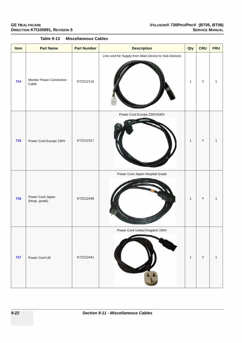
GE HEALTHCARE VOLUSON® 730PRO/PROV (BT05, BT08)DIRECTION KTI105991, REVISION 5 SERVICE MANUAL
9-22 Section 9-11 - Miscellaneous Cables
714 Monitor Power Connection Cable
KTZ212116
Line cord for Supply from Main-Device to Sub-Devices
1 Y 1
715 Power Cord Europe 230V KTZ212317
Power Cord Europe 230V/240V
1 Y 1
716 Power Cord Japan(Hosp. grade)
KTZ212448
Power Cord Japan Hospital Grade
1 Y 1
717 Power Cord UK KTZ212441
Power Cord United Kingdom 240V
1 Y 1
Table 9-13 Miscellaneous Cables
Item Part Name Part Number Description Qty CRU FRU

GE HEALTHCARE VOLUSON® 730PRO/PROV (BT05, BT08)DIRECTION KTI105991, REVISION 5 SERVICE MANUAL
Chapter 9 - Renewal Parts 9-23
718 Power Cord USA (Hosp.grade)
KTZ212402
Power Cord USA Hospital Grade
1 Y 1
719 Power Cord India KTZ212452
Power Cord India
1 Y 1
720 Power Cord - China KTZ212451
Power Cord China
1 Y 1
721 Power Cord - Brazil KTZ280186
Power Cord Brazil
1 Y 1
Table 9-13 Miscellaneous Cables
Item Part Name Part Number Description Qty CRU FRU
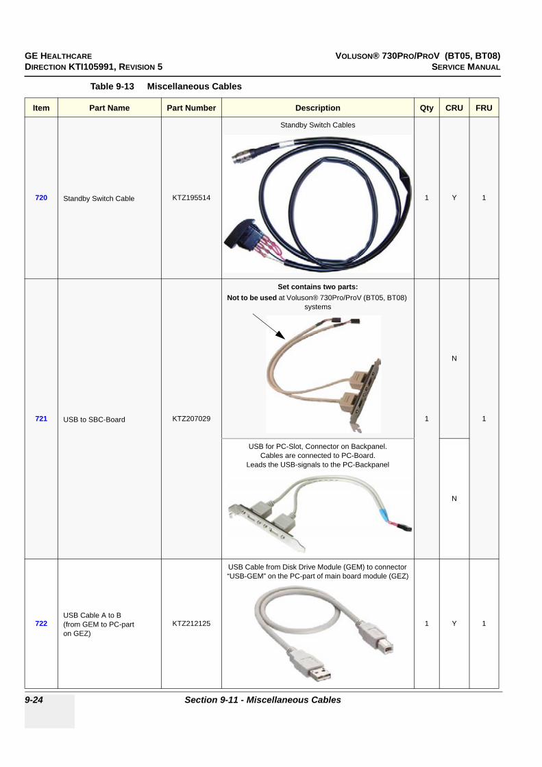
GE HEALTHCARE VOLUSON® 730PRO/PROV (BT05, BT08)DIRECTION KTI105991, REVISION 5 SERVICE MANUAL
9-24 Section 9-11 - Miscellaneous Cables
720 Standby Switch Cable KTZ195514
Standby Switch Cables
1 Y 1
721 USB to SBC-Board KTZ207029
Set contains two parts:Not to be used at Voluson® 730Pro/ProV (BT05, BT08)
systems
1
N
1
USB for PC-Slot, Connector on Backpanel. Cables are connected to PC-Board.
Leads the USB-signals to the PC-Backpanel
N
722USB Cable A to B (from GEM to PC-parton GEZ)
KTZ212125
USB Cable from Disk Drive Module (GEM) to connector “USB-GEM” on the PC-part of main board module (GEZ)
1 Y 1
Table 9-13 Miscellaneous Cables
Item Part Name Part Number Description Qty CRU FRU

GE HEALTHCARE VOLUSON® 730PRO/PROV (BT05, BT08)DIRECTION KTI105991, REVISION 5 SERVICE MANUAL
Chapter 9 - Renewal Parts 9-25
723 VGA cable HD15-HD15 KTZ212275
VGA cable HD15-HD15
1 Y 1
724Cable TMDS(Digital Video cable from Add-On DVI Output to CKV)
KTZ208574
Cable TMDS (Digital Video Cable from ADD-On DVI Output to CKV)
1 N 1
725 USB -> RS-232 Adapter (Modem Data Cable)
KTZ212114
USB -> -RS-232 AdapterData Cable for (optional) Global Modem
1 Y 1
726 Power Connection Cable KTZ212032
Power Connection Cable
1 Y 1
Table 9-13 Miscellaneous Cables
Item Part Name Part Number Description Qty CRU FRU
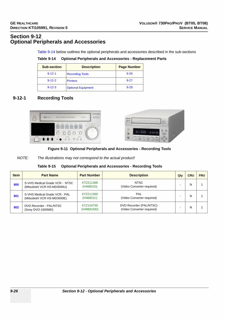
GE HEALTHCARE VOLUSON® 730PRO/PROV (BT05, BT08)DIRECTION KTI105991, REVISION 5 SERVICE MANUAL
9-26 Section 9-12 - Optional Peripherals and Accessories
Section 9-12Optional Peripherals and Accessories
Table 9-14 below outlines the optional peripherals and accessories described in the sub-sections
9-12-1 Recording Tools
NOTE: The illustrations may not correspond to the actual product!
Table 9-14 Optional Peripherals and Accessories - Replacement Parts
Sub-section Description Page Number
9-12-1 Recording Tools 9-26
9-12-2 Printers 9-27
9-12-3 Optional Equipment 9-29
Figure 9-11 Optional Peripherals and Accessories - Recording Tools
Table 9-15 Optional Peripherals and Accessories - Recording Tools
Item Part Name Part Number Description Qty CRU FRU
800 S-VHS Medical Grade VCR - NTSC(Mitsubishi VCR HS-MD3000U)
KTZ211368(H46801D)
NTSC(Video Converter required) - N 1
801 S-VHS Medical Grade VCR - PAL(Mitsubishi VCR HS-MD3000E)
KTZ211369(H46801C)
PAL(Video Converter required) - N 1
802 DVD Recorder - PAL/NTSC(Sony DVO-1000MD)
KTZ154759(H48651ND)
DVD Recorder (PAL/NTSC)(Video Converter required) - N 1

GE HEALTHCARE VOLUSON® 730PRO/PROV (BT05, BT08)DIRECTION KTI105991, REVISION 5 SERVICE MANUAL
Chapter 9 - Renewal Parts 9-27
9-12-2 Printers
NOTE: The illustrations may not correspond to the actual product!
Figure 9-12 Optional Peripherals and Accessories - Printers
803 804 805
806 807
808
810811
812813
814
809
815
816
817
818

GE HEALTHCARE VOLUSON® 730PRO/PROV (BT05, BT08)DIRECTION KTI105991, REVISION 5 SERVICE MANUAL
9-28 Section 9-12 - Optional Peripherals and Accessories
Table 9-16 Optional Peripherals and Accessories - Printers
Item Part Name Part Number Description Qty CRU FRU
803 Sony B/W Video PrinterUP-895MD (CE)
KTZ211332(H46801A) Analog B/W Video Printer NTSC/PAL - N 1
804 PPP55 Connection Set KTZ195643 Connection Set UP-895MD - N 1
805 Digital B/W Video Printer (Sony UP-D897)
KTZ220507(H48651ML) Digital Black&White Video Printer (USB-Port) - N 1
806 Mitsubishi B/W Printer P95DKTZ302617(H48681TH) Mitsubishi B/W Printer P95D - N 1
807 Sony Digital Color PrinterUP-D23MD
KTZ211373(H46831B) USB-Port - N 1
808 PZP60 Connection Set KTZ195776 Connection Set UP-D23MD - N 1
809 Digital Color Printer (Sony UP-D25MD)
KTZ211373(H46831B) Digital Color Printer (USB-Port) - N 1
810 Mitsubishi Color Printer CP30DKTZ302616(H48681TJ) Mitsubishi Color Printer CP30D - N 1
811
Line Printer (Bluetooth)HP 5600 Series orOlivetti Job Jet 210 (license product of HP)
KTZ211503(H46631L)
(Bluetooth Connection Set KTZ196002 is required)replaced by KTZ220510 - N 1
812 Line Printer Bluetooth(HP 5940)
KTZ220510(H48651WE)
Line Printer Bluetooth (USB-Port) without cartridge(Bluetooth Connection Set KTZ196002 is required)
can be replaced by Canon printer KTZ300182- N 1
813 Line Printer Bluetooth(e.g., HP Officejet H470)
KTZ300182(H48661MT)
Line Printer Bluetooth incl. Ink, Bluetooth Adapters + power cable US and EU - N 1
814 Line Printer Bluetooth (Canon Pixma MP600/MP610)
Line Printer Bluetooth incl. Ink, Bluetooth Adapters + power cable US and EU
(replaces HP printer KTZ220510)- N 1
815 Line Printer Bluetooth(Canon Pixma MP550)
Line Printer Bluetooth incl. Ink, Bluetooth Adapters + power cable US and EU
(replaces Canon MP600/MP610)- N 1
816 Bluetooth Connection SetKTZ196002(H46631M)
Bluetooth Connection Set (HP 5600 Series and Olivetti Job Jet 210 only) - N 1
817 Line Printer Destination SetKTZ280057
(H48661MW)Line printer power cable set for US, EU and ROW
(rest of world) - N 1
818 PRR50 Connection Set KTZ195492 Connection Set for VCR without remote control - N 1
819 Canon Driver Kit KTZ280123 Driver-DVD for easy installation Bluetooth Canon Pixma (808) - N 1
BT Version:BT-Version:
The Digital B/W Video Printer “UP-D897” is only applicable at systems with BT08 software (SW 5.4.x).

GE HEALTHCARE VOLUSON® 730PRO/PROV (BT05, BT08)DIRECTION KTI105991, REVISION 5 SERVICE MANUAL
Chapter 9 - Renewal Parts 9-29
9-12-3 Optional Equipment
NOTE: The illustrations may not correspond to the actual product!
Figure 9-13 Optional Peripherals and Accessories
Table 9-17 Optional Peripherals and Accessories cont´d
Item Part Name Part Number Description Qty CRU FRU
820 19” LCD Secondary Monitor KTZ220525 19” LCD Secondary “Patient” Monitor without Wall Mount kit and Isolation Transformer - Y 2
821 Isolation Transformer kit H48671WNIsolation Transformer kit for Secondary Monitor incl. power cord set for US, EU and ROW (rest of world), monitor power cable, fuses, documentation, etc.
- Y -
822 Isolation Transformer KTZ220714 Isolation Transformer without cables, etc. - Y 1
823 Fuses for Isolation Transformer KTZ196333 Fuses for Isolation Transformer(2AT, 4AT; 10 pcs. each = 20) - Y 1
824 Wall Mount kitfor 19” LCD Secondary Monitor
KTZ220526 Wall Mount kit for 19” LCD Secondary Monitor - N 2
825 19” LCD Secondary Monitor kit H48671EM 19” LCD Secondary “Patient” Monitor incl.Wall Mount kit, Isolation Transformer, cables, etc. - Y -
820821
822
823
824
825

GE HEALTHCARE VOLUSON® 730PRO/PROV (BT05, BT08)DIRECTION KTI105991, REVISION 5 SERVICE MANUAL
9-30 Section 9-12 - Optional Peripherals and Accessories
9-12-3 Optional Equipment (cont’d)
NOTE: The illustrations may not correspond to the actual product!
Figure 9-14 Optional Peripherals and Accessories cont´d
Table 9-18 Optional Peripherals and Accessories cont´d
Item Part Name Part Number Description Qty CRU FRU
830 Foot switch (MFT7)KTZ195446(H46681D) Foot switch - Y 1
831 ECG-preamplifier (MAN 6)KTZ154644(H46681H)
consists of ECG-preamplifier and patient connection cable - N 1
832 Global Modem (Analog)2245794
(H48651HF)Global Modem analog (Common Part with L9 and V7)
use modem cable: KTZ212114 + KTZ212032 - N 1
833 USB-RS232 Connection kit PRYKTZ195858(H46681S)
Converter from USB to RS-232 Serial Port(Connection Module - Report data) - N 1
834 Touch-up Paint Set (gray-blue) KTZ154680 contains blue, dark-gray, bright-gray and black4x 2cl bottles incl. brush - N 1
835 RIC-Holder KTZ225469 Probe holder used for Real-time 4D endocavity probes (RIC) during disinfection process - Y 1
DVD+RW Disk blankKTZ196204(H48641D) DVD+RW Disk (re-writable) - Y 1
MO Disk Media 1.3GBKTZ207077(H46681M) MO-Disk Media (Standard) - Y 1
830831 832
833
834 835

GE HEALTHCARE VOLUSON® 730PRO/PROV (BT05, BT08)DIRECTION KTI105991, REVISION 5 SERVICE MANUAL
Chapter 9 - Renewal Parts 9-31
Section 9-13System Manuals
Table 9-19 System Manuals
Item Part Name Part Number Kretz #
Voluson® 730Pro/ProV (BT05, BT08) Service Manual KTI105991 KTI105991
System User Manuals
Basic User Manual, Voluson® 730Pro/ProV (BT05, BT08), English H48651FR KTI105974
Basic User Manual, Voluson® 730Pro/ProV (BT05, BT08), German H48651FS KTI105978
Basic User Manual, Voluson® 730Pro/ProV (BT05, BT08), Spanish H48651FT KTI105979
Basic User Manual, Voluson® 730Pro/ProV (BT05, BT08), Portuguese H48651FW KTI105980
Basic User Manual, Voluson® 730Pro/ProV (BT05, BT08), Italian H48651FY KTI105981
Basic User Manual, Voluson® 730Pro/ProV (BT05, BT08), French H48651FZ KTI105982
Basic User Manual, Voluson® 730Pro/ProV (BT05, BT08), Chinese H48651G KTI105983
Basic User Manual, Voluson® 730Pro/ProV (BT05, BT08), Danish H48651HX KTI106011
Basic User Manual, Voluson® 730Pro/ProV (BT05, BT08), Dutch H48651HY KTI106012
Basic User Manual, Voluson® 730Pro/ProV (BT05, BT08), Finnish H48651HZ KTI106013
Basic User Manual, Voluson® 730Pro/ProV (BT05, BT08), Greek H48651J KTI106014
Basic User Manual, Voluson® 730Pro/ProV (BT05, BT08), Norwegian H48651JP KTI106015
Basic User Manual, Voluson® 730Pro/ProV (BT05, BT08), Polish H48651JA KTI106016
Basic User Manual, Voluson® 730Pro/ProV (BT05, BT08), Russian H48651JB KTI106017
Basic User Manual, Voluson® 730Pro/ProV (BT05, BT08), Swedish H48651JC KTI106018
Basic User Manual, Voluson® 730Pro/ProV (BT05, BT08), Turkish H48651KA KTI106021
Basic User Manual, Voluson® 730Pro/ProV (BT05, BT08), Czech H48661HW KTI106079
Basic User Manual, Voluson® 730Pro/ProV (BT05, BT08), Hungarian H48661HY KTI106080
Basic User Manual, Voluson® 730Pro/ProV (BT05, BT08), Latvian H48661HZ KTI106081
Basic User Manual, Voluson® 730Pro/ProV (BT05, BT08), Lithuanian H48661J KTI106082
Basic User Manual, Voluson® 730Pro/ProV (BT05, BT08), Estonian H48661JA KTI106083
Basic User Manual, Voluson® 730Pro/ProV (BT05, BT08), Slovakian H48661JB KTI106084
Basic User Manual, Voluson® 730Pro/ProV (BT05, BT08), Bulgarian H48661LM KTD100703
Basic User Manual, Voluson® 730Pro/ProV (BT05, BT08), Romanian H48661JC KTI106085
Basic User Manual, Voluson® 730Pro/ProV (BT05, BT08), Serbian H48671LM KTD101013
Basic User Manual, Voluson® 730Pro/ProV (BT05, BT08), Croatian H48671LP KTD101014
Basic User Manual, Voluson® 730Pro/ProV (BT05, BT08), Indonesian H48681TD -
Basic User Manual, Voluson® 730Pro/ProV (BT05, BT08), Korean H48661ED KTI106117

GE HEALTHCARE VOLUSON® 730PRO/PROV (BT05, BT08)DIRECTION KTI105991, REVISION 5 SERVICE MANUAL
9-32 Section 9-13 - System Manuals
Basic User Manual, Voluson® 730Pro/ProV (BT05, BT08), Portuguese (European) H48671EA KTD100706
Advanced Reference Manual Voluson® 730Pro/ProV (BT05, BT08), English
H48651FE KTI106019
Table 9-19 System Manuals
Item Part Name Part Number Kretz #

GE HEALTHCARE VOLUSON® 730PRO/PROV (BT05, BT08)DIRECTION KTI105991, REVISION 5 SERVICE MANUAL
Chapter 9 - Renewal Parts 9-33
Section 9-14Probes
9-14-1 2D-Probes
NOTE: The illustrations may not correspond to the actual product!
Figure 9-15 2D curved array Transducers
Table 9-20 2D curved array Transducers
Item Part Name Part Number Description Qty CRU FRU
901 AB2-7KTZ195757(H46701T)
electronic broadband curved array transducer, frequency range of 2-7 MHzApplications: Abdominal, Obstetrics, Gynecology, Urology, Pediatrics - Y 1
902 AC2-5KTZ195784(H46701U)
electronic broadband curved array transducer, frequency range of 2-5 MHzApplications: Abdominal, Obstetrics, Gynecology, Pediatrics - Y 1
903 4C-AKTZ156952(H46701AA)
electronic broadband curved array transducer, frequency range of 2-5 MHz Applications: Abdominal, Obstetrics, Gynecology - Y 1
904 IC5-9KTZ195386(H46701F)
electronic endocavity broadband curved array transducer with afrequency range of 5-9 MHz and a field-of-view of max. 150°
Applications: Obstetrics, Gynecology, Urology- Y 1
905 IC5-9H5118195
(H40422LL)
electronic endocavity broadband curved array transducer with afrequency range of 5-9 MHz and a field-of-view of max. 150°
Applications: Obstetrics, Gynecology, Urology- Y 1
901 902 903
904 905

GE HEALTHCARE VOLUSON® 730PRO/PROV (BT05, BT08)DIRECTION KTI105991, REVISION 5 SERVICE MANUAL
9-34 Section 9-14 - Probes
9-14-1 2D-Probes (cont’d)
NOTE: The illustrations may not correspond to the actual product!
Figure 9-16 2D linear- and phased array Transducers
Table 9-21 2D linear- and phased array Transducers
Item Part Name Part Number Description Qty CRU FRU
907 SP4-10KTZ195530(H46701A)
electronic broadband linear array transducer, frequency range of 4-10 MHz, electronically steerable
Applications: Small Parts, Peripheral Vascular, Pediatrics, Orthopedics- Y 1
908 SP6-12KTZ195362(H46701B)
electronic broadband linear array transducer, frequency range of 6-12 MHz, electronically steerable
Applications: Small Parts, Peripheral Vascular, Pediatrics, Orthopedics- Y 1
909 SP10-16KTZ195531(H46701C)
electronic broadband linear array transducer, frequency range of 10-16 MHz, electronically steerable
Applications: Small Parts, Peripheral Vascular, Pediatrics, Orthopedics- Y 1
910 PA2-5PKTZ195773(H46701V)
electronic broadband phased array transducer, frequency range of 2-5 MHz
Applications: Abdominal, Cardiology, Transcranial- Y 1
911 PA6-8KTZ195532(H46701J)
electronic broadband phased array transducer, frequency range of 6-8 MHz
Applications: Cardiology, Pediatrics/Neonatology- Y 1
907 908 909
910911
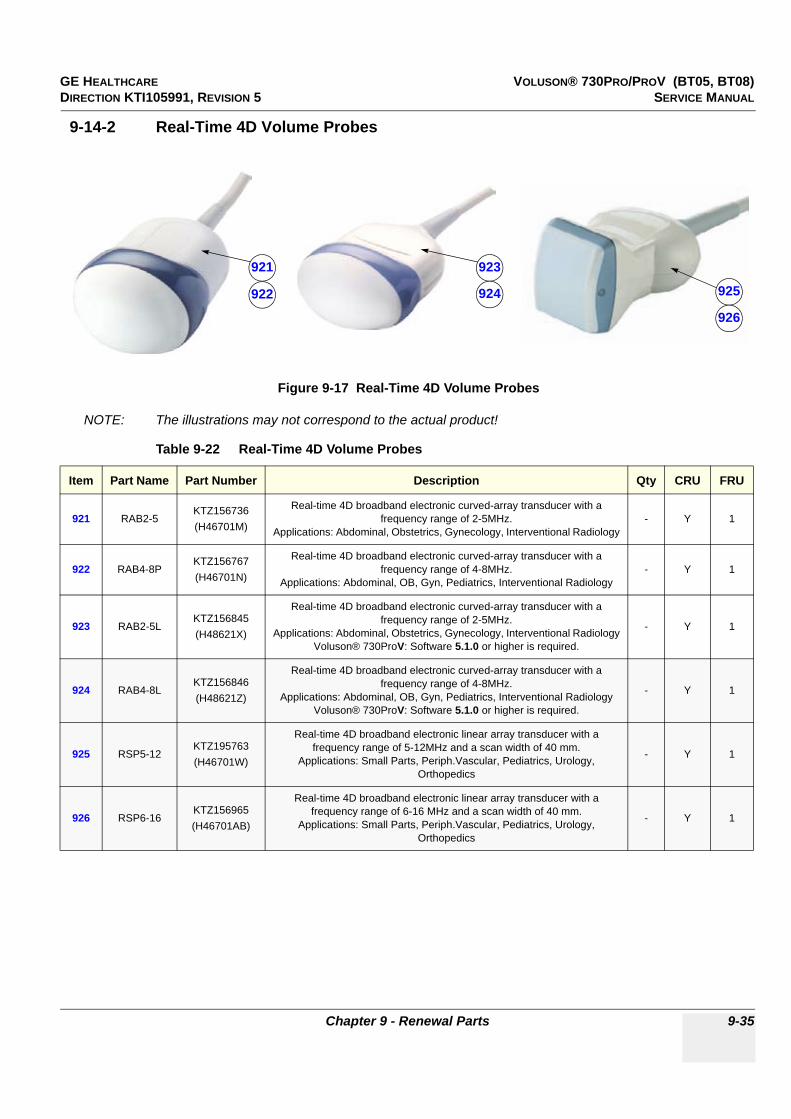
GE HEALTHCARE VOLUSON® 730PRO/PROV (BT05, BT08)DIRECTION KTI105991, REVISION 5 SERVICE MANUAL
Chapter 9 - Renewal Parts 9-35
9-14-2 Real-Time 4D Volume Probes
NOTE: The illustrations may not correspond to the actual product!
Figure 9-17 Real-Time 4D Volume Probes
Table 9-22 Real-Time 4D Volume Probes
Item Part Name Part Number Description Qty CRU FRU
921 RAB2-5KTZ156736(H46701M)
Real-time 4D broadband electronic curved-array transducer with a frequency range of 2-5MHz.
Applications: Abdominal, Obstetrics, Gynecology, Interventional Radiology- Y 1
922 RAB4-8PKTZ156767(H46701N)
Real-time 4D broadband electronic curved-array transducer with a frequency range of 4-8MHz.
Applications: Abdominal, OB, Gyn, Pediatrics, Interventional Radiology- Y 1
923 RAB2-5LKTZ156845(H48621X)
Real-time 4D broadband electronic curved-array transducer with a frequency range of 2-5MHz.
Applications: Abdominal, Obstetrics, Gynecology, Interventional RadiologyVoluson® 730ProV: Software 5.1.0 or higher is required.
- Y 1
924 RAB4-8LKTZ156846(H48621Z)
Real-time 4D broadband electronic curved-array transducer with afrequency range of 4-8MHz.
Applications: Abdominal, OB, Gyn, Pediatrics, Interventional RadiologyVoluson® 730ProV: Software 5.1.0 or higher is required.
- Y 1
925 RSP5-12KTZ195763(H46701W)
Real-time 4D broadband electronic linear array transducer with a frequency range of 5-12MHz and a scan width of 40 mm.
Applications: Small Parts, Periph.Vascular, Pediatrics, Urology, Orthopedics
- Y 1
926 RSP6-16KTZ156965(H46701AB)
Real-time 4D broadband electronic linear array transducer with a frequency range of 6-16 MHz and a scan width of 40 mm.
Applications: Small Parts, Periph.Vascular, Pediatrics, Urology, Orthopedics
- Y 1
921
922
923
924 925
926
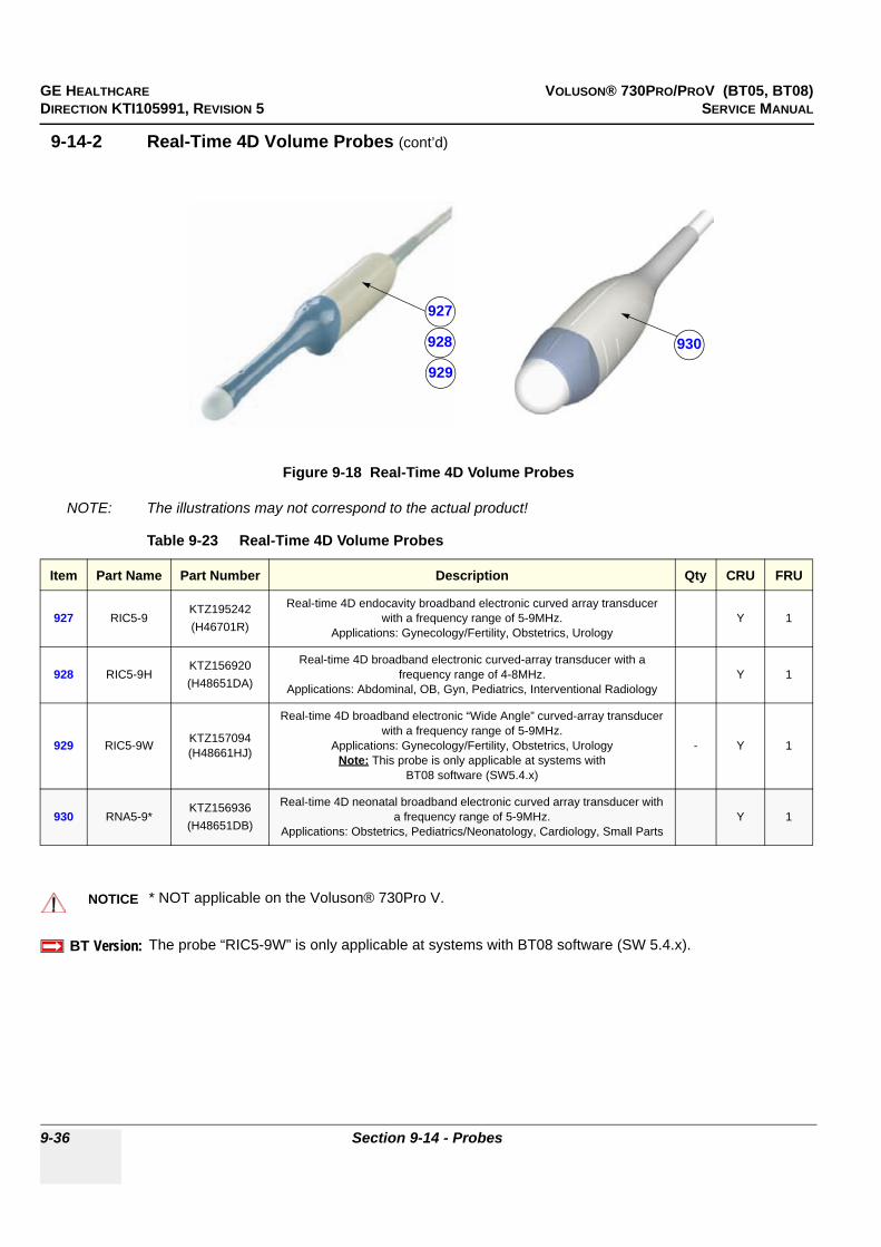
GE HEALTHCARE VOLUSON® 730PRO/PROV (BT05, BT08)DIRECTION KTI105991, REVISION 5 SERVICE MANUAL
9-36 Section 9-14 - Probes
9-14-2 Real-Time 4D Volume Probes (cont’d)
NOTE: The illustrations may not correspond to the actual product!
Figure 9-18 Real-Time 4D Volume Probes
Table 9-23 Real-Time 4D Volume Probes
Item Part Name Part Number Description Qty CRU FRU
927 RIC5-9KTZ195242(H46701R)
Real-time 4D endocavity broadband electronic curved array transducer with a frequency range of 5-9MHz.
Applications: Gynecology/Fertility, Obstetrics, UrologyY 1
928 RIC5-9HKTZ156920(H48651DA)
Real-time 4D broadband electronic curved-array transducer with a frequency range of 4-8MHz.
Applications: Abdominal, OB, Gyn, Pediatrics, Interventional RadiologyY 1
929 RIC5-9W KTZ157094(H48661HJ)
Real-time 4D broadband electronic “Wide Angle” curved-array transducer with a frequency range of 5-9MHz.
Applications: Gynecology/Fertility, Obstetrics, UrologyNote: This probe is only applicable at systems with
BT08 software (SW5.4.x)
- Y 1
930 RNA5-9*KTZ156936(H48651DB)
Real-time 4D neonatal broadband electronic curved array transducer with a frequency range of 5-9MHz.
Applications: Obstetrics, Pediatrics/Neonatology, Cardiology, Small PartsY 1
NOTICE!! NOTICE:
* NOT applicable on the Voluson® 730Pro V.
BT Version:BT-Version:
The probe “RIC5-9W” is only applicable at systems with BT08 software (SW 5.4.x).
927
928
929
930

GE HEALTHCARE VOLUSON® 730PRO/PROV (BT05, BT08)DIRECTION KTI105991, REVISION 5 SERVICE MANUAL
Chapter 9 - Renewal Parts 9-37
9-14-3 CW-Pencil Probes
NOTE: The illustrations may not correspond to the actual product!
Figure 9-19 CW- Pencil Probes
Table 9-24 CW- Pencil Probes
Item Part Name Part Number Description Qty CRU FRU
931 PCW4.0KTZ195540(H46701L)
single element Continuous Wave (CW) Doppler pencil probe with a nominal operating frequency of 4.0 MHz (no B-image)
Applications: Cardiology, Pediatrics1
932 SCW2.0KTZ195538(H46701K)
single element Continuous Wave (CW) Doppler pencil probe with a nominal operating frequency of 2.0 MHz (no B-image)
Applications: Cardiology (suprasternal)1
931 932

GE HEALTHCARE VOLUSON® 730PRO/PROV (BT05, BT08)DIRECTION KTI105991, REVISION 5 SERVICE MANUAL
9-38 Section 9-15 - Biopsy Needle Guides
Section 9-15Biopsy Needle Guides
Figure 9-20 Biopsy Needle Guides
950 951
952953
954 955
956
957958
959
960
961962
963
964
965

GE HEALTHCARE VOLUSON® 730PRO/PROV (BT05, BT08)DIRECTION KTI105991, REVISION 5 SERVICE MANUAL
Chapter 9 - Renewal Parts 9-39
Table 9-25 Biopsy Needle Guides
Item Part Name Part Number Description Qty CRU FRU
950 *****(disposable) E8385MJ disposable Biopsy needle guide for probe IC5-9H
needle diameter: < 1.65 mm - N N
951 *****(reusable) H40412LN reusable Biopsy needle guide for probe IC5-9H
needle diameter: < 1.65 mm - N N
952 PEC42 H46721F reusable Biopsy needle guide for probe IC5-9needle diameter: < 1.8 mm - N N
953 PEC63 H46721R reusable Biopsy needle guide for probe RIC5-9 / RIC5-9H needle diameter: < 1.8 mm - N N
954 PEC64 H46721B reusable Biopsy needle guide for probe SP6-12 needle diameter: < 1 mm, 1.4 mm, 2.2 mm - N N
955 PEC65 H46721M reusable Biopsy needle guide for probe RAB2-5 / RAB4-8Pneedle diameter: < 1 mm, 1.4 mm, 2.2 mm - N N
956 PEC68 H46721Preusable Biopsy needle guide for probe RSP5-12 / RSP6-16
needle diameter: < 1 mm, 1.4 mm, 2.2 mm(can be replaced by PEC75)
- N N
957 PEC71 H46721D reusable Biopsy needle guide for probe AB2-7needle diameter: < 1 mm, 1.4 mm, 2.2 mm - N N
958 PEC74 H48621Y reusable Biopsy needle guide for probe RAB2-5L / RAB4-8Lneedle diameter: < 1 mm, 1.4 mm, 2.2 mm - N N
959RAB Single-
angle bracket
H46701AE Non Sterile Single Angle Bracket needle guide for probe RAB2-5-L/RAB4-8-L needle diameter: > 0.6 mm - < 2.1 mm - N N
960 PEC75 H46721Wreusable Biopsy needle guide for probe RSP5-12 / RSP6-16
needle diameter: < 1 mm, 1.4 mm, 2.2 mm(can replace PEC68)
- N N
961RSP Single-
angle bracket
H46701AD Non Sterile Single Angle Bracket needle guide for probe RSP5-12 / RSP6-16 needle diameter: > 0.6 mm - < 2.1 mm -- N N
962 PEC76 H48651DG reusable Biopsy needle guide for probe RNA5-9needle diameter: < 1 mm, 1.4 mm, 2.2 mm - N N
963RNA Single-
angle bracket
H46701AF Non Sterile Single Angle Bracket needle guide for probe RNA5-9needle diameter: > 0.6 mm - < 2.1 mm - N N
964 3.5C Biopsy Kit E8385MG 3.5C Biopsy Starter Kit for probe AC2-5
needle diameter: > 0.6 mm - < 2.1 mm - N N
9654C Multi-
angle bracket
E8385NA Non Sterile Multi Angle Bracket needle guide starter kit for probe 4C-Aneedle diameter: > 0.6 mm - < 2.1 mm - N N

GE HEALTHCARE VOLUSON® 730PRO/PROV (BT05, BT08)DIRECTION KTI105991, REVISION 5 SERVICE MANUAL
9-40 Section 9-15 - Biopsy Needle Guides
This page was intentionally left blank.
GE HEALTHCARE VOLUSON® 730PRO/PROV (BT05, BT08)DIRECTION KTI105991, REVISION 5 SERVICE MANUAL
Chapter 10 - Care & Maintenance 10-1
Chapter 10Care & Maintenance
Section 10-1Overview
10-1-1 Periodic Maintenance InspectionsIt has been determined by engineering that your Voluson® 730Pro/ProV system does not have any high wear components that fail with use, therefore no Periodic Maintenance Inspections are mandatory. Some Customers Quality Assurance Programs may require additional tasks and or inspections to be performed at periods of frequency different from those listed in this manual.
10-1-2 Purpose of Chapter 10This chapter describes Care & Maintenance on the Voluson® 730Pro/ProV system and its peripherals. These procedures are intended to maintain the quality of the systems performance. Read this chapter completely and familiarize yourself with the procedures before performing a task.
Table 10-1 Contents in Chapter 10
Section Description Page Number
10-1 Overview 10-1
10-2 Why do Maintenance 10-2
10-3 Maintenance Task Schedule 10-2
10-4 Tools Required 10-5
10-5 System Maintenance 10-6
10-6 Using a Phantom 10-12
10-7 Electrical Safety Tests 10-12
10-8 When There's Too Much Leakage Current... 10-22
10-9 Ultrasound Equipment Quality Check (EQC) 10-23
10-10 Electrical Safety Test Form 10-24
CAUTION!! CAUTION:
Practice good ESD prevention. Wear an anti–static strap when handling electronic parts and even when disconnecting/connecting cables.
DANGER!! DANGER:
THERE ARE SEVERAL PLACES ON THE BACKPLANE, THE AC DISTRIBUTION, AND DC DISTRIBUTION THAT ARE DANGEROUS. BE SURE TO DISCONNECT THE SYSTEM POWER PLUG AND SWITCH OFF THE MAIN CIRCUIT BREAKER (F1) BEFORE YOU REMOVE ANY PARTS. BE CAUTIOUS WHENEVER POWER IS STILL ON AND COVERS ARE REMOVED.
CAUTION!! CAUTION:
Do not pull out or insert circuit boards while power is ON.
CAUTION!! CAUTION:
Do not operate this unit unless all board covers and frame panels are securely in place. System performance and cooling require this.

GE HEALTHCARE VOLUSON® 730PRO/PROV (BT05, BT08)DIRECTION KTI105991, REVISION 5 SERVICE MANUAL
10-2 Section 10-2 - Why do Maintenance
Section 10-2Why do Maintenance
10-2-1 Keeping RecordsIt is good business practice that ultrasound facilities maintain records of quality checks and corrective maintenance. The Ultrasound Equipment Quality Check form provides the customer with documentation that the ultrasound scanner is maintained on a periodic basis.
A copy of the Ultrasound Equipment Quality Check (EQC) form (see: page 10-23) should be kept in the same room or near the scanner.
10-2-2 Quality AssuranceIn order to gain accreditation from organizations such as the American College of Radiology (USA), it is the customer’s responsibility to have a quality assurance program in place for each scanner. The program must be directed by a medical physicists, the supervising radiologist/physician or appropriate designer.
Routine quality control testing must occur regularly. The same tests are performed during each period so that changes can be monitored over time and effective corrective action can be taken.
Testing results, corrective action and the effects of corrective action must be documented and maintained on the site.
Your GE service representative can help you with establishing, performing and maintaining records for a quality assurance program. Please contact us for coverage information and/or price for service.
Section 10-3Maintenance Task Schedule
10-3-1 How often should care & maintenance tasks be performed?The Customer Care Schedule (see: page 10-3) specifies how often your Voluson® 730Pro/ProV should be serviced and outlines items requiring special attention.
NOTE: It is the customer’s responsibility to ensure the Voluson® 730Pro/ProV care & maintenance is performed as scheduled in order to retain its high level of safety, dependability and performance.
Your GE Service Representative has an in-depth knowlegde of your Voluson® 730Pro/ProV ultrasound scanning system and can best provide competent, efficient service. Please contact us for coverage information and/or price for service.
The service procedures and recommended intervals shown in the Care & Maintenance Task Schedule assumes that you use your Voluson® 730Pro/ProV for an average patient load (10-12 per day) and not use it as a primary mobile unit which is transported between diagnostic facilities.
NOTE: If conditions exist which exceed typical usage and patient load, then it is recommended to increase the maintenance frequencies.
Abbreviations used in the Periodic Maintenance Schedule Table 10-2:
• D = Daily• W = Weekly• M = Monthly• A = Annually

GE HEALTHCARE VOLUSON® 730PRO/PROV (BT05, BT08)DIRECTION KTI105991, REVISION 5 SERVICE MANUAL
Chapter 10 - Care & Maintenance 10-3
10-3-1 How often should care & maintenance tasks be performed? (cont’d)
Table 10-2 Periodic Maintenance Schedule
Item Service at Indicated Time D W M A Notes
Air Filter GridClean the air filter grid with vacuum cleaner from outside (left side of the system front view).
• more frequently depending on your environment
Air Filter GridRemove back panel and board chassis and clean the housing from inside. (vacuum cleaner and soft brush)
• more frequently depending on your environment
AC Mains Cable Inspect AC Mains Cable • Mobile Unit Check weekly
Cables and Connectors
Remove the Back Panel and check if all cables are well seated and if there is no mechanical damage visible;Check if they are fixed and well seated at the correct position.
• also after corrective maintenance
User Interface
Clean alphanumerical keyboard, Functional keys, Digital potentiometers, TGC-Shift potentiometers. (vacuum cleaner, lukewarm soap water on a soft, damp cloth)
•Be careful not to get the cloth too wet so that moisture does not enter the loudspeakers, TGC-Slider, or other keys!
Monitor andProbe holder
Clean Top surface, Monitor and Probe holder with a fluid detergent in warm water on a soft, damp cloth.
•Be careful not to get the cloth too wet so that moisture does not enter the entire system.
Mechanical parts
Clean and inspect the mechanical function of wheels, casters, brakes and swivel locks as well as side door, foot rest, front and rear handle, and monitor holder. Remove Dust and Coupling gel.
• Mobile Unit Check Daily
Control Panel movement Check Turn mechanism • Mobile Unit Check Daily
Trackball Check Check proper operation (Cursor movement X, Y direction) • If failure occurs go to trackball
cleaning.
Trackball Cleaning
Remove trackball ring; open the trackball housing and take out the trackball (refer to Section 7-7-3 on page 7-14). Clean the trackball (and X, Y axes) with soft tissue and screwdriver shaft.
•
Disk Drives(Sonoview Data Backup)
Test Image filing (Sonoview) Import and Export data capability (MO-, CD-RW Drive) • •*
* save the image filing data monthly or weekly on CD depending on the number of examinations
Safe Probe Operation
Clean probes and probe cables and check acoustic lens housing (cracks) and probe cables. In case of mechanical damage, don’t use them! Danger: Safety risk for operator and patient.
•* * or before each use
Probe Air bubblesTo detect air bubbles in filling liquid, shake the probe carefully and check abnormal noise.
Probe connectors Remove dust/dirt of all probe connectors. Clean with vacuum cleaner if dust is visible. •
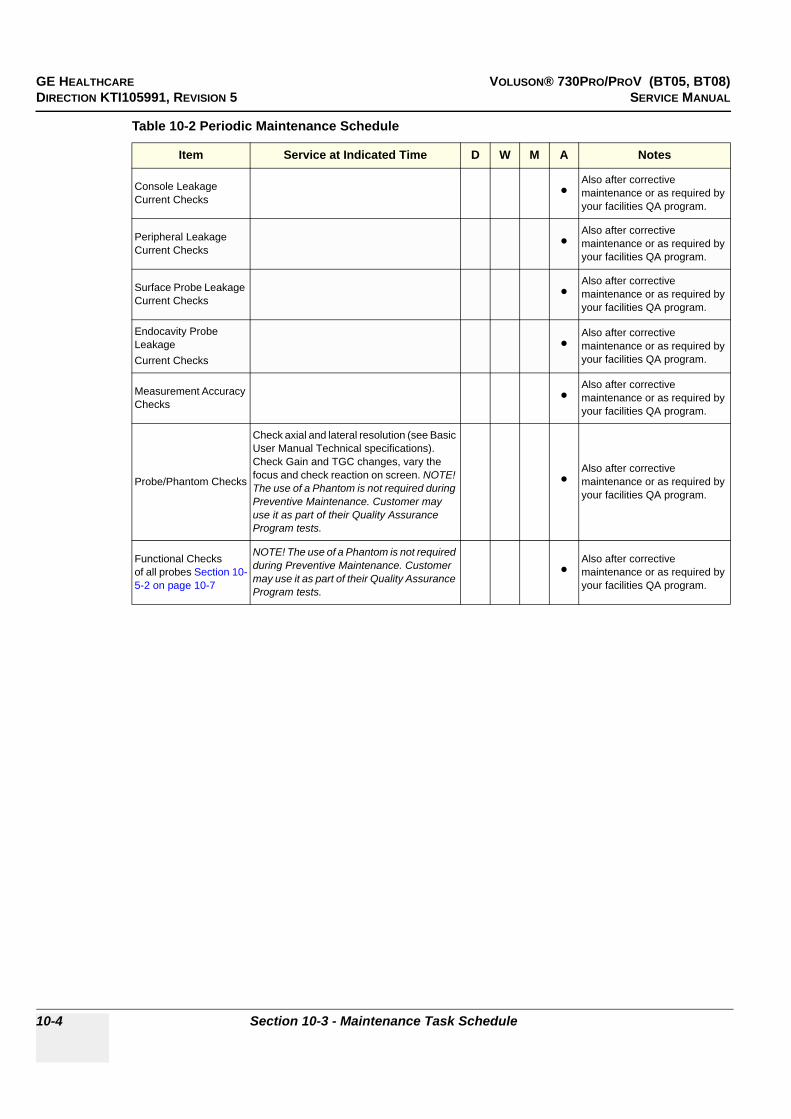
GE HEALTHCARE VOLUSON® 730PRO/PROV (BT05, BT08)DIRECTION KTI105991, REVISION 5 SERVICE MANUAL
10-4 Section 10-3 - Maintenance Task Schedule
Console Leakage Current Checks •
Also after corrective maintenance or as required by your facilities QA program.
Peripheral Leakage Current Checks •
Also after corrective maintenance or as required by your facilities QA program.
Surface Probe Leakage Current Checks •
Also after corrective maintenance or as required by your facilities QA program.
Endocavity Probe Leakage Current Checks
•Also after corrective maintenance or as required by your facilities QA program.
Measurement Accuracy Checks •
Also after corrective maintenance or as required by your facilities QA program.
Probe/Phantom Checks
Check axial and lateral resolution (see Basic User Manual Technical specifications). Check Gain and TGC changes, vary the focus and check reaction on screen. NOTE! The use of a Phantom is not required during Preventive Maintenance. Customer may use it as part of their Quality Assurance Program tests.
•Also after corrective maintenance or as required by your facilities QA program.
Functional Checks of all probes Section 10-5-2 on page 10-7
NOTE! The use of a Phantom is not required during Preventive Maintenance. Customer may use it as part of their Quality Assurance Program tests.
•Also after corrective maintenance or as required by your facilities QA program.
Table 10-2 Periodic Maintenance Schedule
Item Service at Indicated Time D W M A Notes

GE HEALTHCARE VOLUSON® 730PRO/PROV (BT05, BT08)DIRECTION KTI105991, REVISION 5 SERVICE MANUAL
Chapter 10 - Care & Maintenance 10-5
Section 10-4Tools Required
10-4-1 Special Tools, Supplies and Equipment used for Maintenance
Table 10-3 Overview of Requirements for Care & Maintenance
Tool Part Number Comments
Digital Volt Meter (DVM) minimum 5% accuracy, 3.5 digit and 200 Ohm range required
Anti Static Kit
46–194427P23146–194427P27946–194427P36946–194427P37346–194427P370
Kit includes anti–static mat, wrist strap and cables for 200 to 240 V system3M #2204 Large adjustable wrist strap3M #2214 Small adjustable wrist strap3M #3051 conductive ground cord
Anti Static Vacuum Cleaner46–194427P27846–194427P279
120V230V
QIQ Phantom E8370RB
RMI Grayscale Target Model 403GSNOTE! The use of a Phantom is not required during Preventive Maintenance. Customer may use it as part of their Quality Assurance Program tests.
CD-RW Media (minimum quad speed)
DVD+RW Disc Media blank blank 4,7GB DVD+RW disc
B/W Printer Cleaning Sheet see printer user manual for requirements
Color Printer Cleaning Sheet see printer user manual for requirements
Disposable Gloves

GE HEALTHCARE VOLUSON® 730PRO/PROV (BT05, BT08)DIRECTION KTI105991, REVISION 5 SERVICE MANUAL
10-6 Section 10-5 - System Maintenance
Section 10-5System Maintenance
10-5-1 Preliminary ChecksThe preliminary checks take about 15 minutes to perform. Refer to the system user documentation whenever necessary.
Table 10-4 System Checks
Step Item Description
1 Ask & Listen Ask the customer if they have any problems or questions about the equipment.
2 Paperwork Fill in the top of the Ultrasound Inspection Certificate. Note all probes and system options.
3 Power up Turn the system power on and verify that all fans and peripherals turn on. Watch the displays during power up to verify that no warning or error messages are displayed.
4 Probes Verify that the system properly recognizes all probes.
5 Displays Verify proper display on the monitor.
6 Presets “Full Backup” all customer presets on Hard disk and/or DVD (see: Section 4-5-3 "Save Full Backup (Presets, Configurations & Application Settings)" on page 4-36).
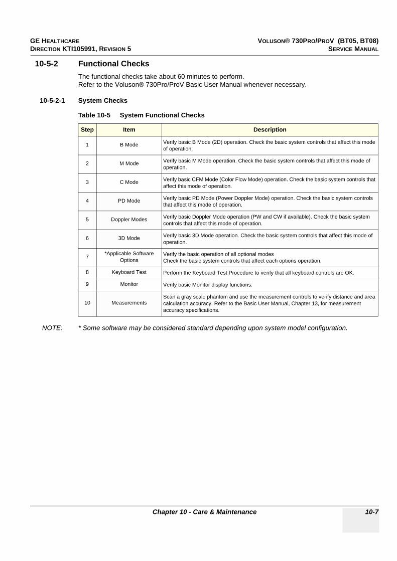
GE HEALTHCARE VOLUSON® 730PRO/PROV (BT05, BT08)DIRECTION KTI105991, REVISION 5 SERVICE MANUAL
Chapter 10 - Care & Maintenance 10-7
10-5-2 Functional ChecksThe functional checks take about 60 minutes to perform.Refer to the Voluson® 730Pro/ProV Basic User Manual whenever necessary.
10-5-2-1 System Checks
NOTE: * Some software may be considered standard depending upon system model configuration.
Table 10-5 System Functional Checks
Step Item Description
1 B Mode Verify basic B Mode (2D) operation. Check the basic system controls that affect this mode of operation.
2 M Mode Verify basic M Mode operation. Check the basic system controls that affect this mode of operation.
3 C Mode Verify basic CFM Mode (Color Flow Mode) operation. Check the basic system controls that affect this mode of operation.
4 PD Mode Verify basic PD Mode (Power Doppler Mode) operation. Check the basic system controls that affect this mode of operation.
5 Doppler Modes Verify basic Doppler Mode operation (PW and CW if available). Check the basic system controls that affect this mode of operation.
6 3D Mode Verify basic 3D Mode operation. Check the basic system controls that affect this mode of operation.
7 *Applicable Software Options
Verify the basic operation of all optional modesCheck the basic system controls that affect each options operation.
8 Keyboard Test Perform the Keyboard Test Procedure to verify that all keyboard controls are OK.
9 Monitor Verify basic Monitor display functions.
10 MeasurementsScan a gray scale phantom and use the measurement controls to verify distance and area calculation accuracy. Refer to the Basic User Manual, Chapter 13, for measurement accuracy specifications.

GE HEALTHCARE VOLUSON® 730PRO/PROV (BT05, BT08)DIRECTION KTI105991, REVISION 5 SERVICE MANUAL
10-8 Section 10-5 - System Maintenance
10-5-2-2 Peripheral/Option ChecksIf any peripherals or options are not part of the system configuration, the check can be omitted. Refer to Table 3-8, “Approved Peripherals,” on page 3-64 for a list of approved peripherals.
10-5-2-3 Mains Cable Inspection
10-5-2-4 Optional Diagnostic ChecksOptionally you can access the diagnostic software as described in Chapters 5 or 7. View the error logs and run desired diagnostics.
Table 10-6 Approved Peripheral/Hardware Option Functional Checks
Step Item Description
1 VCR Verify record/playback capabilities of the VCR. Clean heads and covers if necessary.
2 DVD Recorder Verify record capabilities of the DVD recorder. Clean heads and covers if necessary.
3 B/W Printer Verify hardcopy output of the B/W video page printer. Clean heads and covers if necessary.
4 Color Printer Verify hardcopy output of the Color video page printer. Clean heads and covers if necessary.
5 Line Printer /Bluetooth Printer Verify hardcopy output of the Line or Bluetooth printer. Clean heads and covers if necessary.
6 DICOM Verify that DICOM is functioning properly. Send an image to a DICOM device.
7 Footswitch Verify that the footswitch is functioning as programed. Clean as necessary.
8 DVD and/orMO-Drive
Verify that the DVD-drive and/or optional MO-drive reads/writes properly(export/recall images in Sonoview).
9 Modem Verify modem remote connection.
10 ECG Verify basic operation with customer.
Table 10-7 Mains Cable Inspection
Step Item Description
1 Unplug Cord Disconnect the mains cable from the wall and system.
2 Inspect Inspect it and its connectors for damage of any kind.
3 Verify Verify that the LINE, NEUTRAL and GROUND wires are properly attached to the terminals, and that no strands may cause a short circuit.
4 Verify Inlet connector retainer is functional.

GE HEALTHCARE VOLUSON® 730PRO/PROV (BT05, BT08)DIRECTION KTI105991, REVISION 5 SERVICE MANUAL
Chapter 10 - Care & Maintenance 10-9
10-5-3 Physical Inspection
10-5-4 Cleaning
10-5-4-1 General CleaningFrequent and diligent cleaning of the Voluson® 730Pro ultrasound system reduces the risk of spreading infection from person to person, and also helps to maintain a clean work environment.
Table 10-8 Physical Checks
Step Item Description
1 Labeling Verify that all system labeling is present and in readable condition.
2 Scratches & Dents Inspect the console for dents, scratches or cracks.
3 Control Panel and Keyboard
Inspect keyboard and control panel. Note any damaged or missing items. (Replace faulty components as required.) Verify proper operation of Control Panel backlighting and TGC sliders.
4 Control Panel Movement
Verify ease of control panel (Operator I/O Panel) movement in acceptable direction. Ensure that it latches in position as required.
5 Wheels & Brakes Check all wheels and casters for wear and verify operation of foot brake, to stop the unit from moving, and release mechanism. Check all wheel locks and swivel locks for proper operation.
6 Cables & Connectors Check all internal cable harnesses and connectors for wear and secure connector seating. Pay special attention to footswitch assembly and probe strain or bend reliefs.
7 Shielding & Covers Check to ensure that all EMI shielding, internal covers, air flow panels and screws are in place. Missing covers and hardware could cause EMI/RFI problems while scanning.
8 External I/O Check all connectors for damage and verify that the labeling is good.
9 Op Panel Lights Check proper operation of all operator panel key illuminations (flash once during system start-up).
10 External Microphone Check for proper operation of external microphones by recording an audio test if available.
NOTICE!! NOTICE:
There is no Microphone built in and released for Voluson® 730Pro/ProV.
Table 10-9 General Cleaning
Step Item Description
1 ConsoleUse a fluid detergent in warm water on a soft, damp cloth to carefully wipe the entire system. Be careful not to get the cloth too wet so that moisture does not enter the console.Caution: DO NOT allow any liquid to drip or seep into the system.
2 Monitor Clean Top surface and Monitor and with a fluid detergent in warm water on a soft, damp cloth.Caution: DO NOT spray any liquid directly onto the systems Covers, Monitor, keyboard, etc.
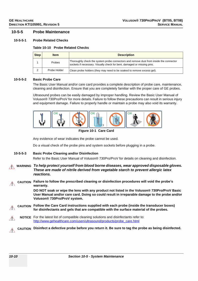
GE HEALTHCARE VOLUSON® 730PRO/PROV (BT05, BT08)DIRECTION KTI105991, REVISION 5 SERVICE MANUAL
10-10 Section 10-5 - System Maintenance
10-5-5 Probe Maintenance
10-5-5-1 Probe Related Checks
10-5-5-2 Basic Probe CareThe Basic User Manual and/or care card provides a complete description of probe care, maintenance, cleaning and disinfection. Ensure that you are completely familiar with the proper care of GE probes.
Ultrasound probes can be easily damaged by improper handling. Review the Basic User Manual of Voluson® 730Pro/ProV for more details. Failure to follow these precautions can result in serious injury and equipment damage. Failure to properly handle or maintain a probe may also void its warranty.
Any evidence of wear indicates the probe cannot be used.
Do a visual check of the probe pins and system sockets before plugging in a probe.
10-5-5-3 Basic Probe Cleaning and/or DisinfectionRefer to the Basic User Manual of Voluson® 730Pro/ProV for details on cleaning and disinfection.
Table 10-10 Probe Related Checks
Step Item Description
1 Probes Thoroughly check the system probe connectors and remove dust from inside the connector sockets if necessary. Visually check for bent, damaged or missing pins.
2 Probe Holder Clean probe holders (they may need to be soaked to remove excess gel).
Figure 10-1 Care Card
WARNINGWARNING To help protect yourself from blood borne diseases, wear approved disposable gloves. These are made of nitrile derived from vegetable starch to prevent allergic latex reactions.
CAUTION Failure to follow the prescribed cleaning or disinfection procedures will void the probe’s warranty.DO NOT soak or wipe the lens with any product not listed in the Voluson® 730Pro/ProV Basic User Manual and/or care card. Doing so could result in irreparable damage to the probe and/or Voluson® 730Pro/ProV system.
CAUTION!! CAUTION:
Follow the Care Card instructions supplied with each probe (inside the transducer boxes)for disinfectants and gels that are compatible with the surface material of the probes.
NOTICE For the latest list of compatible cleaning solutions and disinfectants refer to:http://www.gehealthcare.com/usen/ultrasound/products/probe_care.html
CAUTION Disinfect a defective probe before you return it. Be sure to tag the probe as being disinfected.
OK OKOK

GE HEALTHCARE VOLUSON® 730PRO/PROV (BT05, BT08)DIRECTION KTI105991, REVISION 5 SERVICE MANUAL
Chapter 10 - Care & Maintenance 10-11
10-5-5-3 Basic Probe Cleaning and/or Disinfection (cont’d)
10-5-5-4 Disinfection by means of the RIC-HolderEspecially for Real-time 4D endocavity probes (RIC), it is necessary to take extreme care when transporting the system with the probe attached, or during the disinfection process. Inadequate handling may lead to dead elements, shocked head mechanics, etc.
The RIC-Holder (especially developed for RIC Real-time 4D endocavity probes) guarantees that the sensitive probe head does not hit the bottom of the container during the disinfection procedure.
NOTE: Instructions are supplied with each RIC-Holder (KTZ225469).
CAUTION CAUTION:
Please be aware of the sensitive probe head.TAKE EXTREME CARE!
NEVER place or store a probe on its scan head!
When disinfecting a probe, ensure that there is sufficient space between the probe and the container bottom!
OKOK OKOK
RIC-Holder
Endocavity soaking cup kit
RIC-Holder
RIC-Holder

GE HEALTHCARE VOLUSON® 730PRO/PROV (BT05, BT08)DIRECTION KTI105991, REVISION 5 SERVICE MANUAL
10-12 Section 10-6 - Using a Phantom
Section 10-6Using a Phantom
The use of a Phantom is not required during Preventive Maintenance.Customer may use it as part of their Quality Assurance Program tests.
Section 10-7Electrical Safety Tests
10-7-1 Safety Test OverviewThe electrical safety tests in this section are based on IEC60601 standartd including national deviatons for Health Care Facilities and IEC 62353 Medical electrical equipment – Recurrent test and test after repair of medical electrical equipment. These standards provide guidance on evaluating electrical safety of medical devices which are placed into service and are intended for use in planned maintenance (PM) or testing following service or repair activities. They differ somewhat from the standards that are used for design verification and manufacturing tests (e.g., IEC 60601-1 including national deviations) which require a controlled test environment and can place unnecessary stress on the system.
Prior to initiating any electrical test, the system must be visually inspected. Perform the following visual checks:
• Check for missing or loose enclosure covers that could allow access to internal live parts.• Examine the mains cord, mains plug and appliance inlet for damaged insulation and adequacy of
strain relief and cable clamps.Locate and examine all associated transducers. Inspect the cables and strain relief at each end. Inspect the transducer enclosure and lens for cracks, holes and similar defects.
CAUTION Compare all safety-test results with safety-test results of previously performed safety tests (e.g. last year etc). In case of unexplainable abrupt changes of safety-test results consult experienced authorized service personnel or GE for further analysis.
WARNINGWARNING Equipment users must ensure that safety inspections are performed whenever damage is suspected and at least every 12 months in accordance with local authorities and facility procedures.DO NOT use the system or individual probes which fail any portion of the safety test.
WARNINGWARNING TO MINIMIZE RISK OF ELECTRIC SHOCK, ONLY TRAINED PERSONS ARE ALLOWED TO PERFORM THE ELECTRICAL SAFETY INSPECTIONS AND TESTS.
CAUTION!! CAUTION:
To avoid electrical shock, the unit under test must not be connected to other electrical equipment. Remove all interconnecting cables and wires. The unit under test must not be contacted by users or patients while performing these tests.
CAUTION!! CAUTION:
Possible risk of infection. Do not handle soiled or contaminated probes and other components that have been in patient contact. Follow appropriate cleaning and disinfecting procedures before handling the equipment.
CAUTION For all instructions in Section 10-7:In case of using an UPS (uninterruptable power supply) the terms outlet, wall outlet, AC wall outlet or power outlet refer to the AC power outlet of the UPS.In case of further available AC (or DC) power outlets at the same used UPS these must remain unused; i.e. not connected to any other devices.
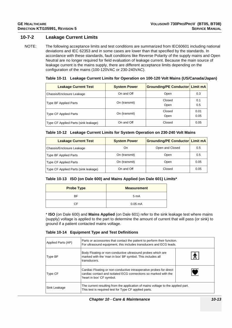
GE HEALTHCARE VOLUSON® 730PRO/PROV (BT05, BT08)DIRECTION KTI105991, REVISION 5 SERVICE MANUAL
Chapter 10 - Care & Maintenance 10-13
10-7-2 Leakage Current Limits
NOTE: The following acceptance limits and test conditions are summarized from IEC60601 including national deviations and IEC 62353 and in some cases are lower than that specified by the standards. In accordance with these standards, fault conditions like Reverse Polarity of the supply mains and Open Neutral are no longer required for field evaluation of leakage current. Because the main source of leakage current is the mains supply, there are different acceptance limits depending on the configuration of the mains (100-120VAC or 230-240VAC).
* ISO (on Dale 600) and Mains Applied (on Dale 601) refer to the sink leakage test where mains (supply) voltage is applied to the part to determine the amount of current that will pass (or sink) to ground if a patient contacted mains voltage.
Table 10-11 Leakage Current Limits for Operation on 100-120 Volt Mains (US/Canada/Japan)
Leakage Current Test System Power Grounding/PE Conductor Limit mA
Chassis/Enclosure Leakage On and Off Open 0.3
Type BF Applied Parts On (transmit)ClosedOpen
0.10.5
Type CF Applied Parts On (transmit)ClosedOpen
0.010.05
Type CF Applied Parts (sink leakage) On and Off Closed 0.05
Table 10-12 Leakage Current Limits for System Operation on 230-240 Volt Mains
Leakage Current Test System Power Grounding/PE Conductor Limit mA
Chassis/Enclosure Leakage On Open and Closed 0.5
Type BF Applied Parts On (transmit) Open 0.5
Type CF Applied Parts On (transmit) Open 0.05
Type CF Applied Parts (sink leakage) On and Off Closed 0.05
Table 10-13 ISO (on Dale 600) and Mains Applied (on Dale 601) Limits*
Probe Type Measurement
BF 5 mA
CF 0.05 mA
Table 10-14 Equipment Type and Test Definitions
Applied Parts (AP) Parts or accessories that contact the patient to perform their function. For ultrasound equipment, this includes transducers and ECG leads.
Type BFBody Floating or non-conductive ultrasound probes which are marked with the 'man in box' BF symbol. This includes all transducers.
Type CFCardiac Floating or non-conductive intraoperative probes for direct cardiac contact and isolated ECG connections so marked with the 'heart in box' CF symbol.
Sink Leakage The current resulting from the application of mains voltage to the applied part.This test is required test for Type CF applied parts.
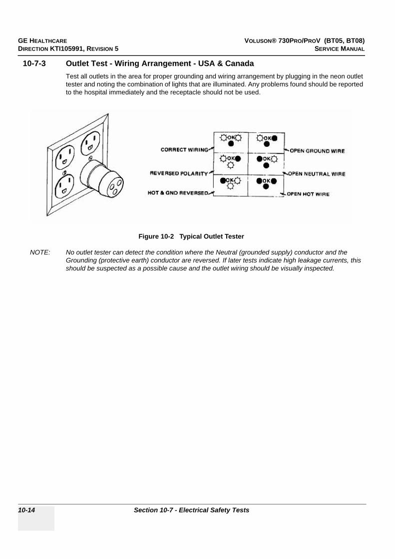
GE HEALTHCARE VOLUSON® 730PRO/PROV (BT05, BT08)DIRECTION KTI105991, REVISION 5 SERVICE MANUAL
10-14 Section 10-7 - Electrical Safety Tests
10-7-3 Outlet Test - Wiring Arrangement - USA & CanadaTest all outlets in the area for proper grounding and wiring arrangement by plugging in the neon outlet tester and noting the combination of lights that are illuminated. Any problems found should be reported to the hospital immediately and the receptacle should not be used.
NOTE: No outlet tester can detect the condition where the Neutral (grounded supply) conductor and the Grounding (protective earth) conductor are reversed. If later tests indicate high leakage currents, this should be suspected as a possible cause and the outlet wiring should be visually inspected.
Figure 10-2 Typical Outlet Tester
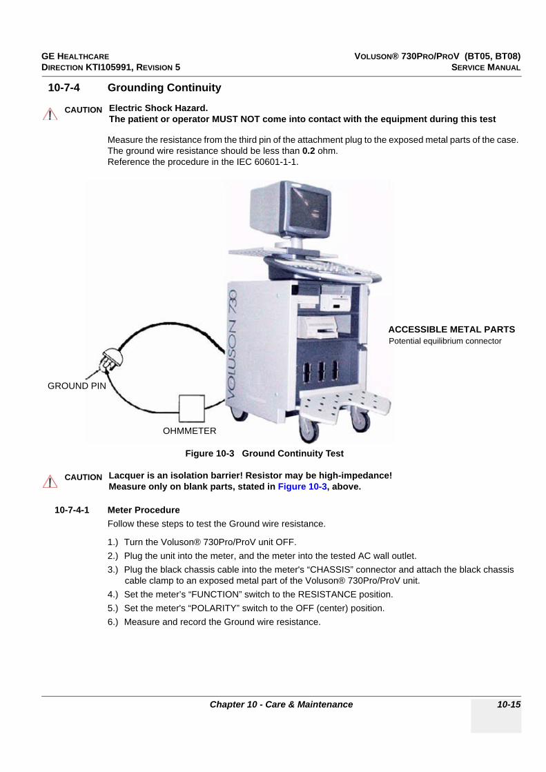
GE HEALTHCARE VOLUSON® 730PRO/PROV (BT05, BT08)DIRECTION KTI105991, REVISION 5 SERVICE MANUAL
Chapter 10 - Care & Maintenance 10-15
10-7-4 Grounding Continuity
Measure the resistance from the third pin of the attachment plug to the exposed metal parts of the case. The ground wire resistance should be less than 0.2 ohm.Reference the procedure in the IEC 60601-1-1.
10-7-4-1 Meter ProcedureFollow these steps to test the Ground wire resistance.
1.) Turn the Voluson® 730Pro/ProV unit OFF.2.) Plug the unit into the meter, and the meter into the tested AC wall outlet.3.) Plug the black chassis cable into the meter's “CHASSIS” connector and attach the black chassis
cable clamp to an exposed metal part of the Voluson® 730Pro/ProV unit.4.) Set the meter’s “FUNCTION” switch to the RESISTANCE position.5.) Set the meter's “POLARITY” switch to the OFF (center) position.6.) Measure and record the Ground wire resistance.
CAUTION!! CAUTION:
Electric Shock Hazard.The patient or operator MUST NOT come into contact with the equipment during this test
Figure 10-3 Ground Continuity Test
CAUTION!! CAUTION:
Lacquer is an isolation barrier! Resistor may be high-impedance!Measure only on blank parts, stated in Figure 10-3, above.
ACCESSIBLE METAL PARTS
GROUND PIN
OHMMETER
Potential equilibrium connector

GE HEALTHCARE VOLUSON® 730PRO/PROV (BT05, BT08)DIRECTION KTI105991, REVISION 5 SERVICE MANUAL
10-16 Section 10-7 - Electrical Safety Tests
10-7-5 Chassis Leakage Current Test
10-7-5-1 DefinitionThis test measures the current that would flow through a grounded person who touches the accessible conductive parts of the equipment during normal and fault conditions.The test verifies the isolation of the power line from the chassis.
The meter is connected to parts of the equipment, easily contacted by the user or patient.Measurements should be made under the test conditions specified in:
• Table 10-11 on page 10-13, or• Table 10-12 on page 10-13, as applicable.Record the highest reading.
10-7-5-2 Generic ProcedureThe test verifies the isolation of the power line from the chassis.The testing meter is connected from accessible metal parts of the case to ground.Measurements should be made under the test conditions specified in:
• Table 10-11 on page 10-13, or• Table 10-12 on page 10-13, as applicable.Record the highest reading of current.
When using the Microguard or a similar test instrument, its power plug may be inserted into the wall outlet and the equipment under test is plugged into the receptacle on the panel of the meter.This places the meter in the grounding conductor and the current flowing from the case to ground will be indicated in any of the current ranges.
The maximum allowable limit for chassis source leakage is shown in:
• Table 10-11 on page 10-13, or• Table 10-12 on page 10-13, as Chassis/Enclosure Leakage.
DANGER!! DANGER:
Electric Shock Hazard. When the meter's ground switch is OPEN, DO NOT touch the unit!
CAUTION!! CAUTION:
Equipment damage possibility. Never switch the Polarity and the status of Neutral when the unit is powered ON. Be sure to turn the unit power OFF before switching them using the POLARITY switch and/or the NEUTRAL switch. Otherwise, the unit may be damaged.
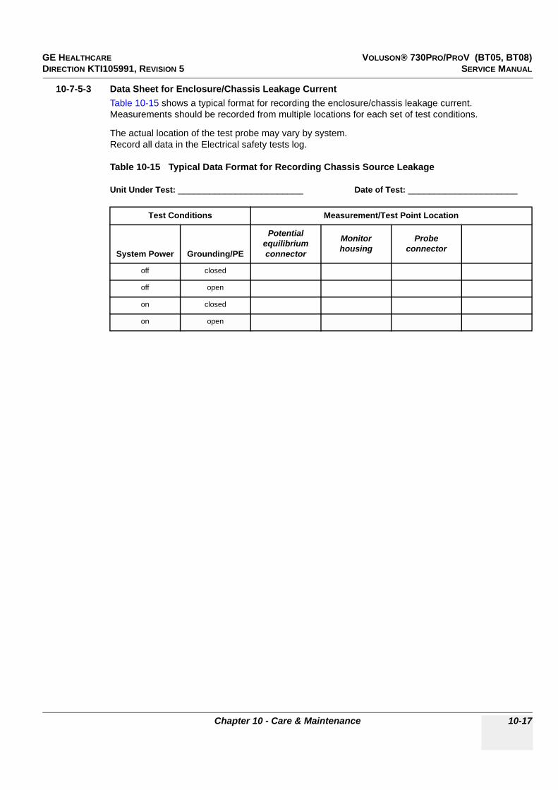
GE HEALTHCARE VOLUSON® 730PRO/PROV (BT05, BT08)DIRECTION KTI105991, REVISION 5 SERVICE MANUAL
Chapter 10 - Care & Maintenance 10-17
10-7-5-3 Data Sheet for Enclosure/Chassis Leakage CurrentTable 10-15 shows a typical format for recording the enclosure/chassis leakage current.Measurements should be recorded from multiple locations for each set of test conditions.
The actual location of the test probe may vary by system.Record all data in the Electrical safety tests log.
Table 10-15 Typical Data Format for Recording Chassis Source Leakage
Unit Under Test: ________________________ Date of Test: _____________________
Test Conditions Measurement/Test Point Location
System Power Grounding/PE
Potential equilibrium connector
Monitor housing
Probe connector
off closed
off open
on closed
on open

GE HEALTHCARE VOLUSON® 730PRO/PROV (BT05, BT08)DIRECTION KTI105991, REVISION 5 SERVICE MANUAL
10-18 Section 10-7 - Electrical Safety Tests
10-7-6 Isolated Patient Lead (Source) Leakage-Lead to Ground
10-7-6-1 DefinitionThis test measures the current which would flow to ground from any of the isolated ECG leads.The meter simulates a patient who is connected to the monitoring equipment and is grounded by touching some other grounded surface.
Measurements should be made under the test conditions specified in:
• Table 10-11 on page 10-13, or:• Table 10-12 on page 10-13, as applicable.For each combination the operating controls, such as the lead switch, should be operated to find the worst case condition.
10-7-6-2 Generic ProcedureMeasurements should be made under the test conditions specified in:
• Table 10-11 on page 10-13, or:• Table 10-12 on page 10-13, as applicable.For each combination the operating controls, such as the lead switch, should be operated to find the worst case condition.
CAUTION!! CAUTION:
Equipment damage possibility. Never switch the Polarity when the unit is powered ON. Be sure to turn the unit power OFF before switching the polarity using the POLARITY switch. Otherwise, the unit may be damaged.
Figure 10-4 Test Circuit for Measuring Patient Lead Leakage
POWEROUTLET
H (Black)
N (White)
G (Green)
Internalcircuitry
Insulating surface
Polarity reversing switch(use both positions)
Appliance power switch(use both "off" and "on" positions)
Patient connected leads
The connection is at service entranceor on the supply side of a separatelyderived system
Buildingground
Grounding contact switch (use in both"open" and "closed" positions)
Current meterH = HotN = Neutral (grounded)G = Grounding conductor
H
N
G
Patient lead selector switch (if any)(activated as required)
Appliance
Between each patient lead and ground
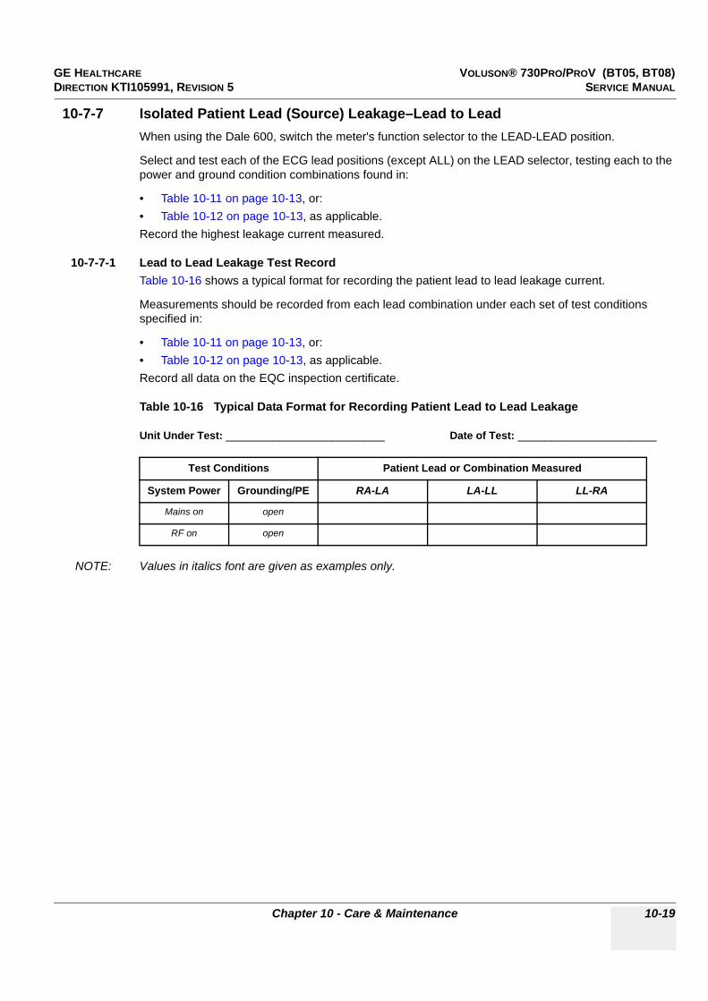
GE HEALTHCARE VOLUSON® 730PRO/PROV (BT05, BT08)DIRECTION KTI105991, REVISION 5 SERVICE MANUAL
Chapter 10 - Care & Maintenance 10-19
10-7-7 Isolated Patient Lead (Source) Leakage–Lead to LeadWhen using the Dale 600, switch the meter's function selector to the LEAD-LEAD position.
Select and test each of the ECG lead positions (except ALL) on the LEAD selector, testing each to the power and ground condition combinations found in:
• Table 10-11 on page 10-13, or: • Table 10-12 on page 10-13, as applicable.Record the highest leakage current measured.
10-7-7-1 Lead to Lead Leakage Test RecordTable 10-16 shows a typical format for recording the patient lead to lead leakage current.
Measurements should be recorded from each lead combination under each set of test conditions specified in:
• Table 10-11 on page 10-13, or: • Table 10-12 on page 10-13, as applicable.Record all data on the EQC inspection certificate.
Table 10-16 Typical Data Format for Recording Patient Lead to Lead Leakage
Unit Under Test: ________________________ Date of Test: _____________________
NOTE: Values in italics font are given as examples only.
Test Conditions Patient Lead or Combination Measured
System Power Grounding/PE RA-LA LA-LL LL-RA
Mains on open
RF on open

GE HEALTHCARE VOLUSON® 730PRO/PROV (BT05, BT08)DIRECTION KTI105991, REVISION 5 SERVICE MANUAL
10-20 Section 10-7 - Electrical Safety Tests
10-7-8 Isolated Patient Lead (Sink) Leakage-Isolation Test
1.) When using the Dale 600, switch the meter’s function selector to the LEAD-ISO.2.) Select the ALL position on the lead selector since the test is performed with mains applied to all
leads at the same time.3.) Depress the rocker switch to ISO TEST to test lead isolation.
10-7-8-1 Isolated Lead (sink) Leakage Test RecordTable 10-17 shows a typical format for recording the isolated patient lead sink leakage current.
Measurements should be recorded for the full lead combination under each set of test conditions specified in:
• Table 10-11 on page 10-13, or: • Table 10-12 on page 10-13, as applicable.Record all data on the EQC inspection certificate.
Table 10-17 Typical Data Format for Recording Patient Lead to Lead Leakage
Unit Under Test: ________________________ Date of Test: _____________________
NOTE: Values in italics font are given as examples only.
CAUTION!! CAUTION:
Line voltage is applied to the ECG leads during this test. To avoid possible electric shock hazard, the system being tested must not be touched by patients, users or anyone while the ISO TEST switch is depressed.
Test Conditions Patient Lead or Combination Measured
System Power Grounding/PE RA-LA LA-LL LL-RA
Mains on open
RF on open

GE HEALTHCARE VOLUSON® 730PRO/PROV (BT05, BT08)DIRECTION KTI105991, REVISION 5 SERVICE MANUAL
Chapter 10 - Care & Maintenance 10-21
10-7-9 Probe Leakage Current Test
10-7-9-1 DefinitionThis test measures the current that would flow to ground from any of the probes through a patient who is being scanned and becomes grounded by touching some other grounded surface.
NOTE: Some leakage current is expected on each probe, depending on its design. Small variations in probe leakage currents are normal from probe to probe. Other variations will result from differences in line voltage and test lead placement. It is abnormal if no leakage current is measured. If no leakage current is detected, check the configuration of the test equipment.
10-7-9-2 ToolsFor needed tools, see: Section 10-4 "Tools Required" on page 10-5
10-7-9-3 Generic Procedure on Probe Leakage CurrentThe most common method of measuring probe leakage is to partly immerse the probe into a saline bath while the probe is connected to the ultrasound system and active. This method measures the actual leakage current resulting from the transducer RF drive.
Measurements should be made under the test conditions specified in:
• Table 10-11 on page 10-13, or:• Table 10-12 on page 10-13, as applicable.For each combination, the probe must be active to find the worst case condition.
NOTE: Each probe will have some amount of leakage current, dependent on its design. Small variations in probe leakage currents are normal from probe to probe. Other variations will result from differences in line voltage and test lead placement.
DANGER Do not use the probe if the insulating material has been punctured or otherwise compromised. Integrity of the insulation material and patient safety can be verified by safety testing according to IEC60601-1.
Figure 10-5 Set Up for Probe Leakage Current
POWEROUTLET
H (BLACK)POLARITY REVERSING SWITCH
MOMENTARYSWITCH
N (WHITE)
G (GREEN)
LEAKAGE TESTMETER
CONSOLE
PROBE
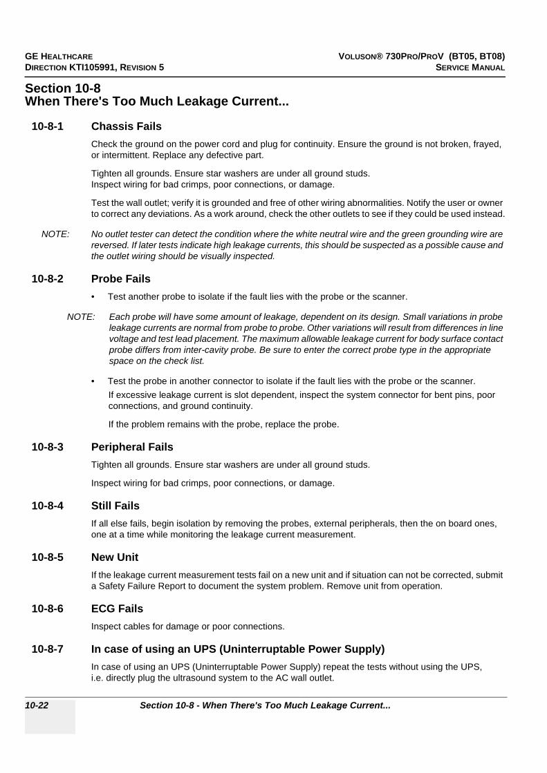
GE HEALTHCARE VOLUSON® 730PRO/PROV (BT05, BT08)DIRECTION KTI105991, REVISION 5 SERVICE MANUAL
10-22 Section 10-8 - When There's Too Much Leakage Current...
Section 10-8When There's Too Much Leakage Current...
10-8-1 Chassis FailsCheck the ground on the power cord and plug for continuity. Ensure the ground is not broken, frayed, or intermittent. Replace any defective part.
Tighten all grounds. Ensure star washers are under all ground studs.Inspect wiring for bad crimps, poor connections, or damage.
Test the wall outlet; verify it is grounded and free of other wiring abnormalities. Notify the user or owner to correct any deviations. As a work around, check the other outlets to see if they could be used instead.
NOTE: No outlet tester can detect the condition where the white neutral wire and the green grounding wire are reversed. If later tests indicate high leakage currents, this should be suspected as a possible cause and the outlet wiring should be visually inspected.
10-8-2 Probe Fails• Test another probe to isolate if the fault lies with the probe or the scanner.
NOTE: Each probe will have some amount of leakage, dependent on its design. Small variations in probe leakage currents are normal from probe to probe. Other variations will result from differences in line voltage and test lead placement. The maximum allowable leakage current for body surface contact probe differs from inter-cavity probe. Be sure to enter the correct probe type in the appropriate space on the check list.
• Test the probe in another connector to isolate if the fault lies with the probe or the scanner.If excessive leakage current is slot dependent, inspect the system connector for bent pins, poor connections, and ground continuity.
If the problem remains with the probe, replace the probe.
10-8-3 Peripheral FailsTighten all grounds. Ensure star washers are under all ground studs.
Inspect wiring for bad crimps, poor connections, or damage.
10-8-4 Still FailsIf all else fails, begin isolation by removing the probes, external peripherals, then the on board ones, one at a time while monitoring the leakage current measurement.
10-8-5 New UnitIf the leakage current measurement tests fail on a new unit and if situation can not be corrected, submit a Safety Failure Report to document the system problem. Remove unit from operation.
10-8-6 ECG FailsInspect cables for damage or poor connections.
10-8-7 In case of using an UPS (Uninterruptable Power Supply)In case of using an UPS (Uninterruptable Power Supply) repeat the tests without using the UPS,i.e. directly plug the ultrasound system to the AC wall outlet.

GE HEALTHCARE VOLUSON® 730PRO/PROV (BT05, BT08)DIRECTION KTI105991, REVISION 5 SERVICE MANUAL
Chapter 10 - Care & Maintenance 10-23
Section 10-9Ultrasound Equipment Quality Check (EQC)
Please download and use the latest version of this form (DOC0537351). It is stored in MyWorkshop.
Figure 10-6 Ultrasound Equipment Quality Check (EQC)

GE HEALTHCARE VOLUSON® 730PRO/PROV (BT05, BT08)DIRECTION KTI105991, REVISION 5 SERVICE MANUAL
10-24 Section 10-10 - Electrical Safety Test Form
Section 10-10Electrical Safety Test Form
Electrical Test PerformedMax Value Allowed
Value Measured OK? Comments
Outlet (correct ground & wiring config.)
System Ground Continuity
Chassis Source Leakage Current - Potential equilibrium connector
Chassis Source Leakage Current - Monitor housing
Chassis Source Leakage Current - Probe connector
Patient Lead Source Leakage(Lead to Ground)
Patient Lead Source Leakage(Lead to Lead)
Patient Lead Source Leakage(Isolation)
Peripheral 1 Leakage Current
Peripheral 1 Ground Continuity
Peripheral 2 Leakage Current
Peripheral 2 Ground Continuity
Peripheral 3 Leakage Current
Peripheral 3 Ground Continuity
PROBES
Probe Number (from previous page)
Max Value Allowed
Max Value Measured OK? Comments
Probe 1:
Probe 2:
Probe 3:
Probe 4:
Probe 5:
Probe 6:
Probe 7:
Probe 8:
Probe 9:

GE HEALTHCAREDRAFT VOLUSON® I / VOLUSON® E (BT05, BT08)DIRECTION KTI105991, REVISION 5 SERVICE MANUAL
A-1
Appendix AAcoustic Output & Index Determination Tables

GE HEALTHCARERAFT VOLUSON® I / VOLUSON® E (BT05, BT08)DIRECTION KTI105991, REVISION 5 SERVICE MANUAL
A-2
Section A-1Overview
This chapter provides Acoustic Output Reporting Tables for IEC60601-2-37 (according to Table 101) and a Summary of measured Quantities for Index Determination (according to IEC60601-2-37 DD.7, Table DD.2) for all applicable Transducers at different Operating Modes.
Table A-1 Tables for Transducers at different Operating Modes
Transducer Section / Transducer at Operating Mode Page Number
AB2-7
A-1-1 Table for AB 2-7 at 2 D Mode (B-Mode) A-6
A-1-2 Table for AB 2-7 at Color Flow Mode (CFM-Mode) A-7
A-1-3 Table for AB 2-7 at Motion Mode (M-Mode) A-8
A-1-4 Table for AB 2-7 at Color Motion Mode (Mc-Mode) A-8
A-1-5 Table for AB 2-7 at Pulsed Wave Doppler (PW-Mode) A-10
AC2-5
A-1-6 Table for AC2-5 at 2 D Mode (B-Mode) A-11
A-1-7 Table for AC2-5 at Color Flow Mode (CFM-Mode)) A-12
A-1-8 Table for AC2-5 at Motion Mode (M-Mode) A-13
A-1-9 Table for AC2-5 at Color Motion Mode (Mc-Mode) A-14
A-1-10 Table for AC2-5 at Pulsed Wave Doppler (PW-Mode) A-15
4C-A
A-1-11 Table for 4C-A at 2 D Mode (B-Mode) A-16
A-1-12 Table for 4C-A at Color Flow Mode (CFM-Mode) A-17
A-1-13 Table for 4C-A at Continuous Wave Doppler (CW-Mode) A-18
A-1-14 Table for 4C-A at Motion Mode (M-Mode) A-19
A-1-15 Table for 4C-A at Color Motion Mode (Mc-Mode) A-20
A-1-16 Table for 4C-A at Pulsed Wave Doppler (PW-Mode) A-21
IC5-9
A-1-17 Table for IC5-9 at 2 D Mode (B-Mode) A-22
A-1-18 Table for IC5-9 at Color Flow Mode (CFM-Mode) A-23
A-1-19 Table for IC5-9 at Motion Mode (M-Mode) A-24
A-1-20 Table for IC5-9 at Color Motion Mode (Mc-Mode) A-25
A-1-21 Table for IC5-9 at Pulsed Wave Doppler (PW-Mode) A-26
IC5-9H
A-1-22 Table for IC5-9H at 2 D Mode (B-Mode) A-27
A-1-23 Table for IC5-9H at Color Flow Mode (CFM-Mode) A-28
A-1-24 Table for IC5-9H at Motion Mode (M-Mode) A-29
A-1-25 Table for IC5-9H at Color Motion Mode (Mc-Mode)) A-30
A-1-26 Table for IC5-9H at Pulsed Wave Doppler (PW-Mode) A-31

GE HEALTHCAREDRAFT VOLUSON® I / VOLUSON® E (BT05, BT08)DIRECTION KTI105991, REVISION 5 SERVICE MANUAL
A-3
SP4-10
A-1-27 Table for SP4-10 at 2 D Mode (B-Mode) A-32
A-1-28 Table for SP4-10 at Color Flow Mode (CFM-Mode) A-33
A-1-29 Table for SP4-10 at Pulsed Wave Doppler (PW-Mode) A-34
A-1-30 Table for SP4-10 at Motion Mode (M-Mode) A-35
SP6-12
A-1-31 Tables for SP6-12 at 2 D Mode (B-Mode) A-36
A-1-32 Tables for SP6-12 at Color Flow Mode (CFM-Mode) A-37
A-1-33 Tables for SP6-12 at Motion Mode (M-Mode) A-38
A-1-34 Tables for SP6-12 at Pulsed Wave Doppler (PW-Mode) A-39
SP10-16
A-1-35 Tables for SP10-16 at 2 D Mode (B-Mode) A-40
A-1-36 Tables for SP10-16 at Color Flow Mode (CFM-Mode) A-41
A-1-37 Tables for SP10-16 at Motion Mode (M-Mode) A-42
A-1-38 Tables for SP10-16 at Pulsed Wave Doppler (PW-Mode) A-43
PA2-5P
A-1-39 Table for PA2-5P at 2 D Mode (B-Mode) A-44
A-1-40 Table for PA2-5P at Color Flow Mode (CFM-Mode) A-45
A-1-41 Table for PA2-5P at Color Motion Mode (Mc-Mode) A-46
A-1-42 Table for PA2-5P at Pulsed Wave Doppler (PW-Mode) A-47
A-1-43 Table for PA2-5P at Motion Mode (M-Mode)) A-48
PA6-8
A-1-44 Table for PA6-8 at 2 D Mode (B-Mode) A-49
A-1-45 Table for PA6-8 at Color Flow Mode (CFM-Mode) A-50
A-1-46 Table for PA6-8 at Continuous Wave Doppler (CW-Mode) A-51
A-1-47 Table for PA6-8 at Color Motion Mode (Mc-Mode) A-52
A-1-48 Table for PA6-8 at Pulsed Wave Doppler (PW-Mode) A-53
A-1-49 Table for PA6-8 at Motion Mode (M-Mode) A-54
PCW4.0 A-1-50 Table for PCW4.0 at Continuous Wave Doppler (CW-Mode) A-55
SCW2.0 A-1-51 Table for SCW2.0 at Continuous Wave Doppler (CW-Mode) A-56
RAB2-5L
A-1-52 Table for RAB2-5L at 2 D Mode (B-Mode) A-57
A-1-53 Table for RAB2-5L at Color Flow Mode (CFM-Mode) A-58
A-1-54 Table for RAB2-5L at Motion Mode (M-Mode) A-59
A-1-55 Table for RAB2-5L at Color Motion Mode (Mc-Mode) A-60
A-1-56 Table for RAB2-5L at Pulsed Wave Doppler (PW-Mode) A-61
RAB4-8L
A-1-57 Table for RAB4-8L at 2 D Mode (B-Mode) A-62
A-1-58 Table for RAB4-8L at Color Flow Mode (CFM-Mode) A-63
A-1-59 Table for RAB4-8L at Motion Mode (M-Mode) A-64
A-1-60 Table for RAB4-8L at Color Motion Mode (Mc-Mode) A-65
A-1-61 Table for RAB4-8L at Power Wave Doppler (PW-Mode) A-66
Table A-1 Tables for Transducers at different Operating Modes
Transducer Section / Transducer at Operating Mode Page Number

GE HEALTHCARERAFT VOLUSON® I / VOLUSON® E (BT05, BT08)DIRECTION KTI105991, REVISION 5 SERVICE MANUAL
A-4
RAB2-5
A-1-62 Table for RAB2-5 at 2 D Mode (B-Mode) A-67
A-1-63 Table for RAB2-5 at Color Flow Mode (CFM-Mode) A-68
A-1-64 Table for RAB2-5 at Motion Mode (M-Mode) A-69
A-1-65 Table for RAB2-5 at Color Motion Mode (Mc-Mode) A-70
A-1-66 Table for RAB2-5 at Pulsed Wave Doppler (PW-Mode) A-71
RAB4-8P
A-1-67 Table for RAB4-8P at 2 D Mode (B-Mode) A-72
A-1-68 Table for RAB4-8P at Color Flow Mode (CFM-Mode) A-73
A-1-69 Table for RAB4-8P at Motion Mode (M-Mode) A-74
A-1-70 Table for RAB4-8P at Color Motion Mode (Mc-Mode) A-75
A-1-71 Table for RAB4-8P at Pulsed Wave Mode (PW-Mode) A-76
RIC5-9
A-1-72 Table for RIC5-9 at 2 D Mode (B-Mode) A-77
A-1-73 Table for RIC5-9 at Color Flow Mode (CFM-Mode) A-78
A-1-74 Table for RIC5-9 at Motion Mode (M-Mode) A-79
A-1-75 Table for RIC5-9 at Color Motion Mode (Mc-Mode) A-80
A-1-76 Table for RIC5-9 at Pulsed Wave Doppler (PW-Mode) A-81
RIC5-9H
A-1-77 Table for RIC5-9H at 2 D Mode (B-Mode) A-82
A-1-78 Table for RIC5-9H at Color Flow Mode (CFM-Mode) A-83
A-1-79 Table for RIC5-9H at Motion Mode (M-Mode) A-84
A-1-80 Table for RIC5-9H at Color Motion Mode (Mc-Mode) A-85
A-1-81 Table for RIC5-9H at Pulsed Wave Doppler (PW-Mode) A-86
RIC5-9W
A-1-82 Tables for RIC5-9W at 2 D Mode (B-Mode) A-87
A-1-83 Tables for RIC5-9W at Color Flow Mode (CFM-Mode) A-88
A-1-84 Tables for RIC5-9W at Motion Mode (M-Mode) A-89
A-1-85 Tables for RIC5-9W at Color Motion Mode (Mc-Mode) A-90
A-1-86 Tables for RIC5-9W at Pulsed Wave Doppler (PW-Mode) A-91
RSP5-12
A-1-87 Table for RSP5-12 at 2 D Mode (B-Mode) A-92
A-1-88 Table for RSP5-12 at Color Flow Mode (CFM-Mode) A-93
A-1-89 Table for RSP5-12 at Pulsed Wave Doppler (PW-Mode) A-94
A-1-90 Table for RSP5-12 at Motion Mode (M-Mode) A-95
RSP6-16
A-1-91 Table for RSP6-16 at 2 D Mode (B-Mode) A-96
A-1-92 Table for RSP6-16 at Color Flow Mode (CFM-Mode) A-97
A-1-93 Table for RSP6-16 at Motion Mode (M-Mode) A-98
A-1-94 Table for RSP6-16 at Pulsed Wave Doppler (PW-Mode) A-99
Table A-1 Tables for Transducers at different Operating Modes
Transducer Section / Transducer at Operating Mode Page Number

GE HEALTHCAREDRAFT VOLUSON® I / VOLUSON® E (BT05, BT08)DIRECTION KTI105991, REVISION 5 SERVICE MANUAL
A-5
RNA5-9
A-1-95 Table for RNA5-9 at 2 D Mode (B-Mode) A-100
A-1-96 Table for RNA5-9 at Color Flow Mode (CFM-Mode) A-101
A-1-97 Table for RNA5-9 at Continuous Wave Doppler (CW-Mode) A-102
A-1-98 Table for RNA5-9 at Motion Mode (M-Mode) A-103
A-1-99 Table for RNA5-9 at Color Motion Mode (Mc-Mode) A-104
A-1-100 Table for RNA5-9 at Pulsed Wave Doppler (PW-Mode) A-105
Table A-1 Tables for Transducers at different Operating Modes
Transducer Section / Transducer at Operating Mode Page Number
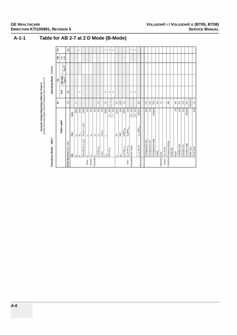
GE HEALTHCARERAFT VOLUSON® I / VOLUSON® E (BT05, BT08)DIRECTION KTI105991, REVISION 5 SERVICE MANUAL
A-6
A-1-1 Table for AB 2-7 at 2 D Mode (B-Mode)
Tran
sduc
er M
odel
: A
B2-
7O
pera
ting
Mod
e: B
-Mod
e
MI
TIS
TIB
TIC
Inde
x La
bel
scan
non-
scan
non-
A apr
t1
A apr
t>1
scan
Glo
bal M
axim
um In
dex
Valu
e1,
3(a
)-
--
(a)
IEC
FDA
Uni
ts
p ra
p r.3
(MPa
)2,
1
PW
o(m
W)
#-
-#
min
of [
P a(z
s), I t
a,a(
z s)]
[W.3
(z1)
, ITA
.3(z
1)]
(mW
)-
Asso
c.z s
z 1(c
m)
-
Acou
stic
z bp
z bp
(cm
)-
Para
met
erz b
z sp
(cm
)-
z at
max
. Ipi
,az s
p(c
m)
1,8
d eq(z
b)d e
q(zsp
)(c
m)
-
f awf
f c(M
Hz)
2,5
#-
--
#
Dim
of A
aprt
X
(cm
)#
--
-#
Y
(cm
)#
--
-#
t dPD
(µse
c)0,
6
prr
PRF
(Hz)
3470
p r a
t max
. Ipi
p r@
PII m
ax(M
Pa)
2,5
Oth
erd e
q at m
ax. I
pid e
q@PI
I max
(cm
)-
Info
rmat
ion
Foca
l Len
gth
FLx
(cm
)#
--
#
FLy
(cm
)#
--
#
I pa,a
at m
ax. M
II P
A.3 @
MI m
ax(W
/cm
²)20
2
B-Im
ages
ecto
r sta
rt(c
m)
0,0
B-Im
ages
ecto
r end
(cm
)24
,0
B-Im
ages
ecto
r ang
le(D
egre
e)20
,0
Qua
lity
low
Ope
ratin
gZo
om1,
0
Con
trol
Foc.
Zon
es1
Con
ditio
nsFr
eque
ncy
Setti
ngM
id
SEN
S PR
I-
Pow
er(%
)10
0
Zoom
Box
star
t(c
m)
8,8
Zoom
Box
end
(cm
)13
,6
Zoom
Box
angl
e(D
egre
e)20
,0
Mod
e Ty
peB(
Har
m)
Foca
l Dep
th(c
m)
3,0
Aco
ustic
Out
put R
epor
ting
Tabl
e fo
r Tra
ck 3
(pro
vide
dat
a w
here
glo
bal m
axim
um d
ispl
ayed
inde
x ex
ceed
s 1.
0)

GE HEALTHCAREDRAFT VOLUSON® I / VOLUSON® E (BT05, BT08)DIRECTION KTI105991, REVISION 5 SERVICE MANUAL
A-7
A-1-2 Table for AB 2-7 at Color Flow Mode (CFM-Mode)
Tran
sduc
er M
odel
: A
B2-
7O
pera
ting
Mod
e: C
olor
Flo
w
MI
TIS
TIB
TIC
Inde
x La
bel
scan
non-
scan
non-
Aap
rt1
Aap
rt>1
scan
Glo
bal M
axim
um In
dex
Val
ue(a
)1,
3-
--
2,0
IEC
FDA
Uni
ts
p ra
p r.3
(MP
a)#
PW
o(m
W)
86-
-25
6
min
of [
P a(z
s), I
ta,a
(zs)
][W
.3(z
1), I
TA.3(z
1)]
(mW
)-
Ass
oc.
z sz 1
(cm
)-
Aco
ustic
z bp
z bp
(cm
)-
Par
amet
erz b
z sp
(cm
)-
z at
max
. I pi,a
z sp
(cm
)#
d eq(
z b)
d eq(
z sp)
(cm
)-
f aw
ff c
(MH
z)#
3,3
--
-2,
8
Dim
of A
aprt
X
(cm
)1,
0-
--
6,2
Y
(cm
)1,
3-
--
1,3
t dP
D(µ
sec)
#
prr
PR
F(H
z)#
p r a
t max
. Ipi
p r@
PII m
ax(M
Pa)
#
Oth
erd e
q at
max
. Ipi
d eq@
PII m
ax(c
m)
-
Info
rmat
ion
Foca
l Len
gth
FLx
(cm
)5
--
5
FLy
(cm
)8
--
8
I pa,a
at m
ax. M
II P
A.3 @
MI m
ax(W
/cm
²)#
B-Im
ages
ecto
r sta
rt(c
m)
0,0
0,0
B-Im
ages
ecto
r end
(cm
)24
,024
,0
B-Im
ages
ecto
r ang
le(D
egre
e)20
,080
,0
B-Q
ualit
ylo
wlo
w
Zoom
1,0
1,0
Foc.
Zon
es1
1
Ope
ratin
gFr
eque
ncy
Set
ting
pene
tpe
net
Con
trol
SE
NS
PR
I-
-
Con
ditio
nsB
Tx
Pow
er(%
)1
1
CFM
Box
sta
rt(c
m)
2,55
2,55
CFM
Box
end
(cm
)6,
156,
15
CFM
Box
ang
le(D
egre
e)7,
3380
,0
CFM
Tx
pow
er(%
)10
010
0
Ens
embl
e9
9
Line
Den
sity
29
Flow
Res
high
low
Vel
ocity
Ran
ge(k
Hz)
7,5
7,5
CFM
Qua
lity
high
high
CFM
Fre
quen
cyhi
ghm
id
Aco
ustic
Out
put R
epor
ting
Tabl
e fo
r Tr
ack
3(p
rovi
de d
ata
whe
re g
loba
l max
imum
dis
play
ed in
dex
exce
eds
1.0)

GE HEALTHCARERAFT VOLUSON® I / VOLUSON® E (BT05, BT08)DIRECTION KTI105991, REVISION 5 SERVICE MANUAL
A-8
A-1-3 Table for AB 2-7 at Motion Mode (M-Mode)
Tran
sduc
er M
odel
: A
B2-7
Ope
ratin
g M
ode:
M-M
ode
(Sim
ulta
neou
s B-
Mod
e in
cl.)
MI
TIS
TIB
TIC
Inde
x La
bel
scan
non-
scan
non-
A apr
t1
A apr
t>1
scan
Glo
bal M
axim
um In
dex
Valu
e(a
)-
-<1
<11,
0
IEC
FDA
Units
p ra
p r.3
(MPa
)#
PW
o(m
W)
--
#77
min
of [
P a(z
s), I t
a,a(
z s)]
[W.3
(z1)
, ITA
.3(z
1)]
(mW
)#
Asso
c.z s
z 1(c
m)
#
Acou
stic
z bp
z bp
(cm
)#
Para
met
erz b
z sp
(cm
)#
z at
max
. I pi,a
z sp
(cm
)#
d eq(z
b)d e
q(zsp
)(c
m)
#
f awf
f c(M
Hz)
#-
-#
#2,
8
Dim
of A
aprt
X
(cm
)-
-#
#2,
5
Y
(cm
)-
-#
#1,
3
t dPD
(µse
c)#
prr
PRF
(Hz)
#
p r a
t max
. Ipi
p r@
PII m
ax(M
Pa)
#
Oth
erd e
q at m
ax. I
pid e
q@PI
I max
(cm
)#
Info
rmat
ion
Foca
l Len
gth
FLx
(cm
)-
-#
15
FLy
(cm
)-
-#
8
I pa,a
at m
ax. M
II PA
.3 @
MI m
ax(W
/cm
²)#
B-Im
ages
ecto
r sta
rt(c
m)
0,0
B-Im
ages
ecto
r end
(cm
)
24
,0
B-Im
ages
ecto
r ang
le(D
egre
e)
80
,0
Qua
lity
low
Ope
ratin
gZo
om
1,
0
Con
trol
Foc.
Zon
es
1
Con
ditio
nsFr
eque
ncy
Setti
ng
H
igh
SEN
S PR
I
-
Pow
er(%
)
10
0
Mod
e Ty
pe
M
(Har
m)
Foca
l Dep
th(c
m)
15,0
Acou
stic
Out
put R
epor
ting
Tabl
e fo
r Tra
ck 3
(pro
vide
dat
a w
here
glo
bal m
axim
um d
ispl
ayed
inde
x ex
ceed
s 1.
0)

GE HEALTHCAREDRAFT VOLUSON® I / VOLUSON® E (BT05, BT08)DIRECTION KTI105991, REVISION 5 SERVICE MANUAL
A-9
A-1-4 Table for AB 2-7 at Color Motion Mode (Mc-Mode)
Tran
sduc
er M
odel
: A
B2-
7O
pera
ting
Mod
e: M
c-M
ode
MI
TIS
TIB
TIC
Inde
x La
bel
scan
non-
scan
non-
A apr
t1
A apr
t>1
scan
Glo
bal M
axim
um In
dex
Val
ue(a
)-
1,0
-1,
42,
0
IEC
FDA
Uni
ts
p ra
p r.3
(MP
a)#
PW
o(m
W)
-63
137
137
min
of [
P a(z
s), I
ta,a
(zs)
][W
.3(z
1), I
TA.3(z
1)]
(mW
)-
Ass
oc.
z sz 1
(cm
)-
Aco
ustic
z bp
z bp
(cm
)-
Par
amet
erz b
z sp
(cm
)0,
3
z at
max
. Ipi
,az s
p(c
m)
#
d eq(
z b)
d eq(
z sp)
(cm
)2,
1
f awf
f c(M
Hz)
#-
3,2
-3,
13,
1
Dim
of A
aprt
X
(cm
)-
0,7
-1,
91,
9
Y
(cm
)-
1,3
-1,
31,
3
t dP
D(µ
sec)
#
prr
PR
F(H
z)#
p r a
t max
. Ipi
p r@
PII m
ax(M
Pa)
#
Oth
erd e
q at m
ax. I
pid e
q@P
II max
(cm
)1,
3
Info
rmat
ion
Foca
l Len
gth
FLx
(cm
)-
7-
15
FLy
(cm
)-
8-
8
I pa,a
at m
ax. M
II P
A.3 @
MI m
ax(W
/cm
²)#
B-Im
ages
ecto
r sta
rt(c
m)
0,0
0,0
0,0
B-Im
ages
ecto
r end
(cm
)24
,024
,024
,0
B-Im
ages
ecto
r ang
le(D
egre
e)80
8080
B-Q
ualit
ylo
wlo
wlo
w
Zoom
1,0
1,0
1,0
Foc.
Zon
es1
11
Ope
ratin
gFr
eque
ncy
Set
ting
pene
tpe
net
pene
t
Con
trol
SE
NS
PR
I-
--
Con
ditio
nsB
Tx
Pow
er(%
)1
11
Mc
Tx P
ower
(%)
100
100
100
Ens
embl
e12
1616
Flow
Res
high
high
high
Vel
ocity
Ran
ge(k
Hz)
1,8
1,8
1,8
Spe
ed5
55
Mc
Freq
uenc
yH
igh
Hig
hH
igh
Aco
ustic
Out
put R
epor
ting
Tabl
e fo
r Tra
ck 3
(pro
vide
dat
a w
here
glo
bal m
axim
um d
ispl
ayed
inde
x ex
ceed
s 1.
0)

GE HEALTHCARERAFT VOLUSON® I / VOLUSON® E (BT05, BT08)DIRECTION KTI105991, REVISION 5 SERVICE MANUAL
A-10
A-1-5 Table for AB 2-7 at Pulsed Wave Doppler (PW-Mode)
Tran
sduc
er M
odel:
AB2
-7Op
erat
ing
Mode
: Pu
lsed D
opple
r
MITI
STI
BTI
C
Inde
x Lab
elsc
anno
n-sc
anno
n-A a
prt
1A a
prt>1
scan
Glob
al Ma
ximum
Inde
x Valu
e(a
)-
1,4-
2,02,0
IEC
FDA
Units
p rap r.
3(M
Pa)
#
PW
o(m
W)
-88
9114
0
min o
f [Pa(z
s), I ta
,a(z s
)][W
.3(z 1
), I TA
.3(z1)]
(mW
)-
Asso
c.z s
z 1(cm
)-
Acou
stic
z bp
z bp
(cm)
-
Para
meter
z bz sp
(cm)
4,8
z at m
ax. I p
i,az sp
(cm)
#
d eq(z
b)d e
q(zsp
)(cm
)0,5
f awf
f c(M
Hz)
#-
3,3-
2,32,7
Dim
of A a
prt
X
(cm)
-0,7
-1,4
1,9
Y (
cm)
-1,3
-1,3
1,3
t dPD
(µse
c)#
prr
PRF
(Hz)
#
p r at
max.
I pip r@
PII ma
x(M
Pa)
#
Othe
rd e
q at m
ax. I p
id e
q@PI
I max
(cm)
0,5
Infor
matio
nFoc
al Le
ngth
FLx
(cm)
-7
-15
FLy
(cm)
-8
-8
I pa,a
at ma
x. MI
I PA.3 @
MIma
x(W
/cm²)
#
Gate
width
(cm)
0,20,9
0,9
Oper
ating
Gate
pos
(cm)
2,48
7,38
9,69
Contr
olB-
Imag
esec
tor an
gle(D
egre
e)4,4
2,21,3
Cond
itions
Powe
r(%
)10
010
010
0
Acou
stic
Outp
ut R
epor
ting
Tabl
e for
Tra
ck 3
(pro
vide d
ata w
here
glob
al ma
ximum
disp
layed
inde
x exc
eeds
1.0)

GE HEALTHCAREDRAFT VOLUSON® I / VOLUSON® E (BT05, BT08)DIRECTION KTI105991, REVISION 5 SERVICE MANUAL
A-11
A-1-6 Table for AC2-5 at 2 D Mode (B-Mode)
Tran
sduc
er M
odel
: A
C2-
5O
pera
ting
Mod
e: B
-Mod
e
MI
TIS
TIB
TIC
Inde
x La
bel
scan
non-
scan
non-
A apr
t1
A apr
t>1
scan
Glo
bal M
axim
um In
dex
Valu
e1,
3(a
)-
--
(a)
IEC
FDA
Uni
ts
p ra
p r.3
(MPa
)2,
0
PW
o(m
W)
#-
-#
min
of [
P a(z
s), I t
a,a(
z s)]
[W.3
(z1)
, ITA
.3(z
1)]
(mW
)-
Asso
c.z s
z 1(c
m)
-
Acou
stic
z bp
z bp
(cm
)-
Para
met
erz b
z sp
(cm
)-
z at
max
. Ipi
,az s
p(c
m)
4,7
d eq(z
b)d e
q(zsp
)(c
m)
-
f awf
f c(M
Hz)
2,3
#-
--
#
Dim
of A
aprt
X
(cm
)#
--
-#
Y
(cm
)#
--
-#
t dPD
(µse
c)0,
5
prr
PRF
(Hz)
3150
p r a
t max
. Ipi
p r@
PII m
ax(M
Pa)
2,8
Oth
erd e
q at m
ax. I
pid e
q@PI
I max
(cm
)-
Info
rmat
ion
Foca
l Len
gth
FLx
(cm
)#
--
#
FLy
(cm
)#
--
#
I pa,a
at m
ax. M
II P
A.3 @
MI m
ax(W
/cm
²)15
5
B-Im
ages
ecto
r sta
rt(c
m)
0,0
B-Im
ages
ecto
r end
(cm
)30
,0
B-Im
ages
ecto
r ang
le(D
egre
e)68
,0
Qua
lity
low
Ope
ratin
gZo
om1,
0
Con
trol
Foc.
Zon
es1
Con
ditio
nsFr
eque
ncy
Setti
ngno
rm
SEN
S PR
I-
Pow
er(%
)10
0
Zoom
Box
star
t(c
m)
13,0
Zoom
Box
end
(cm
)19
,0
Zoom
Box
angl
e(D
egre
e)68
,0
Mod
e Ty
peB
Foca
l Dep
th(c
m)
15,0
Aco
ustic
Out
put R
epor
ting
Tabl
e fo
r Tra
ck 3
(pro
vide
dat
a w
here
glo
bal m
axim
um d
ispl
ayed
inde
x ex
ceed
s 1.
0)
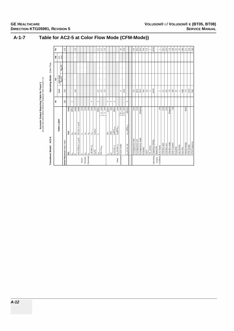
GE HEALTHCARERAFT VOLUSON® I / VOLUSON® E (BT05, BT08)DIRECTION KTI105991, REVISION 5 SERVICE MANUAL
A-12
A-1-7 Table for AC2-5 at Color Flow Mode (CFM-Mode))
Tran
sduc
er M
odel
: A
C2-
5O
pera
ting
Mod
e: C
olor
Flo
w
MI
TIS
TIB
TIC
Inde
x La
bel
scan
non-
scan
non-
Aap
rt1
Aap
rt>1
scan
Glo
bal M
axim
um In
dex
Val
ue(a
)1,
6-
--
2,0
IEC
FDA
Uni
ts
p ra
p r.3
(MP
a)#
PW
o(m
W)
115
--
170
min
of [
P a(z
s), I
ta,a
(zs)
][W
.3(z
1), I
TA.3(z
1)]
(mW
)-
Ass
oc.
z sz 1
(cm
)-
Aco
ustic
z bp
z bp
(cm
)-
Par
amet
erz b
z sp
(cm
)-
z at
max
. I pi,a
z sp
(cm
)#
d eq(
z b)
d eq(
z sp)
(cm
)-
f aw
ff c
(MH
z)#
3,7
--
-3,
7
Dim
of A
aprt
X
(cm
)1,
3-
--
2,7
Y
(cm
)1,
3-
--
1,3
t dP
D(µ
sec)
#
prr
PR
F(H
z)#
p r a
t max
. Ipi
p r@
PII m
ax(M
Pa)
#
Oth
erd e
q at
max
. Ipi
d eq@
PII m
ax(c
m)
-
Info
rmat
ion
Foca
l Len
gth
FLx
(cm
)5
--
15
FLy
(cm
)6,
55-
-6,
55
I pa,a
at m
ax. M
II P
A.3 @
MI m
ax(W
/cm
²)#
B-Im
ages
ecto
r sta
rt(c
m)
0,0
0,0
B-Im
ages
ecto
r end
(cm
)30
,030
,0
B-Im
ages
ecto
r ang
le(D
egre
e)20
,020
,0
B-Q
ualit
ylo
wlo
w
Zoom
1,0
1,0
Foc.
Zon
es1
1
Ope
ratin
gFr
eque
ncy
Set
ting
pene
tpe
net
Con
trol
SE
NS
PR
I-
-
Con
ditio
nsB
Tx
Pow
er(%
)1
1
CFM
Box
sta
rt(c
m)
2,1
18,1
CFM
Box
end
(cm
)6,
622
,6
CFM
Box
ang
le(D
egre
e)7,
67,
6
CFM
Tx
pow
er(%
)10
010
0
Ens
embl
e31
22
Line
Den
sity
110
Flow
Res
high
high
Vel
ocity
Ran
ge(k
Hz)
7,5
0,1
CFM
Qua
lity
norm
low
CFM
Fre
quen
cyhi
ghhi
gh
Aco
ustic
Out
put R
epor
ting
Tabl
e fo
r Tr
ack
3(p
rovi
de d
ata
whe
re g
loba
l max
imum
dis
play
ed in
dex
exce
eds
1.0)

GE HEALTHCAREDRAFT VOLUSON® I / VOLUSON® E (BT05, BT08)DIRECTION KTI105991, REVISION 5 SERVICE MANUAL
A-13
A-1-8 Table for AC2-5 at Motion Mode (M-Mode)
Tran
sduc
er M
odel
: A
C2-5
Ope
ratin
g M
ode:
M-M
ode
(Sim
ulta
neou
s B-
Mod
e in
cl.)
MI
TIS
TIB
TIC
Inde
x La
bel
scan
non-
scan
non-
A apr
t1
A apr
t>1
scan
Glo
bal M
axim
um In
dex
Valu
e(a
)-
-<1
1,4
1,0
IEC
FDA
Units
p ra
p r.3
(MPa
)#
PW
o(m
W)
--
8888
min
of [
P a(z
s), I t
a,a(
z s)]
[W.3
(z1)
, ITA
.3(z
1)]
(mW
)#
Asso
c.z s
z 1(c
m)
#
Acou
stic
z bp
z bp
(cm
)#
Para
met
erz b
z sp
(cm
)3,
9
z at
max
. I pi,a
z sp
(cm
)#
d eq(z
b)d e
q(zsp
)(c
m)
0,8
f awf
f c(M
Hz)
#-
-#
2,1
2,1
Dim
of A
aprt
X
(cm
)-
-#
3,1
3,1
Y
(cm
)-
-#
1,3
1,3
t dPD
(µse
c)#
prr
PRF
(Hz)
#
p r a
t max
. Ipi
p r@
PII m
ax(M
Pa)
#
Oth
erd e
q at m
ax. I
pid e
q@PI
I max
(cm
)0,
8
Info
rmat
ion
Foca
l Len
gth
FLx
(cm
)-
-#
15
FLy
(cm
)-
-#
6,55
I pa,a
at m
ax. M
II PA
.3 @
MI m
ax(W
/cm
²)#
B-Im
ages
ecto
r sta
rt(c
m)
0,
00,
0
B-Im
ages
ecto
r end
(cm
)
30,0
30,0
B-Im
ages
ecto
r ang
le(D
egre
e)
68,0
68,0
Qua
lity
lo
wlo
w
Ope
ratin
gZo
om
1,0
1,0
Con
trol
Foc.
Zon
es
11
Con
ditio
nsFr
eque
ncy
Setti
ng
Hig
hH
igh
SEN
S PR
I
--
Pow
er(%
)
100
100
Mod
e Ty
pe
M(H
arm
)M
(Har
m)
Foca
l Dep
th(c
m)
15
,015
,0
Acou
stic
Out
put R
epor
ting
Tabl
e fo
r Tra
ck 3
(pro
vide
dat
a w
here
glo
bal m
axim
um d
ispl
ayed
inde
x ex
ceed
s 1.
0)

GE HEALTHCARERAFT VOLUSON® I / VOLUSON® E (BT05, BT08)DIRECTION KTI105991, REVISION 5 SERVICE MANUAL
A-14
A-1-9 Table for AC2-5 at Color Motion Mode (Mc-Mode)
Tran
sduc
er M
odel
: A
C2-
5O
pera
ting
Mod
e: M
c-M
ode
MI
TIS
TIB
TIC
Inde
x La
bel
scan
non-
scan
non-
A apr
t1
A apr
t>1
scan
Glo
bal M
axim
um In
dex
Val
ue(a
)-
1,2
-1,
62,
0
IEC
FDA
Uni
ts
p ra
p r.3
(MP
a)#
PW
o(m
W)
-68
137
137
min
of [
P a(z
s), I
ta,a
(zs)
][W
.3(z
1), I
TA.3(z
1)]
(mW
)-
Ass
oc.
z sz 1
(cm
)-
Aco
ustic
z bp
z bp
(cm
)-
Par
amet
erz b
z sp
(cm
)1,
7
z at
max
. Ipi
,az s
p(c
m)
#
d eq(
z b)
d eq(
z sp)
(cm
)1,
4
f awf
f c(M
Hz)
#-
3,7
-2,
63,
6
Dim
of A
aprt
X
(cm
)-
0,7
-2,
21,
8
Y
(cm
)-
1,3
-1,
31,
3
t dP
D(µ
sec)
#
prr
PR
F(H
z)#
p r a
t max
. Ipi
p r@
PII m
ax(M
Pa)
#
Oth
erd e
q at m
ax. I
pid e
q@P
II max
(cm
)1,
0
Info
rmat
ion
Foca
l Len
gth
FLx
(cm
)-
5-
12
FLy
(cm
)-
6,55
-6,
55
I pa,a
at m
ax. M
II P
A.3 @
MI m
ax(W
/cm
²)#
B-Im
ages
ecto
r sta
rt(c
m)
0,0
0,0
0,0
B-Im
ages
ecto
r end
(cm
)5,
030
,030
,0
B-Im
ages
ecto
r ang
le(D
egre
e)20
6820
B-Q
ualit
ylo
wlo
wlo
w
Zoom
1,0
1,0
1,0
Foc.
Zon
es1
11
Ope
ratin
gFr
eque
ncy
Set
ting
pene
tpe
net
pene
t
Con
trol
SE
NS
PR
I-
--
Con
ditio
nsB
Tx
Pow
er(%
)1
11
Mc
Tx P
ower
(%)
100
100
100
Ens
embl
e8
88
Flow
Res
high
high
high
Vel
ocity
Ran
ge(k
Hz)
1,8
1,3
0,9
Spe
ed5
55
Mc
Freq
uenc
yH
igh
Mid
Hig
h
Aco
ustic
Out
put R
epor
ting
Tabl
e fo
r Tra
ck 3
(pro
vide
dat
a w
here
glo
bal m
axim
um d
ispl
ayed
inde
x ex
ceed
s 1.
0)
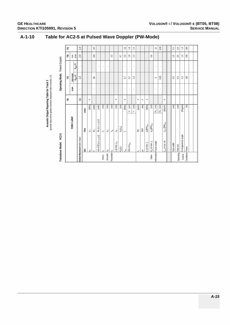
GE HEALTHCAREDRAFT VOLUSON® I / VOLUSON® E (BT05, BT08)DIRECTION KTI105991, REVISION 5 SERVICE MANUAL
A-15
A-1-10 Table for AC2-5 at Pulsed Wave Doppler (PW-Mode)
Tran
sduc
er M
odel:
AC2
-5Op
erat
ing
Mode
: Pu
lsed D
opple
r
MITI
STI
BTI
C
Inde
x Lab
elsc
anno
n-sc
anno
n-A a
prt
1A a
prt>1
scan
Glob
al Ma
ximum
Inde
x Valu
e(a
)-
1,5-
2,02,0
IEC
FDA
Units
p rap r.
3(M
Pa)
#
PW
o(m
W)
-88
103
137
min o
f [Pa(z
s), I ta
,a(z s
)][W
.3(z 1
), I TA
.3(z1)]
(mW
)-
Asso
c.z s
z 1(cm
)-
Acou
stic
z bp
z bp
(cm)
-
Para
meter
z bz sp
(cm)
3,3
z at m
ax. I p
i,az sp
(cm)
#
d eq(z
b)d e
q(zsp
)(cm
)0,7
f awf
f c(M
Hz)
#-
3,7-
2,03,6
Dim
of A a
prt
X
(cm)
-0,7
-1,8
1,8
Y (
cm)
-1,3
-1,3
1,3
t dPD
(µse
c)#
prr
PRF
(Hz)
#
p r at
max.
I pip r@
PII ma
x(M
Pa)
#
Othe
rd e
q at m
ax. I p
id e
q@PI
I max
(cm)
0,6
Infor
matio
nFoc
al Le
ngth
FLx
(cm)
-5
-12
FLy
(cm)
-6,5
5-
6,55
I pa,a
at ma
x. MI
I PA.3 @
MIma
x(W
/cm²)
#
Gate
width
(cm)
0,51,5
0,1
Oper
ating
Gate
pos
(cm)
0,36,5
6,0
Contr
olB-
Imag
esec
tor an
gle(D
egre
e)1,3
1,31,3
Cond
itions
Powe
r(%
)10
010
010
0
Acou
stic
Outp
ut R
epor
ting
Tabl
e for
Tra
ck 3
(pro
vide d
ata w
here
glob
al ma
ximum
disp
layed
inde
x exc
eeds
1.0)
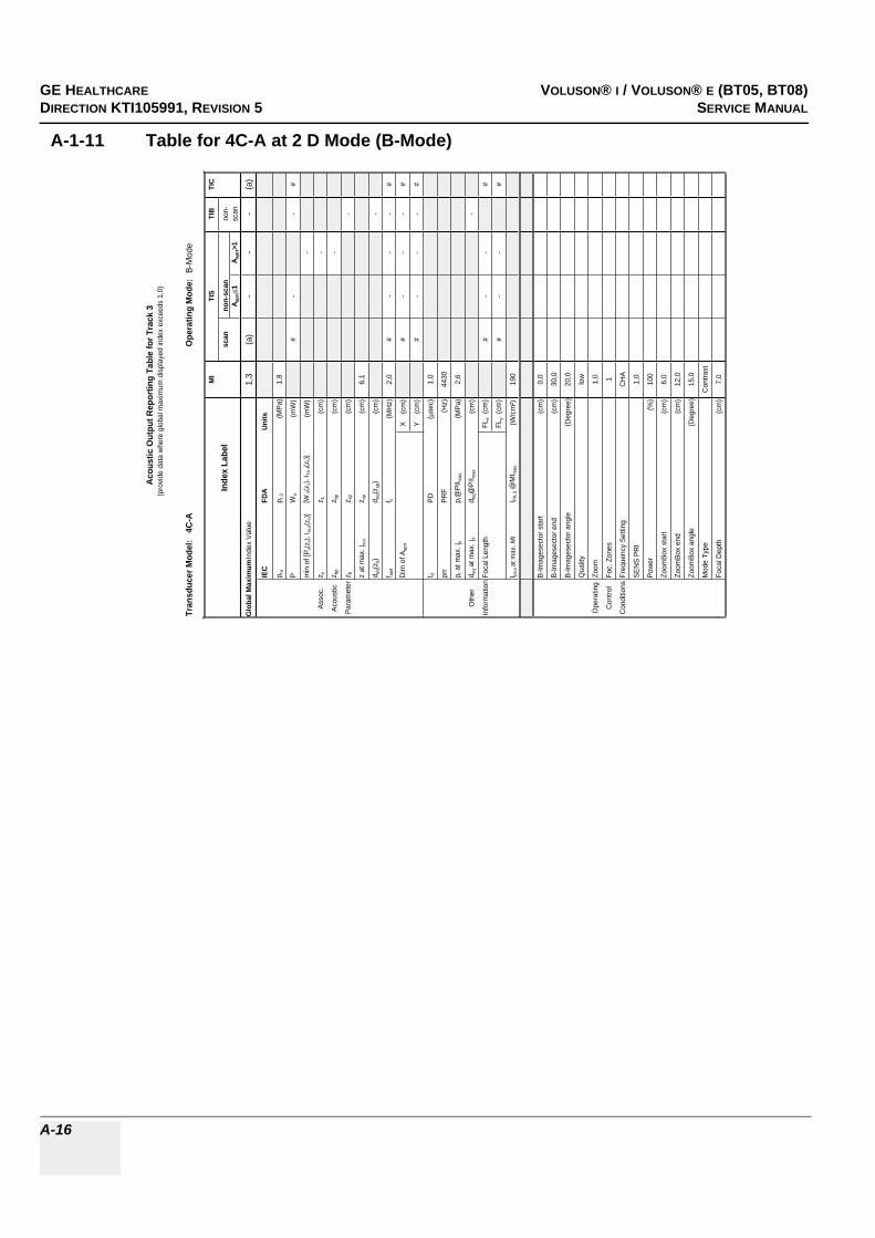
GE HEALTHCARERAFT VOLUSON® I / VOLUSON® E (BT05, BT08)DIRECTION KTI105991, REVISION 5 SERVICE MANUAL
A-16
A-1-11 Table for 4C-A at 2 D Mode (B-Mode)
Tran
sduc
er M
odel
: 4
C-A
Ope
ratin
g M
ode:
B-M
ode
MI
TIS
TIB
TIC
Inde
x La
bel
scan
non-
scan
non-
A apr
t1
A apr
t>1
scan
Glo
bal M
axim
um In
dex
Valu
e1,
3(a
)-
--
(a)
IEC
FDA
Uni
ts
p ra
p r.3
(MPa
)1,
8
PW
o(m
W)
#-
-#
min
of [
P a(z
s), I t
a,a(
z s)]
[W.3
(z1)
, ITA
.3(z
1)]
(mW
)-
Asso
c.z s
z 1(c
m)
-
Acou
stic
z bp
z bp
(cm
)-
Para
met
erz b
z sp
(cm
)-
z at
max
. Ipi
,az s
p(c
m)
6,1
d eq(z
b)d e
q(zsp
)(c
m)
-
f awf
f c(M
Hz)
2,0
#-
--
#
Dim
of A
aprt
X
(cm
)#
--
-#
Y
(cm
)#
--
-#
t dPD
(µse
c)1,
0
prr
PRF
(Hz)
4430
p r a
t max
. Ipi
p r@
PII m
ax(M
Pa)
2,6
Oth
erd e
q at m
ax. I
pid e
q@PI
I max
(cm
)-
Info
rmat
ion
Foca
l Len
gth
FLx
(cm
)#
--
#
FLy
(cm
)#
--
#
I pa,a
at m
ax. M
II P
A.3 @
MI m
ax(W
/cm
²)19
0
B-Im
ages
ecto
r sta
rt(c
m)
0,0
B-Im
ages
ecto
r end
(cm
)30
,0
B-Im
ages
ecto
r ang
le(D
egre
e)20
,0
Qua
lity
low
Ope
ratin
gZo
om1,
0
Con
trol
Foc.
Zon
es1
Con
ditio
nsFr
eque
ncy
Setti
ngC
HA
SEN
S PR
I1,
0
Pow
er(%
)10
0
Zoom
Box
star
t(c
m)
6,0
Zoom
Box
end
(cm
)12
,0
Zoom
Box
angl
e(D
egre
e)15
,0
Mod
e Ty
peC
ontra
st
Foca
l Dep
th(c
m)
7,0
Aco
ustic
Out
put R
epor
ting
Tabl
e fo
r Tra
ck 3
(pro
vide
dat
a w
here
glo
bal m
axim
um d
ispl
ayed
inde
x ex
ceed
s 1.
0)

GE HEALTHCAREDRAFT VOLUSON® I / VOLUSON® E (BT05, BT08)DIRECTION KTI105991, REVISION 5 SERVICE MANUAL
A-17
A-1-12 Table for 4C-A at Color Flow Mode (CFM-Mode)
Tran
sduc
er M
odel
: 4
C-A
Ope
ratin
g M
ode:
Col
or F
low
MI
TIS
TIB
TIC
Inde
x La
bel
scan
non-
scan
non-
Aap
rt1
Aap
rt>1
scan
Glo
bal M
axim
um In
dex
Val
ue(a
)<1
--
-1,
7
IEC
FDA
Uni
ts
p ra
p r.3
(MP
a)#
PW
o(m
W)
#-
-20
4
min
of [
P a(z
s), I
ta,a
(zs)
][W
.3(z
1), I
TA.3(z
1)]
(mW
)-
Ass
oc.
z sz 1
(cm
)-
Aco
ustic
z bp
z bp
(cm
)-
Par
amet
erz b
z sp
(cm
)-
z at
max
. I pi,a
z sp
(cm
)#
d eq(
z b)
d eq(
z sp)
(cm
)-
f aw
ff c
(MH
z)#
#-
--
3,3
Dim
of A
aprt
X
(cm
)#
--
-5,
2
Y
(cm
)#
--
-1,
3
t dP
D(µ
sec)
#
prr
PR
F(H
z)#
p r a
t max
. Ipi
p r@
PII m
ax(M
Pa)
#
Oth
erd e
q at
max
. Ipi
d eq@
PII m
ax(c
m)
-
Info
rmat
ion
Foca
l Len
gth
FLx
(cm
)#
--
18
FLy
(cm
)#
--
6
I pa,a
at m
ax. M
II P
A.3 @
MI m
ax(W
/cm
²)#
B-Im
ages
ecto
r sta
rt(c
m)
0,0
B-Im
ages
ecto
r end
(cm
)30
,0
B-Im
ages
ecto
r ang
le(D
egre
e)20
,0
B-Q
ualit
ylo
w
Zoom
1,0
Foc.
Zon
es1
Ope
ratin
gFr
eque
ncy
Set
ting
norm
Con
trol
SE
NS
PR
I-
Con
ditio
nsB
Tx
Pow
er(%
)1
CFM
Box
sta
rt(c
m)
14,9
CFM
Box
end
(cm
)19
,4
CFM
Box
ang
le(D
egre
e)7,
1
CFM
Tx
pow
er(%
)10
0
Ens
embl
e22
Line
Den
sity
10
Flow
Res
low
Vel
ocity
Ran
ge(k
Hz)
0,1
CFM
Qua
lity
low
CFM
Fre
quen
cyhi
gh
Aco
ustic
Out
put R
epor
ting
Tabl
e fo
r Tr
ack
3(p
rovi
de d
ata
whe
re g
loba
l max
imum
dis
play
ed in
dex
exce
eds
1.0)

GE HEALTHCARERAFT VOLUSON® I / VOLUSON® E (BT05, BT08)DIRECTION KTI105991, REVISION 5 SERVICE MANUAL
A-18
A-1-13 Table for 4C-A at Continuous Wave Doppler (CW-Mode)
Tran
sduc
er M
odel:
4C-
AOp
erat
ing
Mode
: Co
ntinu
es W
ave
MITI
STI
BTI
C
Inde
x Lab
elsc
anno
n-sc
anno
n-A a
prt
1A a
prt>1
scan
Glob
al Ma
ximum
Inde
x Valu
e(a
)-
-<1
1,01,3
IEC
FDA
Units
p rap r.
3(M
Pa)
#
PW
o(m
W)
--
5959
min o
f [Pa(z
s), I ta
,a(z s
)][W
.3(z 1
), I TA
.3(z1)]
(mW
)#
Asso
c.z s
z 1(cm
)#
Acou
stic
z bp
z bp
(cm)
#
Para
meter
z bz sp
(cm)
4,0
z at m
ax. I p
i,az sp
(cm)
#
d eq(z
b)d e
q(zsp
)(cm
)0,7
f awf
f c(M
Hz)
#-
-#
2,02,0
Dim
of A a
prt
X
(cm)
--
#0,8
0,8
Y (
cm)
--
#1,3
1,3
t dPD
(µse
c)#
prr
PRF
(Hz)
#
p r at
max.
I pip r@
PII ma
x(M
Pa)
#
Othe
rd e
q at m
ax. I p
id e
q@PI
I max
(cm)
0,7
Infor
matio
nFoc
al Le
ngth
FLx
(cm)
--
#5
FLy
(cm)
--
#6
I pa,a
at ma
x. MI
I PA.3 @
MIma
x(W
/cm²)
#
Veloc
ity R
ange
(kHz)
12,0
12,0
Oper
ating
Powe
r(%
)10
010
0
Contr
olCo
nditio
ns
Acou
stic
Outp
ut R
epor
ting
Tabl
e for
Tra
ck 3
(pro
vide d
ata w
here
glob
al ma
ximum
disp
layed
inde
x exc
eeds
1.0)

GE HEALTHCAREDRAFT VOLUSON® I / VOLUSON® E (BT05, BT08)DIRECTION KTI105991, REVISION 5 SERVICE MANUAL
A-19
A-1-14 Table for 4C-A at Motion Mode (M-Mode)
Tran
sduc
er M
odel
: 4
C-A
Ope
ratin
g M
ode:
M-M
ode
(Sim
ulta
neou
s B-
Mod
e in
cl.)
MI
TIS
TIB
TIC
Inde
x La
bel
scan
non-
scan
non-
A apr
t1
A apr
t>1
scan
Glo
bal M
axim
um In
dex
Valu
e(a
)-
-<1
1,2
<1
IEC
FDA
Units
p ra
p r.3
(MPa
)#
PW
o(m
W)
--
93#
min
of [
P a(z
s), I t
a,a(
z s)]
[W.3
(z1)
, ITA
.3(z
1)]
(mW
)#
Asso
c.z s
z 1(c
m)
#
Acou
stic
z bp
z bp
(cm
)#
Para
met
erz b
z sp
(cm
)4,
5
z at
max
. I pi,a
z sp
(cm
)#
d eq(z
b)d e
q(zsp
)(c
m)
0,9
f awf
f c(M
Hz)
#-
-#
2,1
#
Dim
of A
aprt
X
(cm
)-
-#
4,6
#
Y
(cm
)-
-#
1,3
#
t dPD
(µse
c)#
prr
PRF
(Hz)
#
p r a
t max
. Ipi
p r@
PII m
ax(M
Pa)
#
Oth
erd e
q at m
ax. I
pid e
q@PI
I max
(cm
)0,
8
Info
rmat
ion
Foca
l Len
gth
FLx
(cm
)-
-#
#
FLy
(cm
)-
-#
#
I pa,a
at m
ax. M
II PA
.3 @
MI m
ax(W
/cm
²)#
B-Im
ages
ecto
r sta
rt(c
m)
0,0
B-Im
ages
ecto
r end
(cm
)30
,0
B-Im
ages
ecto
r ang
le(D
egre
e)57
,6
Qua
lity
low
Ope
ratin
gZo
om1,
0
Con
trol
Foc.
Zon
es1
Con
ditio
nsFr
eque
ncy
Setti
ng
SEN
S PR
I-
Pow
er(%
)85
Mod
e Ty
peM
Foca
l Dep
th(c
m)
18,0
Acou
stic
Out
put R
epor
ting
Tabl
e fo
r Tra
ck 3
(pro
vide
dat
a w
here
glo
bal m
axim
um d
ispl
ayed
inde
x ex
ceed
s 1.
0)
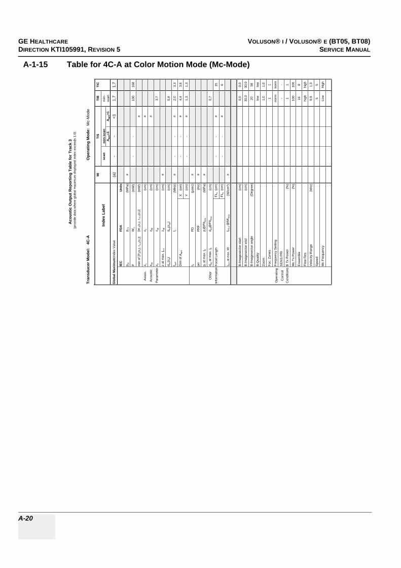
GE HEALTHCARERAFT VOLUSON® I / VOLUSON® E (BT05, BT08)DIRECTION KTI105991, REVISION 5 SERVICE MANUAL
A-20
A-1-15 Table for 4C-A at Color Motion Mode (Mc-Mode)
Tran
sduc
er M
odel
: 4
C-A
Ope
ratin
g M
ode:
Mc-
Mod
e
MI
TIS
TIB
TIC
Inde
x La
bel
scan
non-
scan
non-
A apr
t1
A apr
t>1
scan
Glo
bal M
axim
um In
dex
Val
ue(a
)-
-<1
1,7
1,7
IEC
FDA
Uni
ts
p ra
p r.3
(MP
a)#
PW
o(m
W)
--
100
168
min
of [
P a(z
s), I
ta,a
(zs)
][W
.3(z
1), I
TA.3(z
1)]
(mW
)#
Ass
oc.
z sz 1
(cm
)#
Aco
ustic
z bp
z bp
(cm
)#
Par
amet
erz b
z sp
(cm
)3,
7
z at
max
. Ipi
,az s
p(c
m)
#
d eq(
z b)
d eq(
z sp)
(cm
)0,
8
f aw
ff c
(MH
z)#
--
#2,
03,
3
Dim
of A
aprt
X
(cm
)-
-#
4,4
3,6
Y
(cm
)-
-#
1,3
1,3
t dP
D(µ
sec)
#
prr
PR
F(H
z)#
p r a
t max
. Ipi
p r@
PII m
ax(M
Pa)
#
Oth
erd e
q at m
ax. I
pid e
q@P
II max
(cm
)0,
7
Info
rmat
ion
Foca
l Len
gth
FLx
(cm
)-
-#
15
FLy
(cm
)-
-#
6
I pa,a
at m
ax. M
II P
A.3 @
MI m
ax(W
/cm
²)#
B-Im
ages
ecto
r sta
rt(c
m)
0,0
0,0
B-Im
ages
ecto
r end
(cm
)30
,030
,0
B-Im
ages
ecto
r ang
le(D
egre
e)20
58
B-Q
ualit
ylo
wlo
w
Zoom
1,0
1,0
Foc.
Zon
es1
1
Ope
ratin
gFr
eque
ncy
Set
ting
norm
norm
Con
trol
SE
NS
PR
I-
-
Con
ditio
nsB
Tx
Pow
er(%
)1
1
Mc
Tx P
ower
(%)
100
100
Ens
embl
e16
8
Flow
Res
high
high
Vel
ocity
Ran
ge(k
Hz)
0,9
1,3
Spe
ed5
5
Mc
Freq
uenc
yLo
wH
igh
Aco
ustic
Out
put R
epor
ting
Tabl
e fo
r Tra
ck 3
(pro
vide
dat
a w
here
glo
bal m
axim
um d
ispl
ayed
inde
x ex
ceed
s 1.
0)

GE HEALTHCAREDRAFT VOLUSON® I / VOLUSON® E (BT05, BT08)DIRECTION KTI105991, REVISION 5 SERVICE MANUAL
A-21
A-1-16 Table for 4C-A at Pulsed Wave Doppler (PW-Mode)
Tran
sduc
er M
odel:
4C-
AOp
erat
ing
Mode
: Pu
lsed D
opple
r
MITI
STI
BTI
C
Inde
x Lab
elsc
anno
n-sc
anno
n-A a
prt
1A a
prt>1
scan
Glob
al Ma
ximum
Inde
x Valu
e(a
)-
-<1
1,71,7
IEC
FDA
Units
p rap r.
3(M
Pa)
#
PW
o(m
W)
--
9016
9
min o
f [Pa(z
s), I ta
,a(z s
)][W
.3(z 1
), I TA
.3(z1)]
(mW
)#
Asso
c.z s
z 1(cm
)#
Acou
stic
z bp
z bp
(cm)
#
Para
meter
z bz sp
(cm)
4,7
z at m
ax. I p
i,az sp
(cm)
#
d eq(z
b)d e
q(zsp
)(cm
)0,5
f awf
f c(M
Hz)
#-
-#
2,43,2
Dim
of A a
prt
X
(cm)
--
#1,6
3,6
Y (
cm)
--
#1,3
1,3
t dPD
(µse
c)#
prr
PRF
(Hz)
#
p r at
max.
I pip r@
PII ma
x(M
Pa)
#
Othe
rd e
q at m
ax. I p
id e
q@PI
I max
(cm)
0,5
Infor
matio
nFoc
al Le
ngth
FLx
(cm)
--
#15
FLy
(cm)
--
#6
I pa,a
at ma
x. MI
I PA.3 @
MIma
x(W
/cm²)
#
Gate
width
(cm)
0,10,1
Oper
ating
Gate
pos
(cm)
3,09,0
Contr
olB-
Imag
esec
tor an
gle(D
egre
e)2,2
1,3
Cond
itions
Powe
r(%
)10
010
0
Acou
stic
Outp
ut R
epor
ting
Tabl
e for
Tra
ck 3
(pro
vide d
ata w
here
glob
al ma
ximum
disp
layed
inde
x exc
eeds
1.0)

GE HEALTHCARERAFT VOLUSON® I / VOLUSON® E (BT05, BT08)DIRECTION KTI105991, REVISION 5 SERVICE MANUAL
A-22
A-1-17 Table for IC5-9 at 2 D Mode (B-Mode)
Tran
sduc
er M
odel
: IC
5-9
Ope
ratin
g M
ode:
B-M
ode
MI
TIS
TIB
TIC
Inde
x La
bel
scan
non-
scan
non-
A apr
t1
A apr
t>1
scan
Glo
bal M
axim
um In
dex
Valu
e1,
1(a
)-
--
(a)
IEC
FDA
Units
p ra
p r.3
(MPa
)2,
7
PW
o(m
W)
#-
-#
min
of [
P a(z
s), I t
a,a(
z s)]
[W.3
(z1)
, ITA
.3(z
1)]
(mW
)-
Asso
c.z s
z 1(c
m)
-
Acou
stic
z bp
z bp
(cm
)-
Para
met
erz b
z sp
(cm
)-
z at
max
. Ipi
,az s
p(c
m)
0,7
d eq(z
b)d e
q(zsp
)(c
m)
-
f awf
f c(M
Hz)
5,8
#-
--
#
Dim
of A
aprt
X
(cm
)#
--
-#
Y
(cm
)#
--
-#
t dPD
(µse
c)0,
2
prr
PRF
(Hz)
7010
p r a
t max
. Ipi
p r@
PII m
ax(M
Pa)
3,1
Oth
erd e
q at m
ax. I
pid e
q@PI
I max
(cm
)-
Info
rmat
ion
Foca
l Len
gth
FLx
(cm
)#
--
#
FLy
(cm
)#
--
#
I pa,a
at m
ax. M
II P
A.3 @
MI m
ax(W
/cm
²)52
1
B-Im
ages
ecto
r sta
rt(c
m)
0,0
B-Im
ages
ecto
r end
(cm
)16
,0
B-Im
ages
ecto
r ang
le(D
egre
e)14
6,31
Qua
lity
high
Ope
ratin
gZo
om1,
0
Con
trol
Foc.
Zon
es1
Con
ditio
nsFr
eque
ncy
Setti
ngno
rm
SEN
S PR
I-
Pow
er(%
)10
0
Zoom
Box
star
t(c
m)
0,0
Zoom
Box
end
(cm
)3,
2
Zoom
Box
angl
e(D
egre
e)14
6,31
Mod
e Ty
peB
Foca
l Dep
th(c
m)
1,0
Acou
stic
Out
put R
epor
ting
Tabl
e fo
r Tra
ck 3
(pro
vide
dat
a w
here
glo
bal m
axim
um d
ispl
ayed
inde
x ex
ceed
s 1.
0)

GE HEALTHCAREDRAFT VOLUSON® I / VOLUSON® E (BT05, BT08)DIRECTION KTI105991, REVISION 5 SERVICE MANUAL
A-23
A-1-18 Table for IC5-9 at Color Flow Mode (CFM-Mode)
Tran
sduc
er M
odel
: IC
5-9
Ope
ratin
g M
ode:
Col
or F
low
MI
TIS
TIB
TIC
Inde
x La
bel
scan
non-
scan
non-
Aap
rt1
Aap
rt>1
scan
Glo
bal M
axim
um In
dex
Val
ue(a
)<1
--
-1,
5
IEC
FDA
Uni
ts
p ra
p r.3
(MP
a)#
PW
o(m
W)
#-
-10
9
min
of [
P a(z
s), I
ta,a
(zs)
][W
.3(z
1), I
TA.3(z
1)]
(mW
)-
Ass
oc.
z sz 1
(cm
)-
Aco
ustic
z bp
z bp
(cm
)-
Par
amet
erz b
z sp
(cm
)-
z at
max
. I pi,a
z sp
(cm
)#
d eq(
z b)
d eq(
z sp)
(cm
)-
f aw
ff c
(MH
z)#
#-
--
5,8
Dim
of A
aprt
X
(cm
)#
--
-4,
1
Y
(cm
)#
--
-0,
6
t dP
D(µ
sec)
#
prr
PR
F(H
z)#
p r a
t max
. I pi
p r@
PII m
ax(M
Pa)
#
Oth
erd e
q at m
ax. I p
id e
q@P
II max
(cm
)-
Info
rmat
ion
Foca
l Len
gth
FLx
(cm
)#
--
8
FLy
(cm
)#
--
3
I pa,a
at m
ax. M
II P
A.3 @
MI m
ax(W
/cm
²)#
B-Im
ages
ecto
r sta
rt(c
m)
0,
0
B-Im
ages
ecto
r end
(cm
)
16,0
B-Im
ages
ecto
r ang
le(D
egre
e)
146,
31
B-Q
ualit
y
low
Zoom
1,
0
Foc.
Zon
es
1
Ope
ratin
gFr
eque
ncy
Set
ting
no
rm
Con
trol
SE
NS
PR
I
-
Con
ditio
nsB
Tx
Pow
er(%
)
1
CFM
Box
sta
rt(c
m)
10
,77
CFM
Box
end
(cm
)
13,1
7
CFM
Box
ang
le(D
egre
e)
146,
31
CFM
Tx
pow
er(%
)
100
Ens
embl
e
9
Line
Den
sity
2
Flow
Res
hi
gh
Vel
ocity
Ran
ge(k
Hz)
4,
0
CFM
Qua
lity
hi
gh
Aco
ustic
Out
put R
epor
ting
Tabl
e fo
r Tra
ck 3
(pro
vide
dat
a w
here
glo
bal m
axim
um d
ispl
ayed
inde
x ex
ceed
s 1.
0)

GE HEALTHCARERAFT VOLUSON® I / VOLUSON® E (BT05, BT08)DIRECTION KTI105991, REVISION 5 SERVICE MANUAL
A-24
A-1-19 Table for IC5-9 at Motion Mode (M-Mode)
Tran
sduc
er M
odel
: IC
5-9
Ope
ratin
g M
ode:
M-M
ode
(Sim
ulta
neou
s B-
Mod
e in
cl.)
MI
TIS
TIB
TIC
Inde
x La
bel
scan
non-
scan
non-
A apr
t1
A apr
t>1
scan
Glo
bal M
axim
um In
dex
Valu
e(a
)-
<1-
<1<1
IEC
FDA
Units
p ra
p r.3
(MPa
)#
PW
o(m
W)
-#
##
min
of [
P a(z
s), I t
a,a(
z s)]
[W.3
(z1)
, ITA
.3(z
1)]
(mW
)-
Asso
c.z s
z 1(c
m)
-
Acou
stic
z bp
z bp
(cm
)-
Para
met
erz b
z sp
(cm
)#
z at
max
. Ipi
,az s
p(c
m)
#
d eq(z
b)d e
q(zsp
)(c
m)
#
f awf
f c(M
Hz)
#-
#-
##
Dim
of A
aprt
X
(cm
)-
#-
##
Y
(cm
)-
#-
##
t dPD
(µse
c)#
prr
PRF
(Hz)
#
p r a
t max
. Ipi
p r@
PII m
ax(M
Pa)
#
Oth
erd e
q at m
ax. I
pid e
q@PI
I max
(cm
)#
nfor
mat
ion
Foca
l Len
gth
FLx
(cm
)-
#-
#
FLy
(cm
)-
#-
#
I pa,a
at m
ax. M
II PA
.3 @
MI m
ax(W
/cm
²)#
B-Im
ages
ecto
r sta
rt(c
m)
B-Im
ages
ecto
r end
(cm
)
B-Im
ages
ecto
r ang
le(D
egre
e)
Qua
lity
Ope
ratin
gZo
om
Con
trol
Foc.
Zon
es
Con
ditio
nsFr
eque
ncy
Setti
ng
SEN
S PR
I
Pow
er(%
)
Mod
e Ty
pe
Foca
l Dep
th(c
m)
Acou
stic
Out
put R
epor
ting
Tabl
e fo
r Tra
ck 3
(pro
vide
dat
a w
here
glo
bal m
axim
um d
ispl
ayed
inde
x ex
ceed
s 1.
0)

GE HEALTHCAREDRAFT VOLUSON® I / VOLUSON® E (BT05, BT08)DIRECTION KTI105991, REVISION 5 SERVICE MANUAL
A-25
A-1-20 Table for IC5-9 at Color Motion Mode (Mc-Mode)
Tran
sduc
er M
odel
: IC
5-9
Ope
ratin
g M
ode:
Mc-
Mod
e
MI
TIS
TIB
TIC
Inde
x La
bel
scan
non-
scan
non-
A apr
t1
A apr
t>1
scan
Glo
bal M
axim
um In
dex
Val
ue(a
)-
1,2
-1,
01,
1
IEC
FDA
Uni
ts
p ra
p r.3
(MP
a)#
PW
o(m
W)
-43
1343
min
of [
P a(z
s), I
ta,a
(zs)
][W
.3(z
1), I
TA.3(z
1)]
(mW
)-
Ass
oc.
z sz 1
(cm
)-
Aco
ustic
z bp
z bp
(cm
)-
Par
amet
erz b
z sp
(cm
)0,
8
z at
max
. Ipi
,az s
p(c
m)
#
d eq(
z b)
d eq(
z sp)
(cm
)0,
2
f awf
f c(M
Hz)
#-
5,8
-5,
95,
8
Dim
of A
aprt
X
(cm
)-
1,4
-0,
41,
4
Y
(cm
)-
0,6
-0,
60,
6
t dP
D(µ
sec)
#
prr
PR
F(H
z)#
p r a
t max
. Ipi
p r@
PII m
ax(M
Pa)
#
Oth
erd e
q at m
ax. I
pid e
q@P
II max
(cm
)0,
2
Info
rmat
ion
Foca
l Len
gth
FLx
(cm
)-
8-
8
FLy
(cm
)-
3-
3
I pa,a
at m
ax. M
II P
A.3 @
MI m
ax(W
/cm
²)#
B-Im
ages
ecto
r sta
rt(c
m)
0,0
0,0
0,0
B-Im
ages
ecto
r end
(cm
)16
,016
,016
,0
B-Im
ages
ecto
r ang
le(D
egre
e)14
6,31
146,
3114
6,31
B-Q
ualit
ylo
wlo
wlo
w
Zoom
1,0
1,0
1,0
Foc.
Zon
es1
11
Ope
ratin
gFr
eque
ncy
Set
ting
norm
norm
norm
Con
trol
SE
NS
PR
I-
--
Con
ditio
nsB
Tx
Pow
er(%
)1
11
Mc
Tx P
ower
(%)
100
100
100
Ens
embl
e12
812
Flow
Res
high
high
high
Vel
ocity
Ran
ge(k
Hz)
3,2
2,4
3,2
Spe
ed5
55
Mc
Freq
uenc
yM
idM
idM
id
Aco
ustic
Out
put R
epor
ting
Tabl
e fo
r Tra
ck 3
(pro
vide
dat
a w
here
glo
bal m
axim
um d
ispl
ayed
inde
x ex
ceed
s 1.
0)

GE HEALTHCARERAFT VOLUSON® I / VOLUSON® E (BT05, BT08)DIRECTION KTI105991, REVISION 5 SERVICE MANUAL
A-26
A-1-21 Table for IC5-9 at Pulsed Wave Doppler (PW-Mode)
Tran
sduc
er M
odel:
IC5
-9Op
erat
ing
Mode
: Pu
lsed D
opple
r
MITI
STI
BTI
C
Inde
x Lab
elsc
anno
n-sc
anno
n-A a
prt
1A a
prt>1
scan
Glob
al Ma
ximum
Inde
x Valu
e(a
)-
1,5-
1,51,5
IEC
FDA
Units
p rap r.
3(M
Pa)
#
PW
o(m
W)
-45
5556
min o
f [Pa(z
s), I ta
,a(z s
)][W
.3(z 1
), I TA
.3(z1)]
(mW
)-
Asso
c.z s
z 1(cm
)-
Acou
stic
z bp
z bp
(cm)
-
Para
meter
z bz sp
(cm)
0,7
z at m
ax. I p
i,az sp
(cm)
#
d eq(z
b)d e
q(zsp
)(cm
)0,6
f awf
f c(M
Hz)
#-
7,1-
5,05,8
Dim
of A a
prt
X
(cm)
-1,4
-1,4
1,2
Y (
cm)
-0,6
-0,6
0,6
t dPD
(µse
c)#
prr
PRF
(Hz)
#
p r at
max.
I pip r@
PII ma
x(M
Pa)
#
Othe
rd e
q at m
ax. I p
id e
q@PI
I max
(cm)
0,5
Infor
matio
nFoc
al Le
ngth
FLx
(cm)
-8
-6
FLy
(cm)
-3
-3
I pa,a
at ma
x. MI
I PA.3 @
MIma
x(W
/cm²)
#
Gate
width
(cm)
1,01,5
0,4
Oper
ating
Gate
pos
(cm)
3,58,0
1,76
Contr
olB-
Imag
esec
tor an
gle(D
egre
e)1,3
5,51,3
Cond
itions
Powe
r(%
)10
010
010
0
Acou
stic
Outp
ut R
epor
ting
Tabl
e for
Tra
ck 3
(pro
vide d
ata w
here
glob
al ma
ximum
disp
layed
inde
x exc
eeds
1.0)

GE HEALTHCAREDRAFT VOLUSON® I / VOLUSON® E (BT05, BT08)DIRECTION KTI105991, REVISION 5 SERVICE MANUAL
A-27
A-1-22 Table for IC5-9H at 2 D Mode (B-Mode)
Tran
sduc
er M
odel
: IC
5-9H
Ope
ratin
g M
ode:
B-M
ode
MI
TIS
TIB
TIC
Inde
x La
bel
scan
non-
scan
non-
A apr
t1
A apr
t>1
scan
Glo
bal M
axim
um In
dex
Valu
e1,
3(a
)-
--
(a)
IEC
FDA
Units
p ra
p r.3
(MPa
)2,
7
PW
o(m
W)
#-
-#
min
of [
P a(z
s), I t
a,a(
z s)]
[W.3
(z1)
, ITA
.3(z
1)]
(mW
)-
Asso
c.z s
z 1(c
m)
-
Acou
stic
z bp
z bp
(cm
)-
Para
met
erz b
z sp
(cm
)-
z at
max
. Ipi
,az s
p(c
m)
2,1
d eq(z
b)d e
q(zsp
)(c
m)
-
f awf
f c(M
Hz)
4,5
#-
--
#
Dim
of A
aprt
X
(cm
)#
--
-#
Y
(cm
)#
--
-#
t dPD
(µse
c)0,
3
prr
PRF
(Hz)
2060
p r a
t max
. Ipi
p r@
PII m
ax(M
Pa)
3,5
Oth
erd e
q at m
ax. I
pid e
q@PI
I max
(cm
)-
Info
rmat
ion
Foca
l Len
gth
FLx
(cm
)#
--
#
FLy
(cm
)#
--
#
I pa,a
at m
ax. M
II P
A.3 @
MI m
ax(W
/cm
²)21
2
B-Im
ages
ecto
r sta
rt(c
m)
0,0
B-Im
ages
ecto
r end
(cm
)16
,0
B-Im
ages
ecto
r ang
le(D
egre
e)20
,0
Qua
lity
low
Ope
ratin
gZo
om1,
0
Con
trol
Foc.
Zon
es1
Con
ditio
nsFr
eque
ncy
Setti
ngno
rm
SEN
S PR
I-
Pow
er(%
)10
0
Zoom
Box
star
t(c
m)
12,3
Zoom
Box
end
(cm
)15
,5
Zoom
Box
angl
e(D
egre
e)15
,0
Mod
e Ty
peB
Foca
l Dep
th(c
m)
4,0
Acou
stic
Out
put R
epor
ting
Tabl
e fo
r Tra
ck 3
(pro
vide
dat
a w
here
glo
bal m
axim
um d
ispl
ayed
inde
x ex
ceed
s 1.
0)

GE HEALTHCARERAFT VOLUSON® I / VOLUSON® E (BT05, BT08)DIRECTION KTI105991, REVISION 5 SERVICE MANUAL
A-28
A-1-23 Table for IC5-9H at Color Flow Mode (CFM-Mode)
Tran
sduc
er M
odel
: IC
5-9H
Ope
ratin
g M
ode:
Col
or F
low
MI
TIS
TIB
TIC
Inde
x La
bel
scan
non-
scan
non-
Aap
rt1
Aap
rt>1
scan
Glo
bal M
axim
um In
dex
Val
ue(a
)1,
1-
--
1,7
IEC
FDA
Uni
ts
p ra
p r.3
(MP
a)#
PW
o(m
W)
105
--
116
min
of [
P a(z
s), I
ta,a
(zs)
][W
.3(z
1), I
TA.3(z
1)]
(mW
)-
Ass
oc.
z sz 1
(cm
)-
Aco
ustic
z bp
z bp
(cm
)-
Par
amet
erz b
z sp
(cm
)-
z at
max
. I pi,a
z sp
(cm
)#
d eq(
z b)
d eq(
z sp)
(cm
)-
f aw
ff c
(MH
z)#
7,2
--
-4,
9
Dim
of A
aprt
X
(cm
)3,
2-
--
3,6
Y
(cm
)0,
6-
--
0,6
t dP
D(µ
sec)
#
prr
PR
F(H
z)#
p r a
t max
. I pi
p r@
PII m
ax(M
Pa)
#
Oth
erd e
q at
max
. I pi
d eq@
PII m
ax(c
m)
-
Info
rmat
ion
Foca
l Len
gth
FLx
(cm
)1
--
4
FLy
(cm
)3,
5-
-3,
5
I pa,a
at m
ax. M
II P
A.3 @
MI m
ax(W
/cm
²)#
B-Im
ages
ecto
r sta
rt(c
m)
0,0
0,0
B-Im
ages
ecto
r end
(cm
)16
,016
,0
B-Im
ages
ecto
r ang
le(D
egre
e)14
6,3
146,
3
B-Q
ualit
ylo
wlo
w
Zoom
1,0
1,0
Foc.
Zon
es1
1
Ope
ratin
gFr
eque
ncy
Set
ting
norm
norm
Con
trol
SE
NS
PR
I-
-
Con
ditio
nsB
Tx
Pow
er(%
)1
1
CFM
Box
sta
rt(c
m)
0,0
2,3
CFM
Box
end
(cm
)2,
44,
7
CFM
Box
ang
le(D
egre
e)14
6,3
146,
3
CFM
Tx
pow
er(%
)10
010
0
Ens
embl
e31
7
Line
Den
sity
29
Flow
Res
low
low
Vel
ocity
Ran
ge(k
Hz)
0,1
0,1
CFM
Qua
lity
high
low
CFM
Fre
quen
cyhi
ghlo
w
Aco
ustic
Out
put R
epor
ting
Tabl
e fo
r Tr
ack
3(p
rovi
de d
ata
whe
re g
loba
l max
imum
dis
play
ed in
dex
exce
eds
1.0)

GE HEALTHCAREDRAFT VOLUSON® I / VOLUSON® E (BT05, BT08)DIRECTION KTI105991, REVISION 5 SERVICE MANUAL
A-29
A-1-24 Table for IC5-9H at Motion Mode (M-Mode)
Tran
sduc
er M
odel
: IC
5-9H
Ope
ratin
g M
ode:
M-M
ode
(Sim
ulta
neou
s B-
Mod
e in
cl.)
MI
TIS
TIB
TIC
Inde
x La
bel
scan
non-
scan
non-
A apr
t1
A apr
t>1
scan
Glo
bal M
axim
um In
dex
Valu
e(a
)-
<1-
<1<1
IEC
FDA
Units
p ra
p r.3
(MPa
)#
PW
o(m
W)
-#
##
min
of [
P a(z
s), I t
a,a(
z s)]
[W.3
(z1)
, ITA
.3(z
1)]
(mW
)-
Asso
c.z s
z 1(c
m)
-
Acou
stic
z bp
z bp
(cm
)-
Para
met
erz b
z sp
(cm
)#
z at
max
. I pi,a
z sp
(cm
)#
d eq(z
b)d e
q(zsp
)(c
m)
#
f awf
f c(M
Hz)
#-
#-
##
Dim
of A
aprt
X
(cm
)-
#-
##
Y
(cm
)-
#-
##
t dPD
(µse
c)#
prr
PRF
(Hz)
#
p r a
t max
. Ipi
p r@
PII m
ax(M
Pa)
#
Oth
erd e
q at m
ax. I
pid e
q@PI
I max
(cm
)#
Info
rmat
ion
Foca
l Len
gth
FLx
(cm
)-
#-
#
FLy
(cm
)-
#-
#
I pa,a
at m
ax. M
II PA
.3 @
MI m
ax(W
/cm
²)#
B-Im
ages
ecto
r sta
rt(c
m)
B-Im
ages
ecto
r end
(cm
)
B-Im
ages
ecto
r ang
le(D
egre
e)
Qua
lity
Ope
ratin
gZo
om
Con
trol
Foc.
Zon
es
Con
ditio
nsFr
eque
ncy
Setti
ng
SEN
S PR
I
Pow
er(%
)
Mod
e Ty
pe
Foca
l Dep
th(c
m)
Acou
stic
Out
put R
epor
ting
Tabl
e fo
r Tra
ck 3
(pro
vide
dat
a w
here
glo
bal m
axim
um d
ispl
ayed
inde
x ex
ceed
s 1.
0)

GE HEALTHCARERAFT VOLUSON® I / VOLUSON® E (BT05, BT08)DIRECTION KTI105991, REVISION 5 SERVICE MANUAL
A-30
A-1-25 Table for IC5-9H at Color Motion Mode (Mc-Mode))
Tran
sduc
er M
odel
: IC
5-9H
Ope
ratin
g M
ode:
Mc-
Mod
e
MI
TIS
TIB
TIC
Inde
x La
bel
scan
non-
scan
non-
A apr
t1
A apr
t>1
scan
Glo
bal M
axim
um In
dex
Val
ue(a
)-
1,5
-1,
31,
2
IEC
FDA
Uni
ts
p ra
p r.3
(MP
a)#
PW
o(m
W)
-45
1450
min
of [
P a(z
s), I
ta,a
(zs)
][W
.3(z
1), I
TA.3(z
1)]
(mW
)-
Ass
oc.
z sz 1
(cm
)-
Aco
ustic
z bp
z bp
(cm
)-
Par
amet
erz b
z sp
(cm
)0,
7
z at
max
. Ipi
,az s
p(c
m)
#
d eq(
z b)
d eq(
z sp)
(cm
)0,
2
f awf
f c(M
Hz)
#-
7,1
-5,
95,
0
Dim
of A
aprt
X
(cm
)-
1,4
-0,
41,
4
Y
(cm
)-
0,6
-0,
60,
6
t dP
D(µ
sec)
#
prr
PR
F(H
z)#
p r a
t max
. Ipi
p r@
PII m
ax(M
Pa)
#
Oth
erd e
q at m
ax. I
pid e
q@P
II max
(cm
)0,
2
Info
rmat
ion
Foca
l Len
gth
FLx
(cm
)-
8-
8
FLy
(cm
)-
3,5
-3,
5
I pa,a
at m
ax. M
II P
A.3 @
MI m
ax(W
/cm
²)#
B-Im
ages
ecto
r sta
rt(c
m)
0,0
0,0
0,0
B-Im
ages
ecto
r end
(cm
)16
,03,
016
,0
B-Im
ages
ecto
r ang
le(D
egre
e)20
2020
B-Q
ualit
ylo
wlo
wlo
w
Zoom
1,0
1,0
1,0
Foc.
Zon
es1
11
Ope
ratin
gFr
eque
ncy
Set
ting
norm
norm
norm
Con
trol
SE
NS
PR
I-
--
Con
ditio
nsB
Tx
Pow
er(%
)1
11
Mc
Tx P
ower
(%)
100
100
100
Ens
embl
e12
168
Flow
Res
high
high
high
Vel
ocity
Ran
ge(k
Hz)
2,4
0,9
2,4
Spe
ed4
44
Mc
Freq
uenc
yH
igh
Mid
Low
Aco
ustic
Out
put R
epor
ting
Tabl
e fo
r Tra
ck 3
(pro
vide
dat
a w
here
glo
bal m
axim
um d
ispl
ayed
inde
x ex
ceed
s 1.
0)
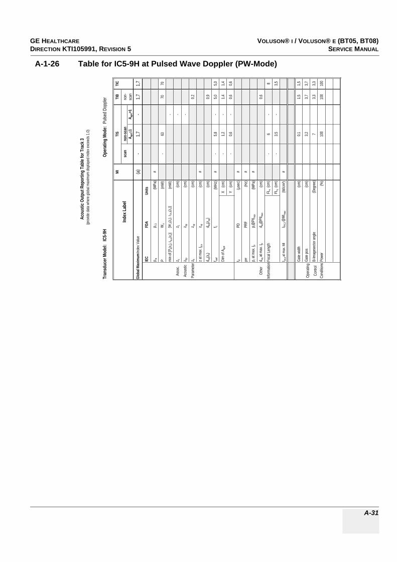
GE HEALTHCAREDRAFT VOLUSON® I / VOLUSON® E (BT05, BT08)DIRECTION KTI105991, REVISION 5 SERVICE MANUAL
A-31
A-1-26 Table for IC5-9H at Pulsed Wave Doppler (PW-Mode)
Tran
sduc
er M
odel:
IC5
-9H
Oper
atin
g Mo
de:
Pulse
d Dop
pler
MITI
STI
BTI
C
Inde
x Lab
elsc
anno
n-sc
anno
n-A a
prt
1A a
prt>1
scan
Glob
al Ma
ximum
Inde
x Valu
e(a
)-
1,7-
1,71,7
IEC
FDA
Units
p rap r.
3(M
Pa)
#
PW
o(m
W)
-63
7070
min o
f [Pa(z
s), I ta
,a(z s
)][W
.3(z 1
), I TA
.3(z1)]
(mW
)-
Asso
c.z s
z 1(cm
)-
Acou
stic
z bp
z bp
(cm)
-
Para
meter
z bz sp
(cm)
0,2
z at m
ax. I p
i,az sp
(cm)
#
d eq(z
b)d e
q(zsp
)(cm
)0,9
f awf
f c(M
Hz)
#-
5,8-
5,05,0
Dim
of A a
prt
X
(cm)
-1,2
-1,4
1,4
Y (
cm)
-0,6
-0,6
0,6
t dPD
(µse
c)#
prr
PRF
(Hz)
#
p r at
max.
I pip r@
PII ma
x(M
Pa)
#
Othe
rd e
q at m
ax. I p
id e
q@PI
I max
(cm)
0,6
Infor
matio
nFoc
al Le
ngth
FLx
(cm)
-6
-8
FLy
(cm)
-3,5
-3,5
I pa,a
at ma
x. MI
I PA.3 @
MIma
x(W
/cm²)
#
Gate
width
(cm)
0,11,5
1,5
Oper
ating
Gate
pos
(cm)
3,23,7
3,7
Contr
olB-
Imag
esec
tor an
gle(D
egre
e)7
3,33,3
Cond
itions
Powe
r(%
)10
010
010
0
Acou
stic
Outp
ut R
epor
ting
Tabl
e for
Tra
ck 3
(pro
vide d
ata w
here
glob
al ma
ximum
disp
layed
inde
x exc
eeds
1.0)
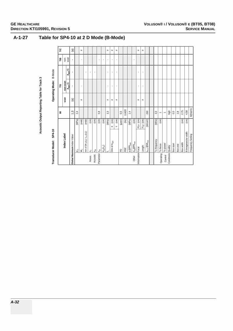
GE HEALTHCARERAFT VOLUSON® I / VOLUSON® E (BT05, BT08)DIRECTION KTI105991, REVISION 5 SERVICE MANUAL
A-32
A-1-27 Table for SP4-10 at 2 D Mode (B-Mode)
Tran
sduc
er M
odel
: S
P4-1
0O
pera
ting
Mod
e: B
-Mod
e
MI
TIS
TIB
TIC
Inde
x La
bel
scan
non-
scan
non-
A apr
t1
A apr
t>1
scan
Glo
bal M
axim
um In
dex
Valu
e1,
3(a
)-
--
(a)
p r.3
(MPa
)2,
4
Wo
(mW
)#
--
#
min
of [
W.3(z
1), I T
A.3(z
1)](m
W)
-
Asso
c.z 1
(cm
)-
Acou
stic
z bp
(cm
)-
Para
met
erz s
p(c
m)
0,8
-
d eq(z
sp)
(cm
)-
f c(M
Hz)
3,3
#-
--
#
Dim
of A
aprt
X
(cm
)#
--
-#
Y
(cm
)#
--
-#
PD(µ
sec)
0,5
PRF
(Hz)
1142
0
p r@
PII m
ax(M
Pa)
2,4
Oth
erd e
q@PI
I max
(cm
)-
Info
rmat
ion
Foca
l FL
x (c
m)
#-
-#
Leng
thFL
y (c
m)
#-
-#
I PA.3 @
MI m
ax(W
/cm
²)20
0
Tx fr
eque
ncy
(MHz
)3,
3
Ope
ratin
gTx
focu
s(c
m)
1
Cont
rol
Tx p
ower
1
Cond
itions
Qua
lityhi
gh
Box
star
t0,
0
Box
end
2,8
Box
widt
h(c
m)
2,75
B-Im
ages
ecto
r wid
th(c
m)
4,58
Freq
uenc
y Se
tting
B(Ha
rm)
Acou
stic
Out
put R
epor
ting
Tabl
e fo
r Tra
ck 3

GE HEALTHCAREDRAFT VOLUSON® I / VOLUSON® E (BT05, BT08)DIRECTION KTI105991, REVISION 5 SERVICE MANUAL
A-33
A-1-28 Table for SP4-10 at Color Flow Mode (CFM-Mode)
Tran
sduc
er M
odel
: S
P4-1
0O
pera
ting
Mod
e: C
olor
Flo
w
MI
TIS
TIB
TIC
Inde
x La
bel
scan
non-
scan
non-
Aap
rt1
Aap
rt>1
scan
Glo
bal M
axim
um In
dex
Valu
e(a
)1,
6-
--
2,0
p r.3
(MPa
)#
Wo
(mW
)74
--
93
min
of [
W.3
(z1)
, ITA
.3(z
1)]
(mW
)-
Asso
c.z 1
(cm
)-
Acou
stic
z bp
(cm
)-
Para
met
erz s
p(c
m)
#-
d eq(
z sp)
(cm
)-
f c(M
Hz)
#4,
9-
--
4,8
Dim
of A
aprt
X
(cm
)1,
2-
--
1,5
Y
(cm
)0,
7-
--
0,7
PD(µ
sec)
#
PRF
(Hz)
#
p r@
PII m
ax(M
Pa)
#
Oth
erd e
q@PI
I max
(cm
)-
Info
rmat
ion
Foca
l FL
x (c
m)
1-
-2
Leng
thFL
y (c
m)
3,25
--
3,25
I PA.
3 @M
I max
#
Tx fr
eque
ncy
(MH
z)5,
05,
0
Tx fo
cus
(cm
)1
2
Tx p
ower
-6-8
Ense
mbl
e26
9
Line
Den
sity
1010
Ope
ratin
gVe
loci
ty R
ange
(kH
z)15
,513
,0
Con
trol
Qua
lity
norm
high
Con
ditio
nsC
FM B
ox s
tart
(cm
)0,
00,
9
CFM
Box
end
(cm
)2,
11,
4
CFM
Box
witd
h(c
m)
0,69
0,92
B Im
age
wid
th(c
m)
0,92
0,92
Aco
ustic
Out
put R
epor
ting
Tabl
e fo
r Tra
ck 3

GE HEALTHCARERAFT VOLUSON® I / VOLUSON® E (BT05, BT08)DIRECTION KTI105991, REVISION 5 SERVICE MANUAL
A-34
A-1-29 Table for SP4-10 at Pulsed Wave Doppler (PW-Mode)
Tran
sduc
er M
odel
: S
P4-1
0Op
erat
ing
Mod
e: P
ulsed
Dop
pler
MI
TIS
TIB
TIC
Inde
x La
bel
scan
non-
scan
non-
A apr
t1
A apr
t>1sc
an
Glob
al M
axim
um In
dex V
alue
(a)
1,5
-1,
22,
01,
9p r.
3(M
Pa)
#
Wo
(mW
)82
-10
510
5
min
of [W
.3(z
1), I T
A.3(z
1)](m
W)
52
Asso
c.z 1
(cm
)2,
1
Acou
stic
z bp
(cm
)2,
0
Para
met
erz s
p(c
m)
#0,
4
d eq(z
sp)
(cm
)1,
1
f c(M
Hz)
#4,
8-
4,9
4,9
4,9
Dim
of A
aprt
X
(cm
)0,
3-
2,1
2,1
2,1
Y
(cm
)0,
7-
0,7
0,7
0,7
PD(µ
sec)
#
PRF
(Hz)
#
p r@PI
I max
(MPa
)#
Othe
rd e
q@PI
I max
(cm
)0,
6
Info
rmat
ionFo
cal
FLx
(cm
)1
-6,
56,
5
Leng
thFL
y (c
m)
3,25
-3,
253,
25
I PA.3
@M
I max
#
Tx fr
eque
ncy
(MHz
)5,
05,
05,
05,
0
Oper
ating
Tx fo
cus
(cm
)1
6,5
6,5
6,5
Cont
rol
Tx p
ower
6-1
8-1
8-1
8
Gate
pos
(cm
)2
1,9
1,9
Cond
itions
prf
(kHz
)10
,010
,010
,0
Sam
ple V
olum
e (G
ate)
(mm
)3
33
Acou
stic
Out
put R
epor
ting
Tabl
e fo
r Tra
ck 3

GE HEALTHCAREDRAFT VOLUSON® I / VOLUSON® E (BT05, BT08)DIRECTION KTI105991, REVISION 5 SERVICE MANUAL
A-35
A-1-30 Table for SP4-10 at Motion Mode (M-Mode)
Acou
stic
Outp
ut R
epor
ting
Tabl
e for
Tra
ck 3
Tran
sduc
er M
odel:
SP4
-10
Oper
atin
g Mo
de:M
-Mod
e(S
imult
aneo
us B
-Mod
e inc
l.)MI
TIS
TIB
TIC
Inde
x Lab
elsc
anno
n-sc
anno
n-A a
prt
1A a
prt>1
scan
Glob
al Ma
ximum
Inde
x Valu
e(a
)1,
5<1
-<1
<1p r.
3(M
Pa)
#
Wo
(mW
)82
##
#
min
of [W
.3(z 1
), I TA
.3(z 1
)](m
W)
-
Asso
c.z 1
(cm
)-
Acou
stic
z bp
(cm
)-
Para
met
erz s
p(c
m)
##
d eq(z
sp)
(cm
)#
f c(M
Hz)
#4,
8#
-#
#
Dim
of A
aprt
X
(cm
)0,
3#
-#
#
Y
(cm
)0,
7#
-#
#
PD(µ
sec)
#
PRF
(Hz)
#
p r@PI
I max
(MPa
)#
Othe
rd e
q@PI
I max
(cm
)#
Info
rmat
ionFo
cal
FLx
(cm
)1
#-
#
Leng
thFL
y (c
m)
3,25
#-
#
I PA.3
@M
I max
#
Tx fr
eque
ncy
(MHz
)5,
0
Oper
ating
Tx fo
cus
1
Cont
rol
Tx p
ower
6
Freq
uenc
y Set
ting
reso
l

GE HEALTHCARERAFT VOLUSON® I / VOLUSON® E (BT05, BT08)DIRECTION KTI105991, REVISION 5 SERVICE MANUAL
A-36
A-1-31 Tables for SP6-12 at 2 D Mode (B-Mode)
Tran
sduc
er Mo
del:
SP6-1
2Op
eratin
g Mod
e: B-
Mode
Index
MITIS
TISTIS
TIBTIB
TIC
Scan
ning
Non-
Scan
ning
Non-
Scan
ning
Scan
ning
Non-
Scan
ning
A apr
t1
A apr
t>1no
tation
acc.
Tes
t Re
port
(DD2
)no
tation
acc.
Stan
dard
(DD.
7)Un
its
Acou
stic w
orking
req
uenc
yf aw
f(M
Hz)
8,58,8
--
8,8-
Outpu
t Pow
erP
(mW
)-
--
118
Boun
ded o
utput
Powe
rP 1
(mW
)33
33
Atten
uated
outpu
t po
wer
P(m
W)
--
Spati
al-pe
ak te
mpor a
avera
ge in
tensit
yI zp
ta
(mW
/cm²)
--
Atten
uated
spati
al-pe
ak te
mpora
l-av
erage
inten
sity
I zpta,
(mW
/cm²)
--
pulse
inten
sity
ntegra
lI pi
(mW
s/cm²
)0,1
1-
Atten
uated
pulse
nte
nsity
integ
ralI pi,
(mW
s/cm²
)0,0
9-
Peak
-raref
actio
nal
acou
stic p
ressu
rep r
(MPa
)3,2
Atten
uated
peak
-are
factio
nal a
cous
ticpre
ssure
p r,(M
Pa)
3,7
12 dB
outpu
t bea
m are
aA a
prt(cm
²)-
-2,1
Equiv
alent
apert
ure
diame
terD e
q(cm
)-
1,6
Depth
for T
ISz s
(cm)
-De
pth fo
r TIB
z b(cm
)-
Depth
at m
ax.
atten
uated
pulse
-nte
nsity
integ
ralz a
t max
. I pi,
(cm)
0,5
Summ
ary of
mea
sured
quan
tities
for in
dex d
eterm
inatio
n(ac
cordi
ng 60
601-2
-37 D
D.7,
Table
DD.
2 )
Tran
sduc
er M
odel
: S
P6-1
2Op
erat
ing
Mod
e: B
-Mod
e
MI
TIS
TIB
TIC
Inde
x La
bel
scan
non-
scan
non-
A apr
t1
A apr
t>1
scan
Glob
al M
axim
um In
dex
Valu
e1,
31,
4-
--
1,8
IEC
FDA
Units
p rp r
.3(M
Pa)
3,7
PW
o(m
W)
79-
-11
8
min
of [
P(z
s), I t
a,(z
s)][W
.3(z
1), I T
A.3(z
1)](m
W)
-
Asso
c.z s
z 1(c
m)
-
Acou
stic
z bp
z bp
(cm
)-
Para
met
erz b
z sp
(cm
)-
z at
max
. I pi,
z sp
(cm
)0,
5
d eq(z
b)d e
q(zsp
)(c
m)
-
f awf
f c(M
Hz)
8,5
8,8
--
-6,
9
Dim
of A
aprt
X
(cm
)2,
4-
--
5,3
Y
(cm
)0,
4-
--
0,4
t dPD
(µse
c)0,
2
prr
PRF
(Hz)
8660
p r a
t max
. I pi
p r@
PII m
ax(M
Pa)
3,2
Oth
erd e
q at m
ax. I p
id e
q@PI
I max
(cm
)-
Info
rmat
ion
Foca
l Len
gth
FLx
(cm
)6,
0-
-6,
0
FLy
(cm
)2,
0-
-2,
0
I pa,
at m
ax. M
II PA
.3 @
MI m
ax(W
/cm
²)41
5
B-Im
ages
ecto
r sta
rt(c
m)
0,0
0,0
0,0
B-Im
ages
ecto
r end
(cm
)8,
08,
08,
0
B-Im
ages
ecto
r wid
th(c
m)
3,7
3,7
3,7
Qua
lityhi
ghhi
ghlo
w
Ope
ratin
gZo
om1,
01,
01,
0
Cont
rol
Foc.
Zon
es1
11
Cond
itions
Freq
uenc
y Se
tting
reso
lre
sol
norm
SENS
PRI
--
-
Powe
r(%
)10
010
010
0
Zoom
Box
star
t(c
m)
0,0
2,7
5,3
Zoom
Box
end
(cm
)1,
64,
26,
9
Zoom
Box
widt
h(c
m)
0,8
0,8
3,7
Mod
e Ty
peB
BB
Foca
l Dep
th(c
m)
0,9
6,0
6,0
Acou
stic
Out
put R
epor
ting
Tabl
e fo
r IEC
6060
1-2-
37(a
cc. t
o Ta
ble
101)
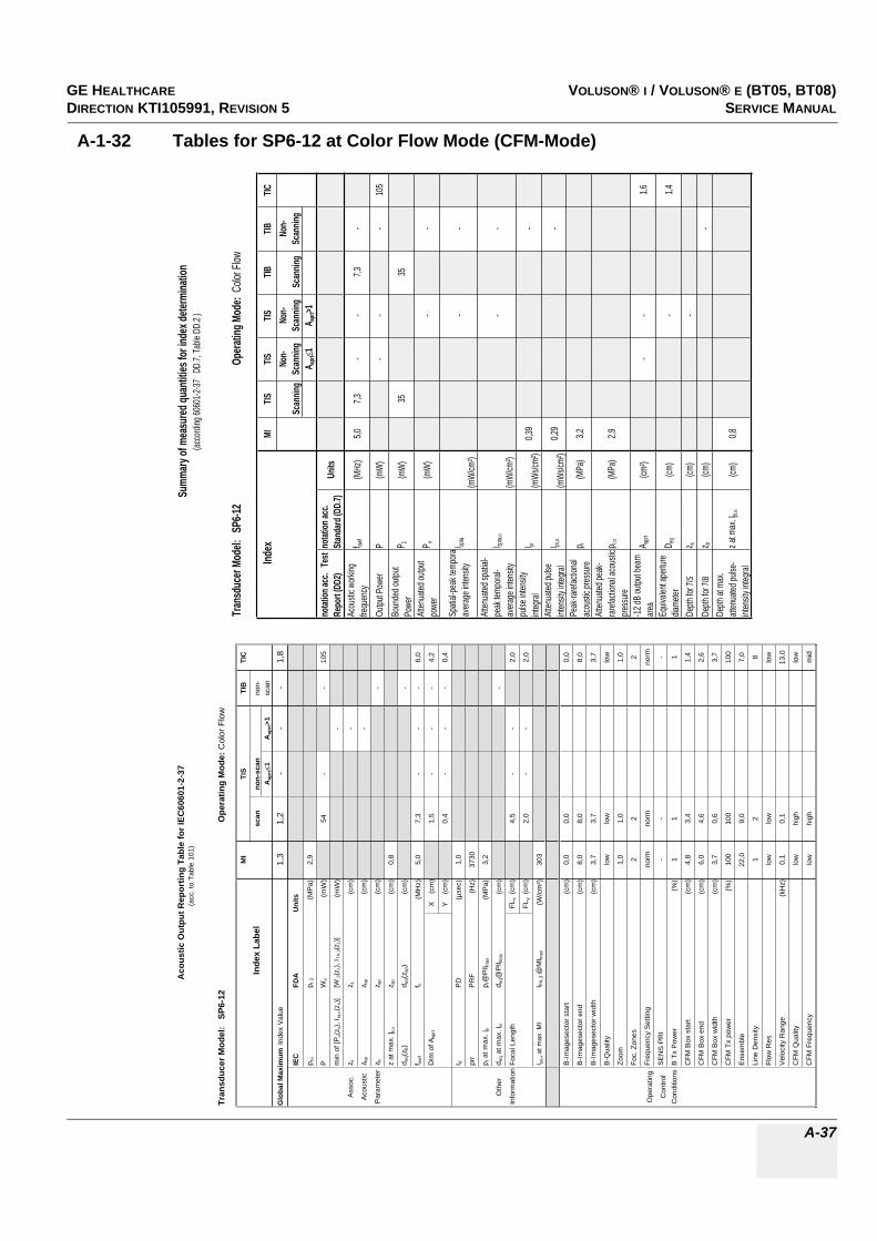
GE HEALTHCAREDRAFT VOLUSON® I / VOLUSON® E (BT05, BT08)DIRECTION KTI105991, REVISION 5 SERVICE MANUAL
A-37
A-1-32 Tables for SP6-12 at Color Flow Mode (CFM-Mode)
Tran
sduc
er Mo
del:
SP6-1
2Op
eratin
g Mod
e: Co
lor Fl
ow
Index
MITIS
TISTIS
TIBTIB
TIC
Scan
ning
Non-
Scan
ning
Non-
Scan
ning
Scan
ning
Non-
Scan
ning
A apr
t1
A apr
t>1no
tation
acc.
Tes
t Re
port
(DD2
)no
tation
acc.
Stan
dard
(DD.
7)Un
its
Acou
stic w
orking
fre
quen
cyf aw
f(M
Hz)
5,07,3
--
7,3-
Outpu
t Pow
erP
(mW
)-
--
105
Boun
ded o
utput
Powe
rP 1
(mW
)35
35
Atten
uated
outpu
t po
wer
P(m
W)
--
Spati
al-pe
ak te
mpor a
avera
ge in
tensit
yI zp
ta
(mW
/cm²)
--
Atten
uated
spati
al-pe
ak te
mpora
l-av
erage
inten
sity
I zpta,
(mW
/cm²)
--
pulse
inten
sity
integ
ralI pi
(mW
s/cm²
)0,3
9-
Atten
uated
pulse
int
ensit
y inte
gral
I pi,(m
Ws/c
m²)
0,29
-
Peak
-raref
actio
nal
acou
stic p
ressu
rep r
(MPa
)3,2
Atten
uated
peak
-rar
efacti
onal
acou
stic
press
urep r,
(MPa
)2,9
-12 dB
outpu
t bea
m are
aA a
prt(cm
²)-
-1,6
Equiv
alent
apert
ure
diame
terD e
q(cm
)-
1,4
Depth
for T
ISz s
(cm)
-De
pth fo
r TIB
z b(cm
)-
Depth
at m
ax.
atten
uated
pulse
-int
ensit
y inte
gral
z at m
ax. I p
i,(cm
)0,8
Summ
ary of
mea
sured
quan
tities
for in
dex d
eterm
inatio
n(ac
cordi
ng 60
601-2
-37 D
D.7,
Table
DD.
2 )
Tran
sduc
er M
odel
: S
P6-1
2O
pera
ting
Mod
e: C
olor
Flo
w
MI
TIS
TIB
TIC
Inde
x La
bel
scan
non-
scan
non-
Aap
rt1
Aap
rt>1
scan
Glo
bal M
axim
um In
dex
Val
ue1,
31,
2-
--
1,8
IEC
FDA
Uni
ts
p rp r
.3(M
Pa)
2,9
PW
o(m
W)
54-
-10
5
min
of [
P(z
s), I
ta,
(zs)
][W
.3(z
1), I
TA.3(z
1)]
(mW
)-
Ass
oc.
z sz 1
(cm
)-
Aco
ustic
z bp
z bp
(cm
)-
Par
amet
erz b
z sp
(cm
)-
z at
max
. I pi,
z sp
(cm
)0,
8
d eq(
z b)
d eq(
z sp)
(cm
)-
f awf
f c(M
Hz)
5,0
7,3
--
-6,
0
Dim
of A
aprt
X
(cm
)1,
5-
--
4,2
Y
(cm
)0,
4-
--
0,4
t dP
D(µ
sec)
1,0
prr
PR
F(H
z)37
30
p r a
t max
. Ipi
p r@
PII m
ax(M
Pa)
3,2
Oth
erd e
q at
max
. Ipi
d eq@
PII m
ax(c
m)
-
Info
rmat
ion
Foca
l Len
gth
FLx
(cm
)4,
5-
-2,
0
FLy
(cm
)2,
0-
-2,
0
I pa,
at m
ax. M
II P
A.3 @
MI m
ax(W
/cm
²)30
3
B-Im
ages
ecto
r sta
rt(c
m)
0,0
0,0
0,0
B-Im
ages
ecto
r end
(cm
)8,
08,
08,
0
B-Im
ages
ecto
r wid
th(c
m)
3,7
3,7
3,7
B-Q
ualit
ylo
wlo
wlo
w
Zoom
1,0
1,0
1,0
Foc.
Zon
es2
22
Ope
ratin
gFr
eque
ncy
Set
ting
norm
norm
norm
Con
trol
SE
NS
PR
I-
--
Con
ditio
nsB
Tx
Pow
er(%
)1
11
CFM
Box
sta
rt(c
m)
4,8
3,4
1,4
CFM
Box
end
(cm
)6,
04,
62,
6
CFM
Box
wid
th(c
m)
3,7
0,6
3,7
CFM
Tx
pow
er(%
)10
010
010
0
Ens
embl
e22
,09,
07,
0
Line
Den
sity
12
8
Flow
Res
low
low
low
Vel
ocity
Ran
ge(k
Hz)
0,1
0,1
13,0
CFM
Qua
lity
low
high
low
CFM
Fre
quen
cylo
whi
ghm
id
Aco
ustic
Out
put R
epor
ting
Tabl
e fo
r IEC
6060
1-2-
37(a
cc. t
o Ta
ble
101)

GE HEALTHCARERAFT VOLUSON® I / VOLUSON® E (BT05, BT08)DIRECTION KTI105991, REVISION 5 SERVICE MANUAL
A-38
A-1-33 Tables for SP6-12 at Motion Mode (M-Mode)
Tran
sduc
er Mo
del:
SP6-1
2Op
eratin
g Mod
e: B+
M-Mo
de
Index
MITIS
TISTIS
TIBTIB
TIC
Scan
ning
Non-
Scan
ning
Non-
Scan
ning
Scan
ning
Non-
Scan
ning
A apr
t1
A apr
t>1no
tation
acc.
Tes
t Re
port
(DD2
)no
tation
acc.
Stan
dard
(DD.
7)Un
its
Acou
stic w
orking
fre
quen
cyf aw
f(M
Hz)
8,58,8
--
8,8-
Outpu
t Pow
erP
(mW
)-
--
87Bo
unde
d outp
ut Po
wer
P 1(m
W)
3016
Atten
uated
outpu
t po
wer
P(m
W)
--
Spati
al-pe
ak te
mpor a
avera
ge in
tensit
yI zp
ta
(mW
/cm²)
--
Atten
uated
spati
al-pe
ak te
mpora
l-av
erage
inten
sity
I zpta,
(mW
/cm²)
--
pulse
inten
sity
integ
ralI pi
(mW
s/cm²
)0,1
1-
Atten
uated
pulse
int
ensit
y inte
gral
I pi,(m
Ws/c
m²)
0,09
-
Peak
-raref
actio
nal
acou
stic p
ressu
rep r
(MPa
)3,2
Atten
uated
peak
-rar
efacti
onal
acou
stic
press
urep r,
(MPa
)3,7
-12 dB
outpu
t bea
m are
aA a
prt(cm
²)-
-0,5
Equiv
alent
apert
ure
diame
terD e
q(cm
)-
0,8
Depth
for T
ISz s
(cm)
-De
pth fo
r TIB
z b(cm
)-
Depth
at m
ax.
atten
uated
pulse
-int
ensit
y inte
gral
z at m
ax. I p
i,(cm
)0,5
Summ
ary of
mea
sured
quan
tities
for in
dex d
eterm
inatio
n(ac
cordi
ng 60
601-2
-37 D
D.7,
Table
DD.
2 )
Tran
sduc
er M
odel
: S
P6-1
2Op
erat
ing
Mod
e:B+
M-M
ode
MI
TIS
TIB
TIC
Inde
x La
bel
scan
non-
scan
non-
A apr
t1
A apr
t>1sc
an
Glob
al M
axim
um In
dex V
alue
1,3
1,3
--
-1,
7
IEC
FDA
Units
p rp r.
3(M
Pa)
3,7
PW
o(m
W)
88-
-87
min
of [P
(zs),
I ta,
(zs)]
[W.3
(z1),
I TA.
3(z1)]
(mW
)-
Asso
c.z s
z 1(c
m)
-
Acou
stic
z bp
z bp
(cm
)-
Para
met
erz b
z sp
(cm
)-
z at m
ax. I p
i,z s
p(c
m)
0,5
d eq(z
b)d e
q(zsp
)(c
m)
-
f awf
f c(M
Hz)
8,5
8,8
--
-6,
8
Dim
of A
aprt
X
(cm
)1,
6-
--
1,2
Y
(cm
)0,
4-
--
0,4
t dPD
(µse
c)0,
2
prr
PRF
(Hz)
900
p r at
max
. I pi
p r@PI
I max
(MPa
)3,
2
Othe
rd e
q at m
ax. I p
id e
q@PI
I max
(cm
)-
Info
rmat
ionFo
cal L
engt
hFL
x (c
m)
6,0
--
4,5
FLy
(cm
)2,
0-
-2,
0
I pa,
at m
ax. M
II PA
.3 @
MI m
ax(W
/cm²)
415
B-Im
ages
ecto
r sta
rt(c
m)
0,0
0,0
0,0
B-Im
ages
ecto
r end
(cm
)8,
08,
08,
0
B-Im
ages
ecto
r widt
h(c
m)
3,7
3,7
3,7
Quali
tylow
lowlow
Oper
ating
Zoom
1,0
1,0
1,0
Cont
rol
Foc.
Zone
s4
11
Cond
itions
Freq
uenc
y Set
ting
reso
lre
sol
norm
SENS
PRI
--
-
Powe
r(%
)10
010
010
0
Mod
e Ty
peM
MM
Foca
l Dep
th(c
m)
0,9
6,0
4,5
Acou
stic
Out
put R
epor
ting
Tabl
e fo
r IEC
6060
1-2-
37(a
cc. t
o Ta
ble 1
01)

GE HEALTHCAREDRAFT VOLUSON® I / VOLUSON® E (BT05, BT08)DIRECTION KTI105991, REVISION 5 SERVICE MANUAL
A-39
A-1-34 Tables for SP6-12 at Pulsed Wave Doppler (PW-Mode)
Tran
sduc
er Mo
del:
SP6-1
2Op
eratin
g Mod
e: Pu
lsed D
opple
r
Index
MITIS
TISTIS
TIBTIB
TIC
Scan
ning
Non-
Scan
ning
Non-
Scan
ning
Scan
ning
Non-
Scan
ning
A apr
t1
A apr
t>1no
tation
acc.
Tes
t Re
port
(DD2
)no
tation
acc.
Stan
dard
(DD.
7)Un
its
Acou
stic w
orking
fre
quen
cyf aw
f(M
Hz)
5,9-
7,4-
-5,0
Outpu
t Pow
erP
(mW
)48
-34
48Bo
unde
d outp
ut Po
wer
P 1(m
W)
--
Atten
uated
outpu
t po
wer
P(m
W)
-25
,6
Spati
al-pe
ak te
mpor a
avera
ge in
tensit
yI zp
ta
(mW
/cm²)
-41
3
Atten
uated
spati
al-pe
ak te
mpora
l-av
erage
inten
sity
I zpta,
(mW
/cm²)
-31
0
pulse
inten
sity
integ
ralI pi
(mW
s/cm²
)0,2
60,0
9
Atten
uated
pulse
int
ensit
y inte
gral
I pi,(m
Ws/c
m²)
0,18
0,07
Peak
-raref
actio
nal
acou
stic p
ressu
rep r
(MPa
)3,5
Atten
uated
peak
-rar
efacti
onal
acou
stic
press
urep r,
(MPa
)3,0
-12 dB
outpu
t bea
m are
aA a
prt(cm
²)0,5
-0,5
Equiv
alent
apert
ure
diame
terD e
q(cm
)-
0,8
Depth
for T
ISz s
(cm)
-De
pth fo
r TIB
z b(cm
)0,8
Depth
at m
ax.
atten
uated
pulse
-int
ensit
y inte
gral
z at m
ax. I p
i,(cm
)0,9
Summ
ary of
mea
sured
quan
tities
for in
dex d
eterm
inatio
n(ac
cordi
ng 60
601-2
-37 D
D.7,
Table
DD.
2 )
Tran
sduc
er Mo
del:
SP6-1
2Op
eratin
g Mod
e: Pu
lsed D
opple
r
MITIS
TIBTIC
Index
Labe
lsc
anno
n-sca
nno
n-A a
prt
1A a
prt>1
scan
Glob
al Ma
ximum
Inde
x Valu
e1,2
-1,7
-1,8
1,6
IECFD
AUn
its
p rp r.
3(M
Pa)
3,0
PW
o(m
W)
-48
3448
min o
f [P(z s
), Ita,
(z s)]
[W.3(z
1), I T
A.3(z
1)](m
W)
-
Asso
c.z s
z 1(cm
)-
Acou
stic
z bpz bp
(cm)
-
Param
eterz
bz sp
(cm)
0,8
z at m
ax. I p
i,z sp
(cm)
0,9
d eq(z b
)d eq
(z sp)
(cm)
0,3
f awf
f c(M
Hz)
5,9-
7,4-
5,07,4
Dim
of A a
prt X
(cm
)-
1,2-
1,21,2
Y (
cm)
-0,4
-0,4
0,4
t dPD
(µsec
)0,4
prrPR
F(H
z)13
00
p r at
max.
I pip r@
PII ma
x(M
Pa)
3,5
Othe
rd eq
at m
ax. I p
id eq
@PI
I max
(cm)
0,3
Inform
ation
Foca
l Len
gthFL
x (cm
)-
6,0-
6,0
FLy (
cm)
-2,0
-2,0
I pa,
at ma
x. MI
I PA.3 @
MIma
x(W
/cm²)
405
Gate
width
(cm)
0,10,2
1,00,2
Opera
ting
Gate
pos
(cm)
0,03,2
2,63,2
Contr
olVe
locity
Ran
ge(kH
z)1,3
1,34,4
1,3
Cond
itions
Powe
r(%
)10
010
010
010
0
Acou
stic O
utput
Repo
rting
Table
for IE
C606
01-2-
37(ac
c. to
Table
101)
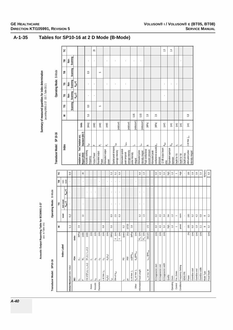
GE HEALTHCARERAFT VOLUSON® I / VOLUSON® E (BT05, BT08)DIRECTION KTI105991, REVISION 5 SERVICE MANUAL
A-40
A-1-35 Tables for SP10-16 at 2 D Mode (B-Mode)
Tran
sduc
er Mo
del:
SP 10
-16Op
eratin
g Mod
e: B-
Mode
Index
MITIS
TISTIS
TIBTIB
TIC
Scan
ning
Non-
Scan
ning
Non-
Scan
ning
Scan
ning
Non-
Scan
ning
A apr
t1
A apr
t>1no
tation
acc.
Tes
t Re
port
(DD2
)no
tation
acc.
Stan
dard
(DD.
7)Un
its
Acou
stic w
orking
fre
quen
cyf aw
f(M
Hz)
5,68,9
--
8,9-
Outpu
t Pow
erP
(mW
)-
--
28Bo
unde
d outp
ut Po
wer
P 1(m
W)
55
Atten
uated
outpu
t po
wer
P(m
W)
--
Spati
al-pe
ak te
mpor a
avera
ge in
tensit
yI zp
ta
(mW
/cm²)
--
Atten
uated
spati
al-pe
ak te
mpora
l-av
erage
inten
sity
I zpta,
(mW
/cm²)
--
pulse
inten
sity
integ
ralI pi
(mW
s/cm²
)0,0
5-
Atten
uated
pulse
int
ensit
y inte
gral
I pi,(m
Ws/c
m²)
0,03
-
Peak
-raref
actio
nal
acou
stic p
ressu
rep r
(MPa
)2,8
Atten
uated
peak
-rar
efacti
onal
acou
stic
press
urep r,
(MPa
)2,6
-12 dB
outpu
t bea
m are
aA a
prt(cm
²)-
-1,5
Equiv
alent
apert
ure
diame
terD e
q(cm
)-
1,4
Depth
for T
ISz s
(cm)
-De
pth fo
r TIB
z b(cm
)-
Depth
at m
ax.
atten
uated
pulse
-int
ensit
y inte
gral
z at m
ax. I p
i,(cm
)0,8
Summ
ary of
mea
sured
quan
tities
for in
dex d
eterm
inatio
n(ac
cordi
ng 60
601-2
-37 D
D.7,
Table
DD.
2 )
Tran
sduc
er M
odel
: S
P10-
16Op
erat
ing
Mod
e: B
-Mod
e
MI
TIS
TIB
TIC
Inde
x La
bel
scan
non-
scan
non-
A apr
t1
A apr
t>1
scan
Glob
al M
axim
um In
dex
Valu
e1,
10,
2-
--
0,5
IEC
FDA
Units
p rp r
.3(M
Pa)
2,6
PW
o(m
W)
13-
-28
min
of [
P(z
s), I t
a,(z
s)][W
.3(z
1), I T
A.3(z
1)](m
W)
-
Asso
c.z s
z 1(c
m)
-
Acou
stic
z bp
z bp
(cm
)-
Para
met
erz b
z sp
(cm
)-
z at
max
. I pi,
z sp
(cm
)0,
8
d eq(z
b)d e
q(zsp
)(c
m)
-
f awf
f c(M
Hz)
5,6
8,9
--
-5,
3
Dim
of A
aprt
X
(cm
)2,
5-
--
5,1
Y
(cm
)0,
3-
--
0,3
t dPD
(µse
c)0,
2
prr
PRF
(Hz)
1072
0
p r a
t max
. I pi
p r@
PII m
ax(M
Pa)
2,8
Oth
erd e
q at m
ax. I p
id e
q@PI
I max
(cm
)-
Info
rmat
ion
Foca
l Len
gth
FLx
(cm
)3,
2-
-6,
0
FLy
(cm
)1,
5-
-1,
5
I pa,
at m
ax. M
II PA
.3 @
MI m
ax(W
/cm
²)17
2
B-Im
ages
ecto
r sta
rt(c
m)
0,0
0,0
0,0
B-Im
ages
ecto
r end
(cm
)4,
54,
54,
5
B-Im
ages
ecto
r wid
th(c
m)
3,4
3,4
3,4
Qua
lityhi
ghlo
whi
gh
Ope
ratin
gZo
om1,
01,
01,
0
Cont
rol
Foc.
Zon
es1
11
Cond
itions
Freq
uenc
y Se
tting
pene
tno
rmHi
gh
SENS
PRI
--
-
Powe
r(%
)10
010
010
0
Zoom
Box
star
t(c
m)
0,0
3,2
2,6
Zoom
Box
end
(cm
)1,
04,
23,
6
Zoom
Box
widt
h(c
m)
2,1
0,8
3,4
Mod
e Ty
peB
BB(
Harm
)
Foca
l Dep
th(c
m)
3,2
3,2
6,0
Acou
stic
Out
put R
epor
ting
Tabl
e fo
r IEC
6060
1-2-
37(a
cc. t
o Ta
ble
101)

GE HEALTHCAREDRAFT VOLUSON® I / VOLUSON® E (BT05, BT08)DIRECTION KTI105991, REVISION 5 SERVICE MANUAL
A-41
A-1-36 Tables for SP10-16 at Color Flow Mode (CFM-Mode)
Tran
sduc
er Mo
del:
SP 10
-16Op
eratin
g Mod
e: Co
lor Fl
ow
Index
MITIS
TISTIS
TIBTIB
TIC
Scan
ning
Non-
Scan
ning
Non-
Scan
ning
Scan
ning
Non-
Scan
ning
A apr
t1
A apr
t>1no
tation
acc.
Tes
t Re
port
(DD2
)no
tation
acc.
Stan
dard
(DD.
7)Un
its
Acou
stic w
orking
fre
quen
cyf aw
f(M
Hz)
9,79,7
--
9,7-
Outpu
t Pow
erP
(mW)
--
-48
Boun
ded o
utput
Powe
rP 1
(mW)
1010
Atten
uated
outpu
t po
wer
P(m
W)-
-
Spati
al-pe
ak te
mpor a
avera
ge in
tensit
yI zp
ta
(mW/
cm²)
--
Atten
uated
spati
al-pe
ak te
mpora
l-av
erage
inten
sity
I zpta,
(mW/
cm²)
--
pulse
inten
sity
integ
ralI pi
(mWs
/cm²)
0,36
-
Atten
uated
pulse
int
ensit
y inte
gral
I pi,(m
Ws/cm
²)0,2
7-
Peak
-raref
actio
nal
acou
stic p
ressu
rep r
(MPa
)4,0
Atten
uated
peak
-rar
efacti
onal
acou
stic
press
urep r,
(MPa
)3,4
-12 dB
outpu
t bea
m are
aA a
prt(cm
²)-
-1,4
Equiv
alent
apert
ure
diame
terD e
q(cm
)-
1,4
Depth
for T
ISz s
(cm)
-De
pth fo
r TIB
z b(cm
)-
Depth
at m
ax.
atten
uated
pulse
-int
ensit
y inte
gral
z at m
ax. I p
i,(cm
)0,4
Summ
ary of
mea
sured
quan
tities
for in
dex d
eterm
inatio
n(ac
cordi
ng 60
601-2
-37 D
D.7,
Table
DD.
2 )
Tran
sduc
er M
odel
: S
P10-
16O
pera
ting
Mod
e: C
olor
Flo
w
MI
TIS
TIB
TIC
Inde
x La
bel
scan
non-
scan
non-
A apr
t1
A apr
t>1
scan
Glo
bal M
axim
um In
dex
Valu
e1,
10,
5-
--
0,9
IEC
FDA
Uni
ts
p rp r
.3(M
Pa)
3,4
PW
o(m
W)
48-
-48
min
of [
P(z
s), I
ta,
(zs)
][W
.3(z
1), I
TA.3(z
1)]
(mW
)-
Asso
c.z s
z 1(c
m)
-
Acou
stic
z bp
z bp
(cm
)-
Para
met
erz b
z sp
(cm
)-
z at
max
. I pi,
z sp
(cm
)0,
4
d eq(
z b)
d eq(
z sp)
(cm
)-
f awf
f c(M
Hz)
9,7
9,7
--
-9,
7
Dim
of A
aprt
X
(cm
)4,
8-
--
4,8
Y
(cm
)0,
3-
--
0,3
t dPD
(µse
c)0,
5
prr
PRF
(Hz)
8520
p r a
t max
. I pi
p r@
PII m
ax(M
Pa)
4,0
Oth
erd e
q at m
ax. I p
id e
q@PI
I max
(cm
)-
Info
rmat
ion
Foca
l Len
gth
FLx
(cm
)3,
2-
-3,
2
FLy
(cm
)1,
5-
-1,
5
I pa,
at m
ax. M
II P
A.3 @
MI m
ax(W
/cm
²)44
6
B-Im
ages
ecto
r sta
rt(c
m)
0,0
0,0
0,0
B-Im
ages
ecto
r end
(cm
)4,
54,
54,
5
B-Im
ages
ecto
r wid
th(c
m)
3,4
3,4
3,4
B-Q
ualit
ylo
wlo
wlo
w
Zoom
1,0
1,0
1,0
Foc.
Zon
es2
22
Ope
ratin
gFr
eque
ncy
Setti
ngre
sol
reso
lre
sol
Con
trol
SEN
S PR
I-
--
Con
ditio
nsB
Tx P
ower
(%)
11
1
CFM
Box
sta
rt(c
m)
0,0
2,4
2,4
CFM
Box
end
(cm
)0,
73,
13,
1
CFM
Box
wid
th(c
m)
3,4
3,4
3,4
CFM
Tx
pow
er(%
)10
010
010
0
Ense
mbl
e7,
031
,031
,0
Line
Den
sity
11
1
Flow
Res
high
high
high
Velo
city
Ran
ge(k
Hz)
20,5
13,0
13,0
CFM
Qua
lity
low
norm
norm
CFM
Fre
quen
cyhi
ghhi
ghhi
gh
Aco
ustic
Out
put R
epor
ting
Tabl
e fo
r IEC
6060
1-2-
37(a
cc. t
o Ta
ble
101)
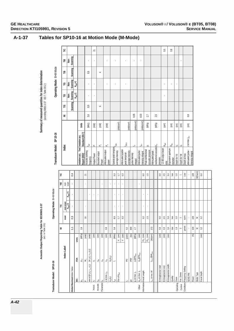
GE HEALTHCARERAFT VOLUSON® I / VOLUSON® E (BT05, BT08)DIRECTION KTI105991, REVISION 5 SERVICE MANUAL
A-42
A-1-37 Tables for SP10-16 at Motion Mode (M-Mode)
Tran
sduc
er Mo
del:
SP 10
-16Op
eratin
g Mod
e: B+
M-Mo
de
Index
MITIS
TISTIS
TIBTIB
TIC
Scan
ning
Non-
Scan
ning
Non-
Scan
ning
Scan
ning
Non-
Scan
ning
A apr
t1
A apr
t>1no
tation
acc.
Tes
t Re
port
(DD2
)no
tation
acc.
Stan
dard
(DD.
7)Un
its
Acou
stic w
orking
fre
quen
cyf aw
f(M
Hz)
5,68,9
--
8,6-
Outpu
t Pow
erP
(mW
)-
--
21Bo
unde
d outp
ut Po
wer
P 1(m
W)
64
Atten
uated
outpu
t po
wer
P(m
W)
--
Spati
al-pe
ak te
mpor a
avera
ge in
tensit
yI zp
ta
(mW
/cm²)
--
Atten
uated
spati
al-pe
ak te
mpora
l-av
erage
inten
sity
I zpta,
(mW
/cm²)
--
pulse
inten
sity
integ
ralI pi
(mW
s/cm²
)0,0
5-
Atten
uated
pulse
int
ensit
y inte
gral
I pi,(m
Ws/c
m²)
0,03
-
Peak
-raref
actio
nal
acou
stic p
ressu
rep r
(MPa
)2,7
Atten
uated
peak
-rar
efacti
onal
acou
stic
press
urep r,
(MPa
)2,6
-12 dB
outpu
t bea
m are
aA a
prt(cm
²)-
-0,5
Equiv
alent
apert
ure
diame
terD e
q(cm
)-
0,8
Depth
for T
ISz s
(cm)
-De
pth fo
r TIB
z b(cm
)-
Depth
at m
ax.
atten
uated
pulse
-int
ensit
y inte
gral
z at m
ax. I p
i,(cm
)0,8
Summ
ary of
mea
sured
quan
tities
for in
dex d
eterm
inatio
n(ac
cordi
ng 60
601-2
-37 D
D.7,
Table
DD.
2 )
Tran
sduc
er M
odel
: S
P10-
16Op
erat
ing
Mod
e:B+
M-M
ode
MI
TIS
TIB
TIC
Inde
x La
bel
scan
non-
scan
non-
A apr
t1
A apr
t>1sc
an
Glob
al M
axim
um In
dex
Valu
e1,
10,
3-
--
0,4
IEC
FDA
Units
p rp r.
3(M
Pa)
2,6
PW
o(m
W)
19-
-21
min
of [
P(z
s), I ta
,(z
s)][W
.3(z
1), I T
A.3(z
1)](m
W)
-
Asso
c.z s
z 1(c
m)
-
Acou
stic
z bp
z bp
(cm
)-
Para
met
erz b
z sp
(cm
)-
z at
max
. I pi,
z sp
(cm
)0,
8
d eq(z
b)d e
q(zsp
)(c
m)
-
f awf
f c(M
Hz)
5,6
8,9
--
-5,
3
Dim
of A
aprt
X
(cm
)1,
7-
--
1,7
Y
(cm
)0,
3-
--
0,3
t dPD
(µse
c)0,
2
prr
PRF
(Hz)
900
p r at
max
. I pi
p r@PI
I max
(MPa
)2,
7
Oth
erd e
q at m
ax. I p
id e
q@PI
I max
(cm
)-
Info
rmat
ion
Foca
l Len
gth
FLx
(cm
)3,
2-
-6,
0
FLy
(cm
)1,
5-
-1,
5
I pa,
at m
ax. M
II PA
.3 @
MI m
ax(W
/cm
²)17
2
B-Im
ages
ecto
r sta
rt(c
m)
0,0
0,0
0,0
B-Im
ages
ecto
r end
(cm
)4,
54,
54,
5
B-Im
ages
ecto
r wid
th(c
m)
3,4
3,4
3,4
Qua
litylo
wlo
wlo
w
Ope
ratin
gZo
om1,
01,
01,
0
Cont
rol
Foc.
Zon
es3
11
Cond
itions
Freq
uenc
y Se
tting
pene
tno
rmLo
w
SENS
PRI
--
-
Powe
r(%
)10
010
010
0
Mod
e Ty
peM
MM
(Har
m)
Foca
l Dep
th(c
m)
3,2
3,2
6,0
Acou
stic
Out
put R
epor
ting
Tabl
e fo
r IEC
6060
1-2-
37(a
cc. t
o Ta
ble
101)

GE HEALTHCAREDRAFT VOLUSON® I / VOLUSON® E (BT05, BT08)DIRECTION KTI105991, REVISION 5 SERVICE MANUAL
A-43
A-1-38 Tables for SP10-16 at Pulsed Wave Doppler (PW-Mode)
Tran
sduc
er Mo
del:
SP 10
-16Op
eratin
g Mod
e: Pu
lsed D
opple
r
Index
MITIS
TISTIS
TIBTIB
TIC
Scan
ning
Non-
Scan
ning
Non-
Scan
ning
Scan
ning
Non-
Scan
ning
A apr
t1
A apr
t>1no
tation
acc.
Tes
t Re
port
(DD2
)no
tation
acc.
Stan
dard
(DD.
7)Un
its
Acou
stic w
orking
fre
quen
cyf aw
f(M
Hz)
8,3-
9,7-
-9,7
Outpu
t Pow
erP
(mW)
25-
2525
Boun
ded o
utput
Powe
rP 1
(mW)
--
Atten
uated
outpu
t po
wer
P(m
W)-
16,1
Spati
al-pe
ak te
mpor a
avera
ge in
tensit
yI zp
ta
(mW/
cm²)
-34
1
Atten
uated
spati
al-pe
ak te
mpora
l-av
erage
inten
sity
I zpta,
(mW/
cm²)
-20
8
pulse
inten
sity
integ
ralI pi
(mWs
/cm²)
0,16
0,08
Atten
uated
pulse
int
ensit
y inte
gral
I pi,(m
Ws/cm
²)0,0
80,0
5
Peak
-raref
actio
nal
acou
stic p
ressu
rep r
(MPa
)4,1
Atten
uated
peak
-rar
efacti
onal
acou
stic
press
urep r,
(MPa
)3,1
-12 dB
outpu
t bea
m are
aA a
prt(cm
²)0,4
-0,4
Equiv
alent
apert
ure
diame
terD e
q(cm
)-
0,7
Depth
for T
ISz s
(cm)
-De
pth fo
r TIB
z b(cm
)0,6
Depth
at m
ax.
atten
uated
pulse
-int
ensit
y inte
gral
z at m
ax. I p
i,(cm
)0,8
Summ
ary of
mea
sured
quan
tities
for in
dex d
eterm
inatio
n(ac
cordi
ng 60
601-2
-37 D
D.7,
Table
DD.
2 )
Tran
sduc
er Mo
del:
SP10
-16Op
eratin
g Mod
e: Pu
lsed D
opple
r
MITIS
TIBTIC
Index
Labe
lsc
anno
n-sca
nno
n-A a
prt
1A a
prt>1
scan
Glob
al Ma
ximum
Inde
x Valu
e1,1
-1,1
-1,1
0,8
IECFD
AUn
its
p rp r.
3(M
Pa)
3,1
PW
o(m
W)
-25
2525
min o
f [P(z s
), Ita,
(z s)]
[W.3(z
1), I T
A.3(z
1)](m
W)
-
Asso
c.z s
z 1(cm
)-
Acou
stic
z bpz bp
(cm)
-
Param
eterz
bz sp
(cm)
0,6
z at m
ax. I p
i,z sp
(cm)
0,8
d eq(z b
)d eq
(z sp)
(cm)
0,3
f awf
f c(M
Hz)
8,3-
9,7-
9,79,7
Dim
of A a
prt X
(cm
)-
1,4-
1,41,4
Y (
cm)
-0,3
-0,3
0,3
t dPD
(µsec
)0,3
prrPR
F(H
z)13
00
p r at
max.
I pip r@
PII ma
x(M
Pa)
4,1
Othe
rd eq
at m
ax. I p
id eq
@PI
I max
(cm)
0,3
Inform
ation
Foca
l Len
gthFL
x (cm
)-
3,2-
3,2
FLy (
cm)
-1,5
-1,5
I pa,
at ma
x. MI
I PA.3 @
MIma
x(W
/cm²)
283
Gate
width
(cm)
0,10,1
0,10,1
Opera
ting
Gate
pos
(cm)
0,01,4
1,41,4
Contr
olVe
locity
Ran
ge(kH
z)1,3
4,44,4
4,4
Cond
itions
Powe
r(%
)10
010
010
010
0
Acou
stic O
utput
Repo
rting
Table
for IE
C606
01-2-
37(ac
c. to
Table
101)

GE HEALTHCARERAFT VOLUSON® I / VOLUSON® E (BT05, BT08)DIRECTION KTI105991, REVISION 5 SERVICE MANUAL
A-44
A-1-39 Table for PA2-5P at 2 D Mode (B-Mode)
Tran
sduc
er M
odel
: P
A2-
5PO
pera
ting
Mod
e: B
-Mod
e
MI
TIS
TIB
TIC
Inde
x La
bel
scan
non-
scan
non-
A apr
t1
A apr
t>1
scan
Glo
bal M
axim
um In
dex
Valu
e1,
2(a
)-
--
(a)
IEC
FDA
Uni
ts
p ra
p r.3
(MPa
)1,
6
PW
o(m
W)
#-
-#
min
of [
P a(z
s), I t
a,a(
z s)]
[W.3
(z1)
, ITA
.3(z
1)]
(mW
)-
Asso
c.z s
z 1(c
m)
-
Acou
stic
z bp
z bp
(cm
)-
Para
met
erz b
z sp
(cm
)-
z at
max
. Ipi
,az s
p(c
m)
3,2
d eq(z
b)d e
q(zsp
)(c
m)
-
f awf
f c(M
Hz)
1,9
#-
--
#
Dim
of A
aprt
X
(cm
)#
--
-#
Y
(cm
)#
--
-#
t dPD
(µse
c)0,
9
prr
PRF
(Hz)
3050
p r a
t max
. Ipi
p r@
PII m
ax(M
Pa)
2,0
Oth
erd e
q at m
ax. I
pid e
q@PI
I max
(cm
)-
Info
rmat
ion
Foca
l Len
gth
FLx
(cm
)#
--
#
FLy
(cm
)#
--
#
I pa,a
at m
ax. M
II P
A.3 @
MI m
ax(W
/cm
²)11
5
B-Im
ages
ecto
r sta
rt(c
m)
0,0
B-Im
ages
ecto
r end
(cm
)23
,7
B-Im
ages
ecto
r ang
le(D
egre
e)20
,0
Qua
lity
low
Ope
ratin
gZo
om1,
0
Con
trol
Foc.
Zon
es1
Con
ditio
nsFr
eque
ncy
Setti
ngH
igh
SEN
S PR
I-
Pow
er(%
)10
0
Zoom
Box
star
t(c
m)
7,9
Zoom
Box
end
(cm
)12
,6
Zoom
Box
angl
e(D
egre
e)15
,0
Mod
e Ty
peB(
Har
m)
Foca
l Dep
th(c
m)
5,0
Aco
ustic
Out
put R
epor
ting
Tabl
e fo
r Tra
ck 3
(pro
vide
dat
a w
here
glo
bal m
axim
um d
ispl
ayed
inde
x ex
ceed
s 1.
0)

GE HEALTHCAREDRAFT VOLUSON® I / VOLUSON® E (BT05, BT08)DIRECTION KTI105991, REVISION 5 SERVICE MANUAL
A-45
A-1-40 Table for PA2-5P at Color Flow Mode (CFM-Mode)
Tran
sduc
er M
odel
: P
A2-
5PO
pera
ting
Mod
e: C
olor
Flo
w
MI
TIS
TIB
TIC
Inde
x La
bel
scan
non-
scan
non-
Aap
rt1
Aap
rt>1
scan
Glo
bal M
axim
um In
dex
Val
ue(a
)1,
0-
--
1,5
IEC
FDA
Uni
ts
p ra
p r.3
(MP
a)#
PW
o(m
W)
72-
-84
min
of [
P a(z
s), I
ta,a
(zs)
][W
.3(z
1), I
TA.3(z
1)]
(mW
)-
Ass
oc.
z sz 1
(cm
)-
Aco
ustic
z bp
z bp
(cm
)-
Par
amet
erz b
z sp
(cm
)-
z at
max
. I pi,a
z sp
(cm
)#
d eq(
z b)
d eq(
z sp)
(cm
)-
f aw
ff c
(MH
z)#
2,9
--
-2,
8
Dim
of A
aprt
X
(cm
)0,
9-
--
1,3
Y
(cm
)1,
15-
--
1,15
t dP
D(µ
sec)
#
prr
PR
F(H
z)#
p r a
t max
. I pi
p r@
PII m
ax(M
Pa)
#
Oth
erd e
q at
max
. I pi
d eq@
PII m
ax(c
m)
-
Info
rmat
ion
Foca
l Len
gth
FLx
(cm
)5
--
8
FLy
(cm
)5,
8-
-5,
8
I pa,a
at m
ax. M
II P
A.3 @
MI m
ax(W
/cm
²)#
B-Im
ages
ecto
r sta
rt(c
m)
0,0
0,0
B-Im
ages
ecto
r end
(cm
)23
,723
,7
B-Im
ages
ecto
r ang
le(D
egre
e)90
,020
,0
B-Q
ualit
ylo
wlo
w
Zoom
1,0
1,0
Foc.
Zon
es1
1
Ope
ratin
gFr
eque
ncy
Set
ting
norm
norm
Con
trol
SE
NS
PR
I-
-
Con
ditio
nsB
Tx
Pow
er(%
)1
1
CFM
Box
sta
rt(c
m)
4,2
5,0
CFM
Box
end
(cm
)7,
88,
6
CFM
Box
ang
le(D
egre
e)90
,012
,0
CFM
Tx
pow
er(%
)10
010
0
Ens
embl
e22
31
Line
Den
sity
110
Flow
Res
low
high
Vel
ocity
Ran
ge(k
Hz)
6,0
6,0
CFM
Qua
lity
low
norm
CFM
Fre
quen
cyhi
ghhi
gh
Aco
ustic
Out
put R
epor
ting
Tabl
e fo
r Tr
ack
3(p
rovi
de d
ata
whe
re g
loba
l max
imum
dis
play
ed in
dex
exce
eds
1.0)

GE HEALTHCARERAFT VOLUSON® I / VOLUSON® E (BT05, BT08)DIRECTION KTI105991, REVISION 5 SERVICE MANUAL
A-46
A-1-41 Table for PA2-5P at Color Motion Mode (Mc-Mode)
Tran
sduc
er M
odel
: P
A2-
5PO
pera
ting
Mod
e: M
c-M
ode
MI
TIS
TIB
TIC
Inde
x La
bel
scan
non-
scan
non-
A apr
t1
A apr
t>1
scan
Glo
bal M
axim
um In
dex
Val
ue(a
)-
-<1
1,5
1,5
IEC
FDA
Uni
ts
p ra
p r.3
(MP
a)#
PW
o(m
W)
--
5695
min
of [
P a(z
s), I
ta,a
(zs)
][W
.3(z
1), I
TA.3(z
1)]
(mW
)#
Ass
oc.
z sz 1
(cm
)#
Aco
ustic
z bp
z bp
(cm
)#
Par
amet
erz b
z sp
(cm
)4,
0
z at
max
. Ipi
,az s
p(c
m)
#
d eq(
z b)
d eq(
z sp)
(cm
)0,
5
f awf
f c(M
Hz)
#-
-#
2,2
2,8
Dim
of A
aprt
X
(cm
)-
-#
1,3
1,6
Y
(cm
)-
-#
1,15
1,15
t dP
D(µ
sec)
#
prr
PR
F(H
z)#
p r a
t max
. Ipi
p r@
PII m
ax(M
Pa)
#
Oth
erd e
q at m
ax. I
pid e
q@P
II max
(cm
)0,
4
Info
rmat
ion
Foca
l Len
gth
FLx
(cm
)-
-#
11
FLy
(cm
)-
-#
5,8
I pa,a
at m
ax. M
II P
A.3 @
MI m
ax(W
/cm
²)#
B-Im
ages
ecto
r sta
rt(c
m)
0,
00,
0
B-Im
ages
ecto
r end
(cm
)
23,7
23,7
B-Im
ages
ecto
r ang
le(D
egre
e)
2020
B-Q
ualit
y
low
low
Zoom
1,
01,
0
Foc.
Zon
es
11
Ope
ratin
gFr
eque
ncy
Set
ting
no
rmno
rm
Con
trol
SE
NS
PR
I
--
Con
ditio
nsB
Tx
Pow
er(%
)
11
Mc
Tx P
ower
(%)
10
010
0
Ens
embl
e
88
Flow
Res
hi
ghhi
gh
Vel
ocity
Ran
ge(k
Hz)
1,
80,
6
Spe
ed
55
Mc
Freq
uenc
y
Mid
Hig
h
Aco
ustic
Out
put R
epor
ting
Tabl
e fo
r Tra
ck 3
(pro
vide
dat
a w
here
glo
bal m
axim
um d
ispl
ayed
inde
x ex
ceed
s 1.
0)

GE HEALTHCAREDRAFT VOLUSON® I / VOLUSON® E (BT05, BT08)DIRECTION KTI105991, REVISION 5 SERVICE MANUAL
A-47
A-1-42 Table for PA2-5P at Pulsed Wave Doppler (PW-Mode)
Tran
sduc
er M
odel:
PA2
-5P
Oper
atin
g Mo
de:
Pulse
d Dop
pler
MITI
STI
BTI
C
Inde
x Lab
elsc
anno
n-sc
anno
n-A a
prt
1A a
prt>1
scan
Glob
al Ma
ximum
Inde
x Valu
e(a
)-
-<1
1,51,5
IEC
FDA
Units
p rap r.
3(M
Pa)
#
PW
o(m
W)
--
9395
min o
f [Pa(z
s), I ta
,a(z s
)][W
.3(z 1
), I TA
.3(z1)]
(mW
)#
Asso
c.z s
z 1(cm
)#
Acou
stic
z bp
z bp
(cm)
#
Para
meter
z bz sp
(cm)
3,5
z at m
ax. I p
i,az sp
(cm)
#
d eq(z
b)d e
q(zsp
)(cm
)0,8
f awf
f c(M
Hz)
#-
-#
2,32,8
Dim
of A a
prt
X
(cm)
--
#1,9
1,6
Y (
cm)
--
#1,1
51,1
5
t dPD
(µse
c)#
prr
PRF
(Hz)
#
p r at
max.
I pip r@
PII ma
x(M
Pa)
#
Othe
rd e
q at m
ax. I p
id e
q@PI
I max
(cm)
0,8
Infor
matio
nFoc
al Le
ngth
FLx
(cm)
--
#11
FLy
(cm)
--
#5,8
I pa,a
at ma
x. MI
I PA.3 @
MIma
x(W
/cm²)
#
Gate
width
(cm)
0,4
1,0
Oper
ating
Gate
pos
(cm)
7,2
0,5
Contr
olB-
Imag
esec
tor an
gle(D
egre
e)
2,21,3
Cond
itions
Powe
r(%
)
100
100
Acou
stic
Outp
ut R
epor
ting
Tabl
e for
Tra
ck 3
(pro
vide d
ata w
here
glob
al ma
ximum
disp
layed
inde
x exc
eeds
1.0)
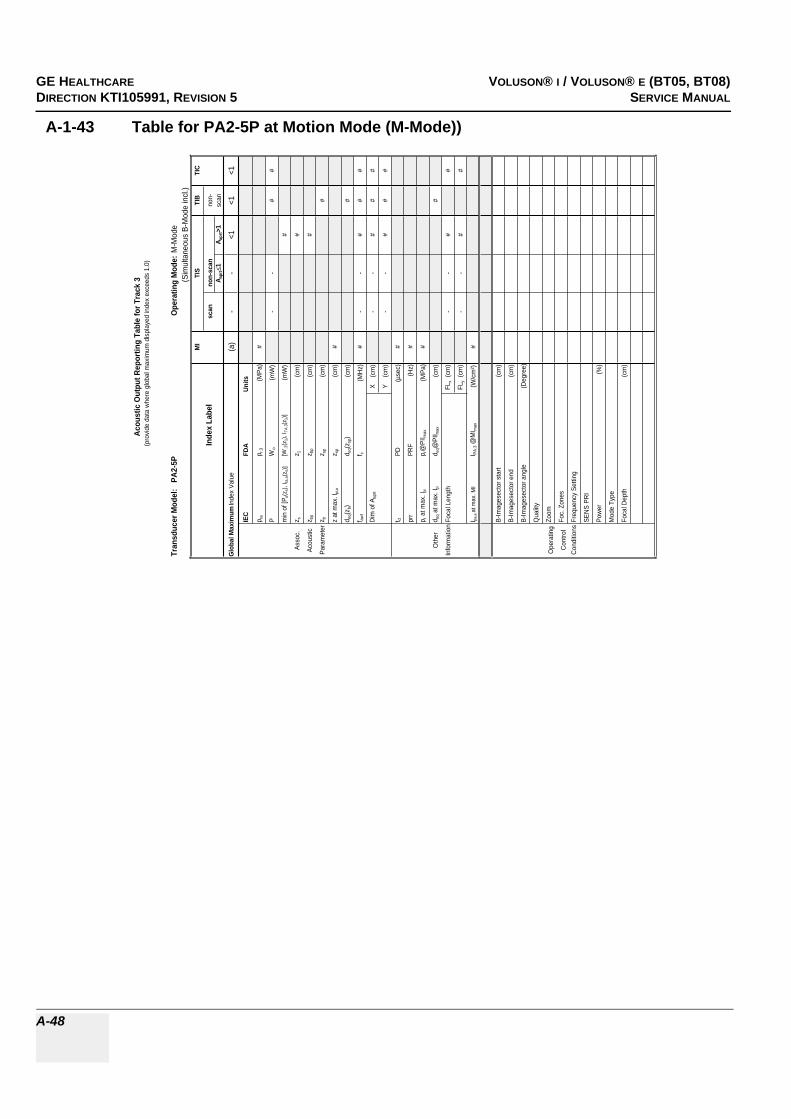
GE HEALTHCARERAFT VOLUSON® I / VOLUSON® E (BT05, BT08)DIRECTION KTI105991, REVISION 5 SERVICE MANUAL
A-48
A-1-43 Table for PA2-5P at Motion Mode (M-Mode))
Tran
sduc
er M
odel
: P
A2-5
PO
pera
ting
Mod
e:M
-Mod
e(S
imul
tane
ous
B-M
ode
incl
.)M
ITI
STI
BTI
C
Inde
x La
bel
scan
non-
scan
non-
A apr
t1
A apr
t>1
scan
Glo
bal M
axim
um In
dex
Valu
e(a
)-
-<1
<1<1
IEC
FDA
Units
p ra
p r.3
(MPa
)#
PW
o(m
W)
--
##
min
of [
P a(z
s), I t
a,a(
z s)]
[W.3
(z1)
, ITA
.3(z
1)]
(mW
)#
Asso
c.z s
z 1(c
m)
#
Acou
stic
z bp
z bp
(cm
)#
Para
met
erz b
z sp
(cm
)#
z at
max
. I pi,a
z sp
(cm
)#
d eq(z
b)d e
q(zsp
)(c
m)
#
f awf
f c(M
Hz)
#-
-#
##
Dim
of A
aprt
X
(cm
)-
-#
##
Y
(cm
)-
-#
##
t dPD
(µse
c)#
prr
PRF
(Hz)
#
p r a
t max
. Ipi
p r@
PII m
ax(M
Pa)
#
Oth
erd e
q at m
ax. I
pid e
q@PI
I max
(cm
)#
Info
rmat
ion
Foca
l Len
gth
FLx
(cm
)-
-#
#
FLy
(cm
)-
-#
#
I pa,a
at m
ax. M
II PA
.3 @
MI m
ax(W
/cm
²)#
B-Im
ages
ecto
r sta
rt(c
m)
B-Im
ages
ecto
r end
(cm
)
B-Im
ages
ecto
r ang
le(D
egre
e)
Qua
lity
Ope
ratin
gZo
om
Con
trol
Foc.
Zon
es
Con
ditio
nsFr
eque
ncy
Setti
ng
SEN
S PR
I
Pow
er(%
)
Mod
e Ty
pe
Foca
l Dep
th(c
m)
Acou
stic
Out
put R
epor
ting
Tabl
e fo
r Tra
ck 3
(pro
vide
dat
a w
here
glo
bal m
axim
um d
ispl
ayed
inde
x ex
ceed
s 1.
0)

GE HEALTHCAREDRAFT VOLUSON® I / VOLUSON® E (BT05, BT08)DIRECTION KTI105991, REVISION 5 SERVICE MANUAL
A-49
A-1-44 Table for PA6-8 at 2 D Mode (B-Mode)
Tran
sduc
er M
odel
: P
A6-
8O
pera
ting
Mod
e: B
-Mod
e
MI
TIS
TIB
TIC
Inde
x La
bel
scan
non-
scan
non-
A apr
t1
A apr
t>1
scan
Glo
bal M
axim
um In
dex
Valu
e1,
3(a
)-
--
(a)
IEC
FDA
Uni
ts
p ra
p r.3
(MPa
)2,
4
PW
o(m
W)
#-
-#
min
of [
P a(z
s), I t
a,a(
z s)]
[W.3
(z1)
, ITA
.3(z
1)]
(mW
)-
Asso
c.z s
z 1(c
m)
-
Acou
stic
z bp
z bp
(cm
)-
Para
met
erz b
z sp
(cm
)-
z at
max
. Ipi
,az s
p(c
m)
3,6
d eq(z
b)d e
q(zsp
)(c
m)
-
f awf
f c(M
Hz)
3,1
#-
--
#
Dim
of A
aprt
X
(cm
)#
--
-#
Y
(cm
)#
--
-#
t dPD
(µse
c)2,
8
prr
PRF
(Hz)
1760
p r a
t max
. Ipi
p r@
PII m
ax(M
Pa)
3,1
Oth
erd e
q at m
ax. I
pid e
q@PI
I max
(cm
)-
Info
rmat
ion
Foca
l Len
gth
FLx
(cm
)#
--
#
FLy
(cm
)#
--
#
I pa,a
at m
ax. M
II P
A.3 @
MI m
ax(W
/cm
²)12
3
B-Im
ages
ecto
r sta
rt(c
m)
0,0
B-Im
ages
ecto
r end
(cm
)24
,0
B-Im
ages
ecto
r ang
le(D
egre
e)80
,0
Qua
lity
low
Ope
ratin
gZo
om1,
0
Con
trol
Foc.
Zon
es1
Con
ditio
nsFr
eque
ncy
Setti
ng-
SEN
S PR
I16
,0
Pow
er(%
)10
0
Zoom
Box
star
t(c
m)
12,0
Zoom
Box
end
(cm
)16
,8
Zoom
Box
angl
e(D
egre
e)80
,0
Mod
e Ty
peBF
low
Foca
l Dep
th(c
m)
5,0
Aco
ustic
Out
put R
epor
ting
Tabl
e fo
r Tra
ck 3
(pro
vide
dat
a w
here
glo
bal m
axim
um d
ispl
ayed
inde
x ex
ceed
s 1.
0)
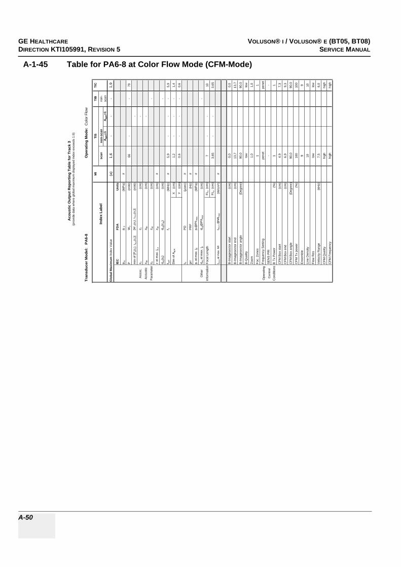
GE HEALTHCARERAFT VOLUSON® I / VOLUSON® E (BT05, BT08)DIRECTION KTI105991, REVISION 5 SERVICE MANUAL
A-50
A-1-45 Table for PA6-8 at Color Flow Mode (CFM-Mode)
Tran
sduc
er M
odel
: P
A6-
8O
pera
ting
Mod
e: C
olor
Flo
w
MI
TIS
TIB
TIC
Inde
x La
bel
scan
non-
scan
non-
Aap
rt1
Aap
rt>1
scan
Glo
bal M
axim
um In
dex
Val
ue(a
)1,
6-
--
1,9
IEC
FDA
Uni
ts
p ra
p r.3
(MP
a)#
PW
o(m
W)
66-
-79
min
of [
P a(z
s), I
ta,a
(zs)
][W
.3(z
1), I
TA.3(z
1)]
(mW
)-
Ass
oc.
z sz 1
(cm
)-
Aco
ustic
z bp
z bp
(cm
)-
Par
amet
erz b
z sp
(cm
)-
z at
max
. I pi,a
z sp
(cm
)#
d eq(
z b)
d eq(
z sp)
(cm
)-
f aw
ff c
(MH
z)#
5,9
--
-5,
9
Dim
of A
aprt
X
(cm
)1,
2-
--
1,4
Y
(cm
)0,
6-
--
0,6
t dP
D(µ
sec)
#
prr
PR
F(H
z)#
p r a
t max
. I pi
p r@
PII m
ax(M
Pa)
#
Oth
erd e
q at
max
. I pi
d eq@
PII m
ax(c
m)
-
Info
rmat
ion
Foca
l Len
gth
FLx
(cm
)7
--
10
FLy
(cm
)3,
65-
-3,
65
I pa,a
at m
ax. M
II P
A.3 @
MI m
ax(W
/cm
²)#
B-Im
ages
ecto
r sta
rt(c
m)
0,0
0,0
B-Im
ages
ecto
r end
(cm
)13
,713
,7
B-Im
ages
ecto
r ang
le(D
egre
e)90
,090
,0
B-Q
ualit
ylo
wlo
w
Zoom
1,0
1,0
Foc.
Zon
es1
1
Ope
ratin
gFr
eque
ncy
Set
ting
pene
tpe
net
Con
trol
SE
NS
PR
I-
-
Con
ditio
nsB
Tx
Pow
er(%
)1
1
CFM
Box
sta
rt(c
m)
4,9
7,3
CFM
Box
end
(cm
)6,
99,
3
CFM
Box
ang
le(D
egre
e)90
,090
,0
CFM
Tx
pow
er(%
)10
010
0
Ens
embl
e9
9
Line
Den
sity
1010
Flow
Res
low
low
Vel
ocity
Ran
ge(k
Hz)
7,5
6,0
CFM
Qua
lity
high
high
CFM
Fre
quen
cyhi
ghhi
gh
Aco
ustic
Out
put R
epor
ting
Tabl
e fo
r Tr
ack
3(p
rovi
de d
ata
whe
re g
loba
l max
imum
dis
play
ed in
dex
exce
eds
1.0)

GE HEALTHCAREDRAFT VOLUSON® I / VOLUSON® E (BT05, BT08)DIRECTION KTI105991, REVISION 5 SERVICE MANUAL
A-51
A-1-46 Table for PA6-8 at Continuous Wave Doppler (CW-Mode)
Tran
sduc
er M
odel:
PA6
-8Op
erat
ing
Mode
: Co
ntinu
es W
ave
MITI
STI
BTI
C
Inde
x Lab
elsc
anno
n-sc
anno
n-A a
prt
1A a
prt>1
scan
Glob
al Ma
ximum
Inde
x Valu
e(a
)-
<1-
<1<1
IEC
FDA
Units
p rap r.
3(M
Pa)
#
PW
o(m
W)
-#
##
min o
f [Pa(z
s), I ta
,a(z s
)][W
.3(z 1
), I TA
.3(z1)]
(mW
)-
Asso
c.z s
z 1(cm
)-
Acou
stic
z bp
z bp
(cm)
-
Para
meter
z bz sp
(cm)
#
z at m
ax. I p
i,az sp
(cm)
#
d eq(z
b)d e
q(zsp
)(cm
)#
f awf
f c(M
Hz)
#-
#-
##
Dim
of A a
prt
X
(cm)
-#
-#
#
Y (
cm)
-#
-#
#
t dPD
(µse
c)#
prr
PRF
(Hz)
#
p r at
max.
I pip r@
PII ma
x(M
Pa)
#
Othe
rd e
q at m
ax. I p
id e
q@PI
I max
(cm)
#
Infor
matio
nFoc
al Le
ngth
FLx
(cm)
-#
-#
FLy
(cm)
-#
-#
I pa,a
at ma
x. MI
I PA.3 @
MIma
x(W
/cm²)
#
Veloc
ity R
ange
(kHz)
Oper
ating
Powe
r(%
)
Contr
olCo
nditio
ns
Acou
stic
Outp
ut R
epor
ting
Tabl
e for
Tra
ck 3
(pro
vide d
ata w
here
glob
al ma
ximum
disp
layed
inde
x exc
eeds
1.0)
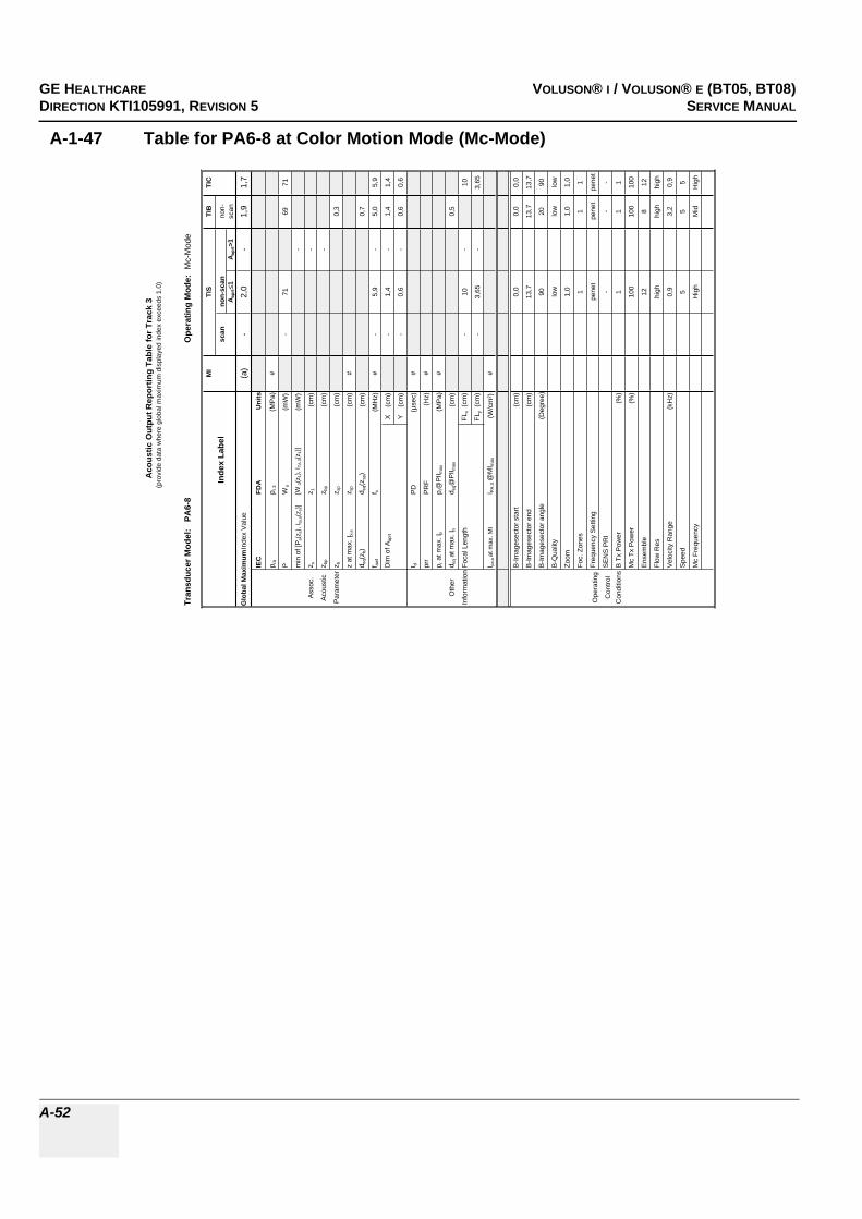
GE HEALTHCARERAFT VOLUSON® I / VOLUSON® E (BT05, BT08)DIRECTION KTI105991, REVISION 5 SERVICE MANUAL
A-52
A-1-47 Table for PA6-8 at Color Motion Mode (Mc-Mode)
Tran
sduc
er M
odel
: P
A6-
8O
pera
ting
Mod
e: M
c-M
ode
MI
TIS
TIB
TIC
Inde
x La
bel
scan
non-
scan
non-
A apr
t1
A apr
t>1
scan
Glo
bal M
axim
um In
dex
Val
ue(a
)-
2,0
-1,
91,
7
IEC
FDA
Uni
ts
p ra
p r.3
(MP
a)#
PW
o(m
W)
-71
6971
min
of [
P a(z
s), I
ta,a
(zs)
][W
.3(z
1), I
TA.3(z
1)]
(mW
)-
Ass
oc.
z sz 1
(cm
)-
Aco
ustic
z bp
z bp
(cm
)-
Par
amet
erz b
z sp
(cm
)0,
3
z at
max
. Ipi
,az s
p(c
m)
#
d eq(
z b)
d eq(
z sp)
(cm
)0,
7
f awf
f c(M
Hz)
#-
5,9
-5,
05,
9
Dim
of A
aprt
X
(cm
)-
1,4
-1,
41,
4
Y
(cm
)-
0,6
-0,
60,
6
t dP
D(µ
sec)
#
prr
PR
F(H
z)#
p r a
t max
. Ipi
p r@
PII m
ax(M
Pa)
#
Oth
erd e
q at m
ax. I
pid e
q@P
II max
(cm
)0,
5
Info
rmat
ion
Foca
l Len
gth
FLx
(cm
)-
10-
10
FLy
(cm
)-
3,65
-3,
65
I pa,a
at m
ax. M
II P
A.3 @
MI m
ax(W
/cm
²)#
B-Im
ages
ecto
r sta
rt(c
m)
0,0
0,0
0,0
B-Im
ages
ecto
r end
(cm
)13
,713
,713
,7
B-Im
ages
ecto
r ang
le(D
egre
e)90
2090
B-Q
ualit
ylo
wlo
wlo
w
Zoom
1,0
1,0
1,0
Foc.
Zon
es1
11
Ope
ratin
gFr
eque
ncy
Set
ting
pene
tpe
net
pene
t
Con
trol
SE
NS
PR
I-
--
Con
ditio
nsB
Tx
Pow
er(%
)1
11
Mc
Tx P
ower
(%)
100
100
100
Ens
embl
e12
812
Flow
Res
high
high
high
Vel
ocity
Ran
ge(k
Hz)
0,9
3,2
0,9
Spe
ed5
55
Mc
Freq
uenc
yH
igh
Mid
Hig
h
Aco
ustic
Out
put R
epor
ting
Tabl
e fo
r Tra
ck 3
(pro
vide
dat
a w
here
glo
bal m
axim
um d
ispl
ayed
inde
x ex
ceed
s 1.
0)

GE HEALTHCAREDRAFT VOLUSON® I / VOLUSON® E (BT05, BT08)DIRECTION KTI105991, REVISION 5 SERVICE MANUAL
A-53
A-1-48 Table for PA6-8 at Pulsed Wave Doppler (PW-Mode)
Tran
sduc
er M
odel:
PA6
-8Op
erat
ing
Mode
: Pu
lsed D
opple
r
MITI
STI
BTI
C
Inde
x Lab
elsc
anno
n-sc
anno
n-A a
prt
1A a
prt>1
scan
Glob
al Ma
ximum
Inde
x Valu
e(a
)-
2,0-
1,91,9
IEC
FDA
Units
p rap r.
3(M
Pa)
#
PW
o(m
W)
-71
6871
min o
f [Pa(z
s), I ta
,a(z s
)][W
.3(z 1
), I TA
.3(z1)]
(mW
)-
Asso
c.z s
z 1(cm
)-
Acou
stic
z bp
z bp
(cm)
-
Para
meter
z bz sp
(cm)
0,3
z at m
ax. I p
i,az sp
(cm)
#
d eq(z
b)d e
q(zsp
)(cm
)0,7
f awf
f c(M
Hz)
#-
5,9-
5,05,9
Dim
of A a
prt
X
(cm)
-1,2
-1,4
1,2
Y (
cm)
-0,6
-0,6
0,6
t dPD
(µse
c)#
prr
PRF
(Hz)
#
p r at
max.
I pip r@
PII ma
x(M
Pa)
#
Othe
rd e
q at m
ax. I p
id e
q@PI
I max
(cm)
0,5
Infor
matio
nFoc
al Le
ngth
FLx
(cm)
-7
-7
FLy
(cm)
-3,6
5-
3,65
I pa,a
at ma
x. MI
I PA.3 @
MIma
x(W
/cm²)
#
Gate
width
(cm)
0,20,7
0,2
Oper
ating
Gate
pos
(cm)
1,54,3
1,5
Contr
olB-
Imag
esec
tor an
gle(D
egre
e)3,3
2,23,3
Cond
itions
Powe
r(%
)10
010
010
0
Acou
stic
Outp
ut R
epor
ting
Tabl
e for
Tra
ck 3
(pro
vide d
ata w
here
glob
al ma
ximum
disp
layed
inde
x exc
eeds
1.0)

GE HEALTHCARERAFT VOLUSON® I / VOLUSON® E (BT05, BT08)DIRECTION KTI105991, REVISION 5 SERVICE MANUAL
A-54
A-1-49 Table for PA6-8 at Motion Mode (M-Mode)
Tran
sduc
er M
odel
: P
A6-8
Ope
ratin
g M
ode:
M-M
ode
(Sim
ulta
neou
s B-
Mod
e in
cl.)
MI
TIS
TIB
TIC
Inde
x La
bel
scan
non-
scan
non-
A apr
t1
A apr
t>1
scan
Glo
bal M
axim
um In
dex
Valu
e(a
)-
<1-
<1<1
IEC
FDA
Units
p ra
p r.3
(MPa
)#
PW
o(m
W)
-#
##
min
of [
P a(z
s), I t
a,a(
z s)]
[W.3
(z1)
, ITA
.3(z
1)]
(mW
)-
Asso
c.z s
z 1(c
m)
-
Acou
stic
z bp
z bp
(cm
)-
Para
met
erz b
z sp
(cm
)#
z at
max
. I pi,a
z sp
(cm
)#
d eq(z
b)d e
q(zsp
)(c
m)
#
f awf
f c(M
Hz)
#-
#-
##
Dim
of A
aprt
X
(cm
)-
#-
##
Y
(cm
)-
#-
##
t dPD
(µse
c)#
prr
PRF
(Hz)
#
p r a
t max
. Ipi
p r@
PII m
ax(M
Pa)
#
Oth
erd e
q at m
ax. I
pid e
q@PI
I max
(cm
)#
Info
rmat
ion
Foca
l Len
gth
FLx
(cm
)-
#-
#
FLy
(cm
)-
#-
#
I pa,a
at m
ax. M
II PA
.3 @
MI m
ax(W
/cm
²)#
B-Im
ages
ecto
r sta
rt(c
m)
B-Im
ages
ecto
r end
(cm
)
B-Im
ages
ecto
r ang
le(D
egre
e)
Qua
lity
Ope
ratin
gZo
om
Con
trol
Foc.
Zon
es
Con
ditio
nsFr
eque
ncy
Setti
ng
SEN
S PR
I
Pow
er(%
)
Mod
e Ty
pe
Foca
l Dep
th(c
m)
Acou
stic
Out
put R
epor
ting
Tabl
e fo
r Tra
ck 3
(pro
vide
dat
a w
here
glo
bal m
axim
um d
ispl
ayed
inde
x ex
ceed
s 1.
0)

GE HEALTHCAREDRAFT VOLUSON® I / VOLUSON® E (BT05, BT08)DIRECTION KTI105991, REVISION 5 SERVICE MANUAL
A-55
A-1-50 Table for PCW4.0 at Continuous Wave Doppler (CW-Mode)
Tran
sduc
er M
odel
: P
CW4.
0Op
erat
ing
Mod
e: C
ontin
ues W
ave
MI
TIS
TIB
TIC
Inde
x La
bel
scan
non-
scan
non-
A apr
t1
A apr
t>1sc
an
Glob
al M
axim
um In
dex V
alue
(a)
-<1
-1,
0<1
p r.3
(MPa
)#
Wo
(mW
)-
#16
#
min
of [W
.3(z
1), I T
A.3(z
1)](m
W)
-
Asso
c.z 1
(cm
)-
Acou
stic
z bp
(cm
)-
Para
met
erz s
p(c
m)
#1,
1
d eq(z
sp)
(cm
)0,
3
f c(M
Hz)
#-
#-
3,9
#
Dim
of A
aprt
X
(cm
)-
#-
0,5
#
Y
(cm
)-
#-
0,50
#
PD(µ
sec)
#
PRF
(Hz)
#
p r@PI
I max
(MPa
)#
Othe
rd e
q@PI
I max
(cm
)0,
3
Info
rmat
ionFo
cal
FLx
(cm
)-
#-
#
Leng
thFL
y (c
m)
-#
-#
I PA.3
@M
I max
#
Tx fr
eque
ncy
(MHz
)3,
9
Oper
ating
Tx fo
cus
(cm
)5
Cont
rol
Tx p
ower
3
Cond
itions
Acou
stic
Out
put R
epor
ting
Tabl
e fo
r Tra
ck 3

GE HEALTHCARERAFT VOLUSON® I / VOLUSON® E (BT05, BT08)DIRECTION KTI105991, REVISION 5 SERVICE MANUAL
A-56
A-1-51 Table for SCW2.0 at Continuous Wave Doppler (CW-Mode)
Tran
sduc
er M
odel
: S
CW2.
0Op
erat
ing
Mod
e: C
ontin
ues W
ave
MI
TIS
TIB
TIC
Inde
x La
bel
scan
non-
scan
non-
A apr
t1
A apr
t>1sc
an
Glob
al M
axim
um In
dex V
alue
(a)
-<1
-1,
2<1
p r.3
(MPa
)#
Wo
(mW
)-
#28
#
min
of [W
.3(z
1), I T
A.3(z
1)](m
W)
-
Asso
c.z 1
(cm
)-
Acou
stic
z bp
(cm
)-
Para
met
erz s
p(c
m)
#0,
4
d eq(z
sp)
(cm
)0,
5
f c(M
Hz)
#-
#-
2,0
#
Dim
of A
aprt
X
(cm
)-
#-
0,9
#
Y
(cm
)-
#-
0,92
#
PD(µ
sec)
#
PRF
(Hz)
#
p r@PI
I max
(MPa
)#
Othe
rd e
q@PI
I max
(cm
)0,
5
Info
rmat
ionFo
cal
FLx
(cm
)-
#-
#
Leng
thFL
y (c
m)
-#
-#
I PA.3
@M
I max
#
Tx fr
eque
ncy
(MHz
)1,
9
Oper
ating
Tx fo
cus
(cm
)5
Cont
rol
Tx p
ower
-1
Cond
itions
Acou
stic
Out
put R
epor
ting
Tabl
e fo
r Tra
ck 3

GE HEALTHCAREDRAFT VOLUSON® I / VOLUSON® E (BT05, BT08)DIRECTION KTI105991, REVISION 5 SERVICE MANUAL
A-57
A-1-52 Table for RAB2-5L at 2 D Mode (B-Mode)
Tran
sduc
er M
odel
: R
AB
2-5L
Ope
ratin
g M
ode:
B-M
ode
MI
TIS
TIB
TIC
Inde
x La
bel
scan
non-
scan
non-
A apr
t1
A apr
t>1
scan
Glo
bal M
axim
um In
dex
Valu
e1,
3(a
)-
--
(a)
IEC
FDA
Uni
ts
p ra
p r.3
(MPa
)1,
8
PW
o(m
W)
#-
-#
min
of [
P a(z
s), I t
a,a(
z s)]
[W.3
(z1)
, ITA
.3(z
1)]
(mW
)-
Asso
c.z s
z 1(c
m)
-
Acou
stic
z bp
z bp
(cm
)-
Para
met
erz b
z sp
(cm
)-
z at
max
. Ipi
,az s
p(c
m)
3,8
d eq(z
b)d e
q(zsp
)(c
m)
-
f awf
f c(M
Hz)
2,1
#-
--
#
Dim
of A
aprt
X
(cm
)#
--
-#
Y
(cm
)#
--
-#
t dPD
(µse
c)0,
7
prr
PRF
(Hz)
4760
p r a
t max
. Ipi
p r@
PII m
ax(M
Pa)
2,4
Oth
erd e
q at m
ax. I
pid e
q@PI
I max
(cm
)-
Info
rmat
ion
Foca
l Len
gth
FLx
(cm
)#
--
#
FLy
(cm
)#
--
#
I pa,a
at m
ax. M
II P
A.3 @
MI m
ax(W
/cm
²)17
7
B-Im
ages
ecto
r sta
rt(c
m)
0,0
B-Im
ages
ecto
r end
(cm
)24
,0
B-Im
ages
ecto
r ang
le(D
egre
e)80
,0
Qua
lity
low
Ope
ratin
gZo
om1,
0
Con
trol
Foc.
Zon
es1
Con
ditio
nsFr
eque
ncy
Setti
ngM
id
SEN
S PR
I-
Pow
er(%
)10
0
Zoom
Box
star
t(c
m)
6,4
Zoom
Box
end
(cm
)11
,2
Zoom
Box
angl
e(D
egre
e)80
,0
Mod
e Ty
peB(
Har
m)
Foca
l Dep
th(c
m)
5,0
Aco
ustic
Out
put R
epor
ting
Tabl
e fo
r Tra
ck 3
(pro
vide
dat
a w
here
glo
bal m
axim
um d
ispl
ayed
inde
x ex
ceed
s 1.
0)

GE HEALTHCARERAFT VOLUSON® I / VOLUSON® E (BT05, BT08)DIRECTION KTI105991, REVISION 5 SERVICE MANUAL
A-58
A-1-53 Table for RAB2-5L at Color Flow Mode (CFM-Mode)
Tran
sduc
er M
odel
: R
AB
2-5L
Ope
ratin
g M
ode:
Col
or F
low
MI
TIS
TIB
TIC
Inde
x La
bel
scan
non-
scan
non-
Aap
rt1
Aap
rt>1
scan
Glo
bal M
axim
um In
dex
Val
ue(a
)<1
--
-1,
4
IEC
FDA
Uni
ts
p ra
p r.3
(MP
a)#
PW
o(m
W)
#-
-20
1
min
of [
P a(z
s), I
ta,a
(zs)
][W
.3(z
1), I
TA.3(z
1)]
(mW
)-
Ass
oc.
z sz 1
(cm
)-
Aco
ustic
z bp
z bp
(cm
)-
Par
amet
erz b
z sp
(cm
)-
z at
max
. I pi,a
z sp
(cm
)#
d eq(
z b)
d eq(
z sp)
(cm
)-
f aw
ff c
(MH
z)#
#-
--
3,6
Dim
of A
aprt
X
(cm
)#
--
-8,
1
Y
(cm
)#
--
-1,
3
t dP
D(µ
sec)
#
prr
PR
F(H
z)#
p r a
t max
. I pi
p r@
PII m
ax(M
Pa)
#
Oth
erd e
q at
max
. I pi
d eq@
PII m
ax(c
m)
-
Info
rmat
ion
Foca
l Len
gth
FLx
(cm
)#
--
15
FLy
(cm
)#
--
7
I pa,a
at m
ax. M
II P
A.3 @
MI m
ax(W
/cm
²)#
B-Im
ages
ecto
r sta
rt(c
m)
0,
0
B-Im
ages
ecto
r end
(cm
)
24,0
B-Im
ages
ecto
r ang
le(D
egre
e)
80,0
B-Q
ualit
y
low
Zoom
1,
0
Foc.
Zon
es
1
Ope
ratin
gFr
eque
ncy
Set
ting
pe
net
Con
trol
SE
NS
PR
I
-
Con
ditio
nsB
Tx
Pow
er(%
)
1
CFM
Box
sta
rt(c
m)
13
,6
CFM
Box
end
(cm
)
17,2
CFM
Box
ang
le(D
egre
e)
80,0
CFM
Tx
pow
er(%
)
100
Ens
embl
e
31
Line
Den
sity
1
Flow
Res
lo
w
Vel
ocity
Ran
ge(k
Hz)
3,
2
CFM
Qua
lity
no
rm
CFM
Fre
quen
cy
high
Aco
ustic
Out
put R
epor
ting
Tabl
e fo
r Tr
ack
3(p
rovi
de d
ata
whe
re g
loba
l max
imum
dis
play
ed in
dex
exce
eds
1.0)

GE HEALTHCAREDRAFT VOLUSON® I / VOLUSON® E (BT05, BT08)DIRECTION KTI105991, REVISION 5 SERVICE MANUAL
A-59
A-1-54 Table for RAB2-5L at Motion Mode (M-Mode)
Tran
sduc
er M
odel
: R
AB2-
5LO
pera
ting
Mod
e:M
-Mod
e(S
imul
tane
ous
B-M
ode
incl
.)M
ITI
STI
BTI
C
Inde
x La
bel
scan
non-
scan
non-
A apr
t1
A apr
t>1
scan
Glo
bal M
axim
um In
dex
Valu
e(a
)<1
-<1
<1<1
IEC
FDA
Units
p ra
p r.3
(MPa
)#
PW
o(m
W)
#-
##
min
of [
P a(z
s), I t
a,a(
z s)]
[W.3
(z1)
, ITA
.3(z
1)]
(mW
)#
Asso
c.z s
z 1(c
m)
#
Acou
stic
z bp
z bp
(cm
)#
Para
met
erz b
z sp
(cm
)#
z at
max
. I pi,a
z sp
(cm
)#
d eq(z
b)d e
q(zsp
)(c
m)
#
f awf
f c(M
Hz)
##
-#
##
Dim
of A
aprt
X
(cm
)#
-#
##
Y
(cm
)#
-#
##
t dPD
(µse
c)#
prr
PRF
(Hz)
#
p r a
t max
. Ipi
p r@
PII m
ax(M
Pa)
#
Oth
erd e
q at m
ax. I
pid e
q@PI
I max
(cm
)#
Info
rmat
ion
Foca
l Len
gth
FLx
(cm
)#
-#
#
FLy
(cm
)#
-#
#
I pa,a
at m
ax. M
II PA
.3 @
MI m
ax(W
/cm
²)#
B-Im
ages
ecto
r sta
rt(c
m)
B-Im
ages
ecto
r end
(cm
)
B-Im
ages
ecto
r ang
le(D
egre
e)
Qua
lity
Ope
ratin
gZo
om
Con
trol
Foc.
Zon
es
Con
ditio
nsFr
eque
ncy
Setti
ng
SEN
S PR
I
Pow
er(%
)
Mod
e Ty
pe
Foca
l Dep
th(c
m)
Acou
stic
Out
put R
epor
ting
Tabl
e fo
r Tra
ck 3
(pro
vide
dat
a w
here
glo
bal m
axim
um d
ispl
ayed
inde
x ex
ceed
s 1.
0)
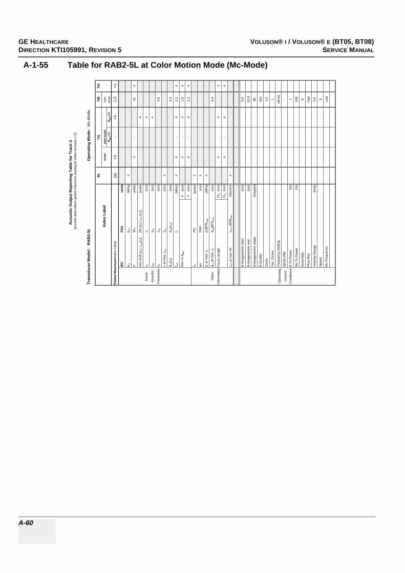
GE HEALTHCARERAFT VOLUSON® I / VOLUSON® E (BT05, BT08)DIRECTION KTI105991, REVISION 5 SERVICE MANUAL
A-60
A-1-55 Table for RAB2-5L at Color Motion Mode (Mc-Mode)
Tran
sduc
er M
odel
: R
AB
2-5L
Ope
ratin
g M
ode:
Mc-
Mod
e
MI
TIS
TIB
TIC
Inde
x La
bel
scan
non-
scan
non-
A apr
t1
A apr
t>1
scan
Glo
bal M
axim
um In
dex
Val
ue(a
)<1
-<1
1,0
<1
IEC
FDA
Uni
ts
p ra
p r.3
(MP
a)#
PW
o(m
W)
#-
33#
min
of [
P a(z
s), I
ta,a
(zs)
][W
.3(z
1), I
TA.3(z
1)]
(mW
)#
Ass
oc.
z sz 1
(cm
)#
Aco
ustic
z bp
z bp
(cm
)#
Par
amet
erz b
z sp
(cm
)4,
6
z at
max
. Ipi
,az s
p(c
m)
#
d eq(
z b)
d eq(
z sp)
(cm
)0,
4
f awf
f c(M
Hz)
##
-#
2,1
#
Dim
of A
aprt
X
(cm
)#
-#
1,6
#
Y
(cm
)#
-#
1,3
#
t dP
D(µ
sec)
#
prr
PR
F(H
z)#
p r a
t max
. Ipi
p r@
PII m
ax(M
Pa)
#
Oth
erd e
q at m
ax. I
pid e
q@P
II max
(cm
)0,
4
Info
rmat
ion
Foca
l Len
gth
FLx
(cm
)#
-#
#
FLy
(cm
)#
-#
#
I pa,a
at m
ax. M
II P
A.3 @
MI m
ax(W
/cm
²)#
B-Im
ages
ecto
r sta
rt(c
m)
0,0
B-Im
ages
ecto
r end
(cm
)
24
,0
B-Im
ages
ecto
r ang
le(D
egre
e)
80
B-Q
ualit
y
lo
w
Zoom
1,0
Foc.
Zon
es
1
Ope
ratin
gFr
eque
ncy
Set
ting
pene
t
Con
trol
SE
NS
PR
I
-
Con
ditio
nsB
Tx
Pow
er(%
)
1
Mc
Tx P
ower
(%)
100
Ens
embl
e
8
Flow
Res
high
Vel
ocity
Ran
ge(k
Hz)
0,6
Spe
ed
5
Mc
Freq
uenc
y
Lo
w
Aco
ustic
Out
put R
epor
ting
Tabl
e fo
r Tra
ck 3
(pro
vide
dat
a w
here
glo
bal m
axim
um d
ispl
ayed
inde
x ex
ceed
s 1.
0)

GE HEALTHCAREDRAFT VOLUSON® I / VOLUSON® E (BT05, BT08)DIRECTION KTI105991, REVISION 5 SERVICE MANUAL
A-61
A-1-56 Table for RAB2-5L at Pulsed Wave Doppler (PW-Mode)
Tran
sduc
er M
odel:
RAB
2-5L
Oper
atin
g Mo
de:
Pulse
d Dop
pler
MITI
STI
BTI
C
Inde
x Lab
elsc
anno
n-sc
anno
n-A a
prt
1A a
prt>1
scan
Glob
al Ma
ximum
Inde
x Valu
e(a
)<1
-<1
1,71,3
IEC
FDA
Units
p rap r.
3(M
Pa)
#
PW
o(m
W)
#-
9910
6
min o
f [Pa(z
s), I ta
,a(z s
)][W
.3(z 1
), I TA
.3(z1)]
(mW
)#
Asso
c.z s
z 1(cm
)#
Acou
stic
z bp
z bp
(cm)
#
Para
meter
z bz sp
(cm)
4,2
z at m
ax. I p
i,az sp
(cm)
#
d eq(z
b)d e
q(zsp
)(cm
)0,7
f awf
f c(M
Hz)
##
-#
2,03,6
Dim
of A a
prt
X
(cm)
#-
#2,5
2,5
Y (
cm)
#-
#1,3
1,3
t dPD
(µse
c)#
prr
PRF
(Hz)
#
p r at
max.
I pip r@
PII ma
x(M
Pa)
#
Othe
rd e
q at m
ax. I p
id e
q@PI
I max
(cm)
0,7
Infor
matio
nFoc
al Le
ngth
FLx
(cm)
#-
#15
FLy
(cm)
#-
#7
I pa,a
at ma
x. MI
I PA.3 @
MIma
x(W
/cm²)
#
Gate
width
(cm)
0,10,5
Oper
ating
Gate
pos
(cm)
9,61
9,65
Contr
olB-
Imag
esec
tor an
gle(D
egre
e)
1,3
2,2
Cond
itions
Powe
r(%
)
10
010
0
Acou
stic
Outp
ut R
epor
ting
Tabl
e for
Tra
ck 3
(pro
vide d
ata w
here
glob
al ma
ximum
disp
layed
inde
x exc
eeds
1.0)

GE HEALTHCARERAFT VOLUSON® I / VOLUSON® E (BT05, BT08)DIRECTION KTI105991, REVISION 5 SERVICE MANUAL
A-62
A-1-57 Table for RAB4-8L at 2 D Mode (B-Mode)
Tran
sduc
er M
odel
: R
AB4-
8LO
pera
ting
Mod
e: B
-Mod
e
MI
TIS
TIB
TIC
Inde
x La
bel
scan
non-
scan
non-
A apr
t1
A apr
t>1
scan
Glo
bal M
axim
um In
dex
Valu
e1,
3(a
)-
--
(a)
IEC
FDA
Units
p ra
p r.3
(MPa
)2,
1
PW
o(m
W)
#-
-#
min
of [
P a(z
s), I t
a,a(
z s)]
[W.3
(z1)
, ITA
.3(z
1)]
(mW
)-
Asso
c.z s
z 1(c
m)
-
Acou
stic
z bp
z bp
(cm
)-
Para
met
erz b
z sp
(cm
)-
z at
max
. Ipi
,az s
p(c
m)
2,8
d eq(z
b)d e
q(zsp
)(c
m)
-
f awf
f c(M
Hz)
2,9
#-
--
#
Dim
of A
aprt
X
(cm
)#
--
-#
Y
(cm
)#
--
-#
t dPD
(µse
c)0,
5
prr
PRF
(Hz)
2800
p r a
t max
. Ipi
p r@
PII m
ax(M
Pa)
2,7
Oth
erd e
q at m
ax. I
pid e
q@PI
I max
(cm
)-
Info
rmat
ion
Foca
l Len
gth
FLx
(cm
)#
--
#
FLy
(cm
)#
--
#
I pa,a
at m
ax. M
II P
A.3 @
MI m
ax(W
/cm
²)24
6
B-Im
ages
ecto
r sta
rt(c
m)
0,0
B-Im
ages
ecto
r end
(cm
)22
,0
B-Im
ages
ecto
r ang
le(D
egre
e)20
,0
Qua
lity
low
Ope
ratin
gZo
om1,
0
Con
trol
Foc.
Zon
es1
Con
ditio
nsFr
eque
ncy
Setti
ngH
igh
SEN
S PR
I-
Pow
er(%
)10
0
Zoom
Box
star
t(c
m)
8,8
Zoom
Box
end
(cm
)13
,2
Zoom
Box
angl
e(D
egre
e)20
,0
Mod
e Ty
peB(
Har
m)
Foca
l Dep
th(c
m)
3,0
Acou
stic
Out
put R
epor
ting
Tabl
e fo
r Tra
ck 3
(pro
vide
dat
a w
here
glo
bal m
axim
um d
ispl
ayed
inde
x ex
ceed
s 1.
0)

GE HEALTHCAREDRAFT VOLUSON® I / VOLUSON® E (BT05, BT08)DIRECTION KTI105991, REVISION 5 SERVICE MANUAL
A-63
A-1-58 Table for RAB4-8L at Color Flow Mode (CFM-Mode)
Tran
sduc
er M
odel
: R
AB
4-8L
Ope
ratin
g M
ode:
Col
or F
low
MI
TIS
TIB
TIC
Inde
x La
bel
scan
non-
scan
non-
Aap
rt1
Aap
rt>1
scan
Glo
bal M
axim
um In
dex
Val
ue(a
)<1
--
-<1
IEC
FDA
Uni
ts
p ra
p r.3
(MP
a)#
PW
o(m
W)
#-
-#
min
of [
P a(z
s), I
ta,a
(zs)
][W
.3(z
1), I
TA.3(z
1)]
(mW
)-
Ass
oc.
z sz 1
(cm
)-
Aco
ustic
z bp
z bp
(cm
)-
Par
amet
erz b
z sp
(cm
)-
z at
max
. I pi,a
z sp
(cm
)#
d eq(
z b)
d eq(
z sp)
(cm
)-
f aw
ff c
(MH
z)#
#-
--
#
Dim
of A
aprt
X
(cm
)#
--
-#
Y
(cm
)#
--
-#
t dP
D(µ
sec)
#
prr
PR
F(H
z)#
p r a
t max
. I pi
p r@
PII m
ax(M
Pa)
#
Oth
erd e
q at
max
. I pi
d eq@
PII m
ax(c
m)
-
Info
rmat
ion
Foca
l Len
gth
FLx
(cm
)#
--
#
FLy
(cm
)#
--
#
I pa,a
at m
ax. M
II P
A.3 @
MI m
ax(W
/cm
²)#
B-Im
ages
ecto
r sta
rt(c
m)
B-Im
ages
ecto
r end
(cm
)
B-Im
ages
ecto
r ang
le(D
egre
e)
B-Q
ualit
y
Zoom
Foc.
Zon
es
Ope
ratin
gFr
eque
ncy
Set
ting
Con
trol
SE
NS
PR
I
Con
ditio
nsB
Tx
Pow
er(%
)
CFM
Box
sta
rt(c
m)
CFM
Box
end
(cm
)
CFM
Box
ang
le(D
egre
e)
CFM
Tx
pow
er(%
)
Ens
embl
e
Line
Den
sity
Flow
Res
Vel
ocity
Ran
ge(k
Hz)
CFM
Qua
lity
CFM
Fre
quen
cy
Aco
ustic
Out
put R
epor
ting
Tabl
e fo
r Tr
ack
3(p
rovi
de d
ata
whe
re g
loba
l max
imum
dis
play
ed in
dex
exce
eds
1.0)

GE HEALTHCARERAFT VOLUSON® I / VOLUSON® E (BT05, BT08)DIRECTION KTI105991, REVISION 5 SERVICE MANUAL
A-64
A-1-59 Table for RAB4-8L at Motion Mode (M-Mode)
Tran
sduc
er M
odel
: R
AB4-
8LO
pera
ting
Mod
e:M
-Mod
e(S
imul
tane
ous
B-M
ode
incl
.)M
ITI
STI
BTI
C
Inde
x La
bel
scan
non-
scan
non-
A apr
t1
A apr
t>1
scan
Glo
bal M
axim
um In
dex
Valu
e(a
)-
-<1
<1<1
IEC
FDA
Units
p ra
p r.3
(MPa
)#
PW
o(m
W)
--
##
min
of [
P a(z
s), I t
a,a(
z s)]
[W.3
(z1)
, ITA
.3(z
1)]
(mW
)#
Asso
c.z s
z 1(c
m)
#
Acou
stic
z bp
z bp
(cm
)#
Para
met
erz b
z sp
(cm
)#
z at
max
. I pi,a
z sp
(cm
)#
d eq(z
b)d e
q(zsp
)(c
m)
#
f awf
f c(M
Hz)
#-
-#
##
Dim
of A
aprt
X
(cm
)-
-#
##
Y
(cm
)-
-#
##
t dPD
(µse
c)#
prr
PRF
(Hz)
#
p r a
t max
. Ipi
p r@
PII m
ax(M
Pa)
#
Oth
erd e
q at m
ax. I
pid e
q@PI
I max
(cm
)#
Info
rmat
ion
Foca
l Len
gth
FLx
(cm
)-
-#
#
FLy
(cm
)-
-#
#
I pa,a
at m
ax. M
II PA
.3 @
MI m
ax(W
/cm
²)#
B-Im
ages
ecto
r sta
rt(c
m)
B-Im
ages
ecto
r end
(cm
)
B-Im
ages
ecto
r ang
le(D
egre
e)
Qua
lity
Ope
ratin
gZo
om
Con
trol
Foc.
Zon
es
Con
ditio
nsFr
eque
ncy
Setti
ng
SEN
S PR
I
Pow
er(%
)
Mod
e Ty
pe
Foca
l Dep
th(c
m)
Acou
stic
Out
put R
epor
ting
Tabl
e fo
r Tra
ck 3
(pro
vide
dat
a w
here
glo
bal m
axim
um d
ispl
ayed
inde
x ex
ceed
s 1.
0)

GE HEALTHCAREDRAFT VOLUSON® I / VOLUSON® E (BT05, BT08)DIRECTION KTI105991, REVISION 5 SERVICE MANUAL
A-65
A-1-60 Table for RAB4-8L at Color Motion Mode (Mc-Mode)
Tran
sduc
er M
odel
: R
AB
4-8L
Ope
ratin
g M
ode:
Mc-
Mod
e
MI
TIS
TIB
TIC
Inde
x La
bel
scan
non-
scan
non-
A apr
t1
A apr
t>1
scan
Glo
bal M
axim
um In
dex
Val
ue(a
)-
-<1
<1<1
IEC
FDA
Uni
ts
p ra
p r.3
(MP
a)#
PW
o(m
W)
--
##
min
of [
P a(z
s), I
ta,a
(zs)
][W
.3(z
1), I
TA.3(z
1)]
(mW
)#
Ass
oc.
z sz 1
(cm
)#
Aco
ustic
z bp
z bp
(cm
)#
Par
amet
erz b
z sp
(cm
)#
z at
max
. Ipi
,az s
p(c
m)
#
d eq(
z b)
d eq(
z sp)
(cm
)#
f awf
f c(M
Hz)
#-
-#
##
Dim
of A
aprt
X
(cm
)-
-#
##
Y
(cm
)-
-#
##
t dP
D(µ
sec)
#
prr
PR
F(H
z)#
p r a
t max
. Ipi
p r@
PII m
ax(M
Pa)
#
Oth
erd e
q at m
ax. I
pid e
q@P
II max
(cm
)#
Info
rmat
ion
Foca
l Len
gth
FLx
(cm
)-
-#
#
FLy
(cm
)-
-#
#
I pa,a
at m
ax. M
II P
A.3 @
MI m
ax(W
/cm
²)#
B-Im
ages
ecto
r sta
rt(c
m)
B-Im
ages
ecto
r end
(cm
)
B-Im
ages
ecto
r ang
le(D
egre
e)
B-Q
ualit
y
Zoom
Foc.
Zon
es
Ope
ratin
gFr
eque
ncy
Set
ting
Con
trol
SE
NS
PR
I
Con
ditio
nsB
Tx
Pow
er(%
)
Mc
Tx P
ower
(%)
Ens
embl
e
Flow
Res
Vel
ocity
Ran
ge(k
Hz)
Spe
ed
Mc
Freq
uenc
y
Aco
ustic
Out
put R
epor
ting
Tabl
e fo
r Tra
ck 3
(pro
vide
dat
a w
here
glo
bal m
axim
um d
ispl
ayed
inde
x ex
ceed
s 1.
0)

GE HEALTHCARERAFT VOLUSON® I / VOLUSON® E (BT05, BT08)DIRECTION KTI105991, REVISION 5 SERVICE MANUAL
A-66
A-1-61 Table for RAB4-8L at Power Wave Doppler (PW-Mode)
Tran
sduc
er M
odel:
RAB
4-8L
Oper
atin
g Mo
de:
Pulse
d Dop
pler
MITI
STI
BTI
C
Inde
x Lab
elsc
anno
n-sc
anno
n-A a
prt
1A a
prt>1
scan
Glob
al Ma
ximum
Inde
x Valu
e(a
)-
-<1
1,41,0
IEC
FDA
Units
p rap r.
3(M
Pa)
#
PW
o(m
W)
--
6363
min o
f [Pa(z
s), I ta
,a(z s
)][W
.3(z 1
), I TA
.3(z1)]
(mW
)#
Asso
c.z s
z 1(cm
)#
Acou
stic
z bp
z bp
(cm)
#
Para
meter
z bz sp
(cm)
3,7
z at m
ax. I p
i,az sp
(cm)
#
d eq(z
b)d e
q(zsp
)(cm
)0,5
f awf
f c(M
Hz)
#-
-#
3,03,0
Dim
of A a
prt
X
(cm)
--
#1,9
1,9
Y (
cm)
--
#1,1
1,1
t dPD
(µse
c)#
prr
PRF
(Hz)
#
p r at
max.
I pip r@
PII ma
x(M
Pa)
#
Othe
rd e
q at m
ax. I p
id e
q@PI
I max
(cm)
0,5
Infor
matio
nFoc
al Le
ngth
FLx
(cm)
--
#11
FLy
(cm)
--
#6
I pa,a
at ma
x. MI
I PA.3 @
MIma
x(W
/cm²)
#
Gate
width
(cm)
0,3
0,3
Oper
ating
Gate
pos
(cm)
6,6
66,6
6
Contr
olB-
Imag
esec
tor an
gle(D
egre
e)
2,22,2
Cond
itions
Powe
r(%
)
100
100
Acou
stic
Outp
ut R
epor
ting
Tabl
e for
Tra
ck 3
(pro
vide d
ata w
here
glob
al ma
ximum
disp
layed
inde
x exc
eeds
1.0)

GE HEALTHCAREDRAFT VOLUSON® I / VOLUSON® E (BT05, BT08)DIRECTION KTI105991, REVISION 5 SERVICE MANUAL
A-67
A-1-62 Table for RAB2-5 at 2 D Mode (B-Mode)
Tran
sduc
er M
odel
: R
AB
2-5
Ope
ratin
g M
ode:
B-M
ode
MI
TIS
TIB
TIC
Inde
x La
bel
scan
non-
scan
non-
A apr
t1
A apr
t>1
scan
Glo
bal M
axim
um In
dex
Valu
e1,
2(a
)-
--
(a)
IEC
FDA
Uni
ts
p ra
p r.3
(MPa
)2,
3
PW
o(m
W)
#-
-#
min
of [
P a(z
s), I t
a,a(
z s)]
[W.3
(z1)
, ITA
.3(z
1)]
(mW
)-
Asso
c.z s
z 1(c
m)
-
Acou
stic
z bp
z bp
(cm
)-
Para
met
erz b
z sp
(cm
)-
z at
max
. Ipi
,az s
p(c
m)
4,0
d eq(z
b)d e
q(zsp
)(c
m)
-
f awf
f c(M
Hz)
3,5
#-
--
#
Dim
of A
aprt
X
(cm
)#
--
-#
Y
(cm
)#
--
-#
t dPD
(µse
c)2,
5
prr
PRF
(Hz)
1870
p r a
t max
. Ipi
p r@
PII m
ax(M
Pa)
3,6
Oth
erd e
q at m
ax. I
pid e
q@PI
I max
(cm
)-
Info
rmat
ion
Foca
l Len
gth
FLx
(cm
)#
--
#
FLy
(cm
)#
--
#
I pa,a
at m
ax. M
II P
A.3 @
MI m
ax(W
/cm
²)21
8
B-Im
ages
ecto
r sta
rt(c
m)
0,0
B-Im
ages
ecto
r end
(cm
)22
,0
B-Im
ages
ecto
r ang
le(D
egre
e)70
,0
Qua
lity
high
Ope
ratin
gZo
om1,
0
Con
trol
Foc.
Zon
es1
Con
ditio
nsFr
eque
ncy
Setti
ng-
SEN
S PR
I16
,0
Pow
er(%
)10
0
Zoom
Box
star
t(c
m)
6,6
Zoom
Box
end
(cm
)11
,0
Zoom
Box
angl
e(D
egre
e)70
,0
Mod
e Ty
peBF
low
Foca
l Dep
th(c
m)
6,0
Aco
ustic
Out
put R
epor
ting
Tabl
e fo
r Tra
ck 3
(pro
vide
dat
a w
here
glo
bal m
axim
um d
ispl
ayed
inde
x ex
ceed
s 1.
0)

GE HEALTHCARERAFT VOLUSON® I / VOLUSON® E (BT05, BT08)DIRECTION KTI105991, REVISION 5 SERVICE MANUAL
A-68
A-1-63 Table for RAB2-5 at Color Flow Mode (CFM-Mode)
Tran
sduc
er M
odel
: R
AB
2-5
Ope
ratin
g M
ode:
Col
or F
low
MI
TIS
TIB
TIC
Inde
x La
bel
scan
non-
scan
non-
Aap
rt1
Aap
rt>1
scan
Glo
bal M
axim
um In
dex
Val
ue(a
)<1
--
-1,
3
IEC
FDA
Uni
ts
p ra
p r.3
(MP
a)#
PW
o(m
W)
#-
-20
3
min
of [
P a(z
s), I
ta,a
(zs)
][W
.3(z
1), I
TA.3(z
1)]
(mW
)-
Ass
oc.
z sz 1
(cm
)-
Aco
ustic
z bp
z bp
(cm
)-
Par
amet
erz b
z sp
(cm
)-
z at
max
. I pi,a
z sp
(cm
)#
d eq(
z b)
d eq(
z sp)
(cm
)-
f aw
ff c
(MH
z)#
#-
--
3,7
Dim
of A
aprt
X
(cm
)#
--
-8,
4
Y
(cm
)#
--
-1,
4
t dP
D(µ
sec)
#
prr
PR
F(H
z)#
p r a
t max
. I pi
p r@
PII m
ax(M
Pa)
#
Oth
erd e
q at
max
. I pi
d eq@
PII m
ax(c
m)
-
Info
rmat
ion
Foca
l Len
gth
FLx
(cm
)#
--
15
FLy
(cm
)#
--
6
I pa,a
at m
ax. M
II P
A.3 @
MI m
ax(W
/cm
²)#
B-Im
ages
ecto
r sta
rt(c
m)
0,
0
B-Im
ages
ecto
r end
(cm
)
24,0
B-Im
ages
ecto
r ang
le(D
egre
e)
80,0
B-Q
ualit
y
low
Zoom
1,
0
Foc.
Zon
es
1
Ope
ratin
gFr
eque
ncy
Set
ting
pe
net
Con
trol
SE
NS
PR
I
-
Con
ditio
nsB
Tx
Pow
er(%
)
1
CFM
Box
sta
rt(c
m)
11
,9
CFM
Box
end
(cm
)
15,5
CFM
Box
ang
le(D
egre
e)
80,0
CFM
Tx
pow
er(%
)
100
Ens
embl
e
22
Line
Den
sity
1
Flow
Res
lo
w
Vel
ocity
Ran
ge(k
Hz)
0,
1
CFM
Qua
lity
lo
w
CFM
Fre
quen
cy
high
Aco
ustic
Out
put R
epor
ting
Tabl
e fo
r Tr
ack
3(p
rovi
de d
ata
whe
re g
loba
l max
imum
dis
play
ed in
dex
exce
eds
1.0)
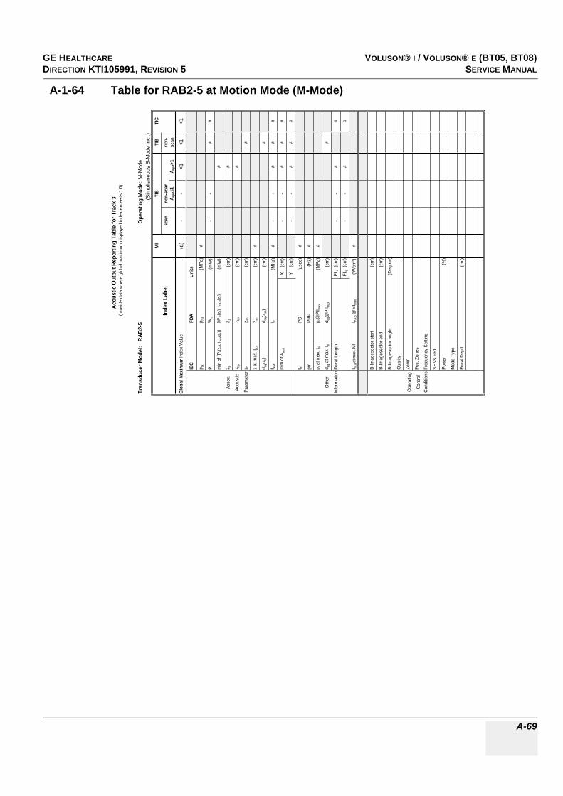
GE HEALTHCAREDRAFT VOLUSON® I / VOLUSON® E (BT05, BT08)DIRECTION KTI105991, REVISION 5 SERVICE MANUAL
A-69
A-1-64 Table for RAB2-5 at Motion Mode (M-Mode)
Tran
sduc
er M
odel
: R
AB2-
5O
pera
ting
Mod
e:M
-Mod
e(S
imul
tane
ous
B-M
ode
incl.
)M
ITI
STI
BTI
C
Inde
x La
bel
scan
non-
scan
non-
A apr
t1
A apr
t>1
scan
Glo
bal M
axim
um In
dex
Valu
e(a
)-
-<1
<1<1
IEC
FDA
Units
p ra
p r.3
(MPa
)#
PW
o(m
W)
--
##
min
of [
P a(z
s), I t
a,a(z
s)][W
.3(z
1), I T
A.3(z
1)](m
W)
#
Asso
c.z s
z 1(c
m)
#
Acou
stic
z bp
z bp
(cm
)#
Para
met
erz b
z sp
(cm
)#
z at
max
. I pi,a
z sp
(cm
)#
d eq(z
b)d e
q(zsp
)(c
m)
#
f awf
f c(M
Hz)
#-
-#
##
Dim
of A
aprt
X
(cm
)-
-#
##
Y
(cm
)-
-#
##
t dPD
(µse
c)#
prr
PRF
(Hz)
#
p r a
t max
. I pi
p r@
PII m
ax(M
Pa)
#
Oth
erd e
q at m
ax. I p
id e
q@PI
I max
(cm
)#
Info
rmat
ion
Foca
l Len
gth
FLx
(cm
)-
-#
#
FLy
(cm
)-
-#
#
I pa,a
at m
ax. M
II PA
.3 @
MI m
ax(W
/cm
²)#
B-Im
ages
ecto
r sta
rt(c
m)
B-Im
ages
ecto
r end
(cm
)
B-Im
ages
ecto
r ang
le(D
egre
e)
Qua
lity
Ope
ratin
gZo
om
Cont
rol
Foc.
Zon
es
Cond
itions
Freq
uenc
y Se
tting
SENS
PRI
Powe
r(%
)
Mod
e Ty
pe
Foca
l Dep
th(c
m)
Acou
stic
Out
put R
epor
ting
Tabl
e fo
r Tra
ck 3
(pro
vide
data
whe
re g
loba
l max
imum
disp
laye
d in
dex
exce
eds
1.0)

GE HEALTHCARERAFT VOLUSON® I / VOLUSON® E (BT05, BT08)DIRECTION KTI105991, REVISION 5 SERVICE MANUAL
A-70
A-1-65 Table for RAB2-5 at Color Motion Mode (Mc-Mode)
Tran
sduc
er M
odel
: R
AB
2-5
Ope
ratin
g M
ode:
Mc-
Mod
e
MI
TIS
TIB
TIC
Inde
x La
bel
scan
non-
scan
non-
A apr
t1
A apr
t>1
scan
Glo
bal M
axim
um In
dex
Val
ue(a
)-
-<1
<1<1
IEC
FDA
Uni
ts
p ra
p r.3
(MP
a)#
PW
o(m
W)
--
##
min
of [
P a(z
s), I
ta,a
(zs)
][W
.3(z
1), I
TA.3(z
1)]
(mW
)#
Ass
oc.
z sz 1
(cm
)#
Aco
ustic
z bp
z bp
(cm
)#
Par
amet
erz b
z sp
(cm
)#
z at
max
. Ipi
,az s
p(c
m)
#
d eq(
z b)
d eq(
z sp)
(cm
)#
f awf
f c(M
Hz)
#-
-#
##
Dim
of A
aprt
X
(cm
)-
-#
##
Y
(cm
)-
-#
##
t dP
D(µ
sec)
#
prr
PR
F(H
z)#
p r a
t max
. Ipi
p r@
PII m
ax(M
Pa)
#
Oth
erd e
q at m
ax. I
pid e
q@P
II max
(cm
)#
Info
rmat
ion
Foca
l Len
gth
FLx
(cm
)-
-#
#
FLy
(cm
)-
-#
#
I pa,a
at m
ax. M
II P
A.3 @
MI m
ax(W
/cm
²)#
B-Im
ages
ecto
r sta
rt(c
m)
B-Im
ages
ecto
r end
(cm
)
B-Im
ages
ecto
r ang
le(D
egre
e)
B-Q
ualit
y
Zoom
Foc.
Zon
es
Ope
ratin
gFr
eque
ncy
Set
ting
Con
trol
SE
NS
PR
I
Con
ditio
nsB
Tx
Pow
er(%
)
Mc
Tx P
ower
(%)
Ens
embl
e
Flow
Res
Vel
ocity
Ran
ge(k
Hz)
Spe
ed
Mc
Freq
uenc
y
Aco
ustic
Out
put R
epor
ting
Tabl
e fo
r Tra
ck 3
(pro
vide
dat
a w
here
glo
bal m
axim
um d
ispl
ayed
inde
x ex
ceed
s 1.
0)

GE HEALTHCAREDRAFT VOLUSON® I / VOLUSON® E (BT05, BT08)DIRECTION KTI105991, REVISION 5 SERVICE MANUAL
A-71
A-1-66 Table for RAB2-5 at Pulsed Wave Doppler (PW-Mode)
Tran
sduc
er M
odel:
RAB
2-5
Oper
atin
g Mo
de:
Pulse
d Dop
pler
MITI
STI
BTI
C
Inde
x Lab
elsc
anno
n-sc
anno
n-A a
prt
1A a
prt>1
scan
Glob
al Ma
ximum
Inde
x Valu
e(a
)-
-<1
1,41,1
IEC
FDA
Units
p rap r.
3(M
Pa)
#
PW
o(m
W)
--
4794
min o
f [Pa(z
s), I ta
,a(z s
)][W
.3(z 1
), I TA
.3(z1)]
(mW
)#
Asso
c.z s
z 1(cm
)#
Acou
stic
z bp
z bp
(cm)
#
Para
meter
z bz sp
(cm)
4,0
z at m
ax. I p
i,az sp
(cm)
#
d eq(z
b)d e
q(zsp
)(cm
)0,3
f awf
f c(M
Hz)
#-
-#
2,72,7
Dim
of A a
prt
X
(cm)
--
#1,2
2,4
Y (
cm)
--
#1,4
1,4
t dPD
(µse
c)#
prr
PRF
(Hz)
#
p r at
max.
I pip r@
PII ma
x(M
Pa)
#
Othe
rd e
q at m
ax. I p
id e
q@PI
I max
(cm)
0,3
Infor
matio
nFoc
al Le
ngth
FLx
(cm)
--
#15
FLy
(cm)
--
#6
I pa,a
at ma
x. MI
I PA.3 @
MIma
x(W
/cm²)
#
Gate
width
(cm)
0,9
0,6
Oper
ating
Gate
pos
(cm)
2,7
616
,68
Contr
olB-
Imag
esec
tor an
gle(D
egre
e)
2,23,3
Cond
itions
Powe
r(%
)
100
100
Acou
stic
Outp
ut R
epor
ting
Tabl
e for
Tra
ck 3
(pro
vide d
ata w
here
glob
al ma
ximum
disp
layed
inde
x exc
eeds
1.0)

GE HEALTHCARERAFT VOLUSON® I / VOLUSON® E (BT05, BT08)DIRECTION KTI105991, REVISION 5 SERVICE MANUAL
A-72
A-1-67 Table for RAB4-8P at 2 D Mode (B-Mode)
Tran
sduc
er M
odel
: R
AB
4-8P
Ope
ratin
g M
ode:
B-M
ode
MI
TIS
TIB
TIC
Inde
x La
bel
scan
non-
scan
non-
A apr
t1
A apr
t>1
scan
Glo
bal M
axim
um In
dex
Valu
e1,
2(a
)-
--
(a)
IEC
FDA
Uni
ts
p ra
p r.3
(MPa
)2,
0
PW
o(m
W)
#-
-#
min
of [
P a(z
s), I t
a,a(
z s)]
[W.3
(z1)
, ITA
.3(z
1)]
(mW
)-
Asso
c.z s
z 1(c
m)
-
Acou
stic
z bp
z bp
(cm
)-
Para
met
erz b
z sp
(cm
)-
z at
max
. Ipi
,az s
p(c
m)
4,7
d eq(z
b)d e
q(zsp
)(c
m)
-
f awf
f c(M
Hz)
2,8
#-
--
#
Dim
of A
aprt
X
(cm
)#
--
-#
Y
(cm
)#
--
-#
t dPD
(µse
c)0,
5
prr
PRF
(Hz)
3400
p r a
t max
. Ipi
p r@
PII m
ax(M
Pa)
3,2
Oth
erd e
q at m
ax. I
pid e
q@PI
I max
(cm
)-
Info
rmat
ion
Foca
l Len
gth
FLx
(cm
)#
--
#
FLy
(cm
)#
--
#
I pa,a
at m
ax. M
II P
A.3 @
MI m
ax(W
/cm
²)25
5
B-Im
ages
ecto
r sta
rt(c
m)
0,0
B-Im
ages
ecto
r end
(cm
)22
,0
B-Im
ages
ecto
r ang
le(D
egre
e)70
,0
Qua
lity
high
Ope
ratin
gZo
om1,
0
Con
trol
Foc.
Zon
es1
Con
ditio
nsFr
eque
ncy
Setti
ngH
igh
SEN
S PR
I-
Pow
er(%
)10
0
Zoom
Box
star
t(c
m)
13,2
Zoom
Box
end
(cm
)17
,6
Zoom
Box
angl
e(D
egre
e)70
,0
Mod
e Ty
peB(
Har
m)
Foca
l Dep
th(c
m)
6,0
Aco
ustic
Out
put R
epor
ting
Tabl
e fo
r Tra
ck 3
(pro
vide
dat
a w
here
glo
bal m
axim
um d
ispl
ayed
inde
x ex
ceed
s 1.
0)

GE HEALTHCAREDRAFT VOLUSON® I / VOLUSON® E (BT05, BT08)DIRECTION KTI105991, REVISION 5 SERVICE MANUAL
A-73
A-1-68 Table for RAB4-8P at Color Flow Mode (CFM-Mode)
Tran
sduc
er M
odel
: R
AB
4-8P
Ope
ratin
g M
ode:
Col
or F
low
MI
TIS
TIB
TIC
Inde
x La
bel
scan
non-
scan
non-
Aap
rt1
Aap
rt>1
scan
Glo
bal M
axim
um In
dex
Val
ue(a
)<1
--
-<1
IEC
FDA
Uni
ts
p ra
p r.3
(MP
a)#
PW
o(m
W)
#-
-#
min
of [
P a(z
s), I
ta,a
(zs)
][W
.3(z
1), I
TA.3(z
1)]
(mW
)-
Ass
oc.
z sz 1
(cm
)-
Aco
ustic
z bp
z bp
(cm
)-
Par
amet
erz b
z sp
(cm
)-
z at
max
. I pi,a
z sp
(cm
)#
d eq(
z b)
d eq(
z sp)
(cm
)-
f aw
ff c
(MH
z)#
#-
--
#
Dim
of A
aprt
X
(cm
)#
--
-#
Y
(cm
)#
--
-#
t dP
D(µ
sec)
#
prr
PR
F(H
z)#
p r a
t max
. I pi
p r@
PII m
ax(M
Pa)
#
Oth
erd e
q at
max
. I pi
d eq@
PII m
ax(c
m)
-
Info
rmat
ion
Foca
l Len
gth
FLx
(cm
)#
--
#
FLy
(cm
)#
--
#
I pa,a
at m
ax. M
II P
A.3 @
MI m
ax(W
/cm
²)#
B-Im
ages
ecto
r sta
rt(c
m)
B-Im
ages
ecto
r end
(cm
)
B-Im
ages
ecto
r ang
le(D
egre
e)
B-Q
ualit
y
Zoom
Foc.
Zon
es
Ope
ratin
gFr
eque
ncy
Set
ting
Con
trol
SE
NS
PR
I
Con
ditio
nsB
Tx
Pow
er(%
)
CFM
Box
sta
rt(c
m)
CFM
Box
end
(cm
)
CFM
Box
ang
le(D
egre
e)
CFM
Tx
pow
er(%
)
Ens
embl
e
Line
Den
sity
Flow
Res
Vel
ocity
Ran
ge(k
Hz)
CFM
Qua
lity
CFM
Fre
quen
cy
Aco
ustic
Out
put R
epor
ting
Tabl
e fo
r Tr
ack
3(p
rovi
de d
ata
whe
re g
loba
l max
imum
dis
play
ed in
dex
exce
eds
1.0)

GE HEALTHCARERAFT VOLUSON® I / VOLUSON® E (BT05, BT08)DIRECTION KTI105991, REVISION 5 SERVICE MANUAL
A-74
A-1-69 Table for RAB4-8P at Motion Mode (M-Mode)
Tran
sduc
er M
odel
: R
AB4-
8PO
pera
ting
Mod
e:M
-Mod
e(S
imul
tane
ous
B-M
ode
incl
.)M
ITI
STI
BTI
C
Inde
x La
bel
scan
non-
scan
non-
A apr
t1
A apr
t>1
scan
Glo
bal M
axim
um In
dex
Valu
e(a
)-
-<1
<1<1
IEC
FDA
Units
p ra
p r.3
(MPa
)#
PW
o(m
W)
--
##
min
of [
P a(z
s), I t
a,a(
z s)]
[W.3
(z1)
, ITA
.3(z
1)]
(mW
)#
Asso
c.z s
z 1(c
m)
#
Acou
stic
z bp
z bp
(cm
)#
Para
met
erz b
z sp
(cm
)#
z at
max
. I pi,a
z sp
(cm
)#
d eq(z
b)d e
q(zsp
)(c
m)
#
f awf
f c(M
Hz)
#-
-#
##
Dim
of A
aprt
X
(cm
)-
-#
##
Y
(cm
)-
-#
##
t dPD
(µse
c)#
prr
PRF
(Hz)
#
p r a
t max
. Ipi
p r@
PII m
ax(M
Pa)
#
Oth
erd e
q at m
ax. I
pid e
q@PI
I max
(cm
)#
Info
rmat
ion
Foca
l Len
gth
FLx
(cm
)-
-#
#
FLy
(cm
)-
-#
#
I pa,a
at m
ax. M
II PA
.3 @
MI m
ax(W
/cm
²)#
B-Im
ages
ecto
r sta
rt(c
m)
B-Im
ages
ecto
r end
(cm
)
B-Im
ages
ecto
r ang
le(D
egre
e)
Qua
lity
Ope
ratin
gZo
om
Con
trol
Foc.
Zon
es
Con
ditio
nsFr
eque
ncy
Setti
ng
SEN
S PR
I
Pow
er(%
)
Mod
e Ty
pe
Foca
l Dep
th(c
m)
Acou
stic
Out
put R
epor
ting
Tabl
e fo
r Tra
ck 3
(pro
vide
dat
a w
here
glo
bal m
axim
um d
ispl
ayed
inde
x ex
ceed
s 1.
0)

GE HEALTHCAREDRAFT VOLUSON® I / VOLUSON® E (BT05, BT08)DIRECTION KTI105991, REVISION 5 SERVICE MANUAL
A-75
A-1-70 Table for RAB4-8P at Color Motion Mode (Mc-Mode)
Tran
sduc
er M
odel
: R
AB
4-8P
Ope
ratin
g M
ode:
Mc-
Mod
e
MI
TIS
TIB
TIC
Inde
x La
bel
scan
non-
scan
non-
A apr
t1
A apr
t>1
scan
Glo
bal M
axim
um In
dex
Val
ue(a
)-
-<1
<1<1
IEC
FDA
Uni
ts
p ra
p r.3
(MP
a)#
PW
o(m
W)
--
##
min
of [
P a(z
s), I
ta,a
(zs)
][W
.3(z
1), I
TA.3(z
1)]
(mW
)#
Ass
oc.
z sz 1
(cm
)#
Aco
ustic
z bp
z bp
(cm
)#
Par
amet
erz b
z sp
(cm
)#
z at
max
. Ipi
,az s
p(c
m)
#
d eq(
z b)
d eq(
z sp)
(cm
)#
f awf
f c(M
Hz)
#-
-#
##
Dim
of A
aprt
X
(cm
)-
-#
##
Y
(cm
)-
-#
##
t dP
D(µ
sec)
#
prr
PR
F(H
z)#
p r a
t max
. Ipi
p r@
PII m
ax(M
Pa)
#
Oth
erd e
q at m
ax. I
pid e
q@P
II max
(cm
)#
Info
rmat
ion
Foca
l Len
gth
FLx
(cm
)-
-#
#
FLy
(cm
)-
-#
#
I pa,a
at m
ax. M
II P
A.3 @
MI m
ax(W
/cm
²)#
B-Im
ages
ecto
r sta
rt(c
m)
B-Im
ages
ecto
r end
(cm
)
B-Im
ages
ecto
r ang
le(D
egre
e)
B-Q
ualit
y
Zoom
Foc.
Zon
es
Ope
ratin
gFr
eque
ncy
Set
ting
Con
trol
SE
NS
PR
I
Con
ditio
nsB
Tx
Pow
er(%
)
Mc
Tx P
ower
(%)
Ens
embl
e
Flow
Res
Vel
ocity
Ran
ge(k
Hz)
Spe
ed
Mc
Freq
uenc
y
Aco
ustic
Out
put R
epor
ting
Tabl
e fo
r Tra
ck 3
(pro
vide
dat
a w
here
glo
bal m
axim
um d
ispl
ayed
inde
x ex
ceed
s 1.
0)

GE HEALTHCARERAFT VOLUSON® I / VOLUSON® E (BT05, BT08)DIRECTION KTI105991, REVISION 5 SERVICE MANUAL
A-76
A-1-71 Table for RAB4-8P at Pulsed Wave Mode (PW-Mode)
Tran
sduc
er M
odel:
RAB
4-8P
Oper
atin
g Mo
de:
Pulse
d Dop
pler
MITI
STI
BTI
C
Inde
x Lab
elsc
anno
n-sc
anno
n-A a
prt
1A a
prt>1
scan
Glob
al Ma
ximum
Inde
x Valu
e(a
)-
-<1
1,4<1
IEC
FDA
Units
p rap r.
3(M
Pa)
#
PW
o(m
W)
--
33#
min o
f [Pa(z
s), I ta
,a(z s
)][W
.3(z 1
), I TA
.3(z1)]
(mW
)#
Asso
c.z s
z 1(cm
)#
Acou
stic
z bp
z bp
(cm)
#
Para
meter
z bz sp
(cm)
3,4
z at m
ax. I p
i,az sp
(cm)
#
d eq(z
b)d e
q(zsp
)(cm
)0,3
f awf
f c(M
Hz)
#-
-#
3,0#
Dim
of A a
prt
X
(cm)
--
#1,1
#
Y (
cm)
--
#1,1
#
t dPD
(µse
c)#
prr
PRF
(Hz)
#
p r at
max.
I pip r@
PII ma
x(M
Pa)
#
Othe
rd e
q at m
ax. I p
id e
q@PI
I max
(cm)
0,3
Infor
matio
nFoc
al Le
ngth
FLx
(cm)
--
##
FLy
(cm)
--
##
I pa,a
at ma
x. MI
I PA.3 @
MIma
x(W
/cm²)
#
Gate
width
(cm)
1,5
Oper
ating
Gate
pos
(cm)
2,8
Contr
olB-
Imag
esec
tor an
gle(D
egre
e)
1,3
Cond
itions
Powe
r(%
)
100
Acou
stic
Outp
ut R
epor
ting
Tabl
e for
Tra
ck 3
(pro
vide d
ata w
here
glob
al ma
ximum
disp
layed
inde
x exc
eeds
1.0)
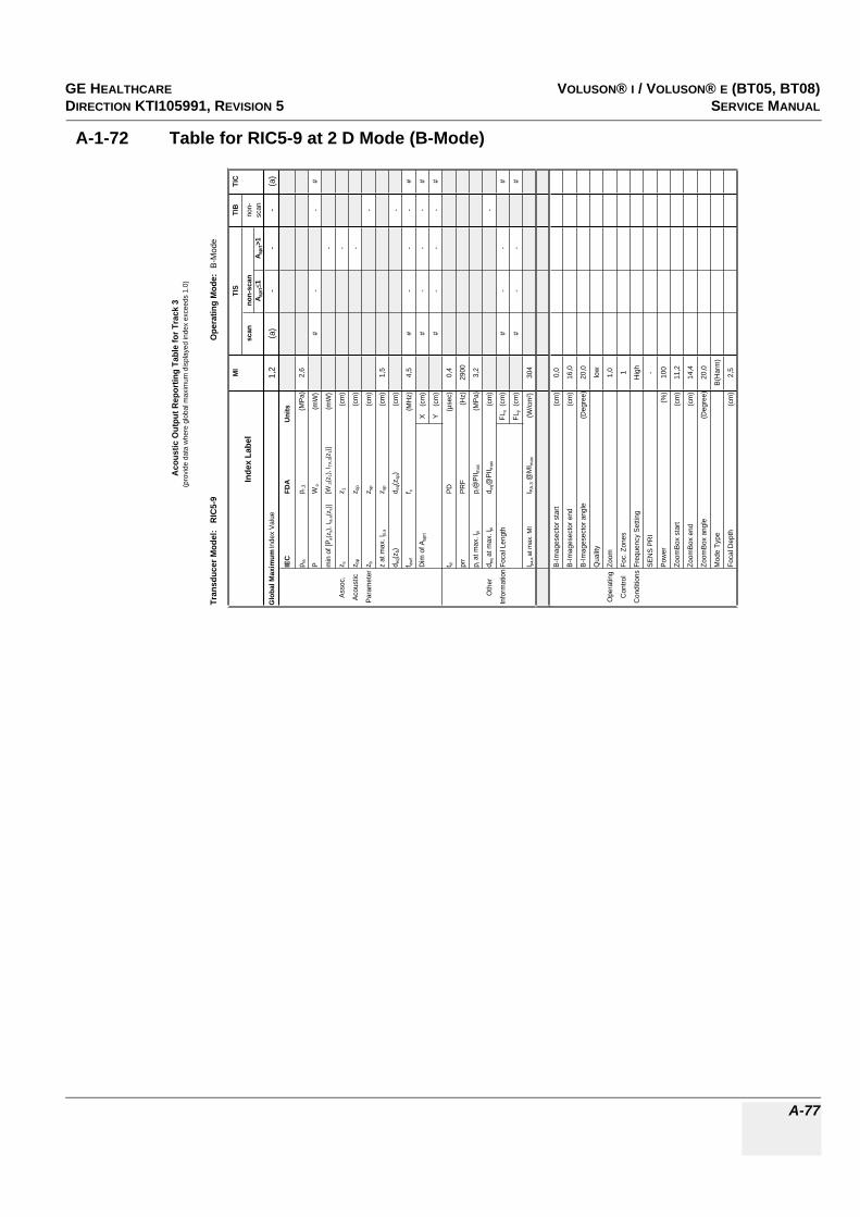
GE HEALTHCAREDRAFT VOLUSON® I / VOLUSON® E (BT05, BT08)DIRECTION KTI105991, REVISION 5 SERVICE MANUAL
A-77
A-1-72 Table for RIC5-9 at 2 D Mode (B-Mode)
Tran
sduc
er M
odel
: R
IC5-
9O
pera
ting
Mod
e: B
-Mod
e
MI
TIS
TIB
TIC
Inde
x La
bel
scan
non-
scan
non-
A apr
t1
A apr
t>1
scan
Glo
bal M
axim
um In
dex
Valu
e1,
2(a
)-
--
(a)
IEC
FDA
Uni
ts
p ra
p r.3
(MPa
)2,
6
PW
o(m
W)
#-
-#
min
of [
P a(z
s), I t
a,a(
z s)]
[W.3
(z1)
, ITA
.3(z
1)]
(mW
)-
Asso
c.z s
z 1(c
m)
-
Acou
stic
z bp
z bp
(cm
)-
Para
met
erz b
z sp
(cm
)-
z at
max
. Ipi
,az s
p(c
m)
1,5
d eq(z
b)d e
q(zsp
)(c
m)
-
f awf
f c(M
Hz)
4,5
#-
--
#
Dim
of A
aprt
X
(cm
)#
--
-#
Y
(cm
)#
--
-#
t dPD
(µse
c)0,
4
prr
PRF
(Hz)
2900
p r a
t max
. Ipi
p r@
PII m
ax(M
Pa)
3,2
Oth
erd e
q at m
ax. I
pid e
q@PI
I max
(cm
)-
Info
rmat
ion
Foca
l Len
gth
FLx
(cm
)#
--
#
FLy
(cm
)#
--
#
I pa,a
at m
ax. M
II P
A.3 @
MI m
ax(W
/cm
²)30
4
B-Im
ages
ecto
r sta
rt(c
m)
0,0
B-Im
ages
ecto
r end
(cm
)16
,0
B-Im
ages
ecto
r ang
le(D
egre
e)20
,0
Qua
lity
low
Ope
ratin
gZo
om1,
0
Con
trol
Foc.
Zon
es1
Con
ditio
nsFr
eque
ncy
Setti
ngH
igh
SEN
S PR
I-
Pow
er(%
)10
0
Zoom
Box
star
t(c
m)
11,2
Zoom
Box
end
(cm
)14
,4
Zoom
Box
angl
e(D
egre
e)20
,0
Mod
e Ty
peB(
Har
m)
Foca
l Dep
th(c
m)
2,5
Aco
ustic
Out
put R
epor
ting
Tabl
e fo
r Tra
ck 3
(pro
vide
dat
a w
here
glo
bal m
axim
um d
ispl
ayed
inde
x ex
ceed
s 1.
0)

GE HEALTHCARERAFT VOLUSON® I / VOLUSON® E (BT05, BT08)DIRECTION KTI105991, REVISION 5 SERVICE MANUAL
A-78
A-1-73 Table for RIC5-9 at Color Flow Mode (CFM-Mode)
Tran
sduc
er M
odel
: R
IC5-
9O
pera
ting
Mod
e: C
olor
Flo
w
MI
TIS
TIB
TIC
Inde
x La
bel
scan
non-
scan
non-
Aap
rt1
Aap
rt>1
scan
Glo
bal M
axim
um In
dex
Val
ue(a
)<1
--
-<1
IEC
FDA
Uni
ts
p ra
p r.3
(MP
a)#
PW
o(m
W)
#-
-#
min
of [
P a(z
s), I
ta,a
(zs)
][W
.3(z
1), I
TA.3(z
1)]
(mW
)-
Ass
oc.
z sz 1
(cm
)-
Aco
ustic
z bp
z bp
(cm
)-
Par
amet
erz b
z sp
(cm
)-
z at
max
. I pi,a
z sp
(cm
)#
d eq(
z b)
d eq(
z sp)
(cm
)-
f aw
ff c
(MH
z)#
#-
--
#
Dim
of A
aprt
X
(cm
)#
--
-#
Y
(cm
)#
--
-#
t dP
D(µ
sec)
#
prr
PR
F(H
z)#
p r a
t max
. Ipi
p r@
PII m
ax(M
Pa)
#
Oth
erd e
q at
max
. Ipi
d eq@
PII m
ax(c
m)
-
Info
rmat
ion
Foca
l Len
gth
FLx
(cm
)#
--
#
FLy
(cm
)#
--
#
I pa,a
at m
ax. M
II P
A.3 @
MI m
ax(W
/cm
²)#
B-Im
ages
ecto
r sta
rt(c
m)
B-Im
ages
ecto
r end
(cm
)
B-Im
ages
ecto
r ang
le(D
egre
e)
B-Q
ualit
y
Zoom
Foc.
Zon
es
Ope
ratin
gFr
eque
ncy
Set
ting
Con
trol
SE
NS
PR
I
Con
ditio
nsB
Tx
Pow
er(%
)
CFM
Box
sta
rt(c
m)
CFM
Box
end
(cm
)
CFM
Box
ang
le(D
egre
e)
CFM
Tx
pow
er(%
)
Ens
embl
e
Line
Den
sity
Flow
Res
Vel
ocity
Ran
ge(k
Hz)
CFM
Qua
lity
CFM
Fre
quen
cy
Aco
ustic
Out
put R
epor
ting
Tabl
e fo
r Tr
ack
3(p
rovi
de d
ata
whe
re g
loba
l max
imum
dis
play
ed in
dex
exce
eds
1.0)

GE HEALTHCAREDRAFT VOLUSON® I / VOLUSON® E (BT05, BT08)DIRECTION KTI105991, REVISION 5 SERVICE MANUAL
A-79
A-1-74 Table for RIC5-9 at Motion Mode (M-Mode)
Tran
sduc
er M
odel
: R
IC5-
9O
pera
ting
Mod
e:M
-Mod
e(S
imul
tane
ous
B-M
ode
incl
.)M
ITI
STI
BTI
C
Inde
x La
bel
scan
non-
scan
non-
A apr
t1
A apr
t>1
scan
Glo
bal M
axim
um In
dex
Valu
e(a
)-
<1-
<1<1
IEC
FDA
Units
p ra
p r.3
(MPa
)#
PW
o(m
W)
-#
##
min
of [
P a(z
s), I t
a,a(
z s)]
[W.3
(z1)
, ITA
.3(z
1)]
(mW
)-
Asso
c.z s
z 1(c
m)
-
Acou
stic
z bp
z bp
(cm
)-
Para
met
erz b
z sp
(cm
)#
z at
max
. I pi,a
z sp
(cm
)#
d eq(z
b)d e
q(zsp
)(c
m)
#
f awf
f c(M
Hz)
#-
#-
##
Dim
of A
aprt
X
(cm
)-
#-
##
Y
(cm
)-
#-
##
t dPD
(µse
c)#
prr
PRF
(Hz)
#
p r a
t max
. Ipi
p r@
PII m
ax(M
Pa)
#
Oth
erd e
q at m
ax. I
pid e
q@PI
I max
(cm
)#
Info
rmat
ion
Foca
l Len
gth
FLx
(cm
)-
#-
#
FLy
(cm
)-
#-
#
I pa,a
at m
ax. M
II PA
.3 @
MI m
ax(W
/cm
²)#
B-Im
ages
ecto
r sta
rt(c
m)
B-Im
ages
ecto
r end
(cm
)
B-Im
ages
ecto
r ang
le(D
egre
e)
Qua
lity
Ope
ratin
gZo
om
Con
trol
Foc.
Zon
es
Con
ditio
nsFr
eque
ncy
Setti
ng
SEN
S PR
I
Pow
er(%
)
Mod
e Ty
pe
Foca
l Dep
th(c
m)
Acou
stic
Out
put R
epor
ting
Tabl
e fo
r Tra
ck 3
(pro
vide
dat
a w
here
glo
bal m
axim
um d
ispl
ayed
inde
x ex
ceed
s 1.
0)

GE HEALTHCARERAFT VOLUSON® I / VOLUSON® E (BT05, BT08)DIRECTION KTI105991, REVISION 5 SERVICE MANUAL
A-80
A-1-75 Table for RIC5-9 at Color Motion Mode (Mc-Mode)
Tran
sduc
er M
odel
: R
IC5-
9O
pera
ting
Mod
e: M
c-M
ode
MI
TIS
TIB
TIC
Inde
x La
bel
scan
non-
scan
non-
A apr
t1
A apr
t>1
scan
Glo
bal M
axim
um In
dex
Val
ue(a
)-
<1-
<1<1
IEC
FDA
Uni
ts
p ra
p r.3
(MP
a)#
PW
o(m
W)
-#
##
min
of [
P a(z
s), I
ta,a
(zs)
][W
.3(z
1), I
TA.3(z
1)]
(mW
)-
Ass
oc.
z sz 1
(cm
)-
Aco
ustic
z bp
z bp
(cm
)-
Par
amet
erz b
z sp
(cm
)#
z at
max
. Ipi
,az s
p(c
m)
#
d eq(
z b)
d eq(
z sp)
(cm
)#
f awf
f c(M
Hz)
#-
#-
##
Dim
of A
aprt
X
(cm
)-
#-
##
Y
(cm
)-
#-
##
t dP
D(µ
sec)
#
prr
PR
F(H
z)#
p r a
t max
. Ipi
p r@
PII m
ax(M
Pa)
#
Oth
erd e
q at m
ax. I
pid e
q@P
II max
(cm
)#
Info
rmat
ion
Foca
l Len
gth
FLx
(cm
)-
#-
#
FLy
(cm
)-
#-
#
I pa,a
at m
ax. M
II P
A.3 @
MI m
ax(W
/cm
²)#
B-Im
ages
ecto
r sta
rt(c
m)
B-Im
ages
ecto
r end
(cm
)
B-Im
ages
ecto
r ang
le(D
egre
e)
B-Q
ualit
y
Zoom
Foc.
Zon
es
Ope
ratin
gFr
eque
ncy
Set
ting
Con
trol
SE
NS
PR
I
Con
ditio
nsB
Tx
Pow
er(%
)
Mc
Tx P
ower
(%)
Ens
embl
e
Flow
Res
Vel
ocity
Ran
ge(k
Hz)
Spe
ed
Mc
Freq
uenc
y
Aco
ustic
Out
put R
epor
ting
Tabl
e fo
r Tra
ck 3
(pro
vide
dat
a w
here
glo
bal m
axim
um d
ispl
ayed
inde
x ex
ceed
s 1.
0)

GE HEALTHCAREDRAFT VOLUSON® I / VOLUSON® E (BT05, BT08)DIRECTION KTI105991, REVISION 5 SERVICE MANUAL
A-81
A-1-76 Table for RIC5-9 at Pulsed Wave Doppler (PW-Mode)
Tran
sduc
er M
odel:
RIC
5-9
Oper
atin
g Mo
de:
Pulse
d Dop
pler
MITI
STI
BTI
C
Inde
x Lab
elsc
anno
n-sc
anno
n-A a
prt
1A a
prt>1
scan
Glob
al Ma
ximum
Inde
x Valu
e(a
)-
<1-
<1<1
IEC
FDA
Units
p rap r.
3(M
Pa)
#
PW
o(m
W)
-#
##
min o
f [Pa(z
s), I ta
,a(z s
)][W
.3(z 1
), I TA
.3(z1)]
(mW
)-
Asso
c.z s
z 1(cm
)-
Acou
stic
z bp
z bp
(cm)
-
Para
meter
z bz sp
(cm)
#
z at m
ax. I p
i,az sp
(cm)
#
d eq(z
b)d e
q(zsp
)(cm
)#
f awf
f c(M
Hz)
#-
#-
##
Dim
of A a
prt
X
(cm)
-#
-#
#
Y (
cm)
-#
-#
#
t dPD
(µse
c)#
prr
PRF
(Hz)
#
p r at
max.
I pip r@
PII ma
x(M
Pa)
#
Othe
rd e
q at m
ax. I p
id e
q@PI
I max
(cm)
#
Infor
matio
nFoc
al Le
ngth
FLx
(cm)
-#
-#
FLy
(cm)
-#
-#
I pa,a
at ma
x. MI
I PA.3 @
MIma
x(W
/cm²)
#
Gate
width
(cm)
Oper
ating
Gate
pos
(cm)
Contr
olB-
Imag
esec
tor an
gle(D
egre
e)
Cond
itions
Powe
r(%
)
Acou
stic
Outp
ut R
epor
ting
Tabl
e for
Tra
ck 3
(pro
vide d
ata w
here
glob
al ma
ximum
disp
layed
inde
x exc
eeds
1.0)

GE HEALTHCARERAFT VOLUSON® I / VOLUSON® E (BT05, BT08)DIRECTION KTI105991, REVISION 5 SERVICE MANUAL
A-82
A-1-77 Table for RIC5-9H at 2 D Mode (B-Mode)
Tran
sduc
er M
odel
: R
IC5-
9HO
pera
ting
Mod
e: B
-Mod
e
MI
TIS
TIB
TIC
Inde
x La
bel
scan
non-
scan
non-
A apr
t1
A apr
t>1
scan
Glo
bal M
axim
um In
dex
Valu
e1,
3(a
)-
--
(a)
IEC
FDA
Uni
ts
p ra
p r.3
(MPa
)2,
7
PW
o(m
W)
#-
-#
min
of [
P a(z
s), I t
a,a(
z s)]
[W.3
(z1)
, ITA
.3(z
1)]
(mW
)-
Asso
c.z s
z 1(c
m)
-
Acou
stic
z bp
z bp
(cm
)-
Para
met
erz b
z sp
(cm
)-
z at
max
. Ipi
,az s
p(c
m)
2,2
d eq(z
b)d e
q(zsp
)(c
m)
-
f awf
f c(M
Hz)
4,5
#-
--
#
Dim
of A
aprt
X
(cm
)#
--
-#
Y
(cm
)#
--
-#
t dPD
(µse
c)0,
5
prr
PRF
(Hz)
4590
p r a
t max
. Ipi
p r@
PII m
ax(M
Pa)
3,7
Oth
erd e
q at m
ax. I
pid e
q@PI
I max
(cm
)-
Info
rmat
ion
Foca
l Len
gth
FLx
(cm
)#
--
#
FLy
(cm
)#
--
#
I pa,a
at m
ax. M
II P
A.3 @
MI m
ax(W
/cm
²)29
3
B-Im
ages
ecto
r sta
rt(c
m)
0,0
B-Im
ages
ecto
r end
(cm
)16
,0
B-Im
ages
ecto
r ang
le(D
egre
e)14
6,3
Qua
lity
high
Ope
ratin
gZo
om1,
0
Con
trol
Foc.
Zon
es1
Con
ditio
nsFr
eque
ncy
Setti
ngH
igh
SEN
S PR
I-
Pow
er(%
)10
0
Zoom
Box
star
t(c
m)
6,4
Zoom
Box
end
(cm
)9,
6
Zoom
Box
angl
e(D
egre
e)14
6,3
Mod
e Ty
peB(
Har
m)
Foca
l Dep
th(c
m)
4,0
Aco
ustic
Out
put R
epor
ting
Tabl
e fo
r Tra
ck 3
(pro
vide
dat
a w
here
glo
bal m
axim
um d
ispl
ayed
inde
x ex
ceed
s 1.
0)
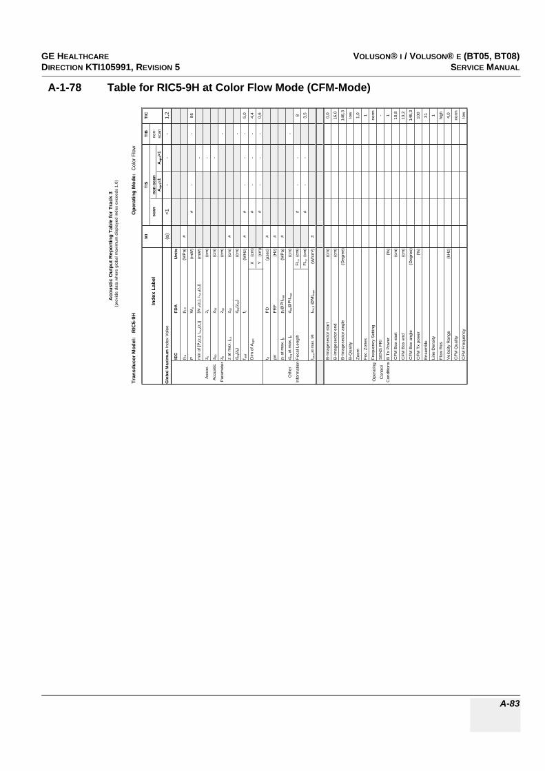
GE HEALTHCAREDRAFT VOLUSON® I / VOLUSON® E (BT05, BT08)DIRECTION KTI105991, REVISION 5 SERVICE MANUAL
A-83
A-1-78 Table for RIC5-9H at Color Flow Mode (CFM-Mode)
Tran
sduc
er M
odel
: R
IC5-
9HO
pera
ting
Mod
e: C
olor
Flo
w
MI
TIS
TIB
TIC
Inde
x La
bel
scan
non-
scan
non-
Aap
rt1
Aap
rt>1
scan
Glo
bal M
axim
um In
dex
Val
ue(a
)<1
--
-1,
2
IEC
FDA
Uni
ts
p ra
p r.3
(MP
a)#
PW
o(m
W)
#-
-86
min
of [
P a(z
s), I
ta,a
(zs)
][W
.3(z
1), I
TA.3(z
1)]
(mW
)-
Ass
oc.
z sz 1
(cm
)-
Aco
ustic
z bp
z bp
(cm
)-
Par
amet
erz b
z sp
(cm
)-
z at
max
. I pi,a
z sp
(cm
)#
d eq(
z b)
d eq(
z sp)
(cm
)-
f aw
ff c
(MH
z)#
#-
--
5,0
Dim
of A
aprt
X
(cm
)#
--
-4,
4
Y
(cm
)#
--
-0,
6
t dP
D(µ
sec)
#
prr
PR
F(H
z)#
p r a
t max
. Ipi
p r@
PII m
ax(M
Pa)
#
Oth
erd e
q at
max
. Ipi
d eq@
PII m
ax(c
m)
-
Info
rmat
ion
Foca
l Len
gth
FLx
(cm
)#
--
8
FLy
(cm
)#
--
3,5
I pa,a
at m
ax. M
II P
A.3 @
MI m
ax(W
/cm
²)#
B-Im
ages
ecto
r sta
rt(c
m)
0,0
B-Im
ages
ecto
r end
(cm
)16
,0
B-Im
ages
ecto
r ang
le(D
egre
e)14
6,3
B-Q
ualit
ylo
w
Zoom
1,0
Foc.
Zon
es1
Ope
ratin
gFr
eque
ncy
Set
ting
norm
Con
trol
SE
NS
PR
I-
Con
ditio
nsB
Tx
Pow
er(%
)1
CFM
Box
sta
rt(c
m)
10,8
CFM
Box
end
(cm
)13
,2
CFM
Box
ang
le(D
egre
e)14
6,3
CFM
Tx
pow
er(%
)10
0
Ens
embl
e31
Line
Den
sity
1
Flow
Res
high
Vel
ocity
Ran
ge(k
Hz)
4,0
CFM
Qua
lity
norm
CFM
Fre
quen
cylo
w
Aco
ustic
Out
put R
epor
ting
Tabl
e fo
r Tr
ack
3(p
rovi
de d
ata
whe
re g
loba
l max
imum
dis
play
ed in
dex
exce
eds
1.0)

GE HEALTHCARERAFT VOLUSON® I / VOLUSON® E (BT05, BT08)DIRECTION KTI105991, REVISION 5 SERVICE MANUAL
A-84
A-1-79 Table for RIC5-9H at Motion Mode (M-Mode)
Tran
sduc
er M
odel
: R
IC5-
9HO
pera
ting
Mod
e:M
-Mod
e(S
imul
tane
ous
B-M
ode
incl
.)M
ITI
STI
BTI
C
Inde
x La
bel
scan
non-
scan
non-
A apr
t1
A apr
t>1
scan
Glo
bal M
axim
um In
dex
Valu
e(a
)-
<1-
<1<1
IEC
FDA
Units
p ra
p r.3
(MPa
)#
PW
o(m
W)
-#
##
min
of [
P a(z
s), I t
a,a(
z s)]
[W.3
(z1)
, ITA
.3(z
1)]
(mW
)-
Asso
c.z s
z 1(c
m)
-
Acou
stic
z bp
z bp
(cm
)-
Para
met
erz b
z sp
(cm
)#
z at
max
. I pi,a
z sp
(cm
)#
d eq(z
b)d e
q(zsp
)(c
m)
#
f awf
f c(M
Hz)
#-
#-
##
Dim
of A
aprt
X
(cm
)-
#-
##
Y
(cm
)-
#-
##
t dPD
(µse
c)#
prr
PRF
(Hz)
#
p r a
t max
. Ipi
p r@
PII m
ax(M
Pa)
#
Oth
erd e
q at m
ax. I
pid e
q@PI
I max
(cm
)#
Info
rmat
ion
Foca
l Len
gth
FLx
(cm
)-
#-
#
FLy
(cm
)-
#-
#
I pa,a
at m
ax. M
II PA
.3 @
MI m
ax(W
/cm
²)#
B-Im
ages
ecto
r sta
rt(c
m)
B-Im
ages
ecto
r end
(cm
)
B-Im
ages
ecto
r ang
le(D
egre
e)
Qua
lity
Ope
ratin
gZo
om
Con
trol
Foc.
Zon
es
Con
ditio
nsFr
eque
ncy
Setti
ng
SEN
S PR
I
Pow
er(%
)
Mod
e Ty
pe
Foca
l Dep
th(c
m)
Acou
stic
Out
put R
epor
ting
Tabl
e fo
r Tra
ck 3
(pro
vide
dat
a w
here
glo
bal m
axim
um d
ispl
ayed
inde
x ex
ceed
s 1.
0)
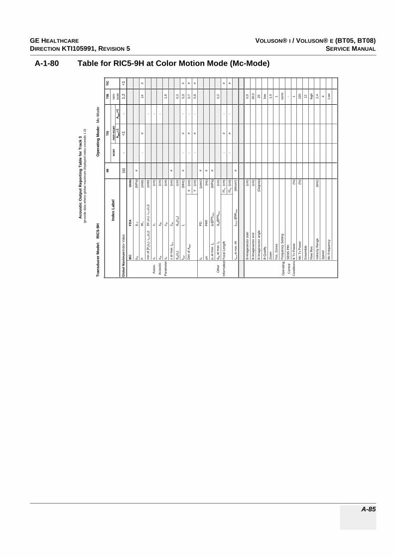
GE HEALTHCAREDRAFT VOLUSON® I / VOLUSON® E (BT05, BT08)DIRECTION KTI105991, REVISION 5 SERVICE MANUAL
A-85
A-1-80 Table for RIC5-9H at Color Motion Mode (Mc-Mode)
Tran
sduc
er M
odel
: R
IC5-
9HO
pera
ting
Mod
e: M
c-M
ode
MI
TIS
TIB
TIC
Inde
x La
bel
scan
non-
scan
non-
A apr
t1
A apr
t>1
scan
Glo
bal M
axim
um In
dex
Val
ue(a
)-
<1-
1,2
<1
IEC
FDA
Uni
ts
p ra
p r.3
(MP
a)#
PW
o(m
W)
-#
14#
min
of [
P a(z
s), I
ta,a
(zs)
][W
.3(z
1), I
TA.3(z
1)]
(mW
)-
Ass
oc.
z sz 1
(cm
)-
Aco
ustic
z bp
z bp
(cm
)-
Par
amet
erz b
z sp
(cm
)1,
6
z at
max
. Ipi
,az s
p(c
m)
#
d eq(
z b)
d eq(
z sp)
(cm
)0,
2
f awf
f c(M
Hz)
#-
#-
5,0
#
Dim
of A
aprt
X
(cm
)-
#-
0,7
#
Y
(cm
)-
#-
0,6
#
t dP
D(µ
sec)
#
prr
PR
F(H
z)#
p r a
t max
. Ipi
p r@
PII m
ax(M
Pa)
#
Oth
erd e
q at m
ax. I
pid e
q@P
II max
(cm
)0,
2
Info
rmat
ion
Foca
l Len
gth
FLx
(cm
)-
#-
#
FLy
(cm
)-
#-
#
I pa,a
at m
ax. M
II P
A.3 @
MI m
ax(W
/cm
²)#
B-Im
ages
ecto
r sta
rt(c
m)
0,0
B-Im
ages
ecto
r end
(cm
)16
,0
B-Im
ages
ecto
r ang
le(D
egre
e)20
B-Q
ualit
ylo
w
Zoom
1,0
Foc.
Zon
es1
Ope
ratin
gFr
eque
ncy
Set
ting
norm
Con
trol
SE
NS
PR
I-
Con
ditio
nsB
Tx
Pow
er(%
)1
Mc
Tx P
ower
(%)
100
Ens
embl
e12
Flow
Res
high
Vel
ocity
Ran
ge(k
Hz)
2,4
Spe
ed4
Mc
Freq
uenc
yLo
w
Aco
ustic
Out
put R
epor
ting
Tabl
e fo
r Tra
ck 3
(pro
vide
dat
a w
here
glo
bal m
axim
um d
ispl
ayed
inde
x ex
ceed
s 1.
0)

GE HEALTHCARERAFT VOLUSON® I / VOLUSON® E (BT05, BT08)DIRECTION KTI105991, REVISION 5 SERVICE MANUAL
A-86
A-1-81 Table for RIC5-9H at Pulsed Wave Doppler (PW-Mode)
Tran
sduc
er M
odel:
RIC
5-9H
Oper
atin
g Mo
de:
Pulse
d Dop
pler
MITI
STI
BTI
C
Inde
x Lab
elsc
anno
n-sc
anno
n-A a
prt
1A a
prt>1
scan
Glob
al Ma
ximum
Inde
x Valu
e(a
)-
1,3-
1,31,3
IEC
FDA
Units
p rap r.
3(M
Pa)
#
PW
o(m
W)
-56
5656
min o
f [Pa(z
s), I ta
,a(z s
)][W
.3(z 1
), I TA
.3(z1)]
(mW
)-
Asso
c.z s
z 1(cm
)-
Acou
stic
z bp
z bp
(cm)
-
Para
meter
z bz sp
(cm)
1,6
z at m
ax. I p
i,az sp
(cm)
#
d eq(z
b)d e
q(zsp
)(cm
)0,6
f awf
f c(M
Hz)
#-
5,0-
5,05,0
Dim
of A a
prt
X
(cm)
-1,5
-1,5
1,5
Y (
cm)
-0,6
-0,6
0,6
t dPD
(µse
c)#
prr
PRF
(Hz)
#
p r at
max.
I pip r@
PII ma
x(M
Pa)
#
Othe
rd e
q at m
ax. I p
id e
q@PI
I max
(cm)
0,5
Infor
matio
nFoc
al Le
ngth
FLx
(cm)
-8
-8
FLy
(cm)
-3,5
-3,5
I pa,a
at ma
x. MI
I PA.3 @
MIma
x(W
/cm²)
#
Gate
width
(cm)
0,90,9
0,9
Oper
ating
Gate
pos
(cm)
3,53,5
3,5
Contr
olB-
Imag
esec
tor an
gle(D
egre
e)7
77
Cond
itions
Powe
r(%
)10
010
010
0
Acou
stic
Outp
ut R
epor
ting
Tabl
e for
Tra
ck 3
(pro
vide d
ata w
here
glob
al ma
ximum
disp
layed
inde
x exc
eeds
1.0)
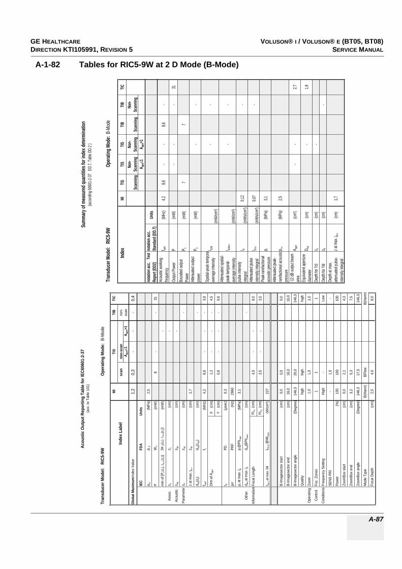
GE HEALTHCAREDRAFT VOLUSON® I / VOLUSON® E (BT05, BT08)DIRECTION KTI105991, REVISION 5 SERVICE MANUAL
A-87
A-1-82 Tables for RIC5-9W at 2 D Mode (B-Mode)
Tran
sduc
er Mo
del:
RIC
5-9W
Opera
ting M
ode:
B-Mo
de
Index
MITIS
TISTIS
TIBTIB
TIC
Scan
ning
Non-
Scan
ning
Non-
Scan
ning
Scan
ning
Non-
Scan
ning
A apr
t1
A apr
t>1no
tation
acc.
Tes
t Re
port
(DD2
)no
tation
acc.
Stan
dard
(DD.
7)Un
its
Acou
stic w
orking
fre
quen
cyf aw
f(M
Hz)
4,28,6
--
8,6-
Outpu
t Pow
erP
(mW)
--
-31
Boun
ded o
utput
Powe
rP 1
(mW)
77
Atten
uated
outpu
t po
wer
P(m
W)-
-
Spati
al-pe
ak te
mpor a
avera
ge in
tensit
yI zp
ta
(mW/
cm²)
--
Atten
uated
spati
al-pe
ak te
mpora
l-av
erage
inten
sity
I zpta,
(mW/
cm²)
--
pulse
inten
sity
integ
ralI pi
(mWs
/cm²)
0,12
-
Atten
uated
pulse
int
ensit
y inte
gral
I pi,(m
Ws/cm
²)0,0
7-
Peak
-raref
actio
nal
acou
stic p
ressu
rep r
(MPa
)3,1
Atten
uated
peak
-rar
efacti
onal
acou
stic
press
urep r,
(MPa
)2,5
-12 dB
outpu
t bea
m are
aA a
prt(cm
²)-
-2,7
Equiv
alent
apert
ure
diame
terD e
q(cm
)-
1,9
Depth
for T
ISz s
(cm)
-De
pth fo
r TIB
z b(cm
)-
Depth
at m
ax.
atten
uated
pulse
-int
ensit
y inte
gral
z at m
ax. I p
i,(cm
)1,7
Summ
ary of
mea
sured
quan
tities
for in
dex d
eterm
inatio
n(ac
cordi
ng 60
601-2
-37 D
D.7,
Table
DD.
2 )
Tran
sduc
er M
odel
: R
IC5-
9WO
pera
ting
Mod
e: B
-Mod
e
MI
TIS
TIB
TIC
Inde
x La
bel
scan
non-
scan
non-
A apr
t1
A apr
t>1
scan
Glo
bal M
axim
um In
dex
Valu
e1,
20,
3-
--
0,4
IEC
FDA
Units
p rp r
.3(M
Pa)
2,5
PW
o(m
W)
8-
-31
min
of [
P(z
s), I t
a,(z
s)][W
.3(z
1), I T
A.3(z
1)](m
W)
-
Asso
c.z s
z 1(c
m)
-
Acou
stic
z bp
z bp
(cm
)-
Para
met
erz b
z sp
(cm
)-
z at
max
. I pi,
z sp
(cm
)1,
7
d eq(z
b)d e
q(zsp
)(c
m)
-
f awf
f c(M
Hz)
4,2
8,6
--
-3,
8
Dim
of A
aprt
X
(cm
)1,
2-
--
4,5
Y
(cm
)0,
6-
--
0,6
t dPD
(µse
c)0,
3
prr
PRF
(Hz)
2960
p r a
t max
. I pi
p r@
PII m
ax(M
Pa)
3,1
Oth
erd e
q at m
ax. I p
id e
q@PI
I max
(cm
)-
Info
rmat
ion
Foca
l Len
gth
FLx
(cm
)4,
0-
-8,
0
FLy
(cm
)3,
5-
-3,
5
I pa,
at m
ax. M
II PA
.3 @
MI m
ax(W
/cm
²)22
7
B-Im
ages
ecto
r sta
rt(c
m)
0,0
0,0
0,0
B-Im
ages
ecto
r end
(cm
)16
,016
,016
,0
B-Im
ages
ecto
r ang
le(D
egre
e)14
6,3
20,0
146,
3
Qua
lityhi
ghhi
ghhi
gh
Ope
ratin
gZo
om1,
01,
01,
0
Cont
rol
Foc.
Zon
es1
11
Cond
itions
Freq
uenc
y Se
tting
High
-Lo
w
SENS
PRI
-1,
0-
Powe
r(%
)10
010
010
0
Zoom
Box
star
t(c
m)
0,0
2,1
4,3
Zoom
Box
end
(cm
)3,
25,
37,
5
Zoom
Box
angl
e(D
egre
e)14
6,3
17,5
146,
3
Mod
e Ty
peB(
Harm
)BF
low
B(Ha
rm)
Foca
l Dep
th(c
m)
2,5
4,0
8,0
Acou
stic
Out
put R
epor
ting
Tabl
e fo
r IEC
6060
1-2-
37(a
cc. t
o Ta
ble
101)

GE HEALTHCARERAFT VOLUSON® I / VOLUSON® E (BT05, BT08)DIRECTION KTI105991, REVISION 5 SERVICE MANUAL
A-88
A-1-83 Tables for RIC5-9W at Color Flow Mode (CFM-Mode)
Tran
sduc
er Mo
del:
RIC
5-9W
Opera
ting M
ode:
Color
Flow
Index
MITIS
TISTIS
TIBTIB
TIC
Scan
ning
Non-
Scan
ning
Non-
Scan
ning
Scan
ning
Non-
Scan
ning
A apr
t1
A apr
t>1no
tation
acc.
Tes
t Re
port
(DD2
)no
tation
acc.
Stan
dard
(DD.
7)Un
its
Acou
stic w
orking
fre
quen
cyf aw
f(M
Hz)
5,05,0
--
5,0-
Outpu
t Pow
erP
(mW
)-
--
41Bo
unde
d outp
ut Po
wer
P 1(m
W)
99
Atten
uated
outpu
t po
wer
P(m
W)
--
Spati
al-pe
ak te
mpor a
avera
ge in
tensit
yI zp
ta
(mW
/cm²)
--
Atten
uated
spati
al-pe
ak te
mpora
l-av
erage
inten
sity
I zpta,
(mW
/cm²)
--
pulse
inten
sity
integ
ralI pi
(mW
s/cm²
)0,3
5-
Atten
uated
pulse
int
ensit
y inte
gral
I pi,(m
Ws/c
m²)
0,29
-
Peak
-raref
actio
nal
acou
stic p
ressu
rep r
(MPa
)3,0
Atten
uated
peak
-rar
efacti
onal
acou
stic
press
urep r,
(MPa
)2,7
-12 dB
outpu
t bea
m are
aA a
prt(cm
²)-
-2,7
Equiv
alent
apert
ure
diame
terD e
q(cm
)-
1,8
Depth
for T
ISz s
(cm)
-De
pth fo
r TIB
z b(cm
)-
Depth
at m
ax.
atten
uated
pulse
-int
ensit
y inte
gral
z at m
ax. I p
i,(cm
)0,6
Summ
ary of
mea
sured
quan
tities
for in
dex d
eterm
inatio
n(ac
cordi
ng 60
601-2
-37 D
D.7,
Table
DD.
2 )
Tran
sduc
er M
odel
: R
IC5-
9WO
pera
ting
Mod
e: C
olor
Flo
w
MI
TIS
TIB
TIC
Inde
x La
bel
scan
non-
scan
non-
A apr
t1
A apr
t>1
scan
Glo
bal M
axim
um In
dex
Valu
e1,
20,
2-
--
0,6
IEC
FDA
Uni
ts
p rp r
.3(M
Pa)
2,7
PW
o(m
W)
33-
-41
min
of [
P(z
s), I
ta,
(zs)
][W
.3(z
1), I
TA.3(z
1)]
(mW
)-
Asso
c.z s
z 1(c
m)
-
Acou
stic
z bp
z bp
(cm
)-
Para
met
erz b
z sp
(cm
)-
z at
max
. I pi,
z sp
(cm
)0,
6
d eq(
z b)
d eq(
z sp)
(cm
)-
f awf
f c(M
Hz)
5,0
5,0
--
-5,
0
Dim
of A
aprt
X
(cm
)3,
5-
--
4,4
Y
(cm
)0,
6-
--
0,6
t dPD
(µse
c)0,
8
prr
PRF
(Hz)
1420
p r a
t max
. I pi
p r@
PII m
ax(M
Pa)
3,0
Oth
erd e
q at m
ax. I p
id e
q@PI
I max
(cm
)-
Info
rmat
ion
Foca
l Len
gth
FLx
(cm
)1,
0-
-8,
0
FLy
(cm
)3,
5-
-3,
5
I pa,
at m
ax. M
II P
A.3 @
MI m
ax(W
/cm
²)35
4
B-Im
ages
ecto
r sta
rt(c
m)
0,0
0,0
0,0
B-Im
ages
ecto
r end
(cm
)16
,016
,016
,0
B-Im
ages
ecto
r ang
le(D
egre
e)14
6,3
146,
314
6,3
B-Q
ualit
ylo
wlo
wlo
w
Zoom
1,0
1,0
1,0
Foc.
Zon
es1
11
Ope
ratin
gFr
eque
ncy
Setti
ngre
sol
reso
lre
sol
Con
trol
SEN
S PR
I-
--
Con
ditio
nsB
Tx P
ower
(%)
11
1
CFM
Box
sta
rt(c
m)
0,0
0,0
7,9
CFM
Box
end
(cm
)2,
42,
410
,3
CFM
Box
ang
le(D
egre
e)14
6,3
146,
314
6,3
CFM
Tx
pow
er(%
)10
010
010
0
Ense
mbl
e7,
09,
031
,0
Line
Den
sity
12
1
Flow
Res
high
low
low
Velo
city
Ran
ge(k
Hz)
0,1
0,1
5,0
CFM
Qua
lity
low
high
norm
CFM
Fre
quen
cylo
wlo
wlo
w
Aco
ustic
Out
put R
epor
ting
Tabl
e fo
r IEC
6060
1-2-
37(a
cc. t
o Ta
ble
101)

GE HEALTHCAREDRAFT VOLUSON® I / VOLUSON® E (BT05, BT08)DIRECTION KTI105991, REVISION 5 SERVICE MANUAL
A-89
A-1-84 Tables for RIC5-9W at Motion Mode (M-Mode)
Tran
sduc
er Mo
del:
RIC
5-9W
Opera
ting M
ode:
B+M-
Mode
Index
MITIS
TISTIS
TIBTIB
TIC
Scan
ning
Non-
Scan
ning
Non-
Scan
ning
Scan
ning
Non-
Scan
ning
A apr
t1
A apr
t>1no
tation
acc.
Tes
t Re
port
(DD2
)no
tation
acc.
Stan
dard
(DD.
7)Un
its
Acou
stic w
orking
fre
quen
cyf aw
f(M
Hz)
3,93,7
--
3,9-
Outpu
t Pow
erP
(mW
)-
--
22Bo
unde
d outp
ut Po
wer
P 1(m
W)
1020
Atten
uated
outpu
t po
wer
P(m
W)
--
Spati
al-pe
ak te
mpor a
avera
ge in
tensit
yI zp
ta
(mW
/cm²)
--
Atten
uated
spati
al-pe
ak te
mpora
l-av
erage
inten
sity
I zpta,
(mW
/cm²)
--
pulse
inten
sity
integ
ralI pi
(mW
s/cm²
)0,1
7-
Atten
uated
pulse
int
ensit
y inte
gral
I pi,(m
Ws/c
m²)
0,11
-
Peak
-raref
actio
nal
acou
stic p
ressu
rep r
(MPa
)2,6
Atten
uated
peak
-rar
efacti
onal
acou
stic
press
urep r,
(MPa
)2,2
-12 dB
outpu
t bea
m are
aA a
prt(cm
²)-
-0,8
Equiv
alent
apert
ure
diame
terD e
q(cm
)-
1,0
Depth
for T
ISz s
(cm)
-De
pth fo
r TIB
z b(cm
)-
Depth
at m
ax.
atten
uated
pulse
-int
ensit
y inte
gral
z at m
ax. I p
i,(cm
)1,6
Summ
ary of
mea
sured
quan
tities
for in
dex d
eterm
inatio
n(ac
cordi
ng 60
601-2
-37 D
D.7,
Table
DD.
2 )
Tran
sduc
er M
odel
: R
IC5-
9WOp
erat
ing
Mod
e:B+
M-M
ode
MI
TIS
TIB
TIC
Inde
x La
bel
scan
non-
scan
non-
A apr
t1
A apr
t>1
scan
Glob
al M
axim
um In
dex
Valu
e1,
10,
2-
--
0,4
IEC
FDA
Units
p rp r.
3(M
Pa)
2,2
PW
o(m
W)
22-
-22
min
of [
P(z
s), I t
a,(z
s)][W
.3(z
1), I T
A.3(z
1)](m
W)
-
Asso
c.z s
z 1(c
m)
-
Acou
stic
z bp
z bp
(cm
)-
Para
met
erz b
z sp
(cm
)-
z at
max
. I pi,
z sp
(cm
)1,
6
d eq(z
b)d e
q(zsp
)(c
m)
-
f awf
f c(M
Hz)
3,9
3,7
--
-3,
7
Dim
of A
aprt
X
(cm
)1,
4-
--
1,4
Y
(cm
)0,
6-
--
0,6
t dPD
(µse
c)0,
6
prr
PRF
(Hz)
450
p r a
t max
. I pi
p r@
PII m
ax(M
Pa)
2,6
Oth
erd e
q at m
ax. I p
id e
q@PI
I max
(cm
)-
Info
rmat
ion
Foca
l Len
gth
FLx
(cm
)6,
0-
-6,
0
FLy
(cm
)3,
5-
-3,
5
I pa,
at m
ax. M
II PA
.3 @
MI m
ax(W
/cm
²)20
1
B-Im
ages
ecto
r sta
rt(c
m)
0,0
0,0
0,0
B-Im
ages
ecto
r end
(cm
)16
,016
,016
,0
B-Im
ages
ecto
r ang
le(D
egre
e)14
6,3
146,
314
6,3
Qua
litylo
wlo
wlo
w
Ope
ratin
gZo
om1,
01,
01,
0
Cont
rol
Foc.
Zon
es2
11
Cond
itions
Freq
uenc
y Se
tting
Low
Low
Low
SENS
PRI
--
-
Powe
r(%
)10
010
010
0
Mod
e Ty
peM
(Har
m)
M(H
arm
)M
(Har
m)
Foca
l Dep
th(c
m)
2,5
6,0
6,0
Acou
stic
Out
put R
epor
ting
Tabl
e fo
r IEC
6060
1-2-
37(a
cc. t
o Ta
ble
101)

GE HEALTHCARERAFT VOLUSON® I / VOLUSON® E (BT05, BT08)DIRECTION KTI105991, REVISION 5 SERVICE MANUAL
A-90
A-1-85 Tables for RIC5-9W at Color Motion Mode (Mc-Mode)
Tran
sduc
er Mo
del:
RIC
5-9W
Opera
ting M
ode:
cM-M
ode
Index
MITIS
TISTIS
TIBTIB
TIC
Scan
ning
Non-
Scan
ning
Non-
Scan
ning
Scan
ning
Non-
Scan
ning
A apr
t1
A apr
t>1no
tation
acc.
Tes
t Re
port
(DD2
)no
tation
acc.
Stan
dard
(DD.
7)Un
its
Acou
stic w
orking
fre
quen
cyf aw
f(M
Hz)
5,85,0
--
5,0-
Outpu
t Pow
erP
(mW
)-
--
35Bo
unde
d outp
ut Po
wer
P 1(m
W)
3562
Atten
uated
outpu
t po
wer
P(m
W)
--
Spati
al-pe
ak te
mpor a
avera
ge in
tensit
yI zp
ta
(mW
/cm²)
--
Atten
uated
spati
al-pe
ak te
mpora
l-av
erage
inten
sity
I zpta,
(mW
/cm²)
--
pulse
inten
sity
integ
ralI pi
(mW
s/cm²
)0,7
9-
Atten
uated
pulse
int
ensit
y inte
gral
I pi,(m
Ws/c
m²)
0,40
-
Peak
-raref
actio
nal
acou
stic p
ressu
rep r
(MPa
)3,9
Atten
uated
peak
-rar
efacti
onal
acou
stic
press
urep r,
(MPa
)3,0
-12 dB
outpu
t bea
m are
aA a
prt(cm
²)-
-0,9
Equiv
alent
apert
ure
diame
terD e
q(cm
)-
1,1
Depth
for T
ISz s
(cm)
-De
pth fo
r TIB
z b(cm
)-
Depth
at m
ax.
atten
uated
pulse
-int
ensit
y inte
gral
z at m
ax. I p
i,(cm
)1,7
Summ
ary of
mea
sured
quan
tities
for in
dex d
eterm
inatio
n(ac
cordi
ng 60
601-2
-37 D
D.7,
Table
DD.
2 )
Tran
sduc
er M
odel
: R
IC5-
9WO
pera
ting
Mod
e: c
M-M
ode
MI
TIS
TIB
TIC
Inde
x La
bel
scan
non-
scan
non-
A apr
t1
A apr
t>1
scan
Glo
bal M
axim
um In
dex
Valu
e1,
30,
8-
--
0,8
IEC
FDA
Units
p rp r
.3(M
Pa)
3,0
PW
o(m
W)
35-
-35
min
of [
P(z
s), I t
a,(z
s)][W
.3(z
1), I
TA.3(z
1)]
(mW
)-
Asso
c.z s
z 1(c
m)
-
Acou
stic
z bp
z bp
(cm
)-
Para
met
erz b
z sp
(cm
)-
z at
max
. Ipi
,z s
p(c
m)
1,7
d eq(z
b)d e
q(zsp
)(c
m)
-
f awf
f c(M
Hz)
5,8
5,0
--
-5,
0
Dim
of A
aprt
X
(cm
)1,
5-
--
1,5
Y
(cm
)0,
6-
--
0,6
t dPD
(µse
c)0,
8
prr
PRF
(Hz)
150
p r a
t max
. Ipi
p r@
PII m
ax(M
Pa)
3,9
Oth
erd e
q at m
ax. I
pid e
q@PI
I max
(cm
)-
Info
rmat
ion
Foca
l Len
gth
FLx
(cm
)8,
0-
-8,
0
FLy
(cm
)3,
5-
-3,
5
I pa,
at m
ax. M
II PA
.3 @
MI m
ax(W
/cm
²)41
6
B-Im
ages
ecto
r sta
rt(c
m)
0,0
0,0
0,0
B-Im
ages
ecto
r end
(cm
)16
,016
,016
,0
B-Im
ages
ecto
r ang
le(D
egre
e)20
2020
B-Q
ualit
ylo
wlo
wlo
w
Zoom
1,0
1,0
1,0
Foc.
Zon
es1
11
Ope
ratin
gFr
eque
ncy
Setti
ngre
sol
reso
lre
sol
Con
trol
SEN
S PR
I-
--
Con
ditio
nsB
Tx P
ower
(%)
11
1
Mc
Tx P
ower
(%)
100
100
100
Ense
mbl
e16
1616
Flow
Res
high
high
high
Velo
city
Ran
ge(k
Hz)
0,1
0,9
0,9
Spee
d5,
05,
05,
0
Mc
Freq
uenc
yM
idLo
wLo
w
Acou
stic
Out
put R
epor
ting
Tabl
e fo
r IEC
6060
1-2-
37(a
cc. t
o Ta
ble
101)

GE HEALTHCAREDRAFT VOLUSON® I / VOLUSON® E (BT05, BT08)DIRECTION KTI105991, REVISION 5 SERVICE MANUAL
A-91
A-1-86 Tables for RIC5-9W at Pulsed Wave Doppler (PW-Mode)
Tran
sduc
er Mo
del:
RIC
5-9W
Opera
ting M
ode:
Pulse
d Dop
pler
Index
MITIS
TISTIS
TIBTIB
TIC
Scan
ning
Non-
Scan
ning
Non-
Scan
ning
Scan
ning
Non-
Scan
ning
A apr
t1
A apr
t>1no
tation
acc.
Tes
t Re
port
(DD2
)no
tation
acc.
Stan
dard
(DD.
7)Un
its
Acou
stic w
orking
fre
quen
cyf aw
f(M
Hz)
4,5-
5,0-
-4,5
Outpu
t Pow
erP
(mW
)35
-24
35Bo
unde
d outp
ut Po
wer
P 1(m
W)
--
Atten
uated
outpu
t po
wer
P(m
W)
-12
,1
Spati
al-pe
ak te
mpor a
avera
ge in
tensit
yI zp
ta
(mW
/cm²)
-35
9
Atten
uated
spati
al-pe
ak te
mpora
l-av
erage
inten
sity
I zpta,
(mW
/cm²)
-17
9
pulse
inten
sity
integ
ralI pi
(mW
s/cm²
)0,2
80,2
8
Atten
uated
pulse
int
ensit
y inte
gral
I pi,(m
Ws/c
m²)
0,14
0,14
Peak
-raref
actio
nal
acou
stic p
ressu
rep r
(MPa
)3,4
Atten
uated
peak
-rar
efacti
onal
acou
stic
press
urep r,
(MPa
)2,5
-12 dB
outpu
t bea
m are
aA a
prt(cm
²)0,9
-0,9
Equiv
alent
apert
ure
diame
terD e
q(cm
)-
1,1
Depth
for T
ISz s
(cm)
-De
pth fo
r TIB
z b(cm
)2,1
Depth
at m
ax.
atten
uated
pulse
-int
ensit
y inte
gral
z at m
ax. I p
i,(cm
)2,2
Summ
ary of
mea
sured
quan
tities
for in
dex d
eterm
inatio
n(ac
cordi
ng 60
601-2
-37 D
D.7,
Table
DD.
2 )
Tran
sduc
er M
odel:
RIC
5-9W
Oper
ating
Mod
e: Pu
lsed D
opple
r
MITIS
TIBTIC
Index
Labe
lsc
anno
n-sc
anno
n-A a
prt
1A a
prt>1
scan
Glob
al Ma
ximum
Inde
x Valu
e1,2
-0,8
-0,8
0,8
IEC
FDA
Units
p rp r.
3(M
Pa)
2,5
PW
o(m
W)
-35
2435
min o
f [P(z s
), Ita,
(z s)]
[W.3(z
1), I T
A.3(z
1)](m
W)
-
Asso
c.z s
z 1(cm
)-
Acou
stic
z bpz bp
(cm)
-
Param
eterz
bz sp
(cm)
2,1
z at m
ax. I p
i,z sp
(cm)
2,2
d eq(z
b)d e
q(zsp
)(cm
)0,3
f awf
f c(M
Hz)
4,5-
5,0-
4,55,0
Dim
of A a
prt X
(cm
)-
1,5-
1,01,5
Y (
cm)
-0,6
-0,6
0,6
t dPD
(µse
c)0,5
prrPR
F(H
z)13
00
p r at
max.
I pip r@
PII ma
x(M
Pa)
3,4
Othe
rd e
q at m
ax. I p
id e
q@PI
I max
(cm)
0,3
Inform
ation
Foca
l Len
gthFL
x (cm
)-
8,0-
8,0
FLy (
cm)
-3,5
-3,5
I pa,
at ma
x. MI
I PA.3 @
MIma
x(W
/cm²)
257
Gate
width
(cm)
0,10,2
0,10,2
Opera
ting
Gate
pos
(cm)
0,03,3
0,03,3
Contr
olVe
locity
Ran
ge(kH
z)1,3
7,01,3
7,0
Cond
itions
Powe
r(%
)10
010
010
010
0
Acou
stic O
utpu
t Rep
ortin
g Tab
le fo
r IEC
6060
1-2-37
(acc.
to Ta
ble 10
1)

GE HEALTHCARERAFT VOLUSON® I / VOLUSON® E (BT05, BT08)DIRECTION KTI105991, REVISION 5 SERVICE MANUAL
A-92
A-1-87 Table for RSP5-12 at 2 D Mode (B-Mode)
Tran
sduc
er M
odel
: R
SP5-
12O
pera
ting
Mod
e: B
-Mod
e
MI
TIS
TIB
TIC
Inde
x La
bel
scan
non-
scan
non-
A apr
t1
A apr
t>1
scan
Glo
bal M
axim
um In
dex
Valu
e1,
3(a
)-
--
(a)
p r.3
(MPa
)3,
3
Wo
(mW
)#
--
#
min
of [
W.3(z
1), I T
A.3(z
1)](m
W)
-
Asso
c.z 1
(cm
)-
Acou
stic
z bp
(cm
)-
Para
met
erz s
p(c
m)
1,1
-
d eq(z
sp)
(cm
)-
f c(M
Hz)
6,3
#-
--
#
Dim
of A
aprt
X
(cm
)#
--
-#
Y
(cm
)#
--
-#
PD(µ
sec)
0,2
PRF
(Hz)
1127
0
p r@
PII m
ax(M
Pa)
4,0
Oth
erd e
q@PI
I max
(cm
)-
Info
rmat
ion
Foca
l FL
x (c
m)
#-
-#
Leng
thFL
y (c
m)
#-
-#
I PA.3 @
MI m
ax(W
/cm
²)54
2
Tx fr
eque
ncy
(MH
z)7,
5
Ope
ratin
gTx
focu
s(c
m)
1,6
Con
trol
Tx p
ower
4
Con
ditio
nsQ
ualit
yhi
gh
Box
star
t0,
0
Box
end
1,6
Box
wid
th(c
m)
3,74
B-Im
ages
ecto
r wid
th(c
m)
3,74
Freq
uenc
y Se
tting
pene
t
Acou
stic
Out
put R
epor
ting
Tabl
e fo
r Tra
ck 3
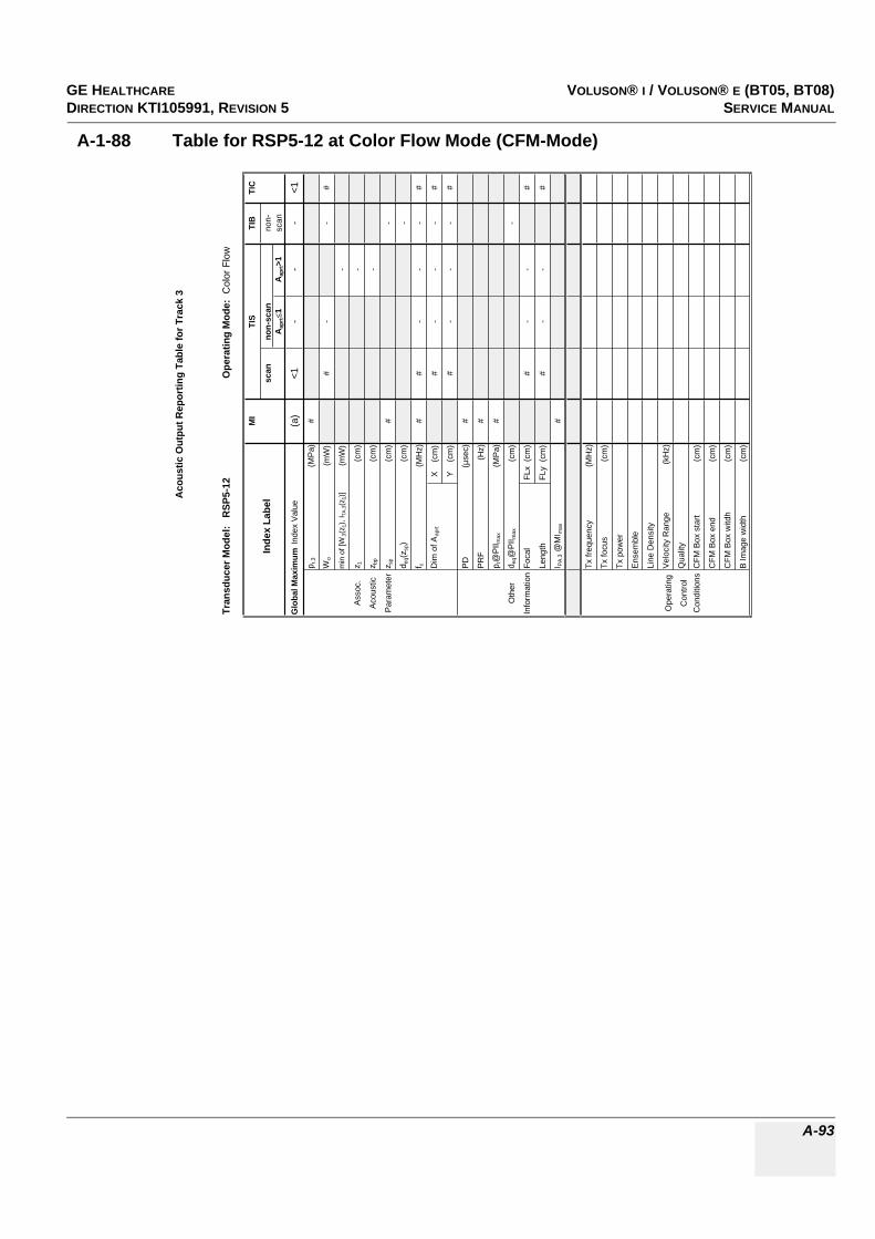
GE HEALTHCAREDRAFT VOLUSON® I / VOLUSON® E (BT05, BT08)DIRECTION KTI105991, REVISION 5 SERVICE MANUAL
A-93
A-1-88 Table for RSP5-12 at Color Flow Mode (CFM-Mode)
Tran
sduc
er M
odel
: R
SP5-
12O
pera
ting
Mod
e: C
olor
Flo
w
MI
TIS
TIB
TIC
Inde
x La
bel
scan
non-
scan
non-
Aap
rt1
Aap
rt>1
scan
Glo
bal M
axim
um In
dex
Valu
e(a
)<1
--
-<1
p r.3
(MPa
)#
Wo
(mW
)#
--
#
min
of [
W.3
(z1)
, ITA
.3(z
1)]
(mW
)-
Asso
c.z 1
(cm
)-
Acou
stic
z bp
(cm
)-
Para
met
erz s
p(c
m)
#-
d eq(
z sp)
(cm
)-
f c(M
Hz)
##
--
-#
Dim
of A
aprt
X
(cm
)#
--
-#
Y
(cm
)#
--
-#
PD(µ
sec)
#
PRF
(Hz)
#
p r@
PII m
ax(M
Pa)
#
Oth
erd e
q@PI
I max
(cm
)-
Info
rmat
ion
Foca
l FL
x (c
m)
#-
-#
Leng
thFL
y (c
m)
#-
-#
I PA.
3 @M
I max
#
Tx fr
eque
ncy
(MH
z)
Tx fo
cus
(cm
)
Tx p
ower
Ense
mbl
e
Line
Den
sity
Ope
ratin
gVe
loci
ty R
ange
(kH
z)
Con
trol
Qua
lity
Con
ditio
nsC
FM B
ox s
tart
(cm
)
CFM
Box
end
(cm
)
CFM
Box
witd
h(c
m)
B Im
age
wid
th(c
m)
Aco
ustic
Out
put R
epor
ting
Tabl
e fo
r Tra
ck 3

GE HEALTHCARERAFT VOLUSON® I / VOLUSON® E (BT05, BT08)DIRECTION KTI105991, REVISION 5 SERVICE MANUAL
A-94
A-1-89 Table for RSP5-12 at Pulsed Wave Doppler (PW-Mode)
Tran
sduc
er M
odel
: R
SP5-
12Op
erat
ing
Mod
e: P
ulsed
Dop
pler
MI
TIS
TIB
TIC
Inde
x La
bel
scan
non-
scan
non-
A apr
t1
A apr
t>1sc
an
Glob
al M
axim
um In
dex V
alue
(a)
<1<1
-1,
81,
1p r.
3(M
Pa)
#
Wo
(mW
)#
#29
30
min
of [W
.3(z
1), I T
A.3(z
1)](m
W)
-
Asso
c.z 1
(cm
)-
Acou
stic
z bp
(cm
)-
Para
met
erz s
p(c
m)
#0,
9
d eq(z
sp)
(cm
)0,
3
f c(M
Hz)
##
#-
5,0
5,9
Dim
of A
aprt
X
(cm
)#
#-
1,0
1,0
Y
(cm
)#
#-
0,4
0,4
PD(µ
sec)
#
PRF
(Hz)
#
p r@PI
I max
(MPa
)#
Othe
rd e
q@PI
I max
(cm
)0,
3
Info
rmat
ionFo
cal
FLx
(cm
)#
#-
4,5
Leng
thFL
y (c
m)
##
-1,
7
I PA.3
@M
I max
#
Tx fr
eque
ncy
(MHz
)5,
06,
0
Oper
ating
Tx fo
cus
(cm
)4,
54,
5
Cont
rol
Tx p
ower
-2-2
Gate
pos
(cm
)0,
90,
9
Cond
itions
prf
(kHz
)2,
22,
2
Sam
ple V
olum
e (G
ate)
(mm
)0,
70,
7
Acou
stic
Out
put R
epor
ting
Tabl
e fo
r Tra
ck 3

GE HEALTHCAREDRAFT VOLUSON® I / VOLUSON® E (BT05, BT08)DIRECTION KTI105991, REVISION 5 SERVICE MANUAL
A-95
A-1-90 Table for RSP5-12 at Motion Mode (M-Mode)
Acou
stic
Outp
ut R
epor
ting
Tabl
e for
Tra
ck 3
Tran
sduc
er M
odel:
RSP
5-12
Oper
atin
g Mo
de:M
-Mod
e(S
imult
aneo
us B
-Mod
e inc
l.)MI
TIS
TIB
TIC
Inde
x Lab
elsc
anno
n-sc
anno
n-A a
prt
1A a
prt>1
scan
Glob
al Ma
ximum
Inde
x Valu
e(a
)<1
<1-
<1<1
p r.3
(MPa
)#
Wo
(mW
)#
##
#
min
of [W
.3(z 1
), I TA
.3(z 1
)](m
W)
-
Asso
c.z 1
(cm
)-
Acou
stic
z bp
(cm
)-
Para
met
erz s
p(c
m)
##
d eq(z
sp)
(cm
)#
f c(M
Hz)
##
#-
##
Dim
of A
aprt
X
(cm
)#
#-
##
Y
(cm
)#
#-
##
PD(µ
sec)
#
PRF
(Hz)
#
p r@PI
I max
(MPa
)#
Othe
rd e
q@PI
I max
(cm
)#
Info
rmat
ionFo
cal
FLx
(cm
)#
#-
#
Leng
thFL
y (c
m)
##
-#
I PA.3
@M
I max
#
Tx fr
eque
ncy
(MHz
)
Oper
ating
Tx fo
cus
Cont
rol
Tx p
ower
Freq
uenc
y Set
ting

GE HEALTHCARERAFT VOLUSON® I / VOLUSON® E (BT05, BT08)DIRECTION KTI105991, REVISION 5 SERVICE MANUAL
A-96
A-1-91 Table for RSP6-16 at 2 D Mode (B-Mode)
Tran
sduc
er M
odel
: R
SP6-
16O
pera
ting
Mod
e: B
-Mod
e
MI
TIS
TIB
TIC
Inde
x La
bel
scan
non-
scan
non-
A apr
t1
A apr
t>1
scan
Glo
bal M
axim
um In
dex
Valu
e1,
2(a
)-
--
(a)
IEC
FDA
Uni
ts
p ra
p r.3
(MPa
)2,
9
PW
o(m
W)
#-
-#
min
of [
P a(z
s), I t
a,a(
z s)]
[W.3
(z1)
, ITA
.3(z
1)]
(mW
)-
Asso
c.z s
z 1(c
m)
-
Acou
stic
z bp
z bp
(cm
)-
Para
met
erz b
z sp
(cm
)-
z at
max
. Ipi
,az s
p(c
m)
1,1
d eq(z
b)d e
q(zsp
)(c
m)
-
f awf
f c(M
Hz)
5,3
#-
--
#
Dim
of A
aprt
X
(cm
)#
--
-#
Y
(cm
)#
--
-#
t dPD
(µse
c)0,
5
prr
PRF
(Hz)
1142
0
p r a
t max
. Ipi
p r@
PII m
ax(M
Pa)
3,5
Oth
erd e
q at m
ax. I
pid e
q@PI
I max
(cm
)-
Info
rmat
ion
Foca
l Len
gth
FLx
(cm
)#
--
#
FLy
(cm
)#
--
#
I pa,a
at m
ax. M
II P
A.3 @
MI m
ax(W
/cm
²)20
9
B-Im
ages
ecto
r sta
rt(c
m)
0,0
B-Im
ages
ecto
r end
(cm
)7,
9
B-Im
ages
ecto
r wid
th(c
m)
3,7
Qua
lity
high
Ope
ratin
gZo
om1,
0
Con
trol
Foc.
Zon
es1
Con
ditio
nsFr
eque
ncy
Setti
ngLo
w
SEN
S PR
I-
Pow
er(%
)10
0
Zoom
Box
star
t(c
m)
0,0
Zoom
Box
end
(cm
)1,
6
Zoom
Box
wid
th(c
m)
2,2
Mod
e Ty
peB(
Har
m)
Foca
l Dep
th(c
m)
1,6
Aco
ustic
Out
put R
epor
ting
Tabl
e fo
r Tra
ck 3
(pro
vide
dat
a w
here
glo
bal m
axim
um d
ispl
ayed
inde
x ex
ceed
s 1.
0)

GE HEALTHCAREDRAFT VOLUSON® I / VOLUSON® E (BT05, BT08)DIRECTION KTI105991, REVISION 5 SERVICE MANUAL
A-97
A-1-92 Table for RSP6-16 at Color Flow Mode (CFM-Mode)
Tran
sduc
er M
odel
: R
SP
6-16
Ope
ratin
g M
ode:
Col
or F
low
MI
TIS
TIB
TIC
Inde
x La
bel
scan
non-
scan
non-
Aap
rt1
Aap
rt>1
scan
Glo
bal M
axim
um In
dex
Val
ue(a
)<1
--
-1,
0
IEC
FDA
Uni
ts
p ra
p r.3
(MP
a)#
PW
o(m
W)
#-
-64
min
of [
P a(z
s), I
ta,a
(zs)
][W
.3(z
1), I
TA.3(z
1)]
(mW
)-
Ass
oc.
z sz 1
(cm
)-
Aco
ustic
z bp
z bp
(cm
)-
Par
amet
erz b
z sp
(cm
)-
z at
max
. I pi,a
z sp
(cm
)#
d eq(
z b)
d eq(
z sp)
(cm
)-
f aw
ff c
(MH
z)#
#-
--
7,4
Dim
of A
aprt
X
(cm
)#
--
-4,
9
Y
(cm
)#
--
-0,
4
t dP
D(µ
sec)
#
prr
PR
F(H
z)#
p r a
t max
. I pi
p r@
PII m
ax(M
Pa)
#
Oth
erd e
q at
max
. I pi
d eq@
PII m
ax(c
m)
-
Info
rmat
ion
Foca
l Len
gth
FLx
(cm
)#
--
6
FLy
(cm
)#
--
1,5
I pa,a
at m
ax. M
II P
A.3 @
MI m
ax(W
/cm
²)#
B-Im
ages
ecto
r sta
rt(c
m)
0,0
B-Im
ages
ecto
r end
(cm
)7,
9
B-Im
ages
ecto
r wid
th(c
m)
3,7
B-Q
ualit
ylo
w
Zoom
1,0
Foc.
Zon
es1
Ope
ratin
gFr
eque
ncy
Set
ting
norm
Con
trol
SE
NS
PR
I-
Con
ditio
nsB
Tx
Pow
er(%
)1
CFM
Box
sta
rt(c
m)
4,8
CFM
Box
end
(cm
)5,
9
CFM
Box
wid
th(c
m)
3,7
CFM
Tx
pow
er(%
)10
0
Ens
embl
e31
Line
Den
sity
1
Flow
Res
high
Vel
ocity
Ran
ge(k
Hz)
9,0
CFM
Qua
lity
norm
CFM
Fre
quen
cyhi
gh
Aco
ustic
Out
put R
epor
ting
Tabl
e fo
r Tr
ack
3(p
rovi
de d
ata
whe
re g
loba
l max
imum
dis
play
ed in
dex
exce
eds
1.0)
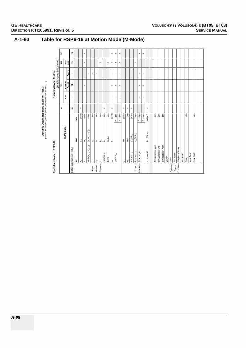
GE HEALTHCARERAFT VOLUSON® I / VOLUSON® E (BT05, BT08)DIRECTION KTI105991, REVISION 5 SERVICE MANUAL
A-98
A-1-93 Table for RSP6-16 at Motion Mode (M-Mode)
Tran
sduc
er M
odel
: R
SP6-
16O
pera
ting
Mod
e:M
-Mod
e(S
imul
tane
ous
B-M
ode
incl
.)M
ITI
STI
BTI
C
Inde
x La
bel
scan
non-
scan
non-
A apr
t1
A apr
t>1
scan
Glo
bal M
axim
um In
dex
Valu
e(a
)-
<1-
<1<1
IEC
FDA
Units
p ra
p r.3
(MPa
)#
PW
o(m
W)
-#
##
min
of [
P a(z
s), I t
a,a(
z s)]
[W.3
(z1)
, ITA
.3(z
1)]
(mW
)-
Asso
c.z s
z 1(c
m)
-
Acou
stic
z bp
z bp
(cm
)-
Para
met
erz b
z sp
(cm
)#
z at
max
. I pi,a
z sp
(cm
)#
d eq(z
b)d e
q(zsp
)(c
m)
#
f awf
f c(M
Hz)
#-
#-
##
Dim
of A
aprt
X
(cm
)-
#-
##
Y
(cm
)-
#-
##
t dPD
(µse
c)#
prr
PRF
(Hz)
#
p r a
t max
. Ipi
p r@
PII m
ax(M
Pa)
#
Oth
erd e
q at m
ax. I
pid e
q@PI
I max
(cm
)#
Info
rmat
ion
Foca
l Len
gth
FLx
(cm
)-
#-
#
FLy
(cm
)-
#-
#
I pa,a
at m
ax. M
II PA
.3 @
MI m
ax(W
/cm
²)#
B-Im
ages
ecto
r sta
rt(c
m)
B-Im
ages
ecto
r end
(cm
)
B-Im
ages
ecto
r wid
th(c
m)
Qua
lity
Ope
ratin
gZo
om
Con
trol
Foc.
Zon
es
Con
ditio
nsFr
eque
ncy
Setti
ng
SEN
S PR
I
Pow
er(%
)
Mod
e Ty
pe
Foca
l Dep
th(c
m)
Acou
stic
Out
put R
epor
ting
Tabl
e fo
r Tra
ck 3
(pro
vide
dat
a w
here
glo
bal m
axim
um d
ispl
ayed
inde
x ex
ceed
s 1.
0)

GE HEALTHCAREDRAFT VOLUSON® I / VOLUSON® E (BT05, BT08)DIRECTION KTI105991, REVISION 5 SERVICE MANUAL
A-99
A-1-94 Table for RSP6-16 at Pulsed Wave Doppler (PW-Mode)
Tran
sduc
er M
odel:
RSP
6-16
Oper
atin
g Mo
de:
Pulse
d Dop
pler
MITI
STI
BTI
C
Inde
x Lab
elsc
anno
n-sc
anno
n-A a
prt
1A a
prt>1
scan
Glob
al Ma
ximum
Inde
x Valu
e(a
)-
1,0-
1,4<1
IEC
FDA
Units
p rap r.
3(M
Pa)
#
PW
o(m
W)
-28
26#
min o
f [Pa(z
s), I ta
,a(z s
)][W
.3(z 1
), I TA
.3(z1)]
(mW
)-
Asso
c.z s
z 1(cm
)-
Acou
stic
z bp
z bp
(cm)
-
Para
meter
z bz sp
(cm)
0,7
z at m
ax. I p
i,az sp
(cm)
#
d eq(z
b)d e
q(zsp
)(cm
)0,3
f awf
f c(M
Hz)
#-
7,4-
6,0#
Dim
of A a
prt
X
(cm)
-1,2
-1,2
#
Y (
cm)
-0,4
-0,4
#
t dPD
(µse
c)#
prr
PRF
(Hz)
#
p r at
max.
I pip r@
PII ma
x(M
Pa)
#
Othe
rd e
q at m
ax. I p
id e
q@PI
I max
(cm)
0,3
Infor
matio
nFoc
al Le
ngth
FLx
(cm)
-6
-#
FLy
(cm)
-1,5
-#
I pa,a
at ma
x. MI
I PA.3 @
MIma
x(W
/cm²)
#
Gate
width
(cm)
0,10,1
Oper
ating
Gate
pos
(cm)
3,23,2
Contr
olB-
Imag
esec
tor an
gle(D
egre
e)1,3
3,3
Cond
itions
Powe
r(%
)10
010
0
Acou
stic
Outp
ut R
epor
ting
Tabl
e for
Tra
ck 3
(pro
vide d
ata w
here
glob
al ma
ximum
disp
layed
inde
x exc
eeds
1.0)

GE HEALTHCARERAFT VOLUSON® I / VOLUSON® E (BT05, BT08)DIRECTION KTI105991, REVISION 5 SERVICE MANUAL
A-100
A-1-95 Table for RNA5-9 at 2 D Mode (B-Mode)
Tran
sduc
er M
odel
: R
NA
5-9
Ope
ratin
g M
ode:
B-M
ode
MI
TIS
TIB
TIC
Inde
x La
bel
scan
non-
scan
non-
A apr
t1
A apr
t>1
scan
Glo
bal M
axim
um In
dex
Valu
e1,
3(a
)-
--
(a)
IEC
FDA
Uni
ts
p ra
p r.3
(MPa
)2,
4
PW
o(m
W)
#-
-#
min
of [
P a(z
s), I t
a,a(
z s)]
[W.3
(z1)
, ITA
.3(z
1)]
(mW
)-
Asso
c.z s
z 1(c
m)
-
Acou
stic
z bp
z bp
(cm
)-
Para
met
erz b
z sp
(cm
)-
z at
max
. Ipi
,az s
p(c
m)
1,7
d eq(z
b)d e
q(zsp
)(c
m)
-
f awf
f c(M
Hz)
3,8
#-
--
#
Dim
of A
aprt
X
(cm
)#
--
-#
Y
(cm
)#
--
-#
t dPD
(µse
c)0,
6
prr
PRF
(Hz)
6590
p r a
t max
. Ipi
p r@
PII m
ax(M
Pa)
3,0
Oth
erd e
q at m
ax. I
pid e
q@PI
I max
(cm
)-
Info
rmat
ion
Foca
l Len
gth
FLx
(cm
)#
--
#
FLy
(cm
)#
--
#
I pa,a
at m
ax. M
II P
A.3 @
MI m
ax(W
/cm
²)19
8
B-Im
ages
ecto
r sta
rt(c
m)
0,0
B-Im
ages
ecto
r end
(cm
)18
,0
B-Im
ages
ecto
r ang
le(D
egre
e)11
7,2
Qua
lity
high
Ope
ratin
gZo
om1,
0
Con
trol
Foc.
Zon
es1
Con
ditio
nsFr
eque
ncy
Setti
ngLo
w
SEN
S PR
I-
Pow
er(%
)10
0
Zoom
Box
star
t(c
m)
4,2
Zoom
Box
end
(cm
)7,
8
Zoom
Box
angl
e(D
egre
e)11
7,2
Mod
e Ty
peB(
Har
m)
Foca
l Dep
th(c
m)
3,5
Aco
ustic
Out
put R
epor
ting
Tabl
e fo
r Tra
ck 3
(pro
vide
dat
a w
here
glo
bal m
axim
um d
ispl
ayed
inde
x ex
ceed
s 1.
0)
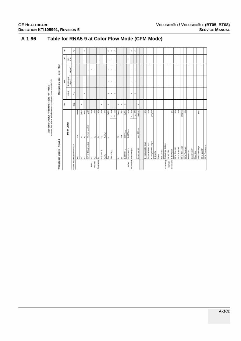
GE HEALTHCAREDRAFT VOLUSON® I / VOLUSON® E (BT05, BT08)DIRECTION KTI105991, REVISION 5 SERVICE MANUAL
A-101
A-1-96 Table for RNA5-9 at Color Flow Mode (CFM-Mode)
Tran
sduc
er M
odel
: R
NA
5-9
Ope
ratin
g M
ode:
Col
or F
low
MI
TIS
TIB
TIC
Inde
x La
bel
scan
non-
scan
non-
Aap
rt1
Aap
rt>1
scan
Glo
bal M
axim
um In
dex
Val
ue(a
)<1
--
-<1
IEC
FDA
Uni
ts
p ra
p r.3
(MP
a)#
PW
o(m
W)
#-
-#
min
of [
P a(z
s), I
ta,a
(zs)
][W
.3(z
1), I
TA.3(z
1)]
(mW
)-
Ass
oc.
z sz 1
(cm
)-
Aco
ustic
z bp
z bp
(cm
)-
Par
amet
erz b
z sp
(cm
)-
z at
max
. I pi,a
z sp
(cm
)#
d eq(
z b)
d eq(
z sp)
(cm
)-
f aw
ff c
(MH
z)#
#-
--
#
Dim
of A
aprt
X
(cm
)#
--
-#
Y
(cm
)#
--
-#
t dP
D(µ
sec)
#
prr
PR
F(H
z)#
p r a
t max
. I pi
p r@
PII m
ax(M
Pa)
#
Oth
erd e
q at
max
. I pi
d eq@
PII m
ax(c
m)
-
Info
rmat
ion
Foca
l Len
gth
FLx
(cm
)#
--
#
FLy
(cm
)#
--
#
I pa,a
at m
ax. M
II P
A.3 @
MI m
ax(W
/cm
²)#
B-Im
ages
ecto
r sta
rt(c
m)
B-Im
ages
ecto
r end
(cm
)
B-Im
ages
ecto
r ang
le(D
egre
e)
B-Q
ualit
y
Zoom
Foc.
Zon
es
Ope
ratin
gFr
eque
ncy
Set
ting
Con
trol
SE
NS
PR
I
Con
ditio
nsB
Tx
Pow
er(%
)
CFM
Box
sta
rt(c
m)
CFM
Box
end
(cm
)
CFM
Box
ang
le(D
egre
e)
CFM
Tx
pow
er(%
)
Ens
embl
e
Line
Den
sity
Flow
Res
Vel
ocity
Ran
ge(k
Hz)
CFM
Qua
lity
CFM
Fre
quen
cy
Aco
ustic
Out
put R
epor
ting
Tabl
e fo
r Tr
ack
3(p
rovi
de d
ata
whe
re g
loba
l max
imum
dis
play
ed in
dex
exce
eds
1.0)

GE HEALTHCARERAFT VOLUSON® I / VOLUSON® E (BT05, BT08)DIRECTION KTI105991, REVISION 5 SERVICE MANUAL
A-102
A-1-97 Table for RNA5-9 at Continuous Wave Doppler (CW-Mode)
Tran
sduc
er M
odel:
RNA
5-9
Oper
atin
g Mo
de:
Conti
nues
Wav
e
MITI
STI
BTI
C
Inde
x Lab
elsc
anno
n-sc
anno
n-A a
prt
1A a
prt>1
scan
Glob
al Ma
ximum
Inde
x Valu
e(a
)-
<1-
<1<1
IEC
FDA
Units
p rap r.
3(M
Pa)
#
PW
o(m
W)
-#
##
min o
f [Pa(z
s), I ta
,a(z s
)][W
.3(z 1
), I TA
.3(z1)]
(mW
)-
Asso
c.z s
z 1(cm
)-
Acou
stic
z bp
z bp
(cm)
-
Para
meter
z bz sp
(cm)
#
z at m
ax. I p
i,az sp
(cm)
#
d eq(z
b)d e
q(zsp
)(cm
)#
f awf
f c(M
Hz)
#-
#-
##
Dim
of A a
prt
X
(cm)
-#
-#
#
Y (
cm)
-#
-#
#
t dPD
(µse
c)#
prr
PRF
(Hz)
#
p r at
max.
I pip r@
PII ma
x(M
Pa)
#
Othe
rd e
q at m
ax. I p
id e
q@PI
I max
(cm)
#
Infor
matio
nFoc
al Le
ngth
FLx
(cm)
-#
-#
FLy
(cm)
-#
-#
I pa,a
at ma
x. MI
I PA.3 @
MIma
x(W
/cm²)
#
Veloc
ity R
ange
(kHz)
Oper
ating
Powe
r(%
)
Contr
olCo
nditio
ns
Acou
stic
Outp
ut R
epor
ting
Tabl
e for
Tra
ck 3
(pro
vide d
ata w
here
glob
al ma
ximum
disp
layed
inde
x exc
eeds
1.0)

GE HEALTHCAREDRAFT VOLUSON® I / VOLUSON® E (BT05, BT08)DIRECTION KTI105991, REVISION 5 SERVICE MANUAL
A-103
A-1-98 Table for RNA5-9 at Motion Mode (M-Mode)
Tran
sduc
er M
odel
: R
NA5-
9O
pera
ting
Mod
e:M
-Mod
e(S
imul
tane
ous
B-M
ode
incl
.)M
ITI
STI
BTI
C
Inde
x La
bel
scan
non-
scan
non-
A apr
t1
A apr
t>1
scan
Glo
bal M
axim
um In
dex
Valu
e(a
)-
<1-
<1<1
IEC
FDA
Units
p ra
p r.3
(MPa
)#
PW
o(m
W)
-#
##
min
of [
P a(z
s), I t
a,a(
z s)]
[W.3
(z1)
, ITA
.3(z
1)]
(mW
)-
Asso
c.z s
z 1(c
m)
-
Acou
stic
z bp
z bp
(cm
)-
Para
met
erz b
z sp
(cm
)#
z at
max
. I pi,a
z sp
(cm
)#
d eq(z
b)d e
q(zsp
)(c
m)
#
f awf
f c(M
Hz)
#-
#-
##
Dim
of A
aprt
X
(cm
)-
#-
##
Y
(cm
)-
#-
##
t dPD
(µse
c)#
prr
PRF
(Hz)
#
p r a
t max
. Ipi
p r@
PII m
ax(M
Pa)
#
Oth
erd e
q at m
ax. I
pid e
q@PI
I max
(cm
)#
Info
rmat
ion
Foca
l Len
gth
FLx
(cm
)-
#-
#
FLy
(cm
)-
#-
#
I pa,a
at m
ax. M
II PA
.3 @
MI m
ax(W
/cm
²)#
B-Im
ages
ecto
r sta
rt(c
m)
B-Im
ages
ecto
r end
(cm
)
B-Im
ages
ecto
r ang
le(D
egre
e)
Qua
lity
Ope
ratin
gZo
om
Con
trol
Foc.
Zon
es
Con
ditio
nsFr
eque
ncy
Setti
ng
SEN
S PR
I
Pow
er(%
)
Mod
e Ty
pe
Foca
l Dep
th(c
m)
Acou
stic
Out
put R
epor
ting
Tabl
e fo
r Tra
ck 3
(pro
vide
dat
a w
here
glo
bal m
axim
um d
ispl
ayed
inde
x ex
ceed
s 1.
0)
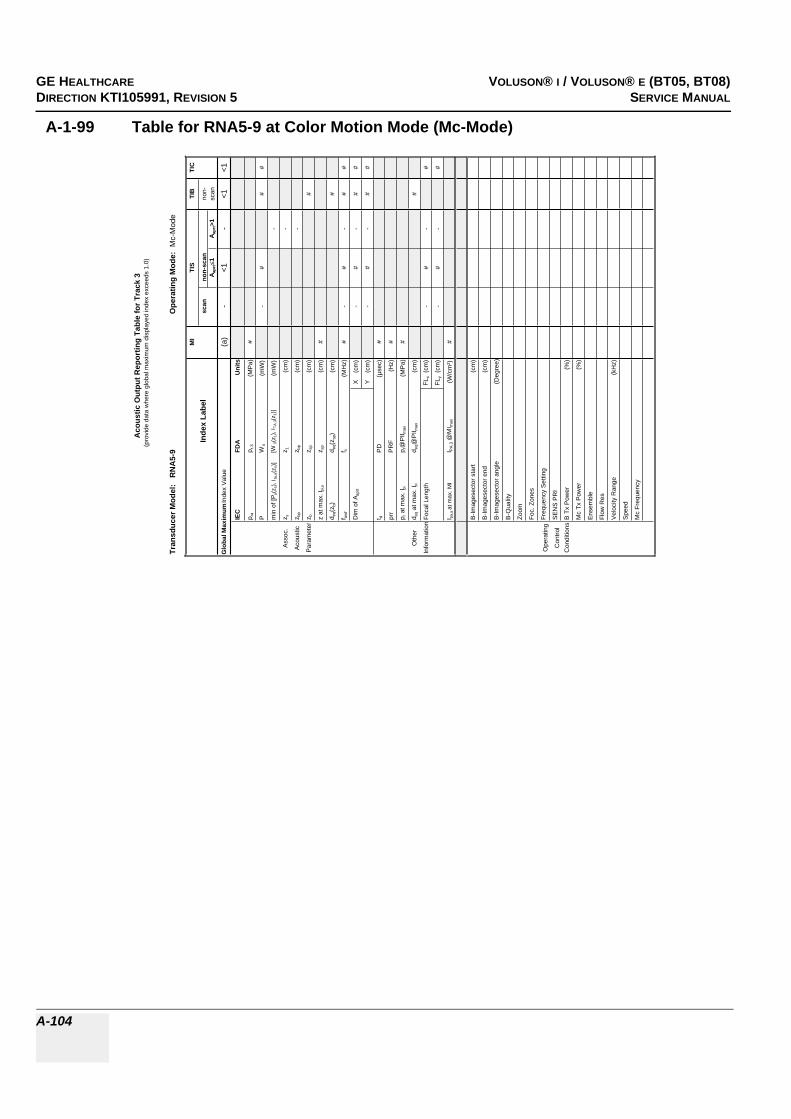
GE HEALTHCARERAFT VOLUSON® I / VOLUSON® E (BT05, BT08)DIRECTION KTI105991, REVISION 5 SERVICE MANUAL
A-104
A-1-99 Table for RNA5-9 at Color Motion Mode (Mc-Mode)
Tran
sduc
er M
odel
: R
NA
5-9
Ope
ratin
g M
ode:
Mc-
Mod
e
MI
TIS
TIB
TIC
Inde
x La
bel
scan
non-
scan
non-
A apr
t1
A apr
t>1
scan
Glo
bal M
axim
um In
dex
Val
ue(a
)-
<1-
<1<1
IEC
FDA
Uni
ts
p ra
p r.3
(MP
a)#
PW
o(m
W)
-#
##
min
of [
P a(z
s), I
ta,a
(zs)
][W
.3(z
1), I
TA.3(z
1)]
(mW
)-
Ass
oc.
z sz 1
(cm
)-
Aco
ustic
z bp
z bp
(cm
)-
Par
amet
erz b
z sp
(cm
)#
z at
max
. Ipi
,az s
p(c
m)
#
d eq(
z b)
d eq(
z sp)
(cm
)#
f awf
f c(M
Hz)
#-
#-
##
Dim
of A
aprt
X
(cm
)-
#-
##
Y
(cm
)-
#-
##
t dP
D(µ
sec)
#
prr
PR
F(H
z)#
p r a
t max
. Ipi
p r@
PII m
ax(M
Pa)
#
Oth
erd e
q at m
ax. I
pid e
q@P
II max
(cm
)#
Info
rmat
ion
Foca
l Len
gth
FLx
(cm
)-
#-
#
FLy
(cm
)-
#-
#
I pa,a
at m
ax. M
II P
A.3 @
MI m
ax(W
/cm
²)#
B-Im
ages
ecto
r sta
rt(c
m)
B-Im
ages
ecto
r end
(cm
)
B-Im
ages
ecto
r ang
le(D
egre
e)
B-Q
ualit
y
Zoom
Foc.
Zon
es
Ope
ratin
gFr
eque
ncy
Set
ting
Con
trol
SE
NS
PR
I
Con
ditio
nsB
Tx
Pow
er(%
)
Mc
Tx P
ower
(%)
Ens
embl
e
Flow
Res
Vel
ocity
Ran
ge(k
Hz)
Spe
ed
Mc
Freq
uenc
y
Aco
ustic
Out
put R
epor
ting
Tabl
e fo
r Tra
ck 3
(pro
vide
dat
a w
here
glo
bal m
axim
um d
ispl
ayed
inde
x ex
ceed
s 1.
0)

GE HEALTHCAREDRAFT VOLUSON® I / VOLUSON® E (BT05, BT08)DIRECTION KTI105991, REVISION 5 SERVICE MANUAL
A-105
A-1-100 Table for RNA5-9 at Pulsed Wave Doppler (PW-Mode)
Tran
sduc
er M
odel:
RNA
5-9
Oper
atin
g Mo
de:
Pulse
d Dop
pler
MITI
STI
BTI
C
Inde
x Lab
elsc
anno
n-sc
anno
n-A a
prt
1A a
prt>1
scan
Glob
al Ma
ximum
Inde
x Valu
e(a
)-
<1-
1,5<1
IEC
FDA
Units
p rap r.
3(M
Pa)
#
PW
o(m
W)
-#
42#
min o
f [Pa(z
s), I ta
,a(z s
)][W
.3(z 1
), I TA
.3(z1)]
(mW
)-
Asso
c.z s
z 1(cm
)-
Acou
stic
z bp
z bp
(cm)
-
Para
meter
z bz sp
(cm)
1,2
z at m
ax. I p
i,az sp
(cm)
#
d eq(z
b)d e
q(zsp
)(cm
)0,4
f awf
f c(M
Hz)
#-
#-
4,3#
Dim
of A a
prt
X
(cm)
-#
-1,7
#
Y (
cm)
-#
-0,8
6#
t dPD
(µse
c)#
prr
PRF
(Hz)
#
p r at
max.
I pip r@
PII ma
x(M
Pa)
#
Othe
rd e
q at m
ax. I p
id e
q@PI
I max
(cm)
0,4
Infor
matio
nFoc
al Le
ngth
FLx
(cm)
-#
-#
FLy
(cm)
-#
-#
I pa,a
at ma
x. MI
I PA.3 @
MIma
x(W
/cm²)
#
Gate
width
(cm)
0,8
Oper
ating
Gate
pos
(cm)
5,6
Contr
olB-
Imag
esec
tor an
gle(D
egre
e)2,2
Cond
itions
Powe
r(%
)10
0
Acou
stic
Outp
ut R
epor
ting
Tabl
e for
Tra
ck 3
(pro
vide d
ata w
here
glob
al ma
ximum
disp
layed
inde
x exc
eeds
1.0)

GE HEALTHCARERAFT VOLUSON® I / VOLUSON® E (BT05, BT08)DIRECTION KTI105991, REVISION 5 SERVICE MANUAL
A-106
This page was intentionally left blank.

GE HEALTHCARE VOLUSON® I / VOLUSON® E (BT05, BT08)DIREKTION KTI105991, REVISION 5 SERVICE MANUAL
Index I
INDEXNumerics2D Mode Checks
Functional Checks, 4-8
A,BAcoustic Noise Output, 2-4Activation of Options, 8-17Adjustment
DVD Recorder Settings, 3-16Keyboard Layout, 6-7Monitor, 6-2Printer Settings, 3-52Trackball, 6-6Write Speed of DVD/CD Recorder, 4-31
Administration of Full Backup data, 4-37Air Flow Control, 5-54Archiving Images, 4-41Auxiliary Devices
Connection Scheme, 3-9B/W Video Printer
Connection Scheme, 3-19BackEnd
ADD2-DVI (Add-On) Card, 5-30Board Description, 5-30CKV - DMA-Controller/Video-Card, 5-30CPE - Back Panel I/O-Card, 5-30CPP - Power Supply Secondary Board, 5-31Hard Disk Drive, 5-30SBC - Single Board Computer, 5-30
BackEnd ProcessorTheory, 5-28
BackupPatient Database and Images, 4-32
Block diagramBackEnd Processor, 5-28CKV - Video Converter Board, 5-29CPD - Beamformer Sub-board, 5-24CPP - Power Supply Secondary Board, 5-27CPV + Beamformer (CPR), 5-23FrontEnd Processor, 5-22Top Level Architecture, 5-9Voluson 730Expert, 5-10Voluson 730Expert Basic, 5-4
Bluetooth PrinterConnection Scheme, 3-23
Board DescriptionBackEnd, 5-30FrontEnd, 5-23
Boot Up, 3-34, , 4-2
CCalculation Measurements
Functional Checks, 4-26General remarks to perform, 4-26
CalibrationMonitor, 6-2
CineFunctional Checks, 4-22
Color Flow ModesFunctional Checks, 4-15
Compliance, 1-14Connection
External USB-Devices, 3-32Connection Scheme
Auxiliary Devices, 3-9B/W Video Printer, 3-19Bluetooth Printer, 3-23Digital Color Printer, 3-22DVD Recorder (DVR), 3-15ECG, 3-11Foot Switch, 3-11Global Modem, 3-12Line Printer, 3-21S-VHS Video Recorder, 3-13
ConnectivityWorksheet, 3-71
Contact Information, 1-15Control Console
Rotation, 5-52Transport Lock, 6-5
Control Panel, 4-4CPN - Main Power Module
Theory, 5-49Customer Assistance, 1-15
DDangerous Procedure Warnings, 1-13Data Flow
Control Description, 5-11Daylight Saving Time (DST), 6-9Delete
Full Backup (Presets, Config. & Appl. Settings), 4-40DICOM
Worksheet for DICOM Network Information, 3-72Digital Black & White Printer
Installation UP-D897, 3-43Digital Color Printer
Connection Scheme, 3-22Installation UP-D21MD, 3-41
GE HEALTHCARE VOLUSON® 730PRO/PROV (BT05, BT08)DIRECTION KTI105991, REVISION 5 SERVICE MANUAL
II -
Installation UP-D23MD, 3-41Disconnection
External USB-Devices, 3-32Doppler Mode Checks
Functional Checks, 4-13DVD Recorder (DVR)
Connection Scheme, 3-15DVD Recorder Settings
Adjustment, 3-16DVD+(R)W Drive
Theory, 5-48
EECG
Connection Scheme, 3-11Functional Checks, 4-43Theory, 5-48
ElectricalRequirements, 2-2
Electrical Safety, 1-10Electronic User Manual (EUM)
Loading Procedure, 8-13Electrostatic Discharge Warning, 1-14EMC
Electromagnetic Compatibility, 1-14EMI Protection, 3-8Error Messages, 7-21External I/O
Theory, 5-47External USB-Devices
Connection, 3-32Disconnection, 3-32
FFoot Switch
Connection, 5-19Connection Scheme, 3-11
FormattingMedia, 4-30
FrontEndBoard Description, 5-23CPK - Motherboard of the GEZ-Module, 5-25CPP - Power Supply Secondary Board, 5-27CPR - Beamformer Board, 5-23CPV - Probe Connector Board, 5-23CPZ - Cover Board, 5-25CRS - Signal Processor Board, 5-26CRW - CW Doppler Board, 5-25
Full Backup (Presets, Configurations & Appl. Settings)Delete, 4-40Load, 4-38Loading Procedure, 8-10Save, 4-36

GE HEALTHCARE VOLUSON® 730PRO/PROV (BT05, BT08)DIRECTION KTI105991, REVISION 5 SERVICE MANUAL
- III
Functional Checks, 4-12D Mode, 4-8Brakes, 4-44Calculation Measurements, 4-26Cine Mode, 4-22Color Flow Modes, 4-15Control Panel, 4-4Doppler Modes, 4-13ECG Checkout, 4-43Generic Measurements, 4-23M Mode, 4-11Mechanical, 4-44MO-Drive, 4-29Monitor Display, 4-6Peripherals, 4-43Probes/Connector Usage, 4-27Required Equipment, 4-1Volume Modes, 4-17
Fuses inside Primary Power Module (CPN), 5-50Fuses on CPE-Board
for Disk Drive Module (GEM), 5-50Fuses on Rear Panel (CPN), 5-50
GGeneral Cleaning, 10-9Generic Measurements
Functional Checks, 4-23GEZ Module
Main board Chassis, 5-21Global Modem
Connection Scheme, 3-12LEDs, 5-20Location in the Unit, 5-20
HHard Disk Drive, 5-30Hardware Options, 5-19Hazard Icons, 1-5How to check power, 7-3How to check status of the Diagnostic LED´s, 7-3How to use the Auto Tester, 7-7http
//libraries.ge.com/foldersIndex.do?entity_id=15869258101&sid=101&SF=1, 3-46Human Safety, 1-9
IiLinq Interactive Platform, 5-56Image Management
Functional Checks, 4-28Inrush Current, 2-2Installation
Digital Black & White Printer UP-D897, 3-43
GE HEALTHCARE VOLUSON® 730PRO/PROV (BT05, BT08)DIRECTION KTI105991, REVISION 5 SERVICE MANUAL
IV -
Digital Color Printer UP-D21MD, 3-41Digital Color Printer UP-D23MD, 3-41Line Printer HP 990cxi, 3-39Line Printer HP 995c, 3-39
Internal I/OTheory, 5-32Theory ("Kontron" SBC installed), 5-33Theory ("Tyan" SBC installed), 5-35
KKey Caps
Replacement Procedure, 8-26Keyboard Layout
Adjustment, 6-7
LLabel Locations, 1-12Line Printer
Connection Scheme, 3-21Installation HP 990cxi, 3-39Installation HP 995c, 3-39
List of Abbreviations, 9-2Load
Full Backup (Presets, Config. & Appl. Settings), 4-38User Settings Only (Application Settings), 4-34
Loading ProcedureElectronic User Manual (EUM), 8-13Full Backup (Presets, Config. & Appl. Settings), 8-10Ultrasound Application Software (UIS), 8-3User Settings Only (Application Settings), 8-10
MM Mode
Functional Checks, 4-11Main board Chassis
GEZ Module, 5-21Map Network Drive, 3-70Mechanical Checks
Control Console, 4-44Mechanical Safety, 1-9Media
Formatting, 4-30Minimum Configuration to scan, 7-10Models Covered, 1-2MO-Drive
Functional Checks, 4-29Theory, 5-48
MonitorAdjustment, 6-2Calibration, 6-2Theory, 5-46
Monitor Display

GE HEALTHCARE VOLUSON® 730PRO/PROV (BT05, BT08)DIRECTION KTI105991, REVISION 5 SERVICE MANUAL
- V
Functional Checks, 4-6
NNetwork IP Address Configuration, 3-69
OOptions
Activation, 8-17Replacement Procedure, 8-17
PPeripherals
Disk Drive Module (GEM), 5-48Functional Checks, 4-43
Physical Dimensions, 2-4Power Distribution, 5-49
CPN - Primary Power Supply, 5-49Disk Drive Module (GEM), 5-50
Power Off / Shutdown, 3-36, , 4-3Power On, 3-34, , 4-2Power Requirements
electrical, 2-2Power Stability Requirements, 2-2Preparing the Unit for Installation, 3-7Printer Installation, 3-38Printer Installation manually, 3-47Printer Remote Control Selection, 3-59Printer Settings
Adjustment, 3-52Probe Connector Cleaning, 10-10Probe Holder
Replacement Procedure, 8-25Probes, 3-68
Disconnecting, 4-43Probes/Connector Usage
Functional Checks, 4-27Product Icons, 1-6
RReceiving and Unpacking the Equipment, 3-5Regulatory, 6-1Replacement Procedures
Digipots and TGC Slider controls, 8-25Key Caps (by special native language keys), 8-26Monitor Task Lamp, 8-24Options, 8-17Probe Holder, 8-25Trackball top fixation ring, 8-25
Returning/ShippingProbes and Repair Parts, 1-13, , 8-3

GE HEALTHCARE VOLUSON® 730PRO/PROV (BT05, BT08)DIRECTION KTI105991, REVISION 5 SERVICE MANUAL
VI -
SSafety Considerations, 1-9Save
Full Backup (Presets, Config. & Appl. Settings), 4-36User Settings Only (Application Settings), 4-33
Screen Captures, 7-4Service Adjustments, 6-1Service Platform
Access/Security, 5-55Service Page, 5-57
Service Platform (SSW)Upgrade Procedure, 8-11
Sharing patient data and imagesbetween systems within the same network, 8-20
Shutdown Procedure, 3-36, , 4-3Software Options, 5-15S-VHS Video Recorder
Connection Scheme, 3-13System Components, 5-3System Configuration
How to activate Screen Lock, 3-62How to change Keyboard Layout, 3-63How to change Language, 3-61How to change the EUM Language, 3-61How to change Video Norm, 3-63How to enter Date and Time, 3-61How to enter Hospital Name, 3-61
System HistoryHardware and Software Versions, 1-3
System Maintenance, 10-6System Manufacturer, 1-15System Voltage Settings, 3-8
TTask Lamp
Replacement Procedure, 8-24Theory
General, 5-2Top Console
Theory, 5-41Trackball
Adjustment, 6-6Transfer of Patient Database and Images
via Sonoview, 8-20Troubleshooting
DVD/CD+(R)W, 7-20Error Messages, 7-21MO-Drive, 7-20Monitor, 7-16Network, 7-20Screen Captures, 7-4Voltage Points, 7-3
Troubleshooting TreesNoise disturbs the Image, 7-13
GE HEALTHCARE VOLUSON® 730PRO/PROV (BT05, BT08)DIRECTION KTI105991, REVISION 5 SERVICE MANUAL
- VII
Printer, 7-18System does not Power OFF/Shutdown, 7-15System does not Power ON/Boot Up, 7-12Trackball, 7-14Unable to Record to VCR, 7-17
UUltrasound Application Software (UIS)
Loading Procedure, 8-3Unpacking the Equipment, 3-5Upgrade Procedure
Service Platform (SSW), 8-11User Settings Only (Application Settings)
Loading Procedure, 8-10
VVideo
Specifications, 3-67Voltage Settings, 3-8Volume Modes
Functional Checks, 4-17
WWarnings and Cautions, 1-9Weight without Monitor and Peripherals, 2-4What is EMC?, 1-14Worksheet for DICOM Network Information, 3-72

GE HEALTHCARE VOLUSON® 730PRO/PROV (BT05, BT08)DIRECTION KTI105991, REVISION 5 SERVICE MANUAL
VIII -


© 2004 and 2012, General Electric Company.GE Medical Systems, a General Electric Company, going to market as GE Healthcare.
GE Healthcare Austria GmbH & Co OGTiefenbach 15A-4871 ZipfAustria
www.gehealthcare.com