volvo maintenance faq for 7xx/9xx/90 cars cluster … maintenance faq for 7xx/9xx/90 cars...
TRANSCRIPT

Electrical: Instruments
file:///C|/Users/Steve/Documents/Volvo%20FAQ%20Updated/ElectricalInstruments.html[01/13/14 9:59:40 PM]
Electrical: Instruments
FAQ Home
Volvo Maintenance FAQ for 7xx/9xx/90 Cars
"Service Engine" Light Reset in Various Models
Cluster Removal:
740 Instrument Cluster Removal
760 Instrument Cluster Removal
940 Instrument Cluster Removal
960 Instrument Cluster Removal
Cluster Cleaning/Disassembly and Connector WireRemoval
Lamps and Switches:
Replacing Instrument Cluster Lamps
Replacing Switch Panel Lamps
Replacing Heater Control Unit Lamp
Replacing Glove Box Lamp
Center Console Lamp Replacement
Shift Indicator Bulb Replacement
Removing Headlamp Switch
Replacing Sunroof Switch
Turn Signal and Wiper Stalks
Dome Lamp
Troubleshooting:
Warning Lights Flickering: Bad Alternator Brushes
Gauges or Warning Lights Stop WorkingIntermittently, Alternator Fails: Failing Flex CircuitConnections
Temperature Gauge Fluctuates
Temperature Gauge Sticks

Electrical: Instruments
file:///C|/Users/Steve/Documents/Volvo%20FAQ%20Updated/ElectricalInstruments.html[01/13/14 9:59:40 PM]
Fuel Gauge Fluctuates or Fails to Work
Speedometer Failures
Speedometer Fluctuates
Speedometer Repairs
Speedometer Calibration
Odometer Failure
Tachometer Failure
Electric Clock Repair
Cluster and Instrument Interchangeability
Bulb Failure Sensor Lamp Won't Go Out
Speedometer Relay and ABS Lamp
Windshield Wipers Operate When Horn Is Pressed
Cruise Control Won't Work or IncorrectlyDisengages/Re-engages
White Switch Markings Fading
Key-in-ignition/Seatbelt Chime Won't Turn Off
Ambient Air Temperature Gauge
Accessories:
Adding a Warning Lamp for Loss of Engine Coolant
Adding Accessories and Wiring Them Through theFirewall
"Service Engine" Light Reset in Various Models.
740 Pre-89 and 760 1987. [Procedure:] There is a reset button on the back sideof the instrument cluster. It is located on the back side about where the 80 mphreading is. You may be able to get your hand up from the bottom to press thereset by first removing the lower kneepad. You can also remove the two outerlower screws on the instrument cluster and gently pull out the instrument panelenough to get your hand behind to press the reset button. Remove each smallplastic cover to expose the mounting screws. The speed nuts into which these twoare screwed sometimes fall off, down into the dash area. There is just enough slackin the harness to allow pulling the assembly over the steering column to get at thereset button. Press the button nearly flush with the back of the cluster for properreset. A lot of people just remove the service bulb on this model to avoid thetrouble of having to reset light every 5000 miles. N.B.: 740's with SRS do not haveservice reminder lamps in these vintages.
740/940 1989-1995, 760 1988-1990, 960/90 through 2000 .

Electrical: Instruments
file:///C|/Users/Steve/Documents/Volvo%20FAQ%20Updated/ElectricalInstruments.html[01/13/14 9:59:40 PM]
On these cars there is a small black, circular rubber plug in the clear plastic of theinstrument cluster. Carefully remove the plug ... then take a very small phillipsscrew driver or even a nail and push in the re-set pin just behind the hole in theclear plastic. The button will click. Replace the plug and the service light is re-set.The later 960/90 series cars have 10k service intervals. Don't let your dealer tellyou that you need a "scan tool" to reset this lamp: they are referring to the "checkengine" lamp, not the "service engine" lamp.
Cluster Removal All Models:
Caution: Before you remove the cluster, disconnect the battery negative sothat any contact between the rear of the cluster and the metal surround willnot result in a short and a fried circuit board.
Cluster Reinstallation: Before you reinstall the panel, make sure the smallsoldered connections on the bottom are intact and you have a piece of tapeprotecting them. They can be torn off when removing or reinstalling.
740 Instrument Cluster Removal. It's very simple. Place the turn signal andwiper stalks in the down position. Take a super slim screwdriver and remove thesmall plastic cap surrounding the small clock set knob on the left and the capsurrounding the dash light dimmer on the right. Under each of these is a phillipsscrew. Remove and pull the whole cluster out. Don't even need to remove thesteering wheel. If it 's the first time out, the wiring will be held in tight behind thedash by plastic ties. You can cut these ties which will afford you enough room totwist the cluster around and replace any bulbs etc, or mark each electrical plug andunplug enough of them to give you the room you need. [Jim] Later 740 cars (e.g.,1991) may have cluster bezels similar to the 940 below with a flat spring on eachside, pressed down with a screwdriver through a slot.
760 Instrument Cluster Removal.
[Inquiry:] I can not figure out how to get the instrument cluster out of my 89 760.It looks like all of the trim around the dash switches has to come off, then take acouple of screws out on top of the dash insert. I can't seem to make anythingmove.
[Response: Chris Ascoli] I found out the hard way. Besides the two screws in theupper black insert, there are I believe 3-4 more screws hiding behind the air vents,one per vent. Take each air vent and push the top all the way into the dash as ifyou want to shoot the air up at the ceiling of the car. Once you do this, you shouldbe able to see the screw in the upper portion of the plastic JUST behind the top ofthe vent. It's kind of tricky to get at, but you should be able to squeeze a Phillipshead in there and remove them. Forget to do this and you'll hear a Crrrrrraaaackof the plastic housing surrounding the temp controls, etc. As you can imagine,that's how I found the screws. Thank God I didn't break it enough so that it hungaway from the dash when reinstalled. Once you get the vent screws, just pry witha little force and it should come out. But if it seems to hold up somewhere, checkfor any other screws at the binding point. The vent ones are definitely key though.

Electrical: Instruments
file:///C|/Users/Steve/Documents/Volvo%20FAQ%20Updated/ElectricalInstruments.html[01/13/14 9:59:40 PM]
[DavideD'Angelantonio] Toremove the cluster inmy 940SE (Euroconfiguration similarto 760), first removethe trim. includingthe two plates on theright and on the leftof the steering wheelthat hold all theswitches. There areno screws here, butpry them carefullysince these are madeof plastic that hascertainly lost itselasticity and isbrittle. I found ithelpful removing thecover plates for thespare switches so that I can pull the plate by inserting my finger inside the emptyhole. You can leave the plates with the switches, hanging by the wires, since youwill neet to make rook for the upper dash to come off.
There are 9 screws to remove:
Inside the upper part of the left climate ventInside the two central vents (2)Above the speedometer (2) covered with a plastic lidThe following are visible after having removed the switch plateAbove the light switchAbove the A/C control panel
Now you can pull the big, black plastic dash cover off. It is one piece with thevents. Once that is gone, you can remove the instrument cluster by unscrew ingthe 4 screws on the 4 corners of the cluster. Slowly pull the cluster forward. Withthe help of a screwdriver, push the black wire, running on top of the cluster, awayfrom the two wire holders. Slide the left side of the cluster out first. Disconnect allthe electrical connector, by unlocking the plastic retainer tabs. CAREFULLY unplugthe turbo pressure hose. It has a white 90 degree angle pipe fitting. LEAVE THEWHITE FITTING ON THE HOSE. Instead disconnect the white fitting from thecluster.
940 Instrument ClusterRemoval
[Inquiry:] How do Iremove the instrument

Electrical: Instruments
file:///C|/Users/Steve/Documents/Volvo%20FAQ%20Updated/ElectricalInstruments.html[01/13/14 9:59:40 PM]
cluster in my 940?
[Responses: Abe Crombieand IanB] Disconnectbattery negative andplace the turn signal andwiper stalks in the downposition. Insert a narrowscrewdriver through theslot in the side of the metal bezel (see photo arrow).You will feel a spring clip as you push into slot. Holdthe screwdriver at the angle shown in the photo.Push the clip hard while pulling toward you with theshank of driver; the clips are attached to the dashand are also robust, not easy to damage. Use ahooked dental pick to pull the cluster bezel whiledepressing the spring clip if it is stuck. The clustermounting surround is alloy and is held by the clusterscrews. There are lugs cast into the sides of thesurround onto which the clips lock. Do one sideonly, it should come out easily once you get one to let go. One clip each side,nothing else holds it in. After you get it out remove the cluster by taking out (4)Torx screws (DON'T DROP THEM) and it's free. Remove by pulling forward until youcan see the rear electrical connectors. If it's turbo you have a gauge hose todisconnect at a joint about 8 or 10 inches from gauge. The latter is easier to dowith the kickpanel above brake removed. Before you replace the bezel, grease thespring clips and the lugs to make future removal easier. To replace the bezelsimply push it in and the clips lock onto the lugs
Difficulties? This bezel can be tough to remove. Some tips:
[Chuck Lee] I took off the knee pad and worked the left clip from underneath thedash. Get the left clip free, pull the bezel out a little and the right clip releaseseasily. More stuff to take off but a lot less cussing
[Paul Larson] When I looked through the vent opening, I saw the steel clip moving,being pushed by the screwdriver....problem is, the screw holding the clip assemblyto the alloy surround was just a tad too long to allow the clip to completely clearthe retaining ears on the bezel....it limited its travel. I removed the vent andground off the screw tip (no easy task through the vent hole) and then loopedbailing wire around the clip and pulled.....finally, the bezel came free. The clipswere twisted on the alloy surround, causing them to be canted way far into thecenterline, making it even more cantankerous to release. That bezel would havenever come out without going through the vent opening and grinding that screw.

Electrical: Instruments
file:///C|/Users/Steve/Documents/Volvo%20FAQ%20Updated/ElectricalInstruments.html[01/13/14 9:59:40 PM]
960 Instrument Cluster Removal.
[Inquiry] I'd like to pull my 960 instrument panel. See the 940 information abovefor basic removal. The 960's fancier dash has what looks like a one piece plastictrim panel that covers everything above the wood strip (with the switches). Isuspect that there are retainers somewhere, but I don't want to risk breaking theplastic by prying where I shouldn't. Possibly the wood trim comes off first toexpose fasteners for the upper panel? Anyone have the right steps to get theinstrument cluster out?
[Tips] Here's how it went in my 1996 960:
Remove the radio. You may have to turn the ignition on the move the gearshifter out of the way to get the radio out. Just slide the radio out but do notunplug any connectors on the rear until you have disonnnected the negativebattery terminal in a few steps. Be sure you have the radio code to get itgoing again. Take out the ashtray. It has a spring under the lip.Disconnect the negative battery terminal. Now you can disconnect the radioplugs and set it aside.Remove the air vent grates. To do this pull straight out. Sometimes it helps totilt them to get a grip. Remove the screws under the top of the vents.There are two torx screws by the ashtray that hold the large wood grain trimpiece in. Undo these. To remove the large piece, use a screw driver to pry thetwo clips inward. There is one on each side of the cavity where the radio goesabout half way up.You will have to unplug a few wires as you go such ashtraylights etc. Make note of where the light plugs go.Remove the plugs from the switches in the wood grain panel. Mine were sunroof and hazard lights. Make note of which plug goes where by color.Gently pop off the wood grain trim under the cluster. It has tabs that hold it inplace. Be very careful. Of note here, my 960 does not have spring clipsholding the wood trim on, contrary to the FAQ section on wood trim removal.Follow the perimeter of the black plastic that is around the cluster. There willbe several torx screws.Pop the covers off the screws on the underside of the 'shelf' above and aroundthe cluster instruments. I think there are two or three. Undo the screws. Ithink they are a torx 25. The long black piece that goes along the front andaround the cluster should slide right out.There are four torx screws that hold the cluster itself in. They are around thefour corners of the cluster. Undo these and the cluster should slide toward youwith some coaxing.
[Response: Tom Irwin] That is a very tricky job. Especially if you have that woodcrap all over it. It is almost impossible not to break one of those strips. As much asI hate to say it in a DIY forum, you might want to have a specialist or *ugh*dealer look at this. Check for super glue repairs when you get it back too. [Editor]Volvo OEM manual is invaluable here, showing locations of screws, etc. They alsowarn you that the wood laminate strips are "extremely delicate", so beware. Seethe FAQ Section on wood trim removal for details.
Cluster Cleaning/Disassembly and Connector Wires. [Inquiry] There is dirt

Electrical: Instruments
file:///C|/Users/Steve/Documents/Volvo%20FAQ%20Updated/ElectricalInstruments.html[01/13/14 9:59:40 PM]
behind the clear cluster front and marks on the inside of the plastic. How do I cleanthis? [Bryan Warfield] Remove the cluster and look at the back of it. There areabout 12 long philips head screws that hold the sections together. Remove themand you can clean the inside of the clear plastic, faces of the gauges etc. Make sureyou have a good quality brand name #2 philips, in good condition (no wear on thetip) as the screw heads are soft and prone to rounding out. The printed circuit foilis fragile, so be extra careful not to damage anything. Most of the screws that holdthe cluster together do not go through the foil, they are around the edges and theones in the middle are in large holes in the foil in direct contact with the whiteplastic. There are other screws that go through the foil and make the connectionsto the actual gauges. You do not want to remove these---it is not necessary to doso to take the face off of the cluster. Remove all the big ones around theperimeter, a couple in the middle, and the two that hold the lighting rheostat to thecluster. [Editor] The screws are small, soft and need the correct size phillips headdriver. Make sure when replacing them you engage the plastic: back off and thenturn when you feel the threads engage.
940 Cluster Disassembly. [Randy Starkie] To separate the halves of a 940 cluster,remove thescrews showncircled in thediagram. Becareful whendoing this: onceseparated, theinstrument facesare exposed andyou can breakoff the zero stopposts very easily.Try placing thefront of theexposed panel on a piece of styrofoam to provide flexible support.
Cluster Electrical Connector Wire Removal. [Jay Simkin]
To remove an individual wire (with terminal attached) from an instrument clusterconnector on a 1995 and later 940 or 960:
Turn the connector, so that the release tab is facing downwardsUsing a small (1/8”-wide tip) screwdriver, open the “door” at the back of theconnector (where the wires enter the connector), by prying gently on tabs, ateither end of the connectorLook at the connectors: each one has a rectangular opening, just behind theflat tip. At the bottom of this opening, is a plastic retainer, which must bepushed down, to release the wire terminalTo release a terminal from the housing, insert a jeweler’s flat-blade screw-driver into the rectangular opening and gently press down on the plasticretainer; then, pull gently on the wire, that you want to remove from theconnector housingThe wire will come loose. To re-insert the wire, simply push it back into place.

Electrical: Instruments
file:///C|/Users/Steve/Documents/Volvo%20FAQ%20Updated/ElectricalInstruments.html[01/13/14 9:59:40 PM]
You’ll hear a “click”, as the connector slides over the retainerWhen you’re done, close the “door” ensuring that both locking tabs engage thehousing
Cluster Interchangeability Among Models and Years. See below.
Lamps and Switches:
Replacing Instrument Cluster Lamps.
[Inquiry:] How I can replace bulbs behind the clocks (speedometer etc.)
[Response: Peter James ] Remove the instrument panel assembly per the notesabove. It will be limited by the wiring harness plugs and the hose for the boostgauge. I usually disconnect the hose which gives you enough space to get yourfingers in to turn the lamp holders and remove/replace the bulbs. You candisconnect the wiring plugs but I don't bother, I put a mirror up on the top of thedash against the windscreen with bluetack and work from the drivers seat.
Changing Warning Lamp Bulbs. [Editor] These 1.2W 12V "grain of wheat" bulbscome in two kinds: presoldered into the integrated black socket, or replaceableseparately from the socket, which can be removed from the panel by unscrewinghalf a turn. The former are expensive (US$12 at the dealer).
[Greg Mustang] I easily found the bulbs themselves without the holder for under 1$each. If you have good soldering skills and good tools, you can do as I did:
Mount the assembly on a vise. Using minipliers pull off the assembly's prongs(they are pressed in). Rip out the old bulb and discard.On the new bulb, straighten out the two leads. Take a strand of wire from astranded copper wire and lengthen (solder) the bulb's leads about a cm or twoeach.Insert the bulb in the old socket, sticking the wires out the end.Press in the old socket's prongs.Solder the lengthened leads to the sides of the prongs where the old oneswere. You need good soldering skills and a smaller iron or you will melt awaythe black holder.
I did five bulbs in a matter of 10 minutes max. ...and saved myself 60 "dealer"bucks. Good for another ten years.
Changing Panel Illumination Colors:
The dash illumination bulbs themselves are #94, a common bulb used in mostdashes, and you can get several colors. I have changed mine all to red. Some ofthe switches use a very small bulb that I could not find colored; for these Ipurchased some heat resistent colored film used for theater lighting from which Imade small straw shaped covers for each bulb. I do a lot of night highway driving

Electrical: Instruments
file:///C|/Users/Steve/Documents/Volvo%20FAQ%20Updated/ElectricalInstruments.html[01/13/14 9:59:40 PM]
and I find the red lighting in the dash much easier on the eyes while still makingthe guages very visible, rather than just dimming the standard green/blue color.
960/90 Cluster, Panel, and Interior Lamps.Here are some part numbers for theinterior bulbs for 960 cars, courtesy of Jon at Borton Volvo. 800-328-7114.
30710781 glovebox bulb with socket US$6.80 ea9130288 rear ashtray/center console bulb with socket (blue tint on bulb). Onebulb lights up both areas. $5.74 ea.9130294 gearselector bulb w/socket and wires. The bulb can be replacedseparately from the socket. $12.30 ea.3523962 front ashtray with connector & socket $13.55 ea.9148906 bulb for dash switches w/long holder (sunroof, foglight) $4.02 ea.Some switches take more than 1 bulb.9148908 bulb for dash switches w/short holder (defroster, hazard light). Ithink these may also be good for radio bulbs. $4.02 ea. Some switches takemore than 1 bulb.
These I got from local autoparts store:
2721 bulbs for ECC. Four bulbs158 bulbs for instrument cluster. Four bulbs. I'd recomend bending thecontacts on the base of the bulb socket a little bit so as to make a betterconnection with the circuit board.
Replacing Switch Panel Lamps. [Editor] Each instrument switch (fog lamps,antenna, rear defroster, etc.) has either an integral 1.2W miniature bulb or a 1.2Wbulb in a holder, transmitting light through a small lightguide. Carefully remove thetrim surround panel, starting at the heater control in the case of the right handtrim, to access the switches from the rear. On the left, you will have to remove theheadlight switch knob and the nut beneath to remove the trim. To access the bulb,gently pry the plastic molding that surrounds the switches and the headlampswitch. Start prying by the left vent and work your way towards the steeringcolumn. The lamps are plugged into the top of the switch unit. Pull out the old bulband replace with the new one. There is no need to remove the switches. Thesebulbs are NOT available from anyone other than Volvo, so plan on either visitingthe dealer or calling a mail order Volvo supplier for the correct bulbs. Severalapplications exist, so make sure you get the right one.
Replacing the Expensive Integral Lamps with Less Expensive Units? [John Sargent]See the FAQ file for tips on replacing your expensive lamp+holder units with earlier740 or LED lamps.
Replacing Heater Control Unit Lamp. [Tip from John] Remove the trimsurrounding the heater/AC control unit, then just take the 4 screws out of the unitand pull it out of the dash.In the back on top of earlier cars there is hole where thelight bulb assembly twists into place. Replacing the bulb is easy. The 1991+ havetwo tiny bulbs on top front of the unit under the tape (looks and feels like electricaltape). Just peel it back and the bulbs are under there.

Electrical: Instruments
file:///C|/Users/Steve/Documents/Volvo%20FAQ%20Updated/ElectricalInstruments.html[01/13/14 9:59:40 PM]
Replacing Glove Box Lamp.
[Inquiry] I've been trying to replace the bulb in my glove compartment for quitesome time now and have been unsuccessful. I've tried opening up the little plasiccasing. How do I do this?
[Response: Dick Riess] You need to remove teh glove box. There are 2 screws anda couple of nuts holding the entire box in. Once you remove it the light is easilyaccessible.
Center Console Lamp Replacement.
[Inquiry:] Does anyone know how to replace the light that illuminates the inside ofthe center console and the rear ashtray? I can't figure out how to get in there.
[Response: John R] The plastic panel on the rear of the centre console clips out,but it is very hard to pull out, feels like it will break. It has two mounting tabs atthe bottom. Try removing ashtray and then gently prying these tabs back, whilepulling around bottom of the panel. Once this panel is removed you can gainaccess to lights (also gives you access to the handbrake adjustment).
Shift Indicator Bulb Replacement. Shift Indicator Lamp. [Inquiry:] How doesone replace the bulb that illuminates the gear selector letters? [Tips from RemiKwan and Dick Riess]
1. The shift light is an Osram #2721 "grain of wheat" bulb fitting into a separatebase, available at most auto parts stores.
2. Remove ashtray, fuse-relay cover3. Pry out plastic L-shaped knockout plate at the base of the hand brake.4. Undo two Phillips or Torx screws on plastic cover under the hand brake.5. Remove metal clip near the front of the shift cover. Pry this with a small
screwdriver and DON'T let it fly behind into the electrical bay.6. Remove the plastic cover from the shift gate all the way back to the hand
brake as one piece. You'll need to push forward a bit, to remove it from thehand brake end, then pull back to remove from the shift lever. You can twist itso you don't have to disconnect the seat heater wiring. But be careful with thebulb connection for the seat heater switches, under the plastic cover, on theright hand side. You might want to just disconnect it and reconnect whendone.
7. The light is deep down on the left (drivers) side of the gear shift, under theshift gate and under the N indicator, with two wires going to it. Reach yourhand down the side and under and feel for the two wires.
8. In many shifters, you can remove the shifter indicator black plastic cover byremoving the two screws at the front and back of the shifter opening. Thismakes bulb replacement very easy.
9. If you can't remove the shift indicator gate cover, using a long needle noseplier or your fingers gently pull down on the wires to remove the light socket,which is held in place by friction. There is enough wire to bring the socket outfar enough to easily replace the lamp. The lamp is held tight in the socket:use part of a nitrile glove to give your fingers enough friction to pull the bulb

Electrical: Instruments
file:///C|/Users/Steve/Documents/Volvo%20FAQ%20Updated/ElectricalInstruments.html[01/13/14 9:59:40 PM]
out. You may want to remove the center console and the left main consolepanel.
10. Make sure the bulb works as you do not want to repeat the job.11. Reinstall in reverse order. The fun part it is to reinsert the bulb holder: it is
harder putting the socket back in than taking it out. A long curved needlenosepliers works best.
12. If you removed the shifter gate cover, make sure you re-engage the smallsliding indicator plastic fitting with the tab on the shift lever or your shiftindicator will not work.
Removing Headlamp Switch
[Inquiry] On the leftmost dash panel, the knob for the headlights is creatingproblems for me. How can I remove the knob from the panel without breaking it?
[Response: Bob] The knob just pulls off. If the panel the switch mounts to has tocome out, gently pry from the left side.
Removing Sunroof Switch. [Tip from Jay Simkin/Jim Holst] To remove thesunroof switch (which fails because of high currents to the motor) you will need topull the fascia trim on the passenger side of the steering wheel. Start at the endfarthest from the steering wheel surrounding the climate control unit and worktoward the steering column. Use a plastic putty knife to GENTLY pry the narrowframe that surrounds the climate control unit loose. Don't start at the steeringcolumn or you'll break the plastic there. There is a fairly stout metal clip on theback of the trim about half-way toward the steering wheel. Use the plastic puttyknife and insert the blade at the bottom at a 45 degree angle. Push down on thehandle and the clip will start to release. A little more pressure and the clip willrelease. Once that is free, lift the section that goes around the ignition. The sunroofswitch has an electrical connector which you must disconnect. The switch is heldinto the fascia by plastic clips on the side of the switch. Press those inward torelease the switch. This is a good time to check and replace any of the light bulbswhich illuminate the switches in the fascia.
Turn Signal andWiper Stalks.
Replacing TurnSignal or WiperStalks.[PhotosCourtesy of JurgenWinkelvoss] [Tip fromEditor] My kid's 940cruise control diedand I traced it to abroken wire in theturn signal stalk. TheVolvo manual instructs you to remove the air bag and steering wheel to replace the

Electrical: Instruments
file:///C|/Users/Steve/Documents/Volvo%20FAQ%20Updated/ElectricalInstruments.html[01/13/14 9:59:40 PM]
stalks, a nightmare if there ever was one. After looking carefully at the assembly,here's an easier way to do it:
1. Buy a small Torx T-25 bit and, using a very hardhacksaw blade (I used a diamond-coated blade fortile) cut the shank end down to just fit inside a narrow1/4 inch box-end or ignition wrench. Tape or glue thebit into the wrench.
2. Disconnect the battery to disable the air bags.3. Remove the top and bottom covers of the stalk
assemblies by removing the four screws (T-10, T-25)forward of the steering wheel. The bottom cover takes some maneuvering toclear the stalks. Remove the driver kick panel, the knee bolster cover (T-30),and the kneebolster (T-30) under the steering wheel.
4. Using your special T-25 tool, remove the two screws holding the stalk to thesteering wheel assembly. Your tool will be just short enough to fit betweenthe stalk screw and the back of the steering wheel or front of the housing. Usea magnet to remove the screws so you don't drop them into the assembly.
5. Disconnect the electrical connector at the front of the stalk and then, in thecase of the turn signal stalk, disconnect the cruise control wire under the dash.Snake this up so it can be pulled out.
6. Pull the stalk out and replace the new one in inverse order.7. Torque the knee bolster screws to 5.8 ft-lb and button it up.
Turn Signal Return Repair. [Tip from Tom McGowan] Problem: a turn signal thatwould not return to center position on a 940. After removing the stalk, I found thatthe turn signal would return OK when the white plastic piece was stroked by hand,but not when mounted on the steering column. The white plastic piece on the turnsignal that returns it to neutral position is at an angle to the steering column and isstroked by a segment of the steering wheel. My fix was to cut two pieces of a thirdof a thin metal washer, glue them (Shoe Goopdoes a good job) to the back of the turn signal onthe steering wheel side of the brass inserts, andthen remount the turn signal. This changes theangle of the white plastic piece to be closer to aright angle to the steering wheel and steeringcolumn, and effectively lengthens the white plasticpiece giving it more stroke. This solved theproblem
Turn Signal Contact Repair. [Procedure fromJurgen Winkelvoss] Once the stalk has been removed,lever the cover off at the points shown in the photo.CAUTION: There is a small spring and button contact atthe inside center which must not be lost, so be careful inseparating the pieces. Remove the contact and spring.Using polishing paste and a small foam swab, removedirt and oxides from the brush surfaces. Note thecontact wear path on the brush surfaces and clean thiscarefully, removingparticles and dirt from the

Electrical: Instruments
file:///C|/Users/Steve/Documents/Volvo%20FAQ%20Updated/ElectricalInstruments.html[01/13/14 9:59:40 PM]
surrounding area. Makesure the brush tracks arenot damaged.Reassemble, including thesmall center spring andcontact, and reinstall.
Wiper Switch ContactRepair. See the FAQsection in Electrical:Wipers.
Dome Lamp. Vacuum Temperature Sensor. [Inquiry] The dome light in my[940 SE/760/960] makes an irritating sound (hissing / whooshing) when I amcruising but backs off when I accelerate. [Response: Alex/Jeff] There is a vacuum-powered air temperature sensor in the dome lamp assembly which draws air acrossthe sensor and sends an electrical air temperature signal to the ECC climate controlunit. Vacuum is limited by a check valve on top of the intake manifold, which hasfailed. Replace the check valve.
Troubleshooting:
Warning Lights Flickering: Bad Alternator Brushes.
[Inquiry:] We just replaced our battery because as we drove the warning lightswere constantly flickering on and off (plus sometimes we had to jumpstart the carto start it). Now the car starts fine but the warning lights continue to flicker. Anyidea on what could be the problem?
[Response: Russell Smith] Check the brushes in the voltage regulator. Most likelythey are worn out, causing the idiot lights to flicker and preventing the batteryfrom charging adequately.
Gauges or Warning Lights Stop Working Intermittently, Alternator Fails:Failing Flex Circuit Connections. Has anyone experienced a situation where allthe gauges in the binnacle act as if they are not getting any power? 2. Has anyoneexperience a situation similar to 1. above, but where the gauges seem to taketurns taking a swan dive?
See Matt's exceptional repair writeup from Turbobricks at the FAQ file. Thisdiscusses repair of failing solder joints and connections on the flex circuit panelbehind the panel.
[Response:] Have seen this problem on a 85 / 740 turbo. I took out the instrumentcluster and tightened every screw and connector I couldget at and this fixed the problem. Talking to a Volvo

Electrical: Instruments
file:///C|/Users/Steve/Documents/Volvo%20FAQ%20Updated/ElectricalInstruments.html[01/13/14 9:59:40 PM]
mechanic, he said there is also likely that a ground is badon the computer module situated near the passenger side,side wall. [Editor] Try using a fine wire brush on eachscrew, then DeOxIt on each screw connection to cleanoxidation from the circuit connection before tightening thescrews. Do the same with the connectors into the panel.
[Response:] For what it's worth, my '90 745 had the gauge problem intermittently.Drove me crazy, and the dealer "tightened the grounds" four times, each with apositive effect for a short while. They did give up, saying it was mostly likely acracked p.c. board in the dash, which would fail as it flexed. Wouldn't know withoutpulling the dash.You can replace this flexible board by purchasing both areplacement board ($200) and the twenty or so new cadmium-plated screws fromthe dealer, the latter to eliminate any oxidized screws at connections. Pull thepanel, marking connectors on the back, and then gently pull off each outerconnector receptacle by unlocking the tabs. Unscrew all the screws, replace the flexboard with new screws, and reassemble.
[Andrew Woods] I've had an intermittent fuel guage, warning lights, and a jumpytach, as well as an alternator that would not worktill I revved the engine up past 2k rpm's, all due tofaulty connections on the instrument cluster. Ialways thought it was bad connections where thewires connect to the cluster but I found out that itwas bad solder joints that were cracking and losingconductivity. I resoldered all the connections andfound at least 3 that where cracked where thesolder was actually supposed to bond to the wires.The solder joints had cracked and were so loosethat I could actually poke the piece of wire comingthrough the solder and see it move. The solder wasstill connected to the PCB, but not to the wire. Afterresoldering these, now my fuel gauge, my warninglights, and my alternator now work when I turn thecar on and my tach is no longer jumpy. For anyoneelse having problems I suggest you try this. [ArthurLambe] I too spent about a month chasing anintermittent gauge problem: fuel sender was fine,the gauge worked when cold, and quit after about15 mins. Cleaned the screws, sandpapered theconnections, also the connectors to the back of the cluster. No joy. Then Iexamined all the printed circuit solder joints with a high power magnifier, andfound a couple of bad ones, not nearthe gauge. Soldered them up (it iseasy), and the gauge has worked wellever since (9 months now). Personally, Idon't think the screws are much of aproblem. Clean them up and if thegauge still doesn't work, then look
Electrical: Instruments
file:///C|/Users/Steve/Documents/Volvo%20FAQ%20Updated/ElectricalInstruments.html[01/13/14 9:59:40 PM]
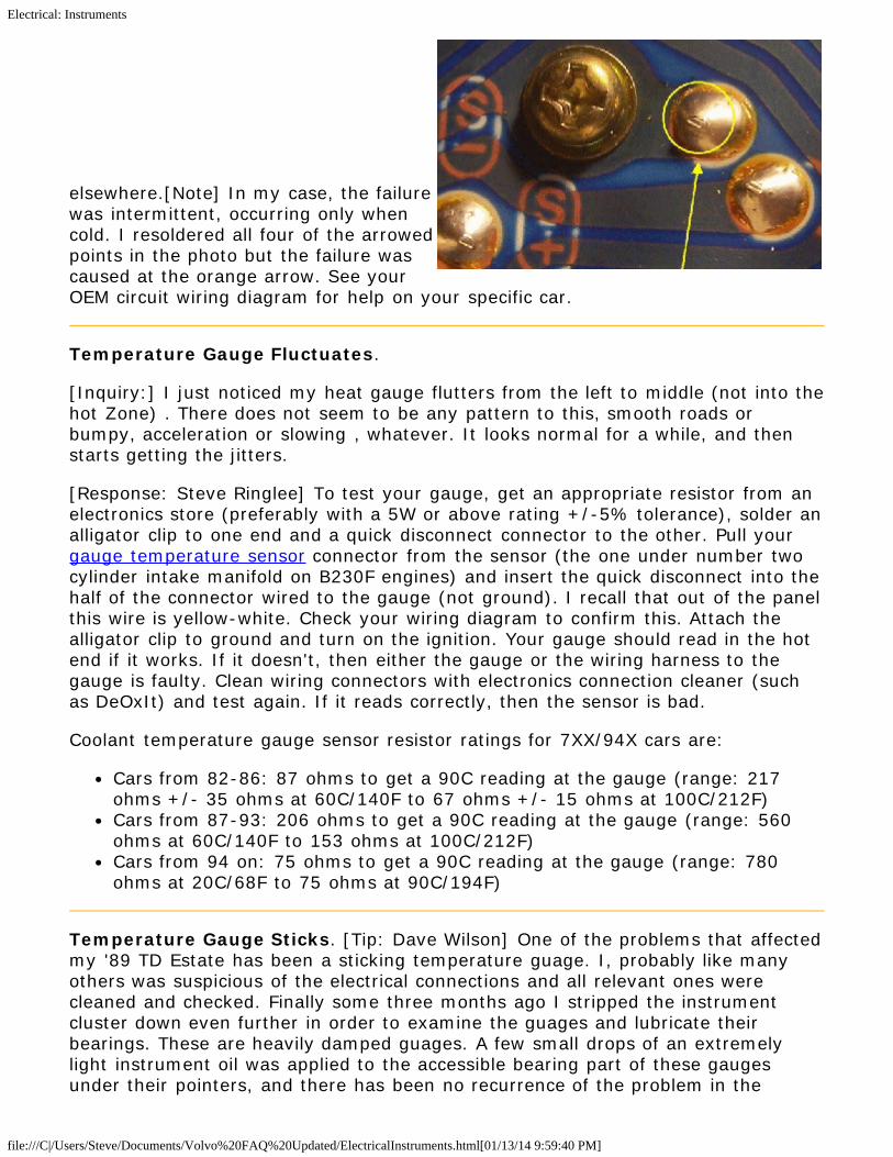
elsewhere.[Note] In my case, the failurewas intermittent, occurring only whencold. I resoldered all four of the arrowedpoints in the photo but the failure wascaused at the orange arrow. See yourOEM circuit wiring diagram for help on your specific car.
Temperature Gauge Fluctuates.
[Inquiry:] I just noticed my heat gauge flutters from the left to middle (not into thehot Zone) . There does not seem to be any pattern to this, smooth roads orbumpy, acceleration or slowing , whatever. It looks normal for a while, and thenstarts getting the jitters.
[Response: Steve Ringlee] To test your gauge, get an appropriate resistor from anelectronics store (preferably with a 5W or above rating +/-5% tolerance), solder analligator clip to one end and a quick disconnect connector to the other. Pull yourgauge temperature sensor connector from the sensor (the one under number twocylinder intake manifold on B230F engines) and insert the quick disconnect into thehalf of the connector wired to the gauge (not ground). I recall that out of the panelthis wire is yellow-white. Check your wiring diagram to confirm this. Attach thealligator clip to ground and turn on the ignition. Your gauge should read in the hotend if it works. If it doesn't, then either the gauge or the wiring harness to thegauge is faulty. Clean wiring connectors with electronics connection cleaner (suchas DeOxIt) and test again. If it reads correctly, then the sensor is bad.
Coolant temperature gauge sensor resistor ratings for 7XX/94X cars are:
Cars from 82-86: 87 ohms to get a 90C reading at the gauge (range: 217ohms +/- 35 ohms at 60C/140F to 67 ohms +/- 15 ohms at 100C/212F)Cars from 87-93: 206 ohms to get a 90C reading at the gauge (range: 560ohms at 60C/140F to 153 ohms at 100C/212F)Cars from 94 on: 75 ohms to get a 90C reading at the gauge (range: 780ohms at 20C/68F to 75 ohms at 90C/194F)
Temperature Gauge Sticks. [Tip: Dave Wilson] One of the problems that affectedmy '89 TD Estate has been a sticking temperature guage. I, probably like manyothers was suspicious of the electrical connections and all relevant ones werecleaned and checked. Finally some three months ago I stripped the instrumentcluster down even further in order to examine the guages and lubricate theirbearings. These are heavily damped guages. A few small drops of an extremelylight instrument oil was applied to the accessible bearing part of these gaugesunder their pointers, and there has been no recurrence of the problem in the

Electrical: Instruments
file:///C|/Users/Steve/Documents/Volvo%20FAQ%20Updated/ElectricalInstruments.html[01/13/14 9:59:40 PM]
intervening months.
Fuel Gauge Fluctuates or Fails to Work. [Inquiry] The fuel gauge on my 940fluctuates up and down and sometimes responds to a whack on the dash board.The gauge has seen numerous attempted repairs over the past year, including thetotal replacement of the gauge itself. It slowly got to the point of not respondingeven to vigorous whackage upon the dash board. How to fix?
Diagnosis. To isolate the fault, obtain a 68-ohm resistor. Disconnect batterynegative, insert the resistor into the sender connector to simulate a working fuelsender, reconnect battery negative, and turn on the ignition. The gauge shouldread the value noted. If it does, then your sensor of faulty. If it does not, thenyour fault is in the wiring from the tank to the gauge, the gauge itself, or (for1982-1984 cars only) in the voltage stabilizer at the panel.
YearGauge IndictationUsing 68 Ohm Test
Resistor
SensorResistance
RangeNotes
1982-1984
Gauge should read 3/4full
Lever-typefuel gauge
If temp gauge is alsoincorrect, then voltagestabilizer is faulty
1984-1992
Tubular-type fuel gaugewith:
60-litre tank: left side ofpointer should touch redpart of gauge
80-litre tank: right sideof pointer should touchred part of gauge
Emptytank: 0-ohms
LED "lowgas" lit:10-18ohms
Full tank:280 ohms
Supply voltage comes fromtemp gauge.
Insert test resistor betweengray-white lead at gauge sideand ground.
Measure sensor resistancebetween ground and gray-white lead at sensor side.
1993+ Non-tubular type fuelgauge with:
60 litre tank: 1/4 tankfull
80 litre tank: 1/5 tankfull
Emptytank:131ohms
LED "lowgas" lit:113 ohms
Full tank: 2ohms
Measure resistance betweenbrown and gray-white sensorleads at sensor side.
1. Fuel Sender Unit Failure. [Tip from Dave Stevens] For the 940's, the earlysymptoms are a fuel tank gauge that appears to stick, often reading too high. Thenit progresses to the point where it won't always go below a certain point or above acertain point. Driving over bumps or filling the tank will often cause the gauge to

Electrical: Instruments
file:///C|/Users/Steve/Documents/Volvo%20FAQ%20Updated/ElectricalInstruments.html[01/13/14 9:59:40 PM]
jump and read more correctly. Eventually the problem gets so bad the gauge willrarely move. No matter how bad it gets, you can probably still get it to move if youtake a mallet and carefully pound the top of the tank around the sending unit(under the access plate). I would say that is the ultimate diagnostic for thisparticular problem. Based on reports here, the problem did show up on a few carsduring the warranty period, but is now starting to show up more and more as thesevehicles age. The problem likely correlates better with mileage and rough roadusage. Quite simply, the fuel level sending unit in the tank is shot. Specifically, theinternal sliding contacts are totally worn out. This only affects the sending units inthe later 940's with the enlarged ~73 litre tank. It is fundamentally different fromthe earlier 900's and 700's with the ~60 litre standard tank or the ~80 litreexpanded tank. It's about 1.5" longer and uses a different pre-pump attachment.Additionally, the resistance values probably don't match so a different or modifiedgauge is likely required (probably just a resistor or jumper wire). The 940 alsoneeds the maximum sender resistance to correspond to the proper tank level as ittriggers a bright low fuel LED on the dash. It's an expensive problem to fix. Italmost goes without saying that you can't get the little contact strip worth only afew cents. You need the whole sending unit. Apparently Volvo only sells thesending unit with the entire tank pickup assembly including the pre-pump forapproximately US$500. There are two alternatives: Find a working used sendingunit and have it installed, or fix it yourself. [Jay simkin] Note that 940 and 960sending units are different and not interchangeable.
Testing the Sending Unit Out of the Car. [Jay Simkin] To check that a send unitis working, you'll need an Volt-Ohm Multimeter (VOM). The signal to the gaugecomes from the float, that slide along two wire-wrapped rods, inside the barrel. Setthe meter to 200 Ohms. Point the end of the barrel towards the ground. Take areading, by touching one of the VOM probe's tips to one of the rods, and the otherVOM probe tip to the other rod. You should get a numerical reading, e.g., 7.8. Turnover the barrel, so it points skyward. If you get a numerical reading of, say, 135,then the send unit likely is sound. If You get no reading at all, the send unit won'twork.
Repair of Sender Unit. To do repair the sender, remove the tank sending unit,remove the sender barrel (fast, high heat de-soldering), crack it open withoutdamaging anything (non-trivial), carefully slide out the float assembly with theworn contacts, repair the contacts, put it all back together. If you're lucky it willstill work. Hints on cracking it open around the mid-seam: warm it for a littleflexibility in hot water; try to wiggle the halves and *slightly* push in the tabs tobreak the friction bond of the inside lip; crack it open by holding each end andfirmly pressing the mid-section over a protected edge with the little notch in theseam facing toward you (it's much like cracking an egg; it takes a lot of strength,just be prepared to stop quickly once it separates so you don't bend the internalrods; it sounds awful when it finally comes apart). Once the guts are exposed,you'll easily see that one or both contact fingers on the float have jagged endswhere they used to have wide pads that would slide up and down the resistancecoils (you can even see this before you start by looking into an open hole -see quizbelow). These pads were too thin and have simply worn off. Your job is to figureout how to re-build these pads. (Our Don Foster would totally love this challenge.)Carefully crimping on a tiny strip of very thin nickle plated sheet metal (scavengedout of some old broken toy or electronic item) is what I used. The tricky bit is to

Electrical: Instruments
file:///C|/Users/Steve/Documents/Volvo%20FAQ%20Updated/ElectricalInstruments.html[01/13/14 9:59:40 PM]
make sure the pads are solidly attached, do not have sharp edges, aren't too bigand can still move freely with light outward pressure. If the resistance coil rods arehandled the coil wire may become loose and will cause binding. If this happens,carefully re-wrap the coil back and forth a number of times to eliminate the loosearea (hint: follow the original coil marks when doing this; carefully fold over anyexcess wire at the top only). You'll need to make sure the little contact framedoesn't get bent out of shape. It must be able to slide up and down withoutbinding (hint: tweak it carefully to restore proper contact; the rods have notches atthe ends for alignment in the sleeve holes; doesn't matter which rod is in whichhole; the float assembly only installs one way so that the contacts fit all the wayup into the head area). Re-assemble and visually test the sender sleeve unit byimmersing it in a pail of water. Clean and dry before final assembly and installing. [Dan Ray] After experiencing years of intermittent fuel gauge operation in my 960,I pulled the sending unit including the whole pre-pump stalk from the tank. I cutthe wires to the sender and removed it from the stalk. Pulling it apart, it wasapparent that the problem is in the sender. There is a thin shiny stainless steelmetal conductor that resides on the float and makes contact to the wound wire(rheostat). The metal contact had a film or sludge that was grey, almost like apowdered metal that was very difficult wipe away. Also after almost 300k miles thepoints of contact had worn a groove into both contact edges. I bent the conductorso the contact point was at a slightly different area. Reassembled the unit, solderedthe wires, added a little shrink tubing and after reinstallation, the gauge worksflawlessly.
2. Failed Fuel Gauge. [Tip] I had a similar problem on my '96 960, noticed it rightafter I pulled the car out of a 3month storage, read empty so I went to fill up andthe tank was already full. Gauge was steady but would never read correctly andnot once would go to full position. Tried testing the Fuel gauge by jumping theconnector in the trunk, located on drivers side, it responded as expected and wentto full position on several tries. Pulled fuel sender and found no problems testing onthe bench. Then went back to the car and re-ran the same test on fuel gauge, thistime it went only 3/4 the way. Put sender back in car and changed out the gaugewhich was the problem. Sending unit appears well built and quite unlikely to gobad, which is good because its a bear to R&R. Electronics are all inside the gasgauge and that's where my problem was.
3. Poor Instrument Panel Contacts. [Response: Tom Irwin] My friend who is aMaster Volvo Tech told me thatusually the comb connector in theback needs to be re-crimped.After I did that 3 times he toldme that if the re-crimp doesn'tfix it, then it is in the electricalinterface between the 3 screwsthat hold the gauge in place, withthe flexible PCB sandwiched inbetween. The flex PCB, whilevery environmentally friendly tomanufacture, easily deforms andbecomes brittle with time. AskANYONE who has a 240 with tail light problems about these little beauties. In

Electrical: Instruments
file:///C|/Users/Steve/Documents/Volvo%20FAQ%20Updated/ElectricalInstruments.html[01/13/14 9:59:40 PM]
addition, the retainer/conductor screws are supposed to be cadmium plated. Butcadmium is bad-bad for the environment. So the 3 little screws are coated withsome other shit that blooms into galvanic corrosion after a while even though they'look' ok. I wire brushed them, straightened the pcb and hit em with DeOxIt. Thatrepair actually lasted the longest: about 3 days. There is only one permanentrepair in this case: the screws must be soldered. My buddy tells me to lay a smallamount of solder, very quickly and VERY carefully to the contact points under eachscrew. Use a light iron with temp control. Try to hold ~700 degrees f. Use anormal 60/40 rosin core solder. Be very careful not to melt the plastic substrate asyou heat up. I like to keep a can of electronic freeze spray to douse the hot spotsimmediately after flowing a bead of solder. In a pinch, a can of 'compressed air'turned upside down will achieve the same thing. Solder all 3 screws to the PCBtraces and you are done. No more fuel gauge problems.
4. Failing Instrument Cluster PCB Solder Joints. [Michael Tuso] Two 940wagons both with intermittent fuel gauges. Fuel senders and wiring were OK, as thecorrect sender resistance was measured at the instrument cluster connector. Firststep was to remove the fuel gauge and resolder every connection on the circuitboard. The gauge still didn't work when the instrument cluster was reinstalled.Next, an ohmmeter was used to check the resistance of the +12v path from the #4terminal power input connector behind the speedometer through the fusible link tothe +12v terminal on the fuel gauge. The resistance was several ohms when itshould have been 0.1 - 0.2 ohms. Close inspection of the flex circuits showed therewere several soldered jumpers in the +12v path. After resoldering the jumpers, theresistance of the +12v path dropped to 0.1 - 0.2 ohms. Resoldering the flex circuitjumpers fixed the fuel gauges on both vehicles.
Speedometer Failures.
Diagnosis: Speedometer Head, Wiring, or Sender Unit? How to tell if the faultlies with the sending sensor on the rear axle, the wiring to the speedo, or thespeedo itself:
Sensor Test. [Peter KL Milne] The sensor is bolted on the rear face of thedifferential behind the Panhard rod with a tied-on electrical connector. It senses therotation of a toothed ring attached to the crown wheel inside the differential. Thetwisted pair wires from the sensor (one Brown (740) or Brown/White (940) and theother Green/White) are shielded right into the boot area. Inside the boot areawhere the filler pipe comes up to the filler opening, they route through a littlesealed tamper proof plastic box at the rear of the wheel arch thence to the large A-pillar connector at the front of the driver's door and then to the back of theinstrument panel. These in turn route into the panel through a small four pinconnector behind the speedometer (740) or the larger passenger side A-connector(940) at the rear of the instrument panel which carries these two wires into thespeedo. These connectors may work loose. You can test the sensor and wiring atthis panel connector. [Tip] I had a dead speedo and odometer. Using my digitalvolt meter, I switched it to 10 volts AC range. I had a friend hold the leads wherethe wires go into the speedometer. I drove up to approximately 15mph, and as Idid, the needle smoothly moved up towards 1 volt. As I slowed down, the voltagedropped smoothly as well. As far as I can tell, this means that the pulse generatorin the rear end is working fine, as is the wiring that comes from it. If I had known

Electrical: Instruments
file:///C|/Users/Steve/Documents/Volvo%20FAQ%20Updated/ElectricalInstruments.html[01/13/14 9:59:40 PM]
this beforehand, it would have saved me major headaches. Now I can justconcentrate on getting the speedometer fixed. [Editor] Make sure that there is nocorrosion at the rear sensor connector. If there is, spray with electronic deoxidizerand clean it. You can take off the old plug and rewire it with new connectors thatyou can seal up with silicone sealer. If you break the connector or if it is corroded,it is identical to that found on the brake master cylinder fluid level sensor.[WJepsen] After my speedo failed, I tried testing the sensor signals with anoscilloscope. They appeared fine. After installing a new speedo which failed to fixthe problem, I installed a used sender and wire pigtail from Revolvostore ($30).That did the trick. Seems that the sender can show up with an oscilloscope test butnot a good enough signal to power the speedometer. See the FAQ File from DavideD. on testing the rear sensor and isolating faults. [A Buxton] If you still have thetamper proof wire on the connector at the rear axle, cut it off. Over time it cutsinto the sensor wire. [Rick Zimmerman] A really easy way to eliminate the speedsensor as a suspect in a speedometer failure is to disconnect its connector in thetrunk. The signal from the speed sensor also goes to the ABS circuit. If your ABSlight does not light up until you disconnect the speed sensor and goes out as soonas you reconnect it, then your speed sensor signal must be OK.
Wiring Test. [Editor] Test continuity in the two sensor wires from the connectorbehind the panel to the sensor connector on the rear axle using a continuity testerand a long wire. Test ground at the panel and the sensor in the Brown orBrown/White wire by using a continuity tester at both the sensor connector and thepanel. If ground is bad, look for corrosion at the left A-post body ground plane.Needless to say, the Volvo OEM wiring diagram manual helps considerably inlocating these wires.
Sensor Wiring Harness. [Editor] Volvo sells the two meter wiring harness (p/n3523912) from the trunk/boot to the sensor for about $60. Frequently, the tamperproof wire on the axle cover cuts into the wiring. To replace, remove trunk trim onthe left to the rear of the wheel well. In the recess, you will find a sealed box (usedto prevent odometer tampering). Cut off the hinges to this box and pry it open toaccess the connector. Disconnect this, cut the zip ties holding the gray harness tothe fuel pipe, and pull the grommet seal loose from axle body panel. Raise the rearof the car. From beneath, break off the sensor connector lock tab on the sensormounted on the rear differential cover. Pull the connector up (it is tight!) and offthe sensor. Remove the rubber grommets from the axle mounts (there will be oneor two) which keep the wiring from chaffing. Then pull the harness up through thetrunk opening. Install the new harness first from the trunk connector, then throughthe trunk opening. Secure the grommet grooves in the panel so it does not leakand test by rotating. Zip tie wiring to the pipes. From beneath, route the wire downthe rear of the differential cover, clearing the parking brake cable, and mount therubber grommet(s) into the axle mounts. Don't break off the sheet metal mount onthe axle cover which will be rusted. Pop the sensor connector back down securelyinto the sensor. Replace trunk trim and you are done.
Sensor Connector Repair. [Chris McCarthy] Volvo sells both the wiring harness(p/n 3523912) and replacements for rear sensor connectors that become corroded:Volvo p/n 3523813. You will need to purchase two of these connectors. The plasticpart of the harness pops open, and it will be come immediately apparent that thetwo sensor wires have the same termination as the replacements. Put the new

Electrical: Instruments
file:///C|/Users/Steve/Documents/Volvo%20FAQ%20Updated/ElectricalInstruments.html[01/13/14 9:59:40 PM]
wires into place, and just snap the connector back together. When routing thewires, you can either reuse the existing conduit (which is more or less impossible),or you can trace it to where it enters the trunk, and wrap the wiring in split loom.The engineers wisely decided to put a nipple into the gasket that you can cut torun the new wiring. From there, simply clip the old wires, splice the new ones uptowards the trunk hinge, and you are all done! Polarity is not important, as an ACsignal such as the one the sensor generates is not polarity dependent. Note: thesealed tamper proof box in the trunk may be pried open (it is there to show if thesensor and hence odometer have been disconnected) and there is a connectorinside. Use a zip tie to re-seal the box.
Removing the Sensor. The sensor is on the rear differential cover. Remove theallen screw, then twist and pull to get the sensor out. It has a rubber o ring aroundit . If the o-ring is leaking oil, replace it.
Speedometer Failure: Flex CircuitConnections. [Randy Starkie] Tryremoving each of the five screws showncircled in the photo, cleaning with a scuffpad the connection surface, and reinstallingto correct oxidized speedometerconnections.
Speedometer Failure: Capacitors. 1991-1992 740/940/960 Speedometer ElectricalFailure Symptoms: Speedo dead, odometerfunctioning or odo dead. Fault: Shorted capacitors inside speedo and corrosion onthe printed circuit board. Capacitors can fail due to poor quality electrolyte or badmanufacturing: this is an industry-wide problem for many manufacturers usingelectrolytic capacitors. See BadCaps.net for details. Volvo had bad capacitors inmodel years 1991-1992. For a repair procedure for the Volvo speedometer PCB,see the FAQ File from Davide D. on Speedo Board Repair. How to repair: Removeinstrument panel; remove speedo; disassemble to gain access to capacitors;replace soldered capacitors; reassemble. [Tip from Rick Borth of OverseasSpeedometer] 1991-1992 speedometers also frequently fluctuate or fail becausethe electrolyte from the capacitors near the chipsleaks on one or bothchips....causing the chip to malfunction. We replace the capacitors, clean the boardand it usually works again. Procedure is tedious, but have successfully completed50-75 repairs without incident. [Kerry O'Connor] The vertical orientation of thecircuit board allows whatever is in the caps to leak down all over the IC and board.Which means un-soldering and re-soldering both the caps and IC. At the least, thisHAS to be cleaned up when replacing the caps. When the mess isn't cleaned up,there is almost no chance of the speedo working again. Even when cleaned, thechances of repair aren't the best, unlike replacing the odo gear. Note that capacitorfailures are not limited to speedometers: see Donna S' note below on repair of atachometer due to failed capacitor.
Odometer Failure. See below.
Speedometer Fluctuates

Electrical: Instruments
file:///C|/Users/Steve/Documents/Volvo%20FAQ%20Updated/ElectricalInstruments.html[01/13/14 9:59:40 PM]
[Inquiry:] My wife's 1991 740 sedan speedometer needle simply drops to zero (asif someone pulled a socket from the wall) At this moment the odometer and tripodo also quit. Very occasionally, when driving, at highway speeds, the speedometerneedle will jump back up to the correct speed, and the odometer starts working,but usually after a 1/2 mile or about 40 seconds, the needle falls back to zero andthe odometer quits. Other times everything works fine for hundreds of miles. Oftenwhen starting the car after is has been parked, odometer and speedometer neverwork at all. [Response: Don Foster] Check the connection at the speedo sensor. It's in thedifferential cover, about 3" above the filler plug. Be sure it's mechanically secure,and check the contacts (both sensor and connector) for signs of corrosion oroxidation. As much as possible, examine the harness for any signs of a break ortear, or for signs the wire might have been cut. If it's not wiring, then it's eitherthe sensor or the speedometer head (which is electronic). Possibly, the powersupplied to the speedo head where it's mounted in the dash cluster is intermittent.[Response: Pat Hannon] The speedometer in my 745 with 160K has been jumpingaround a little on the highway. The cruise control would try to follow the erraticspeedometer, then disengage. I suspected a broken wire at the sending unit. WhatI found was a burnt wire at the sending unit. The wire had grounded out on Volvo'ssafety wire. I suspect that the safety wire slowly eat throught the insulation on thewiring, causing it to ground out. The plug was melted and an inch or so ofinsulation on the green stripe wire. Make sure the safety wire is not cutting into thetwo wires on the sending unit at the back of your rear end. [Response: Scott]Check the instrument cluster grounds under the dash and in the right footwell. In88 there were some 700 series cars that would register up to 60 mph while sittingstill and the grounding problem was the cause.
Speedometer Repairs. See the FAQ File from Davide D. on Speedo Board Repairfor the capacitor problem above. Some suggestions on rebuilders:
A+ Emissions and Speedometer Repairs (Chris (904) 642-8120); 3122 #9Leon Road ;Jacksonville, FL 32246 He's a straight shooter and keeps a cleanshop. Does lots of Volvo speedo work through the mail.Paul's Speedometer Services (http://maps.google.com/maps/place?cid=6336015707570454726)Overseas Speedometer: I wanted to pass on contact information for OverseasSpeedometer in Austin that works on Volvo (and other makes) speedometers.Contact information at www.speedometer.com . [Tom Kaylor] I had minerebuilt for $100 by www.speedometer.com and it now works fine.Palo Alto (CA) Speedometer Service (http://www.paspeedo.com ) : (415)323-0243. Recommended by a local shop here in Boise as the best in thebusiness. The price they quoted was around $90 just to fix the odometer.Editor's Note: PAS reports that Yazaki no longer supplies spare parts for theirclusters and as a result they are not repairable. They may be able to replacecapacitors.DNASpeedometers in Tampa: http://www.dnaspeedometers.com/Commercial Speedometer 2446 Evergreen Avenue, West Sacramento, CA95691 (916) 371-5873. I talked with the person who does these and heseemed quite knowledgeable and says he has done a lot of these. If you bringin or send in the instrument panel, they charge $225 with a warranty
Electrical: Instruments
file:///C|/Users/Steve/Documents/Volvo%20FAQ%20Updated/ElectricalInstruments.html[01/13/14 9:59:40 PM]
Southern Electronics: http://southernelectronics.com/ [Andy Berry] My speedowas working intermittently, the odo wasn't working at all, and the gas guagewas showing 2/3 full when it was actually completely full. i found southernelectronics on the internet and contacted them. for $275 i got parts, labor, a 1year warranty and shipping both ways. i paid by putting a money order in thebox. it was at the house in 8 days, and i plugged it in right away. Everythingworks like brand new and I highly recommend them.
Speedometer Calibration. One of the benefits of the new millennium is that ithas become reasonably cheap to check your speedometer using a GPS. If you don'town one, I'm sure that your neighbor does! When I checked my speedo against theGPS (Garmin Streetpilot) it revealed that the speedo read 10% too high. I.e., 110km/h on the speedo was only 100 km/h in reality. In order to verify this, I checkedthe speed against the odometer. At a certain speed, 1 km takes a certain numberof seconds to pass. Example: 1 km @ 60 km/h takes 60 seconds. This test alsoshowed a 10% difference between indicated speed and true speed (assuming thatthe odo is more accurate). Having this much of an error, I felt very motivated toinvestigate the possibility of a calibration. Since the speedos of the 700 series areelectronic, another approach than replacing an internal driver wheel had to befound. By doing a lot of reasearch on the Internet I found that in most cars itactually could be done, merely by a change of a resistor. The speedo itself is buildaround the ubiquitous ITT UAF2115 chip (A datasheet could be found here:http://heneghan.members.beeb.net/audi/uaf2115_1ds.pdf ). And the resistor to bechanged is the one that is connected to pin 4. Enough theory!
How to calibrate:
1. Remove the instrument cluster as shown in the FAQ, i.e. remove the plasticcovers and unscrew the two screws.
2. When the cluster is removed, open it by removing a number of philips screwson the rear side. Notice that the silver colored screws are longer than thegolden ones so make sure that you where they belong upon reassembly.
3. Remove the speedo by unscrewing four screws on the plastic circuit boardside. Two of the screws are also holding two connectors. Do not mix them!
4. Carefully remove the meter needle by turning it counter clockwise whilepulling. After that remove the "number plate" which is glued onto the meter.Don't worry, you will probably not need more glue to reattach it, it is quitesticky!
5. Unscrew the three small screws which now should be visible. After that, themeter core should come lose.
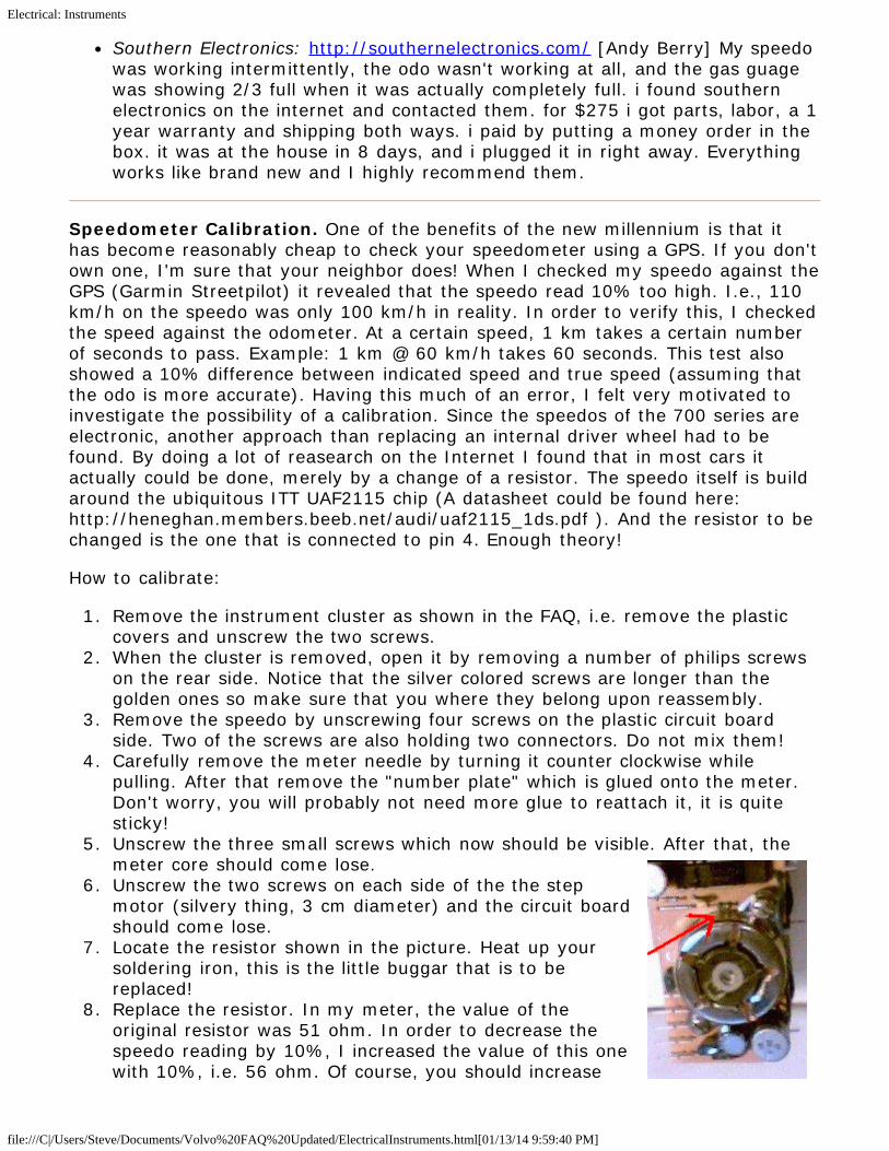
6. Unscrew the two screws on each side of the the stepmotor (silvery thing, 3 cm diameter) and the circuit boardshould come lose.
7. Locate the resistor shown in the picture. Heat up yoursoldering iron, this is the little buggar that is to bereplaced!
8. Replace the resistor. In my meter, the value of theoriginal resistor was 51 ohm. In order to decrease thespeedo reading by 10%, I increased the value of this onewith 10%, i.e. 56 ohm. Of course, you should increase

Electrical: Instruments
file:///C|/Users/Steve/Documents/Volvo%20FAQ%20Updated/ElectricalInstruments.html[01/13/14 9:59:40 PM]
the value with the same amount as your error. I doublechecked this by hooking it up to a signal generator, but that is not necessaryunless the error is REALLY big. It is of course possible to use a potentiometerinstead of a fixed resistor, but I prefer resistors since the do not change thatmuch over time.
9. Reassembly is almost the reverse of the assembly. It could be tricky to realignthe meter needle, but I did it by rotating it counter clockwise until it rested at20 km/h (as it did from the beginning).
10. Buy a bottle of beer.11. Test drive your car and enjoy an extremely accurate speedo reading!12. Drink the beer! And my result? The GPS and speedo now read the same within
1 km/h at all speeds up to 130 km/h (didn't test at higher speeds)!
Odometer Failure.
Engine Service Reset Button. Often the "engineservice" light reset button can make the tripodometer gears stick. Punch this several times tofree it up.
Repairing Non-Working Odometer: JammedGears. [Tip from Mark] At some point during your700/900 series Volvo's life, its odometer may ceaseto function. I believe the gears jam or break due topeople resetting the odometers while the car ismoving. If only the odometer (cumulative mileageand trip) has stopped and the speedometer stillworks properly, do not fret. An easy and cheapsolution is readily available. What has happened with your odometer is the gearsthat turn number barrels have become jammed. The usual culprit, according to theowner of speedometer shop I spoke with, is the set of gears that operate theservice reminder light decided to be stubborn and constipate the entire odometershow. Because the guy in at the speedometer shop was so confident about whatcaused the problem and how easy it was to fix I decided I would try to save myself a few bucks. I got quotes ranging from $95 to $220 to fix the odometer if Iremoved the gauge cluster from the car and brought it to them. I ended up fixingthe jammed odometer for less than 2 dollars. Here is how I did it:
1. Remove the gauge cluster from the dashboard. Directions to remove the trimpanel to access the screws holding the gauge cluster in place can be found inthe 700\900 FAQ. If your car is a turbo I strongly suggest cutting the vacuumline to the boost gauge 3 to 4 inches from where the tube connects to therear of the gauge cluster. These small hoses harden over the years and I wasterrified that I would break the hose nipple off trying to remove the vacuumtube. I went to the local parts house and purchased a package of barbedvacuum hose connectors for less than 2 bucks to reattach the cut hose. Thisway I did not have to worry about doing any expensive and troublesomedamage to the boost gauge.
2. Once the cluster has been removed locate the five or six screws that hold theclear bezel to the front of the gauge cluster. The screws that hold the bezel onare the biggest ones on the back of the cluster. If you try this please take a

Electrical: Instruments
file:///C|/Users/Steve/Documents/Volvo%20FAQ%20Updated/ElectricalInstruments.html[01/13/14 9:59:40 PM]
moment to study the panel before removing screws. In addition to removingthe screws, you will have to unclip or detach a couple of small plastic partsaround the edge of the cluster. I wish I could be more specific but it has beena while since I fixed mine. It is not difficult. You just want to take the time tobe careful and attentive to details. Once the clear bezel has been removed,use the eraser end of a pencil, or some other object that will not scratch thenumber barrels of the odometer, to carefully advance the odometer past thepoint where it has stuck. See below if you need to replace the gear.Reassemble and drive happy.
Repairing Non-Working Odometer: Electrical Corrosion. [Editor] Odometerscan fail due to leaking capacitors described in the FAQ file. This seems endemic in1991/1992 cars. You can clean up the corrosion around the circuit board and ICsusing DeOxIt and also, if you seek a permanent fix, replace the leaking capacitorsas noted.
Replacement Gears and Parts. Earlier odometers are mechanical. Seehttp://www.odometergears.com/ for parts and supplies.[Another Tip] VDO inWinchester, VA, and other places advertise. Get a copy of Hemmings motor news,you will find them in there. [Editor] IPD now sells for $50 a complete odometerrepair kit along with a DVD showing the repair procedure.
Tachometer Failure. Oxidized Contacts. [Dan Ray] My tach sometimes registered zero at idle or wouldbounce around, always at idle. I pulled the instrument cluster, unscrewed the tach,cleaned the contacts with a spray electronics cleaner and shot a little silicon atmoving parts. Next, I cleaned the mounting points to the circuit board. Themounting screws are the electrical pathways from the circuit board to the guages.The copper in the board where the guages mount seemed too dark in color, notcorroded but not real coppery either. After reassembly, tThe tach works as itshould. I assume the resistance from the board to the gauge was the problem.[Editor] Try Caig Labs DeOxIt or ProGold(now available at Radio Shack), useful fordeoxidizing and cleaning contacts. You might also replace the small cadmiumconnector screws securing connectors to the flex board.
Bad Internal Capacitor. [Donna S.] The car: 1988 VOLVO 740 GLE with 244,500miles. Symptom: dead tachometer with no needle movement except for one singleblip immediately after installing a new coil. Diagnostics: Using the wiring diagram, Itraced all the circuits back to the tach itself and they all functioned correctly. Iconcluded that the tachometer gauge itself must be faulty. I removed theinstrument panel and the tachometer. I took my reading glasses, a magnifyingglass and flashlight and examined the guts and circuit board inside thetachometer. Voila! The problem was a burnt out capacitor on the circuitboardinside the tachometer gauge. The capacitor had a small break between thecapacitor body and one of the little metal capacitor legs -- just enough of a breakthat given a large enough spark ( i.e. new coil) allowed the current to jump acrossthe break to make the rpm needle move that one time. The green polyester filmcapacitor that broke was stamped H1 333 1V on the body (after some research onthe internet, I found out this meant .033 µF 1Volt) I went to Radioshack andinstead bought a .047 µF capacitor - marked 473 100 V on the capacitor body

Electrical: Instruments
file:///C|/Users/Steve/Documents/Volvo%20FAQ%20Updated/ElectricalInstruments.html[01/13/14 9:59:40 PM]
(Radioshack didn’t carry the .033 µF capacitor and the .047 µF replacement wasthe next higher value). I took out the soldering iron, melted the solder on thetachometer circuitboard where the offending capacitor was attached and removedit. Then with a pair of tweezers, I threaded the legs of the new capacitor throughthe holes in the circuitboard where the old capacitor was attached and soldered thenew capacitor in its place. [Editor] You can buy the exact capacitor you needfrom Digikey or Mouser electronics; get a higher voltage rating than 1V.
Electric Clock Repair. The Clock Works; (Automotive Clock Repair & QuartzConversions - Most Service Completed Within 24 hours) at 1745 Meta Lake Rd.,Eagle River, WI 54521-8531Contact: Jerry Magayne Voice or Fax: (715) 479-5759E-mail: [email protected]
See also: http://www.speedometer.com/
Cluster and Instrument Interchangeability. [Editor] See the separate FAQ Fileon instrument cluster interchangeability among model years. This file has specificinstructions on workarounds to swap the fuel gauges and clocks from 91/92 cars to93/94 clusters.
Windshield Wipers Operate When Horn Is Pressed. [Inquiry] [Response: ChrisMullet] Besides checking your chassis grounds at the front of the car, it can happenthat the steering column-to-dash structure anchor bolts start working loose,causing a flaky ground and resulting in the "horn honking causes wipers to wipe"problem.
Bulb Failure Sensor Lamp Won't Go Out
[Inquiry:] My left low beam failed, and my bulb failure warning light dutifullyadvised me of the need to replace the bulb. I replaced the left low beam, and allthe lights on the car work now. But, my warning light is still on, though it goes outwhen I flip to high beams. Anyone know a fix for this?
[Response:] The bulb failure sensor works on current flow. If the bulbs are missmatched, say a Wagner bulb on the left and a Sylvania on the right, chances arethey have different resistances. This causes different current flows to each bulb andthe light on the dash will come on. You may just want to change the otherheadlight and hope that stops it, or live with it. Also, corrosion in the connectors inthe circuit that the head lights are on can cause the indicator light to come on. Itcan be very frustrating, and I know many people that have pulled the little bulbout of the dash. [Editor] The bulb-out relay is very sensitive to differential currentflows due to corroded bulb bases, different lamps, same brand but differentcountries of origin, etc. Make sure the bulbs are identical. Watch out that yourbrake lights are still operating as well: if the relay fails, the brake lamps won'twork.
Speedometer Relay and ABS Lamp

Electrical: Instruments
file:///C|/Users/Steve/Documents/Volvo%20FAQ%20Updated/ElectricalInstruments.html[01/13/14 9:59:40 PM]
[Inquiry:] I recently brought my 1987 Volvo 760 GLE with 200,000 miles in forrepair after I noticed that the speedometer, odometer and cruise control stoppedfunctioning. The car does have ABS and the ABS dashboard light also went on full-time just about the same time as the speedo/odometer/cc went out.
[Response: Zippy] The speedometer converter is a relay looking device that isunder the left side kick panel (under dash piece) that has its own fuse mounted tothe top of it. You hadn't recently jump started your car's battery have you? Doneincorrectly it is very common for this hidden fuse to blow, rendering ABS and thespeedometer inoperative. This only happens on the older ABS cars. See also ABSLamp Lights After Start-up
White Switch Markings Fading.
[Inquiry] Every time I clean and detail the interior, the white markings on controls(i.e. horn icons on horn buttons, white line on headlight switch, cruise controlbutton "off" and "resume") slowly fade. I tried different kind of weak cleaners andeven watered-down Windex but the "ink" is very soluble. It's worse with Armorall.
[Response] On recessed markings you can buy paint sticks and rub new paint intothem. Simply take a cloth and buff off the excess.
[Response: Phil] I found the same and now just use water on a rag to clean mostcontrols. You can re-do notched or recessed markings and such with something likea toothpick and "Wite-Out". (Do it in yellow or orange or green for a custom look!)I think the cigarette pictogram on the lighter looks better if it's not re-done.
Key-in-ignition/Seatbelt Chime Won't Turn Off. When you turn the car on theseatbelt/key in vehicle(?) warning bell chime goes on. Even when the seatbelt isused and the door is shut does it continue to chime.Strange thing is that when you turn the radio on OR open the glovebox the chimestops! [Walt Lear] Check your fuse for your dome light. When that fails the chimecan go off.
Ambient Air Temperature Gauge.
Bulb Replacement. [Dave Stevens] To remove the illumination bulb for theambient temperature sensor, remove the instrument panel. The OEM Volvo (yes,dealer only!) bulb sits on top of the gauge unit pointing down. If you don't want topull the panel, you can still get the bulb out by reaching up behind. There isn't a lotof room above the unit and you have to pull the kick panel and other impediments.The bulb has a blue plastic square back end that can be undone with 1/4 turn ofan 8mm open end wrench once you have access to the left back side of theinstrument cluster. Lift the old bulb out, pop the new one in and while pushing thebulb down in the socket turn it back 1/4 turn to seat it. [Joe Tiffin] I designed atool to help remove this tough to access bulb.
Gauge Reads Too High. [Inquiry] The outside temperature gauge is reading up to10 degrees hotter than the actual ambient temperature after the car heatsup.[Response: Tim/Editor] Sensor resides in a hole on the driver's side of the

Electrical: Instruments
file:///C|/Users/Steve/Documents/Volvo%20FAQ%20Updated/ElectricalInstruments.html[01/13/14 9:59:40 PM]
under-bumper air intake. It comes loose easily and is probably hanging next to theradiator. Pop it back in place, using a little silicone to hold it there.
Installing a Sensor and Indicator. [Editor] 900 series cars from 93+ have wiringalready installed. All you need is the sensor, which fits in a hole under the left frontunder-bumper air intake, and the indicator which is inserted in the left side of theinstrument panel (which must be removed to install it). Volvo has the kit. The kitdoes not have wiring, so don't bother to try to install it in a 1992 or prior car.
Accessories:
Adding a Warning Lamp for Loss of Engine Coolant. See Loss of CoolantSensor for Volvo 740/940 Cars for more information as to how to add this sensorand warning lamp.
Adding Accessories and Wiring Them Through the Firewall. See RunningWires From Engine Compartment to the Cabin for wiring tips.
Volvo Maintenance FAQ for 7xx/9xx/90 Cars