vopo suspension design
TRANSCRIPT

Álvaro Fernandez Galiana |Fabrice Matichard, Guilhem Michon| PFE
ISAE‐SUPAERO/ETSEIB‐UPC | November 23, 2015
VOPO SUSPENSION DESIGN A SINGLE STAGE SUSPENSION FOR THE SQUEEZER INSTRUMENT

P a g e | 1
VOPO SUSPENSION DESIGN | A SINGLE STAGE SUSPENSION FOR THE SQUEEZER INSTRUMENT
INDEX
INTRODUCTION .................................................................................................................................................... 7
LIGO PROJECT, aLIGO ....................................................................................................................................... 7
SEISMIC AT LIGO ................................................................................................................................................ 8
VOPO SQUEEZER IN aLIGO ..............................................................................................................................9
NASCENT VOPO SUSPENSION DESIGN ........................................................................................................... 10
STATE OF THE ART .......................................................................................................................................... 10
EARLY VOPO SUSPENSION DESIGNS ............................................................................................................ 11
MONOSTAGE SUSPENSION DESIGN METHODOLOGY .................................................................................. 13
CONSTRAINTS AND REQUIREMETNS ........................................................................................................... 13
INSTRUMENT’S OPTICAL LAYOUT ................................................................................................................ 13
STEP 1: SITUATION IN THE CHAMBER .......................................................................................................... 15
STEP 2: MASS BUDGET ESTIMATION ............................................................................................................ 16
STEP 3: BLADES PRELIMINARY DESIGN ....................................................................................................... 16
STEP 4: FLEXURE DESIGN ............................................................................................................................... 18
STEP 5: LOCATION OF THE BLADES ............................................................................................................. 18
STEP 6: CAD MODEL OF THE OPTICAL LAYOUT ....................................................................................... 19
STEP 7: CHAMBERS’ LAYOUT .......................................................................................................................... 21
STEP 8: REAL MASS BUDGET ........................................................................................................................... 21
STEP 9: ACTUATORS ........................................................................................................................................ 22
STEP 10: INJECTION BENCH DESIGN & BALANCING .................................................................................. 23
STEP 11: BASE PLATE ......................................................................................................................................... 26
STEP 12: BLADE PLATFORM ............................................................................................................................ 26
STEP 13: Motion LIMITERS, LOCKERS & ASSEMBLY BRACKETS ................................................................. 26
STEP 14: ASSEMBLY PROCEDURE & FINAL MASS BUDGET ....................................................................... 27
FINAL DESIGN ................................................................................................................................................... 27
SUBASSEMBLIES ................................................................................................................................................... 29
AOSEM AND MAGNETS ................................................................................................................................... 29
ASSEMBLY BRACKETS ...................................................................................................................................... 33
BASE PLATE ....................................................................................................................................................... 33
BLADE ASSEMBLY ............................................................................................................................................ 35
BLADE ............................................................................................................................................................. 35
CLAMP ............................................................................................................................................................ 39
P a g e | 2
VOPO SUSPENSION DESIGN | A SINGLE STAGE SUSPENSION FOR THE SQUEEZER INSTRUMENT
FLEXURE ......................................................................................................................................................... 40
WIRE CLAMPS ................................................................................................................................................... 43
BLADE PLATFORM ........................................................................................................................................ 44
BLADE GUARD .................................................................................................................................................. 45
INJECTION BENCH ........................................................................................................................................... 47
MOTION LIMITERS ......................................................................................................................................... 48
LOCKER ............................................................................................................................................................. 49
CONTACT STUDY OF THE VOPO BLADES ........................................................................................................ 51
CONTACT STUDY RESULTS ............................................................................................................................. 51
INJECTION BENCH DESIGN ................................................................................................................................ 55
OPTIMIZATION OF THE BENCH ................................................................................................................... 56
VOPO SUSPENSION MECHANICAL DATA ....................................................................................................... 59
O2 ........................................................................................................................................................................ 59
O3 ................................................................................................................................................................... 60
GLOBAL FREQUENCIES OF THE ASSEMBLY .................................................................................................... 61
ACKNOWLEDGEMENT ................................................................................................................................... 64
BIBLIOGRAPHY .................................................................................................................................................... 66
APPENDIX .............................................................................................................................................................. 67
CONTACT STUDY OF THE VOPO BLADES .................................................................................................. 68
USING SW SIMULATION ............................................................................................................................. 69
USING ANSYS ................................................................................................................................................ 80
LARGE DISPLACEMENT SIMULATION ANALYSIS ....................................................................................... 91
MATLAB SCRIPTS .......................................................................................... Error! Bookmark not defined.
DRAWINGS ..................................................................................................... Error! Bookmark not defined.

P a g e | 3
VOPO SUSPENSION DESIGN | A SINGLE STAGE SUSPENSION FOR THE SQUEEZER INSTRUMENT
Figure 1: LIGO interferometer principle ................................................................................................................. 7
Figure 2: Sensitivity improvement in aLIGO ......................................................................................................... 7
Figure 3: Expected sensitivity curve for aLIGO ...................................................................................................... 8
Figure 4: aLIGO chambers layout ........................................................................................................................... 8
Figure 5: BSC‐ISI CAD model (a) and prototype (b); HAM‐ISI exploded view (c) and in chamber (d) ............9
Figure 6: CAD Model of the stack assembly used in the VOPO experiment at MIT. ....................................... 10
Figure 7: Horizontal (left), and vertical (right) measurements of transmissibility stack layers ........................ 11
Figure 8: Early VOPO suspension concepts re‐using the OMC structure and spring assemblies. ................... 11
Figure 9: Concepts using a hexagonal table suspended with three spring assemblies ...................................... 12
Figure 10: VOPO optical layout for O2 (left) and O3 (right) .............................................................................. 14
Figure 11: CAD model (left) and prototype built at MIT (right) of the VOPO Cavity ....................................... 14
Figure 12: HAM6 chamber Layout prior to the installation of the Squeezer ...................................................... 15
Figure 13: HAM5 chamber selected location for the squeezer ............................................................................ 16
Figure 14: VOPO blade preliminary dimensions .................................................................................................. 18
Figure 15: Location of the blades in the VOPO suspension (left) and “forbidden” area (right) ....................... 19
Figure 16: Height of the beam and injection bench ............................................................................................. 19
Figure 17: CAD model of the O2 configuration layout ........................................................................................ 20
Figure 18: CAD model of the O3 configuration layout ........................................................................................ 20
Figure 19: Dog clamps used to lock the base plate on the optical bench of HAM6 .......................................... 22
Figure 20: A schematic of OSEM shadow sensor operation ................................................................................ 22
Figure 21: Position of the AOSEM under the blades; horizontal AOSEM tangently located ............................ 23
Figure 22: Schematic of the iterative process of optimization on the injection bench ..................................... 24
Figure 23: Lateral masses distribution in O3 configuration (same for O2) ........................................................ 24
Figure 24: Injection bench design showing the stiffener underneath ................................................................ 25
Figure 25: Balanced layout for O2 (left) and O3 (right) configurations ............................................................. 25
Figure 26: Base plate of the VOPO suspension (left) and Blade platform (right) ............................................. 26
Figure 27: final design of the VOPO suspension with the O2 optical layout ..................................................... 27
Figure 28: Monostage suspension design methodology schematics .................................................................. 28
Figure 29: Overview of the subassemblies of the VOPO Suspension ................................................................. 29
Figure 30: AOSEM vertical (left) and horizontal (right) assemblies and their motion ..................................... 30
Figure 31: FEA (SW Simulation) for Vertical AOSEM Assembly. First frequency: 646.35Hz ............................ 30
Figure 32: FEA (SW Simulation) for Horizontal AOSEM Assembly. First frequency: 873.05Hz ....................... 31
Figure 33: Overview of the magnet holder and the photodetector ..................................................................... 31

P a g e | 4
VOPO SUSPENSION DESIGN | A SINGLE STAGE SUSPENSION FOR THE SQUEEZER INSTRUMENT
Figure 34: Position of the magnet in the AOSEM ................................................................................................ 32
Figure 35: Magnet riser for the horizontal AOSEM assembly ............................................................................. 32
Figure 36: FEA (SW Simulation) for Magnet Holder. First frequency: 6892.6Hz ............................................. 33
Figure 37: Assembly brackets overview ................................................................................................................ 33
Figure 38: VOPO Base Plate (Left) and the distance to the injection bench ..................................................... 34
Figure 39: Elements bolt to the base plate and dog clamps ................................................................................ 34
Figure 40: VOPO blade assembly; comparison between the flat unloaded position and the bent position ... 35
Figure 41: Width and Height as function of FoS for l=280mm, f=1.5Hz and m=36kg ....................................... 36
Figure 42: Width and Height as function of FoS for l=280mm and m=36kg for f=1.6, 1.65 and 1.7Hz ............ 37
Figure 43: FEA results run in SW (left) and ANSYS (right): Blade deformation ............................................... 37
Figure 44: FEA results run in SW (left) and ANSYS (right): Blade stress ........................................................... 38
Figure 45: Comparison of the results for ANSYS, SW and Bernoulli’s theory ................................................... 38
Figure 46: Angle α between the tip and the base of the bent blade ................................................................... 38
Figure 47: Simplified model used to determine the number of bolts required ................................................. 39
Figure 48: Estimated evolution of the FoS with the diameter of the wire for l=130mm and m=36kg .............. 43
Figure 49: Wire clamp system overview ............................................................................................................... 43
Figure 50 VOPO Wire Base Clamp ....................................................................................................................... 43
Figure 51: VOPO Blade Platform ...........................................................................................................................44
Figure 52: VOPO Blade clamping system overview ............................................................................................. 45
Figure 53: Blade guard assembly ........................................................................................................................... 45
Figure 54: FEA of the simplified Blade Guard assembly. f = 513.47Hz ............................................................... 46
Figure 55: VOPO Injection Bench ......................................................................................................................... 47
Figure 56: First mode of the FEA of the Injection Bench. f=303.42Hz ............................................................... 47
Figure 57: OMC EQ‐Stops (D1201441) .................................................................................................................. 48
Figure 58: VOPO vertical motion limiter system ............................................................................................... 48
Figure 59: VOPO horizontal motion limiter system .......................................................................................... 49
Figure 60: Early locker design overview .............................................................................................................. 49
Figure 61: VOPO locker in the locked (left) and unlocked (right) positions ..................................................... 50
Figure 62: Comparison between the horizontal (left) and the inclined (right) FEA, both with vertical load .. 51
Figure 63: Predicted Blade Platform angle ........................................................................................................... 52
Figure 64: Detail with of the contact between blade and clap (SW Simulation), where the gap is shown ..... 53
Figure 65: Detail with of the contact between blade and clap (ANSYS), where the gap is shown ................... 53
Figure 66: Variation of angle alpha, FoS, Horizontal and Vertical parameters for different preloads ............ 54

P a g e | 5
VOPO SUSPENSION DESIGN | A SINGLE STAGE SUSPENSION FOR THE SQUEEZER INSTRUMENT
Figure 67: Simplified model of the suspended stage for FEA ............................................................................. 55
Figure 68: Parameters considered in the optimization ....................................................................................... 56
Figure 69: FEA modal analysis of the assembly. SW f = 248.74Hz (left); ANSYS f = 256.94Hz (right) ............ 57
Figure 70: Strain in the modal FEA using ANSYS ................................................................................................ 58
Figure 71: Mechanical information of O2 configuration extracted from SW model ......................................... 59
Figure 72: Mechanical information of O3 configuration extracted from SW model ........................................ 60
Figure 73: Definition of the coordinate system used for VOPO suspension ..................................................... 61
Figure 74: Mass [M] and displacement [U] matrix definitions ........................................................................... 62
Figure 75: Stiffness [K] matrix defined for the coordinate system defined below and with 3 springs ............. 62
Figure 76: Difference between the coordinate system defined in [K] (blue) and the previously defined ....... 62
Figure 77: Parameter hf is defined as b‐a ............................................................................................................. 63
Figure 78: Results of GlobalFrequencies.m .......................................................................................................... 63
Figure 79: Bent Blade from Blade study .............................................................................................................. 68
Figure 80: Simplified assembly used for contact study ...................................................................................... 68
Figure 81: Simulation tab ...................................................................................................................................... 69
Figure 82: Select Static Study (1) and give a name (2) ......................................................................................... 70
Figure 83: Apply material ....................................................................................................................................... 71
Figure 84: Define the global contact of the assembly ......................................................................................... 72
Figure 85: Global contact definition. Contact Type (1) and Friction Coefficient (2) ......................................... 72
Figure 86: Define different components between parts ...................................................................................... 73
Figure 87: Apply for a bolted contact ................................................................................................................... 74
Figure 88: Define bolted contact. Define threated screw (1) and Circular Edge of the Bolt Head Hole (2) .... 74
Figure 89: Define the bolted contact. Select the threated surface (1) and the Axial Load (2 & 3) .................... 75
Figure 90: Apply for a Fixture ............................................................................................................................... 76
Figure 91: Fixed Geometry definition ................................................................................................................... 76
Figure 92: Apply for a Force .................................................................................................................................. 77
Figure 93: Define Force parameters. Application Surface (1), Direction (2) and Value (3) ............................... 78
Figure 94: Create Mesh (Automatic Mesh) .......................................................................................................... 79
Figure 95: Run Study.............................................................................................................................................. 79
Figure 96: Bolt Model ........................................................................................................................................... 80
Figure 97: Access the Engineering Data edition ................................................................................................. 80
Figure 98: Material Selection and Edition menu. Apply for new Material (1) ................................................... 81
Figure 99: Import Geometry from CAD design ................................................................................................... 81

P a g e | 6
VOPO SUSPENSION DESIGN | A SINGLE STAGE SUSPENSION FOR THE SQUEEZER INSTRUMENT
Figure 100: Open the Model edition ..................................................................................................................... 82
Figure 101: Model Edition View and access to the Model parts .......................................................................... 82
Figure 102: Material definition. Select part (1), open Material options (2) and select the material (3) ............ 83
Figure 103: Contact Definition. Show Contact Menu (1, 2 & 3) and apply for multiple views (4) .................... 84
Figure 104: Frictional Contact Definition ............................................................................................................. 85
Figure 105: Bonded Contact Definition ................................................................................................................ 85
Figure 106: Frictional Contact Definition for Bolt. Contact type (1) and 0.61 Frictional Coefficient (2) ......... 86
Figure 107: Frictionless contact definition ........................................................................................................... 87
Figure 108: Applying mesh generation ................................................................................................................. 87
Figure 109: Apply for Contact Mesh Refinement ................................................................................................ 88
Figure 110: Force definition. Surface selection (3) and value definition (5) ...................................................... 88
Figure 111: Fixed Geometry definition .................................................................................................................. 89
Figure 112: Block Displacement on symmetry plane ........................................................................................... 89
Figure 113: Bolt Pre‐Load Definition .................................................................................................................... 90
Figure 114: Apply for Solution Information ......................................................................................................... 90
Figure 115: Large Displacement in SW Simulation ............................................................................................... 91
Figure 116: Large Deflection selection in ANSYS .................................................................................................. 92
Figure 117: Comparison between Large (Upper) and Small (Lower) Displacement solution ........................... 92

P a g e | 7
VOPO SUSPENSION DESIGN | A SINGLE STAGE SUSPENSION FOR THE SQUEEZER INSTRUMENT
INTRODUCTION
LIGO PROJECT, aLIGO
This project has been performed at the MIT LIGO laboratory. This Laboratory is one of the main contributors to the LSC (LIGO Scientific Collaboration) group. The Laser Interferometer Gravitational‐Wave Observatory (LIGO) project is designed to directly detect gravitational waves of cosmic origin predicted by Einstein’s General Relativity. To do so, LIGO has built two identical 4km arm interferometers within the United States ‐one in Hanford, WA and the other in Livingston, LA. Using the same principle applied by Michelson’s interferometer with a Fabry‐Perot cavity, as described in (Saulson, 1998), these 4km arm interferometers have the capability of detecting almost imperceptible strains (up to 10‐24 m/in the so called “test masses”, the 40kg mirrors located at the extremes of the arms, Figure 1. This high sensitivity makes LIGO to be one the most sensitive metrology experiment in the world.
Figure 1: LIGO interferometer principle
At this point the LIGO project is running the first scientific run (O1) of the second generation of
interferometer, which that started on September 2015. This second generation, known as advance LIGO
(aLIGO), is an upgrade of the previous generation (iLIGO), improved seismic (ground vibration) isolation,
better ways to hang our mirrors like pendula, a more powerful laser, more massive mirror, better coatings on
the mirrors, and new ways to reuse laser light to increase the laser power in the arms. All of this is results in
an overall enhancement in sensitivity of 10. This improvement towards its predecessor gives aLIGO the
capability of observing astronomical events in a 1000 times greater volume, as shown in Figure 2.
Figure 2: Sensitivity improvement in aLIGO

P a g e | 8
VOPO SUSPENSION DESIGN | A SINGLE STAGE SUSPENSION FOR THE SQUEEZER INSTRUMENT
One of the main concerns of the LSC group, and the main limitation in sensitivity, is the noise perceived by
the detector. Figure 3 shows the diverse sources of noise for aLIGO, as well as the total noise of the device,
and so the derived global sensitivity is about 10‐23 for some specific width band.
Figure 3: Expected sensitivity curve for aLIGO
In the figure, extracted from (Advanced LIGO, 2015) it can be observed that at very low frequencies the
sensitivity is poor due to the “wall”, mainly driven by the seismic noise and suspension thermal noise. On the
other side, the quantum noise is the major contributor to the total noise in the rest of the bandwidth.
Consequently, LSC group dedicates an important amount of human power in the task of reducing the
quantum noise and being isolated from the group noise, and that is with is project has taken place.
SEISMIC AT LIGO
aLIGO interferometers are not only composed of the two arms shown in Figure 1, but they also have an
important number of supporting systems to treat the laser beam that goes to the interferometer in order to
improve the global sensitivity. At the start of this specific project, the overall layout of the aLIGO sites was
the one presented in Figure 4, with 5 primary chambers titled BSCX that host the test masses and constitute
the 4km arms of the interferometers and 6 surrounding chambers named HAMX where the supporting
systems are allocated.
IS
Figure 4: aLIGO chambers layout
P a g e | 9
VOPO SUSPENSION DESIGN | A SINGLE STAGE SUSPENSION FOR THE SQUEEZER INSTRUMENT
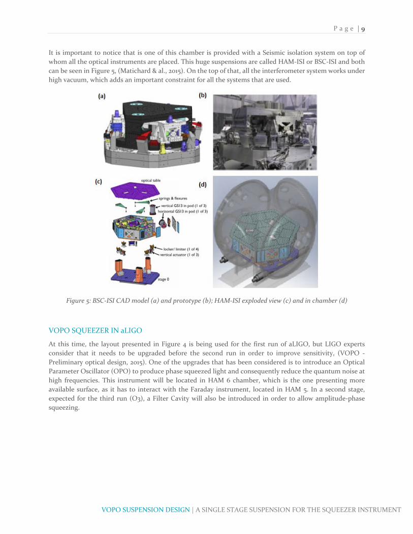
It is important to notice that is one of this chamber is provided with a Seismic isolation system on top of
whom all the optical instruments are placed. This huge suspensions are called HAM‐ISI or BSC‐ISI and both
can be seen in Figure 5, (Matichard & al., 2015). On the top of that, all the interferometer system works under
high vacuum, which adds an important constraint for all the systems that are used.
Figure 5: BSC‐ISI CAD model (a) and prototype (b); HAM‐ISI exploded view (c) and in chamber (d)
VOPO SQUEEZER IN aLIGO
At this time, the layout presented in Figure 4 is being used for the first run of aLIGO, but LIGO experts
consider that it needs to be upgraded before the second run in order to improve sensitivity, (VOPO ‐
Preliminary optical design, 2015). One of the upgrades that has been considered is to introduce an Optical
Parameter Oscillator (OPO) to produce phase squeezed light and consequently reduce the quantum noise at
high frequencies. This instrument will be located in HAM 6 chamber, which is the one presenting more
available surface, as it has to interact with the Faraday instrument, located in HAM 5. In a second stage,
expected for the third run (O3), a Filter Cavity will also be introduced in order to allow amplitude‐phase
squeezing.

P a g e | 10
VOPO SUSPENSION DESIGN | A SINGLE STAGE SUSPENSION FOR THE SQUEEZER INSTRUMENT
NASCENT VOPO SUSPENSION DESIGN
STATE OF THE ART
This project consist of the design of the seismic isolation system for the VOPO instrument that will be used
by aLIGO after the upgrade period in between O1 and O2. This isolation system, as all its previous aLIGO
peers, is intended to guarantee the mechanical isolation between the optical instruments and the ground
motion. Regarding its specific quantitative requirements, the isolation has to be effective so that it provides
isolation comparable to the one provided by the tip‐tilt suspensions, which are in the same optical path.
These tip‐tilts are actuated mirrors used to control the light path and their frequency is around of 1.5 Hz.
The general way used in preceding isolators to guarantee the required performance is to suspend the optical
bench using a multi stage spring‐mass system to guarantee the passive isolation and combine that with the
use of actuators for the active damping control of the rigid body modes. However, the first considered option
was to investigate the possibility of using a rubber spring‐dampers and leg elements as shown in Figure 6,
relying on the chamber’s suspension system to reach the required behavior. This approach was particularly
appealing for its simplicity, low‐cost and easiness of procurement.
Figure 6: CAD Model of the stack assembly used in the VOPO experiment at MIT.
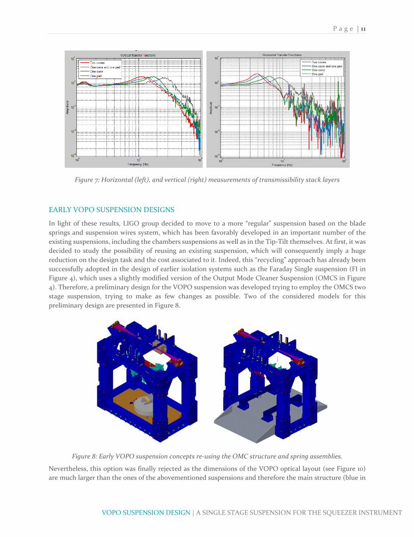
Notwithstanding, this option was tested using diverse values of masses, geometries of rubber (cones, pads...),
and different number of layers and it resulted to be inefficient for the targeted level of isolation. Figure 7
shows transmissibility curves in the vertical directions for various configurations. The lowest corner
frequency was around 10 Hz. Lower corner frequencies were obtained in the horizontal direction, but only
with no more than a factor of 3 of isolation at 10 Hz. Additionally, the better results were obtained with two
layers of isolation, which is difficult to fit in the vertical space available (4 inches between the top surface of
the HAM‐ISI, and the optical plane).
P a g e | 11
VOPO SUSPENSION DESIGN | A SINGLE STAGE SUSPENSION FOR THE SQUEEZER INSTRUMENT
Figure 7: Horizontal (left), and vertical (right) measurements of transmissibility stack layers
EARLY VOPO SUSPENSION DESIGNS
In light of these results, LIGO group decided to move to a more “regular” suspension based on the blade
springs and suspension wires system, which has been favorably developed in an important number of the
existing suspensions, including the chambers suspensions as well as in the Tip‐Tilt themselves. At first, it was
decided to study the possibility of reusing an existing suspension, which will consequently imply a huge
reduction on the design task and the cost associated to it. Indeed, this “recycling” approach has already been
successfully adopted in the design of earlier isolation systems such as the Faraday Single suspension (FI in
Figure 4), which uses a slightly modified version of the Output Mode Cleaner Suspension (OMCS in Figure
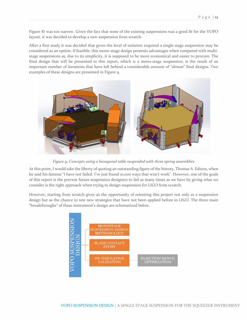
4). Therefore, a preliminary design for the VOPO suspension was developed trying to employ the OMCS two
stage suspension, trying to make as few changes as possible. Two of the considered models for this
preliminary design are presented in Figure 8.
Figure 8: Early VOPO suspension concepts re‐using the OMC structure and spring assemblies.
Nevertheless, this option was finally rejected as the dimensions of the VOPO optical layout (see Figure 10)
are much larger than the ones of the abovementioned suspensions and therefore the main structure (blue in
P a g e | 12
VOPO SUSPENSION DESIGN | A SINGLE STAGE SUSPENSION FOR THE SQUEEZER INSTRUMENT
Figure 8) was too narrow. Given the fact that none of the existing suspensions was a good fit for the VOPO
layout, it was decided to develop a new suspension from scratch.
After a first study it was decided that given the level of isolation required a single stage suspension may be
considered as an option. If feasible, this mono‐stage design presents advantages when compared with multi‐
stage suspensions as, due to its simplicity, it is supposed to be more economical and easier to procure. The
final design that will be presented in this report, which is a mono‐stage suspension, is the result of an
important number of iterations that have left behind a considerable amount of “almost” final designs. Two
examples of these designs are presented in Figure 9.
Figure 9: Concepts using a hexagonal table suspended with three spring assemblies
At this point, I would take the liberty of quoting an outstanding figure of the history, Thomas A. Edison, when
he said his famous “I have not failed. I’ve just found 10,000 ways that won’t work”. However, one of the goals
of this report is the prevent future suspension designers to fail as many times as we have by giving what we
consider is the right approach when trying to design suspension for LIGO from scratch.
However, starting from scratch gives us the opportunity of orienting this project not only as a suspension
design but as the chance to test new strategies that have not been applied before in LIGO. The three main
“breakthroughs” of these instrument’s design are schematized below.
P a g e | 13
VOPO SUSPENSION DESIGN | A SINGLE STAGE SUSPENSION FOR THE SQUEEZER INSTRUMENT
MONOSTAGE SUSPENSION DESIGN METHODOLOGY
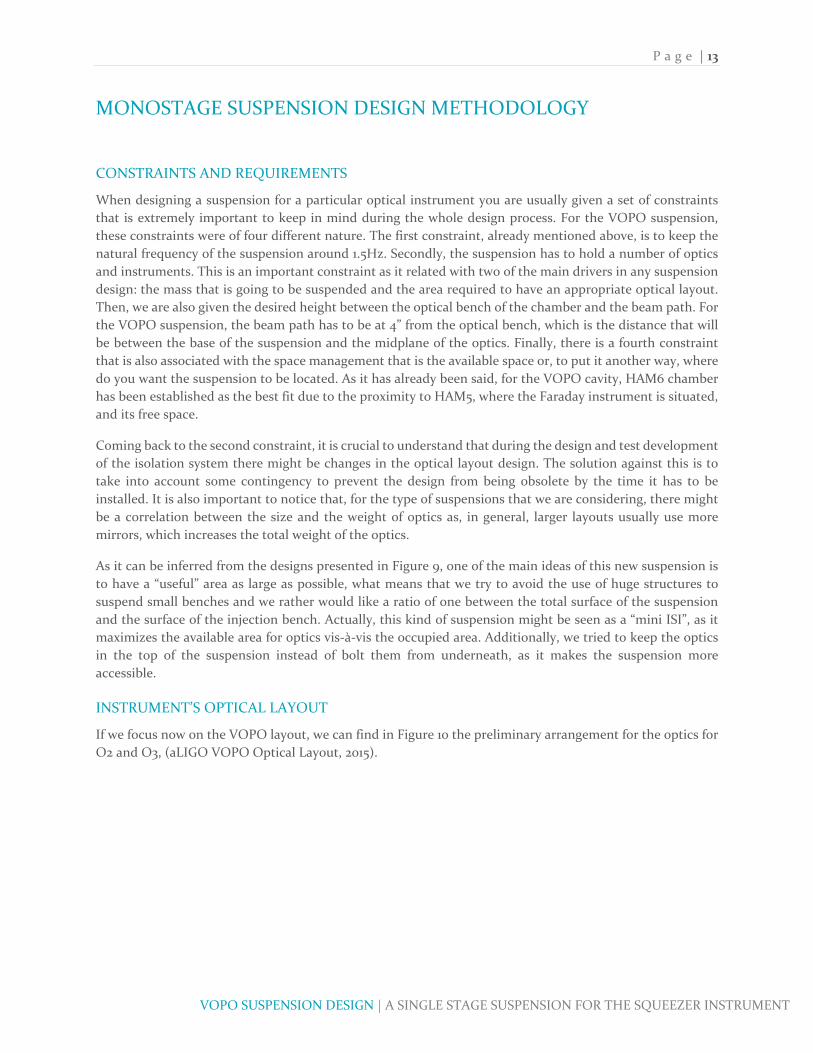
CONSTRAINTS AND REQUIREMENTS
When designing a suspension for a particular optical instrument you are usually given a set of constraints
that is extremely important to keep in mind during the whole design process. For the VOPO suspension,
these constraints were of four different nature. The first constraint, already mentioned above, is to keep the
natural frequency of the suspension around 1.5Hz. Secondly, the suspension has to hold a number of optics
and instruments. This is an important constraint as it related with two of the main drivers in any suspension
design: the mass that is going to be suspended and the area required to have an appropriate optical layout.
Then, we are also given the desired height between the optical bench of the chamber and the beam path. For
the VOPO suspension, the beam path has to be at 4” from the optical bench, which is the distance that will
be between the base of the suspension and the midplane of the optics. Finally, there is a fourth constraint
that is also associated with the space management that is the available space or, to put it another way, where
do you want the suspension to be located. As it has already been said, for the VOPO cavity, HAM6 chamber
has been established as the best fit due to the proximity to HAM5, where the Faraday instrument is situated,
and its free space.
Coming back to the second constraint, it is crucial to understand that during the design and test development
of the isolation system there might be changes in the optical layout design. The solution against this is to
take into account some contingency to prevent the design from being obsolete by the time it has to be
installed. It is also important to notice that, for the type of suspensions that we are considering, there might
be a correlation between the size and the weight of optics as, in general, larger layouts usually use more
mirrors, which increases the total weight of the optics.
As it can be inferred from the designs presented in Figure 9, one of the main ideas of this new suspension is
to have a “useful” area as large as possible, what means that we try to avoid the use of huge structures to
suspend small benches and we rather would like a ratio of one between the total surface of the suspension
and the surface of the injection bench. Actually, this kind of suspension might be seen as a “mini ISI”, as it
maximizes the available area for optics vis‐à‐vis the occupied area. Additionally, we tried to keep the optics
in the top of the suspension instead of bolt them from underneath, as it makes the suspension more
accessible.
INSTRUMENT’S OPTICAL LAYOUT
If we focus now on the VOPO layout, we can find in Figure 10 the preliminary arrangement for the optics for
O2 and O3, (aLIGO VOPO Optical Layout, 2015).

P a g e | 14
VOPO SUSPENSION DESIGN | A SINGLE STAGE SUSPENSION FOR THE SQUEEZER INSTRUMENT
Figure 10: VOPO optical layout for O2 (left) and O3 (right)
The most important part of both layouts is the VOPO cavity, marked in gray color in Figure 10. That is the
key point of the VOPO and when the squeezed light is produced. We are not going to explain the particular
as it is not the main goal of this document, but in this cavity, so called because it “captures” the light in
between its four mirrors and forces it to go through the non‐linear PPKTP crystal. This crystal is the key
element of the cavity as it is where each photon of 532nm light is converted into two 1064nm photons that
are consequently in phase and the same wave length used in the interferometer. Figure 11 present the design
of the VOPO cavity and the MIT prototype that is being tested at the moment.
Figure 11: CAD model (left) and prototype built at MIT (right) of the VOPO Cavity
In order to work as expected, this cavity has to be pumped with a light income. Going back to the O2
configuration presented in Figure 10, both fiber in can be observed in the left edge of the layout, pumping the
cavity with the beams represented in green and orange. There is a critical parameter in the design of the
layout that is the distances between the fiber in, the lenses and the mirrors of the cavity. These distances are
carefully calculated to match the pump beam with the cavity and therefore avoid losses on it. It can also be

P a g e | 15
VOPO SUSPENSION DESIGN | A SINGLE STAGE SUSPENSION FOR THE SQUEEZER INSTRUMENT
observed that there are also two output beams coming out from the cavity. The orange output is then
reflected by some mirrors and leaves the suspension. With the green beam something similar happens, but
with an important difference. This output is split into two different beams, the green and the red, being this
last beam the most important one as it is the actual squeezed light. This squeezed light goes then through
lenses, polarizers, a wave plate and the Faraday rotator, being its final target the Faraday suspension placed
in HAM5. Again, the position of the lenses is critical in order to match this beam with the target. Additionally,
one of the constraints regarding the chambers layout is that in between the VOPO and the Faraday, the beam
has to be reflected in two Tip‐tilt mirrors in order to allow LIGO people to actuate from the outside.
Concerning the green and orange outputs, their target is, for O2, the detectors that will be placed in air next
to the chamber.
If we move to the O3 layout in Figure 10, the same base arrangement can be observed but with some
differences. The main one is the blue beam, which will replace the red one as the one that is injected into the
interferometer. This is because in O3 the squeezed beam goes to a filter cavity (presumably a 16m single cavity
between HAM4 and HAM5) and comes back to the VOPO, where a polarizer separates it from the squeezed
light going out of the cavity; separation that is represented in Figure 10 with the blue beam. The other main
difference, which may be applied or not, is the introduction of in Vacuum RFPD detectors. As it has been
stated above, these detectors are originally (O2) on a table next to HAM6, and the beams reach them by going
through the View Ports (the “windows” of the chambers). Having them in Vacuum will represent an
advantage as the value of the detected data will be higher, even if it bring some technical challenges.
STEP 1: SITUATION IN THE CHAMBER
After all the general requirements have been defined and, even if it may be counterintuitive, the first thing
that has to be defined is what will be the overall shape of the suspension. To define it, both the available area
and the minimum required space for the optics have to be considered. In the case of the VOPO suspension,
a 2 x 1.5 ft2 suspension was needed. Comparing this preliminary estimation with the HAM6 layout, presented
in Figure 12, it was decided that the best place to allocate the new suspension is in the highlighted area of
Figure 13, as all the red rectangles are just balancing mass that can easily be removed and that was intended
to host the upcoming instruments.
Figure 12: HAM6 chamber Layout prior to the installation of the Squeezer
In general, it might be recommended to define symmetric shapes, but in our situation, and as we do not
wanted to move any of the existing equipment, the shape is a heptagon. As shown in Figure 13, in the
definition of the suspension’s shape different needs have been considerate. Firstly, the availability of holes
around the structure is important if we want to use dog clamps to attach it to the optical bench. Also, a free

P a g e | 16
VOPO SUSPENSION DESIGN | A SINGLE STAGE SUSPENSION FOR THE SQUEEZER INSTRUMENT
area has to be left for the Tip‐Tilts that will be used to address the squeezed beam to the next chamber. In
addition, we need to anticipate the need of a “shooting area” in the suspension, which is an area where no
other parts of the suspension will interact with the beams leaving it.
Figure 13: HAM5 chamber selected location for the squeezer
STEP 2: MASS BUDGET ESTIMATION
Once the shape of the suspension was defined, we worked on the preliminary mass budget. What we basically
were looking for is to know the total weight that will conform the first stage, i.e. the suspended. This weight
may be broken down into three: the optics weight, the injection bench weight and the balancing mass weight.
This last mass is important because, as it has been shown in previous suspensions, it is important to have a
way to do the final adjustment in order to have a well‐balanced suspension.
Consequently, the first important thing to do is to estimate the total weight of the optics that are going to be
on the suspension. To do so, the people in charge of the design and development of the VOPO instrument
made a preliminary design and estimated that this weight will be around 12kg. Given that number, we
considered that the total suspended weight, without the injection bench, must be considered to be 18kg. This
six extra kilograms are seen as both the balancing mass and the contingency for the optics weight. Finally,
the weight of the injection bench has also to be estimated. The injection bench has to be stiff enough to hold
all the optics’ mass and keep its resonance frequency as high as possible. As it will further discussed, the
minimum acceptable frequency will be related with the bandwidth of the actuators. Finally, 18kg where
considered a good guess for the required weight of the bench. All in all, the total weight considered for the
first stage is 36kg, distributed as it follows:
:12 :18 :6
STEP 3: BLADES PRELIMINARY DESIGN
With this first estimate the blades’ dimensions can be calculated. To do so, we use the procedure described
in Subassemblies, Blade Assembly, Blade and that we have implemented as a Matlab document
BladeDesign.m. This procedure is applied in the definition of a “bent when loaded blade”. That means that
the blades are going to be flat when machined and they will be bent once they are in service. This approach
is contrasting with other suspensions, like the OMCS, where the blades where subjected to a forming and
heat treatment process to be curved when unloaded. The problem with this type of blades is that the
P a g e | 17
VOPO SUSPENSION DESIGN | A SINGLE STAGE SUSPENSION FOR THE SQUEEZER INSTRUMENT
procurement time and the price are both much higher than for the ones that have been considered, which is
one of the main reasons for this election.
In the VOPO design one of the main restrictions is the available space, and we want to keep the “useful” area
as large as possible. Basically, there are three parameters that have to be defined in the global blade design
process, which are the number of blades, the material of those and the degree of freedom in the blade’s
dimensions (length, wide or thickness). This might be an iterative process in which a compromise has to be
found in order to avoid having too much low‐loaded blades or too fee high‐loaded ones. For the VOPO
suspension, the number of blades has been set at 3, which means that each blade will have to support 12kg.
Given this load, the selection of the material is one of the key points in the blade design. In LIGO, the majority
of the blades are designed using Maraging steel (C250, for example), as they present superior strength and
toughness without losing malleability compared to other steels. However, again both the cost and the
uneasiness in the procurement made us analyze other potential options. The two studied options were 17‐4
SSTL and 440C SSTL, being the second the one that was finally chose. This material, as a Martensitic steel, is
a high carbon steel, which attains the highest hardness, wear resistance and strength of all stainless steel
grades after heat treatment. Additionally, grade 440C is more readily available than the other standard grades
in the 440 series.
On the top of that, this steel has a corrosion resistance lower than that of other austenitic grades and it is
Ultra High Vacuum compatible. Actually, the main drawbacks of this kind of steel are its loss of strength
caused by over‐tempering at high temperatures, and its loss of ductility at temperatures below zero, two
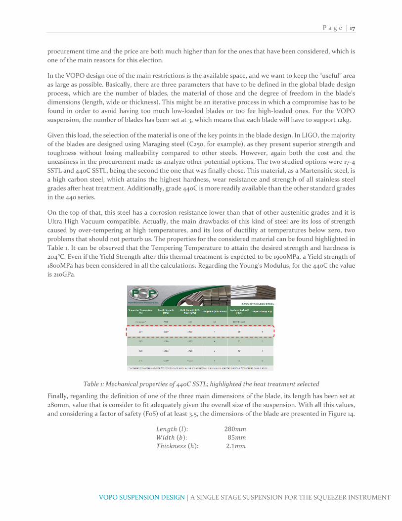
problems that should not perturb us. The properties for the considered material can be found highlighted in
Table 1. It can be observed that the Tempering Temperature to attain the desired strength and hardness is
204°C. Even if the Yield Strength after this thermal treatment is expected to be 1900MPa, a Yield strength of
1800MPa has been considered in all the calculations. Regarding the Young’s Modulus, for the 440C the value
is 210GPa.
Table 1: Mechanical properties of 440C SSTL; highlighted the heat treatment selected
Finally, regarding the definition of one of the three main dimensions of the blade, its length has been set at
280mm, value that is consider to fit adequately given the overall size of the suspension. With all this values,
and considering a factor of safety (FoS) of at least 3.5, the dimensions of the blade are presented in Figure 14.
:280 :85
:2.1

P a g e | 18
VOPO SUSPENSION DESIGN | A SINGLE STAGE SUSPENSION FOR THE SQUEEZER INSTRUMENT
Figure 14: VOPO blade preliminary dimensions
The importance about this first calculation of the blade parameters is to see if with the combination of the
material selection and the defined length the global dimensions of the blade are reasonable. In this case, a
width of 85mm is totally acceptable considering the instrument dimensions. Regarding the detailed shape of
the blade (tip, hole, etc.), it depends on the type of clamp that it is going to be used to attach de wire and the
blade. As it will be discussed further on, this shape in particular has been defined to fit a clamp analogous to
the one used in the Faraday instrument.
On the other hand, there are two important datum that are extracted from this first analysis: the vertical
stiffness of the blades –and hence the vertical frequency– and the Factor of Safety, both presented below:
1255.1
1.6277
3.4117
The frequency is slightly larger than the requirement of 1.5Hz that was set at first. However, the main
advantage of these solution, and the reason why this increase in frequency is allowed, is that the blade will
be working with a stress lower that the 30% of its Yield strength.
STEP 4: FLEXURE DESIGN
After the pre‐definition of the blade, another important element that has a crucial task in the suspension is
the flexure. This element is the equivalent of the blade for the horizontal motion, as it defines the horizontal
frequency of the suspension in both X and Y directions. After the calculation detailed in (Subassemblies,
Blade Assembly, Flexure), the flexures of the VOPO cavity are going to be steel music wires with a diameter
of 0.024”. This kind of flexures has already been used in the aLIGO project, adding confidence to that choice.
The results extracted from that study show that the horizontal frequency attains acceptable values for a length
of 130mm, a reasonable value given the global dimensions of the suspension. The frequency, stiffness and
Zero Moment Point (ZMP), which are going to be used through all the design, are presented below.
955.62
1.4203
3.4066
STEP 5: LOCATION OF THE BLADES
After the definition of the dimensions of the flexure and the blade, which will be checked using Finite Element
Analysis (FEA) in upcoming steps, it is important to decide where to locate them in our suspension. This is

P a g e | 19
VOPO SUSPENSION DESIGN | A SINGLE STAGE SUSPENSION FOR THE SQUEEZER INSTRUMENT
important because the tips of the blades will define a geometric figure in whose centroid the gravity center
of the suspended stage will have to be located in order to have a balanced instrument. That means that
arrangements where the centroid of the blade’s geometry is distant to the “center” of the suspension should
not be considered as it will make the balancing process hard. An exception to that may be the case in which
it is known beforehand that the optical layout will not be centered in the bench. For the VOPO suspension
an equilateral triangle distribution was finally selected, as shown in Figure 15, where the green dot represent
the point where the center of mass of the suspended stage will have to be. Due to all the work that had been
done before, in the case of this suspension we had already defined other positions, as may be observed in the
mentioned figure. However, the main goal of this step is to define the available space for optics, as the next
step will be to define the optical layout. Thus, what it is needed at this point is to define the “forbidden” areas
for optics, as shown in Figure 15.
Figure 15: Location of the blades in the VOPO suspension (left) and “forbidden” area (right)
STEP 6: CAD MODEL OF THE OPTICAL LAYOUT
Knowing the estimated free area for optics, it is time to check if this area is adapted to the real
requirements. It may seem that it is too soon the work on the detailed layout as the suspension is barely
defined, but it is important to do so at this point in order to avoid having to redefine everything in the end.
In the definition of the layout both the mass the volume of each optical instrument must be taken into
account. To do so, SolidWorks models from existing designs were adapted to match our design. The aim
was not to change the optics but to adapt their height because, with the predesign of the VOPO cavity that
was used to define the physical arrangement, the level of the optics and the injection bench are constraint,
as presented in Figure 16.
Figure 16: Height of the beam and injection bench

P a g e | 20
VOPO SUSPENSION DESIGN | A SINGLE STAGE SUSPENSION FOR THE SQUEEZER INSTRUMENT
Typically, the optics used by LIGO are 4” height, so they had to be all adapted to 2.5” high to match the
requirements. On the other side, not all the optical parts had been properly defined and, for example, mirror
mounts have been used to represent both polarizers and fiber inputs. We know that this may not be 100%
accurate but it was considerate as a good estimate, especially considering the high level of contingency that
was selected. Detailed information about these models and their weight may be found in additional
documentation (VOPO Suspension, E1500446‐v).
Using these models and after a few iterations the presented layouts for O2 (Figure 17) and O3 (Figure 18) are
considered to be acceptable and fulfill all the requirements. Again, a detailed overview of both layouts may
be found in (VOPO Suspension, E1500446‐v).
Figure 17: CAD model of the O2 configuration layout
Figure 18: CAD model of the O3 configuration layout
For the VOPO suspension it seemed to us that the optical layout matched the available space without being
excessively constraint or having too much free space. If that is the case in any other suspension, it is necessary
to come back to the first step and reconsider the location and/or the area used by the instrument.
P a g e | 21
VOPO SUSPENSION DESIGN | A SINGLE STAGE SUSPENSION FOR THE SQUEEZER INSTRUMENT
STEP 7: CHAMBERS’ LAYOUT
An important aspect to keep in mind while trying to find an adequate layout is to think about the whole
chamber layout to check if the directions of the beams leaving the suspension can match the overall layout
requirements. To do so, a full HAM5 and HAM6 model was developed and it shown that, even if some small
changes may be done by the time of the implementation, the layout was correct. This full model is detailed
in (VOPO Suspension, E1500446‐v).
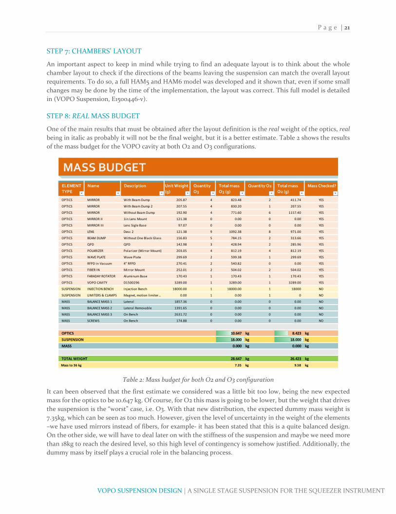
STEP 8: REAL MASS BUDGET
One of the main results that must be obtained after the layout definition is the real weight of the optics, real
being in italic as probably it will not be the final weight, but it is a better estimate. Table 2 shows the results
of the mass budget for the VOPO cavity at both O2 and O3 configurations.
Table 2: Mass budget for both O2 and O3 configuration
It can been observed that the first estimate we considered was a little bit too low, being the new expected
mass for the optics to be 10.647 kg. Of course, for O2 this mass is going to be lower, but the weight that drives
the suspension is the “worst” case, i.e. O3. With that new distribution, the expected dummy mass weight is
7.35kg, which can be seen as too much. However, given the level of uncertainty in the weight of the elements
–we have used mirrors instead of fibers, for example‐ it has been stated that this is a quite balanced design.
On the other side, we will have to deal later on with the stiffness of the suspension and maybe we need more
than 18kg to reach the desired level, so this high level of contingency is somehow justified. Additionally, the
dummy mass by itself plays a crucial role in the balancing process.
MASS BUDGET
ELEMENT
TYPE
Name Description Unit Weight
(g)
Quantity
O3
Total mass
O3 (g)
Quantity O2 Total mass
O2 (g)
Mass Checked?
OPTICS MIRROR With Beam Dump 205.87 4 823.48 2 411.74 YES
OPTICS MIRROR With Beam Dump 2 207.55 4 830.20 1 207.55 YES
OPTICS MIRROR Without Beam Dump 192.90 4 771.60 6 1157.40 YES
OPTICS MIRROR II 1in Lens Mount 121.38 0 0.00 0 0.00 YES
OPTICS MIRROR III Lens Sigle Base 97.07 0 0.00 0 0.00 YES
OPTICS LENS Desc 2 121.38 9 1092.38 8 971.00 YES
OPTICS BEAM DUMP Without One Black Glass 156.83 5 784.15 2 313.66 YES
OPTICS QPD QPD 142.98 3 428.94 2 285.96 YES
OPTICS POLARIZER Polarizer (Mirror Mount) 203.05 4 812.19 4 812.19 YES
OPTICS WAVE PLATE Wave Plate 299.69 2 599.38 1 299.69 YES
OPTICS RFPD in Vacuum 4" RFPD 270.41 2 540.82 0 0.00 YES
OPTICS FIBER IN Mirror Mount 252.01 2 504.02 2 504.02 YES
OPTICS FARADAY ROTATOR Aluminum Base 170.43 1 170.43 1 170.43 YES
OPTICS VOPO CAVITY D1500296 3289.00 1 3289.00 1 3289.00 YES
SUSPENSION INJECTION BENCH Injection Bench 18000.00 1 18000.00 1 18000 NO
SUSPENSION LIMITERS & CLAMPS Magnet, motion l imiter… 0.00 1 0.00 1 0 NO
MASS BALANCE MASS 1 Lateral 1857.36 0 0.00 0 0.00 NO
MASS BALANCE MASS 2 Lateral Removable 1391.65 0 0.00 0 0.00 NO
MASS BALANCE MASS 3 On Bench 2631.72 0 0.00 0 0.00 NO
MASS SCREWS On Bench 174.88 0 0.00 0 0.00 NO
OPTICS 10.647 kg 8.423 kg
SUSPENSION 18.000 kg 18.000 kg
MASS 0.000 kg 0.000 kg
TOTAL WEIGHT 28.647 kg 26.423 kg
Mass to 36 kg 7.35 kg 9.58 kg

P a g e | 22
VOPO SUSPENSION DESIGN | A SINGLE STAGE SUSPENSION FOR THE SQUEEZER INSTRUMENT
Summarizing all, we have reached the point where the main design of the suspension and it is time to move
on into more detailed design and to think about sub‐assemblies. However, before to do so it should be
considerate which will be the thickness of the base plate, the part that is going to connect the stage 0 and the
optical bench of the ISI. In this suspension it has been stated that 0.4” are expected to guarantee a good
contact and allow the use of previously designed dog clamps, Figure 19, to secure it on the chamber’s table.
Figure 19: Dog clamps used to lock the base plate on the optical bench of HAM6
STEP 9: ACTUATORS
The next think to think about is the active damping control of the instrument. Almost all the LIGO
suspensions possess active control systems in order to damp the rigid modes of the instrument. Among all
these systems we have considered the so‐called OSEM, a LIGO designed magnetic actuator. There are two
different versions for these actuators, the AOSEM and the BOSEM, being the second one bigger and with
more actuation capacity. Both actuators are base in a fixed coil free magnet system. Usually, the magnets,
which can also act as flag, are attached to the suspended stage while the coil is attached to the ground. Their
mechanism is roughly explained in Figure 20. The OSEM use a LED‐photodiode pair to know the position of
the magnet and its movement. In addition, the position of this magnet may be controlled via the injection of
current through the coil (LIGO‐T1200468).
Figure 20: A schematic of OSEM shadow sensor operation
At first, the BOSEM were selected but we realized that we were oversizing our system as with a 36kg
suspended mass and the needs in terms of damping, the AOSEMs satisfy all the requirements. Additionally,
LIGO has some spare AOSEM that may be used for the VOPO suspension what will result in an important
cost and procurement time reduction. Thus, AOSEM were finally selected to actuate the VOPO suspension,
guaranteeing good performance as they have already been successfully used in precedent LIGO suspensions,
such as the HSTS.
Specifically, the suspended bench is actively damped by six AOSEM actuators, being half of them used for
the vertical control and the other for the horizontal one. About its disposition, the actuators will be placed

P a g e | 23
VOPO SUSPENSION DESIGN | A SINGLE STAGE SUSPENSION FOR THE SQUEEZER INSTRUMENT
under the blade in order to use as less space as possible. In addition, the horizontal actuators are placed
tangentially to the bench radius to ease the control, as shown in Figure 21. The detailed about the AOSEM
alignment system and its FE study is in (Subassemblies, AOSEM and Magnets), where it can also be found
the description of the magnet holders.
Figure 21: Position of the AOSEM under the blades; horizontal AOSEM tangently located
The selection of AOSEM as actuators has an important implication as it defines the minimum resonance
frequency for all the elements of the instrument. The bandwidth of the AOSEM is approximately to 30‐40Hz,
which means that the frequencies of the elements should be as far away from those as possible.
Approximately, a minimum frequency of 150Hz will be stablished for the design.
In parallel with the AOSEM alignment system, a system to hold the magnet on the first stage has to be
designed. The design of this system, whose principle is to hold magnetically the magnet, is detailed in
(Subassemblies, AOSEM and Magnets). It is important to check that by the end of this process the preliminary
layout is still feasible and that none of its space has been used.
After the AOSEM selection we do have a criteria to select whether the elements are stiff enough or not. This
criteria is going to be used in the injection bench design, using a cyclic process.
STEP 10: INJECTION BENCH DESIGN & BALANCING
In order to optimize the design of the injection bench it is necessary to link this design with the expected
optical layout. By this time, we already have the position and mass of the optics defined so the only elements
that are missing are the balancing masses. This masses have to be movable as it is likely that during the
assembly some discrepancies in weight will appear and part of the dummy mass will have to be added or
removed. Another important aspect about this masses that must not be forgotten is that they should never
interfere with the optics or its tenability. Consequently, it was decided that in the VOPO suspension a fair
portion of the added weight will be attached to the edge of the suspension as a cantilever, as shown in Figure
23.
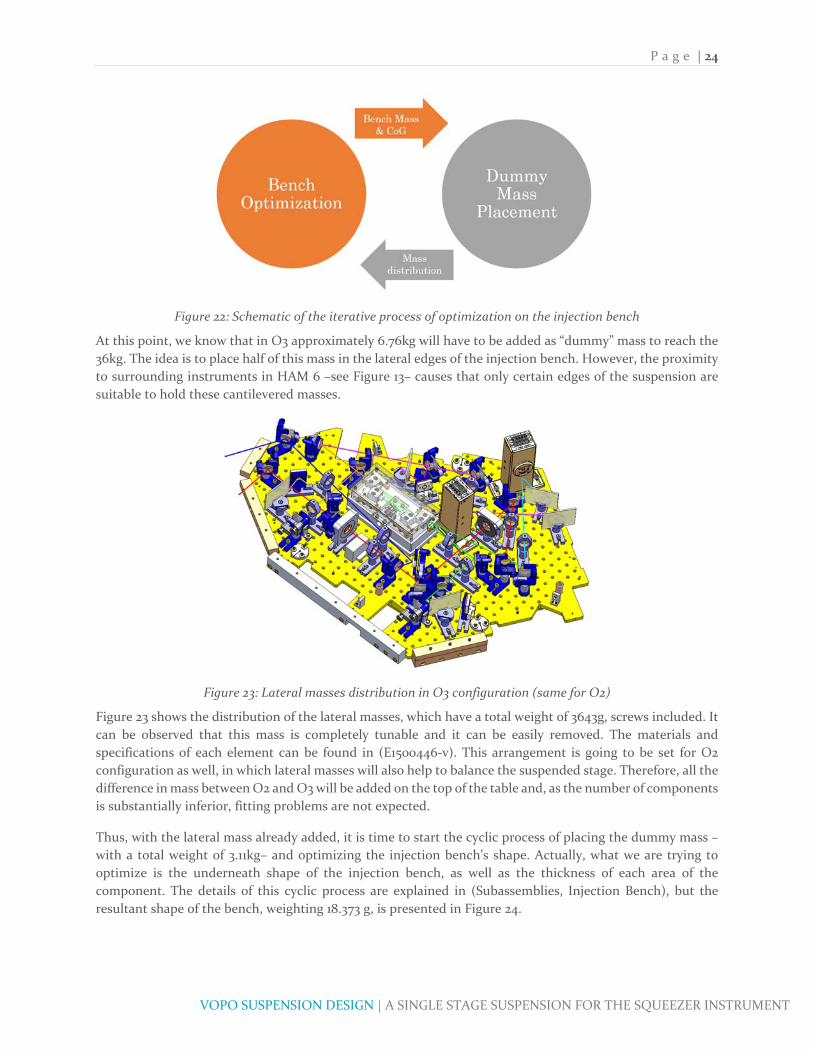
That being said, the abovementioned cyclic process consists in optimizing the shape of the injection bench
and trying to position the masses in order to keep the center of mass in the right position (green point in
Figure 15). Of course, the position of this center of gravity depends on the shape of the injection bench, but
also the position of the different masses depends on the best shape for the optical bench as Figure 22 exposes.
P a g e | 24
VOPO SUSPENSION DESIGN | A SINGLE STAGE SUSPENSION FOR THE SQUEEZER INSTRUMENT
Figure 22: Schematic of the iterative process of optimization on the injection bench
At this point, we know that in O3 approximately 6.76kg will have to be added as “dummy” mass to reach the
36kg. The idea is to place half of this mass in the lateral edges of the injection bench. However, the proximity
to surrounding instruments in HAM 6 –see Figure 13– causes that only certain edges of the suspension are
suitable to hold these cantilevered masses.
Figure 23: Lateral masses distribution in O3 configuration (same for O2)
Figure 23 shows the distribution of the lateral masses, which have a total weight of 3643g, screws included. It
can be observed that this mass is completely tunable and it can be easily removed. The materials and
specifications of each element can be found in (E1500446‐v). This arrangement is going to be set for O2
configuration as well, in which lateral masses will also help to balance the suspended stage. Therefore, all the
difference in mass between O2 and O3 will be added on the top of the table and, as the number of components
is substantially inferior, fitting problems are not expected.
Thus, with the lateral mass already added, it is time to start the cyclic process of placing the dummy mass –
with a total weight of 3.11kg– and optimizing the injection bench’s shape. Actually, what we are trying to
optimize is the underneath shape of the injection bench, as well as the thickness of each area of the
component. The details of this cyclic process are explained in (Subassemblies, Injection Bench), but the
resultant shape of the bench, weighting 18.373 g, is presented in Figure 24.
P a g e | 25
VOPO SUSPENSION DESIGN | A SINGLE STAGE SUSPENSION FOR THE SQUEEZER INSTRUMENT
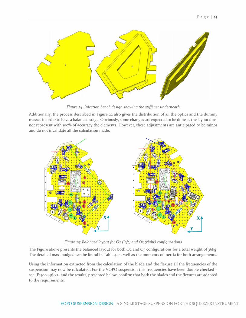
Figure 24: Injection bench design showing the stiffener underneath
Additionally, the process described in Figure 22 also gives the distribution of all the optics and the dummy
masses in order to have a balanced stage. Obviously, some changes are expected to be done as the layout does
not represent with 100% of accuracy the elements. However, these adjustments are anticipated to be minor
and do not invalidate all the calculation made.
Figure 25: Balanced layout for O2 (left) and O3 (right) configurations
The Figure above presents the balanced layout for both O2 and O3 configurations for a total weight of 36kg.
The detailed mass budged can be found in Table 4, as well as the moments of inertia for both arrangements.
Using the information extracted from the calculation of the blade and the flexure all the frequencies of the
suspension may now be calculated. For the VOPO suspension this frequencies have been double checked –
see (E1500446‐v)– and the results, presented below, confirm that both the blades and the flexures are adapted
to the requirements.
X
Y
X
Y
P a g e | 26
VOPO SUSPENSION DESIGN | A SINGLE STAGE SUSPENSION FOR THE SQUEEZER INSTRUMENT
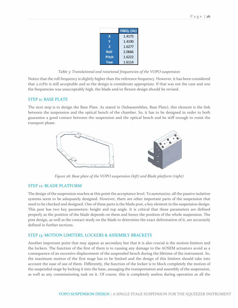
Table 3: Translational and rotational frequencies of the VOPO suspension
Notice that the roll frequency is slightly higher than the reference frequency. However, it has been considered
that 2.07Hz is still acceptable and so the design is considerate appropriate. If that was not the case and one
the frequencies was unacceptably high, the blade and/or flexure design should be revised.
STEP 11: BASE PLATE
The next step is to design the Base Plate. As stated in (Subassemblies, Base Plate), this element is the link
between the suspension and the optical bench of the chamber. So, it has to be designed in order to both
guarantee a good contact between the suspension and the optical bench and be stiff enough to resist the
transport phase.
Figure 26: Base plate of the VOPO suspension (left) and Blade platform (right)
STEP 12: BLADE PLATFORM
The design of the suspension reaches at this point the acceptance level. To summarize, all the passive isolation
systems seem to be adequately designed. However, there are other important parts of the suspension that
need to be checked and designed. One of these parts is the blade post, a key element in the suspension design.
This post has two key parameters: height and top angle. It is critical that these parameters are defined
properly as the position of the blade depends on them and hence the position of the whole suspension. The
post design, as well as the contact study on the blade to determine the exact deformation of it, are accurately
defined in further sections.
STEP 13: MOTION LIMITERS, LOCKERS & ASSEMBLY BRACKETS
Another important point that may appear as secondary but that it is also crucial is the motion limiters and
the lockers. The function of the first of them is to causing any damage to the AOSEM actuators avoid as a
consequence of an excessive displacement of the suspended bench during the lifetime of the instrument. So,
the maximum motion of the first stage has to be limited and the design of this limiters should take into
account the ease of use of them. Differently, the function of the locker is to block completely the motion of
the suspended stage by locking it into the base, assuaging the transportation and assembly of the suspension,
as well as any commissioning task on it. Of course, this is completely useless during operation as all the
FREQ. (Hz)
X 1.4175
Y 1.4190
Z 1.6277
Roll 2.0666
Pitch 1.6222
Yaw 1.6114

P a g e | 27
VOPO SUSPENSION DESIGN | A SINGLE STAGE SUSPENSION FOR THE SQUEEZER INSTRUMENT
isolation is suppressed so the locker should never be used during runs or testing periods, and this is why it is
important to design a system both easy to inspect and manipulate. The details of this elements can be found
in Subassemblies section.
STEP 14: ASSEMBLY PROCEDURE & FINAL MASS BUDGET
The last step of detail is to define an assembly procedure to check that everything has been properly designed
and that the building is feasible. One key element in this procedure is to set all the elements in the right
position with respect to the others because, in a precision instrument like the VOPO suspension, it is
extremely important to avoid misalignments that will lead to poor performances. Particularly, this suspended
instruments require a precise alignment of the flexure as otherwise it may produce an important
displacement of all the first stage when released. With this aim, the position of the first stage with respect to
the base and the position blade’s platform with respect to both the injection bench and the base plate have
to be accurately controlled. To do so, it was first considered to use pin‐hole systems, an approach that has
been successfully implemented in LIGO before. However, do to the difficulties in the assembly procedure this
pin‐hole systems were substituted by tight tolerance surface contact, as may be seen in (Appendix, Drawings).
Additionally, Figure 27 presents the final design of the VOPO suspension with the O2 optical layout.
Figure 27: final design of the VOPO suspension with the O2 optical layout
FINAL DESIGN
Ultimately, the suspension is fully defined and so the first stage of the project is accomplished. Nevertheless,
there is one important part that has not be treated yet and that will play a huge role in the suspension’s
performance and that it is the actuators control design. Figure 28 summarizes the design procedure that has
been followed for the VOPO instrument and that may be used in future similar suspension designs. In
addition, Table 4 presents the final Mass budget for both O2 and O3 configurations and the FEA models.

P a g e | 28
VOPO SUSPENSION DESIGN | A SINGLE STAGE SUSPENSION FOR THE SQUEEZER INSTRUMENT
Figure 28: Monostage suspension design methodology schematics
Table 4: Final mass budget for O2, O3 and the FEA models
Finally, a prototype of the VOPO suspension has to be built in order the check all the calculations before
installing the new instrument into the LIGO sites. In (Appendix, Drawings) all the drawings of the designed
parts, which have been sent to the manufacturers, are presented.
P a g e | 29
VOPO SUSPENSION DESIGN | A SINGLE STAGE SUSPENSION FOR THE SQUEEZER INSTRUMENT
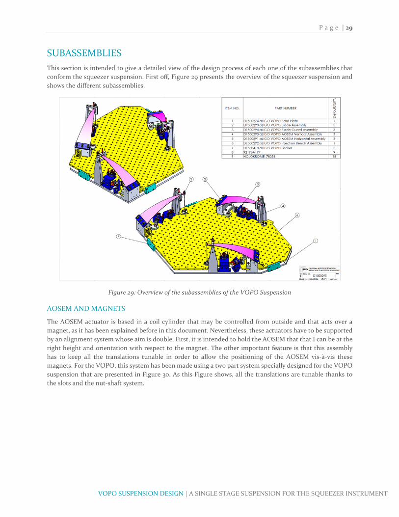
SUBASSEMBLIES
This section is intended to give a detailed view of the design process of each one of the subassemblies that
conform the squeezer suspension. First off, Figure 29 presents the overview of the squeezer suspension and
shows the different subassemblies.
Figure 29: Overview of the subassemblies of the VOPO Suspension
AOSEM AND MAGNETS
The AOSEM actuator is based in a coil cylinder that may be controlled from outside and that acts over a
magnet, as it has been explained before in this document. Nevertheless, these actuators have to be supported
by an alignment system whose aim is double. First, it is intended to hold the AOSEM that that I can be at the
right height and orientation with respect to the magnet. The other important feature is that this assembly
has to keep all the translations tunable in order to allow the positioning of the AOSEM vis‐à‐vis these
magnets. For the VOPO, this system has been made using a two part system specially designed for the VOPO
suspension that are presented in Figure 30. As this Figure shows, all the translations are tunable thanks to
the slots and the nut‐shaft system.

P a g e | 30
VOPO SUSPENSION DESIGN | A SINGLE STAGE SUSPENSION FOR THE SQUEEZER INSTRUMENT
Figure 30: AOSEM vertical (left) and horizontal (right) assemblies and their motion
Similarly to other parts of the VOPO suspension, a simplified model of the AOSEM assemblies has been
studied using FEA in order to guarantee that the resonance frequency are distant enough from the bandwidth
of the actuator. The results of this FEA analysis, presented in Figure 31 and Figure 32, show that, with a
minimum resonance frequency of 646.35Hz, the design satisfies the specifications.
Figure 31: FEA (SW Simulation) for Vertical AOSEM Assembly. First frequency: 646.35Hz
The FEA has been performed using simplified versions of the parts of the assembly and using a bonded
contact with compatible mesh. This may not give the more accurate results but it has been considered to
have an acceptable accuracy, especially because, for the part that is being considered, the first resonance
frequency far exceeds the requirements. If that was not the case, a new design should be developed and a
refined FEA should be performed. Regarding the boundary conditions, all the base was set as fixed geometry.

P a g e | 31
VOPO SUSPENSION DESIGN | A SINGLE STAGE SUSPENSION FOR THE SQUEEZER INSTRUMENT
Figure 32: FEA (SW Simulation) for Horizontal AOSEM Assembly. First frequency: 873.05Hz
The magnets play also an important role in the damping control system. In the VOPO suspension, these
magnets are attached to the suspended stage and they have both the magnet and the flag function. LIGO
group has worked with different kinds and sizes of magnets in the previous designs so the idea for this
instrument was to reuse existing magnets models. At last, 2 x 6mm cylindrical magnets were selected as there
was a considerable number of them in spare so the procurement should be easy.
One of the delicate parts of these magnets is the way they are attached to the suspension. In earlier aLIGO
designs, the magnets were glued to the suspended stage either directly or using a post as interface. In both
cases, the UHV compatible glue had to be used and that uneased the assembly. Consequently, the idea of
getting rid of this glue assembly and using the magnetic property of the magnet instead was studied. The
result is a threaded part made of 440B stainless steel that holds the magnet at the right height from the top
of the injection bench and guarantees an initial penetration of the magnet in the AOSEM of 0.073”. With this
penetration, the tip of the magnet is located in the median plane of the LED‐Photodetector system, as shown
in Figure 33.
Figure 33: Overview of the magnet holder and the photodetector
Figure 34 gives an overview of the whole bracket assembly and the magnet in its position. As it can be seen,
the magnet will be held in its position by being magnetically attracted by the holder, which is then screwed
into the bench.

P a g e | 32
VOPO SUSPENSION DESIGN | A SINGLE STAGE SUSPENSION FOR THE SQUEEZER INSTRUMENT
Figure 34: Position of the magnet in the AOSEM
However, for the horizontal AOSEM it is not possible, or at least not favorable, to screw the holder directly
to the bench. So an intermediate part had to be designed in order to raise the magnet up and hold it
horizontally. This component is presented in Figure 35 and it consists in an L shaped part that is screwed on
the bench and into which the magnet holder is then screwed.
Figure 35: Magnet riser for the horizontal AOSEM assembly
This part should also be checked using FEA even if at first it seems that no resonance problems should appear.
Figure 36 shows the results of these study that confirms the anticipated results, being the first resonance
frequency 6892.6Hz.

P a g e | 33
VOPO SUSPENSION DESIGN | A SINGLE STAGE SUSPENSION FOR THE SQUEEZER INSTRUMENT
Figure 36: FEA (SW Simulation) for Magnet Holder. First frequency: 6892.6Hz
ASSEMBLY BRACKETS
During the assembly phase, the suspended stage and the base plate have to be perfectly positioned and
therefore avoid misalignment issues. Their function is indeed very similar to the one of the lockers, but the
last ones cannot be used from the beginning of the assembly as they are attached to the blade platform. In
addition to that, the lockers are designed to have large play so they are not selectable as positioning systems.
All in all, the system presented in Figure 37 guarantees the good positioning as its tolerances are well
controlled. In the assembly procedure (E1500446‐v) the surfaces that need to be in contact are detailed.
Figure 37: Assembly brackets overview
BASE PLATE
The Base Plate acts as intermediary between the VOPO suspension and the HAM6 optical bench. Its main
goal is to guarantee the proper attachment of the whole suspension to the optical bench and to do so a bunch

P a g e | 34
VOPO SUSPENSION DESIGN | A SINGLE STAGE SUSPENSION FOR THE SQUEEZER INSTRUMENT
of dog clamps are to be used, similarly to what has been done for the OMC suspension. The exact number of
dog clamps is defined according to the available threads in the optical bench and this is why in the first steps
of the design of the suspension we expressed the importance of consider the number of available holes as a
crucial point.
Figure 38: VOPO Base Plate (Left) and the distance to the injection bench
Figure 38 shows the final design of the base plate, which is a heptagonal 0.4” inch thick 6061‐T6 Aluminum
piece that weights 6.426lb (2.91 kg). The interior shape of the base plate has been designed taking into account
the shape of the injection bench in order to have some margin between this two elements, as it can be
observed in the above‐mentioned figure. On the other side, it is relevant to mention that except from the
blade platforms, all the elements are going to be clamped from the top, as shown in Figure 39.
Figure 39: Elements bolt to the base plate and dog clamps
Additionally, the FEA of the transport test has been performed to check if the stiffness of the base plate is
adapted to the requirements. As it can be noticed in Figure 38, the internal shape of the plate could be easily
increased and therefore its stiffness. Nevertheless, one of the main concerns is to ensure a good contact
between the base and the optical bench in the chamber. One option that has been considered is to clamp
directly the base to the optical bench, but the main drawback of it will be that the position of the whole
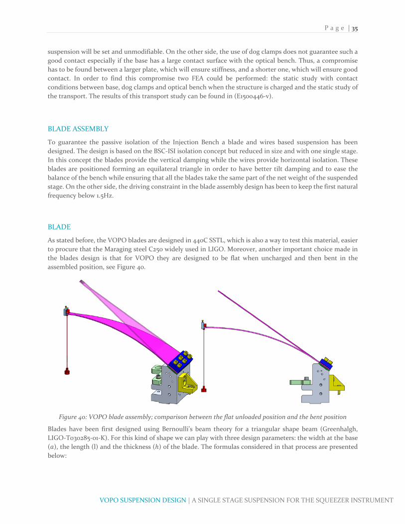
P a g e | 35
VOPO SUSPENSION DESIGN | A SINGLE STAGE SUSPENSION FOR THE SQUEEZER INSTRUMENT
suspension will be set and unmodifiable. On the other side, the use of dog clamps does not guarantee such a
good contact especially if the base has a large contact surface with the optical bench. Thus, a compromise
has to be found between a larger plate, which will ensure stiffness, and a shorter one, which will ensure good
contact. In order to find this compromise two FEA could be performed: the static study with contact
conditions between base, dog clamps and optical bench when the structure is charged and the static study of
the transport. The results of this transport study can be found in (E1500446‐v).
BLADE ASSEMBLY
To guarantee the passive isolation of the Injection Bench a blade and wires based suspension has been
designed. The design is based on the BSC‐ISI isolation concept but reduced in size and with one single stage.
In this concept the blades provide the vertical damping while the wires provide horizontal isolation. These
blades are positioned forming an equilateral triangle in order to have better tilt damping and to ease the
balance of the bench while ensuring that all the blades take the same part of the net weight of the suspended
stage. On the other side, the driving constraint in the blade assembly design has been to keep the first natural
frequency below 1.5Hz.
BLADE
As stated before, the VOPO blades are designed in 440C SSTL, which is also a way to test this material, easier
to procure that the Maraging steel C250 widely used in LIGO. Moreover, another important choice made in
the blades design is that for VOPO they are designed to be flat when uncharged and then bent in the
assembled position, see Figure 40.
Figure 40: VOPO blade assembly; comparison between the flat unloaded position and the bent position
Blades have been first designed using Bernoulli’s beam theory for a triangular shape beam (Greenhalgh,
LIGO‐T030285‐01‐K). For this kind of shape we can play with three design parameters: the width at the base
( ), the length (l) and the thickness ( ) of the blade. The formulas considered in that process are presented
below:

P a g e | 36
VOPO SUSPENSION DESIGN | A SINGLE STAGE SUSPENSION FOR THE SQUEEZER INSTRUMENT
4
12
6
Where KZZ is the spring constant of the blade in N/m, is the first natural frequency of the blade in Hz, is
the total suspended mass, is the maximum stress in the blade, is the force applied at each blade’s tip,
is the Yield stress of the blade’s material and is the used Factor of Safety. As those three equations can
be reduced to a two equations system and the number of design parameters is three, it can be concluded that
in this preliminary design one degree of freedom is allowed. In the VOPO blade design, this DOF has been
assigned to the length of the blade, which has been fixed as 280mm. This choice was made because the global
dimension of the injection bench had been previously defined.
Considering that the estimated suspended mass ( ) is 36 kg, which includes 18kg for the injection bench,
12kg for the optics and 6 kg of dummy mass, which will be used to balance and position the bench, the force
is therefore 117.72N. Thus, Figure 41 is the gives different height and width combinations depending on the
desired FoS.
Figure 41: Width and Height as function of FoS for l=280mm, f=1.5Hz and m=36kg
However, it must not be forgotten that the blade design in constrained by the size of the suspension and that
it has to be keep as compacted as possible. On this wise, whereas the height of the blade is not subjected to
any constraint, its width has to be carefully selected not to interact with the optics. In view of the results
plotted in Figure 41, a compromise has to be found between the FoS and the breath of the spring. However,
none of the combinations fits the requirements as more than 90mm width will clearly interfere with the
optics and, at the same time, a level of safety inferior to the 30% of the Yield strength ‐i.e. FoS>3.33‐ will be
too risky considering that this is the theoretical calculation and that the material considered has never been
used before for LIGO blades.
2 2.2 2.4 2.6 2.8 3 3.2 3.4 3.6 3.8 4
FoS
1.4
1.6
1.8
2
2.2
2.4
2.6
2.8
3
3.2Width and Height as fonction of FoS for Lenght =280mm, f =1.5Hz and m =36kg
20
40
60
80
100
120
140
160
180
200
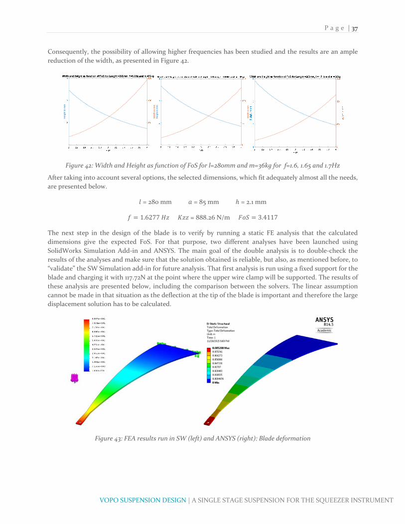
P a g e | 37
VOPO SUSPENSION DESIGN | A SINGLE STAGE SUSPENSION FOR THE SQUEEZER INSTRUMENT
Consequently, the possibility of allowing higher frequencies has been studied and the results are an ample
reduction of the width, as presented in Figure 42.
Figure 42: Width and Height as function of FoS for l=280mm and m=36kg for f=1.6, 1.65 and 1.7Hz
After taking into account several options, the selected dimensions, which fit adequately almost all the needs,
are presented below.
= 280 mm = 85 mm = 2.1 mm
1.6277 = 888.26 N/m 3.4117
The next step in the design of the blade is to verify by running a static FE analysis that the calculated
dimensions give the expected FoS. For that purpose, two different analyses have been launched using
SolidWorks Simulation Add‐in and ANSYS. The main goal of the double analysis is to double‐check the
results of the analyses and make sure that the solution obtained is reliable, but also, as mentioned before, to
“validate” the SW Simulation add‐in for future analysis. That first analysis is run using a fixed support for the
blade and charging it with 117.72N at the point where the upper wire clamp will be supported. The results of
these analysis are presented below, including the comparison between the solvers. The linear assumption
cannot be made in that situation as the deflection at the tip of the blade is important and therefore the large
displacement solution has to be calculated.
Figure 43: FEA results run in SW (left) and ANSYS (right): Blade deformation
Hei
ght i
n m
m
Wid
th in
mm
Hei
ght i
n m
m
Wid
th in
mm

P a g e | 38
VOPO SUSPENSION DESIGN | A SINGLE STAGE SUSPENSION FOR THE SQUEEZER INSTRUMENT
Figure 44: FEA results run in SW (left) and ANSYS (right): Blade stress
Figure 45: Comparison of the results for ANSYS, SW and Bernoulli’s theory
The presented results confirm that for this problem both ANSYS and SW Simulation show similar solutions,
with less than a 1% difference. Regarding the theoretical analysis compared with the results of the FEA, the
error made by estimating the stress with Bernoulli’s formula and considering linearized model is just a 4%.
Therefore, the theoretical approach has been proven to be accurate enough to the design of the blades,
especially when high FoS are selected for the design.
Another key point of the FE analysis is to define the deformed shape of the blade in order to be able to define
the angle of the blade’s base to have the blade’s tip parallel to the injection bench plane. Figure 46 presents
the bent shape of the blade, with an angle α between the base and the tip of 33.16°. This angle is crucial for
the post’s design as in order to keep the tip of the blade parallel to the injection bench it is necessary to
identify it.
Figure 46: Angle α between the tip and the base of the bent blade
SW ANSYS Difference % THEORY Error
Stress (MPa) 545.9 549.67 0.686 527.60 4.016
Displacement (mm) 85.87 85.21 0.775
FoS 3.30 3.27 3.41
FEA BLADE
α

P a g e | 39
VOPO SUSPENSION DESIGN | A SINGLE STAGE SUSPENSION FOR THE SQUEEZER INSTRUMENT
In practice, the angle α is likely to deviate from the theoretical value due to imperfect contact between the
blade, platform and clamp, as we know from the experience of previous aLIGO suspensions. Therefore, a
detailed FE analysis of the bolted contact in the blade base has been run to try to predict the behavior of the
assembly.
CLAMP
In the first design of the blade assembly two pairs of ¼‐20 bolts have been considered enough to hold the
blade in the desired position. This estimation has been made firstly using a rough momentum calculation to
define the required axial load of each bolt. Figure 47 presents the basic geometry parameters used for that
calculation, which has been implemented using ClampDesign.m (E1500446‐v).
Figure 47: Simplified model used to determine the number of bolts required
According to this simple model the required axial load per bolt for the left set of bolts has been calculated as
follows:
#
Additionally, the maximum load per screw is calculated using the equations below, obtained from
(Machinery's Handbook) :
1.299038
0.649519
4
2
The results of this calculation are presented in Table 5 and show that for a minimum of 3, at least two
bolts per row have to be used.

P a g e | 40
VOPO SUSPENSION DESIGN | A SINGLE STAGE SUSPENSION FOR THE SQUEEZER INSTRUMENT
2 3
2460.5 N 2460.5 N
3436.1 N 2290.7 N
# 1 2
Table 5: Results of the simplified bolt calculation
During the assembly the control of pre‐load of these bolts is done by applying the right torque to them. This
applied torque can be calculated as follows:
0.1591.156
For the VOPO blade, being the considerate material for this screws is 316 SSTL, whose Yield Strength is
334.37MPa, the real is 5.5859 and the torque to be applied to the screws is 8.8702.
FLEXURE
To guarantee the horizontal isolation, the key parameter in the design is the length and the section of the
music wires that hold the suspended stage. For the VOPO instrument, Music Wire Steel (E = 154‐201 GPa, σY
= 1600‐2000 MPa) has been considerate to be a good match given the requirements, and the fact that these
wires have already been used and largely tested in precedent aLIGO projects reinforces this idea. This tests
have proved that the wire’s Yield strength is dependent on its diameter as shown in the tables below. This
results have been obtained by testing the UTS of wires with different diameters.
Table 6: Tensile Strength Testing (T1500539)
Table 7: Minimum Tensile Strength (E1100187)
The precedent information has been extracted from the documents (LIGO‐T1400539‐v2) and (LIGO‐E1100187
‐v4). The first one of those shows an average relation between σY and UTS of 84.6%. Therefore, in further
calculations σY is calculated as 80% of the Minimum Tensile Strength, which is indeed a way to increase the
D (in) Min Tensile (ksi) D (mm) Min Tensile (MPa)0.0047 360 0.1194 2482.110.0060 350 0.1524 2413.170.0079 340 0.2007 2344.220.0098 330 0.2489 2275.270.0106 330 0.2692 2275.270.0134 320 0.3404 2206.320.0140 320 0.3556 2206.320.0160 310 0.4064 2137.380.0180 310 0.4572 2137.380.0240 290 0.6096 1999.480.0250 290 0.6350 1999.480.0280 290 0.7112 1999.480.0433 290 1.0998 1999.48

P a g e | 41
VOPO SUSPENSION DESIGN | A SINGLE STAGE SUSPENSION FOR THE SQUEEZER INSTRUMENT
safety of the design. Considering the previous information, Table 8 has been taken as a reference for all the
further calculations.
Table 8: Estimated Yield strength for the Music Wires
Using this data, and considering that, again, the requirement for the lateral motion is that its first frequency
has to be kept lower than 1.5Hz, the flexure parameters can be calculated. This calculation is intended to
define two parameter of the wire, which are the diameter d and the physical length l. In this specific project,
and after some iterations, the parameters that have been defined as they give acceptable performance are
presented below.
130
0.61
To define this values, the script FlexureDesign.m (E1500446‐v) has been implemented using all the equations
presented further on in this section; equations that have been extracted from the document 20007235‐D. The
first set of equations is used to calculate the Zero Moment Point (ZMP) of the flexure and determine the
effective length of the wire. The ZMP defines the length of wire that does not contribute to the pendulum
motion as it is so close to the attachment point that the wire is indeed bent. Moreover, the effective length is
the actual length of the wire that participates in the pendulum motion. The way to calculate them is by using
the following formulas:
64
1tanh
2
2
Being I the Inertia of the wire’s section, K a parameter used in the calculation, l the physical length of the
wire and lz the effective length. For the VOPO suspension, given the above‐mentioned parameter, the result
is:
3.4066
123.1869
Notice that this results expose that even if the wire is 130mm long, the isolation has to be computed as being
123.2mm long when using the pendulum equations. Using those parameters the lateral frequency of the
system may be found using the pendulum equations as shown below:
3
955.6213 /
D (mm) 0.1194 0.1524 0.2007 0.2489 0.2692 0.3404 0.3556 0.4064 0.4572 0.6096 0.6350 0.7112 1.0998Considerated Yield Strength (Mpa)
1986 1931 1875 1820 1820 1765 1765 1710 1710 1600 1600 1600 1600
Average Porportional Yield Strength (Mpa)
1930 1840 1780 1770 1930 2190 1620 2170
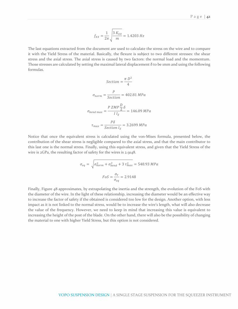
P a g e | 42
VOPO SUSPENSION DESIGN | A SINGLE STAGE SUSPENSION FOR THE SQUEEZER INSTRUMENT
12
31.4203
The last equations extracted from the document are used to calculate the stress on the wire and to compare
it with the Yield Stress of the material. Basically, the flexure is subject to two different stresses: the shear
stress and the axial stress. The axial stress is caused by two factors: the normal load and the momentum.
Those stresses are calculated by setting the maximal lateral displacement δ to be 1mm and using the following
formulas.
4
402.81
2
146.09
3.2699
Notice that once the equivalent stress is calculated using the von‐Mises formula, presented below, the
contribution of the shear stress is negligible compared to the axial stress, and that the main contributor to
this last one is the normal stress. Finally, using this equivalent stress, and given that the Yield Stress of the
wire is 2GPa, the resulting factor of safety for the wires is 2.9148.
3 548.93
2.9148
Finally, Figure 48 approximates, by extrapolating the inertia and the strength, the evolution of the FoS with
the diameter of the wire. In the light of these relationship, increasing the diameter would be an effective way
to increase the factor of safety if the obtained is considered too low for the design. Another option, with less
impact as it is not linked to the normal stress, would be to increase the wire’s length, what will also decrease
the value of the frequency. However, we need to keep in mind that increasing this value is equivalent to
increasing the height of the post of the blade. On the other hand, there will also be the possibility of changing
the material to one with higher Yield Stress, but this option is not considered.
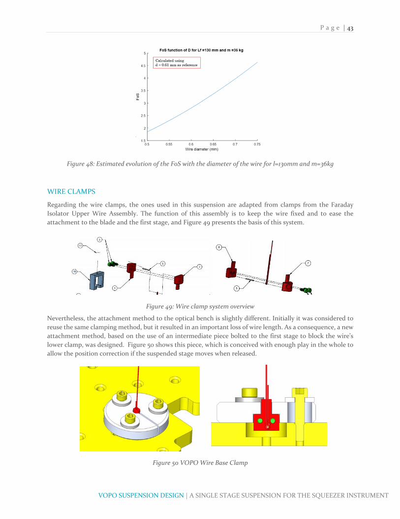
P a g e | 43
VOPO SUSPENSION DESIGN | A SINGLE STAGE SUSPENSION FOR THE SQUEEZER INSTRUMENT
Figure 48: Estimated evolution of the FoS with the diameter of the wire for l=130mm and m=36kg
WIRE CLAMPS
Regarding the wire clamps, the ones used in this suspension are adapted from clamps from the Faraday
Isolator Upper Wire Assembly. The function of this assembly is to keep the wire fixed and to ease the
attachment to the blade and the first stage, and Figure 49 presents the basis of this system.
Figure 49: Wire clamp system overview
Nevertheless, the attachment method to the optical bench is slightly different. Initially it was considered to
reuse the same clamping method, but it resulted in an important loss of wire length. As a consequence, a new
attachment method, based on the use of an intermediate piece bolted to the first stage to block the wire’s
lower clamp, was designed. Figure 50 shows this piece, which is conceived with enough play in the whole to
allow the position correction if the suspended stage moves when released.
Figure 50 VOPO Wire Base Clamp

P a g e | 44
VOPO SUSPENSION DESIGN | A SINGLE STAGE SUSPENSION FOR THE SQUEEZER INSTRUMENT
BLADE PLATFORM
The blade’s platform is a key element of the assembly as it is responsible for the tilt in the blade, and rises the
blade to increase the wire’s length and hence control the lateral frequency. So both the height and the angle
of this platform must be designed after the blade’s bent has been defined and the angle α is known. After the
contact study detailed in the corresponding section, the angle α is expected to be 35.32°, and the length that
has been defined for the wire is 130mm. Thus, the shape of the platform has to be done to respect this two
conditions. As shown in Figure 51, this part has to be highly machined, as it has many secondary functions
other that holding the blades. This is why the material that has been designated for this part is the aluminum
6061‐T6. Additionally, as it has not shown plasticity issues in the FEA.
Figure 51: VOPO Blade Platform
As pointed out before, holding the blade is not the only purpose of the post. This post, as it is attached to the
stage 0, is also used as motion limiter and attach point of the locker system. These two systems are detailed
in (Subassemblies, Motion Limiters) and (Subassemblies, Lockers) respectively. All of this makes this post,
along with the injection bench, the most important element of the suspension.
Finally, another important element of the blade assembly is the blade clamping system, whose objective is to
guarantee a good contact between the blade and the post. The design is adapted from the OMC’s upper blade
and it is designed to maintain contact in the edges of the clamp as shown in Figure 52. This clamping system
has been determined after a thorough contact analysis, described in further sections and that has shown that
with six 17‐4 PH SSTL screws and Nitronic 60 Emhart helicoils, the pretension that can be applied is so that
the contact is almost equivalent to a perfect fixed attachment. Moreover, the clamps are both designed in
stainless steel to guarantee a high friction coefficient with the blade, which is produced in 440C SSTL.
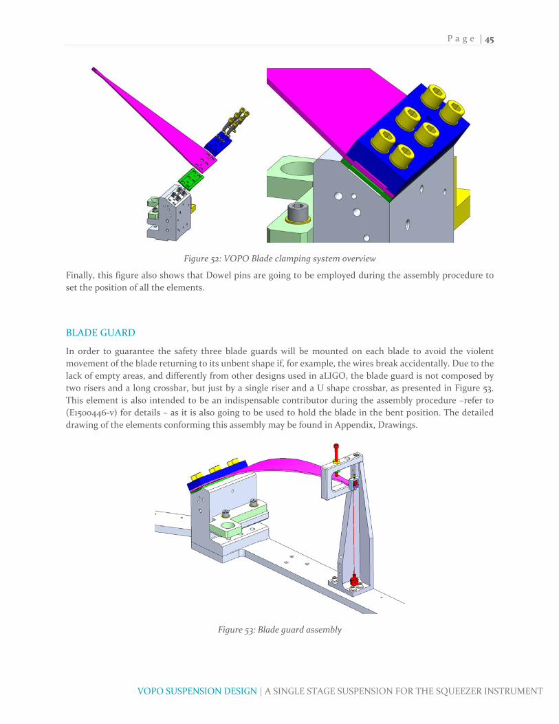
P a g e | 45
VOPO SUSPENSION DESIGN | A SINGLE STAGE SUSPENSION FOR THE SQUEEZER INSTRUMENT
Figure 52: VOPO Blade clamping system overview
Finally, this figure also shows that Dowel pins are going to be employed during the assembly procedure to
set the position of all the elements.
BLADE GUARD
In order to guarantee the safety three blade guards will be mounted on each blade to avoid the violent
movement of the blade returning to its unbent shape if, for example, the wires break accidentally. Due to the
lack of empty areas, and differently from other designs used in aLIGO, the blade guard is not composed by
two risers and a long crossbar, but just by a single riser and a U shape crossbar, as presented in Figure 53.
This element is also intended to be an indispensable contributor during the assembly procedure –refer to
(E1500446‐v) for details – as it is also going to be used to hold the blade in the bent position. The detailed
drawing of the elements conforming this assembly may be found in Appendix, Drawings.
Figure 53: Blade guard assembly

P a g e | 46
VOPO SUSPENSION DESIGN | A SINGLE STAGE SUSPENSION FOR THE SQUEEZER INSTRUMENT
The resonance frequency of the blade guard assembly has been carefully controlled during the design in order
to avoid couplings with the main structure that will result in a weak performance. Figure 54 shows the result
of the FE analyses run using both SW simulation and ANSYS. The first resonance frequency has a value of
513.47Hz, largely above the minimum requirement of 150‐200Hz.
Figure 54: FEA of the simplified Blade Guard assembly. f = 513.47Hz
There is one last calculation to perform to validate that the element is well designed at it is study the
resistance of the bolts. Particularly, the aim of this verification is to ensure that, in the case of a violent
movement of the blade, the guard will operate as expected and it is not going to split up.
After a brief analysis of the force path in case of an impact of the blade, it has been stated that the critical
bolt is the one placed vertically at the top of the assembly. The reason it that, even if the horizontal bolt ‐
which seems to be weaker as it may be facing shear stress in addition to the normal one‐ breaks, the assembly
will not fail unless the top bolt does. Of course, a combined failure of the four bolts in the base will also result
in a global failure, but the top bolt will fail before. Consequently, the calculation has been performed
considering that the horizontal screws has failed and that all the charge is going through the top one.
Notwithstanding, it is delicate to preview the exact force that the blade guard will face if the blade is detached
so the followed approach is to calculate the static case and check which is de Factor of Safety.
Thus, considering that the minimum diameter of the bolt is 0.136” and that it will face a 12kg weight load, the
stress can be calculated as it follows:
120
4 0.136 ∗ 0.025412.8
(Stainless Steel Fasteners) states that the Yield Strength for an 18‐8 SSTL bolt is approximately 30ksi, which
in equivalent to 206.8MPa. Therefore, the FoS of this bolt is:
206.812.8
16.16 6.19%
In the light of this result, and knowing that this is a pessimistic calculation as it is made supposing that one
of the screws has already failed, the system is expected to be able to hold the violent impact of the blade’s
detachment.

P a g e | 47
VOPO SUSPENSION DESIGN | A SINGLE STAGE SUSPENSION FOR THE SQUEEZER INSTRUMENT
Additionally, the blade guard will also be used as attachment point for the transport system. That is the
reason why there is a hole in the U shaped crossbar, as it will allow the operators to secure the crane. So, a
specific FEA has been developed to check is the interaction between the guard and the base plate is enough
to ensure the transport. This FEA is detailed in (E1500446‐v)
INJECTION BENCH
The VOPO Injection Bench, which is the table where all the optics will be screwed, has been designed taking
into account the available space in the HAM6 chamber and the required area for the optics positioning. For
that reason its shape is not a perfect hexagon but an approximately 2ft wide heptagon, as Figure 55 illustrates.
The basic drivers during the design have been to keep the useful surface as big as possible and try to maximize
the first resonance frequency of the assembly. After several preliminary designs, it has been proved that the
best option to fulfill both requirements and try not to increase the mass it to use a 0.4” thickness for the
whole platform and then increase the stiffness of the bench with a shaped contour in the bottom face so that
it will not interfere with the optics positioning.
Figure 55: VOPO Injection Bench
The bench is an 18.4kg solid aluminum 6061 part with the underneath contour being defined after an
optimization using SW Simulation Design Study. Even if the most relevant FEA is the one performed to all
the suspended stage, a study of the bench has revealed that its first resonance frequency is 303.4Hz, as shown
in Figure 56. The details of the optimization process are itemized in sections below.
Figure 56: First mode of the FEA of the Injection Bench. f=303.42Hz

P a g e | 48
VOPO SUSPENSION DESIGN | A SINGLE STAGE SUSPENSION FOR THE SQUEEZER INSTRUMENT
MOTION LIMITERS
The AOSEM actuators are extremely sensitive to shocks so, in order to keep them in working conditions, a
motion limiter system has to be designed. In previous aLIGO suspensions, this system was also used as a
locking systems using a huge number of screws placed around the bench, as presented in Figure 57 ‐refer to
D1201441‐, so that they could be in contact with the suspended mass to lock it or at an established distance
from it in order to work as motion limiter. However, this system has shown difficulties in the assembly ‐it is
not uncommon to forget to unscrew one of these bolts‐ and therefore for the new instrument it has been
determined that a new concept, easier to use, had to be studied.
Figure 57: OMC EQ‐Stops (D1201441)
Thus, the motion limiters have been designed to be immovable and guarantee a maximum translation of the
first stage of 0.76mm (0.03”). This number has been chosen after the revision of the documentation of
previous suspensions and to ensure that the AOSEM’s cannot get any shock damage. Buoyancy effects have
not been considered in this design of the motion limiters, but a proper calculation will be performed to assure
the right election of the in air positioning. In order to limit the motion of the bench, the blade platform has
been designed to also act as vertical stop, using two extensions as contact surfaces in the case of a bench
vertical displacement, as illustrated in Figure 58. It has been considered that having those surfaces fixed is
not a problem as the vertical position of the bench can be adapted by using the dummy masses.
Figure 58: VOPO vertical motion limiter system
0.76mm
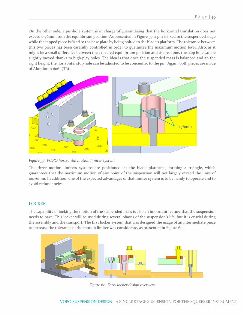
P a g e | 49
VOPO SUSPENSION DESIGN | A SINGLE STAGE SUSPENSION FOR THE SQUEEZER INSTRUMENT
On the other side, a pin‐hole system is in charge of guaranteeing that the horizontal translation does not
exceed 0.76mm from the equilibrium position. As presented in Figure 59, a pin is fixed to the suspended stage
while the tapped piece is fixed to the base plate by being bolted to the blade’s platform. The tolerance between
this two pieces has been carefully controlled in order to guarantee the maximum motion level. Also, as it
might be a small difference between the expected equilibrium position and the real one, the stop hole can be
slightly moved thanks to high play holes. The idea is that once the suspended mass is balanced and an the
right height, the horizontal stop hole can be adjusted to be concentric to the pin. Again, both pieces are made
of Aluminum 6061 (T6).
Figure 59: VOPO horizontal motion limiter system
The three motion limiters systems are positioned, as the blade platforms, forming a triangle, which
guarantees that the maximum motion of any point of the suspension will not largely exceed the limit of
±0.76mm. In addition, one of the expected advantages of that limiter system is to be handy to operate and to
avoid redundancies.
LOCKER
The capability of locking the motion of the suspended mass is also an important feature that the suspension
needs to have. This locker will be used during several phases of the suspension’s life, but it is crucial during
the assembly and the transport. The first locker system that was designed the usage of an intermediate piece
to increase the tolerance of the motion limiter was considerate, as presented in Figure 60.
Figure 60: Early locker design overview
0.76mm
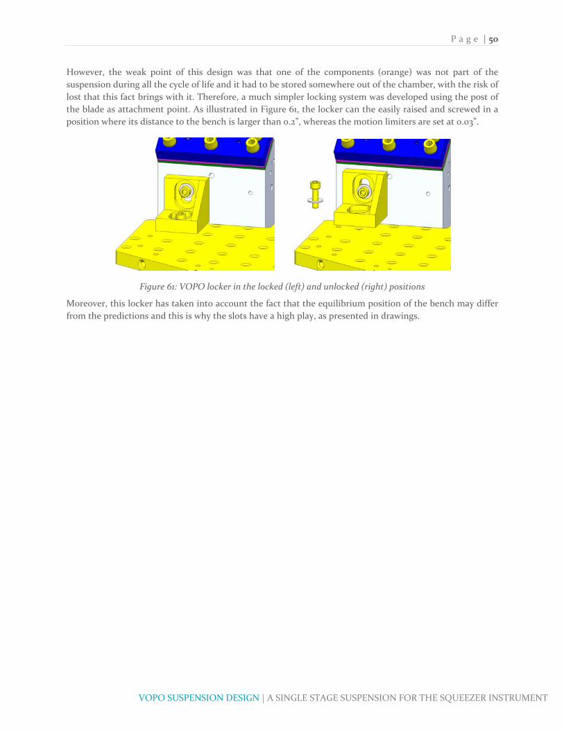
P a g e | 50
VOPO SUSPENSION DESIGN | A SINGLE STAGE SUSPENSION FOR THE SQUEEZER INSTRUMENT
However, the weak point of this design was that one of the components (orange) was not part of the
suspension during all the cycle of life and it had to be stored somewhere out of the chamber, with the risk of
lost that this fact brings with it. Therefore, a much simpler locking system was developed using the post of
the blade as attachment point. As illustrated in Figure 61, the locker can the easily raised and screwed in a
position where its distance to the bench is larger than 0.2”, whereas the motion limiters are set at 0.03”.
Figure 61: VOPO locker in the locked (left) and unlocked (right) positions
Moreover, this locker has taken into account the fact that the equilibrium position of the bench may differ
from the predictions and this is why the slots have a high play, as presented in drawings.

P a g e | 51
VOPO SUSPENSION DESIGN | A SINGLE STAGE SUSPENSION FOR THE SQUEEZER INSTRUMENT
CONTACT STUDY OF THE VOPO BLADES
As mentioned before, one of the purposes of this project is to detail the steps performed in the study of the
bolted contact between the blade and the base of the VOPO suspension. This study has been developed after
the experience acquired in the BSC‐ISI assembly, where an extra compliance was detected in the blades, being
the gap between the blade and its mount one of the main contributors (Matichard & al., Advanced LIGO two‐
stage twelve‐axis vibration isolation andpositioning platform. Part 1: Design and production overviewF, 2015).
It is important to keep in mind that one of the critical elements of the design of the blade is the capability to
predict its deformed shape.
CONTACT STUDY RESULTS
The procedure to perform a contact study is detailed in the next section. However, it is interesting to show
the results that this study, highly recommended for future suspensions, has illustrated. The more relevant
contact studies are presented in Table 9.
Table 9: Main results of the contact studies (cases with low angle horizontal)
The platform angle in the angle at which the blade is inclined before being charged, the load is the charge per
blade, program is SolidWorks (SW) or ANSYS (A), horizontal and vertical are the horizontal and vertical
distances, in inches, between the base of the blade and the center of the hole in its tip, angle horizontal is the
angle between in tip in the horizontal plane when deformed and Max Stress and FoS are, respectively,
Maximum stress in the blade and Factor of Safety. This shows that the first row corresponds to the first
analysis described in previous sections, this angle is 0 as the blade has been charged from an initial horizontal
position. The second row is the study of the single blade but in an initial inclination, see Figure 62, and the
rest of them are contact studies of the assembly as described in the next section.
This is one of the fundamental results of this study and the main contributor to the reduction of the FoS
between the real situation and the theoretical study. In previous sections, using both Bernoulli theory and an
initial FEA, the blade is charged vertically starting from a horizontal position. In this situation, the blade is
undercharged if it is compared to the real situation where the load is indeed vertical –it is due to the gravity‐
but the initial position of the blade is not horizontal, as illustrated in Figure 62.
Figure 62: Comparison between the horizontal (left) and the inclined (right) FEA, both with vertical load
PLATFORM
ANGLE
LOAD
(kg)
FORCE
DIRECTIONPROGRAM
BLADE /
ASSY# BOLTS
BOLTS
PRELOAD
ELEMENT
SIZE
ELEMENT SIZE
BLADEHORIZONTAL VERTICAL
ANGLE
ALPHA
ANGLE
HORIZONTAL
MAX STRESS
(MPa)FoS
0 12 N SW BLADE THE ‐ ‐ ‐ 0.075 ‐ ‐ 33.16 0 547.87 3.285
54.14 12 V SW BLADE ‐ ‐ ‐ 0.075 ‐ ‐ 34.98 0.880 567.15 3.174
54.77 12 V SW ASSY 6 5900 0.2 0.075 10.3424 3.2256 35.31 ‐0.080 566.789 3.176
54.76 12 V SW ASSY 6 5900 0.2 0.075 10.3418 3.2275 35.31 ‐0.070 567.154 3.174
54.68 12 V A ASSY 6 5900 0.2 0.075 10.4437 3.2520 35.32 0.003 570.71 3.154
54.68 12 V A ASSY 6 5900 0.2 0.075 10.4437 3.2520 35.31 0.009 570.71 3.154

P a g e | 52
VOPO SUSPENSION DESIGN | A SINGLE STAGE SUSPENSION FOR THE SQUEEZER INSTRUMENT
Due to this unrealistic study, which has the benefit of being easily performed, the FoS has been overestimated,
approximately, a 3‐4% by using the nonrealistic FEA study. Nevertheless, the expected FoS after this
calculation is still over 3 so it has not been considerate necessary to redesign the blade. An excel sheet with
all the information of all the studies can be found in (E1500446‐v) and shows that this FoS decreases if the
contact is not well designed.
Another important information is that, according to this results, the angle of the blade’s post varies depending
on the method, as illustrated in Figure 63. This figure shows the extra compliance effect due to the imperfect
contact of the blade. This results also show that, again, the first analysis with the horizontal blade is not
particularly good estimate of the real behavior of the assembly. On the other hand, the plot shows a difference
between the single blade study and the assembly inferior that 1°, which means that the contact can be
considered acceptable. Actually, in the first iterations of the process, when only 4 bolts where used, the
difference between the angle for the study of the single blade and the assembly was higher, up to 3°. In the
view of this results, the whole clamping system was redesigned and more clamps were added in order to
improve the attachment. However, this difference is not a problem per se, but the unawareness of it.
Figure 63: Predicted Blade Platform angle
It is also important to notice where does this difference come from at this is illustrated in Figure 64 and Figure
65. These figures are extracted from the FEA and show that the measured extra deflection comes from the
bad contact in the clamp, where instead of having a full surface contact, the blade and the clamp have a line
contact. Even if almost imperceptible, this detail may cause assembly problems and misalignments during
the assembly of the suspension.

P a g e | 53
VOPO SUSPENSION DESIGN | A SINGLE STAGE SUSPENSION FOR THE SQUEEZER INSTRUMENT
Figure 64: Detail with of the contact between blade and clap (SW Simulation), where the gap is shown
Figure 65: Detail with of the contact between blade and clap (ANSYS), where the gap is shown
On the other hand, the main result that is expected from this contact analysis is the data labeled as horizontal
and vertical in the previous table. This parameters are highly dependent on the contact, as shown in Figure
66.

P a g e | 54
VOPO SUSPENSION DESIGN | A SINGLE STAGE SUSPENSION FOR THE SQUEEZER INSTRUMENT
Figure 66: Variation of angle alpha, FoS, Horizontal and Vertical parameters for different preloads
All the presented data is extracted of the comparison for the same number of bolts and the same charge. The
information that should be extracted from this plots is not the comparison between the two cases neither the
absolute parameter of each case, but the relative evolution of them. Actually, the behavior could had been
easily predicted as the general results is that a lower preload results into an increase of the tip deflection,
which then reduces the FoS as more stress appears. Additionally, if the position of the base is fixed, it is clear
that more deflection will mean more less vertical distance and more horizontal, as shown in Figure 66.
Finally, the values that have been considered for the design of the blade platform are shown hereafter:
: 54.68°
: 10.4437
: 3.2520

P a g e | 55
VOPO SUSPENSION DESIGN | A SINGLE STAGE SUSPENSION FOR THE SQUEEZER INSTRUMENT
INJECTION BENCH DESIGN
As described before, the design of the injection bench is an iterative process in order to obtain the best
performances. First off, it is important to define which are the constraints and requirements of this design.
Given the methodology described in this document, by the time the bench has to be conceived the optical
layout is already defined and as well is its position. Thus, the total area of the injection bench is not going to
be one of the parameters of the design, but the thickness and the shape of the stiffener are. The stiffener is
the flange underneath the bench that enhances the stiffness of it and it is illustrated in Figure 24.
Regarding the constraints, the first one that has to be considered is the physical constraint given by the height
of the suspension. For the VOPO, as presented in Figure 16, the top of the bench has to be at 1.5” from the
bottom of it, which gives a maximum total height of 1.4” for the overall bench (0.1” is margin enough as it is
three times more than the maximum vertical movement allowed by the motion limiters. The other condition
is that the stiffener cannot be in the edge of the bench as it will interact with the base plate. Another
constraint is that the distance between the bench and the base has to be enough to allow the use of 0.4” high
dog clamps. Finally, the weight of the suspension is also constraint to a maximum of 18kg.
On the other side, the conditions for this bench are basically related with its stiffness, and more precisely
with the first frequency of the suspended assembly. This is why, the conception of the bench must not be
done independently but in relation with all the elements that are going to be suspended. Additionally, as the
suspended stage has to be balanced, the design of the bench has to take into account the optical layout to
simplify the balancing.
In this optimization process is important to have a simplified model of the assembly. For the VOPO
suspension, the details of each model are detailed in (E1500446‐v), and the model utilized in the FEA is
presented in Figure 67. Note that the configuration that needs to be optimized is the one involving the major
number of optics, i.e. O3.
Figure 67: Simplified model of the suspended stage for FEA
With all this elements the iterative process consists in define the position of the balancing masses so that the
center of gravity is in the desired position and run the optimization of the injection bench stiffener. This
optimization gives an optimal solution that should then be applied, what will therefore change the position
of the center of gravity. Thus, the masses have to be positioned again to have a balanced stage and that implies
that the optimal solution might have changed. Figure 22 presents the schematics of this process.

P a g e | 56
VOPO SUSPENSION DESIGN | A SINGLE STAGE SUSPENSION FOR THE SQUEEZER INSTRUMENT
Usually in a couple of iterations the solution should be found. Of course, the solution can be as refined as
possible, but we need to accept that at some point the frequency is not going to change drastically from one
iteration to the next one.
On the other hand, it is a good practice to run the optimization solver with a constraint in mass higher than
the real and leave a certain amount of this mass, 500g for example, to the final manual tuning. This manual
tuning is more intended to do the final balancing. The idea is that if it is know that the center of gravity of
the optics is clearly displaced in the +X direction, we may want to consider having the center of gravity of the
bench as far as possible in the ‐X direction in order to have a “naturally balanced stage”. Obviously, the stage
does not have to be balanced without the dummy mass on it (even if that situation would simplify the
process), but it is preferable to avoid a highly decentered assembly to allow some freedom in the positioning
of the dummy mass.
OPTIMIZATION OF THE BENCH
The optimization process itself uses the SW Simulation design study to define a set of variables in our model
that will then be tested sequentially in the pursuit of the optimal solution. As the number of cases per
optimization is limiter, the right selection and range of the parameters is important to save computing time.
In Figure 68 the parameters that are going to be considered in the process are presented. The distances are
with respect to the base plate and a minimum of 0.5” has been set.
Figure 68: Parameters considered in the optimization
Actually, the above presented figures also show the optimal results of each one of the parameters. On the top
of that, the shape has been slightly modified in the search of a compromise between the frequency and the
good balancing. Table 10 is an example of the parameters introduced in one of the first optimization
iterations.
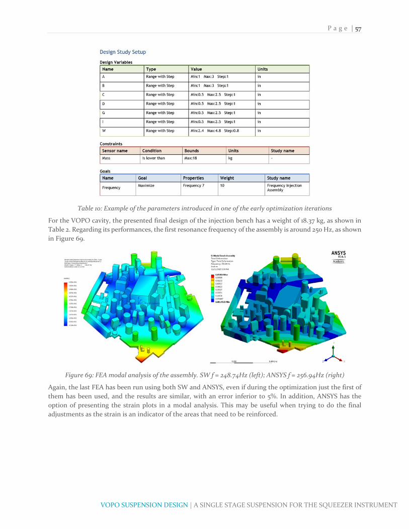
P a g e | 57
VOPO SUSPENSION DESIGN | A SINGLE STAGE SUSPENSION FOR THE SQUEEZER INSTRUMENT
Table 10: Example of the parameters introduced in one of the early optimization iterations
For the VOPO cavity, the presented final design of the injection bench has a weight of 18.37 kg, as shown in
Table 2. Regarding its performances, the first resonance frequency of the assembly is around 250 Hz, as shown
in Figure 69.
Figure 69: FEA modal analysis of the assembly. SW f = 248.74Hz (left); ANSYS f = 256.94Hz (right)
Again, the last FEA has been run using both SW and ANSYS, even if during the optimization just the first of
them has been used, and the results are similar, with an error inferior to 5%. In addition, ANSYS has the
option of presenting the strain plots in a modal analysis. This may be useful when trying to do the final
adjustments as the strain is an indicator of the areas that need to be reinforced.
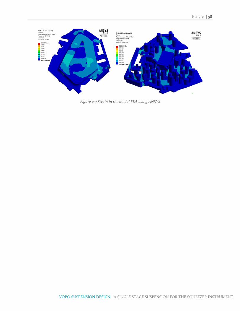
P a g e | 58
VOPO SUSPENSION DESIGN | A SINGLE STAGE SUSPENSION FOR THE SQUEEZER INSTRUMENT
Figure 70: Strain in the modal FEA using ANSYS
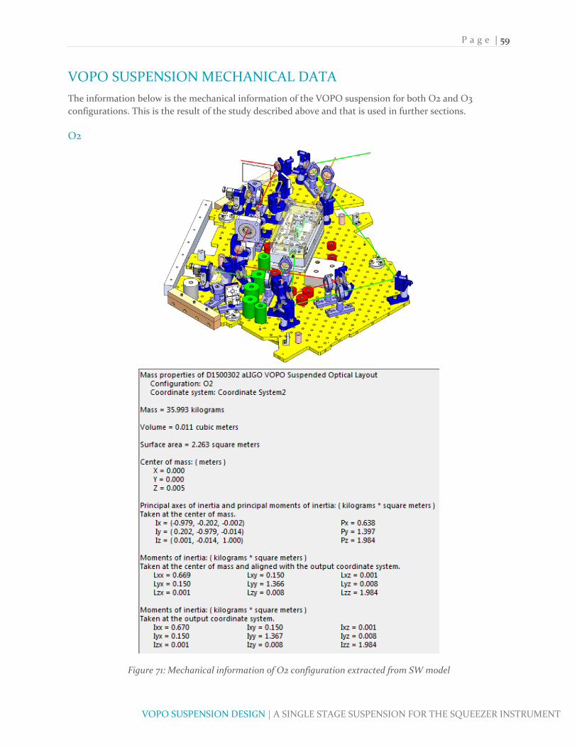
P a g e | 59
VOPO SUSPENSION DESIGN | A SINGLE STAGE SUSPENSION FOR THE SQUEEZER INSTRUMENT
VOPO SUSPENSION MECHANICAL DATA
The information below is the mechanical information of the VOPO suspension for both O2 and O3
configurations. This is the result of the study described above and that is used in further sections.
O2
Figure 71: Mechanical information of O2 configuration extracted from SW model

P a g e | 60
VOPO SUSPENSION DESIGN | A SINGLE STAGE SUSPENSION FOR THE SQUEEZER INSTRUMENT
O3
Figure 72: Mechanical information of O3 configuration extracted from SW model

P a g e | 61
VOPO SUSPENSION DESIGN | A SINGLE STAGE SUSPENSION FOR THE SQUEEZER INSTRUMENT
GLOBAL FREQUENCIES OF THE ASSEMBLY
In the design of the suspension both the lateral and the vertical frequency have been carefully selected in
order to attain the desired level of performance. However, the roll, yaw and pitch frequencies have also to be
checked. Indeed, all the frequencies have been considerate separately, but it may be a coupling between them.
This is usually a step that does not compromise the whole design but that may lead to some changes,
especially in the wire and the wire clamp design. Figure 73 states the reference system for the VOPO
suspension, being the X axis parallel to the beam in the cavity.
Figure 73: Definition of the coordinate system used for VOPO suspension
With the aim of defining all the frequencies, the modal problem will be written in its matrix form and the
resonance frequencies are then obtained as the eigenvalues of the matrix, as presented below.
0
0
22
This is a classical modal analysis problem and the difficulty of this one is to find the value of the matrix M
and K. Particularly, the difficulty is to find the matrix K, as the matrix M is almost given by SW.

P a g e | 62
VOPO SUSPENSION DESIGN | A SINGLE STAGE SUSPENSION FOR THE SQUEEZER INSTRUMENT
Figure 74: Mass [M] and displacement [U] matrix definitions
Figure 75: Stiffness [K] matrix defined for the coordinate system defined below and with 3 springs
Fortunately, the fact that the blades are forming an equilateral triangle simplifies the writing of the stiffness
matrix K. However, in order to do so, the definition of the axis X and Y have been slightly changed, as
illustrated in Figure 76, where the specific moments of inertia are also presented.
Figure 76: Difference between the coordinate system defined in [K] (blue) and the previously defined

P a g e | 63
VOPO SUSPENSION DESIGN | A SINGLE STAGE SUSPENSION FOR THE SQUEEZER INSTRUMENT
All the values of Kxx, Kyy and Kzz are known and extracted from the previous section and hf is the offset
between the CoG of the suspended stage and the flexure ZMP. This concept is illustrated in Figure 77.
Additionally, rs is the radius at between the wire and the center of gravity.
Figure 77: Parameter hf is defined as b‐a
This calculation has been implemented in GlobalFrequencies.m (E1500446‐v) and the results are presented
below, where a coupling between certain modes can be perceived but its influence on the value of the
resonance frequency is low.
Figure 78: Results of GlobalFrequencies.m
Additionally, this calculates the response of the system to an external excitation. At this point, the code is
being revised but the first results show the response presented below. Of course, this response is considering
the passive isolation and all this modes will have to be carefully damped thanks to the AOSEMs.

P a g e | 64
VOPO SUSPENSION DESIGN | A SINGLE STAGE SUSPENSION FOR THE SQUEEZER INSTRUMENT
CONCLUSIONS
The first result of this project is the final design of the VOPO suspension that is now going to be manufactured
and subsequently tested. However, these project has also been the opportunity of testing and developing new
methodologies that had not been applied in LIGO before.
First off, the VOPO suspension itself it is a new kind of suspension because, even if it keeps the spring and
wire isolation system, it is much lighter and easy to manufacture. Actually, proofing that a suspension that
does not use a high welded structure is feasible for aLIGO is one of the contributions of this project. These
huge structures carried problems in low frequency band and also in the manufacturing process, as the
weldment had to be specially performed to be UHV compatible. Thus, these new kind of suspension, which
in addition can be better adapted to the available area, is expected to be less costly and faster to procure.
On the other side, with the election of the 440C for the blades, the possibility of using less expensive
materials, again easier to procure, has been tested. Additionally, an important work has been made in the
prediction of the deformation of the bent blades. This study is particularly useful when the blade is machined
flat and the results, which will have to be compared with the prototype, show that such study is possible and
proves the cause of the extra compliance found in previous designs. If confirmed as a good prediction, the
procedure described in this project could be used in almost all the upcoming suspensions and abandon the
use of curved blades, whose monetary and time cost is huge compared with the flat ones.
Moreover, the process of optimization of the blade has been successfully performed using SW Simulation
Design Study. This tool, incorporated in the last versions of the program and never been used before in
aLIGO, seems to be of great help in the design of this kind of suspensions. On the top of that, several
comparisons between SW and ANSYS have been performed during the project in order to “validate” the use
of the second one. The results show that the difference is usually below 3%.
Finally, there are two main task that have to be performed in the upcoming months. The first one is to design
the active control system using the AOSEM in order to guarantee the damping of the rigid modes of the
suspension. The second one is, clearly, to assembly and test the suspension in order to confirm that the
performances are as expected and otherwise come back to the design. This second task is the one that will
confirm if, indeed, all the stated before about the possibility of this new kind of suspension is or not correct.

P a g e | 65
VOPO SUSPENSION DESIGN | A SINGLE STAGE SUSPENSION FOR THE SQUEEZER INSTRUMENT
ACKNOWLEDGEMENT
Firstly, I would like to express my sincere gratitude to my advisor Dr. F. Matichard for the continuous support
of my project, for his patience, motivation, and immense knowledge. His guidance helped me in all the time
of research and writing of this thesis.
Besides my advisor, I would like to thank the rest of the people in LIGO MIT working in the VOPO project:
Dr. J. Miller, Dr. L. Barsotti and Dr. P. Fritschel. And Prof. M. Evans, for their insightful comments and
encouragement, but also for the hard question which incented me to widen my research from various
perspectives and for their optics classes. My sincere thanks also goes to Dr. Zucker and Dr. Mason for their
help during this project.
I would like also to thank SUPAERO for giving the opportunity of doing this project and in particular to Dr.
G. Michon that has been my home institution advisor.
I thank my fellow labmates at LIGO MIT for the stimulating discussions and for all the fun and movies we
have had in the last months.
Last but not the least, I would like to thank my family: my parents and to my brothers for supporting me
during these months.

P a g e | 66
VOPO SUSPENSION DESIGN | A SINGLE STAGE SUSPENSION FOR THE SQUEEZER INSTRUMENT
BIBLIOGRAPHY
Directory of Fastener Manufacturers. (n.d.). Stainless Steel Fasteners.
E. Oberg, F. J. (2008). Machinery's Handbook. New York: Industrial Press.
Fernandez, A., Matichard, F., Miller, J., & Barsotti, L. (E1500446‐v). VOPO Suspension.
Greenhalgh, J. (LIGO‐T030285‐01‐K). Investigation of blade spring design parameters.
Lewis, J. (LIGO‐E1100187 ‐v4). Advanced LIGO Music Wire Specification for California Fine Wire Company.
Matichard, F., & al. (2015). Advanced LIGO two‐stage twelve‐axis vibration isolation andpositioning
platform. Part 1: Design and production overviewF. Precision Engineering 40, 273‐286.
Matichard, F., & al. (2015). Advanced LIGO two‐stage twelve‐axis vibration isolation andpositioning
platform. Part 2: Experimental investigation and tests results. Precision Engineering 40, 287‐297.
Miller, J. (2015). aLIGO VOPO Optical Layout. D1500302.
Miller, J., Barsotti, L., Matichard, F., Evans, M., & Fritschel, P. (2015). VOPO ‐ Preliminary optical design.
Saulson, P. R. (1998). Fundamentals of Interferometric Gravitational Wave Detectors .
Steplewski, S. (LIGO‐T1200468). AOSEM/BOSEM Calibration.
The LIGO Scientific Collaboration. (2015). Advanced LIGO. IOP Science.
Waller, M. (LIGO‐T1400539‐v2). LIGO SURF Summary: Risk Reduction for Advanced LIGO.

P a g e | 67
VOPO SUSPENSION DESIGN | A SINGLE STAGE SUSPENSION FOR THE SQUEEZER INSTRUMENT
APPENDIX