vpx profiles to platforms, sie computing solutions
DESCRIPTION
The goal of VPX is to provide critical embedded system integrators with a more capable module standard that allows for better exploitation of new technologies, enabling more cost effective end systems. The US Department of Defense and other users are now mandating the implementation of COTS Open Standards like VPX and OpenVPX.TRANSCRIPT

SIE Computing Solutions
VPX Profiles To Platforms
May 17th, 2011
Presented By:
Steve Corbesero
SIE Computng Solutions


3
The specification was designed
to meet the needs of defense
and aerospace applications.
FCS initially selected VPX for
its communication platform.
The US Department of Defense
and other users are mandating
implementation of COTs Open
Standards like VPX.
Who was VPX developed
for?

4
What is the goal of VPX?
Provide critical embedded
system integrators with a
more capable module
standard that allows for better
exploitation of new
technologies, enabling more
cost effective end systems
Improve the performance of
VITA's VME technologies

5
Where can VPX be used?
3U for space-constrained, harsh, conduction-cooled environments
High-end digital signal processing (DSP) applications
Beam forming applications
3U & 6U as a next generation for current VME and cPCI products
Builds on VME form factor and provides method for inclusion of
these past investments

6
Why transition to VPX?
Parallel busses are being replaced by serial fabrics for local
communications
PCI Express, Serial RapidIO, 10 GbE, Fibre channel
Standard I/O interfaces are also moving to high-speed signals
Video – DVI
Storage – Fibre Channel, SATA
Provides increased backplane I/O compared to VME64x
VME VPX
Aggregate Bandwidth (20-slot backplane) 320 MBps 100 GBps
Total Pin Count 320 432
I/O Pins 128 256

7
Why transition to VPX? (Continued)
VPX is the foundation for a number of Vita specifications. VPX
works in conjunction with the following specifications:
Vita 48 – VPX-REDI modules and backplanes
Vita 58 – Line Replaceable Integrated Electronics Chassis
Vita 65 – OpenVPX
Vita 66 – Fiber Optic Interconnect
Vita 67 – Coaxial Interconnect
Vita 75 – Rugged Small Form Factor (RSFF)

8
OpenVPX – Why was it created?
OpenVPX Industry Working Group was formed as the
first step on the path forward to add system-level
clarity to the specifications to accelerate the
commercial benefits of VPX technology for integrated,
multi-vendor systems.

Chassis
Profiles
Open VPX Overview
Backplane
Profiles
Slot
ProfilesSlot
Profiles
Module
Profiles
Module
Profiles
How do I deploy my Application
using an Open VPX Platform?My Application

Open VPX Overview
MODULE PROFILE
Communication Protocols
Slot Profile
Utility Signals
Connector Type
Height (3U or 6U)
Cooling (Air, Conduction, Liquid)
Slot Spacing Pitch (.8”, 1”)
SLOT PROFILE
Connector Type
Height (3U or 6U)
Pin Allocation
Definition
BACKPLANE PROFILE
Communication Plane
(Centralized, Distributed or Hybrid Topology)
Slot Profile
Height (3U or 6U)
Cooling (Air, Conduction, Liquid)
Slot Spacing Pitch (.8”, 1”)
CHASSIS PROFILE
Height (3U or 6U)
Cooling
Slot Spacing Pitch
Backplane
Profile

11
OpenVPX slot profiles
OpenVPX connector pin assignments are defined in
several slot profiles aimed at different types of slots.Slot Profile 3U Versions 6U Versions
Bridge slot 0 2
Payload slot 10 4
Peripheral slot 3 4
Storage slot 1 0
Switch slot 8 4

Open VPX Overview
Module Profile
The Module Profile defines what communication protocol can be used on each pipe
as defined in a corresponding Slot Profile, connector type, module height (6U/3U),
and cooling method (forced air/conduction).
Modules can be:
Bridge Modules = provide communication paths between multiple Plug-In
Modules that support different Plane protocols and/or
implementations.
Payload Modules = provides hardware processing and/or I/O resources
required to satisfy the needs of the top-level application
Peripheral Modules = an I/O device interface that is usually subservient to a
Payload Module
Switch Modules = provides the function of aggregating Channels from payload
modules in a centralized switch architectures to achieve
interconnection of their logical Planes.
Storage Modules = provides disk drive/Storage Device functionality.

13
OpenVPX Backplanes
Planes – Segregated architecture boundaries for backplane and
module connectivity. The following planes are predefined by
OpenVPX:
Control Plane
Data Plane
Expansion Plane
Management Plane
Utility Plane
S
EDiff
P1/J1
Diff
P2/J2
S
E
SE
P0/J0Data Plane
Key for shading
Utility PlaneExpansion Plane
Control Plane
User DefinedKey
S
EDiff
P1/J1
S
E
SE
P0/J0Data Plane
Key for shading
Utility PlaneExpansion Plane
Control Plane
User DefinedKey
Diff
P2/J2
Payload
Slot
Profile
Switch
Slot
Profile

Open VPX Overview
Backplane Profile
A physical and logical interconnection path between elements of a system used for the transfer of
information between elements. The following Planes are predefined by OpenVPX:
Control Plane: A Plane that is dedicated to application software control traffic.
Data Plane: A Plane that is used for application and external data traffic.
Expansion Plane: A Plane that is dedicated to communication between a logical controlling system
element and a separate, but logically adjunct, system resource.
Management Plane: A Plane that is dedicated to the supervision and management of hardware resources.
Functional definitions for this Plane are provided in the [VITA 46.11] specification.
Utility Plane: A Plane that is dedicated to common system services and/or utilities.

15
OpenVPX Backplanes
Backplane Topologies: Different applications require
different backplane topologies. OpenVPX supports the
following topologies:
Centralized Switching (Star)
Distributed Switching (Mesh)
Master-Slave (Master SBC connected to several Slave I/O Cards)
OpenVPX backplane topologies support the following data
rates:
3.125Gbps
5.0Gbps
6.250Gbps
topologies and data rates

Open VPX OverviewPIPEs: A physical aggregation of differential pairs used for a common function that is characterized in terms of
the total number of differential pairs. A Pipe is not characterized by the protocol used on it. The following Pipes
are predefined by OpenVPX:
Ultra-Thin Pipe (UTP): A Pipe comprised of two differential pairs. Example: 1000BASE-KX Ethernet, 1x
Serial RapidIO, and x1 PCIe interfaces.
Thin Pipe (TP): A Pipe composed of four differential pairs. Example: 1000BASE-T interfaces.
Fat Pipe (FP): A Pipe composed of eight differential pairs. Example: 4x Serial RapidIO, x4 PCIe,
and 10GBASE-KX4 interfaces.
Double Fat Pipe (DFP): A Pipe composed of sixteen differential pairs. Example: An x8 PCIe interface.
Quad Fat Pipe (QFP): A Pipe composed of thirty-two differential pairs. Example: An x16 PCIe interface.
Octal Fat Pipe (OFP): A Pipe composed of sixty-four differential pairs. Example: An x32 PCIe interface.
Rx0
Rx1
Rx0
Rx1Tx1 Tx1
Tx0Tx0
Rx0 Rx0
Tx0 Tx0

Open VPX Overview
J0
Slot 1
J2
Slot 2 Slot 3 Slot 4 Slot 5
BKP3-CEN06-15.2.2.3 (3U, Star 6-Slot with 1 I/O Slot)
Slot 6PS Slot I/O Slot 1
Control Plane (1.25 Gbaud Channel Rate)
I/O
Management Plane (IPMB)
Expansion Plane (5.0 Gbaud Channel Rate)
Legend
Data Plane (6.25 Gbaud Channel Rate)
Utility Plane
J1

18
Backplane interconnectivity BKP3-DIS05-TBD

19
Backplane characteristics Specifications
Standards Compliance VITA 46.0, 46.3 Rev. 0.9, 46.4 Rev 0.7, 46.7 Rev. 0.07
VITA 48
Environmental Temperature ranges
Operating: -40 C to +85 C
Storage: -55 C to +85 C
Safety Flammability rating: UL94 V0
Regulatory: Designed to meet……………….UL, CSA and CE requirements
ROHs available
Board 28 Layers 9.94”L x 4.02”W PCB FR-4 / IS620 PCB .215” +/- .022 thick 3U Height 5 Slot full mesh 2 slots for I/O daughter cards Multi-Gig RT-2 connectors All slots and IO

20
HSPICE Simulation of 5-slot VPX Backplane Channels 3.125 GHz

21
HSPICE Simulation of 5-slot VPX Backplane Channels 5.0 GHz

22
Which Thermal Management Solution fits the Size, Weight and Power -
SWaP?
Most Watts per cubic inches
• Side Wall Liquid Cooling
• Forced (Convection) Air Cooling
• Base Plate Liquid Cooling
• Air Over Conduction
• Radiated (Conduction) Cooled
Least Watts per cubic inches
Core 2 Duo, Quad Core,
Multi FPGA
100W - 200W per slot
Atom
5W - 10W per slot

23
Conduction Cooled
Limited by physics
Surface area/ profile critical
Allows for smaller packaging profile
125 watts for ½ ATR at 50°C
Requires Extended Temperature range Boards that have to be
configured for conduction cooled applications

24
Design Verification Through Thermal Simulation
Simulations are run using nominal and maximum wattages at
nominal and maximum ambient temperature .

25
Surface temperature of two main heat sinks

26
26
The chassis is tested powered up under the same load and ambient
conditions in the lab validate the thermal design prior to installing the
actual Processor, Switch and application Conduction Cooled Cards.
Design Validation Through Actual Testing

27
Air Over Conduction Cooled
Increased thermal performance over
traditional radiated designs
Bridges the gap between radiated and liquid
cooling
Requires additional room in the rear or front
of the chassis to accommodate a cooling fan
or duct.
Typically requires a machined dip brazed
design
225 watts for ½ ATR at 50°C

28
Air Cooled
Allows use of Leading edge commercial SFF and other components at lowest cost
IP Rating of 11 to 51
Typically the most flexible in component selection resulting in the shortest lead time 6 to 8 weeks for the delivery of a custom design chassis.
350 watts Base on a ½ ATR

29
Air Cooled VITA 58
• Supports 2- level maintenance and 2- plus level
maintenance requirements that have been specified
in the VITA 58 standard
• Certified to Mil Standards MIL-STD-704E, MIL-STD-
810E, and MIL-STD 461D
• ARINC 600 Blind Mate Connector
• PC 104, OpenVPX, CPCI, VME64x, MiniITX, EPIC
• ARINC 404 Style J Hooks and Rear Bushing
Mounting System
• Dimensions of 14.125” x 7.788” x 4.98”
• Front-panel high-visibility LEDs;
• 9 lb. weight.

30
Liquid
Over 300% increase over radiated
Cools up to 1000 watts in a 1/2 ATR
Requires liquid to be provided in
deployed location or requires an additional heat rejection unit.
Typically requires more space and weighs more than traditional ATR’s
Averages two to three times the cost over radiated cooling solutions

31
Flow : 1.2 l/min- Pressure drop : DP = 0.07 bar
Temperature of the fluid at entrance: 25°C
Average temperature cold plate / case : 37.6 °C
Liquid Cooled Side Plate

32
VPX Seamless Solutions
Thermal
Format (3U & 6U) Profile Range (based on ½ ATR at 50°C) Environment
ATR TYPE Air Cooled Open
Radiated Sealed
Air Assist
Radiated
Sealed
Re-Circulating Sealed
Liquid Sealed
0 250 500 750 1000 Watts
125W
225W
175W
1000 W +
350W
A VPX solution for every program phase from Development to Deployment

33
SIE 522 VPX Test Chassis
VPX Seamless Solutions
34
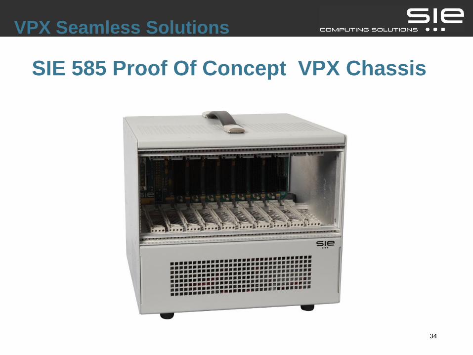
SIE 585 Proof Of Concept VPX Chassis
VPX Seamless Solutions

35
3U VPX ATR’s Enclosures
VPX Seamless Solutions