vr technology limited - xtreme scuba · vr technology limited vr3 dive computer operations manual...
TRANSCRIPT

VR Technology Limited
VR3 Dive Computer Operations Manual 2008 rev 1
1

VR Technology Limited
VR3 Dive Computer Operations Manual 2008 rev 1
2
Contents
Introduction...................................................................................................................3Getting Started......................................................... ......................................................4Battery...........................................................................................................................4Switches............................................................ .............................................................4Home Screen..................................................................................................................5Pin Number System................................................. ......................................................6How to Enter a PIN.......................................................................................................7Notes on the Battery......................................................... .............................................8Mini Screens & Pre Dive Check....................................................................................9Time & Date Screen............................................................................ .........................10Powering up the VR3...................................................................................................10Decompression Algorithms................................................................................... .......11Dive Options Screen and Functions.....................................................................12 – 13Gas Calculator Mode...................................................................................................14OPTIONS Menu..................................................................................................15 – 16Gas List and Profile......................................................................................................17Bailout - A Special Note for CCR Divers....................................................................18Games, including Deco Books.............................................................................19 – 20SETUP screen.................................................. ....................................................21 – 25NO STOP screen..........................................................................................................26FLYTIME screen........................................................... ..............................................26SELECT & ADJUST gases Open Circuit & CCR...............................................27 – 30Display Modes Screen..........................................................................................31 – 32Log Book Screens................................................................................................33 – 35Warnings..............................................................................................................36 – 39Rebreather & Analyser Cable Links....................................................................40 – 52Oxygen Sensors............................................................................................................53Warranty & Support........ ............................................................................................54Maintenance Tips.........................................................................................................55Troubleshooting..................... ......................................................................................56Specifications...............................................................................................................57How to read the Main Dive Screen....... ...............................................................58 – 61How to Switch Gas during a Dive.......................................................................63 – 64Other Dive Screens......................................................... .............................................65

VR Technology Limited
VR3 Dive Computer Operations Manual 2008 rev 1
3
Congratulations on your purchase of a VR dive computer.
You are going to have a lot of fun learning how to use your new VR.
Your VR3 has been delivered to you in G10 mode. This is the latest v ersion of VR3software and, we believe, represents a considerable advance over earlier versions.
If you prefer, you can run the VR3 in G3 mode which almost identical to G10 modebut only allows you to preset three gases in the gas list.
You can also operate the computer in X10 mode which takes the VR3 back to the2007 version of the software. This might be preferred by VR3 owners with longexperience of the computers who have reac hed the point where they have aninstinctive acquaintance with the way the computer used to work and prefer not tolearn new navigation techniques.
Your VR3 is delivered to you in multicolour mode. If you have ordered themulticolour upgrade from new then of course multicolour mode will be permanent. Ifyou have ordered a single colour VR3 you will be able to enjoy multicolour mode foryour first three dives so you can see what it looks like before your computer reverts tosingle colour mode. If you then decide you preferred multicolour mode just call yourdealer and buy the multicolour upgrade PIN and install it.

VR Technology Limited
VR3 Dive Computer Operations Manual 2008 rev 1
4
Getting Started
Looking at the computer (image below) in your hand
Battery
The battery compartment is at the top of the case, accessible via the battery cap whichis opened using the dedicated black two-pronged key that came in the box with yourcomputer.
The VR3 is powered by a single AA battery.
Switches
On the left and right at the bottom are two black plastic slide switches which you useto navigate your way through the functions o f the computer either on the surface orunderwater.
The switches work in four ways, as follows: -
A short push and release of one switch
A push and long hold of one switch (hold the switch in until the screen changes. )
A short push of both switches.
A long push and hold of both switches (a gain, hold the switches in until the screenchanges.)
In some cases 3 and 4 are shown as < > with th e option between the arrows. YourVR3 is activated by pushing and holding either switch. The first screen to bedisplayed will be the Home screen.

VR Technology Limited
VR3 Dive Computer Operations Manual 2008 rev 1
5
Home Screen
The Home Screen features
The current active gas, (top left hand corner) The current remaining battery voltage, (bottom left)
A BAT LOW advisory when the battery voltage drops to 1.1V and an alkalinebattery is being used or 2.8V when a 3.6V battery is being used.
The Pre Dive Check mini screen feature, (on Start Up the log screen showsfirst, giving you a profile of your most recent dive.)
A gas bottle graphic in the bottom left corner A menu graphic in the bottom right corner A GO graphic in the centre at the bottom
When the VR3 is sleeping and the Home Screen is still active , only the selected MiniScreen, active gas and a flashing BAT LOW warning will show.

VR Technology Limited
VR3 Dive Computer Operations Manual 2008 rev 1
6
Understanding Our PIN Upgrade System
VR3 Dive Computers can operate on four levels :-
Level C1: Open Circuit Air / Nitrox
Level C2: Open and Closed Circuit Air / Nitrox
Level C3: Open Circuit Air / Nitrox / Trimix
Level C4: Open and Closed Circuit Air/ Nitrox / Trimi x
The computers are sent out of the factory as level C1 Open Circuit Air / Nitrox unitsbut all are fully loaded with every currently available level and feature including thepermanent Multicolour screen upgrade . These levels and features are locked but canbe activated by purchasing and installing a number of unique dedicated 16 digit PINs.
If you bought your VR3 at level C2, C3 or C4, the PIN required to activate this level,along with the PIN or PINs for any other features you have purchased , includingMulticolour screen, can be found on white strips attached to the plastic CD envelopethat came with the computer. Please keep a note of these PINs, and any other PINsyou subsequently purchase, in a safe place.
To activate the purchased level and featu res, enter the 16 digit PIN(s) following theprocedure outlined below. To purchase further level upgrades or activate additionalfeatures, contact your VR Computers dealer. So that the dealer can give you thecorrect PIN(s), when you make the purchase you will need to provide the unique 16digit serial number of your VR. This Serial Number is on line 4 of the Pin screenwhich can be found in the SETUP menu.
The SETUP menu is accessible via the mini screen feature in the Home screen.

VR Technology Limited
VR3 Dive Computer Operations Manual 2008 rev 1
7
How to enter a PIN
PINs are keyed in using the switches and are logged in on the bottom line of the PinNum screen. A short push on a switch will move the number highlighted by 1; a longhold will move it by 8. When keying in each digit or letter move forwar ds using theright hand + switch. Do not move backwards using the left hand - switch except tocorrect, as this may cause previously entered numbers to change. After you havekeyed in the last digit of your PIN there will be a pause before the cursor moves to thetop of the screen you can use the left and right switches to key in your name andphone number, or any other data you wish, in order to identify the VR computer asyours, (see below).
After a PIN has been successfully installed the bottom line of the screen will revert to16 zeros.
Security and Trace-ability
A key benefit of the PIN system is the security and trace -ability it offers. In order tochange or remove the identifying particulars you have installed, someone would needone of your PINs so keep them in a safe place away from your VR 3. Then, if yourcomputer is ever lost or stolen, notify us and, as your identifying particulars will stillbe there on the screen, we can look out for it in the event that it ever comes in to usfor repair or upgrade. Also don’t forget to write to us and register ownership via ourwebsite, www.vr3.co.uk. If you lose your PIN(s), we can only reissue them to you ifwe have you listed as the owner. If you should ever sell on your computer, you willneed to give the new owner the PINs so that the security information can be changed.

VR Technology Limited
VR3 Dive Computer Operations Manual 2008 rev 1
8
Notes about the Battery and Cap
The battery cap is protected by a pair of O-rings which should be replaced after 10battery changes or if they become damaged or worn. Replacement O rings areavailable from your dealer, (ite m C36 in our Accessory List or as part of our FieldTriage Kit.)
The battery must be inserted positive + end first or the VR will not work. Check thebattery spring is in the cap before inserting the battery. The battery must move freelyon the spring. If the battery coating is too thick and fits too tightly in the cap, this maylead to power supply problems during the dive and the computer will shut off. Makesure the cap and body threads are clean as these provide the system earth. Whenreplacing the battery compartment cap, screw it in until it will screw in no further.
When changing the battery it is good practice to turn the unit on first and then le t itturn itself off again so the internal battery is fully charged. Install a new battery within30 seconds of removing the old one to avoid the risk of losing some stored data.
Battery life is highly dependent on the operating mode of the active backli ght. Toconserve power set Tm instead of ON or Don as the light setting in the Dive Modesscreen. Keep an eye on the battery voltage reading in the Home Screen.
Remember that lithium batteries have a faster discharge curve than standard cells andalthough they last longer, they discharge quickly towards the end of their life. When alithium battery’s voltage begins to drop quickly, change it.
If you are not planning to go a diving for an extended period, (say three months ormore), to avoid any risk of the battery leaking while in storage and damaging thecomputer, remove it. If you are keeping a PC log of your dives, download them first.
Install a new battery just before you are about to start diving again. Note that you willneed to restore your gas list and set up data.

VR Technology Limited
VR3 Dive Computer Operations Manual 2008 rev 1
9
The Home Screen – Navigation via Mini Screen Feature
Pre Dive Check
The Mini Screen feature in the Home Screen is designed primarily to make it easy foryou to check the settings in your VR3 and allow you to change any of the settings ifnecessary before you dive.
A short push on either the right or left switch will allow you to move through the miniscreens one by one. A short push of both switches <GO> will expand whichever miniscreen is currently showing and allow you to change settings within the screen.
The mini screens appear in the following order with successive short pushes of theright hand switch
Log Gas List Dive Options Fly Time Set Up Display Modes Time & Date No Stop Plan Gas Calculator (a PIN upgrade option: see Gas Calculator Section) Oxygen Sensor (a PIN upgrade option: see Rebreather Link and Oxygen
Analyser sections)
A long push of the left hand switch at any time in the Home Screen will take you intothe Gas List so you can set up, select o r adjust the gas mixes you are planning to divewith as well as set your computer to open circuit or closed circuit decompressioncalculations.
A long push of the right hand switch will take you into the Options Menu which willgive you access to five further features, as follows

VR Technology Limited
VR3 Dive Computer Operations Manual 2008 rev 1
10
Time & Date Screen
Mini Screen Full Screen
The VR meets the European PREN standard for digital dive timing devices but it isnot a precision chronograph. You may need to adjust it occasionally in order todisplay the correct time.
Changing the time will not affect desaturation calculations.
A short push of the right switch + will increment t he highlighted field by one, a longpush by ten.
A short push of the left hand switch will decrement the highlighted field by one, along push by ten.
A short push of both switches together will move the highlight to the next field.
A long push of both switches will exit the screen, save the changes and return you tothe home screen.
Powering up the VR3
It is not necessary to power up the VR before you dive. The screen will automaticallypower up within a minute of exposure to an absolute p ressure of 1.3 Bar or greater.Note that this means in practice that if you do a very fast descent the VR computermay not switch on until you are at depth.
If you want the screen to be on from the moment you enter the water, power up theVR before you dive and push either switch once. The screen will stay active for 5minutes. (On the surface, if no switch is pushed the VR will turn itself off after abouta minute to save power.)

VR Technology Limited
VR3 Dive Computer Operations Manual 2008 rev 1
11
Decompression Algorithms
VR dive computers use a derivative of the Buhlmann ZHL 16 algorithm modified toassimilate the latest thinking in practical micro -bubble avoidance for enhanceddecompression safety.
You will note that on all decompression dives, the VR will prompt for deep -watercontrolling stops of 2 minutes in duration. Deep -water stops are recognised by theirduration (normally two minutes) and a + next to the time. It is impo rtant that thesestops are conducted correctly for a safe decompression as they help to reduce theproblems associated with potential micro -bubble growth during an ascent.
Should a microbubble stop be missed, a “Use tables” message will appear. Thedecompression schedule displayed thereafter, although very close to the requiredduration, may be in error. If this occurs consult backup tables and add additional stopsor stop time as required. While continued diving with the VR is possible, thedecompression displayed may not be exact. “Use tables” will show for 24 hours. There is also an optional upgrade available which gives VR owners a choice betweenthe standard decompression algorithm (above) and an alternative algorithmincorporating a variable permeabi lity model (VPM). This upgrade can be activatedsimply by purchasing and installing a PIN. (Ask for the V1 upgrade PIN.) Dependingon gas selection and dive depth and time, the VPM based option may provide areduced decompression requirement compared to th e modified Buhlmann algorithm,although this is not always the case. What it does is smooth out the profile. There areno deep micro-bubble stops and ‘normal’ decompression stops begin much deeper. Ingeneral, intermediate stops are longer and shallower st ops are shorter.
A major advantage is that after activating the V1 upgrade you still have access to theoriginal Buhlmann algorithm and can even switch between the two algorithms fromdive to dive if you wish depending on the type of diving you are doing . This ispossible because although the decompression profile on your VR screen reflects onlythe selected algorithm, the computer still records tissue and bubble states using bo th.

VR Technology Limited
VR3 Dive Computer Operations Manual 2008 rev 1
12
The Dive Options Screen
In surface mode the Dive Options (DVo) screen is accessible from the Home Screen,(toggle through the mini-screens).
Underwater, the Dive Options (DVo) screen is accessed by a short push of bothswitches when you are in the second dive screen. You get to the second dive screenfrom the main dive screen via a long push on the right switch.
The screen allows the diver to get quick access to a number of useful controllablefeatures.
In this screen, a short push of both switches will move the highlight from one featureto the next, a short push of either the left - or right + switch will change the setting. Ifyou do not have a particular feature enabled, the highlight will not land on it.
XFunc
Change XFunc to correspond to the type of sensor connected to the I/O port:i. OFF = no sensor connected. When no sensors are connected XFunc should
be set to OFF to avoid connector damage.ii. ii. XO2 = External PO2 sensor (analyzer or rebreather) connected.
XDec
This feature is enabled when you purchase one of our rebreather linking cables andthe relevant software to allow you to track real time decompression via an externaloxygen cell. In closed circuit mode the XDec setting controls which PO2 figure isused in the decompression and tissue updating calculations. (In semi closed mode thePO2 is reported as an FO2).
To summarise, when XDec = ON the reading from the external sensor is used.
When XDec = OFF the selected gas and internal setpoint are used.

VR Technology Limited
VR3 Dive Computer Operations Manual 2008 rev 1
13
BG (Big Graphics)
(This is only available with the VR3 in X10 mode.)
When you buy the PIN to activate Gas Calculator mode in your VR (item UG 15) youalso get the PIN for Big Graphics Mode free of charge. This enables you to double thesize of the depth and time digits in the Dive Screen with the VR3 in X10 mode only .Note that CNS% and Time to Surface (TTS) information will not appear on the DiveScreen while Big Graphics Mode is ON. Your No Stop Time (NST) remains visible,as do your decompression ceiling and time at stop if you are carrying out adecompression dive.
Light
Switch between three screen backlight modes
Tm............... Light on for 10 seconds at the surface or underwaterOn................ Light always on at the surface and underwaterDOn............. Light off at the surface, light on underwater
Stops
Switch between 3 optional final decompression stop depths, 3m, 4.5m and 6m.

VR Technology Limited
VR3 Dive Computer Operations Manual 2008 rev 1
14
Gas Calculator Mode
You have the option to purchase a PIN to activate this feature. When this mode isenabled, you can gain access from the Home Screen, (toggle through the mini-screens). Gas Calculator mode will allow you to work out partial pressure gas fills onyour VR3.
To find out what gases you need to add to adjust a gas mix, enter your currentcylinder fill in the HAVE column and the gas mixture you need in WANT. The ADDBAR column will automatically show the fill pressures to add.
If you are filling an empty cylinder, leave the HAVE column at 0 (zero).You can also define the WANT column by changing the MaxD (maximum depth),EAND (Equivalent Narcotic Depth) and PPO2 settings.
In this screen, a short push of both switches will move the highlight from one field tothe next and a short push of either the left - or right + switch will change thehighlighted number by 1. A long push of - or + will change the highlighted number by10. A long push of both switches will return you to the Home Screen .
VR Technology Limited
VR3 Dive Computer Operations Manual 2008 rev 1
15
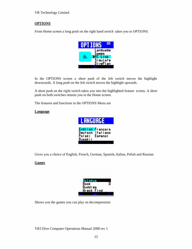
OPTIONS
From Home screen a long push on the right hand switch takes you to OPTIONS.
In the OPTIONS screen a short push of the left switch moves the highlightdownwards. A long push on the left switch moves the highlight upwards.
A short push on the right switch takes you into the highlighted feature screen. A shortpush on both switches returns you to the Home screen.
The features and functions in the OPTIONS Menu are
Language
Gives you a choice of English, French, German, Spanish, Italian, Polish and Russian
Games
Shows you the games you can play on decompression

VR Technology Limited
VR3 Dive Computer Operations Manual 2008 rev 1
16
PC Link
The screen to go to if you want t o download dives from your VR3 to a PC.
Simulate
Simulate mode gives you a chance to practice using the computer in the dry beforetaking it under water. A long push The to the DIVE display and a depth of around10m will be displayed. Short pushes of th e left and right switches will increment ordecrement the depth. To exit a simulated dive do a long hold of both switches orascend to zero depth.
Dive plan
Once you have set your planned dive gases in the VR 3, Diveplan allows you to enterdepth, time and surface interval and calculate a set of backup tables.
A short push of both switches moves between fields. A short push on either the left orright switch adjusts the number in the highlighted field.
Once the parameters are set, a long push o f the both switches will display a divescreen.
There will be a slight delay while the VR computes the plan.
In the dive screen long pushes on the right switch will show page after page ofdecompression stops as in normal Dive mode.
Simulate and Diveplan work on current tissue state. If you have just dived with theVR3 your residual inert gas loading will be taken into account by the VR3 in itscalculations.

VR Technology Limited
VR3 Dive Computer Operations Manual 2008 rev 1
17
Mini Screens
GAS LIST
The gas list is accessible via the mini screen feature in the Home Screen. It shows youat a glance which gases you have currently active on your VR3 and the maximumoperating depth you have set for each.
A short push of both switches in the GAS LIST scr een takes you to PROFILE whichyou can use to programme sets of gases, as follows.
First select which gases you want to include in a gas profile. U se the right-handswitch + to pick a profile memory into which you want it saved (A , B or C). A longpush of both switches saves the selection.
Repeat the process to set up other PROFILES. A short push on the left-hand switchwill return you to the Home screen .
Any time you want to choose a saved profile, return to the PROFILE menu and usethe right-hand switch + to bring up the profile you want (A, B or C). A short push ofboth switches <Get> programmes the selected Profile of gases into your VR3. Youwill see the word RESTORED. Then a short push on the left switch takes you into theADJUST screen where a long push on both switches takes you into the SELECTscreen. Here you can double check which gases you have set by repeated short pushesof the left switch. If they are correct a short push of the right-hand switch returns youto the Home screen.

VR Technology Limited
VR3 Dive Computer Operations Manual 2008 rev 1
18
Bailout! A Special Note on Profile B for CCR Divers
If you are a CCR diver, you can use Profile mode as a convenient way to set yourbailout gases and enable you to install in Profile B the bailout gases that you will becarrying on the dive.
Follow the instructions above on how to add and save a profile.
Then, if during the dive you then find you have to bailout to open circuit, you acc ess anew Bailout screen with a long push on the left switch from the dive screen then along push on both switches to take you to Open Circuit.
There you have the option either to bailout to your diluent gas with a long push on theleft switch (DIL) or bailout to the gas or gases that you have preset in profile B with along push on the right switch (PrB).
Cancel the bailout with a long push on both switches <ABORT>
Check the details are correct on th e select screen, confirm with a long push on theright switch and confirm again with a second long push on the right switch.Decompression will now be calculated based on your bailout gas or gases. (Once thefirst gas in the bailout profile is confirmed any others in the profile will appear as aprompt when their MOD is reached).
If you enter the Bailout warning screen in error a long push on both switches(ABORT) will return you to the main dive screen.
Note: If you are diving with your VR3 connected to your CCR via a cable, XDec hasbeen activated and you are running on real -time decompression based on the PO 2, theexternal cell reading is automatically switched off as s oon as you switch to OpenCircuit.

VR Technology Limited
VR3 Dive Computer Operations Manual 2008 rev 1
19
GAMES
THE OCTOPUS GAME
The Octopus Game works like this: The aim is to try to hit the white octopus with asquirt of ink from the black octopus. The white octopus will explode when he is hitand you will then get a summary of your score. In the game screen short pushes ofboth switches will move you between Ang (angle), Vel (velocity) and Fire modes.When you are in Fire mode a jet of ink will squirt from the black octopus and, if yourangle and velocity are correct, you will hit the white octopus. If not, you need toadjust the angle and velocity settings and this you can do in Ang or Vel mode, by ashort push of either the right hand + or left hand - switch. (A long push will incrementor decrement the setting by 10). While you are firing you will see Tide appear. This isa random setting; the strength and direction of the tide will change from game to gamejust so that it does not all become too easy!
DECOBOOKS AND MORE GAMES
Please note: You must have purchased and installed in your VR Computer both theC11 Downloading PIN AND the UG 15 PIN add on downloading package in order touse these features. Please consult your dealer to purchase. After you have bought andinstalled the DecoBooks PIN, go to your VR computer’s OPTIONS MENU and scrolldown until Games is highlighted. Then a long push of the right switch takes you intothe screen where you will see four options, Octopus, Book, Buddies and Wreck Find.Octopus, Buddies and Wreck Find are your game opt ions, (see details below). Book isyour DecoBooks viewing screen. A short push of the left switch scrolls through theoptions. A long push of the right switch takes you into the option you have selected.The number next to Book option shows how many charac ters are currently loaded.The VR computer can take a maximum of 20000 characters at a time, (around 40pages).

VR Technology Limited
VR3 Dive Computer Operations Manual 2008 rev 1
20
DECOBOOKS
Enter Prolink on your PC and click on Book send.Select a .txt file from your PC andcheck it appears in File Name box.En sure your VR computer is in PC Link mode andConnected. Click on Book send. You scroll through pages using the left and rightswitches. A single short push scrolls one page. A long push scrolls 1000 characters.The number (in this case 0) in the lower menu area shows the cursor position in thefile. When you have finished reading and leave the screen, your VR computer willremember where you left off and return you to the same point in the file when younext open the screen. A short push of both switches re turns you to the DiveScreen.The book-viewing screen shows text from the book that has been uploadedinto the dive computer. You can download text (.txt) files from any source to your PC(see next page). If files are in another format save them as .txt fil es in Notepad beforetransferring them to your VR computer. Please note that you can only transfer andstore in the VR computer 20,000 characters at one time so divide large texts such asnovels into sections.
Buddies Game
The idea of this game is essent ially the same as the card game Pairs. You as theplayer are seen on the screen as “?”.Use the left and right switches to move around thescreen. Short switch pushes move you left and right, a long push on the left switchjumps up a row, a long push on th e right switch drops down a row. When you areover a particular card a short push of both switches will turn the card over and reveal aletter or symbol. Once that letter or symbol is revealed, your task is to find the samecard in another position and re veal it with the next turn of a card. If you areunsuccessful both cards turn face down again. If you are successful the selected cardsdisappear. The aim of the game is to find all the pairs until no more cards remain.Each attempt to find a pair is recor ded as a try in the bottom left hand corner. The bestscore, i.e. the lowest number of attempts needed to clear the screen, is dis played.
Wreck Find Game
There are pieces of a shipwreck hidden in the sand. You as the wreck -finder are seenon the screen as “?”.Use the left and right switches to move around the screen. Shortswitch pushes move you left and right, a long push of the left switch jumps up a row,a long push of the right switch drops down a row. When you think you might be overa piece of wreckage a short push on both switches will reveal what is hidden belowyou. Each piece of wreckage is shown as a cross. When you have found all ten piecesof wreck, the game finishes. The idea is to find them all in the fewest number ofattempts. The number of attempts in the current game to date is shown in the bottomleft of the screen. The best (lowest) score is displayed in the bottom right of thescreen. It is mostly a game of chance but if you are a true wreck -finder you can bringin an element of skill to find the wreckage more quickly and ge t a better score, (think“Battleships”!!)A long push on both switches exits Games.

VR Technology Limited
VR3 Dive Computer Operations Manual 2008 rev 1
21
SETUP
Selecting SETUP from the Mini-Screens in the Home Screen will give you access to arange of sub-menus, which allow you to configure the VR3 according to yourpersonal preference.
A short push of both switches moves the highlight to the next setting. A long push ofboth switches takes you back to the Home Screen.
Units
When “Units” is highlighted , a short push of either the right-hand + or left-hand -switch will change the depth and temperature settings in your VR3 from metric (m) toimperial (ft) or vice versa.
Safe
This enables you to make the VR3’s decompression calculations more conservative.
A push on the right-hand + switch or left hand – switch when “Safe” is highlightedchanges the setting by 10%, from 0% up to a maximum of 50%.
Every 10% increase adds a theoretical 2% to the inert gas content of the gas selectedfor the purposes of decompression calculati on.

VR Technology Limited
VR3 Dive Computer Operations Manual 2008 rev 1
22
Pin
When “Pin” is highlighted a short push on either switch will take you into a screenwhere you will see
a) your VR3’s 16 digit Serial Numberb) a list of letters and numerals denoting which VR3 features are currently
enabledc) a line of zeros where you can input PINs to activate new featuresd) an empty space at the top of the screen where you can key in your name,
telephone number or anything else you wish to add to identify the computerindelibly as yours.
CNS
A push on the right-hand + switch or left hand – switch when “CNS” is highlightedwill change by 10% the level at which you want the CNS Air Break warning to appearin your dive screen, from 80% up to a maximum of 200%.

VR Technology Limited
VR3 Dive Computer Operations Manual 2008 rev 1
23
LCD
On Single Colour VR3s, LCD is the contrast control feature. A second screen isaccessed by a short push on the right switch. Increase the number to make the screendarker. Reduce the number to make the screen brighter.
A short push of both switches <Inv> causes the screen colours to become inverted.
On Multi-Colour VR3s, LCD takes you to the Color Modes screen which allows youto change the colours associated with particular functions and areas of the VR screens.
If you are happy with the default colours that we have selected for your VR3 there isno need to adjust anything in this screen. If you want to adjust the colours , follow theinstructions below:-
When you first enter the screen the panel next to “Type” will be highlighted. “Type”refers to a particular area of the screen. Use short pushes on the right -hand + or left-hand - switch to move from area to area. There are eleven areas:-
NORMAL - this is the middle area of each screen.
HILITE - this is the colour used to highlight.
MENU - this is the lower area of each screen that defines what each switch will doat any given time
HEADER - this is the upper area of each screen
MAIN-HD – these are the colours used for the title section of the mini screens in theHome Screen
MAIN-GR – these are the colours used for the main section of the mini screens in theHome Screen
MAIN-TP – these are the colours used for the main section of the Home Screen

VR Technology Limited
VR3 Dive Computer Operations Manual 2008 rev 1
24
MAIN-BM – these are the colours used for the bottom section of the home screen
GRAPH – these are the colours used for the graphs in the dive and log screens
SCROLL - these are the colours used for the opening logo screen.
SCR RB – these are the colours used for the screen saver in Universal RebreatherMonitor mode
Each area has two colours associated with it, Color A, the foreground (text) and ColorB, the background colour.
A short push of both switches will highlight Color A and, while this is highlighted,short pushes on the right -hand + or left-hand – switch will change the foreground(text) colour in the section listed next to “Type”.
A further short push of both switches will highlight Color B and, while this ishighlighted, short pushes on the right-hand + or left-hand – switch will change thebackground colour in the sect ion listed next to “Type”.
CONTRAST changes the appearance of the screen colours to optimise them forviewing. This may need adjustment based on the colours chosen.
A further short push of both switches will highlight CONTRAST. While this ishighlighted:-.
short pushes on the right switch + make the screen darker short pushes on the left switch - make the screen brighter.
A further short push of both switches will highlight “Default” . While this ishighlighted a short push of either switch will retu rn all colours and the contrast levelback to the factory settings.

VR Technology Limited
VR3 Dive Computer Operations Manual 2008 rev 1
25
Mode
Your VR3 comes with G10 mode enabled. This is standard 2008 software with all thefeatures and options referred to in this manual.
A push of either the right-hand + or left-hand – switch when mode is highlighted willchange your VR3’s mode to either G3 or X10 mode.
G3 mode is the same as G10 mode except you can only preset 3 gases in the gas list.
X10 mode causes the VR3 to revert to old 2007 software, primarily fo r users whoprefer the previous configuration
Prog - DO NOT ENTER THIS FEATURE unless programming via the website. Ifyou access this accidentally, you will see this screen
enter NO with a long push of the left switch . If the unit freezes in this screen simplyremove the battery for ten minutes to reset it.
VPM – if you have purchased the optional V1 a lternative VPM algorithm , a shortpush of either the right-hand + or left-hand – switch when VPM is highlighted willtoggle between VPM ON and VPM OF F.
When VPM OFF is selected decompression will be calculated using our standardmodified Buhlmann ZHL 16 algorithm with 2 minute deep stops.
When VPM ON is selected your VR3 will calculate decompression using a VPM-based algorithm developed by us.
Usage - this figure tells you the total dive hours carried out on your VR computer todate.

VR Technology Limited
VR3 Dive Computer Operations Manual 2008 rev 1
26
NO STOP
In this screen you can see No Stop Times (NST) for depths to 41m, taking intoaccount your previous dives and surface interval. The surface i nterval and target depthare user changeable. Note that the surface interval figure that you set is in addition totime already spent out of the water. You may be surprised that the No Stop timesappear to be short. They do in fact correspond to standard B uhlmann dive tableswhich incorporate safety stops. For instance:VR3 18m dive No Stop Time = 39 minsVR3 18m with 3 min stop at 4.5m = 54 mins This means that if you were to do a diveto 18m on air with 54 minutes bottom time, you would see a required 3 mi nute stop at4.5m on your look ahead schedule as you began your ascent. (Times are on air andassume no residual nitrogen to take into account).
FLY TIME
The FLYTIME screen shows the time that must elapse before you may fly in apressurised aircraft and the length of time before your tissues will be totallydesaturated.

VR Technology Limited
VR3 Dive Computer Operations Manual 2008 rev 1
27
SELECT and ADJUST gases
From the Home screen, the SIMULATE screen AND the Dive screen, you can accessthe gas SELECT and ADJUST features with a long push of the left-hand switch.
In the gas SELECT screen, short pushes on the left-hand switch take you through theON gases. Up to 10 gases are available for selection. Simply keep pressing until thegas you wish to breathe at the start of the dive is displayed. Once you are confidentthat the correct gas is indicated, a push of the right switch will confirm. Your selectedgas will now be displayed in the centre of the Home screen (or the DIVE scr een if youare diving). Only turn ON the gases you intend to breathe on the dive. In closedcircuit mode, only turn on the gas to be used in closed circuit. Bailout gases should bein the list but turned OFF until needed.
While diving, the current depth is displayed at the top of the gas select screen.
If you wish to change the gas displayed in the SELECT screen or any of itsparameters, or you want to programme a new gas, a short push of both switches bringsup the ADJUST screen.
ADJUST screen MOD highlighted
ADJUST screen Nitrox O2% highlighted

VR Technology Limited
VR3 Dive Computer Operations Manual 2008 rev 1
28
ADJUST screen Trimix O2% highlighted
Several options are now available.
With a short push of both switches, a new field will be highlighted and can beadjusted using by a short push of either switch + or -.
The fields available are:
A) The gas number (0 to 9) Ten gases can be set in the gas list.
B) ON (active) or OFF (inactive). Set to ON the gases you will be carrying on thedive in question, set all other gases in the gas list to OFF. (Note: if you turn allgases OFF you will not be able to exit the ADJUST screen. )
C) The oxygen and helium levels in the mix:-
Air is displayed as AIR. Gas 0 is AIR and cannot be changed. Nitrox is displayed as NX followed by the oxygen fraction, (e.g. NX36) Trimix is displayed as TX then the oxygen fraction followed by the helium
fraction e.g. TX 18/35. The helium content setting can be reached by a shortpush of both switches after the oxygen content has been set , (as long as theTrimix activation PIN has been purchased and installed.)
D) The MOD: As you change the MOD the PP (PO2) will adjust accord ingly.

VR Technology Limited
VR3 Dive Computer Operations Manual 2008 rev 1
29
Selecting closed circuit gases and PO2 Set point
If you have purchased and installed the PIN for the closed circuit upgrade, you willhave a Closed Circuit option in your GAS SELECT screen. Press and hold bothswitches to activate this.
Entering this mode allows the selection of a closed circuit decompression algorithmand opens a CLOSED CCT screen. In this screen the gas mix you hav e selected isdisplayed as a diluent (DIL). Change the diluent as required by a short push of bothswitches then following the same procedure as outlined above for selecting andadjusting an open circuit gas.
A selectable PO2 setpoint is also shown in thi s screen. With successive short pushesof the left switch the PO2 will increment in steps of 0.05 bar . Once you have thedesired PO2 a short push of the right switch will confirm and take you back to theHome screen (or Dive screen if you are diving). The P02 and the diluent will bedisplayed there.
You can preset two different PO2 setpoints and switch between them during yourdive. To do this, re-enter the CLOSED CCT screen, select another PO2 and exitagain.
During your dive a long push on + in this screen will enable you to toggle between thetwo setpoints.
The VR3 assumes that the PO2 selected is the PO2 that the rebreather will maintain asits setpoint during the dive and it will calculate decompression based on this and thediluent set. Your PO2 can change, especially on ascent and descent, and depending onthe characteristics of the rebreather and its operator. You are strongly advised to beconservative with your PO2 selection. If you are diving and see a PO2 displayedwhich is higher than the selected setpoint, this is because you are at a depth where thediluent PO2 exceeds your setpoint. From the CLOSED CCT adjust screen, a longpush of both switches will select open circuit mode, where , in the event of a bailoutbeing required, you can select the gas you want to breathe in open circuit .

VR Technology Limited
VR3 Dive Computer Operations Manual 2008 rev 1
30
A Note on the MOD setting and Gas Switches
The MOD setting of an ON gas is important as this is the depth at which the VR willprompt you to switch to that gas. The look -ahead Time To Surface (TTS) anddecompression profile will also assume a switch to deco gas at that depth. If youmistakenly set the MOD shallower than the preferred switch depth, you can stillswitch and tell the VR you have done so. Switching to a decompression gas too deepwill trigger a PO2 warning. Incorrectly setting the MOD, or leaving gases ON whichwill not be used, means that the optimum look -ahead TTS and decompression profilewill not be calculated or displayed. What you actually do during the ascent and anygas switches you make and tell the VR about will still be factored into the calculationbut the on-screen prediction may not be the most efficient profile. The TTS includesascent time and time at all decompression stops based on the diver switching to all theON gases in his gas list at the MOD selected for each gas. If you plan to switch to adeco gas on ascent but subsequently do not in fact switch, the stop times shown willremain the same but the VR minutes will take longer to elapse in real time. If at anypoint during the dive you modify a gas content on the ON list, the decompressionprofile prediction will alter to take this into account. When you change to a differentgas, in a few moments the VR will modify the decompression list and re -calculate alldecompression. The decompression screen stays inactive for 20 seconds. Every timeyou push a switch whilst in this screen the 20 second timer starts again and thedecompression calculations are temporarily frozen.
A Closed Circuit Dive Planning Example
A Trimix rebreather dive is planned with 18/35 as the diluent. The diver will useclosed circuit Trimix throughout and then switch to open circuit surface -suppliedoxygen at the 6m stop. In the event that an open circuit bailout is required the diverplans to carry an 18/35 cylinder and a Nitrox 36 cylinder. 18/35, Nitrox 36 andoxygen are selected as the three gases. The Nitrox 36 and oxygen remain OFF leavingTrimix 18/35 as the only ON gas. This will be seen as the DIL when the diver choosesthe CLOSED CCT screen. In the CLOSED CCT screen the diver selects a PO2 of 0.7for the start of the dive, then exits and re -enters the screen to select a second PO2setpoint of 1.3 which can then be switched to at depth. If the diver were to leaveNitrox 36 and PO2 ON then they would be factored into the decompressionprediction. Having said this, even if they were left ON accidentally the actualdecompression would still be based on the gas selected as the DIL. In other words theprediction would be wrong but the actual decompre ssion would be correct. If therequired diluent is not displayed, in the PO2 select screen press <DIL> (short push,both switches) to get to the gas select screen. This is similar to the gas select screenfor Open Circuit. Once there, by pressing you can s croll through the range ofprogrammed diluents until the one required is found. Pressing confirms your selecteddiluent and returns you to the PO2 SELECT screen.
Note: Setting CCR Bailout gases is covered in detail in the Gaslist section .

VR Technology Limited
VR3 Dive Computer Operations Manual 2008 rev 1
31
Display Modes Screen
The Display Modes screen is a revolutionary unique feature which is new in 2008VR3s. For the first time, a diver can choose which information he sees in his primarydive screen and customise it to his own preferences. The VR3 is the only computerthat allows a diver to do this.
It is accessible via the Mini-Screen Feature in the Home Screen.
This screen offers you the opportunity to decide which information appears in yourprimary dive screen. Check the option s you require and leave unchecked theinformation you don’t require. All checked options will be shown in the dive screen.(Note: you must choose your preferences; you cannot check everything as there isinsufficient space in the screen!)
A short push of both switches moves the highlight from one setting to the next, a shortpush of either switch will check or uncheck as required.
VR Technology Limited
VR3 Dive Computer Operations Manual 2008 rev 1
32
An Explanation of the Options in the Display Modes Screen
Flip
Flip – turns the screen in 180 degrees .
An upward arrow positions the screen for use on a divers left arm,
A downward arrow configures the screen for use on a divers right arm.
Deco – gives you decompression information on the dive screen. If you do not requirethis uncheck the option.
MaxD – gives you a reading on the primary dive screen of the maximum depthreached on the dive so far
AvgD – gives you a reading on the primary dive screen of the average depth on thedive so far, (for on the fly decompression calculation by those who use thistechnique.)
nst – adds No Stop Time information to the primary dive screen
C (or F) – adds An Ambient Temperature reading to the primary dive screen
tts – adds Time To Surface information to the primary dive screen
cns – adds information on your current CNS loading to the primary dive screen
Ceiling Icon – gives you an accurate reading of your current ceiling depth. Use thisalong with the diver-on-the-line feature to ascend “following the curve”.

VR Technology Limited
VR3 Dive Computer Operations Manual 2008 rev 1
33
Log Screen
In the Home Screen, when the graph depth and time of your last dive are shown onthe mini screen, a short push of both switches will take you to the Dive Log Feature .
The logbook screen shows depth, time and surface interval information as well asaccumulated OTUs (oxygen tolerance units). If a decompression stop is missed orviolated during a dive, the MISSED STOPS warning is displayed in the top rightcorner of the screen. If multiple stops have been missed, the number of stops missed isshown immediately after the word ST OPS.
One dive at a time is displayed. With a short push of the right switch, the next dive i nthe sequence will appear. A long push jumps 10 dives. The logbook stores 100 on-screen dives.
If the PC download PIN and cable link have been purchased and installed, dives canbe downloaded to a PC and can be displayed in much more detail.
Your VR3 can store 22 hours of diving for downloading, stored at 10 -secondintervals. When the memory is full, it simply overwrites and starts again.
If long, detailed dives are logged, they should be downloaded as soon as possible toavoid losing them.

VR Technology Limited
VR3 Dive Computer Operations Manual 2008 rev 1
34
Graph
The VR3 has a second log screen, accessible by a long push of both switches , inwhich a graphic profile of the dive is shown. While in the graphic profile screen, ashort push of both switches will bring up a screen showing a graph of ambienttemperature throughout the dive.
The word xfunc appears for five seconds before being replaced by mins (time). Ashort push of the right switch in any pro file screen will bring up a log of the next dive,a short push of the left switch will take you back to the original log screen.
If you have an external oxygen sensor connected and activated, a further short push ofboth switches will bring up a graph of the external oxygen sensor reading throughoutthe dive. For the O2 reading graph to reflect data correctly the Xfunc mode must beset to the external sensor option prior to the dive. If the external function is changedduring the dive, the graphing mode m ay become confused and caution is advised ininterpreting the graph data if this has occurred.
Markers
At any time during a dive when the main dive screen is displayed a long push of bothswitches will place a marker "x" at the top of the screen in the graphic log profile andthe word MARK will appear in the upper right section of the div e screen.

VR Technology Limited
VR3 Dive Computer Operations Manual 2008 rev 1
35
Calendar
From the main Dive Log screen, a long push on the left switch takes you into calendarmode.
A short push on + or - moves the marker back and forward one day. A long pushmoves 30 days. Days with dives are highlighted.
A short push of both switches takes you to the activity screen.
In the activity screen, a short push of both switches moves you between fields. A shortpush of the right switch sets the activity in the calendar, (e.g. F=FLY DAY) .
To set an alarm highlight ALARM OFF, then set the time using + and -. Use < > tomove from hours to minutes. When the time on that date is reached, the unit willautomatically turn on. When you are reading a calendar day on which a dive has takenplace, Log Book will be displayed in the Activity Screen.
When Log Book appears in the screen and is highlighted, a short push of the rightswitch will take you back to the logbook.
VR Technology Limited
VR3 Dive Computer Operations Manual 2008 rev 1
36
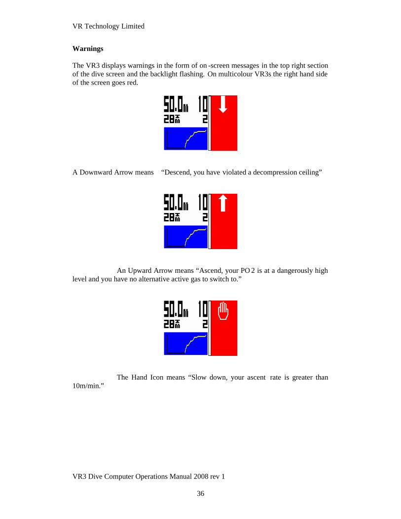
Warnings
The VR3 displays warnings in the form of on -screen messages in the top right sectionof the dive screen and the backlight flashing. On multicolour VR3s the right hand sideof the screen goes red.
A Downward Arrow means “Descend, you have violated a decompression ceiling”
An Upward Arrow means “Ascend, your PO 2 is at a dangerously highlevel and you have no alternative active gas to switch to.”
The Hand Icon means “Slow down, your ascent rate is greater than10m/min.”

VR Technology Limited
VR3 Dive Computer Operations Manual 2008 rev 1
37
“USE Table” means “Decompression has been violated on currentdive, or previous dive within the previous 24 hours.”
“Missed stops” is shown on reaching the surface after adive where a decompression stop has not been completed. •
“Violated stops” is shown on reaching the surface after a dive where adecompression ceiling has been breached for longer than 1 minute, but allrequired estimated stops have subsequently been carried out as advised by theVR in USE TABLES mode. •
The two bottles with arrow icon means “Gas Switch warning. Switchto another gas in the gas list you have set.”

VR Technology Limited
VR3 Dive Computer Operations Manual 2008 rev 1
38
The single bottle icon with AIR to the left is the Air Break warning.Repeats for 5 mins every 30 minutes while CNS % is above the limit you havechosen in the SETUP screen.
Rebreather related warnings
XP Fail meansPO2 sensor reading at 0 - your external sensor isnot showing any reading. The cell has failed or is not connected.
X Check means your FO2 is dangerously low i.e. the PO2 islow compared to the diluent at depth, for instance air diluent at 10m should read aminimum of 0.42 and no less.
Check FO2 means FO2, depth and gas type do notmatch up. For instance if you are at the surface and have air in the counterlung and theFO2 is less than 21%. This would indicate a possible calibration error.

VR Technology Limited
VR3 Dive Computer Operations Manual 2008 rev 1
39
Decompression Stop Violation
If you ascend past a decompression stop to a level where the tissues may becomeover-pressurised, then the down arrow message appears and a 60 second timer displaystarts to count down. If the warning is ignored, after 60 seconds a message will appearwhich says USE TABLE. Once this message appears the VR will continue to display‘best guess’ decompression data. This mea ns that the decompression displayed maybe in error because of the missed stop and that you should consult back up tables andadd additional safety stops as required. But your VR will continue to track. If youtemporarily break a decompression ceiling and get back to the correct depth within 60seconds the timer will start to count up again. When it reaches 60 the decompressioncalculations will restart. Depending on the extent of your excursion you should buildin extra safety for the remainder of the dive . MISSED STOPS warnings will be storedon the logbook and the warning will be displayed for 24 hours on the home screen.The VR will not lock you out. If you re -enter the water, best-guess decompressionwill still be shown but should not be relied upon.
Gas Switch
During a dive, while ascending or descending you may notice a SWITCH message inthe top right hand corner of the screen and a prompt for a gas other than that whichyou are breathing. This is the VR asking whether you wish to switch gases bas ed onthe plan you have entered and/or the gases you have switched on. The SWITCHmessage comes on when the MOD you entered for that gas has been reached. Youmay ignore this if you wish and carry on using the same gas.
Air Break
This warning will be displayed when the user set CNS warning limit is exceeded. Thiswill continue to be displayed for five minutes every thirty minutes thereafter.

VR Technology Limited
VR3 Dive Computer Operations Manual 2008 rev 1
40
Rebreather & Analyser Links
The VR can be fitted with a remote oxygen cell to permit
a) surface use as an oxygen analyserb) underwater use with a semi-closed rebreatherc) surface and underwater use with a closed circuit rebreather.
An accessory cable and dedicated PIN are required.
The accessory cable connects to the seven pin I/O connector on the left hand sideof the VR3. Remove the plastic cap to gain access to the connector
Once you have installed the dedicated PIN to activate the VR’s I/O connector, inthe Dive Options (DVo) screen you will find you are now able to move thehighlight to the XFunc and XDec features via successive short pushes of bothswitches.
To use the VR with an analyser or to calibrate a rebreather link, with the highlightunder XFunc use short pushes of either switch to bring up XO2.
You will then be able to bring up the O2 SENSO R mini screen on your VR3’sHome Screen
When you have a cable connected from your VR3 to an oxygen cell in arebreather, ensure that XDec in the Dive Options screen is set to ON s o that yourVR3 will calculate decompression based on the reading from the e xternal cell.

VR Technology Limited
VR3 Dive Computer Operations Manual 2008 rev 1
41
How to use your Open Circuit VR3 as an Oxygen Analyser using the C8bOxygen Analyser Kit
Connect the sensor cable to the VR 3's I/O port.
Ensure the R17 oxygen sensor cell is installed on the end of the cable.
You can calibrate the analyzer either in ambient air or by inserting the cell in a “QuickOx” cylinder connection kit and attaching the connection kit to an air cylinder.
When using the “Quick Ox” connection kit attach it to an air cylinder and increase theflow gradually until the sensor reading changes, then decrease the flow until thereading comes back down and becomes stable.
That is the correct flow rate to use in future.
Switch on your VR3
Analyser calibration is normally carried out in air and on Open Circuit VR3s air isautomatically set as the only CAL gas.
In the Home Screen on your VR3 scroll through the mini screens until you reach theSENSOR screen, where you will see the current oxygen percentage , the most recentoxygen fraction saved and a PO2 bar graph. A short push of both switches will GOTO this screen.
The PO2 bar graph has no digits but the bottom of the bar is zero and the top 2.0. Thesmall arrow to the left of the bar represents the VR 3's internal PO2 set point.
A long push on both switches then takes you into CAL (calibration) mode.
If you are using an Open Circuit VR 3 you will see a reading and a measurement of theoxygen sensor cell output (in millivolts mV).

VR Technology Limited
VR3 Dive Computer Operations Manual 2008 rev 1
42
When the reading on this screen is stable, a short push of bot h switches will calibratethe sensor (at .209 if using AIR as the CAL gas).
Your VR3 is now calibrated.
A short push of both switches will save the reading.
A short push on the left switch will return you to the Home Screen.
Note: When saving you may be shown a WARNING CELL LOW or a WARNINGCELL HIGH message. This refers to the mV output of your Oxygen Sensor Cell andmay indicate that you have the wrong type of cell connected, that your cell needsreplacing or the wrong CAL gas has been selected.

VR Technology Limited
VR3 Dive Computer Operations Manual 2008 rev 1
43
Special Calibration Procedures for Closed Circuit VR3s
Make sure you are in Closed Circuit Mode and you see CLOSED CCT at the top ofyour screen if not, go to Closed Circuit mode by a long push on both switches.
A short push of both switches takes you int o the SELECT screen
a further short push of both switches takes you to ADJUST
Move the cursor to select your chosen calibration gas , either Air in your gas list andswitch it ON
A long push of both switches will save NX 99 as your diluent
o Save it as calibration gas (CAL) by a long push on both switches o CAL GAS willappear on the screen o Then a short push on the right -hand switch will confirm and afurther short push on the right -hand switch will take you back to the Dive Now screeno Using the right switch toggle to O2 & make a long push to see the SENSOR Screenwhere a long push on both switches takes you to CAL (calibration) mode
VR Technology Limited
VR3 Dive Computer Operations Manual 2008 rev 1
44
You will see the instruction FLUSH CAL GAS (ignore this if you are calibrating inambient air and do a short push on the right switch).
If calibrating using the cylinder connection kit, open the cylinder valve until you heara gentle hiss, (see caveat concerning flow rate, above).
Once the reading is stable a short push on the right switch accepts it and takes youinto the EQUALISE screen (which, again, if calibrating in ambient air you ignore).
If using the cylinder connection kit, stop the flow of gas from the cylinder and a llowthe reading to stabilize
Once the reading is again stable a short push o n the right switch accepts it.
You will then be back in the SENSOR screen where you will see a reading and ameasurement of the oxygen sensor cell output (measure in millivolts mV).
When the reading is stable a short push of both switches saves the calibration in thecentre of the screen.
Your VR is now calibrated.
A short push on the left switch returns you to the Home Screen.
VR Technology Limited
VR3 Dive Computer Operations Manual 2008 rev 1
45
Analysing a Gas
Connect the sensor cable with oxygen sensor cell attached to the VR’s I/O port, placethe cell in the cylinder connection kit and attach the connection kit to the cylinder tobe analysed.
Switch on your VR3.
In the Home Screen on your VR3 scroll through the mini screens until you reach th eSENSOR screen
There you will see the current oxygen percentage, the most recent oxygen percent agesaved and a PO2 bar graph.
Open the cylinder valve until you hear a gentle hiss. The O2 reading will s tart tomove.
When the reading is stable, a further short push of both switches saves the analysis,you will see a saved icon next to the saved analysis and the GAS icon will appear inthe bottom right-hand corner of the screen.
A short push on the right-hand switch will take you into the Gas Adjust screen.
The gas number will be highlighted and you can change that number to place youranalysed gas into any posit ion in the gas list you wish.
Short pushes of both switches will move the cursor on the screen until the analysis (2nd line up) is highlighted.
You will then see a TRANSFER O2 icon in the bottom rig ht hand corner of thescreen.
A short push of the right-hand switch will transfer your analysed gas to the designatedposition in the gas list.
Then a long push of both switches saves it. You will need to make the gas active touse it. If the analysed gas is the same as the gas already occupying the designatedposition in the gas list then the transfer icon and Save O2 icon will not appear. (Thereis no need to transfer what is already there!) For oxygen analysis at altitude, simplyset the analyser to 20.8 to 21% in air.

VR Technology Limited
VR3 Dive Computer Operations Manual 2008 rev 1
46
Semi Closed Rebreather cable link
In Open Circuit mode with the I/O connector activated and the cable linked to anexternal oxygen cell located within a s emi-closed circuit rebreather, your VR3 willread semi-closed circuit decompression.
Calibration: calibrate as per the analyser instructions.
Operation: If you have purchased and installed the PIN to activate the VR 3’s I/Oconnector, in the Dive Options screen (accessible by scrolling through the Miniscreens in the Home Screen) you will be able to move the highlight to the XFunc andXDec features via successive short pushes of both switches.
To activate the VR3 for use with a rebreather link cable, with the highlig ht underXFunc use short pushes of either switch to bring up XO2.
Then, with the highlight under XDec use a short push of either switch to bring up ON.
An Open Circuit VR computer with XDec set to ON will give you semi -closed circuitdecompression based on the external cell readings.
In this mode, the current fraction of oxygen in the mix as read by the cell, preceded byX (e.g. XNx30 for Nitrox 30) the Home Screen and the Dive Screen will display. Alsodisplayed will be the adjusted mix Please note that although actual decompressionwill be based on the external FO2 reading, the look ahead time to surface (TTS)calculation will be based on the ON gas selected in your gas list. So that the predictionwill be as close as possible to actual decompress ion the ON gas should be set as youranticipated FiO2, calculated using the semi -closed equation.

VR Technology Limited
VR3 Dive Computer Operations Manual 2008 rev 1
47
Semi Closed Rebreather Warnings
An XFAIL warning will appear if the PO2 sensed by the external cell falls below 0.16bar.
An XCHECK warning will show if the PO2 of the external call is sensing less that thePO2 of the diluent selected at the depth.
Example. If you have air set as a diluent (or semi -closed gas) and you are at 10 metresand the external cell is reading less than 0.42 PO2 (air PO2 at 10m), then the warningwill show.
This is a possible indication that a flow orifice has failed or PO2 injection has ceased.

VR Technology Limited
VR3 Dive Computer Operations Manual 2008 rev 1
48
Using a Closed Circuit Rebreather cable link
Calibration
Connect the sensor cable to the VR3's I/O port
Ensure the correct oxygen sensor cell is i nstalled in the sensor holder
Install the sensor cell in your rebreather
Switch on your VR3
A long push on the left switch will ta ke you into Gas Select screen
Make sure you are in Closed Circuit Mode and you see CLOSED CCT at the top ofyour screen
If not, go to Closed Circuit mode by a long push on both switches
A short push of both switches take s you into the ADJUST screen
Move the cursor to select NX 99 in your gas list and switch it ON
A long push of both switches wi ll save NX 99 as your diluent
Save it as the calibration gas (CAL) by a furth er long push on both switches
CAL GAS will appear on the screen
Then a short push on the right -hand switch will confirm and a further short push onthe right-hand switch will take you back to the Home Screen.
Remember, AFTER calibrating, to set the diluent setting back to the actual divediluent!
Then in the Home Screen, scroll through the Mini Screens to the SENSOR screen andGO TO the screen with a short push of both switches.
There you will see the current oxygen percentage, the PO2 in bar (adjustedautomatically for ambient atmospheric pressure), and a PO2 bar graph .
A long push on both switches takes you into CAL (calibration) mode

VR Technology Limited
VR3 Dive Computer Operations Manual 2008 rev 1
49
You will see the instruction FLUSH CAL GAS
Completely flood the rebreather loop with oxygen, (usually achieved by flushing andemptying the loop with pure oxygen three times), then equalize the c ounterlung toambient pressure)
A short push on the right switch takes you into the EQUALISE screen
Once the reading is again stable a short push on the right switch accepts it and takesyou into a SENSOR screen where you will see the reading and a measurement of theoxygen sensor cell output (measured in millivolts mV)
When the reading on this screen is stable, a short push of both switches wi ll calibratethe sensor (at .99 if using Oxygen as the CAL gas).
Your VR3 is now calibrated.
A short push of both switches will save the reading.
A short push on the left switch will return you to the Home Screen.

VR Technology Limited
VR3 Dive Computer Operations Manual 2008 rev 1
50
If you have difficulty with this process, it is possible that the rebreather has not beenproperly calibrated. To test this, follow the manufacturer’s recommended calibrationprocedure. For example:If the rebreather has an auto -cal system you may need to setthe rebreathers atmospheric pres sure, especially at altitude.
Fill the rebreather completely with oxygen with the loop closed.
Then evacuate the loop, a llowing no air in at any time.
Repeat this three times.
After the last fill make sure the loop is at ambient pressure by momentarily openingand closing the mouth piece or pulli ng the counter-lung dump cord.
Read the rebreather displays.
If they are at 1.0 Bar PO2, the rebreather is correctly calibrated.
If not, repeat the calibration process. You may get a cell stuck message whilecalibrating with the counterlungs full of oxygen. If so, you may need to add a breathof air to the loop to allow auto calibration to take place.
Fill and evacuate the rebreather one more time with oxygen and the displays shouldread 1.0 Bar.
Now try calibrating the VR3 again.

VR Technology Limited
VR3 Dive Computer Operations Manual 2008 rev 1
51
Closed Circuit Diving Operation
If you have purchased and installed the PIN to activate th e VR's I/O connector, in theDive Options screen you will be able to move the highlight to the XFunc and XDecfeatures via successive short pushes of both switches.
To activate the VR3 for use with a rebreather link cable, with the highlight underXFunc use short pushes of either switch to bring up XO2.
Then, with the highlight under XDec use a short push of either switch to bring up ON.
On the Dive Screen with XDec OFF the display shows SP followed by the VR3'sinternal set-point on the second line up. The diluent gas is displayed on the bottomline.
Note: if the partial pressure of oxygen in the diluent at the prevailing dive depthexceeds the VR's internal set point, then the diluent PO2 will be displayed instead ofthe set-point.
On the Dive Screen with XDec ON the display shows X followed by the actualreading from the external O2 cell on the second line up . The diluent gas is displayedon the bottom line.
If an error occurs with the cell or cable XP FAIL will show on the bottom line.
If XFAIL appears, go back into the Dive Option s screen via the second dive screenand switch XDec to OFF. The VR 3 will then begin calculating decompression basedon the internal setpoint.
Practice such emergency procedures using the VR3 in simulate mode.

VR Technology Limited
VR3 Dive Computer Operations Manual 2008 rev 1
52
VR3 Calibration with a CCR at Altitude
Because the rebreather works on absolute pressure the calibration gas in the VR3 mustbe adjusted to allow for altitude pressure.
Example: If you are at an altitude pressure of 850mb go to the GAS menu and adjus tone of the gases for the following: Actual calibration gas % X Current atmosphericpressure at altitude 1000mb Therefore if 99% is used for a calibration gas at 850mbaltitude: 99 X 850 = 84%
So instead of setting 99% as the calibration gas, set it to 84% and then do a flushroutine as described earlier. This involves evacuating the breathing loop withoutadding any air, then flooding the unit with oxygen and evacuating again. Repeat thisthree times. Now with the loop full of oxygen equalise the pressure in the loop withthe outside pressure. Now calibrate the unit.
The calibration screen also shows a PO2 bar graph
IMPORTANT. After calibrating always remember to set the diluent back to the actualdive gas.

VR Technology Limited
VR3 Dive Computer Operations Manual 2008 rev 1
53
Oxygen Sensors
Galvanic oxygen sensors and their connection systems are affected by manyenvironmental conditions and this must be taken into account when using an oxygenanalyser or rebreather.
These conditions include:
1. Temperature2. Moisture3. Electrical noise (proximity of power sources and RF interference)4. Connector corrosion5. Flow rate (hence partial pressure)
Therefore, it is not unusual to notice small ‘drifts’ while calibrating or using the units.While an ideal calibration in air should read between 20.8% and 21% oxygen, it is notunusual to see momentary shifts due to the above. Many oxygen cells, if unused for aperiod, appear to benefit from a flow of an oxygen enriched gas prior to calibrationand use.
To use the VR3 as an Oxygen Analyser purchase the Delta P ‘Quick-ox’ cylinderconnection kit and I/O cable package, (our product code for the package is C8b).
The standard Teledyne cell recommended for use with the VR analyser cable is theR17 with a 3.5 mini jack connection system.
Care must be taken to ensure that the cable end connector is correctly inserted all theway into the cell and does not disconnect during use. Occasionally corrosion mayoccur on both the cable end and cell connector and it may be necessary to rotat e theconnector in the cell to clean off any build -up. The symptoms of the presence ofcorrosion can be an incorrect (unstable) reading after calibration or seen as a movingFO2 as the connector is rotated.
The R17 is also the cell used with our C8 Inspi ration rebreather cable package.
The cell used with the C8a Drager rebreather cable package is the R22 with a molexconnector.
VR Technology Limited
VR3 Dive Computer Operations Manual 2008 rev 1
54
Warranty And Support
Warranty
This product carries a one year guarantee from date of purchase for bonafidemanufacturing faults. This does not cover damage to the case or screen and switchesduring operation.
Keep your proof of purchase to submit in the event of warranty repair.
Faulty VR3’s will be repaired or replaced as appropriate.
Service
All digital depth monitoring devices need a calibration check from time to time. Dueto the potential depth of operation of VR computers it is recommended that you returnyours to the factory for this check periodically, (a service after every 100 hours ofdiving is recommended.)
User Feedback
We welcome any feed back from our customers. Please feel free to email or fax uswith any requests or suggestions. Registered users will be kept informed of upgrades.
Suggestions
For technical support visit our website on www.VR3.co.uk or email us at:[email protected]
Planned Upgrades
If you have any comments on functions you would like to see included on thecomputer, please do not hesitate to let us know. Please see our websi tewww.VR3.co.uk for announcements regarding new features and options.

VR Technology Limited
VR3 Dive Computer Operations Manual 2008 rev 1
55
Maintenance Tips
The bulkhead I/O connector port
The bulkhead I/O connector port is watertight and any water that gets in to the portcannot harm your VR. However, shou ld sea water get inside the port or the ends ofyour cable link, flush them with fresh water as soon as possible afterwards then leavethem to dry completely BEFORE refitting the cap. If the reading from a 4th cell cablebecomes erratic, a solution may be to put a SMALL amount of grease on the metalend of the cable end that slides into the bulkhead I/O connector to lubricate the innerO ring of the bulkhead connector. This will serve to improve the seal and make theconnection more reliable. If corrosion a ppears on the contacts rinse in a solution ofwhite vinegar and use a fine toothbrush to remove the build -up. Rinse and dry beforereplacing the cap. Remember, the cleanliness of the contacts is essential to theintegrity of the link. Look after your cable and it will look after you.
Battery Cap Maintenance
Clean and re-grease the O-rings and O-ring grooves every 10 dives.
Power Supply
If you get a power supply problem, check the battery compartment, spring and cap forany build up of corrosion. If c orrosion is present, pull the spring out of the cap, soakthe spring and cap in a solution of white vinegar, remove any residual build up with afine toothbrush, rinse in fresh water and d ry.
Switch Maintenance
If the switch sticks, rotate it first in it s groove to loosen it up. If that does not work,hold the switch in and, with a small flat head screwdriver, carefully ease out the silvercirclips holding it in from the small groove on the back of the VR3. The spring andswitch will then come out easily. Soak switch and spring in white vinegar, rinse withfresh water and dry off. Flush the switch groove with fresh water, spray A LITTLElight engineering oil (WD 40 or similar) inside the hole.
Put the spring and switch back in, push it in and out a few t imes and it should nowmove freely. If so, replace the circlips while holding the switch completely in. Pushthe circlips down firmly.

VR Technology Limited
VR3 Dive Computer Operations Manual 2008 rev 1
56
Troubleshooting
VR3 will not turn on.
If the VR3 appears to “lock” in a screen when changing the battery, s imply leave it forthree minutes (with the battery in) and it will reset. If the battery coating is too thickand fits too tightly in the cap, this may lead to power supply problems during the diveand the computer will shut off. Replace the battery with o ne that moves freely withinthe cap even when the spring is compressed.
If the computer does not fire up when a new battery is installed, unscrew the cap thenscrew it in again slowly until the screen flashes on. Stop screwing in the cap at thispoint and allow the unit to turn on and go into the start up screen. After a short time itwill turn off (meaning the backup battery is now charged). Continue screwing in thecap fully.
If the VR3 does not turn on, check to see if the pinhole on the rear may be b locked orcovered. The Pressure transducer lies below this pinhole. In order for the computer tofunction, this pinhole must not be covered or blocked in any way. If it does getblocked, remove debris carefully but NEVER insert a sharp object or direct a j et ofwater into the pinhole for fear of damaging the p ressure transducer irrevocably.
If you cannot get past the initial Start Up screen when turning the VR 3 on, removeand check both the switches to see if one or both may be broken and need sreplacement. Call your dealer for a replacement set. If the external switches are fine,the problem may be a broken internal reed switch, in which case the computer willneed to come back to us.

VR Technology Limited
VR3 Dive Computer Operations Manual 2008 rev 1
57
Specifications
Depth limit 150m (calibrated)Time limit 9999 mins and 59 secondsMax deco stop 99 levelsNumber of gases 10Battery life Up to 100 hoursSleep Approx. 1 yearDive memory Approx. 80 hoursRecord resolution 10 secondsLogbook dives 99
Register your ownership and sign up to receive upda tes and newsletters on ourwebsite www.vr3.co.uk

VR Technology Limited
VR3 Dive Computer Operations Manual 2008 rev 1
58
How to read the Dive Screen.
Open Circuit Diver – No Decompression Screen
This dive screen shows
The diver has no decompression burden – hence the green colour on the right of thescreen.
The diver is at 30m and is 9 mins into his dive.
The maximum depth he has reached on the dive is 30m
He can spend a further two minutes at this depth before he goes into deco. In otherwords his no stop time (NST) is two minutes.
He is using air and diving on open circuit.
It will take him three minutes to reach the surface at a rate of 10m per minute. In otherwords his Time To Surface (TTS) is 3 minutes.
The dark colour on the graph shows the track of the dive so far. The light colourshows a profile of the ascent the diver should make if he ascends now.
Note that in the Display Modes Screen the diver has ticked Deco, MaxD, nst and tts.

VR Technology Limited
VR3 Dive Computer Operations Manual 2008 rev 1
59
Closed Circuit Diver – No Decompression Screen
This dive screen shows
The diver has no decompression burden – hence the green colour on the right of thescreen.
The diver is at 42m and is 38 mins into his dive.
The maximum depth he has reached on the dive is 42m
He can spend a further five minutes at this depth before he goes into deco. In otherwords his no stop time (NST) is five minutes.
He is using trimix 15/45 and diving on closed circuit.
The internal PO2 setpoint is 1.40.
It will take him four minutes to reach the surface at a rate of 10m per minute. In otherwords his Time To Surface (TTS) is 4 minutes.
The dark colour on the graph shows the track of the dive so far. The light colourshows a profile of the ascent the diver should make if he ascends now.
Note that in the Display Modes Screen the diver has ticked Deco, MaxD, nst and tts.

VR Technology Limited
VR3 Dive Computer Operations Manual 2008 rev 1
60
Open Circuit Diver – Decompression Screen
This dive screen shows
The diver has a decompression burden – hence the yellow colour on the right of thescreen.
The diver is at 50m and is 10 mins into his dive.
The maximum depth he has reached on the dive is 50m
His first decompression stop is 2 minutes at 28m.
He is using Air and is diving on open circuit.
It will take him fourteen minutes to reach the surface at a n ascent rate of 10m perminute and including required decompression stops . In other words his Time ToSurface (TTS) is 14 minutes.
The dark colour on the graph shows the track of the dive so far. The light colourshows a profile of the ascent the diver shou ld make if he ascends now.
Note that in the Display Modes Screen the diver has ticked Deco, MaxD and tts.
Note too that when in deco the top line of the right side of the screen will alternatebetween “MaxD” and “deco!”

VR Technology Limited
VR3 Dive Computer Operations Manual 2008 rev 1
61
Closed Circuit Diver – Decompression Screen
This dive screen shows
The diver has a decompression burden – hence the yellow colour on the right of thescreen.
The diver is at 42m and is 56 minutes into his dive.
The maximum depth he has reached on the dive is 42m
His first decompression stop is 1 minute at 12m.
He is using Trimix 15/45 and is diving on closed circuit.
The computer is planning decompression based on the internal setpoint.
The internal PO2 setpoint is 1.40.
An external link to the rebreather is not connected or has not been activated.
It will take him nine minutes to reach the surface at an ascent rate of 10m per minuteand including required decompression stops. In other words his Time To Surface(TTS) is 9 minutes.
The dark colour on the graph s hows the track of the dive so far. The light colourshows a profile of the ascent the diver should make if he ascends now.
Note that in the Display Modes Screen the diver has ticked Deco, MaxD and tts.
Note too that when in deco the top line of the right side of the screen will alternatebetween “MaxD” and “deco!”

VR Technology Limited
VR3 Dive Computer Operations Manual 2008 rev 1
62
More Closed Circuit Dive screens
In closed circuit mode with the external sensor XO2 set to OFF the PO2 set point isdisplayed on the second line up in the right hand section of the s creen.
In closed circuit mode with an external cell connected and XO2 set to ON the actualPO2 is shown on the second line up.

VR Technology Limited
VR3 Dive Computer Operations Manual 2008 rev 1
63
How to Switch Gases during a Dive.
The Gas Switch advisory will appear in the top right han d corner of the dive screen onascent as you reach the MOD you have set for your decompression gas. It will alsoappear on descent to ask if you wish to use your deco gas as a travel gas and, if youare using a travel gas, it will appear again when you exc eed the MOD of that gas toremind you to switch to bottom mix. If you are going to switch gases, first actually dothe switch and then as soon as you have begun breathing from the new gas, tell theVR that you have done so first by a long push on the left switch when the gas bottle isshowing in the bottom left hand corner of the screen.
This will take you into a screen where you will see the gas switch symbol and the newgas you have just switched to. A short push on the right switch will then take youback into the dive screen where the new gas will be displayed and decompression willbegin to be calculated based on this gas.
Remember, your decompression look -ahead (TTS) is based on you switching to allON decompression gases immediately upon reac hing the MOD set. If you do notswitch gas, or delay switching, your decompression time will be extended. This willnot be reflected in the number of minutes on the look ahead. These will stay the same.The minutes will just take longer to e lapse.

VR Technology Limited
VR3 Dive Computer Operations Manual 2008 rev 1
64
Changing or Adding a New Gas During a Dive
One of the unique advantages of the VR3 is that, during a dive while underwater youcan add a new gas to your list of ON gases or amend the gas content of a current gas.
You can practice doing this on the surface in the Simulate screen.
A long push of the left hand switch in the dive screen will take you into a screenshowing the current gas and PO2
In this screen a long push of the left switch will take you into the Gas SELECT andADJUST screens and add a gas, change the parameters of a gas or switch a gas on oroff just as you could on the surface .

VR Technology Limited
VR3 Dive Computer Operations Manual 2008 rev 1
65
Going from the Main Dive Screen to Other Dive Screens
A long push of the right switch in the main dive screen will take you in to further divescreens showing your dive summary information
A short push of both switches in this screen takes you into the Dive Options screen.
Then a short push of the right switch takes you to a list of required decompressionstops if you are in decompression.
In these screens a further short pushes of the right switch move you to the next pageof stops until the final stop is shown.
A long push on the left switch at any time will return you to the first dive screen.