vrealize operations manager load balancing · load balancing concepts load balancers distribute...
TRANSCRIPT
vRealize Operations Manager
Load Balancing
Configuration Guide
Version 7.5
T E C H N I C A L W H I T E P A P E R
J U L Y 2 0 1 9
V E R S I O N 1 . 9 . 1
vRealize Operations Manager Load Balancing
T E C H N I C A L W H I T E P A P E R / 2
Table of Contents Introduction ...................................................................................................................................... 5
Load Balancing Concepts ............................................................................................................ 5
Selecting a Load Balancer ....................................................................................................... 5
How to Handle SSL UI Certificates with a Load Balancer ..................................................... 6
vRealize Operations Manager Overview ..................................................................................... 6
vRealize Operations Manager Architecture............................................................................. 7
Configuring End Point Operations Agents .............................................................................. 9
HAProxy Installation and Configuration ....................................................................................... 10
Install Single-Node HAProxy .................................................................................................... 10
Configure Logging for HAProxy ............................................................................................... 11
Configure HAProxy ................................................................................................................... 11
Configure HAProxy for vRealize Operations Manager Analytics ........................................ 11
Configure EPOps HAProxy .................................................................................................. 13
Verify HAProxy Configuration ............................................................................................. 15
Advanced Configuration: HAProxy with Keepalived ............................................................... 15
Configure HAProxy with Keepalived ................................................................................... 17
F5 Big IP Installation & Configuration .......................................................................................... 21
Configure Custom Persistence Profile ....................................................................................... 21
Configure Health Monitors ........................................................................................................ 23
Configure Server Pools .............................................................................................................. 25
Configure Virtual Servers .......................................................................................................... 26
Verify Component and Pool Status ............................................................................................ 28
Citrix NetScaler Installation & Configuration ............................................................................... 29
Configure Health Monitors ........................................................................................................ 29
Configure Service Groups ......................................................................................................... 32
Configure Virtual Servers .......................................................................................................... 33
Configure Persistence Group ..................................................................................................... 33
NSX-V Installation & Configuration ............................................................................................. 35
Install and Configure Edge for Load Balancing ........................................................................ 35
Configure Application Profiles .................................................................................................. 36
Add Service Monitoring ............................................................................................................ 37
Add Pools .................................................................................................................................. 39
Add Virtual Servers ................................................................................................................... 40
Configure Auto Redirect from HTTP to HTTPS ....................................................................... 42
Configure Application Profile for HTTPS Redirect .............................................................. 42
vRealize Operations Manager Load Balancing
T E C H N I C A L W H I T E P A P E R / 3
Configure the Virtual Server for HTTPS Redirect ................................................................ 43
Verify Component and Pool Status ............................................................................................ 44
NSX-T Installation & Configuration ............................................................................................. 46
NSX-T Version 2.2, 2.3 ............................................................................................................. 47
Configure Application Profiles .................................................................................................. 47
Configure Persistence Profile .................................................................................................... 48
Add Active Health Monitor ....................................................................................................... 49
Configure Server Pools .............................................................................................................. 53
Configure Virtual Servers .......................................................................................................... 57
Configure Load Balancer ........................................................................................................... 62
Verify Components, Pool and Virtual Server Status .................................................................. 64
NSX-T Version 2.4 .................................................................................................................... 66
Configure Load Balancer ........................................................................................................... 66
Configure Application Profiles .................................................................................................. 67
Configure Persistence Profile .................................................................................................... 68
Add Active Health Monitor ....................................................................................................... 68
Configure Server Pools .............................................................................................................. 72
Configure Virtual Servers .......................................................................................................... 73
vRealize Operations Manager Load Balancing
T E C H N I C A L W H I T E P A P E R / 4
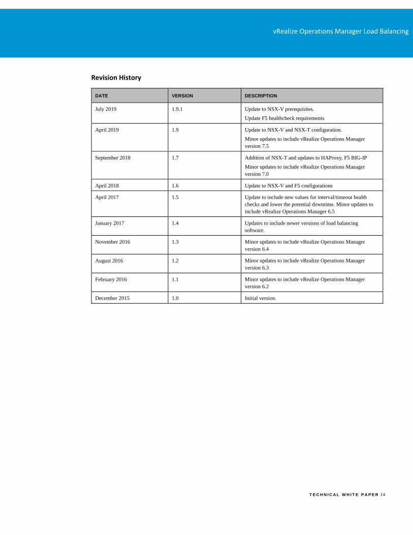
Revision History
DATE VERSION DESCRIPTION
July 2019 1.9.1 Update to NSX-V prerequisites.
Update F5 healthcheck requirements
April 2019 1.9 Update to NSX-V and NSX-T configuration.
Minor updates to include vRealize Operations Manager
version 7.5
September 2018 1.7 Addition of NSX-T and updates to HAProxy, F5 BIG-IP
Minor updates to include vRealize Operations Manager
version 7.0
April 2018 1.6 Update to NSX-V and F5 configurations
April 2017 1.5 Update to include new values for interval/timeout health
checks and lower the potential downtime. Minor updates to
include vRealize Operations Manager 6.5
January 2017 1.4 Updates to include newer versions of load balancing
software.
November 2016 1.3 Minor updates to include vRealize Operations Manager
version 6.4
August 2016 1.2 Minor updates to include vRealize Operations Manager
version 6.3
February 2016 1.1 Minor updates to include vRealize Operations Manager
version 6.2
December 2015 1.0 Initial version.
vRealize Operations Manager Load Balancing
T E C H N I C A L W H I T E P A P E R / 5
Introduction
This document describes the configuration of the load balancing modules of F5 Networks BIG-IP software (F5), Citrix
NetScaler, HAProxy and NSX load balancers for vRealize Operations Manager. This document is not an installation
guide, but a load-balancing configuration guide that supplements the vRealize Operations Manager installation and
configuration documentation available in the vRealize Operations Manager Documentation Center.
This information is for the following products and versions.
PRODUCT VERSION DOCUMENTATION
vRealize
Operations
Manager
6.6, 6.7, 7.0, 7.5
https://www.vmware.com/support/pubs/vmware-vrops-suite-
pubs.html
F5 BIG-IP 11.5, 11.6, 12.1, 13.0, 14x https://support.f5.com/kb/en-us.html
Citrix
NetScaler 10.5*, 11.0*, 11.x, 12.x
https://www.citrix.com/products/netscaler-adc/
NSX-V 6.1.3, 6.2.x, 6.3.x, 6.4.x https://pubs.vmware.com/NSX-
6/index.jsp#Welcome/welcome.html
NSX-T 2.2, 2.3, 2.4 https://docs.vmware.com/en/VMware-NSX-T/index.html
HA Proxy v1.5.x http://www.haproxy.org/
RHEL v7.x https://access.redhat.com/documentation/en-US/index.html
Keepalived v1.3.x http://www.keepalived.org/
* Citrix NetScaler VPX versions prior to 11.0 65.35 have a bug which prevents them from using TLS 1.1/1.2. For more
information, please refer to the NetScaler section of this document.
Load Balancing Concepts
Load balancers distribute connections among servers in high availability (HA) deployments. The system administrator
backs up the load balancers on a regular basis at the same time as other components.
Follow your site policy for backing up load balancers, keeping in mind the preservation of network topology and
vRealize Operations Manager backup planning.
Following are the advantages of using a load balancer in front of the vRealize Operations Manager cluster:
• Utilizing a load balancer ensures that the deployed cluster is properly balanced for performance of UI traffic.
• Allows all nodes in the cluster to equally participate in the handling of UI sessions and traffic.
• Provides high availability if any admin or data node fails, by directing UI traffic only to serving nodes in the cluster.
• Provides simpler access for the users. Instead of accessing each node individually the user only needs one URL to
access the entire cluster and not be concerned with which node is available.
• Provides load balancing, high availability and ease of configuration for the End Point Operations (EPOps) agents.
Selecting a Load Balancer
There are no specific requirements for selecting a load balancer platform for vRealize Operations Manager. Majority of
Load Balancers available today support complex web servers and SSL. You can use a load balancer in front of a
vRealize Operations Manager cluster if certain parameters and configuration variables are followed. HAProxy was
chosen for this example due to its ease of deployment, open source availability, stability, capability handling SSL
sessions, and performance. Following are some of the parameters that should be considered for configuring other
vRealize Operations Manager Load Balancing
T E C H N I C A L W H I T E P A P E R / 6
brands of load balancers:
• You must use TCP Mode. HTTP mode is not supported.
• It is not recommended to use round-robin balancing mode
• Cookie persistence does not work
• SSL pass-through is used, SSL termination is not supported
• IP Hash type balancing is recommended to ensure that the same client IP address always reaches the same node, if
the node is available
• Health checks should be performed with public API provided by vRealize Operations Manager.
How to Handle SSL UI Certificates with a Load Balancer
In all the default installations of vRealize Operations Manager nodes a default self-signed VMware certificate is
included. You can implement your own SSL certificate from an internal Certificate Authority or external Certificate
Authority. For more information on the certificate installation procedures, see Requirements for Custom vRealize
Operations Manager SSL Certificates.
In addition to these configuration variables it is important to understand how SSL certificates are distributed in a
cluster. If you upload a certificate to a node in the cluster, for example: the master node, the certificate will then be
pushed to all nodes in the cluster. To handle UI sessions by all the nodes in the cluster you must upload an SSL
certificate that contains all the DNS names (optional: IP addresses and DNS names) in the Subject Alternative Name
field of the uploaded certificate. The common name should be the Load Balancer DNS name. The subject alternative
names are used to support access to the admin UI page.
When the certificate is uploaded trough admin UI page it is pushed to all the nodes in the cluster. Currently, when you
use a load balancer with vRealize Operations Manager, the only supported method is SSL pass-through, which means
the SSL certificate cannot be terminated on the load balancer.
To change SSL certificate on a cluster deployment:
Log in to the master node by using the following link: https://<ipaddress>/admin.
On the top right side, click the certificate button to change the certificate.
Click on Install New Certificate
Click on Browse button and choose PEM certificate file.
After certificate verification click Install.
When you view the certificate on the node that you are accessing, you will see all nodes in the cluster listed in the
certificate SAN.
vRealize Operations Manager Overview
The vRealize Operations Manager clusters consist of a master node, an optional replica node for high availability,
optional data nodes, and optional remote collector nodes. You can access and interact with the product by using the
product UI available on the master and data nodes. The remote collector nodes do not contain a product UI and are used
for data collection only. The product UI is powered by a Tomcat instance that resides across each node but is not load
balanced out of the box. You can scale up vRealize Operations Manager environment by adding nodes when the
environment grows larger.
vRealize Operations Manager supports high availability by enabling a replica node for the vRealize Operations
Manager master node. A high availability replica node can take over the functions that a master node provides. When a
problem occurs with the master node, fail-over to the replica node is automatic and requires only 2 to 3 minutes of
vRealize Operations Manager downtime. Data stored on the master node is always backed up on the replica node. In
vRealize Operations Manager Load Balancing
T E C H N I C A L W H I T E P A P E R / 7
addition, with high availability enabled, the cluster can survive the loss of a data node without losing any data.
NODE ROLE FUNCTIONS
Master Node
It is the initial, required node in the cluster. All other nodes are managed by the master node. It
contains the product UI.
In a single-node installation, the master node performs data collection and analysis as it is the
only node where vRealize Operations Manager adapters are installed.
Data Node In larger deployments, only data nodes have adapters installed to perform collection and analysis.
It contains the product UI.
Replica Node To enable high availability, the cluster requires that you convert a data node in to a replica of the
master node. It does not contain product UI.
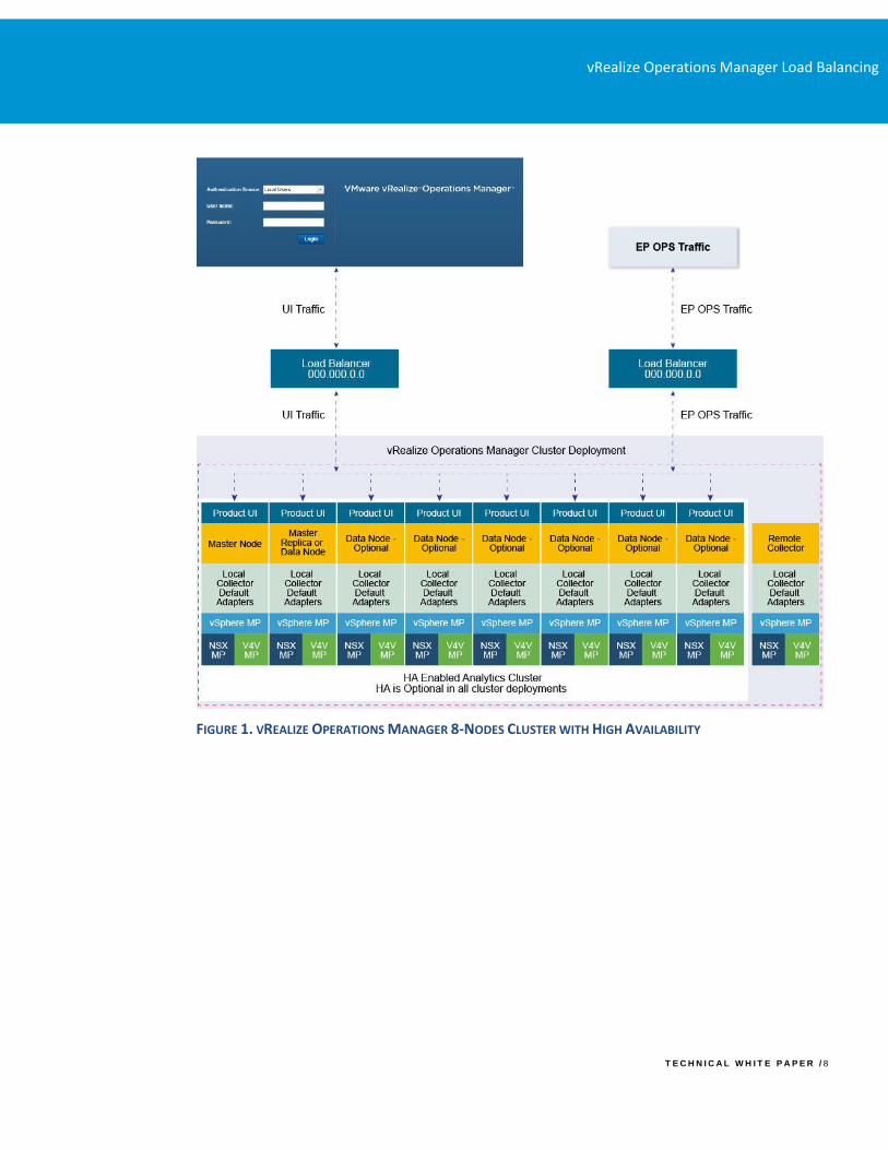
vRealize Operations Manager Architecture
Information about vRealize Operations Manager maximum supported nodes in analytics cluster as well as other
information related to High Availability can be found in the sizing guideline document.
Remote collectors are not considered part of the analytics clusters as they do not participate in any type of data
calculations or processing. EPOps traffic is load balanced to the same cluster.
NOTE: The load balancer cannot decrypt the traffic, hence cannot differentiate between EPOps and analytics traffic.
Following is a basic architecture overview of a vRealize Operations Manager 8-node cluster with high availability
enabled.
vRealize Operations Manager Load Balancing
T E C H N I C A L W H I T E P A P E R / 8
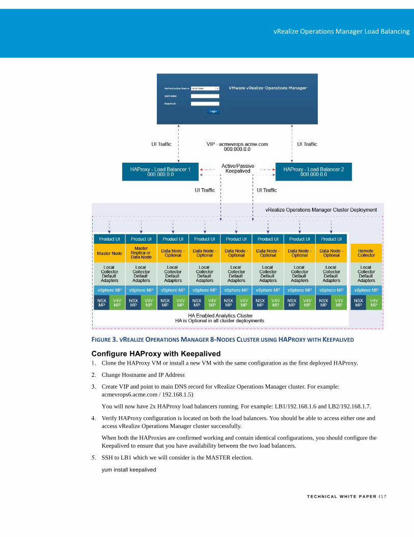
FIGURE 1. VREALIZE OPERATIONS MANAGER 8-NODES CLUSTER WITH HIGH AVAILABILITY

vRealize Operations Manager Load Balancing
T E C H N I C A L W H I T E P A P E R / 9
Configuring End Point Operations Agents
End Point Operations agents are used to gather operating system metrics to monitor availability of remote platforms
and applications. This metrics are sent to the vRealize Operations Manager server. You can configure additional load
balancer profile or dedicated load balancer to separate analytics traffic from EPOps traffic.
The steps to configure EPOps load balancer are described as required throughout this document.
You must shut down that the load balancer while upgrading or shutting down vRealize Operations Manager cluster.
The load balancer should be restarted after the cluster is upgraded.
In the case of EPOps balancing, the overall latency between agent, load balancer, and cluster should be lower than 20
milliseconds. If the latency is higher, you must install a remote collector and direct the agents directly to it.
vRealize Operations Manager Load Balancing
T E C H N I C A L W H I T E P A P E R / 1 0
HAProxy Installation and Configuration
HAProxy offers high availability, load balancing, and proxying for TCP and HTTP-based applications. Both multi-arm
and one-arm configurations are tested and supported.
Prerequisites
Following are the prerequisites to ensure a functional load balancer configuration and deployment.
• OS: Red Hat Enterprise Linux (RHEL) v7.x
• CPU: 2 vCPU
• Memory: 4GB
• Disk space: 50GB
• HAProxy 1.5.x
• Fully functioning DNS with both forward and reverse lookups
• All nodes in the vRealize Operations Manager cluster operating correctly
• HAProxy deployed in same datacenter and preferably on the same cluster as vRealize Operations Manager
• HAProxy not deployed on the same ESX hosts as vRealize Operations Manager cluster to ensure availability
• Minimum 2-node deployment of vRealize Operations Manager cluster
• Deployment does not require high availability to be enabled, but it is recommended that you enable high availability
• One master node and at least one data node is required for using a load balancer beneficially
Install Single-Node HAProxy
HAProxy installation is supported and tested on Red Hat Enterprise Linux (RHEL) 7.x and can be obtained from the
official Red Hat repository. You can install HAProxy on RHEL 7.x by using yum package manager. To configure
HAProxy as a load-balancer for vRealize Operations Manager please follow the steps below:
Perform a package update on system to ensure all packages are up-to-date:
yum update
Install HAProxy:
yum -y install haproxy
Copy original HAProxy configuration to backup file:
cp /etc/haproxy/haproxy.cfg /etc/haproxy/haproxy.cfg.bak
Configure HAProxy configuration. To configure analytics balancer, see Configure HAProxy Analytics and to
configure EPOps balancer, see Configure EPOps HAProxy.
Allow firewall traffic through for the ports needed for HAProxy to function:
firewall-cmd --permanent --zone=public --add-port=80/tcp
firewall-cmd --permanent --zone=public --add-port=9090/tcp
firewall-cmd --permanent --zone=public --add-port=443/tcp
Reload the firewall configuration:
systemctl reload firewalld
Enable HAProxy to connect to any interface:
setsebool -P haproxy_connect_any 1
vRealize Operations Manager Load Balancing
T E C H N I C A L W H I T E P A P E R / 1 1
Enable HAProxy service:
systemctl enable haproxy
Configure Logging for HAProxy
An administrator might want to configure logging of the HAProxy service to aid in monitoring and troubleshooting an
environment. The HAProxy logger allows for the use rsyslog internally on the Linux installation to log to a local file.
You can also utilize vRealize Log Insight integration to send this log to a vRealize Log Insight deployment by utilizing
the new Log Insight Linux agent to greatly simplify the configuration and logging of Linux platforms. To configure
basic applications logging using rsyslog locally on the server perform the following steps.
Configure the rsyslog configuration file to accept UDP syslog reception:
vi /etc/rsyslog.conf
Uncomment the following lines:
# Provides UDP syslog reception
$ModLoad imudp
$UDPServerAddress 127.0.0.1
$UDPServerRun 514
Save the file:
wq!
Create the HAProxy logging configuration file for specific application parameters
vi /etc/rsyslog.d/haproxy.conf
Add the following line:
if ($programname == 'haproxy') then -/var/log/haproxy.log
Save the file:
wq!
Create HAProxy Log file and set proper permissions:
touch /var/log/haproxy.log
chmod 755 /var/log/haproxy.log
Restart the rsyslog service:
Service rsyslog restart
Configure HAProxy
The HAProxy configuration has been tested against an 8-node vRealize Operations Manager cluster. Clusters with
fewer nodes up to a maximum of 16 analytics nodes are also supported and require the same configuration. Every time
the cluster is expanded, and a new node is deployed you must edit the HAProxy configuration and add the IP address of
the new node. After editing the configuration file, the HAProxy service should always be restarted so the configuration
is reloaded.
Configure HAProxy for vRealize Operations Manager Analytics
You can configure the HAProxy for vRealize Operations Manager analytics as follows:
# Configuration file to balance both web and epops

vRealize Operations Manager Load Balancing
T E C H N I C A L W H I T E P A P E R / 1 2
#global parameters
global
log 127.0.0.1 local2
chroot /var/lib/haproxy
pidfile /var/run/haproxy.pid
maxconn 400
user haproxy
group haproxy
daemon
stats socket /var/lib/haproxy/stats
ssl-server-verify none
#default parameters unless otherwise specified
defaults
log global
mode http
option httplog
option tcplog
option dontlognull
timeout connect 5000ms
timeout client 50000ms
timeout server 50000ms
#listener settings for stats webpage can be optional but highly recommended
listen stats :9090
balance
mode http
stats enable
stats auth admin:admin
stats uri /
stats realm Haproxy\ Statistics
#automatic redirect for http to https connections
frontend vrops_unsecured_redirect *:80
redirect location https://<insert_fqdn_address_here>
#front settings in this case we bind to all addresses on system or specify an interface
frontend vrops_frontend_secure
bind <web dedicated ip>:443
mode tcp
option tcplog
default_backend vrops_backend_secure
#backend configuration of receiving servers containing tcp-checks health checks and hashing
#needed for a proper configuration and page sessions
#adjust the server parameters to your environment
backend vrops_backend_secure
vRealize Operations Manager Load Balancing
T E C H N I C A L W H I T E P A P E R / 1 3
mode tcp
option tcplog
balance source
hash-type consistent
option tcp-check
tcp-check connect port 443 ssl
tcp-check send GET\ /suite-api/api/deployment/node/status\ HTTP/1.0\r\n\r\n
tcp-check expect rstring ONLINE
server node1 <Insert node1 ip address here>:443 check inter 60s check-ssl maxconn 140 fall 6 rise 6
server node2 <Insert node2 ip address here>:443 check inter 60s check-ssl maxconn 140 fall 6 rise 6
server node3 <Insert node3 ip address here>:443 check inter 60s check-ssl maxconn 140 fall 6 rise 6
server node4 <Insert node4 ip address here>:443 check inter 60s check-ssl maxconn 140 fall 6 rise 6
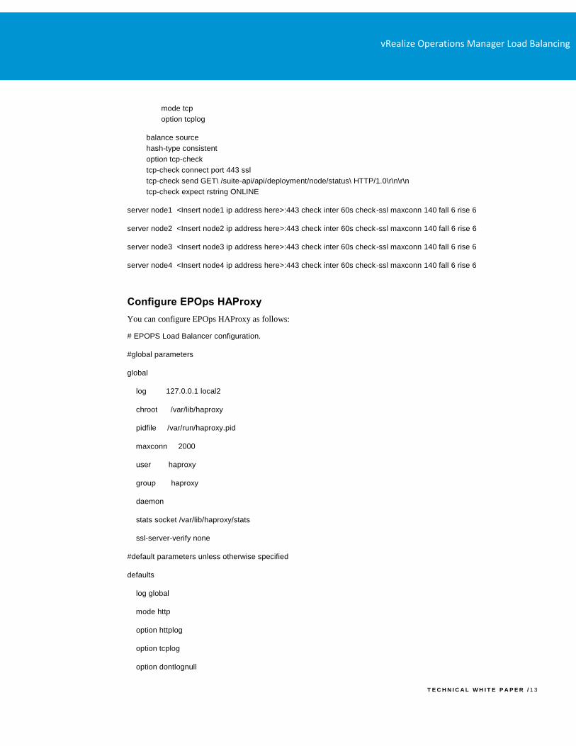
Configure EPOps HAProxy
You can configure EPOps HAProxy as follows:
# EPOPS Load Balancer configuration.
#global parameters
global
log 127.0.0.1 local2
chroot /var/lib/haproxy
pidfile /var/run/haproxy.pid
maxconn 2000
user haproxy
group haproxy
daemon
stats socket /var/lib/haproxy/stats
ssl-server-verify none
#default parameters unless otherwise specified
defaults
log global
mode http
option httplog
option tcplog
option dontlognull

vRealize Operations Manager Load Balancing
T E C H N I C A L W H I T E P A P E R / 1 4
timeout connect 5000ms
timeout client 50000ms
timeout server 50000ms
#listener settings for stats webpage can be optional but highly recommended
listen stats :9090
balance
mode http
stats enable
stats auth admin:admin
stats uri /
stats realm Haproxy\ Statistics
#automatic redirect for http to https connections
frontend vrops_unsecured_redirect *:80
redirect location <Insert https fqdn here >
frontend epops_frontend_secure
bind <epops dedicated ip>:443
mode tcp
option tcplog
use_backend epops_backend_secure
#adjust the server parameters to your environment
backend epops_backend_secure
mode tcp
option tcplog
balance source
hash-type consistent
option tcp-check
timeout queue 20s
tcp-check connect port 443 ssl
tcp-check send GET\ /epops-webapp/health-check\ HTTP/1.0\r\n
tcp-check send \r\n
tcp-check expect string ONLINE
vRealize Operations Manager Load Balancing
T E C H N I C A L W H I T E P A P E R / 1 5
server node1 <Insert node1 ip address here>:443 check inter 60s check-ssl maxconn 140 fall 6 rise 6
server node2 <Insert node2 ip address here>:443 check inter 60s check-ssl maxconn 140 fall 6 rise 6
server node3 <Insert node3 ip address here>:443 check inter 60s check-ssl maxconn 140 fall 6 rise 6
server node4 <Insert node4 ip address here>:443 check inter 60s check-ssl maxconn 140 fall 6 rise 6
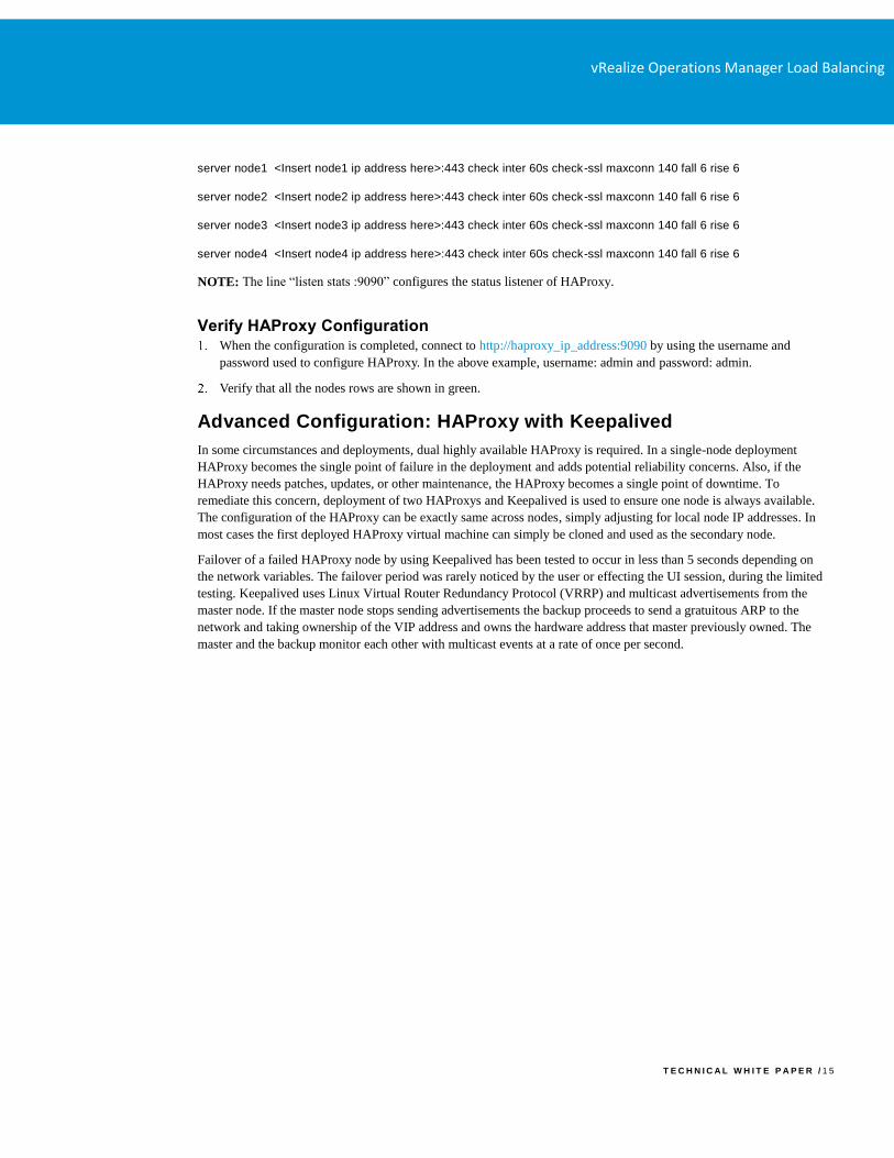
NOTE: The line “listen stats :9090” configures the status listener of HAProxy.
Verify HAProxy Configuration
When the configuration is completed, connect to http://haproxy_ip_address:9090 by using the username and
password used to configure HAProxy. In the above example, username: admin and password: admin.
Verify that all the nodes rows are shown in green.
Advanced Configuration: HAProxy with Keepalived
In some circumstances and deployments, dual highly available HAProxy is required. In a single-node deployment
HAProxy becomes the single point of failure in the deployment and adds potential reliability concerns. Also, if the
HAProxy needs patches, updates, or other maintenance, the HAProxy becomes a single point of downtime. To
remediate this concern, deployment of two HAProxys and Keepalived is used to ensure one node is always available.
The configuration of the HAProxy can be exactly same across nodes, simply adjusting for local node IP addresses. In
most cases the first deployed HAProxy virtual machine can simply be cloned and used as the secondary node.
Failover of a failed HAProxy node by using Keepalived has been tested to occur in less than 5 seconds depending on
the network variables. The failover period was rarely noticed by the user or effecting the UI session, during the limited
testing. Keepalived uses Linux Virtual Router Redundancy Protocol (VRRP) and multicast advertisements from the
master node. If the master node stops sending advertisements the backup proceeds to send a gratuitous ARP to the
network and taking ownership of the VIP address and owns the hardware address that master previously owned. The
master and the backup monitor each other with multicast events at a rate of once per second.
vRealize Operations Manager Load Balancing
T E C H N I C A L W H I T E P A P E R / 1 6
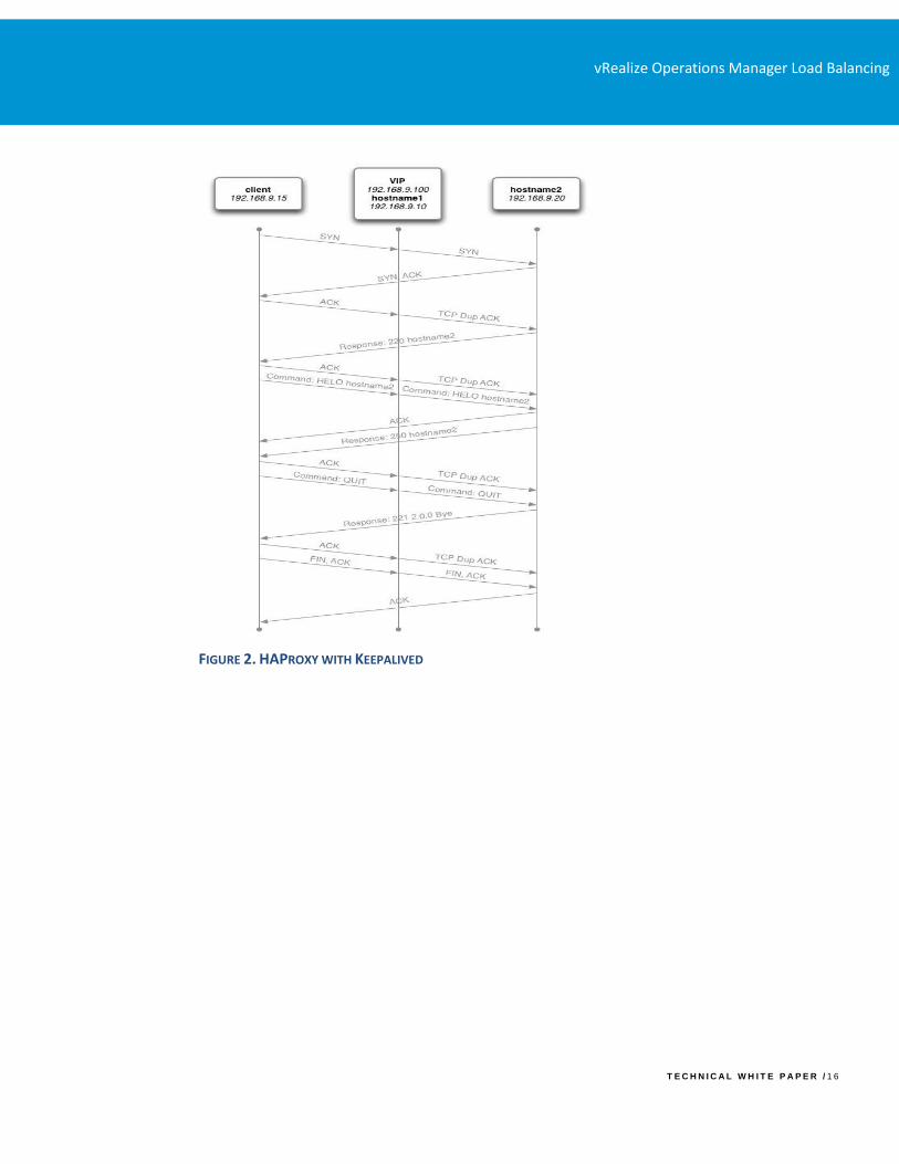
FIGURE 2. HAPROXY WITH KEEPALIVED
vRealize Operations Manager Load Balancing
T E C H N I C A L W H I T E P A P E R / 1 7
FIGURE 3. VREALIZE OPERATIONS MANAGER 8-NODES CLUSTER USING HAPROXY WITH KEEPALIVED
Configure HAProxy with Keepalived
Clone the HAProxy VM or install a new VM with the same configuration as the first deployed HAProxy.
Change Hostname and IP Address
Create VIP and point to main DNS record for vRealize Operations Manager cluster. For example:
acmevrops6.acme.com / 192.168.1.5)
You will now have 2x HAProxy load balancers running. For example: LB1/192.168.1.6 and LB2/192.168.1.7.
Verify HAProxy configuration is located on both the load balancers. You should be able to access either one and
access vRealize Operations Manager cluster successfully.
When both the HAProxies are confirmed working and contain identical configurations, you should configure the
Keepalived to ensure that you have availability between the two load balancers.
SSH to LB1 which we will consider is the MASTER election.
yum install keepalived

vRealize Operations Manager Load Balancing
T E C H N I C A L W H I T E P A P E R / 1 8
You should configure the kernel to use a VIP to bind to vi /etc/sysctl.conf. Add the following line to the file
net.ipv4.ip_nonlocal_bind=1
For the kernel to pick up the new changes without rebooting, run the following command:
sysctl -p
Delete the file:
/etc/keepalived/keepalived.conf
Create a new file:
/etc/keepalived/keepalived.conf
In the new keepalived.conf file add the following
Master Node
global_defs {
router_id haproxy2 # The hostname of this host.
}
vrrp_script haproxy {
script "killall -0 haproxy"
interval 2
weight 2
}
vrrp_instance 50 {
virtual_router_id 50
advert_int 1
priority 50
state MASTER
interface eth0
virtual_ipaddress {
Virtual_IPaddress dev eth0 # The virtual IP address that will be shared between MASTER and BACKUP
}
track_script {
haproxy
}
}

vRealize Operations Manager Load Balancing
T E C H N I C A L W H I T E P A P E R / 1 9
Verify that above the Router_ID is the HOSTNAME of the local load balancer that you are setting up.
Verify that you have set up the correct network device, check if you are using eth0.
Verify that above the Virtual_IPaddress is the VIP address, and not the local IP address of the LB1 node.
Set the priority in increments of 50. In this example, the node has the highest priority, so it is set to 100. Verify that
the node is set as the master node.
Save the configuration file and restart the services.
You must enable the Keepalived service:
systemctl enable keepalived
Run the commands:
service keepalived restart
service haproxy restart
To display if the node has the active load balancer IP, run:
ip a | grep eth0
If the system you are on displays the primary IP address of the load balancer, then this is the active system
processing traffic. Verify that only one system displays the primary IP address of the load balancer.
If the address is present on both the machines, the configuration is incorrect, and both the machines might not be
able to communicate with each other.
To configure the second LB2 Keepalived service perform the same steps as above and configure Keepalived
service on LB2.
In the new keepalived.conf file add the following for the slave node:
global_defs {
router_id haproxy4 # The hostname of this host !
}
vrrp_script haproxy {
script "killall -0 haproxy"
interval 2
weight 2
}
vrrp_instance 50 {
virtual_router_id 50
advert_int 1
priority 50
state BACKUP
interface eth0

vRealize Operations Manager Load Balancing
T E C H N I C A L W H I T E P A P E R / 2 0
virtual_ipaddress {
Virtual_IPaddress dev eth0 # The virtual IP address that will be shared betwee MASTER and BACKUP.
}
track_script {
haproxy
}
}
Verify that the Router_ID is the HOSTNAME of the local load balancer that you are setting up.
Verify that above the Virtual_IPaddress is the VIP address and not the local IP address of the LB1 node.
Set the priority in increments of 50. In this example, the node has the highest priority, so it is set to 100. Verify that
the node is set as the backup.
Save the configuration file and restart the services.
You must enable the Keepalived service:
systemctl enable keepalived
Run the commands:
service keepalived restart
service haproxy restart
To display if the node has the active load balancer IP, run:
ip a | grep eth0
If the system you are on displays the primary IP address of the load balancer, then this is the active system
processing traffic
vRealize Operations Manager Load Balancing
T E C H N I C A L W H I T E P A P E R / 2 1
F5 Big IP Installation & Configuration
The F5 Big IP load balancer configuration is similar to the HAProxy configuration. The F5 uses the SSL pass-through
in the same manner as the HAProxy configuration. The F5 configuration has been tested in both one-arm and multi-arm
topologies.
Prerequisites
The following are the prerequisites for a functional F5 configuration in front of a vRealize Operations Manager cluster:
• This document assumes that an F5 device is already deployed in the environment and is configured with network
connectivity to the deployed environment where the load balancer instance would be used and run from.
• The F5 can be either physical or virtual and can be deployed in one-arm or multi-arm topologies
• The Local Traffic Module (LTM) must be configured and licensed as Nominal, Minimum, or Dedicated. You can
configure LTM on System > Resource Provisioning page.
• A vRealize Operations Manager cluster has been deployed in the environment and is fully functional and all nodes
in the cluster are accepting UI traffic. This cluster might have high availability enabled but it is not a requirement.
• An additional VIP/Virtual Server IP address for vRealize Operations Manager analytics.
• An additional VIP/Virtual Server IP address for EPOps in case you are configuring separate load balancers for
analytics and EPOps.
Configure Custom Persistence Profile
There are multiple possible profiles provided out of box in most F5 deployments and creating a custom persistence
profile using source addresses affinity. You must create a customer persistence profile by using the following steps:
Log in to the F5 and select Local Traffic > Profiles > Persistence.
Click Create.
Enter the name source_addr_vrops and select Source Address Affinity from the drop-down menu.
Enable Custom mode.
Set the Timeout to 1800 seconds (30 minutes).
Click Finished.
NOTE: The timeout of the vRealize Operations Manager user sessions, configured through the Global Settings page is
30 minutes is, consistent with vRealize Operations Manager configuration. If the timeout value is updated for vRealize
Operations Manager, it should be updated for F5 too.
vRealize Operations Manager Load Balancing
T E C H N I C A L W H I T E P A P E R / 2 2
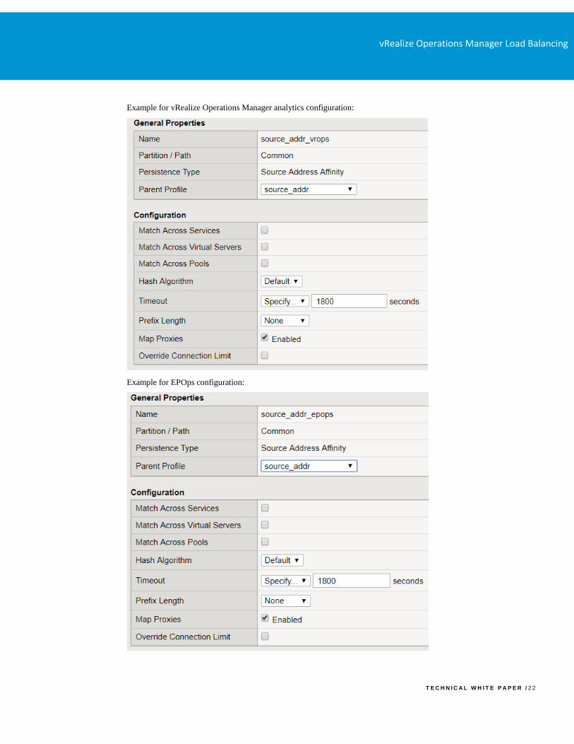
Example for vRealize Operations Manager analytics configuration:
Example for EPOps configuration:
vRealize Operations Manager Load Balancing
T E C H N I C A L W H I T E P A P E R / 2 3
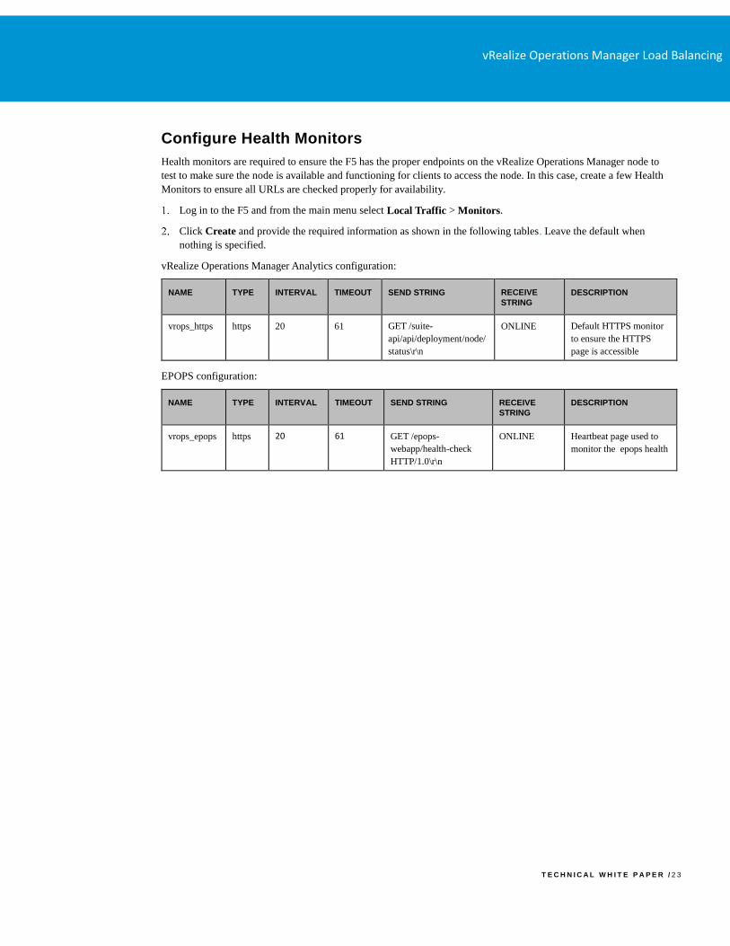
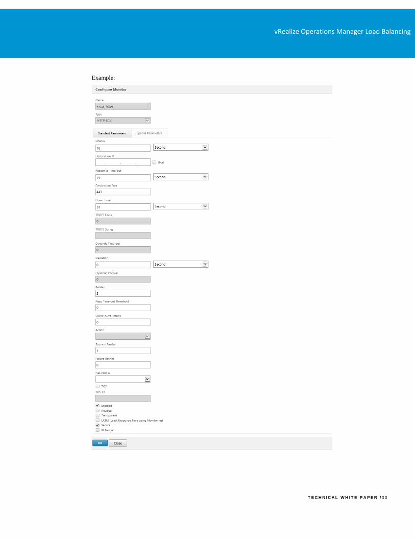
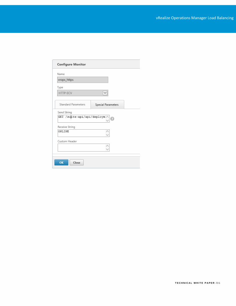
Configure Health Monitors
Health monitors are required to ensure the F5 has the proper endpoints on the vRealize Operations Manager node to
test to make sure the node is available and functioning for clients to access the node. In this case, create a few Health
Monitors to ensure all URLs are checked properly for availability.
Log in to the F5 and from the main menu select Local Traffic > Monitors.
Click Create and provide the required information as shown in the following tables. Leave the default when
nothing is specified.
vRealize Operations Manager Analytics configuration:
NAME TYPE INTERVAL TIMEOUT SEND STRING RECEIVE
STRING
DESCRIPTION
vrops_https https 20 61 GET /suite-
api/api/deployment/node/
status\r\n
ONLINE Default HTTPS monitor
to ensure the HTTPS
page is accessible
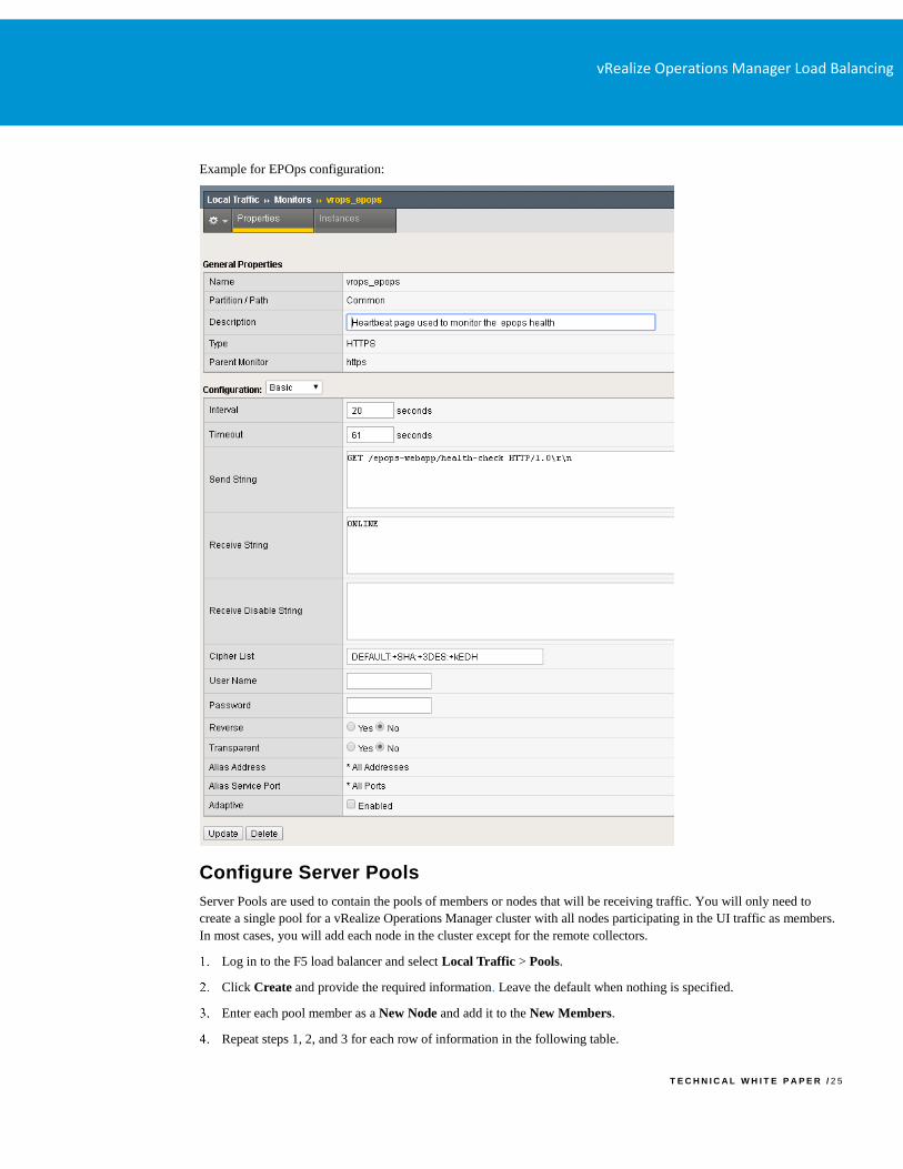
EPOPS configuration:
NAME TYPE INTERVAL TIMEOUT SEND STRING RECEIVE
STRING
DESCRIPTION
vrops_epops https 20 61 GET /epops-
webapp/health-check
HTTP/1.0\r\n
ONLINE Heartbeat page used to
monitor the epops health
vRealize Operations Manager Load Balancing
T E C H N I C A L W H I T E P A P E R / 2 4
Example for vRealize Operations Manager analytics configuration:
vRealize Operations Manager Load Balancing
T E C H N I C A L W H I T E P A P E R / 2 5
Example for EPOps configuration:
Configure Server Pools
Server Pools are used to contain the pools of members or nodes that will be receiving traffic. You will only need to
create a single pool for a vRealize Operations Manager cluster with all nodes participating in the UI traffic as members.
In most cases, you will add each node in the cluster except for the remote collectors.
Log in to the F5 load balancer and select Local Traffic > Pools.
Click Create and provide the required information. Leave the default when nothing is specified.
Enter each pool member as a New Node and add it to the New Members.
Repeat steps 1, 2, and 3 for each row of information in the following table.
vRealize Operations Manager Load Balancing
T E C H N I C A L W H I T E P A P E R / 2 6
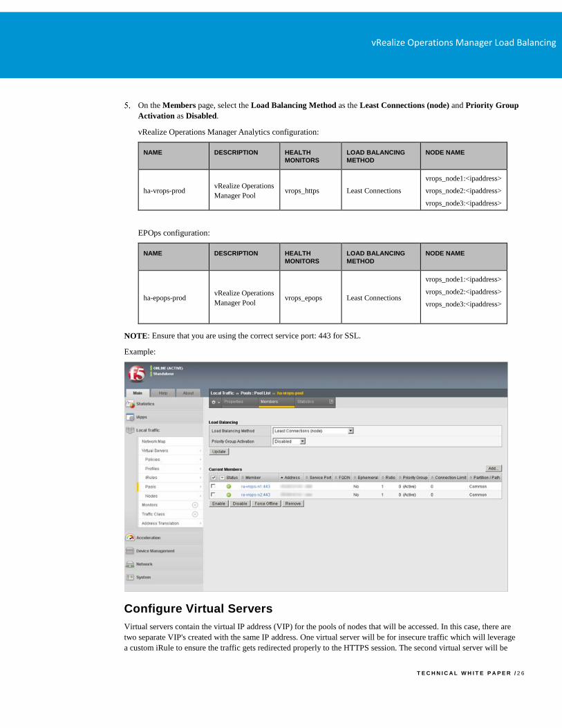
On the Members page, select the Load Balancing Method as the Least Connections (node) and Priority Group
Activation as Disabled.
vRealize Operations Manager Analytics configuration:
NAME DESCRIPTION HEALTH
MONITORS
LOAD BALANCING
METHOD
NODE NAME
ha-vrops-prod vRealize Operations
Manager Pool
vrops_https
Least Connections
vrops_node1:<ipaddress>
vrops_node2:<ipaddress>
vrops_node3:<ipaddress>
EPOps configuration:
NAME DESCRIPTION HEALTH
MONITORS
LOAD BALANCING
METHOD
NODE NAME
ha-epops-prod vRealize Operations
Manager Pool vrops_epops Least Connections
vrops_node1:<ipaddress>
vrops_node2:<ipaddress>
vrops_node3:<ipaddress>
NOTE: Ensure that you are using the correct service port: 443 for SSL.
Example:
Configure Virtual Servers
Virtual servers contain the virtual IP address (VIP) for the pools of nodes that will be accessed. In this case, there are
two separate VIP's created with the same IP address. One virtual server will be for insecure traffic which will leverage
a custom iRule to ensure the traffic gets redirected properly to the HTTPS session. The second virtual server will be
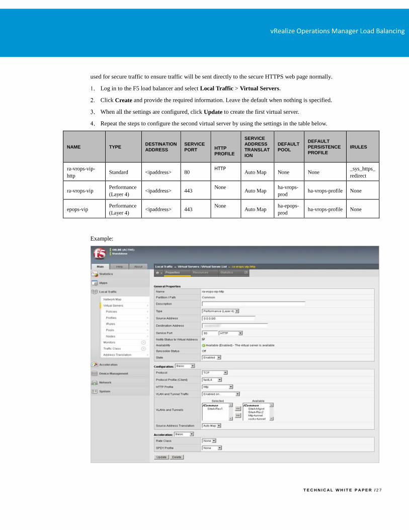
vRealize Operations Manager Load Balancing
T E C H N I C A L W H I T E P A P E R / 2 7
used for secure traffic to ensure traffic will be sent directly to the secure HTTPS web page normally.
Log in to the F5 load balancer and select Local Traffic > Virtual Servers.
Click Create and provide the required information. Leave the default when nothing is specified.
When all the settings are configured, click Update to create the first virtual server.
Repeat the steps to configure the second virtual server by using the settings in the table below.
NAME TYPE DESTINATION
ADDRESS
SERVICE
PORT
HTTP
PROFILE
SERVICE
ADDRESS
TRANSLAT
ION
DEFAULT
POOL
DEFAULT
PERSISTENCE
PROFILE
IRULES
ra-vrops-vip-
http Standard <ipaddress> 80
HTTP Auto Map None None
_sys_https_
redirect
ra-vrops-vip Performance
(Layer 4) <ipaddress> 443
None Auto Map
ha-vrops-
prod ha-vrops-profile None
epops-vip Performance
(Layer 4) <ipaddress> 443
None Auto Map
ha-epops-
prod ha-vrops-profile None
Example:
vRealize Operations Manager Load Balancing
T E C H N I C A L W H I T E P A P E R / 2 8
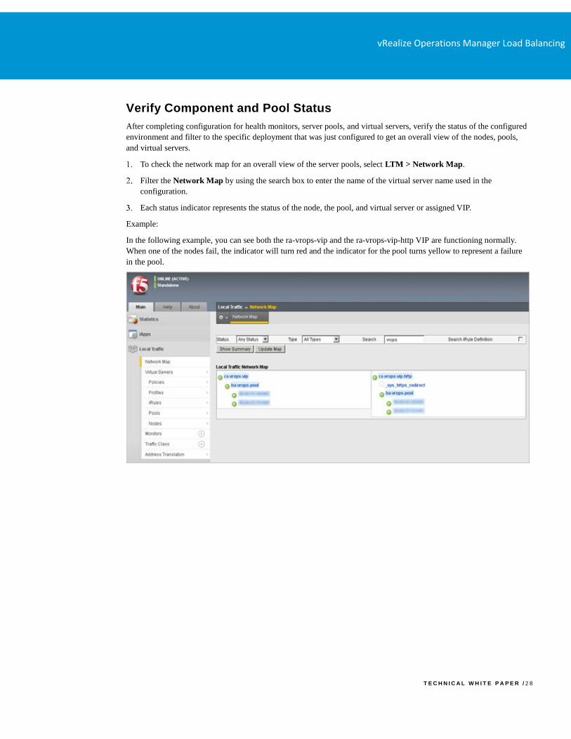
Verify Component and Pool Status
After completing configuration for health monitors, server pools, and virtual servers, verify the status of the configured
environment and filter to the specific deployment that was just configured to get an overall view of the nodes, pools,
and virtual servers.
To check the network map for an overall view of the server pools, select LTM > Network Map.
Filter the Network Map by using the search box to enter the name of the virtual server name used in the
configuration.
Each status indicator represents the status of the node, the pool, and virtual server or assigned VIP.
Example:
In the following example, you can see both the ra-vrops-vip and the ra-vrops-vip-http VIP are functioning normally.
When one of the nodes fail, the indicator will turn red and the indicator for the pool turns yellow to represent a failure
in the pool.

vRealize Operations Manager Load Balancing
T E C H N I C A L W H I T E P A P E R / 2 9
Citrix NetScaler Installation & Configuration Before starting with this configuration make sure that the Netscaler device is deployed in the environment and has
access to the vRealize Operations components.
• You can use either virtual or physical Netscaler in single or clustered configuration.
• Enable the Load Balancer (LB) and SSL modules. You can do so from the NetScaler > System > Settings >
Configure Basic Features page.
• In case you experience SSL timeout issues with the virtual edition of NetScaler please update the appliance
to version 11.0 65.35 or disable TLS 1.1/1.2 as per article http://support.citrix.com/article/CTX205578.
This is a known NetScaler bug – reference ID: 600155.
• You can use either multi-arm or one-arm configuration. Our tests were done in multi-arm configuration.
• VPX versions of Netscaler doesn’t support certificates larger than 2048bits on the back-end servers.
If you are planning to use VPX you will need to change the vRealize Operations certificate.
Please refer to the articles below for more information.
Configure a certificate for use with vRealize Operations Manager
FAQ: Key Sizes/Certificates Supported by NetScaler
Configure Health Monitors
Log in to the Netscaler load balancer and select NetScaler > Traffic Management > Load Balancing > Monitors.
Click Add and provide the required information. Leave the default when nothing is specified.
Repeat steps 1 and 2 for each row of information in the table below.
vRealize Operations Manager Analytics configuration:
NAME TYPE INTERVAL TIMEOUT RETRIES SEND STRING RECEIVE
STRING
DEST.
PORT SECURE
vrops_http HTTP 16 sec. 15 sec. 3 GET / (200|204|301) 80 no
vrops_https HTTP-
EVC 16 sec. 15 sec. 3
GET /suite-
api/api/deployment/node/
status
ONLINE 443 yes
vrops_epops HTTP-
EVC 16 sec. 15 sec. 3
GET /epops-
webapp/health-check ONLINE 443 yes
vRealize Operations Manager Load Balancing
T E C H N I C A L W H I T E P A P E R / 3 0
Example:
vRealize Operations Manager Load Balancing
T E C H N I C A L W H I T E P A P E R / 3 1
vRealize Operations Manager Load Balancing
T E C H N I C A L W H I T E P A P E R / 3 2
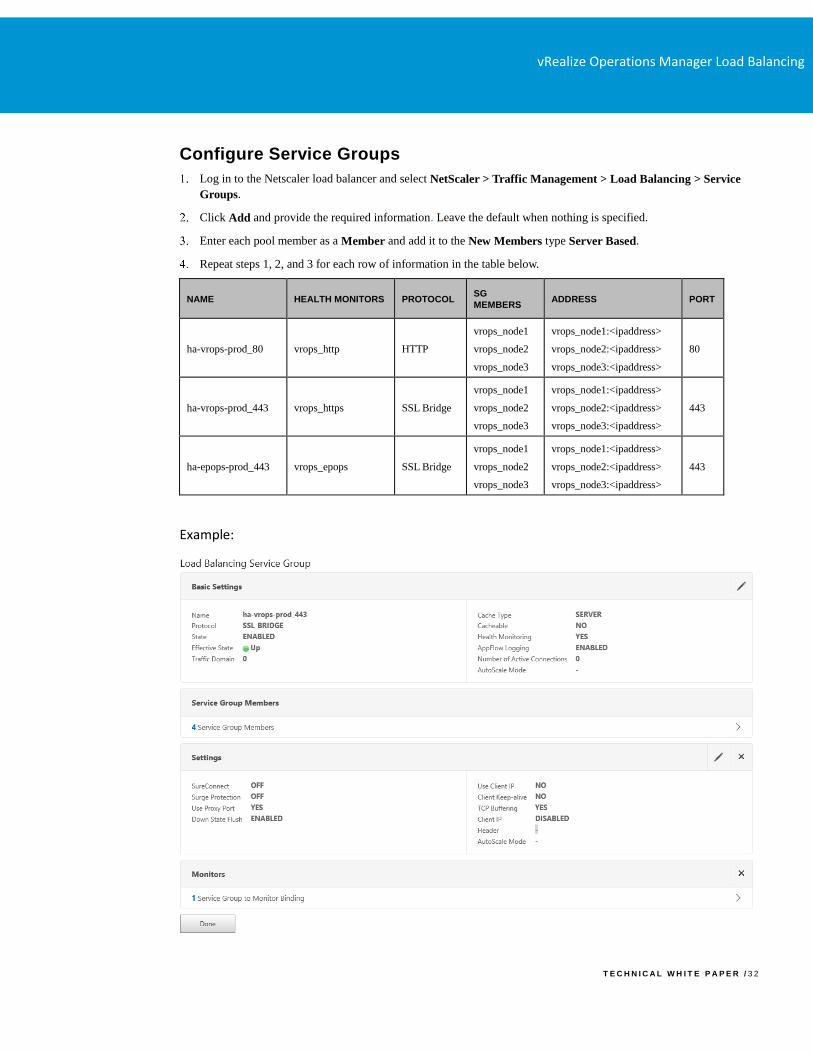
Configure Service Groups
Log in to the Netscaler load balancer and select NetScaler > Traffic Management > Load Balancing > Service
Groups.
Click Add and provide the required information. Leave the default when nothing is specified.
Enter each pool member as a Member and add it to the New Members type Server Based.
Repeat steps 1, 2, and 3 for each row of information in the table below.
NAME HEALTH MONITORS PROTOCOL SG
MEMBERS ADDRESS PORT
ha-vrops-prod_80 vrops_http HTTP
vrops_node1
vrops_node2
vrops_node3
vrops_node1:<ipaddress>
vrops_node2:<ipaddress>
vrops_node3:<ipaddress>
80
ha-vrops-prod_443 vrops_https SSL Bridge
vrops_node1
vrops_node2
vrops_node3
vrops_node1:<ipaddress>
vrops_node2:<ipaddress>
vrops_node3:<ipaddress>
443
ha-epops-prod_443 vrops_epops SSL Bridge
vrops_node1
vrops_node2
vrops_node3
vrops_node1:<ipaddress>
vrops_node2:<ipaddress>
vrops_node3:<ipaddress>
443
Example:
vRealize Operations Manager Load Balancing
T E C H N I C A L W H I T E P A P E R / 3 3
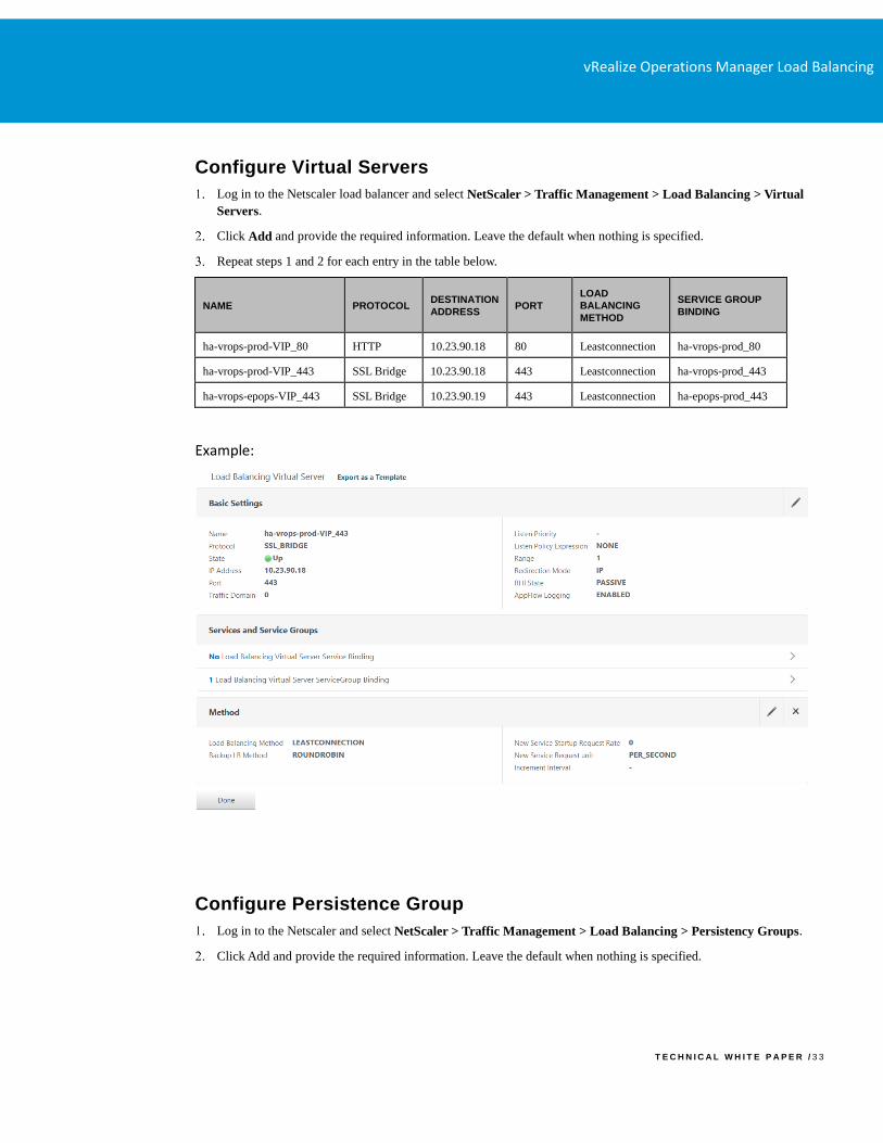
Configure Virtual Servers
Log in to the Netscaler load balancer and select NetScaler > Traffic Management > Load Balancing > Virtual
Servers.
Click Add and provide the required information. Leave the default when nothing is specified.
Repeat steps 1 and 2 for each entry in the table below.
NAME PROTOCOL DESTINATION
ADDRESS PORT
LOAD
BALANCING
METHOD
SERVICE GROUP
BINDING
ha-vrops-prod-VIP_80 HTTP 10.23.90.18 80 Leastconnection ha-vrops-prod_80
ha-vrops-prod-VIP_443 SSL Bridge 10.23.90.18 443 Leastconnection ha-vrops-prod_443
ha-vrops-epops-VIP_443 SSL Bridge 10.23.90.19 443 Leastconnection ha-epops-prod_443
Example:
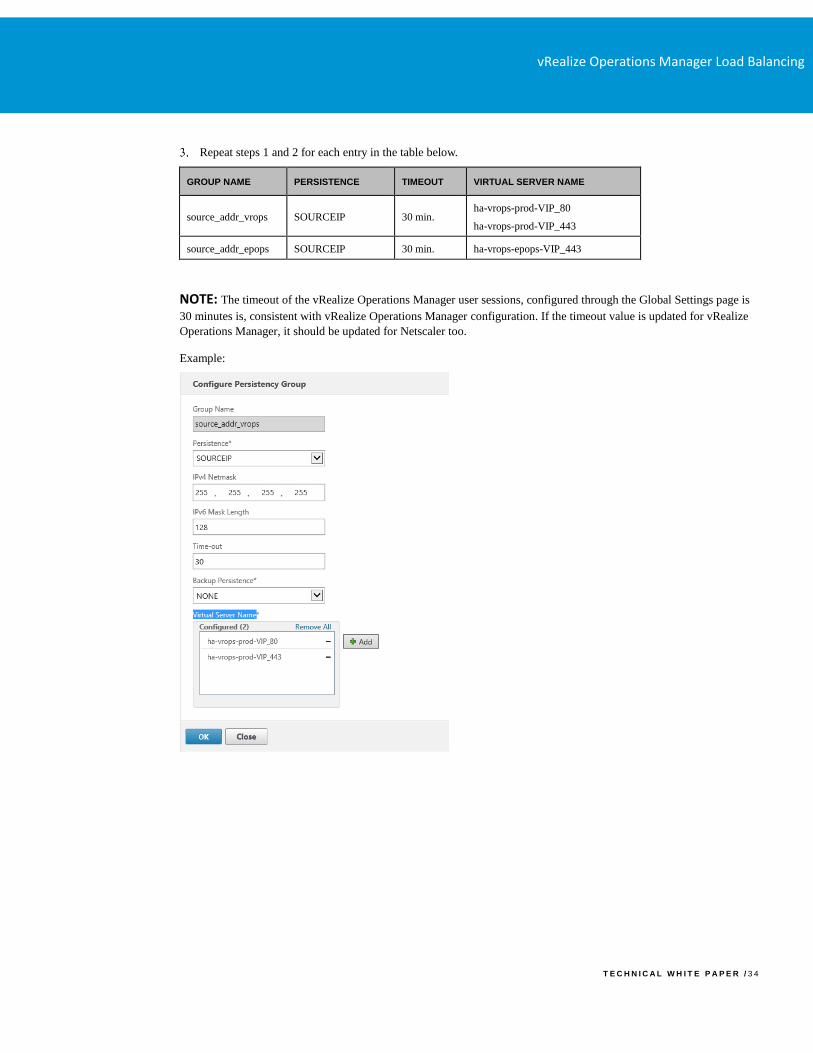
Configure Persistence Group
Log in to the Netscaler and select NetScaler > Traffic Management > Load Balancing > Persistency Groups.
Click Add and provide the required information. Leave the default when nothing is specified.
vRealize Operations Manager Load Balancing
T E C H N I C A L W H I T E P A P E R / 3 4
Repeat steps 1 and 2 for each entry in the table below.
GROUP NAME PERSISTENCE TIMEOUT VIRTUAL SERVER NAME
source_addr_vrops SOURCEIP 30 min. ha-vrops-prod-VIP_80
ha-vrops-prod-VIP_443
source_addr_epops SOURCEIP 30 min. ha-vrops-epops-VIP_443
NOTE: The timeout of the vRealize Operations Manager user sessions, configured through the Global Settings page is
30 minutes is, consistent with vRealize Operations Manager configuration. If the timeout value is updated for vRealize
Operations Manager, it should be updated for Netscaler too.
Example:
vRealize Operations Manager Load Balancing
T E C H N I C A L W H I T E P A P E R / 3 5
NSX-V Installation & Configuration
The NSX-V virtual networking solution includes the capability of deploying an Edge gateway as a load balancer.
Currently, the NSX-V load balancer has basic load balancing functionality and it should not be considered a full-
fledged load balancer with advanced configuration like F5.
NOTE: Use NSX-V version 6.1.3 and higher for all deployments as many issues with the load balancers have been
resolved in this release.
Prerequisites
The following are the prerequisites for a functional NSX-V load balancer in front of a vRealize Operations Manager
cluster:
• This document assumes that NSX-V deployment is already deployed in the environment and is fully functional.
• The NSX-V deployment is of version 6.1.3 or higher.
• NSX-V Edge is deployed and has access to the network on which vRealize Operations Manager cluster is deployed.
• Edge can be enabled for high availability, however it is not a requirement
• Currently, there are 2 types of modes the load balancer can be used: Accelerated and Non-Accelerated. Accelerated
mode uses L4 and LVS and non-accelerated mode uses L7
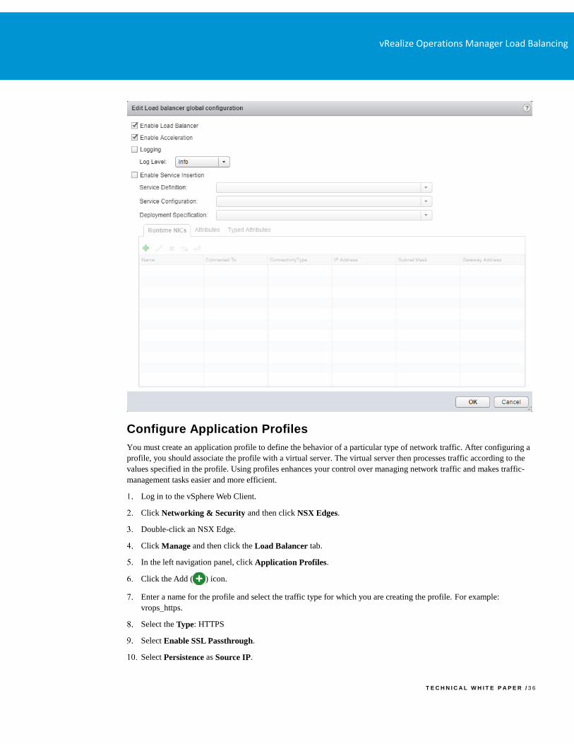
Install and Configure Edge for Load Balancing
You can specify global load balancer configuration parameters and configure the NSX-V Edge for load balancing by
enabling the load balancer service.
Log in to the vSphere Web Client.
Click Networking & Security and then click NSX Edges.
Double-click an NSX-V Edge.
Click Manage and then click the Load Balancer tab.
Click Edit and select Enable Load Balancer and Enable Acceleration
Click OK to save changes and enable the service on the Edge.
Example from NSX-V 6.2.0:
vRealize Operations Manager Load Balancing
T E C H N I C A L W H I T E P A P E R / 3 6
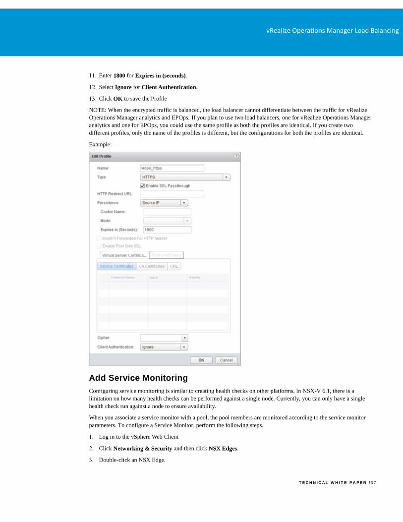
Configure Application Profiles
You must create an application profile to define the behavior of a particular type of network traffic. After configuring a
profile, you should associate the profile with a virtual server. The virtual server then processes traffic according to the
values specified in the profile. Using profiles enhances your control over managing network traffic and makes traffic-
management tasks easier and more efficient.
Log in to the vSphere Web Client.
Click Networking & Security and then click NSX Edges.
Double-click an NSX Edge.
Click Manage and then click the Load Balancer tab.
In the left navigation panel, click Application Profiles.
Click the Add ( ) icon.
Enter a name for the profile and select the traffic type for which you are creating the profile. For example:
vrops_https.
Select the Type: HTTPS
Select Enable SSL Passthrough.
Select Persistence as Source IP.
vRealize Operations Manager Load Balancing
T E C H N I C A L W H I T E P A P E R / 3 7
Enter 1800 for Expires in (seconds).
Select Ignore for Client Authentication.
Click OK to save the Profile
NOTE: When the encrypted traffic is balanced, the load balancer cannot differentiate between the traffic for vRealize
Operations Manager analytics and EPOps. If you plan to use two load balancers, one for vRealize Operations Manager
analytics and one for EPOps, you could use the same profile as both the profiles are identical. If you create two
different profiles, only the name of the profiles is different, but the configurations for both the profiles are identical.
Example:
Add Service Monitoring
Configuring service monitoring is similar to creating health checks on other platforms. In NSX-V 6.1, there is a
limitation on how many health checks can be performed against a single node. Currently, you can only have a single
health check run against a node to ensure availability.
When you associate a service monitor with a pool, the pool members are monitored according to the service monitor
parameters. To configure a Service Monitor, perform the following steps.
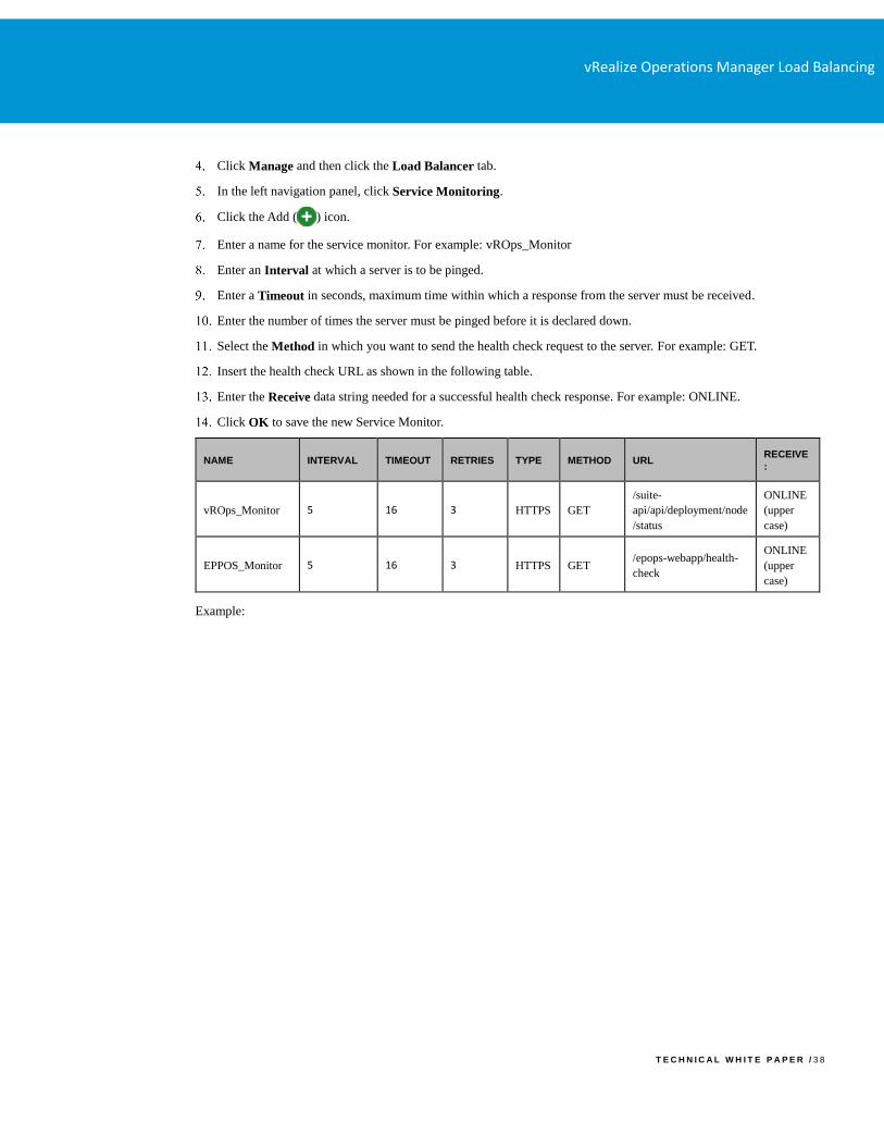
Log in to the vSphere Web Client
Click Networking & Security and then click NSX Edges.
Double-click an NSX Edge.
vRealize Operations Manager Load Balancing
T E C H N I C A L W H I T E P A P E R / 3 8
Click Manage and then click the Load Balancer tab.
In the left navigation panel, click Service Monitoring.
Click the Add ( ) icon.
Enter a name for the service monitor. For example: vROps_Monitor
Enter an Interval at which a server is to be pinged.
Enter a Timeout in seconds, maximum time within which a response from the server must be received.
Enter the number of times the server must be pinged before it is declared down.
Select the Method in which you want to send the health check request to the server. For example: GET.
Insert the health check URL as shown in the following table.
Enter the Receive data string needed for a successful health check response. For example: ONLINE.
Click OK to save the new Service Monitor.
NAME INTERVAL TIMEOUT RETRIES TYPE METHOD URL RECEIVE
:
vROps_Monitor 5 16 3 HTTPS GET
/suite-
api/api/deployment/node
/status
ONLINE
(upper
case)
EPPOS_Monitor 5 16 3 HTTPS GET /epops-webapp/health-
check
ONLINE
(upper
case)
Example:
vRealize Operations Manager Load Balancing
T E C H N I C A L W H I T E P A P E R / 3 9
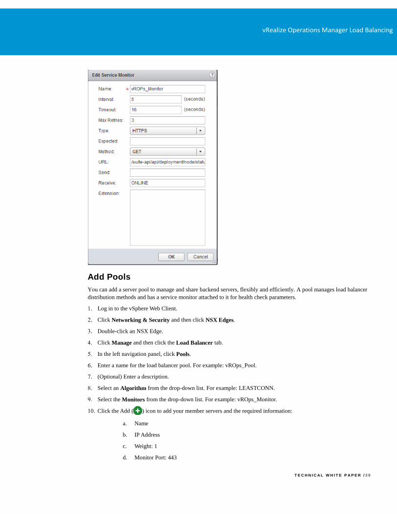
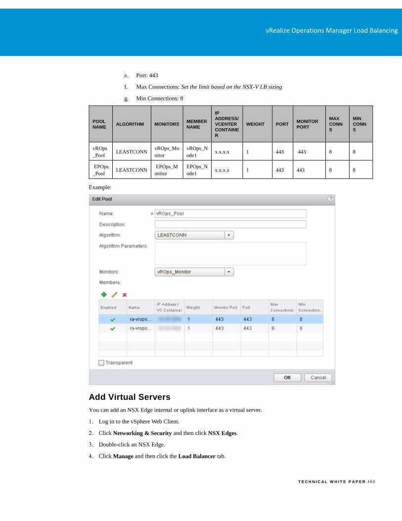
Add Pools
You can add a server pool to manage and share backend servers, flexibly and efficiently. A pool manages load balancer
distribution methods and has a service monitor attached to it for health check parameters.
Log in to the vSphere Web Client.
Click Networking & Security and then click NSX Edges.
Double-click an NSX Edge.
Click Manage and then click the Load Balancer tab.
In the left navigation panel, click Pools.
Enter a name for the load balancer pool. For example: vROps_Pool.
(Optional) Enter a description.
Select an Algorithm from the drop-down list. For example: LEASTCONN.
Select the Monitors from the drop-down list. For example: vROps_Monitor.
Click the Add ( ) icon to add your member servers and the required information:
a. Name
b. IP Address
c. Weight: 1
d. Monitor Port: 443
vRealize Operations Manager Load Balancing
T E C H N I C A L W H I T E P A P E R / 4 0
e. Port: 443
f. Max Connections: Set the limit based on the NSX-V LB sizing
g. Min Connections: 8
POOL
NAME ALGORITHM MONITORS
MEMBER
NAME
IP
ADDRESS/
VCENTER
CONTAINE
R
WEIGHT PORT MONITOR
PORT
MAX
CONN
S
MIN
CONN
S
vROps
_Pool LEASTCONN
vROps_Mo
nitor
vROps_N
ode1 x.x.x.x 1 443 443 8 8
EPOps
_Pool LEASTCONN
EPOps_M
onitor
EPOps_N
ode1 x.x.x.x 1 443 443 8 8
Example:
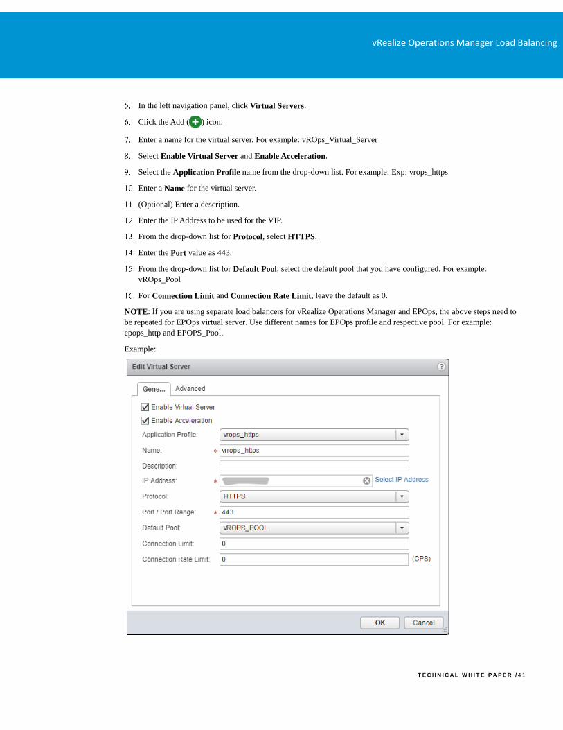
Add Virtual Servers
You can add an NSX Edge internal or uplink interface as a virtual server.
Log in to the vSphere Web Client.
Click Networking & Security and then click NSX Edges.
Double-click an NSX Edge.
Click Manage and then click the Load Balancer tab.
vRealize Operations Manager Load Balancing
T E C H N I C A L W H I T E P A P E R / 4 1
In the left navigation panel, click Virtual Servers.
Click the Add ( ) icon.
Enter a name for the virtual server. For example: vROps_Virtual_Server
Select Enable Virtual Server and Enable Acceleration.
Select the Application Profile name from the drop-down list. For example: Exp: vrops_https
Enter a Name for the virtual server.
(Optional) Enter a description.
Enter the IP Address to be used for the VIP.
From the drop-down list for Protocol, select HTTPS.
Enter the Port value as 443.
From the drop-down list for Default Pool, select the default pool that you have configured. For example:
vROps_Pool
For Connection Limit and Connection Rate Limit, leave the default as 0.
NOTE: If you are using separate load balancers for vRealize Operations Manager and EPOps, the above steps need to
be repeated for EPOps virtual server. Use different names for EPOps profile and respective pool. For example:
epops_http and EPOPS_Pool.
Example:
vRealize Operations Manager Load Balancing
T E C H N I C A L W H I T E P A P E R / 4 2
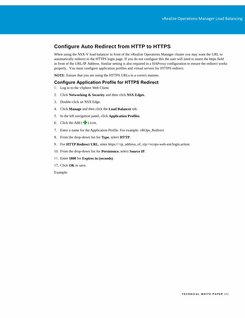
Configure Auto Redirect from HTTP to HTTPS
When using the NSX-V load balancer in front of the vRealize Operations Manager cluster you may want the URL to
automatically redirect to the HTTPS login page. If you do not configure this the user will need to insert the https field
in front of the URL/IP Address. Similar setting is also required in a HAProxy configuration to ensure the redirect works
properly. You must configure application profiles and virtual servers for HTTPS redirect.
NOTE: Ensure that you are using the HTTPS URLs in a correct manner.
Configure Application Profile for HTTPS Redirect Log in to the vSphere Web Client.
Click Networking & Security and then click NSX Edges.
Double-click an NSX Edge.
Click Manage and then click the Load Balancer tab.
In the left navigation panel, click Application Profiles.
Click the Add ( ) icon.
Enter a name for the Application Profile. For example: vROps_Redirect
From the drop-down list for Type, select HTTP.
For HTTP Redirect URL, enter https://<ip_address_of_vip>/vcops-web-ent/login.action.
From the drop-down list for Persistence, select Source IP.
Enter 1800 for Expires in (seconds).
Click OK to save.
Example:
vRealize Operations Manager Load Balancing
T E C H N I C A L W H I T E P A P E R / 4 3
Configure the Virtual Server for HTTPS Redirect You can configure the virtual server for HTTPS redirect.
Log in to the vSphere Web Client.
Click Networking & Security and then click NSX Edges.
Double-click an NSX Edge.
Click Manage and then click the Load Balancer tab.
In the left navigation panel, click Virtual Servers.
Click the Add ( ) icon.
Select Enable Virtual Server.
Select an Application Profile from the drop-down list that you have created. For example: vrops_redirect
Enter a Name for the virtual server.
(Optional) Enter a Description.
Enter IP Address for the VIP.
From the drop-down list for Protocol, select HTTP.
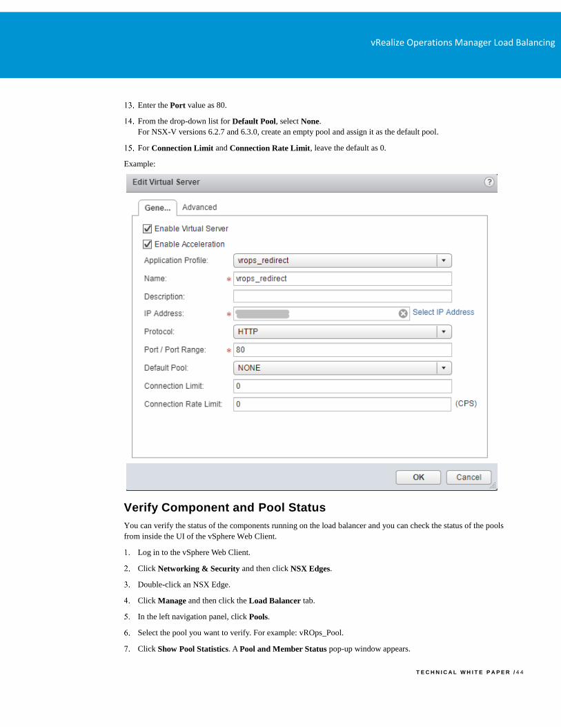
vRealize Operations Manager Load Balancing
T E C H N I C A L W H I T E P A P E R / 4 4
Enter the Port value as 80.
From the drop-down list for Default Pool, select None.
For NSX-V versions 6.2.7 and 6.3.0, create an empty pool and assign it as the default pool.
For Connection Limit and Connection Rate Limit, leave the default as 0.
Example:
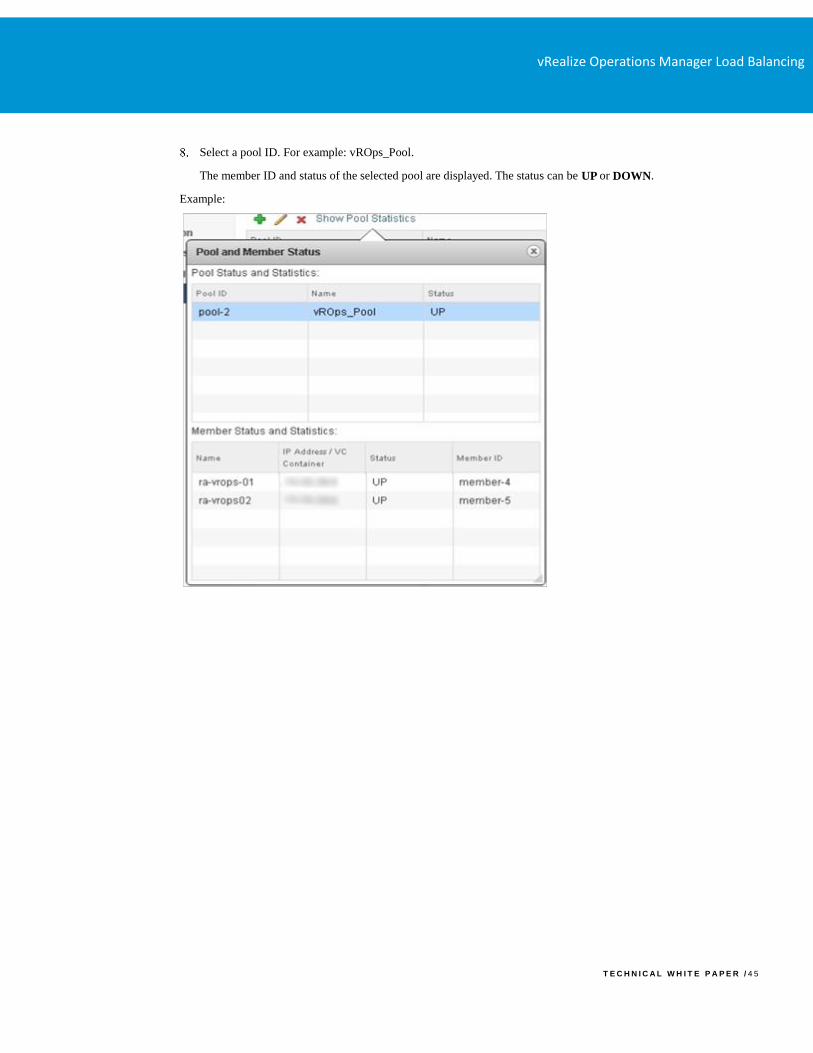
Verify Component and Pool Status
You can verify the status of the components running on the load balancer and you can check the status of the pools
from inside the UI of the vSphere Web Client.
Log in to the vSphere Web Client.
Click Networking & Security and then click NSX Edges.
Double-click an NSX Edge.
Click Manage and then click the Load Balancer tab.
In the left navigation panel, click Pools.
Select the pool you want to verify. For example: vROps_Pool.
Click Show Pool Statistics. A Pool and Member Status pop-up window appears.
vRealize Operations Manager Load Balancing
T E C H N I C A L W H I T E P A P E R / 4 5
Select a pool ID. For example: vROps_Pool.
The member ID and status of the selected pool are displayed. The status can be UP or DOWN.
Example:
vRealize Operations Manager Load Balancing
T E C H N I C A L W H I T E P A P E R / 4 6
NSX-T Installation & Configuration The NSX-T virtual networking solution includes the capability of deploying an Edge gateway as a load-balancer. It
offers high availability and load balancing for TCP and HTTP-based applications.
NOTE: Please use NSX-T version 2.2 or higher if you like to handle SSL Certificates within the load-balancer.
Prerequisites
The following are the prerequisites for a functional NSX-T load balancer in front of a vRealize Operations Manager
cluster:
• This document assumes that NSX-T is already deployed in the environment and is fully functional
• The NSX-T deployment is version 2.2 or higher
• NSX-T Edge has access to the network on which the vRealize Operations Manager cluster is deployed
• NSX-T Tier-1 edge for load balancing is configured
• A vRealize Operations Manager cluster has been deployed in the environment and is fully functional with all
nodes in the cluster accepting traffic. The cluster might have high availability enabled, but it is not a
requirement
• 1 Virtual Server IP address for vRealize Operations Manager analytics
An additional VIP/Virtual Server IP address for EPOps traffic, in case of separate load balancers is used for
analytics and EPOps
vRealize Operations Manager Load Balancing
T E C H N I C A L W H I T E P A P E R / 4 7
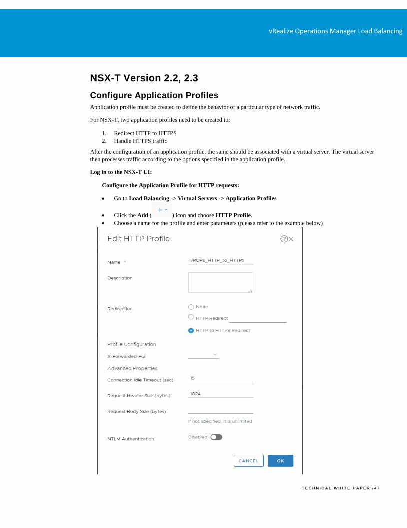
NSX-T Version 2.2, 2.3
Configure Application Profiles
Application profile must be created to define the behavior of a particular type of network traffic.
For NSX-T, two application profiles need to be created to:
1. Redirect HTTP to HTTPS
2. Handle HTTPS traffic
After the configuration of an application profile, the same should be associated with a virtual server. The virtual server
then processes traffic according to the options specified in the application profile.
Log in to the NSX-T UI:
Configure the Application Profile for HTTP requests:
• Go to Load Balancing -> Virtual Servers -> Application Profiles
• Click the Add ( ) icon and choose HTTP Profile.
• Choose a name for the profile and enter parameters (please refer to the example below)
vRealize Operations Manager Load Balancing
T E C H N I C A L W H I T E P A P E R / 4 8
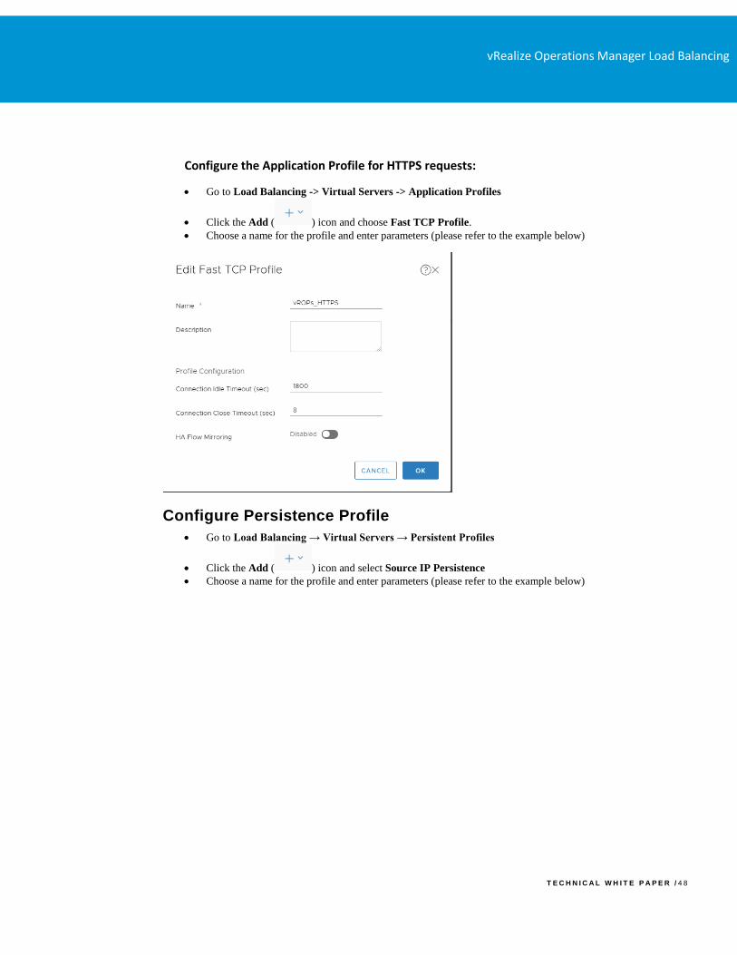
Configure the Application Profile for HTTPS requests:
• Go to Load Balancing -> Virtual Servers -> Application Profiles
• Click the Add ( ) icon and choose Fast TCP Profile.
• Choose a name for the profile and enter parameters (please refer to the example below)
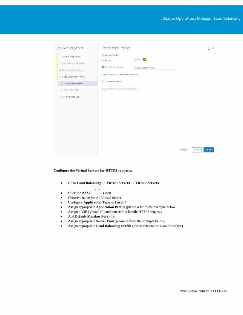
Configure Persistence Profile
• Go to Load Balancing → Virtual Servers → Persistent Profiles
• Click the Add ( ) icon and select Source IP Persistence
• Choose a name for the profile and enter parameters (please refer to the example below)

vRealize Operations Manager Load Balancing
T E C H N I C A L W H I T E P A P E R / 4 9
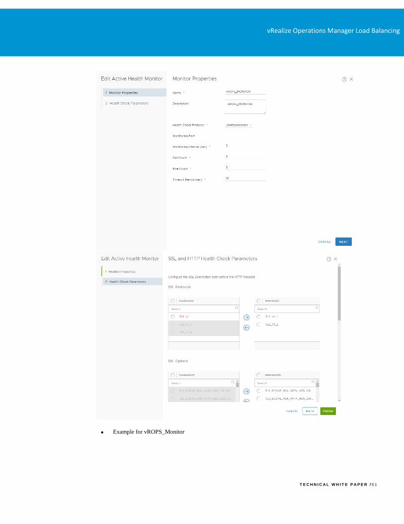
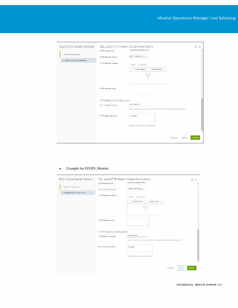
Add Active Health Monitor
Configuring active health monitoring is similar to creating health checks on other load-balancers. When you
associate an active health monitor with a pool, the pool members are monitored according to the active health
monitor parameters. To configure an Active Health Monitor, perform the following steps:
• Go to Load Balancing → Server Pools → Active Health Monitors
• Click the Add ( ) icon
• Choose a name for the active health monitor and enter Monitor Properties (please refer to the example
below)
Note: LbHttpsMonitor is pre-configured monitor for HTTPS protocol and it can be used for this Active Health
Monitor
• Configure Health check parameters with the following values:
1. Request Method
GET
2. Request URL
/suite-api/api/deployment/node/status
3. Request Version
HTTP_VERSION_1_1
4. Response Status Codes
200, 204, 301
5. Response Body
ONLINE (upper case)
6. Ciphers
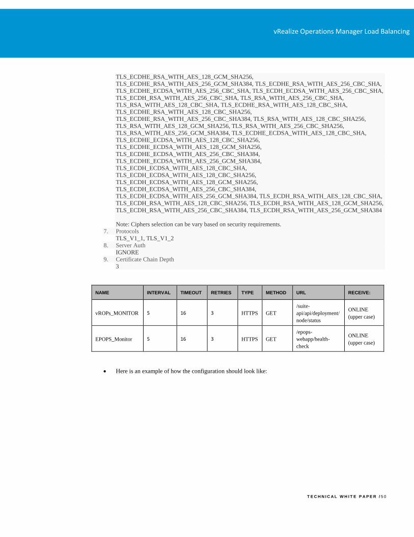
vRealize Operations Manager Load Balancing
T E C H N I C A L W H I T E P A P E R / 5 0
TLS_ECDHE_RSA_WITH_AES_128_GCM_SHA256,
TLS_ECDHE_RSA_WITH_AES_256_GCM_SHA384, TLS_ECDHE_RSA_WITH_AES_256_CBC_SHA,
TLS_ECDHE_ECDSA_WITH_AES_256_CBC_SHA, TLS_ECDH_ECDSA_WITH_AES_256_CBC_SHA,
TLS_ECDH_RSA_WITH_AES_256_CBC_SHA, TLS_RSA_WITH_AES_256_CBC_SHA,
TLS_RSA_WITH_AES_128_CBC_SHA, TLS_ECDHE_RSA_WITH_AES_128_CBC_SHA,
TLS_ECDHE_RSA_WITH_AES_128_CBC_SHA256,
TLS_ECDHE_RSA_WITH_AES_256_CBC_SHA384, TLS_RSA_WITH_AES_128_CBC_SHA256,
TLS_RSA_WITH_AES_128_GCM_SHA256, TLS_RSA_WITH_AES_256_CBC_SHA256,
TLS_RSA_WITH_AES_256_GCM_SHA384, TLS_ECDHE_ECDSA_WITH_AES_128_CBC_SHA,
TLS_ECDHE_ECDSA_WITH_AES_128_CBC_SHA256,
TLS_ECDHE_ECDSA_WITH_AES_128_GCM_SHA256,
TLS_ECDHE_ECDSA_WITH_AES_256_CBC_SHA384,
TLS_ECDHE_ECDSA_WITH_AES_256_GCM_SHA384,
TLS_ECDH_ECDSA_WITH_AES_128_CBC_SHA,
TLS_ECDH_ECDSA_WITH_AES_128_CBC_SHA256,
TLS_ECDH_ECDSA_WITH_AES_128_GCM_SHA256,
TLS_ECDH_ECDSA_WITH_AES_256_CBC_SHA384,
TLS_ECDH_ECDSA_WITH_AES_256_GCM_SHA384, TLS_ECDH_RSA_WITH_AES_128_CBC_SHA,
TLS_ECDH_RSA_WITH_AES_128_CBC_SHA256, TLS_ECDH_RSA_WITH_AES_128_GCM_SHA256,
TLS_ECDH_RSA_WITH_AES_256_CBC_SHA384, TLS_ECDH_RSA_WITH_AES_256_GCM_SHA384
Note: Ciphers selection can be vary based on security requirements.
7. Protocols
TLS_V1_1, TLS_V1_2
8. Server Auth
IGNORE
9. Certificate Chain Depth
3
NAME INTERVAL TIMEOUT RETRIES TYPE METHOD URL RECEIVE:
vROPs_MONITOR 5 16 3 HTTPS GET
/suite-
api/api/deployment/
node/status
ONLINE
(upper case)
EPOPS_Monitor 5 16 3 HTTPS GET
/epops-
webapp/health-
check
ONLINE
(upper case)
• Here is an example of how the configuration should look like:
vRealize Operations Manager Load Balancing
T E C H N I C A L W H I T E P A P E R / 5 1
• Example for vROPS_Monitor
vRealize Operations Manager Load Balancing
T E C H N I C A L W H I T E P A P E R / 5 2
• Example for EPOPS_Monitor
vRealize Operations Manager Load Balancing
T E C H N I C A L W H I T E P A P E R / 5 3
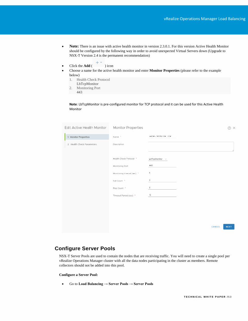
• Note: There is an issue with active health monitor in version 2.3.0.1. For this version Active Health Monitor
should be configured by the following way in order to avoid unexpected Virtual Servers down (Upgrade to
NSX-T Version 2.4 is the permanent recommendation)
• Click the Add ( ) icon
• Choose a name for the active health monitor and enter Monitor Properties (please refer to the example
below)
1. Health Check Protocol
LbTcpMonitor
2. Monitoring Port
443
Note: LbTcpMonitor is pre-configured monitor for TCP protocol and it can be used for this Active Health
Monitor
Configure Server Pools
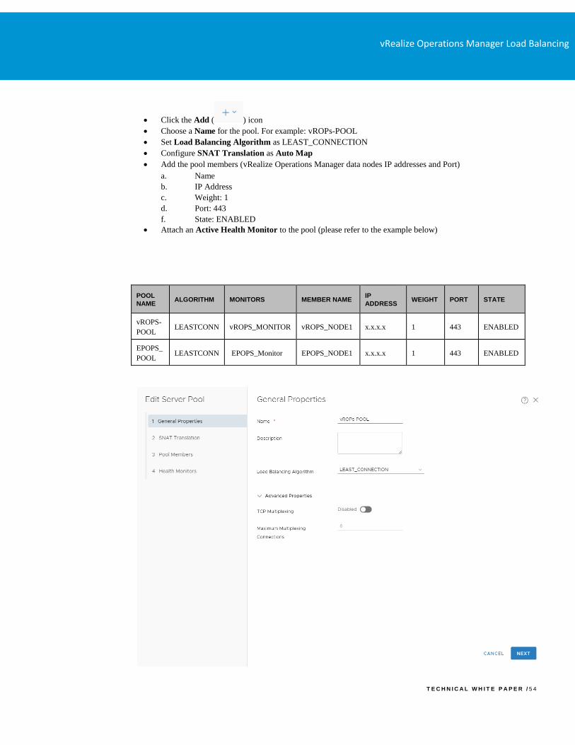
NSX-T Server Pools are used to contain the nodes that are receiving traffic. You will need to create a single pool per
vRealize Operations Manager cluster with all the data nodes participating in the cluster as members. Remote
collectors should not be added into this pool.
Configure a Server Pool:
• Go to Load Balancing → Server Pools → Server Pools
vRealize Operations Manager Load Balancing
T E C H N I C A L W H I T E P A P E R / 5 4
• Click the Add ( ) icon
• Choose a Name for the pool. For example: vROPs-POOL
• Set Load Balancing Algorithm as LEAST_CONNECTION
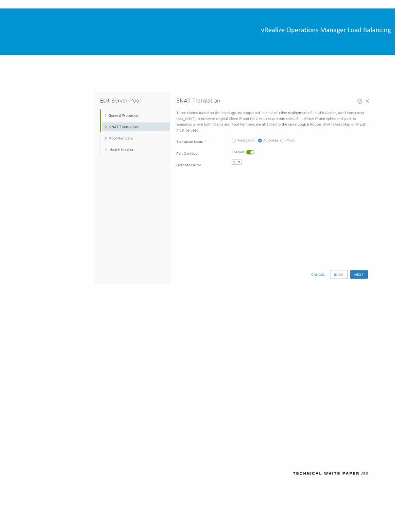
• Configure SNAT Translation as Auto Map
• Add the pool members (vRealize Operations Manager data nodes IP addresses and Port)
a. Name
b. IP Address
c. Weight: 1
d. Port: 443
f. State: ENABLED
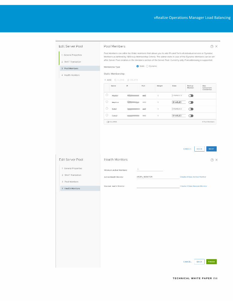
• Attach an Active Health Monitor to the pool (please refer to the example below)
POOL
NAME ALGORITHM MONITORS MEMBER NAME
IP
ADDRESS WEIGHT PORT STATE
vROPS-
POOL LEASTCONN vROPS_MONITOR vROPS_NODE1 x.x.x.x 1 443 ENABLED
EPOPS_
POOL LEASTCONN EPOPS_Monitor EPOPS_NODE1 x.x.x.x 1 443 ENABLED
vRealize Operations Manager Load Balancing
T E C H N I C A L W H I T E P A P E R / 5 5
vRealize Operations Manager Load Balancing
T E C H N I C A L W H I T E P A P E R / 5 6
vRealize Operations Manager Load Balancing
T E C H N I C A L W H I T E P A P E R / 5 7
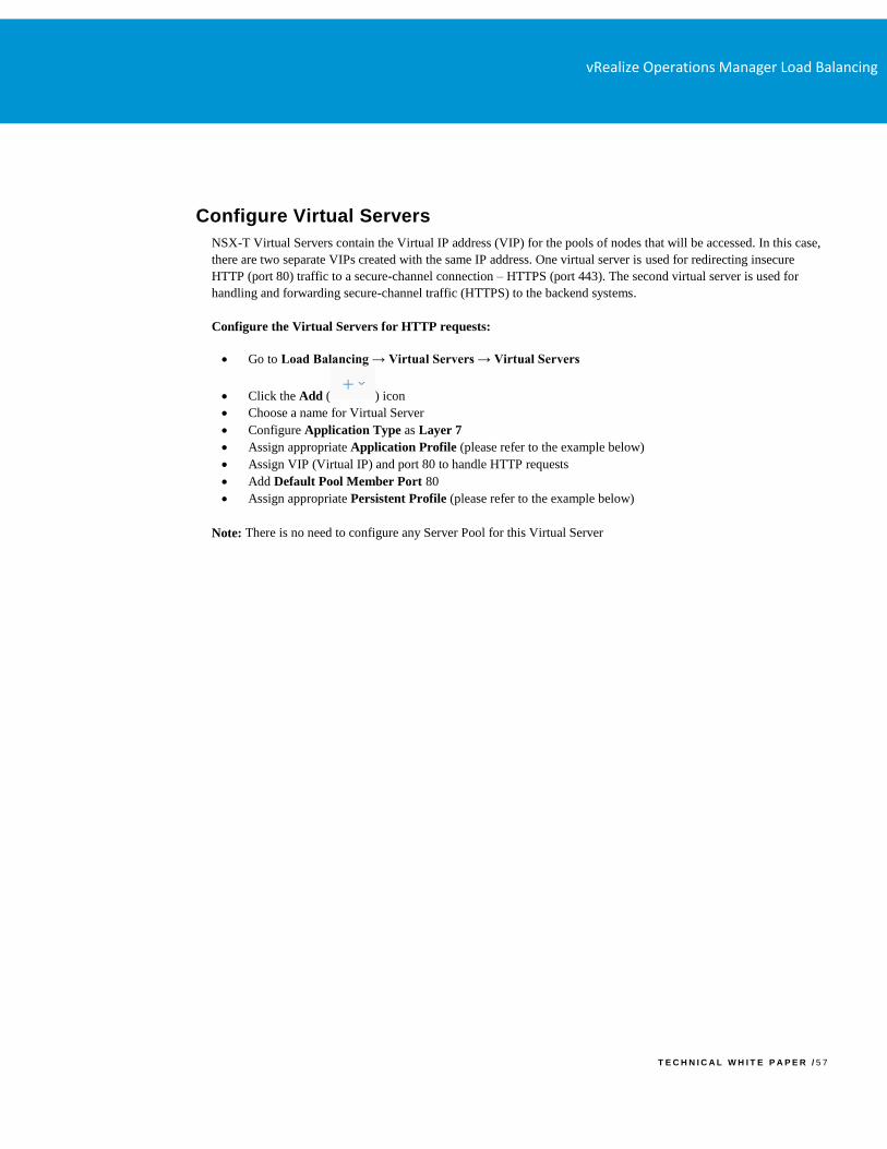
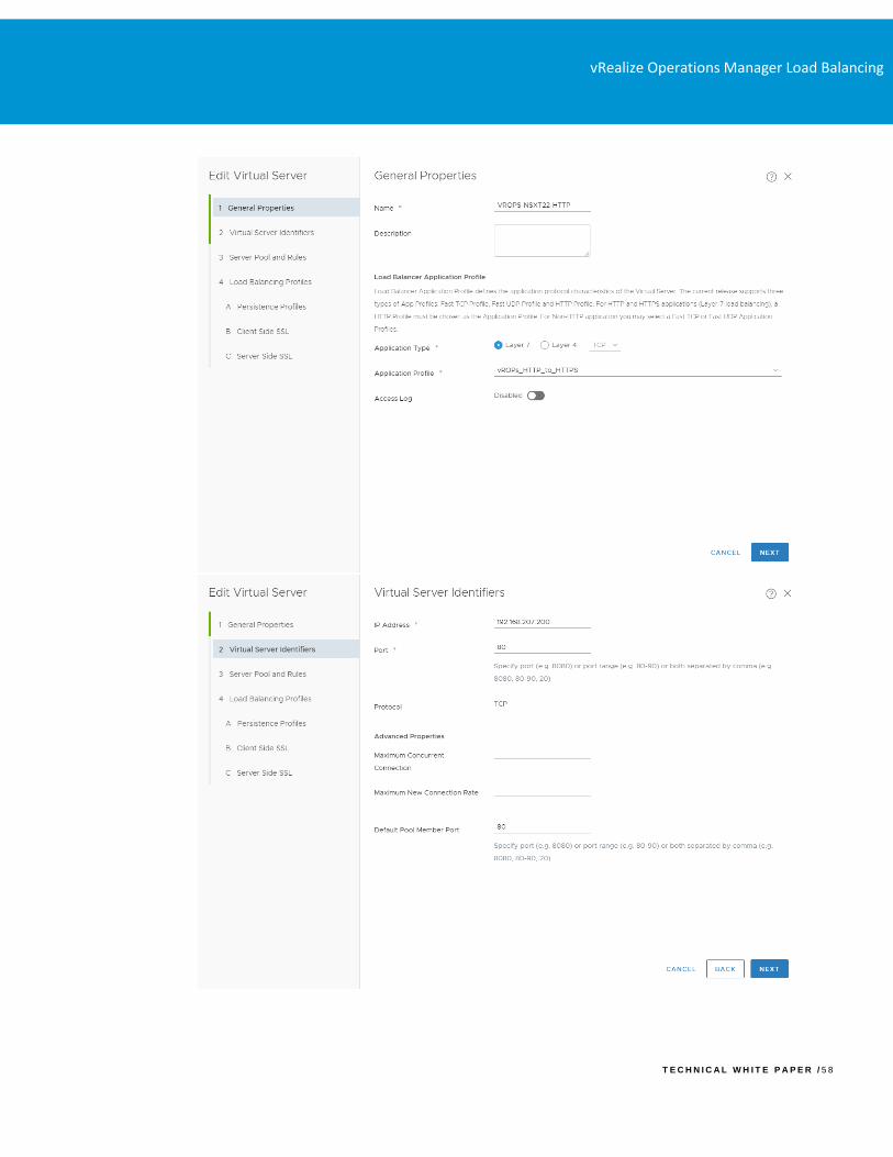
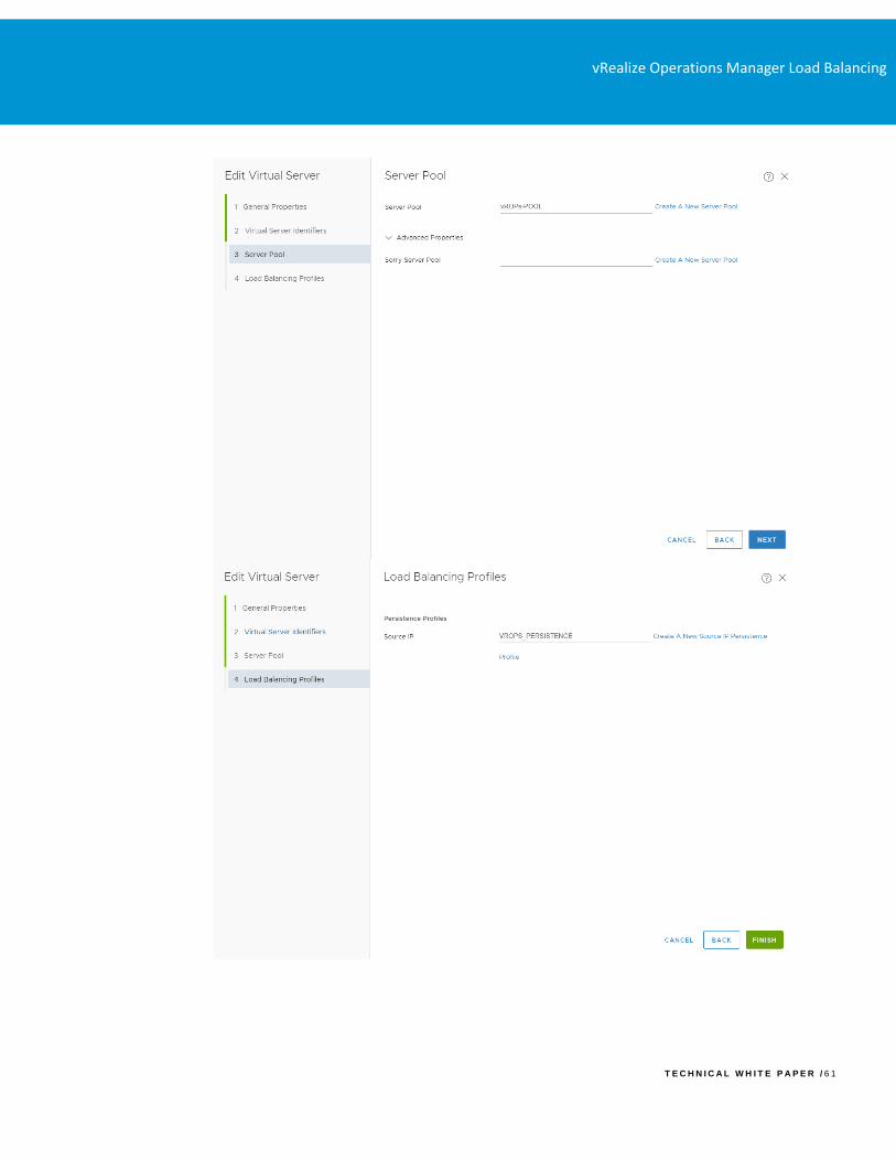
Configure Virtual Servers
NSX-T Virtual Servers contain the Virtual IP address (VIP) for the pools of nodes that will be accessed. In this case,
there are two separate VIPs created with the same IP address. One virtual server is used for redirecting insecure
HTTP (port 80) traffic to a secure-channel connection – HTTPS (port 443). The second virtual server is used for
handling and forwarding secure-channel traffic (HTTPS) to the backend systems.
Configure the Virtual Servers for HTTP requests:
• Go to Load Balancing → Virtual Servers → Virtual Servers
• Click the Add ( ) icon
• Choose a name for Virtual Server
• Configure Application Type as Layer 7
• Assign appropriate Application Profile (please refer to the example below)
• Assign VIP (Virtual IP) and port 80 to handle HTTP requests
• Add Default Pool Member Port 80
• Assign appropriate Persistent Profile (please refer to the example below)
Note: There is no need to configure any Server Pool for this Virtual Server
vRealize Operations Manager Load Balancing
T E C H N I C A L W H I T E P A P E R / 5 8
vRealize Operations Manager Load Balancing
T E C H N I C A L W H I T E P A P E R / 5 9
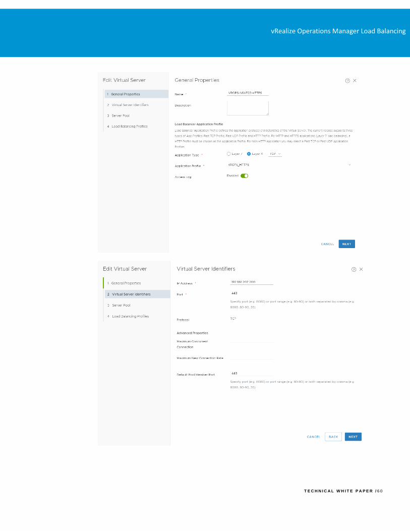
Configure the Virtual Servers for HTTPS requests:
• Go to Load Balancing → Virtual Servers → Virtual Servers
• Click the Add ( ) icon
• Choose a name for the Virtual Server
• Configure Application Type as Layer 4
• Assign appropriate Application Profile (please refer to the example below)
• Assign a VIP (Virtual IP) and port 443 to handle HTTPS requests
• Add Default Member Port 443.
• Assign appropriate Server Pool (please refer to the example below)
• Assign appropriate Load Balancing Profile (please refer to the example below)
vRealize Operations Manager Load Balancing
T E C H N I C A L W H I T E P A P E R / 6 0
vRealize Operations Manager Load Balancing
T E C H N I C A L W H I T E P A P E R / 6 1
vRealize Operations Manager Load Balancing
T E C H N I C A L W H I T E P A P E R / 6 2
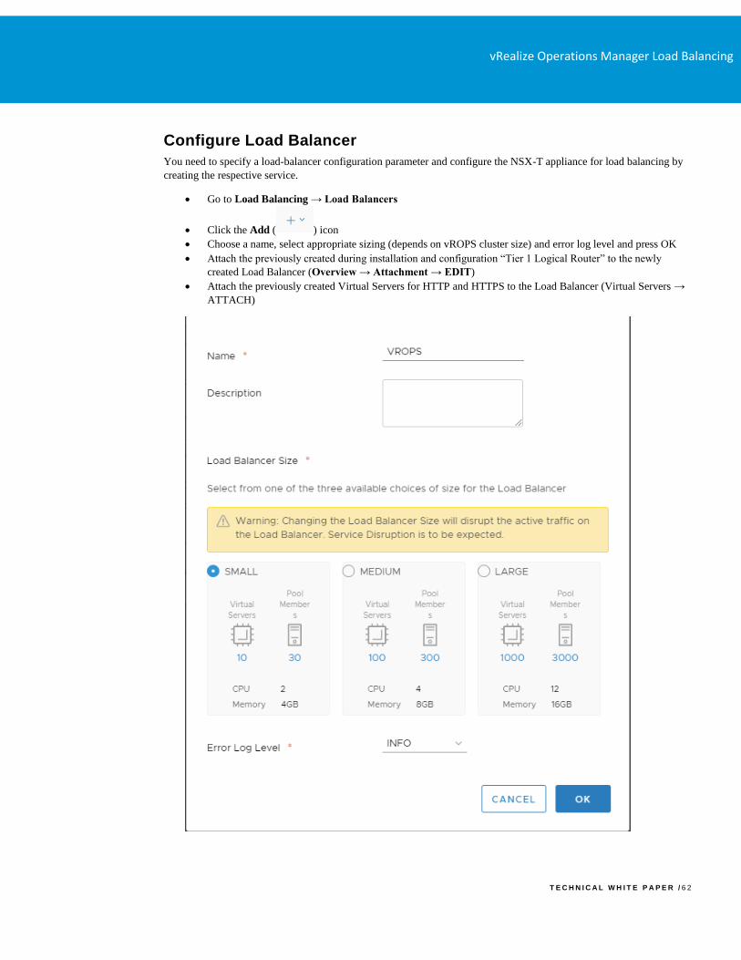
Configure Load Balancer
You need to specify a load-balancer configuration parameter and configure the NSX-T appliance for load balancing by
creating the respective service.
• Go to Load Balancing → Load Balancers
• Click the Add ( ) icon
• Choose a name, select appropriate sizing (depends on vROPS cluster size) and error log level and press OK
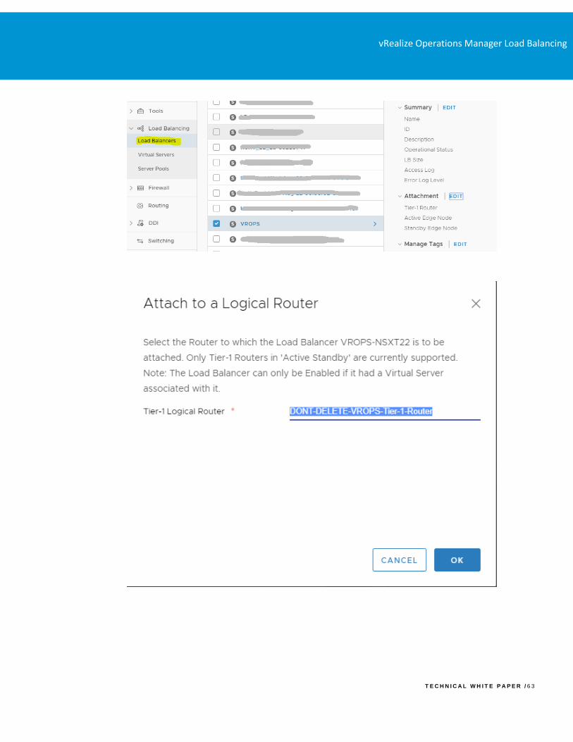
• Attach the previously created during installation and configuration “Tier 1 Logical Router” to the newly
created Load Balancer (Overview → Attachment → EDIT)
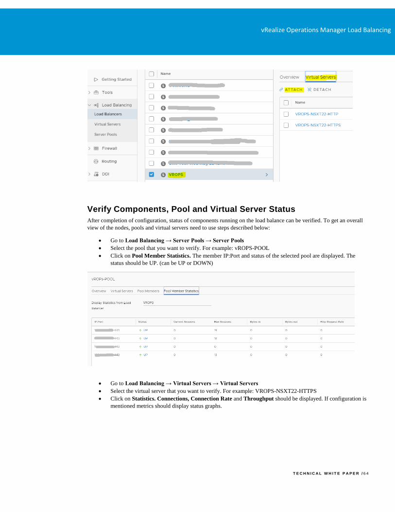
• Attach the previously created Virtual Servers for HTTP and HTTPS to the Load Balancer (Virtual Servers →
ATTACH)
vRealize Operations Manager Load Balancing
T E C H N I C A L W H I T E P A P E R / 6 3
vRealize Operations Manager Load Balancing
T E C H N I C A L W H I T E P A P E R / 6 4
Verify Components, Pool and Virtual Server Status
After completion of configuration, status of components running on the load balance can be verified. To get an overall
view of the nodes, pools and virtual servers need to use steps described below:
• Go to Load Balancing → Server Pools → Server Pools
• Select the pool that you want to verify. For example: vROPS-POOL
• Click on Pool Member Statistics. The member IP:Port and status of the selected pool are displayed. The
status should be UP. (can be UP or DOWN)
• Go to Load Balancing → Virtual Servers → Virtual Servers
• Select the virtual server that you want to verify. For example: VROPS-NSXT22-HTTPS
• Click on Statistics. Connections, Connection Rate and Throughput should be displayed. If configuration is
mentioned metrics should display status graphs.
vRealize Operations Manager Load Balancing
T E C H N I C A L W H I T E P A P E R / 6 5
vRealize Operations Manager Load Balancing
VMware, Inc. 3401 Hillview Avenue Palo Alto CA 94304 USA Tel 877-486-9273 Fax 650-427-5001
www.vmware.com
Copyright © 2015-2017 VMware, Inc. All rights reserved. This product is protected by U.S. and international copyright and intellectual property laws. VMware products are covered by one or more
patents listed at http://www.vmware.com/go/patents. VMware is a registered trademark or trademark of VMware, Inc. in the United States and/or other jurisdictions. All other marks and names
mentioned herein may be trademarks of their respective companies.
T E C H N I C A L W H I T E P A P E R / 6 6
NSX-T Version 2.4
Configure Load Balancer
You need to specify a load-balancer configuration parameter and configure the NSX-T appliance for load balancing by
creating the respective service.
• Go to Networking → Load Balancing → Load Balancers
• Click the Add ( ) icon
• Choose a name, select appropriate sizing (depends on vROPS cluster size), error log level, previously created
during installation and configuration “Tier 1 Logical Router” and press OK
• For the following dialog select NO
vRealize Operations Manager Load Balancing
VMware, Inc. 3401 Hillview Avenue Palo Alto CA 94304 USA Tel 877-486-9273 Fax 650-427-5001
www.vmware.com
Copyright © 2015-2017 VMware, Inc. All rights reserved. This product is protected by U.S. and international copyright and intellectual property laws. VMware products are covered by one or more
patents listed at http://www.vmware.com/go/patents. VMware is a registered trademark or trademark of VMware, Inc. in the United States and/or other jurisdictions. All other marks and names
mentioned herein may be trademarks of their respective companies.
T E C H N I C A L W H I T E P A P E R / 6 7
Configure Application Profiles
Application profile must be created to define the behavior of a particular type of network traffic.
For NSX-T, two application profiles need to be created to:
3. Redirect HTTP to HTTPS
4. Handle HTTPS traffic
After the configuration of an application profile, the same should be associated with a virtual server. The virtual server
then processes traffic according to the options specified in the application profile.
Configure the Application Profile for HTTP requests:
• Go to Networking -> Load balancing -> Profiles
• Select Profile Type
• Click the Add ( ) icon and choose HTTP Profile.
• Choose a name for the profile and enter parameters (please refer to the example below)
Configure the Application Profile for HTTPS requests:
• Go to Networking -> Load balancing -> Profiles
• Select profile type
• Click the Add ( ) icon and choose Fast TCP Profile.
• Choose a name for the profile and enter parameters (please refer to the example below)
vRealize Operations Manager Load Balancing
VMware, Inc. 3401 Hillview Avenue Palo Alto CA 94304 USA Tel 877-486-9273 Fax 650-427-5001
www.vmware.com
Copyright © 2015-2017 VMware, Inc. All rights reserved. This product is protected by U.S. and international copyright and intellectual property laws. VMware products are covered by one or more
patents listed at http://www.vmware.com/go/patents. VMware is a registered trademark or trademark of VMware, Inc. in the United States and/or other jurisdictions. All other marks and names
mentioned herein may be trademarks of their respective companies.
T E C H N I C A L W H I T E P A P E R / 6 8
Configure Persistence Profile
• Go to Networking -> Load balancing -> Profiles
• Select profile type
• Click the Add ( ) icon and select Source IP
• Choose a name for the profile and enter parameters (please refer to the example below)
Add Active Health Monitor
Configuring active health monitoring is similar to creating health checks on other load-balancers. When you
associate an active health monitor with a pool, the pool members are monitored according to the active health
monitor parameters. To configure an Active Health Monitor, perform the following steps:
• Go to Networking -> Load balancing -> Monitors
• Select monitor type
• Click the Add ( ) icon and select HTTPS
• Choose a name for the active monitor and enter Monitor Properties (please refer to the example below)
vRealize Operations Manager Load Balancing
VMware, Inc. 3401 Hillview Avenue Palo Alto CA 94304 USA Tel 877-486-9273 Fax 650-427-5001
www.vmware.com
Copyright © 2015-2017 VMware, Inc. All rights reserved. This product is protected by U.S. and international copyright and intellectual property laws. VMware products are covered by one or more
patents listed at http://www.vmware.com/go/patents. VMware is a registered trademark or trademark of VMware, Inc. in the United States and/or other jurisdictions. All other marks and names
mentioned herein may be trademarks of their respective companies.
T E C H N I C A L W H I T E P A P E R / 6 9
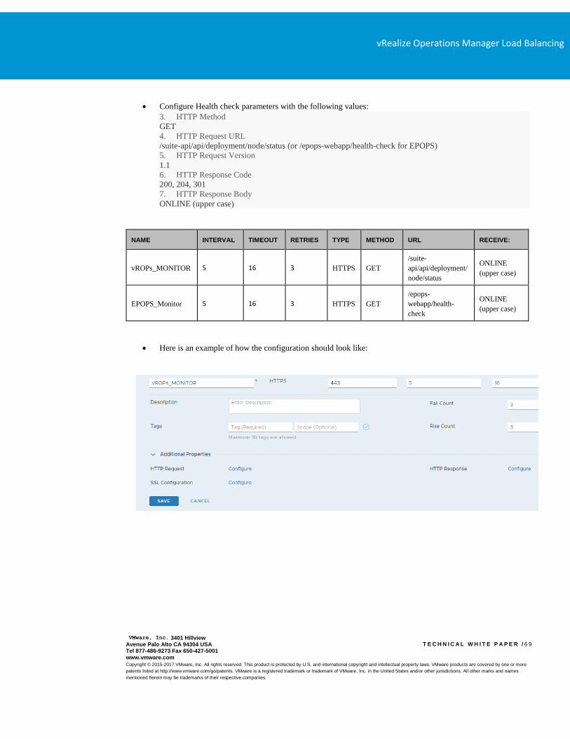
• Configure Health check parameters with the following values:
3. HTTP Method
GET
4. HTTP Request URL
/suite-api/api/deployment/node/status (or /epops-webapp/health-check for EPOPS)
5. HTTP Request Version
1.1
6. HTTP Response Code
200, 204, 301 7. HTTP Response Body
ONLINE (upper case)
NAME INTERVAL TIMEOUT RETRIES TYPE METHOD URL RECEIVE:
vROPs_MONITOR 5 16 3 HTTPS GET
/suite-
api/api/deployment/
node/status
ONLINE
(upper case)
EPOPS_Monitor 5 16 3 HTTPS GET
/epops-
webapp/health-
check
ONLINE
(upper case)
• Here is an example of how the configuration should look like:
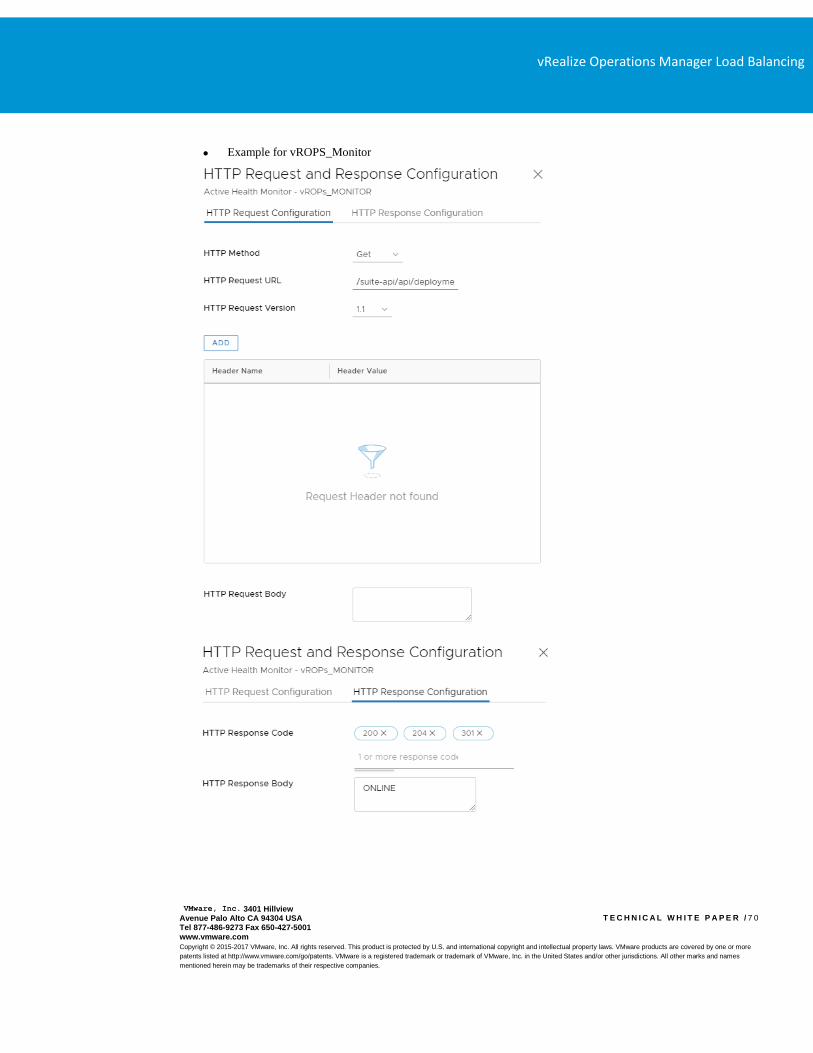
vRealize Operations Manager Load Balancing
VMware, Inc. 3401 Hillview Avenue Palo Alto CA 94304 USA Tel 877-486-9273 Fax 650-427-5001
www.vmware.com
Copyright © 2015-2017 VMware, Inc. All rights reserved. This product is protected by U.S. and international copyright and intellectual property laws. VMware products are covered by one or more
patents listed at http://www.vmware.com/go/patents. VMware is a registered trademark or trademark of VMware, Inc. in the United States and/or other jurisdictions. All other marks and names
mentioned herein may be trademarks of their respective companies.
T E C H N I C A L W H I T E P A P E R / 7 0
• Example for vROPS_Monitor
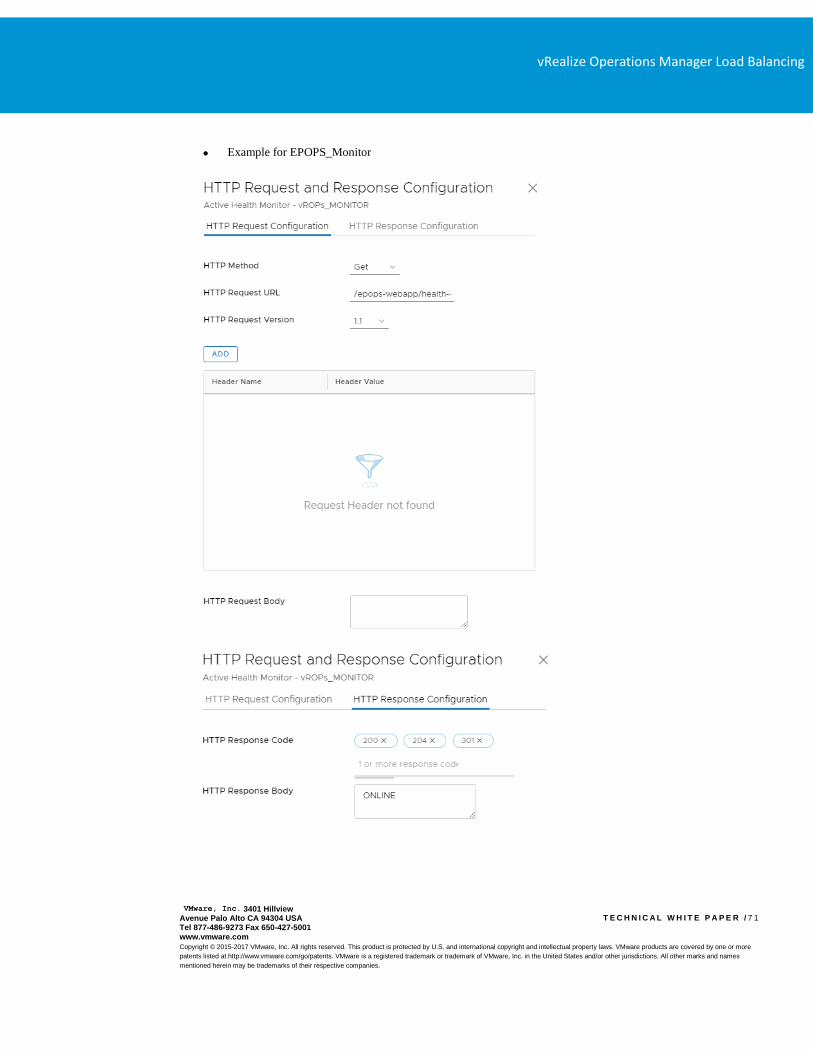
vRealize Operations Manager Load Balancing
VMware, Inc. 3401 Hillview Avenue Palo Alto CA 94304 USA Tel 877-486-9273 Fax 650-427-5001
www.vmware.com
Copyright © 2015-2017 VMware, Inc. All rights reserved. This product is protected by U.S. and international copyright and intellectual property laws. VMware products are covered by one or more
patents listed at http://www.vmware.com/go/patents. VMware is a registered trademark or trademark of VMware, Inc. in the United States and/or other jurisdictions. All other marks and names
mentioned herein may be trademarks of their respective companies.
T E C H N I C A L W H I T E P A P E R / 7 1
• Example for EPOPS_Monitor
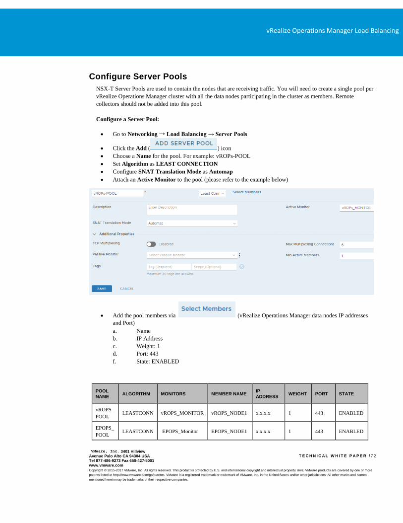
vRealize Operations Manager Load Balancing
VMware, Inc. 3401 Hillview Avenue Palo Alto CA 94304 USA Tel 877-486-9273 Fax 650-427-5001
www.vmware.com
Copyright © 2015-2017 VMware, Inc. All rights reserved. This product is protected by U.S. and international copyright and intellectual property laws. VMware products are covered by one or more
patents listed at http://www.vmware.com/go/patents. VMware is a registered trademark or trademark of VMware, Inc. in the United States and/or other jurisdictions. All other marks and names
mentioned herein may be trademarks of their respective companies.
T E C H N I C A L W H I T E P A P E R / 7 2
Configure Server Pools
NSX-T Server Pools are used to contain the nodes that are receiving traffic. You will need to create a single pool per
vRealize Operations Manager cluster with all the data nodes participating in the cluster as members. Remote
collectors should not be added into this pool.
Configure a Server Pool:
• Go to Networking → Load Balancing → Server Pools
• Click the Add ( ) icon
• Choose a Name for the pool. For example: vROPs-POOL
• Set Algorithm as LEAST CONNECTION
• Configure SNAT Translation Mode as Automap
• Attach an Active Monitor to the pool (please refer to the example below)
• Add the pool members via (vRealize Operations Manager data nodes IP addresses
and Port)
a. Name
b. IP Address
c. Weight: 1
d. Port: 443
f. State: ENABLED
POOL
NAME ALGORITHM MONITORS MEMBER NAME
IP
ADDRESS WEIGHT PORT STATE
vROPS-
POOL LEASTCONN vROPS_MONITOR vROPS_NODE1 x.x.x.x 1 443 ENABLED
EPOPS_
POOL LEASTCONN EPOPS_Monitor EPOPS_NODE1 x.x.x.x 1 443 ENABLED
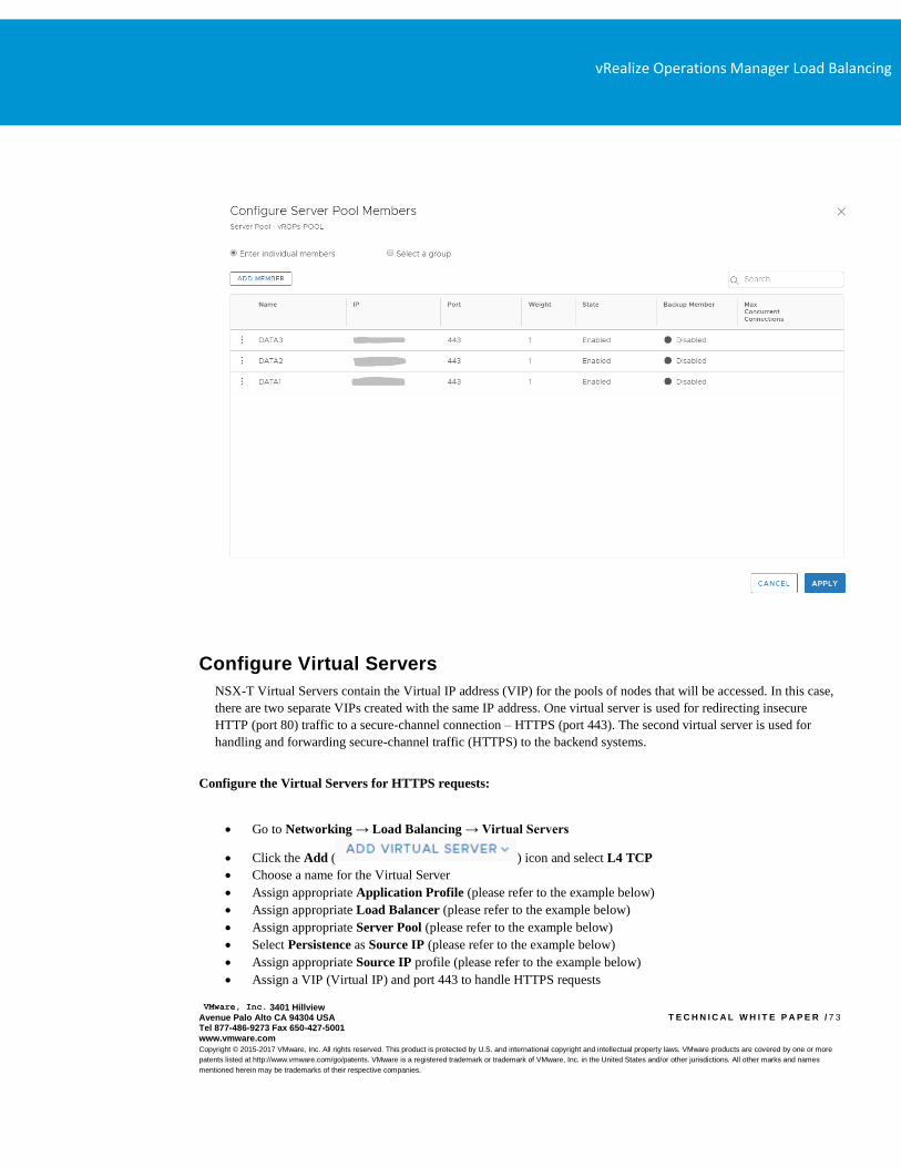
vRealize Operations Manager Load Balancing
VMware, Inc. 3401 Hillview Avenue Palo Alto CA 94304 USA Tel 877-486-9273 Fax 650-427-5001
www.vmware.com
Copyright © 2015-2017 VMware, Inc. All rights reserved. This product is protected by U.S. and international copyright and intellectual property laws. VMware products are covered by one or more
patents listed at http://www.vmware.com/go/patents. VMware is a registered trademark or trademark of VMware, Inc. in the United States and/or other jurisdictions. All other marks and names
mentioned herein may be trademarks of their respective companies.
T E C H N I C A L W H I T E P A P E R / 7 3
Configure Virtual Servers
NSX-T Virtual Servers contain the Virtual IP address (VIP) for the pools of nodes that will be accessed. In this case,
there are two separate VIPs created with the same IP address. One virtual server is used for redirecting insecure
HTTP (port 80) traffic to a secure-channel connection – HTTPS (port 443). The second virtual server is used for
handling and forwarding secure-channel traffic (HTTPS) to the backend systems.
Configure the Virtual Servers for HTTPS requests:
• Go to Networking → Load Balancing → Virtual Servers
• Click the Add ( ) icon and select L4 TCP
• Choose a name for the Virtual Server
• Assign appropriate Application Profile (please refer to the example below)
• Assign appropriate Load Balancer (please refer to the example below)
• Assign appropriate Server Pool (please refer to the example below)
• Select Persistence as Source IP (please refer to the example below)
• Assign appropriate Source IP profile (please refer to the example below)
• Assign a VIP (Virtual IP) and port 443 to handle HTTPS requests
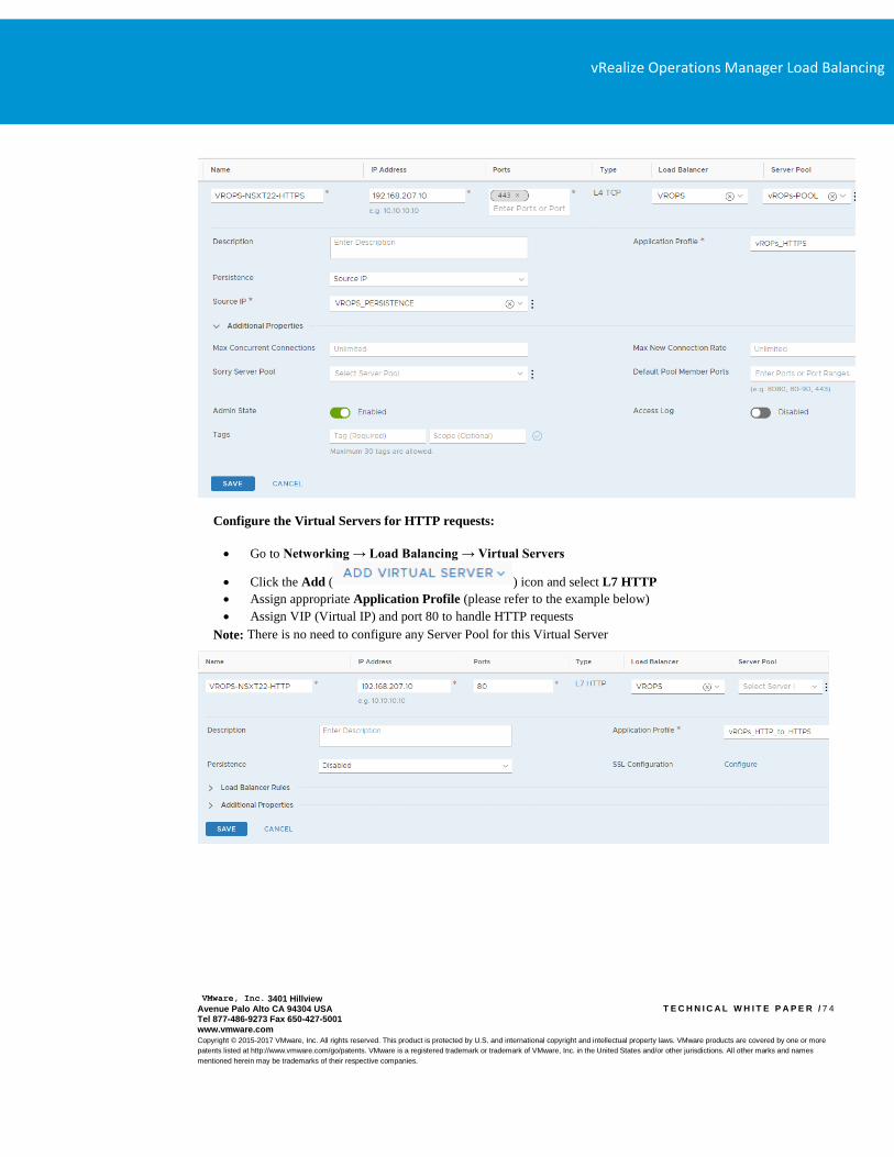
vRealize Operations Manager Load Balancing
VMware, Inc. 3401 Hillview Avenue Palo Alto CA 94304 USA Tel 877-486-9273 Fax 650-427-5001
www.vmware.com
Copyright © 2015-2017 VMware, Inc. All rights reserved. This product is protected by U.S. and international copyright and intellectual property laws. VMware products are covered by one or more
patents listed at http://www.vmware.com/go/patents. VMware is a registered trademark or trademark of VMware, Inc. in the United States and/or other jurisdictions. All other marks and names
mentioned herein may be trademarks of their respective companies.
T E C H N I C A L W H I T E P A P E R / 7 4
Configure the Virtual Servers for HTTP requests:
• Go to Networking → Load Balancing → Virtual Servers
• Click the Add ( ) icon and select L7 HTTP
• Assign appropriate Application Profile (please refer to the example below)
• Assign VIP (Virtual IP) and port 80 to handle HTTP requests
Note: There is no need to configure any Server Pool for this Virtual Server