vrf-lite on ar-series firewalls...application control, malware protection and ip reputation. vrf can...
TRANSCRIPT

FEATURE OVERVIEW AND CONFIGURATION GUIDE
VRF-lite on AR-Series Firewalls
IntroductionVRF-lite is used for isolating customer networks—it allows multiple secure customer routing domains, which remain completely isolated from each other, to co-exist in one physical device simultaneously.
VRF-lite also allows the re-use of IP addresses on the same physical device. An IP address range in one network interface used in one VRF domain can simultaneously be used in another network interface in a different VRF domain within the same device. While VRF-lite will segregate traffic from different customers/clients, VRF-lite can also allow access between VRF domains (inter-VRF communication), by using static inter-VRF routes. This provides controlled access from one VRF routing domain to another where the IP address ranges do not overlap.
VRF-lite can be used in conjunction with firewall features while maintaining security. Additionally, VRF routing domains can be transported across Virtual Private Networks, by associating individual VPNs with one or more VRF instances.
This document describes VRF-lite support and how to configure it on the AR-Series Firewalls. It shows how to configure the following examples:
“Example 1: VRF-lite with firewall protection/security features”
“Example 2: VRF-lite on a Virtual Tunnel Interface (VTI)”
“Example 3: VRF-lite on VTIs with firewall and NAT”
“Example 4: Multiple VRFs via IPsec VPN using Ethernet pseudowires”
“Example 5: VRF instances from central to remote VPN sites”
These are followed by discussion of:
“VRF-aware Utilities in AlliedWare Plus”
“Static Inter-VRF Routing”
“Configuring DNS Relay to be VRF-aware”
“Adding a VRF-aware Static ARP”
“Local Interfaces with VRF-lite”
Finally, a list of commands that are useful for diagnosing VRF-related issues concludes the document.
alliedtelesis.com xC613-22092-00 REV A

Introduction
Which products and software version does it apply to?
The information provided in this document applies to AR-Series firewalls running 5.4.6-2 and above:
AR4050S
AR3050S
AR2050V
AR2010V
Feature support may change in later software versions. For the latest information, see the product’s Command Reference.
VRF-lite is also supported on several switches running AlliedWare Plus. For information about VRF-lite operation and configuration on switches, see the VRF-lite on AlliedWare Plus Switches Feature Overview and Configuration Guide.
Related documents
For information about related features, see the following documents:
The product’s Command Reference
Getting Started with the UTM Firewall GUI Feature Overview and Configuration Guide
Internet Protocol Security (IPsec) Feature Overview and Configuration Guide
Interfaces Feature Overview and Configuration Guide
Page 2 | VRF-lite on AR-Series Firewalls

Introduction
ContentIntroduction .............................................................................................................................................................................1
Which products and software version does it apply to?......................................................................2
Related documents ....................................................................................................................................................2
Understanding VRF-lite on AR-Series Firewalls ..................................................................................................4
Routes tables .................................................................................................................................................................4
Interface management..............................................................................................................................................4
VRF-lite Support on AR-Series Firewalls ................................................................................................................5
Unsupported features ..............................................................................................................................................6
Supported Interface Types..............................................................................................................................................6
Firewall Security Features and VRF-lite....................................................................................................................7
Example 1: VRF-lite with firewall protection/security features .........................................................8
Virtual Tunnel Interfaces and VRF-lite ...................................................................................................................10
Example 2: VRF-lite on a Virtual Tunnel Interface (VTI) ...................................................................10
Example 3: VRF-lite on VTIs with firewall and NAT............................................................................11
Example 4: Multiple VRFs via IPsec VPN using Ethernet pseudowires .....................................16
Example 5: VRF instances from central to remote VPN sites........................................................19
VRF-aware Utilities in AlliedWare Plus .................................................................................................................25
TCPdump .....................................................................................................................................................................25
Ping ...................................................................................................................................................................................26
Trace route ..................................................................................................................................................................26
Telnet client..................................................................................................................................................................27
SSH client......................................................................................................................................................................27
Static Inter-VRF Routing.................................................................................................................................................28
Configuring DNS Relay to be VRF-aware...........................................................................................................29
Introduction.................................................................................................................................................................29
DNS operation with VRF-lite............................................................................................................................29
Configuring DNS operation with VRF-lite.................................................................................................30
Adding a VRF-aware Static ARP...............................................................................................................................32
Local Interfaces with VRF-lite .....................................................................................................................................33
Useful VRF-Related Diagnostics Command List..............................................................................................34
VRF-lite on AR-Series Firewalls | Page 3

Understanding VRF-lite on AR-Series Firewalls
Understanding VRF-lite on AR-Series Firewalls
Multiple VRF instances can be defined within an AR-Series Firewall. One or more Layer 3 interfaces are associated with each VRF instance. A Layer 3 interface cannot belong to more than one VRF instance at any time. Each VRF instance is a separate routing domain.
Routes tables
Each VRF instance maintains its own IPv4 routing table independent from the routing table of the global VRF domain or other VRF instances. So, each VRF instance is a separate routing domain.
By default, before any VRF instance is configured, an AR-Series Firewall will have one route table, and routes via all IP interfaces of the AR-Series Firewall will be stored in this one table. As VRF instances are configured on the AR-Series Firewall, the original route table remains. This default route table, and its associated IP interfaces, are then referred to as the default global VRF domain.
Interface management
Each Layer 3 network interface can belong to only one VRF. Initially, every interface is in the default global VRF domain. As Layer 3 interfaces are moved to the created VRF instances, they are removed from the global VRF domain, so the global VRF domain manages a decreasing set of Layer 3 interfaces.
When a Layer 3 interface is moved to a VRF instance from the default global VRF domain, or when a Layer 3 interface is moved from one VRF instance to another via command, the interface name and ID (ifindex) are never changed as a result of the interface movement. However IP configuration on the interface in the previous VRF is unset (removed) before moving the interface to a new VRF.
Page 4 | VRF-lite on AR-Series Firewalls

VRF-lite Support on AR-Series Firewalls
VRF-lite Support on AR-Series Firewalls From 5.4.6-2 onwards, VRF-lite is supported on the AR-Series Firewalls as part of the standard feature set with no additional licenses required.
Here is a summary of the features provided by the AlliedWare Plus VRF-lite implementation:
Up to 64 VRF instances (including the default VRF) can be created.
Multiple independent routing table instances may co-exist within the same device. The same or overlapping IP addresses can be present in different route table instances without conflicting. All routing table instances remain securely isolated from each other.
By default, no communication occurs between VRF instances, facilitating multiple secure routing domains within the same VRF-aware device. However, inter-VRF communication between routing domains is possible by using static inter-VRF routes.
QoS (software-based) can continue to operate within a VRF instance.
Dynamic routing protocols (OSPF, RIP and BGP) are supported operating within a VRF. Dynamic inter-VRF routing is not supported, i.e. dynamic routing protocols cannot be used to transfer routes between VRF instances.
Static routing can be configured between VRF instances (static inter-VRF routing) as long as the IP addresses do not overlap.
Detailed diagnostic and debugging information is available.
Ability to view routing table information per VRF.
All appropriate VRF-related information and error messages can be viewed in the system-wide log.
All Layer 3 interfaces and associated Layer 2 switch ports remain in the default global VRF domain until associated with a specific VRF instance.
The default global VRF domain always exists and cannot be removed. Initially during startup, every Layer 3 interface belongs to the default global VRF domain. Also, when a Layer 3 interface is removed from a VRF, it is automatically returned to the default global VRF domain. Only one default global VRF domain exists in each physical device.
The following VRF-aware services are supported on the AR-Series Firewalls:
ping
traceroute
tcpdump
Telnet client
SSH client
DNS relay and DNS client.
For more detail, see "VRF-aware Utilities in AlliedWare Plus" on page 25.
VRF-lite on AR-Series Firewalls | Page 5

Supported Interface Types
Unsupported features
The following features are not supported on a per-VRF basis:
IPv6
AMF
multicast protocols (PIM-SM/PIM-DM)
Telnet server
SSH server
file copy
Syslog
SNMP server
DHCP server
NTP server
VRRP.
However, these services remain supported in the global VRF domain.
Supported Interface TypesThe following firewall interface types can be assigned to a VRF-instance:
VLAN interfaces
Ethernet (WAN) interfaces
Ethernet (WAN) sub-interfaces (802.1Q tagged interfaces)
PPPoE interfaces
Virtual Tunnel Interfaces (VTI) with tunnel modes GRE, IPSec, OpenVPN and unmanaged L2TPv3 Ethernet pseudowires
Note: It is not be possible to configure OpenVPN clients to be restricted to a particular VRF. Multiple OpenVPN tunnels operating in different VRFs can, however, are supported by configuring OpenVPN mode VTI tunnels using different listening ports. OpenVPN clients cannot be limited to a particular VRF instance via login credentials.
Bridge interfaces
Local (loopback) interfaces
Page 6 | VRF-lite on AR-Series Firewalls

Firewall Security Features and VRF-lite
Firewall Security Features and VRF-lite Firewall and NAT rules can be configured as long as the IP addresses used in different VRF instances do not overlap. This includes both firewall and NAT application rules to control access between firewall entities such as firewall zones, networks and hosts. VRF instances can be configured with overlapping IP addresses if firewall and NAT rules are not used.
The software update service used for updating the GUI and stream-based UTM security signature files for UTM firewalls is not VRF-aware. Features that require access to a live update server in order to download signature files will continue to receive updates, provided that the server is reachable from the default VRF. This includes IDS/IPS, URL Filtering, Application Control, Malware Protection and IP Reputation.
VRF can be used in conjunction with stream-based UTM features (Intrusion Detection and Prevention System, Application Control (DPI), Malware Protection, IP reputation, URL Filtering). However, the alerts, (event logging) generated by these features do not provide VRF information. This is because the stream-based security features operate on a packet level, intercepting, inspecting and processing packet data streams as they enter the device. This means that the stream inspection engine cannot know which particular Layer 3 interface the packets belong to and so cannot determine which VRF they are associated with.
VRF-lite and proxy-based UTM firewall security features (Web-control, Anti-virus) are not supported together. If VRF-lite is enabled, the proxy-based security features should be disabled.
VRF-lite on AR-Series Firewalls | Page 7

Firewall Security Features and VRF-lite
Example 1: VRF-lite with firewall protection/security features
This example shows how to configure an AR-series firewall with a public and private zone, firewall rules and NAT rules in conjunction with VRF-lite. Traffic from the internal private zone is able to flow to the external (public) zone via the firewall rules. NAT (masquerade) rules ensure the source IP of traffic flowing from the internal (private) zone to the external (public) zone is translated, so that it appears to originate from the (public) external IP address associated with each WAN link. In this example, there is single physical Ethernet WAN interface, configured with 802.1Q Ethernet sub-interfaces.
Figure 1: Example 1
In this example:
NAT applies the global address 10.1.1.1 to traffic from VLAN1 as it goes out onto the WAN link eth1.5.
NAT applies the global address 10.1.2.1 to traffic from VLAN2 as it goes out onto the WAN link eth1.6.
192.168.1.1/24 10.1.1.1/24
192.168.2.1/24 10.1.2.1/24
eth 1.5
eth 1.6
vlan1
vlan2
VRF global
VRF red
Private Zone PublicZone
Page 8 | VRF-lite on AR-Series Firewalls

Firewall Security Features and VRF-lite
Figure 2: Example 1—configuration
!zone external network wan_global ip subnet 10.1.1.0/24 network wan_red ip subnet 10.1.2.0/24!zone internal network lan_global ip subnet 192.168.1.0/24 network lan_red ip subnet 192.168.2.0/24!firewall rule 10 permit any from internal.lan_global to external.wan_global rule 20 permit any from internal to internal rule 30 permit any from internal.lan_red to external.wan_red protect!nat rule 10 masq any from internal.lan_global to external.wan_global rule 20 masq any from internal.lan_red to external.wan_red enable!ip vrf red!vlan database vlan 2 state enable!interface port1.0.2 switchport access vlan 2 interface eth1 encapsulation dot1q 5 encapsulation dot1q 6!interface eth1.5 ip address 10.1.1.1/24!interface eth1.6 ip vrf forwarding red ip address 10.1.2.1/24!interface vlan1 ip address 192.168.1.1/24!interface vlan2 ip vrf forwarding red ip address 192.168.2.1/24!ip route 0.0.0.0/0 10.1.1.254ip route vrf red 0.0.0.0/0 10.1.2.254!
VRF-lite on AR-Series Firewalls | Page 9

Virtual Tunnel Interfaces and VRF-lite
Virtual Tunnel Interfaces and VRF-liteIt is possible to assign a Virtual Tunnel Interface (VTI) operating in GRE, IPsec, OpenVPN or unmanaged L2TPv3 modes, to a VRF instance. This ensures IPv4 traffic routed over the VTI can be associated with a VRF instance.
Note that it is not possible to configure a specific transport VRF within a VTI. The tunnel source and destination IP addresses used to transport the VRF-aware VPNs can only be in the global VRF. Also, IPsec tunnels associated with a VRF instance will not pass multicast packets. Therefore RIPv2 and OSPF will not discover neighbors via the reserved multicast address range. However, it is possible to configure static neighbors for the unicast routing protocols to operate within a VRF instance.
Example 2: VRF-lite on a Virtual Tunnel Interface (VTI)
A VRF-aware VPN can be formed and transported between a pair of AR-Series Firewalls that are separated by an intermediate network (located within the default global VRF), or across the Internet.
This configuration example shows how to associate a GRE-mode Virtual Tunnel Interface (VTI) Tunnel1, with VRF instance 'red'. Eth1 is the interface to the WAN link and it is used as the VPN tunnel source. Both eth1 and vlan1 are in the global VRF. Only traffic from vlan2 (also in VRF red) will flow via the VPN.
Figure 3: Example 2
GRE VPN
VTI1
192.168.1.1/24 eth1 global VRF 10.1.1.1/24
VTI1
VRF global VRF global
VRF red
vlan1 vlan1
192.168.1.1/24
ISP10.1.1.2/24VRF red
172.16.1.1/24
Internet
vlan2vlan2
Page 10 | VRF-lite on AR-Series Firewalls
Virtual Tunnel Interfaces and VRF-lite
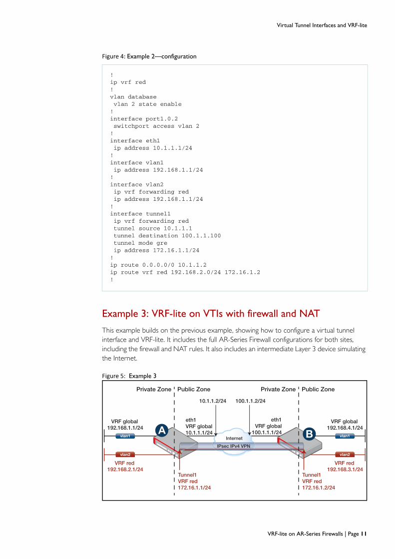
Example 3: VRF-lite on VTIs with firewall and NAT
This example builds on the previous example, showing how to configure a virtual tunnel interface and VRF-lite. It includes the full AR-Series Firewall configurations for both sites, including the firewall and NAT rules. It also includes an intermediate Layer 3 device simulating the Internet.
Figure 5: Example 3
Figure 4: Example 2—configuration
!ip vrf red!vlan database vlan 2 state enable!interface port1.0.2 switchport access vlan 2!interface eth1 ip address 10.1.1.1/24!interface vlan1 ip address 192.168.1.1/24!interface vlan2 ip vrf forwarding red ip address 192.168.1.1/24!interface tunnel1 ip vrf forwarding red tunnel source 10.1.1.1 tunnel destination 100.1.1.100 tunnel mode gre ip address 172.16.1.1/24!ip route 0.0.0.0/0 10.1.1.2ip route vrf red 192.168.2.0/24 172.16.1.2!
VRF global
VRF red VRF red
VRF global
vlan1
vlan2
vlan1
vlan2
Tunnel1VRF red172.16.1.1/24
Tunnel1VRF red172.16.1.2/24
10.1.1.2/24 100.1.1.2/24
eth1VRF global10.1.1.1/24
eth1VRF global
100.1.1.1/24Internet
IPsec IPv4 VPN
192.168.1.1/24
192.168.2.1/24 192.168.3.1/24
192.168.4.1/24
Private Zone Public Zone Private Zone Public Zone
A B
VRF-lite on AR-Series Firewalls | Page 11

Virtual Tunnel Interfaces and VRF-lite
AR-Series Firewall A Figure 6: Example 3—configuration for AR-Series Firewall A
!hostname RouterA!zone private network local ip subnet 192.168.1.0/24 interface vlan1 network local_red ip subnet 192.168.2.0/24 interface vlan2 network remote_red ip subnet 192.168.3.0/24 network tunnel1 ip subnet 172.16.1.0/24!zone public network all ip subnet 0.0.0.0/0 network intf ip subnet 10.1.1.0/24 interface eth1 host router ip address 10.1.1.1!application esp protocol 50!application isakmp protocol udp sport 500 dport 500!firewall rule 10 permit any from private to private rule 20 permit any from private.local to public rule 30 permit esp from public.intf.router to public rule 40 permit isakmp from public.intf.router to public rule 50 permit esp from public to public.intf.router rule 60 permit isakmp from public to public.intf.router protect!nat rule 10 masq any from private.local to public enable!crypto isakmp key 8 <samplekey> address 100.1.1.1!ip vrf red 1!interface vlan1 ip address 192.168.1.1/24!interface vlan2 ip vrf forwarding red ip address 192.168.2.1/24!
Page 12 | VRF-lite on AR-Series Firewalls

Virtual Tunnel Interfaces and VRF-lite
AR-Series Firewall B
interface tunnel1 mtu 1438 ip vrf forwarding red tunnel source 10.1.1.1 tunnel destination 100.1.1.1 tunnel protection ipsec tunnel mode ipsec ipv4 ip address 172.16.1.1/24!ip route 0.0.0.0/0 10.1.1.2ip route vrf red 192.168.3.0/24 172.16.1.2!
Figure 6: Example 3—configuration for AR-Series Firewall A (Continued)
Figure 7: Example 3—configuration for AR-Series Firewall B
!hostname RouterB!zone private network local ip subnet 192.168.4.0/24 interface vlan1 network local_red ip subnet 192.168.3.0/24 interface vlan2 network remote_red ip subnet 192.168.2.0/24 network tunnel1 ip subnet 172.16.1.0/24!zone public network all ip subnet 0.0.0.0/0 network intf ip subnet 100.1.1.0/24 interface eth1 host router ip address 100.1.1.1!application esp protocol 50!application isakmp protocol udp sport 500 dport 500!firewall rule 10 permit any from private to private rule 20 permit any from private.local to public rule 30 permit esp from public.intf.router to public rule 40 permit isakmp from public.intf.router to public rule 50 permit esp from public to public.intf.router rule 60 permit isakmp from public to public.intf.router protect!
VRF-lite on AR-Series Firewalls | Page 13

Virtual Tunnel Interfaces and VRF-lite
Intermediate device
nat rule 10 masq any from private.local to public enable!crypto isakmp key <samplekey> address 10.1.1.1!ip vrf red 1!vlan database vlan 2 state enable!interface port1.0.2 switchport access vlan 2!interface eth1 ip address 100.1.1.1/24!interface vlan1 ip address 192.168.4.1/24!interface vlan2 ip vrf forwarding red ip address 192.168.3.1/24!interface tunnel1 mtu 1438 ip vrf forwarding red tunnel source 100.1.1.1 tunnel destination 10.1.1.1 tunnel protection ipsec tunnel mode ipsec ipv4 ip address 172.16.1.2/24!ip route 0.0.0.0/0 100.1.1.2ip route vrf red 192.168.2.0/24 172.16.1.1!
Figure 7: Example 3—configuration for AR-Series Firewall B (Continued)
Figure 8: Example 3—configuration for intermediate device simulating Internet
!hostname Internet!vlan database vlan 2!interface port1.0.2 switchport access vlan 2!interface vlan1 ip address 10.1.1.2/24!interface vlan2 ip address 100.1.1.2/24!
Page 14 | VRF-lite on AR-Series Firewalls

Virtual Tunnel Interfaces and VRF-lite
Diagnostics The outputs displayed by the following commands can be used to check that interfaces are correctly associated with VRF red, that the VPN security associations have negotiated successfully, and that ping is successful across the VRF-aware VPN.
Figure 9: Example 3— output from show ip interface brief on AR-Series Firewall A
RouterA#show ip interface briefInterface IP-Address Status Protocoleth1 10.1.1.1/24 admin up runningeth2 unassigned admin up downlo unassigned admin up runningvlan1 192.168.1.1/24 admin up running
[VRF: red]Interface IP-Address Status Protocollo1 unassigned admin up runningvlan2 192.168.2.1/24 admin up downtunnel1 172.16.1.1/24 admin up running
Figure 10: Example 3—output from show ipsec sa on AR-Series Firewall A
RouterA#show ipsec sa---------------------------------------------------------------------Peer SPI (in:out) Mode Proto Expires Encryption Integrity PFS---------------------------------------------------------------------100.1.1.1 c8ad86ca:c99a21bf tunnel ESP 22801s AES256 SHA256 -
Figure 11: Example 3—output from ping on AR-Series Firewall A
RouterA#ping vrf red 172.16.1.264 bytes from 172.16.1.2: icmp_seq=1 ttl=64 time=1.11 ms64 bytes from 172.16.1.2: icmp_seq=2 ttl=64 time=0.762 ms64 bytes from 172.16.1.2: icmp_seq=3 ttl=64 time=0.717 ms64 bytes from 172.16.1.2: icmp_seq=4 ttl=64 time=0.720 ms64 bytes from 172.16.1.2: icmp_seq=5 ttl=64 time=0.707 ms
--- 172.16.1.2 ping statistics ---5 packets transmitted, 5 received, 0% packet loss, time 3998msrtt min/avg/max/mdev = 0.707/0.803/1.112/0.158 ms
VRF-lite on AR-Series Firewalls | Page 15

Virtual Tunnel Interfaces and VRF-lite
Example 4: Multiple VRFs via IPsec VPN using Ethernet pseudowires
This example shows how to transport several VRFs instances via a single IPsec VPN between two sites. The single encrypted VPN operating between the pair of sites encapsulates and transports a couple of unmanaged (static) L2TPv3 Ethernet pseudowires. Each individual Ethernet pseudowire is associated with a different VRF instance.
Figure 12: Example 4
AR-Series Firewall A
IPsec-protected L2TPv3 VPN
vlan10
vlan20
vlan10
vlan20
VTI1VTI1
eth1 10.0.0.1/30
Central office
Remote office
Eth pseudowire1.20VRF greenVRF green
192.168.1.1/24
Eth pseudowire1.10VRF red
eth1 10.0.0.2/30
172.16.2.1/24
172.16.1.1/24 172.16.1.2/24
VRF red192.168.1.1/24
VRF green192.168.2.1/24
VRF red192.168.2.1/24
172.16.2.2/24
A B
Figure 13: Example 4—configuration for AR-Series Firewall A
!hostname RouterA!crypto isakmp key <samplekey> address 10.0.0.2!ip vrf red 10!ip vrf green 20!vlan database vlan 10,20 state enable!interface port1.0.1 switchport access vlan 10!interface port1.0.2 switchport access vlan 20!interface eth1 ip address 10.0.0.1/24!interface vlan10 ip vrf forwarding red ip address 192.168.1.1/24!
Page 16 | VRF-lite on AR-Series Firewalls

Virtual Tunnel Interfaces and VRF-lite
AR-Series Firewall B
interface vlan20 ip vrf forwarding green ip address 192.168.1.1/24!interface tunnel1 encapsulation dot1q 10 encapsulation dot1q 20 mtu 1488 tunnel source eth1 tunnel destination 10.0.0.2 tunnel local id 1 tunnel remote id 2 tunnel protection ipsec tunnel mode l2tp v3!interface tunnel1.10 ip vrf forwarding red ip address 172.16.1.1/24!interface tunnel1.20 ip vrf forwarding green ip address 172.16.2.1/24!ip route vrf red 192.168.2.0/24 172.16.1.2ip route vrf green 192.168.2.0/24 172.16.2.2!
Figure 13: Example 4—configuration for AR-Series Firewall A (Continued)
Figure 14: Example 4—configuration for AR-Series Firewall B
!hostname RouterB!crypto isakmp key <samplekey> address 10.0.0.1!ip vrf red 10!ip vrf green 20!vlan database vlan 10,20 state enable!interface port1.0.1 switchport access vlan 10!interface port1.0.2 switchport access vlan 20!interface eth1 ip address 10.0.0.2/24!interface vlan10 ip vrf forwarding red ip address 192.168.2.1/24!
VRF-lite on AR-Series Firewalls | Page 17

Virtual Tunnel Interfaces and VRF-lite
interface vlan20 ip vrf forwarding green ip address 192.168.2.1/24!interface tunnel1 encapsulation dot1q 10 encapsulation dot1q 20 mtu 1488 tunnel source eth1 tunnel destination 10.0.0.1 tunnel local id 2 tunnel remote id 1 tunnel protection ipsec tunnel mode l2tp v3!interface tunnel1.10 ip vrf forwarding red ip address 172.16.1.2/24!interface tunnel1.20 ip vrf forwarding green ip address 172.16.2.2/24!ip route vrf red 192.168.1.0/24 172.16.1.1ip route vrf green 192.168.1.0/24 172.16.2.1!
Figure 14: Example 4—configuration for AR-Series Firewall B (Continued)
Page 18 | VRF-lite on AR-Series Firewalls

Virtual Tunnel Interfaces and VRF-lite
Example 5: VRF instances from central to remote VPN sites
This example shows a typical hub and spoke VPN topology. The central hub site is configured with a VPN to each remote site. Each VPN from the central site to each remote site is associated with a different VRF instance.
Figure 15: Example 5
AR-Series Firewall A
VRF red
vlan2
VRF green
vlan3
VRF global
vlan1
VRF red
VRF global
vlan1
vlan2
VRF green
VRF global
vlan1
vlan3
eth1VRF global10.1.1.1/24
eth1VRF global10.1.1.1/24
eth1VRF global100.1.1.1/24
10.1.1.2/24
100.1.10.2/24
100.1.1.2/24
InternetA192.168.2.1/24
IPsec IPv4
VPN
192.168.20.1/24
192.168.1.1/24
192.168.3.1/24
192.168.4.1/24
192.168.30.1/24
192.168.40.1/24
IPsec IPv4VPN
B
C
Private Zone Public Zone Private Zone Public Zone
Tunnel1VRF red172.16.1.2/24
Tunnel2VRF green172.16.10.2/24
Tunnel2VRF green172.16.10.1/24
Tunnel1VRF red172.16.1.1/24
Figure 16: Example 5—configuration for AR-Series Firewall A
!hostname RouterA!zone private network local ip subnet 192.168.1.0/24 interface vlan1 network local_red ip subnet 192.168.2.0/24 interface vlan2 network local_greenip subnet 192.168.20.0/24 interface vlan3 network remote_red ip subnet 192.168.3.0/24 network remote_green ip subnet 192.168.30.0/24 network tunnel1 ip subnet 172.16.1.0/24 network tunnel2 ip subnet 172.16.10.0/24!
VRF-lite on AR-Series Firewalls | Page 19

Virtual Tunnel Interfaces and VRF-lite
zone public network all ip subnet 0.0.0.0/0 network intf ip subnet 10.1.1.0/24 interface eth1 host router ip address 10.1.1.1!application esp protocol 50!application isakmp protocol udp sport 500 dport 500!firewall rule 10 permit any from private to private rule 20 permit any from private.local to public rule 30 permit esp from public.intf.router to public rule 40 permit isakmp from public.intf.router to public rule 50 permit esp from public to public.intf.router rule 60 permit isakmp from public to public.intf.router protect!nat rule 10 masq any from private.local to public enable!crypto isakmp key <samplekey1> address 100.1.1.1crypto isakmp key <samplekey2> address 100.1.10.1!ip vrf red 1!ip vrf green 2!vlan database vlan 2,3 state enable!interface port1.0.2 switchport access vlan 2!interface port1.0.3 switchport access vlan 3!interface eth1 ip address 10.1.1.1/24!interface vlan1 ip address 192.168.1.1/24!interface vlan2 ip vrf forwarding red ip address 192.168.2.1/24!
Figure 16: Example 5—configuration for AR-Series Firewall A (Continued)
Page 20 | VRF-lite on AR-Series Firewalls

Virtual Tunnel Interfaces and VRF-lite
AR-Series Firewall B
interface vlan3 ip vrf forwarding green ip address 192.168.20.1/24!interface tunnel1 mtu 1438 ip vrf forwarding red tunnel source 10.1.1.1 tunnel destination 100.1.1.1 tunnel protection ipsec tunnel mode ipsec ipv4 ip address 172.16.1.1/24!interface tunnel2 mtu 1438 ip vrf forwarding green tunnel source 10.1.1.1 tunnel destination 100.1.10.1 tunnel protection ipsec tunnel mode ipsec ipv4 ip address 172.16.10.1/24!ip route 0.0.0.0/0 10.1.1.2ip route vrf red 192.168.3.0/24 172.16.1.2ip route vrf green 192.168.30.0/24 172.16.10.2!
Figure 16: Example 5—configuration for AR-Series Firewall A (Continued)
Figure 17: Example 5—configuration for AR-Series Firewall B
!hostname RouterB!zone private network local ip subnet 192.168.4.0/24 interface vlan1 network local_red ip subnet 192.168.3.0/24 interface vlan2 network remote_red ip subnet 192.168.2.0/24 network tunnel1 ip subnet 172.16.1.0/24!zone public network all ip subnet 0.0.0.0/0 network intf ip subnet 100.1.1.0/24 interface eth1 host router ip address 100.1.1.1!application esp protocol 50!
VRF-lite on AR-Series Firewalls | Page 21

Virtual Tunnel Interfaces and VRF-lite
application isakmp protocol udp sport 500 dport 500!firewall rule 10 permit any from private to private rule 20 permit any from private.local to public rule 30 permit esp from public.intf.router to public rule 40 permit isakmp from public.intf.router to public rule 50 permit esp from public to public.intf.router rule 60 permit isakmp from public to public.intf.router protect!nat rule 10 masq any from private.local to public enable!crypto isakmp key <samplekey1> address 10.1.1.1!ip vrf red 1!vlan database vlan 2 state enable!interface port1.0.2 switchport access vlan 2!interface eth1 ip address 100.1.1.1/24!interface vlan1 ip address 192.168.4.1/24!interface vlan2 ip vrf forwarding red ip address 192.168.3.1/24!interface tunnel1 mtu 1438 ip vrf forwarding red tunnel source 100.1.1.1 tunnel destination 10.1.1.1 tunnel protection ipsec tunnel mode ipsec ipv4 ip address 172.16.1.2/24!ip route 0.0.0.0/0 100.1.1.2ip route vrf red 192.168.2.0/24 172.16.1.1!
Figure 17: Example 5—configuration for AR-Series Firewall B (Continued)
Page 22 | VRF-lite on AR-Series Firewalls

Virtual Tunnel Interfaces and VRF-lite
AR-Series Firewall C Figure 18: Example 5—configuration for AR-Series Firewall C
!hostname RouterC!zone private network local ip subnet 192.168.40.0/24 interface vlan1 network local_green ip subnet 192.168.30.0/24 interface vlan3 network remote_green ip subnet 192.168.20.0/24 network tunnel1 ip subnet 172.16.10.0/24!zone public network all ip subnet 0.0.0.0/0 network intf ip subnet 100.1.10.0/24 interface eth1 host router ip address 100.1.10.1!application esp protocol 50!application isakmp protocol udp sport 500 dport 500!firewall rule 10 permit any from private to private rule 20 permit any from private.local to public rule 30 permit esp from public.intf.router to public rule 40 permit isakmp from public.intf.router to public rule 50 permit esp from public to public.intf.router rule 60 permit isakmp from public to public.intf.router protect!nat rule 10 masq any from private.local to public enable!crypto isakmp key <samplekey2> address 10.1.1.1!ip vrf green 1!vlan database vlan 3 state enable!interface port1.0.3 switchport access vlan 3!interface eth1 ip address 100.1.10.1/24!interface vlan1 ip address 192.168.40.1/24!
VRF-lite on AR-Series Firewalls | Page 23

Virtual Tunnel Interfaces and VRF-lite
Intermediate device
interface vlan3 ip vrf forwarding green ip address 192.168.30.1/24!interface tunnel1 mtu 1438 ip vrf forwarding green tunnel source 100.1.10.1 tunnel destination 10.1.1.1 tunnel protection ipsec tunnel mode ipsec ipv4 ip address 172.16.10.2/24!ip route 0.0.0.0/0 100.1.10.2ip route vrf green 192.168.20.0/24 172.16.10.1!
Figure 18: Example 5—configuration for AR-Series Firewall C (Continued)
Figure 19: Example 5—configuration for intermediate Internet device
!hostname Internet!vlan database vlan 2,3 state enable!interface port1.0.2 switchport access vlan 2!interface port1.0.3 switchport access vlan 3!interface vlan1 ip address 10.1.1.2/24!interface vlan2 ip address 100.1.1.2/24!interface vlan3 ip address 100.1.10.2/24!
Page 24 | VRF-lite on AR-Series Firewalls

VRF-aware Utilities in AlliedWare Plus
VRF-aware Utilities in AlliedWare Plus
A number of network utility and management features operate in a VRF-aware manner. Whenever you use one of these utilities, you can inform the utility which VRF instance to direct its traffic into.
These include:
Ping
Trace Route
TCP Dump
SSH Client
Telnet Client
awplus#ping ? WORD Ping destination address or hostname ip IP echo ipv6 IPv6 echo vrf VRF instance (source VRF) <cr>
awplus#ping vrf <name> ? WORD Ping destination address or hostname ip IP echo
awplus#ping vrf <name> x.x.x.x
awplus#ping vrf <name> x.x.x.x ? broadcast Ping to a broadcast address df-bit Enable do-not-fragment bit in IP header interval Specify interval between pings pattern Specify data pattern repeat Specify repeat count size Specify datagram size source Specify source address or interface name timeout Specify timeout interval tos Specify type of service <cr>
Ping
VRF-lite on AR-Series Firewalls | Page 25

VRF-aware Utilities in AlliedWare Plus
awplus#traceroute ? WORD Trace route to destination address or hostname ip IP Trace ipv6 IPv6 trace vrf VRF instance <cr>
awplus#traceroute vrf <name> ? WORD Trace route to destination address or hostname ip IP Trace
awplus#traceroute vrf <name> x.x.x.x
awplus#tcpdump ? LINE Execute tcpdump vrf VRF instance <cr>
awplus#tcpdump vrf <name> ? LINE Execute tcpdump <cr>
awplus#tcpdump vrf <name>
awplus#ssh ? HOSTNAME IP/IPv6 address or hostname of a remote server client Configure global SSH client parameters ip IP SSH ipv6 IPv6 SSH port SSH server port user Login user version SSH client version vrf VRF instance
awplus#ssh vrf <name> ? HOSTNAME IP/IPv6 address or hostname of a remote server ip IP SSH port SSH server port user Login user version SSH client version
awplus#ssh vrf <name> x.x.x.x
Trace route
TCPdump
SSH client
Page 26 | VRF-lite on AR-Series Firewalls

VRF-aware Utilities in AlliedWare Plus
awplus#telnet ? WORD IPv4/IPv6 address or hostname of a remote system ip IP telnet ipv6 IPv6 telnet vrf VRF instance
awplus#telnet vrf <name> ? WORD IPv4 address or hostname of a remote system ip IP telnet
awplus#telnet vrf <name> ip x.x.x.x
Telnet client
VRF-lite on AR-Series Firewalls | Page 27

Static Inter-VRF Routing
Static Inter-VRF Routing Whilst the prime purpose of VRF-lite is to keep routing domains separate from each other, there are cases where you do want some communication between VRFs.
192.168.1.0/24
192.168.20.0/24 192.168.20.0/24
192.168.50.0/24VRF red
VLAN20
global default VRF domain
VLAN10 VLAN10 VLAN30
VRF green
VRF blue
192.168.20.6192.168.20.5192.168.1.5
192.168.50.10
Device A Device B
Static inter-VRF routing involves creating static routes in one VRF instance whose Layer 3 egress interface is in a different VRF instance. These static Inter-VRF routes must specify the egress Interface and may also require a next hop IP address to reach networks that are more than one hop away.
The following figure illustrates use of static routing to achieve inter-VRF communication in VRF-lite.
DEVICE A STATIC ROUTES CONFIGURATION DEVICE B STATIC ROUTES CONFIGURATION
ip route vrf red 192.168.20.0/24 vlan10From source vrf red, create a static route to 192.168.20.0/24 to access target vlan10. Target VLAN is required when performing static IVR.
ip route vrf blue 192.168.20.0/24 vlan10From source vrf blue, create a static route to 192.168.20.0/24 to access target vlan10. Target VLAN is required when performing static IVR.
ip route 192.168.1.0/24 vlan20From the source global VRF domain, create a static route to 192.168.1.0/24 to access target vlan20. Target VLAN is required when performing static IVR.
ip route vrf green 192.168.50.0/24 vlan30From the source vrf green, create a static route to192.168.50.0/24 to access target vlan30. Target VLAN is required when performing static IVR.
ip route vrf red 192.168.50.0/24 192.168.20.6 vlan10From source vrf red, create a static route to 192.168.50.0/24 with a next hop of 192.168.20.6 egressing target vlan10. Target VLAN is required when performing static IVR.
ip route vrf blue 192.168.1.0/24 192.168.20.5 vlan10From source vrf blue, create a static route to 192.168.1.0/24 with a next hop of 192.168.20.5 egressing target vlan10. Target VLAN is required when performing static IVR.
ip route 192.168.50.0/24 192.168.20.6From the global VRF domain, create a static route to 192.168.50.0/24 with a next hop of 192.168.20.6. Static routes to networks within a VRF instance do not require target VLAN.
ip route vrf green 192.168.1.0/24 192.168.20.5From the source vrf green, create a static route to192.168.1.0/24 with a next hop of 192.168.20.5. Static routes to networks within a VRF instance do not require the target VLAN.
Page 28 | VRF-lite on AR-Series Firewalls

Configuring DNS Relay to be VRF-aware
Configuring DNS Relay to be VRF-aware
Introduction
Domain Name System (DNS) is used to translate domain names into IP addresses. A DNS Relay (or proxy or forwarder) is an intermediate service that receives DNS queries from a client then forwards them to a DNS server on the client’s behalf, and provides a local cache of responses. The optional DNS resolver cache provides some lookup speed advantage and avoids unnecessarily repeated requests to external DNS servers.
This section describes how to configure DNS Relay to be VRF-aware.
DNS operation with VRF-lite
When running VRF-lite, you can configure DNS Relay functionality to be VRF-aware. The switch can respond to domain name service lookup requests from external clients that are received via a VLAN interface that is associated with a VRF instance. Each VRF instance supports its own configurable set of DNS servers and DNS cache.
In a typical Service Provider setup, there may be two separate devices each connecting to two separate networks. Clients in each of the remote offices query their own DNS Relay within the Service Provider network, which in turn query their own Head Office DNS server. This can be expensive for the Service Provider as more equipment is needed to separate the networks.
By making DNS Relay VRF-aware, each network can now have its own DNS Relay that queries its own network’s DNS Server and keeps its own DNS cache that is completely separate for the other networks, even if they have overlapping IP addresses.
DNS Relay
DNS Relay
Head Office A Head Office B
Remote A Remote B
Domain Name Server A
Domain Name Server B
IP Range: 192.168.1.x IP Range: 192.168.1.x
Service Provider
VRF-lite on AR-Series Firewalls | Page 29

Configuring DNS Relay to be VRF-aware
Configuring DNS operation with VRF-lite
The command ip name-server [vrf <name>] <ip-address>, configures a name-server for the specified VRF. This command assigns the address of one or more name-servers to a VRF table to be used for name and address resolution. If no VRF-lite instance (vrf <name>) is specified, the name-server is configured for the global VRF. A name-server that is configured on the global VRF will apply to both the DNS relay and DNS client.
Note that the DNS client is not VRF-aware. VRF-aware client services that can utilize the
DNS client such as ping, traceroute, telnet, and ssh will only perform DNS lookup if a VRF instance is not specified in the command. For example, the command ping VRF <instance> <address> is supported and ping <URL> is supported, but ping VRF <instance> <URL> is not supported.
A VRF specific name-cache is created within the DNS relay for every VRF instance that has a name-server configured.
A maximum of three name-servers may be defined for each DNS-relay instance.
The configuration command ip dns forwarding applies the DNS forwarding cache to all VRF instances configured on the device, however cached results are stored on a per VRF basis. That means if you have cached a lookup result learnt via VRF Red, then a subsequent lookup request from VRF Red will use that cached result, but a lookup request from VRF Green will not.
The configuration commands listed below apply to all VRF instances configured on the device and not on a per VRF basis. Timeouts are in seconds as per existing commands:
ip dns forwarding retry
ip dns forwarding timeout
ip dns forwarding dead-time
ip dns forwarding source-interface
ip dns forwarding cache
The following show commands provide output information for the VRF instance specified. If a VRF instance is not specified, output is shown for all VRF instances including the global instance and the output will be formatted in a way that distinguishes the information for each VRF.
show ip dns [vrf <name>|global]forwarding server
show ip dns [vrf <name>|global] forwarding cache
show ip name-server [vrf <name>|global]
The DNS cache can also be cleared on a per VRF instance basis by using the clear ip dns [vrf <name>|global] forwarding cache command.
The following commands show how to configure a DNS relay name-server for both the specified VRF instance VRF red, and the global VRF instance.
Page 30 | VRF-lite on AR-Series Firewalls

Configuring DNS Relay to be VRF-aware
To configure a DNS relay name-server for the VRF-lite instance red:
awplus# configure terminal
awplus(config)# ip name-server vrf red 10.100.1.1
awplus# ip domain-lookup
To configure a DNS relay name-server for the global VRF instance:
awplus# configure terminal
awplus(config)# ip name-server 10.0.0.1
awplus# ip domain-lookup
To configure the IP DNS Forwarding cache:
awplus# ip dns forwarding
awplus# ip dns forwarding cache size 10 timeout 1800
Figure 20: Example extract from running configuration
!ip name-server 10.0.0.1ip name-server vrf red 10.100.1.1ip domain-lookup!...!ip dns forwardingip dns forwarding cache size 10 timeout 1800!
Figure 21: Example output from show ip name-server command
awplus#sh ip name-serverCurrently learned name-servers:10.0.0.1 static
[VRF: red]10.100.1.1 static
Figure 22: Example output from show ip dns forwarding server
awplus#show ip dns forwarding serverServers Forwards Fails Dead-Time10.0.0.1 2 0 active
[VRF: red]Servers Forwards Fails Dead-Time10.100.1.1 2 0 active
VRF-lite on AR-Series Firewalls | Page 31

Adding a VRF-aware Static ARP
Adding a VRF-aware Static ARPARP entries associated with a given Layer 3 interface are cleared when the interface is moved from one VRF instance to another. In addition (static and dynamic) ARP entries are VRF-aware, as the same IP address can be used in other VRF instances.
It is possible to show the whole ARP table, or just that section associated with a given VRF instance. The ARP table is divided into sections for each VRF instance.
Figure 23: Example output from show ip dns vrf <name> forwarding server
awplus#show ip dns vrf red forwarding server[VRF: red]Servers Forwards Fails Dead-Time10.0.0.1 1 0 active
Figure 24: Example output from show ip dns global forwarding server
awplus#show ip dns global forwarding serverServers Forwards Fails Dead-Time10.100.1.1 1 0 active
Figure 25: Example output from show ip dns forwarding cache command
awplus#sh ip dns forwarding cacheHost Address Expires Flagswww.example.com 10.0.0.10 1793 REVERSEwww.example.com 10.0.0.10 1793
[VRF: red]Host Address Expires Flagswww.example_red.com 10.100.1.10 645 REVERSEwww.example_red.com 10.100.1.10 645
Figure 26: Commands to configure static ARP entries
awplus(config)#arp ? A.B.C.D IP address of the ARP entry log Arp log vrf VRF instance
awplus(config)#arp vrf <name> ? A.B.C.D IP address of the ARP entry
Page 32 | VRF-lite on AR-Series Firewalls

Local Interfaces with VRF-lite
Local Interfaces with VRF-liteA local interface (also often referred to as a loopback interface) is an internal interface that is always available for higher layer routing protocols to use and advertise to the network. Although a local interface is assigned an IP address, it does not have the usual requirement of connecting to a lower layer physical entity.
A local interface can be used as a reliable address via which to access a device—an address that is always accessible, irrespective of the link status of any individual external interface.
When a VRF-lite instance is created, a local interface is assigned to it either automatically, or by static assignment of a specific interface.
The following command creates a named VRF-lite instance with an optional local interface:
awplus(config)#ip vrf <vrf-name> [<lo>]
The optional local interface identifier <lo> is simply an integer number. This parameter specifies the number that will appear in the name of the resulting loopback interface. For example, if <lo> has the value 7, then the loopback interface that is created for the VRF-lite instance will have the name lo7.
If the optional local interface <lo> is not specified, a local interface will still be automatically created, and it will be assigned the next available ID number. Specifying the local interface allows the user to statically control which specific local interface ID number is associated with a particular VRF-lite instance.
Once a local interface is created, it remains assigned to the VRF (including over a reboot), unless manually changed by the user. Only a single local interface per VRF is supported.
For example, to create VRF-lite instance ‘red’ with statically assigned local interface ID 5, use the command:
awplus(config)#ip vrf red 5
Each local interface can be configured with its own IP address. For example, to assign an IP address to local interface lo5, use the commands:
awplus(config)# interface lo5
awplus(config-if)# ip address 192.168.200.1/32
VRF-lite on AR-Series Firewalls | Page 33

Useful VRF-Related Diagnostics Command List
Useful VRF-Related Diagnostics Command List Below is a summary list of diagnostic commands that you may find helpful when troubleshooting VRF-related issues. For a complete list of VRF-aware commands, refer to the VRF-lite chapter in the Command Reference for your product.
General
VRF
Routing general
awplus#show tech-supportawplus#show running-configawplus#show running-config vrfawplus#show systemawplus#show bootawplus#show clock
awplus#show ip vrfawplus#show ip vrf ? WORD VRF instance name brief Brief VRF instance information detail Detailed VRF instance information interface Interface information | Output modifiers > Output redirection >> Output redirection (append) <cr>awplus#show ip vrf interfaceawplus#show ip vrf detail
awplus#sh ip routeCodes: C - connected, S - static, R - RIP, B - BGP O - OSPF, D - DHCP, IA - OSPF inter area N1 - OSPF NSSA external type 1, N2 - OSPF NSSA external type 2 E1 - OSPF external type 1, E2 - OSPF external type 2 * - candidate default
S 0.0.0.0/0 [1/0] via 10.0.0.254, vlan1C 10.0.0.0/24 is directly connected, vlan1
Gateway of last resort is not set
[VRF: red]C 10.100.1.0/24 is directly connected, vlan2
Gateway of last resort is not setNo entries in route table
Page 34 | VRF-lite on AR-Series Firewalls

ARP
TCPdump
awplus#sh ip route vrf redCodes: C - connected, S - static, R - RIP, B - BGP O - OSPF, D - DHCP, IA - OSPF inter area N1 - OSPF NSSA external type 1, N2 - OSPF NSSA external type 2 E1 - OSPF external type 1, E2 - OSPF external type 2 * - candidate default
[VRF: red]C 10.100.1.0/24 is directly connected, vlan2
Gateway of last resort is not setNo entries in route table
awplus#sh arp IP Address MAC Address Interface Port Type10.0.0.254 0022.b06b.62d6 vlan1 port1.0.1 dynamic
[VRF: red] IP Address MAC Address Interface Port Type10.100.1.254 001a.eb94.2a44 vlan2 port1.0.2 dynamic
awplus#show arp vrf red
[VRF: red] IP Address MAC Address Interface Port Type10.100.1.254 001a.eb94.2a44 vlan2 port1.0.2 dynamic
awplus#tcpdump awplus#tcpdump vrf <name>
C613-22092-00 REV A
North America Headquarters | 19800 North Creek Parkway | Suite 100 | Bothell | WA 98011 | USA | T: +1 800 424 4284 | F: +1 425 481 3895Asia-Pacifi c Headquarters | 11 Tai Seng Link | Singapore | 534182 | T: +65 6383 3832 | F: +65 6383 3830EMEA & CSA Operations | Incheonweg 7 | 1437 EK Rozenburg | The Netherlands | T: +31 20 7950020 | F: +31 20 7950021
alliedtelesis.com© 2015 Allied Telesis Inc. All rights reserved. Information in this document is subject to change without notice. All company names, logos, and product designs that are trademarks or registered trademarks are the property of their respective owners.