vrml - a first looktla/publ/vrmltut.pdfvrml - a first look thomas larsson department of computer...
TRANSCRIPT

VRML - A First Look
Thomas Larsson
Department of Computer Engineering
Mälardalen University
February 7, 1999
Västerås
Sweden

2
Abstract
This tutorial gives an introduction to the Virtual Reality Modeling Language (VRML). Firstof all, the basics of how to build virtual worlds using this language are explained. Thenfollows a brief presentation of how these worlds can be optimized to achieve better renderingperformance and, finally, some techniques of how to bring these virtual worlds alive areexemplified.
3
Contents
1. Introduction .....................................................................................4
2. Creating Basic Virtual Worlds in VRML.........................................4
2.1 Building a Very Simple World ..................................................................... 4
2.2 Using Transformations ................................................................................. 8
2.3 Defining More Interesting Geometry.......................................................... 11
2.4 Reusing Nodes ........................................................................................... 12
2.5 Lighting...................................................................................................... 14
2.6 Basic Texture Mapping .............................................................................. 17
2.7 Controlling the Viewer............................................................................... 22
3. Optimization Techniques...............................................................23
3.1 Adaptive Level of Detail ............................................................................ 24
3.2 Billboards................................................................................................... 25
4. Moving Beyond Static Worlds.......................................................27
4.1 Allowing User Interaction .......................................................................... 27
4.2 Introducing Scripts ..................................................................................... 29
5. VRML on the Internet ...................................................................31
5.1 Adding Hyperlinks ..................................................................................... 31
5.2 Combining VRML and HTML on Web Pages............................................ 32
6. Conclusions ...................................................................................33
7. Acknowledgements........................................................................33
References .........................................................................................33

4
1. Introduction
VRML, short for Virtual Reality Modeling Language, is often pronounced ‘vermal’. Thislanguage was created to add 3D graphics possibilities to the World Wide Web. So far,however, the acceptance of VRML in the Web community hasn’t exactly been overwhelming,but with the constantly increasing performance available in new PC’s and people getting usedto the Virtual Reality concept, we might see a change of that in the near future.
In 1997 VRML971 was accepted as an ISO standard [Vrm97]. It is quite an improvementcompared to VRML 1.0 from 1994. Some parts have been changed and many new featureshave been added, especially the interactive capabilities have been greatly improved. In thistutorial we will cover VRML97, which still is the latest version, but since this is meant to be ashort introductory tutorial a lot of interesting topics will be left out. There are many textbooksthat can fill in the gaps and guide the interested reader much further.
To fully understand the material presented throughout the rest of this tutorial a generalknowledge of 3D computer graphics is assumed. In particular, knowing the theory behindgeometrical transformations, viewing, lighting calculations and texture mapping will behelpful to understand what’s going on.
The rest of this tutorial is organized in the following way. After describing how to create basicthree-dimensional virtual worlds, we will explore some possibilities of how to optimize theseworlds. Finally, we will deal with possible ways of how to let users interact with the virtualenvironment.
2. Creating Basic Virtual Worlds in VRML
Worlds in VRML are described using the VRML file format. Since this format is text based itis possible to use some general text editor and type in our world descriptions. When namingour files, we use the .wrl extension. To explore a world, described in a VRML file, we can forexample use the free VRML browser Cosmo Player together with Netscape Communicator.All the worlds in this tutorial have been tried out using these mentioned programs2, but ofcourse there are other alternatives. Now, let’s turn our attention to our first VRML world.
2.1 Building a Very Simple World
To build a virtual world in VRML we need to specify different nodes, representing certaingeometry, qualities or actions, and their relationships. In this way, we define the structure ofthe world, also known as the scene graph. To see how this works we can look at a very simpleworld, consisting of only a cylinder object and a cone object, both centered at the origin in theworld:
1 VRML97 is the ISO standard revision of VRML 2.0 from 19962 To be more exact, Cosmo Player 2.1 and Netscape Communicator 4.5 have been used.

5
Listing 1
#VRML V2.0 utf8#A very simple VRML world
Shape {appearance Appearance {
material Material {diffuseColor 1 1 0.5
}}geometry Cylinder { }
}
Shape {appearance Appearance {
material Material {diffuseColor 1 0 0.5specularColor 1 1 1shininess 0.1
}}geometry Cone {
bottomRadius 0.8height 4
}}
Before we discuss the meaning of this VRML code in detail, take a look at how Cosmo Playerinitially render this simple world in Figure 1. Having this picture in mind, let’s examine thecode used to describe this simple world.
First of all, note that a VRML file have to start with a VRML header line:
#VRML V2.0 utf8.
It indicates the file is a VRML file, version 2, and in the following text UTF8 encoding isused. UTF8 is an ISO standard making the representation of characters from many differentlanguages possible. After the header line, a comment follows. All comments start with thecharacter # and continues to the end of the line. Comments are ignored by VRML browsers,but of course they are a good tool for authors to keep track of different sections in a file.
The Shape node is used to associate the actual geometry of an object with its appearance,which is information controlling the look of the object. The definition of the Shape nodelooks like this:
Shape {exposedField SFNode appearance NULLexposedField SFNode geometry NULL
}

6
Every node in VRML consist of a list of fields that holds important values for itsfunctionality. The definition of a node shows us all these fields and gives us quite a lot ofinformation of how that node can be used. For example, in the definition of the Shape node,there are four columns inside the node. In the first column we find the class specifiers. Thespecifier used in this case, exposedField , serves many purposes. Among other things anexposedField can be changed as a result of an event and they are always accessible toscripts. In the second column, we find the data type of the fields. In the Shape node, the datatype for both fields are SFNode, which is a data type referring to other nodes. Hence, aShape node is used to group two other nodes together. The last two columns describe theparts you actually can type into a VRML file. There you find the names of the fields togetherwith suitable default values, used when they are not specified.
Figure 1: The world in listing 1 as rendered by Cosmo Player
In the Appearance node, we can specify what material, e.g. color, or what texture, will beused for the associated geometry. Its definition looks like this:
Appearance {exposedField SFNode material NULLexposedField SFNode texture NULLexposedField SFNode textureTransform NULL
}
This node is also used to hold other nodes. The material field can refer to a Materialnode, which describes color information for surfaces. The texture andtextureTransform fields refers to nodes making different types of texture mapping
7
possible. In our simple example world, we only used the material field. The correspondingnode is defined as follows:
Material {exposedField SFFloat ambientIntensity 0.2exposedField SFColor diffuseColor 0.8 0.8 0.8exposedField SFColor emissiveColor 0 0 0exposedField SFFloat shininess 0.2exposedField SFColor specularColor 0 0 0exposedField SFFloat transparency 0
}
Since we didn’t specify all these fields in our example, many of the default values from thisdefinition are used. For example the ambientIntensity field, that can hold a valuebetween 0 and 1 to specify the amount of background light present, take its default value 0.2in our case. To specify colors in VRML the RGB color model is used. Thus, the basic color ofthe material, held by the diffuseColor field, are specified using three values between 0and 1 for each color component red, green and blue respectively. In the same way, thespecularColor and the emissiveColor of the material are specified. ThespecularColor field controls the color of highlights on shiny objects and it is usedtogether with the shininess field to control the size of the highlights. If you carefullyexamine the look of our example world, you will notice that it is only possible to get ahighlight on the cone object. When it comes to the cylinder object, no specularColor andno shininess value were given and, hence, no highlight is possible in that case. Thetransparency field makes it possible to simulate transparent surfaces. A transparencyvalue of 0 means the material is totally opaque and a value of 1 means it is totally transparent.
The material information discussed here is used together with light source specifications toilluminate objects in the virtual world. So far we haven’t defined any light sources, but stillour world looks alright. The reason for this is that there is always a default light source used,at least in Cosmo Player, if no one is specified. Later, we will see how to specify our ownlight sources.
Finally, we conclude this section by looking at the geometry nodes Cylinder and Cone,also used in our example. These nodes are simple to specify and they can be rendered veryefficiently. Here is the definition of the Cylinder node:
Cylinder {field SFBool bottom TRUEfield SFFloat height 2field SFFloat radius 1field SFBool side TRUEfield SFBool top TRUE
}
As you can see, the meaning of these fields are easy to guess. A cylinder is given by its heightand radius and you can choose what parts of it will be visible. And the Cone node is definedin exactly the same style:

8
Cone {field SFFloat bottomRadius 1field SFFloat height 2field SFBool side TRUEfield SFBool bottom TRUE
}
Apart from these two primitive objects, there are two other primitives, Box and Sphere ,supported by VRML as well. They are used in pretty much the same way and some of thefollowing examples will show them in action.
When viewing our example world, you can’t miss that these two primitives, the cylinder andthe cone, are intersecting each other. That is because they are both centered around the worldcoordinate systems origin. These objects can easily be moved to other positions in the worldwith the help of geometrical transformations. We will see how to do that in the next section.
Figure 2: Transformed objects
2.2 Using Transformations
In our first example, we saw a world where two objects did intersect each other at the originof the world coordinate system. That was because they where both placed there by the VRMLbrowser. Obviously, we need a mechanism to avoid this situation. Such a mechanism is givento us by the Transform node, whose purpose is to make it possible to move geometricalobjects around in the scene, as well as rotate and scale them. Here is an example showing how

9
we can change the position and orientation of the cylinder and sphere object we used before.The result can be seen in Figure 2.
Listing 2
#VRML V2.0 utf8#An example illustrating geometrical transformations
Transform {rotation 0 0 1 0.78children [
Shape {appearance Appearance {
material Material {diffuseColor 1 1 0.5
}}geometry Cylinder { }
}Transform {
translation 3 0 0rotation 0 0 1 0.78children Shape {
appearance Appearance {material Material {
diffuseColor 1 0 0.5specularColor 1 1 1shininess 0.1
}}geometry Cone {
bottomRadius 0.8height 4
}}
}]
}
Note that the children field group a list of other nodes that will be affected by thetransform specified. For example, it is possible to add both Shape nodes and otherTransform nodes to this list to build up some useful scene graph. This make it possible tospecify relative transformations between different objects. Here follows the completedefinition of the Transform node:
Transform {eventIn MFNode addChildreneventIn MFNode removeChildrenexposedField SFVec3f center 0 0 0exposedField MFNode children []exposedField SFRotation rotation 0 0 1 0

10
exposedField SFVec3f scale 1 1 1exposedField SFRotation scaleOrientation 0 0 1 0exposedField SFVec3f translation 0 0 0field SFVec3f bboxCenter 0 0 0field SFVec3f bboxSize -1 –1 -1
}
The translation field simply holds the x-, y- and z-component respectively of a positionin the world where to the children of the node will be moved (from their default position)and the scale field holds the amount of scaling that will be applied relative the threecoordinate axes. But how do we specify the rotation field? We use four values, the firstthree describes a vector which defines the axis of rotation and the last value gives the rotationangle in radians around this axis. The center field allows us to specify a position aboutwhich the rotation occurs.
Another, more advanced scaling operation can be accomplished by using thescaleOrientation field, which allows us to rotate the axes, around which scalingoccurs. This field is specified in the same way as the rotation field, that is, by first defining anaxis followed by the rotation angle in radians. Finally, the two last fields, bboxCenter andbboxSize , are used to specify the position and size of a bounding box surrounding all of thechildren referred to by the node. If this information is not given, the VRML browser has tocalculate them, which can be quite time consuming in some cases.
Figure 3: A pair of red triangle polygons

11
2.3 Defining More Interesting Geometry
Although it is possible to combine primitive objects such as boxes, cones, cylinders andspheres into much more interesting and complex objects, it is certainly not enough for mostapplications. What we need is a way to define the geometry of real world objects in a muchmore realistic manner, yet effective enough for the virtual reality concept we are targeting.The IndexedFaceSet node let us define arbitrarily patches built of flat convex polygons.By using this node we can create approximations of almost all kinds of objects. To show howto use this node, we will first consider a very simple case; how to put two red triangles in aVRML world:
Listing 3
#VRML V2.0 utf8#Example: How to use the IndexedFaceSet node
Shape {appearance Appearance {
material Material {diffuseColor 1 0 0
}}geometry IndexedFaceSet {
coord Coordinate {point [-2 0 0, 0 0 0, -1 2 0, 2 0 0, 1 2 0]
}coordIndex [0, 1, 2, -1, 1, 3, 4, -1]
}}
As we can see, the coord field holds a Coordinate node, which defines the position ofthe five vertexes in the IndexFaceSet . To specify which vertex belonging to which facewe use the coordIndex field. For example, the first face is made up of vertex number 0, 1and 2, in exactly that order, and the face is terminated by the integer –1. The two faces arevisible from the beginning, when we view this world in Cosmo Player, as we can see inFigure 3. That’s because their vertexes are facing the viewer in counter clockwise order. If wewould go around these polygons and lock at them from the backside, we would see nothing.We have to think about this when we create objects using this node. Here is the completedefinition of the IndexedFaceSet node:
IndexedFaceSet {eventIn MFInt32 set_colorIndexeventIn MFInt32 set_coordIndexeventIn MFInt32 set_normalIndexeventIn MFInt32 set_textCoordIndexexposedField SFNode color NULLexposedField SFNode coord NULLexposedField SFNode normal NULLexposedField SFNode texCoord NULLfield SFBool ccw TRUE

12
field MFInt32 colorIndex []field SFBool colorPerVertex TRUEfield SFBool convex TRUEfield MFInt32 coordIndex []field SFFloat creaseAngle 0field MFInt32 normalIndex []field SFBool normalPerVertex TRUEfield SFBool solid TRUEfield MFInt32 texCoordIndex []
}
There are quite many fields in this node. For now, we will just briefly explain what some ofthese fields mean. We have already seen how to use the coord field as well as thecoordIndex field, but we can also assign normals to corresponding vertexes. To do so, weuse the normal and normalIndex field.
The convex field defaults to TRUE, which means we can only use convex polygons in thenode, but this requirement can be removed by setting this flag to FALSE. When doing so,non-convex faces can be used and VRML browsers are expected to treat these surfaces in anappropriate manner. The ccw field tells which side of the polygons are going to be rendered.As discussed before, it depends of the vertex ordering used in the descriptions of thepolygons. You can choose which side of polygons that are going to be considered visible bychanging this field. If both sides are going to be visible you simply set the solid field toFALSE.
Other geometry nodes in VRML are for example IndexedLineSet , PointSet andElevationGrid . The last one mentioned is very useful for describing the ground by usinga uniform grid with height values for each point in the grid. However, none of these nodes arediscussed further in this tutorial.
2.4 Reusing Nodes
In a typical scene, much of the same information is used over and over again. For example,the same material specification might be needed for many objects or some objects might beneeded in many copies. But even if we need ten instances of an object in a scene, we mightonly want to describe its shape once. For this reason, and also for several other reasons, thereis a naming facility in the VRML file format. To define a name we put the DEF keywordfollowed by the name in front of a node. Then we can refer to this node later by putting theUSE keyword, followed by the defined name, in place of a node. The following exampleshows us how it works:
Listing 4
#VRML V2.0 utf8#Example: How to use the DEF and USE modifiers/keywords
DEF mySphere Shape {appearance DEF myApp Appearance {
13
material Material {diffuseColor 1 0 1
}}geometry Sphere { }
}
Transform {translation 0 -2 0children USE mySphere
}
Transform {translation 0 2 0children Shape {
appearance USE myAppgeometry Cylinder { }
}}
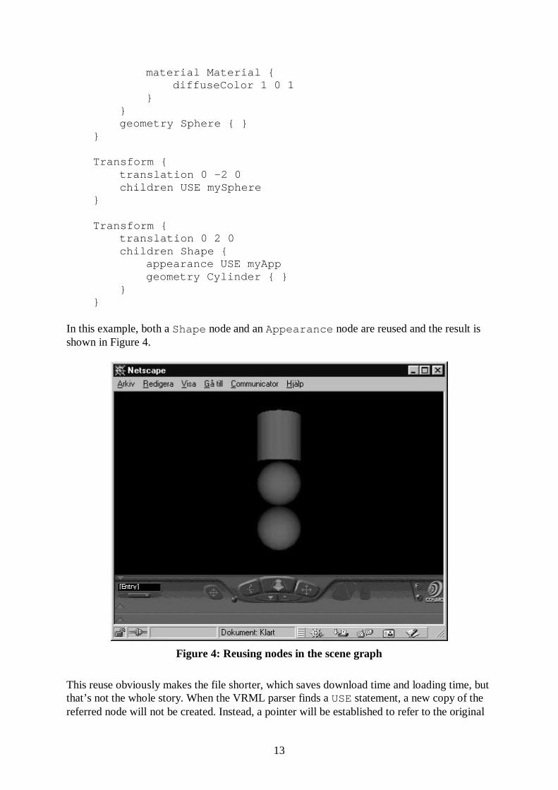
In this example, both a Shape node and an Appearance node are reused and the result isshown in Figure 4.
Figure 4: Reusing nodes in the scene graph
This reuse obviously makes the file shorter, which saves download time and loading time, butthat’s not the whole story. When the VRML parser finds a USE statement, a new copy of thereferred node will not be created. Instead, a pointer will be established to refer to the original

14
node, marked by the corresponding DEF statement. In many cases that doesn’t matter, or iseven desirable, but remember; whatever happens to the original node also happens to the‘copies’. To avoid this effect in a certain case, simply avoid using the DEF/USE construction.
2.5 Lighting
One very important aspect of how to make a virtual world look nice and realistic is thespecification of light sources. So far, we have only specified certain parameters controllingthe appearance at object level. The reason why our examples have looked alright until now isthat a light source have been added to our scenes automatically. However, we need to be ableto specify our own light sources to be used in the lighting calculations together with theappearance information applied to the shapes in the scene. There are three different kinds oflight sources in VRML, represented by the nodes DirectionalLight , PointLight andSpotLight . The simplest one is the DirectionalLight . Let’s see an example of howto use such a light source:
Listing 5
#VRML V2.0 utf8#Example: Using one global directional light
DirectionalLight {direction 1 0 0
}
DEF myCone Shape {appearance Appearance {
material Material {diffuseColor 0.7 0.7 0.1
}}geometry Cone { }
}
Transform {translation -3 0 0children USE myCone
}
Transform {translation 3 0 0children USE myCone
}
All we have to do to add a directional light source to a scene is to enter the direction of theparallel light rays, which is given by a vector. Note that the directional light source doesn’tneed to have any given position in the world. Instead, it is used to simulate light sourcesinfinitely far away, like the sun, for instance.

15
Figure 5: Using a global directional light source
Figure 6: Using two scoped directional light sources

16
The following definition of the DirectionalLight node shows us the options availableto control this kind of light source:
DirectionalLight {exposedField SFFloat ambientIntensity 0exposedField SFColor color 1 1 1exposedField SFVec3D direction 0 0 -1exposedField SFFloat intensity 1exposedField SFBool on TRUE
}
Here we can see that the color field allows us to choose an RGB color for the light rays andif we don’t, the light defaults to white. We can also adjust the overall intensity of thelight as well as turning the light on and off using the on flag. And if we set theambientIntensity field it will be added to the ambientIntensity field in thecurrent Material node throughout the lighting calculations.
Another interesting aspect of the DirectionalLight node is that it will only affect nodesplaced under it in the scene graph. The light source in the example above is global to thewhole scene, which means all three cones are lit, as we can see in Figure 5. In reality, two ofthem would have been in shadow, though. Let’s look at another example illustrating how toput limits on the effect of directional light sources:
Listing 6
#VRML V2.0 utf8#Example: Using two scoped directional lights
DEF myCone Shape {appearance Appearance {
material Material {diffuseColor 0.7 0.7 0.1
}}geometry Cone { }
}
Transform {translation -3 0 0children [
DirectionalLight {direction 1 0 0
}USE myCone
]}
Transform {translation 3 0 0children [

17
DirectionalLight {direction -1 0 0
}USE myCone
]}
When viewing this example (see Figure 6), note how a DirectionalLight is scoped tothe group node (in this case a Transform node) it is placed in. This feature allows us tomake it look like certain objects are in shadow, like the middle cone in our example.
The other kinds of light sources, point lights and spot lights, are a little bit more advanced andalso demands more complicated computations for the VRML browser. Of course, they arevery useful to increase realism in a many scenes, but they won’t be discussed further here.Instead we turn our attention to texture mapping.
2.6 Basic Texture Mapping
When texture mapping is used in a tasteful manner, it often increases the detail and realism invirtual worlds dramatically. In VRML, there are a couple of different nodes supporting texturemapping. We will only look at the ImageTexture node, though. This node let us usetextures given in the GIF, PNG or the JPEG file format. In its simplest form, it is very easy touse. Look at the following example:
Listing 7
#VRML V2.0 utf8#Example: A Texture Mapped Cylinder
Shape {appearance Appearance {
material Material {diffuseColor 0 1 0specularColor 0.5 0.5 0.5shininess 0.1
}texture ImageTexture {
url "wood.jpg"}
}geometry Cylinder { }
}
We specify the texture mapping properties using the texture field inside theAppearance node. The url field is used to give the location of the texture map. Normally,special texture coordinates, often called s and t, are required at each vertex in a shape if it isgoing to be texture mapped. In the example above no such coordinates were specified,because all the built in primitives, Box, Cone, Cylinder and Sphere , have built intexture coordinates.

18
Figure 7: A wood texture applied to a cylinder object
Besides the texture information, we also supply a material to the texture mapped shape. Why?In fact, if no material is used, the shape will not be lit and it will loose realism. The material,will blend nicely together with the texture map, for example making highlights possible. Thediffuse color of the material, green in our example, is ignored, though. This means we don’thave to worry about getting our textures maps messed up with other basic colors.
When we build geometrical models using either the IndexedFaceSet node or theElevationGrid node, we can control how the texture will be placed on the models byspecifying our own texture coordinates. As an example, let’s see how we can put a texture ona triangle polygon:
Listing 8
#VRML V2.0 utf8#Example: How to specify texture coordinates
Shape {appearance Appearance {
material Material {}texture ImageTexture {
url "epcot.jpg"}
}geometry IndexedFaceSet {
coord Coordinate {

19
point [-1 0 0, 1 0 0, 0 1 0 ]}coordIndex [0, 1, 2, -1]texCoord TextureCoordinate {
point [0 0, 1 0, 0.5 1 ]}
}}
As we can see, the texture coordinates are specified in the texCoord field of theIndexFaceSet node. It is a list of s and t pair values, hopefully chosen with care. Sincethere is no texCoordIndex field specified in this example, the first texture coordinatebelongs to the first vertex, the second texture coordinate belongs to the second vertex, and soon. The resulting world can be seen in Figure 8. Can you see what’s on the texture?
Figure 8: A texture mapped triangle polygon
The TextureCoordinate node doesn’t include anything more than we already used.Anyway, it is defined like this:
TextureCoordinate {exposedField MFVec2f point []
}

20
Another useful node in this context is the TextureTransform node. It is used to applytransformations, like translation, scaling and rotation, to the texture coordinates. For example,this is useful if we want to change how the texture map is placed upon the built in primitiveswith predetermined texture coordinates. Here is an example using this ability:
Listing 9
#VRML V2.0 utf8#Example: Using the TextureTransform node
Transform {translation -2 0 0children Shape {
appearance Appearance {material Material {}texture ImageTexture {
url "epcot.jpg"}
}geometry Box { }
}}
Transform {translation 2 0 0children Shape {
appearance Appearance {material Material {}texture ImageTexture {
url "epcot.jpg"}textureTransform TextureTransform {
scale 2 2}
}geometry Box { }
}}
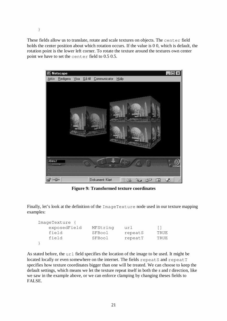
In this world there are two primitive boxes (see Figure 9). The first one simply uses the builtin texture coordinates, resulting in one copy of the texture on every face of the box. However,the built in texture coordinates in the second box are transformed by theTextureTransform node added to its appearance description. Since the texturecoordinates are scaled in both directions by a factor of two, the texture map appear four timeson every side of the box. The TextureTransform node is defined as follows:
TextureTransform {exposedField SFVec2f center 0 0exposedField SFFloat rotation 0exposedField SFVec2f scale 1 1exposedField SFVec2f translation 0 0
21
}
These fields allow us to translate, rotate and scale textures on objects. The center fieldholds the center position about which rotation occurs. If the value is 0 0, which is default, therotation point is the lower left corner. To rotate the texture around the textures own centerpoint we have to set the center field to 0.5 0.5.
Figure 9: Transformed texture coordinates
Finally, let’s look at the definition of the ImageTexture node used in our texture mappingexamples:
ImageTexture {exposedField MFString url []field SFBool repeatS TRUEfield SFBool repeatT TRUE
}
As stated before, the url field specifies the location of the image to be used. It might belocated locally or even somewhere on the internet. The fields repeatS and repeatTspecifies how texture coordinates bigger than one will be treated. We can choose to keep thedefault settings, which means we let the texture repeat itself in both the s and t direction, likewe saw in the example above, or we can enforce clamping by changing theses fields toFALSE.

22
2.7 Controlling the Viewer
So far, we have been navigating around in our virtual world by using the VRML browser, butfrom what view point do we really want to start? By default, the viewpoint starts at thecoordinates 0 0 10, but by using the Viewpoint node we can set up, not only where to start,but also define a list of particularly interesting viewing spots. Here is an example:
Listing 10
#VRML V2.0 utf8#Example: Choosing a viewer
DirectionalLight {direction 0 -1 0
}
Viewpoint {orientation 1 0 0 -0.78position 0 5 5description "first"
}
Viewpoint {fieldOfView 0.6orientation 1 1 0 -0.78position -4 4 5description "second"
}
Shape {appearance Appearance {
material Material {diffuseColor 1 1 1
}}geometry Box { }
}
In this scene, there are two different viewpoints. The first one specified will be the startingviewpoint (see Figure 10). In Cosmo Player all viewpoints holding a name in thedescription field will be added to a viewpoint list from which the user easily can choosea particular viewpoint. Here is the definition of the Viewpoint node:
Viewpoint {eventIn SFBool set_bindexposedField SFFloat fieldOfView 0.785398exposedField SFBool jump TRUEexposedField SFRotation orientation 0 0 1 0exposedField SFVec3f position 0 0 10field SFString description ""

23
eventOut SFTime bindTimeeventOut SFBool isBound
}
The two fields position and orientation are used together to specify the view positionand direction and the fieldOfView field determines the width of the view, in a similar waylike a lens in camera does. It is interesting to play around a little with these parameters to get abetter feel of their usage.
Figure 10: A specified starting viewpoint
This short look at viewpoints concludes our basic discussion of how to start making VRMLworlds. Let’s move on to look at some interesting optimization possibilities.
3. Optimization Techniques
One very important goal when creating nice looking virtual worlds is to achieve an acceptableframe rate when the world is explored. Although the performance on affordable computers areconstantly increasing we still need do be very careful when designing complex virtualenvironments. By definition, in virtual reality applications, we always need real timeperformance. The performance achieved depend pretty much upon the way we model ourobjects as well as the scene. Keeping this in mind, let’s take a look at two quite simplepossibilities to increase the performance in VRML worlds.

24
3.1 Adaptive Level of Detail
The first trick is to represent a complex geometrical model in more than one way, from verysimple and efficient versions to more and more detailed and realistic versions. Then duringrendering a particular representation is chosen depending of the models distance from theviewer. The more far a way an object is, the less detail is needed. There is a direct support forthis adaptive level of detail concept in VRML by the node called LOD. It is defined asfollows:
LOD {exposedField MFNode level []field SFVec3f center 0 0 0field MFFloat range []
}
The field level refers to a list of nodes describing the different representations of an object,the center field holds the center position used for all different representation and therange field is a list of distance values defining when the browser is going to switchrepresentation. An example will make this clearer:
Listing 11
#VRML V2.0 utf8#Example: Using level of details
DEF my_app Appearance {material Material {
diffuseColor 1 1 0}
}
LOD {level [
Shape {appearance USE my_appgeometry Sphere { }
},Shape {
appearance USE my_appgeometry Cylinder { }
},Shape {
appearance USE my_appgeometry Cone { }
}]center 0 0 0range [15, 20]
}

25
In this case we use the LOD node to switch between a sphere, cylinder and cone. Exactlywhen the switches between these representations happens are specified in the range field.The first representation is chosen when the distance between the viewer and the object is lessthan 15 units (see Figure 11). When the distance is between 15 and 20 units, the secondrepresentation is chosen and if the distance is greater than 20 units the last representation isused.
Figure 11: Taking a close look at the LOD node
3.2 Billboards
A well-known technique to decrease the polygon count in a model is to replace a detailedgeometrical description by texture mapped polygons. The texture map can give us quite agood experience of some detailed structure. Using this technique, together with theBillboard node in VRML, will make it possible to include a lot of objects in a scene thatwould be far to complex to represent by pure geometrical descriptions. A classical example ofthis is how to represent trees in a garden. The Billboard node groups a list of children thatwill be forced to face the viewer. Thus, we can represent a tree by a simple flat polygonpainted with a tree texture. Let’s look at an example world with one billboard polygon and abox object beside it to see how this node works:
Listing 12
#VRML V2.0 utf8#Example: Using billboards
26
Billboard {children Shape {
appearance Appearance {material Material {}
}geometry IndexedFaceSet {
coord Coordinate {point [-2 -3 0, 2 -3 0, 2 3 0, -2, 3, 0]
}coordIndex [0, 1, 2, 3, -1]
}}
}
Transform {translation -5, 0, 0children Shape {
appearance Appearance {material Material {}
}geometry Box { }
}}
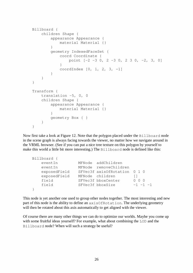
Now first take a look at Figure 12. Note that the polygon placed under the Billboard nodein the scene graph is always facing towards the viewer, no matter how we navigate around inthe VRML browser. (See if you can put a nice tree texture on this polygon by yourself tomake this world a little bit more interesting.) The Billboard node is defined like this:
Billboard {eventIn MFNode addChildreneventIn MFNode removeChildrenexposedField SFVec3f axisOfRotation 0 1 0exposedField MFNode children []field SFVec3f bboxCenter 0 0 0field SFVec3f bboxSize -1 –1 -1
}
This node is yet another one used to group other nodes together. The most interesting and newpart of this node is the ability to define an axisOfRotation . The underlying geometrywill then be rotated about this axis automatically to get aligned with the viewer.
Of course there are many other things we can do to optimize our worlds. Maybe you come upwith some fruitful ideas yourself? For example, what about combining the LOD and theBillboard node? When will such a strategy be useful?

27
Figure 12: A box and a billboard polygon
4. Moving Beyond Static Worlds
So far, the nature of our world has been static. To make more useful and interesting worlds weneed to bring them to life. Some interesting questions are: In what ways can the user interactswith the world? How can we create moving objects? In the following sections, just a glimpseof the possibilities are presented.
4.1 Allowing User Interaction
In VRML there are several sensor nodes. These nodes are used to sense some kind of stimuliand translate it into an appropriate VRML event that will affect the scene. For example, theTouchSensor node is used to determine when the user touches an object. When thathappens, the node generate an event, that will be passed to some receiver node who can reactin respond to that event. But exactly who is the receiver? Actually, we have to give thatinformation in our scene description by creating routes, using the ROUTE keyword.Hopefully, an example will clarify this:
Listing 13
#VRML V2.0 utf8#Example: Allowing user input
Transform {

28
rotation 1 0 0 0.78children [
DEF myTouchSensor TouchSensor {},DEF myDirectionalLight DirectionalLight {
direction 1 0 0on FALSE
},Shape {
appearance Appearance {material Material { }
}geometry Cylinder { }
}]
}
ROUTE myTouchSensor.isOver TO myDirectionalLight.set_on
In this scene, there is a directional light source, casting light in the direction of the positive x-axis, but from the beginning it is turned off. By the help of the functionality provided by theTouchSensor node, placed together with the cylinder object, we are able to turn the lighton, using the mouse input device (see Figure 13). The ROUTE created at the end of theexample specifies that behavior. When the TouchSensor goes off, because of the mousecursor is placed over the geometry grouped together with it, an event will notify theDirectionalLight node. Note that there has to be a perfect type match betweenassociated events. An eventOut has to have the same type as the corresponding eventInin the ROUTEs we create. Here is the definition of the TouchSensor :
TouchSensor {exposedField SFBool enabled TRUEeventOut SFVec3f hitNormal_changedeventOut SFVec3f hitPoint_changedeventOut SFVec2f hitTexCoord_changedeventOut SFBool isActiveeventOut SFBool isOvereventOut SFTime touchTime
}
The eventOut field isOver has the type SFBool . This means we have to connect it to aneventIn field with the same type. Let’s look again in the definition of theDirectionalLight node, given in section 2.5, to see if we can find such an eventInfield. Actually, there is no field called set_on defined at all in that node definition. So howdoes it work then? In fact, there is both an eventIn and an eventOut field implicitlydefined for every exposedField in a node. Just add the prefix set_ to find thecorresponding eventIn name and the suffix _changed to find the correspondingeventOut name.

29
Figure 13: Light rays from the left, when the object is in mouse focus
4.2 Introducing Scripts
If we want to add advanced behavior to our worlds, not built into VRML directly, wehopefully have the possibility to accomplish it using a programming language. Even if theVRML97 standard doesn’t require that a VRML browser has to support any programminglanguage, we can for example use Java, JavaScript or VRMLScript (a subset of JavaScript) inCosmo Player. We will only use VRMLScript, since it is the easiest of them all and it doesn’thave to be pre-compiled. The glue between the scene graph and the code we write is given tous by the Script node. Here is an example:
Listing 14
#VRML V2.0 utf8#Example: Using a VRML Script
Transform {rotation 1 0 0 0.78children [
DEF myTouchSensor TouchSensor {},Shape {
appearance Appearance {material DEF myMaterial Material { }
}geometry Cylinder { }
}

30
]}
DEF myScript Script {eventIn SFBool touchedeventOut SFColor newColorfield SFBool toggleColor TRUEurl "vrmlscript:
function touched() {if (toggleColor) {
newColor = new SFColor(1, 0, 0);toggleColor = FALSE;
} else {newColor = new SFColor(0, 1, 0);toggleColor = TRUE;
}}"
}
ROUTE myTouchSensor.isOver TO myScript.touchedROUTE myScript.newColor TO myMaterial.set_diffuseColor
Thanks to the script in this scene, the color of the cylinder can be changed dynamically. Fromthe beginning, the cylinder has its default diffuse color. When the mouse cursor enter the areacovered by the cylinder its color changes to red and when the mouse cursor leaves this area itscolor is changed to green (see Figure 14).
Figure 14: When the mouse cursor left the object it became green
31
When is this script executed? The code in the script is invoked when the Script nodereceives an isOver event from the TouchSensor in the scene. Why? Because there is aROUTE statement wiring them together in exactly that way. When this happens, the scriptfunction, with the same name as the received eventIn , is executed. Furthermore, when anassignment occurs to the newColor field in the script code it causes an other event, that willbe sent to the Material node, causing the change of color. Why? Because there is anotherROUTE statement connecting them.
5. VRML on the Internet
Remember, the purpose of VRML is to make 3D graphics a natural part of the World WideWeb, as a complement to the widely used HTML standard. We might be able to enrich the on-line experience significantly, if we use virtual reality worlds in a tasteful manner.
One of the most important things on Web pages is the possibility to easily follow hyperlinks.In virtual worlds hyperlinks might be equally important. For this reason, let’s take a look athow to insert hyperlinks into our virtual worlds.
5.1 Adding Hyperlinks
Hyperlinks are very easy to place in a scene. To do so, we just use the node called Anchor ,which let us specify geometry the user can click on in the scene graph. Here is an example:
Listing 15
#VRML V2.0 utf8#Example of how to create a hyperlink
Anchor {url "Simple.wrl"description "Go to Simple.wrl"children Shape {
appearance Appearance {material Material { }
}geometry Sphere { }
}}
In the url field we specify where the hyperlink goes. In this case, it is to the first exampleworld in this tutorial, but we could for example have referred to an image file or a HTML fileinstead. The description field makes it possible for the browser to show what kind ofsource to expect by following the link (see Figure 15).
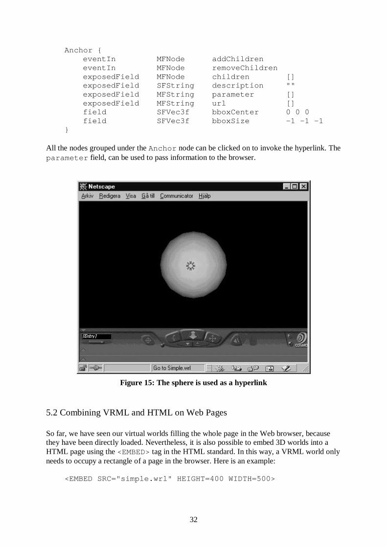
The definition of the Anchor node reveals it is yet another grouping node, holding a list ofchildren:
32
Anchor {eventIn MFNode addChildreneventIn MFNode removeChildrenexposedField MFNode children []exposedField SFString description ""exposedField MFString parameter []exposedField MFString url []field SFVec3f bboxCenter 0 0 0field SFVec3f bboxSize -1 –1 -1
}
All the nodes grouped under the Anchor node can be clicked on to invoke the hyperlink. Theparameter field, can be used to pass information to the browser.
Figure 15: The sphere is used as a hyperlink
5.2 Combining VRML and HTML on Web Pages
So far, we have seen our virtual worlds filling the whole page in the Web browser, becausethey have been directly loaded. Nevertheless, it is also possible to embed 3D worlds into aHTML page using the <EMBED> tag in the HTML standard. In this way, a VRML world onlyneeds to occupy a rectangle of a page in the browser. Here is an example:
<EMBED SRC="simple.wrl" HEIGHT=400 WIDTH=500>

33
Frames in the HTML standard give us yet another possibility to create Web pages includingboth VRML worlds and HTML documents. For example, we can have some frames dedicatedto view the 3D graphics worlds while other frames are used to give associated 2D graphicsinformation. It is even possible to communicate between such frames, to make things evenmore interesting.
6. Conclusions
In this tutorial we have started to learn VRML. We have briefly covered many of the basicfeatures and if we put the pieces together we can accomplish quite nice looking worlds.However, it is quite a challenge to master this language. For example, we have only touchedupon sensors, which are used for triggering events to dynamically affect the scene. We havecompletely ignored interpolators, which are a very useful set of nodes for bringing objects tolife. The scripting facilities, all very central to make our virtual worlds more unpredictableand realistic, have been almost completely left out. Hopefully, these and others interestingtopics will be discussed in another follow-up tutorial. In any case, now let’s have some funbuilding nice virtual worlds, all sharable over the Internet.
7. Acknowledgements
The author would like to thank Kjell Post for his beneficial suggestions to improve thisdocument.
References
[Vrm97] The VRML97 specification, www.vrml.org/Specifications/VRML97/
[Nad97] Introduction to VRML97, Siggraph Tutorial, David Nadeau, John Moreland,Michael Heck, 1997
[Mar97] Teach Yourself VRML 2 in 21 days, Chris Marrin, Bruce Campbell, Sams.net,1997