vsphere esxi vcenter server 55 networking guide
DESCRIPTION
5.5TRANSCRIPT

vSphere NetworkingvSphere 5.5
ESXi 5.5vCenter Server 5.5
This document supports the version of each product listed andsupports all subsequent versions until the document isreplaced by a new edition. To check for more recent editionsof this document, see http://www.vmware.com/support/pubs.
EN-001074-00

vSphere Networking
2 VMware, Inc.
You can find the most up-to-date technical documentation on the VMware Web site at:
http://www.vmware.com/support/
The VMware Web site also provides the latest product updates.
If you have comments about this documentation, submit your feedback to:
Copyright © 2009–2013 VMware, Inc. All rights reserved. This product is protected by U.S. and international copyright andintellectual property laws. VMware products are covered by one or more patents listed at http://www.vmware.com/go/patents.
VMware is a registered trademark or trademark of VMware, Inc. in the United States and other jurisdictions. All other marksand names mentioned herein may be trademarks of their respective companies.
VMware, Inc.3401 Hillview Ave.Palo Alto, CA 94304www.vmware.com

Contents
About vSphere Networking 9
1 Introduction to Networking 11
Networking Concepts Overview 11Network Services in ESXi 13VLAN Configuration 13VMware ESXi Dump Collector Support 13
2 Setting Up Networking with vSphere Standard Switches 15
vSphere Standard Switches 15Port Group Configuration for Virtual Machines 16
Add a Virtual Machine Port Group with the vSphere Web Client 17Edit a Standard Switch Port Group in the vSphere Web Client 18Remove a Port Group from a vSphere Standard Switch in the vSphere Web Client 19
vSphere Standard Switch Properties 19Change the Number of Ports for a vSphere Standard Switch in the vSphere Web Client 19Change the Speed of a Physical Adapter in the vSphere Web Client 20Add and Team Physical Adapters in a Standard Switch in the vSphere Web Client 20View the Topology Diagram of a vSphere Standard Switch in the vSphere Web Client 21
3 Setting Up Networking with vSphere Distributed Switches 23
vSphere Distributed Switch Architecture 24Create a vSphere Distributed Switch with the vSphere Web Client 25Upgrade a vSphere Distributed Switch to a Later Version with the vSphere Web Client 26Edit General and Advanced vSphere Distributed Switch Settings in the vSphere Web Client 27Managing Networking on Multiple Hosts on a vSphere Distributed Switch 28
Tasks for Managing Host Networking on a vSphere Distributed Switch 29Add Hosts to a vSphere Distributed Switch in the vSphere Web Client 30Configure Physical Network Adapters on a vSphere Distributed Switch in the
vSphere Web Client 31Migrate VMkernel Adapters to a vSphere Distributed Switch in the vSphere Web Client 32Create a VMkernel Adapter on a vSphere Distributed Switch in the vSphere Web Client 33Migrate Virtual Machine Networking to the vSphere Distributed Switch in the
vSphere Web Client 34Update the Maximum Number of Distributed Ports on Hosts in the vSphere Web Client 35Use a Host as a Template to Create a Uniform Networking Configuration on a vSphere
Distributed Switch in the vSphere Web Client 35Remove Hosts from a vSphere Distributed Switch in the vSphere Web Client 36
Managing Networking on Host Proxy Switches 37Migrate Network Adapters on a Host to a vSphere Distributed Switch in the
vSphere Web Client 37
VMware, Inc. 3

Migrate a VMkernel Adapter on a Host to a vSphere Standard Switch in thevSphere Web Client 38
Assign a Physical NIC of a Host to a vSphere Distributed Switch in the vSphere Web Client 38Remove a Physical NIC from a vSphere Distributed Switch in the vSphere Web Client 39Set the Number of Ports on a Host Proxy Switch in the vSphere Web Client 39Removing NICs from Active Virtual Machines 40
Distributed Port Groups 40Add a Distributed Port Group in the vSphere Web Client 40Edit General Distributed Port Group Settings with the vSphere Web Client 43Edit Advanced Distributed Port Group Settings with the vSphere Web Client 44Remove a Distributed Port Group in the vSphere Web Client 45Export, Import, and Restore vSphere Distributed Port Group Configurations 45
Working with Distributed Ports 47Monitor Distributed Port State with the vSphere Web Client 47Configure Distributed Port Settings with the vSphere Web Client 47
Configuring Virtual Machine Networking on a vSphere Distributed Switch 48Migrate Virtual Machines to or from a vSphere Distributed Switch with the
vSphere Web Client 48Connect an Individual Virtual Machine to a Distributed Port Group in the vSphere Web Client 48
Topology Diagrams of a vSphere Distributed Switch in the vSphere Web Client 49View the Topology of a vSphere Distributed Switch in the vSphere Web Client 49View the Topology of a Host Proxy Switch in the vSphere Web Client 51
vSphere Distributed Switch Health Check 51Enable or Disable vSphere Distributed Switch Health Check in the vSphere Web Client 51View vSphere Distributed Switch Health Check Information 52
Export, Import, and Restore Distributed Switch Configurations 52Export vSphere Distributed Switch Configurations with the vSphere Web Client 52Import a vSphere Distributed Switch Configuration by Using the vSphere Web Client 53Restore a vSphere Distributed Switch Configuration with the vSphere Web Client 54
Private VLANs 54Create a Private VLAN in the vSphere Web Client 55Remove a Primary Private VLAN with the vSphere Web Client 55Remove a Secondary Private VLAN with the vSphere Web Client 56
LACP Support on a vSphere Distributed Switch 57Convert to the Enhanced LACP Support on a vSphere Distributed Switch in the
vSphere Web Client 58LACP Teaming and Failover Configuration for Distributed Port Groups 60Configure a LAG to Handle the Traffic for Distributed Port Groups in the vSphere Web Client 60Edit a LAG in the vSphere Web Client 64Enable the LACP 5.1 Support on an Uplink Port Group in the vSphere Web Client 65Limitations of the LACP Support on a vSphere Distributed Switch 65
4 Setting Up VMkernel Networking 67
The VMkernel Networking Layer 68View Information About VMkernel Adapters on a Host in the vSphere Web Client 69Create a VMkernel Adapter on a vSphere Standard Switch in the vSphere Web Client 69Create a VMkernel Adapter on a Host Associated with a vSphere Distributed Switch in the
vSphere Web Client 71Edit a VMkernel Adapter Configuration in the vSphere Web Client 72
vSphere Networking
4 VMware, Inc.

View TCP/IP Stack Configuration on a Host in the vSphere Web Client 73Change the Configuration of a TCP/IP Stack on a Host in the vSphere Web Client 74Create a Custom TCP/IP Stack 74Remove a VMkernel Adapter in the vSphere Web Client 75
5 Networking Policies 77
Teaming and Failover Policy 78Edit Teaming and Failover Policy for a vSphere Standard Switch in the vSphere Web Client 78Edit the Teaming and Failover Policy on a Standard Port Group in the vSphere Web Client 80Edit the Teaming and Failover Policy on a Distributed Port Group in the vSphere Web Client 82Edit Distributed Port Teaming and Failover Policies with the vSphere Web Client 83
VLAN Policy 85Edit the VLAN Policy on a Distributed Port Group in the vSphere Web Client 85Edit the VLAN Policy on a Distributed Port with the vSphere Web Client 86Edit the VLAN Policy on an Uplink Port Group in the vSphere Web Client 86Edit the VLAN Policy on an Uplink Port with the vSphere Web Client 87
Security Policy 88Edit Security Policy for a vSphere Standard Switch in the vSphere Web Client 88Edit the Layer 2 Security Policy Exception for a Standard Port Group in the
vSphere Web Client 89Edit the Security Policy for a Distributed Port Group in the vSphere Web Client 89Edit Distributed Port Security Policies with the vSphere Web Client 90
Traffic Shaping Policy 91Edit the Traffic Shaping Policy for a vSphere Standard Switch in the vSphere Web Client 92Edit the Traffic Shaping Policy for a Standard Port Group in the vSphere Web Client 92Edit the Traffic Shaping Policy on a Distributed Port Group in the vSphere Web Client 93Edit the Traffic Shaping Policy on a Distributed Port in the vSphere Web Client 94
Resource Allocation Policy 95Edit the Resource Allocation Policy on a Distributed Port Group in the vSphere Web Client 95Edit the Resource Allocation Policy on a Distributed Port in the vSphere Web Client 96
Monitoring Policy 96Edit the Monitoring Policy on a Distributed Port Group in the vSphere Web Client 96Edit the Monitoring Policy on a Distributed Port in the vSphere Web Client 97
Traffic Filtering and Marking Policy 97Traffic Filtering and Marking on a Distributed Port Group or Uplink Port Group in the
vSphere Web Client 98Traffic Filtering and Marking on a Distributed Port or Uplink Port in the vSphere Web Client 104Qualifying Traffic for Filtering and Marking 111
Port Blocking Policies 113Edit the Port Blocking Policy for a Distributed Port Group in the vSphere Web Client 113Edit Distributed Port or Uplink Port Blocking Policies with the vSphere Web Client 113
Manage Policies for Multiple Port Groups on a vSphere Distributed Switch in thevSphere Web Client 114
6 Managing Network Resources 121
vSphere Network I/O Control 121Enable Network I/O Control on a vSphere Distributed Switch with the vSphere Web Client 122Create a Network Resource Pool with the vSphere Web Client 122
Contents
VMware, Inc. 5

Add or Remove Distributed Port Groups from a Network Resource Pool with thevSphere Web Client 123
Edit Network Resource Pool Settings with the vSphere Web Client 124Delete a User-Defined Network Resource Pool with the vSphere Web Client 124
TCP Segmentation Offload and Jumbo Frames 125Enabling TSO 125Enabling Jumbo Frames 126
NetQueue and Networking Performance 128Enable NetQueue on a Host 128Disable NetQueue on a Host 129
DirectPath I/O 129Configure Passthrough Devices on a Host with the vSphere Web Client 130Configure a PCI Device on a Virtual Machine with the vSphere Web Client 131Enable DirectPath I/O with vMotion on a Virtual Machine with the vSphere Web Client 131
Single Root I/O Virtualization (SR-IOV) 132SR-IOV Support 132SR-IOV Component Architecture and Interaction 134vSphere and Virtual Function Interaction 136DirectPath I/O vs SR-IOV 136Configure a Virtual Machine to Use SR-IOV in the vSphere Web Client 137Networking Options for the Traffic Related to an SR-IOV Enabled Virtual Machine 139Using an SR-IOV Physical Adapter to Handle Virtual Machine Traffic 139Enabling SR-IOV by Using Host Profiles in the vSphere Web Client or Through an ESXCLI
Command 140
7 MAC Address Management 143
MAC Address Assignment from vCenter Server 143VMware OUI Allocation 144Prefix-Based MAC Address Allocation 144Range-Based MAC Address Allocation 145Assigning a MAC Address 145
MAC Address Generation on ESXi Hosts 147Setting a Static MAC Address to a Virtual Machine 148
VMware OUI in Static MAC Addresses 148Assign a Static MAC Address with the vSphere Web Client 149Assign a Static MAC Address in the Virtual Machine Configuration File 149
8 Advanced Networking 151
Enable or Disable IPv6 Support on a Host by Using the vSphere Web Client 151Working With Port Mirroring 152
Port Mirroring Version Compatibility 152Port Mirroring Interoperability 153Create a Port Mirroring Session with the vSphere Web Client 154View Port Mirroring Session Details in the vSphere Web Client 157Edit Port Mirroring Session Details, Sources, and Destinations with the vSphere Web Client 157
Configure NetFlow Settings with the vSphere Web Client 159Switch Discovery Protocol 159
Enable Cisco Discovery Protocol on a vSphere Distributed Switch with the vSphere Web Client 159
vSphere Networking
6 VMware, Inc.

Enable Link Layer Discovery Protocol on a vSphere Distributed Switch in thevSphere Web Client 160
View Switch Information with the vSphere Web Client 161Mounting NFS Volumes 161Networking Rollback and Recovery 161
vSphere Networking Rollback 161Restore a Previous Networking Configuration with the vSphere Web Client 163Resolve Errors in the Management Network Configuration on a vSphere Distributed Switch 164
Configuring Protocol Profiles for Virtual Machine Networking 164Add a Network Protocol Profile in the vSphere Web Client 165Associate a Port Group with a Network Protocol Profile in the vSphere Web Client 167Configure a Virtual Machine or vApp to Use a Network Protocol Profile in the
vSphere Web Client 167Stateless Network Deployment 168
9 Networking Best Practices 171
Index 173
Contents
VMware, Inc. 7

vSphere Networking
8 VMware, Inc.

About vSphere Networking
vSphere Networking provides information about configuring networking for VMware vSphere®, includinghow to create vSphere distributed switches and vSphere standard switches.
vSphere Networking also provides information on monitoring networks, managing network resources, andnetworking best practices.
Intended AudienceThe information presented is written for experienced Windows or Linux system administrators who arefamiliar with network configuration and virtual machine technology.
VMware, Inc. 9

vSphere Networking
10 VMware, Inc.

Introduction to Networking 1The basic concepts of ESXi networking and how to set up and configure a network in a vSphereenvironment are discussed.
This chapter includes the following topics:
n “Networking Concepts Overview,” on page 11
n “Network Services in ESXi,” on page 13
n “VLAN Configuration,” on page 13
n “VMware ESXi Dump Collector Support,” on page 13
Networking Concepts OverviewA few concepts are essential for a thorough understanding of virtual networking. If you are new to ESXi, itis helpful to review these concepts.
Physical Network A network of physical machines that are connected so that they can senddata to and receive data from each other. VMware ESXi runs on a physicalmachine.
Virtual Network A network of virtual machines running on a physical machine that areconnected logically to each other so that they can send data to and receivedata from each other. Virtual machines can be connected to the virtualnetworks that you create when you add a network.
Physical EthernetSwitch
It manages network traffic between machines on the physical network. Aswitch has multiple ports, each of which can be connected to a singlemachine or another switch on the network. Each port can be configured tobehave in certain ways depending on the needs of the machine connected toit. The switch learns which hosts are connected to which of its ports and usesthat information to forward traffic to the correct physical machines. Switchesare the core of a physical network. Multiple switches can be connectedtogether to form larger networks.
vSphere StandardSwitch
It works much like a physical Ethernet switch. It detects which virtualmachines are logically connected to each of its virtual ports and uses thatinformation to forward traffic to the correct virtual machines. A vSpherestandard switch can be connected to physical switches by using physicalEthernet adapters, also referred to as uplink adapters, to join virtual
VMware, Inc. 11

networks with physical networks. This type of connection is similar toconnecting physical switches together to create a larger network. Eventhough a vSphere standard switch works much like a physical switch, it doesnot have some of the advanced functionality of a physical switch.
Standard Port Group It specifies port configuration options such as bandwidth limitations andVLAN tagging policies for each member port. Network services connect tostandard switches through port groups. Port groups define how a connectionis made through the switch to the network. Typically, a single standardswitch is associated with one or more port groups.
vSphere DistributedSwitch
It acts as a single switch across all associated hosts in a datacenter to providecentralized provisioning, administration, and monitoring of virtualnetworks. You configure a vSphere distributed switch on the vCenter Serversystem and the configuration is populated across all hosts that are associatedwith the switch. This lets virtual machines to maintain consistent networkconfiguration as they migrate across multiple hosts.
Host Proxy Switch A hidden standard switch that resides on every host that is associated with avSphere distributed switch. The host proxy switch replicates the networkingconfiguration set on the vSphere distributed switch to the particular host.
Distributed Port A port on a vSphere distributed switch that connects to a host’s VMkernel orto a virtual machine’s network adapter.
Distributed Port Group A port group associated with a vSphere distributed switch and specifies portconfiguration options for each member port. Distributed port groups definehow a connection is made through the vSphere distributed switch to thenetwork.
NIC Teaming NIC teaming occurs when multiple uplink adapters are associated with asingle switch to form a team. A team can either share the load of trafficbetween physical and virtual networks among some or all of its members, orprovide passive failover in the event of a hardware failure or a networkoutage.
VLAN VLAN enable a single physical LAN segment to be further segmented so thatgroups of ports are isolated from one another as if they were on physicallydifferent segments. The standard is 802.1Q.
VMkernel TCP/IPNetworking Layer
The VMkernel networking layer provides connectivity to hosts and handlesthe standard infrastructure traffic of vSphere vMotion, IP storage, FaultTolerance, and Virtual SAN.
IP Storage Any form of storage that uses TCP/IP network communication as itsfoundation. iSCSI can be used as a virtual machine datastore, and NFS can beused as a virtual machine datastore and for direct mounting of .ISO files,which are presented as CD-ROMs to virtual machines.
TCP SegmentationOffload
TCP Segmentation Offload, TSO, allows a TCP/IP stack to emit large frames(up to 64KB) even though the maximum transmission unit (MTU) of theinterface is smaller. The network adapter then separates the large frame intoMTU-sized frames and prepends an adjusted copy of the initial TCP/IPheaders.
vSphere Networking
12 VMware, Inc.

Network Services in ESXiA virtual network provides several services to the host and virtual machines.
You can enable two types of network services in ESXi:
n Connecting virtual machines to the physical network and to each other.
n Connecting VMkernel services (such as NFS, iSCSI, or vMotion) to the physical network.
VLAN ConfigurationVirtual LANs (VLANs) enable a single physical LAN segment to be further isolated so that groups of portsare isolated from one another as if they were on physically different segments.
Configuring ESXi with VLANs is recommended for the following reasons.
n It integrates the host into a pre-existing environment.
n It isolates and secures network traffic.
n It reduces network traffic congestion.
You can configure VLANs in ESXi using three methods: External Switch Tagging (EST), Virtual SwitchTagging (VST), and Virtual Guest Tagging (VGT).
With EST, all VLAN tagging of packets is performed on the physical switch. Host network adapters areconnected to access ports on the physical switch. Port groups that are connected to the virtual switch musthave their VLAN ID set to 0.
With VST, all VLAN tagging of packets is performed by the virtual switch before leaving the host. Hostnetwork adapters must be connected to trunk ports on the physical switch. Port groups that are connectedto the virtual switch must have a VLAN ID between 1 and 4094.
With VGT, all VLAN tagging is done by the virtual machine. VLAN tags are preserved between the virtualmachine networking stack and external switch when frames pass to and from virtual switches. Hostnetwork adapters must be connected to trunk ports on the physical switch. The VLAN ID of port groupswith VGT must be set to 4095.
NOTE When using VGT, you must have an 802.1Q VLAN trunking driver installed on the virtual machine.
VMware ESXi Dump Collector SupportThe ESXi Dump Collector sends the state of the VMkernel memory, that is, a core dump to a network serverwhen the system encounters a critical failure.
The ESXi Dump Collector in ESXi 5.1 and later supports both vSphere Standard and Distributed Switches.The ESXi Dump Collector can also use any active uplink adapter from the team of the port group thathandles the VMkernel adapter for the collector.
Changes to the IP address for the ESXi Dump Collector interface are automatically updated if the IPaddresses for the configured VMkernel adapter changes. The ESXi Dump Collector also adjusts its defaultgateway if the gateway configuration of the VMkernel adapter changes.
If you try to delete the VMkernel network adapter used by the ESXi Dump Collector, the operation fails anda warning message appears. To delete the VMkernel network adapter, disable dump collection and deletethe adapter.
Chapter 1 Introduction to Networking
VMware, Inc. 13

There is no authentication or encryption in the file transfer session from a crashed host to the ESXi DumpCollector. You should configure the ESXi Dump Collector on a separate VLAN when possible to isolate theESXi core dump from regular network traffic.
For information about installing and configuring the ESXi Dump Collector, see the vSphere Installation andSetup documentation.
vSphere Networking
14 VMware, Inc.

Setting Up Networking with vSphereStandard Switches 2
vSphere standard switches handle network traffic at the host level in a vSphere deployment.
This chapter includes the following topics:
n “vSphere Standard Switches,” on page 15
n “Port Group Configuration for Virtual Machines,” on page 16
n “vSphere Standard Switch Properties,” on page 19
vSphere Standard SwitchesYou can create abstracted network devices called vSphere standard switches. You use standard switches toprovide network connectivity to hosts and virtual machines. A standard switch can bridge traffic internallybetween virtual machines in the same VLAN and link to external networks.
Standard Switch OverviewTo provide network connectivity to hosts and virtual machines, you connect the physical NICs of the hoststo uplink ports on the standard switch. Virtual machines have network adapters (vNICs) that you connect toport groups on the standard switch. Every port group can use one or more physical NICs to handle theirnetwork traffic. If a port group does not have a physical NIC connected to it, virtual machines on the sameport group can only communicate with each other but not with the external network.
VMware, Inc. 15

Figure 2‑1. vSphere standard switch architecture
Testenvironment
Production
Physical Switch
vmnic0
VM
Uplink port group
uplink port 0 uplink port 1 uplink port 2
ESXi host 2
vmnic0 vmnic1 vmnic3
Virtualport
vmnic1 vmnic3
vMotion Management
vMotiontraffic
Managementtraffic
vmknic
VM VM VM
Testenvironment
Production
VM
Uplink port group
uplink port 0 uplink port 1 uplink port 2
ESXi host 1
vMotionManagement
vMotiontraffic
Managementtraffic VM VMVM
vNIC
Networkproduction
Portgroups
Physical network adapters
A vSphere standard switch is vary similar a physical Ethernet switch. The default number of logical portsfor a standard switch is 120. Virtual machine network adapters and physical NICs on the host use the logicalports on the switch as each adapter uses one port. Each logical port on the standard switch is a member of asingle port group. For information about maximum allowed ports and port groups, see the ConfigurationMaximums documentation.
Standard Port GroupsEach port group on a standard switch is identified by a network label, which must be unique to the currenthost. You can use network labels to make the networking configuration of virtual machines portable acrosshosts. You should give the same label to the port groups in a datacenter that use physical NICs connected toone broadcast domain on the physical network. Conversely, if two port groups are connected to physicalNICs on different broadcast domains, the port groups should have distinct labels.
For example, you can create Production and Test environment port groups as virtual machine networks on thehosts that share the same broadcast domain on the physical network.
A VLAN ID, which restricts port group traffic to a logical Ethernet segment within the physical network, isoptional. For port groups to receive the traffic that the same host sees, but from more than one VLAN , theVLAN ID must be set to VGT (VLAN 4095).
Port Group Configuration for Virtual MachinesYou can add or modify a virtual machine port group to set up traffic management on a set of virtualmachines.
The Add Networking wizard in the vSphere Web Client guides you through the process to create a virtualnetwork to which virtual machines can connect, including creating a vSphere standard switch andconfiguring settings for a network label.
vSphere Networking
16 VMware, Inc.

When you set up virtual machine networks, consider whether you want to migrate the virtual machines inthe network between hosts. If so, be sure that both hosts are in the same broadcast domain—that is, thesame Layer 2 subnet.
ESXi does not support virtual machine migration between hosts in different broadcast domains because themigrated virtual machine might require systems and resources that it would no longer have access to in thenew network. Even if your network configuration is set up as a high-availability environment or includesintelligent switches that can resolve the virtual machine’s needs across different networks, you mightexperience lag times as the Address Resolution Protocol (ARP) table updates and resumes network trafficfor the virtual machines.
Virtual machines reach physical networks through uplink adapters. A vSphere standard switch can transferdata to external networks only when one or more network adapters are attached to it. When two or moreadapters are attached to a single standard switch, they are transparently teamed.
Add a Virtual Machine Port Group with the vSphere Web ClientCreate port groups in a vSphere standard switch to provide connectivity and common networkconfiguration for a set of virtual machines.
Procedure
1 In the vSphere Web Client, navigate to the host.
2 Right-click the host in the navigator and select All vCenter Actions > Add Networking.
3 In Select connection type, select Virtual Machine Port Group for a Standard Switch and click Next.
4 In Select target device, select an existing standard switch or create a new standard switch.
5 If the new port group is for an existing standard switch, navigate to the switch.
a Click Browse.
b Select a standard switch from the list and click OK.
c Click Next and go to Step 7.
6 (Optional) In the Create a Standard Switch page, assign physical network adapters to the standardswitch.
You can create a standard switch with or without adapters.
If you create a standard switch without physical network adapters, all traffic on that switch is confinedto that switch. No other hosts on the physical network or virtual machines on other standard switchescan send or receive traffic over this standard switch. You might create a standard switch withoutphysical network adapters if you want a group of virtual machines to be able to communicate with eachother, but not with other hosts or with virtual machines outside the group.
a Click Add adapters.
b Select an adapter from the Network Adapters list.
c Use the Failover order group drop-down menu to assign the adapter to Active adapters, Standbyadapters, or Unused adapters, and click OK.
d (Optional) Use the up and down arrows in the Assigned adapters list to change the position of theadapter if needed.
e Click Next.
Chapter 2 Setting Up Networking with vSphere Standard Switches
VMware, Inc. 17

7 In the Connection settings page, identify traffic through the ports of the group.
a Type a Network Label for the port group, or accept the generated label.
b Set the VLAN ID to configure VLAN handling in the port group.
The VLAN ID also reflects the VLAN tagging mode in the port group.
VLAN Tagging Mode VLAN ID Description
External Switch Tagging (EST) 0 The virtual switch does not pass traffic associated with aVLAN.
Virtual Switch Tagging (VST) From 1 to 4094 The virtual switch tags traffic with the entered tag.
Virtual Guest Tagging (VGT) 4095 Virtual machines handle VLANs. The virtual switch passestraffic from any VLAN.
c Click Next.
8 Review the port group settings in the Ready to complete page, and click Finish.
Click Back if you want to change any settings.
Edit a Standard Switch Port Group in the vSphere Web ClientBy using the vSphere Web Client edit the name and VLAN ID of a standard switch port group, and overridenetworking policies at the port group level.
Procedure
1 In the vSphere Web Client, navigate to the host.
2 On the Manage tab, click Networking, and select Virtual switches.
3 Select a standard switch from the list.
The topology diagram of the switch appears.
4 In the topology diagram of the switch, click the name of the port group.
5 Click Edit under the topology diagram title.
6 In the Properties section, rename the port group in the Network Label text field.
7 Configure VLAN tagging in the VLAN ID drop-down menu.
VLAN Tagging Mode VLAN ID Description
External Switch Tagging (EST) 0 The virtual switch does not pass traffic associated with a VLAN.
Virtual Switch Tagging (VST) From 1 to 4094 The virtual switch tags traffic with the entered tag.
Virtual Guest Tagging (VGT) 4095 Virtual machines handle VLANs. The virtual switch passes trafficfrom any VLAN.
8 In the Security section, override the switch settings for protection against MAC address impersonationand for running virtual machines in promiscuous mode.
9 In the Traffic Shaping section, override at the port group level the size of average and peak bandwidthand of bursts.
10 In the Teaming and Failover section, override the teaming and failover settings inherited from thestandard switch.
You can configure traffic distribution and rerouting between the physical adapters associated with theport group. You can also change the order in which host physical adapters are used upon failure.
11 Click OK.
vSphere Networking
18 VMware, Inc.

Remove a Port Group from a vSphere Standard Switch in thevSphere Web Client
You can remove port groups from vSphere standard switches in case you no longer need the associatedlabeled networks.
Prerequisites
Verify that there are no powered-on virtual machines connected to the port group that you want to remove.
Procedure
1 In the vSphere Web Client, navigate to the host.
2 On the Manage tab, click Networking, and select Virtual switches.
3 Select the standard switch.
4 From the topology diagram of the switch, select the port group that you want to remove by clicking itslabel.
5 From the toolbar in the switch topology, click the Remove selected port group action icon .
vSphere Standard Switch PropertiesvSphere standard switch settings control switch-wide defaults for ports, which can be overridden by portgroup settings for each standard switch. You can edit standard switch properties, such as the uplinkconfiguration and the number of available ports.
Change the Number of Ports for a vSphere Standard Switch in thevSphere Web Client
For hosts running ESXi 5.1 and earlier, you can configure the number of ports that are available on astandard switch as the requirements of your environment change.
Each virtual switch on hosts running ESXi 5.1 and earlier provides a finite number of ports through whichvirtual machines and network services can reach one or more networks. You have to increase or decreasethe number of ports manually according to your deployment requirements.
NOTE Increasing the port number of a switch leads to reserving and consuming more resources on the host.If some ports are not occupied, host resources that might be necessary for other operations remain lockedand unused.
To ensure efficient use of host resources on hosts running ESXi 5.5, the ports of virtual switches aredynamically scaled up and down. A switch on such a host can expand up to the maximum number of portssupported on the host. The port limit is determined based on the maximum number of virtual machines thatthe host can handle.
Procedure
1 In the vSphere Web Client, navigate to the host.
2 On the Manage tab, click Networking, and select Virtual switches.
3 Select a standard switch from the table and click Edit settings.
4 In the Properties section, set the Number of ports for the standard switch by using the drop-downmenu.
Chapter 2 Setting Up Networking with vSphere Standard Switches
VMware, Inc. 19

5 (Optional) Change the MTU (bytes) value for the standard switch.
You can enable jumbo frames by setting MTU (bytes) to a number greater than 1500. You cannot set anMTU size greater than 9000 bytes.
6 Click OK.
Change the Speed of a Physical Adapter in the vSphere Web ClientA physical adapter can become a bottleneck for network traffic if the adapter speed does not matchapplication requirements. You can change the connection speed and duplex of a physical adapter to transferdata in compliance with traffic rate.
Procedure
1 Browse to a host in the vSphere Web Client navigator.
2 Click the Manage tab, and select Physical adapters from Networking.
The physical network adapters of the host appear in a table that contains details for each physicalnetwork adapter.
3 Select the physical network adapter from the list and click Edit.
4 Select speed and duplex mode of the physical network adapter from the drop-down menu.
5 (Optional) If the physical adapter supports SR-IOV, enable it and configure the number of virtualfunctions to use for virtual machine networking.
6 Click OK.
Add and Team Physical Adapters in a Standard Switch in thevSphere Web Client
Assign a physical adapter to a standard switch to provide connectivity to virtual machines and VMkerneladapters on the host. You can form a team of NICs to distribute traffic load and to configure failover.
NIC teaming combines multiple network connections to increase throughput and provide redundancyshould a link fail. To create a team, you associate multiple physical adapters to a single vSphere standardswitch.
Procedure
1 In the vSphere Web Client, navigate to the host.
2 On the Manage tab, click Networking, and select Virtual switches.
3 Select the standard switch you want to add a physical adapter to.
4 Click Manage the physical network adapters.
5 Click Add adapters.
6 Select one or more physical network adapters from the list and select the Failover order group to assignthe adapters to, and click OK.
The selected adapters appear in the selected failover group list under the Assigned Adapters list.
7 (Optional) Use the up and down arrows to change the position of an adapter in the failover groups.
8 Click OK to apply the physical adapter configuration.
vSphere Networking
20 VMware, Inc.
View the Topology Diagram of a vSphere Standard Switch in thevSphere Web Client
You can examine the structure and components of a vSphere standard switch by using its topology diagram.
The topology diagram of a standard switch provides a visual representation of the adapters and port groupsconnected to the switch.
From the diagram you can edit the settings of a selected port group and of a selected adapter.
Procedure
1 In the vSphere Web Client, navigate to the host.
2 On the Manage tab, click Networking, and select Virtual switches.
3 Select the standard switch from the list.
The diagram appears under the list of virtual switches on the host.
Chapter 2 Setting Up Networking with vSphere Standard Switches
VMware, Inc. 21

vSphere Networking
22 VMware, Inc.

Setting Up Networking with vSphereDistributed Switches 3
With vSphere distributed switches you can set up and configure networking in a vSphere environment.
This chapter includes the following topics:
n “vSphere Distributed Switch Architecture,” on page 24
n “Create a vSphere Distributed Switch with the vSphere Web Client,” on page 25
n “Upgrade a vSphere Distributed Switch to a Later Version with the vSphere Web Client,” on page 26
n “Edit General and Advanced vSphere Distributed Switch Settings in the vSphere Web Client,” onpage 27
n “Managing Networking on Multiple Hosts on a vSphere Distributed Switch,” on page 28
n “Managing Networking on Host Proxy Switches,” on page 37
n “Distributed Port Groups,” on page 40
n “Working with Distributed Ports,” on page 47
n “Configuring Virtual Machine Networking on a vSphere Distributed Switch,” on page 48
n “Topology Diagrams of a vSphere Distributed Switch in the vSphere Web Client,” on page 49
n “vSphere Distributed Switch Health Check,” on page 51
n “Export, Import, and Restore Distributed Switch Configurations,” on page 52
n “Private VLANs,” on page 54
n “LACP Support on a vSphere Distributed Switch,” on page 57
VMware, Inc. 23

vSphere Distributed Switch ArchitectureA vSphere Distributed Switch provides centralized management and monitoring of the networkingconfiguration of all hosts that are associated with the switch. You set up a distributed switch onvCenter Server system, and its settings are propagated to all hosts that are associated with the switch.
Figure 3‑1. vSphere Distributed Switch Architecture
Physical NICs
Uplink port group
Testenvironment vMotion
Test environmentProduction
Production
uplink port 0 uplink port 1 uplink port 2
Uplink0 Uplink1 Uplink2
ESXi host 1
vSphere Distributed Switch
Physical Switch
vmnic0
VM VM VM VM VM vMotion Management
Uplink port group
uplink port 0 uplink port 1 uplink port 2
ESXi host 2
vmnic0 vmnic1 vmnic3
vNIC VMkernaladapter(vmknic)
Distributedport groups
vmnic1 vmnic3
Uplink port group
vCenter Server
Management Testenvironment vMotionProduction Management
vMotion Management
You associate a vSphere Distributed Switch with a datacenter on a vCenter Server system. The networkingconfiguration and management for all hosts that are associated with the switch is centralized on thevCenter Server system. Every associated host has a host proxy switch that contains the networking settingsfor the host that are configured on distributed switch.
For example, suppose you associate ESXi A and ESXi B hosts to a distributed switch and connect physicalNIC vmnic1 of both hosts to uplink 1 on the switch. As a result, vmnic1 of hosts ESXi A and ESXi B isconnected to uplink 1 on the distributed switch. On the host proxy switches of both hosts, physical NICvmnic1 is connected to uplink port 1.
vSphere Networking
24 VMware, Inc.

A distributed switch has one or more distributed port groups. You use distributed port groups to providenetworking connectivity to virtual machines and to accommodate VMkernel traffic. You identify eachdistributed port group by using a network label, which must be unique to the current datacenter. A copy ofevery distributed port group that you create is also available on the host proxy switches of all hosts that areassociated with the distributed switch. The policies that you configure to a distributed port group areconsistent for all hosts in the distributed switch.
A VLAN ID, which restricts port group traffic to a logical Ethernet segment within the physical network, isoptional.
In addition to vSphere Distributed Switches, vSphere 5 also provides support for third-party virtualswitches. For information about configuring the Cisco Nexus 1000v switch, see the Cisco Systems Web site.
Create a vSphere Distributed Switch with the vSphere Web ClientCreate a vSphere distributed switch on a datacenter to handle the networking configuration of multiplehosts at a time from a central place.
Procedure
1 In the vSphere Web Client, navigate to a datacenter.
2 In the navigator, right-click the datacenter and select New Distributed Switch.
3 In Name and Location, type a name for the new distributed switch, or accept the generated name, andclick Next.
4 In Select version, select a distributed switch version and click Next.
Option Description
Distributed Switch: 5.5.0 Compatible with ESXi 5.5 and later.
Distributed Switch: 5.1.0 Compatible with VMware ESXi 5.1 and later. Features released with latervSphere distributed switch versions are not supported.
Distributed Switch: 5.0.0 Compatible with VMware ESXi 5.0 and later.Features released with later vSphere distributed switch versions are notsupported.
Distributed Switch: 4.1.0 Compatible with ESX/ESXi version 4.1 and later.Features released with later vSphere distributed switch versions are notsupported.
Distributed Switch: 4.0.0 Compatible with ESX/ESXi version 4.0 and later.Features released with later vSphere distributed switch versions are notsupported.
5 In Edit Settings configure the distributed switch settings.
a Use the arrow buttons to select the Number of uplinks.
Uplink ports connect the distributed switch to physical NICs on associated hosts. The number ofuplink ports is the maximum number of allowed physical connections to the distributed switch perhost.
b Use the drop-down menu to enable or disable Network I/O Control.
By using Network I/O Control you can prioritize the access to network resources for certain typesof infrastructure and workload traffic according to the requirements of your deployment. NetworkI/ Control continuously monitors the I/O load over the network and dynamically allocates availableresources.
c Select the Create a default port group check box to create a new distributed port group withdefault settings for this switch.
Chapter 3 Setting Up Networking with vSphere Distributed Switches
VMware, Inc. 25

d (Optional) To create a default distributed port group, type the port group name in the Port groupname, or accept the generated name.
If your system has custom port group requirements, create distributed port groups that meet thoserequirements after you add the distributed switch.
e Click Next.
6 In Ready to complete, review the settings you selected and click Finish.
Use the Back button to edit any settings.
A distributed switch is created on the datacenter. You can view the features supported on the distributedswitch as well as other details by navigating to the new distributed switch and clicking the Summary tab.
What to do next
Add hosts to the distributed switch and configure their network adapters on the switch.
Upgrade a vSphere Distributed Switch to a Later Version with thevSphere Web Client
You can upgrade vSphere Distributed Switch version 4.0, 4.1, 5.0, or 5.1 to a later version. The upgrade letsthe distributed switch take advantage of features that are available only in the later version.
The upgrade of a distributed switch is a non-disruptive operation, that is, the hosts and virtual machinesattached to the switch do not experience any downtime.
NOTE To be able to restore the connectivity of the virtual machines and VMkernel adapters if the upgradefails, back up the configuration of the distributed switch.
You can export the switch configuration before you upgrade vCenter Server if you upgrade fromvCenter Server 5.1. If you upgrade vCenter Server from a version earlier than 5.1, back up the switchconfiguration after you upgrade vCenter Server to version 5.5.
If the upgrade is not successful, to recreate the switch with its port groups and connected hosts, you canimport the switch configuration file with the Preserve original distributed switch and port groupidentifiers option selected in the Import Distributed Switch wizard.
See “Export vSphere Distributed Switch Configurations with the vSphere Web Client,” on page 52 and “Import a vSphere Distributed Switch Configuration by Using the vSphere Web Client,” on page 53.
Prerequisites
n Upgrade vCenter Server to the version 5.5.
n Upgrade all hosts connected to the distributed switch to ESXi 5.5.
Procedure
1 In the vSphere Web Client, navigate to the distributed switch.
2 Right-click the distributed switch and select Upgrade Distributed Switch.
3 Select the vSphere Distributed Switch version that you want to upgrade the switch to and click Next.
Option Description
Version 5.5.0 Compatible with ESXi version 5.5 and later.
Version 5.1.0 Compatible with ESXi version 5.1 and later. Features released with latervSphere Distributed Switch versions are not supported.
vSphere Networking
26 VMware, Inc.

Option Description
Version 5.0.0 Compatible with ESXi version 5.0 and later. Features released with latervSphere Distributed Switch versions are not supported.
Version 4.1.0 Compatible with ESX/ESXi version 4.1 and later. Features released withlater vSphere Distributed Switch versions are not supported.
4 Review host compatibility and click Next.
Some VMware ESX instances that are running on the distributed switch might be incompatible with theselected upgrade version. Upgrade or remove incompatible hosts, or select another upgrade version forthe distributed switch.
5 Review your settings and click Finish.
After you upgrade the vSphere Distributed Switch, you cannot revert it to an earlier version. You cannotadd VMware ESX hosts that are running an earlier incompatible version with the new switch version.
Edit General and Advanced vSphere Distributed Switch Settings inthe vSphere Web Client
General settings for a vSphere Distributed Switch include the switch name and number of uplinks.Advanced settings for a distributed switch include Cisco Discovery Protocol and the maximum MTU for theswitch.
Procedure
1 In the vSphere Web Client, navigate to the distributed switch.
2 Click Manage tab, click Settings, and select Properties.
3 Click Edit.
4 Click General to edit the vSphere Distributed Switch settings.
Option Description
Name Type the name for the distributed switch.
Number of uplinks Select the number of uplink ports for the distributed switch.Click Edit Uplink Names to change the names of the uplinks.
Number of ports The number of ports for this distributed switch. This cannot be edited.
Network I/O Control Use the drop-down menu to enable or disable Network I/O control.
Description Add or modify a description of the distributed switch settings.
5 Click Advanced to edit the vSphere Distributed Switch settings.
Option Description
MTU (Bytes) Maximum MTU size for the vSphere Distributed Switch. To enable jumboframes, set a value greater than 1500 bytes.
Discovery Protocol a Select Cisco Discovery Protocol, Link Layer Discovery Protocol, ordisabled from the Type drop-down menu.
b Set Operation to Listen, Advertise, or Both.For information about Discovery Protocol, see “Switch DiscoveryProtocol,” on page 159.
Administrator Contact Type the name and other details of the administrator for the distributedswitch.
6 Click OK.
Chapter 3 Setting Up Networking with vSphere Distributed Switches
VMware, Inc. 27

Managing Networking on Multiple Hosts on a vSphere DistributedSwitch
You create and manage virtual networks on a vSphere Distributed Switch by adding hosts to the switch andconnecting their network adapters to the switch. To create uniform networking configuration throughoutmultiple hosts on the distributed switch, you can use a host as a template and apply its configuration toother hosts.
n Tasks for Managing Host Networking on a vSphere Distributed Switch on page 29You can add new hosts to a vSphere Distributed Switch, connect network adapters to the switch, andremove hosts from the switch. In a production environment, you might need to keep the networkconnectivity up for virtual machines and VMkernel services while you manage host networking on thedistributed switch.
n Add Hosts to a vSphere Distributed Switch in the vSphere Web Client on page 30To manage the networking of your vSphere environment by using a vSphere Distributed Switch, youmust associate hosts with the switch. You connect the physical NICs, VMkernel adapters, and virtualmachine network adapters of the hosts to the distributed switch.
n Configure Physical Network Adapters on a vSphere Distributed Switch in the vSphere Web Client onpage 31For hosts that are associated with a distributed switch, you can assign physical NICs to uplinks on theswitch. You can configure physical NICs on the distributed switch for multiple hosts at a time.
n Migrate VMkernel Adapters to a vSphere Distributed Switch in the vSphere Web Client on page 32Migrate VMkernel adapters to a distributed switch if you want to handle the traffic for VMkernelservices by using only this switch and you no longer need the adapters on other standard ordistributed switches.
n Create a VMkernel Adapter on a vSphere Distributed Switch in the vSphere Web Client on page 33Create a VMkernel adapter on hosts associated with a distributed switch to provide networkconnectivity to the hosts and to handle the traffic for vSphere vMotion, IP storage, Fault Tolerancelogging, and Virtual SAN. You can create VMkernel adapters on multiple hosts simultaneously byusing the Add and Manage Hosts wizard.
n Migrate Virtual Machine Networking to the vSphere Distributed Switch in the vSphere Web Client onpage 34To manage virtual machine networking by using a distributed switch, migrate virtual machinenetwork adapters to labeled networks on the switch.
n Update the Maximum Number of Distributed Ports on Hosts in the vSphere Web Client on page 35If a host is running ESXi 5.1 or earlier, you can change the maximum number of distributed ports onthe proxy switch on the host.
n Use a Host as a Template to Create a Uniform Networking Configuration on a vSphere DistributedSwitch in the vSphere Web Client on page 35If you plan to have hosts with a uniform networking configuration, you can select a host as a templateand apply its configuration for physical NICs and VMkernel adapters to other hosts on the distributedswitch.
n Remove Hosts from a vSphere Distributed Switch in the vSphere Web Client on page 36Remove hosts from a vSphere distributed switch if you have configured a different switch for thehosts.
vSphere Networking
28 VMware, Inc.

Tasks for Managing Host Networking on a vSphere Distributed SwitchYou can add new hosts to a vSphere Distributed Switch, connect network adapters to the switch, andremove hosts from the switch. In a production environment, you might need to keep the networkconnectivity up for virtual machines and VMkernel services while you manage host networking on thedistributed switch.
Adding Hosts to a vSphere Distributed SwitchConsider preparing your environment before you add new hosts to a distributed switch.
n Create distributed port groups for virtual machine networking.
n Create distributed port groups for VMkernel services. For example, create distributed port groups formanagement network, vMotion, and Fault Tolerance.
n Configure enough uplinks on the distributed switch for all physical NICs that you want to connect tothe switch. For example, if the hosts that you want to connect to the distributed switch have eightphysical NICs each, configure eight uplinks on the distributed switch.
n Make sure that the configuration of the distributed switch is prepared for services with specificnetworking requirements. For example, iSCSI has specific requirements for the teaming and failoverconfiguration of the distributed port group where you connect the iSCSI VMkernel adapter.
You can use the Add and Manage Hosts wizard in the vSphere Web Client to add multiple hosts at a time.
Managing Network Adapters on a vSphere Distributed SwitchAfter you add hosts to a distributed switch, you can connect physical NICs to uplinks on the switch,configure virtual machine network adapters, and manage VMkernel networking.
If some hosts on a distributed switch are associated to other switches in your datacenter, you can migratenetwork adapters to or from the distributed switch.
If you migrate virtual machine network adapters or VMkernel adapters, make sure that the destinationdistributed port groups have at least one active uplink, and the uplink is connected to a physical NIC on thehosts. Another approach is to migrate physical NICs, virtual network adapters, and VMkernel adapterssimultaneously.
If you migrate physical NICs, leave at least one active NIC that handles the traffic of port groups. Forexample, if vmnic0 and vmnic1 handle the traffic of the VM Network port group, migrate vmnic0 and leavevmnic1 connected to the group.
Removing Hosts from a vSphere Distributed SwitchBefore you remove hosts from a distributed switch, you must migrate the network adapters that are in useto a different switch.
n To add hosts to a different distributed switch, you can use the Add and Manage Hosts wizard tomigrate the network adapters on the hosts to the new switch all together. You can then remove thehosts safely from their current distributed switch.
n To migrate host networking to standard switches, you must migrate the network adapters on stages.For example, remove physical NICs on the hosts from the distributed switch by leaving one physicalNIC on every host connected to the switch to keep the network connectivity up. Next, attach thephysical NICs to the standard switches and migrate VMkernel adapters and virtual machine networkadapters to the switches. Lastly, migrate the physical NIC that you left connected to the distributedswitch to the standard switches.
Chapter 3 Setting Up Networking with vSphere Distributed Switches
VMware, Inc. 29

Add Hosts to a vSphere Distributed Switch in the vSphere Web ClientTo manage the networking of your vSphere environment by using a vSphere Distributed Switch, you mustassociate hosts with the switch. You connect the physical NICs, VMkernel adapters, and virtual machinenetwork adapters of the hosts to the distributed switch.
Prerequisites
n Verify that enough uplinks are available on the distributed switch to assign to the physical NICs thatyou want to connect to the switch.
n Verify that there is at least one distributed port group on the distributed switch.
n Verify that the distributed port group have active uplinks configured in its teaming and failover policy.
If you migrate or create VMkernel adapters for iSCSI, verify that the teaming and failover policy of thetarget distributed port group meets the requirements for iSCSI:
n Verify that only one uplink is active, the standby list is empty, and the rest of the uplinks are unused.
n Verify that only one physical NIC per host is assigned to the active uplink.
Procedure
1 In the vSphere Web Client, navigate to the distributed switch.
2 From the Actions menu, select Add and Manage Hosts.
3 Select Add hosts and click Next.
4 Click New hosts, select from the hosts in your datacenter, and click OK.
5 Select the tasks for configuring network adapters to the distributed switch and click Next.
6 Configure physical NICs on the distributed switch.
a From the On other switches/unclaimed list, select a physical NIC.
If you select physical NICs that are already connected to other switches, they are migrated to thecurrent distributed switch.
b Click Assign uplink.
c Select an uplink and click OK.For consistent network configuration, you can connect one and the same physical NIC on every host tothe same uplink on the distributed switch.
For example, if you are adding two hosts connect vmnic1 on of each host to Uplink1 on the distributedswitch.
7 Click Next.
8 Configure VMkernel adapters.
a Select a VMkernel adapter and click Assign port group.
b Select a distributed port group and click OK.
vSphere Networking
30 VMware, Inc.

9 Review the impacted services as well as the level of impact.
Option Description
No impact The service will continue its normal function after the new networkingconfiguration is applied.
Important impact The normal function of the service might be disrupted if the newnetworking configuration is applied.
Critical impact The normal function of the service will be interrupted if the newnetworking configuration is applied.
a If impact on a service is important or critical, click the service and review the reasons that are
displayed in the Analysis details pane.
b After you troubleshoot the impact on all dependent services, proceed with your networkingconfiguration.
10 Click Next.
11 Configure virtual machine networking.
a To connect all network adapters of a virtual machine to a distributed port group, select the virtualmachine, or select an individual network adapter to connect only that adapter.
b Click Assign port group.
c Select a distributed port group from the list and click OK.
12 Click Next and click Finish.
What to do next
Having hosts associated with the distributed switch, you can manage physical NICs, VMkernel adapters,and virtual machine network adapters.
Configure Physical Network Adapters on a vSphere Distributed Switch in thevSphere Web Client
For hosts that are associated with a distributed switch, you can assign physical NICs to uplinks on theswitch. You can configure physical NICs on the distributed switch for multiple hosts at a time.
For consistent networking configuration throughout all hosts, you can assign the same physical NIC onevery host to the same uplink on the distributed switch. For example, you can assign vmnic1 from hostsESXi A and ESXi B to Uplink 1.
Procedure
1 In the vSphere Web Client, navigate to the distributed switch.
2 From the Actions menu, select Add and Manage Hosts.
3 Select Manage host networking and click Next.
4 Click Attached hosts and select from the hosts that are associated with the distributed switch.
5 Click Next.
6 Select Manage physical adapters and click Next.
7 From the On other switches/unclaimed list select a physical NIC .
If you select physical NICs that are already assigned to other switches, they are migrated to the currentdistributed switch.
8 Click Assign uplink.
Chapter 3 Setting Up Networking with vSphere Distributed Switches
VMware, Inc. 31

9 Select an uplink or select Auto-assign.
10 Click Next.
11 Review the impacted services as well as the level of impact.
Option Description
No impact The service will continue its normal function after the new networkingconfiguration is applied.
Important impact The normal function of the service might be disrupted if the newnetworking configuration is applied.
Critical impact The normal function of the service will be interrupted if the newnetworking configuration is applied.
a If impact on a service is important or critical, click the service and review the reasons that are
displayed in the Analysis details pane.
b After you troubleshoot the impact on all dependent services, proceed with your networkingconfiguration.
12 Click Next and click Finish.
Migrate VMkernel Adapters to a vSphere Distributed Switch in thevSphere Web Client
Migrate VMkernel adapters to a distributed switch if you want to handle the traffic for VMkernel servicesby using only this switch and you no longer need the adapters on other standard or distributed switches.
Procedure
1 In the vSphere Web Client, navigate to the distributed switch.
2 From the Actions menu, select Add and Manage Hosts.
3 Select Manage host networking and click Next.
4 Click Attached hosts and select from the hosts that are associated with the distributed switch.
5 Click Next.
6 Select Manage VMkernel adapters and click Next.
7 Select the adapter and click Assign port group.
8 Select a distributed port group and click OK.
9 Click Next.
10 Review the impacted services as well as the level of impact.
Option Description
No impact The service will continue its normal function after the new networkingconfiguration is applied.
Important impact The normal function of the service might be disrupted if the newnetworking configuration is applied.
Critical impact The normal function of the service will be interrupted if the newnetworking configuration is applied.
a If impact on a service is important or critical, click the service and review the reasons that are
displayed in the Analysis details pane.
b After you troubleshoot the impact on all dependent services, proceed with your networkingconfiguration.
vSphere Networking
32 VMware, Inc.

11 Click Next and click Finish.
Create a VMkernel Adapter on a vSphere Distributed Switch in thevSphere Web Client
Create a VMkernel adapter on hosts associated with a distributed switch to provide network connectivity tothe hosts and to handle the traffic for vSphere vMotion, IP storage, Fault Tolerance logging, and VirtualSAN. You can create VMkernel adapters on multiple hosts simultaneously by using the Add and ManageHosts wizard.
You should dedicate one distributed port group for each VMkernel adapter. One VMkernel adapter shouldhandle only one traffic type.
Procedure
1 In the vSphere Web Client, navigate to the distributed switch.
2 From the Actions menu, select Add and Manage Hosts.
3 Select Manage host networking and click Next.
4 Click Attached hosts and select from the hosts that are associated with the distributed switch.
5 Click Next.
6 Select Manage VMkernel adapters and click Next.
7 Click New adapter.
The Add Networking wizard opens.
8 On the Select target device page of the Add Networking wizard, select a distributed port group.
9 On the Port properties page, configure the settings for the VMkernel adapter.
Option Description
Network label The network label is inherited from the label of the distributed port group.
IP settings Select IPv4, IPv6, or both.NOTE The IPv6 option does not appear on hosts that do not have IPv6enabled.
TCP/IP stack If custom stacks are available, select one from the list.
Enable services You can enable services for the default TCP/IP stack on the host. Selectfrom the available services:n vMotion traffic. Enables the VMkernel adapter to advertise itself to
another host as the network connection where vMotion traffic is sent.You can enable this property for only one vMotion and IP storageVMkernel adapter per host. If this property is not enabled for anyVMkernel adapter, migration with vMotion to the selected host is notpossible.
n Fault Tolerance traffic. Enables Fault Tolerance logging on the host.n Management traffic. Enables the management traffic for the host and
vCenter Server. Typically, hosts have such a VMkernel adapter createdwhen the ESXi software is installed. You can create another VMkerneladapter for management traffic on the host to provide redundancy.
n Virtual SAN. Enables the Virtual SAN traffic on the host. Every hostthat is part of a Virtual SAN cluster must have such a VMkerneladapter.
Chapter 3 Setting Up Networking with vSphere Distributed Switches
VMware, Inc. 33
10 (Optional) On the IPv4 settings page, select an option for obtaining IP addresses.
Option Description
Obtain IP settings automatically Use DHCP to obtain IP settings.
Use static IP settings Type the IPv4 IP address and subnet mask for the VMkernel adapter.The VMkernel Default Gateway and DNS server addresses for IPv4 areobtained from the selected TCP/IP stack.
11 (Optional) On the IPv6 settings page, select an option for obtaining IPv6 addresses.
Option Description
Obtain IPv6 addressesautomatically through DHCP
Use DHCP to obtain IPv6 addresses.
Obtain IPv6 addressesautomatically through RouterAdvertisement
Use router advertisement to obtain IPv6 addresses.
Static IPv6 addresses a Click Add to add a new IPv6 address.b Type the IPv6 address and subnet prefix length, and click OK.c To change the VMkernel default gateway, click Edit.
12 Review your setting selections in the Ready to complete page and click Finish.
13 Follow the prompts to complete the wizard.
Migrate Virtual Machine Networking to the vSphere Distributed Switch in thevSphere Web Client
To manage virtual machine networking by using a distributed switch, migrate virtual machine networkadapters to labeled networks on the switch.
Prerequisites
Verify that at least one distributed port group intended for virtual machine networking is present on thedistributed switch.
Procedure
1 In the vSphere Web Client, navigate to the distributed switch.
2 From the Actions menu, select Add and Manage Hosts.
3 Select Manage host networking and click Next.
4 Click Attached hosts and select from the hosts that are associated with the distributed switch.
5 Click Next.
6 Select Manage virtual machine networking and click Next.
7 Configure virtual machine network adapters to the distributed switch.
a To connect all network adapters of a virtual machine to a distributed port group, select the virtualmachine, or select an individual network adapter to connect only that adapter.
b Click Assign port group.
c Select a distributed port group from the list and click OK.
8 Click Next and click Finish.
vSphere Networking
34 VMware, Inc.
Update the Maximum Number of Distributed Ports on Hosts in thevSphere Web Client
If a host is running ESXi 5.1 or earlier, you can change the maximum number of distributed ports on theproxy switch on the host.
Each proxy switch on ESXi hosts 5.1 and earlier provides a finite number of ports through which virtualmachines and network services can reach one or more networks. You have to increase or decrease manuallythe number of ports according to your deployment requirements.
NOTE Increasing the number distributed ports of the proxy switches on hosts reserves and consumes moreresources on the hosts. If some ports are not occupied, host resources that might be necessary for otheroperations remain locked and unused.
To ensure efficient use of host resources, on ESXi 5.5 hosts the number of distributed ports of proxy switchesare dynamically scaled up and down. A proxy switch on such a host can expand up to the maximumnumber of ports supported on the host. The port limit is determined based on the maximum number ofvirtual machines that the host can handle.
Procedure
1 In the vSphere Web Client, navigate to the distributed switch.
2 From the Actions menu, select Add and Manage Hosts.
3 Select Manage host networking and click Next.
4 Click Attached hosts and select from the hosts that are associated with the distributed switch.
5 Click Next.
6 Select a host and click Edit settings.
7 Change the maximum number of distributed ports on the host and click OK.
8 Click Next and click Finish.
Use a Host as a Template to Create a Uniform Networking Configuration on avSphere Distributed Switch in the vSphere Web Client
If you plan to have hosts with a uniform networking configuration, you can select a host as a template andapply its configuration for physical NICs and VMkernel adapters to other hosts on the distributed switch.
Procedure
1 In the vSphere Web Client, navigate to the distributed switch.
2 From the Actions menu, select Add and Manage Hosts.
3 Select a task for managing host networking and click Next.
4 Select the hosts to add or manage on the distributed switch.
5 At the bottom of the dialog box, select Configure identical networking settings on multiple hosts andclick Next.
6 Select a host to use as a template and click Next.
7 Select the network adapter tasks and click Next.
8 On the Manage physical network adapters and Manage VMkernel network adapters pages, make theconfiguration changes that you need on the template host, and click Apply to all for all other hosts.
9 On the Ready to complete page, click Finish.
Chapter 3 Setting Up Networking with vSphere Distributed Switches
VMware, Inc. 35

Example: Configure Physical NICs by Using a Template HostConnect physical NICs on two hosts simultaneously to a vSphere distributed switch by using the templatehost mode in the Add and Manage Hosts wizard. On the Manage physical network adapters page of thewizard, assign two physical NICs to uplinks on the template host, and then click Apply to all to create thesame configuration on the other host.
Figure 3‑2. Applying Physical NICs Configuration on a vSphere Distributed Switch by Using a TemplateHost
Remove Hosts from a vSphere Distributed Switch in the vSphere Web ClientRemove hosts from a vSphere distributed switch if you have configured a different switch for the hosts.
Prerequisites
n Verify that physical NICs on the target hosts are migrated to a different switch.
n Verify that VMkernel adapters on the hosts are migrated to a different switch.
n Verify that virtual machine network adapters are migrated to a different switch.
For details about migrating network adapters to different switches, see “Tasks for Managing HostNetworking on a vSphere Distributed Switch,” on page 29
Procedure
1 In the vSphere Web Client, navigate to the distributed switch.
2 From the Actions menu, select Add and Manage Hosts.
vSphere Networking
36 VMware, Inc.

3 Select Remove hosts and click Next.
4 Select the hosts you want to remove and click Next.
5 Click Finish.
Managing Networking on Host Proxy SwitchesYou can change the configuration of the proxy switch on every host that is associated with a vSpheredistributed switch. You can manage physical NICs, VMkernel adapters, and virtual machine networkadapters.
For details about setting up VMkernel networking on host proxy switches, see “Create a VMkernel Adapteron a vSphere Distributed Switch in the vSphere Web Client,” on page 33.
Migrate Network Adapters on a Host to a vSphere Distributed Switch in thevSphere Web Client
For hosts associated with a distributed switch, you can migrate network adapters from a standard switch tothe distributed switch. You can migrate physical NICs, VMkernel adapters, and virtual machine networkadapters at the same time.
If you want to migrate virtual machine network adapters or VMkernel adapters, make sure that thedestination distributed port groups have at least one active uplink, and the uplink is connected to a physicalNIC on this host. Alternatively, migrate physical NICs, virtual network adapters, and VMkernel adapters atonce.
If you want to migrate physical NICs, make sure that the source port groups on the standard switch have atleast one physical NIC to handle their traffic. For example, if you migrate a physical NIC that is assigned toa port group for virtual machine networking, make sure that the port group is connected to at least onephysical NIC. Otherwise the virtual machines on same VLAN on the standard switch will have connectivitybetween each other but not to the external network.
Procedure
1 In the vSphere Web Client, navigate to the host.
2 On the Manage tab, click Networking, and select Virtual switches.
3 Select the destination distributed switch and click Migrate physical or virtual network adapters.
4 Select the tasks for migrating network adapters and click Next.
5 Configure physical NICs.
a From the On other switches/unclaimed list, select a physical NIC and click Assign uplink.
b Select an uplink and click OK.
c Click Next.
6 Configure VMkernel adapters.
a Select an adapter and click Assign port group.
b Select a distributed port group and click OK.
You should connect one VMkernel adapter to one distributed port group at a time.
c Click Next.
Chapter 3 Setting Up Networking with vSphere Distributed Switches
VMware, Inc. 37

7 Review the services that are affected from the new networking configuration.
a If there is an important or serious impact reported on a service, click the service and review theanalysis details.
For example, an important impact on iSCSI might be reported as a result from an incorrect teamingand failover configuration on the distributed port group where you migrate the iSCSI VMkerneladapter. You must leave one active uplink on the teaming and failover order of the distributed portgroup, leave the standby list empty, and move the rest of the uplinks to unused.
b After troubleshooting any impact on the affected services, click Next.
8 Configure virtual machine network adapters.
a Select a virtual machine or a virtual machine network adapter and click Assign port group.
If you select a virtual machine, you migrate all network adapters on the virtual machine. If youselect a network adapter, you migrate only this network adapter.
b Select a distributed port group from the list anc click OK.
c Click Next.
9 On the Ready to complete page review the new networking configuration and click Finish.
Migrate a VMkernel Adapter on a Host to a vSphere Standard Switch in thevSphere Web Client
If a host is associated with a distributed switch, you can migrate VMkernel adapters from the distributed toa standard switch.
For details about creating VMkernel adapters on a vSphere distributed switch, see “Create a VMkernelAdapter on a vSphere Distributed Switch in the vSphere Web Client,” on page 33.
Procedure
1 In the vSphere Web Client, navigate to the host.
2 On the Manage tab, click Networking, and select Virtual switches.
3 Select the destination standard switch from the list.
4 Click Migrate a VMkernel adapter.
5 On the Select VMkernel network adapter page, select the virtual network adapter to migrate to thestandard switch from the list.
6 On the Configure settings page, edit the Network Label and VLAN ID for the network adapter.
7 Review the migration details on the Ready to complete page and click Finish.
Click Back to edit settings.
Assign a Physical NIC of a Host to a vSphere Distributed Switch in thevSphere Web Client
You can assign physical NICs of a host that is associated with a distributed switch to uplink port on the hostproxy switch.
Procedure
1 In the vSphere Web Client, navigate to the host.
2 On the Manage tab, click Networking, and select Virtual switches.
3 Select a distributed switch from the list.
vSphere Networking
38 VMware, Inc.
4 Click Manage the physical network adapters.
5 Select a free uplink from the list and click Add adapter.
6 Select a physical NIC and click OK.
Remove a Physical NIC from a vSphere Distributed Switch in thevSphere Web Client
You can remove a physical NIC of a host from an uplink on a vSphere distributed switch.
Procedure
1 In the vSphere Web Client, navigate to the host.
2 On the Manage tab, click Networking, and select Virtual switches.
3 Select the distributed switch.
4 Click Manage the physical network adapters.
5 Select an uplink an click Remove selected adapters.
6 Click OK.
What to do next
When you remove physical NICs from active virtual machines, you might see the NICs you removedreported in the vSphere Web Client. See “Removing NICs from Active Virtual Machines,” on page 40.
Set the Number of Ports on a Host Proxy Switch in the vSphere Web ClientYou can increase or decrease the maximum number of distributed ports available on the proxy switch onESXi 5.1 hosts and earlier that are connected to a vSphere distributed switch.
Each proxy switch on hosts that are running ESXi 5.1 and earlier provides a finite number of ports throughwhich virtual machines and network services can reach one or more networks. You have to increase ordecrease the number of ports manually according to your deployment requirements.
NOTE Increasing the number distributed ports of the proxy switches on hosts reserves and consumes moreresources on the hosts. If some ports are not occupied, host resources that might be necessary for otheroperations remain locked and unused.
To ensure efficient use of host resources, the number of distributed ports of proxy switches are dynamicallyscaled up and down on ESXi 5.5 hosts. A proxy switch on such a host can expand up to the maximumnumber of ports supported on the host. The port limit is determined based on the maximum number ofvirtual machines that the host can handle.
Procedure
1 In the vSphere Web Client, navigate to the host.
2 On the Manage tab, click Networking, and select Virtual switches.
3 Select a distributed switch from the list.
4 Click Update the maximum number of distributed ports on this host.
5 Use the up and down arrows to set the maximum number of ports for the host and click OK.
What to do next
If you are changing the maximum number of ports for a host after the host is added to the distributedswitch, you must restart the host before the new maximum takes effect.
Chapter 3 Setting Up Networking with vSphere Distributed Switches
VMware, Inc. 39

Removing NICs from Active Virtual MachinesWhen you remove NICs from active virtual machines, you might still see the NICs you have removed in thevSphere Web Client.
Removing NICs from an Active Virtual Machine Without a Guest Operating SystemInstalledYou cannot remove NICs from an active virtual machine on which no operating system is installed.
The vSphere Web Client might report that the NIC has been removed, but you continue to see it attached tothe virtual machine.
Removing NICs from an Active Virtual Machine with a Guest Operating SystemInstalledYou can remove a NIC from an active virtual machine, but it might not be reported to thevSphere Web Client for some time. If you click Edit Settings for the virtual machine, you might see theremoved NIC listed even after the task is complete. The Edit Settings dialog box for the virtual machine doesnot immediately display the removed NIC.
You might also still see the NIC attached to the virtual machine if the guest operating system of the virtualmachine does not support hot removal of NICs.
Distributed Port GroupsA distributed port group specifies port configuration options for each member port on a vSphere distributedswitch. Distributed port groups define how a connection is made to a network.
Add a Distributed Port Group in the vSphere Web ClientAdd a distributed port group to a vSphere distributed switch to create a distributed switch network for yourvirtual machines and to associate VMkernel adapters.
Procedure
1 Browse to a distributed switch in the vSphere Web Client.
2 Right-click the distributed switch in the navigator and select New distributed port group.
3 In the Select name and location section, type the name of the new distributed port group, or accept thegenerated name, and click Next.
vSphere Networking
40 VMware, Inc.

4 In the Configure settings section, set the general properties for the new distributed port group andclick Next.
Setting Description
Port binding Choose when ports are assigned to virtual machines connected to thisdistributed port group.n Static binding: Assign a port to a virtual machine when the virtual
machine connects to the distributed port group.n Dynamic binding: Assign a port to a virtual machine the first time the
virtual machine powers on after it is connected to the distributed portgroup. Dynamic binding has been deprecated since ESXi 5.0.
n Ephemeral: No port binding. You can assign a virtual machine to adistributed port group with ephemeral port binding also whenconnected to the host.
Port allocation n Elastic: The default number of ports is eight. When all ports areassigned, a new set of eight ports is created. This is the default.
n Fixed: The default number of ports is set to eight. No additional portsare created when all ports are assigned.
Number of ports Enter the number of ports on the distributed port group.
Network resource pool Use the drop-down menu to assign the new distributed port group to auser-defined network resource pool. If you have not created a networkresource pool, this menu is empty.
VLAN Use the Type drop-down menu to select VLAN options:n None: Do not use VLAN.n VLAN: In the VLAN ID field, enter a number between 1 and 4094.n VLAN Trunking: Enter a VLAN trunk range.n Private VLAN: Select a private VLAN entry. If you did not create any
private VLANs, this menu is empty.
Advanced Select this check box to customize the policy configurations for the newdistributed port group.
5 (Optional) In the Security section, edit the security exceptions and click Next.
Setting Description
Promiscuous mode n Reject. Placing an adapter in promiscuous mode from the guestoperating system does not result in receiving frames for other virtualmachines.
n Accept. If an adapter is placed in promiscuous mode from the guestoperating system, the switch allows the guest adapter to receive allframes passed on the switch in compliance with the active VLANpolicy for the port where the adapter is connected.
Firewalls, port scanners, intrusion detection systems and so on, needto run in promiscuous mode.
MAC address changes n Reject. If you set this option to Reject and the guest operating systemchanges the MAC address of the adapter to a value different from theaddress in the .vmx configuration file, the switch drops all inboundframes to the virtual machine adapter. .
If the guest operating system changes the MAC address back, thevirtual machine receives frames again.
n Accept. If the guest operating system changes the MAC address of anetwork adapter, the adapter receives frames to its new address.
Forged transmits n Reject. The switch drops any outbound frame with a source MACaddress that is different from the one in the .vmx configuration file.
n Accept. The switch does not perform filtering and permits alloutbound frames.
Chapter 3 Setting Up Networking with vSphere Distributed Switches
VMware, Inc. 41

6 (Optional) In the Traffic shaping section, enable or disable Ingress or Egress traffic shaping and clickNext.
Setting Description
Status If you enable either Ingress Traffic Shaping or Egress Traffic Shaping,you are setting limits on the amount of networking bandwidth allocatedfor each virtual adapter associated with this particular port group. If youdisable the policy, services have a free, clear connection to the physicalnetwork by default.
Average Bandwidth Establishes the number of bits per second to allow across a port, averagedover time. This is the allowed average load.
Peak Bandwidth The maximum number of bits per second to allow across a port when it issending and receiving a burst of traffic. This tops the bandwidth used by aport whenever it is using its burst bonus.
Burst Size The maximum number of bytes to allow in a burst. If this parameter is set,a port might gain a burst bonus when it does not use all its allocatedbandwidth. Whenever the port needs more bandwidth than specified byAverage Bandwidth, it might temporarily transmit data at a higher speedif a burst bonus is available. This parameter tops the number of bytes thatmight be accumulated in the burst bonus and thus transferred at a higherspeed.
7 (Optional) In the Teaming and failover section, edit the settings and click Next.
Setting Description
Load balancing Specify how to choose an uplink.n Route based on the originating virtual port. Choose an uplink based
on the virtual port where the traffic entered the distributed switch.n Route based on IP hash. Choose an uplink based on a hash of the
source and destination IP addresses of each packet. For non-IP packets,whatever is at those offsets is used to compute the hash.
n Route based on source MAC hash. Choose an uplink based on a hashof the source Ethernet.
n Route based on physical NIC load. Choose an uplink based on thecurrent loads of physical NICs.
n Use explicit failover order. Always use the highest order uplink fromthe list of Active adapters which passes failover detection criteria.
NOTE IP-based teaming requires that the physical switch be configuredwith etherchannel. For all other options, disable etherchannel.
Network failover detection Specify the method to use for failover detection.n Link Status only. Relies solely on the link status that the network
adapter provides. This option detects failures, such as cable pulls andphysical switch power failures, but not configuration errors, such as aphysical switch port being blocked by spanning tree or that ismisconfigured to the wrong VLAN or cable pulls on the other side of aphysical switch.
n Beacon Probing. Sends out and listens for beacon probes on all NICsin the team and uses this information, in addition to link status, todetermine link failure. This detects many of the failures previouslymentioned that are not detected by link status alone.
NOTE Do not use beacon probing with IP-hash load balancing.
vSphere Networking
42 VMware, Inc.

Setting Description
Notify switches Select Yes or No to notify switches in the case of failover. If you select Yes,whenever a virtual NIC is connected to the distributed switch or wheneverthat virtual NIC’s traffic would be routed over a different physical NIC inthe team because of a failover event, a notification is sent out over thenetwork to update the lookup tables on physical switches. In almost allcases, this process is desirable for the lowest latency of failover occurrencesand migrations with vMotion.NOTE Do not use this option when the virtual machines using the portgroup are using Microsoft Network Load Balancing in unicast mode. Nosuch issue exists with NLB running in multicast mode.
Failback Select Yes or No to disable or enable failback.This option determines how a physical adapter is returned to active dutyafter recovering from a failure. If failback is set to Yes (default), the adapteris returned to active duty immediately upon recovery, displacing thestandby adapter that took over its slot, if any. If failback is set to No, afailed adapter is left inactive even after recovery until another currentlyactive adapter fails, requiring its replacement.
Failover order Specify how to distribute the work load for uplinks. To use some uplinksbut reserve others for emergencies if the uplinks in use fail, set thiscondition by moving them into different groups:n Active Uplinks. Continue to use the uplink when the network adapter
connectivity is up and active.n Standby Uplinks . Use this uplink if one of the active adapter’s
connectivity is down.n Unused Uplinks . Do not use this uplink.NOTE When using IP-hash load balancing, do not configure standbyuplinks.
8 (Optional) In the Monitoring section, enable or disable NetFlow and click Next.
Setting Description
Disabled NetFlow is disabled on the distributed port group.
Enabled NetFlow is enabled on the distributed port group. NetFlow settings can beconfigured at the vSphere distributed switch level.
9 (Optional) In the Miscellaneous section, select Yes or No and click Next.
Selecting Yes shuts down all ports in the port group. This action might disrupt the normal networkoperations of the hosts or virtual machines using the ports.
10 (Optional) In the Edit additional settings section, add a description of the port group and set any policyoverrides per port and click Next.
11 Review your settings in the Ready to complete section and click Finish.
Click the Back button to change any settings.
Edit General Distributed Port Group Settings with the vSphere Web ClientYou can edit general distributed port group settings such as the distributed port group name, port settingsand network resource pool.
Procedure
1 Locate a distributed port group in the vSphere Web Client.
a Select a distributed switch and click the Related Objects tab.
b Click Distributed Port Groups.
Chapter 3 Setting Up Networking with vSphere Distributed Switches
VMware, Inc. 43

2 Right-click the distributed port group and select Edit settings.
3 Select General to edit the following distributed port group settings.
Option Description
Name The name of distributed port group. You can edit the name in the textfield.
Port binding Choose when ports are assigned to virtual machines connected to thisdistributed port group.n Static binding: Assign a port to a virtual machine when the virtual
machine connects to the distributed port group.n Dynamic binding: Assign a port to a virtual machine the first time the
virtual machine powers on after it is connected to the distributed portgroup. Dynamic binding has been deprecated since ESXi 5.0.
n Ephemeral: No port binding. You can also assign a virtual machine toa distributed port group with ephemeral port binding when connectedto the host.
Port allocation n Elastic: The default number of ports is set to eight. When all ports areassigned, a new set of eight ports is created. This is the default.
n Fixed: The default number of ports is set to eight. No additional portsare created when all ports are assigned.
Number of ports Enter the number of ports on the distributed port group.
Network resource pool Use the drop-down menu to assign the new distributed port group to auser-defined network resource pool. If you have not created a networkresource pool, this menu is empty.
Description Enter any information about the distributed port group in the descriptionfield.
4 Click OK.
Edit Advanced Distributed Port Group Settings with the vSphere Web ClientYou can edit advanced distributed port group settings, such as override settings and reset at disconnect.
Procedure
1 Locate a distributed port group in the vSphere Web Client.
a To locate a distributed port group, select a distributed switch and click the Related Objects tab.
b Click Distributed Port Groups and select a distributed port group from the list.
2 Click the Manage tab and click Settings.
3 Click Edit.
4 Select theAdvanced page to edit the distributed port group settings.
Option Description
Configure reset at disconnect From the drop-down menu, enable or disable reset at disconnect.When a distributed port is disconnected from a virtual machine, theconfiguration of the distributed port is reset to the distributed port groupsetting. Any per-port overrides are discarded.
Override port policies Select the distributed port group policies to be overridden on a per-portlevel.
5 (Optional) Use the policy pages to set overrides for each port policy.
6 Click OK.
vSphere Networking
44 VMware, Inc.

Remove a Distributed Port Group in the vSphere Web ClientRemove a distributed port group when you no longer need the corresponding labeled network to provideconnectivity for virtual machines or VMkernel networking.
Prerequisites
n Verify that all virtual machines connected to the corresponding labeled network are migrated to adifferent labeled network.
n Verify that all VMkernel adapters connected to the distributed port group are migrated to a differentport group, or are deleted.
Procedure
1 In the vSphere Web Client, navigate to the distributed port group.
2 From the Actions menu, select All vCenter Actions > Remove from Inventory.
Export, Import, and Restore vSphere Distributed Port Group ConfigurationsYou can export vSphere distributed port group configurations to a file. The configuration file allows you topreserve valid port group configurations, enabling distribution of these configurations to otherdeployments.
You can export port group information at the same time you export distributed switch configurations. See “Export, Import, and Restore Distributed Switch Configurations,” on page 52.
Export vSphere Distributed Port Group Configurations with thevSphere Web ClientYou can export vSphere distributed port group configurations to a file. The configuration preserves validnetwork configurations, enabling distribution of these configurations to other deployments.
This functionality is available only with the vSphere Web Client 5.1 or later. However, you can exportsettings from any version of a distributed port if you use the vSphere Web Client 5.1 or later.
Procedure
1 Locate a distributed port group in the vSphere Web Client.
a To locate a distributed port group, select a distributed switch and click the Related Objects tab.
b Click Distributed Port Groups and select a distributed port group from the list.
2 Right-click the distributed port group in the navigator and select All vCenter Actions > ExportConfiguration.
3 (Optional) Type notes about this configuration in the Descriptions field.
4 Click OK.
Click Yes to save the configuration file to your local system.
You now have a configuration file that contains all the settings for the selected distributed port group. Youcan use this file to create multiple copies of this configuration on an existing deployment, or overwritesettings of existing distributed port groups to conform to the selected settings.
What to do next
You can use the exported configuration file to do the following tasks:n To create a copy of the exported distributed port group, see “Import a vSphere Distributed Port Group
Configuration with the vSphere Web Client,” on page 46.
Chapter 3 Setting Up Networking with vSphere Distributed Switches
VMware, Inc. 45

n To overwrite settings on an existing distributed port group, see “Restore a vSphere Distributed PortGroup Configuration with the vSphere Web Client,” on page 46.
Import a vSphere Distributed Port Group Configuration with thevSphere Web ClientUse import to create a distributed port group from a configuration file. Any existing distributed port groupsare converted to conform to the settings in the configuration file.
This functionality is available only with the vSphere Web Client 5.1 or later. However, you can exportsettings from any version of distributed port if you use the vSphere Web Client 5.1 or later.
Procedure
1 Browse to a distributed switch in the vSphere Web Client.
2 Right-click the distributed switch in the navigator and select All vCenter Actions > Import DistributedPort Group.
3 Browse to the location of your saved configuration file and click Next.
You can use a distributed port group configuration file, or a distributed switch configuration file.However, you can use a file containing both distributed switch and distribute port groupconfigurations only if the file contains settings for a single port group. If multiple port group settingsare saved in the distributed switch configuration file, you must use a different file.
4 Review the import settings before completing the import.
5 Click Finish.
Restore a vSphere Distributed Port Group Configuration with thevSphere Web ClientUse the restore option to reset the configuration of an existing distributed port group to the settings in aconfiguration file.
This functionality is available only with the vSphere Web Client 5.1 or later. However, you can restoresettings from any version of distributed switch if you use the vSphere Web Client 5.1 or later.
Procedure
1 Locate a distributed port group in the vSphere Web Client.
a To locate a distributed port group, select a distributed switch and click Related Objects.
b Click Distributed Port Group and select a distributed port group from the list.
2 Right-click the distributed port group in the navigator and select All vCenter Actions > RestoreConfiguration.
3 Select one of the following and click Next:
u Restore to a previous configuration to roll your port group configuration back one step. Youcannot restore the port group configuration completely if you have performed more than one step.
u Restore configuration from a file lets you restore the port group configuration from an exportedbackup file. You can also use a distributed switch backup file as long as it contains configurationinformation for the port group.
4 Review the summary information for the restore.
The restore operation overwrites the current settings of the distributed port group with the settingsfrom the backup. If you are restoring the port group configuration from a switch backup file, the restoreoperation does not delete existing port groups that are not a part of the file.
vSphere Networking
46 VMware, Inc.

5 Click Finish.
Working with Distributed PortsA distributed port is a port on a vSphere distributed switch that connects to the VMkernel or to a virtualmachine's network adapter.
Default distributed port configuration is determined by the distributed port group settings, but somesettings for individual distributed ports can be overridden.
Monitor Distributed Port State with the vSphere Web ClientvSphere can monitor distributed ports and provide information about the current state and runtimestatistics of each port.
Procedure
1 Locate a distributed port group in the vSphere Web Client.
a To locate a distributed port group, select a distributed switch and click the Related Objects tab.
b Click Distributed Port Groups and select a distributed port group from the list.
2 Click the Manage tab, and click Ports.
3 Click Start Monitoring Port State.
The ports table for the distributed port group displays runtime statistics for each distributed port.
The State column displays the current state for each distributed port.
Option Description
Link Up The link for this distributed port is up.
Link Down The link for this distributed port is down.
Blocked This distributed port is blocked.
-- The state of this distributed port is currently unavailable.
Configure Distributed Port Settings with the vSphere Web ClientYou can change general distributed port settings such as the port name and description.
Procedure
1 Locate a distributed port group in the vSphere Web Client.
a To locate a distributed port group, select a distributed switch and click the Related Objects tab.
b Click Distributed Port Groups and select a distributed port group from the list.
2 Click the Manage tab, and click Ports.
3 Select a distributed port from the table.
Information about the distributed port appears at the bottom of the screen.
4 Click Edit distributed port settings.
5 On the Properties page and policy pages, edit information about the distributed port and click OK.
If overrides are not allowed, the policy options are dimmed.
You can allow overrides at the port level by changing the Advanced settings of the distributed portgroup. See “Edit Advanced Distributed Port Group Settings with the vSphere Web Client,” on page 44.
Chapter 3 Setting Up Networking with vSphere Distributed Switches
VMware, Inc. 47

Configuring Virtual Machine Networking on a vSphere DistributedSwitch
Connect virtual machines to a vSphere distributed switch either by configuring an individual virtualmachine NIC or migrating groups of virtual machines from the vSphere distributed switch itself.
Connect virtual machines to vSphere distributed switches by connecting their associated virtual networkadapters to distributed port groups. You can do this either for an individual virtual machine by modifyingthe virtual machine’s network adapter configuration, or for a group of virtual machines by migrating virtualmachines from an existing virtual network to a vSphere distributed switch.
Migrate Virtual Machines to or from a vSphere Distributed Switch with thevSphere Web Client
In addition to connecting virtual machines to a distributed switch at the individual virtual machine level,you can migrate a group of virtual machines between a vSphere distributed switch network and a vSpherestandard switch network.
Procedure
1 Browse to a datacenter in the vSphere Web Client navigator.
2 Right-click the datacenter in the navigator and select Migrate VM to Another Network.
3 Select a source network.
n Select Specific network and use the Browse button to select a specific source network.
n Select No network to migrate all virtual machine network adapters that are not connected to anyother network.
4 Select a destination network. Use Browse to select a specific destination network and click Next.
5 Select virtual machines from the list to migrate from the source network to the destination network andclick Next.
6 Review your selections and click Finish.
Click Back to edit any selections.
Connect an Individual Virtual Machine to a Distributed Port Group in thevSphere Web Client
Connect an individual virtual machine to a vSphere distributed switch by modifying the NIC configurationof the virtual machine.
Procedure
1 Locate a virtual machine in the vSphere Web Client.
a To locate a virtual machine, select a datacenter, folder, cluster, resource pool, or host and click theRelated Objects tab.
b Click Virtual Machines and select a virtual machine from the list.
2 Browse to a virtual machine in the vSphere Web Client.
To locate a virtual machine, select a datacenter, folder, cluster, resource pool, or host. Click the RelatedObjects tab and click .
3 Click the Manage tab, and select Settings > VM Hardware.
4 Click Edit.
vSphere Networking
48 VMware, Inc.

5 Expand the Network adapter section and select a distributed port group from the drop-down menu.
6 Click OK.
Topology Diagrams of a vSphere Distributed Switch in thevSphere Web Client
The topology diagrams of a vSphere Distributed Switch in the vSphere Web Client show the structure ofvirtual machine adapters, VMkernel adapters, and physical adapters in the switch.
You can examine the components, arranged in port groups, whose traffic is handled by the switch, and theconnections between them. The diagram displays information about the physical adapter that connects thevirtual adapters to the external network.
You can view the components that are running on the entire virtual distributed switch and on each hostparticipating in it.
Central Topology DiagramYou can use the central topology diagram of the switch to locate and edit the settings for distributed portgroups and uplink groups associated with multiple hosts. You can initiate migration of virtual machineadapters from a port group to a destination on the same or different switch. You can also reorganize thehosts and their networking on the switch by using the Add and Manage Hosts wizard.
Topology Diagram of a Host Proxy SwitchThe topology diagram of a host proxy switch shows the adapters attached to the switch ports on the host.You can edit the settings of the VMkernel and physical adapters.
Diagram FiltersYou can use diagram filters to limit the information displayed in topology diagrams. The default filter limitsthe topology diagram to display 32 port groups, 32 hosts, and 1024 virtual machines.
You can change the scope of the diagram by using no filters or by applying custom filters. By using a customfilter, you can view information only about a set of virtual machines, a set of port groups on certain hosts, ora port. You can create filters from the central topology diagram of the distributed switch.
View the Topology of a vSphere Distributed Switch in the vSphere Web ClientExamine the organization of components that are connected to the distributed switch across the hosts in avCenter Server.
Procedure
1 Navigate to the vSphere distributed switch in the vSphere Web Client.
2 On the Manage tab, click Settings and select Topology.
By default the diagram shows up to 32 distributed port groups, 32 hosts, and 1024 virtual machines.
Example: Diagram of a Distributed Switch That Connects the VMkernel and VirtualMachines to the NetworkIn your virtual environment, a vSphere Distributed Switch handles VMkernel adapters for vSphere vMotionand for the management network, and virtual machines grouped. You can use the central topology diagramto examine whether a virtual machine or VMkernel adapter is connected to the external network and toidentify the physical adapter that carries the data.
Chapter 3 Setting Up Networking with vSphere Distributed Switches
VMware, Inc. 49

Figure 3‑3. Topology Diagram of a Distributed Switch That Handles VMkernel and Virtual MachineNetworking
What to do next
You can perform the following common tasks in the topology of the distributed switch:
n Use filters to view the networking components only for selected port groups on certain hosts, forselected virtual machines, or for a port.
n Locate, configure and migrate virtual machine networking components across host and port groups byusing the Migrate Virtual Machine Networking wizard.
n Detect the virtual machine adapters that have no network assigned and move them to the selected portgroup by using the Migrate Virtual Machine Networking wizard.
n Handle networking components on multiple hosts by using the Add and Manage Hosts wizard.
n View the physical NIC or NIC team that carries the traffic related to a selected virtual machine adapteror VMkernel adapter.
In this way you can also view the host on which a selected VMkernel adapter resides. Select theadapter, trace the route to the associated physical NIC, and view the IP address or domain name next tothe NIC.
n Determine the VLAN mode and ID for a port group. For information about VLAN modes, see “VLANConfiguration,” on page 13.
vSphere Networking
50 VMware, Inc.

View the Topology of a Host Proxy Switch in the vSphere Web ClientExamine and reorganize the networking of the VMkernel and virtual machines that the vSphere DistributedSwitch handles on a host.
Procedure
1 In the vSphere Web Client, navigate to the host.
2 On the Manage tab, click Networking, and select Virtual switches.
3 Select the distributed switch from the list.
The topology of the host proxy switch appears under the list.
vSphere Distributed Switch Health CheckvSphere 5.1 distributed switch health check helps identify and troubleshoot configuration errors in vSpheredistributed switches.
The following errors are common configuration errors that health check helps identify.
n Mismatched VLAN trunks between a vSphere distributed switch and physical switch.
n Mismatched MTU settings between physical network adapters, distributed switches, and physicalswitch ports.
n Mismatched virtual switch teaming policies for the physical switch port-channel settings.
Health check monitors the following:
n VLAN. Checks whether vSphere distributed switch VLAN settings match trunk port configuration onthe adjacent physical switch ports.
n MTU. Checks whether the physical access switch port MTU jumbo frame setting based on per VLANmatches the vSphere distributed switch MTU setting.
n Teaming policies. Checks whether the physical access switch ports EtherChannel setting matches thedistributed switch distributed port group IPHash teaming policy settings.
Health check is limited to only the access switch port to which the distributed switch uplink connects.
NOTE For VLAN and MTU checks, you must have at least two link-up physical uplink NICs for thedistributed switch.
For a teaming policy check, you must have at least two link-up physical uplink NICs and two hosts whenapplying the policy.
Enable or Disable vSphere Distributed Switch Health Check in thevSphere Web Client
Health check monitors for changes in vSphere distributed switch configurations. You must enable vSpheredistributed switch health check to perform checks on distributed switch configurations.
Health check is available only on ESXi 5.1 distributed switches. You can view health check information onlythrough the vSphere Web Client 5.1 or later.
Procedure
1 Browse to a vSphere distributed switch in the vSphere Web Client.
2 Click the Manage tab.
3 Select Settings, and select Health check.
Chapter 3 Setting Up Networking with vSphere Distributed Switches
VMware, Inc. 51

4 To enable or disable health check, click Edit.
5 Use the drop-down menus to enable or disable health check options.
Option Description
VLAN and MTU Reports the status of distributed uplink ports and VLAN ranges.
Teaming and Failover Checks for any configuration mismatch between ESXi and the physicalswitch used in the teaming policy.
6 Click OK.
What to do next
When you change the configuration of a vSphere distributed switch, you can view information about thechange in the Monitor tab in the vSphere Web Client. See “View vSphere Distributed Switch Health CheckInformation,” on page 52.
View vSphere Distributed Switch Health Check InformationOnce you have enabled health check, you can view vSphere distributed switch health check information inthe vSphere Web Client.
Prerequisites
Enable health check on each vSphere distributed switch. See “Enable or Disable vSphere Distributed SwitchHealth Check in the vSphere Web Client,” on page 51.
Procedure
1 Browse to a vSphere distributed switch in the vSphere Web Client.
2 Click the Monitor tab and click Health.
3 In the Health Status Details section, click a tab to view the health status of the selected check.
The three tabs include: VLAN, MTU, and Teaming and Failover.
Export, Import, and Restore Distributed Switch ConfigurationsYou can export the configuration of a vSphere distributed switch from the vSphere Web Client, includingdistributed port group configurations. The exported configuration preserves valid networking settings,enabling their distribution to other deployments.
You can import or export a configuration of a distributed switch including its port groups. For informationabout exporting, importing, and restoring a port group configuration, see “Export, Import, and RestorevSphere Distributed Port Group Configurations,” on page 45.
NOTE You can use a saved configuration file to restore policies and hosts associations on the distributedswitch. You cannot restore the connection of physical NICs to uplink ports or ports of link aggregationgroups.
Export vSphere Distributed Switch Configurations with the vSphere Web ClientYou can export vSphere distributed switch and distributed port group configurations to a file. The filepreserves valid network configurations, enabling distribution of these configurations to other deployments
This functionality is available only with the vSphere Web Client 5.1 or later. However, you can exportsettings from any version of a distributed switch if you use the vSphere Web Client or later.
vSphere Networking
52 VMware, Inc.

Procedure
1 Browse to a distributed switch in the vSphere Web Client navigator.
2 Right-click the distributed switch in the navigator and select All vCenter Actions > ExportConfiguration.
3 Choose to export the distributed switch configuration, or export the distributed switch configurationand all port groups.
4 (Optional) Enter notes about this configuration in the Descriptions field.
5 Click OK.
6 Click Yes to save the configuration file to your local system.
You now have a configuration file that contains all the settings for the selected distributed switch anddistributes port group. You can use this file to create multiple copies of this configuration on an existingdeployment, or overwrite settings of existing distributed switches and port groups to conform to theselected settings.
What to do next
Use the exported configuration file to do the following tasks:
n To create a copy of the exported distributed switch, see “Import a vSphere Distributed SwitchConfiguration by Using the vSphere Web Client,” on page 53.
n To overwrite settings on an existing distributed switch, see “Restore a vSphere Distributed SwitchConfiguration with the vSphere Web Client,” on page 54.
You can also export, import, and restore only port group configurations. See “Export, Import, and RestorevSphere Distributed Port Group Configurations,” on page 45.
Import a vSphere Distributed Switch Configuration by Using thevSphere Web Client
Import a stored configuration file to create a new vSphere Distributed Switch or to restore a switch that hasbeen deleted earlier.
In vSphere 5.1 or later, you can import a distributed switch by using vSphere Web Client.
The configuration file contains the networking settings of the switch. By using it you can also replicate theswitch in other virtual environments.
NOTE You can use a saved configuration file to replicate the switch instance, its host associations, andpolicies. You cannot replicate the connection of physical NICs to uplink ports or ports on link aggregationgroups.
Procedure
1 In the vSphere Web Client, navigate to a datacenter.
2 Right-click the datacenter and select All vCenter Actions > Import Distributed Switch.
3 Browse to the location of the configuration file.
4 To assign the keys from the configuration file to the switch and its port groups, select the Preserveoriginal distributed switch and port group identifiers check box and click Next.
If you select the Preserve original distributed switch and port group identifiers when you create aswitch by using the configuration file of a deleted switch, all hosts that have been connected to thedeleted switch are added again.
Chapter 3 Setting Up Networking with vSphere Distributed Switches
VMware, Inc. 53

5 Review the settings for the switch and click Finish.
A new distributed switch is created with settings from the configuration file. If you have includeddistributed port group information in the configuration file, the port groups are also created.
Restore a vSphere Distributed Switch Configuration with thevSphere Web Client
Use the restore option to reset the configuration of an existing distributed switch to the settings in theconfiguration file. Restoring a distributed switch changes the settings on the selected switch back to thesettings saved in the configuration file.
You can restore the configuration of a distributed switch only in vCenter Server and vSphere Web Clientversion 5.1 or later.
NOTE You can use a saved configuration file to restore policies and hosts associations on the distributedswitch. You cannot restore the connection of physical NICs to uplink ports or ports of link aggregationgroups.
Procedure
1 In the vSphere Web Client, navigate to the distributed switch.
2 Right-click the distributed switch in the navigator and select All vCenter Actions > RestoreConfiguration.
3 Browse for the configuration backup file to use.
4 Select Restore distributed switch and all port groups or Restore distributed switch only and clickNext
5 Review the summary information for the restore.
Restoring a distributed switch will overwrite the current settings of the distributed switch and its portgroups. It will not delete existing port groups that are not part of the configuration file.
6 Click Finish.
The distributed switch configuration has been restored to the settings in the configuration file.
Private VLANsPrivate VLANs are used to solve VLAN ID limitations and waste of IP addresses for certain network setups.
A private VLAN is identified by its primary VLAN ID. A primary VLAN ID can have multiple secondaryVLAN IDs associated with it. Primary VLANs are Promiscuous, so that ports on a private VLAN cancommunicate with ports configured as the primary VLAN. Ports on a secondary VLAN can be eitherIsolated, communicating only with promiscuous ports, or Community, communicating with bothpromiscuous ports and other ports on the same secondary VLAN.
To use private VLANs between a host and the rest of the physical network, the physical switch connected tothe host needs to be private VLAN-capable and configured with the VLAN IDs being used by ESXi for theprivate VLAN functionality. For physical switches using dynamic MAC+VLAN ID based learning, allcorresponding private VLAN IDs must be first entered into the switch's VLAN database.
To configure distributed ports to use Private VLAN functionality, you must create the necessary PrivateVLANs on the vSphere distributed switch to which the distributed ports are connected.
vSphere Networking
54 VMware, Inc.

Create a Private VLAN in the vSphere Web ClientYou can create a private VLAN for use on a vSphere distributed switch and its associated distributed ports.
Procedure
1 Browse to a distributed switch in the vSphere Web Client navigator.
2 Click the Manage tab, and click Settings.
3 Select Private VLAN and click Edit.
4 Click Add to add a Primary VLAN ID to the list.
5 Click up and down arrows to select a primary private VLAN ID.
6 Click the plus sign (+) next to the Primary VLAN ID to add it to the list.
The primary private VLAN also appears under Secondary Private VLAN ID.
7 To add a secondary VLAN, click Add under the Secondary VLAN list, and click the up and downarrows to enter the number for the secondary VLAN.
8 Click the plus sign (+) next to the Secondary VLAN ID to add it to the list.
9 In the Secondary VLAN type column, click into the column to activate a drop-down menu. Select eitherIsolated or Community for the VLAN type.
10 Click OK.
What to do next
Configure a distributed port group or port to associate traffic with the private VLAN. See “Edit the VLANPolicy on a Distributed Port Group in the vSphere Web Client,” on page 85 and “Edit the VLAN Policy ona Distributed Port with the vSphere Web Client,” on page 86.
Remove a Primary Private VLAN with the vSphere Web ClientRemove unused primary private VLANs from the distributed settings view of the vSphere Web Client.
Prerequisites
Before you remove a private VLAN, be sure that no port groups are configured to use it.
Procedure
1 Browse to a distributed switch in the vSphere Web Client navigator.
2 Click the Manage tab, and click Settings.
3 Select Private VLAN and click Edit.
4 Select a primary private VLAN to remove.
When you remove a primary private VLAN, you also remove all associated secondary private VLANs.
5 Click Remove under the Primary VLAN ID list.
6 Click OK to verify that you want to remove the primary VLAN.
7 Click OK.
Chapter 3 Setting Up Networking with vSphere Distributed Switches
VMware, Inc. 55
Remove a Secondary Private VLAN with the vSphere Web ClientRemove unused secondary private VLANs from the distributed settings view of the vSphere Web Client.
Prerequisites
Before you remove a private VLAN, be sure that no port groups are configured to use it.
Procedure
1 Browse to a distributed switch in the vSphere Web Client navigator.
2 Click the Manage tab, and select Settings.
3 Select Private VLAN and click Edit.
4 Select a primary private VLAN to display its associated secondary private VLANs.
5 Select a secondary private VLAN to remove.
6 Click Remove under the Secondary VLAN ID list, and click OK.
vSphere Networking
56 VMware, Inc.

LACP Support on a vSphere Distributed SwitchThe LACP support on a vSphere Distributed Switch lets you connect ESXi hosts to physical switches byusing dynamic link aggregation. You can create multiple link aggregation groups (LAGs) on a distributedswitch to aggregate the bandwidth of physical NICs on ESXi hosts that are connected to LACP portchannels.
Figure 3‑4. Enhanced LACP Support on a vSphere Distributed Switch
Uplink port group
TestenvironmentProduction
ESXi host 1
LAG1
LAG1-1LAG1-0
vmnic0 vmnic1 vmnic2 vmnic3
LACP port channel
Uplink port group
TestenvironmentProduction
ESXi host 2
LAG1
LAG1-1LAG1-0
vmnic2 vmnic3
LACP port channel
vmnic0 vmnic1
uplinkport 0
uplinkport 1
Physical Switch
Test environment
vCenter Server
Uplink port group
Production
LAG1
LAG1-0 LAG1-1
vSphere Distributed Switch
Uplink0 Uplink1
uplinkport 0
uplinkport 1
You configure the same number of ports to a LAG as the number of ports on the LACP port channel on thephysical switch. Just like with standalone uplinks, you connect physical NICs to the LAG ports. LAG portsare teamed within the LAG and the network traffic is load balanced between them through an LACP loadbalancing algorithm. You can use one LAG to handle the traffic of multiple distributed port groups toprovide increased network bandwidth, redundancy, and load balancing to the port groups.
A representation of a LAG is available on the distributed switch and on the proxy switch on every host thatis connected to the distributed switch. For example, if you create LAG1 with two ports, LAG1 with the samenumber of ports is created on every host that is connected to the distributed switch.
Chapter 3 Setting Up Networking with vSphere Distributed Switches
VMware, Inc. 57

On the host side, you can connect one physical NIC to only one LAG port. On the distributed switch, oneLAG port can have multiple physical NICs from different hosts connected to it. The physical NICs on a hostthat you connect to the LAG ports must be connected to links that participate in an LACP port channel onthe physical switch.
You can create up to 64 LAGs on a distributed switch. A host can support up to 32 LAGs. However, thenumber of LAGs that you can actually use depends on the capabilities of the underlying physicalenvironment and the topology of the virtual network. For example, if the physical switch supports up tofour ports in an LACP port channel, you can connect up to four physical NICs per host to a LAG.
The LACP support on vSphere Distributed Switch 5.5 provides enhanced capabilities for managing linkaggregation compared to vSphere Distributed Switch 5.1.
Table 3‑1. Differences Between the LACP Support in vSphere Distributed Switch 5.5 and 5.1
Functionality
vSphereDistributedSwitch 5.1
vSphereDistributedSwitch 5.5 Description
Support for multipleLAGs
No Yes In distributed switches 5.1, the LACP support isenabled on an entire uplink port group and that portgroup acts as a single LAG for the switch.vSphere Distributed Switch 5.5 supports multipleLAGs.
Configure distributedport groups to useLAGs as activeuplinks
No Yes On distributed switches 5.1, you can configure oneLAG to handle the traffic for all distributed portgroups on the distributed switch.vSphere Distributed Switch 5.5 lets you use a LAG tohandle the traffic for particular distributed portgroups. You can set LAGs as the active uplinks in theteaming and failover order of port groups.
Multiple LACP loadbalancing algorithms
No Yes The LACP support in distributed switches 5.1supports only IP Hash load balancing. In distributedswitches 5.5, all load balancing algorithms of LACPare supported.
Convert to the Enhanced LACP Support on a vSphere Distributed Switch in thevSphere Web Client
After upgrading a vSphere Distributed Switch to version 5.5, you can convert to the enhanced LACPsupport to create multiple LAGs on the distributed switch.
If an LACP configuration exists on the distributed switch, enhancing the LACP support creates a new LAGand migrates all physical NICs from the standalone uplinks to the LAG ports. To create a different LACPconfiguration, you should disable the LACP support on the uplink port group before you start theconversion.
If the conversion to the enhanced LACP support fails, see vSphere Troubleshooting for details about how tocomplete it manually.
Prerequisites
n Verify that the vSphere Distributed Switch is version 5.5.
n Verify that none of the distributed port groups permit overriding their uplink teaming policy onindividual ports.
n If you convert from an existing LACP configuration, verify that only one uplink port group exists onthe distributed switch.
n Verify that hosts that participate in the distributed switch are connected and responding.
vSphere Networking
58 VMware, Inc.

n Verify that you have the dvPort group.Modify privilege on the distributed port groups on the switch.
n Verify that you have the Host.Configuration.Modify privilege on the hosts on the distributed switch.
Procedure
1 In the vSphere Web Client, navigate to the distributed switch.
2 Select Summary.
3 In the Features section, click Enhance next to Link Aggregation Control Protocol.
4 (Optional) Select Export configuration to back up the configuration of the distributed switch and clickNext.
The backup only stores the distributed switch configuration on the vCenter Server side. If theconversion to the enhanced LACP support fails, you can either use the backup to create a newdistributed switch with the same configuration, or complete the conversion manually.
5 Review the validation prerequisites.
Prerequisite Description
Port group accessibility You have enough privileges to access and modify the uplink anddistributed port groups on the switch.
LACP configuration You have only one uplink port group on the distributed switch.
Uplink teaming policy override Distributed port groups do not permit the override of their uplink teamingpolicy on individual ports.
Host accessibility You have enough privileges to modify the networking configuration of thehosts connected to the distributed switch.
Host connectivity Hosts that participate in the distributed switch are connected andresponding.
6 Click Next.
7 If you convert from an existing LACP configuration, type the name of the new LAG in the Name textfield.
8 Click Next to review the details about the conversion and click Finish.
You converted to the Enhanced LACP support on the vSphere Distributed Switch.
What to do next
Create LAGs on the distributed switch to aggregate the bandwidth of multiple physical NICs on theassociated hosts.
Chapter 3 Setting Up Networking with vSphere Distributed Switches
VMware, Inc. 59

LACP Teaming and Failover Configuration for Distributed Port GroupsTo handle the network traffic of distributed port groups by using a LAG, you assign physical NICs to theLAG ports and set the LAG as active in the teaming and failover order of distributed port groups.
Table 3‑2. LACP Teaming and failover configuration of distributed port groups
Failover Order Uplinks Description
Active A single LAG You can only use one active LAG or multiple standaloneuplinks to handle the traffic of distributed port groups . Youcannot configure multiple active LAGs or mix active LAGs andstandalone uplinks.
Standby Empty Having an active LAG and standby uplinks and the reverse isnot supported. Having a LAG and another standby LAG is notsupported.
Unused All standalone uplinks and otherLAGs if any
Because only one LAG must be active and the Standby listmust be empty, you must set all standalone uplinks and otherLAGs to unused.
Configure a LAG to Handle the Traffic for Distributed Port Groups in thevSphere Web Client
To aggregate the bandwidth of multiple physical NICs on hosts, you can create a LAG on the distributedswitch and use it to handle the traffic of distributed port groups.
Newly created LAGs do not have physical NICs assigned to their ports and are unused in the teaming andfailover order of distributed port groups. To handle the network traffic of distributed port groups by using aLAG, you must migrate the traffic from standalone uplinks to the LAG.
Prerequisites
n Verify that an LACP port channel is configured on the physical switch.
n Verify that the distributed switch where you configure the LAG is version 5.5.
n Verify that enhanced LACP is supported on the distributed switch.
Procedure
1 Create a LAG in the vSphere Web Client on page 61To migrate the network traffic of distributed port groups to a LAG, you create a new LAG.
2 Set a LAG as Standby in the Teaming and Failover Order of Distributed Port Groups in the vSphereWeb Client on page 62The new LAG by default is unused in the teaming and failover order of distributed port groups.Because only one LAG or only standalone uplinks can be active for distributed port groups, you mustcreate an intermediate teaming and failover configuration, where the LAG is standby. Thisconfiguration lets you migrate physical NICs to the LAG ports by keeping the network connectivityup.
3 Assign Physical NICs to LAG Ports in the vSphere Web Client on page 62You have set the new LAG as standby in the teaming and failover order of distributed port groups.Having the LAG as standby lets you safely migrate the physical NICs from standalone uplinks to theLAG ports without losing network connectivity.
vSphere Networking
60 VMware, Inc.

4 Set the LAG as Active in the Teaming and Failover Order of the Distributed Port Group in the vSphereWeb Client on page 63You migrated physical NICs to the LAG ports. Set the LAG as active and move all standalone uplinksas unused in the teaming and failover order of the distributed port groups.
Create a LAG in the vSphere Web ClientTo migrate the network traffic of distributed port groups to a LAG, you create a new LAG.
Procedure
1 In the vSphere Web Client, navigate to the distributed switch.
2 Select Manage, and select Settings.
3 Under LACP, click New Link Aggregation Group.
4 Name the new LAG.
5 Set the number of ports to the LAG.
Set the same number of ports to the LAG as the number of ports in the LACP port channel on thephysical switch. A LAG port has the same function as an uplink on the distributed switch. All LAGports form a NIC team in the context of the LAG.
6 Select the LACP negotiating mode of the LAG.
Option Description
Active All LAG ports are in an Active negotiating mode. The LAG ports initiatenegotiations with the LACP port channel on the physical switch bysending LACP packets.
Passive The LAG ports are in Passive negotiating mode. They respond to LACPpackets they receive but do not initiate LACP negotiation.
If the LACP-enabled ports on the physical switch are in Active negotiating mode, you can set the LAGports in Passive mode and the reverse.
7 Select a load balancing mode from the load balancing algorithms that LACP defines.
8 Set the VLAN and the NetFlow policies for the LAG.
This option is active when overriding the VLAN and NetFlow policies per individual uplink ports isenabled on the uplink port group. If you set the VLAN and NetFlow policies to the LAG, they overridethe policies set on the uplink port group level.
9 Click OK.
The new LAG is unused in the teaming and failover order of distributed port groups. No physical NICs areassigned to the LAG ports.
As with standalone uplinks, the LAG has a representation on every host that is associated with thedistributed switch. For example, if you create LAG1 with two ports on the distributed switch, a LAG1 withthe same number of ports is created on every host in the distributed switch.
What to do next
Set the LAG as standby in the teaming and failover configuration of distributed port groups. In this way,you create an intermediate configuration that lets you migrate the network traffic to the LAG without losingnetwork connectivity.
Chapter 3 Setting Up Networking with vSphere Distributed Switches
VMware, Inc. 61

Set a LAG as Standby in the Teaming and Failover Order of Distributed PortGroups in the vSphere Web ClientThe new LAG by default is unused in the teaming and failover order of distributed port groups. Becauseonly one LAG or only standalone uplinks can be active for distributed port groups, you must create anintermediate teaming and failover configuration, where the LAG is standby. This configuration lets youmigrate physical NICs to the LAG ports by keeping the network connectivity up.
Procedure
1 Navigate to the distributed switch.
2 From the Actions menu, select Manage Distributed Port Groups.
3 Select Teaming and failover and click Next.
4 Select the port groups where you want to use the LAG.
5 In Failover order, select the LAG and use the up arrow to move it to the Standby uplinks list.
6 Click Next, review the message that informs you about the usage of the intermediate teaming andfailover configuration, and click OK.
7 On the Ready to complete page, click Finish.
What to do next
Migrate physical NICs from standalone uplinks to the LAG ports.
Assign Physical NICs to LAG Ports in the vSphere Web ClientYou have set the new LAG as standby in the teaming and failover order of distributed port groups. Havingthe LAG as standby lets you safely migrate the physical NICs from standalone uplinks to the LAG portswithout losing network connectivity.
Prerequisites
n Verify that either all LAG ports or the corresponding LACP-enabled ports on the physical switch are inactive LACP negotiating mode.
n Verify that the physical NICs that you want to assign to the LAG ports have the same speed and areconfigured at full duplex.
Procedure
1 In the vSphere Web Client, navigate to the distributed switch where the LAG resides.
2 From the Actions menu, select Add and Manage Hosts.
3 Select Manage host networking.
4 Select the host whose physical NICs you want to assign to the LAG ports and click Next.
5 On the Select network adapter tasks page, select Manage physical adapters and click Next.
6 On the Manage physical network adapters page, select a NIC and click Assign an uplink.
7 Select a LAG port and click OK.
8 Repeat Step 6 and Step 7 for all physical NICs that you want to assign to the LAG ports.
9 Complete the wizard.
vSphere Networking
62 VMware, Inc.

Example: Configure Two Physical NICs to a LAG in the Add and Manage Hosts Wizard
For example, if you have a LAG with two ports, you configure a physical NIC to each LAG port in the Addand Manage Hosts wizard.
Figure 3‑5. Connecting Two Physical NICs to LAG Ports
What to do next
Set the LAG as active and all standalone uplinks to unused in the teaming and failover order of distributedport groups.
Set the LAG as Active in the Teaming and Failover Order of the Distributed PortGroup in the vSphere Web ClientYou migrated physical NICs to the LAG ports. Set the LAG as active and move all standalone uplinks asunused in the teaming and failover order of the distributed port groups.
Procedure
1 Navigate to the distributed switch.
2 From the Actions menu, select Manage Distributed Port Groups.
3 Select Teaming and failover and click Next.
4 Select the port groups where you set the LAG as standby and click Next.
5 In Failover order, use the up and down arrows to move the LAG in the Active list, all standaloneuplinks in the Unused list, and leave the Standby list empty.
6 Click Next and click Finish.
You safely migrated network traffic from standalone uplinks to a LAG for distributed port groups andcreated a valid LACP teaming and failover configuration for the groups.
Example: Topology of a Distributed Switch that Uses a LAG
If you configure a LAG with two ports to handle the traffic of a distributed port group, you can check thetopology of the distributed switch to view how it changed as a result of the new configuration.
Chapter 3 Setting Up Networking with vSphere Distributed Switches
VMware, Inc. 63
Figure 3‑6. Distributed Switch Topology with a LAG
Edit a LAG in the vSphere Web ClientEdit the settings of a LAG if you need to add more ports to the group or change the LACP negotiatingmode, the load balancing algorithm, or the VLAN and NetFlow policies.
Procedure
1 In the vSphere Web Client, navigate to the vSphere Distributed Switch.
2 Select Manage and select Settings.
3 Select LACP.
4 In the Name text box, type a new name for the LAG.
5 Change the number of ports for the LAG if you want to add more physical NICs to it.
The new NICs must be connected to ports that are part of an LACP port channel on the physical switch.
6 Change the LACP negotiating mode of the LAG.
If all ports on the physical LACP port channel are in Active LACP mode, you can change the LACPmode of the LAG to Passive and the reverse.
7 Change the load balancing mode of the LAG.
You can select from the load balancing algorithms that LACP defines.
8 Change the VLAN and the NetFlow policies.
This option is active when the option for overriding the VLAN and NetFlow policies for individualports is enabled on the uplink port group. If you change the VLAN and NetFlow policies for the LAG,they override the policies set at the uplink port group level.
9 Click OK.
vSphere Networking
64 VMware, Inc.

Enable the LACP 5.1 Support on an Uplink Port Group in thevSphere Web Client
You can enable the LACP support on an uplink port group for vSphere Distributed Switches 5.1, and forswitches upgraded to 5.5 that do not have the enhanced LACP support.
Prerequisites
n Verify that distributed port groups have their load balancing policy set to IP Hash.
n Verify that distributed port groups have network failure detection policy set to link status only.
n Verify that distributed port groups have all uplinks set to active in their teaming and failover order.
n Verify that all physical NICs that are connected to the uplinks have the same speed and are configuredat full duplex.
Procedure
1 In the vSphere Web Client, navigate to an uplink port group.
a Select a distributed switch and click Related Objects.
b Click Uplink Port Groups and select the uplink port group.
2 Click Manage, and click Settings.
3 Click Edit.
4 In the LACP section, use the drop-down list to enable LACP.
5 Set the LACP negotiating mode for the uplink port group.
Option Description
Active All uplink ports in the group are in an Active negotiating mode. Theuplink ports initiate negotiations with the LACP-enabled ports on thephysical switch by sending LACP packets.
Passive All uplink ports are in a Passive negotiating mode. They respond to LACPpackets that they receive but do not initiate LACP negotiation.
If the LACP-enabled ports on the physical switch are in Active negotiating mode, you can set the uplinkports in Passive mode and the reverse.
6 Click OK.
Limitations of the LACP Support on a vSphere Distributed SwitchThe LACP support on a vSphere Distributed Switch lets network devices to negotiate automatic bundling oflinks by sending LACP packets to a peer. However, the LACP support on a vSphere Distributed Switch haslimitations.
n The LACP support is not compatible with software iSCSI multipathing.
n The LACP support settings are not available in host profiles.
n The LACP support is not possible between nested ESXi hosts.
n The LACP support does not work with the ESXi dump collector.
n The LACP support does not work with port mirroring.
n The teaming and failover health check does not work for LAG ports. LACP checks the connectivity ofthe LAG ports.
Chapter 3 Setting Up Networking with vSphere Distributed Switches
VMware, Inc. 65

n The enhanced LACP support works correctly when only one LAG handles the traffic per distributedport or port group.
n The LACP 5.1 support only works with IP Hash load balancing and Link Status Network failoverdetection.
n The LACP 5.1 support only provides one LAG per distributed switch and per host.
vSphere Networking
66 VMware, Inc.

Setting Up VMkernel Networking 4You set up VMkernel adapters to provide network connectivity to hosts and to accommodate the traffic ofvMotion, IP storage, Fault Tolerance logging, and Virtual SAN.
n The VMkernel Networking Layer on page 68The VMkernel networking layer provides connectivity to hosts and handles the standardinfrastructure traffic of vSphere vMotion, IP storage, Fault Tolerance, and Virtual SAN. You can set upVMkernel adapters for the standard infrastructure traffic on vSphere standard switches and onvSphere distributed switches.
n View Information About VMkernel Adapters on a Host in the vSphere Web Client on page 69For each VMkernel adapter, you can view its assigned services, associated switch, port settings, IPsettings, TCP/IP stack, VLAN ID, and policies.
n Create a VMkernel Adapter on a vSphere Standard Switch in the vSphere Web Client on page 69Create a VMkernel network adapter on a vSphere standard switch to provide network connectivity forhosts and to handle the traffic for vSphere vMotion, IP storage, Fault Tolerance logging, or VirtualSAN. You should dedicate a VMkernel adapter to only one traffic type.
n Create a VMkernel Adapter on a Host Associated with a vSphere Distributed Switch in the vSphereWeb Client on page 71Create a VMkernel adapter on a host that is associated with a distributed switch to provide networkconnectivity to the host and to handle the traffic for vSphere vMotion, IP storage, Fault Tolerancelogging, and Virtual SAN. You should dedicate a single distributed port group per VMkernel adapter.One VMkernel adapter should handle one traffic type.
n Edit a VMkernel Adapter Configuration in the vSphere Web Client on page 72You might need to change the supported traffic type for a VMkernel adapter, or the way IPv4 or IPv6addresses are obtained.
n View TCP/IP Stack Configuration on a Host in the vSphere Web Client on page 73You can view the DNS and routing configuration of a TCP/IP stack on a host, the IPv4 and IPv6routing tables, the congestion control algorithm, and the maximum number of allowed connections.
n Change the Configuration of a TCP/IP Stack on a Host in the vSphere Web Client on page 74You can change the DNS and default gateway configuration of a TCP/IP stack on a host, thecongestion control algorithm, the maximum number of connections, and the name of custom TCP/IPstacks.
n Create a Custom TCP/IP Stack on page 74You can create a custom TCP/IP stack on a host to forward VMkernel traffic through a customapplication.
VMware, Inc. 67
n Remove a VMkernel Adapter in the vSphere Web Client on page 75Remove a VMkernel adapter from a vSphere distributed or a standard switch when you no longerneed the adapter. Make sure that you leave at least one VMkernel adapter for management traffic onthe host to keep the network connectivity up.
The VMkernel Networking LayerThe VMkernel networking layer provides connectivity to hosts and handles the standard infrastructuretraffic of vSphere vMotion, IP storage, Fault Tolerance, and Virtual SAN. You can set up VMkernel adaptersfor the standard infrastructure traffic on vSphere standard switches and on vSphere distributed switches.
TCP/IP Stacks at the VMkernel LevelThe default TCP/IP stack at the VMkernel level provides networking support for the standard infrastructuretypes of traffic. You can add custom TCP/IP stacks at the VMkernel level and forward networking trafficthrough custom applications.
Infrastructure Traffic Types on the Default TCP/IP StackYou should dedicate a separate VMkernel adapter for every traffic type. For distributed switches, dedicate aseparate distributed port group for each VMkernel adapter.
Management traffic It carries the configuration and management communication for ESXi hostsand vCenter Server as well as the host-to-host High Availability traffic. Bydefault, when you install the ESXi software, a vSphere standard switch iscreated on the host together with a VMkernel adapter for managementtraffic. To provide redundancy, you can create additional VMkernel adaptersfor management traffic.
vMotion traffic To accommodate the vMotion traffic, a VMkernel adapter for vMotion isrequired both on the source and the target hosts. The VMkernel adapters forvMotion should handle only the vMotion traffic. For better performance, youcan assign multiple physical NICs to the port group of the VMkerneladapter. In this way, multiple physical NICs are used for vMotion, whichresults in greater bandwidth.
NOTE vMotion network traffic is not encrypted. You should provisionsecure private networks for use by vMotion only.
IP storage traffic Storage types that use standard TCP/IP networks and depend on theVMkernel networking layer require VMkernel adapters. Such storage typesare software iSCSI, depended hardware iSCSI, and NFS. If you have two ormore physical NICs for iSCSI, you can configure iSCSI multipathing. NFSdoes not require a separate VMkernel adapter. It uses the management trafficon the host for I/O. ESXi hosts support only NFS version 3 over TCP/IP.
Fault Tolerance traffic The traffic that the primary fault tolerant virtual machine sends to thesecondary fault tolerant virtual machine over the VMkernel networkinglayer. A separate VMkernel adapter for Fault Tolerance logging is requiredon every host that is part of a vSphere HA cluster.
Virtual SAN traffic Every host that participates in a Virtual SAN cluster must have a VMkerneladapter to handle the Virtual SAN traffic.
vSphere Networking
68 VMware, Inc.

View Information About VMkernel Adapters on a Host in thevSphere Web Client
For each VMkernel adapter, you can view its assigned services, associated switch, port settings, IP settings,TCP/IP stack, VLAN ID, and policies.
Procedure
1 In the vSphere Web Client, navigate to the host.
2 Click Manage and click Networking.
3 To view information about all VMkernel adapters on the host, select VMkernel adapters.
For ESX hosts 4.x, the VMkernel adapters option displays the ESX service console.
Option Description
Device Name of the VMkernel adapter.
Network Label Name of the network to which the VMkernel adapter is connected.
Switch vSphere standard or distributed switch with which the VMkernel adapter is associated.
IP Address The IP address of the VMkernel adapter.
TCP/IP Stack The TCP/IP stack that handles the traffic for the VMkernel adapter. If there is a customTCP/IP stack, set for the VMkernel adapter, it is displayed.
vMotion Traffic Status of vMotion on the VMkernel adapter.
FT Logging Status of FT Logging on the VMkernel adapter.
Management Traffic Status of Management Traffic on the VMkernel adapter.
Virtual SAN Traffic Status of the Virtual SAN traffic on the VMkernel adapter.
4 Select an adapter from the VMkernel adapters list to view its settings.
Tab Description
All Displays all configuration information about the VMkernel adapter. This includes port and NICsettings, IPv4 and IPv6 settings, traffic shaping, teaming and failover, and security policies.
Properties Displays the port properties and NIC settings of the VMkernel adapter. The port properties include theport group (network label) to which the adapter is associated, the VLAN ID and the enabled services.The NIC settings include
IP Settings Displays all IPv4 and IPv6 settings for the VMkernel adapter. IPv6 information is not displayed if IPv6has not been enabled on the host.
Policies Displays the configured traffic shaping, teaming and failover, and security policies that apply for theport group where the VMkernel adapter is connected.
Create a VMkernel Adapter on a vSphere Standard Switch in thevSphere Web Client
Create a VMkernel network adapter on a vSphere standard switch to provide network connectivity for hostsand to handle the traffic for vSphere vMotion, IP storage, Fault Tolerance logging, or Virtual SAN. Youshould dedicate a VMkernel adapter to only one traffic type.
Procedure
1 In the vSphere Web Client, navigate to the host.
2 Under Manage, select Networking and then select VMkernel adapters.
Chapter 4 Setting Up VMkernel Networking
VMware, Inc. 69
3 Click Add host networking.
4 On the Select connection type page, select VMkernel Network Adapter and click Next.
5 On the Select target device page, select either an existing standard switch or a New vSphere standardswitch.
6 (Optional) On the Create a Standard Switch page, assign physical NICs to the switch.
You can create the standard switch without physical NICs and configure them later. During that timethe host does not have network connectivity to the other hosts on the physical network. The virtualmachines on the host are able to communicate with each other.
a Click Add and select as many physical NICs as you need.
b Use the up and down arrows to configure the active and standby NICs.
7 On the Port properties page, configure the settings for the VMkernel adapter.
Option Description
Network label Type a value for this label to indicate the traffic type for the VMkerneladapter, for example Management traffic or vMotion.
VLAN ID Set a VLAN ID to identify the VLAN that the network traffic of theVMkernel adapter will use.
IP settings Select IPv4, IPv6, or both.NOTE The IPv6 option does not appear on hosts that do not have IPv6enabled.
TCP/IP stack Select a stack from the list.
Enable services You can enable services for the default TCP/IP stack on the host. Selectfrom the available services:n vMotion traffic. Enables the VMkernel adapter to advertise itself to
another host as the network connection where vMotion traffic is sent.You can enable this property for only one vMotion and IP storageVMkernel adapter per host. If this property is not enabled for anyVMkernel adapter, migration with vMotion to the selected host is notpossible.
n Fault Tolerance traffic. Enables Fault Tolerance logging on the host.n Management traffic. Enables the management traffic for the host and
vCenter Server. Typically, hosts have such a VMkernel adapter createdwhen the ESXi software was installed. You can create anotherVMkernel adapter for management traffic on the host to provideredundancy.
n Virtual SAN. Enables the Virtual SAN traffic on the host. Every hostthat is part from a Virtual SAN cluster must have such a VMkerneladapter.
8 (Optional) On the IPv4 settings page, select an option for obtaining IP addresses.
Option Description
Obtain IP settings automatically Use DHCP to obtain IP settings.
Use static IP settings Type the IPv4 IP address and subnet mask for the VMkernel adapter.The VMkernel Default Gateway and DNS server addresses for IPv4 areobtained from the selected TCP/IP stack.
vSphere Networking
70 VMware, Inc.

9 (Optional) On the IPv6 settings page, select an option for obtaining IPv6 addresses.
Option Description
Obtain IPv6 addressesautomatically through DHCP
Use DHCP to obtain IPv6 addresses.
Obtain IPv6 addressesautomatically through RouterAdvertisement
Use router advertisement to obtain IPv6 addresses.
Static IPv6 addresses a Click Add to add a new IPv6 address.b Type the IPv6 address and subnet prefix length, and click OK.c To change the VMkernel default gateway, click Edit.
10 Review your setting selections in the Ready to complete page and click Finish.
Create a VMkernel Adapter on a Host Associated with a vSphereDistributed Switch in the vSphere Web Client
Create a VMkernel adapter on a host that is associated with a distributed switch to provide networkconnectivity to the host and to handle the traffic for vSphere vMotion, IP storage, Fault Tolerance logging,and Virtual SAN. You should dedicate a single distributed port group per VMkernel adapter. OneVMkernel adapter should handle one traffic type.
Procedure
1 In the vSphere Web Client, navigate to the host.
2 Under Manage, select Networking and then select VMkernel adapters.
3 Click Add host networking.
4 On the Select connection type page, select VMkernel Network Adapter and click Next.
5 Select a distributed port group and click Next.
6 On the Port properties page, configure the settings for the VMkernel adapter.
Option Description
Network label The network label is inherited from the label of the distributed port group.
IP settings Select IPv4, IPv6, or both.NOTE The IPv6 option does not appear on hosts that do not have IPv6enabled.
TCP/IP stack If custom stacks are available, select one from the list.
Enable services You can enable services for the default TCP/IP stack on the host. Selectfrom the available services:n vMotion traffic. Enables the VMkernel adapter to advertise itself to
another host as the network connection where vMotion traffic is sent.You can enable this property for only one vMotion and IP storageVMkernel adapter per host. If this property is not enabled for anyVMkernel adapter, migration with vMotion to the selected host is notpossible.
n Fault Tolerance traffic. Enables Fault Tolerance logging on the host.n Management traffic. Enables the management traffic for the host and
vCenter Server. Typically, hosts have such a VMkernel adapter createdwhen the ESXi software is installed. You can create another VMkerneladapter for management traffic on the host to provide redundancy.
n Virtual SAN. Enables the Virtual SAN traffic on the host. Every hostthat is part of a Virtual SAN cluster must have such a VMkerneladapter.
Chapter 4 Setting Up VMkernel Networking
VMware, Inc. 71

7 (Optional) On the IPv4 settings page, select an option for obtaining IP addresses.
Option Description
Obtain IP settings automatically Use DHCP to obtain IP settings.
Use static IP settings Type the IPv4 IP address and subnet mask for the VMkernel adapter.The VMkernel Default Gateway and DNS server addresses for IPv4 areobtained from the selected TCP/IP stack.
8 (Optional) On the IPv6 settings page, select an option for obtaining IPv6 addresses.
Option Description
Obtain IPv6 addressesautomatically through DHCP
Use DHCP to obtain IPv6 addresses.
Obtain IPv6 addressesautomatically through RouterAdvertisement
Use router advertisement to obtain IPv6 addresses.
Static IPv6 addresses a Click Add to add a new IPv6 address.b Type the IPv6 address and subnet prefix length, and click OK.c To change the VMkernel default gateway, click Edit.
9 Review your setting selections in the Ready to complete page and click Finish.
Edit a VMkernel Adapter Configuration in the vSphere Web ClientYou might need to change the supported traffic type for a VMkernel adapter, or the way IPv4 or IPv6addresses are obtained.
Procedure
1 In the vSphere Web Client, navigate to the host.
2 Under Manage, select Networking and then select VMkernel adapters.
3 Select the VMkernel adapter that resides on the target distributed or standard switch and click Edit.
4 On the Port properties page, select the services that you want to enable.
Check box Description
vMotion traffic Enables the VMkernel adapter to advertise itself to another host as thenetwork connection where vMotion traffic is sent. You can enable thisproperty for only one vMotion and IP storage VMkernel adapter per host.If this property is not enabled for any VMkernel adapter, migration withvMotion to the selected host is not possible.
Fault Tolerance traffic Enables Fault Tolerance logging on the host.
Management traffic Enables the management traffic for the host and vCenter Server. Typically,hosts have such a VMkernel adapter created when the ESXi software wasinstalled. You can have an additional VMkernel adapter for managementtraffic on the host to provide redundancy.
Virtual SAN Enables Virtual SAN traffic on the host. Every host that is part from aVirtual SAN cluster must have such a VMkernel adapter.
5 On the NIC Settings page, set the MTU for the network adapter.
vSphere Networking
72 VMware, Inc.

6 With IPv4 enabled, in the IPv4 settings section select the method by which IP addresses are obtained.
Option Description
Obtain IP settings automatically Use DHCP to obtain IP settings.
Use static IP settings Type the IPv4 IP address and subnet mask for the VMkernel adapter.The VMkernel Default Gateway and DNS server addresses for IPv4 areobtained from the selected TCP/IP stack.
7 With IPv6 enabled, in the IPv6 settings select an option for obtaining IPv6 addresses.
NOTE The IPv6 option does not appear on hosts that do not have IPv6 enabled.
Option Description
Obtain IPv6 addressesautomatically through DHCP
Use DHCP to obtain IPv6 addresses.
Obtain IPv6 addressesautomatically through RouterAdvertisement
Use router advertisement to obtain IPv6 addresses.
Static IPv6 addresses a Click Add to add a new IPv6 address.b Type the IPv6 address and subnet prefix length, and click OK.c To change the VMkernel default gateway, click Edit.
In the Advanced Settings section of IP Settings, you can remove IPv6 addresses. If router advertisementis enabled, removed addresses from this origin might reappear. Removal of DHCP addresses on theVMkernel adapter is not supported. These addresses are removed only when the DHCP option isturned off.
8 On the Validate changes page, verify that the changes made to the VMKernel adapter will not disruptother operations.
9 Click OK.
View TCP/IP Stack Configuration on a Host in the vSphere Web ClientYou can view the DNS and routing configuration of a TCP/IP stack on a host, the IPv4 and IPv6 routingtables, the congestion control algorithm, and the maximum number of allowed connections.
Procedure
1 In the vSphere Web Client, navigate to the host.
2 Click Manage, click Networking, and select TCP/IP configuration.
3 Select a stack from the TCP/IP Stacks table.
If there are no custom TCP/IP stacks configured on the host, you view only the default TCP/IP stack onthe host.
DNS and routing details about the selected TCP/IP stack appear below the TCP/IP Stacks table. You canview the IPv4 and IPv6 routing tables, and the DNS and routing configuration for the stack.
NOTE The IPv6 routing table is only visible if IPv6 is enabled on the host.
The Advanced tab contains information about the configured congestion control algorithm and themaximum number of allowed connections to the stack.
Chapter 4 Setting Up VMkernel Networking
VMware, Inc. 73

Change the Configuration of a TCP/IP Stack on a Host in thevSphere Web Client
You can change the DNS and default gateway configuration of a TCP/IP stack on a host, the congestioncontrol algorithm, the maximum number of connections, and the name of custom TCP/IP stacks.
Procedure
1 In the vSphere Web Client, navigate to the host.
2 Click Manage, click Networking, and select TCP/IP configuration.
3 Select a stack from the table and click Edit.
4 On the Name page, you can change the name of a custom TCP/IP stack.
5 On the DNS configuration page, select a method of obtaining DNS server information.
Option Description
Obtain settings automatically fromvirtual network adapter
From the VMKernel network adapter drop-down menu, select a networkadapter.
Enter settings manually a Edit the Host name.b Edit the Domain name.c Type a preferred DNS server IP address.d Type an alternate DNS server IP address.e (Optional) Use the Search domains text box to look for hosts with
specific names.
6 On the Routing page, edit the VMkernel gateway information.
NOTE Removing the default gateway might cause the client to lose connectivity with the host.
7 On the Advanced page, edit the congestion control algorithm of the stack and the maximum number ofconnections.
8 Click OK.
Create a Custom TCP/IP StackYou can create a custom TCP/IP stack on a host to forward VMkernel traffic through a custom application.
Procedure
1 Open an SSH connection to the host.
2 Log in as the root user.
3 Run the following vSphere CLI command:
esxcli network ip netstack add -N="stack_name"
The custom TCP/IP stack is created on the host. You can assign VMkernel adapters to the stack.
vSphere Networking
74 VMware, Inc.

Remove a VMkernel Adapter in the vSphere Web ClientRemove a VMkernel adapter from a vSphere distributed or a standard switch when you no longer need theadapter. Make sure that you leave at least one VMkernel adapter for management traffic on the host to keepthe network connectivity up.
Procedure
1 In the vSphere Web Client, navigate to the host.
2 Under Manage, select Networking and then select VMkernel adapters.
3 Select a VMkernel adapter from the list, and click Remove.
4 On the confirmation dialog, click Analyze impact.
5 Review the impacted services and the level of impact.
Option Description
No impact The service will continue its normal function after the new networkingconfiguration is applied.
Important impact The normal function of the service might be disrupted if the newnetworking configuration is applied.
Critical impact The normal function of the service will be interrupted if the newnetworking configuration is applied.
a If impact on a service is important or critical, click the service and review the reasons that are
displayed in the Analysis details pane.
b If there are no impacted services, close the Analyze Impact dialog, otherwise cancel the removal ofthe VMkernel adapter until you fix the seasons for any critical or important impact on a service.
6 Click OK.
Chapter 4 Setting Up VMkernel Networking
VMware, Inc. 75

vSphere Networking
76 VMware, Inc.

Networking Policies 5Policies set at the standard switch or distributed port group level apply to all of the port groups on thestandard switch or to ports in the distributed port group. The exceptions are the configuration options thatare overridden at the standard port group or distributed port level.
n Teaming and Failover Policy on page 78Teaming and failover policy lets you to determine how network traffic is distributed between physicaladapters and how to reroute traffic in the event of adapter failure.
n VLAN Policy on page 85VLAN policies determine how VLANs function across your network environment.
n Security Policy on page 88Networking security policy provides protection of traffic against MAC address impersonation andunwanted port scanning
n Traffic Shaping Policy on page 91A traffic shaping policy is defined by average bandwidth, peak bandwidth, and burst size. You canestablish a traffic shaping policy for each port group and each distributed port or distributed portgroup.
n Resource Allocation Policy on page 95The Resource Allocation policy allows you to associate a distributed port or port group with a user-created network resource pool. This policy provides you with greater control over the bandwidthgiven to the port or port group.
n Monitoring Policy on page 96The monitoring policy enables or disables NetFlow monitoring on a distributed port or port group.
n Traffic Filtering and Marking Policy on page 97In a vSphere distributed switch 5.5 and later, by using the traffic filtering and marking policy, you canprotect the virtual network from unwanted traffic and security attacks or apply a QoS tag to a certaintype of traffic.
n Port Blocking Policies on page 113Port blocking policies allow you to selectively block ports from sending or receiving data.
n Manage Policies for Multiple Port Groups on a vSphere Distributed Switch in the vSphere Web Clienton page 114You can modify networking policies for multiple port groups on a vSphere Distributed Switch.
VMware, Inc. 77

Teaming and Failover PolicyTeaming and failover policy lets you to determine how network traffic is distributed between physicaladapters and how to reroute traffic in the event of adapter failure.
You can edit your load balancing and failover policy by configuring the following parameters:
n Load Balancing determines how outgoing traffic is distributed among the network adapters associatedwith a switch or port group.
NOTE Incoming traffic is controlled by the load balancing policy on the physical switch.
n Failover Detection controls the link status and beacon probing. Beaconing is not supported with guestVLAN tagging.
n Failover Order can be active or standby.
You might lose connectivity when a failover event occurs. This loss causes the MAC addresses used byvirtual machines that are associated with standard or distributed switch to appear on a different physicalswitch port than the one they had been on previously. To avoid this problem, put your physical switch inPort Fast or Port Fast trunk mode.
Edit Teaming and Failover Policy for a vSphere Standard Switch in thevSphere Web Client
Use the teaming and failover policy to determine how network traffic of the virtual machines and VMkerneladapters that are connected to the switch is distributed between physical adapters and how to reroute trafficin the event of an adapter failure.
Procedure
1 In the vSphere Web Client, navigate to the host.
2 On the Manage tab, click Networking, and select Virtual switches.
3 Select a standard switch from the list, click Edit settings and select Teaming and Failover.
4 From the Load Balancing drop-down menu, specify how the standard or distributed switch selects anuplink to handle traffic from a virtual machine or VMkernel adapter.
Option Description
Route based on the originatingvirtual port
Select an uplink based on the virtual port where the traffic entered thevirtual switch.
Route based on IP hash Select an uplink based on a hash of the source and destination IP addressesof each packet. For non-IP packets, the switch simply uses the data at thosefields to compute the hash.IP-based teaming requires that the physical switch be configured withEtherChannel.
Route based on source MAC hash Select an uplink based on a hash of the source Ethernet.
Use explicit failover order From the list of active adapters, always use the highest order uplink thatpasses failover detection criteria.
vSphere Networking
78 VMware, Inc.

5 From the Network Failover Detection drop-down menu, specify the method that the standard ordistributed switch uses for failover detection.
Option Description
Link Status only Relies only on the link status that the network adapter provides. Thisoption detects failures, such as removed cables and physical switch powerfailures.However, it does not detect configuration errors, such as the following:n Physical switch port that is blocked by spanning tree or is
misconfigured to the wrong VLAN.n Pulled cable that connects a physical switch to another networking
devices, for example, an upstream switch.
Beacon Probing Sends out and listens for beacon probes on all NICs in the team and usesthis information, in addition to link status, to determine link failure.ESX/ESXi sends beacon packets every 10 seconds.Beaconing is most useful with three or more NICs in a team becauseESX/ESXi can detect failures of a single adapter. If only two NICs areassigned and one of them loses connectivity, the switch cannot determinewhich NIC needs to be taken out of service because both do not receivebeacons and as a result all packets sent to both uplinks. Using at least threeNICs in such a team allows for n-2 failures where n is the number of NICsin the team before reaching an ambiguous situation.The NICs must be in an active/active or active/standby configurationbecause the NICs in an unused state do not participate in beacon probing.
6 From the Notify Switches drop-down menu, select whether the standard or distributed switch notifies
the physical switch in case of a failover.
If you select Yes, whenever a virtual NIC is connected to the virtual switch or whenever that virtualNIC’s traffic is routed over a different physical NIC in the team because of a failover event, anotification is sent over the network to update the lookup tables on physical switches. Notifying thephysical switch offers lowest latency when a failover or a migration with vSphere vMotion occurs.
NOTE Set this option to No if a connected virtual machines is using Microsoft Network Load Balancingin unicast mode. No issues exist with Network Load Balancing running in multicast mode.
7 From the Failback drop-down menu, determine whether a physical adapter is returned to active statusafter recovering from a failure.
If failback is set to Yes (default), the adapter is returned to active duty immediately upon recovery,displacing the standby adapter that took over its slot, if any.
If failback is set to No to a standard port, a failed adapter is left inactive after recovery until anothercurrently active adapter fails and must be replaced.
8 Specify how the uplinks in a team are used when a failover occurs by configuring the Failover Orderlist.
If you want to use some uplinks but reserve others for emergencies in case the uplinks in use fail, usethe up and down arrow keys to move them into different groups.
Option Description
Active adapters Continue to use the uplink if the network adapter connectivity is up andactive.
Standby adapters Use this uplink if one of the active physical adapter is down.
Unused adapters Do not use this uplink.
9 Click OK.
Chapter 5 Networking Policies
VMware, Inc. 79

Edit the Teaming and Failover Policy on a Standard Port Group in thevSphere Web Client
Configure the teaming and failover policy on a standard port group to determine how network trafficrelated to a group of virtual machines or a VMkernel adapter is distributed between physical adapters andhow to reroute traffic in the event of a physical adapter failure.
Procedure
1 In the vSphere Web Client, navigate to the host.
2 On the Manage tab, click Networking, and select Virtual switches.
3 Select a standard switch from the list.
The topology diagram of the switch appears.
4 In the topology diagram, select the port group and click Edit settings.
5 On the Teaming and Failover page, to override the teaming and failover properties inherited from thestandard switch, select the check boxes next to the properties that you want to override.
6 From the Load Balancing drop-down menu, specify how the standard or distributed switch selects anuplink to handle traffic from a virtual machine or VMkernel adapter.
Option Description
Route based on the originatingvirtual port
Select an uplink based on the virtual port where the traffic entered thevirtual switch.
Route based on IP hash Select an uplink based on a hash of the source and destination IP addressesof each packet. For non-IP packets, the switch simply uses the data at thosefields to compute the hash.IP-based teaming requires that the physical switch be configured withEtherChannel.
Route based on source MAC hash Select an uplink based on a hash of the source Ethernet.
Use explicit failover order From the list of active adapters, always use the highest order uplink thatpasses failover detection criteria.
vSphere Networking
80 VMware, Inc.

7 From the Network Failover Detection drop-down menu, specify the method that the standard ordistributed switch uses for failover detection.
Option Description
Link Status only Relies only on the link status that the network adapter provides. Thisoption detects failures, such as removed cables and physical switch powerfailures.However, it does not detect configuration errors, such as the following:n Physical switch port that is blocked by spanning tree or is
misconfigured to the wrong VLAN.n Pulled cable that connects a physical switch to another networking
devices, for example, an upstream switch.
Beacon Probing Sends out and listens for beacon probes on all NICs in the team and usesthis information, in addition to link status, to determine link failure.ESX/ESXi sends beacon packets every 10 seconds.Beaconing is most useful with three or more NICs in a team becauseESX/ESXi can detect failures of a single adapter. If only two NICs areassigned and one of them loses connectivity, the switch cannot determinewhich NIC needs to be taken out of service because both do not receivebeacons and as a result all packets sent to both uplinks. Using at least threeNICs in such a team allows for n-2 failures where n is the number of NICsin the team before reaching an ambiguous situation.The NICs must be in an active/active or active/standby configurationbecause the NICs in an unused state do not participate in beacon probing.
8 From the Notify Switches drop-down menu, select whether the standard or distributed switch notifies
the physical switch in case of a failover.
If you select Yes, whenever a virtual NIC is connected to the virtual switch or whenever that virtualNIC’s traffic is routed over a different physical NIC in the team because of a failover event, anotification is sent over the network to update the lookup tables on physical switches. Notifying thephysical switch offers lowest latency when a failover or a migration with vSphere vMotion occurs.
NOTE Set this option to No if a connected virtual machines is using Microsoft Network Load Balancingin unicast mode. No issues exist with Network Load Balancing running in multicast mode.
9 From the Failback drop-down menu, determine whether a physical adapter is returned to active statusafter recovering from a failure.
If failback is set to Yes (default), the adapter is returned to active duty immediately upon recovery,displacing the standby adapter that took over its slot, if any.
If failback is set to No to a standard port, a failed adapter is left inactive after recovery until anothercurrently active adapter fails and must be replaced.
10 Specify how the uplinks in a team are used when a failover occurs by configuring the Failover Orderlist.
If you want to use some uplinks but reserve others for emergencies in case the uplinks in use fail, usethe up and down arrow keys to move them into different groups.
Option Description
Active adapters Continue to use the uplink if the network adapter connectivity is up andactive.
Standby adapters Use this uplink if one of the active physical adapter is down.
Unused adapters Do not use this uplink.
11 Click OK.
Chapter 5 Networking Policies
VMware, Inc. 81

Edit the Teaming and Failover Policy on a Distributed Port Group in thevSphere Web Client
The teaming and failover policy on a distributed port group lets you determine how network traffic of agroup of virtual machines or VMkernel adapters is distributed between the uplink adapters in a vSphereDistributed Switch and how to reroute traffic in the event of an adapter failure.
Procedure
1 In the vSphere Web Client, navigate to the distributed switch.
2 Right-click the distributed switch, and select Manage Distributed Port Groups.
3 Select the Teaming and failover check box and click Next.
4 Select the port group that you want to configure and click Next.
5 From the Load Balancing drop-down menu, specify how the standard or distributed switch selects anuplink to handle traffic from a virtual machine or VMkernel adapter.
Option Description
Route based on the originatingvirtual port
Select an uplink based on the virtual port where the traffic entered thevirtual switch.
Route based on IP hash Select an uplink based on a hash of the source and destination IP addressesof each packet. For non-IP packets, the switch simply uses the data at thosefields to compute the hash.IP-based teaming requires that the physical switch be configured withEtherChannel.
Route based on source MAC hash Select an uplink based on a hash of the source Ethernet.
Use explicit failover order From the list of active adapters, always use the highest order uplink thatpasses failover detection criteria.
6 From the Network Failover Detection drop-down menu, specify the method that the standard or
distributed switch uses for failover detection.
Option Description
Link Status only Relies only on the link status that the network adapter provides. Thisoption detects failures, such as removed cables and physical switch powerfailures.However, it does not detect configuration errors, such as the following:n Physical switch port that is blocked by spanning tree or is
misconfigured to the wrong VLAN.n Pulled cable that connects a physical switch to another networking
devices, for example, an upstream switch.
Beacon Probing Sends out and listens for beacon probes on all NICs in the team and usesthis information, in addition to link status, to determine link failure.ESX/ESXi sends beacon packets every 10 seconds.Beaconing is most useful with three or more NICs in a team becauseESX/ESXi can detect failures of a single adapter. If only two NICs areassigned and one of them loses connectivity, the switch cannot determinewhich NIC needs to be taken out of service because both do not receivebeacons and as a result all packets sent to both uplinks. Using at least threeNICs in such a team allows for n-2 failures where n is the number of NICsin the team before reaching an ambiguous situation.The NICs must be in an active/active or active/standby configurationbecause the NICs in an unused state do not participate in beacon probing.
vSphere Networking
82 VMware, Inc.

7 From the Notify Switches drop-down menu, select whether the standard or distributed switch notifiesthe physical switch in case of a failover.
If you select Yes, whenever a virtual NIC is connected to the virtual switch or whenever that virtualNIC’s traffic is routed over a different physical NIC in the team because of a failover event, anotification is sent over the network to update the lookup tables on physical switches. Notifying thephysical switch offers lowest latency when a failover or a migration with vSphere vMotion occurs.
NOTE Set this option to No if a connected virtual machines is using Microsoft Network Load Balancingin unicast mode. No issues exist with Network Load Balancing running in multicast mode.
8 From the Failback drop-down menu, determine whether a physical adapter is returned to active statusafter recovering from a failure.
If failback is set to Yes (default), the adapter is returned to active duty immediately upon recovery,displacing the standby adapter that took over its slot, if any.
If failback is set to No to a distributed port, a failed adapter is left inactive after recovery only if theassociated virtual machine is running. If the Failback option is No and a virtual machine is powered offwhen all active physical adapters fail and then one of them recovers, after the virtual machine ispowered on, the virtual NIC is connected to the recovered adapter instead of to a standby one.Powering a virtual machine off and then on leads to reconnecting the virtual NIC to a distributed port.The distributed switch considers the port as newly added, and assigns it the default uplink port, that is,the active uplink adapter.
9 Specify how the uplinks in a team are used when a failover occurs by configuring the Failover Orderlist.
If you want to use some uplinks but reserve others for emergencies in case the uplinks in use fail, usethe up and down arrow keys to move them into different groups.
Option Description
Active adapters Continue to use the uplink if the network adapter connectivity is up andactive.
Standby adapters Use this uplink if one of the active physical adapter is down.
Unused adapters Do not use this uplink.
10 Review your settings and click Finish.
Edit Distributed Port Teaming and Failover Policies with thevSphere Web Client
The teaming and failover policy lets you determine how network traffic is distributed between physicaladapters and how traffic is rerouted in the event of an adapter failure.
Prerequisites
Enable the port-level override option for this policy. See “Edit Advanced Distributed Port Group Settingswith the vSphere Web Client,” on page 44.
Procedure
1 In the vSphere Web Client, navigate to the distributed switch.
2 On the Manage tab, and select Ports.
3 Select a distributed port from the list and click Edit distributed port settings.
4 Click Teaming and failover and select the check box next to the properties that you want to override.
Chapter 5 Networking Policies
VMware, Inc. 83

5 From the Load Balancing drop-down menu, specify how the standard or distributed switch selects anuplink to handle traffic from a virtual machine or VMkernel adapter.
Option Description
Route based on the originatingvirtual port
Select an uplink based on the virtual port where the traffic entered thevirtual switch.
Route based on IP hash Select an uplink based on a hash of the source and destination IP addressesof each packet. For non-IP packets, the switch simply uses the data at thosefields to compute the hash.IP-based teaming requires that the physical switch be configured withEtherChannel.
Route based on source MAC hash Select an uplink based on a hash of the source Ethernet.
Use explicit failover order From the list of active adapters, always use the highest order uplink thatpasses failover detection criteria.
6 From the Network Failover Detection drop-down menu, specify the method that the standard or
distributed switch uses for failover detection.
Option Description
Link Status only Relies only on the link status that the network adapter provides. Thisoption detects failures, such as removed cables and physical switch powerfailures.However, it does not detect configuration errors, such as the following:n Physical switch port that is blocked by spanning tree or is
misconfigured to the wrong VLAN.n Pulled cable that connects a physical switch to another networking
devices, for example, an upstream switch.
Beacon Probing Sends out and listens for beacon probes on all NICs in the team and usesthis information, in addition to link status, to determine link failure.ESX/ESXi sends beacon packets every 10 seconds.Beaconing is most useful with three or more NICs in a team becauseESX/ESXi can detect failures of a single adapter. If only two NICs areassigned and one of them loses connectivity, the switch cannot determinewhich NIC needs to be taken out of service because both do not receivebeacons and as a result all packets sent to both uplinks. Using at least threeNICs in such a team allows for n-2 failures where n is the number of NICsin the team before reaching an ambiguous situation.The NICs must be in an active/active or active/standby configurationbecause the NICs in an unused state do not participate in beacon probing.
7 From the Notify Switches drop-down menu, select whether the standard or distributed switch notifies
the physical switch in case of a failover.
If you select Yes, whenever a virtual NIC is connected to the virtual switch or whenever that virtualNIC’s traffic is routed over a different physical NIC in the team because of a failover event, anotification is sent over the network to update the lookup tables on physical switches. Notifying thephysical switch offers lowest latency when a failover or a migration with vSphere vMotion occurs.
NOTE Set this option to No if a connected virtual machines is using Microsoft Network Load Balancingin unicast mode. No issues exist with Network Load Balancing running in multicast mode.
8 From the Failback drop-down menu, determine whether a physical adapter is returned to active statusafter recovering from a failure.
If failback is set to Yes (default), the adapter is returned to active duty immediately upon recovery,displacing the standby adapter that took over its slot, if any.
vSphere Networking
84 VMware, Inc.

If failback is set to No to a distributed port, a failed adapter is left inactive after recovery only if theassociated virtual machine is running. If the Failback option is No and a virtual machine is powered offwhen all active physical adapters fail and then one of them recovers, after the virtual machine ispowered on, the virtual NIC is connected to the recovered adapter instead of to a standby one.Powering a virtual machine off and then on leads to reconnecting the virtual NIC to a distributed port.The distributed switch considers the port as newly added, and assigns it the default uplink port, that is,the active uplink adapter.
9 Specify how the uplinks in a team are used when a failover occurs by configuring the Failover Orderlist.
If you want to use some uplinks but reserve others for emergencies in case the uplinks in use fail, usethe up and down arrow keys to move them into different groups.
Option Description
Active adapters Continue to use the uplink if the network adapter connectivity is up andactive.
Standby adapters Use this uplink if one of the active physical adapter is down.
Unused adapters Do not use this uplink.
10 Click OK.
VLAN PolicyVLAN policies determine how VLANs function across your network environment.
A virtual local area network (VLAN) is a group of hosts with a common set of requirements, whichcommunicate as if they were attached to the same broadcast domain, regardless of their physical location. AVLAN has the same attributes as a physical local area network (LAN), but it allows for end stations to begrouped together even if not on the same network switch.
The scope of VLAN policies can be distributed port groups and ports, and uplink port groups and ports.
Edit the VLAN Policy on a Distributed Port Group in the vSphere Web ClientSet the VLAN policy on a distributed port group to apply VLAN tagging globally on all distributed ports .
Procedure
1 Browse to a distributed switch in the vSphere Web Client navigator.
2 Right-click the distributed switch in the navigator and select Manage Distributed Port Groups.
3 Select the VLAN check box and click Next.
4 Select the port group that you want to edit and click Next.
5 Select the type of VLAN traffic filtering and marking from the Type drop-down menu and click Next.
Option Description
None Do not use VLAN.Use this option in case of External Switch Tagging (EST).
VLAN Tag traffic with the ID from the VLAN ID field.Type a number between 1 and 4094 for Virtual Switch Tagging (VST).Type 4095 for Virtual Guest Tagging (VGT).
Chapter 5 Networking Policies
VMware, Inc. 85

Option Description
VLAN Trunking Pass VLAN traffic with ID within the VLAN trunk range. You can setmultiple ranges and individual VLANs by using a comma-separated list.Use this option in VGT.
Private VLAN Associate the traffic with a private VLAN created on the distributedswitch.
6 Review your settings and click Finish.
Edit the VLAN Policy on a Distributed Port with the vSphere Web ClientUse the VLAN policy on a distributed port to integrate the virtual traffic through the port with physicalVLANs in a different way from the parent distributed port group.
Prerequisites
To override the VLAN policy at the port level, enable the port-level overrides. See “Edit AdvancedDistributed Port Group Settings with the vSphere Web Client,” on page 44
Procedure
1 Browse to a distributed switch in the vSphere Web Client navigator.
2 Click the Manage tab and select Ports.
3 Select a port from the list.
4 Click Edit distributed port settings.
5 Click VLAN and select Override.
Configure VLAN traffic through the distributed port from the VLAN Type drop-down meny.
Option Description
None Do not use VLAN.Use this option in case of External Switch Tagging (EST).
VLAN Tag traffic with the ID from the VLAN ID field.Type a number between 1 and 4094 for Virtual Switch Tagging (VST).Type 4095 for Virtual Guest Tagging (VGT).
VLAN Trunking Pass VLAN traffic with ID within the VLAN trunk range. You can setmultiple ranges and individual VLANs by using a comma-separated list.Use this option in VGT.
Private VLAN Associate the traffic with a private VLAN created on the distributedswitch.
6 Click OK.
Edit the VLAN Policy on an Uplink Port Group in the vSphere Web ClientSet the VLAN policy on an uplink port group to configure VLAN traffic processing generally for all memberuplinks.
Use the VLAN policy at the uplink port level to propagate a trunk range of VLAN IDs to the physicalnetwork adapters for traffic filtering. The physical network adapters drop the packets from the otherVLANs if the adapters support filtering by VLAN. Setting a trunk range improves networking performancebecause physical network adapters filter traffic instead of the uplink ports in the group.
If you have a physical network adapter which does not support VLAN filtering, the VLANs might still notbe blocked. In this case, configure VLAN filtering on a distributed port group or on a distributed port.
vSphere Networking
86 VMware, Inc.

See the technical documentation from the adapter vendors for information about VLAN filtering support.
Procedure
1 Locate an uplink port group in the vSphere Web Client.
a To locate an uplink port group, select a distributed switch and click the Related Objects tab.
b Select the Uplink Port Groups tab and locate the uplink group in the list.
2 Right-click the uplink port group in the list and select Edit Settings.
3 Click VLAN and type a VLAN trunk range to propagate to the physical network adapters.
For trunking of several ranges and individual VLANs, separate the entries with commas.
4 Click OK.
Edit the VLAN Policy on an Uplink Port with the vSphere Web ClientSet the VLAN policy on an uplink port to handle VLAN traffic through the port in a different way than forthe parent uplink port group.
Use the VLAN policy at the uplink port to propagate a trunk range of VLAN IDs to the physical networkadapter for traffic filtering. The physical network adapter drops packets from the other VLANs if theadapter supports filtering by VLAN. Setting a trunk range improves networking performance because thephysical network adapter filters traffic instead of the uplink port.
If you have a physical network adapter which does not support VLAN filtering, the VLANs might still notbe blocked. In this case, configure VLAN filtering on a distributed port group or on a distributed port.
See the technical documentation from the adapter vendor for information about VLAN filtering support.
Prerequisites
To override the VLAN policy at the port level, enable the port-level overrides. See “Edit AdvancedDistributed Port Group Settings with the vSphere Web Client,” on page 44.
Procedure
1 Locate an uplink port group in the vSphere Web Client.
a To locate an uplink port group, select a distributed switch and click the Related Objects tab.
b Select the Uplink Port Groups tab and double-click an uplink port group from the list.
The uplink port group appears at the top level of the navigator on the left.
2 Click the Manage tab and select Ports.
3 Select an uplink port from the list and click Edit distributed port settings.
4 Click VLAN and select the Override check box.
5 Type a VLAN trunk range to propagate to the physical network adapter.
For trunking of several ranges and individual VLANs, separate the entries with commas.
6 Click OK.
Chapter 5 Networking Policies
VMware, Inc. 87

Security PolicyNetworking security policy provides protection of traffic against MAC address impersonation andunwanted port scanning
The security policy of a standard or distributed switch is implemented in Layer 2 (Data Link Layer) of thenetwork protocol stack. The three elements of the security policy are promiscuous mode, MAC addresschanges, and forged transmits. See the vSphere Security documentation for information about potentialnetworking threats.
Edit Security Policy for a vSphere Standard Switch in the vSphere Web ClientFor a vSphere standard switch you can configure security policy to reject MAC address and promiscuousmode changes in the guest operating system of a virtual machine.
You can configure security policy for an individual standard port group as well.
Procedure
1 In the vSphere Web Client, navigate to the host.
2 On the Manage tab, click Networking, and select Virtual switches.
3 Select a standard switch from the list and click Edit settings.
4 Select Security, and reject or accept promiscuous mode activation or MAC address changes in the guestoperating system of the virtual machines attached to the standard switch.
By default, enabling promiscuous mode and MAC address changes for both inbound and outboundtraffic is not accepted.
Option Description
Promiscuous mode n Reject: Placing an adapter in promiscuous mode from the guestoperating system does not result in receiving frames for other virtualmachines.
n Accept: If an adapter is placed in promiscuous mode from the guestoperating system, the switch allows the guest adapter to receive allframes passed on the switch in compliance with the active VLANpolicy for the port to which the adapter is connected.
Firewalls, port scanners, intrusion detection systems and so on, needto run in promiscuous mode.
MAC address changes n Reject: If you set the MAC Address Changes to Reject and the guestoperating system changes the MAC address of the adapter to a valuedifferent from the address in the virtual machine configuration file(.vmx), the switch drops all inbound frames to the virtual machineadapter.
If the guest operating system changes the MAC address back, thevirtual machine receives frames again.
n Accept: If the guest operating system changes the MAC address of anetwork adapter, the switch allows frames to the new address of theadapter to pass.
Forged transmits n Reject: The switch drops any outbound frame from a virtual machineadapter with a source MAC address that is different from the one inthe .vmx configuration file.
n Accept: The switch does not perform filtering and permits alloutbound frames.
5 Click OK.
vSphere Networking
88 VMware, Inc.

Edit the Layer 2 Security Policy Exception for a Standard Port Group in thevSphere Web Client
By using the security policy on a port group you can accept or reject promiscuous mode and MAC addresschanges in the guest operating system of a virtual machine connected to the group.
Procedure
1 In the vSphere Web Client, navigate to the host.
2 On the Manage tab, click Networking, and select Virtual switches.
3 Select a standard switch from the list.
The topology diagram of the standard switch appears.
4 In the topology diagram of the standard switch, click the name of the standard port group to configure.
5 Click Edit settings.
6 In the Security section, select the check boxes next to the security policies to override and use the drop-down menus to configure security over the virtual machine traffic through the ports of the group.
By default, enabling promiscuous mode and MAC address changes for both inbound and outboundtraffic is not accepted.
Option Description
Promiscuous mode n Reject: Placing an adapter in promiscuous mode from the guestoperating system does not result in receiving frames for other virtualmachines.
n Accept: If an adapter is placed in promiscuous mode from the guestoperating system, the switch allows the guest adapter to receive allframes passed on the switch in compliance with the active VLANpolicy for the port to which the adapter is connected.
Firewalls, port scanners, intrusion detection systems and so on, needto run in promiscuous mode.
MAC address changes n Reject: If you set the MAC Address Changes to Reject and the guestoperating system changes the MAC address of the adapter to a valuedifferent from the address in the virtual machine configuration file(.vmx), the switch drops all inbound frames to the virtual machineadapter.
If the guest operating system changes the MAC address back, thevirtual machine receives frames again.
n Accept: If the guest operating system changes the MAC address of anetwork adapter, the switch allows frames to the new address of theadapter to pass.
Forged transmits n Reject: The switch drops any outbound frame from a virtual machineadapter with a source MAC address that is different from the one inthe .vmx configuration file.
n Accept: The switch does not perform filtering and permits alloutbound frames.
7 Click OK.
Edit the Security Policy for a Distributed Port Group in the vSphere Web ClientYou can set a security policy on a distributed port group to allow or reject enabling promiscuous mode andMAC address changes from the guest operating system of a virtual machine associated with the port group.
You can configure security policy for an individual distributed port as well.
Chapter 5 Networking Policies
VMware, Inc. 89

Procedure
1 Navigate to a distributed switch in the vSphere Web Client .
2 Right-click the distributed switch and select Manage Distributed Port Groups.
3 Click the Security check box and click Next.
4 Select the distributed port group to configure and click Next.
5 Use the drop-down menus to edit the security settings on the traffic through the ports of the group, andclick Next.
By default, enabling promiscuous mode and MAC address changes for both inbound and outboundtraffic is not accepted.
Option Description
Promiscuous mode n Reject: Placing an adapter in promiscuous mode from the guestoperating system does not result in receiving frames for other virtualmachines.
n Accept: If an adapter is placed in promiscuous mode from the guestoperating system, the switch allows the guest adapter to receive allframes passed on the switch in compliance with the active VLANpolicy for the port to which the adapter is connected.
Firewalls, port scanners, intrusion detection systems and so on, needto run in promiscuous mode.
MAC address changes n Reject: If you set the MAC Address Changes to Reject and the guestoperating system changes the MAC address of the adapter to a valuedifferent from the address in the virtual machine configuration file(.vmx), the switch drops all inbound frames to the virtual machineadapter.
If the guest operating system changes the MAC address back, thevirtual machine receives frames again.
n Accept: If the guest operating system changes the MAC address of anetwork adapter, the switch allows frames to the new address of theadapter to pass.
Forged transmits n Reject: The switch drops any outbound frame from a virtual machineadapter with a source MAC address that is different from the one inthe .vmx configuration file.
n Accept: The switch does not perform filtering and permits alloutbound frames.
6 Review your settings and click Finish.
Edit Distributed Port Security Policies with the vSphere Web ClientOn a distributed port you can override the policy inherited from the distributed port group to accept orreject enabling promiscuous mode and MAC address changes in the guest operating system of the virtualmachine connected to the port.
Prerequisites
Enable port-level overrides. See “Edit Advanced Distributed Port Group Settings with the vSphere WebClient,” on page 44
Procedure
1 Navigate to a distributed switch in the vSphere Web Client.
2 Click the Manage tab, and select Ports.
3 Select a port from the list.
vSphere Networking
90 VMware, Inc.

4 Click Edit distributed port settings.
5 Click Security and select the check box for the settings you want to override for the traffic through theport.
By default, enabling promiscuous mode and MAC address changes for both inbound and outboundtraffic is not accepted.
Option Description
Promiscuous mode n Reject: Placing an adapter in promiscuous mode from the guestoperating system does not result in receiving frames for other virtualmachines.
n Accept: If an adapter is placed in promiscuous mode from the guestoperating system, the switch allows the guest adapter to receive allframes passed on the switch in compliance with the active VLANpolicy for the port to which the adapter is connected.
Firewalls, port scanners, intrusion detection systems and so on, needto run in promiscuous mode.
MAC address changes n Reject: If you set the MAC Address Changes to Reject and the guestoperating system changes the MAC address of the adapter to a valuedifferent from the address in the virtual machine configuration file(.vmx), the switch drops all inbound frames to the virtual machineadapter.
If the guest operating system changes the MAC address back, thevirtual machine receives frames again.
n Accept: If the guest operating system changes the MAC address of anetwork adapter, the switch allows frames to the new address of theadapter to pass.
Forged transmits n Reject: The switch drops any outbound frame from a virtual machineadapter with a source MAC address that is different from the one inthe .vmx configuration file.
n Accept: The switch does not perform filtering and permits alloutbound frames.
6 Click OK.
Traffic Shaping PolicyA traffic shaping policy is defined by average bandwidth, peak bandwidth, and burst size. You can establisha traffic shaping policy for each port group and each distributed port or distributed port group.
ESXi shapes outbound network traffic on standard switches and inbound and outbound traffic ondistributed switches. Traffic shaping restricts the network bandwidth available on a port, but can also beconfigured to allow bursts of traffic to flow through at higher speeds.
Average Bandwidth Establishes the number of bits per second to allow across a port, averagedover time. This number is the allowed average load.
Peak Bandwidth Maximum number of bits per second to allow across a port when it issending or receiving a burst of traffic. This number limits the bandwidth thata port uses when it is using its burst bonus.
Burst Size Maximum number of bytes to allow in a burst. If this parameter is set, a portmight gain a burst bonus if it does not use all its allocated bandwidth. Whenthe port needs more bandwidth than specified by the average bandwidth, itmight be allowed to temporarily transmit data at a higher speed if a burstbonus is available. This parameter limits the number of bytes that haveaccumulated in the burst bonus and transfers traffic at a higher speed.
Chapter 5 Networking Policies
VMware, Inc. 91

Edit the Traffic Shaping Policy for a vSphere Standard Switch in thevSphere Web Client
ESXi lets you to shape outbound traffic on standard switches. The traffic shaper restricts the networkbandwidth available to any port, but you can also configure it to temporarily allow bursts of traffic to flowthrough a port at higher speeds.
A traffic shaping policy is defined by three characteristics: average bandwidth, peak bandwidth, and burstsize.
Average Bandwidth Establishes the number of bits per second to allow across a port, averagedover time (the allowed average load).
Peak Bandwidth The maximum number of bits per second to allow across a port when it issending a burst of traffic. This tops the bandwidth used by a port wheneverit is using its burst bonus. This parameter can never be smaller than theaverage bandwidth.
Burst Size The maximum number of bytes to allow in a burst. If this parameter is set, aport might gain a burst bonus when it does not use all its allocatedbandwidth. Whenever the port needs more bandwidth than specified byAverage Bandwidth, it might be allowed to temporarily transmit data at ahigher speed if a burst bonus is available. This parameter tops the number ofbytes that can be accumulated in the burst bonus and transferred at a higherspeed.
Procedure
1 In the vSphere Web Client, navigate to the host.
2 On the Manage tab, click Networking, and select Virtual switches.
3 Select a standard switch from the list and click Edit settings.
4 Click Traffic shaping and enable or disable traffic shaping policy exceptions with the Status drop-down menu.
The Status policy is applied to each VMkernel adapter or virtual machine network adapter attached tothe port group, not to the standard switch as a whole. If you enable the traffic policy exception, you setlimits on the amount of networking bandwidth allocation for each VMkernel adapter of virtual machinenetwork adapter associated with this particular port group. If you disable the policy, services have aclear connection to the physical network by default.
5 For each traffic shaping policy (Average Bandwidth, Peak Bandwidth, and Burst Size), enter abandwidth value.
6 Click OK.
Edit the Traffic Shaping Policy for a Standard Port Group in thevSphere Web Client
Use traffic shaping policies to control the bandwidth and burst size on a port group.
Prerequisites
Enable the port-level overrides. See “Edit Advanced Distributed Port Group Settings with the vSphere WebClient,” on page 44
Procedure
1 Browse to a host in the vSphere Web Client navigator.
vSphere Networking
92 VMware, Inc.
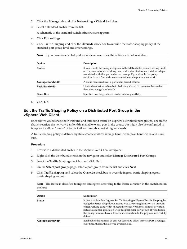
2 Click the Manage tab, and click Networking > Virtual Switches.
3 Select a standard switch from the list.
A schematic of the standard switch infrastructure appears.
4 Click Edit settings.
5 Click Traffic Shaping and click the Override check box to override the traffic shaping policy at thestandard port group level and enter settings.
NOTE If you have not enabled port group-level overrides, the options are not available.
Option Description
Status If you enable the policy exception in the Status field, you are setting limitson the amount of networking bandwidth allocated for each virtual adapterassociated with this particular port group. If you disable the policy,services have a free and clear connection to the physical network.
Average Bandwidth A value measured over a particular period of time.
Peak Bandwidth Limits the maximum bandwidth during a burst. It can never be smallerthan the average bandwidth.
Burst Size Specifies how large a burst can be in kilobytes (KB).
6 Click OK.
Edit the Traffic Shaping Policy on a Distributed Port Group in thevSphere Web Client
ESXi allows you to shape both inbound and outbound traffic on vSphere distributed port groups. The trafficshaper restricts the network bandwidth available to any port in the group, but might also be configured totemporarily allow “bursts” of traffic to flow through a port at higher speeds.
A traffic shaping policy is defined by three characteristics: average bandwidth, peak bandwidth, and burstsize.
Procedure
1 Browse to a distributed switch in the vSphere Web Client navigator.
2 Right-click the distributed switch in the navigator and select Manage Distributed Port Groups.
3 Select the Traffic Shaping check box and click Next.
4 On the Select port groups page, select a port group from the list and click Next
5 Click Traffic shaping, and select the Override check box to override ingress traffic shaping, egresstraffic shaping, or both.
NOTE The traffic is classified to ingress and egress according to the traffic direction in the switch, not inthe host.
Option Description
Status If you enable either Ingress Traffic Shaping or Egress Traffic Shaping byusing the Status drop-down menus, you are setting limits on the amountof networking bandwidth allocated for each VMkernel adapter or virtualnetwork adapter associated with this particular port group. If you disablethe policy, services have a free, clear connection to the physical network bydefault.
Average Bandwidth Establishes the number of bits per second to allow across a port, averagedover time, that is, the allowed average load.
Chapter 5 Networking Policies
VMware, Inc. 93

Option Description
Peak Bandwidth The maximum number of bits per second to allow across a port when it issending or receiving a burst of traffic. This parameter tops the bandwidthused by a port whenever it is using its burst bonus.
Burst Size The maximum number of bytes to allow in a burst. If this parameter is set,a port might gain a burst bonus when it does not use all its allocatedbandwidth. Whenever the port needs more bandwidth than specified byAverage Bandwidth, it might be allowed to temporarily transmit data at ahigher speed if a burst bonus is available. This parameter tops the numberof bytes that might be accumulated in the burst bonus and transferred at ahigher speed.
6 Review your settings and click Finish.
Use the Back button to edit any settings.
Edit the Traffic Shaping Policy on a Distributed Port in the vSphere Web ClientESXi allows you to shape both inbound and outbound traffic on vSphere distributed switches. The trafficshaper restricts the network bandwidth available to a port, but might also be configured to temporarilyallow bursts of traffic to flow through the port at higher speeds.
A traffic shaping policy is defined by three characteristics: average bandwidth, peak bandwidth, and burstsize.
Prerequisites
Enable the port-level override option for this policy. See “Edit Advanced Distributed Port Group Settingswith the vSphere Web Client,” on page 44.
Procedure
1 Browse to a distributed switch in the vSphere Web Client.
2 To navigate to the distributed ports of the distributed switch, click Manage > Ports.
3 Select a port from the list.
4 Click Edit distributed port settings.
5 Click Traffic shaping, and select the Override check box to override ingress traffic shaping, egresstraffic shaping, or both.
NOTE The traffic is classified to ingress and egress according to the traffic direction in the switch, not inthe host.
Option Description
Status If you enable either Ingress Traffic Shaping or Egress Traffic Shaping byusing the Status drop-down menus, you are setting limits on the amountof networking bandwidth allocated for each VMkernel adapter or virtualnetwork adapter associated with this particular port group. If you disablethe policy, services have a free, clear connection to the physical network bydefault.
Average Bandwidth Establishes the number of bits per second to allow across a port, averagedover time, that is, the allowed average load.
vSphere Networking
94 VMware, Inc.

Option Description
Peak Bandwidth The maximum number of bits per second to allow across a port when it issending or receiving a burst of traffic. This parameter tops the bandwidthused by a port whenever it is using its burst bonus.
Burst Size The maximum number of bytes to allow in a burst. If this parameter is set,a port might gain a burst bonus when it does not use all its allocatedbandwidth. Whenever the port needs more bandwidth than specified byAverage Bandwidth, it might be allowed to temporarily transmit data at ahigher speed if a burst bonus is available. This parameter tops the numberof bytes that might be accumulated in the burst bonus and transferred at ahigher speed.
6 Review your settings in the Ready to complete section and click Finish.
Use the Back button to edit any settings.
Resource Allocation PolicyThe Resource Allocation policy allows you to associate a distributed port or port group with a user-creatednetwork resource pool. This policy provides you with greater control over the bandwidth given to the portor port group.
For information about creating and configuring network resource pools, see “vSphere Network I/OControl,” on page 121.
Edit the Resource Allocation Policy on a Distributed Port Group in thevSphere Web Client
Associate a distributed port group with a network resource pool to give you greater control over thebandwidth that is given to the distributed port group.
Prerequisites
Enable Network I/O Control on the host and create one or more user-defined network resource pools.
Procedure
1 Browse to a distributed switch in the vSphere Web Client navigator.
2 Right-click the distributed switch in the navigator and select Manage Distributed Port Groups.
3 Select the Resource allocation check box and click Next.
4 Select the distributed port group to edit and click Next.
5 Add or remove the distributed port group from the network resource pool and click Next.
n To add the distributed port group, select a user-defined resource pool from the Network resourcepool drop-down menu.
n To remove the distributed port group, select default from the Network resource pool drop-downmenu.
6 Review your settings in the Ready to complete section and click Finish.
Use the Back button to change any settings.
Chapter 5 Networking Policies
VMware, Inc. 95

Edit the Resource Allocation Policy on a Distributed Port in the vSphere WebClient
Associate a distributed port with a network resource pool to give you greater control over the bandwidthgiven to the port.
Prerequisites
n Enable Network I/O Control on the host and create one or more user-defined network resource pools.
n Enable port-level overrides. See “Edit Advanced Distributed Port Group Settings with the vSphere WebClient,” on page 44.
Procedure
1 Browse to a distributed switch in the vSphere Web Client navigator.
2 Click the Manage tab and click Ports.
3 Select a port from the list and click Edit distributed port settings.
4 In the Properties section, click the Override check box and add or remove the port from a networkresource pool.
If you did not enable port-level overrides, the options are not available.
n To add the distributed port to a resource pool, select a user-defined resource pool from theNetwork resource pool drop-down menu.
n To remove the distributed port from a resource pool, select Default from the Network resourcepool drop-down menu.
5 Click OK.
Monitoring PolicyThe monitoring policy enables or disables NetFlow monitoring on a distributed port or port group.
NetFlow settings are configured at the vSphere distributed switch level. See “Configure NetFlow Settingswith the vSphere Web Client,” on page 159.
Edit the Monitoring Policy on a Distributed Port Group in thevSphere Web Client
With the Monitoring policy, you can enable or disable NetFlow monitoring on a distributed port group.
Procedure
1 Browse to a distributed switch in the vSphere Web Client navigator.
2 Right-click the distributed switch in the object navigator and select Manage Distributed Port Groups.
3 Select the Monitoring check box and click Next.
4 Select the distributed port group to edit and click Next.
vSphere Networking
96 VMware, Inc.

5 Use the drop-menu to enable or disable NetFlow and click Next.
Option Description
Disabled NetFlow is disabled on the distributed port group.
Enabled NetFlow is enabled on the distributed port group. You can configureNetFlow settings at the vSphere distributed switch level. See “ConfigureNetFlow Settings with the vSphere Web Client,” on page 159.
6 Review your settings and click Finish.
Use the Back button to change any settings.
Edit the Monitoring Policy on a Distributed Port in the vSphere Web ClientWith the Monitoring policy, you can enable or disable NetFlow monitoring on a distributed port.
Prerequisites
To override the monitoring policy at the port level, enable the port-level overrides. See “Edit AdvancedDistributed Port Group Settings with the vSphere Web Client,” on page 44
Procedure
1 Browse to a distributed switch in the vSphere Web Client navigator.
2 Click the Manage tab, and click Ports.
3 Select a port from the list.
Detailed port setting information appears at the bottom of the screen.
4 Click Edit distributed port settings.
5 Click Monitoring and click the check box to override the NetFlow settings at the port group level.
6 Enable or disable Netflow from the drop-down menu.
NOTE If you have no enabled port-level overrides, the options are not available.
Option Description
Disabled NetFlow is disabled on the distributed port group.
Enabled NetFlow is enabled on the distributed port group. You can configureNetFlow settings at the vSphere distributed switch level. See “ConfigureNetFlow Settings with the vSphere Web Client,” on page 159.
7 Click OK.
Traffic Filtering and Marking PolicyIn a vSphere distributed switch 5.5 and later, by using the traffic filtering and marking policy, you canprotect the virtual network from unwanted traffic and security attacks or apply a QoS tag to a certain type oftraffic.
The traffic filtering and marking policy represents an ordered set of network traffic rules for security and forQoS tagging of the data flow through the ports of a distributed switch. In general, a rule consists of aqualifier for traffic, and of an action for restricting or prioritizing the matching traffic.
The vSphere distributed switch applies rules on traffic at different places in the data stream. The distributedswitch applies traffic filter rules on the data path between the virtual machine network adapter anddistributed port, or between the uplink port and physical network adapter for rules on uplinks.
Chapter 5 Networking Policies
VMware, Inc. 97

Traffic Filtering and Marking on a Distributed Port Group or Uplink Port Groupin the vSphere Web Client
Set traffic rules at the level of distributed port groups or of uplink port groups to introduce filtering andpriority tagging for traffic access over virtual machines, VMkernel adapters, or physical adapters.
n Enable Traffic Filtering and Marking on a Distributed Port Group or Uplink Port Group in the vSphereWeb Client on page 98Enable the traffic filtering and marking policy on a port group if you want to configure traffic securityand marking on all virtual machine network adapters or uplink adapters that are participating in thegroup.
n Mark Traffic on a Distributed Port Group or Uplink Port Group in the vSphere Web Client onpage 99Assign priority tags to traffic, such as VoIP and streaming video, that has higher networkingrequirements for bandwidth, low latency, and so on. You can mark the traffic with a CoS tag in Layer2 of the network protocol stack or with a DSCP tag in Layer 3.
n Filter Traffic on a Distributed Port Group or Uplink Port Group in the vSphere Web Client onpage 101Allow or stop traffic for securing the data that flows through the ports of a distributed port group oruplink port group.
n Working with Network Traffic Rules on a Distributed Port Group or Uplink Port Group in thevSphere Web Client on page 102Define traffic rules in a distributed port group or uplink port group to introduce a policy forprocessing traffic related to virtual machines or to physical adapters. You can filter specific traffic ordescribe its QoS demands.
n Disable Traffic Filtering and Marking on a Distributed Port Group or Uplink Port Group in thevSphere Web Client on page 104Let traffic flow to virtual machines or physical adapters without additional control related to securityor QoS by disabling the traffic filtering and marking policy.
Enable Traffic Filtering and Marking on a Distributed Port Group or Uplink PortGroup in the vSphere Web ClientEnable the traffic filtering and marking policy on a port group if you want to configure traffic security andmarking on all virtual machine network adapters or uplink adapters that are participating in the group.
NOTE You can disable the traffic filtering and marking policy on a particular port to avoid processing thetraffic flowing through the port. See “Disable Traffic Filtering and Marking on a Distributed Port or UplinkPort in the vSphere Web Client,” on page 110.
Procedure
1 Locate a distributed port group or an uplink port group in the vSphere Web Client.
a Select a distributed switch and click the Related Objects tab.
b Click Distributed Port Groups to see the list of distributed port groups, or click Uplink PortGroups to see the list of uplink port groups.
2 Right-click the port group and select Edit settings.
3 Select Traffic filtering and marking.
4 From the Status drop-down menu, select Enabled.
vSphere Networking
98 VMware, Inc.
5 Click OK.
What to do next
Set up traffic marking or filtering on the data that is flowing through the ports of the distributed port groupor through the uplink port group. See “Mark Traffic on a Distributed Port Group or Uplink Port Group inthe vSphere Web Client,” on page 99 and “Filter Traffic on a Distributed Port Group or Uplink Port Groupin the vSphere Web Client,” on page 101.
Mark Traffic on a Distributed Port Group or Uplink Port Group in thevSphere Web ClientAssign priority tags to traffic, such as VoIP and streaming video, that has higher networking requirementsfor bandwidth, low latency, and so on. You can mark the traffic with a CoS tag in Layer 2 of the networkprotocol stack or with a DSCP tag in Layer 3.
Priority tagging is a mechanism to mark traffic that has higher QoS demands. In this way, the network canrecognize different classes of traffic. The network devices can handle the traffic from each class according toits priority and requirements.
You can also re-tag traffic to either raise or lower the importance of the flow. By using a low QoS tag, youcan restrict data tagged in a guest operating system.
Procedure
1 Locate a distributed port group or an uplink port group in the vSphere Web Client.
a Select a distributed switch and click the Related Objects tab.
b Click Distributed Port Groups to see the list of distributed port groups, or click Uplink PortGroups to see the list of uplink port groups.
2 Right-click the port group and select Edit settings.
3 Select Traffic filtering and marking.
4 If traffic filtering and marking is disabled, enable it from the Status drop-down menu.
5 Click New to create a new rule, or select a rule and click Edit to edit it.
6 In the network traffic rule dialog box, select the Tag option from the Action drop-down menu.
7 Set the priority tag for the traffic within the scope of the rule.
Option Description
CoS value Mark the traffic matching the rule with a CoS priority tag in network Layer2. Select Update CoS tag and type a value from 0 to 7.
DSCP value Mark the traffic associated with the rule with a DSCP tag in network Layer3. Select Update DSCP value and type a value from 0 to 63.
Chapter 5 Networking Policies
VMware, Inc. 99

8 Specify the kind of traffic that the rule is applicable to.
To determine if a data flow is in the scope of a rule for marking or filtering, the vSphere distributedswitch examines the direction of the traffic, and properties like source and destination, VLAN, nextlevel protocol, infrastructure traffic type, and so on.
a From the Traffic direction drop-down menu, select whether the traffic must be ingress, egress, orboth so that the rule recognizes it as matching.
The direction also influences how you are going to identify the traffic source and destination.
b By using qualifiers for system data type, Layer 2 packet attributes, and Layer 3 packet attributes setthe properties that packets must have to match the rule.
A qualifier represents a set of matching criteria related to a networking layer. You can match trafficto system data type, Layer 2 traffic properties, and Layer 3 traffic properties. You can use thequalifier for a specific networking layer or can combine qualifiers to match packets more precisely.
n Use the system traffic qualifier to match packets to the type of virtual infrastructure data thatis flowing through the ports of the group . For example, you can select NFS for data transfersto network storage.
n Use the MAC traffic qualifier to match packets by MAC address, VLAN ID, and next levelprotocol.
Locating traffic with a VLAN ID on a distributed port group works with Virtual GuestTagging (VGT). To match traffic to VLAN ID if Virtual Switch Tagging (VST) is active, use arule on an uplink port group or uplink port.
n Use the IP traffic qualifier to match packets by IP version, IP address, and next level protocoland port.
9 In the rule dialog box, click OK to save the rule.
Example: Voice over IP Traffic Marking
Voice over IP (VoIP) flows have special requirements for QoS in terms of low loss and delay. The trafficrelated to the Session Initiation Protocol (SIP) for VoIP usually has a DSCP tag equal to 26, which stands forAssured Forwarding Class 3 with Low Drop Probability (AF31).
For example, to mark outgoing SIP UDP packets to a subnet 192.168.2.0/24, you can use the following rule:
Rule Parameter Parameter Value
Action Tag
DSCP value 26
Traffic direction Egress
Traffic qualifiers IP Qualifier
Protocol UDP
Destination port 5060
Source address IP address matches 192.168.2.0 with prefix length 24
vSphere Networking
100 VMware, Inc.

Filter Traffic on a Distributed Port Group or Uplink Port Group in thevSphere Web ClientAllow or stop traffic for securing the data that flows through the ports of a distributed port group or uplinkport group.
Procedure
1 Locate a distributed port group or an uplink port group in the vSphere Web Client.
a Select a distributed switch and click the Related Objects tab.
b Click Distributed Port Groups to see the list of distributed port groups, or click Uplink PortGroups to see the list of uplink port groups.
2 Right-click the port group and select Edit settings.
3 Select Traffic filtering and marking.
4 If traffic filtering and marking is disabled, enable it from the Status drop-down menu.
5 Click New to create a new rule, or select a rule and click Edit to edit it.
6 In the network traffic rule dialog box, use the Action options to let traffic pass through the ports of thedistributed port group or uplink port group, or to restrict it.
7 Specify the kind of traffic that the rule is applicable to.
To determine if a data flow is in the scope of a rule for marking or filtering, the vSphere distributedswitch examines the direction of the traffic, and properties like source and destination, VLAN, nextlevel protocol, infrastructure traffic type, and so on.
a From the Traffic direction drop-down menu, select whether the traffic must be ingress, egress, orboth so that the rule recognizes it as matching.
The direction also influences how you are going to identify the traffic source and destination.
b By using qualifiers for system data type, Layer 2 packet attributes, and Layer 3 packet attributes setthe properties that packets must have to match the rule.
A qualifier represents a set of matching criteria related to a networking layer. You can match trafficto system data type, Layer 2 traffic properties, and Layer 3 traffic properties. You can use thequalifier for a specific networking layer or can combine qualifiers to match packets more precisely.
n Use the system traffic qualifier to match packets to the type of virtual infrastructure data thatis flowing through the ports of the group . For example, you can select NFS for data transfersto network storage.
n Use the MAC traffic qualifier to match packets by MAC address, VLAN ID, and next levelprotocol.
Locating traffic with a VLAN ID on a distributed port group works with Virtual GuestTagging (VGT). To match traffic to VLAN ID if Virtual Switch Tagging (VST) is active, use arule on an uplink port group or uplink port.
n Use the IP traffic qualifier to match packets by IP version, IP address, and next level protocoland port.
8 In the rule dialog box, click OK to save the rule.
Chapter 5 Networking Policies
VMware, Inc. 101

Working with Network Traffic Rules on a Distributed Port Group or Uplink PortGroup in the vSphere Web ClientDefine traffic rules in a distributed port group or uplink port group to introduce a policy for processingtraffic related to virtual machines or to physical adapters. You can filter specific traffic or describe its QoSdemands.
NOTE You can override the rules of the policy for traffic filtering and marking at port level. See “Workingwith Network Traffic Rules on a Distributed Port or Uplink Port in the vSphere Web Client,” on page 108.
n View Traffic Rules on a Distributed Port Group or Uplink Group in the vSphere Web Client onpage 102View the traffic rules that form the traffic filtering and marking policy of a distributed port group oruplink port group.
n Edit a Traffic Rule on a Distributed Port Group or Uplink Port Group in the vSphere Web Client onpage 103Create or edit traffic rules, and use their parameters to configure a policy for filtering or marking thetraffic on a distributed port group or uplink port group.
n Change Rule Priorities on a Distributed Port Group or Uplink Port Group in the vSphere Web Clienton page 103Reorder the rules that form the traffic filtering and marking policy of a distributed port group oruplink port group to change the sequence of actions for processing traffic.
n Delete a Traffic Rule on a Distributed Port Group or Uplink Port Group in the vSphere Web Client onpage 103Delete a traffic rule on a distributed port group or uplink port group to stop processing packetsflowing to virtual machines or physical adapters in a specific way.
View Traffic Rules on a Distributed Port Group or Uplink Group in the vSphere Web Client
View the traffic rules that form the traffic filtering and marking policy of a distributed port group or uplinkport group.
Procedure
1 Locate a distributed port group or an uplink port group in the vSphere Web Client.
a Select a distributed switch and click the Related Objects tab.
b Click Distributed Port Groups to see the list of distributed port groups, or click Uplink PortGroups to see the list of uplink port groups.
2 Right-click the port group and select Edit settings.
3 Select Traffic filtering and marking.
4 If traffic filtering and marking is disabled, enable it from the Status drop-down menu.
5 Examine Action to see if the rule filters traffic (Allow or Deny) or marks traffic (Tag) with special QoSdemands.
6 From the upper list, select the rule for which you want to view the criteria for locating traffic.
The traffic qualifying parameters of the rule appear in the Traffic Qualifiers list.
vSphere Networking
102 VMware, Inc.

Edit a Traffic Rule on a Distributed Port Group or Uplink Port Group in the vSphere Web Client
Create or edit traffic rules, and use their parameters to configure a policy for filtering or marking the trafficon a distributed port group or uplink port group.
Procedure
1 Locate a distributed port group or an uplink port group in the vSphere Web Client.
a Select a distributed switch and click the Related Objects tab.
b Click Distributed Port Groups to see the list of distributed port groups, or click Uplink PortGroups to see the list of uplink port groups.
2 Right-click the port group and select Edit settings.
3 Select Traffic filtering and marking.
4 If traffic filtering and marking is disabled, enable it from the Status drop-down menu.
5 Click New to create a new rule, or select a rule and click Edit to edit it.
What to do next
Name the network traffic rule, and deny, allow, or tag the target traffic.
Change Rule Priorities on a Distributed Port Group or Uplink Port Group in the vSphere Web Client
Reorder the rules that form the traffic filtering and marking policy of a distributed port group or uplink portgroup to change the sequence of actions for processing traffic.
The vSphere distributed switch applies network traffic rules in a strict order. If a packet already satisfies arule, the packet might not be passed to the next rule in the policy.
Procedure
1 Locate a distributed port group or an uplink port group in the vSphere Web Client.
a Select a distributed switch and click the Related Objects tab.
b Click Distributed Port Groups to see the list of distributed port groups, or click Uplink PortGroups to see the list of uplink port groups.
2 Right-click the port group and select Edit settings.
3 Select Traffic filtering and marking.
4 If traffic filtering and marking is disabled, enable it from the Status drop-down menu.
5 Select a rule and use the arrow buttons to change its priority.
6 Click OK to apply the changes.
Delete a Traffic Rule on a Distributed Port Group or Uplink Port Group in the vSphere Web Client
Delete a traffic rule on a distributed port group or uplink port group to stop processing packets flowing tovirtual machines or physical adapters in a specific way.
Procedure
1 Locate a distributed port group or an uplink port group in the vSphere Web Client.
a Select a distributed switch and click the Related Objects tab.
b Click Distributed Port Groups to see the list of distributed port groups, or click Uplink PortGroups to see the list of uplink port groups.
2 Right-click the port group and select Edit settings.
Chapter 5 Networking Policies
VMware, Inc. 103

3 Select Traffic filtering and marking.
4 If traffic filtering and marking is disabled, enable it from the Status drop-down menu.
5 Select the rule and click Delete.
6 Click OK.
Disable Traffic Filtering and Marking on a Distributed Port Group or Uplink PortGroup in the vSphere Web ClientLet traffic flow to virtual machines or physical adapters without additional control related to security or QoSby disabling the traffic filtering and marking policy.
NOTE You can enable and set up the traffic filtering and marking policy on a particular port. See “EnableTraffic Filtering and Marking on a Distributed Port or Uplink Port in the vSphere Web Client,” on page 105.
Procedure
1 Locate a distributed port group or an uplink port group in the vSphere Web Client.
a Select a distributed switch and click the Related Objects tab.
b Click Distributed Port Groups to see the list of distributed port groups, or click Uplink PortGroups to see the list of uplink port groups.
2 Right-click the port group and select Edit settings.
3 Select Traffic filtering and marking.
4 From the Status drop-down menu, select Disabled.
5 Click OK.
Traffic Filtering and Marking on a Distributed Port or Uplink Port in thevSphere Web Client
Filter traffic or describe its QoS demands for an individual virtual machine, VMkernel adapter, or physicaladapter by configuring the traffic filtering and marking policy on a distributed port or uplink port.
n Enable Traffic Filtering and Marking on a Distributed Port or Uplink Port in the vSphere Web Clienton page 105Enable the traffic filtering and marking policy on a port to configure traffic security and marking on avirtual machine network adapter, VMkernel adapter, or uplink adapter.
n Mark Traffic on a Distributed Port or Uplink Port in the vSphere Web Client on page 105Assign priority tags in a rule for traffic that needs special treatment such as VoIP and streaming video.You can mark the traffic for a virtual machine, VMkernel adapter, or physical adapter with a CoS tagin Layer 2 of the network protocol stack or with a DSCP tag in Layer 3.
n Filter Traffic on a Distributed Port or Uplink Port in the vSphere Web Client on page 107By using a rule, permit or stop traffic for securing data flows through a virtual machine, a VMkerneladapter, or a physical adapter.
n Working with Network Traffic Rules on a Distributed Port or Uplink Port in the vSphere Web Clienton page 108Define traffic rules in a distributed port or uplink port group to introduce a policy for processingtraffic related to a virtual machine or to a physical adapter. You can filter specific traffic or describe itsQoS demands.
vSphere Networking
104 VMware, Inc.
n Disable Traffic Filtering and Marking on a Distributed Port or Uplink Port in the vSphere Web Clienton page 110Disable the traffic filtering and marking policy on a port to let traffic flow to a virtual machine or aphysical adapter without filtering for security or marking for QoS.
Enable Traffic Filtering and Marking on a Distributed Port or Uplink Port in thevSphere Web ClientEnable the traffic filtering and marking policy on a port to configure traffic security and marking on avirtual machine network adapter, VMkernel adapter, or uplink adapter.
Prerequisites
Enable the port-level override option for this policy. See “Edit Advanced Distributed Port Group Settingswith the vSphere Web Client,” on page 44.
Procedure
1 Browse to a distributed switch in the vSphere Web Client.
2 Navigate to a distributed port or an uplink port.
n To navigate to the distributed ports of the switch, click Manage > Ports.
n To navigate to the uplink ports of an uplink port group, click Related Objects > Uplink PortGroups, double-click an uplink port group from the list, and select Ports on the Manage tab.
3 Select a port from the list.
4 Click Edit distributed port settings.
5 Select Traffic filtering and marking.
6 Select the Override check box, and from the Status drop-down menu, select Enabled.
7 Click OK.
What to do next
Set up traffic filtering or marking for the data flowing through the distributed port or through the uplinkport. See “Mark Traffic on a Distributed Port or Uplink Port in the vSphere Web Client,” on page 105 and “Filter Traffic on a Distributed Port or Uplink Port in the vSphere Web Client,” on page 107.
Mark Traffic on a Distributed Port or Uplink Port in the vSphere Web ClientAssign priority tags in a rule for traffic that needs special treatment such as VoIP and streaming video. Youcan mark the traffic for a virtual machine, VMkernel adapter, or physical adapter with a CoS tag in Layer 2of the network protocol stack or with a DSCP tag in Layer 3.
Priority tagging is a mechanism to mark traffic that has higher QoS demands. In this way, the network canrecognize different classes of traffic. The network devices can handle the traffic from each class according toits priority and requirements.
You can also re-tag traffic to either raise or lower the importance of the flow. By using a low QoS tag, youcan restrict data tagged in a guest operating system.
Prerequisites
Enable the port-level override option for this policy. See “Edit Advanced Distributed Port Group Settingswith the vSphere Web Client,” on page 44.
Chapter 5 Networking Policies
VMware, Inc. 105

Procedure
1 Navigate to a distributed port or an uplink port.
n To navigate to the distributed ports of the switch, click Manage > Ports.
n To navigate to the uplink ports of an uplink port group, click Related Objects > Uplink PortGroups, double-click an uplink port group from the list, and select Ports on the Manage tab.
2 Select a port from the list.
3 Click Edit distributed port settings.
4 If traffic filtering and marking is not enabled at the port level, click Override, and from the Status drop-down menu, select Enabled.
5 Click New to create a new rule, or select a rule and click Edit to edit it.
You can change a rule inherited from the distributed port group or uplink port group. In this way, therule becomes unique within the scope of the port.
6 In the network traffic rule dialog box, select the Tag option from the Action drop-down menu.
7 Set the priority tag for the traffic within the scope of the rule.
Option Description
CoS value Mark the traffic matching the rule with a CoS priority tag in network Layer2. Select Update CoS tag and type a value from 0 to 7.
DSCP value Mark the traffic associated with the rule with a DSCP tag in network Layer3. Select Update DSCP value and type a value from 0 to 63.
8 Specify the kind of traffic that the rule is applicable to.
To determine if a data flow is in the scope of a rule for marking or filtering, the vSphere distributedswitch examines the direction of the traffic, and properties like source and destination, VLAN, nextlevel protocol, infrastructure traffic type, and so on.
a From the Traffic direction drop-down menu, select whether the traffic must be ingress, egress, orboth so that the rule recognizes it as matching.
The direction also influences how you are going to identify the traffic source and destination.
b By using qualifiers for system data type, Layer 2 packet attributes, and Layer 3 packet attributes setthe properties that packets must have to match the rule.
A qualifier represents a set of matching criteria related to a networking layer. You can match trafficto system data type, Layer 2 traffic properties, and Layer 3 traffic properties. You can use thequalifier for a specific networking layer or can combine qualifiers to match packets more precisely.
n Use the system traffic qualifier to match packets to the type of virtual infrastructure data thatis flowing through the ports of the group . For example, you can select NFS for data transfersto network storage.
n Use the MAC traffic qualifier to match packets by MAC address, VLAN ID, and next levelprotocol.
Locating traffic with a VLAN ID on a distributed port group works with Virtual GuestTagging (VGT). To match traffic to VLAN ID if Virtual Switch Tagging (VST) is active, use arule on an uplink port group or uplink port.
n Use the IP traffic qualifier to match packets by IP version, IP address, and next level protocoland port.
9 In the rule dialog box, click OK to save the rule.
vSphere Networking
106 VMware, Inc.

Filter Traffic on a Distributed Port or Uplink Port in the vSphere Web ClientBy using a rule, permit or stop traffic for securing data flows through a virtual machine, a VMkerneladapter, or a physical adapter.
Prerequisites
Enable the port-level override option for this policy. See “Edit Advanced Distributed Port Group Settingswith the vSphere Web Client,” on page 44.
Procedure
1 Navigate to a distributed port or an uplink port.
n To navigate to the distributed ports of the switch, click Manage > Ports.
n To navigate to the uplink ports of an uplink port group, click Related Objects > Uplink PortGroups, double-click an uplink port group from the list, and select Ports on the Manage tab.
2 Select a port from the list.
3 Click Edit distributed port settings.
4 If traffic filtering and marking is not enabled at the port level, click Override, and from the Status drop-down menu, select Enabled.
5 Click New to create a new rule, or select a rule and click Edit to edit it.
You can change a rule inherited from the distributed port group or uplink port group. In this way, therule becomes unique within the scope of the port.
6 In the network traffic rule dialog box, select the Allow action to let traffic pass through the distributedport or uplink port, or the Drop action to restrict it.
7 Specify the kind of traffic that the rule is applicable to.
To determine if a data flow is in the scope of a rule for marking or filtering, the vSphere distributedswitch examines the direction of the traffic, and properties like source and destination, VLAN, nextlevel protocol, infrastructure traffic type, and so on.
a From the Traffic direction drop-down menu, select whether the traffic must be ingress, egress, orboth so that the rule recognizes it as matching.
The direction also influences how you are going to identify the traffic source and destination.
b By using qualifiers for system data type, Layer 2 packet attributes, and Layer 3 packet attributes setthe properties that packets must have to match the rule.
A qualifier represents a set of matching criteria related to a networking layer. You can match trafficto system data type, Layer 2 traffic properties, and Layer 3 traffic properties. You can use thequalifier for a specific networking layer or can combine qualifiers to match packets more precisely.
n Use the system traffic qualifier to match packets to the type of virtual infrastructure data thatis flowing through the ports of the group . For example, you can select NFS for data transfersto network storage.
n Use the MAC traffic qualifier to match packets by MAC address, VLAN ID, and next levelprotocol.
Locating traffic with a VLAN ID on a distributed port group works with Virtual GuestTagging (VGT). To match traffic to VLAN ID if Virtual Switch Tagging (VST) is active, use arule on an uplink port group or uplink port.
n Use the IP traffic qualifier to match packets by IP version, IP address, and next level protocoland port.
Chapter 5 Networking Policies
VMware, Inc. 107

8 In the rule dialog box, click OK to save the rule.
Working with Network Traffic Rules on a Distributed Port or Uplink Port in thevSphere Web ClientDefine traffic rules in a distributed port or uplink port group to introduce a policy for processing trafficrelated to a virtual machine or to a physical adapter. You can filter specific traffic or describe its QoSdemands.
n View Traffic Rules on a Distributed Port or Uplink Port in the vSphere Web Client on page 108Review the traffic rules that form the traffic filtering and marking policy of a distributed port or uplinkport.
n Edit a Traffic Rule on a Distributed Port or Uplink Port in the vSphere Web Client on page 109Create or edit traffic rules, and use their parameters to configure a policy for filtering or marking thetraffic on a distributed port or uplink port.
n Change Rule Priorities on a Distributed Port or Uplink Port in the vSphere Web Client on page 109Reorder the rules that form the traffic filtering and marking policy of a distributed port or uplink portto change the sequence of actions for analyzing traffic for security and QoS.
n Delete a Traffic Rule on a Distributed Port or Uplink Port in the vSphere Web Client on page 110Delete a traffic rule on a distributed port or uplink port to stop filtering or marking certain type ofpackets that are flowing to a virtual machine or a physical adapter.
View Traffic Rules on a Distributed Port or Uplink Port in the vSphere Web Client
Review the traffic rules that form the traffic filtering and marking policy of a distributed port or uplink port.
Prerequisites
Enable the port-level override option for this policy. See “Edit Advanced Distributed Port Group Settingswith the vSphere Web Client,” on page 44.
Procedure
1 Navigate to a distributed port or an uplink port.
n To navigate to the distributed ports of the switch, click Manage > Ports.
n To navigate to the uplink ports of an uplink port group, click Related Objects > Uplink PortGroups, double-click an uplink port group from the list, and select Ports on the Manage tab.
2 Select a port from the list.
3 Click Edit distributed port settings.
4 Select Traffic filtering and marking.
5 If traffic filtering and marking is not enabled at the port level, click Override, and from the Status drop-down menu, select Enabled.
6 Examine Action to see if the rule filters traffic (Allow or Deny) or marks traffic (Tag) with special QoSdemands.
7 From the upper list, select the rule for which you want to view the criteria for locating traffic.
The traffic qualifying parameters of the rule appear in the Traffic Qualifiers list.
vSphere Networking
108 VMware, Inc.

Edit a Traffic Rule on a Distributed Port or Uplink Port in the vSphere Web Client
Create or edit traffic rules, and use their parameters to configure a policy for filtering or marking the trafficon a distributed port or uplink port.
Prerequisites
Enable the port-level override option for this policy. See “Edit Advanced Distributed Port Group Settingswith the vSphere Web Client,” on page 44.
Procedure
1 Navigate to a distributed port or an uplink port.
n To navigate to the distributed ports of the switch, click Manage > Ports.
n To navigate to the uplink ports of an uplink port group, click Related Objects > Uplink PortGroups, double-click an uplink port group from the list, and select Ports on the Manage tab.
2 Select a port from the list.
3 Click Edit distributed port settings.
4 Select Traffic filtering and marking.
5 If traffic filtering and marking is not enabled at the port level, click Override, and from the Status drop-down menu, select Enabled.
6 Click New to create a new rule, or select a rule and click Edit to edit it.
You can change a rule inherited from the distributed port group or uplink port group. In this way, therule becomes unique within the scope of the port.
What to do next
Name the network traffic rule, and deny, allow, or tag the target traffic.
Change Rule Priorities on a Distributed Port or Uplink Port in the vSphere Web Client
Reorder the rules that form the traffic filtering and marking policy of a distributed port or uplink port tochange the sequence of actions for analyzing traffic for security and QoS.
The vSphere distributed switch applies network traffic rules in a strict order. If a packet already satisfies arule, the packet might not be passed to the next rule in the policy.
Prerequisites
Enable the port-level override option for this policy. See “Edit Advanced Distributed Port Group Settingswith the vSphere Web Client,” on page 44.
Procedure
1 Navigate to a distributed port or an uplink port.
n To navigate to the distributed ports of the switch, click Manage > Ports.
n To navigate to the uplink ports of an uplink port group, click Related Objects > Uplink PortGroups, double-click an uplink port group from the list, and select Ports on the Manage tab.
2 Select a port from the list.
3 Click Edit distributed port settings.
4 Select Traffic filtering and marking.
5 If traffic filtering and marking is not enabled at the port level, click Override, and from the Status drop-down menu, select Enabled.
Chapter 5 Networking Policies
VMware, Inc. 109

6 Select a rule and use the arrow buttons to change its priority.
7 Click OK to apply the changes.
Delete a Traffic Rule on a Distributed Port or Uplink Port in the vSphere Web Client
Delete a traffic rule on a distributed port or uplink port to stop filtering or marking certain type of packetsthat are flowing to a virtual machine or a physical adapter.
Prerequisites
Enable the port-level override option for this policy. See “Edit Advanced Distributed Port Group Settingswith the vSphere Web Client,” on page 44.
Procedure
1 Navigate to a distributed port or an uplink port.
n To navigate to the distributed ports of the switch, click Manage > Ports.
n To navigate to the uplink ports of an uplink port group, click Related Objects > Uplink PortGroups, double-click an uplink port group from the list, and select Ports on the Manage tab.
2 Select a port from the list.
3 Click Edit distributed port settings.
4 Select Traffic filtering and marking.
5 If traffic filtering and marking is not enabled at the port level, click Override, and from the Status drop-down menu, select Enabled.
6 Select the rule and click Delete.
7 Click OK.
Disable Traffic Filtering and Marking on a Distributed Port or Uplink Port in thevSphere Web ClientDisable the traffic filtering and marking policy on a port to let traffic flow to a virtual machine or a physicaladapter without filtering for security or marking for QoS.
Prerequisites
Enable the port-level override option for this policy. See “Edit Advanced Distributed Port Group Settingswith the vSphere Web Client,” on page 44.
Procedure
1 Navigate to a distributed port or an uplink port.
n To navigate to the distributed ports of the switch, click Manage > Ports.
n To navigate to the uplink ports of an uplink port group, click Related Objects > Uplink PortGroups, double-click an uplink port group from the list, and select Ports on the Manage tab.
2 Select a port from the list.
3 Click Edit distributed port settings.
4 Select Traffic filtering and marking.
5 Click Override, and from the Status drop-down menu, select Disabled.
6 Click OK.
vSphere Networking
110 VMware, Inc.

Qualifying Traffic for Filtering and MarkingThe traffic that you want to filter or want to mark with QoS tags can be matched to the type of carriedinfrastructure data, such as data for storage, vCenter Server management, and so on, and to Layer 2 andLayer 3 properties .
To match the traffic in the scope of the rule more precisely, you can combine criteria for system data type,Layer 2 header, and Layer 3 header.
System Traffic QualifierBy using the system traffic qualifier in a rule for port group or port, you can determine whether certainsystem data traffic must be marked with a QoS tag, allowed, or dropped.
System Traffic Type
You can select the type of traffic through the ports of the group that carries system data, that is, traffic formanagement from vCenter Server , storage, VMware vSphere® vMotion®, and vSphere Fault Tolerance.You can mark or filter only a specific traffic type, or for all system data traffic except for a infrastructurefeature. For example, you can mark with a QoS value or filter the traffic for management fromvCenter Server , storage and vMotion, but not the traffic carrying the Fault Tolerance data.
MAC Traffic QualifierBy using the MAC traffic qualifier in a rule, you can define matching criteria for the Layer 2 (Data LinkLayer) properties of packets such as MAC address, VLAN ID, and next level protocol that consumes theframe payload.
Protocol Type
The Protocol type attribute of the MAC traffic qualifier corresponds to the EtherType field in Ethernetframes. EtherType represents the type of next level protocol that is going to consume the payload of theframe.
You can select a protocol from the drop-down menu or type its hexadecimal number. For example, tocapture traffic for the Link Layer Discovery Protocol (LLDP) protocol, type 88CC.
VLAN ID
You can use the VLAN ID attribute of the MAC traffic qualifier to mark or filter traffic in a particular VLAN.
NOTE The VLAN ID qualifier on a distributed port group works with Virtual Guest Tagging (VGT).
If a flow is tagged with a VLAN ID through Virtual Switch Tagging (VST), it cannot be located by using thisID in a rule on a distributed port group or distributed port. The reason is that the distributed switch checksthe rule conditions, including the VLAN ID, after the switch has already untagged the traffic. In this case, tomatch traffic by VLAN ID successfully, you must use a rule on an uplink port group or uplink port.
Source Address
By using the Source Address group of attributes, you can match packets by the source MAC address ornetwork.
You can use a comparison operator to mark or filter packets that have or do not have the specified sourceaddress or network.
You can match the traffic source in several ways.
Chapter 5 Networking Policies
VMware, Inc. 111

Table 5‑1. Patterns for Filtering or Marking Traffic by MAC Source Address
Parameters to Match Traffic SourceAddress Comparison Operator Networking Argument Format
MAC address is or is not Type the MAC address for matching.Use colons to separate the octets in it.
MAC network matches or does not match Type the lowest address in thenetwork and a wildcard mask. Setzeroes at the positions of the networkbits, and ones for the host part.
For example, for a MAC network with prefix 05:50:56 that is 23 bits long, set the address as00:50:56:00:00:00 and mask as 00:00:01:ff:ff:ff.
Destination Address
By using the Destination Address group of attributes, you can match packets to their destination address.The MAC destination address options have the same format as those for the source address.
Comparison Operators
To match traffic in a MAC qualifier more closely to your needs, you can use affirmative comparison ornegation. You can use operators such that all packets except the ones with certain attributes fall in the scopeof a rule.
IP Traffic QualifierBy using the IP traffic qualifier in a rule, you can define criteria for matching traffic to the Layer 3 (NetworkLayer) properties such as IP version, IP address, next level protocol, and port.
Protocol
The Protocol attribute of the IP traffic qualifier represents the next level protocol consuming the payload ofthe packet. You can select a protocol from the drop-down menu or type its decimal number according toRFC 1700.
For the TCP and UDP protocols, you can also match traffic by source and destination ports.
Source Port
By using the Source port attribute, you can match TCP or UDP packets by the source port. Consider thetraffic direction when matching traffic to a source port.
Destination Port
By using the Destination port attribute, you can match TCP or UDP packets by the destination port.Consider the traffic direction when matching traffic to a destination port.
Source Address
By using the Source Address attribute, you can match packets by source address or subnet. Consider thetraffic direction when matching traffic to a source address or network.
You can match traffic source in several ways.
vSphere Networking
112 VMware, Inc.

Table 5‑2. Patterns for Filtering or Marking Traffic by IP Source Address
Parameters to Match Traffic SourceAddress Comparison Operator Networking Argument Format
IP version any Select the IP version from the drop-down menu.
IP address is or is not Type the IP address that you want tomatch.
IP subnet matches or does not match Type the lowest address in the subnetand the bit length of the subnet prefix.
Destination Address
Use the Destination Address to match packets by IP address, subnet, or IP version. The destination addresshas the same format as the one for the source.
Comparison Operators
To match traffic in an IP qualifier more closely to your needs, you can use affirmative comparison ornegation. You can define that all packets fall in the scope of a rule except packets with certain attributes.
Port Blocking PoliciesPort blocking policies allow you to selectively block ports from sending or receiving data.
Edit the Port Blocking Policy for a Distributed Port Group in thevSphere Web Client
You can configure various distributed port group policies.
Procedure
1 Browse to a distributed switch in the vSphere Web Client navigator.
2 Right-click the distributed switch in the object navigator and select Manage Distributed Port Groups.
3 Select the Miscellaneous check box and click Next.
4 Select a distributed port group to edit and click Next.
5 Use the Block all ports drop-down menu to select Yes or No and click Next.
Selecting Yes shuts down all ports in the port group. This might disrupt the normal network operationsof the hosts or virtual machines using the ports.
6 Review your settings and click Finish.
Use the Back button to change any settings.
Edit Distributed Port or Uplink Port Blocking Policies with thevSphere Web Client
You can configure distributed port or uplink port blocking policies.
Prerequisites
To override the traffic shaping policy at the port level, enable the port-level overrides. See “Edit AdvancedDistributed Port Group Settings with the vSphere Web Client,” on page 44
Procedure
1 Browse to a distributed switch in the vSphere Web Client navigator.
Chapter 5 Networking Policies
VMware, Inc. 113

2 Click the Manage tab, and select Ports.
3 Select a port from the list.
4 Click Edit distributed port settings.
5 In the Miscellaneous section, select the Block Port Override check box and choose Yes or No from thedrop-down menu.
Yes shuts down all ports in the port group. This might disrupt the normal network operations of thehosts or virtual machines using the ports.
6 Click OK.
Manage Policies for Multiple Port Groups on a vSphere DistributedSwitch in the vSphere Web Client
You can modify networking policies for multiple port groups on a vSphere Distributed Switch.
Prerequisites
Create a vSphere Distributed Switch with one or more port groups.
Procedure
1 Browse to a distributed switch in the vSphere Web Client.
2 Right-click the distributed switch, and select Manage Distributed Port Groups.
3 On the Select port group policies page, select the check box next to the policy categories to modify andclick Next.
Option Description
Security Set MAC address changes, forged transmits, and promiscuous mode forthe selected port groups.
Traffic shaping Set the average bandwidth, peak bandwidth, and burst size for inboundand outbound traffic on the selected port groups.
VLAN Configure how the selected port groups connect to physical VLANs.
Teaming and failover Set load balancing, failover detection, switch notification, and failoverorder for the selected port groups.
Resource allocation Set network resource pool association for the selected port groups. Thisoption is available for vSphere Distributed Switch version 5.0. and later.
Monitoring Enable or disable NetFlow on the selected port groups. This option isavailable for vSphere Distributed Switch version 5.0.0 and later.
Traffic filtering and marking Configure policy for filtering (allow or drop) and for marking certain typesof traffic through the ports of selected port groups. This option is availablefor vSphere Distributed Switch version 5.5 and later .
Miscellaneous Enable or disable port blocking on the selected port groups.
4 On the Select port groups page, select the distributed port group(s) to edit and click Next.
vSphere Networking
114 VMware, Inc.
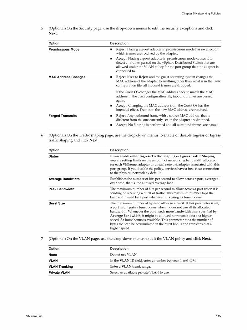
5 (Optional) On the Security page, use the drop-down menus to edit the security exceptions and clickNext.
Option Description
Promiscuous Mode n Reject. Placing a guest adapter in promiscuous mode has no effect onwhich frames are received by the adapter.
n Accept. Placing a guest adapter in promiscuous mode causes it todetect all frames passed on the vSphere Distributed Switch that areallowed under the VLAN policy for the port group that the adapter isconnected to.
MAC Address Changes n Reject. If set to Reject and the guest operating system changes theMAC address of the adapter to anything other than what is in the .vmxconfiguration file, all inbound frames are dropped.
If the Guest OS changes the MAC address back to match the MACaddress in the .vmx configuration file, inbound frames are passedagain.
n Accept. Changing the MAC address from the Guest OS has theintended effect. Frames to the new MAC address are received.
Forged Transmits n Reject. Any outbound frame with a source MAC address that isdifferent from the one currently set on the adapter are dropped.
n Accept. No filtering is performed and all outbound frames are passed.
6 (Optional) On the Traffic shaping page, use the drop-down menus to enable or disable Ingress or Egresstraffic shaping and click Next.
Option Description
Status If you enable either Ingress Traffic Shaping or Egress Traffic Shaping,you are setting limits on the amount of networking bandwidth allocatedfor each VMkernel adapter or virtual network adapter associated with thisport group. If you disable the policy, services have a free, clear connectionto the physical network by default.
Average Bandwidth Establishes the number of bits per second to allow across a port, averagedover time, that is, the allowed average load.
Peak Bandwidth The maximum number of bits per second to allow across a port when it issending or receiving a burst of traffic. This maximum number tops thebandwidth used by a port whenever it is using its burst bonus.
Burst Size The maximum number of bytes to allow in a burst. If this parameter is set,a port might gain a burst bonus when it does not use all its allocatedbandwidth. Whenever the port needs more bandwidth than specified byAverage Bandwidth, it might be allowed to transmit data at a higherspeed if a burst bonus is available. This parameter tops the number ofbytes that can be accumulated in the burst bonus and transferred at ahigher speed.
7 (Optional) On the VLAN page, use the drop-down menus to edit the VLAN policy and click Next.
Option Description
None Do not use VLAN.
VLAN In the VLAN ID field, enter a number between 1 and 4094.
VLAN Trunking Enter a VLAN trunk range.
Private VLAN Select an available private VLAN to use.
Chapter 5 Networking Policies
VMware, Inc. 115

8 (Optional) On the Teaming and failover page, use the drop-down menus to edit the settings and clickNext.
Option Description
Load Balancing IP-based teaming requires that the physical switch be configured withether channel. For all other options, ether channel should be disabled.Select how to choose an uplink.n Route based on the originating virtual port. Choose an uplink based
on the virtual port where the traffic entered the distributed switch.n Route based on IP hash. Choose an uplink based on a hash of the
source and destination IP addresses of each packet. For non-IP packets,whatever is at those offsets is used to compute the hash.
n Route based on source MAC hash. Choose an uplink based on a hashof the source Ethernet.
n Route based on physical NIC load. Choose an uplink based on thecurrent loads of physical NICs.
n Use explicit failover order. Always use the highest order uplink, fromthe list of Active adapters, which passes failover detection criteria.
Network Failover Detection Select the method to use for failover detection.n Link Status only. Relies solely on the link status that the network
adapter provides. This option detects failures, such as cable pulls andphysical switch power failures, but not configuration errors, such as aphysical switch port being blocked by spanning tree or that ismisconfigured to the wrong VLAN or cable pulls on the other side of aphysical switch.
n Beacon Probing. Sends out and listens for beacon probes on all NICsin the team and uses this information, in addition to link status, todetermine link failure. Do not use beacon probing with IP-hash loadbalancing.
Notify Switches Select Yes or No to notify switches in the case of failover. Do not use thisoption when the virtual machines using the port group are using MicrosoftNetwork Load Balancing in unicast mode.If you select Yes, whenever a virtual NIC is connected to the distributedswitch or whenever that virtual NIC’s traffic is routed over a differentphysical NIC in the team because of a failover event, a notification is sentout over the network to update the lookup tables on physical switches. Usethis process for the lowest latency of failover occurrences and migrationswith vMotion.
Failback Select Yes or No to disable or enable failback.This option determines how a physical adapter is returned to active dutyafter recovering from a failure.n Yes (default). The adapter is returned to active duty immediately upon
recovery, displacing the standby adapter that took over its slot, if any.n No. A failed adapter is left inactive even after recovery until another
currently active adapter fails, requiring its replacement.
Failover Order Select how to distribute the work load for uplinks. To use some uplinksbut reserve others in case the uplinks in use fail, set this condition bymoving them into different groups.n Active Uplinks. Continue to use the uplink when the network adapter
connectivity is up and active.n Standby Uplinks . Use this uplink if one of the active adapter’s
connectivity is down. When using IP-hash load balancing, do notconfigure standby uplinks.
n Unused Uplinks . Do not use this uplink.
9 (Optional) On the Resource allocation page, use the network resource pool drop-down menu to add orremove resource allocations and click Next.
vSphere Networking
116 VMware, Inc.

10 (Optional) On the Monitoring page, use the drop-menu to enable or disable NetFlow and click Next.
Option Description
Disabled NetFlow is disabled on the distributed port group.
Enabled NetFlow is enabled on the distributed port group. You can configureNetFlow settings at the vSphere Distributed Switch level.
11 (Optional) On the Traffic filtering and marking page, enable or disable traffic filtering and marking
from Status drop-down menu, configure traffic rules for filtering or marking specific data flows, andclick Next.
You can set the following attributes of a rule determining the target traffic and the action on it:
Option Description
Name Name of the rule
Action n Allow. Grant access to traffic of a certain type.n Drop. Deny access to traffic of a certain type.n Tag. Classify traffic in terms of QoS by inserting or retagging traffic
with a CoS and DSCP tag.
Traffic direction Set whether the rule is for incoming, outgoing or incoming and outgoingtraffic.The direction also influences how you are going to identify the trafficsource and destination.
System traffic qualifier Indicate that the rule scopes over system traffic and set the type ofinfrastructure protocol to apply the rule on. For example, mark with apriority tag the traffic for management from vCenter Server.
Chapter 5 Networking Policies
VMware, Inc. 117

Option Description
MAC qualifier Qualify the traffic for the rule by Layer 2 header.n Protocol type. Set the next level protocol (IPv4, IPv6, etc.) consuming
the payload.
This attribute corresponds to the EtherType field in Ethernet frames.
You can select a protocol from the drop-down menu or type itshexadecimal number
For example, to locate traffic for the Link Layer Discovery Protocol(LLDP) protocol, type 88CC.
n VLAN ID. Locate traffic by VLAN.
The VLAN ID qualifier on a distributed port group works with VirtualGuest Tagging (VGT).
If you have a flow tagged with a VLAN ID through Virtual SwitchTagging (VST), you cannot locate the flow by this ID in a distributedport group rule. The reason is that the distributed switch checks therule conditions, including the VLAN ID, after the switch has alreadyuntagged the traffic. To match successfully traffic to a VLAN ID, use arule for an uplink port group or uplink port.
n Source Filter. Set a single MAC address or a MAC network to matchpackets by source address.
For a MAC network you enter the lowest address in the network and awildcard mask. The mask contains zeroes at the positions of thenetwork bits, and ones for the host part.
For example, for a MAC network with prefix 05:50:56 that is 23 bitslong, set the address as 00:50:56:00:00:00 and the mask as00:00:01:ff:ff:ff.
n Destination Filter. Set a single MAC address or a MAC network tomatch packets by destination address. The MAC destination addresssupports the same format as the source address.
IP qualifier Qualify the traffic for the rule by Layer 3 header.n Protocol. Set the next level protocol (TCP, UDP, etc.) consuming the
payload.
You can select a protocol from the drop-down menu or type itsdecimal number according to RFC 1700, Assigned Numbers.
For TCP and UDP protocol, you can also set source and destinationport.
n Source port. Match TCP or UDP packets to a source port. Consider thedirection of the traffic that is within the scope of the rule whendetermining the source port to match packets to.
n Destination port. Match TCP or UDP packets by the source port.Consider the direction of the traffic that is within the scope of the rulewhen determining the destination port to match packets to.
n Source Filter. Set the IP version, a single IP address or a subnet tomatch packets by source address.
For a subnet you enter the lowest address and the bit length of theprefix.
n Destination Filter. Set the IP version, a single IP address or a subnet tomatch packets by source address. The IP destination address supportsthe same format as the source address.
12 (Optional) On the Miscellaneous page, select Yes or No from the drop-down menu and click Next.
SelectYes to shut down all ports in the port group. This shutdown might disrupt the normal networkoperations of the hosts or virtual machines using the ports.
vSphere Networking
118 VMware, Inc.

13 Review your settings on the Ready to complete page and click Finish.
Use the Back button to change any settings.
Chapter 5 Networking Policies
VMware, Inc. 119

vSphere Networking
120 VMware, Inc.

Managing Network Resources 6vSphere provides several different methods to help you manage your network resources.
This chapter includes the following topics:
n “vSphere Network I/O Control,” on page 121
n “TCP Segmentation Offload and Jumbo Frames,” on page 125
n “NetQueue and Networking Performance,” on page 128
n “DirectPath I/O,” on page 129
n “Single Root I/O Virtualization (SR-IOV),” on page 132
vSphere Network I/O ControlNetwork resource pools determine the bandwidth that different network traffic types are given on avSphere distributed switch.
When network I/O control is enabled, distributed switch traffic is divided into the following predefinednetwork resource pools: Fault Tolerance traffic, iSCSI traffic, vMotion traffic, management traffic, vSphereReplication (VR) traffic, NFS traffic, and virtual machine traffic.
You can also create custom network resource pools for virtual machine traffic. You can control thebandwidth each network resource pool is given by setting the physical adapter shares and host limit foreach network resource pool.
The physical adapter shares assigned to a network resource pool determine the share of the total availablebandwidth guaranteed to the traffic associated with that network resource pool. The share of transmitbandwidth available to a network resource pool is determined by the network resource pool's shares andwhat other network resource pools are actively transmitting. For example, if you set your FT traffic andiSCSI traffic resource pools to 100 shares, while each of the other resource pools is set to 50 shares, the FTtraffic and iSCSI traffic resource pools each receive 25% of the available bandwidth. The remaining resourcepools each receive 12.5% of the available bandwidth. These reservations apply only when the physicaladapter is saturated.
NOTE The iSCSI traffic resource pool shares do not apply to iSCSI traffic on a dependent hardware iSCSIadapter.
The host limit of a network resource pool is the upper limit of bandwidth that the network resource pool canuse.
Assigning a QoS priority tag to a network resource pool applies an 802.1p tag to all outgoing packetsassociated with that network resource pool.
VMware, Inc. 121

n Enable Network I/O Control on a vSphere Distributed Switch with the vSphere Web Client onpage 122Enable network resource management to use network resource pools to prioritize network traffic bytype.
n Create a Network Resource Pool with the vSphere Web Client on page 122Create user-defined network resource pools for customized network resource management.
n Add or Remove Distributed Port Groups from a Network Resource Pool with the vSphere Web Clienton page 123Add a distributed port group to a user-defined network resource pool to include in the networkresource pool all virtual machine network traffic from that distributed port group.
n Edit Network Resource Pool Settings with the vSphere Web Client on page 124You can change both system and user-defined network resource pool settings to change the prioritynetwork traffic for that network resource pool.
n Delete a User-Defined Network Resource Pool with the vSphere Web Client on page 124You can delete user-defined network resource pools that are no longer in use.
Enable Network I/O Control on a vSphere Distributed Switch with thevSphere Web Client
Enable network resource management to use network resource pools to prioritize network traffic by type.
Prerequisites
Verify that your datacenter has at least one vSphere distributed switch version 4.1.0 or later.
Procedure
1 Browse to a distributed switch in the vSphere Web Client navigator.
2 Click the Manage tab, and select Settings > Properties.
3 Click Edit.
4 Select to Enable or Disable network I/O control from the Network I/O Control drop-down menu.
5 Click OK.
Create a Network Resource Pool with the vSphere Web ClientCreate user-defined network resource pools for customized network resource management.
User-defined network resource pools are available only on vSphere distributed switches version 5.0.0 orlater.
Procedure
1 Browse to a distributed switch in the vSphere Web Client navigator.
2 Click the Manage tab, and click Resource Allocation.
3 Click New.
4 Type a Name for the network resource pool or accept the generated name.
5 (Optional) Type a Description for the network resource pool.
6 Set the Host limit for the network resource pool in megabits per second, or select Unlimited.
vSphere Networking
122 VMware, Inc.

7 Select the Physical adapter shares for the network resource pool from the drop-down menu.
Option Description
Low Sets the shares for this resource pool to 25.
Normal Sets the shares for this resource pool to 50.
High Sets the shares for this resource pool to 100.
Custom Aspecific number of shares, from 1 to 100, for this network resource pool.
8 (Optional) Select the QoS tag for the network resource pool.
The QoS priority tag specifies an IEEE 802.1p tag, allowing quality of service at the media access controllevel.
9 Click OK.
The new resource pool appears in the User-defined network resource pools section.
What to do next
Add one or more distributed port groups to the network resource pool.
Add or Remove Distributed Port Groups from a Network Resource Pool with thevSphere Web Client
Add a distributed port group to a user-defined network resource pool to include in the network resourcepool all virtual machine network traffic from that distributed port group.
Prerequisites
Create one or more user-defined network resource pools on the vSphere distributed switch.
Procedure
1 Browse to a distributed switch in the vSphere Web Client.
2 Right-click the distributed switchin the navitgator and select Manage Distributed Port Groups.
3 On the Select port group policies page, select the Resource allocation check box and click Next.
4 On the Select port groups page, select port groups to edit and click Next.
5 On the Configure policies - Resource allocation page, add or remove the distributed switch from thenetwork resource pool and click Next.
n To add the distributed port group to a resource pool, select a user-defined resource pool from theNetwork resource pool drop-down menu.
n To remove the distributed port group from a resource pool, select default from the Networkresource pool drop-down menu.
NOTE If there are no user-defined network resource pools on the distributed switch, you will only seedefault in the drop-down menu.
6 Review your settings on the Ready to Complete page and click Finish.
Use the Back button to change your selections.
Chapter 6 Managing Network Resources
VMware, Inc. 123

Edit Network Resource Pool Settings with the vSphere Web ClientYou can change both system and user-defined network resource pool settings to change the prioritynetwork traffic for that network resource pool.
Procedure
1 Browse to a distributed switch in the vSphere Web Client navigator.
2 Click the Manage tab, and click Resource Allocation.
3 Select a network resource pool from the list and click Edit.
4 Edit the Host limit for the network resource pool in megabits per second or select Unlimited.
5 Select an option for the network resource pool from the Physical adapter shares drop-down menu.
Option Description
Low Sets the shares for this resource pool to 25.
Normal Sets the shares for this resource pool to 50.
High Sets the shares for this resource pool to 100.
Custom A specific number of shares, from 1 to 100, for this network resource pool.
6 (Optional) Select a QoS tag for the network resource pool.
The QoS priority tag specifies an IEEE 802.1p tag, allowing quality of service at the media access controllevel.
7 Click OK.
Delete a User-Defined Network Resource Pool with the vSphere Web ClientYou can delete user-defined network resource pools that are no longer in use.
NOTE You cannot delete a system network resource pool.
Prerequisites
Remove all distributed port groups from the network resource pool.
Procedure
1 Browse to a distributed switch in the vSphere Web Client navigator.
2 Click the Manage tab, and click Resource Allocation.
3 Select a user-defined resource allocation pool and click Remove.
4 Click Yes to delete the resource pool.
vSphere Networking
124 VMware, Inc.
TCP Segmentation Offload and Jumbo FramesUsing TCP Segmentation Offload (TSO) in a VMkernel network adapter and virtual machines, and jumboframes on a vSphere distributed switch or vSphere standard switch, improves the network performance invirtual machines and infrastructure workloads.
Enabling TSOUse TCP Segmentation Offload (TSO) in VMkernel network adapters and virtual machines to improve thenetwork performance.
TSO on the transmission path of physical and virtual machine NICs improves the performance of ESX/ESXihosts by reducing the overhead of the CPU for TCP/IP network operations. When TSO is enabled, the NICdivides larger data chunks into TCP segments instead of the CPU. The host can use more CPU cycles to runapplications.
Enable TSO Support for a Virtual Machine by Using the vSphere Web ClientYou can enable TSO support on a virtual machine by using an enhanced VMXNET adapter for that virtualmachine.
To enable TSO at the virtual machine level, you must replace the existing VMXNET or flexible virtualnetwork adapters with enhanced VMXNET virtual network adapters. This replacement might result in achange in the MAC address of the virtual network adapter.
Prerequisites
To use TSO, verify that the virtual machine runs one of the following guest operating systems:
n Microsoft Windows Server 2003 Enterprise Edition with Service Pack 2 (32 bit and 64 bit)
n Red Hat Enterprise Linux 4 (64 bit)
n Red Hat Enterprise Linux 5 (32 bit and 64 bit)
n SUSE Linux Enterprise Server 10 (32 bit and 64 bit)
Procedure
1 Locate the virtual machine in the vSphere Web Client.
a Select a datacenter, folder, cluster, resource pool, or host and click the Related Objects tab.
b Click Virtual Machines and select the virtual machine from the list.
2 On the Manage tab of the virtual machine, and select Settings > VM Hardware.
3 Click Edit and select the Virtual Hardware tab.
4 Expand the network adapter section and write down the network settings and MAC address for thenetwork adapter.
5 Click Remove to remove the network adapter from the virtual machine.
6 From the New device drop-down menu, select Network and click Add.
7 From the Adapter Type drop-down menu, select VMXNET 2 (Enhanced) or VMXNET 3.
8 Set the network setting and MAC address used by the old network adapter.
9 Click OK.
Chapter 6 Managing Network Resources
VMware, Inc. 125

What to do next
If the virtual machine is not set to upgrade VMware Tools each time it is powered on, you must upgradeVMware Tools manually.
Enable TSO Support for a VMkernel Network AdapterWhen using TSO on a VMkernel network adapter, the physical NIC splits large data chunks into TCPsegments instead of the CPU. As a result, the CPU has more cycles for applications. By default, a host isconfigured to use hardware TSO if its NICs support it.
If TSO becomes disabled for a particular VMkernel adapter, the only way you can re-enable TSO is bydeleting the adapter and recreating it with TSO enabled.
Prerequisites
Verify that one of the following requirements are satisfied:
n The VMkernel adapter does not handle traffic related to host networking services, such as iSCSI,vSphere vMotion, and so on.
n The networking services can send traffic by using an alternative VMkernel adapter.
Procedure
1 In the vSphere Web Client, navigate to the host.
2 Under Manage, select Networking and then select VMkernel adapters.
3 Select a VMkernel adapter from the list, and note its settings.
Later you should set the same settings to the newly added VMkernel adapter.
4 Click Remove.
5 In the confirmation dialog, click Analyze impact, verify that no networking services are impacted, andclick OK.
6 In the VMkernel adapters list, click Add host networking.
7 On the Add connection type page, select VMkernel Network Adapter and click Next.
8 On the Select target device page, assign the VMkernel adapter to a standard switch or distributed portgroup.
9 On the Port properties page, configure the IP version and networking services related to the oldadapter, and click Next.
10 On the IPv4 Settings and IPv6 Settings pages, configure the IP settings used by the old adapter.
11 Review your settings and click Finish.
Enabling Jumbo FramesJumbo frames let ESXi hosts send larger frames out onto the physical network. The network must supportjumbo frames end-to-end that includes physical network adapters, physical switches, and storage devices.
Before enabling jumbo frames, check with your hardware vendor to ensure that your physical networkadapter supports jumbo frames.
You can enable jumbo frames on a vSphere distributed switch or vSphere standard switch by changing themaximum transmission unit (MTU) to a value greater than 1500 bytes. 9000 bytes is the maximum framesize that you can configure.
vSphere Networking
126 VMware, Inc.

Enable Jumbo Frames on a vSphere Distributed Switch with thevSphere Web ClientEnable jumbo frames for the entire traffic that passes through a vSphere distributed switch.
Procedure
1 Browse to a distributed switch in the vSphere Web Client navigator.
2 Click the Manage tab, and click Settings > Properties.
3 Click Edit.
4 Click Advanced and set the MTU property to a value greater than 1500 bytes.
You cannot set the MTU size to a value greater than 9000 bytes.
5 Click OK.
Enable Jumbo Frames on a vSphere Standard Switch with the vSphere Web ClientEnable jumbo frames for all traffic through a vSphere standard switch on a host.
Procedure
1 In the vSphere Web Client, navigate to the host.
2 On the Manage tab, click Networking, and select Virtual switches.
3 Select a standard switch from the virtual switch table and click Edit settings.
4 In the Properties section, set the MTU property to a value greater than 1500 bytes.
You can increase the MTU size up to 9000 bytes.
5 Click OK.
Enable Jumbo Frames for a VMkernel Adapter in the vSphere Web ClientJumbo frames reduce the CPU load caused by transferring data. Enable jumbo frames on a VMkerneladapter by changing the maximum transmission units (MTU) of the adapter.
Procedure
1 In the vSphere Web Client, navigate to the host.
2 Under Manage, select Networking and then select VMkernel adapters.
3 Select a VMkernel adapter from the adapter table.
The properties of the adapter appear.
4 Click the name of the VMkernel adapter.
5 Click Edit.
6 Select NIC settings and set the MTU property to a value greater than 1500.
You can increase the MTU size up to 9000 bytes.
7 Click OK.
Chapter 6 Managing Network Resources
VMware, Inc. 127

Enable Jumbo Frame Support on a Virtual Machine with the vSphere Web ClientEnabling jumbo frame support on a virtual machine requires an enhanced VMXNET adapter for that virtualmachine.
Procedure
1 Locate the virtual machine in the vSphere Web Client.
a Select a datacenter, folder, cluster, resource pool, or host and click the Related Objects tab.
b Click Virtual Machines and select the virtual machine from the list.
2 On the Manage tab of the virtual machine, and select Settings > VM Hardware.
3 Click Edit and select the Virtual Hardware tab.
4 Click the Virtual Hardware section, and expand the network adapter section. Record the networksettings and MAC address that the network adapter is using.
5 Click Remove to remove the network adapter from the virtual machine.
6 From the New device drop-down menu, select Network and click Add.
7 From the Adapter Type drop-down menu, select VMXNET 2 (Enhanced) or VMXNET 3.
8 Set the network settings to the ones recorded for the old network adapter.
9 Set the MAC Address to Manual, and type the MAC address that the old network adapter was using.
10 Click OK.
What to do next
n Check that the enhanced VMXNET adapter is connected to a standard switch or to a distributed switchwith jumbo frames enabled.
n Inside the guest operating system, configure the network adapter to allow jumbo frames. See thedocumentation of your guest operating system.
n Configure all physical switches and any physical or virtual machines to which this virtual machineconnects to support jumbo frames.
NetQueue and Networking PerformanceNetQueue takes advantage of the ability of some network adapters to deliver network traffic to the systemin multiple receive queues that can be processed separately, allowing processing to be scaled to multipleCPUs, improving receive-side networking performance.
Enable NetQueue on a HostNetQueue is enabled by default. To use NetQueue after it has been disabled, you must reenable it.
Prerequisites
Familiarize yourself with the information on configuring NIC drivers in Getting Started with vSphereCommand-Line Interfaces.
vSphere Networking
128 VMware, Inc.

Procedure
1 In the VMware vSphere CLI, use the following command depending on the host version:
ESX/ESXi Version Command
ESX/ESXi 4.x vicfg-advcfg --set true VMkernel.Boot.netNetQueueEnable
ESXi 5.x esxcli system settings kernel set --setting="netNetqueueEnabled" --value="TRUE"
2 Use the VMware vSphere CLI to configure the NIC driver to use NetQueue.
3 Reboot the host.
Disable NetQueue on a HostNetQueue is enabled by default.
Prerequisites
Familiarize yourself with the information on configuring NIC drivers in Getting Started with vSphereCommand-Line Interfaces.
Procedure
1 In the VMware vSphere CLI, use the following command depending on the host version:
ESX/ESXi version Command
ESX/ESXi 4.x vicfg-advcfg --set false VMkernel.Boot.netNetQueueEnable
ESXi 5.x esxcli system settings kernel set --setting="netNetqueueEnabled" --value="FALSE"
2 To disable NetQueue on the NIC driver, use the vicfg-module -s "" module name command.
For example, if you are using the s2io NIC driver, use vicfg-module -s "" s2io.
3 Reboot the host.
DirectPath I/ODirectPath I/O allows virtual machine access to physical PCI functions on platforms with an I/O MemoryManagement Unit.
The following features are unavailable for virtual machines configured with DirectPath:
n Hot adding and removing of virtual devices
n Suspend and resume
n Record and replay
n Fault tolerance
n High availability
n DRS (limited availability. The virtual machine can be part of a cluster, but cannot migrate across hosts)
n Snapshots
Cisco Unified Computing Systems (UCS) through Cisco Virtual Machine Fabric Extender (VM-FEX)distributed switches support the following features for migration and resource management of virtualmachines which use DirectPath I/O:
n vMotion
Chapter 6 Managing Network Resources
VMware, Inc. 129

n Hot adding and removing of virtual devices
n Suspend and resume
n High availability
n DRS
n Snapshots
See Cisco VM-FEX documentation for details on supported switches and switch configuration information.
n Configure Passthrough Devices on a Host with the vSphere Web Client on page 130Passthrough devices provide the means to use resources efficiently and improve performance of yourenvironment. You can configure passthrough networking devices on a host.
n Configure a PCI Device on a Virtual Machine with the vSphere Web Client on page 131Passthrough devices provide the means to more efficiently use resources and improve performance inyour environment. You can configure a passthrough PCI device on a virtual machine in thevSphere Web Client.
n Enable DirectPath I/O with vMotion on a Virtual Machine with the vSphere Web Client on page 131You can enable DirectPath I/O with vMotion for virtual machines in a datacenter on a Cisco UCSsystem that has at least one supported Cisco UCS Virtual Machine Fabric Extender (VM-FEX)distributed switch.
Configure Passthrough Devices on a Host with the vSphere Web ClientPassthrough devices provide the means to use resources efficiently and improve performance of yourenvironment. You can configure passthrough networking devices on a host.
Procedure
1 Browse to a host in the vSphere Web Client navigator.
2 Click the Manage tab, click Settings.
3 In the Hardware section, click PCI Devices.
4 To add a PCI device to the host, click Edit.
A list of available passthrough devices appears.
Icon Description
green icon A device is active and can be enabled.
orange icon The state of the device has changed, and you must reboot the host before you can use the device.
5 Select the devices to be used for passthrough and click OK.
The selected PCI device appears in the table. Device information is displayed at the bottom of the screen.
What to do next
You must reboot the host to to make the PCI device available for use.
vSphere Networking
130 VMware, Inc.

Configure a PCI Device on a Virtual Machine with the vSphere Web ClientPassthrough devices provide the means to more efficiently use resources and improve performance in yourenvironment. You can configure a passthrough PCI device on a virtual machine in the vSphere Web Client.
Prerequisites
Verify that a passthrough networking device is configured on the host of the virtual machine. See “Configure Passthrough Devices on a Host with the vSphere Web Client,” on page 130.
Procedure
1 Locate the virtual machine in the vSphere Web Client.
a Select a datacenter, folder, cluster, resource pool, or host and click the Related Objects tab.
b Click Virtual Machines and select the virtual machine from the list.
2 Power off the virtual machine.
3 On the Manage tab of the virtual machine, and select Settings > VM Hardware.
4 Click Edit and select the Virtual Hardware tab.
5 Expand the Memory section, and set the Limit to Unlimited.
6 From the New device drop-down menu select PCI Device and click Add.
7 From the New PCI device drop-down menu select the passthrough device to use, and click OK.
8 Power on the virtual machine.
Adding a DirectPath device to a virtual machine sets memory reservation to the memory size of the virtualmachine.
Enable DirectPath I/O with vMotion on a Virtual Machine with thevSphere Web Client
You can enable DirectPath I/O with vMotion for virtual machines in a datacenter on a Cisco UCS systemthat has at least one supported Cisco UCS Virtual Machine Fabric Extender (VM-FEX) distributed switch.
Prerequisites
Enable high performance network I/O on at least one Cisco UCS port profile on a supported Cisco VM-FEXdistributed switch. For supported switches and switch configuration, see documentation at the CIsco Website.http://www.cisco.com/go/unifiedcomputing/b-series-doc
Procedure
1 Locate the virtual machine in the vSphere Web Client.
a Select a datacenter, folder, cluster, resource pool, or host and click the Related Objects tab.
b Click Virtual Machines and select the virtual machine from the list.
2 Power off the virtual machine.
3 On the Manage tab of the virtual machine, and select Settings > VM Hardware.
4 Click Edit and select the Virtual Hardware tab.
5 Expand the Memory section, and set the Limit to Unlimited.
6 Expand the Network adapter section to configure a passthrough device.
7 Select a port profile with high performance enabled from the network drop-down menu and click OK.
Chapter 6 Managing Network Resources
VMware, Inc. 131

8 Power on the virtual machine.
Single Root I/O Virtualization (SR-IOV)vSphere 5.1 and later releases support Single Root I/O Virtualization (SR-IOV). You can use SR-IOV fornetworking of virtual machines that are latency sensitive or require more CPU resources.
Overview of SR-IOVSR-IOV is a specification that allows a single Peripheral Component Interconnect Express (PCIe) physicaldevice under a single root port to appear as multiple separate physical devices to the hypervisor or the guestoperating system.
SR-IOV uses physical functions (PFs) and virtual functions (VFs) to manage global functions for the SR-IOVdevices. PFs are full PCIe functions that are capable of configuring and managing the SR-IOV functionality.It is possible to configure or control PCIe devices using PFs, and the PF has full ability to move data in andout of the device. VFs are lightweight PCIe functions that support data flowing but have a restricted set ofconfiguration resources.
The number of virtual functions provided to the hypervisor or the guest operating system depends on thedevice. SR-IOV enabled PCIe devices require appropriate BIOS and hardware support, as well as SR-IOVsupport in the guest operating system driver or hypervisor instance. See “SR-IOV Support,” on page 132.
Using SR-IOV in vSphereIn vSphere, a virtual machine can use an SR-IOV virtual function for networking. The virtual machine andthe physical adapter exchange data directly without using the VMkernel as an intermediary. Bypassing theVMkernel for networking reduces latency and improves CPU efficiency.
In vSphere 5.5 and later, though a virtual switch (standard switch or distributed switch) does not handle thenetwork traffic of an SR-IOV enabled virtual machine connected to the switch, you can control the assignedvirtual functions by using switch configuration policies at port group or port level.
SR-IOV SupportvSphere 5.1 and later supports SR-IOV in an environment with specific configuration only. Some features ofvSphere are not functional when SR-IOV is enabled.
Supported ConfigurationsTo use SR-IOV in vSphere 5.5, your environment must meet several configuration requirements.
Table 6‑1. Supported Configurations for Using SR-IOV
Component Requirements
vSphere n Hosts with Intel processors require ESXi 5.1 or later.n Hosts with AMD processors are supported with SR-
IOV in ESXi 5.5 or later.
Physical host n Must be compatible with the ESXi release.n Must have an Intel processor if you are running ESXi
5.1, or an Intel or AMD processor if you are runningESXi 5.5 and later.
n Must support I/O memory management unit(IOMMU), and must have IOMMU enabled in theBIOS.
n Must support SR-IOV, and must have SR-IOV enabledin the BIOS. Contact the server vendor to determinewhether the host supports SR-IOV.
vSphere Networking
132 VMware, Inc.

Table 6‑1. Supported Configurations for Using SR-IOV (Continued)
Component Requirements
Physical NIC n Must be compatible with the ESXi release.n Must be supported for use with the host and SR-IOV
according to the technical documentation from theserver vendor.
n Must have SR-IOV enabled in the firmware.
PF driver in ESXi for the physical NIC n Must be certified by VMware.n Must be installed on the ESXi host. The ESXi release
provides a default driver for certain NICs, while forothers you must download and manually install it.
Guest OS n Red Hat Enterprise Linux 6.xn Windows Server 2008 R2 with SP2
VF driver in the guest OS n Must be compatible with the NIC.n Must be supported on the guest OS release according
to the technical documentation from the NIC vendor.n Must be Microsoft WLK or WHCK certified for
Windows virtual machines.n Must be installed on the operating system. The
operating system release contains a default driver forcertain NICs, while for others you must download andinstall it from a location provided by the vendor of theNIC or the host.
To verify that your physical hosts and NICs are compatible with ESXi releases, see the VMware CompatibilityGuide.
Availability of FeaturesThe following features are not available for virtual machines configured with SR-IOV:
n vSphere vMotion
n Storage vMotion
n vShield
n NetFlow
n VXLAN Virtual Wire
n vSphere High Availability
n vSphere Fault Tolerance
n vSphere DRS
n vSphere DPM
n Virtual machine suspend and resume
n Virtual machine snapshots
n MAC-based VLAN for passthrough virtual functions
n Hot addition and removal of virtual devices, memory, and vCPU
n Participation in a cluster environment
Chapter 6 Managing Network Resources
VMware, Inc. 133

n Network statistics for a virtual machine NIC using SR-IOV passthrough
NOTE Attempts to enable or configure unsupported features with SR-IOV in the vSphere Web Client resultin unexpected behavior in your environment.
Supported NICsAll NICs must have drivers and firmware that support SR-IOV. Some NICs might require SR-IOV to beenabled on the firmware. The following NICs are supported for virtual machines configured with SR-IOV:
n Products based on the Intel 82599ES 10 Gigabit Ethernet Controller Family (Niantic)
n Products based on the Intel Ethernet Controller X540 Family (Twinville)
n Emulex OneConnect (BE3)
Upgrading from vSphere 5.0 and EarlierIf you upgrade from vSphere 5.0 or earlier to vSphere 5.5 or later, SR-IOV support is not available until youupdate the NIC drivers for the vSphere release. Firmware and drivers that support SR-IOV must be enabledfor NICs so that SR-IOV functionality can operate.
Upgrading from vSphere 5.1Although SR-IOV is supported on ESXi 5.1 hosts satisfying the requirements, you cannot configure SR-IOVon them by using the vSphere Web Client. Use the max_vfs parameter of the NIC driver module to enableSR-IOV on these hosts. See “Enabling SR-IOV by Using Host Profiles in the vSphere Web Client or Throughan ESXCLI Command,” on page 140.
You also cannot assign an SR-IOV passthrough adapter to a virtual machine on such a host. The adapter isavailable for virtual machines that are compatible with ESXi 5.5 and later. Although a vCenter Server 5.5release might be managing an ESXi 5.1 host, the configuration is the same as in release 5.1. You must add aPCI device to the virtual machine hardware and manually select a VF for the device.
SR-IOV Component Architecture and InteractionvSphere SR-IOV support relies on the interaction between the virtual functions (VFs) and the physicalfunction (PF) of the NIC port for better performance, and interaction between the driver of the PF and thehost switch for traffic control.
In a host that runs virtual machine traffic on top of SR-IOV physical adapters, virtual machine adaptersdirectly contact the virtual functions to communicate data. However, the ability to configure networks isbased on the active policies for the port holding the virtual machines.
On an ESXi host without SR-IOV, the virtual switch sends external network traffic through its ports on thehost from or to the physical adapter for the relevant port group. The virtual switch also applies thenetworking policies on managed packets.
vSphere Networking
134 VMware, Inc.

Figure 6‑1. Data and Configuration Paths in the SR-IOV Support of vSphere
VF driver
1
3 4
2 5
VM VM
VF driver
IOMMU
PCI Express
Physical network adapter with SR-IOV
PCI Express
Physical network adapter without SR-IOV
PF
Port group
Uplink port
VMVM
PF
PF driver
Port associationData pathControl path
Port group
Uplink port
VMware ESXi
Virtual Switch Virtual Switch
PF driver
VFVF
Data Path in SR-IOVAfter the virtual machine network adapter is assigned to a virtual function, the VF driver in the guestoperating system uses the I/O memory management unit (IOMMU) technology to access the virtual functionthat must receive or send the data over the network. The VMkernel, that is, the virtual switch in particular,does not process the data flow, which reduces the overall latency of SR-IOV enabled workloads.
Configuration Path in SR-IOVIf the guest operating system attempts to change the configuration of a virtual machine adapter mapped to aVF, the change takes place if it is allowed by the policy on the port associated with the virtual machineadapter.
The configuration workflow consists of the following operations:
1 The guest operating system requests a configuration change on the VF.
2 The VF forwards the request to the PF through a mailbox mechanism.
3 The PF driver checks the configuration request with the virtual switch (standard switch or host proxyswitch of a distributed switch).
Chapter 6 Managing Network Resources
VMware, Inc. 135

4 The virtual switch verifies the configuration request against the policy on the port with which the VFenabled virtual machine adapter is associated.
5 The PF driver configures the VF if the new settings are in compliance with the port policy of the virtualmachine adapter.
For example, if the VF driver tries to modify the MAC address, the address remains the same if MACaddress change is not allowed in the security policy for the port group or port. The guest operatingsystem might show that the change is successful but a log message indicates that the operation hasfailed. As a result, the guest operating system and the virtual device save different MAC addresses. Thenetwork interface in the guest operating system might not be able to acquire an IP address andcommunicate. In this case, you have to reset the interface in the guest operating system to get the latestMAC address from the virtual device and acquire an IP address.
vSphere and Virtual Function InteractionVirtual functions (VFs) are lightweight PCIe functions that contain all the resources necessary for dataexchange but have a minimized set of configuration resources. Interaction between vSphere and VFs islimited.
n VFs do not implement rate control in vSphere. Every VF can potentially use the entire bandwidth of aphysical link.
n When a VF device is configured as a passthrough device on a virtual machine, the standby andhibernate functions for the virtual machine are not supported.
n The maximum number of VFs that you can create and the maximum number of VFs that you can usefor passthrough are different. The maximum number of VFs that you can instantiate depends on theNIC capability. However, due to the limited number of interrupt vectors available for passthroughdevices, only a limited number of all instantiated VFs can be used on an ESXi host. For example, out of64 VFs that can be instantiated on an Intel NIC, the host can use up to 43 VFs for passthrough.
The actual number of VFs used also depends on your system configuration. If you have Intel andEmulex NICs present with SR-IOV enabled, the number of VFs available for the Intel NICs depends onhow many VFs are configured for the Emulex NIC, and and the reverse. You can use the followingformula to estimate the number of VFs available for use:
3X + 2Y < 128
where X is the number of Intel VFs, and Y is the number of Emulex VFs.
n vSphere SR-IOV supports up to 43 VFs on supported Intel NICs and up to 64 VFs on supported EmulexNICs.
n If a supported Intel NIC loses connection, all VFs from the physical NIC stop communicationcompletely, including that between VFs.
n If a supported Emulex NIC loses connection, all VFs stop communication with the externalenvironment, but communication between VFs still works
n VF drivers offer many different features, such as IPv6 support, TSO, and LRO checksum. See thetechnical documentation of the NIC vendor for more details.
DirectPath I/O vs SR-IOVSR-IOV offers performance benefits and tradeoffs similar to those of DirectPath I/O. DirectPath I/O and SR-IOV have similar functionality but you use them to accomplish different things.
SR-IOV is beneficial in workloads with very high packet rates or very low latency requirements. LikeDirectPath I/O, SR-IOV is not compatible with certain core virtualization features, such as vMotion. SR-IOVdoes, however, allow for a single physical device to be shared amongst multiple guests.
vSphere Networking
136 VMware, Inc.

With DirectPath I/O you can map only one physical function to one virtual machine. SR-IOV lets you share asingle physical device, allowing multiple virtual machines to connect directly to the physical function.
Configure a Virtual Machine to Use SR-IOV in the vSphere Web ClientTo use the capabilities of SR-IOV, you must enable the SR-IOV virtual functions on the host and connect avirtual machine to the functions.
Prerequisites
Verify that the configuration of your environment supports SR-IOV. See “SR-IOV Support,” on page 132.
Procedure
1 Enable SR-IOV on a Host Physical Adapter in the vSphere Web Client on page 137Before you can connect virtual machines to virtual functions, use the vSphere Web Client to enable SR-IOV and set the number of virtual functions on your host.
2 Assign a Virtual Function as SR-IOV Passthrough Adapter to a Virtual Machine by Using the vSphereWeb Client on page 138To ensure that a virtual machine and a physical NIC can exchange data, you must associate the virtualmachine with one or more virtual functions as SR-IOV passthrough network adapters.
The traffic passes from an SR-IOV passthrough adapter to the physical adapter in compliance with theactive policy on the associated port on the standard or distributed switch.
To examine which virtual function is assigned to an SR-IOV passthrough network adapter, on the Summarytab for the virtual machine expand the VM Hardware panel and check the properties of the adapter.
The topology diagram of the switch marks virtual machine adapters that use virtual functions with the icon.
What to do next
Set up the traffic passing through the virtual functions attached to the virtual machine by using thenetworking policies on the switch, port group, and port. See “Networking Options for the Traffic Related toan SR-IOV Enabled Virtual Machine,” on page 139.
Enable SR-IOV on a Host Physical Adapter in the vSphere Web ClientBefore you can connect virtual machines to virtual functions, use the vSphere Web Client to enable SR-IOVand set the number of virtual functions on your host.
Procedure
1 In the vSphere Web Client, navigate to the host.
2 On the Manage tab, click Networking and select Physical adapters.
You can look at the SR-IOV property to see whether a physical adapter supports SR-IOV.
3 Select the physical adapter and click Edit adapter settings.
4 Under SR-IOV, select Enabled from the Status drop-down menu.
5 In the Number of virtual functions text box, type the number of virtual functions that you want toconfigure for the adapter.
6 Click OK.
7 Restart the host.
Chapter 6 Managing Network Resources
VMware, Inc. 137

The virtual functions become active on the NIC port represented by the physical adapter entry. They appearin the PCI Devices list in the Settings tab for the host.
You can use the esxcli network sriovnic vCLI commands to examine the configuration of virtual functionson the host.
What to do next
Associate a virtual machine with a virtual function through an SR-IOV passthrough network adapter.
Assign a Virtual Function as SR-IOV Passthrough Adapter to a Virtual Machine byUsing the vSphere Web ClientTo ensure that a virtual machine and a physical NIC can exchange data, you must associate the virtualmachine with one or more virtual functions as SR-IOV passthrough network adapters.
Prerequisites
n Verify that the virtual functions exist on the host.
n Verify that the passthrough networking devices for the virtual functions are active in the PCI Deviceslist on the Settings tab for the host.
n Verify that the virtual machine compatibility is ESXi 5.5 and later.
n Verify that Red Hat Enterprise Linux 6 and later or Windows has been selected as the guest operatingsystem when the virtual machine was created.
Procedure
1 Locate the virtual machine in the vSphere Web Client.
a Select a datacenter, folder, cluster, resource pool, or host and click the Related Objects tab.
b Click Virtual Machines and select the virtual machine from the list.
2 Power off the virtual machine.
3 On the Manage tab of the virtual machine, and select Settings > VM Hardware.
4 Click Edit and select the Virtual Hardware tab.
5 From the New device drop-down menu, select Network and click Add.
6 Expand the New Network section and connect the virtual machine to a port group.
The virtual NIC does not use this port group for data traffic. The port group is used to extract thenetworking properties, for example VLAN tagging, to apply on the data traffic.
7 From the Adapter type drop-down menu, select SR-IOV passthrough.
8 From the Physical function drop-down menu, select the physical adapter to back the passthroughvirtual machine adapter.
9 To allow changes in the MTU of packets from the guest operating system, use the Guest OS MTUChange drop-down menu.
10 Expand the Memory section, select Reserve all guest memory (All locked) and click OK.
I/O memory management unit (IOMMU) must reach all virtual machine memory so that thepassthrough device can access the memory by using direct memory access (DMA).
11 Power on the virtual machine.
vSphere Networking
138 VMware, Inc.
When you power on the virtual machine, the ESXi host selects a free virtual function from the physicaladapter and maps it to the SR-IOV passthrough adapter. The host validates all properties of the virtualmachine adapter and the underlying virtual function against the settings of the port group to which thevirtual machine belongs.
Networking Options for the Traffic Related to an SR-IOV Enabled VirtualMachine
In vSphere 5.5 and later, you can configure certain networking features on a virtual machine adapter that isassociated virtual function (VF). Use settings for the switch, for the port group, or for a port depending onthe type of the virtual switch (standard or distributed) that handles the traffic.
Table 6‑2. Networking Options for a Virtual Machine Adapter That Uses a VF
Networking Option Description
MTU size Change the size of the MTU, for example, to enable jumboframes.
Security policy for VF traffic n If the guest operating system changes the initially setMAC address of a virtual machine network adapterthat uses a VF, accept or drop incoming frames for thenew address by setting the MAC address changesoption.
n Enable global promiscuous mode for virtual machinenetwork adapters, including adapters that use VFs.
VLAN tagging mode Configure VLAN tagging in the standard or distributedswitch, that is, enable VLAN Switch Tagging (VST) mode,or let the tagged traffic reach the virtual machines that areassociated with VFs, that is, enable Virtual Guest Tagging(VGT).
Using an SR-IOV Physical Adapter to Handle Virtual Machine TrafficIn vSphere 5.5 and later, both the physical function (PF) and virtual functions (VFs) of an SR-IOV capablephysical adapter can be configured to handle virtual machine traffic.
The PF of an SR-IOV physical adapter controls the VFs that virtual machines use, and can carry the trafficflowing through the standard or distributed switch that handles the networking of these SR-IOV enabledvirtual machines.
The SR-IOV physical adapter works in different modes depending on whether it backs the traffic of theswitch.
Mixed ModeThe physical adapter provides virtual functions to virtual machines attached to the switch and directlyhandles traffic from non SR-IOV virtual machines on the switch.
You can check whether an SR-IOV physical adapter is in mixed mode in the topology diagram of the switch.
An SR-IOV physical adapter in mixed mode appears with the icon in the list of physical adapters for astandard switch or in the list of uplink group adapters for a distributed switch.
SR-IOV Only ModeThe physical adapter provides virtual functions to virtual machines connected to a virtual switch, but doesnot back traffic from non SR-IOV virtual machines on the switch.
Chapter 6 Managing Network Resources
VMware, Inc. 139

To verify whether the physical adapter is in SR-IOV only mode, examine the topology diagram of theswitch. In this mode, the physical adapter is in a separate list called External SR-IOV Adapters and appears
with the icon.
Non SR-IOV ModeThe physical adapter is not used for traffic related to VF aware virtual machines. It handles traffic from nonSR-IOV virtual machines only.
Enabling SR-IOV by Using Host Profiles in the vSphere Web Client or Throughan ESXCLI Command
You can configure the virtual functions on an ESXi host by using an ESXCLI command, or by using a hostprofile to set up multiple hosts simultaneously or to set up stateless hosts.
Enable SR-IOV in a Host Profile by Using the vSphere Web ClientFor multiple hosts or a stateless host, you can configure the virtual functions of the physical NIC by using ahost profile and apply the profile on a host by using Auto Deploy.
For information about running ESXi by using Auto Deploy with host profiles, see the vSphere Installation andSetup documentation.
You can also enable SR-IOV virtual functions on the host by using theesxcli system module parameters set vCLI command on the NIC driver parameter for virtual functions inaccordance with the driver documentation. For more information about using vCLI commands, see vSphereCommand-Line Interface Documentation.
Prerequisites
n Verify that the configuration of your environment supports SR-IOV. See “SR-IOV Support,” onpage 132.
n Create a host profile based on the SR-IOV capable host. See the vSphere Host Profiles documentation.
Procedure
1 From the vSphere Web Client Home page, click Rules and Profiles > Host Profiles.
2 Select the host profile from the list and click the Manage tab.
3 Click Edit Host Profile and expand the General System Settings node.
4 Expand Kernel Module Parameter and select the parameter of the physical function driver for creatingvirtual functions.
For example, the parameter for the physical function driver of an Intel physical NIC is max_vfs.
5 In the Value text box, type a comma-separated list of valid virtual function numbers.
Each list entry indicates the number of virtual functions that you want to configure for each physicalfunction. A value of 0 ensures that SR-IOV is not enabled for that physical function.
For example, if you have a dual port, set the value to x,y where x or y is the number of virtual functionsyou want to enable for a single port.
If the target number of virtual functions on a single host is 30, you might have two dual port cards set to0,10,10,10.
NOTE The number of virtual functions supported and available for configuration depends on yoursystem configuration.
6 Click Finish.
vSphere Networking
140 VMware, Inc.

7 Remediate the host profile to the host as required.
The virtual functions appear in the PCI Devices list on the Settings tab for the host.
What to do next
Associate a virtual function with a virtual machine adapter by using the SR-IOV passthrough networkadapter type. See “Assign a Virtual Function as SR-IOV Passthrough Adapter to a Virtual Machine by Usingthe vSphere Web Client,” on page 138.
Enable SR-IOV on a Host Physical Adapter by Using an ESXCLI CommandIn certain troubleshooting situations or to configure hosts directly, you can run a console command on ESXito create SR-IOV virtual functions on a physical adapter.
You can create SR-IOV virtual functions on the host by manipulating the NIC driver parameter for virtualfunctions in accordance with the driver documentation.
Prerequisites
Install the vCLI package, deploy the vSphere Management Assistant (vMA) virtual machine, or use theESXi Shell. See Getting Started with vSphere Command-Line Interfaces.
Procedure
1 To create virtual functions by setting the parameter for virtual functions of the NIC driver, run theesxcli system module parameters set command at the command prompt.
esxcli system module parameters set -m driver -p vf_param=w,x,y,z
Where driver is the name of the NIC driver, and vf_param is the driver-specific parameter for creatingthe virtual function.
You can use a comma-separated list to set values for the vf_param parameter, where each entry indicatesthe number of virtual functions for a port. A value of 0 ensures that SR-IOV is not enabled for thatphysical function.
If you have two dual port NICs, you can set the value to w,x,y,z, where w,x,y, and z is the number ofvirtual functions you want to enable for a single port. For example, to create 30 virtual functionsdistributed on two dual port Intel cards by using the ixgbe driver, run the following command for theixgbe driver and the max_vfs parameter:
esxcli system module parameters set -m ixgbe -p max_vfs=0,10,10,10
2 Restart the host to create the virtual functions.
What to do next
Associate a virtual function with a virtual machine adapter by using the SR-IOV passthrough networkadapter type. See “Assign a Virtual Function as SR-IOV Passthrough Adapter to a Virtual Machine by Usingthe vSphere Web Client,” on page 138.
Chapter 6 Managing Network Resources
VMware, Inc. 141

vSphere Networking
142 VMware, Inc.

MAC Address Management 7MAC addresses are used in the Layer 2 (Data Link Layer) of the network protocol stack to transmit framesto a recipient. In vSphere, vCenter Server generates MAC addresses for virtual machine adapters andVMkernel adapters, or you can assign addresses manually.
Each network adapter manufacturer is assigned a unique three-byte prefix called an OrganizationallyUnique Identifier (OUI), which it can use to generate unique MAC addresses.
VMware supports several address allocation mechanisms, each of them with a separate OUI:
n Generated MAC addressesn Assigned by vCenter Server
n Assigned by the ESXi host
n Manually set MAC addresses
n Generated for legacy virtual machines, but no longer used with ESXi
If you reconfigure the network adapter of a powered off virtual machine, for example by changing theautomatic MAC address allocation type, or setting a static MAC address, vCenter Server resolves any MACaddress conflict before the adapter reconfiguration takes effect.
This chapter includes the following topics:
n “MAC Address Assignment from vCenter Server,” on page 143
n “MAC Address Generation on ESXi Hosts,” on page 147
n “Setting a Static MAC Address to a Virtual Machine,” on page 148
MAC Address Assignment from vCenter ServervSphere 5.1 and later provides several schemes for automatic allocation of MAC addresses invCenter Server. You can select the scheme that best suits your requirements for MAC address duplication,OUI requirements for locally administered or universally administered addresses, and so on.
The following schemes of MAC address generation are available in vCenter Server:
n VMware OUI allocation, default allocation
n Prefix-based allocation
n Range-based allocation
VMware, Inc. 143

After the MAC address is generated, it does not change unless the virtual machine's MAC address conflictswith that of another registered virtual machine. The MAC address is saved in the configuration file of thevirtual machine.
NOTE If you use invalid prefix- or range-based allocation values, an error is logged in the vpxd.log file.vCenter Server does not allocate MAC addresses when provisioning a virtual machine.
Preventing MAC Address ConflictsThe MAC address of a powered off virtual machine is not checked against the addresses of running orsuspended virtual machines.
When a virtual machine is powered on again, it might acquire a different MAC address. The change mightbe caused by an address conflict with another virtual machine. While this virtual machine has been poweredoff, its MAC address has been assigned to another virtual machine that has been powered on.
If you reconfigure the network adapter of a powered off virtual machine, for example, by changing theautomatic MAC address allocation type or setting a static MAC address, vCenter Server resolves MACaddress conflicts before the adapter reconfiguration takes effect.
For information about resolving MAC address conflicts, see the vSphere Troubleshooting documentation.
VMware OUI AllocationVMware Organizationally Unique Identifier (OUI) allocation assigns MAC addresses based on the defaultVMware OUI 00:50:56 and the vCenter Server ID.
VMware OUI allocation is the default MAC address assignment model for virtual machines. The allocationworks with up to 64 vCenter Server instances, and each vCenter Server can assign up to 64000 unique MACaddresses. The VMware OUI allocation scheme is suitable for small scale deployments.
MAC Address FormatAccording to the VMware OUI allocation scheme, a MAC address has the format 00:50:56:XX:YY:ZZ where00:50:56 represents the VMware OUI, XX is calculated as (80 + vCenter Server ID), and YY and ZZ arerandom two-digit hexadecimal numbers.
The addresses created through the VMware OUI allocation are in the range 00:50:56:80:YY:ZZ -00:50:56:BF:YY:ZZ.
Prefix-Based MAC Address AllocationOn ESXi hosts 5.1 and later, you can use prefix-based allocation to specify an OUI other than the default one00:50:56 by VMware, or to introduce Locally Administered MAC Addresses (LAA) for a larger addressspace.
Prefix-based MAC address allocation overcomes the limits of the default VMware allocation to provideunique addresses in larger scale deployments. Introducing an LAA prefix leads to a very large MACaddress space (2 to the power of 46) instead of an universally unique address OUI which can give only 16million MAC addresses.
Verify that the prefixes that you provide for different vCenter Server instances in the same network areunique. vCenter Server relies on the prefixes to avoid MAC address duplication issues. See the vSphereTroubleshooting documentation.
vSphere Networking
144 VMware, Inc.

Range-Based MAC Address AllocationOn ESXi hosts 5.1 and later you can use range-based allocation to include or exclude ranges of LocallyAdministered Addresses (LAA).
You specify one or more ranges using a starting and ending MAC addresses, for example,(02:50:68:00:00:02, 02:50:68:00:00:FF). MAC addresses are generated only from within the specifiedrange.
You can specify multiple ranges of LAA, and vCenter Server tracks the number of used addresses for eachrange. vCenter Server allocates MAC addresses from the first range that still has addresses available.vCenter Server checks for MAC address conflicts within its ranges.
When using range-based allocation, you must provide different instances of vCenter Server with ranges thatdo not overlap. vCenter Server does not detect ranges that might be in conflict with other vCenter Serverinstances. See the vSphere Troubleshooting documentation for more information about resolving issues withduplicate MAC addresses.
Assigning a MAC AddressUse the vSphere Web Client to enable prefix-based or range-based MAC address allocation and to adjust theallocation parameters.
If you are changing from one type of allocation to another, for example changing from the VMware OUIallocation to a range-based allocation, use the vSphere Web Client. However, when a schema is prefix-basedor range-based and you want to change to a different allocation schema, you must edit the vpxd.cfd filemanually and restart vCenter Server.
Change to or Adjust Range- or Prefixed-Based Allocations in thevSphere Web ClientBy switching from the default VMware OUI to range- or prefixed-based MAC address allocation throughthe vSphere Web Client, you can avoid and resolve MAC address duplication conflicts in vSpheredeployments.
Change the allocation scheme from the default VMware OUI to range- or to prefixed-based allocation byusing the Advanced Settings available for the vCenter Server instance in the vSphere Web Client.
To switch from range- or prefixed-based allocation back to VMware OUI allocation, or between range- andprefixed-based allocation, edit the vpxd.cfg file manually. See “Set or Change Allocation Type,” onpage 146.
NOTE You should use prefix-based MAC address allocation in vCenter Server 5.1 and ESXi 5.1 hosts, andlater.
If a vCenter Server 5.1 instance manages hosts running ESXi versions earlier than ESXi 5.1, use VMware OUIprefix-based MAC address allocation. Virtual machines assigned non VMware OUI prefixed MACaddresses fail to power on on the pre-5.1 hosts. These hosts explicitly check if an assigned MAC addressuses the VMware OUI 00:50:56 prefix.
Procedure
1 Browse to a vCenter Server in the vSphere Web Client.
2 Click the Manage tab, and select Settings > Advanced Settings.
3 Click Edit.
Chapter 7 MAC Address Management
VMware, Inc. 145

4 Add or edit parameters for the target allocation type.
Use only one allocation type.
n Change to prefix-based allocation.
Key Example Value
config.vpxd.macAllocScheme.prefixScheme.prefix 005026
config.vpxd.macAllocScheme.prefixScheme.prefixLength 23
prefix and prefixLength determine the range of MAC address prefixes that newly added vNICshave. prefix is the starting OUI of MAC addresses related to the vCenter Server instance, andprefixLength determines the length of the prefix in bits.
For example, the settings from the table result in vNIC MAC addresses starting with 00:50:26 or00:50:27.
n Change to range-based allocation.
Key Example Value
config.vpxd.macAllocScheme.rangeScheme.range[X].begin 005067000000
config.vpxd.macAllocScheme.rangeScheme.range[X].end 005067ffffff
X in range[X] stands for the range sequence number. For example, 0 in range[0] represents theallocation settings of the first range for MAC address allocation.
5 Click OK.
Set or Change Allocation TypeIf you are changing from range- or prefixed-based allocation to the VMware OUI allocation, you must setthe allocation type in the vpxd.cfd file and restart the vCenter Server.
Prerequisites
Decide on an allocation type before changing the vpxd.cfg file. For information on allocation types, see “MAC Address Assignment from vCenter Server,” on page 143
Procedure
1 On the host machine of vCenter Server, navigate to the directory that contains the configuration file:
n On a Windows Server operating system, the location of the directory is vCenter Server homedirectory\Application Data\VMware\VMware VirtualCenter.
n On the vCenter Server Appliance, the location of the directory is /etc/vmware-vpx.
2 Open the vpxd.cfg file.
vSphere Networking
146 VMware, Inc.

3 Decide on an allocation type to use and enter the corresponding XML code in the file to configure theallocation type.
The following are examples of XML code to use.
NOTE Use only one allocation type.
u VMware OUI allocation
<vpxd>
<macAllocScheme>
<VMwareOUI>true</VMwareOUI>
</macAllocScheme>
</vpxd>
u Prefix-based allocation
<vpxd>
<macAllocScheme>
<prefixScheme>
<prefix>005026</prefix>
<prefixLength>23</prefixLength>
</prefixScheme>
</macAllocScheme>
</vpxd>
u Range-based allocation
<vpxd>
<macAllocScheme>
<rangeScheme>
<range id="0">
<begin>005067000001</begin>
<end>005067000001</end>
</range>
</rangeScheme>
</macAllocScheme>
</vpxd>
4 Save the vpxd.cfg.
5 Restart the vCenter Server host.
MAC Address Generation on ESXi HostsAn ESXi host generates the MAC address for a virtual machine adapter when the host is not connected tovCenter Server. Such addresses have a separate VMware OUI to avoid conflicts.
The ESXi host generates the MAC address for a virtual machine adapter in one of the following cases:
n The host is not connected to vCenter Server.
n The virtual machine configuration file does not contain the MAC address and information about theMAC address allocation type.
MAC Address FormatThe host generates MAC addresses that consists of the VMware OUI 00:0C:29 and the last three octets inhexadecimal format of the virtual machine UUID. The virtual machine UUID is based on a hash calculatedby using the UUID of the ESXi physical machine and the path to the configuration file (.vmx) of the virtualmachine.
Chapter 7 MAC Address Management
VMware, Inc. 147

Preventing MAC Address ConflictsAll MAC addresses that have been assigned to network adapters of running and suspended virtualmachines on a given physical machine are tracked for conflicts.
If you import a virtual machine with a host-generated MAC address from one vCenter Server to another,select the I Copied It option when you power on the virtual machine to regenerate the address and avoidpotential conflicts in the target vCenter Server or between the vCenter Server systems.
Setting a Static MAC Address to a Virtual MachineIn most network deployments, generated MAC addresses are a good approach. However, you might needto set a static MAC address for a virtual machine adapter with unique value.
The following cases show when you might set a static MAC address:
n Virtual machine adapters on different physical hosts share the same subnet and are assigned the sameMAC address, causing a conflict.
n Ensure that a virtual machine adapter always has the same MAC address.
By default, VMware uses the Organizationally Unique Identifier (OUI) 00:50:56 for manually generatedaddresses, but all unique manually generated addresses are supported.
NOTE Make sure that no other non-VMware devices use addresses assigned to VMware components. Forexample, you might have physical servers in the same subnet, which use 11:11:11:11:11:11,22:22:22:22:22:22 as static MAC addresses. The physical servers do not belong to the vCenter Serverinventory, and vCenter Server is not able to check for address collision.
VMware OUI in Static MAC AddressesBy default, static MAC addresses have the VMware Organizationally Unique Identifier (OUI) as the prefix.However, the range of free address provided by the VMware OUI is restrictions.
If you choose to use the VMware OUI, part of the range is reserved for use by vCenter Server, host physicalNICs, virtual NICs, and for future use.
You can set a static MAC address that contains the VMware OUI prefix in compliance with the followingformat:
00:50:56:XX:YY:ZZ
where XX is a valid hexadecimal number between 00 and 3F, and YY and ZZ are valid hexadecimalnumbers between 00 and FF. To avoid conflict with MAC addresses that are generated by vCenter Server orare assigned to VMkernel adapters for infrastructure traffic, the value for XX must not be greater than 3F.
The maximum value for a manually generated MAC address is as follows.
00:50:56:3F:FF:FF
To avoid conflicts between the generated MAC addresses and the manually assigned ones, select a uniquevalue for XX:YY:ZZ from your hard-coded addresses.
vSphere Networking
148 VMware, Inc.

Assign a Static MAC Address with the vSphere Web ClientYou can assign static MAC addresses to the virtual NIC of a powered off virtual machine by using thevSphere Web Client.
Procedure
1 Locate the virtual machine in the vSphere Web Client.
a Select a datacenter, folder, cluster, resource pool, or host and click the Related Objects tab.
b Click Virtual Machines and select the virtual machine from the list.
2 Power off the virtual machine.
3 On the Manage tab of the virtual machine, and select Settings > VM Hardware.
4 Click Edit and select the Virtual Hardware tab.
5 In the Virtual Hardware tab, expand the network adapter section.
6 Under MAC Address, select Manual from the drop-down menu.
7 Type the static MAC address, and click OK.
8 Power on the virtual machine.
Assign a Static MAC Address in the Virtual Machine Configuration FileTo set a static MAC address for a virtual machine, you can edit the configuration file of the virtual machineby using the vSphere Web Client.
Procedure
1 Locate the virtual machine in the vSphere Web Client.
a Select a datacenter, folder, cluster, resource pool, or host and click the Related Objects tab.
b Click Virtual Machines and select the virtual machine from the list.
2 Power off the virtual machine.
3 On the Manage tab of the virtual machine, select Settings.
4 On the VM Options tab, expand Advanced.
5 Click Edit Configuration.
6 To assign a static MAC address, add or edit parameters as required.
Parameter Value
ethernetX.addressType static
ethernetX.address MAC_address_of_the_virtual_NIC
X next to ethernet stands for the sequence number of the virtual NIC in the virtual machine.
For example, 0 in ethernet0 represents the settings of the first virtual NIC device added to the virtualmachine.
7 Click OK.
8 Power on the virtual machine.
Chapter 7 MAC Address Management
VMware, Inc. 149

vSphere Networking
150 VMware, Inc.

Advanced Networking 8Advanced networking configuration options allow you greater control over your vSphere networkingenvironment.
This chapter includes the following topics:
n “Enable or Disable IPv6 Support on a Host by Using the vSphere Web Client,” on page 151
n “Working With Port Mirroring,” on page 152
n “Configure NetFlow Settings with the vSphere Web Client,” on page 159
n “Switch Discovery Protocol,” on page 159
n “Mounting NFS Volumes,” on page 161
n “Networking Rollback and Recovery,” on page 161
n “Configuring Protocol Profiles for Virtual Machine Networking,” on page 164
n “Stateless Network Deployment,” on page 168
Enable or Disable IPv6 Support on a Host by Using thevSphere Web Client
The IPv6 support in vSphere lets hosts work in an IPv6 network that has a very large address space,enhanced multicasting, simplified routing, and so on.
IPv6 is designated by the Internet Engineering Task Force as the successor to IPv4. The most obviousadvantage of IPv6 to IPv4 is address length. IPv6 uses 128-bit addresses rather than the 32-bit addressesused by IPv4. This increase resolves the problem of address exhaustion and eliminates the need for networkaddress translation. Other differences include link-local addresses that appear as the interface is initialized,addresses that are set by router advertisements, and the ability to have multiple IPv6 addresses on aninterface.
In ESXi 5.1 and later releases, IPv6 is enabled by default.
Prerequisites
Required privilege: Host.Configuration.Network.Configuration.
Procedure
1 In the vSphere Web Client, navigate to the host.
2 On the Manage tab, click Networking and select Advanced.
3 Click Edit.
4 From the IPv6 support drop-down menu, enable or disable IPv6 support.
VMware, Inc. 151

5 Click OK.
6 Reboot the host to apply the changes in the IPv6 support.
What to do next
Configure the IPv6 settings of VMkernel adapters, for example, of the management network. See “Edit aVMkernel Adapter Configuration in the vSphere Web Client,” on page 72.
Working With Port MirroringPort mirroring allows you to mirror a distributed port's traffic to other distributed ports or specific physicalswitch ports.
Port mirroring is used on a switch to send a copy of packets seen on one switch port (or an entire VLAN) toa monitoring connection on another switch port. Port mirroring is used to analyze and debug data ordiagnose errors on a network.
Port Mirroring Version CompatibilityCertain port mirroring functionality in vSphere 5.1 and later depends on which version of vCenter Server,vSphere distributed switch, and host you use, and how you use these aspects of vSphere together.
Table 8‑1. Port mirroring compatibility
vCenter Server versionvSphere distributedswitch version Host version
vSphere 5.1 port mirroringfunctionality
vSphere 5.1 and later vSphere 5.1 and later vSphere 5.1 and later vSphere 5.1 port mirroring isavailable for use. Featuresfor vSphere 5.0 and earlierport mirroring are notavailable.
vSphere 5.1 and later vSphere 5.1 and later vSphere 5.0 and earlier vSphere 5.0 and earlier hostscan be added to vSphere 5.1vCenter Server, but cannotbe added to distributedswitches version 5.1 andlater.
vSphere 5.1 and later vSphere 5.0 vSphere 5.0 vSpherevCenter Serverversion 5.1 and later canconfigure port mirroring ona vSphere 5.0 distributedswitch.
vSphere 5.1 and later vSphere 5.0 vSphere 5.1 and later Hosts running vSphere 5.1can be added to vSphere 5.0distributed switches andsupport vSphere 5.0 portmirroring.
vSphere 5.1 and later Pre-vSphere 5.0 vSphere 5.5 and earlier Port mirroring is notsupported.
vSphere 5.0 and earlier vSphere 5.0 and earlier vSphere 5.1 A vSphere 5.1 host cannot beadded to vCenter Server 5.0and earlier.
If you use a host profile with port mirroring settings, the host profile must be adapted to the new version ofport mirroring in vSphere 5.1 and later.
vSphere Networking
152 VMware, Inc.

Port Mirroring InteroperabilityThere are some interoperability issues to consider when using vSphere 5.1 port mirroring with otherfeatures of vSphere.
vMotionvMotion functions differently depending on which vSphere 5.1 port mirroring session type you select.During vMotion, a mirroring path could be temporarily invalid, but is restored when vMotion completes.
Table 8‑2. vMotion Interoperability with port mirroring
Port mirroring sessiontype Source and destination
Interoperable withvMotion Functionality
Distributed Port Mirroring Non-uplink distributedport source and destination
Yes Port mirroring betweendistributed ports can only belocal. If the source anddestination are on differenthosts due to vMotion,mirroring between them willnot work. However, if thesource and destination moveto the same host, portmirroring works.
Remote Mirroring Source Non-uplink distributedport source
Yes When a source distributedport is moved from host A tohost B, the originalmirroring path from thesource port to A's uplink isremoved on A, and a newmirroring path from thesource port to B's uplink iscreated on B. Which uplinkis used is determined by theuplink name specified insession.
Uplink port destinations No Uplinks can not be movedby vMotion.
Remote MirroringDestination
VLAN source No
Non-uplink distributedport destination
Yes When a destinationdistributed port is movedfrom host A to host B, alloriginal mirroring pathsfrom source VLANs to thedestination port are movedfrom A to B.
Encapsulated RemoteMirroring (L3) Source
Non-uplink distributedport source
Yes When a source distributedport is moved from host A tohost B, all original mirroringpaths from the source port todestination IPs are movedfrom A to B.
IP destination No
Chapter 8 Advanced Networking
VMware, Inc. 153

Table 8‑2. vMotion Interoperability with port mirroring (Continued)
Port mirroring sessiontype Source and destination
Interoperable withvMotion Functionality
Distributed Port Mirroring(legacy)
IP source No
Non-uplink distributedport destination
No When a destinationdistributed port is movedfrom host A to host B, alloriginal mirroring pathsfrom source IPs to thedestination port are invalidbecause the port mirroringsession source still sees thedestination on A.
TSO and LROTCP Segmentation Offload (TSO) and large receive offload (LRO) might cause the number of mirroringpackets to not equal to the number of mirrored packets.
When TSO is enabled on a vNIC, the vNIC might send a large packet to a distributed switch. When LRO isenabled on a vNIC, small packets sent to it might be merged into a large packet.
Source Destination Description
TSO LRO Packets from the source vNIC might be large packets, and whether they are split isdetermined by whether their sizes are larger than the destination vNIC LRO limitation.
TSO Any destination Packets from the source vNIC might be large packets, and they are split to standardpackets at the destination vNIC.
Any source LRO Packets from the source vNIC are standard packets, and they might be merged intolarger packets at the destination vNIC.
Create a Port Mirroring Session with the vSphere Web ClientCreate a port mirroring session with the vSphere Web Client to mirror vSphere distributed switch traffic toports, uplinks, and agent’s remote IP addresses.
Prerequisites
Create a vSphere distributed switch version 5.0.0 or later.
Procedure
1 Select Port Mirroring Session Type with the vSphere Web Client on page 155To begin a port mirroring session, you must specify the type of port mirroring session.
2 Specify Port Mirroring Name and Session Details with the vSphere Web Client on page 155To continue creating a port mirroring session, specify the name, description, and session details for thenew port mirroring session.
3 Select Port Mirroring Sources with the vSphere Web Client on page 156To continue creating a port mirroring session, select sources and traffic direction for the new portmirroring session.
4 Select Port Mirroring Destinations and Verify Settings with the vSphere Web Client on page 156To complete the creation of a port mirroring session, select ports or uplinks as destinations for the portmirroring session.
vSphere Networking
154 VMware, Inc.

Select Port Mirroring Session Type with the vSphere Web ClientTo begin a port mirroring session, you must specify the type of port mirroring session.
Procedure
1 Browse to a distributed switch in the vSphere Web Client navigator.
2 Click the Manage tab and select Settings > Port Mirroring
3 Click New.
4 Select the session type for the port mirroring session.
Option Description
Distributed Port Mirroring Mirror packets from a number of distributed ports to other distributedports on the same host. If the source and the destination are on differenthosts, this session type does not function.
Remote Mirroring Source Mirror packets from a number of distributed ports to specific uplink portson the corresponding host.
Remote Mirroring Destination Mirror packets from a number of VLANs to distributed ports.
Encapsulated Remote Mirroring (L3)Source
Mirror packets from a number of distributed ports to remote agent’s IPaddresses. The virtual machine’s traffic is mirrored to a remote physicaldestination through an IP tunnel.
Distributed Port Mirroring (legacy) Mirror packets from a number of distributed ports to a number ofdistributed ports and/or uplink ports on the corresponding host.
5 Click Next.
Specify Port Mirroring Name and Session Details with the vSphere Web ClientTo continue creating a port mirroring session, specify the name, description, and session details for the newport mirroring session.
Procedure
1 Set the session properties. Different options are available for configuration depending on which sessiontype you selected.
Option Description
Name You can enter a unique name for the port mirroring session, or accept theautomatically generated session name.
Status Use the drop down menu to enable or disable the session.
Session type Displays the type of session you selected.
Normal I/O on destination ports Use the drop-down menu to allow or disallow normal I/O on destinationports. This property is only available for uplink and distributed portdestinations.If you disallow this option, mirrored traffic will be allowed out ondestination ports, but no traffic will be allowed in.
Mirrored packet length (Bytes) Use the check box to enable mirrored packet length in bytes. This puts alimit on the size of mirrored frames. If this option is selected, all mirroredframes are truncated to the specified length.
Sampling rate Select the rate at which packets are sampled. This is enabled by default forall port mirroring sessions except legacy sessions.
Description You have the option to enter a description of the port mirroring sessionconfiguration.
2 Click Next.
Chapter 8 Advanced Networking
VMware, Inc. 155

Select Port Mirroring Sources with the vSphere Web ClientTo continue creating a port mirroring session, select sources and traffic direction for the new port mirroringsession.
You can create a port mirroring session without setting the source and destinations. When a source anddestination are not set, a port mirroring session is created without the mirroring path. This allows you tocreate a port mirroring session with the correct properties set. Once the properties are set, you can edit theport mirroring session to add the source and destination information.
Procedure
1 Select the source of the traffic to be mirrored and the traffic direction.
Depending on the type of port mirroring session you selected, different options are available forconfiguration.
Option Description
Add existing ports from a list Click Select distributed ports. A dialog box displays a list of existingports. Select the check box next to the distributed port and click OK. Youcan choose more than one distributed port.
Add existing ports by port number Click Add distributed ports, enter the port number and click OK.
Set the traffic direction After adding ports, select the port in the list and click the ingress, egress, oringress/egress button. Your choice appears in the Traffic Direction column.
Specify the source VLAN If you selected a Remote Mirroring Destination sessions type, you mustspecify the source VLAN. ClickAdd to add a VLAN ID. Edit the ID byusing the up and down arrows, or clicking in the field and entering theVLAN ID manually.
2 Click Next.
Select Port Mirroring Destinations and Verify Settings with the vSphere Web ClientTo complete the creation of a port mirroring session, select ports or uplinks as destinations for the portmirroring session.
You can create a port mirroring session without setting the source and destinations. When a source anddestination are not set, a port mirroring session is created without the mirroring path. This allows you tocreate a port mirroring session with the correct properties set. Once the properties are set, you can edit theport mirroring session to add the source and destination information.
Port mirroring is checked against the VLAN forwarding policy. If the VLAN of the original frames is notequal to or trunked by the destination port, the frames are not mirrored.
Procedure
1 Select the destination for the port mirroring session.
Depending on which type of session you chose, different options are available.
Option Description
Select a destination distributed port Click Select distributed ports to select ports from a list, or click Adddistributed ports to add ports by port number. You can add more thanone distributed port.
Select an uplink Select an available uplink from the list and click Add to add the uplink tothe port mirroring session. You can select more than one uplink.
vSphere Networking
156 VMware, Inc.

Option Description
Select ports or uplinks Click Select distributed ports to select ports from a list, or click Adddistributed ports to add ports by port number. You can add more thanone distributed port.Click Add uplinks to add uplinks as the destination. Select uplinks fromthe list and click OK.
Specify IP address Click Add. A new list entry is created. Select the entry and either click Editto enter the IP address, or click directly in the IP Address field and type theIP address. A warning appears if the IP address is invalid.
2 Click Next.
3 Review the information that you entered for the port mirroring session on the Ready to complete page.
4 (Optional) Use the Back button to edit the information.
5 Click Finish.
The new port mirroring session appears in the Port Mirroring section of the Settings tab.
View Port Mirroring Session Details in the vSphere Web ClientView port mirroring session details, including status, sources, and destinations.
Procedure
1 Browse to a distributed switch in the vSphere Web Client navigator.
2 On the Manage tab click Settings > Port Mirroring.
3 Select a port mirroring session from the list to display more detailed information at the bottom of thescreen. Use the tabs to review configuration details.
4 (Optional) Click New to add a new port mirroring session.
5 (Optional) Click Edit to edit the details for the selected port mirroring session.
6 (Optional) Click Remove to delete the selected port mirroring session.
Edit Port Mirroring Session Details, Sources, and Destinations with thevSphere Web Client
Edit the details of a port mirroring session, including name, description, status, sources, and destinations.
Procedure
1 Browse to a distributed switch in the vSphere Web Client navigator.
2 Click the Manage tab and select Settings > Port Mirroring.
3 Select a port mirroring session from the list and click Edit.
4 On the Properties page, edit the session properties.
Depending on the type of port mirroring session being edited, different options are available forconfiguration.
Option Description
Name You can enter a unique name for the port mirroring session, or accept theautomatically generated session name.
Status Use the drop-down menu to enable or disable the session.
Chapter 8 Advanced Networking
VMware, Inc. 157

Option Description
Normal I/O on destination ports Use the drop-down menu to allow or disallow normal I/O on destinationports. This property is only available for uplink and distributed portdestinations.If you do not select this option, mirrored traffic will be allowed out ondestination ports, but no traffic will be allowed in.
Encapsulated VLAN ID Enter a valid VLAN ID in the field. This information is required forRemote Mirroring Source port mirroring sessions.Mark the check box next to Preserve original VLAN to create a VLAN IDthat encapsulates all frames at the destination ports. If the original frameshave a VLAN and Preserve original VLAN is not selected, theencapsulation VLAN replaces the original VLAN.
Mirrored packet length (Bytes) Use the check box to enable mirrored packet length in bytes. This puts alimit on the size of mirrored frames. If this option is selected, all mirroredframes are truncated to the specified length.
Description You have the option to enter a description of the port mirroring sessionconfiguration.
5 On the Sources page, edit sources for the port mirroring session.
Depending on the type of port mirroring session being edited, different options are available forconfiguration.
Option Description
Add existing ports from a list Click the Select distributed ports… button. A dialog opens with a list ofexisting ports. Select the check box next to the distributed port and clickOK. You can choose more than one distributed port.
Add existing ports by port number Click the Add distributed ports… button, enter the port number and clickOK.
Set the traffic direction After adding ports, select the port in the list and click the ingress, egress, oringress/egress button. Your choice is displayed in the Traffic Directioncolumn.
Specify the source VLAN If you selected a Remote Mirroring Destination sessions type, you mustspecify the source VLAN. Click the Add button to add a VLAN ID. Editthe ID by either using the up and down arrows, or clicking in the field andentering the VLAN ID manually.
6 In the Destinations section, edit the destinations for the port mirroring session.
Depending on the type of port mirroring session being edited, different options are available forconfiguration.
Option Description
Select a destination distributed port Click the Select distributed ports… button to select ports from a list, orclick the Add distributed ports… button to add ports by port number. Youcan add more than one distributed port.
Select a uplinks Select an available uplink from the list and click Add > to add the uplink tothe port mirroring session. You can select more than one uplink.
Select ports or uplinks Click the Select distributed ports… button to select ports from a list, orclick the Add distributed ports… button to add ports by port number. Youcan add more than one distributed port.Click theAdd uplinks... button to add uplinks as the destination. Selectuplinks from the list and click OK.
Specify IP address Click the Add button. A new list entry is created. Select the entry andeither click the Edit button to enter the IP address, or click directly into theIP Address field and enter the IP address. A warning dialog opens if the IPaddress is invalid.
vSphere Networking
158 VMware, Inc.

7 Click OK.
Configure NetFlow Settings with the vSphere Web ClientNetFlow is a network analysis tool that you can use to watch network monitoring and virtual machinetraffic.
NetFlow is available on vSphere distributed switches version 5.0.0 and later.
Procedure
1 Browse to a distributed switch version 5.0.0 or later in the vSphere Web Client navigator.
2 Right-click the distributed switch in the navigator and select All vCenter Actions > Edit Netflow.
3 Type the IP address and Port of the NetFlow collector.
4 Type the Switch IP address.
With an IP address to the vSphere distributed switch, the NetFlow collector can interact with thevSphere distributed switch as a single switch, rather than interacting with a separate, unrelated switchfor each associated host.
5 (Optional) Set the Active flow export timeout and Idle flow export timeout in seconds.
6 (Optional) Set the Sampling Rate.
The sampling rate determines what portion of data NetFlow collects, with the sampling rate numberdetermining how often NetFlow collects the packets. A collector with a sampling rate of 2 collects datafrom every other packet. A collector with a sampling rate of 5 collects data from every fifth packet.
7 (Optional) Enable or disable Process internal flows only with the drop-down menu.
When enabled, only data on network activity between virtual machines on the same host is collected.
8 Click OK.
Switch Discovery ProtocolSwitch discovery protocols help vSphere administrators to determine which port of the physical switch isconnected to a vSphere standard switch or vSphere distributed switch.
vSphere 5.0 and later supports Cisco Discovery Protocol (CDP) and Link Layer Discovery Protocol (LLDP).CDP is available for vSphere standard switches and vSphere distributed switches connected to Ciscophysical switches. LLDP is available for vSphere distributed switches version 5.0.0 and later.
When CDP or LLDP is enabled for a particular vSphere distributed switch or vSphere standard switch, youcan view properties of the peer physical switch such as device ID, software version, and timeout from thevSphere Web Client.
Enable Cisco Discovery Protocol on a vSphere Distributed Switch with thevSphere Web Client
Cisco Discovery Protocol (CDP) allows vSphere administrators to determine which port of a physical Ciscoswitch connects to a vSphere standard switch or vSphere distributed switch. When CDP is enabled for avSphere distributed switch, you can view the properties of the Cisco switch such as device ID, softwareversion, and timeout.
Procedure
1 Browse to a distributed switch in the vSphere Web Client navigator.
2 Click the Manage tab, and click Settings > Properties.
Chapter 8 Advanced Networking
VMware, Inc. 159
3 Click Edit.
4 Click Advanced.
5 In the Discovery Protocol section, select Cisco Discovery Protocol from the Type drop-down menu .
6 Set the Operation from the drop-down menu.
Option Description
Listen ESXi detects and displays information about the associated Cisco switchport, but information about the vSphere distributed switch is not availableto the Cisco switch administrator.
Advertise ESXi makes information about the vSphere distributed switch available tothe Cisco switch administrator, but does not detect and displayinformation about the Cisco switch.
Both ESXi detects and displays information about the associated Cisco switchand makes information about the vSphere distributed switch available tothe Cisco switch administrator.
7 Click OK.
Enable Link Layer Discovery Protocol on a vSphere Distributed Switch in thevSphere Web Client
With Link Layer Discovery Protocol (LLDP), vSphere administrators can determine which physical switchport connects to a given vSphere distributed switch. When LLDP is enabled for a particular distributedswitch, you can view properties of the physical switch (such as chassis ID, system name and description,and device capabilities) from the vSphere Web Client.
LLDP is available only on vSphere distributed switch version 5.0.0 and later.
Procedure
1 Browse to a distributed switch in the vSphere Web Client navigator.
2 Click the Manage tab, and select Settings > Properties.
3 Click Edit.
4 Click Advanced.
5 Select Link Layer Discovery Protocol from the Type drop-down menu.
6 Set Operation to Listen, Advertise, or Both.
Operation Description
Listen ESXi detects and displays information about the associated physical switchport, but information about the vSphere distributed switch is not availableto the switch administrator.
Advertise ESXi makes information about the vSphere distributed switch available tothe switch administrator, but does not detect and display informationabout the physical switch.
Both ESXi detects and displays information about the associated physical switchand makes information about the vSphere distributed switch available tothe switch administrator.
7 Click OK.
vSphere Networking
160 VMware, Inc.

View Switch Information with the vSphere Web ClientWhen CDP or LLDP is set to Listen or Both, you can view physical switch information from thevSphere Web Client.
Procedure
1 Browse to a host in the vSphere Web Client navigator.
2 Click the Manage tab, and click Networking > Physical adapters.
3 Select a physical adapter from the list to view detailed information.
Depending on the enabled switch discovery protocol, the properties of the switch appear under CiscoDiscovery Protocol or Link Layer Discovery Protocol. If the information is available in the network, underPeer device capability you can see the system capabilities of the switch.
Mounting NFS VolumesESXi supports VMkernel-based NFS mounts for storing virtual disks on NFS datastores.
In addition to storing virtual disks on NFS datastores, you can also use NFS Datastores as a centralrepository for ISO images and virtual machine templates. For more information about creating NFSdatastores, see vSphere Storage.
ESXi supports NFS version 3 over Layer 2 and Layer 3 Network switches. Host servers and NFS storagearrays must be on different subnets and the network switch must handle the routing information.
Networking Rollback and RecoveryIn vSphere 5.1 and later, you can prevent and recover from network misconfiguration by using rollback,backup configuration files or previous configurations.
vSphere 5.1 and later can rollback to previous valid networking configuration if a misconfiguration of themanagement network occurs. To recover from misconfiguration, you can connect directly to a host to fix anynetworking issues through the DCUI. Rollback is available for use on both standard and distributedswitches.
vSphere Networking RollbackBy rolling configuration changes back, vSphere protects hosts from losing connection to vCenter Server as aresult from misconfiguration of the management network.
In vSphere 5.1 and later, networking rollback is enabled by default. However, you can enable or disablerollbacks at the vCenter Server level.
Host Networking RollbacksHost networking rollbacks occur when an invalid change is made to the networking configuration for theconnection with vCenter Server. Every network change that disconnects a host also triggers a rollback. Thefollowing examples of changes to the host networking configuration might trigger a rollback:
n Updating the speed or duplex of a physical NIC.
n Updating DNS and routing settings.
n Updating teaming and failover policies or traffic shaping policies of a standard port group that containsthe management VMkernel network adapter.
n Updating the VLAN of a standard port group that contains the management VMkernel networkadapter.
Chapter 8 Advanced Networking
VMware, Inc. 161

n Increasing the MTU of management VMkernel network adapter and its switch to values not supportedby the physical infrastructure.
n Changing the IP settings of management VMkernel network adapters.
n Removing the management VMkernel network adapter from a standard or distributed switch.
n Removing a physical NIC of a standard or distributed switch containing the management VMkernelnetwork adapter.
If a network disconnects for any of these reasons, the task fails and the host reverts to the last validconfiguration.
vSphere Distributed Switch RollbacksDistributed switch rollbacks occur when invalid updates are made to distributed switches, distributed portgroups, or distributed ports. The following changes to the distributed switch configuration trigger arollback:
n Changing the MTU of a distributed switch.
n Changing the following settings in the distributed port group of the management VMkernel networkadapter:
n Teaming and failover
n VLAN
n Traffic shaping
n Blocking all ports in the distributed port group containing the management VMkernel network adapter.
n Overriding the policies on at the level of the distributed port for the management VMkernel networkadapter.
If a configuration becomes invalid because of any of the changes, one or more hosts might become out ofsynchronization with the distributed switch.
If you know where the conflicting configuration setting is located, you can manually correct the setting. Forexample, if you have migrated a management VMkernel network adapter to a new VLAN, the VLAN mightnot be actually trunked on the physical switch. When you correct the physical switch configuration, the nextdistributed switch-to-host synchronization will resolve the configuration problem.
If you are not sure where the problem exists, you can restore the state of the distributed switch ordistributed port group to an earlier configuration. See “Restore a vSphere Distributed Port GroupConfiguration with the vSphere Web Client,” on page 46.
Disable Network Rollback with the vSphere Web ClientRollback is enabled by default in vSphere 5.1 and later. You can disable rollback in vCenter Server using thevSphere Web Client.
Procedure
1 Browse to a vCenter Server instance in the vSphere Web Client navigator.
2 Click the Manage tab, and select Settings..
3 Select Advanced Settings and click Edit.
4 Select the config.vpxd.network.rollback key, and change the value to false.
If the key is not present, you can add it and set the value to false.
5 Click OK.
6 Restart vCenter Server to apply the changes.
vSphere Networking
162 VMware, Inc.

Disable Network Rollback by Using the vCenter Server Configuration FileRollback is enabled by default in vSphere 5.1 and later. You can disable rollback by editing the vpxd.cfgconfiguration file of vCenter Server directly.
Procedure
1 On the host machine of vCenter Server, navigate to the directory that contains the configuration file:
n On a Windows Server operating system, the location of the directory is vCenter Server homedirectory\Application Data\VMware\VMware VirtualCenter.
n On the vCenter Server Appliance, the location of the directory is /etc/vmware-vpx.
2 Open the vpxd.cfg file for editing.
3 In the <network> element, set the <rollback> element to false:
<config>
<vpxd>
<network>
<rollback>false</rollback>
</network>
</vpxd>
</config>
4 Save and close the file.
5 Restart the vCenter Server system.
Restore a Previous Networking Configuration with the vSphere Web ClientYou can restore a previous configuration of a vSphere distributed switch or port group to revoke invalidchanges.
Procedure
1 In the vSphere Web Client, navigate to the affected a vSphere distributed switch, or to a distributed oruplink port group.
2 Right-click the affected switch or port group and select All vCenter Actions > Restore Configuration.
3 If you are restoring the configuration of a distributed switch, provide a backup file.
a Click Browse and navigate to the location of the distributed switch backup file.
b Select Restore distributed switch and all port groups or Restore distributed switch only.
c Click Next.
4 If you are restoring the configuration of a distributed port group or uplink port group:
a Select Restore to previous configuration or Restore configuration from a file.
Restore to previous configuration reverts the configuration one step back.
b If restoring from a file, click Browse to navigate to the location of a port group backup file.
c Click Next.
5 Review the configuration information and click Finish.
Chapter 8 Advanced Networking
VMware, Inc. 163

Resolve Errors in the Management Network Configuration on a vSphereDistributed Switch
In vSphere 5.1 and later, you can use the Direct Console User Interface (DCUI) to restore the connectionbetween vCenter Server and a host that accesses the management network through a distributed switch.
If networking rollback is disabled, misconfiguring the port group for the management network on thedistributed switch leads to loss of connection between vCenter Server and the hosts added to the switch.You have to use the DCUI to connect each host individually.
For more information about accessing and using the DCUI, see the vSphere Security documentation.
NOTE Recovery of the management connection on a distributed switch is not supported on stateless ESXiinstances.
Prerequisites
Verify that the management network is configured on a port group on the distributed switch.
Procedure
1 Connect to the DCUI of the host.
2 From the Network Restore Options menu, select Restore vDS.
3 Configure the uplinks and optionally the VLAN for the management network.
4 Apply the configuration.
The DCUI creates a local ephemeral port and applies the values you provided for the VLAN and uplinks.The DCUI moves the VMkernel adapter for the management network to the new local port to restoreconnectivity to vCenter Server.
What to do next
After the connection of the host to vCenter Server is restored, correct the configuration of the distributedport group and re-add the VMkernel adapter to the group.
Configuring Protocol Profiles for Virtual Machine NetworkingA network protocol profile contains a pool of IPv4 and IPv6 addresses that vCenter Server assigns to vAppsor to virtual machines with vApp functionality that are connected to port groups associated with the profile.
Network protocol profiles also contain settings for the IP subnet, DNS, and HTTP proxy server.
To configure the networking settings of virtual machines by using from network protocol profiles, performthe following operations:
n Create network profiles at the level of a datacenter or a vSphere distributed switch.
n Associate a protocol profile with the port group of a vApp virtual machine.
n Enable the transient IP allocation policy from the settings of the vApp or from the vApp options of avirtual machine.
n Add a Network Protocol Profile in the vSphere Web Client on page 165Network protocol profiles provide a network identity to and entity such as a virtual machine. Anetwork protocol profile is a network configuration that is assigned to a network used by an entity.The entity can then leverage vCenter Server to automatically provide an IP configuration to its virtualmachines.
vSphere Networking
164 VMware, Inc.

n Associate a Port Group with a Network Protocol Profile in the vSphere Web Client on page 167To apply the range of IP addresses from a network protocol profile to a virtual machine that is a partof a vApp or has vApp functionality enabled, associate the profile with a port group that controls thenetworking of the virtual machine.
n Configure a Virtual Machine or vApp to Use a Network Protocol Profile in the vSphere Web Client onpage 167After you associate a protocol profile to a port group of a standard switch or a distributed switch,enable the usage of profile on a virtual machine that is connected to the port group and is associatedwith a vApp or has the vApp options enabled.
Add a Network Protocol Profile in the vSphere Web ClientNetwork protocol profiles provide a network identity to and entity such as a virtual machine. A networkprotocol profile is a network configuration that is assigned to a network used by an entity. The entity canthen leverage vCenter Server to automatically provide an IP configuration to its virtual machines.
Procedure
1 Navigate to a datacenter and click the Manage tab.
2 Click Network Protocol Profiles
Existing network protocol profiles are listed.
3 Click the Add icon ( ) to add a new network protocol profile.
Select Name and Network in the vSphere Web ClientName the network protocol profile and select the network that should use it.
Procedure
1 Type the name of the network protocol profile.
2 Select the networks that use this network protocol profile.
A network can be associated with one network protocol profile at a time.
3 Click Next.
Configure IPv4 in the vSphere Web ClientSet up the IPv4 configuration for the network protocol profile.
Network protocol profile ranges are configured with IPv4 and IPv6. vCenter Server uses these ranges todynamically allocate IP addresses to virtual machines when a vApp is set up to use transient IP allocation.
Procedure
1 Enter the IP Subnet and Gateway in their respective fields.
2 Select DHCP Present to indicate that the DHCP server is available on this network.
3 Enter the DNS server information.
Specify the servers by IP addresses separated by a comma, semicolon, or space.
4 Select the Enable IP Pool check box to specify an IP pool range.
Chapter 8 Advanced Networking
VMware, Inc. 165

5 If you enable IP Pools, enter a comma-separated list of host address ranges in the IP pool range field.
A range consists of an IP address, a pound sign (#), and a number indicating the length of the range.
The gateway and the ranges must be within the subnet, but must exclude the gateway address.
For example, 10.20.60.4#10, 10.20.61.0#2 indicates that the IPv4 addresses can range from 10.20.60.4to 10.20.60.13 and 10.20.61.0 to 10.20.61.1.
6 Click Next.
Configure IPv6 in the vSphere Web ClientSet up the IPv6 configuration for the network protocol profile.
Network protocol profile ranges are configured with IPv4 and IPv6. vCenter Server uses these ranges todynamically allocate IP addresses to virtual machines when a vApp is set up to use transient IP allocation.
Procedure
1 Enter the IP Subnet and Gateway in their respective fields.
2 Select DHCP Present to indicate that the DHCP server is available on this network.
3 Enter the DNS server information.
Specify the servers by IP addresses separated by a comma, semicolon, or space.
4 Select the Enable IP Pool check box to specify an IP pool range.
5 If you enable IP Pools, enter a comma-separated list of host address ranges in the IP pool range field.
A range consists of an IP address, a pound sign (#), and a number indicating the length of the range.
The gateway and the ranges must be within the subnet, but must exclude the gateway address.
For example, 10.20.60.4#10, 10.20.61.0#2 indicates that the IPv4 addresses can range from 10.20.60.4to 10.209.60.13 and 10.20.61.0 to 10.20.61.1.
6 Click Next.
Specify Network Configuration Settings in the vSphere Web ClientEnter the remaining network configuration settings for the network protocol profile.
Procedure
1 Enter the DNS domain.
2 Enter the host prefex.
3 Enter the DNS searth path.
The search paths are specified as a list of DNS domains separated by commas, semi-colons, or spaces.
4 Enter the server name and port number for the proxy server.
The server name can optionally include a colon and a port number.
For example, web-proxy:3912 is a valid proxy server.
5 Click Next.
Complete the Network Protocol Profile Creation in the vSphere Web Client
Procedure
u Review the settings and click Finish to complete adding the network protocol profile.
vSphere Networking
166 VMware, Inc.

Associate a Port Group with a Network Protocol Profile in thevSphere Web Client
To apply the range of IP addresses from a network protocol profile to a virtual machine that is a part of avApp or has vApp functionality enabled, associate the profile with a port group that controls thenetworking of the virtual machine.
You can associate a port group of a standard switch or a distributed port group of a distributed switch witha network protocol profile by using the settings of the group.
Procedure
1 Navigate to a distributed port group of a vSphere distributed switch or to a port group of a vSpherestandard switch in the Networking view of the vSphere Web Client.
The port groups of standard switches are under the datacenter. The vSphere Web Client displaysdistributed port groups under the parent distributed switch object.
2 On the Manage tab, click Network Protocol Profiles.
3 Click Associate a network protocol profile with the selected network.
4 On the Set association type page of the Associate Network Protocol Profile wizard, select Use anexisting network protocol profile and click Next.
If the existing network protocol profiles do not contain settings suitable for the vApp virtual machinesin the port group, you must create a new profile.
5 Select the network protocol profile and click Next.
6 Examine the association and settings of the network protocol profile and click Finish.
Configure a Virtual Machine or vApp to Use a Network Protocol Profile in thevSphere Web Client
After you associate a protocol profile to a port group of a standard switch or a distributed switch, enable theusage of profile on a virtual machine that is connected to the port group and is associated with a vApp orhas the vApp options enabled.
For more information about configuring IP allocation for vApps, see the vSphere Virtual MachineAdministration documentation.
Prerequisites
Verify that the virtual machine is connected to a port group that is associated with the network protocolprofile.
Procedure
1 Navigate to the virtual machine or the vApp in the inventory of the vSphere Web Client.
2 In the vSphere Web Client, open the settings of the vApp or the vApp Options tab of the virtualmachine.
n Right-click a vApp and select Edit settings.
n Right-click a virtual machine, select Edit settings, and in the Edit Settings dialog box, click thevApp Options tab.
3 Click Enable vApp options.
4 Under Authoring, expand IP allocation and set the IP allocation scheme to OVF environment.
5 Under Deployment, expand IP allocation and set IP allocation to Transient - IP Pool.
Chapter 8 Advanced Networking
VMware, Inc. 167

6 Click OK.
When the virtual machine is powered on, the adapters connected to the port group receive IP addressesfrom the range in the protocol profile. When the virtual machine is powered off, the IP addresses arereleased.
Stateless Network DeploymentStateless is a mode of execution for ESXi hosts with no local storage that formerly would save configurationor state. Configurations are abstracted into a host profile, which is a template that applies to a class ofmachines. Stateless allows easy replacement, removal, and addition of failed hardware, and improves theease of scaling a hardware deployment.
Every stateless ESXi boot is like a first boot. The ESXi host boots with networking connectivity tovCenter Server through the built-in standard switch. If the host profile specifies distributed switchmembership, vCenter Server joins the ESXi host to VMware distributed switches or a third party switchsolution.
When planning the network setup for stateless ESXi hosts, you should keep the configuration as generic aspossible and avoid host-specific items. Currently the design has no hooks to reconfigure physical switcheswhen deploying a new host. Any such requirement would need special handling.
To set up stateless deployment, one ESXi host must be installed in the standard fashion. Then find andrecord the following network-related information to save in the host profile:n vSphere standard switch instances and settings (port groups, uplinks, MTU, and so forth)
n Distributed switch instances (VMware and third party)
n Selection rules for uplinks and uplink port or port groups
n vNIC information:n Address information (IPv4 or IPv6, static or DHCP, gateway)
n Port groups and distributed port groups assigned to the physical network adapter (vmknic)
n If there are distributed switches, record VLAN, physical NICs bound to the vmknic, and ifEtherchannel is configured
The recorded information is used as a template for the host profile. Once the host profile virtual switchinformation has been extracted and placed in the host profile, you have the opportunity to change any of theinformation. Modifications are offered for both standard and distributed switches in these sections: uplinkselection policy, based on either vmnic name or device number, and auto discovery based on VLAN ID. The(possibly modified) information is stored by the stateless boot infrastructure and applied to a stateless ESXihost on its next boot. During network initialization, a generic network plug-in interprets the recorded hostprofile setting and does the following:n Loads appropriate physical NIC drivers.
n Creates all standard switch instances, along with port groups. It selects uplinks based on policy. If thepolicy is based on the VLAN ID, there is a probing process to gather relevant information.
n For VMkernel network adapters connected to the standard switch, it creates VMkernel networkadapters and connects them to port groups.
n For each VMkernel network adapter connected to a distributed switch, it creates a temporary standardswitch (as needed) with uplinks bound to the VMkernel network adapter. It creates a temporary portgroup with VLAN and teaming policies based on recorded information. Specifically, IP-hash is used ifEtherchannel was used in the distributed switch.
n Configures all VMkernel network adapter settings (assigns address, gateway, MTU, and so forth).
Basic connectivity is functioning, and the networking setup is complete if there is no distributed switchpresent.
vSphere Networking
168 VMware, Inc.

If there is a distributed switch present, the system stays in maintenance mode until distributed switchremediation is complete. No virtual machines are started at this time. Because distributed switches requiresvCenter Server, the boot process continues until vCenter Server connectivity is established, andvCenter Server notices that the host should be part of a distributed switch. It issues a distributed switch hostjoin, creating a distributed switch proxy standard switch on the host, selects appropriate uplinks, andmigrates the vmknic from the standard switch to the distributed switch. When this operation is complete, itdeletes the temporary standard switch and port groups.
At the end of the remediation process, the ESXi host is taken out of maintenance mode, and HA or DRS canstart virtual machines on the host.
In the absence of a host profile, a temporary standard switch is created with “default networking” logic,which creates a management network switch (with no VLAN tag) whose uplink corresponds to the PXEbooting vNIC. A vmknic is created on the management network port group with the same MAC address asthe PXE booting vNIC. This logic was previously used for PXE booting. If there is a host profile, but thenetworking host profile is disabled or fatally incomplete, vCenter Server falls back to default networking sothat the ESXi host can be managed remotely. This triggers a compliance failure, so vCenter Server theninitiates recovery actions.
Chapter 8 Advanced Networking
VMware, Inc. 169

vSphere Networking
170 VMware, Inc.

Networking Best Practices 9Consider these best practices when you configure your network.
n Isolate from one another the networks for host management, vSphere vMotion, vSphere FT, and so on,to improve security and performance.
Assign a group of virtual machines on a separate physical NIC. This separation allows for a portion ofthe total networking workload to be shared evenly across multiple CPUs. The isolated virtual machinescan then better handle application traffic, for example, from a Web client.
n To physically separate network services and to dedicate a particular set of NICs to a specific networkservice, create a vSphere Standard Switch or vSphere Distributed Switch for each service. If this is notpossible, separate network services on a single switch by attaching them to port groups with differentVLAN IDs. In either case, verify with your network administrator that the networks or VLANs youchoose are isolated from the rest of your environment and that no routers connect them.
n Keep the vSphere vMotion connection on a separate network. When migration with vMotion occurs,the contents of the guest operating system’s memory is transmitted over the network. You can do thiseither by using VLANs to segment a single physical network or by using separate physical networks(the latter is preferable).
n When using passthrough devices with a Linux kernel version 2.6.20 or earlier, avoid MSI and MSI-Xmodes because these modes have significant performance impact.
n You can add and remove network adapters from a standard or distributed switch without affecting thevirtual machines or the network service that is running behind that switch. If you remove all therunning hardware, the virtual machines can still communicate among themselves. If you leave onenetwork adapter intact, all the virtual machines can still connect with the physical network.
n To protect your most sensitive virtual machines, deploy firewalls in virtual machines that routebetween virtual networks with uplinks to physical networks and pure virtual networks with nouplinks.
n For best performance, use VMXNET 3 virtual machine NICs.
n Physical network adapters connected to the same vSphere Standard Switch or vSphere DistributedSwitch should also be connected to the same physical network.
n Configure all VMkernel network adapters in a vSphere Distributed Switch with the same MTU. Whenseveral VMkernel network adapters, configured with different MTUs, are connected to vSpheredistributed switches, you might experience network connectivity problems.
n When creating a distributed port group, do not use dynamic port binding. Dynamic port binding hasbeen deprecated since ESXi 5.0.
VMware, Inc. 171

vSphere Networking
172 VMware, Inc.

Index
Aactive uplinks 80add host to distributed switch 29adding
distributed switch 25vSphere distributed switch 25
adjust MAC address allocation parameters 145average bandwidth, standard switch 92
Bbandwidth
average 91peak 91
beacon probing, standard switches 78block all ports
distributed port groups 113distributed ports 113
blocked ports, distributed port groups 114burst size, standard switch 92
CCDP 159Cisco Discovery Protocol 159Cisco switches 159configuration
distributed switch 53importing 53
configure LACP 61create LAG 61create link aggregation group 61create TCP/IP stack 74custom TCP/IP stack 74
DDCUI, restore vDS 164Direct Console User Interface (DCUI), restore
vDS 164DirectPath I/O
enable 131virtual machine 131vMotion 131
disable rollback 162disabling rollback 163disabling rollback with vpxd.cfg 163distributed port
changing rule priorities 109
defining traffic rules 108deleting a rule 110disabling traffic filtering and marking 110edit name 47edit settings 47enabling traffic filtering and marking 105granting or denying access to traffic 107marking traffic with CoS and DSCP 105monitoring port state 47opening a traffic rule for editing 109port state 47Security policy 90traffic filtering and marking 104traffic shaping policy 94viewing traffic rules 108VLAN policies 86
distributed port groupchanging rule priorities 103configuring traffic filtering and marking 98connect to a virtual machine 48defining traffic rules 102deleting a rule 103deleting a traffic rule 103disabling traffic filtering and marking 104enabling traffic filtering and marking 98granting or denying access to traffic 101marking traffic with CoS and DSCP tags 99network resource pool 123opening a traffic rule for editing 103remove 45traffic shaping policy 93viewing traffic rules 102
distributed port groupsadd new 40Advanced settings 44average bandwidth 114block all ports 113blocked ports 114burst size 114export configuration 45, 52failover order 82, 114failover policies 82, 114forged transmits 114general settings 43
VMware, Inc. 173

import configuration 45, 46, 52Layer 2 security policy 89load balancing 114MAC address changes 114mass configuration 114miscellaneous policies 114Miscellaneous policy 113Monitoring Policy 96NetFlow 40, 114NetFlow policy 96Network I/O Control 114network resource pools 95, 114network resource pool 40, 43notify switches 114override port policies 44peak bandwidth 114port blocking 40port policies 114port allocation 40, 43port binding 40, 43promiscuous mode 114PVLAN 114QOS policies 114reset at disconnect 44restore configuration 45, 46, 52security policy 114security policies 40teaming policies 82, 114teaming and failover policies 40traffic shaping 114traffic filtering and marking 114traffic shaping policies 40VLAN 40, 43VLAN policy 114VLAN trunking 114VLAN policies 85
distributed portsblock all ports 113blocking 113failover order 83failover policies 83Miscellaneous policy 113Monitoring Policy 97NetFlow policy 97network resource pools 96port mirroring 155teaming policies 83
distributed switchadd hosts 28add VMkernel adapters 32adding 25adding a network adapter 38
adding a NIC 38adding a uplink adapter 38administrator contact information 27CDP 159, 161Cisco Discovery Protocol 159configure virtual networks 28create VMkernel adapter 71Dump Collector support 13edit network resource pool 124export configuration 52Fault Tolerance traffic 32health check 51health check enable or disable 51import configuration 52, 53IP storage traffic 32LACP 65Link Layer Discovery Protocol 160LLDP 160, 161manage host networking 28management traffic 32migrate virtual machine networking 34migrate virtual machine network adapters 34migrate VMkernel adapters 32migrating virtual machines 48MTU 27name 27network adapter 33Network I/O Control 27, 122network resource pool 122, 123new network resource pool 122number of ports on hosts 35physical network adapter 37port mirroring 155ports 39private VLAN 55proxy switch 37recovery 161, 164remove hosts 36removing a network adapter 39removing a NIC 39removing a uplink adapter 39restore configuration 52, 54, 163rollback 161settings 27stateless 168switch discovery protocol 27template host 35upgrading 26uplinks 27viewing network adapter information 69virtual machine networking 34
vSphere Networking
174 VMware, Inc.

virtual machine network adapter 37virtual machine networking adapters 34virtual machines 48Virtual SAN traffic 32VLAN 55VMkernel adapters 32VMkernel networking 32VMkernel network adapter 33vMotion traffic 32
DNS, configuration 74Dump Collector 13
EEST 13export configuration
distributed port groups 45distributed switch 52
External Switch Tagging 13
Ffailback 80, 114failover, standard switches 78failover order
distributed port groups 82, 114distributed ports 83
failover policiesdistributed port groups 82, 114distributed ports 83standard switch 80
Fault Tolerance logging 69, 72Fault Tolerance traffic 68forged transmits 88, 114
Gguest operating system, remove NIC 40
Hhealth check
enable or disable 51view information 52
hostdisabling IPv6 151enable SR-IOV 140, 141enabling IPv6 151
host networking,rollback 161host networking, viewing network adapter
information 69host profile
enable SR-IOV 140SR-IOV 140
Iimport configuration
distributed port groups 45, 46distributed switch 52
IOMMU 132, 137IP address configuration 165, 166IP storage traffic 68IPv4 69, 72IPv6
disabling 151enabling 151VMkernel 73
iSCSI traffic 68
Jjumbo frames
enabling in vSphere distributed switch 127enabling in vSphere standard switch 127enabling in virtual machines 128enabling on vSphere standard switch 127
jumbo frames, enabling 127
LLACP
convert to Enhanced LACP 58distributed switch 65enhanced support 58host 65IP Hash load balancing 65iSCSI 65limitations 65upgrade 58uplink port group 65
LACP support 57LAG
active 63assign physical adapters 62assign physical NICs 62configure 60create 60, 61failover order 62intermediate configuration 62migrate network traffic 60set as standby 62teaming and failover order 63unused 62
Layer 2 security 88Layer 2 security policy, distributed port
groups 89link aggregation group
add ports 64change configuration 64edit settings 64
Index
VMware, Inc. 175

load balancing algorithm 64VLAN and NetFlow policies 64
Link Layer Discovery Protocol 159, 160link status, standard switches 78LLDP 159, 160load balancing
distributed port groups 114standard switches 78
MMAC address
adjust allocation parameters 145assign MAC address 145configuration 149configuring 143generation 143, 144generation, host 147Locally Administered Address (LAA) 145manually assign MAC address 148prefix-based allocation 144–146range-based allocation 145, 146set allocation type 146static 149static MAC address 148static, VMware OUI 148vCenter Server 143VMware OUI 144VMware OUI allocation 146
MAC address changes 88, 114MAC address conflict 145manage host networking 29management network 164management traffic 68Management traffic 69, 72miscellaneous policies, distributed port
groups 114Miscellaneous policy
distributed port groups 113distributed ports 113
Monitoring Policydistributed port groups 96distributed ports 97
MTU, health check 51, 52
NNAS, mounting 161netdump 13NetFlow
collector settings 159configure 159disable 96, 114, 159distributed port Groups 114enable 96, 114, 159
NetFlow policydistributed port groups 96distributed ports 97
netqueue, enable 128NetQueue, disabling 129network association settings 165network failover detection 80Network I/O Control 27, 95, 122network protocol profile
associating with a port group 167configuring vApp 167configuring virtual machine 167
network protocol profiles, See protocol profilesnetwork resource management 121network resource pool
delete 124host limit 122, 124physical adapter shares 122, 124QoS tag 122, 124user-defined 124
network resource poolsdistributed port groups 95, 114distributed ports 96
networkingadvanced 151introduction 11performance 128
networking best practices 171networks
distributed ports 47IP address configuration 165, 166resource pools 121
new resource pool, distributed switch 122NFS traffic 68NIC teaming
definition 11standard switch 20standard switches 78
NICsguest operating system 40remove from a vSphere distributed switch 40remove from active virtual machine 40removing from a distributed switch 39
NICS, adding to a distributed switch 38notify switches 114notify standard switch 80
Ppassthrough device
add to a host 130virtual machine 131
PCI, virtual machine 131PCIe devices 132, 137peak bandwidth, standard switch 92
vSphere Networking
176 VMware, Inc.

physical network adapteradd to standard switch 20failover 20standard switch 20
physical network adaptersadding to a distributed switch 38removing from a distributed switch 39
port configuration 19port groups, definition 11port blocking 77port mirroring
add uplinks 156adding ports 156create with vSphere Web Client 154destinations 156, 157edit destinations 157edit sources 157edit status 157edit VLAN 157feature compatibility 152I/O 155IP address 156LRO 153name 155sampling rate 155session type 155session types 153sources 156, 157status 157traffic direction 156TSO 153verify settings 156, 157version compatibility 152VLAN 155–157vMotion 153
port policies, distributed port groups 114ports, distributed switch 39prefix-based MAC address allocation 144prefixed-based MAC address allocation 145private VLAN
create 55primary 55remove 56removing 55secondary 55, 56
promiscuous mode 88, 114protocol profiles, configuring 164
QQOS policies, distributed port groups 114
Rrange-based MAC address allocation 145recovery, distributed switch 164remove a port group 19remove a standard port group 19remove distributed port group 45resource pools, networks 121restore configuration
distributed port groups 45, 46distributed switch 52, 54
rollbackdisable 162distributed switch 161, 163host networking 161restore configuration 163standard switch 161vpxd.cfg file 163
Ssecurity policy
distributed port groups 114forged transmits 88MAC address changes 88policy exceptions 88promiscuous mode 88vSphere standard switch 88
Security policy, distributed port 90set MAC address allocation type 146Single Root I/O Virtualization, enabling on a host
physical adapter 137SR-IOV
associating with a virtual machine as anetwork adapter 138
backing modes 139components 134control path 134data path 134enable 140, 141enable with a host profile 140enabling on a host physical adapter 137enabling with a vCLI command 140ESXCLI command 141host profile 140networking options 139number of VFs available 136overview 134physical NIC interaction 136physical function 136security policy 139VF 136VF rate control 136virtual function 136
Index
VMware, Inc. 177

virtual machine 137VLAN policy 139
standard port group, traffic shaping policy 92standard switch
average bandwidth 92burst size 92create new standard switch 17failback 80failover order 80Fault Tolerance logging 69, 72forged transmit 88IPv4 69, 72IPv6 69, 72Layer 2 security policy 88, 89load balancing 80MAC address changes 88Management traffic 69, 72MTU 72network adapter 69, 72network failover detection 80notify switches 80peak bandwidth 92physical network adapter 20port configuration 19port group 17, 18port group network label 18port group VLAN ID 18promiscuous mode 88Security policy 18speed and duplex of physical network
adapter 20stateless 168teaming and failover policies 80Teaming and Failover policy 18Traffic Shaping policy 18traffic shaping policies 92viewing network adapter information 69virtual network adapter 38VMkernel network adapter 69VMKernel network adapter 72vMotion 69, 72
standard switchesbeacon probing 78configuration 19Dump Collector support 13failover 78link status 78load balancing 78NIC teaming 78properties 19recovery 161
rollback 161using 15
standby uplinks 80stateless boot 168stateless distributed switch 168static MAC address 148switch topology, SR-IOV 139
TTCP Segmentation Offload, See TSOteaming policies
distributed port groups 114health check 51, 52standard switch 80
third-party switch 24traffic
filtering and marking 97, 111, 114filtering and marking by Data Link Layer
properties 111filtering and marking by MAC address 111filtering and marking by VLAN ID 111marking with CoS 99marking with DSCP 99view rules 102
traffic filtering, granting or denying access totraffic 101
traffic rules, adding 103, 109traffic filtering and marking
allow or drop action 107by Data Link Layer properties 111by IP address 112by Layer 2 properties 111by Layer 3 properties 111by MAC address 111by Network Layer properties 112by type of system data 111changing rule priorities 103changing rule priorities on a port 109defining traffic rules 102defining traffic rules on a port 108deleting a rule on a port 110disabling 104disabling on a port 110enabling on a port 105enabling on a port group 98granting or denying access to traffic 107marking traffic with CoS and DSCP on a
port 105opening a rule for editing 103opening a rule on a port for editing 109
traffic filtering and markingby transport protocol and port 112by VLAN ID 111
vSphere Networking
178 VMware, Inc.

viewing traffic rules 102viewing traffic rules on a port 108
traffic shaping, distributed port groups 114traffic shaping policies
average bandwidth 92burst size 92distributed port 94distributed port group 93peak bandwidth 92standard port group 92standard switch 92
TSOvirtual machine 125VMkernel network adapter 126
UUniversally Unique Identifier (UUID) 144upgrading
distributed switch 26vSphere distributed switch 26
uplink adaptersadding to a distributed switch 38removing from a distributed switch 39
uplink portchanging rule priorities 109defining traffic rules 108deleting a rule 110disabling traffic filtering and marking 110enabling traffic filtering and marking 105granting or denying access to traffic 107marking traffic with CoS and DSCP 105opening a traffic rule for editing 109traffic filtering and marking 104viewing traffic rules 108VLAN policies 86
uplink port groupchanging rule priorities 103configuring traffic filtering and marking 98defining traffic rules 102deleting a traffic rule 103disabling traffic filtering and marking 104enabling traffic filtering and marking 98granting or denying access to traffic 101LACP 65
marking traffic with CoS and DSCP,port group 99
marking traffic with CoS and DSCP tags 99opening a traffic rule for editing 103viewing traffic rules 102
uplink port groups, VLAN policies 86uplink ports, VLAN policies 87
VvApp, network protocol profile 167vApps
configuring IPv4 165configuring IPv6 166selecting network associations 165
VDSadd a host 30assign physical NICs 31assign vmnics 31migrate vmnics 31migrate physical NICs 31
VGT 13Virtual LAN 13Virtual Guest Tagging 13virtual machine
enabling TSO 125network protocol profile 167SR-IOV 137static MAC address 148
virtual machine networking 13, 16virtual machines
connect to a distributed port group 48enabling jumbo frames 128migrating to and from and vSphere distributed
switch 48migrating to or from a distributed switch 48networking 48
virtual network adapterremove from distributed switch 75standard switch 38
Virtual SAN traffic 68Virtual Switch Tagging 13VLAN
definition 11health check 51, 52port mirroring 157private 55secondary 56type 55
VLAN IDprimary 54, 55secondary 54, 55
VLAN policiesdistributed port 86distributed port groups 85uplink port 86uplink port groups 86uplink ports 87
VLAN policydistributed port groups 114SR-IOV 139
VLAN trunking, distributed port groups 114
Index
VMware, Inc. 179

VMkernelconfiguring 67definition 11DNS 73gateway 73IPv6 73
VMkernel adapter, viewing information 69VMKernel network adapter 72VMkernel network adapter, enabling TSO 126VMkernel networking, create VMkernel
adapter 71vMotion
compatibility 129definition 11networking configuration 67port mirroring 153
vMotion traffic 68VMware OUI
MAC address, host 147MAC address, static 148vCenter Server assignment 144
VMware OUI allocation 144vpxd.cfg 146, 163vSphere Distributed Switch
third-party 24See also distributed switch
vSphere distributed switchadding 25CDP 159Cisco Discovery Protocol 159configuring traffic filtering and marking on a
port group 98edit network resource pool 124jumbo frames, enabling 127Link Layer Discovery Protocol 160LLDP 160migrate virtual machines to or from 48mirror 152port mirroring 152ports 39protection against MAC address
impersonation 88protection against traffic scanning 88security policy 88topology diagram, all hosts 49topology diagram, host proxy switch 51topology diagrams 49traffic filtering and marking 97traffic filtering and marking on a port 104upgrading 26virtual machines 48
vSphere standard switchconfiguration 19
definition 11enabling jumbo frames 127forged transmit 88Layer 2 security policy 88MAC address changes 88port configuration 19promiscuous mode 88properties 19protection against MAC address
impersonation 88protection against traffic scanning 88security policy 88topology diagram 21using 15
VST 13
vSphere Networking
180 VMware, Inc.