vtx - oceanic worldwide · the programs within the vtx simulate the absorption of nitrogen into the...
TRANSCRIPT

1
VTX OPERATING MANUAL
© 2002 Design, 2014 Doc. No. 12-5382-r01 (10/24/14)
VTX
DIVE COMPUTER
OPERATING MANUAL

2
VTX OPERATING MANUAL
© 2002 Design, 2014 Doc. No. 12-5382-r01 (10/24/14)
Welcome
to
Oceanic
and
Thank You
for choosing the
VTX
3
VTX OPERATING MANUAL
© 2002 Design, 2014 Doc. No. 12-5382-r01 (10/24/14)
NOTICES................................................................................................4
ACTIVATION.AND.OVERVIEW.............................................................5ACTIVATION......................................................................................6MENU.SYSTEM.................................................................................6SAMPLE.DISPLAYS,.ICONS,.AbbREVIATIONS.............................7POWER.SUPPLY...............................................................................8Power.Saver.Mode.......................................................................8
VTX.bATTERY.STATUS....................................................................8Low.battery.Warning,.Alarm.......................................................8
TRANSMITTER.(TMT).bATTERY.STATUS......................................8bRIGHTNESS.CONTROL.................................................................9Adjust.brightness........................................................................9
AUDIbLE.ALARM..............................................................................9OPERATING.MODES......................................................................10
HOME.MODE....................................................................................... 11HOME.MENU...................................................................................12My.Info.........................................................................................12DC.Info.........................................................................................12Clear.NI-O2.Calculations...........................................................12Home.Setup.Menu......................................................................13Set.Auto.Dim...........................................................................13Set.Date,.Time.Menu..............................................................13battery/TMT.Status.................................................................13bluetooth.................................................................................14
NORM/GAUG.Log.Mode.............................................................15NORM/GAUG.History.Mode.......................................................15
NORM.SURFACE.MODE.....................................................................16NORM.SURF.MAIN.........................................................................17ADJUST.bRIGHTNESS..................................................................17NORM.SURF.ALTS..........................................................................17NORM.MENU...................................................................................18Plan.Mode...................................................................................18Set.Gas.Menu..............................................................................18Set.TMT.Menu.(NORM,.GAUG)..................................................19Set.Alarms.Menu........................................................................20Set.Utilities.Menu.......................................................................20Set.Preview.................................................................................20View.Preview...............................................................................21
DIVE.MODE.FEATURES.....................................................................21TRANSMITTER.SIGNAL.RECEPTION.GUIDE...............................23PROXIMITY.OF.THE.TMTS.AND.VTX............................................23Link.Interruption.Underwater....................................................23
OVERVIEW.OF.AUTO.DIM..............................................................23WET.ACTIVATION...........................................................................24bAR.GRAPHS.................................................................................24ALGORITHM....................................................................................24CONSERVATIVE.FACTOR..............................................................24DEEP.STOP.....................................................................................24SAFETY.STOP.................................................................................25DIVE.TIME.REMAINING.(DTR).......................................................25No.Deco.DTR.(NDC)...................................................................25O2.DTR.(OTR).............................................................................25
GAS.TIME.REMAINING.(GTR).......................................................25
NORM.DIVE.MODES...........................................................................26NO.DECO.MAIN..............................................................................27ADJUST.bRIGHTNESS..................................................................27NO.DECO.ALT.................................................................................27DEEP.STOP.(DS).............................................................................27SAFETY.STOP.(SS)........................................................................28DECOMPRESSION.........................................................................28VIOLATION.MODES........................................................................29HIGH.PO2........................................................................................30HIGH.O2...........................................................................................31
GAS/TMT.SWITCHING........................................................................32OVERVIEW......................................................................................33NORM.GAS.SWITCH.MENU...........................................................33GAUG.TMT.SWITCH.MENU...........................................................33
GAUG.OP.MODE.................................................................................34GAUG.SURF.MAIN..........................................................................35ADJUST.bRIGHTNESS..................................................................35GAUG.SURF.ALTS..........................................................................35GAUG.MENU...................................................................................35Set.Alarms.Menu........................................................................36Set.Utilities.Menu.......................................................................36View.Preview...............................................................................36
GAUG.DIVE.MAIN...........................................................................37Adjust.brightness......................................................................37GAUG.Dive.ALT..........................................................................37Delayed.Violation.......................................................................37
FREE.DIVE.OP.MODE.........................................................................38FREE.SURF.MAIN...........................................................................39ADJUST.bRIGHTNESS..................................................................39FREE.SURF.ALTS...........................................................................39FREE.MENU....................................................................................40Countdown.Timer.......................................................................40Set.Menu.....................................................................................40
FREE.DIVE.MAIN............................................................................41Adjust.brightness......................................................................41FREE.Dive.ALT............................................................................41
FREE.DIVE.ALARMS......................................................................41
COMPASS.MODE................................................................................43COMPONENTS................................................................................44OVERVIEW......................................................................................45COMPASS.MENU............................................................................45NORTH.OP.MAIN............................................................................45REFERENCE.OP.MAIN...................................................................45REFERENCE.MENU........................................................................46CALIbRATION.................................................................................46DECLINATION.................................................................................47ALARMS..........................................................................................47
NORM/GAUG.DIVE.MODE.ALARMS.................................................48
REFERENCE.......................................................................................51UPLOADING/DOWNLOADING.......................................................52USb.Connection.........................................................................52PC/Mac.Requirements...............................................................52
ALTITUDE.SENSING.AND.ADJUSTMENT.....................................53CARE.AND.CLEANING...................................................................53INSPECTIONS.AND.SERVICE........................................................53bATTERY.REPLACEMENT.............................................................54Data.Retention............................................................................54
TRANSMITTER.bATTERY.REPLACEMENT..................................55TRANSMITTER.INSTALLATION.ON.A.REGULATOR....................55
TECHNICAL.DATA..............................................................................56SPECIFICATIONS............................................................................57DSAT.ALGORITHM.NDL.CHART...................................................60ALTITUDE.LEVEL.CHART..............................................................60Z+.ALGORITHM.NDL.CHART.........................................................61ADDITIONAL.INFORMATION.-.bRIGHTNESS.&.POWER............62
INSPECTION/SERVICE.RECORD......................................................63
OCEANIC.WORLDWIDE.....................................................................63
CONTENTS
4
VTX OPERATING MANUAL
© 2002 Design, 2014 Doc. No. 12-5382-r01 (10/24/14)
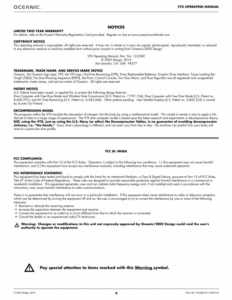
NOTICESLIMITED TWO-YEAR WARRANTYFor details, refer to the Product Warranty Registration Card provided. Register on line at www.oceanicworldwide.com
COPYRIGHT NOTICEThis operating manual is copyrighted, all rights are reserved. It may not, in whole or in part, be copied, photocopied, reproduced, translated, or reduced to any electronic medium or machine readable form without prior consent in writing from Oceanic/2002 Design.
VTX Operating Manual, Doc. No. 12-5382© 2002 Design, 2014
San Leandro, CA USA 94577
TRADEMARK, TRADE NAME, AND SERVICE MARK NOTICEOceanic, the Oceanic logo type, VTX, the VTX logo, GasTime Remaining (GTR), Diver Replaceable Batteries, Graphic Diver Interface, Tissue Loading Bar Graph (TLBG), Pre Dive Planning Sequence (PDPS), Set Point, Control Console, Turn Gas Alarm, and Dual Algorithm are all registered and unregistered trademarks, trade names, and service marks of Oceanic. All rights are reserved.
PATENT NOTICEU.S. Patents have been issued, or applied for, to protect the following design features:Dive Computer with Free Dive Mode and Wireless Data Transmission (U.S. Patent no. 7,797,124), Dive Computer with Free Dive Mode (U.S. Patent no. 8,600,701), and Air Time Remaining (U.S. Patent no. 6,543,444). Other patents pending. User Setable Display (U.S. Patent no. 5,845,235) is owned by Suunto Oy Finland.
DECOMPRESSION MODELThe programs within the VTX simulate the absorption of nitrogen into the body by using a mathematical model. This model is merely a way to apply a lim-ited set of data to a large range of experiences. The VTX dive computer model is based upon the latest research and experiments in decompression theory. Still, using the VTX, just as using the U.S. Navy (or other) No Decompression Tables, is no guarantee of avoiding decompression sickness, i.e. “the bends.” Every diver’s physiology is different, and can even vary from day to day. No machine can predict how your body will react to a particular dive profile.
Pay special attention to items marked with this Warning symbol.
fCC ID: MH8A
fCC COMPLIANCE:This equipment complies with Part 15 of the FCC Rules. Operation is subject to the following two conditions: 1.) this equipment may not cause harmful interference, and 2.) this equipment must accept any interference received, including interference that may cause undesired operation.
fCC INTERfERENCE STATEMENT: This equipment has been tested and found to comply with the limits for an Intentional Radiator, a Class B Digital Device, pursuant to Part 15 of FCC Rules, Title 47 of the Code of Federal Regulations. These rules are designed to provide reasonable protection against harmful interference in a commercial or residential installation. This equipment generates, uses and can radiate radio frequency energy and, if not installed and used in accordance with the instructions, may cause harmful interference to radio communications.
There is no guarantee that interference will not occur in a particular installation. If this equipment does cause interference to radio or television reception, which can be determined by turning the equipment off and on, the user is encouraged to try to correct the interference by one or more of the following measures:• Reorient or relocate the receiving antenna.• Increase the separation between the equipment and receiver.• Connect the equipment to an outlet on a circuit different from that to which the receiver is connected.• Consult the dealer or an experienced radio/TV technician.
Warning: Changes or modifications to this unit not expressly approved by Oceanic/2002 Design could void the user's authority to operate the equipment.

5
VTX OPERATING MANUAL
© 2002 Design, 2014 Doc. No. 12-5382-r01 (10/24/14)
ACTIVATION
AND
OVERVIEW
6
VTX OPERATING MANUAL
© 2002 Design, 2014 Doc. No. 12-5382-r01 (10/24/14)
HOME MENU
MY INFODC INFO
SE TUPLOG
HISTORY
NORMGAUGFREE
COMPASS
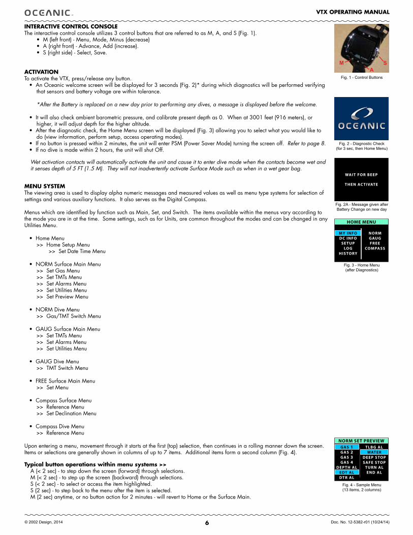
INTERACTIVE CONTROL CONSOLEThe interactive control console utilizes 3 control buttons that are referred to as M, A, and S (Fig. 1).
• M (left front) - Menu, Mode, Minus (decrease)• A (right front) - Advance, Add (increase).• S (right side) - Select, Save.
ACTIVATION To activate the VTX, press/release any button.
• An Oceanic welcome screen will be displayed for 3 seconds (Fig. 2)* during which diagnostics will be performed verifying that sensors and battery voltage are within tolerance.
*After the Battery is replaced on a new day prior to performing any dives, a message is displayed before the welcome.
• It will also check ambient barometric pressure, and calibrate present depth as 0. When at 3001 feet (916 meters), or higher, it will adjust depth for the higher altitude.
• After the diagnostic check, the Home Menu screen will be displayed (Fig. 3) allowing you to select what you would like to do (view information, perform setup, access operating modes).
• If no button is pressed within 2 minutes, the unit will enter PSM (Power Saver Mode) turning the screen off. Refer to page 8.• If no dive is made within 2 hours, the unit will shut Off.
Wet activation contacts will automatically activate the unit and cause it to enter dive mode when the contacts become wet and it senses depth of 5 FT (1.5 M). They will not inadvertently activate Surface Mode such as when in a wet gear bag.
MENU SYSTEMThe viewing area is used to display alpha numeric messages and measured values as well as menu type systems for selection of settings and various auxiliary functions. It also serves as the Digital Compass.
Menus which are identified by function such as Main, Set, and Switch. The items available within the menus vary according to the mode you are in at the time. Some settings, such as for Units, are common throughout the modes and can be changed in any Utilities Menu.
• Home Menu >> Home Setup Menu >> Set Date Time Menu
• NORM Surface Main Menu >> Set Gas Menu >> Set TMTs Menu >> Set Alarms Menu >> Set Utilities Menu >> Set Preview Menu
• NORM Dive Menu >> Gas/TMT Switch Menu
• GAUG Surface Main Menu >> Set TMTs Menu >> Set Alarms Menu >> Set Utilities Menu
• GAUG Dive Menu >> TMT Switch Menu
• FREE Surface Main Menu >> Set Menu
• Compass Surface Menu >> Reference Menu >> Set Declination Menu
• Compass Dive Menu >> Reference Menu
Upon entering a menu, movement through it starts at the first (top) selection, then continues in a rolling manner down the screen. Items or selections are generally shown in columns of up to 7 items. Additional items form a second column (Fig. 4).
Typical button operations within menu systems >>A (< 2 sec) - to step down the screen (forward) through selections.M (< 2 sec) - to step up the screen (backward) through selections.S (< 2 sec) - to select or access the item highlighted.S (2 sec) - to step back to the menu after the item is selected.M (2 sec) anytime, or no button action for 2 minutes - will revert to Home or the Surface Main.
Fig. 3 - Home Menu(after Diagnostics)
Fig. 2 - Diagnostic Check(for 3 sec, then Home Menu)
GAS 1GAS 2GAS 3GAS 4
DEPTH AL
TLBG AL
TURN ALEND AL
WATERDEEP STOPSAFE STOP
EDT ALDTR AL
NORM SET PREVIEW
Fig. 4 - Sample Menu(13 items, 2 columns)
Fig. 1 - Control Buttons
MA
S
WAIT FOR BEEP
THEN AC TIVATE
Fig. 2A - Message given after Battery Change on new day
7
VTX OPERATING MANUAL
© 2002 Design, 2014 Doc. No. 12-5382-r01 (10/24/14)
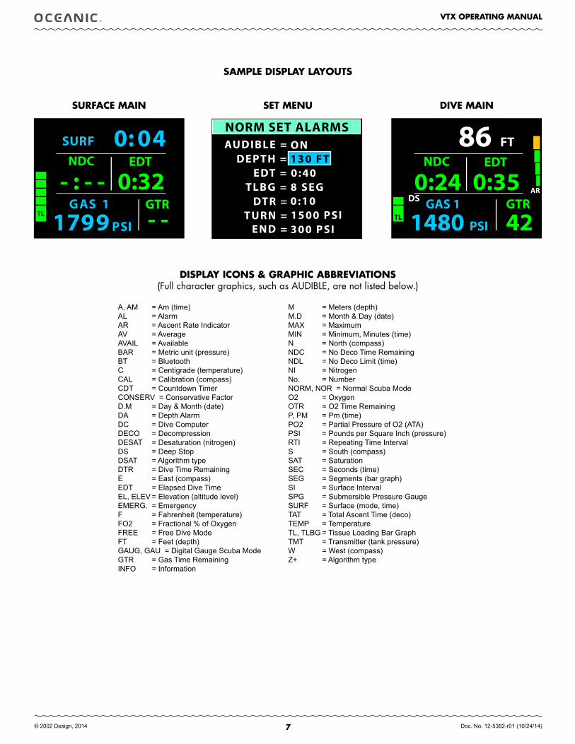
SAMPLE DISPLAY LAYOUTS
DISPLAY ICONS & GRAPHIC ABBREVIATIONS(Full character graphics, such as AUDIBLE, are not listed below.)
A, AM = Am (time) AL = AlarmAR = Ascent Rate IndicatorAV = AverageAVAIL = AvailableBAR = Metric unit (pressure)BT = BluetoothC = Centigrade (temperature)CAL = Calibration (compass)CDT = Countdown TimerCONSERV = Conservative FactorD.M = Day & Month (date)DA = Depth AlarmDC = Dive ComputerDECO = DecompressionDESAT = Desaturation (nitrogen)DS = Deep StopDSAT = Algorithm typeDTR = Dive Time RemainingE = East (compass)EDT = Elapsed Dive TimeEL, ELEV = Elevation (altitude level)EMERG. = EmergencyF = Fahrenheit (temperature)FO2 = Fractional % of OxygenFREE = Free Dive ModeFT = Feet (depth)GAUG, GAU = Digital Gauge Scuba ModeGTR = Gas Time RemainingINFO = Information
M = Meters (depth)M.D = Month & Day (date)MAX = MaximumMIN = Minimum, Minutes (time)N = North (compass)NDC = No Deco Time RemainingNDL = No Deco Limit (time)NI = NitrogenNo. = NumberNORM, NOR = Normal Scuba ModeO2 = OxygenOTR = O2 Time RemainingP, PM = Pm (time)PO2 = Partial Pressure of O2 (ATA)PSI = Pounds per Square Inch (pressure)RTI = Repeating Time IntervalS = South (compass)SAT = SaturationSEC = Seconds (time)SEG = Segments (bar graph)SI = Surface IntervalSPG = Submersible Pressure GaugeSURF = Surface (mode, time)TAT = Total Ascent Time (deco)TEMP = TemperatureTL, TLBG = Tissue Loading Bar GraphTMT = Transmitter (tank pressure)W = West (compass)Z+ = Algorithm type
FT
GAS 1 GTR
PSI1480 42
86AR
TL
DS0:24
NDC
0:35 EDT
G AS 1 GTR
SP I1 79 9
SURF 0 : 0 4
- : - - NDC
0:32 EDT
- -
NORM SET ALARMSAUDIBLE =
EDT =TLBG =
DTR =TURN =
END =
DEPTH =ON130 FT0:408 SEG0:101500 PSI300 PSI
SURfACE MAIN SET MENU DIVE MAIN
8
VTX OPERATING MANUAL
© 2002 Design, 2014 Doc. No. 12-5382-r01 (10/24/14)
GAS 1 DIVE
PSI380 5
SURF 0:11
TL
CHANGEBATTERY
GAS 1 DIVE
PSI850 1
SURF 1:03
TL
TMT 1 LOW BATTERY
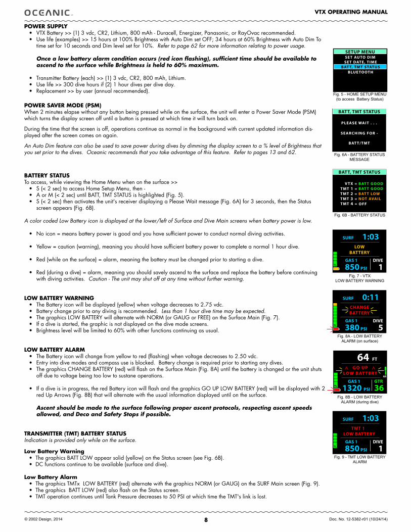
POWER SUPPLY• VTX Battery >> (1) 3 vdc, CR2, Lithium, 800 mAh - Duracell, Energizer, Panasonic, or RayOvac recommended.• Use life (examples) >> 15 hours at 100% Brightness with Auto Dim set OFF; 34 hours at 60% Brightness with Auto Dim To
time set for 10 seconds and Dim level set for 10%. Refer to page 62 for more information relating to power usage.
Once a low battery alarm condition occurs (red icon flashing), sufficient time should be available to ascend to the surface while Brightness is held to 60% maximum.
• Transmitter Battery (each) >> (1) 3 vdc, CR2, 800 mAh, Lithium.• Use life >> 300 dive hours if (2) 1 hour dives per dive day.• Replacement >> by user (annual recommended).
POWER SAVER MODE (PSM)When 2 minutes elapse without any button being pressed while on the surface, the unit will enter a Power Saver Mode (PSM) which turns the display screen off until a button is pressed at which time it will turn back on.
During the time that the screen is off, operations continue as normal in the background with current updated information dis-played after the screen comes on again.
An Auto Dim feature can also be used to save power during dives by dimming the display screen to a % level of Brightness that you set prior to the dives. Oceanic recommends that you take advantage of this feature. Refer to pages 13 and 62.
BATTERY STATUS To access, while viewing the Home Menu when on the surface >>
• S (< 2 sec) to access Home Setup Menu, then -• A or M (< 2 sec) until BATT, TMT STATUS is highlighted (Fig. 5).• S (< 2 sec) then activates the unit's receiver displaying a Please Wait message (Fig. 6A) for 3 seconds, then the Status
screen appears (Fig. 6B).
A color coded Low Battery icon is displayed at the lower/left of Surface and Dive Main screens when battery power is low.
• No icon = means battery power is good and you have sufficient power to conduct normal diving activities.
• Yellow = caution (warning), meaning you should have sufficient battery power to complete a normal 1 hour dive.
• Red (while on the surface) = alarm, meaning the battery must be changed prior to starting a dive.
• Red (during a dive) = alarm, meaning you should savely ascend to the surface and replace the battery before continuing with diving activities. Caution - The unit may shut off at any time without further warning.
LOW BATTERY WARNING• The Battery icon will be displayed (yellow) when voltage decreases to 2.75 vdc.• Battery change prior to any diving is recommended. Less than 1 hour dive time may be expected.• The graphics LOW BATTERY will alternate with NORM (or GAUG or FREE) on the Surface Main (Fig. 7). • If a dive is started, the graphic is not displayed on the dive mode screens. • Brightness level will be limited to 60% with other functions continuing as usual.
LOW BATTERY ALARM• The Battery icon will change from yellow to red (flashing) when voltage decreases to 2.50 vdc.• Entry into dive modes and compass use is blocked. Battery change is required prior to starting any dives. • The graphics CHANGE BATTERY (red) will flash on the Surface Main (Fig. 8A) until the battery is changed or the unit shuts
off due to voltage being too low to sustane operations. • If a dive is in progress, the red Battery icon will flash and the graphics GO UP LOW BATTERY (red) will be displayed with 2
red Up Arrows (Fig. 8B) that will alternate with the usual information displayed until on the surface.
Ascent should be made to the surface following proper ascent protocols, respecting ascent speeds allowed, and Deco and Safety Stops if possible.
TRANSMITTER (TMT) BATTERY STATUSIndication is provided only while on the surface.
Low Battery Warning• The graphics BATT LOW appear solid (yellow) on the Status screen (see Fig. 6B).• DC functions continue to be available (surface and dive).
Low Battery Alarm• The graphics TMTx LOW BATTERY (red) alternate with the graphics NORM (or GAUG) on the SURF Main screen (Fig. 9).• The graphics BATT LOW (red) also flash on the Status screen.• TMT operation continues until Tank Pressure decreases to 50 PSI at which time the TMT's link is lost.
Fig. 5 - HOME SETUP MENU(to access Battery Status)
Fig. 6B - BATTERY STATUS
Fig. 7 - VTX LOW BATTERY WARNING
Fig. 8A - LOW BATTERY ALARM (on surface)
SETUP MENU
SE T DATE, TIMEBAT T, TMT STATUS
BLUE TOOTH
SE T AUTO DIM
BATT, TMT STATUS
V T X =TMT 1 =TMT 2 =TMT 3 =TMT 4 =
BAT T GOOD
NOT AVAILBAT T LOW
OFF
BAT T GOOD
GAS 1 DIVE
PSI850 1
SURF 1:03
TL
LOWBATTERY
Fig. 9 - TMT LOW BATTERY ALARM
FT
GAS 1 GTR
PSI1320 36
64AR
TL
GO UPLOW BAT TERY
Fig. 8B - LOW BATTERY ALARM (during dive)
BATT, TMT STATUS
PLEASE WAIT . . .
SEARCHING FOR -
BAT T/TMT
Fig. 6A - BATTERY STATUSMESSAGE
9
VTX OPERATING MANUAL
© 2002 Design, 2014 Doc. No. 12-5382-r01 (10/24/14)
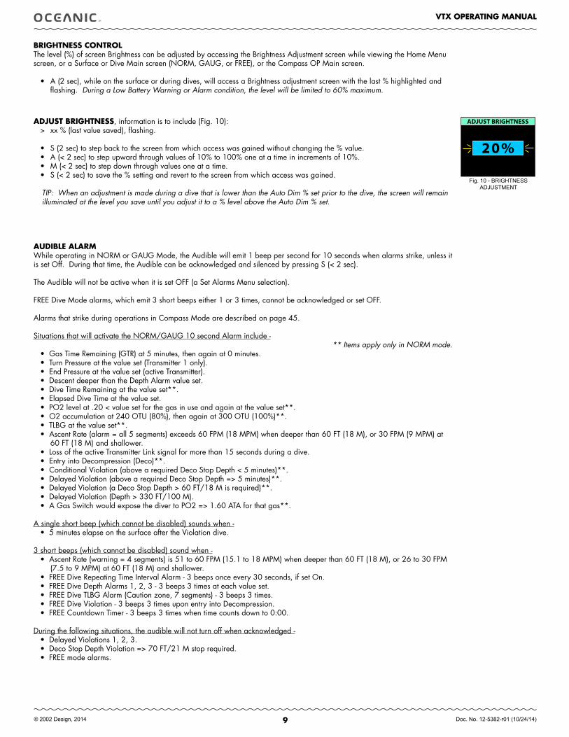
BRIGHTNESS CONTROLThe level (%) of screen Brightness can be adjusted by accessing the Brightness Adjustment screen while viewing the Home Menu screen, or a Surface or Dive Main screen (NORM, GAUG, or FREE), or the Compass OP Main screen.
• A (2 sec), while on the surface or during dives, will access a Brightness adjustment screen with the last % highlighted and flashing. During a Low Battery Warning or Alarm condition, the level will be limited to 60% maximum.
ADJUST BRIGHTNESS, information is to include (Fig. 10):> xx % (last value saved), flashing.
• S (2 sec) to step back to the screen from which access was gained without changing the % value.• A (< 2 sec) to step upward through values of 10% to 100% one at a time in increments of 10%.• M (< 2 sec) to step down through values one at a time. • S (< 2 sec) to save the % setting and revert to the screen from which access was gained.
TIP: When an adjustment is made during a dive that is lower than the Auto Dim % set prior to the dive, the screen will remain illuminated at the level you save until you adjust it to a % level above the Auto Dim % set.
AUDIBLE ALARMWhile operating in NORM or GAUG Mode, the Audible will emit 1 beep per second for 10 seconds when alarms strike, unless it is set Off. During that time, the Audible can be acknowledged and silenced by pressing S (< 2 sec).
The Audible will not be active when it is set OFF (a Set Alarms Menu selection).
FREE Dive Mode alarms, which emit 3 short beeps either 1 or 3 times, cannot be acknowledged or set OFF.
Alarms that strike during operations in Compass Mode are described on page 45.
Situations that will activate the NORM/GAUG 10 second Alarm include -** Items apply only in NORM mode.
• Gas Time Remaining (GTR) at 5 minutes, then again at 0 minutes.• Turn Pressure at the value set (Transmitter 1 only).• End Pressure at the value set (active Transmitter).• Descent deeper than the Depth Alarm value set.• Dive Time Remaining at the value set**.• Elapsed Dive Time at the value set.• PO2 level at .20 < value set for the gas in use and again at the value set**.• O2 accumulation at 240 OTU (80%), then again at 300 OTU (100%)**. • TLBG at the value set**.• Ascent Rate (alarm = all 5 segments) exceeds 60 FPM (18 MPM) when deeper than 60 FT (18 M), or 30 FPM (9 MPM) at
60 FT (18 M) and shallower.• Loss of the active Transmitter Link signal for more than 15 seconds during a dive.• Entry into Decompression (Deco)**.• Conditional Violation (above a required Deco Stop Depth < 5 minutes)**.• Delayed Violation (above a required Deco Stop Depth => 5 minutes)**.• Delayed Violation (a Deco Stop Depth > 60 FT/18 M is required)**.• Delayed Violation (Depth > 330 FT/100 M).• A Gas Switch would expose the diver to PO2 => 1.60 ATA for that gas**.
A single short beep (which cannot be disabled) sounds when -• 5 minutes elapse on the surface after the Violation dive.
3 short beeps (which cannot be disabled) sound when -• Ascent Rate (warning = 4 segments) is 51 to 60 FPM (15.1 to 18 MPM) when deeper than 60 FT (18 M), or 26 to 30 FPM
(7.5 to 9 MPM) at 60 FT (18 M) and shallower.• FREE Dive Repeating Time Interval Alarm - 3 beeps once every 30 seconds, if set On.• FREE Dive Depth Alarms 1, 2, 3 - 3 beeps 3 times at each value set. • FREE Dive TLBG Alarm (Caution zone, 7 segments) - 3 beeps 3 times. • FREE Dive Violation - 3 beeps 3 times upon entry into Decompression. • FREE Countdown Timer - 3 beeps 3 times when time counts down to 0:00.
During the following situations, the audible will not turn off when acknowledged - • Delayed Violations 1, 2, 3.• Deco Stop Depth Violation => 70 FT/21 M stop required.• FREE mode alarms.
20%
ADJUST BRIGHTNESS
Fig. 10 - BRIGHTNESS ADJUSTMENT
10
VTX OPERATING MANUAL
© 2002 Design, 2014 Doc. No. 12-5382-r01 (10/24/14)
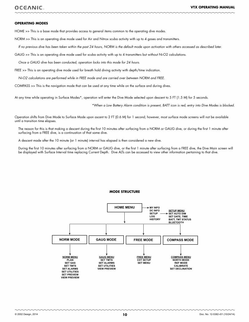
OPERATING MODES
HOME >> This is a base mode that provides access to general items common to the operating dive modes.
NORM >> This is an operating dive mode used for Air and Nitrox scuba activity with up to 4 gases and transmitters.
If no previous dive has been taken within the past 24 hours, NORM is the default mode upon activation with others accessed as described later.
GAUG >> This is an operating dive mode used for scuba activity with up to 4 transmitters but without Ni-O2 calculations.
Once a GAUG dive has been conducted, operation locks into this mode for 24 hours. FREE >> This is an operating dive mode used for breath hold diving activity with depth/time indication.
Ni-O2 calculations are performed while in FREE mode and are carried over between NORM and FREE.
COMPASS >> This is the navigation mode that can be used at any time while on the surface and during dives.
At any time while operating in Surface Modes*, operation will enter the Dive Mode selected upon descent to 5 FT (1.5 M) for 5 seconds.
*When a Low Battery Alarm condition is present, BATT icon is red, entry into Dive Modes is blocked.
Operation shifts from Dive Mode to Surface Mode upon ascent to 2 FT (0.6 M) for 1 second; however, most surface mode screens will not be available until a transition time elapses.
The reason for this is that making a descent during the first 10 minutes after surfacing from a NORM or GAUG dive, or during the first 1 minute after surfacing from a FREE dive, is a continuation of that same dive.
A descent made after the 10 minute (or 1 minute) interval has elapsed is then considered a new dive.
During the first 10 minutes after surfacing from a NORM or GAUG dive, or the first 1 minute after surfacing from a FREE dive, the Dive Main screen will be displayed with Surface Interval time replacing Current Depth. Dive ALTs can be accessed to view other information pertaining to that dive.
MODE STRUCTURE
HOME.MENU
NORM.MODE GAUG.MODE FREE.MODE COMPASS.MODE
MY.INFODC.INFOSETUPLOGHISTORY
SETUP.MENUSET.AUTO.DIMSET.DATE,.TIMEbATT,.TMT.STATUSbLUETOOTH
NORM.MENUPLAN
SET.GASSET.TMTS
SET.ALARMSSET.UTILITIESSET.PREVIEWVIEW.PREVIEW
GAUG.MENUSET.TMTS
SET.ALARMSSET.UTILITIESVIEW.PREVIEW
FREE.MENUCDT.SETUPSET.MENU
COMPASS.MENUNORTH.MODEREF.MODECALIbRATE
SET.DECLINATION

11
VTX OPERATING MANUAL
© 2002 Design, 2014 Doc. No. 12-5382-r01 (10/24/14)
HOME
MODE
12
VTX OPERATING MANUAL
© 2002 Design, 2014 Doc. No. 12-5382-r01 (10/24/14)
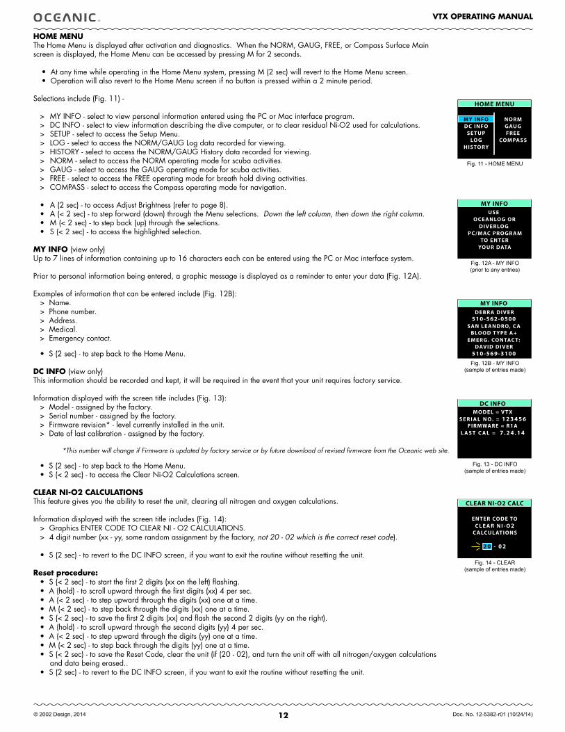
HOME MENUThe Home Menu is displayed after activation and diagnostics. When the NORM, GAUG, FREE, or Compass Surface Main screen is displayed, the Home Menu can be accessed by pressing M for 2 seconds.
• At any time while operating in the Home Menu system, pressing M (2 sec) will revert to the Home Menu screen. • Operation will also revert to the Home Menu screen if no button is pressed within a 2 minute period.
Selections include (Fig. 11) -
> MY INFO - select to view personal information entered using the PC or Mac interface program. > DC INFO - select to view information describing the dive computer, or to clear residual Ni-O2 used for calculations.> SETUP - select to access the Setup Menu.> LOG - select to access the NORM/GAUG Log data recorded for viewing.> HISTORY - select to access the NORM/GAUG History data recorded for viewing.> NORM - select to access the NORM operating mode for scuba activities.> GAUG - select to access the GAUG operating mode for scuba activities.> FREE - select to access the FREE operating mode for breath hold diving activities.> COMPASS - select to access the Compass operating mode for navigation.
• A (2 sec) - to access Adjust Brightness (refer to page 8).• A (< 2 sec) - to step forward (down) through the Menu selections. Down the left column, then down the right column.• M (< 2 sec) - to step back (up) through the selections. • S (< 2 sec) - to access the highlighted selection.
MY INfO (view only) Up to 7 lines of information containing up to 16 characters each can be entered using the PC or Mac interface system.
Prior to personal information being entered, a graphic message is displayed as a reminder to enter your data (Fig. 12A).
Examples of information that can be entered include (Fig. 12B):> Name.> Phone number.> Address.> Medical.> Emergency contact.
• S (2 sec) - to step back to the Home Menu.
DC INfO (view only) This information should be recorded and kept, it will be required in the event that your unit requires factory service.
Information displayed with the screen title includes (Fig. 13):> Model - assigned by the factory.> Serial number - assigned by the factory.> Firmware revision* - level currently installed in the unit.> Date of last calibration - assigned by the factory.
*This number will change if Firmware is updated by factory service or by future download of revised firmware from the Oceanic web site.
• S (2 sec) - to step back to the Home Menu.• S (< 2 sec) - to access the Clear Ni-O2 Calculations screen.
CLEAR NI-O2 CALCULATIONSThis feature gives you the ability to reset the unit, clearing all nitrogen and oxygen calculations.
Information displayed with the screen title includes (Fig. 14):> Graphics ENTER CODE TO CLEAR NI - O2 CALCULATIONS.> 4 digit number (xx - yy, some random assignment by the factory, not 20 - 02 which is the correct reset code).
• S (2 sec) - to revert to the DC INFO screen, if you want to exit the routine without resetting the unit.
Reset procedure: • S (< 2 sec) - to start the first 2 digits (xx on the left) flashing. • A (hold) - to scroll upward through the first digits (xx) 4 per sec. • A (< 2 sec) - to step upward through the digits (xx) one at a time. • M (< 2 sec) - to step back through the digits (xx) one at a time. • S (< 2 sec) - to save the first 2 digits (xx) and flash the second 2 digits (yy on the right).• A (hold) - to scroll upward through the second digits (yy) 4 per sec. • A (< 2 sec) - to step upward through the digits (yy) one at a time. • M (< 2 sec) - to step back through the digits (yy) one at a time. • S (< 2 sec) - to save the Reset Code, clear the unit (if (20 - 02), and turn the unit off with all nitrogen/oxygen calculations
and data being erased..• S (2 sec) - to revert to the DC INFO screen, if you want to exit the routine without resetting the unit.
Fig. 11 - HOME MENU
MY INFOUSE
PC/MAC PROGR AMTO ENTER
OCEANLOG ORDIVERLOG
YOUR DATA
MY INFODEBR A DIVER
SAN LEANDRO, C ABLOOD T YPE A+
EMERG. CONTAC T:DAVID DIVER
510-569-3100
510-562-0500
DC INFOMODEL = V T X
FIRMWARE = R1AS E R I A L N O. = 1 2 3 4 5 6
L A S T C A L = 7 . 2 4 . 1 4
CLEAR NI-O2 CALC
ENTER CODE TO
C ALCUL ATIONSC L E A R N I - O 2
2 0 - 0 2
Fig. 12A - MY INFO(prior to any entries)
Fig. 12B - MY INFO(sample of entries made)
Fig. 13 - DC INFO(sample of entries made)
Fig. 14 - CLEAR(sample of entries made)
HOME MENU
MY INFODC INFO
SE TUPLOG
HISTORY
NORMGAUGFREE
COMPASS
13
VTX OPERATING MANUAL
© 2002 Design, 2014 Doc. No. 12-5382-r01 (10/24/14)
SET AUTO DIM
TIME UNTIL DIMOFF
DIM TO BRIGHTNESS30 %
SET AUTO DIM
TIME UNTIL DIM0:30 MIN:SEC
DIM TO BRIGHTNESS30 %
SETUP MENU
SE T DATE, TIMEBAT T, TMT STATUS
BLUE TOOTH
SE T AUTO DIM
Fig. 15 - HOME SETUP MENU
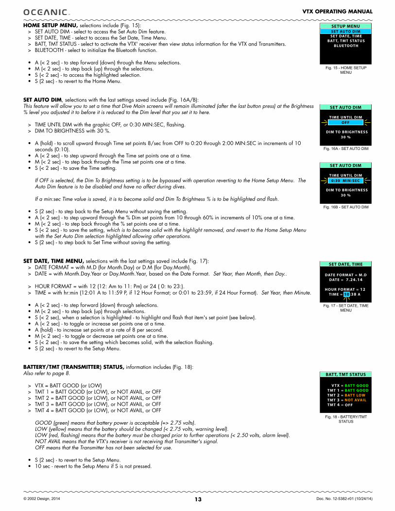
HOME SETUP MENU, selections include (Fig. 15):> SET AUTO DIM - select to access the Set Auto Dim feature. > SET DATE, TIME - select to access the Set Date, Time Menu. > BATT, TMT STATUS - select to activate the VTX' receiver then view status information for the VTX and Transmitters.> BLUETOOTH - select to initialize the Bluetooth function.
• A (< 2 sec) - to step forward (down) through the Menu selections. • M (< 2 sec) - to step back (up) through the selections. • S (< 2 sec) - to access the highlighted selection.• S (2 sec) - to revert to the Home Menu.
SET AUTO DIM, selections with the last settings saved include (Fig. 16A/B):This feature will allow you to set a time that Dive Main screens will remain illuminated (after the last button press) at the Brightness % level you adjusted it to before it is reduced to the Dim level that you set it to here.
> TIME UNTIL DIM with the graphic OFF, or 0:30 MIN:SEC, flashing.> DIM TO BRIGHTNESS with 30 %.
• A (hold) - to scroll upward through Time set points 8/sec from OFF to 0:20 through 2:00 MIN:SEC in increments of 10 seconds (0:10).
• A (< 2 sec) - to step upward through the Time set points one at a time.• M (< 2 sec) - to step back through the Time set points one at a time.• S (< 2 sec) - to save the Time setting.
If OFF is selected, the Dim To Brightness setting is to be bypassed with operation reverting to the Home Setup Menu. The Auto Dim feature is to be disabled and have no affect during dives.
If a min:sec Time value is saved, it is to become solid and Dim To Brightness % is to be highlighted and flash.
• S (2 sec) - to step back to the Setup Menu without saving the setting.• A (< 2 sec) - to step upward through the % Dim set points from 10 through 60% in increments of 10% one at a time.• M (< 2 sec) - to step back through the % set points one at a time.• S (< 2 sec) - to save the setting, which is to become solid with the highlight removed, and revert to the Home Setup Menu
with the Set Auto Dim selection highlighted allowing other operations.• S (2 sec) - to step back to Set Time without saving the setting.
SET DATE, TIME MENU, selections with the last settings saved include Fig. 17):> DATE FORMAT = with M.D (for Month.Day) or D.M (for Day.Month).> DATE = with Month.Day.Year or Day.Month.Year, based on the Date Format. Set Year, then Month, then Day..
> HOUR FORMAT = with 12 (12: Am to 11: Pm) or 24 ( 0: to 23:). > TIME = with hr:min (12:01 A to 11:59 P, if 12 Hour Format; or 0:01 to 23:59, if 24 Hour Format). Set Year, then Minute.
• A (< 2 sec) - to step forward (down) through selections. • M (< 2 sec) - to step back (up) through selections. • S (< 2 sec), when a selection is highlighted - to highlight and flash that item's set point (see below).• A (< 2 sec) - to toggle or increase set points one at a time. • A (hold) - to increase set points at a rate of 8 per second.• M (< 2 sec) - to toggle or decrease set points one at a time. • S (< 2 sec) - to save the setting which becomes solid, with the selection flashing.• S (2 sec) - to revert to the Setup Menu.
BATTERY/TMT (TRANSMITTER) STATUS, information includes (Fig. 18): Also refer to page 8.
> VTX = BATT GOOD (or LOW)> TMT 1 = BATT GOOD (or LOW), or NOT AVAIL, or OFF> TMT 2 = BATT GOOD (or LOW), or NOT AVAIL, or OFF> TMT 3 = BATT GOOD (or LOW), or NOT AVAIL, or OFF> TMT 4 = BATT GOOD (or LOW), or NOT AVAIL, or OFF
GOOD (green) means that battery power is acceptable (=> 2.75 volts).LOW (yellow) means that the battery should be changed (< 2.75 volts, warning level).LOW (red, flashing) means that the battery must be charged prior to further operations (< 2.50 volts, alarm level).NOT AVAIL means that the VTX's receiver is not receiving that Transmitter's signal.OFF means that the Transmitter has not been selected for use.
• S (2 sec) - to revert to the Setup Menu.• 10 sec - revert to the Setup Menu if S is not pressed.
DATE FORMAT = M.D
HOUR FORMAT = 12
DATE = 7 .24.14
SET DATE, TIME
TIME = 10:38 A
Fig. 17 - SET DATE, TIME MENU
Fig. 18 - BATTERY/TMT STATUS
BATT, TMT STATUS
V T X =TMT 1 =TMT 2 =TMT 3 =TMT 4 =
BAT T GOOD
NOT AVAILBAT T LOW
OFF
BAT T GOOD
Fig. 16A - SET AUTO DIM
Fig. 16B - SET AUTO DIM
14
VTX OPERATING MANUAL
© 2002 Design, 2014 Doc. No. 12-5382-r01 (10/24/14)
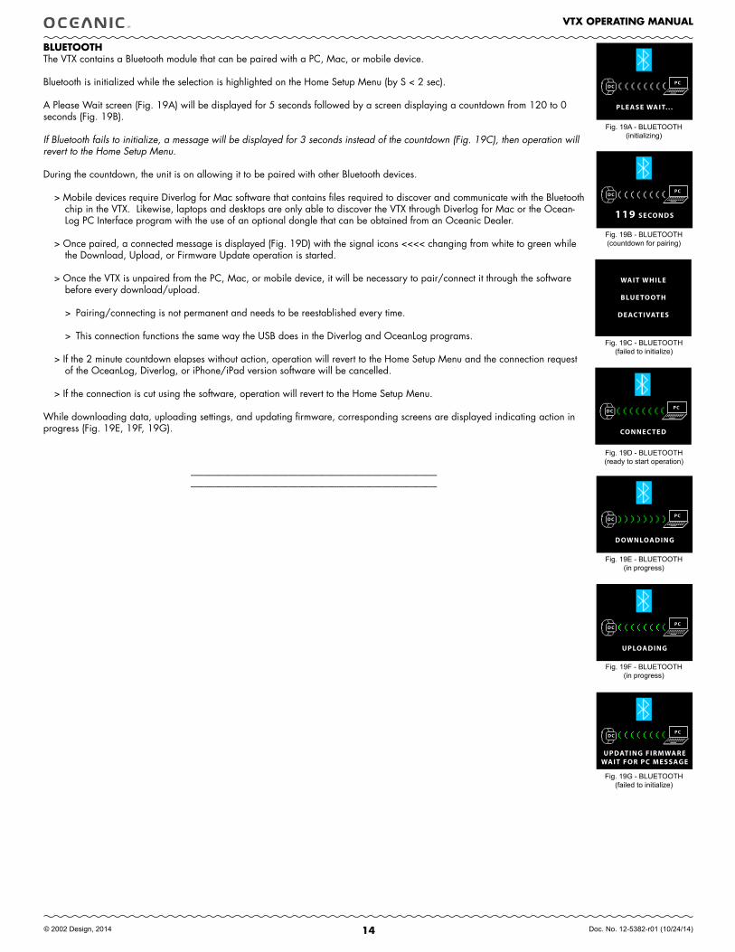
BLUETOOTHThe VTX contains a Bluetooth module that can be paired with a PC, Mac, or mobile device.
Bluetooth is initialized while the selection is highlighted on the Home Setup Menu (by S < 2 sec).
A Please Wait screen (Fig. 19A) will be displayed for 5 seconds followed by a screen displaying a countdown from 120 to 0 seconds (Fig. 19B).
If Bluetooth fails to initialize, a message will be displayed for 3 seconds instead of the countdown (Fig. 19C), then operation will revert to the Home Setup Menu. During the countdown, the unit is on allowing it to be paired with other Bluetooth devices.
> Mobile devices require Diverlog for Mac software that contains files required to discover and communicate with the Bluetooth chip in the VTX. Likewise, laptops and desktops are only able to discover the VTX through Diverlog for Mac or the Ocean-Log PC Interface program with the use of an optional dongle that can be obtained from an Oceanic Dealer.
> Once paired, a connected message is displayed (Fig. 19D) with the signal icons <<<< changing from white to green while the Download, Upload, or Firmware Update operation is started.
> Once the VTX is unpaired from the PC, Mac, or mobile device, it will be necessary to pair/connect it through the software before every download/upload.
> Pairing/connecting is not permanent and needs to be reestablished every time.
> This connection functions the same way the USB does in the Diverlog and OceanLog programs.
> If the 2 minute countdown elapses without action, operation will revert to the Home Setup Menu and the connection request of the OceanLog, Diverlog, or iPhone/iPad version software will be cancelled.
> If the connection is cut using the software, operation will revert to the Home Setup Menu.
While downloading data, uploading settings, and updating firmware, corresponding screens are displayed indicating action in progress (Fig. 19E, 19F, 19G).
------------------------------------------------------------------------------------------------------------------------------------------------------------------------------------------------------------------------------------------------------
Fig. 19A - BLUETOOTH(initializing)
Fig. 19B - BLUETOOTH(countdown for pairing)
PLEASE WAIT. . .
DCPC
119 SECONDS
DCPC
WAIT WHILE
BLUE TOOTH
DEAC TIVATES
Fig. 19C - BLUETOOTH(failed to initialize)
CONNEC TED
DCPC
DOWNLOADING
DCPC
UPLOADING
DCPC
UPDATING FIRMWAREWAIT FOR PC MESSAGE
DCPC
Fig. 19D - BLUETOOTH(ready to start operation)
Fig. 19E - BLUETOOTH(in progress)
Fig. 19F - BLUETOOTH(in progress)
Fig. 19G - BLUETOOTH(failed to initialize)
15
VTX OPERATING MANUAL
© 2002 Design, 2014 Doc. No. 12-5382-r01 (10/24/14)
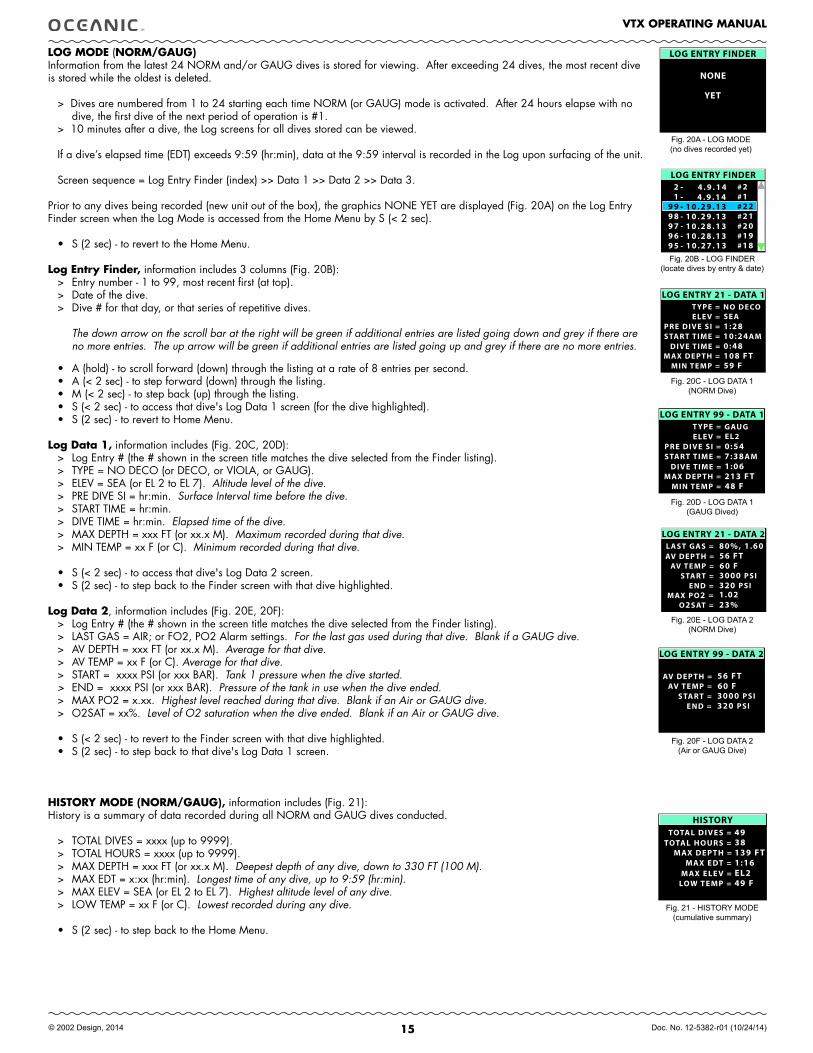
LOG MODE (NORM/GAUG)Information from the latest 24 NORM and/or GAUG dives is stored for viewing. After exceeding 24 dives, the most recent dive is stored while the oldest is deleted.
> Dives are numbered from 1 to 24 starting each time NORM (or GAUG) mode is activated. After 24 hours elapse with no dive, the first dive of the next period of operation is #1.
> 10 minutes after a dive, the Log screens for all dives stored can be viewed.
If a dive’s elapsed time (EDT) exceeds 9:59 (hr:min), data at the 9:59 interval is recorded in the Log upon surfacing of the unit.
Screen sequence = Log Entry Finder (index) >> Data 1 >> Data 2 >> Data 3.
Prior to any dives being recorded (new unit out of the box), the graphics NONE YET are displayed (Fig. 20A) on the Log Entry Finder screen when the Log Mode is accessed from the Home Menu by S (< 2 sec).
• S (2 sec) - to revert to the Home Menu.
Log Entry finder, information includes 3 columns (Fig. 20B):> Entry number - 1 to 99, most recent first (at top).> Date of the dive.> Dive # for that day, or that series of repetitive dives.
The down arrow on the scroll bar at the right will be green if additional entries are listed going down and grey if there are no more entries. The up arrow will be green if additional entries are listed going up and grey if there are no more entries.
• A (hold) - to scroll forward (down) through the listing at a rate of 8 entries per second.• A (< 2 sec) - to step forward (down) through the listing.• M (< 2 sec) - to step back (up) through the listing.• S (< 2 sec) - to access that dive's Log Data 1 screen (for the dive highlighted).• S (2 sec) - to revert to Home Menu.
Log Data 1, information includes (Fig. 20C, 20D):> Log Entry # (the # shown in the screen title matches the dive selected from the Finder listing).> TYPE = NO DECO (or DECO, or VIOLA, or GAUG).> ELEV = SEA (or EL 2 to EL 7). Altitude level of the dive.> PRE DIVE SI = hr:min. Surface Interval time before the dive. > START TIME = hr:min.> DIVE TIME = hr:min. Elapsed time of the dive.> MAX DEPTH = xxx FT (or xx.x M). Maximum recorded during that dive.> MIN TEMP = xx F (or C). Minimum recorded during that dive.
• S (< 2 sec) - to access that dive's Log Data 2 screen. • S (2 sec) - to step back to the Finder screen with that dive highlighted.
Log Data 2, information includes (Fig. 20E, 20F):> Log Entry # (the # shown in the screen title matches the dive selected from the Finder listing).> LAST GAS = AIR; or FO2, PO2 Alarm settings. For the last gas used during that dive. Blank if a GAUG dive.> AV DEPTH = xxx FT (or xx.x M). Average for that dive.> AV TEMP = xx F (or C). Average for that dive.> START = xxxx PSI (or xxx BAR). Tank 1 pressure when the dive started.> END = xxxx PSI (or xxx BAR). Pressure of the tank in use when the dive ended.> MAX PO2 = x.xx. Highest level reached during that dive. Blank if an Air or GAUG dive.> O2SAT = xx%. Level of O2 saturation when the dive ended. Blank if an Air or GAUG dive.
• S (< 2 sec) - to revert to the Finder screen with that dive highlighted. • S (2 sec) - to step back to that dive's Log Data 1 screen.
HISTORY MODE (NORM/GAUG), information includes (Fig. 21): History is a summary of data recorded during all NORM and GAUG dives conducted.
> TOTAL DIVES = xxxx (up to 9999).> TOTAL HOURS = xxxx (up to 9999).> MAX DEPTH = xxx FT (or xx.x M). Deepest depth of any dive, down to 330 FT (100 M).> MAX EDT = x:xx (hr:min). Longest time of any dive, up to 9:59 (hr:min). > MAX ELEV = SEA (or EL 2 to EL 7). Highest altitude level of any dive.> LOW TEMP = xx F (or C). Lowest recorded during any dive.
• S (2 sec) - to step back to the Home Menu.
Fig. 20B - LOG FINDER(locate dives by entry & date)
LOG ENTRY FINDER 2 -- 4 . 9 . 1 4 # 2--
9 8 -- 1 0 . 2 9 . 1 3 # 2 19 7 -- 1 0 . 2 8 . 1 3 # 2 09 6 -- 1 0 . 2 8 . 1 3 # 1 9
9 9 -- 1 0 . 2 9 . 1 3 # 2 2---- 1 -- 4 . 9 . 1 4 # 1--
9 5 -- 1 0 . 2 7 . 1 3 # 1 8
T YPE = NO DECOLOG ENTRY 21 - DATA 1
START TIME =
ELE V =PRE DIVE SI =
MIN TEMP =
DIVE TIME =MAX DEPTH =
SEA1:2810:24 AM0:48108 FT59 F
L AST GAS = 80%, 1.60
START =
MAX PO2 =O2 SAT =
AV TEMP =
END =
AV DEPTH =
1.0223%
3000 PSI320 PSI
56 FT60 F
LOG ENTRY 21 - DATA 2
Fig. 20C - LOG DATA 1(NORM Dive)
Fig. 20E - LOG DATA 2(NORM Dive)
TOTAL DIVES =TOTAL HOURS =
MAX DEPTH =MAX EDT =
MAX ELE V =
HISTORY49
LOW TEMP =
38139 FT1:16EL249 F
Fig. 21 - HISTORY MODE(cumulative summary)
LOG ENTRY FINDER
NONE
YET
Fig. 20A - LOG MODE(no dives recorded yet)
T YPE = GAUGLOG ENTRY 99 - DATA 1
START TIME =
ELE V =PRE DIVE SI =
MIN TEMP =
DIVE TIME =MAX DEPTH =
EL20:547:38 AM1:06213 FT48 F
START =AV TEMP =
END =
AV DEPTH =
3000 PSI320 PSI
56 FT60 F
LOG ENTRY 99 - DATA 2
Fig. 20D - LOG DATA 1(GAUG Dived)
Fig. 20F - LOG DATA 2(Air or GAUG Dive)
16
VTX OPERATING MANUAL
© 2002 Design, 2014 Doc. No. 12-5382-r01 (10/24/14)
NORM
SURfACE MODE
17
VTX OPERATING MANUAL
© 2002 Design, 2014 Doc. No. 12-5382-r01 (10/24/14)
G AS 1 GTR
SP I1 79 9
SURF 0 : 0 4
- : - - NDC
0:32 EDT
- -
20%
ADJUST BRIGHTNESS
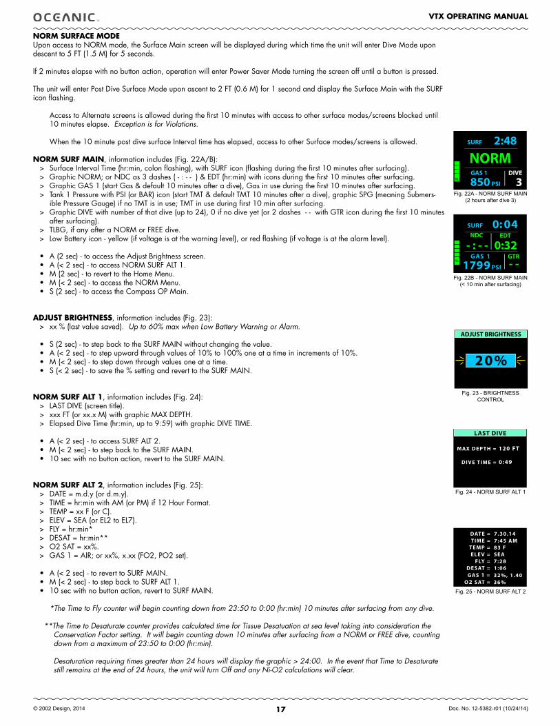
NORM SURfACE MODE Upon access to NORM mode, the Surface Main screen will be displayed during which time the unit will enter Dive Mode upon descent to 5 FT (1.5 M) for 5 seconds.
If 2 minutes elapse with no button action, operation will enter Power Saver Mode turning the screen off until a button is pressed.
The unit will enter Post Dive Surface Mode upon ascent to 2 FT (0.6 M) for 1 second and display the Surface Main with the SURF icon flashing.
Access to Alternate screens is allowed during the first 10 minutes with access to other surface modes/screens blocked until 10 minutes elapse. Exception is for Violations.
When the 10 minute post dive surface Interval time has elapsed, access to other Surface modes/screens is allowed.
NORM SURf MAIN, information includes (Fig. 22A/B):> Surface Interval Time (hr:min, colon flashing), with SURF icon (flashing during the first 10 minutes after surfacing).> Graphic NORM; or NDC as 3 dashes ( - : - - ) & EDT (hr:min) with icons during the first 10 minutes after surfacing.> Graphic GAS 1 (start Gas & default 10 minutes after a dive), Gas in use during the first 10 minutes after surfacing.> Tank 1 Pressure with PSI (or BAR) icon (start TMT & default TMT 10 minutes after a dive), graphic SPG (meaning Submers-
ible Pressure Gauge) if no TMT is in use; TMT in use during first 10 min after surfacing.> Graphic DIVE with number of that dive (up to 24), 0 if no dive yet (or 2 dashes - - with GTR icon during the first 10 minutes
after surfacing).> TLBG, if any after a NORM or FREE dive.> Low Battery icon - yellow (if voltage is at the warning level), or red flashing (if voltage is at the alarm level).
• A (2 sec) - to access the Adjust Brightness screen.• A (< 2 sec) - to access NORM SURF ALT 1.• M (2 sec) - to revert to the Home Menu.• M (< 2 sec) - to access the NORM Menu.• S (2 sec) - to access the Compass OP Main.
ADJUST BRIGHTNESS, information includes (Fig. 23):> xx % (last value saved). Up to 60% max when Low Battery Warning or Alarm.
• S (2 sec) - to step back to the SURF MAIN without changing the value.• A (< 2 sec) - to step upward through values of 10% to 100% one at a time in increments of 10%.• M (< 2 sec) - to step down through values one at a time. • S (< 2 sec) - to save the % setting and revert to the SURF MAIN.
NORM SURf ALT 1, information includes (Fig. 24):> LAST DIVE (screen title).> xxx FT (or xx.x M) with graphic MAX DEPTH.> Elapsed Dive Time (hr:min, up to 9:59) with graphic DIVE TIME.
• A (< 2 sec) - to access SURF ALT 2.• M (< 2 sec) - to step back to the SURF MAIN.• 10 sec with no button action, revert to the SURF MAIN.
NORM SURf ALT 2, information includes (Fig. 25):> DATE = m.d.y (or d.m.y). > TIME = hr:min with AM (or PM) if 12 Hour Format. > TEMP = xx F (or C).> ELEV = SEA (or EL2 to EL7).> FLY = hr:min*> DESAT = hr:min**> O2 SAT = xx%.> GAS 1 = AIR; or xx%, x.xx (FO2, PO2 set).
• A (< 2 sec) - to revert to SURF MAIN.• M (< 2 sec) - to step back to SURF ALT 1.• 10 sec with no button action, revert to SURF MAIN.
*The Time to Fly counter will begin counting down from 23:50 to 0:00 (hr:min) 10 minutes after surfacing from any dive.
**The Time to Desaturate counter provides calculated time for Tissue Desatuation at sea level taking into consideration the Conservation Factor setting. It will begin counting down 10 minutes after surfacing from a NORM or FREE dive, counting down from a maximum of 23:50 to 0:00 (hr:min).
Desaturation requiring times greater than 24 hours will display the graphic > 24:00. In the event that Time to Desaturate still remains at the end of 24 hours, the unit will turn Off and any Ni-O2 calculations will clear.
Fig. 23 - BRIGHTNESS CONTROL
Fig. 22A - NORM SURF MAIN(2 hours after dive 3)
Fig. 24 - NORM SURF ALT 1
Fig. 25 - NORM SURF ALT 2
NORM GAS 1 DIVE
PSI850 3
SURF 2:48
TL
LAST DIVE
DIVE TIME =
MAX DEPTH =
0:49
120 FT
TIME =TEMP =
SHORTCUT
O2 SAT =GAS 1 =
FLY =DESAT =
DATE =
ELE V =
7.30.147:45 AM83 FSEA
36%32%, 1.40
7:281:06
Fig. 22B - NORM SURF MAIN(< 10 min after surfacing)
18
VTX OPERATING MANUAL
© 2002 Design, 2014 Doc. No. 12-5382-r01 (10/24/14)
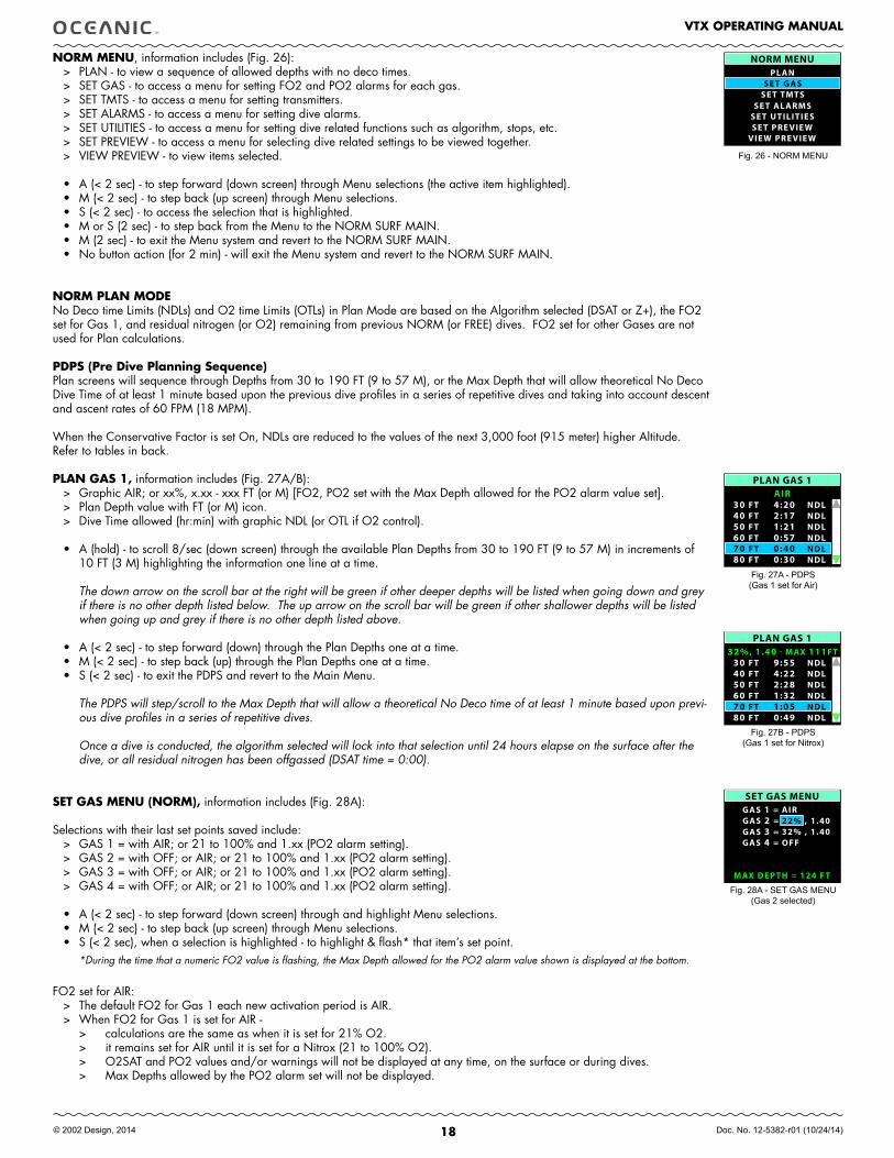
NORM MENU, information includes (Fig. 26): > PLAN - to view a sequence of allowed depths with no deco times.> SET GAS - to access a menu for setting FO2 and PO2 alarms for each gas.> SET TMTS - to access a menu for setting transmitters.> SET ALARMS - to access a menu for setting dive alarms.> SET UTILITIES - to access a menu for setting dive related functions such as algorithm, stops, etc.> SET PREVIEW - to access a menu for selecting dive related settings to be viewed together. > VIEW PREVIEW - to view items selected. • A (< 2 sec) - to step forward (down screen) through Menu selections (the active item highlighted). • M (< 2 sec) - to step back (up screen) through Menu selections. • S (< 2 sec) - to access the selection that is highlighted.• M or S (2 sec) - to step back from the Menu to the NORM SURF MAIN.• M (2 sec) - to exit the Menu system and revert to the NORM SURF MAIN.• No button action (for 2 min) - will exit the Menu system and revert to the NORM SURF MAIN.
NORM PLAN MODE No Deco time Limits (NDLs) and O2 time Limits (OTLs) in Plan Mode are based on the Algorithm selected (DSAT or Z+), the FO2 set for Gas 1, and residual nitrogen (or O2) remaining from previous NORM (or FREE) dives. FO2 set for other Gases are not used for Plan calculations.
PDPS (Pre Dive Planning Sequence)Plan screens will sequence through Depths from 30 to 190 FT (9 to 57 M), or the Max Depth that will allow theoretical No Deco Dive Time of at least 1 minute based upon the previous dive profiles in a series of repetitive dives and taking into account descent and ascent rates of 60 FPM (18 MPM).
When the Conservative Factor is set On, NDLs are reduced to the values of the next 3,000 foot (915 meter) higher Altitude. Refer to tables in back.
PLAN GAS 1, information includes (Fig. 27A/B):> Graphic AIR; or xx%, x.xx - xxx FT (or M) [FO2, PO2 set with the Max Depth allowed for the PO2 alarm value set]. > Plan Depth value with FT (or M) icon.> Dive Time allowed (hr:min) with graphic NDL (or OTL if O2 control).
• A (hold) - to scroll 8/sec (down screen) through the available Plan Depths from 30 to 190 FT (9 to 57 M) in increments of 10 FT (3 M) highlighting the information one line at a time.
The down arrow on the scroll bar at the right will be green if other deeper depths will be listed when going down and grey if there is no other depth listed below. The up arrow on the scroll bar will be green if other shallower depths will be listed when going up and grey if there is no other depth listed above.
• A (< 2 sec) - to step forward (down) through the Plan Depths one at a time.• M (< 2 sec) - to step back (up) through the Plan Depths one at a time.• S (< 2 sec) - to exit the PDPS and revert to the Main Menu.
The PDPS will step/scroll to the Max Depth that will allow a theoretical No Deco time of at least 1 minute based upon previ-ous dive profiles in a series of repetitive dives.
Once a dive is conducted, the algorithm selected will lock into that selection until 24 hours elapse on the surface after the dive, or all residual nitrogen has been offgassed (DSAT time = 0:00).
SET GAS MENU (NORM), information includes (Fig. 28A):
Selections with their last set points saved include:> GAS 1 = with AIR; or 21 to 100% and 1.xx (PO2 alarm setting).> GAS 2 = with OFF; or AIR; or 21 to 100% and 1.xx (PO2 alarm setting).> GAS 3 = with OFF; or AIR; or 21 to 100% and 1.xx (PO2 alarm setting).> GAS 4 = with OFF; or AIR; or 21 to 100% and 1.xx (PO2 alarm setting).
• A (< 2 sec) - to step forward (down screen) through and highlight Menu selections. • M (< 2 sec) - to step back (up screen) through Menu selections. • S (< 2 sec), when a selection is highlighted - to highlight & flash* that item’s set point.
*During the time that a numeric FO2 value is flashing, the Max Depth allowed for the PO2 alarm value shown is displayed at the bottom.
FO2 set for AIR:> The default FO2 for Gas 1 each new activation period is AIR. > When FO2 for Gas 1 is set for AIR - > calculations are the same as when it is set for 21% O2. > it remains set for AIR until it is set for a Nitrox (21 to 100% O2). > O2SAT and PO2 values and/or warnings will not be displayed at any time, on the surface or during dives. > Max Depths allowed by the PO2 alarm set will not be displayed.
Fig. 26 - NORM MENU
Fig. 27A - PDPS(Gas 1 set for Air)
Fig. 27B - PDPS(Gas 1 set for Nitrox)
NORM MENUPL AN
SE T TMTS
SE T PRE VIE WVIE W PRE VIE W
SE T GAS
SE T UTILITIESSE T AL ARMS
PLAN GAS 1
30 FT 9:55 NDL 40 FT 4:22 NDL 50 FT 2:28 NDL 60 FT 1:32 NDL
80 FT 0:49 NDL
32% , 1.40 111 FTMAX-
70 FT 1:05 NDL
PLAN GAS 1
30 FT 4:20 NDL 40 FT 2:17 NDL 50 FT 1:21 NDL 60 FT 0:57 NDL
80 FT 0:30 NDL
AIR
70 FT 0:40 NDL
Fig. 28A - SET GAS MENU(Gas 2 selected)
SET GAS MENUGAS 1 =
22% , 1.40GAS 2 =GAS 3 =GAS 4 =
AIR
32% , 1.40OFF
MAX DEPTH = 124 FT
19
VTX OPERATING MANUAL
© 2002 Design, 2014 Doc. No. 12-5382-r01 (10/24/14)
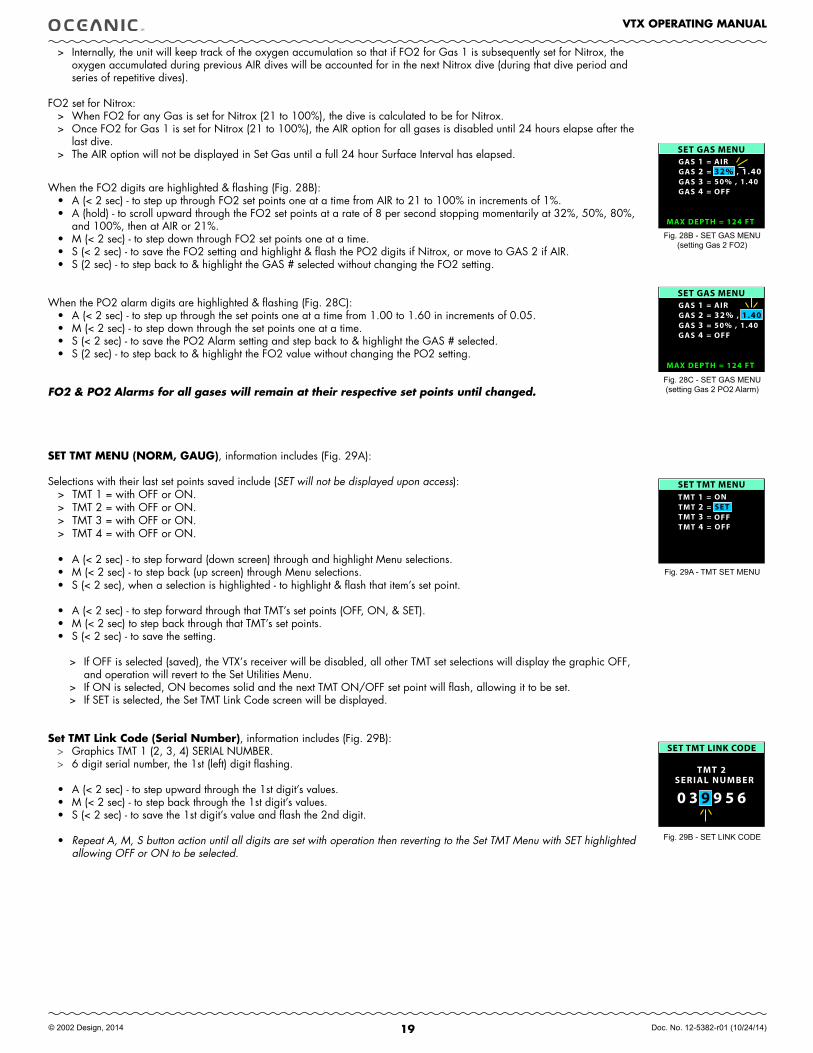
> Internally, the unit will keep track of the oxygen accumulation so that if FO2 for Gas 1 is subsequently set for Nitrox, the oxygen accumulated during previous AIR dives will be accounted for in the next Nitrox dive (during that dive period and series of repetitive dives).
FO2 set for Nitrox:> When FO2 for any Gas is set for Nitrox (21 to 100%), the dive is calculated to be for Nitrox. > Once FO2 for Gas 1 is set for Nitrox (21 to 100%), the AIR option for all gases is disabled until 24 hours elapse after the
last dive. > The AIR option will not be displayed in Set Gas until a full 24 hour Surface Interval has elapsed.
When the FO2 digits are highlighted & flashing (Fig. 28B):
• A (< 2 sec) - to step up through FO2 set points one at a time from AIR to 21 to 100% in increments of 1%.• A (hold) - to scroll upward through the FO2 set points at a rate of 8 per second stopping momentarily at 32%, 50%, 80%,
and 100%, then at AIR or 21%. • M (< 2 sec) - to step down through FO2 set points one at a time. • S (< 2 sec) - to save the FO2 setting and highlight & flash the PO2 digits if Nitrox, or move to GAS 2 if AIR.• S (2 sec) - to step back to & highlight the GAS # selected without changing the FO2 setting.
When the PO2 alarm digits are highlighted & flashing (Fig. 28C):• A (< 2 sec) - to step up through the set points one at a time from 1.00 to 1.60 in increments of 0.05.• M (< 2 sec) - to step down through the set points one at a time. • S (< 2 sec) - to save the PO2 Alarm setting and step back to & highlight the GAS # selected.• S (2 sec) - to step back to & highlight the FO2 value without changing the PO2 setting.
FO2 & PO2 Alarms for all gases will remain at their respective set points until changed.
SET TMT MENU (NORM, GAUG), information includes (Fig. 29A):
Selections with their last set points saved include (SET will not be displayed upon access):> TMT 1 = with OFF or ON.> TMT 2 = with OFF or ON.> TMT 3 = with OFF or ON.> TMT 4 = with OFF or ON.
• A (< 2 sec) - to step forward (down screen) through and highlight Menu selections. • M (< 2 sec) - to step back (up screen) through Menu selections. • S (< 2 sec), when a selection is highlighted - to highlight & flash that item’s set point.
• A (< 2 sec) - to step forward through that TMT’s set points (OFF, ON, & SET). • M (< 2 sec) to step back through that TMT’s set points. • S (< 2 sec) - to save the setting.
> If OFF is selected (saved), the VTX’s receiver will be disabled, all other TMT set selections will display the graphic OFF, and operation will revert to the Set Utilities Menu.
> If ON is selected, ON becomes solid and the next TMT ON/OFF set point will flash, allowing it to be set.> If SET is selected, the Set TMT Link Code screen will be displayed.
Set TMT Link Code (Serial Number), information includes (Fig. 29B):> Graphics TMT 1 (2, 3, 4) SERIAL NUMBER.> 6 digit serial number, the 1st (left) digit flashing.
• A (< 2 sec) - to step upward through the 1st digit’s values. • M (< 2 sec) - to step back through the 1st digit’s values. • S (< 2 sec) - to save the 1st digit’s value and flash the 2nd digit.
• Repeat A, M, S button action until all digits are set with operation then reverting to the Set TMT Menu with SET highlighted allowing OFF or ON to be selected.
Fig. 29B - SET LINK CODE
Fig. 29A - TMT SET MENU
Fig. 28C - SET GAS MENU(setting Gas 2 PO2 Alarm)
SET GAS MENUGAS 1 =
32% , 1.40GAS 2 =GAS 3 =GAS 4 =
AIR
50% , 1.40OFF
MAX DEPTH = 124 FT
SET GAS MENUGAS 1 =
32% , 1.40GAS 2 =GAS 3 =GAS 4 =
AIR
50% , 1.40OFF
MAX DEPTH = 124 FT
Fig. 28B - SET GAS MENU(setting Gas 2 FO2)
SET TMT MENUTMT 1 =TMT 2 =TMT 3 =TMT 4 =
ON
OFFOFF
SE T
SET TMT LINK CODE
SERIAL NUMBER
0 3 9 9 5 6
TMT 2
20
VTX OPERATING MANUAL
© 2002 Design, 2014 Doc. No. 12-5382-r01 (10/24/14)
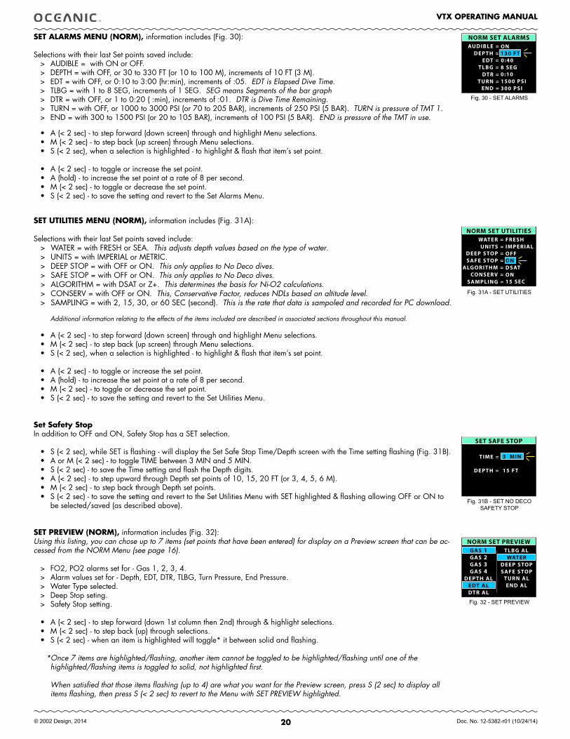
SET ALARMS MENU (NORM), information includes (Fig. 30):
Selections with their last Set points saved include:> AUDIBLE = with ON or OFF.> DEPTH = with OFF, or 30 to 330 FT (or 10 to 100 M), increments of 10 FT (3 M).> EDT = with OFF, or 0:10 to 3:00 (hr:min), increments of :05. EDT is Elapsed Dive Time.> TLBG = with 1 to 8 SEG, increments of 1 SEG. SEG means Segments of the bar graph> DTR = with OFF, or 1 to 0:20 ( :min), increments of :01. DTR is Dive Time Remaining.> TURN = with OFF, or 1000 to 3000 PSI (or 70 to 205 BAR), increments of 250 PSI (5 BAR). TURN is pressure of TMT 1.> END = with 300 to 1500 PSI (or 20 to 105 BAR), increments of 100 PSI (5 BAR). END is pressure of the TMT in use.
• A (< 2 sec) - to step forward (down screen) through and highlight Menu selections. • M (< 2 sec) - to step back (up screen) through Menu selections. • S (< 2 sec), when a selection is highlighted - to highlight & flash that item’s set point.
• A (< 2 sec) - to toggle or increase the set point.• A (hold) - to increase the set point at a rate of 8 per second. • M (< 2 sec) - to toggle or decrease the set point. • S (< 2 sec) - to save the setting and revert to the Set Alarms Menu.
SET UTILITIES MENU (NORM), information includes (Fig. 31A):
Selections with their last Set points saved include:> WATER = with FRESH or SEA. This adjusts depth values based on the type of water.> UNITS = with IMPERIAL or METRIC.> DEEP STOP = with OFF or ON. This only applies to No Deco dives.> SAFE STOP = with OFF or ON. This only applies to No Deco dives.> ALGORITHM = with DSAT or Z+. This determines the basis for Ni-O2 calculations.> CONSERV = with OFF or ON. This, Conservative Factor, reduces NDLs based on altitude level.> SAMPLING = with 2, 15, 30, or 60 SEC (second). This is the rate that data is sampoled and recorded for PC download.
Additional information relating to the effects of the items included are described in associated sections throughout this manual.
• A (< 2 sec) - to step forward (down screen) through and highlight Menu selections. • M (< 2 sec) - to step back (up screen) through Menu selections. • S (< 2 sec), when a selection is highlighted - to highlight & flash that item’s set point.
• A (< 2 sec) - to toggle or increase the set point.• A (hold) - to increase the set point at a rate of 8 per second. • M (< 2 sec) - to toggle or decrease the set point. • S (< 2 sec) - to save the setting and revert to the Set Utilities Menu.
Set Safety StopIn addition to OFF and ON, Safety Stop has a SET selection.
• S (< 2 sec), while SET is flashing - will display the Set Safe Stop Time/Depth screen with the Time setting flashing (Fig. 31B).• A or M (< 2 sec) - to toggle TIME between 3 MIN and 5 MIN.• S (< 2 sec) - to save the Time setting and flash the Depth digits.• A (< 2 sec) - to step upward through Depth set points of 10, 15, 20 FT (or 3, 4, 5, 6 M).• M (< 2 sec) - to step back through Depth set points.• S (< 2 sec) - to save the setting and revert to the Set Utilities Menu with SET highlighted & flashing allowing OFF or ON to
be selected/saved (as described above).
SET PREVIEW (NORM), information includes (Fig. 32):Using this listing, you can chose up to 7 items (set points that have been entered) for display on a Preview screen that can be ac-cessed from the NORM Menu (see page 16).
> FO2, PO2 alarms set for - Gas 1, 2, 3, 4.> Alarm values set for - Depth, EDT, DTR, TLBG, Turn Pressure, End Pressure.> Water Type selected.> Deep Stop seting.> Safety Stop setting.
• A (< 2 sec) - to step forward (down 1st column then 2nd) through & highlight selections. • M (< 2 sec) - to step back (up) through selections. • S (< 2 sec) - when an item is highlighted will toggle* it between solid and flashing.
*Once 7 items are highlighted/flashing, another item cannot be toggled to be highlighted/flashing until one of the highlighted/flashing items is toggled to solid, not highlighted first.
When satisfied that those items flashing (up to 4) are what you want for the Preview screen, press S (2 sec) to display all items flashing, then press S (< 2 sec) to revert to the Menu with SET PREVIEW highlighted.
NORM SET ALARMSAUDIBLE =
EDT =TLBG =
DTR =TURN =
END =
DEPTH =ON130 FT0:408 SEG0:101500 PSI300 PSI
Fig. 30 - SET ALARMS
NORM SET UTILITIES WATER =
DEEP STOP = SAFE STOP =
ALGORITHM = CONSERV =
SAMPLING =
UNITS =
ON
FRESHIMPERIALOFF
DSATON15 SEC
Fig. 31A - SET UTILITIES
SET SAFE STOP
TIME = 3 MIN
DEPTH = 15 FT
Fig. 31B - SET NO DECO SAFETY STOP
GAS 1GAS 2GAS 3GAS 4
DEPTH AL
TLBG AL
TURN ALEND AL
WATERDEEP STOPSAFE STOP
EDT ALDTR AL
NORM SET PREVIEW
Fig. 32 - SET PREVIEW

21
VTX OPERATING MANUAL
© 2002 Design, 2014 Doc. No. 12-5382-r01 (10/24/14)
NORM DIVE PREVIEW, information includes (Fig. 33):Upon accessing this screen from the NORM MENU, the items selected using the NORM Set Preview function previously described will be displayed with the settings last saved. The illustration shown is a sampling of various items selected with their settings.
• S or M (2 sec) to step back to the NORM MENU with VIEW PREVIEW highlighted.
------------------------------------------------------------------------------------------------------------------------------------------------------------------------------------------------------------------------------------------------------------------------------------
Fig. 33 - PREVIEW(sample of selected items)
GAS 1 =DEPTH AL =
EDT AL =WATER =
DEEP STOP =SAFE STOP =
NORM DIVE PREVIEW32%, 1.40130 FT0:50SEAOFF15 FT, 3:00

22
VTX OPERATING MANUAL
© 2002 Design, 2014 Doc. No. 12-5382-r01 (10/24/14)
DIVE MODE
fEATURES
23
VTX OPERATING MANUAL
© 2002 Design, 2014 Doc. No. 12-5382-r01 (10/24/14)
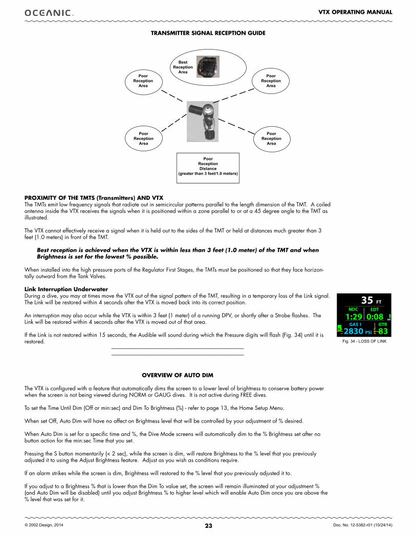
TRANSMITTER SIGNAL RECEPTION GUIDE
best.Reception.
Area
PoorReception.
Area
PoorReception.
Area
PoorReception.
Area
PoorReception.
Area
PoorReception.Distance
(greater.than.3.feet/1.0.meters)
PROXIMITY Of THE TMTS (Transmitters) AND VTXThe TMTs emit low frequency signals that radiate out in semicircular patterns parallel to the length dimension of the TMT. A coiled antenna inside the VTX receives the signals when it is positioned within a zone parallel to or at a 45 degree angle to the TMT as illustrated.
The VTX cannot effectively receive a signal when it is held out to the sides of the TMT or held at distances much greater than 3 feet (1.0 meters) in front of the TMT.
Best reception is achieved when the VTX is within less than 3 feet (1.0 meter) of the TMT and when Brightness is set for the lowest % possible.
When installed into the high pressure ports of the Regulator First Stages, the TMTs must be positioned so that they face horizon-tally outward from the Tank Valves.
Link Interruption UnderwaterDuring a dive, you may at times move the VTX out of the signal pattern of the TMT, resulting in a temporary loss of the Link signal. The Link will be restored within 4 seconds after the VTX is moved back into its correct position.
An interruption may also occur while the VTX is within 3 feet (1 meter) of a running DPV, or shortly after a Strobe flashes. The Link will be restored within 4 seconds after the VTX is moved out of that area.
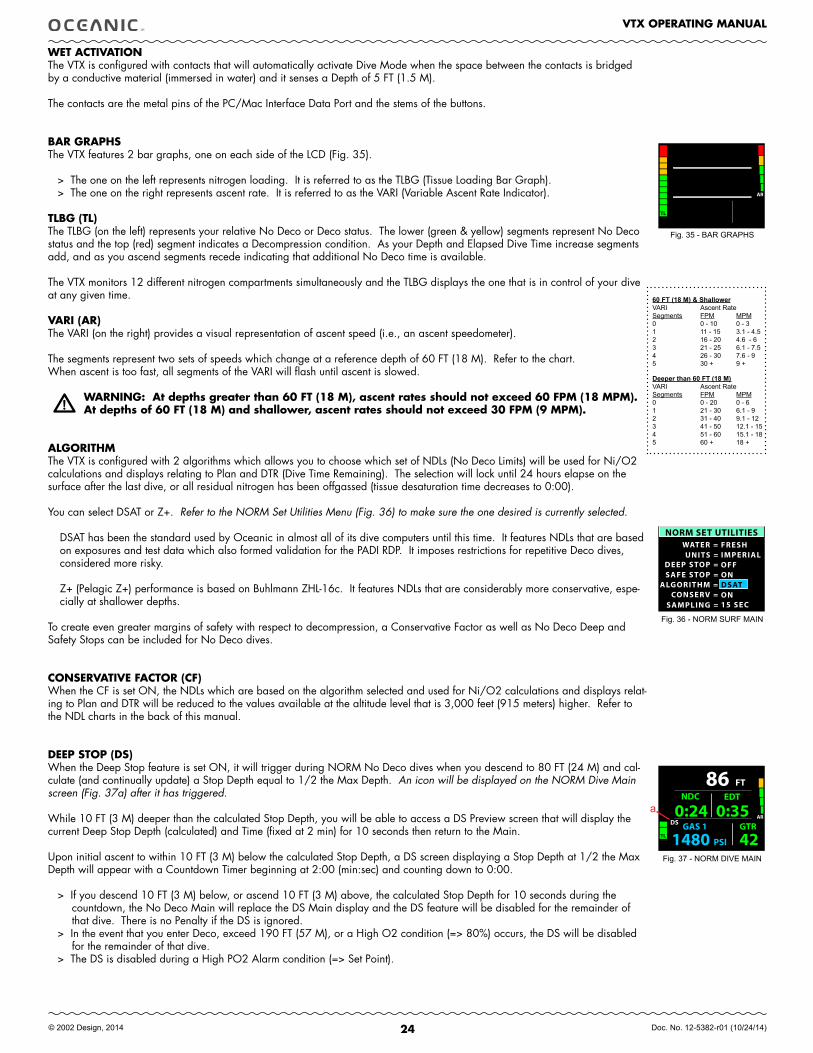
If the Link is not restored within 15 seconds, the Audible will sound during which the Pressure digits will flash (Fig. 34) until it is restored.
------------------------------------------------------------------------------------------------------------------------------------------------------------------------------------------------------------------------------------------
Fig. 34 - LOSS OF LINK
FT
GAS 1 GTR
PSI2830 83
35AR
TL
1:29 NDC
0:08 EDT
OVERVIEW Of AUTO DIM
The VTX is configured with a feature that automatically dims the screen to a lower level of brightness to conserve battery power when the screen is not being viewed during NORM or GAUG dives. It is not active during FREE dives.
To set the Time Until Dim (Off or min:sec) and Dim To Brightness (%) - refer to page 13, the Home Setup Menu.
When set Off, Auto Dim will have no affect on Brightness level that will be controlled by your adjustment of % desired.
When Auto Dim is set for a specific time and %, the Dive Mode screens will automatically dim to the % Brightness set after no button action for the min:sec Time that you set.
Pressing the S button momentarily (< 2 sec), while the screen is dim, will restore Brightness to the % level that you previously adjusted it to using the Adjust Brightness feature. Adjust as you wish as conditions require.
If an alarm strikes while the screen is dim, Brightness will restored to the % level that you previously adjusted it to.
If you adjust to a Brightness % that is lower than the Dim To value set, the screen will remain illuminated at your adjustment % (and Auto Dim will be disabled) until you adjust Brightness % to higher level which will enable Auto Dim once you are above the % level that was set for it.
24
VTX OPERATING MANUAL
© 2002 Design, 2014 Doc. No. 12-5382-r01 (10/24/14)
NORM SET UTILITIES WATER =
DEEP STOP = SAFE STOP =
ALGORITHM = CONSERV =
SAMPLING =
UNITS =
ON
FRESHIMPERIALOFF
DSATON15 SEC
FT
GAS 1 GTR
PSI1480 42
86AR
TL
DS0:24
NDC
0:35 EDT
AR
TL
WET ACTIVATIONThe VTX is configured with contacts that will automatically activate Dive Mode when the space between the contacts is bridged by a conductive material (immersed in water) and it senses a Depth of 5 FT (1.5 M).
The contacts are the metal pins of the PC/Mac Interface Data Port and the stems of the buttons.
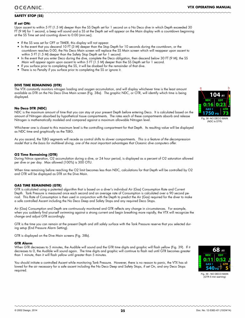
BAR GRAPHSThe VTX features 2 bar graphs, one on each side of the LCD (Fig. 35).
> The one on the left represents nitrogen loading. It is referred to as the TLBG (Tissue Loading Bar Graph).> The one on the right represents ascent rate. It is referred to as the VARI (Variable Ascent Rate Indicator).
TLBG (TL)The TLBG (on the left) represents your relative No Deco or Deco status. The lower (green & yellow) segments represent No Deco status and the top (red) segment indicates a Decompression condition. As your Depth and Elapsed Dive Time increase segments add, and as you ascend segments recede indicating that additional No Deco time is available.
The VTX monitors 12 different nitrogen compartments simultaneously and the TLBG displays the one that is in control of your dive at any given time.
VARI (AR)The VARI (on the right) provides a visual representation of ascent speed (i.e., an ascent speedometer).
The segments represent two sets of speeds which change at a reference depth of 60 FT (18 M). Refer to the chart.When ascent is too fast, all segments of the VARI will flash until ascent is slowed.
WARNING: At depths greater than 60 fT (18 M), ascent rates should not exceed 60 fPM (18 MPM). At depths of 60 fT (18 M) and shallower, ascent rates should not exceed 30 fPM (9 MPM).
ALGORITHMThe VTX is configured with 2 algorithms which allows you to choose which set of NDLs (No Deco Limits) will be used for Ni/O2 calculations and displays relating to Plan and DTR (Dive Time Remaining). The selection will lock until 24 hours elapse on the surface after the last dive, or all residual nitrogen has been offgassed (tissue desaturation time decreases to 0:00).
You can select DSAT or Z+. Refer to the NORM Set Utilities Menu (Fig. 36) to make sure the one desired is currently selected.
DSAT has been the standard used by Oceanic in almost all of its dive computers until this time. It features NDLs that are based on exposures and test data which also formed validation for the PADI RDP. It imposes restrictions for repetitive Deco dives, considered more risky.
Z+ (Pelagic Z+) performance is based on Buhlmann ZHL-16c. It features NDLs that are considerably more conservative, espe-cially at shallower depths.
To create even greater margins of safety with respect to decompression, a Conservative Factor as well as No Deco Deep and Safety Stops can be included for No Deco dives.
CONSERVATIVE fACTOR (Cf)When the CF is set ON, the NDLs which are based on the algorithm selected and used for Ni/O2 calculations and displays relat-ing to Plan and DTR will be reduced to the values available at the altitude level that is 3,000 feet (915 meters) higher. Refer to the NDL charts in the back of this manual.
DEEP STOP (DS)When the Deep Stop feature is set ON, it will trigger during NORM No Deco dives when you descend to 80 FT (24 M) and cal-culate (and continually update) a Stop Depth equal to 1/2 the Max Depth. An icon will be displayed on the NORM Dive Main screen (Fig. 37a) after it has triggered. While 10 FT (3 M) deeper than the calculated Stop Depth, you will be able to access a DS Preview screen that will display the current Deep Stop Depth (calculated) and Time (fixed at 2 min) for 10 seconds then return to the Main.
Upon initial ascent to within 10 FT (3 M) below the calculated Stop Depth, a DS screen displaying a Stop Depth at 1/2 the Max Depth will appear with a Countdown Timer beginning at 2:00 (min:sec) and counting down to 0:00.
> If you descend 10 FT (3 M) below, or ascend 10 FT (3 M) above, the calculated Stop Depth for 10 seconds during the countdown, the No Deco Main will replace the DS Main display and the DS feature will be disabled for the remainder of that dive. There is no Penalty if the DS is ignored.
> In the event that you enter Deco, exceed 190 FT (57 M), or a High O2 condition (=> 80%) occurs, the DS will be disabled for the remainder of that dive.
> The DS is disabled during a High PO2 Alarm condition (=> Set Point).
Fig. 35 - BAR GRAPHS
Deeper.than.60.FT.(18.M)VARI Ascent RateSegments FPM MPM0 0 - 20 0 - 61 21 - 30 6.1 - 92 31 - 40 9.1 - 123 41 - 50 12.1 - 154 51 - 60 15.1 - 185 60 + 18 +
60.FT.(18.M).&.ShallowerVARI Ascent RateSegments FPM MPM0 0 - 10 0 - 31 11 - 15 3.1 - 4.52 16 - 20 4.6 - 63 21 - 25 6.1 - 7.54 26 - 30 7.6 - 95 30 + 9 +
Fig. 36 - NORM SURF MAIN
Fig. 37 - NORM DIVE MAIN
a
25
VTX OPERATING MANUAL
© 2002 Design, 2014 Doc. No. 12-5382-r01 (10/24/14)
FFT
GAS 1 GTR
PSI1750 73
104
AR
TL
0:16 NDC
0:23 EDT
SAfETY STOP (SS)
If set ON:Upon ascent to within 5 FT (1.5 M) deeper than the SS Depth set for 1 second on a No Deco dive in which Depth exceeded 30 FT (9 M) for 1 second, a beep will sound and a SS at the Depth set will appear on the Main display with a countdown beginning at the SS Time set and counting down to 0:00 (min:sec).
• If the SS was set for OFF or TIMER, this display will not appear.• In the event that you descend 10 FT (3 M) deeper than the Stop Depth for 10 seconds during the countdown, or the
countdown reaches 0:00, the No Deco Main screen will replace the SS Main screen which will reappear upon ascent to within 5 FT (1.5 M) deeper than the Safety Stop Depth set for 1 second.
• In the event that you enter Deco during the dive, complete the Deco obligation, then descend below 30 FT (9 M); the SS Main will appear again upon ascent to within 5 FT (1.5 M) deeper than the SS Depth set for 1 second.
• If you surface prior to completing the SS, it will be disabed for the remainder of that dive. • There is no Penalty if you surface prior to completing the SS or ignore it.
DIVE TIME REMAINING (DTR)The VTX constantly monitors nitrogen loading and oxygen accumulation, and will display whichever time is the least amount available as DTR on the No Deco Dive Main screen (Fig. 38a). The graphic NDC, or OTR, will identify which time is being displayed.
No Deco DTR (NDC)NDC is the maximum amount of time that you can stay at your present Depth before entering Deco. It is calculated based on the amount of Nitrogen absorbed by hypothetical tissue compartments. The rates each of these compartments absorb and release Nitrogen is mathematically modeled and compared against a maximum allowable Nitrogen level.
Whichever one is closest to this maximum level is the controlling compartment for that Depth. Its resulting value will be displayed as NDC time and graphically as the TLBG.
As you ascend, the TLBG segments will recede as control shifts to slower compartments. This is a feature of the decompression model that is the basis for multilevel diving, one of the most important advantages that Oceanic dive computers offer.
O2 Time Remaining (OTR)During Nitrox operation, O2 accumulation during a dive, or 24 hour period, is displayed as a percent of O2 saturation allowed per dive or per day. Max allowed (100%) is 300 OTU. When time remaining before reaching the O2 limit becomes less than NDC, calculations for that Depth will be controlled by O2 and OTR will be displayed as DTR on the Dive Main.
GAS TIME REMAINING (GTR)GTR is calculated using a patented algorithm that is based on a diver's individual Air (Gas) Consumption Rate and Current Depth. Tank Pressure is measured once each second and an average rate of Consumption is calculated over a 90 second pe-riod. This Rate of Consumption is then used in conjunction with the Depth to predict the Air (Gas) required for the diver to make a safe controlled Ascent including the No Deco Deep and Safety Stops and any required Deco Stops.
Air (Gas) Consumption and Depth are continuously monitored and GTR reflects any change in circumstances. For example, when you suddenly find yourself swimming against a strong current and begin breathing more rapidly, the VTX will recognize the change and adjust GTR accordingly.
GTR is the time you can remain at the present Depth and still safely surface with the Tank Pressure reserve that you selected dur-ing setup (End Pressure Alarm Setting).
GTR is displayed on the Dive Main screens (Fig. 38b).
GTR AlarmWhen GTR decreases to 5 minutes, the Audible will sound and the GTR time digits and graphic will flash yellow (Fig. 39). If it decreases to 0, the Audible will sound again. The time digits and graphic will continue to flash red until GTR becomes greater than 1 minute, then it will flash yellow until greater than 5 minutes.
You should initiate a controlled Ascent while monitoring Tank Pressure. However, there is no reason to panic, the VTX has al-lowed for the air necessary for a safe ascent including the No Deco Deep and Safety Stops, if set On, and any Deco Stops required.
Fig. 38 -NO DECO MAIN(NDC is DTR)
Fig. 39 - NO DECO MAIN(GTR 5 min warning)
FT
GAS 1 GTR
PSI540 5
68
TL
AR0:11 NDC
0:52 EDT
a b
26
VTX OPERATING MANUAL
© 2002 Design, 2014 Doc. No. 12-5382-r01 (10/24/14)
NORM
DIVE MODE
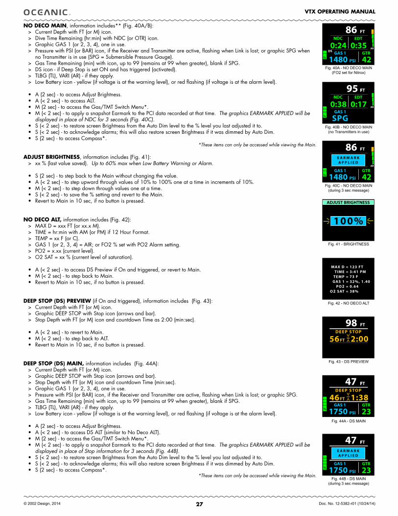
27
VTX OPERATING MANUAL
© 2002 Design, 2014 Doc. No. 12-5382-r01 (10/24/14)
NO DECO MAIN, information includes** (Fig. 40A/B):> Current Depth with FT (or M) icon.> Dive Time Remaining (hr:min) with NDC (or OTR) icon.> Graphic GAS 1 (or 2, 3, 4), one in use.> Pressure with PSI (or BAR) icon, if the Receiver and Transmitter are active, flashing when Link is lost; or graphic SPG when
no Transmitter is in use (SPG = Submersible Pressure Gauge).> Gas Time Remaining (min) with icon, up to 99 (remains at 99 when greater), blank if SPG.> DS icon - if Deep Stop is set ON and has triggered (activated).> TLBG (TL), VARI (AR) - if they apply.> Low Battery icon - yellow (if voltage is at the warning level), or red flashing (if voltage is at the alarm level).
• A (2 sec) - to access Adjust Brightness. • A (< 2 sec) - to access ALT.• M (2 sec) - to access the Gas/TMT Switch Menu*.• M (< 2 sec) - to apply a snapshot Earmark to the PCI data recorded at that time. The graphics EARMARK APPLIED will be
displayed in place of NDC for 3 seconds (Fig. 40C).• S (< 2 sec) - to restore screen Brightness from the Auto Dim level to the % level you last adjusted it to.• S (< 2 sec) - to acknowledge alarms; this will also restore screen Brightness if it was dimmed by Auto Dim.• S (2 sec) - to access Compass*.
*These items can only be accessed while viewing the Main.
ADJUST BRIGHTNESS, information includes (Fig. 41):> xx % (last value saved). Up to 60% max when Low Battery Warning or Alarm.
• S (2 sec) - to step back to the Main without changing the value.• A (< 2 sec) - to step upward through values of 10% to 100% one at a time in increments of 10%.• M (< 2 sec) - to step down through values one at a time. • S (< 2 sec) - to save the % setting and revert to the Main.• Revert to Main in 10 sec, if no button is pressed.
NO DECO ALT, information includes (Fig. 42):> MAX D = xxx FT (or xx.x M).> TIME = hr:min with AM (or PM) if 12 Hour Format.> TEMP = xx F (or C).> GAS 1 (or 2, 3, 4) = AIR; or FO2 % set with PO2 Alarm setting.> PO2 = x.xx (current level).> O2 SAT = xx % (current level of saturation).
• A (< 2 sec) - to access DS Preview if On and triggered, or revert to Main.• M (< 2 sec) - to step back to Main.• Revert to Main in 10 sec, if no button is pressed.
DEEP STOP (DS) PREVIEW (if On and triggered), information includes (Fig. 43):> Current Depth with FT (or M) icon.> Graphic DEEP STOP with Stop icon (arrows and bar).> Stop Depth with FT (or M) icon and countdown Time as 2:00 (min:sec).
• A (< 2 sec) - to revert to Main.• M (< 2 sec) - to step back to ALT.• Revert to Main in 10 sec, if no button is pressed.
DEEP STOP (DS) MAIN, information includes (Fig. 44A):> Current Depth with FT (or M) icon.> Graphic DEEP STOP with Stop icon (arrows and bar).> Stop Depth with FT (or M) icon and countdown Time (min:sec).> Graphic GAS 1 (or 2, 3, 4), one in use.> Pressure with PSI (or BAR) icon, if the Receiver and Transmitter are active, flashing when Link is lost; or graphic SPG.> Gas Time Remaining (min) with icon, up to 99 (remains at 99 when greater), blank if SPG.> TLBG (TL), VARI (AR) - if they apply.> Low Battery icon - yellow (if voltage is at the warning level), or red flashing (if voltage is at the alarm level).
• A (2 sec) - to access Adjust Brightness.• A (< 2 sec) - to access DS ALT (similar to No Deco ALT).• M (2 sec) - to access the Gas/TMT Switch Menu*.• M (< 2 sec) - to apply a snapshot Earmark to the PCI data recorded at that time. The graphics EARMARK APPLIED will be
displayed in place of Stop information for 3 seconds (Fig. 44B).• S (< 2 sec) - to restore screen Brightness from the Auto Dim level to the % level you last adjusted it to.• S (< 2 sec) - to acknowledge alarms; this will also restore screen Brightness if it was dimmed by Auto Dim.• S (2 sec) - to access Compass*.
*These items can only be accessed while viewing the Main.
Fig. 40A - NO DECO MAIN(FO2 set for Nitrox)
Fig. 42 - NO DECO ALT
Fig. 43 - DS PREVIEW
FFT
GAS 1
95AR
TL SPG
0:38 NDC
0:17 EDT
Fig. 40C - NO DECO MAIN(during 3 sec message)
FT
GAS 1 GTR
PSI1480 42
86AR
TL
DS0:24
NDC
0:35 EDT
Fig. 40B - NO DECO MAIN(no Transmitters in use)
TIME =TEMP =
MAX D =
GAS 1 =PO2 =
O2 SAT =
123 FT3:41 PM73 F32%, 1.400.6438%
98 FT
FT56 2:00DEEP STOP
100%
ADJUST BRIGHTNESS
Fig. 41 - BRIGHTNESS
F47 FT
GAS 1 GTR
PSI1750 23
DEEP STOP
FT46 1:38TL
Fig. 44A - DS MAIN
FT
GAS 1 GTR
PSI1480 42
86AR
TL
E A R M A R KA P P L I E D
F47 FT
GAS 1 GTR
PSI1750 23 TL
E A R M A R KA P P L I E D
Fig. 44B - DS MAIN(during 3 sec message)
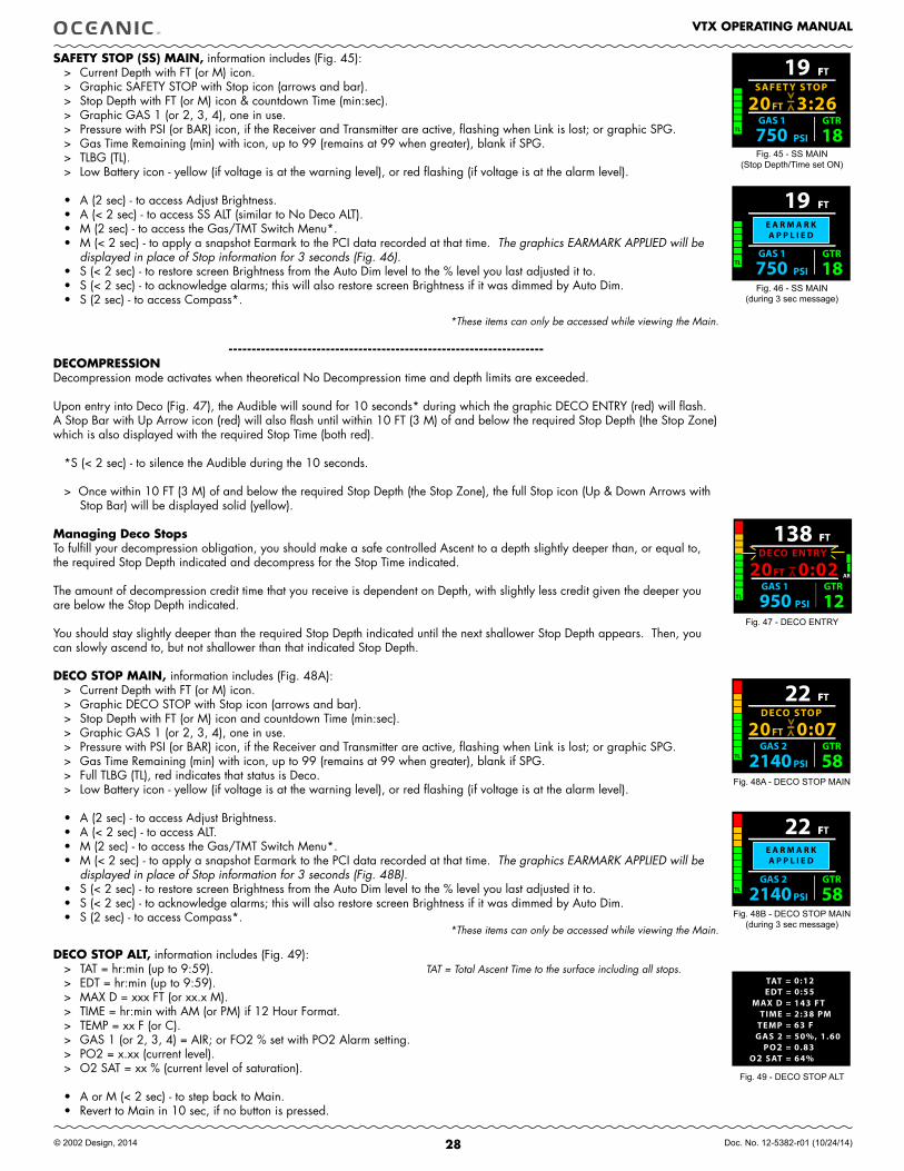
28
VTX OPERATING MANUAL
© 2002 Design, 2014 Doc. No. 12-5382-r01 (10/24/14)
SAfETY STOP (SS) MAIN, information includes (Fig. 45):> Current Depth with FT (or M) icon.> Graphic SAFETY STOP with Stop icon (arrows and bar).> Stop Depth with FT (or M) icon & countdown Time (min:sec).> Graphic GAS 1 (or 2, 3, 4), one in use.> Pressure with PSI (or BAR) icon, if the Receiver and Transmitter are active, flashing when Link is lost; or graphic SPG.> Gas Time Remaining (min) with icon, up to 99 (remains at 99 when greater), blank if SPG.> TLBG (TL).> Low Battery icon - yellow (if voltage is at the warning level), or red flashing (if voltage is at the alarm level).
• A (2 sec) - to access Adjust Brightness.• A (< 2 sec) - to access SS ALT (similar to No Deco ALT).• M (2 sec) - to access the Gas/TMT Switch Menu*.• M (< 2 sec) - to apply a snapshot Earmark to the PCI data recorded at that time. The graphics EARMARK APPLIED will be
displayed in place of Stop information for 3 seconds (Fig. 46).• S (< 2 sec) - to restore screen Brightness from the Auto Dim level to the % level you last adjusted it to.• S (< 2 sec) - to acknowledge alarms; this will also restore screen Brightness if it was dimmed by Auto Dim.• S (2 sec) - to access Compass*.
*These items can only be accessed while viewing the Main.
--------------------------------------------------------------------DECOMPRESSIONDecompression mode activates when theoretical No Decompression time and depth limits are exceeded.
Upon entry into Deco (Fig. 47), the Audible will sound for 10 seconds* during which the graphic DECO ENTRY (red) will flash. A Stop Bar with Up Arrow icon (red) will also flash until within 10 FT (3 M) of and below the required Stop Depth (the Stop Zone) which is also displayed with the required Stop Time (both red).
*S (< 2 sec) - to silence the Audible during the 10 seconds.
> Once within 10 FT (3 M) of and below the required Stop Depth (the Stop Zone), the full Stop icon (Up & Down Arrows with Stop Bar) will be displayed solid (yellow).
Managing Deco StopsTo fulfill your decompression obligation, you should make a safe controlled Ascent to a depth slightly deeper than, or equal to, the required Stop Depth indicated and decompress for the Stop Time indicated.
The amount of decompression credit time that you receive is dependent on Depth, with slightly less credit given the deeper you are below the Stop Depth indicated.
You should stay slightly deeper than the required Stop Depth indicated until the next shallower Stop Depth appears. Then, you can slowly ascend to, but not shallower than that indicated Stop Depth.
DECO STOP MAIN, information includes (Fig. 48A):> Current Depth with FT (or M) icon.> Graphic DECO STOP with Stop icon (arrows and bar).> Stop Depth with FT (or M) icon and countdown Time (min:sec).> Graphic GAS 1 (or 2, 3, 4), one in use.> Pressure with PSI (or BAR) icon, if the Receiver and Transmitter are active, flashing when Link is lost; or graphic SPG.> Gas Time Remaining (min) with icon, up to 99 (remains at 99 when greater), blank if SPG.> Full TLBG (TL), red indicates that status is Deco.> Low Battery icon - yellow (if voltage is at the warning level), or red flashing (if voltage is at the alarm level).
• A (2 sec) - to access Adjust Brightness.• A (< 2 sec) - to access ALT.• M (2 sec) - to access the Gas/TMT Switch Menu*.• M (< 2 sec) - to apply a snapshot Earmark to the PCI data recorded at that time. The graphics EARMARK APPLIED will be
displayed in place of Stop information for 3 seconds (Fig. 48B).• S (< 2 sec) - to restore screen Brightness from the Auto Dim level to the % level you last adjusted it to.• S (< 2 sec) - to acknowledge alarms; this will also restore screen Brightness if it was dimmed by Auto Dim.• S (2 sec) - to access Compass*.
*These items can only be accessed while viewing the Main.
DECO STOP ALT, information includes (Fig. 49):> TAT = hr:min (up to 9:59). TAT = Total Ascent Time to the surface including all stops.> EDT = hr:min (up to 9:59).> MAX D = xxx FT (or xx.x M).> TIME = hr:min with AM (or PM) if 12 Hour Format.> TEMP = xx F (or C).> GAS 1 (or 2, 3, 4) = AIR; or FO2 % set with PO2 Alarm setting.> PO2 = x.xx (current level).> O2 SAT = xx % (current level of saturation).
• A or M (< 2 sec) - to step back to Main.• Revert to Main in 10 sec, if no button is pressed.
Fig. 45 - SS MAIN (Stop Depth/Time set ON)
F19 FT
GAS 1 GTR
PSI750 18
SAFE T Y STOP
FT20 3:26TL
FFT
GAS 1 GTR
PSI 950 12
138DECO ENTRY
FT20 0:02 AR
TL
FFT
GAS 2 GTR
PSI 2140 58
22DECO STOP
FT20 0:07TL
Fig. 47 - DECO ENTRY
Fig. 48A - DECO STOP MAIN
TAT =EDT =
TIME =TEMP =
MAX D =
GAS 2 =PO2 =
O2 SAT =
0:120:55143 FT2:38 PM63 F50%, 1.600.8364%
Fig. 49 - DECO STOP ALT
F19 FT
GAS 1 GTR
PSI750 18 TL
E A R M A R KA P P L I E D
Fig. 46 - SS MAIN(during 3 sec message)
FFT
GAS 2 GTR
PSI 2140 58
22
TL
E A R M A R KA P P L I E D
Fig. 48B - DECO STOP MAIN(during 3 sec message)
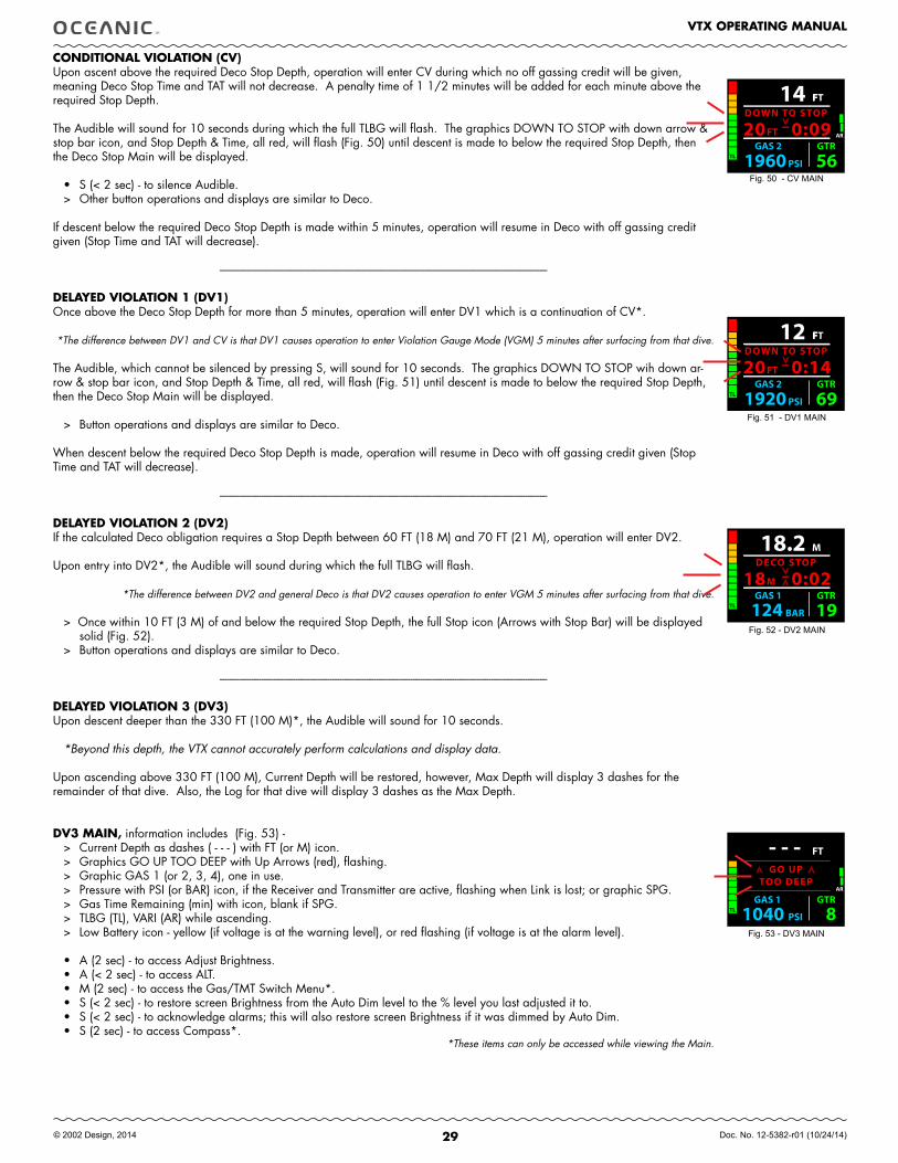
29
VTX OPERATING MANUAL
© 2002 Design, 2014 Doc. No. 12-5382-r01 (10/24/14)
CONDITIONAL VIOLATION (CV)Upon ascent above the required Deco Stop Depth, operation will enter CV during which no off gassing credit will be given, meaning Deco Stop Time and TAT will not decrease. A penalty time of 1 1/2 minutes will be added for each minute above the required Stop Depth.
The Audible will sound for 10 seconds during which the full TLBG will flash. The graphics DOWN TO STOP with down arrow & stop bar icon, and Stop Depth & Time, all red, will flash (Fig. 50) until descent is made to below the required Stop Depth, then the Deco Stop Main will be displayed.
• S (< 2 sec) - to silence Audible.> Other button operations and displays are similar to Deco.
If descent below the required Deco Stop Depth is made within 5 minutes, operation will resume in Deco with off gassing credit given (Stop Time and TAT will decrease).
--------------------------------------------------------------------------------------------------------------------------------------
DELAYED VIOLATION 1 (DV1)Once above the Deco Stop Depth for more than 5 minutes, operation will enter DV1 which is a continuation of CV*.
*The difference between DV1 and CV is that DV1 causes operation to enter Violation Gauge Mode (VGM) 5 minutes after surfacing from that dive.
The Audible, which cannot be silenced by pressing S, will sound for 10 seconds. The graphics DOWN TO STOP wih down ar-row & stop bar icon, and Stop Depth & Time, all red, will flash (Fig. 51) until descent is made to below the required Stop Depth, then the Deco Stop Main will be displayed.
> Button operations and displays are similar to Deco.
When descent below the required Deco Stop Depth is made, operation will resume in Deco with off gassing credit given (Stop Time and TAT will decrease).
--------------------------------------------------------------------------------------------------------------------------------------
DELAYED VIOLATION 2 (DV2)If the calculated Deco obligation requires a Stop Depth between 60 FT (18 M) and 70 FT (21 M), operation will enter DV2.
Upon entry into DV2*, the Audible will sound during which the full TLBG will flash.
*The difference between DV2 and general Deco is that DV2 causes operation to enter VGM 5 minutes after surfacing from that dive.
> Once within 10 FT (3 M) of and below the required Stop Depth, the full Stop icon (Arrows with Stop Bar) will be displayed solid (Fig. 52).
> Button operations and displays are similar to Deco.
--------------------------------------------------------------------------------------------------------------------------------------
DELAYED VIOLATION 3 (DV3)Upon descent deeper than the 330 FT (100 M)*, the Audible will sound for 10 seconds.
*Beyond this depth, the VTX cannot accurately perform calculations and display data.
Upon ascending above 330 FT (100 M), Current Depth will be restored, however, Max Depth will display 3 dashes for the remainder of that dive. Also, the Log for that dive will display 3 dashes as the Max Depth.
DV3 MAIN, information includes (Fig. 53) -> Current Depth as dashes ( - - - ) with FT (or M) icon.> Graphics GO UP TOO DEEP with Up Arrows (red), flashing.> Graphic GAS 1 (or 2, 3, 4), one in use.> Pressure with PSI (or BAR) icon, if the Receiver and Transmitter are active, flashing when Link is lost; or graphic SPG.> Gas Time Remaining (min) with icon, blank if SPG.> TLBG (TL), VARI (AR) while ascending.> Low Battery icon - yellow (if voltage is at the warning level), or red flashing (if voltage is at the alarm level).
• A (2 sec) - to access Adjust Brightness.• A (< 2 sec) - to access ALT.• M (2 sec) - to access the Gas/TMT Switch Menu*.• S (< 2 sec) - to restore screen Brightness from the Auto Dim level to the % level you last adjusted it to.• S (< 2 sec) - to acknowledge alarms; this will also restore screen Brightness if it was dimmed by Auto Dim.• S (2 sec) - to access Compass*.
*These items can only be accessed while viewing the Main.
Fig. 50 - CV MAIN
Fig. 51 - DV1 MAIN
Fig. 52 - DV2 MAIN
Fig. 53 - DV3 MAIN
FFT
GAS 2 GTR
PSI 1960 56
14DOWN TO STOP
FT20 0:09TL
AR
FFT
GAS 2 GTR
PSI 1920 69
12DOWN TO STOP
FT20 0:14TL
M
GAS 1 GTR
BAR 124 19
18.2DECO STOP
M18 0:02TL
FT
GAS 1 GTR
PSI1040 8
- - - AR
TL
GO UPTOO DEEP
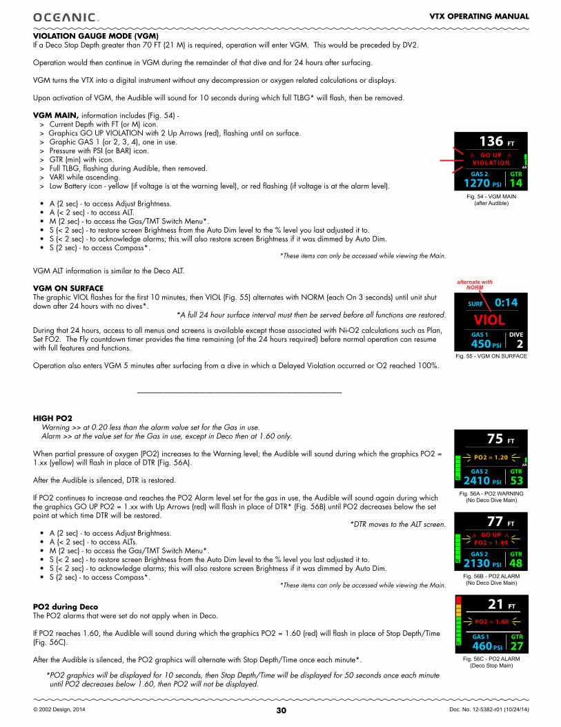
30
VTX OPERATING MANUAL
© 2002 Design, 2014 Doc. No. 12-5382-r01 (10/24/14)
VIOLATION GAUGE MODE (VGM)If a Deco Stop Depth greater than 70 FT (21 M) is required, operation will enter VGM. This would be preceded by DV2.
Operation would then continue in VGM during the remainder of that dive and for 24 hours after surfacing.
VGM turns the VTX into a digital instrument without any decompression or oxygen related calculations or displays.
Upon activation of VGM, the Audible will sound for 10 seconds during which full TLBG* will flash, then be removed.
VGM MAIN, information includes (Fig. 54) -> Current Depth with FT (or M) icon.> Graphics GO UP VIOLATION with 2 Up Arrows (red), flashing until on surface.> Graphic GAS 1 (or 2, 3, 4), one in use.> Pressure with PSI (or BAR) icon.> GTR (min) with icon.> Full TLBG, flashing during Audible, then removed.> VARI while ascending.> Low Battery icon - yellow (if voltage is at the warning level), or red flashing (if voltage is at the alarm level).
• A (2 sec) - to access Adjust Brightness.• A (< 2 sec) - to access ALT.• M (2 sec) - to access the Gas/TMT Switch Menu*.• S (< 2 sec) - to restore screen Brightness from the Auto Dim level to the % level you last adjusted it to.• S (< 2 sec) - to acknowledge alarms; this will also restore screen Brightness if it was dimmed by Auto Dim.• S (2 sec) - to access Compass*. *These items can only be accessed while viewing the Main.
VGM ALT information is similar to the Deco ALT.
VGM ON SURfACEThe graphic VIOL flashes for the first 10 minutes, then VIOL (Fig. 55) alternates with NORM (each On 3 seconds) until unit shut down after 24 hours with no dives*.
*A full 24 hour surface interval must then be served before all functions are restored.
During that 24 hours, access to all menus and screens is available except those associated with Ni-O2 calculations such as Plan, Set FO2. The Fly countdown timer provides the time remaining (of the 24 hours required) before normal operation can resume with full features and functions.
Operation also enters VGM 5 minutes after surfacing from a dive in which a Delayed Violation occurred or O2 reached 100%.
--------------------------------------------------------------------------------------------------------------------------------------
HIGH PO2Warning >> at 0.20 less than the alarm value set for the Gas in use.Alarm >> at the value set for the Gas in use, except in Deco then at 1.60 only.
When partial pressure of oxygen (PO2) increases to the Warning level; the Audible will sound during which the graphics PO2 = 1.xx (yellow) will flash in place of DTR (Fig. 56A).
After the Audible is silenced, DTR is restored.
If PO2 continues to increase and reaches the PO2 Alarm level set for the gas in use, the Audible will sound again during which the graphics GO UP PO2 = 1.xx with Up Arrows (red) will flash in place of DTR* (Fig. 56B) until PO2 decreases below the set point at which time DTR will be restored.
*DTR moves to the ALT screen.• A (2 sec) - to access Adjust Brightness.• A (< 2 sec) - to access ALTs.• M (2 sec) - to access the Gas/TMT Switch Menu*.• S (< 2 sec) - to restore screen Brightness from the Auto Dim level to the % level you last adjusted it to.• S (< 2 sec) - to acknowledge alarms; this will also restore screen Brightness if it was dimmed by Auto Dim.• S (2 sec) - to access Compass*.
*These items can only be accessed while viewing the Main.
PO2 during DecoThe PO2 alarms that were set do not apply when in Deco.
If PO2 reaches 1.60, the Audible will sound during which the graphics PO2 = 1.60 (red) will flash in place of Stop Depth/Time (Fig. 56C).
After the Audible is silenced, the PO2 graphics will alternate with Stop Depth/Time once each minute*.
*PO2 graphics will be displayed for 10 seconds, then Stop Depth/Time will be displayed for 50 seconds once each minute until PO2 decreases below 1.60, then PO2 will not be displayed.
FT
GAS 2 GTR
PSI1270 14
136AR
GO UPVIOL ATION
VIOL GAS 1 DIVE
PSI450 2
SURF 0:14
Fig. 54 - VGM MAIN(after Audible)
Fig. 55 - VGM ON SURFACE
FT
GAS 2 GTR
PSI2410 53
75AR
TL
PO2 = 1.20
FT
GAS 2 GTR
PSI2130 48
77
TL
GO UPPO2 = 1.40
FFT
GAS 1 GTR
PSI 460 27
21
TL
PO2 = 1.60
Fig. 56A - PO2 WARNING(No Deco Dive Main)
Fig. 56B - PO2 ALARM(No Deco Dive Main)
Fig. 56C - PO2 ALARM(Deco Stop Main)
alternate with NORM
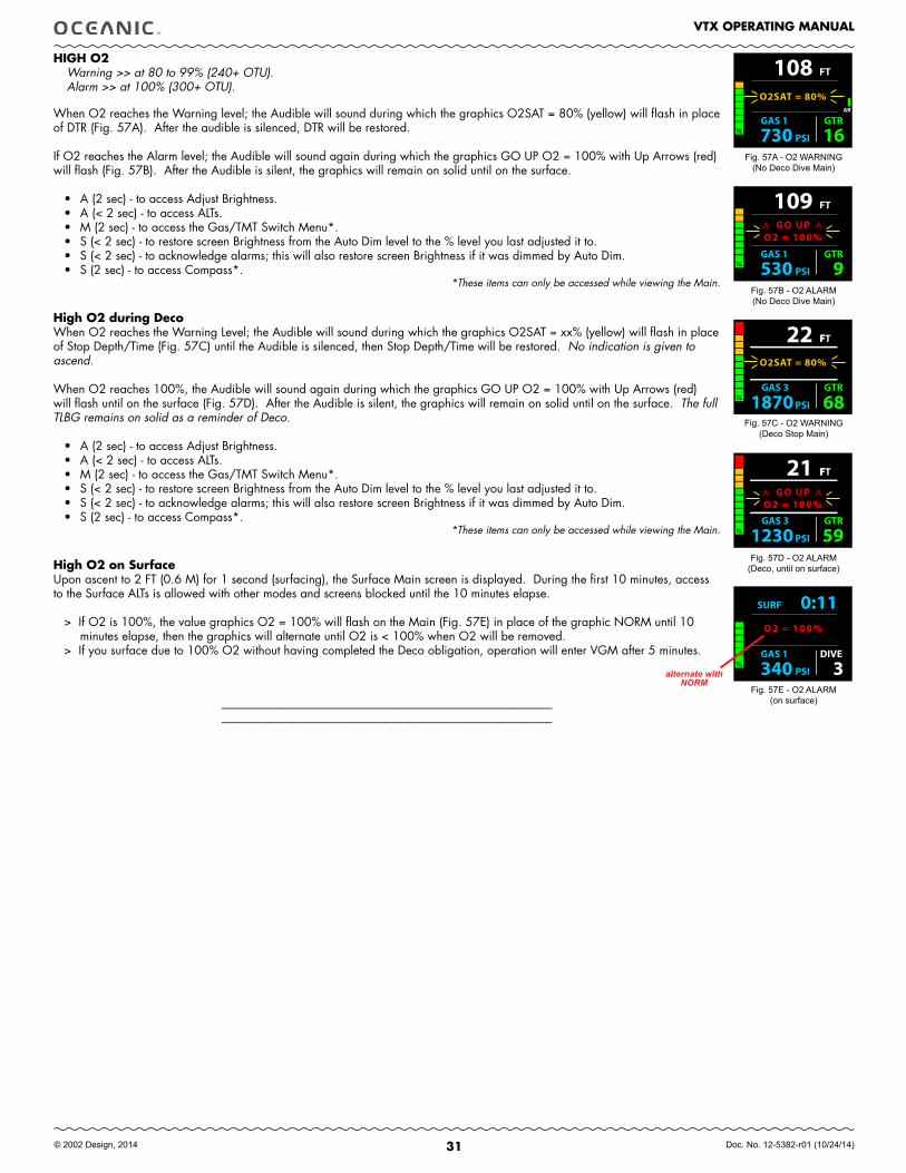
31
VTX OPERATING MANUAL
© 2002 Design, 2014 Doc. No. 12-5382-r01 (10/24/14)
HIGH O2Warning >> at 80 to 99% (240+ OTU).Alarm >> at 100% (300+ OTU).
When O2 reaches the Warning level; the Audible will sound during which the graphics O2SAT = 80% (yellow) will flash in place of DTR (Fig. 57A). After the audible is silenced, DTR will be restored.
If O2 reaches the Alarm level; the Audible will sound again during which the graphics GO UP O2 = 100% with Up Arrows (red)will flash (Fig. 57B). After the Audible is silent, the graphics will remain on solid until on the surface.
• A (2 sec) - to access Adjust Brightness.• A (< 2 sec) - to access ALTs.• M (2 sec) - to access the Gas/TMT Switch Menu*.• S (< 2 sec) - to restore screen Brightness from the Auto Dim level to the % level you last adjusted it to.• S (< 2 sec) - to acknowledge alarms; this will also restore screen Brightness if it was dimmed by Auto Dim.• S (2 sec) - to access Compass*.
*These items can only be accessed while viewing the Main.
High O2 during DecoWhen O2 reaches the Warning Level; the Audible will sound during which the graphics O2SAT = xx% (yellow) will flash in place of Stop Depth/Time (Fig. 57C) until the Audible is silenced, then Stop Depth/Time will be restored. No indication is given to ascend.
When O2 reaches 100%, the Audible will sound again during which the graphics GO UP O2 = 100% with Up Arrows (red) will flash until on the surface (Fig. 57D). After the Audible is silent, the graphics will remain on solid until on the surface. The full TLBG remains on solid as a reminder of Deco.
• A (2 sec) - to access Adjust Brightness.• A (< 2 sec) - to access ALTs.• M (2 sec) - to access the Gas/TMT Switch Menu*.• S (< 2 sec) - to restore screen Brightness from the Auto Dim level to the % level you last adjusted it to.• S (< 2 sec) - to acknowledge alarms; this will also restore screen Brightness if it was dimmed by Auto Dim.• S (2 sec) - to access Compass*.
*These items can only be accessed while viewing the Main.
High O2 on SurfaceUpon ascent to 2 FT (0.6 M) for 1 second (surfacing), the Surface Main screen is displayed. During the first 10 minutes, access to the Surface ALTs is allowed with other modes and screens blocked until the 10 minutes elapse.
> If O2 is 100%, the value graphics O2 = 100% will flash on the Main (Fig. 57E) in place of the graphic NORM until 10 minutes elapse, then the graphics will alternate until O2 is < 100% when O2 will be removed.
> If you surface due to 100% O2 without having completed the Deco obligation, operation will enter VGM after 5 minutes.
----------------------------------------------------------------------------------------------------------------------------------------------------------------------------------------------------------------------------------------------------------------------------
Fig. 57A - O2 WARNING(No Deco Dive Main)
Fig. 57B - O2 ALARM(No Deco Dive Main)
Fig. 57C - O2 WARNING(Deco Stop Main)
Fig. 57D - O2 ALARM(Deco, until on surface)
FT
GAS 1 GTR
PSI730 16
108AR
TL
O2SAT = 80%
FT
GAS 1 GTR
PSI530 9
109
TL
GO UPO2 = 100%
FFT
GAS 3 GTR
PSI 1870 68
22
TL
O2SAT = 80%
FFT
GAS 3 GTR
PSI 1230 59
21
TL
GO UPO2 = 100%
GAS 1 DIVE
PSI340 3TL
O2 = 100%
SURF 0:11
Fig. 57E - O2 ALARM(on surface)
alternate with NORM
32
VTX OPERATING MANUAL
© 2002 Design, 2014 Doc. No. 12-5382-r01 (10/24/14)
GAS/TMT
SWITCHING
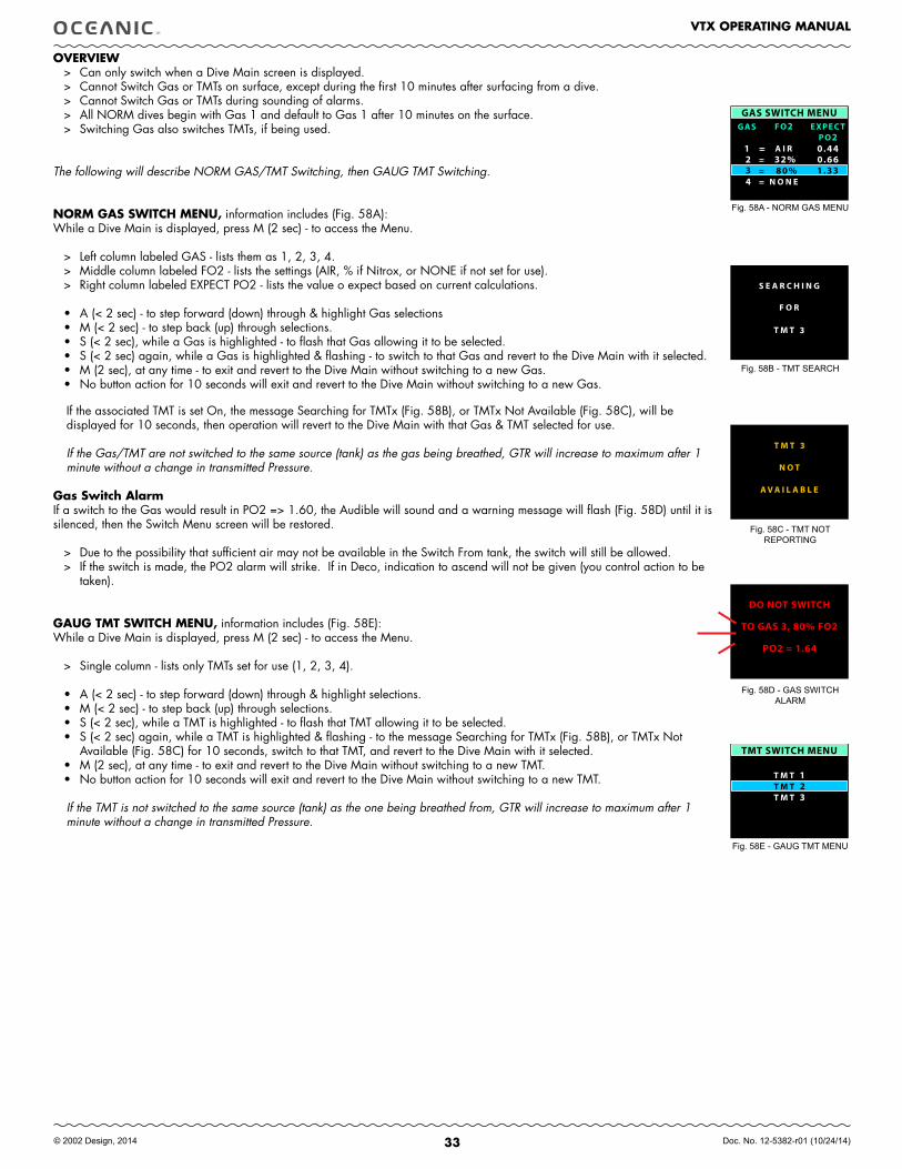
33
VTX OPERATING MANUAL
© 2002 Design, 2014 Doc. No. 12-5382-r01 (10/24/14)
OVERVIEW> Can only switch when a Dive Main screen is displayed.> Cannot Switch Gas or TMTs on surface, except during the first 10 minutes after surfacing from a dive.> Cannot Switch Gas or TMTs during sounding of alarms.> All NORM dives begin with Gas 1 and default to Gas 1 after 10 minutes on the surface.> Switching Gas also switches TMTs, if being used.
The following will describe NORM GAS/TMT Switching, then GAUG TMT Switching.
NORM GAS SWITCH MENU, information includes (Fig. 58A):While a Dive Main is displayed, press M (2 sec) - to access the Menu.
> Left column labeled GAS - lists them as 1, 2, 3, 4.> Middle column labeled FO2 - lists the settings (AIR, % if Nitrox, or NONE if not set for use).> Right column labeled EXPECT PO2 - lists the value o expect based on current calculations.
• A (< 2 sec) - to step forward (down) through & highlight Gas selections• M (< 2 sec) - to step back (up) through selections.• S (< 2 sec), while a Gas is highlighted - to flash that Gas allowing it to be selected.• S (< 2 sec) again, while a Gas is highlighted & flashing - to switch to that Gas and revert to the Dive Main with it selected.• M (2 sec), at any time - to exit and revert to the Dive Main without switching to a new Gas.• No button action for 10 seconds will exit and revert to the Dive Main without switching to a new Gas.
If the associated TMT is set On, the message Searching for TMTx (Fig. 58B), or TMTx Not Available (Fig. 58C), will be displayed for 10 seconds, then operation will revert to the Dive Main with that Gas & TMT selected for use.
If the Gas/TMT are not switched to the same source (tank) as the gas being breathed, GTR will increase to maximum after 1 minute without a change in transmitted Pressure.
Gas Switch AlarmIf a switch to the Gas would result in PO2 => 1.60, the Audible will sound and a warning message will flash (Fig. 58D) until it is silenced, then the Switch Menu screen will be restored.
> Due to the possibility that sufficient air may not be available in the Switch From tank, the switch will still be allowed. > If the switch is made, the PO2 alarm will strike. If in Deco, indication to ascend will not be given (you control action to be
taken).
GAUG TMT SWITCH MENU, information includes (Fig. 58E):While a Dive Main is displayed, press M (2 sec) - to access the Menu.
> Single column - lists only TMTs set for use (1, 2, 3, 4).
• A (< 2 sec) - to step forward (down) through & highlight selections.• M (< 2 sec) - to step back (up) through selections.• S (< 2 sec), while a TMT is highlighted - to flash that TMT allowing it to be selected.• S (< 2 sec) again, while a TMT is highlighted & flashing - to the message Searching for TMTx (Fig. 58B), or TMTx Not
Available (Fig. 58C) for 10 seconds, switch to that TMT, and revert to the Dive Main with it selected.• M (2 sec), at any time - to exit and revert to the Dive Main without switching to a new TMT.• No button action for 10 seconds will exit and revert to the Dive Main without switching to a new TMT.
If the TMT is not switched to the same source (tank) as the one being breathed from, GTR will increase to maximum after 1 minute without a change in transmitted Pressure.
Fig. 58A - NORM GAS MENU
Fig. 58D - GAS SWITCH ALARM
Fig. 58C - TMT NOT REPORTING
Fig. 58B - TMT SEARCH
Fig. 58E - GAUG TMT MENU
GAS SWITCH MENUGAS FO2 EXPEC T
PO21
32% 0.660.44
2
4
== A I R
N O N E
=
=1.33 80% 3 =
S E A R C H I N G
F O R
T M T 3
A V A I L A B L E
T M T 3
N O T
DO NOT SWITCH
PO2 = 1.64
TO GAS 3, 80% FO2
TMT SWITCH MENU
T M T 1T M T 2
= T M T 3
34
VTX OPERATING MANUAL
© 2002 Design, 2014 Doc. No. 12-5382-r01 (10/24/14)
GAUG
OP MODE
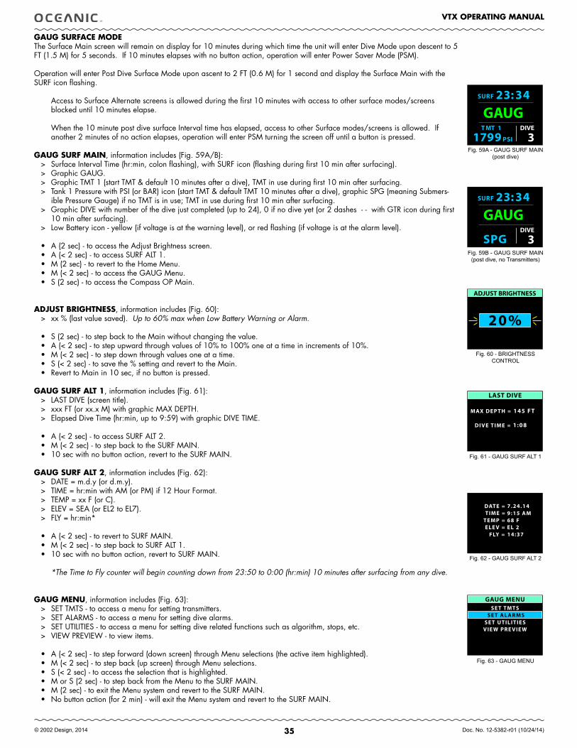
35
VTX OPERATING MANUAL
© 2002 Design, 2014 Doc. No. 12-5382-r01 (10/24/14)
GAUG SURfACE MODE The Surface Main screen will remain on display for 10 minutes during which time the unit will enter Dive Mode upon descent to 5 FT (1.5 M) for 5 seconds. If 10 minutes elapses with no button action, operation will enter Power Saver Mode (PSM).
Operation will enter Post Dive Surface Mode upon ascent to 2 FT (0.6 M) for 1 second and display the Surface Main with the SURF icon flashing.
Access to Surface Alternate screens is allowed during the first 10 minutes with access to other surface modes/screens blocked until 10 minutes elapse.
When the 10 minute post dive surface Interval time has elapsed, access to other Surface modes/screens is allowed. If another 2 minutes of no action elapses, operation will enter PSM turning the screen off until a button is pressed.
GAUG SURf MAIN, information includes (Fig. 59A/B):> Surface Interval Time (hr:min, colon flashing), with SURF icon (flashing during first 10 min after surfacing).> Graphic GAUG.> Graphic TMT 1 (start TMT & default 10 minutes after a dive), TMT in use during first 10 min after surfacing.> Tank 1 Pressure with PSI (or BAR) icon (start TMT & default TMT 10 minutes after a dive), graphic SPG (meaning Submers-
ible Pressure Gauge) if no TMT is in use; TMT in use during first 10 min after surfacing.> Graphic DIVE with number of the dive just completed (up to 24), 0 if no dive yet (or 2 dashes - - with GTR icon during first
10 min after surfacing). > Low Battery icon - yellow (if voltage is at the warning level), or red flashing (if voltage is at the alarm level).
• A (2 sec) - to access the Adjust Brightness screen.• A (< 2 sec) - to access SURF ALT 1.• M (2 sec) - to revert to the Home Menu.• M (< 2 sec) - to access the GAUG Menu.• S (2 sec) - to access the Compass OP Main.
ADJUST BRIGHTNESS, information includes (Fig. 60):> xx % (last value saved). Up to 60% max when Low Battery Warning or Alarm.
• S (2 sec) - to step back to the Main without changing the value.• A (< 2 sec) - to step upward through values of 10% to 100% one at a time in increments of 10%.• M (< 2 sec) - to step down through values one at a time. • S (< 2 sec) - to save the % setting and revert to the Main.• Revert to Main in 10 sec, if no button is pressed.
GAUG SURf ALT 1, information includes (Fig. 61):> LAST DIVE (screen title).> xxx FT (or xx.x M) with graphic MAX DEPTH.> Elapsed Dive Time (hr:min, up to 9:59) with graphic DIVE TIME.
• A (< 2 sec) - to access SURF ALT 2.• M (< 2 sec) - to step back to the SURF MAIN.• 10 sec with no button action, revert to the SURF MAIN.
GAUG SURf ALT 2, information includes (Fig. 62):> DATE = m.d.y (or d.m.y). > TIME = hr:min with AM (or PM) if 12 Hour Format. > TEMP = xx F (or C).> ELEV = SEA (or EL2 to EL7).> FLY = hr:min*
• A (< 2 sec) - to revert to SURF MAIN.• M (< 2 sec) - to step back to SURF ALT 1.• 10 sec with no button action, revert to SURF MAIN.
*The Time to Fly counter will begin counting down from 23:50 to 0:00 (hr:min) 10 minutes after surfacing from any dive.
GAUG MENU, information includes (Fig. 63): > SET TMTS - to access a menu for setting transmitters.> SET ALARMS - to access a menu for setting dive alarms.> SET UTILITIES - to access a menu for setting dive related functions such as algorithm, stops, etc.> VIEW PREVIEW - to view items. • A (< 2 sec) - to step forward (down screen) through Menu selections (the active item highlighted). • M (< 2 sec) - to step back (up screen) through Menu selections. • S (< 2 sec) - to access the selection that is highlighted.• M or S (2 sec) - to step back from the Menu to the SURF MAIN.• M (2 sec) - to exit the Menu system and revert to the SURF MAIN.• No button action (for 2 min) - will exit the Menu system and revert to the SURF MAIN.
Fig. 59A - GAUG SURF MAIN (post dive)
SURF 2 3 : 3 4
T MT 1
SP I1 79 9 3
GAUG DIVE
SURF 2 3 : 3 4
3
GAUG SPG
DIVE
Fig. 59B - GAUG SURF MAIN (post dive, no Transmitters)
Fig. 60 - BRIGHTNESS CONTROL
Fig. 61 - GAUG SURF ALT 1
Fig. 62 - GAUG SURF ALT 2
20%
ADJUST BRIGHTNESS
LAST DIVE
DIVE TIME =
MAX DEPTH =
1:08
145 FT
TIME =TEMP =
SHORTCUTFLY =
DATE =
ELE V =
7.24.149:15 AM68 FEL 214:37
GAUG MENUSE T TMTS
SE T UTILITIESVIE W PRE VIE W
SE T AL ARMS
Fig. 63 - GAUG MENU
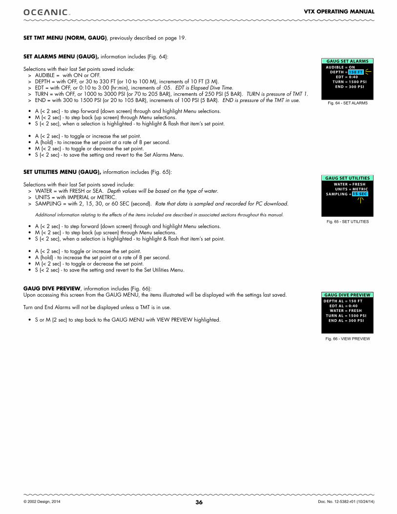
36
VTX OPERATING MANUAL
© 2002 Design, 2014 Doc. No. 12-5382-r01 (10/24/14)
SET TMT MENU (NORM, GAUG), previously described on page 19.
SET ALARMS MENU (GAUG), information includes (Fig. 64):
Selections with their last Set points saved include:> AUDIBLE = with ON or OFF.> DEPTH = with OFF, or 30 to 330 FT (or 10 to 100 M), increments of 10 FT (3 M).> EDT = with OFF, or 0:10 to 3:00 (hr:min), increments of :05. EDT is Elapsed Dive Time.> TURN = with OFF, or 1000 to 3000 PSI (or 70 to 205 BAR), increments of 250 PSI (5 BAR). TURN is pressure of TMT 1.> END = with 300 to 1500 PSI (or 20 to 105 BAR), increments of 100 PSI (5 BAR). END is pressure of the TMT in use.
• A (< 2 sec) - to step forward (down screen) through and highlight Menu selections. • M (< 2 sec) - to step back (up screen) through Menu selections. • S (< 2 sec), when a selection is highlighted - to highlight & flash that item’s set point.
• A (< 2 sec) - to toggle or increase the set point.• A (hold) - to increase the set point at a rate of 8 per second. • M (< 2 sec) - to toggle or decrease the set point. • S (< 2 sec) - to save the setting and revert to the Set Alarms Menu.
SET UTILITIES MENU (GAUG), information includes (Fig. 65):
Selections with their last Set points saved include:> WATER = with FRESH or SEA. Depth values will be based on the type of water.> UNITS = with IMPERIAL or METRIC.> SAMPLING = with 2, 15, 30, or 60 SEC (second). Rate that data is sampled and recorded for PC download.
Additional information relating to the effects of the items included are described in associated sections throughout this manual.
• A (< 2 sec) - to step forward (down screen) through and highlight Menu selections. • M (< 2 sec) - to step back (up screen) through Menu selections. • S (< 2 sec), when a selection is highlighted - to highlight & flash that item’s set point.
• A (< 2 sec) - to toggle or increase the set point.• A (hold) - to increase the set point at a rate of 8 per second. • M (< 2 sec) - to toggle or decrease the set point. • S (< 2 sec) - to save the setting and revert to the Set Utilities Menu.
GAUG DIVE PREVIEW, information includes (Fig. 66):Upon accessing this screen from the GAUG MENU, the items illustrated will be displayed with the settings last saved.
Turn and End Alarms will not be displayed unless a TMT is in use.
• S or M (2 sec) to step back to the GAUG MENU with VIEW PREVIEW highlighted.
Fig. 64 - SET ALARMS
Fig. 65 - SET UTILITIES
Fig. 66 - VIEW PREVIEW
GAUG SET ALARMSAUDIBLE =
EDT =TURN =
END =
DEPTH =ON150 FT0:401500 PSI300 PSI
GAUG SET UTILITIESWATER =
SAMPLING =UNITS =
15 SEC
FRESHME TRIC
DEPTH AL =EDT AL =
TURN AL =END AL =
WATER =
GAUG DIVE PREVIEW150 FT0:40
1500 PSI300 PSI
FRESH
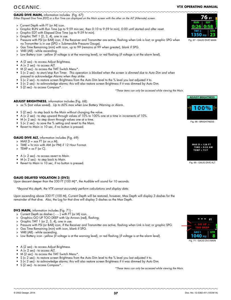
37
VTX OPERATING MANUAL
© 2002 Design, 2014 Doc. No. 12-5382-r01 (10/24/14)
FT
GAS 1 GTR
PSI1040 8
- - - AR
GO UPTOO DEEP
GAUG DIVE MAIN, information includes (Fig. 67):Either Elapsed Dive Time (EDT) or a Run Time can displayed on the Main screen with the other on the ALT (Alternate) screen.
> Current Depth with FT (or M) icon.> Graphic RUN with Run Time (up to 9:59 min:sec, then 0:10 to 9:59 hr:min), 0:00 until started and after reset.> Graphic EDT with Elapsed Dive Time (up to 9:59 hr:min).> Graphic TMT 1 (2, 3, 4), one in use.> Pressure with PSI (or BAR) icon, if the Receiver and Transmitter are active, flashing when Link is lost; or graphic SPG when
no Transmitter is in use (SPG = Submersible Pressure Gauge).> Gas Time Remaining (min) with icon, up to 99 (remains at 99 when greater), blank if SPG.> VARI (AR) - while ascending.> Low Battery icon - yellow (if voltage is at the warning level), or red flashing (if voltage is at the alarm level).
• A (2 sec) - to access Adjust Brightness.• A (< 2 sec) - to access ALT.• M (2 sec) - to access the TMT Switch Menu*.• S (< 2 sec) - to start/stop Run Timer. This operation is blocked when the screen is dimmed due to Auto Dim and when
pressed to acknowledge Alarms when they strike.• S (< 2 sec) - to restore screen Brightness from the Auto Dim level to the % level you last adjusted it to.• S (< 2 sec) - to acknowledge alarms; this will also restore screen Brightness if it was dimmed by Auto Dim.• S (2 sec) - to access Compass*.
*These items can only be accessed while viewing the Main.
ADJUST BRIGHTNESS, information includes (Fig. 68):> xx % (last value saved). Up to 60% max when Low Battery Warning or Alarm.
• S (2 sec) - to step back to the Main without changing the value.• A (< 2 sec) - to step upward through values of 10% to 100% one at a time in increments of 10%.• M (< 2 sec) - to step down through values one at a time. • S (< 2 sec) - to save the % setting and revert to the Main.• Revert to Main in 10 sec, if no button is pressed.
GAUG DIVE ALT, information includes (Fig. 69):> MAX D = xxx FT (or xx.x M).> TIME = hr:min with AM (or PM) if 12 Hour Format.> TEMP = xx F (or C).
• A (< 2 sec) - to access revert to Main.• M (< 2 sec) - to step back to Main.• Revert to Main in 10 sec, if no button is pressed.
GAUG DELAYED VIOLATION 3 (DV3)Upon descent deeper than the 330 FT (100 M)*, the Audible will sound for 10 seconds.
*Beyond this depth, the VTX cannot accurately perform calculations and display data.
Upon ascending above 330 FT (100 M), Current Depth will be restored, however, Max Depth will display 3 dashes for the remainder of that dive. Also, the Log for that dive will display 3 dashes as the Max Depth.
DV3 MAIN, information includes (Fig. 71) -> Current Depth as dashes ( - - - ) with FT (or M) icon.> Graphics GO UP TOO DEEP with Up Arrows (red), flashing.> Graphic TMT 1 (or 2, 3, 4), one in use.> Pressure with PSI (or BAR) icon, if the Receiver and Transmitter are active, flashing when Link is lost; or graphic SPG.> Gas Time Remaining (min) with icon, blank if SPG.> VARI (AR) - while ascending.> Low Battery icon - yellow (if voltage is at the warning level), or red flashing (if voltage is at the alarm level).
• A (2 sec) - to access Adjust Brightness.• A (< 2 sec) - to access ALT.• M (2 sec) - to access the TMT Switch Menu*.• S (< 2 sec) - to restore screen Brightness from the Auto Dim level to the % level you last adjusted it to.• S (< 2 sec) - to acknowledge alarms; this will also restore screen Brightness if it was dimmed by Auto Dim.• S (2 sec) - to access Compass*.
*These items can only be accessed while viewing the Main.
Fig. 67 - GAUG DIVE MAIN
Fig. 69 - GAUG DIVE ALT
F76 FT
TMT 2 GTR
PSI1350 23
AR0:26 RUN
0:58 EDT
TIME =TEMP =
MAX D = 128 FT9:52 AM73 F
100%
ADJUST BRIGHTNESS
Fig. 68 - BRIGHTNESS
Fig. 71 - GAUG DV3 MAIN
38
VTX OPERATING MANUAL
© 2002 Design, 2014 Doc. No. 12-5382-r01 (10/24/14)
fREE DIVE
OP MODE
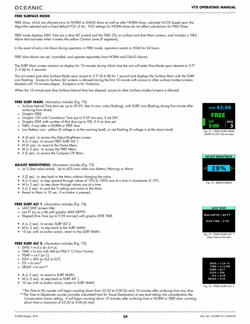
39
VTX OPERATING MANUAL
© 2002 Design, 2014 Doc. No. 12-5382-r01 (10/24/14)
fREE SURfACE MODE
FREE dives, which are allowed prior to NORM or GAUG dives as well as after NORM dives, calculate Ni-O2 based upon the Algorithm selected and a fixed default FO2 of Air. FO2 settings for NORM dives do not affect calculations for FREE Dives.
FREE mode displays NDC Time (on a dive ALT screen) and the TLBG (TL) on surface and dive Main screens, and includes a TLBG Alarm that activates when it enters the yellow Caution zone (9 segments).
In the event of entry into Deco during operation in FREE mode, operation reverts to VGM for 24 hours.
FREE dive alarms are set, controlled, and operate separately from NORM and GAUG Alarms.
The SURF Main screen remains on display for 10 minutes during which time the unit will enter Dive Mode upon descent to 5 FT (1.5 M) for 5 seconds.
The unit enters post dive Surface Mode upon ascent to 2 FT (0.6 M) for 1 second and displays the Surface Main with the SURF icon flashing. Access to Surface ALT screens is allowed during the first 10 minute with access to other surface modes/screens blocked until 10 minutes elapse. Exception is for Violations.
When the 10 minute post dive Surface Interval time has elapsed, access to other Surface modes/screens is allowed.
fREE SURf MAIN, information includes (Fig. 72):> Surface Interval Time (min:sec up to 59:59, then hr:min, colon flashing), with SURF icon (flashing during first minute after
surfacing from dives).> Graphic FREE.> Graphic CDT with Countdown Time (up to 9:59 min:sec), if set ON.> Graphic DIVE with number of that dive (up to 99), 0 if no dive yet.> TLBG, if any after a NORM or FREE dive. > Low Battery icon - yellow (if voltage is at the warning level), or red flashing (if voltage is at the alarm level).
• A (2 sec) - to access the Adjust Brightness screen.• A (< 2 sec) - to access FREE SURF ALT 1.• M (2 sec) - to revert to the Home Menu.• M (< 2 sec) - to access the FREE Menu.• S (2 sec) - to access the Compass OP Main.
ADJUST BRIGHTNESS, information includes (Fig. 73):> xx % (last value saved). Up to 60% max when Low Battery Warning or Alarm.
• S (2 sec) - to step back to the Main without changing the value.• A (< 2 sec) - to step upward through values of 10% to 100% one at a time in increments of 10%.• M (< 2 sec) - to step down through values one at a time. • S (< 2 sec) - to save the % setting and revert to the Main.• Revert to Main in 10 sec, if no button is pressed.
fREE SURf ALT 1, information includes (Fig. 74):> LAST DIVE (screen title).> xxx FT (or xx.x M) with graphic MAX DEPTH.> Elapsed Dive Time (up to 9:59 min:sec) with graphic DIVE TIME.
• A (< 2 sec) - to access SURF ALT 2.• M (< 2 sec) - to step back to the SURF MAIN.• 10 sec with no button action, revert to the SURF MAIN.
fREE SURf ALT 2, information includes (Fig. 75):> DATE = m.d.y (or d.m.y). > TIME = hr:min with AM (or PM) if 12 Hour Format. > TEMP = xx F (or C).> ELEV = SEA (or EL2 to EL7).> FLY = hr:min*> DESAT = hr:min**
• A (< 2 sec) - to revert to SURF MAIN.• M (< 2 sec) - to step back to SURF ALT 1.• 10 sec with no button action, revert to SURF MAIN.
*The Time to Fly counter will begin counting down from 23:50 to 0:00 (hr:min) 10 minutes after surfacing from any dive.**The Time to Desaturate counter provides calculated time for Tissue Desatuation at sea level taking into consideration the
Conservation Factor setting. It will begin counting down 10 minutes after surfacing from a NORM or FREE dive, counting down from a maximum of 23:50 to 0:00 (hr:min).
Fig. 74 - FREE SURF ALT 1 (Dive Time is min:sec)
Fig. 72 - FREE SURF MAIN(SURF & CDT are min:sec)
Fig. 75 - FREE SURF ALT 2
FREE CDT
5:00 3
SURF 4 2 : 0 6
DIVE
LAST DIVE
DIVE TIME =
MAX DEPTH =
2:16
64 FT
TIME =TEMP =
SHORTCUTFLY =
DATE =
ELE V =
7.24.143:15 PM82 FSEA6:28
DESAT = 0:54
20%
ADJUST BRIGHTNESS
Fig. 73 - BRIGHTNESS
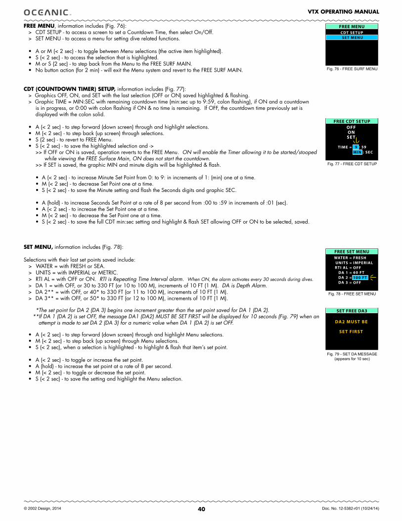
40
VTX OPERATING MANUAL
© 2002 Design, 2014 Doc. No. 12-5382-r01 (10/24/14)
fREE MENU, information includes (Fig. 76): > CDT SETUP - to access a screen to set a Countdown Time, then select On/Off.> SET MENU - to access a menu for setting dive related functions. • A or M (< 2 sec) - to toggle between Menu selections (the active item highlighted). • S (< 2 sec) - to access the selection that is highlighted.• M or S (2 sec) - to step back from the Menu to the FREE SURF MAIN.• No button action (for 2 min) - will exit the Menu system and revert to the FREE SURF MAIN.
CDT (COUNTDOWN TIMER) SETUP, information includes (Fig. 77):> Graphics OFF, ON, and SET with the last selection (OFF or ON) saved highlighted & flashing.> Graphic TIME = MIN:SEC with remaining countdown time (min:sec up to 9:59, colon flashing), if ON and a countdown
is in progress, or 0:00 with colon flashing if ON & no time is remaining. If OFF, the countdown time previously set is displayed with the colon solid.
• A (< 2 sec) - to step forward (down screen) through and highlight selections.• M (< 2 sec) - to step back (up screen) through selections.• S (2 sec) - to revert to FREE Menu.• S (< 2 sec) - to save the highlighted selection and ->
>> If OFF or ON is saved, operation reverts to the FREE Menu. ON will enable the Timer allowing it to be started/stooped while viewing the FREE Surface Main, ON does not start the countdown.
>> If SET is saved, the graphic MIN and minute digits will be highlighted & flash.
• A (< 2 sec) - to increase Minute Set Point from 0: to 9: in increments of 1: (min) one at a time.• M (< 2 sec) - to decrease Set Point one at a time.• S (< 2 sec) - to save the Minute setting and flash the Seconds digits and graphic SEC.
• A (hold) - to increase Seconds Set Point at a rate of 8 per second from :00 to :59 in increments of :01 (sec). • A (< 2 sec) - to increase the Set Point one at a time.• M (< 2 sec) - to decrease the Set Point one at a time.• S (< 2 sec) - to save the full CDT min:sec setting and highlight & flash SET allowing OFF or ON to be selected, saved.
SET MENU, information includes (Fig. 78):
Selections with their last set points saved include:> WATER = with FRESH or SEA.> UNITS = with IMPERIAL or METRIC.> RTI AL = with OFF or ON. RTI is Repeating Time Interval alarm. When ON, the alarm activates every 30 seconds during dives.> DA 1 = with OFF, or 30 to 330 FT (or 10 to 100 M), increments of 10 FT (1 M). DA is Depth Alarm.> DA 2** = with OFF, or 40* to 330 FT (or 11 to 100 M), increments of 10 FT (1 M).> DA 3** = with OFF, or 50* to 330 FT (or 12 to 100 M), increments of 10 FT (1 M).
*The set point for DA 2 (DA 3) begins one increment greater than the set point saved for DA 1 (DA 2). **If DA 1 (DA 2) is set OFF, the message DA1 (DA2) MUST BE SET FIRST will be displayed for 10 seconds (Fig. 79) when an
attempt is made to set DA 2 (DA 3) for a numeric value when DA 1 (DA 2) is set OFF.
• A (< 2 sec) - to step forward (down screen) through and highlight Menu selections. • M (< 2 sec) - to step back (up screen) through Menu selections. • S (< 2 sec), when a selection is highlighted - to highlight & flash that item’s set point.
• A (< 2 sec) - to toggle or increase the set point.• A (hold) - to increase the set point at a rate of 8 per second. • M (< 2 sec) - to toggle or decrease the set point. • S (< 2 sec) - to save the setting and highlight the Menu selection.
Fig. 78 - FREE SET MENU
Fig. 77 - FREE CDT SETUP
Fig. 76 - FREE SURF MENU
FREE MENUCDT SE TUPSE T MENU
FREE CDT SETUPOFF ON SE T
TIME = 9 : 59MIN : SEC
FREE SET MENU WATER =
RTI AL = DA 1 = DA 2 = DA 3 =
UNITS =
60 FT
FRESHIMPERIALOFF
100 FTOFF
SET FREE DA3
DA2 MUST BE
SE T FIRST
Fig. 79 - SET DA MESSAGE(appears for 10 sec)
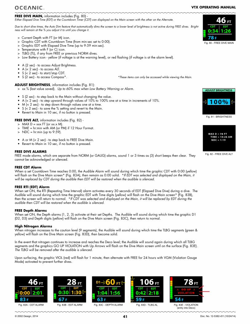
41
VTX OPERATING MANUAL
© 2002 Design, 2014 Doc. No. 12-5382-r01 (10/24/14)
fREE DIVE MAIN, information includes (Fig. 80) -Either Elapsed Dive Time (EDT) or the Countdown Timer (CDT) can displayed on the Main screen with the other on the Alternate.
Due to short dive times, the Auto Dim feature that automatically dims the screen to a lower level of brightness is not active during FREE dives. Bright-ness will remain at the % you adjust it to until you change it.
> Current Depth with FT (or M) icon.> Graphic CDT with Countdown Time (from min:sec set to 0:00).> Graphic EDT with Elapsed Dive Time (up to 9:59 min:sec).> Temperature with F (or C) icon.> TLBG (TL), if any from FREE or previous NORM dives.> Low Battery icon - yellow (if voltage is at the warning level), or red flashing (if voltage is at the alarm level).
• A (2 sec) - to access Adjust Brightness.• A (< 2 sec) - to access ALT.• S (< 2 sec) - to start/stop CDT.• S (2 sec) - to access Compass*. *These items can only be accessed while viewing the Main.
ADJUST BRIGHTNESS, information includes (Fig. 81):> xx % (last value saved). Up to 60% max when Low Battery Warning or Alarm.
• S (2 sec) - to step back to the Main without changing the value.• A (< 2 sec) - to step upward through values of 10% to 100% one at a time in increments of 10%.• M (< 2 sec) - to step down through values one at a time. • S (< 2 sec) - to save the % setting and revert to the Main.• Revert to Main in 10 sec, if no button is pressed.
fREE DIVE ALT, information includes (Fig. 82) -> MAX D = xxx FT (or xx.x M).> TIME = hr:min with AM (or PM) if 12 Hour Format.> NDC = hr:min (up to 9:59).
• A or M (< 2 sec) - to step back to FREE Dive Main.• Revert to Main in 10 sec, if no button is pressed.
fREE DIVE ALARMSFREE mode alarms, which are separate from NORM (or GAUG) alarms, sound 1 or 3 times as (3) short beeps then clear. They cannot be acknowledged or silenced.
fREE CDT AlarmWhen a set Countdown Time reaches 0:00, the Audible Alarm will sound during which time the graphic CDT with 0:00 (yellow) will flash on the Dive Main screen* (Fig. 83A), then remain as 0:00 solid. *If EDT was selected and displayed on the Main, it will be replaced by CDT during the audible then EDT will be restored when the audible is silenced.
fREE RTI (EDT) AlarmWhen set ON, the RTI (Repeating Time Interval) alarm activates every 30 seconds of EDT (Elapsed Dive Dive) during a dive. The Audible will sound during which time the graphic EDT with Time digits (yellow) will flash on the Dive Main screen* (Fig. 83B), then the screen will return to normal. *If CDT was selected and displayed on the Main, it will be replaced by EDT during the audible then CDT will be restored when the audible is silenced. fREE Depth AlarmsWhen set ON, the Depth alarms (1, 2, 3) activate at their set Depths. The Audible will sound during which time the graphic D1 (D2, D3) and Depth digits (yellow) will flash on the Dive Main screen (Fig. 83C), then return to normal.
High Nitrogen AlarmsWhen nitrogen increases to the caution level (9 segments), the Audible will sound during which time the TLBG segments (green & yellow) will flash on the Dive Main screen (Fig. 83D), then become solid.
In the event that nitrogen continues to increase and reaches the Deco level; the Audible will sound again during which all TLBG segments and the graphics GO UP VIOLATION with Up Arrows will flash on the Dive Main screen until on the surface (Fig. 83E). The TLBG will be removed after the audible is silenced.
Upon surfacing, the graphic VIOL (red) will flash for 1 minute, then alternate with FREE for 24 hours with VGM (Violation Gauge Mode) activated to prevent further dives.
Fig. 80 - FREE DIVE MAIN
Fig. 81 - BRIGHTNESS
Fig. 83B - EDT ALARM Fig. 83C - DEPTH ALARM Fig. 83D - TLBG AL Fig. 83E - VIOLATION(entry into Deco)
Fig. 83A - CDT ALARM
46 FT
F78 TL
0:34 CDT
1:26 EDT
100%
ADJUST BRIGHTNESS
TIME =NDC =
MAX D = 78 FT10:26 AM1:19
Fig. 82 - FREE DIVE ALT
60 FT
F63 TL
D1
1:04 CDT
1:56 EDT
46 FT
F83 TL
0:00 CDT
2:01 EDT
28 FT
F67 TL
0:30 CDT
1:30 EDT
106 FT
F59 TL
0:42 CDT
2:18 EDT
78 FT
F54 TL
GO UPVIOL ATION
42
VTX OPERATING MANUAL
© 2002 Design, 2014 Doc. No. 12-5382-r01 (10/24/14)
ADDITIONAL INfORMATION PERTAINING TO fREE DIVE MODE
Although breathing apparatus is not utilized for fREE Dive activities, nitrogen tissue loading remains a factor. Nitrogen loading is calculated based upon a fixed fO2 of AIR.
Since a user has the option of alternating between NORM (SCUBA) and fREE Dive activities within a 24 hour period, nitrogen calculations and the displayed value of No Deco Dive Time Remaining (NDC Time) are carried over from one operating mode to the other, which permits the user to maintain awareness of nitrogen absorption and offgasing status.
The mathematical models currently used in the VTX are based on no decompression/decompression multilevel repetitive dive schedules.
These algorithms do not take into account the physiological changes associated with the high pressures that competitive type free diving can expose a diver to.
WARNINGS
Ensure that you know which Operating Mode is selected (NORM, GAUG, or fREE) prior to commencing any dive.
Conducting free dives within a 24 hour period after conducting SCUBA dives, combined with the effects of multiple rapid free Dive ascents, increases your risk of decompression sickness. Such activities may result in accelerated entry into decompression which could cause serious injury or death.
Combining competitive type free dive activities that involve multiple descents/ascents with activities utilizing SCUBA during the same 24 hour period is not recommended. Presently, there is no data relating to such activities.
It is highly recommended that anyone planning to become involved in competitive type free dive activities obtain proper instruction and training from a recognized free Diving trainer. It is imperative that the physiological affects be understood and the diver is physically prepared.

43
VTX OPERATING MANUAL
© 2002 Design, 2014 Doc. No. 12-5382-r01 (10/24/14)
COMPASS
MODE
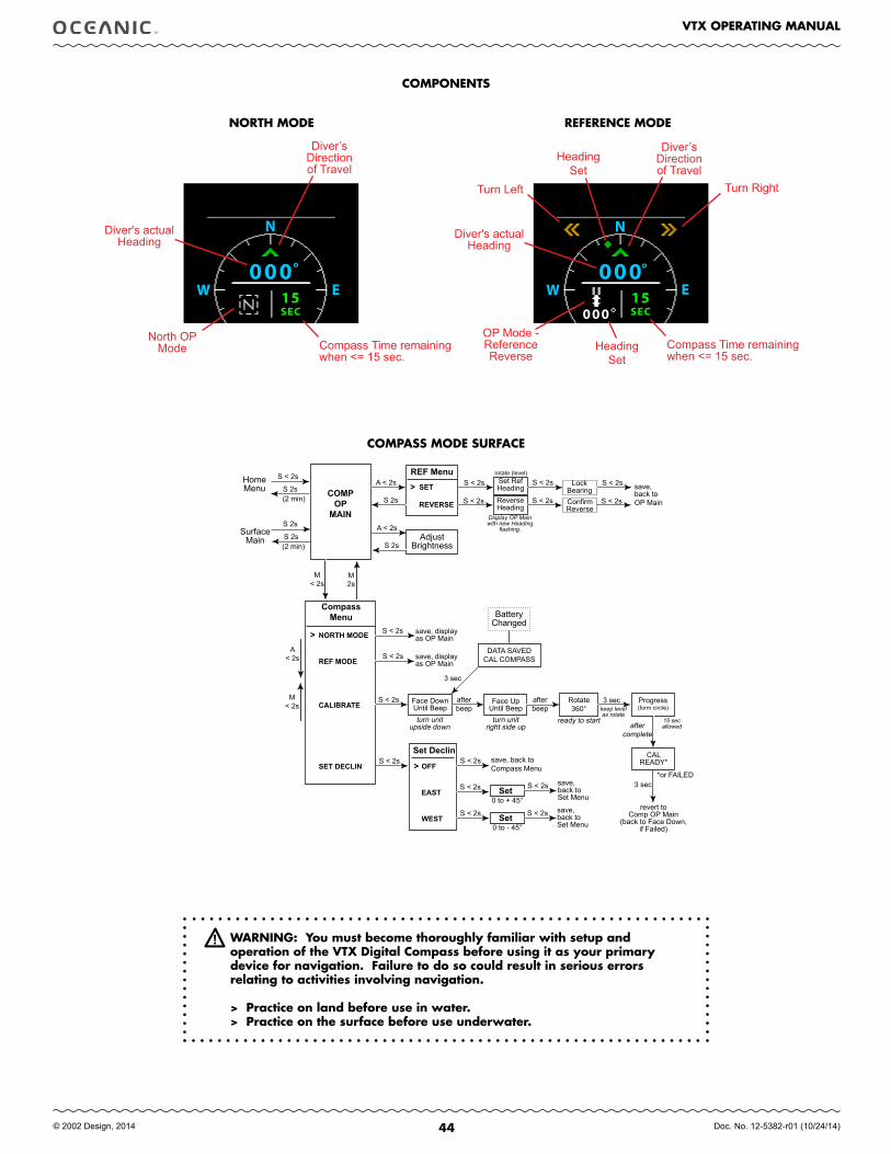
44
VTX OPERATING MANUAL
© 2002 Design, 2014 Doc. No. 12-5382-r01 (10/24/14)
N
EW000
15
°
SEC 000
N
EW000°
15SEC
COMPASS MODE SURfACE
Home Menu
CompassMenu
COMPOP.MAIN
A < 2s
SurfaceMain
M< 2s
A< 2s
M2s
> NORTH.MODE
REF.MODE.
CALIbRATE
SET.DECLIN
M< 2s
S 2s
(2 min)
Face DownUntil Beep
Progress(form circle)
aftercomplete
save, display as OP Main
Set RefHeading save,
back to OP Main
rotate (level)
Set.Declin
> OFF
EAST
WEST
save, back to Compass Menu
Set0 to + 45°
BatteryChanged
DATA SAVEDCAL COMPASS
afterbeep
turn unitupside down
15 sec allowed
Setsave, back to Set Menu0 to - 45°
3 sec
Rotate360°
CALREADY*
3 sec
revert to Comp OP Main
(back to Face Down, if Failed)
*or FAILED
save, display as OP Main
REF.Menu> SET
REVERSE ReverseHeading
LockBearingConfirmReverse
Display OP Main with new Heading
flashing.
Face UpUntil Beepturn unit
right side up
afterbeep
ready to start
3 sec keep levelas rotate
save, back to Set Menu
COMPONENTS
North OP Mode
OP Mode -ReferenceReverse
Turn Left Turn Right
Diver’s Direction of Travel
Diver's actualHeading
Heading Set
Compass Time remaining when <= 15 sec.
WARNING: You must become thoroughly familiar with setup and operation of the VTX Digital Compass before using it as your primary device for navigation. failure to do so could result in serious errors relating to activities involving navigation.
> Practice on land before use in water.> Practice on the surface before use underwater.
Diver's actualHeading
Compass Time remaining when <= 15 sec.
Diver’s Direction of Travel
S 2s
S < 2s
(2 min)S 2s
S 2s
S < 2s
S < 2s
S < 2s
S < 2sS < 2s
S < 2s
A < 2s
S 2sAdjust
Brightness
S < 2s
S < 2s
S < 2s
S < 2s S < 2s
S < 2s
S < 2s
S < 2s
S < 2s
Heading Set
NORTH MODE REfERENCE MODE
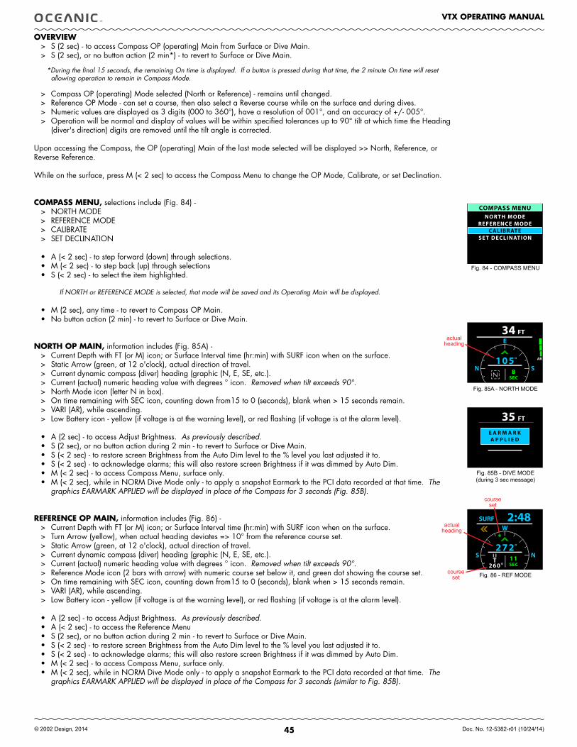
45
VTX OPERATING MANUAL
© 2002 Design, 2014 Doc. No. 12-5382-r01 (10/24/14)
E A R M A R KA P P L I E D
FT35
COMPASS MENUNORTH MODE
REFERENCE MODE
SE T DECLINATIONC ALIBR ATE
FT134E
SN105° AR
8SEC
OVERVIEW> S (2 sec) - to access Compass OP (operating) Main from Surface or Dive Main.> S (2 sec), or no button action (2 min*) - to revert to Surface or Dive Main.
*During the final 15 seconds, the remaining On time is displayed. If a button is pressed during that time, the 2 minute On time will reset allowing operation to remain in Compass Mode.
> Compass OP (operating) Mode selected (North or Reference) - remains until changed.> Reference OP Mode - can set a course, then also select a Reverse course while on the surface and during dives.> Numeric values are displayed as 3 digits (000 to 360°), have a resolution of 001°, and an accuracy of +/- 005°.> Operation will be normal and display of values will be within specified tolerances up to 90° tilt at which time the Heading
(diver's direction) digits are removed until the tilt angle is corrected.
Upon accessing the Compass, the OP (operating) Main of the last mode selected will be displayed >> North, Reference, or Reverse Reference.
While on the surface, press M (< 2 sec) to access the Compass Menu to change the OP Mode, Calibrate, or set Declination.
COMPASS MENU, selections include (Fig. 84) -> NORTH MODE> REFERENCE MODE > CALIBRATE > SET DECLINATION
• A (< 2 sec) - to step forward (down) through selections.• M (< 2 sec) - to step back (up) through selections• S (< 2 sec) - to select the item highlighted.
If NORTH or REFERENCE MODE is selected, that mode will be saved and its Operating Main will be displayed.
• M (2 sec), any time - to revert to Compass OP Main.• No button action (2 min) - to revert to Surface or Dive Main.
NORTH OP MAIN, information includes (Fig. 85A) - > Current Depth with FT (or M) icon; or Surface Interval time (hr:min) with SURF icon when on the surface.> Static Arrow (green, at 12 o'clock), actual direction of travel.> Current dynamic compass (diver) heading (graphic (N, E, SE, etc.).> Current (actual) numeric heading value with degrees ° icon. Removed when tilt exceeds 90°.> North Mode icon (letter N in box).> On time remaining with SEC icon, counting down from15 to 0 (seconds), blank when > 15 seconds remain.> VARI (AR), while ascending.> Low Battery icon - yellow (if voltage is at the warning level), or red flashing (if voltage is at the alarm level).
• A (2 sec) - to access Adjust Brightness. As previously described. • S (2 sec), or no button action during 2 min - to revert to Surface or Dive Main.• S (< 2 sec) - to restore screen Brightness from the Auto Dim level to the % level you last adjusted it to.• S (< 2 sec) - to acknowledge alarms; this will also restore screen Brightness if it was dimmed by Auto Dim.• M (< 2 sec) - to access Compass Menu, surface only.• M (< 2 sec), while in NORM Dive Mode only - to apply a snapshot Earmark to the PCI data recorded at that time. The
graphics EARMARK APPLIED will be displayed in place of the Compass for 3 seconds (Fig. 85B).
REfERENCE OP MAIN, information includes (Fig. 86) - > Current Depth with FT (or M) icon; or Surface Interval time (hr:min) with SURF icon when on the surface.> Turn Arrow (yellow), when actual heading deviates => 10° from the reference course set.> Static Arrow (green, at 12 o'clock), actual direction of travel.> Current dynamic compass (diver) heading (graphic (N, E, SE, etc.).> Current (actual) numeric heading value with degrees ° icon. Removed when tilt exceeds 90°.> Reference Mode icon (2 bars with arrow) with numeric course set below it, and green dot showing the course set.> On time remaining with SEC icon, counting down from15 to 0 (seconds), blank when > 15 seconds remain.> VARI (AR), while ascending.> Low Battery icon - yellow (if voltage is at the warning level), or red flashing (if voltage is at the alarm level).
• A (2 sec) - to access Adjust Brightness. As previously described. • A (< 2 sec) - to access the Reference Menu• S (2 sec), or no button action during 2 min - to revert to Surface or Dive Main.• S (< 2 sec) - to restore screen Brightness from the Auto Dim level to the % level you last adjusted it to.• S (< 2 sec) - to acknowledge alarms; this will also restore screen Brightness if it was dimmed by Auto Dim.• M (< 2 sec) - to access Compass Menu, surface only.• M (< 2 sec), while in NORM Dive Mode only - to apply a snapshot Earmark to the PCI data recorded at that time. The
graphics EARMARK APPLIED will be displayed in place of the Compass for 3 seconds (similar to Fig. 85B).
Fig. 85A - NORTH MODE
Fig. 86 - REF MODE
Fig. 84 - COMPASS MENU
actualheading
courseset
W
NS272°
11SEC260
SURF 2:48actual
heading
Fig. 85B - DIVE MODE(during 3 sec message)
courseset
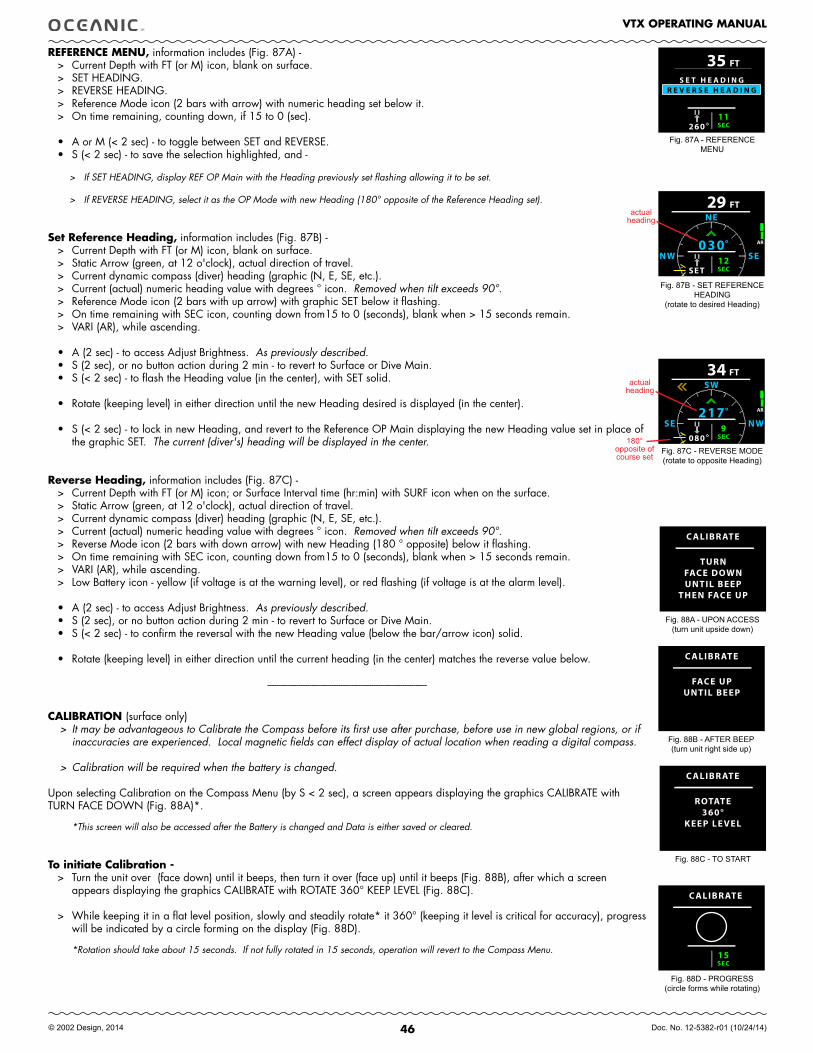
46
VTX OPERATING MANUAL
© 2002 Design, 2014 Doc. No. 12-5382-r01 (10/24/14)
REfERENCE MENU, information includes (Fig. 87A) - > Current Depth with FT (or M) icon, blank on surface.> SET HEADING.> REVERSE HEADING.> Reference Mode icon (2 bars with arrow) with numeric heading set below it.> On time remaining, counting down, if 15 to 0 (sec).
• A or M (< 2 sec) - to toggle between SET and REVERSE.• S (< 2 sec) - to save the selection highlighted, and -
> If SET HEADING, display REF OP Main with the Heading previously set flashing allowing it to be set.
> If REVERSE HEADING, select it as the OP Mode with new Heading (180° opposite of the Reference Heading set).
Set Reference Heading, information includes (Fig. 87B) - > Current Depth with FT (or M) icon, blank on surface.> Static Arrow (green, at 12 o'clock), actual direction of travel.> Current dynamic compass (diver) heading (graphic (N, E, SE, etc.).> Current (actual) numeric heading value with degrees ° icon. Removed when tilt exceeds 90°.> Reference Mode icon (2 bars with up arrow) with graphic SET below it flashing.> On time remaining with SEC icon, counting down from15 to 0 (seconds), blank when > 15 seconds remain.> VARI (AR), while ascending.
• A (2 sec) - to access Adjust Brightness. As previously described. • S (2 sec), or no button action during 2 min - to revert to Surface or Dive Main.• S (< 2 sec) - to flash the Heading value (in the center), with SET solid.
• Rotate (keeping level) in either direction until the new Heading desired is displayed (in the center).
• S (< 2 sec) - to lock in new Heading, and revert to the Reference OP Main displaying the new Heading value set in place of the graphic SET. The current (diver's) heading will be displayed in the center.
Reverse Heading, information includes (Fig. 87C) - > Current Depth with FT (or M) icon; or Surface Interval time (hr:min) with SURF icon when on the surface.> Static Arrow (green, at 12 o'clock), actual direction of travel.> Current dynamic compass (diver) heading (graphic (N, E, SE, etc.).> Current (actual) numeric heading value with degrees ° icon. Removed when tilt exceeds 90°.> Reverse Mode icon (2 bars with down arrow) with new Heading (180 ° opposite) below it flashing.> On time remaining with SEC icon, counting down from15 to 0 (seconds), blank when > 15 seconds remain.> VARI (AR), while ascending.> Low Battery icon - yellow (if voltage is at the warning level), or red flashing (if voltage is at the alarm level).
• A (2 sec) - to access Adjust Brightness. As previously described. • S (2 sec), or no button action during 2 min - to revert to Surface or Dive Main.• S (< 2 sec) - to confirm the reversal with the new Heading value (below the bar/arrow icon) solid.
• Rotate (keeping level) in either direction until the current heading (in the center) matches the reverse value below.
------------------------------------------------------------------------
CALIBRATION (surface only)> It may be advantageous to Calibrate the Compass before its first use after purchase, before use in new global regions, or if
inaccuracies are experienced. Local magnetic fields can effect display of actual location when reading a digital compass.
> Calibration will be required when the battery is changed.
Upon selecting Calibration on the Compass Menu (by S < 2 sec), a screen appears displaying the graphics CALIBRATE with TURN FACE DOWN (Fig. 88A)*.
*This screen will also be accessed after the Battery is changed and Data is either saved or cleared.
To initiate Calibration -> Turn the unit over (face down) until it beeps, then turn it over (face up) until it beeps (Fig. 88B), after which a screen
appears displaying the graphics CALIBRATE with ROTATE 360° KEEP LEVEL (Fig. 88C).
> While keeping it in a flat level position, slowly and steadily rotate* it 360° (keeping it level is critical for accuracy), progress will be indicated by a circle forming on the display (Fig. 88D).
*Rotation should take about 15 seconds. If not fully rotated in 15 seconds, operation will revert to the Compass Menu.
Fig. 87B - SET REFERENCE HEADING
(rotate to desired Heading)
Fig. 88A - UPON ACCESS(turn unit upside down)
Fig. 88B - AFTER BEEP (turn unit right side up)
Fig. 88C - TO START
Fig. 88D - PROGRESS(circle forms while rotating)
Fig. 87C - REVERSE MODE(rotate to opposite Heading)
180°opposite ofcourse set
FT134SW
NWSE217° AR
9SEC080
actualheading
FT129NE
SENW030° AR
12SECSE T
actualheading
C ALIBR ATE
TURNFACE DOWNUNTIL BEEP
THEN FACE UP
C ALIBR ATE
FACE UPUNTIL BEEP
C ALIBR ATE
ROTATE360°
KEEP LE VEL
C ALIBR ATE
15SEC
Fig. 87A - REFERENCE MENU
S E T H E A D I N GR E V E R S E H E A D I N G
11SEC260
FT35
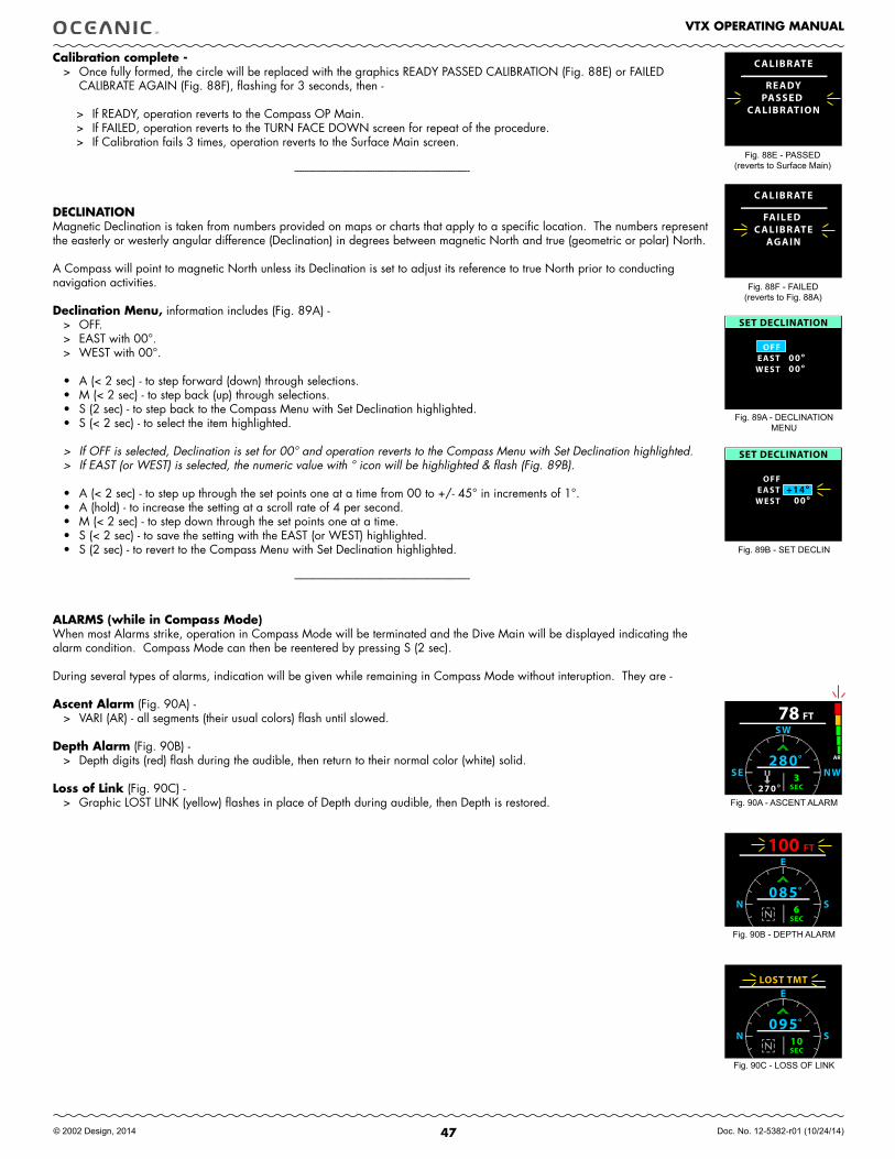
47
VTX OPERATING MANUAL
© 2002 Design, 2014 Doc. No. 12-5382-r01 (10/24/14)
Calibration complete -> Once fully formed, the circle will be replaced with the graphics READY PASSED CALIBRATION (Fig. 88E) or FAILED
CALIBRATE AGAIN (Fig. 88F), flashing for 3 seconds, then -
> If READY, operation reverts to the Compass OP Main.> If FAILED, operation reverts to the TURN FACE DOWN screen for repeat of the procedure. > If Calibration fails 3 times, operation reverts to the Surface Main screen.
------------------------------------------------------------------------
DECLINATION Magnetic Declination is taken from numbers provided on maps or charts that apply to a specific location. The numbers represent the easterly or westerly angular difference (Declination) in degrees between magnetic North and true (geometric or polar) North.
A Compass will point to magnetic North unless its Declination is set to adjust its reference to true North prior to conducting navigation activities.
Declination Menu, information includes (Fig. 89A) -> OFF.> EAST with 00°.> WEST with 00°.
• A (< 2 sec) - to step forward (down) through selections. • M (< 2 sec) - to step back (up) through selections. • S (2 sec) - to step back to the Compass Menu with Set Declination highlighted.• S (< 2 sec) - to select the item highlighted.
> If OFF is selected, Declination is set for 00° and operation reverts to the Compass Menu with Set Declination highlighted.> If EAST (or WEST) is selected, the numeric value with ° icon will be highlighted & flash (Fig. 89B).
• A (< 2 sec) - to step up through the set points one at a time from 00 to +/- 45° in increments of 1°. • A (hold) - to increase the setting at a scroll rate of 4 per second.• M (< 2 sec) - to step down through the set points one at a time. • S (< 2 sec) - to save the setting with the EAST (or WEST) highlighted.• S (2 sec) - to revert to the Compass Menu with Set Declination highlighted.
------------------------------------------------------------------------
ALARMS (while in Compass Mode) When most Alarms strike, operation in Compass Mode will be terminated and the Dive Main will be displayed indicating the alarm condition. Compass Mode can then be reentered by pressing S (2 sec).
During several types of alarms, indication will be given while remaining in Compass Mode without interuption. They are -
Ascent Alarm (Fig. 90A) -> VARI (AR) - all segments (their usual colors) flash until slowed.
Depth Alarm (Fig. 90B) -> Depth digits (red) flash during the audible, then return to their normal color (white) solid.
Loss of Link (Fig. 90C) -> Graphic LOST LINK (yellow) flashes in place of Depth during audible, then Depth is restored.
Fig. 89A - DECLINATION MENU
Fig. 89B - SET DECLIN
Fig. 90A - ASCENT ALARM
Fig. 90B - DEPTH ALARM
Fig. 90C - LOSS OF LINK
SET DECLINATION
OFF
WEST 00°EAST 00°
SET DECLINATION
OFF+14°
WEST 00°EAST
FT178SW
NWSE280° AR
3SEC270
FT1100E
SN085°
6SEC
1E
SN095°
10SEC
LOST TMT
Fig. 88E - PASSED(reverts to Surface Main)
C ALIBR ATE
READYPASSED
C ALIBR ATION
C ALIBR ATE
FAILED C ALIBR ATE
AGAIN
Fig. 88F - FAILED(reverts to Fig. 88A)
48
VTX OPERATING MANUAL
© 2002 Design, 2014 Doc. No. 12-5382-r01 (10/24/14)
NORM/GAUG
DIVE MODE
ALARMS
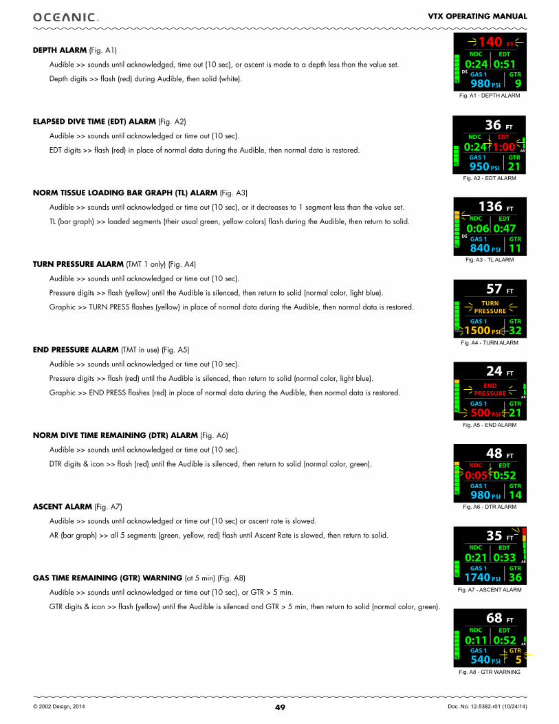
49
VTX OPERATING MANUAL
© 2002 Design, 2014 Doc. No. 12-5382-r01 (10/24/14)
FT
GAS 1 GTR
PSI980 14
48
TL
0:05 NDC
0:52 EDT
FT
GAS 1 GTR
PSI1740 36
35
TL
AR0:21 NDC
0:33 EDT
FT
GAS 1 GTR
PSI540 5
68
TL
AR0:11 NDC
0:52 EDT
FT
GAS 1 GTR
PSI1500 32
57
TL
TURNPRESSURE
FT
GAS 1 GTR
PSI500 21
24
TL
ENDPRESSURE
AR
FT
GAS 1 GTR
PSI980 9
140
TL
DS0:24
NDC
0:51 EDT
FFT
GAS 1 GTR
PSI950 21
36AR
TL
0:24 NDC
1:00 EDT
FT
GAS 1 GTR
PSI840 11
136
TL
DS0:06
NDC
0:47 EDT
DEPTH ALARM (Fig. A1)
Audible >> sounds until acknowledged, time out (10 sec), or ascent is made to a depth less than the value set.
Depth digits >> flash (red) during Audible, then solid (white).
ELAPSED DIVE TIME (EDT) ALARM (Fig. A2)
Audible >> sounds until acknowledged or time out (10 sec).
EDT digits >> flash (red) in place of normal data during the Audible, then normal data is restored.
NORM TISSUE LOADING BAR GRAPH (TL) ALARM (Fig. A3)
Audible >> sounds until acknowledged or time out (10 sec), or it decreases to 1 segment less than the value set.
TL (bar graph) >> loaded segments (their usual green, yellow colors) flash during the Audible, then return to solid.
TURN PRESSURE ALARM (TMT 1 only) (Fig. A4)
Audible >> sounds until acknowledged or time out (10 sec).
Pressure digits >> flash (yellow) until the Audible is silenced, then return to solid (normal color, light blue).
Graphic >> TURN PRESS flashes (yellow) in place of normal data during the Audible, then normal data is restored.
END PRESSURE ALARM (TMT in use) (Fig. A5)
Audible >> sounds until acknowledged or time out (10 sec).
Pressure digits >> flash (red) until the Audible is silenced, then return to solid (normal color, light blue).
Graphic >> END PRESS flashes (red) in place of normal data during the Audible, then normal data is restored.
NORM DIVE TIME REMAINING (DTR) ALARM (Fig. A6)
Audible >> sounds until acknowledged or time out (10 sec).
DTR digits & icon >> flash (red) until the Audible is silenced, then return to solid (normal color, green).
ASCENT ALARM (Fig. A7)
Audible >> sounds until acknowledged or time out (10 sec) or ascent rate is slowed.
AR (bar graph) >> all 5 segments (green, yellow, red) flash until Ascent Rate is slowed, then return to solid.
GAS TIME REMAINING (GTR) WARNING (at 5 min) (Fig. A8)
Audible >> sounds until acknowledged or time out (10 sec), or GTR > 5 min.
GTR digits & icon >> flash (yellow) until the Audible is silenced and GTR > 5 min, then return to solid (normal color, green).
Fig. A1 - DEPTH ALARM
Fig. A2 - EDT ALARM
Fig. A3 - TL ALARM
Fig. A4 - TURN ALARM
Fig. A5 - END ALARM
Fig. A6 - DTR ALARM
Fig. A7 - ASCENT ALARM
Fig. A8 - GTR WARNING
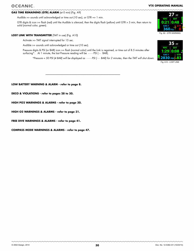
50
VTX OPERATING MANUAL
© 2002 Design, 2014 Doc. No. 12-5382-r01 (10/24/14)
FT
GAS 1 GTR
PSI360 0
27
TL
AR0:21 NDC
0:48 EDT
FT
GAS 1 GTR
PSI2830 83
35AR
TL
1:29 NDC
0:08 EDT
GAS TIME REMAINING (GTR) ALARM (at 0 min) (Fig. A9)
Audible >> sounds until acknowledged or time out (10 sec), or GTR => 1 min.
GTR digits & icon >> flash (red) until the Audible is silenced, then the digits flash (yellow) until GTR > 5 min, then return to solid (normal color, green).
LOST LINK WITH TRANSMITTER (TMT in use) (Fig. A10)
Activate >> TMT signal interrupted for 15 sec.
Audible >> sounds until acknowledged or time out (10 sec).
Pressure digits & PSI (or BAR) icon >> flash (normal color) until the Link is regained, or time out of 8.5 minutes after surfacing*. At 1 minute, the last Pressure reading will be - - - - PSI ( - - BAR).
*Pressure < 50 PSI (4 BAR) will be displayed as - - - - PSI ( - - BAR) for 2 minutes, then the TMT will shut down.
-----------------------------------------------------------------------------------------------------------------
LOW BATTERY WARNING & ALARM - refer to page 8.
DECO & VIOLATIONS - refer to pages 28 to 30.
HIGH PO2 WARNINGS & ALARMS - refer to page 30.
HIGH O2 WARNINGS & ALARMS - refer to page 31.
fREE DIVE WARNINGS & ALARMS - refer to page 41.
COMPASS MODE WARNINGS & ALARMS - refer to page 47.
Fig. A9 - GTR WARNING
Fig. A10 - LOST LINK
51
VTX OPERATING MANUAL
© 2002 Design, 2014 Doc. No. 12-5382-r01 (10/24/14)
REfERENCE
CAUTION: When the procedure provided in this section is used to change the VTX Battery, you must be sure that the case o-ring is not pinched and that the VTX is water tight before conducting diving actvities. Pre dive pressure testing by an Authorized Oceanic facility is highly recommended.
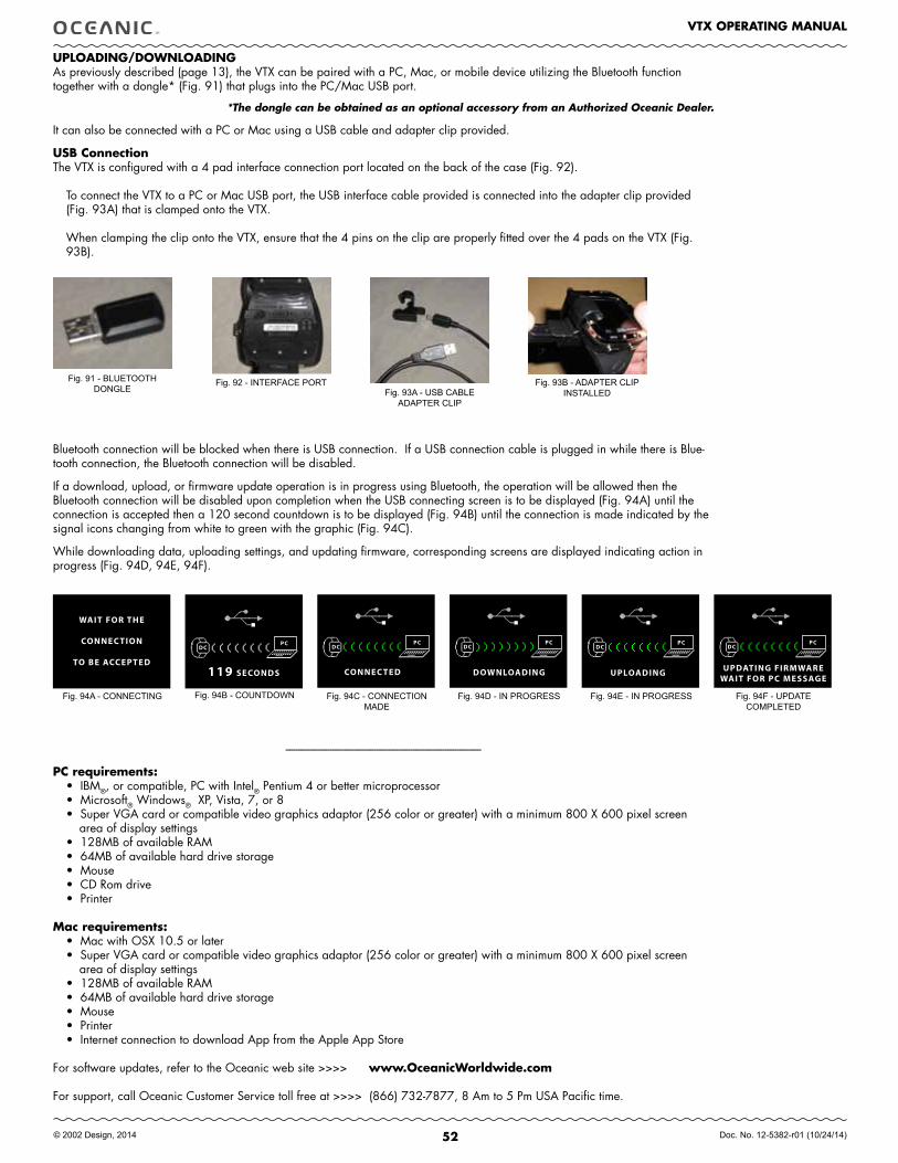
52
VTX OPERATING MANUAL
© 2002 Design, 2014 Doc. No. 12-5382-r01 (10/24/14)
UPLOADING/DOWNLOADING As previously described (page 13), the VTX can be paired with a PC, Mac, or mobile device utilizing the Bluetooth function together with a dongle* (Fig. 91) that plugs into the PC/Mac USB port.
*The dongle can be obtained as an optional accessory from an Authorized Oceanic Dealer.
It can also be connected with a PC or Mac using a USB cable and adapter clip provided.
USB Connection The VTX is configured with a 4 pad interface connection port located on the back of the case (Fig. 92).
To connect the VTX to a PC or Mac USB port, the USB interface cable provided is connected into the adapter clip provided (Fig. 93A) that is clamped onto the VTX.
When clamping the clip onto the VTX, ensure that the 4 pins on the clip are properly fitted over the 4 pads on the VTX (Fig. 93B).
Bluetooth connection will be blocked when there is USB connection. If a USB connection cable is plugged in while there is Blue-tooth connection, the Bluetooth connection will be disabled.
If a download, upload, or firmware update operation is in progress using Bluetooth, the operation will be allowed then the Bluetooth connection will be disabled upon completion when the USB connecting screen is to be displayed (Fig. 94A) until the connection is accepted then a 120 second countdown is to be displayed (Fig. 94B) until the connection is made indicated by the signal icons changing from white to green with the graphic (Fig. 94C).
While downloading data, uploading settings, and updating firmware, corresponding screens are displayed indicating action in progress (Fig. 94D, 94E, 94F).
--------------------------------------------------------------------------------
PC requirements:• IBM®, or compatible, PC with Intel® Pentium 4 or better microprocessor• Microsoft® Windows® XP, Vista, 7, or 8• Super VGA card or compatible video graphics adaptor (256 color or greater) with a minimum 800 X 600 pixel screen
area of display settings• 128MB of available RAM• 64MB of available hard drive storage• Mouse• CD Rom drive• Printer
Mac requirements:• Mac with OSX 10.5 or later• Super VGA card or compatible video graphics adaptor (256 color or greater) with a minimum 800 X 600 pixel screen
area of display settings• 128MB of available RAM• 64MB of available hard drive storage• Mouse• Printer• Internet connection to download App from the Apple App Store
For software updates, refer to the Oceanic web site >>>> www.OceanicWorldwide.com
For support, call Oceanic Customer Service toll free at >>>> (866) 732-7877, 8 Am to 5 Pm USA Pacific time.
Fig. 94B - COUNTDOWN Fig. 94C - CONNECTION MADE
Fig. 94A - CONNECTING Fig. 94D - IN PROGRESS
Fig. 92 - INTERFACE PORT Fig. 93A - USB CABLE
ADAPTER CLIP
Fig. 91 - BLUETOOTH DONGLE
Fig. 93B - ADAPTER CLIPINSTALLED
Fig. 94E - IN PROGRESS Fig. 94F - UPDATECOMPLETED
WAIT FOR THE
CONNEC TION
TO BE ACCEPTED119 SECONDS
DCPC
CONNEC TED
DCPC
DOWNLOADING
DCPC
UPLOADING
DCPC
DCPC
UPDATING FIRMWAREWAIT FOR PC MESSAGE
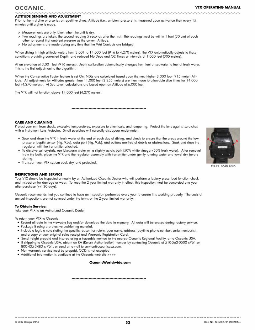
53
VTX OPERATING MANUAL
© 2002 Design, 2014 Doc. No. 12-5382-r01 (10/24/14)
ALTITUDE SENSING AND ADJUSTMENTPrior to the first dive of a series of repetitive dives, Altitude (i.e., ambient pressure) is measured upon activation then every 15 minutes until a dive is made.
> Measurements are only taken when the unit is dry. > Two readings are taken, the second reading 5 seconds after the first. The readings must be within 1 foot (30 cm) of each
other to record that ambient pressure as the current Altitude. > No adjustments are made during any time that the Wet Contacts are bridged.
When diving in high altitude waters from 3,001 to 14,000 feet (916 to 4,270 meters), the VTX automatically adjusts to these conditions providing corrected Depth, and reduced No Deco and O2 Times at intervals of 1,000 feet (305 meters).
At an elevation of 3,001 feet (916 meters), Depth calibration automatically changes from feet of seawater to feet of fresh water. This is the first adjustment to the algorithm.
When the Conservative Factor feature is set On, NDLs are calculated based upon the next higher 3,000 foot (915 meter) Alti-tude. All adjustments for Altitudes greater than 11,000 feet (3,355 meters) are then made to allowable dive times for 14,000 feet (4,270 meters). At Sea Level, calculations are based upon an Altitude of 6,000 feet.
The VTX will not function above 14,000 feet (4,270 meters).
---------------------------------------------------------
CARE AND CLEANINGProtect your unit from shock, excessive temperatures, exposure to chemicals, and tampering. Protect the lens against scratches with a Instrument Lens Protector. Small scratches will naturally disappear underwater.
• Soak and rinse the VTX in fresh water at the end of each day of diving, and check to ensure that the areas around the low pressure (depth) sensor (Fig. 95a), data port (Fig. 95b), and buttons are free of debris or obstructions. Soak and rinse the regulator with the transmitter attached.
• To dissolve salt crystals, use lukewarm water or a slightly acidic bath (50% white vinegar/50% fresh water). After removal from the bath, place the VTX and the regulator assembly with transmitter under gently running water and towel dry before storing.
• Transport your VTX system cool, dry, and protected.
INSPECTIONS AND SERVICEYour VTX should be inspected annually by an Authorized Oceanic Dealer who will perform a factory prescribed function check and inspection for damage or wear. To keep the 2 year limited warranty in effect, this inspection must be completed one year after purchase (+/- 30 days).
Oceanic recommends that you continue to have an inspection performed every year to ensure it is working properly. The costs of annual inspections are not covered under the terms of the 2 year limited warranty.
To Obtain Service:Take your VTX to an Authorized Oceanic Dealer.
To return your VTX to Oceanic:• Record all data in the viewable Log and/or download the data in memory. All data will be erased during factory service. • Package it using a protective cushioning material.• Include a legible note stating the specific reason for return, your name, address, daytime phone number, serial number(s),
and a copy of your original sales receipt and Warranty Registration Card.• Send freight prepaid and insured using a traceable method to the nearest Oceanic Regional Facility, or to Oceanic USA.• If shipping to Oceanic USA, obtain an RA (Return Authorization) number by contacting Oceanic at 510-562-0500 x761 or
800-435-3483 x 761, or send an e-mail to [email protected].• Non warranty service must be prepaid. COD is not accepted. • Additional information is available at the Oceanic web site >>>>
OceanicWorldwide.com
---------------------------------------------------------
Fig. 95 - CASE BACK
ab
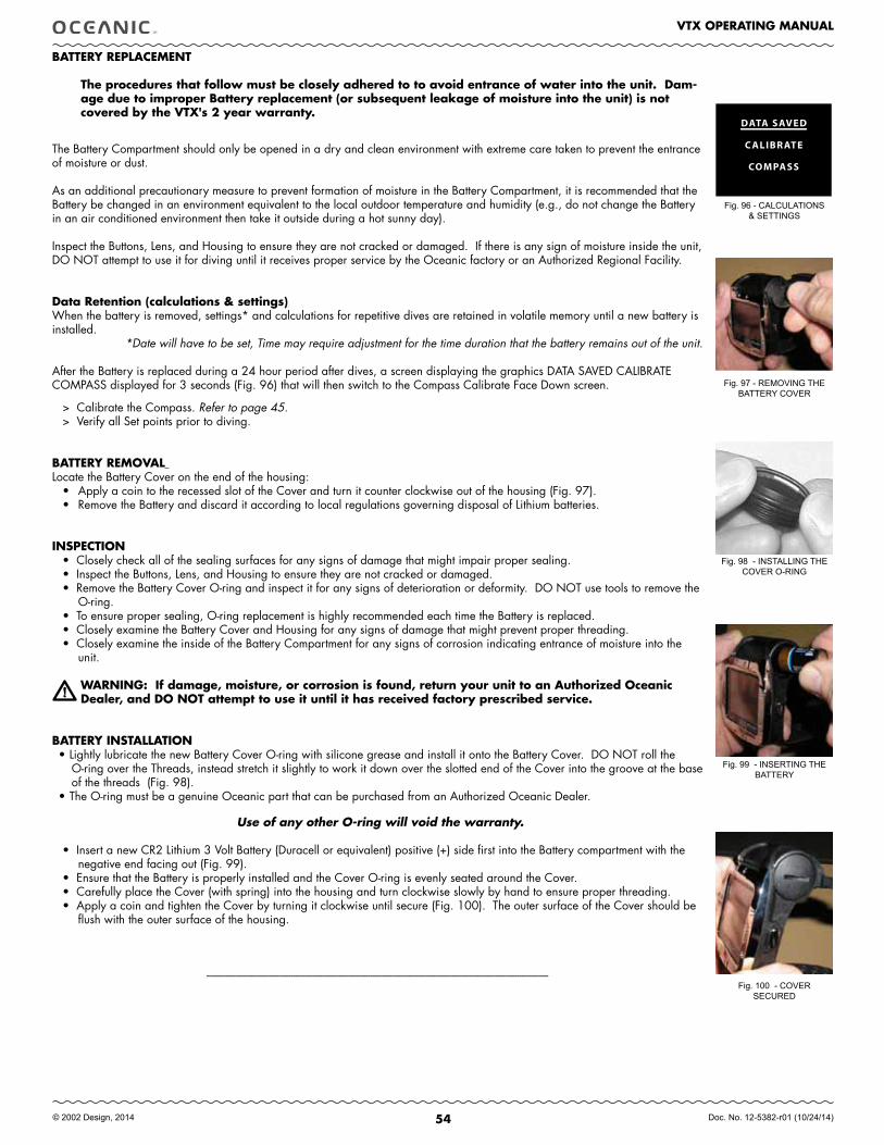
54
VTX OPERATING MANUAL
© 2002 Design, 2014 Doc. No. 12-5382-r01 (10/24/14)
BATTERY REPLACEMENT
The procedures that follow must be closely adhered to to avoid entrance of water into the unit. Dam-age due to improper Battery replacement (or subsequent leakage of moisture into the unit) is not covered by the VTX's 2 year warranty.
The Battery Compartment should only be opened in a dry and clean environment with extreme care taken to prevent the entrance of moisture or dust.
As an additional precautionary measure to prevent formation of moisture in the Battery Compartment, it is recommended that the Battery be changed in an environment equivalent to the local outdoor temperature and humidity (e.g., do not change the Battery in an air conditioned environment then take it outside during a hot sunny day).
Inspect the Buttons, Lens, and Housing to ensure they are not cracked or damaged. If there is any sign of moisture inside the unit, DO NOT attempt to use it for diving until it receives proper service by the Oceanic factory or an Authorized Regional Facility.
Data Retention (calculations & settings)When the battery is removed, settings* and calculations for repetitive dives are retained in volatile memory until a new battery is installed.
*Date will have to be set, Time may require adjustment for the time duration that the battery remains out of the unit.
After the Battery is replaced during a 24 hour period after dives, a screen displaying the graphics DATA SAVED CALIBRATE COMPASS displayed for 3 seconds (Fig. 96) that will then switch to the Compass Calibrate Face Down screen.
> Calibrate the Compass. Refer to page 45. > Verify all Set points prior to diving.
BATTERY REMOVAL Locate the Battery Cover on the end of the housing:
• Apply a coin to the recessed slot of the Cover and turn it counter clockwise out of the housing (Fig. 97).• Remove the Battery and discard it according to local regulations governing disposal of Lithium batteries.
INSPECTION• Closely check all of the sealing surfaces for any signs of damage that might impair proper sealing. • Inspect the Buttons, Lens, and Housing to ensure they are not cracked or damaged.• Remove the Battery Cover O-ring and inspect it for any signs of deterioration or deformity. DO NOT use tools to remove the
O-ring.• To ensure proper sealing, O-ring replacement is highly recommended each time the Battery is replaced.• Closely examine the Battery Cover and Housing for any signs of damage that might prevent proper threading.• Closely examine the inside of the Battery Compartment for any signs of corrosion indicating entrance of moisture into the
unit.
WARNING: If damage, moisture, or corrosion is found, return your unit to an Authorized Oceanic Dealer, and DO NOT attempt to use it until it has received factory prescribed service.
BATTERY INSTALLATION• Lightly lubricate the new Battery Cover O-ring with silicone grease and install it onto the Battery Cover. DO NOT roll the
O-ring over the Threads, instead stretch it slightly to work it down over the slotted end of the Cover into the groove at the base of the threads (Fig. 98).
• The O-ring must be a genuine Oceanic part that can be purchased from an Authorized Oceanic Dealer.
Use of any other O-ring will void the warranty.
• Insert a new CR2 Lithium 3 Volt Battery (Duracell or equivalent) positive (+) side first into the Battery compartment with the negative end facing out (Fig. 99).
• Ensure that the Battery is properly installed and the Cover O-ring is evenly seated around the Cover.• Carefully place the Cover (with spring) into the housing and turn clockwise slowly by hand to ensure proper threading. • Apply a coin and tighten the Cover by turning it clockwise until secure (Fig. 100). The outer surface of the Cover should be
flush with the outer surface of the housing.
----------------------------------------------------------------------------------------------------------------------------------------------
Fig. 97 - REMOVING THE BATTERY COVER
Fig. 98 - INSTALLING THE COVER O-RING
Fig. 99 - INSERTING THE BATTERY
Fig. 100 - COVERSECURED
DATA SAVED
C ALIBR ATE
COMPASS
Fig. 96 - CALCULATIONS& SETTINGS
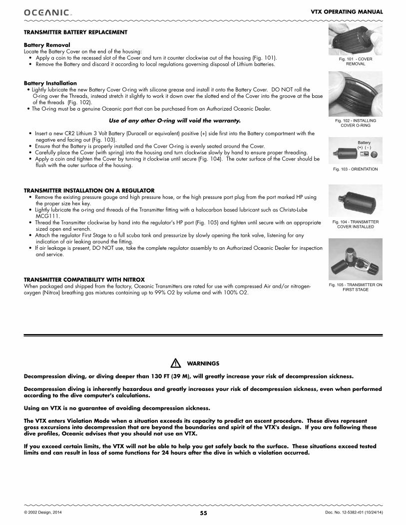
55
VTX OPERATING MANUAL
© 2002 Design, 2014 Doc. No. 12-5382-r01 (10/24/14)
TRANSMITTER BATTERY REPLACEMENT
Battery RemovalLocate the Battery Cover on the end of the housing:
• Apply a coin to the recessed slot of the Cover and turn it counter clockwise out of the housing (Fig. 101).• Remove the Battery and discard it according to local regulations governing disposal of Lithium batteries.
Battery Installation• Lightly lubricate the new Battery Cover O-ring with silicone grease and install it onto the Battery Cover. DO NOT roll the
O-ring over the Threads, instead stretch it slightly to work it down over the slotted end of the Cover into the groove at the base of the threads (Fig. 102).
• The O-ring must be a genuine Oceanic part that can be purchased from an Authorized Oceanic Dealer.
Use of any other O-ring will void the warranty.
• Insert a new CR2 Lithium 3 Volt Battery (Duracell or equivalent) positive (+) side first into the Battery compartment with the negative end facing out (Fig. 103).
• Ensure that the Battery is properly installed and the Cover O-ring is evenly seated around the Cover.• Carefully place the Cover (with spring) into the housing and turn clockwise slowly by hand to ensure proper threading. • Apply a coin and tighten the Cover by turning it clockwise until secure (Fig. 104). The outer surface of the Cover should be
flush with the outer surface of the housing.
TRANSMITTER INSTALLATION ON A REGULATOR • Remove the existing pressure gauge and high pressure hose, or the high pressure port plug from the port marked HP using
the proper size hex key. • Lightly lubricate the o-ring and threads of the Transmitter fitting with a halocarbon based lubricant such as Christo-Lube
MCG111. • Thread the Transmitter clockwise by hand into the regulator's HP port (Fig. 105) and tighten until secure with an appropriate
sized open end wrench. • Attach the regulator First Stage to a full scuba tank and pressurize by slowly opening the tank valve, listening for any
indication of air leaking around the fitting. • If air leakage is present, DO NOT use, take the complete regulator assembly to an Authorized Oceanic Dealer for inspection
and service.
TRANSMITTER COMPATIBILITY WITH NITROXWhen packaged and shipped from the factory, Oceanic Transmitters are rated for use with compressed Air and/or nitrogen-oxygen (Nitrox) breathing gas mixtures containing up to 99% O2 by volume and with 100% O2.
Fig. 103 - ORIENTATION
Battery(+) ( - )
Fig. 101 - COVER REMOVAL
Fig. 102 - INSTALLING COVER O-RING
Fig. 104 - TRANSMITTER COVER INSTALLED
Fig. 105 - TRANSMITTER ON FIRST STAGE
WARNINGS
Decompression diving, or diving deeper than 130 fT (39 M), will greatly increase your risk of decompression sickness.
Decompression diving is inherently hazardous and greatly increases your risk of decompression sickness, even when performed according to the dive computer's calculations.
Using an VTX is no guarantee of avoiding decompression sickness.
The VTX enters Violation Mode when a situation exceeds its capacity to predict an ascent procedure. These dives represent gross excursions into decompression that are beyond the boundaries and spirit of the VTX's design. If you are following these dive profiles, Oceanic advises that you should not use an VTX.
If you exceed certain limits, the VTX will not be able to help you get safely back to the surface. These situations exceed tested limits and can result in loss of some functions for 24 hours after the dive in which a violation occurred.

56
VTX OPERATING MANUAL
© 2002 Design, 2014 Doc. No. 12-5382-r01 (10/24/14)
TECHNICAL DATA
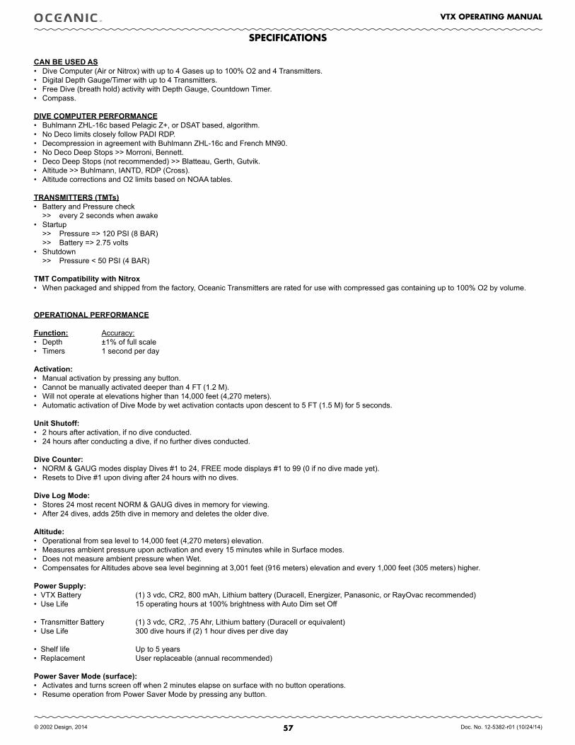
57
VTX OPERATING MANUAL
© 2002 Design, 2014 Doc. No. 12-5382-r01 (10/24/14)
CAN.bE.USED.AS• Dive Computer (Air or Nitrox) with up to 4 Gases up to 100% O2 and 4 Transmitters. • Digital Depth Gauge/Timer with up to 4 Transmitters.• Free Dive (breath hold) activity with Depth Gauge, Countdown Timer.• Compass.
DIVE.COMPUTER.PERFORMANCE• Buhlmann ZHL-16c based Pelagic Z+, or DSAT based, algorithm.• No Deco limits closely follow PADI RDP.• Decompression in agreement with Buhlmann ZHL-16c and French MN90.• No Deco Deep Stops >> Morroni, Bennett.• Deco Deep Stops (not recommended) >> Blatteau, Gerth, Gutvik.• Altitude >> Buhlmann, IANTD, RDP (Cross).• Altitude corrections and O2 limits based on NOAA tables.
TRANSMITTERS.(TMTs)• Battery and Pressure check >> every 2 seconds when awake• Startup >> Pressure => 120 PSI (8 BAR) >> Battery => 2.75 volts• Shutdown >> Pressure < 50 PSI (4 BAR)
TMT.Compatibility.with.Nitrox• When packaged and shipped from the factory, Oceanic Transmitters are rated for use with compressed gas containing up to 100% O2 by volume.
OPERATIONAL.PERFORMANCE
Function: Accuracy:• Depth ±1% of full scale• Timers 1 second per day
Activation:• Manual activation by pressing any button.• Cannot be manually activated deeper than 4 FT (1.2 M).• Will not operate at elevations higher than 14,000 feet (4,270 meters).• Automatic activation of Dive Mode by wet activation contacts upon descent to 5 FT (1.5 M) for 5 seconds.
Unit.Shutoff:• 2 hours after activation, if no dive conducted.• 24 hours after conducting a dive, if no further dives conducted.
Dive.Counter:• NORM & GAUG modes display Dives #1 to 24, FREE mode displays #1 to 99 (0 if no dive made yet). • Resets to Dive #1 upon diving after 24 hours with no dives.
Dive.Log.Mode:• Stores 24 most recent NORM & GAUG dives in memory for viewing.• After 24 dives, adds 25th dive in memory and deletes the older dive.
Altitude:• Operational from sea level to 14,000 feet (4,270 meters) elevation.• Measures ambient pressure upon activation and every 15 minutes while in Surface modes.• Does not measure ambient pressure when Wet.• Compensates for Altitudes above sea level beginning at 3,001 feet (916 meters) elevation and every 1,000 feet (305 meters) higher.
Power.Supply:• VTX Battery (1) 3 vdc, CR2, 800 mAh, Lithium battery (Duracell, Energizer, Panasonic, or RayOvac recommended)• Use Life 15 operating hours at 100% brightness with Auto Dim set Off
• Transmitter Battery (1) 3 vdc, CR2, .75 Ahr, Lithium battery (Duracell or equivalent)• Use Life 300 dive hours if (2) 1 hour dives per dive day
• Shelf life Up to 5 years• Replacement User replaceable (annual recommended)
Power.Saver.Mode.(surface):• Activates and turns screen off when 2 minutes elapse on surface with no button operations.• Resume operation from Power Saver Mode by pressing any button.
SPECIfICATIONS
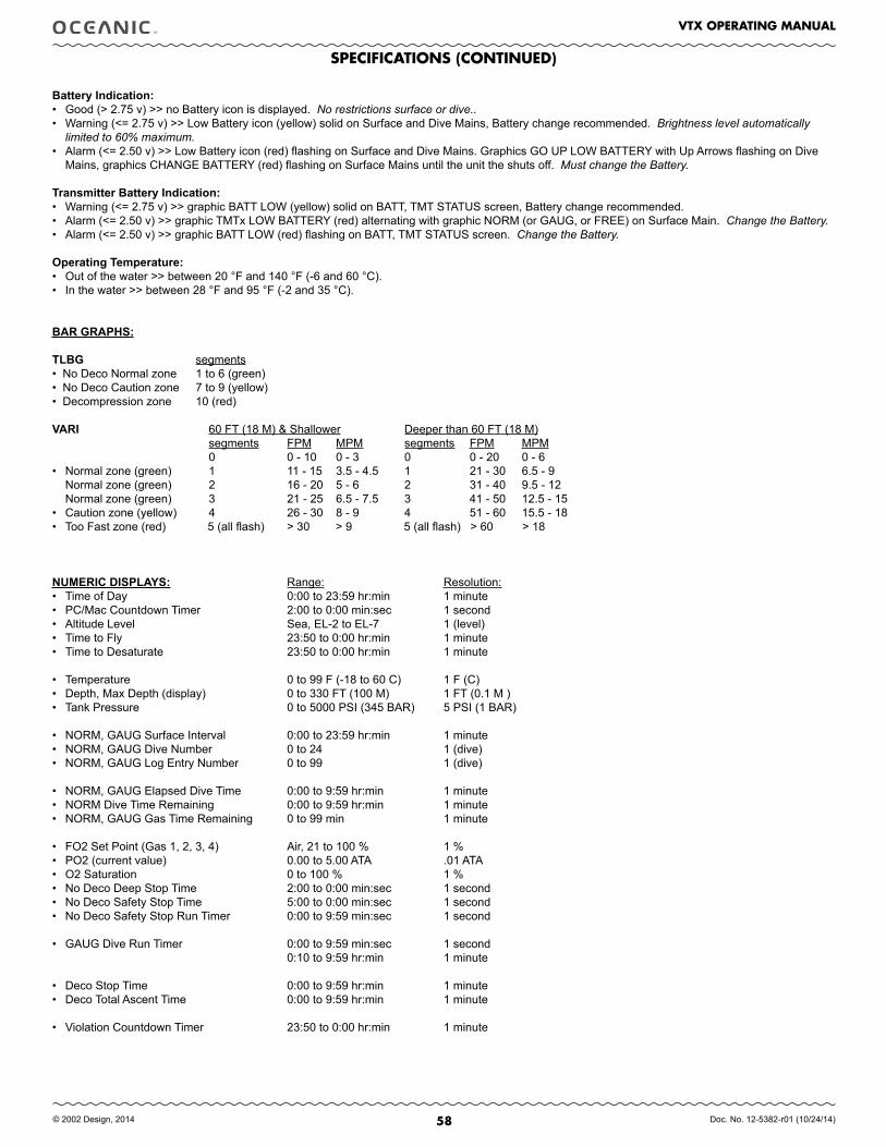
58
VTX OPERATING MANUAL
© 2002 Design, 2014 Doc. No. 12-5382-r01 (10/24/14)
battery.Indication: • Good (> 2.75 v) >> no Battery icon is displayed. No restrictions surface or dive..• Warning (<= 2.75 v) >> Low Battery icon (yellow) solid on Surface and Dive Mains, Battery change recommended. Brightness level automatically
limited to 60% maximum.• Alarm (<= 2.50 v) >> Low Battery icon (red) flashing on Surface and Dive Mains. Graphics GO UP LOW BATTERY with Up Arrows flashing on Dive
Mains, graphics CHANGE BATTERY (red) flashing on Surface Mains until the unit the shuts off. Must change the Battery.
Transmitter.battery.Indication: • Warning (<= 2.75 v) >> graphic BATT LOW (yellow) solid on BATT, TMT STATUS screen, Battery change recommended.• Alarm (<= 2.50 v) >> graphic TMTx LOW BATTERY (red) alternating with graphic NORM (or GAUG, or FREE) on Surface Main. Change the Battery. • Alarm (<= 2.50 v) >> graphic BATT LOW (red) flashing on BATT, TMT STATUS screen. Change the Battery.
Operating.Temperature:• Out of the water >> between 20 °F and 140 °F (-6 and 60 °C).• In the water >> between 28 °F and 95 °F (-2 and 35 °C).
bAR.GRAPHS:
TLbG segments .• No Deco Normal zone 1 to 6 (green) • No Deco Caution zone 7 to 9 (yellow) • Decompression zone 10 (red) VARI 60 FT (18 M) & Shallower Deeper than 60 FT (18 M) segments FPM MPM segments FPM MPM 0 0 - 10 0 - 3 0 0 - 20 0 - 6 • Normal zone (green) 1 11 - 15 3.5 - 4.5 1 21 - 30 6.5 - 9 Normal zone (green) 2 16 - 20 5 - 6 2 31 - 40 9.5 - 12 Normal zone (green) 3 21 - 25 6.5 - 7.5 3 41 - 50 12.5 - 15• Caution zone (yellow) 4 26 - 30 8 - 9 4 51 - 60 15.5 - 18• Too Fast zone (red) 5 (all flash) > 30 > 9 5 (all flash) > 60 > 18
NUMERIC.DISPLAYS:. Range: Resolution:• Time of Day 0:00 to 23:59 hr:min 1 minute• PC/Mac Countdown Timer 2:00 to 0:00 min:sec 1 second• Altitude Level Sea, EL-2 to EL-7 1 (level)• Time to Fly 23:50 to 0:00 hr:min 1 minute• Time to Desaturate 23:50 to 0:00 hr:min 1 minute
• Temperature 0 to 99 F (-18 to 60 C) 1 F (C)• Depth, Max Depth (display) 0 to 330 FT (100 M) 1 FT (0.1 M ) • Tank Pressure 0 to 5000 PSI (345 BAR) 5 PSI (1 BAR)
• NORM, GAUG Surface Interval 0:00 to 23:59 hr:min 1 minute• NORM, GAUG Dive Number 0 to 24 1 (dive) • NORM, GAUG Log Entry Number 0 to 99 1 (dive)
• NORM, GAUG Elapsed Dive Time 0:00 to 9:59 hr:min 1 minute• NORM Dive Time Remaining 0:00 to 9:59 hr:min 1 minute• NORM, GAUG Gas Time Remaining 0 to 99 min 1 minute
• FO2 Set Point (Gas 1, 2, 3, 4) Air, 21 to 100 % 1 %• PO2 (current value) 0.00 to 5.00 ATA .01 ATA• O2 Saturation 0 to 100 % 1 %• No Deco Deep Stop Time 2:00 to 0:00 min:sec 1 second• No Deco Safety Stop Time 5:00 to 0:00 min:sec 1 second• No Deco Safety Stop Run Timer 0:00 to 9:59 min:sec 1 second
• GAUG Dive Run Timer 0:00 to 9:59 min:sec 1 second 0:10 to 9:59 hr:min 1 minute
• Deco Stop Time 0:00 to 9:59 hr:min 1 minute• Deco Total Ascent Time 0:00 to 9:59 hr:min 1 minute
• Violation Countdown Timer 23:50 to 0:00 hr:min 1 minute
SPECIfICATIONS (CONTINUED)
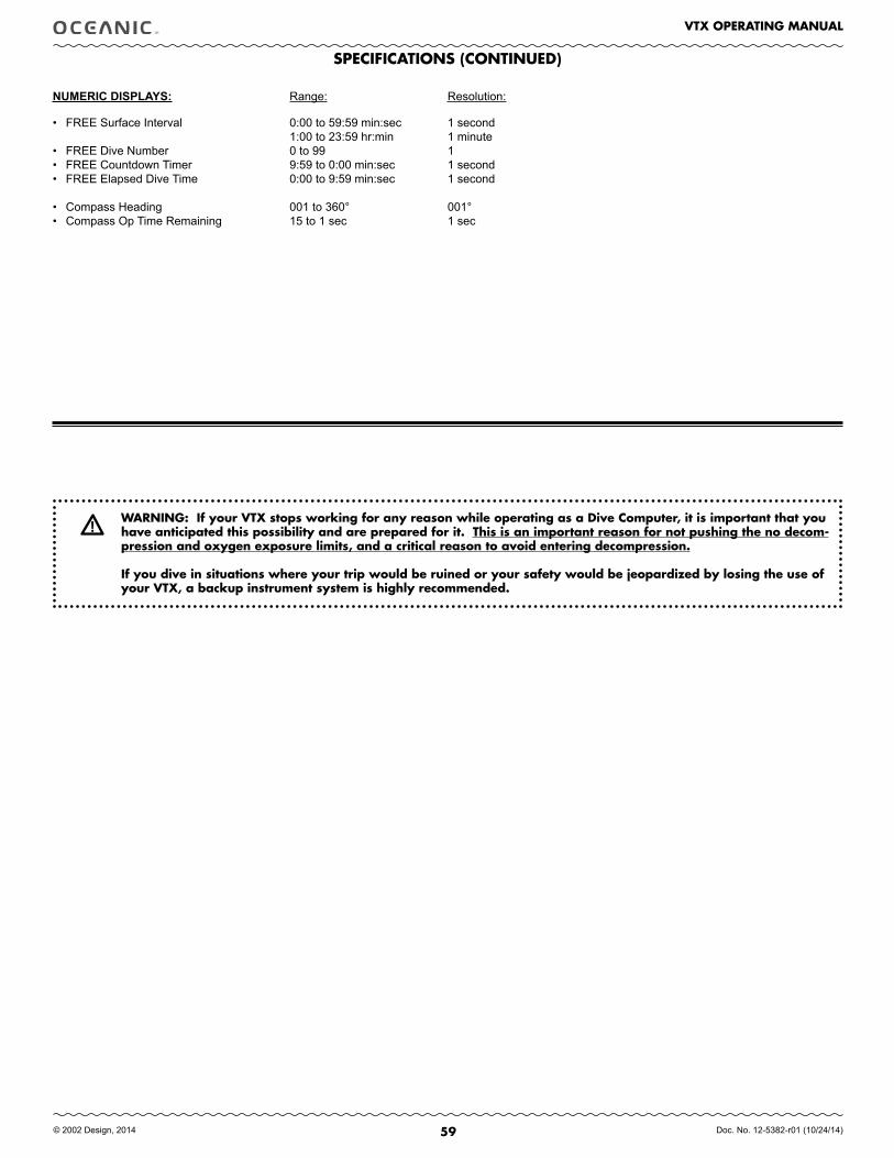
59
VTX OPERATING MANUAL
© 2002 Design, 2014 Doc. No. 12-5382-r01 (10/24/14)
SPECIfICATIONS (CONTINUED)
• FREE Surface Interval 0:00 to 59:59 min:sec 1 second 1:00 to 23:59 hr:min 1 minute• FREE Dive Number 0 to 99 1 • FREE Countdown Timer 9:59 to 0:00 min:sec 1 second• FREE Elapsed Dive Time 0:00 to 9:59 min:sec 1 second
• Compass Heading 001 to 360° 001°• Compass Op Time Remaining 15 to 1 sec 1 sec
WARNING: If your VTX stops working for any reason while operating as a Dive Computer, it is important that you have anticipated this possibility and are prepared for it. This is an important reason for not pushing the no decom-pression and oxygen exposure limits, and a critical reason to avoid entering decompression.
If you dive in situations where your trip would be ruined or your safety would be jeopardized by losing the use of your VTX, a backup instrument system is highly recommended.
NUMERIC.DISPLAYS:. Range: Resolution:
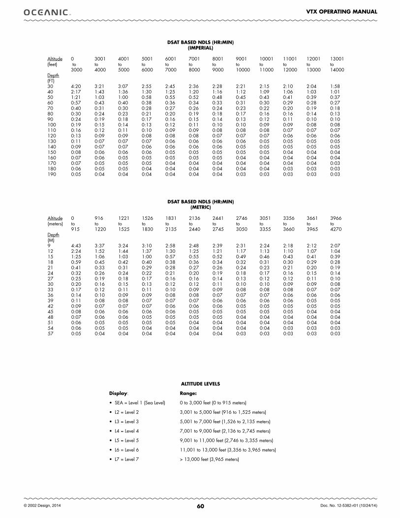
60
VTX OPERATING MANUAL
© 2002 Design, 2014 Doc. No. 12-5382-r01 (10/24/14)
ALTITUDE LEVELS
Display: Range:
• SEA = Level 1 (Sea Level) 0 to 3,000 feet (0 to 915 meters)
• L2 = Level 2 3,001 to 5,000 feet (916 to 1,525 meters)
• L3 = Level 3 5,001 to 7,000 feet (1,526 to 2,135 meters)
• L4 = Level 4 7,001 to 9,000 feet (2,136 to 2,745 meters)
• L5 = Level 5 9,001 to 11,000 feet (2,746 to 3,355 meters)
• L6 = Level 6 11,001 to 13,000 feet (3,356 to 3,965 meters)
• L7 = Level 7 > 13,000 feet (3,965 meters)
DSAT BASED NDLS (HR:MIN) (IMPERIAL)
Altitude 0 3001 4001 5001 6001 7001 8001 9001 10001 11001 12001 13001(feet) to to to to to to to to to to to to 3000 4000 5000 6000 7000 8000 9000 10000 11000 12000 13000 14000Depth(FT)30 4:20 3:21 3:07 2:55 2:45 2:36 2:28 2:21 2:15 2:10 2:04 1:5840 2:17 1:43 1:36 1:30 1:25 1:20 1:16 1:12 1:09 1:06 1:03 1:0150 1:21 1:03 1:00 0:58 0:55 0:52 0:48 0:45 0:43 0:41 0:39 0:3760 0:57 0:43 0:40 0:38 0:36 0:34 0:33 0:31 0:30 0:29 0:28 0:2770 0:40 0:31 0:30 0:28 0:27 0:26 0:24 0:23 0:22 0:20 0:19 0:1880 0:30 0:24 0:23 0:21 0:20 0:19 0:18 0:17 0:16 0:16 0:14 0:1390 0:24 0:19 0:18 0:17 0:16 0:15 0:14 0:13 0:12 0:11 0:10 0:10100 0:19 0:15 0:14 0:13 0:12 0:11 0:10 0:10 0:09 0:09 0:08 0:08110 0:16 0:12 0:11 0:10 0:09 0:09 0:08 0:08 0:08 0:07 0:07 0:07120 0:13 0:09 0:09 0:08 0:08 0:08 0:07 0:07 0:07 0:06 0:06 0:06 130 0:11 0:07 0:07 0:07 0:06 0:06 0:06 0:06 0:05 0:05 0:05 0:05140 0:09 0:07 0:07 0:06 0:06 0:06 0:06 0:05 0:05 0:05 0:05 0:05150 0:08 0:06 0:06 0:06 0:05 0:05 0:05 0:05 0:05 0:04 0:04 0:04160 0:07 0:06 0:05 0:05 0:05 0:05 0:05 0:04 0:04 0:04 0:04 0:04170 0:07 0:05 0:05 0:05 0:04 0:04 0:04 0:04 0:04 0:04 0:04 0:03180 0:06 0:05 0:05 0:04 0:04 0:04 0:04 0:04 0:04 0:03 0:03 0:03190 0:05 0:04 0:04 0:04 0:04 0:04 0:04 0:03 0:03 0:03 0:03 0:03
DSAT BASED NDLS (HR:MIN) (METRIC)
Altitude 0 916 1221 1526 1831 2136 2441 2746 3051 3356 3661 3966(meters) to to to to to to to to to to to to 915 1220 1525 1830 2135 2440 2745 3050 3355 3660 3965 4270Depth(M)9 4:43 3:37 3:24 3:10 2:58 2:48 2:39 2:31 2:24 2:18 2:12 2:0712 2:24 1:52 1:44 1:37 1:30 1:25 1:21 1:17 1:13 1:10 1:07 1:0415 1:25 1:06 1:03 1:00 0:57 0:55 0:52 0:49 0:46 0:43 0:41 0:3918 0:59 0:45 0:42 0:40 0:38 0:36 0:34 0:32 0:31 0:30 0:29 0:2821 0:41 0:33 0:31 0:29 0:28 0:27 0:26 0:24 0:23 0:21 0:20 0:1924 0:32 0:26 0:24 0:22 0:21 0:20 0:19 0:18 0:17 0:16 0:15 0:1427 0:25 0:19 0:18 0:17 0:16 0:16 0:14 0:13 0:12 0:12 0:11 0:1030 0:20 0:16 0:15 0:13 0:12 0:12 0:11 0:10 0:10 0:09 0:09 0:0833 0:17 0:12 0:11 0:11 0:10 0:09 0:09 0:08 0:08 0:08 0:07 0:0736 0:14 0:10 0:09 0:09 0:08 0:08 0:07 0:07 0:07 0:06 0:06 0:0639 0:11 0:08 0:08 0:07 0:07 0:07 0:06 0:06 0:06 0:06 0:05 0:0542 0:09 0:07 0:07 0:07 0:06 0:06 0:06 0:05 0:05 0:05 0:05 0:0545 0:08 0:06 0:06 0:06 0:06 0:05 0:05 0:05 0:05 0:05 0:04 0:0448 0:07 0:06 0:06 0:05 0:05 0:05 0:05 0:04 0:04 0:04 0:04 0:0451 0:06 0:05 0:05 0:05 0:05 0:04 0:04 0:04 0:04 0:04 0:04 0:0454 0:06 0:05 0:05 0:04 0:04 0:04 0:04 0:04 0:04 0:03 0:03 0:0357 0:05 0:04 0:04 0:04 0:04 0:04 0:04 0:03 0:03 0:03 0:03 0:03

61
VTX OPERATING MANUAL
© 2002 Design, 2014 Doc. No. 12-5382-r01 (10/24/14)
Z+ BASED NDLS (HR:MIN) (IMPERIAL)
Altitude 0 3001 4001 5001 6001 7001 8001 9001 10001 11001 12001 13001(feet) to to to to to to to to to to to to 3000 4000 5000 6000 7000 8000 9000 10000 11000 12000 13000 14000Depth(FT)30 3:17 2:30 2:21 2:14 2:08 2:02 1:57 1:52 1:47 1:39 1:34 1:2940 1:49 1:21 1:15 1:11 1:08 1:05 1:02 1:00 0:57 0:55 0:53 0:5150 1:05 0:53 0:51 0:49 0:47 0:44 0:42 0:39 0:37 0:35 0:34 0:3360 0:48 0:37 0:35 0:33 0:32 0:30 0:28 0:26 0:24 0:23 0:22 0:2170 0:35 0:26 0:24 0:23 0:21 0:20 0:19 0:18 0:17 0:16 0:16 0:1480 0:26 0:19 0:18 0:17 0:16 0:15 0:14 0:13 0:12 0:11 0:11 0:1090 0:19 0:15 0:14 0:13 0:12 0:11 0:10 0:10 0:09 0:09 0:08 0:08100 0:16 0:11 0:10 0:10 0:09 0:09 0:08 0:08 0:07 0:07 0:07 0:07110 0:12 0:09 0:08 0:08 0:08 0:07 0:07 0:07 0:06 0:06 0:06 0:05120 0:10 0:08 0:07 0:07 0:07 0:06 0:06 0:06 0:05 0:05 0:05 0:05130 0:08 0:07 0:06 0:06 0:06 0:05 0:05 0:05 0:05 0:05 0:04 0:04140 0:07 0:06 0:05 0:05 0:05 0:05 0:05 0:04 0:04 0:04 0:04 0:04150 0:06 0:05 0:05 0:05 0:05 0:04 0:04 0:04 0:04 0:04 0:04 0:03160 0:06 0:05 0:05 0:04 0:04 0:04 0:04 0:04 0:04 0:03 0:03 0:03170 0:05 0:04 0:04 0:04 0:04 0:04 0:03 0:03 0:03 0:03 0:03 0:03180 0:05 0:04 0:04 0:04 0:03 0:03 0:03 0:03 0:03 0:03 0:03 0:03190 0:04 0:04 0:04 0:03 0:03 0:03 0:03 0:03 0:03 0:03 0:03 0:00
Z+ BASED NDLS (HR:MIN) (METRIC)
Altitude 0 916 1221 1526 1831 2136 2441 2746 3051 3356 3661 3966(meters) to to to to to to to to to to to to 915 1220 1525 1830 2135 2440 2745 3050 3355 3660 3965 4270Depth(M)9 3:37 2:41 2:31 2:23 2:16 2:10 2:04 1:59 1:54 1:50 1:43 1:3712 1:55 1:27 1:21 1:15 1:12 1:08 1:05 1:03 1:00 0:58 0:55 0:5415 1:08 0:55 0:53 0:51 0:49 0:47 0:44 0:42 0:39 0:37 0:36 0:3418 0:50 0:39 0:37 0:35 0:33 0:32 0:30 0:28 0:26 0:24 0:23 0:2221 0:36 0:28 0:26 0:24 0:23 0:21 0:20 0:19 0:18 0:17 0:16 0:1624 0:27 0:20 0:19 0:18 0:17 0:16 0:15 0:14 0:13 0:12 0:11 0:1127 0:20 0:16 0:15 0:13 0:12 0:11 0:11 0:10 0:09 0:09 0:09 0:0830 0:16 0:12 0:11 0:10 0:09 0:09 0:09 0:08 0:08 0:07 0:07 0:0733 0:13 0:09 0:09 0:08 0:08 0:07 0:07 0:07 0:07 0:06 0:06 0:0636 0:10 0:08 0:07 0:07 0:07 0:06 0:06 0:06 0:05 0:05 0:05 0:0539 0:09 0:07 0:06 0:06 0:06 0:06 0:05 0:05 0:05 0:05 0:05 0:0442 0:08 0:06 0:06 0:05 0:05 0:05 0:05 0:05 0:04 0:04 0:04 0:0445 0:06 0:05 0:05 0:05 0:05 0:04 0:04 0:04 0:04 0:04 0:04 0:0448 0:06 0:05 0:05 0:04 0:04 0:04 0:04 0:04 0:04 0:03 0:03 0:0351 0:05 0:04 0:04 0:04 0:04 0:04 0:04 0:03 0:03 0:03 0:03 0:0354 0:05 0:04 0:04 0:04 0:04 0:03 0:03 0:03 0:03 0:03 0:03 0:0357 0:05 0:04 0:04 0:03 0:03 0:03 0:03 0:03 0:03 0:03 0:03 0:03
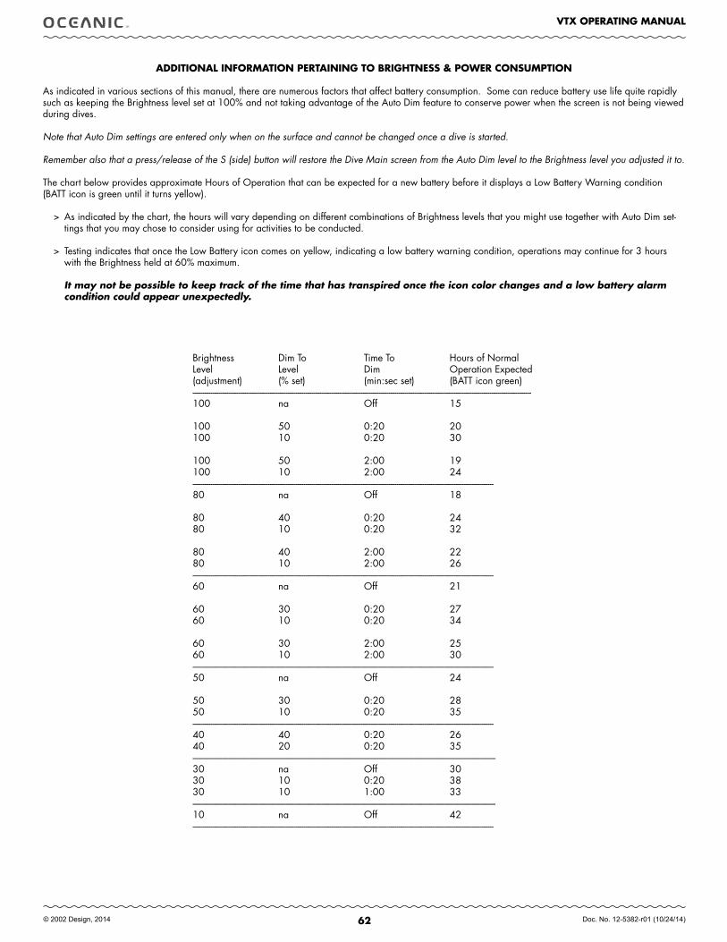
62
VTX OPERATING MANUAL
© 2002 Design, 2014 Doc. No. 12-5382-r01 (10/24/14)
Brightness Dim To Time To Hours of NormalLevel Level Dim Operation Expected(adjustment) (% set) (min:sec set) (BATT icon green)---------------------------------------------------------------------------------------------------------------------------------------------------------------------------100 na Off 15
100 50 0:20 20100 10 0:20 30
100 50 2:00 19100 10 2:00 24--------------------------------------------------------------------------------------------------------------------------------------------------------80 na Off 18
80 40 0:20 2480 10 0:20 32
80 40 2:00 2280 10 2:00 26--------------------------------------------------------------------------------------------------------------------------------------------------------60 na Off 21
60 30 0:20 2760 10 0:20 34
60 30 2:00 2560 10 2:00 30--------------------------------------------------------------------------------------------------------------------------------------------------------50 na Off 24
50 30 0:20 2850 10 0:20 35--------------------------------------------------------------------------------------------------------------------------------------------------------40 40 0:20 2640 20 0:20 35---------------------------------------------------------------------------------------------------------------------------------------------------------30 na Off 3030 10 0:20 3830 10 1:00 33---------------------------------------------------------------------------------------------------------------------------------------------------------10 na Off 42--------------------------------------------------------------------------------------------------------------------------------------------------------
ADDITIONAL INfORMATION PERTAINING TO BRIGHTNESS & POWER CONSUMPTION
As indicated in various sections of this manual, there are numerous factors that affect battery consumption. Some can reduce battery use life quite rapidly such as keeping the Brightness level set at 100% and not taking advantage of the Auto Dim feature to conserve power when the screen is not being viewed during dives.
Note that Auto Dim settings are entered only when on the surface and cannot be changed once a dive is started.
Remember also that a press/release of the S (side) button will restore the Dive Main screen from the Auto Dim level to the Brightness level you adjusted it to.
The chart below provides approximate Hours of Operation that can be expected for a new battery before it displays a Low Battery Warning condition (BATT icon is green until it turns yellow).
> As indicated by the chart, the hours will vary depending on different combinations of Brightness levels that you might use together with Auto Dim set-tings that you may chose to consider using for activities to be conducted.
> Testing indicates that once the Low Battery icon comes on yellow, indicating a low battery warning condition, operations may continue for 3 hours with the Brightness held at 60% maximum.
It may not be possible to keep track of the time that has transpired once the icon color changes and a low battery alarm condition could appear unexpectedly.
63
VTX OPERATING MANUAL
© 2002 Design, 2014 Doc. No. 12-5382-r01 (10/24/14)
INSPECTION / SERVICE RECORD
VTX Serial Number: ___________________________________________________________________________________________________
VTX Firmware Rev: ___________________________________________________________________________________________________ Transmitter1 Serial Number: ___________________________________________________________________________________________________
Transmitter 2 Serial Number: ___________________________________________________________________________________________________
Transmitter 3 Serial Number: ___________________________________________________________________________________________________
Transmitter 4 Serial Number: ___________________________________________________________________________________________________
Date of Purchase: ___________________________________________________________________________________________________
Purchased from: ___________________________________________________________________________________________________
Below to be filled in by an Authorized Oceanic Dealer:
Date Service Performed Dealer/Technician
Oceanic.WORLD.WIDE
Oceanic USA2002 Davis Street
San Leandro, CA 94577Tel: 510/562-0500Fax: 510/569-5404
Web: www.OceanicWorldwide.comE-mail: [email protected]
Oceanic EUROPEAugsburg, Germany
Tel: +49 (0) 821 810342 0 Fax: +49 (0) 821 810342 29Web: www.Oceanic-eu.com E-mail: [email protected]
Oceanic UKDevon, United Kingdom
Tel: (44) 1404-891819 Fax: +44 (0) 1404-891909Web: www.OceanicUK.com
E-mail: [email protected]
Oceanic AUSTRALIARosebud, Victoria, Australia
Tel: 61-3-5986-0100 Fax: 61-3-5986-1760Web: www.OceanicAUS.com.au
E-mail: [email protected]
Oceanic ASIA PACIFICSingapore
Tel: +65-6391-1420 Fax: +65-6297-5424 E-mail: [email protected]
Oceanic HAWAII and MICRONESIAKapolei, Hawaii
Tel: 808-682-5488 Fax: 808-682-1068 E-mail: [email protected]

64
VTX OPERATING MANUAL
© 2002 Design, 2014 Doc. No. 12-5382-r01 (10/24/14)
VTX
DIVE COMPUTER
OPERATING MANUAL