vulcan foundry locomotive factory industrial - enuii.org
TRANSCRIPT
1
Vulcan Foundry
Locomotive Factory Organisation
By:-
G. H. Birkinhead A.M.I.Mech.E. 1951
E. Littler. 1952-55
T. H. Talbot, A.M.I.Mech.E. 1952-55
Transcribed and updated by G. Pilkington M.I.E.T 2006-2008
Foreword
This for want of a better word E-Book records the day to day workings of a large British manufacturing company
‘The Vulcan Foundry Ltd’ in the 1950’s that once resided in the small Lancashire town of Newton-le-Willows.
Each of the Chapters in the book originally formed an individual article within the quarterly ‘Vulcan Magazine’ which was written and published by the workers and for the workers of the foundry. The articles provide as
complete a record as you are going to find within such a small number of pages of what it was like to work in such
a company, one of many such companies that were once upon a time spread across the length and breadth of this
once great manufacturing nation.
The original authors concluding remarks; ‘we feel these articles have served a dual purpose in giving readers a
picture of the other man's job and recording the layout and organisation required for the manufacture of steam locomotives’, are profoundly written, literally at the end of the steam locomotive manufacturing era, and
summarise this article far better than I can.

2
Contents
1. General Industrial Organisation
2. Industrial Organisation
3. Estimating and Tendering
4. Drawing Office and Purchasing Department
5. Production Office
6. Pattern Shop and Joiners Shop
7. Iron and Non-Ferrous Foundries
8. Laboratory and Test House
9. Forge and Smithy
10. Boiler Shop
11. Tool Room and Marking Out
12. Machine Shops
13. Brass Finishing and Copper Shop
14. Electric Welding
15. Sub-Assembly Ahops
16. Cylinder and Motion Shops
17. Erecting Shops (Steam Traction)
18. Erecting Shops (Diesel Mechanical, Diesel Electric and Electric Traction)
19. Paint and Packing Shops
20. Ancillary Departments
21. Conclusion

3
LOCOMOTIVE FACTORY ORGANISATION
1. General Industrial Organisation
By G. H. BIRKINHEAD A.M.I.Mech.E. 1951 – Transcribed and Updated by G. Pilkington M.I.E.T. 2006
Frequently we read in our newspapers reports of speeches given by M.P's or economic experts, exhorting us to
produce more and more goods, chiefly for export. We are told "A large increase in production will lower the costs
of manufacture, enabling us to sell at a competitive price in foreign markets." We are an industrial nation, and must export our products in return for food grown in other countries. We had devaluation of the pound sterling,
with the explanation that it would enable us to sell our products at a cheaper rate in the dollar countries.
Unfortunately, this advantage does not apply if we purchase our raw materials from a dollar area. We all realise
only too well that as our earnings increase, the cost of living increases, and we find that we are like a kitten trying to catch its own tail. The only cure for this inflationary trend is increased production, and so reduced selling
prices.
How can we keep the selling price of our goods down when we have steadily increasing costs of materials and
labour? The answer is "Take every advantage of efficient organisation." This can be stated quite simply as "making the best of men and things," which is the foundation of Industrial Organisation.
Let us, in a theoretical sense, examine the elements of the selling price of a product of a factory (see Fig. 1).
To this we add the cost of freight, insurance, &c., to give the actual price charged to the customer.
It can be seen from the chart that it is only necessary to add items 1 to 5 together to arrive at the selling price of our products. Unfortunately, it is not quite as simple as that. The trouble is that the selling price is influenced by the condition of the "Market", and we have to arrive at this market figure by manipulating items 1 to 5. If we are
unable to do this, and are badly organised, our selling price will be too high, and customers will buy elsewhere at
cheaper prices, with dire results to our business.
Let us examine how this "Market Price" is fixed. We all know that when a commodity is in short supply, the sellers can ask, and receive, very high prices (e.g. dwelling houses are scarce at present, and sell at many times the
pre-1939 prices. If by a miracle houses were to spring up like mushrooms overnight, the prices would drop just as
quickly). When the Market is flooded with a commodity, sellers are forced to reduce their prices, in order to tempt
customers to buy. The seller's slogan becomes "Better to sell at reduced prices than to have shelves stacked with unsaleable goods." It must be remembered, too, that stocked goods represent a capital outlay, and must be sold to
acquire cash to spend on the purchase of further goods. From this, we see that selling prices are influenced by the
supply and demand position of the Market. It is a common practice for vendors of consumer articles to distribute their wares in regulated quantities, to avoid flooding the Market, and so reducing prices to an uneconomic level.
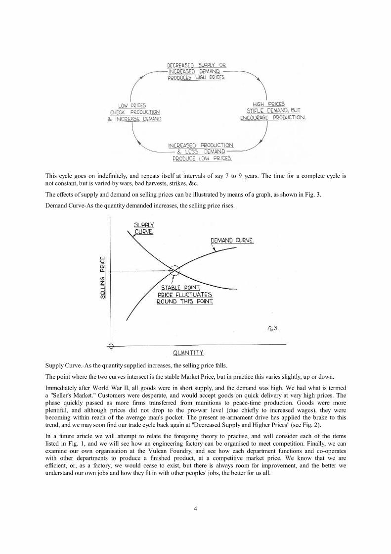
The supply and demand position of the Market is constantly varying, and we have what is termed a "TRADE CYCLE" as shown in Fig. 2.
4
This cycle goes on indefinitely, and repeats itself at intervals of say 7 to 9 years. The time for a complete cycle is
not constant, but is varied by wars, bad harvests, strikes, &c.
The effects of supply and demand on selling prices can be illustrated by means of a graph, as shown in Fig. 3.
Demand Curve-As the quantity demanded increases, the selling price rises.
Supply Curve.-As the quantity supplied increases, the selling price falls.
The point where the two curves intersect is the stable Market Price, but in practice this varies slightly, up or down.
Immediately after World War II, all goods were in short supply, and the demand was high. We had what is termed
a "Seller's Market." Customers were desperate, and would accept goods on quick delivery at very high prices. The
phase quickly passed as more firms transferred from munitions to peace-time production. Goods were more
plentiful, and although prices did not drop to the pre-war level (due chiefly to increased wages), they were becoming within reach of the average man's pocket. The present re-armament drive has applied the brake to this
trend, and we may soon find our trade cycle back again at "Decreased Supply and Higher Prices" (see Fig. 2).
In a future article we will attempt to relate the foregoing theory to practise, and will consider each of the items
listed in Fig. 1, and we will see how an engineering factory can be organised to meet competition. Finally, we can
examine our own organisation at the Vulcan Foundry, and see how each department functions and co-operates with other departments to produce a finished product, at a competitive market price. We know that we are
efficient, or, as a factory, we would cease to exist, but there is always room for improvement, and the better we
understand our own jobs and how they fit in with other peoples' jobs, the better for us all.

5
2. Industrial Organisation
By G. H. BIRKINHEAD A.M.I.Mech.E. 1951 – Transcribed and Updated by G. Pilkington M.I.E.T. 2006
It would be difficult to find any two factories with organisations exactly alike even when the products are similar. The size of the factory and number of employees; the physical layout of the plant (often governed by existing
buildings or land available); the nature of the product; the class of labour, &c., all affect organisation. The
majority of factories in Great Britain work on Batch Production, where the article being manufactured is passed through the workshops in batches. The size of batch is governed by many factors, and varies from factory to
factory. The type of organisation most frequently adopted is "The Military" or "Line" formation as shown in Fig.
4.
The diagram serves to illustrate the form of authority, and in practice is extended to include all departmental heads. It can be seen that in "Line" organisation, each person receives instructions from one person only, the one
immediately above him on the diagram. We should remember that an organisation is set up to manufacture a
certain product, and the success or failure is measured by the degree to which it is able to manufacture the product
economically. Changes in the policy of a firm may warrant changes in the organisation and a certain amount of flexibility is desirable. It would be foolish to allow an organisation to be restricted by previous decisions and the possibilities of future developments should be provided for. A firm must be receptive to new ideas and keep in
step if not a step ahead, of its competitors. Each position indicated on the chart is essential for the efficient
running of the factory and new departments should only be introduced where an overall saving will result.
We can illustrate this point by considering a small fir:n without an Inspection Department. Complaints are received from customers of faulty work. The articles are returned and have to be replaced free of charge. An
Inspection Department is installed and the faulty work is prevented in the early stages of manufacture. The cost of
the new department is more than offset by the elimination of replacement work and incidentally the "goodwill" of the firm benefits.
Let us now examine item by item the elements of the Selling Price as listed in Fig. 1
1. DIRECT RAW MATERIAL.
All material used in the manufacture of the finished product is included in this item. Steel sections, castings, forgings, wood, and any material which appears in the finished article must be included. Finished components
bought from other firms also come under this heading. The quantity of material used and the cost, are obtained
from the Stores Requisition notes that are handed to the Storekeeper in return for the required material. If too
much material is withdrawn for any job, it is essential that the surplus be returned to the Stores so that the particular job can be credited with it.
2. PRODUCTIVE LABOUR.
This item should only include the cost of wages paid to workmen who perform some operation in the actual
manufacture of the article, (e.g. Machine Operator, Fitter, &c.). Piece-work money or Bonuses should also be
included.
6
For the above two items it is most important that Requisition Notes, Time Notes, &c., should be correctly filled in because the most up-to-date cost accounting department fails in its task of proportioning expenses unless supplied
with reliable data.
3.-FACTORY "ON COST" or "OVERHEAD."
All aids to the actual manufacturing process are included under this heading. To list the most important items we
have:
l.-Wages of Foremen, Inspectors, Progress Men, Crane Drivers, Slingers, Labourers, &c.
2.-Maintenance of Plant and Buildings.
3.-Depreciation of Machines, &c.
4.-Rent, Rates, Taxes.
5.-Motive Power, Lighting, Heating.
6.-Ambulance, Fire Brigade.
7.-Internal Transport.
8.-Spoilt Work.
9.-Hand Tools, &c.
Swarf and Scrap sold can be deducted from the above expenses if not traceable to a particular job. Some firms charge the cost of expensive patterns and jigs to this item, if the cost added to the price of the article would make
the Selling Price too high.
This means that all customers share the cost so distributed. It should be noted that the customer pays for
everything and one of the tasks is to see that each customer pays a fair share of the "overheads" in proportion to
the cost of the article he purchases.
The method of obtaining the costs of items I to 4 above are obvious, but the method of sharing it out to the customers is more involved. There are several ways of doing this, and many factories use a combination of the
various methods. One simple
method is to base the figure on the Prime Cost. Monthly figures of the total Prime Cost, and Factory On Cost are
calculated by the Accounts Department, and a percentage arrived at which is used until the next revised figure is
obtained the following month.
4.-ADMINISTRATION "ON COST" OR "OVERHEAD."
Higher executive and office staff expenses are recovered under this heading. A simple method used by many factories is to make this charge a percentage of the Factory Cost. In the same manner as explained in the
preceding paragraph, the Accounts
Department issue a revised monthly figure expressed as a percentage of the Factory Cost i.e.:
Administration On Cost= Administration Cost x 100 = y%.
Total Factory Cost
We now have:
Total Cost = Factory Cost + Factory Cost x y
100
Some factories do not include Drawing Office expenses in the Administration On Cost, but add an extra item of
the actual cost involved. In the case of a new design requiring much development, this expense is considerable, but for a repeat order when only shop prints of existing designs are required, the cost is much less. Advertising and Sales Department expenses can be recovered under this heading.

7
5.-PROFITS.
To set up any kind of factory someone has to make an outlay of money to purchase land, machines and
equipment, &c. When large sums are required, the usual way is to issue a prospectus inviting the public to loan money in return for share certificates.
The prospectus is a Document which, under risk of severe penalties of the law if it is misleading, must set out the
aims and objects of the company and the probable financial results including the dividend it expects to be able to
pay.
The wise man always seeks the safest possible means of investing his spare money and therefore Savings Banks, Government Securities, &c., which involve very little risk are always the most popular. Accordingly, a new enterprise which may involve considerable risk must offer a higher rate of interest or dividend in order to attract
the money required. The money to pay this interest or dividend is taken from the Profit.
The Profit is included in the Selling Price as a percentage of the total cost. We have seen that Selling Prices are
controlled by the condition of the market and competitors' prices. Hence unless, the factory produces
economically, it will not make any profit at all. Out of Profit money has to be set aside to meet:
l.-Taxation (at present between 50/60 per cent. of the profit).
2.-Cost of new buildings or extensions to the factory.
3.-Cost of new Plant, Machinery and Tools.
4.-General Reserve, i.e. to meet unforseen events such as may occur in hard times, &c.
5.-The necessary finance for next year's production.
In the light of what can be spared after the above provisions have been made, the amount payable to the shareholder by way of dividend is determined.
In these two brief articles, we have endeavoured to outline the principles of factory organisation and following articles will trace an order from the "Enquiry" stage to the "Final Product" illustrating with examples from our
own Works.
3. Estimating and Tendering
By G. H. BIRKINHEAD A.M.I.Mech.E. 1951 – Transcribed and Updated by G. Pilkington M.I.E.T. 2006
When a Railway Company or a firm wishes to purchase a locomotive, they have the choice of various methods of
approaching the builders. If they have a definite idea of the type of locomotive required, a Specification is compiled and this together
with the customers conditions of contract and tender form, makes up the official tender documents or enquiry. Sometimes the enquiry is advertised in trade journals and Builders are invited to apply for a copy for which a fee may be charged, but often a copy is immediately issued to firms of repute with a request for their quotation to be
submitted. Often the selection of the type of locomotive is left to the builder, the customer stating the duties required, such as loads to be hauled, gradients of track, curves, maximum allowable axleload, etc.
Upon receipt of a specification or request to quote, the Management have to decide if we can offer a suitable locomotive. A factory with facilities like The Vulcan Foundry can manufacture locomotives from the smallest to
the largest sizes and to suit all gauges of railways. You are all familiar with the " main line " type steam
locomotive we manufacture and will have observed that Diesel and Electric locomotives of similar powers are also produced. As regards industrial locos. when enquiries are for small quantities and no suitable steam or diesel
design exists, prices would be unlikely to be competitive with the smaller builders' standard industrial designs,
and consequently such enquiries are often left to those builders who specialise in these types.
If it is decided that the enquiry comes within our range of products, the known particulars are passed to the Technical Estimating Office where the first task is to interpret the potential customers requirements and make an arrangement drawing or diagram of a locomotive suitable for the duties required. Many proprietary fittings such

8
as brake valves etc., are used in locomotive construction and the Technical Estimating Office send out enquiries to the firms manufacturing such articles asking for prices and dates on which deliveries can be made in the event of a
definite order being placed. Material Estimate Sheets are then compiled; listing all raw material required by our
workshops to build the proposed locomotive.
Cost Estimating Office
On these sheets, two columns of estimated weights are given, one, the weight of raw material and the other the weight of the finished article as it will appear on the locomotive. To the total of the finished weights is added the weight of Fuel, Water, Sand, etc., the resultant figure being the estimated weight of the locomotive in working
order. This total finished weight is most important. The weight on the driving wheels of a locomotive must be
sufficient to provide the adhesion required to transmit the tractive offort developed without slipping the wheels. It
is equally important that the locomotive shall not be too heavy. Railways have limited axleloads which have been decided by the safe loads that can be carried by existing bridges. The weakest bridge structure fixes the
maximum allowable load and unfortunately on many foreign railways only low axleloads are permitted. The
spacing of wheels and the wheelbase is governed by the strength of the bridges, and bending moment diagrams are made to compare the proposed loading with that of a recognised standard such as Coopers. The Technical
Estimating Office may have to submit a modified design to conform to these loading conditions.
Copies of the prepared estimate sheets are sent to the Cost Estimating Office, who are responsible for pricing all raw materials to be used. Lists of proprietary fittings are supplied by the Technical Estimating Office and as
quotations are received the prices are entered by the Cost Estimating Office. We now have all prices constituting item 1 " Direct Raw Material " (See Figure It in our last issue.) Copies of the Estimate Sheets together with a
diagram of the proposed locomotive are supplied to the Rate Fixing Department who estimate the Labour charges
(item 2. Figure II). Having ascertained the Prime Cost it is now the duty of the Estimating Cost Office to add the
charges for Drawing Office work, Factory on Cost, Administration on Cost and Profit. Jigs, Tools and new patterns have also to be allowed for.
The Technical Estimating Office have meanwhile prepared a complete specification stating all the features of the
proposed design. The rough pencil diagram has been elaborated and an ink tracing made from it. Prints are now
made from this tracing and a finished tender quoting a price and a delivery forecast is made. The complete tender
is dispatched to arrive at the prospective customer's office on the date stipulated for the receipt of quotation.
In our next article we will assume the customer has accepted our offer and places a contract with us for the supply of the proposed locomotive.

9
The Secretarial Department, through which passes most of the official correspondence.
4. Drawing Office and Purchasing Department
By G. H. BIRKINHEAD A.M.I.Mech.E. 1952 – Transcribed and Updated by G. Pilkington M.I.E.T. 2006
In our last article we outlined the procedure for dealing with an enquiry and submitting a tender, stating the price
at which we could produce the type of locomotive required, together with a forecast of the delivery date. Now let
us go a stage further and assume that the customer has given us an order in writing for a number of locomotives to the proposed design. The first step is to allocate the contract a " Working " or " Job " number and give it a place in
the work programme, so that the delivery promised will be maintained.
The time taken between the receipt of an order and the delivery of the finished product allows for (a) the design,
preparation of assembly and detail drawings and the compiling of material lists in the Drawing Office, (b) the placing of Orders by the Purchasing Dept., and the lapse of time between ordering and delivery of the necessary material, (c) casting and forging processes and machining, (d) assembling, testing, painting and delivering.
The Technical Estimating Office hands over to the Design Department, all documents and reference prints which
were used in the estimating stage, together with a copy of the estimated weights. It is now the task of the Drawing
Office to elaborate the rough schemes prepared and if necessary submit copies to the customer or his representatives for approval before making the production drawings. As the arrangement drawings progress,
sheets of details are also prepared. As each item is completed, the finished weights of the parts shown are
calculated and the results compared with the weights shown on the original estimate sheets. The reason for this is
simply to keep a close check on the final weight of the locomotive. If the weight of a designed detail is heavier than the estimate figure and the weight for strength reasons cannot be reduced, steps are taken to " save " a
corresponding amount on some other part so that the total will still tally with the estimate. This check is most
important where a certain axleload must not be exceeded and it is known that it is going to be difficult to keep within this limit. As soon as the design is finalised, the Drawing Office compiles a list of raw materials and proprietary fittings required.
10
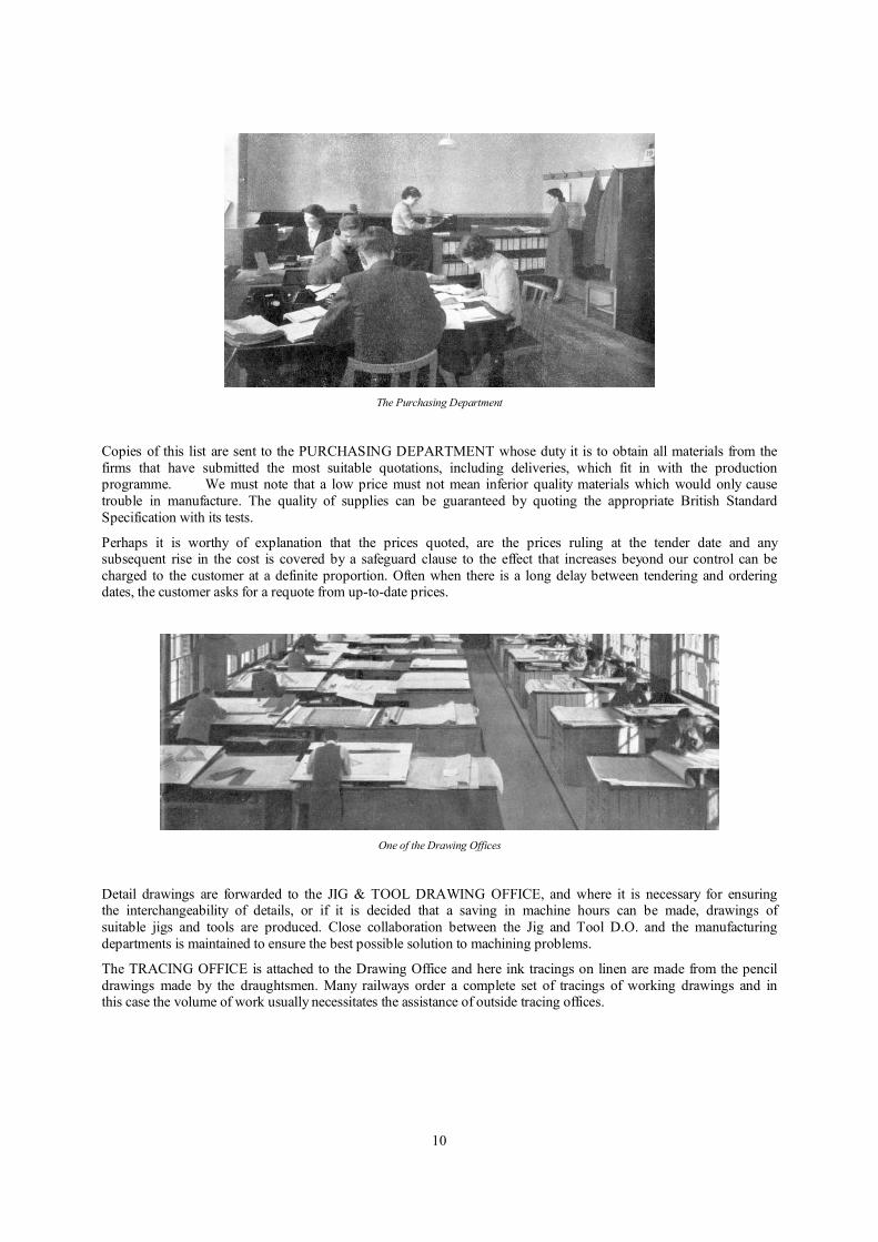
The Purchasing Department
Copies of this list are sent to the PURCHASING DEPARTMENT whose duty it is to obtain all materials from the
firms that have submitted the most suitable quotations, including deliveries, which fit in with the production programme. We must note that a low price must not mean inferior quality materials which would only cause
trouble in manufacture. The quality of supplies can be guaranteed by quoting the appropriate British Standard
Specification with its tests.
Perhaps it is worthy of explanation that the prices quoted, are the prices ruling at the tender date and any subsequent rise in the cost is covered by a safeguard clause to the effect that increases beyond our control can be
charged to the customer at a definite proportion. Often when there is a long delay between tendering and ordering dates, the customer asks for a requote from up-to-date prices.
One of the Drawing Offices
Detail drawings are forwarded to the JIG & TOOL DRAWING OFFICE, and where it is necessary for ensuring the interchangeability of details, or if it is decided that a saving in machine hours can be made, drawings of
suitable jigs and tools are produced. Close collaboration between the Jig and Tool D.O. and the manufacturing
departments is maintained to ensure the best possible solution to machining problems.
The TRACING OFFICE is attached to the Drawing Office and here ink tracings on linen are made from the pencil
drawings made by the draughtsmen. Many railways order a complete set of tracings of working drawings and in this case the volume of work usually necessitates the assistance of outside tracing offices.

11
5. Production Office
By E. Littler and T. H. Talbot, A.M.LMech.E. 1952 – Transcribed and Updated by G. Pilkington M.I.E.T. 2006
The previous article having dealt with the production of the working drawing and the ordering of raw materials and proprietary fittings, we now come to the next stage before the actual production of the locomotive is started in
the Works. This consists of planning and rate fixing which is carried out in the Production Office. Other Sections
of this Department deal with progress and material control. The detail drawings are issued by the Drawing Office to the Planning Department, whose job it is to arrange lists of basic materials from the information given on these
drawings, i.e.. castings, forgings, hot flangings, etc. These lists, together with additional copies of the drawings
are then issued to the Pattern Shop, Forge and Foundries in order that pattern and tools can he inade in advance of
production requirements.
It will be realised that a sequence of operations for all the details is necessary before production can be started in the Works and the Operational Planning Department goes through each detail drawing and prelarcs on a Planning
sheet a list of operations to produce every detail which is to be made in our own shops. At this stage decisions are
taken oil how to produce the items from material previously allocated by the Drawing Ollice. keeping in mind the
latest methods of manufacture and the cheapest way of' producing the item without detriment to the actual design.
These planning sheets are used by the Pre-Rate Fixing Department to fix the times and contract values for the operations previously planned. In this way a close check can be obtained to ensure that we are within the original
contract price given to the customer (see Article III, Estimating and Tendering). The information obtained from
these two dcpurtnients is then passed on to another section of the Production Office, the Progress Department. Here a master planning sheet is typed, which contains all the information regarding material, quantity required,
sequence of operations and contract prices. This master copy is used in a Fordigraphic Duplicating Machine
which prints in one operation all the cards and lists required on the Planning system. These include cards for
material requisition, stock control and contract notes. The Contract Note is issued to the Works and eventually reaches the operator. This note contains information regarding
Planning Office
Times and Prices for the particular operation. On the completion of each batch of details, the Note is signed
by the Shop Foreman and returned to the Progress Department, where it is checked for quantities and price. Notes
are then made on a copy of the operation sheet regarding the progress of the item concerned. This Department is therefore able to keep up-todate with the progress made on any individual part of the locomotive or spares. The
most important function of the Contract Note as far as the operator is concerned, is that it is used by the General
Office Staff to calculate the amount of piece work to be paid to him.
Another important section of the Production Office is the Stock Control Department. As the name implies, this
Department is mainly concerned with the control of all the stock material used in the production of the locomotive. Their job is to ensure that sufficient stock material is available at any time for any particular contract. A card system is used which tells at a glance what the position is for any size of stock material and by
close co-operation with the Purchasing Department a safe level of stock is maintained.
The last, but by no means the least, of the sections of the Production Office which we are considering is the
Material Control Department which has an important part to play in ensuring that material and proprietary fittings previously requisitioned by the Drawing Office and ordered by the Purchasing Department are received into our
Works during the delivery period promised by the sub-contractors. This necessary delivery period is stipulated by
the Planning Office and the Material Control Office is responsible for the urging, often by direct contact, in order

12
to get the material and fittings into our Works in time to meet production requirements. The Progress of delivery is noted for every order in hand, advice notes being daily received from the Purchasing Department which are
entered on to basic record cards. All materials other than commercial bars and other stock are inspected as they
are delivered to our works and reports of any faulty material or fittings are sent to the Material Control Depart-
ment which is then responsible for seeing that such items are replaced by the sub-contractors concerned.
For the successful running of the Planning system close co-operation between the various Departments is essential to maintain an even flow of work through the shops.
Rate Fixing and Operational Planning Oflice
6. Pattern Shop and Joiners’ Shop
By E. Littler and T. H. Talbot, A.M.LMech.E. 1952 – Transcribed and Updated by G. Pilkington M.I.E.T. 2006
The PATTERN SHOP, being the initial stage in production, must be well ahead of the building programme with the supply of patterns to the foundries. Drawings having been issued by the Drawing Office through the Planning
Department, production is started and priority is given to patterns for Steel Castings, Cylinders, and Flanging Blocks for boiler and firebox plates.
The cast iron and non-ferrous castings are produced in our own foundries, but the steel castings are made from our
patterns by the various steel companies and supplied to us ready for machining. The number of castings to be
produced from a particular pattern will decide whether the mould is to be hand rammed or machine rammed, this
in turn having a large part to play in the design of the pattern. Close co-operation is maintained between the pattern shop, foundries and the steel companies.
A considerable amount of work is entailed in the production of some of the larger patterns for cylinders, flanging
blocks, smokebox saddles, etc. The highly specialised job of producing a cylinder pattern for example, with its
many core boxes, often numbering from 30 to 40, requires a team of six to eight pattern makers.
Pattern Shop-South End.

13
7. Iron and Non-Ferrous Foundries
By E. Littler and T. H. Talbot, A.M.I.Mech.E. 1953 – Transcribed and Updated by G. Pilkington M.I.E.T. 2006
In the previous chapter we dealt with the production of the patterns and coreboxes.
These are delivered to the Foundries together with an order note which contains all the necessary information for the manufacture of the castings. This information includes the order number, drawing number, quantity required
and the material specification.
On receiving the pattern the Foundryman decides on the most suitable method of moulding and selects a moulding
box and other equipment to suit the job. If the machine or plate moulding method is adopted, then the large
patterns for such items as cylinders,
liners, chimneys, etc., are mounted on plates or boards, the smaller ones having been already mounted in the Pattern Shop. The core or cores form an essential part of the mould and these are put in hand as soon as possible to ensure that they are ready for setting into the mould. The cores are carefully prepared from special sands and on
completion are baked in the core ovens.
There are three types of moulds commonly used in our Foundries, i.e. Dry Sand moulds for heavy castings such as
cylinders, Skin Dried moulds for medium castings and Green Sand moulds for the smaller and simpler castings. The dry sand mould is produced
from a loam sand of the requisite quality to withstand the temperature of the stoves. The pattern is rammed up, in
a suitable moulding box, either by hand or machine, and when completed the mould is baked in specially
constructed stoves. In the case of green sand moulds, the procedure for the preparation is similar but on completion of the moulds they are not baked but are left in the moist state.
The finishing process in preparing the mould includes the setting of the cores and closing and weighting or clamping the boxes, ready for the pouring of the molten metal. The time taken in preparing a mould varies,
depending upon the size and nature of the
casting to be produced. In the case of cylinders, this can vary from three days for a simple casting to three weeks
for a large and elaborate casting, such as the L.N.E.R. mono-bloc cylinders weighing approximately six tons.
Iron Foundry – Light Section.
The metal for the IRON FOUNDRY is prepared in two furnaces or cupolas, used on alternate days, with a capacity of four to five tons per hour. Pig iron and iron scrap is melted to produce the various grades of iron
required, which range from cylinder quality with a minimum tensile strength of 14 tons per square inch, down to

14
common iron of 10 tons per square inch. A new and interesting addition to one of the furances, that has resulted in a considerable recovery of scrap in the course of a year, has been the installation of a " Crofts " patent swarf
injector, one of the few in use in this country. The cast iron cuttings from our machines are fed into the injector
which forces them into the furnace by air pressure. A large number of moulds are prepared for receiving the
molten metal on the same day, the actual " pour " taking place during the afternoon. The molten metal is run off into ladles and poured into the prepared moulds. In order to ensure that the metal is to the required specification,
test bars are cast on all the important castings and these are tested in the Laboratory in the presence of the Railway
Companies Inspectors. If these prove satisfactory, the castings are then weighed and dispatched to the marking out
tables. The first casting from any new pattern is checked over at the marking out tables to ensure that all the sizes and machining allowances are correct. Sometimes, if considered necessary, the castings are proof machined before
proceeding with the rest of the order.
Iron Foundry-Casting Press Top. Finished Press Top.
Core Shop-Non-Ferrous Foundry.
The Iron Foundry is divided up into various sections. The Cylinder Section is devoted almost entirely to the
production of locomotive cylinders and here some thirty moulders and core makers are engaged. It is in this department that experience plays an important part, due to the nature of the job and the amount of skill involved in
producing a sound casting.

15
In the Heavy Jobbing Section cylinder and piston valve liners and chimneys form the main production castings but a large variety of other castings are also produced. These include the flanging blocks for the Boiler Shop
presses and large castings for the plant.
It was in this section where a new top casting was made recently for the 157-ton Boiler Shop press. This casting
weighed 9,1 tons and is the heaviest yet made at our Works.
The Light Section of the Iron Foundry has only a small number of fully skilled moulders and coremakers, as this
department is considered the training ground for the Foundry apprentices. Although the castings are small compared with those produced in the other sections, it is in no way less intricate or difficult work. This section
contains a modern Jackman's Roll-over jolt machine, complete with a conveyor and overhead sand feed. It is mainly used on castings of a repetition nature and since installed has increased production on a variety of castings
weighing up to 2 cwts.
Another important section is the Sand Mixing Department where the various kinds of sands are prepared for use in the moulds and coreboxes.
Finally, there is the Fettling Department where the castings are de-cored, cleaned and all the rough edges and fins
removed and from where the finished castings are despatched to the various departments in the works.
Non-Ferrous Foundry.
In the NON-FERROUS FOUNDRY the procedure and sequence of operations is much the same as in the Iron
Foundry but a finer grade of sand is used in the moulds. The melting equipment consists of two large gas fired
tilting furnaces of 6001bs. and 4001bs. capacity and two fixed furnaces of 120 lbs. capacity for the melting of
small quantities and for heating the crucibles before being filled for casting.
One of the difficulties facing the Non-Ferrous Foundry is the large number of different alloys required for the production of bearings, axleboxes, boiler mountings, oilboxes, etc. Each alloy presents its own particular problem in regard to the moulding method needed to produce sound castings.
The moulds and castings are produced by skilled moulders and apprentices and all the core-making is carried out
by female labour, who have become accustomed to making the small intricate cores used in the moulds.
Test pieces are required as in the case of the Iron Foundry, some to be used for obtaining an analysis of the
material and other for tensile testing.
The castings are cleaned and the majority shot-blasted before being sent into the Non-Ferrous Foundry stores. Here they are weighed and dispatched to the Brass Finishing Shop-and other departments concerned.
The type of castings produced in our Foundries could be regarded as specialist work in which long years of
service and experience play an important part.

16
8. Laboratory and Test House
By E. Littler and T. H. Talbot, A.M.I.Mech.E. 1953 – Transcribed and Updated by G. Pilkington M.I.E.T. 2006
There must be many in our works who will remember the Test House in the Tool Room, which for many years served the purpose of providing mechanical tests required by the Railway Companies. Due to the expansion of the
Firm and the ever increasing demands for different types of mechanical and chemical tests, our present Laboratory
and Test House was built in 1947.
Very close liaison with the works is essential, hence the siting of the Laboratory in a convenient position so that the works personnel may easily contact the Laboratory, and the Laboratory Staff be as readily available to the
works.
On the ground floor is the Mechanical Testing Section, the Metallography and Sand Testing Sections and the Dark
Room. On the first floor is the Chemical Laboratory and Office.
Denison Universal Testing Machine. Test Piece in Denison Machine.
Mechanical Testing Section. The Test House is equipped with various machines for carrying out mechanical
tests on all metals used in our shops. The most important machine is the 50 ton Denison Universal Testing
Machine, on which tensile, compression and bend tests are carried out. The primary purpose of the tensile test is to obtain the maximum strength of the material and the bend test serves to indicate the capacity of a material for
deformation in a particular direction without cracking.
In the case of tensile test pieces, these may be of steel, non-ferrous alloys or cast iron. Each one is carefully
machined, pulled to destruction and the breaking load in tons per square inch is calculated from the readings on the machine. Other information such as percentage elongation and reduction in area is obtained from the test
piece.
Test Pieces Before and After Testing.
Two machines are also installed for determining the degree of hardness of any particular metal. These are the Vickers Pyramid and the Brinell Hardness Testers. They are applicable to all types of work, but the Vickers
Pyramid tester is mainly used for finished work and for very thin sheets.
17
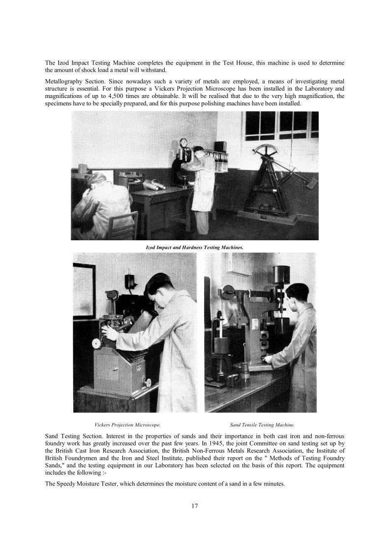
The Izod Impact Testing Machine completes the equipment in the Test House, this machine is used to determine the amount of shock load a metal will withstand.
Metallography Section. Since nowadays such a variety of metals are employed, a means of investigating metal structure is essential. For this purpose a Vickers Projection Microscope has been installed in the Laboratory and
magnifications of up to 4,500 times are obtainable. It will be realised that due to the very high magnification, the
specimens have to be specially prepared, and for this purpose polishing machines have been installed.
Izod Impact and Hardness Testing Machines.
Vickers Projection Microscope. Sand Tensile Testing Machine.
Sand Testing Section. Interest in the properties of sands and their importance in both cast iron and non-ferrous foundry work has greatly increased over the past few years. In 1945, the joint Committee on sand testing set up by
the British Cast Iron Research Association, the British Non-Ferrous Metals Research Association, the Institute of
British Foundrymen and the Iron and Steel Institute, published their report on the " Methods of Testing Foundry Sands," and the testing equipment in our Laboratory has been selected on the basis of this report. The equipment includes the following :-
The Speedy Moisture Tester, which determines the moisture content of a sand in a few minutes.

18
A Permeability Meter, for comparing the rates at which gases can escape through a sand mould. A Compression Testing Machine, which indicates the mechanical strength of the mould and its ability to with stand fracture under
the weight of metal in the casting, and a Dry Tensile Strength Machine for testing the strength of oil bonded core
sands.
Carbon Testing Apparatus. Radiographing Welded Firebox Joints.
The Chemical Laboratory is equipped with apparatus to help in the control of the various metals produced in our
Foundries. This control is necessary due to the variety of mixtures now used in the production of locomotive
parts.
For the determination of Carbon in steel or cast iron, a Stroehlein apparatus is used, which enables a test to be
carried out in about seven minutes. An Electro-deposition apparatus assists in the rapid analysis of non-ferrous metals and a Spekker Photo-electric Absorptiometer is used for determining the percentage of manganese,
phosphorus, chromium or nickel present in the metal.
Radiography Section. The successful use of welding in the fabrication of locomotive components, and the
accepted practice of welded steel fireboxes has made the X-ray apparatus essential, not only as an inspection tool,
but also as a method of investigating and improving our welding techniques.
The equipment which is housed in the Boiler Yard, consists of a 250,000 volt Victor X-ray set, capable of penetrating up to 22" of steel. In order to ensure the safety of the operating personnel, all high tension gear is
enclosed in the oil cooled head, thus eliminating trailing high tension leads and flexible connections. The control
panel is situated in a lead-lined cab so that the operator is completely protected from X-rays. The processing of the Radiographs is carried out in the Laboratory Dark Room which is equipped with a Kodak Processing Unit and
Drying Cabinet. Viewing is done with a fluorescent illuminator in the Laboratory.
Although our Laboratory and Test House are equipped with a variety of Mechanical and Chemical apparatus, the
efficiency of the Departments largely depends on the scientific training and experience of the Laboratory Staff.
Chemical Laboratory.

19
9. Forge and Smithy
By E. Littler and T. H. Talbot, A.M.I.Mech.E. 1953 – Transcribed and Updated by G. Pilkington M.I.E.T. 2006
In our article on the Production Office, we stated that in order to keep in advance of production requirements, the Forge and Smithy must be one of the first departments to commence the initial locomotive details.
The large forgings such as connecting and coupling rods, slide bars, etc., are produced in the FORGE and the
smaller work m the SMITHY. The basic materials from which the forgings are made, are called blooms, these are
in the form of rectangular sections of steel, varying in length and weighing from 4 to 26 cwts. These blooms are kept in stock, identifying colours and letters being painted on them to distinguish the various grades of steel.
Generally, a piece of material which has been subjected to forging has a structural quality which is superior to bar material, and when highly stressed parts are encountered use is made of the grain flow to give additional strength.
This increase in toughness which forging gives to a work piece is applied to many locomotive details.
When commencing a job, the blacksmith first ensures that all the necessary tools and templates are to hand, the
majority of these being made in the Forge and Smithy. When choosing a bloom, the following points have to be
considered.
(a) The size and shape of the finished forging.
(b) The loss of steel when heating in the furnace.
(c) The allowance to be left for test pieces, these test pieces being left on all the major forgings.
After "tackling up" the bloom in order to facilitate handling, the next step is to heat it up to forging temperature of approximately .1150°C. This is a rather slow process, but with the double shift system which is m operation in our
forge, the furnaces are charged with blooms in order that the next shift can commence forging without undue
delay. This heating process is a most important one and the smith must also see that forging does not go on below
a certain temperature. Here colours play an important role, the smith being able to determine the temperature quite accurately as the white hot steel gradually changes colour, e.g. White-1320°C., Lemon-1200°C., Light Orange-1150°C., Light Red-970°C., Dull Red-700°C. All the furnaces in our forge are of the gas fired type, using gas
from our own producers.
Assuming that a bloom for a large component, such as a connecting rod, has been brought up to the requisite
tcmpcralurc, it is taken to ?he five ton hammer (the largest in the shop) and with the aid of forging tools and templates is forged to the required shape. To produce these large forgings a team of six men is required, consisting
of a forgeman, two furnacemen, crane driver, hammer driver and one general helper.
In addition to the 5 ton hammer the forge is equipped with a 3 ton, a 1! ton and 1 ton hammer, each with its own
furnace.
The forgings produced in our Smithy are many and varied, requiring semi-automatic forging machines as well as
light hammers. These consist of one Platt forging machine for bolts and rivets, five upsetting machines for forgings where only the ends of the bars are required to be formed, five 10 cwt. hammers and a saw for cutting hot steel.
Tack ling Gear Coupling Rod Forging under 5 ton Hammer
20
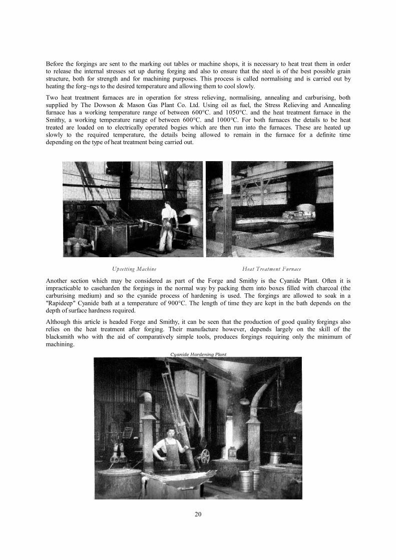
Before the forgings are sent to the marking out tables or machine shops, it is necessary to heat treat them in order to release the internal stresses set up during forging and also to ensure that the steel is of the best possible grain
structure, both for strength and for machining purposes. This process is called normalising and is carried out by
heating the forg~ngs to the desired temperature and allowing them to cool slowly.
Two heat treatment furnaces are in operation for stress relieving, normalising, annealing and carburising, both
supplied by The Dowson & Mason Gas Plant Co. Ltd. Using oil as fuel, the Stress Relieving and Annealing furnace has a working temperature range of between 600°C. and 1050°C. and the heat treatment furnace in the
Smithy, a working temperature range of between 600°C. and 1000°C. For both furnaces the details to be heat
treated are loaded on to electrically operated bogies which are then run into the furnaces. These are heated up slowly to the required temperature, the details being allowed to remain in the furnace for a definite time depending on the type of heat treatment being carried out.
Upse tting Machine Heat Treatment Furnace
Another section which may be considered as part of the Forge and Smithy is the Cyanide Plant. Often it is impracticable to caseharden the forgings in the normal way by packing them into boxes filled with charcoal (the
carburising medium) and so the cyanide process of hardening is used. The forgings are allowed to soak in a
"Rapideep" Cyanide bath at a temperature of 900°C. The length of time they are kept in the bath depends on the depth of surface hardness required.
Although this article is headed Forge and Smithy, it can be seen that the production of good quality forgings also relies on the heat treatment after forging. Their manufacture however, depends largely on the skill of the
blacksmith who with the aid of comparatively simple tools, produces forgings requiring only the minimum of
machining.
Cyanide Hardening Plant

21
10. Boiler Shop
By E. Littler and T. H. Talbot, A.M.I.Mech.E. 1953 – Transcribed and Updated by G. Pilkington M.I.E.T. 2006
We have now reached the section of our Works which produces what may be considered the heart of the steam locomotive. Most modern locomotives are designed with a boiler as large as the loading gauge will permit, for on
its ability to generate steam as fast as the cylinders require it, depends the haulage and speed capacity of the
locomotive.
The boiler and firebox shells are made from special quality rolled steel plates and the majority of the holes are drilled in the plates before they are bent or rolled to the required shape. The inner firebox wrapper plate is secured
to the outer shell by means of staybolts. This staying is very important because it prevents the inner firebox from
being crushed in by the steam pressure. The inner and outer firebox plates are also secured at the bottom by what
is known as the foundation ring and the whole shell is rivetted together by circumferential and longitudinal joints.
The two main types of boilers produced in our Shops are the roundtopped and the square topped or Belpaire. In many instances, additional heating surface is provided in the firebox by including a combustion chamber or fitting
thermic syphons or arch tubes, which all have the effect of improving the steaming qualities of the boiler.
So much for the general description of the boiler and firebox. Now we shall deal with some of the operations and
different stages in its production, which vary according to the type of boiler under construction. At the time of
writing this article one of the " Y " Class Indian boilers was in the process of building and the following procedure relates to this type.
Boiler Barrel.- The steel plates are first levelled by rolling and are then edge planed to the required size. The
barrels are usually made up of two or three longitudinal sections and one plate only of each particular size is sent
to the marking out tables. After marking out, this plate is used as a template and batches of plates are then drilled
from this master on the Kitchen and Wade Duplex Drilling machine. It must be pointed out that at this stage the holes which are drilled are only pilot holes.
In order to ensure that the barrels form a complete circle after rolling, the longitudinal edges of the plates for a
distance of 12" are curved in the Bending Press to the desired radius of the finished barrel.
The sections of the barrel are then sent to the assembly bay and the barrel assembled with the smokebox tubeplate
and secured by tacking bolts. The complete barrel is then centred on the trunnion carriage of the boiler shell
drilling machine and the rivet holes " position drilled."
Firebox Wrapper Plate.- A similar procedure is carried out with regard to the Wrapper Plate, i.e., levelled, marked out, drilled and cut to the developed shape ready for bending in the hydraulic vertical bender.
Kitchen & Wade Drilling Machine Rolling Barrell Plate

22
Throat Plate before Flanging Throat Plate after Flanging
Wrapper Plate in Vertical Bending Press. Rivetting Boiler Shell.
Flanged Plates.-Included under this heading we have the Firebox throat plates, back plates and tube plates, which
are all produced by hot flanging. Again one plate is marked out and used as a template from which the remainder
of the plates are cut to size and shape. The plates are first heated in gas fired furnaces and then placed on to the
pressing blocks in the 500 ton hydraulic press. After flanging, all the steel plates are shot blasted and returned to the marking out tables. To complete the units, a certain .amount of machining is carried out, the surplus material
being removed and the necessary holes drilled.
The stage is now reached when we can think about the final assembly of the complete boiler. The barrel, having
been broken down and cleaned, is taken to the rivetting tower and all circumferential and longitudinal joints
rivetted up. The fitting of the firebox outer throat plate comes next. This is made up of two separate fiangings, which are welded to make a complete throat. After milling the corners it is fitted to the foundation ring ensuring that it seats well on the ring. It is now heated in the furnace and shrunk on the boiler barrel.
The boiler barrel now complete with its firebox throat plate is again taken to the building job where the back plate
and wrapper plate are assembled and the foundation ring fitted. Before being sent to the Boiler shell drilling machine it is lined up and checked by the foreman.
The boiler shell and the outer firebox is now position drilled, broken down, cleaned and finally rivetted up to form the complete shell ready for receiving the foundation ring and the inner firebox. If, as in the case of the " Y " class
boilers, the inner firebox has to be placed in the shell from the back, then the back plate is left unrivetted until this
has been done.
23
This inner box is fitted up on to the foundation ring and treated similarly to the outer shell, if the joints are to be rivetted. If, as in the majority of modern steel fireboxes, the joints at the tube plate and back plate are welded, this
is carried out in a specially constructed manipulator. All the welds are X-rayed by means of the 250,000 volt X-
ray set described in a previous article (No. 8-Laboratory and Test House).
The completed inner firebox is now placed into the boiler shell and before final reamering and rivetting the inner
and outer boxes at the foundation ring, the foreman ensures that they are in the correct relative position and tacking stays are then inserted.
The final stages are now reached, the complete boiler being taken to the reamering and tapping bay. All the stay
holes are reamered and tapped through the inner and outer fireboxes, using special long reamers and taps. The stays are now run in and in the case of rigid stays the ends are rivetted over. In the regions where a good deal of
expansion between the inner and outer boxes is known to take place, " Flannery " type flexible stays are usually fitted in order to allow this movement without exerting undue stress on the staybolts, which are rivetted over on
the fire side of the inner firebox plates, the free ends being enclosed in stay cups, welded to the outside plate and
fitted with joint washers and caps to ensure a steam tight joint.
The completed boiler is now ready for the Boiler Mounters, which is dealt with in a future chapter.
Drilling Boiler Shell. Rivetting Water Space Stays.
The experienced boiler maker will have realised that many stages in boiler construction have not been mentioned,
the fitting of internal gussets, diagonal stays, dome seatings, etc., but many articles would be required to do full justice to this important section of the locomotive industry. We trust that what has been written will have conveyed to the reader some idea of the amount of hard work and considerable skill which is entailed in the
production of the largest single unit of the steam locomotive.
Caulking Water Space Stays
24
11. Tool Room and Marking Out
By E. Littler and T. H. Talbot, A.M.I.Mech.E. 1953 – Transcribed and Updated by G. Pilkington M.I.E.T. 2006
Before machining operations on the locomotive components can be commenced, the machinists must have the necessary jigs, fixtures, gauges and tools. The majority of these are produced in our Tool Room well in advance of
production requirements.
Jigs.-It will be realised that there must be close liaison between the Jig and Tool Design Office, Tool Room and
Machine Shop Foremen. This is desirable because although in many cases it is our accepted practice to produce
jigs for certain
operations on various components, discussions are essential to decide if a jig is required for new work, this being usually determined by the number of identical details required on a contract, and also by the possibility of repeat orders. Another reason for this liaison is to decide on the type of jig required to suit the sequence of operations.
The Tool Room may be considered a self-contained department, having the necessary machines installed to carry
out the majority of machining operations on the jigs and tools being produced. Deserving special mention are the
two " Societe Genevoise " Jig Boring machines, housed in a thermostatically controlled compartment to keep them at a constant temperature, this being essential when working to very fine limits. On completion, the jigs are
thoroughly checked before being forwarded to the Jig Stores. They are later issued to the departments concerned
and are used to assist in completing a particular machining operation. After use they are returned to the Tool Room and stored in the jig stores.
Machine Tools.-The Tool Room is responsible for the issue and maintenance of all tools used in the Works.
Standard tools such as twist drills, milling cutters, etc., are ordered out and kept in stock, but non-standard tools,
including turning, planing, slotting and special cutters are made in this department. In certain classes of
machining, use is made of special tipped tools. These tips are usually made from tungsten carbide steel and fuse welded to the shanks by a special welding process. At this stage it would be opportune to mention that the Tool
Room is equipped with its own forge and heat treatment plant.
Strict control is exercised on the issue of all tools, and these are only obtainable on the production of a note signed
by the shop foreman.
Gauges.-A variety of gauges are used in the production of locomotive details, including length, block, ring, plug,
screw and profile gauges. The majority of these are produced in our Tool Room. Screw thread gauges and taps are finished in two Lindner thread grinding machines, one of which is a recent addition.
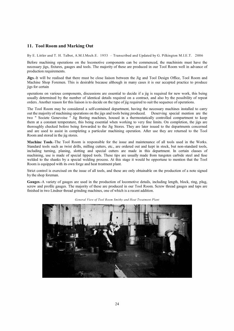
General View of Tool Room Smithy and Heat Treatment Plant

25
"Societe-Geneooise" Jig Borer "Lindner" Thread Grinding Machine
In order to ensure that all plate profile gauges are produced accurately, each gauge is checked by projecting the
shadow of the profile magnified to fifty times actual size. This shadow is then checked with the drawn out profile
to the same scale and any discrepancies are corrected accordingly.
Maintenance Section.-In order to avoid any undue delay in production, it is essential that the machines, tools and pneumatic equipment should be properly maintained, and a team of fitters attached to the Tool Room are engaged
on this work. A further section is also responsible for the overhaul and upkeep of special measuring equipment
such as micrometers, clock gauges, etc.
Without selecting any section of the Tool Room for special mention, it will be realised that much is owed to the
organisation behind this department for the successful production of the varied details required on a locomotive.
Welding Tunsten Carbide Tip Grinding Milling Cutters Checking Slip Gauges on “Taylor-Hobson’
Electrolimit Comparator
In a large number of cases, even when jigs are used, an initial machining operation is required to produce a datum face from which the jig can be located. Before this machining is done, the detail is first "marked out." This
important operation is carried out on various tables situated in the following departments. These cover all locomotive details with the exception of the Boiler shells which were mentioned in the previous article.
l. Frame Bay - Frames and general plates.
2. Fitting Shop - Castings, forgings and general details.
3. Cylinder Shop - Cylinders, Saddles and motion details.
4. Tender Shop - Tender_ frames and plate work.
5. Diesel Shop - Fabricated stretchers and the majority of Diesel and Electric locomotive mechanical parts.
In the case of castings and forgings where the majority of machining operations necessitate planing, slotting and
milling, the details are first checked to ensure that allowances have been left on all the faces to be machined.
The marking out tables also produce numerous templates either to aid in the actual marking out or to use on the
oxy-propane burners. The marker-out may be considered an important link between the drawing board and the

26
machine shops. The ability to read drawings efficiently enables him to assist the machinist in producing the required locomotive details.
Frame Bay Marking Out Tables Diesel Shop Marking Out Tables Fitting Shop Marking Out Tables
12. Machine Shops
By E. Littler and T. H. Talbot, A.M.I.Mech.E. 1953 – Transcribed and updated by G. Pilkington M.I.E.T. 2006
(a) Flame Cutting and Saws
Gxy-acetylene cutting machines have for many years been standard equipment in locomotive, carriage and wagon, boiler and general engineering workshops and have contributed considerably to the saving of both man and
machine hours in the cutting of plates and other forms of steelwork.
An outstanding example of this type of machine is the one situated in the Frame Bay and used chiefly for cutting
out the profile of the main frame plates.
The fuel used in these machines is, however, a combination of oxygen and propane gas. The oxy-propane flame is
used to heat the plate and an oxygen jet does the actual cutting. Four other smaller flame cutting machines are situated in the Copper Shop and two mobile machines are also in use, together with several hand burners, for
cutting miscellaneous slabs and plates. Another initial cutting operation, used mainly to cut various sections to
required lengths, is carried out in the Steel Sawing Section. Here the bars and angles are cut to the requirements of
the machine and erecting shops on " Band " and Rotary saws.
(b) Turning Shops Turning constitutes a large part of the machining operations carried out on the locomotive details and many types of machines are to be found in our Workshops.
The five main departments concerned with turning operations are as follows : -
(1) SMALL TURNERY: Numerous details of a light nature are machined in this department in Centre Lathes on
which the majority of turning operations can be carried out.
This department may be termed the " training ground " for the apprentice turner. It is here where he gains
experience in general turning, chuck, face plate and screw cutting work.
Some of the more important details produced in this department are reversing screws and nuts; piston valve heads
and rods.
(2) TURRET LATHES: These machines deal with work of a larger size and each machine is usually set up for one particular job, e.g., crossheads, bogie and truck wheel centres, fly cranks and eccentric cranks.

27
Flame Cutting Slab Turning Small Details Checking Axle Journals
In order to avoid excessive setting up for each operation, jigs and fixtures are widely used and these also help
towards increased production.
(3) AXLE SHOP : As the title implies, the main concern of this department is the production of numerous types of axles and crank pins used in the various locomotives under construction. The shop is equipped with large centre
lathes and also special machines for boring axles and crank pins when hollow types are required for a particular contract.
Much importance is attached to the finish of these details and care is taken to ensure that the bearing journals are
of a high grade finish.
(4) TURNING SHOP: This department is equipped with Centre Lathes and general details of a large size are machined here. A few examples are as follows : Piston heads and rods, cylinder covers and liners, brake
crossbeams.
(5) WHEEL BAY : This is one of the few self contained machine shops in our works which produces from the
basic material, i.e., rolled rings and castings, completely machined and assembled details ready for the
locomotives.
The wheel centres are first machined in wheel turning lathes and the tyres in a Crane's tyre borer, the necessary allowances being made for the shrinking on process used to assemble these two details.
When the wheels are ready for mounting on to their individual axles, this is done in a 250 ton wheel press. The interference tolerances between the axle diameter and the wheel bore are designed to give a pressing on tonnage
of between 8 and 12 tons per inch of axle diameter.
Tyre Boring Pressing Wheels on Axles
(c) Planing Generally this is the initial machining operation to be carried out on castings and fabrications, often for the
purpose of producing the " datum face," which is so essential for setting up and location of jigs for the subsequent
machining operations.
The majority of details used in locomotive construction lend themselves to " batch planing " and the operator's job
of setting up the batches on the machine is no mean task. The importance of marking out can be clearly seen on this type of work in assisting the operator, who by ensuring that the lines and "pops" on the details are set in line
with the cutting action of the tool, can obtain the nominal finished sizes. The term "nominal" has been used
28
because the operator will often make use of the many types of length, block and profile gauges in order to arrive at the actual finished sizes.
A wide variety of these machines are in use in our Works ranging from small planers for light work to the large frame plate planer, with a traversing table 50 ft. in length.
(1) LIGHT PLANERS : As the name of the Department implies, the machines are of the light type and numerous
small castings and fabrications are machined here.
(2) AXLEBOX SHOP : It is a common sight in this Department to see batches of axleboxes, guides and other
medium size castings and fabrications being machined. The following list may serve to indicate the number of
details handled on these machines by batch planing : Axleboxes, 24; axlebox guides, 12; dragboxes, 8. The size of the details will, of course, determine the number which can be accommodated in each batch and the above are
consequently only average figures.
(3) CYLINDER SHOP : One heavy planer and three medium size planers are accommodated in this Department
to deal with all the cylinder and smokebox saddle castings.
(4) HEAVY PLANERS: The large planers in this Department are used to machine the heavier types of castings
and fabrications, such as motion girders, slidebar brackets, frame stretchers, bogie bolsters, etc.
(5) LARGE BETTS FRAME PLANER : This is a comparatively recent addition to our plant and is used mainly for the machining of bar frames, and any large fabrications which cannot be handled on the other machines.
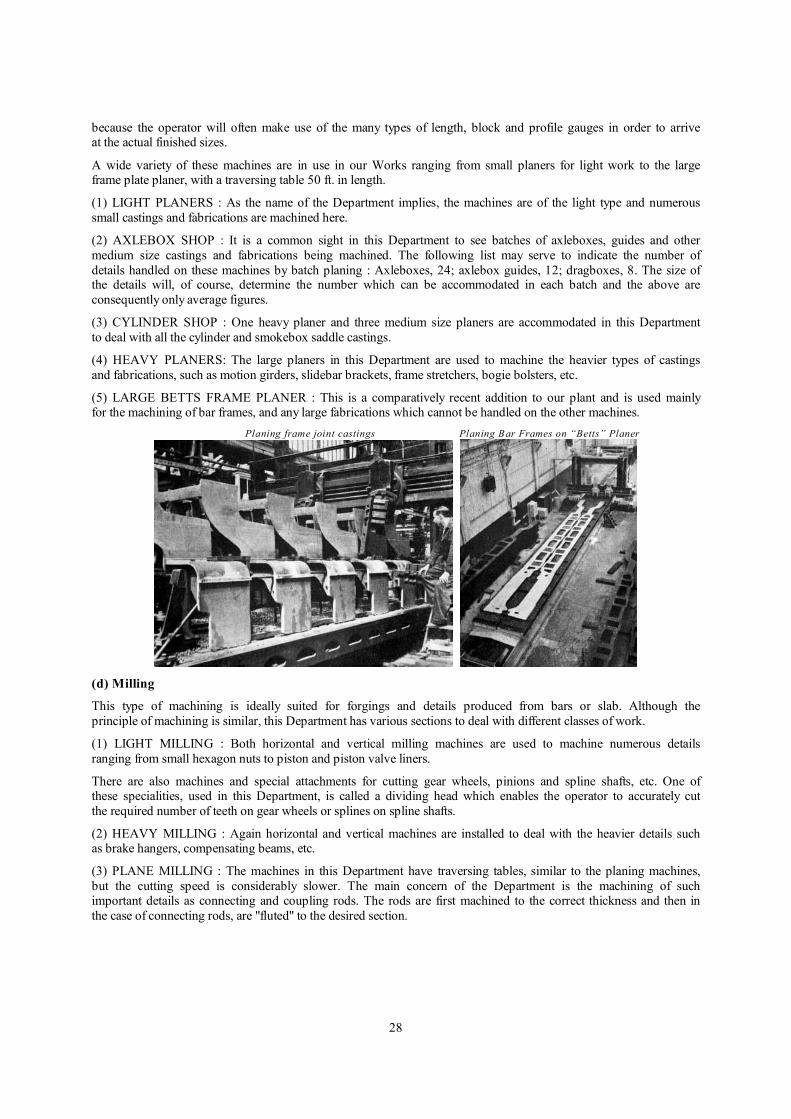
Planing frame joint castings Planing Bar Frames on “Betts” Planer
(d) Milling
This type of machining is ideally suited for forgings and details produced from bars or slab. Although the
principle of machining is similar, this Department has various sections to deal with different classes of work.
(1) LIGHT MILLING : Both horizontal and vertical milling machines are used to machine numerous details
ranging from small hexagon nuts to piston and piston valve liners.
There are also machines and special attachments for cutting gear wheels, pinions and spline shafts, etc. One of these specialities, used in this Department, is called a dividing head which enables the operator to accurately cut
the required number of teeth on gear wheels or splines on spline shafts.
(2) HEAVY MILLING : Again horizontal and vertical machines are installed to deal with the heavier details such as brake hangers, compensating beams, etc.
(3) PLANE MILLING : The machines in this Department have traversing tables, similar to the planing machines,
but the cutting speed is considerably slower. The main concern of the Department is the machining of such important details as connecting and coupling rods. The rods are first machined to the correct thickness and then in
the case of connecting rods, are "fluted" to the desired section.

29
Milling Ports in Cylinder Liners Plane Milling Rods
(e) Slotting and Shaping
The finished profile in many of the locomotive details is obtained by these machining operations.
(1) SLOTTING: Forgings and castings are usually singly machined on large, medium or light slotting machines,
whilst the plates and smaller details are batch machined, using the top plate as a guide, this having previously been marked out.
Deserving special mention is the Holroyd Three-Headed Frame Slotter, where the three slotting heads are housed
on a continuous bed some 90 feet in length. The bar and plate frames are finished profiled on this machine, the
plate frames being machined in batches of approximately 15. The advantage of this machine is that the frames can
be completed at the one setting, using two or even three heads to machine the profile over the total length.
(2) SHAPING : The cutting action of the five shaping machines installed in this Department is very similar to that of slotting, the major difference being in the direction of the stroke, the slotting machine being vertical, whilst the
shaper is horizontal. Details which are difficult to set in a vertical plane are usually machined here, such as
awkwardly shaped brackets, boiler seatings, etc.
Slotting Horn Blocks Slotting Bar Frames
(f) Drilling and Boring
There are very few locomotive details which at some time or other do not require either drilling or boring and many and varied are the machines used for this important operation. Wide use is made of jigs for all important
details and often the holes will be drilled undersize in order that after being fitted to the mating component they can both be opened out to the correct diameter.
We list below the various drilling Departments and also describe briefly the details which each one deals with.

30
(1) FRAME BAY DRILLERS : Plate and bar frames, smokebox saddles, frame stretchers, dragboxes.
(2) AXLEBOX SHOP DRILLERS : Axleboxes, guides, boiler mountings, brake block, connecting and coupling
rod oil cups.
(3) BORERS: The major details machined in this Department are the connecting and coupling rods which are drilled and finished bored to take the brasses or roller bearings.
(4) CYLINDER SHOP : Cylinders, covers, slide bars, crossheads and practically all details appertaining to the
Cylinder assembly.
(5) PIN DRILLING (FITTING SHOP) : Many small assemblies which have been fitted are drilled in this
Department, usually to suit split or taper pins.
(6) SLOT DRILLERS : Cotter pin slots in crossheads, piston rods and various pins are machined in this
Department by first drilling two plain holes at the extreme ends of the slot and the material between them machined out by a two-pronged revolving drill which also has a horizontal traversing movement.
Many of the machines in the above Departments are equipped with attachments for tapping and are fitted with
spring loaded safety devices for " blind holes."
We have only covered the Departments where the majority of drilling is carried out, but we might mention that in
some of the self-contained Departments one or two drilling machines are installed to cover work of a local nature.
Drilling Bar Frames Producing Cup Stays
13. Brass Finishing and Copper Shop
By E. Littler and T. H. Talbot, A.M.I.Mech.E. 1953 – Transcribed and updated by G. Pilkington M.I.E.T. 2006
Brass Finishing. Whilst the majority of non-ferrous valves, cocks and other brass work are these days machined and fitted and tested in the department, this was not the case during the major part of the Firm's history, as most of
these details were produced by various sub-contractors. A change was made some 15 years ago when gradually all
the non-ferrous parts (except proprietary fittings) were cast, machined and fitted in our own works. The extent of this change may be gathered from the fact that in the early days of brass finishing at The Vulcan, four men and
one or two apprentices could cope with the work, whereas now a team of 23 tradesmen and 12 apprentices are employed to produce the many details undertaken in the Brass Finishing Shop, where the majority of the
machining operations are carried out on various types of lathes.
The other machines in the Department are as follows : 4 Milling Machines, used mainly for machining hexagons and squares on valve spindles, caps, etc.; 2 Drilling Machines for medium and light work and 1 Buffing Machine
for polishing brasswork and 1 Saw for cutting extruded brass bars.
Before the finished details are either sent to the various shops for fitting or to the department's own assembly
bench, they are first inspected for correct size and surface finish. The valves and cocks, etc., which are produced
in the department are assembled by skilled brass finishers and fitters and before being transported to the Erecting Shops, are pressure tested under hydraulic and steam. The section is equipped with its own gas fired boiler for the
steam pressure test, which of course, is arranged according to the actual boiler pressure of the locomotive. The
hydraulic test is usually given this pressure plus 10% .
31
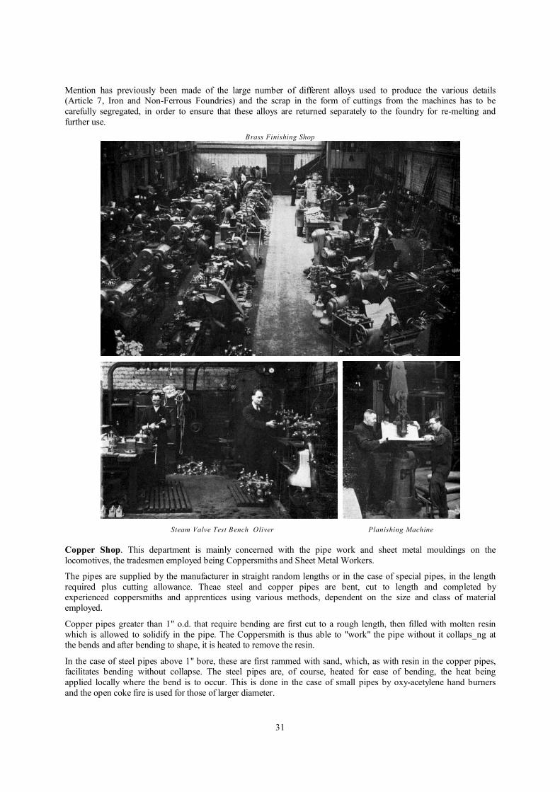
Mention has previously been made of the large number of different alloys used to produce the various details (Article 7, Iron and Non-Ferrous Foundries) and the scrap in the form of cuttings from the machines has to be
carefully segregated, in order to ensure that these alloys are returned separately to the foundry for re-melting and
further use.
Brass Finishing Shop
Steam Valve Test Bench Oliver Planishing Machine
Copper Shop. This department is mainly concerned with the pipe work and sheet metal mouldings on the
locomotives, the tradesmen employed being Coppersmiths and Sheet Metal Workers.
The pipes are supplied by the manufacturer in straight random lengths or in the case of special pipes, in the length
required plus cutting allowance. Theae steel and copper pipes are bent, cut to length and completed by experienced coppersmiths and apprentices using various methods, dependent on the size and class of material
employed.
Copper pipes greater than 1" o.d. that require bending are first cut to a rough length, then filled with molten resin
which is allowed to solidify in the pipe. The Coppersmith is thus able to "work" the pipe without it collaps_ng at the bends and after bending to shape, it is heated to remove the resin.
In the case of steel pipes above 1" bore, these are first rammed with sand, which, as with resin in the copper pipes, facilitates bending without collapse. The steel pipes are, of course, heated for ease of bending, the heat being
applied locally where the bend is to occur. This is done in the case of small pipes by oxy-acetylene hand burners
and the open coke fire is used for those of larger diameter.

32
Coppersmiths Shop
The pipes are bent to the required shape to suit the wire templates previously made by the Coppersmith. In the
case of fixed pipe connections, the nuts are assembled on to the pipes and the connections brazed or welded in
position.
The first set of pipes is assembled on the locomotives and after making any adjustments found necessary during erection, the templates are corrected to suit and the remainder of the pipes for the contract are then completed.
The Sheet Metal section of the Copper Shop produces a variety of details such as clothing mouldings and pockets,
dome casings for steam locomotives, nose end and cab mouldings for diesel and electric locomotives. These
mouldings are produced without the aid of forming blocks, the steel sheets being cut to the correct developed
shape and cold worked on an Oliver planishing hammer, using templates to ensure that the correct radii are formed on the mouldings.
In the case of cab and nose ends for the large diesel and electric locomotives, the mouldings are actually produced
and fitted on to the framework in the sheet metal section.
14. Electric Welding
By E. Littler and T. H. Talbot, A.M.I.Mech.E. 1953 – Transcribed and updated by G. Pilkington M.I.E.T. 2006
Electric welding was introduced in our Works in 1924 when some Great Western Railway Boilers were being
produced. The specification called for the welding of the boiler barrel seams, and a double operator Quasi Arc D.C. welding set was installed for this purpose. Even at that time however, the principle of electric welding had not been generally accepted by the engineering industry, and many firms still received it with suspicion. It was
only after practical tests had proved its reliability coupled with improvements in the welding equipment that its
use became more general. This popularity gradually increased as welding techniques developed, until at the present time it has become the major operation in the production of fabricated units.
The majority of modern steam locomotives are designed with many of the major units welded instead of riveted
and with the development of the Diesel Electric and Electric locomotives an even wider use is made of welding,
as practically all the units are fabricated from plate and miscellaneous rolled sections.
We shall now deal with the various sections of the welding department, describing briefly the type of work
undertaken in each section together with the jigs and special equipment used to assist production.
(a) DIESEL FABRICATING SHOP
This is a comparatively new section, being converted from the old brass foundry which is now housed in a new building adjacent to the Iron Foundry.

33
The majority of the fabricated units for Diesel and Electric locomotives are produced in the fabricating shop, including frame stretchers, dragboxes, fuel tanks, etc. The most satisfactory welds are produced by what is known
as "down hand welding", the electrode being held to the work in a down position, and in order to achieve this and
to avoid excessive crane lifts, two Metro-Vickers power driven manipulators are used. Units of up to two tons in
weight can be handled in these manipulators and they play an important part in the production of large sub-assemblies. A small seven cwt. hand operated manipulator is also in use for smaller fabrications.
Another important fixture in this department is a stationary jig some 30 feet in length to assist in the welding of
long fabricated units.
Diesel Loco Frame in Fabrication Shop
Welding Manipulator in Fabrication Shop
(b) DIESEL ERECTING SHOP
Although this will be covered more fully in a future article, we feel that mention must be made here that welding
plays a major part in this shop, for in addition to the welding which is carried out during erection of the locomotive, large units such as superstructure. cab and roof framings are also produced. For this purpose three
large stationary jigs are used together with other smaller jigs for various other details.

34
A recent addition to the equipment in this department is a Crompton-Parkinson stud welding machine which welds studs in position in a "split second". This machine is used for the fixing of studs for cable cleats, pipe clips
and numerous brackets. It is also adaptable for use as an ordinary welding set.
(c) COPPER SHOP WELDERS
This is the oldest welding section in our works and practically all fabricated details were produced here prior to
the last war. Many important items are still produced in this shop, such as foundation rings, frame stretchers,
reversing shafts and brake shafts. Two trunnion mounted jigs for welding foundation rings together with a tilting rotating manipulator for reversing shafts form part of the equipment.
(d) BOILER SHOP
The majority of modern locomotive boilers are designed with certain of the major units of welded construction, the main development in this direction of recent years being the all welded inner firebox. Two trunnion mounted
manipulators are in use in the Boiler Shop for the production of these large units, the joint seams being welded
and afterwards subjected to X-ray insnection, by means of a Victor X-ray set described in a previous article (see article R, Laboratory and Test House), Vol. 2, No. 9.
Other work carried out in this section includes the welding of flexible stay cups to the outer firebox; barrel end joints, dome seams and seal weldinge at foundation rings, boiler seatings and washout plug seatings, etc.
(e) FITTING AND ERECTION SHOPS
A certain amount of welding is carried out during the course of assembly and erection of the various details and
three welding sets are in use for this purpose, two in the Erecting Shop and one in the Fitting Shop.
(f) TENDER SHOP
The welded tender tank has now become accepted practice on many of the Railways of the world and with this trend came the demand for a manipulator which could handle these bulky units. A large power driven rotating
manipulator was designed and constructed in our works to facilitate the welding of the outside seams of the tender water tanks. A small hand onerated manipulator is also in use for welding tender oil fuel tanks. Other equipment
in this shop includes two large stationary jigs for fabricated underframes.
Since welding has become such an important operation in all branches of engineering, the training of skilled
operators has to be borne in mind and a scheme is in operation in our works in order that apprentice welders are
trained under strict supervision. Initial training consists of working on portable oxy-acetylene cutters, after which experience is provided on various classes of work until fully qualified to tackle all types of jobs.
Tank Welding Manipulator. Tender Shop

35
15. Sub-Assembly Shops
By E. Littler and T. H. Talbot, A.M.I.Mech.E. 1954 – Transcribed and updated by G. Pilkington M.I.E.T. 2008
1) Fitting Shops The Fitting Shop is composed of seven different sections, each having its own chargehand and being responsible
for various detail, and sub assemblies on the locomotives. Each team of fitters under their chargehand specialise in
the details produced in their section, although sometimes changes in personel have to be made, depending on the flow of work through thc various sections.
The number of fitters and appren[ices in each section vary according to the type of work produced, but on average
each team consists of six fitters and three apprentices.
Listed below are the various sections with a brief description of the work carried out, together with any
special equipment used.
(a) Axlebox Guides Section
The coupled wheel, truck and bogie axlebox guides with their details are fitted in this section. The work
entails, the dressing and preparation of the steel castings and details and positioning the slide liners which
are fitted to the guides on the majority of modern locomotives.
(b) Boiler Detail Section
The majority of boiler details are fitted and sub-assembled in this section including the main steam pipe and regulator elbow, regulator gear, firedoor details, a main steam stand, safety valves, injector steam valves, inspection doors, etc.
After assembly the valves and cocks are tested under hydraulic pressure and then sent to the brass finishing shop
for steam pressure testing.
(c) Control Gear Section
Included in this section are the control gears for operating the ashpan, injectors, and cylinder cocks, etc., for steam
locomotives, together with the drivers desk and controls for diesel shunters.
General View of Fitting Shop
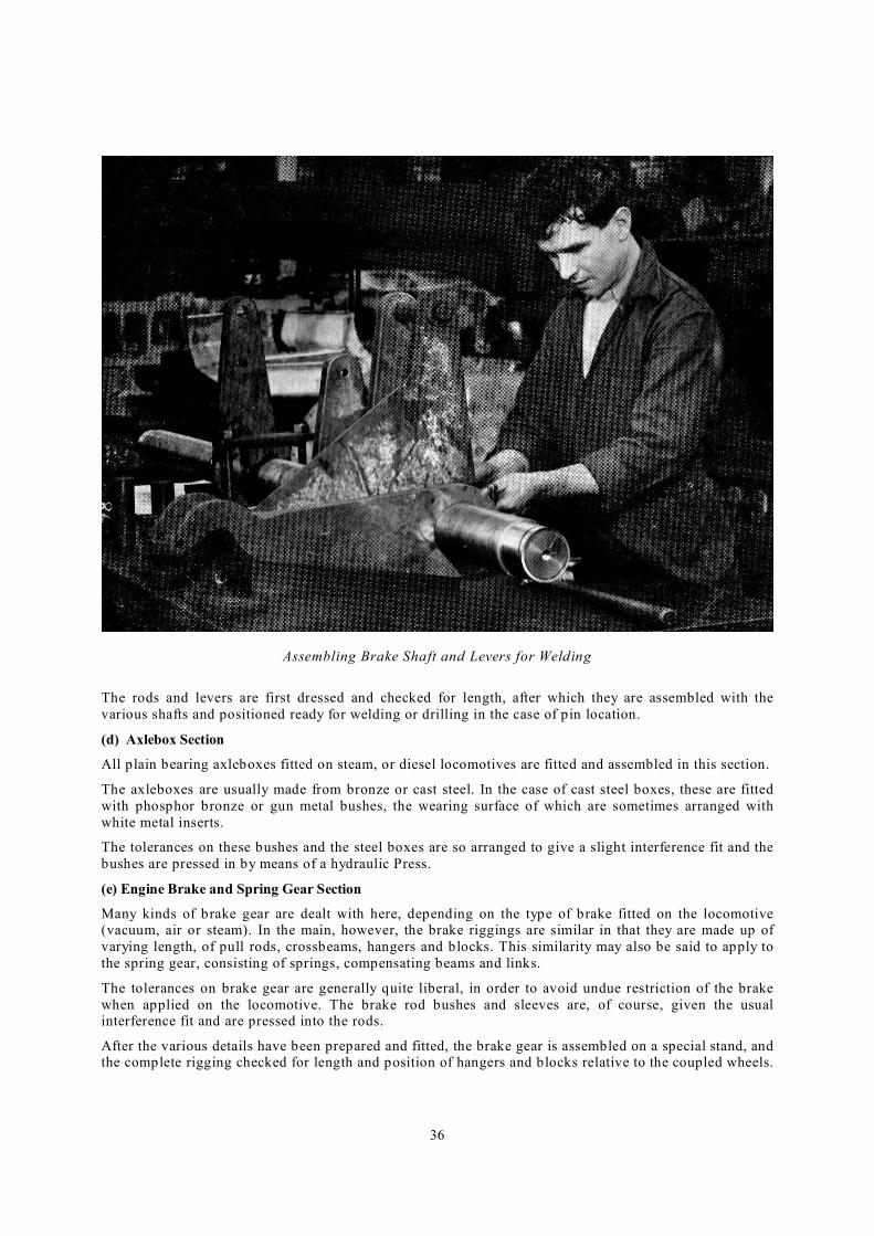
36
Assembling Brake Shaft and Levers for Welding
The rods and levers are first dressed and checked for length, after which they are assembled with the
various shafts and positioned ready for welding or drilling in the case of pin location.
(d) Axlebox Section
All plain bearing axleboxes fitted on steam, or diesel locomotives are fitted and assembled in this section.
The axleboxes are usually made from bronze or cast steel. In the case of cast steel boxes, these are fitted
with phosphor bronze or gun metal bushes, the wearing surface of which are sometimes arranged with
white metal inserts.
The tolerances on these bushes and the steel boxes are so arranged to give a slight interference fit and the
bushes are pressed in by means of a hydraulic Press.
(e) Engine Brake and Spring Gear Section
Many kinds of brake gear are dealt with here, depending on the type of brake fitted on the locomotive (vacuum, air or steam). In the main, however, the brake riggings are similar in that they are made up of
varying length, of pull rods, crossbeams, hangers and blocks. This similarity may also be said to apply to
the spring gear, consisting of springs, compensating beams and links.
The tolerances on brake gear are generally quite liberal, in order to avoid undue restriction of the brake
when applied on the locomotive. The brake rod bushes and sleeves are, of course, given the usual interference fit and are pressed into the rods.
After the various details have been prepared and fitted, the brake gear is assembled on a special stand, and the complete rigging checked for length and position of hangers and blocks relative to the coupled wheels.
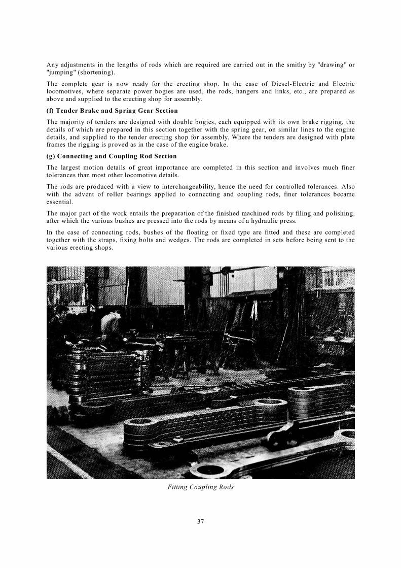
37
Any adjustments in the lengths of rods which are required are carried out in the smithy by "drawing" or "jumping" (shortening).
The complete gear is now ready for the erecting shop. In the case of Diesel-Electric and Electric locomotives, where separate power bogies are used, the rods, hangers and links, etc., are prepared as
above and supplied to the erecting shop for assembly.
(f) Tender Brake and Spring Gear Section
The majority of tenders are designed with double bogies, each equipped with its own brake rigging, the
details of which are prepared in this section together with the spring gear, on similar lines to the engine
details, and supplied to the tender erecting shop for assembly. Where the tenders are designed with plate frames the rigging is proved as in the case of the engine brake.
(g) Connecting and Coupling Rod Section
The largest motion details of great importance are completed in this section and involves much finer
tolerances than most other locomotive details.
The rods are produced with a view to interchangeability, hence the need for controlled tolerances. Also
with the advent of roller bearings applied to connecting and coupling rods, finer tolerances became
essential.
The major part of the work entails the preparation of the finished machined rods by filing and polishing, after which the various bushes are pressed into the rods by means of a hydraulic press.
In the case of connecting rods, bushes of the floating or fixed type are fitted and these are completed
together with the straps, fixing bolts and wedges. The rods are completed in sets before being sent to the
various erecting shops.
Fitting Coupling Rods
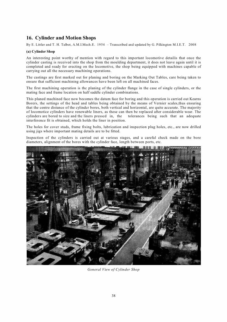
38
16. Cylinder and Motion Shops
By E. Littler and T. H. Talbot, A.M.I.Mech.E. 1954 – Transcribed and updated by G. Pilkington M.I.E.T. 2008
(a) Cylinder Shop
An interesting point worthy of mention with regard to this important locomotive detailis that once the
cylinder casting is received into the shop from the moulding department, it does not leave again until it is
completed and ready for erecting on the locomotive, the shop being equipped with machines capable of carrying out all the necessary machining operations.
The castings are first marked out for planing and boring on the Marking Out Tables, care being taken to ensure that sufficient machining allowances have been left on all machined faces.
The first machining operation is thc planing of the cylinder flange in the case of single cylinders, or the
mating face and frame location on half saddle cylinder combinations.
This planed machined face now becomes the datum face for boring and this operation is carried out Kearns
Borers, the settings of the head and tables being obtained by the means of Vernier scales,thus ensuring
that the centre distance of the cylindcr bores, both vertical and horizontal, are quite accurate. The majority of locomotice cylinders have renewable liners, as these can then be replaced after considerable wear. The
cylinder s are bored to size and thc liners presscd in, the tolerances being such that an adequate
interference fit is obtained, which holds the liner in position.
The holes for cover studs, frame fixing bolts, lubrication and inspection plug holes, etc., are now drilled using jigs where important mating details are to be fitted.
Inspection of the cylinders is carried out at various stages, and a careful check made on the bore diameters, alignment of the bores with the cylinder face, length between ports, etc.
General View of Cylinder Shop

39
Preparing Cylinders for Hydraulic Test Boring Steam Chest of Cylinder
The cylinders are now prepared and fitted with covers for their first hydraulic test under hot water
pressure of 50% above actual boiler pressure. This test is only carried out on the, high pressure sections
of the cylinders. The cylinders are now completed with all studs, plugs, dowels and covers fitted and are
given a final hydraulic test on alI sections at 75% boiler pressure.
(b) Sidebar Piston & Crosshead Section
The major details on the cylinder assembly are prepared in this section, and in the case of cylinder covers and slide bars, jigs and fixtures play an important part. The jig for the hind cylinder cover is located on a
cast iron table, and when the cover and slidebars are fitted up in their working condition, the alignment
and clearances can be checked. Adjusiments are made by the use of shims between the cover and
slidebars.
The piston rod and crosshead are also fitted and assembled in this section and before completion the whole assembly is located on vee blocks for final fitting and checking. The concentricity of the piston, rod and
crosshead is essential and this is ensured by making the necessary adjustment to the crosshead liners.
(c) Piston Valve Section
This section is mainly concerned with the fitting and assembly of piston valve heads, rings, spindles,
crossheads and hind steam chest covers. The piston valve heads are fitted to the valve epindle and after
assembling the valve rings, the distance between the inner ring, on each head is checked and adjustments carried out if necessary. It is essential that this length should be correct in order to obtain the correct valve
readings when they are assembled on the locomotive.
A specially constructed jig is used to facilitate the fitting of the gun metal liners to the hind steam chest
covers, and for checking the clearances between these liners and the valve spindle crosshcad. This jig is so
designed to enable the details to be fitted in their normal working condition on the locomotive.
(d) Motion Detail Section
The motion details induding reversing gear are fitted and assembled here. These details indude such items as valve and eccentric rods, combination levers, links and die blocks, reversing shafts, screws and
brackets, etc.

40
Piston Valve Fitting Section Piston, Piston Rod and Crosshead Fitting Section
The major portion of the work entails the preparation of the finished machined details by filing, polishing,
setting and assembly. The various bushes used in the rods are pressed in by the means of a small hydraulic press.
To ensure that the driving mechanismof the locomotive works efficiently, fine tolerances are maintained
on all the motion details.
Grinding Die Path of Reversing Link
(e) Machine Grinding Department
This department is closely connected with the
cylinder and motion shops. A Iarge proportion of
the motion details are case-hardened on all wearing surfaces and this necessitates machine grinding for
the final machining operation. Specialised machines are used for grinding the internal radius path for the die block on the
reversing links. Other details on which grinding
operations are carried out include piston rods,
slidebars, crank pins, motion pins, etc. The interna1 grinding of holes for motion pins, and the polishing
and finish grinding of motion coupling and
connecting rods are also carried out in this
department.
Machine Grinding Department
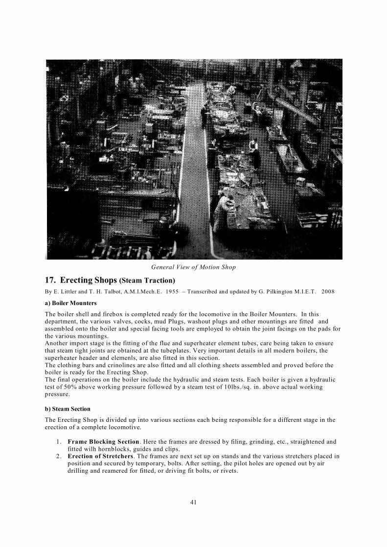
41
General View of Motion Shop
17. Erecting Shops (Steam Traction)
By E. Littler and T. H. Talbot, A.M.I.Mech.E. 1955 – Transcribed and updated by G. Pilkington M.I.E.T. 2008
a) Boiler Mounters
The boiler shell and firebox is completed ready for the locomotive in the Boiler Mounters. In this department, the various valves, cocks, mud Plugs, washout plugs and other mountings are fitted and
assembled onto the boiler and special facing tools are employed to obtain the joint facings on the pads for
the various mountings. Another import stage is the fitting of the flue and superheater element tubes, care being taken to ensure
that steam tight joints are obtained at the tubeplates. Very important details in all modern boilers, the
superheater header and elemenls, are also fitted in this section.
The clothing bars and crinolines are also fitted and all clothing sheets assembled and proved before the boiler is ready for the Erecting Shop.
The final operations on the boiler include the hydraulic and steam tests. Each boiler is given a hydraulic
test of 50% above working pressure followed by a steam test of 10lbs./sq. in. above actual working pressure.
b) Steam Section
The Erecting Shop is divided up into various sections each being responsible for a different stage in the
erection of a complete locomotive.
1. Frame Blocking Section . Here the frames are dressed by filing, grinding, etc., straightened and
fitted wilh hornblocks, guides and clips. 2. Erection of Stretchers. The frames are next set up on stands and the various stretchers placed in
position and secured by temporary, bolts. After setting, the pilot holes are opened out by air
drilling and reamered for fitted, or driving fit bolts, or rivets.

42
3. Erection of Cylinders, etc. The next step is the erection of the cylinders, motion girders, and slide bar brackets. Care is taken to ensure that the distance from the driving wheel to the cylinders
is correct and also that the measurements from the cylinder to the members affecting the motion
are within the specified tolerances.
Fitting Tubes in Boiler Preparing Boiler for Test
Lowering Boiler in Position Setting Cylinders on Frame
4. Fitting the Boiler in the Frames. The boiler complete with smokebox, etc., is now tried in the frame
and the holding down bolt holes marked off in the smokebox and expansion shoe clips. The breathing
plates and expansion slides are also proved. Some of the holes in the smokebox ring and boiler are opened out to full size and these items rivetted together whilst in position.
The boiler is now lifted out and completed, that is smokebox rivetted to boiler, the ashpan fitted;
adjustments being carried out if necessary and finally fastened in position, mattresses and clothing are also fitted as far as possible. The boiler is now ready for final erection and after lowering in position, the holding down bolts are fitted
and the expansion shoe clips and breathing plates, fastened in position.
5. Cab, Platforms and Piping Section . These items are now assembled and the frame checked and
prepared for final inspcetion by the Customer's representative prior to wheeling.
6. Wheeling and final assembly . The complete unit of frames, boiler, cab, ete., is now lifted and lowered
onto the wheels, these having been carefully set in their correct position. The locomotive is "floated", that
is, the driving wheels are located at their correct working level and are free to revolve for valve setting
after the motion has been fitted. 7. Steaming and Testing. The tender is now coupled up and after the services have been added the
1ocomotive is "Steamed'. When the boiler pressure reaches 150 lbs. per square inch, the regulator is
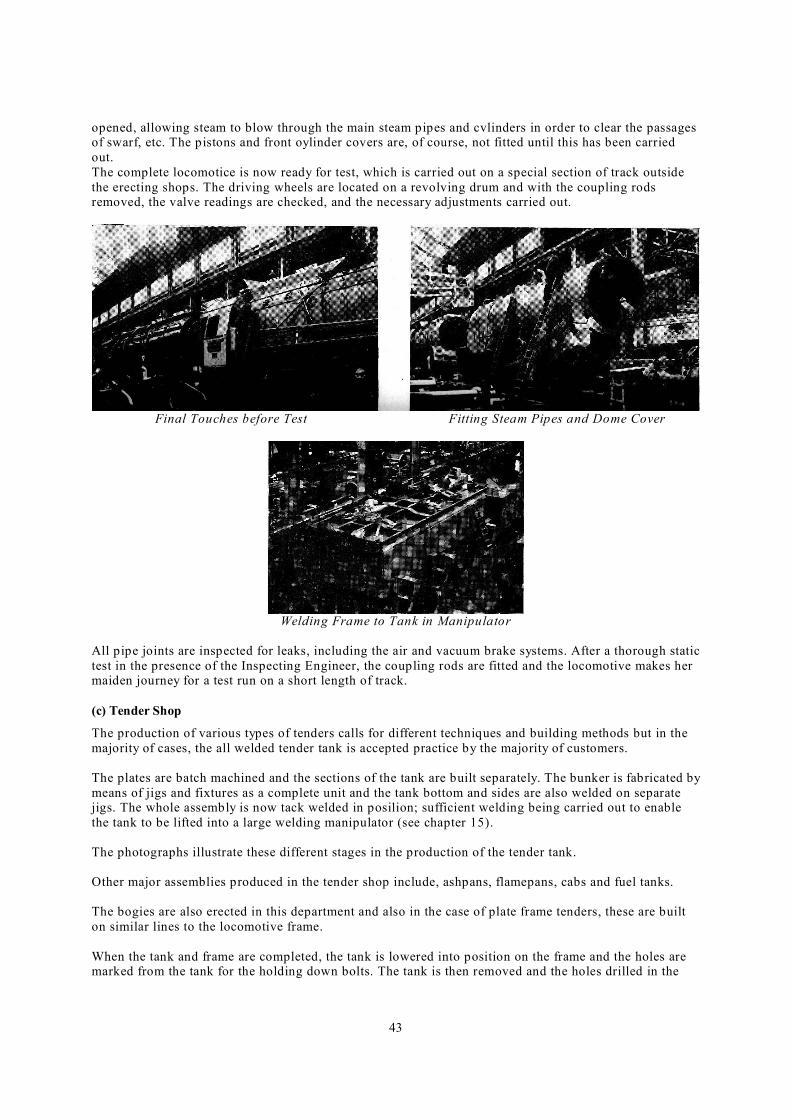
43
opened, allowing steam to blow through the main steam pipes and cvlinders in order to clear the passages of swarf, etc. The pistons and front oylinder covers are, of course, not fitted until this has been carried
out.
The complete locomotice is now ready for test, which is carried out on a special section of track outside
the erecting shops. The driving wheels are located on a revolving drum and with the coupling rods removed, the valve readings are checked, and the necessary adjustments carried out.
Final Touches before Test Fitting Steam Pipes and Dome Cover
Welding Frame to Tank in Manipulator
All pipe joints are inspected for leaks, including the air and vacuum brake systems. After a thorough static
test in the presence of the Inspecting Engineer, the coupling rods are fitted and the locomotive makes her maiden journey for a test run on a short length of track.
(c) Tender Shop
The production of various types of tenders calls for different techniques and building methods but in the
majority of cases, the all welded tender tank is accepted practice by the majority of customers.
The plates are batch machined and the sections of the tank are built separately. The bunker is fabricated by
means of jigs and fixtures as a complete unit and the tank bottom and sides are also welded on separate jigs. The whole assembly is now tack welded in posilion; sufficient welding being carried out to enable
the tank to be lifted into a large welding manipulator (see chapter 15).
The photographs illustrate these different stages in the production of the tender tank.
Other major assemblies produced in the tender shop include, ashpans, flamepans, cabs and fuel tanks.
The bogies are also erected in this department and also in the case of plate frame tenders, these are built
on similar lines to the locomotive frame.
When the tank and frame are completed, the tank is lowered into position on the frame and the holes are marked from the tank for the holding down bolts. The tank is then removed and the holes drilled in the
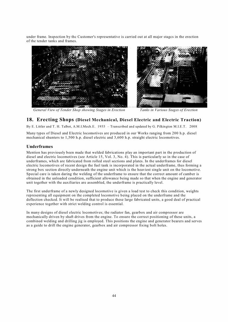
44
under frame. lnspection by thc Customer's representative is carried out at all major stagcs in the erection of the tender tanks and frames.
General View of Tender Shop showing Stages in Erection Tanks in Various Stages of Erection
18. Erecting Shops (Diesel Mechanical, Diesel Electric and Electric Traction)
By E. Littler and T. H. Talbot, A.M.I.Mech.E. 1955 – Transcribed and updated by G. Pilkington M.I.E.T. 2008
Many types of Diesel and Electric locomotives are produced in our Works ranging from 200 h.p. diesel
mechanical shunters to 1,500 h.p. diesel electric and 3,600 h.p. straight electric locomotives.
Underframes
Mention has previously been made that welded fabrications play an important part in the production of
diesel and electric locomotives (see Article 15, Vol. 3, No. 4). This is particularly so in the case of
underframes, which are fabricated from rolled steel sections and plates. In the underframes for diesel electric locomotives of recent design the fuel tank is incorporated in the actual underframe, thus forming a
strong box section directly underneath the engine unit which is the heaviest single unit on the locomotive.
Special care is taken daring the welding of the underframe to ensure that the correct amount of camber is
obtained in the unloaded condition, sufficient allowance being made so that when the engine and generator unit together with the auxiliaries are assembled, the underframe is practically level.
The first underframe of a newly designed locomotive is given a load test to check this condition, weights representing all equipment on the completed locomotive being placed on the underframe and the
deflection checked. It will be realised that to produce these large fabricated units, a good deal of practical
experience together with strict welding control is essential.
In many designs of diesel electric locomotives; the radiator fan, gearbox and air compressor are
mechanically driven by shaft drives from the engine. To ensure the correct positioning of these units, a
combined welding and drilling jig is employed. This positions the engine and generator bearers and serves as a guide to drill the engine generator, gearbox and air compressor fixing bolt holes.
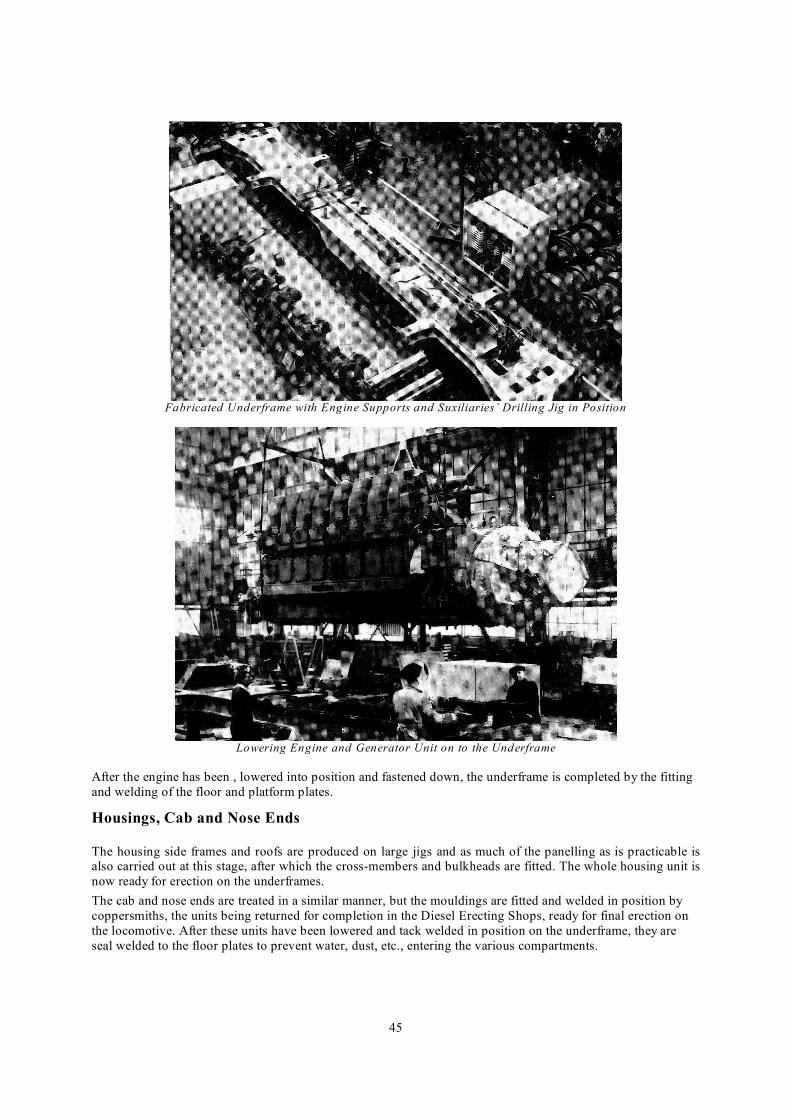
45
Fabricated Underframe with Engine Supports and Suxiliaries’ Drilling Jig in Position
Lowering Engine and Generator Unit on to the Underframe
After the engine has been , lowered into position and fastened down, the underframe is completed by the fitting
and welding of the floor and platform plates.
Housings, Cab and Nose Ends
The housing side frames and roofs are produced on large jigs and as much of the panelling as is practicable is also carried out at this stage, after which the cross-members and bulkheads are fitted. The whole housing unit is
now ready for erection on the underframes.
The cab and nose ends are treated in a similar manner, but the mouldings are fitted and welded in position by
coppersmiths, the units being returned for completion in the Diesel Erecting Shops, ready for final erection on
the locomotive. After these units have been lowered and tack welded in position on the underframe, they are
seal welded to the floor plates to prevent water, dust, etc., entering the various compartments.

46
Housing Framework in Position
Housing and Main Items of Equipment in Position Lowering Motor into Position on Power Bogie
Auxilaries
Auxiliary equipment such as traction motor blowers, exhausters, compressors, main control frames, resistances, etc.,
together with all cab controls and brake equipment are now fitted into the locomotive and connected up with the
necessary piping and electrical cables.
In many cases much of the piping and conduit which is carried on the underframe is erected with the underframe
upside down to simplify erection.
Close co-operation is maintained between the staff employed on the mechanical parts section of the
locomotive and the electrical personnel.

47
Bogies
The power bogies for the higher horse power locomotives usually fall into one of the following types :-
Bo-4 wheel bogies with motors to each axle.
AlA-6 wheel bogies with motors to each outer axle.
Co-6 wheel bogies with motors to all axles.
The majority of these bogies have swing link bolsters which make for good riding qualities.
One piece cast steel frames and stretchers are
sometimes used in the construction of these power bogies but often due to strict weight limitations, the
majority are built up from fabrications. The frames,
bolsters, stretchers, spring planks, etc., being fabricated from plates and sections and stress
relieved before completion.
For locomotives of the 3,000 h.p. range, the frames are usually produced from rolled steel slab.
Drivers Controls and Inside of Main Equipment
Cubicle
Preparation for Test
In the case of Diesel Electric locomotives, before the superstructure is lowered on to the bogies, the brake
piping is given a leakage test. The air piping being tested under pressure from the shop supply and the
vacuum piping by means of electric motor driven portable exhausters.
The superstructure is now lowered on to the power bogies and the services for the engine and auxiliaries are added, including water for the cooling system, lubricating and fuel oil. All the control and lighting cables are
proved at each terminal box and all the controls are "sequence tested".
The locomotive is now placed in the test booth adjacent to a special "test car", the main purpose of which is
to dissipate the generated, power through resistances. This electricity would of course normally be used to
drive the motors on the power bogies.
Load curves are checked and recorded at varying engine speeds, after which the brakes are adjusted and
checked for correct pressures and application including emergency features. The cables carrying the
generated power are now connected to the motors on the bogies and the locomotive is given a rolling test on a short length of track.
The preparation for test of the straight electric locomotive is similar to that for the diesel electric with regard
to brake piping, cable tests, etc. The essential difference is of course, the power supply for the: bogie motors to replace the overhead cable and pantograph which provides the electricity under working conditions; transformers and rectifiers are used to boost up our works supply from 400 volts A.C. to 3,000 volts D.C.
This supply is connected'to the locomotive and the necessary tests carried out.
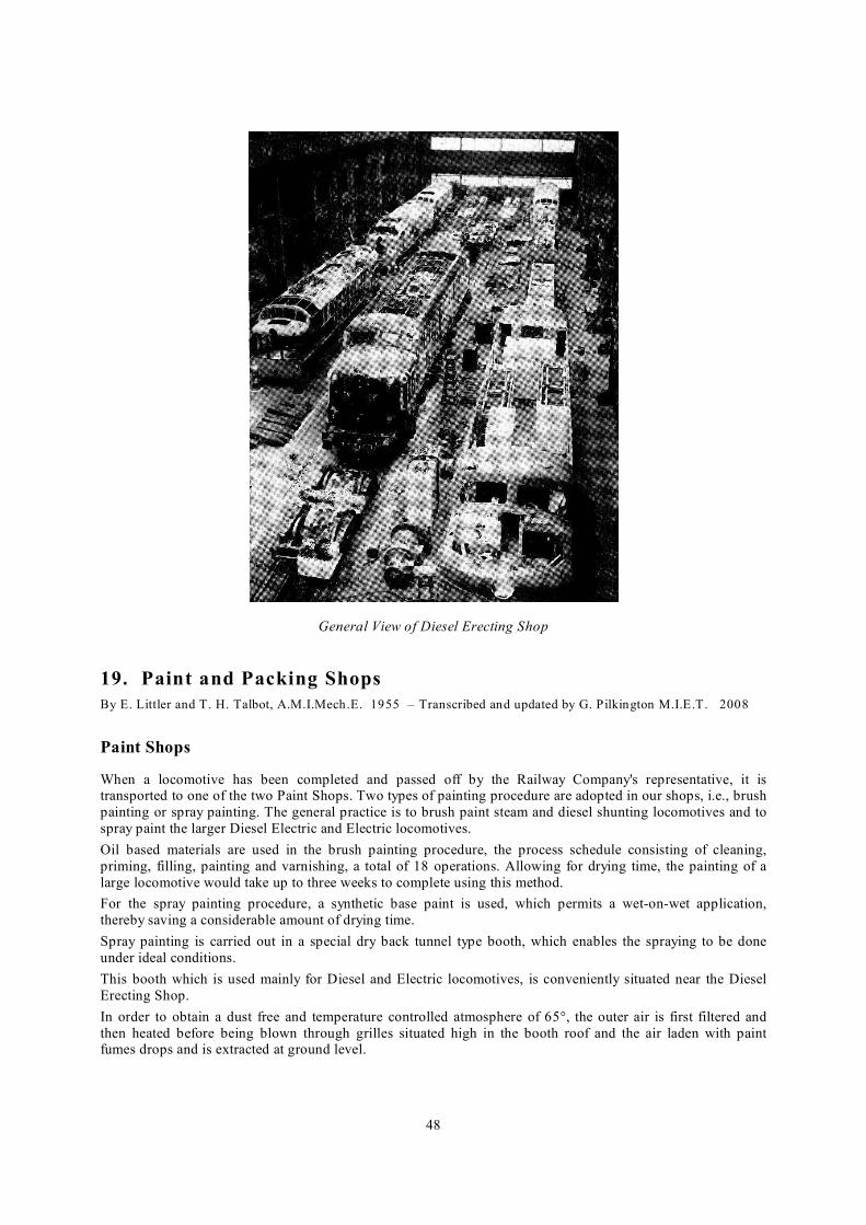
48
General View of Diesel Erecting Shop
19. Paint and Packing Shops
By E. Littler and T. H. Talbot, A.M.I.Mech.E. 1955 – Transcribed and updated by G. Pilkington M.I.E.T. 2008
Paint Shops
When a locomotive has been completed and passed off by the Railway Company's representative, it is transported to one of the two Paint Shops. Two types of painting procedure are adopted in our shops, i.e., brush
painting or spray painting. The general practice is to brush paint steam and diesel shunting locomotives and to
spray paint the larger Diesel Electric and Electric locomotives.
Oil based materials are used in the brush painting procedure, the process schedule consisting of cleaning,
priming, filling, painting and varnishing, a total of 18 operations. Allowing for drying time, the painting of a
large locomotive would take up to three weeks to complete using this method.
For the spray painting procedure, a synthetic base paint is used, which permits a wet-on-wet application,
thereby saving a considerable amount of drying time.
Spray painting is carried out in a special dry back tunnel type booth, which enables the spraying to be done
under ideal conditions.
This booth which is used mainly for Diesel and Electric locomotives, is conveniently situated near the Diesel
Erecting Shop.
In order to obtain a dust free and temperature controlled atmosphere of 65°, the outer air is first filtered and
then heated before being blown through grilles situated high in the booth roof and the air laden with paint fumes drops and is extracted at ground level.

49
1000 h.p. Diesel Electric Locomotive in Spray Booth
1,500 h.p. Diesel Electric Locomotive on accommodation bogies leaving Spray Booth
The booth can accommodate locomotives up to 77' 0" long and the width is such that ample room is provided on either side of the body for spraying operations.
Air for the spray guns is drawn from the works compressed air system but is filtered and pressure regulated before reaching the guns.
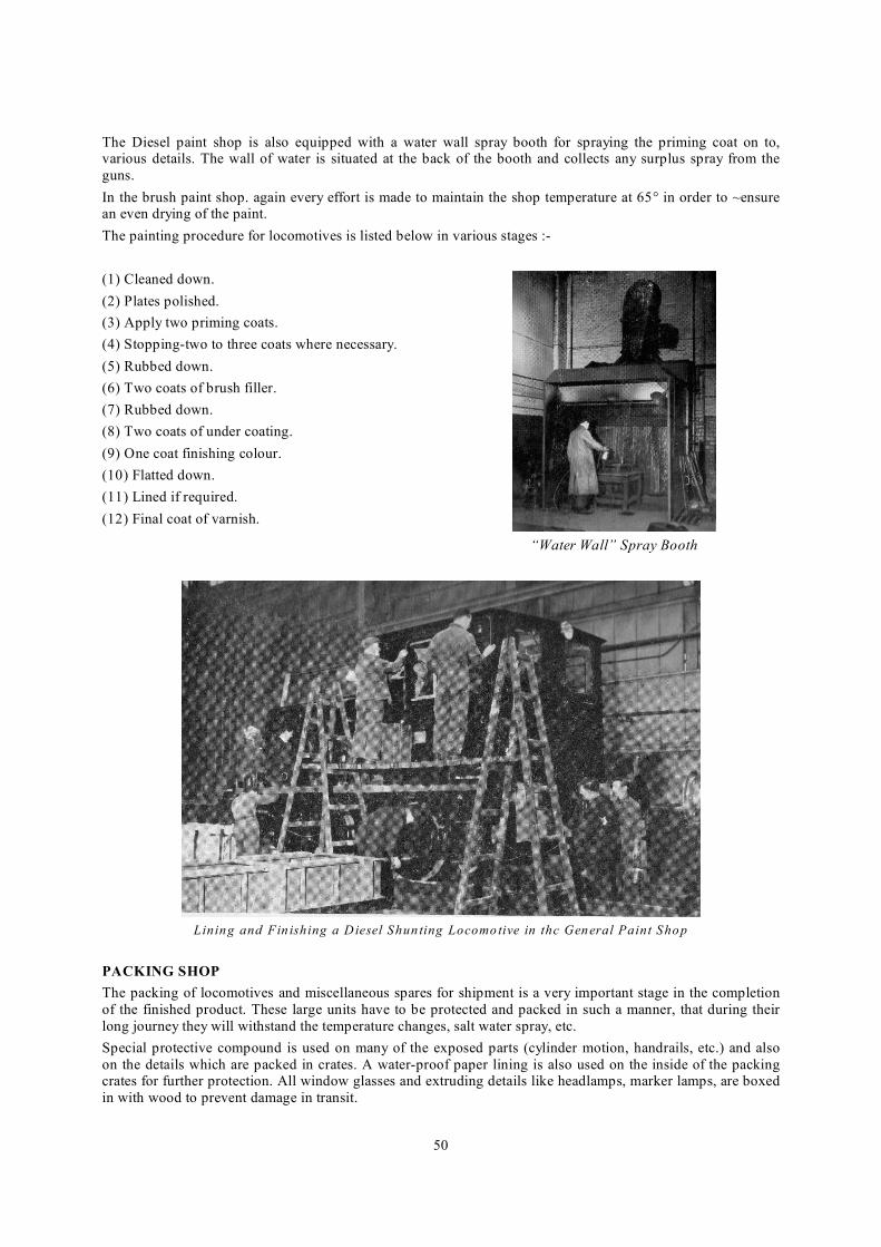
50
The Diesel paint shop is also equipped with a water wall spray booth for spraying the priming coat on to, various details. The wall of water is situated at the back of the booth and collects any surplus spray from the
guns.
In the brush paint shop. again every effort is made to maintain the shop temperature at 65° in order to ~ensure an even drying of the paint.
The painting procedure for locomotives is listed below in various stages :-
(1) Cleaned down.
(2) Plates polished.
(3) Apply two priming coats.
(4) Stopping-two to three coats where necessary.
(5) Rubbed down.
(6) Two coats of brush filler.
(7) Rubbed down.
(8) Two coats of under coating.
(9) One coat finishing colour.
(10) Flatted down.
(11) Lined if required.
(12) Final coat of varnish.
“Water Wall” Spray Booth
Lining and Fin ishing a Diesel Shun ting Locomotive in thc General Paint Shop
PACKING SHOP
The packing of locomotives and miscellaneous spares for shipment is a very important stage in the completion
of the finished product. These large units have to be protected and packed in such a manner, that during their
long journey they will withstand the temperature changes, salt water spray, etc.
Special protective compound is used on many of the exposed parts (cylinder motion, handrails, etc.) and also
on the details which are packed in crates. A water-proof paper lining is also used on the inside of the packing crates for further protection. All window glasses and extruding details like headlamps, marker lamps, are boxed
in with wood to prevent damage in transit.

51
Genera l View o f Pa in t and Packing Shop
20. Ancillary Departments
By E. Littler and T. H. Talbot, A.M.I.Mech.E. 1955 – Transcribed and updated by G. Pilkington M.I.E.T. 2008
Having covered the major departments concerned with the production of diesel, electric and steam locomotives,
we now propose to give a brief resume of the various ancillary departments or services which are essential for the efficient running of a Works such as The Vulcan Foundrv.
(a) INTERNAL TRANSPORT
The major part of the internal transport system is carried out by 18 Lister trucks of varying capacities and are
powered by 4 to 8 H.P. engines. These trucks are used to move miscellaneous details from one department to
another, each truck generally operating in a specified group of departments. The trucks are of the fixed or elevating platform type and some are adapted for special duties such as swarf collection and for carrying
bricklayers' and concrete mixers' supplies.
(b) ELECTRICIANS
This department is responsible for the installation and maintenance of all our electrical equipment.

52
Electricians' Department
Lister Auto. Truck for Inter-Departmental Transport
(c) MILLWRIGHTS
The millwrights are responsible for the installation and removal of all our mechanical equipment together with
the maintenance of the compressed air system, boilers, steam raising and heating plant.
(d) CRANE FITTERS
The erection and maintenance of all electrical and manually operated cranes, blocks, jibs, etc., is carried out by this department. They are also responsible for the inspection and servicing of all lifting gear, including hemp,
wire rope and chain slings.
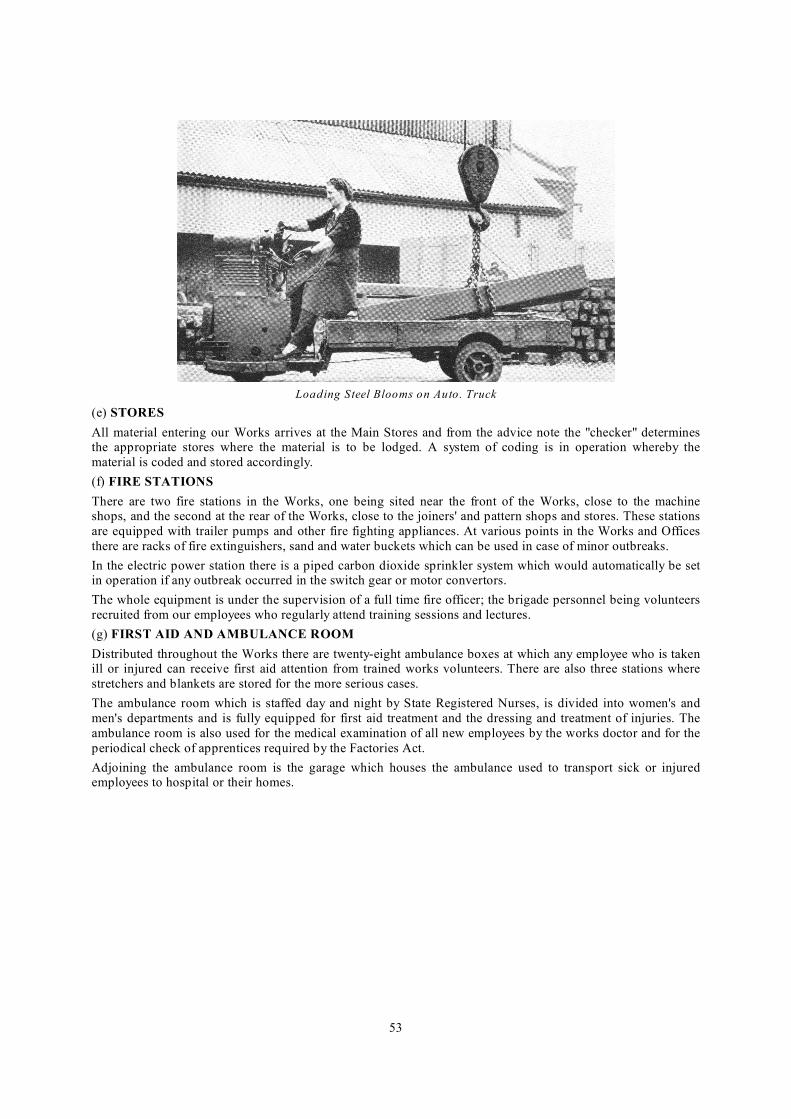
53
Loading Steel Blooms on Auto. Truck
(e) STORES
All material entering our Works arrives at the Main Stores and from the advice note the "checker" determines the appropriate stores where the material is to be lodged. A system of coding is in operation whereby the
material is coded and stored accordingly.
(f) FIRE STATIONS
There are two fire stations in the Works, one being sited near the front of the Works, close to the machine shops, and the second at the rear of the Works, close to the joiners' and pattern shops and stores. These stations
are equipped with trailer pumps and other fire fighting appliances. At various points in the Works and Offices
there are racks of fire extinguishers, sand and water buckets which can be used in case of minor outbreaks.
In the electric power station there is a piped carbon dioxide sprinkler system which would automatically be set in operation if any outbreak occurred in the switch gear or motor convertors.
The whole equipment is under the supervision of a full time fire officer; the brigade personnel being volunteers
recruited from our employees who regularly attend training sessions and lectures.
(g) FIRST AID AND AMBULANCE ROOM
Distributed throughout the Works there are twenty-eight ambulance boxes at which any employee who is taken ill or injured can receive first aid attention from trained works volunteers. There are also three stations where
stretchers and blankets are stored for the more serious cases.
The ambulance room which is staffed day and night by State Registered Nurses, is divided into women's and
men's departments and is fully equipped for first aid treatment and the dressing and treatment of injuries. The
ambulance room is also used for the medical examination of all new employees by the works doctor and for the
periodical check of apprentices required by the Factories Act.
Adjoining the ambulance room is the garage which houses the ambulance used to transport sick or injured employees to hospital or their homes.

54
Ambulance Room, Men's Department
21. Conclusion
This article concludes the present series on Locomotive Factory Organisation. In the series we have
endeavoured to give a description of each department in our Works, in the sequence of an actual locomotive order, the first article appearing in the Summer Issue 1951. During the last twelve months, some of the shops
have been altered and departments rearranged to suit the new products being manufactured in our Works and
we feel these articles have served a dual purpose in giving readers a picture of the other man's job and recording the layout and organisation required for the manufacture of steam locomotives.
We conclude by thanking all managers, foremen and others concerned for the fine co-operation they have given
to us for the compilation of these articles.