vuototecnica
DESCRIPTION
VACUUM MEASUREMENT, CONTROL AND ADJUSTMENT INSTRUMENTSTRANSCRIPT

3
3D
dra
win
gs
ava
ilable
at
ww
w.v
uoto
tecn
ica.n
et
VACUUM AND PRESSURE UNIT CONVERSION TABLE PAG. 3.00
VACUUM AND PRESSURE GAUGES PAG. 3.01 ÷ 3.04
VACUUM GAUGES WITH STEEL PUNCH PAG. 3.05
MINI PNEUMATIC VACUUM SWITCHES PAG. 3.06
MINI ELECTROMECHANICAL VACUUM SWITCHES PAG. 3.07
ELECTROMECHANICAL VACUUM - PRESSURE SWITCHES PAG. 3.08
MICRO DIGITAL VACUUM SWITCHES PAG. 3.09 ÷ 3.10
ANALOG VACUUM SWITCHES PAG. 3.11 ÷ 3.12
DIGITAL VACUUM AND PRESSURE SWITCHES PAG. 3.13 ÷ 3.16
ACCESSORIES FOR DIGITAL VACUUM AND PRESSURE SWITCHES PAG. 3.17 ÷ 3.18
VACUUM REGULATORS PAG. 3.19
REGULATORS FOR LOW VACUUM LEVELS PAG. 3.20
VACUUM REGULATORS WITH PNEUMATIC ADJUSTMENT PAG. 3.21
DIAGRAMS REFERRING TO THE VACUUM LEVEL ACCORDING TO THE SERVO-CONTROL
SUPPLY PRESSURE PAG. 3.22
VACUUM ADJUSTMENT VALVES PAG. 3.23
VACUUM MEASUREMENT, CONTROL
AND ADJUSTMENT INSTRUMENTS
3.00
3D
dra
win
gs
ava
ilable
at
ww
w.v
uoto
tecn
ica.n
et
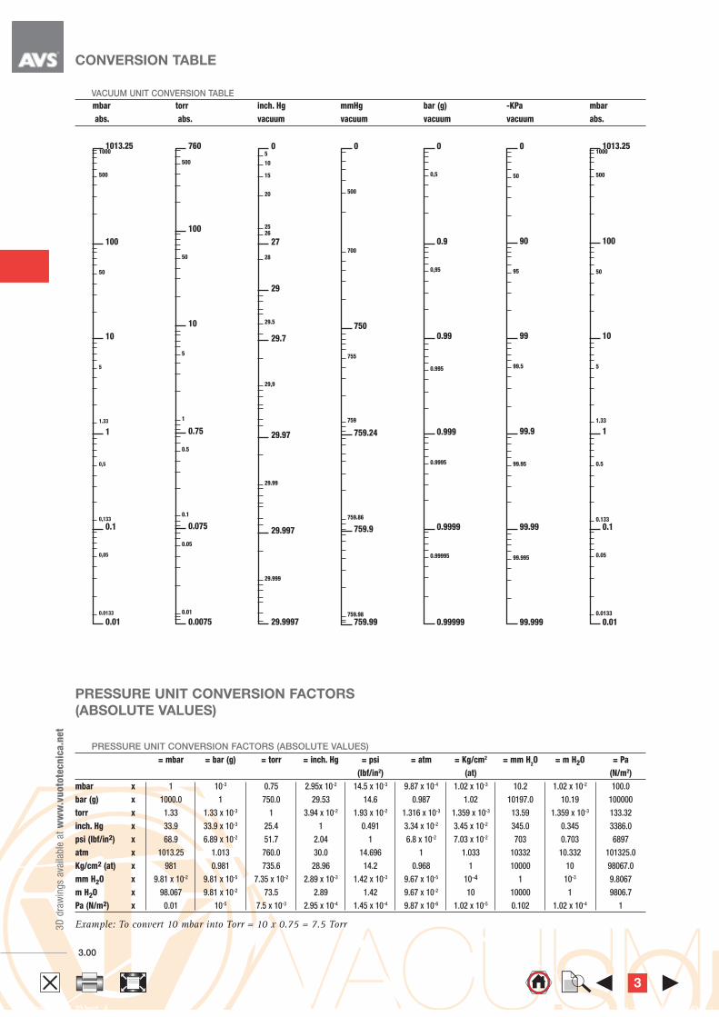
CONVERSION TABLE
PRESSURE UNIT CONVERSION FACTORS (ABSOLUTE VALUES)
= mbar = bar (g) = torr = inch. Hg = psi = atm = Kg/cm2 = mm H2O = m H2O = Pa
(Ibf/in2) (at) (N/m2)
mbar x 1 10-3 0.75 2.95x 10⁻² 14.5 x 10⁻³ 9.87 x 10⁻⁴ 1.02 x 10⁻³ 10.2 1.02 x 10⁻² 100.0
bar (g) x 1000.0 1 750.0 29.53 14.6 0.987 1.02 10197.0 10.19 100000
torr x 1.33 1.33 x 10⁻³ 1 3.94 x 10⁻² 1.93 x 10⁻² 1.316 x 10⁻³ 1.359 x 10⁻³ 13.59 1.359 x 10⁻³ 133.32
inch. Hg x 33.9 33.9 x 10⁻³ 25.4 1 0.491 3.34 x 10⁻² 3.45 x 10⁻² 345.0 0.345 3386.0
psi (lbf/in2) x 68.9 6.89 x 10⁻² 51.7 2.04 1 6.8 x 10⁻² 7.03 x 10⁻² 703 0.703 6897
atm x 1013.25 1.013 760.0 30.0 14.696 1 1.033 10332 10.332 101325.0
Kg/cm2 (at) x 981 0.981 735.6 28.96 14.2 0.968 1 10000 10 98067.0
mm H2O x 9.81 x 10-2 9.81 x 10⁻⁵ 7.35 x 10⁻² 2.89 x 10⁻³ 1.42 x 10⁻³ 9.67 x 10⁻⁵ 10-4 1 10-3 9.8067
m H2O x 98.067 9.81 x 10⁻² 73.5 2.89 1.42 9.67 x 10⁻² 10 10000 1 9806.7
Pa (N/m2) x 0.01 10-5 7.5 x 10⁻³ 2.95 x 10⁻⁴ 1.45 x 10⁻⁴ 9.87 x 10⁻⁶ 1.02 x 10⁻⁵ 0.102 1.02 x 10⁻⁴ 1
Example: To convert 10 mbar into Torr = 10 x 0.75 = 7.5 Torr
PRESSURE UNIT CONVERSION FACTORS
(ABSOLUTE VALUES)
VACUUM UNIT CONVERSION TABLE
mbar torr inch. Hg mmHg bar (g) -KPa mbar
abs. abs. vacuum vacuum vacuum vacuum abs.
1013.25 1000
500
100
50
10
5
1.33
1
0,5
0,133
0.1
0,05
0.0133
0.01
760
500
100
50
10
5
1
0.75
0.5
0.1
0.075
0.05
0.01
0.0075
0
500
700
750
755
759
759.24
759.86
759.9
759.98
759.99
0
0,5
0.9
0,95
0.99
0.995
0.999
0.9995
0.9999
0.99995
0.99999
0
50
90
95
99
99.5
99.9
99.95
99.99
99.995
99.999
1013.25 1000
500
100
50
10
5
1.33
1
0.5
0.133
0.1
0.05
0.0133
0.01
0 5
10
15
20
25 26
27
28
29
29.5
29.7
29,9
29.97
29.99
29.997
29.999
29.9997
3

3
3D
dra
win
gs
ava
ilable
at
ww
w.v
uoto
tecn
ica.n
et
3.01 Conversion ratio: inch = ; pounds =
= 25.4 453.6 0.4536mm g Kg GAS-NPT thread adapters available at page 1.117
VACUUM AND PRESSURE GAUGES
VACUUM GAUGE
Art. Scale Double Scale Scale error Operating Notes Weight
Kpa allowed temperature g
09 03 15 0 ÷ -100 -- 2.5% -10 °C ÷ +50 °C dry 52
The measurement method of our vacuum gauges is based on the principle of
the Bourdon spring (Eugène Bourdon,
France, 1808–1884).
It is made using section tubes in special copper alloy, one end is welded to
the threaded pin of the vacuum-pressure gauge, thus forming a single body
with it, while the other closed end is free
As the vacuum or the pressure inside increases, it tends
to shift from the initial position (Bourdon effect).
The movement of the free end of the spring determines the vacuum-
pressure measurement.
In order to allow an easier reading, this movement is amplified by means
of a connection lever and transmitted to the pointer.
All is enclosed in a sturdy metal casing which contains the dial and the
pointer, that can be seen through a glass.
They are available in various versions,
with coaxial or radial connectors, with built-in or external flange,
dry or glycerine filled.
Except for vacuum gauges with diameter Ø 40 mm, all the
other models have a double scale dial.
All the vacuum and pressure gauges we will describe in these pages are
made in compliance with all the safety standards and measurement units in
force in the European Union.
PRESSURE GAUGES
Art. Scale Double Scale Scale error Operating Notes Weight
bar (g) allowed temperature g
09 03 20 0 ÷ 1.6 0 ÷ 23 psi 2.5% -10 °C ÷ +50 °C dry 54
09 03 25 0 ÷ 10 0 ÷ 1.0 MPa 2.5% -10 °C ÷ +50 °C dry 54
3

3D
dra
win
gs
ava
ilable
at
ww
w.v
uoto
tecn
ica.n
et
Conversion ratio: inch = ; pounds =
= 25.4 453.6 0.4536mm g Kg
GAS-NPT thread adapters available at page 1.1173.02
3 ø 3.5 holes at 120°
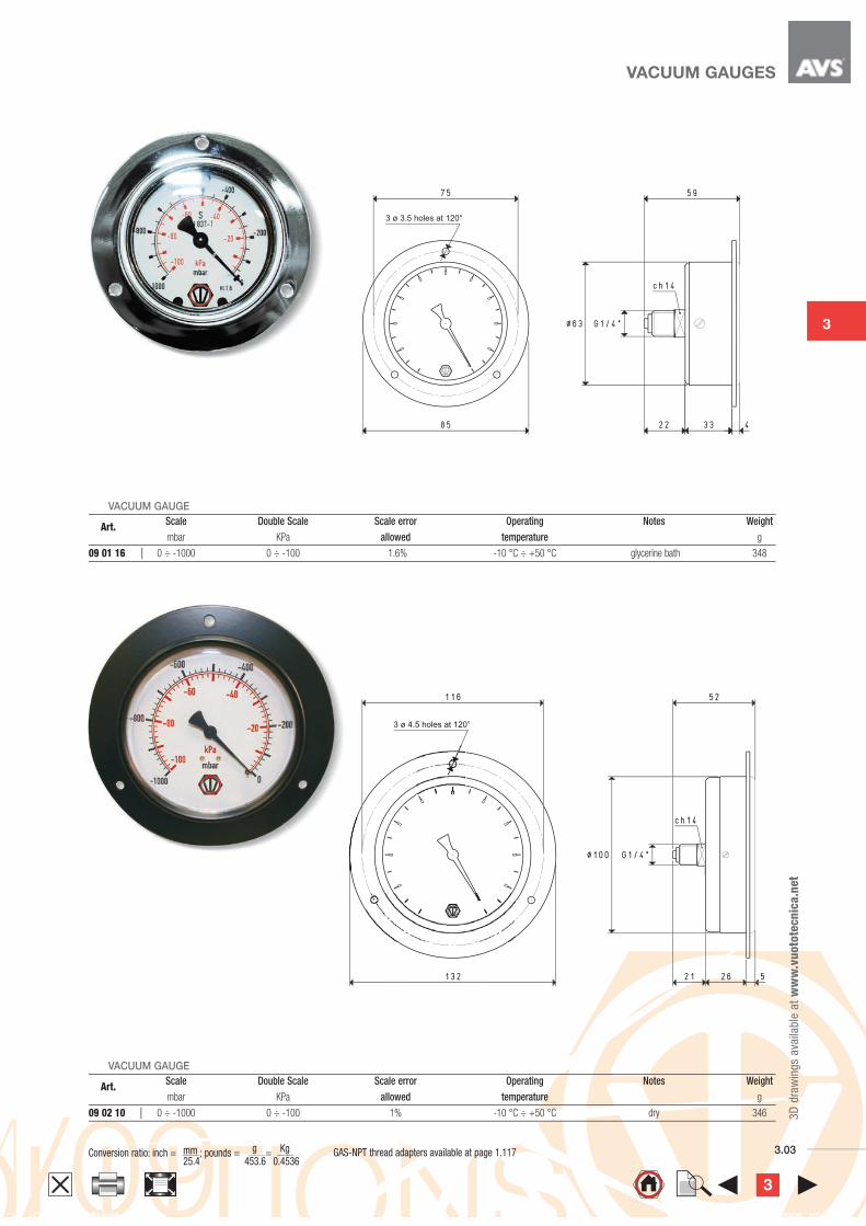
VACUUM GAUGES
VACUUM GAUGE
Art. Scale Double Scale Scale error Operating Notes Weight
mbar Kpa allowed temperature g
09 01 10 0 ÷ -1000 0 ÷ -100 2.5% -10 °C ÷ +50 °C dry 162
VACUUM GAUGE
Art. Scale Double Scale Scale error Operating Notes Weight
mbar KPa allowed temperature g
09 03 10 0 ÷ -1000 0 ÷ -100 2.5% -10 °C ÷ +50 °C dry 134
3
3
3D
dra
win
gs
ava
ilable
at
ww
w.v
uoto
tecn
ica.n
et
3.03 Conversion ratio: inch = ; pounds =
= 25.4 453.6 0.4536mm g Kg GAS-NPT thread adapters available at page 1.117
3 ø 3.5 holes at 120°
3 ø 4.5 holes at 120°
VACUUM GAUGES
VACUUM GAUGE
Art. Scale Double Scale Scale error Operating Notes Weight
mbar KPa allowed temperature g
09 01 16 0 ÷ -1000 0 ÷ -100 1.6% -10 °C ÷ +50 °C glycerine bath 348
VACUUM GAUGE
Art. Scale Double Scale Scale error Operating Notes Weight
mbar KPa allowed temperature g
09 02 10 0 ÷ -1000 0 ÷ -100 1% -10 °C ÷ +50 °C dry 346
3

Conversion ratio: inch = ; pounds =
= 25.4 453.6 0.4536mm g Kg
GAS-NPT thread adapters available at page 1.1173.04
VACUUM GAUGE
Art. Scale Double Scale Scale error Operating Notes Weight
mbar KPa allowed temperature g
09 05 10 0 ÷ -1000 0 ÷ -100 2.5% -10 °C ÷ +50 °C dry 136
VACUUM GAUGE
Art. Scale Double Scale Scale error Operating Notes Weight
mbar KPa allowed temperature g
09 05 16 0 ÷ -1000 0 ÷ -100 1.6% -10 °C ÷ +50 °C glycerine bath 218
VACUUM GAUGES3
D d
raw
ings
ava
ilable
at
ww
w.v
uoto
tecn
ica.n
et
3

3
3.05
Vacuum gauge
Punch
Cup
This vacuum gauge has been designed to allow the immediate detection of
the vacuum level inside tin cans and food containers
in general.
The glycerine bath vacuum gauge art. 09 05 16 used for this
application (features described in the previous page), is provided
with a hardened steel punch to easily perforate the containers and
with a vacuum cup in silicon compound to guarantee vacuum seal after
perforation.
It is available in the standard version (which is the one shown in this page),
but can be provided in other versions upon request.
VACUUM GAUGE WITH STEEL PUNCH
Art. Scale Double Scale Scale error Operating Notes Weight
mbar KPa allowed temperature g
09 05 99 0 ÷ -1000 0 ÷ -100 1.6% -10 °C ÷ +50 °C glycerine bath 250
Conversion ratio: inch = ; pounds =
= 25.4 453.6 0.4536mm g Kg
3D
dra
win
gs
ava
ilable
at
ww
w.v
uoto
tecn
ica.n
et
3

3D
dra
win
gs
ava
ilable
at
ww
w.v
uoto
tecn
ica.n
et
Conversion ratio: inch = ; pounds =
= 25.4 453.6 0.4536mm g Kg
GAS-NPT thread adapters available at page 1.1173.06
Adjustment screw
Vacuum
connection
Vacuum
connection
These vacuum switches feature reduced overall dimensions and, according
to the model, they give or remove a pneumatic signal
when a certain adjustable vacuum level is reached.
The pressure differential between the set maximum value and
the value of reset of the rest signal is not adjustable.
They are particularly suited for controlling vacuum generators and for
activating pneumatic valves.
MINI PNEUMATIC VACUUM SWITCH
Art. 12 01 30 12 02 30
Adjustment range mbar abs. 930 ÷ 50 900 ÷ 40
Fixed differential mbar 70 100
Repeatability mbar ± 5 ±5
Idle signal NC NO
Supply pressure bar (g) 2 ÷ 8 2 ÷ 8
Pneumatic microvalve art. 00 12 17 00 12 18
Max. capacity of the 6 bar (g) microvalve NI / s 1.2 1.2
Working temperature °C -10 ÷ +60 -10 ÷ +60
Weight g 104 102
3

3
3D
dra
win
gs
ava
ilable
at
ww
w.v
uoto
tecn
ica.n
et
3.07 Conversion ratio: inch = ; pounds =
= 25.4 453.6 0.4536mm g Kg GAS-NPT thread adapters available at page 1.117
Adjustment screw
Vacuum
connection
NBR rubber protection
These vacuum switches feature reduced overall dimensions and give an
electric signal when a certain adjustable vacuum level is reached.
The pressure differential existing between the set maximum value
and the value of reset of the rest signal is 50 ÷60 mbar and it is not
adjustable.
They are particularly suited when an electrical signal is needed
when a certain vacuum level is reached, for safety, for starting a cycle, for
checking the cup grip, etc.
MINI ELECTROMECHANICAL VACUUM SWITCHES
Art.
12 02 10
Adjustment range mbar abs. 930 ÷ 10
Fixed differential mbar 50 ÷ 60
Repeatability mbar ±1.5
Microswitch art. 00 12 12
Contacts one change-over
Contact capacity A 3 a 250 V in A.C.
Electrical connections 110-type fast-on terminals
Working temperature °C -25 ÷ +80
Protection IP 55
Weight g 102
3

Conversion ratio: inch = ; pounds =
= 25.4 453.6 0.4536mm g Kg
GAS-NPT thread adapters available at page 1.1173.08
Common contact
Change-over contacts
Microswitch
Differential index
Basic pressure scale
Basic pressure index
Differential scale
Pressure adjustment
Pressure reducer
The vacuum - pressure switches of the 836 series are compact, sturdy and
accurate units that can be adapted to many applications. The feature of the
control is a quick tripping precision microswitch, equipped with silver
contacts. Normal industrial vibrations have no effect on the
efficient opening and closing of the contacts.
The particular linear construction, relatively friction free, assures a precise
and reliable operation independent of the pressure switch
mounting angle.
The “Long Life”bellows with which they are equipped, are made of copper
alloy and can be used for air, water, oil, liquid, vapour and gas circuits,
provided that all these agents are not corrosive.
These devices are included in the U.L. lists and approved by C.S.A.
ELECTROMECHANICAL VACUUM - PRESSURE SWITCHES
Art. 836 - C6A 836 - C2A
Adjustment range bar abs. 0 ÷ 8 0 ÷ 1.7
Adjustable differential mbar from 133 to 1200 from 26 to 1280
Max. line pressure bar abs. 21 4.5
Repeatability measuring range % ±0.5 ±0.5
Contacts one change-over
Contact features unipolar with double interruption
125 VA with ac from 24 to 600 Volts
57.5 VA with ac from 115 to 230 Volts
Rated current for non inductive loads
Contact capacity A 5 a 240 V in A.C.
A 3 a 600 V in A.C.
Electrical connections with terminals
Working temperature °C -25 ÷ +70
Protection IP 54
Weight Kg 0.984 1.130
3D
dra
win
gs
ava
ilable
at
ww
w.v
uoto
tecn
ica.n
et
3

3
3D
dra
win
gs
ava
ilable
at
ww
w.v
uoto
tecn
ica.n
et
3.09 Conversion ratio: inch = ; pounds =
= 25.4 453.6 0.4536mm g Kg
red LED
Adjustment screw
Vacuum connectionVacuum connection
Body (polycarbonate)Body (polycarbonate)
Manifold (anodised aluminium)Manifold (anodised aluminium)
3-pole shielded cable3-pole shielded cable
Adjustment screw
red LED
SealVacuum connection
Body (polycarbonate)
3-pole shielded cable
Coupler
(nickel-plated brass)
Hex. 8
These small devices, if accurately calibrated and compensated for
temperatures, are able to give very precise digital signals to the set
maximum measuring value.
The commutation point, which is within the scale value, can be easily
programmed by means of an adjustment screw located on the upper part
of the device. A red LED near the screw indicates the digital output
signal commutation status.
The pressure differential (hysteresis) between the set maximum value
and the value of reset of the rest signal is 2% of the set value and
cannot be adjusted.
They are composed of a polycarbonate enclosure, which includes the
sensor and the electric circuit, and of a coupler or a small aluminium
manifold with the vacuum connections.
Art. 12 05 10 can also be rotated freely to place the display in the desired
position, without having to unscrew it from the vacuum connection. The
vacuum connection can be carried out via male or female M5 connectors,
while the electrical connection is made via a three-connector cable which
they are equipped with. Mini digital vacuum switches are suited for
controlling dry air and non-corrosive gasses and they are recommended
in all those cases that require a signal when a certain vacuum level is
reached, for safety, for starting a cycle, for checking the cup grip, etc.
MICRO DIGITAL VACUUM SWITCHES
Cable colour Connection
brown positive pole +
black output signal
blue negative pole -
3
3D
dra
win
gs
ava
ilable
at
ww
w.v
uoto
tecn
ica.n
et
3.10
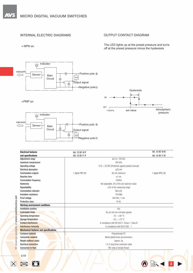
vacuum
Indicator
Sensor
Negative pole
Positive poleMain
Circuitload
Output signal
PNP on
vacuum
Indicator
Sensor Main
Circuit
load
Positive pole
Negative pole
Output signal
Hysteresis
Atmospheric
pressureset value
MICRO DIGITAL VACUUM SWITCHES
INTERNAL ELECTRIC DIAGRAMS
NPN on
OUTPUT CONTACT DIAGRAM
The LED lights up at the preset pressure and turns
The LED lights up at the preset pressure and turns
off at the preset pressure minus the hysteresis
Electrical features Art. 12 05 10 P Art. 12 05 10 N
and specifications Art. 12 05 11 P Art. 12 05 11 N
Adjustment range da 0 a -100 kPa
maximum overpressure 200 kPa
Operating voltage 10.8 ÷ 30 VDC (Protection against polarity reversal)
Electrical absorption ≤20 mA
Commutation outputs 1 digital PNP, NO 80 mA maximum 1 digital NPN, NO
Reaction time ≤1 ms
Commutation frequency 1000Hz
Hysteresis Not adjustable, 2% of the set maximum value
Repeatability ±2% of the measuring range
Commutation indicator Red LED
Insulation resistance 100 MΩ
Proof voltage 500 VAC, 1 min
Protection class IP 40
Working environment conditions
Installation position Any
Controlable fluids Dry air and non-corrosive gasses
Operating temperature -10 ÷ +60 °C
Storage temperature -20 ÷ +70 °C
Emitted interference In compliance with EN 55011, Group 1, Class B
Interference immunity In compliance with EN 61326 - 1
Mechanical features and specifications
Container material Polycarbonate PC
Connection material Nickel-plated brass and aluminium
Weight (without cable) Approx. 5g
Electrical connection 1.5 m long three-conductor cable
Connection to fluid M5 male or female thread
3
3
3D
dra
win
gs
ava
ilable
at
ww
w.v
uoto
tecn
ica.n
et
3.11 Conversion ratio: inch = ; pounds =
= 25.4 453.6 0.4536mm g Kg GAS-NPT thread adapters available at page 1.117
3
3D
dra
win
gs
ava
ilable
at
ww
w.v
uoto
tecn
ica.n
et
3.11 Conversion ratio: inch = ; pounds =
= 25.4 453.6 0.4536mm g Kg
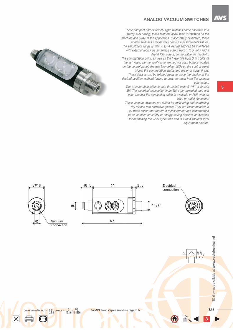
Vacuum
connection
Electrical
connection
These compact and extremely light switches come enclosed in a
sturdy ABS casing; these features allow their installation on the
machine and close to the application. If accurately calibrated, these
analog switches provide very precise measurements values.
The adjustment range is from 0 to -1 bar (g) and can be interfaced
with external logics via an analog output from 1 to 5 Volts and a
digital PNP output, configurable via Teach-In.
The commutation point, as well as the hysterisis from 0 to 100% of
the set value, can be easily programmed via push buttons located
on the control panel; the two two-colour LEDs on the control panel
signal the commutation status and the error code, if any.
These devices can be rotated freely to place the display in the
desired position, without having to unscrew them from the vacuum
connection.
The vacuum connection is dual threaded: male G 1/8” or female
M5. The electrical connection is an M8 4-pin threaded plug and
upon request the connection cable is available in PUR, with an
axial or radial connector.
These vacuum switches are suited for measuring and controlling
dry air and non-corrosive gasses. They are recommended in
all those cases that require a measurement and commutation
to be installed on safety or energy-saving devices, on systems
for optimising the work cycle time and in circuit vacuum level
adjustment circuits.
ANALOG VACUUM SWITCHES
GAS-NPT thread adapters available at page 1.117
3
3D
dra
win
gs
ava
ilable
at
ww
w.v
uoto
tecn
ica.n
et
Conversion ratio: inch = ; pounds =
= 25.4 453.6 0.4536mm g Kg
GAS-NPT thread adapters available at page 1.1173.12
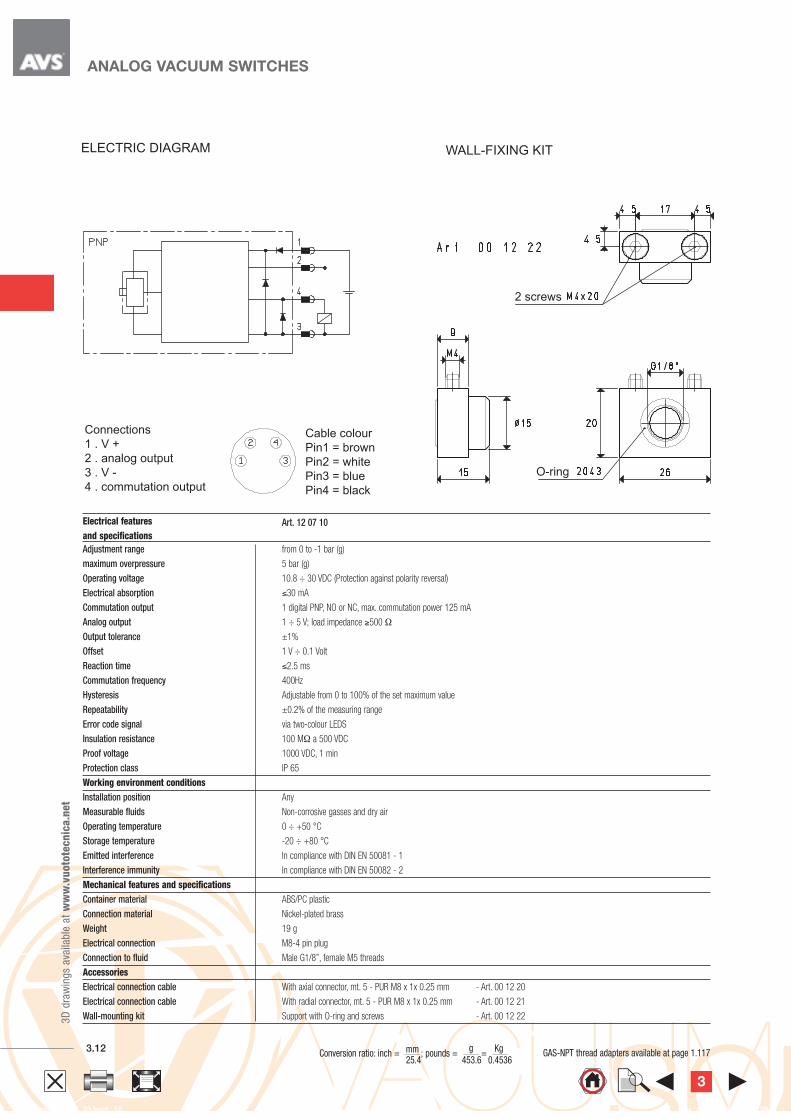
Connections
1 . V +
2 . analog output
3 . V -
4 . commutation output
Cable colour
Pin1 = brown
Pin2 = white
Pin3 = blue
Pin4 = black
WALL-FIXING KIT
2 screws
2 screws
O-ring
ANALOG VACUUM SWITCHES
ELECTRIC DIAGRAM WALL-FIXING KIT
Electrical features Art. 12 07 10
and specifications
Adjustment range from 0 to -1 bar (g)
maximum overpressure 5 bar (g)
Operating voltage 10.8 ÷ 30 VDC (Protection against polarity reversal)
Electrical absorption ≤30 mA
Commutation output 1 digital PNP, NO or NC, max. commutation power 125 mA
Analog output 1 ÷ 5 V; load impedance ≥500 Ω
Output tolerance ±1%
Offset 1 V ÷ 0.1 Volt
Reaction time ≤2.5 ms
Commutation frequency 400Hz
Hysteresis Adjustable from 0 to 100% of the set maximum value
Repeatability ±0.2% of the measuring range
Error code signal via two-colour LEDS
Insulation resistance 100 MΩ a 500 VDC
Proof voltage 1000 VDC, 1 min
Protection class IP 65
Working environment conditions
Installation position Any
Measurable fluids Non-corrosive gasses and dry air
Operating temperature 0 ÷ +50 °C
Storage temperature -20 ÷ +80 °C
Emitted interference In compliance with DIN EN 50081 - 1
Interference immunity In compliance with DIN EN 50082 - 2
Mechanical features and specifications
Container material ABS/PC plastic
Connection material Nickel-plated brass
Weight 19 g
Electrical connection M8-4 pin plug
Connection to fluid Male G1/8”, female M5 threads
Accessories
Electrical connection cable With axial connector, mt. 5 - PUR M8 x 1x 0.25 mm - Art. 00 12 20
Electrical connection cable With radial connector, mt. 5 - PUR M8 x 1x 0.25 mm - Art. 00 12 21
Wall-mounting kit Support with O-ring and screws - Art. 00 12 22
3

3
3D
dra
win
gs
ava
ilable
at
ww
w.v
uoto
tecn
ica.n
et
3.13 Conversion ratio: inch = ; pounds =
= 25.4 453.6 0.4536mm g Kg GAS-NPT thread adapters available at page 1.117
Electrical
connection
Vacuum and
compressed
air connection
These compact and extremely light digital vacuum and pressure switches
are enclosed in a sturdy ABS casing. These features allow installation
on the machine and close to the application.
These digital switches, accurately calibrated and compensated for
temperatures, is able to give very precise measurements values. The
measured values are shown on the display, making the vacuum gauge
redundant. The two LEDs, one red and one green, built-in the control panel,
indicate the commutation status of the two digital output signals.
The two commutation outputs are completely independent.
The switch point between the scale values as well as the hysteresis from
0 to 100% of the set up value can be easily programmed via the push
buttons on the control panel.
Other additional functions can be configured, such as the comparison
between two values, NO and NC contacts, choice of the measurement unit,
locking the programmed values and functions, display reversal, etc. These
devices can be rotated freely to place the display in the desired position,
without having to unscrew them from the vacuum connection.
The vacuum or the pressure connections can be carried out via a dual
male G 1/8” or female M5 thread. The electrical connection is carried
out via M8-4 pin threaded plug and upon request the connection cable
is available in PUR, with an axial or radial connector. These switches are
suited for measuring and controlling dry air and non-corrosive gasses.
They are recommended in all those cases that require a signal when a
certain vacuum level is reached set for safety, for starting a cycle, for
checking the cup grip, etc. Moreover, the hysteresis function allows
managing the vacuum generator compressed air supply, allowing
considerable energy saving.
DIGITAL VACUUM AND PRESSURE SWITCHES
3

3D
dra
win
gs
ava
ilable
at
ww
w.v
uoto
tecn
ica.n
et
Conversion ratio: inch = ; pounds =
= 25.4 453.6 0.4536mm g Kg
GAS-NPT thread adapters available at page 1.1173.14
Connections
1 . V +
2 . commutation output 2
3 . V -
4 . commutation output 1
Cable colour
Pin1 = brown
Pin2 = white
Pin3 = blue
Pin4 = black
WALL-FIXING KIT
2 screws
2 screws
O-ring
DIGITAL VACUUM AND PRESSURE SWITCHES
Electrical features Art. 12 10 10 Art. 12 25 11
and specifications Vacuum switch Pressure switch
Adjustment range from 0 to -1 bar (g) from 0 to 10 bar (g)
maximum overpressure 5 bar (g) 16 bar (g)
Minimum detected values 0.01 bar (g) 0.01 bar (g)
1 KPa --
1 mmHg --
0.1 InHg --
Operating voltage 10.8 ÷ 30 VDC (Protection against polarity reversal)
Electrical absorption ≤35 mA
Commutation output 2 digital PNP,NO or NC,max commutation power 125 mA
Display tolerance ≤ ±1% F.S.
Reaction time ≤2.5 ms
Commutation frequency 400Hz
Hysteresis Adjustable from 0 to 100% of the set maximum value
Repeatability ±0.2% of the measuring range
Display 3-digit, 7-segment LED
Insulation resistance 100 MΩ a 500 VDC
Proof voltage 1000 VDC, 1 min
Protection class IP 65
Working environment conditions
Installation position Any
Measurable fluids Non-corrosive gasses and dry air
Operating temperature 0 ÷ +50 °C
Storage temperature -20 ÷ +80 °C
Emitted interference In compliance with DIN EN 50081 - 1
Interference immunity In compliance with DIN EN 50082 - 2
Mechanical features and specifications
Container material ABS/PC plastic
Connection material Nickel-plated brass
Weight 20 g
Electrical connection M8-4 pin plug
Connection to fluid Male G1/8”, female M5 threads
Accessories
Electrical connection cable With axial connector, mt. 5 - PUR M8 x 1x 0.25 mm - Art. 00 12 20
Electrical connection cable With radial connector, mt. 5 - PUR M8 x 1x 0.25 mm - Art. 00 12 21
Wall-mounting kit Support with O-ring and screws - Art. 00 12 22
ELECTRIC DIAGRAM WALL-FIXING KIT
3

3
3D
dra
win
gs
ava
ilable
at
ww
w.v
uoto
tecn
ica.n
et
3.15 Conversion ratio: inch = ; pounds =
= 25.4 453.6 0.4536mm g Kg GAS-NPT thread adapters available at page 1.117
Vacuum and
compressed
air connection
Threaded cap
Vacuum and
compressed
air connection
DIGITAL VACUUM AND PRESSURE SWITCHES
These compact and extremely light digital vacuum and pressure switches
are enclosed in a sturdy ABS casing. These features allow installation
on the machine and close to the application.
These digital switches, accurately calibrated and compensated for
temperatures, is able to give very precise measurements values. The
measured values are shown on the display, making the vacuum gauge
redundant. The two LEDs, one red and one green, built-in the control panel,
indicate the commutation status of the two digital output signals.
The two commutation outputs are completely independent.
The switch point between the scale values as well as the hysteresis can be
easily programmed via the push buttons on the control panel.
Other additional functions can be configured, such as the comparison
between two values, NO and NC contacts, choice of the measurement
unit, locking the programmed values and functions, display reversal, etc.
The vacuum or the pressure connections can be carried out via a dual
connection with female G 1/8” thread, while the electrical connection
is carried out through the 4-conductor cable which they are equipped
with. Digital vacuum and pressure switches are suited for measuring and
controlling dry air and non-corrosive gasses.
They are recommended in all those cases that require a signal when a
certain vacuum level is reached, for safety, for starting a cycle, for
checking the cup grip, etc. Moreover, the hysteresis function allows
managing the vacuum generator compressed air supply, allowing
considerable energy saving.
3

3.16
MA
IN C
OM
MU
TA
TIO
N
CIR
CU
IT
MA
IN C
OM
MU
TA
TIO
N
CIR
CU
IT
brown
black
white
blue
brown
black
white
blue
load lo
ad
load
load
DIGITAL VACUUM AND PRESSURE SWITCHES
MA
IN C
OM
MU
TA
TIO
N
Electrical features Art. 12 20 10 P Art. 12 35 10 P
and specifications Vacuum switch Pressure switch
Adjustment range da 0 a -101.3 KPa da 0 a 1 MPa
maximum overpressure 500 KPa 1.5 MPa
Minimum detected values 0.1 KPa --
-- 0.001 MPa
0.001 Kgf/cm2 0.01 Kgf/cm2
0.001 bar (g) 0.01 bar (g)
0.01 psi 0.1 psi
0.1 InHg --
1 mmHg --
10 mmH2O --
Operating voltage 12 ÷ 24 VDC, ±10% (Protection against polarity reversal)
Electrical absorption ≤55 mA
Commutation output 2 digital PNP, NO or NC, max. commutation power 80 mA
Display tolerance ≤ ±2% F.S. ±1 digit
Reaction time ≤2.5 ms
Hysteresis Adjustable
Repeatability ±0.2% of the measuring range
Display 3 1/2 digit, 7-segment LED
Insulation resistance 50 MΩ a 500 VDC
Proof voltage 1000 VDC, 1 min
Protection class IP 40
Working environment conditions
Installation position Any
Measurable fluids Non-corrosive gasses and dry air
Operating temperature 0 ÷ +50 °C
Storage temperature -20 ÷ +60 °C
Emitted interference In compliance with EN 55011 Group 1, class B
Interference immunity In compliance with EN 61326 - 1
Mechanical features and specifications
Container material ABS/PC plastic
Connection material Nickel-plated brass
Weight 105 g, electric cable included
Electrical connection With 4-conductor cable
Connection to fluid Female G1/8” thread
Accessories
Fixing kit wall - Art. 00 12 30
plane - Art. 00 12 31
panel - Art. 00 12 32
Note: By adding the letter N after the art. (e.g. 12 20 10 N), the commutation output will be NPN and not PNP.3D
dra
win
gs
ava
ilable
at
ww
w.v
uoto
tecn
ica.n
et
3

3
3.17
WALL-FIXING KIT
2 screws
2 screws
O-ring O-ring
3D
dra
win
gs
ava
ilable
at
ww
w.v
uoto
tecn
ica.n
et
ACCESSORIES FOR DIGITAL VACUUM AND PRESSURE SWITCHES
Art.
Description
00 12 20 Electrical connection cable with axial connector
for digital vacuum and pressure switches
Cable with axial connector
Art.
Description
00 12 22 Wall-mounting kit for digital
vacuum and pressure switches
Art.
Description
00 12 21 Electrical connection cable with radial connector
for digital vacuum and pressure switches
Cable with radial connector
Wall-mounting kit
GAS-NPT thread adapters available at page 1.117 Conversion ratio: inch = ; pounds =
= 25.4 453.6 0.4536mm g Kg
3
3D
dra
win
gs
ava
ilable
at
ww
w.v
uoto
tecn
ica.n
et
Conversion ratio: inch = ; pounds =
= 25.4 453.6 0.4536mm g Kg3.18
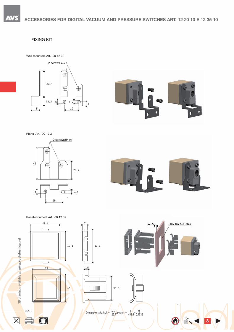
Wall-mounted Art. 00 12 30
2 screws
Plane Art. 00 12 31
Panel-mounted Art. 00 12 32
2 screws
Panel-mounted Art. 00 12 32Panel-mounted Art. 00 12 32
FIXING KIT
ACCESSORIES FOR DIGITAL VACUUM AND PRESSURE SWITCHES ART. 12 20 10 E 12 35 10
3

3
3D
dra
win
gs
ava
ilable
at
ww
w.v
uoto
tecn
ica.n
et
3.19 Conversion ratio: inch = ; pounds =
= 25.4 453.6 0.4536mm g Kg GAS-NPT thread adapters available at page 1.117
Vacuum gauge
Adjustment screw
VACUUM REGULATORS
Vacuum regulators are used to adjust the pre-set vacuum level, keeping
it constant (secondary vacuum), regardless of the capacity and the
oscillations of the network vacuum level (primary vacuum).
Their operation is with a membrane-piston and they exploit the pressure
differential between the secondary vacuum and the atmospheric pressure.
Unlike the vacuum adjusting valves, regulators do not introduce air into the
circuit, thus producing more gripping points with different vacuum values,
from only one vacuum source.
The vacuum level is adjusted by rotating the special reeded screw
clockwise to increase it, and anti-clockwise to reduce it.
Technical features
- Operation:membrane-piston regulator.
- Adjustable operating pressure: from 800 to 1 mbar abs.
- Capacity: from 2 to 160 cum/h.
- Room temperature: from -10 to +80 °C.
- Installation position: any.
Use
Vacuum regulators are mainly used on centralised plants where, regardless
of the plant vacuum level, each grip can be adjusted within that value.
Moreover, they are necessary whenever the working vacuum must be
lower than the primary vacuum.
Art.
A Max. capacity B C D F G H I L M O P Q Art. Weight
Ø cum/h Ø Ø Ø pressure gauge Kg
11 01 10 G1/4” 6 47 42.0 10 40 60 20 6.5 89.0 40 G1/8” 30 40 09 03 15 0.60
11 02 10 G3/8” 10 47 42.0 10 40 60 20 6.5 89.0 40 G1/8” 30 40 09 03 15 0.58
11 03 10 G1/2” 20 53 52.0 15 55 85 25 8.5 105.0 50 G1/4” 36 63 09 03 10 1.15
11 04 10 G3/4” 40 55 55.5 15 70 100 30 8.5 110.5 50 G1/4” 36 63 09 03 10 1.39
11 05 10 G1” 80 60 58.0 15 90 120 30 8.5 118.0 60 G1/4” 36 63 09 03 10 2.08
11 06 10 G1” 1/2 160 54 77.5 15 130 160 20 8.5 131.5 99 G1/4” 36 63 09 03 10 5.49
Note: Pressure gauges are not integral part of the regulators, therfore, they must be ordered seperately.
3
Conversion ratio: inch = ; pounds =
= 25.4 453.6 0.4536mm g Kg
GAS-NPT thread adapters available at page 1.1173.20
Vacuum gauge
Adjustment screw
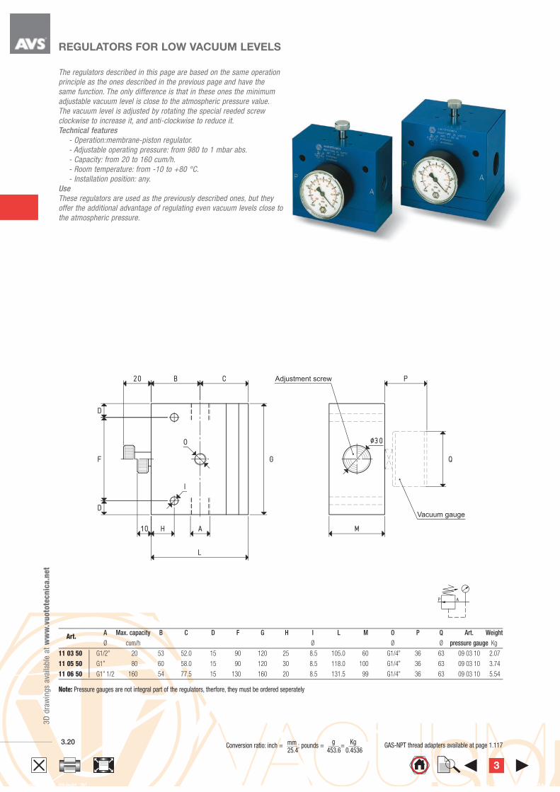
REGULATORS FOR LOW VACUUM LEVELS
The regulators described in this page are based on the same operation
principle as the ones described in the previous page and have the
same function. The only difference is that in these ones the minimum
adjustable vacuum level is close to the atmospheric pressure value.
The vacuum level is adjusted by rotating the special reeded screw
clockwise to increase it, and anti-clockwise to reduce it.
Technical features
- Operation:membrane-piston regulator.
- Adjustable operating pressure: from 980 to 1 mbar abs.
- Capacity: from 20 to 160 cum/h.
- Room temperature: from -10 to +80 °C.
- Installation position: any.
Use
These regulators are used as the previously described ones, but they
offer the additional advantage of regulating even vacuum levels close to
the atmospheric pressure.
Art.
A Max. capacity B C D F G H I L M O P Q Art. Weight
Ø cum/h Ø Ø Ø pressure gauge Kg
11 03 50 G1/2” 20 53 52.0 15 90 120 25 8.5 105.0 60 G1/4” 36 63 09 03 10 2.07
11 05 50 G1” 80 60 58.0 15 90 120 30 8.5 118.0 100 G1/4” 36 63 09 03 10 3.74
11 06 50 G1” 1/2 160 54 77.5 15 130 160 20 8.5 131.5 99 G1/4” 36 63 09 03 10 5.54
Note: Pressure gauges are not integral part of the regulators, therfore, they must be ordered seperately
3D
dra
win
gs
ava
ilable
at
ww
w.v
uoto
tecn
ica.n
et
3

3
3D
dra
win
gs
ava
ilable
at
ww
w.v
uoto
tecn
ica.n
et
3.21 Conversion ratio: inch = ; pounds =
= 25.4 453.6 0.4536mm g Kg GAS-NPT thread adapters available at page 1.117
3
3.21 Conversion ratio: inch = ; pounds =
= 25.4 453.6 0.4536mm g Kg GAS-NPT thread adapters available at page 1.117
Vacuum gauge
VACUUM REGULATORS WITH PNEUMATIC ADJUSTMENT
Vacuum regulators with pneumatic adjustment differ from the previous ones for the way
they adjust the vacuum level; in fact, instead of acting manually on the adjustment screw,
it is necessary to act on the pneumatic cylinder compressed air supply: the higher the
pressure, and the higher the vacuum level and viceversa.
Vacuum regulators are used to adjust the pre-set vacuum level and keep it constant
(secondary vacuum), regardless of the pump vacuum level (primary vacuum).
Unlike the vacuum adjusting valves, regulators do not introduce air into the circuit, thus
producing more gripping points with different vacuum values, from only one vacuum
source.
Their operating principle is based on the contrasting action between a pneumatic
cylinder with short stroke and a fluctuating piston driven by the pressure differential
existing between the secondary vacuum and the atmospheric pressure
Technical features
- Operation: membrane-piston regulator.
- Supply pressure: from 0 to 3 bar (g) for regulators art. 11 .. 30;
from 0 to 5 bar (g) for regulators art. 11 .. 80.
- Adjustable working pressure: from 800 to 1 mbar abs. for regulators art. 11 .. 30;
from 980 to 1 mbar abs. for regulators art. 11 .. 80:
- Capacity: from 2 to 160 cum/h.
- Room temperature: from -10 to +80 °C.
- Installation position: any.
Use
Vacuum regulators are mainly used on centralised plants where, regardless of the plant
vacuum level, each grip can be adjusted within that value. Moreover, they are necessary
whenever the working vacuum must be lower than the primary vacuum and kept constant.
Vacuum regulators with pneumatic adjustment can be installed away from the control
point, since it is sufficient to have a pressure regulator on the control panel to act on them.
Art.
A Max. capacity. B C D E F G H I L M N O P Q R S T Art. Weight
Ø cum/h Ø Ø Ø Ø pressure gauge Kg
11 01 30 G1/4” 6 47 42.0 10 20 10.5 60 20 6.5 89.0 40 G1/8” G1/8” 30 40 9.0 45 6.0 09 03 15 0.71
11 02 30 G3/8” 10 47 42.0 10 20 10.5 60 20 6.5 89.0 40 G1/8” G1/8” 30 40 9.0 45 6.0 09 03 15 0.69
11 03 30 G1/2” 20 53 52.0 15 26 16.5 85 25 8.5 105.0 50 G1/8” G1/4” 36 63 16.5 58 10.5 09 03 10 1.32
11 04 30 G3/4” 40 55 55.5 15 26 16.5 100 30 8.5 110.5 50 G1/8” G1/4” 36 63 24.0 58 18.0 09 03 10 1.94
11 05 30 G1” 80 60 58.0 15 26 16.5 120 30 8.5 118.0 60 G1/8” G1/4” 36 63 34.0 58 28.0 09 03 10 2.35
11 06 30 G1” 1/2 160 54 77.5 15 30 19.5 160 20 8.5 131.5 99 G1/4” G1/4” 36 63 37.5 80 42.5 09 03 10 5.56
11 03 80 G1/2” 20 53 52.0 15 26 16.5 120 25 8.5 105.0 60 G1/8” G1/4” 36 63 34.0 58 28.0 09 03 10 2.28
11 05 80 G1” 80 60 58.0 15 26 16.5 120 30 8.5 118.0 100 G1/8” G1/4” 36 63 34.0 58 28.0 09 03 10 3.96
11 06 80 G1” 1/2 160 54 77.5 15 30 19.5 160 20 8.5 131.5 99 G1/4” G1/4” 36 63 37.5 80 42.5 09 03 10 5.60
Note: Pressure gauges are not integral part of the regulators, therfore, they must be ordered seperately. 3D
dra
win
gs
ava
ilable
at
ww
w.v
uoto
tecn
ica.n
et
3
3.22
3D
dra
win
gs
ava
ilable
at
ww
w.v
uoto
tecn
ica.n
et
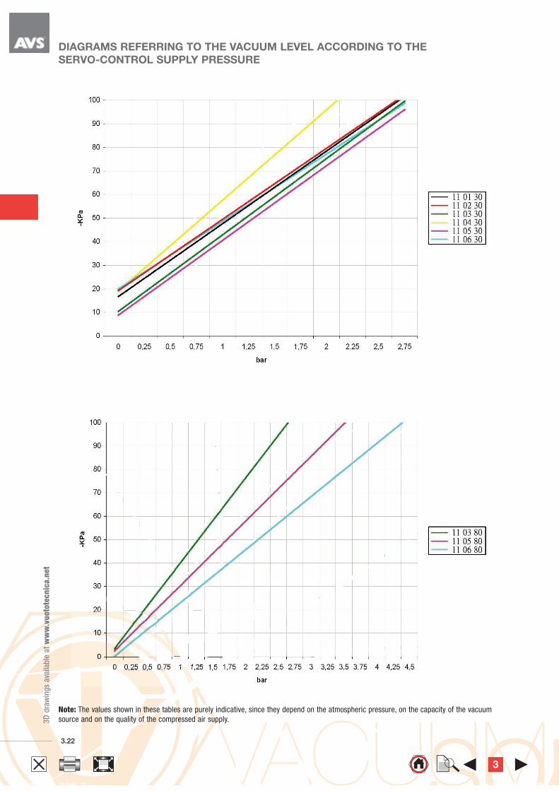
DIAGRAMS REFERRING TO THE VACUUM LEVEL ACCORDING TO THE
SERVO-CONTROL SUPPLY PRESSURE
Note: The values shown in these tables are purely indicative, since they depend on the atmospheric pressure, on the capacity of the vacuum
source and on the quality of the compressed air supply.
3
3
3D
dra
win
gs
ava
ilable
at
ww
w.v
uoto
tecn
ica.n
et
3.23 Conversion ratio: inch = ; pounds =
= 25.4 453.6 0.4536mm g Kg GAS-NPT thread adapters available at page 1.117
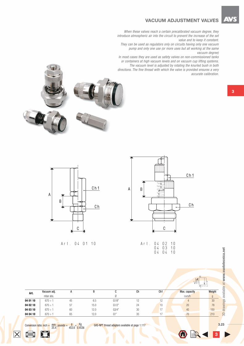
VACUUM ADJUSTMENT VALVES
Art.
Vacuum adj. A B C Ch Ch1 Max. capacity Weight
mbar abs. Ø cum/h g
04 01 10 670 ÷ 1 45 6.5 G1/8” 12 12 4 30
04 02 10 670 ÷ 1 57 15.0 G1/2” 24 10 20 78
04 03 10 670 ÷ 1 60 12.0 G3/4” 30 17 40 150
04 04 10 670 ÷ 1 65 12.0 G1” 35 17 70 210
When these valves reach a certain precalibrated vacuum degree, they
introduce atmospheric air into the circuit to prevent the increase of the set
value and to keep it constant.
They can be used as regulators only on circuits having only one vacuum
pump and only one use (or more uses but all working at the same
vacuum degree)
In most cases they are used as safety valves on non-commissioned tanks
or containers at high vacuum levels and on vacuum cup lifting systems.
The vacuum level is adjusted by rotating the knurled bush in both
directions. The fine thread with which the valve is provided ensures a very
accurate calibration.
3333