vx1100 f1k-28107-1g-11
TRANSCRIPT

ASSEMBLY MANUAL
WaveRunner
F1K-28107-1G-11LIT-18666-00-36*LIT186660036*
VX110 SportVX110 Deluxe

E
WaveRunnerVX110 Sport/VX110 Deluxe
ASSEMBLY MANUAL©2004 by Yamaha Motor Corporation, USA
1st Edition, October 2004All rights reserved.
Any reprinting or unauthorized use without the written permission of Yamaha Motor Corporation, USA
is expressly prohibited.Printed in USA
P/N LIT-18666-00-36
E
PREFACE
This Assembly Manual contains the informa-tion needed to assemble the Yamaha water-craft correctly prior to delivery to the customer.Since some external parts of the watercrafthave not been assemblied at the Yamaha fac-tory for convenience of packing, assembly bythe Yamaha dealer is required. It should benoted that the reassembled watercraft shouldbe thoroughly cleaned, inspected, andadjusted prior to delivery to the customer.
NOTICE
Because Yamaha constantly strives for prod-uct improvement, the service specificationsmay be subject to change in the future. If anychange is introduced into the specifications orassembly procedures, Yamaha dealers will benotified by a technical bulletin.
IMPORTANT MANUAL INFORMATION:Particularly important information is distin-guished in this manual by the following nota-tions.
The safety Alert Symbol means ATTEN-TION! BECOME ALERT! YOURSAFETY IS INVOLVED!
WARNINGFailure to follow WARNING instructionscould result in severe injury or death to themachine operator, passenger(s), abystander, or a person inspecting or repair-ing the watercraft.
CAUTION:A CAUTION indicates special precautionsthat must be taken to avoid damage to thewatercraft.
NOTE:A NOTE provides key information to make pro-cedures easier or cleaner.
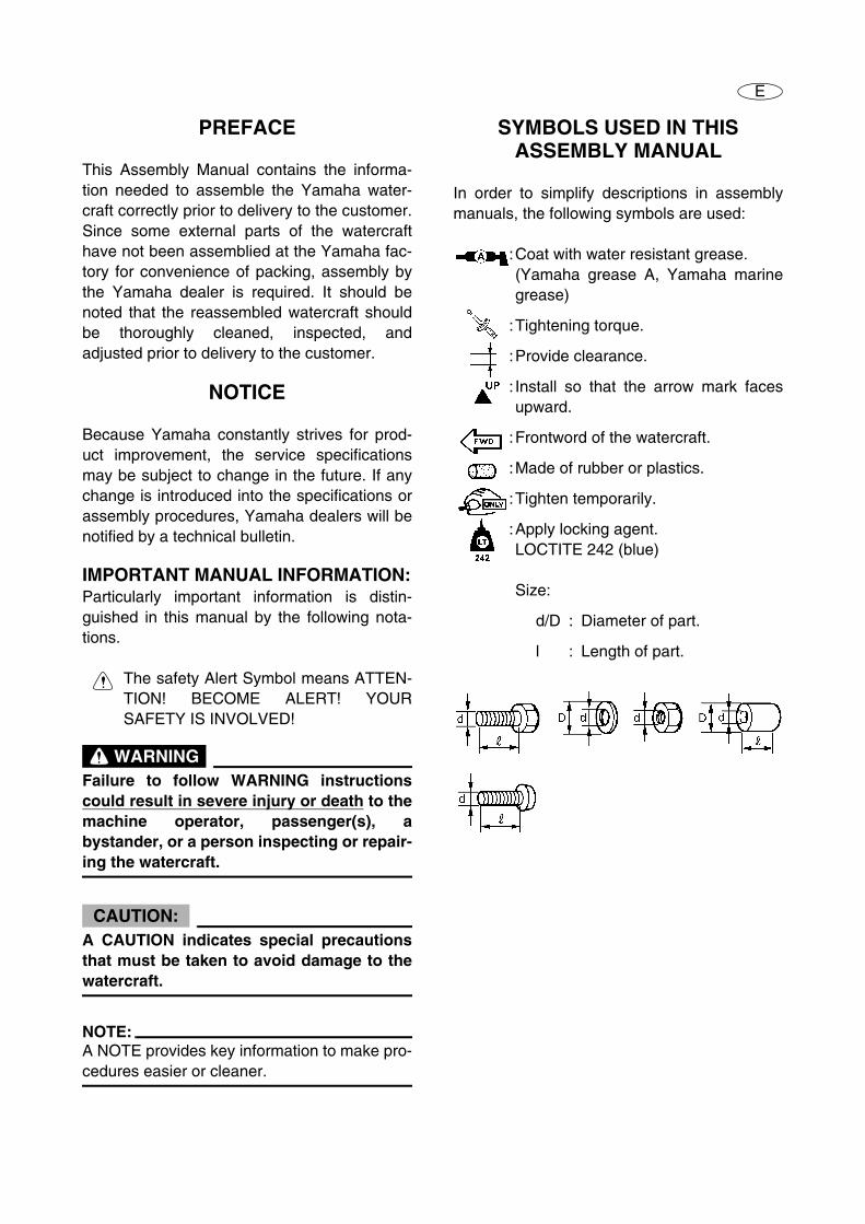
SYMBOLS USED IN THIS ASSEMBLY MANUAL
In order to simplify descriptions in assemblymanuals, the following symbols are used:
:Coat with water resistant grease. (Yamaha grease A, Yamaha marinegrease)
:Tightening torque.
:Provide clearance.
: Install so that the arrow mark facesupward.
:Frontword of the watercraft.
:Made of rubber or plastics.
:Tighten temporarily.
:Apply locking agent. LOCTITE 242 (blue)
Size:
d/D : Diameter of part.
l : Length of part.
E
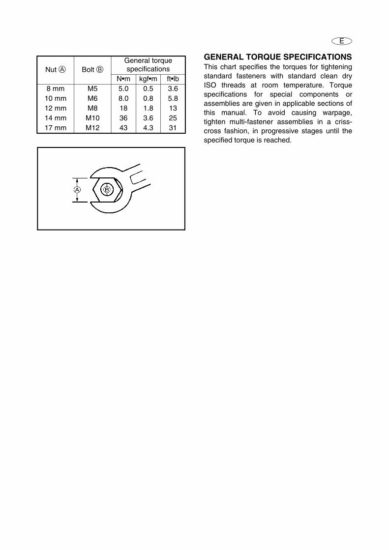
GENERAL TORQUE SPECIFICATIONSThis chart specifies the torques for tighteningstandard fasteners with standard clean dryISO threads at room temperature. Torquespecifications for special components orassemblies are given in applicable sections ofthis manual. To avoid causing warpage,tighten multi-fastener assemblies in a criss-cross fashion, in progressive stages until thespecified torque is reached.
Nut A Bolt B General torque specifications
N•m kgf•m ft•lb8 mm M5 5.0 0.5 3.6
10 mm M6 8.0 0.8 5.812 mm M8 18 1.8 1314 mm M10 36 3.6 2517 mm M12 43 4.3 31
– 1 –
E
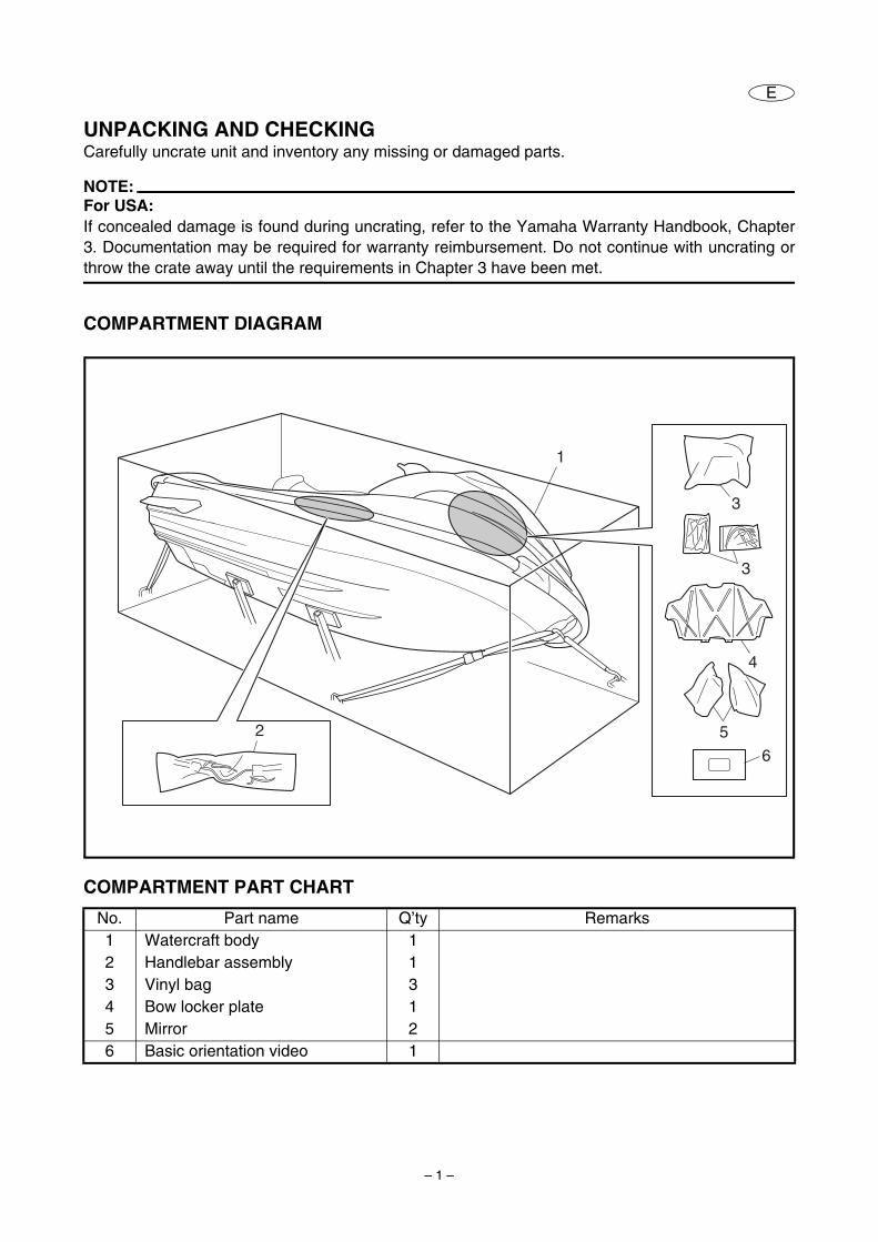
UNPACKING AND CHECKINGCarefully uncrate unit and inventory any missing or damaged parts.
NOTE:For USA:If concealed damage is found during uncrating, refer to the Yamaha Warranty Handbook, Chapter3. Documentation may be required for warranty reimbursement. Do not continue with uncrating orthrow the crate away until the requirements in Chapter 3 have been met.
COMPARTMENT DIAGRAM
COMPARTMENT PART CHART
No. Part name Q’ty Remarks1 Watercraft body 12 Handlebar assembly 13 Vinyl bag 34 Bow locker plate 15 Mirror 26 Basic orientation video 1
3
3
4
5
6
2
1

– 2 –
E
COMPARTMENT DIAGRAM
COMPARTMENT PART CHART
*1: For California
No. Part name Q’ty Part number1 Handlebar assembly 1 F1K-U155A-002 Engine shut-off cord 1 EW2-68348-003 Upper handlebar holder 2 EU0-23814-304 Bolt 8 × 48 mm (0.31 × 1.89 in) 4 90119-089UU5 Pad 1 F1K-U142D-006 Upper handlebar cover 1 F1K-U143D-017 Lower handlebar cover 1 F1K-U143E-008 Screw 6 × 13 mm (0.24 × 0.51 in) 4 90154-060179 Screw 5 × 15 mm (0.20 × 0.59 in) 4 90149-0590310 Screw 4 × 9 mm (0.16 × 0.35 in) 2 90157-0400311 Star label tag*1 1 F1B-U410M-0012 Grommet 1 F0M-61469-0013 Corrugated tube 1 F0D-6773E-0014 Left mirror (with seal) 1 F1S-U596B-1015 Right mirror (with seal) 1 F1S-U596C-10
– 3 –
E
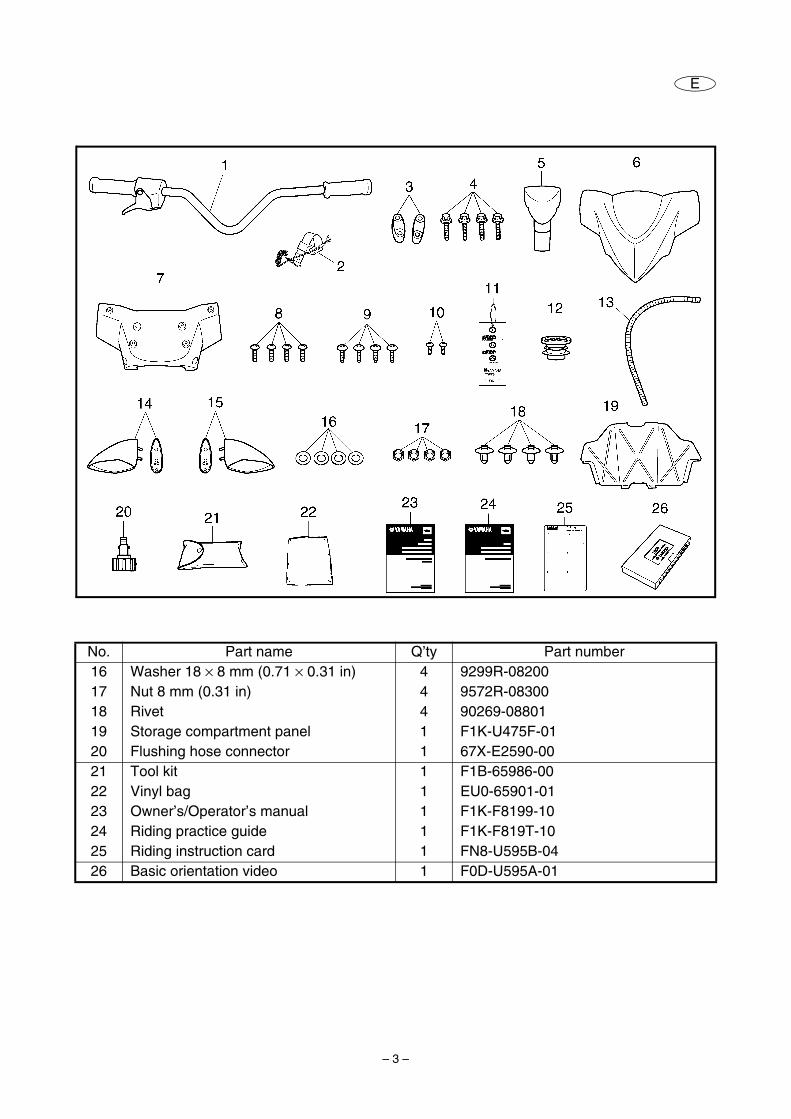
No. Part name Q’ty Part number16 Washer 18 × 8 mm (0.71 × 0.31 in) 4 9299R-0820017 Nut 8 mm (0.31 in) 4 9572R-0830018 Rivet 4 90269-0880119 Storage compartment panel 1 F1K-U475F-0120 Flushing hose connector 1 67X-E2590-0021 Tool kit 1 F1B-65986-0022 Vinyl bag 1 EU0-65901-0123 Owner’s/Operator’s manual 1 F1K-F8199-1024 Riding practice guide 1 F1K-F819T-1025 Riding instruction card 1 FN8-U595B-0426 Basic orientation video 1 F0D-U595A-01
– 4 –
E
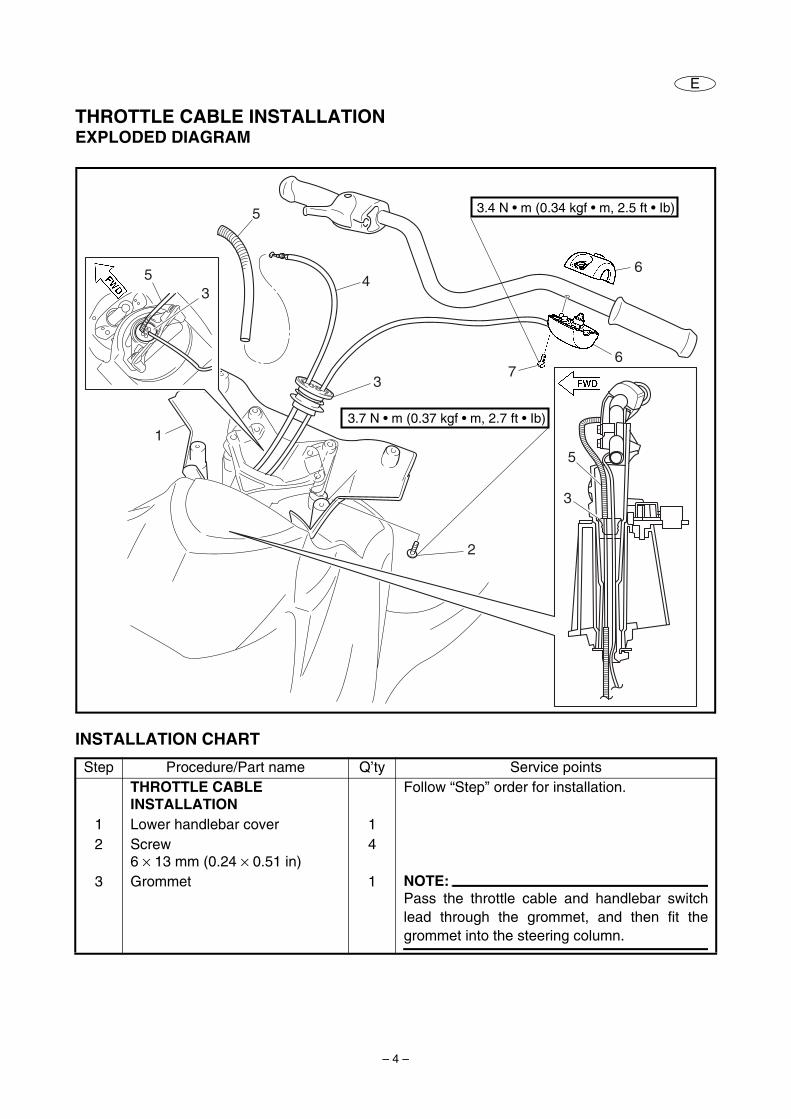
THROTTLE CABLE INSTALLATIONEXPLODED DIAGRAM
INSTALLATION CHART
Step Procedure/Part name Q’ty Service pointsTHROTTLE CABLE INSTALLATION
Follow “Step” order for installation.
1 Lower handlebar cover 12 Screw
6 × 13 mm (0.24 × 0.51 in)4
3 Grommet 1 NOTE:Pass the throttle cable and handlebar switchlead through the grommet, and then fit thegrommet into the steering column.
1
2
3
4
5
3
3.7 N • m (0.37 kgf • m, 2.7 ft • Ib)
53
5
6
67
3.4 N • m (0.34 kgf • m, 2.5 ft • Ib)
– 5 –
E
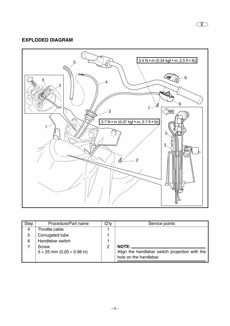
EXPLODED DIAGRAM
Step Procedure/Part name Q’ty Service points4 Throttle cable 15 Corrugated tube 16 Handlebar switch 17 Screw
5 × 25 mm (0.20 × 0.98 in)2 NOTE:
Align the handlebar switch projection with thehole on the handlebar.
1
2
3
4
5
3
3.7 N • m (0.37 kgf • m, 2.7 ft • Ib)
53
5
6
67
3.4 N • m (0.34 kgf • m, 2.5 ft • Ib)
– 6 –
E
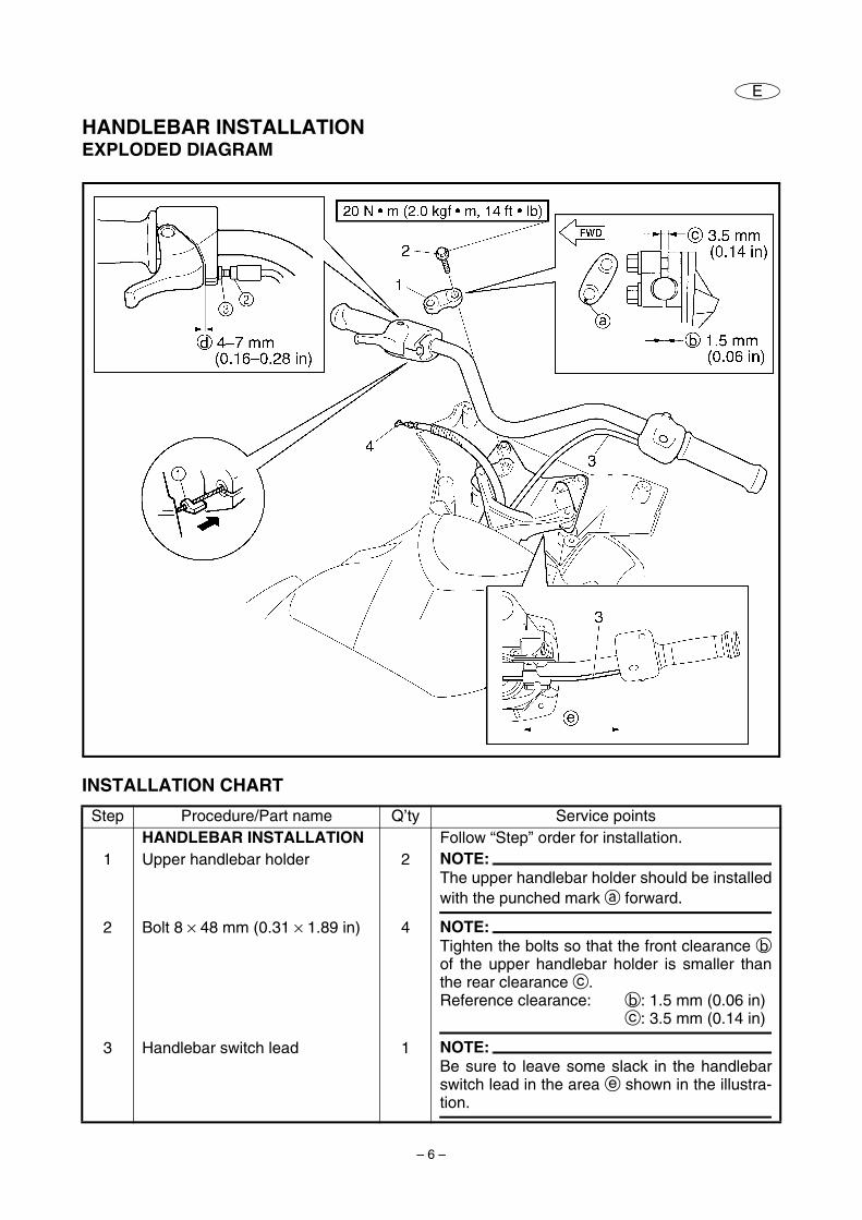
HANDLEBAR INSTALLATIONEXPLODED DIAGRAM
INSTALLATION CHART
Step Procedure/Part name Q’ty Service pointsHANDLEBAR INSTALLATION Follow “Step” order for installation.
1 Upper handlebar holder 2 NOTE:The upper handlebar holder should be installedwith the punched mark a forward.
2 Bolt 8 × 48 mm (0.31 × 1.89 in) 4 NOTE:Tighten the bolts so that the front clearance bof the upper handlebar holder is smaller thanthe rear clearance c.Reference clearance: b: 1.5 mm (0.06 in)
c: 3.5 mm (0.14 in)
3 Handlebar switch lead 1 NOTE:Be sure to leave some slack in the handlebarswitch lead in the area e shown in the illustra-tion.
– 7 –
E
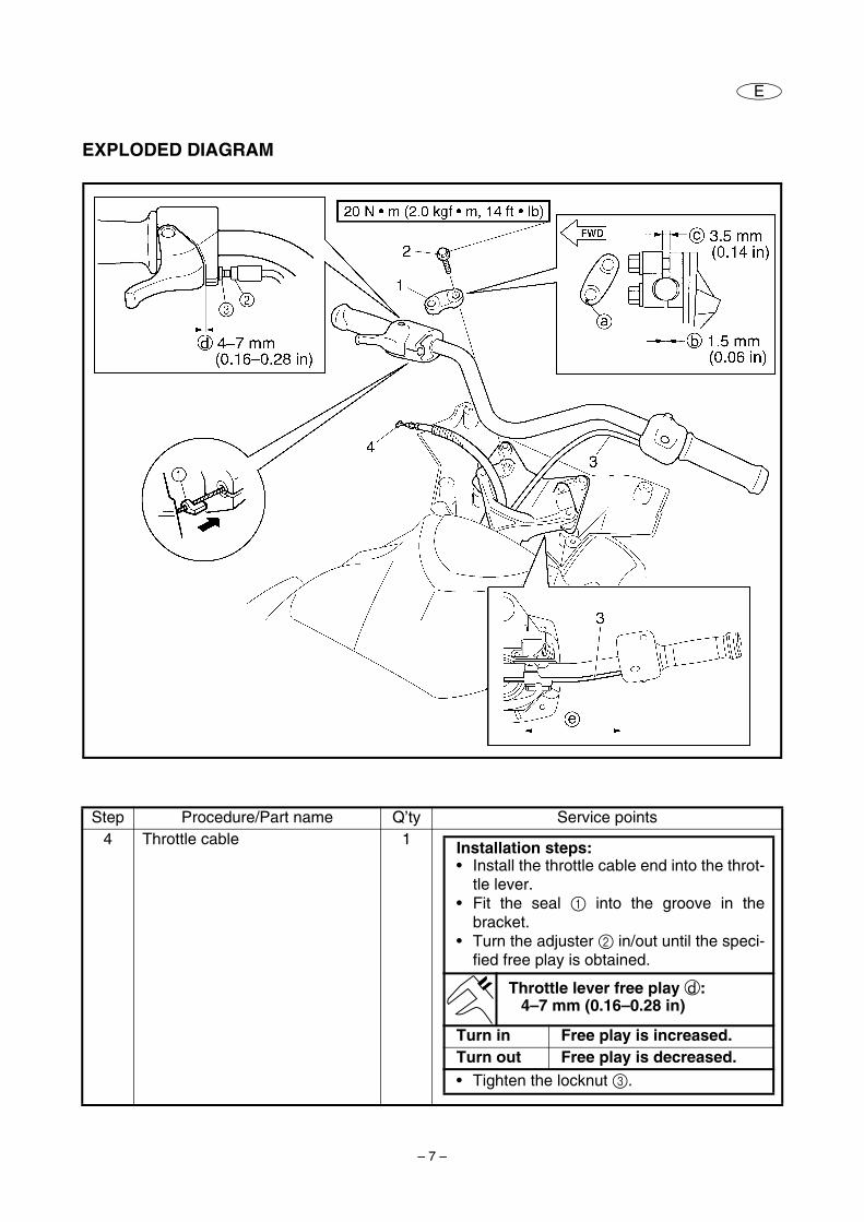
EXPLODED DIAGRAM
Step Procedure/Part name Q’ty Service points4 Throttle cable 1 Installation steps:
• Install the throttle cable end into the throt-tle lever.
• Fit the seal 1 into the groove in thebracket.
• Turn the adjuster 2 in/out until the speci-fied free play is obtained.
Throttle lever free play d:4–7 mm (0.16–0.28 in)
Turn in Free play is increased.Turn out Free play is decreased.• Tighten the locknut 3.
– 8 –
E
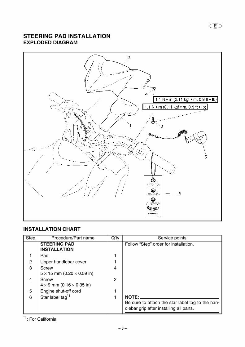
STEERING PAD INSTALLATIONEXPLODED DIAGRAM
INSTALLATION CHART
*1: For California
Step Procedure/Part name Q’ty Service pointsSTEERING PAD INSTALLATION
Follow “Step” order for installation.
1 Pad 12 Upper handlebar cover 13 Screw
5 × 15 mm (0.20 × 0.59 in)4
4 Screw 4 × 9 mm (0.16 × 0.35 in)
2
5 Engine shut-off cord 16 Star label tag*1 1 NOTE:
Be sure to attach the star label tag to the han-dlebar grip after installing all parts.
– 9 –
E
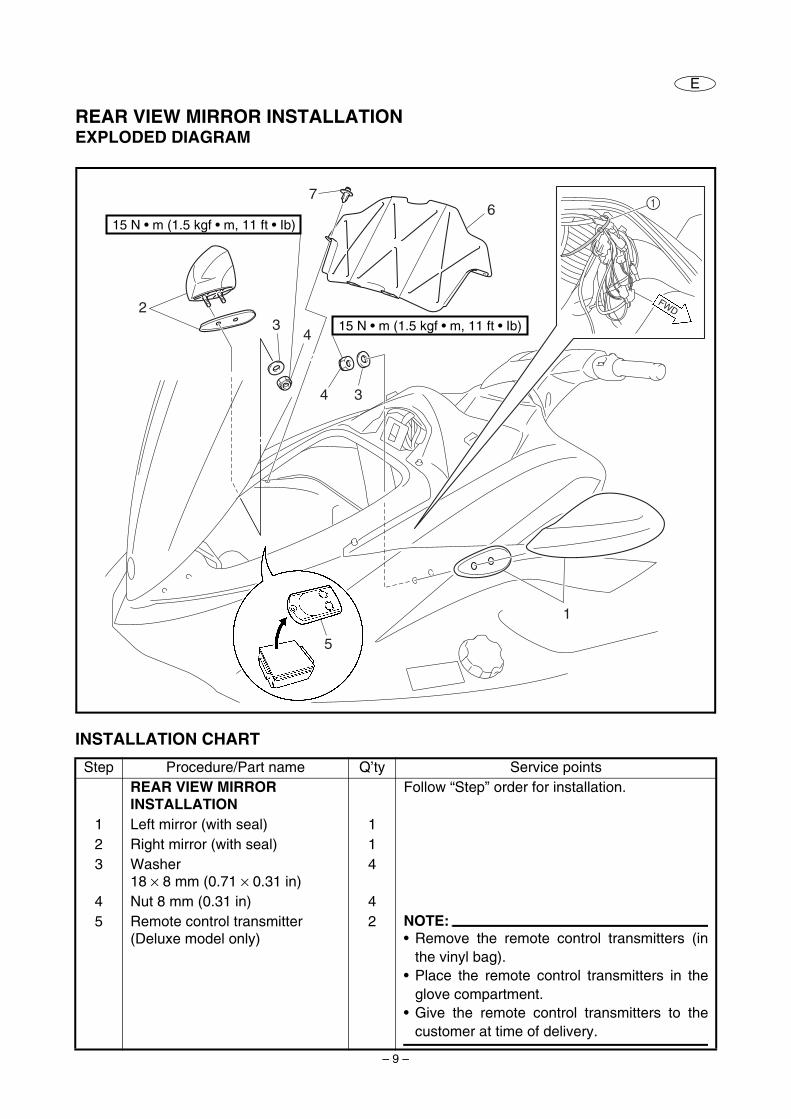
REAR VIEW MIRROR INSTALLATIONEXPLODED DIAGRAM
INSTALLATION CHART
Step Procedure/Part name Q’ty Service pointsREAR VIEW MIRROR INSTALLATION
Follow “Step” order for installation.
1 Left mirror (with seal) 12 Right mirror (with seal) 13 Washer
18 × 8 mm (0.71 × 0.31 in)4
4 Nut 8 mm (0.31 in) 45 Remote control transmitter
(Deluxe model only)2 NOTE:
• Remove the remote control transmitters (inthe vinyl bag).
• Place the remote control transmitters in theglove compartment.
• Give the remote control transmitters to thecustomer at time of delivery.
1
FWD2
76
34
4 3
1
5
15 N • m (1.5 kgf • m, 11 ft • Ib)
15 N • m (1.5 kgf • m, 11 ft • Ib)
– 10 –
E
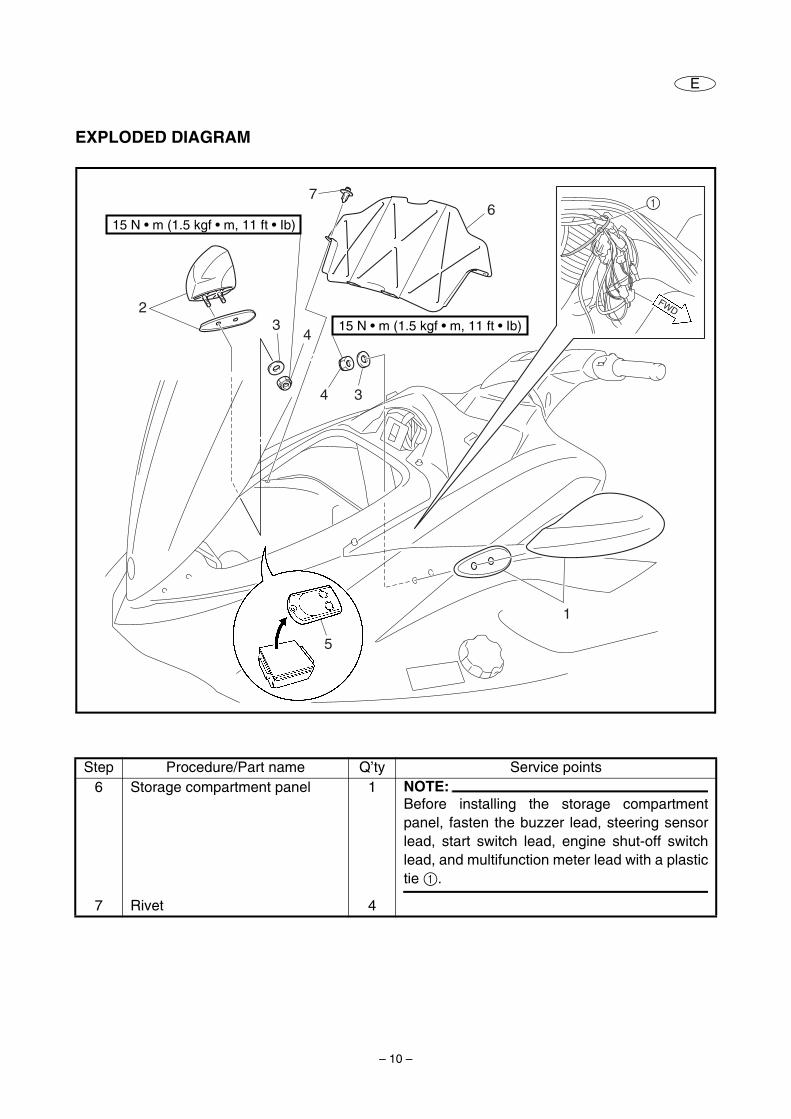
EXPLODED DIAGRAM
Step Procedure/Part name Q’ty Service points6 Storage compartment panel 1 NOTE:
Before installing the storage compartmentpanel, fasten the buzzer lead, steering sensorlead, start switch lead, engine shut-off switchlead, and multifunction meter lead with a plastictie 1.
7 Rivet 4
1
FWD2
76
34
4 3
1
5
15 N • m (1.5 kgf • m, 11 ft • Ib)
15 N • m (1.5 kgf • m, 11 ft • Ib)
– 11 –
E
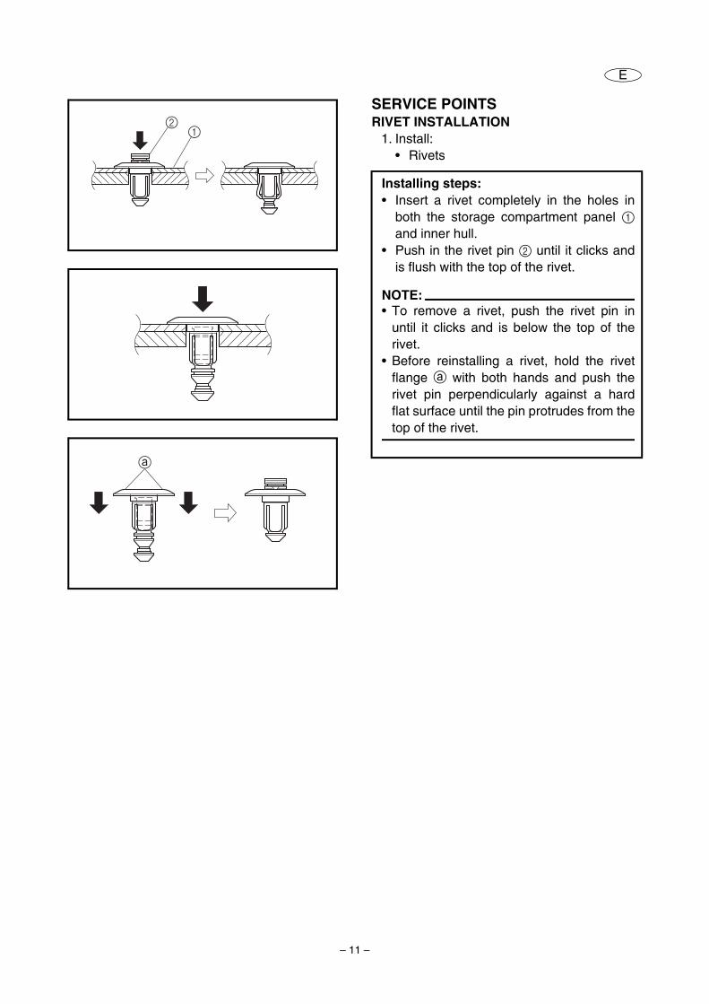
SERVICE POINTSRIVET INSTALLATION
1. Install:• Rivets
Installing steps:• Insert a rivet completely in the holes in
both the storage compartment panel 1and inner hull.
• Push in the rivet pin 2 until it clicks andis flush with the top of the rivet.
NOTE:• To remove a rivet, push the rivet pin in
until it clicks and is below the top of therivet.
• Before reinstalling a rivet, hold the rivetflange a with both hands and push therivet pin perpendicularly against a hardflat surface until the pin protrudes from thetop of the rivet.
21
a
– 12 –
E
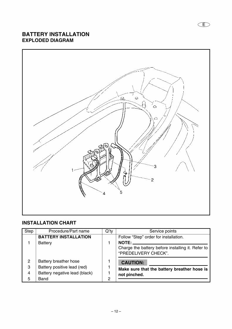
BATTERY INSTALLATIONEXPLODED DIAGRAM
INSTALLATION CHART
Step Procedure/Part name Q’ty Service pointsBATTERY INSTALLATION Follow “Step” order for installation.
1 Battery 1 NOTE:Charge the battery before installing it. Refer to“PREDELIVERY CHECK”.
2 Battery breather hose 1 CAUTION:Make sure that the battery breather hose isnot pinched.
3 Battery positive lead (red) 14 Battery negative lead (black) 15 Band 2
– 13 –
E
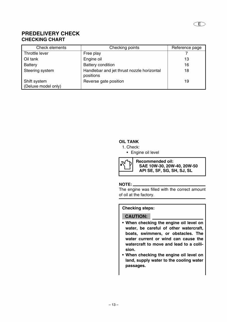
PREDELIVERY CHECKCHECKING CHART
Check elements Checking points Reference pageThrottle lever Free play 7Oil tank Engine oil 13Battery Battery condition 16Steering system Handlebar and jet thrust nozzle horizontal
positions18
Shift system (Deluxe model only)
Reverse gate position 19
OIL TANK1. Check:
• Engine oil level
NOTE:The engine was filled with the correct amountof oil at the factory.
Recommended oil:SAE 10W-30, 20W-40, 20W-50API SE, SF, SG, SH, SJ, SL
Checking steps:
CAUTION:• When checking the engine oil level on
water, be careful of other watercraft,boats, swimmers, or obstacles. Thewater current or wind can cause thewatercraft to move and lead to a colli-sion.
• When checking the engine oil level onland, supply water to the cooling waterpassages.
– 14 –
E
• Make sure that engine has enough oilbut do not overfill. If there is too littleoil, the engine can be damaged. If thereis too much oil, the air filter canbecome saturated with oil, perma-nently damaging the filter and reduc-ing engine performance. Follow thechecking procedure carefully.
• Make sure that debris or water doesnot enter the oil tank filler hole. Debrisor water in the engine oil can causeserious engine damage.
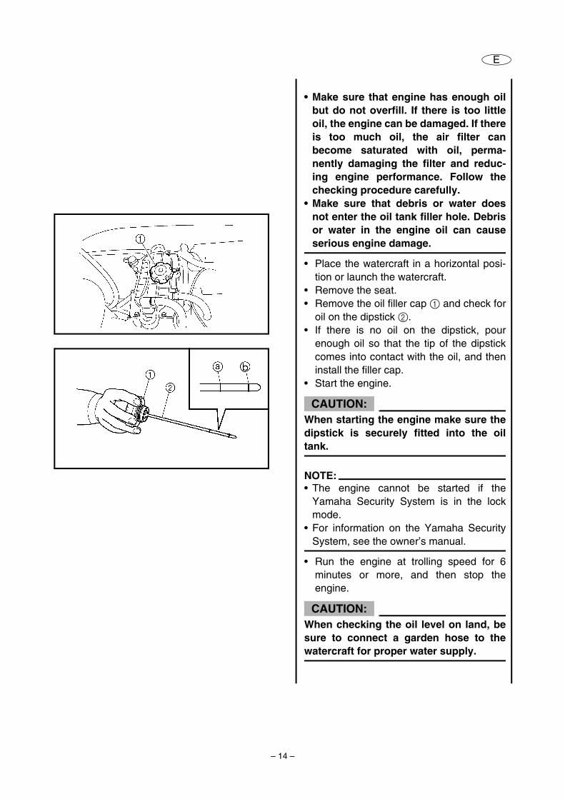
• Place the watercraft in a horizontal posi-tion or launch the watercraft.
• Remove the seat.• Remove the oil filler cap 1 and check for
oil on the dipstick 2.• If there is no oil on the dipstick, pour
enough oil so that the tip of the dipstickcomes into contact with the oil, and theninstall the filler cap.
• Start the engine.
CAUTION:When starting the engine make sure thedipstick is securely fitted into the oiltank.
NOTE:• The engine cannot be started if the
Yamaha Security System is in the lockmode.
• For information on the Yamaha SecuritySystem, see the owner’s manual.
• Run the engine at trolling speed for 6minutes or more, and then stop theengine.
CAUTION:When checking the oil level on land, besure to connect a garden hose to thewatercraft for proper water supply.
– 15 –
E
NOTE:If the ambient temperature is 20 °C (68 °F)or less, warm up the engine for an addi-tional 5 minutes.
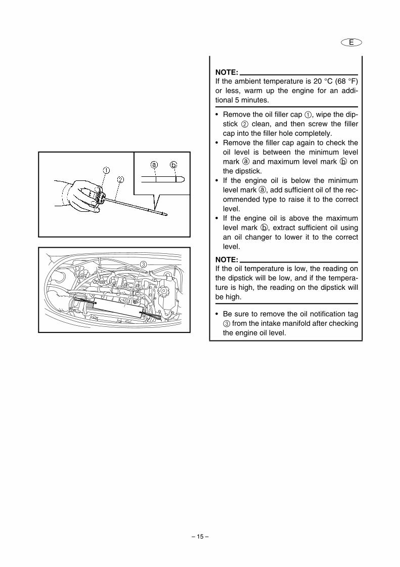
• Remove the oil filler cap 1, wipe the dip-stick 2 clean, and then screw the fillercap into the filler hole completely.
• Remove the filler cap again to check theoil level is between the minimum levelmark a and maximum level mark b onthe dipstick.
• If the engine oil is below the minimumlevel mark a, add sufficient oil of the rec-ommended type to raise it to the correctlevel.
• If the engine oil is above the maximumlevel mark b, extract sufficient oil usingan oil changer to lower it to the correctlevel.
NOTE:If the oil temperature is low, the reading onthe dipstick will be low, and if the tempera-ture is high, the reading on the dipstick willbe high.
• Be sure to remove the oil notification tag3 from the intake manifold after checkingthe engine oil level.
3
– 16 –
E
BATTERY
WARNINGBattery electrolyte is poisonous and dan-gerous, causing severe burns, etc. Electro-lyte contains sulfuric acid. Avoid contactwith skin, eyes or clothing. AntidotesExternal: Flush with water. Internal: Drink large quantities of water ormilk. Follow with milk of magnesia, beatenegg or vegetable oil. Call physician immedi-ately. Eyes: Flush with water for 15 minutes andget prompt medical attention. Batteries produce explosive gases. Keepsparks, flame, cigarettes, etc., well away. Ifusing or charging the battery in anenclosed space, make sure that it is wellventilated. Always shield your eyes whenworking near batteries. KEEP OUT OF THE REACH OF CHILDREN.
CAUTION:Be careful not to place the battery on itsside. Make sure to remove the battery from thebattery compartment when adding batteryelectrolyte or charging the battery. When checking the battery, make sure thebreather hose is connected to the batteryand not obstructed.
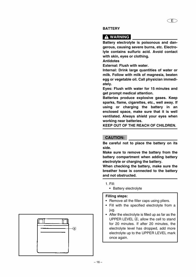
1. Fill:• Battery electrolyte
Filling steps:• Remove all the filler caps using pliers.• Fill with the specified electrolyte from a
jug.• After the electrolyte is filled up as far as the
UPPER LEVEL a, allow the cell to standfor 20 minutes. If after 20 minutes, theelectrolyte level has dropped, add moreelectrolyte up to the UPPER LEVEL markonce again.
– 17 –
E
2. Initial battery charging:• Battery
WARNINGTurn the battery charger on after the bat-tery is connected to the charger.The sparking by connecting the chargingcable to the battery terminal can cause anexplosion to the explosive gases comingout from the battery cells.
CAUTION:Always charge the battery when the elec-trolyte is poured into the battery for thefirst time. Otherwise, the battery can causethe lowering of performance earlier.
3. Inspect:• Specific gravity of the electrolyte
Out of specification → Recharge.
NOTE:Replace the battery if there are differences of0.025 or more on the specific gravity of eachcell’s electrolyte after recharging.
4. Install:• Filler caps
CAUTION:Rinse off any electrolyte from the batterycase and wipe the battery dry prior toinstallation.
Charging steps:• Connect the charging cable (+) and (–) of
the battery charger to the battery termi-nals correctly.
• Charge the battery for 3 to 5 hours withthe rate of 1.9 ampere.
Specific gravity at 20°C (68°F):1.28
– 18 –
E
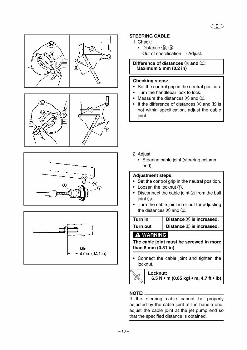
STEERING CABLE1. Check:
• Distance a, bOut of specification → Adjust.
Difference of distances a and b:Maximum 5 mm (0.2 in)
Checking steps:• Set the control grip in the neutral position.• Turn the handlebar lock to lock.• Measure the distances a and b.• If the difference of distances a and b is
not within specification, adjust the cablejoint.
2. Adjust:• Steering cable joint (steering column
end)
NOTE:If the steering cable cannot be properlyadjusted by the cable joint at the handle end,adjust the cable joint at the jet pump end sothat the specified distance is obtained.
Adjustment steps:• Set the control grip in the neutral position.• Loosen the locknut 1.• Disconnect the cable joint 2 from the ball
joint 3.• Turn the cable joint in or out for adjusting
the distances a and b.
Turn in Distance a is increased.
Turn out Distance b is increased.
WARNINGThe cable joint must be screwed in morethan 8 mm (0.31 in).
• Connect the cable joint and tighten thelocknut.
T R..
Locknut:6.5 N • m (0.65 kgf • m, 4.7 ft • lb)
– 19 –
E
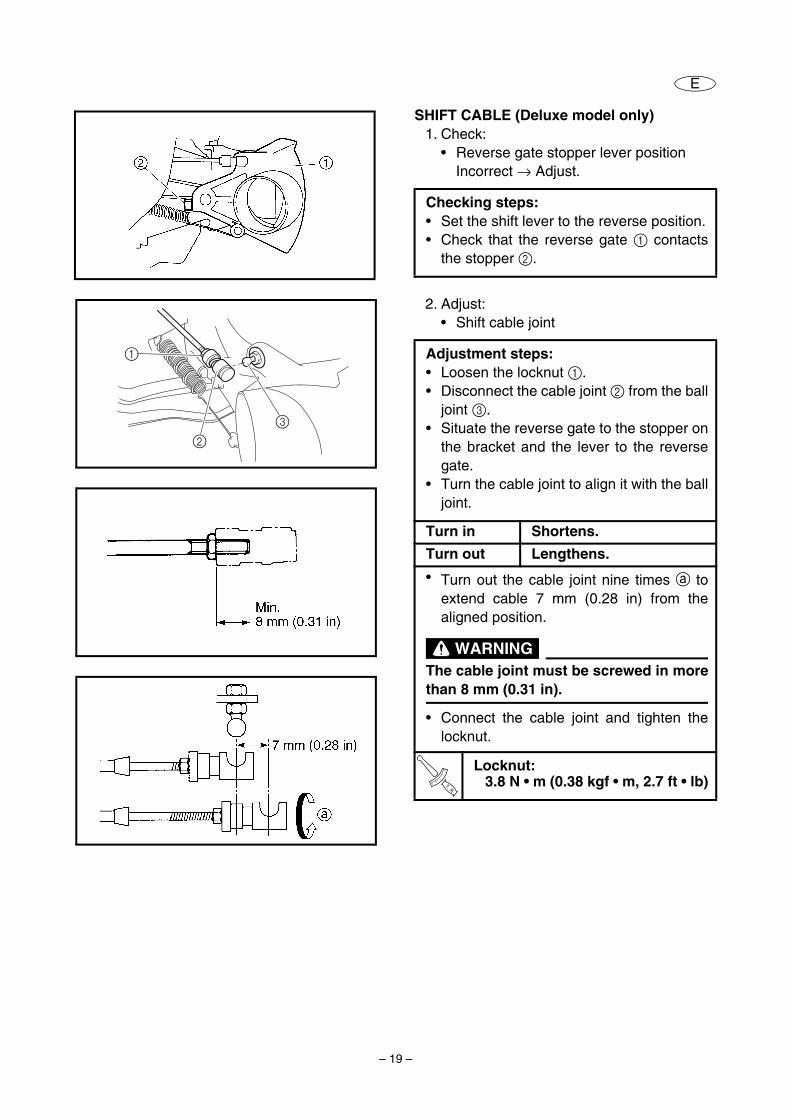
SHIFT CABLE (Deluxe model only)1. Check:
• Reverse gate stopper lever positionIncorrect → Adjust.
Checking steps:• Set the shift lever to the reverse position.• Check that the reverse gate 1 contacts
the stopper 2.
2. Adjust:• Shift cable joint
Adjustment steps:• Loosen the locknut 1.• Disconnect the cable joint 2 from the ball
joint 3.• Situate the reverse gate to the stopper on
the bracket and the lever to the reversegate.
• Turn the cable joint to align it with the balljoint.
Turn in Shortens.
Turn out Lengthens.
• Turn out the cable joint nine times a toextend cable 7 mm (0.28 in) from thealigned position.
WARNINGThe cable joint must be screwed in morethan 8 mm (0.31 in).
• Connect the cable joint and tighten thelocknut.
T R..
Locknut:3.8 N • m (0.38 kgf • m, 2.7 ft • lb)
1
2
3
– 20 –
E
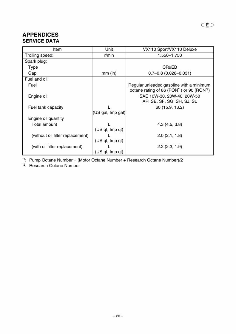
APPENDICESSERVICE DATA
*1: Pump Octane Number = (Motor Octane Number + Research Octane Number)/2*2: Research Octane Number
Item Unit VX110 Sport/VX110 DeluxeTrolling speed: r/min 1,550–1,750Spark plug:
Type CR9EBGap mm (in) 0.7–0.8 (0.028–0.031)
Fuel and oil:Fuel Regular unleaded gasoline with a minimum
octane rating of 86 (PON*1) or 90 (RON*2)Engine oil SAE 10W-30, 20W-40, 20W-50
API SE, SF, SG, SH, SJ, SLFuel tank capacity L
(US gal, Imp gal)60 (15.9, 13.2)
Engine oil quantityTotal amount L
(US qt, Imp qt)4.3 (4.5, 3.8)
(without oil filter replacement) L (US qt, Imp qt)
2.0 (2.1, 1.8)
(with oil filter replacement) L (US qt, Imp qt)
2.2 (2.3, 1.9)


YAMAHA MOTOR CORPORATION, USA
Printed in USANov. 2004 – 0.0 × 1 CR(E)