w4.5 linker and utilities manual - analog.com · w4.5 linker and utilities manual revision 2.0,...
TRANSCRIPT

W4.5Linker and Utilities Manual
Revision 2.0, April 2006
Part Number 82-000420-03
Analog Devices, Inc.One Technology WayNorwood, Mass. 02062-9106 a
Copyright Information© 2006 Analog Devices, Inc., ALL RIGHTS RESERVED. This docu-ment may not be reproduced in any form without prior, express written consent from Analog Devices, Inc.
Printed in the USA.
DisclaimerAnalog Devices, Inc. reserves the right to change this product without prior notice. Information furnished by Analog Devices is believed to be accurate and reliable. However, no responsibility is assumed by Analog Devices for its use; nor for any infringement of patents or other rights of third parties which may result from its use. No license is granted by impli-cation or otherwise under the patent rights of Analog Devices, Inc.
Trademark and Service Mark NoticeThe Analog Devices logo, the CROSSCORE logo, VisualDSP++, Blackfin, SHARC, TigerSHARC, and EZ-KIT Lite are registered trade-marks of Analog Devices, Inc.
All other brand and product names are trademarks or service marks of their respective owners.

VisualDSP++ 4.5 Linker and Utilities Manual iii
CONTENTS
PREFACE
Purpose of This Manual ................................................................. xix
Intended Audience ......................................................................... xix
Manual Contents ............................................................................ xx
What’s New in This Manual ........................................................... xxi
Technical or Customer Support ..................................................... xxii
Supported Processors ................................................................... xxiii
Product Information .................................................................... xxiv
MyAnalog.com ....................................................................... xxiv
Processor Product Information ................................................. xxv
Related Documents ................................................................ xxvi
Online Technical Documentation .......................................... xxvii
Accessing Documentation From VisualDSP++ ................... xxvii
Accessing Documentation From Windows ........................ xxviii
Accessing Documentation From the Web .......................... xxviii
Printed Manuals ..................................................................... xxix
VisualDSP++ Documentation Set ....................................... xxix
Hardware Tools Manuals .................................................... xxix
Processor Manuals .............................................................. xxix

CONTENTS
iv VisualDSP++ 4.5 Linker and Utilities Manual
Data Sheets ....................................................................... xxix
Notation Conventions .................................................................. xxx
INTRODUCTION
Software Development Flow ......................................................... 1-2
Compiling and Assembling ........................................................... 1-3
Inputs – C/C++ and Assembly Sources .................................... 1-3
Input Section Directives in Assembly Code .............................. 1-4
Input Section Directives in C/C++ Source Files ........................ 1-5
Linking ........................................................................................ 1-7
Linker and Assembler Preprocessor .......................................... 1-8
Loading and Splitting ................................................................. 1-10
LINKER
Linker Operation .......................................................................... 2-2
Directing Linker Operation ..................................................... 2-3
Linking Process Rules .............................................................. 2-4
Linker Description File Overview ............................................ 2-5
Linking Environment for Windows ............................................... 2-6
Project Builds ......................................................................... 2-6
Expert Linker .......................................................................... 2-9
Linker Warning and Error Messages ............................................ 2-10
Link Target Description .............................................................. 2-11
Representing Memory Architecture ........................................ 2-12
Specifying the Memory Map ................................................. 2-12

VisualDSP++ 4.5 Linker and Utilities Manual v
CONTENTS
Memory Usage and Default Memory Sections .................... 2-13
Default Memory Sections for SHARC Processors ............... 2-14
.bss ............................................................................... 2-15
.rtti ............................................................................... 2-15
seg_rth .......................................................................... 2-15
seg_init ......................................................................... 2-15
seg_int_code ................................................................. 2-15
seg_pmco ...................................................................... 2-15
seg_pmda ...................................................................... 2-16
seg_argv ........................................................................ 2-16
seg_ctdm ...................................................................... 2-16
seg_dmda ...................................................................... 2-16
seg_heap ....................................................................... 2-16
seg_stak ........................................................................ 2-16
seg_vtbl ........................................................................ 2-17
Other Memory Sections ................................................ 2-17
Default Memory Sections for TigerSHARC Processors ....... 2-17
bsz ................................................................................ 2-19
bsz_init ......................................................................... 2-19
ctor ............................................................................... 2-19
data1 ............................................................................ 2-19
data2 ............................................................................ 2-19
mem_argv ..................................................................... 2-20
program ........................................................................ 2-20

CONTENTS
vi VisualDSP++ 4.5 Linker and Utilities Manual
vtbl .............................................................................. 2-20
Other Memory Sections ................................................ 2-20
Default Memory Sections for Blackfin Processors .............. 2-20
program ....................................................................... 2-21
data1 ............................................................................ 2-21
cplb_code ..................................................................... 2-21
constdata ...................................................................... 2-21
cplb_data ..................................................................... 2-21
L1_DATA_A ................................................................ 2-21
L1_DATA_B ................................................................ 2-22
voldata ......................................................................... 2-22
ctor .............................................................................. 2-22
bsz ............................................................................... 2-22
bsz_init ........................................................................ 2-22
stack ............................................................................. 2-22
heap ............................................................................. 2-23
noncache_code ............................................................. 2-23
sdram0 ......................................................................... 2-23
sdram0_bank{1|2|3} ...................................................... 2-23
sdram_bcz .................................................................... 2-23
sdram_shared ............................................................... 2-23
vtbl .............................................................................. 2-24
Other Memory Sections ................................................ 2-24
Special “Table” Memory Sections ...................................... 2-24

VisualDSP++ 4.5 Linker and Utilities Manual vii
CONTENTS
.gdt ............................................................................... 2-24
.gdtl .............................................................................. 2-25
.edt ............................................................................... 2-25
.cht ............................................................................... 2-25
.frt ................................................................................ 2-25
primio_atomic_lock ...................................................... 2-25
mc_data ........................................................................ 2-25
.rtti ............................................................................... 2-25
cplb .............................................................................. 2-25
Input Sections Provided in Deflaut LDFs for User Code and Data 2-26
L1_data ........................................................................ 2-26
L1_data_a ..................................................................... 2-26
L1_data_b .................................................................... 2-26
L1_code ........................................................................ 2-26
L1_bcz .......................................................................... 2-26
L2_bcz .......................................................................... 2-26
L2_sram ....................................................................... 2-26
l2_sram ......................................................................... 2-27
L2_sram_a .................................................................... 2-27
L2_sram_b .................................................................... 2-27
l2_shared ...................................................................... 2-27
Memory Characteristics Overview ..................................... 2-27
SHARC Memory Characteristics ................................... 2-27
TigerSHARC Memory Characteristics ........................... 2-30

CONTENTS
viii VisualDSP++ 4.5 Linker and Utilities Manual
Linker MEMORY{} Command in .ldf File ........................ 2-32
Entry Address ................................................................... 2-34
Wildcard Characters ......................................................... 2-35
Placing Code on the Target ................................................... 2-35
Specifying Two Buffers in Different Memory Segments ...... 2-39
Linking with Attributes - Overview ................................... 2-40
Profile-Guided Optimization Support .................................... 2-41
Passing Arguments for Simulation or Emulation .................... 2-42
Linker Command-Line Reference ................................................ 2-43
Linker Command-Line Syntax ............................................... 2-43
Command-Line Object Files ............................................. 2-44
Command-Line File Names .............................................. 2-45
Object File Types .............................................................. 2-47
Linker Command-Line Switches ............................................ 2-47
Linker Switch Summary and Descriptions ......................... 2-49
@filename ........................................................................ 2-51
-Dprocessor ...................................................................... 2-51
-L path ............................................................................. 2-52
-M ................................................................................... 2-52
-MM ................................................................................ 2-52
-Map filename .................................................................. 2-53
-MDmacro[=def ] ............................................................. 2-53
-MUDmacro .................................................................... 2-53
-S ..................................................................................... 2-54

VisualDSP++ 4.5 Linker and Utilities Manual ix
CONTENTS
-T filename ....................................................................... 2-54
-Wwarn [number] ............................................................. 2-54
-Wnumber[,number] ......................................................... 2-54
-e ...................................................................................... 2-55
-ek sectionName ............................................................... 2-55
-es sectionName ................................................................ 2-55
-entry ............................................................................... 2-56
-ev .................................................................................... 2-56
-flags-meminit -opt1[,-opt2... ........................................... 2-56
-flags-pp-opt1[,-opt2...] ................................................... 2-56
-h[elp] .............................................................................. 2-56
-i|I directory ..................................................................... 2-56
-ip .................................................................................... 2-57
-jcs2l ................................................................................ 2-57
-jcs2l+ .............................................................................. 2-58
-keep symbolName ............................................................ 2-58
-meminit .......................................................................... 2-58
-nonmemcheck ................................................................. 2-58
-o filename ....................................................................... 2-59
-od directory ..................................................................... 2-59
-pp ................................................................................... 2-59
-proc processor .................................................................. 2-59
-s ...................................................................................... 2-60
-save-temps ....................................................................... 2-60
CONTENTS
x VisualDSP++ 4.5 Linker and Utilities Manual
-si-revision version ............................................................ 2-60
-sp ................................................................................... 2-61
-t ..................................................................................... 2-61
-tx .................................................................................... 2-61
-v[erbose] ......................................................................... 2-61
-version ............................................................................ 2-62
-warnonce ........................................................................ 2-62
-xref ................................................................................. 2-62
LINKER DESCRIPTION FILE
LDF File Overview ....................................................................... 3-3
Generated LDFs ..................................................................... 3-4
Default LDFs .......................................................................... 3-4
Example 1 – Basic .ldf File for Blackfin Processors ................... 3-7
Memory Usage in Blackfin Processors .................................. 3-9
Example 2 – Basic .ldf File for TigerSHARC Processors .......... 3-10
Example 3 – Basic .ldf File for SHARC Processors ................. 3-11
Common Notes on Basic .ldf File Examples ........................... 3-12
LDF Structure ............................................................................ 3-17
Command Scoping ............................................................... 3-18
LDF Expressions ........................................................................ 3-19
LDF Keywords, Commands, and Operators ................................ 3-20
Miscellaneous LDF Keywords ................................................ 3-21
LDF Operators ........................................................................... 3-22
ABSOLUTE() Operator ........................................................ 3-22
VisualDSP++ 4.5 Linker and Utilities Manual xi
CONTENTS
ADDR() Operator ................................................................. 3-23
DEFINED() Operator ........................................................... 3-24
MEMORY_END() Operator ................................................. 3-25
MEMORY_SIZEOF() Operator ............................................ 3-25
MEMORY_START() Operator .............................................. 3-26
SIZEOF() Operator ............................................................... 3-26
Location Counter (.) .............................................................. 3-27
LDF Macros ............................................................................... 3-27
Built-In LDF Macros ............................................................. 3-29
User-Declared Macros ........................................................... 3-30
LDF Macros and Command-Line Interaction ......................... 3-30
LDF Commands ......................................................................... 3-31
ALIGN() ............................................................................... 3-32
ARCHITECTURE() ............................................................. 3-32
ELIMINATE() ...................................................................... 3-33
ELIMINATE_SECTIONS() .................................................. 3-34
ENTRY() .............................................................................. 3-34
INCLUDE() ......................................................................... 3-35
INPUT_SECTION_ALIGN() .............................................. 3-35
KEEP() ................................................................................. 3-36
KEEP_SECTIONS() ............................................................. 3-37
LINK_AGAINST() ............................................................... 3-37
MAP() .................................................................................. 3-38
MEMORY{} .......................................................................... 3-38

CONTENTS
xii VisualDSP++ 4.5 Linker and Utilities Manual
Segment Declarations ....................................................... 3-39
segment_name .............................................................. 3-40
START(address_number) .............................................. 3-40
TYPE() ........................................................................ 3-40
LENGTH(length_number)/END(address_number) ...... 3-41
WIDTH(width_number) .............................................. 3-41
MPMEMORY{} .................................................................... 3-42
OVERLAY_GROUP{} .......................................................... 3-42
PACKING() ......................................................................... 3-42
Packing in SHARC Processors ........................................... 3-44
Overlay Packing Formats in SHARC Processors ............. 3-46
External Execution Packing in SHARC Processors ......... 3-47
PLIT{} .................................................................................. 3-48
PROCESSOR{} .................................................................... 3-48
RESERVE() .......................................................................... 3-50
Linker Error Resolutions ................................................... 3-51
Example ........................................................................... 3-52
RESERVE_EXPAND() ......................................................... 3-53
RESOLVE() .......................................................................... 3-53
SEARCH_DIR() ................................................................... 3-54
SECTIONS{} ....................................................................... 3-55
INPUT_SECTIONS() ..................................................... 3-58
Using Optional Filter Expression ................................... 3-59
INPUT_SECTIONS_PIN/INPUT_SECTIONS_PIN_EXCLUSIVE Commands ................................................................. 3-60

VisualDSP++ 4.5 Linker and Utilities Manual xiii
expression ......................................................................... 3-62
FILL(hex number) ............................................................ 3-63
PLIT{plit_commands} ...................................................... 3-63
OVERLAY_INPUT{overlay_commands} ........................... 3-63
SHARED_MEMORY{} ......................................................... 3-65
EXPERT LINKER
Expert Linker Overview ................................................................ 4-2
Launching the Create LDF Wizard ................................................ 4-4
Step 1: Specifying Project Information ..................................... 4-5
Step 2: Specifying System Information ..................................... 4-6
Step 3: Completing the LDF Wizard ...................................... 4-10
Expert Linker Window Overview ................................................ 4-11
Input Sections Pane ..................................................................... 4-13
Input Sections Menu ............................................................. 4-13
Mapping an Input Section to an Output Section .................... 4-15
Viewing Icons and Colors ...................................................... 4-16
Sorting Objects ..................................................................... 4-17
Memory Map Pane ...................................................................... 4-19
Context Menu ....................................................................... 4-22
Tree View Memory Map Representation ................................. 4-24
Graphical View Memory Map Representation ........................ 4-25
Specifying Pre- and Post-Link Memory Map View .................. 4-31
Zooming In and Out on the Memory Map ............................. 4-32
Adding a Memory Segment .................................................... 4-34
xiv VisualDSP++ 4.5 Linker and Utilities Manual
Inserting a Gap Into a Memory Segment ............................... 4-36
Working With Overlays ........................................................ 4-37
Viewing Section Contents ..................................................... 4-40
Viewing Symbols .................................................................. 4-44
Profiling Object Sections ....................................................... 4-45
Adding Shared Memory Segments and Linking Object Files ... 4-49
Managing Object Properties ........................................................ 4-54
Managing General Global Properties ..................................... 4-55
Managing Processor Properties .............................................. 4-56
Managing PLIT Properties for Overlays ................................. 4-58
Managing Elimination Properties .......................................... 4-59
Managing Symbols Properties ................................................ 4-61
Managing Memory Segment Properties .................................. 4-64
Managing Output Section Properties ..................................... 4-65
Managing Packing Properties ................................................. 4-68
Managing Alignment and Fill Properties ................................ 4-70
Managing Overlay Properties ................................................. 4-72
Managing Stack and Heap in Processor Memory .................... 4-74
Managing Shared Memory Properties .................................... 4-77
MEMORY OVERLAYS AND ADVANCED LDF COMMANDS
Overview ...................................................................................... 5-2
Memory Management Using Overlays ........................................... 5-4
Introduction to Memory Overlays ........................................... 5-5

VisualDSP++ 4.5 Linker and Utilities Manual xv
Overlay Managers .................................................................... 5-6
Breakpoints on Overlays ...................................................... 5-7
Memory Overlay Support ........................................................ 5-8
Example – Managing Two Overlays ....................................... 5-13
Linker-Generated Constants .................................................. 5-15
Overlay Word Sizes ................................................................ 5-16
Storing Overlay ID ................................................................ 5-19
Overlay Manager Function Summary ..................................... 5-19
Reducing Overlay Manager Overhead .................................... 5-20
Using PLIT{} and Overlay Manager ....................................... 5-24
Inter-Overlay Calls ............................................................ 5-26
Inter-Processor Calls ......................................................... 5-27
Advanced LDF Commands ......................................................... 5-29
OVERLAY_GROUP{} ........................................................... 5-29
Ungrouped Overlay Execution ........................................... 5-31
Grouped Overlay Execution .............................................. 5-32
PLIT{} .................................................................................. 5-33
PLIT Syntax ..................................................................... 5-34
Command Evaluation and Setup ....................................... 5-35
Overlay PLIT Requirements and PLIT Examples ............... 5-35
PLIT – Summary .............................................................. 5-36
Linking Multiprocessor Systems .................................................. 5-37
Selecting Code and Data for Placement .................................. 5-38
Using LDF Macros ........................................................... 5-39

xvi VisualDSP++ 4.5 Linker and Utilities Manual
Mapping by Section Name .................................................... 5-41
Mapping Using Attributes ..................................................... 5-42
Mapping Using Archives ....................................................... 5-42
MPMEMORY{} .................................................................... 5-44
SHARED_MEMORY{} ........................................................ 5-45
COMMON_MEMORY{} ..................................................... 5-51
ARCHIVER
Introduction ................................................................................. 6-2
Archiver Guide ............................................................................. 6-3
Creating a Library ................................................................... 6-3
Making Archived Functions Usable ......................................... 6-4
Writing Archive Routines: Creating Entry Points ................. 6-4
Accessing Archived Functions From Your Code ................... 6-5
Specifying Object Files ....................................................... 6-6
Tagging an Archive With Version Information ..................... 6-7
Basic Version Information ............................................... 6-7
User-Defined Version Information .................................. 6-8
Printing Version Information .......................................... 6-9
Removing Version Information From an Archive ........... 6-10
Checking Version Number ............................................ 6-10
Archiver Symbol Name Encryption ....................................... 6-11
Archiver Command-Line Reference ............................................. 6-14
elfar Command Syntax .......................................................... 6-14
Archiver Parameters and Switches .......................................... 6-15
VisualDSP++ 4.5 Linker and Utilities Manual xvii
Command-Line Constraints .................................................. 6-17
MEMORY INITIALIZER
Memory Initializer Overview ......................................................... 7-2
Basic Operation of Memory Initializer ........................................... 7-3
Input and Output Files ............................................................ 7-3
Initialization Stream Structure ....................................................... 7-5
Run-Time Library Routine Basic Operation ................................... 7-6
Using the Memory Initializer ......................................................... 7-7
Preparing the Linker Description File (.ldf ) .............................. 7-7
Preparing the Source Files ........................................................ 7-8
Invoking the Memory Initializer ............................................ 7-10
Invoking Memory Initializer from the VisualDSP++ IDDE 7-10
Invoking Memory Initializer from Command Line ............. 7-11
Invoking Memory Initializer from Linker’s Command Line 7-11
Invoking Memory Initializer from Compiler’s Command Line 7-11
Invoking Memory Initializer with Callback Executables ..... 7-11
Memory Initializer Command-Line Switches ............................... 7-13
-BeginInit Initsymbol ............................................................ 7-14
-h .......................................................................................... 7-15
-IgnoreSection Sectionname ................................................... 7-15
-Init Initcode.dxe .................................................................. 7-15
InputFile.dxe ......................................................................... 7-16
-NoAuto ............................................................................... 7-16
-NoErase ............................................................................... 7-16
xviii VisualDSP++ 4.5 Linker and Utilities Manual
-o Outputfile.dxe .................................................................. 7-17
-Section Sectionname ............................................................ 7-17
-v ......................................................................................... 7-17
FILE FORMATS
Source Files .................................................................................. A-2
C/C++ Source Files ................................................................. A-2
Assembly Source Files (.asm) ................................................... A-3
Assembly Initialization Data Files (.DAT) ................................ A-3
Header Files (.H) .................................................................... A-4
Linker Description Files (.ldf ) ................................................. A-4
Linker Command-Line Files (.TXT) ........................................ A-5
Build Files .................................................................................... A-5
Assembler Object Files (.doj) ................................................... A-5
Library Files (.dlb) .................................................................. A-6
Linker Output Files (.dxe, .sm, and .ovl) .................................. A-6
Memory Map Files (.xml) ........................................................ A-6
Loader Output Files in Intel Hex-32 Format (.ldr) ................... A-6
Splitter Output Files in ASCII Format (.ldr) ............................ A-8
Debugger Files .............................................................................. A-9
Format References ...................................................................... A-10
UTILITIES
elfdump – ELF File Dumper ......................................................... B-1
Disassembling a Library Member ............................................. B-3
VisualDSP++ 4.5 Linker and Utilities Manual xix
Dumping Overlay Library Files ............................................... B-4
plinker ......................................................................................... B-4
LDF PROGRAMMING EXAMPLES FOR TIGERSHARC PROCESSORS
Linking a Single-Processor System ................................................ C-2
Linking Large Uninitialized or Zero-InitializedVariables ................ C-4
Linking an ADSP-TS101 MP Shared Memory System .................. C-6
Linking for Overlay Memory ...................................................... C-12
LDF PROGRAMMING EXAMPLES FOR SHARC PROCESSORS
Linking a Single-Processor SHARC System ................................... D-2
Linking Large Uninitialized Variables ........................................... D-4
Linking for MP and Shared Memory ............................................ D-6
Reflective Semaphores .......................................................... D-12
Linking for Overlay Memory ...................................................... D-14
LDF PROGRAMMING EXAMPLES FOR BLACKFIN PROCESSORS
Linking for a Single-Processor System ........................................... E-2
Linking Large Uninitialized or Zero-initialized Variables ............... E-4
Linking for Assembly Source File .................................................. E-6
Linking for C Source File – Example 1 ......................................... E-8
Linking for Complex C Source File – Example 2 .......................... E-11
Linking for Overlay Memory ....................................................... E-17

xx VisualDSP++ 4.5 Linker and Utilities Manual
INDEX

VisualDSP++ 4.5 Linker and Utilities Manual xix
PREFACE
Thank you for purchasing Analog Devices development software for digi-tal signal processors (DSPs).
Purpose of This ManualThe VisualDSP++ 4.5 Linker and Utilities Manual contains information about the linker and utilities programs for 16-bit fixed-point Blackfin® (ADSP-BFxxx) processors, and 32-bit (floating-point and fixed-point) TigerSHARC® (ADSP-TSxxx) and SHARC® (ADSP-21xxx) processors which set a new standard of performance for digital signal processors, combining multiple computation units for floating-point and fixed-point processing as well as wide word width. The manual describes the linking process in the VisualDSP++ Windows application environment.
This manual provides information on the linking process and describes the syntax for the linker’s command language—a scripting language that the linker reads from the linker description file. The manual leads you through using the linker, archiver, and utilities to produce DSP programs and provides reference information on the file utility software.
Intended AudienceThe primary audience for this manual is a programmer who is familiar with Analog Devices processors. This manual assumes that the audience has a working knowledge of the appropriate processor architecture and instruction set. Programmers who are unfamiliar with Analog Devices
Manual Contents
xx VisualDSP++ 4.5 Linker and Utilities Manual
processors can use this manual, but should supplement it with other texts (such as the appropriate hardware reference and programming reference manuals) that describe your target architecture.
Manual ContentsThe manual contains:
• Chapter 1, “Introduction” This chapter provides an overview of the linker and utilities.
• Chapter 2, “Linker” This chapter describes how to combine object files into reusable library files to link routines referenced by other object files.
• Chapter 3, “Linker Description File” This chapter describes how to write an .ldf file to define the target.
• Chapter 4, “Expert Linker” This chapter describes Expert Linker, which is an interactive graphical tool to set up and map processor memory.
• Chapter 5, “Memory Overlays and Advanced LDF Commands” This chapter describes how overlays and advanced LDF commands are used for memory management.
• Chapter 6 “Archiver” This chapter describes the elfar archiver utility used to combine object files into library files, which serve as reusable resources for code development.
• Chapter 7 “Memory Initializer” This chapter describes the Memory Initializer utility that is used to generate a single initialization stream and save it in a section in the output executable file.

VisualDSP++ 4.5 Linker and Utilities Manual xxi
Preface
• Appendix A, “File Formats” This appendix lists and describes the file formats that the develop-ment tools use as inputs or produce as outputs.
• Appendix B, “Utilities” This appendix describes the utilities that provide legacy and file conversion support.
• Appendix C, “LDF Programming Examples for TigerSHARC Pro-cessors” This appendix provides code examples of .LDF files used with TigerSHARC processors.
• Appendix D, “LDF Programming Examples for SHARC Proces-sors” This appendix provides code examples of .LDF files used with SHARC processors.
• Appendix E, “LDF Programming Examples for Blackfin Proces-sors” This appendix provides code examples of .LDF files used with Blackfin processors.
What’s New in This ManualThis manual documents linking support for all currently available Analog Devices 32-bit floating-point and fixed-point SHARC and TigerSHARC
processors, as well as 16-bit fixed-point Blackfin processors. The manual describes the linking process in the VisualDSP++ Windows application environment.
Loader/splitter information is available in a separate Loader manual.
Refer to VisualDSP++ 4.5 Product Bulletin for information on all new and updated features and other release information.

Technical or Customer Support
xxii VisualDSP++ 4.5 Linker and Utilities Manual
Technical or Customer SupportYou can reach Analog Devices, Inc. Customer Support in the following ways:
• Visit the Embedded Processing and DSP products Web site at http://www.analog.com/processors/technicalSupport
• E-mail tools questions to [email protected]
• E-mail processor questions to [email protected] (World wide support)
[email protected] (Europe support)
[email protected] (China support)
• Phone questions to 1-800-ANALOGD
• Contact your Analog Devices, Inc. local sales office or authorized distributor
• Send questions by mail to: Analog Devices, Inc.
One Technology Way
P.O. Box 9106
Norwood, MA 02062-9106
USA
VisualDSP++ 4.5 Linker and Utilities Manual xxiii
Preface
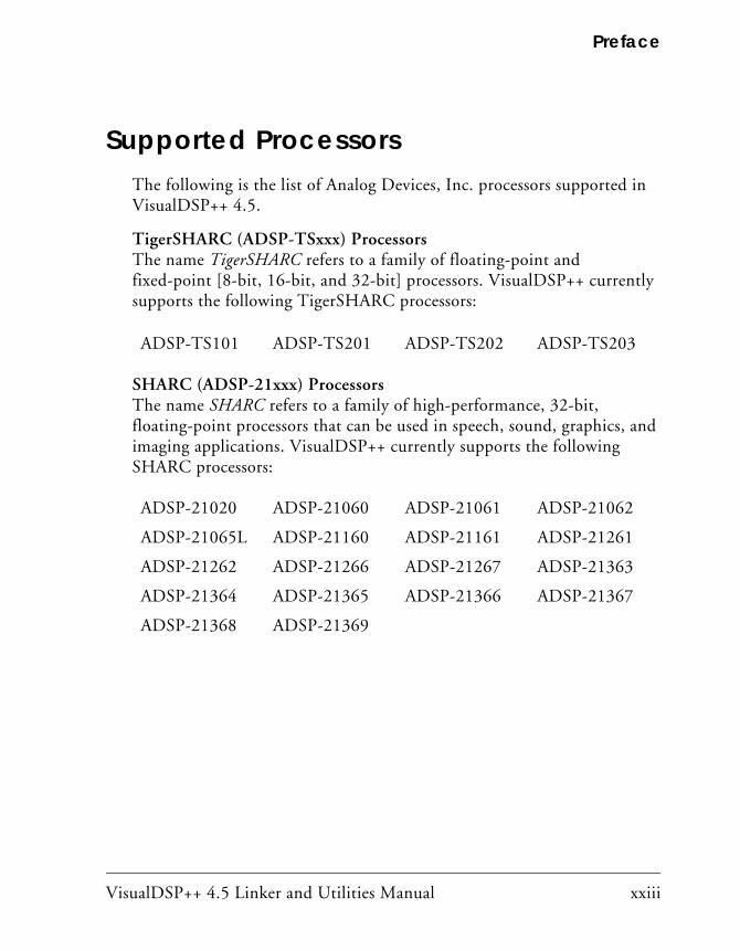
Supported ProcessorsThe following is the list of Analog Devices, Inc. processors supported in VisualDSP++ 4.5.
TigerSHARC (ADSP-TSxxx) ProcessorsThe name TigerSHARC refers to a family of floating-point and fixed-point [8-bit, 16-bit, and 32-bit] processors. VisualDSP++ currently supports the following TigerSHARC processors:
SHARC (ADSP-21xxx) ProcessorsThe name SHARC refers to a family of high-performance, 32-bit, floating-point processors that can be used in speech, sound, graphics, and imaging applications. VisualDSP++ currently supports the following SHARC processors:
ADSP-TS101 ADSP-TS201 ADSP-TS202 ADSP-TS203
ADSP-21020 ADSP-21060 ADSP-21061 ADSP-21062
ADSP-21065L ADSP-21160 ADSP-21161 ADSP-21261
ADSP-21262 ADSP-21266 ADSP-21267 ADSP-21363
ADSP-21364 ADSP-21365 ADSP-21366 ADSP-21367
ADSP-21368 ADSP-21369

Product Information
xxiv VisualDSP++ 4.5 Linker and Utilities Manual
Blackfin (ADSP-BFxxx) ProcessorsThe name Blackfin refers to a family of 16-bit, embedded processors. VisualDSP++ currently supports the following Blackfin processors:
Product InformationYou can obtain product information from the Analog Devices Web site, from the product CD-ROM, or from the printed publications (manuals).
Analog Devices is online at www.analog.com. Our Web site provides infor-mation about a broad range of products—analog integrated circuits, amplifiers, converters, and digital signal processors.
MyAnalog.comMyAnalog.com is a free feature of the Analog Devices Web site that allows customization of a Web page to display only the latest information on products you are interested in. You can also choose to receive weekly e-mail notifications containing updates to the Web pages that meet your interests. MyAnalog.com provides access to books, application notes, data sheets, code examples, and more.
ADSP-BF531 ADSP-BF532 (formerly ADSP-21532)
ADSP-BF533 ADSP-BF535 (formerly ADSP-21535)
ADSP-BF534 ADSP-BF536
ADSP-BF537 ADSP-BF538
ADSP-BF539 ADSP-BF561
AD6903 AD6531
AD6901 AD6902

VisualDSP++ 4.5 Linker and Utilities Manual xxv
Preface
Registration
Visit www.myanalog.com to sign up. Click Register to use MyAnalog.com. Registration takes about five minutes and serves as a means to select the information you want to receive.
If you are already a registered user, just log on. Your user name is your e-mail address.
Processor Product InformationFor information on embedded processors and DSPs, visit our Web site at www.analog.com/processors, which provides access to technical publica-tions, data sheets, application notes, product overviews, and product announcements.
You may also obtain additional information about Analog Devices and its products in any of the following ways.
• E-mail questions or requests for information to [email protected] (World wide support) [email protected] (Europe support)
[email protected] (China support)
• Fax questions or requests for information to 1-781-461-3010 (North America) +49-89-76903-157 (Europe)
• Access the FTP Web site at ftp ftp.analog.com (or ftp 137.71.25.69) ftp://ftp.analog.com

Product Information
xxvi VisualDSP++ 4.5 Linker and Utilities Manual
Related Documents For information on product related development software, see these publications:
• VisualDSP++ 4.5 Getting Started Guide
• VisualDSP++ 4.5 User’s Guide
• VisualDSP++ 4.5 C/C++ Compiler and Library Manual for SHARC Processors
• VisualDSP++ 4.5 C/C++ Compiler and Library Manual for TigerSHARC Processors
• VisualDSP++ 4.5 C/C++ Compiler and Library Manual for Blackfin Processors
• VisualDSP++ 4.5 Assembler and Preprocessor Manual
• Device Drivers and System Services Manual for Blackfin Processors
• VisualDSP++ 4.5 Product Release Bulletin
• VisualDSP++ Kernel (VDK) User’s Guide
• Quick Installation Reference Card
For hardware information, refer to your processors’s hardware reference, programming reference, or data sheet. All documentation is available online. Most documentation is available in printed form.
Visit the Technical Library Web site to access all processor and tools man-uals and data sheets:
http://www.analog.com/processors/resources/technicalLibrary
VisualDSP++ 4.5 Linker and Utilities Manual xxvii
Preface
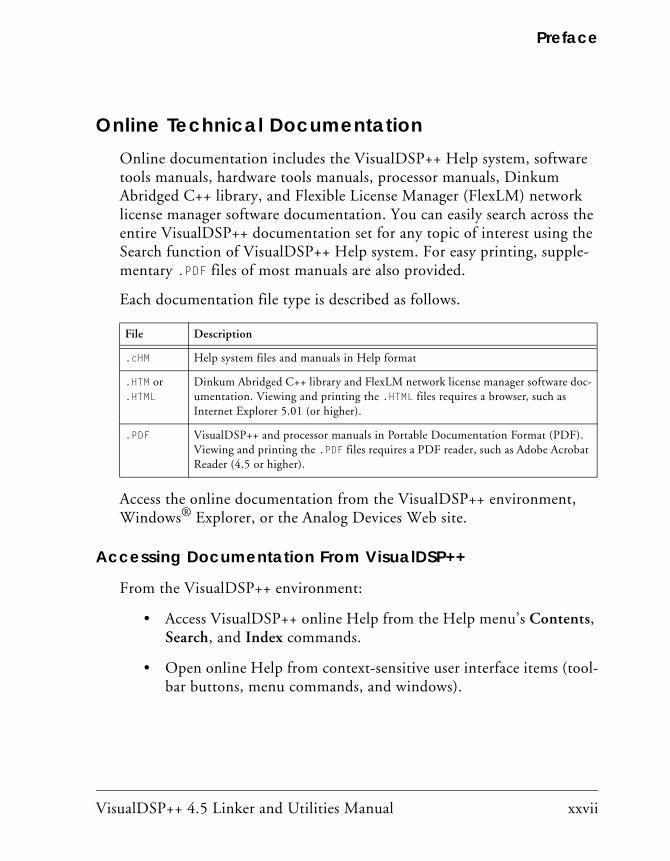
Online Technical Documentation Online documentation includes the VisualDSP++ Help system, software tools manuals, hardware tools manuals, processor manuals, Dinkum Abridged C++ library, and Flexible License Manager (FlexLM) network license manager software documentation. You can easily search across the entire VisualDSP++ documentation set for any topic of interest using the Search function of VisualDSP++ Help system. For easy printing, supple-mentary .PDF files of most manuals are also provided.
Each documentation file type is described as follows.
Access the online documentation from the VisualDSP++ environment, Windows® Explorer, or the Analog Devices Web site.
Accessing Documentation From VisualDSP++
From the VisualDSP++ environment:
• Access VisualDSP++ online Help from the Help menu’s Contents, Search, and Index commands.
• Open online Help from context-sensitive user interface items (tool-bar buttons, menu commands, and windows).
File Description
.cHM Help system files and manuals in Help format
.HTM or
.HTMLDinkum Abridged C++ library and FlexLM network license manager software doc-umentation. Viewing and printing the .HTML files requires a browser, such as Internet Explorer 5.01 (or higher).
.PDF VisualDSP++ and processor manuals in Portable Documentation Format (PDF). Viewing and printing the .PDF files requires a PDF reader, such as Adobe Acrobat Reader (4.5 or higher).

Product Information
xxviii VisualDSP++ 4.5 Linker and Utilities Manual
Accessing Documentation From Windows
In addition to any shortcuts you may have constructed, there are many ways to open VisualDSP++ online Help or the supplementary documenta-tion from Windows.
Help system files (.CHM) are located in the Help folder of VisualDSP++ environment. The .PDF files are located in the Docs folder of your VisualDSP++ installation CD-ROM. The Docs folder also contains the Dinkum Abridged C++ library and the FlexLM network license manager software documentation.
Using Windows Explorer
• Double-click the vdsp-help.chm file, which is the master Help sys-tem, to access all the other .cHM files.
• Open your VisualDSP++ installation CD-ROM and double-click any file that is part of the VisualDSP++ documentation set.
Using the Windows Start Button
• Access VisualDSP++ online Help by clicking the Start button and choosing Programs, Analog Devices, VisualDSP++, and VisualDSP++ Documentation.
Accessing Documentation From the Web
Download manuals in PDF format at the following Web site: http://www.analog.com/processors/resources/technicalLibrary/manuals
Select a processor family and book title. Download archive (.ZIP) files, one for each manual. Use any archive management software, such as WinZip, to decompress downloaded files.

VisualDSP++ 4.5 Linker and Utilities Manual xxix
Preface
Printed ManualsFor general questions regarding literature ordering, call the Literature Center at 1-800-ANALOGD (1-800-262-5643) and follow the prompts.
VisualDSP++ Documentation Set
To purchase VisualDSP++ manuals, call 1-603-883-2430. The manuals may be purchased only as a kit.
If you do not have an account with Analog Devices, you are referred to Analog Devices distributors. For information on our distributors, log onto http://www.analog.com/salesdir/continent.asp.
Hardware Tools Manuals
To purchase EZ-KIT Lite® and In-Circuit Emulator (ICE) manuals, call 1-603-883-2430. The manuals may be ordered by title or by product number located on the back cover of each manual.
Processor Manuals
Hardware reference and instruction set reference manuals may be ordered through the Literature Center at 1-800-ANALOGD (1-800-262-5643), or downloaded from the Analog Devices Web site. Manuals may be ordered by title or by product number located on the back cover of each manual.
Data Sheets
All data sheets (preliminary and production) may be downloaded from the Analog Devices Web site. Only production (final) data sheets (Rev. 0, A, B, C, and so on) can be obtained from the Literature Center at 1-800-ANALOGD (1-800-262-5643); they also can be downloaded from the Web site.

Notation Conventions
xxx VisualDSP++ 4.5 Linker and Utilities Manual
To have a data sheet faxed to you, call the Analog Devices Faxback System at 1-800-446-6212. Follow the prompts and a list of data sheet code numbers will be faxed to you. If the data sheet you want is not listed, check for it on the Web site.
Notation ConventionsText conventions used in this manual are identified and described as follows.
Additional conventions, which apply only to specific chapters, may appear throughout this document.
Example Description
Close command (File menu)
Titles in reference sections indicate the location of an item within the VisualDSP++ environment’s menu system (for example, the Close command appears on the File menu).
{this | that} Alternative required items in syntax descriptions appear within curly brackets and separated by vertical bars; read the example as this or that. One or the other is required.
[this | that] Optional items in syntax descriptions appear within brackets and sepa-rated by vertical bars; read the example as an optional this or that.
[this,…] Optional item lists in syntax descriptions appear within brackets delimited by commas and terminated with an ellipse; read the example as an optional comma-separated list of this.
.SECTION Commands, directives, keywords, and feature names are in text with letter gothic font.
filename Non-keyword placeholders appear in text with italic style format.

VisualDSP++ 4.5 Linker and Utilities Manual xxxi
Preface
Note: For correct operation, ... A Note provides supplementary information on a related topic. In the online version of this book, the word Note appears instead of this symbol.
Caution: Incorrect device operation may result if ... Caution: Device damage may result if ... A Caution identifies conditions or inappropriate usage of the product that could lead to undesirable results or product damage. In the online version of this book, the word Caution appears instead of this symbol.
Warning: Injury to device users may result if ... A Warning identifies conditions or inappropriate usage of the product that could lead to conditions that are potentially hazardous for devices users. In the online version of this book, the word Warning appears instead of this symbol.
Example Description

Notation Conventions
xxxii VisualDSP++ 4.5 Linker and Utilities Manual
VisualDSP++ 4.5 Linker and Utilities Manual 1-1
1 INTRODUCTION
This chapter provides an overview of VisualDSP++ development tools and their use in the [DSP] project development process.
The code examples in this manual have been compiled using VisualDSP++ 4.5. The examples compiled with other versions of VisualDSP++ may result in build errors or different output although the highlighted algorithms stand and should continue to stand in future releases of VisualDSP++.
This chapter includes:
• “Software Development Flow” on page 1-2 Shows how linking, loading, and splitting fit into the project devel-opment process.
• “Compiling and Assembling” on page 1-3 Shows how compiling and assembling the code fits into the project development process.
• “Linking” on page 1-7 Shows how linking fits into the project development process.
• “Loading and Splitting” on page 1-10 Shows how loading and splitting fit into the project development process.

Software Development Flow
1-2 VisualDSP++ 4.5 Linker and Utilities Manual
Software Development FlowThe majority of this manual describes linking, a critical stage in the program development process for embedded applications.
The linker tool (linker) consumes object and library files to produce exe-cutable files, which can be loaded onto a simulator or target processor. The linker also produces map files and other output that contain informa-tion used by the debugger. Debug information is embedded in the executable file.
After running the linker, you test the output with a simulator or emulator. Refer to online Help for information about debugging.
Finally, you process the debugged executable file(s) through the loader or splitter to create output for use on the actual processor. The output file may reside on another processor (host) or may be burned into a PROM. The VisualDSP++ 4.5 Loader Manual describes loader/splitter functional-ity for the target processors.
The processor software development flow can be split into three phases:
1. Compiling and Assembling – Input source files C (.c), C++ (.cpp), and assembly (.asm) yield object files (.doj)
2. Linking – Under the direction of the Linker Description File (.ldf), a linker command line, and VisualDSP++ Project Options dialog box settings, the linker utility consumes object files (.doj) to yield an executable (.dxe) file. If specified, shared memory (.sm) and overlay (.ovl) files are also produced.
3. Loading or Splitting – The executable (.dxe) file, as well as shared memory (.sm) and overlay (.ovl) files, are processed to yield output file(s). For TigerSHARC and Blackfin processors, these are boot-loadable (.ldr) files or non-bootable PROM image files, which execute from the processor’s external memory.

VisualDSP++ 4.5 Linker and Utilities Manual 1-3
Introduction
Compiling and AssemblingThe process starts with source files written in C, C++, or assembly. The compiler (or a code developer who writes assembly code) organizes each distinct sequence of instructions or data into named sections, which become the main components acted upon by the linker.
Inputs – C/C++ and Assembly SourcesThe first step towards producing an executable file is to compile or assem-ble C, C++, or assembly source files into object files. The VisualDSP++ development software assigns a .doj extension to object files (Figure 1-1).
Object files produced by the compiler (via the assembler) and by the assembler itself consist of input sections. Each input section contains a particular type of compiled/assembled source code. For example, an input section may consist of program opcodes or data, such as variables of various widths.
Some input sections may contain information to enable source-level debugging and other VisualDSP++ features. The linker maps each input section (via a corresponding output section in the executable) to a memory segment, a contiguous range of memory addresses on the target system.
Figure 1-1. Compiling and Assembling
Source Files Object Files(.C, .CPP, .ASM) (.DOJ)
Compiler andAssembler
Compiling and Assembling
1-4 VisualDSP++ 4.5 Linker and Utilities Manual
Each input section in the .ldf file requires a unique name, as specified in the source code. Depending on whether the source is C, C++, or assembly, different conventions are used to name an input section (see “Linker Description File”).
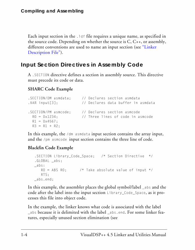
Input Section Directives in Assembly CodeA .SECTION directive defines a section in assembly source. This directive must precede its code or data.
SHARC Code Example
.SECTION/DM asmdata; // Declares section asmdata
.VAR input[3]; // Declares data buffer in asmdata
.SECTION/PM asmcode; // Declares section asmcode R0 = 0x1234; // Three lines of code in asmcode R1 = 0x4567; R3 = R1 + R2;
In this example, the /dm asmdata input section contains the array input, and the /pm asmcode input section contains the three line of code.
Blackfin Code Example
.SECTION Library_Code_Space; /* Section Directive */ .GLOBAL _abs; _abs: R0 = ABS R0; /* Take absolute value of input */ RTS; _abs.end;
In this example, the assembler places the global symbol/label _abs and the code after the label into the input section Library_Code_Space, as it pro-cesses this file into object code.
In the example, the linker knows what code is associated with the label _abs because it is delimited with the label _abs.end. For some linker fea-tures, especially unused section elimination (see
VisualDSP++ 4.5 Linker and Utilities Manual 1-5
Introduction
“ELIMINATE_SECTIONS()” on page 3-34), the linker needs to be able to determine the end of code or data associated with a label. In assembly code, the end of a function data block can be marked with a label with the same name as the label at the start of the name with .end appended to it. It is also possible to prepend a “.” in which case the label will not appear in the symbol table which can make debugging easier.
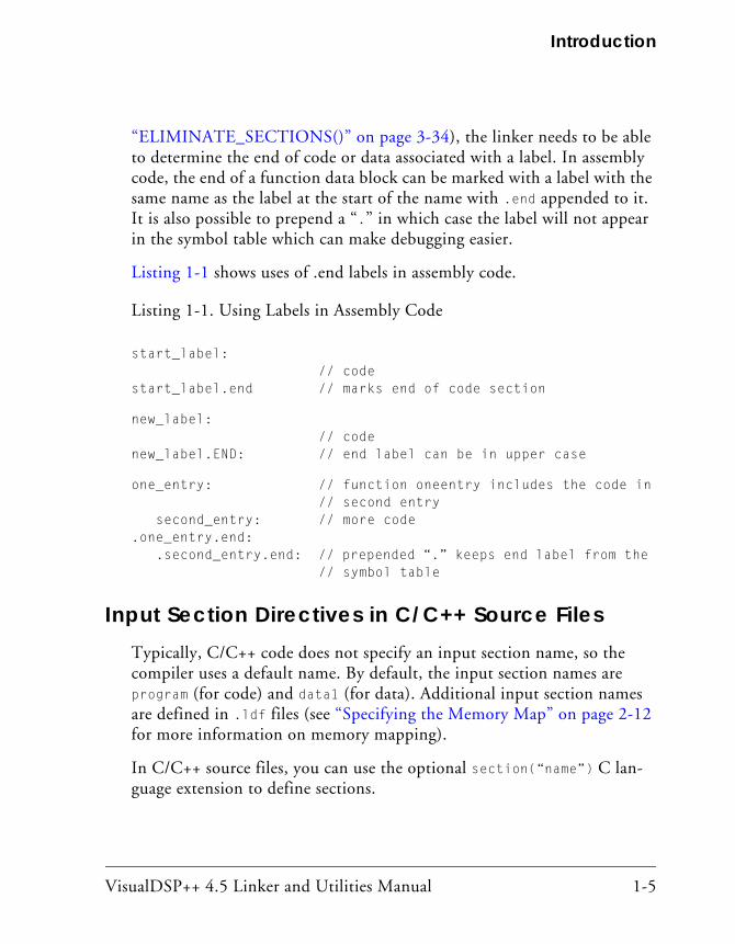
Listing 1-1 shows uses of .end labels in assembly code.
Listing 1-1. Using Labels in Assembly Code
start_label: // code start_label.end // marks end of code section
new_label: // code new_label.END: // end label can be in upper case
one_entry: // function oneentry includes the code in // second entry second_entry: // more code.one_entry.end: .second_entry.end: // prepended “.” keeps end label from the // symbol table
Input Section Directives in C/C++ Source FilesTypically, C/C++ code does not specify an input section name, so the compiler uses a default name. By default, the input section names are program (for code) and data1 (for data). Additional input section names are defined in .ldf files (see “Specifying the Memory Map” on page 2-12 for more information on memory mapping).
In C/C++ source files, you can use the optional section(“name”) C lan-guage extension to define sections.

Compiling and Assembling
1-6 VisualDSP++ 4.5 Linker and Utilities Manual
Example 1
While processing the following code, the compiler stores the temp variable in the ext_data input section of the .DOJ file and also stores the code gen-erated from func1 in an input section named extern.
...
section ("ext_data") int temp; /* Section directive */
section ("extern") void func1(void) { int x = 1; }
...
Example 2
The section ("name") extension is optional and only applies to the decla-ration to which it is applied. Note that the new function (func2) does not have section ("extern") and will be placed in the default input section program. For more information on LDF sections, refer to “Specifying the Memory Map” on page 2-12.
section ("ext_data") int temp;
section ("extern") void func1(void) { int x = 1; }
int func2(void) { return 13; } /* New */
For information on compiler default section names, refer to the VisualDSP++ 4.5 C/C++ Compiler and Library Manual for appropriate target processors and “Placing Code on the Target” on page 2-35.
Identify the difference between input section names, output sec-tion names, and memory segment names because these types of names appear in the .ldf file. Usually, default names are used. However, in some situations you may want to use non-default names. One such situation is when various functions or variables (in the same source file) are to be placed into different memory segments.
VisualDSP++ 4.5 Linker and Utilities Manual 1-7
Introduction
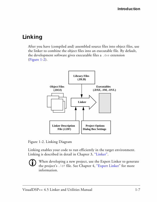
LinkingAfter you have (compiled and) assembled source files into object files, use the linker to combine the object files into an executable file. By default, the development software gives executable files a .dxe extension (Figure 1-2).
Linking enables your code to run efficiently in the target environment. Linking is described in detail in Chapter 3, “Linker”.
When developing a new project, use the Expert Linker to generate the project’s .ldf file. See Chapter 4, “Expert Linker” for more information.
Figure 1-2. Linking Diagram
Object Files Executables(.DOJ) (.DXE, .SM, .OVL)
Linker
Library Files(.DLB)
Linker DescriptionFile (.LDF)
Project OptionsDialog Box Settings
Linking
1-8 VisualDSP++ 4.5 Linker and Utilities Manual
Linker and Assembler PreprocessorThe linker and assembler preprocessor program (pp) evaluates and pro-cesses preprocessor commands in source files. With these commands, you direct the preprocessor to define macros and symbolic constants, include header files, test for errors, and control conditional assembly and compilation.
The pp preprocessor is run by the assembler or linker from the operating system’s command line or within the VisualDSP++ environment. These tools accept and pass this command information to the preprocessor. The preprocessor can also operate from the command line using its own com-mand-line switches.
Assembler/Linker Preprocessor treats the character “.” as part of an identifierThe preprocessor matches the assembler which uses “.” as part of assem-bler directives and as a legal character in labels. This behavior does create a possible problem for users that have written preprocessor macros that rely on identifiers to break when encountering the “.” character, usually seen when processing register names. For example,
#define Loadd(reg, val) \ reg.l = val; \ reg.h = val;
The above example would not work in VisualDSP++ 4.5 because Visu-alDSP++ 4.5 does not provide any replacement since reg is not parsed as a separate identifier. The macro has to be rewritten using the operator ## such as:
#define Loadd(reg, val) \ reg ## .l = val; \ reg ## .h = val;

VisualDSP++ 4.5 Linker and Utilities Manual 1-9
Introduction
The preprocessor supports ANSI C standard preprocessing with extensions but differs from the ANSI C standard preprocessor in several ways. For more information on the pp preprocessor, see the VisualDSP++ 4.5 Assembler and Preprocessor Manual.
The compiler has it own preprocessor that allows you to use pre-processor commands within your C/C++ source. The compiler preprocessor automatically runs before the compiler. For more information, see the VisualDSP++ 4.5 C/C++ Compiler and Library Manual for the appropriate target archtecture.
Loading and Splitting
1-10 VisualDSP++ 4.5 Linker and Utilities Manual
Loading and SplittingAfter debugging the .dxe file, you process it through a loader or splitter to create output files used by the actual processor. The file(s) may reside on another processor (host) or may be burned into a PROM.
For more information, refer to the VisualDSP++ 4.5 Loader Manual which provides detailed descriptions of the processes and options used to generate boot-loadable .ldr (loader) files for the appropriate target pro-cessors. This manual also describes the splitting utility, which (when used) creates the non-bootloadable files that execute from the processor’s exter-nal memory.
In general:
• The SHARC ADSP-2106x/ADSP-21160 processors use the loader (elfloader.exe) to yield a boot-loadable image (.ldr file), which resides in memory external to the processor (PROM or host proces-sor). Use the splitter utility (elfspl21k) to generate non-bootable PROM image files, which execute from the processor’s external memory (often used with the ADSP-21065L processors).
• The SHARC ADSP-2116x/2126x/2136x processors use the loader (elfloader) to yield a boot-loadable image (.ldr file), which trans-ported to (and run from) processor memory. To make a loadable file, the loader processes data from a boot-kernel file (.DXE) and one or more other executable files (.dxe).
• The TigerSHARC processors use the loader (elfloader.exe) to yield a boot-loadable image (.ldr file), which transported to (and run from) processor memory. To make a loadable file, the loader processes data from a boot-kernel file (.dxe) and one or more other executable files (.dxe).

VisualDSP++ 4.5 Linker and Utilities Manual 1-11
Introduction
• Both TigerSHARC and SHARC processors use the splitter utility (elfspl21k) to generate non-bootable PROM image files, which execute from the processor’s external memory.
• The Blackfin processors use the loader (elfloader) to yield a boot-loadable image (.ldr file), which resides in memory external to the processor (PROM or host processor. To make a loadable file, the loader processes data from a boot-kernel file (.dxe) and one or more other executable files (.dxe).
Figure 1-3 shows a simple application of the loader. In this example, the loader’s input is a single executable (.dxe) file. The loader can accommo-date up to two .dxe files as input plus one boot kernel file (.dxe).
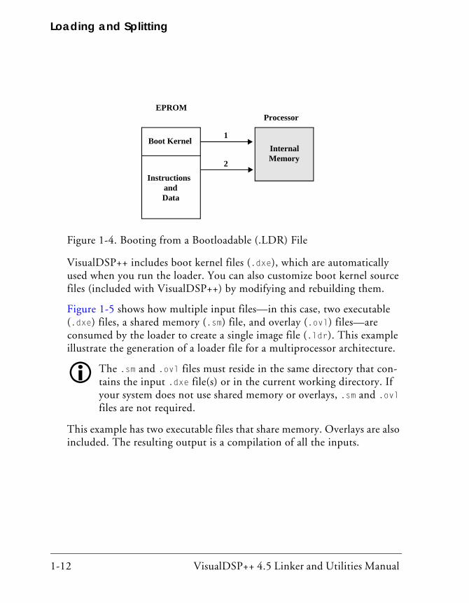
For example, when a TigerSHARC processor is reset, the boot kernel por-tion of the image is transferred to the processor’s core. Then, the instruction and data portion of the image are loaded into the processor’s internal RAM (as shown in Figure 1-4) by the boot kernel.
Figure 1-3. Loading Diagram
Boot Image(.LDR)
Executables(.DXE, .SM, .OVL)
Loader
Boot Kernel(.DXE)
Debugger(Simulator, ICE, or EZ-KIT Lite)
Loading and Splitting
1-12 VisualDSP++ 4.5 Linker and Utilities Manual
VisualDSP++ includes boot kernel files (.dxe), which are automatically used when you run the loader. You can also customize boot kernel source files (included with VisualDSP++) by modifying and rebuilding them.
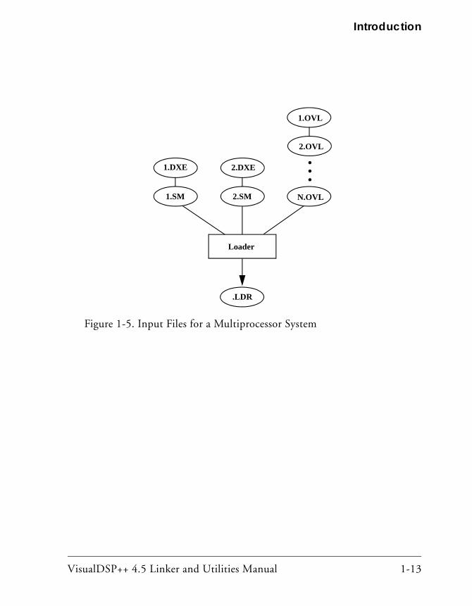
Figure 1-5 shows how multiple input files—in this case, two executable (.dxe) files, a shared memory (.sm) file, and overlay (.ovl) files—are consumed by the loader to create a single image file (.ldr). This example illustrate the generation of a loader file for a multiprocessor architecture.
The .sm and .ovl files must reside in the same directory that con-tains the input .dxe file(s) or in the current working directory. If your system does not use shared memory or overlays, .sm and .ovl files are not required.
This example has two executable files that share memory. Overlays are also included. The resulting output is a compilation of all the inputs.
Figure 1-4. Booting from a Bootloadable (.LDR) File
EPROM ADSP-21DSP
Boot Kernel
InstructionsandData
1
2
InternalMemory
EPROMProcessor
Boot Kernel
InstructionsandData
1
2
InternalMemory
VisualDSP++ 4.5 Linker and Utilities Manual 1-13
Introduction
Figure 1-5. Input Files for a Multiprocessor System
1.DXE
1.SM
2.DXE
2.SM
1.OVL
2.OVL
N.OVL
Loader
.LDR
Loading and Splitting
1-14 VisualDSP++ 4.5 Linker and Utilities Manual
VisualDSP++ 4.5 Linker and Utilities Manual 2-1
2 LINKER
Linking assigns code and data to processor memory. For a simple single processor architecture, a single .dxe file is generated. A single invocation of the linker may create multiple executable (.dxe) files for multiprocessor (MP) or multicore architectures. Linking can also produce a shared mem-ory (.sm) file for an MP system. A large executable file can be split into a smaller executable file and overlays (.ovl) files, which contain code that is called in (swapped into internal processor memory) as needed. The linker performs this task.
You can run the linker from a command line or from the VisualDSP++ Integrated Development and Debugging Environment (IDDE).
You can load the link output into the VisualDSP++ debugger for simula-tion, testing, and profiling.
This chapter includes:
• “Linker Operation” on page 2-2
• “Linking Environment for Windows” on page 2-6
• “Linker Warning and Error Messages” on page 2-10
• “Link Target Description” on page 2-11
• “Linker Command-Line Reference” on page 2-43
Linker Operation
2-2 VisualDSP++ 4.5 Linker and Utilities Manual
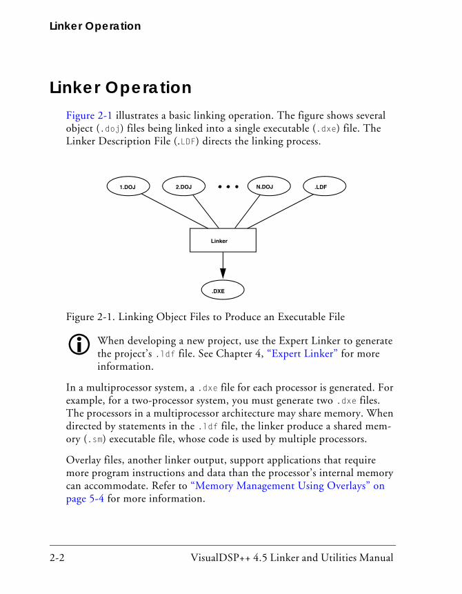
Linker OperationFigure 2-1 illustrates a basic linking operation. The figure shows several object (.doj) files being linked into a single executable (.dxe) file. The Linker Description File (.LDF) directs the linking process.
When developing a new project, use the Expert Linker to generate the project’s .ldf file. See Chapter 4, “Expert Linker” for more information.
In a multiprocessor system, a .dxe file for each processor is generated. For example, for a two-processor system, you must generate two .dxe files. The processors in a multiprocessor architecture may share memory. When directed by statements in the .ldf file, the linker produce a shared mem-ory (.sm) executable file, whose code is used by multiple processors.
Overlay files, another linker output, support applications that require more program instructions and data than the processor’s internal memory can accommodate. Refer to “Memory Management Using Overlays” on page 5-4 for more information.
Figure 2-1. Linking Object Files to Produce an Executable File
1.DOJ 2.DOJ .LDFN.DOJ
Linker
.DXE
VisualDSP++ 4.5 Linker and Utilities Manual 2-3
Linker
Similar to object files, executable files are partitioned into output sections with unique names. Output sections are defined by the Executable and Linking Format (ELF) file standard to which VisualDSP++ conforms.
The executable’s input section names and output section names occupy different namespaces. Because the namespaces are indepen-dent, the same section names may be used. The linker uses input section names as labels to locate corresponding input sections within object files.
The executable file(s) (.DXE) and auxiliary files (.sm and .ovl) are not loaded into the processor or burned onto an EPROM. These files are used to debug the system.
Directing Linker OperationLinker operations are directed by these options and commands:
• Linker (linker) command-line switches (options). Refer to “Linker Command-Line Reference” on page 2-43.
• Windows environment: Settings (options) on the Link page of the Project Options dialog box. See “Project Builds” on page 2-6.
• LDF commands. Refer to “LDF Commands” on page 3-31 for a detailed description.
Linker options control how the linker processes object files and library files. These options specify various criteria such as search directories, map file output, and dead code elimination.
LDF commands in a Linker Description File (.ldf) define the target memory map and the placement of program sections within processor memory. The text of these commands provides the information needed to link your code.

Linker Operation
2-4 VisualDSP++ 4.5 Linker and Utilities Manual
The VisualDSP++ Project window displays the .ldf file as a source file, though the file provides linker command input.
Using directives in the .ldf file, the linker:
• Reads input sections in the object files and maps them to output sections in the executable file. More than one input section may be placed in an output section.
• Maps each output section in the executable to a memory segment, a contiguous range of memory addresses on the target processor. More than one output section may be placed in a single memory segment.
Linking Process RulesThe linking process observes these rules:
• Each source file produces one object file.
• Source files may specify one or more input sections as destinations for compiled/assembled object(s).
• The compiler and assembler produce object code with labels that direct one or more portions to particular output sections.
• As directed by the .ldf file, the linker maps each input section in the object code to an output section in the .dxe file.
• As directed by the .ldf file, the linker maps each output section to a memory segment.
• Each input section may contain multiple code items, but a code item may appear in one input section only.
• More than one input section may be placed in an output section.
• Each memory segment must have a specified width.

VisualDSP++ 4.5 Linker and Utilities Manual 2-5
Linker
• Contiguous addresses on different-width hardware must reside in different memory segments.
• More than one output section may map to a memory segment if the output sections fit completely within the memory segment.
Linker Description File OverviewWhether you are linking C/C++ functions or assembly routines, the mech-anism is the same. After converting the source files into object files, the linker uses directives in an .ldf file to combine the objects into an execut-able (.dxe) file, which may be loaded into a simulator for testing.
Executable file structure conforms to the Executable and Linkable Format (ELF) standard.
Each project must include one .ldf file that specifies the linking process by defining the target memory and mapping the code and data into that memory. You can write your own .ldf file, or you can modify an existing file; modification is often the easier alternative when there are few changes in your system’s hardware or software. VisualDSP++ provides an .ldf file that supports the default mapping of each processor type.
When developing a new project, use the Expert Linker to generate the project’s .ldf file, as described in Chapter 4, “Expert Linker”.
Similar to an object (.doj) file, an executable (.dxe) file consists of different segments, called output sections. Input section names are inde-pendent of output section names. Because they exist in different namespaces, input section names can be the same as output section names.
Refer to Chapter 3, “Linker Description File” for further information.

Linking Environment for Windows
2-6 VisualDSP++ 4.5 Linker and Utilities Manual
Linking Environment for WindowsThe linking environment refers to Windows command-prompt windows and the VisualDSP++ IDDE. At a minimum, run development tools (such as the linker) via a command line and view output in standard output.
VisualDSP++ provides an environment that simplifies the processor pro-gram build process. From VisualDSP++, you specify build options from the Project Options dialog box and modify files, including the Linker Description File (.ldf). The Project Options dialog box’s Type option allows you to choose whether to build a library (.dlb) file, an executable (.dxe) file, or an image file (.ldr or others). Error and warning messages appear in the Output window.
Project BuildsThe linker runs from an operating system command line, issued from the VisualDSP++ IDDE, or a command prompt window. The VisualDSP++ IDDE provides an intuitive interface for processor programming. When you open VisualDSP++, a work area contains everything needed to build, manage, and debug a DSP project. You can easily create or edit an .ldf file, which maps code or data to specific memory segments on the target.
For information about the VisualDSP++ environment, refer to the VisualDSP++ User’s Guide or online Help. Online Help provides powerful search capabilities. To obtain information on a code item, parameter, or error, select text in an VisualDSP++ IDDE Editor window or Output window and press the keyboard’s F1 key.
Within VisualDSP++, specify tool settings for project builds. Use the Project menu to open Project Options dialog box.
These dialog boxes allow you to select the target processor, type and name of the executable file, as well as VisualDSP++ tools available for use with the selected processor.
VisualDSP++ 4.5 Linker and Utilities Manual 2-7
Linker
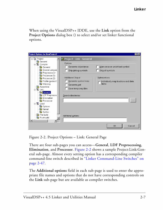
When using the VisualDSP++ IDDE, use the Link option from the Project Options dialog box () to select and/or set linker functional options.
There are four sub-pages you can access—General, LDF Preprocessing, Elimination, and Processor. Figure 2-2 shows a sample Project:Link:Gen-eral sub-page. Almost every setting option has a corresponding compiler command-line switch described in “Linker Command-Line Switches” on page 2-47.
The Additional options field in each sub-page is used to enter the appro-priate file names and options that do not have corresponding controls on the Link sub-page but are available as compiler switches.
Figure 2-2. Project Options – Link: General Page

Linking Environment for Windows
2-8 VisualDSP++ 4.5 Linker and Utilities Manual
Due to different processor architectures, the processors may provide dif-ferent Link tab selection options. Use the VisualDSP++ context-sensitive online Help for each target architecture to obtain information on linker options you can specify in VisualDSP++. To do that, click on the ? button and then click in a field or box you need information about.

VisualDSP++ 4.5 Linker and Utilities Manual 2-9
Linker
Expert LinkerThe VisualDSP++ IDDE provides an interactive tool, Expert Linker, to map code or data to specific memory segments. When developing a new project, use the Expert Linker to generate the .ldf file.
Windows-hosted Expert Linker graphically displays the .ldf information (object files, LDF macros, libraries, and a target memory description). With Expert Linker, use drag-and-drop operations to arrange the object files in a graphical memory mapping representation. When you are satis-fied with the memory layout, generate the executable (.dxe) file.
Figure 2-3 shows the Expert Linker window, which comprises two panes: Input Sections and Memory Map (output sections). Refer to Chapter 4, “Expert Linker”, for detailed information.
Figure 2-3. Expert Linker Window

Linker Warning and Error Messages
2-10 VisualDSP++ 4.5 Linker and Utilities Manual
Linker Warning and Error MessagesLinker messages are written to the VisualDSP++ Output window or to the standard output (when the linker is run from a command line). Messages describe problems the linker encountered while processing the .ldf file. Warnings indicate processing errors that do not prevent the linker from producing a valid output file, such as unused symbols in your code. Errors are issued when the linker encounters situations that prevent the produc-tion of a valid output file.
Typically, these messages include the name of the .ldf file, the line num-ber containing the message, a six-character code, and a brief description of the condition. For example,
>linker -proc ADSP-unknown a.doj
[Error li1010] The processor ‘ADSP-unknown’ is unknown or unsuppported.
Interpreting Linker Messages You can access descriptions of linker messages by selecting a six-character code (for example, li1010) and pressing the F1 key.
Within VisualDSP++, the Output window’s Build tab displays project build status and error messages. In most cases, double-clicking a message displays the line in the source file causing the problem.
Some build errors, such as a reference to an undefined symbol, do not cor-relate directly to source files. These errors often stem from omissions in the .ldf file.
For example, if an input section from the object file is not placed by the .ldf file, a cross-reference error occurs at every object that refers to labels in the missing section. Fix this problem by reviewing the .ldf file and specifying all sections that need placement. For more information, refer to online Help.

VisualDSP++ 4.5 Linker and Utilities Manual 2-11
Linker
Link Target DescriptionBefore defining the system’s memory and program placement with linker commands, analyze the target system to ensure you can describe the target in terms the linker can process. Then, produce an .ldf file for your project to specify these system attributes:
• Physical memory map
• Program placement within the system’s memory map
If the project does not include an .ldf file, the linker uses a default .ldf file for the processor that matches the -proc <processor> switch on the linker’s command line (or the Processor selection specified on the Project page of the Project Options dialog box in the VisualDSP++ IDDE).
Be sure to understand the processor’s memory architecture, which is described in the appropriate processor’s hardware reference manual and in its data sheet.
This section contains:
• “Representing Memory Architecture” on page 2-12
• “Specifying the Memory Map” on page 2-12
• “Placing Code on the Target” on page 2-35
• “Profile-Guided Optimization Support” on page 2-41
• “Passing Arguments for Simulation or Emulation” on page 2-42
Link Target Description
2-12 VisualDSP++ 4.5 Linker and Utilities Manual
Representing Memory Architecture The .ldf file’s MEMORY{} command is used to represent the memory archi-tecture of your processor system. The linker uses this information to place the executable file into the system’s memory.
Perform the following tasks to write a MEMORY{} command:
• Memory Usage – List the ways your program uses memory in your system. Typical uses for memory segments include interrupt tables, initialization data, program code, data, heap space, and stack space. Refer to “Specifying the Memory Map” on page 2-12.
• Memory Characteristics – List the types of memory in your pro-cessor system and the address ranges and word width associated with each memory type. Memory type is defined as RAM or ROM.
• MEMORY{} Command – Construct a MEMORY{} command to combine the information from the previous two lists and to declare your system’s memory segments.
For complete information, refer to “MEMORY{}” on page 3-38.
Specifying the Memory MapAn embedded program must conform to the constraints imposed by the processor’s data path (bus) widths and addressing capabilities. The follow-ing information describes an .ldf file for a hypothetical project. This file specifies several memory segments that support the SECTIONS{} command, as shown in “SECTIONS{}” on page 3-55.
The three topics are important when allocating memory:
• “Memory Usage and Default Memory Sections” on page 2-13
• “Memory Characteristics Overview” on page 2-27
• “Linker MEMORY{} Command in .ldf File” on page 2-32
VisualDSP++ 4.5 Linker and Utilities Manual 2-13
Linker
Memory Usage and Default Memory Sections
Input section names are generated automatically by the compiler or are specified in the assembly source code. The .ldf file defines memory sec-tion names and output section names. The default .ldf file handles all compiler-generated input sections (refer to the “Input Section” column in Table 2-1, Table 2-2, and Table 2-3). The produced .dxe file has a corre-sponding output section for each input section. Although programmers typically do not use output section labels, the labels are used by down-stream tools.
Use the ELF file dumper utility (elfdump) to dump contents of an output section (for example, data1) of an executable file. See “elfdump – ELF File Dumper” on page B-1 for information about this utility.
The following sections show how input sections, output sections, and memory segments correspond in the default .ldf files for the appropriate target processor.
Refer to your processor’s default .ldf file and to the hardware ref-erence manual for details. Also see “Wildcard Characters” on page 2-35.
Typical uses for memory segments include interrupt tables, initialization data, program code, data, heap space, and stack space, etc. For detailed processor-specific information, refer to:
• “Default Memory Sections for SHARC Processors”
• “Default Memory Sections for TigerSHARC Processors”
• “Default Memory Sections for Blackfin Processors”
• “Special “Table” Memory Sections”
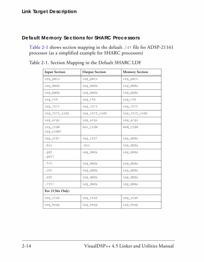
Link Target Description
2-14 VisualDSP++ 4.5 Linker and Utilities Manual
Default Memory Sections for SHARC Processors
Table 2-1 shows section mapping in the default .ldf file for ADSP-21161 processor (as a simplified example for SHARC processors)
Table 2-1. Section Mapping in the Default SHARC LDF
Input Section Output Section Memory Section
seg_pmco seg_pmco seg_pmco
seg_dmda seg_dmda seg_dmda
seg_pmda seg_pmda seg_pmda
seg_rth seg_rth seg_rth
seg_init seg_init seg_init
seg_init_code seg_init_code seg_init_code
seg_argv seg_argv seg_argv
seg_ctdmseg_ctdml
dxe_ctdm mem_ctdm
seg_vtbl seg_vtbl seg_dmda
.bss .bss seg_dmda
.gdt
.gdtlseg_dmda seg_dmda
.frt seg_dmda seg_dmda
.cht seg_dmda seg_dmda
.edt seg_dmda seg_dmda
.rtti seg_dmda seg_dmda
For 2136x Only:
seg_stak seg_stak seg_stak
seg_heap seg_heap seg_heap

VisualDSP++ 4.5 Linker and Utilities Manual 2-15
Linker
For more information on stack and heap allocation, see “Memory Usage” in the C/C++ Compiler and Library Manual for SHARC Processors.There are several input/memory sections used in the default .ldf files for ADSP-210xx/211xx/212xx/213xx processors, which must be present in user’s own .ldf files. These sections are described in detail below.
.bss
This section contains global zero-initialized data. The linker places the contents of this data section in seg_dmda).
.rtti
This section is used by the C++ runtime type identification support, when enabled.
seg_rth
This section contains the interrupt vector table (by default, this is located in the start-up file (for example, 060_hdr.doj).
seg_init
This section contains location and size information about the stack and heap; also contains compressed data created by the memory initialization tool. (See “-meminit” on page 2-58 for more information.)
seg_int_code
Code that modifies interrupt latch registers must not be executed from external memory. To minimize the impact of this restriction, the library functions that modify the latch registers are located in the seg_init_code section, which should be located in internal memory.
seg_pmco
This section is the default location for program code.

Link Target Description
2-16 VisualDSP++ 4.5 Linker and Utilities Manual
seg_pmda
This section is the default location for global program data that is quali-fied with the “pm” keyword. For example,
int pm xyz[100]; // Located in seg_pmda
seg_argv
This section contains the command-line arguments that are used as part of Profile-Guided Optimization (PGO).
seg_ctdm
This section contains the addresses of constructors that are called before the start of a C++ program (such as constructors for global and static objects). This section must be terminated with the symbol “___ctor_NULL_marker” (the default .ldf files ensure this). It is required if compiling with C++ code.
seg_dmda
This section is the default location for global data, and also for data that is qualified with the “dm” keyword. For example,
int abc[100]; // Located in seg_dmda
int dm def[100]; // Located in seg_dmda
seg_heap
This section is the area from which memory allocation functions and operators (new, malloc(), and so on) allocate memory.
seg_stak
This section is the area where the run-time stack is located. Local vari-ables, function parameters, and so on are stored here.

VisualDSP++ 4.5 Linker and Utilities Manual 2-17
Linker
seg_vtbl
This section contains C++ virtual function tables. The default .ldf files place the virtual function tables into the default data memory area but this can be re-mapped as required. You can also direct the compiler to use a different section for C+ virtual function tables, by using the -section compiler switch.
Other Memory Sections
The compiler and libraries also use other data sections that are linked into one of the above memory sections. These data sections include:
seg_ctdml
The symbol “___ctor_NULL_marker” (located in the C++ run-time library) marks the end of the list of global and static constructors and is placed in this data section. The linker ensures that the contents of this data section are the last items in seg_ctdm.
.gdt .gdtl .frt .cht .edt
These data sections are used to hold data used during the handling of exceptions. The linker places the contents of these data sections in seg_dmda. See “Special “Table” Memory Sections” on page 2-24.
Default Memory Sections for TigerSHARC Processors
Table 2-2 shows section mapping in the default .ldf file for ADSP-TS101 processor (as a simplified example for TigerSHARC processors)
Table 2-2. Section Mapping in the Default TigerSHARC LDF
Input Section Output Section Memory Section
program code M0Code
data1 data1 M1Data

Link Target Description
2-18 VisualDSP++ 4.5 Linker and Utilities Manual
There are several input/memory sections used in the default .ldf files for ADSP-TSxxx processors, which must be present in user’s own .ldf files. These sections are described in detail below.
For more information on stack and heap allocation, see “Allocation of memory for stacks and heaps in LDFs” in the C/C++ Compiler and Library Manual for TigerSHARC Processors.
data2 data2 M2Data
mem_argv mem_argv M1Data
bsz bsz M1Data
bsz_init bsz_init M1Data
ctor data1 M1Data
ctor0 data1 M1Data
ctor1 data1 M1Data
ctor2 data1 M1Data
ctor3 data1 M1Data
ctor4 data1 M1Data
.gdt
.gdtldata1 M1Data
.frt data1 M1Data
.cht data1 M1Data
.edt data1 M1Data
.rtti data1 M1Data
vtbl vtbl vtbl
Table 2-2. Section Mapping in the Default TigerSHARC LDF (Cont’d)
Input Section Output Section Memory Section

VisualDSP++ 4.5 Linker and Utilities Manual 2-19
Linker
bsz
This section is a BSS-style section for global zero-initialized data.
bsz_init
This section contains run-time initialization data. (See “-meminit” on page 2-58 for more information.)
ctor
This section contains the addresses of constructors that are called before the start of a C++ program (such as constructors for global and static objects). This section must be terminated with the symbol “___ctor_NULL_marker” (the default .ldf files ensure this). It is required if compiling with C++ code.
When all ctor sections are merged, they form a table containing a list of all constructors for all global C++ objects. The table is only used at startup and can be placed in ROM. When linking, it is important that all ctor sections are merged in sequence (no other sections in between) and the run-time library or the VDK run-time library is placed with the first ctor section. Note that the default LDF’s “___ctor_NULL_marker” symbol is placed in a section named “ctorl” which must be the last of the ctor sec-tions to be used as input. The final letter in this name is a lower-case “L”.
data1
This section is the default location for global program data.
data2
This section is the default location for global program data specified with the pm memory qualifier.

Link Target Description
2-20 VisualDSP++ 4.5 Linker and Utilities Manual
mem_argv
This section contains the command-line arguments that are used as part of Profile-Guided Optimization (PGO).
program
This section is the default location for program code.
vtbl
This section contains C++ virtual function tables. The default .ldf files place the virtual function tables into the default data memory area but this can be re-mapped as required. You can also direct the compiler to use a different section for C+ virtual function tables, by using the -section compiler switch.
Other Memory Sections
The compiler and libraries also use other data sections that are linked into one of the above memory sections. These data sections include:
ctor1
This section contains the terminator for the ctor table section. It must be mapped immediately after the ctor sections.
.gdt .gdtl .frt .cht .edt .rtti
These data sections are used to hold data used during the handling of exceptions. The linker places the contents of these data sections in seg_dmda. See “Special “Table” Memory Sections” on page 2-24.
Default Memory Sections for Blackfin Processors
The default LDFs in Blackfin/ldf show the mapping of input sections to output sections and memory segments. There are several input sections present in the default .ldf files and their uses are detailed below.

VisualDSP++ 4.5 Linker and Utilities Manual 2-21
Linker
See “Linker Description File” in Chapter 3, Linker Description File for more information on .ldf files and help on customization. Before cus-tomizing any default .ldf files, consider using the LDF wizard available in the IDDE. Generation and configuration of a custom LDF is available when creating a new project, or in the project options dialog box.
program
This section is the default location for program code.
data1
This section is the default location for global program data.
cplb_code
This section stores the run-time library’s CPLB management routines. It is usually mapped into L1 Instruction SRAM. In particular, if CPLB replacement is a possibility, this section must be mapped to memory that is guaranteed to always available; this means that it must be addressed by a locked CPLB.
constdata
This section is used for global data that is declared as constant, and for lit-eral constants such as strings and array initializers.
cplb_data
This section stores CPLB configuration tables. In particular, the cplbtabx.doj files (where x indicates the target) mapped by the LDFs are placed into this section.
L1_DATA_A
This section is used to allow data to be mapped explicitly into L1 Data A SRAM using the SECTION directive. By default, the compiler does not gen-erate data here. This section is analogous to L1_code.

Link Target Description
2-22 VisualDSP++ 4.5 Linker and Utilities Manual
L1_DATA_B
This section is similar to L1_DATA_A, except that it is used to map data into L1 Data B SRAM.
voldata
This section is used for data that may change due to external influences (such as DMA), and should not be placed into cached data areas.
ctor
This section contains addresses of C++ constructor functions which are to be called before main() to construct static objects. The mapping of ctor must be directly followed by the mapping of ctor.
bsz
This section is used to map global zero initialized data. This section does not actually contain data; it is zero-filled upon loading via the Visu-alDSP++ IDDE, via a command line, or when processed by the loader.
bsz_init
This section contains run-time initialization data. (See “-meminit” on page 2-58 for more information.) It is expected that this section is mapped into read-only memory. When a .dxe file has been processed by the Mem-ory Initializer utility and the program starts running, other data sections (such as data1 and constdata) are initialized by data copied from this section.
stack
This section is the area where the run-time stack is located. Local vari-ables, function parameters, and so on are stored here.
VisualDSP++ 4.5 Linker and Utilities Manual 2-23
Linker
heap
This section is the area where the heap is located. Dynamically allocated data is placed here.
noncache_code
This section is mapped to areas of memory that cannot be cache and take program code. This section would be used if you have a function that turns on the cache to ensure that the function itself does not reside in cache (as executing code from a cache memory address causes a hardware exception).
sdram0
In most LDFs and LDF configurations this section allows code or data to be mapped explicitly into external memory by using the SECTION directive. This can be used to place large, infrequently-used data or functions into external memory to free up valuable internal memory.
sdram0_bank{1|2|3}
This section is used to map code and data into separate SDRAM banks which are defined when SDRAM partitioned in the default LDF files.
sdram_bcz
This section is the same as section bsz except it gets placed in sdram, when sdram is enabled.
sdram_shared
This section is used to map code and data into the part of memory shared between core A and core B on multicore systems.
Link Target Description
2-24 VisualDSP++ 4.5 Linker and Utilities Manual
vtbl
This section contains C++ virtual function tables. The default .ldf files place the virtual function tables into the default data memory area but this can be re-mapped as required. You can also direct the compiler to use a different section for C+ virtual function tables, by using the -section compiler switch.
Other Memory Sections
The compiler and libraries also use other data sections that are linked into one of the above memory sections. These data sections include:
ctorl
This section contains the terminator for the ctor table section. It must be mapped immediately after the ctor section.
.gdt .gdtl .frt .cht .edt .rtti
These data sections are used to hold data used during the handling of exceptions. See “Special “Table” Memory Sections”.
Special “Table” Memory Sections
The following “table” data sections are used to hold data used during the handling of exceptions. The linker is generally mapping these sections into read-only memory.
.gdt
This section (Global Dispatch Table) is used by the C++ Exception Library to determine which area of code to which a particular address belongs. This section must be contiguous in memory.
VisualDSP++ 4.5 Linker and Utilities Manual 2-25
Linker
.gdtl
This section contains the terminator for the .gdt table section. It must be mapped immediately after the .gdt section.
.edt
This section (Exception Dispatch Table) is used by the C++ Exception Library to map from try blocks to catch blocks.
.cht
This section (Catch Handler Types Table) is used to map to the RTTI type information. The C++ Exception Library uses it to determine the types that correspond to catch entries for a try block.
.frt
This section (Function Range Table) is used by the C++ Exception Library during exception processing to unwind the stack of active functions.
primio_atomic_lock
This section is used by the control variable that is used to ensure atomic file I/O. It must be in shared memory and not cached.
mc_data
This section is used to hold the core-specific storage on multicore systems.
.rtti
This section is used by the C++ runtime type identification support, when enabled.
cplb
This section is in the .ldf files for legacy reasons.

Link Target Description
2-26 VisualDSP++ 4.5 Linker and Utilities Manual
Input Sections Provided in Deflaut LDFs for User Code and Data
These sections are not normally used by the compiler and libraries.
L1_data
This section is used to allow global data to be mapped explicitly into L1 data SRAM using the section pragma or directive. This input section maps data to both banks A and B where present on the target.
L1_data_a
These sections are not normally used by the compiler and libraries.
L1_data_b
This section is similar to L1_data_a, except that it is used to map data into L1 data B SRAM where it is present on the target chip.
L1_code
This section is used to allow code to be mapped explicitly into L1 code SRAM using the section pragma or directive.
L1_bcz
This section is used to map global zero initialized data into L1 data SRAM using the section pragma or directive.
L2_bcz
This section is used to map global zero-initialized data to L2 for parts which have L2 memory using the section pragma or directive.
L2_sram
This section can be used to map code and data into L2 for non-multicore parts that have L2 SRAM.

VisualDSP++ 4.5 Linker and Utilities Manual 2-27
Linker
l2_sram
This section can be used on a multicore system to map code and data into L2 for parts which have L2 memory.
L2_sram_a
This section is used to map code and data into the part of L2 memory reserved for core A on a multicore system.
L2_sram_b
This section is used to map code and data into the part of L2 memory reserved for code B on a multicore system.
l2_shared
This section is used to map code and data into the part of L2 memory shared between core A and core B.
Memory Characteristics Overview
This section provides an overview of basic memory information (including addresses and ranges) for sample target architectures.
Some portions of the processor memory are reserved. Refer to the hardware reference manual for target processor for more information.
SHARC Memory Characteristics
As an example of the SHARC memory architecture, the ADSP-21161 processor contains a large, dual-ported internal memory for single-cycle, simultaneous, independent accesses by the core processor and I/O proces-sor. The dual-ported memory in combination with three separate on-chip buses allow two data transfers from the core and one transfer from the I/O processor in a single cycle. Using the IO bus, the I/O processor provides data transfers between internal memory and the processor’s communica-
Link Target Description
2-28 VisualDSP++ 4.5 Linker and Utilities Manual
tion ports (link ports, serial ports, and external port) without hindering the processor core’s access to memory. The processor provides access to external memory through the processor’s external port.
The processor contains one megabit of on-chip SRAM, organized as two blocks of 0.5 Mbits. Each block can be configured for different combina-tions of code and data storage. All of the memory can be accessed as 16-bit, 32-bit, 48-bit, or 64-bit words. The memory can be configured in each block as a maximum of 16 Kwords of 32-bit data, 8 Kwords of 64-bit data, 32K words of 16-bit data, 10.67 Kwords of 48-bit instructions (or 40-bit data), or combinations of different word sizes up to 0.5 Mbit. This gives a total for the complete internal memory: a maximum of 32 Kwords of 32-bit data, 16 Kwords of 64-bit data, 64 Kwords of 16-bit data, and 21 Kwords of 48-bit instructions (or 40-bit data).
The processor features a 16-bit floating-point storage format that effec-tively doubles the amount of data that may be stored on-chip. A single instruction converts the format from 32-bit floating-point to 16-bit floating-point.
While each memory block can store combinations of code and data, accesses are most efficient when one block stores data using the DM bus, (typically, Block 1) for transfers, and the other block (typically, Block 0) stores instructions and data using the PM bus. Using the DM bus and PM bus with one dedicated to each memory block assures single-cycle execu-tion with two data transfers. In this case, the instruction must be available in the cache.
Internal MemoryThe ADSP-21161 processor has 2 MBits of internal memory space; 1 Mbit is addressable. The 1 Mbit of memory is divided into two 0.5 Mbit blocks: Block 0 and Block 1. The additional 1 MBit of the memory space is reserved on the ADSP-21161 processor. Table 2-3 shows the maximum number of data or instruction words that can fit in each 0.5 MBit internal memory block.

VisualDSP++ 4.5 Linker and Utilities Manual 2-29
Linker
External MemoryWhile the processor’s internal memory is divided into blocks, the proces-sor’s external memory spaces are divided into banks. The internal memory blocks and the external memory spaces may be addressed by either data address generator. External memory banks are fixed sizes that can be con-figured for various waitstate and access configurations.
There are 254 Mwords of external memory space that the processor can address. External memory connects to the processor’s external port, which extends the processor’s 24-bit address and 32-bit data buses off the proces-sor. The processor can make 8, 16, 32, or 48-bit accesses to external memory for instructions and 8,16, or 32-bit accesses for data. Table 2-4 shows the access types and words for processor’s external memory accesses. The processor’s DMA controller automatically packs external data into the appropriate word width during data transfer.
The external data bus can be expanded to 48-bits if the link ports are disabled and the corresponding full width instruction packing mode (IPACK) is enabled in the SYSCON register. Ensure that link ports are disabled when executing code from external 48-bit memory.
Table 2-3. Words Per 0.5 MBit Internal Memory Block
Word Type Bits Per Word Maximum Number of Words Per 0.5 Mbit Block
Instruction 48-bits 10.67 Kwords
Long Word Data 64-bits 8 Kwords
Extended Precision Normal Word Data 40-bits 10.67 Kwords
Normal Word Data 32-bits 16 Kwords
Short Word Data 16-bits 32 Kwords

Link Target Description
2-30 VisualDSP++ 4.5 Linker and Utilities Manual
The total addressable space for the fixed external memory bank sizes depends on whether SDRAM or Non-SDRAM (such as SRAM, SBSRAM) is used. Each external memory bank for SDRAM can address 64 Mwords. For Non-SDRAM memory, each bank can address up to 16 Mwords. The remaining 48 Mwords are reserved. These reserved addresses for non-SDRAM accesses are aliased to the first 16 Mspaces within the bank.
TigerSHARC Memory Characteristics
As an example of the TigerSHARC memory architecture, the ADSP-TS101 processor has three internal memory blocks: M0, M1, and M2. Each memory block consists of 2 Mbits of memory space, and is con-figured as 64 kwords each 32 bits in width. There are three separate internal 128-bit data buses, each connected to one of the memory blocks. Memory blocks can store instructions and data interchangeably, with one access per memory block per cycle. If the programmer ensures that pro-gram and data are in different memory blocks, then data access can occur at the same time as program fetch. Therefore, in one cycle, up to three 128-bit transfers can occur within the core (two data transfers and one program instruction transfer).
The I/O Processor can use only one internal bus at a time, and the I/O Processor competes with the core for use of the internal bus. Therefore, in one cycle, the processor can fetch four 32-bit instructions, and load or store 256 bits of data (four 64-bit words or eight 32-bit words or sixteen 16-bit words or thirty-two 8-bit words).
Table 2-4. Internal-to-External Memory Word Transfers
Word Type Transfer Type
Packed Instruction 32, 16, or 8- to 48-bit packing
Normal Word Data 32-bit word in 32-bit transfer
Short Word Data Not supported

VisualDSP++ 4.5 Linker and Utilities Manual 2-31
Linker
The TigerSHARC processor 32-bit address bus provides an address space of four gigawords. This address space is common to a cluster of Tiger-SHARC processors that share the same cluster bus.
The zones in the memory space are made up of the following regions.
• External memory bank space—the region for standard addressing of off-chip memory (including SDRAM, MB0, MB1, and Host)
• External multiprocessor space—the on-chip memory of all other TigerSHARC processors connected in a multiprocessor system
• Internal address space—the region for standard internal addressing
In the example system, the ADSP-TS101 processor has internal memory addresses from 0x0 to 0x17FFFF. Refer to Table 2-5.
Table 2-5. ADSP-TS101 Processor Memory Structure
Block Range Word Size
M0 memory block 0x0000 0000 - 0x0000 FFFF 32-bit instructions
0x0001 0000 - 0x0007 FFFF Reserved
M1 memory block 0x0008 0000 - 0x0008 FFFF 32-bit instructions
0x0009 0000 - 0x0009 FFFF Reserved
M2 memory block 0x0010 0000 - 0x0010 FFFF 32-bit instructions
0x0011 0000 - 0x0017 FFFF Reserved
Internal registers 0x0018 0000 - 0x0018 07FF Control, status, and I/O registers. This cannot be used in .ldf files. Internal registers are memory accessible in MP space only.
0x0018 0800 - 0x01BF FFFF Reserved
0x01C0 0000 - 0x03FF FFFF Broadcast and multiprocessor (not used in .ldf file)
SDRAM 0x0400 0000 - 0x07FF FFFF 32-bit instructions

Link Target Description
2-32 VisualDSP++ 4.5 Linker and Utilities Manual
Details of the Blackfin Processor memory characteristics can be found in the data sheets for individual processors, available at www.analog.com/processors/productsDatasheets/dataSheets.html, or in more detail in the appropriate hardware reference manuals.
Linker MEMORY{} Command in .ldf File
Referring to information in sections “Memory Usage and Default Mem-ory Sections” and “Memory Characteristics Overview”, you can specify the target’s memory with the MEMORY{} command for any of target proces-sor architectures (Listing 2-1, Listing 2-2, and Listing 2-3 provide code examples for specific processors).
Listing 2-1. ADSP-21161 MEMORY{} Command Code
MEMORY {seg_rth { TYPE(PM RAM) START(0x00040000) END(0x000400ff) WIDTH(48) }seg_init { TYPE(PM RAM) START(0x00040100) END(0x000401ff) WIDTH(48) }seg_int_code { TYPE(PM RAM) START(0x00040200) END(0x00040287) WIDTH(48) }seg_pmco { TYPE(PM RAM) START(0x00040288) END(0x000419ff) WIDTH(48) }seg_pmda { TYPE(PM RAM) START(0x00042700) END(0x00043fff) WIDTH(32) }seg_dmda { TYPE(DM RAM) START(0x00050000) END(0x00051fff) WIDTH(32) }seg_heap { TYPE(DM RAM) START(0x00052000) END(0x00052fff) WIDTH(32) }seg_stak { TYPE(DM RAM) START(0x00053000) END(0x00053fff) WIDTH(32) }}

VisualDSP++ 4.5 Linker and Utilities Manual 2-33
Linker
Listing 2-2. ADSP-TS101 MEMORY{} Command
MEMORY { /* Internal memory blocks are 0x10000 (64K bytes) */ /* Start of TS101_memory.ldf */
M0Code {TYPE(RAM) START(0x00000000) END(0x0000FFFF) WIDTH(32)}M1Data {TYPE(RAM) START(0x00080000) END(0x0008BFFF) WIDTH(32)}M1Stack {TYPE(RAM) START(0x0008C000) END(0x0008FFFF) WIDTH(32)}M2Data {TYPE(RAM) START(0x00100000) END(0x0010BFFF) WIDTH(32)}M2Heap {TYPE(RAM) START(0x0010C000) END(0x0010C7FF) WIDTH(32)}M2Stack {TYPE(RAM) START(0x0010C800) END(0x0010FFFF) WIDTH(32)}SDRAM {TYPE(RAM) START(0x04000000) END(0x07FFFFFF) WIDTH(32)}MS0 {TYPE(RAM) START(0x08000000) END(0x0BFFFFFF) WIDTH(32)}MS1 {TYPE(RAM) START(0x0C000000) END(0x0FFFFFFF) WIDTH(32)}
/* end of TS101_memory.ldf file */}
Listing 2-3. ADSP-BF533 MEMORY{} Command Code
MEMORY /* Define/label system memory */{ /* List of global Memory Segments */ MEM_L2_CODE { TYPE(RAM) START(0xF0000000) END(0xF002FFFF) WIDTH(8) } MEM_L1_DATA_A { TYPE(RAM) START(0xFF800000) END(0xFF803FFF) WIDTH(8) } MEM_L1_DATA_B { TYPE(RAM) START(0xFF900000) END(0xFF903FFF) WIDTH(8) } MEM_HEAP { TYPE(RAM) START(0xF0030000) END(0xF0037FFF) WIDTH(8) } MEM_STACK { TYPE(RAM) START(0xF0038000) END(0xF003DFFF) WIDTH(8) } MEM_ARGV { TYPE(RAM) START(0xF003FE00) END(0xF003FFFF) WIDTH(8) } MEM_SDRAM0
Link Target Description
2-34 VisualDSP++ 4.5 Linker and Utilities Manual
{ TYPE(RAM) START(0x00000004) END(0x07FFFFFF) WIDTH(8) }}
The above examples apply to the preceding discussion of how to write a MEMORY{} command and to the following discussion of the SECTIONS{} command. The SECTIONS{} command is not atomic; it can be interspersed with other directives, including location counter information. You can define new symbols within the .ldf file. These examples define the starting stack address, the highest possible stack address, and the heap’s starting location and size. These newly-created symbols are entered in the executable’s symbol table.
Entry Address
In previous VisualDSP++ releases, the entry address was filled in from a global symbol “start” (no underscore), if present. The “start” symbol could either be a global file symbol or an LDF symbol.
Currently, the entry address field can also be set using:
• The -entry command-line switch (on page 2-56), where option’s argument is a symbol.
• The ENTRY(symbol) or ENTRY(address) command (on page 3-34) in the .ldf file. If -entry and ENTRY() are both present, they must be the same. Neither overrides the other. If there is a mismatch, the linker detects an error.
• In the absence of the -entry switch or the ENTRY() command, the value of the global file symbol start, or LDF symbol start, is used, if present.
• If none of the above is used, the address is 0.

VisualDSP++ 4.5 Linker and Utilities Manual 2-35
Linker
Multiprocessor/multicore Applications The -entry switch for a multiprocessor/multicore LDF applies the same entry address to all processors. If the entry addresses differ (for multipro-cessor systems), use ENTRY() commands in the .ldf file – do not use the -entry switch.
If the -entry switch is specified, it is an error if any of the processors uti-lize an ENTRY() command with a different specification.
Wildcard Characters
The linker supports the use of wildcards in input section name specifica-tions in the .ldf file. The * and ? wildcard characters are provided on input section names.
* – Matches any number of characters
? – Matches any one character
Placing Code on the TargetUse the SECTIONS{} command to map code and data to the physical mem-ory of a processor in a processor system.
To write a SECTIONS{} command:
1. List all input sections defined in the source files.
• Assembly files – List each assembly code .SECTION directive, identify its memory type (PM or CODE, or DM or DATA), and note when location is critical to its operation. These .SECTIONS por-tions include interrupt tables, data buffers, and on-chip code or data. (See “Specifying Two Buffers in Different Memory Seg-ments” on page 2-39 for TigerSHARC-specific information.)
Link Target Description
2-36 VisualDSP++ 4.5 Linker and Utilities Manual
• C/C++ source files – The compiler generates sections with the name “program” or “code” for code, and the names “data1” and “data2” for data. These sections correspond to your source when you do not specify a section by means of the optional section() extension.
2. Compare the input sections list to the memory segments specified in the MEMORY{} command. Identify the memory segment into which each .SECTION must be placed.
3. Combine the information from these two lists to write one or more SECTIONS{} commands in the .ldf file.
SECTIONS{} commands must appear within the context of the PROCESSOR{} or SHARED_MEMORY() command.
Listing 2-4 presents a SECTIONS{} command that would work with the MEMORY{} command in Listing 2-1.
Listing 2-4. ADSP-21161 SECTIONS{} Command in the .ldf File
SECTIONS {/* Begin output sections */ seg_rth { // run-time header and interrupt table INPUT_SECTIONS( $OBJS(seg_rth) $LIBS(seg_rth)) } >seg_rth seg_init { // Initialization ldf_seginit_space = . ; INPUT_SECTIONS( $OBJS(seg_init) $LIBS(seg_init)) } >seg_init seg_init_code { // Initialization data INPUT_SECTIONS( $OBJS(seg_init_code) $LIBS(seg_init_code)) } >seg_init_code seg_pmco { // PM code INPUT_SECTIONS( $OBJS(seg_pmco) $LIBS(seg_pmco)) } >seg_pmco seg_pmda { // PM data
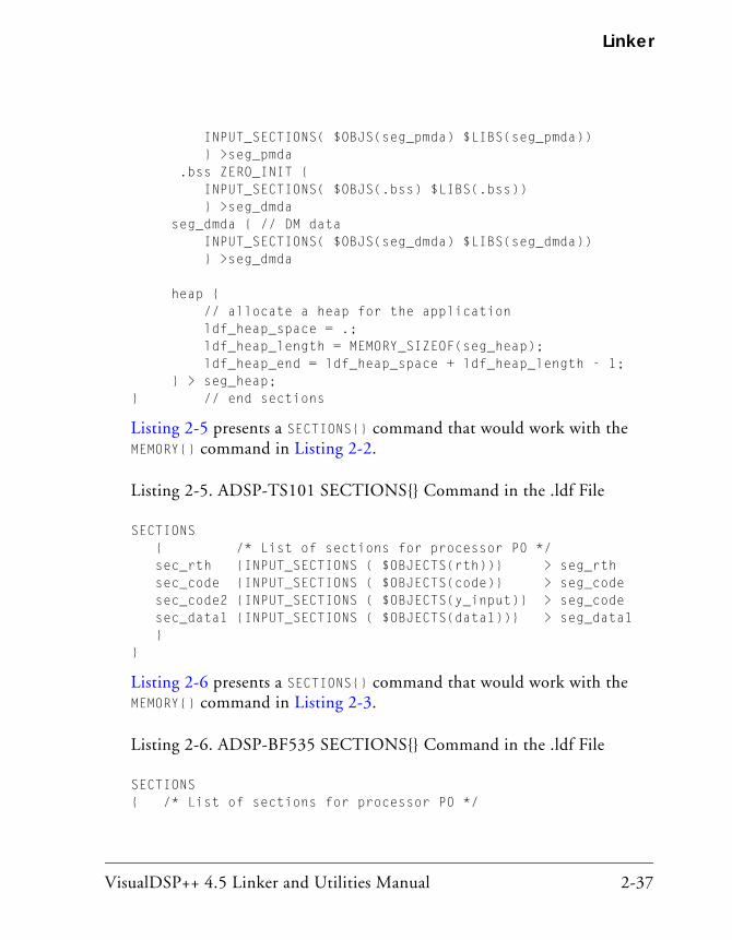
VisualDSP++ 4.5 Linker and Utilities Manual 2-37
Linker
INPUT_SECTIONS( $OBJS(seg_pmda) $LIBS(seg_pmda)) } >seg_pmda .bss ZERO_INIT { INPUT_SECTIONS( $OBJS(.bss) $LIBS(.bss)) } >seg_dmda seg_dmda { // DM data INPUT_SECTIONS( $OBJS(seg_dmda) $LIBS(seg_dmda)) } >seg_dmda heap { // allocate a heap for the application ldf_heap_space = .; ldf_heap_length = MEMORY_SIZEOF(seg_heap); ldf_heap_end = ldf_heap_space + ldf_heap_length - 1; } > seg_heap; } // end sections
Listing 2-5 presents a SECTIONS{} command that would work with the MEMORY{} command in Listing 2-2.
Listing 2-5. ADSP-TS101 SECTIONS{} Command in the .ldf File
SECTIONS { /* List of sections for processor P0 */ sec_rth {INPUT_SECTIONS ( $OBJECTS(rth))} > seg_rth sec_code {INPUT_SECTIONS ( $OBJECTS(code)} > seg_code sec_code2 {INPUT_SECTIONS ( $OBJECTS(y_input)} > seg_code sec_data1 {INPUT_SECTIONS ( $OBJECTS(data1))} > seg_data1 }}
Listing 2-6 presents a SECTIONS{} command that would work with the MEMORY{} command in Listing 2-3.
Listing 2-6. ADSP-BF535 SECTIONS{} Command in the .ldf File
SECTIONS{ /* List of sections for processor P0 */
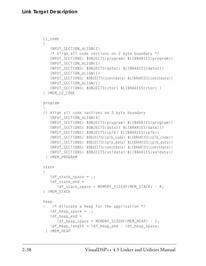
Link Target Description
2-38 VisualDSP++ 4.5 Linker and Utilities Manual
L1_code { INPUT_SECTION_ALIGN(2) /* Align all code sections on 2 byte boundary */ INPUT_SECTIONS( $OBJECTS(program) $LIBRARIES(program)) INPUT_SECTION_ALIGN(1) INPUT_SECTIONS( $OBJECTS(data1) $LIBRARIES(data1)) INPUT_SECTION_ALIGN(1) INPUT_SECTIONS( $OBJECTS(constdata) $LIBRARIES(constdata)) INPUT_SECTION_ALIGN(1) INPUT_SECTIONS( $OBJECTS(ctor) $LIBRARIES(ctor) ) } >MEM_L2_CODE
program { // Align all code sections on 2 byte boundary INPUT_SECTION_ALIGN(4) INPUT_SECTIONS( $OBJECTS(program) $LIBRARIES(program)) INPUT_SECTIONS( $OBJECTS(data1) $LIBRARIES(data1)) INPUT_SECTIONS( $OBJECTS(cplb) $LIBRARIES(cplb)) INPUT_SECTIONS( $OBJECTS(cplb_code) $LIBRARIES(cplb_code)) INPUT_SECTIONS( $OBJECTS(cplb_data) $LIBRARIES(cplb_data)) INPUT_SECTIONS( $OBJECTS(constdata) $LIBRARIES(constdata)) INPUT_SECTIONS( $OBJECTS(voldata) $LIBRARIES(voldata)) } >MEM_PROGRAM
stack { ldf_stack_space = .; ldf_stack_end = ldf_stack_space + MEMORY_SIZEOF(MEM_STACK) - 4; } >MEM_STACK
heap { /* Allocate a heap for the application */ ldf_heap_space = .; ldf_heap_end = ldf_heap_space + MEMORY_SIZEOF(MEM_HEAP) - 1; ldf_heap_length = ldf_heap_end - ldf_heap_space; } >MEM_HEAP

VisualDSP++ 4.5 Linker and Utilities Manual 2-39
Linker
argv { /* Allocate argv space for the application */ ldf_argv_space = .; ldf_argv_end = ldf_argv_space + MEMORY_SIZEOF(MEM_ARGV) - 1; ldf_argv_length = ldf_argv_end - ldf_argv_space; } >MEM_ARGV
} /* end SECTIONS */
Specifying Two Buffers in Different Memory Segments
On TigerSHARC processors, the linker is enhanced to support efficient programming using the .SEPARATE_MEM_SEGMENTS assembler directive.
• The .SEPARATE_MEM_SEGMENTS assembler directive (or the compiler pragma #pragma separate_mem_segments) specifies two buffers directing the linker to place the buffers into different memory seg-ments. For example,
.SECTION data1; .VAR buf1; .VAR buf2; .EXTERN buf3; .SEPARATE_MEM_SEGMENTS(buf1, buf2) .SEPARATE_MEM_SEGMENTS(buf1, buf3)
• The set of available memory segments for each buffer is defined by using the linker’s “one-to-many” feature—mapping the input sec-tion(s) that contain the buffer into multiple memory segments. For example,
data2 { INPUT_SECTIONS( $OBJECTS(data1) ) } >M2DataA
data4 {
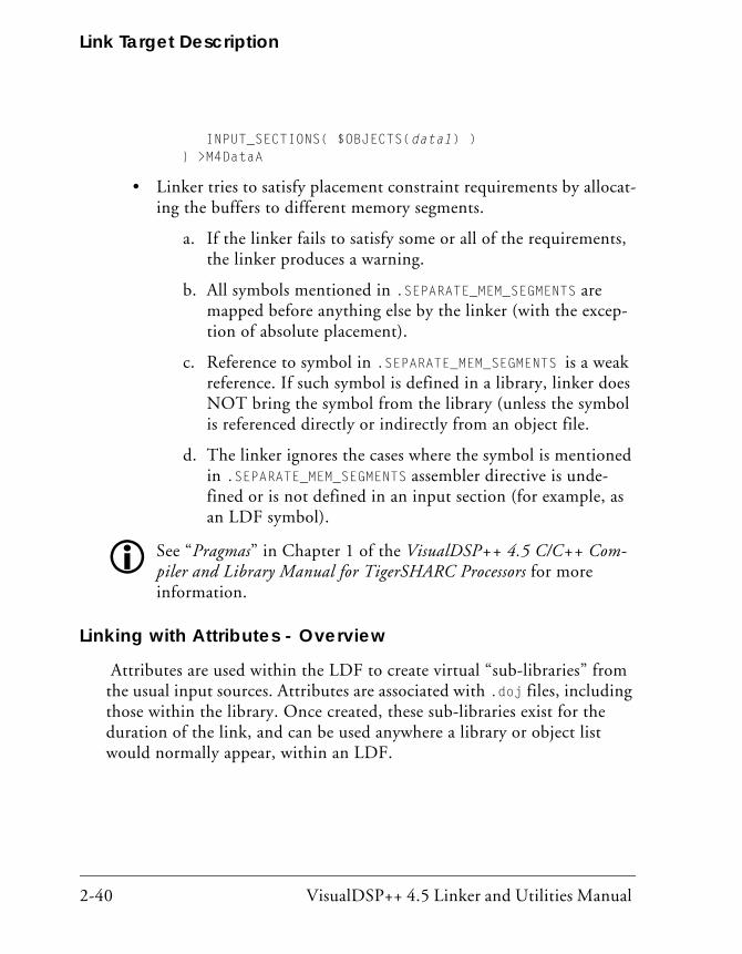
Link Target Description
2-40 VisualDSP++ 4.5 Linker and Utilities Manual
INPUT_SECTIONS( $OBJECTS(data1) ) } >M4DataA
• Linker tries to satisfy placement constraint requirements by allocat-ing the buffers to different memory segments.
a. If the linker fails to satisfy some or all of the requirements, the linker produces a warning.
b. All symbols mentioned in .SEPARATE_MEM_SEGMENTS are mapped before anything else by the linker (with the excep-tion of absolute placement).
c. Reference to symbol in .SEPARATE_MEM_SEGMENTS is a weak reference. If such symbol is defined in a library, linker does NOT bring the symbol from the library (unless the symbol is referenced directly or indirectly from an object file.
d. The linker ignores the cases where the symbol is mentioned in .SEPARATE_MEM_SEGMENTS assembler directive is unde-fined or is not defined in an input section (for example, as an LDF symbol).
See “Pragmas” in Chapter 1 of the VisualDSP++ 4.5 C/C++ Com-piler and Library Manual for TigerSHARC Processors for more information.
Linking with Attributes - Overview
Attributes are used within the LDF to create virtual “sub-libraries” from the usual input sources. Attributes are associated with .doj files, including those within the library. Once created, these sub-libraries exist for the duration of the link, and can be used anywhere a library or object list would normally appear, within an LDF.

VisualDSP++ 4.5 Linker and Utilities Manual 2-41
Linker
Within the LDF, attributes are used to reduce the usual set of input files into more manageable subsets. Inputs are in two forms: objects and librar-ies, both of which appear in lists within the LDF. Filters can be applied to these lists to winnow out momentarily-undesirable objects.
An attribute is a name/value pair of strings. A valid attribute name is a valid C identifier
Attribute names and attribute values are both case-sensitive. Windows file-names can be used as values, with care and consistency.
An attribute is associated with an object (.doj), but not with a library (.dlb), not with a symbol name, and not with an ELF section. An object has zero or more attributes associated with it. A given object may have more than one attribute with the same name, associated with it.
Using attributes, the filtering process can be used to remove some objects from consideration, providing that the same objects are not included else-where via other filters, or through unfiltered mappings. A filter operation is done with curly braces, and can be used to define sub-lists and sub-libraries. It may also be used in INPUT_SECTIONS commands (refer to “INPUT_SECTIONS()” on page 3-58).
The linker reads the LDF and uses the {…} filter commands (for example, INPUT_SECTIONS commands) to eliminate some input objects from consid-eration before resolving symbols. The linker is not changing its behavior if no filter commands are present in the LDF.
Profile-Guided Optimization SupportThe SHARC, TigerSHARC and Blackfin processor architectures support Profile-Guided Optimization (PGO). PGO is the process of gathering information about a running application over many invocations of the executable with different input data, and then re-optimizing it using that gathered information.
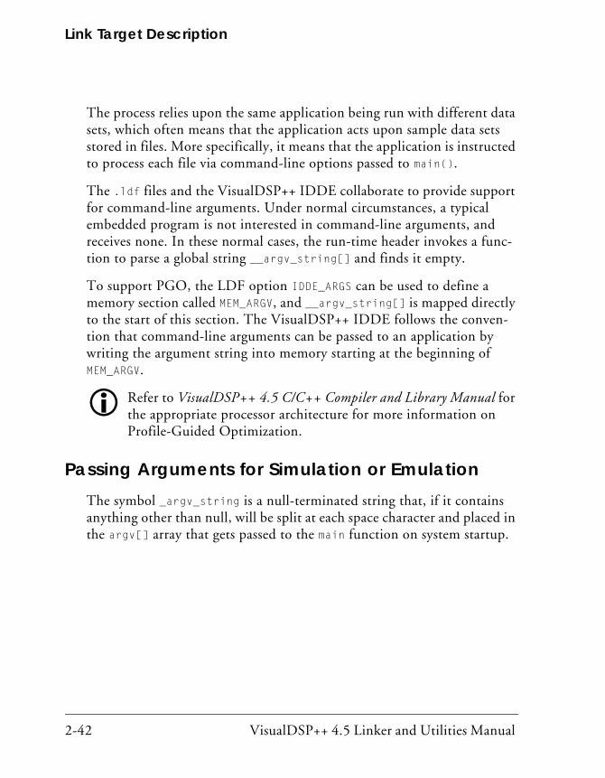
Link Target Description
2-42 VisualDSP++ 4.5 Linker and Utilities Manual
The process relies upon the same application being run with different data sets, which often means that the application acts upon sample data sets stored in files. More specifically, it means that the application is instructed to process each file via command-line options passed to main().
The .ldf files and the VisualDSP++ IDDE collaborate to provide support for command-line arguments. Under normal circumstances, a typical embedded program is not interested in command-line arguments, and receives none. In these normal cases, the run-time header invokes a func-tion to parse a global string __argv_string[] and finds it empty.
To support PGO, the LDF option IDDE_ARGS can be used to define a memory section called MEM_ARGV, and __argv_string[] is mapped directly to the start of this section. The VisualDSP++ IDDE follows the conven-tion that command-line arguments can be passed to an application by writing the argument string into memory starting at the beginning of MEM_ARGV.
Refer to VisualDSP++ 4.5 C/C++ Compiler and Library Manual for the appropriate processor architecture for more information on Profile-Guided Optimization.
Passing Arguments for Simulation or EmulationThe symbol _argv_string is a null-terminated string that, if it contains anything other than null, will be split at each space character and placed in the argv[] array that gets passed to the main function on system startup.
VisualDSP++ 4.5 Linker and Utilities Manual 2-43
Linker
Linker Command-Line ReferenceThis section provides reference information, including:
• “Linker Command-Line Syntax” on page 2-43
• “Linker Command-Line Switches” on page 2-47
When you use the linker via the VisualDSP++ IDDE, the settings on the Link tab of the Project Options dialog box correspond to linker command-line switches. Provided here is the detailed descriptions of the linker’s command-line switches and their syn-tax. For more information, refer to VisualDSP++ online Help.
Linker Command-Line SyntaxRun the linker by using one of the following normalized formats of the linker command line.
linker -proc processor -switch [-switch …] object [object …]
linker -T target.ldf -switch [-switch …] object [object …]
The linker command requires -proc processor or a -T <ldf name> for the link to proceed. If the command line does not include -proc processor, the .ldf file following the -T switch must con-tain a -ARCHITECTURE command. The linker command may contain both but then the ARCHITECTURE() command in the .ldf file must match the -proc processor. Use -proc processor instead of the deprecated -Darchitecture on the command line to select the target processor. See Table 2-7 on page 2-49 for more information.

Linker Command-Line Reference
2-44 VisualDSP++ 4.5 Linker and Utilities Manual
All other switches are optional, and some commands are mutually exclusive.
The following are the example linker commands.
linker -proc ADSP-21161 p0.doj -T target.ldf -t -o program.dxelinker -proc ADSP-TS201 p0.doj -T target.ldf -t -o program.dxelinker -proc ADSP-BF535 p0.doj -T target.ldf -t -o program.dxe
The linker command line (except for file names) is case sensitive. For example, linker -t differs from linker -T.
The linker can be controlled by the compiler via the -flags-link com-mand-line switch that passes explicit options to the linker. For more information, refer to Chapter 1 of the VisualDSP++ 4.5 C/C++ Compiler and Library Manual for appropriate processors.
When using the linker’s command line, be familiar with the following topics:
• “Command-Line Object Files”
• “Command-Line File Names”
• “Object File Types” on page 2-47
Command-Line Object Files
The command line must list at least one (typically more) object file(s) to be linked together. These files may be of several different types.
• Standard object (.doj) files produced by the assembler
• One or more libraries (archives), each with a .DLB extension. Examples include the C run-time libraries and math libraries included with VisualDSP++. You may create libraries of common or specialized objects. Special libraries are available from DSP algo-rithm vendors. For more information, see Chapter 6, “Archiver”.

VisualDSP++ 4.5 Linker and Utilities Manual 2-45
Linker
• An executable (.dxe) file to be linked against. Refer to $COMMAND_LINE_LINK_AGAINST in “Built-In LDF Macros” on page 3-29.
Object File Names
An object file name may include:
• The drive, directory path, file name, and file extension
• The directory path may be an absolute path or a path relative to the directory where the linker is invoked
• Long file names enclosed within straight quotes
If the file exists before the link begins, the linker opens the file to verify its type before processing the file. Table 2-6 lists valid file extensions used by the linker.
Command-Line File Names
Some linker switches take a file name as a parameter. Table 2-6 lists the types of files, names, and extensions that the linker expects on file name arguments. The linker follows the conventions for file extensions in Table 2-6.
Table 2-6. File Extension Conventions
Extension File Description
.dlb Library (archive) file
.doj Object file
.dxe Executable file
.ldf Linker Description File
.ovl Overlay file
.sm Shared memory file

Linker Command-Line Reference
2-46 VisualDSP++ 4.5 Linker and Utilities Manual
The linker supports relative and absolute directory names, default directo-ries, and user-selected directories for file search paths. File searches occur in the following order.
1. Specified path – If the command line includes relative or absolute path information, the linker searches that location for the file.
2. Specified directories – If you do not include path information on the command line and the file is not in the default directory, the linker searches for the file in the search directories specified with the -L (path) command-line switch, and then searches direc-tories specified by SEARCH_DIR commands in the .ldf file. Directories are searched in order of appearance on the command line or in the .ldf file.
3. Default directory – If you do not include path information in the .ldf file named by the -T switch, the linker searches for the .ldf file in the current working directory. If you use a default .ldf file (by omitting LDF information in the command line and instead specifying -proc <processor>), the linker searches in the proces-sor-specific LDF directory; for example, $ADI_DSP/Blackfin/ldf.
• For more information on file searches, see “Built-In LDF Macros” on page 3-29.
When providing input or output file names as command-line parameters:
• Use a space to delimit file names in a list of input files.
• Enclose file names that contain spaces within straight quotes; for example, “long file name”.
• Include the appropriate extension to each file. The linker opens existing files and verifies their type before processing. When the linker creates a file, it uses the file extension to determine the type of file to create.
VisualDSP++ 4.5 Linker and Utilities Manual 2-47
Linker
Object File Types
The linker handles an object (file) by its file type. File type is determined by the following rules.
• Existing files are opened and examined to determine their type. Their names can be anything.
• Files created during the link are named with an appropriate exten-sion and are formatted accordingly. A map file is generated in XML format only and is given an .xml extension. An executable is writ-ten in the ELF format and is given a .dxe extension.
The linker treats object (.doj) and library (.dlb) files that appear on the command line as object files to be linked. The linker treats executable (.dxe) and shared memory (.sm) files on the command line as executables to be linked against.
For more information on objects, see the $COMMAND_LINE_OBJECTS macro. For information on executables, see the $COMMAND_LINE_LINK_AGAINST macro. Both are described in “Built-In LDF Macros” on page 3-29.
If link objects are not specified on the command line or in the .ldf file, the linker generates appropriate informational or error messages.
Linker Command-Line SwitchesThis section describes the linker’s command-line switches. Table 2-7 on page 2-49 briefly describes each switch with regard to case sensitivity, equivalent switches, switches overridden or contradicted by the one described, and naming and spacing constraints for parameters.
The linker provides switches to select operations and modes. The standard switch syntax is:
-switch [argument]

Linker Command-Line Reference
2-48 VisualDSP++ 4.5 Linker and Utilities Manual
Rules
• Switches may be used in any order on the command line. Items in brackets [ ] are optional. Items in italics are user-definable and are described with each switch.
• Path names may be relative or absolute.
• File names containing white space or colons must be enclosed by double quotation marks, though relative path names such as ../../test.dxe do not require double quotation marks.
Different switches require (or prohibit) white space between the switch and its parameter.
Example
linker -proc ADSP-BF535 p0.doj p1.doj p2.doj -T target.ldf -t -o program.dxe
Note the difference between the -T and the -t switches. The command calls the linker as follows:
• -proc ADSP-BF535 Specifies the processor.
• p0.doj, p1.doj, and p2.doj Links three object files into an executable file.
• -T target.ldf
Uses a secondary .ldf file to specify executable program placement.
• -t Turns on trace information, echoing each link object’s name to stdout as it is processed.
• -o program.dxe Specifies a name of the linked executable file.

VisualDSP++ 4.5 Linker and Utilities Manual 2-49
Linker
Typing linker without any switches displays a summary of command-line options. Using no switches is the same as typing linker -help.
Linker Switch Summary and Descriptions
Table 2-7 briefly describes each linker switch. Each individual switch is described in detail following this table. See “Project Builds” on page 2-6 for information on the VisualDSP++ Project Options dialog box.
Table 2-7. Linker Command-Line Switches – Summary
Switch Description More Info
@file Uses the specified file as input on the command line on page 2-51
-DprocessorID Specifies the target processor ID. The use of -proc processorID is recommended.
on page 2-51
-L path Adds the path name to search libraries for objects on page 2-52
-M Produces dependencies on page 2-52
-MM Builds and produces dependencies on page 2-52
-Map file Outputs a map of link symbol information to a file on page 2-53
-MDmacro[=def] Defines and assigns value def to a preprocessor macro
on page 2-53
-MUDmacro Undefines the preprocessor macro on page 2-53
-S Omits debugging symbols from the output file on page 2-54
-T filename Names the LDF on page 2-54
-Wwarn number Demotes the specified error message to a warning on page 2-54
-Wnumber Selectively disables warnings by one or more mes-sage numbers. For example, -W1010 disables warn-ing message li1010.
on page 2-54
-e Eliminates unused symbols from the executable on page 2-55
-ek secName Specifies a section name in which elimination should not take place
on page 2-55

Linker Command-Line Reference
2-50 VisualDSP++ 4.5 Linker and Utilities Manual
-es secName Names input sections (secName list) to which elim-ination algorithm is applied
on page 2-55
-ev Eliminates unused symbols verbosely on page 2-56
-entry Specifies entry address where an argument can be either a symbol or an address
on page 2-56
-flag-meminit Passes each comma-separated option to the Memory Initializer utility
on page 2-56
-flag-pp Passes each comma-separated option to the prepro-cessor
on page 2-56
-h -help
Outputs the list of command-line switches and exits on page 2-56
-i path Includes search directory for preprocessor include files
on page 2-56
-ip Fills fragmented memory with individual data objects that fit
on page 2-57
-jcs21 Converts out-of-range short calls and jumps to the longer form. It also allows the linker to convert out-of-range branches to indirect calls and jump sequences.
on page 2-57
-jcs21+ Same as -jcs21+. on page 2-58
-keep symName Keeps symbols from being eliminated on page 2-58
-meminit Causes post-processing of the executable file on page 2-58
-nonmemcheck Turns off LDF memory checking on page 2-58
-o filename Outputs the named executable file on page 2-59
-od filename Specifies the output directory on page 2-59
-pp Stops after preprocessing on page 2-59
-proc processor Selects a target processor on page 2-59
-s Strips symbol information from the output file on page 2-60
Table 2-7. Linker Command-Line Switches – Summary (Cont’d)
Switch Description More Info

VisualDSP++ 4.5 Linker and Utilities Manual 2-51
Linker
The following sections provide the detailed descriptions of the linker’s command-line switches.
@filename
This switch causes the linker to treat the contents of filemname as input to the linker command line. The @ switch circumvents environmental com-mand-line length restrictions. The filename may not start with “linker” (that is, it cannot be a linker command line). White space (including “newline”) in filename serves to separate tokens.
-Dprocessor
The -Dprocessor (define processor) switch specifies the target processor (architecture); for example, -DADSP-BF533.
The -proc processor switch (on page 2-59) is a preferred option to be used as a replacement for the -Dprocessor command line entry to specify the target processor.
-save-temps Saves temporary output files on page 2-60
-si-revision version Specifies silicon revision of the specified processor on page 2-60
-sp Skips preprocessing on page 2-61
-t Outputs the names of link objects on page 2-61
-tx Outputs full names of link objects on page 2-61
-v -verbose
Verbose: Outputs status information on page 2-61
-version Outputs version information and exits on page 2-62
-warnonce Warns only once for each undefined symbol on page 2-62
-xref Produces a cross-reference file on page 2-62
Table 2-7. Linker Command-Line Switches – Summary (Cont’d)
Switch Description More Info
Linker Command-Line Reference
2-52 VisualDSP++ 4.5 Linker and Utilities Manual
White space is not permitted between -D and processor. The architecture entry is case sensitive and must be available in your VisualDSP++ installa-tion. This switch (or -proc processor switch) must be used if no .ldf file is specified on the command line. (See -T on page 2-54.) This switch (or -proc processor switch) must be used if the specified .ldf file does not specify ARCHITECTURE(). Architectural inconsistency between this switch and the .ldf file causes an error.
-L path
The -Lpath (search directory) switch adds path name to search libraries and objects. This switch is case sensitive and spacing is unimportant. The path parameter enables searching for any file, including the .ldf file itself. Repeat this switch to add multiple search paths. The paths named with this switch are searched before arguments in the SEARCH_DIR{} command.
-M
The -M (generate make rule only) switch directs the linker to check a dependency and to output the result to stdout.
-MM
The -MM (generate make rule and build) switch directs the linker to output a rule, which is suitable for the make utility, describing the dependencies of the source file. The linker check for a dependency, outputs the result to stdout, and performs the build. The only difference between -MM and -M actions is that the linking continues with -MM. See “-M” for more information.

VisualDSP++ 4.5 Linker and Utilities Manual 2-53
Linker
-Map filename
The -Map filename (generate a memory map) switch directs the linker to output a memory map of all symbols. The map file name corresponds to the filename argument. The linker generates the map file in XML format only. For example, if the file name argument is test, the map file name is test.map.xml. The.xml extension is added where necessary.
Opening an .xml map file in a Web browser provides an organized view of the map file. By using hyperlinks, it becomes easy to quickly find any rele-vant information. Since the format of .xml files can be extended between VisualDSP++ releases, the map file is dependant on particular installation of VisualDSP++. Thus, the .xml map file can be used only on a machine it was generated. In order to view the map file on a different machine, the file should be transformed to HTML format using the “xmlmap2html.exe” command-line utility. The utility makes it possible to view the map on virtually any machine with any browser.
-MDmacro[=def]
The -MDmacro[=def] (define macro) switch declares and assigns value def to the preprocessor macro named macro. For example, -MDTEST=BAR exe-cutes the code following #ifdef TEST==BAR in the .ldf file (but not the code following #ifdef TEST==XXX).
If =def is not included, macro is declared and set to “1” to ensure the code following #ifdef TEST is executed. This switch may be repeated.
-MUDmacro
The -MUDmacro (undefine macro) switch undefines the preprocessor macro where macro specifies a name. For example, -MUDTEST undefines macro TEST. The switch is processed after all -MDmacro switches have been pro-cessed. The -MUDmacro switch may be repeated on the command line.
Linker Command-Line Reference
2-54 VisualDSP++ 4.5 Linker and Utilities Manual
-S
The -S (strip debug symbol) switch directs the linker to omit debugging symbol information (not all symbol information) from the output file. Compare this switch with the -s switch on page 2-60.
-T filename
The -T filename (linker description file) switch directs the linker to use filename to name an .ldf file. The .ldf file specified following the -T switch must contain an ARCHITECTURE() command if the command line does not have -proc <processor>. The linker requires the -T switch when linking for a processor for which no VisualDSP++ support has been installed. In such cases, the processor ID does not appear in the Target processor field of the Project Options dialog box.
The filename must exist and be found (for example, via the -L option). White space must appear before filename. A file’s name is unconstrained, but must be valid. For example, a.b works if it is a valid .ldf file, where .LDF is a valid extension but not a requirement.
-Wwarn [number]
The -Wwarn (override error message) switch directs the linker to demote the specified error message to a warning. The number argument specifies the message to demote.
-Wnumber[,number]
The -Wnumber or -wnumber (warning suppression) switch selectively dis-ables warnings specified by one or more message numbers. For example, -W1010 disables warning message li1010. This switch optionally accepts a list, such as [,number ...].

VisualDSP++ 4.5 Linker and Utilities Manual 2-55
Linker
-e
The -e switch directs the linker to eliminate unused symbols from the exe-cutable file.
In order for the C and C++ run-time libraries to work properly, the following symbols should be retained with the “KEEP()” LDF command (described on page 3-36): ___ctor_NULL_marker and ___lib_end_of_heap_descriptions
-ek sectionName
The -ek sectionName (no elimination) switch specifies a section to which the elimination algorithm is not applied. Both this switch and the KEEP_SECTIONS() LDF command (on page 3-37) may be used to specify a section name in which elimination should not take place.
-es sectionName
The -es sectionName (eliminate listed section) switch specifies a section to which the elimination algorithm is to be applied. This switch restricts elimination to the named input sections. The -es switch may be used on a command line more than once. In the absence of the -es switch or the ELIMINATE_SECTIONS() LDF command (on page 3-34), the linker applies elimination to all sections. Both this switch and the ELIMINATE_SECTIONS() LDF command may be used to specify sections from which unreferenced code and data are to be eliminated.
In order for the C and C++ run-time libraries to work properly, the following symbols should be retained with the “KEEP()” LDF command (described on page 3-36): ___ctor_NULL_marker and ___lib_end_of_heap_descriptions

Linker Command-Line Reference
2-56 VisualDSP++ 4.5 Linker and Utilities Manual
-entry
The -entry switch indicates the entry address where an argument can be either a symbol or an address.
-ev
The -ev switch directs the linker to eliminate unused symbols and pro-vides reports on each eliminated symbol.
-flags-meminit -opt1[,-opt2...
The -flags-meminit switch passes each comma-separated option to the Memory Initializer utility. (See “Memory Initializer” for more information.)
-flags-pp-opt1[,-opt2...]
The -flags-pp switch passes each comma-separated option to the preprocessor.
Use -flags-pp with caution. For example, if the pp legacy com-ment syntax is enabled, the comment characters become unavailable for non-comment syntax.
-h[elp]
The -h or -help switch directs the assembler to output to <stdout> a list of command-line switches with a syntax summary.
-i|I directory
The -idirectory or -Idirectory (include directory) switch directs the linker to append the specified directory or a list of directories separated by semicolons (;) to the search path for included files.
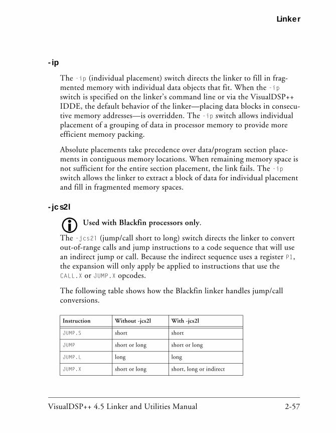
VisualDSP++ 4.5 Linker and Utilities Manual 2-57
Linker
-ip
The -ip (individual placement) switch directs the linker to fill in frag-mented memory with individual data objects that fit. When the -ip switch is specified on the linker’s command line or via the VisualDSP++ IDDE, the default behavior of the linker—placing data blocks in consecu-tive memory addresses—is overridden. The -ip switch allows individual placement of a grouping of data in processor memory to provide more efficient memory packing.
Absolute placements take precedence over data/program section place-ments in contiguous memory locations. When remaining memory space is not sufficient for the entire section placement, the link fails. The -ip switch allows the linker to extract a block of data for individual placement and fill in fragmented memory spaces.
-jcs2l
Used with Blackfin processors only.
The -jcs2l (jump/call short to long) switch directs the linker to convert out-of-range calls and jump instructions to a code sequence that will use an indirect jump or call. Because the indirect sequence uses a register P1, the expansion will only apply be applied to instructions that use the CALL.X or JUMP.X opcodes.
The following table shows how the Blackfin linker handles jump/call conversions.
Instruction Without -jcs2l With -jcs2l
JUMP.S short short
JUMP short or long short or long
JUMP.L long long
JUMP.X short or long short, long or indirect

Linker Command-Line Reference
2-58 VisualDSP++ 4.5 Linker and Utilities Manual
Refer to the instruction set reference for target architecture for more infor-mation on jump and call instructions.
-jcs2l+
Used with Blackfin processors only. This is a deprecated switch equivalent to the -jcs2l switch.
-keep symbolName
The -keep symbolName (keep unused symbols) switch directs the linker to keep symbols from being eliminated. It directs the linker (when -e or -ev is enabled) to retain listed symbols in the executable even if they are unused.
-meminit
The -meminit (post-processing executable file) switch directs the linker to post-process the .dxe file through the Memory Initializer utility. (See “Memory Initializer” for more information.) This action causes the sec-tions specified in the .LDF file to be “run-time” initialized by the C run-time library. By default, if this flag is not specified, all sections are ini-tialized at “load” time (for example, via the VisualDSP++ IDDE or the boot loader). Refer to “SECTIONS{}” on page 3-55 for more information on section initialization.
-nonmemcheck
The -nonmemcheck (memory checking off) switch allows you to turn off memory checking in any .ldf file.
CALL CALL CALL
CALL.X CALL CALL or indirect
Instruction Without -jcs2l With -jcs2l
VisualDSP++ 4.5 Linker and Utilities Manual 2-59
Linker
-o filename
The -o filename (output file) switch sets the value of $COMMAND_LINE_OUTPUT_FILE macro which is normally used as a parameter in LDF OUTPUT() command which specifies the output file name. If no -o is present on command line, the $COMMAND_LINE_OUTPUT_FILE macro gets a value of “a.dxe”.
-od directory
The -od directory switch directs the linker to specify the value of the $COMMAND_LINE_OUTPUT_DIRECTORY LDF macro. This switch allows you to make a command-line change that propagates to many places without changing the .ldf file. Refer to “Built-In LDF Macros” on page 3-29.
-pp
The -pp (end after preprocessing) switch directs the linker to stop after the preprocessor runs without linking. The output (preprocessed LDF) is printed to a file with the same name as the .ldf file with the extension .is. This file is in the same directory as the .ldf file.
-proc processor
The -proc processor (target processor) switch directs the linker to pro-duce code suitable for the specified processor. For example,
linker -proc ADSP-BF533 p0.doj p1.doj p2.doj -o program.dxe
See also “-si-revision version” for more information on silicon revi-sion of the specified processor.

Linker Command-Line Reference
2-60 VisualDSP++ 4.5 Linker and Utilities Manual
-s
The -s (strips all symbols) switch directs the linker to omit all symbol information from the output file.
Some debugger functionality (including “run to main”), all stdio functions, and the ability to stop at the end of program execution rely on the debugger’s ability to locate certain symbols in the exe-cutable file. This switch removes these symbols.
-save-temps
The -save-temps switch directs the linker to save temporary (intermedi-ate) output files.
-si-revision version
The -si-revision version (silicon revision) switch directs the linker to build for a specific hardware revision. Any errata workarounds available for the targeted silicon revision will be enabled. The parameter “version” represents a silicon revision of the processor specified by the -proc switch (on page 2-59). For example,
linker -proc ADSP-BF533 -si-revision 0.1
If silicon version “none” is used, then no errata workarounds are enabled, whereas specifying silicon version “any” will enable all errata workarounds for the target processor.
If the -si-revision switch is not used, the linker builds for the latest known silicon revision for the target processor and any errata workarounds which are appropriate for the latest silicon revision will be enabled.
If the silicon revision is set to “any”, the __SILICON_REVISION__ macro is set to 0xffff and if the -si-revision switch is set to “none”, the linker will not set the __SILICON_REVISION__ macro.

VisualDSP++ 4.5 Linker and Utilities Manual 2-61
Linker
The linker will pass the -si-revision <silicon version> switch when invoking another VisualDSP++ tool, for example when the linker invokes the assembler.
Example:
The Blackfin linker invoked as
linker -proc ADSP-BF533 -si-revision 0.1 …
invokes the assembler with
easmblkfn -proc ADSP-BF533 -si-revision 0.1
-sp
The -sp (skip preprocessing) switch directs the linker to link without pre-processing the .ldf file.
-t
The -t (trace) switch directs the linker to output the names of link objects to standard output as the linker processes them.
-tx
The -tx (full trace) switch directs the linker to output the full names of link objects (full directory path) to standard output as the linker processes them.
-v[erbose]
The -v or -verbose (verbose) switch directs the linker to display version and command-line information for each phase of linking.
Linker Command-Line Reference
2-62 VisualDSP++ 4.5 Linker and Utilities Manual
-version
The -version (display version) switch directs the linker to display version information for the linker.
-warnonce
The -warnonce (single symbol warning) switch directs the linker to warn only once for each undefined symbol, rather than once for each reference to that symbol.
-xref
The -xref switch directs the linker to produce a cross-reference file (xref.xml file).

VisualDSP++ 4.5 Linker and Utilities Manual 3-1
3 LINKER DESCRIPTION FILE
Every DSP project requires one Linker Description File (.ldf). The .ldf file specifies precisely how to link projects. Chapter 2, “Linker”, describes the linking process and how the .ldf file ties into the linking process.
When generating a new .ldf file, use the Expert Linker to generate an .ldf file. Refer to Chapter 4, “Expert Linker” for details.
The .ldf file allows code development for any processor system. It defines your system to the linker and specifies how the linker cre-ates executable code for your system. This chapter describes .ldf file syntax, structure and components. Refer to Appendix C, “LDF Programming Examples for TigerSHARC Processors”, Appendix D, “LDF Programming Examples for SHARC Processors”, and Appendix E, “LDF Programming Examples for Blackfin Proces-sors” for the LDF examples for typical systems.
This chapter contains:
• “LDF File Overview” on page 3-3
• “LDF Structure” on page 3-17
• “LDF Expressions” on page 3-19
• “LDF Keywords, Commands, and Operators” on page 3-20
• “LDF Operators” on page 3-22
• “LDF Macros” on page 3-27
• “LDF Commands” on page 3-31

3-2 VisualDSP++ 4.5 Linker and Utilities Manual
The linker runs the preprocessor on the .LDF file, so you can use preprocessor commands (such as #defines) within the file. For information about preprocessor commands, refer to a VisualDSP++ 4.5 Assembler and Preprocessor Manual for an appropriate target processor architecture.
Assembler section declarations in this document correspond to the assembler’s .SECTION directive.
Refer to example DSP programs shipped with VisualDSP++ for sample .ldf files supporting typical system models.

VisualDSP++ 4.5 Linker and Utilities Manual 3-3
Linker Description File
LDF File OverviewThe .ldf file directs the linker by mapping code or data to specific mem-ory segments. The linker maps program code (and data) within the system memory and processor(s), and assigns an address to every symbol, where:
symbol = label symbol = function_name symbol = variable_name
If you neither write an .ldf file nor import an .ldf file into your project, nor have VisualDSP++ generate an .ldf file, VisualDSP++ links the code using a default .ldf file. The chosen default .ldf file is determined by the processor specified in the VisualDSP++ Project Options dialog box. Default .ldf files are packaged with your processor tool distribution kit in a subdirectory specific to your target processor’s family. One default .ldf file is provided for each processor supported by your VisualDSP++ installation (see “Default LDFs”).
The .ldf file combines information, directing the linker to place input sections in an executable file according to the memory available in the DSP system.
The linker may output warning messages and error messages. You must resolve the error messages to enable the linker to produce valid output. See “Linker Warning and Error Messages” on page 2-10 for more information.

LDF File Overview
3-4 VisualDSP++ 4.5 Linker and Utilities Manual
Generated LDFsOn Blackfin, the VisualDSP++ New Project Wizard and the Project Options dialog allow you to generate and configure a custom Linker Description File (LDF). This is the quickest and easiest way to customize your LDF. See the VisualDSP++ 4.5 User's Guide for more information about the New Project Wizard and Project Options dialog.
Default LDFsThe name of each .ldf file indicates the intended processor (for example, ADSP-BF531.ldf). If the .ldf file name has no suffix, it is the “default .ldf file”. That is, when no .ldf file is explicitly specified, the default file is used to link an application when building for that processor. Therefore, ADSP-BF531.ldf is the default .ldf file for the ADSP-BF531 processor.
If no .ldf file is specified explicitly via the –T command-line switch, the compiler driver selects the default .ldf file for the target processor. For example, the first of the following commands uses the default .ldf file, and the second uses a user-specified file:
ccblkfn –proc ADSP-BF531 hello.c # uses default ADSP-BF531.ldf
ccblkfn –proc ADSP-BF531 hello.c –T ./my.ldf # uses ./my.ldf
On non-Blackfin platforms, for each processor, there are three .ldf files with suffixes _C, _CPP, and _ASM, respectively (for example, ADSP-21363_C.ldf).
On non-Blackfin platforms, these .ldf files are templates for the Expert Linker. If you use the Expert Linker to create a custom .ldf file for your project, the Expert Linker will do so by querying you for the kind of .ldf file you want to create (asm, C, or C++) and then copying one of the above templates. The suffixes indicate the kind of .ldf files they support.
The CPP template is a superset of the C template, and the C template is a superset of the ASM template. The differences are as follows:

VisualDSP++ 4.5 Linker and Utilities Manual 3-5
Linker Description File
• The CPP template links against C++ run-time libraries, C++ excep-tion libraries, and the run-time headers built to initialize C++ constructors. It maps data sections that contain information con-trolling how thrown exceptions are caught.
• The C template is currently identical to the CPP template, since a C project may link against local or system libraries that have been implemented in C++; there may be differences in a future release.
• The ASM template does not include a run-time header, and does not permit command-line arguments to applications. The ASM template is not suitable for use with the compiler’s Profile-Guided Optimi-zation. Since the ASM template has no run-time header, it does not mandate a “start” symbol resolved to the Reset address. It does not map the C++ exception sections into memory.
Each .ldf file handles a variety of demands, allowing applications to be built in multiple configurations, merely by supplying a few command-line options. This flexibility is achieved by extensive use of preprocessor mac-ros within the .ldf file. Macros serve as flags to indicate one choice or another, and as variables within the .ldf file to hold the name of a chosen file or other link-time parameter. This reliance on preprocessor operation can make the .ldf file seem an imposing sight.
In simple terms, different .ldf file configurations are selected by defining preprocessor macros on the linker command line. This can be specified from the Link tab of the VisualDSP++ IDDE’s Project Options dialog box or directly from the command line.
At the top of the default Blackfin LDFs, you will find documentation on the macros you can use to configure the default LDFs.
You can use an .ldf file written from scratch. However, modifying an existing LDF (or a default .LDF file) is often the easier alternative when there are no large changes in your system’s hardware or software. See Listing 3-1 on page 3-7, Listing 3-2 on page 3-10, and Listing 3-3 on

LDF File Overview
3-6 VisualDSP++ 4.5 Linker and Utilities Manual
page 3-11 as examples of basic .ldf files for supported processors. See “Common Notes on Basic .ldf File Examples” on page 3-12 for basic information on LDF structure. See Appendix C, Appendix D, and Appendix E for code examples for Tig-erSHARC, SHARC, and Blackfin processors, respectively.

VisualDSP++ 4.5 Linker and Utilities Manual 3-7
Linker Description File
Example 1 – Basic .ldf File for Blackfin ProcessorsListing 3-1 is an example of a basic .ldf file for ADSP-BF535 processors (formatted for readability). Note the MEMORY{} and SECTIONS{} commands and refer to “Common Notes on Basic .ldf File Examples” on page 3-12. Other .ldf file examples are provided in “LDF Programming Examples for Blackfin Processors”.
Listing 3-1. Example .ldf File for ADSP-BF535 Processor
ARCHITECTURE(ADSP-BF535)SEARCH_DIR($ADI_DSP\Blackfin\lib)$OBJECTS = CRT, $COMMAND_LINE_OBJECTS ENDCRT;
MEMORY /* Define/label system memory */{ /* List of global Memory Segments */ MEM_L2 { TYPE(RAM) START(0xF0000000) END(0xF002FFFF) WIDTH(8) } MEM_HEAP { TYPE(RAM) START(0xF0030000) END(0xF0037FFF) WIDTH(8) } MEM_STACK { TYPE(RAM) START(0xF0038000) END(0xF003DFFF) WIDTH(8) } MEM_SYSSTACK { TYPE(RAM) START(0xF003E000) END(0xF003FDFF) WIDTH(8) } MEM_ARGV { TYPE(RAM) START(0xF003FE00) END(0xF003FFFF) WIDTH(8) }}
PROCESSOR P0 { /* the only processor in the system */ OUTPUT ( $COMMAND_LINE_OUTPUT_FILE )
SECTIONS { /* List of sections for processor P0 */
L2 { INPUT_SECTION_ALIGN(2) /* Align all code sections on 2 byte boundary */

LDF File Overview
3-8 VisualDSP++ 4.5 Linker and Utilities Manual
INPUT_SECTIONS( $OBJECTS(program) $LIBRARIES(program)) INPUT_SECTION_ALIGN(1) INPUT_SECTIONS( $OBJECTS(data1) $LIBRARIES(data1)) INPUT_SECTION_ALIGN(1) INPUT_SECTIONS( $OBJECTS(constdata) $LIBRARIES(constdata)) INPUT_SECTION_ALIGN(1) INPUT_SECTIONS( $OBJECTS(ctor) $LIBRARIES(ctor) ) } >MEM_L2
stack { ldf_stack_space = .; ldf_stack_end = ldf_stack_space + MEMORY_SIZEOF(MEM_STACK) - 4; } >MEM_STACK
heap { /* Allocate a heap for the application */ ldf_heap_space = .; ldf_heap_end = ldf_heap_space + MEMORY_SIZEOF(MEM_HEAP) - 1; ldf_heap_length = ldf_heap_end - ldf_heap_space; } >MEM_HEAP
argv { /* Allocate argv space for the application */ ldf_argv_space = .; ldf_argv_end = ldf_argv_space + MEMORY_SIZEOF(MEM_ARGV) - 1; ldf_argv_length = ldf_argv_end - ldf_argv_space; } >MEM_ARGV
} /* end SECTIONS */
} /* end PROCESSOR p0 */

VisualDSP++ 4.5 Linker and Utilities Manual 3-9
Linker Description File
Memory Usage in Blackfin Processors
The default .ldf files define memory areas for all defined spaces on the processor.1 Not all of these memory areas are used within the .ldf files. Instead, the .ldf files provide three basic memory configurations:
• The default configuration specifies that only internal memory is available and caching is disabled. Thus, no code or data is mapped to SDRAM unless explicitly placed there, and all of the available L1 space is used for code or data.
• Defining the USE_CACHE macro selects the alternative configuration, where code and data caches are enabled and external SDRAM is used. Code and data are mapped into L1 where possible, but the Cache/SRAM areas are left empty; any spill-over goes into the SDRAM.
• Defining the USE_SDRAM macro has the same effect as defining the USE_CACHE macro, except that code and data get mapped to the L1 Cache/SRAM areas.
If USE_CACHE is used, caches may safely be turned on, because doing so will not corrupt code or data. Selecting this option does not actually enable the caches — that must be done separately (for example, through the ___cplb_ctrl configuration variable). Instead, this option ensures that the memory layout allows caches to be enabled later.
A common user error is to enable cache despite not having specified USE_CACHE, which would lead to code or data corruption as cache activity overwrites the contents of SRAM. Therefore, the .ldf files use the follow-ing “guard symbols”:
___l1_code_cache
___l1_data_cache_a
1 With the exception of the core MMRs, which the linker considers “out of bounds”.

LDF File Overview
3-10 VisualDSP++ 4.5 Linker and Utilities Manual
___l1_data_cache_b
These symbols are defined by the .ldf files and are given values (that is, resolved to addresses 0 or 1), depending on whether USE_CACHE is defined. The run-time library examines these symbols when cache configuration is requested, and refuses to enable a cache if the corresponding guard symbol is zero, indicating that valid information already occupies this space.
For more information, refer to VisualDSP++ 4.5 C/C++ Compiler and Library Manual, section “Caching and Memory Protection”.
Example 2 – Basic .ldf File for TigerSHARC Processors
Listing 3-2 is an example of a basic .ldf file for the ADSP-TS101 proces-sor (formatted for readability). Note the MEMORY{} and SECTIONS{} commands and refer to “Common Notes on Basic .ldf File Examples” on page 3-12. Other .ldf file examples are provided in “LDF Programming Examples for TigerSHARC Processors”.
Listing 3-2. Example .ldf File for ADSP-TS201 Processor
ARCHITECTURE(ADSP-TS101)SEARCH_DIR($ADI_DSP\TS\lib)$OBJECTS = main.doj, $COMMAND_LINE_OBJECTS;
MEMORY { /* Define and label system memory */ /* List of global memory segments */ M0Code {TYPE(RAM) START(0x000000) END(0x00FFFF) WIDTH(32)} M1Data {TYPE(RAM) START(0x080000) END(0x08FFFF) WIDTH(32)} M2Data {TYPE(RAM) START(0x100000) END(0x10FFFF) WIDTH(32)}}PROCESSOR P0 { /* the only processor in the system */ OUTPUT ( $COMMAND_LINE_OUTPUT_FILE ) SECTIONS{ code { INPUT_SECTIONS ( $OBJECTS(program))} > M0Code data1 { INPUT_SECTIONS ( $OBJECTS(data1))} > M1Data data2 { INPUT_SECTIONS ( $OBJECTS(data2))} > M2Data

VisualDSP++ 4.5 Linker and Utilities Manual 3-11
Linker Description File
} /* End of SECTIONS command for processor P0 */} /* End of PROCESSOR command. /*
Example 3 – Basic .ldf File for SHARC ProcessorsListing 3-3 is an example of a basic .ldf file for the ADSP-21161 proces-sor (formatted for readability). Note the MEMORY{} and SECTIONS{} commands and refer to “Common Notes on Basic .ldf File Examples” on page 3-12. Other examples for assembly and C source files are in “LDF Programming Examples for SHARC Processors”.
Listing 3-3. Example .ldf File for ADSP-21161 Processor
// Link for the ADSP-21161ARCHITECTURE(ADSP-21161)SEARCH_DIR ( $ADI_DSP\211xx\lib )MAP (SINGLE-PROCESSOR.XML) // Generate a MAP file
// $ADI_DSP is a predefined linker macro that expands to // the VisualDSP++ installation directory. Search for objects // in directory 21k\lib relative to the installation directory
// lib161.dlb is an ADSP-2116x-specific library and must precede // precede libc.dlb, C library to link 2116x-specific routines
$LIBS = lib161.dlb, libc.dlb;
// single.doj is a user-generated file. // The linker will be invoked as follows: // linker -T single-processor.ldf single.doj. // $COMMAND_LINE_OBJECTS is a predefined linker macro. // The linker expands this macro into the name(s) of the // the object(s) (.doj files) and libraries (.dlb files) // that appear on the command line. In this example, // $COMMAND_LINE_OBJECTS = single.doj
// 161_hdr.doj is the standard initialization file for 2116x$OBJS = $COMMAND_LINE_OBJECTS, 161_hdr.doj;
// A linker project to generate a .dxe filePROCESSOR P0
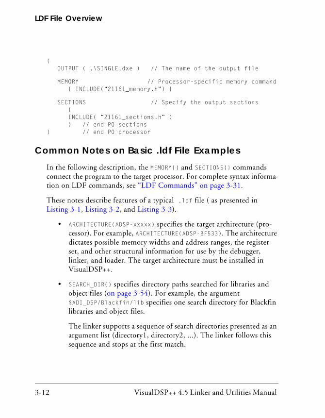
LDF File Overview
3-12 VisualDSP++ 4.5 Linker and Utilities Manual
{ OUTPUT ( .\SINGLE.dxe ) // The name of the output file
MEMORY // Processor-specific memory command { INCLUDE(“21161_memory.h”) }
SECTIONS // Specify the output sections { INCLUDE( “21161_sections.h” ) } // end P0 sections} // end P0 processor
Common Notes on Basic .ldf File ExamplesIn the following description, the MEMORY{} and SECTIONS{} commands connect the program to the target processor. For complete syntax informa-tion on LDF commands, see “LDF Commands” on page 3-31.
These notes describe features of a typical .ldf file ( as presented in Listing 3-1, Listing 3-2, and Listing 3-3).
• ARCHITECTURE(ADSP-xxxxx) specifies the target architecture (pro-cessor). For example, ARCHITECTURE(ADSP-BF533). The architecture dictates possible memory widths and address ranges, the register set, and other structural information for use by the debugger, linker, and loader. The target architecture must be installed in VisualDSP++.
• SEARCH_DIR() specifies directory paths searched for libraries and object files (on page 3-54). For example, the argument $ADI_DSP/Blackfin/lib specifies one search directory for Blackfin libraries and object files.
The linker supports a sequence of search directories presented as an argument list (directory1, directory2, ...). The linker follows this sequence and stops at the first match.

VisualDSP++ 4.5 Linker and Utilities Manual 3-13
Linker Description File
• $LIBRARIES is a list of the library and object files searched to resolve references, in the required order. Some of the options specify the selection of one library over another.
• $OBJECTS is an example of a user-definable macro, which expands to a comma-delimited list of file names. Macros improve readability by replacing long strings of text. Conceptually similar to preproces-sor macro support (#defines) also available in the .ldf file, string macros are independent. In this example, $OBJECTS expands to a comma-delimited list of the input files to be linked.
Note: In this example and in the default .ldf files that accompany VisualDSP++, $OBJECTS in the SECTIONS() command specifies the object files to be searched for specific input sections.
As another example, $ADI_DSP expands to the VisualDSP++ home directory.
• $COMMAND_LINE_OBJECTS (on page 3-29) is an LDF command-line macro, which expands in the .ldf file into the list of input files that appears on the command line.
Note: The order in which the linker processes object files (which affects the order in which addresses in memory segments are assigned to input sections and symbols) is determined by the listed order in the SECTIONS{} command. As noted above, this order is typically the order listed in $OBJECTS ($COMMAND_LINE_OBJECTS).
VisualDSP++ generates a linker command line that lists objects in alphabetical order. This order carries through to the $OBJECTS macro. You may customize the .ldf file to link objects in any desired order. Instead of using default macros such as $OBJECTS, each INPUT_SECTION command can have one or more explicit object names.

LDF File Overview
3-14 VisualDSP++ 4.5 Linker and Utilities Manual
The following examples are functionally identical:
dxe_program { INPUT_SECTIONS ( main.doj(program) fft.doj(program) ) } > mem_program
$DOJS = main.doj, fft.doj; dxe_program { INPUT_SECTIONS ($DOJS(program))
} >mem_program;
• The MEMORY{} command (on page 3-38) defines the target system’s physical memory and connects the program to the target system. Its arguments partition the memory into memory segments. Each memory segment is assigned a distinct name, memory type, a start and end address (or segment length), and a memory width. These names occupy different namespaces from input section names and output section names. Thus, a memory segment and an output sec-tion may have the same name.
• Each PROCESSOR{} command (on page 3-48) generates a single exe-cutable file.
• The OUTPUT() command (on page 3-49) produces an executable (.dxe) file and specifies its file name.
In basic example, the argument to the OUTPUT() command is the $COMMAND_LINE_OUTPUT_FILE macro (on page 3-29). The linker names the executable file according to the text following the -o switch (which corresponds to the name specified in the Project Options dialog box when the linker is invoked via the VisualDSP++ IDDE).
>linker ... -o outputfilename
• SECTIONS{} (on page 3-55) specifies the placement of code and data in physical memory. The linker maps input sections (in object files) to output sections (in executable files), and maps the output sections to memory segments specified by the MEMORY{} command.

VisualDSP++ 4.5 Linker and Utilities Manual 3-15
Linker Description File
The INPUT_SECTIONS() statement specifies the object file the linker uses as an input to resolve the mapping to the appropriate memory segment declared in the .ldf file.
For example, in TigerSHARC processors, the following INPUT_SECTIONS() statement directs the linker to place the program input section in the code output section and to map it to the M0Code memory segment.
code { INPUT_SECTIONS ( $OBJECTS(program))} > M0Code
For SHARC processors, the following INPUT_SECTIONS() statement directs the linker to place the isr_tbl input section in the dxe_isr output section and to map it to the mem_isr memory segment.
dxe_isr{ INPUT_SECTIONS ( $OBJECTS (isr_tbl) ) } > mem_isr
For Blackfin processors, the following two input sections (program and data1) are mapped into one memory segment (L2), as shown below.
dxe_L2 1 INPUT_SECTIONS_ALIGN (2) 2 INPUT_SECTIONS($OBJECTS(program) $LIBRARIES(program)) 3 INPUT_SECTIONS_ALIGN (1) 4 INPUT_SECTIONS($OBJECTS(data1) $LIBRARIES(data1)) }>MEM_L2
The second line directs the linker to place the object code assem-bled from the source file’s “program” input section (via the “.section program” directive in the assembly source file), place the output object into the “DXE_L2” output section, and map the out-put section to the “MEM_L2” memory segment. The fourth line does the same for the input section “data1” and output section

LDF File Overview
3-16 VisualDSP++ 4.5 Linker and Utilities Manual
“DXE_L2”, mapping them to the memory segment “MEM_L2”. The two pieces of code follow each other in the program memory segment.
The INPUT_SECTIONS() commands are processed in the same order as object files appear in the $OBJECTS macro. You may intersperse INPUT_SECTIONS() statements within an output section with other directives, including location counter information.
VisualDSP++ 4.5 Linker and Utilities Manual 3-17
Linker Description File
LDF StructureOne way to produce a simple and maintainable .ldf file is to parallel the structure of your DSP system. Using your system as a model, follow these guidelines.
• Split the file into a set of PROCESSOR{} commands, one for each DSP in your system.
• Place a MEMORY{} command in the scope that matches your system and define memory unique to a processor within the scope of the corresponding PROCESSOR{} command.
• If applicable, place a SHARED_MEMORY{} command in the .ldf file’s global scope. This command specifies system resources available as shared resources in a multiprocessor environment.
Declare common (shared) memory definitions in the global scope before the PROCESSOR{} commands. See “Command Scoping” for more information.
Comments in the .ldf File C-style comments begin with /* and may cross “newline” boundaries until a */ terminator is encountered.
A C++ style comment begins with // and ends at the end of the line.
For more information on LDF structure, see:
• “Link Target Description” on page 2-11
• “Placing Code on the Target” on page 2-35
Also see Appendix C, Appendix D, and Appendix E for code and LDF structure examples for TigerSHARC, SHARC and Blackfin processors, respectively.

LDF Structure
3-18 VisualDSP++ 4.5 Linker and Utilities Manual
Command ScopingThe two LDF scopes are global and command. A global scope occurs outside commands. Commands and expressions that appear in the global scope are always available and are visible in all subsequent scopes. LDF macros are available globally, regardless of the scope in which the macro is defined (see “LDF Macros” on page 3-27).
A command scope applies to all commands that appear between the braces ({ }) of another command, such as a PROCESSOR{} or PLIT{} command. Commands and expressions that appear in the command scopes are lim-ited to those scopes.
Figure 3-1 illustrates some scoping issues. For example, the MEMORY{} command that appears in the LDF’s global scope is available in all com-mand scopes, but the MEMORY{} command that appear in command scopes is restricted to those scopes.
Figure 3-1. LDF Command Scoping Example
GlobalLDFScope
Scope of SHARED_MEMORY{}
Scope of PROCESSOR P0{}
MEMORY{}
MPMEMORY{} SHARED_MEMORY { OUTPUT() SECTIONS{} }
PROCESSOR P0 { OUTPUT() MEMORY{} SECTIONS{} RESOLVE{}
}
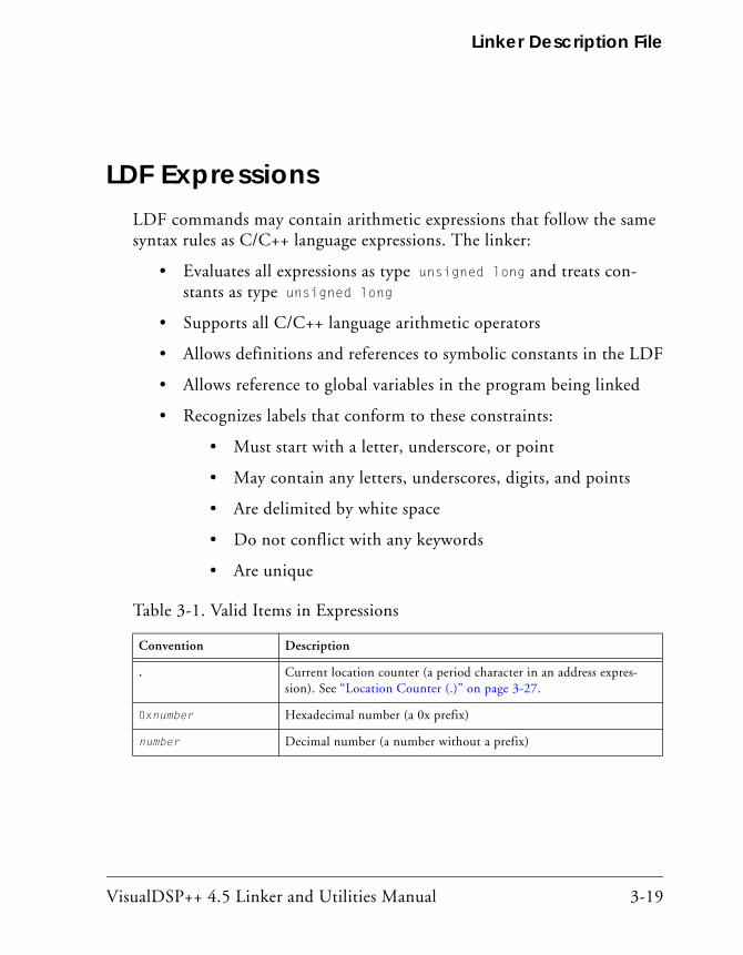
VisualDSP++ 4.5 Linker and Utilities Manual 3-19
Linker Description File
LDF ExpressionsLDF commands may contain arithmetic expressions that follow the same syntax rules as C/C++ language expressions. The linker:
• Evaluates all expressions as type unsigned long and treats con-stants as type unsigned long
• Supports all C/C++ language arithmetic operators
• Allows definitions and references to symbolic constants in the LDF
• Allows reference to global variables in the program being linked
• Recognizes labels that conform to these constraints:
• Must start with a letter, underscore, or point
• May contain any letters, underscores, digits, and points
• Are delimited by white space
• Do not conflict with any keywords
• Are unique
Table 3-1. Valid Items in Expressions
Convention Description
. Current location counter (a period character in an address expres-sion). See “Location Counter (.)” on page 3-27.
0xnumber Hexadecimal number (a 0x prefix)
number Decimal number (a number without a prefix)

LDF Keywords, Commands, and Operators
3-20 VisualDSP++ 4.5 Linker and Utilities Manual
LDF Keywords, Commands, and Operators
Table 3-2 lists .ldf file keywords (used in Blackfin, SHARC and Tiger-SHARC processor families). Descriptions of LDF keywords, operators, macros, and commands are provided in the following sections.
• “Miscellaneous LDF Keywords” on page 3-21
• “LDF Operators” on page 3-22
• “LDF Macros” on page 3-27
• “LDF Commands” on page 3-31
Keywords are case sensitive; the linker recognizes a keyword only when the entire word is UPPERCASE.
numberk or numberK
A decimal number multiplied by 1024
B#number or b#number
A binary number
Table 3-2. LDF File Keywords Summary
ABSOLUTE ADDR ALGORITHM
ALIGN ALL_FIT ARCHITECTURE
BEST_FIT BOOT DEFINED
DYNAMIC ELIMINATE ELIMINATE_SECTIONS
ENTRY END
Table 3-1. Valid Items in Expressions (Cont’d)
Convention Description
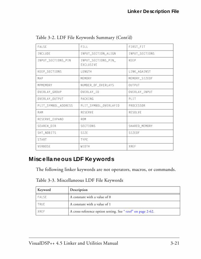
VisualDSP++ 4.5 Linker and Utilities Manual 3-21
Linker Description File
Miscellaneous LDF KeywordsThe following linker keywords are not operators, macros, or commands.
FALSE FILL FIRST_FIT
INCLUDE INPUT_SECTION_ALIGN INPUT_SECTIONS
INPUT_SECTIONS_PIN INPUT_SECTIONS_PIN_ EXCLUSIVE
KEEP
KEEP_SECTIONS LENGTH LINK_AGAINST
MAP MEMORY MEMORY_SIZEOF
MPMEMORY NUMBER_OF_OVERLAYS OUTPUT
OVERLAY_GROUP OVERLAY_ID OVERLAY_INPUT
OVERLAY_OUTPUT PACKING PLIT
PLIT_SYMBOL_ADDRESS PLIT_SYMBOL_OVERLAYID PROCESSOR
RAM RESERVE RESOLVE
RESERVE_EXPAND ROM
SEARCH_DIR SECTIONS SHARED_MEMORY
SHT_NOBITS SIZE SIZEOF
START TYPE
VERBOSE WIDTH XREF
Table 3-3. Miscellaneous LDF File Keywords
Keyword Description
FALSE A constant with a value of 0
TRUE A constant with a value of 1
XREF A cross-reference option setting. See “-xref” on page 2-62.
Table 3-2. LDF File Keywords Summary (Cont’d)

LDF Operators
3-22 VisualDSP++ 4.5 Linker and Utilities Manual
For more information about other .ldf file keywords, see “LDF Opera-tors” on page 3-22, “LDF Macros” on page 3-27, and “LDF Commands” on page 3-31.
LDF OperatorsLDF operators in expressions support memory address operations. Expres-sions that contain these operators terminate with a semicolon, except when the operator serves as a variable for an address. The linker responds to several LDF operators including the location counter.
Each LDF operator is described in the following sections.
ABSOLUTE() OperatorSyntax:
ABSOLUTE(expression)
The linker returns the value expression. Use this operator to assign an absolute address to a symbol. The expression can be:
• A symbolic expression in parentheses; for example:
ldf_start_expr = ABSOLUTE(start + 8);
This example assigns ldf_start_expr the value corresponding to the address of the symbol start, plus 8, as in:
ldf_start_expr = start + 8;
• An integer constant in one of these forms: hexadecimal, decimal, or decimal optionally followed by “K” (kilo [x1024]) or “M” (Mega [x1024x1024])
• A period, indicating the current location (see “Location Counter (.)” on page 3-27)
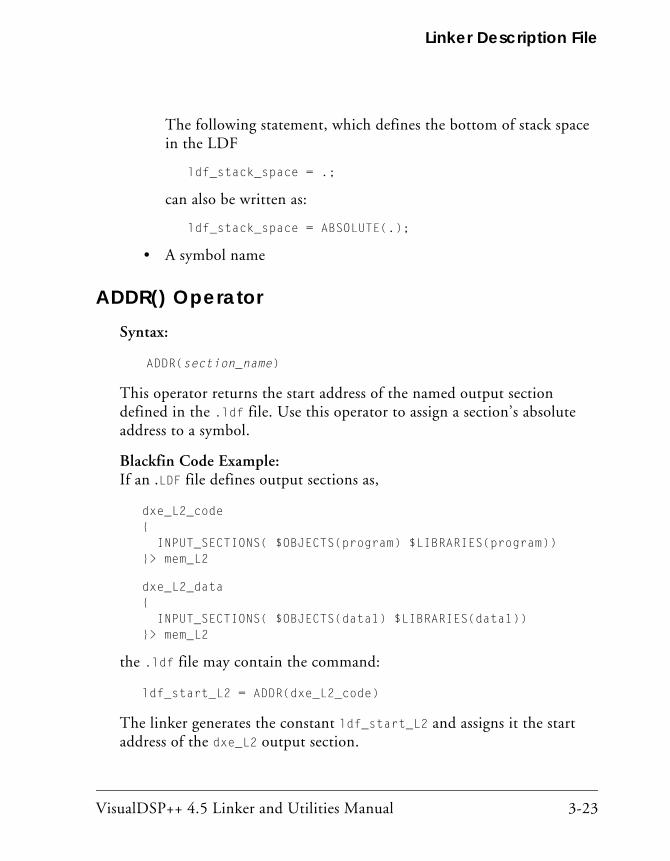
VisualDSP++ 4.5 Linker and Utilities Manual 3-23
Linker Description File
The following statement, which defines the bottom of stack space in the LDF
ldf_stack_space = .;
can also be written as:
ldf_stack_space = ABSOLUTE(.);
• A symbol name
ADDR() OperatorSyntax:
ADDR(section_name)
This operator returns the start address of the named output section defined in the .ldf file. Use this operator to assign a section’s absolute address to a symbol.
Blackfin Code Example:If an .LDF file defines output sections as,
dxe_L2_code { INPUT_SECTIONS( $OBJECTS(program) $LIBRARIES(program)) }> mem_L2
dxe_L2_data { INPUT_SECTIONS( $OBJECTS(data1) $LIBRARIES(data1)) }> mem_L2
the .ldf file may contain the command:
ldf_start_L2 = ADDR(dxe_L2_code)
The linker generates the constant ldf_start_L2 and assigns it the start address of the dxe_L2 output section.

LDF Operators
3-24 VisualDSP++ 4.5 Linker and Utilities Manual
SHARC Code Example:If an .ldf file defines output sections as,
dxe_pmco
{
INPUT_SECTIONS( $OBJECTS(seg_pmco) $LIBRARIES(seg_pmco))
}> mem_pmco
dxe_dmda
{
INPUT_SECTIONS( $OBJECTS(seg_dmda) $LIBRARIES(seg_dmda))
}> mem_seg_dmda
the .ldf file may contain the command:
ldf_start_dmda = ADDR(mem_seg_dmda)
The linker generates the constant ldf_start_dmda and assigns it the start address of the mem_seg_dmda output section.
DEFINED() OperatorSyntax:
DEFINED(symbol)
The linker returns 1 when the symbol appears in the global symbol table, and returns 0 when the symbol is not defined. Use this operator to assign default values to symbols.
Example:If an assembly object linked by the .ldf file defines the global symbol test, the following statement sets the test_present constant to 1. Other-wise, the constant has the value 0.
test_present = DEFINED(test);
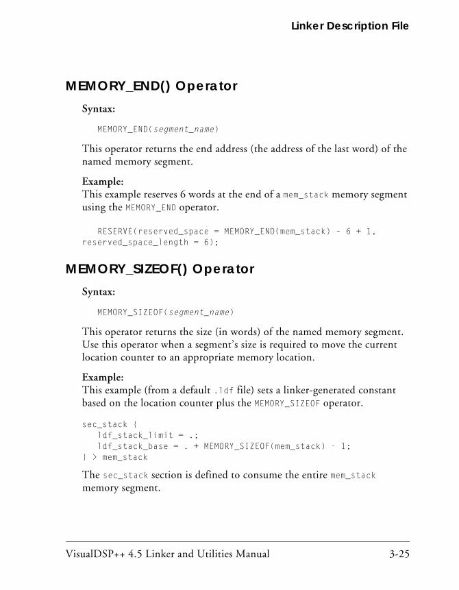
VisualDSP++ 4.5 Linker and Utilities Manual 3-25
Linker Description File
MEMORY_END() OperatorSyntax:
MEMORY_END(segment_name)
This operator returns the end address (the address of the last word) of the named memory segment.
Example:This example reserves 6 words at the end of a mem_stack memory segment using the MEMORY_END operator.
RESERVE(reserved_space = MEMORY_END(mem_stack) – 6 + 1, reserved_space_length = 6);
MEMORY_SIZEOF() OperatorSyntax:
MEMORY_SIZEOF(segment_name)
This operator returns the size (in words) of the named memory segment. Use this operator when a segment’s size is required to move the current location counter to an appropriate memory location.
Example:This example (from a default .ldf file) sets a linker-generated constant based on the location counter plus the MEMORY_SIZEOF operator.
sec_stack { ldf_stack_limit = .; ldf_stack_base = . + MEMORY_SIZEOF(mem_stack) - 1;} > mem_stack
The sec_stack section is defined to consume the entire mem_stack memory segment.

LDF Operators
3-26 VisualDSP++ 4.5 Linker and Utilities Manual
MEMORY_START() OperatorSyntax:
MEMORY_START(segment_name)
This operator returns the start address (the address of the first word) of the named memory segment.
Example:This example reserves 4 words at the start of a mem_stack memory segment using the MEMORY_START operator.
RESERVE(reserved_space = MEMORY_START(mem_stack), reserved_space_length = 4;
The sec_stack section is defined to consume the entire mem_stack memory segment.
SIZEOF() OperatorSyntax:
SIZEOF(section_name)
This operator returns the size (in bytes) of the named output section. Use this operator when a section’s size is required to move the current location counter to an appropriate memory location.
SHARC Code Example:The following LDF fragment defines the _sizeofdata1 constant to the size of the seg_dmda section.
seg_dmda { INPUT_SECTIONS( $OBJECTS(seg_dmda) $LIBRARIES(seg_dmda)) _sizeofdata1 = SIZEOF(seg_dmda); } > seg_dmda

VisualDSP++ 4.5 Linker and Utilities Manual 3-27
Linker Description File
Blackfin Code Example:The following LDF fragment defines the _sizeofdata1 constant to the size of the data1 section.
data1 { INPUT_SECTIONS( $OBJECTS(data1) $LIBRARIES(data1)) _sizeofdata1 = SIZEOF(data1); } > MEM_DATA1
Location Counter (.)The linker treats a “.” (period surrounded by spaces) as the symbol for the current location counter. The location counter is a pointer to the memory location at the end of the previous linker command. Because the period refers to a location in an output section, this operator may appear only within an output section in a SECTIONS{} command.
Observe these rules:
• Use a period anywhere a symbol is allowed in an expression.
• Assign a value to the period operator to move the location counter and to leave voids or gaps in memory.
• The location counter may not be decremented.
LDF MacrosLDF macros (or linker macros) are built-in macros. They have predefined system-specific procedures or values. Other macros, called user macros, are user-definable.
LDF macros are identified by a leading dollar sign ($) character. Each LDF macro is a name for a text string. You may assign LDF macros with textual or procedural values, or simply declare them to exist.
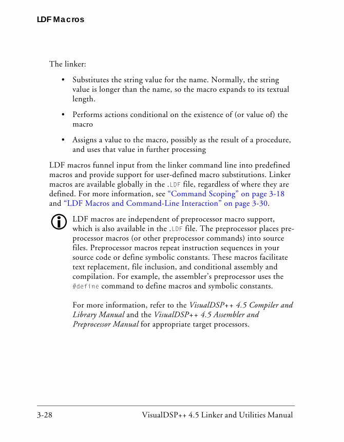
LDF Macros
3-28 VisualDSP++ 4.5 Linker and Utilities Manual
The linker:
• Substitutes the string value for the name. Normally, the string value is longer than the name, so the macro expands to its textual length.
• Performs actions conditional on the existence of (or value of) the macro
• Assigns a value to the macro, possibly as the result of a procedure, and uses that value in further processing
LDF macros funnel input from the linker command line into predefined macros and provide support for user-defined macro substitutions. Linker macros are available globally in the .LDF file, regardless of where they are defined. For more information, see “Command Scoping” on page 3-18 and “LDF Macros and Command-Line Interaction” on page 3-30.
LDF macros are independent of preprocessor macro support, which is also available in the .LDF file. The preprocessor places pre-processor macros (or other preprocessor commands) into source files. Preprocessor macros repeat instruction sequences in your source code or define symbolic constants. These macros facilitate text replacement, file inclusion, and conditional assembly and compilation. For example, the assembler’s preprocessor uses the #define command to define macros and symbolic constants. For more information, refer to the VisualDSP++ 4.5 Compiler and Library Manual and the VisualDSP++ 4.5 Assembler and Preprocessor Manual for appropriate target processors.
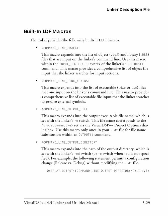
VisualDSP++ 4.5 Linker and Utilities Manual 3-29
Linker Description File
Built-In LDF MacrosThe linker provides the following built-in LDF macros.
• $COMMAND_LINE_OBJECTS
This macro expands into the list of object (.doj) and library (.DLB) files that are input on the linker’s command line. Use this macro within the INPUT_SECTIONS() syntax of the linker’s SECTIONS{} command. This macro provides a comprehensive list of object file input that the linker searches for input sections.
• $COMMAND_LINE_LINK_AGAINST
This macro expands into the list of executable (.dxe or .sm) files that one input on the linker’s command line. This macro provides a comprehensive list of executable file input that the linker searches to resolve external symbols.
• $COMMAND_LINE_OUTPUT_FILE
This macro expands into the output executable file name, which is set with the linker’s -o switch. This file name corresponds to the <projectname.dxe> set via the VisualDSP++ Project Options dia-log box. Use this macro only once in your .ldf file for file name substitution within an OUTPUT() command.
• $COMMAND_LINE_OUTPUT_DIRECTORY
This macro expands into the path of the output directory, which is set with the linker’s -od switch (or -o switch when -od is not speci-fied). For example, the following statement permits a configuration change (Release vs. Debug) without modifying the .ldf file.
OVERLAY_OUTPUT($COMMAND_LINE_OUTPUT_DIRECTORY\OVL1.ovl)

LDF Macros
3-30 VisualDSP++ 4.5 Linker and Utilities Manual
• $ADI_DSP
This macro expands into the path of the VisualDSP++ installation directory. Use this macro to control how the linker searches for files.
User-Declared MacrosThe linker supports user-declared macros for file lists. The following syn-tax declares $macroname as a comma-delimited list of files.
$macroname = file1, file2, file3, ... ;
After $macroname has been declared, the linker substitutes the file list when $macroname appears in the .ldf file. Terminate a $macroname decla-ration with a semicolon. The linker processes the files in the listed order.
LDF Macros and Command-Line InteractionThe linker receives commands through a command-line interface, regard-less of whether the linker runs automatically from the VisualDSP++ IDDE or explicitly from a command window. Many linker operations, such as input and output, are controlled through the command-line entries. Use LDF macros to apply command-line inputs within the LDF.
Base your decision on whether to use command-line inputs in the .ldf file or to control the linker with LDF code on the following considerations.
• An .ldf file that uses command-line inputs produces a more generic LDF that can be used in multiple projects. Because the command line can specify only one output, an .ldf file that relies on command-line input is best suited for single-processor systems.
• An .ldf file that does not use command-line inputs produces a more specific LDF that can control complex linker features.

VisualDSP++ 4.5 Linker and Utilities Manual 3-31
Linker Description File
LDF CommandsCommands in the .ldf file (called LDF commands) define the target sys-tem and specify the order in which the linker processes output for that system. LDF commands operate within a scope, influencing the operation of other commands that appear within the range of that scope. For more information, see “Command Scoping” on page 3-18.
The linker supports the use of wildcards in section name specifica-tions in the .ldf file. The * and ? are provided on input section names.
The linker supports these LDF commands (not all commands are used with specific processors):
• “ALIGN()” on page 3-32
• “ARCHITECTURE()” on page 3-32
• “ELIMINATE()” on page 3-33
• “ELIMINATE_SECTIONS()” on page 3-34
• “INCLUDE()” on page 3-35
• “INPUT_SECTION_ALIGN()” on page 3-35
• “KEEP()” on page 3-36
• “KEEP_SECTIONS()” on page 3-37
• “LINK_AGAINST()” on page 3-37
• “MEMORY{}” on page 3-38
• “MPMEMORY{}” on page 3-42
• “OVERLAY_GROUP{}” on page 3-42

LDF Commands
3-32 VisualDSP++ 4.5 Linker and Utilities Manual
• “PACKING()” on page 3-42
• “PLIT{}” on page 3-48
• “PROCESSOR{}” on page 3-48
• “RESERVE()” on page 3-50
• “RESERVE_EXPAND()” on page 3-53
• “RESOLVE()” on page 3-53
• “SEARCH_DIR()” on page 3-54
• “SECTIONS{}” on page 3-55
• “SHARED_MEMORY{}” on page 3-65
ALIGN()The ALIGN(number) command aligns the address of the current location counter to the next address that is a multiple of number, where number is a power of 2. The number is a word boundary (address) that depends on the word size of the memory segment in which the ALIGN() takes action.
ARCHITECTURE()The ARCHITECTURE() command specifies the target system’s processor. An .ldf file may contain one ARCHITECTURE() command only. The ARCHITECTURE() command must appear with global LDF scope, applying to the entire .ldf file.
The command’s syntax is:
ARCHITECTURE(processor)
The ARCHITECTURE() command is case sensitive. For example, a valid entry is ADSP-BF533. Thus, ADSP-BF533 is valid, but adsp-BF533 is not.
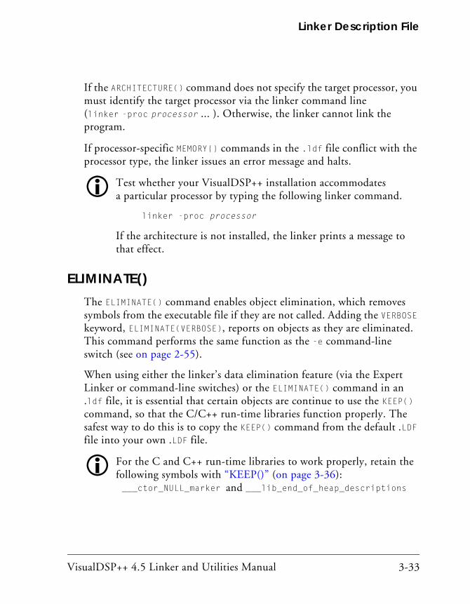
VisualDSP++ 4.5 Linker and Utilities Manual 3-33
Linker Description File
If the ARCHITECTURE() command does not specify the target processor, you must identify the target processor via the linker command line (linker -proc processor ... ). Otherwise, the linker cannot link the program.
If processor-specific MEMORY{} commands in the .ldf file conflict with the processor type, the linker issues an error message and halts.
Test whether your VisualDSP++ installation accommodates a particular processor by typing the following linker command.
linker -proc processor
If the architecture is not installed, the linker prints a message to that effect.
ELIMINATE()The ELIMINATE() command enables object elimination, which removes symbols from the executable file if they are not called. Adding the VERBOSE keyword, ELIMINATE(VERBOSE), reports on objects as they are eliminated. This command performs the same function as the -e command-line switch (see on page 2-55).
When using either the linker’s data elimination feature (via the Expert Linker or command-line switches) or the ELIMINATE() command in an .ldf file, it is essential that certain objects are continue to use the KEEP() command, so that the C/C++ run-time libraries function properly. The safest way to do this is to copy the KEEP() command from the default .LDF file into your own .LDF file.
For the C and C++ run-time libraries to work properly, retain the following symbols with “KEEP()” (on page 3-36): ___ctor_NULL_marker and ___lib_end_of_heap_descriptions

LDF Commands
3-34 VisualDSP++ 4.5 Linker and Utilities Manual
In order to allow efficient elimination, the structure of the assembly source has to be such that the linker can unambiguously identify the boundaries of each “source object” in the input section (a “source object” is a function or a data item). Specifically, an input section must be fully covered by non-overlapping source objects with explicit boundaries. The boundary of a function item is specified by the function label and its cor-responding “.end” label. If an input section layout does not conform to the rule described above, no elimination is performed in the section. See the VisualDSP++ 4.5 Assembler and Preprocessor Manual for more details on using “.end” labels.
ELIMINATE_SECTIONS()The ELIMINATE_SECTIONS(sectionList) command instructs the linker to remove unreferenced code and data from listed sections only.
The sectionList is a comma-delimited list of input sections. Both this LDF command and the linker’s -es command-line switch (on page 2-55) may be used to specify sections where unreferenced code and data should be eliminated.
ENTRY()The ENTRY(symbol) command specifies the entry address. The entry address is usually filled from a global symbol “start” (no underscore), if present. Refer to “Entry Address” on page 2-34 for more information.
Both this LDF command and the linker’s -entry command-line switch (on page 2-56) may be used to specify the entry address.

VisualDSP++ 4.5 Linker and Utilities Manual 3-35
Linker Description File
INCLUDE()The INCLUDE() command specifies additional .ldf files that the linker processes before processing the remainder of the current LDF. Specify any number of additional .ldf files. Supply one file name per INCLUDE() command.
Only one of these additional .ldf files is obligated to specify a target architecture. Normally, the top-level .ldf file includes the other .ldf files.
INPUT_SECTION_ALIGN()The INPUT_SECTION_ALIGN(number) command aligns each input section (data or instruction) in an output section to an address satisfying number. The number argument, which must be a power of 2, is a word boundary (address). Valid values for number depend on the word size of the memory segment receiving the output section being aligned.
The linker fills empty spaces created by INPUT_SECTION_ALIGN() com-mands with zeros (by default), or with the value specified with the preceding FILL command valid for the current scope. See FILL under “SECTIONS{}” on page 3-55.
The INPUT_SECTION_ALIGN() command is valid only within the scope of an output section. For more information, see “Command Scoping” on page 3-18. For more information on output sections, see the syntax description for “SECTIONS{}” on page 3-55.
Example:In the following Blackfin example, input sections from a.doj, b.doj, and c.doj are aligned on even addresses. Input sections from d.doj and e.doj are not quad-word aligned because INPUT_SECTION_ALIGN(1) indicates subsequent sections are not subject to input section alignment.
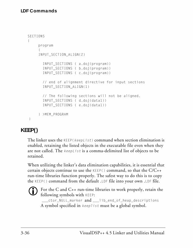
LDF Commands
3-36 VisualDSP++ 4.5 Linker and Utilities Manual
SECTIONS{ program { INPUT_SECTION_ALIGN(2) INPUT_SECTIONS ( a.doj(program)) INPUT_SECTIONS ( b.doj(program)) INPUT_SECTIONS ( c.doj(program))
// end of alignment directive for input sections INPUT_SECTION_ALIGN(1)
// The following sections will not be aligned. INPUT_SECTIONS ( d.doj(data1)) INPUT_SECTIONS ( e.doj(data1))
} >MEM_PROGRAM }
KEEP()The linker uses the KEEP(keepList) command when section elimination is enabled, retaining the listed objects in the executable file even when they are not called. The keepList is a comma-delimited list of objects to be retained.
When utilizing the linker’s data elimination capabilities, it is essential that certain objects continue to use the KEEP() command, so that the C/C++ run-time libraries function properly. The safest way to do this is to copy the KEEP() command from the default .LDF file into your own .LDF file.
For the C and C++ run-time libraries to work properly, retain the following symbols with KEEP: ___ctor_NULL_marker and ___lib_end_of_heap_descriptions A symbol specified in keeplist must be a global symbol.

VisualDSP++ 4.5 Linker and Utilities Manual 3-37
Linker Description File
KEEP_SECTIONS()The linker uses the KEEP_SECTIONS() command to specify a section name in which elimination should not take place. This command can appear anywhere the ELIMINATE_SECTION command appears. You may either use the KEEP_SECTIONS() command or the -ek linker switch (on page 2-55).
LINK_AGAINST()The LINK_AGAINST() command checks specific executables to resolve vari-ables and labels that have not been resolved locally.
To link programs for multiprocessor systems, you must use the LINK_AGAINST() command in the .ldf file.
This command is an optional part of the PROCESSOR{} and SHARE_MEMORY{} commands. The syntax of the LINK_AGAINST() command (as part of a PROCESSOR{} command) is:
PROCESSOR Pn{ ... LINK_AGAINST (executable_file_names) ...}
where:
• Pn is the processor name; for example, P0 or P1.
• executable_file_names is a list of one or more executable (.dxe) or shared memory (.sm) files. Separate multiple file names with commas. However, Expert Linker allows the use of white spaces to separate multiple file names.
The linker searches the executable files in the order specified in the LINK_AGAINST() command. When a symbol’s definition is found, the linker stops searching. Override the search order for a specific variable or label by using the RESOLVE() command (see “RESOLVE()” on page 3-53),
LDF Commands
3-38 VisualDSP++ 4.5 Linker and Utilities Manual
which directs the linker to use the specified resolver, thus ignoring LINK_AGAINST() for a specific symbol. The LINK_AGAINST() command for other symbols still applies.
MAP()The MAP(filename) command outputs a map (.xml) file with the specified name. You must supply a file name. Place this command anywhere in the LDF.
The MAP(filename) command corresponds to and may be overridden by the linker’s -Map <filename> command-line switch (on page 2-53). In VisualDSP++, if project options (Link tab of the Project Options dialog box) specify the generation of a symbol map, the linker runs with -Map <projectname>.xml asserted and the LDF’s MAP() command generates a warning.
MEMORY{}The MEMORY{} command specifies the memory map for the target system. After declaring memory segment names with this command, use the mem-ory segment names to place program sections via the SECTIONS{} command.
The LDF must contain a MEMORY{} command for global memory on the target system and may contain a MEMORY{} command that applies to each processor’s scope. There is no limit to the number of memory segments you can declare within each MEMORY{} command. For more information, see “Command Scoping” on page 3-18.
In each scope scenario, follow the MEMORY{} command with a SECTIONS{} command. Use the memory segment names to place program sections. Only memory segment declarations may appear within the MEMORY{} com-mand. There is no limit to section name lengths.

VisualDSP++ 4.5 Linker and Utilities Manual 3-39
Linker Description File
If you do not specify the target processor’s memory map with the MEMORY{} command, the linker cannot link your program. If the combined sections directed to a memory segment require more space than exists in the segment, the linker issues an error message and halts the link.
The syntax for the MEMORY{} command appears in Figure 3-2, followed by a description of each part of a segment declaration.
Segment Declarations
A segment declaration declares a memory segment on the target proces-sor. Although an .ldf file may contain only one MEMORY{} command that applies to all scopes, there is no limit to the number of memory segments declared within a MEMORY{} command.
Each segment declaration must contain a segment_name, TYPE(), START(), LENGTH() or END(), and a WIDTH(). Parts of a segment declaration are described below.
Figure 3-2. MEMORY{} Command Syntax Tree
segment_name {
TYPE(RAM | ROM)
START(address_expression)
LENGTH(length_expression) | END(address_expression)
WIDTH(width_expression)
}
MEMORY{segment_commands}
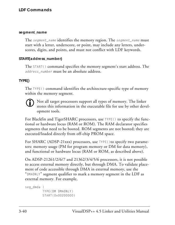
LDF Commands
3-40 VisualDSP++ 4.5 Linker and Utilities Manual
segment_name
The segment_name identifies the memory region. The segment_name must start with a letter, underscore, or point, may include any letters, under-scores, digits, and points, and must not conflict with LDF keywords.
START(address_number)
The START() command specifies the memory segment’s start address. The address_number must be an absolute address.
TYPE()
The TYPE() command identifies the architecture-specific type of memory within the memory segment.
Not all target processors support all types of memory. The linker stores this information in the executable file for use by other devel-opment tools.
For Blackfin and TigerSHARC processors, use TYPE() to specify the func-tional or hardware locus (RAM or ROM). The RAM declarator specifies segments that need to be booted. ROM segments are not booted; they are executed/loaded directly from off-chip PROM space.
For SHARC (ADSP-21xxx) processors, use TYPE()to specify two parame-ters: memory usage (PM for program memory or DM for data memory), and functional or hardware locus (RAM or ROM, as described above).
On ADSP-21261/2/6/7 and 21362/3/4/5/6 processors, it is not possible to access external memory directly, but through DMA. To validate place-ment of code accessible through DMA in external memory, use the “DMAONLY” segment qualifier to mark a memory segment in the LDF as external memory. For example,
seg_dmda { TYPE(DM DMAONLY) START(0x00200000)

VisualDSP++ 4.5 Linker and Utilities Manual 3-41
Linker Description File
END(0x3FFFFFFF) WIDTH(32) }<…>seg_dmda{INPUT_SECTIONS( $OBJECTS(seg_extm) )} > seg_dmda
The linker identifies the section as “dmaonly”. At link time, the linker ver-ifies that the section must reside in external memory identified with the “DMAONLY” qualifier. More importantly, the linker checks that only sec-tions marked “dmaonly” are placed in external memory. The linker issues an error if there is any inconsistency between memory the section is mapped to and that section’s qualifier:
[Error el2017] Invalid/missing memory qualifier for memory 'sec-
tion name.
LENGTH(length_number)/END(address_number)
The LENGTH/END() command identifies the length of the memory segment (in words) or specifies the segment’s end address. When you state the length, length_number is the number of addressable words within the region or an expression that evaluates to the number of words. When you state the end address, address_number is an absolute address.
WIDTH(width_number)
The WIDTH() command specifies the physical width (number of bits) of the on-chip or off-chip memory interface. The width_number parameter must be a whole number.
For Blackfin processors, width must be 8 (bits) for TigerSHARC processors, width must be 32 (bits); and for SHARC processors, width may be 8, 16, 32, 48 or 64 (bits).

LDF Commands
3-42 VisualDSP++ 4.5 Linker and Utilities Manual
MPMEMORY{}The MPMEMORY{} command specifies the offset of each processor’s physical memory in a multiprocessor target system. After you declare the processor names and memory segment offsets with the MPMEMORY{} command, the linker uses the offsets during multiprocessor linking.
Refer to “MPMEMORY{}” on page 5-44 for a detailed description of the MPMEMORY{} command.
OVERLAY_GROUP{}The OVERLAY_GROUP{} command is deprecated. This command provides support for defining a set of overlays that share a block of run-time memory.
For detailed command description, refer to “OVERLAY_GROUP{}” on page 5-29. Refer to “Memory Management Using Overlays” on page 5-4 for a detailed description of overlay functionality.
PACKING()In VisualDSP++ 4.5, the PACKING() command is used with ADSP-21xxx (SHARC) processors only (as described in “Packing in SHARC Processors” on page 3-44) .
Processors exchange data with their environment (on-chip or off-chip) through several buses. The configuration, placement, and amounts of memory are determined by the application. Specify memory of width(s) and data transfer byte order(s) that suit your needs.
The linker places data in memory according to the constraints imposed by your system’s architecture. The LDF’s PACKING() command specifies the order the linker uses to place bytes in memory. This ordering places data in memory in the sequence the processor uses as it transfers data.
VisualDSP++ 4.5 Linker and Utilities Manual 3-43
Linker Description File
The PACKING() command allows the linker to structure its executable out-put to be consistent with your installation’s memory organization. This command can be applied (scoped) on a segment-by-segment basis within the .ldf file, with adequate granularity to handle heterogeneous memory configurations. Any memory segment requiring more than one packing command may be divided into homogeneous segments.
Syntax
The syntax of the PACKING() command is:
PACKING (number_of_bytes byte_order_list)
where:
• number_of_bytes is an integer specifying the number of bytes to pack (reorder) before repeating the pattern
• byte_order_list is the output byte ordering – what the linker writes into memory. Each list entry consists of “B” followed by the byte’s number (in a group) at the storage medium (memory). The list follows these rules:
• Parameters are whitespace-delimited
• The total number of non-null bytes is number_of_bytes
• If null bytes are included, they are labeled B0
For example, in SHARC processors, the first byte is B1 (not B0). The sec-ond byte is B2, and so on.
PACKING (12 B1 B2 B3 B4 B0 B11 B12 B5 B6 B0 B7 B8 B9 B10 B0)
Non-default use of the PACKING() command reorders bytes in executable files (.dxe, .sm, or .ovl), so they arrive at the target in the correct number, alignment, and sequence. To accomplish this task, the command specifies the size of the reordered group, the byte order within the group, and
LDF Commands
3-44 VisualDSP++ 4.5 Linker and Utilities Manual
whether and where “null” bytes must be inserted to preserve alignment on the target. The term “null” refers to usage – the target ignores a null byte; the linker sets these bytes to zeros.
The order used to place bytes in memory correlates to the order the pro-cessor may use while unpacking the data when the processor transfers data from external memory into its internal memory. The processor’s unpack-ing order can relate to the transfer method.
VisualDSP++ comes with the packing.h file in the ...\include folder. This file provides macros that define packing commands for use in a Linker Description File (.ldf). The macros support vari-ous types of packing for Direct Memory Access functionality (used in overlays) and for direct external execution. To use these macros, place them in an .ldf file’s SECTIONS{} command when a PACKING() command is needed.
Packing in SHARC Processors
On SHARC processors, PACKING() applies to the processor’s external port. Each external port buffer contains data packing logic that allows the pack-ing of 8-, 16-, or 32-bit external bus words into 32- or 48-bit internal words. This logic is fully reversible.
The following information describes how the PACKING() command may apply in an .LDF file for your ADSP-21xxx processor.
In some Direct Memory Access (DMA) modes, SHARC processors unpack three 32-bit words to build two 48-bit instruction words when the processor receives data from 32-bit memory. For example, the unpacked order and storage order (Table 3-4) could apply to a DMA mode.
The order of unpacked bytes does not match the transfer (stored) order. Because the processor uses two bytes per short word, the above transfer translates into the format in Table 3-5.

VisualDSP++ 4.5 Linker and Utilities Manual 3-45
Linker Description File
You specify to the linker how to accommodate processor-specific byte packing (for example, non-sequential byte order) with the PACKING() syn-tax within the OVERLAY_INPUT{} command. The above example’s byte ordering translates into the following PACKING() command syntax, which supports 48-bit to 32-bit packing over the processor’s external port.
PACKING (12 B1 B2 B3 B4 B0 B11 B12 B5 B6 B0 B7 B8 B9 B10 B0)
The above PACKING() syntax places instructions in an overlay stored in a 32-bit external memory, but is unpacked and executed from 48-bit inter-nal memory.
Refer to fft_ovly.fft, which uses a macro that defines the packing. This file is included with the overlay3 example that ships with VisualDSP++.
Table 3-4. DMA Packing Order
Transfer Order (from storage in a 32-bit external memory)
Unpacked Order Two 48-bit internal words (after the third transfer)
B1 and B2 (word 1, bits 47-32) B3 and B4 (word 1, bits 31-16)
B11 and B12 (word 2, bits 15-0) B5 and B6 (word 1, bits 15-0)
B7 and B8 (word 2, bits 47-32) B9 and B10 (word 2, bits 31-16)
B1, B2, B3, B4, B5, B6 (word 1, bits 47-0) B7, B8, B9, B10, B11, B12 (word 2, bits 47-0)
Table 3-5. Storage Order vs. Unpacked Order
Storage Order (in 32-bit external memory)
Unpacked Order (two 48-bit internal words)
B1, B2, B3, B4, B11, B12 B5, B6, B7, B8, B9, B10
B1, B2, B3, B4, B5, B6 B7, B8, B9, B10, B11, B12
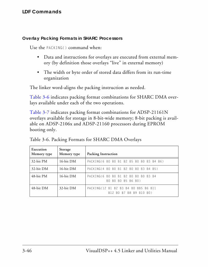
LDF Commands
3-46 VisualDSP++ 4.5 Linker and Utilities Manual
Overlay Packing Formats in SHARC Processors
Use the PACKING() command when:
• Data and instructions for overlays are executed from external mem-ory (by definition those overlays “live” in external memory)
• The width or byte order of stored data differs from its run-time organization
The linker word-aligns the packing instruction as needed.
Table 3-6 indicates packing format combinations for SHARC DMA over-lays available under each of the two operations.
Table 3-7 indicates packing format combinations for ADSP-21161N overlays available for storage in 8-bit-wide memory; 8-bit packing is avail-able on ADSP-2106x and ADSP-21160 processors during EPROM booting only.
Table 3-6. Packing Formats for SHARC DMA Overlays
Execution Memory type
Storage Memory type
Packing Instruction
32-bit PM 16-bit DM PACKING(6 B0 B0 B1 B2 B5 B0 B0 B3 B4 B6)
32-bit DM 16-bit DM PACKING(4 B0 B0 B1 B2 B0 B0 B3 B4 B5)
48-bit PM 16-bit DM PACKING(6 B0 B0 B1 B2 B0 B0 B0 B3 B4 B0 B0 B0 B5 B6 B0)
48-bit DM 32-bit DM PACKING(12 B1 B2 B3 B4 B0 BB5 B6 B11 B12 B0 B7 B8 B9 B10 B0)

VisualDSP++ 4.5 Linker and Utilities Manual 3-47
Linker Description File
External Execution Packing in SHARC Processors
The only two processors that require packed memory for external execu-tion are the ADSP-21161N and the ADSP-21065L chips. The ADSP-21161N processor supports 48-, 32-, 16-, and 8-bit-wide external memory. The ADSP-21065L processor supports 32-bit external memory only.
Previous to VisualDSP++ 3.5, it was required to use “packing” commands in the .ldf file to cause the code to be placed properly. In VisualDSP++ 3.5 and latter releases, the VisualDSP++ tools are enhanced to perform packing automatically.
In order for the VisualDSP++ tools to execute packing directly from exter-nal memory on ADSP-21065L and ADSP-21161N processors, the tools “pack” the code into the external memory providing the following condi-tions are met:
1. Ensure the “type” of the external memory is PM (Program Memory)
2. Ensure the data width matches the “real/actual” memory width: ADSP-21065L processor – 32 bits; ADSP-21161N processor – 48, 32, 16 and 8 bits
Table 3-7. Additional Packing Formats for DMA Overlays
Execution Memory type
Storage Memory type
Packing Instruction
48-bit PM 8-bit DM PACKING(6 B0 B0 B0 B1 B0 B0 B0 B2 B0 B0 B0 B3 B0 B0 B0 B0 B4 B0 B0 B0 B0 B5 B0 B0 B0 B0 B6 B0 B0 B0 B0 B0 B0 B0 B0 B0 B0 B0)
32-bit DM 8-bit DM PACKING(4 B0 B0 B0 B1 B0 B0 B0 B0 B2 B0 B0 B0 B0 B3 B0 B0 B0 B0 B4 B0)
16-bit DM 8-bit DM PACKING(2 B0 B0 B0 B1 B0 B0 B0 B0 B2 B0)

LDF Commands
3-48 VisualDSP++ 4.5 Linker and Utilities Manual
3. If the .ldf file has the PACKING() command for the particular sec-tion, remove the command.
When defining memory segments (required for external memory), the “type” of a memory section is recommended to be:
• PM – code or 40-bit data (data requires PX register to access)
• DM – all other sections
Width should be the “actual/physical” width of the external memory.
PLIT{}The PLIT{} (procedure linkage table) command in an .ldf file inserts assembly instructions that handle calls to functions in overlays. The PLIT{} commands provide a template from which the linker generates assembly code when a symbol resolves to a function in overlay memory.
Refer to “PLIT{}” on page 5-33 for a detailed description of the PLIT{} command. Refer to “Memory Management Using Overlays” on page 5-4 for a detailed description of overlay and PLIT functionality.
PROCESSOR{}The PROCESSOR{} command declares a processor and its related link infor-mation. A PROCESSOR{} command contains the MEMORY{}, SECTIONS{}, RESOLVE{}, and other linker commands that apply only to that specific processor.
The linker produces one executable file from each PROCESSOR{} command. If you do not specify the type of link with a PROCESSOR{} command, the linker cannot link your program.
The syntax for the PROCESSOR{} command appears in Figure 3-3.
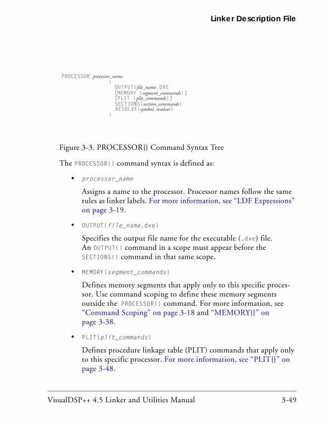
VisualDSP++ 4.5 Linker and Utilities Manual 3-49
Linker Description File
The PROCESSOR{} command syntax is defined as:
• processor_name
Assigns a name to the processor. Processor names follow the same rules as linker labels. For more information, see “LDF Expressions” on page 3-19.
• OUTPUT(file_name.dxe)
Specifies the output file name for the executable (.dxe) file. An OUTPUT() command in a scope must appear before the SECTIONS{} command in that same scope.
• MEMORY{segment_commands}
Defines memory segments that apply only to this specific proces-sor. Use command scoping to define these memory segments outside the PROCESSOR{} command. For more information, see “Command Scoping” on page 3-18 and “MEMORY{}” on page 3-38.
• PLIT{plit_commands}
Defines procedure linkage table (PLIT) commands that apply only to this specific processor. For more information, see “PLIT{}” on page 3-48.
Figure 3-3. PROCESSOR{} Command Syntax Tree
PROCESSOR processor_name{OUTPUT(file_name.DXE[MEMORY {segment_commands}][PLIT {plit_commands}]SECTIONS{section_commands}RESOLVE(symbol, resolver)
}

LDF Commands
3-50 VisualDSP++ 4.5 Linker and Utilities Manual
• SECTIONS{section_commands}
Defines sections for placement within the executable (.dxe) file. For more information, see “SECTIONS{}” on page 3-55.
• RESOLVE{symbol, resolver}
Ignores any LINK_AGAINST() command. For details, see the “RESOLVE()” command.
Multiprocessor/Multicore Applications The PROCESSOR{} command may be used in linking projects on multipro-cessor/multicore Blackfin architectures such as the ADSP-BF561 processor. For example, the command syntax for two-processor system is as follows:
PROCESSOR p0 { ... } PROCESSOR p1 { }
See also “LINK_AGAINST()” on page 3-37, “MPMEMORY{}” on page 5-44, “COMMON_MEMORY{}” on page 5-51, and “SHARED_MEMORY{}” on page 5-45.
RESERVE()The RESERVE (start_symbol, length_symbol, min_size [,align]) command allocates address space and defines symbols start_symbol and length_symbol. The command allocates the largest free memory block available, larger than or equal to min_size. Given an optional parameter align, RESERVE allocates aligned address space.
Input:
• The min_size parameter defines a required minimum size of mem-ory to allocate.

VisualDSP++ 4.5 Linker and Utilities Manual 3-51
Linker Description File
• The align parameter is optional and defines alignment of allocated address space.
Output:
• The start_symbol is assigned the starting address of the allocated address space.
• The length_symbol is assigned the size of the allocated address space.
A user may restrict the command by defining the start and length sym-bols together or individually. For example,
RESERVE (start_symbol = address, length_symbol, min_size)
RESERVE (start_symbol = address, length_symbol = size)
RESERVE (start_symbol, length_symbol = size [,align])
The RESERVE() command is valid only within the scope of an output sec-tion. For more information on output sections, see “Command Scoping” on page 3-18 and “SECTIONS{}” on page 3-55. Also see “RESERVE_EXPAND()” on page 3-53 for more information on how to claim any unused memory after input sections have been mapped.
Linker Error Resolutions
Linker error li1224: When a user defines length_symbol, the min_size parameter is redundant and not included in the command. When a user defines start_symbol, the align parameter is redundant and not included in the command.
Linker errors li1221, li1222, li1223: When user defines start_symbol = address, the align parameter is redundant and should not be included in the command.
LDF Commands
3-52 VisualDSP++ 4.5 Linker and Utilities Manual
When user defines align parameter, length_symbol or min_size parame-ter should be divisible by align; the align parameter must be a power of 2.
Given the start_symbol is not restricted (not defined), RESERVE allocates address space, starting from a segment end address.
Example
Consider an example where given memory segment [0 - 8]. Range [0 - 2] is used by an input section. To allocate address space of minimum size 4 and aligned by 2, the RESERVE command has minimum length require-ment of 4 and alignment 2.
M0 {START(0), END(8), WIDTH(1)}
out{… RESERVE(start, length, 4, 2) } >M0
1. Allocate 4 words {5, 6, 7, 8},
start = 5
length = 4
2. To satisfy alignment by 2, allocate address space {4, 5, 6, 7, 8}
start = 4
length = 5
3. Consider length exactly 4 (not minimum 4). Allocated address space is {4, 5, 6, 7}. Address [8] is freed.
start = 4
length = 4

VisualDSP++ 4.5 Linker and Utilities Manual 3-53
Linker Description File
RESERVE_EXPAND()The RESERVE_EXPAND(start_symbol, length_symbol, min_size) com-mand may be applied following RESERVE command and is used to define same symbols as RESERVE. Ordinarily, RESERVE_EXPAND is specified last in an output section to claim any unused memory after input sections have been mapped. RESERVE_EXPAND attempts to allocate memory adjacent to the range allocated by RESERVE. Accordingly, start_symbol and length_symbol are redefined to include expanded address range. Refer to “RESERVE()” on page 3-50 for more information.
RESOLVE()Use the RESOLVE(symbol_name, resolver) command to ignore a LINK_AGAINST() command for a specific symbol. This command overrides the search order for a specific variable or label. Refer to the “LINK_AGAINST()” on page 3-37 for more information.
The RESOLVE(symbol_name, resolver) command uses the resolver to specify an address of a particular symbol (variable or label). The resolver is an absolute address or a file (.dxe or .sm) that contains the definition of the symbol.
For example,
RESOLVE(start, 0xFFA00000)
If the symbol is not located in the designated file, an error is issued.

LDF Commands
3-54 VisualDSP++ 4.5 Linker and Utilities Manual
For the RESOLVE(symbol_name, resolver) command:
• When the symbol is not defined in the current processor scope, the <resolver> supplies a file name, overriding any LINK_AGAINST().
• When the symbol is defined in the current processor scope, the <resolver> supplies to the linker the symbol location address.
Resolve a C variable by prefixing the variable with an underscore in the RESOLVE() command (for example, _symbol_name).
SEARCH_DIR()The SEARCH_DIR() command specifies one or more directories that the linker searches for input files. Specify multiple directories within a SEARCH_DIR command by delimiting each path with a semicolon (;). On Windows, enclose long directory names with embedded spaces within straight quotes.
The search order follows the order of the listed directories. This command appends search directories to the directory selected with the linker’s -L command-line switch (on page 2-52). Place this command at the begin-ning of the .LDF file to ensure that the linker applies the command to all file searches.
Example
ARCHITECTURE (ADSP-Blackfin) MAP (SINGLE-PROCESSOR.XML) // Generate a MAP file
SEARCH_DIR( $ADI_DSP/Blackfin/lib; ABC/XYZ ) // $ADI_DSP is a predefined linker macro that expands // to the VisualDSP++ install directory. Search for objects // in directory Blackfin/lib relative to the install directory // and to the ABC/XYZ directory.
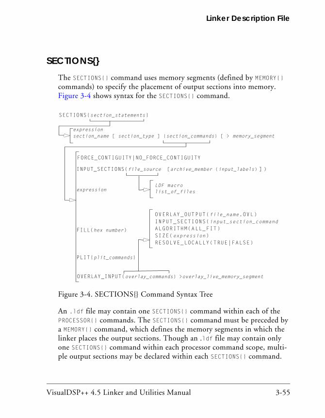
VisualDSP++ 4.5 Linker and Utilities Manual 3-55
Linker Description File
SECTIONS{}The SECTIONS{} command uses memory segments (defined by MEMORY{} commands) to specify the placement of output sections into memory. Figure 3-4 shows syntax for the SECTIONS{} command.
An .ldf file may contain one SECTIONS{} command within each of the PROCESSOR{} commands. The SECTIONS{} command must be preceded by a MEMORY{} command, which defines the memory segments in which the linker places the output sections. Though an .ldf file may contain only one SECTIONS{} command within each processor command scope, multi-ple output sections may be declared within each SECTIONS{} command.
Figure 3-4. SECTIONS{} Command Syntax Tree
INPUT_SECTIONS(file_source [archive_member (input_labels) ] )
expression
FILL(hex number)
OVERLAY_INPUT(overlay_commands) >overlay_live_memory_segment
OVERLAY_OUTPUT(file_name.OVL)INPUT_SECTIONS(input_section_commandALGORITHM(ALL_FIT)SIZE(expression)RESOLVE_LOCALLY(TRUE|FALSE)
PLIT{plit_commands}
LDF macrolist_of_files
SECTIONS{section_statements}
expressionsection_name [ section_type ] {section_commands} [ > memory_segment ]
FORCE_CONTIGUITY|NO_FORCE_CONTIGUITY
LDF Commands
3-56 VisualDSP++ 4.5 Linker and Utilities Manual
The SECTIONS{} command’s syntax includes several arguments.
expressions or section_declarations
Use expressions to manipulate symbols or to position the current loca-tion counter. Refer to “LDF Expressions” on page 3-19.
Use a section_declaration to declare an output section. Each section_declaration has a section_name, optional section_type, section_commands, and a memory_segment.
Parts of a SECTION declaration are:
• section_name Starts with a letter, underscore, or period and may include any let-ters, underscores, digits, and points. A section_name must not conflict with any LDF keywords.
The special section name .PLIT indicates the procedure linkage table (PLIT) section that the linker generates when resolving sym-bols in overlay memory. Place this section in non-overlay memory to manage references to items in overlay memory.
The special section name .MEMINIT indicates where to place the “run-time” initialization structures used by the C run-time library. The linker “places” this section into the largest available unused memory at the specified memory segment. The memory initializa-tion post-process fills this space with the data needed by the C RTL for run-time initialization. The .MEMINIT section should be placed in non-overlay memory. See “Memory Initializer” for more information.
• init_qualifier Specifies run-time initialization type (optional).

VisualDSP++ 4.5 Linker and Utilities Manual 3-57
Linker Description File
The qualifiers are:
• NO_INIT – Contains un-initialized data. There is no data stored in the .DXE file for this section (equivalent to SHT_NOBITS legacy qualifier).
• ZERO_INIT – Contains only “zero-initialized” data. If invoked with the -meminit switch (on page 2-58), the “zeroing” of the section is done at runtime by the C run-time library. If -meminit is not specified, the “zeroing” is done at “load” time.
• RUNTIME_INIT – If the linker is invoked with the -meminit switch, this section fills at runtime. If -meminit is not spec-ified, the section fills at “load” time.
• section_commands May consist of any combination of such commands and/or expres-sions, such as:
“INPUT_SECTIONS()” on page 3-58 “expression” on page 3-62 “FILL(hex number)” on page 3-63 “PLIT{plit_commands}” on page 3-63 “OVERLAY_INPUT{overlay_commands}” on page 3-63
• memory_segment Declares that the output section is placed in the specified memory segment.
The memory_segment is optional. Some sections, such as those for debugging, need not be included in the memory image of the exe-cutable file, but are needed for other development tools that read the executable file.

LDF Commands
3-58 VisualDSP++ 4.5 Linker and Utilities Manual
By omitting a memory segment assignment for a section, you direct the linker to generate the section in the executable, but prevent sec-tion content from appearing in the memory image of the executable file.
INPUT_SECTIONS()
The INPUT_SECTIONS() portion of a section_command identifies the parts of the program to place in the executable file. When placing an input sec-tion, you must specify the file_source. Optionally, you could also specify a filterexpr. When file_source is a library, specify the input section’s archive_member and input_labels.
The command syntax is:
INPUT_SECTIONS(library.dlb [ member.doj (input_label) ])
Note that spaces are significant in this syntax.
In the INPUT_SECTIONS() of the LDF command:
• file_source may be a list of files or an LDF macro that expands into a file list, such as $COMMAND_LINE_OBJECTS. Delimit the list of object files or library files with commas.
• archive_member names the source-object file within a library. The archive_member parameter and the left/right brackets ([ ]) are required when the file_source of the input_label is a library.
• input_labels are derived from run-time .SECTION names in assem-bly programs (for example, program). Delimit the list of names with commas.
Example
To place section “program” of object “foo.doj” in library “myLib.dlb”:
INPUT_SECTIONS(myLib.dlb [ foo.doj (program) ])

VisualDSP++ 4.5 Linker and Utilities Manual 3-59
Linker Description File
Using Optional Filter Expression
The filter operation is done with curly braces, and can be used to define sub-lists and sub-libraries. It can be used for linking with attributes.
INPUT_SECTIONS( $FILES { expr } (program) )
The optional filter expr is a Boolean expression that may contain:
Attribute operators:
• name returns true if the object has one or more attributes called name, regardless of value. Otherwise, returns false.
• name("string") returns true if the attribute name has a value that matches string. The comparison is case-sensitive string. This oper-ator may be used on multi-valued attributes. Note that string must be quoted.
• name cmp-op "string" returns true if the attribute name has a single value that matches string, according to cmp-op. Otherwise, returns false. Cmp-op can be “==” or “!=”, for equality and inequal-ity, via case-sensitive string comparison. Note that string must be quoted. This operator may only be used on sin-gle-valued attributes. If the attribute does not have exactly one value, the linker generates an error.
• name cmp-op number returns true if the attribute name has a single value that numerically matches integer number (which can be nega-tive). Otherwise, returns false. Cmp-op can be “==”, “!=”, “<“, “<=”, “>” or “>=”. This operator may only be used on single-valued attributes. If the attribute does not have exactly one value, the linker generates an error.
LDF Commands
3-60 VisualDSP++ 4.5 Linker and Utilities Manual
Logical operators: “&&”, “||” and “!”, having the usual C meanings and precedence.
Parentheses, for grouping: “(" and “)”
Example:
$OBJS_1_and_2 = $OBJS {attr1 && attr2 };
$OBJS_3_and_2 = $OBJS { attr3("value3") && attr2 == "value2" };
Outsec {
INPUT_SECTIONS($OBJS_1_and_2(program))
INPUT_SECTIONS($OBJS_3_and_2(program))
INPUT_SECTIONS($OBJS_2 { attr2 } (program))
} >mem
INPUT_SECTIONS_PIN/INPUT_SECTIONS_PIN_EXCLUSIVE Com-mands
The INPUT_SECTIONS_PIN/INPUT_SECTIONS_PIN_EXCLUSIVE commands are used to allow mapping of an input section in one of several output sec-tions, as in “one input section to many output section” linker feature. For example,
os_mem1 { INPUT_SECTIONS($OBJECTS(program))} > mem1 os_mem2 { INPUT_SECTIONS($OBJECTS(program))} > mem2
In the above example, if some of the input sections included in $OBJECTS(program) do not fit in os_mem1, the linker will try to map them into os_mem2.
VisualDSP++ 4.5 Linker and Utilities Manual 3-61
Linker Description File
An input section listed in an INPUT_SECTIONS_PIN() command will not be mapped by any INPUT_SECTIONS commands that appear later in the LDF, and an input section listed in INPUT_SECTIONS_PIN_EXCLUSIVE com-mand(s) will not be mapped by any other INPUT_SECTIONS command.
Each time an input sections is mentioned in an INPUT_SECTIONS com-mand, the linker is instructed to "give another chance" to the input section by trying to map it in different output section (given the section has not been already mapped), thus achieving the effect of “one-to-many” mapping.
The INPUT_SECTIONS_PIN() and INPUT_SECTIONS_PIN_EXCLUSIVE() com-mands limit the effect of “one-to-many” mapping – once the input section is mentioned inside INPUT_SECTIONS_PIN(), the linker will not map it in any of the following output sections; an input section mentioned inside INPUT_SECTIONS_PIN_EXCLUSIVE() command can not be mapped in any other output section.
The commands help to avoid breaking existing LDF macros. To achieve the same affect without using INPUT_SECTIONS_PIN and INPUT_SECTIONS_PIN_EXCLUSIVE commands, the definition of the output sections would have be:
os_mem1 {
INPUT_SECTIONS(b.doj(program))
INPUT_SECTIONS(c.doj(program) d.doj(program))
} > mem1
os_mem2 {
INPUT_SECTIONS(c.doj(program) d.doj(program))
INPUT_SECTIONS(a.doj(program))
} > mem2
Please note that without the use of general LDF macros and INPUT_SECTIONS_PIN commands, the LDF will have to change every time the list of objects changes.

LDF Commands
3-62 VisualDSP++ 4.5 Linker and Utilities Manual
If the same section is mentioned in more than one of INPUT_SECTIONS_PIN() commands, linker will honor the first command only.
In conjunction with attribute expressions, the commands can be used to control the order of input section placement without explicitly mention-ing the object files.
os_internal { INPUT_SECTIONS_PIN($OBJECTS{high_priority}(program)) INPUT_SECTIONS($OBJECTS(program))} > mem_internal os_external { INPUT_SECTIONS($OBJECTS(program)) INPUT_SECTIONS_EXCLUSIVE($OBJECTS{low_priority}(program))} > mem_external
In the above example:
• “program” input sections from input files marked with “high_priority” attribute can be mapped to “mem_internal” only
• “program” input sections from input files marked with “low_priority” attribute can be mapped to “mem_external” only
• all other “program” input section can be mapped to either “mem_internal” or “mem_external”
expression
In a section_command, an expression manipulates symbols or positions the current location counter. See “LDF Expressions” on page 3-19 for details.
VisualDSP++ 4.5 Linker and Utilities Manual 3-63
Linker Description File
FILL(hex number)
In a section_command, the FILL() command fills gaps (created by aligning or advancing the current location counter) with hexadecimal numbers.
The FILL() command is used only within a section declaration.
By default, the linker fills gaps with zeros. Specify only one FILL() com-mand per output section. For example,
FILL (0x0) or FILL (0xFFFF)
PLIT{plit_commands}
In a section_command, a PLIT{} command declares a locally-scoped pro-cedure linkage table (PLIT). It contains its own labels and expressions. For more information, see “PLIT{}” on page 5-33.
OVERLAY_INPUT{overlay_commands}
In a section_command, OVERLAY_INPUT{} identifies the parts of the pro-gram to place in an overlay executable (.ovl) file. For more information on overlays, see “Memory Management Using Overlays” on page 5-4 and “OVERLAY_GROUP{}” on page 5-29. For overlay code examples, see “Linking for Overlay Memory” on page C-12 and “Linking for Overlay Memory” on page D-14.
The overlay_commands item consists of at least one of the following com-mands: INPUT_SECTIONS(), OVERLAY_ID(), NUMBER_OF_OVERLAYS(), OVERLAY_OUTPUT(), ALGORITHM(), RESOLVE_LOCALLY(), or SIZE().
The overlay_memory_segment item (optional) determines whether the overlay section is placed in an overlay memory segment. Some overlay sec-tions, such as those loaded from a host, do not need to be included in the overlay memory image of the executable file, but are required for other
LDF Commands
3-64 VisualDSP++ 4.5 Linker and Utilities Manual
tools that read the executable file. Omitting an overlay memory segment assignment from a section retains the section in the executable file, but marks the section for exclusion from the overlay memory image of the exe-cutable file.
The overlay_commands portion of an OVERLAY_INPUT{} command follows these rules.
• DEFAULT_OVERLAY() When the DEFAULT_OVERLAY() command is used, the linker initially places the overlay in the run-time space (that is, without running the overlay manager). .
• OVERLAY_OUTPUT() Outputs an overlay (.OVL) file for the overlay with the specified name. The OVERLAY_OUTPUT() in an OVERLAY_INPUT{} command must appear before any INPUT_SECTIONS() for that overlay.
INPUT_SECTIONS() Has the same syntax within an OVERLAY_INPUT{} command as when it appears within an output_section_command, except that a .PLIT section may not be placed in overlay memory. For more information, see “INPUT_SECTIONS()” on page 3-58.
• OVERLAY_ID() Returns the overlay ID.
• NUMBER_OF_OVERLAYS() Returns the number of overlays that the current link generates when the FIRST_FIT or BEST_FIT overlay placement for ALGO-RITHM() is used. Note: Not currently available.
• ALGORITHM() Directs the linker to use the specified overlay linking algorithm. The only currently available linking algorithm is ALL_FIT.

VisualDSP++ 4.5 Linker and Utilities Manual 3-65
Linker Description File
For ALL_FIT, the linker tries to fit all the OVERLAY_INPUT{} into a single overlay that can overlay into the output section’s run-time memory segment. (FIRST_FIT – Not currently available. For FIRST_FIT, the linker splits the input sections listed in OVERLAY_INPUT{} into a set of overlays that can each overlay the output section’s run-time memory segment, according to First-In-First-Out (FIFO) order. (BEST_FIT – Not currently available. For BEST_FIT, the linker splits the input sections listed in OVERLAY_INPUT{} into a set of overlays that can each overlay the output section’s run-time memory segment, but splits these over-lays to optimize memory usage.
• SIZE() Sets an upper limit to the size of the memory that may be occupied by an overlay.
• FORCE_CONTIGUITY Forces contiguous placement of sections. NOFORCE_CONTIGUITY sup-presses a linker warning about non-contiguous placement of sections in the operating system.
SHARED_MEMORY{}The linker can produce two types of executable output—.dxe files and .sm files. A .dxe file runs in a single-processor system’s address space. Shared memory executable (.sm) files reside in the shared memory of a multiprocessor system. The SHARED_MEMORY{} command is used to pro-duce .sm files.
For more information, see “SHARED_MEMORY{}” on page 5-45.

LDF Commands
3-66 VisualDSP++ 4.5 Linker and Utilities Manual
VisualDSP++ 4.5 Linker and Utilities Manual 4-1
4 EXPERT LINKER
The linker (linker) combines object files into a single executable object module. Using the linker, you can create a new Linker Description File (LDF), modify an existing .ldf file, and produce an executable file (files). The linker is described in Chapter 2, “Linker”, of this manual.
The Expert Linker is a graphical tool that simplifies complex tasks such as memory-mapping manipulation, code and data placement, overlay and shared memory creation, and C stack/heap adjustment. This tool comple-ments the existing VisualDSP++ .ldf file format by providing a visualization capability enabling new users to take immediate advantage of the powerful LDF format flexibility.
Graphics in this chapter demonstrate Expert Linker features. Some graphics show features not available to all processor families. Processor-specific features are noted in neighboring text.
This chapter contains:
• “Expert Linker Overview” on page 4-2
• “Launching the Create LDF Wizard” on page 4-4
• “Expert Linker Window Overview” on page 4-11
• “Input Sections Pane” on page 4-13
• “Memory Map Pane” on page 4-19
• “Managing Object Properties” on page 4-54
Expert Linker Overview
4-2 VisualDSP++ 4.5 Linker and Utilities Manual
Expert Linker OverviewExpert Linker is a graphical tool that allows you to:
• Define a target processor’s memory map
• Place a project’s object sections into that memory map
• View how much of the stack or heap has been used after running the DSP program
Expert Linker takes available project information in an .ldf file as input (object files, LDF macros, libraries, and target memory description) and graphically displays it. You can then use drag-and-drop action to arrange the object files in a graphical memory-mapping representation. When you are satisfied with the memory layout, you can generate the executable (.dxe) file via VisualDSP++ project options.
Use default .ldf files that come with VisualDSP++, or use the Expert Linker interactive wizard to create new .ldf files.
When opening Expert Linker in a project that has an existing .LDF file, Expert Linker parses the .ldf file and graphically displays the target’s memory map and the object mappings. The memory map displays in the Expert Linker window (Figure 4-1).
Use this display to modify the memory map or the object mappings. When the project is ready to be built, Expert Linker saves the changes to the .LDF file.
Expert Linker is able to show graphically how much space is allocated for program heap and stack. After you load and run the program, Expert Linker can show how much of the heap and stack has been used. You can interactively reduce the amount of space allocated to heap or stack if they are using too much memory. Freeing up memory enables you to store other things like processor code or data.

VisualDSP++ 4.5 Linker and Utilities Manual 4-3
Expert Linker
There are three ways to launch the Expert Linker from VisualDSP++:
• Double-click the .LDF file in the Project window.
• Right-click the .LDF file in the Project window to display a menu and then choose Open in Expert Linker.
• From the VisualDSP++ main menu, choose Tools -> Expert Linker -> Create LDF.
The Expert Linker window appears.
Figure 4-1. Expert Linker Window
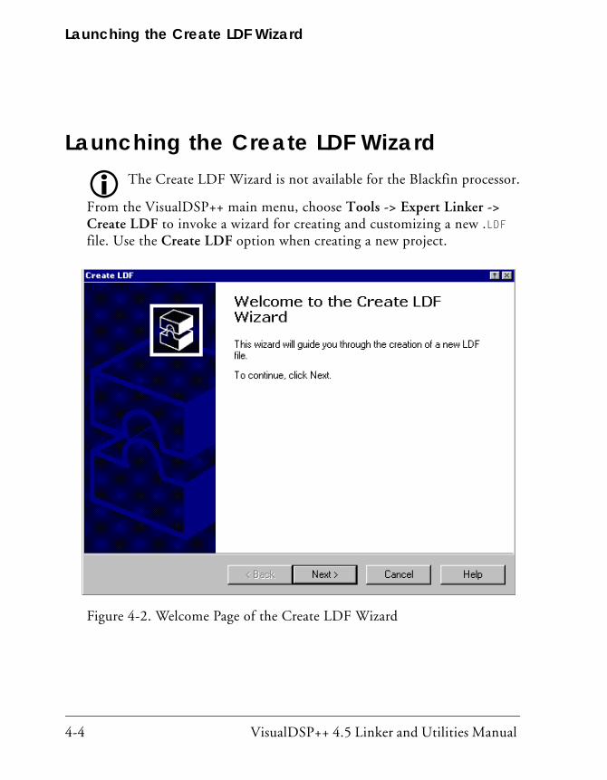
Launching the Create LDF Wizard
4-4 VisualDSP++ 4.5 Linker and Utilities Manual
Launching the Create LDF WizardThe Create LDF Wizard is not available for the Blackfin processor.
From the VisualDSP++ main menu, choose Tools -> Expert Linker -> Create LDF to invoke a wizard for creating and customizing a new .LDF file. Use the Create LDF option when creating a new project.
Figure 4-2. Welcome Page of the Create LDF Wizard
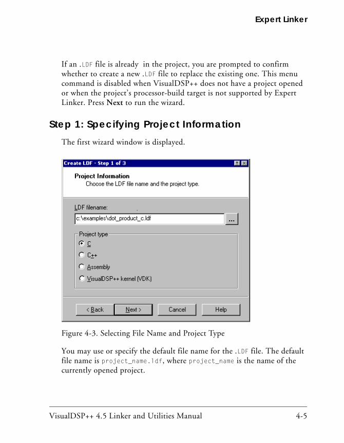
VisualDSP++ 4.5 Linker and Utilities Manual 4-5
Expert Linker
If an .LDF file is already in the project, you are prompted to confirm whether to create a new .LDF file to replace the existing one. This menu command is disabled when VisualDSP++ does not have a project opened or when the project’s processor-build target is not supported by Expert Linker. Press Next to run the wizard.
Step 1: Specifying Project InformationThe first wizard window is displayed.
You may use or specify the default file name for the .LDF file. The default file name is project_name.ldf, where project_name is the name of the currently opened project.
Figure 4-3. Selecting File Name and Project Type
Launching the Create LDF Wizard
4-6 VisualDSP++ 4.5 Linker and Utilities Manual
The Project type selection specifies whether the LDF is for a C, C++, assembly, or a VDK project. The default setting depends on the source files in the project. For example, if .c files are in the project, the default is C; if a VDK.H file is in the project, the default is VDK, and so on. This set-ting determines which template is used as a starting point.
For a case where there is a mix of assembly and C files (or any other file combination), the most abstract programming language should be selected. For example, for a project with C and assembly files, a C LDF should be selected. Similarly, for a C++ and C project, the C++ LDF should be selected.
Press Next.
Step 2: Specifying System InformationChoose whether the project is for a single-processor system or a multipro-cessor (MP) system.
By default, the .LDF file is set for single processors. Under System type, select Single processor or Multiprocessor.
• For a single-processor system, the Processors list shows only one processor and the MP address columns do not appear.
• For a multiprocessor system, right-click in the Processor Proper-ties box to add the desired number of processors included in the .LDF file, name each processor, and set the processor order (which will determine each processor’s MP memory address range).
Processor type identifies the DSP system’s processor architecture. This setting is derived from the processor target specified via the Project Options dialog box in VisualDSP++.
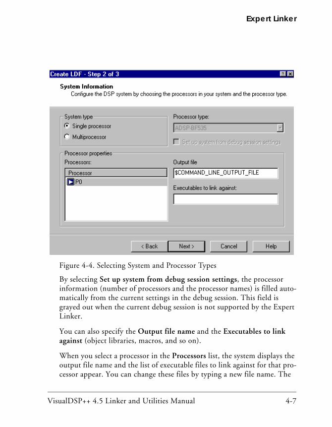
VisualDSP++ 4.5 Linker and Utilities Manual 4-7
Expert Linker
By selecting Set up system from debug session settings, the processor information (number of processors and the processor names) is filled auto-matically from the current settings in the debug session. This field is grayed out when the current debug session is not supported by the Expert Linker.
You can also specify the Output file name and the Executables to link against (object libraries, macros, and so on).
When you select a processor in the Processors list, the system displays the output file name and the list of executable files to link against for that pro-cessor appear. You can change these files by typing a new file name. The
Figure 4-4. Selecting System and Processor Types

Launching the Create LDF Wizard
4-8 VisualDSP++ 4.5 Linker and Utilities Manual
file name may include a relative path, an LDF macro, or both. In addition, if the processor’s ID is detected, the processor is placed in the correct posi-tion in the processor list.
For multiprocessor systems, the window (Figure 4-5) shows the list of pro-cessors in the project. Expert Linker automatically displays MP address range for each processor space providing specific MP addresses and multi-processor memory space (MMS) offsets which makes using MP commands much easier. This is an automatic replacement for the MPMEM-ORY linker command used in the LDF source file.
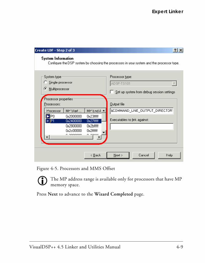
VisualDSP++ 4.5 Linker and Utilities Manual 4-9
Expert Linker
The MP address range is available only for processors that have MP memory space.
Press Next to advance to the Wizard Completed page.
Figure 4-5. Processors and MMS Offset

Launching the Create LDF Wizard
4-10 VisualDSP++ 4.5 Linker and Utilities Manual
Step 3: Completing the LDF Wizard From the Wizard Completed page, you can go back and verify or modify selections made up to this point.
When you click the Finish button, Expert Linker copies a template .LDF file to the same directory that contains the project file and adds it to the current project. The Expert Linker window appears and displays the con-tents of the new .LDF file.
Figure 4-6. Wizard Completed Page of the Create LDF Wizard
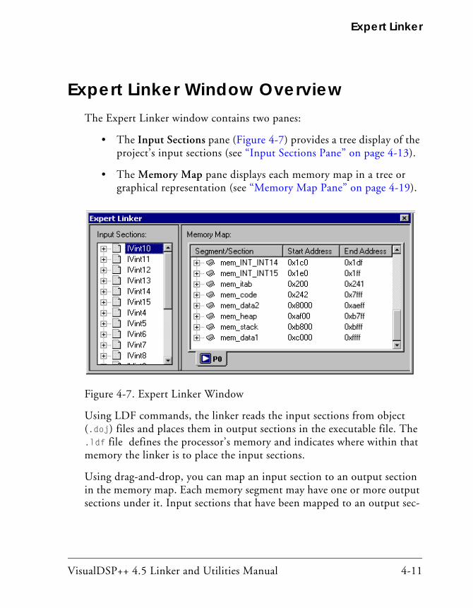
VisualDSP++ 4.5 Linker and Utilities Manual 4-11
Expert Linker
Expert Linker Window OverviewThe Expert Linker window contains two panes:
• The Input Sections pane (Figure 4-7) provides a tree display of the project’s input sections (see “Input Sections Pane” on page 4-13).
• The Memory Map pane displays each memory map in a tree or graphical representation (see “Memory Map Pane” on page 4-19).
Using LDF commands, the linker reads the input sections from object (.doj) files and places them in output sections in the executable file. The .ldf file defines the processor’s memory and indicates where within that memory the linker is to place the input sections.
Using drag-and-drop, you can map an input section to an output section in the memory map. Each memory segment may have one or more output sections under it. Input sections that have been mapped to an output sec-
Figure 4-7. Expert Linker Window

Expert Linker Window Overview
4-12 VisualDSP++ 4.5 Linker and Utilities Manual
tion are displayed under that output section. For more information, refer to “Input Sections Pane” on page 4-13 and “Memory Map Pane” on page 4-19.
Access various Expert Linker functions with your mouse. Right-click to display appropriate menus and make selections.

VisualDSP++ 4.5 Linker and Utilities Manual 4-13
Expert Linker
Input Sections PaneThe Input Sections pane initially displays a list of all the input sections referenced by the .LDF file, and all input sections contained in the object files and libraries. Under each input section, a list of LDF macros, librar-ies, and object files may be contained in that input section. You can add or delete input sections, LDF macros, or objects/library files in this pane.
Input Sections MenuRight-click an object in the Input Sections pane, and a menu appears as shown in Figure 4-8.
Figure 4-8. Input Sections Right-Click Menu

Input Sections Pane
4-14 VisualDSP++ 4.5 Linker and Utilities Manual
The main menu functions include:
• Sort by – Sorts objects by input sections or LDF macros. These selections are mutually exclusive.
• Add – Adds input sections, object/library files, and LDF macros. Appropriate menu selections are grayed out when right-clicking on a position (area) in which you cannot create a corresponding object.
Create an input section as a shell, without object/library files or LDF macros in it. You can even map this section to an output sec-tion. However, input sections without data are grayed out.
• Delete – Deletes the selected object (input section, object/library file, or LDF macro).
• Remove – Removes an LDF macro from another LDF macro but does not delete the input section mappings that contain the removed macro. The difference between Delete and Remove is that Delete completely deletes the input section macros that contain the deleted macro. NOTE: The Remove option becomes available only if you right-click on an LDF macro that is part of another LDF macro.
• Expand All LDF Macros – Expands all the LDF macros in the input sections pane so that the contents of all the LDF macros are visible.
• View Legend – Displays the Legend dialog box which shows icons and colors used by the Expert Linker.

VisualDSP++ 4.5 Linker and Utilities Manual 4-15
Expert Linker
• View Section Contents – Opens the Section Contents dialog box, which displays the section contents of the object file, library file, or .dxe file. This command is available only after you link or build the project and then right-click on an object or output section.
• View Global Properties – Displays the Global Properties dialog box which provides the map file name (of the map file generated after linking the project) as well as access to various processor and setup information (see Figure 4-43 on page 4-55).
Mapping an Input Section to an Output SectionUsing the Expert Linker, you can map an input section to an output sec-tion. By using Windows drag-and-drop action, click on the input section, drag the mouse pointer to an output section, and then release the mouse button to drop the input section onto the output section.
All objects, such as LDF macros or object files under that input section, are mapped to the output section. Once an input section has been mapped, the icon next to the input section changes to denote that it is mapped.
If an input section is dragged onto a memory segment with no output sec-tion in it, an output section with a default name is automatically created and displayed.
A red “x” on an icon indicates the object/file is not mapped. Once an input section has been completely mapped (that is, all object files that contain the section are mapped), the icon next to the input section changes to indicate that it is now mapped; the “x” disappears. See Figure 4-9.
As you drag the input section, the icon changes to a circle with a diagonal slash if it is over an object where you are not allowed to drop the input section.
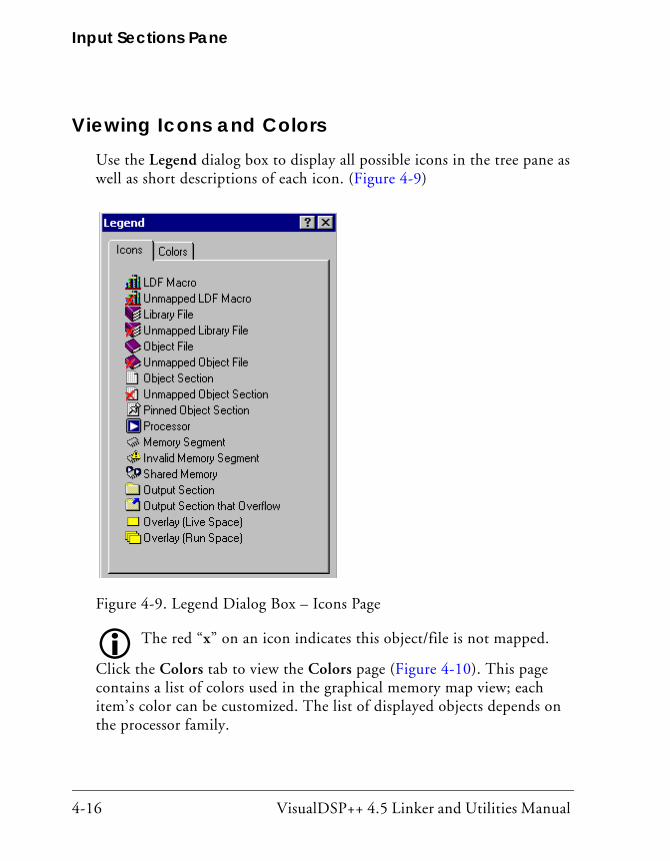
Input Sections Pane
4-16 VisualDSP++ 4.5 Linker and Utilities Manual
Viewing Icons and ColorsUse the Legend dialog box to display all possible icons in the tree pane as well as short descriptions of each icon. (Figure 4-9)
The red “x” on an icon indicates this object/file is not mapped.
Click the Colors tab to view the Colors page (Figure 4-10). This page contains a list of colors used in the graphical memory map view; each item’s color can be customized. The list of displayed objects depends on the processor family.
Figure 4-9. Legend Dialog Box – Icons Page
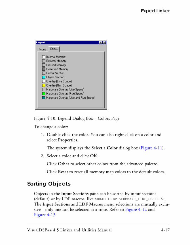
VisualDSP++ 4.5 Linker and Utilities Manual 4-17
Expert Linker
To change a color:
1. Double-click the color. You can also right-click on a color and select Properties.
The system displays the Select a Color dialog box (Figure 4-11).
2. Select a color and click OK.
Click Other to select other colors from the advanced palette.
Click Reset to reset all memory map colors to the default colors.
Sorting ObjectsObjects in the Input Sections pane can be sorted by input sections (default) or by LDF macros, like $OBJECTS or $COMMAND_LINE_OBJECTS. The Input Sections and LDF Macros menu selections are mutually exclu-sive—only one can be selected at a time. Refer to Figure 4-12 and Figure 4-13.
Figure 4-10. Legend Dialog Box – Colors Page
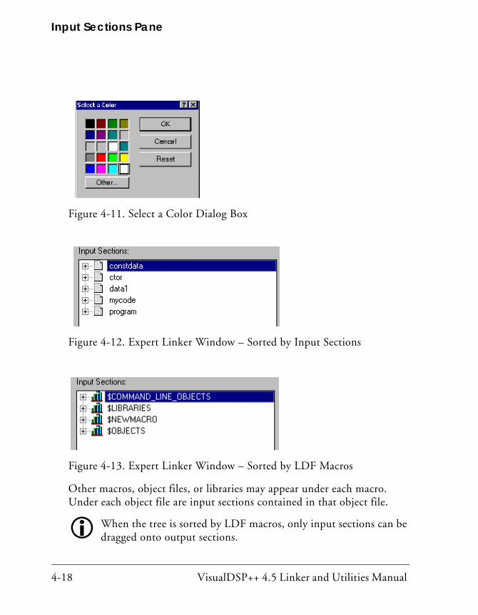
Input Sections Pane
4-18 VisualDSP++ 4.5 Linker and Utilities Manual
Other macros, object files, or libraries may appear under each macro. Under each object file are input sections contained in that object file.
When the tree is sorted by LDF macros, only input sections can be dragged onto output sections.
Figure 4-11. Select a Color Dialog Box
Figure 4-12. Expert Linker Window – Sorted by Input Sections
Figure 4-13. Expert Linker Window – Sorted by LDF Macros

VisualDSP++ 4.5 Linker and Utilities Manual 4-19
Expert Linker
Memory Map PaneIn an .LDF file, the linker’s MEMORY() command defines the target system’s physical memory. Its argument list partitions memory into memory seg-ments and specifies start and end addresses, memory width, and memory type (such as program, data, stack, and so on). It connects your program to the target system. The OUTPUT() command directs the linker to produce an executable (.DXE) file and specifies its file name. Figure 4-14 shows a typical memory map pane.
For Blackfin, SHARC, and TigerSHARC processors, the combo box (located to the right of the Memory Map label) is not available.
Figure 4-14. Expert Linker Window – Memory Map

Memory Map Pane
4-20 VisualDSP++ 4.5 Linker and Utilities Manual
This section describes:
• “Context Menu” on page 4-22
• “Tree View Memory Map Representation” on page 4-24
• “Graphical View Memory Map Representation” on page 4-25
• “Specifying Pre- and Post-Link Memory Map View” on page 4-31
• “Zooming In and Out on the Memory Map” on page 4-32
• “Adding a Memory Segment” on page 4-34
• “Inserting a Gap Into a Memory Segment” on page 4-36
• “Working With Overlays” on page 4-37
• “Viewing Section Contents” on page 4-40
• “Viewing Symbols” on page 4-44
• “Profiling Object Sections” on page 4-45
• “Adding Shared Memory Segments and Linking Object Files” on page 4-49
The Memory Map pane has tabbed pages. You can page through the memory maps of the processors and shared memories to view their makeup. The two viewing modes are a tree view and a graphical view.
Select these views and other memory map features by means of the right-click (context) menu. All procedures involving memory map han-dling assume the Expert Linker window is open.
The Memory Map pane displays a tooltip when the mouse cursor moves over an object in the display. The tooltip shows the object’s name, address, and size. The system also uses representations of overlays, which display in “run” space and “live” space.
Use the right-click menu (“Context Menu” on page 4-22) to select and perform major memory map functions.

VisualDSP++ 4.5 Linker and Utilities Manual 4-21
Expert Linker
Invalid Memory Segment Notification:When a memory segment is invalid (for example, when a memory range overlaps another memory segment or if the memory width is invalid), the tree shows an Invalid Memory Segment icon (see Figure 4-15). Move the mouse pointer over the icon and a tooltip displays a message describing why the segment is invalid.
Figure 4-15. Memory Map With Invalid Memory Segments

Memory Map Pane
4-22 VisualDSP++ 4.5 Linker and Utilities Manual
Context MenuDisplay the context menu by right-clicking in the Memory Map pane. The menu (Figure 4-16) allows you to select and perform major func-tions. The available right-click menu commands are listed below.
View Mode
• Memory Map Tree – Displays the memory map in a tree represen-tation (see Figure 4-17 on page 4-25)
• Graphical Memory Map – Displays the memory map in graphical blocks (see Figure 4-18 on page 4-26)
Figure 4-16. Memory Map Main Menu
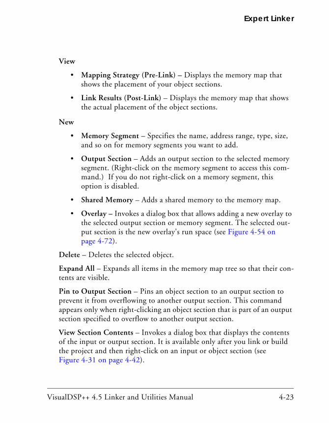
VisualDSP++ 4.5 Linker and Utilities Manual 4-23
Expert Linker
View
• Mapping Strategy (Pre-Link) – Displays the memory map that shows the placement of your object sections.
• Link Results (Post-Link) – Displays the memory map that shows the actual placement of the object sections.
New
• Memory Segment – Specifies the name, address range, type, size, and so on for memory segments you want to add.
• Output Section – Adds an output section to the selected memory segment. (Right-click on the memory segment to access this com-mand.) If you do not right-click on a memory segment, this option is disabled.
• Shared Memory – Adds a shared memory to the memory map.
• Overlay – Invokes a dialog box that allows adding a new overlay to the selected output section or memory segment. The selected out-put section is the new overlay’s run space (see Figure 4-54 on page 4-72).
Delete – Deletes the selected object.
Expand All – Expands all items in the memory map tree so that their con-tents are visible.
Pin to Output Section – Pins an object section to an output section to prevent it from overflowing to another output section. This command appears only when right-clicking an object section that is part of an output section specified to overflow to another output section.
View Section Contents – Invokes a dialog box that displays the contents of the input or output section. It is available only after you link or build the project and then right-click on an input or object section (see Figure 4-31 on page 4-42).

Memory Map Pane
4-24 VisualDSP++ 4.5 Linker and Utilities Manual
View Symbols – Invokes a dialog box that displays the symbols for the project, overlay, or input section. It is available only after you link the project and then right-click on a processor, overlay, or input section (see Figure 4-43 on page 4-55).
Properties – Displays a Properties dialog box for the selected object. The Properties menu is context-sensitive; different properties are displayed for different objects. Right-click a memory segment and choose Properties to specify a memory segment’s attributes (name, start address, end address, size, width, memory space, PM/DM/(BM), RAM/ROM, and internal or external flag).
View Legend – Displays the Legend dialog box showing tree view icons and a short description for each icon. The Colors page lists the colors used in the graphical memory map. You can customize each object’s color. See Figure 4-9 on page 4-16 and Figure 4-10 on page 4-17.
View Global Properties – Displays a Global Properties dialog box that lists the map file generated after linking the project. It also provides access to some processor and setup information (see Figure 4-44 on page 4-56).
Tree View Memory Map RepresentationIn the tree view (selected by right-clicking and choosing View Mode -> Memory Map Tree), the memory map is displayed with memory seg-ments at the top level.
Each memory segment may have one or more output sections under it. Input sections mapped to an output section appear under that output section.
The start address and size of the memory segment display in separate col-umns. If available, the start address and the size of each output section are displayed (for example, after you link the project).

VisualDSP++ 4.5 Linker and Utilities Manual 4-25
Expert Linker
Graphical View Memory Map RepresentationIn the graphical view (selected by right-clicking in the Memory Map pane and choosing View Mode -> Graphical Memory Map), the graphical memory map displays the processor’s hardware memory map (refer to your processor’s hardware reference manual or data sheet). Each hardware memory segment contains a list of user-defined memory segments.
View the memory map from two perspectives: pre-link view and post-link view (see “Specifying Pre- and Post-Link Memory Map View” on page 4-31). Figure 4-18 through Figure 4-22 show examples of graphical memory map representations.
Figure 4-17. Expert Linker Window – Memory Map Tree View

Memory Map Pane
4-26 VisualDSP++ 4.5 Linker and Utilities Manual
Figure 4-18. Graphical Memory Map Representation
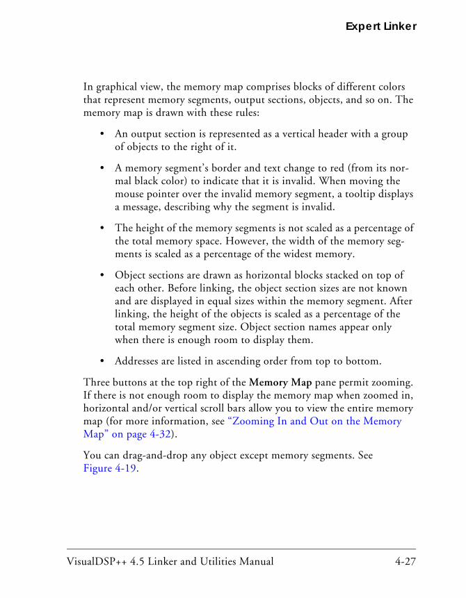
VisualDSP++ 4.5 Linker and Utilities Manual 4-27
Expert Linker
In graphical view, the memory map comprises blocks of different colors that represent memory segments, output sections, objects, and so on. The memory map is drawn with these rules:
• An output section is represented as a vertical header with a group of objects to the right of it.
• A memory segment’s border and text change to red (from its nor-mal black color) to indicate that it is invalid. When moving the mouse pointer over the invalid memory segment, a tooltip displays a message, describing why the segment is invalid.
• The height of the memory segments is not scaled as a percentage of the total memory space. However, the width of the memory seg-ments is scaled as a percentage of the widest memory.
• Object sections are drawn as horizontal blocks stacked on top of each other. Before linking, the object section sizes are not known and are displayed in equal sizes within the memory segment. After linking, the height of the objects is scaled as a percentage of the total memory segment size. Object section names appear only when there is enough room to display them.
• Addresses are listed in ascending order from top to bottom.
Three buttons at the top right of the Memory Map pane permit zooming. If there is not enough room to display the memory map when zoomed in, horizontal and/or vertical scroll bars allow you to view the entire memory map (for more information, see “Zooming In and Out on the Memory Map” on page 4-32).
You can drag-and-drop any object except memory segments. See Figure 4-19.
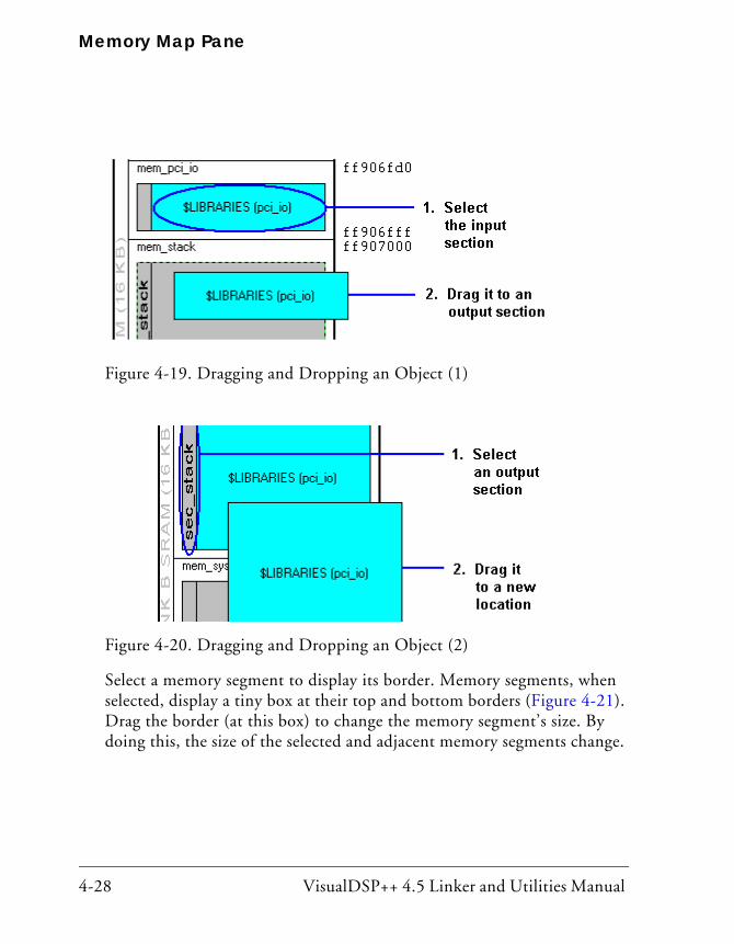
Memory Map Pane
4-28 VisualDSP++ 4.5 Linker and Utilities Manual
Select a memory segment to display its border. Memory segments, when selected, display a tiny box at their top and bottom borders (Figure 4-21). Drag the border (at this box) to change the memory segment’s size. By doing this, the size of the selected and adjacent memory segments change.
Figure 4-19. Dragging and Dropping an Object (1)
Figure 4-20. Dragging and Dropping an Object (2)
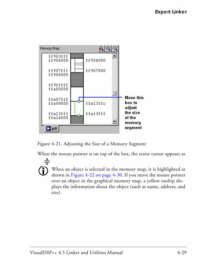
VisualDSP++ 4.5 Linker and Utilities Manual 4-29
Expert Linker
When the mouse pointer is on top of the box, the resize cursor appears as
When an object is selected in the memory map, it is highlighted as shown in Figure 4-22 on page 4-30. If you move the mouse pointer over an object in the graphical memory map, a yellow tooltip dis-plays the information about the object (such as name, address, and size).
Figure 4-21. Adjusting the Size of a Memory Segment
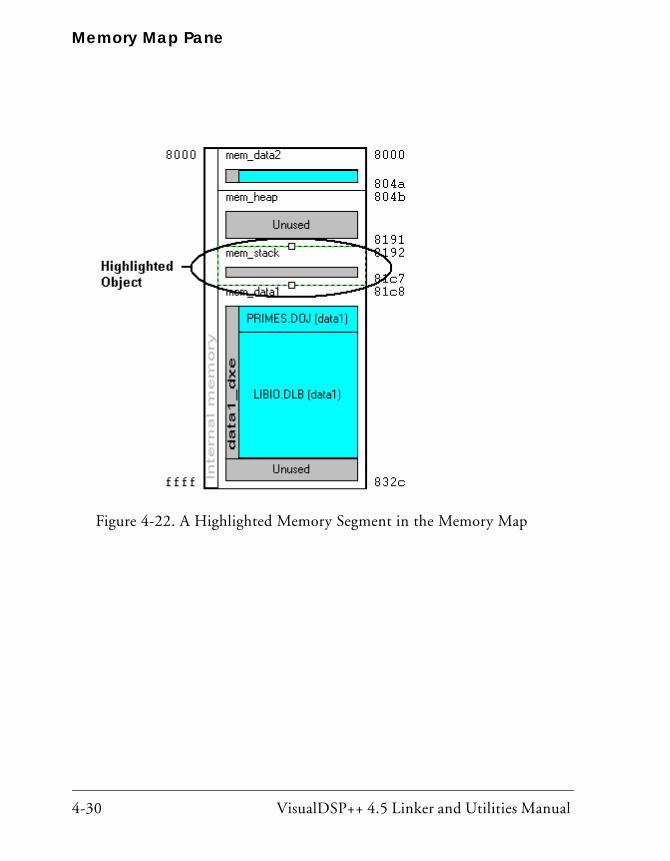
Memory Map Pane
4-30 VisualDSP++ 4.5 Linker and Utilities Manual
Figure 4-22. A Highlighted Memory Segment in the Memory Map

VisualDSP++ 4.5 Linker and Utilities Manual 4-31
Expert Linker
Specifying Pre- and Post-Link Memory Map ViewView the memory map from two perspectives: pre-link view and post-link view. Pre-link view is typically used to place input sections. Post-link view is typically used to view where the input sections are placed after linking the project. Other information (such as the sizes of each section, symbols, and the contents of each section) is available after linking.
• To enable pre-link view from the Memory Map pane, right-click and choose View and Mapping Strategy (Pre-Link). Figure 4-23 on page 4-31 illustrates a memory map before linking.
Figure 4-23. Memory Map Pane in Pre-Link View

Memory Map Pane
4-32 VisualDSP++ 4.5 Linker and Utilities Manual
• To enable post-link view from the Memory Map pane, right-click and choose View and Link Results (Post-Link). Figure 4-24 on page 4-32 illustrates a memory map after linking.
Zooming In and Out on the Memory MapFrom the Memory Map pane, you can zoom in or out incrementally or zoom in or out completely. Three buttons at the top right of the pane per-form zooming operations. Horizontal and/or vertical scroll bars appear when there is not enough room to display a zoomed memory map in the Memory Map pane (see Figure 4-25 on page 4-33).
Figure 4-24. Memory Map Pane in Post-Link View

VisualDSP++ 4.5 Linker and Utilities Manual 4-33
Expert Linker
To:
• Zoom in, click on the magnifying glass icon with the + sign above the upper right corner of the memory map window.
• Zoom out, click on the magnifying glass icon with the - sign above the upper right corner of the memory map window.
• Exit zoom mode, click on the magnifying glass icon with the “x” above the upper right corner of the memory map window.
• View a memory object by itself by double-clicking on the memory object.
• View the memory object containing the current memory object by double-clicking on the white space around the memory object
Figure 4-25. Memory Map – Zoom Options

Memory Map Pane
4-34 VisualDSP++ 4.5 Linker and Utilities Manual
Adding a Memory SegmentYou can add memory segments to the memory map. This procedure assumes that the Expert Linker window (Memory Map pane) is open.
To add a memory segment:
1. Right-click in the Memory Map pane.
2. Choose New and then choose Memory Segment. The Memory Segment Properties dialog box appears (Figure 4-26).
3. In Name, type a name for the memory segment.
4. Specify the following attributes:

VisualDSP++ 4.5 Linker and Utilities Manual 4-35
Expert Linker
• Start address
• End Address
• Size (hexadecimal)
It is only necessary to specify either “End Address” or “Length” and not both.
• Width
• Memory Space For Blackfin and TigerSHARC processors, this option is unavailable, because VisualDSP employs a unified memory space.
• ROM/RAM
• Internal/External (memory location)
Figure 4-26. Memory Segment Properties Dialog Box

Memory Map Pane
4-36 VisualDSP++ 4.5 Linker and Utilities Manual
5. Click OK.
Inserting a Gap Into a Memory SegmentA gap may be inserted into a memory segment in the graphical memory map.
To insert a gap:
1. Right-click on a memory segment.
2. Choose Insert gap. The Insert Gap dialog box appears, as shown in Figure 4-27. It displays the start address, end address, and size of the selected memory segment.
Figure 4-27. Insert Gap Dialog Box

VisualDSP++ 4.5 Linker and Utilities Manual 4-37
Expert Linker
You may insert a gap at the start of the memory segment or the end of it.
• If the Start... is chosen, the Start address for the gap is grayed out and you must enter an End Address or Size (of the gap).
• If the End... is chosen, the End address of the gap is grayed out and you must enter a Start Address or Size.
Working With OverlaysOverlays appear in the memory map window in two places: “run” space and “live” space. Live space is where the overlay is stored until it is swapped into run space. Because multiple overlays can exist in the same “run” space, the overlays display as multiple blocks on top of each other in cascading fashion.
Figure 4-28 shows an overlay in “live” space, and Figure 4-29 shows an overlay in “run” space.
Figure 4-28. Graphical Memory Map Showing an Overlay in “Live” Space
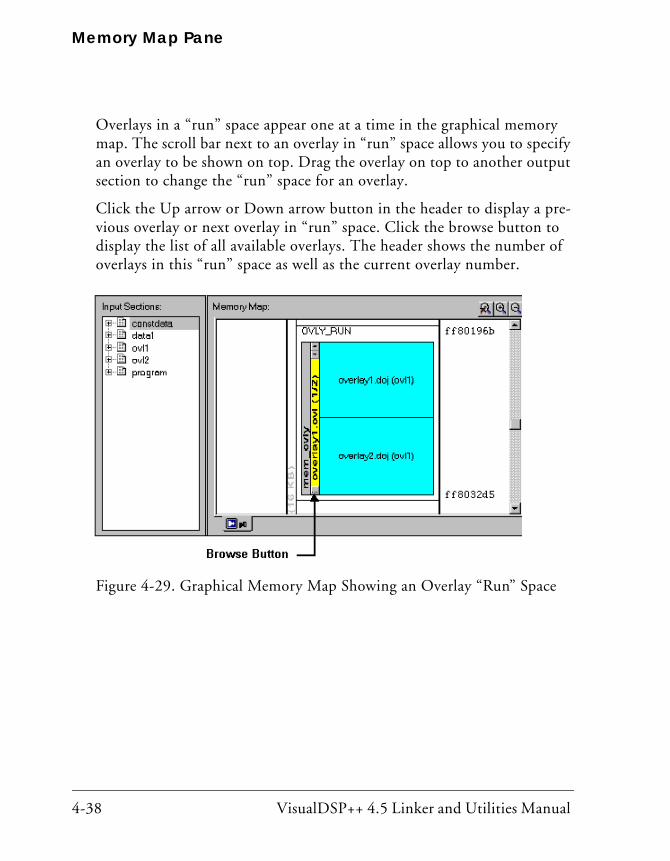
Memory Map Pane
4-38 VisualDSP++ 4.5 Linker and Utilities Manual
Overlays in a “run” space appear one at a time in the graphical memory map. The scroll bar next to an overlay in “run” space allows you to specify an overlay to be shown on top. Drag the overlay on top to another output section to change the “run” space for an overlay.
Click the Up arrow or Down arrow button in the header to display a pre-vious overlay or next overlay in “run” space. Click the browse button to display the list of all available overlays. The header shows the number of overlays in this “run” space as well as the current overlay number.
Figure 4-29. Graphical Memory Map Showing an Overlay “Run” Space
VisualDSP++ 4.5 Linker and Utilities Manual 4-39
Expert Linker
To create an overlay in the “run” space:
1. Right-click on an output section.
2. Choose New -> Overlay.
3. Select the “live” space from the Overlay Properties dialog box (see “Managing Overlay Properties” on page 4-72). The new overlay appears in the “run” and “live” spaces in two different colors in the memory map.

Memory Map Pane
4-40 VisualDSP++ 4.5 Linker and Utilities Manual
Viewing Section ContentsTo view the contents of an input section or an output section, specify the particular memory address and the display’s format.
This capability employs the elfdump utility (elfdump.exe) to obtain the section contents and display it in a window similar to a memory window in VisualDSP++. Multiple Section Contents dialog boxes may be dis-played. For example, Figure 4-30 shows output section contents in HEX format.
Figure 4-30. Output Section Contents in Hex Format

VisualDSP++ 4.5 Linker and Utilities Manual 4-41
Expert Linker
To display the contents of an output section:
1. In the Memory Map pane, right-click an output section.
2. Choose View Section Contents from the menu. The Section Contents dialog box appears.
By default, the memory section content appears in Hex format.
3. Right-click anywhere in the section view to display a menu with these selections:
• Go To – Displays an address in the window.
• Select Format — Provides a list of formats: Hex, Hex and ASCII, and Hex and Assembly. Select a format type to specify the memory format.
Figure 4-31 and Figure 4-32 illustrate memory data formats available for the selected output section.

Memory Map Pane
4-42 VisualDSP++ 4.5 Linker and Utilities Manual
Figure 4-31. Output Section Contents in Hex and ASCII Format

VisualDSP++ 4.5 Linker and Utilities Manual 4-43
Expert Linker
Figure 4-32. Output Section Contents in Hex and Assembly Format
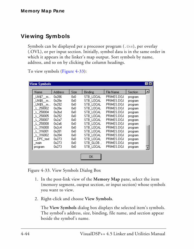
Memory Map Pane
4-44 VisualDSP++ 4.5 Linker and Utilities Manual
Viewing SymbolsSymbols can be displayed per a processor program (.dxe), per overlay (.OVL), or per input section. Initially, symbol data is in the same order in which it appears in the linker’s map output. Sort symbols by name, address, and so on by clicking the column headings.
To view symbols (Figure 4-33):
1. In the post-link view of the Memory Map pane, select the item (memory segment, output section, or input section) whose symbols you want to view.
2. Right-click and choose View Symbols.
The View Symbols dialog box displays the selected item’s symbols. The symbol’s address, size, binding, file name, and section appear beside the symbol’s name.
Figure 4-33. View Symbols Dialog Box
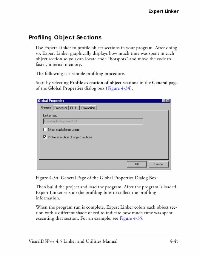
VisualDSP++ 4.5 Linker and Utilities Manual 4-45
Expert Linker
Profiling Object SectionsUse Expert Linker to profile object sections in your program. After doing so, Expert Linker graphically displays how much time was spent in each object section so you can locate code “hotspots” and move the code to faster, internal memory.
The following is a sample profiling procedure.
Start by selecting Profile execution of object sections in the General page of the Global Properties dialog box (Figure 4-34).
Then build the project and load the program. After the program is loaded, Expert Linker sets up the profiling bins to collect the profiling information.
When the program run is complete, Expert Linker colors each object sec-tion with a different shade of red to indicate how much time was spent executing that section. For an example, see Figure 4-35.
Figure 4-34. General Page of the Global Properties Dialog Box
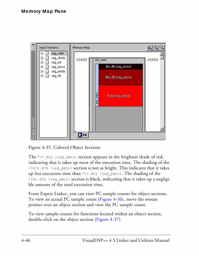
Memory Map Pane
4-46 VisualDSP++ 4.5 Linker and Utilities Manual
The fir.doj (seg_pmco) section appears in the brightest shade of red, indicating that it takes up most of the execution time. The shading of the libio.dlb (seg_pmco) section is not as bright. This indicates that it takes up less execution time than fir.doj (seg_pmco). The shading of the libc.dlb (seg_pmco) section is black, indicating that it takes up a negligi-ble amount of the total execution time.
From Expert Linker, you can view PC sample counts for object sections. To view an actual PC sample count (Figure 4-36), move the mouse pointer over an object section and view the PC sample count.
To view sample counts for functions located within an object section, double-click on the object section (Figure 4-37).
Figure 4-35. Colored Object Sections
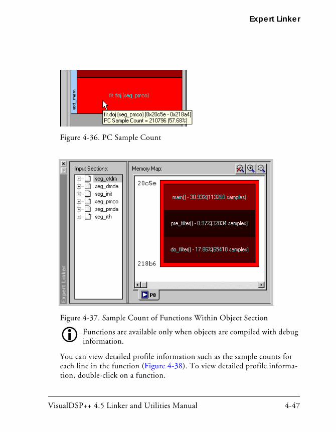
VisualDSP++ 4.5 Linker and Utilities Manual 4-47
Expert Linker
Functions are available only when objects are compiled with debug information.
You can view detailed profile information such as the sample counts for each line in the function (Figure 4-38). To view detailed profile informa-tion, double-click on a function.
Figure 4-36. PC Sample Count
Figure 4-37. Sample Count of Functions Within Object Section

Memory Map Pane
4-48 VisualDSP++ 4.5 Linker and Utilities Manual
To view PC samples as a percentage of total samples, view the memory map tree (Figure 4-39).
Figure 4-38. Detailed Profile Information
Figure 4-39. Percentage of Total PC Sample Count

VisualDSP++ 4.5 Linker and Utilities Manual 4-49
Expert Linker
Adding Shared Memory Segments and Linking Object Files
In many DSP applications where large amounts of memory for multipro-cessing tasks and sharing of data are required, an external resource in the form of shared memory may be desired.
Refer to Engineer-To- Engineer Note EE-202 “Using the Expert Linker for Multiprocessor LDF” for a detailed description and proce-dure. Find this EE Note on Analog Devices Web site at http://www.analog.com/ee-notes.
Figure 4-40. Multiprocessor LDF Selection

Memory Map Pane
4-50 VisualDSP++ 4.5 Linker and Utilities Manual
To add a shared memory section to the .LDF file, right-click in the Memory Map pane and select New/Shared Memory. Then specify a name for the shared memory segment (.SM) and select the processors that have access to this shared memory segment. Refer to “Managing Shared Mem-ory Properties” on page 4-77 for more information.
As shown in Figure 4-41, a new shared memory segment, visible to pro-cessors P0 and P1, has been successfully added to the system. Note that variables declared in the shared memory segment will be accessed by both processors in the system. In order for the linker to be able to correctly resolve these variables, the link against command should be used once again.
Figure 4-41. Shared Memory Segment

VisualDSP++ 4.5 Linker and Utilities Manual 4-51
Expert Linker
Expert Linker automatically adds shared memory segments, and therefore no any additional modifications to the LDF are needed.
Confirm that Expert Linker has correctly added the .SM file to the link against command line by selecting View Global Properties in the Mem-ory Map pane and clicking on the Processor tab.
The shared.sm file should now be contained in the Executables to Link Against box for each processor.
Use Expert Linker to detect non-linked input sections, such as a variable declared in external SDRAM memory, which belongs to the shared mem-ory segment.
When both processors and the shared memory segments have been prop-erly configured, and Expert Linker has detected all input sections, you can link the object files from different input sections to their corresponding memory sections.
In general, the linking process consists of these steps:
1. Sort the left pane of the Expert Linker window by LDF macros instead of input sections (default setting). To do that, right-click on the left pane and select Sort by/LDF Macros.
2. Right-click on the LDF Macro window and add a new macro for P0 (Add/LDF Macro). For example, $OBJECTS_P0. Repeat the same step for P1 and shared.sm.
3. Add the object (.DOJ) files that correspond to each processor as well as to the shared memory segment. To do this, right-click on each recently created LDF macro and then select Add/Object/Library File. The use of LDF macros becomes extremely useful in systems where there is more than one object files, .doj files per processor or shared memory segments, in which case the same step previously explained should be followed for each .DOJ file.
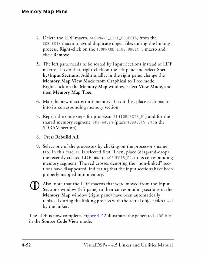
Memory Map Pane
4-52 VisualDSP++ 4.5 Linker and Utilities Manual
4. Delete the LDF macro, $COMMAND_LINE_OBJECTS, from the $OBJECTS macro to avoid duplicate object files during the linking process. Right-click on the $COMMAND_LINE_OBJECTS macro and click Remove.
5. The left pane needs to be sorted by Input Sections instead of LDF macros. To do that, right-click on the left pane and select Sort by/Input Sections. Additionally, in the right pane, change the Memory Map View Mode from Graphical to Tree mode. Right-click on the Memory Map window, select View Mode, and then Memory Map Tree.
6. Map the new macros into memory. To do this, place each macro into its corresponding memory section.
7. Repeat the same steps for processor P1 ($OBJECTS_P1) and for the shared memory segment, shared.sm (place $OBJECTS_SM in the SDRAM section).
8. Press Rebuild All.
9. Select one of the processors by clicking on the processor’s name tab. In this case, P0 is selected first. Then, place (drag-and-drop) the recently created LDF macro, $OBJECTS_P0, in its corresponding memory segment. The red crosses denoting the “non-linked” sec-tions have disappeared, indicating that the input sections have been properly mapped into memory.
Also, note that the LDF macros that were moved from the Input Sections window (left pane) to their corresponding sections in the Memory Map window (right pane) have been automatically replaced during the linking process with the actual object files used by the linker.
The LDF is now complete. Figure 4-42 illustrates the generated .LDF file in the Source Code View mode.
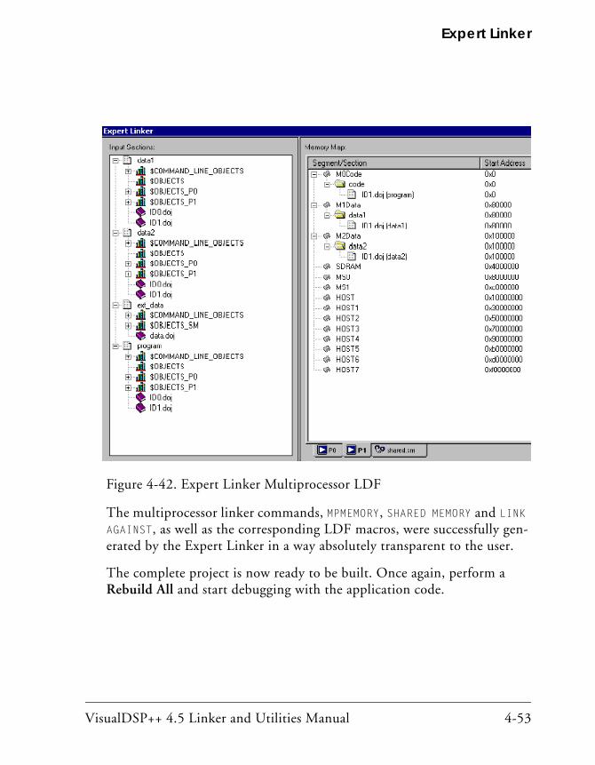
VisualDSP++ 4.5 Linker and Utilities Manual 4-53
Expert Linker
The multiprocessor linker commands, MPMEMORY, SHARED MEMORY and LINK AGAINST, as well as the corresponding LDF macros, were successfully gen-erated by the Expert Linker in a way absolutely transparent to the user.
The complete project is now ready to be built. Once again, perform a Rebuild All and start debugging with the application code.
Figure 4-42. Expert Linker Multiprocessor LDF

Managing Object Properties
4-54 VisualDSP++ 4.5 Linker and Utilities Manual
Managing Object PropertiesYou can display different properties for each type of object. Since different objects may share certain properties, their Properties dialog boxes share pages.
The following procedures assume the Expert Linker window is open.
To display a Properties dialog box, right-click an object and choose Prop-erties. You may choose these functions:
• “Managing General Global Properties” on page 4-55
• “Managing Processor Properties” on page 4-56
• “Managing PLIT Properties for Overlays” on page 4-58
• “Managing Elimination Properties” on page 4-59
• “Managing Symbols Properties” on page 4-61
• “Managing Memory Segment Properties” on page 4-64
• “Managing Output Section Properties” on page 4-65
• “Managing Packing Properties” on page 4-68
• “Managing Alignment and Fill Properties” on page 4-70
• “Managing Overlay Properties” on page 4-72
• “Managing Stack and Heap in Processor Memory” on page 4-74
• “Managing Shared Memory Properties” on page 4-77

VisualDSP++ 4.5 Linker and Utilities Manual 4-55
Expert Linker
Managing General Global PropertiesTo access Global Properties, right-click in the Input Sections pane and choose Properties.
The Global Properties dialog box appears.
The General tab of the Global Properties dialog box provides these selec-tions (Figure 4-43):
• Linker map file displays the map file generated after linking the project. This is a read-only field.
• If Show stack/heap usage is selected after you run a project, Expert Linker shows how much of the stack and heap were used.
• If Profile execution of object sections is selected, Expert Linker enables the profiling feature that allows you to see “hotspots” in object sections and to fine-tune the placement of object sections.
Figure 4-43. General Page of the Global Properties Dialog Box
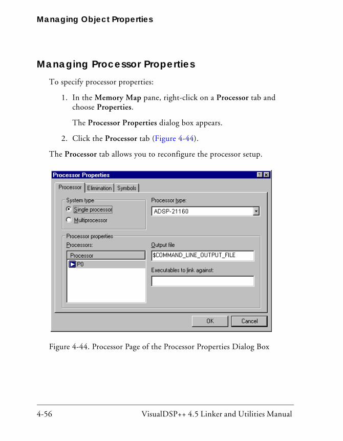
Managing Object Properties
4-56 VisualDSP++ 4.5 Linker and Utilities Manual
Managing Processor PropertiesTo specify processor properties:
1. In the Memory Map pane, right-click on a Processor tab and choose Properties.
The Processor Properties dialog box appears.
2. Click the Processor tab (Figure 4-44).
The Processor tab allows you to reconfigure the processor setup.
Figure 4-44. Processor Page of the Processor Properties Dialog Box

VisualDSP++ 4.5 Linker and Utilities Manual 4-57
Expert Linker
With a Processor tab in focus, you can:
• Specify System Type – It may be a Single processor or Multipro-cessor selection. (The Processors list displays the names of all the processors in the project and the address range for each processor.)
• Select a Processor type (such as ADSP-21060).
• Specify an Output file name – The file name may include a relative path and/or LDF macro. Specify an output file for each processor.
• Specify Executables to link against – Multiple files names are per-mitted, but must be separated with space characters or commas. Only .SM, .DLB, and .DXE files are permitted. A file name may include a relative path, LDF macro, or both.
Additionally, a processor can be renamed by selecting the processor, right-clicking, choosing Rename Processor, and typing a new name.
For multiprocessor systems, you can add, delete, and rearrange processor order. Right-click in the Processors box, choose Add Processor, and type a name for the new processor, or choose Delete Processor. To move a pro-cessor, select the processor and drag it to another position in the Processors list.
When a processor in a multiprocessor system is moved to a differ-ent position, its address range changes. The MP Start Addr. and MP End Addr. information is static.

Managing Object Properties
4-58 VisualDSP++ 4.5 Linker and Utilities Manual
Managing PLIT Properties for OverlaysThe PLIT tab allows you to view and edit the function template used in overlays. Assembly instructions observe the same syntax coloring as specified for editor windows.
Enter assembly code only. Comments are not allowed.
To view and edit PLIT information:
1. Right-click in the Input Sections pane.
2. Choose Properties. The Global Properties dialog box appears.
3. Click the PLIT tab (Figure 4-45).
Figure 4-45. PLIT Page of the Global Properties Dialog Box

VisualDSP++ 4.5 Linker and Utilities Manual 4-59
Expert Linker
Managing Elimination PropertiesEliminate unused code from the target .DXE file. Specify the input sections from which to eliminate code and the symbols you want to keep.
Select the Global Properties dialog box by right-clicking in the Input Sections pane and choosing Properties.
Use the Elimination tab to perform elimination (Figure 4-46).
Selecting the Enable elimination of unused objects option enables elimi-nation. This check box is grayed out when elimination is enabled through the linker command line or when the .LDF file is read-only.
Figure 4-46. Elimination Tab

Managing Object Properties
4-60 VisualDSP++ 4.5 Linker and Utilities Manual
When Verbose linker output of eliminated objects is selected, the elimi-nated objects are shown as linker output in the Output window’s Build page during linking. This check box is grayed out when the Enable elimi-nation of unused objects check box is cleared. It is also grayed out when elimination is enabled through the linker command line or when the .LDF file is read-only.
The Sections to apply elimination box lists all input sections with a check box next to each section. Elimination applies to the sections that are selected. By default, all input sections are selected.
The Symbols to keep box displays a list of symbols to be retained (see “Managing Symbols Properties” on page 4-61 for more information).
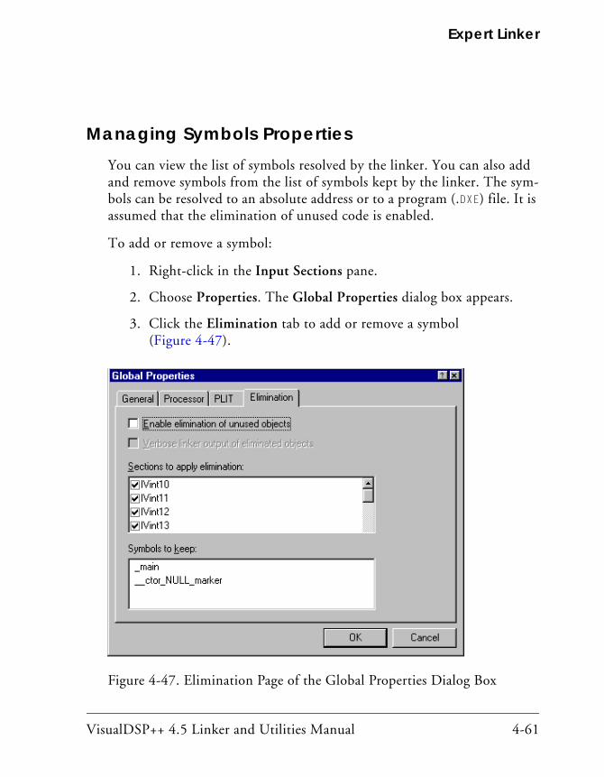
VisualDSP++ 4.5 Linker and Utilities Manual 4-61
Expert Linker
Managing Symbols PropertiesYou can view the list of symbols resolved by the linker. You can also add and remove symbols from the list of symbols kept by the linker. The sym-bols can be resolved to an absolute address or to a program (.DXE) file. It is assumed that the elimination of unused code is enabled.
To add or remove a symbol:
1. Right-click in the Input Sections pane.
2. Choose Properties. The Global Properties dialog box appears.
3. Click the Elimination tab to add or remove a symbol (Figure 4-47).
Figure 4-47. Elimination Page of the Global Properties Dialog Box
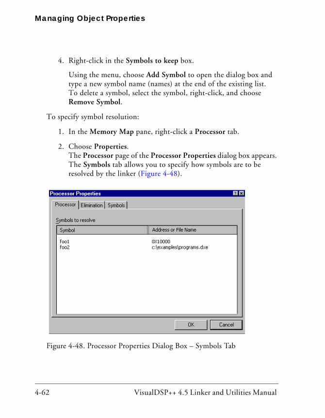
Managing Object Properties
4-62 VisualDSP++ 4.5 Linker and Utilities Manual
4. Right-click in the Symbols to keep box.
Using the menu, choose Add Symbol to open the dialog box and type a new symbol name (names) at the end of the existing list. To delete a symbol, select the symbol, right-click, and choose Remove Symbol.
To specify symbol resolution:
1. In the Memory Map pane, right-click a Processor tab.
2. Choose Properties. The Processor page of the Processor Properties dialog box appears. The Symbols tab allows you to specify how symbols are to be resolved by the linker (Figure 4-48).
Figure 4-48. Processor Properties Dialog Box – Symbols Tab
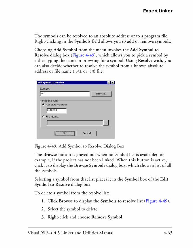
VisualDSP++ 4.5 Linker and Utilities Manual 4-63
Expert Linker
The symbols can be resolved to an absolute address or to a program file. Right-clicking in the Symbols field allows you to add or remove symbols.
Choosing Add Symbol from the menu invokes the Add Symbol to Resolve dialog box (Figure 4-49), which allows you to pick a symbol by either typing the name or browsing for a symbol. Using Resolve with, you can also decide whether to resolve the symbol from a known absolute address or file name (.DXE or .SM) file.
The Browse button is grayed out when no symbol list is available; for example, if the project has not been linked. When this button is active, click it to display the Browse Symbols dialog box, which shows a list of all the symbols.
Selecting a symbol from that list places it in the Symbol box of the Edit Symbol to Resolve dialog box.
To delete a symbol from the resolve list:
1. Click Browse to display the Symbols to resolve list (Figure 4-49).
2. Select the symbol to delete.
3. Right-click and choose Remove Symbol.
Figure 4-49. Add Symbol to Resolve Dialog Box

Managing Object Properties
4-64 VisualDSP++ 4.5 Linker and Utilities Manual
Managing Memory Segment Properties Specify or change the memory segment’s name, start address, end address, size, width, memory space, memory type, and internal/external flag.
To display the Memory Segment Properties dialog box (Figure 4-50):
1. Right-click a memory segment (for example, PROGRAM or MEM_CODE) in the Memory Map pane.
2. Choose Properties. The selected segment properties are displayed.
Figure 4-50. Memory Segment Properties Dialog Box

VisualDSP++ 4.5 Linker and Utilities Manual 4-65
Expert Linker
Managing Output Section PropertiesUse the Output Section tab to change the output section’s name or to set the overflow. Overflow allows objects that do not fit in the current output section to spill over into the specified output section. By default, all objects that do not fit (except objects that are manually pinned to the cur-rent output section) overflow to the specified section.
To specify output section properties:
1. Right-click an output section (for example, PROGRAM_DXE or CODE_DXE) in the Memory Map pane.
2. Choose Properties (Figure 4-51).
Figure 4-51. Output Section Properties Dialog Box – Output Section Tab
Managing Object Properties
4-66 VisualDSP++ 4.5 Linker and Utilities Manual
The selections in the output section/segment list include “None” (for no overflow) and “All” output sections. Pin objects to an output section by right-clicking the object and choosing Pin to output section.
You can:
• Type a name for the output section in Name.
• In Overflow, select an output section into which the selected out-put section will overflow; select None for no overflow. This setting appears in the Placement box.
Before linking the project, the Placement box indicates the output section’s address and size as “Not available”. After linking is done, the box displays the output section’s actual address and size.
• Initialization allows you to choose the initialization qualifier for an output section. The section qualifier set by this option controls the operation of run-time initialization by tools that process the exe-cutable file and the run-time initialization that can be achieved by enabling the meminit utility. The choices are:
• None: Stipulates no special treatment for the section – the section data are statically initialized according to their defi-nition in the source, no runtime initialization is called for. Please note that data that have no explicit initialization in source are initialized to 0.
• No initialization: Stipulates no data initialization, even stat-ically. No data for the section are in the executable file. This is equivalent to specifying a section qualifier SHT_NOBITS in the LDF.
• Initialize to zero: The memory space for this section will be initialized to zero at either “load” or “runtime”, if invoked with the linker’s -meminit switch. If the -meminit switch is

VisualDSP++ 4.5 Linker and Utilities Manual 4-67
Expert Linker
not used, the memory is initialized at “load” time when the .dxe file is loaded via VisualDSP++ IDDE, or boot-loaded by the boot kernel. If the memory initializer is invoked, the C/C++run-time library (CRTL) will process embedded information to initialize the memory space during the CRTL initialization process.
• Initialize at runtime: If the linker is invoked with the -mem-init switch, this section will be filled at runtime. If the -meminit switch is not specified, the section is filled at “load” time.
• Contiguity of Input Sections allows you to choose whether or not code or data in an output section should be mapped contiguously. The choices are:
• Display linker warning if section is not mapped contiguously
• Force contiguous placement of sections
• Suppress linker warning about non-contiguous placement of sections in the operating system
• Specify the Packing (on page 4-68) and Alignment (with Fill value) properties (on page 4-70) as needed.
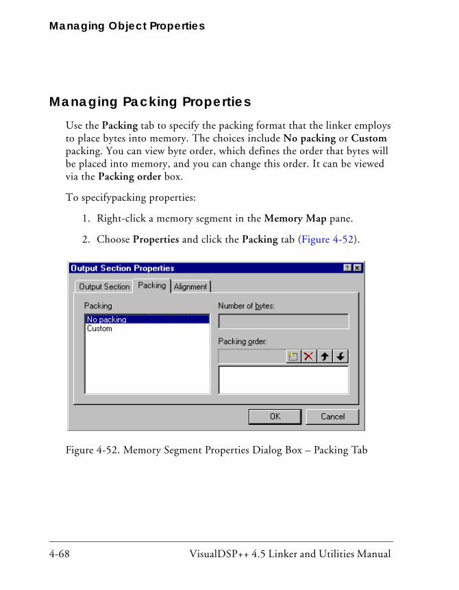
Managing Object Properties
4-68 VisualDSP++ 4.5 Linker and Utilities Manual
Managing Packing PropertiesUse the Packing tab to specify the packing format that the linker employs to place bytes into memory. The choices include No packing or Custom packing. You can view byte order, which defines the order that bytes will be placed into memory, and you can change this order. It can be viewed via the Packing order box.
To specifypacking properties:
1. Right-click a memory segment in the Memory Map pane.
2. Choose Properties and click the Packing tab (Figure 4-52).
Figure 4-52. Memory Segment Properties Dialog Box – Packing Tab
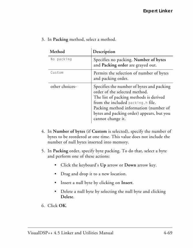
VisualDSP++ 4.5 Linker and Utilities Manual 4-69
Expert Linker
3. In Packing method, select a method.
4. In Number of bytes (if Custom is selected), specify the number of bytes to be reordered at one time. This value does not include the number of null bytes inserted into memory.
5. In Packing order, specify byte packing. To do that, select a byte and perform one of these actions:
• Click the keyboard's Up arrow or Down arrow key.
• Drag and drop it to a new location.
• Insert a null byte by clicking on Insert.
• Delete a null byte by selecting the null byte and clicking Delete.
6. Click OK.
Method Description
No packing Specifies no packing. Number of bytes and Packing order are grayed out.
Custom Permits the selection of number of bytes and packing order.
other choices- Specifies the number of bytes and packing order of the selected method. The list of packing methods is derived from the included packing.h file. Packing method information (number of bytes and packing order) appears, but you cannot change it.
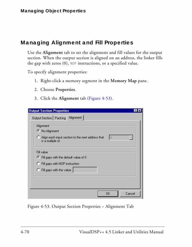
Managing Object Properties
4-70 VisualDSP++ 4.5 Linker and Utilities Manual
Managing Alignment and Fill PropertiesUse the Alignment tab to set the alignment and fill values for the output section. When the output section is aligned on an address, the linker fills the gap with zeros (0), NOP instructions, or a specified value.
To specify alignment properties:
1. Right-click a memory segment in the Memory Map pane.
2. Choose Properties.
3. Click the Alignment tab (Figure 4-53).
Figure 4-53. Output Section Properties – Alignment Tab

VisualDSP++ 4.5 Linker and Utilities Manual 4-71
Expert Linker
If you select No Alignment, the output section is not be aligned on an address.
If you choose Align each input section to the next address that is a multi-ple of, select an integer value from the drop-down list to specify the output section alignment.
When the output section is aligned on an address, a gap is filled by the linker. Based on the processor architecture, Expert Linker determines the opcode for the NOP instruction.
The Fill value is either 0 (default), a NOP instruction, or a user-specified value (a hexadecimal value entered in the entry box).

Managing Object Properties
4-72 VisualDSP++ 4.5 Linker and Utilities Manual
Managing Overlay PropertiesUse the Overlay tab to add/choose the output file for the overlay, its “live” memory, and its linking algorithm.
To specify overlay properties:
1. Right-click an overlay object in the Memory Map pane.
2. Choose Properties and click the Overlay tab (Figure 4-54)
Use the Output file name box to specify the name of the overlay file (.ovl).
Figure 4-54. Overlay Properties Dialog Box – Overlay Tab

VisualDSP++ 4.5 Linker and Utilities Manual 4-73
Expert Linker
The Live Memory drop-down list contains all output sections or memory segments within one output section. The “live” memory is where the over-lay is stored before it is swapped into memory.
The Overlay linking algorithm box permits one overlay algorithm—ALL_FIT. Expert Linker does not currently allow changes to this setting. When ALL_FIT is used, the linker tries to fit all of the mapped objects into one overlay.
The Placement box provides the following information:
• Live Address—The starting address of the overlay
• Run Address—The starting address where the overlay is swapped into memory at runtime
• Size—The overlay’s size
Click the Packing tab to specify byte packing order.
The Browse button is only available after the overlay build and when the symbols are available. Clicking Browse opens the Browse Symbols dialog box.
You can choose the address for the symbol group or let the linker choose the address.

Managing Object Properties
4-74 VisualDSP++ 4.5 Linker and Utilities Manual
Managing Stack and Heap in Processor MemoryExpert Linker shows how much space is allocated for your program’s heap and stack.
Figure 4-55 shows stack and heap output sections in the Memory Map pane. Right-click on either of them to display its properties.
Use the Global Properties dialog box to select Show stack/heap usage (Figure 4-56). This option graphically displays the stack/heap usage in memory (Figure 4-57).
Figure 4-55. Memory Map Window With Stack and Heap Sections

VisualDSP++ 4.5 Linker and Utilities Manual 4-75
Expert Linker
The Expert Linker can:
• Locate stacks and heaps and fill them with a marker value.
This occurs after loading the program into a processor target. The stacks and heaps are located by their output section names, which may vary across processor families.
• Search the heap and stack for the highest memory locations written to by the DSP program.
This action occurs when the target halts after running the program. (assume the unused portion of the stack or heap starts here). The Expert Linker updates the memory map to show how much of the stack and heap are unused.
Use this information to adjust the size of your stack and heap. This infor-mation helps make better use of the processor memory, so the stack and heap segments do not use too much memory.
Figure 4-56. Global Properties – Selecting Stack and Heap Usage

Managing Object Properties
4-76 VisualDSP++ 4.5 Linker and Utilities Manual
Use the graphical view (View Mode -> Graphical Memory Map) to dis-play stack and heap memory map blocks. Figure 4-57 shows a possible memory map after running a project program.
Figure 4-57. Graphical Memory Map Showing Stack and Heap Usage

VisualDSP++ 4.5 Linker and Utilities Manual 4-77
Expert Linker
Managing Shared Memory PropertiesSpecify the path and name of the file used by shared memory. This proce-dure assumes the Expert Linker window is open.
To specify shared memory properties:
1. In the Memory Map pane, click the Shared Memory tab (located at the bottom of dialog box).
Figure 4-58. Shared Memory Tab
Managing Object Properties
4-78 VisualDSP++ 4.5 Linker and Utilities Manual
2. Right-click anywhere on the Memory Map pane. Note: Do not right-click on a memory segment, output section, input section, or overlay.
3. Choose Properties. The Shared Memory page of the Shared Memory Properties dia-log box appears.
4. In Output file name, specify the name of the output file for the shared memory.
5. In Processors sharing this memory, select the processors that share the file whose name appears in Output file name. Selecting a pro-cessor links its executable file against this shared memory file.
6. Optionally, click the Elimination tab (see “Managing Elimination Properties” on page 4-59) and specify options.
7. Click OK.

VisualDSP++ 4.5 Linker and Utilities Manual 5-1
5 MEMORY OVERLAYS AND ADVANCED LDF COMMANDS
This chapter describes memory management with the overlay functions as well as several advanced LDF commands used for memory management.
This chapter includes:
• “Overview” on page 5-2 Provides an overview of Analog Devices processor’s overlay strategy
• “Memory Management Using Overlays” on page 5-4 Describes memory management using the overlay functions
• “Advanced LDF Commands” on page 5-29 Describes LDF commands that support memory management with overlay functions, the implementation of physical shared memory, and multiprocessor support
This chapter generally uses code examples for Blackfin processors. If used, other processor’s code examples are marked accordingly.
Overview
5-2 VisualDSP++ 4.5 Linker and Utilities Manual
OverviewAnalog Devices processors generally have a hierarchy of memory. The fast-est memory is the “internal” memory that is integrated with the processor on the same chip. For some processors, like the Blackfin, there are two lev-els of internal memory, with L1 memory being faster than L2 memory. Users can configure their system to include “external” memory, usually SDRAM or ROM that is connected to the part.
Ideally, a program can fit in internal memory for optimal performance. Large programs need to be expanded to use external memory. When that happens, accessing code and data in slower memory can affect program performance.
One way to address performance issues is to partition the program so that time-critical memory accesses are done using internal memory while parts of the program that are not time-critical can be placed into external mem-ory. The placement of [program] sections into specific memory sections can be done using the LDF’s MEMORY{} and SECTION{} commands.
Another way to address performance issues is via memory architecture. Some memory architectures, for example, Blackfin architecture, have instruction and data cache. The processor can be configured to bring instruction and data into faster memory for fast processing.
The third way to optimize performance is to use overlays. In an overlay system, code and data that is in slower memory is moved into faster mem-ory when it is to be used. For architectures without cache, this method is the only way to have large parts of the program run out of fast internal memory. Even on processors that have cache support, users may want to use overlays to have direct control of what is placed in internal memory for more deterministic behavior.
VisualDSP++ 4.5 Linker and Utilities Manual 5-3
Memory Overlays and Advanced LDF Commands
The overlay manager is a user-defined function responsible for insuring that a required symbol (function or data) within an overlay is in the run-time memory when it is needed. The transfer usually occurs using the direct memory access (DMA) capability of the processor. The overlay manager may also handle other advanced functionality described in “Introduction to Memory Overlays” on page 5-5 and “Overlay Managers” on page 5-6.

Memory Management Using Overlays
5-4 VisualDSP++ 4.5 Linker and Utilities Manual
Memory Management Using OverlaysTo reduce DSP system costs, many applications employ processors with small amounts of on-chip memory and place much of the program code and data off-chip. The linker supports the linking of executable files for systems with overlay memory. Applications notes on the Analog Devices Web site provide detailed descriptions of this technique; for example,
This section describes the use of memory overlays. The topics are:
• “Introduction to Memory Overlays” on page 5-5
• “Overlay Managers” on page 5-6
• “Memory Overlay Support” on page 5-8
• “Example – Managing Two Overlays” on page 5-13
• “Linker-Generated Constants” on page 5-15
• “Overlay Word Sizes” on page 5-16
• “Storing Overlay ID” on page 5-19
• “Overlay Manager Function Summary” on page 5-19
• “Reducing Overlay Manager Overhead” on page 5-20
• “Using PLIT{} and Overlay Manager” on page 5-24
The following LDF commands facilitate overlay features.
• “OVERLAY_GROUP{}” on page 5-29
• “PLIT{}” on page 5-33

VisualDSP++ 4.5 Linker and Utilities Manual 5-5
Memory Overlays and Advanced LDF Commands
Introduction to Memory OverlaysMemory overlays support applications that cannot fit the program instruc-tions into the processor’s internal memory. In such cases, program instructions are partitioned and stored in external memory until they are required for program execution. These partitions are memory overlays, and the routines that call and execute them are called overlay managers.
Overlays are “many to one” memory-mapping systems. Several overlays may “live” (be stored) in unique locations in external memory, but “run” (execute) in a common location in internal memory. Throughout the fol-lowing description, the overlay storage location is referred to as the “live” location, and the internal location where instructions are executed is referred to as the “run” (run-time) space.
Overlay functions are written to overlay (.ovl) files, which are specified as one type of linker executable output file. The loader can read .ovl files to generate an .ldr file.
Figure 5-1 demonstrates the concept of memory overlays. The two mem-ory spaces are: internal and external. The external memory is partitioned into the live space for four overlays. The internal memory contains the main program, an overlay manager function, and two memory segments reserved for execution of overlay program instructions (run space).
In this example, overlays 1 and 2 share the same run-time location within internal memory, and overlays 3 and 4 also share a common run-time memory. When FUNC_B is required, the overlay manager loads overlay 2 to the location in internal memory where overlay 2 is designated to run. When FUNC_D is required, the overlay manager loads overlay 3 into its des-ignated run-time memory.

Memory Management Using Overlays
5-6 VisualDSP++ 4.5 Linker and Utilities Manual
The transfer is typically implemented with the processor’s Direct Memory Access (DMA) capability. The overlay manager can also handle advanced functionality, such as checking whether the requested overlay is already in run-time memory, executing another function while loading an overlay, and tracking recursive overlay function calls.
Overlay ManagersAn overlay manager is a user-definable routine responsible for loading a referenced overlay function or data buffer into internal memory (run space). This task is accomplished with linker-generated constants and PLIT{} commands.
Figure 5-1. Memory Overlays
Overlay 1
Overlay 2
Overlay 3
Overlay 4Overlay 3 and 4Runtime Memory
Overlay 1 and 2Runtime Memory
OverlayManager
Main: call FUNC_Hcall .plt_FUNC_A
FUNC_A
FUNC_CFUNC_B
FUNC_EFUNC_D
FUNC_F
FUNC_G
External Memory Internal Memory

VisualDSP++ 4.5 Linker and Utilities Manual 5-7
Memory Overlays and Advanced LDF Commands
Linker-generated constants inform the overlay manager of the overlay’s live address, where the overlay resides for execution, and the number of words in the overlay PLIT{} commands inform the overlay manager of the requested overlay and the run-time address of the referenced symbol.
An overlay manager’s main objective is to transfer overlays to a run-time location when required. Overlay managers may also:
• Set up a stack to store register values
• Check whether a referenced symbol has already been transferred into its run-time space as a result of a previous reference
If the overlay is already in internal memory, the overlay transfer is bypassed and execution of the overlay routine begins immediately
• Load an overlay while executing a function from a second overlay (or a non-overlay function)
You may require an overlay manager to perform other specialized tasks to satisfy the special needs of a given application. Overlay managers are application-specific and must be developed by the user.
Breakpoints on Overlays
The debugger relies on the presence of the __ov_start and__ov_end sym-bols to support breakpoints on overlays. These symbols should appear in the user’s overlay manager for debugger support of overlays. The symbol manager sets a silent breakpoint at each symbol.
The more important of the two symbols is the breakpoint at _ov_end. Code execution in the overlay manager passes through this location once an overlay is fully swapped in. At this point, the debugger may probe the target to determine which overlays are in context. The symbol manager now sets any breakpoints requested on the overlays and resume execution.

Memory Management Using Overlays
5-8 VisualDSP++ 4.5 Linker and Utilities Manual
The second breakpoint is at symbol _ov_start. The label _ov_start is defined in the overlay manager (in code always executed immediately before the transfer of a new overlay begins). The breakpoint disables all of the overlays in the debugger—the idea being that while the target is run-ning in the overlay manager, the target is “unstable” in the sense that the debugger should not rely on the overlay information it may gather since the target is “in flux”. The debugger still functions without this break-point, but there may be some inconsistencies while overlays are being moved in and out.
Memory Overlay SupportThe overlay support provided by the DSP tools includes:
• Specification of the live and run locations of each overlay
• Generation of constants
• Redirection of overlay function calls to a jump table
Overlay support is partially user-designed in the .ldf file. You specify which overlays share run-time memory and which memory segments establish the “live” and “run” space.
Listing 5-1 shows the portion of an .ldf file that defines two overlays. This overlay declaration configures the two overlays to share a common run-time memory space. The syntax for the OVERLAY_INPUT{} command is described in “OVERLAY_INPUT{overlay_commands}” on page 3-63..
In this code example, OVLY_one contains FUNC_A and lives in memory seg-ment ovl_live; OVLY_two contains functions FUNC_B and FUNC_C and also lives in memory segment ovl_live.

VisualDSP++ 4.5 Linker and Utilities Manual 5-9
Memory Overlays and Advanced LDF Commands
Listing 5-1. Overlay Declaration in an .ldf File
.dxe_code
{ OVERLAY_INPUT {
OVERLAY_OUTPUT (OVLY_one.ovl)
INPUT_SECTIONS (FUNC_A.doj(program))
} >ovl_live
OVERLAY_INPUT {
OVERLAY_OUTPUT (OVLY_two.ovl)
INPUT_SECTIONS (FUNC_B.doj(program) FUNC_C.doj(sec_code))
} >ovl_live
} >ovl_run
The common run-time location shared by overlays OVLY_one and OVLY_two is within the ovl_run memory segment.
The .ldf file configures the overlays and provides the information necessary for the overlay manager to load the overlays. The information includes the following linker-generated overlay constants (where # is the overlay ID).
_ov_startaddress_#
_ov_endaddress_#
_ov_size_#
_ov_word_size_run_#
_ov_word_size_live_#
_ov_runtimestartaddress_#
Each overlay has a word size and an address, which is used by the overlay manager to determine where the overlay resides and where it is executed. One exception, _ov_size_#, specifies the total size in bytes.

Memory Management Using Overlays
5-10 VisualDSP++ 4.5 Linker and Utilities Manual
Overlay “live” and “run” word sizes differ when internal memory and external memory widths differ. A system containing either 16-bit-wide or 32-bit-wide external memory requires data packing to store an overlay containing instructions.
The Blackfin processor architecture supports byte addressing that uses 16-bit, 32-bit, or 64-bit opcodes. Thus, no data packing is required.
Redirection In addition to providing constants, the linker replaces overlay symbol ref-erences to the overlay manager within your code. Redirection is accomplished by means of a procedure linkage table (PLIT). A PLIT is essentially a jump table that executes user-defined code and then jumps to the overlay manager. The linker replaces an overlay symbol reference (function call) with a jump to a location in the PLIT.
You must define PLIT code within the .ldf file. This code prepares the overlay manager to handle the overlay that contains the referenced sym-bol. The code initializes registers to contain the overlay ID and the referenced symbol’s run-time address.
The linker reserves one word (or two bytes in Blackfin processors) at the top of an overlay to house the overlay ID.
The following is an example call instruction to an overlay function:
CALL FUNC_A;; /* Call to function in overlay */
If FUNC_A is in an overlay, the linker replaces the function call with the fol-lowing instruction:
CALL .plt_FUNC_A; / * Call to PLIT entry */
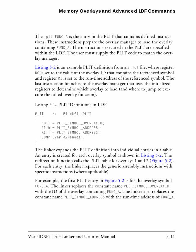
VisualDSP++ 4.5 Linker and Utilities Manual 5-11
Memory Overlays and Advanced LDF Commands
The .plt_FUNC_A is the entry in the PLIT that contains defined instruc-tions. These instructions prepare the overlay manager to load the overlay containing FUNC_A. The instructions executed in the PLIT are specified within the LDF. The user must supply the PLIT code to match the over-lay manager.
Listing 5-2 is an example PLIT definition from an .ldf file, where register R0 is set to the value of the overlay ID that contains the referenced symbol and register R1 is set to the run-time address of the referenced symbol. The last instruction branches to the overlay manager that uses the initialized registers to determine which overlay to load (and where to jump to exe-cute the called overlay function).
Listing 5-2. PLIT Definitions in LDF
PLIT // Blackfin PLIT{ R0.l = PLIT_SYMBOL_OVERLAYID; R1.h = PLIT_SYMBOL_ADDRESS; R1.l = PLIT_SYMBOL_ADDRESS; JUMP OverlayManager;}
The linker expands the PLIT definition into individual entries in a table. An entry is created for each overlay symbol as shown in Listing 5-2. The redirection function calls the PLIT table for overlays 1 and 2 (Figure 5-2). For each entry, the linker replaces the generic assembly instructions with specific instructions (where applicable).
For example, the first PLIT entry in Figure 5-2 is for the overlay symbol FUNC_A. The linker replaces the constant name PLIT_SYMBOL_OVERLAYID with the ID of the overlay containing FUNC_A. The linker also replaces the constant name PLIT_SYMBOL_ADDRESS with the run-time address of FUNC_A.

Memory Management Using Overlays
5-12 VisualDSP++ 4.5 Linker and Utilities Manual
When the overlay manager is called via the jump instruction of the PLIT table, R0 contains the referenced function’s overlay ID and R1 contains the referenced function’s run-time address. The overlay manager uses the overlay ID and run-time address to load and execute the referenced function.
Figure 5-2. Expanded PLIT Table (for TigerSHARC Processors)
Overlay 1
FUNC_A
Overlay 2
FUNC_B
FUNC_C
Main:call .plt_FUNC_A
.
.
.
call .plt_FUNC_Ccall .plt_FUNC_B
.
.
.
Plit_table.plt_FUNC_A
.plt_FUNC_B
R0.L = 0x00001;
R1.L = 0x22000;jumpOverlayManager;
.plt_FUNC_C
Internal Memory
call .plt_FUNC_C
R1.H = 0x00000;
R0.L = 0x00002;
R1.L = 0x22000;jumpOverlayManager;
R1.H = 0x00000;
R0.L = 0x00002;
R1.L = 0x23000;jumpOverlayManager;
R1.H = 0x00000;
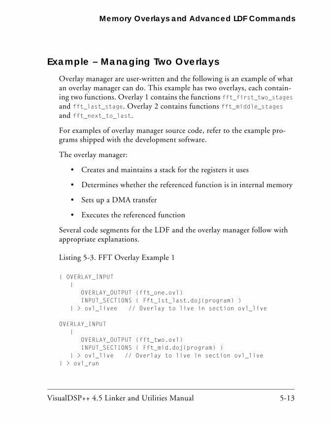
VisualDSP++ 4.5 Linker and Utilities Manual 5-13
Memory Overlays and Advanced LDF Commands
Example – Managing Two OverlaysOverlay manager are user-written and the following is an example of what an overlay manager can do. This example has two overlays, each contain-ing two functions. Overlay 1 contains the functions fft_first_two_stages and fft_last_stage. Overlay 2 contains functions fft_middle_stages and fft_next_to_last.
For examples of overlay manager source code, refer to the example pro-grams shipped with the development software.
The overlay manager:
• Creates and maintains a stack for the registers it uses
• Determines whether the referenced function is in internal memory
• Sets up a DMA transfer
• Executes the referenced function
Several code segments for the LDF and the overlay manager follow with appropriate explanations.
Listing 5-3. FFT Overlay Example 1
{ OVERLAY_INPUT { OVERLAY_OUTPUT (fft_one.ovl) INPUT_SECTIONS ( Fft_1st_last.doj(program) ) } > ovl_livee // Overlay to live in section ovl_live
OVERLAY_INPUT { OVERLAY_OUTPUT (fft_two.ovl) INPUT_SECTIONS ( Fft_mid.doj(program) ) } > ovl_live // Overlay to live in section ovl_live} > ovl_run

Memory Management Using Overlays
5-14 VisualDSP++ 4.5 Linker and Utilities Manual
The two defined overlays (fft_one.ovl and fft_two.ovl) live in memory segment ovl_live (defined by the MEMORY{} command), and run in sec-tion ovl_run. All instruction and data defined in the program memory segment within the Fft_1st_last.doj file are part of the fft_one.ovl overlay. All instructions and data defined in program within the file Fft_mid.doj are part of overlay fft_two.ovl. The result is two functions within each overlay.
The first and the last called functions are in overlay fft_one. The two middle functions are in overlay fft_two. When the first function (fft_one) is referenced during code execution, overlay id=1 is transferred to internal memory. When the second function (fft_two) is referenced, overlay id=2 is transferred to internal memory. When the third function (in overlay fft_two) is referenced, the overlay manager recognizes that it is already in internal memory and an overlay transfer does not occur.
To verify whether an overlay is in internal memory, place the overlay ID of this overlay into a register (for example, P0) and compare this value to the overlay ID of each loaded overlay. This is done by loading these over-lay values into a register (for example, R1).
/* Is overlay already in internal memory? */CC = p0 == p1; /* If so, do not transfer it in. */if CC jump skipped_DMA_setup;
Finally, when the last function (fft_one) is referenced, overlay id=1 is again transferred to internal memory for execution.
The following code segment calls the four FFT functions.
fftrad2: call fft_first_2_stages;; call fft_middle_stages;; call fft_next_to_last;; call fft_last_stage;;wait: NOP;; jump wait;;

VisualDSP++ 4.5 Linker and Utilities Manual 5-15
Memory Overlays and Advanced LDF Commands
The linker replaces each overlay function call with a call to the appropriate entry in the PLIT. For this example, only three instructions are placed in each entry of the PLIT.
PLIT{ R0.l = PLIT_SYMBOL_OVERLAYID; R1.h = PLIT_SYMBOL_ADDRESS; R1.l = PLIT_SYMBOL_ADDRESS; JUMP OverlayManager;}
Register R0 contains the overlay ID with the referenced symbol, and regis-ter R1 contains the run-time address of the referenced symbol. The final instruction jumps to the starting address of the overlay manager. The overlay manager uses the overlay ID in conjunction with the overlay con-stants generated by the linker to transfer the proper overlay into internal memory. Once the transfer is complete, the overlay manager jumps to the address of the referenced symbol stored in R1.
Linker-Generated ConstantsThe following constants, generated by the linker, are used by the overlay manager.
.EXTERN _ov_startaddress_1;
.EXTERN _ov_startaddress_2;
.EXTERN _ov_endaddress_1;
.EXTERN _ov_endaddress_2;
.EXTERN _ov_size_1;
.EXTERN _ov_size_2;
.EXTERN _ov_word_size_run_1;
.EXTERN _ov_word_size_run_2;
.EXTERN _ov_word_size_live_1;
.EXTERN _ov_word_size_live_2;

Memory Management Using Overlays
5-16 VisualDSP++ 4.5 Linker and Utilities Manual
.EXTERN _ov_runtimestartaddress_1;
.EXTERN _ov_runtimestartaddress_2;
The constants provide the following information to the overlay manager.
• Overlay sizes (both run-time word sizes and live word sizes)
• Starting address of the “live” space
• Starting address of the “run” space
Overlay Word SizesEach overlay has a word size and an address, which the overlay manager uses to determine where the overlay resides and where it is executed.
Table 5-1 shows the linker-generated constants and examples of processor-specific addresses.
Table 5-1. Linker-Generated Constants and Processor-Specific Addresses
Constant Blackfin Processors
_ov_startaddress_1 0x00000000
_ov_startaddress_2 0x00000010
_ov_endaddress_1 0x0000000F
_ov_endaddress_2 0x00001F
_ov_word_size_run_1 0x00000010
_ov_word_size_run_2 0x00000010
_ov_word_size_live_1 0x00000010
_ov_word_size_live_2 0x00000010
_ov_runtimestartaddress_1 0xF0001000
_ov_runtimestartaddress_2 0xF0001000

VisualDSP++ 4.5 Linker and Utilities Manual 5-17
Memory Overlays and Advanced LDF Commands
The overlay manager places the constants in arrays as shown in Figure 5-3 and Figure 5-4. The arrays are referenced by using the overlay ID as the index to the array. The index or ID is stored in a Modify register (Jn/Kn for TigerSHARC processors and M# for SHARC and Blackfin processors), and the beginning address of the array is stored in the Index register (Jm/Km for TigerSHARC processors and I# for SHARC and Blackfin processors).
.VAR liveAddresses[2] = _ov_startaddress_1,
_ov_startaddress_2;
.VAR runAddresses[2] = _ov_runtimestartaddress_1,
_ov_runtimestartaddress_2;
.VAR runWordSize[2] = _ov_word_size_run_1,
_ov_word_size_run_2;
.VAR liveWordSize[2] = _ov_word_size_live_1,
_ov_word_size_live_2;
Figure 5-3. TigerSHARC Overlay Live and Run Memory Sizes
External Memory
Address 0x04000000
0x0400007F
0x04000080
0x040000FF
Overlay 1(24 x 32-bits)
FUNC_A
Overlay 2(60 x 32-bits)
FUNC_BFUNC_C
Internal Memory
Address 0x00001000
Overlay Runtime Memory(40 x 48-bits)
Overlay 1 Overlay 216 x 48 bits 40 x 48 bits
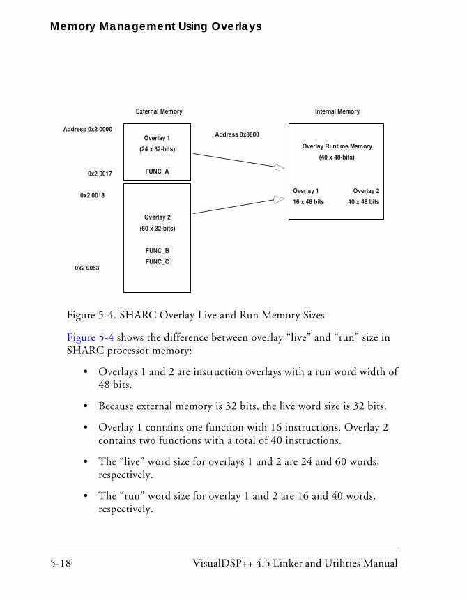
Memory Management Using Overlays
5-18 VisualDSP++ 4.5 Linker and Utilities Manual
Figure 5-4 shows the difference between overlay “live” and “run” size in SHARC processor memory:
• Overlays 1 and 2 are instruction overlays with a run word width of 48 bits.
• Because external memory is 32 bits, the live word size is 32 bits.
• Overlay 1 contains one function with 16 instructions. Overlay 2 contains two functions with a total of 40 instructions.
• The “live” word size for overlays 1 and 2 are 24 and 60 words, respectively.
• The “run” word size for overlay 1 and 2 are 16 and 40 words, respectively.
Figure 5-4. SHARC Overlay Live and Run Memory Sizes
External Memory
Address 0x2 0000
0x2 0017
0x2 0018
0x2 0053
Overlay 1
(24 x 32-bits)
FUNC_A
Overlay 2
(60 x 32-bits)
FUNC_B
FUNC_C
Internal Memory
Address 0x8800
Overlay Runtime Memory
(40 x 48-bits)
Overlay 1 Overlay 2
16 x 48 bits 40 x 48 bits
VisualDSP++ 4.5 Linker and Utilities Manual 5-19
Memory Overlays and Advanced LDF Commands
Storing Overlay IDThe overlay manager stores the ID of an overlay currently residing in internal memory. When an overlay is transferred to internal memory, the overlay manager stores the overlay ID in internal memory in the buffer labeled ov_id_loaded. Before another overlay is transferred, the overlay manager compares the required overlay ID with the ID stored in the ov_id_loaded buffer. If they are equal, the required overlay is already in internal memory and a transfer is not required. The PC is sent to the proper location to execute the referenced function. If they are not equal, the value in ov_id_loaded is updated and the overlay is transferred into its internal run space via DMA.
On completion of the transfer, the overlay manager restores register values from the run-time stack, flushes the cache, and then jumps the PC to the run-time location of the referenced function. It is very important to flush the cache before moving the PC to the referenced function. Otherwise, when code is replaced or modified, incorrect code execution may occur. If the program sequencer searches the cache for an instruction and an instruction from the previous overlay is in the cache, that instruction may be executed because the expected cache miss is not received.
Overlay Manager Function SummaryIn summary, the overlay manager routine:
• Maintains a run-time stack for registers being used by the overlay manager.
• Compares the requested overlay’s ID with that of the previously loaded overlay (stored in the ov_id_loaded buffer).
• Sets up the DMA transfer of the overlay (if it is not already in internal memory).
• Jumps the PC to the run-time location of the referenced function.

Memory Management Using Overlays
5-20 VisualDSP++ 4.5 Linker and Utilities Manual
These are the basic tasks that are performed by an overlay manager. More sophisticated overlay managers may be required for individual applications.
Reducing Overlay Manager OverheadThe example in this section incorporates the ability to transfer one overlay to internal memory while the core executes a function from another over-lay. Instead of the core sitting idle while the overlay DMA transfer occurs, the core enables the DMA, and then begins executing another function.
This example uses the concept of overlay function loading and executing. A function load is a request to load the overlay function into internal memory but not execute the function. A function execution is a request to execute an overlay function that may or may not be in internal memory at the time of the execution request. If the function is not in internal memory, a transfer must occur before execution.
In several circumstances, an overlay transfer can be in progress while the core is executing another task. Each circumstance can be labeled as deter-ministic or non-deterministic. A deterministic circumstance is one where you know exactly when an overlay function is required for execution. A non-deterministic circumstance is one where you cannot predict when an overlay function is required for execution. For example, a deterministic application may consist of linear flow code except for function calls. A non-deterministic example is an application with calls to overlay functions within an interrupt service routine (ISR) where the interrupt occurs randomly.
The example provided by the software contains deterministic overlay function calls. The time of overlay function execution requests are known as the number of cycles required to transfer an overlay. Therefore, an over-lay function load request can be placed to complete the transfer by the time the execution request is made. The next overlay transfer (from a load request) can be enabled by the core, and the core can execute the instruc-tions leading up to the function execution request.
VisualDSP++ 4.5 Linker and Utilities Manual 5-21
Memory Overlays and Advanced LDF Commands
Since the linker handles all overlay symbol references in the same way (jump to PLIT table and then overlay manager), it is up to the overlay manager to distinguish between a symbol reference requesting the load of an overlay function and a symbol reference requesting the execution of an overlay function. In the example, the overlay manager uses a buffer in memory as a flag to indicate whether the function call (symbol reference) is a load or an execute request.
The overlay manager first determines whether the referenced symbol is in internal memory. If not, it sets up the DMA transfer. If the symbol is not in internal memory and the flag is set for execution, the core waits for the transfer to complete (if necessary) and then executes the overlay function. If the symbol is set for load, the core returns to the instructions immedi-ately following the location of the function load reference.
Every overlay function call requires initializing the load/execute flag buffer. Here, the function calls are delayed branch calls. The two slots in the delayed branch contain instructions to initialize the flag buffer. Regis-ter j4 is set to the value placed in the flag buffer, and the value in j4 is stored in memory; 1 indicates a load, and 0 indicates an execution call. At each overlay function call, the load buffer must be updated.
The following code is from the main FFT subroutine. Each of the four function calls are execution calls so the pre-fetch (load) buffer is set to zero. The flag buffer in memory is read by the overlay manager to deter-mine whether the function call is a load or an execution call.
R0 = 0 (Z); p0.h = prefetch; p0.l = prefetch; [P0] = R0; call fft_first_2_stages; R0 = 0 (Z); p0.h = prefetch; p0.l = prefetch; [P0] = R0;

Memory Management Using Overlays
5-22 VisualDSP++ 4.5 Linker and Utilities Manual
call fft_middle_stages; R0 = 0 (Z); p0.h = prefetch; p0.l = prefetch; [P0] = R0; call fft_next_to_last; R0 = 0 (Z); p0.h = prefetch; p0.l = prefetch; [P0] = R0; call fft_last_stage;
The next set of instructions represents a load function call.
R0 = 1 (Z); p0.h = prefetch; p0.l = prefetch; [P0] = R0; /* Set prefetch flag to 1 to indicate a load */call fft_middle_stages; /* Pre-loads the function into the */ /* overlay run memory. */
The code executes the first function and transfers the second function and so on. In this implementation, each function resides in a unique overlay and requires two run-time locations. While one overlay loads into one run-time location, a second overlay function executes in another run-time location.
The following code segment allocates the functions to overlays and forces two run-time locations.
OVERLAY_GROUP1 {
OVERLAY_INPUT
{
ALGORITHM(ALL_FIT)
OVERLAY_OUTPUT(fft_one.ovl)

VisualDSP++ 4.5 Linker and Utilities Manual 5-23
Memory Overlays and Advanced LDF Commands
INPUT_SECTIONS( Fft_ovl.doj (program) )
} >ovl_code // Overlay to live in section ovl_code
OVERLAY_INPUT
{
ALGORITHM(ALL_FIT)
OVERLAY_OUTPUT(fft_three.ovl)
INPUT_SECTIONS( Fft_ovl.doj (program) )
} >ovl_code // Overlay to live in section ovl_code
} > mem_code
OVERLAY_MGR {
INPUT_SECTIONS(ovly_mgr.doj(program))
} > mem_code
OVERLAY_GROUP2 {
OVERLAY_INPUT
{
ALGORITHM(ALL_FIT)
OVERLAY_OUTPUT(fft_two.ovl)
INPUT_SECTIONS( Fft_ovl.doj(program) )
} >ovl_code // Overlay to live in section ovl_code
OVERLAY_INPUT
{
ALGORITHM(ALL_FIT)
OVERLAY_OUTPUT(fft_last.ovl)
INPUT_SECTIONS( Fft_ovl.doj(program) )
} >ovl_code // Overlay to live in section ovl_code
} > mem_code
The first and third overlays share one run-time location, and the second and fourth (last) overlays share the second run-time location.
Additional instructions are included to determine whether the function call is a load or an execution call. If the function call is a load, the overlay manager initiates the DMA transfer and then jumps the PC back to the

Memory Management Using Overlays
5-24 VisualDSP++ 4.5 Linker and Utilities Manual
location where the call was made. If the call is an execution call, the over-lay manager determines whether the overlay is currently in internal memory. If so, the PC jumps to the run-time location of the called func-tion. If the overlay is not in internal memory, a DMA transfer is initiated and the core waits for the transfer to complete.
The overlay manager pushes the appropriate registers on the run-time stack. It checks whether the requested overlay is currently in internal memory. If not, the overlay manager sets up the DMA transfer. It then checks whether the function call is a load or an execution call.
If it is a load call, the overlay manager begins the transfer and returns the PC back to the instruction following the call. If it is an execution call, the core is idle until the transfer is completed (if the transfer was necessary). The PC then jumps to the run-time location of the function.
Specific applications may require specific code modifications, which may eliminate some instructions. For instance, if your appli-cation allows the free use of registers, you may not need a run-time stack.
Using PLIT{} and Overlay ManagerThe PLIT{} command inserts assembly instructions that handle calls to functions in overlays. The instructions are specific to an overlay and are executed each time a call to a function in that overlay is detected.
Refer to “PLIT{}” on page 5-33 for basic syntax information. Refer to “Introduction to Memory Overlays” on page 5-5 for detailed information on overlays.
Figure 5-5 shows the interaction between a PLIT and an overlay manager.

VisualDSP++ 4.5 Linker and Utilities Manual 5-25
Memory Overlays and Advanced LDF Commands
To make this kind of interaction possible, the linker generates special sym-bols for overlays. These overlay symbols are:
• _ov_startaddress_#
• _ov_endaddress_#
• _ov_size_#
• _ov_word_size_run_#
• _ov_word_size_live_#
• _ov_runtimestartaddress_#
Figure 5-5. PLITs and Overlay Memory; main() Calls to Overlays
main(){int (*pf)() = X;Y();
}
/* PLIT & overlay manager handle calls,using the PLIT to resolve callsand load overlays as needed */
.plt_X: call OM
.plt_Y: call OM
X() {...} // function X defined
Y() {...} // function Y defined
Run-time Overlay Memory
Overlay 1 Storage
Overlay 2 Storage
// currently loaded overlay
Non-Overlay Memory

Memory Management Using Overlays
5-26 VisualDSP++ 4.5 Linker and Utilities Manual
The # indicates the overlay number.
Overlay numbers start at 1 (not 0) to avoid confusion when these elements are placed into an array or buffer used by an overlay manager.
The two functions in Figure 5-5 describe different overlays. By default, the linker generates PLIT code only when an unresolved function refer-ence is resolved to a function definition in overlay memory.
The main function calls functions X() and Y(), which are defined in over-lay memory. Because the linker cannot resolve these functions locally, the linker replaces the symbols X and Y with .plit_X and .plit_Y. Unresolved references to X and Y are resolved to .plit_X and .plit_Y.
When the reference and the definition reside in the same executable file, the linker does not generate PLIT code. However, you can force the linker to output a PLIT, even when all references can be resolved locally. The PLIT code sets up data for the overlay manager, which first loads the over-lay that defines the desired symbol, and then branches to that symbol.
Inter-Overlay Calls
PLITs resolve inter-processor overlay calls, as shown in Figure 5-6, for sys-tems that permit one processor to access the memory of another processor.
When one processor calls into another processor’s overlay, the call increases the size of the .plit section in the executable file that manages the overlay.
The linker resolves all references to variables in overlays, and the PLIT lets an overlay manager handle the overhead of loading and unloading overlays.
Placing global variables in non-overlay memory optimizes overlays. This action ensures that the proper overlay is loaded before a global variable is referenced.

VisualDSP++ 4.5 Linker and Utilities Manual 5-27
Memory Overlays and Advanced LDF Commands
Inter-Processor Calls
PLITs resolve inter-processor overlay calls, as shown in Figure 5-6, for sys-tems that permit one processor to access the memory of another processor.
Figure 5-6. PLITs and Overlay Memory – Inter-Processor Calls
main(){
.plt_foo();}
Processor P1Non-Overlay Memory
// current overlay
Processor P2Overlay Memory
Processor P2Overlay Storage
Processor P2Non-Overlay Memory
P2_Overlay_Manager(){
// manager routines}
/* PLIT & overlay managerhandle calls using thePLIT to resolve callsand load overlays asneeded */
.plt_foo:call P2_Overlay_Manager
P2 Overlayfoo() { ... }

Memory Management Using Overlays
5-28 VisualDSP++ 4.5 Linker and Utilities Manual
When one processor calls into another processor’s overlay, the call increases the size of the .plit section in the executable file that manages the overlay.
The linker resolves all references to variables in overlays, and the PLIT lets an overlay manager handle the overhead of loading and unloading overlays.
Not putting global variables in overlays optimizes overlays. This action ensures that the proper overlay is loaded before a global is referenced.
VisualDSP++ 4.5 Linker and Utilities Manual 5-29
Memory Overlays and Advanced LDF Commands
Advanced LDF CommandsCommands in the .ldf file define the target system and specify the order in which the linker processes output for that system. The LDF commands operate within a scope, which influences the operation of other commands that appear within the range of that scope.
The following LDF commands support advanced memory management functions, overlays, multiprocessor and shared memory features.
• “MPMEMORY{}” on page 5-44
• “OVERLAY_GROUP{}” on page 5-29
• “PLIT{}” on page 5-33
• “SHARED_MEMORY{}” on page 5-45
For detailed information on other LDF commands, refer to “LDF Com-mands” on page 3-31.
OVERLAY_GROUP{}The OVERLAY_GROUP{} command provides legacy support. This command is deprecated and is not recommended for use. When running the linker, the following warning may occur.
[Warning li2534] More than one overlay group or explicit
OVERLAY_GROUP command is detected in the output section
'seg_data1'. Create a separate output section for each group
of overlays. Expert Linker makes the change automatically upon
reading the .ldf file.
Memory overlays support applications whose program instructions and data do not fit in the internal memory of the processor.
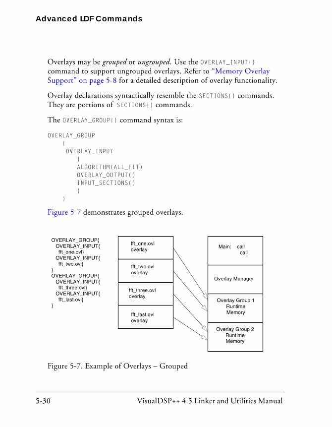
Advanced LDF Commands
5-30 VisualDSP++ 4.5 Linker and Utilities Manual
Overlays may be grouped or ungrouped. Use the OVERLAY_INPUT{} command to support ungrouped overlays. Refer to “Memory Overlay Support” on page 5-8 for a detailed description of overlay functionality.
Overlay declarations syntactically resemble the SECTIONS{} commands. They are portions of SECTIONS{} commands.
The OVERLAY_GROUP{} command syntax is:
OVERLAY_GROUP { OVERLAY_INPUT { ALGORITHM(ALL_FIT) OVERLAY_OUTPUT() INPUT_SECTIONS() } }
Figure 5-7 demonstrates grouped overlays.
Figure 5-7. Example of Overlays – Grouped
OVERLAY_GROUP{OVERLAY_INPUT{fft_one.ovl}
OVERLAY_INPUT{fft_two.ovl}
}OVERLAY_GROUP{
OVERLAY_INPUT{fft_three.ovl}
OVERLAY_INPUT{fft_last.ovl}
}
fft_one.ovloverlay
fft_two.ovloverlay
fft_three.ovloverlay
fft_last.ovloverlay
Overlay Group 1RuntimeMemory
Overlay Manager
Main: callcall
Overlay Group 2RuntimeMemory

VisualDSP++ 4.5 Linker and Utilities Manual 5-31
Memory Overlays and Advanced LDF Commands
In the simplified examples in Listing 5-4 and Listing 5-5, the functions are written to overlay (.ovl) files. Whether functions are disk files or memory segments does not matter (except to the DMA transfer that brings them in). Overlays are active only while being executed in run-time memory, which is located in the program memory segment.
Ungrouped Overlay Execution
In Listing 5-4, as the FFT progresses and overlay functions are called in turn, they are brought into run-time memory in sequence as four function transfers. Figure 5-8 shows the ungrouped overlays.
“Live” locations reside in several different memory segments. The linker outputs the executable overlay (.ovl) files while allocating destinations for them in the program section.
Listing 5-4. LDF Overlays – Not Grouped
// This is part of the SECTIONS{} command for processor P0// Declare which functions reside in which overlay.// The overlays have been split into different segments
Figure 5-8. Example of Overlays – Not Grouped
OVERLAY_INPUTfft_one.ovl
{fft_one.ovl}
OVERLAY_INPUT
{fft_two.ovl}
OVERLAY_INPUT
{fft_three.ovl}
OVERLAY_INPUT
{fft_last.ovl}
Overlay
fft_two.ovl
Overlay
fft_three.ovl
Overlay
fft_last.ovl
Overlay
Main: call call
Overlay
Manager
Overlay Run-time
Memory

Advanced LDF Commands
5-32 VisualDSP++ 4.5 Linker and Utilities Manual
// in one file, or into different files.// The overlays declared in this section (seg_pmco)// will run in segment seg_pmco.
OVERLAY_INPUT { // Overlays to live in section ovl_code ALGORITHM ( ALL_FIT ) OVERLAY_OUTPUT ( fft_one.ovl) INPUT_SECTIONS ( Fft_1st.doj(program) ) } >ovl_code
OVERLAY_INPUT { ALGORITHM ( ALL_FIT ) OVERLAY_OUTPUT ( fft_two.ovl) INPUT_SECTIONS ( Fft_2nd.doj(program) ) } >ovl_code
OVERLAY_INPUT { ALGORITHM ( ALL_FIT ) OVERLAY_OUTPUT ( fft_three.ovl) INPUT_SECTIONS ( Fft_3rd.doj(program) ) } >ovl_code
OVERLAY_INPUT { ALGORITHM ( ALL_FIT ) OVERLAY_OUTPUT ( fft_last.ovl) INPUT_SECTIONS ( Fft_last.doj(program) ) } >ovl_code
Grouped Overlay Execution
Listing 5-5 shows a different implementation of the same algorithm. The overlay functions are grouped in pairs. Since all four pairs of routines reside simultaneously, the processor executes both routines before paging.
Listing 5-5. LDF Overlays – Grouped
OVERLAY_GROUP { // Declare first overlay group OVERLAY_INPUT { // Overlays to live in section ovl_code ALGORITHM ( ALL_FIT ) OVERLAY_OUTPUT ( fft_one.ovl) INPUT_SECTIONS ( Fft_1st.doj(program) ) } >ovl_code OVERLAY_INPUT {

VisualDSP++ 4.5 Linker and Utilities Manual 5-33
Memory Overlays and Advanced LDF Commands
ALGORITHM ( ALL_FIT ) OVERLAY_OUTPUT ( fft_two.ovl) INPUT_SECTIONS ( Fft_mid.doj(program) ) } >ovl_code}OVERLAY_GROUP { // Declare second overlay group OVERLAY_INPUT { // Overlays to live in section ovl_code ALGORITHM ( ALL_FIT ) OVERLAY_OUTPUT ( fft_three.ovl) INPUT_SECTIONS ( Fft_last.doj(program) ) } >ovl_code OVERLAY_INPUT { ALGORITHM ( ALL_FIT ) OVERLAY_OUTPUT ( fft_last.ovl) INPUT_SECTIONS ( Fft_last.doj(program) ) } >ovl_code}
PLIT{}The linker resolves function calls and variable accesses (both direct and indirect) across overlays. This task requires the linker to generate extra code to transfer control to a user-defined routine (an overlay manager) that handles the loading of overlays. Linker-generated code goes in a spe-cial section of the executable file, which has the section name .PLIT.
The PLIT{} command in an .ldf file inserts assembly instructions that handle calls to functions in overlays. The assembly instructions are specific to an overlay and are executed each time a call to a function in that overlay is detected.
The PLIT{} command provides a template from which the linker generates assembly code when a symbol resolves to a function in overlay memory. The code typically handles a call to a function in overlay memory by calling an overlay memory manager. Refer to “Memory Overlay Support” on page 5-8 for a detailed description of overlay and PLIT functionality.

Advanced LDF Commands
5-34 VisualDSP++ 4.5 Linker and Utilities Manual
A PLIT{} command may appear in the global LDF scope, within a PROCESSOR{} command or within a SECTIONS{} command. For an example of using a PLIT{} command, see “Using PLIT{} and Overlay Manager” on page 5-24.
When writing the PLIT{} command in the LDF, the linker generates an instance of the PLIT, with appropriate values for the parameters involved, for each symbol defined in overlay code.
PLIT Syntax
Figure 5-9 shows the general syntax of the PLIT{} command and indicates how the linker handles a symbol (symbol) local to an overlay function.
Parts of the PLIT{} command are:
• instruction – None, one, or multiple assembly instructions. The instructions may occur in any reasonable order in the com-mand structure and may precede or follow symbols. The following two constants contain information about symbol and the overlay in which it occurs. You must supply instructions to handle that information.
• PLIT_SYMBOL_OVERLAYID – Returns the overlay ID
• PLIT_SYMBOL_ADDRESS – Returns the absolute address of the resolved symbol in run-time memory
Figure 5-9. PLIT{} Command Syntax Tree
PLIT{plit_commands}
instruction
symbol = PLIT_SYMBOL_OVERLAYID [symbol]symbol = PLIT_SYMBOL_ADDRESSsymbol = PLIT_DATA_OVERLAY_ID
VisualDSP++ 4.5 Linker and Utilities Manual 5-35
Memory Overlays and Advanced LDF Commands
Command Evaluation and Setup
The linker first evaluates the sequence of assembly code in each plit_command. Each line is passed to a processor-specific assembler, which supplies values for the symbols and expressions. After evaluation, the linker places the returned bytes into the .PLIT output section and manages the addressing in that output section.
To help write an overlay manager, the linker generates PLIT constants for each symbol in an overlay. Data can be overlaid, just like code. If an over-lay-resident function calls for additional data overlays, include an instruction for finding them.
After the setup and variable identification are completed, the overlay itself is brought (via DMA transfer) into run-time memory. This process is con-trolled by assembly code called an overlay manager.
The branch instruction, such as jump OverlayManager, is normally the last instruction in the PLIT{} command.
Overlay PLIT Requirements and PLIT Examples
Both the .plit output section (allocating space for PLIT) and the PLIT{} command are necessary when specifying PLIT for overlays. The .ldf file must allocate space in memory to hold PLITs built by the linker. Typi-cally, that memory resides in the program code memory segment.
No input section is associated with the .plit output section. The LDF allocates space for linker-generated routines, which do not contain (input) data objects.
A typical LDF declaration for that purpose is:
// ... [In the SECTIONS command for Processor P0]
// Plit code is to reside and run in mem_program segment
.plit {} > mem_program
Advanced LDF Commands
5-36 VisualDSP++ 4.5 Linker and Utilities Manual
This segment allocation does not take any parameters. You write the struc-ture of this command according to the PLIT syntax. The linker creates an instance of the command for each symbol that resolves to an overlay. The linker stores each instance in the .plit output section, which becomes part of the program code’s memory segment.
A PLIT{} command may appear in the global LDF scope, within a PROCESSOR{} command or within a SECTIONS{} command.
Simple PLIT – States are not SavedA simple PLIT merely copies the symbol’s address and overlay ID into registers and jumps to the overlay manager. The following fragment is extracted from the global scope (just after the MEMORY{} command) of sample fft_group.ldf. Verify that the contents of P0 and P1 are either safe or irrelevant. For example,
PLIT{ P0 = PLIT_SYMBOL_OVERLAY_ID; P1.L = PLIT_SYMBOL_ADDRESS; P1.H = PLIT_SYMBOL_ADDRESS; JUMP _OverlayManager; }
As a general rule, minimize overlay transfer traffic. Improve performance by designing code to ensure overlay functions are imported and use mini-mal (or no) reloading.
PLIT – Summary
A PLIT is a template of instructions for loading an overlay. For each overlay routine in the program, the linker builds and stores a list of PLIT instances according to that template, as it builds its executable file. The linker may also save registers or stack context information. The linker does not accept a PLIT without arguments.
If you do not want the linker to redirect function calls in overlays, omit the PLIT{} commands entirely.

VisualDSP++ 4.5 Linker and Utilities Manual 5-37
Memory Overlays and Advanced LDF Commands
To help write an overlay manager, the linker generates PLIT_SYMBOL con-stants for each symbol in an overlay.
The overlay manager can also:
• Be helped by manual intervention. Save the target’s state on the stack or in memory before loading and executing an overlay func-tion, to ensure it continues correctly on return. However, you can implement this feature within the PLIT section of your LDF. Note: Your program may not need to save this information.
• Initiate (jump to) the routine that transfers the overlay code to internal memory, after given the previous information about its identity, size and location: _OverlayManager. “Smart” overlay man-agers first check whether an overlay function is already in internal memory to avoid reloading the function.
Linking Multiprocessor SystemsThe linker has several commands that can be used to build executable images for multiprocessor systems. Selecting the right multiprocessor link-ing commands and how to use them will depend on both the system you are building and which Analog Devices processor is in your system.
The linker will only support linking for homogeneous multiprocessors. That is the system uses the same kind of processor throughout. If you are building a heterogeneous multiprocessing environment you will need to build the system with more than one link step, using an LDF for each kind of processor in your system.
A homogeneous multiprocessor system can be linked with a single LDF file. The LDF file will have a PROCESSOR{} command that describes which object files and libraries are to be linked into the memory for each proces-sor. Every PROCESSOR{} command will produce a separate executable file (.dxe).

Linking Multiprocessor Systems
5-38 VisualDSP++ 4.5 Linker and Utilities Manual
For processors that have the ability to access the local memory of other processors, for example through link ports, the MPMEMORY{} command can be used to define the offset of each processor's physical memory. The MPMEMORY{} command is described below.
In addition, it is possible to define what code and data is to be placed into memory that is shared between processors. There are two commands avail-able for placing objects and libraries into shared memory: SHARED_MEMORY{} and COMMON_MEMORY{}. Which of these commands you use will depend on how you intend to use the shared memory and the lim-itations of the processor architecture. The SHARED_MEMORY{} command can be used if the shared memory in the system does not contain any refer-ences to memory that is internal to an individual processor, or if the processor architecture supports addressing the internal memory of other processors. For other processors, for example the ADSP-BF561, where one processor can not access the internal memory of the other processor, the COMMON_MEMORY{} command should be used. These commands, and their usage, are described in more detail below.
Regardless of which of the linker commands you use, you will have to make decisions regarding which code is going to run on which processor, where data will be placed, and what processors have access to what data. Once you have a partitioning of your code and data you can use the LDF to instruct the linker on placement.
Selecting Code and Data for PlacementThere are many ways to identify code and data objects for placement in a multiprocessor system. The methods are the same methods used when being selective about placement of objects in internal or external memory. There are advantages and disadvantages for each of the methods, and an LDF may use a combination of many of these methods.
VisualDSP++ 4.5 Linker and Utilities Manual 5-39
Memory Overlays and Advanced LDF Commands
Using LDF Macros
The easiest way to partition code and data between processors is to explic-itly place the object files by name. In the example below, the code that is to be placed in CoreA are in object files that are explicitly named in the LDF.
PROCESSOR COREA
{
OUTPUT ( $COMMAND_LINE_OUTPUT_DIRECTORY\corea.dxe )
SECTIONS
{
code
{
INPUT_SECTIONS (corea.doj(program) coreamain.doj(program))
} > CoreaCode
...
}
PROCESSOR COREB
{
OUTPUT ( $COMMAND_LINE_OUTPUT_DIRECTORY\coreb.dxe )
SECTIONS
{
code
{
INPUT_SECTIONS (coreb.doj(program) corebmain.doj(program))
} > CorebCode
...
}
Doing placement explicitly by object file can be made easier through the use of LDF macros. The example could be simplified with macros for the objects to be placed in each core.
$COREAOBJECTS = corea.doj, coreamain.doj;
$COREBOBJECTS = coreb.doj, corebmain.doj;

Linking Multiprocessor Systems
5-40 VisualDSP++ 4.5 Linker and Utilities Manual
...
PROCESSOR COREA
{
...
SECTIONS
{
code
{
INPUT_SECTIONS ( $COREAOBJECTS(program) )
} > CoreaCode
}
By using an LDF macro it is much easier to make changes if functionality is going to be moved from one processor to another.
Object files can appear in more than one LDF macro. Depending on the system, the same object file may be mapped to more than one processor.
The main advantages of explicitly naming object files when placing object files to processors is that it is explicit in the LDF where each object file goes. By using LDF macros the list of object files can be localized. A disad-vantage for explicitly naming object files is that every time a new file is added to your system the LDF must be modified to explicitly reference the file. Also, it is not possible to share the LDF with other projects that are built on the same multiprocessing system.

VisualDSP++ 4.5 Linker and Utilities Manual 5-41
Memory Overlays and Advanced LDF Commands
Mapping by Section NameBoth the compiler and assembler provide you the ability to give names to sections in the object files. In the assembler this is done using the .SEC-TION directive:
.SECTION Corea_Code;
The compiler has two ways to name a section. The first method uses the section() qualifier:
section("Corea_Code") main() {...}
The section name can also be specified using the section pragma. Using the pragma is recommended since it is more flexible and will also result in code that is portable.
#pragma section ("Corea_Code")
main() {...}
Users can use section names to identify code that is to be placed with a particular processor.
PROCESSOR COREA
{
OUTPUT ( $COMMAND_LINE_OUTPUT_DIRECTORY\corea.dxe )
SECTIONS
{
code
{
INPUT_SECTIONS ( $OBJECTS(Corea_Code) )
} > CoreaCode
...
}
Linking Multiprocessor Systems
5-42 VisualDSP++ 4.5 Linker and Utilities Manual
The advantage of mapping by section name is that the LDF can be made generic and reused for other projects using the same multiprocessor. The disadvantage is that it requires making changes to C and assembly source code files to make the mapping. It also may not be possible to modify source code for some libraries or code supplied by third parties.
Mapping Using AttributesBeginning with VisualDSP++ 4.5, the linker supports mapping by attributes. When compiling and assembling, users can assign attributes to object files. These attributes can then be used to filter object files for inclusion (or exclusion) during mapping. Users can assign attributes to object files that identify a core that the object files should be mapped to, a core that an object file shouldn't be mapped to, code that is safe to be shared by all processors, etc.
The runtime libraries are built using attributes so it possible to select areas within the runtime libraries for placement. For example, it is possible to select the objects in the runtime libraries that are needed for I/O and have them only placed in external memory.
An advantage of using attributes is that the LDF can be made generic and reused for other projects using the same multiprocessor. The disadvantage is that changing where an object is placed requires rebuilding the object file in order to change the attributes. Also, if all of the object files are being built in the same project it can be inconvenient to use file specific build options. It also may not be possible to rebuild the object for some libraries.
Mapping Using ArchivesAnother way to partition files is to build an object archive or library.

VisualDSP++ 4.5 Linker and Utilities Manual 5-43
Memory Overlays and Advanced LDF Commands
As an example, you could create a project just for building the object files to be placed in CoreA. The target of the project would be an archive named corea.dlb. The project that actually did the linking of the multi-processor system would include corea.dlb. In fact it is easiest to build a project group in which the linking project would have dependencies on the projects that build the archives it depends on. The LDF would then use the archive for linking:
PROCESSOR COREA
{
OUTPUT ( $COMMAND_LINE_OUTPUT_DIRECTORY\corea.dxe )
SECTIONS
{
code
{
INPUT_SECTIONS ( corea.dlb(program) )
} > CoreaCode
...
}
The disadvantage of using archives for mapping is that it requires organiz-ing more than one project. The advantage is that it can be easy to add, delete, or move objects from one processor to another. Removing an object from a project will remove it from the archive when the project is rebuilt. Adding a file to a project that builds an archive will automatically add the file to the link without needing to make changes to source. This flexibility makes it easy to create an LDF that can be shared by users building for the same architecture.
The COMMON_MEMORY{} command requires archives when mapping objects into memory that is shared between processors. This command is described in more detail below.

Linking Multiprocessor Systems
5-44 VisualDSP++ 4.5 Linker and Utilities Manual
MPMEMORY{}The MPMEMORY{} command is not used with Blackfin processors.
The MPMEMORY{} command specifies the offset of each processor’s physical memory in a multiprocessor target system. After you declare the processor names and memory segment offsets with the MPMEMORY{} command, the linker uses the offsets during multiprocessor linking. Refer to “Memory Overlay Support” on page 5-8 for a detailed description of overlay functionality.
Your .ldf file (and other .ldf files that it includes), may contain one MPMEMORY{} command only. The maximum number of processors that you can declare is architecture-specific. Follow the MPMEMORY{} command with PROCESSOR processor_name{} commands, which contain each processor’s MEMORY{} and SECTIONS{} commands.
Figure 5-10 shows MPMEMORY{} command syntax.
Figure 5-10. MPMEMORY{} Command Syntax Tree
processor_name {
START(address_expression)
}
MPMEMORY{shared_segment_commands}

VisualDSP++ 4.5 Linker and Utilities Manual 5-45
Memory Overlays and Advanced LDF Commands
Definitions for parts of the MPMEMORY{} command’s syntax are:
• shared_segment_commands – Contains processor_name declara-tions with a START{} address for each processor’s offset in multiprocessor memory. Processor names and linker labels follow the same rules. For more information, refer to “LDF Expressions” on page 3-19.
• processor_name{placement_commands} – Applies the processor_name offset for multiprocessor linking. Refer to “PROCESSOR{}” on page 3-48 for more information.
The MEMORY{} command specifies the memory map for the target system. The LDF must contain a MEMORY{} command for global memory on the target system and may contain a MEMORY{} com-mand that applies to each processor’s scope. An unlimited number of memory segments can be declared within each MEMORY{} com-mand. For more information, see “MEMORY{}” on page 3-38. See “Memory Characteristics Overview” on page 2-27 for memory map descriptions.
SHARED_MEMORY{}The SHARED_MEMORY{} command creates an executable output that maps code and data into a memory space that is shared by multiple processors. The output is given the extension .SM for shared memory. The SHARED_MEMORY{} command is similar in structure to the PROCESSOR{} command. The PROCESSOR{} command contains, among other commands, an OUTPUT() command that specifies a .DXE file for the output, and uses SECTIONS{} command to map selected sections from object files into spec-ified sections in processor memory. Similarly, the SHARED_MEMORY{} command uses an OUTPUT() command and SECTIONS{} command to create a .SM file.
Figure 5-11 on page 5-46 shows the syntax for the SHARED_MEMORY{} com-mand, followed by definitions of its components.

Linking Multiprocessor Systems
5-46 VisualDSP++ 4.5 Linker and Utilities Manual
The command components are:
• OUTPUT() – Specifies the output file name (file_name.SM) of the shared memory executable (.sm) file. An OUTPUT() command in a SHARED_MEMORY{} command must appear before the SECTIONS{} command in that scope.
• SECTIONS() – Defines sections for placement within the shared memory executable (.sm) file.
• The LDF will have a MEMORY{} command that defines the memory configuration for the multiprocessor. The SHARED_MEMORY{} com-mand must appear in the same LDF scope as the MEMORY{} command. The PROCESSOR{} commands for each processor in the system should also appear at this same LDF scope.
Figure 5-12 on page 5-47 shows the scope of SHARED_MEMORY{} commands in the LDF.
The mapping of objects into processors and shared memory is made useful by being able to have processors and shared memory "link against" each other. The LINK_AGAINST() command specifies a .DXE file or .SM file gen-erated by the mapping for another processor or shared memory and makes the symbols in that file available for resolution for the current processor.
Figure 5-11. SHARED_MEMORY{} Command Syntax
SHARED_MEMORY{OUTPUT(file_name.SM)
}SECTIONS {section_commands}
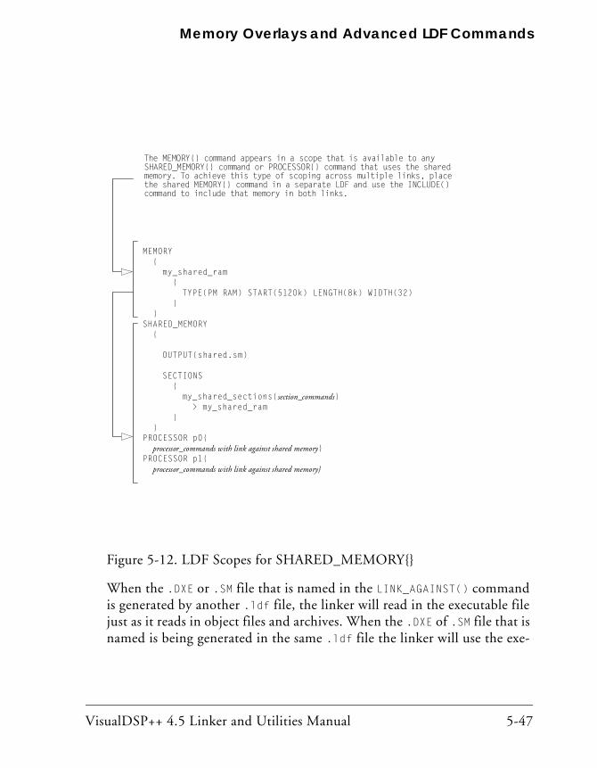
VisualDSP++ 4.5 Linker and Utilities Manual 5-47
Memory Overlays and Advanced LDF Commands
When the .DXE or .SM file that is named in the LINK_AGAINST() command is generated by another .ldf file, the linker will read in the executable file just as it reads in object files and archives. When the .DXE of .SM file that is named is being generated in the same .ldf file the linker will use the exe-
Figure 5-12. LDF Scopes for SHARED_MEMORY{}
MEMORY{
my_shared_ram{
TYPE(PM RAM) START(5120k) LENGTH(8k) WIDTH(32)}
}SHARED_MEMORY
{
OUTPUT(shared.sm)
SECTIONS{
my_shared_sections{section_commands}> my_shared_ram
}}
PROCESSOR p0{processor_commands with link against shared memory}
PROCESSOR p1{processor_commands with link against shared memory}
The MEMORY{} command appears in a scope that is available to anySHARED_MEMORY{} command or PROCESSOR{} command that uses the sharedmemory. To achieve this type of scoping across multiple links, placethe shared MEMORY{} command in a separate LDF and use the INCLUDE()command to include that memory in both links.

Linking Multiprocessor Systems
5-48 VisualDSP++ 4.5 Linker and Utilities Manual
cutable file as it is being generated. When the processor and shared memory appear in the same LDF the order that the processor or shared memory commands appear is not important.
For example, consider that the object file data.doj contains the global data buffer DBUF, and the object file main.doj contains code that refer-ences that data. Further, the data buffer DBUF is placed in shared memory so that it is available to multiple processors, while main.doj con-tains code that is going to be executed from CoreA. An LDF that does this mapping would include:
SHARED_MEMORY
{
OUTPUT("shared_memory.sm")
SECTIONS
{
data_sm
{
INPUT_SECTIONS(data.doj(data))
} > mem_shared_mem
}
}
PROCESSOR CoreA
{
OUTPUT("corea.dxe")
LINK_AGAINST("shared_memory.sm")
SECTIONS
{
code_corea
{
INPUT_SECTIONS(main.doj(program))
} > corea_a_mem
}
}
VisualDSP++ 4.5 Linker and Utilities Manual 5-49
Memory Overlays and Advanced LDF Commands
In the example LDF, the SHARED_MEMORY{} command creates the output file shared_memory.sm. The data from the object file data.doj is mapped into the output file and placed into the memory named mem_shared_mem. (The memory definition is not shown.) Later in the LDF the mapping for CoreA is done with a PROCESSOR{} command. In addition to creating the output file corea.dxe and mapping the program sections from the object file main.doj, it also "links against" the file corea.dxe.
The LINK_AGAINST() command has the following effect. After all of the objects and sections for processor CoreA have been mapped, the symbol table in the file shared_memory.sm is used to find any symbols that could not be resolved. In the example, the object file main.doj contains a refer-ence to the symbol DBUF but none of the object files mapped into CoreA contained that symbol. The symbols in shared_memory.sm are then read and DBUF is found to have been mapped into shared memory. The linker will resolve the reference in CoreA to be the address in shared memory that DBUF was mapped into by processing the SHARED_MEMORY{} com-mand that produced shared_memory.sm.
The processing order described above is slightly modified if there are sym-bols that have weak linkage. A symbol with strong linkage in an executable named in a LINK_AGAINST() command will take precedence over a "weak" symbol.
The LINK_AGAINST() command takes effect only after mapping of objects and libraries in the input sections for the processor. Object from libraries will be mapped if needed to resolve references, even if those symbols are available in the shared memory .SM file named in the LINK_AGAINST() command. If both the processor and shared memory both map the same library files it is possible that an object from that library may both get mapped into the processor and the shared memory. The multiple mapping is unlikely to make the program incorrect, but it can be a waste of memory.
Linking Multiprocessor Systems
5-50 VisualDSP++ 4.5 Linker and Utilities Manual
The LINK_AGAINST() command can also appear within a SHARED_MEMORY{} command. It is possible for a shared memory to link against a processor .dxe. The LINK_AGAINST() works in the same way. After mapping objects and libraries that are listed in INPUT_SECTIONS() commands, if there are symbols that have not been resolved, the .dxe (or .sm) file that is specified in the LINK_AGAINST() will be used.
It is possible for more than one LINK_AGAINST() command to appear in the same processor or shared memory. The .dxe or .sm files that are named will be searched in the order they appear to resolve references.
It is also possible to have a processor link against a shared memory and have the same shared memory link against that processor. The bidirec-tional link against can allow code in the processor memory to call code that exists in shared memory that can then call code that is in the proces-sor memory. As mentioned above, linking behavior does not depend on the order that processors and shared memory appear in the .ldf file. This order independence is still true with a bidirectional link against.
Note that references from shared memory into processor memory may not be supported by all processors. For example, for a multi-core Blackfin pro-cessor like the ADSP-BF561, it is not possible for code executing in one core to access memory that is in internal memory of the other processor. If there is code in shared memory that makes a reference to internal memory of CoreA, that code can only be executed on CoreA. If CoreB executes the code, once CoreB tries to reference the internal memory on CoreA the part will halt because of a hardware exception.
Also note that on parts where processors can access the internal memory of the other processors, that access may be slow and affect the performance of your program.
If you don't have LINK_AGAINST() commands within a SHARED_MEMORY{} command then there won't be any references from shared memory back to internal memory of any of the cores. If your system needs to have refer-ences from shared memory back to processors it is best to use the
VisualDSP++ 4.5 Linker and Utilities Manual 5-51
Memory Overlays and Advanced LDF Commands
COMMON_MEMORY{} command. If there are references from shared memory back to processor internal memory for the Blackfin processors, COMMON_MEMORY{} is required.
One solution that can be used is to partition shared memory into a section reserved for CoreA, a section reserved for CoreB, and a section that is memory shared between the two processors. The partitioning is managed by using the MEMORY{} command. Then the PROCESSOR{} command for CoreA will map into the CoreA internal memory and into the section of shared memory reserved for CoreA. It will also typically link against the shared memory. The PROCESSOR{} command for CoreB will map into the CoreB internal memory and into the section of shared memory reserved for CoreB, and link against the shared memory. The SHARED_MEMORY{}} command is used to map the program and data that is common to both processors.
COMMON_MEMORY{}The COMMON_MEMORY{} command is another way to map objects into mem-ory that is shared by more than one processor. The mapping is done in the context of the processors that will use the shared memory; these processors are identified as a "master" of the common memory. The COMMON_MEMORY{} command will also manage references from the shared memory back to internal memory of the processors so that each processor will not reference memory that is in another processor's internal memory. The COMMON_MEMORY{} command looks like the PROCESSOR{} and SHARED_MEMORY{} commands in that it will use INPUT_SECTIONS() com-mands for mapping. A restriction is that within a COMMON_MEMORY{} command only archives may be mapped and not individual object files.
The following example shows the basic components of the COMMON_MEMORY{} command.
COMMON_MEMORY
{

Linking Multiprocessor Systems
5-52 VisualDSP++ 4.5 Linker and Utilities Manual
OUTPUT("common_memory.cm")
MASTERS(CoreA, CoreB)
SECTIONS
{
data_cm
{
INPUT_SECTIONS(common.dlb(data))
} > mem_common_mem
}
}
PROCESSOR CoreA
{
OUTPUT("corea.dxe")
SECTIONS
{
code_corea
{
INPUT_SECTIONS(main.doj(program))
} > corea_a_mem
}
}
PROCESSOR CoreB
{
OUTPUT("coreb.dxe")
SECTIONS
{
code_corea
{
INPUT_SECTIONS(main.doj(program))
} > corea_a_mem
}
}

VisualDSP++ 4.5 Linker and Utilities Manual 5-53
Memory Overlays and Advanced LDF Commands
The COMMON_MEMORY{} command uses the OUTPUT() to name the file that will hold the result of the mapping. The command uses the extension .CM for the file. The COMMON_MEMORY{} command also uses the SECTIONS{} command to map files into memory segments. However, the only files that can be mapped are archive (.dlb) files. Individual object files can not be mapped from inside of a COMMON_MEMORY{} command.
The biggest syntactic difference in the COMMON_MEMORY{} command is the The MASTERS() command. This command explicitly identifies the proces-sors that are going to share the memory. The processor names are the name used in the PROCESSOR{} commands also appearing in the same .ldf file. Within the PROCESSOR{} command there is no need for a LINK_AGAINST() command specifying the common memory. The MAS-TERS() command describes the connection.
The mapping of the archives in the COMMON_MEMORY{} is really done when the mapping is done for the masters named in the The MASTERS(). While mapping for each of the processors named as a master, the linker will treat each INPUT_SECTIONS() command in the common memory as if they appeared within the PROCESSOR{} command. Since only archives are allowed, only the objects within the archive that are needed to satisfy ref-erences for the processor will be mapped. The mapping will be into the memory sections in the common memory.
For example, the effect of the previous example will be as if the INPUT_SECTIONS() in the COMMON_MEMORY{} were part of the PROCESSOR{}:
// NOT ACTUAL LDF – EFFECT OF COMMON_MEMORY{}
PROCESSOR CoreA
{
OUTPUT("corea.dxe")
SECTIONS
{
code_corea
{
INPUT_SECTIONS(main.doj(program))

Linking Multiprocessor Systems
5-54 VisualDSP++ 4.5 Linker and Utilities Manual
} > corea_a_mem
// when mapping CoreA, the input sections from
// the common memory are mapped as if they were
// part of this PROCESSOR{} because CoreA is
// listed as a MASTER
data_cm
{
INPUT_SECTIONS(common.dlb(data))
} > mem_common_mem
}
}
Of course, by specifying with COMMON_MEMORY{} the same mapping for the objects in common.dlb will also be done for CoreB, and the objects that are shared by the two processors will only be mapped once into the shared memory space.
The mapping will be done for each of the processors named as a master. Some symbols will be needed for each processor and in simple cases the common memory will share the code or data between the processors. If there is an object that is mapped into common memory that has a refer-ence that goes back into internal memory of a processor, the linker will if necessary make a copy of the object file so that both cores can safely use common memory. This behavior is described in the example below.
To demonstrate the complexities of multiprocessing linking the example has several dependencies. The abbreviated C examples show the depen-dencies for several object files.
// file mainA.doj
void mainA() {
// the main code in CoreA references 2 common functions
commonfunc1();
commonfunc2();
}
// file mainB.doj

VisualDSP++ 4.5 Linker and Utilities Manual 5-55
Memory Overlays and Advanced LDF Commands
void mainB() {
// the main code in CoreB references 3 common functions
commonfunc1();
commonfunc2();
commonfunc3();
}
// file func1.doj
void commonfunc1() {
// a common function with a reference to a library
libfunc1();
}
// file func2.doj
void commonfunc2() {
// a common function with a reference to a library
libfunc2();
}
// file func3.doj
void commonfunc3() {
// no further references
}
// file libfunc1.doj and libfunc2.doj have no further references
// create archives for common files
elfar –c common.dlb func1.doj func2.doj func3.doj
elfar –c commonlib.dlb libfunc1.doj libfunc2.doj
Each of the processors has its own main function. Each of the main func-tions makes calls to common functions. Some of the common functions make further calls to library functions. The common functions have been placed in an archive named common.dlb and the library files have been placed in an archive named commonlib.dlb.
The LDF to build the multiprocessor system is shown below.
COMMON_MEMORY
{
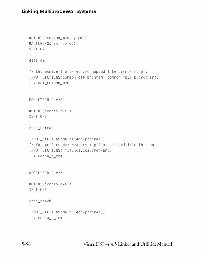
Linking Multiprocessor Systems
5-56 VisualDSP++ 4.5 Linker and Utilities Manual
OUTPUT("common_memory.cm")
MASTERS(CoreA, CoreB)
SECTIONS
{
data_cm
{
// the common libraries are mapped into common memory
INPUT_SECTIONS(common.dlb(program) commonlib.dlb(program))
} > mem_common_mem
}
}
PROCESSOR CoreA
{
OUTPUT("corea.dxe")
SECTIONS
{
code_corea
{
INPUT_SECTIONS(mainA.doj(program))
// for performance reasons map libfunc1.doj into this core
INPUT_SECTIONS(libfunc1.doj(program))
} > corea_a_mem
}
}
PROCESSOR CoreB
{
OUTPUT("coreb.dxe")
SECTIONS
{
code_coreb
{
INPUT_SECTIONS(mainB.doj(program))
} > corea_b_mem

VisualDSP++ 4.5 Linker and Utilities Manual 5-57
Memory Overlays and Advanced LDF Commands
}
}
Notice that processor CoreA explicitly maps libfunc1.doj into its inter-nal memory. CoreB does not map a version of libfunc1.doj. Both processors link against the common memory that does mapping against the archives that contain common functions.
To understand the operation of COMMON_MEMORY{} we will walk through the mapping of the objects into memory, beginning with CoreA. The INPUT_SECTIONS() commands for CoreA will map mainA.doj and libfunc1.doj into the memory corea_a_mem. The references to commonfunc1 and commonfunc2 will cause the object files func1.doj and func2.doj to be pulled out of the archive common.dlb and they will be mapped into the common memory mem_common_mem. The object file func1.doj has a reference to libfunc1. This symbol was already mapped when libfunc1.doj was mapped into the core memory. The object file func2.doj has a reference to libfunc2 so the object libfunc2.doj will be pulled out of the archive commonlib.dlb and it will also be mapped into mem_common_mem. Note that this mapping only considers the files required for CoreA so commonfunc3 is not considered.
The mapping for CoreB will be similar. The INPUT_SECTIONS() command for CoreB will map mainB.doj into the memory coreb_b_mem. The refer-ences to the common functions will cause the object files func1.doj, func2.doj, and func3.doj to be pulled out of the archive common.dlb and to be mapped into mem_common_mem. The references in the common func-tions to the library functions will cause the library objects to be pulled from the commonlib.dlb so libfunc1.doj and libfunc2.doj will be mapped into the common memory mem_common_mem. Note that this map-ping only considers the files for CoreB and the common memory. In particular the fact that libfunc1.doj was mapped into CoreA memory is not considered for this mapping.

Linking Multiprocessor Systems
5-58 VisualDSP++ 4.5 Linker and Utilities Manual
Now the linker ensures that all the objects mapped into common memory can be shared; for those files that can't be shared, it will fix them by mak-ing duplications. Those object files mapped into common memory that do not have any further references (the leaf functions func3.doj, libfunc1.doj, and libfunc2.doj) are fine as they are. The function commonfunc2 references libfunc2.doj (which is only mapped into com-mon memory), so it is also fine. The function commonfunc1 references libfunc1.doj. In the context of CoreA, func1.doj will call the version of libfunc1 that is mapped into CoreA internal memory. In the context of CoreB, func1.doj will call the version of libfunc1 that is mapped into common memory. To resolve this problem, the linker will create a copy of func1.doj. The mainA function will call the version that references back to the version of libfunc1 that is in CoreA memory while mainB will call the version that references back to the version of libfunc1 that is in common memory.
It is rare that an object mapped into common memory will be duplicated. In the cases that an object is duplicated, the linker will only duplicate the minimal amount needed to keep integrity. The duplication will only hap-pen in cases where using the SHARED_MEMORY{} command would have resulted in a runtime exception, because a processor was accessing memory in another processor's internal memory.

VisualDSP++ 4.5 Linker and Utilities Manual 6-1
6 ARCHIVER
The VisualDSP++ archiver (elfar) combines object (.doj) files into library files, which serve as reusable resources for code development. The VisualDSP++ linker rapidly searches library files for routines (library members) referred to by other object files and links these routines into the executable program.
This chapter provides:
• “Introduction” on page 6-2 Introduces the archiver’s functions
• “Archiver Guide” on page 6-3 Describes the archiver’s functions
• “Archiver Command-Line Reference” on page 6-14 Describes archiver operations by means of command-line switches

Introduction
6-2 VisualDSP++ 4.5 Linker and Utilities Manual
IntroductionThe elfar utility combines and indexes object files (or any other files) to produce a searchable library file. It performs the following operations, as directed by options on the elfar command line:
• Creates a library file from a list of object files
• Appends one or more object files to an existing library file
• Deletes file(s) from a library file
• Extracts file(s) from a library file
• Prints the contents of object files of an existing library file to stdout
• Replaces file(s) in an existing library file
• Encrypts symbol(s) in an existing library file
• Embeds version information into a library built with elfar
The archiver can run only one of these operations at a time. However, for commands that take a list of file names as arguments, the archiver can input a text file that contains the names of object files (separated by white space). The operation makes long lists easily manageable.
The archiver, which is sometimes called a librarian, is a general-purpose utility. It combines and extracts arbitrary files. This manual refers to DSP object (.doj) files because they are relevant to DSP code development.
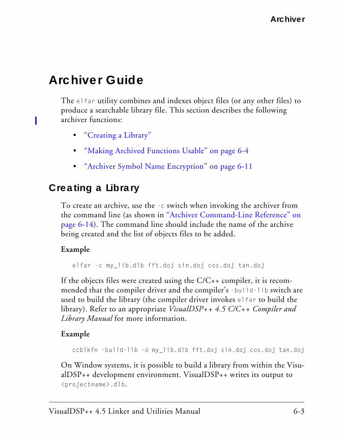
VisualDSP++ 4.5 Linker and Utilities Manual 6-3
Archiver
Archiver GuideThe elfar utility combines and indexes object files (or any other files) to produce a searchable library file. This section describes the following archiver functions:
• “Creating a Library”
• “Making Archived Functions Usable” on page 6-4
• “Archiver Symbol Name Encryption” on page 6-11
Creating a LibraryTo create an archive, use the -c switch when invoking the archiver from the command line (as shown in “Archiver Command-Line Reference” on page 6-14). The command line should include the name of the archive being created and the list of objects files to be added.
Example
elfar -c my_lib.dlb fft.doj sin.doj cos.doj tan.doj
If the objects files were created using the C/C++ compiler, it is recom-mended that the compiler driver and the compiler’s -build-lib switch are used to build the library (the compiler driver invokes elfar to build the library). Refer to an appropriate VisualDSP++ 4.5 C/C++ Compiler and Library Manual for more information.
Example
ccblkfn -build-lib -o my_lib.dlb fft.doj sin.doj cos.doj tan.doj
On Window systems, it is possible to build a library from within the Visu-alDSP++ development environment. VisualDSP++ writes its output to <projectname>.dlb.
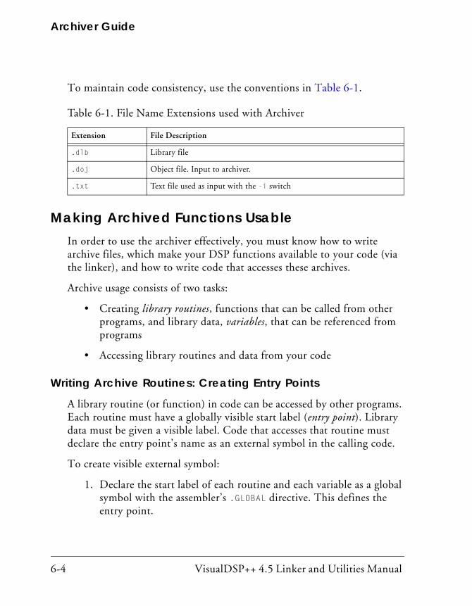
Archiver Guide
6-4 VisualDSP++ 4.5 Linker and Utilities Manual
To maintain code consistency, use the conventions in Table 6-1.
Making Archived Functions UsableIn order to use the archiver effectively, you must know how to write archive files, which make your DSP functions available to your code (via the linker), and how to write code that accesses these archives.
Archive usage consists of two tasks:
• Creating library routines, functions that can be called from other programs, and library data, variables, that can be referenced from programs
• Accessing library routines and data from your code
Writing Archive Routines: Creating Entry Points
A library routine (or function) in code can be accessed by other programs. Each routine must have a globally visible start label (entry point). Library data must be given a visible label. Code that accesses that routine must declare the entry point’s name as an external symbol in the calling code.
To create visible external symbol:
1. Declare the start label of each routine and each variable as a global symbol with the assembler’s .GLOBAL directive. This defines the entry point.
Table 6-1. File Name Extensions used with Archiver
Extension File Description
.dlb Library file
.doj Object file. Input to archiver.
.txt Text file used as input with the -i switch
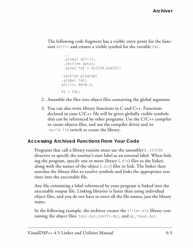
VisualDSP++ 4.5 Linker and Utilities Manual 6-5
Archiver
The following code fragment has a visible entry point for the func-tion dIriir and creates a visible symbol for the variable FAE.
... .global dIriir; .section data1; .byte2 FAE = 0x1234,0x4321;
.section program; .global FAE; dIriir: R0=N-2;
P2 = FAE;
2. Assemble the files into object files containing the global segments.
3. You can also write library functions in C and C++. Functions declared in your C/C++ file will be given globally visible symbols that can be referenced by other programs. Use the C/C++ compiler to create objects files, and use the compiler driver and its -build-lib switch to create the library.
Accessing Archived Functions From Your Code
Programs that call a library routine must use the assembler’s .EXTERN directive to specify the routine’s start label as an external label. When link-ing the program, specify one or more library (.dlb) files to the linker, along with the names of the object (.doj) files to link. The linker then searches the library files to resolve symbols and links the appropriate rou-tines into the executable file.
Any file containing a label referenced by your program is linked into the executable output file. Linking libraries is faster than using individual object files, and you do not have to enter all the file names, just the library name.
In the following example, the archiver creates the filter.dlb library con-taining the object files: taps.doj, coeffs.doj, and go_input.doj.

Archiver Guide
6-6 VisualDSP++ 4.5 Linker and Utilities Manual
elfar -c filter.dlb taps.doj coeffs.doj go_input.doj
If you then run the linker with the following command line, the linker links the object files main.doj and sum.doj, uses the default .ldf file (for example, ADSP-BF533.ldf), and creates the executable file (main.dxe).
linker -DADSP-BF533 main.doj sum.doj filter.dlb -o main.dxe
Assuming that one or more library routines from filter.dlb are called from one or more of the object files, the linker searches the library, extracts the required routines, and links the routines into the executable file.
Specifying Object Files
The list of object files on the command line is used to specify objects to be added to the archive. Such commands are -c (create), -a (add) or -r (replace). The list can also be used to specify objects in the library to be extracted using the -e (extract) command.
When the list refers to object files to be added to the archive, the file name is specified the way the file names are specified for the host operating sys-tem. The file name can include path information – relative or absolute. If path information is not included, the archiver will look for the file in the current working directory.
When the list refers to object files already in the archive, the file names should not include any path information. The archiver only saves the base file name for the object files in the archive.
The archiver accepts the wildcard character “*” in the specification of the object file names. On Windows systems, the archiver does all interpreta-tion of the wildcard character. When it appears in a list of object files to be added, the archiver searches the file system for files that match this specification. When a wildcard appears in a list of objects already in the library, the archiver will search through the object files in the library for matches.

VisualDSP++ 4.5 Linker and Utilities Manual 6-7
Archiver
Tagging an Archive With Version Information
The archiver supports embedding version information into a library built with elfar.
Basic Version Information
You can “tag” an archive with a version. The easiest way to tag an archive is with the -t switch (see Table 6-2 on page 6-15), which takes an argu-ment (the version number). For example,
elfar –t 1.2.3 lib.dlb
The –t switch can be used in addition to any other elfar command. For example, a version can be assigned at the same time that a library is created:
elfar –c –t "Steve's sandbox Rev 1" lib.dlb *.doj
To hold version information, the archiver creates an object file, __version.doj, that has version information in the .strtab section. This file is not made visible to the user.
An archive without version information will not have the __version.doj entry. The only operations on the archive using elfar that add version information are those that use the –t switch. That is, an archive without version information does not pick up version information unless specifi-cally requested.
If an archive contains version information (__version.doj is present), all operations on the archive preserve that version information, except opera-tions that explicitly request version information to be stripped from the archive (see “Removing Version Information From an Archive” on page 6-10).

Archiver Guide
6-8 VisualDSP++ 4.5 Linker and Utilities Manual
If an archive contains version information, that information can be printed with the -p command.
elfar –p lib.dlb ::User Archive Version Info: Steve's sandbox Rev 1 a.doj b.doj
The archiver adds “::” to the front of the version information to highlight it.
User-Defined Version Information
You can provide any number of user-defined version values by supplying a text file with those values. The text file can have any number of entries. Each line in the file begins with a name (a single token with no embedded white space), followed by a space and then the value associated with that name. As an example, consider the file foo.txt:
my_name neo my_location zion CVS_TAG matrix_v_8_0 other version value can be many words; name is only one
This file defines four version names: my_name, my_location, CVS_TAG, and other. The value of my_name is neo; the value of other is “version value can be many words; name is only one”.
To tag an archive with version information from a file, use the –tx switch (see Table 6-2 on page 6-15) which accepts the name of that file as an argument:
elfar –c –tx foo.txt lib.dlb object.doj elfar –p lib.dlb ::CVS_TAG matrix_v_8_0 ::my_location zion ::my_name neo ::other version value can be many words; name is only one
VisualDSP++ 4.5 Linker and Utilities Manual 6-9
Archiver
Version information can be added to an archive that already has version information. The effect is additive. Version information already in the archive is carried forward. Version information that is given new values is assigned the new values. New version information is added to the archive without destroying existing information.
Printing Version Information
As mentioned above, when printing the contents of an archive, the –p command (see Table 6-2 on page 6-15) prints any version information. Two more forms of the –p switch can be used to examine version information.
The –pv switch prints only version information, and does not print the contents of the archive. This switch provides a quick way to check the ver-sion of an archive.
The –pva switch prints all version information. Version names without values cannot not be printed with –p or –pv but are shown with –pva. In addition, the archiver keeps two additional kinds of information:
elfar –a lib.dlb t*.doj elfar –pva lib.dlb ::User Archive Version Info: 1.2.3 ::elfar Version: 4.4.5.2 ::__log: -a lib.dlb t*.doj
The archiver version that created the archive is stored in __version.doj and is available using the –pva switch. Also, if any operations that cause the archive to be written were executed since adding version information, these commands appear as part of special version information called “__log”. The log prints a line for every command that has been done on the archive since version information was added to the archive.

Archiver Guide
6-10 VisualDSP++ 4.5 Linker and Utilities Manual
Removing Version Information From an Archive
Every operation has a special form of switch that can cause an archive to be written and request that the version information is not written to the archive. Version information already in the archive would be lost. Adding “nv” (no version) to a command strips version information. For example,
elfar –anv lib.dlb new.doj elfar –dnv lib.dlb *
In addition, a special form of the –t switch (see Table 6-2 on page 6-15), which takes no argument, can be used for stripping version information from an archive:
elfar –tnv lib.dlb // only effect is to remove version info
Checking Version Number
You can have version numbers conform to a strict format. The archiver confirms that version numbers given on the command line conform to an nn.nn.nn format (three numbers separated by “.”). The –twc switch (see Table 6-2 on page 6-15) causes the archiver to raise a warning if the ver-sion number is not in this form. The check ensures that the version number starts with a number in this format. For example,
elfar –twc "1.2 new library" lib.dlb [Warning ar0081] Version number does not match num.num.num format Version 0.0.0 will be used. elfar –pv lib.dlb ::User Archive Version Info: 0.0.0 1.2 new library

VisualDSP++ 4.5 Linker and Utilities Manual 6-11
Archiver
Archiver Symbol Name Encryption Symbol name encryption protects intellectual property contained in an archive (.dlb) library that might be revealed when using meaningful sym-bol names. Code and test a library with meaningful symbol names, and then use archive library encryption on the fully tested library to disguise the names.
Source file names in the symbol tables of object files in the archive are not encrypted. The encryption algorithm is not reversible. Also, encryption does not guarantee a given symbol is encrypted the same way when different libraries, or different builds of the same library, are encrypted.
The -s switch (see Table 6-2) is used to encrypt symbols in <in_library_file> to produce <library_file>. Symbols in <exclude_file> are not encrypted, and <type-letter> provides the first letter of scrambled names.
Command Syntax
The following command line encrypts symbols in an existing archive file.
elfar -s [-v] library_file in_library_file exclude_file type-letter
where:
-s – Selects the encryption operation.
-v – Selects verbose mode, which provides statistics on the encrypted symbols.
library_file – Specifies the name of the library (.dlb) file to be produced by the encryption process
in_library_file – Specifies the name of the archive (.dlb) file to be encrypted. This file is not altered by the encryption process, unless in-archive is the same as out-archive.
Archiver Guide
6-12 VisualDSP++ 4.5 Linker and Utilities Manual
exclude-file – Specifies the name of a text file containing a list of symbols not to be encrypted. The symbols are listed one or more to a line, separated by white space.
type-letter – The initial letter of type-letter provides the initial letter of all encrypted symbols.
Encryption Constraints
All local symbols can be encrypted, unless they are correlated with a sym-bol having external binding that should not be encrypted. Symbols with external binding can be encrypted when they are used only within the library in which they are defined. Symbols with external binding that are not defined in the library (or are defined in the library and referred to out-side of the library) should not be encrypted. Symbols that should not be encrypted must be placed in a text file, and the name of that file given as the exclude-file command-line argument.
Some symbol names have a prefix or suffix that has special meaning. The debugger does not show a symbol starting with “.” (period), and a symbol starting with “.” and ending with “.end” is correlated with another sym-bol. For example, “.bar” would not be shown by the debugger, and “._foo.end” would correlated with the symbol “_foo” appearing in the same object file. The encryption process encrypts only the part of the sym-bol after any initial “.” and before any final “.end”. This part is called the root of the symbol name. Since only the root is encrypted, a name with a prefix or suffix having special meaning retains that special meaning after encryption.
The encryption process ensures that a symbol with external binding is encrypted the same way in all object files contained in the library. This process also ensures that correlated symbols within an object file are encrypted the same way, so they remain correlated.
The names listed in the exclude-file are interpreted as root names. Thus, “_foo” in the exclude-file prevents the encryption of the symbol names “_foo”, “._foo”, “_foo.end”, and “._foo.end”.
VisualDSP++ 4.5 Linker and Utilities Manual 6-13
Archiver
The type-letter argument, which provides the first letter of the encrypted part of a symbol name, ensures that the encrypted names in dif-ferent archive libraries can be made distinct. If different libraries are encrypted with the same type-letter argument, unrelated external sym-bols of the same length may be encrypted identically.
Archiver Command-Line Reference
6-14 VisualDSP++ 4.5 Linker and Utilities Manual
Archiver Command-Line ReferenceThe archiver processes object files into a library file with a .dlb extension, which is the default extension for library files. The archiver can also append, delete, extract, or replace member files in a library, as well as list them to stdout. This section provides the following reference information on the archiver command line and linking.
• “elfar Command Syntax”
• “Archiver Parameters and Switches”
• “Command-Line Constraints”
elfar Command SyntaxUse the following syntax to run elfar from the command line.
elfar -[a|c|d|e|p|r] <options> library_file object_file ...
Table 6-2 describes each switch.
Example
elfar -v -c my_lib.dlb fft.doj sin.doj cos.doj tan.doj
This command line runs the archiver as follows:
-v – Outputs status information
-c my_lib.dlb – Creates a library file named my_lib.dlb
fft.doj sin.doj cos.doj tan.doj – Places these object files in the library file
Table 6-1 on page 6-4 lists typical file types, file names, and extensions.
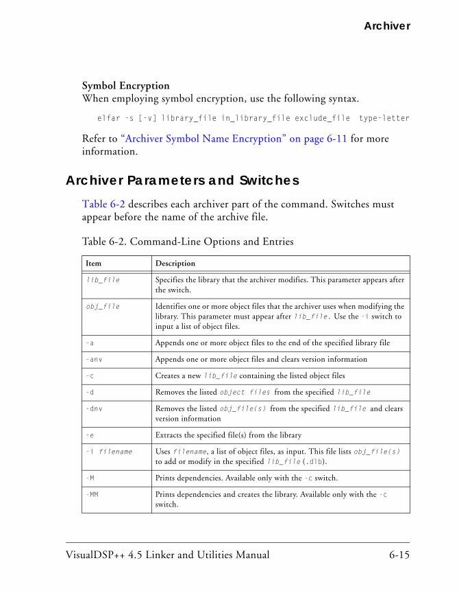
VisualDSP++ 4.5 Linker and Utilities Manual 6-15
Archiver
Symbol EncryptionWhen employing symbol encryption, use the following syntax.
elfar -s [-v] library_file in_library_file exclude_file type-letter
Refer to “Archiver Symbol Name Encryption” on page 6-11 for more information.
Archiver Parameters and SwitchesTable 6-2 describes each archiver part of the command. Switches must appear before the name of the archive file.
Table 6-2. Command-Line Options and Entries
Item Description
lib_file Specifies the library that the archiver modifies. This parameter appears after the switch.
obj_file Identifies one or more object files that the archiver uses when modifying the library. This parameter must appear after lib_file. Use the -i switch to input a list of object files.
-a Appends one or more object files to the end of the specified library file
-anv Appends one or more object files and clears version information
-c Creates a new lib_file containing the listed object files
-d Removes the listed object files from the specified lib_file
-dnv Removes the listed obj_file(s) from the specified lib_file and clears version information
-e Extracts the specified file(s) from the library
-i filename Uses filename, a list of object files, as input. This file lists obj_file(s) to add or modify in the specified lib_file (.dlb).
-M Prints dependencies. Available only with the -c switch.
-MM Prints dependencies and creates the library. Available only with the -c switch.

Archiver Command-Line Reference
6-16 VisualDSP++ 4.5 Linker and Utilities Manual
The elfar utility enables you to specify files in an archive by using the wildcard character ‘*’. For example, the following commands are valid:
elfar –c lib.dlb *.doj // create using every .doj file
elfar –a lib.dlb s*.doj // add objects starting with 's'
elfar –p lib.dlb *1* // print the files with '1' in their name
elfar –e lib.dlb * // extract all files from the archive
elfar –d lib.dlb t*.doj // delete .doj files starting with 't'
elfar –r lib.dlb *.doj // replace all .doj files
-p Prints a list of the obj_file(s) (.doj) in the selected lib_file (.dlb) to standard output
-pv Prints only version information in library to standard output
-pva Prints all version information in library to standard output
-r Replaces the specified object file in the specified library file. The object file in the library and the replacement object file must have identical names.
-s Specifies symbol name encryption. Refer to “Archiver Symbol Name Encryption” on page 6-11.
-t verno Tags the library with version information in string
-tx filename Tags the library with full version information in the file
-twc ver Tags the library with version information in the num.num.num form
-tnv Clears version information from a library
-v (Verbose) Outputs status information as the archiver processes files
-version Prints the archiver (elfar) version to standard output
-w Removes all archiver-generated warnings
-Wnnnn Selectively disables warnings specified by one or more message numbers. For example, -W0023 disables warning message ar0023.
Table 6-2. Command-Line Options and Entries (Cont’d)
Item Description
VisualDSP++ 4.5 Linker and Utilities Manual 6-17
Archiver
The –c, -a, and –r switches use the wildcard to look up the file names in the file system. The -p, -e, and -d switches use the wildcard to match file names in the archive.
Command-Line ConstraintsThe elfar command is subject to the following constraints.
• Select one action switch (a, c, d, e, p, r, or s) only in a single command.
• Do not place the verbose operation switch, -v, in a position where it can be mistaken for an object file. It may not follow the lib_file during an append or create operation.
• The file include switch, -i, must immediately precede the name of the file to be included. The archiver’s -i switch enters a list of members from a text file instead of listing each member on the command line.
• Use the library file name first, following the switches. The -i and -v switches are not operational switches, and can appear later.
• When using the archiver’s -p switch, it is not necessary to identify members on the command line.
• Enclose file names containing white space or colons within straight quotes.
• Append the appropriate file extension to each file. The archiver assumes nothing, and does not do it for you.
• Wildcard options are supported with the use of the wildcard char-acter “*”).

Archiver Command-Line Reference
6-18 VisualDSP++ 4.5 Linker and Utilities Manual
• The obj_file name (.doj object file) can be added, removed, or replaced in the lib_file.
• The archiver’s command line is not case sensitive.

VisualDSP++ 4.5 Linker and Utilities Manual 7-1
7 MEMORY INITIALIZER
VisualDSP++ 4.5 supports the Memory Initializer (MemInit) tool. The Memory Initializer’s main function is to modify executable files (.dxe files) so that the programs are self-initializing. It does this by converting the program’s RAM-based contents into an initialization stream which it embeds into the executable file.
This chapter provides:
• “Memory Initializer Overview” on page 7-2
• “Basic Operation of Memory Initializer” on page 7-3
• “Initialization Stream Structure” on page 7-5
• “Run-Time Library Routine Basic Operation” on page 7-6
• “Using the Memory Initializer” on page 7-7
• “Memory Initializer Command-Line Switches” on page 7-13

Memory Initializer Overview
7-2 VisualDSP++ 4.5 Linker and Utilities Manual
Memory Initializer OverviewThe Memory Initializer may be used with processor systems where the RAM memory needs to be initialized with the code and data stored in the ROM memory before the execution of the application code begins. This is generally true for a processor system running in NO-BOOT mode.
The initialization stream generated by the Memory Initializer is consumed by a dedicated Run-Time Library (RTL) routine. Following a system reset, the RTL routine searches the initialization stream and initializes the processor’s RAM memory with the data in the initialization stream before the call to main(), the starting point of the application code.
In creating the initialization stream, the Memory Initializer can, in most cases, effectively reduce the overall size of an executable file by combining contiguous, identical initialization into a single block. For example, a large zero-initialized array in an executable file can be compressed to a single small data block by the Memory Initializer.
In addition to a primary executable file (.dxe), the Memory Initializer accepts one or more additional executable files called “callback” executable files, and includes their data and instructions in the initialization stream. The RTL routine is able to call and execute them before conducting the process of the memory initialization for the primary application. This allows you to perform memory configuration and any other set-up func-tions that must occur before the code and data are extracted from ROM memory.

VisualDSP++ 4.5 Linker and Utilities Manual 7-3
Memory Initializer
Basic Operation of Memory InitializerThis section describes the basic operations of the Memory Initializer, its input and output files, as well as basic initialization stream generated by the Memory Initializer.
Input and Output FilesThe Memory Initializer takes an executable file (.dxe) as a primary input file and augments it by adding an initialization stream. The enhanced exe-cutable file is written as the output file.
Processing the Primary Input Executable FileAfter opening an input primary executable file, the Memory Initializer looks for sections, marked with the initialization flag in their section head-ers or specified from the command line, and extracts the data and instructions from them to make the primary initialization stream.
By default, the stream is saved in the dedicated memory section called “.meminit” in the output file. For the sections from which the Memory Initializer extracts no data, the Memory Initializer simply copies them from the input file to the output file. Sections that are processed by the Memory Initializer to form the initialization stream are not needed in the output executable file, as their contents will be regenerated at run time when the initialization stream is processed. Therefore, by default such sec-tions are not copied to the output file in order to reduce the size of the executable file.
Processing Callback Input Executable FilesIn addition to a primary input executable file, the Memory Initializer optionally accepts a number of individually-built “callback” executable files specified with the -init switch (on page 7-15).

Basic Operation of Memory Initializer
7-4 VisualDSP++ 4.5 Linker and Utilities Manual
The Memory Initializer sequentially processes the callback executable files, one at a time. After opening an input callback executable file, the Memory Initializer looks for all of the sections marked with the initialization flag and PROGBITS qualifier (it indicates the section contains either the instruc-tions or data or both), and extracts the data and instructions from them make a callback initialization stream. When this stream is built up, all the callback .dxe files are processed in the order they are specified on the com-mand line.
The Memory Initializer continues making a callback initialization stream from each of the callback executable files and pre-pending it to the pri-mary initialization stream in the same sequence the callback executable files appear in the command line until the last callback executable file is processed.
When processing a callback executable file, the Memory Initializer extracts all the code and data from it to make up the callback initialization stream regardless of the Memory Initializer command-line switches used only for the primary input file. Those switches are:
• “-BeginInit Initsymbol” on page 7-14
• “-Init Initcode.dxe” on page 7-15
• “-NoAuto” on page 7-16
• “-NoErase” on page 7-16
• “-Section Sectionname” on page 7-17
This ensures the integrity of the code and data from each callback execut-able file in the callback initialization stream – the code can be executed independently and successfully regardless of the Memory Initializer com-mand-line switches.
By taking multiple input files, the Memory Initializer supports those sys-tems which have to run a number of independent service applications before starting the primary application.
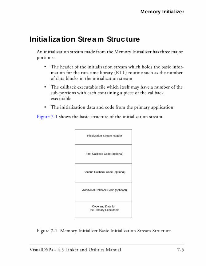
VisualDSP++ 4.5 Linker and Utilities Manual 7-5
Memory Initializer
Initialization Stream StructureAn initialization stream made from the Memory Initializer has three major portions:
• The header of the initialization stream which holds the basic infor-mation for the run-time library (RTL) routine such as the number of data blocks in the initialization stream
• The callback executable file which itself may have a number of the sub-portions with each containing a piece of the callback executable
• The initialization data and code from the primary application
Figure 7-1 shows the basic structure of the initialization stream:
Figure 7-1. Memory Initializer Basic Initialization Stream Structure
Initialization Stream Header
First Callback Code (optional)
Second Callback Code (optional)
Additional Callback Code (optional)
Code and Data forthe Primary Executable
Run-Time Library Routine Basic Operation
7-6 VisualDSP++ 4.5 Linker and Utilities Manual
Run-Time Library Routine Basic OperationA Run-Time Library (RTL) routine performs the memory initialization with the initialization stream created by the Memory Initializer during runtime. It can be a dedicated RTL routine or user-provided routine called _mi_initialize (from the assembly code).
For more information on the definition of the initialization stream, see EE-239 for Blackfin processors
Following a system reset, the RTL routine is invoked by the application’s start-up code.
The RTL routine:
1. searches for the initialization stream
2. digests the stream header
3. for each callback executable specified, the RTL routine first copies “callback” code into RAM, and then executes it. It is done piece by piece and continue until execution is complete
4. brings the code and data from the primary executable file into the processor’s memory
Once each callback executable has been executed, it is no longer needed in RAM; it may be overwritten by future callback executables or by the code or data spaces of the primary executable. After all the “callback” codes are executed, the RTL routine starts to initialize the processor’s memory with the initialization stream created from the primary input executable file, and overwrites the memory spaces previously initialized with the “call-back” codes. After that, the RTL routine returns execution to the start-up header, and the application proceeds as normal.
If there are no callback executables to be executed, the RTL routine imme-diately starts the process of initializing memory for the primary application.

VisualDSP++ 4.5 Linker and Utilities Manual 7-7
Memory Initializer
Using the Memory InitializerThere are several reasons why it may be beneficial to use the Memory Initializer:
• The system needs to initialize the RAM memory from the data stored in ROM.
• It is desirable to reduce the overall size of the executable.
• Initialization executable files need to run to configure the system, before the primary application starts.
If it is decided to use the Memory Initializer, the preparation starts from the linker description file (.ldf) and the source files of the project.
Preparing the Linker Description File (.ldf)If a section is to be processed by the Memory Initializer in order to create the initialization stream, the section must be marked in the .ldf file to indicate the kind of initialization required. This is done using initializa-tion qualifiers. The qualifiers that are used here are ZERO_INIT and RUNTIME_INIT. The sections marked with ZERO_INIT may contain only “zero-initialized” data, and the sections marked with RUNTIME_INIT may contain the data with any initialization values.
Refer to the SECTIONS description for detailed information on these qualifiers (see on page 3-55).
The following example shows how to use the ZERO_INIT and RUNTIME_INIT qualifiers in a .ldf file to set up the section type.
my_zero_section ZERO_INIT { INPUT_SECTION_ALIGN(4) INPUT_SECTIONS( $OBJECTS(my_zero_section) $LIBRARIES(my_zero_section)) } >MEM_L1_DATA_A

Using the Memory Initializer
7-8 VisualDSP++ 4.5 Linker and Utilities Manual
my_data_section RUNTIME_INIT { INPUT_SECTION_ALIGN(4) INPUT_SECTIONS( $OBJECTS(my_data_section) ) }>MEM_L1_DATA_A
The section my_zero_section is intended to hold all the zero-initialized data, and the section my_data_section is to hold any other initialized data. After the program is first linked, the sections in the .dxe file have flags set according to the qualifiers in the .ldf file. Then the Memory Ini-tializer runs and processes the DXE sections according to those flags, and produces a modified output .dxe file.
The Memory Initializer is able to identify the DXE sections with the dis-tinct initialization flag and extract the data from them to make an initialization stream. Any number of sections can be set as either ZERO_INIT or RUNTIME_INIT type in an .ldf file.
Please note that there are two memory sections specified in a default .ldf file, which also serve the Memory Initializer: bsz_init and .meminit. The bsz_init section is used to hold the pointer generated by the Memory Ini-tializer, which points to the start address of the initialization stream, while the section .meminit is used to hold the actual initialization stream gener-ated by the Memory Initializer. Although other sections may be selected as alternatives (using the appropriate command-line switches), it is not rec-ommended to do so.
Preparing the Source FilesThe sections marked with the ZERO_INIT and RUNTIME_INIT qualifiers need to be initialized with the proper values in the source files before being compiled. The following example shows one way to initialize a section.
#include <stdio.h>#pragma section("my_data_section", RUNTIME_INIT)unsigned int A [ 100 ] =

VisualDSP++ 4.5 Linker and Utilities Manual 7-9
Memory Initializer
{ 0xaabbccdd,0xaabbccdd,0xaabbccdd,0xaabbccdd,0xaabbccdd, 0xaabbccdd,0xaabbccdd,0xaabbccdd,0xaabbccdd,0xaabbccdd, 0xaabbccdd,0xaabbccdd,0xaabbccdd,0xaabbccdd,0xaabbccdd, 0xaabbccdd,0xaabbccdd,0xaabbccdd,0xaabbccdd,0xaabbccdd, 0xaabbccdd,0xaabbccdd,0xaabbccdd,0xaabbccdd,0xaabbccdd, 0xaabbccdd,0xaabbccdd,0xaabbccdd,0xaabbccdd,0xaabbccdd, 0xaabbccdd,0xaabbccdd,0xaabbccdd,0xaabbccdd,0xaabbccdd, 0xaabbccdd,0xaabbccdd,0xaabbccdd,0xaabbccdd,0xaabbccdd, 0xaabbccdd,0xaabbccdd,0xaabbccdd,0xaabbccdd,0xaabbccdd, 0xaabbccdd,0xaabbccdd,0xaabbccdd,0xaabbccdd,0xaabbccdd, 0xaabbccdd,0xaabbccdd,0xaabbccdd,0xaabbccdd,0xaabbccdd, 0xaabbccdd,0xaabbccdd,0xaabbccdd,0xaabbccdd,0xaabbccdd, 0xaabbccdd,0xaabbccdd,0xaabbccdd,0xaabbccdd,0xaabbccdd, 0xaabbccdd,0xaabbccdd,0xaabbccdd,0xaabbccdd,0xaabbccdd, 0xaabbccdd,0xaabbccdd,0xaabbccdd,0xaabbccdd,0xaabbccdd, 0xaabbccdd,0xaabbccdd,0xaabbccdd,0xaabbccdd,0xaabbccdd, 0xaabbccdd,0xaabbccdd,0xaabbccdd,0xaabbccdd,0xaabbccdd, 0xaabbccdd,0xaabbccdd,0xaabbccdd,0xaabbccdd,0xaabbccdd, 0xaabbccdd,0xaabbccdd,0xaabbccdd,0xaabbccdd,0xaabbccdd, 0xaabbccdd,0xaabbccdd,0xaabbccdd,0xaabbccdd,0xaabbccdd };
#pragma section("my_zero_section", ZERO_INIT)unsigned int B [ 128 ];
int void main(){ int i; int not_init = 0, not_zero = 0;
for (i = 0; i < 100; i++) if ( A [ i ] != 0xaabbccdd ) not_init++;
for (i = 0; i < 128; i++) if ( B [ i ] != 0 ) not_zero++;
printf ("A[]: %d elements not initialized\n", not_init); printf ("B[]: %d elements not zeroed\n", not_zero); return 0;}

Using the Memory Initializer
7-10 VisualDSP++ 4.5 Linker and Utilities Manual
Invoking the Memory InitializerThere are several ways to invoke the Memory Initializer, either from the IDDE or from a command line.
Invoking Memory Initializer from the VisualDSP++ IDDE
Use the Project menu in the VisualDSP++ main screen to select Project -> Project Options -> Link (see Figure 7-2) The Link option is displayed. Type -meminit in the Additional options field and then click OK. When the project is built, the linker calls the Memory Initializer.
Figure 7-2. Invoking the Memory Initializer from the VisualDSP++ IDDE

VisualDSP++ 4.5 Linker and Utilities Manual 7-11
Memory Initializer
Invoking Memory Initializer from Command Line
The simplest command line to invoke the Memory Initializer is:
mem21k.exe input.dxe -o output.dxe
The Memory Initializer identifies all the sections with initialization flags in the input file, produces an initialization stream, and places it in the out-put file. The Memory Initializer command-line switches are listed in Table 7-1.
Invoking Memory Initializer from Linker’s Command Line
The simplest way to invoke the Memory Initializer from the linker’s com-mand line is to use the linker’s -meminit switch. The linker also provides the -flag-meminit switch that passes each comma-separated option to the Memory Initializer. For example,
linker -proc ADSP-BF535 -meminit input.dxe -o output.dxe
Invoking Memory Initializer from Compiler’s Command Line
The simplest command line to invoke the Memory Initializer from the compiler’s command line is (for example, for Blackfin processors):
ccblkfn -proc ADSP-BF535 -mem input.dxe -o output.dxe
Invoking Memory Initializer with Callback Executables
To directly invoke the Memory Initializer from a command line, use the -Init switch for each “callback” executable as shown below:
meminit Input.dxe -o Output.dxe -Init Callback1.dxe -Init Callback2.dxe
For VisualDSP++ IDDE, select Project -> Project Options -> Link. The Link option is displayed. Use the Additional options field to process call-back executable files.

Using the Memory Initializer
7-12 VisualDSP++ 4.5 Linker and Utilities Manual
For example, if you have two callback executable files, callback1.dxe and callback2.dxe, and you wish to pass them to the Memory Initializer, you can enter them in the Additional options window as
-meminit -flag-meminit -Init callback1.dxe -Init callback2.dxe
then click OK (see Figure 7-3).
Figure 7-3. Invoking Callback Executable from the VisualDSP++ IDDE
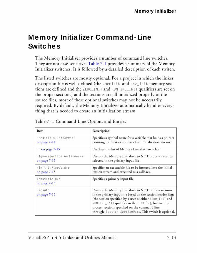
VisualDSP++ 4.5 Linker and Utilities Manual 7-13
Memory Initializer
Memory Initializer Command-Line Switches
The Memory Initializer provides a number of command line switches. They are not case-sensitive. Table 7-1 provides a summary of the Memory Initializer switches. It is followed by a detailed description of each switch.
The listed switches are mostly optional. For a project in which the linker description file is well-defined (the .meminit and bsz_init memory sec-tions are defined and the ZERO_INIT and RUNTIME_INIT qualifiers are set on the proper sections) and the sections are all initialized properly in the source files, most of these optional switches may not be necessarily required. By default, the Memory Initializer automatically handles every-thing that is needed to create an initialization stream.
Table 7-1. Command-Line Options and Entries
Item Description
-BeginInit Initsymbol on page 7-14
Specifies a symbol name for a variable that holds a pointer pointing to the start address of an initialization stream.
-h on page 7-15 Displays the list of Memory Initializer switches.
-IgnoreSection Sectionname on page 7-15
Directs the Memory Initializer to NOT process a section selected in the primary input file
-Init Initcode.dxe on page 7-15
Specifies an executable file to be inserted into the initial-ization stream and executed as a callback.
InputFile.dxe on page 7-16
Specifies a primary input file.
-NoAuto on page 7-16
Directs the Memory Initializer to NOT process sections in the primary input file based on the section header flags (the section specified by a user as either ZERO_INIT and RUNTIME_INIT qualifier in the .ldf file), but to only process sections specified on the command line through-Section SectionName. This switch is optional.
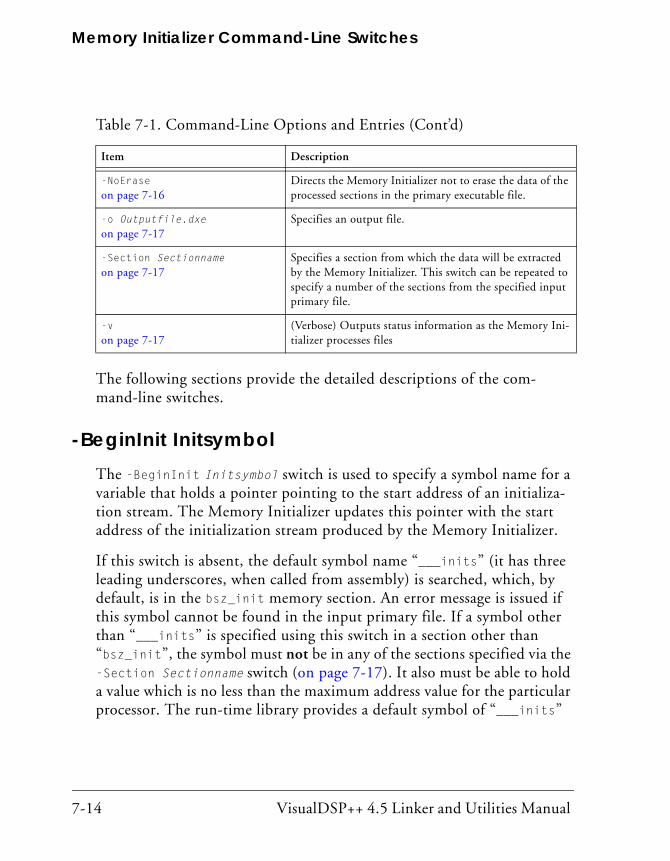
Memory Initializer Command-Line Switches
7-14 VisualDSP++ 4.5 Linker and Utilities Manual
The following sections provide the detailed descriptions of the com-mand-line switches.
-BeginInit InitsymbolThe -BeginInit Initsymbol switch is used to specify a symbol name for a variable that holds a pointer pointing to the start address of an initializa-tion stream. The Memory Initializer updates this pointer with the start address of the initialization stream produced by the Memory Initializer.
If this switch is absent, the default symbol name “___inits” (it has three leading underscores, when called from assembly) is searched, which, by default, is in the bsz_init memory section. An error message is issued if this symbol cannot be found in the input primary file. If a symbol other than “___inits” is specified using this switch in a section other than “bsz_init”, the symbol must not be in any of the sections specified via the -Section Sectionname switch (on page 7-17). It also must be able to hold a value which is no less than the maximum address value for the particular processor. The run-time library provides a default symbol of “___inits”
-NoErase on page 7-16
Directs the Memory Initializer not to erase the data of the processed sections in the primary executable file.
-o Outputfile.dxe on page 7-17
Specifies an output file.
-Section Sectionname on page 7-17
Specifies a section from which the data will be extracted by the Memory Initializer. This switch can be repeated to specify a number of the sections from the specified input primary file.
-v on page 7-17
(Verbose) Outputs status information as the Memory Ini-tializer processes files
Table 7-1. Command-Line Options and Entries (Cont’d)
Item Description
VisualDSP++ 4.5 Linker and Utilities Manual 7-15
Memory Initializer
for the Memory Initializer and, therefore, it is not necessary to use this switch in most cases. This switch has no effect on callback executable files specified using the “-Init Initcode.dxe” on page 7-15.
-hThe -h[elp] switch is used to display the list of Memory Initializer switches.
-IgnoreSection SectionnameThe -IgnoreSection Sectionname switch is used to specify a section that is not to be processed by the Memory Initializer. This switch can be repeated to specify a number of sections not to be processed in the primary input file. All the specified sections must exist in the primary input file.
The -IgnoreSection switch is optional. It is normally easier to remove a section’s initialization qualifier (ZERO_INIT or RUNTIME_INIT) from the .ldf file than to use this switch. The switch does not affect a callback exe-cutable file specified using the -Init Sectionname switch.
-Init Initcode.dxeThe -Init Initcode.dxe switch is used to specify an executable file to be inserted into the initialization stream and executed as a callback. Any number of executable files can be specified this way, and it is allowed to specify the same file name a number of times. The callback executable file must exist before the Memory Initializer is run. All the code and data from callback executable files are extracted to make up the initialization stream. This is an optional switch.

Memory Initializer Command-Line Switches
7-16 VisualDSP++ 4.5 Linker and Utilities Manual
InputFile.dxeThe InputFile.dxe parameter is used to specify a primary input file. The Memory Initializer issues an error message if no primary input file is specified.
-NoAutoThe -NoAuto switch directs the Memory Initializer to not process sections in the primary input file based on the section header flags (the section specified as either ZERO_INIT and RUNTIME_INIT qualifier in the .ldf file), but to only process sections specified on the command line using the -section SectionName switch.
By default, the Memory Initializer automatically processes only the sec-tions with ZERO_INIT and RUNTIME_INIT qualifiers in the .ldf file. This switch has no effect on the the code and data of callback executable files specified using the -init switch. All the code and data sections of a call-back executable file are processed by the Memory Initializer regardless of this switch being used or not. This switch is optional.
-NoEraseThe -NoErase switch directs the Memory Initializer not to erase the data of the processed sections. By default, the Memory Initializer empties the sections from which the data are extracted to make up the initialization stream. This switch is valid for the primary input file only and has no effect on callback executable files. The Memory Initializer does not carry any sections of a callback executable file over to the output file, nor erase any sections, but only extracts the code and data from it to form the ini-tialization stream.

VisualDSP++ 4.5 Linker and Utilities Manual 7-17
Memory Initializer
-o Outputfile.dxeThe -o Outputfile.dxe switch is used to specify an output file. If this switch is absent, the Memory Initializer makes up an output file name from the root of the input file name. For example, the output file name is created as InputFile1.dxe if the input file name is InputFile.dxe. This switch is optional.
-Section SectionnameThe -Section Sectionname switch is used to specify a section from which the data is extracted by the Memory Initializer. This switch can be repeated to specify a number of the sections from the specified input primary file. All the section specified must exist in the specified input primary file. Note that the section name specified via the -IgnoreSection switches cannot be used with the -Section switch.
It is not necessary to use this switch to specify any sections which already have the ZERO_INIT or RUNTIME_INIT qualifiers in the linker description file (.ldf), as the Memory Initializer processes such sections automati-cally. Using initialization qualifiers in the .ldf file is usually the simpler and recommended method. The -Section SectionName switch has no effect on callback executable files specified via the -Init switch. There-fore, do not use this switch to specify any sections in callback executable files.
-vThe -v or -verbose (verbose) switch directs the Memory Initializer to out-put status information as it processes files.

Memory Initializer Command-Line Switches
7-18 VisualDSP++ 4.5 Linker and Utilities Manual

VisualDSP++ 4.5 Linker and Utilities Manual A-1
A FILE FORMATS
The VisualDSP++ development tools support many file formats. In some cases, several file formats for each development tool are supported. This appendix describes file formats that are prepared as input for the tools and points out the features of files produced by the tools.
This appendix discusses three types of file formats:
• “Source Files” on page A-2
• “Build Files” on page A-5
• “Debugger Files” on page A-9
Most of the development tools use industry-standard file formats. Sources that describe these formats appear in “Format References” on page A-10.

Source Files
A-2 VisualDSP++ 4.5 Linker and Utilities Manual
Source FilesThis section describes these input file formats:
• “C/C++ Source Files” on page A-2
• “Assembly Source Files (.asm)” on page A-3
• “Assembly Initialization Data Files (.DAT)” on page A-3
• “Header Files (.H)” on page A-4
• “Linker Description Files (.ldf)” on page A-4
• “Linker Command-Line Files (.TXT)” on page A-5
C/C++ Source FilesThese are text files (with extensions such as .c, .cpp, .CXX, and so on) containing C/C++ code, compiler directives, possibly a mixture of assembly code and directives, and (typically) preprocessor commands.
Several “dialects” of C code are supported: pure (portable) ANSI C, and at least two subtypes1 of ANSI C with ADI extensions. These extensions include memory type designations for certain data objects, and segment directives used by the linker to structure and place executable files.
For information on using the C/C++ compiler and associated tools, as well as a definition of ADI extensions to ANSI C, see the VisualDSP++ 4.5 C/C++ Compiler and Library Manual for appropriate target architectures.
1 With and without built-in function support; a minimal differentiator. There are others.

VisualDSP++ 4.5 Linker and Utilities Manual A-3
File Formats
Assembly Source Files (.asm)Assembly source files are text files containing assembly instructions, assembler directives, and (optionally) preprocessor commands. For infor-mation on assembly instructions, see your processor’s Programming Reference.
The instruction set is supplemented with assembler directives. Preproces-sor commands control macro processing and conditional assembly or compilation.
For information on the assembler and preprocessor, see the VisualDSP++ 4.5 Assembler and Preprocessor Manual.
Assembly Initialization Data Files (.DAT)Assembly initialization data (.DAT) files are text files that contain fixed- or floating-point data. These files provide the initialization data for an assembler .VAR directive or serve in other tool operations.
When a .VAR directive uses a .DAT file for data initialization, the assembler reads the data file and initializes the buffer in the output object (.doj) file. Data files have one data value per line and may have any number of lines.
The .dat extension is explanatory or mnemonic. A directive to #include <file> can take any file name (or extension) as an argument.
Fixed-point values (integers) in data files may be signed, and they may be decimal-, hexadecimal-, octal-, or binary-base values. The assembler uses the prefix conventions in Table A-1 to distinguish between numeric formats.
For all numeric bases, the assembler uses 16-bit words for data storage; 24-bit data is for the program code only. The largest word in the buffer determines the size for all words in the buffer. If there is some 8-bit data

Source Files
A-4 VisualDSP++ 4.5 Linker and Utilities Manual
in a 16-bit wide buffer, the assembler loads the equivalent 8-bit value into the most significant eight bits in the 8-bit memory location and zero-fills the lower eight bits.
Header Files (.H)Header files are ASCII text files that contain macros or other preprocessor commands that the preprocessor substitutes into source files. For informa-tion on macros or other preprocessor commands, see the VisualDSP++ 4.5 C/C++Compiler and Library Manual for appropriate target architectures. For information on the assembler and preprocessor, see the VisualDSP++ 4.5 Assembler and Preprocessor Manual.
Linker Description Files (.ldf)Linker Description Files are ASCII text files that contain commands for the linker in the linker’s scripting language. For information on this scripting language, see “LDF Commands” on page 3-31.
Table A-1. Numeric Formats
Convention Description
0xnumber H#number h#number
Hexadecimal number
number D#number d#number
Decimal number
B#number b#number
Binary number.
O#number o#number
Octal number.

VisualDSP++ 4.5 Linker and Utilities Manual A-5
File Formats
Linker Command-Line Files (.TXT)Linker command-line files are ASCII text files that contain command-line input for the linker. For more information on the linker command line, see “Linker Command-Line Reference” on page 2-43.
Build FilesBuild files are produced by the VisualDSP++ development tools when building a project. This section describes these build file formats:
• “Assembler Object Files (.doj)” on page A-5
• “Library Files (.dlb)” on page A-6
• “Linker Output Files (.dxe, .sm, and .ovl)” on page A-6
• “Memory Map Files (.xml)” on page A-6
• “Loader Output Files in Intel Hex-32 Format (.ldr)” on page A-6
• “Splitter Output Files in ASCII Format (.ldr)” on page A-8
Assembler Object Files (.doj)Assembler output object (.doj) files are in binary, executable and linkable file (ELF) format. Object files contain relocatable code and debugging information for a DSP program’s memory segments. The linker processes object files into an executable (.dxe) file. For information on the object file’s ELF format, see “Format References” on page A-10.

Build Files
A-6 VisualDSP++ 4.5 Linker and Utilities Manual
Library Files (.dlb)Library files, the archiver’s output, are in binary, executable and linkable file (ELF) format. Library files (called archive files in previous software releases) contain one or more object files (archive elements).
The linker searches through library files for library members used by the code. For information on the ELF format used for executable files, refer to “Format References” on page A-10.
Linker Output Files (.dxe, .sm, and .ovl)The linker’s output files are in binary, executable and linkable file (ELF) format. These executable files contain program code and debugging information. The linker fully resolves addresses in executable files. For information on the ELF format used for executable files, see the TIS Com-mittee texts cited in “Format References” on page A-10.
The archiver automatically converts legacy input objects from COFF to ELF format.
Memory Map Files (.xml)The linker can output memory map files that contain memory and symbol information for your executable file(s). The map file contains a summary of memory defined with MEMORY{} commands in the .ldf file, and pro-vides a list of the absolute addresses of all symbols. Memory map files are available only in .xml format.
Loader Output Files in Intel Hex-32 Format (.ldr)The loader can output Intel hex-32 format (.ldr) files. These files support 8-bit-wide PROMs. The files are used with an industry-standard PROM programmer to program memory devices for a hardware system. One file contains data for the whole series of memory chips to be programmed.
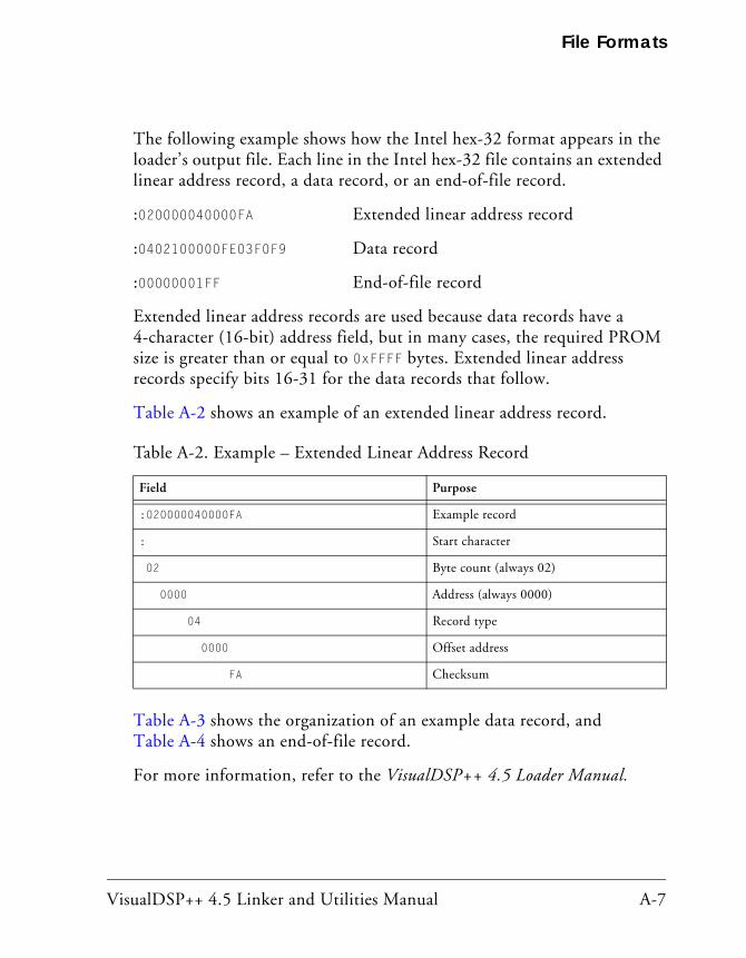
VisualDSP++ 4.5 Linker and Utilities Manual A-7
File Formats
The following example shows how the Intel hex-32 format appears in the loader’s output file. Each line in the Intel hex-32 file contains an extended linear address record, a data record, or an end-of-file record.
:020000040000FA Extended linear address record
:0402100000FE03F0F9 Data record
:00000001FF End-of-file record
Extended linear address records are used because data records have a 4-character (16-bit) address field, but in many cases, the required PROM size is greater than or equal to 0xFFFF bytes. Extended linear address records specify bits 16-31 for the data records that follow.
Table A-2 shows an example of an extended linear address record.
Table A-3 shows the organization of an example data record, and Table A-4 shows an end-of-file record.
For more information, refer to the VisualDSP++ 4.5 Loader Manual.
Table A-2. Example – Extended Linear Address Record
Field Purpose
:020000040000FA Example record
: Start character
02 Byte count (always 02)
0000 Address (always 0000)
04 Record type
0000 Offset address
FA Checksum

Build Files
A-8 VisualDSP++ 4.5 Linker and Utilities Manual
Splitter Output Files in ASCII Format (.ldr)When the loader is invoked as a splitter, its output can be an ASCII for-mat file. ASCII format files are text representations of ROM memory images that you can use in post-processing. For more information, refer to no-boot mode information in the VisualDSP++ 4.5 Loader Manual..
Table A-3. Example – Data Record
Field Purpose
:0402100000FE03F0F9 Example record
: Start character
04 Byte count of this record
0210 Address
00 Record type
00 First data byte
F0 Last data byte
F9 Checksum
Table A-4. Example – End-of-File Record
Field Purpose
:00000001FF End-of-file record
: Start character
00 Byte count (zero for this record)
0000 Address of first byte
01 Record type
FF Checksum
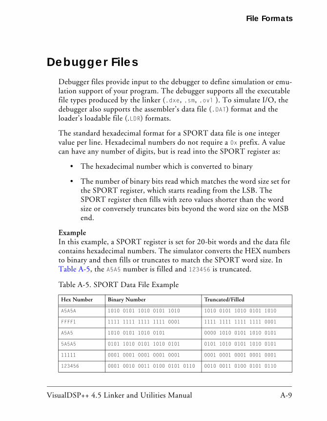
VisualDSP++ 4.5 Linker and Utilities Manual A-9
File Formats
Debugger FilesDebugger files provide input to the debugger to define simulation or emu-lation support of your program. The debugger supports all the executable file types produced by the linker (.dxe, .sm, .ovl ). To simulate I/O, the debugger also supports the assembler’s data file (.DAT) format and the loader’s loadable file (.LDR) formats.
The standard hexadecimal format for a SPORT data file is one integer value per line. Hexadecimal numbers do not require a 0x prefix. A value can have any number of digits, but is read into the SPORT register as:
• The hexadecimal number which is converted to binary
• The number of binary bits read which matches the word size set for the SPORT register, which starts reading from the LSB. The SPORT register then fills with zero values shorter than the word size or conversely truncates bits beyond the word size on the MSB end.
ExampleIn this example, a SPORT register is set for 20-bit words and the data file contains hexadecimal numbers. The simulator converts the HEX numbers to binary and then fills or truncates to match the SPORT word size. In Table A-5, the A5A5 number is filled and 123456 is truncated.
Table A-5. SPORT Data File Example
Hex Number Binary Number Truncated/Filled
A5A5A 1010 0101 1010 0101 1010 1010 0101 1010 0101 1010
FFFF1 1111 1111 1111 1111 0001 1111 1111 1111 1111 0001
A5A5 1010 0101 1010 0101 0000 1010 0101 1010 0101
5A5A5 0101 1010 0101 1010 0101 0101 1010 0101 1010 0101
11111 0001 0001 0001 0001 0001 0001 0001 0001 0001 0001
123456 0001 0010 0011 0100 0101 0110 0010 0011 0100 0101 0110

Format References
A-10 VisualDSP++ 4.5 Linker and Utilities Manual
Format ReferencesThe following texts define industry-standard file formats supported by VisualDSP++.
• Gircys, G.R. (1988) Understanding and Using COFF by O’Reilly & Associates, Newton, MA
• (1993) Executable and Linkable Format (ELF) V1.1 from the Portable Formats Specification V1.1, Tools Interface Standards (TIS) Committee
Go to: http://developer.intel.com/vtune/tis.htm
• (1993) Debugging Information Format (DWARF) V1.1 from the Portable Formats Specification V1.1, UNIX International, Inc.
Go to: http://developer.intel.com/vtune/tis.htm
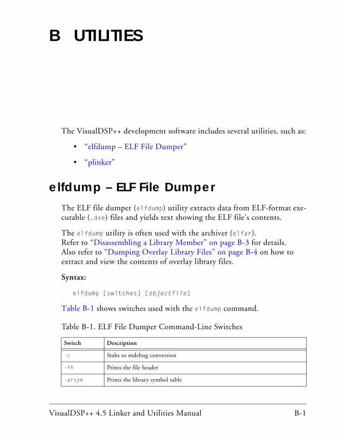
VisualDSP++ 4.5 Linker and Utilities Manual B-1
B UTILITIES
The VisualDSP++ development software includes several utilities, such as:
• “elfdump – ELF File Dumper”
• “plinker”
elfdump – ELF File DumperThe ELF file dumper (elfdump) utility extracts data from ELF-format exe-cutable (.dxe) files and yields text showing the ELF file’s contents.
The elfdump utility is often used with the archiver (elfar). Refer to “Disassembling a Library Member” on page B-3 for details. Also refer to “Dumping Overlay Library Files” on page B-4 on how to extract and view the contents of overlay library files.
Syntax:
elfdump [switches] [objectfile]
Table B-1 shows switches used with the elfdump command.
Table B-1. ELF File Dumper Command-Line Switches
Switch Description
-c Stabs to mdebug conversion
-fh Prints the file header
-arsym Prints the library symbol table

elfdump – ELF File Dumper
B-2 VisualDSP++ 4.5 Linker and Utilities Manual
The -n and -i switches can have a modifier letter options after the main option character to force section contents to be formatted as:
• a – Dumps contents in hex and ASCII, 16 bytes per line.
• x – Dumps contents in hex, 32 bytes per line.
• xN – Dumps contents in hex, N bytes per group (default is N = 4).
-arall Prints every library member
-help Prints the list of elfdump switches to stdut
-ph Prints the program header table
-s Prints contents as a list of disassembled machine instructions. Also prints labels.
-sh Prints the section header table. This switch is the default when no options are specified.
-notes Prints note segment(s)
-n name Prints contents of the named section(s). The name may be a simple ‘glob’-style pattern, using “?” and “*” as wildcard characters. Each section’s name and type determines its output format, unless overridden by a modifier.
-i x0[-x1] Prints contents of sections numbered x0 through x1, where x0 and x1 are decimal integers, and x1 defaults to x0 if omitted. Formatting rules are the same as for the -n switch.
-all Prints everything. This is the same as -fh -ph -sh -notes -n ‘*’.
-ost Omits string table sections
-v Prints version information
objectfile Specifies the file whose contents are to be printed. It can be a core file, executable, shared library, or relocatable object file. If the name is in the form A(B), A is assumed to be a library and B is an ELF member of the library. B can be a pattern similar to the one accepted by -n.
Table B-1. ELF File Dumper Command-Line Switches (Cont’d)
Switch Description

VisualDSP++ 4.5 Linker and Utilities Manual B-3
• t – Dumps contents in hex, N bytes per line, where N is the sec-tion’s table entry size. If N is not in the range 1 to 32, 32 is used.
• hN – Dumps contents in hex, N bytes per group.
• HN – Dumps contents in hex, (MSB first order), N bytes per group.
• i – Prints contents as list of disassembled machine instructions.
• s – Prints contents as list of disassembled machine instructions and also prints labels.
Disassembling a Library MemberThe elfar and elfdump utilities are more effective when their capabilities are combined. One application of these utilities is for disassembling a library member and converting it to source code. Use this technique when the source of a particularly useful routine is missing and is available only as a library routine.
For information about elfar, refer to “Archiver” on page 6-1.
The following procedure lists the objects in a library, extracts an object, and converts the object to a listing file. The first archiver command line lists the objects in the library and writes the output to a text file.
elfar -p libc.dlb > libc.txt
Open the text file, scroll through it, and locate the object file you need.
To convert the object file to an assembly listing file with labels, use the following elfdump command line, which references the library and the object file in the library.
elfdump -ns * libc.dlb (fir.doj) > fir.asm
The output file is practically source code. Just remove the line numbers and opcodes.

plinker
B-4 VisualDSP++ 4.5 Linker and Utilities Manual
Disassembly yields a listing file with symbols. Assembly source with sym-bols can be useful if you are familiar with the code and hopefully have some documentation on what the code does. If the symbols are stripped during linking, the dumped file contains no symbols.
Disassembling a third-party’s library may violate the license for the third-party software. Ensure there are no copyright or license issues with the code’s owner before using this disassembly technique.
Dumping Overlay Library FilesUse the elfar and elfdump utilities to extract and view the contents of overlay library (.ovl) files.
For example, the following command lists (prints) the contents (library members) of the clone2.ovl library file.
elfar -p clone2.ovl
The following command allows you to view one of the library members (clone2.elf).
elfdump -all clone2.ovl(clone2.elf)
The following commands extract clone2.elf and print its contents.
elfar -e clone2.ovl clone2.elf
elfdump -all clone2.elf
Switches for the elfdump commands are case sensitive.
plinkerIn VisualDSP++ 4.1, the plinker command-line tool provides “partial linker” functionality.

VisualDSP++ 4.5 Linker and Utilities Manual B-5
The plinker tool is a specialized linker that produces a partially-linked relocatable object file instead of a fully-linked executable. It is similar in function to a standard UNIX linker (ld) invoked with the -r switch.
The partial linker performs two main functions:
• It combines a number of input object files into a single output file by concatenating sections having the same name into a single sec-tion in the output file. All references to offsets or indices within the input files are modified to reflect the new locations of sections, and of records within sections, in the output file.
• For symbols with external linkage, it resolves multiple occurrences of the same symbol to a single instance. Local function and object symbols are made unique by adding a suffix in order to satisfy linker input requirements.
The partial linker can link both object files and archive libraries. The ordering of object file and library arguments in the plinker command line is highly significant.
If a referenced external symbol has no global definition and multiple weak definitions, the symbol is resolved to the first weak definition that is encountered.
For example, consider the following plinker command line:
plinker -o out.o in1.o in2.o -l lib1.a in3.o -l lib2.a
Library “lib1.a” will be searched only for references encountered in “in1.o;” and “in2.o”. It will not be searched again after “in3.o” and library “lib2.a” have been read. If either “in3.o” or “lib2.a” has refer-ences that should be resolved by “lib1.a”, the “lib1.a” must be specified a second time, later in the command line.
If invoked with no arguments, or with “-h” or “-help”, the partial linker prints command-line information. The -info switch provides additional details, including current bugs and limitations. Tracing of linker actions can be enabled and finely controlled with the -t, -tr, and -ntr switches.
plinker
B-6 VisualDSP++ 4.5 Linker and Utilities Manual

VisualDSP++ 4.5 Linker and Utilities Manual C-1
C LDF PROGRAMMING EXAMPLES FOR TIGERSHARC PROCESSORS
This appendix provides several typical LDFs used with TigerSHARC pro-cessors. As you modify these examples, refer to the syntax descriptions in “LDF Commands” on page 3-31.
This appendix provides the following examples.
• “Linking a Single-Processor System” on page C-2
• “Linking Large Uninitialized or Zero-InitializedVariables” on page C-4
• “Linking an ADSP-TS101 MP Shared Memory System” on page C-6
• “Linking for Overlay Memory” on page C-12
The source code for several programs is bundled with your devel-opment software. Each program includes an .ldf file. For working examples of the linking process, examine the .ldf files that come with the examples. Examples are in the following directory.
<VisualDSP++ InstallationPath>/TS/Examples
A variety of processor-specific default .ldf files come with the development software, providing information about each proces-sor’s internal memory architecture. Default .ldf files are in the following directories.
<VisualDSP++ InstallationPath>/TS/ldf
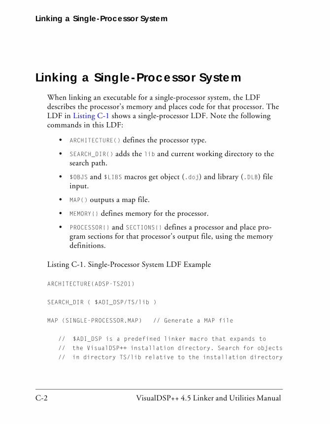
Linking a Single-Processor System
C-2 VisualDSP++ 4.5 Linker and Utilities Manual
Linking a Single-Processor SystemWhen linking an executable for a single-processor system, the LDF describes the processor’s memory and places code for that processor. The LDF in Listing C-1 shows a single-processor LDF. Note the following commands in this LDF:
• ARCHITECTURE() defines the processor type.
• SEARCH_DIR() adds the lib and current working directory to the search path.
• $OBJS and $LIBS macros get object (.doj) and library (.DLB) file input.
• MAP() outputs a map file.
• MEMORY{} defines memory for the processor.
• PROCESSOR{} and SECTIONS{} defines a processor and place pro-gram sections for that processor’s output file, using the memory definitions.
Listing C-1. Single-Processor System LDF Example
ARCHITECTURE(ADSP-TS201)
SEARCH_DIR ( $ADI_DSP/TS/lib )
MAP (SINGLE-PROCESSOR.MAP) // Generate a MAP file
// $ADI_DSP is a predefined linker macro that expands to
// the VisualDSP++ installation directory. Search for objects
// in directory TS/lib relative to the installation directory

VisualDSP++ 4.5 Linker and Utilities Manual C-3
$LIBS = libc.dlb;
// single.doj is a user-generated file.
// The linker will be invoked as follows:
// linker -T single-processor.ldf single.doj.
// $COMMAND_LINE_OBJECTS is a predefined linker macro.
// The linker expands this macro into the name(s) of the // the object(s) (.doj files) and libraries (.dlb files)
// $COMMAND_LINE_OBJECTS = single.doj
// ts_header.doj is the standard initialization file for TSxxx
$OBJS = $COMMAND_LINE_OBJECTS, ts_hdr.doj;
// A linker project to generate a .dxe file
PROCESSOR P0
{
OUTPUT ( ./SINGLE.dxe ) // The name of the output file
MEMORY // Processor-specific memory command
{ INCLUDE(“TS201_memory.ldf”) }
SECTIONS // Specify the output sections
{
INCLUDE( “TS201_sections.ldf” )
} // end P0 sections
} // end P0 processor
Linking Large Uninitialized or Zero-InitializedVariables
C-4 VisualDSP++ 4.5 Linker and Utilities Manual
Linking Large Uninitialized or Zero-InitializedVariables
When linking an executable file that contains large uninitialized variables, use the NO_INIT (equivalent to SHT_NOBITS legacy qualifier) or ZERO_INIT section qualifier to reduce the file size.
A variable defined in a source file normally takes up space in an object and executable file even if that variable is not explicitly initialized when defined. For large buffers, this action can result in large executables filled mostly with zeros. Such files take up excess disk space and can incur long download times when used with an emulator. This situation also may occur when you boot from a loader file (because of the increased file size). Listing C-2 shows an example of assembly source code. Listing C-3 shows the use of the NO_INIT and ZERO_INIT sections to avoid initialization of a segment.
The LDF can omit an output section from the output file. The NO_INIT qualifier directs the linker to omit data for that section from the output file.
Refer to “SECTIONS{}” on page 3-55 for more information on the NO_INIT and ZERO_INIT section qualifiers.
The NO_INIT qualifier corresponds to the /UNINIT segment qualifier in previous (.ACH) development tools. Even if NO_INIT is not used, the boot loader removes variables initialized to zeros from the .ldr file and replaces them with instructions for the loader kernel to zero-out the variable. This action reduces the loader’s output file size, but still requires execution time for the processor to initialize the memory with zeros.

VisualDSP++ 4.5 Linker and Utilities Manual C-5
Listing C-2. Large Uninitialized Variables: Assembly Source
.SECTION/NO_INIT sdram_area; /* 1Mx32 SDRAM */
.VAR huge_buffer[0x1000000];
Listing C-3. Large Uninitialized Variables: LDF Source
ARCHITECTURE(ADSP-TS201)$OBJECTS = $COMMAND_LINE_OBJECTS; // Libraries & objects from // the command lineMEMORY { SDRAM { TYPE(RAM) START(0x04000000) END(0x07FFFFFF) WIDTH(32) } // end segment } // end memory
PROCESSOR P0 {
LINK_AGAINST( $COMMAND_LINE_LINK_AGAINST )
OUTPUT( $COMMAND_LINE_OUTPUT_FILE )
// NO_INIT section isn’t written to the output file
SECTION {
sdram_output NO_INIT {
INPUT_SECTIONS( $OBJECTS ( sdram_area ) )}
>mem_sdram;
SECTION {
zero_sdram_output ZERO_INIT {
INPUT_SECTIONS ( $OBJECTS ( zero_sdram_area ) )}
>mem_sdram;
} // end section
} // end processor P0

Linking an ADSP-TS101 MP Shared Memory System
C-6 VisualDSP++ 4.5 Linker and Utilities Manual
Linking an ADSP-TS101 MP Shared Memory System
When linking executable files for a multiprocessor system using shared memory, the .ldf file describes the multiprocessor memory offsets, shared memory, each processor’s memory, and places code for each processor. Note the following in the example .ldf file in Listing C-4 on page C-6:
• The ARCHITECTURE() command defines the processor type, which can only be one type.
• The MPMEMORY{} command defines each processor’s offset within multiprocessor memory.
• The SHARED_MEMORY{} command identifies the output for the shared memory items.
• The MEMORY{} command defines memory for the processors.
• The PROCESSOR{} and SECTIONS{} commands define each processor and place program sections using memory definitions for each pro-cessor’s output file.
• The LINK_AGAINST() commands resolve symbols within multipro-cessor memory.
Listing C-4. LDF for a Multiprocessor System With Shared Memory
ARCHITECTURE(ADSP-TS101)SEARCH_DIR( $ADI_DSP/TS/lib )
// Allocate multiprocessor memory space with the MPMEMORY{}// command. The values represent an “addend” that the linker// uses to resolve undefined symbols in one DXE file to symbols// defined in another DXE file. The addend is added to each

VisualDSP++ 4.5 Linker and Utilities Manual C-7
// defined symbol’s value.// For example, PROCESSOR project PSH0 contains the undefined // symbol “buffer”, and PROCESSOR project PSH1 defines “buffer”// at address 0x22000. The linker will “fix up” the reference// to “buffer” in PSH0’s code to address:// 0x22000 + MPMEMORY(PSH1) = 0x22000 + 0x2400000= 0x2422000 MPMEMORY { PSH0 { START (0x2000000) } PSH1 { START (0x2400000) }}MEMORY { // This is used for all processors. Alternatively, // a PROCESSOR can describe its own memory. /* Internal memory blocks are 0x10000 (64K bytes) */
M0Code {TYPE(RAM) START(0x00000000) END(0x0000FFFF) WIDTH(32)}M1Data {TYPE(RAM) START(0x00080000) END(0x0008BFFF) WIDTH(32)}M1Stack {TYPE(RAM) START(0x0008C000) END(0x0008FFFF) WIDTH(32)}M2Data {TYPE(RAM) START(0x00100000) END(0x0010BFFF) WIDTH(32)}M2Heap {TYPE(RAM) START(0x0010C000) END(0x0010C7FF) WIDTH(32)}M2Stack {TYPE(RAM) START(0x0010C800) END(0x0010FFFF) WIDTH(32)}SDRAM {TYPE(RAM) START(0x04000000) END(0x07FFFFFF) WIDTH(32)}MS0 {TYPE(RAM) START(0x08000000) END(0x0BFFFFFF) WIDTH(32)}MS1 {TYPE(RAM) START(0x0C000000) END(0x0FFFFFFF) WIDTH(32)}}
$LIBRARIES = libc.dlb; // Three link projects are specified in one LDF // The first LDF is a shared memory link project // against which the PROCESSOR projects are linked
SHARED_MEMORY { // The file containing the shared data buffers // is defined in shared.c
$SHARED_OBJECTS = shared.doj;
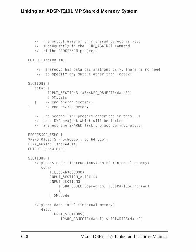
Linking an ADSP-TS101 MP Shared Memory System
C-8 VisualDSP++ 4.5 Linker and Utilities Manual
// The output name of this shared object is used // subsequently in the LINK_AGAINST command // of the PROCESSOR projects.
OUTPUT(shared.sm)
// shared.c has data declarations only. There is no need // to specify any output other than “data2”.
SECTIONS { data2 { INPUT_SECTIONS ($SHARED_OBJECTS(data2)) } >M1Data } // end shared sections} // end shared memory
// The second link project described in this LDF // is a DXE project which will be linked // against the SHARED link project defined above.
PROCESSOR_PSH0 {$PSH0_OBJECTS = psh0.doj, ts_hdr.doj;LINK_AGAINST(shared.sm)OUTPUT (psh0.dxe)
SECTIONS { // places code (instructions) in M0 (internal memory) code{ FILL(0xb3c00000) INPUT_SECTION_ALIGN(4) INPUT_SECTIONS( $PSH0_OBJECTS(program) $LIBRARIES(program) ) } >M0Code
// place data in M2 (internal memory) data1{ INPUT_SECTIONS( $PSH0_OBJECTS(data1) $LIBRARIES(data1)
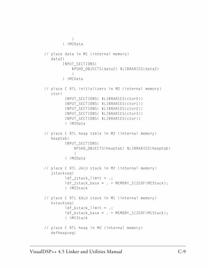
VisualDSP++ 4.5 Linker and Utilities Manual C-9
) } >M2Data
// place data in M1 (internal memory) data2{ INPUT_SECTIONS( $PSH0_OBJECTS(data2) $LIBRARIES(data2) ) } >M1Data
// place C RTL initializers in M2 (internal memory) ctor{ INPUT_SECTIONS( $LIBRARIES(ctor0)) INPUT_SECTIONS( $LIBRARIES(ctor1)) INPUT_SECTIONS( $LIBRARIES(ctor2)) INPUT_SECTIONS( $LIBRARIES(ctor3)) INPUT_SECTIONS( $LIBRARIES(ctor)) } >M2Data
// place C RTL heap table in M2 (internal memory) heaptab{ INPUT_SECTIONS( $PSH0_OBJECTS(heaptab) $LIBRARIES(heaptab) ) } >M2Data
// place C RTL JALU stack in M2 (internal memory) jstackseg{ ldf_jstack_limit = .; ldf_jstack_base = . + MEMORY_SIZEOF(M2Stack); } >M2Stack
// place C RTL KALU stack in M1 (internal memory) kstackseg{ ldf_kstack_limit = .; ldf_kstack_base = . + MEMORY_SIZEOF(M1Stack); } >M1Stack
// place C RTL heap in M2 (internal memory) defheapseg{

Linking an ADSP-TS101 MP Shared Memory System
C-10 VisualDSP++ 4.5 Linker and Utilities Manual
ldf_defheap_base = .; ldf_defheap_size = . + MEMORY_SIZEOF(M2Heap); } >M2Heap } // end PSH0 sections} // end PSH0 processor
// The third and final link project defined in this LDF file // is another DXE project and will be linked against // both the SHARED project and the PSH0 DXE project.
PROCESSOR_PSH1 { $PSH1_OBJECTS = psh1.doj, ts_hdr.doj; LINK_AGAINST(shared.sm, psh0.dxe) OUTPUT (psh1.dxe)
SECTIONS { // places code (instructions) in M0 (internal memory) code{ FILL(0xb3c00000) INPUT_SECTION_ALIGN(4) INPUT_SECTIONS( $PSH1_OBJECTS(program) $LIBRARIES(program) ) } >M0Code
// place data in M2 (internal memory) data1{ INPUT_SECTIONS( $PSH1_OBJECTS(data1) $LIBRARIES(data1) ) } >M2Data
// place data in M1 (internal memory) data2{ INPUT_SECTIONS( $PSH1_OBJECTS(data2) $LIBRARIES(data2) ) } >M1Data
// place C RTL initializers in M2 (internal memory)
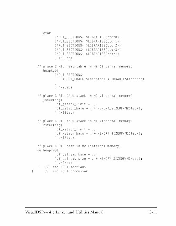
VisualDSP++ 4.5 Linker and Utilities Manual C-11
ctor{ INPUT_SECTIONS( $LIBRARIES(ctor0)) INPUT_SECTIONS( $LIBRARIES(ctor1)) INPUT_SECTIONS( $LIBRARIES(ctor2)) INPUT_SECTIONS( $LIBRARIES(ctor3)) INPUT_SECTIONS( $LIBRARIES(ctor)) } >M2Data
// place C RTL heap table in M2 (internal memory) heaptab{ INPUT_SECTIONS( $PSH1_OBJECTS(heaptab) $LIBRARIES(heaptab) ) } >M2Data
// place C RTL JALU stack in M2 (internal memory) jstackseg{ ldf_jstack_limit = .; ldf_jstack_base = . + MEMORY_SIZEOF(M2Stack); } >M2Stack
// place C RTL KALU stack in M1 (internal memory) kstackseg{ ldf_kstack_limit = .; ldf_kstack_base = . + MEMORY_SIZEOF(M1Stack); } >M1Stack
// place C RTL heap in M2 (internal memory) defheapseg{ ldf_defheap_base = .; ldf_defheap_size = . + MEMORY_SIZEOF(M2Heap); } >M2Heap } // end PSH1 sections} // end PSH1 processor
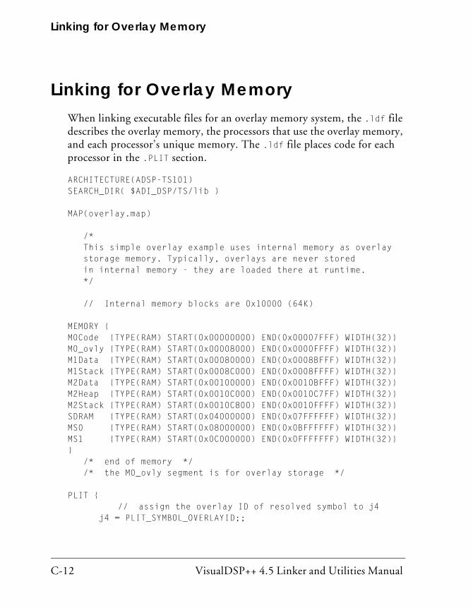
Linking for Overlay Memory
C-12 VisualDSP++ 4.5 Linker and Utilities Manual
Linking for Overlay MemoryWhen linking executable files for an overlay memory system, the .ldf file describes the overlay memory, the processors that use the overlay memory, and each processor’s unique memory. The .ldf file places code for each processor in the .PLIT section.
ARCHITECTURE(ADSP-TS101)SEARCH_DIR( $ADI_DSP/TS/lib )
MAP(overlay.map)
/* This simple overlay example uses internal memory as overlay storage memory. Typically, overlays are never stored in internal memory - they are loaded there at runtime. */
// Internal memory blocks are 0x10000 (64K)
MEMORY {M0Code {TYPE(RAM) START(0x00000000) END(0x00007FFF) WIDTH(32)}M0_ovly {TYPE(RAM) START(0x00008000) END(0x0000FFFF) WIDTH(32)}M1Data {TYPE(RAM) START(0x00080000) END(0x0008BFFF) WIDTH(32)}M1Stack {TYPE(RAM) START(0x0008C000) END(0x0008FFFF) WIDTH(32)}M2Data {TYPE(RAM) START(0x00100000) END(0x0010BFFF) WIDTH(32)}M2Heap {TYPE(RAM) START(0x0010C000) END(0x0010C7FF) WIDTH(32)}M2Stack {TYPE(RAM) START(0x0010C800) END(0x0010FFFF) WIDTH(32)}SDRAM {TYPE(RAM) START(0x04000000) END(0x07FFFFFF) WIDTH(32)}MS0 {TYPE(RAM) START(0x08000000) END(0x0BFFFFFF) WIDTH(32)}MS1 {TYPE(RAM) START(0x0C000000) END(0x0FFFFFFF) WIDTH(32)}} /* end of memory */ /* the M0_ovly segment is for overlay storage */
PLIT { // assign the overlay ID of resolved symbol to j4 j4 = PLIT_SYMBOL_OVERLAYID;;

VisualDSP++ 4.5 Linker and Utilities Manual C-13
// assign “run” address of resolved symbol to j5 j5 = PLIT_SYMBOL_ADDRESS;;
JUMP _OverlayManager;;}
$LIBRARIES = libc.dlb;$OBJECTS = ts_hdr.doj;
PROCESSOR P0 { $P0_OBJECTS = main.doj, manager.doj;
OUTPUT(Mgrovly.dxe)
SECTIONS { // .text output section Code { INPUT_SECTIONS( $P0_OBJECTS(program) $LIBRARIES(program) )
// Specify the first overlay. This overlay is stored // in the memory defined by “M0_ovly”. It runs in the // memory space defined by “M0Code”. OVERLAY_INPUT {
// The output archive file (overlay.olv) contains the code // and symbol table for this overlay. OVERLAY_OUTPUT (overlay1.ovl) // Take the code from overlay1.doj only. If there is data // that this code needs, it must be the INPUT of a data // overlay or the INPUT to non-overlay data memory. INPUT_SECTIONS (overlay1.doj (program) ) } > M0_ovly // This is the second overlay. Note that the OVERLAY_INPUT // commands must be contiguous in the LDF file to occupy // the same runtime memory.
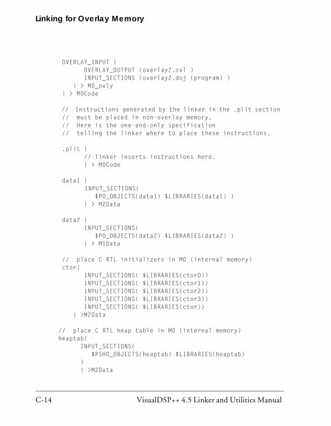
Linking for Overlay Memory
C-14 VisualDSP++ 4.5 Linker and Utilities Manual
OVERLAY_INPUT { OVERLAY_OUTPUT (overlay2.ovl ) INPUT_SECTIONS (overlay2.doj (program) ) } > M0_ovly } > M0Code // Instructions generated by the linker in the .plit section // must be placed in non-overlay memory. // Here is the one-and-only specification // telling the linker where to place these instructions. .plit { // linker inserts instructions here. } > M0Code data1 { INPUT_SECTIONS( $P0_OBJECTS(data1) $LIBRARIES(data1) ) } > M2Data data2 { INPUT_SECTIONS( $P0_OBJECTS(data2) $LIBRARIES(data2) ) } > M1Data
// place C RTL initializers in M0 (internal memory) ctor{ INPUT_SECTIONS( $LIBRARIES(ctor0)) INPUT_SECTIONS( $LIBRARIES(ctor1)) INPUT_SECTIONS( $LIBRARIES(ctor2)) INPUT_SECTIONS( $LIBRARIES(ctor3)) INPUT_SECTIONS( $LIBRARIES(ctor)) } >M2Data
// place C RTL heap table in M0 (internal memory) heaptab{ INPUT_SECTIONS( $PSH0_OBJECTS(heaptab) $LIBRARIES(heaptab) ) } >M2Data

VisualDSP++ 4.5 Linker and Utilities Manual C-15
// place C RTL JALU stack in M0 (internal memory) jstackseg{ ldf_jstack_limit = .; ldf_jstack_base = . + MEMORY_SIZEOF(M2Stack); } >M2Stack
// place C RTL KALU stack in M1 (internal memory) kstackseg{ ldf_kstack_limit = .; ldf_kstack_base = . + MEMORY_SIZEOF(M1Stack); } >M1Stack
// place C RTL heap in M0 (internal memory) defheapseg{ ldf_defheap_base = .; ldf_defheap_size = . + MEMORY_SIZEOF(M2Heap); } >M2Heap } // end P0 sections} // end P0 processor

Linking for Overlay Memory
C-16 VisualDSP++ 4.5 Linker and Utilities Manual
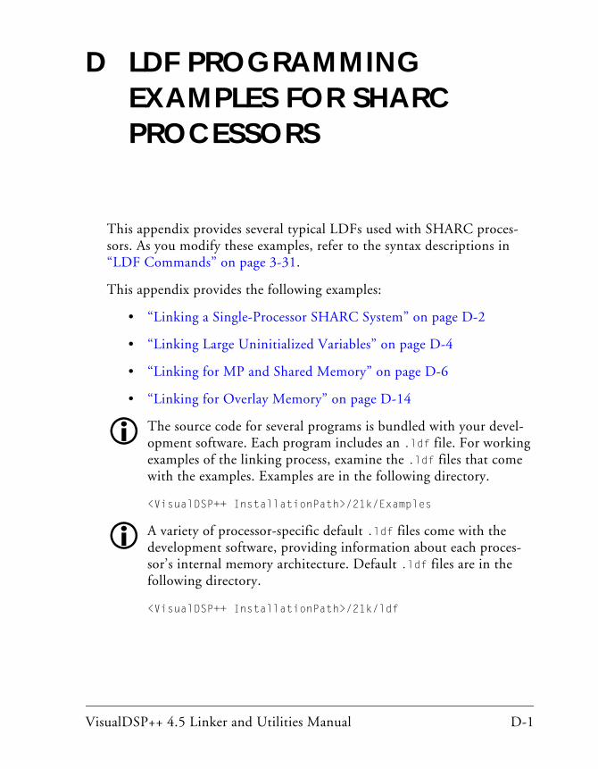
VisualDSP++ 4.5 Linker and Utilities Manual D-1
D LDF PROGRAMMING EXAMPLES FOR SHARC PROCESSORS
This appendix provides several typical LDFs used with SHARC proces-sors. As you modify these examples, refer to the syntax descriptions in “LDF Commands” on page 3-31.
This appendix provides the following examples:
• “Linking a Single-Processor SHARC System” on page D-2
• “Linking Large Uninitialized Variables” on page D-4
• “Linking for MP and Shared Memory” on page D-6
• “Linking for Overlay Memory” on page D-14
The source code for several programs is bundled with your devel-opment software. Each program includes an .ldf file. For working examples of the linking process, examine the .ldf files that come with the examples. Examples are in the following directory.
<VisualDSP++ InstallationPath>/21k/Examples
A variety of processor-specific default .ldf files come with the development software, providing information about each proces-sor’s internal memory architecture. Default .ldf files are in the following directory.
<VisualDSP++ InstallationPath>/21k/ldf
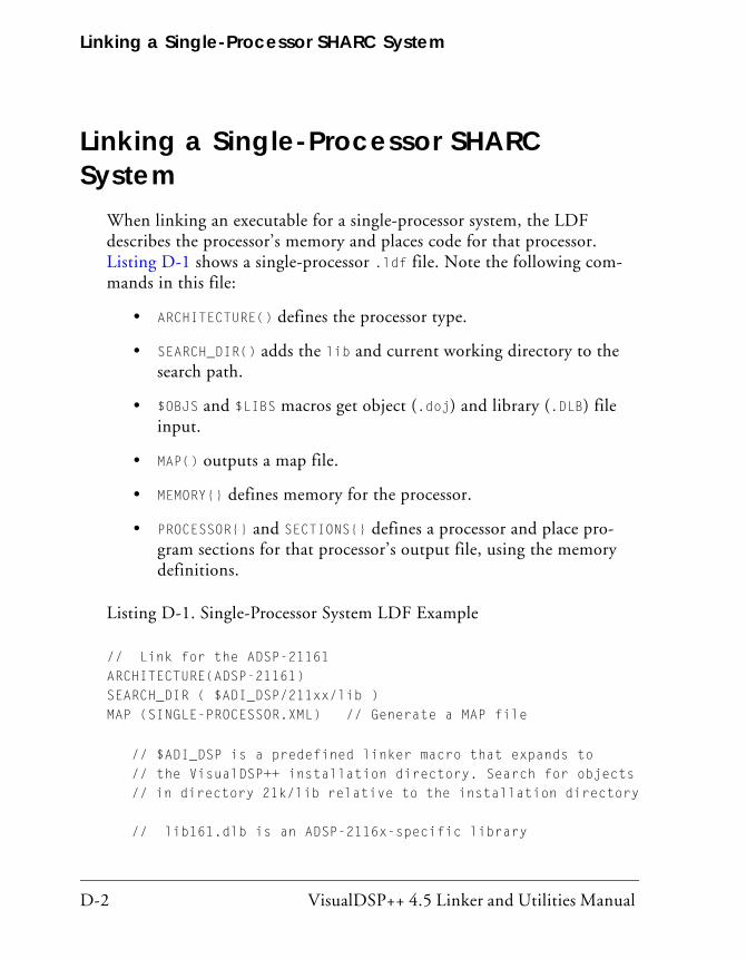
Linking a Single-Processor SHARC System
D-2 VisualDSP++ 4.5 Linker and Utilities Manual
Linking a Single-Processor SHARC System
When linking an executable for a single-processor system, the LDF describes the processor’s memory and places code for that processor. Listing D-1 shows a single-processor .ldf file. Note the following com-mands in this file:
• ARCHITECTURE() defines the processor type.
• SEARCH_DIR() adds the lib and current working directory to the search path.
• $OBJS and $LIBS macros get object (.doj) and library (.DLB) file input.
• MAP() outputs a map file.
• MEMORY{} defines memory for the processor.
• PROCESSOR{} and SECTIONS{} defines a processor and place pro-gram sections for that processor’s output file, using the memory definitions.
Listing D-1. Single-Processor System LDF Example
// Link for the ADSP-21161ARCHITECTURE(ADSP-21161)SEARCH_DIR ( $ADI_DSP/211xx/lib )MAP (SINGLE-PROCESSOR.XML) // Generate a MAP file
// $ADI_DSP is a predefined linker macro that expands to // the VisualDSP++ installation directory. Search for objects // in directory 21k/lib relative to the installation directory
// lib161.dlb is an ADSP-2116x-specific library
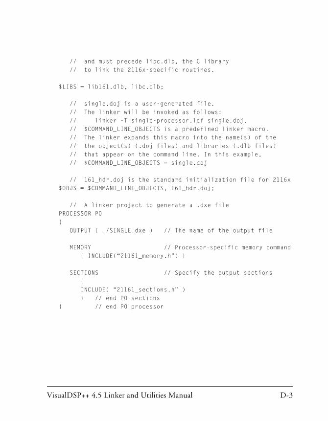
VisualDSP++ 4.5 Linker and Utilities Manual D-3
// and must precede libc.dlb, the C library // to link the 2116x-specific routines.
$LIBS = lib161.dlb, libc.dlb;
// single.doj is a user-generated file. // The linker will be invoked as follows: // linker -T single-processor.ldf single.doj. // $COMMAND_LINE_OBJECTS is a predefined linker macro. // The linker expands this macro into the name(s) of the // the object(s) (.doj files) and libraries (.dlb files) // that appear on the command line. In this example, // $COMMAND_LINE_OBJECTS = single.doj
// 161_hdr.doj is the standard initialization file for 2116x$OBJS = $COMMAND_LINE_OBJECTS, 161_hdr.doj;
// A linker project to generate a .dxe filePROCESSOR P0{ OUTPUT ( ./SINGLE.dxe ) // The name of the output file
MEMORY // Processor-specific memory command { INCLUDE(“21161_memory.h”) }
SECTIONS // Specify the output sections { INCLUDE( “21161_sections.h” ) } // end P0 sections} // end P0 processor

Linking Large Uninitialized Variables
D-4 VisualDSP++ 4.5 Linker and Utilities Manual
Linking Large Uninitialized VariablesWhen linking an executable file that contains large uninitialized variables, use the NO_INIT (equivalent to SHT_NOBITS legacy qualifier) or ZERO_INIT section qualifier to reduce the file size.
A variable defined in a source file normally takes up space in an object and executable file even if that variable is not explicitly initialized when defined. For large buffers, this action can result in large executables filled mostly with zeros. Such files take up excess disk space and can incur long download times when used with an emulator. This situation also may occur when you boot from a loader file (because of the increased file size). Listing D-2 shows an example of assembly source code. Listing D-3 shows the use of the NO_INIT and ZERO_INIT sections to avoid initialization of a segment.
The LDF can omit an output section from the output file. The NO_INIT qualifier directs the linker to omit data for that section from the output file.
Refer to “SECTIONS{}” on page 3-55 for more information on the NO_INIT and ZERO_INIT section qualifiers.
The NO_INIT qualifier corresponds to the /UNINIT segment qualifier in previous (.ach) development tools. Even if NO_INIT is not used, the boot loader removes variables initialized to zeros from the .ldr file and replaces them with instructions for the loader kernel to zero-out the variable. This action reduces the loader’s output file size, but still requires execution time for the processor to initialize the memory with zeros.
Listing D-2. Large Uninitialized Variables: Assembly Source
.SECTION/DM/NO_INIT sdram_area; /* 1Mx32 SDRAM */
.VAR huge_buffer[0x100000];

VisualDSP++ 4.5 Linker and Utilities Manual D-5
Listing D-3. Large Uninitialized Variables: LDF Source
ARCHITECTURE(ADSP-21161)
$OBJECTS = $COMMAND_LINE_OBJECTS; // Libraries & objects from
// the command line
MEMORY {
mem_sdram {
TYPE(DM RAM) START(0x3000000) END(0x30FFFFF) WIDTH(32)
} // end segment
} // end memory
PROCESSOR P0 {
LINK_AGAINST( $COMMAND_LINE_LINK_AGAINST )
OUTPUT( $COMMAND_LINE_OUTPUT_FILE )
// NO_INIT section isn’t written to the output file
SECTION {
sdram_output NO_INIT {
INPUT_SECTIONS( $OBJECTS ( sdram_area ) )}
>mem_sdram;
SECTION {
zero_sdram_output ZERO_INIT {
INPUT_SECTIONS ( $OBJECTS ( zero_sdram_area ) )}
>mem_sdram;
} // end section
} // end processor P0
Linking for MP and Shared Memory
D-6 VisualDSP++ 4.5 Linker and Utilities Manual
Linking for MP and Shared MemoryWhen linking executable files for a multiprocessor system using shared memory, the .ldf file describes the multiprocessor memory offsets, shared memory, each processor’s memory, and places code for each processor. Note the following in the example .ldf file in Listing D-4 on page D-7:
• The ARCHITECTURE() command defines the processor type, which can be one type only.
• The SEARCH_DIR() command adds the lib and current working directory to the search path.
• The $OBJS and $LIBS macros get object (.doj) and library (.DLB) file input.
• The MPMEMORY{} command defines each processor’s offset within multiprocessor memory.
• The SHARED_MEMORY{} command identifies the output for the shared memory items.
• The MAP() command outputs map files.
• The MEMORY{} command defines memory for the processors.
• The PROCESSOR{} and SECTIONS{} commands define each processor and place program sections using memory definitions for each pro-cessor’s output file.
• The LINK_AGAINST() commands resolve symbols within multipro-cessor memory.

VisualDSP++ 4.5 Linker and Utilities Manual D-7
Listing D-4. LDF for a Multiprocessor System With Shared Memory
ARCHITECTURE(ADSP-21161)SEARCH_DIR( $ADI_DSP/211xx/lib )
// Allocate multiprocessor memory space with the MPMEMORY{}// command. The values represent an “offset” that the linker// uses to resolve undefined symbols in one DXE file to symbols// defined in another DXE file. That is, the offset is added// to each defined symbol’s value.// For example, PROCESSOR project PSH0 references the undefined // symbol “buffer”, and PROCESSOR project PSH1 defines “buffer”// at address 0x22000. The linker will “fix up” the reference// to “buffer” in PSH0’s code to address:// 0x22000 + MPMEMORY(PSH1) = 0x22000 + 0x120000 = 0x142000 MPMEMORY { PSH0 { START (0x100000) } PSH1 { START (0x120000) }}MEMORY { // This is used for all processors. Alternatively, // a PROCESSOR can describe its own memory. seg_rth { TYPE(PM RAM) START(0x00040000) END(0x000400ff) WIDTH(48) }seg_init { TYPE(PM RAM) START(0x00040100) END(0x000401ff) WIDTH(48) }seg_int_code { TYPE(PM RAM) START(0x00040200) END(0x00040287) WIDTH(48) }seg_pmco { TYPE(PM RAM) START(0x00040288) END(0x000419ff) WIDTH(48) }seg_pmda { TYPE(PM RAM) START(0x00042700) END(0x00043fff) WIDTH(32) }seg_dmda { TYPE(DM RAM) START(0x00050000) END(0x00051fff) WIDTH(32) }
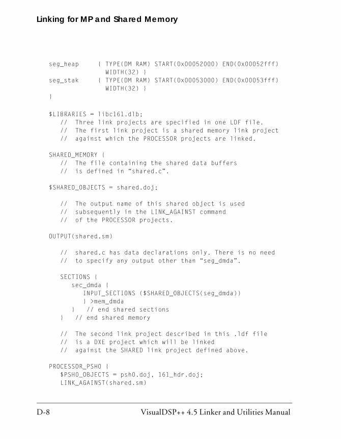
Linking for MP and Shared Memory
D-8 VisualDSP++ 4.5 Linker and Utilities Manual
seg_heap { TYPE(DM RAM) START(0x00052000) END(0x00052fff) WIDTH(32) }seg_stak { TYPE(DM RAM) START(0x00053000) END(0x00053fff) WIDTH(32) }}
$LIBRARIES = libc161.dlb; // Three link projects are specified in one LDF file. // The first link project is a shared memory link project // against which the PROCESSOR projects are linked.
SHARED_MEMORY { // The file containing the shared data buffers // is defined in “shared.c”.
$SHARED_OBJECTS = shared.doj;
// The output name of this shared object is used // subsequently in the LINK_AGAINST command // of the PROCESSOR projects.
OUTPUT(shared.sm)
// shared.c has data declarations only. There is no need // to specify any output other than “seg_dmda”.
SECTIONS { sec_dmda { INPUT_SECTIONS ($SHARED_OBJECTS(seg_dmda)) } >mem_dmda } // end shared sections } // end shared memory
// The second link project described in this .ldf file // is a DXE project which will be linked // against the SHARED link project defined above.
PROCESSOR_PSH0 { $PSH0_OBJECTS = psh0.doj, 161_hdr.doj; LINK_AGAINST(shared.sm)
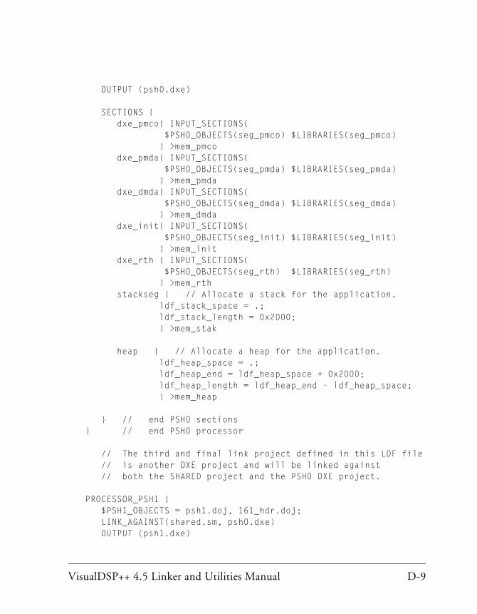
VisualDSP++ 4.5 Linker and Utilities Manual D-9
OUTPUT (psh0.dxe)
SECTIONS { dxe_pmco{ INPUT_SECTIONS( $PSH0_OBJECTS(seg_pmco) $LIBRARIES(seg_pmco) } >mem_pmco dxe_pmda{ INPUT_SECTIONS( $PSH0_OBJECTS(seg_pmda) $LIBRARIES(seg_pmda) } >mem_pmda dxe_dmda{ INPUT_SECTIONS( $PSH0_OBJECTS(seg_dmda) $LIBRARIES(seg_dmda) } >mem_dmda dxe_init{ INPUT_SECTIONS( $PSH0_OBJECTS(seg_init) $LIBRARIES(seg_init) } >mem_init dxe_rth { INPUT_SECTIONS( $PSH0_OBJECTS(seg_rth) $LIBRARIES(seg_rth) } >mem_rth stackseg { // Allocate a stack for the application. ldf_stack_space = .; ldf_stack_length = 0x2000; } >mem_stak
heap { // Allocate a heap for the application. ldf_heap_space = .; ldf_heap_end = ldf_heap_space + 0x2000; ldf_heap_length = ldf_heap_end - ldf_heap_space; } >mem_heap
} // end PSH0 sections} // end PSH0 processor
// The third and final link project defined in this LDF file // is another DXE project and will be linked against // both the SHARED project and the PSH0 DXE project.
PROCESSOR_PSH1 { $PSH1_OBJECTS = psh1.doj, 161_hdr.doj; LINK_AGAINST(shared.sm, psh0.dxe) OUTPUT (psh1.dxe)

Linking for MP and Shared Memory
D-10 VisualDSP++ 4.5 Linker and Utilities Manual
SECTIONS { dxe_pmco{ INPUT_SECTIONS( $PSH1_OBJECTS(seg_pmco) $LIBRARIES(seg_pmco) } >mem_pmco dxe_pmda{ INPUT_SECTIONS( $PSH1_OBJECTS(seg_pmda) $LIBRARIES(seg_pmda) } >mem_pmda dxe_dmda{ INPUT_SECTIONS( $PSH1_OBJECTS(seg_dmda) $LIBRARIES(seg_dmda) } >mem_dmda dxe_init{ INPUT_SECTIONS( $PSH1_OBJECTS(seg_init) $LIBRARIES(seg_init) } >mem_init dxe_rth { INPUT_SECTIONS( $PSH1_OBJECTS(seg_rth) $LIBRARIES(seg_rth) } >mem_rth stackseg { // Allocate a stack for the application. ldf_stack_space = .; ldf_stack_length = 0x2000; } >mem_stak heap { // Allocate a heap for the application. ldf_heap_space = .; ldf_heap_end = ldf_heap_space + 0x2000; ldf_heap_length = ldf_heap_end - ldf_heap_space; } >mem_heap
// The following definition sections are needed only // for pre-VisualDSP combatibility woth COFF objects. .coff.stringstab {INPUT_SECTIONS( $PSH1_OBJECTS(.coff.stringstab) $LIBRARIES(.coff.stringstab)) } .coff.SDB {INPUT_SECTIONS( $PSH1_OBJECTS(.coff.SDB) $LIBRARIES(.coff.SDB)) } .lnno.seg_pmco {INPUT_SECTIONS( $PSH1_OBJECTS(.lnno.seg_pmco) $LIBRARIES(.lnno.seg_pmco))

VisualDSP++ 4.5 Linker and Utilities Manual D-11
} } // end PSH1 sections} // end PSH1 processor

Linking for MP and Shared Memory
D-12 VisualDSP++ 4.5 Linker and Utilities Manual
Reflective SemaphoresSemaphores may be used in multiprocessor (MP) systems to permit processors to share resources such as memory or I/O. A semaphore is a flag that can be read and written by any of the processors sharing the resource. A semaphore’s value indicates when the processor can access the resource. Reflective semaphores permit communication among processors that share a multiprocessor memory space.
Use broadcast writes to implement reflective semaphores in an MP system. Broadcast writes allow simultaneous transmission of data to all the SHARC processors in an MP system. The master processor can broadcast writes to the same memory location or IOP register on all the slaves. During a broadcast write, the master also writes to itself unless the broad-cast is a DMA write.
Broadcast writes can also be used to simultaneously download code or data to multiple processors.
Bus lock can be used in combination with broadcast writes to implement reflective semaphores in an MP system. The reflective semaphore should be located at the same address in internal memory (or IOP register) of each SHARC processor.
SHARC processors have a “broadcast” space. Use .ldf file (or header files) to define a memory segment in this space, just as in internal memory or any processor MP space. The broadcast space aliases internal space, so if there is a memory segment defined in the broadcast space, the .ldf file cannot have a memory segment at the corresponding address in the inter-nal space (or in the MP space of any processor). Otherwise, the linker generates an error indicating that the memory definition is not valid.
To check the semaphore, each SHARC processor reads from its own inter-nal memory. Any object in the project can be mapped to an appropriate memory segment defined in the broadcast space for use as a reflective

VisualDSP++ 4.5 Linker and Utilities Manual D-13
semaphore. If an object defining symbol SemA is mapped to a broadcast space, when the program writes to SemA, the written value appears at the aliased internal address of each processor in the cluster. Each processor may read the value using SemA, or read it from internal memory by select-ing (SemA-0x380000), thus avoiding bus traffic.
To modify the semaphore, a SHARC processor requests bus lock and then performs a broadcast write to the semaphore address (for example, SemA).
The processors should read the semaphore before modifying it to verify that another processor has not changed it.
For more information on semaphores, refer to your processor’s Hardware Reference manual.

Linking for Overlay Memory
D-14 VisualDSP++ 4.5 Linker and Utilities Manual
Linking for Overlay MemoryWhen linking executable files for an overlay memory system, the .ldf file describes the overlay memory, the processors that use the overlay memory, and each processor’s unique memory. The .ldf file places code for each processor in the .PLIT section.
ARCHITECTURE(ADSP-21161)SEARCH_DIR( $ADI_DSP/211xx/lib )
MAP(overlay.map)
/* This simple overlay example uses internal memory as overlay storage memory. Typically, overlays are never stored in internal memory, but are loaded there at runtime. */
MEMORY { seg_rth {TYPE(PM RAM) START(0x00040000) END(0x000400ff) WIDTH(48)} seg_init {TYPE(PM RAM) START(0x00040100) END(0x000401ff) WIDTH(48)} seg_init_code {TYPE(PM RAM) START(0x00040200) END(0x00040287) WIDTH(48)} seg_pmco {TYPE(PM RAM) START(0x00040288) END(0x000409ff) WIDTH(48)} seg_ovly {TYPE(PM RAM) START(0x00040100) END(0x000419ff) WIDTH(48)} seg_pmda {TYPE(PM RAM) START(0x00042700) END(0x00043fff) WIDTH(32)} seg_dmda {TYPE(DM RAM) START(0x00050000) END(0x00051fff) WIDTH(32)} seg_heap {TYPE(DM RAM) START(0x00052000) END(0x00052fff) WIDTH(32)} seg_stak {TYPE(DM RAM) START(0x00053000) END(0x00053fff) WIDTH(32)}
/* mem_pmco is the “run” memory segment */ /* mem_ovly is the “live” memory segment */
// Processor and application-specific assembly language // instructions. One instance of these instructions is // generated for each symbol resolved in overlay memory.
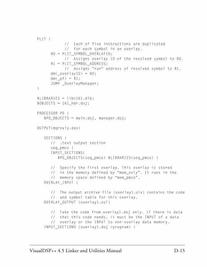
VisualDSP++ 4.5 Linker and Utilities Manual D-15
PLIT { // Each of five instructions are duplicated // for each symbol in an overlay. R0 = PLIT_SYMBOL_OVERLAYID; // Assigns overlay ID of the resolved symbol to R0. R1 = PLIT_SYMBOL_ADDRESS; // Assigns “run” address of resolved symbol to R1. dm(_overlayID) = R0; dm(_pf) = R1; JUMP _OverlayManager; }
$LIBRARIES = libc161.dlb;$OBJECTS = 161_hdr.doj;
PROCESSOR P0 { $P0_OBJECTS = main.doj, manager.doj;
OUTPUT(mgrovly.dxe)
SECTIONS { // .text output section seg_pmco { INPUT_SECTIONS( $P0_OBJECTS(seg_pmco) $LIBRARIES(seg_pmco) )
// Specify the first overlay. This overlay is stored // in the memory defined by “mem_ovly”. It runs in the // memory space defined by “mem_pmco”. OVERLAY_INPUT {
// The output archive file (overlay1.olv) contains the code // and symbol table for this overlay. OVERLAY_OUTPUT (overlay1.ovl) // Take the code from overlay1.doj only. If there is data // that this code needs, it must be the INPUT of a data // overlay or the INPUT to non-overlay data memory. INPUT_SECTIONS (overlay1.doj (program) )
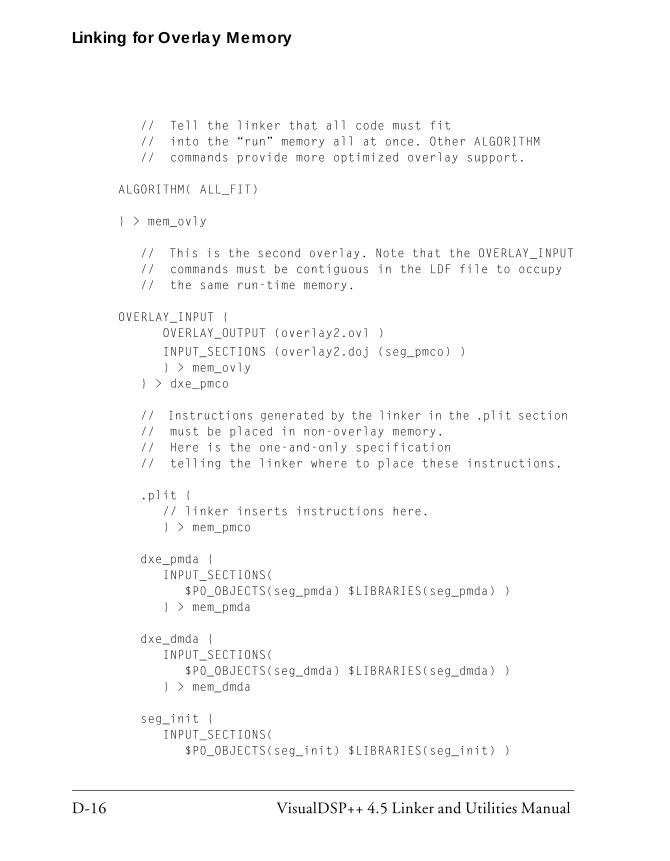
Linking for Overlay Memory
D-16 VisualDSP++ 4.5 Linker and Utilities Manual
// Tell the linker that all code must fit // into the “run” memory all at once. Other ALGORITHM // commands provide more optimized overlay support. ALGORITHM( ALL_FIT) } > mem_ovly // This is the second overlay. Note that the OVERLAY_INPUT // commands must be contiguous in the LDF file to occupy // the same run-time memory. OVERLAY_INPUT { OVERLAY_OUTPUT (overlay2.ovl )
INPUT_SECTIONS (overlay2.doj (seg_pmco) ) } > mem_ovly } > dxe_pmco // Instructions generated by the linker in the .plit section // must be placed in non-overlay memory. // Here is the one-and-only specification // telling the linker where to place these instructions. .plit { // linker inserts instructions here. } > mem_pmco dxe_pmda { INPUT_SECTIONS( $P0_OBJECTS(seg_pmda) $LIBRARIES(seg_pmda) ) } > mem_pmda dxe_dmda { INPUT_SECTIONS( $P0_OBJECTS(seg_dmda) $LIBRARIES(seg_dmda) ) } > mem_dmda seg_init { INPUT_SECTIONS( $P0_OBJECTS(seg_init) $LIBRARIES(seg_init) )

VisualDSP++ 4.5 Linker and Utilities Manual D-17
} > mem_init dxe_rth { INPUT_SECTIONS( $P0_OBJECTS(seg_rth) $LIBRARIES(seg_rth) ) } > mem_rth stackseg { // Allocate a stack for the application. ldf_stack_space = .; ldf_stack_length = 0x2000; } > mem_stak heap { // Allocate a heap for the application. ldf_heap_space = .; ldf_heap_end = ldf_heap_space + 0x2000; ldf_heap_length = ldf_heap_end - ldf_heap_space; } > mem_heap
} }

Linking for Overlay Memory
D-18 VisualDSP++ 4.5 Linker and Utilities Manual

VisualDSP++ 4.5 Linker and Utilities Manual E-1
E LDF PROGRAMMING EXAMPLES FOR BLACKFIN PROCESSORS
This appendix provides several typical LDFs. used with Blackfin proces-sors. As you modify these examples, refer to the syntax descriptions in “LDF Commands” on page 3-31.
This appendix provides the following examples.
• “Linking for a Single-Processor System” on page E-2
• “Linking Large Uninitialized or Zero-initialized Variables” on page E-4
• “Linking for Assembly Source File” on page E-6
• “Linking for C Source File – Example 1” on page E-8
• “Linking for Complex C Source File – Example 2” on page E-11
• “Linking for Overlay Memory” on page E-17
The source code for several programs is bundled with the development software. Each program includes an .ldf file. For working examples of the linking process, examine the .ldf files that come with the examples. These examples are in the directory:
VisualDSP++ InstallPath>/Blackfin/examples
The development software includes a variety of default .ldf files. These files provide an example .ldf for each processor’s internal memory architecture. The default .ldf files are in the directory:
<VisualDSP++ InstallPath>/Blackfin/ldf

Linking for a Single-Processor System
E-2 VisualDSP++ 4.5 Linker and Utilities Manual
Linking for a Single-Processor SystemWhen you link an executable file for a single-processor system, the .ldf file describes the processor’s memory and places code for that processor. The .ldf file in Listing E-1 is for a single-processor system. Note the fol-lowing commands in this example .ldf file.
• ARCHITECTURE() defines the processor type
• SEARCH_DIR() commands add the lib and current working direc-tory to the search path
• $OBJS and $LIBS macros retrieve object (.doj) and library (.DLB) file input
• MAP() outputs a map file
• MEMORY{} defines memory for the processor
• PROCESSOR{} and SECTIONS{} commands define a processor and place program sections for that processor’s output file by using the memory definitions
Listing E-1. Example .ldf File for a Single-Processor System
ARCHITECTURE(ADSP-BF535)
SEARCH_DIR( $ADI_DSP/Blackfin/lib )
MAP(SINGLE-PROCESSOR.MAP) // Generate a MAP file
// $ADI_DSP is a predefined linker macro that expands
// to the VDSP install directory. Search for objects in
// directory Blackfin/lib relative to the install directory
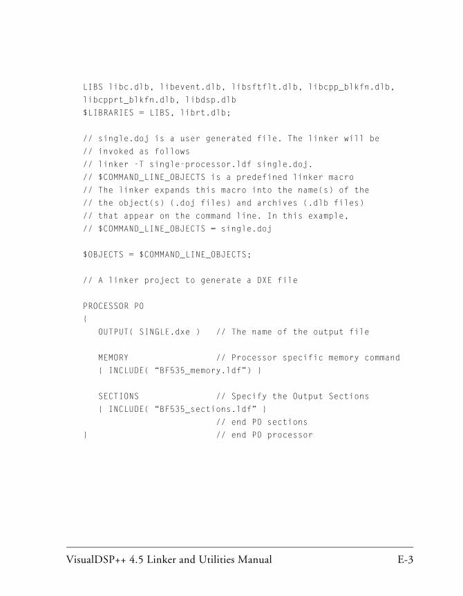
VisualDSP++ 4.5 Linker and Utilities Manual E-3
LIBS libc.dlb, libevent.dlb, libsftflt.dlb, libcpp_blkfn.dlb,
libcpprt_blkfn.dlb, libdsp.dlb
$LIBRARIES = LIBS, librt.dlb;
// single.doj is a user generated file. The linker will be
// invoked as follows
// linker -T single-processor.ldf single.doj.
// $COMMAND_LINE_OBJECTS is a predefined linker macro
// The linker expands this macro into the name(s) of the
// the object(s) (.doj files) and archives (.dlb files)
// that appear on the command line. In this example,
// $COMMAND_LINE_OBJECTS = single.doj
$OBJECTS = $COMMAND_LINE_OBJECTS;
// A linker project to generate a DXE file
PROCESSOR P0
{
OUTPUT( SINGLE.dxe ) // The name of the output file
MEMORY // Processor specific memory command
{ INCLUDE( “BF535_memory.ldf”) }
SECTIONS // Specify the Output Sections
{ INCLUDE( “BF535_sections.ldf” }
// end P0 sections
} // end P0 processor

Linking Large Uninitialized or Zero-initialized Variables
E-4 VisualDSP++ 4.5 Linker and Utilities Manual
Linking Large Uninitialized or Zero-initialized Variables
When linking an executable file that contains large uninitialized variables, use the NO_INIT (equivalent to SHT_NOBITS legacy qualifier) or ZERO_INIT section qualifier to reduce the file size.
A variable defined in a source file normally takes up space in an object and executable file even if that variable is not explicitly initialized when defined. For large buffers, this action can result in large executables filled mostly with zeros. Such files take up excess disk space and can incur long download times when used with an emulator. This situation also may occur when you boot from a loader file (because of the increased file size). Listing E-2 shows an example of assembly source code. Listing E-3 shows the use of the NO_INIT and ZERO_INIT sections to avoid initialization of a segment.
The LDF can omit an output section from the output file. The NO_INIT qualifier directs the linker to omit data for that section from the output file.
Refer to “SECTIONS{}” on page 3-55 for more information on the NO_INIT and ZERO_INIT section qualifiers.
The NO_INIT qualifier corresponds to the /UNINIT segment qualifier in previous (.ach) development tools. Even if you do not use NO_INIT, the boot loader removes variables initialized to zeros from the .ldr file and replaces them with instructions for the loader ker-nel to zero out the variable. This action reduces the loader’s output file size, but still requires execution time for the processor to ini-tialize the memory with zeros.
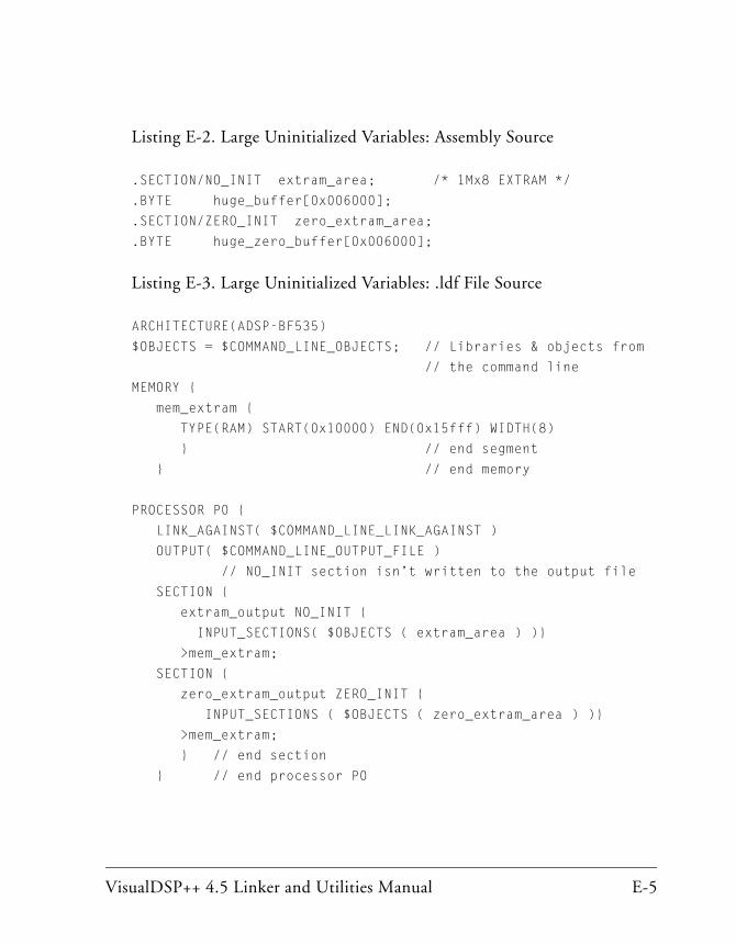
VisualDSP++ 4.5 Linker and Utilities Manual E-5
Listing E-2. Large Uninitialized Variables: Assembly Source
.SECTION/NO_INIT extram_area; /* 1Mx8 EXTRAM */
.BYTE huge_buffer[0x006000];
.SECTION/ZERO_INIT zero_extram_area;
.BYTE huge_zero_buffer[0x006000];
Listing E-3. Large Uninitialized Variables: .ldf File Source
ARCHITECTURE(ADSP-BF535)
$OBJECTS = $COMMAND_LINE_OBJECTS; // Libraries & objects from
// the command line
MEMORY {
mem_extram {
TYPE(RAM) START(0x10000) END(0x15fff) WIDTH(8)
} // end segment
} // end memory
PROCESSOR P0 {
LINK_AGAINST( $COMMAND_LINE_LINK_AGAINST )
OUTPUT( $COMMAND_LINE_OUTPUT_FILE )
// NO_INIT section isn’t written to the output file
SECTION {
extram_output NO_INIT {
INPUT_SECTIONS( $OBJECTS ( extram_area ) )}
>mem_extram;
SECTION {
zero_extram_output ZERO_INIT {
INPUT_SECTIONS ( $OBJECTS ( zero_extram_area ) )}
>mem_extram;
} // end section
} // end processor P0

Linking for Assembly Source File
E-6 VisualDSP++ 4.5 Linker and Utilities Manual
Linking for Assembly Source FileListing E-5 shows an example .ldf file for an ADSP-BF535 DSP that describes a simple memory placement of an assembly source file. The file in Listing E-4 contains code and data that is to reside in, and execute from, L2 SRAM. This example assumes that the code and data declared in L2 memory is cacheable within L1 code and data memories. The LDF file includes two commands, MEMORY and SECTIONS, which are used to describe specific memory and system information. Refer to Notes for Listing E-2 for information on items in this basic example.
Listing E-4. MyFile.asm
.SECTION program;
.GLOBAL main;main:p0.l = myArray;p0.h = myArray;r0 = [p0++];….SECTION data1;.GLOBAL myArray;.VAR myArray[256] = "myArray.dat";
Listing E-5. Simple .ldf File Based on Assembly Source File Only
#define L2_START 0xf0000000#define L2_END 0xf003ffff
// Declare specific DSP Architecture here (for linker)ARCHITECTURE(ADSP-BF535)// LDF macro equals all object files in project command line$OBJECTS = $COMMAND_LINE_OBJECTS;
// Describe the physical system memory below
MEMORY{
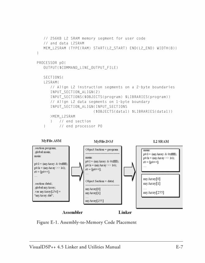
VisualDSP++ 4.5 Linker and Utilities Manual E-7
// 256KB L2 SRAM memory segment for user code // and data L2SRAM MEM_L2SRAM {TYPE(RAM) START(L2_START) END(L2_END) WIDTH(8)}}
PROCESSOR p0{ OUTPUT($COMMAND_LINE_OUTPUT_FILE)
SECTIONS{ L2SRAM{ // Align L2 instruction segments on a 2-byte boundaries INPUT_SECTION_ALIGN(2) INPUT_SECTIONS($OBJECTS(program) $LIBRARIES(program)) // Align L2 data segments on 1-byte boundary INPUT_SECTION_ALIGN(INPUT_SECTIONS ($OBJECTS(data1) $LIBRARIES(data1)) >MEM_L2SRAM } // end section } // end processor P0
Figure E-1. Assembly-to-Memory Code Placement

Linking for C Source File – Example 1
E-8 VisualDSP++ 4.5 Linker and Utilities Manual
Linking for C Source File – Example 1Listing E-7 shows an example LDF that describes the memory placement of a simple C source file (Listing E-6) which contains code and data that is to reside in, and execute from, L2 SRAM. This example also assumes that the code and data declared in L2 memory is cacheable within L1 code and data memories. The LDF file includes two commands, MEMORY and SEC-TIONS, which are used to describe specific memory and system information. Refer to Notes for Listing E-2 for information on items in this basic example.
Listing E-6. Simple C Source File Example 1
int myArray[256];
void main(void){ int i;
for(i=0; i<256; i++) myArray[i] = i;
} // end main ()
Listing E-7. Example: Simple C-based .ldf File for ADSP-BF535 Processor
ARCHITECTURE(ADSP-BF535)SEARCH_DIR( $ADI_DSP/Blackfin/lib )
#define LIBS libsmall535.dlb libc535.dlb libm3free535.dlb libevent535.dlb libio535.dlb libcpp535.dlb libcpprt535.dlb libdsp535.dlb libsftflt535.dlb libetsi535.dlb idle535.doj
$LIBRARIES = LIBS, librt535.dlb;
$OBJECTS = crts535.doj, $COMMAND_LINE_OBJECTS crtn535.doj;
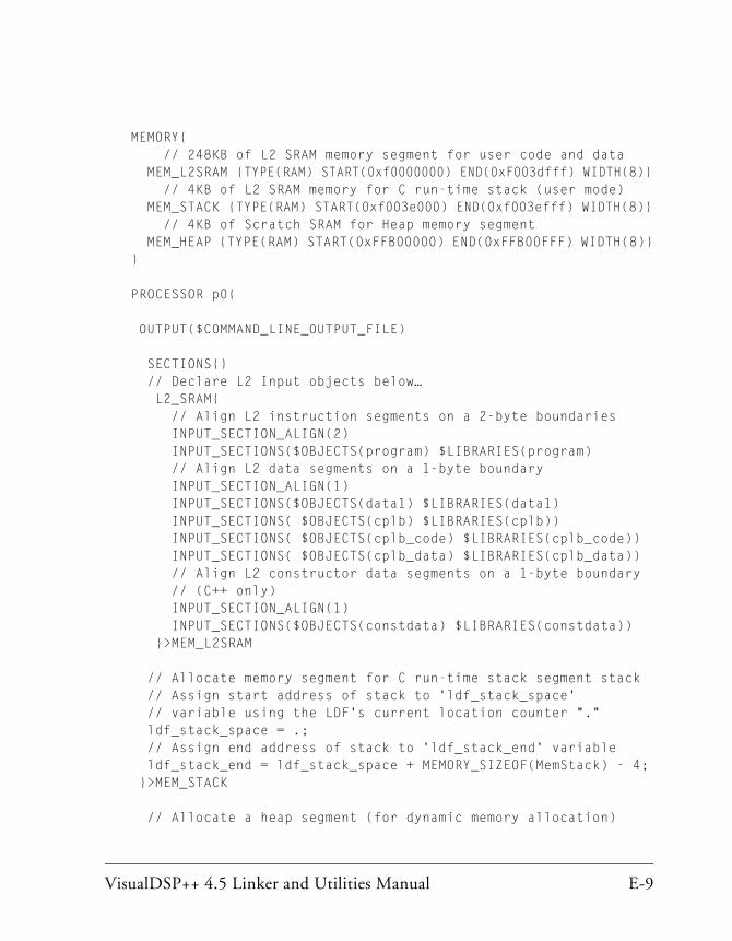
VisualDSP++ 4.5 Linker and Utilities Manual E-9
MEMORY{ // 248KB of L2 SRAM memory segment for user code and data MEM_L2SRAM {TYPE(RAM) START(0xf0000000) END(0xF003dfff) WIDTH(8)} // 4KB of L2 SRAM memory for C run-time stack (user mode) MEM_STACK {TYPE(RAM) START(0xf003e000) END(0xf003efff) WIDTH(8)} // 4KB of Scratch SRAM for Heap memory segment MEM_HEAP {TYPE(RAM) START(0xFFB00000) END(0xFFB00FFF) WIDTH(8)}}
PROCESSOR p0{
OUTPUT($COMMAND_LINE_OUTPUT_FILE)
SECTIONS{} // Declare L2 Input objects below… L2_SRAM{ // Align L2 instruction segments on a 2-byte boundaries INPUT_SECTION_ALIGN(2) INPUT_SECTIONS($OBJECTS(program) $LIBRARIES(program) // Align L2 data segments on a 1-byte boundary INPUT_SECTION_ALIGN(1) INPUT_SECTIONS($OBJECTS(data1) $LIBRARIES(data1) INPUT_SECTIONS( $OBJECTS(cplb) $LIBRARIES(cplb)) INPUT_SECTIONS( $OBJECTS(cplb_code) $LIBRARIES(cplb_code)) INPUT_SECTIONS( $OBJECTS(cplb_data) $LIBRARIES(cplb_data)) // Align L2 constructor data segments on a 1-byte boundary // (C++ only) INPUT_SECTION_ALIGN(1) INPUT_SECTIONS($OBJECTS(constdata) $LIBRARIES(constdata)) }>MEM_L2SRAM
// Allocate memory segment for C run-time stack segment stack // Assign start address of stack to 'ldf_stack_space' // variable using the LDF's current location counter "." ldf_stack_space = .; // Assign end address of stack to 'ldf_stack_end' variable ldf_stack_end = ldf_stack_space + MEMORY_SIZEOF(MemStack) - 4; }>MEM_STACK
// Allocate a heap segment (for dynamic memory allocation)

Linking for C Source File – Example 1
E-10 VisualDSP++ 4.5 Linker and Utilities Manual
// heap // Assign start address of heap to 'ldf_heap_space' variable // using the LDF's current location counter "." ldf_heap_space = .; // Assign end address of heap to 'ldf_heap_length' variable ldf_heap_end = ldf_heap_space + MEMORY_SIZEOF(MemHeap) - 1; // Assign length of heap to 'ldf_heap_length' variable ldf_heap_length = ldf_heap_end - ldf_heap_space; }>MEM_HEAP
} // end SECTIONS{} // end PROCESSOR p0{}

VisualDSP++ 4.5 Linker and Utilities Manual E-11
Linking for Complex C Source File – Example 2
Listing E-8 shows an example LDF that describes the memory placement of a C source file. This file contains code and data that is to reside in, and execute from, L1, L2, Scratchpad SRAM, and external SDRAM Banks 0 through 3. The .LDF file includes two commands, MEMORY and SECTIONS, which are used to describe specific memory and system information. Refer to Notes for Listing E-2 for information on items in this complex example.
Listing E-8. Complex C Source File Example
static section ("Fast_Code") void MEM_DMA_ISR(void){
...}
static section ("SDRAM_0") int page_buff1[0x08000000];static section ("SDRAM_1") int page_buff2[0x08000000];static section ("SDRAM_2") int page_buff3[0x08000000];static section ("SDRAM_3") int page_buff4[0x08000000];
static section ("Data_BankA") int coeffs1[256];static section ("Data_BankB") int input_array[0x2000];
int x, y, z;void main(void){
int i;x = 0x5555;
...}

Linking for Complex C Source File – Example 2
E-12 VisualDSP++ 4.5 Linker and Utilities Manual
The following is an example of an LDF file (for ADSP-BF535 DSP) which is based on the complex C source from Listing E-8. Also see Listing E-2 on page E-5.
Listing E-9. C .ldf File Example - SDRAM.ldf
ARCHITECTURE(ADSP-BF535)SEARCH_DIR($ADI_DSP/Blackfin/lib
#define LIBS libsmall535.dlb libc535.dlb libm3free535.dlb libevent535.dlb libio535.dlb libcpp535.dlb libcpprt535.dlb libdsp535.dlb libsftflt535.dlb libetsi535.dlb idle535.doj
$LIBRARIES = LIBS, librt535.dlb;
$OBJECTS = crts535.doj, $COMMAND_LINE_OBJECTS crtn535.doj;
// Define physical system memory below…MEMORY{ // 16KB of user code in L1 SRAM segment MEM_L1_CODE_SRAM {TYPE(RAM) START(0xFFA00000) END(0xFFA03FFF) WIDTH(8)} // 16KB of user data in L1 Data Bank A SRAM MEM_L1_DATAA_SRAM {TYPE(RAM) START(0xFF800000) END(0xFF803FFF) WIDTH(8)} // 16KB of user data in L1 Data Bank B SRAM MEM_L1_DATAB_SRAM {TYPE(RAM) START(0xFF900000) END(0xFF903FFF) WIDTH(8)}
// 4KB of L1 Scratch memory for C run-time stack (user mode) MeM_SCRATCH_STACK {TYPE(RAM) START(0xFFB00000) END(0xFFB007FF) WIDTH(8)}
// 248KB of user code and data in L2 SRAM segment MEM_L2_SRAM {TYPE(RAM) START(0xF0000000) END(0xF003DFFF) WIDTH(8)} // 4KB for heap in L2 SRAM (for dynamic memory allocation) MEM_HEAP {{TYPE(RAM) START(0xF003E000) END(0xF003EFFF) WIDTH(8)}

VisualDSP++ 4.5 Linker and Utilities Manual E-13
// 4KB for system stack in L2 SRAM (supervisor mode stack) MEM_SYSSTACK {TYPE(RAM) START(0xF003F000) END(0xF003FFFF) WIDTH(8)}
// 4 x 128MB External SDRAM memory segments MEM_SDRAM_BANK0 {TYPE(RAM) START(0x00000000) END(0x07FFFFFF) WIDTH(8)} MEM_SDRAM_BANK1 {TYPE(RAM) START(0x08000000) END(0x0FFFFFFF WIDTH(8)} MEM_SDRAM_BANK2 {TYPE(RAM) START(0x10000000) END(0x17FFFFFF) WIDTH(8)} MEM_SDRAM_BANK3 {TYPE(RAM) START(0x18000000) END(0x1FFFFFFF) WIDTH(8)} } // end MEMORY{}
PROCESSOR p0{ OUTPUT($COMMAND_LINE_OUTPUT_FILE)
SECTIONS{ // Input section declarations for L1 code memory L1_CODE_SRAM{ // Align L1 code segments on a 2-byte boundary INPUT_SECTION_ALIGN(2) INPUT_SECTIONS($OBJECTS(Fast_Code) }>MEM_L1_CODE_SRAM
// Input section declarations for L1 data bank A memory L1_DATAA_SRAM{ // Align L1 data segments on a 1-byte boundary INPUT_SECTION_ALIGN(1) INPUT_SECTIONS($OBJECTS(Data_BankA) }>MEM_L1_BANKA_SRAM
// Input section declarations for L1 data bank B memory L1_BANKB_SRAM{ // Align L1 data segments on a 1-byte boundary INPUT_SECTION_ALIGN(1) INPUT_SECTIONS($OBJECTS(Data_BankB) }>MEM_L1_BANKB_SRAM

Linking for Complex C Source File – Example 2
E-14 VisualDSP++ 4.5 Linker and Utilities Manual
stack{ ldf_stack_space = .; ldf_stack_end = ldf_stack_space + MEMORY_SIZEOF(Mem_Scratch_Stack) - 4; }>MEM_SCRATCH_STACK
heap{ ldf_heap_space = .; ldf_heap_end = ldf_heap_space + MEMORY_SIZEOF(Mem_Heap) - 1; ldf_heap_length = ldf_heap_end - ldf_heap_space; }>MEM_HEAP
L2_SRAM{ // Align L2 code segments on a 2-byte boundary INPUT_SECTION_ALIGN(2) INPUT_SECTIONS($OBJECTS(program) $LIBRARIES(program)) // Align L2 data segments on a 1-byte boundary INPUT_SECTION_ALIGN(1) INPUT_SECTIONS($OBJECTS(data1) $LIBRARIES(data1)) // Align L2 constructor data segments on a 1-byte boundary // (C++ only) INPUT_SECTION_ALIGN(1) INPUT_SECTIONS($OBJECTS(constdata) $LIBRARIES(constdata)) }>MEM_L2_SRAM
SDRAM_0{ // Align external SDRAM data segments on a 1-byte boundary INPUT_SECTION_ALIGN(1) INPUT_SECTIONS($OBJECTS(SDRAM_0)) }>MEM_SDRAM_BANK0
SDRAM_1{ // Align external SDRAM data segments on a 1-byte boundary INPUT_SECTION_ALIGN(1) INPUT_SECTIONS($OBJECTS(SDRAM_1)) }>MEM_SDRAM_BANK1
SDRAM_2{ // Align external SDRAM data segments on a 1-byte boundary

VisualDSP++ 4.5 Linker and Utilities Manual E-15
INPUT_SECTION_ALIGN(1) INPUT_SECTIONS($OBJECTS(SDRAM_2)) }>MEM_SDRAM_BANK2
SDRAM_3{ // Align external SDRAM data segments on a 1-byte boundary INPUT_SECTION_ALIGN(1) INPUT_SECTIONS($OBJECTS(SDRAM_3)) }>MEM_SDRAM_BANK3
} // End Sections{}} // End PROCESSOR p0{}

Linking for Complex C Source File – Example 2
E-16 VisualDSP++ 4.5 Linker and Utilities Manual
Figure E-2. C-to-Memory Code Placement

VisualDSP++ 4.5 Linker and Utilities Manual E-17
Linking for Overlay MemoryWhen you link executable files for an overlay memory system, the .ldf file describes the overlay memory, the processor(s) that use the overlay memory, and each processor’s unique memory. The .ldf file places code for each processor and the special PLIT{} section.
Listing E-10 shows an example .ldf file for an overlay-memory system. For more information on this .ldf file, see the comments in the listing.
Listing E-10. Example .ldf File for an Overlay-Memory System
ARCHITECTURE(BF535)SEARCH_DIR( $ADI_DSP\Blackfin\lib )
{MAP(overlay.map)// This simple example uses internal memory for overlays// (Real overlays would never “live” in internal memory)
MEMORY{ MEM_PROGRAM { TYPE(RAM) START(0xF0000000) END(0xF002FFFF) WIDTH(8) } MEM_HEAP { TYPE(RAM) START(0xF0030000) END(0xF0037FFF) WIDTH(8) } MEM_STACK { TYPE(RAM) START(0xF0038000) END(0xF003DFFF) WIDTH(8) } MEM_SYSSTACK { TYPE(RAM) START(0xF003E000) END(0xF003EFFF) WIDTH(8) } MEM_OVLY { TYPE(RAM) START(0x00000000) END(0x08000000) WIDTH(8) }}
PROCESSOR p0{

Linking for Overlay Memory
E-18 VisualDSP++ 4.5 Linker and Utilities Manual
LINK_AGAINST( $COMMAND_LINE_LINK_AGAINST) OUTPUT( $COMMAND_LINE_OUTPUT_FILE ) SECTIONS { reset { INPUT_SECTIONS($OBJECTS(IVreset)) } >MEM_PROGRAM itab { INPUT_SECTIONS($OBJECTS(IVpwrdwn)) } >MEM_PROGRAM
// Processor and application specific assembly language
// instructions, generated for each symbol that is resolved // in overlay memory.
PLIT{ P0 = PLIT_SYMBOL_OVERLAYID; P1.L = PLIT_SYMBOL_ADDRESS; P1.H = PLIT_SYMBOL_ADDRESS; JUMP _OverlayManager; }
#define LIBS libsmall535.dlb libc535.dlb libm3free535.dlb libevent535.dlb libio535.dlb libcpp535.dlb libcpprt535.dlb libdsp535.dlb libsftflt535.dlb libetsi535.dlb idle535.doj
$LIBRARIES = LIBS, librt535.dlb;
$OBJECTS = crts535.doj, $COMMAND_LINE_OBJECTS crtn535.doj;
PROCESSOR P0 { $P0_OBJECTS = main.doj , manager.doj; OUTPUT(mgrovly.dxe) OUTPUT( $COMMAND_LINE_OUTPUT_FILE )
SECTIONS { program { // Align all code sections on 2 byte boundary INPUT_SECTION_ALIGN(2)
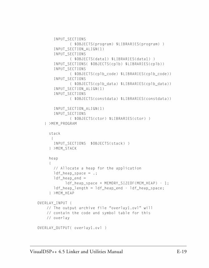
VisualDSP++ 4.5 Linker and Utilities Manual E-19
INPUT_SECTIONS ( $OBJECTS(program) $LIBRARIES(program) ) INPUT_SECTION_ALIGN(1) INPUT_SECTIONS ( $OBJECTS(data1) $LIBRARIES(data1) ) INPUT_SECTIONS( $OBJECTS(cplb) $LIBRARIES(cplb)) INPUT_SECTIONS ( $OBJECTS(cplb_code) $LIBRARIES(cplb_code)) INPUT_SECTIONS ( $OBJECTS(cplb_data) $LIBRARIES(cplb_data)) INPUT_SECTION_ALIGN(1) INPUT_SECTIONS ( $OBJECTS(constdata) $LIBRARIES(constdata))
INPUT_SECTION_ALIGN(1) INPUT_SECTIONS ( $OBJECTS(ctor) $LIBRARIES(ctor) ) } >MEM_PROGRAM
stack { INPUT_SECTIONS $OBJECTS(stack) ) } >MEM_STACK
heap { // Allocate a heap for the application ldf_heap_space = .; ldf_heap_end = ldf_heap_space + MEMORY_SIZEOF(MEM_HEAP) - 1; ldf_heap_length = ldf_heap_end - ldf_heap_space; } >MEM_HEAP
OVERLAY_INPUT { // The output archive file “overlay1.ovl” will // contain the code and symbol table for this // overlay
OVERLAY_OUTPUT( overlay1.ovl )
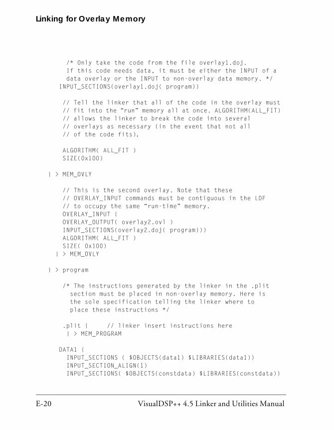
Linking for Overlay Memory
E-20 VisualDSP++ 4.5 Linker and Utilities Manual
/* Only take the code from the file overlay1.doj. If this code needs data, it must be either the INPUT of a data overlay or the INPUT to non-overlay data memory. */ INPUT_SECTIONS(overlay1.doj( program))
// Tell the linker that all of the code in the overlay must // fit into the “run” memory all at once. ALGORITHM(ALL_FIT) // allows the linker to break the code into several // overlays as necessary (in the event that not all // of the code fits).
ALGORITHM( ALL_FIT ) SIZE(0x100)
} > MEM_OVLY
// This is the second overlay. Note that these // OVERLAY_INPUT commands must be contiguous in the LDF // to occupy the same “run-time” memory. OVERLAY_INPUT { OVERLAY_OUTPUT( overlay2.ovl ) INPUT_SECTIONS(overlay2.doj( program))) ALGORITHM( ALL_FIT ) SIZE( 0x100) } > MEM_OVLY
} > program
/* The instructions generated by the linker in the .plit section must be placed in non-overlay memory. Here is the sole specification telling the linker where to place these instructions */
.plit { // linker insert instructions here } > MEM_PROGRAM
DATA1 { INPUT_SECTIONS ( $OBJECTS(data1) $LIBRARIES(data1)) INPUT_SECTION_ALIGN(1) INPUT_SECTIONS( $OBJECTS(constdata) $LIBRARIES(constdata))
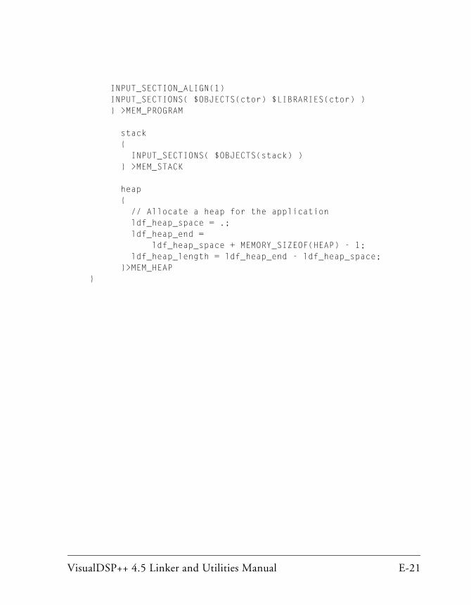
VisualDSP++ 4.5 Linker and Utilities Manual E-21
INPUT_SECTION_ALIGN(1) INPUT_SECTIONS( $OBJECTS(ctor) $LIBRARIES(ctor) ) } >MEM_PROGRAM
stack { INPUT_SECTIONS( $OBJECTS(stack) ) } >MEM_STACK
heap { // Allocate a heap for the application ldf_heap_space = .; ldf_heap_end = ldf_heap_space + MEMORY_SIZEOF(HEAP) - 1; ldf_heap_length = ldf_heap_end - ldf_heap_space; }>MEM_HEAP }
Linking for Overlay Memory
E-22 VisualDSP++ 4.5 Linker and Utilities Manual

VisualDSP++ 4.5 Linker and Utilities Manual I-1
I INDEX
A-a archiver switch, 6-15absolute data placements, 2-57ABSOLUTE() LDF operator, 3-22adding
input sections, 4-13LDF macros, 4-13library files, 4-13memory segments to memory map, 4-34object files, 4-13
address space, allocating, 3-50ADDR() LDF operator, 3-23$ADI_DSP LDF macro, 3-30ADSP-21xxx processors
broadcast space, D-12external memory, 2-29internal memory, 2-28memory architecture, 2-27overlays, D-14
ADSP-TSxxx processorsallocating buffers to different memory
segments, 2-39external memory, 2-31internal memory, 2-30memory architecture, 2-30overlays, C-12see also TigerSHARC
ALGORITHM() LDF command, 3-64ALIGN() LDF command, 3-32alignment
setting, 4-70specifying properties, 4-70
ALL_FIT LDF identifier, 4-73, 3-64-anv archiver switch, 6-15ARCHITECTURE() LDF command, 3-32archive
files, see library filesfunctions, making usable, 6-4members, A-6routines, creating entry points, 6-4routines, writing, 6-4specify objects in, 6-6writing library files in, 6-4
archiverabout, 6-1accesing archived functions, 6-5adding version information, 6-7checking version number, 6-10command constraints, 6-17command-line switches, 6-15command-line syntax, 6-14deleting version information, 6-10handling arbitrary files, 6-2printing version information, 6-9removing version information, 6-10running, 6-14, 6-15symbol name encryption, 6-11tagging with version, 6-7, 6-8use in code disassembly, B-3wildcard character, 6-6, 6-16
.ASM filesassembler, A-3
INDEX
I-2 VisualDSP++ 4.5 Linker and Utilities Manual
assemblerinitialization data files (.DAT), A-3object files (.DOJ), A-5source files (.ASM), 1-3, A-3
assembler directives, using with archiver, 6-5
attribute, linking, 2-41
B-BeginInit InitSymbol switch, 7-14BEST_FIT LDF identifier, 3-65Blackfin memory sections
bsz_init, 2-22constdata, 2-21cplb_code, 2-21cplb_data, 2-21ctor, 2-22ctorl, 2-24data1, 2-21.gdt .gdtl .frt .frtl .cht .chtl .edt .edtl,
2-24heap, 2-23L1_DATA_A, 2-21L1_DATA_B, 2-22noncache_code, 2-23program, 2-21sdram0, 2-23sdram0_bank, 2-23sdram0_shared, 2-23sdram_bcz, 2-23stack, 2-22voldata, 2-22vtbl, 2-24
Blackfin processorsbasic memory configurations, 3-9memory usage in, 3-9
branchexpansion instruction, 2-57, 2-60instructions, 5-35
breakpoints, on overlays, 5-7
broadcast space, D-12broadcast writes, D-12.bss input section, 2-14, 2-15bsz_init input section, 2-18, 2-19, 2-22bsz_init memory section, 7-8bsz input section, 2-18, 2-19, 2-22buffers, allocating to different memory
segments, 2-40build errors, linker, 2-10build files, description of, A-5built-in LDF macros, 3-29bus lock
broadcast writes, D-12multiprocessor systems, D-12
byteorder, 4-68packing, 4-69
Ccaching, external memory, 3-9callback executable file, 7-3, 7-5, 7-15calls
inter-overlay, 5-26inter-processor, 5-27
-c archiver switch, 6-15C/C++, source files, A-2.cht input section, 2-14, 2-25color selection, in Expert Linker, 4-16command LDF scope, 3-18$COMMAND_LINE_LINK_AGAINST
LDF macro, 3-29$COMMAND_LINE_OBJECTS LDF
macro, 3-13, 3-29$COMMAND_LINE_OUTPUT_DIRE
CTORY LDF macro, 3-29$COMMAND_LINE_OUTPUT_DIRE
CTORY macro, 2-59$COMMAND_LINE_OUTPUT_FILE
LDF macro, 3-14, 3-29

VisualDSP++ 4.5 Linker and Utilities Manual I-3
INDEX
$COMMAND_LINE_OUTPUT_FILE macro, 2-59
commands, LDF, 3-31, 5-29comma-separated option, 2-56comments, .LDF file, 3-17compiler, source files (.C .CC), 1-3constdata input section, 2-21constructors, 2-16, 2-19converting
library members to source code, B-3out-of-range short calls and jumps, 2-57
cplb_code input section, 2-21___cplb_ctrl configuration variable, 3-9cplb_data input section, 2-21cplb input section, 2-25Create LDF wizard, 4-4ctor0 input section, 2-18ctor1 input section, 2-18ctor3 input section, 2-18ctor4 input section, 2-18ctor input section, 2-18, 2-19, 2-22ctorl input section, 2-24___ctor_NULL_marker symbol, 2-19,
3-36
D-d archiver switch, 6-15data1 input section, 2-17, 2-19, 2-21data2 input section, 2-18, 2-19data placement, 2-57data sections, exception handling, 2-24.DAT files, initialization data, A-3debugger, files, A-9declaring, macros, 3-30default LDF file, 3-4DEFAULT_OVERLAY () LDF command,
3-64DEFINED() LDF operator, 3-24
directories, supported by linker, 2-46disassembly
library member, B-3using archiver, B-3using dumper, B-3
.DLB filesdefined, A-6description ofextension convention, 2-45symbol name encryption, 6-11
DMAaccessing external memory, 3-40
DMAONLY memory segment qualifier, 3-40
-dnv archiver switch, 6-15.DOJ files
about, A-5extension conventions, 2-45
-Dprocessor (target architecture) linker switch, 2-51
dram, 2-23DSPs, development software, 1-2dumper, use in code disassembly, B-3DWARF, references, A-10.DXE files
data extraction, B-1described, 1-7diagram, 1-7extension conventions, 2-45linker, A-6linker output files described, A-6
E-e archiver switch, 6-15.edt input section, 2-14, 2-18, 2-25-e (eliminate unused symbols) linker
switch, 2-55-ek (no elimination) linker switch, 2-55

INDEX
I-4 VisualDSP++ 4.5 Linker and Utilities Manual
elfar.exeabout, 6-1command-line reference, 6-14constraints, 6-17
elfdump.execommand-line switches, B-1file dumper, B-1used by Expert Linker, 4-40
ELF file contents, B-1ELF file dumper
about, B-1command-line switches, B-1extracting data, B-1overlay library files, B-4references, A-10
elfloader.exe loader utility, 1-10elfspl21k.exe splitter utility, 1-10ELIMINATE() LDF command, 3-33ELIMINATE_SECTIONS() LDF
command, 3-34elimination
enabling, 3-33, 3-36specifying properties, 4-59
encryptionconstraints, 6-12symbol names in libraries, 6-11
end address, memory segment, 3-41.end label, 3-34END() LDF identifier, 3-41entry address
ENTRY() command, 3-34-entry switch, 2-56global start symbol, 2-34multiprocessor system, 2-35setting, 2-34
-entry (entry address) linker switch, 2-56
ENTRY() LDF command, 3-34errata workaround, 2-60errors, linker, 2-10-es (eliminate listed sections) linker switch,
2-55-ev (eliminate unused symbols, verbose)
linker switch, 2-56executable files, 1-7, A-6EXPAND() LDF command, 3-53Expert Linker
about, 4-1adding input sections, 4-14adding LDF macros, 4-14adding object files, 4-14adding output section to memory
segment, 4-23adding overlay, 4-23adding shared memory, 4-23adding shared memory segments, 4-49alignment properties, 4-70allocating for heap, 4-74allocating for stack, 4-74choosing initialization qualifier, 4-66color selection, 4-16context menu, 4-22deleting objects, 4-14deleting selected object, 4-23displaying global properties, 4-15displaying section contents, 4-15elimination properties, 4-59expanding items, 4-23expanding LDF macros, 4-14Global Properties, 4-55heap properties, 4-74icons, 4-16Input Sections pane, 4-13

VisualDSP++ 4.5 Linker and Utilities Manual I-5
INDEX
menu, 4-13invalid memory segments, 4-21launching, 4-3Legend dialog box, 4-16mapping sections in, 4-15memory map graphical view, 4-25Memory Map pane, 4-19memory segment properties, 4-64multiprocessing tasks, 4-49object properties, 4-54output section properties, 4-65overlay properties, 4-72overlays, 4-37overview, 2-9, 4-2packing properties, 4-68processor properties, 4-56profiling object sections, 4-45properties for overlays, 4-58removing LDF macro, 4-14resize cursor, 4-29sorting objetcs, 4-17specifying new memory segments, 4-23stack properties, 4-74symbols properties, 4-61vewing icons and colors, 4-16viewing section contents, 4-40viewing symbols, 4-44
Expert Linker shared memory properties, 4-77
external execution packing, 3-47external memory
access, 3-40TigerSHARC processors, 2-31
extracting, data from ELF executable files, B-1
Ffile extension conventions, 2-45@filename linker switch, 2-51
files.ASM, A-3assembler, A-5build, A-5C/C++, A-2.DAT, A-3debugger, A-9.DLB, A-6.DOJ, A-5dumping contents of, B-1.DXE, A-6executable, A-6format references, A-10formats, A-1input, A-2.LDR (ASCII-format), A-8.LDR (hex format), A-6librarylinker command-line (.TXT), 2-45, A-5object, 2-47output, 1-7.OVL, A-6.SM, A-6.TXT, A-5.XML, A-6
FILL() LDF command, 3-35, 3-63filter operation, 2-41, 3-59FIRST_FIT LDF identifier, 3-65-flags-meminit linker switch, 2-56-flags-pp linker switch, 2-56FORCE_CONTIGUITY LDF command,
3-65fragmented memory, filling in, 2-57.frt input section, 2-14, 2-18, 2-25
Ggap, inserting into memory segment, 4-36.gdt input section, 2-14, 2-18, 2-24.gdtl input section, 2-14, 2-18, 2-25global LDF scope, 3-18

INDEX
I-6 VisualDSP++ 4.5 Linker and Utilities Manual
Global Properties dialog boxGeneral tab, 4-55PLIT tab, 4-58viewing, 4-24
Hheap
graphic representation, 4-74input section, 2-23managing in memory, 4-74
hex-format files.LDR, A-6
-h (-help) switch, 2-56-h switch, 7-15
Iicons
Expert Linker, 4-16unmapped icon, 4-15
IDDE_ARGS option, 2-42-i filename archiver switch, 6-15-IgnoreSection SectionName switch, 7-15-i (include search directory) linker switch,
2-56INCLUDE() LDF command, 3-35initialization flag, 7-8initialization qualifier, choosing in Expert
Linker, 4-66initialization stream
generated from Memory Initializer, 7-2inserting executable file into, 7-15start address, 7-14structure, 7-5
-Init Initcode.dxe switch, 7-15___inits symbol name, 7-14InputFile.dxe switch, 7-16input files
callback input executable file, 7-3primary input file, 7-3
input/output sections, contents of, 4-40INPUT_SECTION_ALIGN() LDF
command, 3-35input sections
adding, 4-13contiguity, 4-67directives, 1-4names, 2-13source code, 1-3
INPUT_SECTIONS() LDF command, 3-58
INPUT_SECTIONS() LDF identifier, 3-15
Input Sections panedisplayed, 4-13menu selections, 4-13
INPUT_SECTIONS_PIN_EXCLUSIVE LDF command, 3-60
INPUT_SECTIONS_PIN LDF command, 3-60
internal memorymemory blocks M0, M1, M2, 2-30TigerSHARC processors, 2-30
inter-overlay calls, 5-26inter-processor calls, 5-27-ip (individual placement) linker switch,
2-57
J-jcs2l (convert out-of-range short calls)
linker switch, 2-57jumps, converting, 2-57
K-keep (keep unused symbols) linker switch,
2-58KEEP() LDF command, 3-36KEEP_SECTIONS() LDF command,
3-37

VisualDSP++ 4.5 Linker and Utilities Manual I-7
INDEX
LL1_bcz input section, 2-26___l1_code_cache guard symbol, 3-9L1_code input section, 2-26L1_DATA_A input section, 2-21L1_data_a input section, 2-26L1_DATA_B input section, 2-22L1_data_b input section, 2-26L1_data input section, 2-26L2_bcz input section, 2-26l2_shared input section, 2-27L2_sram_a input section, 2-27L2_sram_b input section, 2-27L2_sram input section, 2-26l2_sram input section, 2-27LDF commands
about, 2-3, 3-31, 5-29ALIGN(), 3-32ARCHITECTURE(), 3-32ELIMINATE(), 3-33ELIMINATE_SECTIONS(), 3-34ENTRY(), 3-34EXPAND(), 3-53FILL(), 3-63INCLUDE(), 3-35INPUT_SECTION_ALIGN(), 3-35INPUT_SECTIONS(), 3-58KEEP(), 3-36KEEP_SECTIONS(), 3-37LINK_AGAINST(), 3-37MAP(), 3-38MEMORY{}, 3-38, 5-45MPMEMORY{}, 3-42, 5-44OVERLAY_GROUP{}, 3-42, 5-29OVERLAY_INPUT{}, 3-63
LDF commands (continued)PACKING(), 3-43PLIT{}, 3-63, 5-33PROCESSOR{}, 3-48RESERVE(), 3-50RESOLVE(), 3-53SEARCH_DIR(), 3-54SECTIONS{}, 3-55SHARED_MEMORY{}, 3-65
LDF expressions, 3-19LDF file
commands, 3-31default, 2-11keywords, 3-20miscellaneous keywords, 3-21operators, 3-22purpose, 2-5scope, 3-18structure, 3-17
.LDF filescommands in, 2-3, 3-31, 5-29comments in, 3-17creating in Expert Linker, 4-4defined, A-4extension conventions, 2-45memory segments, 2-4output sections, 2-4
LDF macrosabout, 3-27adding, 4-13built-in, 3-29command-line input, 3-30expanding, 4-14removing, 4-14user-declared, 3-30
INDEX
I-8 VisualDSP++ 4.5 Linker and Utilities Manual
LDF operatorsabout, 3-27ABSOLUTE(), 3-22ADDR(), 3-23DEFINED(), 3-24MEMORY_SIZEOF(), 3-25, 3-26SIZEOF(), 3-26
ld linker, B-5.LDR files
ASCII-format, A-8hex-format, A-6splitter output, A-8
legends, Expert Linker, 4-14LENGTH() LDF identifier, 3-41length_symbol symbol, 3-50___lib_end_of_heap_descriptions symbol,
3-36librarian, VisualDSP++, 6-1library, symbol name encryption, 6-11library files (.DLB)
aboutadding, 4-13defined, A-6searching, 6-2
library membersconverting to source code, B-3library routines, 6-1
library routines, accesssing, 6-5LINK_AGAINST() LDF command, 3-37linker
about, 2-1command-line files (.TXT), A-5command-line syntax, 2-43defined, 1-2
linker (continued)describing the target, 2-11error messages, 2-10executable files, A-6file name conventions, 2-46linking object files, 2-47memory map files (.XML), A-6options, 2-3output files, A-6outputs, 1-7overlay constants generated by, 5-9running from command line, 2-43running from VisualDSP++, 2-6switches, 2-47warning messages, 2-10
Linker Description Fileoverview, 2-5, 3-1see also LDF file
linker.exe, 1-2linker-generated constants, 5-16linker macros, 3-27, 3-29linker switches
-Darchitecture, 2-51--Dprocessor, 2-51-e, 2-58-e, 2-55-ek secName, 2-55-entry, 2-56-es secName, 2-55-ev, 2-56@filename, 2-51-flags-meminit, 2-56-flags-pp, 2-56
VisualDSP++ 4.5 Linker and Utilities Manual I-9
INDEX
linker switches (continued)-h (help), 2-56-i (include search directory), 2-56-ip (individual placement), 2-57-jcs2l, 2-57-keep symbolName, 2-58-L path, 2-52-M, 2-52-Map filename, 2-53-MDmacro, 2-53-meminit, 2-58-MM, 2-52-MUDmacro, 2-53-nonmemcheck, 2-58-od directory, 2-59-o filename (output file), 2-59-pp, 2-59-proc processor, 2-59-S, 2-54-save-temps, 2-60-si-revision version (silicon revision),
2-60-sp, 2-61-sp (skip preprocessing), 2-61-s (strips all symbols), 2-60-T filename, 2-54, 2-62-t (trace), 2-61-tx (full trace), 2-61-version (display version), 2-62-v (verbose), 2-61-warnonce, 2-62-Wnumber (warning suppression), 2-54-Wwarn num (override error message),
2-54-xref filename, 2-62
linkingabout, 2-2controlling, 2-3file with large uninitialized variables,
C-4, D-4, E-4file with large zero-initialized variables,
C-4, D-4, E-4multiprocessor systems, C-6, D-6overlay memory system, E-17process rules, 2-4single-processor system, C-2, D-2, E-2ttributes, 2-40
linking environment, 2-6Link tab, setting linker options, 2-6link target, 2-11loader
creating bootloadable image, 1-10, 1-11hex-format files, A-6
location counter, definition of, 3-27-L path (libraries and objects) linker switch,
2-52
M$macroname declaration
for user macros, 3-30macros
LDF, 3-27preprocessor, 3-28user-declared, 3-30
map file, 2-47-Map (filename) linker switch, 2-53map file (.XML), 2-53, 3-38MAP() LDF command, 3-38mapping
input sections to output sections, 4-15input section to several output sections,
3-60-M archiver switch, 6-15mc_data input section, 2-25
INDEX
I-10 VisualDSP++ 4.5 Linker and Utilities Manual
-M (dependency check and output) linker switch, 2-52
-MDmacro (macro value) linker switch, 2-53
mem_argv input section, 2-18, 2-20MEM_ARGV memory section, 2-42MemInit.exe utility, 7-1-meminit linker switch, 2-58.meminit memory section, 7-8.MEMINIT section name, 3-56MemInit switches, 7-13memory
allocation, 2-12architecture representation, 2-12initialization, 7-6initializer, 3-56internal, 2-30managing heap/stack, 4-74map files, A-6multiprocessor, 2-31overlays, 5-4, 5-5partitions, 4-19segment declaration, 2-12segment length, 3-41segments, 4-19TigerSHARC, 2-30types, 2-12, 3-40
Memory Initializercommand line switches, 7-13extracting data from section, 7-17function of, 7-1___inits default symbol name, 7-14invoking, 7-10invoking with -meminit switch, 2-58,
7-11NO-BOOT mode, 7-2output file, 7-17passing comma-separated option to, 2-56primary input file, 7-16section initialization flag, 7-11
Memory Initializer switches-BeginInit InitSymbol, 7-14-h, 7-15-IgnoreSection SectionName, 7-15-Init Initcode.dxe, 7-15InputFile.dxe, 7-16-NoAuto, 7-16-NoErase, 7-16-o OutputFile.dxe, 7-17-Section SectionName, 7-17-v (-verbose), 7-17
memory interface, width (bits), 3-41MEMORY{} LDF command
described, 5-45.LDF file component, 3-14segment_declaration, 3-39syntax diagram, 3-38writing, 2-12
memory mapadding memory segments to, 4-34generating, 2-53graphical view, 4-25highlighted objects in, 4-29post-link view, 4-31pre-link view, 4-31specifying, 2-12tree view, 4-24viewing, 4-20
Memory Map context menu, 4-22Memory Map pane
described, 4-20Main Menu displayed, 4-22overlays, 4-37zooming in/out, 4-32
memory sectionsSHARC, 2-14TigerSHARC, 2-17, 2-20

VisualDSP++ 4.5 Linker and Utilities Manual I-11
INDEX
memory segmentsabout, 1-3adding, 4-34changing size of, 4-28insering a gap, 4-36invalid, 4-21MEMORY{} command, 4-19rules, 2-4size, 4-24specifying properties, 4-64start address, 4-24
MEMORY_SIZEOF() LDF operator, 3-25, 3-26
-MM archiver switch, 6-15-MM (dependency check, output and
build) linker switch, 2-52modify register, 5-17MPMEMORY{} LDF command, 3-42,
5-44MP systems, semaphores, D-12-MUDmacro (undefine macro) linker
switch, 2-53multicore applications, 2-35multiple overlays, 4-37multiprocessor
applications, 2-35memory, 2-31systems, bus lock, D-12systems, semaphores, D-12
multiprocessor/multicore applications, 3-50
Nnew
memory segment, 4-23, 4-34output section, 4-23overlay, 4-23shared memory, 4-23
-NoAuto switch, 7-16-NoErase switch, 7-16
NOFORCE_CONTIGUITY LDF command, 3-65
NO_INIT qualifier, 3-57, C-4, D-4, E-4noncache_code input section, 2-23-nonmemcheck inker switch, 2-58
Oobject files
adding, 4-13explained, 1-3linking into executable, 2-2
object properties, managing with Expert Linker, 4-54
objectsdeleting, 4-14sorting, 4-14, 4-18
$OBJECTS LDF macro, 3-13-od (output directory) linker switch, 2-59-o filename linker switch, 2-59-o OutputFile.dxe switch, 7-17operators, LDF, 3-22output directory, specifying, 2-59OUTPUT() LDF command, 4-19, 3-14output sections
about, 2-3dumping, 2-13mapped contiguously, 4-67overflow, 4-66rules, 2-4specifying properties, 4-65
_ov_endaddress_#, 5-9, 5-25_ov_end breakpoint, 5-7overlay
ALL_FIT algorithm, 4-73file, producing, 3-64identifier, 5-10live space, 4-37run space, 4-37
OVERLAY_GROUP{} LDF command, 3-42, 5-29
INDEX
I-12 VisualDSP++ 4.5 Linker and Utilities Manual
overlay ID, 5-19OVERLAY_ID LDF identifier, 3-64OVERLAY_INPUT{} LDF command
DEFAULT_OVERLAY() portion, 3-64described, 3-63
overlay library files, B-4overlay manager
about, 5-4, 5-6assembly code, 5-35constants, 5-15major functions, 5-7performance summary, 5-19placing constants, 5-17PLIT table, 5-12storing overlay ID, 5-19
overlay memory, linking for, E-17OVERLAY_OUTPUT() LDF command,
3-64overlays
address, 5-9, 5-16ADSP-21xxx processors, D-14ADSP-TSxxx processors, C-12constants, 5-9, 5-15debugging, 5-7dumping library files, B-4grouped, 5-30grouping, 5-30in Memory Map pane, 4-37live address, 4-73live space, 4-37loading and executing, 5-20loading instructions with PLIT, 5-36managing properties, 4-72memory, 5-4, 5-5multiple, 4-37numbering, 5-26reducing overhead, 5-20run address, 4-73run space, 4-38size, 4-73
overlays (continued)special symbols, 5-25ungrouped, 5-30word size, 5-9, 5-16
ov_id_loaded buffer, 5-19.OVL files
described, A-6diagram, 1-7dumping, B-4extracting content from, B-4file conventions, 2-45linker, A-6OVERLAY_INPUT{} command, 3-64
_ov_runtimestartaddress_#, 5-9, 5-25_ov_size_#, 5-9, 5-25_ov_startaddress_, 5-25_ov_startaddress_#, 5-9__ov_start breakpoint, 5-7_ov_start breakpoint, 5-7_ov_word_size_live_#, 5-9, 5-25_ov_word_size_run_#, 5-9, 5-25
Ppacking
data, 3-42DMA, 3-44external execution, 3-47in SHARC processors, 3-44overlay format, 3-46PACKING() LDF command, 3-43properties, specifying, 4-68
packing.h header file, 3-44PACKING() LDF command, 3-42-p archiver switch, 6-16partial linker, B-5partially-linked relocatable object file, B-5pinning objects to output section, 4-23,
4-66plinker switch, B-4
VisualDSP++ 4.5 Linker and Utilities Manual I-13
INDEX
PLITabout, 5-10allocating space for, 5-35constants, 5-35executing user-defined code, 5-10overlay management, 5-6specifying overlay properties, 4-58summary, 5-36syntax, 5-34
PLIT{} LDF commandabout, 5-33in SECTIONS{}, 3-63instruction qualifier, 5-34LDF input section, 3-63PLIT_SYMBOL_ADDRESS, 5-34PLIT_SYMBOL_OVERLAYID, 5-34syntax described, 5-33
.plit output section, 5-35PLIT{} (procedure linkage table) LDF
command, 3-48PLIT_SYMBOL_ADDRESS, 5-34PLIT_SYMBOL constants, 5-37PLIT_SYMBOL_OVERLAYID, 5-34-pp (end after preprocessing) linker switch,
2-59pp. exe preprocessor, 1-8preprocessor
compiler, 1-9linker and assembler command, 1-8running from linker, 2-59
primio_atomic_lock input section, 2-25procedure linkage table (PLIT)
about, 5-10about PLIT{} command, 5-33PLIT{} command described, 3-48using, 5-24see also PLIT
processorselection, 2-51specifying properties, 4-57
PROCESSOR{} LDF commandlinking projects on
multiprocessor/multicore Blackfin architectures, 3-50
syntax, 3-48Processor Properties dialog box, 4-56-proc (target processor) linker switch, 2-59profile-guided optimization, 2-41PROGBITS qualifier, 7-4program, input section, 2-17, 2-20, 2-21project builds, linker, 2-6Project Options dialog box, 2-6PROM, TYPE() command, 3-40Properties dialog box, viewing, 4-24-pva archiver switch, 6-9, 6-16-pv archiver switch, 6-9, 6-16
RRAM, TYPE() command, 3-40-r archiver switch, 6-16references, file formats, A-10reflective semaphores, D-12removing, LDF macro, 4-14RESERVE() LDF command, 3-50reserving space for, 5-10resize cursor, 4-29RESOLVE() LDF command, 3-37, 3-53ROM, TYPE() command, 3-40RTL routine, performing memory
initialization, 7-2, 7-6.rtti input section, 2-14, 2-15, 2-18, 2-25run-time initialization
placement of initialization structures, 3-56
qualifiers, 3-56RUNTIME_INIT qualifier, 3-57, 7-7,
7-8, 7-15, 7-16, 7-17

INDEX
I-14 VisualDSP++ 4.5 Linker and Utilities Manual
S-s archiver switch, 6-16-save-temps linker switch, 2-60sdram0_bank input section, 2-23sdram0 input section, 2-23sdram0_shared input section, 2-23sdram_bcz input section, 2-23SEARCH_DIR() LDF command, 3-54sec_rth input section, 2-14section contents, 4-15.SECTION directive, 1-4section formats, selecting, 4-41section_name qualifier, 3-56-Section SectionName switch, 7-17SECTIONS{} LDF command, 2-36, 3-14,
3-55seg_argv input section, 2-14, 2-16seg_ctdm input section, 2-14, 2-16seg_ctdml input section, 2-14seg_ctdml memory section, 2-17, 2-20seg_dmda input section, 2-14seg_dmda memory section, 2-16seg_heap input section, 2-14, 2-16seg_init_code input section, 2-14seg_init input section, 2-14, 2-15seg_int_code input section, 2-15segment declaration, 3-39seg_pmco input section, 2-14, 2-15seg_pmda input section, 2-14, 2-16seg_rth input section, 2-15seg_stak input section, 2-14, 2-16seg_vtbl input section, 2-14, 2-17, 2-20,
2-24semaphores, reflective, D-12.SEPARATE_MEM_SEGMENTS
assembler directive, 2-39setting, alignment, 4-70setting, fill values, 4-70
SHARC memory sections.gdt .gdtl .frt .frtl .cht .chtl .edt .edtl,
2-17, 2-20seg_argv, 2-16seg_ctdm, 2-16seg_ctdml, 2-17seg_dmda, 2-16seg_heap, 2-16seg_init, 2-15seg_init_code, 2-15seg_pmco, 2-15seg_pmda, 2-16seg_rth, 2-15seg_stak, 2-16seg_vtbl, 2-17
SHARED_MEMORY{} LDF command, 3-65
shared memory system, C-6, D-6short calls, converting, 2-57SHT_NOBITS
keyword, 3-57, C-4, D-4, E-4section qualifier, C-4, D-4, E-4
-si-revision (silicon revision) linker switch, 2-60
SIZE() LDF command, 3-65SIZEOF() LDF operator, 3-26.SM files
described, A-6diagram, 1-7file extension conventions, 2-45linker, A-6
software development, 1-2sort, objects, 4-14, 4-17, 4-18source code, in input sections, 1-3source files
assembly instructions, A-3C/C++, A-2compiling into object files, 1-3fixed-point data, A-3preparing, 7-8

VisualDSP++ 4.5 Linker and Utilities Manual I-15
INDEX
special section name.MEMINIT, 3-56.PLIT, 3-56
splitterASCII-format files (.LDR), A-8generating non-bootable PROM image
files, 1-11SPORT data files, A-9-sp (skip preprocessing) linker switch, 2-61-s (strip all symbols) linker switch, 2-60-S (strip debug symbols) linker switch, 2-54stack
graphic representation, 4-74managing in memory, 4-74section, 2-22
startaddress, memory segment, 3-40global symbol, 2-34label, 6-4symbol, 3-5
start_symbol symbol, 3-50symbol
declaration, 3-12manager, 5-7
symbolsadding, 4-61, 4-63deleting from resolve list, 4-63encryption of names, 6-11managing properties of, 4-61removing, 2-60, 4-61resolution, 4-62, 4-63viewing, 4-24, 4-44, 4-61
T-t archiver switch, 6-7, 6-16target processor, specifying, 2-52-T file (executable program placement)
linker switch, 2-54
TigerSHARCmemory sections, bsz, 2-19memory sections, bsz_init, 2-19memory sections, ctor, 2-19memory sections, data1, 2-19memory sections, data2, 2-19memory sections, mem_argv, 2-20memory sections, program, 2-20memory sections, vtbl, 2-20programming enhancement, 2-39
-tnv archiver switch, 6-16tree view, memory map, 4-24-t (trace) linker switch, 2-61-twc ver archiver switch, 6-16-tx filename archiver switch, 6-16-tx (full trace) linker switch, 2-61.TXT files
linker, A-5linker command-line files, A-5
TYPE() command, 3-40
Uuninitialized variables, C-4, D-4, E-4UNIX linker, B-5unmapped object icon, 4-15unpacking, data, 3-44USE_CACHE configuration, 3-9user-declared macros, 3-30utilities
archiver (elfar.exe), 6-1file dumper (elfdump.exe), B-1producing a partially-linked relocatable
object file, B-5
V-version archiver switch, 6-16-version (display version) linker switch,
2-62

INDEX
I-16 VisualDSP++ 4.5 Linker and Utilities Manual
version informationbuilt in with archiver, 6-7user-defined, 6-8
viewingarchive files, B-4icons and colors, 4-16input sections, 4-13memory map, 4-20.OVL files
content, B-4section contents, 4-40
VisualDSP++archiver, 6-1Assemble tab, 2-7Expert Linker, 4-2librarian, 6-1project builds, 2-6Project Options dialog box, 2-6, 2-7running linker from, 2-6setting assembler options, 2-7setting options, 2-7
voldata input section, 2-22vtbl input section, 2-18-v (verbose) archiver switch, 6-16-v (verbose) linker switch, 2-61-v (verbose) MemInit switch, 7-14-v (verbose) switch, 7-17
Wwarnings, linker, 2-10
-warnonce (single symbol warning) linker switch, 2-62
wildcard characterspecifying archive files, 6-16
wildcard charactersin section names, 2-35, 3-31using in archiver, 6-6
wizards, Create LDF, 4-4-Wnnnn archiver switch, 6-16-Wnumber (warning suppression) linker
switch, 2-54word width (number of bits), 3-41-w (remove warning) archiver switch, 6-16-Wwarn num (override error message)
linker switch, 2-54
Xxmlmap2html.exe command-line utility,
2-53.XML map file
described, A-6MAP filename command, 3-38opening in Web browser, 2-53
-xref (external reference file) linker switch, 2-62
ZZERO_INIT qualifier, 3-57, 7-7, 7-8,
7-15, 7-16, 7-17

VisualDSP++ 4.5 Linker and Utilities Manual I-17
INDEX

I-18 VisualDSP++ 4.5 Linker and Utilities Manual

VisualDSP++ 4.5 Linker and Utilities Manual I-19
I-20 VisualDSP++ 4.5 Linker and Utilities Manual

VisualDSP++ 4.5 Linker and Utilities Manual I-21

I-22 VisualDSP++ 4.5 Linker and Utilities Manual