wa320pz 6 spec sheet - erb equipmenterbequipment.com/aggregate/media/erb-equipment/used equipment...
TRANSCRIPT

NET HORSEPOWER125 kW 167 HP @ 2000 rpm
OPERATING WEIGHT14730- 15380 kg
32,480- 33,900 lb
BUCKET CAPACITY2.5 - 2.7 m3 3.25 - 3.50 yd3
WH
EE
L L
OA
DE
RW
ITH
PA
RA
LL
EL
Z-B
AR
LIN
KA
GE
WA320PZ-6WA320PZ
Photo may include optional equipment.

2
W H E E L L O A D E R W I T H P A R A L L E L Z - B A R L I N K A G E
WALK-AROUND
WA320PZ-6
High Productivity & Low Fuel Consumption withHydrostatic Transmission
● High performance SAA6D107E-1 engine● Low fuel consumption● Electronically-controlled HST with variable shift
control system● Variable traction control system● S-mode
Excellent Operator Environment● HST traction control switch● Electronically controlled directional lever● Tiltable steering column● Low-noise designed cab● Pillar-less large ROPS/FOPS Level 2 cab-integrated● Easy entry/exit, rear-hinged doors
Environmentally Friendly● EPA Tier 3 and EU Stage 3A
emissions certified● Low exterior noise● Low fuel consumption
KOMTRAX sends machine location, Service Meter Reading (SMR)and operation maps to a secure website utilizing wirelesstechnology. Machines also relay error codes, cautions, maintenanceitems, fuel levels, and much more.
®
3
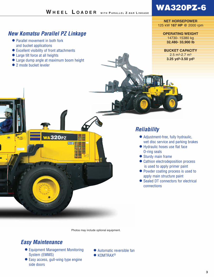
NET HORSEPOWER125 kW 167 HP @ 2000 rpm
OPERATING WEIGHT14730- 15380 kg32,480- 33,900 lb
BUCKET CAPACITY2.5 m3-2.7 m3
3.25 yd3-3.50 yd3
W H E E L L O A D E R W I T H P A R A L L E L Z - B A R L I N K A G E
WA320PZ-6
Reliability● Adjustment-free, fully hydraulic,
wet disc service and parking brakes● Hydraulic hoses use flat face
O-ring seals● Sturdy main frame● Cathion electrodeposition process
is used to apply primer paint● Powder coating process is used to
apply main structure paint● Sealed DT connectors for electrical
connections
Easy Maintenance● Equipment Management Monitoring
System (EMMS)● Easy access, gull-wing type engine
side doors
● Automatic reversible fan● KOMTRAX®
Photos may include optional equipment.
● Parallel movement in both fork and bucket applications
● Excellent visibility of front attachments● Large tilt force at all heights● Large dump angle at maximum boom height● 2 mode bucket leveler
New Komatsu Parallel PZ Linkage

4
HIGH PRODUCTIVITY AND LOW FUEL CONSUMPTION
High Performance SAA6D107E-1 Engine
Electronic Heavy Duty Common Rail fuel injection systemprovides optimum combustion of fuel.This system also provides quick throttle response to matchthe machine’s powerful tractive effort and quick hydraulicresponse.
Net: 125 kW 167 HP
Low Emission Engine
This engine is EPA Tier 3 and EU Stage 3A emissionscertified, without sacrificing power or machine productivity.
Low Fuel Consumption
The high-torque engine and Hydrostatic Transmission (HST)with maximum efficiency in the low-speed range provide lowfuel consumption.
Eco Indicator
The eco indicator will help an operator achieve energysavings.
Electronically-Controlled HST Using a 1-Pump,2-Motor System
● The 1-pump, 2-motor system allows high-efficiency andhigh tractive effort. Engine power is transmittedhydraulically to a transfer case, then mechanically out tothe differentials and the four driving wheels.
● HST provides quick travel response and aggressive driveinto the pile. The variable displacement systemautomatically adjusts to the tractive effort demand toprovide maximum power and efficiency.
● Full auto-shifting eliminates any gear shifting and kick-down operation to allow the operator to concentrate ondigging and loading.
● When high drive torque is needed for digging, climbing,or initiating movement, the pump feeds both motors. Thiscombination makes the loader very aggressive andquick.
● Under deceleration, the HST system acts as a dynamicbrake on the mechanical drive system. The dynamicbrake can hold the loader in position on most workableslopes. This can be an advantage in stockpiling andramp loading.
● As the machine moves and gains ground speed, thetorque demand decreases and the low speed motor iseffectively removed from the drive system by a clutch. Atthis point, the flow is going to the high-speed motor andthe low-speed motor is not causing drag on the system.
● An inching pedal gives the operator excellentsimultaneous control of travel and equipment hydraulicspeeds. By depressing the inching pedal, drive pumpflow to the motors will decrease, reducing ground speedand allowing the operator to use the accelerator toincrease flow to the equipment hydraulics. Depressingthe inching pedal further will activate the service brakes.
Hydrostatic Transmission (HST)
Piston PumpEngine
Low speedpistonmotor
High speedpistonmotor
Transfer case
To differentials
Eco indicator
W H E E L L O A D E R W I T H P A R A L L E L Z - B A R L I N K A G EWA320PZ-6

5
N
Dumping Clearance and Reach
The long lift arms provide high dumping clearance and longdumping reach. The operator can even level loads on thebody of a dump truck easily and efficiently.
Dumping Clearance: 2785 mm 9'2"Dumping Reach: 1240 mm 4'1"(Dimensions at max. height and 45° dump angle;2.7 m3 3.5 yd3 bucket with B.O.C.E.)
Electronically-Controlled HST with Variable ShiftControl System
The operator can choose between first, second, third or fourthmaximum speeds by dialing the speed range selector switch.For V-cycles, the operator can set the speed control switch to1 or 2, which providesaggressive digging, quickresponse, and fasthydraulics. For load andcarry, select 3 or 4 whichstill provides aggressivedigging but with muchfaster travel speed.
The variable shift switchallows the operator to adjust machine speed in applicationssuch as confined V-loading. When in 1, the operator canadjust travel speed using the variable shift switch to matchmachine speed and hydraulics to the distance traveled. Thisfeature is also useful when powering a broom or snowblower.
Variable Traction Control System
The tractive effort of themachine, when traveling at alow speed, can be reduced byusing the traction controlswitch. Combined with torqueproportioning differentials, oroptional limited slip differentialsthis system provides thefollowing benefits:
● Facilitates operation on soft groundwhere the tires of the machine are aptto slip.
● Eliminates excessive bucketpenetration and reduces tire slippageduring stockpile loading to improve thework efficiency.
● Reduces tire slippage to extend the life of tires.
Furthermore, the maximum tractive effort can be adjusted inthree stages (one stage for conventional machines) when thetraction control switch is ON. This allows the operator to selectthe optimum tractive effort for diversified road conditions.
S-mode
Setting the switch to S-mode provides excellent driving forcefor operations on slippery road surfaces, like snow-removal onsnow-covered surfaces, resulting in low tire slippage andfacilitation of the operation.Unexpected tire slippageon slippery road surfaces issuppressed by controllingthe engine speed and HSTmotor when traveling at alow speed. (S-mode iseffective only in forwardtravel.)
Accelerator Pedal Sensitive HST Control
Finely-tuned HST control according tothe accelerator pedal angle allowssmoother traveling and better energy-saving operation.
Max. Traction Switch
The max. traction switch is located on the work equipmentcontrol lever. When the traction control switch is at the ONposition or S-mode is selected, pushing this switch cancelsthe setting of the traction control temporarily and increasesthe tractive effort to its 100% value. Then pushing the max.traction switch again or operating the F/R lever returns thetractive effort to the set value automatically. This switch isuseful for operations such as stockpile work where largetractive effort is required temporarily.
0Travel speed
Trac
tive
effo
rt
2.5 8.1 (mph)
Variable range of travel speed
S-mode:Reduces the tractive effort when traveling at a low speed
0 Travel speed
Trac
tive
effo
rt
1st2.5mph
Adjust the machine speed using the Variable shift control system
8.1mph
2nd
3rd
4th
8.1mph
11.6mph
23.6mph
0
Max. tractive effort can be adjusted in 3 stages when the traction control switch is ON.
Max: Traction control switch is OFF.(Max. tractive effort)
0 Travel speed
Trac
tive
effo
rt
WA320PZ-6W H E E L L O A D E R W I T H P A R A L L E L Z - B A R L I N K A G E
RELIABILITY
6
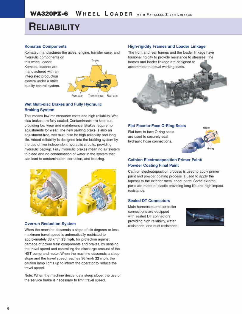
Komatsu Components
Komatsu manufactures the axles, engine, transfer case, andhydraulic components onthis wheel loader.Komatsu loaders aremanufactured with anintegrated productionsystem under a strictquality control system.
Wet Multi-disc Brakes and Fully Hydraulic Braking System
This means low maintenance costs and high reliability. Wetdisc brakes are fully sealed. Contaminants are kept out,providing low wear and maintenance. Brakes require noadjustments for wear. The new parking brake is also anadjustment-free, wet multi-disc for high reliability and longlife. Added reliability is designed into the braking system bythe use of two independent hydraulic circuits, providinghydraulic backup. Fully hydraulic brakes mean no air systemto bleed and no condensation of water in the system thatcan lead to contamination, corrosion, and freezing.
Overrun Reduction System
When the machine descends a slope of six degrees or less,maximum travel speed is automatically restricted toapproximately 38 km/h 23 mph, for protection againstdamage of power train components and brakes, by sensingthe travel speed and controlling the discharge amount of theHST pump and motor. When the machine descends a steepslope and the travel speed reaches 36 km/h 22 mph, thecaution lamp lights up to inform the operator to reduce thetravel speed.
Note: When the machine descends a steep slope, the use ofthe service brake is necessary to limit travel speed.
High-rigidity Frames and Loader Linkage
The front and rear frames and the loader linkage havetorsional rigidity to provide resistance to stresses. Theframes and loader linkage are designed to accommodate actual working loads.
Flat Face-to-Face O-Ring Seals
Flat face-to-face O-ring seals are used to securely seal hydraulic hose connections.
Cathion Electrodeposition Primer Paint/Powder Coating Final Paint
Cathion electrodeposition process is used to apply primerpaint and powder coating process is used to apply thetopcoat to the exterior metal sheet parts. Some externalparts are made of plastic providing long life and high impactresistance.
Sealed DT Connectors
Main harnesses and controllerconnections are equipped with sealed DT connectorsproviding high reliability, waterresistance, and dust resistance.
nipple
hose O-ring
Front axle Rear axleTransfer case
Engine
W H E E L L O A D E R W I T H P A R A L L E L Z - B A R L I N K A G EWA320PZ-6

7
Equipment Management Monitoring System(EMMS)
The monitor is mounted in front of the operator for easy viewing, allowing the operator to easily check gauges and warning lights.
A specially designed two-spoke steering wheel allows theoperator to easily see the instrument panel.
Maintenance Control and Troubleshooting Functions
● Action code display function: If an abnormality occurs,the monitor displays action details on the characterdisplay at the center bottom of the monitor.
● Monitor function: The controller monitors engine oilpressure, coolant temperature, air cleaner clogging, etc.If the controller finds abnormalities, the error is displayedon the LCD.
● Replacement time notice function: The monitorinforms replacement time of oil and filters on the LCD whenreplacement intervals are reached.
● Trouble data memory function: The monitor storesabnormality data for effective troubleshooting.
Easy Radiator Cleaning
If the machine is operating in adverse conditions, theoperator can reverse the hydraulic cooling fan from inside thecab by pressing a switch on the control panel.
Gull-wing Type Engine Side Doors Open Wide
The operator can open and close each gull-wing type engineside door easily, with the assistance of a gas spring, toperform daily service checks from the ground.
Automatic Reversible Fan
The engine fan is driven hydraulically and can be operatedin reverse automatically. When the switch is in theautomatic position, the fan revolves in reverse intermittentlyfor 2 minutes every 2 hours. (Default setting)
B: Manual Reverse Mode
A: Normal Rotation Mode
C: Auto Reverse Mode
EASY MAINTENANCE
WA320PZ-6
Photo may include optional equipment.
W H E E L L O A D E R W I T H P A R A L L E L Z - B A R L I N K A G E
OPERATOR ENVIRONMENT
8
Tiltable Steering Column
The operator can tilt thesteering column to providea comfortable workingposition.
Rear-hinged Full Open Cab Doors
The large cab doors arerear-hinged to open fully,offering easy entry/exit. Exitfrom the cab is easilyaccomplished by havingsteps in view of theoperator. Sloped hand railshelp guide the foot onto thefirst step.
Low-noise Design
Noise level at operator’s ear: 70 dB(A)
Dynamic noise level (outside): 107 dB(A)
The large cab is mounted with Komatsu’s unique ROPS/FOPS viscous mounts. The low-noise engine, hydraulically driven fan, and hydraulic pumps are mounted with rubber cushions, and the cab sealing is improved toprovide a quiet, low-vibration, pressurized, and comfortableoperating environment.
W H E E L L O A D E R W I T H P A R A L L E L Z - B A R L I N K A G EWA320PZ-6
Excellent Visibility With Forks
The new PZ loader linkage design enables the operator tosee the fork tine tips to aid in loading pallets and othermaterials onto the forks.
Multi-function Loader Control Lever with Forward & Reverse SwitchA new multi-function control lever integrated with forward andreverse switch allows theoperator to easily operatethe work equipment,providing low operatorfatigue and goodcontrollability. Theadjustable wrist restprovides the operator witha variety of comfortableoperating positions.
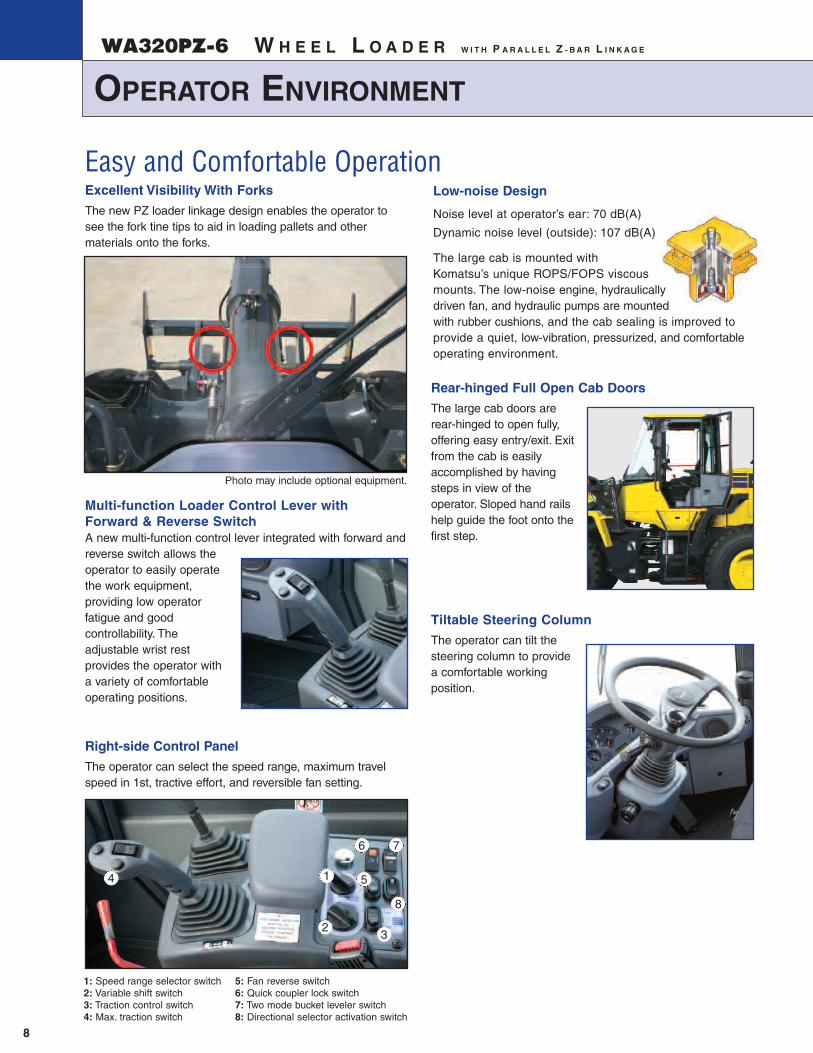
Right-side Control Panel
The operator can select the speed range, maximum travelspeed in 1st, tractive effort, and reversible fan setting.
Easy and Comfortable Operation
1
2
4
3
5
6 7
1: Speed range selector switch 2: Variable shift switch 3: Traction control switch 4: Max. traction switch
8
Photo may include optional equipment.
5: Fan reverse switch 6: Quick coupler lock switch7: Two mode bucket leveler switch 8: Directional selector activation switch

9
SPECIFICATIONS
WA320PZ-6
AXLES AND FINAL DRIVES
Drive system . . . . . . . . . . . . . . . . . . . . . . . . . . . . . . .Four-wheel driveFront . . . . . . . . . . . . . . . . . . . . . . . . . . . . . . . . . . . .Fixed, semi-floatingRear . . . . . . . . . . . . . . . . . . . . . . . .Center-pin support, semi-floating,
30˚ total oscillationReduction gear . . . . . . . . . . . . . . . . . . . . . . . . . . . . .Spiral bevel gearDifferential gear . . . . . . . . . . . . . . . . . . . . . . . . . .Torque proportioningFinal reduction gear . . . . . . . . . . . . . .Planetary gear, single reduction
BRAKES
Service brakes . . . . . . . . . . . . . . . . . . . . . . . . .Hydraulically actuated,wet disc brakes actuate on four wheels
Parking brake . . . . . . . .Wet, multi-disc brake on transfer output shaftEmergency brake . . . . . . . . . . . . . . .Parking brake is commonly used
1st 2nd 3rd 4th
Both Forward 4.0 - 13.0 13.0 18.7 38.0and Reverse 2.5 - 8.1 8.1 11.6 23.6
ENGINE
Model . . . . . . . . . . . . . . . . . . . . . . . . . . . . . .Komatsu SAA6D107E-1Type . . . . . . . . . . . . . . . . . . . . . . . . . . . . . . . . . .Water-cooled, 4-cycleAspiration . . . . . . . . . . . . . . . . . . . . . . . . . .Turbocharged, aftercooled Number of cylinders . . . . . . . . . . . . . . . . . . . . . . . . . . . . . . . . . . . . . . 6Bore x stroke . . . . . . . . . . . . . . . . . 107 mm x 124 mm 4.21" x 4.88"Piston displacement . . . . . . . . . . . . . . . . . . . . . . . . . . 6.69 ltr 408 in3
Governor . . . . . . . . . . . . . . . . . . . . . . . . . . . . . . . All-speed, electronicHorsepower
SAE J1995 . . . . . . . . . . . . . . . . . . . . . . . . .Gross 127.3 kW 171 HPISO 9249/SAE J1349 . . . . . . . . . . . . . . . . . . . .Net 125 kW 167 HPHydraulic fan at maximum speed . . . . . . . . . . .Net 117 kW 156 HPRated rpm . . . . . . . . . . . . . . . . . . . . . . . . . . . . . . . . . . . . . 2000 rpm
Fan drive method for radiator cooling . . . . . . . . . . . . . . . . . .HydraulicFuel system . . . . . . . . . . . . . . . . . . . . . . . . . . . . . . . . . .Direct injectionLubrication system:
Method . . . . . . . . . . . . . . . . . . . . . . . . .Gear pump, force-lubricationFilter . . . . . . . . . . . . . . . . . . . . . . . . . . . . . . . . . . . . . . . Full-flow type
Air cleaner . . . . . . . . . . . . . . . . . . .Dry type with double elements and dust evacuator, plus dust indicator
EPA Tier 3 and EU Stage 3A emissions certified.
TRANSMISSION
Type . . . . . . . .Hydrostatic, 1 pump, 2 motors with speed range select
Travel speed: km/h mphMeasured with 20.5-25 tires
STEERING SYSTEM
Type . . . . . . . . . . . . . . . . . . . . . . . . . . . .Full-hydraulic power steeringSteering angle . . . . . . . . . . . . . . . 38.5˚ each direction (40˚ end stop)Minimum turning radius at
the center of outside tire . . . . . . . . . . . . . . . . . . . . . 5380 mm 17'8"
HYDRAULIC SYSTEM
Steering system:Hydraulic pump . . . . . . . . . . . . . . . . . . . . . . . . . . . .Gear type pumpCapacity . . . . . . . . . . . . 172 ltr/min 45.4 U.S. gal/min at rated rpmRelief valve setting . . . . . . . . . . . . 20.6 MPa 210 kgf/cm2 2,990 psiHydraulic cylinders:
Type . . . . . . . . . . . . . . . . . . . . . . . . . . . .Double-acting, piston typeNumber of cylinders . . . . . . . . . . . . . . . . . . . . . . . . . . . . . . . . . . .2
Bore x stroke . . . . . . . . . . . . . . . 70 mm x 453 mm 2.8" x 17.8"
Loader control:Hydraulic pump . . . . . . . . . . . . . . . . . . . . . . . . . . . .Gear type pumpCapacity . . . . . . . . . . . . . . . . . . . . . . . . 61 ltr/min 16.1 U.S. gal/minRelief valve setting . . . . . . . . . . . . 20.6 MPa 210 kgf/cm2 3,000 psiHydraulic cylinders:
Type . . . . . . . . . . . . . . . . . . . . . . . . . . . .Double-acting, piston typeNumber of cylinders—bore x stroke:
Boom cylinder . . . . . . . . . . . 2- 140 mm x 729 mm 5.5" x 28.7"Bucket cylinder . . . . . . . . . . . 1- 180 mm x 558 mm 7.1" x 22.0"
Control valve . . . . . . . . . . . . . . . . . . . . . . . . . . . . . . . . . 3-spool typeControl positions:
Boom . . . . . . . . . . . . . . . . . . . . . . . . .Raise, hold, lower, and floatBucket . . . . . . . . . . . . . . . . . . . . . . . . . . .Tilt-back, hold, and dump
Hydraulic cycle time (rated load in bucket)Raise . . . . . . . . . . . . . . . . . . . . . . . . . . . . . . . . . . . . . . . . . 5.6 secDump . . . . . . . . . . . . . . . . . . . . . . . . . . . . . . . . . . . . . . . . . 1.9 secLower (Empty) . . . . . . . . . . . . . . . . . . . . . . . . . . . . . . . . . . 3.3 sec
SERVICE REFILL CAPACITIES
Cooling system . . . . . . . . . . . . . . . . . . . . . . . . . . 25 ltr 6.6 U.S. galFuel tank . . . . . . . . . . . . . . . . . . . . . . . . . . . . . . 245 ltr 64.7 U.S. galEngine . . . . . . . . . . . . . . . . . . . . . . . . . . . . . . . . . 23 ltr 6.1 U.S. galHydraulic system . . . . . . . . . . . . . . . . . . . . . . . . . 89 ltr 23.5 U.S. galAxle (each front and rear) . . . . . . . . . . . . . . . . . . 24 ltr 6.3 U.S. galTransfer case . . . . . . . . . . . . . . . . . . . . . . . . . . . 6.5 ltr 1.7 U.S. gal
W H E E L L O A D E R W I T H P A R A L L E L Z - B A R L I N K A G E

10
DIMENSIONS
W H E E L L O A D E R W I T H P A R A L L E L Z - B A R L I N K A G E WA320PZ-6
AJ
H
FE
D
45
C
G
B
I
AM
K
I
LG
FE
DC
J
HB
Standard tire . . . . . . . . . . . . . . . . . . . . . . . . . . . . . . 20.5-25-12PR(L2)Tread . . . . . . . . . . . . . . . . . . . . . . . . . . . . . . . . . . . . . . . 2050 mm 6'9"Width over tires . . . . . . . . . . . . . . . . . . . . . . . . . . . . . . . 2590 mm 8'6"A Wheelbase . . . . . . . . . . . . . . . . . . . . . . . . . . . . . . . 3030 mm 9'11"B Hinge pin height, maximum height . . . . . . . . . . . . . 4005 mm 13'2"
Hinge pin height, at carry position . . . . . . . . . . . . . . . 440 mm 1'5"
C Ground clearance . . . . . . . . . . . . . . . . . . . . . . . . . . . . 425 mm 1'5"D Hitch height . . . . . . . . . . . . . . . . . . . . . . . . . . . . . . . . 1095 mm 3'7"E Overall height, top of stack . . . . . . . . . . . . . . . . . . . . 2915 mm 9'7"F Overall height, ROPS cab . . . . . . . . . . . . . . . . . . . 3200 mm 10'6"
*At the end of B.O.C.E.
All dimensions, weights, and performance values based on SAE J732c andJ742b standards. Static tipping load and operating weight shown includelubricant, coolant, full fuel tank, ROPS cab and operator. Machine stability andoperating weight affected by tire size and attachments.
Operating load per SAE J1197 (Feb. 1991), 50% of static tipping load.
Static tipping load and operating weight shown include lubricant, coolant, fullfuel tank, ROPS cab and operator. Machine stability and operating weightaffected by tire size and attachments.
Bucket Fork
G Fork tine length 1524 mm 5'0"Fork weight 685 kg 1510 lb
H Ground to top of tine at maximum lift 3860 mm 12'8"
I Reach at maximum lift 840 mm 2'9"J Ground to top of tine –
boom and tine level 1855 mm 6'1"K Reach – boom and tine level 1735 mm 5'8"L Reach – tine level on ground 1065 mm 3'6"
Operating height (fully raised) 5120 mm 16'9"M Overall length – tine level on ground 8320 mm 27'3"
Static tipping load – boom levelFork level, 610 mm 24"load center Straight 7815 kg 17,255 lb
Full turn (40˚) 6720 kg 14,820 lbOperating load 4805 kg 10,590 lbOperating weight 14730 kg 32,480 lb
Bucket w/ BOCE Light Material General Purpose Bucket capacity: heaped 2.7 m3 2.5 m3
3.5 yd3 3.25 yd3
struck 2.2 m3 2.1 m3
2.9 yd3 2.75 yd3
Bucket width 2740 mm 2740 mm9'0" 9'0"
Bucket weight 1260 kg 1230 kg2,780 lb 2,712 lb
G Dumping clearance, max. height 2785 mm 2820 mmand 45˚ dump angle* 9'2" 9'3"
H Reach at max. height and 45˚ 1240 mm 1200 mmdump angle* 4'1" 3'11"Reach at 2130 mm 7' clearance 1770 mm 1755 mmand 45˚ dump angle* 5'10" 5'9"Reach with boom and 2735 mm 2680 mmbucket level* 9'0" 8'10"
I Operating height (fully raised) 5395 mm 5355 mm17'8" 17'7"
J Overall length: Bucket on ground 7800 mm 7750 mm25'7" 25'5"
Bucket at carry 7750 mm 7715 mm25'5" 25'4"
Digging depth: 0˚ 65 mm 65 mm2.5" 2.5"
10˚ 440 mm 385 mm1'5" 1'3"
Static tipping load: straight 10880 kg 10990 kg23,990 lb 24,228 lb
40˚ full turn 9580 kg 9670 kg21,110 lb 21,320 lb
Breakout force 136 kN 142 kN13900 kgf 14430 kgf30,620 lb 31,810 lb
Operating weight 15380 kg 15350 kg33,900 lb 33,830 lb
Measured with 20.5-25-12PR (L2) tires, ROPS/FOPS cab Measured with 20.5-25-12PR (L2) tires, ROPS/FOPS cab

11
WA320PZ-6
WEIGHT CHANGES
BUCKET SELECTION GUIDE
Material (loose) kg/m3 lb/yd3
Caliche 1250 2,100
Cinders 590 1,000
Clay and gravel, dry 1420 2,400
Clay and gravel, wet 1540 2,600
Clay, dry 1480 2,500
Clay, natural bed 1660 2,800
Clay, wet 1660 2,800
Coal, anthracite, broken 1100 1,850
Coal, bituminous, broken 830 1,400
Earth, dry, packed 1510 2,550
Earth, loam 1250 2,100
Earth, wet, excavated 1600 2,700
Granite, broken or large crushed 1660 2,800
Gravel, dry 1510 2,550
Gravel, dry 13 to 50 mm 1/2" to 2" 1690 2,850
Gravel, pit run (graveled sand) 1930 3,250
Gravel, wet 13 to 50 mm 1/2" to 2" 2020 3,400
Gypsum, crushed 1600 2,700
Limestone, broken or crushed 1540 2,600
Magnetite, iron ore 2790 4,700
Phosphate rock 1280 2,160
Pyrite, iron ore 2580 4,350
Sand and gravel, dry 1720 2,900
Sand and gravel, wet 2020 3,400
Sand, dry 1420 2,400
Sand, wet 1840 3,100
Sandstone, broken 1510 2,550
Shale 1250 2,100
Slag, broken 1750 2,950
Stone, crushed 1600 2,700
Topsoil 950 1,600
Bu
cket
cap
acit
y: m
3 yd
3
3.5
1000 1300 1600 1900 2200
1.9
2.3
2.7
3.1
4.7
2.5
3.0
3.5
4.1
Material density: kg/m3 lb/yd3
1686 2192 2698 3203 3709
100% Bucket Fill
105% Bucket Fill
95% Bucket Fill
Light Material Bucket
General Purpose Bucket
2.7 m3 3.5 yd3
2.5 m3 3.25 yd3
This guide, representing bucket sizes not necessarily manufac-
tured by Komatsu, will help you select the proper bucket size for
material density, loader configuration, and operating conditions.
Optimum bucket size is determined after adding or subtracting
all tipping load changes due to optional equipment. Bucket fill
factors represent the approximate amount of material as a
percent of rated bucket capacity. Fill factors are primarily
affected by material, ground conditions, breakout force, bucket
profile, and the cutting edge of the bucket used.
Approximate Material Densities
Change in Change in Tipping Load
Operating Weight Straight Full Turn
20.5/25-12PR (L3) 165 kg 364 lb 105 kg 231 lb 95 kg 209 lb
W H E E L L O A D E R W I T H P A R A L L E L Z - B A R L I N K A G E
Bucket

www.KomatsuAmerica.com Komatsu America Corp. is an authorized licensee of Komatsu Ltd.Materials and specifications are subject to change without notice
is a registered trademark of Komatsu Ltd., JapanKOMTRAX® is a registered trademark of Komatsu America Corp.
OPTIONAL EQUIPMENT
STANDARD EQUIPMENT
● 3-spool valve for boom and bucketcontrols
● Air conditioner● Alternator, 60 A● Back-up alarm● Back-up lamp● Batteries, 110 Ah/2 x 12 V● Boom kick-out● Bucket positioner● Counterweight, standard and additional● Deluxe air suspension seat● Directional signal● Engine, Komatsu SAA6D107E-1 diesel● Floor mat
● Front fenders● Fuel pre-filter with water separator● Horn● Hydraulic-driven fan with auto-reverse
rotation● KOMTRAX®
● Lift cylinders and bucket cylinder● Loader linkage with PZ lift arm● Main monitor panel with
Equipment Management MonitoringSystem (EMMS)
● Mono-lever loader control withtransmission F/R switch + 1 lever
● Quick coupler
● Radiator mask, lattice type● Rear defroster (electric)● Rear view mirrors, inside (2), outside (3)● Rear window washer and wiper● Rims for 20.5-25 tires● ROPS/FOPS Level 2 cab● Seat belt, 76 mm 3" retractable● Service brakes, wet disc type● Starting motor, 4.5 kW/24 V● Steering wheel, tiltable● Sun visor● Transmission speed ranges,
4 forward and 4 reverse
● AM/FM stereo radio cassette● Bucket teeth (bolt-on type)● Electronically Controlled Suspension
System (ECSS)● Engine pre-cleaner with extension
● JRB bucket, general purpose, for use withcoupler, with BOCE 2.5 m3 3.25 yd3
● JRB bucket, light material, for use with coupler, with BOCE 2.7 m3 3.5 yd3
● JRB construction forks for use withcoupler, 1524 mm 60"
● JRB utility pallet forks for use withcoupler, 1370 mm 54"
● Limited slip differential (F&R)● Rear full fenders● Secondary steering (SAE)● Wide core radiator
Quick coupler
AESS766-02 ©2008 Komatsu America Corp. Printed in USA D12(5M)C 12/08 (EV-1)