wafer loader nwl860 series · 2013. 5. 9. · select “cnvrt”. the conversion starts. upon...
TRANSCRIPT

M232 E 04.7.CF.3
Wafer Loader NWL860 Series
IFC Function(SECS Communications)
Specifications

i
Thank you for purchasing a Nikon Product. Communications requirements for the Nikon Wafer LoaderNWL860 series are specified in this IFC Function (SECS Communications) Specifications. To ensurecorrect usage, please read this manual before using.
� No part of this manual may be reproduced or transmitted in any form without the prior consent ofNikon.
� This manual is subject to change in part or in full without prior notice.
� Every effort has been made to ensure the accuracy of this manual. If you find that parts of the manualare unclear or in error, please contact your nearest Nikon representative.
� Please be sure to read the manuals for the NWL wafer loader, microscope, and other products usedwith the wafer loader.
� PurposeThis specification described the requirements for serial communications between the modelNWL860TMB-SP or NWL860INX and the customer's computer. The specification has the followingpurposes:
<Online Remote Control Mode>
All operations except those involving the stage and the joystick can be performed with external devices,including PCs, after communications have been set up correctly.
<Online Local Control Mode>
During manual operation, information on sampling/inspection patterns, the carrier, wafer loader, andinspection results can be accessed both by the host computer and by the wafer loader.
� Wafer Loader� NWL860TMB-SP using interface communications (NWL3R-IFC)
� NWL860INX using interface communications (NWL3A-IFC)
(See “5. Hardware and Setting” in Chapter 1.)
� ROM� NWL3R-IFC, Ver 2.30 or later
� NWL3A-IFC, Ver 2.30 or later
The IFC function is available only with the models shown above, using the indicated ROMs.


1
Chaper 1 General Description
1
2
3
4
Table of Contents
Chaper 1 General Description .............................................................................. 4
1. Wafer Loader Model No. ............................................................................ 4
2. Summary ..................................................................................................... 4
3. IFC Protection .............................................................................................. 4
4. Standard Compliance ................................................................................. 4
5. Hardware and Setting................................................................................. 5
Chaper 2 System Specification............................................................................ 6
1. Communications Port ................................................................................. 6
2. Control Mode .............................................................................................. 62-1. Online Remote Control Mode ...................................................................... 6
2-2. Online Local Control Mode ........................................................................... 6
2-3. Offline Control Mode .................................................................................... 7
3. External Connection ................................................................................... 7
Chaper 3 Interface Specification.......................................................................... 8
1. Physical Interface (Common to all ports) .................................................. 81-1. Interactive Signal Connection Circuit .......................................................... 8
1-2. Connector ....................................................................................................... 8
1-3. Data Rate ........................................................................................................ 8
1-4. Pin Connection .............................................................................................. 8
1-5. Synchronization System ............................................................................... 8
1-6. Transmission .................................................................................................. 8
1-7. Connection ..................................................................................................... 8
2. Character ..................................................................................................... 92-1. Character Length ........................................................................................... 9
2-2. Format ............................................................................................................ 9
2-3. Start Bit .......................................................................................................... 9
2-4. Data Bit ........................................................................................................... 9
2-5. Parity Bit ......................................................................................................... 9
2-6. Stop Bit ........................................................................................................... 9
3. Block Transfer Protocol ............................................................................ 103-1. System ......................................................................................................... 10
3-2. Transmission Control Character ................................................................. 10
3-3. Protocol Parameter ..................................................................................... 10
4. Message..................................................................................................... 114-1. Format .......................................................................................................... 11
4-2. Message Length .......................................................................................... 11
4-3. Header .......................................................................................................... 11
4-4. Message Data .............................................................................................. 11
4-5. Checksum..................................................................................................... 11
4-6. Header .......................................................................................................... 11
4-7. Message Data .............................................................................................. 14

2
Chaper 1 General Description
15. Message Protocol ..................................................................................... 17
5-1. Detection of Double Block .......................................................................... 17
5-2. Handling of Multi-Block .............................................................................. 17
5-3. Multi-Transaction......................................................................................... 17
5-4. Size of Incoming Message .......................................................................... 17
5-5. Size of Outgoing Message .......................................................................... 17
6. Examples of Data Link Protocol ............................................................... 186-1. Normal Transmission and Receipt ............................................................. 18
6-2. Contention ................................................................................................... 18
Chaper 4 Communications Specification ......................................................... 20
1. Compliance with GEM .............................................................................. 201-1. GEM Compliance Level Shown by E30 GEM Compliance Sheet
(E30 Table 8.3) .............................................................................................. 20
1-2. GEM Basic Requirements ........................................................................... 21
1-3. Equipment Processing State ...................................................................... 23
1-4. Saving of Settings ....................................................................................... 24
2. List of SECS Messages to and from the Host ......................................... 25
3. Functions Implemented in Communications with Host andScenario ..................................................................................................... 273-1. Establishment of Communications ............................................................ 27
3-2. Online Check ................................................................................................ 27
3-3. Sample File Management ........................................................................... 27
3-4. Carrier File Management ............................................................................ 28
3-5. Equipment Information Management ....................................................... 29
3-6. Event Report ................................................................................................ 29
3-7. Control Mode Selection .............................................................................. 31
3-8. Remote Control ........................................................................................... 33
3-9. Alarm Management .................................................................................... 33
3-10. Status Data Collection ................................................................................. 34
3-11. Error Message ............................................................................................. 34
4. Detailed Message Format ........................................................................ 364-1. Stream 1 ....................................................................................................... 36
4-2. Stream 2 ....................................................................................................... 42
4-3. Stream 5 ....................................................................................................... 49
4-4. Stream 6 ....................................................................................................... 52
4-5. Stream 7 ....................................................................................................... 56
4-6. Stream 9 ....................................................................................................... 61
5. Definition of Message Variable (Data Item) ............................................ 655-1. ACKC5 .......................................................................................................... 65
5-2. ACKC6 .......................................................................................................... 65
5-3. ACKC7 .......................................................................................................... 65
5-4. ACKC7A ........................................................................................................ 65
5-5. ALCD............................................................................................................. 65
5-6. ALED ............................................................................................................. 66

3
Chaper 1 General Description
15-7. ALID .............................................................................................................. 66
5-8. ALTX ............................................................................................................. 68
5-9. CCODE .......................................................................................................... 69
5-10. CEED ............................................................................................................. 72
5-11. CEID .............................................................................................................. 73
5-12. COMMACK ................................................................................................... 75
5-13. CPNAME ....................................................................................................... 75
5-14. CPACK .......................................................................................................... 75
5-15. CPVAL ........................................................................................................... 75
5-16. DATALENGHTH............................................................................................ 76
5-17. DATAID ......................................................................................................... 76
5-18. DRACK .......................................................................................................... 76
5-19. EAC ............................................................................................................... 76
5-20. ECDEF ........................................................................................................... 77
5-21. ECID .............................................................................................................. 77
5-22. ECMAX ......................................................................................................... 80
5-23. ECMIN .......................................................................................................... 80
5-24. ECNAME ....................................................................................................... 80
5-25. ECV ............................................................................................................... 80
5-26. EDID .............................................................................................................. 81
5-27. ERACK .......................................................................................................... 81
5-28. ERRW7 .......................................................................................................... 81
5-29. GRANT6 ....................................................................................................... 81
5-30. LENGTH ........................................................................................................ 81
5-31. LRACK .......................................................................................................... 82
5-32. HCACK .......................................................................................................... 82
5-33. MDLN ........................................................................................................... 82
5-34. MEXP ............................................................................................................ 82
5-35. MHEAD ......................................................................................................... 83
5-36. OFLACK ........................................................................................................ 83
5-37. ONLACK ....................................................................................................... 83
5-38. PPARM .......................................................................................................... 83
5-39. PPGNT .......................................................................................................... 83
5-40. PPID .............................................................................................................. 84
5-41. RCMD ........................................................................................................... 84
5-42. RPTID ............................................................................................................ 87
5-43. SEQNUM ...................................................................................................... 87
5-44. SHEAD .......................................................................................................... 87
5-45. SOFTREV ...................................................................................................... 88
5-46. SV ................................................................................................................. 88
5-47. SVID .............................................................................................................. 88
5-48. SVNAME ...................................................................................................... 89
5-49. UNITS ........................................................................................................... 89
5-50. V .................................................................................................................... 89
5-51. VID ................................................................................................................ 89

4
1
1 General Description
1. Wafer Loader Model No.This specification applies to the following wafer loader models.
� NWL860TMB-SP
� NWL860INX
In this document, these models will be referred to collectively as NWLs.
This specification applies to the following ROM versions.
� NWL3R-IFC Version 2.30 or later for NWL860TMB-SP
� NWL3A-IFC Version 2.30 or later for NWL860INX
2. SummaryFor more information on the following requirements, please see the following chapters.
� External devices and control mode ................................... Chapter 2 “System Specification”
� Connectors, signal standards, mechanical,and electrical requirements ................................................ Chapter 3 “Interface Specification”
� Transmission timing, messages, and protocols .............. Chapter 3 “Interface Specification”
� Communications scenario and message details .............. Chapter 4 “Communications Specification”
3. IFC ProtectionThis specification applies when the ROM is NOT IFC-protected and the DipSW (1 of SW1) of the controlcircuit board is ON.
4. Standard ComplianceThis specification conforms to the following standards.
* For details on GEM standard compliance, see 1 in Chapter 5.
Physical Interface (See 1 in Chapter 3.)Character (See 2 in Chapter 3.)Block Transfer Protocol (See 3 in Chapter 3.)
Message (See 4 in Chapter 3.)Message Protocol (See 5 in Chapter 3.)
State ModelEquipment Behavior and ScenarioData ItemCollection EventBehavior Conforming to GEM
SEMI E4-91SEMI Equipment Communications Standard 1Message Transfer (SECS-I)
SEMI E5-95SEMI Equipment Communications Standard 2Message Content (SECS-II)
SEMI E30-95Generic Model for Communications and Controlof SEMI Equipment (GEM)GEMDefines basic requirements and additions to theequipment for the equipment only forcommunications with the host.
General Description

5
Chaper 1 General Description
15. Hardware and SettingSome ROMs used with the NWL are not designed for IFC function. If the ROM name does not include“-IFC”, it cannot be used for communications.
Additionally, some NWLs are not designed for IFC function. To add IFC functionality to these NWLs, youmust upgrade the ROM and modify related settings.
<NWL860INX>
The circuit board and the internal cable required for communications are built in.
Use ROMs for NWL3A-IFC version 2.30 or later.
� Setting
① Change the ROM if it is not designed for IFC function.
② Turn on DipSW (1 of SW1) on the control circuit board.
③ Turn on power.
④ Proceed through the steps below, following the instructions given in the operation panel. (The stepsmay vary slightly with different ROM versions.)
A prompt for conversion appears in the display screen.
Select “Cnvrt”. The conversion starts.
Upon completion, the “Welcome NWL860” screen (the screen shown at startup) is displayed.
<NWL860TMB-SP>
The circuit board and internal cable required for communications are built in.
Use ROMs for NWL3R-IFC version 2.30 or later.
* NWL860TMBs other than type SP lack the required circuit board and internal cable. Those modelscannot communicate with external devices, even with upgraded ROMs.
� Setting
① Change the ROM if it is not designed for IFC function.
② Turn on DipSW (1 of SW1) on the control circuit board.
③ Turn on power.
④ Proceed through the steps below, following the instructions given in the operation panel. (The stepsmay vary slightly with different ROM versions.)
A prompt for conversion appears in the display screen.
Select “Cnvrt”. The conversion starts.
Upon completion, the “Welcome NWL860” screen (the screen shown at startup) is displayed.

6
2
2 System Specification
1. Communications PortThree communications ports are available.
① COM1: Used for communications with PC (host)
② COM2: Used for communications with indexer (equipment)
③ COM3: Used for debug monitoring (reserved for Remote Box)
2. Control Mode(Note) Control mode is not a communications mode; rather, it refers to on-line or off-line control of the
equipment.
* For communications modes, see “1-2-1. State Model” in Chapter 4.
Three control modes are available. The control mode is automatically switched by the operations on theNWL’s option setting screen, commands from the external device, and in the event of an error. Atstartup, control mode is factory-set to offline. You can change this setting.
Communications between the NWL860INX and the indexer are always controlled in online mode.
2-1. Online Remote Control Mode
In this mode, all operations (except those involving the joystick and the stage) and file management arecontrolled through communications by an external device.
� All switches and control knob settings except the joystick, emergency stop switch and function switchfor turning off communications are disabled. (If any of these switches is turned on, the inhibit buzzerwill sound.)
� The control mode is switched to offline (host offline) mode by a command from the host.
� The control mode is also switched to offline (host offline) mode if the host does not reply and a timer’sset time elapses.
� When the NWL requires manual initialization of wafer storage and arms at startup, key operationbecomes available, just as in local mode.
2-2. Online Local Control Mode
The equipment is controlled in the same environment as offline, with the difference that this mode allowsthe equipment to exchange sample files, result files, carrier files, and status information with the host.
� All operating switches and the control knobs are enabled.
� Files are transmitted by a command from the host at a timing regulated by the host. File transmissionis not controlled by the NWL operation.
� The control mode is switched to offline (host offline) mode by a command from the host.
� The control mode is also switched to offline (host offline) mode if the host does not reply and a timer’sset time elapses.
System Specification

7
Chapter 2 System Specification
2
2-3. Offline Control Mode
The equipment is controlled locally.
� All operating switches and control knobs are enabled.
� The control mode is switched to online remote or online local control mode by selecting the option setting.
� When the equipment is in maintenance mode, control mode is automatically set to offline mode.
The offline control mode is further divided into two states.
<Host Offline State>
The equipment is ready for communications, but the host rejects communications with the equipment orthe connection fails.
<Equipment Offline State>
The equipment is in offline mode.
3. External ConnectionThis specification is based on three different connection methods.
① Communications with Host
② Communications with Indexer
③ Communications with Host and Indexer
Host Equipment
COM2
NWL(Indexer)
INX
Host Equipment
COM2
NWLHost
(Indexer)INX
COM1
Equipment Host
COM1
NWL Host
For remote control and monitoring of the NWL by the host.
For control of the INX by the NWL.
For remote control and monitoring ofthe NWL and the INX by the host.
Equipment Host

8
Interface Specification
2
3
3
1. Physical Interface (Common to all ports)
1-1. Interactive Signal Connection Circuit
RS-232C: Conforms to the EIA Standard.
1-2. Connector
D-Sub 25-pin female (ISO 2110-1980) or equivalent.
Locking: Female 4-40 threaded jack screw lock
1-3. Data Rate
300, 1200, 2400, 4800, 9600 (default) baud
1-4. Pin Connection
1-5. Synchronization System
Start-stop system (asynchronous system)
1-6. Transmission
Half-duplex transmission
1-7. Connection
Point-to-point connection
Interface Specification
FGTXDRXDRTSCTSDSR
SGCD
DTR
②�
⑧�⑦�⑥�
④�⑤�
③�
①�
⑧�~� ⑨�
<NWL ←→ PC Connection>
④�
⑥�⑦�
⑤�
②�③�
①�
⑳�
Shielding
D-sub25pin (male) D-sub9pin (female)M2.6 Screw #4-40 Screw
Frame
~�
Frame
NWL PC
*The Length of cable must be less than 3M
22

9
Chapter 3 Interface Specification
3
2. Character
2-1. Character Length
10 bits
2-2. Format
2-3. Start Bit
1 bit (0)
2-4. Data Bit
8 bits
2-5. Parity Bit
N/A
2-6. Stop Bit
1 bit (1)
Data Bit
Start Bit Stop Bit(LSB)1
(MSB)82 3 4 5 6 7

10
Chapter 3 Interface Specification
2
3
3. Block Transfer Protocol
3-1. System
Line contention system (The master is the equipmemt.)
3-2. Transmission Control Character
* “H” stands for hexadecimal numbers.
① ENQ (05H): Request to send
② EOT (04H): Ready to receive
③ ACK (06H): Acknowledge
④ NAK (15H): Negative acknowledge
3-3. Protocol Parameter
You can set the following parameters in the NWL display screen with the precision shown below.
Typical
ValueCode
9600
101 (65H)
0.5 S
10 S
45 S
45 S
3
Serial communications speed
Equipment identification number
Error detected in characters
No protocol response determination
No reply message determination
Error detected in a multi-block message
The maximum number of retries
BAUD
DEVID
T1
T2
T3
T4
RTY
Function
Baud rate
Device ID
Character time out
Protocol time out
Reply time out
Block time out
Retry limit
300–9600
0–32767
0.1–10 S
0.2–25 S
1–120 S
1–120 S
0–31
—
1
0.1 S
0.2 S
1 S
1 S
1
DescriptionRange Precision
Parameter

11
Chapter 3 Interface Specification
3
4. Message
4-1. Format
4-2. Message Length
The first message byte.This gives the total length (byte count) of the header and the message data.
4-3. Header
See “4-6. Header” in this chapter.
4-4. Message Data
See “4-7. Message Data” in this chapter.
4-5. Checksum
A 2-byte block representing the sum of the binary numbers of the header and the message data withoutcodes.The upper-digit byte is sent before the lower-digit byte.
4-6. Header
4-6-1. Format
Message length 1 byte
Header 10 bytes
Message data max 244 bytes
Checksum 2 bytes
Messages consists of the following blocks.
Time
Upper device IDLower device IDUpper message IDLower message IDUpper block No.Lower block No.
System byte
8 7 6 5 4 3 2 1123456789
10
Device ID
Message ID
Block No.
System Byte
R
W
E
4-6-2. Device ID
Used as an identification number for each device in an SECS network.

12
Chapter 3 Interface Specification
2
3
4-6-3. R-Bit
Defines the direction of message transmission.
R = 0: Host (H) → Equipment (E)R = 1: Host (H) ← Equipment (E)
4-6-4. Message ID
Consists of 2 bytes; seven upper bits (stream code) + eight lower bits (function code).See 4-6-6. for the stream code, and 4-6-7. For the function code.
4-6-5. W-Bit
Defines whether the message contains a request for a response.
W = 0: The transmitter does not expect a response.W = 1: The transmitter expects a response.
4-6-6. Stream Code
Stream code represents the category of a message. Several code numbers are reserved by theSECS.
Code
S1
S2
S3
S4
S5
S6
S7
S8
S9
S10
Equipment status
Equipment status and diagnosis
Status of the material
Control of the material
Exception report
Data gathering
Control of manufacturing program
Control program
System error
Terminal service
Message Type
4-6-7. Function Code
The Function code represents the specific message contained in a stream. Several codenumbers are reserved by the SECS.
① The code F0 is defined as an abort transaction for all stream codes.
② During information exchange, the first message sent is always assigned an odd codenumber, while the response to the message is assigned an even code number, determined byincrementing the first message code number by one.
Stream Code 0–63: Reserved by the SECS.64–127: Defined by the user.
Function Code 0–63: Reserved by the SECS.64–255: Defined by the user.

13
Chapter 3 Interface Specification
34-6-8. Standard Message ID
For standard stream and function codes, see “4. Detailed Message Format” in Chapter 4.
4-6-9. Block No.
When the length of message data to be transmitted exceeds 244 bytes, the message is dividedinto several blocks, and the blocks are sent separately. Block No. represents the order in whichthey are transmitted.
* See “4-6-11. Multi-Block” in this chapter.
When the message consists of only one block, it is assigned Block No. 1.
4-6-10. E-Bit
Defines whether additional message blocks follow.
E = 0: More blocks follow.E = 1: No blocks follow.
4-6-11. Multi-Block
When message data consists of more than one block, the data is referred to as a multi-blockmessage. One multi-block message can contain up to 32767 blocks (a total length of 7.99Mbytes).
The first block of a multi-block message is numbered 1. All subsequent blocks are numbered inorder, with each assigned number incremented by one from the preceding.
Defined by the user
Stream
Reservedby theSECSFunction Code
0 1 – 63 64 – 12701
6364
255
Message to Transmit
Transmitted Message
HeaderNo. = 1
HeaderNo. = 2
HeaderNo. = 3
① ② ③
① ② ③
System Byte 1
System Byte 2
System Byte 3
System Byte 4
Source ID (Upper)
Source ID (Lower)
Transaction ID (Upper)
Transaction ID (Lower)
4-6-12. System Byte
System byte is classified as follows.

14
Chapter 3 Interface Specification
2
3
� Source IDAn identification code given to the message for every source in the application level.The source ID of a primary message is a copy of the transaction ID. When a message isretransmitted due to errors or for other reasons, the source ID is incremented.The source ID of a secondary message is a copy of the system byte of the received primarymessage.
� Transaction IDAn integer, incremented each time a primary message is transmitted.The same transaction ID is assigned to all blocks of a multi-block message.
4-7. Message Data
4-7-1. Format
The data in a message is written in the form of an item (item header) or list (list header).
4-7-2. Item Header Format
Item header consists of format byte (upper 6 bits) and length byte (lower 2 bits).
4-7-3. Format Byte
Format byte consists of item format code and length byte count.
4-7-4. Item Format Code
Defines the format of data.
(DATA) . . . . . . . . . . . . . . . . . . . . . . . . .Item or
List DATAItem or
List
8 7 6 5 4 3 2 1
Item Format Code Length Byte Count
MSB Data Length Byte LSB
MSB Data Length Byte LSB
MSB Data Length Byte LSB
1
2
3
4
MS Byte
LS Byte
Format Byte
Length Byte
Data Format
List
Binary
Truth value
ASCII
8-byte binary integer (with sign)
2-byte binary integer (with sign)
8-byte floating point
4-byte floating point
1-byte integer (without sign)
2-byte integer (without sign)
4-byte integer (without sign)
00
10
11
20
30
32
40
44
51
52
54
octal
000000
001000
001001
010000
011000
011010
100000
100100
101001
101010
101100
bit — 876543
Format Code

15
Chapter 3 Interface Specification
3
4-7-5. Length Byte Count
Defines the number of bytes making up the length byte.
0 = Illegal, data format error1 = 1-byte binary length byte (max. 255)2 = 2-byte binary length byte (max. 64 K)3 = 3-byte binary length byte (max. 7.99 M)
For list format, length represents the number of elements (lists or items) in the list.
The length byte of 0 has a special meaning, which is defined by the individual specification.
4-7-6. Length Byte
Defines the byte count required for the following data.
When the length byte is made up of more than one byte, the bytes are sent out in order, fromthe upper byte.
The length byte consists of 1 to 3 bytes.
4-7-7. List
Defines the number of component data (elements) when the data consists of data in differentformats.
The format of the list header is the same as that of the item header.
Individual component data are defined by the item header.
4-7-8. Examples of Item and List
(a) Item containing one binary code 10101010bit 87654321
00100001 Item with length byte 100000001 Byte length 110101010 Data byte
(b) Item containing three ASCII characters A, B, and C01000001 Item ASCII, length byte 100000011 Byte length 301000001 ASCII character A01000010 ASCII character B01000011 ASCII character C
(c) Item containing (b) above and three binary numbers in 2-byte format00000001 List, length byte 100000100 Number of elements 401000001 Item ASCII, length byte 100000011 Byte length 301000001 ASCII character A01000010 ASCII character B01000011 ASCII character C01101001 Item 2-byte integer, length byte 100000010 Byte length 2xxxxxxxx Upper byte for a number Xxxxxxxxx Lower byte for a number X

16
Chapter 3 Interface Specification
2
3
01101001 Item 2-byte integer, length byte 100000010 Byte length 2yyyyyyyy Upper byte for a number Yyyyyyyyy Lower byte for a number Y01101001 Item 2-byte integer, length byte 100000010 Byte length 2zzzzzzzz Upper byte for a number Zzzzzzzzz Lower byte for a number Z
4-7-9. Examples of Message
Response, from the equipment (device ID = 0487H) to the host, to an inquiry into online status.
00011100 Message length 28 bytes10000100 From host (Device ID) to equipment10000111 0487H00000001 Not expecting response message00000010 S1F210000000 Single block00000001 Block No. 100000000 System byte ‘0’00000001 ‘1’00000000 ‘0’00000001 ‘1’00000001 List00000010 2 elements01000001 ASCII 1 byte00000110 6 bytes00110001 MDLN ‘1’00110010 ‘2’00110011 ‘3’00110100 ‘4’00110101 ‘5’00110110 ‘6’01000001 ASCII 1 byte00000110 6 bytes01000001 SOFTREV ‘A’01000010 ‘B’01000011 ‘C’01000100 ‘D’01000101 ‘E’01000110 ‘F’

17
Chapter 3 Interface Specification
3
5. Message Protocol
5-1. Detection of Double Block
Double blocks are detected by checking the block header system byte. If a double block is detected, thedata is ignored.
5-2. Handling of Multi-Block
Multi-block messages are handled at both the transmitting and receiving ends.
5-3. Multi-Transaction
The NWLs do not apply to multi-transactions (interleaving messages).
5-4. Size of Incoming Message
An incoming message should not exceed 17 blocks.
5-5. Size of Outgoing Message
An outgoing message should not exceed 17 blocks.

18
Chapter 3 Interface Specification
2
3
6. Examples of Data Link Protocol
6-1. Normal Transmission and Receipt
* For details on T1–T3, see “3-3. (Block Transfer) Protocol Parameter” in this chapter.
6-2. Contention
Requestto send
T2
T2
T3
T2
T1
ENQ
EOT
Message length
DATA
DATA
Checksum
Checksum
ACK
ENQ
EOT
Message length
DATA
T2
T1
T2
Acknowledge
Send a reply.
Ready to receive
··
Equipment HostENQ
EOT
Message
ACK
ENQ
EOT
Message
ACK
ENQ
··
Ready to receive
Acknowledge
Send a reply (if required).
Resend contention.


20
Communications Specification
4
4
1. Compliance with GEM
1-1. GEM Compliance Level Shown by E30 GEM Compliance Sheet(E30 Table 8.3)
Yes
Yes
Yes
Yes
Yes
Yes
Yes
Yes
Capability
Yes
Yes
Yes
No
Yes
Yes
Yes
Yes
Yes
No
No
No
No
No
Yes
Capability
State model
Equipment processing state
S1F13/F14 scenario initiated by host
Event report
Online check
Error message
Control (started by operator)
Documentation
Additional Capabilities
Establishment of Communications
Selecting the dynamic event report setting
Variable data collection
Trace data collection
Status data collection
Alarm management
Remote control
Equipment constant
Process program management
Material movement
Equipment terminal service
Clock
Limit monitoring
Spooling
Control (started by host)
GEM Basic Requirements
GEM Compliance
Compliance
Compliance
Yes
Yes
Yes
Yes
Yes
Yes
Yes
Yes
Yes
Communications Specification

21
Chapter 4 Communications Specification
4
1-2. GEM Basic Requirements
1-2-1. State Model
� Online Communications State Model
(Example: Transition from one state to another, ② or ③)
� Equipment Constant for Establishment of Communications Time-Out Value
See “5-21. Message Variable ECID (028)” in this chapter.
DISABLE
ENABLE
NOTCOMMUNICATING
COMMUNICATING
c
State
DISABLE
ENABLE
NOT COMMUNICATING
COMMUNICATING
Communications between host and equipment are disabled.
This setting has two sub-states; COMMUNICATING and NOT
COMMUNICATING.
No messages except S1F13,F14, or S9Fx may be transmitted.
Full communications established
Explanation
HOST WL
S1F13
S1F14
DISABLE or ENABLENOT COMMUUNICATING
DISABLE or ENABLECOMMUUNICATING
①
② ③
④
⑤ ⑥

22
Chapter 4 Communications Specification
4
� Control State Model
With the standard specification, you may change the control state any time the equipment isidle or active.
� Indication of Current Control State and Change of Control State by Operator
Check the communications control state in the initial screen or in the option-setting screen.
The control state is indicated as follows under these conditions:
OFFLINE
LOCAL
c
①
②③
④
⑤
⑥
ONLINE
REMOTE
State
OFFLINE
ONLINE
LOCAL
REMOTE
When the equipment is offline, the equipment and
host are able to exchange messages, but use of
messages for automation is restricted.
When online, the equipment can be controlled
through exchange of messages with the host.
The equipment is controlled directly by operators.
The host can control a range of equipment functions
via the communications interface.
Explanation
c
CommunicationsState
Equipment
OFFLINE
Host OFFLINE
ONLINE
The “OFFLINE” indication appears in the
option setting screen, and no indication
appears in the initial screen.
The “OFFLINE” key in the initial screen
starts blinking.
The “OFFLINE” indication at the bottom
of the fixed screen starts blinking.
The “REMOTE” function key appears in
the initial screen.
The “ONLINE” indication appears at the
bottom of the fixed screen.
IndicationControl
LOCAL
LOCAL
REMOTE
LOCAL
REMOTE
Recipe isSelected
by
Operator
Operator
Host
Operator
Host
Processingis initiated
by
Operator
Operator
Host
Operator
Host

23
Chapter 4 Communications Specification
4
� Control State Changed by Operator
<To save changes: Engineer mode>
Start the equipment in engineer mode. → Select Setting. → Select Option.→ Select SECS.→ Select OFFLINE, LOCAL, or REMOTE.
<To make temporary changes: Operator mode>
(Online Local → Online Remote)Press the Remote key in the initial screen.
(Online Remote → Online Local)Press the Local key in the fixed screen.
� Status Variable Controlling Current Control State
See “5. Definition of Message Variable” in this chapter.
� Operator Command Event in Remote State
See “5. Definition of Message Variable” in this chapter.
� Event in State Transition
Inquiries for control state (S1F3,F4), operator command event reports (S6F11,F12) and statetransition event reports (S6F11,F12) may be available, through the particular communicationssoftware.
1-3. Equipment Processing State
� NWL Processing State Model
POWER ON
MAINTENANCE INIT
ERROR
PROCESS
PAUSE ACTIVE
IDLE
SET-UP

24
Chapter 4 Communications Specification
4
State
INIT
IDLE
ACTIVE
PAUSE
ERROR
MAINTENANCE
SET-UP
The equipment is undergoing system initialization.
The equipment is ON and awaiting commands.
The equipment is ON and operating.
The equipment is temporarily halted.
The equipment is in an error state.
The equipment is in maintenance status.
The equipment is in setup status.
Explanation
� State Transition Event
See “5-11. CEID” in this chapter.
� Variables of Current and Preceding Processing States
Event reports for current and the preceding processing states (S6F11,F12) and inquiries for processingstate (S1F3,F4) may be available, through the particular communications software.
1-4. Saving of Settings
The following status settings are stored in non-volatile memory.
GEM-DefinedCapabilities
Establishment of
Communications
Control
Event Report
Alarm
Management
Time (seconds) within which
S1F13 must be transmitted
once communications are
established.
Online/Offline
Equipment Online/
Online Establishment Try/
Host Offline
Enable or disable event
transmission.
ID attached to the report, and
VID representing the
attributive value of the report
Report ID linked to the
collection event.
Enable or disable alarm
transmission.
CommentEquipment Parameter
Establish communications
time-out (constant)
Control state at equipment
startup (constant)
The offline sub-state at
equipment startup (constant)
Setting parameter for event
enable/disable S2F37
Setting parameter for define
report S2F33: Report ID,
variable ID
Setting parameter for link
event report S2F35: Event ID,
report ID
Alarm enable/disable
Related Data
Estabilish
Communication
Timeout
Control State (variable)
Control State (variable)
Event Enabled reflects
the CEID of the enabled
event.
RPTID,VID
CEID,VID
Alarms Enabled reflects
the ALID of the enabled
alarm.

25
Chapter 4 Communications Specification
4
2. List of SECS Messages to and from the HostH: Host E: NWL S: Single block M: Multi-block
<Stream Function> <Function> <Direction of Transmission>
S* F0 Abort Transaction S H ↔ E
Stream 1: Equipment StateS1 F1 Are You There Request S H → E REPLY
F2 Online data (D) S H ← EF3 Selected equipment status request (SSR) S H → E REPLYF4 Selected equipment status data (SSD) S · M H ← EF11 Status variable name list request (SVNR) S H → E REPLYF12 Status variable name list reply (SVNRR) (S) H ← EF13 Establish communications request (CR) S H ↔ E REPLYF14 Establish communications request acknowledge (CRA) S H ↔ EF15 Request offline (ROFL) S H → E REPLYF16 Offline acknowledge (OFLA) S H ← EF17 Request online (RONL) S H → E REPLYF18 Online acknowledge (ONLA) S H ← E
Stream 2: Equipment Control and DiagnosisS2 F13 Equipment constant request (ECR) S H → E REPLY
F14 Equipment constant data (ECD) S · M H ← EF15 New equipment constant send (ECS) S H → E REPLYF16 New equipment constant acknowledge (ECA) S H ← EF29 Equipment constant name list request (ECNR) S H → E REPLYF30 Equipment constant name list (ECN) S H ← EF33 Define report (DR) S · M H → E REPLYF34 Define report acknowledge (DRA) S H ← EF35 Link event report (LER) S · M H → E REPLYF36 Link event report acknowledge (LERA) S H ← EF37 Enable/disable event report (EDER) S H → E REPLYF38 Enable/disable event report acknowledge (EERA) S H ← EF41 Host command send (HCS) S H → E REPLYF42 Host command acknowledge (HCA) S H ← E
Stream 5: Exception (alarm) reportS5 F1 Alarm report send (ARS) S H ← E REPLY
F2 Alarm report acknowledge (ARA) S H → EF3 Enable/disable alarm send (EAN) S H → E REPLYF4 Enable/disable alarm acknowledge (EAA) S H ← EF5 List alarm request (LAR) S H → E REPLYF6 List alarm data (LAD) (S) H ← E

26
Chapter 4 Communications Specification
4
Stream 6: Data collectionS6 F5 Multi-block data send inquire (MBI) S H ← E REPLY
F6 Multi-block grant (MBG) S H → EF11 Event report send (ERS) S · M H ← E REPLYF12 Event report acknowledge (ERA) S H → EF15 Event report request (ERR) S H → E REPLYF16 Event report data (ERD) S · M H ← EF19 Individual report request (IRR) S H → E REPLYF20 Individual report data (IRD) S · M H ← E
Stream 7: Process program loadS7 F1 Process program load inquire (PPI) S H ↔ E REPLY
F2 Process program load grant (PPG) S H ↔ EF19 Current EPPD request (RER) S H → E REPLYF20 Current EPPD data (RED) S · M H ← EF23 Formatted process program send (FPS) S · M H ↔ E REPLYF24 Formatted process program acknowledge (FPA) S H ↔ EF25 Formatted process program request (FPR) S H ↔ E REPLYF26 Formatted process program data (FPD) S · M H ↔ EF27 Process program verification send (PVS) S H ← E REPLYF28 Process program verification acknowledge (PVA) S H → E
Stream 9: System errorS9 F1 Unrecognized device ID (UDN) S H ← E
F3 Unrecognized stream type (USN) S H ← EF5 Unrecognized function type (UFN) S H ← EF7 Illegal data (IDN) S H ← EF9 Transaction timer time-out (TTN) S H ← EF11 Data too long (DLN) S H ← EF13 Conversation time-out (CTN) S H ← E

27
Chapter 4 Communications Specification
4
3. Functions Implemented in Communications with Hostand Scenario
This chapter complies with the SEMI E30-95 (GEM).
3-1. Establishment of Communications
Notification that interrupted communications (power off or error) are restored. This notification may bemade by the host or by the equipment (NWL).
<Scenario>
○ Communications established from host Message: S1F13,F14
<Comment> [Host] [Equipment] <Comment>Communications state = ENABLE
Request to establish communications S1F13 →← S1F14 Transmits COMMACK = 0 in reply.
Communications state = COMMUNICATING
○ Communications established from equipment Message: S1F13,F14
<Comment> [Host] [Equipment] <Comment>Communications state = ENABLE
← S1F13 Requests to establish communications.Acknowledges request to establish S1F14 → Transmits COMMACK = 0 in reply.communications.
For scenarios involving time-outs and negative acknowledgements, refer to SEMI E30-4-1-5-2.
3-2. Online Check
Checks the line or equipment status. The online check is performed by the host and used for periodic linecheck (heart beat) by the host.
<Scenario>
○ Online check Message: S1F1,F2
<Comment> [Host] [Equipment] <Comment>Are You There? S1F1 →
← S1F2 Transmits MDLN,SOFTREV in reply.
3-3. Sample File Management
3-3-1. Sample File Uploading
The equipment transfers sample file data to the host for the host-selected PPID.
The equipment should not transmit a multi-block data send inquiry before sending the processprogram.
The NWL transfers the sample files in multi-block data format.

28
Chapter 4 Communications Specification
4
<Scenario>
○ Process program (sample file) uploading by host Message: S7F25,F26
<Comment> [Host] [Equipment] <Comment>Requests formatted process program. S7F25 →
← S7F26 Transmits formatted process program data.
3-3-2. Sample File Downloading
① The host transmits information to the equipment involving PPID and the size of the samplefile to be transferred.
② The equipment allows the transfer, if no problems are detected.
③ The host transfers the sample file to the equipment.
④ The equipment checks the sample file and notifies the host of the results.
The sample files must be transferred to the NWL in multi-block data format.
<Scenario>
○ Process program (sample file) downloading by host Message: S7F1,F2,F23,F24,F27,F28
<Comment> [Host] [Equipment] <Comment>Inquires for process program loading. S7F1 →
← S7F2 Acknowledges inquiry for process program loading.Transmits formatted process program. S7F23 →
← S7F24 Acknowledges formatted process program.← S7F27 Transmits process program verification.
Acknowledges process program verification. S7F28 →
3-3-3. PPID List Transmission
The equipment transfers PPID information to the host for all host sample and carrier files.
<Scenario>
○ Process program directory request Message: S7F19,F20
<Comment> [Host] [Equipment] <Comment>Request for current EPPD. S7F19 →
← S7F20 Transmits current EPPD data.
3-4. Carrier File Management
3-4-1. Carrier File Uploading
The equipment transfers data to the host for the carrier file of the PPID selected by the host.
<Scenario>
○ Process program (carrier file) uploading by host Message: S7F25,F26
<Comment> [Host] [Equipment] <Comment>Requests formatted process program. S7F25 →
← S7F26 Transmits formatted process program data.
3-4-2. Carrier File Downloading
① The host transfers the sample file to the equipment.
② The equipment checks the carrier file and notifies the host of the results.

29
Chapter 4 Communications Specification
4
<Scenario>
○ Process program (carrier file) downloading by host Message: S7F23,F24,F27,F28
<Comment> [Host] [Equipment] <Comment>Transmits formatted process program. S7F23 →
← S7F24 Acknowledges formatted process program.← S7F27 Transmits process program verification.
Acknowledges process program verification. S7F28 →
3-5. Equipment Information Management
3-5-1. Equipment Setting Changes Made by Host
The equipment changes the equipment constant selected and transmitted by the host.
<Scenario>
○ Equipment constant transmission by host Message: S2F15,F16
<Comment> [Host] [Equipment] <Comment>Transmits equipment constant. S2F15 →
← S2F16 Sets the ERC = 0 equipment constant.
3-5-2. Equipment Setting Data Request from Host
The equipment transmits the equipment constant selected and transmitted by the host.
<Scenario>
○ Equipment constant request by host Message: S2F13,F14
<Comment> [Host] [Equipment] <Comment>Requests equipment constant. S2F13 →
← S2F14 Transmits equipment constant data.
3-5-3. Equipment Setting Definition Request by Host
The equipment transmits the maximum, minimum, and default values for the equipmentconstant selected by the host.
<Scenario>
○ Equipment constant name list request from host Message: S2F29,F30
<Comment> [Host] [Equipment] <Comment>Requests equipment constant name list. S2F29 →
← S2F30 Transmits equipment constant name list.
3-6. Event Report
3-6-1. Event Report Transmission upon Occurrence
When an enabled collection event (change in equipment status) occurs, the equipmenttransmits the event report to the host. The host learns the equipment state has changed andobtains the linked data.

30
Chapter 4 Communications Specification
4
<Scenario>
○ Collection event occurs at equipment. Message: S6F11,F12
<Comment> [Host] [Equipment] <Comment>[IF] The event report is multi-block data;
← S6F5 [THEN] The equipment sends a multi-block datasend inquiry.
Grants multi-block data send inquiry. S6F6 →← S6F11 Transmits event report.
Acknowledges event report. S6F12 →
3-6-2. Event Report Transmission Upon Request
The equipment transmits the event report requested by the host to the host.
The equipment does not send a multi-block data send inquiry before transmission, even if thereport is to be transmitted in multi-block data format.
<Scenario>
○ Event report request by host Message: S6F15,F16
<Comment> [Host] [Equipment] <Comment>Requests event report. S6F15 →
← S6F16 Transmits event report.
3-6-3. Event Report Setting
① The host defines the report (defines a data group as a report). (Single-block transmission)
② The host links the above report to the collection event. (Single-block transmission)
③ The host defines the collection event as enabled or disabled. (Single-block transmission)
During communications with the NWL, the host can define up to eight (0–7) reports. One reportcan contain up to five variable data.
The define reports must be transmitted in single-block data format.
<Scenario>
○ Collection event report setting Message: S2F33,F34,F35,F36,F37,F38
<Comment> [Host] [Equipment] <Comment>Defines report. S2F33 → Receives DATAIDs, RPTIDs, and VDSs.
← S2F34 DRACK = 0, the report is OK.Links the report to the event. S2F35 → Receives CEIDs and corresponding RPTIDs.
← S2F36 LRACK = 0, acknowledges that the report is linkedto the event.
Enable the collection event. S2F37 → Receives CEIDs and corresponding RPTIDs.← S2F38 ERACK = 0, OK. The selected report is created
when the applicable event occurs.

31
Chapter 4 Communications Specification
4
3-6-4. Report Transmission upon Request
The equipment transmits the report requested by the host to the host.
The equipment does not send a multi-block data send inquiry before transmission, even if thereport is to be transmitted in multi-block data format.
<Scenario>
○ Report request by host Message: S6F19,F20
<Comment> [Host] [Equipment] <Comment>Requests variable data in RPTID. S6F19 →
← S6F20 Transmits the variable data for the given RPTID.
3-7. Control Mode Selection
Switches from one control mode to another (Offline/Online Local/Online Remote).
3-7-1. Switching to Online by Equipment (Operator) — (Permitted by Host)
The operator switches equipment control mode from offline to online.
<Scenario>
○ Online permitted by host Message: S1F1,F2,S6F11,F12
<Comment> [Host] [Equipment] <Comment>← S1F1 Request to switch to online mode.
Grants request to switch to online mode. S1F2 →← S6F11 Transmits event report; control state is local
(remote).Acknowledges S6F12 →
3-7-2. Switching to Online by Equipment (Operator) — (Rejected by Host)
<Scenario>
○ Online rejected by host Message: S1F1,F0
<Comment> [Host] [Equipment] <Comment>← S1F1 Request to switch to online mode.
Rejects request to switch to online mode. S1F0 →
3-7-3. Switching to Offline by Equipment (Operator)
The operator switches equipment control mode from online to offline.
<Scenario>
○ Offline selected by operator Message: S6F11,F12
<Comment> [Host] [Equipment] <Comment>← S6F11 Transmits event report; equipment offline.
Acknowledges S6F12 →

32
Chapter 4 Communications Specification
4
3-7-4. Switching to Remote by Equipment (Operator)
The operator switches equipment control mode from local to remote.
<Scenario>
○ Remote selected by operator Message: S6F11,F12
<Comment> [Host] [Equipment] <Comment>← S6F11 Transmits event report; control state is remote.
Acknowledges S6F12 →
3-7-5. Switching to Local by Equipment (Operator)
The operator switches equipment control mode from remote to local.
<Scenario>
○ Local selected by operator Message: S6F11,F12
<Comment> [Host] [Equipment] <Comment>← S6F11 Transmits event report; control state is local.
Acknowledges S6F12 →
3-7-6. Switching to Offline by Host
<Scenario>
○ Offline selected by host Message: S1F0,F15,F16,S6F11,F12
<Comment> [Host] [Equipment] <Comment>Request to switch to offline mode. S1F15 → [IF] The equipment is offline;
[THEN]← S1F10 Rejects request.
[ELSE]← S1F16 Accepts request.← S6F11 Transmits event report; host offline.
Acknowledges S6F12 → [END_IF]
3-7-7. Switching to Online by Host
<Scenario>
○ Online selected by host Message: S1F17,F18,S6F11,F12
<Comment> [Host] [Equipment] <Comment>Request to switch to online mode. S1F17 → [IF] Other than host offline;
[THEN]← S1F18 Rejects request. (other than ONLACK0)
[ELSE]← S1F18 Accepts request. (ONLACK = 0)← S6F11 Transmits event report; control state is local
(remote).Acknowledges S6F12 → [END_IF]

33
Chapter 4 Communications Specification
4
3-8. Remote Control
Remote control of equipment from the host is performed through transmission of commands from thehost and corresponding event reports from equipment.
(Examples: Changes in current PPID, startup, stop, and individual operation (mapping))
<Scenario>
○ Remote control Message: S2F41,F42,S6F11,F12
<Comment> [Host] [Equipment] <Comment>Transmits a command. S2F41 →
← S2F42 Acknowledges the host command.[IF] The command is accepted (HCACK = 0, 4);
← S6F11 [THEN] Event report of changes in status or othercollection events.
Acknowledges event report. S6F12 →
3-9. Alarm Management
When a problem included in the preset alarm conditions by the host occurs, the equipment sendsnotification to the host of the alarm.
Alarm notification is transmitted separately from event reports.
3-9-1. Alarm Enable/Disable Setting
The host sets the alarms for which the equipment should transmit notification.
<Scenario>
○ Alarm enable/disable Message: S5F3,F4
<Comment> [Host] [Equipment] <Comment>Transmits the alarm enable/disable setting. S5F3 →
← S5F4 Acknowledges the setting.
3-9-2. Alarm Information Uploading
<Scenario>
○ Alarm information uploading Message: S5F5,F6
<Comment> [Host] [Equipment] <Comment>Requests alarm data/text. S5F5 →
← S5F6 Transmits alarm data/text.
3-9-3. Alarm Report Transmission
The equipment detects the occurrence of an alarm.
<Scenario>
○ Alarm report transmission Message: S5F1,F2
<Comment> [Host] [Equipment] <Comment>← S5F1 Transmits alarm data/text.
Acknowledges alarm data/text. S5F2 →(Transmits event report, if the alarm is enabled.)

34
Chapter 4 Communications Specification
4
3-10. Status Data Collection
The host can query the equipment for status information selected by the host.
<Scenario>
○ Equipment status report request Message: S1F3,F4
<Comment> [Host] [Equipment] <Comment>Requests status variable report. S1F3 →
← S1F4 Replies by transmitting requested status variabledata.
○ Equipment status variable name list request Message: S1F11,F12
<Comment> [Host] [Equipment] <Comment>Requests acknowledgement of selected S1F11 →status variable. ← S1F12 Replies by transmitting description of requested
status variable.
3-11. Error Message
The equipment notifies the host of messages and errors in communications detected by the equipment.
3-11-1. Message Error by Unrecognized Device ID
<Scenario>
○ Message error by unrecognized device ID Message: S9F1
<Comment> [Host] [Equipment] <Comment>Transmits a message. SxFx →
Detects unrecognized device ID.← S9F1 Notifies the host that an unrecognized device ID
is detected.
3-11-2. Message Error by Unrecognized Stream Type
<Scenario>
○ Message error by unrecognized stream type Message: S9F3
<Comment> [Host] [Equipment] <Comment>Transmits a message. SxFx →
Detects unrecognized stream type.← S9F3 Notifies the host that an unrecognized stream
type is detected.
3-11-3. Message Error by Unrecognized Function Type
<Scenario>
○ Message error by unrecognized function type Message: S9F5
<Comment> [Host] [Equipment] <Comment>Transmits a message. SxFx →
Detects unrecognized function type.← S9F5 Notifies the host that an unrecognized function
type is detected.

35
Chapter 4 Communications Specification
4
3-11-4. Message Error by Unrecognized Data Format
<Scenario>
○ Message error by unrecognized data format Message: S9F7
<Comment> [Host] [Equipment] <Comment>Transmits a message. SxFx →
Detects illegal data format.← S9F7 Notifies the host that an unrecognized data
format is detected.
3-11-5. Communications Error by Transaction Time-Out
<Scenario>
○ Communications error by transaction time-out Message: S9F9
<Comment> [Host] [Equipment] <Comment>Transmits a message. SxFx →
Failure to receive expected reply from the host.Transaction time-out occurs.
← S9F9 Notifies the host that transaction time-out hasoccurred.
3-11-6. Message Error by Excessive Data Size
<Scenario>
○ Message error involving excessive data size Message: S9F11
<Comment> [Host] [Equipment] <Comment>Transmits a message. SxFx →
Detects data longer than can be processed by theequipment in message from host.
← S9F11 Notifies the host of excessive data length.
3-11-7. Communications Error by Communications Time-Out
<Scenario>
○ Communications error by communications time-out Message: S9F13
<Comment> [Host] [Equipment] <Comment>Transmits a message. SxFx →
←SxF(x+1) ReplyAwaits message from the host resulting from thepreceding transaction.Fails to receive expected message, resulting incommunications time-out.
← S9F13 Notifies the host that communications time-outhas occurred.

36
Chapter 4 Communications Specification
4
1 Are You There Requestst
FunctionS F
1 ↔SR
REPLYH-EM/SAbbr.
Checks whether the equipment is operating online.
When receiving “function 0,” the host cannot communicate with the equipment.
Structure
<HEADER>
Required
4. Detailed Message Format
4-1. Stream 1
1 On Line Data
FunctionS F
2 ↔SD
REPLYH-EM/SAbbr.
Declares that the equipment is operating online.
Structure
<HEADER>
L, 2 1.<MDLN> 2.<SOFTREV>

37
Chapter 4 Communications Specification
4
1 Selected Equipment Status Request
FunctionS F
3 →SSSR
REPLYH-EM/SAbbr.
The host queries the equipment for the selected status variable value.
Structure
<HEADER>
L, n 1.<SVID1> . . . n.<SVIDn>
Required
1 Selected Equipment Status Data
FunctionS F
4 ←SSSD
REPLYH-EM/SAbbr.
The equipment reports SVID values by order of request.
The host should retain a record of the SVID whose values were requested.
Structure
<HEADER>
L, n 1.<SV1> . . . n.<SVn>

38
Chapter 4 Communications Specification
4
1 Status Variable Name list Request
FunctionS F
11 →SSVNR
REPLYH-EM/SAbbr.
The host queries the equipment to check status variables.
Structure
<HEADER>
L, n 1.<SVID1> . . . n.<SVIDn>
Required
1 Status Variable Name list Reply
FunctionS F
12 ←SSVNRR
REPLYH-EM/SAbbr.
The equipment reports the name and unit of the requested status variables.
Structure
<HEADER>
L, n 1.L, 3 1.<SVID1> 2.<SVNAME1> 3.<UNITS1> . . . n.L, 3 1.<SVIDn> 2.<SVNAMEn> 3.<UNITSn>

39
Chapter 4 Communications Specification
4
1 Establish Communication Request
FunctionS F
13 ↔SCR
REPLYH-EM/SAbbr.
At the logical level at which power is switched on again after completion or interruption of communications,
this command establishes the start of a new communications session.
Structure
<HEADER>
L, 2 1.<MDLN> 2.<SOFTREV>
Required
1 Establish Communication Request Acknowledge
FunctionS F
14 ↔SCRA
REPLYH-EM/SAbbr.
Accepts or denies the Establish Communications Request (S1F13).
Structure
<HEADER>
L, 2 1.<COMMACK> 2.L, 2 1.<MDLN> 2.<SOFTREV>

40
Chapter 4 Communications Specification
4
1 Request OFF-LINE
FunctionS F
15 →SROFL
REPLYH-EM/SAbbr.
The host asks the equipment to shift to offline status.
Structure
<HEADER>
Required
1 OFF-LINE Acknowledge
FunctionS F
16 ←SOFLA
REPLYH-EM/SAbbr.
Transmits OK or NG to S1F15.
Structure
<HEADER>
<OFLACK>

41
Chapter 4 Communications Specification
4
1 Request ON-LINE
FunctionS F
17 →SRONL
REPLYH-EM/SAbbr.
The host asks the equipment to shift to online status.
Structure
<HEADER>
Required
1 ON Line Acknowledge
FunctionS F
18 →SONLA
REPLYH-EM/SAbbr.
Transmits OK or NG to S1F17.
Structure
<HEADER>
<ONLACK>

42
Chapter 4 Communications Specification
4
2 Equipment Constant Request
FunctionS F
13 →SECR
REPLYH-EM/SAbbr.
Inquires for correction value, servo gain, limit for alarm, data collection mode, and other values that do not vary
significantly (constant).
Structure
<HEADER>
L, n 1.<ECID1> . . . 2.<ECIDn>
Required
2 Equipment Constant Data
FunctionS F
14 ←SECD
REPLYH-EM/SAbbr.
Transmits constants by order of request in response to F13.
Structure
<HEADER>
L, n 1.<ECV1> 2.<ECV2> . . . n.<ECVn>
4-2. Stream 2

43
Chapter 4 Communications Specification
4
2 New Equipment Constant Send
FunctionS F
15 →SECS
REPLYH-EM/SAbbr.
Changes one or more equipment constants.
Structure
<HEADER>
L, n 1.L, 2 1.<ECID1> 2.<ECV1> . . . n.L, 2 1.<ECIDn> 2.<ECVn>
Required
2 New Equipment Constant Acknowledge
FunctionS F
16 ←SEAC
REPLYH-EM/SAbbr.
Transmits OK or NG to S2F15.
Structure
<HEADER>
<EAC>

44
Chapter 4 Communications Specification
4
2 Equipment Constant Name list Request
FunctionS F
29 →SECNR
REPLYH-EM/SAbbr.
The host gathers basic information on equipment constants currently valid for the equipment.
Structure
<HEADER>
L, n 1.<ECID1> . . . n.<ECIDn>
Required
2 Equipment Constant Name list
FunctionS F
30 ←MECN
REPLYH-EM/SAbbr.
Replies to S2F29.
Structure
<HEADER>
L, n (n represents the number of equipment constant names.) 1.L, 6 1.<ECID1> 2.<ECNAME1> 3.<ECMIN1> 4.<ECMAX1> 5.<ECDEF1> 6.<UNITS1> . . . n.L, 6 1.<ECIDn> 2.<ECNAMEn> 3.<ECMINn> 4.<ECMAXn> 5.<ECDEFn> 6.<UNITSn>

45
Chapter 4 Communications Specification
4
2 Define Report
FunctionS F
33 →MDR
REPLYH-EM/SAbbr.
The host defines a series of reports on the equipment.
Structure
<HEADER>
L, 2 1.<DATAID> 2.L, a 1.L, 2 1.<RPTID1> 2.L, b 1.<VID1> . . . b.<VIDb> . . . a. L, 2 1.<RPTIDa> 2.L, c 1.<VID1> . . . c.<VIDc>
Required
2 Define Report Acknowledge
FunctionS F
34 ←SDRA
REPLYH-EM/SAbbr.
Acknowledgement or error. If an error state is detected, all messages are rejected. Partial changes are not
permitted.
Structure
<HEADER>
<DRACK>

46
Chapter 4 Communications Specification
4
2 Link Event Report
FunctionS F
35 →MLER
REPLYH-EM/SAbbr.
The host links to the report collected event ID (CEID).
Structure
<HEADER>
L, 2 1.<DATAID> 2.L, a 1.L, 2 1.<CEID1> 2.L, b 1.<RPTID1> . . . b.<RPTIDb> . . . a.L, 2 1.<CEIDa> 2.L, c 1.<RPTID1> . . . c.<RPTIDc>
Required
2 Link Event Report Acknowledge
FunctionS F
36 ←SLERA
REPLYH-EM/SAbbr.
Transmits acceptance or error. If an error state is detected, all messages are rejected. Partial changes are not
permitted.
Structure
<HEADER>
<LRACK>

47
Chapter 4 Communications Specification
4
2 Enable/Disable Event Report
FunctionS F
37 →SEDER
REPLYH-EM/SAbbr.
The host enables or disables a series of reports on the collected event ID (CEIDs).
Structure
<HEADER>
<CEED>L, n (n represents the number of CEID.) 1.<CEID1> . . . n.<CEIDn>
Required
2 Enable/Disable Event Report Acknowledge
FunctionS F
38 ←SEERA
REPLYH-EM/SAbbr.
Transmits acceptance or error. If an error state is detected, all messages are rejected. Partial changes are not
permitted.
Structure
<HEADER>
<ERACK>

48
Chapter 4 Communications Specification
4
2 Host Command Send
FunctionS F
41 →SHSC
REPLYH-EM/SAbbr.
The host asks the equipment to implement a particular remote command with the related parameters.
Structure
<HEADER>
L, 2 1.2<RCMD> 2.L, n (Number of parameters) 1.L, 2 1.<CPNAME1> 2.<CPVAL1> . . . n.L, 2 1.<CPNAMEn> 2.<CPVALn>
Required
2 Host Command Acknowledge
FunctionS F
42 ←SHCA
REPLYH-EM/SAbbr.
Transmits a host command or error. If the command is not accepted due to one or more incorrect parameters,
the equipment returns a list of incorrect parameters, including parameter names and reasons for
inappropriateness.
Structure
<HEADER>
L, 2 1.<HCACK> 2.L, n 1.L, 2 1.<CPNAME1> 2.<CPACK1> . . . n.L, 2 1.<CPNAMEn> 2.<CPACKn>

49
Chapter 4 Communications Specification
4
5 Alarm Report Send
FunctionS F
1 ←SARS
REPLYH-EM/SAbbr.
Transmits notification that an alarm has occurred or has been canceled. This message is transmitted when an
alarm is activated or canceled. The errors that cannot be recovered and the caution flag are not required to
have corresponding release messages.
Structure
<HEADER>
L, 3 1.<ALCD> 2.<ALID> 3.<ALTX>
Required
5 Alarm Report Acknowledge
FunctionS F
2 →SARA
REPLYH-EM/SAbbr.
Transmits OK or NG to S5F1.
Structure
<HEADER>
<ACKC5>
4-3. Stream 5

50
Chapter 4 Communications Specification
4
5 Enable/Disable Alarm Send
FunctionS F
3 →SEAS
REPLYH-EM/SAbbr.
(Enable/disable alarm send)
Sets or resets the enable bit of an alarm report from the equipment. Using this bit, the equipment determines
whether to send an alarm report to the host. Some alarms may not be controlled by this method.
Structure
<HEADER>
L, 2 1.<ALED> 2.<ALID>
Required
5 Enable/Disable Alarm Acknowledge
FunctionS F
4 ←SEAA
REPLYH-EM/SAbbr.
Transmits OK or NG to S5F3.
Structure
<HEADER>
<ACKC5>

51
Chapter 4 Communications Specification
4
5 List Alarm Request
FunctionS F
5 →SLAR
REPLYH-EM/SAbbr.
(Alarm list request)
The host asks the equipment to send an alarm information list.
Structure
<HEADER>
<ALID1.....ALIDn>
Required
5 List Alarm Request
FunctionS F
6 ←SLAD
REPLYH-EM/SAbbr.
(Alarm list data)
This indicates the current alarm status (alarm has occurred/is being canceled). It may contain more than one
alarm data.
Structure
<HEADER>
L, m 1.L, 3 1.<ALCD1> 2.<ALID1> 3.<ALTX1> . . . m.L, 3 1.<ALCDm> 2.<ALIDm> 3.<ALTXm>
When m=0, there is no alarm data.When ALCDi or ALTXi item length is 0, there is no data for the alarm in question.

52
Chapter 4 Communications Specification
4
6 Multi-block Data Send Inquire
FunctionS F
5 ←SMBI
REPLYH-EM/SAbbr.
When a discrete type data report S6F11 requires multi-block format, this transaction must be performed before
transmission.
Structure
<HEADER>
L, 2 1.<DATAID> 2.<DATALENGTH>
Required
6 Multi-block Grant
FunctionS F
6 →SMBG
REPLYH-EM/SAbbr.
Transmits OK or NG to S6F5.
Structure
<HEADER>
<GRANT6>
4-4. Stream 6

53
Chapter 4 Communications Specification
4
6 Event Report Send
FunctionS F
11 ←MERS
REPLYH-EM/SAbbr.
The equipment sends a series of defined and linked enabled reports to the host as soon as an event occurs.
Structure
<HEADER>
L, 3 1.<DATAID> 2.<CEID> 3.L, a 1.L, 2 1.<RPTID1> 2.L, b 1.<V1> . . . b.<Vb> . . . a.L, 2 1.<RPTIDa> 2.L, c 1.<V1> . . . c.<Vc>
Required
6 Event Report Acknowledge
FunctionS F
12 →SERA
REPLYH-EM/SAbbr.
Indicates acceptance or error.
Structure
<HEADER>
<ACKC6>

54
Chapter 4 Communications Specification
4
6 Event Report Request
FunctionS F
15 →SERR
REPLYH-EM/SAbbr.
(Event report request)
The host queries the equipment for a series of given reports.
<HEADER>
<CEID>
Required
6 Event Report Data
FunctionS F
16 ←MERD
REPLYH-EM/SAbbr.
(Event report data)
The equipment transmits reports linked to the given CEID.
Structure
<HEADER>
L, 3 1.<DATAID> 2.<CEID> 3.L, a 1.L, 2 1.<RPTID1> 2.L, b 1.<V1> . . . b.<Vb> . . . a.L, 2 1.<RPTIDa> 2.L, c 1.<V1> . . . c.<Vc>

55
Chapter 4 Communications Specification
4
6 Individual Report Request
FunctionS F
19 →SIRR
REPLYH-EM/SAbbr.
The host requests defined reports from the equipment.
Structure
<HEADER>
<RPTID>
Required
6 Individual Report Data
FunctionS F
20 ←MIDR
REPLYH-EM/SAbbr.
The equipment sends variable data defined for the given RPTID to the host.
Structure
<HEADER>
L, n (Number of variable data items) 1.<V1> . . . n.<Vn>

56
Chapter 4 Communications Specification
4
7 Process Program Load Inquire
FunctionS F
1 ↔SPPI
REPLYH-EM/SAbbr.
Used before process program transmission (S7F3,F4) sent before loading or unloading of process programs.
Structure
<HEADER>
L, 2 1.<PPID> 2.<LENGTH>
Required
7 Process Program Load Grant
FunctionS F
2 ↔SPPG
REPLYH-EM/SAbbr.
Grants permission to load process program.
Structure
<HEADER>
<PPGNT>
4-5. Stream 7

57
Chapter 4 Communications Specification
4
7 Current EPPD Request
FunctionS F
19 →SRER
REPLYH-EM/SAbbr.
Requests the current equipment process program directory (EPPD), a list of the process program PPID stored by
the equipment.
Structure
<HEADER>
Required
7 Current EPPD Data
FunctionS F
20 ←MRED
REPLYH-EM/SAbbr.
Transmits the current EPPD.
Structure
<HEADER>
L, n (n represents the number of process programs in the directory.) 1.<PPID1> . . . n.<PPIDn>

58
Chapter 4 Communications Specification
4
7 Formatted Process Program Send
FunctionS F
23 ↔MFPS
REPLYH-EM/SAbbr.
(Formatted process program send)
Transmits a formatted process program to the host or equipment.
If S7F23 is in multi-block data format, an S7F1 transaction must be performed before this transaction.
Structure
<HEADER>
L, 4
1.<PPID> 2.<MDLN> 3.<SOFTREV> 4.L, c (c represents the number of process commands.) 1.L, 2 1.<CCODE> 2.L, p (p represents the number of parameters.) 1.<PPARM> . . . p.<PPARM> . . . c.L, 2
Required
7 Formatted Process Program Acknowledge
FunctionS F
24 ↔SFPA
REPLYH-EM/SAbbr.
(Formatted process program acknowledge)
Transmits notification that the formatted process program has been received, and the interpreter accepts the
process program. Acceptance by the interpreter indicates only that the message is understood. Verification of
the content of the process program is sent by S7F27,F28 transactions.
Structure
<HEADER>
<ACKC7>

59
Chapter 4 Communications Specification
4
7 Formatted Process Program Request
FunctionS F
25 ↔SFPR
REPLYH-EM/SAbbr.
(Formatted process program request)
The host or equipment requests a process program.
Structure
<HEADER>
<PPID>
Required
7 Formatted Process Program DATA
FunctionS F
26 ↔MFPD
REPLYH-EM/SAbbr.
(Formatted process program data)
Transfers process program in response to PPID request. MDLN and SOFTREV values are obtained from the
PCV used to create the process program.
Structure
<HEADER>
L, 4
1.<PPID> 2.<MDLN> 3.<SOFTREV> 4.L, c (c represents the number of process commands.) 1.L, 2 1.<CCODE> 2.L, p (p represents the number of parameters.) 1.<PPARM> . . . p.<PPARM> . . . c.L, 2

60
Chapter 4 Communications Specification
4
7 Process Program Verification Send
FunctionS F
27 ←MPVS
REPLYH-EM/SAbbr.
(Process program verification send)
The equipment notifies the host that the equipment has received and checked the process program. The results
of the check are shown in the error list.
A list length of 0 or a single-element list with ACKC7A of 0 indicates that no errors are found in the process.
The equipment is responsible for sending a copy of this message to the host when it receives any formatted
process program (S7F23,F26,F31).
Structure
<HEADER>
L, 2
1.<PPID> 2. L, n (n represents the number of errors to report.) 2.L, 3 1.<ACKC7A> 2.<SEQNUM> 3.<ERRW7> . . .
n.L, 3 1.<ACKC7A> 2.<SEQNUM> 3.<ERRW7>
Required
7 Process Program Verification Acknowledge
FunctionS F
28 →SPVA
REPLYH-EM/SAbbr.
(Process program verification acknowledge)
The host acknowledges receipt of S7F27.
Structure
<HEADER>

61
Chapter 4 Communications Specification
4
9 Unrecognized Device ID
FunctionS F
1 ←SUDN
REPLYH-EM/SAbbr.
Transmits notification that the device ID in the message block header is not recognized at the node.
Structure
<HEADER>
<MHEAD>
9 Unrecognized Stream Type
FunctionS F
3 ←SUSN
REPLYH-EM/SAbbr.
Transmits notification that the stream type in the message block header is not recognized by the equipment.
Structure
<HEAD>
<MHEAD>
4-6. Stream 9

62
Chapter 4 Communications Specification
4
9 Unrecognized Function Type
FunctionS F
5 ←SUFN
REPLYH-EM/SAbbr.
Transmits notification that the function type in the message ID is not recognized by the equipment.
Structure
<HEADER>
<MHEAD>
9 Illegal Data
FunctionS F
7 ←SIDN
REPLYH-EM/SAbbr.
Transmits notification that the equipment is able to understand the stream and function, but unable to interpret
the data format.
Structure
<HEADER>
<MHEAD>

63
Chapter 4 Communications Specification
4
9 Transaction Timer Time-out
FunctionS F
9 ←STTN
REPLYH-EM/SAbbr.
Transmits notification that the set time for the transaction (receiving) timer has elapsed and that the current
transaction is terminated.
Structure
<HEADER>
<SHEAD>
Required
9 Data Too Long
FunctionS F
11 ←SDLN
REPLYH-EM/SAbbr.
Transmits notification that the equipment has received data longer than can be processed.
Structure
<HEADER>
<MHEAD>

64
Chapter 4 Communications Specification
4
9 Conversation Time-out
FunctionS F
13 ←SCTN
REPLYH-EM/SAbbr.
Transmits notification that the equipment has failed to receive expected data within a certain timeframe.
Structure
<HEADER>
L, 2 1.<MEXP> 2.<EDID>

65
Chapter 4 Communications Specification
4
MessageVariable
S5F2
S5F4
ACKC5 Acknowledge code 1 byte
0 = Accepted
1 = Denied (error, unacceptable)
Format: 10
(Binary)
Constant Format
5. Definition of Message Variable (Data Item)Numbers are expressed in decimal form, unless otherwise specified. Hexadecimal numbers are indicatedby H (XXH).
5-1. ACKC5
MessageVariable
S6F12ACKC6 Acknowledge code 1 byte
0 = Accepted
1 = Error (unacceptable)
Format: 10
(Binary)
Constant Format
5-2. ACKC6
MessageVariable
S7F18
S7F24
ACKC7 Acknowledge code 1 byte
0 = Accepted
1 = Not granted
2 = Length error
3 = Array overflow
4 = Unrecognized PPID
5 = Mode error
Format: 10
(Binary)
Constant Format
5-3. ACKC7
MessageVariable
S7F27ACKC7A Acknowledge code 1 byte
0 = Accepted
1 = MDLN does not match.
2 = SOFTRREV does not match.
3 = Ineffective CCODE
4 = Ineffective PPARM
Format: 51
(1-byte integer)
Constant Format
5-4. ACKC7A
MessageVariable
S5F1
S5F6
ALCD Alarm code
8 = Alarm activated.
0 = Alarm canceled.
Format: 10
(Binary)
Constant Format
5-5. ALCD

66
Chapter 4 Communications Specification
4
MessageVariable
S5F3ALED Alarm enable/disable 1 byte
Bit 8 = 1 Enable alarm.
Bit 8 = 0 Disable alarm.
Format: 10
Constant Format
5-6. ALED
MessageVariable
S5F1
S5F3
S5F5
ALID This ID is used to distinguish errors shown in the
error display screen from other errors.
It accompanies the ALTX of the related data item.
Format: 20 (ASCII)
Format: 52
(2-byte integer)
Constant Format
5-7. ALID
The text consists of two lines: error type and action, which are separated by NUL. If the text in the tablebelow has only one line, the error type is indicated. If so, the common action given below is applied.
If the default is marked by *, the error is factory-set for notification upon occurrence.
63 EEPROM checksum err *
68 Incorrect ROM is used *
69 EEPROM checksum err *
166 Carr is not installed *
Install carr
167 Waf not correctly set to carr *
Set waf correctly
169 V.S. err of Stage *
Confirm waf vacuum section setting
197 BScentmac ispct sec init err *
Initialize by manual key
198 Feed armX init err *
Move Feed arm to Buf side sensor pstn
199 Feed arm Y init err *
Move Feed arm to Buf side sensor pstn
200 Chng arm init err *
Initialize by manual key
201 Elvtr init err *
Initialize by manual key
DefaultALID ALTX
Reset the system.
DefaultALID ALTX
202 Buf section init err *
Initialize by manual key
223 Bad course algn (no centraliz) *
229 Carrier Data err *
Confirm Carr data
231 Waf srch err (hght, ptch) *
236 Elevator sensor err *
238 Elevator movement T.O. *
240 Waf srch err (waf cen pstn det) *
241 Waf srch err (bad waf cen pstn) *
242 Waf srch err (waf not flat) *
243 Waf srch err (waf not found) *
244 Waf srch err (nospaceforfeedarm) *
245 Waf srch err (AGC err) *
262 OrFl ispct T.O. *
263 V.S. err of Buf sec (Stage) *
Confirm waf vacuum section setting
264 Buf lwr limit move T.O. *

67
Chapter 4 Communications Specification
4
DefaultALID ALTX ALID
265 Buf OrFl pstn move T.O. *
266 Buf surf mac pstn move T.O. *
267 Buf BS mac pstn move T.O. *
274 Buf sec macX tilt err *
275 Buf sec macY tilt err *
287 OriFla detect err *
Confirm Carr data
299 BS cent mac snsr cant be ON *
305 BS cent mac ispct lwr limit T.O. *
306 BS cent mac ispct trnsfer T.O. *
315 V.S. err of BS cent mac (Stage) *
Confirm waf vacuum section setting
322 Change arm movement T.O. *
324 V.S. err of Change arm *
Confirm waf vacuum section setting
333 Chng arm sensor pstn not spcfd *
334 Chng arm uplmt snsr err *
335 Chng arm lwrlmt snsr err *
337 Chng arm slide sensorerr (buf) *
338 Chng arm slide sensorerr (stage) *
339 Chng arm sld pstn not spcfd *
Move Chang arm to sensor pstn
349 Feed armX home pstn move T.O. *
350 Feed armX wait pstn move T.O. *
352 Feed arm does not move out buf *
359 Feed arm pstn is not spcfd *
363 Feeder XorY hit the other unit *
364 V.S. err of Feed arm (Stage) *
Confirm waf vacuum section setting
368 Centering rangeX is exceeded *
Confirm carr pstn
369 Centering rangeY is exceeded *
Confirm carr pstn
370 Centering rangeXY is exceeded *
Confirm carr pstn
375 Incorrect carrier is set *
Confirm the specification
377 V.S. err of Stage *
Confirm waf vacuum section setting
378 System cant load wafer *
DefaultALTX
379 System cant unload wafer *
380 Uplmt snsr of elvtr cant be OFF *
381 Uplmt snsr of elvtr cant be ON *
382 Lrlmt snsr of elvtr cant be OFF *
383 Lrlmt snsr of elvtr cant be ON *
386 Carr data error *
Confirm Carrier Data
387 System detected more than 3 waf *
Remove wafer
388 System does not prod a vacuum *
Confirm vacuum pres
389 Waf storage system does not work *
Remove wafer
393 Vacuum pres is not sufficient *
Confirm vacuum pres
395 V.S. err of Feed arm *
serch next wafer, push Skip key
396 Feeder arm timeout (Yaxis) *
397 Wafer was detected. *
Store wafer with Control Local
400 Feeder not in buffer when rise *
401 Feeder Z operation timeout *
402 Feeder Z hit the other unit *
403 Feeder arm Z not in position *
404 Feeder arm Z upper sensor OFF *
405 Feder arm Z lower sensor OFF *
406 SECS framing error *
Check the cable connection
407 SECS overrun error *
Check the cable connection
408 SECS break signal detected *
Check the cable connection
409 SECS communication lost *
Check the cable connection
410 SECS block timeout *
Check the cable connection
411 SECS undefined device ID *
Check the cable connection
412 SECS undefined stream *
Check the cable connection

68
Chapter 4 Communications Specification
4
DefaultALID ALTX DefaultALID ALTX
413 SECS undefined function *
Check the cable connection
414 SECS undefined data format *
Check the cable connection
415 SECS data too long *
Check the cable connection
416 SECS conversation timeout *
Check the cable connection
417 SECS unexpected primary msg *
Check the cable connection
418 SECS unexpected secondary msg *
Check the cable connection
419 SECS in/out line err *
Check the cable connection
420 Initialization cant be done *
Specify transfer
421 Wafr size incarrfil not corct *
Initialize carrier file
422 Unexpected wafer detected *
Remove wafer on change arm (stage)
423 Detected the carrier removed *
Do not select “Conti” if the carrier
has been replaced Select
424 Detected the carrier removed *
Do not select “End” if the carrier
has been replaced Select
425 Can’t unload the wafer *
Set the correct carrier
426 Remote box hardware err *
Turn off the power once and again
427 Remove box line err *
Check the cable connection
428 Initialization can’t be done *
Indicate the operation by the
function key on the display
429 Centering sensor is shaded *
Confirm the lighting state of
centering sensor
430 Height search err *
Check and see if the wafer is in the
lowermost pocket of the carrier
431 Pitch search err *
Check and see if the wafer is in the
uppermost pocket of the carrier
9XX < < < Indxr error > > >
900 Indxr error *
901 Indxr Internal error *
902 Indxr in/out line err *
903 Indxr send retry-limit over *
Check the cable connection
904 Indxr abort msg. receive error *
905 Indxr interference error *
906 Pod is not installed *
Install Pod
907 Load/Unload Position error *
Other Internal Err *
ALID Please push reset key
MessageVariable
S5F1
S5F6
ALTX Alarm message text
Text indicating “error type” and the “action” shown
on the LCD if an error occurs. Each text
corresponds to an ALID. All text is in English (see
ALID above). NUL is used to start a new line.
Format: 20
(ASCII)
Constant Format
5-8. ALTX

69
Chapter 4 Communications Specification
4
Command code
Control unit used to express a process program
(sample/carrier file)
(The inspection items and settings are determined
by the PPRAM, described later.)
A process program is transmitted by order of
CCODE No.
[Sample File Defining CCODE]
When the process program to be transmitted is a
sample file, the entirety of the following CCODE for
sample file definition must be transmitted.
1 = Inspection item for Slot 1
PPARM Format: 10 (binary)
Bit 0: The wafer is selected when wafer
sampling is 1, and not selected
when 0.
When no inspection item is
selected, the equipment only
performs centering and orientation
flat alignment. When an inspection
item(s) is selected, if the wafer is
not selected, no inspection(s) is
performed on the wafer.
Bit 1: Surface Macro inspection
1: Selected 0: Not selected
Bit 2: Back Side Edge Macro inspection
1: Selected 0: Not selected
Bit 3: Back Side Center Macro
inspection
1: Selected 0: Not selected
Bit 4: Microscopic inspection
1: Selected 0: Not selected
Bit 5, 6, 7: Always set to 0.
(Example) Select Back Side Edge Macro and
microscopic inspections.
(MSB) (LSB)
0 0 0 1 0 1 0 1 B
2 = Inspection item for Slot 2 Same as 1 above.
↓26 = Inspection item for Slot 26 Same as 1 above.
102 = Surface Macro inspection time
PPARM Format: 31 (1-byte integer with sign)
0–99 (0–99 seconds)
-1 (infinite)
103 = Back Side Edge Macro inspection time
Same as 102 above.
MessageVariable
S7F23
S7F26
CCODE Format: 52
(2-byte integer)
Constant Format
5-9. CCODE

70
Chapter 4 Communications Specification
4
MessageVariable
S7F23
S7F26
CCODE Format: 52
(2-byte integer)
Constant Format
104 = Back Side Center Macro inspection time
Same as 102 above.
105 = Orientation flat/Notch alignment angle for
LOAD
PPARM Format: 32 (2-byte integer with sign)
0: (0°), 90: (90°), 180: (180°), 270: (270°)
106 = Orientation flat/Notch alignment angle for
accepted wafer storage Same as 105 above.
107 = Orientation flat/Notch alignment angle for
rejected wafer storage in Surface Macro
inspection
PPARM Format: 32 (2-byte integer with sign)
0: (0°), 45: (45°), 90: (90°), 135: (135°),
180: (180°), 225: (225°), 270: (270°), 315: (315°)
108 = Orientation flat/Notch alignment angle for
rejected wafer storage in Back Side Edge
Macro inspection Same as 107 above.
109 = Orientation flat/Notch alignment angle for
rejected wafer storage in Back Side Center
Macro inspection Same as 107 above.
110 = Orientation flat/Notch alignment angle for
rejected wafer storage in microscopic
inspection Same as 107 above.
111 = Rotational rate (VR-dependent/independent)
PPARM Format: 52 (2-byte integer)
MSB of Upper Byte = 1: Set independent of
equipment VR setting
(The value of the PPARM lower byte is used.)
MSB of Upper Byte = 0: The equipment VR
setting is used.
(The value of the PPARM lower byte is
ignored.)
Relation between lower byte and rate
00H: (Stop)–FFH: (Maximum rate)
112 = Surface Macro X-axis tilt (VR-dependent/
independent)
PPARM Format: 52 (2-byte integer)
MSB of Upper Byte = 1: Set independent of
equipment VR setting
(The value of the PPARM lower byte is used.)
MSB of Upper Byte = 0: The equipment VR
setting is used.
(The value of the PPARM lower byte is
ignored.)
Relation between lower byte and tilt
00H: (- maximum tilt)–FFH: (+ maximum tilt)
113 = Surface Macro Y-axis tilt (VR-dependent/
independent) Same as 112 above.
114 = Back Side Edge Macro tilt (VR-dependent/
independent) Same as 112 above.

71
Chapter 4 Communications Specification
4
MessageVariable
S7F23
S7F26
CCODE Format: 52
(2-byte integer)
Constant Format
115 = Back Side Center Macro tilt (VR-dependent/
independent)
PPARM Format: 52 (2-byte integer)
MSB of Upper Byte = 1: Set independent of
equipment VR setting
(The value of the PPARM lower byte is
used.)
MSB of Upper Byte = 0: The equipment VR
setting is used.
(The value of the PPARM lower byte is
ignored.)
Relation between lower byte and tilt
00H: (0°)–FFH: (160°)
116 = Protection attribute
PPARM Format: 51 (1-byte integer)
Permits or prohibits reading (restore) and
writing (store) of a sample file in operator
mode.
Bit 0: Always set to 1.
Bit 1: RESTORE
1: Prohibited 0: Permitted
Bit 2: STORE
1: Prohibited 0: Permitted
Bit 3–7: Always set to 0.
(Example): Prohibit both STORE and
RESTORE.
(MSB) (LSB)
0 0 0 0 0 1 1 1 B
117 = Use of orientation flat/Notch for unloading
PPARM Format: 51 (1-byte integer)
0 = Orientation flat/Notch is used.
1 = Orientation flat/Notch is not used.
Default = 0
[Carrier File Defining CCODE]
When the process program to be transmitted is a
carrier file, the entirety of the following CCODE for
carrier file definition must be transmitted.
202 = Carrier (wafer) size
PPARM Format: 44 (4-byte floating point)
150.0 = 6" wafer
200.0 = 8" wafer
203 = Maximum number of pockets
PPARM Format: 51 (1-byte integer)
25 = 25-pocket carrier
26 = 26-pocket carrier
204 = Pocket counting direction (does wafer
transfer start from the top or bottom of a
carrier?)
PPARM Format: 51 (1-byte integer)

72
Chapter 4 Communications Specification
4
MessageVariable
S7F23
S7F26
CCODE Format: 52
(2-byte integer)
Constant Format
0 = Start from bottom pocket
1 = Start from top pocket
205 = Orientation flat/notch
PPARM Format: 52 (2-byte integer)
0 = Orientation flat
1 = Notch
206 = SEMI/JEIDA
PPARM Format: 52 (2-byte integer)
0 = SEMI
1 = JEIDA
207 = Carrier height adjustment range
PPARM Format: 44 (4-byte floating point)
Range: 6-inch wafer
69.165–81.915 mm
8-inch wafer
69.165–81.915 mm
Actual adjustment resolution: 0.1 mm
208 = Carrier pitch adjustment range
PPARM Format: 44 (4-byte floating point)
Range: 6-inch wafer
4.51–5.01 mm
8-inch wafer
6.10–6.60 mm
Actual adjustment resolution: 0.1 mm
209 = Protection attribute
PPARM Format: 51 (1-byte integer)
Permits or prohibits reading (restore) and
writing (store) of a carrier file in the operator
mode.
Bit 0: Always set to 1.
Bit 1: RESTORE
1: Prohibited 0: Permitted
Bit 2: STORE
1: Prohibited 0: Permitted
Bit 3–7: Always set to 0.
(Example): Prohibit both STORE and
RESTORE.
(MSB) (LSB)
0 0 0 0 0 1 1 1 B
MessageVariable
S2F37CEED Collection event enable/disable code
0 = Disable
1 = Enable
Format: 11
(Truth value)
Constant Format
5-10. CEED

73
Chapter 4 Communications Specification
4
MessageVariable
S2F35
S2F37
S6F11
S6F15
CEID Format: 52
(2-byte integer)
Constant Format
5-11. CEID
Collected Event ID
Transmits notification of a processing state change
important for the host. An even-numbered ID
represents a normal change, while an odd-
numbered ID represents an abnormal change. For
the same incident, notification of this ID is sent
independent of the alarm ID, if any.
In maintenance mode, the system operates offline,
and no collection events occur.
CEID 0020 and 0022 occur with ROM version 2.10 or
later when the NWL is connected to the remote box.
[Events Related to Changes in Operational Mode
(Security)]
<Meaning> <Default Setting>
0002 = Initial routine starts. OFF
0004 = Wafer is detected during initial routine. ON
0005 = More than 2 wafers are detected during
the initial routine. ON
0006 = Initial routine ends. OFF
0008 = Enters operator mode. OFF
0010 = Enters engineer mode. OFF
0020 = Enters remote box mode. OFF
0022 = Exits remote box mode. OFF
[Events Related to Changes in Carrier and Wafer
Transfer]
0100 = Cassette is installed. OFF
0102 = Cassette is removed. OFF
0200 = Wafer has moved into Surface
macro position. OFF
0300 = Wafer has moved into Back Side
Edge Macro position. OFF
0400 = Wafer has moved into Back Side
Center Macro position. OFF
0450 = Wafer has moved into Surface PS
position. OFF
0500 = Stage sensor is ON. OFF
0502 = Stage sensor is OFF. OFF
0504 = Wafer has moved onto the stage. OFF
0510 = Wafer has moved onto the change arm
from the stage. OFF
[Events Related to Progress of Inspection]
0600 = Lot inspection starts. OFF
0602 = Wafer is accepted. OFF
0604 = Wafer is rejected in Macro inspection. OFF
0606 = Wafer is rejected in Micro inspection. OFF

74
Chapter 4 Communications Specification
4
MessageVariable
S2F35
S2F37
S6F11
S6F15
CEID Format: 52
(2-byte integer)
Constant Format
0608 = Pause OFF
0610 = Pause canceled. OFF
0612 = Inspection of one item is completed. OFF
Occurs on completion of:
• Surface Macro inspection
• Back Side Edge Macro inspection
• Back Side Center Macro inspection
• Surface PS inspection
• Micro inspection
0614 = One wafer inspection begins. OFF
0616 = One wafer inspection is completed. OFF
0618 = Lot inspection is completed. OFF
0620 = Lot inspection is forcibly terminated. OFF
0622 = Mapping is completed. OFF
0624 = Wafer ejection is completed. OFF
0626 = Immediate stop is completed. OFF
0628 = An error occurs. OFF
Refers to errors defined by ALID.
0630 = An error is canceled. OFF
0632 = Height/pitch measurement is
completed. OFF
[Events Related to File Management]
0800 = Data for a sample file is changed
(STORE). OFF
Occurs when the change is saved.
0802 = Data for a carrier file is changed
(STORE). OFF
Occurs when the changes is stored.
0804 = Another sample file is selected for
implementation. OFF
0808 = Another carrier file is selected for
implementation. OFF
0810 = Equipment setting(s) is changed. OFF
0812 = Data for a sample file is changed
(temporary). OFF
Occurs when changes are made,
or during temporary inspections.
[Events Related to Control Mode]
0900 = Shifts to offline mode. OFF
0902 = Shifts to online local mode. OFF
0904 = Shifts to online remote mode. OFF
[Events Related to Indexer]
9000 = Indexer self-check is completed. OFF
9001 = Indexer self-check is completed
(abnormal). OFF
9002 = Indexer pod has been locked. OFF
9003 = Indexer pod has been locked
(abnormal). OFF
9004 = Indexer pod has been unlocked. OFF

75
Chapter 4 Communications Specification
4
9005 = Indexer pod has been unlocked
(abnormal). OFF
9010 = MSC interlock is enabled. OFF
9012 = MSC interlock is disabled. OFF
9097 = Indexer error occurs. OFF
9098 = Indexer error is canceled. OFF
MessageVariable
S2F35
S2F37
S6F11
S6F15
CEID Format: 52
(2-byte integer)
Constant Format
MessageVariable
S1F14COMMACK Establish communications acknowledge code, 1
byte
0 =Accepted
1 =Denied, retry
2–63 = Reserved
Format: 10
(Binary)
Constant Format
5-12. COMMACK
MessageVariable
S2F41
S2F42
CPNAME Command parameter name
Parameter name for a remote-controlled operation
performed by the NWL upon receipt of a host
remote command (RCMD). Specific operations
are defined by RCMD.
Format: 20
(ASCII)
Constant Format
5-13. CPNAME
MessageVariable
S2F42CPACK Command parameter acknowledge code
1 =The parameter name (CPNAME) does not exist.
2 = Illegal value. It is used for CPVAL.
3 = Illegal format. It is used for CPVAL.
>3 =Other equipment-specific errors
4–63 = Reserved
Format: 10
(Binary)
Constant Format
5-14. CPACK
MessageVariable
S2F41CPVAL Command parameter.
Parameter value for a remote-controlled operation
performed by the NWL upon receipt of a host
remote command (RCMD). These values are sent
along with the host command in S1F41. The
parameter names are defined by CPNAME. Specific
operations are defined by RCMD.
Format:
Depends on
CPNAME.
Constant Format
5-15. CPVAL

76
Chapter 4 Communications Specification
4
MessageVariable
S2F39
S6F5
DATALENGHTH Total length (byte count) of the message data Format: 30, 31
(32 or 34 for the
sign, 50 or 51 for
Yes/No, 52 or 54 for
integer)
Constant Format
5-16. DATALENGHTH
MessageVariable
S2F33
S2F35
S2F39
S6F5
S6F11
DATAID Data ID = 0
Used to identify a series of data collectively. It is
used particularly for a series of data having a high
likelihood of multi-block transmission. (This is
used for a multi-block data format send inquiry.)
It is set to 0.
Format: 51
(1-byte integer)
Constant Format
5-17. DATAID
MessageVariable
S2F34DRACK Define report acknowledge code
0 = Accepted
1 = Denied, insufficient space
2 = Denied, incorrect format
3 = Denied. At least one RPTID is already defined.
4 = Denied. At least one VID does not exist.
>4 = Other errors
Format:10
(Binary)
Constant Format
5-18. DRACK
MessageVariable
S2F16EAC Equipment acknowledge code. Reply to host
request to modify equipment constants. 1 byte
0 = Accepted
1 = Denied. No constant exists.
2 = Denied. Busy
3 = Denied. The constant falls outside the range.
4 = Denied. Unrecognized command
>4 = Other errors
Format:10
(Binary)
Constant Format
5-19. EAC

77
Chapter 4 Communications Specification
4
MessageVariable
S2F30ECDEF Equipment constant default
The default value of an equipment constant.
See ECV:DEFAULT in “5-21. ECID” below.
The format and code depend on the ECV.
Depends on ECID.
Constant Format
5-20. ECDEF
MessageVariable
S2F13
S2F15
S2F29
S2F30
ECID Format: 51
(1-byte integer)
Constant Format
5-21. ECID
Equipment Constant ID
Identifies NWL setting items; used in
communications concerning retrieval, updates, and
changes to settings. The setting values are
indicated by ECV.
001 = Wafer search retry/skip
ECNAME = SET_SKIP_RETRY
ECV: Format 51 (1-byte integer)
0 = Skip
1 = Retry Default = 0
002 = Rejected wafer removal
ECNAME = SET_EJECT
ECV: Format 51 (1-byte integer)
0 = Not remove
1 = Remove Default = 0
003 = Orientation flat/Notch angle offset
(instrumental error adjustment range)
ECNAME = OFFSET_ROT
ECV: Format 44 (4-byte floating point)
Range: -45–45 (-45°–+45°)
Precision: 1° Default = 0
004 = Feeder offset (LOAD)
ECNAME = OFFSET_LOAD_FEEDER
ECV: Format 44 (4-byte floating point)
Range: -5.1403–7.9441
(-5.1403–+7.9441 mm)
Precision: 0.23365 mm Default = 0
005 = Feeder offset (UNLOAD)
ECNAME = OFFSET_UNLOAD_FEEDER
ECV: Format 44 (4-byte floating point)
Range: -8–8 (-8–+8 mm)
Precision: 0.23365 mm Default = 0
006 = Elevator downward travel for wafer transfer
(6-inch wafer)
ECNAME = ELV_DN_6
ECV: Format 44 (4-byte floating point)

78
Chapter 4 Communications Specification
4
MessageVariable
S2F13
S2F15
S2F29
S2F30
ECID Format: 51
(1-byte integer)
Constant Format
Range: 1.35–2.10 (1.35–2.10 mm)
Precision: 0.01 mm Default = 2.10
007 = Elevator downward travel for wafer transfer
(8-inch wafer)
ECNAME = ELV_DN_8
ECV: Format 44 (4-byte floating point)
Range: 2.05–2.80 (2.05–2.80 mm)
Precision: 0.01 mm Default = 2.80
008 = Elevator offset
(instrumental error adjustment range)
ECNAME = OFFSET_ELV
ECV: Format 44 (4-byte floating point)
Range: -6.40–6.35 (-6.40–+6.35 mm)
Precision: 0.01 mm Default = 0.00
009 = Display language
ECNAME = SET_DISP_LANG
ECV: Format 51 (1-byte integer)
0 = Japanese
1 = English Default = 0
010 = Cassette eject error
(during elevator rises after inspection)
ECNAME = SET_WITHDRAW
ECV: Format 51 (1-byte integer)
0 = Error
1 = Non-error Default = 0
011 = Change arm speed
ECNAME = SET_CHG_SPEED
ECV: Format 51 (1-byte integer)
0 = Regular
1 = Slow Default = 0
012 = Slot sensor (6-inch)
ECNAME = SET_SLOT_SNS_6
ECV: Format 51 (1-byte integer)
0 = On
1 = Off Default = 0
013 = Slot sensor (8-inch)
ECNAME = SET_SLOT_SNS_8
ECV: Format 51 (1-byte integer)
0 = On
1 = Off Default = 0
021 = COM1 baud rate
ECNAME = SECS_BAUD
ECV: Format 51 (1-byte integer)
0 = 9600 baud
1 = 4800 baud
2 = 2400 baud
3 = 1200 baud
4 = 300 baud Default = 0

79
Chapter 4 Communications Specification
4
MessageVariable
S2F13
S2F15
S2F29
S2F30
ECID Format: 51
(1-byte integer)
Constant Format
022 = SECSDEVID
ECNAME = SECS_DEVID
ECV: Format 52 (2-byte integer)
Range: 0–32767
Setting unit: 1 Default = 101
023 = SECST1 (character to character time-out)
ECNAME = SECS_T1
ECV: Format 51 (1-byte integer)
Range: 1–100 (0.1–10 seconds)
Setting unit: 1 (0.1 seconds)
Default = 5 (0.5 seconds)
024 = SECST2 (protocol time-out)
ECNAME = SECS_T2
ECV: Format 51 (1-byte integer)
Range: 1–125 (0.2–25 seconds)
Setting unit: 1 (0.2 seconds)
Default = 50 (10 seconds)
025 = SECST3 (Response time-out)
ECNAME = SECS_T3
ECV: Format 51 (1-byte integer)
Range: 1–120 (1–120 seconds)
Setting unit: 1 (1 second)
Default = 45 (45 seconds)
026 = SECST4 (block to block time-out)
ECNAME = SECS_T4
ECV: Format 51 (1-byte integer)
Range: 1–120 (1–120 seconds)
Setting unit: 1 (1 second)
Default = 45 (45 seconds)
027 = SECS retry
ECNAME = SECS_RTY
ECV: Format 51 (1-byte integer)
Range: 0–31 (0–3 times)
Setting unit: 1 (once)
Default = 3 (3 times)
028 = Establishment of Communications time-out
ECNAME = ECD
ECV: Format 51 (1-byte integer)
Range: 1–120 (10–1200 seconds)
Setting unit: 1 (10 seconds)
Default = 1 (10 seconds)
041 = Programmable stop
ECNAME = SET_PS
ECV: Format 51 (1-byte integer)
0 = Off
1 = On Default = 0

80
Chapter 4 Communications Specification
4
MessageVariable
S2F13
S2F15
S2F29
S2F30
ECID Format: 51
(1-byte integer)
Constant Format
042 = Programmable stop time
ECNAME = PS_TIME
ECV: Format 31 (1-byte integer with sign)
-1–99 (second)
-1 = Infinite Setting unit: 1 (1 second)
Default = -1
043 = Programmable stop angle
ECNAME = PS_ROT
ECV: Format 32 (2-byte integer with sign)
0,45,90,135,180,225,270,315 (degree)
Default = 0
MessageVariable
S2F30ECMAX Maximum value of equipment constants
See ECV ranges in “5-21. ECID” above. Format
codes vary, depending on ECV.
Depends on ECID.
Constant Format
5-22. ECMAX
MessageVariable
S2F30ECMIN Minimum value of equipment constants
See the ECV ranges in “5-21. ECID” above. Format
codes vary, depending on ECV.
Depends on ECID.
Constant Format
5-23. ECMIN
MessageVariable
S2F30ECNAME Text data for equipment constant names
See “5-21. ECID” above.
Format: 20
(ASCII)
Constant Format
5-24. ECNAME
MessageVariable
S2F14
S2F15
ECV Value of equipment constants
See “5-21. ECID” above.
Depends on ECID.
Constant Format
5-25. ECV

81
Chapter 4 Communications Specification
4
MessageVariable
S9F13EDID ID of data to receive
MEXP EDID EDID
S7F3 <PPID> A[16],B[16]
Depends on ECID.
Constant Format
5-26. EDID
MessageVariable
S2F38ERACK Enable/disable event report acknowledge code
0 = Accepted
1 = Denied: At least one CEID doesn’t exist.
>1 = Other errors
Format: 10
(Binary)
Constant Format
5-27. ERACK
MessageVariable
S7F27ERRW7 Not defined for NWL. (Always shown as a blank) Format: 20
(ASCII)
Constant Format
5-28. ERRW7
MessageVariable
S6F6GRANT6 Grant code, 1 byte
Response to a multi-block data send inquiry
0 = Permits the transmission.
1 = Busy; Requests for retry.
2 = Response is not required.
Format: 10
(Binary)
Constant Format
5-29. GRANT6
MessageVariable
S7F1LENGTH Byte length of service or process program Format: 30,31
(32 or 34 for the
sign, 50 or 51 for
Yes/No, 52 or 54 for
integer)
Constant Format
5-30. LENGTH

82
Chapter 4 Communications Specification
4
MessageVariable
S2F36LRACK Link report acknowledge code, 1 byte
0 = Accepted
1 = Denied: Not enough space
2 = Denied: Ineffective format
3 = Denied: At least one CEID link is already
defined.
4 = Denied: At least one CEID doesn’t exist.
5 = Denied: At least one RPTID doesn’t exist.
>5 = Other errors
6–63 = Reserved
Format: 10
(Binary)
Constant Format
5-31. LRACK
MessageVariable
S2F42HCACK Host command/parameter acknowledge code, 1 byte
Response to host command
0 = Acknowledge: The command has been
implemented.
1 = Reject: The command doesn’t exist.
2 = Reject: The command can’t be implemented at
this point.
3 = Reject: At least one parameter is disabled.
4 = Acknowledge: The command has been
implemented, and completion notification is
sent by event report.
5 = Reject: The equipment is already in the state
requested.
Format: 10
(Binary)
Constant Format
5-32. HCACK
MessageVariable
S1F2MDLN Equipment model name, 6 bytes at max.
Model name: “NWL860”
Format: 20
(ASCII)
Constant Format
5-33. MDLN
MessageVariable
S9F13MEXP SxxFyy of a message to receive Format: 20
(ASCII)
Constant Format
5-34. MEXP

83
Chapter 4 Communications Specification
4
MessageVariable
S9F1
S9F3
S9F5
S9F7
S9F11
MHEAD Header of a message with error, 10 bytes Format: 10
(Binary)
Constant Format
5-35. MHEAD
MessageVariable
S1F16OFLACK Acknowledge code for offline request, 1 byte
0 =Offline OK
Format: 20
(ASCII)
Constant Format
5-36. OFLACK
MessageVariable
S1F18ONLACK Acknowledge code for online request, 1 byte
0 =Online OK
1 =Online not permitted.
2 =Equipment is already online.
Format: 10
(Binary)
Constant Format
5-37. ONLACK
MessageVariable
S7F23
S7F26
PPARM Process parameter
Parameters contained in process program
See “5-9. CCODE” above.
Depends on CCODE.
Constant Format
5-38. PPARM
MessageVariable
S7F2
S7F30
PPGNT Process program permit state
0 =OK
3 =Disabled PPID
4 =Busy (a program is being implemented)
5 =Not permitted (in error state)
Format: 10
(Binary)
Constant Format
5-39. PPGNT

84
Chapter 4 Communications Specification
4
MessageVariable
S7F1
S7F17
S7F20
S7F23
S7F25
S7F26
S9F13
PPID Process program ID
Name of process program (sample file/carrier file)
“_” in the file name means a blank.
(Sample File Created by NWL)
S_1–S10
(Sample File Created by Host)
XXXXS_1–XXXXS10
(where XXXX are alphanumeric characters)
(Carrier File Created by NWL)
C_1–C10
(Carrier File Created by Host)
XXXXC_1–XXXXC10
(where XXXX are alphanumeric characters)
When a file created by the host is changed on
the NWL, XXXX is deleted.
A file name must consist of 7 letters.
XXXXS_1
XXXXC10
The name may not end with a blank “_”. For
example, XXXXS1_ is not a valid file name.
Format: 20
(ASCII)
Constant Format
5-40. PPID
MessageVariable
S2F41RCMD Remote command code
Operation command from the host to the NWL.
When detailed identification of operation and
parameter value are required, they are expressed
by command parameters (CPNAME and CPVAL).
<START>
Implements the selected sample file; enabled when
equipment processing status is READY.
Command Parameter: Not Required
When the command is enabled, collection event
CEID = 0600 occurs.
<PP-SELECT>
Selects (changes) a sample file to implement;
enabled when equipment processing status is
READY.� Selects a sample file.
CPNAME = C_PPID_S
CPVAL Format: 20 (ASCII)
Content: PPID of the sample file to implement� Selects a carrier file.
CPNAME = C_PPID_C
CPVAL Format: 20 (ASCII)
Format: 20
(ASCII)
Constant Format
5-41. RCMD

85
Chapter 4 Communications Specification
4
MessageVariable
S2F41RCMD Format: 20
(ASCII)
Constant Format
Content: PPID of the carrier file to implement
When the command is enabled, collection event
CEID = 0804 or 0808 occurs.
<STOP>
Completes the ongoing sequence of operations to
finish a lot.
(Equivalent to selecting End after the key-initiated
pause.)
Command Parameter: Not Required
When the command is enabled, collection event
CEID = 0620 occurs.
<PAUSE>
Equivalent to key-initiated pause. (Resumable)
Command Parameter: Not Required
When the command is enabled, collection event
CEID = 0608 occurs.
<RESUME>
Equivalent to resuming after key-initiated pause.
Command Parameter: Not Required
When the command is enabled, collection event
CEID = 0610 occurs.
<ABORT>
Immediately halts operation. (Not resumable)
Command Parameter: Not Required
When the command is enabled, collection event
CEID = 0626 occurs.
<ERR_RECOVER>
Sends notification that the error cause has been
resolved and instructs the equipment to resume
interrupted operations.
Command Parameter: Not Required
When the command is enabled, collection event
CEID = 0630 occurs.
<ACCEPT>
Equivalent to pressing the Accept key (OK, NEXT).
Does not have start function. Enabled when the
processing status is inspecting.
Command Parameter: Not Required
When the command is enabled, collection event
CEID = 0602 occurs.
<MIC_NG>
Equivalent to pressing the Microscope Reject key;
enabled only when a Micro inspection is underway.� When the reject type is not specified, a list of
zero length follows MIC_NG.� When the reject type is specified:
CPNAME = NG_TYPE
CPVAL Format: 20 (ASCII) one character
Content: 1–9

86
Chapter 4 Communications Specification
4
MessageVariable
S2F41RCMD Format: 20
(ASCII)
Constant Format
When the command is enabled, collection event
CEID = 0606 occurs.
<MACRO_NG>
Equivalent to pressing the Macro-NG key; enabled
only when a Macro inspection is underway.� When the reject type is not specified, a list of
zero length follows MIC_NG.� When the reject type is specified:
CPNAME = NG_TYPE
CPVAL Format: 20 (ASCII) one character
Content: 1–9
When the command is enabled, collection event
CEID = 0604 occurs.
<GETMAP>
Performs mapping and obtains MAP data; enabled
when equipment processing status is READY.
Command Parameter: Not Required
VID of Mapping Data to be obtained = 4
When the command is enabled, collection event
CEID = 0622 occurs.
<GET_H/P>
Measures height and pitch and obtains the height/
pitch data; enabled when equipment processing
status is READY.
Command Parameter: Not Required
VID of Height Data to be obtained = 50
VID of Pitch Data to be obtained = 51
When the command is enabled, collection event
CEID = 0632 occurs.
<EJECT_OK>
Sends notification to the NWL that the wafer has
been removed at wafer eject with the Microscope
Reject key.
Command Parameter: Not Required
When the command is enabled, collection event
CEID = 0624 occurs.
<INX_P_LK>
Locks the indexer pod.
Command Parameter: Not Required
When the command is enabled, collection event
CEID = 9002 or 9003 occurs.
<INX_P_ULK>
Unlocks the indexer pod.
Command Parameter: Not Required
When the command is enabled, collection event
CEID = 9004 or 9005 occurs.
<INX_PD_LK>
Locks the indexer pod door.
Command Parameter: Not Required
Collection event doesn’t occur.

87
Chapter 4 Communications Specification
4
MessageVariable
S2F41RCMD Format: 20
(ASCII)
Constant Format
<INX_PD_ULK>
Unlocks the indexer pod door.
Command Parameter: Not Required
Collection event doesn’t occur.
<EEPROM_DMP>
Updates all EEPROM data. Enabled when
equipment processing status is READY.
CPNAME = EEPROM_DATA
CPVAL: Format 10 (Binary)
Collection event doesn’t occur.
<REMOTE_BOX_ON> (available with the ROM
version 2.10 or later)
Selects the remote box mode.
Command Parameter: Not Required
Collection event doesn’t occur.
MessageVariable
S2F33
S2F35
S6F11
S6F16
RPTID Report ID
Name (number) of a report (a group of data defined
by VID)
(Defined by the host using 1-byte integer: S2F33)
Format: 51
(1-byte integer)
Constant Format
5-42. RPTID
MessageVariable
S7F27SEQNUM Command No.
Specifies a processing command and indicates its
position within the list. The first command of a
process program has SEQNUM 1.
Format: 52
(2-byte integer)
Constant Format
5-43. SEQNUM
MessageVariable
S9F9SHEAD Header of a primary message that sets a transaction
timer, 10 bytes
Format: 10
(Binary)
Constant Format
5-44. SHEAD
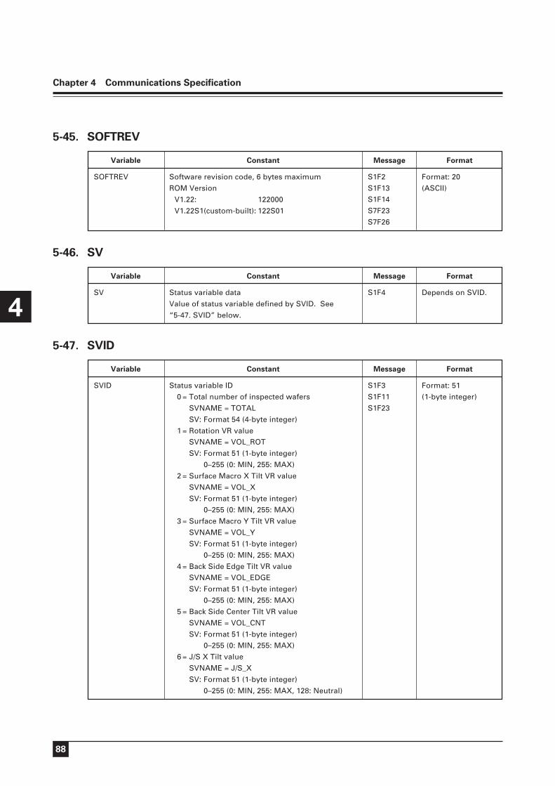
88
Chapter 4 Communications Specification
4
MessageVariable
S1F2
S1F13
S1F14
S7F23
S7F26
SOFTREV Software revision code, 6 bytes maximum
ROM Version
V1.22: 122000
V1.22S1(custom-built): 122S01
Format: 20
(ASCII)
Constant Format
5-45. SOFTREV
MessageVariable
S1F4SV Status variable data
Value of status variable defined by SVID. See
“5-47. SVID” below.
Depends on SVID.
Constant Format
5-46. SV
MessageVariable
S1F3
S1F11
S1F23
SVID Status variable ID
0 = Total number of inspected wafers
SVNAME = TOTAL
SV: Format 54 (4-byte integer)
1 = Rotation VR value
SVNAME = VOL_ROT
SV: Format 51 (1-byte integer)
0–255 (0: MIN, 255: MAX)
2 = Surface Macro X Tilt VR value
SVNAME = VOL_X
SV: Format 51 (1-byte integer)
0–255 (0: MIN, 255: MAX)
3 = Surface Macro Y Tilt VR value
SVNAME = VOL_Y
SV: Format 51 (1-byte integer)
0–255 (0: MIN, 255: MAX)
4 = Back Side Edge Tilt VR value
SVNAME = VOL_EDGE
SV: Format 51 (1-byte integer)
0–255 (0: MIN, 255: MAX)
5 = Back Side Center Tilt VR value
SVNAME = VOL_CNT
SV: Format 51 (1-byte integer)
0–255 (0: MIN, 255: MAX)
6 = J/S X Tilt value
SVNAME = J/S_X
SV: Format 51 (1-byte integer)
0–255 (0: MIN, 255: MAX, 128: Neutral)
Format: 51
(1-byte integer)
Constant Format
5-47. SVID

89
Chapter 4 Communications Specification
4
MessageVariable
S1F3
S1F11
S1F23
SVID Format: 51
(1-byte integer)
Constant Format
7 = J/S Y Tilt value
SVNAME = J/S_Y
SV: Format 51 (1-byte integer)
0–255 (0: MIN, 255: MAX, 128: Neutral)
11 = Current Control State
SVNAME = CNT_ST
SV: Format 51 (1-byte integer)
0 = Offline
1 = Online Local
2 = Online Remote
MessageVariable
S1F12SVNAME A single line of characters: status variable name
See “5-47. SVID” above.
Format: 20
(ASCII)
Constant Format
5-48. SVNAME
MessageVariable
S1F12
S2F30
UNITS Specifies the value unit.
Always shown as a blank for the NWL.
Format: 20
(ASCII)
Constant Format
5-49. UNITS
MessageVariable
S6F11
S6F16
S6F20
V Variable data
See “5-51. VID” below.
Depends on VID.
Constant Format
5-50. V
MessageVariable
S2F33VID Variable ID
1 = All inspection results data for a carrier
V Format: 20 (ASCII)
Results of 26 wafers x 5 inspection items
[Wafer judgement (whether the wafers are
accepted on all items), Surface Macro, Back
Side Edge Macro, and Back Side Center
Macro]
Format: 51
(1-byte integer)
Constant Format
5-51. VID

90
Chapter 4 Communications Specification
4
MessageVariable
S2F33VID Format: 51
(1-byte integer)
Constant Format
Results are transmitted in order of wafer
number on orientation flat alignment,
Surface Macro, Back Side Edge Macro, and
Back Side Center Macro, in this order. Wafer
results are delimited from following wafer
results by a comma. (A comma is also used
to indicate the end of the result message.)
(Meaning of Character)
G: Accepted
N: Rejected
0–9: Reject type
U: Uninspected (the inspection is
terminated halfway)
,: Separate wafers.
_: The inspection item is not
selected.
(Example)
GGGGG,NGGGG,GGGGG,GGGGG,GGGGG,
GGGGG,GGGGG,GGGGG,GGGGG,GGGGG,
GGGGG,GGGGG,22GGG,GGGGG,GGGGG,
GGGGG,GGGGG,GGGGG,GGGGG,GGGGG,
GGGGG,GGUUU,UUUUU,UUUUU,UUUUU,
_ _ _ _ _,
In a 25-pocket carrier, wafer No. 2 is rejected
on Surface Macro inspection, and wafer No.
13 is rejected on Surface Macro and Back
Side Edge Macro, with reject type 2.
2 = Inspection result data for preceding pocket
(one wafer)
V Format: 20 (ASCII)
Wafer number, wafer judgement, Surface
Macro, Back Side Edge Macro, and Back Side
Center Macro results are transmitted, in this
order. The meaning of the characters is the
same as for VID = 1 above.
(Meaning of Character)
G: Accepted
N: Rejected
0–9: Reject type
U: Uninspected
_: The inspection item is not
selected.
(Example)
09NGN1U
Wafer No. 9 is accepted on Surface Macro,
rejected on Back Side Edge Macro, rejected
on Back Side Center Macro with reject type
1, uninspected on Micro, and rejected for
general wafer judgement.

91
Chapter 4 Communications Specification
4
MessageVariable
S2F33VID Format: 51
(1-byte integer)
Constant Format
3 = Result data for the preceding inspection item
V Format: 20 (ASCII)
Wafer number, inspection item, and results
are transmitted.
The meaning of the characters is the same
as for VID = 1 above.
(Meaning of Character)
The number sent first, 0–26:
Inspected wafer number
S: Surface Macro inspection
E: Back Side Edge Macro inspection
C: Back Side Center Macro
inspection
P: Surface programmable stop
inspection
M: Microscopic inspection
G: Accepted
N: Rejected
0–9: Reject type
(Example)
09M1
Wafer No. 9 is rejected on microscopic
inspections, with reject type 1.
4 = Mapping data
V Format: 20 (ASCII)
Wafer detection data
(Meaning of Character)
*: Wafer is in the pocket.
_: Wafer is not in the pocket.
(Example)
*****_ _ _ _ _ _ _ _ _ _ _ _ _ _ _ _ _ _ _*_
Wafers No. 1, 2, 3, 4, 5, and 25 are
held in the carrier.
10 = Carrier Detection
V Format: 20 (ASCII)
0: Carrier is not installed.
1: 6" Carrier is installed.
2: 8" Carrier is installed.
?: Unknown
11 = Stage sensor status
V Format: 20 (ASCII)
1: ON
0: OFF
12 = Wafer sensor status
V Format: 20 (ASCII)
1 = ON (wafer sticks out)
0 = OFF
? = Unknown (A model with unknown
status (e.g. NWL860INX) is used.)

92
Chapter 4 Communications Specification
4
MessageVariable
S2F33VID Format: 51
(1-byte integer)
Constant Format
N = N/A (Not equipped with sensor, or
sensor setting is OFF.)
13 = Wafer pocket number
V format: 20 (ASCII)
Transmit a wafer pocket number.
This wafer pocket number is transmitted
together with CEID when CEID is any of the
following: 200 (transfer to surface macro
position complete); 300 (transfer to back side
edge macro position complete); 400 (transfer
to back side center macro position
complete); 450 (transfer to PS position
complete); 504 (transfer to stage complete);
510 (transfer from stage to change arm
complete)
'01' to '26': Target wafer pocket numbers
'00': Not applicable
(The wafer pocket number is valid only
when CEID is 200, 300, 400, 450, 504, or
510. '00' is returned if the event is other
than these.)
19 = Pressure sensor pressure level
V Format: 20 (ASCII)
00(xxx)–FF(xxx)
50 = Height measurement data
V Format: Format 44 (4-byte floating point)
Carrier height measurement data: mm
51 = Pitch measurement data
V Format: Format 44 (4-byte floating point)
Carrier pitch measurement data: mm
101 = Currently-selected sample file
V Format: 20 (ASCII)
PPID of currently-selected sample file
102 = Currently-selected carrier file
V Format: 20 (ASCII)
PPID of the currently-selected carrier file
103 = All EEPROM data
V Format: 10 (Binary)
201 = Indexer software revision
V Format: 20 (ASCII)
202 = Indexer MSC_ENABLE status
V Format: 20 (ASCII)
0 = Disable
1 = Enable
? = Unknown
203 = Indexer MSC_INTLK status
V Format: 20 (ASCII)
0 = Disable
1 = Enable
N= Unknown (NWL860INX is always in
this state.)
