wafer type check valve k6 pvc - ips flow systems · the wafer type check valve is centered in the...
TRANSCRIPT
Technical data
Wafer type check valve K6 PVC
www.praher.com page 1 of 6
© P
rahe
r Kun
stst
offte
chni
k G
mbH
DB/
EN/D
EEN
/14/
01/2
25B
Subj
ect t
o te
chni
cal m
odifi
catio
ns!
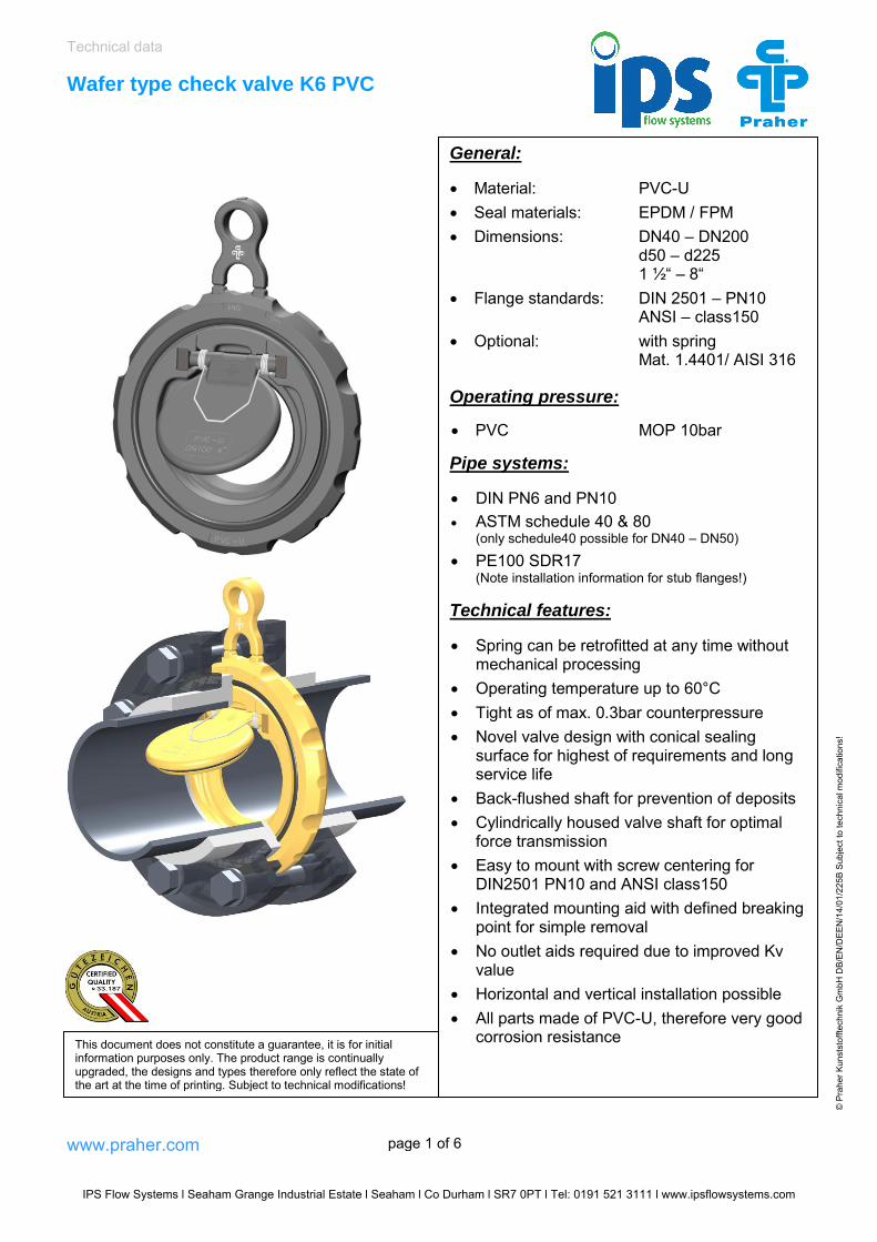
General:
Material: PVC-U Seal materials: EPDM / FPM Dimensions: DN40 – DN200
d50 – d225 1 ½“ – 8“
Flange standards: DIN 2501 – PN10 ANSI – class150
Optional: with spring Mat. 1.4401/ AISI 316
Operating pressure:
PVC MOP 10bar
Pipe systems:
DIN PN6 and PN10 ASTM schedule 40 & 80
(only schedule40 possible for DN40 – DN50)
PE100 SDR17(Note installation information for stub flanges!)
Technical features:
Spring can be retrofitted at any time withoutmechanical processing
Operating temperature up to 60°C Tight as of max. 0.3bar counterpressure Novel valve design with conical sealing
surface for highest of requirements and longservice life
Back-flushed shaft for prevention of deposits Cylindrically housed valve shaft for optimal
force transmission Easy to mount with screw centering for
DIN2501 PN10 and ANSI class150 Integrated mounting aid with defined breaking
point for simple removal No outlet aids required due to improved Kv
value Horizontal and vertical installation possible All parts made of PVC-U, therefore very good
corrosion resistanceThis document does not constitute a guarantee, it is for initial information purposes only. The product range is continually upgraded, the designs and types therefore only reflect the state of the art at the time of printing. Subject to technical modifications!
IPS Flow Systems l Seaham Grange Industrial Estate l Seaham l Co Durham l SR7 0PT l Tel: 0191 521 3111 l www.ipsflowsystems.com

Technical data
Wafer type check valve K6 PVC
www.praher.com page 2 of 6
© P
rahe
r Kun
stst
offte
chni
k G
mbH
DB/
EN/D
EEN
/14/
01/2
25B
Subj
ect t
o te
chni
cal m
odifi
catio
ns!
Dimensions:
DN 40 50 65 80 100 125 150 200
d 50 63 75 90 110 140 160 225
ØA 95 109 130 146 175 198 223 280
B 16 18 20 20 23 25 30 34
C 141,8 159,5 185 200,4 237,2 262,3 288,8 348,3
LK DIN 110 125 145 160 180 210 240 295
ØD 18 18 18 18 18 18 22 22
LK ANSI 98,5 120,65 139,7 152,4 190,5 215,9 241,3 298,45
ØE 15,5 19 19 19 19 22,2 22,2 22,2
ØF 23,5 33 42 53 73 93 110 150 Dimensions in mm
Flap opening angle W with various pipe dimensions
PVC PN10 91 88,5 82 84,5 72,5 73,5 69 74
PVC PN6 93,5 92,5 86 88,5 78 79 75 79
PVC schedule40 80,5 79,5 72 79,5 76 75 78,5 73
PVC schedule80 - - 63 72 69 68 71 66
PE100 SDR17 88* 85,5* 78,5* 81,5* 68,5* 69,5* 64,5* 70* *Note installation information Dimensions in degrees
© P
rahe
r Kun
stst
offte
chni
k G
mbH
DB/
EN/D
/03/
11/2
25Te
chni
sche
Änd
erun
gen
vorb
ehal
ten!
© P
rahe
r Kun
stst
offte
chni
k G
mbH
DB/
EN/D
/03/
11/2
25Te
chni
sche
Änd
erun
gen
vorb
ehal
ten!
IPS Flow Systems l Seaham Grange Industrial Estate l Seaham l Co Durham l SR7 0PT l Tel: 0191 521 3111 l www.ipsflowsystems.com

Technical data
Wafer type check valve K6 PVC
www.praher.com page 3 of 6
© P
rahe
r Kun
stst
offte
chni
k G
mbH
DB/
EN/D
EEN
/14/
01/2
25B
Subj
ect t
o te
chni
cal m
odifi
catio
ns!
Exploded drawing:
01. Body02. Flap03. Flap clip04. O-ring, flap05. O-ring, body frontside06. O-ring, body backside07. Optional spring08. Label
Spares:
01. Flap kit: Flap Flap clips
02. O-ring set EPDM: O-ring, flapO-ring, body frontsideO-ring, body backside
03. O-ring set FPM: O-ring, flapO-ring, body frontsideO-ring, body backside
04. Spring: Spring Label EPDM / FPM
Diagrams:
Pressure–temperature diagram Pressure loss diagram
from 40°C increased safety factor
Water 20°C
IPS Flow Systems l Seaham Grange Industrial Estate l Seaham l Co Durham l SR7 0PT l Tel: 0191 521 3111 l www.ipsflowsystems.com

Technical data Wafer type check valve K6 PVC
www.praher.com page 4 of 6
© P
rahe
r Kun
stst
offte
chni
k G
mbH
DB/
EN/D
EEN
/14/
01/2
25B
Subj
ect t
o te
chni
cal m
odifi
catio
ns!
Cv value table
Pressure loss 1 bar 0.001 bar
DN40 333l/min 10.5l/min
DN50 700l/min 22.1l/min
DN65 1050l/min 33.2l/min
DN80 1750l/min 55.3l/min
DN100 3633l/min 114.9l/min
DN125 6067l/min 191,9l/min
DN150 8217l/min 259,8l/min
DN200 15733l/min 497,5l/min
Measurements implemented as per DIN EN 60534-2-3. Values in pressure loss diagram obtained at max. opening angle with PVC PN10 pipes and flow medium water at 20°C! Opening pressure (without spring)
Mounting position horizontal vertical
DN40 2 mbar 10 mbar
DN50 2 mbar 10 mbar
DN65 2 mbar 10 mbar
DN80 2 mbar 10 mbar
DN100 2 mbar 10 mbar
DN125 3 mbar 15 mbar
DN150 3 mbar 15 mbar
DN200 3 mbar 15 mbar
Opening pressure with spring is about 10 mbar higher!
Opening pressure is required differential pressure to open flap!
© P
rahe
r Kun
stst
offte
chni
k G
mbH
DB/
EN/D
/03/
11/2
25 S
ubje
ct to
tech
nica
l mod
ifica
tions
!
IPS Flow Systems l Seaham Grange Industrial Estate l Seaham l Co Durham l SR7 0PT l Tel: 0191 521 3111 l www.ipsflowsystems.com

Technical data
Wafer type check valve K6 PVC
www.praher.com page 5 of 6
© P
rahe
r Kun
stst
offte
chni
k G
mbH
DB/
EN/D
EEN
/14/
01/2
25B
Subj
ect t
o te
chni
cal m
odifi
catio
ns!
ANSI class150 DIN 2501 PN10
General installation information
The following must be noted when installing on a pump (pressure-side): No direct mounting on the pump flange or downstream bends or elbows A calming zone distance of 5x the DN nominal diameter must be planned before and after
the wafer type check valve
Note:Wafer type check valves without springs are not recommended for pulsing flow conditions. We recommend a wafer type check valve with spring for such applications.
Installation in PE100 SDR17 piping:To obtain the correct opening with PE100 SDR17 stub flanges either the outlet side must be according to the table or alternatively the outlet side must be chamfered according to the table.
DN 40 50 65 80 100 125 150 200
Ø (mm)
46 57 68 80 103 128 147 198
W (degree)
20 20 20 20 20 20 20 20
Centering in the piping: The wafer type check valve is centered in the piping via the different screw recesses for DIN 2501 PN 10 and ANSI class150 around the circumference of the body.
IPS Flow Systems l Seaham Grange Industrial Estate l Seaham l Co Durham l SR7 0PT l Tel: 0191 521 3111 l www.ipsflowsystems.com

Technical data
Wafer type check valve K6 PVC
www.praher.com page 6 of 6
© P
rahe
r Kun
stst
offte
chni
k G
mbH
DB/
EN/D
EEN
/14/
01/2
25B
Subj
ect t
o te
chni
cal m
odifi
catio
ns!
Tightening torque of screws for flange connections
DN 40 50 65 80 100 125 150 200
Nm 15 20 20 20 20 25 30 35
Bolts should be tightened in alternative diagonal sequence and with an equal torque
1. tighten the bolts by hand in order to ensure an equal alignment of the sealing surfaces2. first, tighten the bolts to 50% of the recommended torque in alternative sequence
(diagonal)3. then, tighten the bolts further to 80% of the recommended torque in alternative sequence
(diagonal)4. finally, tighten the bolts to the recommended torque
IPS Flow Systems l Seaham Grange Industrial Estate l Seaham l Co Durham l SR7 0PT l Tel: 0191 521 3111 l www.ipsflowsystems.com