waffle structure
TRANSCRIPT
Laser Cut Waffl e Structure
The City University of New YorkArchitectural Technology Dept.
written by Mauricio TacoamanRhino 4.0
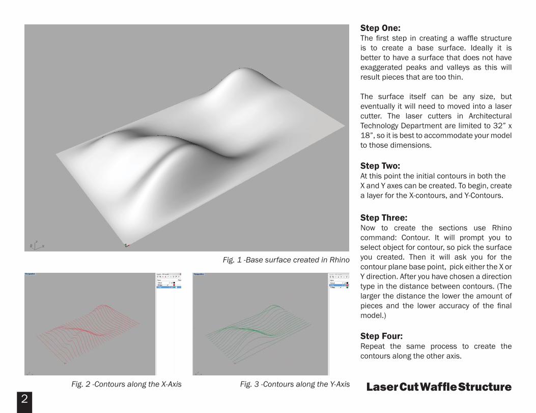
Laser Cut Waffl e StructureFig. 3 -Contours along the Y-AxisFig. 2 -Contours along the X-Axis
Fig. 1 -Base surface created in Rhino
Step One:The fi rst step in creating a waffl e structure is to create a base surface. Ideally it is better to have a surface that does not have exaggerated peaks and valleys as this will result pieces that are too thin.
The surface itself can be any size, but eventually it will need to moved into a laser cutter. The laser cutters in Architectural Technology Department are limited to 32” x 18”, so it is best to accommodate your model to those dimensions.
Step Two:At this point the initial contours in both theX and Y axes can be created. To begin, create a layer for the X-contours, and Y-Contours.
Step Three: Now to create the sections use Rhino command: Contour. It will prompt you to select object for contour, so pick the surface you created. Then it will ask you for the contour plane base point, pick either the X or Y direction. After you have chosen a direction type in the distance between contours. (The larger the distance the lower the amount of pieces and the lower accuracy of the fi nal model.)
Step Four: Repeat the same process to create the contours along the other axis.
2
Laser Cut Waffl e Structure3
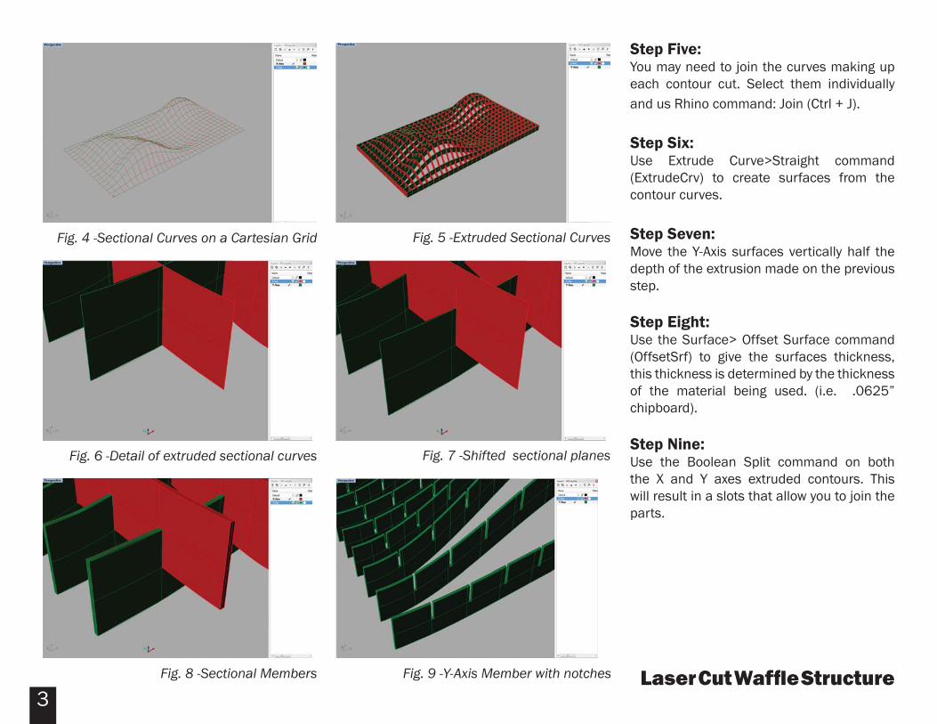
Fig. 9 -Y-Axis Member with notchesFig. 8 -Sectional Members
Fig. 4 -Sectional Curves on a Cartesian Grid
Step Five:You may need to join the curves making up each contour cut. Select them individually and us Rhino command: Join (Ctrl + J).
Step Six:Use Extrude Curve>Straight command (ExtrudeCrv) to create surfaces from the contour curves.
Step Seven:Move the Y-Axis surfaces vertically half the depth of the extrusion made on the previous step.
Step Eight:Use the Surface> Offset Surface command (OffsetSrf) to give the surfaces thickness, this thickness is determined by the thickness of the material being used. (i.e. .0625” chipboard).
Step Nine:Use the Boolean Split command on both the X and Y axes extruded contours. This will result in a slots that allow you to join the parts.
Fig. 5 -Extruded Sectional Curves
Fig. 6 -Detail of extruded sectional curves Fig. 7 -Shifted sectional planes
Laser Cut Waffl e Structure4
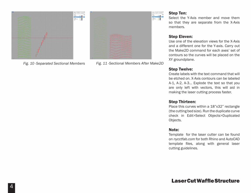
Step Ten:Select the Y-Axis member and move them so that they are separate from the X-Axis members.
Step Eleven:Use one of the elevation views for the X-Axis and a different one for the Y-axis. Carry out the Make2D command for each axes’ set of contours so the curves will be placed on the XY groundplane.
Step Twelve:Create labels with the text command that will be etched on. X-Axis contours can be labeled A-1, A-2, A-3... Explode the text so that you are only left with vectors, this will aid in making the laser cutting process faster.
Step Thirteen:Place this curves within a 18”x32” rectangle (the cutting bed size). Run the duplicate curve check in Edit>Select Objects>Duplicated Objects.
Note:Template for the laser cutter can be found on nycctfab.com for both Rhino and AutoCAD template fi les, along with general laser cutting guidelines.
Fig. 10 -Separated Sectional Members Fig. 11 -Sectional Members After Make2D