wagner concepts: the valkyrie an unmanned air launched
TRANSCRIPT

WAGNER CONCEPTS: The Valkyrie An Unmanned Air Launched Disaster Relief Quadrotor
Executive Summary
33rd Annual American Helicopter Society International
Student Design Competition
Jada Green, Colin Gurry, Jimmy Hubert, Jared Lee, Charles “Coty” Pinckney, Killian Wagner, and Stephanie Wagner
TheDanielGuggenheim

SchoolofAerospaceEngineering270FerstDrive
Atlanta,GA30332
JadaGreen
UndergraduateStudent(TeamLeader)
Charles“Coty”Pinckney
UndergraduateStudent(ChiefEngineer)
ColinGurry
UndergraduateStudent
JamesHubert
UndergraduateStudent
jhubert7.gatech.edu
JaredLee
UndergraduateStudent
KillianWagner
UndergraduateStudent
StephanieWagner
UndergraduateStudent
ACKNOWLEDGMENTS
The Wagner Concepts design team would like to thank Dr. Daniel Schrage, Dr. J.V.R. Prasad, and Dr. Marilyn Smith for their invaluable support and guidance.

1 Introduction The American Helicopter Society (AHS) has submitted a request for proposal of an air
launched, unmanned disaster relief delivery vehicle. This vehicle will be able to be deployed from the cargo hold of a C-130J, at 15,000 feet and 140 knots. From this location, the vehicle will arrest its descent and switch to autonomous flight before reaching 11,000 feet International Standard Atmosphere (ISA). This corresponds to 1000 feet above ground level (AGL). The vehicle will descend to 50 feet AGL of a disaster location where it will hover for 1 minute, while deploying the relief package. Once the payload has been released, at a speed no greater than 5 feet per second, the vehicle will return to a base camp, located 50 nautical miles from the disaster zone. The base camp is located at 4000 feet ISA. The vehicle will then be inspected, refueled, reloaded onto the C-130J and ready to deploy again.
2 Design Process
2.1 Mission Profile A preliminary outline of the mission profile is illustrated in Figure 1.
Figure 1: Mission Profile
The C-130J will first depart from the base location at 4,000 feet ISA, and climb to cruise until near the disaster location (50 nautical miles from the base). At 15,000 feet ISA, the disaster relief UAV will be released from the C-130J flying at 140 knots. The UAV will then transition to autonomous flight at an altitude greater than 11,000 feet ISA. It will then descend to 50 feet above the disaster location, which is located at 10,000 feet ISA. At this point, the UAV will transition to hover and will hover for 1 minute to deliver the disaster relief payload. After delivery, the UAV will remain at 10,050 feet ISA and will travel back to the base location 50 nautical miles away. After reaching the base location, the UAV will descend to the ground at 4,000 feet ISA.

2.2 Vehicle Selection Process
2.2.1 Concept Selection Georgia Tech Integrated Product/ Process Development (IPPD) Methodology was used in
order to select a design concept capable of fulfilling the mission requirements for the AHS design competition. IPPD Methodology is outlined in Figure 2.
Figure 2: IPPD Methodology Flow Chart
First, the customer and technical requirements were outlined and evaluated in the Quality Functional Deployment (QFD) matrix. Next, an Overall Evaluation Criterion (OEC) was constructed to evaluate any proposed concepts. A morphological matrix was then formed in order to generate a set of feasible alternatives. The feasible alternatives were then evaluated in a Pugh Evaluation Matrix and the best alternative was selected through the TOPSIS decision-making process.
3 Computer Aided Design Modeling and Weight and Balance The proposed vehicle (The Valkyrie) capable of accomplishing the disaster relief mission
has a quadrotor configuration and uses a gas turbine-electric propulsion system. Electric power from both a turboshaft engine and batteries will supply the vehicle with power. Two of these vehicles will fit inside a C-130 and deploy from the aircraft using a parachute at the rear of each vehicle. Once out of the aircraft, the parachute will aid in reducing the vehicle’s speed. Then, the vehicle will autorotate to arrest descent. Each rotor includes two blades and a hub that uses collective pitch to control the angle of attack of each rotor blade. Figure 3 shows the total vehicle configuration.

Figure 3: The Valkyrie Vehicle Configuration.
The two primary design drivers that led the vehicle conceptualization were dimensional size and payload weight. The dimensions provided by the request for proposal (RFP) limited overall vehicle size, and the proposed vehicle is capable of carrying a 750 pound payload. Using the Sikorksy S-64 Skycrane as a design influence, the proposed vehicle was constructed around the payload weight and water bottle package dimensions provided by the RFP. Figure 4 shows the vehicle and C-130 cargo bay dimensions.
Figure 4: 3D View of Complete Valkyrie Vehicle and Loading inside C-130J Cargo Bay

4 Aerodynamic Performance This vehicle was designed to maximize hover performance in the altitude range of 10-
15,000 ft. The rotorcraft is able to hover out of ground effect at 10,050 ft for well over 1 minute while it safely deploys the 750 lb disaster relief payload to the ground. With a thrust coefficient of .0132 and a disk loading of 9.46 lb/ft2, the vehicle’s four rotors produce enough thrust to complete the mission without overworking the blades. Additionally, as a safety measure, the aircraft can bring itself to the ground steadily with one rotor inoperative.
Table I: Generalized Power Plant Characteristics (Predictions)
Characteristic Value
Sea Level MCP 395 Hp SFC .77 lb/(Hp*hr)
Thrust-to-Weight 1.4
Engine Weight 136 lbs
Table II: Design Parameters
Parameter Values
Tip Speed [600, 650, 700, 750] ft/s Chord [.4, .5, .6]
R [4.1, 4.2, 4.3]
The lightest approximate gross weight occurs where the available and required fuel weight ratios intersect .The power required equations used to calculate the Rf,req for each mission segment are given below and come from Leishman’s Principles of Helicopter Aerodynamics Chapter 2 for momentum theory approximations. The segments are broken down into forward flight, hover, and descent although hover is the main design-driver.
Table III: Initial Design Parameters from Rf Analysis
Parameter Result
Disk Loading 10.8 lb/ft2
Power Loading 6.327
Chord 0.4 ft
Solidity 0.044

Radius 4.3
Tip Speed 600
GW 2479 lbs
FM 0.8035
These initial sizing results have been updated as power plant characteristics, detailed weight analysis, etc. has developed. The more specific blade design, used to create the CATIA model depicted in the figure above, was a result of BEMT techniques described in Chapter 3 of Leishman. The amount of thrust we need, our tip speed, disk area, and density give us a value for CT. Using the figure of merit estimate we retrieved from the Rf process, we can back out an average Cd0 value over the rotor. We can also get an average CL value using CLmean=6CT/σ. From this, we can use the fact that lift coefficient varies with local Mach number (Cl=CL01-Mlocal) and drag coefficient varies with local Reynold’s number (Cd∝ Re-2) to get Cl/Cd characteristics and airfoil baselines at the root and tip.
Table IV: Blade Characteristics
FOM .8
Clalpha tip 5.8
Clalpha root 6.1
α at root for max Cl/Cd 8.25 deg
α at tip for max Cl/Cd 4.25 deg
θ twist .93 degrees/ft
Hub Design Process:
The hub selection for our application was simple: minimize complexity and maximize change in thrust. This design goal led us to a hub system with collective pitch as the sole control input, much like a typical tail rotor configuration. The simple system keeps maintainability and complexity low for a four-rotor aircraft. It also drastically improves the response time to a control input as opposed to a fixed-pitch hub type, giving each rotor large ΔT values for a small time increment. Advanced Tactics, the company that developed our baseline vehicle, corroborated this selection and mentioned that they had planned on implementing this hub type in the AT Transporter.

4.1 Performance Predictions Table V: Performance Characteristics
Performance Parameter Value Method
CT .0132 BEA
Vtip 750 ft/s Updated from RF to meet thrust requirements
FM (Rotor only) .82 BEA
𝜎 .0592 Geometry constraints, RF
Disk Loading, w 9.46 lb/ft2 RF
GW / Disk Area
Blade Loading 160 lb/ft2 RF
GW / Blade Area
𝜇 .122 Fwd Velocity for min. Fuel burn
Power Loading, lp 5.5 ft2/HP RF
GW / Installed Power
Tip Loss Factor .92 Hiller Transport Helicopter Design Methods
Parasite Drag 277 lbs Star CCM+
Vclimb 6 ft/s ∆P/W
*Note: several performance variables fall under propulsion section with power characteristics.
4.2 Validation Star CCM+ was used to model the vehicle in forward flight as shown in the figure below.
The top two images show streamlines moving around the body and the vortical region developed at the wake. The bottom image shows the velocity magnitude of the flow. Although the payload will theoretically be gone once we reach the cruise condition, it is nice to know that our thrust is sufficient to propel the vehicle in forward flight. This analysis was also used to predict parasite drag and estimate forces and moments that assisted in the development of a position controller.
Figure 5: Wake Streamlines (Left), Total Body Streamlines (Right)

Figure 6: Cruise Velocity Scene
5 Structures Analysis Modeling The vehicle fully was modeled and a finite element model analysis was accomplished. The
material selection can be seen below in Figure 7. The members that appear gold in color are considered primary structure and are principal structural elements. These members are manufactured form formed 0.071’ TI-6Al-4V Solution Treated and Aged Titanium sheet metal. The members that appear silver in color are considered secondary structure or are non-principal structural elements. These members are manufactured from formed 0.071” 2024-T4 Heat Treated Aluminum sheet metal. Lastly, the members that appear black in color are considered aerodynamic fairings and are manufactured from composite materials formed of plies of fiberglass type E and plies of Hexcel AS4C 3,000 filament Carbon Fiber. The vehicle was then tested for a dynamic flight condition. This analysis can be seen below in Figure 8. Although the Titanium is a costly (108 dollars per kg compared to 3 dollars per kg for Aluminum) and heavier option, its strength was required in the primary structure of this aircraft. This analysis shows that the vehicle will maintain structural integrity throughout the entire mission.
Figure 7: Material Selection Figure 8: Analysis of Primary Structure
6 Structural Dynamics and Aeroelasticity DYMORE analysis was used to generate a fan plot of the rotor system. The system was
optimized to achieve flap and lead-lag natural frequencies above 1P at the operational rotor speed of 600 RPM. As can be observed from the plot, flap and lead-lag do not intersect with any

1P – 4P frequency lines at the operational rotor speed of 600 RPM, indicating that the blade design is dynamically acceptable and does not need major modifications in terms of dynamic behavior. Additionally, the same desired result is achieved up to 800 RPM, ensuring acceptable behavior in the event that operational RPM is raised. Below 600 RPM, this condition is not met; however, this is acceptable because the rotor will not operate at these speeds except for in the short increments of time needed to accelerate to operational RPM.
Figure 9: Fan plot of rotor configuration.
7 Flight Dynamics and Guidance, Navigation, and Control A set of flight dynamics equations were derived to describe the vehicle’s motion during
flight. The equations were linearized about hover and forward cruise trim states and stability analysis was performed in Matlab using the Control System toolbox to determine that the open-loop system was unstable.
𝑢𝜔
=𝑚I)*) 0)*)0)*) I
,- 𝐹/012𝑀/012
+ 𝐹12521𝑀67876
+𝑅𝑚𝑔0)*-
− 𝜔×𝑚𝑢𝜔×I𝜔
0
1
2
3
4
5
6
0 0.2 0.4 0.6 0.8 1 1.2 1.4
Frequency(perrev)
AngularVelocity(perrev)
1P
2P
3P
4P
Flap1
Lead-Lag1

Figure 10: Pole-Zero Map of Vehicle in Hover (left) and Cruise (right).
Implementing the system in Simulink, a series of cascaded PID controllers were designed to stabilize angular rates and establish attitude and velocity control authority. The controllers were tuned to achieve reasonable response times and robustness to perturbations.
Figure 11: Simulink model of PID controllers.
Simulations were run in hover, 90 knots forward cruise, and post-deployment. In hover and cruise, the vehicle was able to maintain control and return to steady-state conditions after encountering longitudinal and lateral 50 knot gusts. With the help of a parachute, the vehicle was able to stabilize its angular rates and regain attitude control after being deployed from the C-130J.

Figure 12: Response to Longitudinal Gust in Hover (left) and Cruise (right).
Figure 13: Response to Deployment form C-130J
A GNC architecture was also designed that uses a series of sensors and a state estimator to estimate the full dynamic state of the vehicle. Using this state information to inform a series of guidance systems, the vehicle will be able to actively adjust its flight plan mid-flight in response to the presence of obstacles and changing mission objectives.
Figure 14: GNC Architecture Flow Diagram

8 Propulsion System Modeling
8.1 Propulsion System Overview
Propulsion System Components: • 1 Allison 250-C30 Turboshaft Engine (primary engine – 540 MCP @ sea-level) • Fuel tanks (to store the 140 lb of fuel necessary to complete the 50 nm mission) • Planetary gearboxes • Generator, Motor (these two are housed in a single unit titled the MG2) • Inverters (to transform the DC that the batteries use to the AC required for the motor &
generator – both of these are housed in a single PCU, power control unit) • Converter (steps up the 201.6 V of the battery pack to the full 500 V required to get the
full 67 horsepower from the motor while also decreasing current as a result) The power required throughout the mission is graphed below.
Figure 15: Total Power for Various Cruise Velocities (at 10,050 ft)
Figure 16: Required Power through Mission
Fuel Used:
The Specific Fuel Consumption on the turboshaft engine is known to be:

𝑆𝐹𝐶 = 0.77𝑙𝑏
ℎ𝑝 ∗ ℎ𝑟
To determine the fuel flow rate necessary per second, the following can expression can be used:
𝑓𝑓 = 𝑆𝐹𝐶 ∗ 𝑃6IJKL6IM3600(QIR7SMQ
T6)= 𝑓𝑢𝑒𝑙𝑓𝑙𝑜𝑤𝑟𝑎𝑡𝑒𝑝𝑒𝑟𝑠𝑒𝑐𝑜𝑛𝑑
Since the power required is known at every instance in the mission profile, the fuel flow rate can also be determined with the assumption of constant SFC. The mission profile was then broken down into many incremental segments and the fuel expended during each of these segments was calculated and then summed over the entire mission.
Available Horsepower:
As the mission does not take place at sea-level, there is a reduction in the amount of horsepower that will be available to the rotorcraft for the duration of the flight. This is graphically modeled as:
Figure 17: Required Power Throughout Mission
Table VI: Parameters Associated with the 2010 Prius Battery Pack
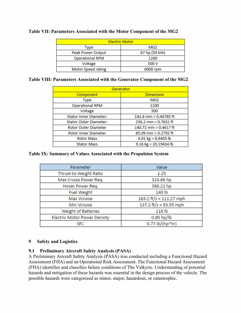
Table VII: Parameters Associated with the Motor Component of the MG2
Table VIII: Parameters Associated with the Generator Component of the MG2
Table IX: Summary of Values Associated with the Propulsion System
9 Safety and Logistics
9.1 Preliminary Aircraft Safety Analysis (PASA) A Preliminary Aircraft Safety Analysis (PASA) was conducted including a Functional Hazard Assessment (FHA) and an Operational Risk Assessment. The Functional Hazard Assessment (FHA) identifies and classifies failure conditions of The Valkyrie. Understanding of potential hazards and mitigation of these hazards was essential in the design process of the vehicle. The possible hazards were categorized as minor, major, hazardous, or catastrophic.

Table X: Functional Hazard Assessment
System Subsystem Function Failure Condition Hazard Classification
Propulsion System Quad Rotor Provides Lift for The Valkyrie Wrong RPM Major
Not Working Catastrophic
Working when not Necessary Major
Turboshaft Engine/ Battery/
Motor Quad Rotor Provides Power/ Energy
Source/ Power to The Valkyrie Wrong RPM Hazardous
Not Working Catastrophic
Working when not Necessary Major Tele-
communications Radio Communications
Quad Rotor Provides Mission Updates to
Base Missing Connection to the Ground Catastrophic
Wrong Ground Connection Hazardous
High Noise Hazardous
Working when not Necessary Minor
Navigation Device Provides Navigation for The Valkyrie Missing Connection to the Ground Catastrophic
Wrong Path Hazardous
Objects not Identified, Potential Crash Catastrophic
Working when not Necessary Minor
Software / Hardware Controls The Valkyrie Autonomously Data not Processed Hazardous
Data not Processed Correctly Major
Not Communicating with the
Navigation Device Hazardous
Working when not Necessary Minor
Payload Payload to be Delivered Winch System to Drop Payload
Payload not Delivered/ Delivered Improperly Hazardous
Controls Wiring System Transfers Signals for Control Overheating Major
Missing Connections Hazardous
Software/ Hardware Control
System Creates Signals for Control Overheating Major
Missing Connections Hazardous
Bugs in the Software/ Hardware Hazardous Structure Fuselage/ Rotor Structure Keeps the Fuselage Together Minor Damage Minor
Major Damage that Prevents Operation Hazardous
The major hazards were identified as: collision with other aircraft, ground-based
obstacles, high winds or extreme weather, and low visibility. Different mitigation strategies were chosen for the deployment phase and the drop phase; they are listed in Table X with the proper suggested mitigations.
Table XI: Risk Assessment
1 2 3 4 5 Classification of Failure
Conditions No Hazard Minor Major Hazardous Catastrophic
Allowable Qualitative Probability
Extremely Improbable Extremely Remote Remote Probable Extremely Probable

Deployment Hazards Severity Probability Mitigation
Collision with other Aircraft 5 1 Sense and Avoid Systems Ground-Based Obstacles 5 1 Pre-planned Flight Plans
High Winds or Extreme Weather 5 3 Delay Deployment Low Visibility 2 2 Weather Information, GPS
Drop Hazards Severity Probability Mitigation
Collision with other Aircraft 5 1 Sense and Avoid Systems Ground-Based Obstacles 5 1 Sense and Avoid Systems
High Winds or Extreme Weather 5 3 Backup Drop Location Low Visibility 3 2 Sensors
Return (Climb, Cruise, Landing) Hazards Severity Probability Mitigation
Collision with other Aircraft 1 4 Sense and Avoid Systems Ground-Based Obstacles 1 3 Pre-planned Flight Plans
High Winds or Extreme Weather 1 3 Delay Deployment Low Visibility 2 2 Weather Information, GPS
9.2 Certification Plan A certification plan must be established to provide the necessary documentation that The
Valkyrie is in compliance with all Federal Aviation Administration regulations, specifically Part 27—Airworthiness Standards: Normal Category Rotorcraft. The “Mock Certification Basis for an Unmanned Rotorcraft for Precision Agricultural Spraying” (Mock) was used as a guideline. Because of the nature of the mission and design requirements, the current regulations had to be added to or modified. According to the mock certification, three regulatory actions within the past few years have opened the door in the United States for commercial use of unmanned aircraft systems (UAS): the Federal Aviation Administration (FAA) Modernization and Reform Act of 2012, the proposed rulemaking for small unmanned aircraft, and Section 333 exemption process.
Current airworthiness regulations are insufficient to ensure the safety of LUAS, mainly
due to novel operational concepts, vehicle design types, operational environment, level of autonomy, and unique hazards. Additionally, many regulations may not be relevant to The Valkyrie and present an undue burden to the certification process. In order to meet all regulatory requirements much faster, the paper has proposed some modifications to Part 27. The regulations modified or omitted will address unique aspects of the UAS with respect to its intended operation.
9.3 Logistics The vehicle is comprised of modular systems that can be taken out and replaced easily.
This allows for easier maintenance and decrease maintenance time. The vehicle will undergo a brief inspection in between each mission, to check for any apparent damage done to the outside of the vehicle. After a predetermined number of flight hours or time, the vehicle will undergo a more through inspection to ensure the safety and lifespan of the vehicle. The vehicle is also comprised of off the shelf parts that are easily purchased and kept in stock to decrease

maintenance costs and delays. By using readily accessible parts, the cost of production and maintenance is minimized.
The turnaround time between missions is estimated to be 20 minutes. The refueling of the The Valkyries and the C-130J is estimated to take 15 minutes total. While this job is being performed, the rotorcrafts will be reloaded with relief packages. A quick maintenance check will also be performed simultaneously on the The Valkyries and the C-130J. The final step will be to reload the rotorcrafts onto the C-130J. This is expected to take an additional 5 minutes.
10 Life Cycle Cost Analysis The total cost of building, maintaining, and operating a fleet of 50 Valkyrie disaster relief
vehicles is roughly $36 million.
Table XII: Ten - Year Cost for a Fleet of 50
Fixed Cost Price per Rotorcraft
Price per Rotorcraft for 10 Years
Total for a Fleet of 50
Research and Development $5,000,000 N/A N/A $5,000,000
Raw Materials N/A $400,009 N/A $20,000,473 Manufacturing N/A $9,600 N/A $480,000
Major and Minor Maintenance N/A N/A $200,000 $10,000,000
Fuel for 50 Missions a Year N/A $1,228 $12,283 $614,148
Total $5,000,000 $410,838 $212,283 $36,094,621

11 Works Cited
2015 AHS RFP for “Air Launched Unmanned Disaster Relief Delivery Vehicle”.
Hiller, “Section I. Performance Data Report”, December 1960.
Hiller, “Transport Helicopter Design Analysis Methods”, November 1956.
Lowry, John, James Larminie, and Inc ebrary. Electric Vehicle Technology Explained. Second edition. Hoboken, N.J.: Wiley, 2012
NASA. “Mock Certification Basis for an Unmanned Rotorcraft for Precision Agricultural Spraying”. NASA/TM. 2015.
Schrage, D. P., VTOL Synthesis for Advanced VTOL Aircraft (Extension of the RF Method to Advanced VTOL Aircraft, 2004.
Schweizer Aircraft Corporation, “FAA Approved Rotorcraft Flight Manual for Schweizer 333 Helicopter”, September 2000.
Simons, R.M., “A Generalized Graphical Method of Minimum Gross Weight Estimation”, Presentation at the National Conference of the Society of Aeronautical Weights Engineers, Inc., San Diego, CA May 1956.
Transport Helicopter Design Analysis Methods. United States Army, Office of Naval Research – Air Branch. Report No. 473.6. November 30, 1955. Hiller Helicopters.