walk through the associated design - umn ccaps · walk through the associated design ... ampacity...
TRANSCRIPT

Walk through the associated design considerations associated with transmission line design
Follow-up to Transmission Design 101 (2012) & Transmission Design 102 (2013)
Additional design considerations

Route Selection Concepts
Material Testing Concepts
Electrical Studies

Purpose: develop and define a viable route centerline for design and construction of transmission facility
Viable means an acceptable route that can be permitting and constructed
Study Area: geographical area small enough to encompass feasible alternatives, but large enough to include adequate number of corridors
Macro-Corridor: broad linear area of land within which alternative corridors can be located

Micro-Corridor: linear areas within macro-corridor suitable of locating transmission line when natural environment, built environment, and engineering requirements are considered

Route: contiguous constructable right-of-way within alternative micro-corridor
Siting: process of determining location for proposed action

Environmental
Land Use Limitations
Land Owners
Availability of Property
Public Opinion/Opposition

Initiated following determination of project need and feasibility
Ends with identification of one or more macro-corridors
Completion of macro-corridor study signals beginning of scoping and permitting processes
Interdisciplinary study involving engineering, environmental, land acquisition, permitting, etc.
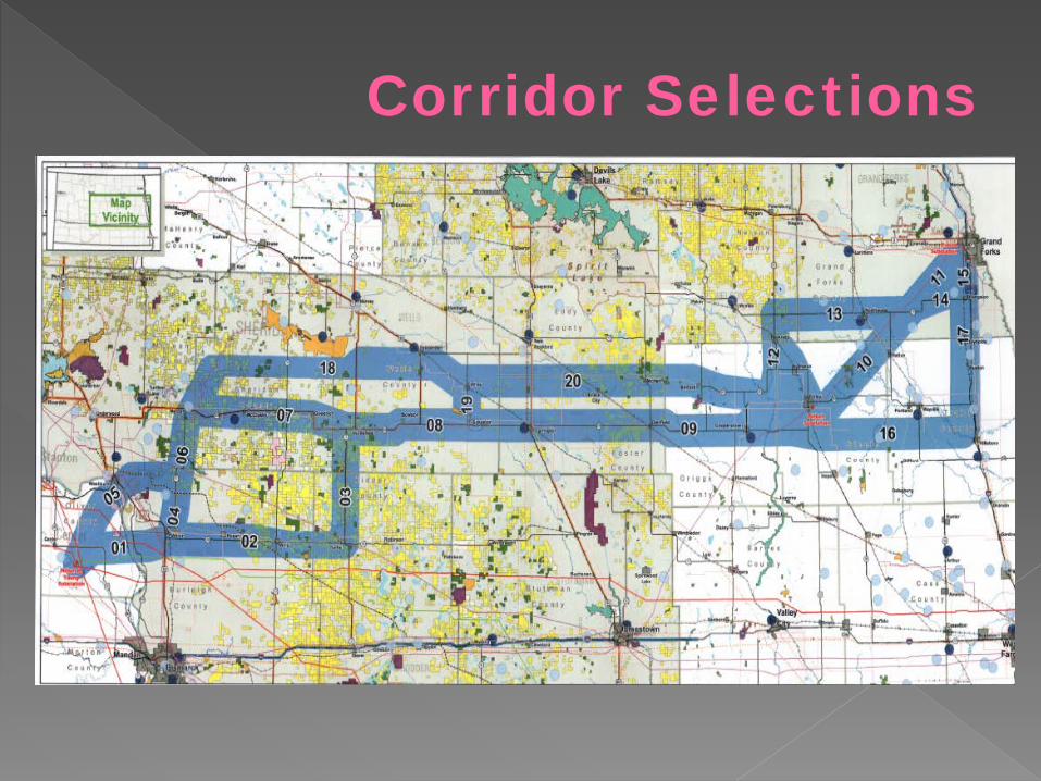
Corridor Selections
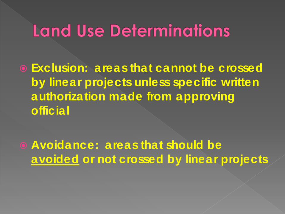
Exclusion: areas that cannot be crossed by linear projects unless specific written authorization made from approving official
Avoidance: areas that should be avoided or not crossed by linear projects

Line Draw
Weighted Methodology
GIS Tier Methodology

Land segments are assigned weighted value for each segment based on land usage› 1-3 high suitability› 4-6 moderate suitability› 7-9 low suitability
Route alternative determined by contiguous paths of lowest value
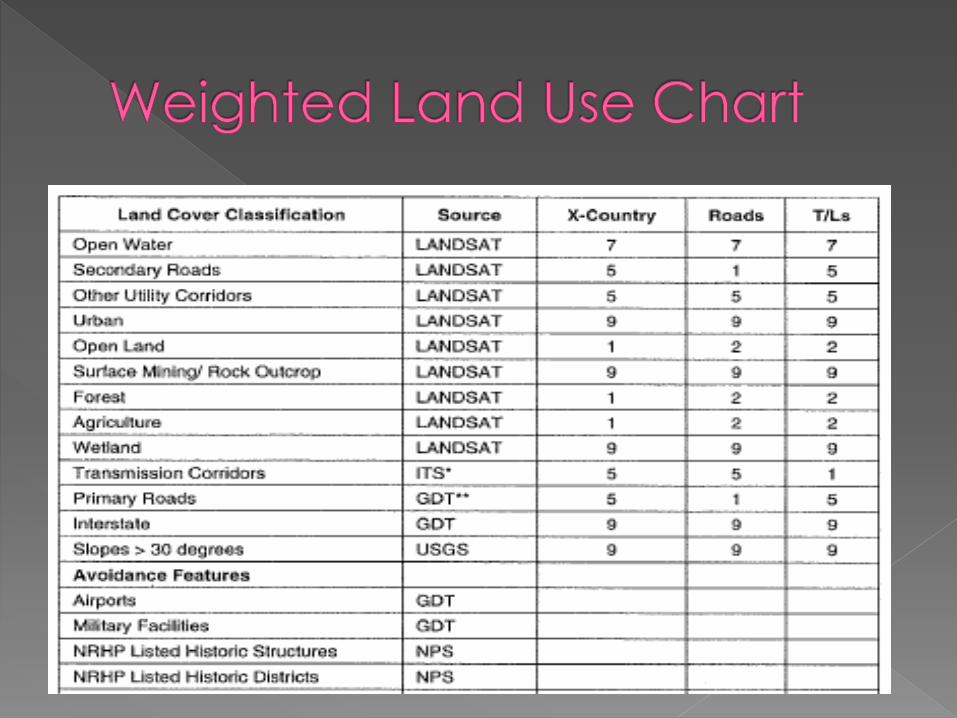


Land segments are categorized by land use classification, built environment, natural environment, and engineering considerations into layers
Each data layer is assigned a weighted value based on relative importance to linear project specifications
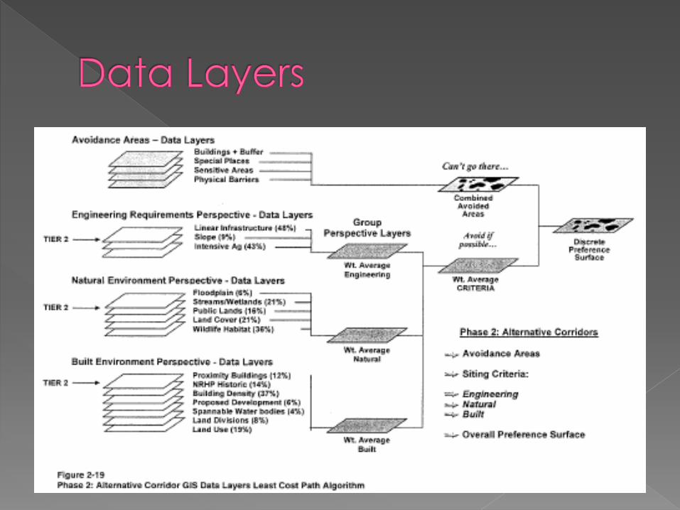

Once weighted, data layers are combined to form group perspective (alternative routes)
Each group is then graded based on combined weighting


Multiple alternative routes identified for each macro-corridor
Alternative routes are further evaluated for same considerations used for weighting → at more detailed level
Selected route is contiguous path with lowest scoring and most feasible construction

Corridor Selections

Route Selections

Route Selections
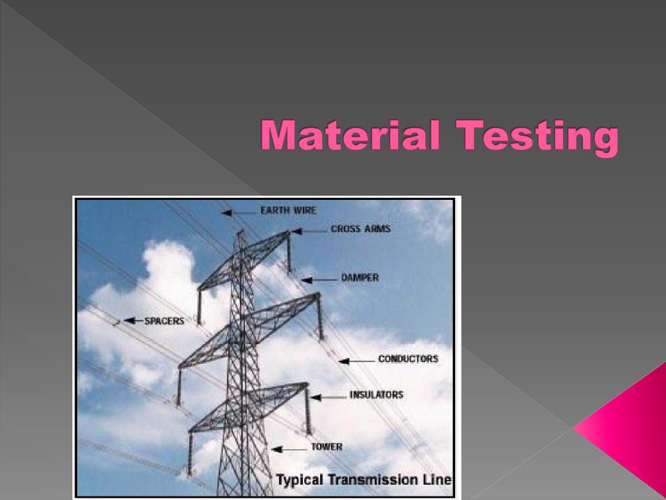

Verification that proposed materials will perform adequately and meet design specifications
Implied warrantee for design function of assembly

Hardware: any single piece or item of material used in support of transmission facility functions and purpose
Assembly: grouping of multiple items of hardware to form a functional arrangement with designed purpose

Mechanical Strength
Electrical
Fit & Function
Functional mechanical strength is load at which any part of hardware will not perform it’s design function…
…or that causes sufficient deformation or destruction of any part that will prevent it’s proper operational function

Ultimate Break Strength› Maximum stress can be withstood before
mechanical failure occurs (breaks)
Ultimate Yield Strength› Maximum stress can be withstood before plastic
deformation occurs
Ultimate Mechanical Strength› Maximum stress can be withstood before
deformation occurs preventing ability to perform designed function

Ultimate mechanical strength is the load at which failure of part occurs
Most materials classified based on ultimate mechanical strength rating (lbs)

Mechanical strength testing & ratings determined by manufacturer through use of independent certified testing
Testing results should be less than 5 years old to ensure inclusion of any manufacturing process, materials, or design modifications
Construct assembly of designed materials and load to ultimate breaking strength› Identifies weak link› Predictor of where failures should occur› Allows adjustment for design of least
impacting weak link
Assembly does not have to be full assembly → but should include all hardware (i.e. 2-3 insulator bells vs 23)
Purpose is to ensure that the design assembly will perform adequately during electrical conditions
Main types:› Flashover› Withstand› Corona/Radio-Induced Voltage (RIV)

Application of voltage quickly to 75%, then increase such that flashover conditions reached in 5-30 seconds
Flashover value is arithmetical mean of not less than 5 individual flashovers taken consecutively
Types: dry & wet (under water spray)

Application of voltage quickly to 75%, then increased to 100% in 5-30 seconds
Voltage at 100% held at least 1 minute
Types: dry (1 min), wet (10 secs), dew (20 secs under 100% humidity), Impulse (no flashover)

Corona: ionization of air caused by intense electric field
RIV: high frequency voltage generated by source of ionization current at terminals of power circuits
Produces audible noise and causes tracking, pitting, cracking, and damage to hardware & assemblies


Application of voltage well above corona point (up to 1.9 times rated voltage) → then lowered until corona disappears as inspected with ultraviolet cameras or visually in darkened room
› High levels of corona indicate inadequate design & material selection
› Long term high corona decreases life expectancy of hardware & assemblies


Construction and assembly of design hardware into proper configuration or assembly
Assembly is then maneuvered into expected conditions and alignments
Assembly is verified for freedom of movement, proper fit of hardware, assembly dimensions, & constructability

Electrical studies provides verification of transmission facility operating conditions and coordination of design elements
Groups: Interactive & Design
Interconnection› Feasibility› System Impact› Interconnection Facilities
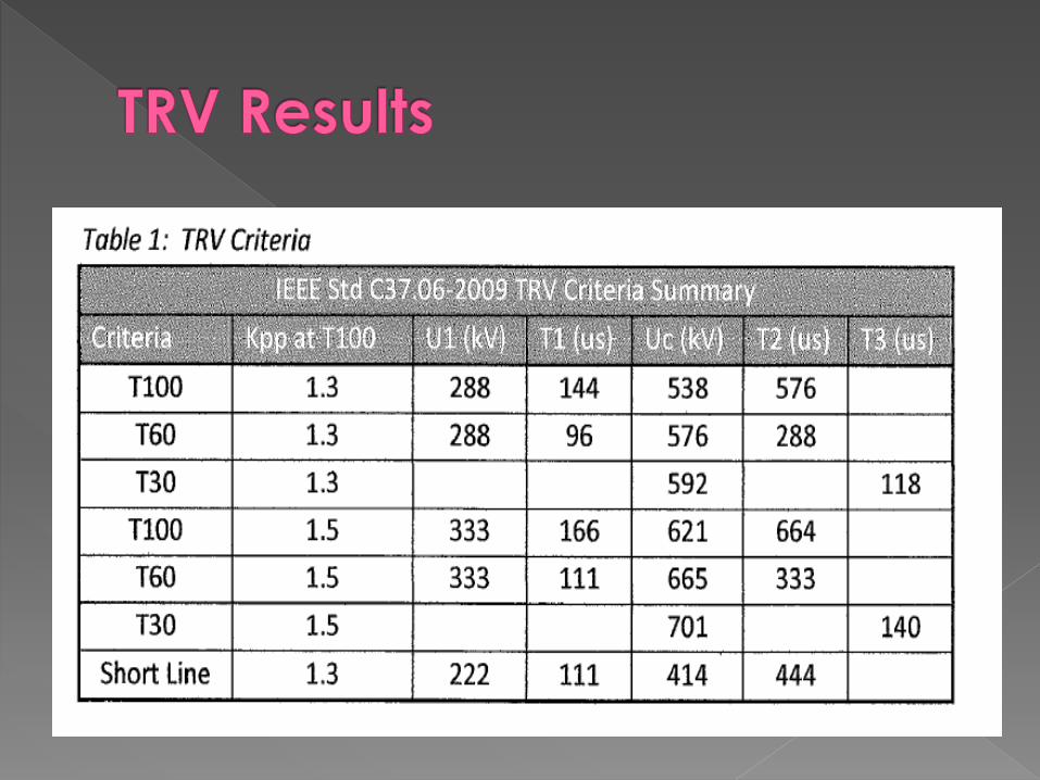
Transient Response (TRV)
Transient Overvoltage (TOV)

Determine the impact of connecting additional facilities to existing operating systems
3 analytical steps:› Feasibility› System Impact› Interconnection Facilities

Practicality and cost of incorporating requested interconnection facility into existing operating system
Limited to load flow and fault analysis
Provides preliminary estimates for type, scope, cost, construction lead time of facilities required to interconnect
Relationship between new facility, other planned new facilities (queue), and existing system
Model based analysis of operating system› Manufacturer models and operating system
parameters identified and agreed upon as basis for study

Comprehensive regional analysis of impact of adding facility on operating conditions and deliverability to load
Identifies constraints, required attachment facilities, local and/or network upgrades, detailed estimates with cost responsibility

Identifies the engineering design work necessary to begin construction
Good faith estimate as to cost for required upgrades or alterations (from System Impact Study)
Detailed design and construction schedules
Result is defined 1-line with annotated changes & interconnection agreement


Capacity based → configuration, conductor, structures
Operating condition based → configuration, insulation coordination
Facility based → interconnection facilities & upgrades
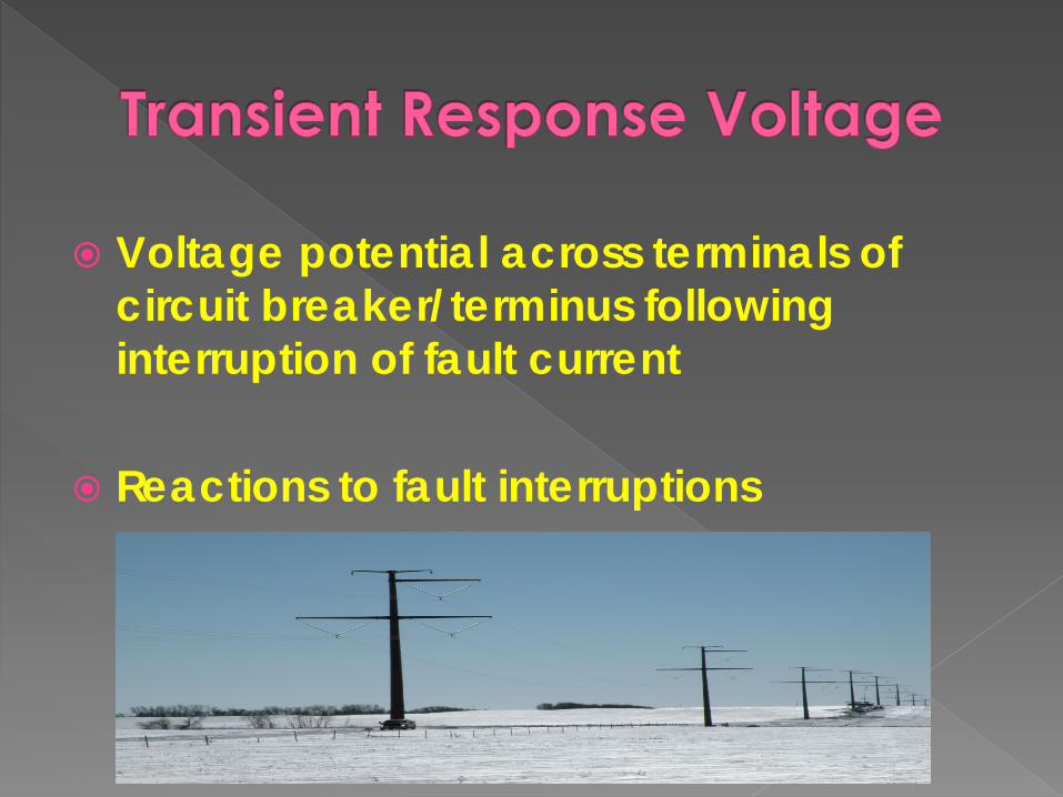
Voltage potential across terminals of circuit breaker/terminus following interruption of fault current
Reactions to fault interruptions


Models based which expand out multiple levels & incorporates ‘case based’ scenarios (interconnection)
Model based from facility/component ratings & operating conditions
Multiple fault types/levels› LG, LLL, LLG, N-0, N+1, etc.
Models resultant voltage from fault to trips (typically 3 cycles)

Results within criteria → no further action› Validation
Results exceed criteria → additional review & design› Circuit breaker design (live tank, dead tank)› Configuration changes› Insulation coordination

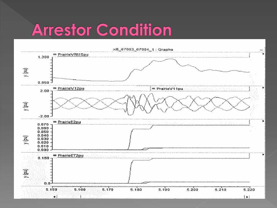
Voltage present across line and terminal arrestors during switching surges/ operational transients
Factors in impedance, capacitance, and line & system characteristics

Models based which expand out multiple levels & incorporates ‘case based’ scenarios (interconnection)
Model based from facility/component ratings & operating conditions
Multiple fault types/levels› LG, LLL, LLG, N-0, N+1, etc.

Facility type (generator type, configuration) has larger impact than with TRV
Assumptions include re-closing scenarios


Results within criteria → no further action› Validation
Results exceed criteria → additional review & design› Arrestor or insulator design› Configuration or facility changes› Insulation coordination

Design studies are studies which will impact physical design of transmission facility to meet design parameters
Can be used to aid in design determination or verification of designs

Economic Conductor Insulation Coordination Electric & Magnetic Field Interaction Induction Parallel Circuit Grounding Transposition Shield Wire


Comparison of conductor alternatives to design most cost effective conductor size given the life cycle of line
Mean of analysis to aid in conductor selection

Cost› Conductor, design & construction, losses,
maintenance Ampacity
› Current carrying capacity (power) Line Losses
› Cost, impact to operations, thermal Life Cycle
› Assumed life of facility, O&M considerations
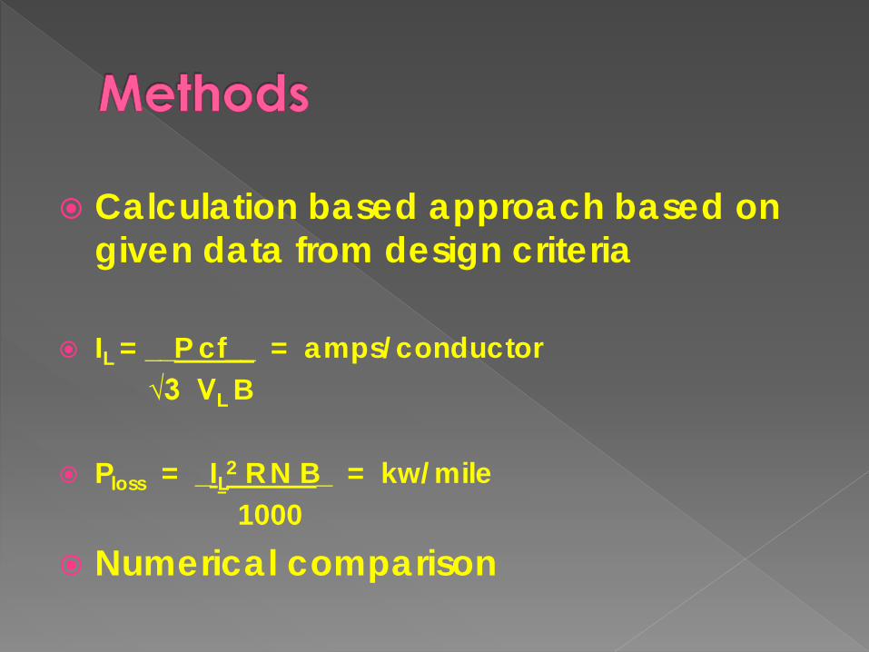
Calculation based approach based on given data from design criteria
IL = __P cf__ = amps/conductor√3 VL B
Ploss = _IL2 R N B_ = kw/mile1000
Numerical comparison


Conductor selection
Structure design & configuration from conductor loading
EHV bundling driven by corona performance vs. ampacity

Purpose: realize annual energy savings based on percentage of utility’s annual retail sales
Energy savings realized from alternative designs of new transmission projects is option available
Adds an additional cost comparison for line losses factor


Basic goal is to be above stress/strength curve
Power system is contiguous when connected → each part/facility affects anything else connected to

Select insulator characteristics that accommodate the expected over voltages within an acceptable risk of failure
Coordinate physical & electrical requirements with voltage stresses, protective devices, substation equipment

Operating Voltage Conductors & shield wires Contamination Insulator selection Voltage drop across insulator materials
› Voltage stresses are non-linear

Power Frequency › Considers environmental conditions specific
to line (contamination, air density)
Lightning Surge› Based on ground fault distribution, assumed
risk/acceptable outage rate› Based on surge analysis (ground resistance,
shield wire capacity

Switching Surge› Statistical analysis of anticipated electrical
stresses› Determined from transient studies (TRV, TOV)
Limiting condition will establish electrical stress level to be designed to
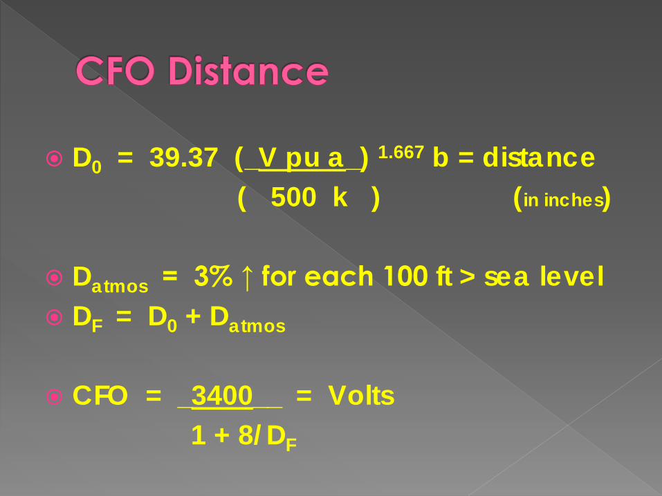
D0 = 39.37 (_V pu a_) 1.667 b = distance( 500 k ) (in inches)
Datmos = 3% ↑ for each 100 ft > sea level DF = D0 + Datmos
CFO = _3400__ = Volts1 + 8/DF
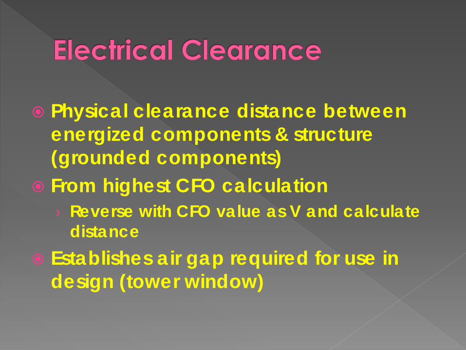
Physical clearance distance between energized components & structure (grounded components)
From highest CFO calculation › Reverse with CFO value as V and calculate
distance Establishes air gap required for use in
design (tower window)


Electric → based on voltage levels
Magnetic → based on current flow (load)
Concerns› Induction (Induction Study)› Public perception (health, livestock, safety)

Model based on system operating characteristics
Configuration & proximity based
Guidelines or limits vary based on region (Design Criteria)
Result: Electric (kV/m), Magnetic (mG), Audible (dBA)


Results within criteria → no further action› Validation
Results exceed criteria → additional review & design› Configuration changes (height, layout, ROW)
Public/Safety perception → V vs. mA


Potential conductors that exists within electrical fields can have voltage generated in them
Voltage potentials create touch potentials and current flow
Concern for safety (touch) & other facility operations
Common: fence, pipeline, railroad, structures, facilities

Model based on operating characteristics, scenario based, and configuration & proximity
Case based so magnitude can be reviewed for mitigation methods
Some safety limits (NESC) as well as facility & regional based guidelines

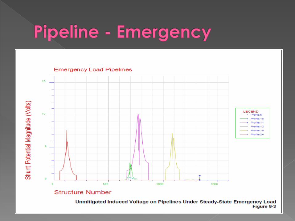
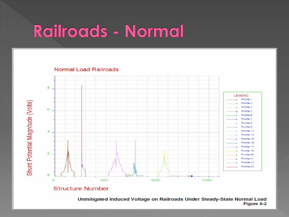


Mitigation of impacts from induced voltage (normal & fault/emergency)
Coordination with other facility designs (pipelines, railroads, power lines)

Voltage Mitigation› Grounding (mats/grids, rods, wire)› Configuration & materials
Current› Filters, insulators, materials
Mitigation level varies based on scenario & facility

Modified induction study between parallel circuits
Parallel is on same system facility, interconnection or induction if on different systems
Geometry & configuration based (model or calculation)

Model built (CDEGS) based on operating characteristics, scenario based, and configuration & proximity
Case based so magnitude can be reviewed for mitigation methods

No or tolerable interference → no further action› Validation
Measureable interference› Configuration› Layout/location› Facility changes (mitigation)


Adequacy of grounding methods to carry fault conditions
Maintain NESC safety criteria during any conditions
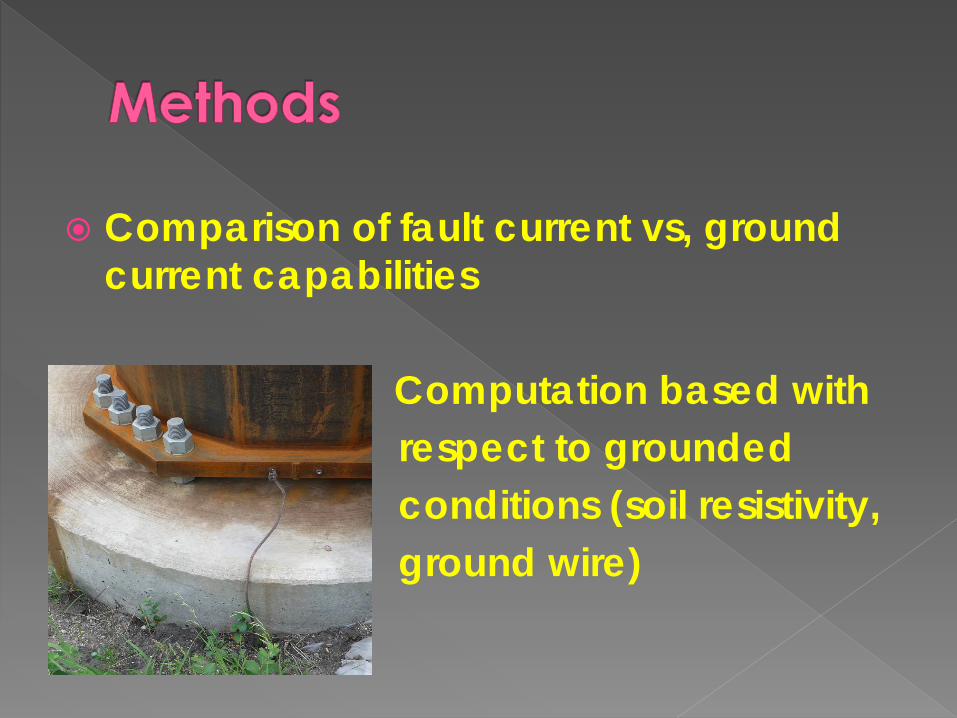
Comparison of fault current vs, ground current capabilities
Computation based with respect to grounded conditions (soil resistivity, ground wire)
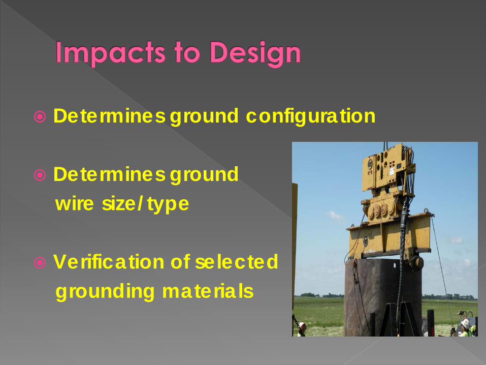
Determines ground configuration
Determines ground wire size/type
Verification of selected grounding materials

Determine induction based voltage imbalance along line length
Determination if mitigation required to minimize imbalances
Eliminates potential relay sensing errors (calculating mho element)

Calculation of impedance matrix (self, mutual, sequence)
Imbalances calculated from sequence imbalances, compared as ratio
Calculated by line length and line segments

Requirement of line transpositions
Addition of transposition structures or alternate methods


Adequacy of shielding methods to carry fault conditions
Combined with Grounding study determines fault current mitigation
Maintain NESC safety criteria during any conditions


Comparison of fault current vs. shield wire current capabilities
Computation based with respect to grounded conditions (soil resistivity, ground wire, ground rods)
Comparison of cost of shielding materials (height vs. 2nd wire)

Determines shield wire configuration
Determines shield wire size/type
Standard designs are those designs based on previous application in which the base design work (including studies & calculations) has already been performed
Standard designs are more typical for HV applications (41.6 kV thru 115 kV, 230 kV)

EHV standard designs should be validated…..
› Changing conditions such as location, environmental, etc. can invalidate a standard design
› Changing regulatory or permitting conditions may also invalidate standard designs
Studies can determine values to be used in design criteria -or- utility standards can dictate design criteria then design to meet standards
Do electrical (studies) then physical → or perform physical design and adjust/validate from electrical studies

