walk`n´chair tm - activeforever.com
TRANSCRIPT

BHI
User Manual
Walk`n´ChairTM Model: L-3 Patent Number : 5,605,345 Other Patents Pending
Brookefield Hunter Incorporated 40 Buckskin Rd. Belgrade, MT 59714
W a l k ` n ´b y
B R O O K E F I E L D H U N T E R I N C O R P O R A T E D
C h a i r T M

• | II
Walk`n´ChairTM Intended Use
The Walk`n´ChairTM is a sturdy dual-function device which serves individuals with limited physical disabilities as a walker and wheeled chair. It was designed primarily as a walker to provide for stable navigation and travel over gravel, dirt, and other rough surfaces and for easier maneuverability up and down street curbs.
Because of its stability with the large wheels forward in the walker mode, Walk`n´ChairTM users do not have to continually concentrate on watching the walker’s wheels while moving thus allowing for more visual freedom to look around and not feel confined to looking at the path of travel.
With the wheels locked by the hand brakes and the Seat Back Frame placed in either the forward or reverse position, the walker becomes a stationary chair.
With hand brakes locked, reposition the Seat Back Frame and handles, insert Optional Foot Rests, unlock the brakes, and the device can be converted and used as a wheeled chair.
There is also a collapsible metal accessory basket which can be expanded and attached to the seat back frame and used for carrying items.
The Walk`n´ChairTM has had a significant amount of engineering time dedicated to its ruggedness, function, comfort, ease of use, and safety. To that end we at Brookefield Hunter Incorporated hope this device will become an indispensible and integral part of improving the user’s quality of life.

Walk`n´ChairTM User ManUal | III
Walk`n´ChairTM Intended Use (continued)
Sitting wheeled position. (Optional Foot Rests attached)
Sitting wheeled position. Sitting wheeled position. (Optional Foot Rests attached)
Walking position. (0ptional Foot Rests attached)
Walking position. (Optional Basket attached
in the reverse position.)
Walking position. (Optional Basket attached in the forward position)
Walking position. (Optional Basket and Foot Rests attached)
Walking position reversed. (Optional Basket and Foot Rests attached)
Walking position reversed. (Optional Basket attached)
Optional Basket
Optional Foot Rest
Assemblies.

• | IV
Walk`n´ChairTM - Parts Terminology
1
1
22
33
4
5
6
78
8
9
10
11
12
13
1 - Handle Bar Locking Knob 2 - Handle Bar Grip 3 - Parking Brake Handle 4 - Seat Back Frame 5 - Large Wheel 6 - Quick Release Axle Bolt Buttom 7 - Wheel Brake Pad 8 - Foot Plate Locking Knob 9 - Foot Plate Left10 - Foot Plate Right11 - Seat Pan12 - Main Frame Right13 - Main Frame Left
n

Walk`n´ChairTM User ManUal | V
Warnings:
Do not operate, maintain, or adjust the Walk`n´ChairTM without reading and understanding all instructions in this User Manual.
The Walk`n´Chair• TM has not been approved as a seat surface to be used within a vehicle of any kind. Always transfer the Walk`n´ChairTM user to an approved vehicle seat and use restraints available from the auto industry for this application.Do not operate the Walk`n´Chair• TM on inclines greater than 8% without assistance.Completely engage and lock the parking brakes when entering and leaving the Walk`n´Chair• TM or using the Walk`n´ChairTM in an elevator or a wheelchair lift.The Walk`n´Chair• TM should be on a stable, level surface and parking brakes should be locked before transferring the user to or from the Walk`n´ChairTM.Do not stand on or put pressure on the (optional) Foot Rests when not occupying chair.•Before leaning or reaching forward, rotate the front wheels toward the front of the Walk`n´Chair• TM and lock parking brakes to help prevent the Walk`n´ChairTM from tipping over.Do not lean the Walk`n´Chair• TM back since this can cause the Walk`n´ChairTM to tip over. If trying to reach objects, reach back only as far as your arm will extend without altering your seating position.Do not change direction when going down an incline because it could cause instability.•Do not transfer in and out of the Walk`n´Chair• TM on your own unless you have sufficient upper body strength, balance, and agility.Do not use the Walk`n´Chair• TM on stairs or escalators.Do not exceed the 250 pounds weight capacity of the Walk`n´Chair• TM. The weight capacity of 250 pounds includes the weight of the rider plus items carried or attached to the Walk`n´ChairTM.Do not modify the Walk`n´Chair• TM (such as drilling holes, grinding, welding parts, using non-approved parts, etc.). Such modifications may increase the risk to the user and will void the warranty.Do not operate the Walk`n´Chair• TM on loose, slippery, surfaces such as ice.Any person assisting the rider in the maneuvering or lifting of the Walk`n´Chair• TM must have sufficient strength and be able to see obstacles in the path of travel.DO NOT OPER• ATE the Walk`n´ChairTM until Quick Release Axle Bolts for Large Wheels are in the locked position. (see fig 1 & 2 following page) The Quick Release Axle Bolts are locked when the Quick Release Axle Bolt Buttons are fully popped out and both ball bearings on the other end of the Quick Release Axle Bolts are fully exposed. Also check that the Quick Release Axle Bolts are locked by pulling on the Large Wheel. A Quick Release Axle Bolt that is not fully locked can allow the Large Wheel to come off during use.DO NOT OPER• ATE the Walk`n´ChairTM until Both Handle Bar Grip Assemblies and Both Adjustment Latches are in the locked position (see fig 3 & 4 following page).

• | VI
Warnings: (continued)
Quick Release Axle Bolt in the unlocked position.
After the Quick Release Axle Bolt has been released, the locked position should look like the image above.
(Make sure both ball bearings are pushed
out!)
(Make sure both ball bearings are pushed out!)
Handle Bar Locking Knob should be in the locked position before use.
Latch should be fully visible.
3.4.
2.
(No Gap) LOCKED
POSITION
1.
Wa r n i n g
DO nOT OPEraTE Walk`n´ChairTM UnTiL
BOTH HanDLE Bar griP assEMBLiEs anD LaTCH
aDJUsTMEnTs arE in THE LOCKED POsiTiOn

Walk`n´ChairTM User ManUal | VII
Warnings (continued)
Pinch Points - Reversible Seat
Pinch point between Seat Back Frame and side of Seat Pan.
Pinch point between bottom of Seat Back Frame and rear of Seat Pan.
Pinch point between base of Seat Pan and Folding Frame.Side view of pinch point between bottom
of Seat Back Frame and rear of Seat Pan.
1. 2.
4.3.
PinCH POinTs
Wa r n i n g KEEP HanDs CLEar
Of HingE

• | VIII
Warnings (continued)
Pinch Points - Folding the Walk`n´ChairTM
Keep fingers outside of Folding Frame and Seat Frame. (opening and closing)1.Be aware of hand placement.2.
PinCH POinTs
Wa r n i n g KEEP HanDs CLEar
Of HingE
PinCH POinTs
Wa r n i n g KEEP HanDs CLEar
Of HingE PinCH POinTs
Wa r n i n g KEEP HanDs CLEar
Of HingE PinCH POinTs
Wa r n i n g KEEP HanDs CLEar
Of HingE
PinCH POinTs
Wa r n i n g KEEP HanDs CLEar
Of HingE

Walk`n´ChairTM User ManUal | IX
Warnings (continued)
Pinch Points - Large Wheel & Chair Frame/Chair Frame & Seat
Pinch point between Large Wheel and Chair Frame.
Pinch point between bottom of Reversible Seat and Chair Frame.
1. 2.
PinCH POinTs
Wa r n i n g KEEP HanDs CLEar
Of HingE
• | X
Table of ConTenTs
1
Assembly Large Wheel 1 Optional Foot Rests 12-13
Use And sAfety Folding the Walk`n´ChairTM 2 -3 Reversing the Seat Back direction 4 Snapping Seat Pads in place 5-6 Handle Bar Grip Adjustments (sitting or walking position) 7-8 Handle Bar Grip Height Adjustments 9 Braking the Walk`n´ChairTM 10 Parking Brake Handle and Brake Pad Adjustments 11
Accessories 14bHi limited WArrAnty 15extended PArts list 16-17sPecificAtions 18

Walk`n´ChairTM User ManUal | 1
Assembly - Wheel Assembly
Squeeze the Quick Release Axle Bolt Button between the thumb and the forefingers (arrow 1) to release pin (arrow 2).
With Quick Release Axle Bolt Button depressed, insert through both
sets of wheel bearings on the Large Wheel.
After Quick Release Axle Bolt is fully inserted into Walk`n´ChairTM frame,
release thumb pressure to lock Large Wheel into
place. Make sure the Quick Release Axle Bolt has both ball bear-ings pushed out in the locked position before operating the
Walk`n´ChairTM.
Align Quick Release AxleBolt with insertion point on
Walk`n´ChairTM frame.
1. 1.
1.
2. 2. 3. 4.
5.
2.
(Ball bearings are pushed out!)
(Release Button) (Release Pin)
(Button)
(Adjustment Nut) (Adjustment Nut)

2 |
Fold Seat Back Frame forward.
Grip the side of the folded seat indicated by the (LIFT HERE) Sticker.
Pull up on folded seat of Walk`n´ChairTM.
Use and Safety - Folding the Walk`n´ChairTM
Fully opened Walk`n´ChairTM with Optional Foot Rests
installed.LifT HErE
Lif
T H
Er
E
Lif
T H
Er
E
Lif
T H
Er
E
Lif
T H
Er
E
1.
3.
4.
2.

Walk`n´ChairTM User ManUal | 3
Fully folded Walk`n´ChairTM
Use and Safety - Folding the Walk`n´ChairTM (continued)
Continue to pull folded seat of Walk`n´ChairTM.
5. 6.
Lif
T H
Er
E

4 |
Use and Safety - Seat Back Frame Reversal
Lift Seat Back Frame straight up. Move Seat Back Frame forward.
Push lower bar of Seat Back Frame into position as shown above.
Push lower bar of Seat Back Frame forward .
Secure Seat Back Frame into the reverse position.
1.
3.
5.
2.
4.
Walk`n´ChairTM User ManUal | 5
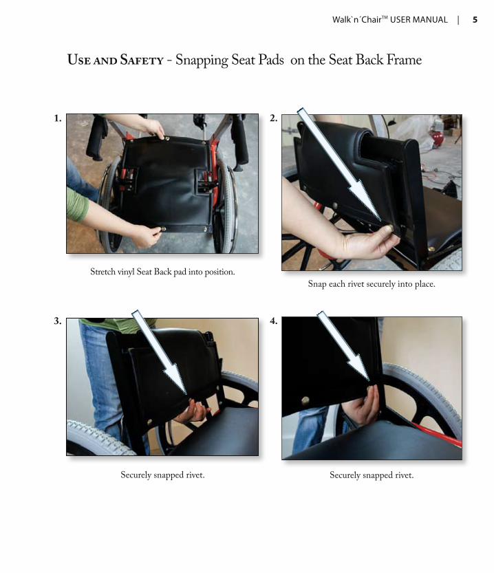
Use and Safety - Snapping Seat Pads on the Seat Back Frame
Stretch vinyl Seat Back pad into position.
Securely snapped rivet.
Snap each rivet securely into place.
Securely snapped rivet.
1.
3.
2.
4.

6 |
Use and Safety - Snapping Seat Pads in Place (seat bottom)
Stretch vinyl seat bottom pad into position.Snap rivet securely onto Seat Pan.
Snap rivet securely onto Seat Pan.Snap rivet securely onto Seat Pan.
Snap rivet securely onto Seat Pan.
1. 2.
3.
5 .
4.

Walk`n´ChairTM User ManUal | 7
Use and Safety - Handle Grip Direction Adjustment
Pull and twist Handle Bar Locking Knob 900 clockwise or counter-clockwise.
Grip Handle Bar Grip and twist to the inside of Walk`n´ChairTM.
Walk`n´ChairTM Handle Bar Grip Assemblies before direction adjustment.
before Adjustment
Pulled and twisted Handle Bar Locking Knob (notice the gap between Handle Bar Locking Knob and the Handle Bar Grip Assembly).
1.
3.
2.
(No Gap)
(Gap)

8 |
Use and Safety - Handle Grip Direction Adjustment (continued)
Handle Bar Grip twisted to 450 to the inside of the Walk`n´ChairTM.
Handle Bar Grip twisted to 900 (notice the Handle Bar Locking Knob held in its
unlocked position).
After both Handle Bar Grip Assemblies are twisted a full 1800, release the Handle Bar Locking Knobs
by twisting and jiggling into locked position.
(note both Handle Bar Grip Assemblies in the reverse and locked position)
Walk`n´ChairTM Handle Bar Grip Assemblies after direction adjustment.
After Adjustment
5.
6.
4.
DO nOT OPEraTE Walk`n´ChairTM UnTiL
BOTH HanDLE Bar griP assEMBLiEs anD LaTCH
aDJUsTMEnTs arE in THE LOCKED POsiTiOn
Wa r n i n g

Walk`n´ChairTM User ManUal | 9
Use and Safety - Hand Grip Height Adjustments
In the 900 “twist” position the whole Handle Bar Grip Assembly can be adjusted up or down.
Be sure that the height adjustment latch is in the desired slot by moving Handle Bar Grip Assembly up and down until latch is
secured in slot.
When steps 2-5 from pages 7 and 8 have been completed, the Handle Bar Locking Knob and
Handle Bar Grip should look like the above picture.
After both Handle Bar Grips are at the desired height, release the Handle Bar Locking Knobs by
twisting and jiggling into locked position.
1.
3.
2.
5.
4.
Latch
Note both Handle Bar Grip Assemblies in the reverse and locked position.
DO nOT OPEraTE Walk`n´ChairTM UnTiL
BOTH HanDLE Bar griP assEMBLiEs anD LaTCH
aDJUsTMEnTs arE in THE LOCKED POsiTiOn
Wa r n i n g

10 |
Use and Safety - Braking the Walk`n´ChairTM
Walk`n´ChairTM in unlocked Parking Brake Handle position.
Squeeze Parking Brake Handle to engage brake.
To release locked parking brake, pull up on Parking Brake Handle until “clicking” sound is
heard then release handle.Push the Parking Brake Handle down to engage the parking brake.
1.
3.
2.
4.

Walk`n´ChairTM User ManUal | 11
Use and Safety - Brake Adjustments
Adjust clearance between tire and Wheel Brake Pad to 1/16th of an inch by twisting adjustment
barrels. Secure with locking nut.
Wheel Brake Pad cable adjustment.
1. 2.
Locking Nut
1/16th
inch gap

12 |
Assembly - Optional Foot Rest Assembly
Remove the Foot Rest Assembly Shaft plugs.
Closeup of alignment marking on the Foot Rest Assembly Shaft.
Feed the Foot Rest Assembly Shaft for each side of chair and align to the desired length.
Shaft alignment marker.
Pull and twist Foot Rest Locking Knob 900 clockwise or counter clockwise to
unlock.
2.1.
3.
4.

Walk`n´ChairTM User ManUal | 13
Assembly - Optional Foot Rest Assembly (continued)
In order for the Foot Rest Assembly Shaft to be locked in place
by the Foot Rest Locking Knob, make sure desired hole is aligned as
shown above.
Foot Rest Assemblies in the extended position with the Right and Left Foot Plates folded.
Foot Plate in the retracted and folded position.
Foot Rest Assemblies in the extended position with Foot Plates opened.
4. 5.
6.
7.
Alignment Hole
14 |
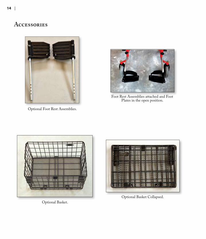
Accessories
Optional Foot Rest Assemblies.
Optional Basket Collapsed.Optional Basket.
Foot Rest Assemblies attached and Foot Plates in the open position.

Walk`n´ChairTM User ManUal | 15
Brookefield Hunter Incorporated Limited WarrantyBrookefield Hunter Incorporated warrants this product is free from defects in original workmanship and materials. If proven to be defective in original workmanship or original materials Brookefield Hunter Incorporated will replace or repair the device free of charge.
This warranty only applies to original factory delivered products or products delivered by authorized agents of Brookefield Hunter Incorporated.
This warranty only applies to an original factory device that has been used for its normal and intended functions.
The structural frame has a lifetime warranty and a two-year limited parts warranty.
This warranty is void on product which have been altered or modified in any fashion and does not extend to parts which may require replacement due to normal wear and tear.
Warranty inquiries should be referred to:
Customer Service Brookefield Hunter Incorporated 40 Buckskin Rd. Belgrade, MT 59714
Toll Free: (855) 925-5663 Telephone: (406) 388-1248 Fax: (406) 924-7005
Walk`n´ChairTM Warranty Card
Name_________________________________________ Address_________________________________City_____________________ State_______Postal Code___________________ Country_________________________________ Phone___________________Fax__________________Email_________________________ Serial #________________________ Where Purchased - Name__________________________Date_____________
Retailer Address___________________________________ Comments

16 |
20
1717
20
19
2 4
723
24
22
25
25
8
24
23
22
31
3737
36
35
32
18
13
15
12
528
26
27
14
13
27
29
16 11
30
27
2716
9
26
28
6
29
3038
40
31
Walk`n´ChairTM Expanded View
10
21
39
3
35
23
37
227
24
17
25
37
20
25
17
1
18 24
1116
27
28
5
14
27
26
30
30
38
40
13
31
26
28
69
16
27
29
12
29
15
27
22
23
24
8
2037
13
19
32
36

Walk`n´ChairTM User ManUal | 17
Walk`n´ChairTM Parts List for Expanded View ITEM NO. PART NUMBER DESCRIPTION QTY./UNIT
1 1001-B Handle Assembly Left 1
2 1004-A Foot Plate Assembly Right 1
3 1007-B Handle Assembly Right 1
4 1008-A Foot Plate Assembly Left 1
5 2000-D Main Frame Weldment Right 1
6 2001-D Main Frame Weldment Left 1
7 2002-C Brake Pad Weldment Right 1
8 2003-C Brake Pad Weldment Left 1
9 2004-B Seat Bar Bottom H-Bar Weldment 1
10 2005-B Seat Pan Weldment 1
11 2006-A Seat Back Weldment 1
12 3013-A Scissor Bar Single Lower Short 1
13 3014-B Scissor Bar Single Lower Long 1
14 3015-B Seat Bar Bottom Straight Front 1
15 3016-B Seat Bar Bottom Straight Back 1
16 3021-A Seat Back Pivot Bar 2
17 4000-A Rear Wheel 24" x 2.125" x 3" Hub 2
18 4001-B Front Wheel 8" x 2" x 2.5" Hub 2
19 4002-A Front Caster 8" w/Stem 2
20 4003-B Quick Release Axle Bolt 0.5" Big Button 2
21 4007-C Brake Handle w/Cable 2
22 4009-A Pyramid Barrel Adjuster w/Locknut 2
23 4010-B Wire Swivel Stop 2
24 4011-A Handle Release Spring 2
25 4019-A Brake Cable Spring 2
26 5011-B Spring Plunger Handle Pull 2
27 5008-A Nylon Washer 0.25" x 0.7" x 0.05" Thick 18
28 5012-B Hand Knob w/Threaded Insert 2
29 5018-A Clevis Pin w/Cotter Pin 0.5" x 1.75" 2
30 5019-A Spacer Plastic 0.51"OD x 0.5" Long 2
31 5020-A *SHBH 0.25"-20 x 1.25" Long 8
32 5031-A Flat Washer 0.32" Thick 6
35 5028-A *SHBH 0.32"-18 x 3.5" Long 2
36 5029-A Acorn Nut 0.32"-18 2
37 5004-A Acorn Nut 0.32"-13 2
38 5006-A Nylon Nut 0.25"-20 10
39 5001-A Nylon Nut 0.32"-18 2
40 5021-A Steel Flat Washer 0.25" 10
Note: *SHBH - Socket Head Button Head.

18 |
Specifications
sPecificAtions
Chair Weight without Foot Rests 42 Pounds Maximum Weight Capacity of Chair 250 Pounds Seat Width 15 Inches
Seat Depth 10 Inches
Seat to Floor Height 21 Inches
Overall Open Width 30 Inches
Overall Folded Width 15 Inches
Caster Tire Inflation 25-30 P S I
Powder Coated Frame
Upholstery : Vinyl with Gym Foam Padding
Accessories : Basket and Foot Rests

BHI
W a l k ` n ´b y
B R O O K E F I E L D H U N T E R I N C O R P O R A T E D
C h a i r T M