wall mount wooden pergolas … above: 10x10 cedar pergola wall mount wooden pergolas instructions...
TRANSCRIPT

Shown above: 10x10 Cedar Pergola
WALL MOUNT WOODEN PERGOLAS INSTRUCTIONS
(Treated Pine and Cedar)
Components: Posts - Minimum of 2 – may be more for larger pergolas Post Brackets – Stainless Steel, includes Wedge Bolts Post base trim - assembled - 1 per post Beams - The beams sandwich the top of the posts so there are two 2x8 on each side of the posts. On longer pergolas, the beams may come in 2 pieces and need to be spliced over the middle post(s). Runners - Number varies by size, spaced approximately 16" on center Top Runners - 2x2s – Number varies by size, standard spacing is 16". Closer spacing is optional. Corner Braces - There are usually 1 per post. If you have additional posts, there will be additional braces as well. Hardware - See the parts list that comes with your pergola for quantities on each component. Kit includes a #2 square head bit for use with screws provided. Additional Options - lattice, walls, etc. are not in this booklet, but will have additional pages added.
Tools needed: Ladder, Level, Tape m=Measure, Square, Drill or Screw Gun. If attaching to concrete, an Impact Drill may be needed for drilling into slab, 1½" (Masonry Bit).
P a g e | 1

1. Ideally your pergola should set on a level concrete or wood base. This can be a full slab, or footers that are poured specifically for the pergola. If installing on a deck be sure that there are supports (joists) directly under the posts of the pergola.
2. If the slab is an existing one, be sure that the post will be on a solid spot. If the thickness of the slab is 6 or more inches, no additional work should need to be done. Be sure to position the posts so that they are a minimum of 4 inches from the edge of the slab to the middle of the posts, to prevent cracking.
3. If pouring a new slab, it is best that the slab is at least 12" wider and longer than the stated size of the pergola. Our pergola sizes are to the outside corners of the posts, for instance, a 12' x 16' pergola ideally should be on a slab that is at minimum 13' x 17'. When pouring the slab make sure that the slab is thicker under the location of the posts (minimum is 12" or to local codes if applicable).
4. If pouring individual footers, Sono-Tubes can be used as shown at right. It is important that the tops of all footers (4 or 6, depending on the size of the pergola) be level, and at least larger than double the size of the post – for example, if the posts for your pergola are 5x5, your footer should be 10 to 12 inches in diameter. This allows for sufficient strength and also for a “margin of error”. The posts do not have to sit perfectly on the center of the footers. The depth of the footer should be a minimum of 12" deep, or to your local code.
P a g e | 2
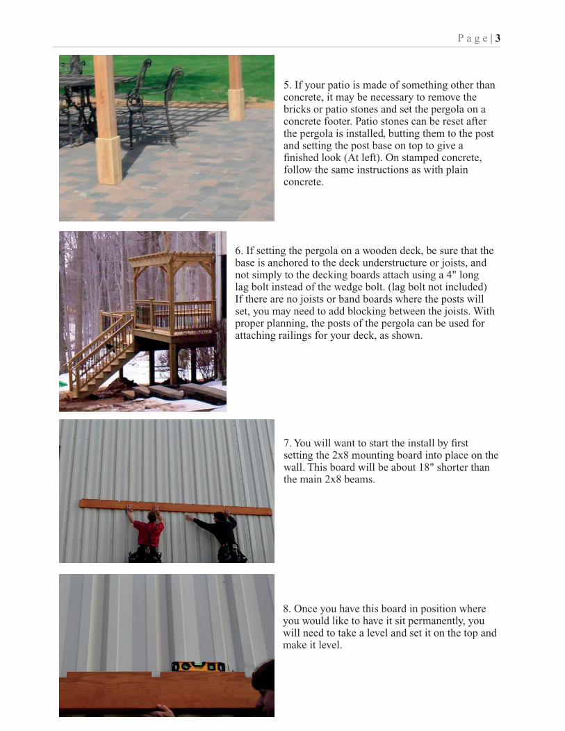
5. If your patio is made of something other than concrete, it may be necessary to remove the bricks or patio stones and set the pergola on a concrete footer. Patio stones can be reset after the pergola is installed, butting them to the post and setting the post base on top to give a finished look (At left). On stamped concrete, follow the same instructions as with plain concrete.
6. If setting the pergola on a wooden deck, be sure that the base is anchored to the deck understructure or joists, and not simply to the decking boards attach using a 4" long lag bolt instead of the wedge bolt. (lag bolt not included) If there are no joists or band boards where the posts will set, you may need to add blocking between the joists. With proper planning, the posts of the pergola can be used for attaching railings for your deck, as shown.
7. You will want to start the install by first setting the 2x8 mounting board into place on the wall. This board will be about 18" shorter than the main 2x8 beams.
8. Once you have this board in position where you would like to have it sit permanently, you will need to take a level and set it on the top and make it level.
P a g e | 3

9. Now that it is level you will need to secure the mounting board to the wall with the appropriate hardware. This is not supplied with the kit, because of the different materials the wall may be made of.
10. Next you will take the 2x8 ledger board with the decorative ends and place this over the mounting board making sure that the bottoms of the boards are flush with each other. You then connect the ledger board with 2½" screws (2 every 16 inches).
11. Once the ledger board is connected to the mounting board you will need to take a measurement from the underside of the ledger board to the ground/mounting surface. This will then let you know what height you will need to cut the post. Take your measurement and then measure from the notch shown in the picture down to your measurement and make a line to cut the bottom of the post. After you cut the post to size, put the 5x5 stainless steel plates on the bottom of post these get attached with 1½" stainless screws.
P a g e | 4
12. After you put the bottom plates on the post, the next step is to attach the main beams to the top of the posts. The beams will be marked with a line showing where the posts should rest against them (as shown).

13. You will now want to lay the posts on the ground as shown and then set the first beam on it with the marked line against the outside of the post. Take four 2½" screws and screw them from the beam into the post, do this for all posts.
14. Next take a square and rest it where the beam and post assembly meet and make sure that everything is square. You will want to do this with all posts. Once everything is square you will take four more 2½" screws and screw them from the beam into the post. So now you should have 4 screws in each post.
15. Once you have the beam fully secured to one side of the post you will want to take your post trim and slide it over the post. This step is done now because once you stand the posts up you will be unable to apply the post trim.
16. After you have all of the post trim on you may stand this assembly up as shown. You will then need to lift up the other beam and attach it to the posts as done in step # 13.
P a g e | 5

17. Now that you have the posts standing up take 2 of your main runners that run from the building outward. You will place them in the slots that are already cut into the top of the beams. Once they are resting in place you will want to take a tape measure and measure from one corner to the opposite (as shown). Then take the same measurement from the other 2 corners. These measurements need to be the same; if they are not currently you should be able to move the structure a little until they are.
18. You may need a helper to hold the posts in place as you position the first runner. Make sure that the overhang is the same on both ends of the runner. You can do this by measuring from the beam to the end of the runner on both sides. Slide the runner until they have the same overhang on both ends.
19. Once you have these measurements matching, screw the two runners to the beams. You will attach one side using a 3½" screw on an angle as shown. Attach each runner to both beams on each side and on the back beam as well.
20. Next set all of the other main runners into their slots and connect them the same way with the 3½" screws.
P a g e | 6

21. Now connect all of the top runners. You will notice that there are marks on top of the main runners where the top runners are to be attached. These markings are about 16" on center, or another dimension if your pergola was ordered with additional top runners. There are also markings and pre drilled holes on each of the 2x2 runners.
22. Set the top markings on the centers of the runners and attach with 2½" screws. Check that the overhangs are the same on both sides of the top runners.
Note: There are only corner braces on the front of the pergola, they will rest against the posts and then go up into the space between the beams.
23. Once the corner braces are centered on the post and the tops of them are in place, secure them to the posts with two 6" ledger lock screws. Follow this process on all posts until the bottoms of the corner braces are all secured.
24. Secure the tops by driving four 2½" screws from the outside of the beams into the braces. Do this from both beams, there should be a total of 4 screws going into each brace at the top, 2 from each side.
P a g e | 7

25. Once all of the corner braces are in place and secured, you now need to secure the posts to the ground. First make sure that the posts are level. To do this, take a level and hold it up against the side of the posts to assure they are level.
26. If they are not level, take a hammer and tap on the bottom of the post in the direction that it needs to move. Once the post is level then you can secure it with the supplied brackets and anchor bolts.
27. Attach the L brackets to the post with 5 2½" screws. 2 brackets per post.
28. Using a ½" masonry bit and a hammer drill, drill a hole in the concrete slab. Be sure to reach a depth approximately ½" longer than the length of the wedge anchors that were supplied with your kit.
P a g e | 8

29. Before you insert the bolt make sure you have the nut and washer on, otherwise you may hit the bolt too deep into the hole. Now insert the wedge anchor bolts into the holes, leaving approximately 1/8" of bolt exposed above the nut. (You may need to use a hammer to tap the wedge anchor bolts into the holes, this is normal).
30. When all the wedge bolts set, tighten down the nut. As you tighten the nut, the wedge anchor will expand the bottom of the bolt in the concrete, securely anchoring the bolt into the concrete.
31. After you have tightened all of the nuts down and the posts are securely mounted to the concrete slab, slide the post trim down into place. If you need to secure the post trim you can do so by using a single 3½" screw, attaching from the trim into the post. Congratulations you are now finished!
P a g e | 9


