wallerawang quarry - walker quarries
TRANSCRIPT

ABN: 82 003 061 890
SOIL AND WATER
MANAGEMENT PLAN
for the
Wallerawang Quarry
November 2018
Prepared by:
R.W. CORKERY & CO. PTY. LIMITED

This page has intentionally been left blank
R. W. CORKERY & CO. PTY. LIMITED
ABN: 82 003 061 890
SOIL AND WATER
MANAGEMENT PLAN
for the
Wallerawang Quarry
Prepared for:
Walker Quarries Pty Ltd ABN: 82 003 061 890 Lot 6, Great Western Highway WALLERAWANG NSW 2845
Telephone: (02) 6352 3377 Email: [email protected]
Prepared by:
R.W. Corkery & Co. Pty. Limited
Geological & Environmental Consultants
ABN: 31 002 033 712
Brooklyn Office: 1st Floor, 12 Dangar Road PO Box 239 BROOKLYN NSW 2083
Telephone: (02) 9985 8511 Email: [email protected]
Orange Office: 62 Hill Street ORANGE NSW 2800
Telephone: (02) 6362 5411 Email: [email protected]
Brisbane Office: Suite 5, Building 3 Pine Rivers Office Park 205 Leitchs Road BRENDALE QLD 4500
Telephone: (07) 3205 5400 Email: [email protected]
Ref No. 949/02f November 2018

WALKER QUARRIES PTY LTD SOIL AND WATER MANAGEMENT PLAN
Wallerawang Quarry Report No. 949/02f – November 2018
ii
R. W. CORKERY & CO. PTY. LIMITED
Document Control
Document Title
Soil and Water Management Plan
Document Number
949/02f
Document Owner
Quarry Manager
Revision Issue Date
Reason Sections Updated
Originator Reviewed Approved
Original Oct 2014 P. Hensley WQPL -
Revision 1 Sep 2016 A. Irwin (RWC) D. Murray H. Reed (DPE) (27 Sep 2016)
Revision 2.0 Nov 2017 A. Irwin (RWC) P. Hensley / D. Murray
Revision 2.1 Jan 2018 A. Irwin (RWC) P. Hensley
Revision 2.2 Jan 2018 A. Irwin (RWC) P. Hensley H. Reed (DPE) (30 Jan 2018)
Revision 2.3 Apr 2018 A. Irwin (RWC) P. Hensley
Revision 2.4 Sep 2018 A. Irwin (RWC) P. Hensley H. Reed (DPE)
Revision 3 Sep 2018 Response to Independent Environmental Audit of July 2018
1, 4, 5.1.1, 9.3, 10.6.1, 10.7, 11.2.2, 11.3
A. Bridle / A. Irwin (RWC)
P. Hensley
Revision 4 Nov 2018 Response to DPE request for further information 10/10/2018
10.3 G. Barnes (RWC)
Next Review Due
31 December 2019
This Copyright is included for the protection of this document
COPYRIGHT
© R.W. Corkery & Co. Pty Limited 2018
and
© Walker Quarries Pty Ltd 2018
All intellectual property and copyright reserved.
Apart from any fair dealing for the purpose of private study, research, criticism or review, as permitted under the Copyright
Act, 1968, no part of this report may be reproduced, transmitted, stored in a retrieval system or adapted in any form or by any
means (electronic, mechanical, photocopying, recording or otherwise) without written permission. Enquiries should be addressed
to R.W. Corkery & Co. Pty Limited.

SOIL AND WATER MANAGEMENT PLAN WALKER QUARRIES PTY LTD
Report No. 949/02f – November 2018 Wallerawang Quarry
CONTENTS Page
iii
R. W. CORKERY & CO. PTY. LIMITED
LIST OF ABBREVIATIONS ...................................................................................................................... VI
1. SCOPE ............................................................................................................................................. 1
2. SITE DESCRIPTION AND OPERATIONS ...................................................................................... 1
3. REGULATORY REQUIREMENTS .................................................................................................. 4
3.1 DEVELOPMENT CONSENT DA 344-11-2001 (AS MODIFIED) ........................................... 4
3.2 ENVIRONMENT PROTECTION LICENCE EPL - 13172 ...................................................... 6
3.3 WATER LICENSING .............................................................................................................. 9
4. OBJECTIVES AND OUTCOMES .................................................................................................... 9
5. SITE CHARACTERISTICS AND CONSTRAINTS ........................................................................ 10
5.1 SURFACE WATER .............................................................................................................. 10
Baseline Water Quality .............................................................................................. 10
Catchments ................................................................................................................ 10
Water Capture and Storage ....................................................................................... 13
5.2 LOCAL GROUNDWATER ................................................................................................... 14
6. SITE WATER MANAGEMENT SYSTEM ...................................................................................... 15
7. SITE WATER BALANCE .............................................................................................................. 17
7.1 WATER SOURCES ............................................................................................................. 17
7.2 WATER USAGE AND LOSSES .......................................................................................... 17
7.3 WATER BALANCE .............................................................................................................. 18
Water Storage Inputs ................................................................................................. 18
Water Storage Reuse and Evaporation (Site Water Demand) .................................. 19
Water Balance ........................................................................................................... 19
7.4 OFF-SITE WATER TRANSFERS ........................................................................................ 19
8. WASTE WATER MANAGEMENT (FOR BENEFICIAL USE)....................................................... 20
9. STORMWATER MANAGEMENT .................................................................................................. 21
9.1 OVERVIEW (STORMWATER MANAGEMENT SCHEME) ................................................. 21
9.2 CLEAN WATER DIVERSIONS ............................................................................................ 21
9.3 SEDIMENT BASINS AND DISCHARGE PROTECTION .................................................... 22
9.4 OTHER EROSION AND SEDIMENT CONTROL MEASURES .......................................... 23
10. WATER MONITORING PROGRAM .............................................................................................. 24
10.1 MONITORING PROGRAM OBJECTIVES .......................................................................... 24
10.2 MONITORING LOCATIONS ................................................................................................ 24
Surface Water ............................................................................................................ 24
Groundwater .............................................................................................................. 26
10.3 MONITORING FREQUENCY AND PARAMETERS ........................................................... 26

WALKER QUARRIES PTY LTD SOIL AND WATER MANAGEMENT PLAN
Wallerawang Quarry Report No. 949/02f – November 2018
CONTENTS Page
iv
R. W. CORKERY & CO. PTY. LIMITED
Surface Water ............................................................................................................ 26
Groundwater .............................................................................................................. 26
10.4 MONITORING CRITERIA .................................................................................................... 27
Surface Water ............................................................................................................ 27
Groundwater .............................................................................................................. 27
10.5 WATER MONITORING PROCEDURES ............................................................................. 28
Surface Water ............................................................................................................ 28
Surface Water Flow Monitoring ................................................................................. 29
Groundwater Monitoring ............................................................................................ 30
10.6 REVIEW AND RECORDING OF MONITORING DATA ...................................................... 30
Surface Water ............................................................................................................ 30
Groundwater .............................................................................................................. 31
10.7 REPORTING AND PUBLICATION OF MONITORING DATA ............................................. 32
10.8 INSPECTIONS AND MAINTENANCE ................................................................................. 33
11. INCIDENT MANAGEMENT ........................................................................................................... 34
11.1 INCIDENT IDENTIFICATION ............................................................................................... 34
11.2 INCIDENT MANAGEMENT AND NOTIFICATION .............................................................. 34
Non-compliance Incident ........................................................................................... 34
Pollution Incident ........................................................................................................ 34
Complaint ................................................................................................................... 35
Groundwater Inflow .................................................................................................... 36
11.3 INCIDENT REPORTING ...................................................................................................... 36
12. DATA MANAGEMENT AND REPORTING ................................................................................... 36
12.1 REVIEW AND RECORDING OF MONITORING DATA ...................................................... 36
12.2 REPORTING AND PUBLICATION OF MONITORING DATA ............................................. 37
13. PLAN IMPLEMENTATION ............................................................................................................ 37
13.1 ROLES AND RESPONSIBILITIES ...................................................................................... 37
13.2 COMPETENCE TRAINING AND AWARENESS ................................................................. 38
13.3 PLAN REVIEW ..................................................................................................................... 38
14. REFERENCES ............................................................................................................................... 39 APPENDICES
Appendix 1 Endorsement of Author as Suitably Qualified and Experienced ..................................... A1-1
Appendix 2 Consultation with Environment Protection Authority, Water NSW & DPI-Water ............ A2-1
Appendix 3 Erosion and Sediment Control Plan ................................................................................ A3-1
Appendix 4 Detailed Calculation Sheets ............................................................................................ A4-1
SOIL AND WATER MANAGEMENT PLAN WALKER QUARRIES PTY LTD
Report No. 949/02f – November 2018 Wallerawang Quarry
CONTENTS Page
v
R. W. CORKERY & CO. PTY. LIMITED
FIGURES
Figure 1 Locality Plan ........................................................................................................................... 2
Figure 2 Approved Quarry Site Layout................................................................................................. 3
Figure 3 Quarry Site Catchments and Water Management Features ............................................... 11
Figure 4 Monitoring Locations ............................................................................................................ 25
TABLES
Table 3.1 Conditional Requirements for Soil and Water Management Plan of DA 344-11-2001.......... 4
Table 3.2 Conditional Requirements for Prevention of Pollution (Water) of EPL 13172 ....................... 6
Table 4.1 Water Management Objectives and Key Performance Outcomes ........................................ 9
Table 5.1 Coxs River Water Sampling Results 2016 ........................................................................... 10
Table 5.2 Quarry Site Catchment Areas .............................................................................................. 12
Table 5.3 Quarry Site Water Storage Information ............................................................................... 13
Table 7.1 Calculated Runoff Volumes (ML) ......................................................................................... 18
Table 7.2 Site Water Balance: Selected AEP Rainfall Years .............................................................. 19
Table 9.1 Design Sediment Basin Storage Requirements .................................................................. 22
Table 10.1 Water Management Objectives and Key Performance Outcomes ...................................... 24
Table 10.2 Conditional Requirements for Soil and Water Management Plan of DA 344-11-2001........ 24
Table 10.3 Surface Water Monitoring Frequency and Parameters ....................................................... 26
Table 10.4 Surface Water Monitoring Criteria ....................................................................................... 27
Table 10.5 Groundwater Monitoring Action Triggers ............................................................................. 27
Table 13.1 Roles and Responsibilities of Personnel with Respect to Management of Water ............... 37

WALKER QUARRIES PTY LTD SOIL AND WATER MANAGEMENT PLAN
Wallerawang Quarry Report No. 949/02f – November 2018
vi
R. W. CORKERY & CO. PTY. LIMITED
L I ST O F AB B R E VI AT I O N S
AHD Australian Height Datum
BoM Bureau of Meteorology
DA Development Consent
DECC Department of Environment and Climate Change
DOI-Water Department of Industry – Office of Water
DPE Department of Planning and Environment
EA Environmental Assessment
EIS Environmental Impact Statement
EL Exploration Licence
EMS Environmental Management Strategy
EPA Environment Protection Authority
EPL Environment Protection Licence
ESCP Erosion and Sediment Control Plan
LCC Lithgow City Council
ML Mining Lease
MOP Mining Operations Plan
PIRMP Pollution Incident Response Management Plan
RWC R.W. Corkery & Co Pty Limited
SCA Sydney Catchment Authority
SWMP Soil and Water Management Plan
TSS Total Suspended Solids

SOIL AND WATER MANAGEMENT PLAN WALKER QUARRIES PTY LTD
Report No. 949/02f – November 2018 Wallerawang Quarry
1
R. W. CORKERY & CO. PTY. LIMITED
1. S C OP E
This Soil and Water Management Plan (SWMP) for the Wallerawang Quarry (“the Quarry”)
has been prepared by R.W. Corkery & Co. Pty Limited (RWC) on behalf of Walker Quarries
Pty Limited (the Company) in accordance with Condition 3(18) of the modified Development
Consent DA 344-11-2001 issued in August 2017. The SWMP synthesises the recommendations
made during the preparation of an Environmental Impact Statement (EIS) for development of
the Quarry (Pacrim, 2001), an Environmental Assessment for a modification to DA 344-11-
2001 (RWC, 2017), the conditions of DA 344-11-2001 and Environment Protection Licence
(EPL) 13172 and the document Managing Urban Stormwater: Soils and Construction,
Volume 1, 4th eds. (Landcom, 2004) and Volume 2E Mines and Quarries (DECC, 2008),
hereafter referred to as the “Blue Book”.
The Quarry is located approximately 8km northwest of Lithgow (see Figure 1) and comprises a
total disturbed area of approximately 11ha. The Quarry is approved to produce 500 000t per
year of quartzite, rock aggregate material and sand for use principally in the Wallerawang,
Lithgow, Blue Mountains and Sydney regions.
This SWMP has been prepared in consultation with the Environment Protection Authority
(EPA), Department of Industry – Office of Water (DOI-Water) (formerly Department of
Primary Industries – Water) and WaterNSW. A summary of this consultation is provided as
Appendix 2a. Matters raised by these agencies have been considered and addressed as part of
the preparation of this SWMP (see Appendix 2b).
A copy of the SWMP has been provided to the NSW Department of Planning & Environment
(DPE) and these agencies. The SWMP will be reviewed periodically and any material updates
submitted to DOI-Water, WaterNSW, EPA and DPE. This version of the AQMP (Rev 3)
incorporates the recommendations of an Independent Environmental Audit (IEA) completed in
July 2018.
2. S I TE D ES C RI PT I O N AN D O PE R AT I O N S
Figure 2 displays the layout of the Quarry. Detailed information regarding approved activities
is available in the following documents.
• Report titled Environmental Assessment for the Modification to the Operations at
the Wallerawang Quarry (DA 344-11-2001), dated May 2017 (RWC, 2017).
• Wallerawang Quarry Mining Operations Plan, for the period 15 May 2018 to 15
December 2019 (RWC, 2018).
In general, the following activities are undertaken, subject to market demand.
• Where it can be accessed, topsoil will be stripped and stockpiled for use in
rehabilitation activities. Vegetation that is cleared will be selectively placed
within areas being revegetated to take advantage of the existing seed bank, where
available.
• Raw material is extracted using conventional drill and blast, load and haul
methods.

WALKER QUARRIES PTY LTD SOIL AND WATER MANAGEMENT PLAN
Wallerawang Quarry Report No. 949/02f – November 2018
2
R. W. CORKERY & CO. PTY. LIMITED
Figure 1 Locality Plan
Figure dated 12/7/16. Inserted 4/8/16

SOIL AND WATER MANAGEMENT PLAN WALKER QUARRIES PTY LTD
Report No. 949/02f – November 2018 Wallerawang Quarry
3
R. W. CORKERY & CO. PTY. LIMITED
Figure 2 Approved Quarry Site Layout
Figure dated 14/11/18 Inserted 16/11/18

WALKER QUARRIES PTY LTD SOIL AND WATER MANAGEMENT PLAN
Wallerawang Quarry Report No. 949/02f – November 2018
4
R. W. CORKERY & CO. PTY. LIMITED
• Overburden material is temporarily stockpiled within the footprint of the open cut
from where it is either used within the site for approved construction activities or
sold for use as road base materials.
• Processing of raw material involving crushing, screening and washing using fixed
or mobile plant to meet customer requirements.
• Product transportation involves loading of road registered trucks. Trucks then
enter the Great Western Highway directly from the Quarry Site entrance.
• Progressive rehabilitation of eastern slopes of the extraction area and
rehabilitation of the remaining landform at Quarry closure in accordance with the
approved Mining Operations Plan (MOP).
3. R E G U L ATO RY R E Q UI REM E NT S
3.1 DEVELOPMENT CONSENT DA 344-11-2001 (AS MODIFIED)
Conditions 3(16) and 3(17) of DA 344-11-2001 (as modified on 25 August 2017) provide
instructions as to the requirements of Walker Quarries in relation to soil and water
management. Condition 3(18) requires the preparation of a Soil and Water Management Plan.
Table 3.1 identifies each of these conditional requirements and identifies the section of this
SWMP where each is addressed.
Table 3.1
Conditional Requirements for Soil and Water Management Plan of DA 344-11-2001 Page 1 of 2
No Condition Section
Water Supply
3(16) The Applicant must ensure that it has sufficient water for all stages of the development, and if necessary, adjust the scale of operations under the consent to match its available water supply, to the satisfaction of the Secretary.
5.2
Water Discharges
3(17) The Applicant must comply with the discharge limits in any EPL, or with section 120 of the POEO Act.
3.2, 4
Soil and Water Management Plan
3(18) The Applicant must prepare a Soil and Water Management Plan for the development to the satisfaction of the Secretary. This plan must:
(a) be prepared by suitably qualified and experienced person/s approved by the Secretary;
App 1
(b) be prepared in consultation with the EPA, DPI Water and WaterNSW; App 2
(c) be submitted to the Secretary for approval within three months of the determination of Modification 1, unless otherwise agreed by the Secretary; and
Noted

SOIL AND WATER MANAGEMENT PLAN WALKER QUARRIES PTY LTD
Report No. 949/02f – November 2018 Wallerawang Quarry
5
R. W. CORKERY & CO. PTY. LIMITED
Table 3.1 (Cont’d)
Conditional Requirements for Soil and Water Management Plan of DA 344 – 11 – 2001 Page 2 of 2
No Condition Section
Soil and Water Management Plan (Cont’d)
(d) include a:
• Site Water Balance that includes:
− details of:
▪ sources and security of water supply; 7.1, 7.3.1, 7.3.3
▪ water use and management on site; 7.2, 7.3.2
▪ any off-site water transfers; and N/A
▪ reporting procedures; and 10.7
− measures to be implemented to minimise clean water use on site; 6
• Surface Water Management Plan, that includes:
− a program for obtaining detailed baseline data on surface water flows and quality in water bodies that could potentially be affected by the development;
10.2.1, 10.3.1
− a detailed description of the surface water management system on site including the:
6 & App 3
▪ clean water diversion system; 9.2
▪ erosion and sediment controls; 9.3, 9.4
▪ dirty water management system; and 8, 9
▪ water storages; and 5.2
− a program to monitor and report on:
10.1, 10.2.1, 10.3.1, 10.4.1
▪ any surface water discharges;
▪ the effectiveness of the water management system,
▪ the quality of water discharged from the site to the environment;
▪ surface water flows and quality in local watercourses;
• Groundwater Management Plan that includes:
− a provision that requires the Applicant to obtain appropriate water licence(s) to cover the volume of any unforeseen groundwater inflows into the quarry from the quarry face or floor; and
3.3
− a monitoring program to manage potential impacts, if any, on any alluvium and associated surface water source near the proposed extraction area that includes: 10.1,
10.2.2, 10.3.2, 10.4.2
▪ identification of a methodology for determining threshold water level criteria;
▪ contingency measures in the event of a breach of thresholds; and
▪ a program to regularly report on monitoring.
The Applicant must implement the approved Soil and Water Management Plan as approved from time to time by the Secretary.
Noted

WALKER QUARRIES PTY LTD SOIL AND WATER MANAGEMENT PLAN
Wallerawang Quarry Report No. 949/02f – November 2018
6
R. W. CORKERY & CO. PTY. LIMITED
3.2 ENVIRONMENT PROTECTION LICENCE EPL - 13172
Environment Protection Licence 13172 (EPL 13172) contains a number of conditional
requirements related to the prevention of pollution of or to water. Table 3.2 identifies each of
these conditional requirements and identifies the section of this SWMP where each is
addressed.
Table 3.2
Conditional Requirements for Prevention of Pollution (Water) of EPL 13172
Page 1 of 3
No Condition Section
P1 Location of Monitoring/Discharge Points and Areas
P1.3 The following points referred to in the table are identified in this licence for the purposes of
the monitoring and/or the setting of limits for discharges of pollutants to water from the point.
EPA Id.
no
Type of Monitoring
Point
Type of Discharge
Point
Location Description
1 Discharge to waters;
Discharge quality
monitoring.
Discharge to waters;
Discharge quality
monitoring.
Overflow from settlement dam to unnamed
tributary of Coxs River as shown by point
“SD1” in Figure 4 ”Surface Water Monitoring
Locations” Wallerawang Quarry Soil and
Water Management Plan Report Np 949/02f –
January 2018”.
2 Discharge to waters;
Discharge quality
monitoring.
Discharge to waters;
Discharge quality
monitoring.
Overflow from settlement dam to unnamed
tributary of Coxs River as shown by point
“SB2” in Figure 4 ”Surface Water Monitoring
Locations” Wallerawang Quarry Soil and
Water Management Plan Report Np 949/02f –
January 2018”.
10.2
L1 Pollution of Waters
L1.1 Except as may be expressly provided in any other condition of this licence, the licensee
must comply with section 120 of the Protection of the Environment Operations Act 1997.
10.4
L2 Concentration Limits
L2.1 For each monitoring/discharge point or utilisation area specified in the table\s below (by a
point number), the concentration of a pollutant discharged at that point, or applied to that area
must not exceed the concentration limits specified for that pollutant in the table.
10.4
L2.2 Where a pH quality limit is specified in the table, the specified percentage of samples must be
within the specified ranges.
10.4
L2.3 To avoid any doubt, this condition does not authorize the pollution of waters by any pollutant
other than those specified in the table\s.
10.4
L2.4 Water and Land Concentration Limits.
Po
llu
tan
t
Un
its o
f M
easu
re
50
th p
erc
en
tile
co
nc
en
trati
on
lim
it
90
th p
erc
en
tile
co
nc
en
trati
on
lim
it
3D
GM
co
nc
en
trati
on
lim
it
100
th p
erc
en
tile
co
nc
en
trati
on
lim
it
Oil and grease Milligrams per litre 10
pH pH 6.5 – 8.5
Sulfate Milligrams per litre 250
Total suspended solids Milligrams per litre 30
10.4

SOIL AND WATER MANAGEMENT PLAN WALKER QUARRIES PTY LTD
Report No. 949/02f – November 2018 Wallerawang Quarry
7
R. W. CORKERY & CO. PTY. LIMITED
Table 3.2 (Cont’d) Conditional Requirements for Prevention of Pollution (Water) of EPL 13172
Page 2 of 3
No Condition Section
L2.5 The concentration limits stipulated by condition L2.4 for EPA identification points 1 and 2 are deemed not to apply when the discharge from the stormwater control structures (sediment dams) occurs solely as a result of rainfall measured at the premises which exceeds:
a) A total of 56 millimetres of rainfall over any consecutive 5 day period.
10.4
L2.6 The concentration limit for total suspended solids stipulated by condition L2.4 for EPA identification points 1 and 2 are deemed not to apply where:
a) The water discharged is covered by condition L2.5: OR
b) When not covered by condition L2.5, the water discharged (in accordance with conditions O5.1 and O5.2) is within pH range 6.5 – 8.5 and has a turbidity (as measured in nephelometric turbidity units (NTU) using a hand held turbidity meter) of 25 NTU or less at the time of the discharge; and
c) The EPA is advised within 3 working days of the completion of the sample testing and analysis as required by condition M2.2 of any results above the licence discharge limits specific under condition L2.4.
10.4
O4 Effluent Application to Land
O4.1 The quantity of effluent applied to the utilization areas(s) must not exceed the capacity of the utilization areas(s) to effectively utilise the effluent.
N/A
(8) O4.2 Effluent application to the utilization area(s) must not occur in a manner that causes surface run-
off from the utilization areas(s).
O4.3 Spray from the effluent application to the utilizations area(s) must not drift beyond the boundary of the utilization area(s).
O5 Other Operating Conditions
O5.1 The stormwater control structures (sediment dams) identified at Condition L2.4 EPA identification point 1 and 2 must be drained or pumped out as necessary to maintain each basins design storage capacity within 5 days following rainfall.
9 &
App 3
O5.2 Water discharged to comply with condition O5.1 may only be discharged to waters from the those stormwater control structures (sediment dams) identified at EPA identification point 1 and 2 where the discharged water complies with the discharge limits stipulated at condition L2.4 (and taking into consideration condition L2.6).
O5.3 The licensee must undertake maintenance as necessary to desilt any storage basin identified at EPA identification points 1 and 2 in order to retain each storage basins design storage capacity (the capacity to store 56mm of rainfall over any consecutive 5 day period).
M1 Monitoring Records
M1.1 The results of any monitoring required to be conducted by this licence or a load calculation protocol must be recorded and retained as set out in this condition.
10.7
M1.2 All records required to be kept by this licence must be:
a) in a legible form, or in a form that can readily be reduced to a legible form;
b) kept for at least 4 years after the monitoring or event to which they relate took place; and
c) produced in a legible form to any authorised officer of the EPA who asks to see them.
10.6
M1.3 The following records must be kept in respect of any samples required to be collected for the purposes of this licence:
a) the date(s) on which the sample was taken;
b) the time(s) at which the sample was collected;
c) the point at which the sample was taken; and
d) the name of the person who collected the sample.
10.5
M2 Requirement to monitor concentration of pollutants discharged
M2.1 For each monitoring/discharge point or utilisation area specified below (by a point number), the licensee must monitor (by sampling and obtaining results by analysis) the concentration of each pollutant specified in Column 1. The licensee must use the sampling method, units of measure, and sample at the frequency, specified opposite in the other columns.
10.6
Table 3.2 (Cont’d) Conditional Requirements for Prevention of Pollution (Water) of EPL 13172

WALKER QUARRIES PTY LTD SOIL AND WATER MANAGEMENT PLAN
Wallerawang Quarry Report No. 949/02f – November 2018
8
R. W. CORKERY & CO. PTY. LIMITED
Table 3.2 (Cont’d) Conditional Requirements for Prevention of Pollution (Water) of EPL 13172
Page 3 of 3
No Condition Section
M2.2 Water and/or Land Monitoring Requirements.
Pollutant Units of Measure Frequency Sampling Method
Conductivity Microsiemens per
centimetre
Monthly during discharge Grab sample
Oil and Grease Milligrams per litre Monthly during discharge Grab sample
pH pH Monthly during discharge Grab sample
Sulfate Milligrams per litre Monthly during discharge Grab sample
Total Suspended
Solids
Milligrams per litre Monthly during discharge Grab sample
10.3
M3 Testing methods – concentration limits
M3.1 Subject to any express provision to the contrary in this licence, monitoring for the concentration of a pollutant discharged to waters or applied to a utilisation area must be done in accordance with the Approved Methods Publication unless another method has been approved by the EPA in writing before any tests are conducted.
10.5
M5 Recording of pollution complaints
M5.1 The licensee must keep a legible record of all complaints made to the licensee or any employee or agent of the licensee in relation to pollution arising from any activity to which this licence applies.
11.2.3
M5.2 The record must include details of the following:
a) the date and time of the complaint;
b) the method by which the complaint was made;
c) any personal details of the complainant which were provided by the complainant or, if no
such details were provided, a note to that effect;
d) the nature of the complaint;
e) the action taken by the licensee in relation to the complaint, including any follow-up contact with the complainant; and
f) if no action was taken by the licensee, the reasons why no action was taken.
11.2.3
M5.3 The record of a complaint must be kept for at least 4 years after the complaint was made. 11.2.3
R1 Annual return documents
R1.1 The licensee must complete and supply to the EPA an Annual Return in the approved form comprising:
1. a Statement of Compliance,
2. a Monitoring and Complaints Summary,
3. a Statement of Compliance – Licence Conditions,
4. a Statement of Compliance – Load based fee,
5. a Statement of Compliance – Requirement to Prepare Pollution Incident Response
Management Plan,
6. a Statement of Compliance – Requirement to Publish Pollution Monitoring Data; and
7. a Statement of Compliance – Environmental Management Systems and Practices.
10.7
R1.2 An Annual Return must be prepared in respect of each reporting period, except as provide below. …
10.7
R2 Notification of environmental harm
R2.1 Notifications must be made by telephoning the Environment Line service on 131 555. 11.3
R2.2 The licensee must provide written details of the notification to the EPA within 7 days of the date on which the incident occurred.
11.2

SOIL AND WATER MANAGEMENT PLAN WALKER QUARRIES PTY LTD
Report No. 949/02f – November 2018 Wallerawang Quarry
9
R. W. CORKERY & CO. PTY. LIMITED
3.3 WATER LICENSING
Previous assessment of the Quarry (Pacrim, 2001) concluded that the local groundwater table
occurs well below the extraction area at an elevation equivalent to the base of the Coxs River
(850m AHD). However, if groundwater is encountered at an elevation above 930m AHD, i.e.
base elevation of the approved extraction area (refer to Section 10), the Company will make
application and obtain appropriate water access licence(s) and water supply and use approvals.
4. O B JE C TI VE S AN D O U T C O M E S
Table 4.1 presents the objectives and key performance outcomes relating to water management
for this SWMP and the Quarry.
Table 4.1
Water Management Objectives and Key Performance Outcomes
Objectives Key Performance Outcomes
(a) To ensure compliance with the conditions of
DA 344-11-2001 and EPL 13172 and
reasonable community expectations.
(i) Implementation of this SWMP.
(ii) No legitimate community complaints or
reportable incidents.
(b) To implement appropriate water management
and mitigation measures during all stages of
the Quarry so as to ensure that harm to the
environment is minimised as far as possible.
(i) Implementation of this Plan.
(ii) No discharge of water in breach of EPL 13172
criteria.
(iii) No reportable incidents related to water
management or pollution.
(c) To implement an appropriate monitoring
program which reviews compliance with
relevant criteria during all stages of the
Quarry.
(i) All identified monitoring is undertaken in
accordance with the relevant procedures and at
the relevant intervals.
(ii) Monitoring results are published and reported
annually within the Annual Review and/or
Annual Return.
(d) To implement continual improvement for
investigating, implementing and reporting on
reasonable and feasible measures to improve
water quality and reduce soil loss.
(i) Annual Review includes a review of this Plan,
which is updated as required in response to this
review or a review following a reported incident.
(e) To implement an appropriate incident
reporting program, if required.
(i) Incidents (if any) are reported in an appropriate
manner (in accordance with this Plan).
WALKER QUARRIES PTY LTD SOIL AND WATER MANAGEMENT PLAN
Wallerawang Quarry Report No. 949/02f – November 2018
10
R. W. CORKERY & CO. PTY. LIMITED
5. S I TE C H AR AC T E RI S T I CS AN D CO N S T R AI N T S
5.1 SURFACE WATER
Baseline Water Quality
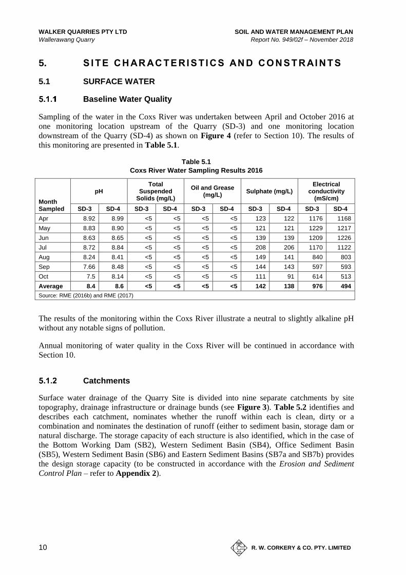
Sampling of the water in the Coxs River was undertaken between April and October 2016 at
one monitoring location upstream of the Quarry (SD-3) and one monitoring location
downstream of the Quarry (SD-4) as shown on Figure 4 (refer to Section 10). The results of
this monitoring are presented in Table 5.1.
Table 5.1
Coxs River Water Sampling Results 2016
Month Sampled
pH Total
Suspended Solids (mg/L)
Oil and Grease (mg/L)
Sulphate (mg/L) Electrical
conductivity (mS/cm)
SD-3 SD-4 SD-3 SD-4 SD-3 SD-4 SD-3 SD-4 SD-3 SD-4
Apr 8.92 8.99 <5 <5 <5 <5 123 122 1176 1168
May 8.83 8.90 <5 <5 <5 <5 121 121 1229 1217
Jun 8.63 8.65 <5 <5 <5 <5 139 139 1209 1226
Jul 8.72 8.84 <5 <5 <5 <5 208 206 1170 1122
Aug 8.24 8.41 <5 <5 <5 <5 149 141 840 803
Sep 7.66 8.48 <5 <5 <5 <5 144 143 597 593
Oct 7.5 8.14 <5 <5 <5 <5 111 91 614 513
Average 8.4 8.6 <5 <5 <5 <5 142 138 976 494
Source: RME (2016b) and RME (2017)
The results of the monitoring within the Coxs River illustrate a neutral to slightly alkaline pH
without any notable signs of pollution.
Annual monitoring of water quality in the Coxs River will be continued in accordance with
Section 10.
Catchments
Surface water drainage of the Quarry Site is divided into nine separate catchments by site
topography, drainage infrastructure or drainage bunds (see Figure 3). Table 5.2 identifies and
describes each catchment, nominates whether the runoff within each is clean, dirty or a
combination and nominates the destination of runoff (either to sediment basin, storage dam or
natural discharge. The storage capacity of each structure is also identified, which in the case of
the Bottom Working Dam (SB2), Western Sediment Basin (SB4), Office Sediment Basin
(SB5), Western Sediment Basin (SB6) and Eastern Sediment Basins (SB7a and SB7b) provides
the design storage capacity (to be constructed in accordance with the Erosion and Sediment
Control Plan – refer to Appendix 2).

SOIL AND WATER MANAGEMENT PLAN WALKER QUARRIES PTY LTD
Report No. 949/02f – November 2018 Wallerawang Quarry
11
R. W. CORKERY & CO. PTY. LIMITED
Figure 3 Quarry Site Catchments and Water Management Features
Figure dated 14/11/18 Inserted 16/11/18

WALKER QUARRIES PTY LTD SOIL AND WATER MANAGEMENT PLAN
Wallerawang Quarry Report No. 949/02f – November 2018
12
R. W. CORKERY & CO. PTY. LIMITED
Table 5.2
Quarry Site Catchment Areas
Name Area
(ha)
Runoff
Type Description Storage
Volume (ML)
1 3.4 Combined Entrance road, west facing slope of the extraction area, haul road and miscellaneous disturbance.
Bottom Working Dam (SB2).
2.8 GWH 1.0 Clean Runoff collected in roadside drains and culverts of the Great Western Highway adjacent to the Quarry Entrance.
2 2.71 Combined Mining area – eastern slope.
E
1.42 Dirty Mining area – central section below surface elevation (no runoff).
In-pit. N/R
0.23 Dirty Mining area – southern disturbance area. Southern Sediment Basin (SB3)
0.3
3 0.5 Dirty Site office, weighbridge area and selected haul roads.
Office Sediment Basin (SB5).
0.153
4 6.0 Dirty Processing and stockpiling areas, internal access roads. Main Sediment
Basins (SB1). 2.1
6b 0.9 Dirty Lower tier of the Western Stockpile Area.
6a 0.6 Dirty Upper Tier of the Western Stockpile Area.
Western Sediment Basin (SB6).
0.3
7 0.5 Dirty Eastern Stockpile Area. Eastern Sediment Basins (SB7 a/b)
0.3 (each)
Note 1: Catchment to reduce in size as Catchment E increases in size
Note 2: Catchment to increase in size as the extraction area is developed below surface elevation
Note 3: Catchment to be removed as Catchment E extends to replace Catchment 2
With reference to the type of runoff identified in Table 5.2:
• Dirty water refers to runoff from disturbed areas of the Quarry Site; and
• Clean water refers to runoff from catchments unaffected by Quarry Site activities
(regardless of water quality).
Where the water type is identified as ‘Combined’ this refers to catchments receiving both clean
and dirty water runoff.
As shown in Table 5.2, seven catchments are considered to contain dirty water runoff. With the
exception of runoff from Catchment E (the below ground level area of the open cut), this runoff
is to be diverted to one of seven sediment basins (SB1, SB2, SB3, SB5, SB6, SB7a and SB7b).
Additional capacity for water storage is provided by two storage dams (SD1 and SD2).
One catchment is identified as carrying clean water (Catchments GWH). By virtue of the
construction of the Quarry Site intersection with the Great Western Highway, runoff from the
small section of the highway drainage (Catchment GWH) is diverted via road side drains to a
culvert below the Quarry Site Access Road which also accepts dirty water runoff from
Catchment 1. This runoff is diverted to SB2. The remaining clean water runoff from the Great
Western Highway is segregated from Quarry Site disturbance, captured within a clean water
drain (CWD-5), which includes a section of below ground pipe transfer, and allowed to
discharge to natural drainage to the south of the SD1.

SOIL AND WATER MANAGEMENT PLAN WALKER QUARRIES PTY LTD
Report No. 949/02f – November 2018 Wallerawang Quarry
13
R. W. CORKERY & CO. PTY. LIMITED
Further information on the design, capacities and management of these clean and dirty water
structures is provided in Section 9 and the Quarry Erosion and Sediment Control Plan (ESCP)
(refer to Appendix 3)
Water Capture and Storage
As detailed in Section 5.1, surface water runoff generated within “dirty” catchments is captured
and directed into sediment basins by site topography, drain or bund. This runoff is diverted by
rock-lined drains into one of seven sediment basins which have been designed to provide
sufficient water settlement and sediment storage capacity up to the design rainfall conditions
(56.4mm in 5 days) (refer to Section 9). In accordance with the ESCP, these structures will be
maintained as ‘dry’ structures, i.e. emptied to reinstate the required storage capacity within
5 days of water accumulation.
A further two storage dams are maintained at the Quarry to which water accumulated in the
sediment basins after rainfall will be discharged (either by overflow from SB1 to SD1, or
pumping to SD2). Water for dust suppression and processing operations is drawn from these
dams.
Three silt cells are operated at the Quarry, these structures accept water from sand washing
operations containing elevated silt and fines content. The silty water flows through these cells,
allowing for the settlement and collection of silt, before discharge into SD 2 (Top Working
Dam) from which the water is redrawn for washing and operations.
Table 5.3 presents information on the permanent water storages on the Quarry.
Table 5.3
Quarry Site Water Storage Information
Page 1 of 2
Storage Volume
(ML) Purpose Water Use
Sediment Basins
SB1: Main Sediment Basin
2.1 Collection and storage of runoff Catchment 4 and 6 (Main and Western Stockpile Areas).
Source of water for dust suppression and sand washing.
Discharges via spillway to Main Storage Dam (SD1).
SB2: Bottom Working Dam
2.8 Collection and storage of runoff from Catchment 1 (Site Entrance and Roads) and Catchment 2 (Extraction area). Collection of overflow from the drying cell.
Transferred to Top Working Dam (SD2) to maintain design storage for sediment control or discharged to the receiving environment if of suitable quality.
SB3: Southern Sediment Basin1
0.3 Collection and storage of runoff from the southern extraction area (temporary structure).
Transferred to Top Working Dam (SD2) to maintain design storage for sediment control.
SB5: Office Sediment Basin
0.15 Collection and storage of runoff from the Site office and selected haul roads.
Transferred to Top Working Dam (SD2) to maintain design storage for sediment control or discharged to CWD-5 (subject to compliance with the ESCP – Appendix 3).

WALKER QUARRIES PTY LTD SOIL AND WATER MANAGEMENT PLAN
Wallerawang Quarry Report No. 949/02f – November 2018
14
R. W. CORKERY & CO. PTY. LIMITED
Table 5.3 (Cont’d)
Quarry Site Water Storage Information
Page 2 of 2
Storage Volume
(ML) Purpose Water Use
Sediment Basins (Cont’d)
SB6: Western Sediment Basin
0.3 Collection and storage of runoff from the upper tier of the Western Stockpile Area.
Either transferred to Top Working Dam (SD2) to maintain design storage for sediment control or captured in collection sump of Catchment 6b for transfer to SB1.
SB7a and SB7b1
0.3 Collection and storage of runoff from ESEA.
Transferred to Top Working Dam (SD2) to maintain design storage for sediment control.
Storage Dams
SD1: Main Storage Dam
8.1 Storage of runoff to ensure sediment basins can retain nominated capacity.
Supplementary supply for processing or dust suppression. Discharge to receiving environment under rainfall conditions exceeding design event or if of suitable quality.
SD2: Top Working Dam
4 Process water supply. Storage of water accumulated within sediment basins.
Primary supply for sand washing and dust suppression.
Silt Cells
Cells 1 to 3 3 x 2.4 (7.2)
Progressive settlement of silt from water used in sand washing.
Discharge to SD2 for re-use in sand washing.
Note 1: Both sediment basins have been sized to account for all runoff from the ESEA
EPL 13172 allows for the discharge of water from SB2 and SD1, either following rainfall
exceeding the design rainfall event (5-day 95th percentile rainfall, 55.6mm – refer to Section 8)
or on confirmation of compliance with the quality criteria of EPL 13172 (refer to Section 9.4).
As nominated in Tables 5.2 and 5.3, water accumulated in the sediment basins will be
transferred to the two storage dams from which the water will be drawn for dust suppression
and processing operations.
5.2 LOCAL GROUNDWATER
Assessment of the occurrence of groundwater in local setting has concluded the groundwater
table occurs at an elevation well below the current extraction area.
• The original Environmental Impact Statement (EIS) for the Quarry (Pacrim, 2001)
concluded that the local groundwater table occurs at an elevation equivalent to the
base of the Coxs River (850m AHD).
• The more recent Environmental Assessment prepared for the recent modification
to the Quarry (RWC, 2017) reviewed the records of registered groundwater bores
within 3km of the Quarry Site and established groundwater levels below
910m AHD.

SOIL AND WATER MANAGEMENT PLAN WALKER QUARRIES PTY LTD
Report No. 949/02f – November 2018 Wallerawang Quarry
15
R. W. CORKERY & CO. PTY. LIMITED
• No interceptions of groundwater were recorded during recent exploration drilling
completed by Rangott Mineral Exploration (RME) to depths of 890m AHD. This
supports the records of the original drilling company (Lord Bros Drilling) who
notes no water was encountered during drilling on the Quarry Site dating back to
1997 (pers. comm. Phil Lord of Lord Bros Drilling).
6. S I TE WAT E R M AN AG EM E N T SY ST EM
As detailed in previous sections, water is managed in a manner that maximises opportunities for
reuse and recycling and minimises the possibility of uncontrolled discharge. The site water
management system has been developed in a manner that enables the:
• efficient recovery and use of natural resources;
• effective management of available storage volumes that prevents uncontrolled
discharge to receiving environments; and,
• effective water quality management strategies that prevent discharge of impacted
water to receiving environments.
This is achieved by utilising strategies and infrastructure to transfer water around the site for
use in Quarry activities. Each water storage is utilised in a specific role in the site water
management system so that the system can operate in an integrated manner to achieve SWMP
objectives.
SB1: Main Sediment Basin
SB1 captures runoff from the Main and Western Stockpile Areas of the Quarry (Catchments 4
and 6), which is diverted by low flow diversion drains (see Figure 3). The design of this
storage provides for 2.1ML of storage for the settlement of runoff and storage of sediment
generated under 5-day 95th percentile conditions (refer to Section 9) prior to discharging into
the Main Storage Dam (SD1). By ensuring that all runoff is directed to SB1, the water held in
the Main Storage Dam is more likely to achieve the total suspended sediment concentration
required of discharged water.
SB1 will be regularly emptied (to SD1 or SD2) with any accumulated sediment removed,
allowed to dry on the stockpiling area and either sold as fill or blended with other products prior
to sale.
SD1: Main Storage Dam
SD1 will accept overflow, via a stabilised (rock-lined) spillway from SB1, or by pumping. SD1
provides 8.1ML of storage which allows significant settlement time for any accumulated water
prior to discharge as well as providing a significant repository of water on-site to account for
extended low rainfall periods.
Water held in SD1 may be transferred to the Top Working Dam (SD2) to supplement supply of
water for dust suppression and sand washing.

WALKER QUARRIES PTY LTD SOIL AND WATER MANAGEMENT PLAN
Wallerawang Quarry Report No. 949/02f – November 2018
16
R. W. CORKERY & CO. PTY. LIMITED
SB2: Bottom Working Dam
SB2 captures runoff from:
• Catchment 1, via rock-lined roadside drains;
• Catchment GWH, via concrete drains and culverts of the Great Western Highway;
and
• Catchment 2 via various low flow and road-side drains (see Figure 3).
The design volume of SB2 (2.8ML) provides sufficient settlement and storage volume for
runoff generated under 5-day 95th percentile conditions (refer to Section 9). As water
accumulates within SB2, it will be pumped to SD2, SD1 or the silt cells, or discharged subject
to achieving the water quality criteria nominated in Section 9.4, within 5 days of accumulation.
The transfer of captured runoff from this storage assists in managing the design storage
requirements for sediment control and lowers the possibility of discharge.
SD2: Top Working Dam
This storage is operated as the principal point of draw for dust suppression and sand washing. It
is constructed above ground, with no run-on catchment, and accepts overflow from the silt cells
as well as water pumped to it from other basins and SD1.
SD2 is the primary source of water for dust suppression and sand washing, and is kept at or
close to full capacity as a result. Under rainfall conditions exceeding 5-day 95th percentile
conditions (55.6mm), SD2 may discharge water via a rock-lined spillway. Discharge from the
spillway of SD2 flows to SB2.
Silt Cells
The three silt cells (of combined 7.2ML capacity) which provide for the settling of silt from
water used to wash sand and other quartzite products.
Additional Sediment Basins (SB3, SB5, SB6, SB7a and SB7b)
These sediment basins are maintained within the three additional dirty water catchments of the
Quarry Site (Catchments 3, 6a and 7). Each sediment basin has been designed and will be
maintained (by pumping of accumulated water to SD2 or SD1) to accept runoff and sediment
following a 5-day 95th percentile rainfall event (refer also to Section 8.3).

SOIL AND WATER MANAGEMENT PLAN WALKER QUARRIES PTY LTD
Report No. 949/02f – November 2018 Wallerawang Quarry
17
R. W. CORKERY & CO. PTY. LIMITED
7. S I TE WAT E R BAL AN C E
7.1 WATER SOURCES
The principal source of water on the Quarry is rainfall that generates surface runoff with this
currently supplemented by water purchased from off-site sources.
As stated in the Pacrim (2001), however, "it is anticipated that during dry years it may be
necessary to import additional water onto site to meet daily requirements" and the Company
continues to investigate and review additional sources of water for importation and use on the
Quarry Site. These sources could include:
• purchase from off-site water storage locations and importation using water trucks;
• purchase of an allocation, either temporary or permanent, from an existing surface
Water Access Licence (WAL) of the Wywandy Creek Management Zone;
• extraction under a new surface WAL of the Wywandy Creek Management Zone,
obtained on application to WaterNSW should new allocations be released;
• purchasing of an allocation, either temporary or permanent, from an existing
groundwater WAL of the Cox’s River Fracture Zone groundwater source; or
• extraction under a new groundwater WAL of the Cox’s River Fracture Zone
groundwater source, obtained on application to WaterNSW should new
allocations be released.
If water is obtained through an allocation associated with a surface WAL, and relevant Water
Use Approval from WaterNSW, the Company will then explore whether to install a pump on
the Cox’s River, either on Company’s land or (with permission) from an adjacent landholder. If
water is obtained through an allocation associated with a groundwater WAL, the Company will
undertake the necessary hydrogeological assessment and obtain the necessary approvals for the
installation of a bore and pump.
In both cases (surface and groundwater allocation), delivery of water would require the
installation of a (poly) pipeline (from the selected water source) to the existing header tank
currently in use.
7.2 WATER USAGE AND LOSSES
Water captured from disturbed areas is recycled on site for reuse in the following site activities.
Sand Processing
Based on the maximum operating capacity of the sand washing plant of the Quarry, up to
100 000t of sand can be washed annually. Based on a wash ratio of 0.5 to 0.625kL water per
tonne of sand, and a recovery / reuse rate of 85%1, up to 9.4ML/yr is required.
1 Losses include evaporation, retained moisture content of sand products and silt, and pipe losses.

WALKER QUARRIES PTY LTD SOIL AND WATER MANAGEMENT PLAN
Wallerawang Quarry Report No. 949/02f – November 2018
18
R. W. CORKERY & CO. PTY. LIMITED
Dust Suppression and Wheel Wash
16ML/yr of water is applied to potential dust emission sources to manage potential air quality
impacts arising from Quarry activities, or the Quarry wheel wash.
Recycling captured runoff ensures the efficient use of the available water resource and allows
for the proper management of sediment control dams, therefore lowering the possibility of
uncontrolled discharge of water to the receiving environment in a rainfall event.
Evaporation
Water will also be lost through evaporation from dam / basin surface. To estimate annual
losses, the National Centre for Engineering in Agriculture (NCEA), Ready Reckoner (for
analysing evaporation and seepage from water storages) was applied to the location
(http://readyreckoner.nceaprd.usq.edu.au/). Based on a combined dam surface area of 0.857ha
of dam surface area, and an average evaporation of 1527.7mm (varying between 47.2mm in
June and 211.5mm in December) for the local setting, evaporation of 13.1ML/yr is expected.
7.3 WATER BALANCE
Water Storage Inputs
As detailed in Section 6.2 above, all inputs to the site water balance are derived from rainfall
and the capture of runoff. Table 7.1 below details the runoff yield volumes calculated based on
statistical analysis (Log Pearson Type III) of the rainfall data derived from the Scientific
Information for Land Owners (SILO) database, managed by the Queensland Department of
Science, Information Technology and Innovation (DSITI). The program uses historic Bureau of
Meteorology datasets and interpolation techniques to generate continuous daily time step
synthetic rainfall and other climate data for any given location in Australia. The SILO dataset
for the period 1 January 1889 to 14 November 2017 was generated for the Quarry Site (Latitude
-33.45, Longitude 150.05) on 15 November 2017 for the period commencing 15 Nov 2017.
Table 7.1
Calculated Runoff Volumes (ML)
Storage Annual Exceedance Probability
95% 90% 50% 10% 5%
SB2: Bottom Working Dam (Catchments 1, 2 & GWH)
18.4 20.4 28.6 38.3 41.3
SD1: Main Storage Dam (Catchments 4 & 6)
17.9 19.9 27.9 37.4 40.3
Total 36.3 40.3 56.6 75.8 81.6
A runoff coefficient (Cv) of 0.48 has been applied to Catchments 1, 2, 4 and 6. This accounts
for variation in runoff between rainfall events of 10mm or less, when runoff will be very low
(Cv <0.25), and more substantive rainfall (>10mm) when runoff from the hardstand surfaces
and steep topography will be high (Cv ~0.74), reflecting ‘soil’ with high runoff potential (refer
to Table F2 of the Blue Book).
A Cv factor of 0.8 has been applied to Catchment GWH to reflect the fact that runoff is over an
impermeable surface with a significant portion of the flow delivered by pipe culvert.

SOIL AND WATER MANAGEMENT PLAN WALKER QUARRIES PTY LTD
Report No. 949/02f – November 2018 Wallerawang Quarry
19
R. W. CORKERY & CO. PTY. LIMITED
Water Storage Reuse and Evaporation (Site Water Demand)
Water used for processing activities, dust suppression and evaporation are effectively
withdrawals from the available water stored on site.
The anticipated annual volumes (ML) required to meet the demand from each of these
parameters is as follows:
• Processing (make-up) 9.4ML.
• Dust Suppression 16ML.
• Evaporation 13.1ML.
Water Balance
Table 7.2 below shows the expected water surplus or deficit for a range of AEPs. This indicates
that rainfall greater than the median is sufficient to account for site water demand and
evaporative losses. Based on the analysis of rainfall data collected at BoM 063132, rainfall in
between 85% and 90% of years would be sufficient to meet site water demand and evaporative
loss.
The balance of Table 7.2 is indicative as site water demand and evaporative losses will vary on
an annual basis. Importantly, the balance illustrates that sufficient water will be available to
account for operations (38.5ML) in greater than 95% of years.
Table 7.2
Site Water Balance: Selected AEP Rainfall Years
AEP Runoff (ML) Site Water Demand / Loss (ML) Surplus/Deficit
95% 36.3
38.5
-2.1
90% 40.3 1.9
80% 45.5 5.1
50% 56.6 18.2
10% 75.8 37.4
5% 81.6 43.2
7.4 OFF-SITE WATER TRANSFERS
Discharge of water will occur from the Quarry Site under the following circumstances.
1. Under high rainfall conditions, a controlled discharge may be required to ensure the
minimum water storage capacity is available within the site sediment basins (refer to
Table 9.1 and the ESCP of Appendix 3).
The maximum discharge under this scenario would be equivalent to the combined
minimum water storage requirement of these sediment basins, approximately 4.5ML.
2. Under rainfall conditions exceeding 55.6mm over 5 consecutive days, when only the
minimum water storage capacity is available within the site sediment basins (refer to
Table 9.1 and the ESCP of Appendix 3), water may discharge from the sediment
basins.

WALKER QUARRIES PTY LTD SOIL AND WATER MANAGEMENT PLAN
Wallerawang Quarry Report No. 949/02f – November 2018
20
R. W. CORKERY & CO. PTY. LIMITED
The volume of discharge under this scenario would be dependent on the rainfall,
however, under 1% AEP rainfall conditions over 72 hours (250mm) and assuming a
runoff coefficient of 0.48 (as used to establish the sediment basins capacity
requirement – refer to Section 9.3 and the ESCP of Appendix 3) over the 15.8ha of
catchment, 19ML of runoff would be generated resulting in discharge of 14.5ML.
8. WAS T E WAT E R M AN AG EM EN T ( F O R B E N E FI C I AL U S E )
Waste water generated at the Quarry is categorised as follows.
• Effluent / ablutions water.
• Process water discharge.
Runoff from disturbed areas of the Quarry is considered stormwater and managed in
accordance with a ESCP (refer to Section 8).
The following reviews the management, beneficial use and monitoring of these waste water
streams.
Effluent and Ablutions Water
Several methods of disposal were investigated, including application to a utilisation area,
however, following a review of site and soil limitations, the only viable option for management
was a monitoring pump out system. The limiting features for on-site land application disposal
were the soil permeability, shallow bedrock, soil structure, and textures, run-on and seepage.
Each of these features imposes major limitation to the use of an on-site disposal.
As a consequence of the limitations to onsite disposal, all wastewater generated via the effluent
and ablutions system is collected and disposed of offsite by a licenced contractor. Therefore, as
this stream of waste water is not applied to land on the Quarry, no monitoring will be
undertaken.
Process Water Discharge
The water management system (see Section 6.5) describes how silt containing water from the
wash plant is delivered to three silt cells (constructed in series)2. The water flows through these
structures, depositing silt in each before discharging into the Top Working Dam (SD 2). The
water is then re-used through the wash plant or used for dust suppression.
Monitoring of water quality, including this waste water stream, is described in Section 9.
2 Prior to the extraction extending to its maximum extent, the affected silt cell(s) will be relocated.

SOIL AND WATER MANAGEMENT PLAN WALKER QUARRIES PTY LTD
Report No. 949/02f – November 2018 Wallerawang Quarry
21
R. W. CORKERY & CO. PTY. LIMITED
9. S TO RM WAT E R M AN AG EM E N T
9.1 OVERVIEW (STORMWATER MANAGEMENT SCHEME)
As detailed in Sections 5.1 and 6.5, stormwater runoff generated in those areas disturbed by
Quarry activities is directed via gravity or drainage infrastructure to sediment basins.
Water from undisturbed (clean) catchments, on site or upstream, is directed away from
disturbed areas via diversion drains which discharge directly to the receiving environment
downstream of the Quarry.
The following-sub-sections describe, in general terms, the management of clean and dirty
stormwater at the Quarry. Further detail on the design, management, maintenance and
monitoring of the various structures described is provided in an ESCP (which incorporates the
requirements of a Stormwater Management Scheme) for the Quarry (see Appendix 2).
9.2 CLEAN WATER DIVERSIONS
Three clean water diversion drains are maintained on the Quarry Site (see Figure 3).
• CWD-1 collects water from the roadside drains of the Great Western Highway,
which flow onto the Quarry Site through rock-lined drains and diverts to SB2.
• CWD-2 collects runoff from the undisturbed land to the north of the extraction
area and SD2 and diverts via a road-side drain to natural drainage to the north.
• CWD-5 collects runoff from the roadside drainage of the Great Western Highway
and diverts this to the south and into a natural tributary of the Coxs River.
Diversion and collection of clean water from Catchment GWH (by CWD-1) is necessary due to
the existing drainage created by the construction of the Quarry Site intersection with the Great
Western Highway. The capture of this water assists in ensuring sufficient water is accumulated
on the Quarry Site for dust suppression and processing activities.
Clean water from the Great Western Highway to the northwest of the Quarry Site is diverted
through the Quarry via CWD-5. CWD-5 has been constructed as both an open, rock lined drain
which is collected and transferred below the stockpile areas via a 400mm HDPE pipe, before
discharging to an open, rock lined drain again. The clean water is then diverted to the south of
the Quarry where it discharges into a natural tributary of the Coxs River. An energy dissipater
and outlet protection (equivalent to SD 5-8 of the Blue Book) is to be maintained at the
discharge point from the pipeline and open drain sections of CWD-5.
Diversion of water by the clean water drains prevents mixing of disturbed and clean runoff,
therefore reducing the volumes of water requiring management on site and lowering the risk of
an uncontrolled discharge from site. The diversion of this water around the site also assists in
maintaining the local hydrologic regime of the downstream receiving environment.
Further detail on the maintenance of these diversions is provided in the ESCP (Appendix 3).

WALKER QUARRIES PTY LTD SOIL AND WATER MANAGEMENT PLAN
Wallerawang Quarry Report No. 949/02f – November 2018
22
R. W. CORKERY & CO. PTY. LIMITED
9.3 SEDIMENT BASINS AND DISCHARGE PROTECTION
As noted in Section 5.2, runoff generated on disturbed catchments is to be directed to one of
seven sediment basins. Each of these storages effectively acts as Type D (equivalent to SD 6-4
of the Blue Book) sediment basin for their respective catchments.
Type D sediment basins are designed to capture runoff from disturbed catchments and store the
runoff for a sufficient period of time to allow the sediment to settle out of suspension prior to
discharging water of suitable quality to receiving environments.
The required design volumes for each of the site water storages are presented in Table 9.1 and
are calculated using the following equation.
Settling zone = 10 x Cv x A x R(y%ile, 5 day)
Where:
10 = unit conversion factor
Cv = coefficient of runoff (volumetric) (0.48)3
A = catchment area (ha)
R(y%ile, 5 day) = 5 day 95th percentile design rainfall depth (mm) (55.6mm)
Table 9.1
Design Sediment Basin Storage Requirements
Catchment Area (ha)
Reporting to:
Water Settlement (m3)
Sediment Storage (m3)
Total Basin Volume Requirement (m3)
1 3.4
SB2
903 1
2 004 GWH 1.0 225 -
2 2.7 874 1
3 0.2 SB3 56 7 63
4 6.0 SB1 1 946 15 1 961
6b 0.9
6a 0.6 SB6 (SB1) 169 1 170
5 0.5 SB5 141 1 142
7 0.5 SB7 (a/b) 141 1 142
Source: Detailed Calculation Sheets (using RUSLE) of RWC (see Appendix 3)
Comparing the storage volume requirements for water settlement of Table 9.1 to the design
capacities of all sediment basins (see Table 5.1), sufficient capacity will be provided for their
respective catchments.
Further detail on the maintenance of these sediment basins is provided in the ESCP (see
Appendix 2). In summary, a marker will be maintained within each sediment basin near the
discharge point identifying minimum freeboard requirement. Sediment basins will be inspected
3 Due to the presence of significant stockpiles (which will accumulate and therefore reduce runoff), as well as
areas containing significant groundcover within each catchment, a low to moderate runoff potential (Soil Hydrologic Group B) has been applied. Table F2 of the Blue Book has been used to estimate the runoff coefficient based on a Soil Hydrologic Group B, and Cv of 56.4mm.

SOIL AND WATER MANAGEMENT PLAN WALKER QUARRIES PTY LTD
Report No. 949/02f – November 2018 Wallerawang Quarry
23
R. W. CORKERY & CO. PTY. LIMITED
monthly to monitor accumulated sediment levels. Prior to the accumulated sediment exceeding
this marker, the basin will be cleaned, with the accumulated sediment placed on the stockpiling
area for blending and sale.
Under EPL 13172, discharge of water is permitted from the spillways of SD1 and SB2.
9.4 OTHER EROSION AND SEDIMENT CONTROL MEASURES
Other erosion and sediment control measures will be installed as required to reduce the velocity
of flows and capture sediments. Additional sediment protection will include the use of one or
more of the following.
• Sediment Fencing.
Sediment (silt) fencing consisting of geotextile filter fabric supported by wire and
posts will be utilised in areas where the:
– the area draining to the fence is 0.6 ha or less;
– the maximum slope gradient behind the fence is 1:2 (V:H); and
– the maximum slope length behind the fence is 60m.
Sediment fences will generally be installed prior to disturbance activities
(e.g. down slope of soil stockpiles) or downslope of areas being rehabilitated and
maintained until stabilisation of the area.
• Straw Bale Filters and Check Dams.
In the event that additional erosion control is required at the outlet of a drain or
across a swale or channel of a diversion bund, a temporary barrier of straw bales
laid end to end across the direction of flow may be utilised to reduce the water
velocity and capture sediments. Check dams may also be utilised consisting of
rock material. Check dams would primarily be utilised to reduce the velocity of
water to prevent erosion rather than as a sediment retention structure.
• Rock Armouring and Jute Mesh.
In the event additional erosion controls are required, other options that will be
considered include the use of rock armouring, whereby a channel or outlet is
effectively lined with appropriately sized aggregate material to provide a physical
barrier to erosion. Similar to rock armouring, jute mesh, a biodegradable erosion
control blanket, may be installed, particularly where vegetation growth is
preferable.
• Energy Dissipaters and Outlet Protection.
In the event that additional erosion controls are required to reduce water velocity
and mitigate erosion at the outlet of pipe drains, the outlet and a section of the
receiving drain or watercourse is lined with appropriately sized, angular and
durable material to provide a physical barrier to erosion and lower water velocity
by obstructing the flow path and absorbing energy (rip rap apron). The rip rap
apron will be underlain with geotextile and the rip rap apron level matched to the
invert level of the receiving watercourse. The dimensions of the rip rap apron and
material will be determined by the flow conditions (water level and peak
discharge) and pipe diameter.

WALKER QUARRIES PTY LTD SOIL AND WATER MANAGEMENT PLAN
Wallerawang Quarry Report No. 949/02f – November 2018
24
R. W. CORKERY & CO. PTY. LIMITED
These additional measures are applicable to water management structures, active disturbance
areas and rehabilitated areas which have not yet stabilised.
10. WAT E R M ONI TO RI N G P R O GR AM
10.1 MONITORING PROGRAM OBJECTIVES
Table 10.1 presents the objectives and key performance outcomes relating to the surface water
and groundwater monitoring program for the Quarry that were introduced in Section 4.
Table 10.1
Water Management Objectives and Key Performance Outcomes
Objectives Key Performance Outcomes
(a) To implement appropriate water
management and mitigation
measures during all stages of the
Quarry.
(i) Implementation of this Plan.
(ii) No discharge of water in breach of licence criteria.
(iii) No reportable incidents related to water management or
pollution.
(b) To implement an appropriate
monitoring program which reviews
compliance with relevant criteria
during all stages of the Quarry.
(iv) All identified monitoring is undertaken in accordance with
the relevant procedures and at the relevant intervals.
(v) Monitoring results are published and reported annually
within the Annual Review and/or Annual Return.
(vi) No unanticipated groundwater inflow to extraction area.
10.2 MONITORING LOCATIONS
Surface Water
Surface water monitoring at the Quarry is undertaken at the locations shown on Figure 4 and
described in Table 10.2. Monitoring is undertaken to assess the quality of water discharged
from the Quarry, and in the receiving system (Coxs River) both upstream and downstream of
the Quarry.
Table 10.2
Conditional Requirements for Soil and Water Management Plan of DA 344-11-2001
Type Ref Location Description
Discharge
EPL 1 (SD1) SD 1 Sampled from water discharging over the dam spillway to unnamed tributary of the Coxs River.
EPL 2 (SD2) SB 2 Sampled from water discharging over the dam spillway to unnamed tributary of the Coxs River.
Off-site Baseline
SD3 Coxs River Location upstream of the Quarry.
SD4 Coxs River Location downstream of the Quarry.

SOIL AND WATER MANAGEMENT PLAN WALKER QUARRIES PTY LTD
Report No. 949/02f – November 2018 Wallerawang Quarry
25
R. W. CORKERY & CO. PTY. LIMITED
Figure 4 Monitoring Locations
Figure dated 16/11/18 Inserted 16/11/18

WALKER QUARRIES PTY LTD SOIL AND WATER MANAGEMENT PLAN
Wallerawang Quarry Report No. 949/02f – November 2018
26
R. W. CORKERY & CO. PTY. LIMITED
Groundwater
The groundwater table is expected to occur at an elevation of no higher than 910m AHD. As the
Quarry is only approved to an elevation of 930m AHD, it is not expected groundwater will be
encountered over the remaining life of the approved Quarry operations and there are no
prescribed groundwater monitoring locations in DA 344-11-2001 or EPL 13172.
Prior to extraction below 930m AHD, the Company will commence a program of groundwater
monitoring. Three bores will be constructed to north, east and southwest of the extraction area
for the purpose of better defining the groundwater characteristics below the Quarry and
establishment of a median groundwater level (refer to Section 10.4.2). Figure 4 provides the
indicative location of these initial bores with the final location to be the subject of further
investigation to ensure appropriate ground and sub-surface conditions.
While at the anticipated rate of development, and assuming the Quarry continues to operate
beyond July 2019, extraction below 930m AHD is unlikely before July 2020. The Company
proposes the bores will be installed by the end of 2018. The SWMP will be updated to identify
the specific locations of the bore once confirmed.
10.3 MONITORING FREQUENCY AND PARAMETERS
Surface Water
The monitoring frequency or sampling event triggers and the parameters analysed for surface
water are presented in Table 10.3. All parameters will be monitored monthly during discharge.
Table 10.3
Surface Water Monitoring Frequency and Parameters
Ref Parameters Frequency
EPL 1 (SD1)
Total Suspended Solids (TSS), Sulfate, Grease and Oil, Electrical Conductivity, pH and turbidity.
Monthly during discharge
EPL 2 (SB2)
SD3 Annual
SD4
Groundwater
The bore nominated in Section 10.2.2 will be installed and groundwater monitoring commenced
at least 6 months prior to extraction progressing to an elevation of 930m AHD.
On commencement, the monitoring frequency will be quarterly, increasing to monthly if
groundwater is identified within 2m of the extraction area floor. Standing water levels will be
recorded to assess whether future extraction operations will intersect the local water table and
assist in quantifying the groundwater responses to rainfall.

SOIL AND WATER MANAGEMENT PLAN WALKER QUARRIES PTY LTD
Report No. 949/02f – November 2018 Wallerawang Quarry
27
R. W. CORKERY & CO. PTY. LIMITED
10.4 MONITORING CRITERIA
Surface Water
Quality criteria only apply to water discharged from the Quarry. Table 10.4 lists the water
quality criteria for the Quarry, as provided by EPL 13172. The limits presented below do not
authorise the pollution of waters by any other pollutants and the Quarry must comply with
Section 120 of the Protection of the Environment Operations Act (1997).
Table 10.4
Surface Water Monitoring Criteria
Pollutant Unit of Measure Criteria
TSS mg/L 30
Sulfate mg/L 250
Grease and Oil mg/L 10
Electrical Conductivity µS/cm 1 500
pH pH 6.5-8.5
In accordance with Conditions L2.5 and L2.6 of EPL 13172, the criteria are deemed not
applicable under the following conditions or where the following can be demonstrated.
a) A total of 56mm of rainfall is received at the Quarry Site over any consecutive 5
day period.
b) The measured pH of the water is within 6.5 – 8.5 and turbidity <25 NTU at the
time of the discharge.
The EPA is to be advised within 3 working days of the completion of the sample testing and
analysis where the exclusions apply.
Water flow within the Coxs River is a qualitative measure and as such no criteria are attached
to this parameter.
Groundwater
There are no prescribed groundwater monitoring criteria in DA 344-11-2001 or EPL 13172.
Rather, groundwater monitoring will be undertaken to prevent the unanticipated intersection of
the local water table by extraction operations at the Quarry, which is considered unlikely above
an elevation of 930m AHD (see Section 5.2). In the absence of prescribed criteria, the triggers
presented in Table 10.5 are proposed as mechanisms for action.
Table 10.5
Groundwater Monitoring Action Triggers
Location
Standing Water Level
Measured (monthly) Trend (12 month)
TBC1 Within 2 metres of extraction floor elevation 2 metre deviation from long-term median
Note 1: To be confirmed with indicative locations identified on Figure 4

WALKER QUARRIES PTY LTD SOIL AND WATER MANAGEMENT PLAN
Wallerawang Quarry Report No. 949/02f – November 2018
28
R. W. CORKERY & CO. PTY. LIMITED
Development of Long-term Median Groundwater Level
Due to the absence of groundwater level information for the Quarry, a long-term, median
groundwater level is yet to be established. In order to appropriately account for seasonal and
temporal variation in groundwater level, two years of groundwater level monitoring data will be
required to establish a long-term median groundwater level. Assuming groundwater occurs at
depths below 900m AHD, installation and commencement of monitoring from July 2020 will
provide several years of data before interception of groundwater is likely. Furthermore, the
long-term median groundwater level for each monitoring location would continue to be
recalculated as the program of data collection progresses over time.
In the interim, the Quarry will rely upon the “measured (monthly)” criterion (see Table 10.5)
set out for the action trigger until two years of groundwater level monitoring data has been
collected.
Notwithstanding this, the Quarry must comply with Section 120 of the Protection of the
Environment Operations Act (1997).
10.5 WATER MONITORING PROCEDURES
Surface Water
10.5.1.1 In-Field Analyses
A hand-held meter will be used to collect measurements of pH and Turbidity. Prior to use, the
meter will be calibrated in accordance with the manufacturers specifications.
10.5.1.2 Sample Collection and Analyses
The procedures water sampling and analysis generally follow those presented in the Approved
Methods for the Sampling and Analysis of Water Pollutants in New South Wales (DEC, 2004).
Monitoring Equipment
The following equipment is used for the collection of surface water samples.
• Chain of custody form (laboratory supplied).
• Labelled sample containers. As supplied by laboratory.
• Marker pen and ink pen.
• Esky (with ice or chilled briquettes).
• Camera.
• Spares kit, including;
– spare sampling bottles; and
– marker pen/ink pen.

SOIL AND WATER MANAGEMENT PLAN WALKER QUARRIES PTY LTD
Report No. 949/02f – November 2018 Wallerawang Quarry
29
R. W. CORKERY & CO. PTY. LIMITED
Due to the types of analyses required, it is anticipated that two separate sampling containers
would be required for the purposes of collecting samples:
1. Electrical conductivity, TSS, pH and Sulfate.
2. Oil and Grease.
A minimum of 10 sets of sampling bottles (i.e. sufficient for two rounds of sampling) will be
retained on site. Additional bottles are available through the laboratory services provider.
Sampling Procedure
The following procedures apply to surface water sampling.
1. Clearly label each sample bottle before sampling, as follows.
Site: Walker Quarry.
Sampling Location: e.g. SD1.
Date: 15/10/2019.
Time: 7:00am.
Sampled by: John Smith.
2. Remove lid of TSS, EC, pH and Sulfate sampling container and rinse with at least
500mL of water from the sample area. Ensure rinsed water is tipped away from
the sampling area.
3. Fill the sampling container and use it to carefully fill the other sampling container
ensuring not to spill the preservative contained within the other sampling
container, or mix the lids between bottles. Tighten the sampling container lid and
place the sample in the chilled esky immediately.
4. Refill the other sampling container to capacity. Tighten the sample bottle lid and
place the sample in the chilled esky immediately.
5. Prior to leaving each monitoring site, photograph the site and record observations
on stream flow, water colour or any other relevant matter.
Collected water samples will be delivered to laboratory for analysis as soon as possible and
submitted with a chain of custody form.
Surface Water Flow Monitoring
The methods for determining flow when sampling for water quality are modified from the
Velocity-area method of Part 3 of Australian Standard (AS) 3778-2009: Measurement of water
flow in open channels (SA, 2009).
The flow will be recorded as either:
• high: rapid movement of water flowing at, or over the defined channel;
• medium: moderate movement of water covering >50% of the defined channel;
• low: slow movement of water covering >50% of the defined channel; or
• none: no movement of water.

WALKER QUARRIES PTY LTD SOIL AND WATER MANAGEMENT PLAN
Wallerawang Quarry Report No. 949/02f – November 2018
30
R. W. CORKERY & CO. PTY. LIMITED
A photo will be taken on each occasion for comparison to previous flows.
Groundwater Monitoring
The following provides the equipment and methods to be implemented when groundwater
monitoring commences.
Monitoring Equipment
The following equipment will be used for the collection of groundwater data from the deployed
logger.
• A portable data reader to download logger information (ensure suitability and
methods in accordance with data logger manufacturer’s instructions prior to use).
• Spares kit, including;
– pliers;
– replacement batteries; and
– spare cable.
Field Measurement and Observations
The data logger will be calibrated prior to redeployment after downloading, and a record of the
calibration will be kept.
Once the groundwater level data has been downloaded, the download will be recorded on a
field sheet, along with the following information:
1. Monitoring bore identifier;
2. Date and time of download;
3. Extraction floor elevation at time of download;
4. General site observations including presence of algae or vegetation on data logger;
5. Appearance of the water, including water clarity and colour (if possible);
6. Water odour; and
7. Anything else that may be significantly contributing to the groundwater conditions
at the location.
10.6 REVIEW AND RECORDING OF MONITORING DATA
Surface Water
Following receipt of water quality monitoring results, Walker Quarries (or delegated
environmental consultant) will review the data against the criteria listed in Table 10.4. The
results will also be entered into an existing water monitoring database where trends in water
quality can be considered.

SOIL AND WATER MANAGEMENT PLAN WALKER QUARRIES PTY LTD
Report No. 949/02f – November 2018 Wallerawang Quarry
31
R. W. CORKERY & CO. PTY. LIMITED
Daily rainfall data from the on-site meteorological station for the previous 5 days will be
reviewed and recorded in the water monitoring database beside the water quality monitoring
results. As noted in Section 10.4.1, where rainfall received at the Quarry Site over the previous
5 days exceeds 56mm, the surface water monitoring criteria presented in Table 10.4 do not
apply.
Original copies monitoring results supplied by the NATA accredited laboratory will be retained
by Walker Quarries for at least 4 years.
Groundwater
10.6.2.1 Review and Reporting
Groundwater data obtained from the data loggers would be entered into an existing water
monitoring database and reviewed against the action triggers identified in Section 10.4.2. The
standing water levels would be compared to the current extraction floor elevation. On
commencement of groundwater monitoring, the Company would prepare a quarterly report of
results for publishing on the Company website. A full report on groundwater monitoring will be
provided to the DPE and DOI-Water on an annual basis as a component of the Quarry Annual
Review.
Review of the groundwater data would also occur to establish the long-term trends in standing
water levels in the groundwater monitoring bore(s). If review of the trend data identifies that an
action trigger level is met (refer to Section 10.7), a review of recent rainfall records (rising
trend) and any pit inflow volumes (lowering trend) will be completed to assist in identifying a
possible reason for the trend.
If review of the trend data identifies that groundwater inflow to the extraction area is likely to
occur, a review of groundwater monitoring data and recent rainfall records will be undertaken
to determine if anomalous rainfall events are the cause (rising trend) or if extraction operations
will intersect the natural long-term trend in standing water level, as established by the
monitoring program.
10.6.2.2 Contingency Response Management
Contingency management would be required in the event of the following events.
Unanticipated Groundwater Inflow
Unanticipated groundwater inflows shall be deemed to be occurring when groundwater inflow
to the active section of the extraction area is observed (direct inflow), or if the active extraction
area is observed to contain standing water in the absence of a rainfall and runoff event (inferred
inflow). If this is observed, the following action/response procedures will be implemented.
• Extraction will be ceased in the immediate vicinity of the identified seepage zone
and relocated to an alternate location.
• The Quarry Manager will cordon off the area, to prevent inadvertent access, and
take photos of the seepage zone.
• The unanticipated groundwater inflow will be reported immediately to the DPE
and DoI-Water.

WALKER QUARRIES PTY LTD SOIL AND WATER MANAGEMENT PLAN
Wallerawang Quarry Report No. 949/02f – November 2018
32
R. W. CORKERY & CO. PTY. LIMITED
• Within 7 days of the commencement of inflow, a report to DoI-Water will be
prepared that includes the following information:
1. time at which inflow event commenced;
2. time at which inflow event ceased;
3. duration of the inflow event;
4. volume of groundwater inflow; and
5. extraction area floor elevation at which the inflow event occurred.
• The recommendations of DoI-Water will be followed with extraction from the
affected areas of the Quarry only recommencing on approval by DoI-Water.
Breach of Threshold Trigger (Standing Water Level)
If the Standing Water Level (SWL) is observed within 2m of the extraction area floor (Monthly
Measured Trigger), extraction will not progress any deeper until the following action/response
procedures are implemented.
• The DOI-Water will be notified.
• A methodology to calculate any future inflow of water will be established.
• A Water Access Licence and adequate allocation will be obtained.
If the extraction area is developed below the groundwater table, and the SWL is observed to
deviate by greater than 2m from the long-term median, the following action/response
procedures will be implemented.
• The DoI-Water will be notified.
• A qualified hydrogeologist will be commissioned to complete a review of
operations and assess:
– the relationship, if any, between the SWL reduction and Quarry operations;
and
– the potential impact of the SWL reduction on other groundwater users.
• The results of the assessment, along with recommendations for additional
contingency or mitigation measures if required, will be provided to DoI-Water for
review.
• Unless instructed otherwise by DoI-Water, the recommended contingency or
mitigation measures will be implemented.
10.7 REPORTING AND PUBLICATION OF MONITORING DATA
In the event that water is discharged from the Quarry (from the licensed discharge points at
either the Main Storage Dam or the Bottom Working Dam) during the annual reporting period
of EPL 13172, the results of water quality monitoring will be included within an Annual
Return, submitted to the EPA within 60 days of the Anniversary date of EPL 13172

SOIL AND WATER MANAGEMENT PLAN WALKER QUARRIES PTY LTD
Report No. 949/02f – November 2018 Wallerawang Quarry
33
R. W. CORKERY & CO. PTY. LIMITED
(21 October) each year, in accordance with Condition R1.1 of EPL 13172, and Annual Review,
submitted by the end of September each and required by Condition 5(12) of DA 344-11-2001.
The results included in the Annual Return will be assessed by an independent reviewer prior to
submission to confirm accuracy.
In the event that the results of water quality monitoring identify an exceedance of the criteria
nominated in Section 10.4, the Quarry Manager will immediately notify the DPE4, the EPA and
WaterNSW.
In the event the groundwater monitoring threshold triggers are breached, the Company will
immediately notify the DPE and DoI-Water. A report will be prepared and submitted to the
DoI-Water (and DPE if requested) within 7 days of the breach being identified.
Additionally, results of water quality monitoring required by DA 344-11-2001 and other
regulatory approvals will be made publicly available on the Walker Quarries website
(http://walkerquarries.com.au/statutory-information/) in accordance with the current version of
EPA’s guideline “Requirements for publishing pollution monitoring data”, within 14 days of
analysis being received by the Company. The Quarry Manager is responsible for publication of
this monitoring information.
In the event in-field pH and turbidity is measured and the results confirm the water quality
criteria as not applicable (refer to Section 10.4.1), these results will be provided in writing to
the EPA within three working days of water sampling.
10.8 INSPECTIONS AND MAINTENANCE
Regular inspections are undertaken of all water management (erosion and sediment control)
structures. Inspections are undertaken on a monthly basis and following a rainfall event of
>25mm/24hr. The inspections of water management structures record the following details.
• Storage volumes held in each dam.
• Evidence of overflow and condition of downstream catchment of SD 1 and SB 2.
• Water colour of all dams, especially SD 1 and SB 2 (e.g. highly turbid, brown,
clear).
• Presence of any oily film.
• The general condition of the water management structures and / or the soil surface
of the rehabilitation area. This will include recording of any areas of active
erosion and the level of any sedimentation.
In any areas where active erosion is observed, consideration will be given to installation of
additional erosion and sediment controls as described in Section 8.4.
4 Using the contact name, email address and phone number provided by the DPE.

WALKER QUARRIES PTY LTD SOIL AND WATER MANAGEMENT PLAN
Wallerawang Quarry Report No. 949/02f – November 2018
34
R. W. CORKERY & CO. PTY. LIMITED
11. I N CI DE N T M AN AG E M E N T
11.1 INCIDENT IDENTIFICATION
Condition R2 of EPL 13172 requires that the Company must notify all relevant authorities of
incidents causing or threatening material harm to the environment immediately after the person
becomes aware of the incident.
In accordance with the definition provided by Section 147 of the POEO Act, harm to the
environment is deemed to be material if:
i) it involves actual or potential harm to the health or safety of human beings or to
ecosystems that is not trivial; or
ii) it results in actual or potential loss or property damage of an amount, or amounts
in aggregate, exceeding $10,000 (or such other amount as is prescribed by the
regulations).
An incident which causes or threatens to cause material harm to the environment (and may or
may not result in an exceedance of water quality criteria) is referred to as a Pollution Incident.
An incident which is only as a result of an exceedance of water quality criterion, is referred to
as a Non-compliance Incident.
11.2 INCIDENT MANAGEMENT AND NOTIFICATION
Non-compliance Incident
On identification of non-compliance against water quality criteria, which may follow receipt of
a complaint, the Quarry Manager will be notified who, in accordance with Condition 9 of
Schedule 5 of DA 344-11-2001, will immediately notify the Secretary of the DPE5, the EPA
and WaterNSW. Following notification, an investigation into the source of the non-compliance
or complaint commenced in accordance with the response and corrective actions described in
Sections 6.2 and 6.3 of the Quarry Environmental Management Strategy.
Pollution Incident
In the event of a discharge of or to water which is deemed a Pollution Incident, the Quarry
Manager will be notified who, in accordance with Condition 9 of Schedule 5 of DA 344-11-
2001, will immediately notify the Secretary of the DPE5, the EPA and WaterNSW. Following
notification, the Quarry Manager will initiate the Quarry Pollution Incident Response
Management Plan (PIRMP) notification and management procedures. A copy of the PIRMP is
maintained on the Walker Quarries website (http://walkerquarries.com.au/statutory-
information/). Condition 9 of Schedule 5 of DA 344-11-2001 requires the incident is reported
immediately (first practical opportunity) to the DPE (refer to
http://majorprojects.planning.nsw.gov.au/page/development-categories/mining--petroleum---
5 Using the contact name, email address and phone number provided by the DPE.

SOIL AND WATER MANAGEMENT PLAN WALKER QUARRIES PTY LTD
Report No. 949/02f – November 2018 Wallerawang Quarry
35
R. W. CORKERY & CO. PTY. LIMITED
extractive-industries/extractive-industries/?action=view_job&job_id=8443 for the current
departmental contact) and EPA (using the Environmental Line 131 555).
An investigation into the cause of the exceedance will be immediately commenced and once
identified the Quarry Manager or delegate will implement corrective measures (to be identified
as part of the investigation).
Within 7 days of the incident, the Applicant must provide the DPE, EPA and any other relevant
agencies, e.g. WaterNSW, with a detailed report on the incident, and such further reports as
may be requested (in satisfaction of Condition 10 of Schedule 5 of DA 344-11-2001 and
Condition R2.2 of EPL 13172). The report must include the time and date of the incident,
details of the incident, cause of the exceedance, actions taken and ongoing management to
prevent future incidents. Where the incident resulted in a non-compliance against DA 344-11-
2001 or EPL 13172, the report must identify this.
In the event that a non-compliant discharge is identified, the Company will investigate the use
of flocculant as a means of reducing the concentration of suspended solids in water stored at the
Quarry.
Complaint
A Complaints Management Procedure is provided in Section 6.2 of the Environmental
Management Strategy. Following receipt of a complaint, appropriate action will be taken within
two working days to determine the cause and identify appropriate actions to remediate the
complaint source. The following details will be recorded following receipt of any dust-related
complaint.
a) The date and time of the complaint.
b) The method by which the complaint was made.
c) Any personal details of the complainant which were provided by the complainant
or, if no such details were provided, a note to that effect.
d) The nature of the complaint.
Within 48 hours of receipt of a complaint, action to identify the cause of the complaint and
identify appropriate actions to remediate this will be commenced. On completion of actions to
address the complaint, the following information will be added to the complaint register.
e) The action taken in relation to the complaint, including any follow-up contact
with the complainant.
f) If no action was taken, the reasons why no action was taken.
Complaints of a general nature, e.g. “turbid water from the Quarry” will be investigated and an
appropriate response provided to the complainant.
The complaints register maintained on the Walker Quarries website and is updated monthly
(http://walkerquarries.com.au/complaint-register/).

WALKER QUARRIES PTY LTD SOIL AND WATER MANAGEMENT PLAN
Wallerawang Quarry Report No. 949/02f – November 2018
36
R. W. CORKERY & CO. PTY. LIMITED
Groundwater Inflow
It is not anticipated that extraction activities at the Quarry will encounter groundwater.
However, any unanticipated groundwater inflows to the extraction area will be immediately
reported to the DPE and DOI-Water. In accordance with the contingency management
measures nominated in Section 10.6.2.2, a report will be issued to DOI-Water within 7 days of
the commencement of inflow and include the following information:
1. time at which direct inflow event observed or inferred;
2. time at which inflow event ceased;
3. duration of the inflow event;
4. estimated volume of groundwater inflow; and
5. pit floor elevation at the time which the groundwater inflow event occurred.
The recommendations of DOI-Water will be followed with extraction from the affected areas of
the Quarry only recommencing on approval by DOI-Water.
11.3 INCIDENT REPORTING
Following implementation and review of the corrective measures, a short description of the
incident, actions taken and results of the corrective actions will be documented by the Quarry
Manager.
Within three months of the submission of an incident report to the DPE, the Quarry Manager
will review this SWMP and any other relevant strategies, plans and programs required under
DA 344-11-2001 and revise them if required The Company will notify the DPE in writing that
this review is being undertaken. If the review does lead to revision, the Company will submit
the revised SWMP to the DPE within 3 months of the incident for approval.
A summary of all incidents, including dates of occurrence, corrective measures taken and
success of these measures will be compiled and reported in the Annual Return to the EPA and
the Annual Review to the DPE.
12. D ATA M AN AG EM E N T AN D R E PO R TI N G
12.1 REVIEW AND RECORDING OF MONITORING DATA
The Company will retain records of water quality monitoring for a minimum period of four
years. Monitoring records will be made available to relevant government authorities following a
written request.

SOIL AND WATER MANAGEMENT PLAN WALKER QUARRIES PTY LTD
Report No. 949/02f – November 2018 Wallerawang Quarry
37
R. W. CORKERY & CO. PTY. LIMITED
12.2 REPORTING AND PUBLICATION OF MONITORING DATA
The Company will include all water quality monitoring reports as appendices to the AEMR.
That document, once approved by the relevant government agencies, would be published on the
Company’s website.
In accordance with the requirements of Section 66(6) of the Protection of the Environment
Operations Act 1997, each month the Company will publish a meaningful summary of all
pollution monitoring data on the Company’s website. The summary will be published within 14
days of the last sample for that period being collected. In addition, the Company will provide a
copy of obtained data (the value of each individual monitoring sample) free of charge to a
member of the public when requested in writing. The data will be provided in a format that
includes raw data values if requested, is comprehensible by the general public and also includes
all accompanying necessary information. These requirements are presented in detail in
Requirements for Publishing Pollution Monitoring Data” (EPA, 2013). A summary of all
monitored data will be included in the Annual Return submitted to the EPA.
13. P L AN I M P LEM E N TAT I O N
13.1 ROLES AND RESPONSIBILITIES
Table 13.1 outlines the roles and responsibilities of personnel with reference to water
management.
Table 13.1
Roles and Responsibilities of Personnel with Respect to Management of Water
Role Responsibilities
Managing Director Ensure compliance with the SWMP.
Ensure adequate resources are available to implement the SWMP.
Ensure suitably trained personnel are available to implement the responsibilities of the Quarry Manager during any time of the Quarry Manager’s absence from site.
Quarry Manager, or his/her nominee
Ensure the implementation of the SWMP.
Ensure monitoring results are regularly reviewed/evaluated.
Review of meteorological forecasts are undertaken on a daily basis prior to the commencement of operations.
Implementation of the Water Quality Management System (see Section 5).
Relocate or postpone relevant activities in the event of adverse weather conditions, where practical.
Provide primary contact for complaints and supply follow-up information to any complainant.
Initiate investigations of complaints as received from the public or government agency.
Prepare a report to government agencies following a notifiable pollution incident (see Section 10).
Inform the Managing Director of identified causes of elevated water in storage and any alterations to site operations that may or has influenced stored water volumes.
Ensure employees are aware through training and awareness programs.
All On-site Personnel
Operate in manner that minimises risks of incidents to themselves, fellow workers or the surrounding environment.
Fully implement the relevant control measures within the SWMP.
Report any extraordinary events to the Quarry Manager.
Follow any instructions provided by the Quarry Manager.

WALKER QUARRIES PTY LTD SOIL AND WATER MANAGEMENT PLAN
Wallerawang Quarry Report No. 949/02f – November 2018
38
R. W. CORKERY & CO. PTY. LIMITED
13.2 COMPETENCE TRAINING AND AWARENESS
All personnel and contractors working at the Quarry undergo an induction. This induction
includes information on the management of water while working on site.
Regular toolbox meetings are held to discuss whole-of-site production, management, safety and
environmental issues. Matters relating to water and water quality are raised during these
meetings, when necessary.
13.3 PLAN REVIEW
In accordance with Schedule 5 Condition 5 of DA 344-11-2001, this Plan will be reviewed
within three months of the submission of an:
a) incident as defined by Section 11.1;
b) Annual Review6;
c) an Independent Environmental Audit completed in accordance with
Condition 5(13) of DA 344-11-2001; and
d) any modifications to this consent.
The Company will notify the DPE in writing of any review being undertaken and if this review
results in any revisions to the SWMP, submit a copy to the Secretary of the DPE for approval
(within 6 weeks of the review).
Each review will also evaluate the effectiveness of the overall water quality monitoring
program and whether there is scope for modification. This will ensure the adequacy of the
SWMP and allow for opportunities for adaptive management and continual improvement.
6 The Annual Review is due by 30 September each year.

SOIL AND WATER MANAGEMENT PLAN WALKER QUARRIES PTY LTD
Report No. 949/02f – November 2018 Wallerawang Quarry
39
R. W. CORKERY & CO. PTY. LIMITED
14. R E F E RE N C ES
Department of Environment and Conservation (DEC) (2004). Approved Methods for the
Sampling and Analysis of Water Pollutants in New South Wales, March 2004.
Department of Environment and Climate Change (DECC) (2008). Managing Urban
Stormwater – Volume 2E Mines and Quarries.
Environmental Protection Authority (EPA) (2013). Requirements for Publishing Pollution
Monitoring Data.
Landcom (2004). Managing Urban Stormwater: Soils and Construction, Volume 1, 4th eds.
Pacrim Environmental Pty Ltd (Pacrim) (2001). Environmental Impact Statement for the
Proposed Wallerawang Quarry, Report 01/206.1.
Pacrim Environmental Pty Ltd (Pacrim) (2002). Supplementary Report to the EIS for the
Proposed Wallerawang, Quarry, Report 02/206.1.
Rangott Mineral Exploration Pty Ltd (RME) (2016a). Wallerawang Quarry Mining
Operations Plan, for the period 14 August 2016 to 14 August 2018.
Rangott Mineral Exploration Pty Ltd (RME) (2016b). Annual Environmental Management
Report and Annual Review for the Wallerawang Quarry, for the period 1 July 2015 to
30 June 2016.
Rangott Mineral Exploration Pty Ltd (RME) (2017). Annual Environmental Management
Report and Annual Review for the Wallerawang Quarry, for the period 1 July 2016 to
30 June 2017.
RW Corkery & Co Pty Limited (RWC) (2017) Environmental Assessment for the
Modification to the Operations at the Wallerawang Quarry (DA 344-11-2001).
Sitegoal Pty Ltd (2014). Water Management Plan for Wallerawang Quarry.

WALKER QUARRIES PTY LTD SOIL AND WATER MANAGEMENT PLAN
Wallerawang Quarry Report No. 949/02f – November 2018
40
R. W. CORKERY & CO. PTY. LIMITED
This page has intentionally been left blank

SOIL AND WATER MANAGEMENT PLAN WALKER QUARRIES PTY LTD
Report No. 949/02f – November 2018 Wallerawang Quarry
41
R. W. CORKERY & CO. PTY. LIMITED
Appendices
(Total No. of pages including blank pages = 40)
Appendix 1 Endorsement of Author as Suitably Qualified and Experienced (4 pages)
Appendix 2 Consultation with Environment Protection Authority, Water NSW & DPI-Water (14 pages)
Appendix 3 Erosion and Sediment Control Plan (16 pages)
Appendix 4 Detailed Calculation Sheets (4 pages)

WALKER QUARRIES PTY LTD SOIL AND WATER MANAGEMENT PLAN
Wallerawang Quarry Report No. 949/02f – November 2018
42
R. W. CORKERY & CO. PTY. LIMITED
This page has intentionally been left blank

SOIL AND WATER MANAGEMENT PLAN WALKER QUARRIES PTY LTD
Report No. 949/02f – November 2018 Wallerawang Quarry
A1-1
Appendix 1
Endorsement of Author as Suitably Qualified and
Experienced
(Total No. of pages including blank pages = 4)

WALKER QUARRIES PTY LTD SOIL AND WATER MANAGEMENT PLAN
Wallerawang Quarry Report No. 949/02f – November 2018
A1-2
This page has intentionally been left blank

SOIL AND WATER MANAGEMENT PLAN WALKER QUARRIES PTY LTD
Report No. 949/02f – November 2018 Wallerawang Quarry
A1-3

WALKER QUARRIES PTY LTD SOIL AND WATER MANAGEMENT PLAN
Wallerawang Quarry Report No. 949/02f – November 2018
A1-4
This page has intentionally been left blank

SOIL AND WATER MANAGEMENT PLAN WALKER QUARRIES PTY LTD
Report No. 949/02f – November 2018 Wallerawang Quarry
A2-1
Appendix 2
Consultation with Environment Protection
Authority, Water NSW &
DPI-Water
(Total No. of pages including blank pages = 14)

WALKER QUARRIES PTY LTD SOIL AND WATER MANAGEMENT PLAN
Wallerawang Quarry Report No. 949/02f – November 2018
A2-2
This page has intentionally been left blank

SOIL AND WATER MANAGEMENT PLAN WALKER QUARRIES PTY LTD
Report No. 949/02f – November 2018 Wallerawang Quarry
A2-3
Appendix 2A: Consultation

WALKER QUARRIES PTY LTD SOIL AND WATER MANAGEMENT PLAN
Wallerawang Quarry Report No. 949/02f – November 2018
A2-4

SOIL AND WATER MANAGEMENT PLAN WALKER QUARRIES PTY LTD
Report No. 949/02f – November 2018 Wallerawang Quarry
A2-5

WALKER QUARRIES PTY LTD SOIL AND WATER MANAGEMENT PLAN
Wallerawang Quarry Report No. 949/02f – November 2018
A2-6

SOIL AND WATER MANAGEMENT PLAN WALKER QUARRIES PTY LTD
Report No. 949/02f – November 2018 Wallerawang Quarry
A2-7

WALKER QUARRIES PTY LTD SOIL AND WATER MANAGEMENT PLAN
Wallerawang Quarry Report No. 949/02f – November 2018
A2-8

SOIL AND WATER MANAGEMENT PLAN WALKER QUARRIES PTY LTD
Report No. 949/02f – November 2018 Wallerawang Quarry
A2-9

WALKER QUARRIES PTY LTD SOIL AND WATER MANAGEMENT PLAN
Wallerawang Quarry Report No. 949/02f – November 2018
A2-10

SOIL AND WATER MANAGEMENT PLAN WALKER QUARRIES PTY LTD
Report No. 949/02f – November 2018 Wallerawang Quarry
A2-11

WALKER QUARRIES PTY LTD SOIL AND WATER MANAGEMENT PLAN
Wallerawang Quarry Report No. 949/02f – November 2018
A2-12

SOIL AND WATER MANAGEMENT PLAN WALKER QUARRIES PTY LTD
Report No. 949/02f – November 2018 Wallerawang Quarry
A2-13
Appendix 2B: Summary of Requirements and Actions
Agency Consulted on: Replied on Requests / Requirements Addressed
EPA 20/07/2016 4/08/2016 None
20-Oct-17 No reply
EPA 5/08/2016 19/08/2016 None
20-Oct-17 No reply
DPI-Water 20/10/2017 Referred within agency on 20/10/2017
No further response received
WaterNSW 5/08/2016 24/08/2016 None
20/10/2017 31/10/2017 The existing Water Management Plan needs to be updated with regards to the modified Quarry operations.
Complete (refer to Figure 3)
Review of modified catchment and design of erosion and sediment control;
Complete (refer to Appendix 3)
Review of the site water balance and assessment of potential for impacts associated with the surplus or deficit of water at the quarry site; and
Complete (refer to Section 7)
Review of the potential for impacts on the receiving environment as a result of the modified features.
Complete (refer to Sections 5, 6, 9 and 10)

WALKER QUARRIES PTY LTD SOIL AND WATER MANAGEMENT PLAN
Wallerawang Quarry Report No. 949/02f – November 2018
A2-14
This page has intentionally been left blank

SOIL AND WATER MANAGEMENT PLAN WALKER QUARRIES PTY LTD
Report No. 949/02f – November 2018 Wallerawang Quarry
A3-1
Appendix 3
Erosion and Sediment
Control Plan
(Total No. of pages including blank pages = 16)

WALKER QUARRIES PTY LTD SOIL AND WATER MANAGEMENT PLAN
Wallerawang Quarry Report No. 949/02f – November 2018
A3-2
This page has intentionally been left blank

WALLERAWANG QUARRY: EROSION AND SEDIMENT CONTROL PLAN (In Satisfaction of Schedule 3 Condition 18(d) of DA 344-11-2-001)
GENERAL NOTES
SCOPE
• This Erosion and Sediment Control Plan (ESCP) has been prepared to satisfy Schedule 3 Condition 18(d) of Development Consent DA 344-11-2001 for the Wallerawang Quarry (“the Quarry”) of Walker Quarries. Specifically, this ESCP provides for a detailed description
of the surface water management system on site.
• The ESCP provides for the management of rainfall and runoff (Stormwater Management), management of erosion and sediment control (Erosion and Sediment Control Management) and mitigation of associated impacts, during the operation of the Quarry.
• The ESCP has been prepared with reference to:
Managing Urban Stormwater: Soils and Construction, Vol. 1 Second ed., Landcom, NSW, Sydney (Landcom, 2004) (“the Blue Book”);
Managing Urban Stormwater: Soils and Construction, Volumes 2C and 2E (DECC, 2008); and
Managing Urban Stormwater: Council Handbook (EPA, 1997) (“the Council Handbook“) (in lieu of a Stormwater Management Plan for the Coxs River Catchment).
• The ESCP describes the Best Management Practices (BMPs) that will be employed to minimise soil erosion and discharge of sediment and other pollutants to lands and/or waters associated with activities at the Quarry.
• The BMPs, i.e. diversion banks, sediment fencing, drains and sediment basin are to remain in place and be maintained for the life of the Quarry or unless otherwise instructed.
• The ESCP is valid for the life of DA 344-11-2001, but is to be updated at least every three years, or in response to significant modification to operation of the Quarry.
MANAGEMENT OBJECTIVES
Stormwater Management
In accordance with the primary goal for stormwater management nominated by the Council Handbook, the objective of the SMS is to facilitate the movement, storage and discharge of rainfall and runoff within and from the Range to:
• prevent or minimise pollution;
• maximise ecological sustainability; and
• promote adaptive management.
MANAGEMENT OBJECTIVES (Cont’d)
Erosion and Sediment Control Management
As identified in Volume 2E of the Blue Book, the principle management objective for erosion and sediment control is:
• to minimise the water-quality impacts from erosion and sedimentation through implementing best practice management techniques.
The following specific management objectives have been defined with respect to erosion and sediment control management for the Quarry.
• To minimise the impact of construction and operational activities on erosion and the sedimentation of disturbed land, watercourses and water bodies.
• To minimise the loss of topsoil from areas disturbed by mining activities.
• To restrict disturbance to those areas identified in the Mining Operations Plan (MOP).
• To ensure runoff from disturbed (and unrehabilitated) catchments is controlled and captured by sediment control systems.
• To prevent active erosion of stabilised areas.
• To ensure no increase in sediment deposition of receiving waters.
• To have no other detrimental impact on the water quality of downstream watercourses and water bodies.
MANAGEMENT PRINCIPLES
Stormwater Management
• The management of stormwater is based on the three broad management principals for stormwater management identified by Table 4.1 of the Council Handbook (see adjacent).
Source: EPA (1997) (the Council Handbook)
MANAGEMENT PRINCIPLES (Cont’d)
Stormwater Management (Cont’d)
• These management principles are applied in a hierarchical manner, whereby valuable features of the natural environment are identified and retained or restored. Preventative measures are then implemented initially with ‘end of pipe’ measures only applied for residual impacts that cannot be cost-effectively mitigated by source control.
Erosion and Sediment Control Management
Erosion and Sediment Control Management is based on the broad management principals of Section 3.2 of Volume 2E of the Blue Book.
Planning Phase
• Assess the soil and water implications of the planning stage.
• Plan for erosion and sediment control before any earthworks begin, including assessment of site constraints.
Operations Phase
• Minimise the area of soil disturbed and exposed to erosion.
• Conserve topsoil for later site rehabilitation or regeneration (in a stabilised stockpile).
• Control water flow from the top of and through the project area by diverting up-slope ‘clean’ water away from disturbed areas and ensuring that concentrated flows are below erosive levels and sediment is retained from disturbed areas.
Maintenance and Rehabilitation Phase
• Rehabilitate disturbed lands as soon as possible following disturbance.
• Maintain erosion and control measures appropriately.
MANAGEMENT TECHNIQUES
• Five broad management practices are applied (in accordance with the Council Handbook).
• Table S1 identifies the stormwater management techniques to be applied for each of the five management practices and with reference to the principles of stormwater management hierarchy.
IMPLEMENTATION
Works are to proceed in the following order:
1. Delineate No Go Areas with barrier fence, sediment fence, tape, contour bank or other suitable means in the areas nominated on Figure S1 (refer to Sheet 02). Ensure plant does not enter these areas unless absolutely necessary (refer to BMP Notes - Barrier Fencing).
2. Restrict access within the land defined by the ESCP as nominated in Table S2 (refer to Sheet 05).
IMPLEMENTATION (CONT’D)
3. Establish sediment fencing or straw bale protection down-slope of any new disturbance (refer to BMP Notes - Sediment Fencing and Straw Bale Protection) or soil stockpiles (Refer to BMP Notes - Stockpiling).
4. Complete construction of Bottom Working Dam (SB2) extension (to create 2.8ML storage).
5. Establish low bund walls around perimeter of the Stockpile Area to contain runoff to Sediment Basin (SB) 1 (refer to Figure S1).
6. Construct Sediment Basins 4 and 5 for the capture of runoff from the future stockpile area and office and car park areas respectively. Ensure design capacities exceed that required to store and settle water generated by a 5 day 95th percentile rainfall event (refer to BMP Notes - Sediment Basins, Figure S1 and Table S4).
7. Place a vertical marker representing minimum Water Settlement Zone Requirements within the sediment basins (refer to BMP Notes - Sediment Basins).
8. Construct Dirty Water Diversion Drains to capture runoff from disturbed catchments as identified on Figure S1 (refer to Sheet 02) (refer to BMP Notes - Diversion Drains). Ensure drainage is to the nominated Sediment Basin.
9. Stabilise all drains and batters (refer to BMP Notes - Diversion Drains).
10. Construct outlet protection on the discharge point from sediment basins (refer to BMP Notes - Outlet Protection Notes).
11. Mine rehabilitation to be completed in accordance with the MOP. Install sediment fencing down-slope of rehabilitation under maintenance (see also SD 6-8 on Sheet 12) (refer to BMP Notes - Sediment Fencing and Straw Bale Protection).
12. Ensure all monitoring and maintenance procedures are implemented and adhered to (refer to BMP Notes - Water Quality Monitoring and Maintenance).
13. Undertake a self-auditing program (refer to BMP Notes - Self-auditing Program).
WATER DISTRIBUTION
• Water is required for the suppression of dust and product washing.
• Water is sourced from rainfall and runoff captured within catchments of the Quarry.
• Water is stored with the Main Storage Dam (SD1) and Top Working Dam (SD2).
• Water is drawn from SD2.
• Two licensed discharge points are maintained at the outlet of SD1 and SB2 (to tributaries of the Coxs River).
REV DATE BY APP. REVISION DETAILS DRAWING STATUS
ESCP - GENERAL NOTES 1
0 04/08/16 AI Original DESIGN BY: N/A
1 08/09/16 AI DRAWN BY N/A
2 22/01/18 AI FINAL APPROVAL N/A
PROJECT NO. 949/02f SHEET NO. 01 REV 2.2

WALLERAWANG QUARRY: EROSION AND SEDIMENT CONTROL PLAN (In Satisfaction of Schedule 3 Condition 18(d) of DA 344-11-2-001)
GENERAL NOTES
REV DATE BY APP. REVISION DETAILS DRAWING STATUS
ESCP - GENERAL NOTES 2 0 4/8/2016 AI Original DESIGN BY: AI 25/8/2017
1 08/09/16 AI DRAWN BY MA 12/1/2018
2 22/01/18 AI FINAL APPROVAL
PROJECT NO. 949/02f SHEET NO. 02 REV 2.2

WALLERAWANG QUARRY: EROSION AND SEDIMENT CONTROL PLAN (In Satisfaction of Schedule 3 Condition 18(d) of DA 344-11-2-001)
GENERAL NOTES
TABLE S1 STORMWATER MANAGEMENT SCHEME
Page 1 of 2
Management Practice
Management Techniques
Monitoring Maintenance and Contingency Management Retention and Restoration Source Control End-of-Pipe Mitigation
Flow Reduce the catchment of the Quarry by diverting runoff from Catchment 5 through the Quarry Site by Clean Water Drains (refer to BMP Notes - Diversion Drains).
Reduce the total disturbed catchment of the Quarry (reduction in flow) by only clearing in immediate advance of mining or ancillary activities.
Install outlet protection at discharge points from Clean Water Diversion Drains (CWD-1, CWD-2 and CWD-5) (refer to BMP Notes - Outlet Protection). Implement a Self-Auditing
Program to confirm the continued implementation of the nominated management techniques, in particular source control and 'End-of-Pipe' techniques (refer to BMP Notes - Self-Auditing Program).
Inspect erosion and sediment control structures at least monthly and immediately following heavy rainfall.
Implement maintenance measures in accordance with BMP Notes - Monitoring and Maintenance.
If repeated failures of structures are identified, engage a qualified erosion and Sediment control specialist to review design and implement recommended modifications or additions.
Construct clean water drains CWD-1, CWD-2 and CWD-5 to divert water as nominated Figure S1 and BMP Notes - Diversion Drains to control accumulated flow and allow for non-erosive discharge to the catchment.
Construct sediment basins in accordance with SD 6-4, i.e. wet basin (water retention) structure, in the locations nominated in Figure S1, with the minimum capacities nominated in Table S4 and in accordance with BMP Notes - Sediment Basins.
Channel Morphology
Reduce the erosive force of flows within Diversion Drains and discharge points to natural drainage by establishing ground cover (with average retardance height as noted in Table S3) to achieve the C-Factor nominated in Table S2.
Establishing ground cover (with average retardance height as noted in Table S3) to achieve the C-Factor nominated in Table S2.
Maintain Diversion Drains in accordance with the design features nominated in BMP Notes - Diversion Drains.
Where groundcover cannot be established to achieve the nominated C-Factor, install rock check dams or straw bale protection to reduce flow velocity.
Install outlet protection at discharge points from Clean Water Diversion Drains (CWD-1, CWD-2 and CWD-5) and licensed discharge points (SD1 & SB2) (refer to BMP Notes - Outlet Protection).
Water Quality
Divert runoff away from disturbed ground of the Quarry
Construct and maintain CWD-2 and CWD-5 as nominated Figure S1 and BMP Notes - Diversion Drains.
Install and maintain sediment fences downslope of disturbance areas prior to stabilisation in accordance with Table S2 (refer to BMP Notes - Sediment Fencing and Straw Bale Protection).
Implement a Self-Auditing Program to confirm the continued implementation of the nominated management techniques (refer to BMP Notes - Self-Auditing Program).
Implement maintenance measures in accordance with BMP Notes - Monitoring and Maintenance.
If stabilisation using grass or ground cover fails to achieve the required C-factor, engage a rehabilitation specialist to provide advice on alternative revegetation strategies or an appropriately qualified erosion and Sediment control specialist to review alternative surface stabilisation options.
Reduce runoff from disturbed catchments of the Quarry
Reduce the total disturbed catchment of the Quarry (reduction in flow) by only clearing in immediate advance of mining or ancillary activities.
Clearly mark 'No Go Areas' to prevent unnecessary clearing.
Maintain a C-Factor of 0.1 or less on non-active disturbed areas, i.e. soil stockpiles, bunds (refer to BMP Notes - Site Stabilisation).
Progressively rehabilitate non-operational areas of the Quarry.
Ensure only water compliant with EPL 13172 conditions discharged from the Quarry (under rainfall conditions not exceeding 56.4mm in 5 days).
Sample and analyse water contained within SD1 and SB2 prior to 'controlled discharge'.
Undertake sampling and analysis in accordance with a Surface Water Monitoring Program (refer also to BMP Notes - Monitoring and Maintenance).
In the event of water quality exceeding quality criteria, the following contingency management would be implemented.
1. Transfer (pump) to the Top Working Dam (SD2). If capacity unavailable then;
2. transfer to the silt cells (if capacity available) and cease washing. If capacity unavailable then:
3. transfer to the open cut sump.
If sufficient storage capacity is unavailable, review the requirement to discharge. If a discharge is required to maintain Blue Book minimum capacity within SD1 and SB2, the contingency measures will vary based on the elevated parameter.
1. For TSS, dose the water with an EPA approved flocculent, resample, analyse and repeat as required.
2. For sulphate, does the water with hydrated lime (Ca(OH)2), resample, analyse, and repeat as required
4. For pH, buffer using appropriate alkaline or acidic reagent, resample, analyse and repeat as required.
5. For Grease and oil / EC, provide for dilution on discharge to reduce the effective concentration.
REV DATE BY APP. REVISION DETAILS DRAWING STATUS
ESCP - GENERAL NOTES 3
0 4/8/2016 AI Original DESIGN BY: N/A
1 08/09/16 AI DRAWN BY N/A
2 22/01/18 AI FINAL APPROVAL N/A
PROJECT NO. 949/02f SHEET NO. 03 REV 2.2

WALLERAWANG QUARRY: EROSION AND SEDIMENT CONTROL PLAN (In Satisfaction of Schedule 3 Condition 18(d) of DA 344-11-2-001)
GENERAL NOTES
TABLE S1 (Cont’d) STORMWATER MANAGEMENT SCHEME
Page 2 of 2
Management Practice
Management Techniques
Monitoring Maintenance and Contingency Management Retention and Restoration Source Control End-of-Pipe Mitigation
Water Quality (Cont’d)
Ensure only water compliant with EPL 13172 conditions discharged from the Quarry (under rainfall conditions not exceeding 56.4mm in 5 days).
Sample and analyse water discharged from SD1 and SB2 during 'wet weather discharge', i.e. event exceeding 5-day 95th percentile rainfall event.
Undertake sampling and analysis in accordance with a Surface Water Monitoring Program (refer also to BMP Notes - Monitoring and Maintenance).
Provide for reinstatement of required capacities within SD1 and SB2 with 5 days of rainfall event.
Implement contingency measures nominated for controlled discharges if insufficient capacity retained on the Quarry Site for internal transfer.
Riparian Vegetation
Retain and prevent disturbance to native vegetation external to disturbance areas nominated in the Mining Operations Plan.
None required. Not applicable.
Aquatic Habitat
Reduce the catchment of the Quarry by diverting runoff around and through the Quarry by Clean Water Drains (refer to BMP Notes - Diversion Drains).
Construct CWD-2 and CWD-5 as nominated Figure S1 and BMP Notes - Diversion Drains to control accumulated flow and allow for non-erosive discharge to the catchment.
Construct sediment basins in accordance with SD 6-4, i.e. wet basin (water retention) structure, in the locations nominated in Figure S1, with the minimum capacities nominated in Table S4 and in accordance with BMP Notes - Sediment Basins.
Implement a Self-Auditing Program to confirm the continued implementation of the nominated management techniques (refer to BMP Notes - Self-Auditing Program).
Implement maintenance measures in accordance with BMP Notes - Monitoring and Maintenance.
If repeated failures of structures are identified, commission an appropriately qualified erosion and Sediment control specialist to review design and implement recommended modifications or additions.
Ensure the quality of water discharged under conditions not exceeding 56.4mm in 5 days meets the water quality criteria of EPL 13172.
Sample and analyse water contained within SD1 and SB2 prior to 'controlled discharge'.
Undertake sampling and analysis in accordance with a Surface Water Monitoring Program.
Undertake sampling and analysis in accordance with a Surface Water Monitoring Program (refer also to BMP Notes - Monitoring and Maintenance).
See contingency measures nominated above for Water Quality.
REV DATE BY APP. REVISION DETAILS DRAWING STATUS
ESCP - GENERAL NOTES 4
0 4/8/2016 AI Original DESIGN BY: N/A
1 08/09/16 AI DRAWN BY N/A
2 22/01/18 AI FINAL APPROVAL N/A
PROJECT NO. 949/02f SHEET NO. 04 REV 2.2

WALLERAWANG QUARRY: EROSION AND SEDIMENT CONTROL PLAN (In Satisfaction of Schedule 3 Condition 18(d) of DA 344-11-2-001)
GENERAL NOTES BEST MANAGEMENT PRACTICES
TABLE S2 LIMITATIONS TO ACCESS DURING CONSTRUCTION
LAND USE LIMITATION REMARKS
Construction Areas Limited to 5m from the edge of any essential construction activity as shown on the engineering plans
All site workers should clearly recognise these areas that, where appropriate, are identified with barrier fencing (upslope) and sediment fencing (downslope) or similar materials.
Access Areas Limited to a maximum width of 5m The site manager will determine and mark the location of these zones on the site. They can vary in position so as to best conserve existing vegetation and protect downstream areas while being considerate of the needs of efficient works activities. All site workers will clearly recognise these boundaries.
Remaining lands including revegetation areas
Entry prohibited except for essential management works.
Thinning of growth might be necessary in accordance with bushfire management requirements or weed reduction strategies.
TABLE S3 MAXIMUM ACCEPTABLE C-FACTORS AT NOMINATED TIMES DURING WORKS
LANDS MAXIMUM C-FACTOR REMARKS
Waterways and other areas subjected to concentrated flows (e.g. table drains), post construction and during operation.
0.05 Applies after ten working days from completion of formation and before they are allowed to carry any concentrated flows. Flows will be limited to those shown in Table 5.2 of Landcom (2004). Foot and vehicular traffic will be prohibited in these areas.
Stockpiles and batters, post construction and during operation.
0.10 Applies after ten working days from completion of formation. Maximum C-Factor of 0.10 equals 60% ground cover.
All lands, including waterways and stockpiles during construction and operation.
0.15 Applies after 90 working days of reseeding. Maximum C-Factor of 0.15 equals 50% ground cover. Modified after Table 7.2 of Landcom (2004).
All lands, including waterways and stockpiles during construction and operation.
0.05 Applies after 120 working days of reseeding Maximum C-Factor of 0.05 equals 70% ground cover. Modified after Table 7.2 of Landcom (2004).
FACILITY ACCESS AND BARRIER FENCING
• A sealed access road ensures all vehicles entering and leaving the Quarry use the designated site entrance.
• Internal access and haul roads delineate access to operational areas of the Quarry.
• Figure S1 (see Sheet 02) identifies the location of additional barrier fencing / tape, drainage structures and sediment fencing to control access and prevent entry to No Go Areas.
• Soils erosion hazard of the Mine will be kept as low as practicable by minimizing land disturbance in accordance with Table S3.
SEDIMENT FENCING OR STRAW BALE PROTECTION
• Sediment fencing or straw bale protection are to be established in the location identified on Figure S1 (see Sheet 02) and down-slope of any new disturbance where earth bank diversion drains are not established.
• Install sediment fencing as described by SD 6-8 (see Sheet 11) or straw bale protection as described by SD 6-7 (see Sheet 11).
MITRE DRAINS
The construction and compaction of the roads and tracks within the Mine Access Corridors will create a preferential drainage path for runoff.
Mitre drains enable runoff captured from clean water catchments to be divert accumulated runoff away from the roadside drain to prevent flow concentration and erosion.
• Construct and maintain each mitre drain as required.
• The ‘tail’ of the mitre drain should extend at least 5m from the road surface.
• Construct with V-shaped cross section and grade of 1% or less.
• If erosion within the mitre drain is observed, install a rock check dam (see SD 5-4 of Sheet 09) approximately midway between the road and discharge point of the drain.
SOIL STRIPPING AND STOCKPILING
• Where an identifiable topsoil layer is identified, this will be stripped to a depth of at least 200mm ahead of excavation.
• Soil stripping will not be undertaken during or following rainfall when soil likely to be damp.
• Soil stripping will not be undertaken during hot, windy conditions.
• Stripped topsoil will either be temporarily stockpiled or immediately transferred to active rehabilitation areas (refer to Notes on Soil Respreading and Vegetation Establishment).
Figure S3
Schematic Illustration of Mitre Drain
• Soil stockpiles will be located at the discretion of the Quarry Manager within the defined perimeter of the extraction area, i.e. not beyond the No Go Areas. Figure S1 (see Sheet 02) provides indicative locations
• All stockpiles must be constructed in accordance with SD 4-1 (see Sheet 09).
• Stockpiles must have sediment fencing, straw bale protection or a grass buffer strip installed around the downslope base.
• Stockpiles must be placed at least 5m from a watercourse.
• Stockpiles are to be stabilized to achieve a C-Factor of 0.1 within 10 days of formation (refer to Table S3).
• Soil stockpiles will remain less than 3m in height
• Slopes of the stockpiles will be battered to provide a slope no steeper than 2:1 (H:V).
DIVERSION DRAINS AND LEVEL SPREADERS
• Two types of diversion drains will be constructed (refer to Figure S1 on Sheet 02).
– Clean Water Diversion Drains will be constructed and maintained to divert surface flows from land undisturbed by the Mine to the south.
– Dirty Water Diversion Drains will be constructed and maintained to capture runoff from disturbed areas and divert to sediment basins (refer to Notes on Sediment Basins).
REV DATE BY APP. REVISION DETAILS DRAWING STATUS
ESCP - BEST MANAGEMENT PRACTICES 1 0 4/8/2016 AI Original DESIGN BY: N/A
1 08/09/16 AI DRAWN BY N/A
2 22/01/18 AI FINAL APPROVAL N/A
PROJECT NO. 949/02f SHEET NO. 05 REV 2.2

WALLERAWANG QUARRY: EROSION AND SEDIMENT CONTROL PLAN (In Satisfaction of Schedule 3 Condition 18(d) of DA 344-11-2-001)
BEST MANAGEMENT PRACTICES
DIVERSION DRAINS AND LEVEL SPREADERS (Cont’d)
• Clean water from the Great Western Highway is diverted away from the disturbed Quarry catchment by rock lined drains.
• The discharge point of each Clean Water Diversion Drain will be constructed and maintained as a Level Spreader with dimensions meeting the design standards of SD 5-6 (see Sheet 10), namely:
drain slope of <1% for >6m on approach to discharge;
sill width of >4m;
sill grade of 0%; and
sill to be maintained with grass cover.
• Dirty Water Diversion Drains will be constructed in accordance with SD 5-5.
The channel and bank will be grassed where practical to achieve a C-Factor of 0.05 (see Table S3).
If grassing of channel and bank not possible, rock check dams (constructed in accordance with SD 5-4 – Sheet 09) or straw bales (installed in accordance with SD 6-7 – Sheet 10) will be constructed at regular intervals.
Where the channel slope of the diversion drain exceeds 10% (~6º), rock check dams will be installed in accordance with SD 5-4 (see Sheet 09).
SEDIMENT BASINS
• SB1 to SB5 will be constructed and maintained in accordance with SD 6-4 (for fine and/or dispersible soils) (see Sheet 11).
• The design rainfall event considered in the design of each sediment basin is the 5-day, 95th percentile rainfall for the Lithgow (being closest long-term meteorological station of the far western region) (56.4mm).
• With exception of runoff from the Great Western Highway (to which a coefficient of 0.8 is applied), a volumetric runoff coefficient (Cv) of 0.48 has been applied to account for the presence of significant stockpiles (which will accumulate and therefore reduce runoff), as well as areas containing significant groundcover within each catchment, a low to moderate runoff potential (Soil Hydrologic Group B) has been applied.
• Table S4 provides the minimum storage and settlement capacities for each of the sediment basins.
• A marker will be maintained within each sediment basin near the discharge point identifying minimum freeboard requirement. The minimum freeboard is equivalent to the water settlement zone design requirement (see Table S4).
• Except during, and for a maximum of five days after a rainfall event, the water level within each sediment basin will not exceed this mark.
• Prior to the accumulated sediment exceeding this marker, the basin will be cleaned with the accumulated sediment placed on the stockpiling area for blending and sale.
OUTLET PROTECTION AND ENERGY DISSIPATION
• Maintain a rock-lined apron at the discharge point of SD1 and SB2 (see Figure S1) (EPL Points 1 and 2).
• The toe of the apron is to be keyed into the ground a minimum of 900mm.
SITE STABILISATION
• Undertake progressive stabilisation of disturbed ground surfaces as completed (refer to Table S2).
• Appropriate seedbed preparation will be carried out, i.e. in accordance with SD 7-1 (see Sheet 12).
• Diversion Drains will be stabilized as nominated in Table S3.
• Stabilisation measures and products will comply with Table A3 (of the Landcom, 2004) (see Sheet 07).
• As surfaces are stabilized, temporary water management structures can be removed, e.g. diversion drains (or portions of).
SOIL RESPREADING AND VEGETATION ESTABLISHMENT
• Paddock dump soil at top of slope and push down by bulldozer.
• Lightly rip parallel to the contour to assist in keying the soil into the landform below.
• Native seed will be sown and watered as seasonal conditions dictate. Seedbed preparation will be carried out, i.e. in accordance with SD 7-1 (see Sheet 12).
Refer to the Mining Operations Plan (MOP) for further detail on rehabilitation.
BMP REHABILITATION
Sediment Fencing
• Confirm C-factor ≤0.1 (refer to Table S2) established upslope of fencing.
• Remove fencing taking care not to damage the material (such that it can be reused).
• Lightly scarify along the contour where required to level off surface and spread any vegetative debris.
Dirty & Clean Water Drains
• Consider stability of each drain and discharge point. Where stable and not inhibiting surface flows of the final landform, retain.
• Gently push bank component of the drain into the channel and grade using dozer blade, excavator bucket or other means until level.
• Lightly scarify and allow to re-seed naturally.
Sediment Basins
• Consider use for water storage in the final landform and retain where not inhibiting surface flows of the final landform.
• Backfill with available screening reject or other stockpiled material and allow to compact.
• Cover with 100mm to 200mm of previously stockpiled soil and either sow with native species or allow to revegetated naturally.
TABLE S4
DESIGN CAPACITIES FOR SEDIMENT BASINS
Basin Identification
Surface Area (m2)
Basin Volume (m3)
Minimum Water Settlement Volume (m3)
Minimum Sediment Storage Volume (m3)
Total Minimum Storage Requirement (m3) Comments
SB1 1 200 2 100 1 895 41 1 936 Provides for the collection and settlement of runoff from the Processing and Stockpiling Area. As accumulated, water will be transferred to SD1. If water retained within SB1, a combined minimum capacity of 2 000m3 will be maintained between SB1 and SD1.
SB 2 1 400 2 800 2 255 47 2 302
Provides for the collection and settlement of runoff from the Great Western Highway (adjacent to the Quarry Site intersection), Extraction Area and sections of the Quarry Access Road and haul roads. To be operated as a dry structure, with accumulated water transferred to other storages (SD1 and/or SD2) with 5 days of a runoff generating rainfall event.
SB3 200 300 108 1 109 This temporary structure will only be required as long as Catchment 2b generates runoff from the southern section of the extraction area.
SB4 400 1 000 839 34 873 Provides for the collection and settlement of runoff from a future stockpile area of the Quarry.
SB5 25 140 135 0 135 Provides for the collection and settlement of runoff from the unsealed areas of the office are and haul roads.
REV DATE BY APP. REVISION DETAILS DRAWING STATUS
ESCP - BEST MANAGEMENT PRACTICES 2 0 4/8/2016 AI Original DESIGN BY: N/A
1 08/09/16 AI DRAWN BY N/A
2 22/01/18 AI FINAL APPROVAL N/A
PROJECT NO. 949/02f SHEET NO. 06 REV 2.2

WALLERAWANG QUARRY: EROSION AND SEDIMENT CONTROL PLAN (In Satisfaction of Schedule 3 Condition 18(d) of DA 344-11-2-001)
BEST MANAGEMENT PRACTICES
MONITORING AND MAINTENANCE
Water Quality • Monitoring will be undertaken in accordance with
Section 9 of the Walker Quarry Water Management Plan. • In the event a discharge of water is proposed from SD1 or
SB2, a water sample will first be taken to confirm water quality meets criteria of the Environment Protection Licence. No discharge will occur prior to the receipt of results confirming compliance.
BMPs
• Diversion Drains, mitre drains, sediment basins, sediment fencing and other erosion and sediment control structures will be inspected (at least monthly and immediately following heavy rainfall) to ensure adequate capacity is retained (where applicable) and are not eroding or causing erosion.
• Ensure there is no build up of sediment or vegetation against sediment fencing or straw bale protection. If present, remove as soon as practically possible.
• If observed, remove sediment build-up from drains to reduce the potential for these to overtop and by-pass the Containment Dam.
• If erosion observed within drains, install rock check dams (see SD 5-4 of Sheet 08).
SELF-AUDITING PROGRAM
A self-auditing program will be initiated. The Quarry Manager (or delegate) is to inspect the site at least monthly and maintain a written log of inspections, paying particular attention to the following.
• Ensure barrier fencing is maintained and exclusion zones are being observed by all workers and contractors.
• Ensure sediment fencing is maintained as illustrated on SD 6-8 (see Sheet 12).
• Water settlement and sediment storage capacity in sediment basins remains below the marker levels.
• Provide for discharge of water or removal of sediment if capacities reduced below the minimum requirements of Table S4 (see Sheet 06).
• Ensure accumulated sediment is excavated from sediment basins and disposed to safe.
• Ensure the outlet protection of SD1 and SB2 remains intact and continues to protect against erosion.
SELF-AUDITING PROGRAM (Cont’d)
• Maintain erosion and sediment control measures in their functioning condition for the duration of the mining activities. Identify areas of localised soil erosion and taking appropriate preventative measures. These might include:
– planting additional stabilising vegetation or wind breaks;
– stabilising soils with mulches or alternative soil binders;
– taking steps to minimise any unnecessary concentrated stormwater flow; or
– installing formalised drainage channels or pipes.
• Remove spilled soils or other materials and dispose to safe areas, e.g. stabilized stockpile.
• Construct additional erosion and/or sediment control works as become necessary to ensure the desired water control is achieved.
• Ensure any waste materials (such as rocks and debris) are to be removed from any publicly trafficked road surface as soon as possible.
• Ensure waste receptacles are emptied as necessary. Disposal of waste must be in a manner approved by the superintendent.
• Ensure records of water usage, rainfall, water quality and auditing are being kept.
REV DATE BY APP. REVISION DETAILS DRAWING STATUS
ESCP - BEST MANAGEMENT PRACTICES 3 0 4/8/2016 AI Original DESIGN BY: N/A
1 08/09/16 AI DRAWN BY N/A
2 22/01/18 AI FINAL APPROVAL N/A
PROJECT NO. 949/02f SHEET NO. 07 REV 2.2

WALLERAWANG QUARRY: EROSION AND SEDIMENT CONTROL PLAN (In Satisfaction of Schedule 3 Condition 18(d) of DA 344-11-2-001)
BEST MANAGEMENT PRACTICES
REV DATE BY APP. REVISION DETAILS DRAWING STATUS
ESCP - BEST MANAGEMENT PRACTICES 4 0 4/8/2016 AI Original DESIGN BY: N/A
1 08/09/16 AI DRAWN BY N/A
2 22/01/18 AI FINAL APPROVAL N/A
PROJECT NO. 949/02f SHEET NO. 08 REV 2.2

WALLERAWANG QUARRY: EROSION AND SEDIMENT CONTROL PLAN (In Satisfaction of Schedule 3 Condition 18(d) of DA 344-11-2-001)
STANDARD DRAWINGS
REV DATE BY APP. REVISION DETAILS DRAWING STATUS
ESCP – STANDARD DRAWINGS 1 0 4/8/2016 AI Original DESIGN BY: N/A
1 08/09/16 AI DRAWN BY N/A
2 22/01/18 AI FINAL APPROVAL N/A
PROJECT NO. 949/02f SHEET NO. 09 REV 2.2

WALLERAWANG QUARRY: EROSION AND SEDIMENT CONTROL PLAN (In Satisfaction of Schedule 3 Condition 18(d) of DA 344-11-2-001)
STANDARD DRAWINGS
REV DATE BY APP. REVISION DETAILS DRAWING STATUS
ESCP - STANDARD DRAWINGS 2 0 4/8/2016 AI Original DESIGN BY: N/A
1 08/09/16 AI DRAWN BY N/A
2 22/01/18 AI FINAL APPROVAL N/A
PROJECT NO. 949/02f SHEET NO. 10 REV 2.2

WALLERAWANG QUARRY: EROSION AND SEDIMENT CONTROL PLAN (In Satisfaction of Schedule 3 Condition 18(d) of DA 344-11-2-001)
STANDARD DRAWINGS
REV DATE BY APP. REVISION DETAILS DRAWING STATUS
ESCP - STANDARD DRAWINGS 3 0 4/8/2016 AI Original DESIGN BY: N/A
1 08/09/16 AI DRAWN BY N/A
2 22/01/18 AI FINAL APPROVAL N/A
PROJECT NO. 949/02f SHEET NO. 11 REV 2.2

WALLERAWANG QUARRY: EROSION AND SEDIMENT CONTROL PLAN (In Satisfaction of Schedule 3 Condition 18(d) of DA 344-11-2-001)
STANDARD DRAWINGS
REV DATE BY APP. REVISION DETAILS DRAWING STATUS
ESCP - STANDARD DRAWINGS 4 0 4/8/2016 AI Original DESIGN BY: N/A
1 08/09/16 AI DRAWN BY N/A
2 22/01/18 AI FINAL APPROVAL N/A
PROJECT NO. 949/02f SHEET NO. 12 REV 2.2

WALLERAWANG QUARRY: EROSION AND SEDIMENT CONTROL PLAN (In Satisfaction of Schedule 3 Condition 18(d) of DA 344-11-2-001)
STANDARD DRAWINGS
REV DATE BY APP. REVISION DETAILS DRAWING STATUS
ESCP - STANDARD DRAWINGS 5 0 4/8/2016 AI Original DESIGN BY: N/A
1 08/09/16 AI DRAWN BY N/A
2 22/01/18 AI FINAL APPROVAL N/A
PROJECT NO. 949/02f SHEET NO. 12 REV 2.2

This page has intentionally been left blank
This page has intentionally been left blank

SOIL AND WATER MANAGEMENT PLAN WALKER QUARRIES PTY LTD
Report No. 949/02f – November 2018 Wallerawang Quarry
A4-1
R. W. CORKERY & CO. PTY. LIMITED
Appendix 4
Detailed Calculation
Sheets
(RUSLE Equation)
(Total No. of pages including blank pages = 4)

WALKER QUARRIES PTY LTD SOIL AND WATER MANAGEMENT PLAN
Wallerawang Quarry Report No. 949/02f – November 2018
A4-2
R. W. CORKERY & CO. PTY. LIMITED
This page has intentionally been left blank
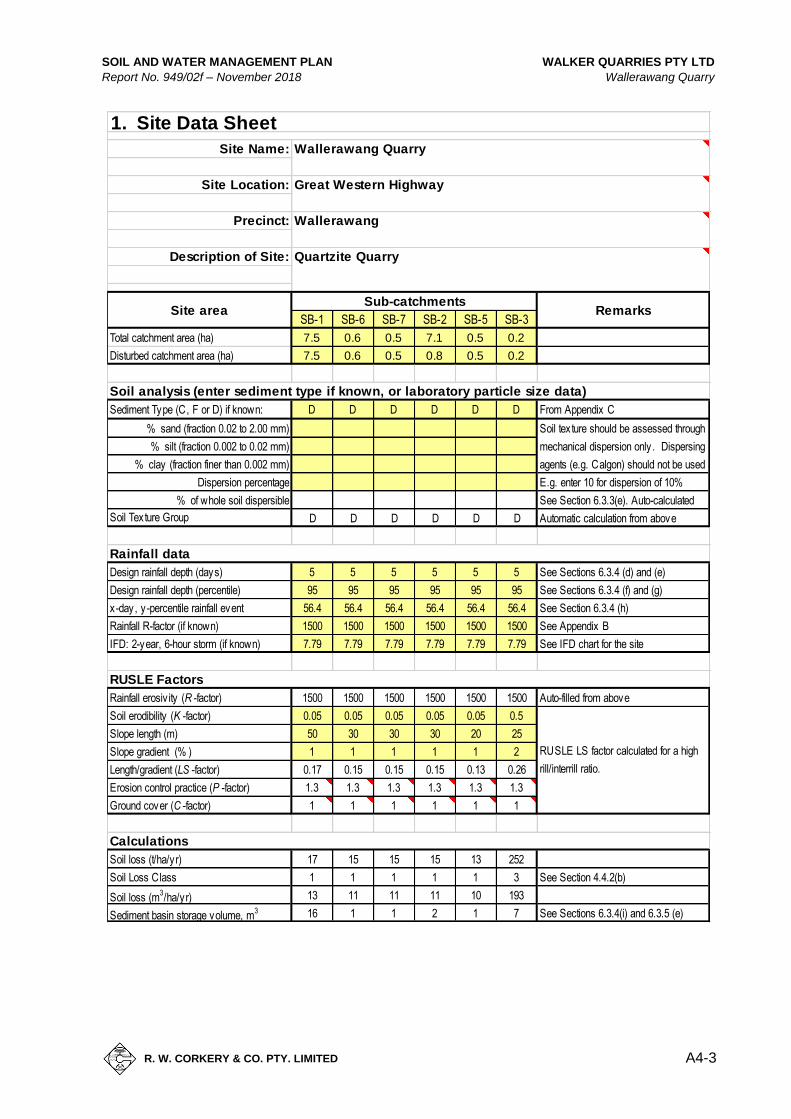
SOIL AND WATER MANAGEMENT PLAN WALKER QUARRIES PTY LTD
Report No. 949/02f – November 2018 Wallerawang Quarry
A4-3
R. W. CORKERY & CO. PTY. LIMITED
SB-1 SB-6 SB-7 SB-2 SB-5 SB-3
7.5 0.6 0.5 7.1 0.5 0.2
7.5 0.6 0.5 0.8 0.5 0.2
Sediment Type (C, F or D) if known: D D D D D D From Appendix C
% sand (fraction 0.02 to 2.00 mm)
% silt (fraction 0.002 to 0.02 mm)
% clay (fraction finer than 0.002 mm)
Dispersion percentage
% of whole soil dispersible
D D D D D D
Design rainfall depth (days) 5 5 5 5 5 5 See Sections 6.3.4 (d) and (e)
Design rainfall depth (percentile) 95 95 95 95 95 95 See Sections 6.3.4 (f) and (g)
x-day, y-percentile rainfall event 56.4 56.4 56.4 56.4 56.4 56.4 See Section 6.3.4 (h)
Rainfall R-factor (if known) 1500 1500 1500 1500 1500 1500 See Appendix B
IFD: 2-year, 6-hour storm (if known) 7.79 7.79 7.79 7.79 7.79 7.79 See IFD chart for the site
Rainfall erosiv ity (R -factor) 1500 1500 1500 1500 1500 1500 Auto-filled from above
0.05 0.05 0.05 0.05 0.05 0.5
50 30 30 30 20 25
1 1 1 1 1 2
0.17 0.15 0.15 0.15 0.13 0.26
1.3 1.3 1.3 1.3 1.3 1.3
1 1 1 1 1 1
17 15 15 15 13 252
Soil Loss Class 1 1 1 1 1 3 See Section 4.4.2(b)
Soil loss (m3/ha/yr) 13 11 11 11 10 193
Sediment basin storage volume, m3 16 1 1 2 1 7 See Sections 6.3.4(i) and 6.3.5 (e)
1. Site Data Sheet
Wallerawang QuarrySite Name:
Great Western Highway
Wallerawang
Quartzite QuarryDescription of Site:
Site Location:
Precinct:
Soil texture should be assessed through
mechanical dispersion only . Dispersing
agents (e.g. Calgon) should not be used
RemarksSub-catchments
Site area
Total catchment area (ha)
RUSLE Factors
Rainfall data
E.g. enter 10 for dispersion of 10%
See Section 6.3.3(e). Auto-calculated
Automatic calculation from aboveSoil Texture Group
Disturbed catchment area (ha)
Soil analysis (enter sediment type if known, or laboratory particle size data)
Soil loss (t/ha/yr)
Length/gradient (LS -factor)
Erosion control practice (P -factor)
Ground cover (C -factor)
RUSLE LS factor calculated for a high
rill/interrill ratio.
Calculations
Slope length (m)
Slope gradient (% )
Soil erodibility (K -factor)

WALKER QUARRIES PTY LTD SOIL AND WATER MANAGEMENT PLAN
Wallerawang Quarry Report No. 949/02f – November 2018
A4-4
R. W. CORKERY & CO. PTY. LIMITED
where:
10 = a unit conversion factor
Cv =
A =
x
SB-1 0.50 56.4 7.5 2115 16 2131
SB-6 0.50 56.4 0.6 169.2 1 170.2
SB-7 0.50 56.4 0.5 141 1 142
SB-2 0.50 56.4 7.1 2002.2 2 2004.2
SB-5 0.50 56.4 0.5 141 1 142
SB-3 0.50 56.4 0.2 56.4 7 63.4
Note that designers
should achieve a
minimum 3:1
length:width ratio in
Type D or F basins
4. Volume of Sediment Basins, Type D and Type F Soils
settling zone volume + sediment storage zone volumeBasin volume =
Settling Zone VolumeThe settling zone volume for Type F and Type D soils is calculated to provide capacity to contain all
runoff expected from up to the y-percentile rainfall event. The volume of the basin's settling zone (V)
can be determined as a function of the basin's surface area and depth to allow for particles to settle
and can be determined by the following equation:
10 x Cv x A x Rx-day , y -%ile (m3)V =
2 months soil loss calculated by RUSLE
the volumetric runoff coefficient defined
as that portion of rainfall that runs off as
stormwater over the x-day period
is the x-day total rainfall depth (mm)
that is not exceeded in y percent of
rainfall events. (See Sections 6.3.4(d),
(e), (f), (g) and (h)).
total catchment area (ha)
Sediment Storage Zone Volume
Rx-day , y -%ile =
In the detailed calculation on Soil Loss Classes 1 to 4 lands, the sediment storage zone can be
taken as 50 percent of the settling zone capacity. Alternately designers can design the zone to store
the 2-month soil loss as calculated by the RUSLE (Section 6.3.4(i)(ii)). However, on Soil Loss
Classes 5, 6 and 7 lands, the zone must contain the 2-month soil loss as calculated by the RUSLE
(Section 6.3.4(i)(iii).
Place an "X" in the box below to show the sediment storage zone design parameters used here:
50% of settling zone capacity,
Total Basin Volume
Settling
zone
volume
(m3)
Sediment
storage
volume
(m3)
Total
basin
volume
(m3)
Site Cv Rx-day, y-%ile
Total
catchment
area
(ha)