walling masonry - brikmakersbrikmakers.com/docs/cmaaguide/cmaa_ma47.pdf · single-leaf masonry...
TRANSCRIPT

Concrete Flag PavementsDesign and Construction Guide
WallingC
on
cre
te M
aso
nry
Single-Leaf Masonry
Design Manual
Concrete Masonry Association of AustraliaQueensland Promotions Committee

Single-Leaf MasonryDesign Manual
Click on this heading to return to ‘Contents’
1
CONTENTSClick on subject to go to it
1 INTRODUCTION 21.1 General 2
1.2 Application of Designs 2
1.3 Material Properties 3
1.4 Earthquake Loading 3
1.5 Typical Details 3
2 SIMPLIFIED DESIGN OF EXTERNAL WALLS 5
3 TABULAR DESIGN OF EXTERNAL WALLS 11
4 BRACING DESIGN 174.1 Method 17
4.2 Racking Forces 17
4.3 Bracing Wall Location 20
4.4 Bracing Wall Capacities 21
5 CONNECTION DETAILS 235.1 Truss Tie Down 23
5.2 Fixing to Gable Ends 25
5.3 Timber Floor Fixing 25
6 BASEMENT WALLS 266.1 General 26
6.2 Drainage 26
6.3 Tanking 27
7 WATERPROOFING RECOMMENDATIONS FOR HOUSING 287.1 Joint Finishing 28
7.2 Weatherproofing Application 28
7.3 Window Installation 28
Disclaimer: The Concrete Masonry Association of Australia Limited is a non-profit organisation sponsored by the concretemasonry industry in Australia to provide information on the many uses of concrete masonry products. Since the informationprovided is intended for general guidance only and in no way replaces the service of professional consultants on particularprojects, no liability can be accepted by the Association for its use.
Industry Support. Most of the manufacturers of quality concrete masonry products in Australia are members of the ConcreteMasonry Association of Australia (CMAA). It is recommended that advice be obtained from local CMAA members to adapt orsupplement information contained in this Guide.
Remember, when working with cement and concrete/mortar or manufactured or prefabricated concrete products, ALWAYS followthe manufacturer's instructions and seek advice about working safely with the products from the manufacturer, your nearestWorkCover Authority or Worksafe Australia.
Prepared by: Ron Marshall Consulting Pty Ltd

Single-Leaf MasonryDesign Manual
2
1 Introduction
1.1 GeneralThis design manual has been prepared for theConcrete Masonry Association of Australia,Queensland Promotions Committee for use bybuilding designers. The information is intendedprimarily for single-leaf concrete masonry houses,but the tables are applicable to other buildings.
Designs for single-leaf buildings in this manual havebeen provided on two levels. The first level issimplified diagrams that are suitable for mosthouses or for initial designs. Where the house ismore complex or it is required to fine-tune thedesign, then the Tabular Design is provided.
1.2 Application of DesignsThe design details in this manual are applicable tobuildings complying with the following:■ The size of the building complies with the
geometric limitations given in Australian StandardAS 4055–1992 Wind loads for housing, exceptthe floor-to-ceiling height, may go to 3.0 m withthe appropriate increase in applied forces.
■ The footings are in accordance with LocalAuthority requirements with starter bars cast inand lapping with all vertical reinforcement in thewalls.
■ Grouted reinforced cores provide the bendingstrength to resist the wind pressure on theexternal walls by spanning vertically betweenfloors or a floor and a roof. Vertical wallreinforcement is anchored into bond beams.Figure 1.1 shows a typical layout of wallreinforcement
■ Wind loads on openings are transferred to theside of the opening or to a central frame ormullions in the opening. Where there is no centralframe or mullion, such as a roller door or similar,the effective “opening width” for wall design willbe the full opening size. Where there is centralframes or mullions, the “opening width” for walldesign is the width of the panel adjacent to theedge of the opening.
NOTE: Lintels are always designed to span thefull opening width.
■ Bond beams are provided at intermediate floorand roof levels. The floor and ceiling systems areconnected to the bond beams and act asdiaphragms to transfer the racking forceshorizontally to bracing walls. Cathedral ceilingswith a slope exceeding 35° and unlined ceilingsdo not act as a diaphragm unless wind bracing isprovided.
■ Uplift forces on the roof are resisted byconnecting the roof to bond beams and lintelswith connections designed to carry the upliftforces. The bond beams span between verticalreinforcement that transfers the uplift to thefoundations. A typical bond beam/lintel layout isshown in Figure 1.1.
■ The amount of load applied to the top of the wallis determined by the width of roof it supports.This width (called Dimension “A”) is determinedin accordance with Figure 1.2.
Pier betweenopenings
Bar at corners
Opening Window Opening
Reinforced cores atsides of all openings
Lintel reinforcement Bond beam reinforcement Lintel reinforcement
Vertical bars in groutedcores spaced along wall
One-course bond beamunder all windows
Figure 1.1 Typical Wall and Reinforcement Layout
'A1' 'A2' 'A3'
Load andtie-downpoint '1'
Load andtie-downpoint '2'
Load andtie-downpoint '3'
Figure 1.2 Determination of Dimension “A”

Single-Leaf MasonryDesign Manual
3
1.3 Material PropertiesThe design tables in this Manual are based onmaterials with the following properties:■ Characteristic Unconfined Compressive Strength
of concrete masonry units, f’uc = 15 MPa
■ Characteristic Compressive Strength of grout,f’c = 20 MPa
■ Yield Strength of reinforcement, f’sy = 500 MPa
■ Mortar Type, M3
1.4 Earthquake LoadingBuildings designed for wind loading N2 and greaterwill satisfy Earthquake Design Categories H1 andH2, applicable in Queensland.
1.5 Typical DetailsTypical details for various components are shown inFigures 1.3 to 1.7. Where an N16 bar is required inthe details, 2-N12 bars may be used as analternative.
Knock-outbond beamblock
1-N16 bar
60 tobar bottom
140or 190
TYPE 1 TYPE 2 TYPE 3
Standardblocks
Knock-outbond beamblocks
Minimum1-N12 bar
60 tobar bottom
260to barbottom
140or 190
Standardblocks
Minimum1-N12 bar
Knock-outblock
Knock-out block
Minimum1-N12 bar
60 tobar bottom
460to barbottom
140or 190
Standardblock
Standard blocks
Minimum1-N12 bar
Figure 1.3 Typical Details for Bond Beams Supporting a Roof
1-N12 bar
CONCRETE FLOOR TIMBER FLOOR
1-coursebond beam usingknock-out block Block saw-cut at floor soffit level
Wall vertical reinforcement from belowfloor level bent into top face of floor slab
Starter-bars at same sizeand location as wall verticalreinforcement, lapped 450 min.
Vertical wall reinforcement abovefloor level, lapped 450 min. withreinforcement from below
Wall verticalreinforcementabove floor level
1-N12 bar
1-coursebond beam usingknock-out block
Wall verticalreinforcementabove floor level
Bearer bolted to bond beam
Figure 1.4 Typical Details for Bond Beams Supporting a Floor
Knock-out block withinside face removed
L8 or N10 ties at600 centres
Floor slabreinforcement
Starter-bars at samesize and location as wallvertical reinforcement,lapped 450 min.
Starter-bars at samesize and location as wallvertical reinforcement,lapped 450 min. Starter-bars at same size
and location as wall verticalreinforcement, lapped 450 min.
Strip footing
Wall vertical reinforcement
L6 ties at 600 centres
Floor slab reinforcement
Strip footing
Wall vertical reinforcement Wall vertical reinforcement
Floor slabreinforcement
Integral footing
Figure 1.5 Typical Details of Connections to Footings

Single-Leaf MasonryDesign Manual
4
TYPE A – SECTIONTYPE A – TYPICAL ELEVATION
TYPE C – SECTION
3/4 lintelblock*
* for 140-mm-thick walls, use 15.02block cut on site and turned on end
Cut out endand web
15.02 block
Knock-outblock
1-N12, N16 or N20 bar
Top reinforcementcarried beyond the support
Bottom reinforcementcarried beyond the support
1-N12, N16 or N20 bar
NOTE: For requiredbar size, see Tables3.5, 3.6 and 3.7
NOTE: For requiredbar size, see Tables3.5, 3.6 and 3.7
NOTE: For requiredbar size, see Tables3.5, 3.6 and 3.7
60 tobar bottom
215to barbottom 290
140*or 190
290
290
390
590Standardblock
60 tobar bottom
460to barbottom
140or 190
590
Lintel block
L8 fitments at 150 crswith N16 & N20 bars
L8 fitments at 150 crs for full width of openingwith N16 & N20 bars
1-N12, N16 or N20 bar
1-N12, N16 or N20 bar
L8 fitments at 200 crswith N16 & N20 bars
1-N12, N16 or N20 bar
1-N12, N16 or N20 bar
L8 fitments at 200 crswith N16 & N20 bars
TYPE B – SECTION
Lintel block
Knock-outblock
60 tobar bottom
260to barbottom 390
140or 190
L8 fitments at 200 crs for full width of openingwith N16 & N20 bars
L8 fitments at 200 crs for full width of openingwith N16 & N20 bars
TYPE B – TYPICAL ELEVATION
Top reinforcementcarried beyond the support
Bottom reinforcementcarried beyond the support
TYPE C – TYPICAL ELEVATION
Top reinforcementcarried beyond the support
Bottom reinforcementcarried beyond the support
Figure 1.6 Typical Details for Lintels Supporting a Roof
TYPE BB – TYPICAL SECTION TYPE CC – TYPICAL SECTION
Lintel block
Knock-outblock
Knock-outblock
1-N16 baror 1-N20 bar
60 tobar bottom
315to barbottom 390
140or 190
Standardblock
1-N16 baror 1-N20 bar
1-N16 baror 1-N20 bar
60 tobar bottom
515to barbottom
140or 190
590
Lintel block1-N16 baror 1-N20 bar
L8 fitmentsat 200 crs
L8 fitmentsat 200 crs
NOTE: For requiredbar size, see Table 3.8
NOTE: For requiredbar size, see Table 3.8
Figure 1.7 Details of Lintels Supporting Timber Floors

Single-Leaf MasonryDesign Manual
5
2 Simplified Designof External Walls
External wall reinforcement may be detailed usingFigures 2.1 to 2.14 for the wind classification anddimensional limitations as noted on the drawingsand summarised in Table 2.1.
For earthquake classifications H1, H2 and H3, thedetails given for wind category N2 are suitable. Thelintel details are only suitable for standard roof trussloading. Where there is either floor loadings orgirder-truss loadings, use lintel design tables(Tables 3.8 and 3.9) in Chapter 3 of this manual.
Where the building geometry is other than shown,design should be in accordance with Chapter 3.
2400
NOTE: Drawing not to scale
1-N12 at corners
300
600 2400 400 2400 2400 maximum
300
1-N12 at edge of opening
1-N16
1-N16
1-N16L8 fitmentsat 150 crs
L8 fitmentsat 150 crs
1-N16
1-N12at edgeof opening
1-N12 at edge ofall openings
2-N12 in400 x 150 pier
1-N12 at2000 crsin wall
1-N12
Table 2.1 Summary of Design Parameters
Leaf WallFigure thickness Wind height Pagenumber (mm) Classification (mm) number
2.1 140 N1, N2 & N3 2400 52.2 140 N1, N2 & N3 2500 52.3 140 N1, N2 & N3 2700 6
2.4 140 N4 & C1 2400 62.5 140 N4 & C1 2700 7
2.6 140 N5 & C2 2500 72.7 140 N5 & C2 2700 7
2.8 190 N1, N2 & N3 2400 82.9 190 N1, N2 & N3 2500 82.10 190 N1, N2 & N3 2700 9
2.11 190 N4 & C1 2400 92.12 190 N4 & C1 2700 10
2.13 190 N5 & C2 2500 102.14 190 N5 & C2 2700 10
Figure 2.1 Wall Reinforcement for 140-mm Leaf for Wind Classifications N1, N2 and N3 and2400-mm Wall Height
2500
NOTE: Drawing not to scale
1-N12 at corners
400
600 2400 400 2400 3000 maximum
400
1-N12 at edge of opening
1-N16
1-N16
1-N16L8 fitmentsat 200 crs
L8 fitmentsat 200 crs
1-N16
1-N12at edgeof opening
1-N12 at edge ofall openings
1-N12 at2000 crsin wall
2-N12 in400 x 150 pier
1-N12
Figure 2.2 Wall Reinforcement for 140-mm Leaf for Wind Classifications N1, N2 and N3 and2500-mm Wall Height

Single-Leaf MasonryDesign Manual
6
2700
NOTE: Drawing not to scale
1-N12 at corners
600
600 2400 400 2400 3000 maximum
600
1-N12 at edge of opening
1-N12 1-N16
1-N12
1-N12
1-N12
1-N12
1-N12
6001-N12
1-N12
1-N12at edgeof opening
1-N12 at edge ofall openings
1-N12 at2000 crsin wall
DOUBLE GARAGE WITH PIER
2700
NOTE: Drawing not to scale
1-N12 at corners
600
600 5400 3000 maximum
1-N12 at edge of opening
1-N16 1-N16
1-N20
L8 fitments at 200 crs
1-N12at edgeof opening
1-N12 at edge ofall openings
1-N12 at2000 crsin wall
DOUBLE GARAGE WITHOUT PIER
2-N12 in400 x 150 pier
Figure 2.3 Wall Reinforcement for 140-mm Leaf for Wind Classifications N1, N2 and N3 and2700-mm Wall Height
2400
NOTE: Drawing not to scale
1-N12 at corners
300
600 2400 400 2400 2400 maximum
300
1-N12 (if near corner)
1-N16
1-N16
1-N16
1-N16
1-N16L8 fitmentsat 150 crs
L8 fitmentsat 150 crs
1-N16
2-N12 atopenings≤ 2.4 m
1-N12 for openings≤ 1.2 m, 2-N12 for> 1.2 m ≤ 2.4 m
1-N12 at1800 crsin wall
2-N12 in400 x 150 pier
1-N12
Figure 2.4 Wall Reinforcement for 140-mm Leaf for Wind Classifications N4 and C1 and2400-mm Wall Height

Single-Leaf MasonryDesign Manual
7
6001-N12
1-N12
1-N12
1-N12
1-N12
2700
NOTE: Drawing not to scale
1-N12 at corners
600
600 5400 3000 maximum
1-N12 (if near corner)
1-N20
1-N20
L8 fitments at 200 crs
3-N12at edgeof opening
1-N12 for openings≤ 1.2 m, 2-N12 for> 1.2 m ≤ 3.0 m
1-N12 at1400 crsin wall
Figure 2.5 Wall Reinforcement for 140-mm Leaf for Wind Classifications N4 and C1 and2700-mm Wall Height
2500
NOTE: Drawing not to scale
1-N12 at corners
400
600 2400 600 2400 2400 maximum
400
1-N12 (if near corner)
1-N16
1-N16
1-N16
1-N16
1-N16L8 fitmentsat 200 crs
L8 fitmentsat 200 crs
1-N16
2-N12 atedge ofopening
1-N12 at1200 crsin wall
2-N12 at edges ofopenings
600 x 300 T-pier
2-N12 in face of pier
1-N16 in stem of pier 1-N12
Figure 2.6 Wall Reinforcement for 140-mm Leaf for Wind Classifications N5 and C2 and2500-mm Wall Height
2700
NOTE: Drawing not to scale
1-N12 at corners
600
600 2400 600 2400 2400 maximum
600
1-N12 (if near corner)
1-N12
1-N12
1-N12
1-N12
1-N12
1-N12
3-N12 atopenings≤ 2.4 m
1-N12 at1000 crsin wall
2-N12 for openings≤ 1.8 m, 3-N12 for> 1.8 m ≤ 2.4 m
600 x 300 T-pier
2-N12 in face of pier
1-N16 in stem of pier 1-N12
Figure 2.7 Wall Reinforcement for 140-mm Leaf for Wind Classifications N5 and C2 and2700-mm Wall Height

Single-Leaf MasonryDesign Manual
8
2400
NOTE: Drawing not to scale
1-N12 at corners
300
600 2400 400 2400 2400 maximum
300
1-N12 at edge of opening
1-N16
1-N16
1-N16L8 fitmentsat 150 crs
L8 fitmentsat 150 crs
1-N16
1-N12at edgeof opening
1-N12 at edge ofall openings
2-N12 in400 x 200 pier
1-N12 at2000 crsin wall
1-N12
Figure 2.8 Wall Reinforcement for 190-mm Leaf for Wind Categories N1, N2 and N3 and2400-mm Wall Height
2500
NOTE: Drawing not to scale
1-N12 at corners
400
600 2400 400 2400 3000 maximum
400
1-N12 at edge of opening
1-N12 1-N16
1-N12
1-N16L8 fitmentsat 200 crs
1-N16
1-N12
1-N12at edgeof opening
1-N12 at edge ofall openings
1-N12 at2000 crsin wall
2-N12 in400 x 200 pier
Figure 2.9 Wall Reinforcement for 190-mm Leaf for Wind Categories N1, N2 and N3 and2500-mm Wall Height

Single-Leaf MasonryDesign Manual
9
2700
NOTE: Drawing not to scale
1-N12 at corners
600
600 2400 400 2400 3000 maximum
600
1-N12 at edge of opening
1-N12
1-N12
1-N12
1-N12
1-N12
1-N12
6001-N12
1-N12
1-N12at edgeof opening
1-N12 at edgesof openings
1-N12 at edgesof openings
1-N12 at2000 crsin wall
DOUBLE GARAGE WITH PIER
2700
NOTE: Drawing not to scale
1-N12 at corners
600
600 5400 3000 maximum
1-N12 (if near corner)
1-N16
1-N20
L8 fitments at 200 crs
2-N12at edgeof opening
1-N12 at2000 crsin wall
DOUBLE GARAGE WITHOUT PIER
2-N12 in400 x 200 pier
Figure 2.10 Wall Reinforcement for 190-mm Leaf for Wind Classifications N1, N2 and N3 and2700-mm Wall Height
2400
NOTE: Drawing not to scale
1-N12 at corners
300
600 2400 400 2400 3000 maximum
300
1-N12 (if near corner)
1-N16
1-N16
1-N16
1-N16
1-N16L8 fitmentsat 150 crs
L8 fitmentsat 150 crs
1-N16
1-N12 atedge ofopening
1-N12 at edges ofopenings
1-N12 at1800 crsin wall
2-N12 in400 x 200 pier
1-N12
Figure 2.11 Wall Reinforcement for 190-mm Leaf for Wind Classifications N4 and C1 and2400-mm Wall Height

Single-Leaf MasonryDesign Manual
10
6001-N12
1-N12
1-N12
1-N12
1-N12
2700
NOTE: Drawing not to scale
1-N12 at corners
600
600 5400 3000 maximum
1-N12 (if near corner)
1-N20
1-N20
L8 fitments at 200 crs
2-N12at edgeof opening
1-N12 for openings≤ 1.8 m, 2-N12 for> 1.8 m ≤ 3.0 m
1-N12 at1800 crsin wall
Figure 2.12 Wall Reinforcement for 190-mm Leaf for Wind Classifications N4 and C1 and2700-mm Wall Height
2500
NOTE: Drawing not to scale
1-N12 at corners
400
600 2400 600 2400 2400 maximum
400
1-N12 (if near corner)
1-N16
1-N16
1-N16
1-N16
1-N16L8 fitmentsat 200 crs
L8 fitmentsat 200 crs
1-N16
2-N12 atopenings≤ 2.4 m
2-N12 in600 x 200 pier
1-N12 at1600 crsin wall
1-N12 for openings≤ 1.2 m, 2-N12 for> 1.2 m ≤ 2.4 m
1-N12
Figure 2.13 Wall Reinforcement for 190-mm Leaf for Wind Classifications N5 and C2 and2500-mm Wall Height
2700
NOTE: Drawing not to scale
1-N12 at corners
600
600 2400 600 2400 2400 maximum
600
1-N12 (if near corner)
1-N12
1-N12
1-N12
1-N12
1-N12
1-N12
2-N12 atopenings≤ 2.4 m
1-N12 at1400 crsin wall
1-N12 for openings≤ 1.2 m, 2-N12 for> 1.2 m ≤ 2.4 m
2-N12 in600 x 200 pier
1-N12
Figure 2.14 Wall Reinforcement for 190-mm Leaf for Wind Classifications N5 and C2 and2700-mm Wall Height
Single-Leaf MasonryDesign Manual
11
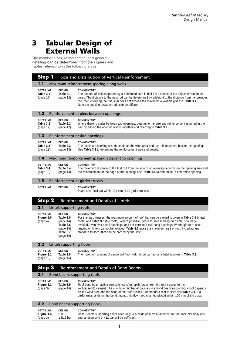
3 Tabular Design ofExternal Walls
The member sizes, reinforcement and generaldetailing can be determined from the Figures andTables referred to in the following steps:
DETAILING DESIGN COMMENTARYTable 3.1 Table 3.1 The amount of wall supported by a reinforced core is half the distance to the adjacent reinforced(page 12) (page 12) cores. The distance to the next rod can be determined by adding it to the distance from the previous
rod, then checking that the sum does not exceed the maximum allowable given in Table 3.1.Note the spacing between rods can be different.
DETAILING DESIGN COMMENTARYTable 3.2 Table 3.2 Where there is a pier between two openings, determine the size and reinforcement required in the(page 12) (page 12) pier by adding the opening widths together and referring to Table 3.2.
DETAILING DESIGN COMMENTARYTable 3.3 Table 3.3 The maximum opening size depends on the wind area and the reinforcement beside the opening.(page 13) (page 13) Use Table 3.3 to determine the reinforcement size and details.
DETAILING DESIGN COMMENTARYTable 3.4 Table 3.4 The maximum distance to the first rod from the side of an opening depends on the opening size and(page 13) (page 13) the reinforcement at the edge of the opening. Use Table 3.4 to determine to determine spacing.
DETAILING DESIGN COMMENTARY– – Place a vertical bar within 100 mm of all girder trusses.
DETAILING DESIGN COMMENTARYFigure 1.6 Table 3.5 For standard trusses, the maximum amount of roof that can be carried is given in Table 3.5 (metal(page 4) (page 14) roofs} and Table 3.6 (tile roofs). Where possible, girder trusses landing on a lintel should be
Table 3.6 avoided, even over small openings, and not permitted over long openings. Where girder trusses(page 15) landing on lintels cannot be avoided, Table 3.7 gives the maximum area of roof, including anyTable 3.7 standard trusses, that can be carried by the lintel.(page 16)
DETAILING DESIGN COMMENTARYFigure 3.1 Table 3.8 The maximum amount of supported floor width to be carried by a lintel is given in Table 3.8.(page 16) (page 16)
DETAILING DESIGN COMMENTARYFigure 1.3 Table 3.9 Roof bond beam acting vertically transfers uplift forces from the roof trusses to the(page 3) (page 16) vertical reinforcement. The minimum number of courses in a bond beam supporting a roof depends
on the wind area and the span of the roof trusses. For standard roof trusses see Table 3.9. If agirder truss lands on the bond beam, a tie-down rod must be placed within 100 mm of the truss.
DETAILING DESIGN COMMENTARYFigure 1.4 Use Bond Beams supporting floors need only to provide positive attachment for the floor. Normally one(page 3) 1-N12 bar course deep with 1-N12 bar will be sufficient.
Step 3 Reinforcement and Details of Bond Beams
3.1 Bond beams supporting roofs
Step 1 Size and Distribution of Vertical Reinforcement
1.2 Reinforcement in piers between openings
Step 2 Reinforcement and Details of Lintels
2.1 Lintels supporting roofs
3.2 Bond beams supporting floors
1.3 Reinforcement beside openings
1.4 Maximum reinforcement spacing adjacent to openings
1.1 Maximum reinforcement spacing along walls
1.5 Reinforcement at girder trusses
2.2 Lintels supporting floors

Single-Leaf MasonryDesign Manual
12
Table 3.2 Selection and Detailing of Pier Reinforcement
Maximum allowable sum of openings, w1 + w2 (m)
140-mm-leaf wall 190-mm-leaf wall
Wind Wall height (m) Wall height (m)
Pier details Class. 2.4 2.7 3.0 3.3 3.6 2.4 2.7 3.0 3.3 3.6
N2 5.2 4.0 3.2 2.6 2.1 9.9 7.7 6.2 5.0 4.2N3 3.2 2.5 1.9 – – 6.3 4.9 3.9 3.1 2.6N4 2.0 – – – – 4.1 3.1 2.5 2.0 –N5 – – – – – 2.7 2.1 – – –N6 – – – – – 1.9 – – – –
C1 2.3 – – – – 4.5 3.5 2.8 2.2 1.8C2 – – – – – 2.9 2.2 – – –C3 – – – – – 1.9 – – – –C4 – – – – – – – – – –
N2 10.8 8.5 6.7 5.5 4.5 10.8 10.8 10.8 10.4 8.6N3 6.8 5.3 4.2 3.3 2.7 10.8 10.0 8.0 6.5 5.4N4 4.4 3.3 2.6 2.0 – 8.4 6.5 5.2 4.2 3.4N5 2.9 2.1 – – – 5.7 4.4 3.4 2.7 2.2N6 1.9 – – – – 4.0 3.0 2.4 1.8 –
C1 4.9 3.7 2.9 2.3 1.8 9.4 7.3 5.8 4.7 3.8C2 3.1 2.3 1.8 – – 6.1 4.7 3.6 2.9 2.4C3 2.0 – – – – 4.0 3.1 2.4 1.9 –C4 – – – – – 2.8 2.1 – – –
N2 10.8 10.8 10.8 10.8 10.8 10.8 10.8 10.8 10.8 10.8N3 10.8 10.8 10.8 10.8 10.8 10.8 10.8 10.8 10.8 10.8N4 10.8 10.8 10.8 10.7 8.9 10.8 10.8 10.8 10.8 10.8N5 10.8 10.8 8.9 7.3 6.0 10.8 10.8 10.8 10.8 10.8N6 – – – – – 10.8 10.8 10.8 10.8 9.2
C1 10.8 10.8 10.8 10.8 9.9 10.8 10.8 10.8 10.8 10.8C2 10.8 10.8 9.6 7.8 6.4 10.8 10.8 10.8 10.8 10.8C3 10.4 8.1 6.4 5.2 4.3 10.8 10.8 10.8 10.8 9.3C4 – – – – – 10.8 10.8 9.9 8.0 6.7
Table 3.1 Selection and Detailing of Maximum Reinforcement Spacing Along Walls
Maximum sum of adjacent bar spacing, s1 + s2 (m)
140-mm-leaf wall 190-mm-leaf wall
Wind Wall height (m) Wall height (m)
Wall details Class. 2.4 2.7 3.0 3.3 3.6 2.4 2.7 3.0 3.3 3.6
N2 4.0 4.0 4.0 4.0 3.8 4.0 4.0 4.0 4.0 4.0N3 4.0 4.0 3.5 2.9 2.4 4.0 4.0 4.0 4.0 3.4N4 3.7 2.9 2.4 2.0 1.6 4.0 4.0 3.3 2.8 2.3N5 2.6 2.0 1.6 – – 3.6 2.9 2.3 1.9 1.6N6 – – – – – 2.7 2.1 1.7 – –
C1 4.0 3.2 2.6 2.1 1.8 4.0 4.0 3.7 3.0 2.5C2 2.7 2.2 1.7 – – 3.9 3.0 2.5 2.0 1.7C3 1.9 – – – – 2.7 2.1 1.7 – –C4 – – – – – 2.0 1.6 – – –
N2 – – – – – 4.0 4.0 4.0 4.0 4.0N3 – – – – – 4.0 4.0 4.0 4.0 3.4N4 – – – – – 4.0 4.0 4.0 4.0 4.0N5 – – – – – 4.0 4.0 4.0 3.3 2.8N6 – – – – – 4.0 3.7 3.0 2.5 2.1
C1 – – – – – 4.0 4.0 4.0 4.0 4.0C2 – – – – – 4.0 4.0 4.0 3.6 3.0C3 – – – – – 4.0 3.7 3.0 2.5 2.1C4 – – – – – 3.4 2.7 2.2 1.8 1.5
1-N12 barin groutedcore140 or
190
w1 190 w2
2-N12 barsin grouted cores
140 or190
w1 390 w2
1-N16 bar
2-N12 bars
140
190
w1 590 w2
290
1-N16 bar
140-mm-LEAF WALL
Medium-dutyties at 400 crs
2-N12 bars
190
190
w1 590 w2
390
Medium-dutyties at 400 crs
190-mm-LEAF WALL
1-N12 bar ingrouted core
140 or190
s1 s2
1-N12 bar ingrouted core
1-N12 bar ingrouted core
1-N16 bar ingrouted core190
s1 s2
1-N16 bar ingrouted core
1-N16 bar ingrouted core

Single-Leaf MasonryDesign Manual
13
Table 3.3 Selection and Detailing of Reinforcement Beside Openings
Maximum allowable opening size, w1 (m)
140-mm-leaf wall 190-mm-leaf wall
Wind Wall height (m) Wall height (m)
Opening details Class. 2.4 2.7 3.0 3.3 3.6 2.4 2.7 3.0 3.3 3.6
N2 5.4 5.4 4.6 3.7 3.0 5.4 5.4 5.4 5.4 4.6N3 4.6 3.5 2.8 2.2 1.7 5.4 5.3 4.2 3.4 2.7N4 2.9 2.2 1.7 1.3 1.0 4.5 3.4 2.6 2.1 1.7N5 1.9 1.3 1.0 – – 2.9 2.2 1.7 1.3 1.0N6 – – – – – 2.0 1.4 1.1 – –
C1 3.3 2.5 1.9 1.5 1.1 5.0 3.8 3.0 2.4 1.9C2 2.0 1.5 1.1 – – 3.2 2.4 1.8 1.4 1.1C3 1.2 – – – – 2.0 1.5 1.1 – –C4 – – – – – 1.3 0.9 – – –
N2 5.4 5.4 5.4 5.4 5.4 5.4 5.4 5.4 5.4 5.4N3 5.4 5.4 5.4 4.3 3.5 5.4 5.4 5.4 5.4 5.4N4 5.4 4.3 3.3 2.6 2.0 5.4 5.4 5.3 4.2 3.4N5 3.7 2.7 2.0 1.5 1.1 5.4 4.4 3.4 2.6 2.0N6 – – – – – 4.0 3.0 2.2 1.6 1.2
C1 5.4 4.9 3.8 2.9 2.3 5.4 5.4 5.4 4.7 3.8C2 4.0 3.0 2.2 1.7 1.2 5.4 4.7 3.7 2.8 2.2C3 2.5 1.8 1.2 – – 4.1 3.0 2.2 1.7 1.2C4 – – – – – 2.7 1.9 1.4 1.0 –
N2 – – – – – 5.4 5.4 5.4 5.4 5.4N3 – – – – – 5.4 5.4 5.4 5.4 5.4N4 – – – – – 5.4 5.4 5.4 5.4 5.4N5 – – – – – 5.4 5.4 5.4 4.9 3.9N6 – – – – – 5.4 5.4 4.2 3.3 2.6
C1 – – – – – 5.4 5.4 5.4 5.4 5.4C2 – – – – – 5.4 5.4 5.4 5.2 4.2C3 – – – – – 5.4 5.4 4.2 3.3 2.6C4 – – – – – 5.0 3.8 2.9 2.2 1.7
Table 3.4 Selection and Detailing of Maximum Reinforcement Spacing Adjacent to Openings
Maximum adjacent bar spacing plus opening, s1 + w1(m)
140-mm-leaf wall 190-mm-leaf wall
Wind Wall height (m) Wall height (m)
Wall and opening details Class. 2.4 2.7 3.0 3.3 3.6 2.4 2.7 3.0 3.3 3.6
N2 7.4 6.2 5.0 4.1 3.4 7.4 7.4 7.2 5.9 5.0N3 5.0 3.9 3.2 2.6 2.1 7.3 5.7 4.6 3.8 3.1N4 3.3 2.6 2.1 1.7 1.4 4.9 3.8 3.0 2.5 2.1N5 2.3 1.7 1.4 – – 3.3 2.6 2.1 1.7 1.4N6 – – – – – 2.4 1.8 1.5 – –
C1 3.7 2.9 2.3 1.9 1.5 5.4 4.2 3.4 2.8 2.3C2 2.4 1.9 1.5 – – 3.6 2.8 2.2 1.8 1.5C3 1.2 – – – – 2.4 1.9 1.5 – –C4 – – – – – 1.7 1.3 – – –
N2 7.4 7.4 7.4 7.4 6.3 7.4 7.4 7.4 7.4 7.4N3 7.4 7.4 5.8 4.7 3.9 7.4 7.4 7.4 7.1 5.9N4 6.2 4.7 3.7 3.0 2.4 7.4 7.4 5.7 4.6 3.8N5 4.1 3.1 2.4 1.9 1.5 6.2 4.8 3.8 3.0 2.4N6 – – – – – 4.4 3.4 2.6 2.0 1.6
C1 6.9 5.3 4.2 3.3 2.7 7.4 7.4 6.3 5.1 4.2C2 4.4 3.4 2.6 2.1 1.6 6.7 5.1 4.1 3.2 2.6C3 2.9 2.2 1.6 – – 4.5 3.4 2.6 2.1 1.6C4 – – – – – 3.1 2.3 1.8 1.4 –
N2 – – – – – 7.4 7.4 7.4 7.4 7.4N3 – – – – – 7.4 7.4 7.4 7.4 7.4N4 – – – – – 7.4 7.4 7.4 7.4 6.5N5 – – – – – 7.4 7.4 6.5 5.3 4.3N6 – – – – – 7.4 5.8 4.6 3.7 3.0
C1 – – – – – 7.4 7.4 7.4 7.4 6.8C2 – – – – – 7.4 7.4 7.0 5.6 4.6C3 – – – – – 7.4 5.9 4.6 3.7 3.0C4 – – – – – 5.4 4.2 3.3 2.6 2.1
1-N12 bar ingrouted core140 or
190
w1
1-N12 bar ingrouted core
2-N12 bars ingrouted cores140 or
190
w1
2-N12 bars ingrouted cores
2-N16 bars ingrouted cores190
w1
2-N16 bars ingrouted cores
1-N12 bar ingrouted core140 or
190
w1s1
1-N12 bar ingrouted core
1-N12 bar ingrouted core140 or
190
w1s1
2-N12 bars ingrouted cores
1-N16 bar ingrouted core190
w1s1
2-N16 bars ingrouted cores

Single-Leaf MasonryDesign Manual
14
Table 3.5 Selection of Lintels Supporting Standard Trusses with Metal Roofing Material
Maximum allowable value of dimension ‘A’ (m)
140-mm-wide lintels 190-mm-wide lintels
Wind Opening Type A(1) with: Type B(1) with: Type C(1) with: Type A(1) with: Type B(1) with: Type C(1) with:
class. (m) N12 N16 N20 N12 N16 N20 N12 N16 N20 N12 N16 N20 N12 N16 N20 N12 N16 N20
N1 0.9 9.0 9.0 9.0 9.0 9.0 9.0 9.0 9.0 9.0 9.0 9.0 9.0 9.0 9.0 9.0 9.0 9.0 9.0and 1.2 9.0 9.0 9.0 9.0 9.0 9.0 9.0 9.0 9.0 9.0 9.0 9.0 9.0 9.0 9.0 9.0 9.0 9.0N2 1.8 8.5 9.0 9.0 9.0 9.0 9.0 9.0 9.0 9.0 9.0 9.0 9.0 9.0 9.0 9.0 9.0 9.0 9.0
2.4 6.3 9.0 9.0 7.7 9.0 9.0 9.0 9.0 9.0 7.9 9.0 9.0 9.0 9.0 9.0 9.0 9.0 9.03.0 5.0 8.5 8.5 6.1 9.0 9.0 9.0 9.0 9.0 5.0 9.0 9.0 6.1 9.0 9.0 9.0 9.0 9.03.6 – – – 4.2 8.3 9.0 8.4 9.0 9.0 – – – 3.7 8.2 9.0 7.6 9.0 9.04.2 – – – 2.7 5.6 6.3 5.5 9.0 9.0 – – – 2.1 5.4 8.5 4.7 9.0 9.04.8 – – – – – – 3.7 8.5 9.0 – – – – – – 2.9 7.8 9.05.4 – – – – – – 2.5 6.4 9.0 – – – – – – 1.6 5.7 9.0
N3 0.9 9.0 9.0 9.0 9.0 9.0 9.0 9.0 9.0 9.0 9.0 9.0 9.0 9.0 9.0 9.0 9.0 9.0 9.01.2 8.2 9.0 9.0 9.0 9.0 9.0 9.0 9.0 9.0 9.0 9.0 9.0 9.0 9.0 9.0 9.0 9.0 9.01.8 6.6 9.0 9.0 9.0 9.0 9.0 9.0 9.0 9.0 8.7 9.0 9.0 9.0 9.0 9.0 9.0 9.0 9.02.4 5.3 9.0 9.0 7.7 9.0 9.0 9.0 9.0 9.0 6.9 9.0 9.0 9.0 9.0 9.0 9.0 9.0 9.03.0 4.5 8.3 8.3 6.1 9.0 9.0 9.0 9.0 9.0 5.0 9.0 9.0 6.1 9.0 9.0 9.0 9.0 9.03.6 – – – 4.2 8.3 9.0 8.4 9.0 9.0 – – – 3.7 8.2 9.0 7.6 9.0 9.04.2 – – – 2.7 5.6 6.3 5.5 9.0 9.0 – – – 2.1 5.4 8.5 4.7 9.0 9.04.8 – – – – – – 3.7 8.5 9.0 – – – – – – 2.9 7.8 9.05.4 – – – – – – 2.5 6.4 9.0 – – – – – – 1.6 5.7 9.0
N4 0.9 7.4 9.0 9.0 9.0 9.0 9.0 9.0 9.0 9.0 9.0 9.0 9.0 9.0 9.0 9.0 9.0 9.0 9.0and 1.2 5.7 9.0 9.0 9.0 9.0 9.0 9.0 9.0 9.0 7.5 9.0 9.0 9.0 9.0 9.0 9.0 9.0 9.0C1 1.8 4.6 9.0 9.0 6.7 9.0 9.0 9.0 9.0 9.0 6.0 9.0 9.0 9.0 9.0 9.0 9.0 9.0 9.0
2.4 3.6 8.0 8.0 5.3 9.0 9.0 8.4 9.0 9.0 4.8 8.7 9.0 7.7 9.0 9.0 9.0 9.0 9.03.0 3.1 5.7 5.7 4.5 8.8 9.0 7.8 9.0 9.0 3.9 6.3 7.8 5.6 8.3 9.0 8.2 9.0 9.03.6 – – – 3.9 6.6 8.6 6.6 9.0 9.0 – – – 3.7 7.0 9.0 7.0 9.0 9.04.2 – – – 2.7 5.0 6.3 5.1 8.3 9.0 – – – 2.1 5.3 7.5 4.7 8.7 9.04.8 – – – – – – 3.7 6.7 9.0 – – – – – – 2.9 7.1 9.05.4 – – – – – – 2.5 5.7 8.1 – – – – – – 1.6 6.1 8.7
N5 0.9 4.3 9.0 9.0 6.7 9.0 9.0 9.0 9.0 9.0 5.7 9.0 9.0 9.0 9.0 9.0 9.0 9.0 9.0and 1.2 3.4 9.0 9.0 5.3 9.0 9.0 9.0 9.0 9.0 4.4 9.0 9.0 7.0 9.0 9.0 9.0 9.0 9.0C2 1.8 2.7 8.1 8.1 3.9 9.0 9.0 7.2 9.0 9.0 3.5 8.7 9.0 5.2 9.0 9.0 9.0 9.0 9.0
2.4 2.1 4.7 4.7 3.1 7.3 9.0 5.5 9.0 9.0 2.8 5.1 6.4 4.1 7.0 9.0 7.4 9.0 9.03.0 1.8 3.4 3.4 2.6 5.2 6.8 4.6 8.7 9.0 2.3 3.7 4.6 3.3 5.5 7.9 5.4 9.0 9.03.6 – – – 2.3 3.9 5.0 3.9 6.5 9.0 – – – 2.5 4.1 5.9 4.1 6.8 9.04.2 – – – 2.0 2.9 3.8 3.0 4.9 7.1 – – – 2.0 3.1 4.4 3.2 5.1 7.54.8 – – – – – – 2.5 4.0 5.7 – – – – – – 2.6 4.2 6.05.4 – – – – – – 2.1 3.4 4.8 – – – – – – 1.6 3.6 5.1
N6 0.9 4.1 9.0 9.0 6.3 9.0 9.0 9.0 9.0 9.01.2 3.2 9.0 9.0 5.1 9.0 9.0 9.0 9.0 9.01.8 2.5 6.3 7.9 3.8 9.0 9.0 6.9 9.0 9.02.4 2.0 3.7 4.6 3.0 5.5 8.0 5.3 9.0 9.03.0 1.6 2.7 3.3 2.4 3.9 5.7 3.9 6.5 9.03.6 – – – 1.8 3.0 4.3 3.0 4.9 7.24.2 – – – 1.4 2.3 3.2 2.3 3.7 5.44.8 – – – – – – 1.9 3.0 4.45.4 – – – – – – 1.6 2.6 3.7
C3 0.9 3.8 9.0 9.0 5.8 9.0 9.0 9.0 9.0 9.01.2 2.9 9.0 9.0 4.7 9.0 9.0 9.0 9.0 9.01.8 2.3 5.8 7.3 3.5 8.7 9.0 6.4 9.0 9.02.4 1.9 3.4 4.2 2.7 5.1 7.4 4.9 8.4 9.03.0 1.5 2.4 3.0 2.2 3.6 5.3 3.6 6.0 8.93.6 – – – 1.7 2.7 3.9 2.7 4.5 6.64.2 – – – 1.3 2.1 2.9 2.1 3.4 5.04.8 – – – – – – 1.8 2.8 4.05.4 – – – – – – 1.5 2.4 3.4
C4 0.9 2.7 9.0 9.0 4.3 9.0 9.0 8.8 9.0 9.01.2 2.1 7.1 9.0 3.4 9.0 9.0 7.4 9.0 9.01.8 1.7 4.2 5.3 2.5 6.3 9.0 4.6 9.0 9.02.4 1.4 2.5 3.1 2.0 3.7 5.4 3.6 6.1 9.03.0 1.2 1.8 2.2 1.6 2.7 3.8 2.6 4.4 6.53.6 – – – 1.2 2.0 2.9 2.0 3.3 4.84.2 – – – 1.0 1.5 2.1 1.5 2.5 3.64.8 – – – – – – 1.3 2.0 2.95.4 – – – – – – 1.1 1.7 2.5
(1) See Figure 1.6 (page 4) for details
'A1' 'A2'
Lintel '1'
Standard truss with metal roofing
Lintel '2'

Single-Leaf MasonryDesign Manual
15
Table 3.6 Selection of Lintels Supporting Standard Trusses with Tile Roofing Material
Maximum allowable value of dimension ‘A’ (m)
140-mm-wide lintels 190-mm-wide lintels
Wind Opening Type A(1) with: Type B(1) with: Type C(1) with: Type A(1) with: Type B(1) with: Type C(1) with:
class. (m) N12 N16 N20 N12 N16 N20 N12 N16 N20 N12 N16 N20 N12 N16 N20 N12 N16 N20
N1 0.9 9.0 9.0 9.0 9.0 9.0 9.0 9.0 9.0 9.0 9.0 9.0 9.0 9.0 9.0 9.0 9.0 9.0 9.0and 1.2 7.0 9.0 9.0 9.0 9.0 9.0 9.0 9.0 9.0 9.0 9.0 9.0 9.0 9.0 9.0 9.0 9.0 9.0N2 1.8 4.9 9.0 9.0 6.2 9.0 9.0 9.0 9.0 9.0 6.4 9.0 9.0 8.0 9.0 9.0 9.0 9.0 9.0
2.4 3.7 7.4 7.4 4.5 9.0 9.0 9.0 9.0 9.0 4.6 8.5 9.0 5.7 9.0 9.0 9.0 9.0 9.03.0 2.9 4.9 4.9 3.6 7.0 7.7 7.2 9.0 9.0 2.9 5.6 6.7 3.5 7.1 9.0 6.9 9.0 9.03.6 – – – 2.5 4.8 5.3 4.9 9.0 9.0 – – – 2.2 4.8 7.3 4.4 9.0 9.04.2 – – – 1.5 3.3 3.7 3.2 6.7 9.0 – – – 1.2 3.1 5.0 2.7 6.4 9.04.8 – – – – – – 2.2 5.0 8.1 – – – – – – 1.7 4.6 7.95.4 – – – – – – 1.5 3.8 6.4 – – – – – – 0.9 3.3 6.1
N3 0.9 9.0 9.0 9.0 9.0 9.0 9.0 9.0 9.0 9.0 9.0 9.0 9.0 9.0 9.0 9.0 9.0 9.0 9.01.2 7.0 9.0 9.0 9.0 9.0 9.0 9.0 9.0 9.0 9.0 9.0 9.0 9.0 9.0 9.0 9.0 9.0 9.01.8 4.9 9.0 9.0 6.2 9.0 9.0 9.0 9.0 9.0 6.4 9.0 9.0 8.0 9.0 9.0 9.0 9.0 9.02.4 3.7 7.4 7.4 4.5 9.0 9.0 9.0 9.0 9.0 4.6 8.5 9.0 5.7 9.0 9.0 9.0 9.0 9.03.0 2.9 4.9 4.9 3.6 7.0 7.7 7.2 9.0 9.0 2.9 5.6 6.7 3.5 7.1 9.0 6.9 9.0 9.03.6 – – – 2.5 4.8 5.3 4.9 9.0 9.0 – – – 2.2 4.8 7.3 4.4 9.0 9.04.2 – – – 1.5 3.3 3.7 3.2 6.7 9.0 – – – 1.2 3.1 5.0 2.7 6.4 9.04.8 – – – – – – 2.2 5.0 8.1 – – – – – – 1.7 4.6 7.95.4 – – – – – – 1.5 3.8 6.4 – – – – – – 0.9 3.3 6.1
N4 0.9 8.2 9.0 9.0 9.0 9.0 9.0 9.0 9.0 9.0 9.0 9.0 9.0 9.0 9.0 9.0 9.0 9.0 9.0and 1.2 6.4 9.0 9.0 9.0 9.0 9.0 9.0 9.0 9.0 8.3 9.0 9.0 9.0 9.0 9.0 9.0 9.0 9.0C1 1.8 4.9 9.0 9.0 6.2 8.2 9.0 9.0 9.0 9.0 6.4 9.0 9.0 8.0 9.0 9.0 9.0 9.0 9.0
2.4 3.7 7.4 7.4 4.5 6.5 9.0 9.0 9.0 9.0 4.6 8.5 9.0 5.7 9.0 9.0 9.0 9.0 9.03.0 2.9 4.9 4.9 3.6 5.5 7.7 7.2 9.0 9.0 2.9 5.6 6.7 3.5 7.1 9.0 6.9 9.0 9.03.6 – – – 2.5 4.7 5.3 4.9 9.0 9.0 – – – 2.2 4.8 7.3 4.4 9.0 9.04.2 – – – 1.5 3.3 3.7 3.2 6.7 9.0 – – – 1.2 3.1 5.0 2.7 6.4 9.04.8 – – – – – – 2.2 5.0 8.1 – – – – – – 1.7 4.6 7.95.4 – – – – – – 1.5 3.8 6.4 – – – – – – 0.9 3.3 6.1
N5 0.9 4.9 9.0 9.0 7.6 9.0 9.0 9.0 9.0 9.0 6.4 9.0 9.0 9.0 9.0 9.0 9.0 9.0 9.0and 1.2 3.8 9.0 9.0 6.1 9.0 9.0 9.0 9.0 9.0 5.0 9.0 9.0 8.0 9.0 9.0 9.0 9.0 9.0C2 1.8 3.1 9.0 9.0 4.5 9.0 9.0 8.2 9.0 9.0 4.0 9.0 9.0 5.9 9.0 9.0 9.0 9.0 9.0
2.4 2.4 5.3 5.3 3.5 8.3 9.0 6.3 9.0 9.0 3.2 5.8 7.3 4.7 8.7 9.0 8.4 9.0 9.03.0 2.1 3.8 3.8 3.0 5.9 7.7 5.2 9.0 9.0 2.6 4.2 5.2 3.5 6.2 9.0 6.1 9.0 9.03.6 – – – 2.5 4.4 5.3 4.4 7.4 8.0 – – – 2.2 4.8 6.7 4.4 7.7 9.04.2 – – – 1.5 3.3 3.7 3.2 5.6 6.0 – – – 1.2 3.1 5.0 2.7 5.9 8.54.8 – – – – – – 2.2 4.5 4.9 – – – – – – 1.7 4.6 6.95.4 – – – – – – 1.5 3.8 4.1 – – – – – – 0.9 3.3 5.8
N6 0.9 4.5 9.0 9.0 7.0 9.0 9.0 9.0 9.0 9.01.2 3.5 9.0 9.0 5.6 9.0 9.0 9.0 9.0 9.01.8 2.8 6.9 8.7 4.1 9.0 9.0 7.6 9.0 9.02.4 2.2 4.0 5.0 3.3 6.0 8.2 5.8 9.0 9.03.0 1.9 2.9 3.6 2.6 4.3 6.3 4.3 7.2 9.03.6 – – – 2.0 3.3 4.7 3.3 5.4 7.94.2 – – – 1.2 2.5 3.5 2.5 4.1 5.94.8 – – – – – – 1.7 3.3 4.85.4 – – – – – – 0.9 2.8 4.0
C3 0.9 4.1 9.0 9.0 6.4 9.0 9.0 9.0 9.0 9.01.2 3.2 7.6 8.0 5.1 9.0 9.0 9.0 9.0 9.01.8 2.5 6.0 6.3 3.8 9.0 9.0 6.9 9.0 9.02.4 2.0 3.7 4.6 3.0 5.5 7.5 5.3 9.0 9.03.0 1.7 2.7 3.3 2.4 4.0 5.7 3.9 6.6 9.03.6 – – – 1.8 3.0 4.3 3.0 4.9 7.24.2 – – – 1.2 2.3 3.2 2.3 3.7 5.44.8 – – – – – – 1.7 3.0 4.45.4 – – – – – – 0.9 2.6 3.7
C4 0.9 2.9 7.0 7.3 4.5 9.0 9.0 9.0 9.0 9.01.2 2.3 5.4 5.7 3.6 9.0 9.0 7.9 9.0 9.01.8 1.8 4.3 4.5 2.7 6.7 6.9 4.9 9.0 9.02.4 1.4 2.6 3.3 2.1 3.9 5.4 3.8 6.5 9.03.0 1.2 1.9 2.4 1.7 2.8 4.1 2.8 4.7 6.93.6 – – – 1.3 2.1 3.0 2.1 3.5 5.24.2 – – – 1.0 1.6 2.3 1.6 2.7 3.94.8 – – – – – – 1.4 2.2 3.15.4 – – – – – – 0.9 1.9 2.6
(1) See Figure 1.6 (page 4) for details
'A1' 'A2'
Lintel '1'
Standard truss with tile roofing
Lintel '2'

Single-Leaf MasonryDesign Manual
16
Table 3.7 Selection of Lintels Supporting Girder Roof Trusses
Maximum supported roof area, including standard trusses (m2)
140-mm-wide lintels 190-mm-wide lintels
Opening Type B(1) with: Type C(1) with: Type B(1) with: Type C(1) with:
Wind class. (m) N16 N20 N16 N20 N16 N20 N16 N20
N1 and N2 0.9 33 34 75 80 36 38 76 891.2 30 31 58 65 31 34 59 721.8 20 22 40 54 21 30 40 592.4 15 16 30 45 15 23 30 463.0 12 13 23 36 12 17 23 37
N3 0.9 33 34 75 80 36 38 76 891.2 30 31 58 65 31 34 59 721.8 20 22 40 54 21 30 40 592.4 15 16 30 45 15 23 30 463.0 12 13 23 36 12 17 23 37
N4 and C1 0.9 28 28 60 61 30 31 64 681.2 25 26 50 51 28 29 50 571.8 20 22 35 44 21 27 36 482.4 16 16 27 40 17 23 28 423.0 12 13 22 33 12 17 23 34
N5 and C2 0.9 18 18 39 40 20 20 41 441.2 16 17 32 33 18 19 33 371.8 13 16 22 28 14 18 23 312.4 10 14 17 26 11 16 18 273.0 – 11 14 21 – 13 15 23
(1) See Figure 1.6 (page 4) for details
Table 3.8 Selection of Lintels Supporting a Timber Floor
Maximum supported width (m)
140-mm-wide lintels 190-mm-wide lintels
Determination of Opening Type BB(1) with: Type CC(1) with: Type BB(1) with: Type CC(1) with:
supported width (m) N16 N20 N16 N20 N16 N20 N16 N20
0.9 3.0 3.0 3.0 3.0 3.0 3.0 3.0 3.01.2 3.0 3.0 3.0 3.0 3.0 3.0 3.0 3.01.8 3.0 3.0 3.0 3.0 3.0 3.0 3.0 3.02.4 2.3 2.6 3.0 3.0 2.8 3.0 3.0 3.03.0 1.7 1.9 2.9 3.0 2.1 2.2 3.0 3.03.6 1.4 1.5 2.2 2.3 1.7 1.8 2.4 2.74.2 – – 1.8 1.9 – – 1.8 2.24.8 – – 1.5 1.6 – – 1.4 1.85.4 – – 1.2 1.4 – – 1.1 1.6
(1) See Figure 1.7 (page 4) for details
Table 3.9 Selection of Bond Beams Supporting Standard Truss Roofs
Maximum allowable value of dimension ‘A’ (m)
140-mm-leaf wall 190-mm leaf-wall
Determination of Wind Bond beams(1) Bond beams(1)
dimension ‘A’ Class. Type 1 Type 2 Type 3 Type 1 Type 2 Type 3
N2 9 9 9 9 9 9N3 7 9 9 9 9 9N4 – 9 9 5 9 9N5 – 6 9 – 7 9N6 – – 7 – 5 9
C1 – 9 9 – 9 9C2 – 6 9 – 9 9C3 – – 7 – 5 9C4 – – – – – 7
(1) See Figure 1.3 (page 3) for details
'A1' 'A2'
Bondbeam '1'
Bondbeam '2'
FirstsupportSupported width
Assumed floor loadings:Dead load – 2 kPa (including partitions)Live load – 1.5 kPa
= =
Lintel

Single-Leaf MasonryDesign Manual
17
4 Bracing Design
4.1 MethodBracing walls of sufficient number and strengthmust be located through the building to resist theracking forces from the wind and earthquake. Thesum of the capacities of all bracing walls in eachdirection must exceed the total racking force in therelevant direction. The bracing walls can be eitherall masonry, other wall types or a combination ofboth. The external walls will act as bracing walls ineither direction.
4.2 Racking ForcesDetermine the racking forces imposed on thebuilding in both directions from Tables 4.1, 4.2 and4.3 for the wind classification
For earthquake loads on housing, H1 racking forcescan be taken as equivalent to N2 wind classificationand H2 and H3 racking forces equivalent to N3wind classification.
Note, these tables are extracts from AustralianStandards AS 1684.2–1999 and AS 1684.3–1999and are limit state loads (ultimate loads based onAS 1170.2) for consistency with limit state design.
Table 4.1 Wind Force Per Unit Length, Normal to Length of Buildings with Hip or Gable Ends
Wind force to be resisted (kN/m) [Total force (kN) = building length (m) x wind force (kN/m)]
Single-storey or upper-storey Lower-storey of two storeys
Wind BuildingRoof slope (degrees) Roof slope (degrees)
Class. width (m) 0 5 10 15 20 25 30 35 0 5 10 15 20 25 30 35
N1 4 0.8 0.8 0.8 0.8 1.0 1.2 1.4 1.5 2.7 2.7 2.7 2.7 2.8 3.2 3.4 3.56 0.8 0.8 0.8 0.9 1.2 1.5 1.6 1.9 2.7 2.7 2.7 2.7 2.9 3.4 3.7 3.88 0.8 0.8 0.8 1.0 1.4 1.7 1.9 2.3 2.7 2.7 2.7 2.7 3.0 3.6 3.9 4.2
10 0.8 0.8 0.8 1.1 1.5 2.0 2.2 2.7 2.7 2.7 2.7 2.8 3.2 3.9 4.2 4.612 0.8 0.8 0.8 1.2 1.7 2.2 2.5 3.1 2.7 2.7 2.7 2.9 3.4 4.2 4.5 5.014 0.8 0.8 0.8 1.3 1.9 2.4 2.8 3.5 2.7 2.7 2.7 3.0 3.6 4.4 4.8 5.416 0.8 0.8 0.8 1.4 2.0 2.6 3.1 3.8 2.7 2.7 2.7 3.1 3.8 4.7 5.1 5.9
N2 4 1.1 1.1 1.2 1.2 1.4 1.8 2.0 2.2 3.7 3.7 3.7 3.7 3.8 4.4 4.7 4.96 1.1 1.1 1.2 1.3 1.7 2.1 2.3 2.7 3.7 3.7 3.7 3.7 4.0 4.7 5.1 5.38 1.1 1.1 1.2 1.5 2.0 2.5 2.8 3.3 3.7 3.7 3.7 3.8 4.2 5.0 5.4 5.9
10 1.1 1.1 1.1 1.6 2.2 2.8 3.2 3.9 3.7 3.7 3.7 3.9 4.5 5.4 5.8 6.412 1.1 1.1 1.1 1.8 2.5 3.2 3.6 4.5 3.7 3.7 3.7 4.0 4.7 5.7 6.2 6.914 1.1 1.1 1.1 1.9 2.7 3.5 4.0 5.0 3.7 3.7 3.7 4.1 5.0 6.1 6.6 7.516 1.1 1.1 1.1 2.0 2.9 3.8 4.4 5.5 3.7 3.7 3.7 4.3 5.3 6.5 7.1 8.1
N3 4 1.8 1.8 1.8 1.9 2.2 2.8 3.1 3.4 5.7 5.7 5.8 5.8 6.0 6.9 7.4 7.6and 6 1.8 1.8 1.8 2.0 2.6 3.3 3.6 4.3 5.7 5.7 5.8 5.8 6.2 7.3 7.9 8.3C1 8 1.8 1.8 1.8 2.3 3.1 3.9 4.3 5.2 5.7 5.7 5.8 5.9 6.6 7.9 8.5 9.1
10 1.8 1.8 1.8 2.5 3.5 4.4 5.0 6.1 5.7 5.7 5.8 6.0 7.0 8.4 9.0 1012 1.8 1.8 1.8 2.7 3.9 5.0 5.7 7.0 5.7 5.7 5.8 6.2 7.4 9.0 9.6 1114 1.8 1.8 1.8 2.9 4.2 5.5 6.3 7.8 5.7 5.7 5.8 6.4 7.8 9.5 10 1216 1.8 1.8 1.8 3.1 4.6 6.0 6.9 8.7 5.7 5.7 5.8 6.7 8.2 10 11 13
N4 4 2.7 2.7 2.7 2.8 3.3 4.1 4.5 5.1 8.5 8.5 8.6 8.6 8.9 10 11 11and 6 2.7 2.7 2.7 3.0 3.9 4.9 5.4 6.3 8.5 8.5 8.6 8.7 9.2 11 12 12C2 8 2.7 2.7 2.7 3.4 4.6 5.8 6.5 7.7 8.5 8.5 8.7 8.8 9.8 12 13 14
10 2.7 2.7 2.7 3.8 5.2 6.6 7.5 9.1 8.5 8.5 8.7 9.0 10 13 13 1512 2.7 2.7 2.7 4.1 5.8 7.4 8.5 10 8.5 8.5 8.7 9.2 11 13 14 1614 2.7 2.7 2.7 4.3 6.3 8.1 9.4 12 8.5 8.5 8.7 9.6 12 14 15 1816 2.7 2.7 2.7 4.6 6.8 8.9 10 13 8.5 8.5 8.7 10 12 15 16 19
N5 4 3.9 3.9 4.0 4.1 4.9 6.0 6.7 7.4 13 13 13 13 13 15 16 17and 6 3.9 3.9 4.0 4.5 5.7 7.3 8.0 9.3 13 13 13 13 14 16 17 18C3 8 3.9 3.9 4.0 5.0 6.7 8.5 9.5 11 13 13 13 13 14 17 19 20
10 3.9 3.9 3.9 5.6 7.7 9.7 11 13 13 13 13 13 15 18 20 2212 3.9 3.9 3.9 6.0 8.5 11 12 15 13 13 13 14 16 20 21 2414 3.9 3.9 3.9 6.4 9.3 12 14 17 13 13 13 14 17 21 23 2616 3.9 3.9 3.9 6.7 10 13 15 19 13 13 13 15 18 22 24 28
Width
Hip or gable
Direction
of wind
Length
Width
Hip or gable
Direction
of wind
Length

Single-Leaf MasonryDesign Manual
18
Table 4.2 Wind Force on End of Buildings with Gable End
Wind force to be resisted by gable end (kN)
Single-storey or upper-storey Lower-storey of two storeys
Wind BuildingRoof slope (degrees) Roof slope (degrees)
Class. width (m) 0 5 10 15 20 25 30 35 0 5 10 15 20 25 30 35
N1 4 3.4 3.7 3.9 4.1 4.4 4.6 4.9 5.2 12 12 12 12 13 13 13 136 5.2 5.7 6.2 6.7 7.3 7.9 8.5 9.2 17 18 18 19 20 20 21 228 6.9 7.8 8.7 9.6 11 12 13 14 23 24 25 26 27 28 29 31
10 8.6 10 11 13 14 16 18 20 29 30 32 33 35 37 39 4112 10 12 14 17 19 21 24 26 35 37 39 41 43 46 49 5214 12 15 18 20 23 27 30 34 41 43 46 49 52 56 59 6316 14 17 21 25 29 33 37 42 46 50 54 58 62 66 71 76
N2 4 5.0 5.3 5.6 6.0 6.3 6.7 7.1 7.6 16 16 17 17 17 18 18 196 7.5 8.2 8.9 9.7 10 11 12 13 24 25 26 26 27 28 29 308 10 11 13 14 15 17 18 20 32 33 35 36 37 39 41 42
10 12 14 17 19 21 23 26 29 40 42 44 46 48 51 53 5612 15 18 21 24 27 30 34 38 48 51 54 57 60 64 67 7114 17 21 25 30 34 38 43 49 56 60 64 68 73 77 82 8816 20 25 30 36 41 47 54 61 64 69 75 80 86 92 98 105
N3 4 7.8 8.3 8.8 9.3 9.9 10 11 12 25 26 26 27 27 28 28 29and 6 12 13 14 15 16 18 19 21 38 39 40 41 42 44 45 47C1 8 16 18 20 22 24 26 29 32 50 52 54 56 58 61 63 66
10 19 23 26 29 33 36 40 45 63 66 69 72 76 79 83 8812 23 28 32 37 42 48 53 60 75 80 84 89 94 99 105 11114 27 33 40 46 53 60 68 77 88 94 100 107 113 121 128 13716 31 39 47 56 65 74 84 96 100 108 116 125 134 143 153 165
N4 4 12 12 13 14 15 16 17 18 37 38 39 40 40 41 42 43and 6 17 19 21 23 24 26 28 31 56 58 59 61 63 65 67 69C2 8 23 26 29 32 36 39 43 47 75 78 81 84 87 91 94 99
10 29 34 38 43 48 54 60 66 93 98 103 108 113 118 124 13112 35 41 48 55 63 71 79 89 112 119 125 133 140 148 156 16614 41 50 59 69 79 89 101 114 131 140 149 159 169 179 191 20416 46 58 70 83 96 110 125 142 149 161 173 186 199 213 228 245
N5 4 17 18 19 20 22 23 24 26 55 56 57 58 59 61 62 64and 6 26 28 31 33 36 39 42 45 82 85 87 90 93 96 99 102C3 8 34 38 43 48 52 58 63 69 110 114 119 123 128 133 139 145
10 43 49 56 64 71 79 88 98 137 144 151 158 166 174 183 19212 51 61 71 82 92 104 117 131 165 175 185 195 206 218 230 24414 60 73 87 101 116 132 149 168 192 206 219 234 248 264 281 30016 68 86 104 122 142 162 185 209 220 237 255 274 293 314 336 361
Width
Directionof wind
Length
Width
Directionof wind
Length

Single-Leaf MasonryDesign Manual
19
Table 4.3 Wind Force on End of Buildings with Hip End
Wind force to be resisted by hip end (kN)
Single-storey or upper-storey Lower-storey of two storeys
Wind BuildingRoof slope (degrees) Roof slope (degrees)
Class. width (m) 0 5 10 15 20 25 30 35 0 5 10 15 20 25 30 35
N1 4 3.6 3.6 3.6 6.7 4.0 4.4 4.6 4.9 12 12 12 12 12 12 13 136 5.4 5.4 5.5 5.7 6.6 7.3 7.8 8.6 17 17 17 18 18 19 20 208 7.2 7.2 7.2 8.1 9.6 11 12 13 23 23 23 24 25 26 27 29
10 9.0 9.0 9.0 11 13 15 16 19 29 29 29 30 32 34 35 3812 11 11 11 13 17 19 21 25 35 35 35 36 39 42 44 4714 13 13 13 16 21 24 27 32 41 41 41 43 47 51 54 5816 14 14 14 19 25 29 33 39 46 46 47 50 56 61 64 70
N2 4 5.0 5.0 5.0 5.1 5.5 6.0 6.4 6.8 16 16 16 16 16 17 17 186 7.5 7.5 7.6 7.9 9.1 10 11 12 24 24 24 24 25 26 27 288 10 10 10 11 13 15 16 18 32 32 32 33 34 36 38 39
10 12 12 12 15 18 20 22 26 40 40 40 41 44 47 49 5212 15 15 15 19 23 27 29 34 48 48 49 50 54 59 61 6614 17 17 17 22 28 33 37 44 56 56 57 59 65 71 74 8116 20 20 20 26 34 41 45 54 64 64 65 69 77 84 88 97
N3 4 7.8 7.8 7.9 8.0 8.6 9.4 10 11 25 25 25 25 26 26 27 28and 6 12 12 12 12 14 16 17 19 38 38 38 38 39 41 43 44C1 8 16 16 16 18 21 23 25 29 50 50 50 51 53 57 59 62
10 19 19 19 23 28 32 35 40 63 63 63 64 69 73 76 8112 23 23 23 29 36 41 46 54 75 75 76 78 85 91 95 10314 27 27 27 35 44 52 58 68 88 88 88 93 102 111 116 12616 31 31 31 41 53 63 71 85 100 100 101 108 120 131 138 152
N4 4 12 12 12 12 13 14 15 16 37 37 37 37 38 39 41 41and 6 17 17 18 18 21 24 25 28 56 56 56 56 58 61 63 65C2 8 23 23 23 26 31 35 37 42 75 75 75 76 80 84 88 92
10 29 29 29 35 42 48 52 60 93 93 94 95 102 109 114 12112 35 35 35 43 53 62 68 80 112 112 113 116 126 136 142 15314 41 41 41 52 66 77 86 102 131 131 131 138 152 165 173 18816 46 46 46 62 80 94 106 126 149 149 150 161 179 195 206 226
N5 4 17 17 17 17 19 21 22 23 55 55 55 55 56 58 60 61and 6 26 26 26 27 31 35 37 41 82 82 83 83 85 89 93 96C3 8 34 34 34 39 45 51 55 62 110 110 111 112 117 124 129 135
10 43 43 43 51 61 70 76 88 137 137 138 140 151 161 168 17812 51 51 51 64 79 91 100 117 165 165 166 170 196 200 209 22514 60 60 60 77 97 114 127 150 192 192 194 203 224 242 254 27716 68 68 68 91 117 139 156 186 220 220 221 236 263 287 303 332
Width
Directionof wind
Length
Width
Directionof wind
Length

Single-Leaf MasonryDesign Manual
20
4.3 Bracing Wall LocationBracing walls must be distributed approximatelyevenly along the length and width of the building.The maximum distance between bracing wallssupporting a roof is given in Table 4.4 for thevarious wind classifications. Where bracing wallscannot be spaced to comply with Table 4.4, thenadditional cross bracing needs to be included in theceiling to distribute the racking forces.
The maximum distance between bracing wallssupporting a floor is given in Table 4.5. Where thewidth of floor exceeds the value in Table 4.5, thenthe spacing of the bracing walls shall be as given inTable 4.4.
Note, these tables are extracts from AustralianStandards AS 1684.2–1999 and AS 1684.3–1999.
Table 4.4 Spacing of Bracing Walls Under Roofs
Maximum spacing of bracing walls (m)
Wind BuildingRoof slope (degrees)
Class. width (m) 0 5 10 15 20 25 30 35
N1 4 9.0 9.0 9.0 9.0 9.0 9.0 9.0 9.06 9.0 9.0 9.0 9.0 9.0 9.0 9.0 9.08 9.0 9.0 9.0 9.0 9.0 9.0 9.0 9.0
10 9.0 9.0 9.0 9.0 9.0 9.0 9.0 9.012 9.0 9.0 9.0 9.0 9.0 9.0 9.0 9.014 9.0 9.0 9.0 9.0 9.0 9.0 9.0 9.016 9.0 9.0 9.0 9.0 9.0 9.0 9.0 9.0
N2 4 9.0 9.0 9.0 9.0 9.0 7.8 6.7 6.46 9.0 9.0 9.0 9.0 9.0 9.0 8.6 7.98 9.0 9.0 9.0 9.0 9.0 9.0 9.0 8.8
10 9.0 9.0 9.0 9.0 9.0 9.0 9.0 9.012 9.0 9.0 9.0 9.0 9.0 9.0 9.0 9.014 9.0 9.0 9.0 9.0 9.0 9.0 9.0 9.016 9.0 9.0 9.0 9.0 9.0 9.0 9.0 9.0
N3 4 6.2 6.6 7.4 7.5 6.4 5.1 4.4 4.2and 6 9.0 9.0 9.0 9.0 8.8 6.7 5.6 5.1C1 8 9.0 9.0 9.0 9.0 9.0 7.6 6.7 5.7
10 9.0 9.0 9.0 9.0 9.0 8.4 7.9 6.212 9.0 9.0 9.0 9.0 9.0 9.0 7.9 6.614 9.0 9.0 9.0 9.0 9.0 9.0 8.3 6.716 9.0 9.0 9.0 9.0 9.0 9.0 8.6 6.9
N4 4 3.9 4.3 4.9 5.0 4.2 3.3 2.9 2.7and 6 5.9 6.6 7.3 7.3 5.8 4.4 3.7 3.4C2 8 7.9 9.0 9.0 9.0 6.7 5.0 4.4 3.8
10 9.0 9.0 9.0 9.0 7.3 5.5 5.2 4.112 9.0 9.0 9.0 9.0 7.9 5.9 5.2 4.314 9.0 9.0 9.0 9.0 8.2 6.1 5.5 4.416 9.0 9.0 9.0 9.0 8.5 6.5 5.7 4.6
N5 4 2.7 3.0 3.4 3.5 3.0 2.3 2.0 1.9and 6 4.1 4.6 5.1 5.1 4.1 3.1 2.6 2.4C3 8 5.5 6.3 6.7 6.5 4.7 3.5 3.1 2.6
10 6.8 7.9 8.3 7.8 5.1 3.9 3.6 2.912 8.2 9.0 9.0 8.5 5.5 4.1 3.7 3.014 9.0 9.0 9.0 9.0 5.7 4.3 3.8 3.116 9.0 9.0 9.0 9.0 6.0 4.6 4.0 3.2
Table 4.5 Spacing of Bracing Walls Supportinga Floor (Lower Storey)
Wind Minimum building Maximum spacing ofClassification width (m) bracing walls (m)
N1 4.8 14.0
N2 4.8 14.0
N3 and C1 6.0 14.0
N4 and C2 6.0 11.5
N5 and C3 6.0 10.0

Single-Leaf MasonryDesign Manual
21
4.4 Bracing Wall CapacitiesThe capacities of masonry acting as bracing wallsare given in the following Tables:■ Table 4.6 for walls that comply with the details
shown in Figure 4.1.■ Table 4.7 for wind at right angles (normal) to
reinforced walls.■ Table 4.8 for reinforced piers.
The bracing capacities given in Tables 4.6 to 4.8rely on the tie-down reinforcement being effectivelyfixed into the foundations and the foundations beingof sufficient size to resist overturning.
Table 4.6 Bracing Capacity of Typical Walls(1)
up to 3.0-m High
Walls reinforced
Wall Unreinforced walls with tie-downs
length Leaf thickness (mm) Leaf thickness (mm)
(m) 90 110 140 190 140 190
0.4 0.1 0.1 0.1 0.1 2.9 2.90.6 0.2 0.2 0.3 0.3 5.8 5.80.8 0.4 0.4 0.5 0.6 8.7 8.81.0 0.6 0.6 0.7 0.9 12 121.2 0.9 0.9 1.1 1.3 15 151.8 2.0 2.1 2.4 2.9 24 252.4 3.5 3.7 4.3 5.1 34 35
3.0 5.5 5.8 6.7 7.9 45 464.0 10 10 12 14 64 665.0 15 16 19 22 85 886.0 22 23 27 32 107 1117.0 30 32 37 43 130 1378.0 39 41 48 56 155 1649.0 50 52 61 71 182 192
10.0 61 64 75 88 210 222
(1) As detailed in Figure 4.1
Slab thickening under wall
Starter bars anchored in slab
1-N12 bar grouted into topcourse bond beam andturned down 200 mminto end cores
Wall
heig
ht (≤
3.0
m)
Bracing wall length
WALL NOT CONNECTED TO AN EXTERNAL WALL – ELEVATION
1-N12 grouted into end cores
Floor slab Floor slab
Slab thickening under wall
L8 ties every second course,bent down 100 mminto grouted coresW
all h
eight
(≤ 3.
0 m
)
Bracing wall length
WALL CONNECTED TO AN EXTERNAL WALL – ELEVATION SECTION A–A
External wall
External wall Footing
INTERNAL WALLS WITH TIE-DOWNS
A A
Wall
heig
ht (≤
3.0
m)
Bracing wall length
Wall
heig
ht (≤
3.0
m)
Bracingwall
length
Bond beam
Floor level
Bracing wall length
WALL NOT CONNECTED TO AN EXTERNAL WALL – ELEVATION
Masonry mesh, 500 longevery second course
Wall
heig
ht (≤
3.0
m)
Bracing wall length
WALL CONNECTED TO AN EXTERNAL WALL – ELEVATION SECTION A–A
External wall
External wall Footing
INTERNAL WALLS WITHOUT TIE-DOWNS (UNREINFORCED)
BRACING LENGTH FOR EXTERNAL REINFORCED WALLS
A A
Figure 4.1 Typical Bracing Wall Details

Single-Leaf MasonryDesign Manual
22
Table 4.7 Bracing Capacity of Walls with Wind Normal to Wall
Bracing capacity per reinforced core (kN)
Wall Height (mm)
Wall details 600 1200 1800 2400 3000 3600
4.4 2.2 1.5 1.1 0.9 0.7
6.2 3.1 2.1 1.6 1.2 1.0
10.9 5.5 3.6 2.7 2.2 1.8
Table 4.8 Bracing Capacity of Reinforced Piers with Wind in Either Direction
Bracing capacity of reinforced pier (kN)
Pier Height (mm)
Pier details 600 1200 1800 2400 3000 3600
5.4 2.7 1.8 1.3 1.1 0.9
9.2 4.6 3.1 2.3 1.8 1.5
16 7.8 5.2 3.9 3.1 2.6
27 13 9.1 6.8 5.5 4.5
44 22 15 11 8.8 7.3
38 19 13 10 7.7 6.4
66 33 22 17 13 11
140
1-N12 bar in grouted coreWind direction
190
1-N12 bar in grouted coreWind direction
190
1-N16 bar in grouted coreWind direction
190
190 1-N12 bar in grouted core
290
290 1-N12 bar in grouted core
290
290 1-N16 bar in grouted core
290
290 4-N12 bars in grouted core
290
290 4-N16 bars in grouted core
390
390 4-N12 bars in grouted cores
390
390 4-N16 bars in grouted cores

Single-Leaf MasonryDesign Manual
23
5 Connection Details
5.1 Truss Tie-DownTrusses must be tied down to the top bond beam toprevent both uplift and horizontal movement. Thiscan be achieved by either directly fixing the truss tothe bond beam (where the walls are 2500 mm orhigher) or by bolting a top plate to the bond beamand then attaching the truss to the top plate. Typicaldetails and design capacities are given in thefollowing Tables:■ Table 5.1, using threaded rod
■ Table 5.2, using timber top plate
■ Table 5.3, using truss plates.
Table 5.1 Truss Tie-Down using Threaded Rod
Uplift capacity (kN) with following timbers:
Threaded Unseasoned Seasoned
Connection detail rod details J2 J3 J4 JD4 JD5 JD6
2-M10 rods 36 36 36 30 24 18
2-M12 rods 54 54 52 40 32 24
Table 5.2 Truss Tie-Down using Timber Top Plate
Uplift capacity (kN) with following timbers:Unseasoned Seasoned
Connection detail Description J2 J3 J4 JD4 JD5 JD6
Single framing anchor 4.9 3.5 2.5 3.5 2.9 2.2
Double framing anchor 8.3 5.9 4.2 5.9 4.9 3.7
Single strap 6.5 4.7 3.3 4.7 3.8 2.9
Double strap 12 8.4 5.9 8.4 6.9 5.2
Single looped strap 13 13 13 13 13 13
Double looped strap 25 25 25 25 25 25
Threaded rodswith end cogged,extending down twocourses, bent to suit
75 x 10-mm GS platedrilled to suitsize of rod
25max.
ELEVATION
Framing anchor (single ordouble) with 4-2.8-mm dia.nails to each end
NOTE:Refer to AS 1684.3for top platetie-down details
30 x 0.8-mm GI strap (single ordouble) with 3-2.8-mm dia.nails to each end
NOTE:Refer to AS 1684.3for top platetie-down details
30 x 0.8-mm GI looped strap(single or double) with nailsas shown below
Nails requiredfor each end oflooped strap:3-2.8-mm dia. for J24-2.8-mm dia. for J3 and JD45-2.8-mm dia. for J4, JD5 and JD6
NOTE:Refer to AS 1684.3for top platetie-down details

Single-Leaf MasonryDesign Manual
24
Table 5.3 Truss Tie-Down using Truss Plates
Uplift capacity (kN) with following timbers:Unseasoned Seasoned
Connection detail Description J2 J3 J4 JD4 JD5 JD6
Single truss plate,single roof truss 20 15 10 16 11 8
Single truss platewith overstrap andsingle roof truss 35 25 16 23 18 15
Double truss plate,double roof truss 49 44 28 44 36 28
Double truss platewith overstrap and2 or 3 roof trusses 76 54 34 54 43 34
2 roof trusses 3 roof trusses
REF: An Investigation of Truss Hold Down TR44 James Cook University, Cyclone Structural Testing Station October 1996.
M16 bolt throughhead plate
50 x 5 x 200 GS truss platethreaded over bond beamreinforcement
M16 bolt throughhead plate
50 x 5 x 200 GS truss platethreaded over bond beamreinforcement andanchored in second course
50 x 3-mm GI strap
Overstrapmust be tight orpacked with non-compressive packing
M16 bolt throughhead plates
Double roof trusses
50 x 5 x 200 GS truss platesthreaded over bond beamreinforcement andanchored in second course
M16 bolt throughhead plates
50 x 3-mm GI strap Two or threeroof trusses
50 x 5 x 200 GS truss platesthreaded over bond beamreinforcement andanchored in second course
Overstrapmust be tight orpacked with non-compressive packing

Single-Leaf MasonryDesign Manual
25
5.2 Fixing to Gable EndsGable walls must be supported by the roofdiaphragm by anchoring of end roof trusses atregular centres. The attached end truss must thenbe braced back to internal trusses with trimmingjoists. Typical details and design capacities aregiven in the following Figures:■ Figure 5.1, for timber gable fixings
■ Figure 5.2, for block gable fixing.
5.3 Timber Floor FixingA pole plate supporting a timber floor must havesufficient anchors to carry the shear load imposedby the floor. Typical fixing is shown in Figure 5.3.
Top chords of trusses
Noggins between end twotrusses at fixing pointsnot exceeding spacing givenin table below
78 x 38 trimmingjoist, on flat,screwed to bottomchords of truss
M12 threaded rod cogged in bond beam,passing through trimming joist and noggingat spacings not exceeding those given intable below
FC sheeting, min.100 mm belowtop of blockwork
Seal blocks beforeFC sheeting isfixed in place
Approved sealant
Sheeting battensfixed to truss
METHOD 1
Top chords of trusses
Noggins between end twotrusses at fixing pointsnot exceeding spacing givenin table below78 x 38 trimming
joist, on edge
50 x 50 x 8 steel angle threaded overbond beam reinforcement and bolted withM12 bolts through bottom chord of trussand trimmer joist at spacings not exceedingthose given in table below
FC sheeting, min.100 mm belowtop of blockwork
Seal blocks beforeFC sheeting isfixed in place
Approved sealant
Sheeting battensfixed to truss
METHOD 2
Figure 5.1 Timber Gable End Fixing
50 x 8 GS 'Z' bracket, fixed to truss chordby coach screw and masonry by 12-mmRamset fixings or equivalent, at spacingsnot exceeding those given in thetable below
Ceiling
Top chord of roof truss
50 x 8 GS 'Z' bracket, fixed as above
Bond beam
Bottom chordof roof truss
Figure 5.2 Blockwork Gable Fixing
Hilti HSA stud anchor or equivalent
Timber or steel pole plate
Bond beamwith 1-N 12 bar
Figure 5.3 Pole Plate Fixing for Timber Floor
Wind Classification Maximum spacing of fixings (m)
N1 3.6N3 3.6N3 3.6
N4 and C1 2.4N5 and C2 1.8N6 and C3 1.2
Wind Classification Maximum spacing of fixings (m)
N1 3.6N3 3.6N3 2.4
N4 and C1 1.8N5 and C2 1.2N6 and C3 0.9

Single-Leaf MasonryDesign Manual
26
6 Basement Walls
6.1 GeneralThe foundation slab of a basement can be modifiedto provide an efficient footing for a retaining wall. Inaddition, a concrete floor slab will provide a “prop”to the top of the wall, simplifying the wall detailscompared to a timber floor. All backfill must be withgranular material. Details of typical basement wallsare shown in the following Figures:■ Figure 6.1, with concrete floor
■ Figure 6.2, with timber floor.
6.2 DrainageAs with all retaining walls it is critical that thebackfill is prevented from becoming saturated.Steps to be taken to achieve this include:■ A drainage system within the backfill. This should
preferable take the form of a 300-mm width ofgravel immediately behind the wall with acontinuous agricultural pipe located at the baseof the wall. The pipe must discharge beyond theends of the wall or be connected to thestormwater drain.
■ Sealing the backfill surface. This can be done byplacing a compacted layer of low-permeabilitymaterial over the backfill and sloping the surfaceaway from the house.
It is also important to prevent hydrostatic pressureunder the floor slab. Where there is the possibility ofgroundwater under the slab, then a subfloordrainage system is advisable.
2700max.
N12 at 200 crs
N12 at 400 crs
Floor slabreinforcement
TYPICAL DETAILS ALTERNATIVE DETAILS
N16 at 400 crs*
190-thickblockwork
20.48 'H' blocksat horizontalreinforcement
20.20 knock-out blocksaw-cut at floor soffit level
Drained cavity
False wall
20.01 standardblocks between Vertical reinforcement,
N16 at 400 crs, central*
Ag drain
Horizontal reinforcement,N12 at 400 crs
Tanking to backface of wall
Starter bar to matchwall reinforcementabove
One-course bondbeam with N12 bar
NOTE:No tanking required
NOTE:Wall blocks andreinforcement as for'Typical Details'
55 cover
1000
200 200
* N12 at 200 crs may be used instead of N16 at 400 crs
600min. lapFloor slab
reinforcement
Figure 6.1 Typical Basement Wall Supporting a Concrete Floor

Single-Leaf MasonryDesign Manual
27
6.3 TankingWhere it is required that the basement be kept dry,a proper tanking system needs to be installedbehind the wall before backfilling. An alternative tothis is to provide a drain and a false wall in front ofthe wall (see Figures 6.1 and 6.2).
Ag drain
NOTE:No tanking required
N12 at 400 crs
Timber floor
TYPICAL DETAILS ALTERNATIVE DETAILS
Timber floor
N16 at 200 crs*
190-thickblockwork
140-thickblockwork
290-thickblockwork
190-thickblockwork
290-thickblockwork
20.48 'H' blocksat horizontalreinforcement
30.48 'H' blocksat horizontalreinforcement
Pole plate fixed tobond beam
Drained cavity
False wall
Vertical reinforcement,N16 at 400 crs, central
Horizontal reinforcement,N12 at 400 crs
Tanking to backface of wall
One-course bond beamusing 20.20 knock-outblock with 1-N12 bar
55 cover
55 cover to back face
1500
300 300
600min. lapFloor slab
reinforcement
2700 max. toground level
1200
* N20 at 400 crs may be used instead of N16 at 200 crs
NOTE:Reinforcement as for'Typical Details'
Figure 6.2 Typical Basement Wall Supporting a Timber Floor

Single-Leaf MasonryDesign Manual
28
7 WeatherproofingRecommendationsfor Housing
7.1 Joint FinishingIt is essential that all mortar joints be filled to thedepth of the face shell and the surface compressedby tooling, leaving no voids. Ironing with an ironingtool of 12-mm diameter, 450-mm long, is generallysatisfactory. Particular care needs to be takenaround openings and window sills to ensure jointsare properly filled.
7.2 WeatherproofingApplication
It is recommended that a weatherproof coating beapplied to the outside of houses unlesswaterproofing additives have been incorporated intothe blocks and the mortar. Where waterproofing hasbeen incorporated into the blocks, consult with themanufacturer for advice and constructionspecifications.
It is also recommended that the weatherproofing beapplied before fixing downpipes, etc and before thewindows are installed. The weatherproofing needsto be taken around the window reveals. All coatingsmust be applied strictly in accordance with themanufacturer’s instructions.
Some alternative coating systems available include:■ Textured or architectural finishes. There are an
number of proprietary weatherproof coatingsystems available.
■ 100% acrylic-base exterior quality gloss paint.Three coats are recommended, applied by brushor roller. Suitable paints include Wattyl Solagard,Dulux Weathershield, and Taubmans All WeatherGloss.
■ Cement-based paint, eg Silasec. At least one fullcoat of cement-based paint followed by twocoats of 100% acrylic-based exterior-qualitygloss paint, is recommended.
■ Clear coatings. Clear coatings are NOT generallyrecommended but may be necessary forcoloured blockwork. If they are used then specialcare must be taken to ensure that there are nogaps or cracks that will allow water entry. Thesecoatings will also need more regularmaintenance.
7.3 Window InstallationPost fitting of windows is recommended inaccordance with Figure 7.1.
Lintel beam
Apply weatherproofcoating to all of theopening surroundbefore windowsare fixed intoposition
Ramset anchorsor equivalent
Ramset anchorsor equivalent
Ramset anchorsor equivalent
Sill unit
Bond beam
HEAD FIXING
JAMB FIXING
SILL FIXING
RECOMMENDED PROCEDURE
1 Weatherproof all of the external wall, including window reveals, before the windows are fixed
2 Fix windows with Ramset ED642 anchors, or equivalent. Before the anchor is inserted, the hole should be filled with sealant
3 Seal the whole perimeter of the window frame on the inside and the jamb and head sections on the outside, with Sikaflex 15LM or equivalent
4 Door frames are to be fixed and sealed as set out for windows, except the anchors should be Ramset ED655 or equivalent.
Weatherproofcoating
Weatherproofcoating
Weatherproofcoating
Weatherproofcoating
Weatherproofcoating
Ramset anchorsor equivalent
Sealant each sideof window frame
Ramset anchorsor equivalent
Ramset anchorsor equivalent
Sealant each sideof window frame
Sill flap on outside
Sealant on inside
Figure 7.1 Installation of Windows

Co
ncr
ete
Mas
on
ryWalling
ISBN 0 909407 46 0
March 2001
MA47
DESIGNED AND PRODUCED BY TECHMEDIA PUBLISHING PTY LTD + 61 2 9477 7766
Concrete Masonry Association of AustraliaQueensland Promotions Committee
IBM Centre 348 Edward Street Brisbane QLD 4000
Telephone 07 3831 3288
Besser Masonry85 Christensen Road Stapylton QLD 4207
Telephone 07 3382 4100
Boral Masonry62 Industrial Avenue Wacol QLD 4076
Telephone 07 3271 2922