walri’iriii luiib(dri’ - nasa “-6 symbols a ag au a ua au ~ aw b c cp c p* cpg d n~ da ‘% d1...
TRANSCRIPT

NATIONAL
-.?,-) F
“. ,! 4 {.! #/ i=
.1
COMMITTEE FOR AERONAUTICS
wAlrI’IRIII lUIIB(DRI’ORIGINALLY ISSUED
October 1942 asAdvance Restricted Report
AN INVESTIGATION OF AIRCRAFT HEATERS
IV - MEASURED AND PREDICTED PERFORMANCE OF
LONGITUDINALLY FINNED ‘TUBES
By R. C. Martinelli, E. B. Weinberg,E. H., Morrin, and L. M. K. Boelter
University of California
NACA,.,
WASHINGTON
,-..
.,,:,,,.,r .::.. “,. :., .’.\ .,,.
NACA WARTIME REPORTS are reprints of papers originally issued to provide, rapid: distribution ofadvance research results to an authorized group requiring them for the war effort. ‘ They were pre-
--- viously held under. a security status but are now unclassified. Some of these reports were not techn-ically edited. All have been reproduced without change in order to expedite general distribution.
https://ntrs.nasa.gov/search.jsp?R=19930092964 2018-06-26T20:44:21+00:00Z

31176 013M 4441--— - -— —__ ---- .-
NATIOHAL ADVISORY COMMITTEE FOR AEEOMAU!!!ICS------- ---
1
+ AI)V~MC19RESTRICTED REPO;;
- - -- -- -- --. .. .
All Iti~iTI&A-TIOH OF--AIRCRAFT HEATER*; .
IV - ME.kSURED AND PREDICTED PERI’0RN4HCX “OF
LOIJGITUDIXJ.L~Y FIE~D TUBES
By R. C. .Msrtinilli, E. B. Weinberg, “E. H. Morrin, and L. M. X. Boelter ,
IlTTl?ODUCTf077
~w~ double tube, c~lindrlca~, lo~g~tudil~plly flnnefi].eat qxchanRer= In which hot exbwust F=seq mfiss throupl!the annular sr~ce Pnd ~entilatinp sir nmsgez through thecenter tube hove been tested to determine he*t transferand pressure dron pertormaac-.
One of the exchan~erm (57 in. lonp) was nrovldedwith eight loripitudinal fins 52 inches in width* (fig. 1).The fins on the other tubs were 6 inches wide, ulmced endto end, snaced 1/16 Inch (fig. 2).
The teete wlere conducted in order
1. TO estq%llsh a m’”thotlof predicting tke merform-nce of ?ongitudlnally finne? double tube heat exci.angprs
2. TtiIcofi:r.r~ the performance? of th~ two finned tubeswith reference to the effect of fin width*
3. To compare the performance of the finned tubeq withtbe straigk.t Rnd dimpled tubes discus~ed in referent= 1
k. TO determine the nressure dron acros~ the f~nnedtubes uncle- isothermal and nor-iqothermfl conditions
*Throughout this renort thp term ‘widthH refers to the Yindimension in th~ direction of fluid flow. The fin lenrthr=fers to the dimerslon n=r~endioular tn the t?u?)=uall,and fin thickness refers to the remminin~ dlmenelor.

2
● “-6 SYMBOLS
A
Ag
Au
AUa
Au~
Aw
B
c
Cp
c P*
CPg
D
n~
Da
‘%
D1
Do
E
13eak triaiefer
heat tranafer
unfinned area
unfinned area
unfinned area
~,w~
area, fta
area on ga8 side, fta
of tube, fta
of tube on air side, fta
of tube on gas side, fta
surface area of outer tube of annulus , fta
experimental constant, 03’
experimental constant, 03/ft
heat capacity at constant pressure, 3tu/lb ‘F “ “
heat c~pacit~ of air at cocetant pressure, Btu/lb or
heat capacity of gas at conetant pressure, 3tu/lb ‘1’
diameter, ft
hydraullc diameter, ft
hydraullc diameter of finned tube on air eide, ft
hydraulic diameter of gas annulus, ft
inner diameter mf air tube, ft
outer diameter of aiz tube, ft
experimental constant, 03’
el,ea emlsaiylttea of inner and outer surfaces of annulus,respectively
f unit tharmal convactlve conductance, Btu/hr fta ‘F
(fA)e effactive conductance of finned tube, Btu/hr olf
(fA)ea effective conductance on air sida, Btu/hr ‘F
(fA) =F effective conductance on gas side, Btulhr ‘F.

3
(fA)fins ~effective eonductanoe fnr ~imjied tube, Btu/hr ‘F
,. ..(fA)~m~~th ?f.f:~ti~e eenduotance for.ynfinned smooth. . t-ube,”Btu/hr ‘F ‘ ‘
.
unit thermmI convective con~uctanee along tube,Btu/hr fta ‘E
—
unit thermalair side,
unit thermalgai side,
convective conductance along tube, onBtu/hr fta ‘F
oonveotive conduotanee along tube, onBtu/hr fta 03’:
conductance bataed on hydraulic diameter,unit thermalBtu/hr fta ‘p
.
unit thermal conductance along fin, Btu/hr fta ‘p
unit thermal conductance alon~ fin on air side,Btu/hr fta ‘F
unit thermal eondvciIano@ along fin on gas side,Btu/hr fta ‘E
unit thermal conductance based ~n vidth of fine,Btu/hr fta ‘F
equivalent unit thermal conductance for rqdiatlnn,Btu/hr fta ‘Y
experimental oonstant, cI’/ft
shape modulus, the fmctor i.n the rad3atlon equationwhich allows for th~ geotietrical position of theradiating surfncea
emisslvity modulus, the f’actor.In the rndiation eaua-tion which allews for the non-Planokian characterof the reidiatlon eurfaces
gravitational force per unit mass, lb/(lb seoa/ft)
weight rats of flov per unit area, lb/hr fta
veight rate of flow per unit area for air, lb/hr fta
weight rate of flow per unit area for gas, lb/hr fta

4
k
ka
1
L
La
Lg
E
n
P
PI
Pa
q
qa
.Q
thermal conduotivlty of fin material, Btu/hr fta (or/ft)
thermal conductivity of air,. Btu/h~ f~a (OT/ft)
width of fin In direotion of fluid flow, ft
length of fin measured perpendicular to tube surface,ft
length of fin measured perpendicular to tube surfaceon air aide, ft
length of fin measured perpendicular to tube eurfaceon gae eide, ft
dla+ance betwean preesure tape, ft
-number of fine meaeured along circumference of tube
perimeter of fln In appendix 3, ft
preseure at entrance to heat exchanger, lb/ft=
&eseure at exit from heat exchanger, lb/fta
rate of heat transfer, Btu/hr
predicted rate of heat tranefer, Btu/hr
meaeured rkte of heat tranefer, Bt~/hr
qn*o rato of heat tra~s:er for unfinned tube, Btu/hr
s thickness of fin, ft
‘P average intensifier tube wall temperature, ‘I’
tw average temperature of outer wall of annulus, ‘1’
T abaolute temperature, OR
Tl absolute mixed mean temperature of air entering heat-jng eectlon, ‘k
Ta absolute mixed mean temperature of air l=a~ing heatingeection, 01>
Ta arithmetic average absolute temperature of air inheater, oll

5
.>
‘% arithmetic avarage absolute temperature of gas inheater, oR
-. -.. . .7 .-,. .-...-
‘P average absolute temperature of intensifier tubewall, ‘R
Tw average absolute temperature of outer wall of annu-lUS, W ..
u over-all unit conductanoa, 3t~/hr fta ‘~
(UA) over-all conductance for any tube, Btu/hr or “
(UA)e over-all conductance for finned tube defined byequation (2B), 3tu/hr 0?
(UA)U over-all conductance for unfinned tube defined byequation (26), Btv/hr or
w
‘gx
AP
APT
fluid rate, lb/ hr
air rate, lb/hr
exhaust gas rate, lb/ hr
defined In appendix B
length of finn~d portion of tube, ft
weight density of nlr at any temperature and pres-sure , lb/ft3
weight density of air at entrance to heating section,lb/ft3
preesure drop acroes pipe, lb/fta
Isothermal preesure drop across pipe, at temperature .T, lb/fta
‘PT3 Isothermal preesure drop due to friction at tempera-ture Tl, lb/fta
AP
Gpreseure drop per foot, lb/fta/ft
‘tlm logarithmic moan temperature difference, b
c isothermal frict~on factor
--- .—
6
Pa
T1
Tal
T8a
Tax
Tgl
Tga
‘Ux
T =B
‘g =
Tx
Pr =
Re =
Re =P
vlscoaity of air, lb secjfta ““ “.“ ..
mixed-mean temperature of fluid at x = o (appendixB), ‘n’
mixed-mean temperature of air at entrance to heatingsection, ‘F
mixed-mean temperature of air leaving heating sactlnn,fJ ~
mixed-mean temperature cf alr at any point x, ‘R’
mixed-mean temperature. of gas at entrance to heatingsection, ‘F
mixed-mean temperature of gas leaving heating sectinn,c’F
mixed-mean temperatur~ of gas at %ny noint x, ‘F
~nl + Ta=------ --- OF
2s
‘L?l+ ‘~a or------- --2
v
mixed-m~an temperature nf fluid at any unint x, ‘F
Va Cp 4?B----- -- x 3650, Prandtl modulus fnr alr
ka
G DE------ --- Reynolds modulus fnr air (pipe)3600 pa g’
f3a--------- Reynolds modulus for air (flat plate)3600 pa g’
ANALYSIS OF TI13 MECHAFISM CIF HEAT TRANN’E3 IllA
LONGITUDINALLY FINNED DOUJ31JETUBE FEAT EXCHANGER
In appendtx B of this remort the following equationis derived for the rate of heat transfer to a fluid from

7
a length dx of a 10ngituai~l17 fi”tine~tube (negleotlngthe heat transfer from the ende of the fins):
where
aq
n
6
k
‘1?
L
f=
D
tP
Tx
x
to:
rate of heat tranefer from lenRth of tube dx, Btu/hr
.number of fins in length dx
“thlokness of fin, ft . .
()
orthermal conductivity of fin material, Btu/lir fta ;I
unit thermal conductance along fin, Btu/hr fta ‘F
length of fin, mmasured from base outward, ft
unit thermal conductance along tute surface,Btu/hr fta ‘F
diameter @f finned tube, ft
temperature of tube wall at moint x, ‘F
mixed-mean temncrature of pas at noint x, ‘Y
length of finned tube, ft
For purposes of analysis equation (1) may be equated
(2)dq = (tp - Tx)d(fA)e
where the product (fA)e mar be called the Weffectlve aon-
ductanceW of the finn~d tube.
Thus, equating (1) and (2), and lntegratlng* theeffeotive conductance of the finned tube becomas:-------------- ------- --------------------- -------------- ---*In the Ideal eystem the bracketed expression in equation(1) is postulated ae conetant with x. In the actual eys-tem thie is only a~proxlmately true, etnce for narrow fine”fr will be shown to be inversely proportional to the 1/5power of the fin width (m~asured parallel to the directtonof flow) in the turbulent flow region.

8
Ffp(fA)e = ~n= tanh ~ 1L+ f& D-ns) x
L(3)
The first term In the braokets represents the effectiveconductance of the fins proper, and the second term theconductance of the pipe surface not covered by fins.
It should be noted that, if either n or e becomemzero, equation (3) yleldg the conductance cf a smooth un-finned pine, that ie, fc (nDx).
If etther fF or fl~ becomes zero, the conductancebecomes fc(mD - ns)x, that 1s, the fins ~ct a~ insula-tor and rnduce the effective heat transfer araa of thetube.
ThuEI in BO~O excegtlonal caaee poorly designed finsmay actually xadum the effectivenees”of the tube. Undernormal condltlons, however, the heat tranefer from thefins will more than offset the reduction In the heattransfer from the tube proper brought about by the addi-tion of the fins.
The expression for the effective conductance of thefins proper” (the first term in the bracketed expressionof equation (3)) merits further anal~sls. If the hyper-bolic tangent term is expanded In a power series (refer-ence 2, p. 53),
a 2f~\s/~ ~+—
()L+..,
15 x(4)
the term
(fA)fins = [n & tanh]~ ~x (5)
becomes :
1

. . .
9
If the term2fm La----i- s small (0.1 or lies), it is appar-
ksent that the thermal oonduotivity of the fin material k..
‘And” the fin” thickhe~~ s are Immaterial in-determiningthe thermal performance of the fin.
2fF LaFor many fins utlllzed in practice, the term --.-.-
ksis of the ordsr of magnitude of 0.30 to 0.40. Men forthese magnitudes, however, inspection of emation(6)reveale that the fin thickness and eonduotirtty nre ofsmall importance=
2 f~ II*If, on the other hand, the magnitude of -------
ksIs about 4.0 or greater; the hyperbolic tan~ent of
F-is L approaches unity aad the effective fin conduct-
ance becomes
(fA) fins =“nw;’ (7)
In this caee the thsrmal conductivity of the fin materialand the fin thickness are of direct importance, but themagnitude of the fin length (measured perpendicular to thetube surfaoo) be:omes immaterial.
2fr LaFor intermediate” riiagnitudes of ------
ksall the vnri-
ablss involved are eff~ctive.
Equation (3) cannot be amplied directly to the ex-perimental heat exchangers, Inspection of figure 1 andfigure 2 reveals that the fins did not extend the wholedistance along the central tube, but that 2: inches at
eaoh end of the tube were unfinned. Ths co~duc!tance ofthe unftnned area mav be added to that of the finned por-ti~n of the tube, and as a first approximation, for sim-plicity, the unit conductance at the ende is assumed equalto thmt -long the finned mortion of the tube. Thus thetotal effective conductance for the experimental heat ex-chmnger becomes:
r r2f;(rA)e = n~=y- tanh
1---; L + f. (TTD - ns) x + fe Au (g)
1!“
—

—
10
I.t should be nbted that in aquation (g) neither thef &r the A in the product (fA)e oan be evaluated,
but the product (fA)e.0 thnt is, the effective conduct--
ance of the tube depends on fy~ SC, the fin arran~ement,
the fin eize nnd material, nnd so forth. If the Product
(fA)e Is assumed constant with length, it may he demons-
trated readily (reference “3- P. XIV-3) that the thermaloutput of the finned heat ~xchanger bacomes:
where
At ~m log mean temperature difference betwe~n exhaust~aeeg and ventilating air, ‘1’
The effeotive conductance on the air side is:
r
—+ fca Aua
(9)
(10)
The effective conductance on the HRR eide !s*
ThP unit condactances fr, fra, fca, ‘Fg’ and fCg Clu’%t
be evalunted hefnre the tb~rmal outrut of the heater can “be predicted. ” The phenomenon of ~eat tr~n~fpr fr~m the
.,--- --- - - - - - - - - -- - --- - - - - - - -- -- -- - - - - -- -- - - - -- --- - -- - - - ----
*Ad&ttion of the equlvnlent radiation conductance to theunit convective conductance on thm g133 sifi- is only an nn-proximation, but do~s not introduce a very large error. “(S-e reference 1.)

11
fins requl~en some elucidattnn before a method ef annlyei~aan be etitabliehed.
. . . . . .If a ningle fin”lm abtaohed ’t”o”B flfit‘RurfacR; the...... .
fin aote ad a flat plate 8E far au its fluid-dynamic midthermal performance Is concerned. It-la well known (ref-
-erenoe 4; vol. 1, .p. 50) that a laminar boundary layer@uild@ up on.such a nlate, the thickness of which increasesas. the flutd mioceeds down the plats evny from the leadingedge. The thickness of the bounitary. layer, the frictional“dra~, “and the unit thermal conductance fbr this laminarcondition. arn all” funat:one”of the squ?re”root of.the.“Reyfiblds modulus for the Tlate (raferencQ 4, vol. I, p, 50.knd”vol. II, p. 623). . . .
... .. . . ... ,:At a“certaln” point albng the ylate the tioundar.y lfiyer
becomes turbulent; and from this moint on” (fig. 3) thethickness of the boundary layer, thQ drmg, and the unitthermal conductance are all functions of the l/s.mowGr(referenoe 4, v51. 11”, p. 361 and reference 5, p. 174) ofthe Reynold”s mcdulus for the plate. In most longitudinally
“finned air. heat exchangers tha latter type of flbw 6CCllrfi.ower the greatest portion of the fin unless the fins* areextremely narrow (reference 6, p. 48Q). (Only the turbu-lent. condition-will be:oon.sidered in the remainder of theanalysie. )
Thus , for a single fin al~ng tihich”a turbulent boundarylayer has. been” established, the unit thorrnal conductancewill be a function of the 1/5 power of the fln Vidth (heas-ured in the direction of fluid flow). When, however, oev-eral fins are placed close to each other Insldm of s closedtube, the si”mple picture presented alove cannot exio”t. Atthe” leading edge of” a lon~ fin the boundary layer willbuild Up, tiut, aftsr the fluid ha~ passed a short distance“d”own“th~ fl”m, tk”e other fins and the tu~e wallm will” bepintn. ini?lu”ence”the flo~, The boundary layer will “not con-tinue to build up, hut will rench a con~tant thickness”which will depend, not on the relate vidth” (measured in the“dir”ec!tionof fluid flow), but dn the hydraulic dd.ameter ofthe finned tube (referencm 7, p. 142 and reference !?,D.447 )●,--------------- -------- -m-----= ------- ------- ---------- q--.--- --
*The criterion fox *he .t~fl of flow exietin~” “ovfirt-he plateis the Reynolds modulus for the plate (reference 4, vol.II, P. 366). If. Rem >50,~O@9 thn flow Is considered tur-bulent; if hp.g:so;oob, the ‘flow”1“s Iantinar.
.—— —.- —

12
The same type of phenomenon also takes place In un-finndl tubes with no hydrodynamic calming section. (Seereference 7, p. 142.) The enterin”g section of such atube can be regstrded ae a fla~ plate, since the velocityand temperature distributions in the fluid stream areaffected only by the state of the tube WR1l lmm~dlatelyin contact with the fluld and arp unaffected by the con-ditions a% “the center of the alr stream. When the fluidhas traversed a oertaln length of tube, however, stendystate temperature and veloclt.y dlatributiona are estab-lished which are independent of tube length, for low ratesof heat transfer, but depend on the tube diameter. Thusthe unit conductance of a wide fia enclosed In a tub~ willnot depend primarily on the width of the fin, but on thehydraulic radius of the tub?. It vil.1 be shown that theu-nit convective conductance for thle case varies inverselywith the 1/5 po~”’erof the hydraulic diameter.
If, however, the enclosed fins are narrow enough, thethickness of the boundary layer built up about each finwllj not bacome sufficiently great to interf~re vith theflow alone the tube and along the other fins. The”se nar-row fins may then be considered as i~olatmd flat PIBtes,
A sketch showing the three phenomena discussed shoveis shown In figure 3..,
The terms ~widen and ‘narrow~ fins have been used inthe above discussion with no exact definition, The term~~wide ffnw is used in the sense of n fin alonp which theboundary layer does not build UP completely, but is lim-ited in its gro~’th by the interference from other fine oradjacent tube vans. The term Wnarro*- firm is used Inthe sense of a fin alone which the turbulent boundarylayer is completely eetablishsd, Thus the l%idthll of thefin depends on the presence and proximity of other solidboundaries. An approximate criterion of fin width may bedetermined by equating the unit thermal conductanc+s bas~don fin vidth and on k-ydraulic diameter. The viilth of finwhich makes these conductance equal will be the criterionfor fin width.
It will be shown that the equation for the unit con-ductance along a fin bas~d on fin width is
(12)

13
The unit conductance baaed on h~drmulic diameter 1s: “ .
fD = 5.56 X 10⁻⁴ T*”ass ~~;~;;a (13)_-— -- .. .-.-.,--,.. - . -~H.
Equating these two conductance yields
Thus , if a f~n is wider tham 13.4 times the hydraulicdiameter of the finned tube, it is a wide fin and ths unitconductance for prediction of performance should be basedon hydraulic diameter. If, on the other hand, the widthof the fin is less than 13.4 times the hydrau~io diameterof the finned tubs, it is a narrow fin and its unit con-ductance should be Fased on fin width. The equations forunit convective conduatances! r~fOrTed tm In this discus-sion are pre8ented Below:
(a) Unit conductance for R tube basqd on th~ hyilrmulic-..----- --- ---- ---- -k- -.------------------ --------diameter (Sac reference 1, p. 11):------ --
fD = 5.56 X 10⁻⁴ T*- ’96 C~;~;;Z (15)
‘H “where
G weight rate of flov per unit area, lb/hr fta
T absolute temperature of the gas-s, ‘E
DE hydraul~c di%meter of tube, ft
(~x cro8i3 -seotlonal area-------- ------------vetted perimeter )
In referenoq ~ the equation for the unit conduct-ance along a flat plate is presented, based onthe approximation of Colburn (reference 5) tothg analcgy between heat and momentum trsansfer.(See ref*rance #, p. 447, and references 10and 11.) The equation is
L____ . .. .... — ._ .— -

—. — --
14 .
.
(16)
Equation (16) reduces to
09000(3
fl m 0.000160 (kao”ee’ Pa-0’4G7 Cpa0’s33)— o .aoo (17)1
which for air. reduces to (reference 1, p. 11)
0.800fz = 9.36 X 10⁻⁴ T
0.290 G~1
(18)
where
G weight rate of flow per unit area, lb/hr fta
T absolute temperature of gas, ‘R
i width of flat plate measured in the dlrectlon ofgas flow, ft
(c) Calculation of f (equivalent unit conductance.——.—tiLEEi@&&m J
If the gaseous radiation and absorption (refer-ence 12, p. 531) In the exhaust gas annulusis neglected, the equivalent unit conductancefor radiation may be calculated from (refer-erence 13,
‘* ‘~(~)4 .(~)”]0,173 ~A FE
f. = — (19)(Tg - tp)
where
FA = 1.00
*The properties of air were ut illzed for the exhaust gasalso, in the absence of more precise data. As discussedtn”reference 1, this approximation wI1l probably not in-troduce a large error .
-— . .—-. —, ,,

15
. . .. . . . .
and as a first approximation .,..,.. . .. ...
..”.-.% =
-. ----a ------- -q- .
:;+ :;?;”- 11” “’ ‘“”“
‘(20)
. ..
Recap.itull%tion ““’“ ..-,--..“J- .,..
Woti-t“h:e%redictlon of the merfo”r’man-oe”of the finned . .0double tube. heat” exchan~”ere the folloksjn~ equat~one willbe utllized~ ““
....,....
““At
“’-(“8)”[“- “ i ‘= ---------:----:- “’
‘“ (ii)oa ~“(kii;,.
The effect,iv,e cond’ur!tanc~s (fA),a mr.d
%iven “by equations (10) and (11), pag~ 19.
(b) “ fD = 5.56 X 10⁻⁴ “Tdoa90 ~:;::%DH
,
The unit conductahc~ fD ia utilized along the un-
finncd portion of the t.ube.and for fins wheE. . .
(23)
The unit conductance f~ Is ut~llzed for the fine.’
whenever -z-< 13.4.*. .
‘“E . . .

16
SAMPLE .CAZCULATIO?J “.
An X-11 (s2-in. fins) - - “ - -.. . . . .. .
From figure 1 . ,
lf~ttod perimeter (includin~ fins) - on air gide. 1.33 St
Wetted perimeter (lncludin~ fi”ns) - on gF.s side. 1.66 ft..
C.ras~-sectlo~al .&refi of flo” - .on air sidma . . . ‘o.o152G ft,.
Cross-gectional nr~n of flov - on ras sld~ . “. . “0.02F6 ‘ft
/Hydraulic diameter -“ on air side, Da. . . . . . 0.0460 ft
Hydraulic diameter - on gas side, Dp. . . . . . 0.06gg ft-.
Width of.fins parallel to flow - on air side, an 4.33 ft
Width of fins parallel to flov - on gas side,” Ig ~,JJ”ft
Length of finned portion of tu~e, x . . . . . . 463: ft
Area of unfinned ends - air side Aua. . . . . . O.1~ ft
Area of unfinned ends - gas side Aug. . . . . . 0.22 ft
Length of fins perpendicular totube - on air side, La . . . . . . , . . . . 0.0537 ft
Length of fins mermendlcular totube - on gas side, L
e“” “ “ “ “ ““ “ “’Q.o?og ft
Thiokness.of f!nso s. . . . , . . . , . . . . . 0.00521 ft
Inside diameter of ventilating ~ir tube, Di.. 0.1491 ft
Oatsids di~meter of ventilating air tube, Do. . 0.167 ftBtu
Thermal conductivit:~ of fin material (iror). . 2“? ------- ----

..—. —. .- — —.-
17
PklhlLiti8:;’:~” ““”“.”” ““ ““ ‘ “ ‘“”s ‘ “-” : “.””.’”~-.. . ‘ . ..
. .. ---- Rate of..aizlflow-, Wa . . . ~ ~ . . . . . . . 199 i;;’:
RRte of gae flow, W&. . .. -..::.: . ---. . . . . 181 lb/hrL. .
Air temperature entering, 98 ‘F‘al ● s. “ .’,~,~...,t‘. ... .--O... . ::,.?. ... ... ...- .. .Air temperature (mixed mean) leaving, , 562. or ..:-’.:.
‘f&a “
@as temperature entering, Tgl ...,.-... .1496 ‘E.
Gas temperature leavipgq %,” $“ ~ :;’.””,? “ ‘ 848 ‘r.- !(aj
(a) Calculat ion of the l~g.‘bean”t6m@erature cliffer-ence ,.
- ‘---- (149C - “98).: (648.- 552).:”At.lm.,= -—— —. = 710 03’
“(
1496 - 98 \In..
.,.-. 1 .“.848 -,552 ~
.. .... +
(b) Calculation of fca” “(unit conductance at thetiube eurf’kce:~ air-side) “ ‘. ‘.‘ .. . . ‘
‘., ‘a? .+.~~~ = 7&5° R.. T:’ “E :91
2
WaG*:* A- —. = 13,tJ00.lb/hr fta
0.01525 ..
Da =0.0460ft ~ . . . .o.eo
o .:+90 Gaf&“E = 5.66 X-. 10-4i T’a ‘ ‘. % —.D.O.no.
a (13,000 )0”e0= 5.56 R ~0-4 (785-)z0“ass %
(o.046)0”c0Btu
I’=a =. 3.4,5 -.. hr fta ‘r. .. .-. ,.
(c),.Caloulat ion of f~a , (t~e.unit. t:hrmal conduotanue
along the fins on the air stal e).” . . .. ... .
For the 52-inoh finv, la -, 4.3Z feet, The hydraulio

II m ■
diameter of the finned tube on the air aide is 0.0460foot: The ratio ::.: :.:..““..
.!-:..,-.; -..... . .-J, . .‘a’ - 4,~~. - “ . ~. .“ :: .:’* . ..:....
::l,.::”..[.~ ~=z..* .. - 94.1 “.D8 “ 0.046 -’... ,,..:..:. ::..:,
.< :,.
Thus the calhuia~ Ibn of ‘f~a. .dhould~be’based. en.*he . ....hydr aul Ic...r ad IUS . .: . .
“d:! ,4.“’.. ”-... ... .. .: ... :. . ... -:.... . . ... ..:,
‘Ta“ == 785@~. ..”. . “i:”.:.- ‘..::: .,. ., . . .
-.. : . lF, .
“ “GJ =. 13;000 ab’f”w.~ft?a .’- ,, .;.. .-. ..
..’: :.. .; ”.+ -:.,Q.0460 ft;,.D,a=.. ...,. . .. .
-4 0 .noe (3ao’*-fFa = ,5~56 x ~“. ‘a
,., ..~“: :..-. ““~ O.c... . a
..
. .fra = 14.5 Btii/hr f~a ‘%. .
(d) Calculation of ““fcg...* . -,.F...
(unit” ther-rnal’c“onductahce””at the tube surf~ce on the gasside)
. . . . ..... ... .
*glTg “T.. .
+ ‘ga+. .460 = ,1’632° R
2 ““ ‘--- “
~g ..? & = 6340 lb/hr fta0.0286- ‘ .- ‘.. -
. .
D = 0.0689ft . ...g . .. . . O.eoo
f-4 o.lJ96 %
--- F 5.56 x.1O T. .Cg % .. ‘—~ O.noo
# %. .. ..’... .. .:.f = .9.2 Btu/hr fta
. . “Cg ...“,. ...!
(e) Calculat Ion of (the unit thermal conduct-?Fg” -. .ante along the fins on the gas” side) ‘“
. ..““THe~fin “wfdt~ I.Jg;= :4.33 feet. .The hydraulic diam-
eter of the exhaust gas annu~us“D%
= 0.0688 feet. Thue
.:! :.,..:,,. ...... i -. r“. ,.,
.-.7
. . . .

!e = 63.0. !Che unit. condu”otanceD~
. ,,. hydraulic-diameter...
‘~” =16320” R .
%E 6,j40 - “
DF = 0.06s8 ft
39
f~ should be based on~
. .
.’
0.00/
fFg%= 5.56 x 10⁻⁴ T~o;aOe x ~-G
. .‘&.
= 9.2 Btu/hr fta ‘F “ . . ‘- “. ~:
(f) Calculation of fr (equivalent unit conductancefor radiation) . .
.
Tn order to evaluate the equivalent unit conductancefor radiation, the temperature of the outer eurface of theinner tube must be calculated. This calculation must beone of.trial and error. Tlie rate of heat tranqf~r from thegas to the outer wall of the tube Is ~1.ven by:
Qa = (fA)aF (TF - .tp) (25)
where
—— .(fA)eg =:n @sk(fFg + fr) tanh
L CT ‘: “------ ----
, ..
+. (f.cg 1+f.r) (mDo - n.s) x + .(fc’g.+ fr)Au (26).R
All ma~nltudee in equation (2s) and in eauation(26) are” knovn except” qa~ tp~ . and “f=. The measured
rate of heat transfer qm is utilized for qa- A mag-
nitude of fr = 6 may be aesumed ae. .a reasonable valueand ‘P
calculated from equations (25.) and (26). Thisprocedure ylQlde:
“ (fA)eg = 56. G Btu/hr ‘E’
q~. .:.“=T - -.----
‘P .- .~ (fA)eg.:. . . . ..
..
20 . . ,.*
21300‘P
= 1172 -—=79701? .056.8 ... :..
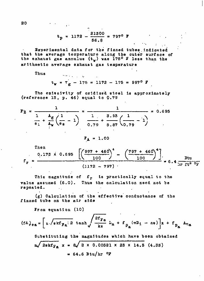
ltx?erlmontal data for the finned tubee. lndie~tedthat the average temperature along the outer eurface ofthe exhaust gas annulus (tw) wae 175° F lese than the
arithmetic average exhaust--gas temperature
Thus ...... . ...
tw = T& - 175 = 1172 - 1’?5 = 997° 1?
The e~leeivity of oxldize”d eteel is apPrOXimntelY(reference 13, p. 46) equal to Q.7S
1— = 0,6951. 3.53 1
(+——- $—-0.79 5.87 NO.79 ).
~A = 1.00
Then
0.173 x 0.695[(~
997 + 460~4
( )1
797 + 460 4
fr=-”100 j- 100 atu
=6.4(1172 - 797) “
:lrfta ‘r
This magnitude of f= is practlc~lly equal to the
value assumed (6.0). Thus the calculation need not berepeated. ,.
.(g) CalcVlatlon of the effective” conductance of the
finned tube on the air Bide
From squation (10)
(fA~ea= [n= tanh~~ La +fp~~.i - n.)]. + fpa A,za
Subetitutlng the magnitudes which have been obtained
=X=d 2 X 0.00521 X 23 X 1405 (4.33)
= 64.6 Btu/hr ‘F

> -#
II2fra J
2 X: OI.5----- La = --.---- .----
ks 23 x 0.00521
21””
(0.0537) = 0,g35 (dimensionless)..
fca(nD - ns)x” & d+.5(3.140.x ,0.1491 - g x 0.00521) 4.33
fea Aua = (14.5)(0.19) = 2.7 Btu/hr. f% .1’: “..-,.
64.6 -tanh 0.1335,t 26.9 .+ 2.7(fA)ea = .
. . = (.4%.2). % {26.,9) + ~2.T) .= 7.3*g.Bt.y/hr ‘F. . ..
.flhu~ it. is noted_ .thn.tOri the air si”de”t~e ~f”i.nsco”n-,,
tributg 60 ,nerce.nt of the eff.~ctdve condu.c.tance,.mid the
unflnned port.1.on.JO mer.cent.. (This calculntl.on ind~ca%ti?the ‘effect -of the fins p.- se. The indirect @ffsots ofthe fins which also. tend .to increas~ heater output”.are disc-ussed on c. 23.) . ..
-(h) ~alcvlati:n of .t.he.effectiv~ con~uctn~ce 0$ “t4~~finned.tube .on the gas -side. . .., . . . . . , ..-
. . In exactly “the same rninner as *’as shown for the “8ir .side, . .. . . . ,. .
li. 42 s k(fF + fr~x = 67.o 3tu/hr ‘F “.
~—— “.b..
.4
2(fFg + fr)- . .I,------ ------ = 0.335 (d.l.mOrislonless) ‘ .
.Lg . ... ..ks..,. . . . . . .. . .. . . . . . . .. .
.(fr”+ fcg)(mD ~-ns)”x = 32~? Btu/hr ‘F,.”: “ “ “~ -.. .. . . .
..(f= i ‘C~)AUg = 3.k JMju/hr YT’”. “ “ . “-,. .,, ... .
.. . . . . . . “’.”(fA)eg’= ~ “- “ ‘6+.”ti‘taxh(o..yyj)’+ .32.9-+ 3.”4-,. ... . .. . . . .. .
.. .
.,‘“’-●.(21;6)’+:(32,9) “+.(3.4) = .57;9~..- ..,., 1.+..: ... . .
On thn Ras side, “therafare, ovtng to the shorter-fins,the contrl%utlan of-thd ‘fins ‘to the eff66biwe conductanceIs only”J’7;4 percent”; u~e~eds the “unflnned porfi(sn of tube “eontrl-butes 6?.6 percqnti. .- . :,. .- ~- . . . - . . . . . . . .
-— .— —

22
The measured rate of heat t~.an=far is. . -.. :
. qM .W ~...?p-(Taa.r..iali.- -’ ‘ ‘.”-”~:.,. .. .. . . ..1, ..,-
. . . . . . .
s (199) (0.2W f~52 ~ 90. . . ,.-
,, . . . ... ,..-. ... < Zlj?C!O-9tu/hr. “ “. “.’=
Ratio of~~ = 10Q55qM .. . . . .
.“
“DIsCUSSION OF. RESULTS .. . i’.“. . .
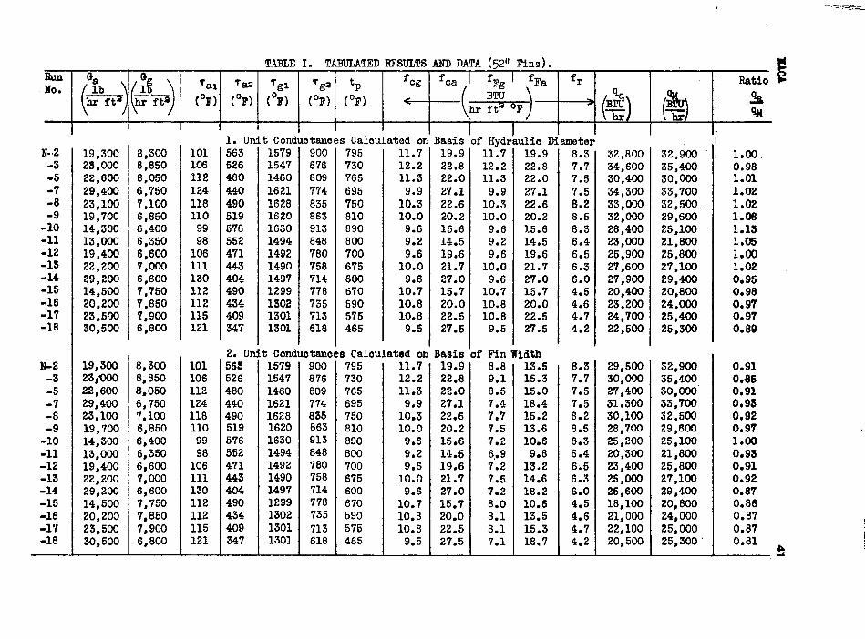
Inspection. of’ table I reveals that tke avcrnge of theratio of pre.digted rnagn~tudh.ofJh eat butnut to the meas-ured haghitud~s for tho exchanger vlth the q2-i~ch fins is1.00,* with a? a~exaga .de~inti.on”of .+4 ~erce~t, vhen the .unit cohductanceq along the flhs ar~ calculated o.n.thebasis tif-the hydraulic di-ametf>r.of the finn~d tub-e. A com-plete dalculationi~ which the unit conduc.t~nc.es alonk thefin are based on. the fin width (measured I;nrallel to the ‘dlr.eotion” of.gas flov) Ie also show?i in table 1“, and indi-cates an underestimation of the predicted. outmut. of” 10 ner-cent. Thus the results .for the g2-i~oh fins verify theconclusion re~ch~d in an earlier narn ranh, that is, sincethe g2-inch fine are greater than 13. [ tin-e thp hydraulicdiameter of t~e finned tube,. calculation of unit conduqtfince~along the fin should be bas?d on hydraulic diameter.
Inspection of %able II reveals tlint th+. ;verage ofthe ratio of predicted magnitudes of heat outnut to meas-ured mgnitudee for the exchangers with the 6-inch .flns is1.00,* v~th an a~~r~Fe devi~tion of +?. P“r.cPnt, ~h~n the------- ------- ----=.- --.=-A.---a---- ------- ------- -----------●During the runs with the finned tub~s, a lsak developed inthe exhaust line between the heater and the ven$uri meter.This leak, unforturlatel~, .Flagnot dj.scover=d until the runs
were completed. The venturi,. tht?re.fore, ind~cat~d n prenterrate of exhaust gas flow than w.fisactuall~. massing throughthe heating s~ctio.n. In order to estimwtp what the gne flowthrough the heater Was., the hpa’t 19ss from the heatin~ sac-tion to the ambient air was ~stimated (10,009 Btu/hr), add~dto the heat gained b? thti air,’ and the w’~ipht rnte of pnsnecessary to yield t~.~s quantity of..he~ttcnloulated, Theseare the values of .Wg kabulqted in tables. I and 11.. This
prooedure is justified , .slnce calculation shows that Rri erroras large as *~000 3tu/hr in the heat .1OSS”“from.tke heatlnesection to the ambient air chan~es the.nre.dieted heater out-put only *3 percent. The accurmcy,bf the prediction shownin tables I and II is In some measure fortuitous; t-h~refore,but is nevertheless accura}.e. .to .ahout..*5 psr~enti~ ‘.
. . . . ... .

23....
,...The differahca-;~b *h.b two methods of prediction for
the 6-inch fins i~:’sm.’small, howev.sr, that a series oftests on a much “&horter fin (,eay, 3 in.) q.hquld.~q p?r-fQrmed.1.n.opder $urther.’to %bdt ~%~.~ronosed method,. ..Thee.e t.e.stq.-are.belhg planned and will b~~”~epdrtbd.,$.p~~...latOi section.
It ie Imnortant, of cpuree, to dete~rn~ne the effectof the fine on tha.heat..wt=u~-vf. the’’exehanRer. The ef-fect of longitudinal-f?ns on the!.ratn of heat transfer Isfourfold: .-. +. ...-...
... .. .L:” -.~ .. -.
(1) The fins increase the effe.ct~ve conductance ox,. ....”t.he..tube-as ‘&ko- ‘by.equa-tion (.~).”“ .,, . ..
.. .
(2) Next, the finm increase the unit thqrmal con-,du.ct.km.c:e,,a.lonyt..t:kge.-+ub=.swfade”~by ‘ti.de?%.easi,n.g-.th:e c~ose=-ko~.tio-np.la~a..of, ”tha”tfiti ~and thus ~.
.-:%ncreasiiqr’“(3 for a eiv~n veipht rate of ‘ ‘-flow.
. (3) Further, ~-h.O_.ZA.l&zrmwa.e--t.hewet.$’ed~erlmeter,-. as veil as decreaee ~e croes-eeottonal area
of the”.tu%%.i th’u-a-d%%h%li~~$p the hydraullcdiameter o~.”the $fi~~ And,.further increasingthe un<t thermal conductance. “
The tot,al-effectlveneee of ~,~.4.a,Z&ns.q,:wQ~@ .,c.Q.nst,d.ereall four of %hti:abov’e ZUititd, .m&y tie‘otitnined by divldlagthe thermal .o.utp,utof the finneQq+-q:,.b~ t-hs.t.her.m%~output of “the a%oo%h u~fln”ne”d“tube, for. the same ratee of
— —. .
24,.. .. . . ..
gas ank’ a“~r:floti;.and for a fixed temper a$ur’e”dlfferqncebetween g~y and-air temperatures at the entrance to theexchanger. , “
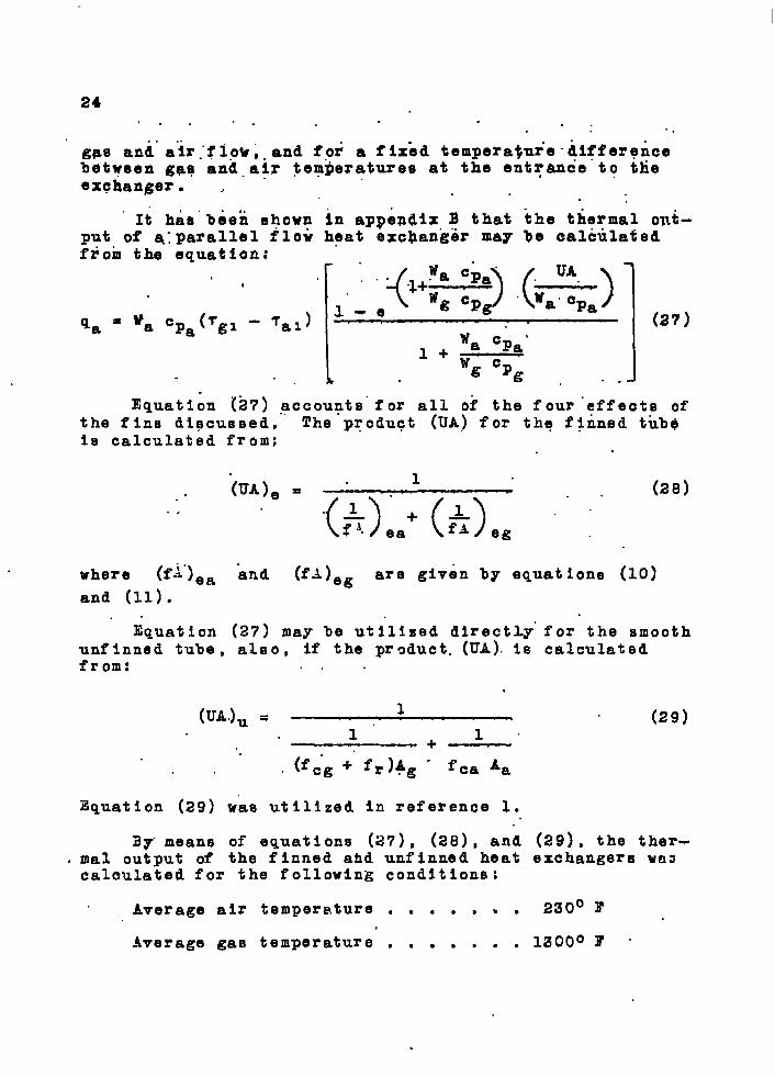
.“It has”beeh shown
put of q:parallel flowfiorn the equation:
,
qa = ‘a cpa(Tgl - ‘al)
In appendix B that the thermalheat excban~er may be calcula~
!“””..,‘“++-) (-)
-e
Wa Cpa’l+—
%% %g ., 1
(27)
Equati On (2?) -accounts” for all of the four “effects ofthe fins dipcuseed. The product (UA) for the finned tkb$ia calculated from;
(UA)e = “..
“ “(&jia: (~jeg ““ “ ’28)
where (f~”)ea and (fA)eg are given by equations (10)
and (11).. .
Equation (27) may be utilized directly” for the smoothunf Inned tube , also, if the product. (UA). is calculatedfrom: . .
(UA.)U = 1(29)
1“ 1“+—
. (fC“g+“ fr )~g - fca ‘a
Equation (29) was utilized In reference 1.
i3y”means of equations (27) , (28) , and (29), the ther-mal output of the finned and unf inned heat exchangers WU3calculated for the following condltion$ :
Average air temperature . . . . , . . 230° I’
Average gas temperature . . . . . . . 1300° I’ “
25
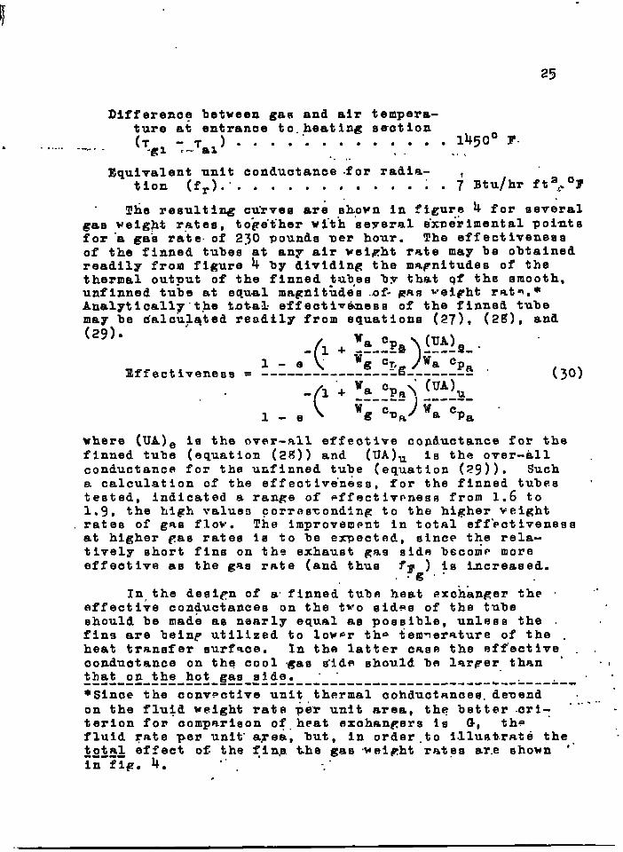
Difference between gas and air tempera-ture at entranae to.mheating sa-ction
. (Tgz:-,?ax) . . . . . .. o.... .1450° F”-..... -m-,- . . ..... ..
Equivalent unit conduotanee for radia-tion (f=).. . . . . . . . . . . . i . j Btu/hr ft=4.0F
The resulting CUTVSS are shown in ??igur.? ~ for severalgas welg~t rates, to~e”t”hervl.th se?rernl tixnerifcental pointsfor “a gas rate. of 230 Pounde mer hour. The effectivenessof the finned tubes at any air weight rate may be obtainedreadily from figure 4 by dividing the ma~nltudee of thethermal output of the finned tub,es by that qf the smooth,unflnned tube at equal magnitudes of- gnfi ~ei~ht rnt~.*Analyticall?.t.he t.otak effecti~tiess of the finned tubemay be dalculqted readily from equations (27), (2~), and(29)8
Zffect( ‘a ‘pa ) (UA)- 1 + ~_--- --.-9-.
1 -e” g c~,g ‘a Cpaiveneas = ------ ------ ---- ------ --
(
-1+ s (UA)U‘a cPa\------)
------
1 -e ‘g %J& ‘a ‘Pa
(~o)
where (UA)9 is the over-all effeotive conductance for thefinned tube (equation (2S)) and (UA)U 19 the over-all .conductance for the unfinned tube (equation (29)). Sucha calculation of the effectiveness, for the finned tubes ‘te~ted, indicated a range of ~ffectlvpness from 1.6 to1.9, the high values corrascondtng to the higher veightrate~ of gnO flow. The improvement in total eff’activenessat higher Cas rates is to be expected, since the rela-tively short fins on the exhaust gas sids becornp moreeffeotlve as the gas rate (and thus fF ) iS increased.
g“”
In,the desl~n of a. finned tuba heat exchanger the “ ““effective conductance on the two sid~s of the tubeehould be made as naarly equal as possibla, unless the . .fins are beinp utilized to lover the tem~erature of the .heat transfer surf%ce. In the latter cnse the effective . ,conductance on the cool gas snide should be larper than “ “Ithat on the hot gas slde~ “ . . .------ ------ ---- ---- ---------.-- -- ---------- -- -.--“----~--~s~nce thg con~pct~vg unit th~rmal co~duc~~ncesm de~end . -
..on the flu$d weight rate per unit area, th? better .crl= ““. -
...
terion fon comparison ofheat exchangers is G, thefluid rate per unit- area, but, in order.to Illustrate the, .“total effect of the finp the gae .weipht rates are shown “in fig. 4.
.. ...

—
26 .. . .“ I . . .. . . . . . .“.. ‘., . ,,PR@S5L~E “DfiOP - .,“ “ .. “
.- AS was discus se-d”in reference 1, “the pressure dropalong a tube .of uniform dlamater In which a compressible
.. fluid (gas) is.being heated. or. cool~d. will not be simplythe frictional 10SEI occurrln~. along the. tybq, but willalso include the effect .of fluid acceleration. .It wasshown in reference 1. (p. 22) that the non-isothermalpressure loss ~s related to..the isothermal uressure 10s!3by the expression: .-
. . .
(Pi -
where
Pi - Pa
‘pTiso
Ta
TI .
Ta .
Y;,
G
~
hon”=isothermal. preseurs lQSS, lb/fta ‘
“isothermal. pressure” loss at temperatureTiso”
lb~fta “
arithmetic average gas temperature in tube, ‘R
gas. temperature entering heater., ‘R
gas temperature leaving heater, ‘R “
dengity of gas enterinp bent.er, lb/fts . .,“
veight rate of gas flow ner unit area, lb/hr fta
32.2 ft/seca
This equation vas applied to the rion-isothermal mres-sure drop dntn obtained for the two f~.nned tubes. Thecalculated preseure dron ‘pTiso vaq thnn correct~d to
Tg” F as outlined on page 23 of reference 1.. These calcu-lated isothermal pressur~ drons as shown In figures ~ and6 check the measured Isothermal mressure drop dnta vpryclosely (less than 10 Percdnt discrepancy). Thes~.&ataare further proof of. the amnllcability of equation (:1)to the prediction of non-isothermal pressure drops Sngas-al~ heat exchangers.*
. .------ -------------- -----1.-- --- &---- ------- ----------------*Actually equation (31) 3s only an approximation, since itis based on a linear increase in gas temperature vith-length. The Increase Is more nearly exp~nential.
.

.—
in addition to changing the magnitude of the pressuredrop,. aquation .(31) changes the: slope of the AP /Ali
. . . against; Wa. .cu~v:e.as sh’ovn.in figure, 5. The” slmope of
the, non-lsotherm~l pressur,e drop curve is less -t-bantheIsothermal one. This Is to b.e expected “for lower” air “ratea.,.since the temperature .rtse pf %h= alr pasein.gthrough the heater Is large, thus causing a larger pres-s“ur’edrop” owl’~ td the-”greater ex3t” val&c”ity o“f the-:vmrd .afrm -. . . . . . . . . . ;.;.
. . . ●
.The ieo”thermal fricti~n factor for.tlie firi~~d tubes~a”s..oa.lculated; utilizing the ,h~haulle .radl.us-of the .finned tu’bs -S .tke slgnlficaat dlmsnsion in. the R.eynoldq.modulus and in the equatio~ defininp the friction factor.T~en - ‘
,. . ..-. . . ... . .. . .
G Da,..
. . Re = --------- . ,. ~~ (32). . 3600 g Wa
and ‘ ...,
ApT.” ~\ ~ & . ..’.--- =
to-- _- ,----- (33)
YT Da 2J?(<~0@aVTa ..where Da= the hydraulic diameter of the finned tube; .,. ...
Sat~sfactarF Correlation .between the”isothermal .frt”ct%on fp.ctor for the ftnned 52-”inch and 6-inch tubesand the smooth tu%e dlsauqs~d In reference l.re”sulted.The points for all three tuh~~ fell within 15 mercent -of the recommended curve for ~commercialn pipe .(refer~ “ence 3, p. XI-EI) (fig. 7). Thus it amne~rs that, forlongitudinally finned tub~s with wide fins, th~ pres-sure drop hay be satlsfactoril~ pr=dict.ed by me.an~ ofthe normal friction “fadtoF data.. The Increased press!ura.ddo$ for the”finned tube is dus mainly to its iljcreased -wetted perimeter. “.. “ . “ .. .,.
When narrow fins are utilized, howev~r, the above “conclusions probab~y will no longer applyi owing to the,increased”pressure drop produced by.eddies, and.so forth,on the downstream side of each narrow fin.*------- ------- ------- ------- ------- ------- ------- -q----- -●The G-in, fin is-so close to being a wide fin that it .is considered as”auch in the .m~essure”.drop dlsoussiop.Actually the ratio of 2/DH for the 6-inch fin is 1Q,9,thus causing It to fall in the narrol~ fin specificationae discussed on p. 12.
,----- ,,. .. . , -. . . .... ., .,, ,
..
, . . . . ——. . —. .—-

2g
COECLUSIOHS .. ..,
1. The effect of” longitudinal fins may be predictedsuoceesfully (+5 percent) by utlllzin~ equation (~) tocaloulate the effective conductance of the finned tube.
2. If th~ ratio2 fF La--E-;-- for a fin Is of” the order
of magnitude of 0.10, the thermxl conductivity of the finmaterial and Ite thickn~se are unimportant in establish-
ing the fin performance, If the ratio2 f~ La------ - i8 of
ksthe order of magnitude of 4.0, fin length measured msrnen-d~cularly to the tube surface becomes unimportant.
3. It appears, although It has not he~n conclusivelyprovedO* that If a longitudinal fin Is wider (measured Inthe direction of fluid flow) than a%out 13.4 times thehydraulic diam~ter of thn finned tube, thn unit con?.uct-ances along the fin surface shnuld be based on th~ hydrau-lic diameter (equation (15)). rf the fin is narrowerthan 13.4 times the hydraulic diamet=r, the unit conduct-ance should be based on the fin width (equation (12)).
4. The 6-inch fins Indicated a slight advantage (3percent) over the s2-inoh f~ns. Conclusion 3 predictsthat-the use of still narrower fins would produce Rreaterimprovement in heat-transfer performance. The almostnegligible improvement for the 6-inch fins, however, maybe due in part to the very small Fan between fins (1/16In.). A greater gap or staggnrin~ of the fins would ner-haps ”improve the fin performance.
‘5. For the same weight rates of flow, the finned tubeprovided about 1.75 times the thermal outmut of thesmooth, unfinned tube. The Improvement in output is, ofcouree, a function of the fin d@sign and this particularIncrease of output by the use of fins apmlies only to theunit tested.
6. Equation (31) may be used to predict the non-Isothermal pressurs dron acroes longitudinally flnn~ddouble tube heat exchangers, if the isoth~rm.%1 drop is-- ------ ---- -------------------------- --- ------------- -- --*Tests are planned on narrow fins (3 In.) to test furth~rthe applicability of the flat plate -quatfon for narrowfins.
I

!!
“29!:.
known, The isothermal a~-moqy:i’~othermal pressure dropsdiffer greatly beoause 6f:jih9 large hlfference in veloc-ity of the gnees entering .snd leaving the exe-hanger. ~%i.. . .. -,,- ,.. : .. . .. .. . - .. .
.. .. . . .. .i . . .. . . .. . “’:’!d..:.”...:,~~ .’-’-”-‘... . . . ..- ● .
7-.”’JThe;’-ie”othermalfriwtion factor for the longitu-dlnali~ finned tubes tee.t.ed.,compared eatlafactorily withcommercial pipe frlctioh factor” ‘data,
. . . ... . ..“-,-...-
. . . . . . .
‘- ,.: . . : .:. . if’+:-:.., , .
MIXllVG CHA;13ER .., .. ... ..”. ,...,.
In order-’to ~btaln nn accurate mixqd..mean tempera-ture of the air leaVlnR.~h& heat exchanger (reference 1,P- lg), a mlx:ng chamber was ~esigned.whtch produced avery .uniform .temperature across the mixing chamber out-let. This mixing ohamber, compos”ed of a e~t of perforat-ed baffles-, produced an excessive Bressure drop ”whlch,
“ :Yn:tu!rn, reduced the.alr blow.em capaci%$r. T~” remedy this,the original mlxl~ chamber wae progressively strippedof baff,l,?sunti.> p patisf.actcry comm.rem~se vas remched
‘h“btheen the. pressure drom. and the effecti~eness of mix--‘lng. The final desiFh ie shown in figure. g. A similar
design was ueed by Colburn and Co~h18n (reference 14).The pressure drop across the unit is ab”out.d?in. CC1 at‘8 ~pighlj”rate.of a4r of 400 lb/hr. ...’.
.. . ..The mixlng”charn~er shol’n In fig. g allowed the deter-
mination of the mixed mean fluid temperature by means ofa single thermocouple ”.placed a’t the center of the stre~m
.V$th..a maximum error-in the te$merntura rise of the. fluid,paasbiqg through the he=t-er-ti a’bout 1 mercent for the-f.lnned tubee, ,2 parcdnt.lr~t.h t.he..dimmIed “$ubee, and 5.p.erqeqtiwdth-tihe smooth, u“tifinn=d tube.. .
. .;.. ....... . .“As..dl~s~~:osettaliove,.ti“mo~d u.hecise mixing cham~ber “
was available but vas not utilized becnuse it introduced...too g,ra~i:a prewaure drop. A -tiaximum ~rror of ~ percent‘:W”@EIopas~serefl .permlssi~le” for”.the teets. In reference 1poncernlng t~e smooth and d.impled:tubes, it was.shows that
.th:e~am~sslon:o$ a mlxlmg ohamber introduced errors in the.tkmp’.era.t~e.rl.seof t,he”fluid” as nigh. as .50 nercent... .. ~ .. . .-, .:.
..-....: ... . . .,..-’ . .

30
., .. “. ~PPEnlXB- . . . - ,.. ,.:. . ., .. .
HEAT ~RAMSFEE TO A“R’iUID EROM” ~ L“OIGITUDI?IALLY FIWNED TUBE
.. . . .-. ” . .,. . . . . .
I19TRODUCTIOW ..”..,., .,..
An analytical expression for the heat tranafer from alongitudinally finned tube Ie .present’e,dbel”ow: “. .I ,
Heat Transfer Equations for Longitudinally Finned Tubes
when the Tube Wall Temperature is Known
. . The following system IS defdnedr “ “ “,
.
. . .
,.
... . .
.#
. .-..
1. There” ie no heat flow in the fins”in the~dlre~tion.. .
.- Of fluid flow. ,..,.
“2* The heat tranefer through the, ends. of the f~ne” into.- ,.the.air stream Is negligible. ‘.
. . ..”..3“.-The tube wall temperature.is Invariable with”x and
~he baee of the fin is at the tube whll temperat-ure. , ,
.+ .
..,.
.4.-Th.e.up”it conductance f-or heat transfer. is the came‘over the fi.n.as over- the unfi”hned” surf-ace of thetube wall,. and constant ‘with length an-d tempera-ture.*
. . . . . . .“
. 5, ~h$lant heat tran”sfer IS g“ero.** . . ‘—..—.—..— -“”
*The Unit Conv’ect iye””thermal c~nduc.taiice map” not alwaye beindependent of .len&th, but may vary Invergely with a frac- “tional pmwer” of the fin width in tEet’,@lrection of.fluid flow.However, the utl.llzatlon of an .averagk magnitude of thermalconductance I,n the length x will not Introduce taeriouse.~rore.” “ . . .
“ **Unl-e.ssth”is pos%ula.te. is.m“ad.e, the eqti”ation derived below‘carino~ be i.nte”&ated readily “bec”ausd of the mamier In whichrad~-ant .~eat transf”er yarie$ with ”tetiperature. . However , at“the rates of”fl~id flow met”’~n.pract~o”e, the radiant heattr”anifer’“may be ei”ther “negle~t~d as “postulated here or ln-eluded..i’n the magnitude of the unit thermal conductance byutilizing an equivalent thermal conductance for r&dititiOn.

6. The thlakmes~ of a“f~n .1s pmall- compared to its .length; . - ‘,’ : .“
,.. ... .
“:-”’Ina lerigth of tube dx the. chan~e In enthhipy of theair will be:
...“...... ..., . ....
-,.. ..“dqawo (Bij .:.d,~~.. . “ ....-” ...:. .
.P.-. . a.. . .-
Thp heat””’fio~””from,the tube .wlll !be t“hat“from the .f Inem @lus. that from tlie.unfinn”e~ surface of the tube ‘(r ef-erence X,” p. 1’1-26) - .. .
. . .
dq = n~~ (tp - ?=) ~arih-/’#::--.: “““ s “:’: “~.:- ~-.. . ..
r% . .----. , . ... .
.“ . .. . + f(tp - Tx)(nD - ns)d~ (B2). . .“. .
but -..
. .. .
dp=adx..”:
~ ~ gd~.. .
~. .. . .
F’.“
dq . In ~~tanh 1.L + f’(mD - ns) (tp - ~X)dx (B2a) ‘L 1:
Equating (El) and (B2a) , and defining X as:
J.--...—.-.-...%f—...-----XZn 2skf tanh2f
L+ f(nD-nta)z
gives :
d?i..
“x ‘—-—- = — dx(tp - 7=) “ “w Cp : ..
(Ba)
The Integrated form 1s:.-x.x-— . .
‘P ,- T.x & (t ?l)O W Cp. .P-.
(a4)“.
which may be subhtltuted Intc equation 32s and, ~ntegratedto yield:
..
L—: -..–..—----– .. —

32
... I >..:, . . . .. . ( -A~\
q. = w ~p (tp_7”i). l-e. “?‘p., ) . (B5).,, ,: . ... . . .
.,.!L ~...-
This Is the general iquatio”n fcr. the “heat.flow from a.’:”..: longitudinally finned tube of length x. . .%..
The term w oR(tp :: +1) = qmu Is the maximum pos-. .“J ~i~.le heat exchange from tube to fluid, since the fluid
cannot exce”ed the tube wall temperature. .. .
Equation .@). may be expressed: ... , . , : -. .....
(..~.’:?..,
)( t,- .)=”(;’:3 ‘B5a)q=l_e-~x=l -tp-~x..... ........ ..- ?qmax . . . ,.
This equation is plotted in figs. 10, 11, and 12.
When n=c, the equation represents the heat transferfrom en unflnned tube.
,.
(x=
,, 2-)-. x..
q CP ..= .Wcp (t.p- TL)..:n.~o 1 -e..
“. . .. . .
where . . . ... .... .
. .
.%. .x =fTra” ..n= o
The bff.activeness o; the. fins $s denoted by. .
(B6j
..
and is plotted In figs. 13 and 14.
Si.mil.ar.analyses were perf ormed for the case forwhich the temperature at the base of the fin .tw .wae
(B7)
postulated to vary linearly and. exponentially with length... X9. : . ,
Expressing the temperature at the .%ase of the fin as “ “.a linear function of the dlstanc e,

. .
. ..:-.‘P
=.cx+B.
The constants 3, &nd C are evaluated by plottingthe temperature distribution as a function of lenRth. Theconstant “B 1s the value of the intercent nnd C is theslope of the ternp”erature-d$eta~c.e line....
If the temperature of the-bkee”l’e:an exponentialfunction of the dlptanoe along the tube,. . c’
‘P=Ee-Fx “-
yields
{1X E ;-x:- - F )( )
9-FX - ~- --x--xq w Cp
P
The constante E and 1’ are evalunted from a seml-logarithmic plot of the temperatur~ distribution.
DISCU’SSIOI!J
Eauation (95B) has been plotted In three diffprentforms, the ratio qlqm~x and Its ~quivalent
Tx - T1------ - agninst --x-- x, x, and n, g~ch ?lot ex~ih-
‘P - ‘1Y Cp
Its suffialently different charactf!rlstlcs to “arrantseparate consideration. “The eauation in generalized dimen-eionleee form has beqn mr.~s.ented in fig. 10. This plotmay be used to determine the manner in which variation infin material and dimensions, tube dlmensione, and rate ofgas flow affecte the p~rformantie of the finned tube.
..rig. ll”le a replot of flg~ 10 show~np q/qmax
agalnat x, with --A~- ae parameter. This plot enablesw CF
one to observe” *hat two short. tubes. In narallel will givea higher heat. flbv than one tube of twice the length withthe same number of fins, but the temperature rls.e of theair will be ~e.ss. ..
. .
:.

34
‘From fig. 11:” “For * 3-ft tube q/qmax = 0-36
For a 6-ft, tube q/qmaX”= 0.59...”.,.
“ k 20-per cen.t inore”ase In the rate of heat transfer -IE thus- accomplished. with’ two 3-ft. .tubes in parallel, ascompared with one 6-ft tube. The temperature rise, how-ever , is 60 percent of the” w~lue obtained by using One&ft tube. . .
~ Plot of qlqmax againat n (fig. 12) based on
fig. 10 allows the observation that two tubes with halfthe number of fins permit a higher heat transfer ratethan one tube with twice the number of fins for the same .length.
From fig. 12: At x ,= 4;75 ft
4 fins qlq max = 0.51
8 fins “ q/qmax = 0.64.
A 60.6-percent increase In the rate of heat transferIs thus obtained with two tubes having four fins each.Here , again, the temperature rise is 80.3 percent of thevalue for one tube. ,.”
In orddr to plot the equations, average values ofdata from laboratory tests were .Used.
The advantage of a finned tube over 6 tube withoutfins Is otta$ned upon inspection of fige. 13 and 14,plots of equation (B7). From fig. 13 a plot of q/qn=zoagainst” x “ reveals that f“or a given length the effec-tiveness is increased as--the number of fins increases.This Is particularly true for short lengths, For- longlengths the effectiveness is changed little for large.Increases In the number of fins.
:,.Fi.g. 14,, dfit =0
#
againBt .n, indicates the mannerIn which the effec Iveness decreases ae the tube Increasesin length with the same number of fins. .
A careful inspection of the equations and figuresdoes not Indicate any practical v~lue of the optimum num-ber of fins or length of tube. It should be emphasized,however, that other, more important considerations governthe selection of the number of fins and the length oftube , such as pressure drop, specified lengths, tempera-ture rise, and quantity of fluid.

.0
35. ...
Case II...
Heat Trahsfer Eou8tiqne for Finned or Unflnned Hemt Exchangers. . ... ..
when the Tu~e Wall. Temperature Is not Knownand..
.,.%the Heat Loss to the Surroundings is Zsro.-.
!ChP he~~ absofibe.db~ the 0001 Rir at”any point x legiven 12y
-..,The heat glv”en up by the hot g~ses at any pointgiven by
d qg =-W d?~ CPF ~x
= (UdA) (T - T )gx ax
Equations (B1O) n“nd(Bll) may b? rewrltt”n as
,. d~ U dA%--- = --.---------
(?gx - %x ) ~a Cp=
and
(Blo)
x Is
(311)
(B12)
(B13)
Subtracting equation (B12) from (B13) fives the folloWlnRexpression:
( 1 1
)
d(Tgx - Tax)-u ------ + ------ .dA = ------ ------
w. % OPgWa
‘Pa (Tgx - Tax)(B14)
When U and Op are oonstant along the heat exohanger,
equation (B14) “maybe integrated along its length frompoint 1 .at eptranoe to po~nt 2 at the exit end of theexohanger, The result 1s
( T
)(Ua - ‘fi~ . ---------- 1+1------ ------)
(UA)Wg Cpg Wm Cpaln \Tgl - %1
.— -—.-.. . _ .—

*. .. .36-: ”-t. .: . .-.:.::.,... . .
This ””-egtiatio?may be G*ltten. RO.—. .: m.. ..
-( ),..:;--+‘ me:,:-,. ,.*.. . ... .. ----3+-. +. .. . .,.. . -- ~i::. . .. . ‘~.=Pg a..-..: ~ga Pa ..
.------ =e -. ... ..= Tax .
(Bl~)Tgl
. .. .... .... .
When %oth “sfdes of eauation (315). ar~ subtracted fromunify and.multiplied by .(T
ga -.%1), the Sesult is
..
When the heat loss to the surroun.dings ig zero, ~~ = qgand separate integration of equatinns” (?I1O.)and (Bll)yiel&~
.. .!.....-..
. .
‘%1 - ‘ga Wa %)a------ --- = - ------
. . T T vax - . na ~ cFg .. .
Substituting this last equmtion into equation (1316)andrearranging terms. .
[ -( 1+1------ ------)(UA)_
.-.(Taa - ~ai) = --IgA-:;s& ~ - e . ‘~ %g. ‘a cPa
‘a cpB - .1 + --.*--
. . ‘tr cPg “..
Multiplying b~th si”des of *his eouation b~ Wa cPa
arid
rearranging ths exmonentlal t=rm Fives equation (27).

.,.
. .
... -.~~mation- {B~7):will:yield. t6xahtl#~the”. adme resultsai”equatlon (“9); in equation” {B17) the log ~e+am”tempoha=“timr~-~$ff.esencm ti~ti”liue-n‘evaluatdd Ip.”f”sr.pm oaf-“kadwn.quantities , thereby allowing an explicit holntldn for”” qaP.. ..
For* a:”.etiO~~h:~~.nf”$n$ed~.tube ‘(U.).”IS gdl?~n b~”egua~ien(29). ‘ ““..”,’-’‘“ .
.,:. ●J
,... . “::,(UA];:J’”:-:-”.’””“ ‘:”‘1-““ ‘ ““’”““:::.-.. ::”.”.’ :0318]v“.. ~... . ...’1.””.’......- .:,:7: :. l’.., ‘“+”. ”~ *“:.’.’.”,”” “,...
(fcg + ‘r)Ag fea Aa J“! ----: ,..
.wh~le f e.~.a lougitu.diaql~ f Iqned tube , . (m). is given byequa”t,ion (.2.8)ti.” ,. .“ ,. ;.. “ . . . . .. . “ ~“
... . .. . . .. .“ .““1. “...-..” ..,. .. . . . .. .1 ”’”
.
. ..(u$)el= “:.”:: . . . . .. . . ... fi.. .: ..: “ .(319).
where “ (f~-)ea and (f!.)eg are given by equations (10)
and (11).
T~e ratio of the rate of heat tranefer from a longi-tudinally finned tube to that of a smooth unfinned tubeid obtained by substituting equations (28) and (29) Inequation (27) to yield equation (30).
qqa
I?ffectiveneea = -—qn=o
<
‘a ‘Pa
)
(UA)el+——
.
‘g Cpg ‘a ‘Pa1 -ea .- .
(
Wa Cpa
)
(u~)ll .(320)
-l+—
1 -e ‘g oPg ‘a cP~
It should be noted that equation (B7) Ie a .speclalqase of the more general equet~on (B20). The formerequation evaluates the effeptivenees of the fins ba~edon a aonetant tube wall temperature.

The foregoing equations are applicable to parallel..;.fllov In double..tuba. he-at exchang-ars. . S+rn$lar equations
for contraflow of fluids are Riven In-reference 3(P. XIV-4), “ ,-:-m-w,.~.. ... ‘...-
-. t. ----- . .:;” ,...
.. .. . . :.:The~y~$orq.g?qtefu~~y.. q..$~pw~dge.fi~e :cqn~rtbu~~onsof Messrs, M. Tribus , D. DuBain, M. A, M~~ler, .E. ..H8,qaker,and C. Buchter in the performance of the tests “and thepreparation of the report, and of Messrs. II. Eagles and
,.~. Poe land in the cou.tr.uc.ti.on..of-..the e.qut~ment .r
._-...:”-. . . . . . .#
. . . .‘.
..Ui) %. .,:7.... .,. : ..!. ~~; ,... . . . :, -.. ! -... - . . } .; } s. .i . ... ..:. . .. . . .,. ‘ . .... ,.. ,.( :-,’
,,..:i~, ~...:::. . .>.,,-..~.!.! ‘! :, . ”: ”:.::..- .,$! “.,. ,.., .- ~.-!;. .
f 1; .,,:.. . “.. . . , ”..’.”.;’ “’. -r.: “.’:, ..: ;- j . : :::.”:.-. :i:.:. :,; m-.* ,,. q) .m. :: .:. /:.
>,. .:
1“!. , “ “..1:”... “. :.. -.s. ..: .:. ./ . .., .1-. “ . : :.- “.: :-” .“; ‘:’:.’. -
●✎ 1.... ... .. . . . .. . -.:. .. . . .:.. .. “. “... .-” : “, “.. .’
.! ”...>”’ .-... r I
. . . . . . . .. . . - +. “L., , .. .1 . “. .J .. .
. . . . . . . ‘.-i. . . .. . . . .. . . . . .... . . ... . . - . . . ... ..- .. .
,-. ..J:” -.:’ -.”...::” .? ‘ .-
F. ‘)... :....:; /.. .,.- .
. . .#j:: z,-. .f, .,-. ~b..: )- ;.. -. ,>:-....-,.. .; ..-.: . . :.~..,” . .“ .. . . . . . .,.. - ‘.-. :,..... -.. . . ...” “.. .,a i . ““’.”. ‘.”’” . -: r . .. . >
:. .:.? n, . . .. ., -...:: .:. ..”: .:,7 .. <;.- ?, +-, ., <,- . . . . . .:.- .,. .,?t ; ::. . .. .
!. -.,... ,., ,,, ,-I . . . . ..: ... J ,:
:...}. . . i .’:. . .%,.. -. ,.

’59
.. m’. .L .:.. .*- :?~FXREm~YS” . . . . . . . . . ~ -“ ..-
9’
...%.
1. Mart iriiill.,i.R.’p.c:.i”:” “-W:aikberg,. ~,. B..,~,M.orrin,,.“E.mH. , and‘30eilt”&r,”L. M; K.: An Invest lgatlon of Aircraft
t [email protected]~+ :.III-=: Heasured. and.-~red$ctsd Perf”orrnanc6”-of Double Tube Heat Exchanger”s”-. , “.-..
2. Pe-irce.,:B.. 0.: :#..S~brt: Table “of.”In.tsgrals,.”“.?3ihn”and.~oq, .1910; p,; 93. , “. “ ““ .. “: :’- :“ “: ““
...”. .. .
3. Boiitiri L,” M; K.; Cherry, V.’ H~, and Johnson: H. A.:Supplementary Heat Transfer Notes, Univ. of CalifoPress, 3d cd. , 1942.
~. (301dstein, S., Ed. : Modern Developments in FluidDynamics. Oxford Univ. Press, l$l~g.
5. Colburn, Allnn P.: A Method of Correlating ForcedConvection Heat Transfer Data and a Comparison withFluid Friction. Trans., Am. Inst. of Chem. E4.,vol. XXIX, 1933, pp. 170-210.
6. ?lorris, R. H., and Snofford, w. A.: High-PerformanceFins for Heat Transfer. Trans., A.S.M.E. , vol. 64,no. 5, July 1942, pp. Ogg-096.
7. ten ~osch, H.: Die W~rme#hertragunp. Julius Smrlnger(Berlin), 1936.
g. ~oelter, L. M, Km, M~rtlnel].~, R, cm, and Jonassen,Finn: Remarks on the Analogy betveen Heat Transferand Momentum Transfer. Trans. , A. S.M.E., VO1. 63,July 1941, ppo 447-455.
9. Martinelli, R. C., Tribus, M., and Boelter, L. M. K.:An Investigation of Alrcraf.t Ematers. I - ElementaryHeat Transfer Considerations In an Airplane. I?ACAARR, Oct. l~02.
10. Mattioli, G. D.: Theorie der W#rmeflbertra@ng in glat-ten und rauhen Rohren. Forschung auf dem Oebietedes Ingenleurvesens, Ausgabe A, Bd. 11, no. 4, July-Aug. 1940, pp. lJg-15gm
11. Reichardt, H,: Die W&rme#bertragung In turbulentenReibungschichten. Z.f.a.M.M. , Bd. 20, no. 6, Dec.1940, pp. 2g7-32g,

40 .
12. Hottel, H. C., and Egbert; R;”-B.:.--”.-:..:~
Eadiant Heat Trans-mi-ssion from Water Vapor, . .T~ans. ,,.AJB..Inst. Chem, .
. .., pp”g.,:Vol:h 38:, fine. 25”;-.i9.42,-p , %?r{;: :;L .- -. ‘ “. . . . .%. :”... . . . . . . %
13. l$c~dgrne, W. H;: . ‘ Eoaf Transtiission;”” ~cGra%;~~ill BookCo. , Inc. , 1933.. ’.- - ..
... ... .14, Colburni A. P., and” Coghlan, C, A.: “Heat T$an~fer to
Hydrogen.-l!Jltrogen Mixtures inside Tubed. Tram. ,A. S.M.E., vol. 63, no. 7, Oct. 1941, p. 563.
.
.
,
sNo.
N-2-3-5-7-8
-i:-11-12-1s-14-15-16-17-18
N-2-3-5-7-8-9-lo-11-12-13-14-15-16-~’f-18
19,30023,00022,60029,40023,10019,70014,30013,00019,40022,20029,20014,50020,20023,50030,500
19,30023$00022,60029,40023,10019,70014,30013,00019,40022,20029,20014,50020,20323,50030,500
8,3008,8508,0506,7’507,1006,8506,4006,3506,6007,0006,6007,7507,8507,9006,800
8,3008,8508,0506,7507,1006,8506,4006,3506,6007,0006,6007,7507,8507,9006,800
1011061121241181109998106111130112112115121
1011061121241181109998106111130112112115121
1. Urc563526480440490519576552471443404490434409347
2. UIX56S526480440490519576552471443404490434409347
t Cone157915471460162116281620163014941492149014971299130213011301
I
vu=)tances Calculated 019008768097748358639136487807587147787s5713818
900876809774833863913848780758714778735713618
795730765695750810890800700675600670590575465
11.712.211.3
9.910.310.09.69.29.610.09.610.7100810.89.5
:ConduotsmesCalculateda157915471460162116281620163014941492149014971299130213011301
795730765695750810890800700675600670590575465
11.712.211.39.910.310.09.69.29.610.09.610.710.810.89.5
m DATA (521!Fins).
~3asisofHvdraulicDiameter19.9 11:722.822.027.122.620.215.614.519.621.727.015.720.022.527.5
12.211.39.910.310.09.69.29.610.09.610.710.810.89.5
3asis19.922.822.027.122.620.215.614.519.621.727.015.720.022.527.5
19.922.822.027.122.620.21.5.614.519.621.727.015.720.022.527.5
f FinWidth8.89.18.57.47.77.57e26,097.27.57-28.08.18.17.1
13.515.315.018.415.213.610.69.813.214.618.210.613.515*318.7
8.37.77.57.58.28.58.36.46.56.36.04.54.64.74.2
8.37.77.57.58.28.58,36.46.56.36.04.54.64.74.2
32,80034,60030,40034,30033,00032,00028,40023,00025,90027,60027,90020,40023,20024,70022,500
29,50030,00027,40031.30030,10028,70025,20020,30023,40025,00025,60018,10021,00022,10020,500
32,90035,40030,00033,70032,50029,60025,10021,80025,80027,10029,40020,80024,00025,40025,300
32,90035,40030,000’33,70032,50029,60025,10021,80025,80027,10029,40020,80024,00025,00025,300
l.(u)0.981.011.021.021.061.1s10051.001.020.950.980.970.970-89
0.910,8s0.910.9s0,920.97l.m0.9s0.910.9200870.860-870.870s81
+

TABLE II.
~
J -1-2-3-4-5-6-7-8
G-11-lZ.13.14-15
J -1-2-3-4-5-6-7-8-9
-lo-11-12-13-14-15
19,00028,60020,40019,60021,20030,30018,80022,00028,90034,50041,70036,40040,00085,50039,300
19,00028,60020,40019,60021,20030,30018,80022,00028,90034,50041,70036,40040,0m35,50039,300
8,4508,6508,8008,6508,5008,1508,3009,3009,5008,2008,3508.1008,2009,0008,900
2. Uni”8,4508,5508,8008,6508,5008,1508,3009,3009,5008,2008,3508,1008,2009 ,OoCJ8,900
89106
98102105120104108117
848476737874
2ondl89
10698
102105120104108117
848476737874
,.UnZt Cond538444523453444379579667504323294360335414389
tanc538444523453444379579567504323294360335414389
152815421505131013231328161716231616132513171516151616111611
1Calc152815421505131013231328161716231616132513171516151616111611
TABULATEDRESULTSANDDATA (6”Fins). ~
Tga
(°F)
819878770760699949956904678652725706817799
lated881819878770760699949956904678652725?06817799
Calculatedon Basis”of Fin Width76065075063062552586@825730510420525500580555
In Bag760650750
625525860825730510420525500580555
11.711.812.111.811.511.211.712.812.911.211.211.211.311.912.2
of ~11.711.812.111.811.511.211.712.812.911.211.211.211.311.912.2
19.5/ 13.5
119.620.827.519.422.27,330.234.531.533.831,233.5
mlic19.527.C20.5
19.620.827.519.422*C27.930.234.531.633*E31.233.5
13.814.013.613.312.913.514.814.912.912.912.913.013.714.1
ianete11.711.8120111.8110511.211.712.812.911.211.211.211.311.912.2.—
20.428.521.519.721.828.620.423.028.631.036.032.835.332.535.2
19.527.020.519.620.827.519.422.027.330.234.531.633.831.233.5
, )“ I
7.67.27.54.95.24.98.89.18.54.74.36.15.97.16.9
7.67.27.54.95.24.98.89.18.64.74.36.15.97.16.9
32,20037,20033,20025,80026,70028,40035,50039,50043,80031,20030,80035,90036,80041,00042,000
31,40036.00032,40025,20026,00027,6(XI34,40038,50040,20030,60029,80036,10035,70039,9cKl41,100
31,60037D10032.10025;60026,60029,10032,10037,40041,50030,60032,40038,20038,80044,3cm345,800
1,021.001.031.011.000.981.111.061.051.020.950.940.950.930.92
31,600 .37,10032,10025,60026,600 :29,10032,10037,40041,s0030,60032,40038,20038,80044,30045,800
0.990.971.010.980.980.9E1.0?Z.030.$71.000.920,920.920.900.90 &
—~

43
TJ3EIJI111.-IS~ _URE DROP - AIR S1331
..
Measured
Run pressure drop*
(lb}ti)TX Reynolds Friction
(lb~h ft2, (OF) (lb/ft2/ft) mdulus* facto+
Finned Tube (52-in.
Km-l 375
-2 416
-3 584
-4 536
-5 589
-6 640
Finned Tube (6
LI-1
1-
573
-2 502
-3 428
-4 338
fins) (distance between pressure taps, 6.25 f%)
24,600
27,200
38,300
35,100
38,300
42,000
78
78
78
78
78
78
6.35
7.68
13.4
25,400
28,100
39>300
11.7 36,200
12.5
15.8
39,300
43,300
in. fins) (distancebetween pressure taps, 6.20
37,500I
83
32,900 83
28,000 83
22,100 83
13.6
10.5
8.29
5.69
38,500
33,800
28>800
22,700
0.0296
.0294
.0256
.0268
.0242
.0254
t)
0.0270
.0270
.0294
.0323
%Corrected to 780 F. (See equation (33) of this report and.equation (25)of reference 1.)

44
2kBLE IV.-NON-IS&lERMAL PRESSURE DROP - AIR’SI~
M-1
-2
-3
-4
-5
-6
-7
IL-l
-2
-3
-4
Measured nom-Va @a T, Ta Ta isothermal
pressure dropper ft
(lb/hr) (‘~) (‘q (‘q (lb/ ft2/ft)
Isothermalpressuredrop calculated fromnon-isothermalpres-sure droP*
(lb/f~/ft)
Finned Tube (~2-in. fins)(distancebetween pressure taps, 6.25 ft)
514
37&l
53g
459
393
323
599
33 t600
240&300
35,200
30,000
25,700
21,100
39,200
538
542
540
542
546
545
550
7&j
7gt3
757
770
824
fyx
763
667
670
64g
656
695
701
656
15.2
10.3
1509
12.9
1005
fi.y
20,4
9e82
6.92
10.7
g,go
6,5g
5.20
13eg
I%med Tube (6-in. fins)(distance between pressure taps, 6.2o ft)
5g6
520
331
556
y, 300
34,100
21)700
y5,@o
549
553
546
546
7go 664 23,6 15.9
790 671 M*7 12,4
g72 709 10,0 6.26
797 671 20.5 13.5
*Corrected to Tt3° F. (See equation (31) srilfootnote on table III of thisreport.)
L—-,,,.—, ---- .... ..! ! m !! . !-! . . . . . . . . . . !.. ! .!.! --.! ------ . . . . . ..-. ——— _—..-—

NACA Figs. l,.?
52”)FINNED TUBE
, ,8
cI
*3.07=j
GROSS - SECTIONAL AREAS
AIR SIDE = 001526 ft.2
GAS SIDE = 0.0286 ft.2
HYDRAULIC DIAMETERS
AIR SIDE = 0.0460 ft.
GAS SIOE = 0.0688 ftfig. I
FINNED TUBE (6”)
WE LDEO~
LT
~
1! II II
t- J’I,,
22 52”+
fk.o+--j
CR OS S- SECTIONAL AREAS
AIR SIOE = 0.01526 ft.2
GAS SIDE = 0.0286 ft.2
HYORAULIC OIAMETERS
AIR SIDE = 0.0460 ft.
GAS SIDE = 0.0688 ft.fig. 2

NACA Figs. 3, 8
SINGLEFLAT PLATE
>turbulent
buffer’”y’r>’aminar> ,
TWO WIDE FLAT
PLATES ~
DISTANCE
~ APART
Rate of heat transfer o function I Rate af heat transfer independentof distance from leading odgo of distance from leading edge
— —
IDEALIZED FLOW ALONG FINSFLAT PLATE
M XING CHAMBER
T_3“
L —
TRAVERSINGPITOT TUBE AND
THERMOCOUPLE
H
L---6“-
=
- l“-
TRAVERSING
A
1
THERMOCOUPLE
T-a-F--
-1’4I I
~ @
,,
.
SECTIONS A-A SECTION B–B
BAFFLE PLATES
T2“
L
NARROW PLATES
& DISTANCE
Q APART
fig. 3
fig. ~

NACA Figs. 4,10I I I I I I I I 1 1
*’
II I
I ITEMPERATURE RAT lO x– 8 RATlO ~ 1 VS *X
I I I 1’qmax
P
*
P—
I
FOR LONGITUDINALLY FINNED TUBES
1.0
[ 1
xxq
-- WFp ~ -.6‘Eq. (50) ~ = I - ●
mox / -
/ -/ ‘
.6 / ‘
.4
/
.2 / ‘
o0 .2 .4 .6 .8 I.0 1.2 1.4 1.6 I .8 2.0
J_Wcpx
(DIMENSIONLESS)
‘J,~ \,~ \l\l II Ill 1? Y1-11I I I I I 1 1 1
Ill1- “, J I 1 1 I
3a+Ow
c!)II
0w1-0—
IL
,,
6- 5- 6. 6- 60 00- ~. 0
0 0 0 00
m ho- 0 0
w UYo-
* m N
fig. 10
CL’

WA Fi#
Zo f #, I I IIWmEBMAL Am Yoh -ISOTH ERMU
0/ +
M2MuradUoD- 1~ 1 x ‘ -elus#gE REQPEQBELUED
R2mEi? ’m”-”o (=” flN)
‘o -%f
/ / 1
_lb@ - . _ .
ftI*othorm@ prossur~ ~
-t~ Isothor@ &311HK@OK2
6GakdM94fLQrn~
,x{ !3SSwzQQt22
4
EXPERIMEN TA ~ 12QlKIS
3 c Measured Non - Isothermal - .
Pressure Drop
x2
Isothermal Pressure Drop
Calculated from Non-
Isothermal Data
0 Measured Isothermal
Pressure Dr~Wa’ Ib/hr
Ifig. s
t’ooI
200 300 600 1000
1 120+ ~d ~-.
141 I [ I IL.” -... -, —tlltti
~e Qm2II3/ I
II I I I [ / I
/YI I I
)’m41111 (E F1 N s]
A–’ ‘essu; _ _ _ _ _ _ _ _
x Ill
h r r
Olc!ll Calculated f~m
sotharmal— Ny# / n- 11
It/ // ‘ !ZISSUU, RC92 I 1 1 1 1 1 1 1 I I
I I i
6 II”
/k ~d Iw
I I I I I I 1
rRmua Qra2/ EMEm&uueQlcu3
4
●
3
x
2 -
0
w- lb~r .
-1oo 200 300 400 600 1000IL I I I ““ I
illMoasurod Nan- Isothermal
Prosauro Ore
Isafhormal Pre$swe ~
Cakulafod from Norr-
Isatlwrrml Data
Moasurod Isothermal
ITI_kru

0.05
9,04
0.03
0.02
0.01
—
(=FRICTION
FACTOR -—
=FF
ISOTHERMAL
FINNED
Smooth Pks
Nikuradse —
L REYNOL
10,000
1=FRICTION FACTOR
FQR
A~D STRAIGHT TUBES,
+--I--+ XR’MFNTATA’POINT!
I I I I x 6 “ Fins
tlltt; ‘traightTub’+
Straiaht Tube
S MODULUS
20,000 30,000 50,000 100,000 200,000
fig. 7
—
—
—
—
—
-m@’4

!-“-T---- ____ ___
““”u1
D
/!2
II
1
pi~e 9.- Longitudinallyfinned tube.
u)

NACA Figs. I 1,12
I I I I I 1 1
TEMPERATURE RATlO ‘~
I I I I I I I I I 1 I& RATlO +maxvs LENGTH “OF TUBE .
FOR LONGITUDINALLY FINNED TUBESI
1.0
~ .8
‘max
a .6
TX-T .4
t~ x
.2
0
0 I 2 3 4 5 6 7 6 9
x, LENGTH OF TUBE (F T.) Fig. II
I 1 ITEMPERATURE RkTIO ::;
I Ia RATlO +m~x
I I I IVS NUMB/R OF FINS
.
1.0
~ .8qmax
.6a
TX-x “4
tp–m
.2
0
r
FOR LONGITUDINALLY FINNED TUBESI
-[’ ‘ 1x-—
Eq. (5a) ~ , l–e~cpx
qmax
‘=i~’anh~’+ ‘(HD-”S’I - –
X= Length of tube1
Aswming:
/ / / ‘ W= 500 lbs/hr/ ‘
./ “ Cp= 0.242 BTU/lb. ‘F.
/ ‘ S = 0.0052 ft. ( W6”)
L= 0.0625 ft. (3/4”)
k = 25Ll BTU/hr. ft2(*F/ftJ
f = 20.0 BTU/hr. ft?
D= 0.1667 ft. (2”) I
o 2 4 6 8 10 12
n, NUMBER OF FINS Fig. lZ

NACA Figs. 13,142.6- I I I I I I I I I I I I I I I
EFFECTIVENESS RATlO & VS LENGTH OF TUBE
2.4FOR LONGITUDINALLY FINNED TUBES
.,● I
\
2.2 \\ ,nx 10 xx\ - Wcp
2.0 Eq. (7) + = 1-’\ n=o
- x&%L
Qnso \ 8 l-a p.
I .s\
\6 \ ~ [,, ,
X= n~ tanh~,
~ L + f(_mD-ns)ks
1.6\ \. ‘ \ n= Number of fins
i. \ > \Assuming,
4\ W= 500 lbs/hr.
I .4\ \
cp= 0.242 BTU/ lb. ”F.\
\ s = 0.0052 ft. ( 1/16”)
L = 0.0625 ft. (3/4”)
I .2I
k = 25.0 BTU/hr. ft’? (°F/fl.) —
f = 20.0 BTU/hr. ff2 I
1.0D= 0.1667 ft., (2”)
o 2 4 6 B 12 14x, LENGTH OF TUi~ (FT. ) Fig.13
I I I I I I I I I I I I I I I I
EFFECTIVENESS RATIO1 +-0 VS NUMBER OF FINS
2.4 FOR LONGITUDINALLY FINNED TUBES
IX=1
2.2 //
/ x-—3
Wcpx
2.0 Eq. (7) + = 1-0/
n=oq_
Xn=o-—
qn=o /, Y l-ewCp
I .8/
- ‘= F-t”& + f(~”-n< ~/ //
1.6 / X = Lenqth of tube, tt.
// / ‘ Assuming,—.
/ / & ~ - W= 500 lbs/hr.
1.4 -“Cp= 0.242 BTU/lb. “F.
S = 0.0052 ft. ( 1/16-)
L= 0.0625 ft. (3/4” )1.2 k = 25.0 BTU/hr. ft? (“F/fL)
f = 20.0 BTU/hr. ft? I
D ; 0.J667 ft., (2-, )
nl NUMBER OF FINS Fig. 14
.

JIllllllll3 1176013544441——.—— — ——
[