war in vietnam a surveyor’s story
TRANSCRIPT

1
WAR IN VIETNAM – A SURVEYOR’S STORY
The Royal Australian Survey Corps at Nui Dat in its first year
1966-67
ANNEXES A - N
A personal reflection forty years later… Bob Skitch

2
ANNEX A
DET 1ST TOPOGRAPHICAL SURVEY TROOP
OPERATION ORDER 1/66
3
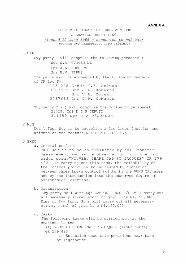
ANNEX A
DET 1ST TOPOGRAPHICAL SURVEY TROOP
OPERATION ORDER 1/66
(Issued 12 June 1966 – connexion to Nui Dat) (scanned and transcribed from original)
1.SIT
Svy party 1 will comprise the following personnel:
Sgt S.R. C A M B E L L
Cpl J.L. ROBERTS
Spr B.W. FIRNS
The party will be augmented by the following members
of TF Loc Tp.
1731045 L/Bdr J.F. Selwood
3787005 Gnr J.L. Roberts
Gnr V.A. Moreau
3787689 Gnr D.P. McManus
Svy party 2 (-) will comprise the following personnel:
214295 Cpl D G P CERUTI
311459 Spr J A O'CONNOR
2.MSN
Det 1 Topo Svy is to establish a 3rd Order Position and
azimuth on the feature NUI DAT GR 433 675.
3.EXEC
a. General outline
NUI DAT is to be co-ordinated by tellurometer
measurement and angle observation from the 1st
order point"NOUVEAU PHARE CAP ST JACQUES" GR 279
428. In carrying out this task, the reliability of
the control point is to be tested by connexion
between three known control points in the VUNG TAU area
and by the introduction into the observed figure of
astronomical azimuths.
b. Organisation
Svy party No 1 with Sgt CAMPBELL NCO I/C will carry out
all necessary survey south of grid line N1,150,000.
Elms of Svy Party No 2 will carry out all necessary
survey north of grid line N1,150,000.
c. Tasks
The following tasks will be carried out at the
stations listed
(1) NOUVEAU PHARE CAP ST JACQUES (light house)
GR 279 428.
(i) Establish eccentric positions near base
of lighthouse.

4
(ii) Measure circumference of lighthouse at
height of theodolite.
(iii) Determine and mark centre of lighthouse,
radial to theodolite, by bisecting the
angle between the targets from the instrument
position to the lighthouse.
(iv) Measure the distance from the eccentric
to the position marked.
(v) Measure the following distances by
tellurometer:
Ecce....CAP ST JACQUES (20 fine readings)
Ecce....THANH ecce (10 fine readings)
Ecce....NUI DAT (20 fine readings - both
directions)
(vi) Observe the following directions from
ecce positions.
CAP ST JACQUES (8 arcs)
NUI DAT (8 arcs)
THANH ecce (4 arcs)
Lighthouse centre point (2 arcs)
(vii) Observe the following vertical angles from
the ecce position.
CAP ST JACQUES (4 FL and 4 FR) reciprocal
NUI DAT NUI DAT (4 FL and 4 FR) simul reciprocal
THANH ecce (4 FL and 4 FR) single direction
(2) CAP ST JACQUES 3rd order station GR 287
419.
(i) Clear ground mark and check recovery marks.
(ii) Measure the following distances by
tellurometer.
Lighthouse ecce 20 fine readings
NUI DAT 20 fine readings both
direction
THANH ecce 10 fine readings
VUNG TAU azimuth Mk 5 fine readings
(iii) Observe the following directions.
Lighthouse 8 arcs

5
Lighthouse ecce 4 arcs
NUI DAT 8 arcs
VUNG TAU azimuth mark 8 arcs
THANH ecce 4 arcs
(iv) Observe the following vertical angles;
Lighthouse ecce 4 FL and 4 FR
reciprocal
NU1 DAT 4 FL and 4 FR simul
reciprocal
THANH ecce 2 FL and 2 FR single direction
Azimuth Mk 2 FL and 2 FR single
direction
(3) THANH 3rd order station
(i)Establish THANH 3rd eccentric west of road
to enable intervisibility to lighthouse and CAP
ST JACQUES.
(ii)Measure the following distances by
tellurometer (remote only).
Lighthouse ecce 10 fine readings
CAP ST JACQUES 10 fine readings
(4) VUNG TAU azimuth station.
(i)Establish station in convenient locality
in ALSG area.
(ii)Observe either of the following Astro
observations using red light on Radar Hill
as RO
(a)8 arcs on polaris or
(b)6 arcs W and 6 arcs E Ex meridian observation on star within 15 degrees of
prime vertical
NOTE(a) is preferable to(b).
(iii) Observe angle between RO and CAP ST
JACQUES.
(5)NUI DAT 3rd order Artillery station.
(i) Adequately clear and establish station

6
at highest point of feature to be
groundmarked with RA Svy plaque set in
concrete.
(ii) Measure the following distances by
tellurometer.
Lighthouse ecce 20 fine readings
reciprocal.
CAP ST JACQUES 20 fine readings reciprocal
Arty orientation Pt 10 fine readings
single direction.
(iii)Observe the following directions:
Lighthouse 8 arcs
CAP ST JACQUES 8 arcs
Arty orientation Pt 4 arcs
( i v )Observe a sun azimuth (AM and PM) on
the line to Lighthouse.
d. Barometer Calibrations.
NCO I/C of party (1) will endeavor to calibrate
barometers at NUT DAT on return.
Note :- in calibration, sea level correction not
to be applied.
e. Technical specifications
All survey tasks will be carried out in accordance with RA Svy practice as specified
in Corps Manuals, unless otherwise directed
by 0C Det.
f. Recording - To be carried out in duplicate.
g. Timings
(1) Party No 1.
(i) Tue 14 Jun 66
(a) Depart TF area NUI DAT (time to be
notified)
(b) Report to HQ ALSG on arrival VUNG
TAU.
(c) Establish and observe Azimuth Station. To be carried out on following
nights in area if nec.
(ii) Wed 15 Jun 66
(a) Establish liaison with US
Advising Team at Vung Tau and obtain
clearance to proceed to Lighthouse and
CAP ST JACQUES Trig,

7
(b) Establish and measure ecce at
lighthouse.
(c) Recover and clear ground mark at
CAP ST JACQUES.
(d) Establish and measure ecce at THANH.
(e) Measure all angles and distances
in the figure lighthouse - CAP ST
JACQUES - THANH.
(f) Measure distance CAP ST JACQUES to
Azimuth Mk
Note:- Carry over of tasks of Wed to be
carried out on Fri 17 Jun 66 if necessary.
(iii) Thu 16 Jun 66.
(a) Occupy Lighthouse ecce and
observe and measure to NUI DAT including
verticals.
(b) Occupy CAP ST JACQUES and
observe and measure to NUi DAT.
Call up time for measurement 0900 at Lighthouse
(iv) Fri 17 Jun 66 Complete outstanding work
(v) Sat 17 Jun 66
Return NUI DAT
(2) Party no 2
(i)Tue 14 Jun 66.
(a) Clear and ground mark NUI DAT.
(b) Check tellurometer systems
(ii) Wed 15 Jun 66
( a ) Observe sun as azimuths at NUI DAT
(iii) Thu 16 Jun 66
(a) Carry out all observations and
measurements at NUI DAT
(iv) Fri 17 Jun 66
Nil
(v) Sat 18 Jun 66
(a) Computations
4. ADM and LOG
a. Transport:

8
Svy party No 1 augmented by personnel
from TF LOC TP will take the following
vehicles
Trucks ¾ ton GS 113 130 1 Topo Svy Tp
Trl ½ ton cargo 1 Topo Svy Tp
Truck ¾ ton GS TF Loc Tp
Trl ½ ton cargo TF Loc Tp
Party to travel with convoy NUI DAT - VUNG TAU as
directed.
b. Rations and quarters:
(i)NCO/1C Party No 1 to report to HQ ALSG for
direction on rationing and quarters. Party No 1
to carry normal accommodation stores including
tent Lt wt ll‟xll‟
tent Lt wt7‟x7‟
c. Weapons and Ammunition
(i) All personnel involved will carry
personal weapons at all times. States of
readiness as follows:-
(a)In secured areas and VUNG TAU
township, empty mag on, full mag in
pouch
(b)In unsecured areas and including travel
between NUI DAT and VUNG TAU and whilst
working in THANH locality; f u l l mag on -
working parts forward.
(c)Ammo as follows will be carried
SLR 120 rounds
OMC 180 rounds
d. Stores and equipment
All stores and equipment other than compasses,
prismatic, binoculars and watches will be
issued on AAF F95. The articles mentioned are
to be issued on AAF F12 to members nominated by
NCO I/C.

9
5. COMD AND SIG
a. Call signs
b.
Frequency 62.5 mcs
c. Call words
13/14 GOLF ZULU
15/16 VICTOR WHISKEY
17/18 PAPA ROMEO
19/20 KILO OSCAR
d. Nick names
Light house BRICK BAT
NUI DAT SHORT LEG
CAP ST JACQUES HOCKEY BALL
THANH PIANO STRING
AZIMUTH STATION FINE DAY
STA P HOT COCOA
STA Q WET CHEESE
105 Bty DIRECTOR LONG POLE

10
ANNEX B
NUI DAT CONNEXION
TRIG DIAGRAM

11
ANNEX B
12
ANNEX B1
NUI DAT CONNEXION
SUMMARY OF CLOSURES

13
ANNEX B-1
SUMMARY OF CLOSURES (continued) (Transcribed from the hand-lettered original)
AZIMUTH TRUE GRID Observed Azimuth at Vung Tau Az Mk 295º 21’ 25”.0 (8 arcs on Polaris – Range 7.0’’) Observed Sun Az at Nui Dat to Lighthouse 212 º 28’ 22”.0 212 º 03’ 54”6 Azimuth at Nui Dat to Lighthouse carried from Vung Tau Az Mk 212 º 28’ 23”.4 212 º03’ 56”.0 Misclose 1”.4 1”.4
GENERAL DESCRIPTION: The feature Nui Dat was fixed from the 1st order point NOUVEAU PHARE CAP ST
JACQUES (VUNG TAU LIGHTHOUSE) by telluromenter measurement and angle observation. CONSISTENCY OF EXISTING CONTROL To obtain an indication of the consistency of the control a connexion was also made to the third order points CAP ST JACQUES and THANH from VUNG TAU LIGHTHOUSE. The triangle so formed was measured on two sides and two angles were observed. The third side could not be measured because of radar interference from Vung Tau airfield and possibly the lighthouse. The results indicate a complete lack of consistency in the control with a tendency for the 3rd order point THANH to support the first order point VUNG TAU LIGHTHOUSE. For this reason and also because the 3rd order point CAP ST JACQUES is listed three times in the Geodetic Coordinate Listing the 1st order point VUNG TAU LIGHTHOUSE was adopted as datum for the theatre. DETAILED DESCRIPTION OF CONNEXION: The triangle formed by NUI DAT, VUNG TAU LIGHTHOUSE & CAP ST JACQUES was fully observed and measured, ie, all sides and all angles. Azimuth was introduced at CAP ST JACQUES & NUI DAT. For convenience and security an azimuth point was established in the ALSG area of Vung Tau Peninsula and 8 arcs on Polaris observed to the Radar Tower Light, this being a convenient RO for night observations. At NUI DAT 8 arcs of sun azimuth were observed, (4 arcs AM and 4 arcs PM) on the line NUI DAT to LIGHTHOUSE. At THANH a satellite station named THANH MINOR was established in a position to give intervisibility to VUNG TAU LIGHTHOUSE and CAP ST JACQUES. THANH MINOR
was treated as an independent station and not as an eccentric to THANH. At VUNG TAU LIGHTHOUSE an eccentric station was established and measurements taken to determine the relationship of the eccentric to the centre of the lighthouse. All angles and distance measurements at VUNG TAU LIGHTHOUSE were reduced to centre. COMPUTATIONS 1. A preliminary computation of Lat, Long and Reverse Azimuth carried the
true azimuth from the azimuth point to the line VUNG TAU LIGHTHOUSE to CAP ST JACQUES. Grid convergence was applied at LIGHTHOUSE.
2. The UTM coordinates of CAP ST JACQUES were computed from VUNG TAU
LIGHTHOUSE and the comparison obtained between the computed and the listed values. The computed values carried from LIGHTHOUSE were adopted.
3. The triangle LIGHTHOUSE – CAP ST JACQUES – THANH MINOR was solved

14
to give the unmeasured side and angle. The triangle was adjusted angularly.. The sides were adjusted to maintain the sine-rule relationship with the adjusted angles.
4. The UTM coordinates of THANH MINOR were computed from CAP ST
JACQUES and LIGHTHOUSE by UTM bearing and distance computation. 5. The coordinates of THANH were computed from THAN MINOR and
comparisons obtained between the listed values and the values carried from LIGHTHOUSE.
6. The triangle NUI DAT- CAP ST JACQUES-LIGHTHOUSE was closed angularly.
7. The UTM coordinates of NUI DAT were computed from both LIGHTHOUSE
and CAP ST JACQUES by UTM bearing and distance computation using adjusted angles and measured distances. (Misclose 0.32 metres easting: 0.01 metres northing).
8. The UTM coordinates of NUI DAT were converted to geographical values. The sun azimuth of the line NUI DAT to LIGHTHOUSE was converted to a grid bearing and the comparison obtained with the Grid Bearing carried through from LIGHTHOUSE.

15
ANNEX B2
NUI DAT CONNEXION
SUMMARY OF OBSERVATIONS

16
ANNEX B-2
SUMMARY OF OBSERVATIONS (Transcribed from the hand-lettered original)
DISTANCES MEASURED VUNG TAU LIGHTHOUSE – NUI DAT – 20 fine readings - 29,087.16 M (Ecce Corr applied) CAP ST JACQUES – 20 fine readings 1,104.38,M (Ecce Corr applied) CAP ST JACQUES – NUI DAT – 10 fine readings 29,420.83M THANH MINOR – 10 fine readings 9,394.38M AZIMUTH POINT – 5 fine readings 2.672.9 M THANH MINOR – THANH – chained 38.466M DIRECTIONS OBSERVED AT LIGHTHOUSE ECCE TO NUI DAT 00º 00’ 00”.0 – 8 arcs (reduced to NuiDat as common RO) CAP ST JACQUES 106º 28’ 49”.4 – 8 arcs Ra 8”.5 THANH MINOR 00º 56 33”.2 – 4 arcs Ra 7”.0 AT CAP ST JACQUES TO NUI DAT 00º 00’ 00”.0 – 8 arcs (reduced to Nui Dat as common RO) AZ MK 02º 39’ 34”.4 – 8 arcs Ra 13”.0 LIGHTHOUSE ECCE 288º 31’ 46”.4 – 8 arcs Ra 6”.5 LIGHTHOUSE 288º 36’ 37”.5 – 8 arcs THANH MINOR 356º 31’ 53”.1 – 8 arcs Ra 6”.0 AT NUI DAT TO CAP ST JACQUES 00º 00’ 00”.0 – 8 arcs LIGHTHOUSE 02º 03’ 42”.9 – 8 arcs Ra 7”.5 AT THANH MINOR TO LIGHTHOUSE 00º 00’ 00”.0 – 4 arcs THANH 235º O4’ 43”.2 – 4 arcs Ra 5”.0 AT VUNG TAU AZ PT TO CAP ST JACQUES 00º 00’ 00”.0 – 8 arcs RADAR TR LIGHT 82º 18’ 31”.5 – 8 arcs Ra 4”.5 SUMMARY OF CLOSURES POSITION E N THANH – LISTED COORDS 732,903.58 1150,334.82 COMPUTED COORDS 732,896.47 1150,341.36 (From Lighthouse)
Difference +7.11M -6.54m CAP ST JACQUES – LISTED COORDS 728,683.83 1141,928.19 COMPUTED COORDS 728,658.74 1141,933.86 (From lighthouse)
Difference +25.09M -5.67M NOTE: LISTED VALUE OF NOUVEAU PHARE CAP ST JACQUES (VUNG TAU LIGHTHOUSE) 1ST ORDER STATION ADOPTED AS DATUM FOR THEATRE GRID. VALUES AS FOLLOWS: E N 727,928.5 1142,762.8 NUI DAT – ADOPTED VALUE 743,380.36 1167,418.42 LONG 07º 13’ 27”.704E LAT 10º 33’ 13”.724 N GRID CONVERGENCE 00 º 24’ 27”.41

17
TRIANGLE CLOSURES THANH MINOR TRIANGLE: ANGLE AT – LIGHTHOUSE 105º 34’ 31”.5 (Observed) CAP ST JACQUES 67º 55’ 15”.6 (Observed) THANH MINOR 06º 30’ 07”.8 (Calc from sides) TOTAL 179º 59’ 54”.9 MISCLOSE - 05”.1 NUI DAT TRIANGLE: ANGLE AT – LIGHTHOUSE 106º 32’ 52”.7 CAP ST JACQUES 71º 23’ 22”.5 NUI DAT 02º 03’ 42”.9 TOTAL 179º 59’ 58”.1 MISCLOSE - 01”.9 Compiled RF Skitch Capt Checked Cpl J Roberts

18
ANNEX C
REQUEST FOR STEREOTOPES

19
ANNEX C
From: Capt R.F. Skitch
Det 1 Topo Svy Tp
1st Aust Task Force
NUI DAT
VIETNAM
14 Jun 66
Maj W. Child
Directorate of Military Survey
Army Headquarters
CANBERRA ACT (Scanned and transcribed from the original)
Dear Major Child
Today I have submitted an RVE through HQ 1 ATF
for the following equipment:-
Stereotope Zeiss Quantity 2 (for det)
Stereoscope OLD DELFT Quantity 1 (for det)
I have included on the RVE a fairly comprehensive
statement under the section marked „reasons‟. I have a
real need for the Zeiss Stereotope and if supplied as
requested they will tremendously increase the capability
of the Troop in the theatre.
Gradually the pattern of our role is unfolding
and as can be imagined, it is closely allied to
intelligence, civil affairs and operations generally.
There is a big demand for large scale plots of villages
and close patrol areas at scales of 1:5000.
We have provided enlargements from the existing
1:50,000 maps but these leave something to be desired in
the way of detail. New photography is easy to get,
although it tends to be patchy, since it is basically
flown for tactical reconnaissance purposes. I have
considered the possibility of sending this sort of stuff
back to AUSTRALIA for plotting and although this could be
done it would be difficult to achieve the result required
by HQ 1ATF. In the plotting stage information becomes
available from Int sources which assists in photo
interpretation. Furthermore it would be difficult to
achieve a completed annotation before sending data back,
since this has to be done a bit piece-meal when protection
and linguists are available. Thus this can proceed whilst
the plot is in progress.
Most work we do is done in a tremendous hurry
and to make matters more difficult, night work is not
possible for security reasons. Thus the requirement
20
exists for two of the instruments.
It would be simple enough to obtain height
control on the overlap to be plotted, barometrically,
and scale could, at the worst be obtained by direct
measurement on the face of existing map sheets. Where
security permits, ground control could be established.
If approved, it would be necessary to get the
equipment here as soon as possible. I appreciate the
difficulties of getting supply into the theatre, however if
delay occurs in obtaining the equipment we will to some
extent „miss the boat‟ and have to resort to a compromise
solution. All units are getting tremendous amounts of
material into the theatre, and the presence of two
steriotopes will certainly not create an embarrassment.
The OLD DELFT Stereoscope is intended to
supplement the Zeiss in aiding photo-annotation.
Do hope you see your way clear to give me
support in this matter,
Yours sincerely
Bob Skitch

21
ANNEX D
SILK SCREEN REPRODUCTION FACILITY FOR 1 ATF
Letter to HQ AFV

22
ANNEX D
Int/29/66
1 ATF
Nui Dat
30 Jun 66
HQ AFV
SILK SCREEN REPRODUCTION FACILITY FOR 1 ATF (Scanned and transcribed from original)
Introduction
1. 1 ATF has a continual requirement for the
reproduction of operational intelligence,
particularly in the following forms:
a. Enlargements from existing 1:50,000 and 1:25,000pictomap coverage for battalion and
TF operations.
b. Photo plots of towns and villages-for
battalion and TF clearing operations,
c. Overlays and. traces showing operational
boundaries and free fire areas.
2. To supply an enlargement or photoplot to
section level in a battalion operation requires 171
copies, and for a Task Force operation, 750 copies.
If.the
.operation is at all prolonged, a further 100
copies in the case of the battalion and 300 copies in
the case of the Task Force may need distribution to
make up for wastage; and in any case a reasonable
number should be held in reserve.
Resources Available
3. Resources available within I ATF at present
are:
a. Gestetner office duplicating machine
capable of handling brief size paper operated
by 1 ATF
b. Dyeline printing machine operated by
Det 1 Topo Svy Tp.
4. Det 1 Topo Svy Tp currently has the facility
for reproduction in the form of a dyeline printing
machine. This machine produces a direct positive copy
on sensitized paper from a trace. It suffers from the
following limitations:
a. Dyelne paper is soft and absorbent.
It therefore has no durability and
quickly deteriorates, particularly when
distributed at battalion level.
b. In this humid climate, the paper
rapidly absorbs moisture and does not

23
easily take pencil or ink.
c. Partly because the process is wet and
partly because of the humid conditions,
the paper has no dimensional stability,
that is, it is given to stretching, this
has been found to be as much as 1/8th of
an inch in a 2 inch grid square.
d. It is impossible to maintain adequate
stocks of dyeline paper in the theatre
due to the fact that the sensitized
surface deteriorates. This means that the
background colour of the paper
progressively darkens from an initial
creamy colour to a dirty brown. In the
final instance, the paper will no longer
produce an acceptable image.
Suggested Solution
5. Provision has been made in the organisation of 1
Topo Svy Tp for a Lithographic section with a capability
of operating a silk screen printing press. This equipment
has been acquired and is now held by the loaned-back
element of the Troop at AHQ Survey Regiment in BENDIGO
VICTORIA. OC 1 Topo Svy Tp reports that the user trials
indicate that the equipment is functioning
satisfactorily.
6 The silk screen printing press is capable of
reproducing line drawings in unlimited numbers at the
rate of about 100 per hour. In any four hour period, 200
copies could be produced allowing 1 hour to prepare the
screen, and a further hour for drying. The latter factor
may be variable in the climatic condition of VIETNAM. A
further colour could be overprinted on the first colour
if required to give two colour copy or to be registered
to an existing map. The equipment is designed to be
carried complete in a Landrover ¾ ton excluding expense
stores, paper, inks, and film.
7. The establishment of the Survey Troop provides
for a Lithographic section of 7 personnel to completely
operate and maintain the silk screen printing press and
its ancillary photographic equipment. OC Det 1 Topo Svy
Tp suggests that this number could be reduced to two and
the draughtsmen held on the Det establishment in VIETNAM
could be trained to assist in the operation of the
equipment. If the current theatre ceiling cannot be
exceeded, OC Det 1 Topo Svy Tp suggests that the
Lithographic personnel be introduced in lieu of the
following:

24
Spr Storeman
Pte Cook
Recommendation
8. The following recommendations are made:
a. The establishment of Det 1 Topo Svy Tp be
adjusted along the lines suggested.
b. The silk screen printing press be
procured from AHQ Svy Regt BENDIGO VIC and sent
to the theatre, (if possible by air).
(Signed)
(O.D. Jackson)
Brig
Commander 1 ATF

25
ANNEX E
MAPPING AND MAP DISTRIBUTION
1ATF Policy Statement

26
ANNEX E RESTRICTED
AUSTRALIAN MILITARY FORCES
VIETNAM
HQ 1 ATF
NUI DAT
R7640-1-1 3 Jul 66
See Distribution list
MAPPING AND MAP DISTRIBUTION (Scanned and transcribed from the original)
PART 1 MAP DISTRIBUTION
Responsibility
1. Det 1 Topo Svy Tp is responsible for the supply of
all maps to 1 ATF Units and units of 1 ALSG.
Map Ordering Procedure
2. 1 ATF Units may request maps in the following:
a. Written minute.
b. Signal.
c. Verbally „over the counter‟.
3. ALSG Units should place map orders with GS03 INT HQ ALSG
who will then collate and place request with Det 1 Topo Svy Tp.
Maps will be supplied directly to GS03 INT HQ ALSG.
4. Combinations of information as indicated below will allow
a map order to be successfully satisfied.
SERIES NO SCALE SERIAL NO NAME BOUNDARY
DESCRIPTION
NO OF
COPIES
REQUIRED
/ / /
/ / /
/ / /
/ / /
/ / /
/ / /
NOTES
1. The series number is the number used to designate a
particular series of maps in a particular country.
eg 1:50,000 series in VIETNAM is the L701 series.
1:50,000 series in THAILAND is the L708 series.
2. Decimal scales are used on all maps in SE ASIA.
ie 1:25,000
1:50,000
1:250,000
Grids throughout are in metres and heights on all ground
editions are given in metres also. Air charts give heights in

27
feet; this is always clearly stated on the map.
3. The serial number designates a particular map sheet
and is found in the top right hand corner of the sheet,
together with the series number.
4. The map sheet may have a name (usually only 1:50,000
sheets) and this appears in the top centre and lower right hand
corner of the map sheet.
5. Boundary description: When a unit does not have
access to a map index, the boundaries of the required coverage
should be described.
eg: 1:50,000 coverage of 1 ATF TAOR
or
1;25,000 coverage between grid lines
30-46 EASTING
64-74 NORTHING
6. No of copies required of each map sheet may be calculated
to effect distribution down to infantry section level or lower
if required. When a particular map sheet is in limited supply,
Det 1 Topo Svy Tp will provide as many as stocks allow and
indicate to the unit on a proforma when further supplies can be
anticipated.
PART II
NOTES ON MAP SERIES AVAILABLE IN VIETNAM
Series L8020 1:25,000 “Pictomap”
1. This map consists of a photomap base with intensified
photo images overprinted with standard map details (roads,
railways, water courses and some contours) The series is keyed
to the standard 1:50,000 L7014 series - see Para 7 below. Each
sheet measures 15‟longitude by 7 ½‟latitude.
2. As stated a "pictomap" is basically a photomap and
consequently contains many of the disadvantages of a photomap
eg:
a. The heavy background tends to obscure marked up
detail.
b. The map user needs some photo interpretation
experience to read the more subtle detail in the map eg
cultivations, timber, village layout.
c. Positional accuracy is not necessarily precise. This
means that a GR to a particular point of detail may
disagree with the grid reference obtained from the
standard 1:50,000. This is especially likely to be so in
mountainous terrain where the differences in elevation of

28
the ground cause the photographic image to be displaced
outwards from the centre of the photograph. For a feature
200 metres high above the surrounding country, the image
of which is near the edge of the photograph, the
displacement would be 0.2 inches or 150 metres on the
pictomap series. In overprinting standard map detail,
displacement due to height has been minimised by holding
positional accuracy on the overprinted detail, regardless
of the position of the photo image. This means that the
overprinted detail may appear to 'miss' the feature.
d. Where photographs have been joined to produce the
photomap base, 'steps' in detail can occur. Such a step
might be at right angles to the join, in which case detail
may be repeated twice, or be obscured by the overlap. If
the step occurs along the join, detail will be displaced
accordingly. Generally, however, on the pictomap series
the joins between photographs are very good. Join
displacements do occur in hilly or mountainous terrain,
and this has been disguised to some extent by the colour
intensification of the photo image and the overprinting of
the standard map detail. This means that the pictomap
contains minor misrepresentations of map detail which are
not obvious to the user.
e. Pictomaps are printed out of the country and supplies
are inclined to be erratic. It is intended that ultimately
large bulk holdings will be held „in country‟. When this
happens Det l Topo Svy Tp will carry 1000 copies of each
sheet of interest.
3. Notice should be taken of the name describing the series
that is – PICTOMAP SUPPLEMENT TO STANDARD 1:50,000 SCALE
SERIES. This clearly indicates that the Pictomap is meant to
supplement the 1:50,000 series and be used in conjunction with
it.
Series L701 – VIETNAM 1:50,000
4. This is the standard large scale coverage of VIETNAM. The
sheet is 10‟lat by 15‟ long. Relief is shown by 20 metre
contours. The series is generally reliable in detail with the
follow exceptions:
a. Village detail is inaccurate and must be treated as
being representative,
b. Creeks and contours tend to be generalised that is,
creeks do not show small meanders and bends and contours
may not show small re-entrants,
c. It should be kept in mind when using this series that
the maps were compiled from air photos without field

29
inspection. Therefore man made detail may be in error as
the result of misinterpretation. Also in many areas, the
heavy jungle canopy precluded the plotting of many non-
perennial creeks and small re-entrants.
Series L7014 VIETNAM 1:50,000
7. This series is a revised version of the L701 series with
sheet size changed to 15‟ X 15‟. It is anticipated that the new
series will be available for issue in about Aug – Sep 66. The
map will be very similar to the L701 series in general
appearance.
8. When available Det 1 Topo Svy Tp will replace bulk
holdings of the L701 series with L7014 series.
Series 1501 Joint Operations Graphics Scale 1:250,000
9. The JOGs are the standard medium scale maps covering all
of VIETNAM. All sheet are on UTM projection with 10,000 metre
UTM grid. The JOGs are designated (G) for ground and (A) for
air use. The ground version shows relief by 100 metre contours
and relief is given a three dimensional effect by the combined
use of elevation tints and shaded relief. The air version JOG
is basically the same except that contours are labeled with the
approximate value in feet and each 1 degree square is
overprinted with its highest elevation. Additional air
information is shown on the JOG (A).
10. Det 1 Topo Svy Tp carries bulk holdings of all relevant
JOGs (G) and JOGs (A), the latter being held for distribution
to army aviation.
USAF Pilotage Charts – 1:500,000
11. This is an air navigation chart covering an area 4 degrees
Long and 6 degrees Lat. It is contoured with a contour interval
of 500 feet. Relief is shaded to produce a three dimensional
effect. The chart is suitable for a general purpose wall map.
The sheets are easily obtainable and are held by Det 1 Topo Svy
Tp in reasonable quantity.
RAF Topographical Tactical Chart 1:500,000
12. This sheet is compiled from the USAF Pilotage Chart. It
contains similar information, however, it uses stronger colours
in depiction of relief. It therefore makes a better wall map
than the Pilotage Chart. The series is held in limited numbers
by Det 1 Topo Svy Tp.

30
RAF Topographical Navigation Chart 1:1,000,000
13. This sheet is of similar type to the 1:500,000 sheets
previously mentioned. Limited copies are held by Det 1 Topo Svy
Tp.
Series 5303 South East Asia Road Map 1:1,250.000
14. This map covers all of S VIETNAM in one sheet. It shows
topographical detail, road classifications and categorized
population places by population. Reasonable quantities of this
map sheet are held by Det 1 Topo Svy Tp.
Series 1206 Continental SE Asia 1:2,500,000
15. This map shows relief by colour tinting, railroads,
principal roads, all weather and seasonal airfields. Populated
places are categorized by population. Reasonable quantities of
this map are held by Det 1 Topo Svy Tp.
(signed) J.S. Rowe Maj for
(O.D. Jackson)
Brig
Commander 1 ATF
Distribution
List A
HQ ALSG (25 copies)
HQ AFV (5 copies)
31
ANNEX F
PROVISION OF CONTACT/MIPOFOLIE FOR 1 ATF
Letter to HQ AFV

32
ANNEX F
R7640-1-2 1ATF
NUI DAT
3 Aug 66
HQ AFV
PROVISION OF CONTACT/MIPOFOLIE FOR 1 ATF (scanned and transcribed from original)
1. 1 ATF has an urgent requirement to protect all maps,
enlargements and photographs used in the field, with some form
of plastic protecting film.
2. Experience has shown that the life of any map carried by
the infantryman or any other soldier required to support the
infantryman is from 1 to 2 days. Under very wet conditions the
life may be less than this before th map becomes soggy and
illegible. Other forms of map intelligence suffer as badly or
worse.
3. The desirable qualities of such a protecting film are:
a. It must continue to adhere to the map when the map
is folded without lifting or cracking.
b. It must be easy to apply and the map must be
immediately useable after application.
c. It must be in continuous contact over the whole face
of the map, that is, without crinkles or bubbles.
d. It must not add noticeably to the bulk of the map.
e. It must exclude all moisture.
4. To date the only material found to satisfy these
requirements is „Contact‟ or „Mipofolie‟.
ESTIMATED QUANTITIES
5. Table A shows the air photo and map requirements of all
1 ATF units, taking part in a Battalion Group on TF Operation
with calculated amounts of contact required. The quantities
fall into three categories:
a. Immediate requirement to allow ll maps in current
use covering the TAOR to be covered immediately.
b. A continuing requirement to meet the needs of a
particular operation. New battalion size operations have been

33
occurring about one per week.
c. Future requirement to allow maps covering any
operation outside the TAOR to be covered.
6. The following criteria have been applied to the
calculations of quantity, for the reasons listed.
CRITERION REASON
a. Pictomap must
be covered on
both sides
Experience has shown that maps
covered on one side only are not
adequately protected. Moisture enters
through the back of the map and along
the edges.
Pictomaps are very limited in supply
and it is necessary that 75% of the
pictomaps issued must remain in use
for 6 months. Re-supply of pictos
cannot be guaranteed in greater
quantity than 25% of normal holdings
over a 6 month period.
b. Standard
1:50,000 maps
to be covered
on one side
only
The current series 1:50,000 will be
superceded within 3 months
c. Photoplots and
map
enlargrments
printed on
dyeline
photographic
paper to be
covered both
sides
Dyeline paper is very soft and
absorbent and will last only 2 to 3
hours in the field in moist
conditions. Moisture must be
completely excluded to allow the map
to last the duration of the
operation.
d. Air photographs
to be covered
on emulsion
side
The emulsion on air photographs
issued by the US in Vietnam have been
found to discolour and fade with
continued exposure to air and light
after developing. Covering the
emulsion side with „Contact‟has been
found to completely arrest this
process as well as increasing the
durability of the print.
SUMMARY OF QUANTITIES
7. The following table summarises the quanties of
Contact/Mipofolie to cover 1 ATF requirements for an initial
period of 6 months based on a roll measuring 25m x 1.2m
containing 302 square feet.
34
Quantity required to cover:
a. Map enlargements and photoplots. 180 rolls
b. Pictomaps in AO 438 rolls
c. Air photographs and mosaics 24 rolls
d. 1:50,000 maps 98 rolls
TOTAL 740 rolls
CONCLUSION
8. It is requested that immediate action be taken to supply
1 ATF with 300 rolls of Contact/Mipofolie to meet the
immediate operational requirement with delivery effected by
courier aircraft.
9. It is further requested that the remaining 440 rolls to
make up the estimated 6 month requirement be delivered to the
theatre within 3 months.
O.D. Jackson
Brig
Commander 1 ATF
Attached: (i) Table A

35
ANNEX G
ROUTINE ORDERS PART 1
17 AUG 66

36
ANNEX G
The information given in this document is not to be
communicated, either directly or indirectly, to the Press
or to any person not authorised to receive it. (Scanned and transcribed from the original)
Serial 5
Numbers 16 - 20
AUSTRALIAN MILITARY FORCES
ROUTINE ORDERS PART 1
BY
CAPT R.F. SKITCH
COMMANDING DET 1 TOPO SVY TP
NUI DAT
17 AUG 66
16. POSTAL
1. The following is a copy of HQ AFV signal Q9409
dated 5 Aug 66.
2. The following is a brief explanation of the
postal system now in operation.
a. Letter Mail.
(1) Letter mail to AUSTRALIA is
dispatched daily from 1 ATF to AFP03 VUNG
TAU and daily from AFPO3 to SAIGON (except
Sundays as US postal authorities do not
accept mail on Sundays) and daily from
SAIGON to HONOLULU by PANAM aircraft
(except Sat and Mon when no civil aircraft
are available). At HONOLULU mail is
transferred to a PANAM or QANTAS aircraft
flying daily to SYDNEY.
(2) Letter mail from AUST is
dispatched daily to HONOLULU by PANAM
or QANTAS and then on-forwarded daily
by PANAM to SAIGON. From Saigon
military aircraft fly the mail to VUNG
TAU (including Sundays) and it is
received the same day at 1 ATF
(3) Recent mail delays have not been
the result of the mail system within
VIETNAM. Delays have been experienced in
HONOLULU and in delivery by GPO SYDNEY.
Both of these places have been informed
of all delays and detailed investigation
is still in progress.
(4) It is thought some delays in mail
from AUST may be due to insufficient
postage ie 4 cents instead of 5 cents
stamp on letters and this could result in
the mail being forwarded by RAAF courier.

37
b. Parcel Mail.
(1) All parcel mail from AUST is
dispatched weekly by RAAF courier from
RICHMOND NSW.The system of dispatching
parcels from AUST by RAAF courier is a
recent development and for some weeks
delayed parcels can be expected as they
will be arriving by US military aircraft
via HONOLULU which was the old system of
parcel delivery.
c. Telegrams.
(1) Telegrams from AUST are sent by
the PMG to 6 Sig Regt WATSONIA who
dispatch the telegram direct to SAIGON,
VUNG TAU, or 1 ATF through army signal
channels. The telegram is delivered to the
AFPO in each area, placed in an envelope
and delivered to the unit.
(2) For telegrams to AUST the system
works in reverse.
(3) Some delays have occurred recently
in this system. Again the delay is not in
VIETNAM. AUST has been asked to invest-
igate the system in operation with the PMG
and 6 Sig Regt.
d. It is stressed that many mail delays are a
direct result of in-complete or inaccurate
addressing of mail, parcels and telegrams.
Particular care should be taken to inform NOK,
friends and relatives of the correct method of
addressing mail.
17. MORTAR ATTACK
1. During a mortar attack, the following procedure
is to apply in Det 1 Topo Svy Tp:
a. At the first indication of a mortar
attack:
(1) All members are to take immediate
shelter in their weapon pits and remain in
the pit until instructed to stand down.
(2) All members will wear helmets and
take with them personal weapons and 1st
line ammunition.
(3) 0C will man the telephone.
b. On cessation of the mortar attack, the
following action will take place.
(1) W01 R.H. Rollston will determine
the state in the WO & Sgts lines and
report to the OC in the work area for
further instructions.

38
(2) W02 D. Christie will proceed to
the Cpls and Sprs lines to determine the
state of casualty and or damage and report
back to the OC.
(3) All other members will continue to
stand to in the shelters.
(4) OC will report the unit state to
the camp commandant.
c. Notification of stand down will come from
the camp commandant to the OC who will then
send runners to the Sgts lines and Cpls and
Sprs lines instructing either a percentage
stand down or a full stand down. No member will
stand down until notification is received in
this manner from the 0C of Det 1 Topo Svy Tp.
2. In the event of casualties occurring in any of
the accommodation areas the following actions will take
place as soon as the situation as determined by the
senior member present, permits.
a. A runner will be dispatched to notify:
(1) 2 Fd Amb of the extent and nature
of the casualties.
(2) 0C of the extent and nature of
the casualties.
b. The injured member will be taken by
the most expedient means to the Field
Ambulance Post. Two members in addition to
any stretcher bearers necessary will
accompany the injured member.
3. The senior member present must make the
assessment on when to send the runner and when to
evacuate the casualty. The runner should be sent as
soon as the immediate danger has apparently passed, ie
mortars are no longer falling in the immediate area.
Depending on the severity of the wounds, the casualty
may be evacuated:
a. Immediately.
b. When the situation permits the evacuation
with reasonable safety.
c. When stand down is ordered.
d. When ordered to do so by either Fd
Ambulance or an officer, warrant officer
or senior NCO.
4. A stretcher improvised with poles and capes

39
half shelter will be held in each accommodation area
and in the work area at all times.
18 PARADES
1. The following timings will be adhered to by
DEt 1 Topo Svy Tp.
a. Reveille 0630
b. Administration Parade 0800
c. Morning tea 1000-1015
d. Lunch 1200 –
e. Administration parade 1330
f. Afternoon tea 1500-1515
g. Stand down 1630
19. DISCIPLINE
1. No person(s) will leave the unit area without
first notifying W01 R.H. Rollston or WO2 D. Christie or
in their absence the senior member present.
20. Q PARADES
1. Personal issues from the Q Store are only to be
made between 1600 hrs and 1630 hrs.
Capt
OC Det 1 Topo Svy Tp
Distribution
Notice Board
Q Store
1 Topo Svy Tp
Adm Officer
File
HQ Coy 1 ATF
40
ANNEX H
PROVISION OF AIR PHOTOS, MOSAICS, MAPS, ENLARGEMENTS AND USE OF CONTACT IN 1 ATF

41
ANNEX H
RESTRICTED
AUSTRALIAN MILITARY FORCES
VIETNAM
HQ 1 ATF
NUI DAT
10 Aug 66
R-1-1
See Distribution List
PROVISION OF AIR PHOTOS, MOSAICS, MAPS,
ENLARGEMENTS AND USE OF CONTACT IN 1 ATF (Scanned and transcribed from the original)
1. The aim of this instruction is to clarify Task Force
policy on the provision of:
a. Air photographs
b. Photo mosaics
c. Maps
d. Enlargements and photo plots
e. Contact/Mipofolie plastic protecting film.
2. Air photographs are obtained primarily for photo
intelligence. However, a limited distribution is proposed for
operational planning purposes and unit intelligence uses to
supplement the existing mapping. The intended distribution for
air photographs is shown in Annex A.
3. Air photographs will normally be at scale of 1:25,000. This
may be varied to suit the photo-intelligence requirement, or the
requirement of a particular unit. The number of prints obtained
may also have to be varied to allow printing priorities to be
maintained.
4. A request for air photographs should be submitted 10 days
before the date on which delivery is required. The actual date of
delivery is dependent upon the priority allocated to the task and
cloud conditions prevailing during the flying period.

42
5. Priorities are subject to review by higher HQ. Those in use
are:
a. 1-X (Immediate) Restricted to major Field Commanders
only.
b. Priority 1 – To exploit major targets of opportunity.
c. Priority 2 - In support of operations beginning within
48 hours of the requested time over target.
d. Priority 3 - In support of operational planning and
surveillance of activities capable of posing a future
threat.
e. Priority 4 – In support of routine planning, terrain
studies, map supplements, surveillance of units or
activities capable of limited interference with missions,
basic cover.
6. The Photo Intelligence Section of Det 1 Div Int Unit is
responsible for collating photo requests and placing orders on
the US supply source. Normally 6 complete sets of prints will be
obtained in order to effect the required scale of issue. For SAS
operations 3 sets will be ordered, usually at a scale larger than
1:5,000.
Photo Mosaics
7. A large distribution of photo mosaics cannot be effected in
1 ATF for any operation. The 1:25,000 pictomap is basically a
photomap with an intensified image and marked up cultural detail.
As a supplement to the standard 1:50,000 map series the pictomap
is intended to satisfy all normal photomap requirements.
8. A limited distribution of photo mosaics prepared from
intelligence photography is intended (Annex A). The scale of
these photo mosaics will normally be 1:5,000 but may be varied to
suit photo intelligence requirements or the needs of a particular
operation.
Maps
9. The scaling of 1:25,000 pictomaps and standard 1:50,000 maps
for all 1ATF units is shown on Annex A. Every effort wil be made
to meet the stated scaling, however, „in country‟ bulk stocks of
pictomaps are limited and the distribution rate for these may
have to be scaled down. It is therefore essential that pictomaps
are used judiciously and wasteage kept to a minimum. Cutting of
pictomaps should be done carefully and the offcuts retained.
Units are urged to cover, whenever possible pictomaps back and
front with „Contact‟ or other similar plastic films.
43
Map Enlargements – Photoplots
10. Det 1 Topo Svy Tp has the capability to produce map
enlargements and photoplots. A photoplot is a map plotted
directly from air photographs, using scaled map points for
position and scale. The scale at which photoplots will normally
be produced is as follows:
a. Areas including a village or hamlet – 1:5,000.
b. Areas not including a village or hamlet – 1:10,000.
11. The distribution of map enlargements and photoplots will
normall be the same as that for maps. This may be limited by the
amount of dyeline paper available for reproduction.
Use of Contact/Mipofolie Plastic Films
12. Contact/Mipofolie should be used in the following instances:
a. To cover both sides of all pictomaps issued.
b. To cover the detail side of 1:50,000 maps subject to
arduous use.
c. To cover both sides of dyeline copied map enlargements
and photoplots.
13. Pictomaps are in short supply, and must therefore be made
to last as long as possible. Covered on both sides it should be
possible to get 6 months life out of each map sheet.
14. Conversely the supply of standard 1:50,000 maps is
plentiful. Contact should therefore only be used on 1:50,000
maps when these are going to be subject to arduous use over a
protracted period without the opportunity for resupply.
15. Dyeline paper is soft and absorbent. It is therefore very
vulnerable to the ravages of normal useage. Whenever possible,
dyeline copies should be covered with Contact/Mipofolie on both
sides.

44
16. Distribution of Contact/Mipofolie to all 1 ATF units will
be controlled and effected by Det 1 Topo Svy Tp. It is intended
that when an adequate supply of material becomes available,
sufficient quantities in roll form will be issued to units to
cover their scaled holdings of pictomaps, in accordance with
Annex A, to give complete coverage of the TAOR. Dyeline copies
for a particular operation will be supplied with adequate
Contact to cover both sides of each sheet.
(signed)J S Rowe Maj for
(O.D. Jackson)
Brig
Commander 1 ATF
Annexes: A. Air photos, Mosaics, Maps and Enlargements
Distribution Table.
Distribution:
List B
List C
List D
RESTRICTED

45
ANNEX H-1
PROVISION OF AIR PHOTOS, MOSAICS, MAPS, ENLARGEMENTS AND USE OF CONTACT IN 1 ATF
DISTRIBUTION TABLE
46
ANNEX H-1
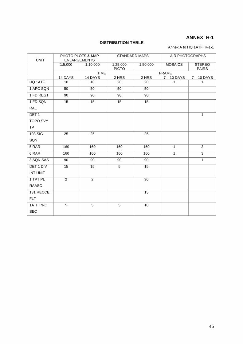
DISTRIBUTION TABLE Annex A to HQ 1ATF R-1-1
UNIT
PHOTO PLOTS & MAP ENLARGEMENTS
STANDARD MAPS AIR PHOTOGRAPHS
1:5,000 1:10,000 1:25,000 PICTO
1:50,000 MOSAICS STEREO PAIRS
TIME FRAME
14 DAYS 14 DAYS 2 HRS 2 HRS 7 – 10 DAYS 7 – 10 DAYS
HQ 1ATF 10 10 20 20 1 1
1 APC SQN 50 50 50 50
1 FD REGT 90 90 90 90
1 FD SQN
RAE
15 15 15 15
DET 1
TOPO SVY
TP
1
103 SIG
SQN
25 25 25
5 RAR 160 160 160 160 1 3
6 RAR 160 160 160 160 1 3
3 SQN SAS 90 90 90 90 1
DET 1 DIV
INT UNIT
15 15 5 15
1 TPT PL
RAASC
2 2 30
131 RECCE
FLT
15
1ATF PRO
SEC
5 5 5 10

47
ANNEX I
OPERATION_ORDER 2/66 – OPERATION TRISIDER

48
ANNEX I
Det 1 Topo Svy Tp
1ATF
NUI DAT
21 Nov 66
See Distribution List
OPERATION_ORDER 2/66 OPERATION TRISIDER
(Scanned and transcribed from original)
1. SITUATION
a. En: No part of the area of survey operations should be
considered as completely secure. En interference with the
operation is not likely, however north of northing 1148000 the
possibility of sniper fire should be realised.
b. Own Forces: Det 1 Topo Svy Tp Survey Party will comprise of
elements of Det 1 Topo Svy Tp, Det 131 Div Loc Bty and A Bty 2/35
Artillery Bn. Details of personnel are included as Annex A
2. MISSION
a. Det 1 Topo Svy Tp Survey Party is to provide 3rd order
position and azimuth at batteries located at the following grid
references; YS382618 YS468778 YS255740 YS648692.
3. EXECUTION
a. General: Position will be based on the Indian Datum 1960
as defined by the new listed values of the 3rd order point CAP ST
JACQUES GR YS287419. Thus all points established will be
connected to third order station CAP ST JACQUES. An attempt will
be made to connect to any existing major or minor order station
within the area of Survey Operation as defined below:
b. Area of Operation will be bounded by the following grid
lines:
Easting 720000 770000
Northing 1140000 1180000
c. Phases: - The operation will be carried out in the
following phases:
(1) Phase 1 VUNG TAU Area.
(a) Effect connexion from Point No 16
(3rd order) YS299450 to CAP ST JACQUES.
(b) Establish 3rd order position on NUI LON
Hill in vicinity of GR YS 262473 from triangle

49
Point No 16 - THANH MINOR - NUI LON.
(c) The following lines will be measured
to 3rd order specifications:
(d) The following directions will be observed
to 3rd order specifications:
at CAP ST JACQUES
NUI DAT (AAS 001)
Point No 16
at Point No 16
CAP ST JACQUES
NUI LON
at AZIMUTH MARK
CAP ST JACQUES
RADAR LIGHT
Point No 16
at NUI LON
Point No 16
THANH MINOR
BARIA BATTERY
at THANH MINOR
Point No 16
NUI LON
(e) In the vicinity of the ALSG Back Beach
area establish 4th order points to provide basic
control for an Engineer Cantonment Survey.
(2) Phase 2 BARIA Area
(a) Establish 3rd order control station in
vicintity of ARVN Bty at BARIA (AAS 005).
(b) Measure the following lines to 3rd order
specifications.
BARIA – NUI LON (AAS 004)
BARIA - NUI DAT (AAS 001)
(c) Observe the following directions
NUI LON
NUI DAT
(3) Phase 3 - BINH GIA Area.
(a) Establishing 3rd order station on knoll
to south of BINH GIA (AAS 006).
(b) Measure the following lines:
BINH GIA - NUI LON
BINH GIA – DUC THANH (AAS 007)

50
(c) Observe the following directions:
BINH GIA - NUI LON
BINH GIA - DUC THANH
(d) Establish 4th order photo point at
eastern end of BINH GIA village by chain and
theodolite traverse.
(e) Connect line from DUC THANH to Arty
Station PENN by chain and theodolite traverse
measured along LTL2.
(f) Dependent upon result of connection to
PENN, carry out further connection from BINH BA
water tower to NUI LON,
(4) Phase 4 - PHU MY Area.
(a) Establish 3rd order station in vicinity
of PHU MY Battery (AS007).
(b) Measure line PHU MY - NUI LON.
(c) Observe AM - PM sun azimuth on line PHU
MY - NUI LON, or an abitrary azimuth line.
(5) Phase 5- XUYEN MOC Area.
(a) Carry out map and air reconnaissance to
determine best possible means of establishing 3rd
order station in vicinity of XUYEN MOC.
d. Vertical observations will be carried out on all lines.
e. Technical Specification. All survey tasks will be
carried out in accordance with RA Svy practice as specified
in Corps manuals unless otherwise directed by OC Det 1 Topo
Svy Tp. Specifications relevant to Operation TRISIDER are
listed in Annex B.
f. Barometer calibrations. Calibration of Aneroid
Barometers will be carried out at VUNG TU Air Base during
Phase 1.
g. Recording will be carried out in duplicate. Original
copies will be returned to Det HQ at intervals of not
greater than 1 week.
h. Station Marking. Stations established by Det 1 Topo Svy
Tp Svy Party will be marked with a RA Svy bronze mark set in
concrete. Three recovery marks consisting of cartridge cases
set in concrete will be positioned and in addition to these
a further reference mark consisting of a permanent existing
feature (eg building) will be connected to wherever
possible.
i. Protection will be organised as required by OC Det 1

51
Topo Svy Tp.
j. Timings. Survey Party will depart 1 ATF base area for
VUNG TAU on 21 Nov 66. The following schedule of timings
will be adhered to as far as possible.
Phase 1 21 Nov 66 - 30 Nov 66
Phase 2 2 Dec 66 - 4 Dec 66
Phase 3 5 Dec 66 - 10 Dec 66
Phase 4 11 Dec 66 - 14 Dec 66
Phase 5 15 Dec 66 - 20 Dec 66
4. ADM AND LOG
a. Transport: Svy party will take the following vehicles:
Truck ¾ ton GS 113 130 - 1 Topo Svy Tp
Trailer ½ ton - 1 Topo Svy Tp
Truck ¾ ton FFR 111 434 - Det 131 Div Loc
Truck ¾ ton US & Trailer - A Bty
b. Accommodation.
(1) Phase 1: - Svy Party will be rationed and
quartered at 1 ALSG Transit Depot during phase 1 of Op
TRISIDER.
(2) Phase 2: - BARIA Party will operate from 1 ATF
Base Area.
(3) Phase 3: - BINH GIA party will be
accommodated at DUC THANH Compound during phase 3.
Rationing will be from 24 hour packs.
(4) Phase 4: - To be notified.
c. Weapons and Ammunition
(1) Except in the proclaimed „no weapons area‟ of
VUNG TAU, personal weapons will be carried at all
times. States of readiness will be as follows:
(a) In secured areas outside of VUNG TAU city
area - no mag on, full mag in pouch.
(b) In unsecured areas full mag on,
working parts forward.
(2) Ammo as follows will be carried:
SLR - 120 rounds per man
OMC - 180 rounds per man

52
d. Stores and Equipment
(1) All stores and equipment other than compasses
prismatic and binoculars will be issued on AAF 1A.
Compasses prismatic and binoculars will be issued on AAF
F12 to members nominated by NCO I/C.
5. COMMAND AND SIGNALS
a. Sgt S.R. Campbell as NCO I/C of Det 1 Topo Svy Tp Survey
Party as listed in Annex A. In the event of Sgt Campbell being
withdrawn from the party for any reason, S/Sgt R.E. Glasgow will
assume Comd, and thence in order of rank and seniority.
b. Communications: Survey Party will carry ANPRC 25 sets.
(1) Call signs
(2) Frequency 59.25
(3) Call words.
18 - 24 GOLF FOXTROT
24 - To be notified.-
(4) Nick names:
BASE AREA HAPPY TOWN CAP ST JACQUES FOOT REST LIGHT HOUSE APPLE SAUCE NUI LON LONG ROPE POINT NO 16 ROSE ROLL AZIMUTH MK DEAD DOG THANH JOLLY SPRING BARIA HOLLOW LOG
NUI DAT WELCOME CITY
BINH GIA CRAZY PLACE PHU MI NUT CAKE
XUYEN MOC PEN GRIP
(5) Appointment Titles:
OC Det 1 Topo Svy Tp STADIA MAJOR
NCO/IC Svy Party STADIA
US Element MICRO
Det 131 Div Loc Elm ASTRO
Det 1 Topo Svy Tp Elm GEOID
[11A (25)] [11B (25)] [11C (25)] [11D (25)] [11E (25)]
[11F (25)]
[11 (25)]

53
(6) Schedules: NCO/IC is responsible for maintaining
internal schedules within the Survey Party. A rear link
schedule will be held at 0730 hours daily.
Annexes A. Det 1 Topo Svy Tp Survey Party Nominal Roll
B. Technical Specifications.
Distribution
HQ 1 ATF
Det 131 Div Loc Bty 1 Fd Regt
A Bty 2/35 Artillery Bn
8th Tgt Acq Bn, 25th Artillery 2 FFV Artillery
66 Eng Co(Topo)(Corps) - LONG BINH File 1st Bn 83rd Artillery.

54
Annex A to Operation Order
2/66 OPERATION TRISIDER
DET 1 TOPO SVY TP SURVEY PARTY
NOMINAL ROLL
36616 Sgt Campbell Det 1 Topo Svy Tp 54467 Spr Firns Det 1 Topo Svy Tp
1731045 L/Bdr Sellwood (NS) Det 131 Div Loc Bty 2781996 Gnr Whittle (NS) do
1200577 Gnr Moreau do 2782434 Gnr Lock (NS) do 3787334 Gnr Earwicker(NS) do
2782129 Gnr Killworth(NS) do A Bty 2/35 RA27094307 S/Sgt Glascow
US55834299 PFC Bach do US52622237 PFC Renzo do
55
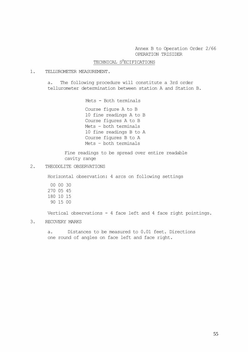
Annex B to Operation Order 2/66
OPERATION TRISIDER
TECHNICAL SPECIFICATIONS
1. TELLUROMETER MEASUREMENT.
a. The following procedure will constitute a 3rd order
tellurometer determination between station A and Station B.
Mets - Both terminals
Course figure A to B
10 fine readings A to B
Course figures A to B
Mets – both terminals
10 fine readings B to A
Course figures B to A
Mets – both terminals
Fine readings to be spread over entire readable
cavity range
2. THEODOLITE OBSERVATIONS
Horizontal observation: 4 arcs on following settings
00 00 30
270 05 45
180 10 15
90 15 00
Vertical observations - 4 face left and 4 face right pointings.
3. RECOVERY MARKS
a. Distances to be measured to 0.01 feet. Directions
one round of angles on face left and face right.

56
ANNEX J
MAPS FOR OPERATIONAL HISTORY OF 1ST ATF IN VIETNAM
Letter to Directorate of Military Survey

57
ANNEX J 17-2-1(14) Det 1 Topo Svy Tp
Aust Forces Vietnam
Aust FPO 4
c/o G.P.O. SYDNEY
7 Jan 67
Directorate of Military Survey
MAPS FOR OPERATIONAL HISTORY OF
1ST ATF IN VIETNAM
(Scanned and transcribed from original)
1. An operational history of the 1st ATF in Vietnam
during 1966 has been prepared by HQ 1 ATF. The writing is
tentatively called “NUI DAT – WITH THE FIRST AUSTRALIAN
TASK FORCE IN VIETNAM – 1966” It is anticipated that the
history will be published in the form of a book or army
manual.
2. Det 1 Topo Svy Tp has prepared a series of 36 map
drawings and 3 diagrams to support the written text. Six
proof copies of the history have been prepared with dyeline
copies of the maps and diagrams included. A detailed
description of each map drawing is attached as Annex A.
3. Also enclosed is one dyelined set of the maps
and diagrams. Forwarded by safe hand with Maj R.R.
Hannigan is the complete set of reproducibles,
consisting of original drawings, and, in some cases
direct positive copies on cronaflex.
4. It is requested that two film positives be
produced from each original drawing. In cases where a
separate drawing showing a tactical situation overlaps
a base map, eg SMITHFIELD maps, it is requested that a
composite film positive be prepared, to include the
base map and the overlay.
5. The final editing and preparation for
publication is to be undertaken by Major R.R. Hannigan
of E Comd Training Cell, formally GSO2 Operations on HQ
1st ATF. Major Hannigan would be able to answer any
queries that might occur in relation to the task. It is
requested that one set of film positives be supplied to
Major Hannigan and the 2nd set forwarded to Det 1 Topo
Svy Tp for record purposes.
6. Included with each proof copy of the
operational history, and with the dyelined set of maps
enclosed is a composite 1:50,000 map entitled "1ST ATF

58
AREA OF INTEREST – 1966". This map shows each "Area of
Operation" of all the operations carried out by 1st ATF
during 1966. Depending upon the nature of the
publication in its final form, it in hoped to have a
composite map overprinted with the detail shown on the
proof copies included with each published copy of the
history in the form of a map enclosure.
7. HQ 1 ATF has been made aware that problems, both
in production and the possible infringement of mapping
agreements might make the inclusion of the map enclosure
impracticable. However, its inclusion would greatly
enhance the value of the writing and it is recommended
that the problem be looked at closely. Since the history
could run into several thousand copies it would
obviously be necessary to produce from the reproduction
material held by RA Svy a special map sheet covering the
area of interest. In doing this a reduction in the
number of colours could perhaps be made to reduce the
detail on the sheet to that which is essential to the
history. Liaison with Major Hannigan would be needed
both in this and also to determine the extent and nature
of the marginal information.
R.F.Skitch Capt
OC Det 1 Topo Svy Tp
Annexes: A. Schedule of Maps and Diagrams

59
ANNEX J-1
Annex A to
MAPS FOR OPERATIONAL HISTORY OF 1ST ATF IN VIETNAM

60
ANNEX J-1
Annex A to SVY 117-2-1 (14)
of 7 Jan 67
MAPS FOR OPERATIONAL HISTORY OF
1ST ATF IN VIETNAM
(Transcribed from the original)
MAP NO TITLE DESCRIPTION Frontispiece 1ST ATF BASE CAMP AND
ENVIRONS
Single direct positive on
cronaflex.
1 AREA OF OPERATION –
OPERATION ENOGGERA
Single drawing on cronaflex
2 INTELLIGENCE – OPERATION
ENOGGERA
Single drawing on cronaflex
3 INSTALLATIONS, CACHES AND
EQUIPMENT – OPERATION
ENOGGERA
Single drawing on cronaflex
4 AREA OF OPERATION –
OPERATION SYDNEY 1
Single drawing on cronaflex
5 VC INSTALLATIONS OPERATION
SYDNEY 1
Single drawing on cronaflex
6 EXTENDED AREA OF OPERATION
– OPERATION SYDNEY 1
Single drawing on cronaflex
7 ASSEMBLY AREAS, ROUTES,
CORDON AND HARBOUR
POSITIONS – OPERATION
SYDNEY 2
Single photo-positive on
cronaflex
8 AREA OF SEARCH, AMBUSHES,
ROUTES – OPERATION SYDNEY 2
Single photo-positive on
cronaflex
9 AREA OF OPERATION –
OPERATION HOBART 1
Single drawing on cronaflex
10 AREA OF OPERATION –
OPERATION HOBART 2
Single drawing on cronaflex
11 AREA OF OPERATION –
OPERATION HOLSWORTHY
Single drawing on cronaflex
12 ENEMY ARTILLERY ACTION
NIGHT 16/17 AUG 66 – AREAS
ENGAGED AND LOCATIONS
Single photo-positive on
cronaflex
13 AREA OF OPERATION –
OPERATION SMITHFIELD
Single drawing on cronaflex
14 OPERATION SMITHFIELD Overlay on cronaflex marked
map 14 over SMITHFIELD base
map on cronaflex
15 OPERATION SMITHFIELD Overlay on cronaflex marked
map 15 over SMITHFIELD base
map on cronaflex
16 OPERATION SMITHFIELD Overlay on cronaflex marked
map 16 over SMITHFIELD base
map on cronaflex
17 OPERATION SMITHFIELD Overlay on cronaflex marked
map 17 over SMITHFIELD base
map on cronaflex
18 OPERATION SMITHFIELD Overlay on cronaflex marked
map 18 over SMITHFIELD base
map on cronaflex
19 OPERATION SMITHFIELD Overlay on cronaflex marked

61
map 19 over SMITHFIELD base
map on cronaflex
20 OPERATION SMITHFIELD Overlay on cronaflex marked
map 20 over SMITHFIELD base
map on cronaflex
21 AREA OF OPERATION –
OPERATION TOLEDO 1
Single drawing on cronaflex
22 AREA OF OPERATION –
OPERATION TOLEDO 2
Single drawing on cronaflex
23 AREA OF OPERATION –
OPERATION VAUCLUSE
Single drawing on cronaflex
24 SAS INTELLIGENCE –
OPERATION VAUCLUSE
Overlay on cronaflex marked
MAP 24 over VAUCLUSE base
map on cronaflex
25 VC CONTACTS AND
INSTALLATIONS – OPERATION
VAUCLUSE
Overlay on cronaflex marked
MAP 25 over VAUCLUSE base
map on cronaflex
26 AREA OF OPERATION –
OPERATION CROWS NEST
Single photo positive on
cronaflex
27 AREA OF OPERATION –
OPERATION CANBERRA
Overlay on cronaflex over
photo positive base map -
CANBERRA
28 AREA OF OPERATION –
OPERATION ROBIN
Photo positive overlay over
photo positive base map as
for CANBERRA
29 AREA OF OPERATION –
OPERATION QUEANBEYAN
Photo positive overlay over
photo positive base map as
for CANBERRA
30 AREA OF OPERATION –
OPERATION BUNDABERG
Overlay on cronaflex marked
MAP 30 over Bundaberg Base
Map on cronaflex
31 3SAS SQN AREA OF OPERATION
(OPERATION HAYMAN PHASES 1
– 3)
Overlay on cronaflex
showing zones 11 – 15 over
HAYMAN base map showing
zones 1 - 4
32 5RAR AREA OF OPERATION –
OPERATION HAYMAN PHASE 1
Photo positive overlay over
photo positive base map
showing PHUOC HOA VILLAGE
33 5 RAR AREA OF OPERATION –
HAYMAN PHASES 2 & 3
Overlay on cronaflex over
base map on cronaflex
showing LONG SON ISLAND
34 INTELLIGENCE OPERATION
INGHAM
Cronaflex overlay marked
MAP 34 over INGHAM base map
on cronaflex
35 AREA OF OPERATION –
OPERATION INGHAM
Direct positive overlay
over INGHAM base map on
cronaflex
36 VC INSTALLATIONS –
OPERATION INGHAM
Overlay on cronaflex over
INGHAM base map on
cronaflex
APPENDIX D MINOR TUNNEL SYSTEMS –
OPERATION ENOGGERA
Single direct positive on
cronaflex
APPENDIX E XA LONG PHUOC TUNNEL
COMPLEX LOCATION PLAN –
OPERATION ENOGGERA
Single drawing on cronaflex
APPENDIX F APPARENT VC ORGANISATION –
BINH BA
Single drawing on tracing
paper
MAP
ENCLOSURE
1ST ATF AREA OF INTEREST
1966
Composite 1:50,000 sheets
6429-I, IV. 6430-I, II,
III, IV.

62
ANNEX K
OP INSTR 1/67 - OP TRISIDER - PHASE 5
63
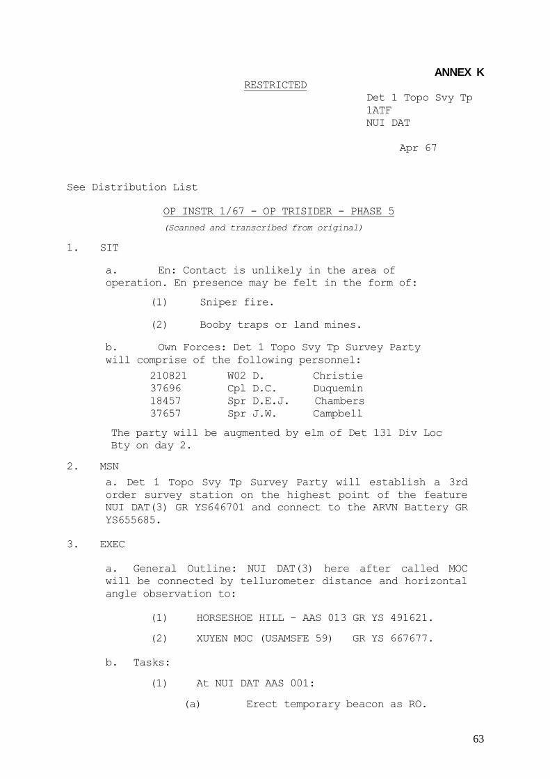
ANNEX K RESTRICTED
Det 1 Topo Svy Tp
1ATF
NUI DAT
Apr 67
See Distribution List
OP INSTR 1/67 - OP TRISIDER - PHASE 5
(Scanned and transcribed from original)
1. SIT
a. En: Contact is unlikely in the area of
operation. En presence may be felt in the form of:
(1) Sniper fire.
(2) Booby traps or land mines.
b. Own Forces: Det 1 Topo Svy Tp Survey Party
will comprise of the following personnel:
210821 W02 D. Christie
37696 Cpl D.C. Duquemin
18457 Spr D.E.J. Chambers
37657 Spr J.W. Campbell
The party will be augmented by elm of Det 131 Div Loc
Bty on day 2.
2. MSN
a. Det 1 Topo Svy Tp Survey Party will establish a 3rd
order survey station on the highest point of the feature
NUI DAT(3) GR YS646701 and connect to the ARVN Battery GR
YS655685.
3. EXEC
a. General Outline: NUI DAT(3) here after called MOC
will be connected by tellurometer distance and horizontal
angle observation to:
(1) HORSESHOE HILL - AAS 013 GR YS 491621.
(2) XUYEN MOC (USAMSFE 59) GR YS 667677.
b. Tasks:
(1) At NUI DAT AAS 001:
(a) Erect temporary beacon as RO.

64
(b) Maintain helio aligned on HORSESHOE
HILL if nec as required.
(2) At HORSESHOE HILL (AAS 013).
(a) Observe included angle at AAS 013
between AAS 001 and MOC.
(b) Measure 3rd order tellurometer
distance AAS 013 - MOC.
(c) Observe vertical angles to MOC.
(3) At MOC (AAS 014)
(a) Observe the following horizontal
directions:
i. HORSESHOE HILL AAS 013.
ii. XUYEN MOC (USAMSFE 59).
iii. Arbitrary Azimuth Mark in XUYEN
MOC Village area.
iv. ARVN Bty Pos.
(b) Measure 4th order tellurometer distance
to the following sta:
i. HORSESHOE HILL AAS 013.
ii. XUYEN MOC (USAMSFE 59).
(c) Measure 4th order tellurometer distance
to fol sta:
i. ARVN Bty Pos.
(d) Measure vertical angles to:
i. HORSESHOE HILL.
ii. XUYEN MOC (USAMSFE 59).
iii. ARVN Bty Pos.
(e) Observe AM & PM sun observation on
either of the following lines:
AAS 014 MOC – ARBITARY AZ MK
AAS 014 MOC - XUYEN MOC (USAMSFE 59)
(f) Establish surface mark, subsurface mark
and three recovery marks.

65
(4) At XUYEN MOC (USAMSFE 59):
(a) Measure tellurometer distance to MOC
AAS 014.
(b) Measure vertical angle to MOC AAS 014.
(c) Observe AM & PM sun observations as
alternative to (3)(e) above.
(5) At ARVN Bty Pos:
(a) Measure 4th order tellurometer to MOC
AAS 014.
(b) Measure vertical angle to MOC AAS 014.
(c) Establish ground marks and 3 recovery
marks.
c. Technical Specifications: All observations and
measurements carried out will be in accordance with RA SVY
practice as specified in Corps Manuals. Annex l outlines
specifications applicable to TRISIDER PHASE 5.
d. Recording will be carried out on RA SVY recording
forms. Care must be taken to ensure that all detail, eg
instr height is properly recorded.
e. Protection: Will be provided by 6 RAR.
f. Station Clearing: Assistance is to be provided for the
clearing of MOC AAS 014 by 1 Fd Sqn RAE in the form of a
bulldozer. Clearing priorities will be:
(1) Cleared lane to HORSESHOE HILL AAS 013 (MAG
BRG 245 degrees).
(2) Cleared lane to XUYEN MOC - ARVN BTY (MAG BRG
135 – 155 degrees).
(3) Remaining clearing to North, West and South.
(4) Clearing to East.
g. Timings: Svy Party will depart KANGAROO PAD at 081100
by UH1B or UH1D for 6 RAR area GR YS 655671. Two lifts
will be provided if necessary. The following schedule of
timings will apply:
DAY 1 - 8 Apr 67
1100 Dep KANGAROO
1120 Arr 6 RAR
1300-1700 estb accommodation and recce XUYEN MOC
USAMSFE 59 and ARVN Bty Pos.

66
DAY 2 - 9 Apr 67
Clearing of MOC AAS 014 and ground marking.
DAY 3 - 10 Apr 67
Carry out connexion to HORSESHOE HILL AAS 013 and
commence connexion to XUYEN MOC USAMSFE ARVN Bty
Pos.
DAY 4 - 11 Apr 67
Complete all tasks, and RTU 1 ATF Base Area.
4. ADMIN AND LOG
a. Rations: Survey party will take 2 days hard rations.
Further rations can be taken fwd on DAY 3 if required.
b. Transport: Mov between 1ATF Base Area and XUYEN MOC to
be by helicopter. Ground movement at XUYEN MOC to be by
vehicle GS or track as provided by 6 RAR.
c. Accommodation: Members to carry Lt wt camping
equipment; stretchers can be taken.
d. Wpns and Ammo:
(1) In the XUYEN MOC AREA the fol state of
readiness will apply: Mag on - working parts forward.
(2) First line ammo will be carried.
e. Stores and Eqpt: All stores and eqpt other than
compasses and binoculars will be issued on AAF 1A. Compasses
and binoculars will be a personal issue to members nominated
by WO I/C.
5. COMD & SIG
a. 210821 W02 D. Christie is in charge of Det 1 Topo Svy
Tp Survey Party. 37696 Cpl D.C. Duquemin is second in
charge.
b. Communications: Survey party to XUYEN MOC will
carry two ANPRC 25 sets.
(1) Callsigns.
XUYEN MOC 81
XUYEN MOC SUBSTATION 81 ALPHA
HORSESHOE 81 BRAVO
NUI DAT (1) 81 CHARLIE
ARTY 81 DELTA

67
(2) Frequency 59.25
(3) Callword: GOLF ROMEO
(4) Q Hour 0800 daily
(5) POINT OF ORIGIN – 6366 CAR 6568 ANIMAL
(6) NICKNAMES
MOC AAS 014 PENGRIP
HORSESHOE CIDER WINE
1 ATF BASE AREA BRIGHT DAY
6 RAR LOC HAPPY SITE
NUI DAT AAS OO1 WELCOME CITY
XUYEN MOC (USAMSFE) DOGS TAIL
(7) Appointment titles
OC Det 1 Topo Svy Tp TOPO SUNRAY
WO I/C TOPO SUNRAY MINOR
(8) Schedules:
(a) WO I/C is responsible for maintaining
internal schedules within survey party.
(b) Tellurometer call up time 0900 - cav 7
master at MOC AAS 014.
(c) SITREP - daily at 1850H on COMD NET.
R.F. Skitch (signed) Capt
OC Det 1 Topo Svy Tp
Annexes: 1. Technical Specifications.
Distribution
HQ 1 ATF
Det 131 Div Loc Bty
6 RAR
1 Fd Sqn
File

68
Annex 1 to Op Instr 1/67
OP TRISIDER PHASE 5
TECHNICAL SPECIFICATIONS
(Scanned and transcribed from original)
1. TELUROMETER MEASUREMENT
a. The following procedure will constitute a 3rd order
tellurometer determination between station A & station B.
Mets - both terminals
Course figure - A to B
10 fine readings A to B
Course figure A to B
Mets – both terminals
10 fine readings B to A
Course figure B to A
Mets – both terminals
Fine readings to be spread over entire readable cavity range.
2. THEODOLITE OBSERVATIONS
a. Horizontal observations -
(1) Major traverse stations of unclosed figure -
8 Arcs. Half the number of arcs will be observed with
the backsight as RO and the remaining half with the
foresight as RO. The summation of the two angles
observed must fall on either side of 360° within 8".O
of arc.
b. Minor stations.
(1) Major lines - 4 face left and 4 face right
pointings.
(2) Minor lines – 2 face left and 2 face right
pointings.

69
ANNEX L
REPORT ON PRELIMINARY FIELD TESTING OF AIRBORNE SURVEY SYSTEM (ARTY CONCEPT) AT NUI DAT - SOUTH VIETNAM

70
ANNEX L
R723:1:3 A Sec 1 Topo Svy Tp
NUI DAT
May 67
HQ AFV SAIGON (3)
REPORT ON PRELIMINARY FIELD TESTING OF AIRBORNE SURVEY SYSTEM
(ARTY CONCEPT) AT NUI DAT - SOUTH VIETNAM (Scanned and transcribed from the original)
Refs A. DRA 542-I of I6 Feb 67.
B. Paper submitted by Lt Col D. Tier.
General
1. On receipt of reference A in February 1967 it was decided to
carry out a field test of the principle expounded in reference B.
The testing was intended to:-
a. Develop a field procedure which could be used in this
and other observations of this nature.
b. Determine whether the inherent weaknesses of height
measurement by altimetry would negate the resolution of such
measurement into the horizontal plane.
c. Determine what modifications might be needed to develop
the principle of simultaneous co-ordinated observations to an
air station into a practical reality.
2. The testing carried out was limited in extent although
sufficient to give some indication of the problems involved and
the likely solutions. Observations were carried out on two
separate days, the results of the first day being completely
abortive and those of the second being sufficient to provide
sensible computations.
Procedure
3. The procedure adopted is outlined in Annex A, and this was
found to be very suitable and the only modifications necessary
were:
a. After day one it became obvious that the helicopter
would have to hover as steady as possible with no forward

71
movement.
b. The number of observations at each air station was
reduced from 5 to 3 face left and face right pointings.
Modifications
4. In addition to the principle of fixing the unknown station
from a single known station with observations to two air-stations,
one on either side of the line between the known and the unknown
station, a second known station was introduced into the observat-
ions of the first, air-station. This permitted the air-station
position to be horizontally triangulated, requiring the altimetric
vertical interval principle to be used only in carrying the
position from the air-station to the unknown station.
Computations
5. All computations were carried out in plane trigonometrical
figures. Separate computations were carried out for face left and
face right readings and these meaned. Computations are attached as
Annex B.(omitted)
Results
6. Co-ordinates of the assumed unknown station obtained, viz,
the air-station fixed in the first instance by horizontal
triangulation from the two known stations and in the second
instance by vertical triangulation from the single known station,
are shown in comparison with the known values of the assumed
unknown station.
Results of Airborne System of Survey
7. CO-ORDS BEARING
Correct value (E 749 052 100° 42‟ 07”
(N 1162 131
Computed from 2 known stations (E 748 944
and one air-station (N 1162 229
Computed from one known station (E 749 206 98° 31‟ 43”
and two air-stations (N 1162 395
Analysis of Results
8. The large miscloses on the unknown station are due to:
a. To a greater extent, the imprecision of the principles
of altimetry.

72
b. To a lesser extent the difficulties of intersecting
the rotor mast of the helicopter from two or three directions
simultaneously, over comparatively short distances.
c. The difficulty in holding the helicopter steady in both
the horizontal and the vertical plane at the instant of
intersection, without a point of reference on the ground.
This aggravated the situation in (b.) above.
Altimetry Discussion
9. It is the opinion of the writer that the principle of
altimetry does not offer sufficient precision to allow vertical
intervals so measured to be resolved into a horizontal plane. The
altimeters used were of WALLACE and TIERNAN (manufacturer)
graduated to ten metres. It is possible to interpolate fairly
precisely to two metres. The following factors, however, prevent
vertical (interval) being measured to this degree of accuracy.
a. The vertical interval between the ground station and
the air station is necessarily in the order of 300 - 500
metres, at the horizontal distance of 5000-6000 metres. The
barometric datum plane is not likely to be truly horizontal
over this range of altitude or distance.
b. Internal pressures within the helicopter make precise
measurement of altitude by altimetry difficult. An attempt to
calibrate the air station barometer against the ground
station barometer was made, with the helicopter hovering with
maximum power. This was not necessarily representative of the
internal pressures at an altitude of 700 metres.
c. The combined effect of vapour pressure and an air
temperature produces an altitude correction of 5% of the
vertical interval. It was only possible to measure this with
any degree of precision at the ground station, due to the
internal influences of the helicopter.
d. Altimeters are affected by a condition known as 'lag'
i.e., the altimeter requires time to „settle‟ after movement,
while the internal stresses in the mechanical components
„take up‟. This is especially true when large changes of
altitude are effected. The error introduced by 'lag' could
conceivably be 10 metres in the vertical interval of 700
metres.
e. The general assumptions applied to altimetry are
acceptable only when the vertical interval is kept to a
minimum. Generally, for accuracy to be within 5 metres, the
maximum vertical interval should be no more than 100 metres.

73
Even if this interval was possible, error in resolution to
horizontal distance would be magnified 50 times, so requiring
a precision of better than one metre.
f. At an altitude of 700 metres, errors are magnified
8 times in resolving to the horizontal. To obtain an
accuracy of 50 metres in horizontal position, an accuracy of
+/-7 metres would be required in measuring the vertical
interval. This is not likely to be achieved by altimetry
under these conditions, regardless of the mechanical
accuracy of the instruments.
Conclusion
10. Although the field testing carried out could not be
considered to be exhaustive, when supported by the known facts of
altimetry outlined above, it would indicate that sufficient
precision to provide a horizontal fixation to an accuracy of +/-20
(metres) is unlikely to be attained. This would require a vertical
interval to be measured to better than 2 ½ metres. Even under
optimum conditions this accuracy would be difficult to achieve.
Recommendations
It is considered that further testing of the principle developed
in reference B is not warranted.
RF Skitch (signed)
Capt. OC
A Sec 1 Topo Svy Tp

74
Annex A to
R732:1:3
AIRBORNE SURVEY CONTROL SYSTEM
PROCEDURE
General
1. Simultaneous hor and vert observations are carried out from
two known survey control stations to a hovering or slow moving
helicopter (Air Station).
2. The vertical interval between the Air Station and all three
ground stations (known and unknown) is measured at the instant of
observation by altimetry.
3. At the known stations, the horizontal angle to the air
station is read from a known azimuth line and at the unknown
station, the horizontal angle to the air station is read from an
unknown azimuth line.
4. Vertical observations from the known and unknown ground
stations are carried out simultaneously with the horizontal
observations to the air station.
5. Co-ordination is carried out by radio with control from the
air station.
Procedure
6. All ground station personnel will be positioned and fully
ready for observations 15 minutes before the helicopter moves to
air station (1). RO lines will be proven during the setting up
procedure.
7. Barometers/altimeters and psychrometers will be positioned in
the shade.
8. A comparative altimeter reading between the air station
altimeter and the unknown ground station altimeter will be carried
out before the commencement of the 1st air station observations
and after the completion of the 2nd air station observations. This
will be effected by having the helicopter hover horizontal with
the instrument position approx 100 metres out from the instrument
position. The instrument observer will indicate whether the
helicopter needs to rise or fall by:
a. Extending left arm for fall.
b. Extending right arm for rise.
c. Extending both arms for 0K.

75
Altimeters will be read on the command READ given by the ground
station.
9. Barometers/Altimeters on the ground stations will be read
before and after each set of observations. Altimeter at the air
station will be read on each observation. Barometers/Altimeters
will be calibrated together at base before and after the task.
10. A set of observations will consist 5 face left and 5
face right observations with the horizontal being closed at the
completion of each ½ set. Commands and responses will be as
follows:
COMMAND RESPONSE
a. To determine when station preparation is complete enroute to
air station.
81. To all stations- 81A - READY
: )Y
OK OUT
STATION REPORT SIGNALS - 81B - READY
`Y
OK OUT
OVER. 81C - READY OK OUT
COMMAND RESPONSE
b. To determine whether helicopter can be sighted.
81. To all stations - 81A ROGER OUT
CAN YOU SEE ME OVER 81B ROGER OUT
81C NEGATIVE OUT
c. Air station will then proceed towards 81C until 81C reports
„I CAN SEE YOU – OVER‟. Other stations keep aligned during this
process. Air station will then move back to 1st position.
81. To all stations- 81A ROGER OUT
CAN YOU SEE ME OVER 81B ROGER OUT
81C ROGER OUT
81. To all stations - All stations record hor and vert
RECORD HOR AND VERT angle for recovery.
d. To commence observations. All stations align on RO.
81. To all stations - 81A READY OUT
PREPARE FOR OBSERVATIONS 81B READY OUT
OVER 81C READY OUT

76
e. 81. To all stations - 81A BAROMERER OUT
READ BAROMETERS OVER 81B BAROMETER OUT
81C BAROMETER OUT
f. 81. To all Stations - 81A READY OUT
FACE LEFT ON AIR STATION 81B READY OUT
PREPARE TO READ 81C READY OUT
g. 81. To all stations – All stations read and record hor and
READING NO 1 – „ONE vert readings. Remember to check
TWO-THREE-FOUR-MARK‟ alidade bubble. Air station will read
altimeter and record. On completion of
readings all stations will report.
81A OUT
81B OUT
81C OUT
If any one station finds that a mistake
or an accident has occurred he will
report: 81A ABORT OVER
h. 81. To all stations - 81A OUT
ABORT READING NO 1 81B OUT
READING NO 1 ALPHA 81C OUT
„ONE-TWO-THREE-FOUR-MARK‟
i. 81. To all stations - etc etc
READING NO 2 etc etc to reading No 5
j. 81. To all stations -
READING NO 5 „ONE-TWO 81A OUT
THREE-FOUR-MARK‟ 81B OUT
81C OUT
k. 81. To all stations - All stations continue swing
CLOSE HORIZONS AND through 3600 and re-read RO and
REPORT report miscloses in seconds of arc
81 A 5 SECONDS OUT
81 B 2 SECONDS OUT
81 C 10 SECONDS OUT
l. If miscloses in excess of 20 seconds occur, set will be
aborted and re-observed as follows:
To all stations - 81A READY OUT
ABORT FIRST HALF 81B READY OUT
SET - FACE LEFT 81C READY OUT
ON AIR STATION PREPARE
TO READ – OVER
m. Observation of 1st set will then continue. If misclose on 1st

77
set is satisfactory:
81. To all stations - 81A OUT
PLUNGE ON RO 81B OUT
81C OUT
n. 2nd ½ set will continue in same manner.
81. To all stations- 81A BAROMETER OUT
READ BAROMETER OVER 81B BAROMETER OUT
81C BAROMETER OUT
o. 81. To all stations-
FACE RIGHT ON AIR 81A READY OUT
STATION – PREPARE TO 81B READY OUT
READ – OVER 81C READY OUT
p. Procedure will then continue as before. At completion of 2nd
set, after miscloses have been verified and barometers read
helicopter will proceed to 2nd air station and all observers will
keep telescopes on the helicopter during movement. 2nd air station
will proceed in same manner as first.
q. 81. To all stations -
PROCEEDING TO SECOND AIR STATION OUT
r. Should any ground station lose the helicopter in the movement
the 2nd air station, this station should report immediately:
81B I CANNOT SEE YOU – OUT
s. At completion of 2nd air station comparative altimeter
reading between air station and ground station 81C will be carried
out as before. At completion of this:
81. To all stations - 81A ROGER OUT
END OF OBSERVATIONS 81B ROGER OUT
RETURN TO BASE OUT 81C ROGER OUT

78
ANNEX M
DETACHMENT (A SECTION) 1ST TOPOGRAPHICAL SURVEY TROOP
STANDING OPERATING PROCEDURE (PROV)
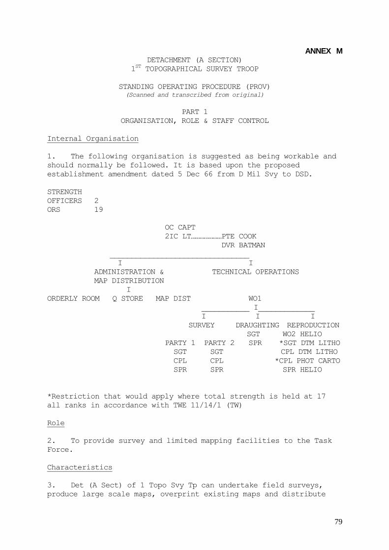
79
ANNEX M DETACHMENT (A SECTION)
1ST TOPOGRAPHICAL SURVEY TROOP
STANDING OPERATING PROCEDURE (PROV) (Scanned and transcribed from original)
PART 1
ORGANISATION, ROLE & STAFF CONTROL
Internal Organisation
1. The following organisation is suggested as being workable and
should normally be followed. It is based upon the proposed
establishment amendment dated 5 Dec 66 from D Mil Svy to DSD.
STRENGTH
OFFICERS 2
ORS 19
OC CAPT
2IC LT…………………PTE COOK
DVR BATMAN
________________________________
I I
ADMINISTRATION & TECHNICAL OPERATIONS
MAP DISTRIBUTION
I
ORDERLY ROOM Q STORE MAP DIST WO1
___________ I_____________
I I I
SURVEY DRAUGHTING REPRODUCTION
SGT WO2 HELIO
PARTY 1 PARTY 2 SPR *SGT DTM LITHO
SGT SGT CPL DTM LITHO
CPL CPL *CPL PHOT CARTO
SPR SPR SPR HELIO
*Restriction that would apply where total strength is held at 17
all ranks in accordance with TWE 11/14/1 (TW)
Role
2. To provide survey and limited mapping facilities to the Task
Force.
Characteristics
3. Det (A Sect) of 1 Topo Svy Tp can undertake field surveys,
produce large scale maps, overprint existing maps and distribute

80
maps.
Tasks
4. The following tasks are to be carried out:
a. Establish and extend survey control in the operational
area as a basis for the theatre grid and the co-ordination of
fire control.
b. Compile large scale maps to supplement existing maps.
c. Produce map enlargements and sketch maps.
d. Print limited numbers of maps and carry out
overprints to existing maps.
c. Hold limited numbers of maps and distribute
these to Task Force units.
e. The Officer Commanding the Det (Sect) advises
the Task Force Commander and staff on all survey and mapping
matters.
Duties
5. The duties of the Det (Sect) personnel are as follows:
a. Officer Commanding.
(1) To exercise full administrative,
technical and productive control of the Det (Sect).
(2) To advise the Commander 1 ATF on all
survey and mapping matters.
b. Second in Command.
(1) To assist the OC in carrying out his duties
with particular reference to the administrative
functions of the Det.
(2) To deputise for the OC in any period in
which the OC is absent.
(3) To be responsible for the security of information and
documentation.
c. W01 Surveyor Topographical.
(1) To assist in the planning of all technical tasks
of a surveying, photogrammetric and draughting nature

81
with the OC or 2IC.
(2) To supervise the detailed planning of tasks with
the NCOs and I/C of the survey and draughting elements
the unit.
(3) To carry out limited administrative and regimental
duties as Troop Sergeant Major.
NOTE. The WO1 Surveyor Topographical would carry out normal
technical duties of a survey compilation nature in addition to
the specific tasks outlined above.
d. WO2 Helioworker (Silk Screen)
(1) To be directly responsible to the OC for the
operation and production control of the Silk Screen
Printing equipment and Dyeline equipment.
(2) The control and maintenance of adequate reserves
of all expendable stores required in silk screen
printing. This will necessarily include the timely
notification of depleting stock levels.
e. Sgts Surveyor Topographical.
(1) To plan and supervise the detailed operations of
the survey parties in field survey operations.
(2) To carry out map compilation duties as directed
by the WO1 Surveyor Topographical.
f. Sgt Draughtsman (Litho).
(1) To supervise and carryout re-touching of silk
screen stencils and photo negatives.
g. Sgt Draughtsman (Carto).
(1) To supervise and carry out tasks of a purely
drawing nature allocated to the draughting element by
the WO1 Surveyor Topographical.
h. Cpl Surveyor (Topo).
(1) To assist the Sgt Svyr Topo in the detailed
planning and supervision of field survey operations
(2) To carry out map compilation duties as directed by
the WO1 Surveyor Topographical.

82
i. Sprs Surveyor Topographical.
(1) To carry out field survey, map compilation and photo
inspection duties as directed by the WO1 Surveyor
Topographical.
j. Cpl Photographer (Carto).
(1) To operate the camera and photographic equipment of
the unit on tasks as directed by the WO1 Surveyor
Topographical.
k. Cpl Draughtsman (Litho).
(1) To carry out re-touching of silk screen stencils
and photo negatives as directed.
(2) To assist in general and topographic draughting as
directed.
l. Sprs Surveyor Topo.
(1) To carry out field survey, map compilation and
photo inspection duties as directed by the WO1 Surveyor
Topographical.
m. Sprs Draughtsman Topo.
(1) To carry out draughting duties as directed by the
Sgt Draughtsman.
n. Spr Helioworker.
(1) To assist in the operation of the silk screen
printing equipment.
o. S/Sgt CQMS.
(1) The overall supervision of all Q functions in the
unit, including:
(a) Receipt and issue of all stores and equipment.
(b) Receipt and issue of maps.
(c) Maintenance of map stock records.
p. Cpl Clerk (GD).
(1) To carry out all „A‟ functions of the unit
including the following:

83
(a) The compilation and submission of all periodic
returns.
(b) The maintenance of the unit correspondence
filing system.
p. Cpl/Spr Storeman Tech.
(1) To carry out Q duties as directed by the CQMS in
relation to:
(a) The receipt and issue of stores and equipment.
(b) The maintenance of a neat and tidy Q Store.
(c) Receipt and issue of maps.
(d) The maintenance of an orderly and efficient
map store.
(e) Collection and processing of unit laundry.
q. Spr Driver-Batman.
(1) To carry out driving duties as required.
(2) To carry out batman duties as required.
(3) To be responsible to the CQMS for the fuelling and
maintenance of vehicles and the maintenance of vehicle
records.
r. Pte Cook.
(1) To carry out cooking duties as directed.
Allocation within the Task Force
6. Det (A Sect) of 1 Topo Svy Tp is allocated to a Task Force. It
is a sub-unit of HQ 1ATF and is under command of HQ 1ATF. Det (A
Sect)1 Topo Svy Tp bears a relationship to HQ Coy 1ATF similar to
that between and independent unit and an area command. Det (A Sect)
1 Topo Svy Tp retains responsibility for the following aspects of
its administration:
a. Discipline. OC Det (A Sect)1 Topo Svy Tp is
appointed by Comd 1ATF to exercise the power of a
Commanding Officer in accordance with AMR 238 (8) in
relation to all NCO's and private soldiers of Det (A
Sect)1 Topo Svy Tp and can impose the punishments set

84
out as follows:
(1)In the case of an offence committed by a non-
commissioned officer:
(a) Reprimand, or
(b) Admonition.
(2) In the case of an offence committed by a private
soldier, one or more of the following sentences:
(a) A fine not exceeding $10.
(b) Confinement to barracks not exceeding seven
days.
(c) Extra guards or picquets.
(d) Admonition.
b. Personal administration – Det (A Sect)1 Topo Svy Tp
carries out all aspects of administration applied to its
own members; in particular, that pertaining to:
(1) Promotion.
(2) Raising of PORs and Confidential Reports.
(3) Administration of Paludrin.
(4) Maintenance of Company Roll Book and routine
administrative parades.
(5) Submissions or returns both periodic and
occasional.
The following aspects of administration are specifically
tied to HQ Coy HQ 1 ATF:
(6) Pay is drawn from a sub-sub imprest on HQ Coy.
(7) Orders and instructions from HQ 1ATF may be
promulgated by HQ Coy to Det (A Sect) 1 Topo Svy Tp.
(8) All inwards correspondence from both HQ 1ATF
registry and SDS is routed via HQ Coy.
(9) Personal mail inwards and outwards passes via
the HQ Coy Postal Orderly.

85
(10) Amenities - allocation is via HQ Coy.
(11) R&R / R&C - allocation from HQ Coy.
(12) Weekly parade states are submitted to HQ Coy.
b. Det (A Sect) 1 Topo Svy Tp receives an ASCO rebate and
operates a Unit Trust Account for handling this and other
funds.
c. Defence - OC HQ Coy, HQ 1 ATF is responsible for the
coordination of defence within the HQ 1 ATF area. Det (A
Sect) 1 Topo Svy Tp is included in the overall defence plan.
d. Q Management and Administration.
(1)General – Det (A Sect) 1 Topo Svy Tp maintains its
own Q Account. The account number allocated is 2593.
(2) The Det(A Sect) Q Account is used to:
(a) Maintain unit equipment.
(b) Obtain on block scales such stores as are
required to maintain a unit base camp.
(c) Obtain all such expense stores as are
necessary for the technical function of the unit.
(3) Clothing and ordinary expense stores are obtained
from the HQ Coy HQ 1ATF store.
(4) Rationing – Det (A Sect) 1 Topo Svy Tp is rationed
by HQ Coy and for this purpose a daily ration strength
return is submitted before 0900. The Private cook on Det
(A Sect)1 Topo Svy Tp strength will normally be employed
on cooking duties in the HQ Coy kitchen.
(5) Accommodation – Det (A Sect) 1 Topo Svy Tp occupies
an area of ground within the limits of HQ 1 ATF. In this
sense, HQ Coy is the „property holder‟ and exercises
control over the external improvements of the area.
86
PART II
TECHNICAL PROCEDURES
Staff Direction
1. Det (A Sect) 1 Topo Svy Tp comes under GS02 Int (Int 1) for
routine staff direction. The responsibilities of GSO2 Int to Det (A
Sect) 1 Topo Svy Tp are:
a. Vetting of all requests for survey assistance from units.
b. Allocation of work priorities on operational tasks.
c. Representation on behalf of Det (A Sect) 1 Topo Svy Tp
at Staff level on Task Force Headquarters.
d. Provision of sufficient advance information on
forthcoming operations to allow the general planning and
commencement of operational overprints, photoplots and large
scale maps for the support of the operation.
e. To initiate the provision of infantry protection as
required for field survey in insecure or disputed areas.
Control Surveys
2. The responsibility of Det (A Sect) 1 Topo Svy Tp in the
provision of control survey is:
a. To provide 3rd order control points within and around
the 1st ATF TAOR of sufficient density to allow simple
connexions to be made from these points to the battery
centres of fire support bases established in direct support
of operations.
b. To assist the Task Force Artillery surveyors in extending
this control to the near vicinity of the battery centres,
where such assistance is requested, in the form of equipment
or technical advice.
c. To provide photo control points for large scale
mapping or map revision as determined by OC Det(A Sect) 1
Topo Svy Tp.
3. The following considerations apply:
a. For ease of establishment and ease of subsequent re-
occupation, the basic 3rd order control points should be in
either secure areas or areas easily secured.

87
b. Where possible each new basic control point should be
fixed from two previously determined points by a
combination of tellurometer and angle observations so that
three additional quantities are measured independently on
each triangle so formed.
c. All observations and measurements are to be carried
out to normal RA Svy 3rd order specifications. These are
summarized in Annex A to this instruction (not included).
d. Chain and theodolite traverses will conform to the RA Svy
3rd order specifications as stated in the RA Svy Manual of
3rd Order Traverse. Chain and theodolite traverses will be
closed where possible either onto the start point or onto
another station independently established. Where this is not
possible, a Sun Azimuth will be observed on the closing line
and all distances will be chained and check-chained
independently.
e. When observing traverse angles whether on chain and
theodolite traverses or tellurometer traverses, half the
number of arcs will be observed using the backsight as RO
and the remaining half with the foresight as RO. The
summation of the two angles observed must fall on either
side of 360 degrees within the allowable range of the set.
Cantonment Surveys
4. Det (A Sect)1 Topo Svy Tp carries responsibility for
maintaining an up to date detailed Cantonment Survey of the 1 ATF
Base Area or any sub base area. With the concurrence of HQ 1 ATF,
Det (A Sect) 1 Topo Svy Tp will maintain a similar detailed survey
plan of the 1 ALSG area at VUNG TAU, and this will be kept current
when operational mapping tasks permit. The following considerations
apply:
a. The scale should be sufficiently large to permit the
p1otting of permanent buildings to scale and true to shape. A
convenient scale has been found to be 1:2,000 or 1:2,500.
a. b. The contour interval should show the general shape of
the ground sufficiently well to permit the planning of main
scheme drainage. A contour interval of 2 metres has been
found to be satisfactory in the Task Force Base Area.
b.
c. Contours should be accurate to within one half a contour
interval.
5. The essential ingredients of a Cantonment Survey are:

88
a. A general frame work of 4th order control stations at
intervals of about 2000 metres throughout the area. At
least 3 such stations should be established.
b. A closed 3rd order traverse, permanently marked, within
the outer perimeter, and surrounding the inner perimeter, to
carry both horizontal and vertical position.
c. Tacheometric traverses semi-permanently marked
subdividing the 3rd order traverse into areas of about 500
metres square, starting and finishing on 3rd order traverse
stations. Further tacheometric loop traverses should be
extended from the 3rd order traverse to include the outer
perimeter. These should carry both horizontal and vertical
position.
d. Detail, both horizontal and vertical filled in from
combined plane table and tacheometric survey, using the
former to carry azimuth and maintain a continuous plot, and
the latter for distance.
e. The availability of vertical air photography at a
suitable scale to permit a photogrammetric solution will
allow a reduction in the requirement for tacheometric control
traverses and detailed field survey. A photo scale of 1:5,000
has been found adequate for the reproduction of a 1:2,500
plot.
6. A useful by-product of the cantonment survey is a further
plot at 1:5000 published as a standard map showing all permanent
buildings, road plan and physical detail. This can then become the
base map for the overprinting of tactical areas and defences or any
other information of a tactical or engineering nature.
Application of Photogrammetry
7. Photogrammetry is employed by Det(A Sect)1 Topo Svy Tp to:
a. Produce large scale maps of village areas or other areas
of specific interest, to supplement the existing map.
b. Revise and up-date existing maps by:
(1) Increasing track information.
(2) Adding and where necessary eliminating buildings.
(3) Improving the drainage pattern and adding
detail to the existing streams and rivers.
(4) Improving vegetation boundaries and classification.

89
c. Provide detail in the compilation of cantonment survey
plans.
d. Extend artillery control by the block adjustment of
consecutive runs of homogeneous photography and reading out
the additional easily identifiable points for future battery
positions or calibration points. This is a concept yet to be
developed.
8. Det (A Sect) 1 Topo Svy Tp carries the following equipments
for photogrammetric work:
a. Stereotopes Qty 2
b. Old Delft Scanning Stereoscopes Qty 2
c. Walch Sketchmaster Qty 1
Also Casella pocket stereoscopes and Universal Stereoscopes.
9. Limitations - The application of photogrammetry within the Det
(A Sect) is limited by the following considerations:
a. Current equipment does not permit block adjustment of any
form and only graphical strip adjustments.
b. Available photography is generally not flown to mapping
specifications and may be entirely unsuitable for mapping
purposes.
c. Tactical considerations usually prevent the establishment
of ground control. In such cases control has to be scaled
from the L7014 1:50,000 Series.
10. Large scale maps of village areas fall into the following
categories:
a. Map enlargements extensively edited from direct photo
inspection and proportional scaling from oblique photography.
b. Photo plots from split vertical (oblique) photography,
plotted stereoscopically on the Stereotope, accepting the
distortions inherent in the tilted photography. Maximum
adjustment on the Stereotope rectiputers will minimise tilts
up to 13 degrees obliquity. Approximate scale is obtained by
comparison with the standard map and the Stereotope
pantograph is adjusted to an even decimal scale.
c. Strip adjustment of consecutive runs of vertical air
photography, using scaled points from the standard 1:50000

90
map as ground control. Plotting may be graphical or
stereoscopic on the Stereotope. Detail may be field checked.
d. Strip adjustment of consecutive runs of vertical air
photography using photo identified ground control. Plotting
may be graphical or stereoscopic on the Stereotope. Detail
may be field checked.
11. Plotting should normally be carried out stereoscopically
on the Stereotope even when only planimetric detail is sought.
12. Map Revision - Additional track and building detail can be
obtained from the various types of intelligence photography and
transferred by direct inspection to the Pictomap (Photomap) series,
In this way, any type of intelligence photography regardless of
scale, format or tilt characteristics can be used. This detail can
then be further transferred from the Picto Series to the 1:25,000
Enlargement Series correcting where possible for variations between
Picto positions and standard map position. Overprint traces may be
prepared for the 1:25,000 enlargement series. All photo inspection
should be carried out stereoscopically using either Casella pocket
stereoscopes or the Old Delft scanning stereoscope.
Reproduction
13. Det (A Sect) 1 Topo Svy Tp has the following reproduction
facilities:
(1) Dyeline direct positive printing.
(2) Silk Screen Printing.
(3) Camera reproduction (reserved)
a. Reproduction facilities offered by Det (A Sect) 1 Topo
Svy Tp is limited to the reproduction of maps, map
overprints, map overlays and other drawings of a map like
character. Expense stores associated with all forms of
reproduction are scaled to meet the stated mapping and
survey role of the Det (A Sect). The application of the
reproductive capability to tasks of a GD nature not
associated with maps and survey is a misuse of this
capability.
14. „Dyeline‟ direct positive printing produces a positive image
on either an opaque or translucent light sensitive paper from a
positive transparency.
15 The limitations of dyeline reproduction are:
a. The photo sensitive paper is dimensionally unstable and

91
may stretch 2½% of its overall dimensions.
b. Dyeline paper is not durable.
c. The dyeline process is strictly single colour - viz, a
black lined image on a brown-white background.
d. For large numbers of copies (eg in excess of 50) the
process is slow.
16. The dyeline process has the following advantages:
a. Simplicity of operation.
b. The sheet size is restricted in one direction only since
the reproduction process is of a continuous nature on a roll
of light sensitive paper.
c. The dyeline machine is available for immediate use
without any special preparation.
17. Silk Screen printing is a stencil process where an image is
produced on a sheet of paper or other material by applying ink to
the stencil when in contact with the paper. An outline description
of the process is given in Annex X (not prepared at the time of
this SOP).
18. Silk Screen Printing has the following limitations:
a. Requires highly trained and experienced tradesmen to
obtain results.
b. Draughting for the production of silk screen stencils
needs to be of good quality in opaque black drawing ink on a
dimensionally stable drawing medium.
c. Upwards to 4 hours may be needed for stencil preparation
before a single print is obtained. The process is therefore
not economica1 in time when less than 20 copies are required.
19. The Silk Screen process has the following advantages:
a. Printing can be carried out in any colour desired.
b. Printing can be carried out in two or more colours,
however, the time factor is a direct multiple of the number
of colours used.
c. Printing can be carried out on any medium; paper,
plastic, talc, tracing paper.

92
d. Once the stencil is made the printing rate is 150
impressions per hour. Therefore an optimum number of copies
ranges from 100 to 400.
e. Overprinting of existing map series can be carried out.
20 - 21 Camera Reproduction - Reserved.
Draughting
22 Det (A Sect) 1 Topo Svy Tp has two topographical draughtsmen
on establishment. In addition to those, two lithographic
draughtsmen are provided for photographic re-touching and these may
have some general draughting capability. The surveyors on
establishment may also have some general draughting capability.
This, however, is usually limited to the preparation of compilation
work sheets, survey records and is not usually adequate for direct
reproduction other than dyeline. In every cases the draughting
capability of Det (A Sect) 1 Topo Svy Tp is limited to draughting
associated with survey and mapping and is misused when applied on
other tasks of a GD nature.
Registration
23. Registration is the most significant draughting problem and
the following sub-paras are intended to provide an analysis of
this problem.
a. Most draughting tasks carried out by the Det (A Sect)
are required to register in detail against the detail of a
standard map or some other map product. The registration
may take the form of a direct overprint onto a standard
map or an overlay keyed in to a standard map. Factors
causing lack of registration are:-
(1) inaccurate draughting,
(2) expansion or contraction of the printing mediums,
(3) expansion or contraction of the draughting mediums.
b. Thus lack of registration may occur between the
draughting process and the printing process due to:
(1) Movement of the draughting medium during or after
draughting,
(2) Movement of the printing medium before printing or
between successive colour overprints.
c. Overlays are usually reproduced as opaque dyeline
93
copies. Lack of registration in this case is usually caused
by expansion of the dyeline paper after printing. It is
impossible to prevent this from happening, however, its
effect can be minimised by the construction of a standard
grid on the original trace, so that errors in registration
can be meaned out square by square, when transferring the
overlay detail to the map in subsequent use.
d. Lack of registration in draughting applied to silkscreen
printing can be minimized by constantly applying the
following principles:
(1) Only dimensional stable draughting mediums should
be used.
(2) The base map used for the production of an
overprint drawing must be from the same stock as that
to be used for the actual overprinting.
(3) Upon overlaying the base map with the draughting
mediums, registration marks should be marked at approx
8” intervals (10,000 metre marks at 1:50,000), to
cover the entire area of the overprint.
(4) Any line draughting required on the face of the
base map should be carried out at this stage - after
the marking of the registration marks. Then working
between each set of four registration marks, the
detail on the map traced onto the draughting medium.
____________________________

94
ANNEX N
A SEA VOYAGE TO SOUTH VIETNAM on the good ship HMAS Sydney
by Stan Campbell

95
ANNEX N
A SEA VOYAGE TO SOUTH VIETNAM on the good ship HMAS Sydney
by Stan Campbell
A ‘nice sea voyage’ That was the proposal put to me by my Officer Commanding,
Captain Bob Skitch, as we were preparing for the departure of our unit "Detachment 1 Topographical Survey Troop" for South Vietnam in early 1966. We had recently finished our DP1 military training at Holsworthy and the prospect of
Vietnam was very much on our minds. It wasn’t until 8 March that the Prime Minister announced that the 1st Task Force of two battalions with supporting arms and services would be deployed to South Vietnam to replace the 1st Battalion Royal Australian Regiment. Our Troop was part of the Task Force – would we be going? It was some days later that Captain Skitch assembled all Troop members at Randwick and confirmed that Survey had a guernsey and read the names of the twelve members present who were to form the Detachment for Vietnam. It was a few days later that we were told that while the Detachment would be inserted by air, two members, a senior NCO and a Sapper, would be required to escort our vehicles and survey stores to Vietnam on the HMAS Sydney. I wasn't sure whether this proposal of a sea voyage was subject to discussion or a polite
order but in any case the idea appealed to me so I put my hand up. Sapper Brian Firns and I became the nominated escort personnel to escort two Landrovers with trailers all packed with an assortment of survey, drafting and basic reproduction equipment together with a small amount of consumable stores, on a voyage aboard HMAS Sydney to the South Vietnamese port of Vung Tau. But first we had to complete our three weeks battle efficiency training at the Jungle Warfare Centre at Canungra and that is another story. We returned to Randwick on 2 May to find preparation for our departure well under way.
The embarkation was relatively uneventful considering the apparent lack of trust between the Army and the Navy evident from time to time. Our Troop’s preparation was fairly straightforward, all stores were securely packed, labeled with our unique colour code and loaded into the vehicles and trailers which were then driven to the wharf at Woolloomooloo and placed in the care of the army movement’s staff. On the day of departure I said my farewells to my family at Randwick Barracks, as the situation down at the wharf would be somewhat chaotic and a bit traumatic for my wife and two small children. Brian and I were then driven to Woolloomooloo wharf where we boarded the HMAS Sydney and were placed in the hands of the ships army staff, processed through the administrative system and allocated our respective quarters. My living/sleeping area, called in navy terms a mess deck was a small bare room about l0 metres square which I was to share with 25 other senior NCOs. There were some lockers along one wall and several poles with hooks mounted at various heights going from floor to ceiling. Four bins were also fixed against the wall and contained rolled and tied objects which I later found out were hammocks. I was assigned a locker by a member of the crew and after depositing my few belongings went up to the flight deck to watch the procedure for the ship’s departure. Several shore patrol vehicles were unloading reluctant and inebriated crew members who were escorted on board and impounded in the brig to await subsequent disciplinary action. Other fairly ‘well oiled’ but well behaved army personnel were shepherded up the gangway including some cheerful NZ gunners from the NZ Battery which formed part of our artillery regiment. At last the lines were cast off and we slipped away from the wharf to the accompan iment

96
of cheers, whistles streamers and tears. We sailed down Sydney Harbour and through the Heads on our way to South Vietnam. As the land faded in the background we were summoned by loudspeakers to our mess decks for a briefing on the domestic arrangements for the voyage. By then our mess deck was filling up fast with sergeants from various corps mainly engineers, infantry and armoured who all seemed to know each other from past exercises. As there was one lone signals sergeant and I was the only survey sergeant we naturally gravitated together and compared job profiles. He was from a small "hush hush" signals unit and like myself was there to escort vehicles, trailers and equipment, assisted by a signaler who happened to be accommodated in the same mess deck as Brian Firns. Very early in the voyage it was established that the four of us played 500, so combating the tedium was not going to be a problem.
We gradually slipped into the shipboard routine which consisted of breakfast then a morning parade for all army personnel on the flight deck, where any administrative instructions were read out. Then sub-unit commanders and if required other key personnel in the sub-units were dismissed to attend to their own administration or equipment maintenance. This of course included Brian and I and the two RA Sigs so our first game of 500 for the day got away soon after. The other larger units were required to attend lectures (medical hygiene etc.) physical training and military skills revision which included live firing of weapons from the flight deck at targets thrown into the water. Our days then consisted of playing cards, reading, dodging work details and sleeping in the many nooks and crannies that can be found on a non-operative aircraft carrier. The highlight of the day was the afternoon beer issue where one large can of beer (opened) was given to each man. For the Senior NCOs one member of the mess deck would be rostered to collect the beer and bring the cans down to his thirsty colleagues to be drunk at leisure. The ORs and junior NCOs had to wait in a line while the duty NCO (usually a sergeant) would open a can and drink it to ascertain if it was cold enough. He would then open each can and distribute them individually to the troops, the theory being that they could not hoard the beer for a big splurge because it would go flat. It's the only time I have seen NCOs begging to be made duty NCO. Teetotalers naturally gained many friends during this time. The daily routine was interrupted from time to time for special events. When the ship reached the equator a canvas pool was set up for the crossing of the line ceremony where the first timers crossing the equator were initiated with red food dye and shaving cream by King Neptune. Several concerts were held featuring the ships band and a talent quest was conducted which drew out talent of various degrees of competence from the passengers. Movies were screened on deck and bingo, or tombola as the navy call it, was featured most nights in the eating area. The days seemed to pass reasonably quickly although at the back of our minds was always the thought of where we were going and what we were likely to encounter, especially when the ship conducted an "action stations drill" of which there were several. These reminded us that this was not a leisure cruise. Finally after twelve days at sea we reached our destination. As we sailed into Vung Tau harbour the scene was of incredible activity. Numerous large ships were anchored all around the area where we moored, mainly merchant vessels and the water was teeming with small craft, barges, tugs, landing craft, ships tenders etc. Overhead, helicopters of various sizes were ferrying cargo in slings from ship to shore, an air strike was going on in the distance and the rumble of artillery and the sharp bark of small arms completed the impression of organised chaos. We packed our personal equipment and dressed in full battle gear but with empty magazines, proceeded to the flight deck where we were assigned to groups for disembarkation in small landing craft. The craft had fairly high sides and we were told to keep our heads down, so we couldn't see what we heading into. We were very apprehensive when the craft approached the shore and we felt the scrape of the keel on the sand. The ramp on the bow dropped and I am sure most of us expected to be greeted by a volley of withering gun-fire from the enemy. Instead we were faced by a row of small stalls with smiling locals offering to sell us coca -cola, Salem

97
cigarettes and fresh peeled pineapples. There were representatives waiting from the various units that were disembarking and I was pleased to see two of our survey troop WO2 Snow Rollston and WO2 Dave Christie who had flown in a few days earlier with the rest of the troop. After a few kind words of greeting we were told that our vehicles and stores would be off loaded later so they drove us to the back beach area of Vung Tau where our troop had set up camp in the sand dunes .And so began my 12 months tour of South Vietnam, a lot of which I have forgotten but some that will remain with me forever…….Stan Campbell