warning€¦ · · 2015-10-08this manual is the user's manual for fuji's faldic-w...
TRANSCRIPT

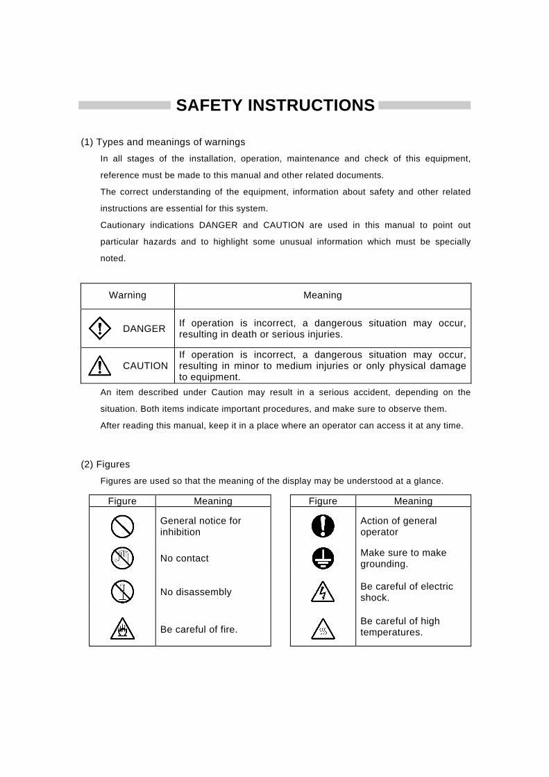
(1) Types and meanings of warnings
In all stages of the installation, operation, maintenance and check of this equipment,
reference must be made to this manual and other related documents.
The correct understanding of the equipment, information about safety and other related
instructions are essential for this system.
Cautionary indications DANGER and CAUTION are used in this manual to point out
particular hazards and to highlight some unusual information which must be specially
noted.
Warning Meaning
DANGER If operation is incorrect, a dangerous situation may occur,
resulting in death or serious injuries.
CAUTION
If operation is incorrect, a dangerous situation may occur, resulting in minor to medium injuries or only physical damage to equipment.
An item described under Caution may result in a serious accident, depending on the
situation. Both items indicate important procedures, and make sure to observe them.
After reading this manual, keep it in a place where an operator can access it at any time.
(2) Figures
Figures are used so that the meaning of the display may be understood at a glance.
Figure Meaning Figure Meaning
General notice for inhibition
Action of general operator
No contact
Make sure to make grounding.
No disassembly
Be careful of electric shock.
Be careful of fire.
Be careful of high temperatures.
SAFETY INSTRUCTIONS

1. Precautions for operation
Danger
1. Never touch components inside the servo amplifier as you may receive an electric shock.
2. Make sure to ground the grounding terminals of the servo amplifier and the servomotor or you may receive an electric shock.
3. Perform wiring and inspection after waiting 5 minutes after shutting off the power or you may receive an electric shock.
4. Do not damage cables, subject them to undue stress, put any heavy object on them or pinch them as failure, damage or electric shock may result.
5. Do not touch the rotating part of the servomotor during operation as you may be injured.
Caution
1. Use the specified combination of the servomotor and the servo amplifier or fire or failure may occur.
2. Do not use the system in a place where it is exposed to water, a corrosive atmosphere or flammable gas atmosphere, or beside a flammable item as fire or failure may result.
3. Be careful as the temperature of the servo amplifier, servomotor and peripheral devices is high and may cause burns.
4. Do not touch the radiator of the servo amplifier, the regenerative resistor and the servomotor during power supply or soon after shutoff because they will be hot and may cause burns.
5. When the surface temperature of the servomotor exceeds 70°C for the final product during operation of the servomotor, affix a caution label indicating its high temperature.
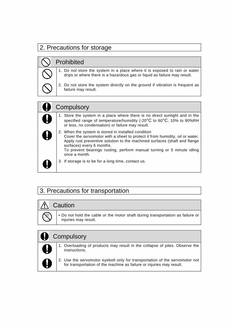
2. Precautions for storage
Prohibited
1. Do not store the system in a place where it is exposed to rain or water drips or where there is a hazardous gas or liquid as failure may result.
2. Do not store the system directly on the ground if vibration is frequent as failure may result.
Compulsory
1. Store the system in a place where there is no direct sunlight and in the specified range of temperature/humidity (-20°C to 60°C, 10% to 90%RH or less, no condensation) or failure may result.
2. When the system is stored in installed condition Cover the servomotor with a sheet to protect it from humidity, oil or water. Apply rust preventive solution to the machined surfaces (shaft and flange surfaces) every 6 months. To prevent bearings rusting, perform manual turning or 5 minute idling once a month.
3. If storage is to be for a long time, contact us.
3. Precautions for transportation
Caution
• Do not hold the cable or the motor shaft during transportation as failure or
injuries may result.
Compulsory
1. Overloading of products may result in the collapse of piles. Observe the instructions.
2. Use the servomotor eyebolt only for transportation of the servomotor not for transportation of the machine as failure or injuries may result.
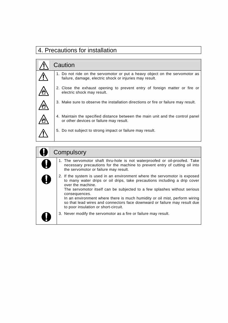
4. Precautions for installation
Caution
1. Do not ride on the servomotor or put a heavy object on the servomotor as failure, damage, electric shock or injuries may result.
2. Close the exhaust opening to prevent entry of foreign matter or fire or electric shock may result.
3. Make sure to observe the installation directions or fire or failure may result.
4. Maintain the specified distance between the main unit and the control panel or other devices or failure may result.
5. Do not subject to strong impact or failure may result.
Compulsory
1. The servomotor shaft thru-hole is not waterproofed or oil-proofed. Take necessary precautions for the machine to prevent entry of cutting oil into the servomotor or failure may result.
2. If the system is used in an environment where the servomotor is exposed to many water drips or oil drips, take precautions including a drip cover over the machine. The servomotor itself can be subjected to a few splashes without serious consequences. In an environment where there is much humidity or oil mist, perform wiring so that lead wires and connectors face downward or failure may result due to poor insulation or short-circuit.
3. Never modify the servomotor as a fire or failure may result.
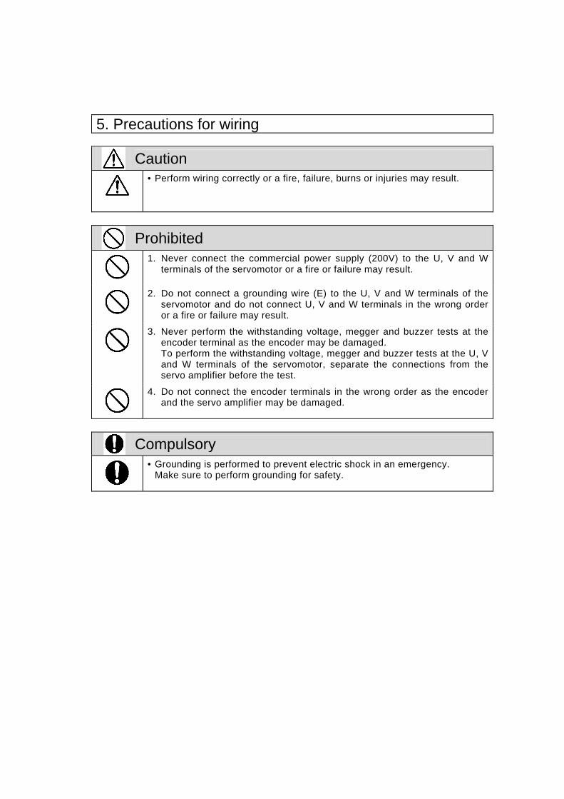
5. Precautions for wiring
Caution
• Perform wiring correctly or a fire, failure, burns or injuries may result.
Prohibited
1. Never connect the commercial power supply (200V) to the U, V and W terminals of the servomotor or a fire or failure may result.
2. Do not connect a grounding wire (E) to the U, V and W terminals of the servomotor and do not connect U, V and W terminals in the wrong order or a fire or failure may result.
3. Never perform the withstanding voltage, megger and buzzer tests at the encoder terminal as the encoder may be damaged. To perform the withstanding voltage, megger and buzzer tests at the U, V and W terminals of the servomotor, separate the connections from the servo amplifier before the test.
4. Do not connect the encoder terminals in the wrong order as the encoder and the servo amplifier may be damaged.
Compulsory
• Grounding is performed to prevent electric shock in an emergency. Make sure to perform grounding for safety.
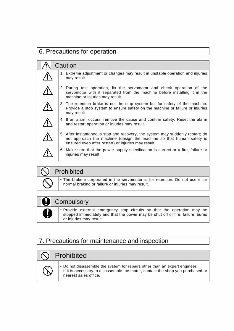
6. Precautions for operation
Caution
1. Extreme adjustment or changes may result in unstable operation and injuries may result.
2. During test operation, fix the servomotor and check operation of the servomotor with it separated from the machine before installing it in the machine or injuries may result.
3. The retention brake is not the stop system but for safety of the machine. Provide a stop system to ensure safety on the machine or failure or injuries may result.
4. If an alarm occurs, remove the cause and confirm safety. Reset the alarm and restart operation or injuries may result.
5. After instantaneous stop and recovery, the system may suddenly restart; do not approach the machine (design the machine so that human safety is ensured even after restart) or injuries may result.
6. Make sure that the power supply specification is correct or a fire, failure or injuries may result.
Prohibited
• The brake incorporated in the servomotor is for retention. Do not use it for normal braking or failure or injuries may result.
Compulsory
• Provide external emergency stop circuits so that the operation may be stopped immediately and that the power may be shut off or fire, failure, burns or injuries may result.
7. Precautions for maintenance and inspection
Prohibited
• Do not disassemble the system for repairs other than an expert engineer. If it is necessary to disassemble the motor, contact the shop you purchased or nearest sales office.
Descriptions given in this manual may be different from those of the product as a
result of improvements of the product. Descriptions in this manual are subject to
change without notice.
Values are indicated in SI units (third stage) in this manual. The units may be
different from those indicated on the product (nameplate).
Illustration given in this manual may show the servo amplifier or servomotor of a
specific capacity. Accordingly they may be different from the appearance of the
product you have purchased.
Products introduced in this manual have not been designed or manufactured for
such applications in a system or equipment that will affect human bodies or lives.
Customers, who want to use the products introduced in this manual for special
systems or devices such as for atomic-energy control, aerospace use, medical use,
and traffic control, are requested to consult Fuji.
Customers are requested to prepare safety measures when they apply the products
introduced in this manual to such systems or facilities that will affect human lives or
cause severe damage to property if the products become faulty.

This manual is the User's Manual for Fuji's FALDIC-W Series AC Servo System. The
User's Manual comes in one volume and covers all handling procedures of the
product.
The following document is included in the package of each device.
Device Document No.
Servo amplifier
Name of document
Instruction ManualFuji FALDIC-W Series ACServo Amplifier (RYC D (C, B) 3- 2)
INR-SI47-0853
Servomotor Instruction ManualFuji GYS/GYG Series AC Servomotor ING-SI47-0863
The type designation of the product covered in this manual is shown below.
For any uncertainties in the description of this manual or in the product itself, contact your dealer or Fuji’s sales outlet.
Icons In this manual, the following icons are used:
Note If the system is incorrectly operated by ignoring this mark, the optimum performanceof FALDIC-W may not be shown, or such an operation or setting may result in anaccident.
Hint Useful reference items are given for operation or setting of the servo amplifier or theservomotor.
The page for reference is shown.
Introduction
* “ ” in the type designation indicates a decimalpoint or number.
* “*” in the type designation indicates an alphabetic character or no mark.
Device
Servo amplifier
Applicable type
RYC D3-VVT2RYC C3-VVT2RYC B3-VVT2
GYS DC2-***GYG CC2-***GYG BC2-***
Servomotor
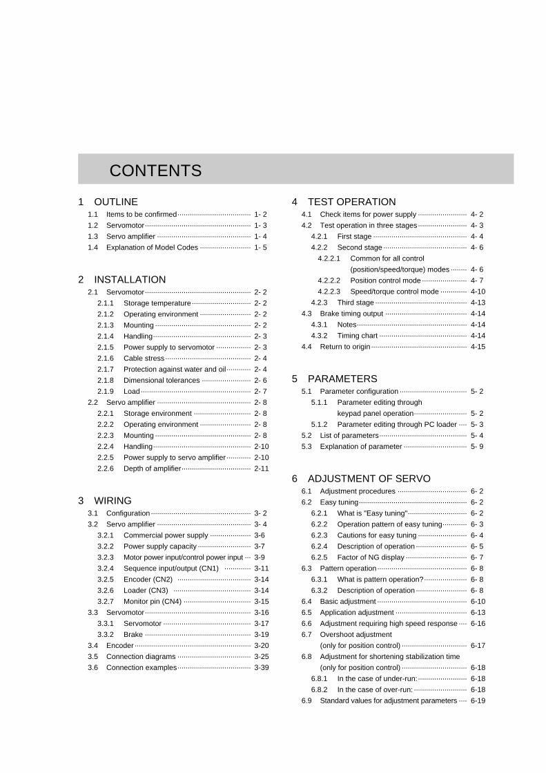
CONTENTS
1 OUTLINE 1.1 Items to be confirmed·····································1.2 Servomotor·····················································1.3 Servo amplifier ···············································1.4 Explanation of Model Codes ··························
2 INSTALLATION
2.1 Servomotor·····················································2.1.1 Storage temperature······························2.1.2 Operating environment ··························2.1.3 Mounting ················································2.1.4 Handling·················································2.1.5 Power supply to servomotor ··················2.1.6 Cable stress···········································2.1.7 Protection against water and oil·············2.1.8 Dimensional tolerances ·························2.1.9 Load·······················································
2.2 Servo amplifier ···············································2.2.1 Storage environment ·····························2.2.2 Operating environment ··························2.2.3 Mounting ················································2.2.4 Handling·················································2.2.5 Power supply to servo amplifier·············2.2.6 Depth of amplifier···································
3 WIRING
3.1 Configuration··················································3.2 Servo amplifier ···············································
3.2.1 Commercial power supply ·····················3.2.2 Power supply capacity ···························3.2.3 Motor power input/control power input ····3.2.4 Sequence input/output (CN1) ··············3.2.5 Encoder (CN2) ·····································3.2.6 Loader (CN3) ·······································3.2.7 Monitor pin (CN4) ··································
3.3 Servomotor·····················································3.3.1 Servomotor ············································3.3.2 Brake ·····················································
3.4 Encoder ··························································3.5 Connection diagrams ·····································3.6 Connection examples·····································
4 TEST OPERATION 4.1 Check items for power supply ························4.2 Test operation in three stages························
4.2.1 First stage ··············································4.2.2 Second stage·········································
4.2.2.1 Common for all control (position/speed/torque) modes ········
4.2.2.2 Position control mode ······················4.2.2.3 Speed/torque control mode ·············
4.2.3 Third stage ·············································4.3 Brake timing output ········································
4.3.1 Notes······················································4.3.2 Timing chart ···········································
4.4 Return to origin···············································
5 PARAMETERS 5.1 Parameter configuration ·································
5.1.1 Parameter editing through keypad panel operation··························
5.1.2 Parameter editing through PC loader ····5.2 List of parameters···········································5.3 Explanation of parameter ·······························
6 ADJUSTMENT OF SERVO 6.1 Adjustment procedures ··································6.2 Easy tuning·····················································
6.2.1 What is "Easy tuning"·····························6.2.2 Operation pattern of easy tuning············6.2.3 Cautions for easy tuning ························6.2.4 Description of operation ·························6.2.5 Factor of NG display ······························
6.3 Pattern operation············································6.3.1 What is pattern operation?·····················6.3.2 Description of operation ·························
6.4 Basic adjustment ············································6.5 Application adjustment ···································6.6 Adjustment requiring high speed response ····6.7 Overshoot adjustment
(only for position control) ································6.8 Adjustment for shortening stabilization time
(only for position control) ································6.8.1 In the case of under-run:························6.8.2 In the case of over-run: ··························
6.9 Standard values for adjustment parameters ····
4- 2 4- 3 4- 4 4- 6 4- 6
4- 7 4-10 4-13 4-14 4-14 4-14 4-15 5- 2 5- 2 5- 3 5- 4
5- 9 6- 2 6- 2 6- 2 6- 3 6- 4 6- 5 6- 7 6- 8 6- 8 6- 8 6-10 6-13 6-16 6-17 6-18 6-18 6-18 6-19
1- 2 1- 3 1- 4 1- 5 2- 2 2- 2 2- 2 2- 2 2- 3 2- 3 2- 4 2- 4 2- 6 2- 7 2- 8 2- 8 2- 8 2- 8 2-10 2-10 2-11 3- 2 3- 4 3-6 3-7 3-9 3-11 3-14 3-14 3-15 3-16 3-17 3-19 3-20 3-25 3-39
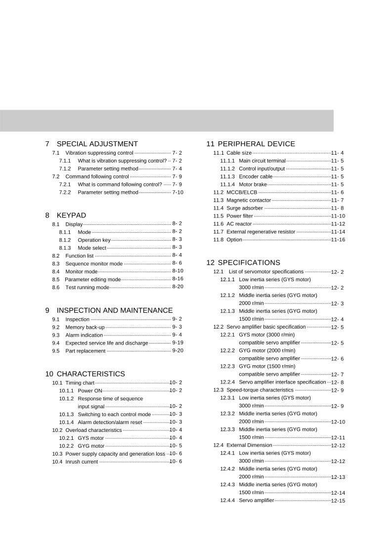
7 SPECIAL ADJUSTMENT 7.1 Vibration suppressing control ·························
7.1.1 What is vibration suppressing control? ·· 7.1.2 Parameter setting method······················
7.2 Command following control ···························· 7.2.1 What is command following control? ····· 7.2.2 Parameter setting method······················
8 KEYPAD 8.1 Display····························································
8.1.1 Mode ······················································ 8.1.2 Operation key········································· 8.1.3 Mode select············································
8.2 Function list ···················································· 8.3 Sequence monitor mode ································ 8.4 Monitor mode·················································· 8.5 Parameter editing mode·································· 8.6 Test running mode··········································
9 INSPECTION AND MAINTENANCE 9.1 Inspection ······················································· 9.2 Memory back-up············································· 9.3 Alarm indication ·············································· 9.4 Expected service life and discharge ··············· 9.5 Part replacement ············································
10 CHARACTERISTICS 10.1 Timing chart····················································
10.1.1 Power ON··············································· 10.1.2 Response time of sequence
input signal ············································· 10.1.3 Switching to each control mode ············· 10.1.4 Alarm detection/alarm reset ···················
10.2 Overload characteristics ································· 10.2.1 GYS motor ············································· 10.2.2 GYG motor ·············································
10.3 Power supply capacity and generation loss ··· 10.4 Inrush current ·················································
11 PERIPHERAL DEVICE 11.1 Cable size·················································
11.1.1 Main circuit terminal······························· 11.1.2 Control input/output ······························· 11.1.3 Encoder cable········································ 11.1.4 Motor brake············································
11.2 MCCB/ELCB ·················································· 11.3 Magnetic contactor········································· 11.4 Surge adsorber ·············································· 11.5 Power filter ····················································· 11.6 AC reactor ······················································ 11.7 External regenerative resistor ························ 11.8 Option·····························································
12 SPECIFICATIONS 12.1 List of servomotor specifications ··················
12.1.1 Low inertia series (GYS motor) 3000 r/min··············································
12.1.2 Middle inertia series (GYG motor) 2000 r/min··············································
12.1.3 Middle inertia series (GYG motor) 1500 r/min··············································
12.2 Servo amplifier basic specification ················· 12.2.1 GYS motor (3000 r/min)
compatible servo amplifier ····················· 12.2.2 GYG motor (2000 r/min)
compatible servo amplifier ····················· 12.2.3 GYG motor (1500 r/min)
compatible servo amplifier ····················· 12.2.4 Servo amplifier interface specification ···
12.3 Speed-torque characteristics ························· 12.3.1 Low inertia series (GYS motor)
3000 r/min·············································· 12.3.2 Middle inertia series (GYG motor)
2000 r/min·············································· 12.3.3 Middle inertia series (GYG motor)
1500 r/min·············································· 12.4 External Dimension ········································
12.4.1 Low inertia series (GYS motor) 3000 r/min··············································
12.4.2 Middle inertia series (GYG motor) 2000 r/min··············································
12.4.3 Middle inertia series (GYG motor) 1500 r/min··············································
12.4.4 Servo amplifier·······································
11- 4 11- 5 11- 5 11- 5 11- 5 11- 6 11- 7 11- 8 11-1011-1211-1411-16 12- 2 12- 2 12- 3 12- 4 12- 5 12- 5 12- 6 12- 7 12- 8 12- 9 12- 9 12-10 12-1112-12 12-12 12-13 12-1412-15
7- 2 7- 2 7- 4 7- 9 7- 9 7-10 8- 2 8- 2 8- 3 8- 3 8- 4 8- 6 8-10 8-16 8-20 9- 2 9- 3 9- 4 9-19 9-20 10- 2 10- 2 10- 2 10- 3 10- 3 10- 4 10- 4 10- 5 10- 6 10- 6

13 RS485 COMMUNICATIONS 13.1 RS485 communication function ·····················
13.1.1 Station number ······································13.1.2 Sequence input terminal (CONT1 to
CONT5) /sequence output terminal (OUT1 to OUT4) ····································
13.1.3 Response time·······································13.1.4 Communication specifications ···············13.1.5 Transmission protocol····························13.1.6 Description of transmission data············13.1.7 Status information··································13.1.8 List of commands···································
13.2 Command transmission specification·············13.2.1 Communication start procedure·············13.2.2 Normal communication procedure·········
13.3 Protocol level error ·········································
APPENDIXES Calculation of capacity selection ····················· PC loader ·························································· Parameter list ····················································
13- 2 13- 2 13- 2 13- 2 13- 3 13- 4 13- 5 13- 6 13- 7 13- 8 13- 8 13- 8 13- 9 A- 2 A-17 A-18
CONTENTS

1 OUTLINE
1-2
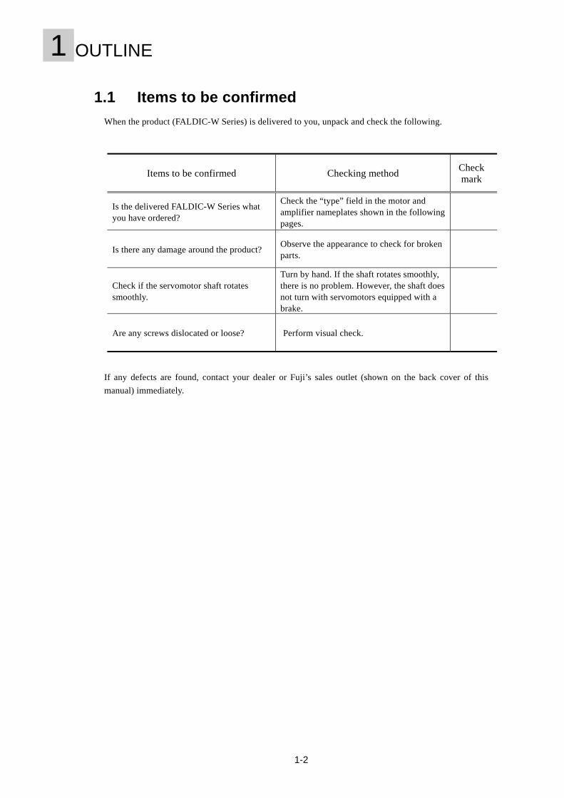
1.1 Items to be confirmed When the product (FALDIC-W Series) is delivered to you, unpack and check the following.
Items to be confirmed Checking method Check mark
Is the delivered FALDIC-W Series what you have ordered?
Check the “type” field in the motor and amplifier nameplates shown in the following pages.
Is there any damage around the product? Observe the appearance to check for broken parts.
Check if the servomotor shaft rotates smoothly.
Turn by hand. If the shaft rotates smoothly, there is no problem. However, the shaft does not turn with servomotors equipped with a brake.
Are any screws dislocated or loose? Perform visual check.
If any defects are found, contact your dealer or Fuji’s sales outlet (shown on the back cover of this manual) immediately.
OUTLINE 1
1-3
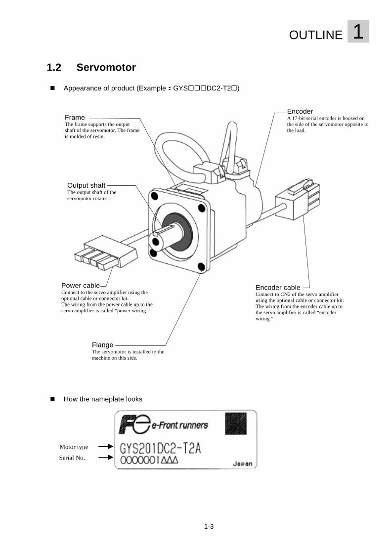
1.2 Servomotor
Appearance of product (Example:GYS DC2-T2 )
How the nameplate looks
Output shaft The output shaft of the servomotor rotates.
Encoder cable Connect to CN2 of the servo amplifier using the optional cable or connector kit.The wiring from the encoder cable up to the servo amplifier is called “encoder wiring.”
Encoder A 17-bit serial encoder is housed on the side of the servomotor opposite to the load.
Frame The frame supports the output shaft of the servomotor. The frame is molded of resin.
Power cable Connect to the servo amplifier using the optional cable or connector kit. The wiring from the power cable up to the servo amplifier is called “power wiring.”
Flange The servomotor is installed to the machine on this side.
Motor type
Serial No.
1 OUTLINE
1-4
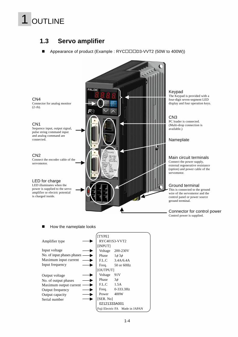
1.3 Servo amplifier Appearance of product (Example : RYC D3-VVT2 (50W to 400W))
How the nameplate looks
[TYPE] RYC401S3-VVT2 [INPUT] Voltage 200-230V Phase 1φ 3φ F.L.C 3.4A/6.4A Freq. 50 or 60Hz [OUTPUT] Voltage 91V Phase 3φ F.L.C 1.5A Freq. 0-333.3Hz Power 400W [SER. No] 02121333A001 Fuji Electric FA Made in JAPAN
Amplifier type
Input voltage No. of input phases phases Maximum input current
Output voltage No. of output phases Maximum output current
Input frequency
Output capacity Serial number
Output frequency
Keypad The Keypad is provided with a four-digit seven-segment LED display and four operation keys.
CN1 Sequence input, output signal, pulse string command input and analog command are connected.
CN2 Connect the encoder cable of the servomotor.
Ground terminal This is connected to the ground wire of the servomotor and the control panel or power source ground terminal.
LED for charge LED illuminates when the power is supplied to the servo amplifier or electric potential is charged inside.
Main circuit terminals Connect the power supply, external regenerative resistance (option) and power cable of the servomotor.
CN4 Connector for analog monitor (2 ch).
CN3 PC loader is connected. (Multi-drop connection is available.)
Nameplate
Connector for control powerControl power is supplied.
OUTLINE 1
1-5
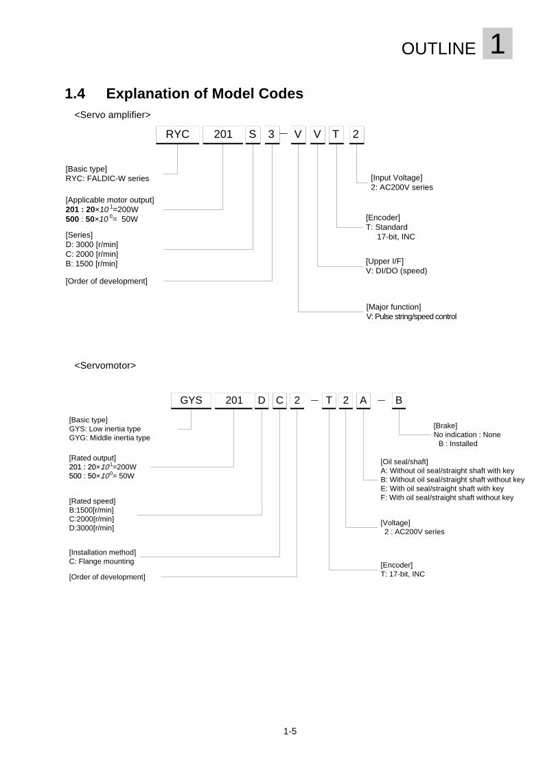
1.4 Explanation of Model Codes <Servo amplifier>
[Basic type]RYC: FALDIC-W series
RYC 201 S T3 V V
[Applicable motor output]201 : 20×10 1=200W500 : 50×10 0= 50W
[Series]D: 3000 [r/min]C: 2000 [r/min] B: 1500 [r/min]
[Order of development]
[Major function]V: Pulse string/speed control
[Upper I/F]V: DI/DO (speed)
[Encoder]T: Standard 17-bit, INC
2
[Input Voltage]2: AC200V series
<Servomotor>
[Basic type]GYS: Low inertia typeGYG: Middle inertia type
[Rated output]201 : 20×10 1=200W500 : 50×10 0= 50W
[Rated speed]B:1500[r/min]C:2000[r/min]D:3000[r/min]
[Installation method]C: Flange mounting
[Order of development]
[Encoder]T: 17-bit, INC
[Voltage] 2 : AC200V series
[Oil seal/shaft]A: Without oil seal/straight shaft with keyB: Without oil seal/straight shaft without keyE: With oil seal/straight shaft with keyF: With oil seal/straight shaft without key
[Brake]No indication : None B : Installed
GYS 201 D TC 2 2 A B

2 INSTALLATION
2-2
2.1 Servomotor 2.1.1 Storage temperature
Store the servomotor in the following environment when leaving it without energization.
Storage temperature : -20 to 60 °C
Storage humidity : 10 to 90% RH (no condensation allowed)
* To store the gear head without power supplied, store it in the following environment:
Storage temperature : -20 to 60 °C
Storage humidity : 10 to 90% RH (no condensation allowed)
2.1.2 Operating environment Operate the servomotor in the following environment.
Operating temperature : -10 to 40 °C
Operating humidity : 10 to 90% RH (no condensation allowed)
*Use the gear head in the following operating environment.
Operating temperature : 0 to 40 °C
Operating humidity : 10 to 90% RH (no condensation allowed)
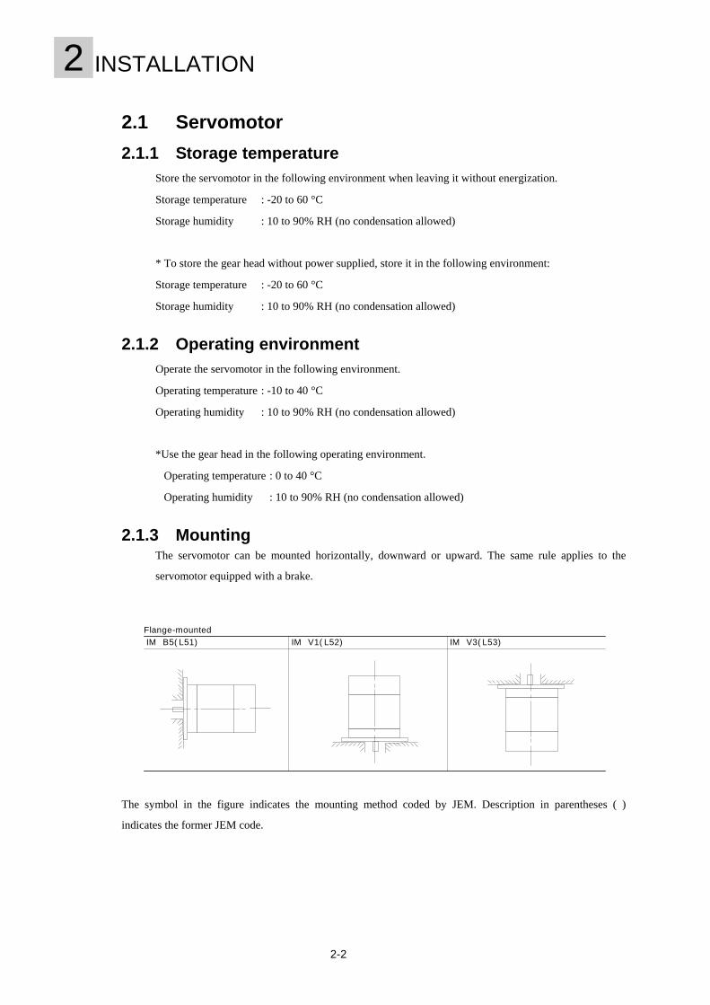
2.1.3 Mounting The servomotor can be mounted horizontally, downward or upward. The same rule applies to the
servomotor equipped with a brake.
The symbol in the figure indicates the mounting method coded by JEM. Description in parentheses ( )
indicates the former JEM code.
Flange-mounted
IM V1( L52) IM V3( L53) IM B5( L51)
INSTALLATION 2
2-3
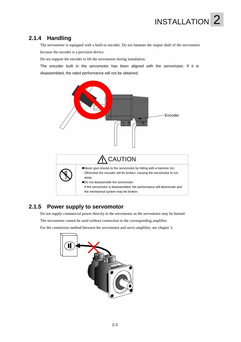
2.1.4 Handling The servomotor is equipped with a built-in encoder. Do not hammer the output shaft of the servomotor
because the encoder is a precision device.
Do not support the encoder to lift the servomotor during installation.
The encoder built in the servomotor has been aligned with the servomotor. If it is
disassembled, the rated performance will not be obtained.
CAUTIONNever give shocks to the servomotor by hitting with a hammer etc.Otherwise the encoder will be broken, causing the servomotor to run away.Do not disassemble the servomotor.If the servomotor is disassembled, the performance will deteriorate and the mechanical system may be broken.
2.1.5 Power supply to servomotor Do not supply commercial power directly to the servomotor as the servomotor may be burned.
The servomotor cannot be used without connection to the corresponding amplifier.
For the connection method between the servomotor and servo amplifier, see chapter 3.
Encoder
2 INSTALLATION
2-4
2.1.6 Cable stress Do not apply bending or tensile stress to the cable.
Precautions for applications with moving servomotor
・ Design a system of an application with a moving servomotor so that the cables are free from
forcible stress. ・ Route the encoder cable and power cable in Cableveyor. ・ Fix the encoder cable and power cable from the servomotor using cable clamps. ・ Design the bending radius as large as possible. ・ Do not allow bending stress or the weight of the cable itself to be exerted at cable connections.
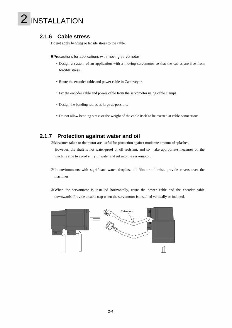
2.1.7 Protection against water and oil Measures taken to the motor are useful for protection against moderate amount of splashes.
However, the shaft is not water-proof or oil resistant, and so take appropriate measures on the
machine side to avoid entry of water and oil into the servomotor.
In environments with significant water droplets, oil film or oil mist, provide covers over the
machines.
When the servomotor is installed horizontally, route the power cable and the encoder cable
downwards. Provide a cable trap when the servomotor is installed vertically or inclined.
Cable trap
INSTALLATION 2
2-5
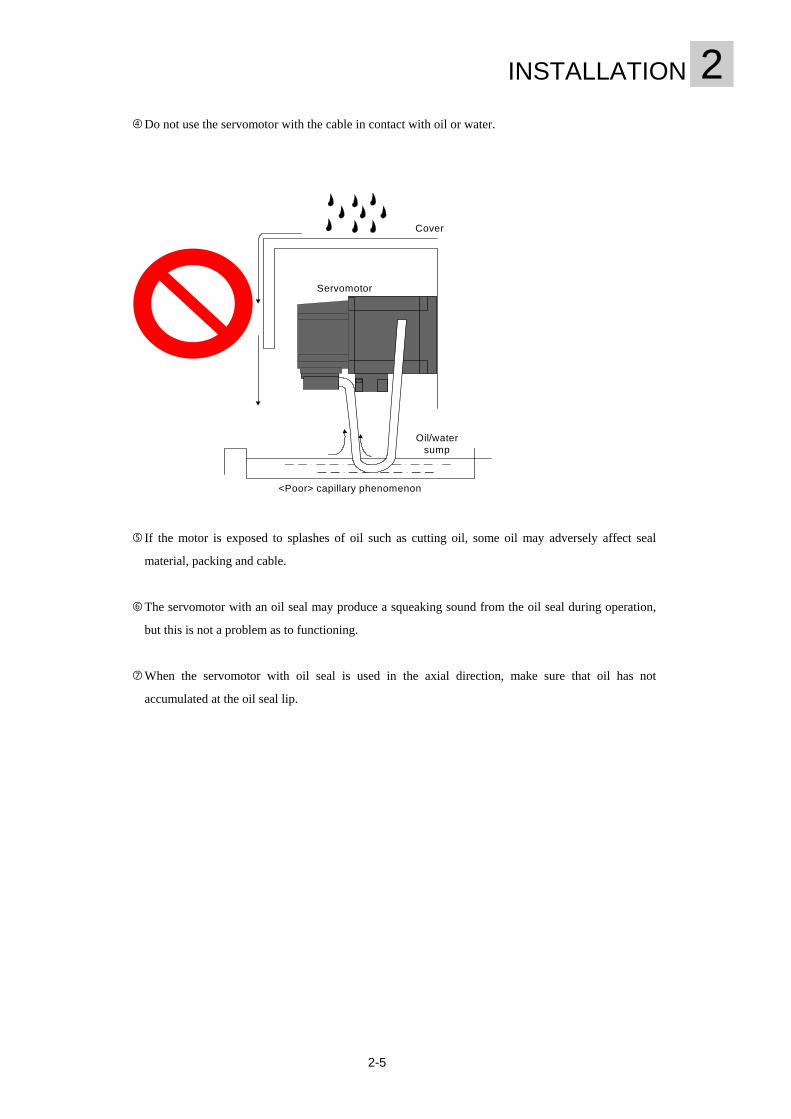
Do not use the servomotor with the cable in contact with oil or water.
Cover
Servomotor
Oil/water sump
<Poor> capillary phenomenon
If the motor is exposed to splashes of oil such as cutting oil, some oil may adversely affect seal
material, packing and cable.
The servomotor with an oil seal may produce a squeaking sound from the oil seal during operation,
but this is not a problem as to functioning.
When the servomotor with oil seal is used in the axial direction, make sure that oil has not
accumulated at the oil seal lip.

2 INSTALLATION
2-6
List of IP67 compatible connectors for GYG motor
Plug
CE05-6A18-10SD-B-BSS
IP67 compatible connector type
Straight Angle
CE05-8A18-10SD-B-BSA
Cable clamp
CE3057-10A-x
CE3057-12A-xCE05-8A20-15SD-B-BSA
CE05-6A20-15SD-B-BSS
Without brake for motor power wiring
With brake for motor power wiring
Wiring area
For encoder wiring
Back shell
⎯
Straight Angle
⎯
⎯⎯
MS3106A20-29S (D190) CE02-20BS-S CE-20BA-S CE3057-12A-x
DDK Ltd.
2.1.8 Dimensional tolerances The servomotor is assembled to the following accuracy.
Type of servomotor
GYG C2
Run-out at shaft end
≤ 0.02≤ 0.02
GYS DC2
Center deviation (Flange)
≤ 0.06≤ 0.06
Perpendicularity of flange face (Flange)
≤ 0.08≤ 0.08
Unit: mm
Run-out at shaft end Center deviation Perpendicularity of flange face

INSTALLATION 2
2-7
2.1.9 Load The radial load and thrust load exerted on the shaft end of the servomotor are as follows.
Radial load : Load exerted at right angles to motor shaft
Thrust load : Load exerted in parallel to motor shaft
LR
Fs
Fr
Type of servomotorAllowable radial
load Fr[ N]Allowable thrust
load Fs [N]LR
[ mm]
GYS3000[r/min]
500DC2-T2A
751DC2-T2A
101DC2-T2A
201DC2-T2A
401DC2-T2A
127
127
264
264
676
19
19
58
58
147
25
25
30
30
40
GYG2000[r/min]
501CC2-T2E
202CC2-T2E
751CC2-T2E
102CC2-T2E
152CC2-T2E
GYG1500[r/min]
501BC2-T2E
851BC2-T2E
132BC2-T2E
400
400
510
510
253
253
253
253
55
55
55
55
510 253 55
253
253
253
58
58
58
449
449
575

2 INSTALLATION
2-8
2.2 Servo amplifier 2.2.1 Storage environment
Store the servo amplifier in the following environment when leaving it without energization.
Storage temperature : -20 to 85 °C
Storage humidity : 10 to 90% RH (no condensation allowed) Storage area : Indoors with altitude of 1000 [m] or less
There shall be no dust, corrosive gas or direct sunlight.
Storage pressure : 70 - 106 [kPa]
Vibration/impact : 4.9 [m/s2]/19.6 [m/s2]
2.2.2 Operating environment Operate the servomotor in the following environment.
The servo amplifier is not drip-proof and dust resistant.
Operating temperature : -10 to 55 °C
Operating humidity : 10 to 90% RH (no condensation allowed)
Operation area : Indoors with altitude of 1000 [m] or less
There shall be no dust, corrosive gas or direct sunlight.
Operation pressure : 70 - 106 [kPa]
Vibration/impact : 4.9 [m/s2]/19.6 [m/s2]
2.2.3 Mounting Mount the servo amplifier in the upright direction so that the “FALDIC” characters on the Keypad of
the servo amplifier look horizontally.

INSTALLATION 2
2-9
The servo amplifier has the part that generates heat during operation.
To mount multiple servo amplifiers in the same panel, observe the following precautions.
・ Mount side by side in principle. The RYC servo amplifier can be mounted closely. Use the amplifiers
at 80% ED rating* if they are installed in contact with each other. There is no limitation in the
operation frequency when amplifiers are mounted at 5 mm or larger intervals.
・ Reserve 40 mm or a larger distance at the bottom of the servo amplifier.
・ 50 mm or a larger distance is necessary above the servo amplifier for heat radiation.
* When the ambient temperature is 45 [°C] or less in close contact, the servo amplifier can be used at 100
[%ED].
i) Top: 50 mm or more
ii) Bottom: 40 mm or more
iii) Casing About 10 mm The value assumes various errors. The distance can be reduced to 0 mm.
iv) Interval between amplifiers
About 5 mm The value assumes various errors. The distance can bereduced to 0 mm.
2 INSTALLATION
2-10
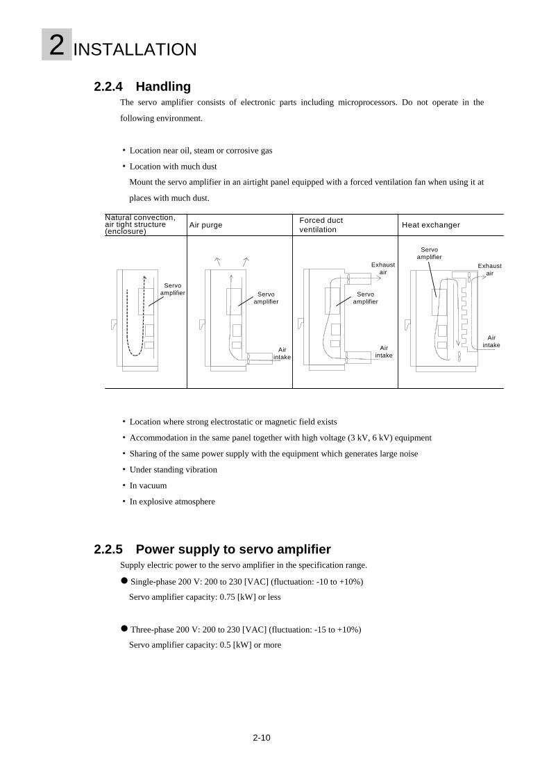
2.2.4 Handling The servo amplifier consists of electronic parts including microprocessors. Do not operate in the
following environment.
・ Location near oil, steam or corrosive gas
・ Location with much dust
Mount the servo amplifier in an airtight panel equipped with a forced ventilation fan when using it at
places with much dust.
Natural convection, air tight structure (enclosure)
Air purgeForced duct ventilation
Heat exchanger
Servoamplifier Servo
amplifierServo
amplifier
Servoamplifier
Airintake
Airintake
Airintake
Exhaustair
Exhaustair
・ Location where strong electrostatic or magnetic field exists
・ Accommodation in the same panel together with high voltage (3 kV, 6 kV) equipment
・ Sharing of the same power supply with the equipment which generates large noise
・ Under standing vibration
・ In vacuum
・ In explosive atmosphere
2.2.5 Power supply to servo amplifier Supply electric power to the servo amplifier in the specification range.
Single-phase 200 V: 200 to 230 [VAC] (fluctuation: -10 to +10%)
Servo amplifier capacity: 0.75 [kW] or less
Three-phase 200 V: 200 to 230 [VAC] (fluctuation: -15 to +10%)
Servo amplifier capacity: 0.5 [kW] or more
INSTALLATION 2
2-11
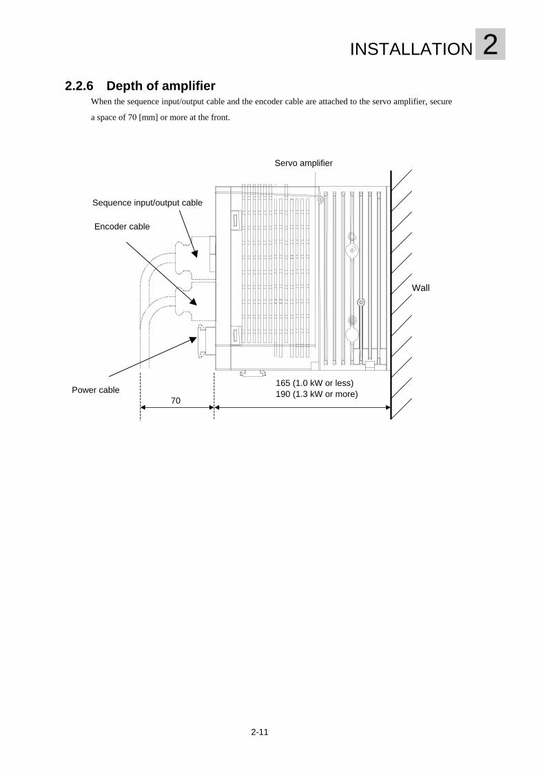
2.2.6 Depth of amplifier When the sequence input/output cable and the encoder cable are attached to the servo amplifier, secure
a space of 70 [mm] or more at the front.
Wall
70
165 (1.0 kW or less) 190 (1.3 kW or more)
Sequence input/output cable
Power cable
Servo amplifier
Encoder cable

2 INSTALLATION
2-12
-MEMO-

3 WIRING
3-2
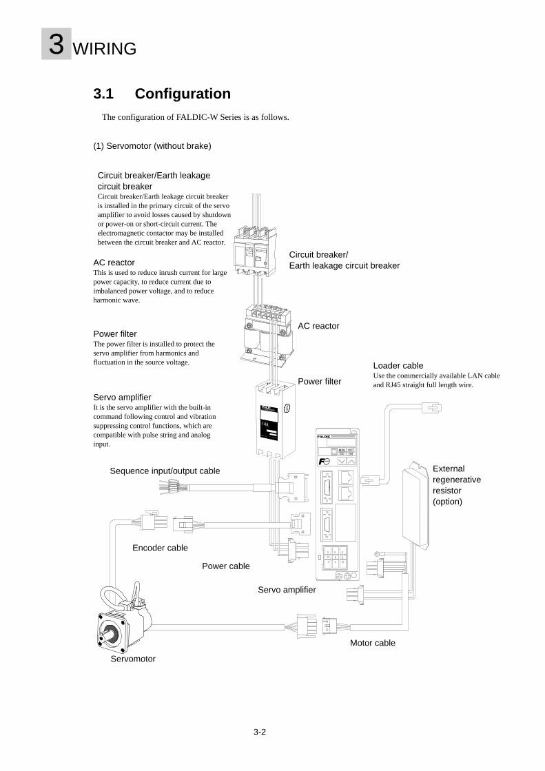
3.1 Configuration The configuration of FALDIC-W Series is as follows.
(1) Servomotor (without brake)
Circuit breaker/ Earth leakage circuit breaker
AC reactor
Power filter
External regenerativeresistor (option)
Motor cable
Servomotor
Encoder cable
Power cable
Sequence input/output cable
Loader cable Use the commercially available LAN cable and RJ45 straight full length wire.
Servo amplifier
Circuit breaker/Earth leakage circuit breaker Circuit breaker/Earth leakage circuit breaker is installed in the primary circuit of the servo amplifier to avoid losses caused by shutdown or power-on or short-circuit current. The electromagnetic contactor may be installed between the circuit breaker and AC reactor.
AC reactor This is used to reduce inrush current for large power capacity, to reduce current due to imbalanced power voltage, and to reduce harmonic wave.
Power filter The power filter is installed to protect the servo amplifier from harmonics and fluctuation in the source voltage.
Servo amplifier It is the servo amplifier with the built-in command following control and vibration suppressing control functions, which are compatible with pulse string and analog input.
WIRING 3
3-3
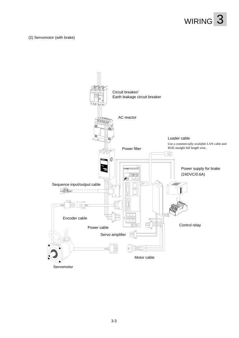
(2) Servomotor (with brake)
Circuit breaker/ Earth leakage circuit breaker
AC reactor
Power filter
Power supply for brake (24DVC/0.6A)
Motor cable
Servomotor
Encoder cable
Power cable
Sequence input/output cable
Servo amplifier
Control relay
Loader cable Use a commercially available LAN cable and RJ45 straight full length wire.
3 WIRING
3-4
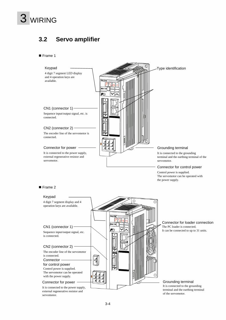
Keypad 4 digit 7 segment display and 4 operation keys are available.
Connector for control power Control power is supplied. The servomotor can be operated with the power supply.
3.2 Servo amplifier
Frame 1
Frame 2
Grounding terminal It is connected to the grounding terminal and the earthing terminal of the servomotor.
Keypad 4 digit 7 segment LED display and 4 operation keys are available.
Type identification
CN1 (connector 1) Sequence input/output signal, etc. is connected.
Connector for power It is connected to the power supply, external regenerative resistor and servomotor.
CN2 (connector 2) The encoder line of the servomotor is connected.
Connector for control power Control power is supplied. The servomotor can be operated with the power supply.
Grounding terminal It is connected to the grounding terminal and the earthing terminal of the servomotor.
Connector for loader connection The PC loader is connected. It can be connected to up to 31 units.
Connector for power It is connected to the power supply, external regenerative resistor and servomotor.
CN1 (connector 1) Sequence input/output signal, etc. is connected.
CN2 (connector 2) The encoder line of the servomotor is connected.

WIRING 3
3-5
Keypad 4 digit 7 segment display and 4 operation keys are available.
Frame 3
Outer frame Rated rotation speed Applicable motor output Servo amplifier type
0.05kW RYC500D3-VVT2 0.1kW RYC101D3-VVT2 0.2kW RYC201D3-VVT2
Frame 1 3000r/min
0.4kW RYC401D3-VVT2 3000r/min 0.75kW RYC751D3-VVT2
0.5kW RYC501C3-VVT2 0.75kW RYC751C3-VVT2
2000r/min
1kW RYC102C3-VVT2 0.5kW RYC501B3-VVT2
Frame 2
1500r/min 0.85kW RYC851B3-VVT2 1.5kW RYC152C3-VVT2 2000r/min 2kW RYC202C3-VVT2
Frame 3
1500r/min 1.3kW RYC132B3-VVT2
Grounding terminal It is connected to the grounding terminal and the earthing terminal of the servomotor.
Connector for loader connection The PC loader is connected. It can be connected to up to 31 units.
Terminal block for power It is connected to the control power, power supply, external regenerative resistor and servomotor.
CN1 (connector 1) Sequence input/output signal,etc. is connected.
CN2 (connector 2)The encoder line of the servomotor is connected.
3 WIRING
3-6
3.2.1 Commercial power supply Supply the commercial power in chapter 12 to the servo amplifier. If the commercial power is directly supplied to the servomotor, the servomotor will be damaged.
• GYS type 0.4 kW or less (3000 r/min)
Supply the commercial power of single phase 200V to the servo amplifier. Connect it to L1 and L2 terminals.
Voltage: 200 to 230V, -10% to +10% Frequency: 50/60 Hz No. of phases: Single phase (Motor power source: L1, L2)/
Single phase (Control power source: sL1, sL2) The voltage is reduced from 400V system. (Direct supply may damage the servomotor.)
• GYS type 0.75 kW (3000 r/min) • GYG type 0.5 kW, 0.75 kW (2000 r/min) • GYG type 0.5 kW (2000 r/min)
Supply commercial power of single phase 200V or 3 phase 200V to the servo amplifier. Connect the power to L1 and L2 terminals for single phase and to L1, L2 and L3 terminals for 3 phase.
Voltage: Single phase 200 to 230V, to -10% to +10%, 3 phase 200V to 230V, -15% to +10% Frequency: 50/60 Hz No. of phases: Single phase (Motor power source: L1, L2),
3 phase (Motor power source: L1, L2, L3)/ Single phase (Control power source: sL1, sL2)
The voltage is reduced from 400V system. (Direct supply may damage the servomotor.)
• GYG type other than the above
Supply the commercial power of 3 phase 200V to the servo amplifier. Connect the power to L1, L2 and L3 terminals.
Voltage: 3 phase 200V to 230V, -15% to +10% Frequency: 50/60 Hz No. of phases: 3 phase (Motor power source: L1, L2, L3)/
Single phase (Control power source: sL1, sL2) The voltage is reduced from 400V system. (Direct supply may damage the servomotor.)
WIRING 3
3-7
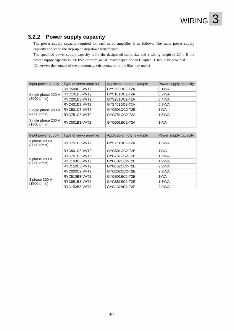
3.2.2 Power supply capacity The power supply capacity required for each servo amplifier is as follows. The same power supply capacity applies to the step-up or step-down transformer. The specified power supply capacity is for the designated cable size and a wiring length of 20m. If the power supply capacity is 500 kVA or more, an AC reactor specified in Chapter 11 should be provided. (Otherwise the contact of the electromagnetic contactor or the like may melt.)
Type of servo amplifier
RYC101D3-VVT2 RYC201D3-VVT2 RYC401D3-VVT2 RYC501C3-VVT2 RYC751C3-VVT2
RYC500D3-VVT2 Input power supply
Single phase 200 V (3000 r/min)
Applicable motor example Power supply capacity
0.2kVA 0.4kVA 0.8kVA 1kVA 1.5kVA
0.1kVA
Single phase 200 V (2000 r/min)
RYC501B3-VVT2
GYG501CC2-T2EGYG751CC2-T2A
GYG501BC2-T2A 1kVA
Type of servo amplifier
RYC152C3-VVT2
RYC751D3-VVT2
RYC501C3-VVT2 RYC751C3-VVT2 RYC103C3-VVT2
RYC202C3-VVT2
Input power supply 3 phase 200 V(3000 r/min)
Applicable motor example Power supply capacity
1kVA 1.5kVA 1.9kVA 2.9kVA 3.9kVA
3 phase 200 V(2000 r/min)
3 phase 200 V(1500 r/min)
RYC510B3-VVT2 RYC851B3-VVT2 RYC152B3-VVT2
GYS751DC2-T2A
GYG501CC2-T2EGYG751CC2-T2EGYG102CC2-T2EGYG152CC2-T2EGYG202CC2-T2EGYG501BC2-T2EGYG851BC2-T2EGYG132BC2-T2E 2.9kVA
1.5kVA
1kVA 1.5kVA
GYS500DC2-T2AGYS101DC2-T2AGYS201DC2-T2AGYS401DC2-T2A
Single phase 200 V (1500 r/min)
3 WIRING
3-8
Action to prevent harmonic wave
The multipurpose inverter and the servo amplifier have been excluded from the “Guideline for prevention of harmonic waves in electric appliances and multipurpose products” from January 2004. The procedures to prevent harmonic waves of multipurpose inverters and servo amplifiers are revised from the previous guideline as follows:
Source: Japan Electrical Manufacturers’ Association
Note) The above description is only valid in Japan.
All types of multipurpose inverters and servo amplifiers used by a specific user apply to the “Guideline for
prevention of harmonic waves by users who receive power at high voltages or especially high voltages”.
All users who are requested to apply the guideline should calculate the equivalent capacity or the harmonic
wave runoff current according to the guideline. If the harmonic wave current exceeds the limit specified on
the contract demand, appropriate action is required. (Refer to JEM-TR 201 and JEM-TR 225.)
WIRING 3
3-9
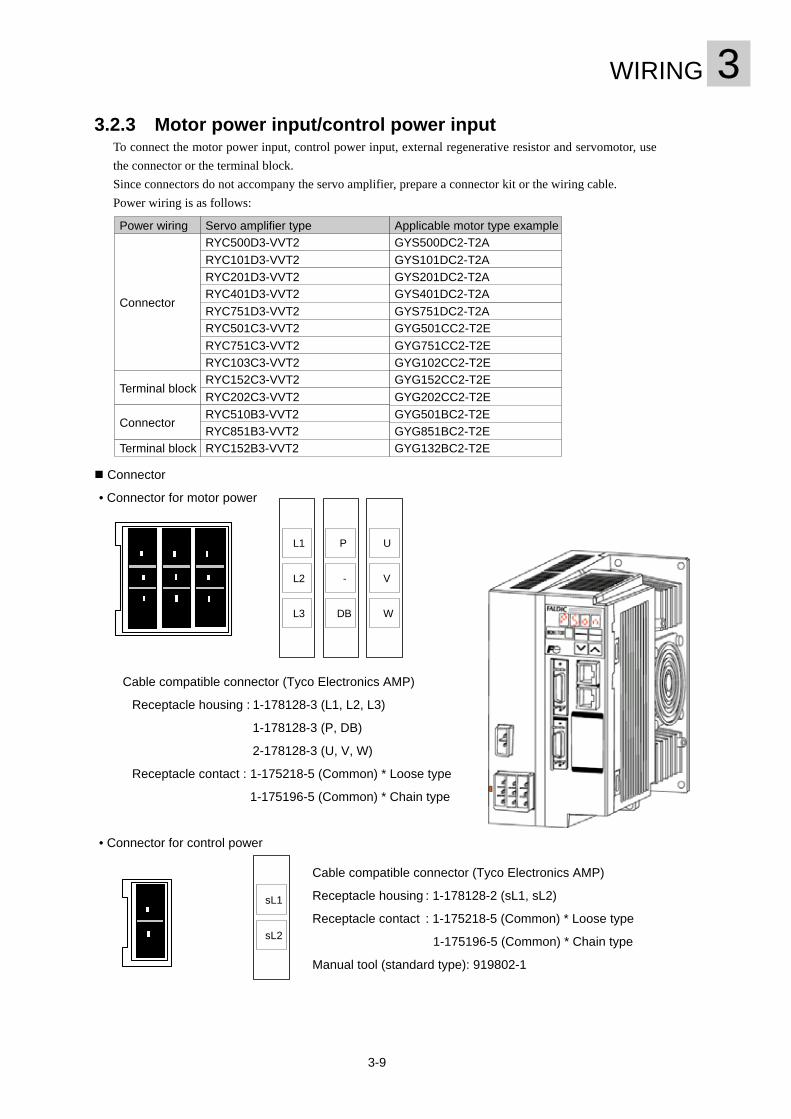
3.2.3 Motor power input/control power input To connect the motor power input, control power input, external regenerative resistor and servomotor, use the connector or the terminal block. Since connectors do not accompany the servo amplifier, prepare a connector kit or the wiring cable. Power wiring is as follows:
RYC101D3-VVT2 RYC201D3-VVT2 RYC401D3-VVT2
RYC500D3-VVT2
RYC152C3-VVT2
RYC751D3-VVT2 RYC501C3-VVT2 RYC751C3-VVT2 RYC103C3-VVT2
RYC202C3-VVT2 RYC510B3-VVT2 RYC851B3-VVT2 RYC152B3-VVT2
GYS751DC2-T2AGYG501CC2-T2EGYG751CC2-T2EGYG102CC2-T2EGYG152CC2-T2EGYG202CC2-T2EGYG501BC2-T2EGYG851BC2-T2EGYG132BC2-T2E
GYS500DC2-T2AGYS101DC2-T2AGYS201DC2-T2AGYS401DC2-T2A
Servo amplifier type Applicable motor type examplePower wiring
Terminal block
Connector
Terminal block
Connector
Connector
• Connector for motor power
Cable compatible connector (Tyco Electronics AMP)
Receptacle housing : 1-178128-3 (L1, L2, L3)
1-178128-3 (P, DB)
2-178128-3 (U, V, W)
Receptacle contact : 1-175218-5 (Common) * Loose type
1-175196-5 (Common) * Chain type
• Connector for control power
Cable compatible connector (Tyco Electronics AMP)
Receptacle housing : 1-178128-2 (sL1, sL2)
Receptacle contact : 1-175218-5 (Common) * Loose type
1-175196-5 (Common) * Chain type
Manual tool (standard type): 919802-1
L1
L2
L3
P
-
DB
U
V
W
sL1
sL2
3 WIRING
3-10
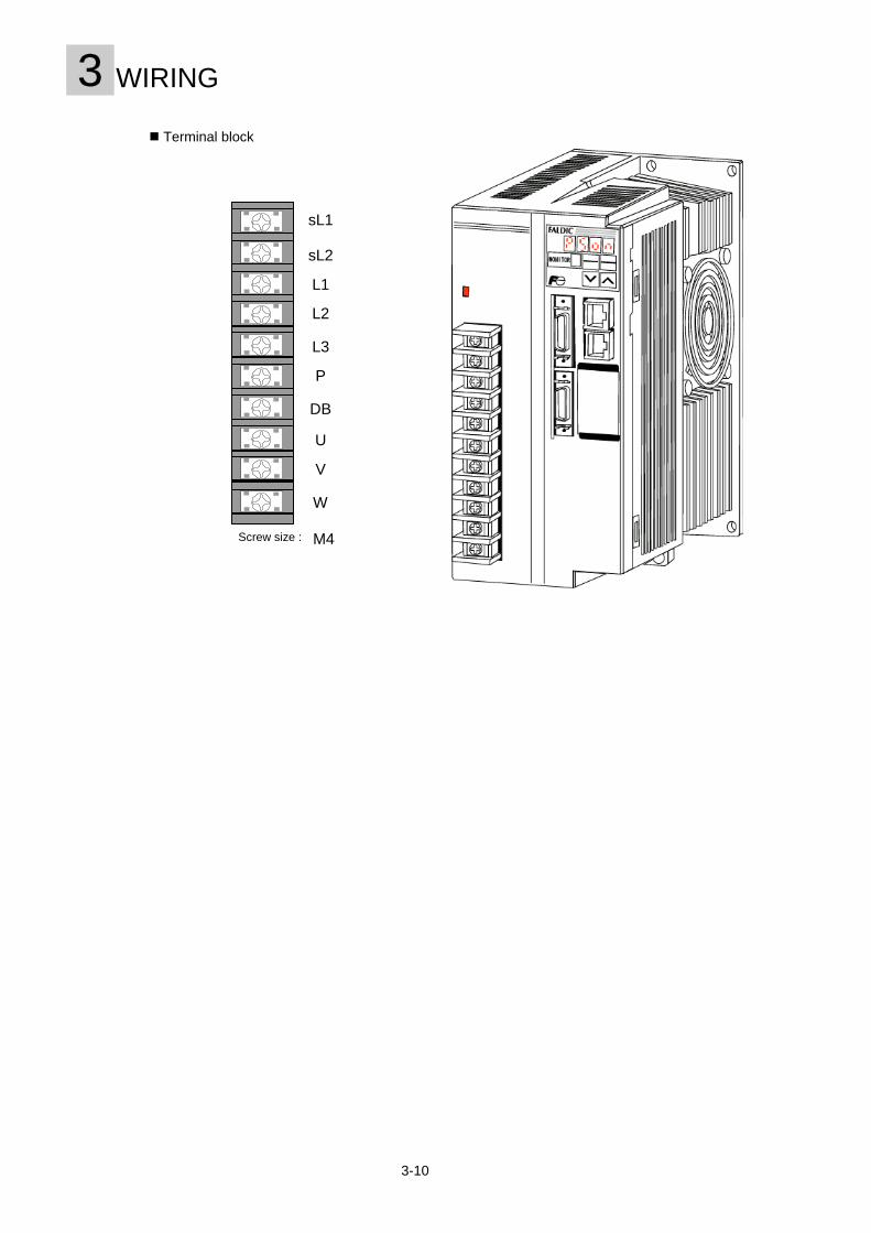
Terminal block
sL1
sL2
L1
L2
L3
P
DB
U
V
W
Screw size : M4
WIRING 3
3-11
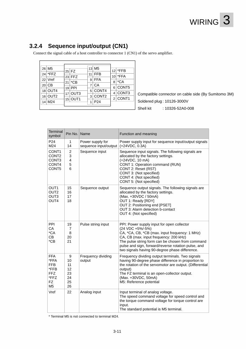
3.2.4 Sequence input/output (CN1) Connect the signal cable of a host controller to connector 1 (CN1) of the servo amplifier.
Compatible connector on cable side (By Sumitomo 3M)
Soldered plug : 10126-3000V
Shell kit : 10326-52A0-008
Terminal symbol
* Terminal M5 is not connected to terminal M24.
Pin No. Name Function and meaning
P24 M24
114
Power supply for sequence input/output
Power supply input for sequence input/output signals(+24VDC, 0.3A)
OUT1 OUT2 OUT3 OUT4
15161718
Sequence output Sequence output signals. The following signals are allocated by the factory settings. (Max. +30VDC / 50mA) OUT 1: Ready [RDY] OUT 2: Positioning end [PSET] OUT 3: Alarm detection b-contact OUT 4: (Not specified)
PPI CA *CA CB *CB
1978
2021
Pulse string input PPI: Power supply input for open collector (24 VDC +5%/-5%) CA, *CA, CB, *CB (max. input frequency: 1 MHz) CA, CB (max. input frequency: 200 kHz) The pulse string form can be chosen from command pulse and sign, forward/reverse rotation pulse, and two signals having 90-degree phase difference.
FFA *FFA FFB *FFB FFZ *FFZ FZ M5
910111223242526
Frequency dividing output
Frequency dividing output terminals. Two signals having 90-degree phase difference in proportion to the rotation of the servomotor are output. (Differential output) The FZ terminal is an open-collector output. (Max. +30VDC, 50mA) M5: Reference potential
Vref 22 Analog input Input terminal of analog voltage. The speed command voltage for speed control and the torque command voltage for torque control are input. The standard potential is M5 terminal.
CONT1 CONT2 CONT3 CONT4 CONT5
23456
Sequence input Sequence input signals. The following signals are allocated by the factory settings. (+24VDC, 10 mA) CONT 1: Operation command (RUN) CONT 2: Reset (RST) CONT 3: (Not specified) CONT 4: (Not specified) CONT 5: (Not specified)
FZ 25
FFZ 23 *CB 21
PPI 19 OUT3 17 OUT1 15
M5 13
FFB 11 FFA 9 CA 7 CONT45
CONT23 P24 1
*FFB 12
*FFA 10*CA 8CONT56CONT34
CONT12
24 Vref 22 CB 20 OUT4 18
OUT2 16 M24 14
26 M5 *FFZ
3 WIRING
3-12
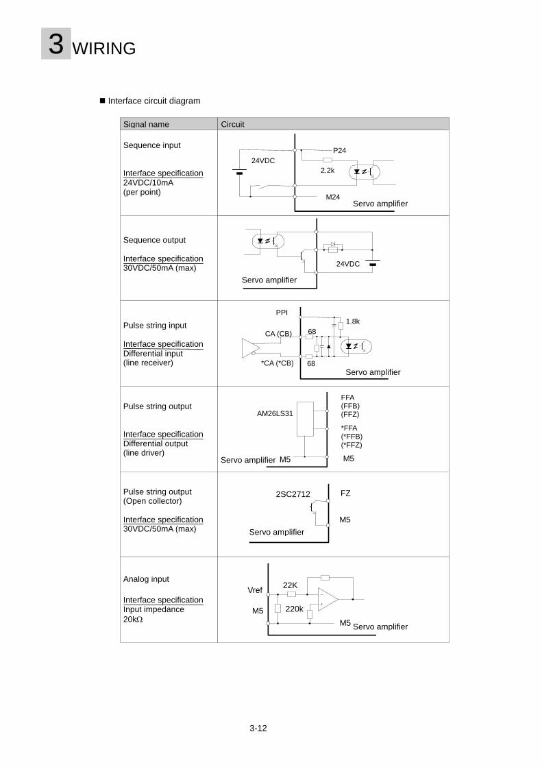
Interface circuit diagram
24VDC
P24
M24
2.2k 24VDC
Signal name Circuit
Sequence input
Interface specification 24VDC/10mA (per point)
Servo amplifier
Sequence output
Interface specification 30VDC/50mA (max)
Servo amplifier
Pulse string input
Interface specification Differential input (line receiver)
Pulse string output
Interface specification Differential output (line driver)
Servo amplifier
68
PPI
Servo amplifier 68
1.8k
CA (CB)
*CA (*CB)
Pulse string output (Open collector)
Interface specification 30VDC/50mA (max) Servo amplifier
AM26LS31
M5
FFA (FFB)(FFZ) *FFA(*FFB)(*FFZ)
M5
2SC2712 FZ
M5
M5
22K
220k
Analog input
Interface specification Input impedance 20kΩ
Vref
M5
Servo amplifier
WIRING 3
3-13
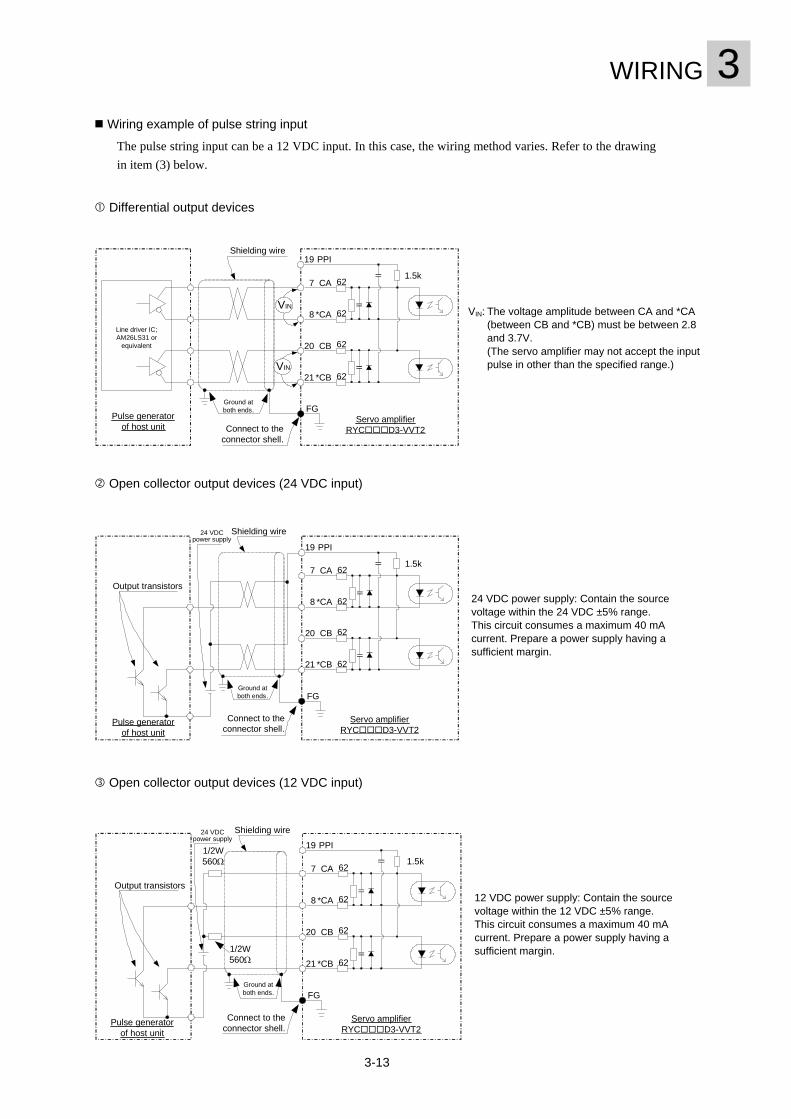
Wiring example of pulse string input
The pulse string input can be a 12 VDC input. In this case, the wiring method varies. Refer to the drawing in item (3) below.
Differential output devices
Servo amplifier RYC D3-VVT2
FG
Connect to the connector shell.
Pulse generator of host unit
Line driver IC;AM26LS31 or
equivalent
Shielding wire
VIN
VIN
Ground at both ends.
CB
*CB
CA
*CA
7
8
20
21
62
62
1.5k
62
62
PPI19
Open collector output devices (24 VDC input)
Servo amplifier RYC D3-VVT2
1.5k
Shielding wire
FG
CB
*CB
CA
*CA
7
8
20
21
62
62
62
62
PPI19
Connect to the connector shell.
Pulse generator of host unit
Ground at both ends.
24 VDC power supply
Output transistors
Open collector output devices (12 VDC input)
Connect to the connector shell.
Servo amplifier RYC D3-VVT2
1.5k
Shielding wire
FG
CB
*CB
CA
*CA
7
8
20
21
62
62
62
62
PPI19
Pulse generator of host unit
Ground at both ends.
24 VDC power supply
Output transistors
1/2W560Ω
1/2W560Ω
VIN: The voltage amplitude between CA and *CA (between CB and *CB) must be between 2.8 and 3.7V. (The servo amplifier may not accept the input pulse in other than the specified range.)
24 VDC power supply: Contain the source voltage within the 24 VDC ±5% range. This circuit consumes a maximum 40 mA current. Prepare a power supply having a sufficient margin.
12 VDC power supply: Contain the source voltage within the 12 VDC ±5% range. This circuit consumes a maximum 40 mA current. Prepare a power supply having a sufficient margin.

3 WIRING
3-14
3.2.5 Encoder (CN2) Connect the encoder signal of the servomotor to connector 2 (CN2) of the servo amplifier.
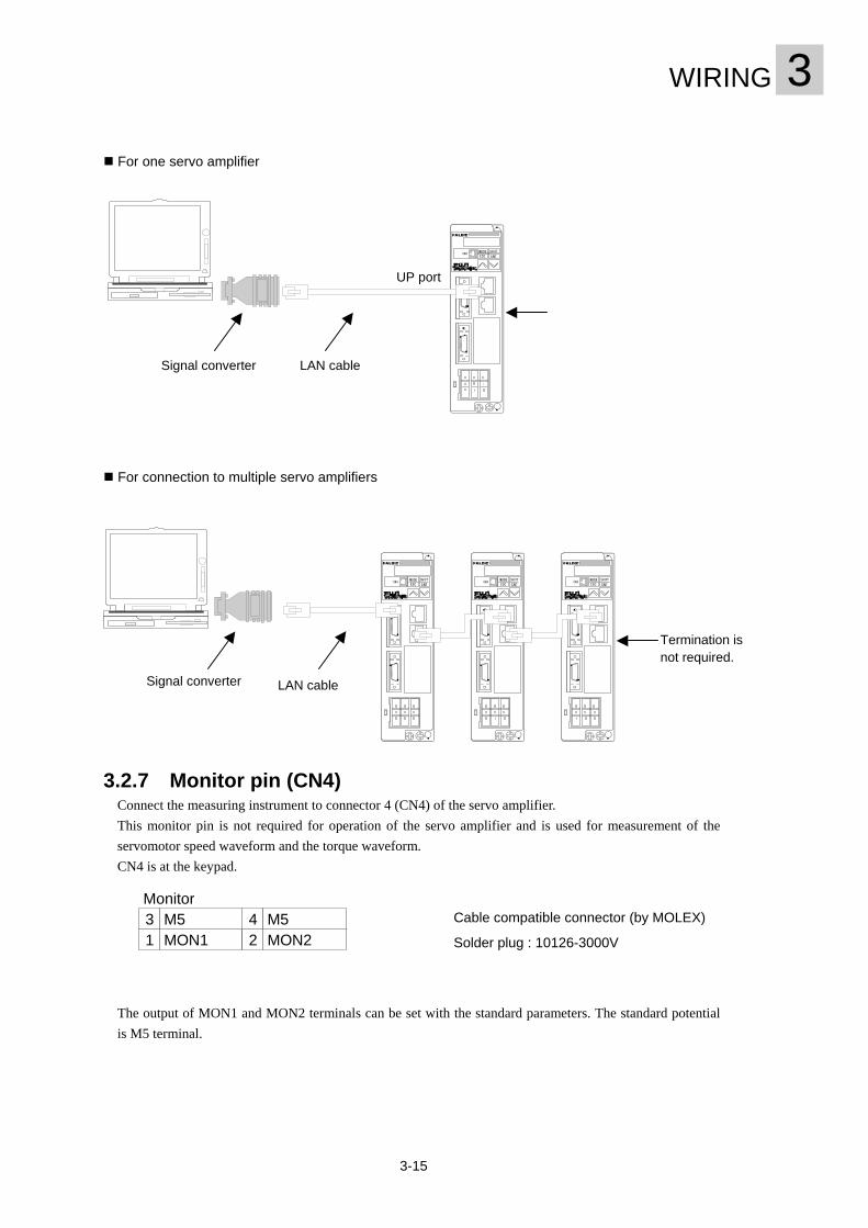
3.2.6 Loader (CN3) Connect the PC to connector 3 (CN3) of the servo amplifier. Use the signal converter and the commercially available LAN cable (CAT.5 straight full length wire) for connection. 31 servo amplifiers maximum can be connected.
Connect the PC to the DN port (lower) and the UP port of the next servo amplifier between the UP port (upper) and the servo amplifier. Final termination is not required.
Cable compatible connector (by Sumitomo 3M Ltd.)
Solder plug : 10120-3000V
Shell kit : 10320-52A0-008
Cable compatible connector (commercially available product)
RJ-45
FG 20 SIG- 18 NC 16 NC 14 NC 12
NC9NC7NC5P53M51
NC10NC8NC6P54M52
NC 19 SIG+ 17 NC 15 NC 13 NC 11
UP Port
M5
7
*RXD5
*TXD
3
1 P5 (output)
8
TXD
6 RXD
4
M5
2
P5 (output)
DN Port
M5
7
*RXD 5
*TXD
3
1 NC
8
TXD
6RXD
4
M5
2
NC
UP
DN
WIRING 3
3-15
For one servo amplifier
For connection to multiple servo amplifiers
3.2.7 Monitor pin (CN4) Connect the measuring instrument to connector 4 (CN4) of the servo amplifier. This monitor pin is not required for operation of the servo amplifier and is used for measurement of the servomotor speed waveform and the torque waveform. CN4 is at the keypad.
The output of MON1 and MON2 terminals can be set with the standard parameters. The standard potential is M5 terminal.
Cable compatible connector (by MOLEX)
Solder plug : 10126-3000V
Signal converter LAN cable
UP port
Signal converter LAN cable
Termination is not required.
Monitor
MON1 MON2 3 1
42
M5 M5

3 WIRING
3-16
3.3 Servomotor
GYS type 3000 r/min series
The encoder and the power line have lead wires (0.3 m) with connectors. The protection grade is IP67 except for the shaft thru-hole and the connector.
GYG type 2000 and 1500 r/min series
Both the encoder and the power line are connected with canon connectors. The protection grade is IP67 except for the shaft thru-hole.
Output shaft It is the rotating shaft of the servomotor.
Encoder line The line is connected to CN2 of the servo amplifier with the optional cable or the connector kit.
Frame The servomotor output shaft is supported. It is molded with resin.
Flange It is the surface that mounts the servomotor on the machine.
* The appearance varies depending on the motor capacity.
Encoder The 17-bit encoder is built into the opposite side to the servomotor load.
Output shaft It is the rotating shaft of the servomotor.
Connector for encoder The 17-bit serial encoder is built into the opposite side to the servomotor load.
Frame The servomotor output shaft issupported.
Flange It is the surface that mounts the servomotor on the machine.
Connector for power lineThe line is connected to the servo amplifier with the optional cable or the connector kit.
Power line The line is connected to the servo amplifier with the optional cable or the connector kit.
WIRING 3
3-17
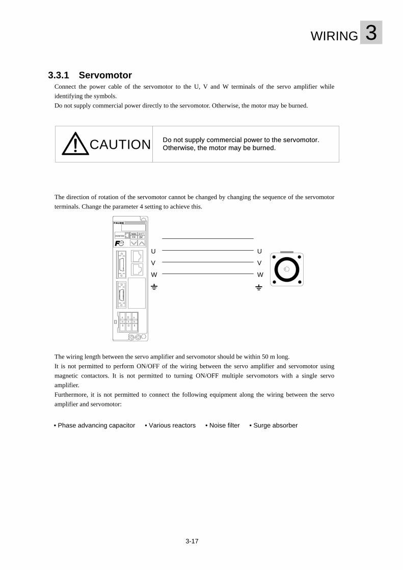
3.3.1 Servomotor Connect the power cable of the servomotor to the U, V and W terminals of the servo amplifier while identifying the symbols. Do not supply commercial power directly to the servomotor. Otherwise, the motor may be burned.
CAUTION Do not supply commercial power to the servomotor.Otherwise, the motor may be burned.
The direction of rotation of the servomotor cannot be changed by changing the sequence of the servomotor terminals. Change the parameter 4 setting to achieve this.
The wiring length between the servo amplifier and servomotor should be within 50 m long. It is not permitted to perform ON/OFF of the wiring between the servo amplifier and servomotor using magnetic contactors. It is not permitted to turning ON/OFF multiple servomotors with a single servo amplifier. Furthermore, it is not permitted to connect the following equipment along the wiring between the servo amplifier and servomotor:
• Phase advancing capacitor • Various reactors • Noise filter • Surge absorber
U
V
W
U
V
W
MONITOR
3 WIRING
3-18
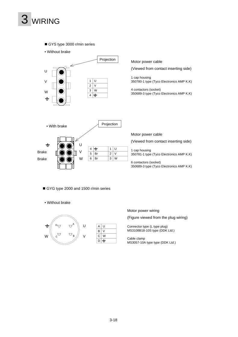
GYS type 3000 r/min series
GYG type 2000 and 1500 r/min series
2
3
U1
4
V
W
6
Br5 2
3
U14
V
W
Br
B
C
UA
D
V
W
Motor power cable
(Viewed from contact inserting side)
Motor power cable
(Viewed from contact inserting side)
1 cap housing 350780-1 type (Tyco Electronics AMP K.K) 4 contactors (socket) 350689-3 type (Tyco Electronics AMP K.K)
1 cap housing 350781-1 type (Tyco Electronics AMP K.K) 6 contactors (socket) 350689-3 type (Tyco Electronics AMP K.K)
• Without brake
• With brake
Projection
U
V
W
U
Brake
Brake
V
W
Projection
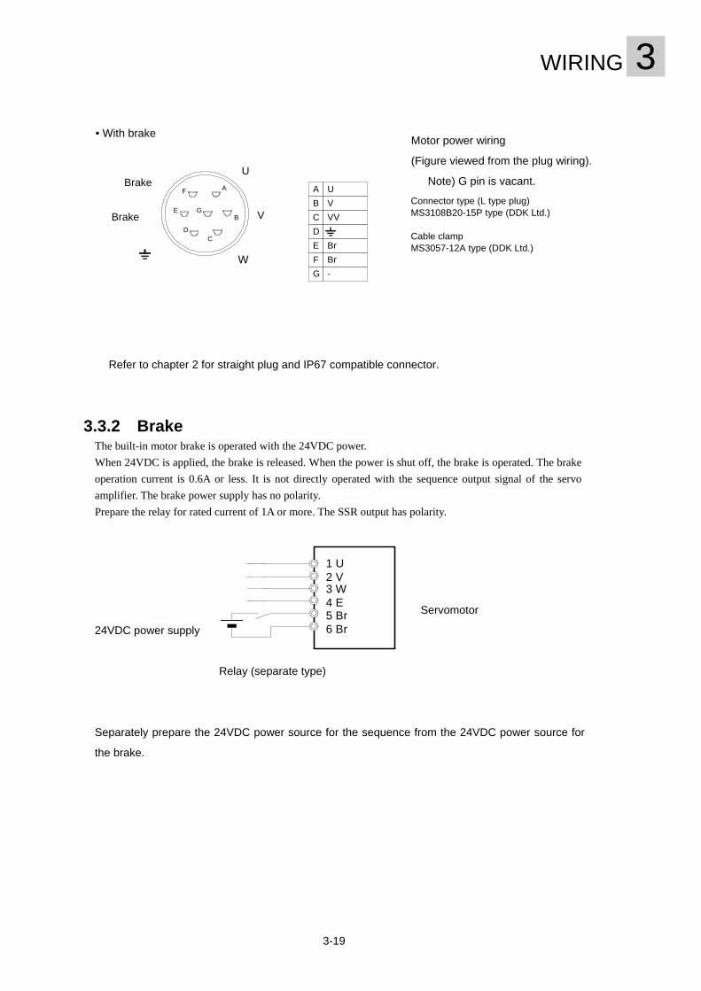
Motor power wiring
(Figure viewed from the plug wiring)
• Without brake
Connector type (L type plug) MS3108B18-10S type (DDK Ltd.) Cable clamp MS3057-10A type type (DDK Ltd.)
12
3
45
6
U
V W
A
C B
D
WIRING 3
3-19
Refer to chapter 2 for straight plug and IP67 compatible connector.
3.3.2 Brake The built-in motor brake is operated with the 24VDC power. When 24VDC is applied, the brake is released. When the power is shut off, the brake is operated. The brake operation current is 0.6A or less. It is not directly operated with the sequence output signal of the servo amplifier. The brake power supply has no polarity. Prepare the relay for rated current of 1A or more. The SSR output has polarity.
Servomotor
24VDC power supply
Relay (separate type)
Separately prepare the 24VDC power source for the sequence from the 24VDC power source for
the brake.
B
C
UA
D
V
VV
F
BrE
Br
G -
Motor power wiring
(Figure viewed from the plug wiring).
Note) G pin is vacant.
• With brake
Brake
Brake
U
V
W
5 Br 6 Br
3 W4 E
1 U 2 V
Connector type (L type plug) MS3108B20-15P type (DDK Ltd.) Cable clamp MS3057-12A type (DDK Ltd.)
DC
A
BE
F
G
3 WIRING
3-20
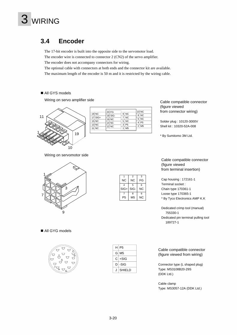
3.4 Encoder The 17-bit encoder is built into the opposite side to the servomotor load. The encoder wire is connected to connector 2 (CN2) of the servo amplifier. The encoder does not accompany connectors for wiring. The optional cable with connectors at both ends and the connector kit are available. The maximum length of the encoder is 50 m and it is restricted by the wiring cable.
All GYS models
Wiring on servo amplifier side
Wiring on servomotor side
All GYG models
Cable compatible connector (figure viewed from wiring) Connector type (L shaped plug) Type: MS3108B20-29S (DDK Ltd.) Cable clamp Type: MS3057-12A (DDK Ltd.)
Cable compatible connector (figure viewed from connector wiring) Solder plug : 10120-3000V Shell kit : 10320-52A-008 * By Sumitomo 3M Ltd.
Cable compatible connector (figure viewed from terminal insertion) Cap housing : 172161-1 Terminal socket : Chain type 170361-1 Loose type 170365-1 * By Tyco Electronics AMP K.K Dedicated crimp tool (manual) 755330-1 Dedicated pin terminal pulling tool 189727-1
1
7
3
9
321
654
987
FGNCNC
NCSIG-SIG+
NCM5P5
P5H
M5G
+SIGC
-SIGD
SHIELDJ
C
D
J
G
T
S
H
11
19
10
FG20SIG-18NC16NC14NC12
NC9NC7NC5P53M51
NC10NC8NC6P54M52
NC19 SIG+17 NC15 NC13 NC11
1

WIRING 3
3-21
• Wiring cable
Use the following cables if the optional encoder cable is not used. It is a normal twisted pair total shielded wire. If the motor and the cable are not moving, it is not necessary to use a flexible cable.
Cross-link polyethylene insulated, vinyl sheath cable for robot travel (DAIDEN Co., Ltd.)
RMCV-SB-A (UL2464) AWG#24/3P (twisted-pair cable)
(Cable length: within 20m)
Cross-link polyethylene insulated, vinyl sheath cable for robot travel (DAIDEN Co., Ltd.)
RMCV-SB-A (UL2464) AWG#16/2P (twisted-pair cable)
(Wire length exceeds 20m and is 50m or less.)
Wire size AWG#24 P5 line x 2 (1 pair) M5 line x 2 (1 pair) SIG line x 2 (1 pair)
3M connector 10120-3000VE
AMP connector 172161-*
Wire size AWG#16 P5-M5 line × 1 (1 pair) SIG line × 2 (1 pair)
3M connector 10120-3000VE
AMP connector 172161-*
AMP connector 172161-*
AMP connector 172169-*
Wire size AWG#16 P5-M5 line × 1 (1 pair) SIG line × 2 (1 pair)
5m or less 20m to 50m
MONITOR
MONITOR
3 WIRING
3-22
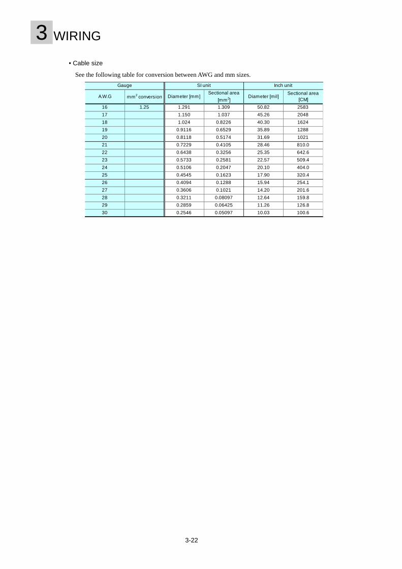
• Cable size
See the following table for conversion between AWG and mm sizes.
A.W.G mm2 conversion Diameter [mm]Sectional area
[mm2]Diameter [mil] Sectional area
[CM]16 1.25 1.291 1.309 50.82 258317 1.150 1.037 45.26 204818 1.024 0.8226 40.30 162419 0.9116 0.6529 35.89 128820 0.8118 0.5174 31.69 102121 0.7229 0.4105 28.46 810.022 0.6438 0.3256 25.35 642.623 0.5733 0.2581 22.57 509.424 0.5106 0.2047 20.10 404.025 0.4545 0.1623 17.90 320.426 0.4094 0.1288 15.94 254.127 0.3606 0.1021 14.20 201.628 0.3211 0.08097 12.64 159.829 0.2859 0.06425 11.26 126.830 0.2546 0.05097 10.03 100.6
SI unit Inch unitGauge
WIRING 3
3-23
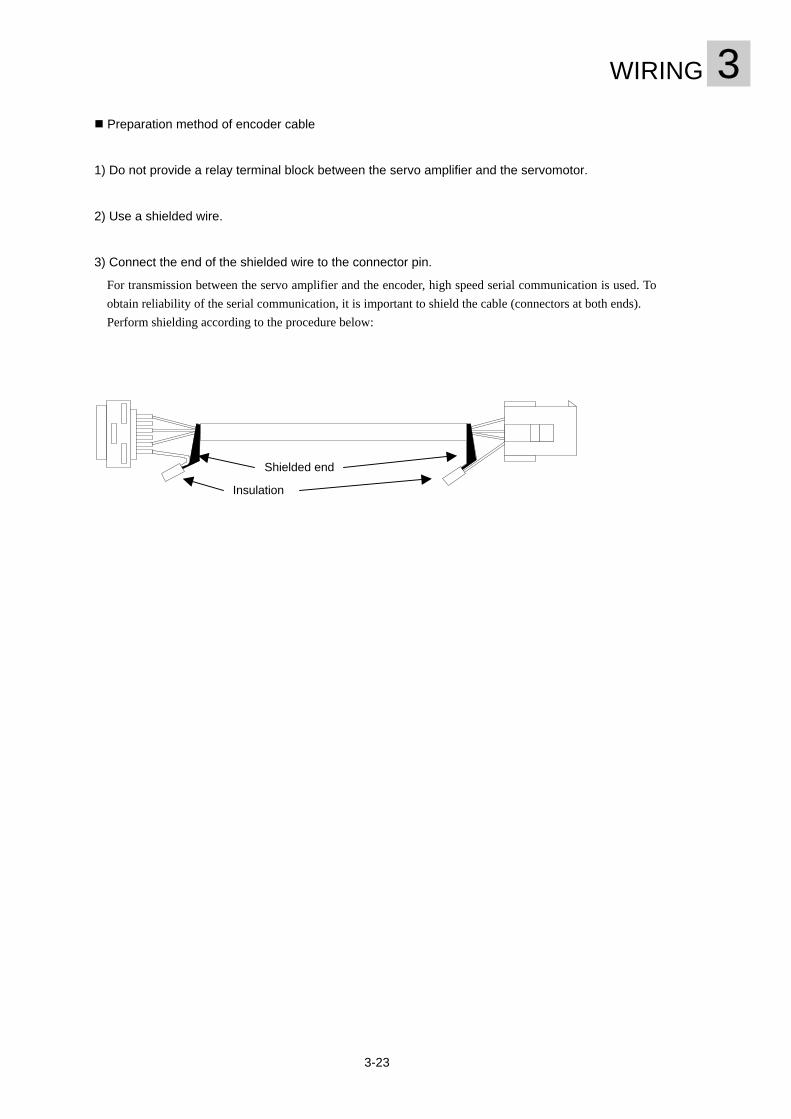
Preparation method of encoder cable
1) Do not provide a relay terminal block between the servo amplifier and the servomotor.
2) Use a shielded wire.
3) Connect the end of the shielded wire to the connector pin.
For transmission between the servo amplifier and the encoder, high speed serial communication is used. To obtain reliability of the serial communication, it is important to shield the cable (connectors at both ends). Perform shielding according to the procedure below:
Shielded end
Insulation
3 WIRING
3-24
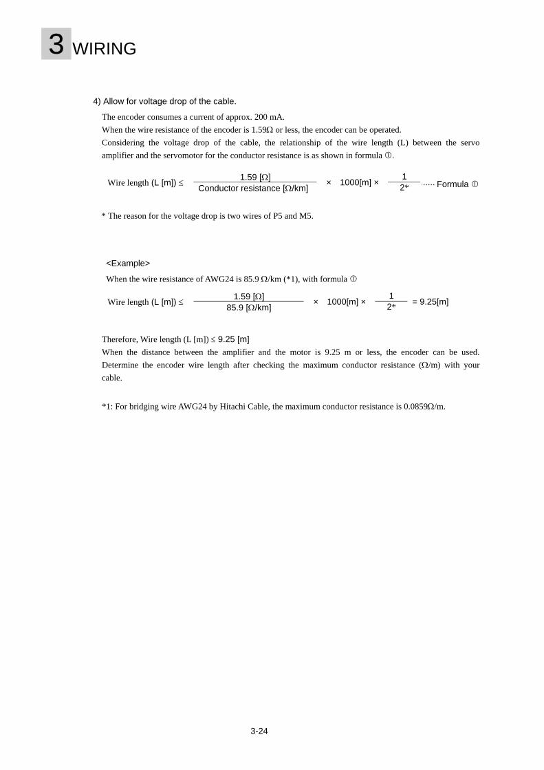
4) Allow for voltage drop of the cable.
The encoder consumes a current of approx. 200 mA. When the wire resistance of the encoder is 1.59Ω or less, the encoder can be operated. Considering the voltage drop of the cable, the relationship of the wire length (L) between the servo amplifier and the servomotor for the conductor resistance is as shown in formula .
························· Formula
* The reason for the voltage drop is two wires of P5 and M5.
<Example>
When the wire resistance of AWG24 is 85.9 Ω/km (*1), with formula
Therefore, Wire length (L [m]) ≤ 9.25 [m] When the distance between the amplifier and the motor is 9.25 m or less, the encoder can be used. Determine the encoder wire length after checking the maximum conductor resistance (Ω/m) with your cable.
*1: For bridging wire AWG24 by Hitachi Cable, the maximum conductor resistance is 0.0859Ω/m.
1.59 [Ω] 1 Wire length (L [m]) ≤ 85.9 [Ω/km]
× 1000[m] × 2* = 9.25[m]
1.59 [Ω] 1 Wire length (L [m]) ≤ Conductor resistance [Ω/km]
× 1000[m] × 2*

WIRING 3
3-25
3.5 Connection diagrams Connection diagrams of the servo amplifier are shown here.
(1) 3000 r/min series 0.05 kW - 0.4 kW
(2) 3000 r/min series 0.75 kW
(3) 2000 r/min series 0.5 kW - 0.75 kW
(4) 2000 r/min series 1 kW - 2 kW
(5) 1500 r/min series 0.5 kW
(6) 1500 r/min series 0.85 kW - 1.3 kW
• The servomotor shows the wiring diagram of the motor with a brake. The servomotor without a brake does not have No. 5 and 6 terminals or E, F and G terminals.
• Refer to Section 3.6 for the connection of other devices.
• The sequence input/output terminal initial values of the servo amplifier are as follows: Settings before shipment from factory
CONT1: Servo ON OUT1 terminal: Servo ready
CONT2: Alarm reset OUT2 terminal: Positioning end
CONT3: (Not specified) OUT3 terminal: Servo alarm (b contact)
CONT4: (Not specified) OUT4 terminal: (Not specified)
CONT5: (Not specified)
• Connector 4 (CN4) is not required for operation of the servomotor. It is used for measurement of the servomotor speed waveform and the torque waveform using measuring instruments.
• The control power input terminal (sL1, sL2) is connected to perform parameter editing while the motor power is shut off. The servo amplifier is only operated with the motor power supply.
• Do not use the 24VDC power for both sequence input/output and the brake. When the brake is released, the voltage may suddenly increase. Also use a surge absorber.
3 WIRING
3-26
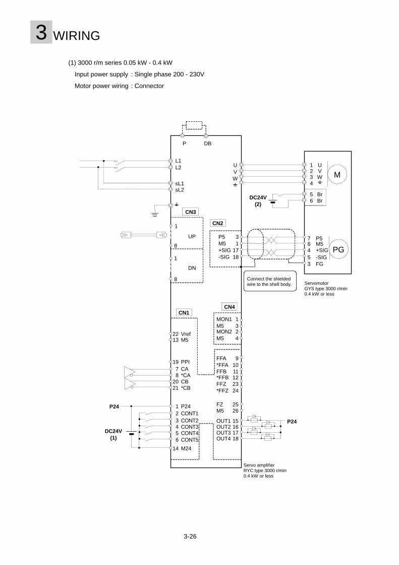
(1) 3000 r/m series 0.05 kW - 0.4 kW
Input power supply : Single phase 200 - 230V
Motor power wiring : Connector
7
Servo amplifier RYC type 3000 r/min 0.4 kW or less
P5 P5 3
P24
1 P24 2 CONT1
5 CONT4
3 CONT2
14 M24
4 CONT3
P24
19 PPI 7 CA 8 *CA
21 *CB20 CB
6 CONT5
22 Vref 13 M5
OUT1 15OUT2 16OUT3 17OUT4 18
DC24V(1)
Servomotor GYS type 3000 r/min 0.4 kW or less
U
W
1 U 2 V 3 W 4
M
8 M5 4 +SIG
3 FG 5 -SIG
M5 1+SIG 17-SIG 18
PG
L1L2
sL1sL2
CN2
P DB
Connect the shielded wire to the shell body.
CN3
8
1
8
UP
DN
FFZ 23*FFZ 24
FZ 25M5 26
CN1
1
FFA 9*FFA 10
*FFB 12
5 Br 6 Br
CN4
MON1 1M5 3MON2 2M5 4
DC24V(2)
V
FFB 11
WIRING 3
3-27
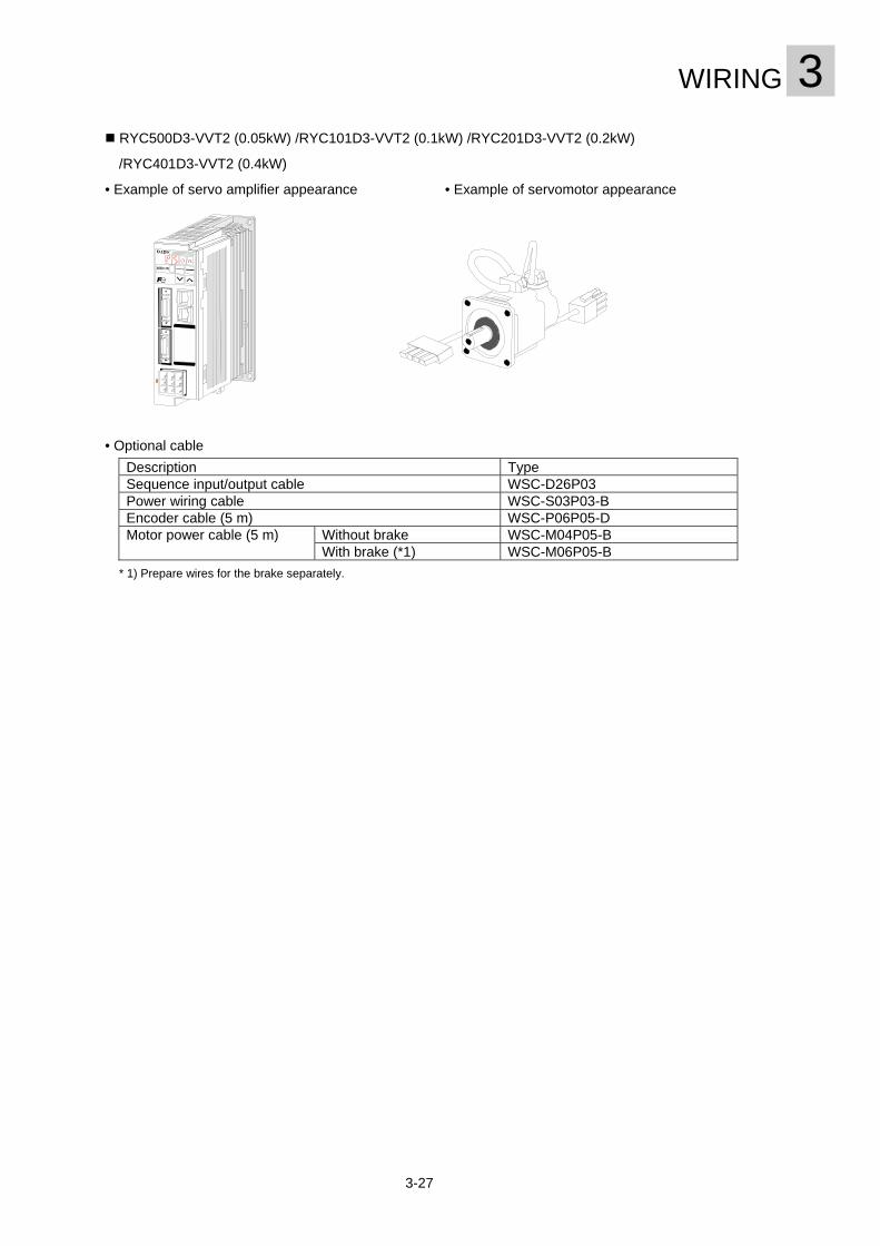
RYC500D3-VVT2 (0.05kW) /RYC101D3-VVT2 (0.1kW) /RYC201D3-VVT2 (0.2kW)
/RYC401D3-VVT2 (0.4kW)
• Example of servo amplifier appearance • Example of servomotor appearance
• Optional cable Description Type Sequence input/output cable WSC-D26P03 Power wiring cable WSC-S03P03-B Encoder cable (5 m) WSC-P06P05-D
Without brake WSC-M04P05-B Motor power cable (5 m) With brake (*1) WSC-M06P05-B
* 1) Prepare wires for the brake separately.

3 WIRING
3-28
(2) 3000 r/m series 0.75 kW
Input power supply : Single phase 200 - 230V or 3 phase 200 - 230V
Motor power wiring : Connector
7
Servo amplifier RYC type 3000 r/min 0.75 kW
P5 P5 3
P24
1 P24 2 CONT1
5 CONT4
3 CONT2
14 M24
4 CONT3
P24
19 PPI 7 CA 8 *CA
21 *CB20 CB
6 CONT5
22 Vref 13 M5
OUT1 15OUT2 16OUT3 17OUT4 18DC24V
(1)
Servomotor GYS type 3000 r/min 0.75 kW
U
W
1 U 2 V 3 W 4
M
8 M5 4 +SIG
3 FG 5 -SIG
M5 1+SIG 17-SIG 18
PG
L1L2
sL1sL2
CN2
P DB
Connect the shielded wire to the shell body.
CN3
8
1
8
UP
DN
FFZ 23*FFZ 24FZ 25M5 26
CN1
1
FFA 9*FFA 10
*FFB 12
5 Br 6 Br
CN4
MON1 1M5 3MON2 2M5 4
DC24V(2)
V
FFB 11
L3
WIRING 3
3-29
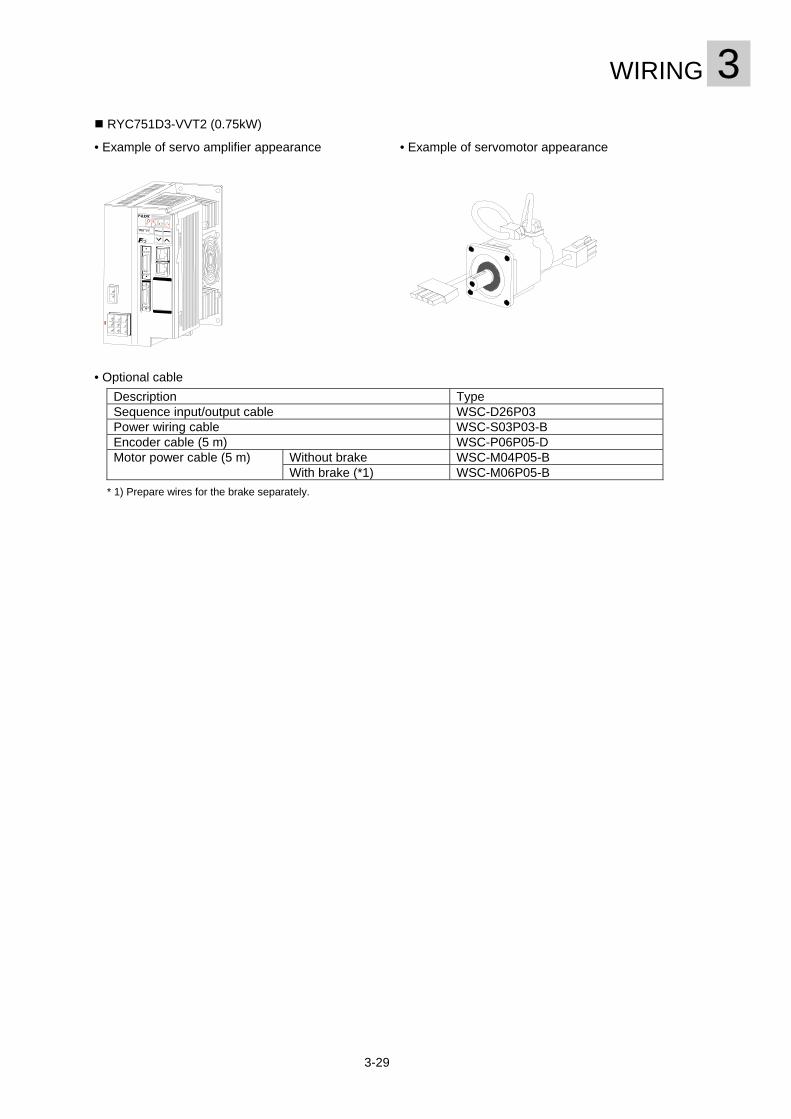
RYC751D3-VVT2 (0.75kW)
• Example of servo amplifier appearance • Example of servomotor appearance
• Optional cable Description Type Sequence input/output cable WSC-D26P03 Power wiring cable WSC-S03P03-B Encoder cable (5 m) WSC-P06P05-D
Without brake WSC-M04P05-B Motor power cable (5 m) With brake (*1) WSC-M06P05-B
* 1) Prepare wires for the brake separately.

3 WIRING
3-30
(3) 2000 r/m series 0.5 kW - 0.75 kW
Input power supply : Single phase 200 - 230V or 3 phase 200 - 230V
Motor power wiring : Connector
H
Servo amplifier RYC type 2000 r/min 0.5 kW, 0.75 kW
P5 P5 3
P24
1 P24 2 CONT1
5 CONT4
3 CONT2
14 M24
4 CONT3
P24
19 PPI 7 CA 8 *CA
21 *CB20 CB
6 CONT5
22 Vref 13 M5
OUT1 15OUT2 16OUT3 17OUT4 18DC24V
(1)
Servomotor GYG type 2000 r/min 0.5 kW, 0.75 kW
U
W
A U B V C W D
M
G M5 C +SIG
J FG D -SIG
M5 1+SIG 17-SIG 18
PG
L1L2
sL1sL2
CN2
P DB
Connect the shielded wire to the shell body.
CN3
8
1
8
UP
DN
FFZ 23*FFZ 24FZ 25M5 26
CN1
1
FFA 9*FFA 10
*FFB 12
E Br F Br
CN4
MON1 1M5 3MON2 2M5 4
DC24V(2)
V
FFB 11
L3
G -
WIRING 3
3-31
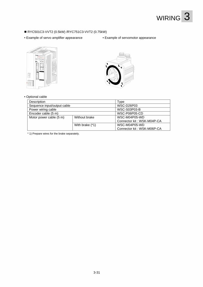
RYC501C3-VVT2 (0.5kW) /RYC751C3-VVT2 (0.75kW)
• Example of servo amplifier appearance • Example of servomotor appearance
• Optional cable Description Type Sequence input/output cable WSC-D26P03 Power wiring cable WSC-S03P03-B Encoder cable (5 m) WSC-P06P05-CD
Without brake WSC-M04P05-WD Connector kit : WSK-M04P-CA
Motor power cable (5 m)
With brake (*1) WSC-M04P05-WD Connector kit : WSK-M06P-CA
* 1) Prepare wires for the brake separately.
3 WIRING
3-32
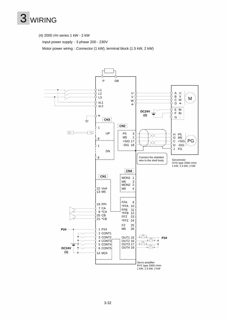
(4) 2000 r/m series 1 kW - 2 kW
Input power supply : 3 phase 200 - 230V
Motor power wiring : Connector (1 kW), terminal block (1.5 kW, 2 kW)
H
Servo amplifier RYC type 2000 r/min 1 kW, 1.5 kW, 2 kW
P5 P5 3
P24
1 P24 2 CONT1
5 CONT4
3 CONT2
14 M24
4 CONT3
P24
19 PPI 7 CA 8 *CA
21 *CB20 CB
6 CONT5
22 Vref 13 M5
OUT1 15OUT2 16OUT3 17OUT4 18DC24V
(1)
Servomotor GYG type 2000 r/min 1 kW, 1.5 kW, 2 kW
U
W
A U B V C W D
M
G M5 C +SIG
J FG D -SIG
M5 1+SIG 17-SIG 18
PG
L1L2
sL1sL2
CN2
P DB
Connect the shielded wire to the shell body.
CN3
8
1
8
UP
DN
FFZ 23*FFZ 24FZ 25M5 26
CN1
1
FFA 9*FFA 10
*FFB 12
E Br F Br
CN4
MON1 1M5 3MON2 2M5 4
DC24V(2)
V
FFB 11
L3
G -

WIRING 3
3-33
RYC102C3-VVT2 (1kW)
• Example of servo amplifier appearance • Example of servomotor appearance
• Optional cable Description Type Sequence input/output cable WSC-D26P03 Power wiring cable WSC-S03P03-B Encoder cable (5 m) WSC-P06P05-CD
Without brake WSC-M04P05-WD Connector kit : WSK-M04P-CA
Motor power cable (5 m)
With brake (*1) WSC-M04P05-WD Connector kit : WSK-M06P-CA
*1) Prepare wires for the brake separately.
RYC152C3-VVT2 (1.5kW) /RYC202C3-VVT2 (2kW)
• Example of servo amplifier appearance • Example of servomotor appearance
• Optional cable Description Type Sequence input/output cable WSC-D26P03 Power wiring cable (Terminal block: M4) Encoder cable (5 m) WSC-P06P05-CD
Without brake - Connector kit : WSK-M04P-CA
Motor power cable (5 m)
With brake (*1) - Connector kit : WSK-M06P-CA
* 1) Prepare wires for the brake separately.

3 WIRING
3-34
(5) 1500 r/m series 0.5 kW
Input power supply : Single phase 200 - 230V or 3 phase 200 - 230V
Motor power wiring : Connector
H
Servo amplifier RYC type 1500 r/min 0.5 kW
P5 P5 3
P24
1 P24 2 CONT1
5 CONT4
3 CONT2
14 M24
4 CONT3
P24
19 PPI 7 CA 8 *CA
21 *CB20 CB
6 CONT5
22 Vref 13 M5
OUT1 15OUT2 16OUT3 17OUT4 18DC24V
(1)
Servomotor GYG type 1500 r/min 0.5 kW
U
W
A U B V C W D
M
G M5 C +SIG
J FG D -SIG
M5 1+SIG 17-SIG 18
PG
L1L2
sL1sL2
CN2
P DB
Connect the shielded wire to the shell body.
CN3
8
1
8
UP
DN
FFZ 23*FFZ 24FZ 25M5 26
CN1
1
FFA 9*FFA 10
*FFB 12
E Br F Br
CN4
MON1 1M5 3MON2 2M5 4
DC24V(2)
V
FFB 11
L3
G -
WIRING 3
3-35
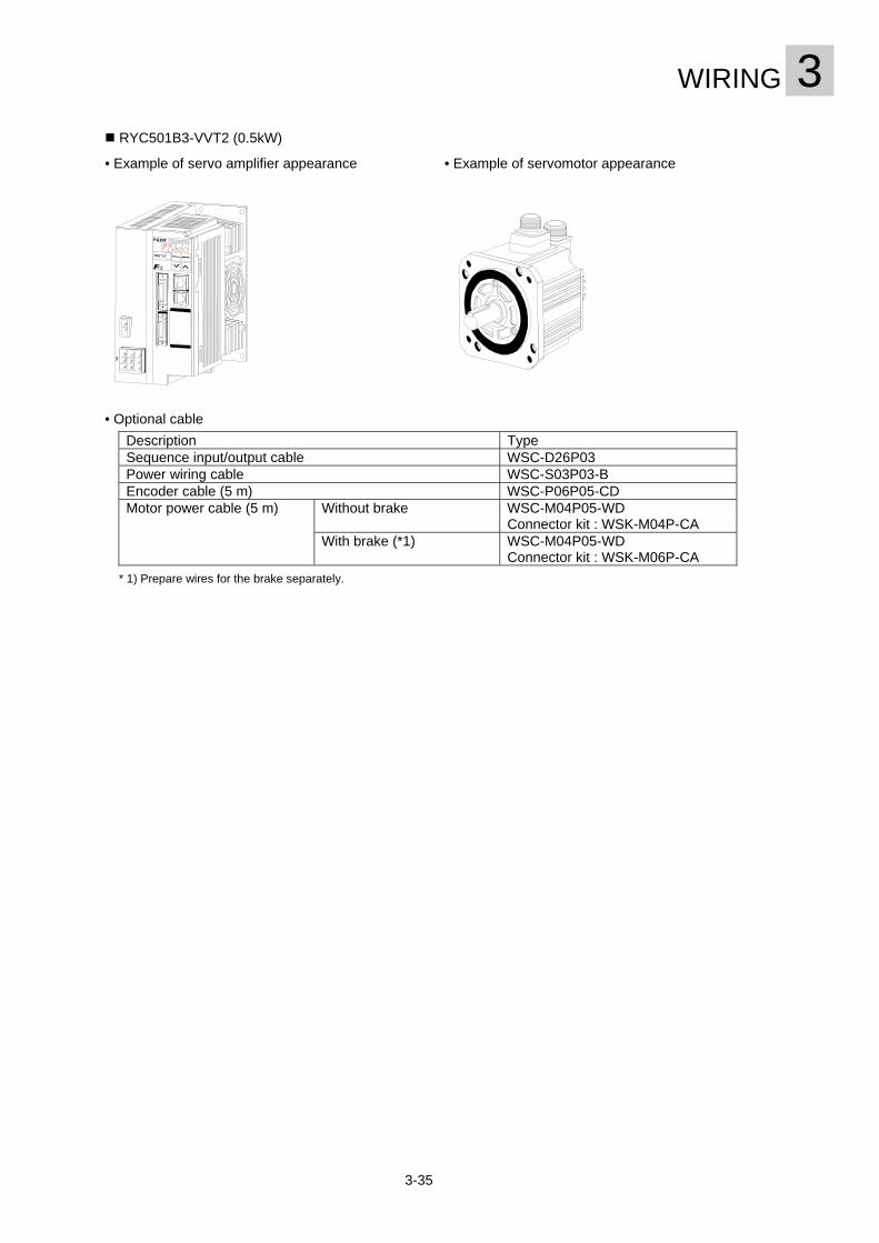
RYC501B3-VVT2 (0.5kW)
• Example of servo amplifier appearance • Example of servomotor appearance
• Optional cable Description Type Sequence input/output cable WSC-D26P03 Power wiring cable WSC-S03P03-B Encoder cable (5 m) WSC-P06P05-CD
Without brake WSC-M04P05-WD Connector kit : WSK-M04P-CA
Motor power cable (5 m)
With brake (*1) WSC-M04P05-WD Connector kit : WSK-M06P-CA
* 1) Prepare wires for the brake separately.
3 WIRING
3-36
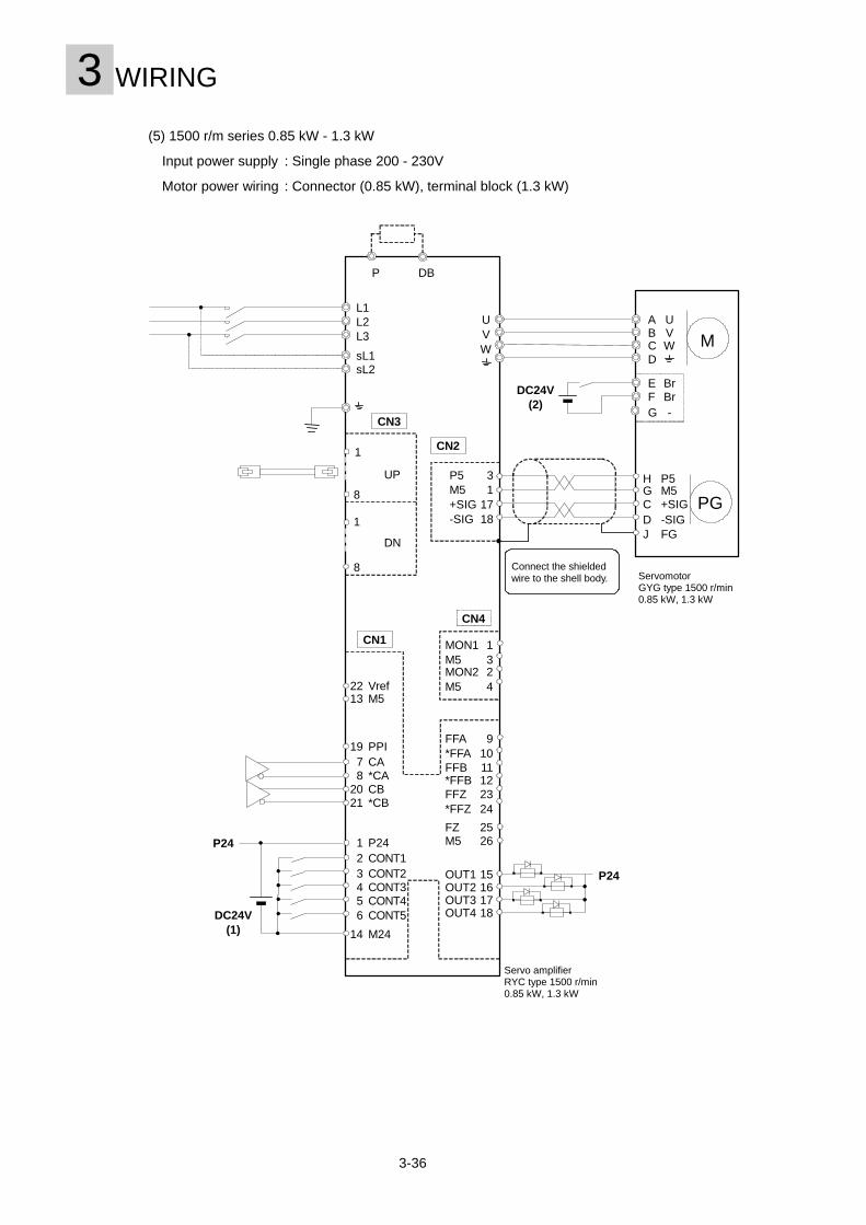
(5) 1500 r/m series 0.85 kW - 1.3 kW
Input power supply : Single phase 200 - 230V
Motor power wiring : Connector (0.85 kW), terminal block (1.3 kW)
H
Servo amplifier RYC type 1500 r/min 0.85 kW, 1.3 kW
P5 P5 3
P24
1 P24 2 CONT1
5 CONT4
3 CONT2
14 M24
4 CONT3
P24
19 PPI 7 CA 8 *CA
21 *CB20 CB
6 CONT5
22 Vref 13 M5
OUT1 15OUT2 16OUT3 17OUT4 18DC24V
(1)
Servomotor GYG type 1500 r/min 0.85 kW, 1.3 kW
U
W
A U B V C W D
M
G M5 C +SIG
J FG D -SIG
M5 1+SIG 17-SIG 18
PG
L1L2
sL1sL2
CN2
P DB
Connect the shielded wire to the shell body.
CN3
8
1
8
UP
DN
FFZ 23*FFZ 24FZ 25M5 26
CN1
1
FFA 9*FFA 10
*FFB 12
E Br F Br
CN4
MON1 1M5 3MON2 2M5 4
DC24V(2)
V
FFB 11
L3
G -

WIRING 3
3-37
RYC851B3-VVT2 (0.85kW)
• Example of servo amplifier appearance • Example of servomotor appearance
• Optional cable Description Type Sequence input/output cable WSC-D26P03 Power wiring cable WSC-S03P03-B Encoder cable (5 m) WSC-P06P05-CD
Without brake WSC-M04P05-WD Connector kit : WSK-M04P-CA
Motor power cable (5 m)
With brake (*1) WSC-M04P05-WD Connector kit : WSK-M06P-CA
*1) Prepare wires for the brake separately.
RYC132B3-VVT2 (1.3kW)
• Example of servo amplifier appearance • Example of servomotor appearance
• Optional cable Description Type Sequence input/output cable WSC-D26P03 Power wiring cable (Terminal block: M4) Encoder cable (5 m) WSC-P06P05-CD
Without brake - Connector kit : WSK-M04P-CA
Motor power cable (5 m)
With brake (*1) - Connector kit : WSK-M06P-CA
*1) Prepare wires for the brake separately.

3 WIRING
3-38
-MEMO-
WIRING 3
3-39
3.6 Connection examples Examples of connections to each device are described. For products not specified in this manual, be sure to refer to the operation manual or user’s manual of the corresponding equipment. The connection diagrams shown in this chapter are for reference only.
Positioning module (NP1F-MP2)
Positioning unit (QD75D type)
Position control unit (NC113)
3 WIRING
3-40
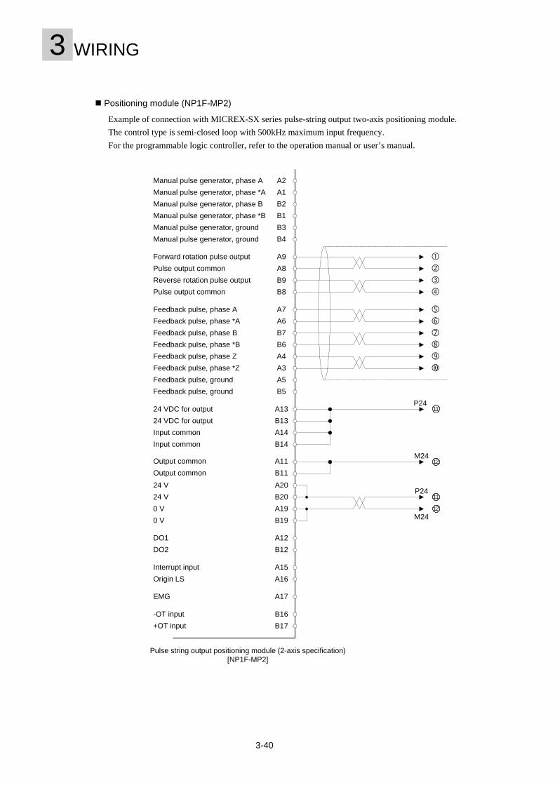
Positioning module (NP1F-MP2)
Example of connection with MICREX-SX series pulse-string output two-axis positioning module. The control type is semi-closed loop with 500kHz maximum input frequency. For the programmable logic controller, refer to the operation manual or user’s manual.
A2A1B2B1B3B4
A9A8B9B8
A7A6B7B6A4A3A5B5
A13B13A14B14
A20B20A19B19
A12B12
A15A16
A17
B16B17
P24
M24
P24
M24
Pulse string output positioning module (2-axis specification)[NP1F-MP2]
Manual pulse generator, phase AManual pulse generator, phase *AManual pulse generator, phase BManual pulse generator, phase *BManual pulse generator, groundManual pulse generator, ground
Forward rotation pulse outputPulse output commonReverse rotation pulse outputPulse output common
Feedback pulse, phase AFeedback pulse, phase *AFeedback pulse, phase BFeedback pulse, phase *B
Feedback pulse, groundFeedback pulse, ground
Feedback pulse, phase ZFeedback pulse, phase *Z
24 VDC for output24 VDC for outputInput commonInput common
24 V24 V0 V0 V
DO1DO2
Interrupt inputOrigin LS
EMG
-OT input+OT input
A11B11
Output commonOutput common
12
11
12
11

WIRING 3
3-41
311718
11
12
7 P5 8 M5 4 +SIG
3 FG 5 -SIG
PG
1 U 2 V 3 W 4
M
5 Br 6 Br DC24V
(2)
OUT1 15OUT2 16OUT3 17OUT4 18
FFZ 23*FFZ 24
FZ 25M5 26
FFA 9*FFA 10
*FFB 12FFB 11
CN4
MON1 1M5 3MON2 2M5 4
22 Vref 13 M5
CN1
19 PPI 7 CA 8 *CA
21 *CB 20 CB
DC24V (1)
1 P24 2 CONT1
5 CONT4
3 CONT2
14M24
4 CONT3
6 CONT5
U
W
L1 L2
sL1 sL2
P DB
V
CN2
CN3
8
1
8
1
P5 1M5 3+SIG 17-SIG 18
UP
DN
Servo amplifier RYC type 3000 r/min 0.4 kW or less
P24
Servomotor GYS type 3000 r/min 0.4 kW or less
Connect the shielded wire to the shell body.
Commercial power supply Single phase: 200V
3 WIRING
3-42
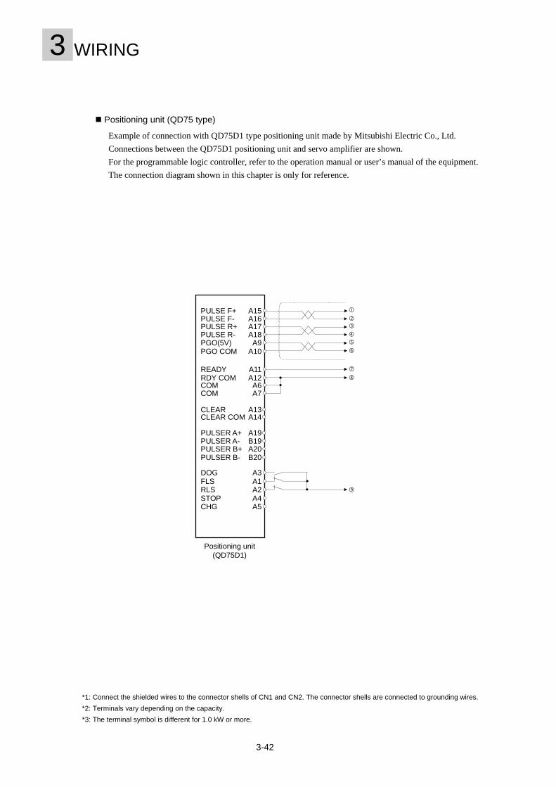
Positioning unit (QD75 type)
Example of connection with QD75D1 type positioning unit made by Mitsubishi Electric Co., Ltd. Connections between the QD75D1 positioning unit and servo amplifier are shown. For the programmable logic controller, refer to the operation manual or user’s manual of the equipment. The connection diagram shown in this chapter is only for reference.
*1: Connect the shielded wires to the connector shells of CN1 and CN2. The connector shells are connected to grounding wires. *2: Terminals vary depending on the capacity. *3: The terminal symbol is different for 1.0 kW or more.
PULSE F+ A15PULSE F- A16PULSE R+ A17PULSE R- A18PGO(5V) A9PGO COM A10
READY A11RDY COM A12COM A6
CLEAR A13CLEAR COM A14
PULSER A+ A19PULSER A- B19
DOG A3FLS A1RLS A2STOP A4CHG A5
Positioning unit(QD75D1)
COM A7
PULSER B- B20PULSER B+ A20

WIRING 3
3-43
7 P5 8 M5 4 +SIG
3 FG 5 -SIG
PG
1 U 2 V 3 W 4
M
5 Br 6 Br DC24V
(2)
OUT1 15OUT2 16OUT3 17OUT4 18
FFZ 23*FFZ 24
FZ 25M5 26
FFA 9*FFA 10
*FFB 12FFB 11
CN4
MON1 1M5 3MON2 2M5 4
22 Vref 13 M5
CN1
19 PPI 7 CA 8 *CA
21 *CB 20 CB
DC24V (1)
1 P24 2 CONT1
5 CONT4
3 CONT2
14 M24
4 CONT3
6 CONT5
U
W
L1 L2
sL1 sL2
P DB
V
CN2
CN3
8
1
8
1
P5 1M5 3+SIG 17-SIG 18
UP
DN
Servo amplifier RYC type 3000 r/min 0.4 kW or less
Servomotor GYS type 3000 r/min 0.4 kW or less
Connect the shielded wire to the shell body.
Commercial power supply Single phase: 200V
3 WIRING
3-44
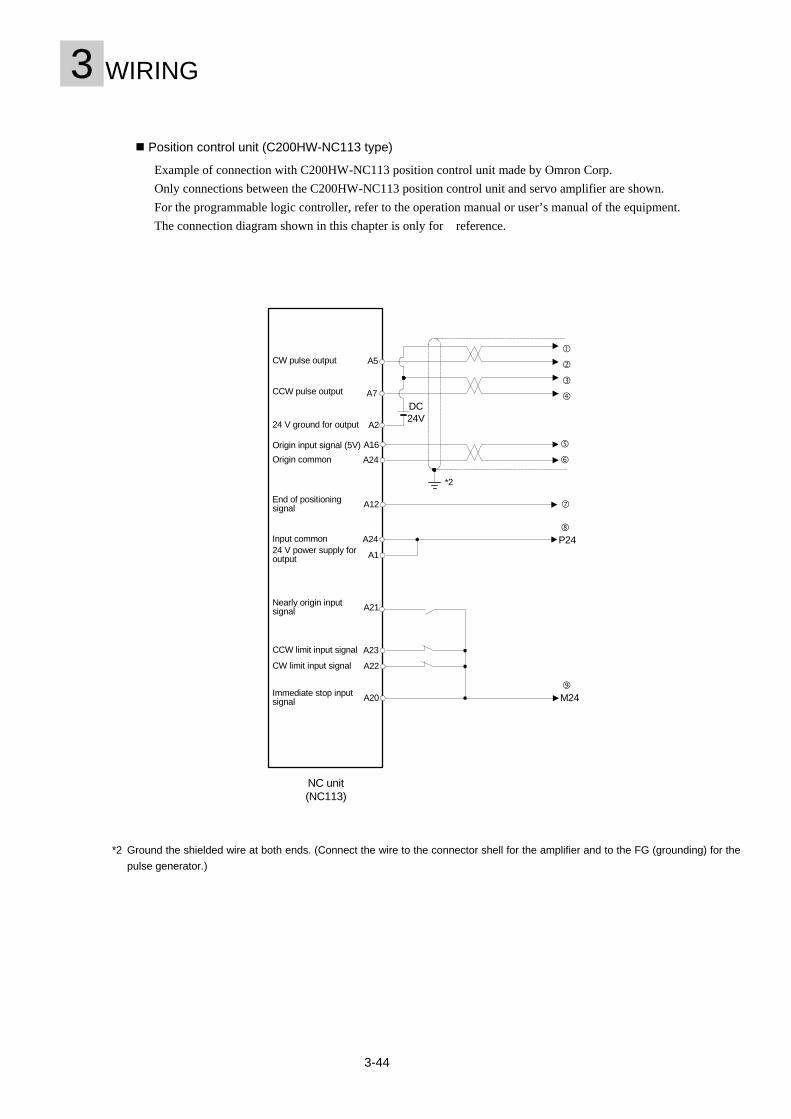
Position control unit (C200HW-NC113 type)
Example of connection with C200HW-NC113 position control unit made by Omron Corp. Only connections between the C200HW-NC113 position control unit and servo amplifier are shown. For the programmable logic controller, refer to the operation manual or user’s manual of the equipment. The connection diagram shown in this chapter is only for reference.
*2 Ground the shielded wire at both ends. (Connect the wire to the connector shell for the amplifier and to the FG (grounding) for thepulse generator.)
A21
A20
A7
A24
NC unit (NC113)
A5
A2
A16
A12
M24
A24
A1
A23
A22
*2
DC24V
P24
Nearly origin input signal
Immediate stop input signal
CCW pulse output
Origin common
CW pulse output
24 V ground for output
Origin input signal (5V)
End of positioning signal
Input common24 V power supply for output
CCW limit input signal
CW limit input signal

WIRING 3
3-45
311718
7 P5 8 M5 4 +SIG
3 FG 5 -SIG
PG
1 U 2 V 3 W 4
M
5 Br 6 Br DC24V
(2)
OUT1 15OUT2 16OUT3 17OUT4 18
FFZ 23*FFZ 24
FZ 25M5 26
FFA 9*FFA 10
*FFB 12FFB 11
CN4
MON1 1M5 3MON2 2M5 4
22 Vref 13 M5
CN1
19 PPI 7 CA 8 *CA
21 *CB 20 CB
DC24V (1)
1 P24 2 CONT1
5 CONT4
3 CONT2
14 M24
4 CONT3
6 CONT5
U
W
L1 L2
sL1 sL2
P DB
V
CN2
CN3
8
1
8
1
P5 1M5 3+SIG 17-SIG 18
UP
DN
Servo amplifier RYC type 3000 r/min 0.4 kW or less
Servomotor GYS type 3000 r/min 0.4 kW or less
Connect the shielded wire to the shell body.
Commercial power supply Single phase: 200V

3 WIRING
3-46
-MEMO-

TEST OPERATION
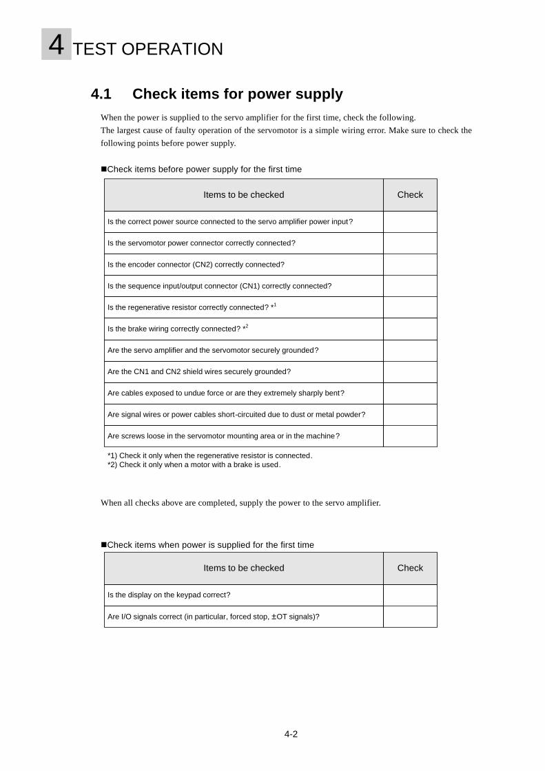
4 TEST OPERATION
4-2
4.1 Check items for power supply When the power is supplied to the servo amplifier for the first time, check the following. The largest cause of faulty operation of the servomotor is a simple wiring error. Make sure to check the following points before power supply. Check items before power supply for the first time
Items to be checked
Is the correct power source connected to the servo amplifier power input?
Is the servomotor power connector correctly connected?
Is the encoder connector (CN2) correctly connected?
Is the sequence input/output connector (CN1) correctly connected?
Are the servo amplifier and the servomotor securely grounded?
Are the CN1 and CN2 shield wires securely grounded?
Is the regenerative resistor correctly connected? *1
*1) Check it only when the regenerative resistor is connected.*2) Check it only when a motor with a brake is used.
Check
Are cables exposed to undue force or are they extremely sharply bent?
Are signal wires or power cables short-circuited due to dust or metal powder?
Are screws loose in the servomotor mounting area or in the machine?
Is the brake wiring correctly connected? *2
When all checks above are completed, supply the power to the servo amplifier.
Check items when power is supplied for the first time
Items to be checked
Is the display on the keypad correct?
Are I/O signals correct (in particular, forced stop, ±OT signals)?
Check

TEST OPERATION 4
4-3
4.2 Test operation in three stages Perform test operation in the following three stages. First stage
Perform test operation with the servomotor and the servo amplifier.
Second stage Connect the upper level control system to the servo amplifier and perform test operation with the command from the upper level control system.
3rd stage Connect the upper level control system to the servo amplifier and mount the servomotor on the machine. Then, perform test operation.
Check wiring with the upper level control system. Check I/O signals. Check the rotation speed and rotation level of the servomotor.
Check input power supply/motor power/encoder wiring. Check rotation direction of the servomotor.
To proceed to the 2nd stage, make sure to turn off the power before starting work.
To proceed to the 3rd stage, make sure to turn off the power before starting work.
Check that the servomotor is correctly installed on the machine. Check the travel distance of the machine.
Note
Note

4 TEST OPERATION
4-4
4.2.1 First stage Connect the servo amplifier and servomotor to perform test operation. Refer to Chapter 3 for the wiring method. Perform test operation of the servomotor output shaft without connecting to the machine. Check the following items in the first stage. <Check> (1) Check the power supply wiring of the servo amplifier (L1, L2 and L3). (2) Check the servomotor power cables (U, V and W) and encoder cable. (3) Check if the servo amplifier and servomotor function correctly. (4) Check parameter #4 (rotation direction switching/phase switching for rotation in CCW direction)
Test operation procedure
(1) Fix the servomotor so that it will not fall. (2) Referring to Chapter 3, connect cables to the servo amplifier and the servomotor.
* In the first instance, the test operation is performed in individual unit. Do not connect CN1. (3) After checking items listed under "Check items before power supply for the first time" on page 4-2,
supply the power.
i) Check LED for charge. ii) Check touch panel display.
Fix securely.
Mount nothing on the motor shaft.
i) Check the charge LED. Red LED lights up in the normal state.
ii) Check the touch panel indication.
When faultyAlarm detection
(letters are blinking)
When correct
* If an alarm is detected, turn the power off, check wiring, and refer to Chapter 9.
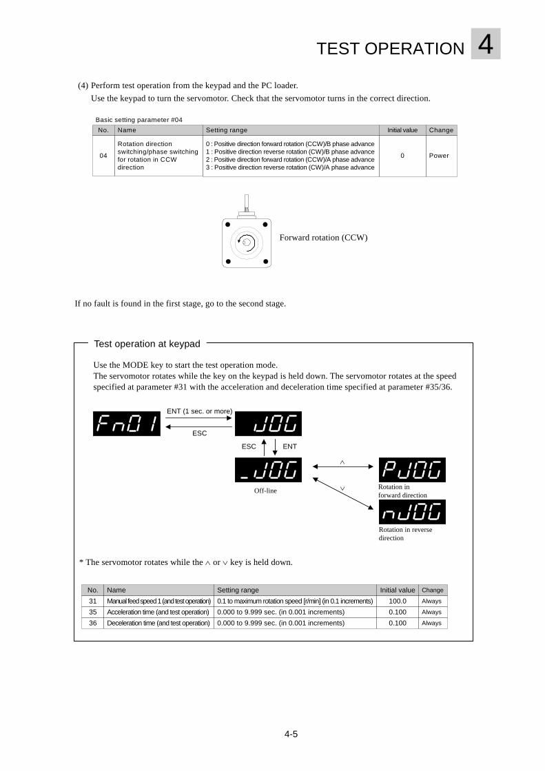
TEST OPERATION 4
4-5
(4) Perform test operation from the keypad and the PC loader. Use the keypad to turn the servomotor. Check that the servomotor turns in the correct direction.
If no fault is found in the first stage, go to the second stage.
* The servomotor rotates while the ∧ or ∨ key is held down.
Test operation at keypad
Use the MODE key to start the test operation mode. The servomotor rotates while the key on the keypad is held down. The servomotor rotates at the speed specified at parameter #31 with the acceleration and deceleration time specified at parameter #35/36.
Basic setting parameter #04
No. Name Setting range Initial value Change
04
Rotation direction switching/phase switching for rotation in CCW direction
0 : Positive direction forward rotation (CCW)/B phase advance1 : Positive direction reverse rotation (CW)/B phase advance2 : Positive direction forward rotation (CCW)/A phase advance3 : Positive direction reverse rotation (CW)/A phase advance
0 Power
Forward rotation (CCW)
ENT (1 sec. or more)
ESC
∧
∨
ENTESC
Off-line Rotation in forward direction
Rotation in reverse direction
No. Name Setting range Initial value Change
31 Manual feed speed 1 (and test operation) 0.1 to maximum rotation speed [r/min] (in 0.1 increments) 100.0 Always
35 Acceleration time (and test operation) 0.000 to 9.999 sec. (in 0.001 increments) 0.100 Always
36 Deceleration time (and test operation) 0.000 to 9.999 sec. (in 0.001 increments) 0.100 Always

4 TEST OPERATION
4-6
4.2.2 Second stage
Connect the upper level control system to the servo amplifier and perform test operation with the command from the upper level control system. Refer to Chapter 3 for wiring. Perform test operation without connecting the servomotor output shaft to the machine.
4.2.2.1 Common for all control (position/speed/torque) modes In the 2nd stage, check the following items. Then, check parameters for each control mode.
<Check> (1) Check wiring of signal wires between the servo amplifier and the upper level control systems (2) Check I/O signals
Test operation procedures
(1) According to wiring in Chapter 3, connect the servo amplifier (CN1) to the upper control system. (2) Check I/O signals from the keypad or the PC loader.
In particular, check forced stop (EMG), ±overtravel (±OT) and brake timing which are protective functions. Check that the servo amplifier is recognizing each signal.
ENT (1 sec. or more)
ESC
CONT5· · · · · · ·CONT1
OUT4· · · · · · ·OUT1
I/O check from keypad
I/O check from PC loader
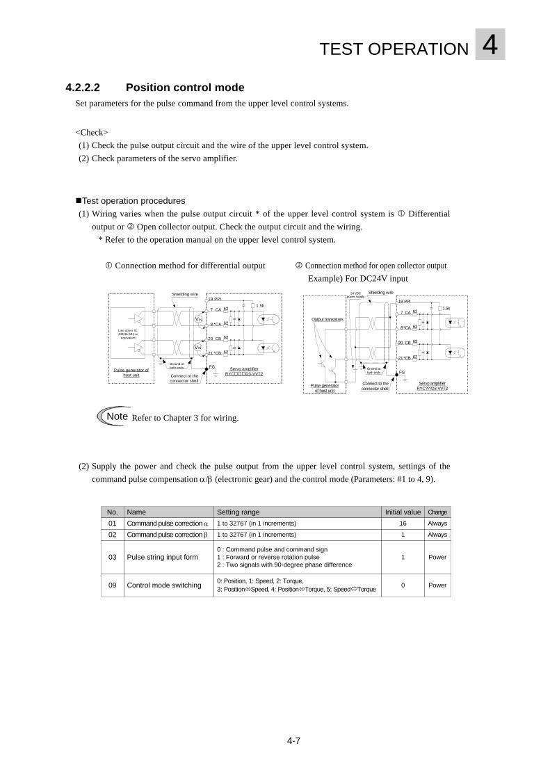
TEST OPERATION 4
4-7
4.2.2.2 Position control mode
Set parameters for the pulse command from the upper level control systems.
<Check> (1) Check the pulse output circuit and the wire of the upper level control system. (2) Check parameters of the servo amplifier.
Test operation procedures
(1) Wiring varies when the pulse output circuit * of the upper level control system is Differential output or Open collector output. Check the output circuit and the wiring.
* Refer to the operation manual on the upper level control system.
Connection method for differential output Connection method for open collector output Example) For DC24V input
Refer to Chapter 3 for wiring.
(2) Supply the power and check the pulse output from the upper level control system, settings of the
command pulse compensation α/β (electronic gear) and the control mode (Parameters: #1 to 4, 9).
Note
24 VDCpower supply
Pulse generatorof host unit
Connect to theconnector shell
Output transistors
Shielding wire
Ground atboth ends
Servo amplifierRYC???D3-VVT2
FG
CB
*CB
CA
*CA
7
8
20
21
62
62
1.5k
62
62
PPI19
No. Name Setting range Initial value Change
01 Command pulse correction α 1 to 32767 (in 1 increments) 16 Always
02 Command pulse correction β 1 to 32767 (in 1 increments) 1 Always
03 Pulse string input form0 : Command pulse and command sign1 : Forward or reverse rotation pulse2 : Two signals with 90-degree phase difference
1 Power
09 Control mode switching 0: Position, 1: Speed, 2: Torque,3: Position Speed, 4: Position Torque, 5: Speed Torque 0 Power
Servo amplifier RYC D3-VVT2
FG
Connect to the connector shell
Pulse generator of host unit
Line driver IC; AM26LS31 or
equivalent
Shielding wire
VIN
VIN
Ground at both ends
CB
*CB
CA
*CA
7
8
20
21
62
62
1.5k
62
62
PPI19
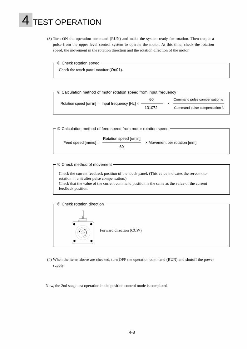
4 TEST OPERATION
4-8
(3) Turn ON the operation command (RUN) and make the system ready for rotation. Then output a pulse from the upper level control system to operate the motor. At this time, check the rotation speed, the movement in the rotation direction and the rotation direction of the motor.
Check the touch panel monitor (On01).
Rotation speed [r/min] =131072
Input frequency [Hz] × 60
×Command pulse compensation β
Command pulse compensation α
Check the current feedback position of the touch panel. (This value indicates the servomotor rotation in unit after pulse compensation.) Check that the value of the current command position is the same as the value of the current feedback position.
(4) When the items above are checked, turn OFF the operation command (RUN) and shutoff the power
supply.
Now, the 2nd stage test operation in the position control mode is completed.
Feed speed [mm/s] =60
× Movement per rotation [mm] Rotation speed [r/min]
Forward direction (CCW)
Check rotation speed
Calculation method of motor rotation speed from input frequency
Calculation method of feed speed from motor rotation speed
Check method of movement
Check rotation direction
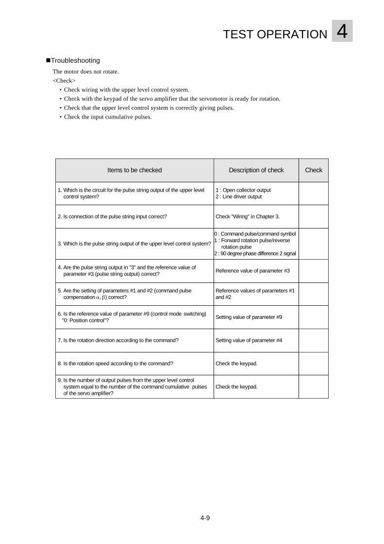
TEST OPERATION 4
4-9
Troubleshooting The motor does not rotate. <Check>
• Check wiring with the upper level control system. • Check with the keypad of the servo amplifier that the servomotor is ready for rotation. • Check that the upper level control system is correctly giving pulses. • Check the input cumulative pulses.
Items to be checked Description of check
3. Which is the pulse string output of the upper level control system?
4. Are the pulse string output in "3" and the reference value of parameter #3 (pulse string output) correct?
6. Is the reference value of parameter #9 (control mode switching) "0: Position control"?
7. Is the rotation direction according to the command?
8. Is the rotation speed according to the command?
Check
0 : Command pulse/command symbol1 : Forward rotation pulse/reverse
rotation pulse2 : 90 degree phase difference 2 signal
Reference value of parameter #3
Check the keypad.
Setting value of parameter #9
Setting value of parameter #4
5. Are the setting of parameters #1 and #2 (command pulse compensation α, β) correct?
Reference values of parameters #1 and #2
1. Which is the circuit for the pulse string output of the upper level control system?
1 : Open collector output2 : Line driver output
2. Is connection of the pulse string input correct? Check "Wiring" in Chapter 3.
9. Is the number of output pulses from the upper level control system equal to the number of the command cumulative pulses of the servo amplifier?
Check the keypad.

4 TEST OPERATION
4-10
4.2.2.3 Speed/torque control mode
Set parameters for the analog command from the upper level control system.
<Check> (1) Check wiring of the analog input. (2) Check parameters of the servo amplifier.
Test operation procedures
(1) Check that the analog output from the upper level control system is correctly wired to the analog input terminal (Vref) of the servo amplifier.
Refer to Chapter 3.
(2) Supply the power and check the control mode and the analog command gain (Parameters: #9, 70).
* When the control mode is set to "1: Speed control," the Vref terminal is the speed command
terminal. When it is set to "2: Torque control," the terminal is the torque command terminal.
No. Description Setting range Initial value Change
09 Control mode switching * 0: Position, 1: Speed, 2: Torque, 3: Position Speed,4: Position Torque, 5: Speed Torque 0 Power
70 Analog command gain ±0.10 to ±1.50 (in 0.01 increments) 1.00 Always
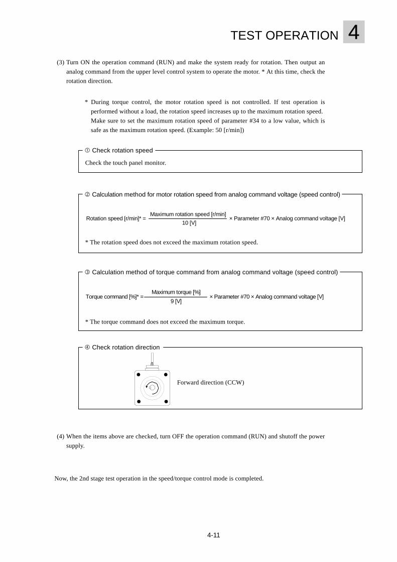
TEST OPERATION 4
4-11
(3) Turn ON the operation command (RUN) and make the system ready for rotation. Then output an analog command from the upper level control system to operate the motor. * At this time, check the rotation direction.
* During torque control, the motor rotation speed is not controlled. If test operation is
performed without a load, the rotation speed increases up to the maximum rotation speed. Make sure to set the maximum rotation speed of parameter #34 to a low value, which is safe as the maximum rotation speed. (Example: 50 [r/min])
Check the touch panel monitor.
* The rotation speed does not exceed the maximum rotation speed.
* The torque command does not exceed the maximum torque.
(4) When the items above are checked, turn OFF the operation command (RUN) and shutoff the power
supply.
Now, the 2nd stage test operation in the speed/torque control mode is completed.
Forward direction (CCW)
Check rotation speed
Calculation method for motor rotation speed from analog command voltage (speed control)
Check rotation direction
Calculation method of torque command from analog command voltage (speed control)
Rotation speed [r/min]* = × Parameter #70 × Analog command voltage [V]Maximum rotation speed [r/min]
10 [V]
Torque command [%]* = × Parameter #70 × Analog command voltage [V]Maximum torque [%]
9 [V]
4 TEST OPERATION
4-12
Troubleshooting (1) Motor does not rotate.
<Check> • Check wiring with the upper level control system. • Check with the keypad of the servo amplifier if the servomotor is ready for rotation. • Check that the upper level control system is correctly giving the analog voltage. • Check with the keypad if the servo amplifier is receiving the analog voltage.
(2) The motor rotates when the analog voltage command is "0V".
<Check> • Adjust the analog command offset (parameter #71). • Use the zero clamp function (parameter #39).
TEST OPERATION 4
4-13
4.2.3 Third stage Mount the servo amplifier to the host controller and mount the servomotor to the machine to perform test operation. The test operation should be conducted in the final operation state.
Check the following items in the second stage. <Check> (1) Installation of servomotor to mechanical system (2) Check I/O signals. (3) Check movement of the machine.
Test operation procedure
(1) Referring to section 2.1 “Servomotor,” mount the servomotor to the machine securely. (Mount securely without play or deflection.)
(2) Check I/O signals checked in 4.2.2 "2nd stage."
In particular, check forced stop (EMG), ±overtravel (±OT) and brake timing which are protective functions. Check that the servo amplifier is recognizing each signal and is performing protective functions.
(3) Check that the command movement matches the actual movement of the machine. (4) According to description in Chapter 6 “Adjustment of servo,” adjust the parameters of the servo
amplifier.
If no fault is found in the third stage, the test operation is complete.
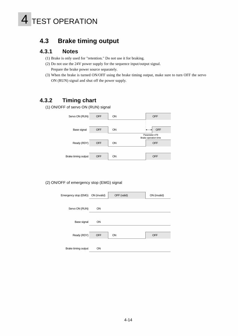
4 TEST OPERATION
4-14
4.3 Brake timing output 4.3.1 Notes
(1) Brake is only used for "retention." Do not use it for braking. (2) Do not use the 24V power supply for the sequence input/output signal.
Prepare the brake power source separately. (3) When the brake is turned ON/OFF using the brake timing output, make sure to turn OFF the servo
ON (RUN) signal and shut off the power supply.
4.3.2 Timing chart (1) ON/OFF of servo ON (RUN) signal
(2) ON/OFF of emergency stop (EMG) signal
Servo ON (RUN) OFF ON OFF
Base signal OFF ON OFF
Ready (RDY) OFF ON OFF
Brake timing output OFF ON OFF
Parameter #79Brake operation time
Emergency stop (EMG) ON (invalid) OFF (valid)
Base signal ON
Ready (RDY) OFF ON OFF
Brake timing output ON
ON (invalid)
Servo ON (RUN) ON

TEST OPERATION 4
4-15
(3) Alarm occurrence
4.4 Return to origin When a FALDIC-W series system returns to the origin, input the return-to-origin pattern from the upper level control system. When the Z phase of the servomotor is detected to return to the origin immediately after the power supply, turn the motor 372° or more at a speed of 100 [r/min]. If this condition is not satisfied, the Z phase cannot be correctly detected.
<Notes for return to origin by detecting Z phase immediately after power supply>
• Rotation speed: 100 r/min or less
• Rotation angle: 372° or more (equivalent to approximately 1.04 rotations) at motor output
shaft.
Alarm detection (a contact) OFF ON
Base signal OFF
Ready (RDY)
Brake timing output ON OFF
Alarm Not detected Detected
ON
ON OFF
Motor shaft Turn the motor shaft by 372°.
The speed is 100 r/min or less.

4 TEST OPERATION
4-16
-MEMO-

PARAMETERS
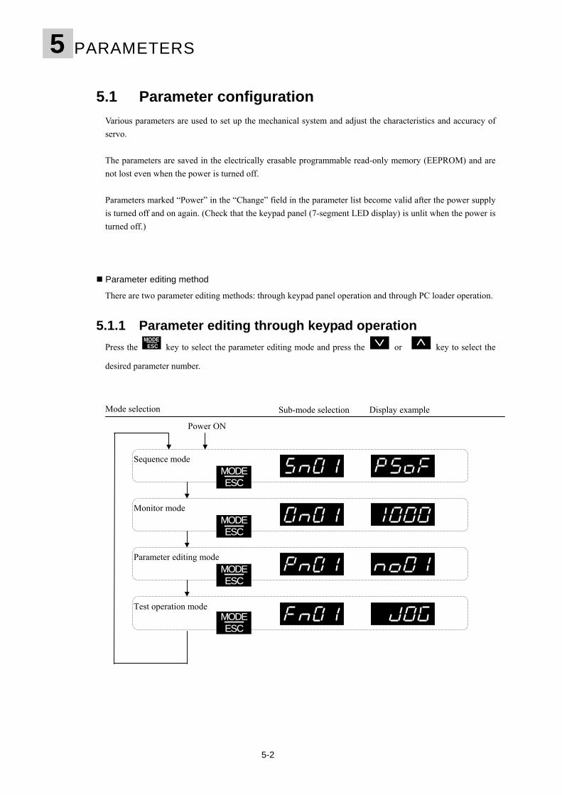
5 PARAMETERS
5-2
Sequence mode
Monitor mode
Parameter editing mode
Test operation mode
5.1 Parameter configuration Various parameters are used to set up the mechanical system and adjust the characteristics and accuracy of servo. The parameters are saved in the electrically erasable programmable read-only memory (EEPROM) and are not lost even when the power is turned off. Parameters marked “Power” in the “Change” field in the parameter list become valid after the power supply is turned off and on again. (Check that the keypad panel (7-segment LED display) is unlit when the power is turned off.) Parameter editing method
There are two parameter editing methods: through keypad panel operation and through PC loader operation.
5.1.1 Parameter editing through keypad operation Press the MODE
ESC key to select the parameter editing mode and press the or key to select the
desired parameter number.
Mode selection
Power ON
Sub-mode selection Display example
MODEESC
MODEESC
MODEESC
MODEESC

5PARAMETERS
5-3
5.1.2 Parameter editing through PC loader Use the PC loader to edit parameters.
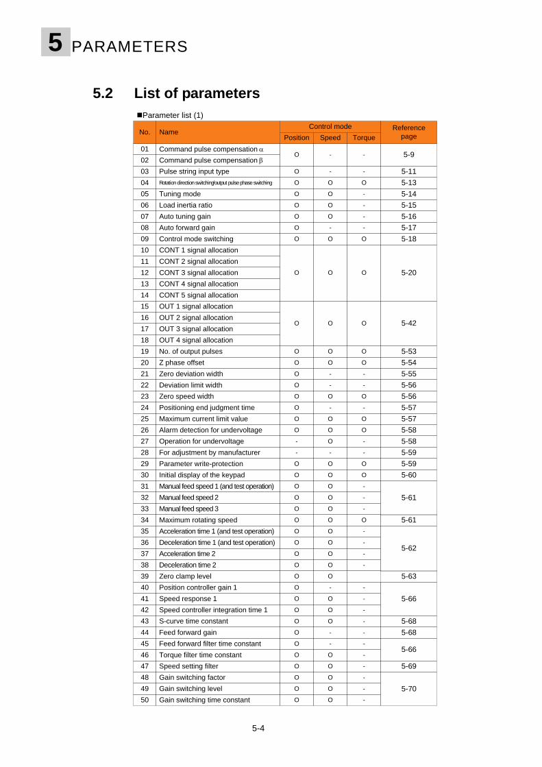
5 PARAMETERS
5-4
5.2 List of parameters
1920212223242526
282930
04 Rotation direction switching/output pulse phase switching
050607
09
No. Name Control mode
Position
Parameter list (1)
01 Command pulse compensation α02 Command pulse compensation β03 Pulse string input type
08
27
101112131415161718
No. of output pulsesZ phase offsetZero deviation width Deviation limit width Zero speed widthPositioning end judgment time Maximum current limit value Alarm detection for undervoltage
For adjustment by manufacturerParameter write-protection Initial display of the keypad
Tuning modeLoad inertia ratioAuto tuning gain
Control mode switching Auto forward gain
Operation for undervoltage
CONT 1 signal allocation CONT 2 signal allocation CONT 3 signal allocation CONT 4 signal allocation CONT 5 signal allocation OUT 1 signal allocation OUT 2 signal allocation OUT 3 signal allocation OUT 4 signal allocation
Speed TorqueReference
page
O
35 Acceleration time 1 (and test operation) 36 Deceleration time 1 (and test operation)37 Acceleration time 238 Deceleration time 239 Zero clamp level
31 Manual feed speed 1 (and test operation) 32 Manual feed speed 2 33 Manual feed speed 3 34 Maximum rotating speed
40 Position controller gain 141 Speed response 142 Speed controller integration time 143 S-curve time constant44 Feed forward gain
46 Torque filter time constant47 Speed setting filter48 Gain switching factor49 Gain switching level 50 Gain switching time constant
45 Feed forward filter time constant
- - 5-9
O
O
O
O
O
O
O - -
O O
O
O
O
-
-
-
- -
O O
5-115-135-145-155-165-175-18
O
O
O O
O O
5-20
5-42
O O O 5-53O O O 5-54O - - 5-55O - - 5-56O O O 5-56O 5-57O O O 5-57O O O 5-58
O 5-585-59
O O O 5-59O O O 5-60O O
5-61O O
O O
O O O 5-61O O
5-62O O
O O
O O
O O 5-63O
5-66O O
O O
O O 5-68O 5-68O
O O5-66
O O 5-69O O
5-70O O
O O
- -
- - -
--
-
-
-
-
-
-
-
- -
-
-
-
-
-
-
-
-
-
-
-
-
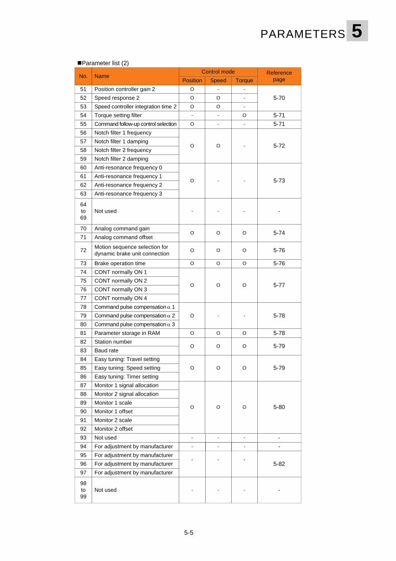
5PARAMETERS
5-5
No. NameControl mode
Position
Parameter list (2)
Speed TorqueReference
page
O -
56575859
5152535455
60616263
74757677787980
64to69
7071
72
73
Notch filter 1 frequencyNotch filter 1 dampingNotch filter 2 frequencyNotch filter 2 damping
Position controller gain 2Speed response 2Speed controller integration time 2 Torque setting filterCommand follow-up control selection
Anti-resonance frequency 0Anti-resonance frequency 1Anti-resonance frequency 2Anti-resonance frequency 3
CONT normally ON 1CONT normally ON 2CONT normally ON 3CONT normally ON 4Command pulse compensation α 1
Not used
Analog command gain Analog command offset
Motion sequence selection for dynamic brake unit connection
Brake operation time
Command pulse compensation α 2Command pulse compensation α 3
89 Monitor 1 scale90 Monitor 1 offset
93 Not used
9192
87 Monitor 1 signal allocation
81 Parameter storage in RAM82 Station number83 Baud rate848586
Easy tuning: Travel setting
88 Monitor 2 signal allocation
Monitor 2 scaleMonitor 2 offset
Easy tuning: Speed settingEasy tuning: Timer setting
-
O O -
-
O
-
-
-
-
O O
--
O -
O O
O -
--
O O O
O O O
O O O
O O O
O
O O O
--
O O O
O O O
O O O
--- -
5-70
5-715-71
5-72
5-73
-
5-74
5-76
5-76
5-77
5-78
5-78
5-79
5-79
5-80
95 For adjustment by manufacturer96 For adjustment by manufacturer97 For adjustment by manufacturer
98to99
Not used
---5-82
--- -
94 For adjustment by manufacturer - - - -
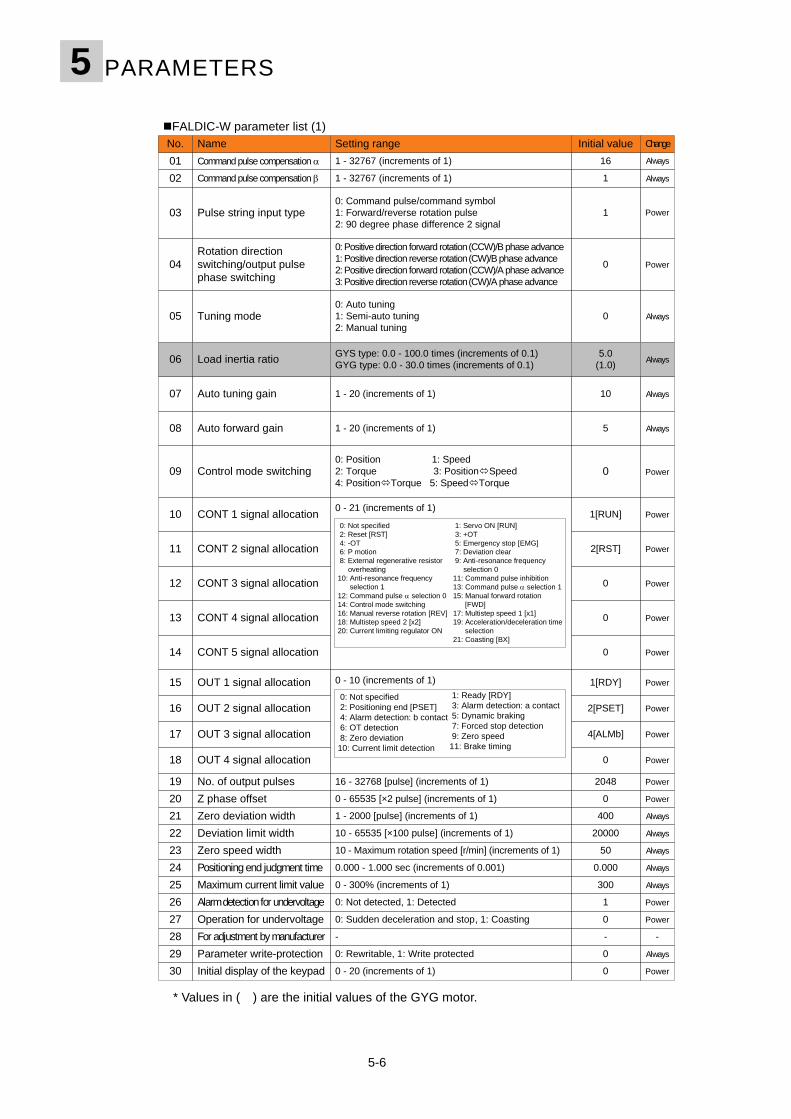
5 PARAMETERS
5-6
0 - 21 (increments of 1) 1[RUN] Power
2[RST] Power
0 Power
0 Power
0 Power
19 No. of output pulses 16 - 32768 [pulse] (increments of 1) 2048 Power
20 Z phase offset 0 - 65535 [×2 pulse] (increments of 1) 0 Power
21 Zero deviation width 1 - 2000 [pulse] (increments of 1) 400 Always
22 Deviation limit width 10 - 65535 [×100 pulse] (increments of 1) 20000 Always
23 Zero speed width 10 - Maximum rotation speed [r/min] (increments of 1) 50 Always
24 Positioning end judgment time 0.000 - 1.000 sec (increments of 0.001) 0.000 Always
25 Maximum current limit value 0 - 300% (increments of 1) 300 Always
26 Alarm detection for undervoltage 0: Not detected, 1: Detected 1 Power
28 For adjustment by manufacturer - - -
29 Parameter write-protection 0: Rewritable, 1: Write protected 0 Always
30 Initial display of the keypad 0 - 20 (increments of 1) 0 Power
1: Servo ON [RUN] 3: +OT 5: Emergency stop [EMG] 7: Deviation clear 9: Anti-resonance frequency
selection 011: Command pulse inhibition 13: Command pulse α selection 115: Manual forward rotation
[FWD]17: Multistep speed 1 [x1]19: Acceleration/deceleration time
selection 21: Coasting [BX]
0: Not specified 2: Positioning end [PSET] 4: Alarm detection: b contact 6: OT detection 8: Zero deviation 10: Current limit detection
1: Ready [RDY] 3: Alarm detection: a contact 5: Dynamic braking 7: Forced stop detection 9: Zero speed 11: Brake timing
04Rotation direction switching/output pulse phase switching
0: Positive direction forward rotation (CCW)/B phase advance1: Positive direction reverse rotation (CW)/B phase advance2: Positive direction forward rotation (CCW)/A phase advance3: Positive direction reverse rotation (CW)/A phase advance
0 Power
05 Tuning mode0: Auto tuning 1: Semi-auto tuning 2: Manual tuning
0 Always
06 Load inertia ratio GYS type: 0.0 - 100.0 times (increments of 0.1)GYG type: 0.0 - 30.0 times (increments of 0.1)
5.0(1.0) Always
07 Auto tuning gain 1 - 20 (increments of 1) 10 Always
09 Control mode switching 0: Position 1: Speed 2: Torque 3: Position Speed4: Position Torque 5: Speed Torque
0 Power
No. Name Setting range Initial value Change
FALDIC-W parameter list (1)
01 Command pulse compensation α 1 - 32767 (increments of 1) 16 Always
02 Command pulse compensation β 1 - 32767 (increments of 1) 1 Always
03 Pulse string input type0: Command pulse/command symbol 1: Forward/reverse rotation pulse2: 90 degree phase difference 2 signal
1 Power
08 Auto forward gain 1 - 20 (increments of 1) 5 Always
27 Operation for undervoltage 0: Sudden deceleration and stop, 1: Coasting 0 Power
0: Not specified 2: Reset [RST] 4: -OT 6: P motion 8: External regenerative resistor
overheating10: Anti-resonance frequency
selection 112: Command pulse α selection 014: Control mode switching 16: Manual reverse rotation [REV]18: Multistep speed 2 [x2]20: Current limiting regulator ON
10 CONT 1 signal allocation
11 CONT 2 signal allocation
12 CONT 3 signal allocation
13 CONT 4 signal allocation
14 CONT 5 signal allocation
0 - 10 (increments of 1)
0
15 OUT 1 signal allocation
16 OUT 2 signal allocation
17 OUT 3 signal allocation
18 OUT 4 signal allocation
1[RDY]
2[PSET]
4[ALMb]
Power
Power
Power
Power
* Values in ( ) are the initial values of the GYG motor.
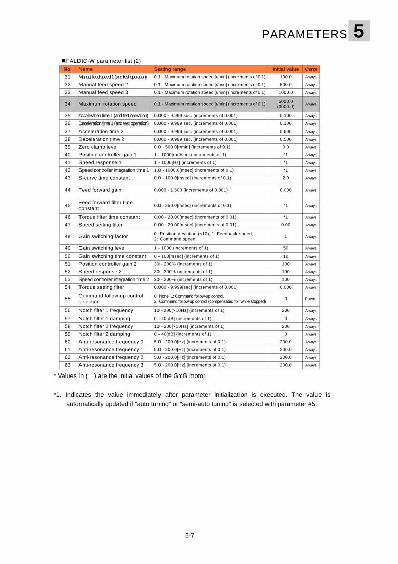
5PARAMETERS
5-7
*1
No. Name Setting range Initial value Change
40 Position controller gain 1 1 - 1000[rad/sec] (increments of 1) Always
41 Speed response 1 1 - 1000[Hz] (increments of 1) *1 Always
42 Speed controller integration time 1 1.0 - 1000.0[msec] (increments of 0.1) *1 Always
43 S-curve time constant 0.0 - 100.0[msec] (increments of 0.1) 2.0 Always
44 Feed forward gain 0.000 - 1.500 (increments of 0.001) 0.000 Always
46 Torque filter time constant 0.00 - 20.00[msec] (increments of 0.01) *1 Always
56 Notch filter 1 frequency 10 - 200[×10Hz] (increments of 1) 200 Always
57 Notch filter 1 damping 0 - 40[dB] (increments of 1) 0 Always
FALDIC-W parameter list (2)
47 Speed setting filter 0.00 - 20.00[msec] (increments of 0.01) 0.00 Always
48 Gain switching factor 0: Position deviation (×10), 1: Feedback speed, 2: Command speed 1 Always
49 Gain switching level 1 - 1000 (increments of 1) 50 Always
50 Gain switching time constant 0 - 100[msec] (increments of 1) 10 Always
45 Feed forward filter time constant 0.0 - 250.0[msec] (increments of 0.1) *1 Always
58 Notch filter 2 frequency 10 - 200[×10Hz] (increments of 1) 200 Always
59 Notch filter 2 damping 0 - 40[dB] (increments of 1) 0 Always
51 Position controller gain 2 30 - 200% (increments of 1) 100 Always
52 Speed response 2 30 - 200% (increments of 1) 100 Always
53 Speed controller integration time 2 30 - 200% (increments of 1) 100 Always
54 Torque setting filter 0.000 Always
55 Command follow-up control selection
0: None, 1: Command follow-up control, 2: Command follow-up control (compensated for while stopped) 0 Powre
60 Anti-resonance frequency 0 5.0 - 200.0[Hz] (increments of 0.1) 200.0 Always
61 Anti-resonance frequency 1 5.0 - 200.0[Hz] (increments of 0.1) 200.0 Always
62 Anti-resonance frequency 2 5.0 - 200.0[Hz] (increments of 0.1) 200.0 Always
63 Anti-resonance frequency 3 5.0 - 200.0[Hz] (increments of 0.1) 200.0 Always
0.000 - 9.999[sec] (increments of 0.001)
35 Acceleration time 1 (and test operation) 0.000 - 9.999 sec. (increments of 0.001) 0.100 Always
36 Deceleration time 1 (and test operation) 0.000 - 9.999 sec. (increments of 0.001) 0.100 Always
37 Acceleration time 2 0.000 - 9.999 sec. (increments of 0.001) 0.500 Always
38 Deceleration time 2 0.000 - 9.999 sec. (increments of 0.001) 0.500 Always
39 Zero clamp level 0.0 Always0.0 - 500.0[r/min] (increments of 0.1)
31 Manual feed speed 1 (and test operation) 0.1 - Maximum rotation speed [r/min] (increments of 0.1) 100.0 Always
32 Manual feed speed 2 500.0 Always
33 Manual feed speed 3 1000.0 Always
34 Maximum rotation speed 5000.0(3000.0) Always
0.1 - Maximum rotation speed [r/min] (increments of 0.1)
0.1 - Maximum rotation speed [r/min] (increments of 0.1)
0.1 - Maximum rotation speed [r/min] (increments of 0.1)
* Values in ( ) are the initial values of the GYG motor. *1. Indicates the value immediately after parameter initialization is executed. The value is
automatically updated if “auto tuning” or “semi-auto tuning” is selected with parameter #5.
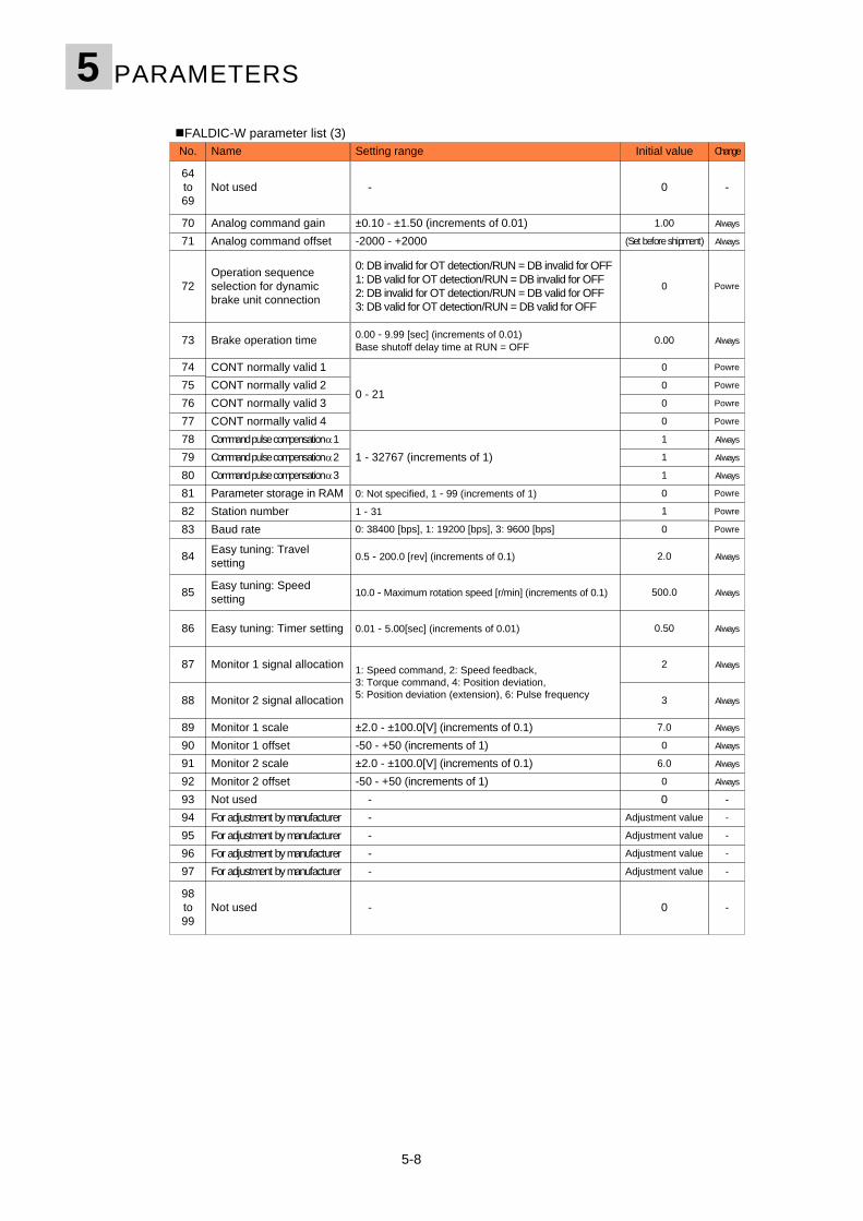
5 PARAMETERS
5-8
No. Name Setting range Initial value Change
89 Monitor 1 scale 7.0 Always
90 Monitor 1 offset 0 Always
93 Not used - 0 -
FALDIC-W parameter list (3)
91 6.0 Always
92 0 Always
87 Monitor 1 signal allocation 21: Speed command, 2: Speed feedback, 3: Torque command, 4: Position deviation, 5: Position deviation (extension), 6: Pulse frequency 3
95 For adjustment by manufacturer - Adjustment value -
96 For adjustment by manufacturer - Adjustment value -
97 For adjustment by manufacturer - Adjustment value -
74 CONT normally valid 175 CONT normally valid 276 CONT normally valid 377 CONT normally valid 4
0 - 21
0
0
0
0
Powre
Powre
Powre
Powre
78 Command pulse compensation α 1
7980
1 - 32767 (increments of 1)1
1
1
81 Parameter storage in RAM 0: Not specified, 1 - 99 (increments of 1) 0 Powre
82 Station number 1 - 31 1 Powre
83 Baud rate 0: 38400 [bps], 1: 19200 [bps], 3: 9600 [bps] 0 Powre
84 0.5 - 200.0 [rev] (increments of 0.1) 2.0 Always
85 Easy tuning: Speed setting 10.0 - Maximum rotation speed [r/min] (increments of 0.1) 500.0 Always
Easy tuning: Timer setting86
Easy tuning: Travel setting
0.01 - 5.00[sec] (increments of 0.01) 0.50 Always
88 Monitor 2 signal allocation
Monitor 2 scaleMonitor 2 offset
±2.0 - ±100.0[V] (increments of 0.1)-50 - +50 (increments of 1)±2.0 - ±100.0[V] (increments of 0.1)-50 - +50 (increments of 1)
64to69
Not used - 0 -
70 Analog command gain ±0.10 - ±1.50 (increments of 0.01) 1.00 Always
71 Analog command offset -2000 - +2000 (Set before shipment)
Always
72Operation sequence selection for dynamic brake unit connection
0: DB invalid for OT detection/RUN = DB invalid for OFF 1: DB valid for OT detection/RUN = DB invalid for OFF 2: DB invalid for OT detection/RUN = DB valid for OFF 3: DB valid for OT detection/RUN = DB valid for OFF
0 Powre
73 Brake operation time 0.00 Always0.00 - 9.99 [sec] (increments of 0.01)Base shutoff delay time at RUN = OFF
98to99
Not used - 0 -
Command pulse compensation α 2
Command pulse compensation α 3
Always
Always
Always
Always
Always
94 For adjustment by manufacturer - Adjustment value -
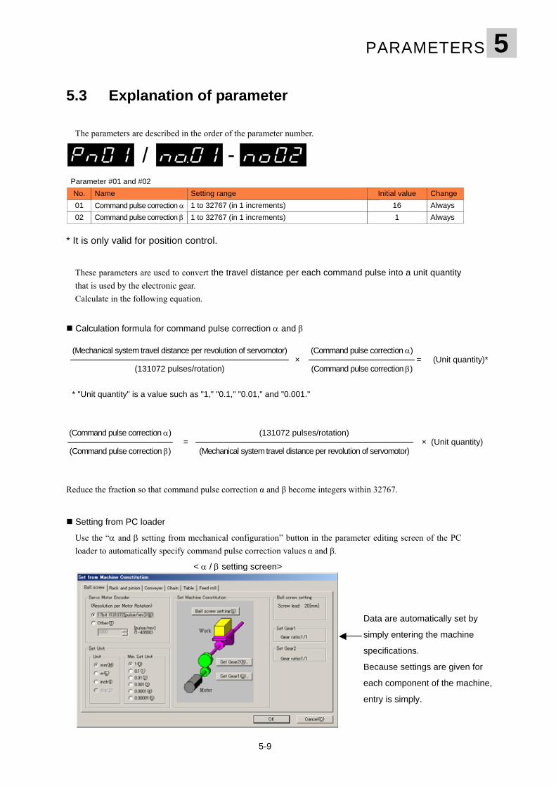
5PARAMETERS
5-9
< α / β setting screen>
5.3 Explanation of parameter
The parameters are described in the order of the parameter number.
/ -
Parameter #01 and #02No. Name Setting range Initial value Change01 Command pulse correction α 1 to 32767 (in 1 increments) 16 Always02 Command pulse correction β 1 to 32767 (in 1 increments) 1 Always
* It is only valid for position control.
These parameters are used to convert the travel distance per each command pulse into a unit quantity that is used by the electronic gear. Calculate in the following equation.
Calculation formula for command pulse correction α and β
(131072 pulses/rotation)= (Unit quantity)*
(Command pulse correction β)
(Command pulse correction α)×
(Mechanical system travel distance per revolution of servomotor)
* "Unit quantity" is a value such as "1," "0.1," "0.01," and "0.001."
(131072 pulses/rotation)× (Unit quantity)
(Command pulse correction β)
(Command pulse correction α)
(Mechanical system travel distance per revolution of servomotor)=
Reduce the fraction so that command pulse correction α and β become integers within 32767.
Setting from PC loader
Use the “α and β setting from mechanical configuration” button in the parameter editing screen of the PC loader to automatically specify command pulse correction values α and β.
Data are automatically set by
simply entering the machine
specifications.
Because settings are given for
each component of the machine,
entry is simply.
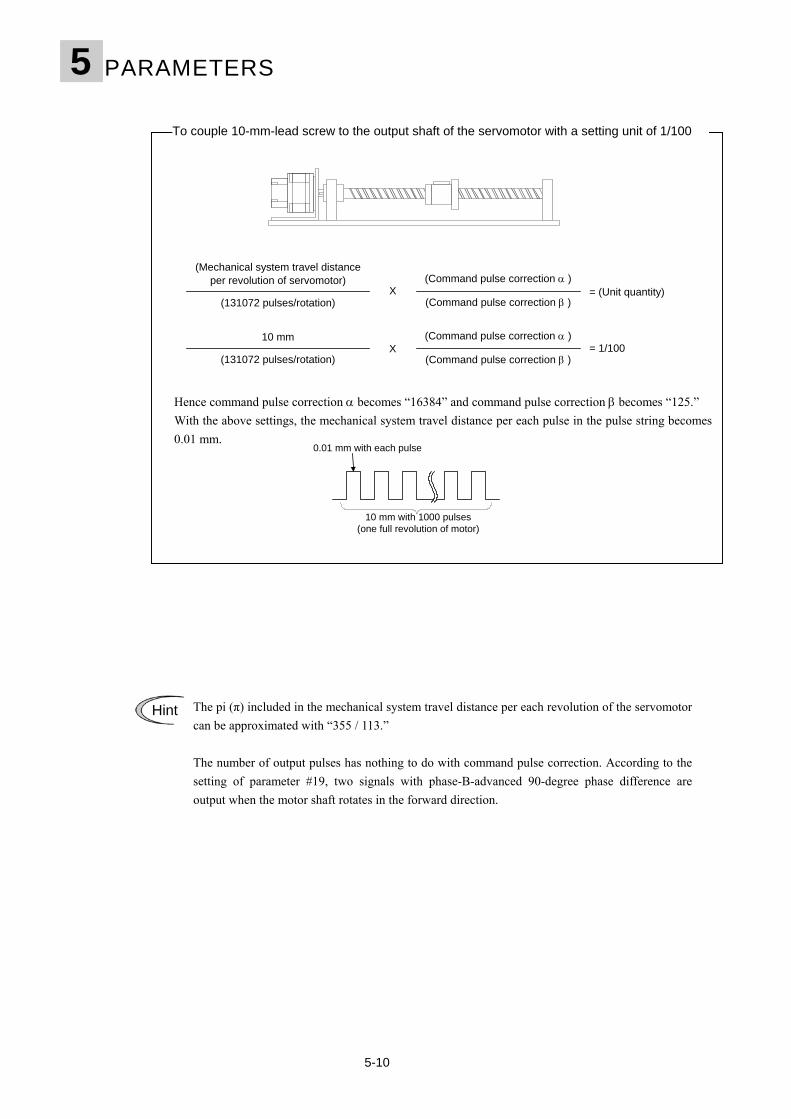
5 PARAMETERS
5-10
Hint
Hence command pulse correction α becomes “16384” and command pulse correction β becomes “125.” With the above settings, the mechanical system travel distance per each pulse in the pulse string becomes 0.01 mm.
(131072 pulses/rotation) = (Unit quantity) X
(Mechanical system travel distance per revolution of servomotor)
(131072 pulses/rotation)= 1/100 X
10 mm
0.01 mm with each pulse
10 mm with 1000 pulses(one full revolution of motor)
To couple 10-mm-lead screw to the output shaft of the servomotor with a setting unit of 1/100
(Command pulse correction β )
(Command pulse correction α )
(Command pulse correction β )
(Command pulse correction α )
The pi (π) included in the mechanical system travel distance per each revolution of the servomotorcan be approximated with “355 / 113.” The number of output pulses has nothing to do with command pulse correction. According to thesetting of parameter #19, two signals with phase-B-advanced 90-degree phase difference are output when the motor shaft rotates in the forward direction.
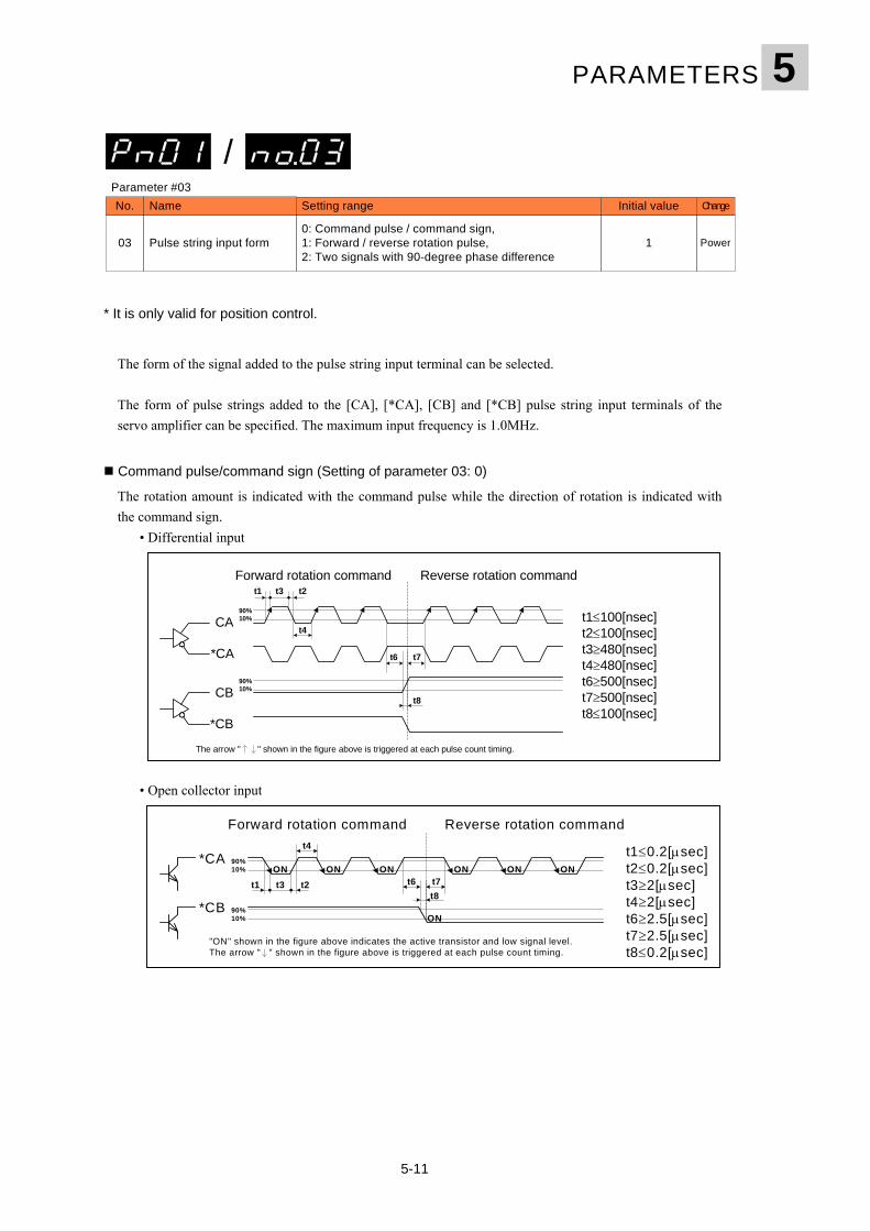
5PARAMETERS
5-11
/ Parameter #03
No. Name Setting range Initial value Change
03 Pulse string input form0: Command pulse / command sign,1: Forward / reverse rotation pulse,2: Two signals with 90-degree phase difference
1 Power
* It is only valid for position control.
The form of the signal added to the pulse string input terminal can be selected. The form of pulse strings added to the [CA], [*CA], [CB] and [*CB] pulse string input terminals of the servo amplifier can be specified. The maximum input frequency is 1.0MHz.
Command pulse/command sign (Setting of parameter 03: 0)
The rotation amount is indicated with the command pulse while the direction of rotation is indicated with the command sign.
• Differential input
• Open collector input
Forward rotation command
CA
*CA
CB
*CB
Reverse rotation command
The arrow " " shown in the figure above is triggered at each pulse count timing.
t1≤100[nsec] t2≤100[nsec]t3≥480[nsec]t4≥480[nsec]t6≥500[nsec]t7≥500[nsec]t8≤100[nsec]
90%10%
t3t1 t2
90%10%
t6 t7
t8
t4
Forward rotation command
*CA
*CB
Reverse rotation command
"ON" shown in the figure above indicates the active transistor and low signal level.The arrow " " shown in the figure above is triggered at each pulse count timing.
90%10%
t1 t3 t2
t4 t1≤0.2[µsec]t2≤0.2[µsec]t3≥2[µsec]t4≥2[µsec]t6≥2.5[µsec]t7≥2.5[µsec]t8≤0.2[µsec]
90%10%
t6t8t7
ON ON ONON ON ON
ON
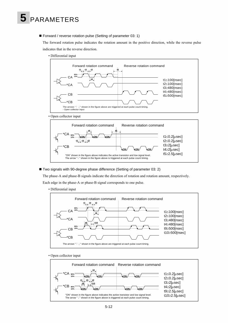
5 PARAMETERS
5-12
Forward / reverse rotation pulse (Setting of parameter 03: 1)
The forward rotation pulse indicates the rotation amount in the positive direction, while the reverse pulse
indicates that in the reverse direction.
• Differential input
• Open collector input
Two signals with 90-degree phase difference (Setting of parameter 03: 2)
The phase-A and phase-B signals indicate the direction of rotation and rotation amount, respectively.
Each edge in the phase-A or phase-B signal corresponds to one pulse.
• Differential input
• Open collector input
Forward rotation command
CA
*CA
CB
*CB
Reverse rotation command
The arrows " " shown in the figure above are triggered at each pulse count timing.- Open collector input
t1≤100[nsec]t2≤100[nsec] t3≥480[nsec]t4≥480[nsec]t5≥500[nsec]
90%10%
t3t1 t2 t5
t4
Forward rotation command
*CA
*CB
Reverse rotation command
"ON" shown in the figure above indicates the active transistor and low signal level.The arrow " " shown in the figure above is triggered at each pulse count timing.
90%10%
t1 t3 t2
t4 t5
t1≤0.2[µsec]t2≤0.2[µsec] t3≥2[µsec]t4≥2[µsec]t5≥2.5[µsec]
ON ON ON
ON ON ON
Forward rotation command
CA
*CA
CB
*CB
Reverse rotation command
The arrows " " shown in the figure above are triggered at each pulse count timing.
t1≤100[nsec]t2≤100[nsec] t3≥480[nsec]t4≥480[nsec]t9≥500[nsec]t10≥500[nsec]
90%10%
t1 t2
90%10%
t9 t10
t3
t4
Forward rotation command
*CA
*CB
Reverse rotation command
"ON" shown in the figure above indicates the active transistor and low signal level.The arrow " " shown in the figure above is triggered at each pulse count timing.
t1 t3 t2
t4t1≤0.2[µsec]t2≤0.2[µsec] t3≥2[µsec]t4≥2[µsec]t9≥2.5[µsec]t10≥2.5[µsec]
90%10%
t10t990%10%
ON ON ON ON
ON ONON ON

5PARAMETERS
5-13
/
Parameter #04
No. Name Setting range Initial value Change
04 0 Power
Rotation direction switching/output pulse switching for rotation in CCW direction
0: Positive direction forward rotation (CCW)/B phase advance1: Positive direction reverse rotation (CW)/B phase advance2: Positive direction forward rotation (CCW)/A phase advance3: Positive direction reverse rotation (CW)/A phase advance
Set the servomotor rotation direction and the output pulse phase to the direction the machine is moving. The rotation direction when the forward rotation pulse and the command signal are the H level or the 90 degree phase difference 2 signal with input of B phase advance pulse string is the positive direction. To switch the output pulse phase, select the phase when the servomotor is rotating counterclockwise (CCW).
A phase
B phase
B phase
A phase
- When the reference value is 0 or 1
- When the reference value is 2 or 3
Forward/reverse rotation
Counterclockwise rotation (CCW) when the servomotor output shaft is viewed from the front is forward rotation. Clockwise rotation (CW) is reverse rotation.
Forward rotation

5 PARAMETERS
5-14
/ Parameter #05
No. Name Setting range Initial value Change
05 Tuning mode0: Auto tuning,1: Semi-auto tuning,2: Manual tuning
0 Always
* It is valid for position control and speed control.
Select the tuning method of the servo amplifier. Auto tuning (Setting of basic setting parameter 05: 0)
This is the factory setting of the servo amplifier. The inertia ratio of the machine is always assumed inside the amplifier in this mode to automatically set the optimum gain. Set 0 for easy tuning.
Semi-auto tuning (Setting of parameter 05: 1)
Use this mode when the inertia ratio of the machine cannot be assumed correctly inside the amplifier.
Manual tuning (Setting of parameter 05: 2)
Use this option when adjustment fails in the auto tuning and semi-auto tuning modes.
Parameters that must be set or those automatically adjusted in each tuning mode are as follows.
No. NameTuning mode
06 Load inertia ratio
07 Auto tuning gain
0: Auto 1: Semi-auto 2: Manual
- O O
O O ×
40 Position controller gain 1 - - O
41 Speed response 1 - - O
42 Speed controller integration time 1 - - O
45 Feed forward filter time constant - - O
46 Torque filter time constant - - O
* O : Parameter that must be set - : Parameter that may not be set (The value is automatically calculated inside the amplifier and the
result is reflected on the parameter.) × : The parameter has no effect even if it is set.
Refer to Chapter 6 for detailed description of tuning.
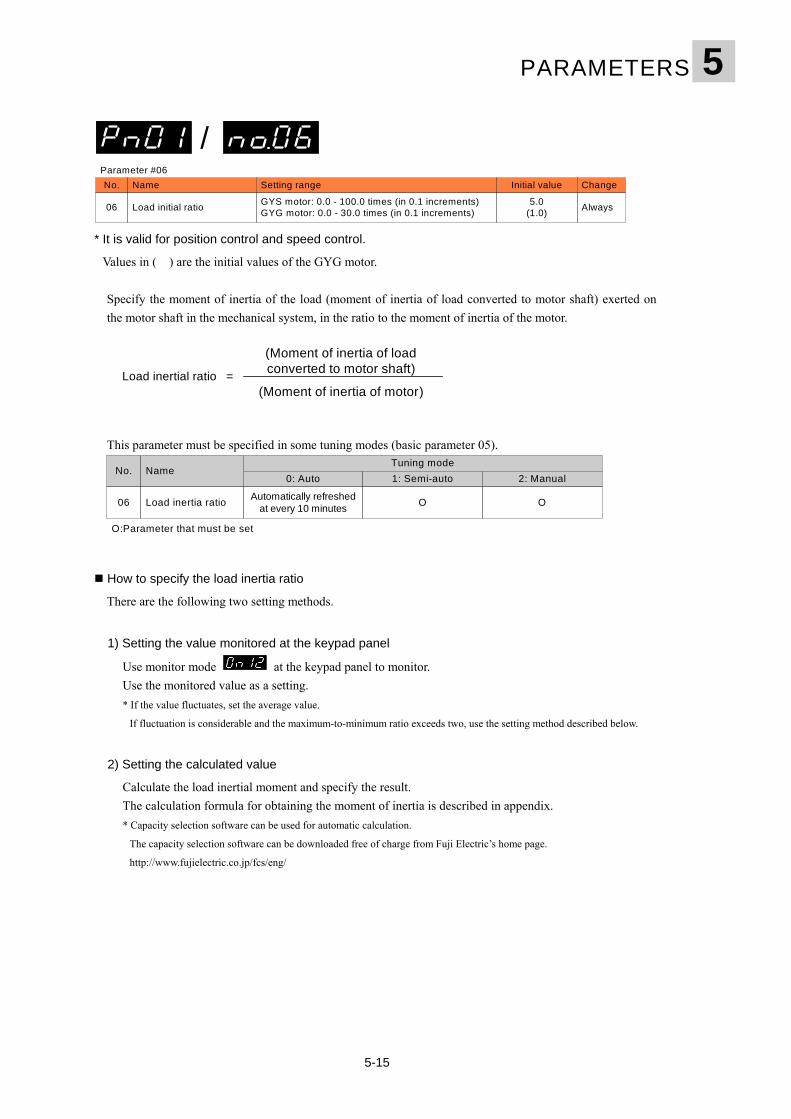
5PARAMETERS
5-15
/ Parameter #06
No. Name Setting range Initial value Change
06 Load initial ratioGYS motor: 0.0 - 100.0 times (in 0.1 increments)GYG motor: 0.0 - 30.0 times (in 0.1 increments)
5.0(1.0)
Always
* It is valid for position control and speed control.
Values in ( ) are the initial values of the GYG motor. Specify the moment of inertia of the load (moment of inertia of load converted to motor shaft) exerted on the motor shaft in the mechanical system, in the ratio to the moment of inertia of the motor.
Load inertial ratio =
(Moment of inertia of load converted to motor shaft)
(Moment of inertia of motor)
This parameter must be specified in some tuning modes (basic parameter 05).
No. NameTuning mode
06 Load inertia ratio
0: Auto 1: Semi-auto 2: Manual
Automatically refreshed at every 10 minutes
O O
O:Parameter that must be set
How to specify the load inertia ratio
There are the following two setting methods.
1) Setting the value monitored at the keypad panel
Use monitor mode at the keypad panel to monitor. Use the monitored value as a setting. * If the value fluctuates, set the average value.
If fluctuation is considerable and the maximum-to-minimum ratio exceeds two, use the setting method described below.
2) Setting the calculated value
Calculate the load inertial moment and specify the result. The calculation formula for obtaining the moment of inertia is described in appendix. * Capacity selection software can be used for automatic calculation.
The capacity selection software can be downloaded free of charge from Fuji Electric’s home page.
http://www.fujielectric.co.jp/fcs/eng/

5 PARAMETERS
5-16
/
Parameter #07
No. Name Setting range Initial value Change
07 Auto tuning gain 1 to 20 (in 1 increments) 10 Always
* It is valid for position control and speed control. Specify the response of the servomotor used in the auto tuning or semi-auto tuning mode. Specify a larger value to reduce the command follow-up time and positioning setting time, but too large a value cause the motor to vibrate. * There is no need to set the parameter in the manual tuning mode.
Setting method
There are two setting methods 1) Setting parameter using PC loader and keypad panel (parameter setting mode)
After the parameter is established, the setting content is updated. 2) Setting through auto tuning gain setting from keypad panel (in test operation mode)
The setting is updated at real time when the value is changed.
Press the or key to update the setting at real time.
SHIFTENTSHIFT
ENT
Approximate measure for setting
* If the gain cannot be increased up to the value specified as an approximate measure, there may be mechanical resonance. Use a notch filter to suppress mechanical resonance. → Refer to page 5-72.
Configuration of machine Auto tuning gain (approximate)
Large transfer machine 1 to 6
Belt drive
5 to 10
Ball screw mechanism
7 to 13
Inserting, mounting or bonding machine
10 to 15
Arm robot
13 to 20
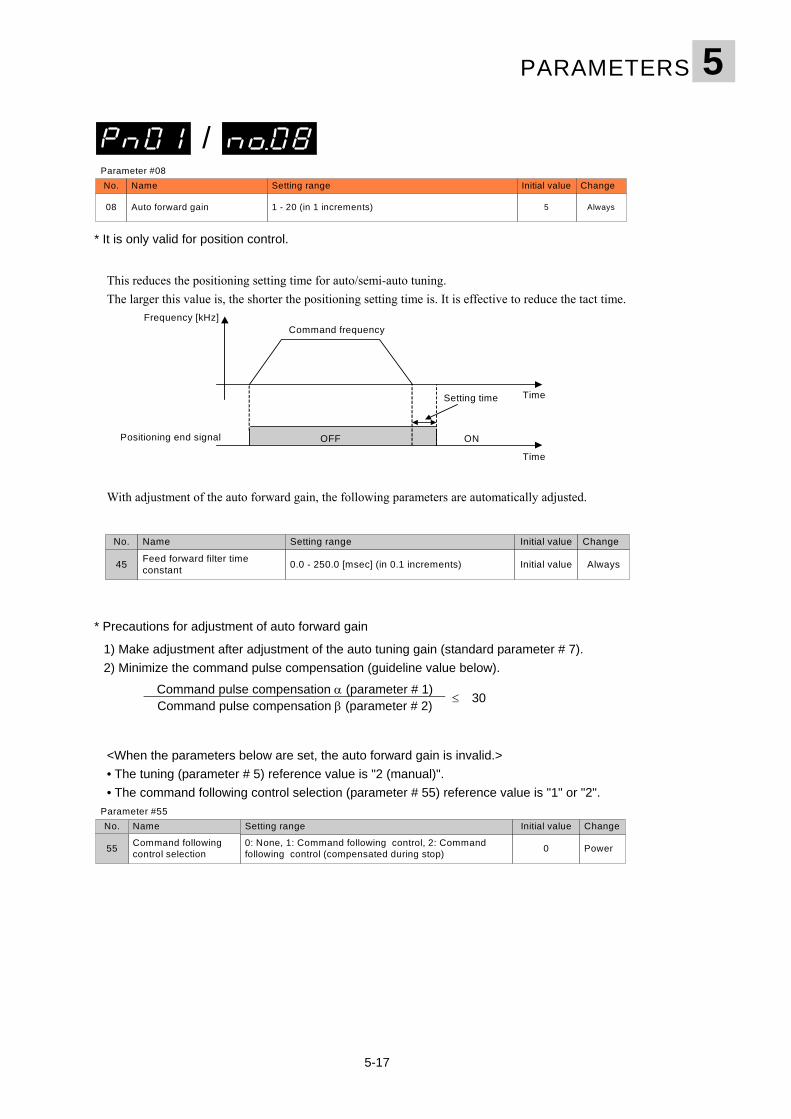
5PARAMETERS
5-17
/ Parameter #08
No. Name Setting range Initial value Change
08 Auto forward gain 1 - 20 (in 1 increments) 5 Always
* It is only valid for position control.
This reduces the positioning setting time for auto/semi-auto tuning. The larger this value is, the shorter the positioning setting time is. It is effective to reduce the tact time.
OFF ON
Frequency [kHz]Command frequency
Positioning end signal
Setting time
Time
Time
With adjustment of the auto forward gain, the following parameters are automatically adjusted.
No. Name
45Feed forward filter time constant
Setting range Initial value Change
0.0 - 250.0 [msec] (in 0.1 increments) Initial value Always
* Precautions for adjustment of auto forward gain
1) Make adjustment after adjustment of the auto tuning gain (standard parameter # 7). 2) Minimize the command pulse compensation (guideline value below).
<When the parameters below are set, the auto forward gain is invalid.> • The tuning (parameter # 5) reference value is "2 (manual)". • The command following control selection (parameter # 55) reference value is "1" or "2".
55Command following control selection
0: None, 1: Command following control, 2: Command following control (compensated during stop)
0 Power
Parameter #55
No. Name Setting range Initial value Change
Command pulse compensation α (parameter # 1) Command pulse compensation β (parameter # 2) ≤ 30
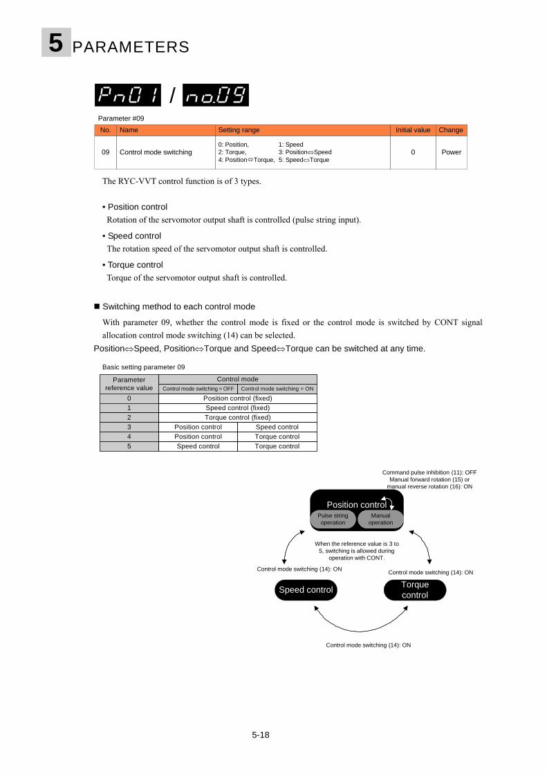
5 PARAMETERS
5-18
/ Parameter #09No. Name Setting range Initial value Change
09 Control mode switching0: Position, 1: Speed2: Torque, 3: Position⇔Speed4: Position Torque, 5: Speed⇔Torque
0 Power
The RYC-VVT control function is of 3 types. • Position control
Rotation of the servomotor output shaft is controlled (pulse string input).
• Speed control The rotation speed of the servomotor output shaft is controlled.
• Torque control Torque of the servomotor output shaft is controlled.
Switching method to each control mode
With parameter 09, whether the control mode is fixed or the control mode is switched by CONT signal allocation control mode switching (14) can be selected.
Position⇔Speed, Position⇔Torque and Speed⇔Torque can be switched at any time.
Speed control
Position control
Torque control
Command pulse inhibition (11): OFFManual forward rotation (15) or
manual reverse rotation (16): ON
Control mode switching (14): ON
When the reference value is 3 to 5, switching is allowed during
operation with CONT.
Pulse string operation
Manual operation
Control mode switching (14): ON
Control mode switching (14): ON
Control mode switching = OFF
Parameter reference value
0
1
2
Position control (fixed)
Basic setting parameter 09
Control modeControl mode switching = ON
3
4
5
Speed control (fixed)
Torque control (fixed)
Position control
Position control
Speed control
Speed control
Torque control
Torque control
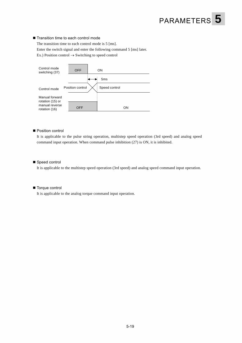
5PARAMETERS
5-19
Transition time to each control mode The transition time to each control mode is 5 [ms]. Enter the switch signal and enter the following command 5 [ms] later. Ex.) Position control → Switching to speed control
Position control Speed controlControl mode
Control mode switching (37)
OFF ON
5ms
Manual forward rotation (15) or manual reverse rotation (16) ONOFF
Position control It is applicable to the pulse string operation, multistep speed operation (3rd speed) and analog speed command input operation. When command pulse inhibition (27) is ON, it is inhibited.
Speed control It is applicable to the multistep speed operation (3rd speed) and analog speed command input operation.
Torque control It is applicable to the analog torque command input operation.
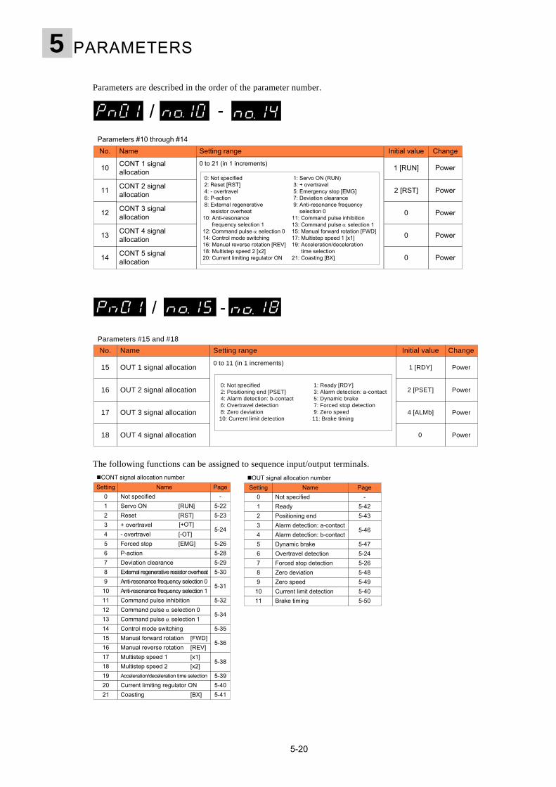
5 PARAMETERS
5-20
Parameters are described in the order of the parameter number.
/ -
Parameters #10 through #14No. Name Setting range Initial value Change
0 to 21 (in 1 increments)
1: Servo ON (RUN) 3: + overtravel 5: Emergency stop [EMG] 7: Deviation clearance 9: Anti-resonance frequency selection 011: Command pulse inhibition13: Command pulse α selection 115: Manual forward rotation [FWD]17: Multistep speed 1 [x1]19: Acceleration/deceleration time selection21: Coasting [BX]
0: Not specified 2: Reset [RST] 4: - overtravel 6: P-action 8: External regenerative resistor overheat10: Anti-resonance frequency selection 112: Command pulse α selection 014: Control mode switching16: Manual reverse rotation [REV]18: Multistep speed 2 [x2]20: Current limiting regulator ON
1 [RUN]
2 [RST]
0
0
0
Power
Power
Power
Power
Power
10 CONT 1 signal allocation
11 CONT 2 signal allocation
12 CONT 3 signal allocation
13 CONT 4 signal allocation
14 CONT 5 signal allocation
-/
Parameters #15 and #18
No. Name Setting range Initial value Change
0: Not specified2: Positioning end [PSET] 4: Alarm detection: b-contact 6: Overtravel detection8: Zero deviation10: Current limit detection
1: Ready [RDY] 3: Alarm detection: a-contact 5: Dynamic brake 7: Forced stop detection9: Zero speed
11: Brake timing
0 to 11 (in 1 increments)15 OUT 1 signal allocation
16 OUT 2 signal allocation
17 OUT 3 signal allocation
18 OUT 4 signal allocation
Power
Power
Power
Power0
1 [RDY]
2 [PSET]
4 [ALMb]
The following functions can be assigned to sequence input/output terminals. CONT signal allocation number
Setting Name
1 Servo ONReset+ overtravel- overtravelForced stop
2345678910
0 Not specified[RUN][RST][+OT][-OT][EMG]
P-actionDeviation clearanceExternal regenerative resistor overheatAnti-resonance frequency selection 0Anti-resonance frequency selection 1
Page-
5-225-23
5-24
5-265-285-295-30
5-31
11 Command pulse inhibition 5-3212 Command pulse α selection 0
5-3413 Command pulse α selection 114 Control mode switching 5-3515 Manual forward rotation
5-3616 Manual reverse rotation17 Multistep speed 1
5-3818 Multistep speed 219 Acceleration/deceleration time selection 5-3920 Current limiting regulator ON 5-4021 Coasting 5-41
[FWD][REV][x1][x2]
[BX]
OUT signal allocation numberSetting Name
1
Alarm detection: a-contact
Dynamic brakeOvertravel detectionForced stop detection
2345
0 Not specifiedPage
-5-42
5-46
5-47Alarm detection: b-contact
6 5-24
Ready
7 5-26Zero deviation8 5-48Zero speed9 5-49Current limit detection10 5-40Brake timing11 5-50
Positioning end 5-43

5PARAMETERS
5-21
Each sequence input/output signal can be monitored in the trace screen of the PC loader.
7 CA8 *CA
CN1
19 PPI
21 *CB20 CB
FZ 25M5 26
FFA 9
FFB 11*FFB 12FFZ 23
*FFZ 24
*FFA 10
1 P24
2 CONT1
5 CONT4
3 CONT2
6 CONT5
14 M24
4 CONT3
OUT1 15OUT2 16OUT3 17OUT4 18
Servo amplifier
M5 13
Terminal allocation of connector 1 (CN1) of servo amplifier and trace screen of PC loader
5 PARAMETERS
5-22
(1) Servo on [RUN]
This signal makes the servomotor ready to rotate.
Sequence input signal Operation command [RUN]... Assigned to CONT 1 with factory setting
Function The servomotor is ready to rotate while the servo on [RUN] signal remains active. The servomotor does not rotate if motor power is supplied but the servo on signal is turned off. If the signal is turned off during rotation, the servomotor decelerates at its maximum performance and, after the stopping point (with rotation speed being within the zero speed width specified at parameter #21), the servomotor coasts to stop. There is no retaining torque after the servomotor is stopped. When the servo on [RUN] remains inactive, all rotation commands are ignored. The servomotor is ready to rotate when the servo on [RUN] is active without alarm detection with active + overtravel, - overtravel and forced stop [EMG] signals.
If the servo on [RUN] signal is active and other signals are turned off, the servomotor is stopped.
Parameter setting
To assign the servo on [RUN] signal to a sequence input terminal, specify the corresponding value (“1”) to the system setting parameter. If the signal is not assigned to sequence input terminals, the signal is assumed to be active at any time.
Reference
For the forced stop signal, refer to page 5-26.

5PARAMETERS
5-23
(2) Reset [RST]
Alarm detection of the servo amplifier is reset.
Sequence input signal Reset [RST] ... Assigned to CONT 2 with factory setting
Function The sequence input signal resets the alarm detected at the servo amplifier. Alarm detection is reset upon the activating edge of the reset [RST] signal.
Indication DescriptionOvercurrent 1
Overspeed
Undervoltage
Overvoltage
Encoder troubleControl power alarmMemory alarm
Regenerative transistor overheatEncoder communication alarm
CONT duplication
Overload
Amplifier overheat
Regenerative resistance overheatDeviation limit
Alarm that can be reset by alarm resetIndication Description
Alarm that is reset by rebooting
Overcurrent 2
Parameter setting
To assign the reset [RST] signal to a sequence input terminal, specify the corresponding value (“2”) to the parameter. If this signal is not assigned to the sequence input terminals, the signal is assumed to be inactive at any time.
Reference
Alarm detection can be reset in any of the following methods. 1) Activating edge of reset [RST] sequence input signal 2) ENT key operation upon alarm reset [ ] in test operation mode 3) Simultaneous depression of ∧ and ∨ keys upon alarm detection [ ] (for more than 1 second) 4) Power off and on
The alarm history can be initialized through ENT key operation at alarm history initialization [ ] in the test operation mode.

5 PARAMETERS
5-24
(3) Overtravel and overtravel detection
Movement of the machine can be forcibly stopped upon a signal from a limit switch or the like.
Sequence input/output signal Overtravel / overtravel detection
Function +OT (3)/-OT (4) These are input signals from limit switches for the prevention of overtravel (OT) at the end of the moving stroke of the machine. When the input signal is turned off, the servomotor decelerates to stop at its maximum performance while ignoring the rotation command in the detected direction. Only pulse string inputs in the direction opposite to the detecting direction and manual feed (forward/reverse rotation command) in the test operation mode are executed. (b-contact) If over-travel is detected, the position deviation is cleared.
Parameter setting
To assign the +OT signal to a sequence input terminal, specify the corresponding value (“3”) to the parameter. For -OT signal, specify “4.” These signals are assumed to be active at any time if they are not assigned to the sequence input terminals. To assign OT detection to a sequence output terminal, specify the corresponding value (“6”) to the system setting parameter.
Reference
(1) Detecting direction The +OT signal is detected while the servomotor rotates in the positive direction. The positive direction is the direction specified in basic setting parameter #4. The servomotor is not stopped even if the +OT signal is detected during rotation in the negative direction.
(2) OT detection (6) This sequence output signal is turned on when +OT (3) or -OT (4) sequence input is turned off.
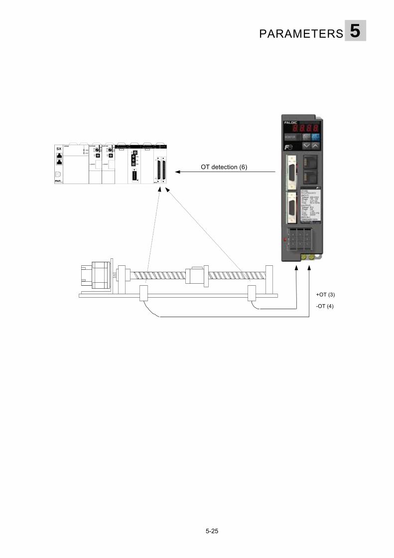
5PARAMETERS
5-25
+OT (3)
-OT (4)
OT detection (6)
APS30
PWR
ALM
SXSCPU32
LOADER
RUNTERMSLVSTOP
CPUNo.
ONLERR
RUNALMBAT
ONL 0 1 2 3 4 5 6 7
ERR 8 9 101112131415
ONL CH1
ERR CH2 EMG +OT -OT
20
1B/A
HP2
ONL
ERR
PE1
PH
PL
DA
CHNo.
SCPU32
LOADER
RUNTERMSLVSTOP
CPUNo.
ONLERR
RUNALMBAT
ONL 0 1 2 3 4 5 6 7
ERR 8 9 101112131415
5 PARAMETERS
5-26
(4) Forced stop and forced stop detection
This signal supplied at the sequence input terminal stops the servomotor forcibly.
Sequence input/output signal Forced stop/forced stop detection
Function (1) Forced stop (Valid for position control/speed control)
The servomotor is forcibly stopped (with a b-contact) while the forced stop (5) signal is turned off. This signal is valid in all control states and it is executed at the highest priority. Because safety and detection speeds are generally important for forced stop (5), the signal is directly connected to the servo amplifier. Usually a self-locking pushbutton switch (command switch) on the operation panel is connected. If forced stop is detected, the position deviation is cleared.
(2) Forced stop detection When the forced stop (5) signal is turned off, the forced stop detection (7) signal is turned on to notify external devices of the event.
Parameter setting
To assign forced stop to a sequence input terminal, specify the corresponding value (“5”) to the parameter. If this signal is not assigned to the sequence input terminals, the signal is assumed to be active at any time. When detection of forced stop is allocated to the sequence output terminal, set value (7) applicable to the parameter.
Reference
(1) Ready [RDY] Assign the forced stop (5) signal to a sequence input terminal to turn on the ready [RDY] signal upon activation of the servo on [RUN] and forced stop signals, readying the output shaft of the servomotor to rotate.

5PARAMETERS
5-27
(2) State of forced stop If forced stop (5) is inactive and servo on [RUN] is active, the servomotor is stopped with the zero speed command state. Activate forced stop to ready the servomotor for operation. Deactivate the servo on [RUN] signal to coast to stop.
(3) Rotation command While the forced stop signal remains inactive, all rotation commands are ignored.
5 PARAMETERS
5-28
(5) P-action
Proportional band control is adopted as a control method of the servo amplifier.
Sequence input signal P-action
Function
Activate this signal while the servo on [RUN] signal is active with the motor shaft being mechanically locked. If P-action is activated during rotation of the servomotor, position control becomes unstable. Do not activate the signal while the servomotor rotates.
Parameter setting
To assign P-action to a sequence input terminal, specify the corresponding value (“6”) to the parameter. The signal is assumed to be inactive at any time if it is not assigned to the sequence input terminals
If the brake is handled with servo locked, an overload alarm (“ ”) is detected. This is because the servo performs PI control to generate a torque and restore the originalposition even upon small deviation. Therefore activate P-action without fail, using anexternal signal, when the brake is applied.
Hint
5PARAMETERS
5-29
(6) Deviation clearance
Difference (position deviation) between the command position and feedback position is reduced to zero.
Sequence input signal Deviation clearance
Function
While this signal remains active, the difference (position devition) between the command position and feedback position is reduced to zero. The feedback position is made the command position.
Parameter setting
To assign deviation clearance to a sequence input terminal, specify the corresponding value (“7”) to the parameter.
Reference
While the deviation clearance signal is activated, all rotation commands are ignored. If the deviation clearance signal is turned on during rotation of the servomotor, pulse command, manual forward rotation [FWD] of the test operation mode and other commands are ignored, to cause the servomotor to be stopped. Deviation accumulated at a stopper can be zeroed to avoid movement caused by the offsetting of deviation upon a released load.

5 PARAMETERS
5-30
(7) Regenerative resistor overheat
Connect the thermistor signal of the external regenerative resistor (option) to this signal. When this signal is OFF with the regenerative resistor overheating alarm, the servomotor is forcibly stopped.
Sequence input signal Regenerative resistor overheat
Function
The servomotor is forcibly stopped (with a b-contact) while the regenerative resistor overheat signal is inactive. If this signal is deactivated during rotation, the servomotor decelerates by its maximum performance to stop (within the zero speed width (parameter #23)), and then it coasts to stop. No holding torque generates after the servomotor is stopped.
Parameter setting
To assign regenerative resistor overheat to a sequence input terminal, specify the corresponding value (“8”) to the parameter. The signal is assumed to be active at any time if it is not assigned to the sequence input terminals.
U V
W
U VWE
M
PG7 P58 M54 SIG+5 SIG-
P5 3 M5 1
SIG+ 17SIG- 18
L1L2L3
CN2
P DB
Servo amplifierRYC S3-VVT2
Servomotor
Commercial power supply,3-phase 200V
External regenerative resistorWSR-
M24CONTn
Thermistor
Connect the shield to the shell body and shell cover.
3 FG
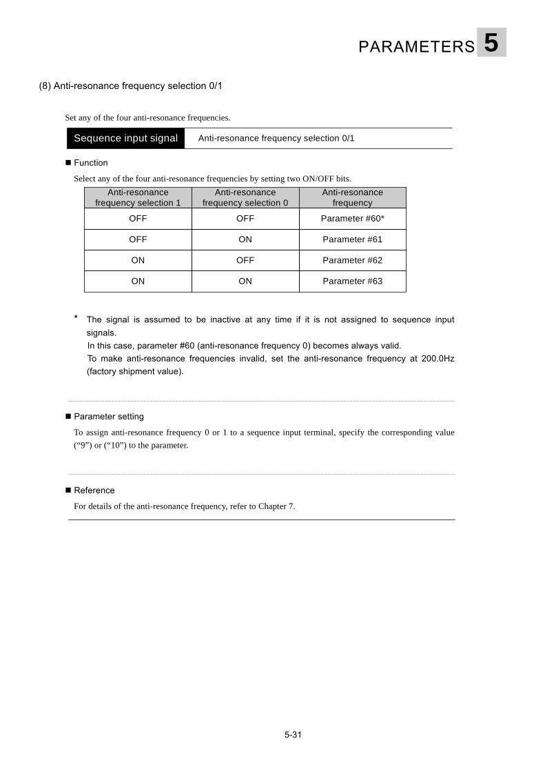
5PARAMETERS
5-31
(8) Anti-resonance frequency selection 0/1
Set any of the four anti-resonance frequencies.
Sequence input signal Anti-resonance frequency selection 0/1
Function
Select any of the four anti-resonance frequencies by setting two ON/OFF bits. Anti-resonance
frequency selection 1Anti-resonance
frequency selection 0
OFF OFF
OFF ON
ON OFF
ON ON
Anti-resonance frequency
Parameter #60*
Parameter #61
Parameter #62
Parameter #63
* The signal is assumed to be inactive at any time if it is not assigned to sequence input signals. In this case, parameter #60 (anti-resonance frequency 0) becomes always valid. To make anti-resonance frequencies invalid, set the anti-resonance frequency at 200.0Hz (factory shipment value).
Parameter setting
To assign anti-resonance frequency 0 or 1 to a sequence input terminal, specify the corresponding value (“9”) or (“10”) to the parameter.
Reference
For details of the anti-resonance frequency, refer to Chapter 7.
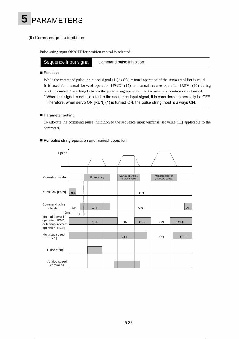
5 PARAMETERS
5-32
(9) Command pulse inhibition
Pulse string input ON/OFF for position control is selected.
Sequence input signal Command pulse inhibition
Function
While the command pulse inhibition signal (11) is ON, manual operation of the servo amplifier is valid. It is used for manual forward operation [FWD] (15) or manual reverse operation [REV] (16) during position control. Switching between the pulse string operation and the manual operation is performed. * When this signal is not allocated to the sequence input signal, it is considered to normally be OFF.
Therefore, when servo ON [RUN] (1) is turned ON, the pulse string input is always ON.
Parameter setting
To allocate the command pulse inhibition to the sequence input terminal, set value (11) applicable to the parameter.
For pulse string operation and manual operation
Operation mode
Servo ON [RUN]
Command pulse inhibition
Manual forward operation [FWD] or Manual reverse operation [REV]
Multistep speed [x 1]
Pulse string
Analog speed command
Pulse stringManual operation
(analog speed)Manual operation (multistep speed)
OFF
Speed
OFF
OFF OFF
OFF
ON
ON ON OFF
ON ON OFF
ON OFF
5ms
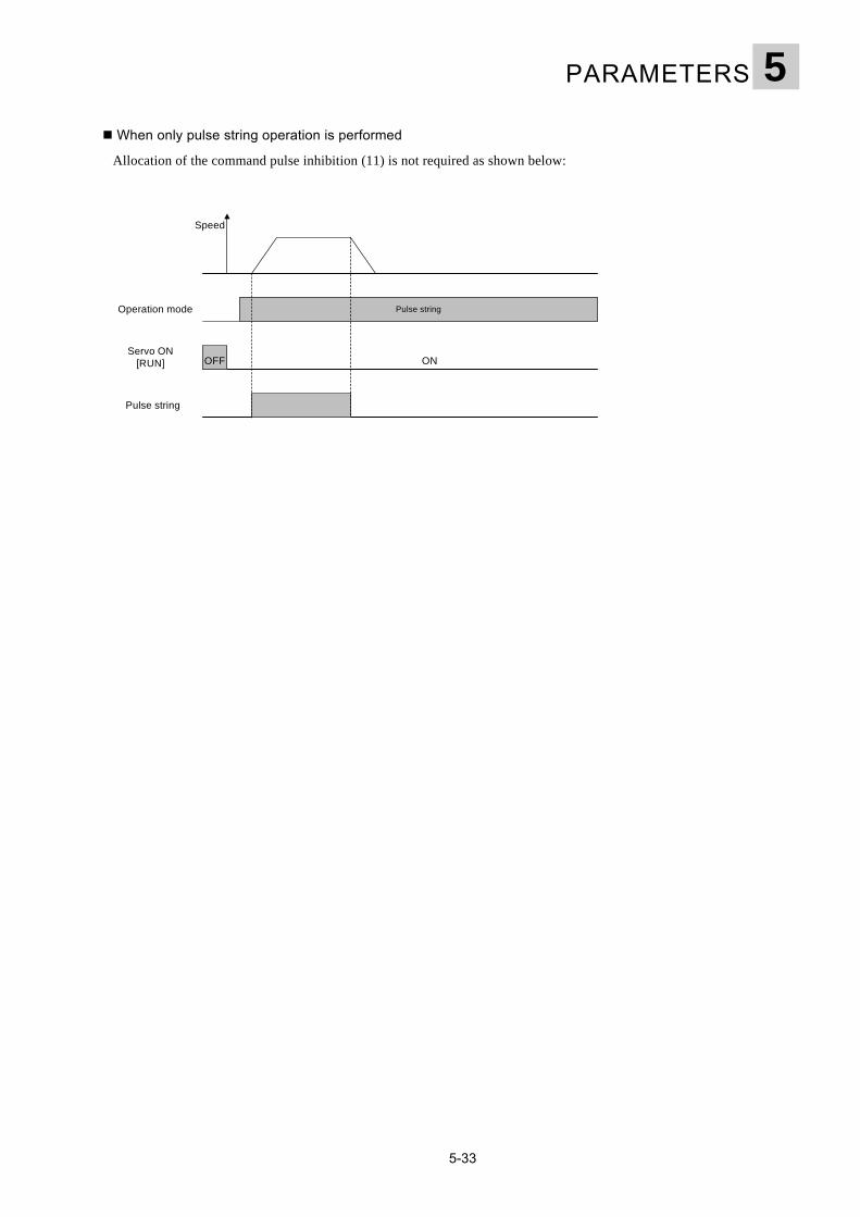
5PARAMETERS
5-33
When only pulse string operation is performed
Allocation of the command pulse inhibition (11) is not required as shown below:
Pulse string
OFF
Speed
Operation mode
Servo ON [RUN]
Pulse string
ON
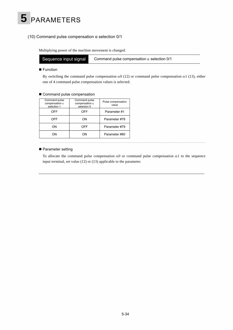
5 PARAMETERS
5-34
(10) Command pulse compensation α selection 0/1
Multiplying power of the machine movement is changed.
Sequence input signal Command pulse compensation α selection 0/1
Function
By switching the command pulse compensation α0 (12) or command pulse compensation α1 (13), either one of 4 command pulse compensation values is selected.
Command pulse compensation Command pulse compensation α
selection 1
ONOFF
Pulse compensation value
Command pulse compensation α
selection 0
OFF OFF
ON OFF
ON ON
Parameter #1
Parameter #78
Parameter #79
Parameter #80
Parameter setting
To allocate the command pulse compensation α0 or command pulse compensation α1 to the sequence input terminal, set value (12) or (13) applicable to the parameter.
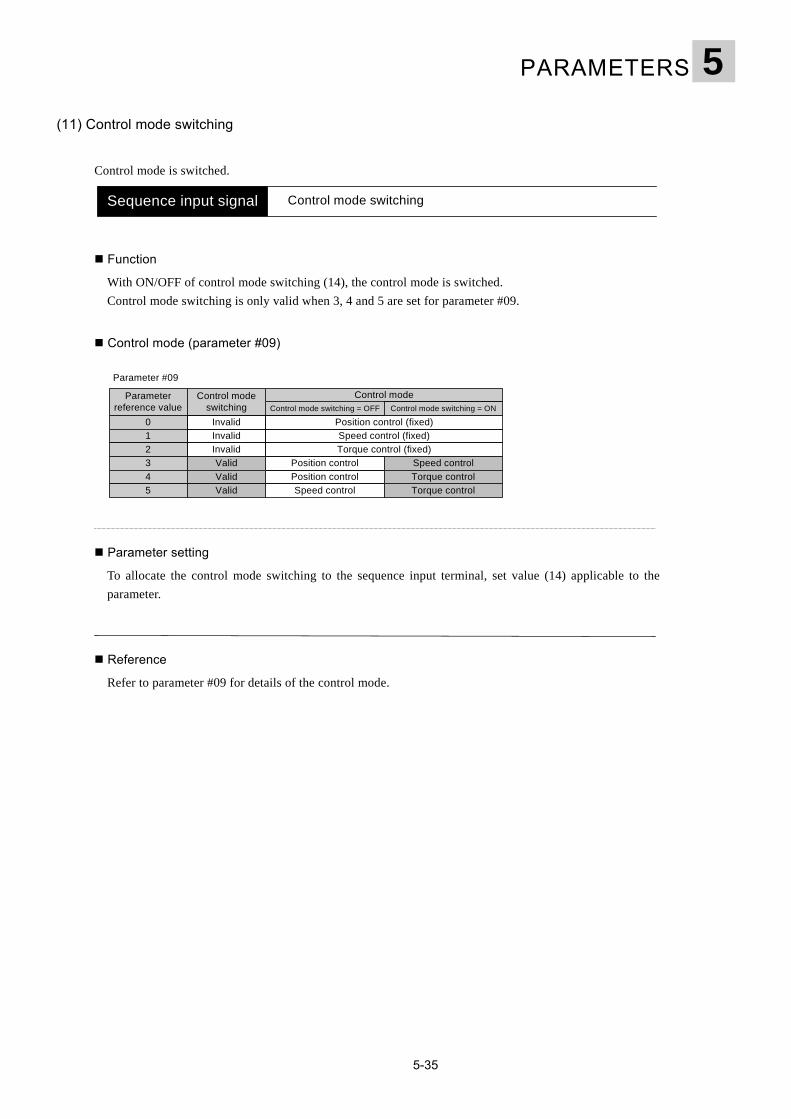
5PARAMETERS
5-35
(11) Control mode switching
Control mode is switched.
Function
With ON/OFF of control mode switching (14), the control mode is switched. Control mode switching is only valid when 3, 4 and 5 are set for parameter #09.
Control mode (parameter #09)
Parameter setting
To allocate the control mode switching to the sequence input terminal, set value (14) applicable to the parameter.
Reference
Refer to parameter #09 for details of the control mode.
Sequence input signal Control mode switching
Control mode switching = OFF
Parameter reference value
01
2
Position control (fixed)
Parameter #09
Control modeControl mode switching = ON
3
4
5
Speed control (fixed)
Torque control (fixed)
Position control
Position control
Speed control
Speed control
Torque control
Torque control
Control mode switching
InvalidInvalid
Invalid
Valid
Valid
Valid

5 PARAMETERS
5-36
(12) Forward rotation command [FWD]/Reverse rotation command [REV]
It is the signal to rotate the servomotor.
Sequence input signal Forward rotation command [FWD]/Reverse rotation command [REV]
Function
While the forward rotation command [FWD] (reverse rotation command [REV]) is ON, the servomotor rotates in the positive (negative) direction. When it is ON, acceleration starts. When it is OFF, deceleration starts.
(1) Speed control The motor rotates at the voltage of the analog speed command input [Vref] terminal and at the speed selected from multistep speed [X1] and [X2].
(2) Position control It is the same as speed control. The motor starts rotation when the forward rotation command [FWD] (reverse rotation command [REV]) is at the ON edge. If other [REV] or [FWD] signal is ON during rotation, it is ignored.
(3) Torque control Torque is output from the servomotor shaft according to the torque command voltage.
[ FWD]
[ REV]
OFF ON
OFF ON
Status is maintained even for simultaneous FWD/REV ON.
Since the level is valid at the ON edge, reverse rotation does not start.
Rotation speed
Position control
[ FWD]
[ REV]
OFF ON
OFF ON
Deceleration stop at simultaneous FWD/REV ON
ON level of REV is valid. Reverse rotation starts.
Rotation speed
Speed control Torque control
Position control
Torque control
Speed control
Control mode FWD/REV signal
ON level
ON edge
ON level
Simultaneous FWD/REV ON
Deceleration stop
Motion immediately before simultaneous ON is maintained.
Deceleration stop
Parameter setting
To allocate the forward rotation command [FWD] signal to the sequence input terminal, set value (15) applicable to the parameter. ((16) for the reverse rotation command.) When this signal is not allocated to the sequence input terminal, it is considered to normally be OFF.
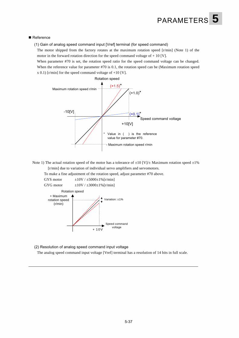
5PARAMETERS
5-37
Reference
(1) Gain of analog speed command input [Vref] terminal (for speed command) The motor shipped from the factory rotates at the maximum rotation speed [r/min] (Note 1) of the motor in the forward rotation direction for the speed command voltage of + 10 [V]. When parameter #70 is set, the rotation speed ratio for the speed command voltage can be changed. When the reference value for parameter #70 is 0.1, the rotation speed can be (Maximum rotation speed x 0.1) [r/min] for the speed command voltage of +10 [V].
Note 1) The actual rotation speed of the motor has a tolerance of ±10 [V]/± Maximum rotation speed ±1%
[r/min] due to variation of individual servo amplifiers and servomotors. To make a fine adjustment of the rotation speed, adjust parameter #70 above. GYS motor ±10V / ±5000±1%[r/min] GYG motor ±10V / ±3000±1%[r/min]
+ 1 0 V
+ Maximum rotation speed
(r/min)Variation: ±1%
Rotation speed
Speed command voltage
(2) Resolution of analog speed command input voltage The analog speed command input voltage [Vref] terminal has a resolution of 14 bits in full scale.
Speed command voltage +10[V]
Maximum rotation speed r/min
- Maximum rotation speed r/min
-10[V]
(×1.5)*
(×1.0)*
(×0.1)*
Rotation speed
* Value in ( ) is the referencevalue for parameter #70.
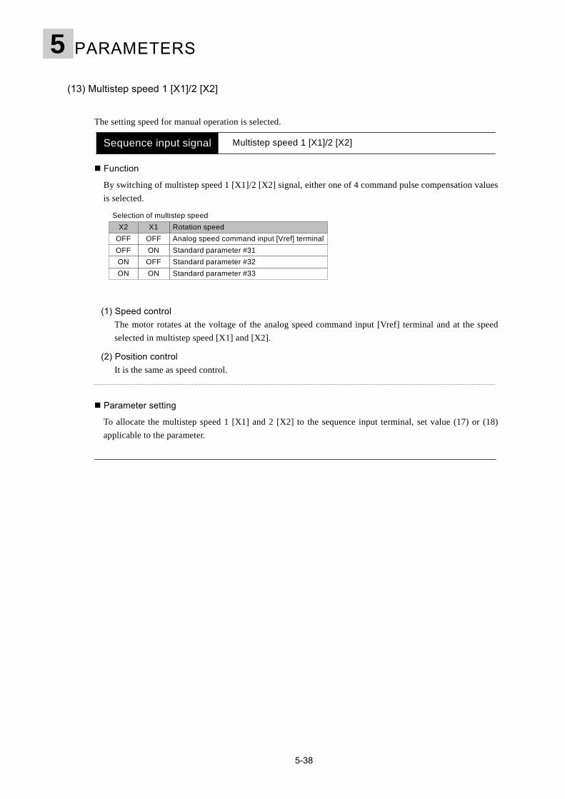
5 PARAMETERS
5-38
(13) Multistep speed 1 [X1]/2 [X2]
The setting speed for manual operation is selected.
Sequence input signal Multistep speed 1 [X1]/2 [X2]
Function
By switching of multistep speed 1 [X1]/2 [X2] signal, either one of 4 command pulse compensation values is selected.
Analog speed command input [Vref] terminal
Standard parameter #31
Selection of multistep speed
Rotation speed
OFF
X2
OFF
OFF
X1
OFF
ON
ON
ON ON
Standard parameter #32
Standard parameter #33
(1) Speed control The motor rotates at the voltage of the analog speed command input [Vref] terminal and at the speed selected in multistep speed [X1] and [X2].
(2) Position control It is the same as speed control.
Parameter setting
To allocate the multistep speed 1 [X1] and 2 [X2] to the sequence input terminal, set value (17) or (18) applicable to the parameter.
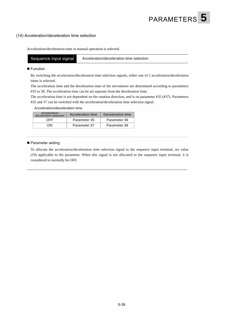
5PARAMETERS
5-39
(14) Acceleration/deceleration time selection
Acceleration/deceleration time in manual operation is selected.
Sequence input signal Acceleration/deceleration time selection
Function
By switching the acceleration/deceleration time selection signals, either one of 2 acceleration/deceleration times is selected. The acceleration time and the deceleration time of the servomotor are determined according to parameters #35 to 38. The acceleration time can be set separate from the deceleration time. The acceleration time is not dependent on the rotation direction, and is on parameter #35 (#37). Parameters #35 and 37 can be switched with the acceleration/deceleration time selection signal.
Acceleration/deceleration time
Parameter 36OFF
Acceleration/deceleration selection Deceleration time
Parameter 35
Acceleration time
ON Parameter 38Parameter 37
Parameter setting
To allocate the acceleration/deceleration time selection signal to the sequence input terminal, set value (19) applicable to the parameter. When this signal is not allocated to the sequence input terminal, it is considered to normally be OFF.

5 PARAMETERS
5-40
(15) Current limit valid/current limit detection
The maximum output torque of the servomotor can be limited.
Sequence input/output signal Current limit valid/current limit detection
Function
(1) Current limit valid While the current limit valid (20) signal is ON, the output torque of the servomotor can be limited. The torque limit value can be set in the range from 0 to 300 at the increments of 1 [%] to parameter #25. The maximum output torque is set as 100[%] rated torque. Current limit is always valid for all control types. When the output torque is limited during acceleration or deceleration, the acceleration/deceleration time in parameter setting may not be observed.
(2) Current limit detection This signal is ON while the output torque of the servomotor has reached the torque limit value. The output of current limit detection (10) is valid for all control types.
Parameter setting
To allocate the current limit valid signal to the sequence input terminal, set value (20) applicable to the parameter. When the current limit valid (20) signal is not allocated to the sequence input terminal, the reference value for parameter 25 is always valid. To allocate the current limit detection signal to the sequence input terminal, set value (10) applicable to the parameter.
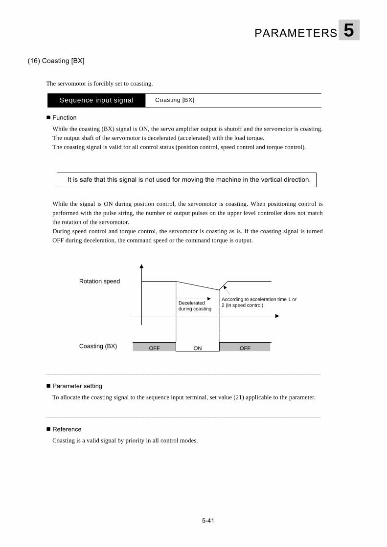
5PARAMETERS
5-41
(16) Coasting [BX]
The servomotor is forcibly set to coasting.
Sequence input signal Coasting [BX]
Function
While the coasting (BX) signal is ON, the servo amplifier output is shutoff and the servomotor is coasting. The output shaft of the servomotor is decelerated (accelerated) with the load torque. The coasting signal is valid for all control status (position control, speed control and torque control).
While the signal is ON during position control, the servomotor is coasting. When positioning control is performed with the pulse string, the number of output pulses on the upper level controller does not match the rotation of the servomotor. During speed control and torque control, the servomotor is coasting as is. If the coasting signal is turned OFF during deceleration, the command speed or the command torque is output.
OFF
Rotation speed
Coasting (BX) ON
Decelerated during coasting
According to acceleration time 1 or 2 (in speed control)
OFF
Parameter setting
To allocate the coasting signal to the sequence input terminal, set value (21) applicable to the parameter.
Reference
Coasting is a valid signal by priority in all control modes.
It is safe that this signal is not used for moving the machine in the vertical direction.
5 PARAMETERS
5-42
(17) Ready [RDY]
The signal is activated when the motor is ready to rotate.
Sequence output signal Ready [RDY]...Assigned to OUT 1 with shipment setting
Function
The signal is activated when the following conditions are satisfied: 1) Servo ON [RUN] (1) signal ON 2) Active forced stop [EMG] (5) signal* 3) Inactive alarm detection: a-contact (3) signal (Or active alarm detection: b-contact (4) signal) 4) Active external regenerative resistor overheat (8) signal* 5) Source voltage above 150V 6) Coasting [BX] (21) signal OFF
* Conditions 2) and 4) are ignored if the corresponding signal is not assigned to the CONT terminals. The host controller recognizes the ready [RDY] signal to check if the servomotor is ready to rotate.
Parameter setting
To allocate the ready [RDY] signal to the sequence input terminal, set value (1) applicable to the parameter.
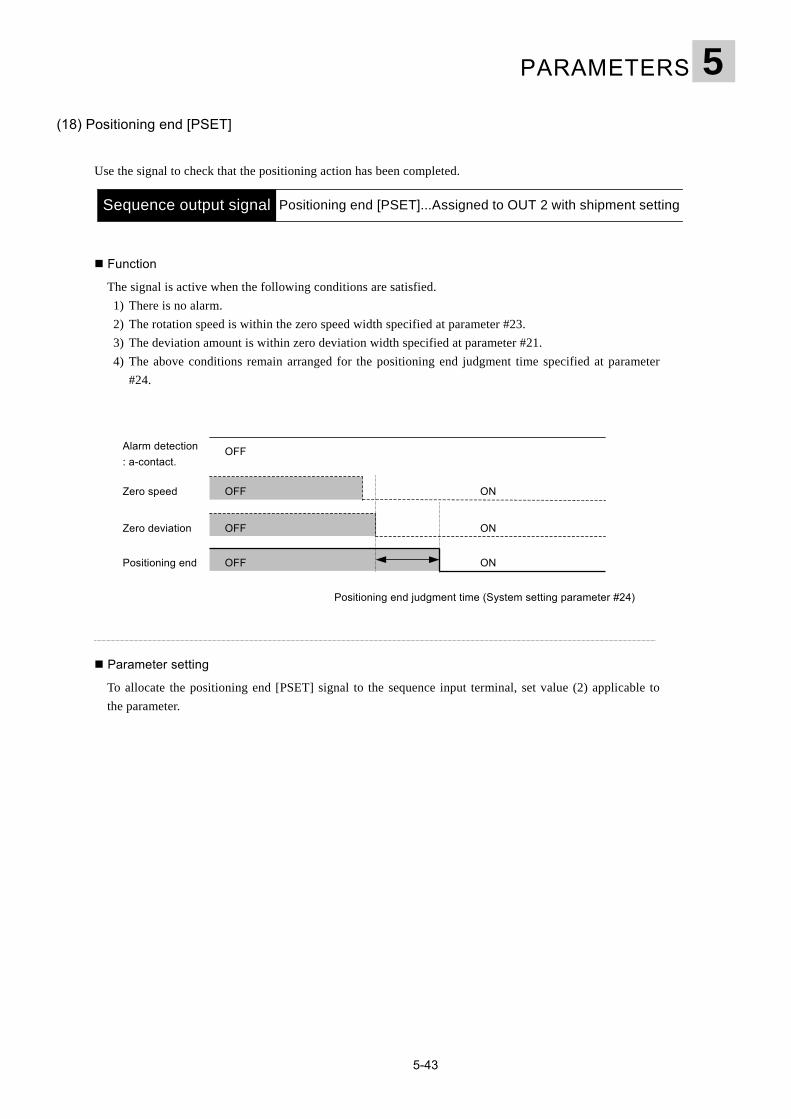
5PARAMETERS
5-43
(18) Positioning end [PSET]
Use the signal to check that the positioning action has been completed.
Sequence output signal Positioning end [PSET]...Assigned to OUT 2 with shipment setting
Function
The signal is active when the following conditions are satisfied. 1) There is no alarm. 2) The rotation speed is within the zero speed width specified at parameter #23. 3) The deviation amount is within zero deviation width specified at parameter #21. 4) The above conditions remain arranged for the positioning end judgment time specified at parameter
#24.
Parameter setting
To allocate the positioning end [PSET] signal to the sequence input terminal, set value (2) applicable to the parameter.
OFF
OFF
ON
ON
Zero deviation
Positioning end
Positioning end judgment time (System setting parameter #24)
OFF ON Zero speed
Alarm detection : a-contact.
OFF
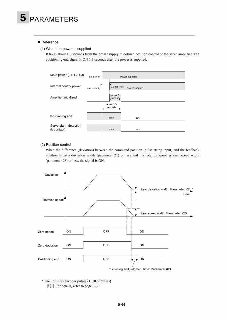
5 PARAMETERS
5-44
Reference
(1) When the power is supplied It takes about 1.5 seconds from the power supply to defined position control of the servo amplifier. The positioning end signal is ON 1.5 seconds after the power is supplied.
Main power (L1, L2, L3)
Internal control power
Amplifier initialized
Positioning end
Servo alarm detection (b contact)
No power Power supplied
No continuity Power supplied0.5 seconds
About 1 second
About 1.5 seconds
OFF
OFF
ON
ON
(2) Position control When the difference (deviation) between the command position (pulse string input) and the feedback position is zero deviation width (parameter 21) or less and the rotation speed is zero speed width (parameter 23) or less, the signal is ON.
* The unit uses encoder pulses (131072 pulses).
For details, refer to page 5-55.
Zero speed OFF ON
Deviation
Time
Rotation speed
ON
Zero deviation OFF ON ON
Positioning end OFF ON ON
Zero speed width: Parameter #23
Zero deviation width: Parameter #21 *
Positioning end judgment time: Parameter #24
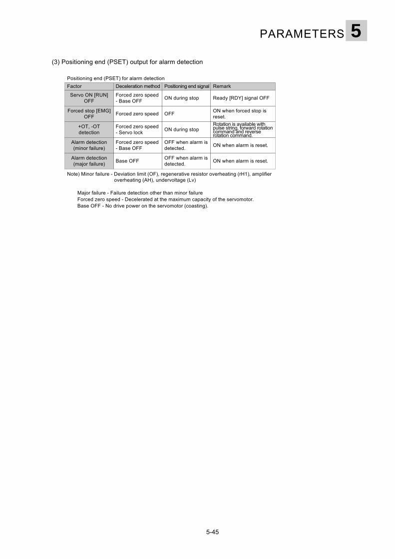
5PARAMETERS
5-45
(3) Positioning end (PSET) output for alarm detection
Forced zero speed - Base OFF
Positioning end (PSET) for alarm detectionFactor Deceleration method
Servo ON [RUN] OFF
Forced stop [EMG] OFF
+OT, -OT detection
Alarm detection (minor failure)
Alarm detection (major failure)
Forced zero speed
Forced zero speed - Servo lock
Forced zero speed - Base OFF
Base OFF
ON during stop
Positioning end signal
OFF
ON during stop
OFF when alarm is detected.
OFF when alarm is detected.
Ready [RDY] signal OFF
Remark
ON when forced stop is reset.Rotation is available with pulse string, forward rotation command and reverse rotation command.
ON when alarm is reset.
ON when alarm is reset.
Note) Minor failure - Deviation limit (OF), regenerative resistor overheating (rH1), amplifier overheating (AH), undervoltage (Lv)
Major failure - Failure detection other than minor failureForced zero speed - Decelerated at the maximum capacity of the servomotor.Base OFF - No drive power on the servomotor (coasting).

5 PARAMETERS
5-46
(19) Alarm detection: a-contact (b-contact)
The servo amplifier detects the action (alarm) of protection function to activate (desactivate)* the signal.
Sequence output signal Alarm detection: a-contact Alarm detection: b-contact ... Assigned to OUT 3 with shipment setting
Function
The signal is activated (deactivated*) and is held at the servo amplifier when the servo amplifier detects an alarm. After the cause of the alarm is removed, the signal is deactivated (activated*) upon the activating edge of the reset signal [RST] so that operation is resumed. The host controller recognizes the alarm detection signal to check for an alarm. * Description in parentheses ( ) is for b-contact alarm detection.
<Precaution for usage of b-contact alarm detection>
Power supplyOFF ON
Alarm detection:b-contact OFF 1 sec. ON
Alarm detection
Reset [RST]OFF
OFF ON
ON OFF
Make sure that the signal is inactive for about one second after the power is turned on.
Parameter setting
To assign a- or b-contact alarm detection to the sequence output terminal, specify the corresponding value (“3” or “4”) to the parameter.
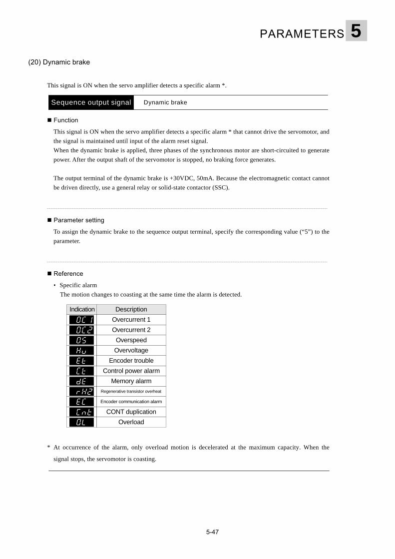
5PARAMETERS
5-47
(20) Dynamic brake
This signal is ON when the servo amplifier detects a specific alarm *.
Sequence output signal Dynamic brake
Function
This signal is ON when the servo amplifier detects a specific alarm * that cannot drive the servomotor, and the signal is maintained until input of the alarm reset signal. When the dynamic brake is applied, three phases of the synchronous motor are short-circuited to generate power. After the output shaft of the servomotor is stopped, no braking force generates. The output terminal of the dynamic brake is +30VDC, 50mA. Because the electromagnetic contact cannot be driven directly, use a general relay or solid-state contactor (SSC).
Parameter setting
To assign the dynamic brake to the sequence output terminal, specify the corresponding value (“5”) to the parameter.
Reference
• Specific alarm The motion changes to coasting at the same time the alarm is detected.
Indication Description
Overcurrent 1
Overspeed
Overvoltage
Encoder trouble
Memory alarm
Regenerative transistor overheat
Encoder communication alarm
CONT duplication
Overload
Control power alarm
Overcurrent 2
* At occurrence of the alarm, only overload motion is decelerated at the maximum capacity. When the
signal stops, the servomotor is coasting.
5 PARAMETERS
5-48
(21) Zero deviation
This can confirm that the servomotor has almost reached the command position.
Function
The signal is ON when the difference (position deviation) between the current command position and the current feedback position is within the reference value for parameter #21. The zero deviation signal is valid at the position control mode. The signal is always ON in control status (torque control, etc.) other than the position control. Reference value level for parameter #21 is not related to positioning accuracy.
Parameter setting
To allocate the zero deviation signal to the sequence input terminal, set value (8) applicable to the parameter.
Sequence output signal Zero deviation
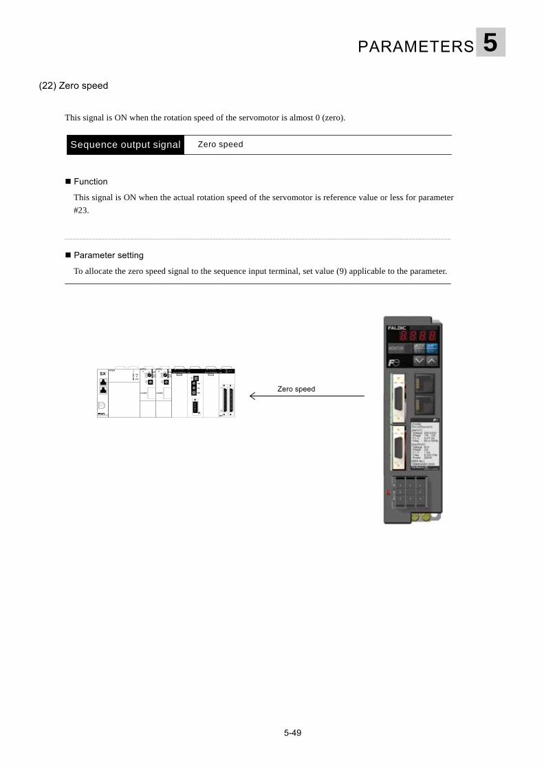
5PARAMETERS
5-49
(22) Zero speed
This signal is ON when the rotation speed of the servomotor is almost 0 (zero).
Function
This signal is ON when the actual rotation speed of the servomotor is reference value or less for parameter #23.
Parameter setting
To allocate the zero speed signal to the sequence input terminal, set value (9) applicable to the parameter.
Sequence output signal Zero speed
Zero speed
APS30
PWR
ALM
SXSCPU3
2
LOADER
RUNTERMSLVSTOP
CPUNo.
ONLERR
RUNALMBAT
ONL 0 1 2 3 4 5 6 7
ERR 8 9 101112131415
ONL CH1
ERR CH2 EMG +OT -OT
20
1B/A
HP2
ONL
ERR
PE1
PH
PL
DA
CHNo.
SCPU32
LOADER
RUNTERMSLVSTOP
CPUNo.
ONLERR
RUNALMBAT
ONL 0 1 2 3 4 5 6 7
ERR 8 9 101112131415
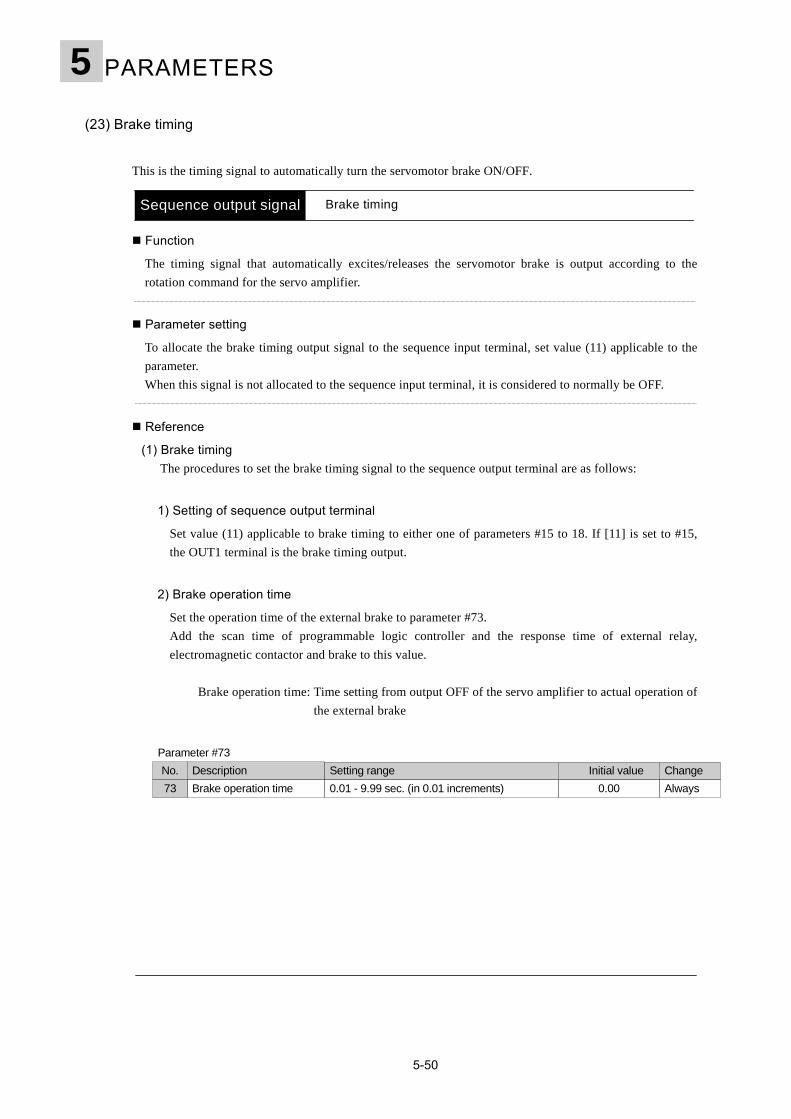
5 PARAMETERS
5-50
(23) Brake timing
This is the timing signal to automatically turn the servomotor brake ON/OFF.
Sequence output signal Brake timing
Function
The timing signal that automatically excites/releases the servomotor brake is output according to the rotation command for the servo amplifier.
Parameter setting
To allocate the brake timing output signal to the sequence input terminal, set value (11) applicable to the parameter. When this signal is not allocated to the sequence input terminal, it is considered to normally be OFF.
Reference
(1) Brake timing The procedures to set the brake timing signal to the sequence output terminal are as follows:
1) Setting of sequence output terminal
Set value (11) applicable to brake timing to either one of parameters #15 to 18. If [11] is set to #15, the OUT1 terminal is the brake timing output.
2) Brake operation time
Set the operation time of the external brake to parameter #73. Add the scan time of programmable logic controller and the response time of external relay, electromagnetic contactor and brake to this value.
Brake operation time: Time setting from output OFF of the servo amplifier to actual operation of
the external brake
Parameter #73
No. Description Setting range Initial value Change
73 Brake operation time 0.00 Always0.01 - 9.99 sec. (in 0.01 increments)
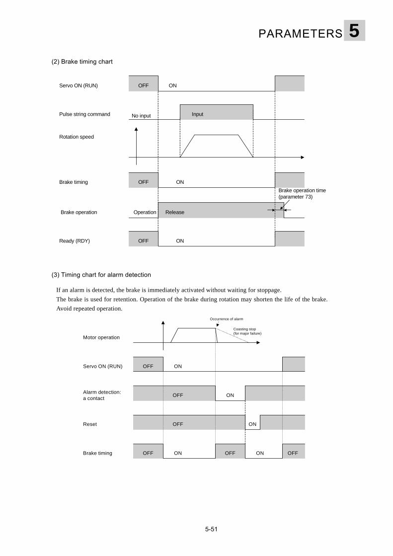
5PARAMETERS
5-51
(2) Brake timing chart
Servo ON (RUN) OFF ON
Pulse string command
Rotation speed
InputNo input
Brake timing OFF ON
Ready (RDY) OFF ON
Brake operation time (parameter 73)
Brake operation Operation Release
(3) Timing chart for alarm detection
If an alarm is detected, the brake is immediately activated without waiting for stoppage. The brake is used for retention. Operation of the brake during rotation may shorten the life of the brake. Avoid repeated operation.
Servo ON (RUN) OFF ON
OFFAlarm detection: a contact
Brake timing OFF ON OFF
OFFReset ON
ON
ON OFF
Occurrence of alarm
Coasting stop (for major failure)
Motor operation
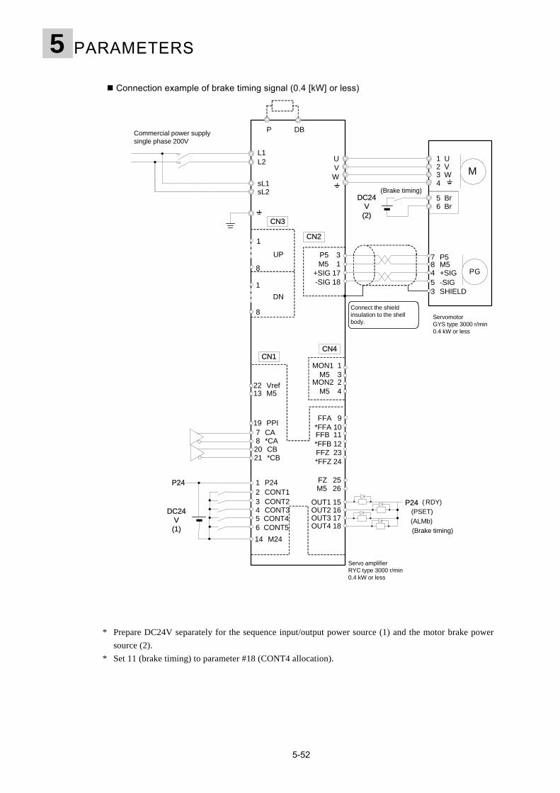
5 PARAMETERS
5-52
Connection example of brake timing signal (0.4 [kW] or less)
ServomotorGYS type 3000 r/min0.4 kW or less
Servo amplifierRYC type 3000 r/min0.4 kW or less
Commercial power supply single phase 200V
U V
W
1 U 2 V3 W4
M
7 P5 8 M5 4 +SIG
3 SHIELD 5 -SIG
P5 3M5 1
+SIG 17-SIG 18
PG
L1L2
sL1sL2
CN2
P DB
Connect the shield insulation to the shell body.
CN3
8
1
8
UP
DN
FFZ 23*FFZ 24
FZ 25 M5 26
CN1
P24
1 P24 2 CONT1
5 CONT4
3 CONT2
14 M24
4 CONT3
P24
19 PPI 7 CA 8 *CA
21 *CB20 CB
1
6 CONT5
22 Vref13 M5
FFA 9*FFA 10FFB 11*FFB 12
OUT1 15 OUT2 16 OUT3 17 OUT4 18
5 Br6 Br
CN4
MON1 1 M5 3
MON2 2M5 4
DC24V
(1)
DC24V
(2)
(Brake timing)
(ALMb)
(PSET)
( RDY)
(Brake timing)
* Prepare DC24V separately for the sequence input/output power source (1) and the motor brake power source (2).
* Set 11 (brake timing) to parameter #18 (CONT4 allocation).
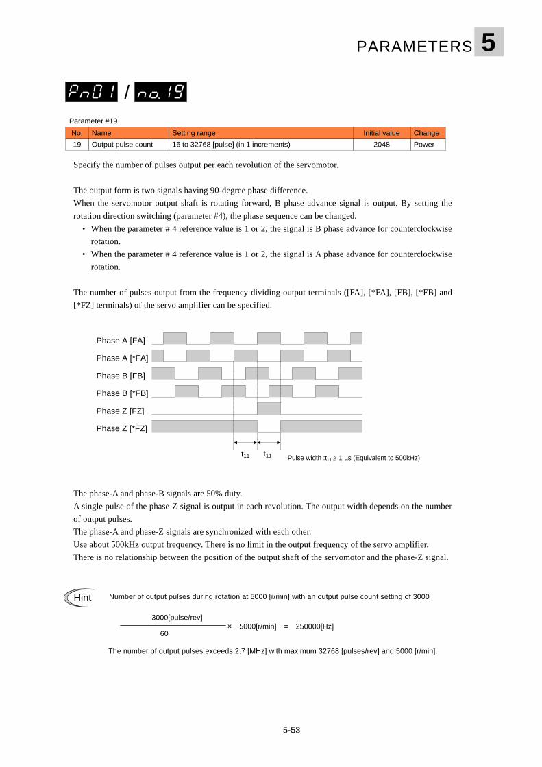
5PARAMETERS
5-53
/
Parameter #19
No. Name Setting range Initial value Change
19 Output pulse count 16 to 32768 [pulse] (in 1 increments) 2048 Power
Specify the number of pulses output per each revolution of the servomotor. The output form is two signals having 90-degree phase difference. When the servomotor output shaft is rotating forward, B phase advance signal is output. By setting the rotation direction switching (parameter #4), the phase sequence can be changed.
• When the parameter # 4 reference value is 1 or 2, the signal is B phase advance for counterclockwise rotation.
• When the parameter # 4 reference value is 1 or 2, the signal is A phase advance for counterclockwise rotation.
The number of pulses output from the frequency dividing output terminals ([FA], [*FA], [FB], [*FB] and [*FZ] terminals) of the servo amplifier can be specified.
Phase A [FA]
Phase A [*FA]
Phase B [FB]
Phase B [*FB]
Phase Z [FZ]
Phase Z [*FZ]
t11 Pulse width :t11 ≥ 1 µs (Equivalent to 500kHz)t11
The phase-A and phase-B signals are 50% duty. A single pulse of the phase-Z signal is output in each revolution. The output width depends on the number of output pulses. The phase-A and phase-Z signals are synchronized with each other. Use about 500kHz output frequency. There is no limit in the output frequency of the servo amplifier. There is no relationship between the position of the output shaft of the servomotor and the phase-Z signal.
Number of output pulses during rotation at 5000 [r/min] with an output pulse count setting of 3000
3000[pulse/rev]
60 × 5000[r/min] = 250000[Hz]
The number of output pulses exceeds 2.7 [MHz] with maximum 32768 [pulses/rev] and 5000 [r/min].
Hint
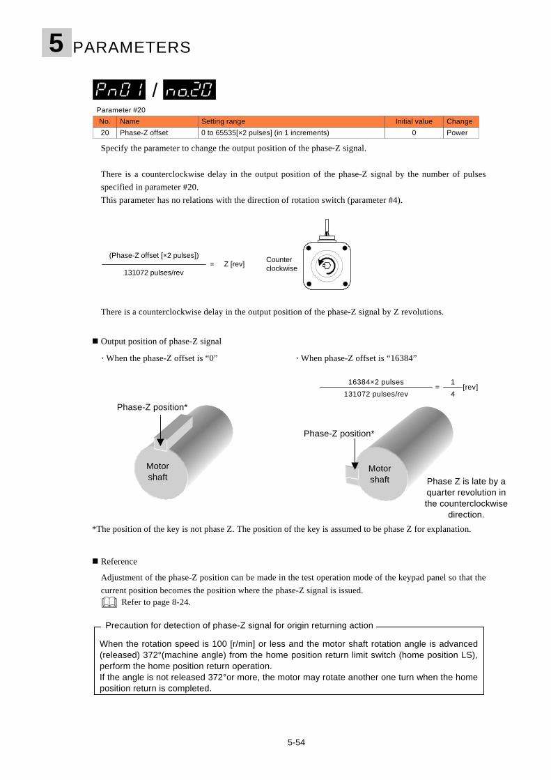
5 PARAMETERS
5-54
/
Parameter #20
No. Name Setting range Initial value Change
20 Phase-Z offset 0 to 65535[×2 pulses] (in 1 increments) 0 Power Specify the parameter to change the output position of the phase-Z signal. There is a counterclockwise delay in the output position of the phase-Z signal by the number of pulses specified in parameter #20. This parameter has no relations with the direction of rotation switch (parameter #4).
Counterclockwise
131072 pulses/rev
(Phase-Z offset [×2 pulses]) = Z [rev]
There is a counterclockwise delay in the output position of the phase-Z signal by Z revolutions.
Output position of phase-Z signal
· When the phase-Z offset is “0” · When phase-Z offset is “16384”
*The position of the key is not phase Z. The position of the key is assumed to be phase Z for explanation.
Reference
Adjustment of the phase-Z position can be made in the test operation mode of the keypad panel so that the current position becomes the position where the phase-Z signal is issued.
Refer to page 8-24.
Motorshaft
Phase-Z position*
Motor shaft
Phase-Z position*
When the rotation speed is 100 [r/min] or less and the motor shaft rotation angle is advanced(released) 372°(machine angle) from the home position return limit switch (home position LS),perform the home position return operation. If the angle is not released 372°or more, the motor may rotate another one turn when the homeposition return is completed.
Precaution for detection of phase-Z signal for origin returning action
131072 pulses/rev
16384×2 pulses = [rev]
4
1
Phase Z is late by a quarter revolution in the counterclockwise
direction.
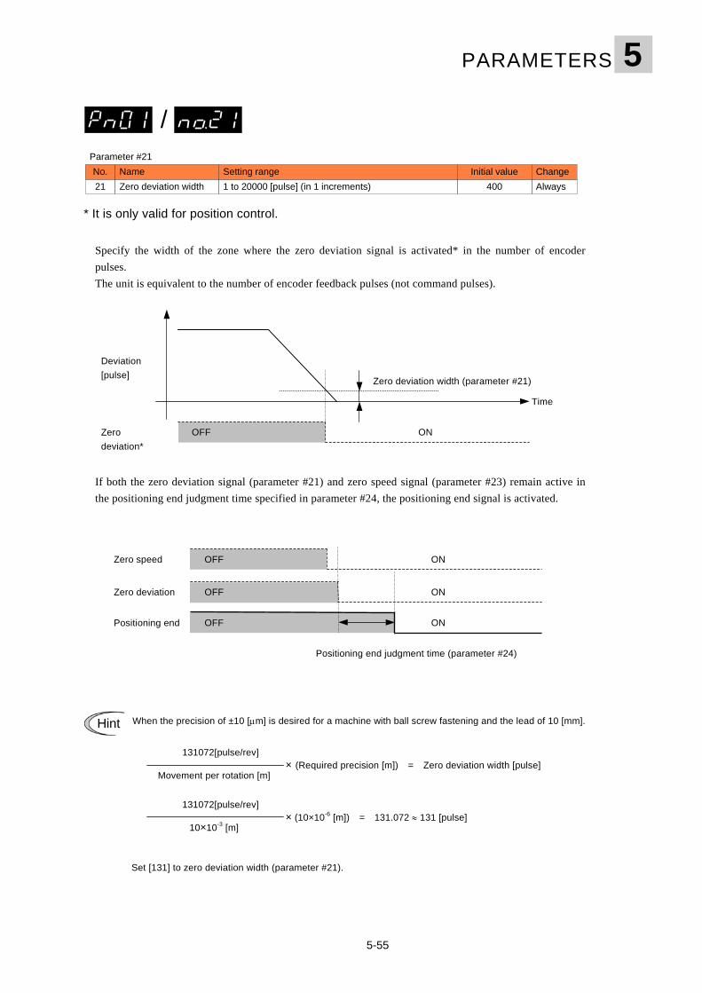
5PARAMETERS
5-55
/
Parameter #21
No. Name Setting range Initial value Change
21 Zero deviation width 1 to 20000 [pulse] (in 1 increments) 400 Always
* It is only valid for position control. Specify the width of the zone where the zero deviation signal is activated* in the number of encoder pulses. The unit is equivalent to the number of encoder feedback pulses (not command pulses). If both the zero deviation signal (parameter #21) and zero speed signal (parameter #23) remain active in the positioning end judgment time specified in parameter #24, the positioning end signal is activated.
Time
OFF ON
Zero deviation width (parameter #21)
Deviation [pulse]
Zero deviation*
OFF
OFF
ON
ON
Zero deviation
Positioning end
Positioning end judgment time (parameter #24)
OFF ON Zero speed
When the precision of ±10 [µm] is desired for a machine with ball screw fastening and the lead of 10 [mm].
131072[pulse/rev]
10×10-3 [m] × (10×10-6 [m]) = 131.072 ≈ 131 [pulse]
Set [131] to zero deviation width (parameter #21).
131072[pulse/rev]
Movement per rotation [m] × (Required precision [m]) = Zero deviation width [pulse]
Hint

5 PARAMETERS
5-56
/
Parameter #22
No. Name Setting range Initial value Change
22 Deviation limit width 10 to 65535 [× 100 pulse] (in 1 increments) 20000 Always
* It is only valid for position control.
Specify the number of pulses for detecting the deviation limit (for alarm detection) in the number of encoder feedback pulses (not command pulses). The initial setting is “20000,” so that deviation is detected at 2000000 pulses. With the initial setting, deviation is detected if the difference between the command position and feedback position is equivalent to about 15.2 revolutions of the servomotor shaft. The deviation limit width is provided for alarm detection.
/
Parameter #23
No. Name Setting range Initial value Change
23 Zero speed width 10 to 5000 [r/min] (in 1 increments) 50 Always
Use the parameter to judge if the servomotor is stopped. Specify the width where the zero speed signal is
activated*.
If the zero deviation signal (parameter #21) and zero speed signal (parameter #23) remain active in the positioning completion judgment time specified in parameter #24, the positioning end signal is activated.
Time
OFF ON
Zero speed width (parameter #23)
Speed
Zero speed*
OFF
OFF
ON
ON
Zero deviation
Positioning end
Positioning end judgment time (parameter #24)
OFF ON Zero speed
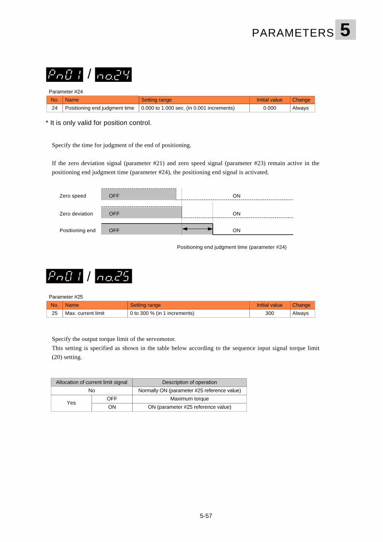
5PARAMETERS
5-57
/
Parameter #24
No. Name Setting range Initial value Change
24 Positioning end judgment time 0.000 to 1.000 sec. (in 0.001 increments) 0.000 Always
* It is only valid for position control.
Specify the time for judgment of the end of positioning. If the zero deviation signal (parameter #21) and zero speed signal (parameter #23) remain active in the positioning end judgment time (parameter #24), the positioning end signal is activated.
/
Parameter #25
No. Name Setting range Initial value Change
25 Max. current limit 0 to 300 % (in 1 increments) 300 Always
Specify the output torque limit of the servomotor. This setting is specified as shown in the table below according to the sequence input signal torque limit (20) setting.
Yes
No
Allocation of current limit signal Description of operation
OFF
ON
Normally ON (parameter #25 reference value)
Maximum torque
ON (parameter #25 reference value)
OFF
OFF
ON
ON
Zero deviation
Positioning end
Positioning end judgment time (parameter #24)
OFF ON Zero speed
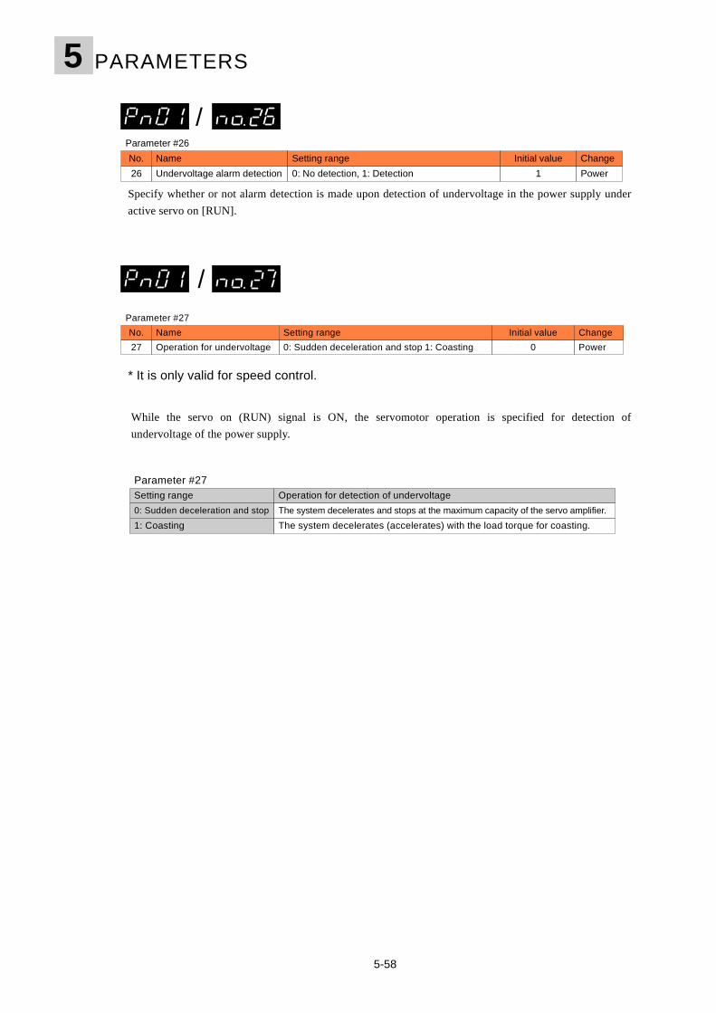
5 PARAMETERS
5-58
/
Parameter #26
No. Name Setting range Initial value Change
26 Undervoltage alarm detection 0: No detection, 1: Detection 1 Power Specify whether or not alarm detection is made upon detection of undervoltage in the power supply under active servo on [RUN].
/
Parameter #27
No. Name Setting range Initial value Change
27 Operation for undervoltage 0: Sudden deceleration and stop 1: Coasting 0 Power
* It is only valid for speed control.
While the servo on (RUN) signal is ON, the servomotor operation is specified for detection of undervoltage of the power supply.
Parameter #27Setting range
0: Sudden deceleration and stop
1: Coasting
Operation for detection of undervoltage
The system decelerates and stops at the maximum capacity of the servo amplifier.
The system decelerates (accelerates) with the load torque for coasting.

5PARAMETERS
5-59
/
Parameter #28
No. Name Setting range Initial value Change
28 For adjustment by manufacturer - Adjustment value -
This parameter is for adjustment by manufacturer. Do not change it.
/
Parameter #29
No. Name Setting range Initial value Change
29 Parameter write-protection 0: Write-enable, 1: Write-protected 0 Always
Parameter editing is prohibited. Even if write-protection is selected with parameter #29, parameter #29 can be edited.
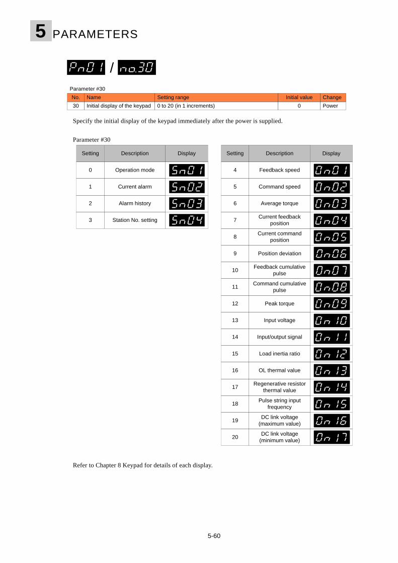
5 PARAMETERS
5-60
/
Parameter #30
No. Name Setting range Initial value Change
30 Initial display of the keypad 0 to 20 (in 1 increments) 0 Power
Specify the initial display of the keypad immediately after the power is supplied. Parameter #30
Setting Description Display
Current alarm
Alarm history
Operation mode
Station No. setting
0
1
2
3
Setting Description Display
Command speed
Average torque
Feedback speed
Current feedback position
4
5
6
7
Position deviation
Feedback cumulative pulse
Current command position
Command cumulative pulse
8
9
10
11
Input voltage
Input/output signal
Peak torque
Load inertia ratio
12
13
14
15
Regenerative resistor thermal value
Pulse string input frequency
OL thermal value
DC link voltage (maximum value)
16
17
18
19
DC link voltage (minimum value)
20
Refer to Chapter 8 Keypad for details of each display.
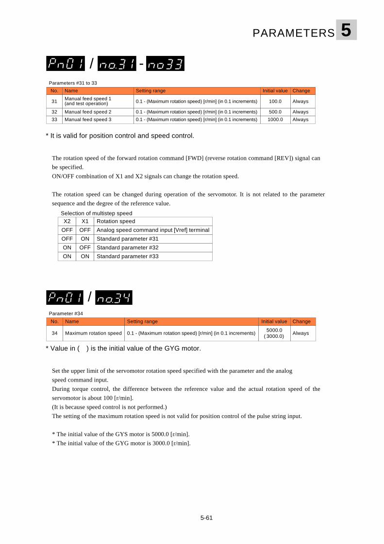
5PARAMETERS
5-61
/ -
Parameters #31 to 33
No. Name Setting range Initial value Change
31 Manual feed speed 1 (and test operation) 0.1 - (Maximum rotation speed) [r/min] (in 0.1 increments) 100.0 Always
32 Manual feed speed 2 0.1 - (Maximum rotation speed) [r/min] (in 0.1 increments) 500.0 Always
33 Manual feed speed 3 0.1 - (Maximum rotation speed) [r/min] (in 0.1 increments) 1000.0 Always
* It is valid for position control and speed control.
The rotation speed of the forward rotation command [FWD] (reverse rotation command [REV]) signal can be specified. ON/OFF combination of X1 and X2 signals can change the rotation speed. The rotation speed can be changed during operation of the servomotor. It is not related to the parameter sequence and the degree of the reference value.
Analog speed command input [Vref] terminal
Standard parameter #31
Selection of multistep speed
Rotation speed
OFF
X2
OFF
OFF
X1
OFF
ON
ON
ON ON
Standard parameter #32
Standard parameter #33
/
Parameter #34
No. Name Setting range Initial value Change
34 Maximum rotation speed 0.1 - (Maximum rotation speed) [r/min] (in 0.1 increments)5000.0
( 3000.0)Always
* Value in ( ) is the initial value of the GYG motor.
Set the upper limit of the servomotor rotation speed specified with the parameter and the analog speed command input. During torque control, the difference between the reference value and the actual rotation speed of the servomotor is about 100 [r/min]. (It is because speed control is not performed.) The setting of the maximum rotation speed is not valid for position control of the pulse string input. * The initial value of the GYS motor is 5000.0 [r/min]. * The initial value of the GYG motor is 3000.0 [r/min].
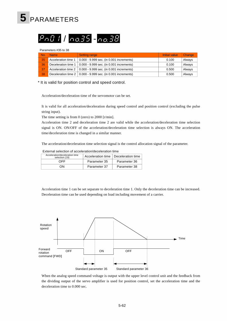
5 PARAMETERS
5-62
-/
35 Acceleration time 1 0.000 - 9.999 sec. (in 0.001 increments) 0.100 Always
36 Deceleration time 1 0.100 Always
37 Acceleration time 2 0.500 Always
38 Deceleration time 2 0.500 Always
0.000 - 9.999 sec. (in 0.001 increments)
0.000 - 9.999 sec. (in 0.001 increments)
0.000 - 9.999 sec. (in 0.001 increments)
Parameters #35 to 38
No. Name Setting range Initial value Change
* It is valid for position control and speed control.
Acceleration/deceleration time of the servomotor can be set. It is valid for all acceleration/deceleration during speed control and position control (excluding the pulse string input). The time setting is from 0 (zero) to 2000 [r/min]. Acceleration time 2 and deceleration time 2 are valid while the acceleration/deceleration time selection signal is ON. ON/OFF of the acceleration/deceleration time selection is always ON. The acceleration time/deceleration time is changed in a similar manner. The acceleration/deceleration time selection signal is the control allocation signal of the parameter.
External selection of acceleration/deceleration time
Parameter 36OFF
Acceleration/deceleration time selection (19) Deceleration time
Parameter 35
Acceleration time
ON Parameter 38Parameter 37
Acceleration time 1 can be set separate to deceleration time 1. Only the deceleration time can be increased. Deceleration time can be used depending on load including movement of a carrier.
When the analog speed command voltage is output with the upper level control unit and the feedback from the dividing output of the servo amplifier is used for position control, set the acceleration time and the deceleration time to 0.000 sec.
Time
Rotation speed
Forward rotation command [FWD]
OFF ON OFF
Standard parameter 35 Standard parameter 36
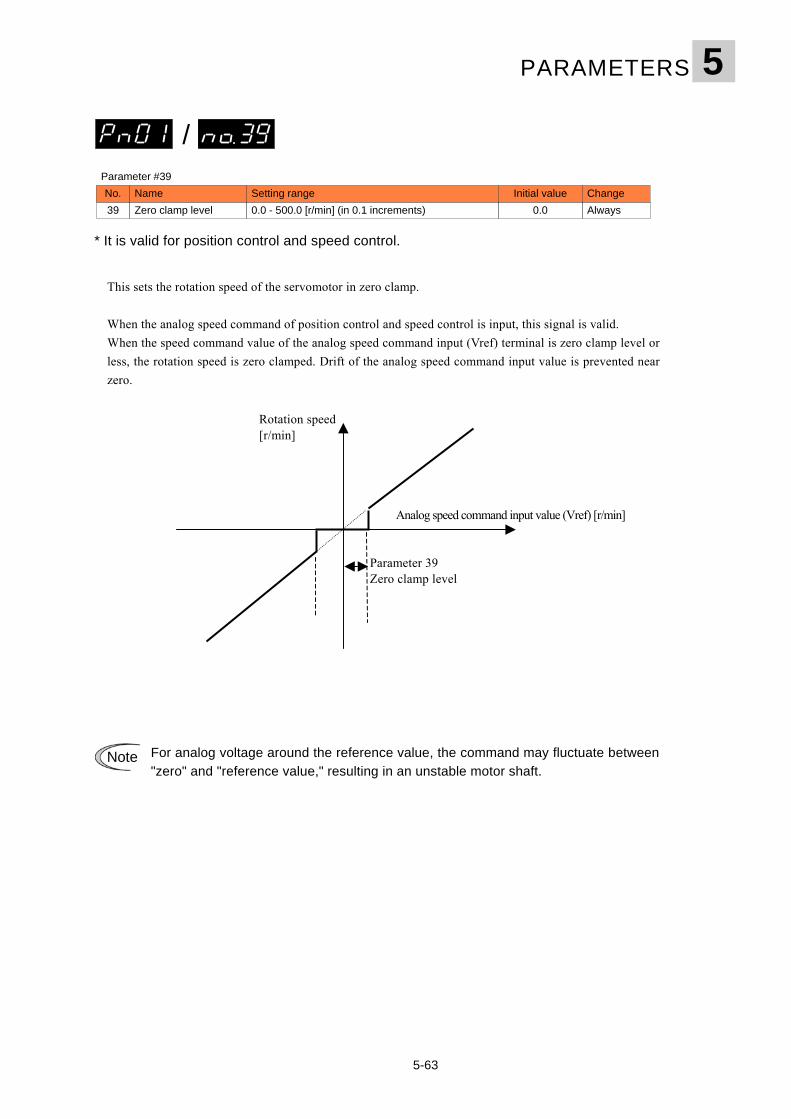
5PARAMETERS
5-63
/
Parameter #39
No. Name Setting range Initial value Change
39 Zero clamp level 0.0 - 500.0 [r/min] (in 0.1 increments) 0.0 Always
* It is valid for position control and speed control.
This sets the rotation speed of the servomotor in zero clamp. When the analog speed command of position control and speed control is input, this signal is valid. When the speed command value of the analog speed command input (Vref) terminal is zero clamp level or less, the rotation speed is zero clamped. Drift of the analog speed command input value is prevented near zero.
Rotation speed [r/min]
Analog speed command input value (Vref) [r/min] Parameter 39
Zero clamp level
For analog voltage around the reference value, the command may fluctuate between "zero" and "reference value," resulting in an unstable motor shaft.
Note
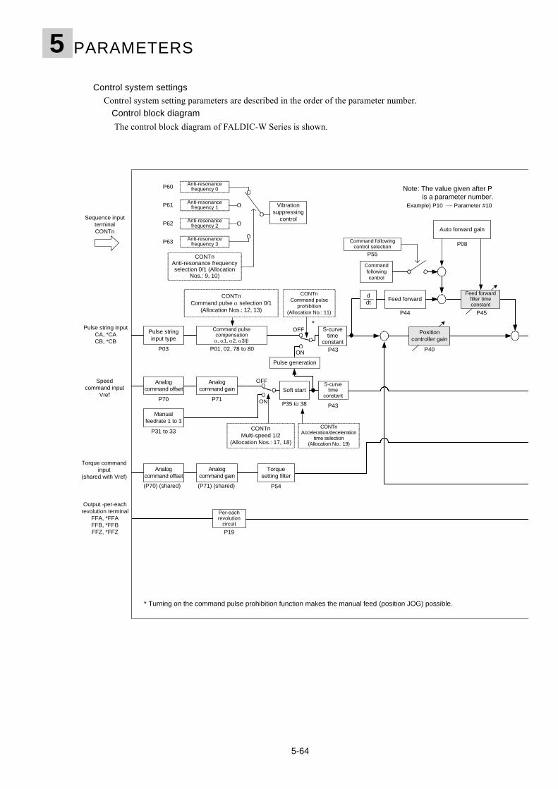
5 PARAMETERS
5-64
Control system settings Control system setting parameters are described in the order of the parameter number. Control block diagram
The control block diagram of FALDIC-W Series is shown.
Pulse string inputCA, *CACB, *CB
Sequence input terminalCONTn
Output -per-each revolution terminal
FFA, *FFAFFB, *FFBFFZ, *FFZ
Speed command input
Vref
Torque command input
(shared with Vref)
* Turning on the command pulse prohibition function makes the manual feed (position JOG) possible.
P03
Command pulse compensationα, α1, α2, α3/β
P01, 02, 78 to 80
S-curve time
constantP43
Per-each revolution
circuitP19
Vibration suppressing
control
Anti-resonance frequency 0
CONTnAnti-resonance frequency selection 0/1 (Allocation
Nos.: 9, 10)
P60
Anti-resonance frequency 1P61
Anti-resonance frequency 2P62
Anti-resonance frequency 3P63
CONTnCommand pulse α selection 0/1
(Allocation Nos.: 12, 13)
P31 to 33
Soft startS-curve
time constant
P43
Pulse generation
P35 to 38
CONTnAcceleration/deceleration
time selection (Allocation No.: 19)
Analog command gain
P70 P71
Analog command gain
(P70) (shared) (P71) (shared) P54
CONTnCommand pulse
prohibition (Allocation No.: 11)
*
CONTnMulti-speed 1/2
(Allocation Nos.: 17, 18)
ON
OFFPulse string input type
Manual feedrate 1 to 3
Analog command offset
Analog command offset
Torque setting filter
ON
OFF
ddt
Position controller gain
Feed forward
P44 P45
P40
Command following control
P55
Command following control selection
Auto forward gain
P08
Feed forward filter time constant
Note: The value given after P is a parameter number. Example) P10 Parameter #10
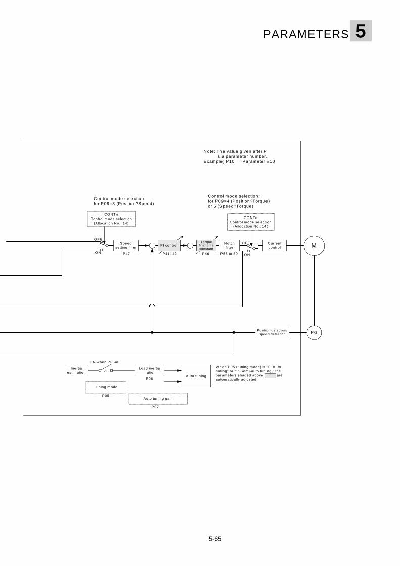
5PARAMETERS
5-65
Speed setting filter
P47
PI control
P41, 42 P46
Notch filter
Current control M
Position detection/Speed detection
P56 to 59
Inertia estimation
Tuning m ode
P05
O N when P05=0
Load inertia ratio
P06Auto tuning
Auto tuning gain
P07
CO NTnControl m ode selection
(A llocation No.: 14)
CO NTnControl m ode selection
(A llocation No.: 14)
Control m ode selection: for P09=3 (Position?Speed)
Control m ode selection: for P09=4 (Position?Torque) or 5 (Speed?Torque)
Torque filter tim e constant
PG
ON
O FF
ON
OFF
W hen P05 (tuning m ode) is "0: Auto tuning" or "1: Sem i-auto tuning," the param eters shaded above are autom atically adjusted .
Note: The value given after P is a param eter num ber.Exam ple) P10 Param eter #10

5 PARAMETERS
5-66
/ -
Parameters #40 through #42
No. Name Setting range Initial value Change
40 Position controller gain 1 1 to 1000 [rad/sec] (in 1 increments) 77 Always
41 Speed response 1 1 to 1000 [Hz] (in 1 increments) 57 Always
42 Speed controller integration time 1 1.0 to 1000.0 [msec] (in 0.1 increments) 25.9 Always * The initial value is for the GYS motor.
/ -
Parameters #45 and #46
No. Name Setting range Initial value Change
45 Feed forward filter time constant 0.0 to 250.0 [msec] (in 0.1 increments) 12.9 Always
46 Torque filter time constant 0.00 to 20.00 [msec] (in 0.01 increments) 0.31 Always
* The initial value is for the GYS motor.
* It is valid for position control and speed control. No. 40 and No. 45 are only valid for position control.
These parameters are automatically updated when “auto tuning” or “semi-auto tuning” is selected at basic setting parameter #5. Specify them when “manual tuning” is selected.
No. NameTuning mode
06 Load inertia ratio
07 Auto tuning gain
0: Auto 1: Semi-auto 2: Manual
- O O
O O X
40 Position controller gain 1 - - O
41 Speed response 1 - - O
42 Speed controller integration time 1 - - O
45 Feed forward filter time constant - - O
46 Torque filter time constant - - O
* O : Parameter which must be set- : Parameter which may not be set (The value is automatically calculated inside the amplifier and the
result is reflected on the parameter.)X : The parameter has no effect even if it is set.
5PARAMETERS
5-67
Position controller gain 1 (Parameter 40) This parameter determines the response of the position control loop. A larger setting improves the response to the position command, while too large a setting is likely to generate overshoot. Speed response 1 (Parameter 41) This parameter determines the response of the speed control loop. A larger setting improves the response of the servomotor, while too large a setting may cause the mechanical system to vibrate.
Speed controller integration time 1 (Parameter 42) This parameter determines the response of the speed control loop. A smaller setting improves the response of the servomotor, while too small a setting may cause the mechanical system to vibrate. Feed forward filter time constant (Parameter 45) This parameter filters feed forward action of the position control loop. A smaller setting improves the response while it may cause torque shock. Torque filter time constant (Parameter 46) This parameter filters the torque command. A larger setting suppresses resonance of the machine while stability in the control may be undermined.
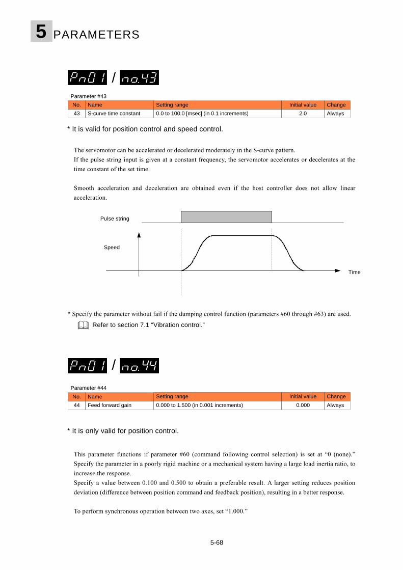
5 PARAMETERS
5-68
/
Parameter #43
No. Name Setting range Initial value Change
43 S-curve time constant 0.0 to 100.0 [msec] (in 0.1 increments) 2.0 Always
* It is valid for position control and speed control. The servomotor can be accelerated or decelerated moderately in the S-curve pattern. If the pulse string input is given at a constant frequency, the servomotor accelerates or decelerates at the time constant of the set time. Smooth acceleration and deceleration are obtained even if the host controller does not allow linear acceleration.
* Specify the parameter without fail if the dumping control function (parameters #60 through #63) are used.
Refer to section 7.1 “Vibration control.”
/
Parameter #44
No. Name Setting range Initial value Change
44 Feed forward gain 0.000 to 1.500 (in 0.001 increments) 0.000 Always
* It is only valid for position control.
This parameter functions if parameter #60 (command following control selection) is set at “0 (none).” Specify the parameter in a poorly rigid machine or a mechanical system having a large load inertia ratio, to increase the response. Specify a value between 0.100 and 0.500 to obtain a preferable result. A larger setting reduces position deviation (difference between position command and feedback position), resulting in a better response. To perform synchronous operation between two axes, set “1.000.”
Speed
Time
Pulse string

5PARAMETERS
5-69
/
Parameter #47
No. Name Setting range Initial value Change
47 Speed setting filter 0.00 to 20.00 [msec] (in 0.01 increments) 0.00 Always
* It is valid for position control and speed control.
Specify the parameter to filter the speed command. * No change is necessary in principle.
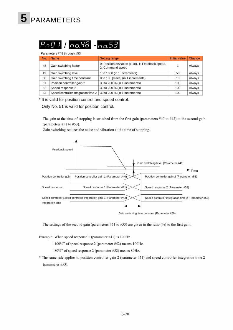
5 PARAMETERS
5-70
/ -
Parameters #48 through #53
No. Name Setting range Initial value Change
48 Gain switching factor0: Position deviation (x 10), 1: Feedback speed, 2: Command speed
1 Always
49 Gain switching level 1 to 1000 (in 1 increments) 50 Always
50 Gain switching time constant 0 to 100 [msec] (in 1 increments) 10 Always
51 Position controller gain 2 30 to 200 % (in 1 increments) 100 Always
52 Speed response 2 30 to 200 % (in 1 increments) 100 Always
53 Speed controller integration time 2 30 to 200 % (in 1 increments) 100 Always * It is valid for position control and speed control.
Only No. 51 is valid for position control.
The gain at the time of stopping is switched from the first gain (parameters #40 to #42) to the second gain (parameters #51 to #53). Gain switching reduces the noise and vibration at the time of stopping.
The settings of the second gain (parameters #51 to #53) are given in the ratio (%) to the first gain.
Example: When speed response 1 (parameter #41) is 100Hz
“100%” of speed response 2 (parameter #52) means 100Hz.
“80%” of speed response 2 (parameter #52) means 80Hz.
* The same rule applies to position controller gain 2 (parameter #51) and speed controller integration time 2
(parameter #53).
Position controller gain 2 (Parameter #51) Position controller gain 1 (Parameter #40)
Time
Gain switching level (Parameter #49)
Feedback speed
Position controller gain
Gain switching time constant (Parameter #50)
Speed response 1 (Parameter #41)Speed response
Speed controller integration time 1 (Parameter #42)Speed controller
integration time
Speed response 2 (Parameter #52)
Speed controller integration time 2 (Parameter #53)

5PARAMETERS
5-71
/
Parameter #54
No. Name Setting range Initial value Change
54 0.000 - 9.999 [sec] (in 0.001 increments) 0.000 AlwaysTorque setting filter * It is only valid for torque control.
With this parameter, the input voltage of the analog torque command input [Vref] terminal can be filtered.
/
Parameter #55
No. Name Setting range Initial value Change
55Command following control selection
0: None, 1: Command following control, 2: Command following control (with correction on stop)
0 Power
* It is only valid for position control. Use the parameter to select the command following control mode where the mechanical system follows the command without delay to the pulse command.
Refer to section 7.2 “Command following control.”

5 PARAMETERS
5-72
/ -
Parameters #56 through #59
No. Name Setting range Initial value Change
56 Notch filter 1 frequency 10 to 200 [x 100 Hz] (in 1 increments) 200 Always
57 Notch filter 1 damping amount 0 to 40 [dB] (in 1 increments) 0 Always
58 Notch filter 2 frequency 10 to 200 [x 10Hz] (in 1 increments) 200 Always
59 Notch filter 2 damping amount 0 to 40 [dB] (in 1 increments) 0 Always * It is valid for position control and speed control.
Specify to suppress resonance of the mechanical system. Resonance can be suppressed at up to two points.
Notch filter setting method
i) Use the servo analysis function of the PC loader (option) to determine the resonance point of
the machine.
ii) Specify the resonance frequency and damping amount of the resonance point of the machine
in parameters.
1 Resonance frequency → Parameter #56 (Notch filter 1 frequency) 2 Depth → Parameter #57 (Notch filter 1 damping amount)* * Too deep a damping amount may undermine stability of the control. Avoid setting too large a value.
Gain[dB]
Frequency [Hz]
Resonance point
1 Resonance frequency
2 Depth
Notch filter 1,damping amount
Notch filter 1,frequency
Use the servo analysis
function again.
The notch filter functions at the resonancepoint as shown in the figure above.
The resonance point is eliminateddue to the notch filter.

5PARAMETERS
5-73
/ -
Parameters #60 through #63
No. Name Setting range Initial value Change
60 Anti-resonance frequency 0 5.0 to 200.0 [Hz] (in 0.1 increments) 200.0 Always
61 Anti-resonance frequency 1 5.0 to 200.0 [Hz] (in 0.1 increments) 200.0 Always
62 Anti-resonance frequency 2 5.0 to 200.0 [Hz] (in 0.1 increments) 200.0 Always
63 Anti-resonance frequency 3 5.0 to 200.0 [Hz] (in 0.1 increments) 200.0 Always * It is only valid for position control.
Use these parameters to specify anti-resonance frequencies and suppress vibration of the workpiece (vibration suppressing control). The vibration suppressing control function becomes invalid with 200.0Hz (factory setting).
Refer to section 7.1 “Vibration suppressing control.”
/ -
Parameters #64 through #69
No. Name Setting range Initial value Change
64to69
Not used - 0 -
These parameters are not used.
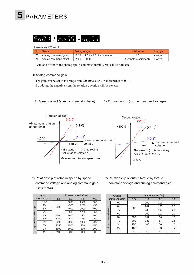
5 PARAMETERS
5-74
/ -
Parameters #70 and 71
No. Name Setting range Initial value Change
70 Analog command gain ±0.10 - ±1.5 (in 0.01 increments) 1.0 Always
71 Analog command offset -2000 - +2000 (Set before shipment) Always Gain and offset of the analog speed command input [Vref] can be adjusted.
Analog command gain
The gain can be set in the range from ±0.10 to ±1.50 in increments of 0.01. By adding the negative sign, the rotation direction will be reverse.
1) Speed control (speed command voltage) 2) Torque control (torque command voltage)
*) Relationship of rotation speed by speed *) Relationship of output torque by torque command voltage and analog command gain. command voltage and analog command gain. (GYS motor)
Spe
ed c
omm
and
volta
ge
10V
9V
Rotation speed [r/min]Analog command gain
8V
7V
6V
5V
4V
3V2V
1V
1.5
5000
3000
22501500
750
1.0
5000
4500
4000
3500
3000
2500
2000
15001000
500
0.5 0.1
2500
2250
2000
1750
1500
1250
1000
750500
250
4500
3750
500
450
400
350
300
250
200
150100
50
Tor
que
com
man
d vo
ltage
9V
Output torque [%]Analog command gain
8V
7V
6V
5V4V
3V
2V
1V
1.5
300
150
10050
1.0
300
267
233200
167
133
100
6733
0.5 0.1
150
133
117100
83
67
50
3317
250
200
30
27
2320
17
13
10
6.73.3
+9V
+300%
-300%
-9V
(×1.5)* Output torque
* The value in ( ) is the setting value for parameter 70.
(×1.0)*
(×0.1)* Torque command voltage
+Maximum rotation speed r/min
-Maximum rotation speed r/min
+10[V]
-10[V]
(×1.5)* Rotation speed
* The value in ( ) is the setting value for parameter 70.
(×1.0)*
(×0.1)* Speed command voltage
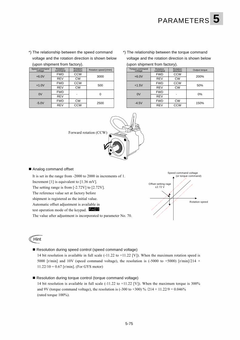
5PARAMETERS
5-75
*) The relationship between the speed command *) The relationship between the torque command voltage and the rotation direction is shown below voltage and the rotation direction is shown below (upon shipment from factory). (upon shipment from factory).
Rotation command
Rotation direction
Speed command voltage
FWD CCW+6.0V
Rotation speed [r/min]
3000REV CW
FWD CCW+1.0V 500
REV CWFWD
-0V 0REV
FWD CW-5.0V 2500
REV CCW
Analog command offset
It is set in the range from -2000 to 2000 in increments of 1. Increment [1] is equivalent to [1.36 mV]. The setting range is from [-2.72V] to [2.72V]. The reference value set at factory before shipment is registered as the initial value. Automatic offset adjustment is available in test operation mode of the keypad. The value after adjustment is incorporated to parameter No. 70.
Resolution during speed control (speed command voltage) 14 bit resolution is available in full scale (-11.22 to +11.22 [V]). When the maximum rotation speed is 5000 [r/min] and 10V (speed command voltage), the resolution is (-5000 to +5000) [r/min]/214 × 11.22/10 = 0.67 [r/min]. (For GYS motor)
Resolution during torque control (torque command voltage) 14 bit resolution is available in full scale (-11.22 to +11.22 [V]). When the maximum torque is 300% and 9V (torque command voltage), the resolution is (-300 to +300) % /214 × 11.22/9 = 0.046% (rated torque 100%).
Speed command voltage (or torque command)
Rotation speed
Offset setting rage ±2.72 V
Forward rotation (CCW)
Rotation command
Rotation direction
Torque command voltage
FWD CCW+6.0V
Output torque
200%REV CW
FWD CCW+1.5V 50%
REV CWFWD
-0V 0%REV
FWD CW-4.5V 150%
REV CCW
Hint
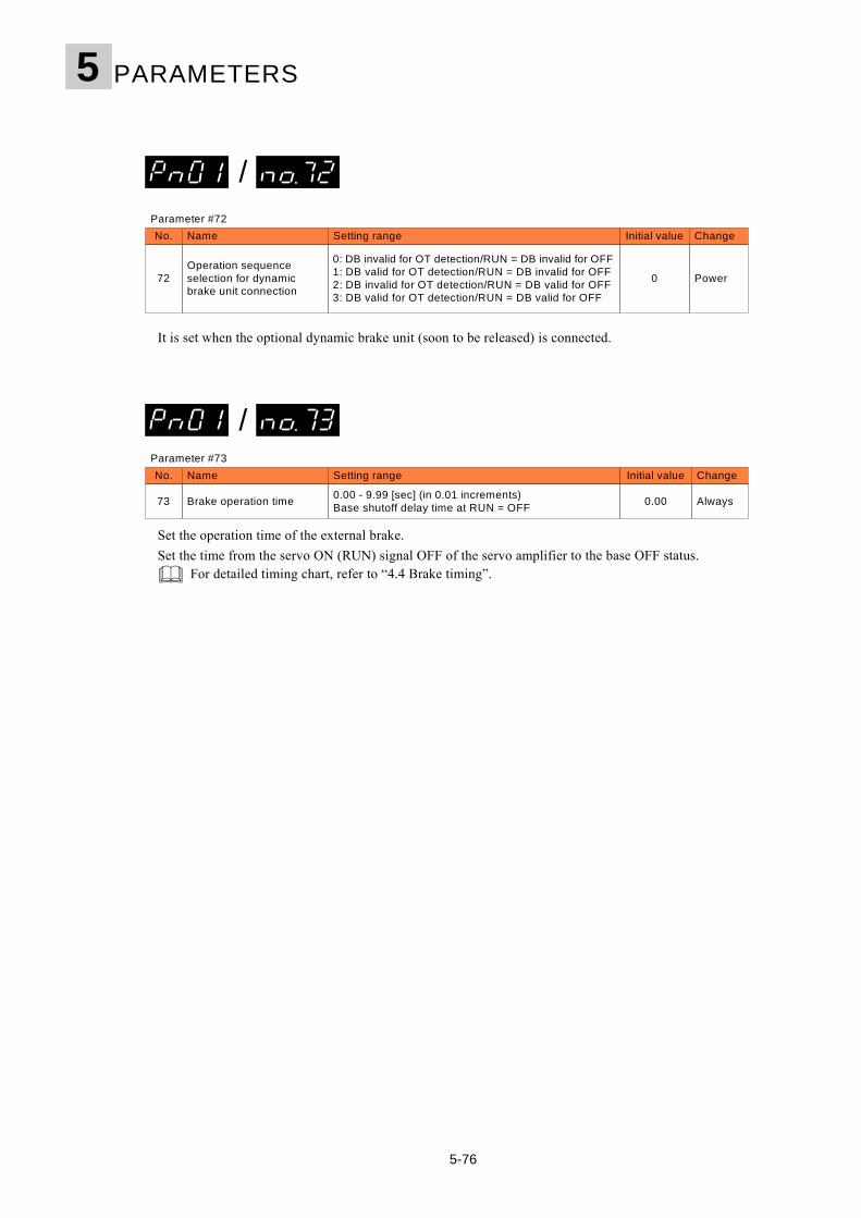
5 PARAMETERS
5-76
/
Parameter #72
No. Name Setting range Initial value Change
72Operation sequence selection for dynamic brake unit connection
0 Power
0: DB invalid for OT detection/RUN = DB invalid for OFF1: DB valid for OT detection/RUN = DB invalid for OFF2: DB invalid for OT detection/RUN = DB valid for OFF3: DB valid for OT detection/RUN = DB valid for OFF
It is set when the optional dynamic brake unit (soon to be released) is connected.
/
Parameter #73
No. Name Setting range Initial value Change
73 Brake operation time0.00 - 9.99 [sec] (in 0.01 increments) Base shutoff delay time at RUN = OFF
0.00 Always
Set the operation time of the external brake. Set the time from the servo ON (RUN) signal OFF of the servo amplifier to the base OFF status.
For detailed timing chart, refer to “4.4 Brake timing”.
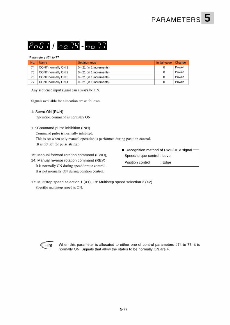
5PARAMETERS
5-77
-/
Parameters #74 to 77
No. Name Setting range Initial value Change
74 CONT normally ON 1 0 - 21 (in 1 increments) 0 Power
75
76
77
CONT normally ON 2
CONT normally ON 3
CONT normally ON 4
0 - 21 (in 1 increments)
0 - 21 (in 1 increments)
0 - 21 (in 1 increments)
0
0
0
Power
Power
Power
Any sequence input signal can always be ON. Signals available for allocation are as follows: 1: Servo ON (RUN)
Operation command is normally ON. 11: Command pulse inhibition (INH)
Command pulse is normally inhibited. This is set when only manual operation is performed during position control. (It is not set for pulse string.)
15: Manual forward rotation command (FWD), 14: Manual reverse rotation command (REV)
It is normally ON during speed/torque control. It is not normally ON during position control.
17: Multistep speed selection 1 (X1), 18: Multistep speed selection 2 (X2)
Specific multistep speed is ON.
Speed/torque control : Level
Position control : Edge
Recognition method of FWD/REV signal
When this parameter is allocated to either one of control parameters #74 to 77, it isnormally ON. Signals that allow the status to be normally ON are 4.
Hint
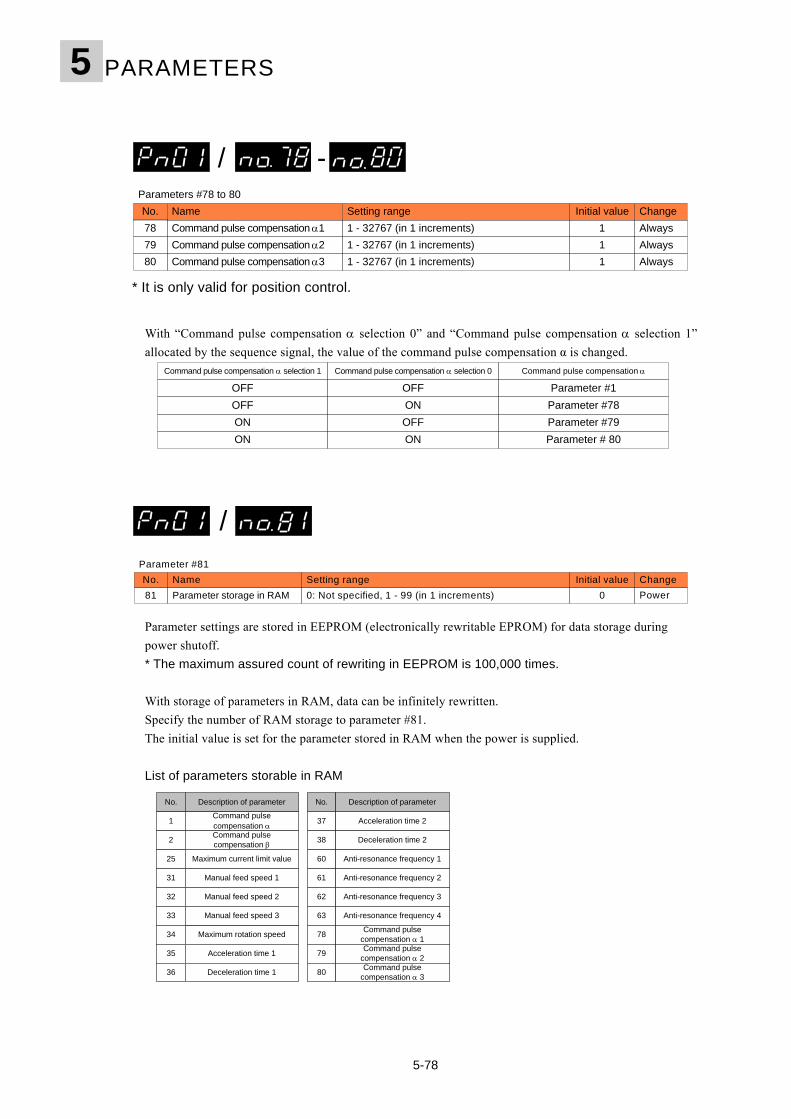
5 PARAMETERS
5-78
-/
Parameters #78 to 80No. Name Setting range Initial value Change78 Command pulse compensation α1 1 - 32767 (in 1 increments) 1 Always7980
Command pulse compensation α2Command pulse compensation α3
1 - 32767 (in 1 increments)1 - 32767 (in 1 increments)
11
AlwaysAlways
* It is only valid for position control.
With “Command pulse compensation α selection 0” and “Command pulse compensation α selection 1” allocated by the sequence signal, the value of the command pulse compensation α is changed.
Command pulse compensation α selection 1
OFF
ONOFF
ON
Command pulse compensation α selection 0
ONOFF
OFFON
Command pulse compensation α
Parameter #1Parameter #78Parameter #79Parameter # 80
/
Parameter #81
No. Name Setting range Initial value Change
81 Parameter storage in RAM 0: Not specified, 1 - 99 (in 1 increments) 0 Power
Parameter settings are stored in EEPROM (electronically rewritable EPROM) for data storage during power shutoff. * The maximum assured count of rewriting in EEPROM is 100,000 times. With storage of parameters in RAM, data can be infinitely rewritten. Specify the number of RAM storage to parameter #81. The initial value is set for the parameter stored in RAM when the power is supplied. List of parameters storable in RAM
No.
1
2
25
31
32
33
34
35
36
37
38
Description of parameter
Command pulse compensation α
Maximum current limit value
Manual feed speed 1
Maximum rotation speed
Acceleration time 1
Command pulse compensation β
Manual feed speed 2
Manual feed speed 3
Deceleration time 1
Acceleration time 2
Deceleration time 2
No.
60
61
62
63
78
79
80
Description of parameter
Anti-resonance frequency 1
Anti-resonance frequency 2
Anti-resonance frequency 3
Anti-resonance frequency 4
Command pulse compensation α 1Command pulse
compensation α 2 Command pulse
compensation α 3
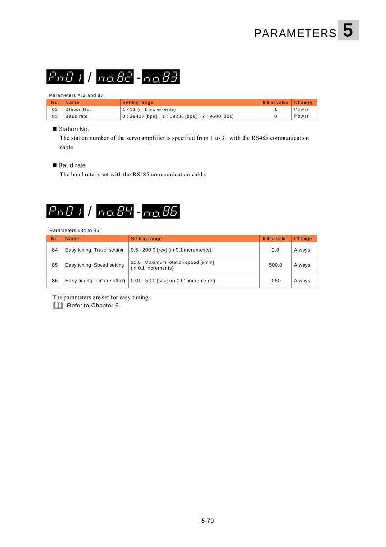
5PARAMETERS
5-79
-/
Param eters #82 and 83
No. Nam e Setting range Initial value Change
82 Station No. 1 - 31 (in 1 increm ents) 1 Power
83 Baud rate 0 : 38400 [bps] , 1 : 19200 [bps] , 2 : 9600 [bps] 0 Power Station No. The station number of the servo amplifier is specified from 1 to 31 with the RS485 communication cable.
Baud rate The baud rate is set with the RS485 communication cable.
-/
Parameters #84 to 86
No. Name Setting range Initial value Change
84 Easy tuning: Travel setting 0.5 - 200.0 [rev] (in 0.1 increments) 2.0 Always
85
86
10.0 - Maximum rotation speed [r/min] (in 0.1 increments)
0.01 - 5.00 [sec] (in 0.01 increments)
500.0
0.50
Easy tuning: Speed setting
Easy tuning: Timer setting
Always
Always
The parameters are set for easy tuning.
Refer to Chapter 6.
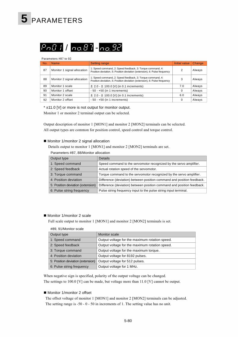
5 PARAMETERS
5-80
-/
Parameters #87 to 92
No. Name Setting range Initial value Change
87 Monitor 1 signal allocation 2 Always
88
89 Monitor 1 scale
1: Speed command, 2: Speed feedback, 3: Torque command, 4: Position deviation, 5: Position deviation (extension), 6: Pulse frequency
± 2.0 - ± 100.0 [V] (in 0.1 increments)
3
7.0
Always
Always
90 Monitor 1 offset - 50 - +50 (in 1 increments) 0 Always
91
92
6.0
0
Always
Always
Monitor 2 signal allocation
Monitor 2 scale
Monitor 2 offset
± 2.0 - ± 100.0 [V] (in 0.1 increments)
- 50 - +50 (in 1 increments)
1: Speed command, 2: Speed feedback, 3: Torque command, 4: Position deviation, 5: Position deviation (extension), 6: Pulse frequency
* ±11.0 [V] or more is not output for monitor output. Monitor 1 or monitor 2 terminal output can be selected. Output description of monitor 1 [MON1] and monitor 2 [MON2] terminals can be selected. All output types are common for position control, speed control and torque control.
Monitor 1/monitor 2 signal allocation Details output to monitor 1 [MON1] and monitor 2 [MON2] terminals are set.
Monitor 1/monitor 2 scale Full scale output to monitor 1 [MON1] and monitor 2 [MON2] terminals is set.
#89, 91/Monitor scale
Output type
1: Speed command
2: Speed feedback
3: Torque command
4: Position deviation
5: Position deviation (extension)
6: Pulse string frequency
Monitor scale
Output voltage for the maximum rotation speed.
Output voltage for the maximum rotation speed.
Output voltage for the maximum torque.
Output voltage for 8192 pulses.
Output voltage for 1 MHz.
Output voltage for 512 pulses.
When negative sign is specified, polarity of the output voltage can be changed. The settings to 100.0 [V] can be made, but voltage more than 11.0 [V] cannot be output.
Monitor 1/monitor 2 offset The offset voltage of monitor 1 [MON1] and monitor 2 [MON2] terminals can be adjusted. The setting range is -50 - 0 - 50 in increments of 1. The setting value has no unit.
Parameters #87, 88/Monitor allocation
Output type Details
1: Speed command Speed command to the servomotor recognized by the servo amplifier.
2: Speed feedback Actual rotation speed of the servomotor.
3: Torque command
4: Position deviation
Torque command to the servomotor recognized by the servo amplifier.
Difference (deviation) between position command and position feedback.
5: Position deviation (extension)
6: Pulse string frequency Pulse string frequency input to the pulse string input terminal.
Difference (deviation) between position command and position feedback.
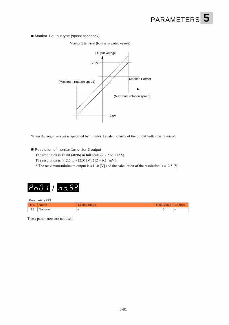
5PARAMETERS
5-81
Monitor 1 output type (speed feedback)
When the negative sign is specified by monitor 1 scale, polarity of the output voltage is reversed.
Resolution of monitor 1/monitor 2 output The resolution is 12 bit (4096) in full scale (-12.5 to +12.5). The resolution is (-12.5 to +12.5) [V]/212 = 6.1 [mV]. * The maximum/minimum output is ±11.0 [V] and the calculation of the resolution is ±12.5 [V].
/Parameters #93
No. Name Setting range Initial value Change
93 Not used - 0 -
These parameters are not used.
-7.0V
+7.0V
Output voltage
(Maximum rotation speed)
Monitor 1 terminal (both anticipated values)
Monitor 1 offset(Maximum rotation speed)

5 PARAMETERS
5-82
-/
Parameters #94 to 97
No. Name Setting range Initial value Change
95 For adjustment by manufacturer - Adjusted value -
96 For adjustment by manufacturer - Adjusted value -
97 For adjustment by manufacturer - Adjusted value -
94 For adjustment by manufacturer - Adjusted value -
The parameters are for adjustment by manufacturer. Do not change them.
-/
Parameters #98 and 99
No. Name Setting range Initial value Change
98to99
Not used - 0 -
These parameters are not used.
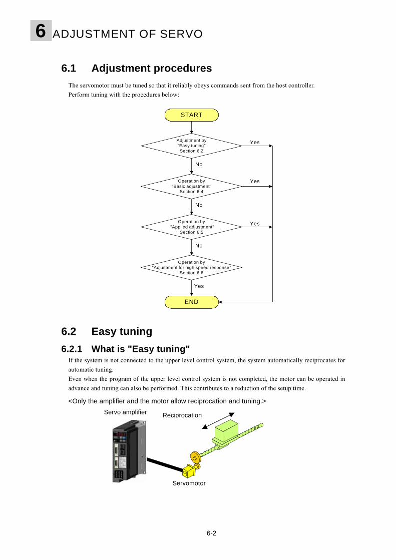
6 ADJUSTMENT OF SERVO
6-2
6.1 Adjustment procedures The servomotor must be tuned so that it reliably obeys commands sent from the host controller. Perform tuning with the procedures below:
6.2 Easy tuning 6.2.1 What is "Easy tuning"
If the system is not connected to the upper level control system, the system automatically reciprocates for automatic tuning. Even when the program of the upper level control system is not completed, the motor can be operated in advance and tuning can also be performed. This contributes to a reduction of the setup time.
<Only the amplifier and the motor allow reciprocation and tuning.>
No
Yes
START
Adjustment by "Easy tuning" Section 6.2
END
Operation by "Basic adjustment"
Section 6.4
Operation by "Applied adjustment"
Section 6.5
Yes
No
Yes
Operation by "Adjustment for high speed response"
Section 6.6
No
Yes
Servo amplifier
Servomotor
Reciprocation
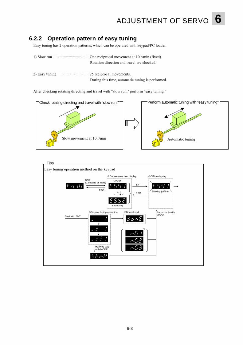
ADJUSTMENT OF SERVO 6
6-3
6.2.2 Operation pattern of easy tuning Easy tuning has 2 operation patterns, which can be operated with keypad/PC loader.
1) Slow run ····································One reciprocal movement at 10 r/min (fixed). Rotation direction and travel are checked.
2) Easy tuning ······························25 reciprocal movements. During this time, automatic tuning is performed.
After checking rotating directing and travel with "slow run," perform "easy tuning."
Check rotating directing and travel with "slow run."
Slow movement at 10 r/min
Perform automatic tuning with "easy tuning".
Automatic tuning
Easy tuning operation method on the keypad Tips
∨∧
ENT
ENT (1 second or more)
ESC
*1
Halfway stop with MODE
Slow run
Easy tuning
Blinking (offline)
Course selection display Offline display
Start with ENT Display during operation Normal end Return to with
MODE.
ESC

6 ADJUSTMENT OF SERVO
6-4
6.2.3 Cautions for easy tuning During easy tuning, the system is automatically operated with the function of the servo amplifier. Be careful as to safety. If the motor oscillates and an adverse effect on the machine is expected, allocate the servo ON (RUN) signal or the emergency stop (EMG) signal to the CONT signal. Perform easy tuning with these signals ON. If an error occurs during operation, turn OFF any of the signals immediately. If the machine may be damaged due to overtravel, allocate ±overtravel signal (±OT) to the CONT signal and provide the overtravel sensors at both ends of the movable travel before easy tuning.
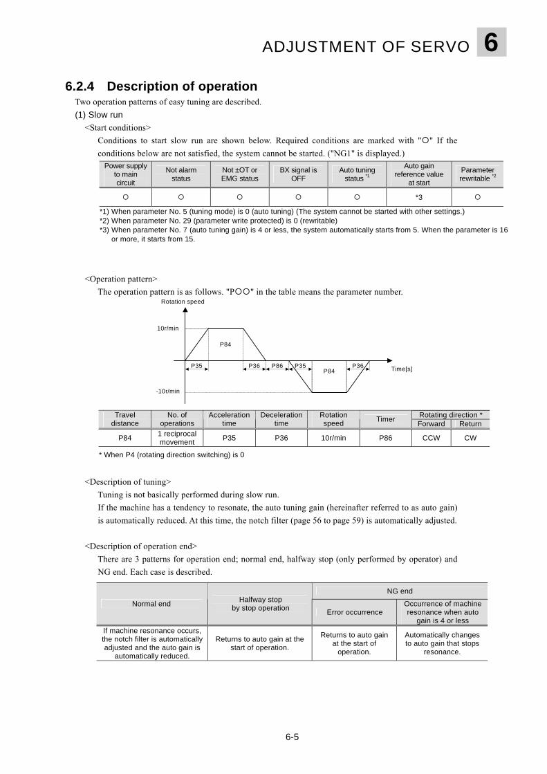
ADJUSTMENT OF SERVO 6
6-5
6.2.4 Description of operation Two operation patterns of easy tuning are described. (1) Slow run
<Start conditions> Conditions to start slow run are shown below. Required conditions are marked with " " If the conditions below are not satisfied, the system cannot be started. ("NG1" is displayed.)
<Operation pattern>
The operation pattern is as follows. "P " in the table means the parameter number.
<Description of tuning>
Tuning is not basically performed during slow run. If the machine has a tendency to resonate, the auto tuning gain (hereinafter referred to as auto gain) is automatically reduced. At this time, the notch filter (page 56 to page 59) is automatically adjusted.
<Description of operation end>
There are 3 patterns for operation end; normal end, halfway stop (only performed by operator) and NG end. Each case is described.
10r/min
Rotation speed
-10r/min
P35 P36 P86 P35 P36
P84
Time[s]P84
Rotating direction *Travel distance
No. of operations
Acceleration time
Deceleration time
Rotation speed Timer Forward Return
P84 1 reciprocal movement P35 P36 10r/min P86 CCW CW
* When P4 (rotating direction switching) is 0
NG end
Normal end Halfway stop by stop operation Error occurrence
Occurrence of machine resonance when auto
gain is 4 or less If machine resonance occurs, the notch filter is automatically adjusted and the auto gain is
automatically reduced.
Returns to auto gain at the start of operation.
Returns to auto gain at the start of
operation.
Automatically changes to auto gain that stops
resonance.
Power supply to main circuit
Not alarm status
Not ±OT or EMG status
BX signal is OFF
Auto tuning status *1
Auto gain reference value
at start
Parameter rewritable *2
*3
*1) When parameter No. 5 (tuning mode) is 0 (auto tuning) (The system cannot be started with other settings.) *2) When parameter No. 29 (parameter write protected) is 0 (rewritable) *3) When parameter No. 7 (auto tuning gain) is 4 or less, the system automatically starts from 5. When the parameter is 16
or more, it starts from 15.
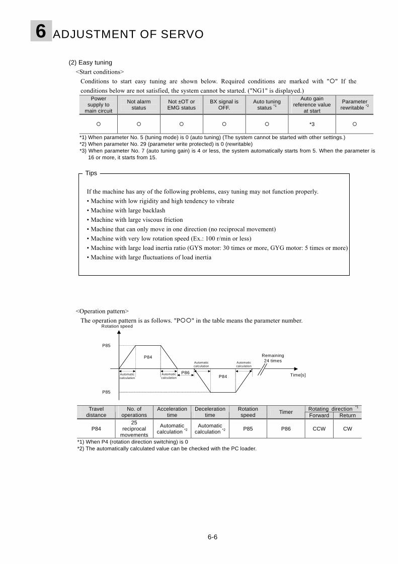
6 ADJUSTMENT OF SERVO
6-6
(2) Easy tuning <Start conditions>
Conditions to start easy tuning are shown below. Required conditions are marked with " " If the conditions below are not satisfied, the system cannot be started. ("NG1" is displayed.)
<Operation pattern>
The operation pattern is as follows. "P " in the table means the parameter number.
Power supply to
main circuit
Not alarm status
Not ±OT or EMG status
BX signal is OFF.
Auto tuning status *1
Auto gain reference value
at start
Parameter rewritable *2
*3
*1) When parameter No. 5 (tuning mode) is 0 (auto tuning) (The system cannot be started with other settings.) *2) When parameter No. 29 (parameter write protected) is 0 (rewritable) *3) When parameter No. 7 (auto tuning gain) is 4 or less, the system automatically starts from 5. When the parameter is
16 or more, it starts from 15.
Rotating direction *1Travel distance
No. of operations
Acceleration time
Deceleration time
Rotation speed Timer Forward Return
P84 25
reciprocal movements
Automatic calculation *2
Automatic calculation *2 P85 P86 CCW CW
*1) When P4 (rotation direction switching) is 0 *2) The automatically calculated value can be checked with the PC loader.
P85
Rotation speed
P85
P86
P84
Time[s]Automatic calculation
Remaining 24 times
P84
Automatic calculation
Automatic calculation
Automatic calculation
If the machine has any of the following problems, easy tuning may not function properly. • Machine with low rigidity and high tendency to vibrate • Machine with large backlash • Machine with large viscous friction • Machine that can only move in one direction (no reciprocal movement) • Machine with very low rotation speed (Ex.: 100 r/min or less) • Machine with large load inertia ratio (GYS motor: 30 times or more, GYG motor: 5 times or more)• Machine with large fluctuations of load inertia
Tips

ADJUSTMENT OF SERVO 6
6-7
<Description of tuning> During easy tuning, 25 reciprocal movements are performed. During this operation, automatic tuning (auto gain in the range from 5 to 15) is performed.
<Description of operation end>
There are 3 patterns for operation end; normal end, halfway stop (only performed by the operator) and NG end. Each case is described.
6.2.5 Factor of NG display Factors when NG is displayed during easy tuning are described (common for each mode).
<Cause of NG1 display> (1) Parameter No. 29 (parameter write protect) is "1: Write protect." (2) ±OT, EMG or external regenerative resistor overheating is detected. (3) Parameter No. 5 (tuning mode) is not "0: Auto tuning." (4) Power is not supplied to the main circuit.
<Cause of NG2 display> (1) ±OT, EMG or external regenerative resistor overheating is detected halfway. (Coasting signal is
ignored.) (2) RUN signal is turned OFF. (RUN: Started with ON.)
<Cause of NG3> (1) Auto tuning gain is 4 or less and the motor is oscillating.
NG end Normal end Halfway stop by stop
operation Error occurrence Machine resonance
occurs even when auto gain is 4 or less
Auto gain (range from 5 to 15) is
automatically and finally adjusted.
Returns to auto gain at start of operation.
Returns to auto gain at start of operation.
Automatically changes to auto gain that stops
resonance.

6 ADJUSTMENT OF SERVO
6-8
6.3 Pattern operation
6.3.1 What is pattern operation? If the system is not connected to the upper level control system, the system automatically performs reciprocation for automatic tuning. The operation continues until the system is stopped by an operator. This operation is used to confirm the effective torque (keypad: On13). (Tuning is not performed during pattern operation.)
6.3.2 Description of operation <Start conditions>
Conditions to start pattern operation are shown below. Required conditions are marked with " ". If the conditions below are not satisfied, the system cannot be started. ("NG1" is displayed.)
Power supply to main circuit Not alarm status BX signal is OFF. Not ±OT or EMG
status
Pattern operation method with keypad
Tips
ENT
Pattern operation stopwith MODE key
ENT (1 second or more)
ESC
Offline (standby status)
ENT
Pattern operation
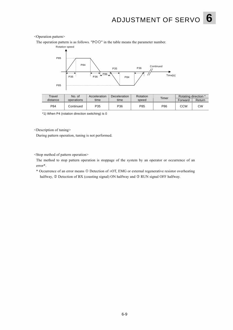
ADJUSTMENT OF SERVO 6
6-9
<Operation pattern> The operation pattern is as follows. "P " in the table means the parameter number.
<Description of tuning>
During pattern operation, tuning is not performed.
<Stop method of pattern operation>
The method to stop pattern operation is stoppage of the system by an operator or occurrence of an error*. * Occurrence of an error means Detection of ±OT, EMG or external regenerative resistor overheating
halfway, Detection of BX (coasting signal) ON halfway and RUN signal OFF halfway.
Rotating direction *Travel distance
No. of operations
Acceleration time
Deceleration time
Rotation speed Timer Forward Return
P84 Continued P35 P36 P85 P86 CCW CW
*1) When P4 (rotation direction switching) is 0
P85
Rotation speed
P85
P35P86
P84
Time[s]P36
P35 P36Continued
P84
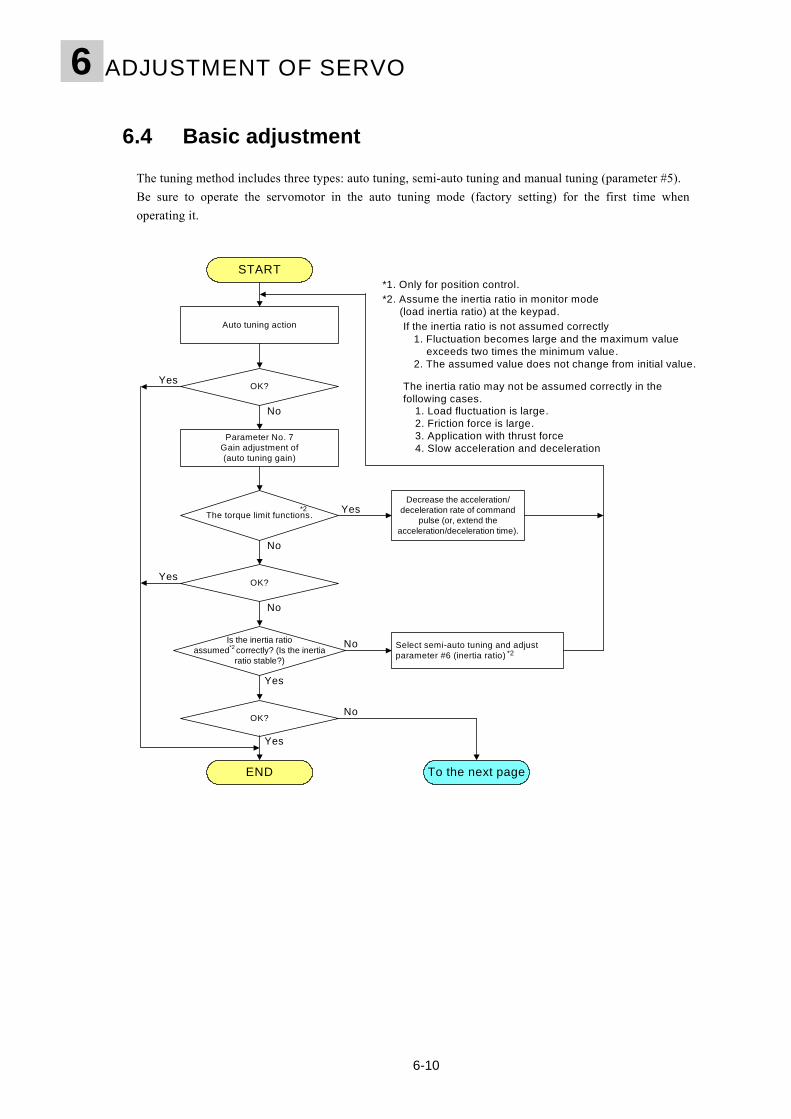
6 ADJUSTMENT OF SERVO
6-10
6.4 Basic adjustment
The tuning method includes three types: auto tuning, semi-auto tuning and manual tuning (parameter #5). Be sure to operate the servomotor in the auto tuning mode (factory setting) for the first time when operating it.
Select semi-auto tuning and adjust parameter #6 (inertia ratio)
Auto tuning action
No
Yes
No
START
OK?
Is the inertia ratio assumed*2 correctly? (Is the inertia
ratio stable?)
Parameter No. 7Gain adjustment of (auto tuning gain)
OK?
Yes
Yes
No
YesDecrease the acceleration/
deceleration rate of command pulse (or, extend the
acceleration/deceleration time).
The torque limit functions. *2
No
OK?
Yes
No
END To the next page
If the inertia ratio is not assumed correctly1. Fluctuation becomes large and the maximum value
exceeds two times the minimum value.2. The assumed value does not change from initial value.
*2. Assume the inertia ratio in monitor mode (load inertia ratio) at the keypad.
*2
1. Load fluctuation is large.2. Friction force is large.3. Application with thrust force4. Slow acceleration and deceleration
The inertia ratio may not be assumed correctly in the following cases.
*1. Only for position control.

ADJUSTMENT OF SERVO 6
6-11
ENDTo application adjustment
Parameter No. 8 *1
Adjustment of (auto forward gain)
No
YesDecrease the acceleration/
deceleration rate of command pulse (or, extend the
acceleration/deceleration time).
The torque limit functions. *1
No
Yes
OK?No
Decrease S-curve time.
No
OK?Yes
From the previous page
*1 Only for position control.
Set the zero deviation width (parameter No. 21) referring to the description below:
Ex.) When precision of ±10 µm is desired on a machine with ball screw fastening and 10 mm lead.
131072[pulse/rev]
10 × 10-3 [m] × (10×10-6 [m]) = 131.072 ≈ 131 [pulse]
Set "131" for zero deviation width (parameter No. 21).
131072[pulse/rev]
Movement per rotation [m] × (Required precision [m]) = Zero deviation width [pulse]
Hint
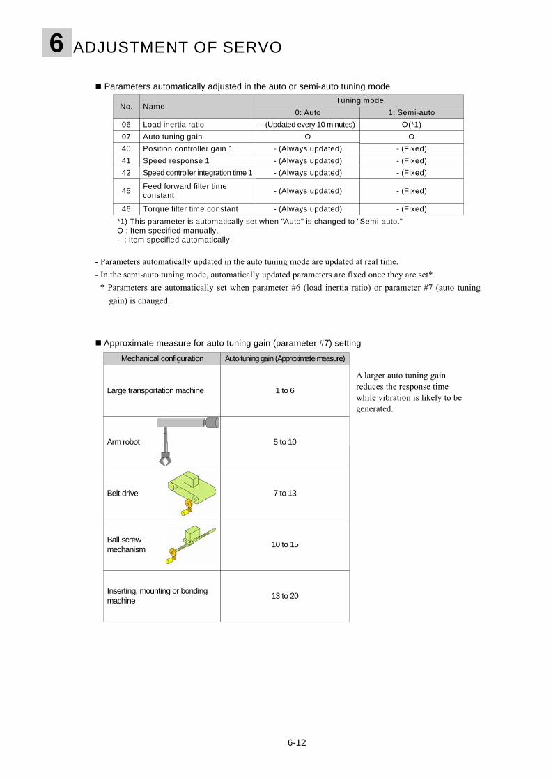
6 ADJUSTMENT OF SERVO
6-12
Parameters automatically adjusted in the auto or semi-auto tuning mode
- Parameters automatically updated in the auto tuning mode are updated at real time. - In the semi-auto tuning mode, automatically updated parameters are fixed once they are set*.
* Parameters are automatically set when parameter #6 (load inertia ratio) or parameter #7 (auto tuning gain) is changed.
Approximate measure for auto tuning gain (parameter #7) setting
Speed controller integration time 1
No. NameTuning mode
06 Load inertia ratio
07 Auto tuning gain
0: Auto
- (Updated every 10 minutes)
O
40 Position controller gain 1 - (Always updated)
41 - (Always updated)
- (Always updated)
45Feed forward filter time constant
- (Always updated)
46 Torque filter time constant - (Always updated)
*1) This parameter is automatically set when "Auto" is changed to "Semi-auto."O : Item specified manually.- : Item specified automatically.
1: Semi-auto
O(*1)
O
- (Fixed)
- (Fixed)
- (Fixed)
- (Fixed)
- (Fixed)
Speed response 1
42
Mechanical configuration Auto tuning gain (Approximate measure)
Large transportation machine 1 to 6
Belt drive
5 to 10
Ball screw mechanism
7 to 13
Inserting, mounting or bonding machine
10 to 15
Arm robot
13 to 20
A larger auto tuning gain reduces the response time while vibration is likely to be generated.

ADJUSTMENT OF SERVO 6
6-13
6.5 Application adjustment
Use this adjustment method when adjustment is not satisfactory after the procedure described in section 6.4 “Basic adjustment” or if the servomotor vibrates and the auto tuning gain (parameter #7) cannot be increased sufficiently.
Check the mechanical system for the following problems. i) Large backlash ii) Deflection of belt
No
END
START
Auto tuning gain cannot be increased due to vibration.
1. Check the mechanical system.
No
Use the servo analysis function to apply the notch filter.
Readjustment of auto tuning gain
OK?
Yes
Yes
No
Inertia ratio > 100 times?
2. Adjust the large inertia.
Yes
Adjust the second gain*2 .
*2 Decrease the speed response 2 (parameter #52). The minimum allowable value is 50%.
Return auto forward gain*1 to "5."
Readjustment of auto forward gain*1
OK?Yes
*1 It is only for position control.
No
1. Check the mechanical system.
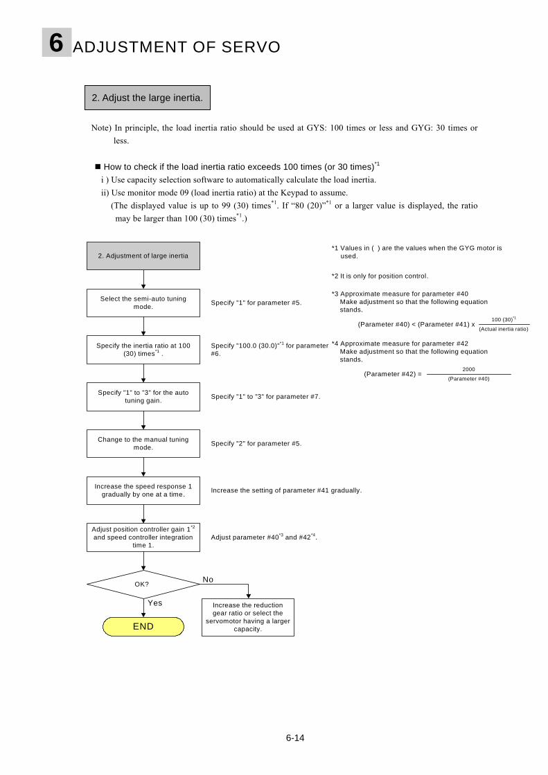
6 ADJUSTMENT OF SERVO
6-14
Note) In principle, the load inertia ratio should be used at GYS: 100 times or less and GYG: 30 times or
less.
How to check if the load inertia ratio exceeds 100 times (or 30 times)*1 i ) Use capacity selection software to automatically calculate the load inertia. ii) Use monitor mode 09 (load inertia ratio) at the Keypad to assume.
(The displayed value is up to 99 (30) times*1. If “80 (20)”*1 or a larger value is displayed, the ratio may be larger than 100 (30) times*1.)
END
Select the semi-auto tuning mode.
2. Adjustment of large inertia
Specify the inertia ratio at 100 (30) times*1 .
Specify "1" to "3" for the auto tuning gain.
Change to the manual tuning mode.
Increase the speed response 1 gradually by one at a time.
Adjust position controller gain 1*2
and speed controller integration time 1.
Specify "1" for parameter #5.
Specify "100.0 (30.0)"*1 for parameter #6.
Specify "1" to "3" for parameter #7.
Specify "2" for parameter #5.
Increase the setting of parameter #41 gradually.
OK?
Yes
No
Increase the reduction gear ratio or select the
servomotor having a larger capacity.
Adjust parameter #40*3 and #42*4.
(Parameter #42) =(Parameter #40)
2000
*4 Approximate measure for parameter #42Make adjustment so that the following equation stands.
(Parameter #40) < (Parameter #41) x(Actual inertia ratio)
100 (30)*1
*3 Approximate measure for parameter #40Make adjustment so that the following equation stands.
*2 It is only for position control.
*1 Values in ( ) are the values when the GYG motor is used.
2. Adjust the large inertia.
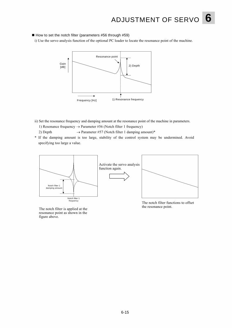
ADJUSTMENT OF SERVO 6
6-15
How to set the notch filter (parameters #56 through #59) i) Use the servo analysis function of the optional PC loader to locate the resonance point of the machine.
ii) Set the resonance frequency and damping amount at the resonance point of the machine in parameters.
1) Resonance frequency → Parameter #56 (Notch filter 1 frequency) 2) Depth → Parameter #57 (Notch filter 1 damping amount)*
* If the damping amount is too large, stability of the control system may be undermined. Avoid specifying too large a value.
Gain[dB]
Frequency [Hz]
Resonance point
1) Resonance frequency
2) Depth
Notch filter 1 damping amount
Notch filter 1 frequency
Activate the servo analysisfunction again.
The notch filter is applied at the resonance point as shown in the figure above.
The notch filter functions to offsetthe resonance point.
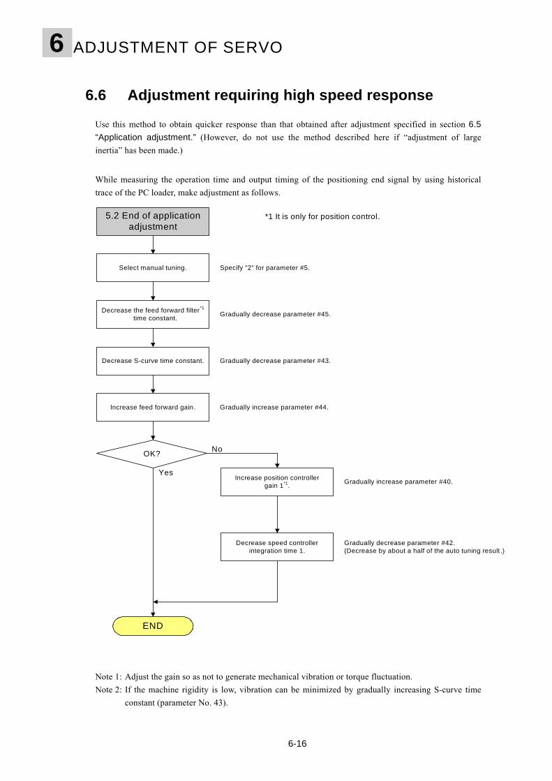
6 ADJUSTMENT OF SERVO
6-16
6.6 Adjustment requiring high speed response
Use this method to obtain quicker response than that obtained after adjustment specified in section 6.5 “Application adjustment.” (However, do not use the method described here if “adjustment of large inertia” has been made.)
While measuring the operation time and output timing of the positioning end signal by using historical trace of the PC loader, make adjustment as follows.
Note 1: Adjust the gain so as not to generate mechanical vibration or torque fluctuation. Note 2: If the machine rigidity is low, vibration can be minimized by gradually increasing S-curve time
constant (parameter No. 43).
END
Select manual tuning.
5.2 End of application adjustment
Decrease the feed forward filter*1
time constant.
Decrease S-curve time constant.
Specify "2" for parameter #5.
Gradually decrease parameter #45.
Gradually decrease parameter #43.
Increase position controller gain 1*1.
Decrease speed controller integration time 1.
Gradually increase parameter #40.
Gradually decrease parameter #42.(Decrease by about a half of the auto tuning result .)
OK?No
Yes
*1 It is only for position control.
Increase feed forward gain. Gradually increase parameter #44.
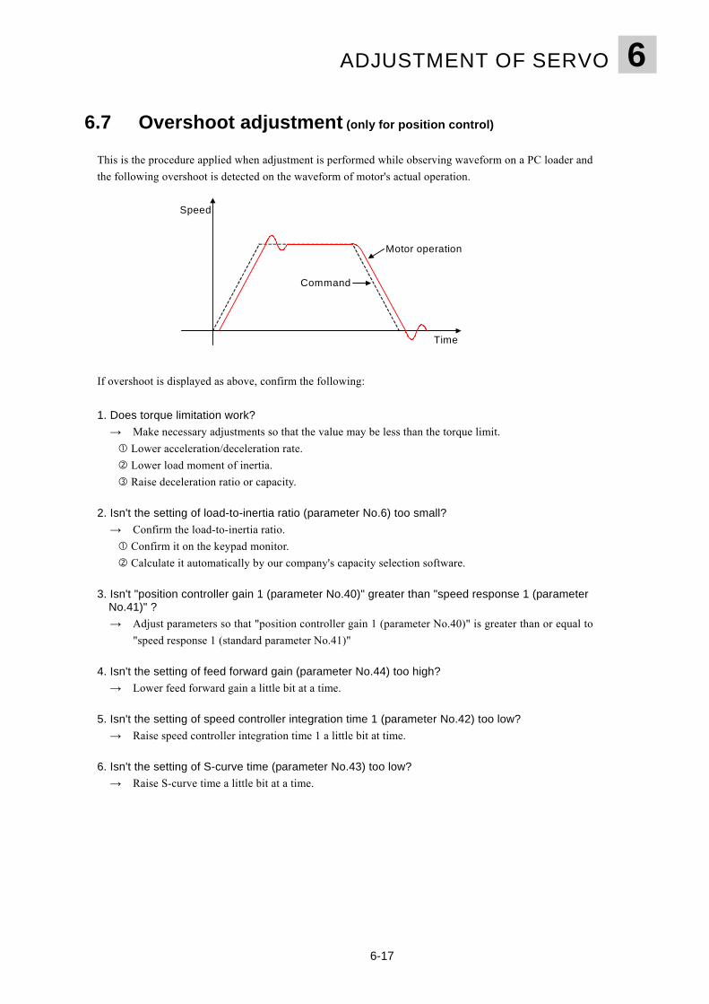
ADJUSTMENT OF SERVO 6
6-17
6.7 Overshoot adjustment (only for position control)
This is the procedure applied when adjustment is performed while observing waveform on a PC loader and the following overshoot is detected on the waveform of motor's actual operation.
If overshoot is displayed as above, confirm the following:
1. Does torque limitation work? → Make necessary adjustments so that the value may be less than the torque limit.
Lower acceleration/deceleration rate. Lower load moment of inertia. Raise deceleration ratio or capacity.
2. Isn't the setting of load-to-inertia ratio (parameter No.6) too small? → Confirm the load-to-inertia ratio.
Confirm it on the keypad monitor. Calculate it automatically by our company's capacity selection software.
3. Isn't "position controller gain 1 (parameter No.40)" greater than "speed response 1 (parameter
No.41)" ? → Adjust parameters so that "position controller gain 1 (parameter No.40)" is greater than or equal to
"speed response 1 (standard parameter No.41)"
4. Isn't the setting of feed forward gain (parameter No.44) too high? → Lower feed forward gain a little bit at a time.
5. Isn't the setting of speed controller integration time 1 (parameter No.42) too low? → Raise speed controller integration time 1 a little bit at time.
6. Isn't the setting of S-curve time (parameter No.43) too low? → Raise S-curve time a little bit at a time.
Command
Motor operation
Speed
Time
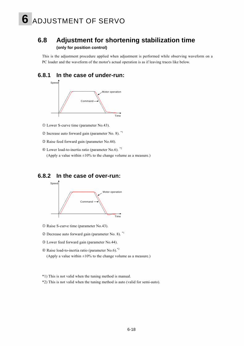
6 ADJUSTMENT OF SERVO
6-18
6.8 Adjustment for shortening stabilization time (only for position control)
This is the adjustment procedure applied when adjustment is performed while observing waveform on a PC loader and the waveform of the motor's actual operation is as if leaving traces like below.
6.8.1 In the case of under-run:
Lower S-curve time (parameter No.43).
Increase auto forward gain (parameter No. 8). *1
Raise feed forward gain (parameter No.44).
Lower load-to-inertia ratio (parameter No.6). *2 (Apply a value within ±10% to the change volume as a measure.)
6.8.2 In the case of over-run:
Raise S-curve time (parameter No.43).
Decrease auto forward gain (parameter No. 8). *1
Lower feed forward gain (parameter No.44).
Raise load-to-inertia ratio (parameter No.6).*2 (Apply a value within ±10% to the change volume as a measure.)
*1) This is not valid when the tuning method is manual. *2) This is not valid when the tuning method is auto (valid for semi-auto).
Command
Motor operation
Speed
Time
Command
Motor operation
Speed
Time
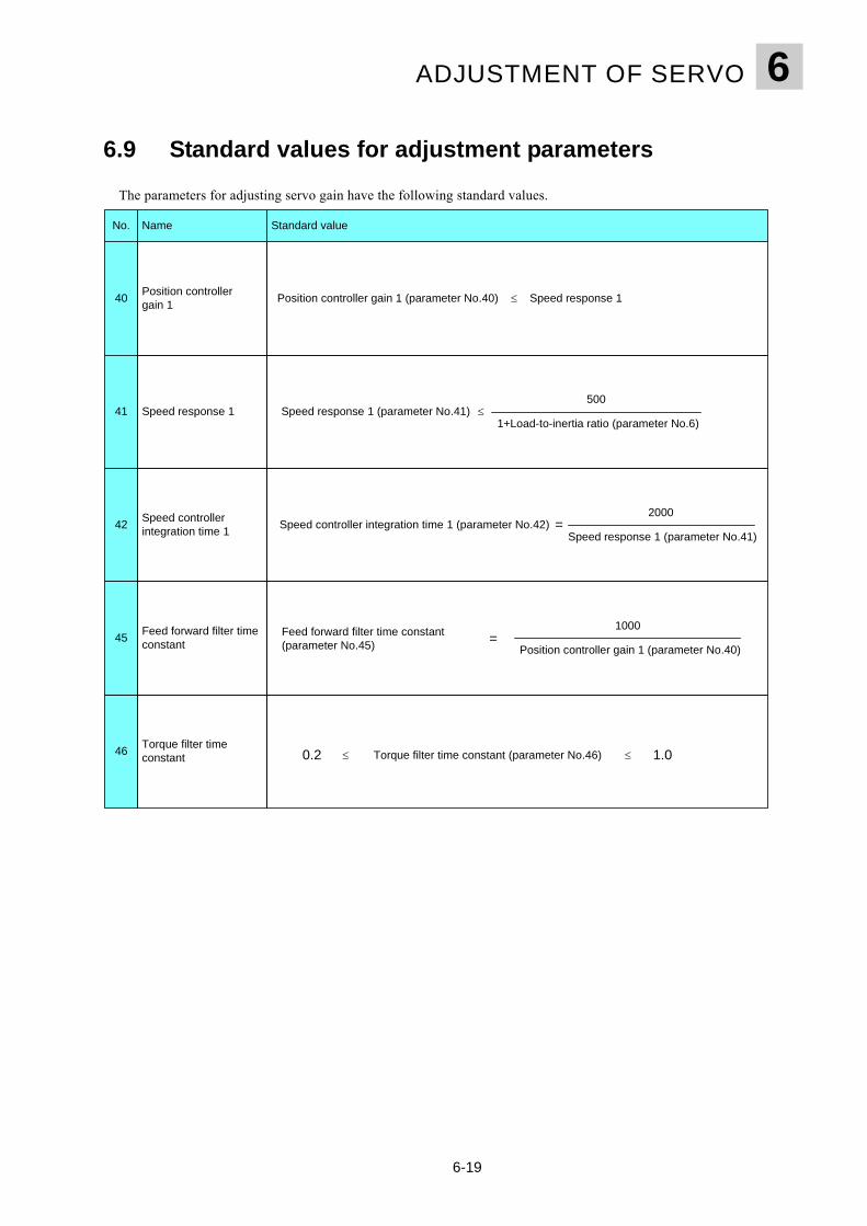
ADJUSTMENT OF SERVO 6
6-19
6.9 Standard values for adjustment parameters
The parameters for adjusting servo gain have the following standard values.
40 Position controller gain 1
No. Name Standard value
41 Speed response 1
42 Speed controller integration time 1
46 Torque filter time constant
45 Feed forward filter time constant
Speed response 1 (parameter No.41)500
Speed controller integration time 1 (parameter No.42)2000
Position controller gain 1 (parameter No.40)
1000Feed forward filter time constant (parameter No.45) =
Torque filter time constant (parameter No.46)0.2 1.0
Position controller gain 1 (parameter No.40) Speed response 1
1+Load-to-inertia ratio (parameter No.6)
=Speed response 1 (parameter No.41)
≤
≤
≤ ≤

6 ADJUSTMENT OF SERVO
6-20
-MEMO-
SPECIAL ADJUSTMENT

7 SPECIAL ADJUSTMENT
7-2
7.1 Vibration suppressing control 7.1.1 What is vibration suppressing control?
(1) Purpose of vibration suppressing control In the spring structure of a robot arm or a transfer unit, a part end vibrates when the motor is suddenly accelerated or decelerated. The vibration suppressing control function prevents vibration of parts in such a system and performs positioning with high tact.
• Without vibration suppressing control unit ········ The maximum torque is generated when the motor is accelerated/decelerated. The entire machine may vibrate due to impact during acceleration/deceleration.
• With vibration suppressing control unit ·············· Torque during acceleration/deceleration of the motor is controlled. Impact during acceleration/deceleration is redvibration suppressing controluced and vibration of the entire machine may be controlled even on a machine with a relatively weak rigidity.
Not only vibration of parts is reduced, but also vibration of the overall unit is reduced.
b) With vibration suppressing control functiona) Without vibration suppressing control function
2mm/div
500r/min/div
Target arm position
Actual speed
2mm/div
500r/min/div
Target arm position
Actual speed
Laser displacement gauge
Laserdisplacement gauge
Standstill Rattling
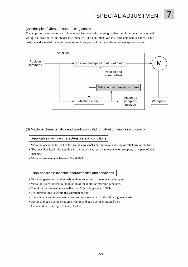
SPECIAL ADJUSTMENT 7
7-3
(2) Principle of vibration suppressing control The amplifier incorporates a machine mode land controls dumping so that the vibration at the assumed workpiece position of the model is eliminated. The controlled variable thus obtained is added to the position and speed of the motor as an offset to suppress vibration at the actual workpiece position.
(3) Machine characteristics and conditions valid for vibration suppressing control
• Vibration occurs at the end of the arm due to shocks during travel and stop of robot arm or the like. • The machine itself vibrates due to the shock caused by movement or stopping of a part of the
machine. • Vibration frequency is between 5 and 100Hz.
• Vibration generates continuously without relations to movement or stopping. • Vibration synchronized to the rotation of the motor or machine generates. • The vibration frequency is smaller than 5Hz or larger than 100Hz. • The moving time is within the vibration period. • There is backlash in mechanical connections located up to the vibrating mechanism. • (Command pulse compensation α/ Command pulse compensation β)>50 • Command pulse string frequency ≤ 20 kHz
Non-applicable machine characteristics and conditions
Applicable machine characteristics and conditions
Position and speed control of motor
Machine modelAssumed workpiece
position
Vibration suppressing control
MPosition command
Amplifier
Workpiece
Position and speed offset
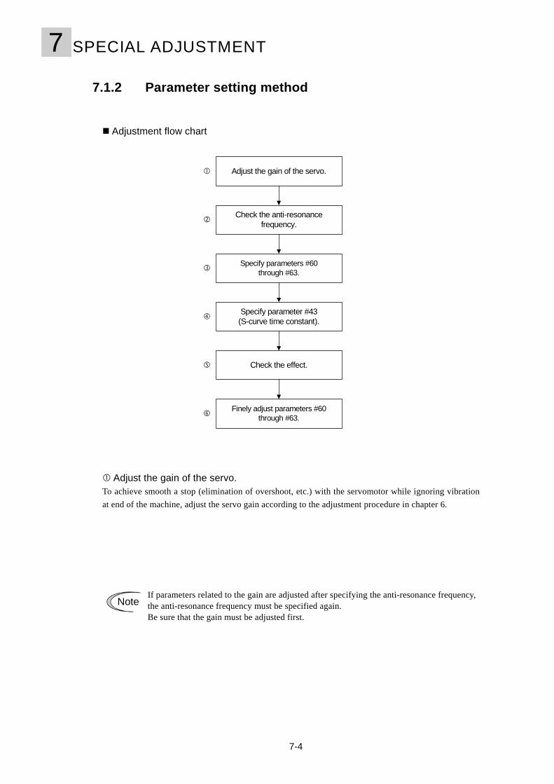
7 SPECIAL ADJUSTMENT
7-4
7.1.2 Parameter setting method
Adjustment flow chart
Adjust the gain of the servo. To achieve smooth a stop (elimination of overshoot, etc.) with the servomotor while ignoring vibration at end of the machine, adjust the servo gain according to the adjustment procedure in chapter 6.
If parameters related to the gain are adjusted after specifying the anti-resonance frequency,the anti-resonance frequency must be specified again. Be sure that the gain must be adjusted first.
Note
Check the anti-resonance frequency.
Specify parameters #60 through #63.
Check the effect.
Finely adjust parameters #60through #63.
Adjust the gain of the servo.
Specify parameter #43(S-curve time constant).
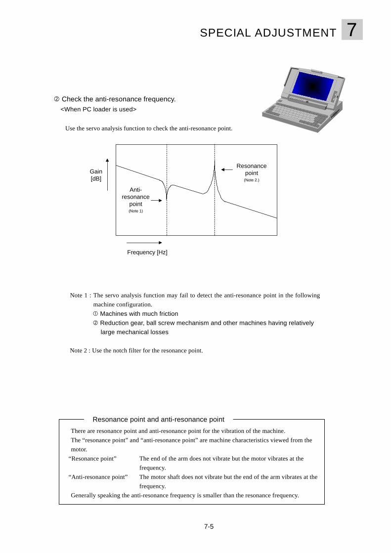
SPECIAL ADJUSTMENT 7
7-5
Check the anti-resonance frequency. <When PC loader is used>
Use the servo analysis function to check the anti-resonance point.
Note 1 : The servo analysis function may fail to detect the anti-resonance point in the following
machine configuration. Machines with much friction Reduction gear, ball screw mechanism and other machines having relatively large mechanical losses
Note 2 : Use the notch filter for the resonance point.
Gain[dB]
Frequency [Hz]
Anti-resonance
point
Resonance point
(Note 2.)
(Note 1)
There are resonance point and anti-resonance point for the vibration of the machine. The “resonance point” and “anti-resonance point” are machine characteristics viewed from the motor.
“Resonance point” The end of the arm does not vibrate but the motor vibrates at the frequency.
“Anti-resonance point” The motor shaft does not vibrate but the end of the arm vibrates at the frequency.
Generally speaking the anti-resonance frequency is smaller than the resonance frequency.
Resonance point and anti-resonance point

7 SPECIAL ADJUSTMENT
7-6
<When PC loader is not used> There are two checking methods. If vibration frequency can be measured using a laser displacement gauge or the like, follow checking method i). In other cases, follow checking method ii). i) Measure vibration of the end of the arm directly using a laser displacement gauge or the like. ii) While reducing the settings of parameters #60 through #63 gradually from 200.0Hz
(maximum value), visually check vibration to find the best value.
Vibration period (Ts)
Time
Vibration
1 Anti-resonance frequency = Ts [Hz]
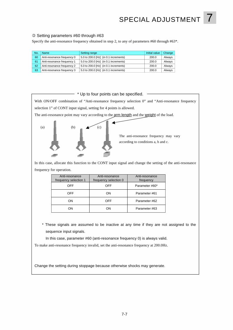
SPECIAL ADJUSTMENT 7
7-7
Setting parameters #60 through #63 Specify the anti-resonance frequency obtained in step 2, to any of parameters #60 through #63*.
With ON/OFF combination of “Anti-resonance frequency selection 0” and “Anti-resonance frequency
selection 1” of CONT input signal, setting for 4 points is allowed.
The anti-resonance point may vary according to the arm length and the weight of the load.
In this case, allocate this function to the CONT input signal and change the setting of the anti-resonance
frequency for operation.
* These signals are assumed to be inactive at any time if they are not assigned to the
sequence input signals.
In this case, parameter #60 (anti-resonance frequency 0) is always valid.
To make anti-resonance frequency invalid, set the anti-resonance frequency at 200.0Hz.
Change the setting during stoppage because otherwise shocks may generate.
Anti-resonance frequency selection 1
Anti-resonance frequency selection 0
OFF OFF
OFF ON
ON OFF
ON ON
Anti-resonance frequency
Parameter #60*
Parameter #61
Parameter #62
Parameter #63
* Up to four points can be specified.
(a) (b) (c)
The anti-resonance frequency may vary
according to conditions a, b and c.
No. Name Setting range Initial value Change
60 Anti-resonance frequency 0 5.0 to 200.0 [Hz] (in 0.1 increments) 200.0 Always
61 Anti-resonance frequency 1 5.0 to 200.0 [Hz] (in 0.1 increments) 200.0 Always
62 Anti-resonance frequency 2 5.0 to 200.0 [Hz] (in 0.1 increments) 200.0 Always
63 Anti-resonance frequency 3 5.0 to 200.0 [Hz] (in 0.1 increments) 200.0 Always
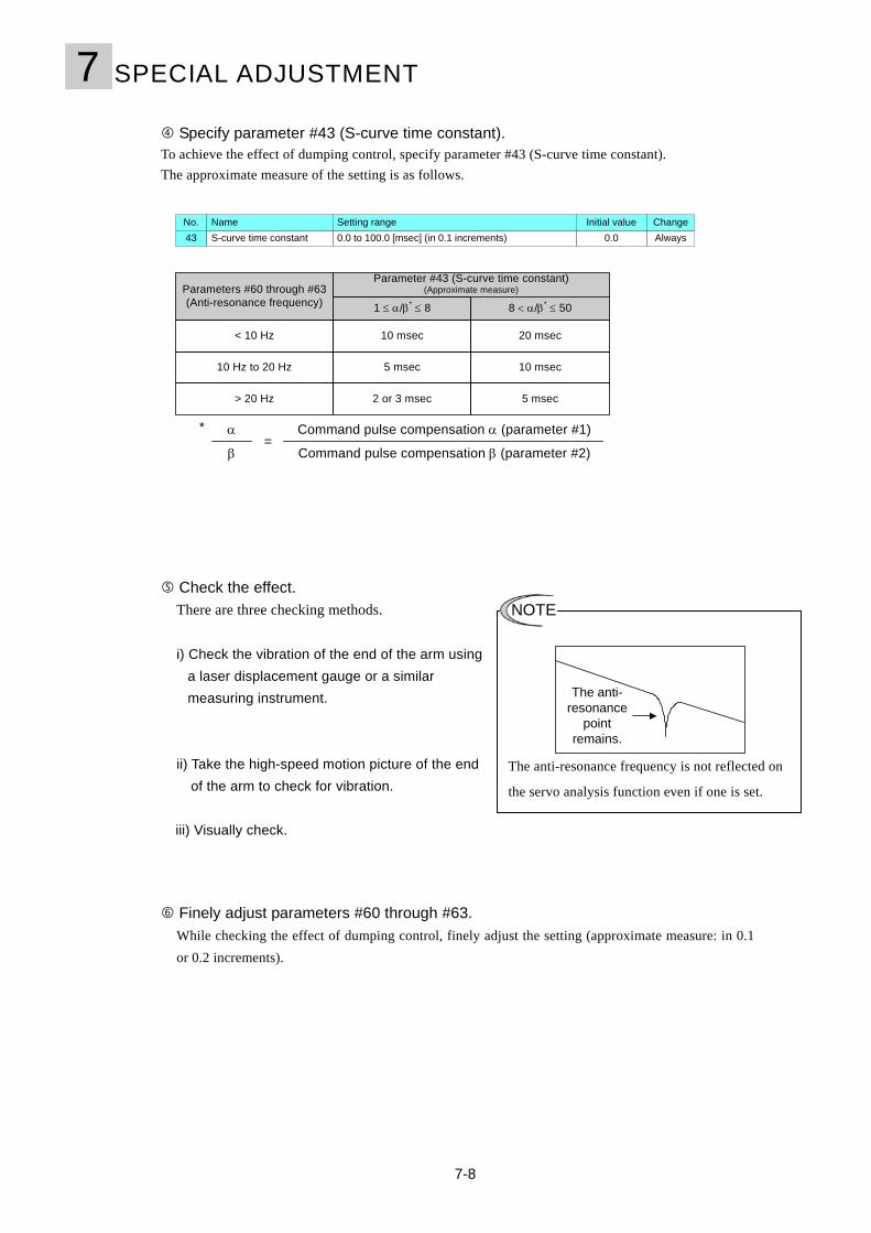
7 SPECIAL ADJUSTMENT
7-8
Specify parameter #43 (S-curve time constant). To achieve the effect of dumping control, specify parameter #43 (S-curve time constant). The approximate measure of the setting is as follows.
Check the effect. There are three checking methods.
i) Check the vibration of the end of the arm using
a laser displacement gauge or a similar measuring instrument.
ii) Take the high-speed motion picture of the end
of the arm to check for vibration.
iii) Visually check.
Finely adjust parameters #60 through #63. While checking the effect of dumping control, finely adjust the setting (approximate measure: in 0.1 or 0.2 increments).
The anti-resonance frequency is not reflected on
the servo analysis function even if one is set.
The anti-resonance
point remains.
No. Name Setting range Initial value Change
43 S-curve time constant 0.0 to 100.0 [msec] (in 0.1 increments) 0.0 Always
NOTE
Parameters #60 through #63(Anti-resonance frequency)
< 10 Hz
10 Hz to 20 Hz
> 20 Hz
1 ≤ α/β* ≤ 8
10 msec
5 msec
2 or 3 msec
20 msec
10 msec
5 msec
Parameter #43 (S-curve time constant)(Approximate measure)
8 < α/β* ≤ 50
Command pulse compensation α (parameter #1)
Command pulse compensation β (parameter #2)=
β
α*

SPECIAL ADJUSTMENT 7
7-9
7.2 Command following control 7.2.1 What is command following control?
In the command following control mode, movement follows the command pulse string completely with almost zero position deviation.
Mechanical system realizing command following control
Use “command following control” for the mechanical system satisfying all the following conditions.
(1) Highly rigid machine
(2) Pulse commands sent from the host controller are linear or in an S-curve to assure
smooth acceleration and deceleration.
(3) The pulse frequency updating period of the host controller is within several milliseconds.
(4) Load inertia ratio (parameter #6) ≤ 10.0 As a guideline, set the parameters to suit the following conditions. (5) Position controller gain 1 (parameter #40) × S-curve time constant (parameter #43) ≤ 1000.0 (6)
If command following control is used for a system not satisfying all of the above conditions, mechanical
vibration may generate.
Command speed
Feedback speed
Time
Speed
The feedback speed follows the command speed completely.Speed
Time
Command pulse compensation α (parameter #1) Command pulse compensation β (parameter #2)
≤ 30
Parameter #44
Parameter #40 or #51
Parameter #55
Command following control selection
ddt
Position controller gain
Feed forward
Parameter #45
Commandfollowing control
Position command
Feedback position
Command speed

7 SPECIAL ADJUSTMENT
7-10
7.2.2 Parameter setting method
The command following control includes two variations: with no correction on stop (setting: 1) and with correction on stop (setting: 2). Position deviation generates in both methods when the acceleration changes (at , , , and ).
In case “with correction on stop (setting: 2),” position deviation caused by the acceleration change when the mechanical system is stopped is smaller.
Select “no correction on stop (setting: 1)” for operation patterns where changes from forward to reverse rotation continue.
* In the command following control mode, specify “10” or a larger value for the auto tuning gain
(parameter #7).
No. Name Setting range Initial value Change
55Command following control selection
0: None, 1: Command following control,2: Command following control (with correction on stop)
0 Power
Forward rotation
Speed
Reverse rotation
Time
Position deviation
Command speed
Deviation of the stopping mechanism becomes almost zero.
Position deviation
Command speed

KEYPAD
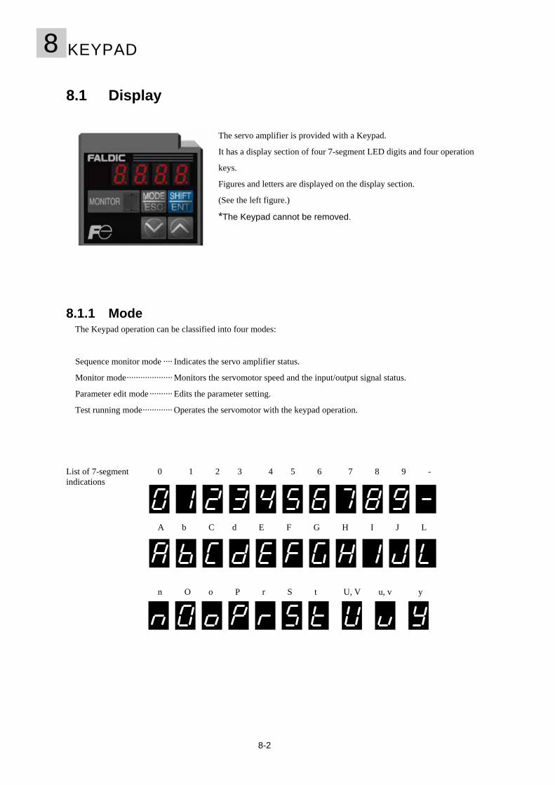
8 KEYPAD
8-2
8.1 Display
The servo amplifier is provided with a Keypad.
It has a display section of four 7-segment LED digits and four operation
keys.
Figures and letters are displayed on the display section.
(See the left figure.)
*The Keypad cannot be removed.
8.1.1 Mode The Keypad operation can be classified into four modes:
Sequence monitor mode ···· Indicates the servo amplifier status.
Monitor mode···················· Monitors the servomotor speed and the input/output signal status.
Parameter edit mode·········· Edits the parameter setting.
Test running mode············· Operates the servomotor with the keypad operation.
List of 7-segment 0 1 2 3 4 5 6 7 8 9 - indications
A b C d E F G H I J L
n O o P r S t U, V u, v y

KEYPAD 8
8-3
Sequence monitor mode
Monitor mode
Parameter edit mode
Test running mode
8.1.2 Operation key
SHIFTENT When this key is pressed, the upper 4 digits are replaced with the lower 4 digits.
8.1.3 Mode select Each mode can be selected by the [MODE] key.
Mode select
Power on
Sub-mode select Display example
Changes the mode (MODE).
Cancels the selected mode (ESC).
Selects the sub-mode.
Decreases the figure (-1).
Selects the sub-mode.
Increases the figure (+1).
MODEESC
Shifts to the less significant digit (SHIFT).
Stores the mode and figure (ENT).
Press more than 1 sec to store the data.
SHIFTENT
MODEESC
MODEESC
MODEESC
MODEESC
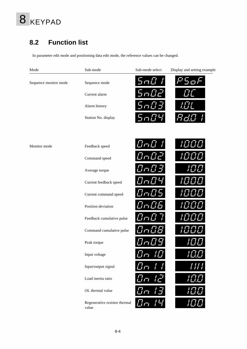
8 KEYPAD
8-4
8.2 Function list
In parameter edit mode and positioning data edit mode, the reference values can be changed.
Mode Sub-mode Sub-mode select Display and setting example
Sequence monitor mode Sequence mode
Current alarm
Alarm history
Station No. display
Monitor mode Feedback speed
Command speed
Average torque
Current feedback speed
Current command speed
Position deviation
Feedback cumulative pulse
Command cumulative pulse
Peak torque
Input voltage
Input/output signal
Load inertia ratio
OL thermal value
Regenerative resistor thermal value
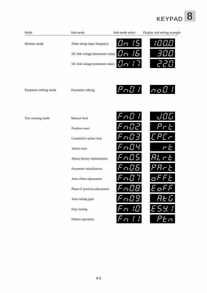
KEYPAD 8
8-5
Mode Sub-mode Sub-mode select Display and setting example
Monitor mode Pulse string input frequency
DC link voltage (maximum value)
DC link voltage (minimum value)
Parameter editing mode Parameter editing
Test running mode Manual feed
Position reset
Cumulative pulse clear
Alarm reset
Alarm history initialization
Parameter initialization
Auto offset adjustment
Phase-Z position adjustment
Auto tuning gain
Easy tuning
Pattern operation
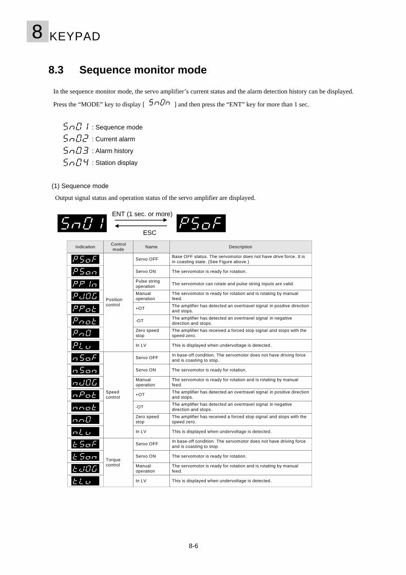
8 KEYPAD
8-6
8.3 Sequence monitor mode
In the sequence monitor mode, the servo amplifier’s current status and the alarm detection history can be displayed.
Press the “MODE” key to display [ ] and then press the “ENT” key for more than 1 sec.
(1) Sequence mode
Output signal status and operation status of the servo amplifier are displayed.
ENT (1 sec. or more)
ESC
IndicationControl mode
Base OFF status. The servomotor does not have drive force. It is in coasting state. (See Figure above.)
The amplifier has detected an overtravel signal in negative direction and stops.
This is displayed when undervoltage is detected .
Name Description
Servo OFF
The servomotor is ready for rotation. Servo ON
The amplifier has detected an overtravel signal in positive direction and stops.
Pulse string operation
Manual operation
+OT
-OT
Zero speed stop
In LV
The servomotor is ready for rotation and is rotating by manual feed.
The servomotor can rotate and pulse string inputs are valid.
The amplifier has received a forced stop signal and stops with the speed zero.
Position control
In base-off condition. The servomotor does not have driving force and is coasting to stop.
The amplifier has detected an overtravel signal in negative direction and stops.
Servo OFF
The servomotor is ready for rotation. Servo ON
The amplifier has detected an overtravel signal in positive direction and stops.
Manual operation
+OT
-OT
Zero speed stop
In LV
The servomotor is ready for rotation and is rotating by manual feed.
The amplifier has received a forced stop signal and stops with the speed zero.
Speed control
This is displayed when undervoltage is detected .
Torque control Manual
operation
In LV
In base-off condition. The servomotor does not have driving force and is coasting to stop.
Servo OFF
The servomotor is ready for rotation. Servo ON
The servomotor is ready for rotation and is rotating by manual feed.
This is displayed when undervoltage is detected .
: Sequence mode
: Current alarm
: Alarm history
: Station display

KEYPAD 8
8-7
When the power is supplied to the servo amplifier, sequence of the sequence monitor mode is
displayed.
The type of indication at power on can be changed by system parameter 30 setting.
Initial display
Sequence mode
Setting
0
1
2
3
Current alarm
Alarm history
Station display
Initial display
Feedback speed
Setting
4
5
6
7
8
9
10
Command speed
Average torque
Current feedback speed
Current command speed
Feedback cumulative pulse
Command cumulative pulse
Peak torque
11
12
13
14
15
16
17
Input voltage
Input/output signal
Load inertia ratio
OL thermal value
Regenerative resistor thermal value
Pulse string input frequency
18
19DC link voltage (maximum value)
DC link voltage (minimum value)
Position deviation
20
Hint

8 KEYPAD
8-8
The alarm codes are indicated automatically.
When an alarm is detected, the blinking occurs faster (intervals of 0.5 sec.) than normal
(intervals of 1 sec.).
The reset of alarm detection can be carried out in the test operation mode.
Press the ∧ and ∨ keys simultaneously for one second or more while alarm detection is
indicated to reset the alarm detection.
When the alarm is reset, the display becomes .
(2) Current Alarm
The contents of current alarm can be displayed with codes.
* The code is blinking during alarm detection. When the alarm is reset, the display becomes .
The history can be displayed by [ ].
When an alarm is detected, the following indication will appear automatically.
Alarm code
ENT(1 sec. or more)
ESC
Indication Description
Overcurrent 1
Overspeed
Undervoltage
Overvoltage
Encoder trouble
Memory alarm
Regenerative transistor overheat
Encoder communication alarm
CONT duplication
Overload
Amplifier overheat
Regenerative resistor overheat
Deviation limit
Control power alarm
Indication DescriptionPriority
1
2
3
4
5
6
7
8
9
10
11
12
Priority
13
14
15
Overcurrent 2
Hint
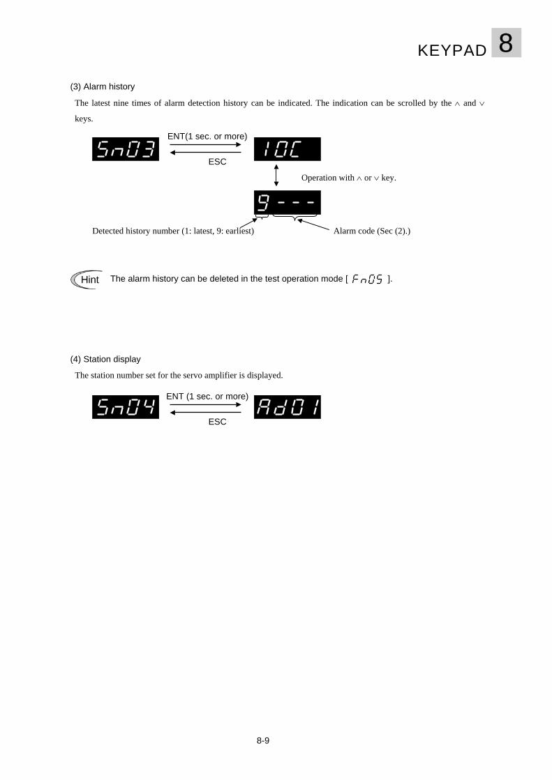
KEYPAD 8
8-9
(3) Alarm history
The latest nine times of alarm detection history can be indicated. The indication can be scrolled by the ∧ and ∨
keys.
Detected history number (1: latest, 9: earliest) Alarm code (Sec (2).)
(4) Station display
The station number set for the servo amplifier is displayed.
The alarm history can be deleted in the test operation mode [ ].
ENT(1 sec. or more)
ESC
Operation with ∧ or ∨ key.
ENT (1 sec. or more)
ESC
Hint

8 KEYPAD
8-10
* During reverse rotation, the first digit ("1" for the example above) and "-" are displayed alternately. Ex.)
* During reverse rotation, the first digit ("1" for the example above) and "-" are displayed alternately. Ex.)
8.4 Monitor mode
In monitor mode, the rotation speed of the servomotor and the input pulse cumulative value are displayed.
Press the MODE key to display [ ] and press the ENT key (for 1 sec or more) to display the content.
(1) Feedback speed ······························· No. of displayed digits: 4 digits with sign
The servomotor’s current speed. Even if the servomotor is driven by the load (mechanical system), the
correct speed will be indicated.
The display is increments of 1 [r/min] and the negative sign is given for reverse rotation (clockwise when viewed
from the motor shaft).
(2) Command speed······························· No. of displayed digits: 4 digits with sign
It is the speed command to current servomotor. The command speed includes speed command voltage, multistep
speed and pulse string, etc.
The display is in increments of 1 [r/min] and the negative sign is given for reverse rotation (clockwise when viewed
from the motor shaft).
ENT (1 sec. or more)
ESC
Alternately displayed
ENT (1 sec. or more)
ESC
Alternately displayed
: Command cumulative pulse
: Peak torque
: Input voltage
: Input/output signal
: Load inertia ratio
: OL thermal value
: Regenerative resistor thermal value
: Pulse string input frequency
: DC link voltage (maximum value)
: DC link voltage (minimum value)
: Feedback speed
: Command speed
: Average torque
: Current feedback speed
: Current command speed
: Position deviation
: Feedback cumulative pulse
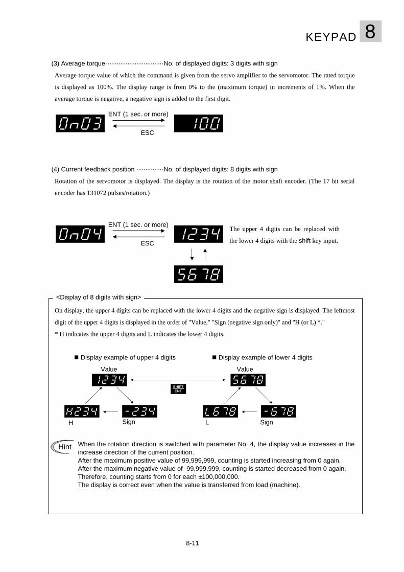
KEYPAD 8
8-11
(3) Average torque································No. of displayed digits: 3 digits with sign
Average torque value of which the command is given from the servo amplifier to the servomotor. The rated torque
is displayed as 100%. The display range is from 0% to the (maximum torque) in increments of 1%. When the
average torque is negative, a negative sign is added to the first digit.
(4) Current feedback position ···············No. of displayed digits: 8 digits with sign
Rotation of the servomotor is displayed. The display is the rotation of the motor shaft encoder. (The 17 bit serial
encoder has 131072 pulses/rotation.)
On display, the upper 4 digits can be replaced with the lower 4 digits and the negative sign is displayed. The leftmost
digit of the upper 4 digits is displayed in the order of "Value," "Sign (negative sign only)" and "H (or L) *."
* H indicates the upper 4 digits and L indicates the lower 4 digits.
Display example of upper 4 digits Display example of lower 4 digits
When the rotation direction is switched with parameter No. 4, the display value increases in theincrease direction of the current position. After the maximum positive value of 99,999,999, counting is started increasing from 0 again. After the maximum negative value of -99,999,999, counting is started decreased from 0 again. Therefore, counting starts from 0 for each ±100,000,000. The display is correct even when the value is transferred from load (machine).
The upper 4 digits can be replaced with
the lower 4 digits with the shift key input.
ENT (1 sec. or more)
ESC
ENT (1 sec. or more)
ESC
Value
L
<Display of 8 digits with sign>
Value
Sign H
SHIFTENT
Sign
Hint
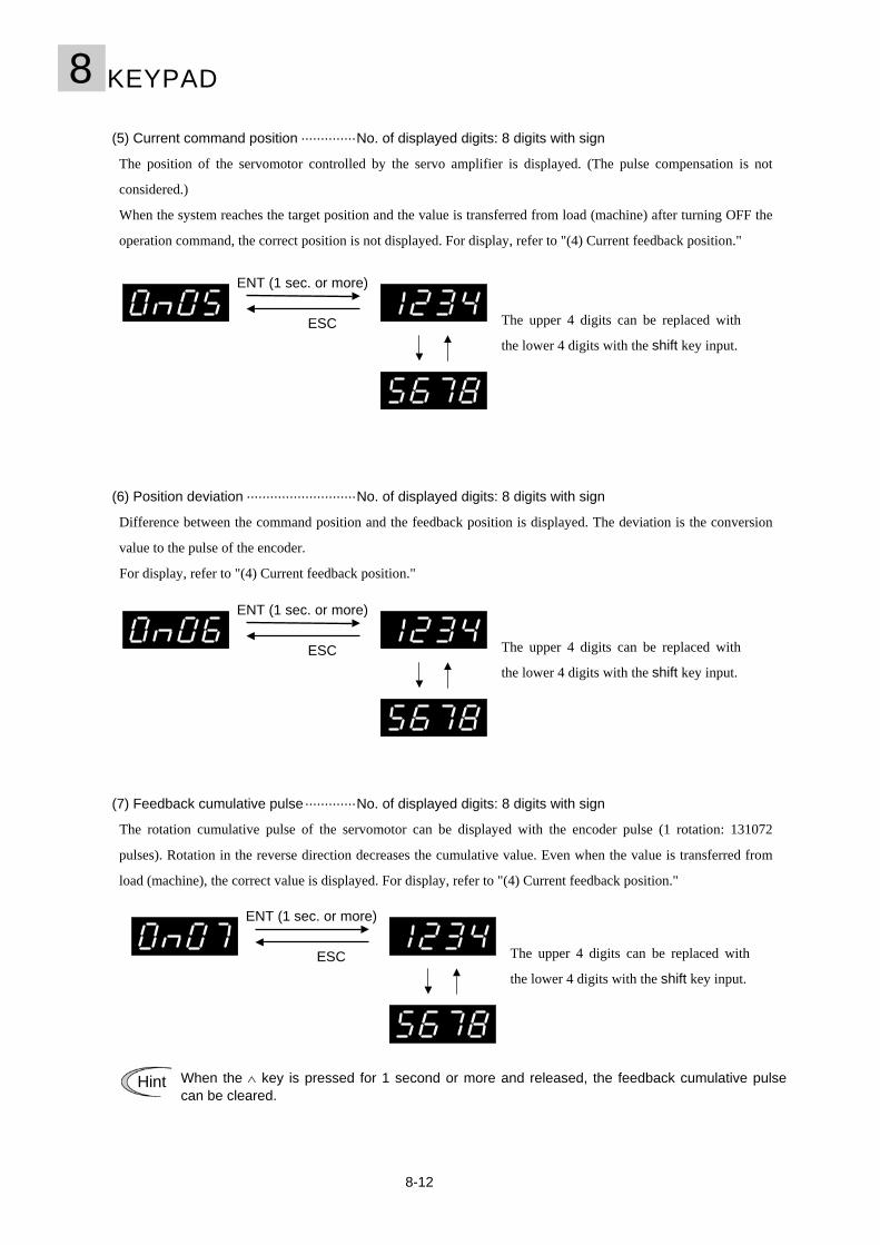
8 KEYPAD
8-12
(5) Current command position ··············No. of displayed digits: 8 digits with sign
The position of the servomotor controlled by the servo amplifier is displayed. (The pulse compensation is not
considered.)
When the system reaches the target position and the value is transferred from load (machine) after turning OFF the
operation command, the correct position is not displayed. For display, refer to "(4) Current feedback position."
(6) Position deviation ····························No. of displayed digits: 8 digits with sign
Difference between the command position and the feedback position is displayed. The deviation is the conversion
value to the pulse of the encoder.
For display, refer to "(4) Current feedback position."
(7) Feedback cumulative pulse·············No. of displayed digits: 8 digits with sign
The rotation cumulative pulse of the servomotor can be displayed with the encoder pulse (1 rotation: 131072
pulses). Rotation in the reverse direction decreases the cumulative value. Even when the value is transferred from
load (machine), the correct value is displayed. For display, refer to "(4) Current feedback position."
The upper 4 digits can be replaced with
the lower 4 digits with the shift key input.
ENT (1 sec. or more)
ESC
The upper 4 digits can be replaced with
the lower 4 digits with the shift key input.
ENT (1 sec. or more)
ESC
The upper 4 digits can be replaced with
the lower 4 digits with the shift key input.
ENT (1 sec. or more)
ESC
When the ∧ key is pressed for 1 second or more and released, the feedback cumulative pulsecan be cleared.
Hint
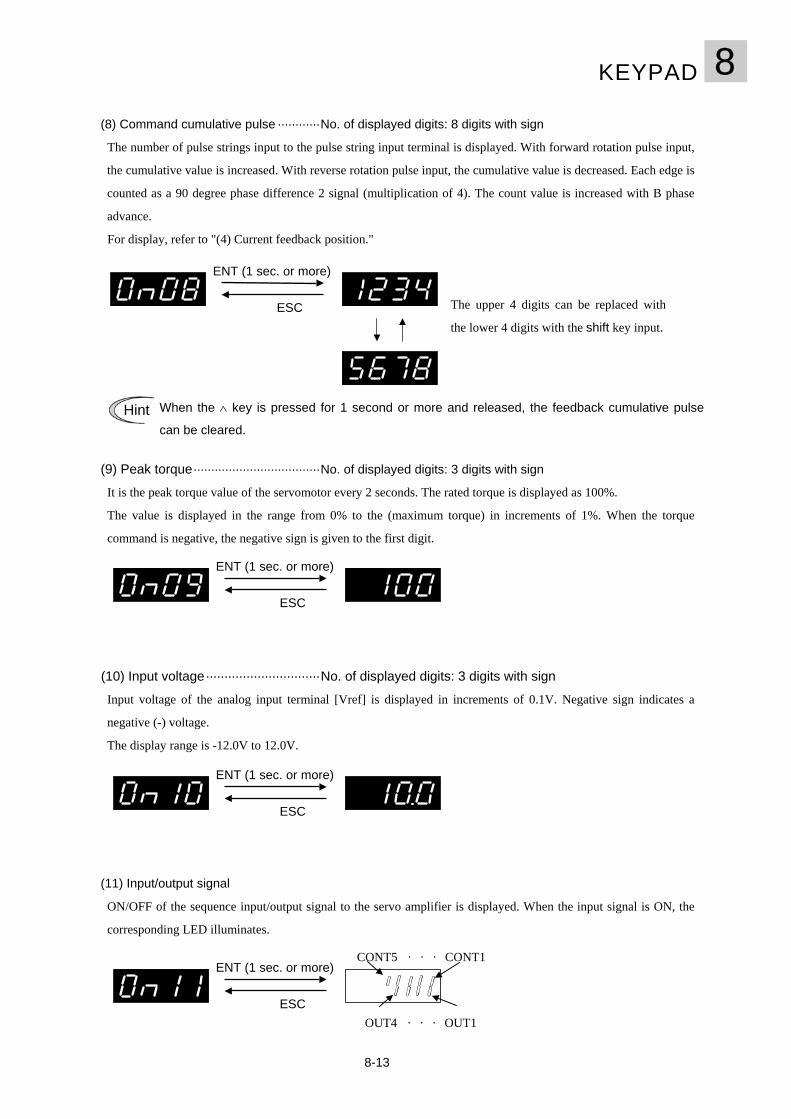
KEYPAD 8
8-13
(8) Command cumulative pulse ············No. of displayed digits: 8 digits with sign
The number of pulse strings input to the pulse string input terminal is displayed. With forward rotation pulse input,
the cumulative value is increased. With reverse rotation pulse input, the cumulative value is decreased. Each edge is
counted as a 90 degree phase difference 2 signal (multiplication of 4). The count value is increased with B phase
advance.
For display, refer to "(4) Current feedback position."
(9) Peak torque····································No. of displayed digits: 3 digits with sign
It is the peak torque value of the servomotor every 2 seconds. The rated torque is displayed as 100%.
The value is displayed in the range from 0% to the (maximum torque) in increments of 1%. When the torque
command is negative, the negative sign is given to the first digit.
(10) Input voltage·······························No. of displayed digits: 3 digits with sign
Input voltage of the analog input terminal [Vref] is displayed in increments of 0.1V. Negative sign indicates a
negative (-) voltage.
The display range is -12.0V to 12.0V.
(11) Input/output signal
ON/OFF of the sequence input/output signal to the servo amplifier is displayed. When the input signal is ON, the
corresponding LED illuminates.
The upper 4 digits can be replaced with
the lower 4 digits with the shift key input.
ENT (1 sec. or more)
ESC
ENT (1 sec. or more)
ESC
ENT (1 sec. or more)
ESC
ENT (1 sec. or more)
ESC
CONT5 · · · CONT1
OUT4 · · · OUT1
When the ∧ key is pressed for 1 second or more and released, the feedback cumulative pulse
can be cleared.
Hint
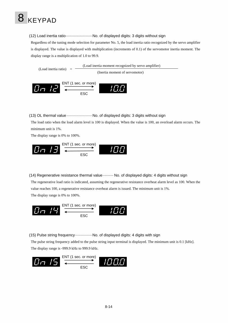
8 KEYPAD
8-14
(12) Load inertia ratio·························No. of displayed digits: 3 digits without sign
Regardless of the tuning mode selection for parameter No. 5, the load inertia ratio recognized by the servo amplifier
is displayed. The value is displayed with multiplication (increments of 0.1) of the servomotor inertia moment. The
display range is a multiplication of 1.0 to 99.9.
(13) OL thermal value ························No. of displayed digits: 3 digits without sign
The load ratio when the load alarm level is 100 is displayed. When the value is 100, an overload alarm occurs. The
minimum unit is 1%.
The display range is 0% to 100%.
(14) Regenerative resistance thermal value·········· No. of displayed digits: 4 digits without sign
The regenerative load ratio is indicated, assuming the regenerative resistance overheat alarm level as 100. When the
value reaches 100, a regenerative resistance overheat alarm is issued. The minimum unit is 1%.
The display range is 0% to 100%.
(15) Pulse string frequency················No. of displayed digits: 4 digits with sign
The pulse string frequency added to the pulse string input terminal is displayed. The minimum unit is 0.1 [kHz].
The display range is -999.9 kHz to 999.9 kHz.
(Load inertia moment recognized by servo amplifier)
(Inertia moment of servomotor) (Load inertia ratio) =
ENT (1 sec. or more)
ESC
ENT (1 sec. or more)
ESC
ENT (1 sec. or more)
ESC
ENT (1 sec. or more)
ESC
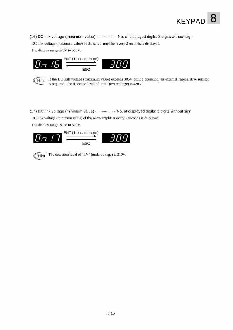
KEYPAD 8
8-15
(16) DC link voltage (maximum value) ·················· No. of displayed digits: 3 digits without sign
DC link voltage (maximum value) of the servo amplifier every 2 seconds is displayed.
The display range is 0V to 500V.
(17) DC link voltage (minimum value) ··················· No. of displayed digits: 3 digits without sign
DC link voltage (minimum value) of the servo amplifier every 2 seconds is displayed.
The display range is 0V to 500V.
ENT (1 sec. or more)
ESC
If the DC link voltage (maximum value) exceeds 385V during operation, an external regenerative resistoris required. The detection level of "HV" (overvoltage) is 420V.
ENT (1 sec. or more)
ESC
The detection level of "LV" (undervoltage) is 210V.
Hint
Hint
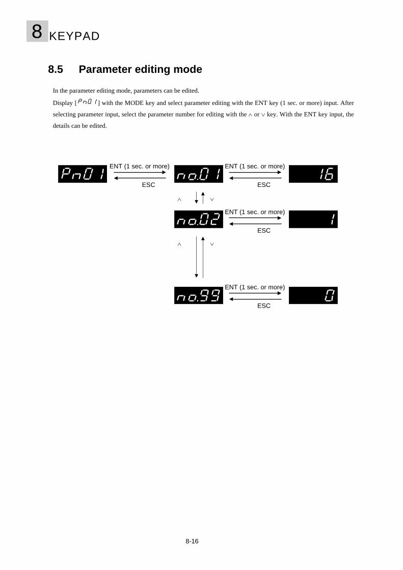
8 KEYPAD
8-16
8.5 Parameter editing mode
In the parameter editing mode, parameters can be edited.
Display [ ] with the MODE key and select parameter editing with the ENT key (1 sec. or more) input. After
selecting parameter input, select the parameter number for editing with the ∧ or ∨ key. With the ENT key input, the
details can be edited.
∧ ∨
∧ ∨
ENT (1 sec. or more)
ESC
ENT (1 sec. or more)
ESC
ENT (1 sec. or more)
ESC
ENT (1 sec. or more)
ESC
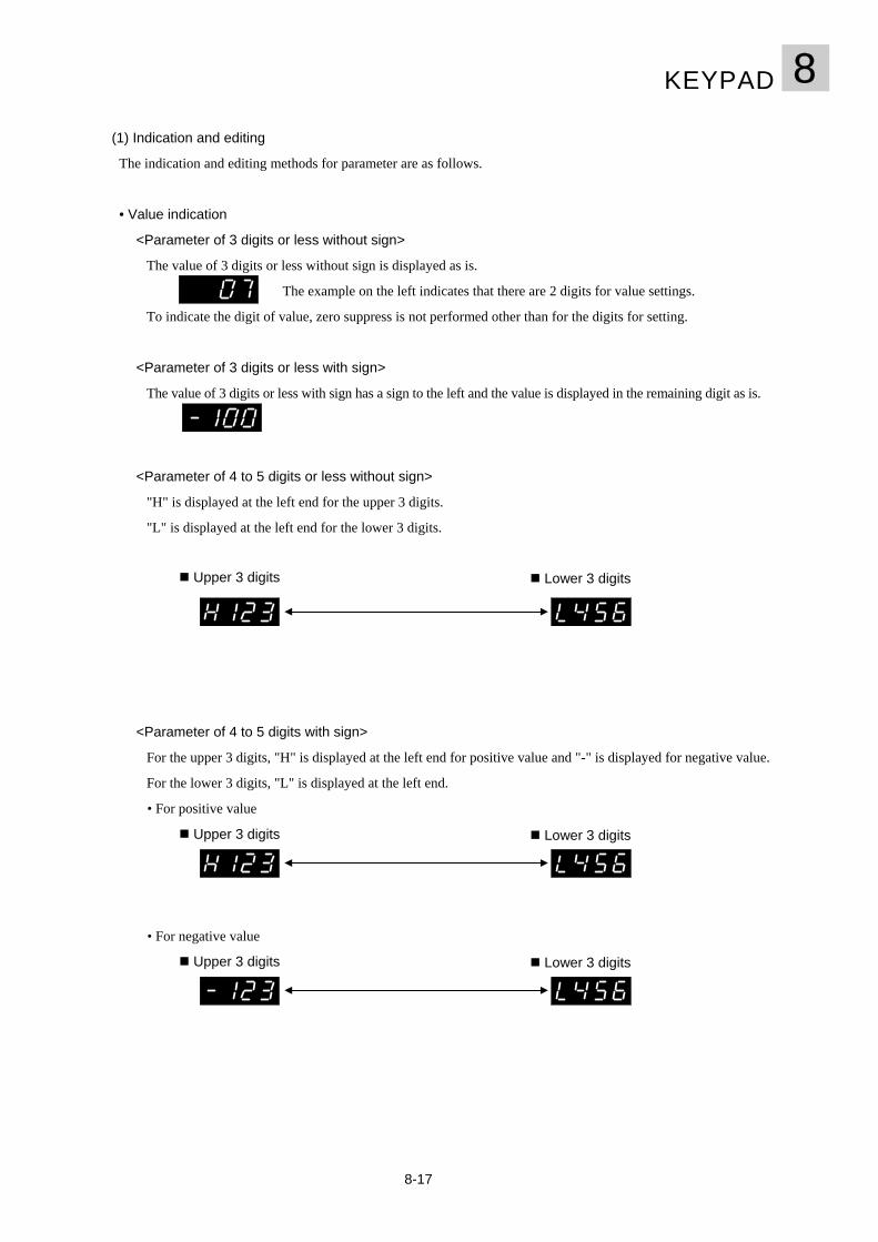
KEYPAD 8
8-17
(1) Indication and editing
The indication and editing methods for parameter are as follows.
• Value indication
<Parameter of 3 digits or less without sign>
The value of 3 digits or less without sign is displayed as is.
The example on the left indicates that there are 2 digits for value settings.
To indicate the digit of value, zero suppress is not performed other than for the digits for setting.
<Parameter of 3 digits or less with sign>
The value of 3 digits or less with sign has a sign to the left and the value is displayed in the remaining digit as is.
<Parameter of 4 to 5 digits or less without sign>
"H" is displayed at the left end for the upper 3 digits.
"L" is displayed at the left end for the lower 3 digits.
<Parameter of 4 to 5 digits with sign>
For the upper 3 digits, "H" is displayed at the left end for positive value and "-" is displayed for negative value.
For the lower 3 digits, "L" is displayed at the left end.
• For positive value
• For negative value
Upper 3 digits Lower 3 digits
Upper 3 digits Lower 3 digits
Upper 3 digits Lower 3 digits
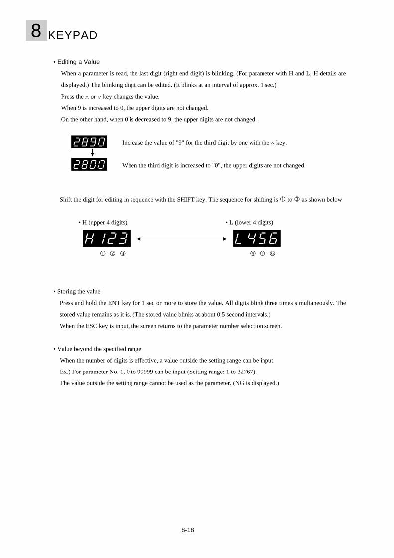
8 KEYPAD
8-18
• Editing a Value
When a parameter is read, the last digit (right end digit) is blinking. (For parameter with H and L, H details are
displayed.) The blinking digit can be edited. (It blinks at an interval of approx. 1 sec.)
Press the ∧ or ∨ key changes the value.
When 9 is increased to 0, the upper digits are not changed.
On the other hand, when 0 is decreased to 9, the upper digits are not changed.
Increase the value of "9" for the third digit by one with the ∧ key.
When the third digit is increased to "0", the upper digits are not changed.
Shift the digit for editing in sequence with the SHIFT key. The sequence for shifting is to as shown below
• H (upper 4 digits) • L (lower 4 digits)
• Storing the value
Press and hold the ENT key for 1 sec or more to store the value. All digits blink three times simultaneously. The
stored value remains as it is. (The stored value blinks at about 0.5 second intervals.)
When the ESC key is input, the screen returns to the parameter number selection screen.
• Value beyond the specified range
When the number of digits is effective, a value outside the setting range can be input.
Ex.) For parameter No. 1, 0 to 99999 can be input (Setting range: 1 to 32767).
The value outside the setting range cannot be used as the parameter. (NG is displayed.)

KEYPAD 8
8-19
• Editing example
Change the manual feed speed of 3 in parameter No. 33 to 1.0.
The action mode in the sequence mode is displayed.
Returns to mode selection.
Select the parameter mode.
Display the parameter number.
Select parameter No. 33.
Settings of No. 33 are displayed. The first digit of H (upper
3 digits) is blinking.
(Upper 2 digits of initial value 1000.0 are displayed.)
Decrease the value to 0.
Display L (lower 4 digits).
Shift to the editing digit.
Change the value to "1."
Define the changed value.
The stored value remains as it is.
(1 sec. or more)
Indication Keying Remarks
Blinking
Blinking
MODEESC
SHIFTENT
(1 sec. or more)
(1 sec. or more)
Blinking
Blinking
Blinking
MODEESC
SHIFTENT
SHIFTENT
SHIFTENT
SHIFTENT
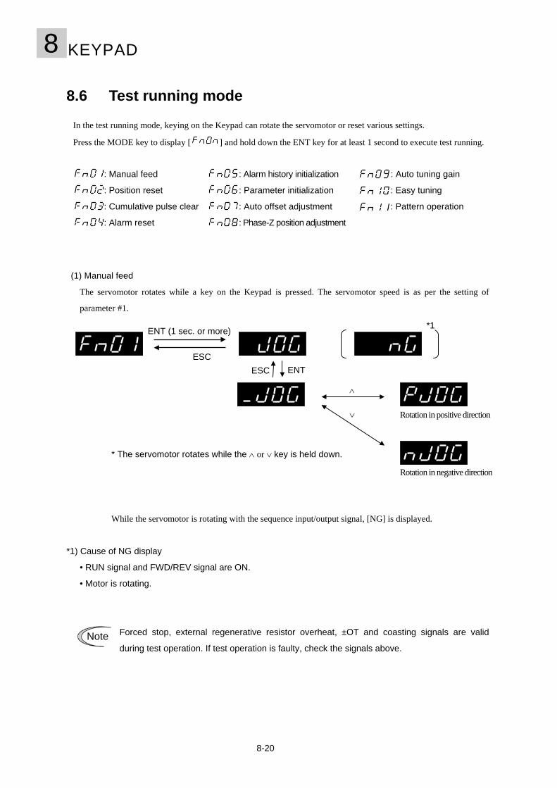
8 KEYPAD
8-20
8.6 Test running mode
In the test running mode, keying on the Keypad can rotate the servomotor or reset various settings.
Press the MODE key to display [ ] and hold down the ENT key for at least 1 second to execute test running.
(1) Manual feed
The servomotor rotates while a key on the Keypad is pressed. The servomotor speed is as per the setting of
parameter #1.
* The servomotor rotates while the ∧ or ∨ key is held down.
While the servomotor is rotating with the sequence input/output signal, [NG] is displayed.
*1) Cause of NG display
• RUN signal and FWD/REV signal are ON.
• Motor is rotating.
Forced stop, external regenerative resistor overheat, ±OT and coasting signals are valid
during test operation. If test operation is faulty, check the signals above.
ENT ESC
∧
∨ Rotation in positive direction
Rotation in negative direction
*1ENT (1 sec. or more)
ESC
: Alarm history initialization
: Parameter initialization
: Auto offset adjustment
: Phase-Z position adjustment
: Auto tuning gain
: Easy tuning
: Pattern operation
: Manual feed
: Position reset
: Cumulative pulse clear
: Alarm reset
Note
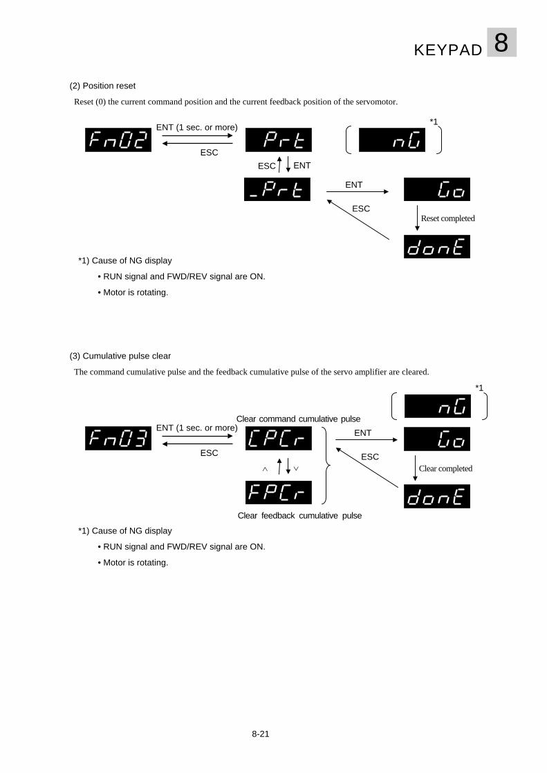
KEYPAD 8
8-21
(2) Position reset
Reset (0) the current command position and the current feedback position of the servomotor.
*1) Cause of NG display
• RUN signal and FWD/REV signal are ON.
• Motor is rotating.
(3) Cumulative pulse clear
The command cumulative pulse and the feedback cumulative pulse of the servo amplifier are cleared.
*1) Cause of NG display
• RUN signal and FWD/REV signal are ON.
• Motor is rotating.
ENT ESC
ENT
ESC
*1ENT (1 sec. or more)
ESC
Reset completed
∨ ∧
ENT
ESC
ENT (1 sec. or more)
ESC
*1
Clear completed
Clear command cumulative pulse
Clear feedback cumulative pulse
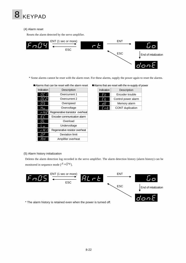
8 KEYPAD
8-22
(4) Alarm reset
Resets the alarm detected by the servo amplifier.
* Some alarms cannot be reset with the alarm reset. For these alarms, supply the power again to reset the alarms.
(5) Alarm history initialization
Deletes the alarm detection log recorded in the servo amplifier. The alarm detection history (alarm history) can be
monitored in sequence mode [ ].
* The alarm history is retained even when the power is turned off.
ENT (1 sec or more)
ESC
ENT
ESC End of intialization
ENT (1 sec or more)
ESC
ENT
ESC End of intialization
Indication DescriptionOvercurrent 1
Overspeed
Undervoltage
Overvoltage
Encoder troubleControl power alarm
Memory alarm
Regenerative transistor overheatEncoder communication alarm
CONT duplication
Overload
Amplifier overheat
Regenerative resistor overheatDeviation limit
Alarms that can be reset with the alarm resetIndication Description
Alarms that are reset with the re-supply of power
Overcurrent 2

KEYPAD 8
8-23
(6) Parameter initialization
Initializes the parameters.
* After initializing, turn the power off then on again.
*1) Cause of NG display
• RUN signal is ON.
• Write-protection selected at parameter #29 (write-protection of parameters)
ENT (1 sec or more)
ESC
ENT
ESC End of intialization
*1
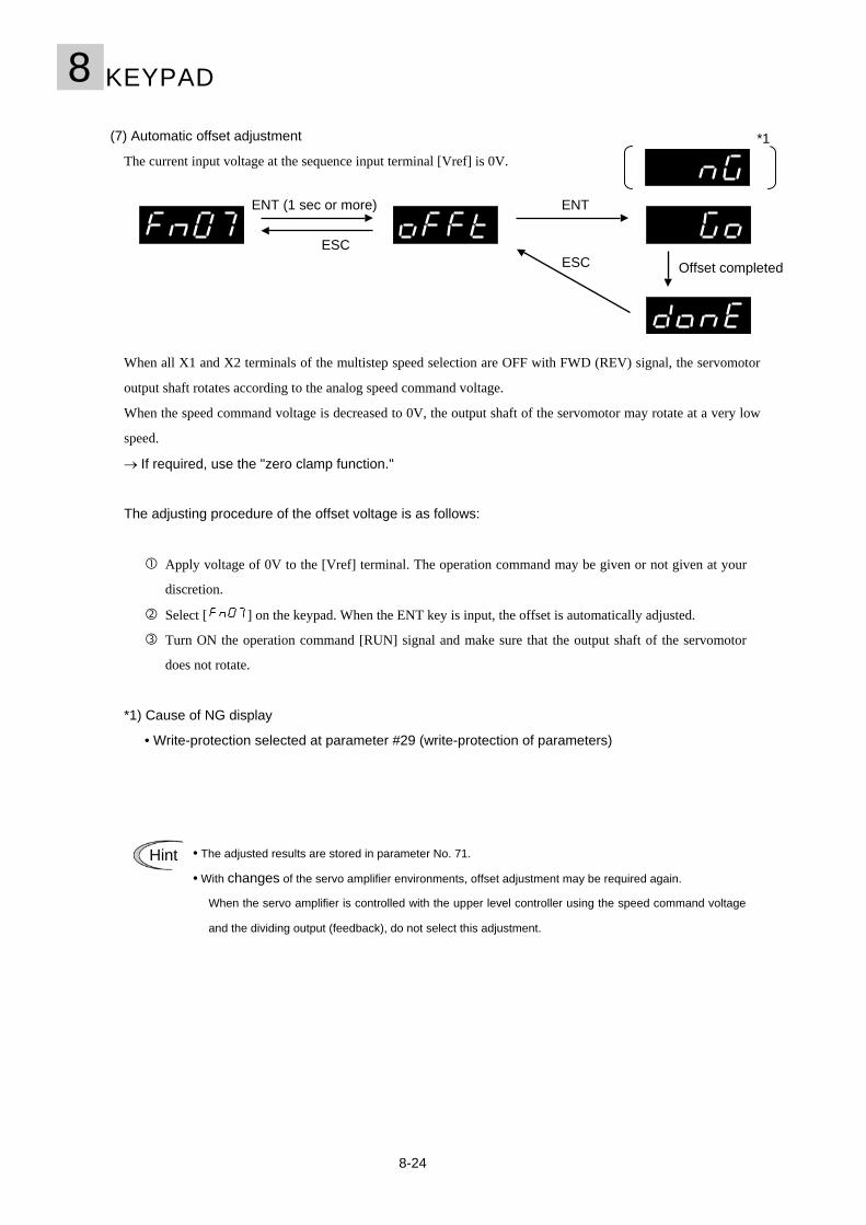
8 KEYPAD
8-24
(7) Automatic offset adjustment
The current input voltage at the sequence input terminal [Vref] is 0V.
When all X1 and X2 terminals of the multistep speed selection are OFF with FWD (REV) signal, the servomotor
output shaft rotates according to the analog speed command voltage.
When the speed command voltage is decreased to 0V, the output shaft of the servomotor may rotate at a very low
speed.
→ If required, use the "zero clamp function."
The adjusting procedure of the offset voltage is as follows:
Apply voltage of 0V to the [Vref] terminal. The operation command may be given or not given at your
discretion.
Select [ ] on the keypad. When the ENT key is input, the offset is automatically adjusted.
Turn ON the operation command [RUN] signal and make sure that the output shaft of the servomotor
does not rotate.
*1) Cause of NG display
• Write-protection selected at parameter #29 (write-protection of parameters)
• The adjusted results are stored in parameter No. 71.
• With changes of the servo amplifier environments, offset adjustment may be required again.
When the servo amplifier is controlled with the upper level controller using the speed command voltage
and the dividing output (feedback), do not select this adjustment.
ENT (1 sec or more)
ESC
ENT
ESC Offset completed
*1
Hint
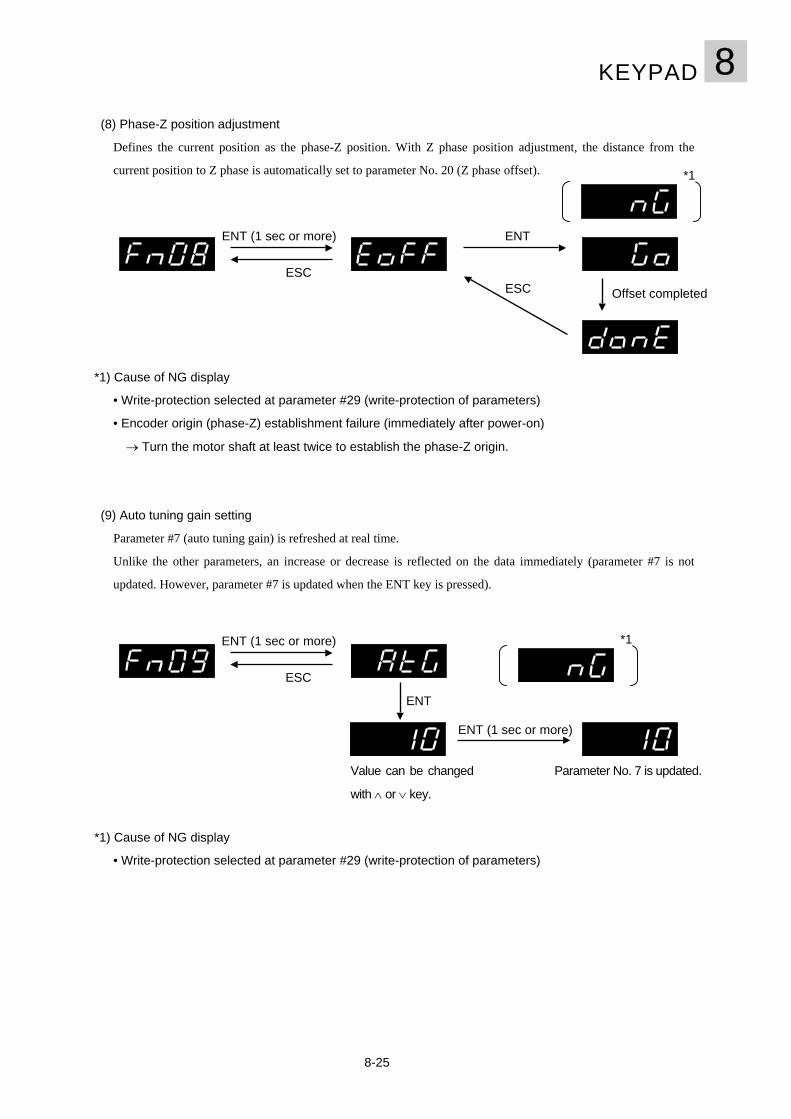
KEYPAD 8
8-25
(8) Phase-Z position adjustment
Defines the current position as the phase-Z position. With Z phase position adjustment, the distance from the
current position to Z phase is automatically set to parameter No. 20 (Z phase offset).
*1) Cause of NG display
• Write-protection selected at parameter #29 (write-protection of parameters)
• Encoder origin (phase-Z) establishment failure (immediately after power-on)
→ Turn the motor shaft at least twice to establish the phase-Z origin.
(9) Auto tuning gain setting
Parameter #7 (auto tuning gain) is refreshed at real time.
Unlike the other parameters, an increase or decrease is reflected on the data immediately (parameter #7 is not
updated. However, parameter #7 is updated when the ENT key is pressed).
*1) Cause of NG display
• Write-protection selected at parameter #29 (write-protection of parameters)
ENT (1 sec or more)
ESC
ENT
ESC Offset completed
*1
Value can be changed
with ∧ or ∨ key.
ENT (1 sec or more)
ESC
ENT
*1
ENT (1 sec or more)
Parameter No. 7 is updated.
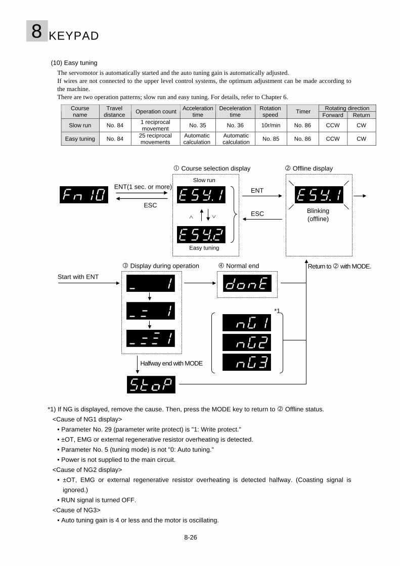
8 KEYPAD
8-26
(10) Easy tuning The servomotor is automatically started and the auto tuning gain is automatically adjusted. If wires are not connected to the upper level control systems, the optimum adjustment can be made according to the machine. There are two operation patterns; slow run and easy tuning. For details, refer to Chapter 6.
*1) If NG is displayed, remove the cause. Then, press the MODE key to return to Offline status. <Cause of NG1 display>
• Parameter No. 29 (parameter write protect) is "1: Write protect." • ±OT, EMG or external regenerative resistor overheating is detected. • Parameter No. 5 (tuning mode) is not "0: Auto tuning." • Power is not supplied to the main circuit.
<Cause of NG2 display> • ±OT, EMG or external regenerative resistor overheating is detected halfway. (Coasting signal is
ignored.) • RUN signal is turned OFF.
<Cause of NG3> • Auto tuning gain is 4 or less and the motor is oscillating.
Rotating direction Course name
Travel distance Operation count Acceleration
time Deceleration
time Rotation speed Timer Forward Return
Slow run No. 84 1 reciprocal movement No. 35 No. 36 10r/min No. 86 CCW CW
Easy tuning No. 84 25 reciprocal movements
Automatic calculation
Automatic calculation No. 85 No. 86 CCW CW
∨ ∧
ENT ENT(1 sec. or more)
ESC
*1
Halfway end with MODE
Slow run
Easy tuning
Blinking (offline)
Course selection display Offline display
Start with ENT
Display during operation Normal end Return to with MODE.
ESC
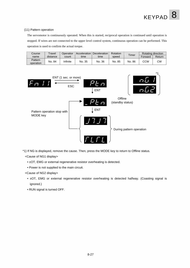
KEYPAD 8
8-27
(11) Pattern operation
The servomotor is continuously operated. When this is started, reciprocal operation is continued until operation is
stopped. If wires are not connected to the upper level control system, continuous operation can be performed. This
operation is used to confirm the actual torque.
*1) If NG is displayed, remove the cause. Then, press the MODE key to return to Offline status.
<Cause of NG1 display>
• ±OT, EMG or external regenerative resistor overheating is detected.
• Power is not supplied to the main circuit.
<Cause of NG2 display>
• ±OT, EMG or external regenerative resistor overheating is detected halfway. (Coasting signal is
ignored.)
• RUN signal is turned OFF.
Rotating direction Course name
Travel distance
Operation count
Acceleration time
Deceleration time
Rotation speed Timer Forward Return
Pattern operation No. 84 Infinite No. 35 No. 36 No. 85 No. 86 CCW CW
ENT
Pattern operation stop withMODE key
ENT (1 sec. or more)
ESC
Offline (standby status)
ENT
During pattern operation
*1

8 KEYPAD
8-28
-MEMO-
INSPECTION AND MAINTENANCE
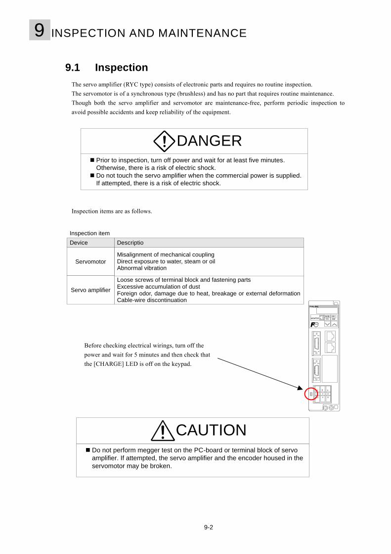
9 INSPECTION AND MAINTENANCE
9-2
MONITOR
9.1 Inspection The servo amplifier (RYC type) consists of electronic parts and requires no routine inspection. The servomotor is of a synchronous type (brushless) and has no part that requires routine maintenance. Though both the servo amplifier and servomotor are maintenance-free, perform periodic inspection to avoid possible accidents and keep reliability of the equipment.
Prior to inspection, turn off power and wait for at least five minutes.Otherwise, there is a risk of electric shock.Do not touch the servo amplifier when the commercial power is supplied.If attempted, there is a risk of electric shock.
DANGER
Inspection items are as follows.
Before checking electrical wirings, turn off the power and wait for 5 minutes and then check that the [CHARGE] LED is off on the keypad.
Misalignment of mechanical coupling Direct exposure to water, steam or oil Abnormal vibration
Device Descriptio
Servomotor
Inspection item
Servo amplifier Loose screws of terminal block and fastening parts Excessive accumulation of dust Foreign odor, damage due to heat, breakage or external deformationCable-wire discontinuation
Do not perform megger test on the PC-board or terminal block of servo amplifier. If attempted, the servo amplifier and the encoder housed in the servomotor may be broken.
CAUTION
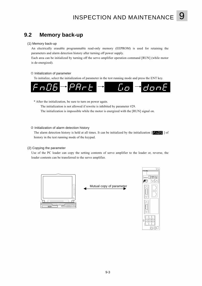
INSPECTION AND MAINTENANCE 9
9-3
MONITOR
9.2 Memory back-up (1) Memory back-up
An electrically erasable programmable read-only memory (EEPROM) is used for retaining the parameters and alarm detection history after turning off power supply. Each area can be initialized by turning off the servo amplifier operation command [RUN] (while motor is de-energized).
Initialization of parameter To initialize, select the initialization of parameter in the test running mode and press the ENT key.
* After the initialization, be sure to turn on power again. The initialization is not allowed if rewrite is inhibited by parameter #29. The initialization is impossible while the motor is energized with the [RUN] signal on.
Initialization of alarm detection history The alarm detection history is held at all times. It can be initialized by the initialization [ ] of history in the test running mode of the keypad.
(2) Copying the parameter Use of the PC loader can copy the setting contents of servo amplifier to the loader or, reverse, the loader contents can be transferred to the servo amplifier.
Mutual copy of parameter
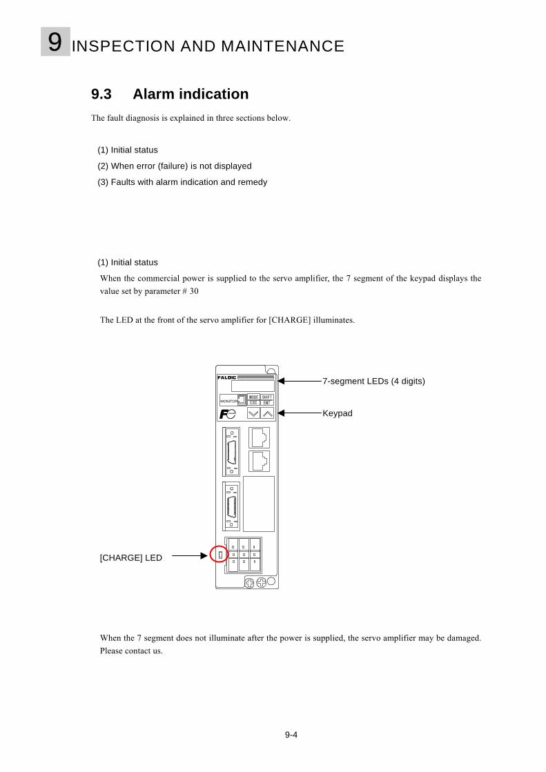
9 INSPECTION AND MAINTENANCE
9-4
MONITOR
9.3 Alarm indication The fault diagnosis is explained in three sections below.
(1) Initial status
(2) When error (failure) is not displayed
(3) Faults with alarm indication and remedy
(1) Initial status
When the commercial power is supplied to the servo amplifier, the 7 segment of the keypad displays the value set by parameter # 30
The LED at the front of the servo amplifier for [CHARGE] illuminates.
7-segment LEDs (4 digits)
Keypad
[CHARGE] LED
When the 7 segment does not illuminate after the power is supplied, the servo amplifier may be damaged. Please contact us.
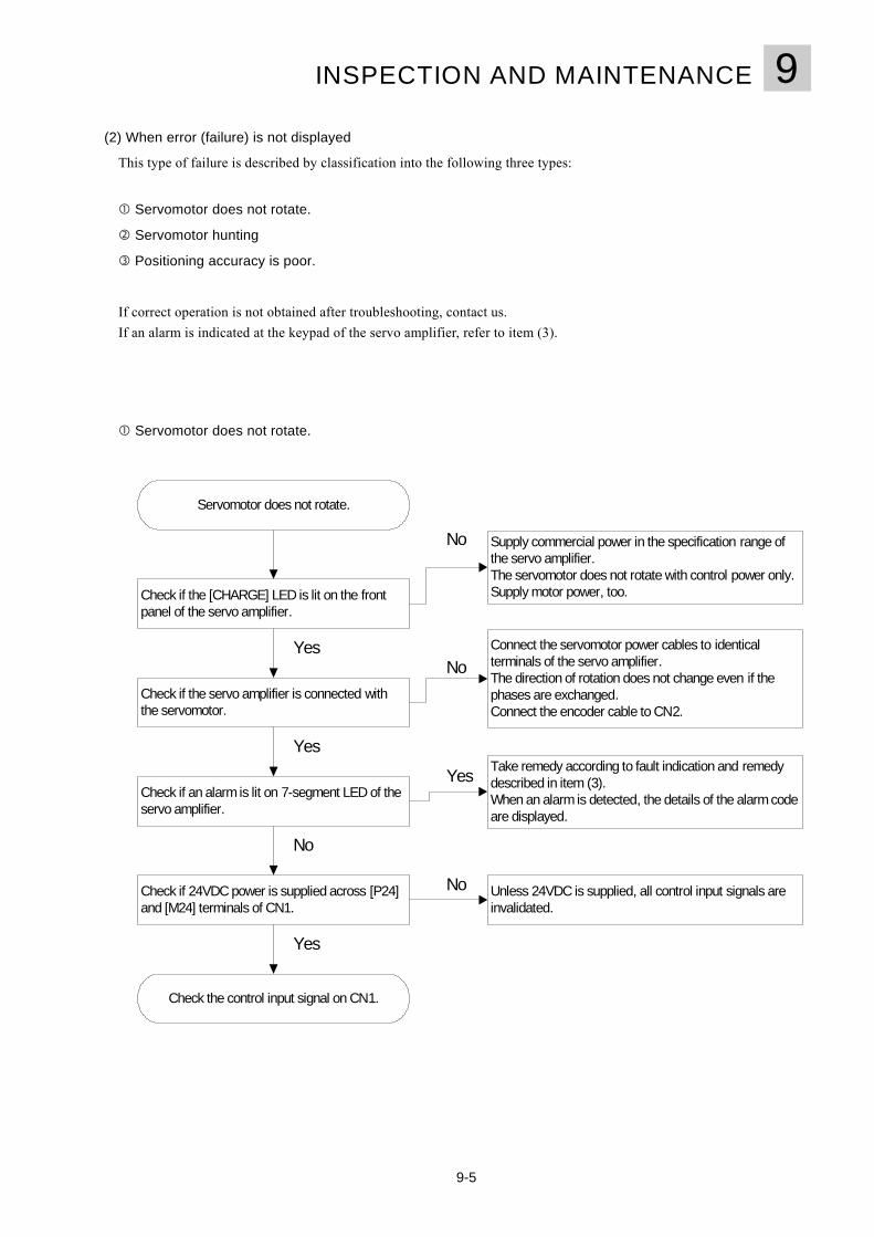
INSPECTION AND MAINTENANCE 9
9-5
(2) When error (failure) is not displayed
This type of failure is described by classification into the following three types:
Servomotor does not rotate.
Servomotor hunting
Positioning accuracy is poor.
If correct operation is not obtained after troubleshooting, contact us. If an alarm is indicated at the keypad of the servo amplifier, refer to item (3).
Servomotor does not rotate.
Servomotor does not rotate.
Check if the [CHARGE] LED is lit on the front panel of the servo amplifier.
Check if the servo amplifier is connected with the servomotor.
Check if an alarm is lit on 7-segment LED of the servo amplifier.
Check if 24VDC power is supplied across [P24] and [M24] terminals of CN1.
Check the control input signal on CN1.
Supply commercial power in the specification range of the servo amplifier.The servomotor does not rotate with control power only.Supply motor power, too.
Connect the servomotor power cables to identical terminals of the servo amplifier.The direction of rotation does not change even if the phases are exchanged.Connect the encoder cable to CN2.
Take remedy according to fault indication and remedy described in item (3).When an alarm is detected, the details of the alarm code are displayed.
Unless 24VDC is supplied, all control input signals are invalidated.
Yes
Yes
No
Yes
No
No
Yes
No

9 INSPECTION AND MAINTENANCE
9-6
ESC
ENT (1 sec or more)
Hint
Check the state of the servo amplifier.
Action mode check
Indication (1st digit) Sequence
Position control
Speed control
Torque control
Indication (2 to 4 digits) SequenceBase off. Servomotor has no drive force. Coasting.
Waiting for command with the servo ON.
The servomotor is ready to rotate. Pulse string input is effective. The servomotor is ready to rotate by manual operation (test running). Stopped under detection of positive overtravel signal. Stopped under detection of negative overtravel signal.
Stopped at zero speed upon forced stop signal input. Undervoltage is detected.
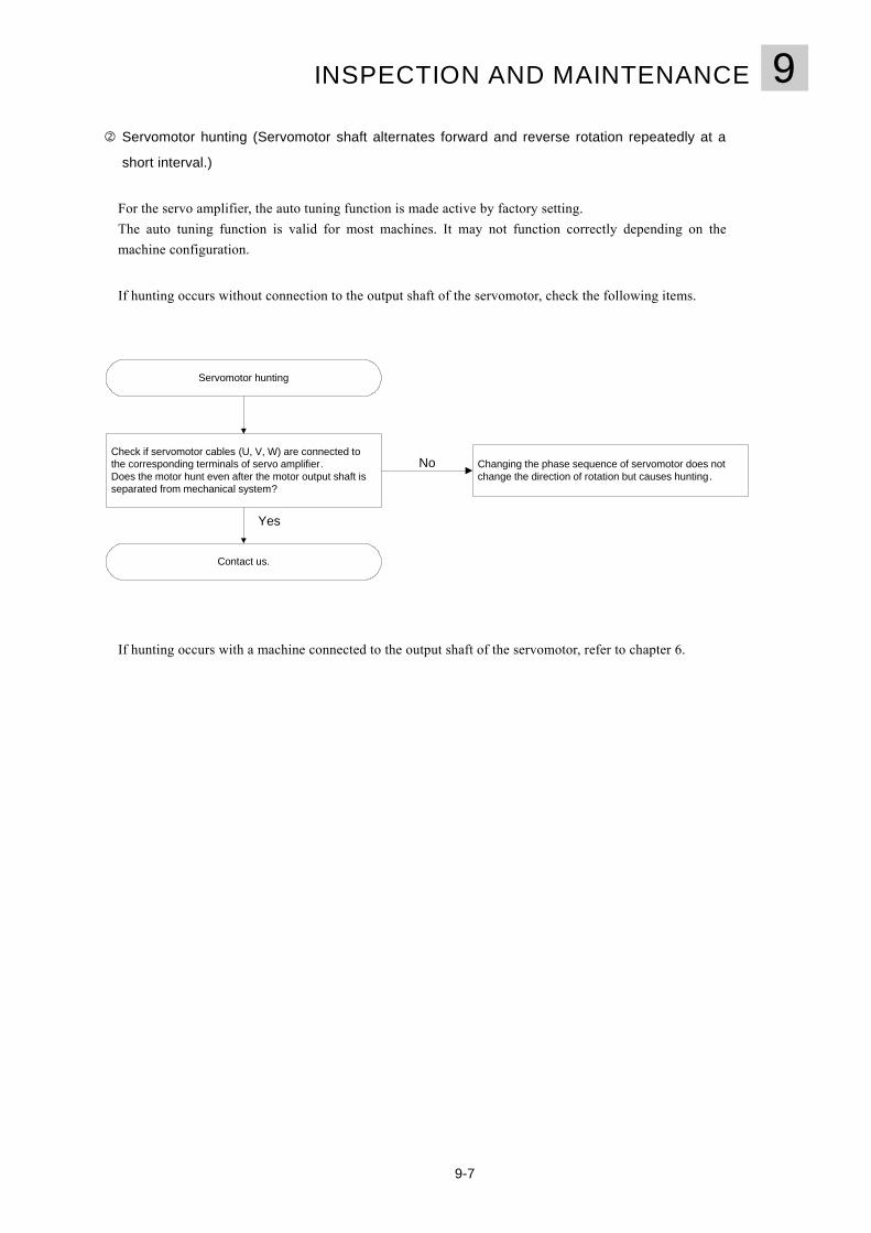
INSPECTION AND MAINTENANCE 9
9-7
Servomotor hunting (Servomotor shaft alternates forward and reverse rotation repeatedly at a
short interval.)
For the servo amplifier, the auto tuning function is made active by factory setting. The auto tuning function is valid for most machines. It may not function correctly depending on the machine configuration.
If hunting occurs without connection to the output shaft of the servomotor, check the following items.
Check if servomotor cables (U, V, W) are connected tothe corresponding terminals of servo amplifier.Does the motor hunt even after the motor output shaft isseparated from mechanical system?
Changing the phase sequence of servomotor does notchange the direction of rotation but causes hunting.
Servomotor hunting
Contact us.
Yes
No
If hunting occurs with a machine connected to the output shaft of the servomotor, refer to chapter 6.

9 INSPECTION AND MAINTENANCE
9-8
Poor positioning accuracy
Check if the grounding wire is correctly connected. Connect the grounding wire correctly.
Positioning accuracy is poor
Contact us.
Check if the sequence input/output signal cables arerouted at a sufficient distance from the power supplyand motor power cables.
Allow at least 10 cm.
Check if the coupling or the like is loose.Examine mechanical configuration provided with keys.Examine mechanical configuration provided withSchupan ring or the like.
Check if the backlash and other mechanical accuracy ofthe reduction gear are adequate.
Check the mechanical accuracy.
Check if there is an excess or shortage in the number ofcumulative pulses monitored at the PC loader.
1. Examine wiring (Allow at least 10 cm from the power and motor cables.)2. Check the pulse string frequency.Differential input: within 1 MHz Open collector input: within 200 kHz
Yes
Yes
Yes
No
Yes
No
No
No
Yes
No
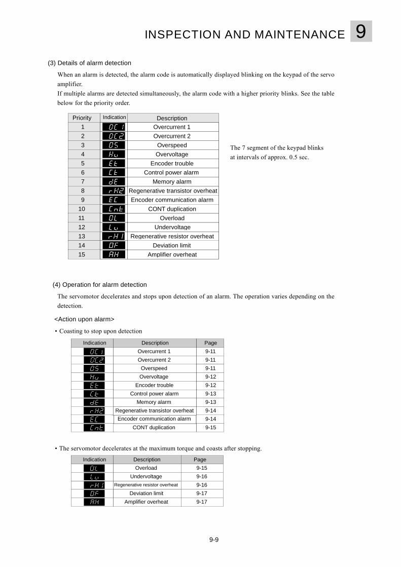
INSPECTION AND MAINTENANCE 9
9-9
(3) Details of alarm detection
When an alarm is detected, the alarm code is automatically displayed blinking on the keypad of the servo amplifier. If multiple alarms are detected simultaneously, the alarm code with a higher priority blinks. See the table below for the priority order.
The 7 segment of the keypad blinks at intervals of approx. 0.5 sec.
(4) Operation for alarm detection
The servomotor decelerates and stops upon detection of an alarm. The operation varies depending on the detection.
<Action upon alarm>
• Coasting to stop upon detection
• The servomotor decelerates at the maximum torque and coasts after stopping.
Indication
Undervoltage
Regenerative transistor overheatEncoder communication alarm
CONT duplicationOverload
Amplifier overheat
Regenerative resistor overheatDeviation limit
Priority 1 2 3 4 5 6 7 8 9
10 11 12 13 14 15
DescriptionOvercurrent 1
OverspeedOvervoltage
Encoder trouble
Memory alarmControl power alarm
Overcurrent 2
Indication Page9-119-119-11
9-139-129-12
9-139-149-149-15CONT duplication
Regenerative transistor overheat
Description
Overspeed
Control power alarm
Overcurrent 1
OvervoltageEncoder trouble
Memory alarm
Overcurrent 2
Encoder communication alarm
Overload 9-15
Indication Description
Regenerative resistor overheat
Undervoltage
Deviation limit Amplifier overheat
9-169-169-179-17
Page

9 INSPECTION AND MAINTENANCE
9-10
An alarm is automatically displayed if detected. When this is displayed, the alarm can be reset with the sequence input signal (reset). The alarm detection of encoder error, control power error, memory error and CONT duplication cannot be reset with the sequence input signal. In this case, shut off the power and make sure that the display of the keypad goes off. Then, re-supply the power. Alarm detection can be reset in the test running mode [ ] also.
Hint
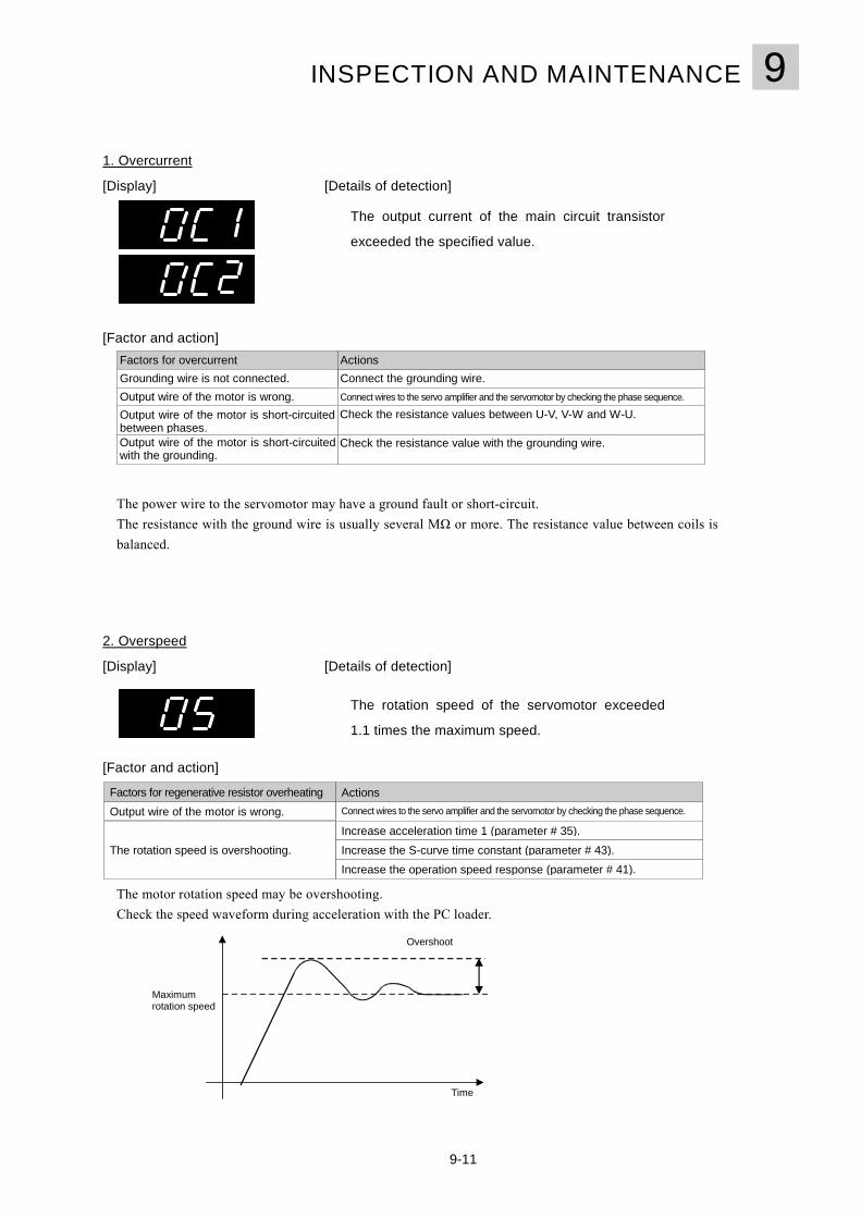
INSPECTION AND MAINTENANCE 9
9-11
1. Overcurrent
[Display] [Details of detection]
[Factor and action]
The power wire to the servomotor may have a ground fault or short-circuit. The resistance with the ground wire is usually several MΩ or more. The resistance value between coils is balanced.
2. Overspeed
[Display] [Details of detection]
[Factor and action]
ActionsOutput wire of the motor is wrong. Connect wires to the servo amplifier and the servomotor by checking the phase sequence.
The rotation speed is overshooting. Increase acceleration time 1 (parameter # 35).
Factors for regenerative resistor overheating
Increase the S-curve time constant (parameter # 43). Increase the operation speed response (parameter # 41).
The motor rotation speed may be overshooting. Check the speed waveform during acceleration with the PC loader.
The output current of the main circuit transistor
exceeded the specified value.
The rotation speed of the servomotor exceeded
1.1 times the maximum speed.
Factors for overcurrent Connect the grounding wire. Actions
Grounding wire is not connected. Output wire of the motor is wrong. Connect wires to the servo amplifier and the servomotor by checking the phase sequence. Output wire of the motor is short-circuited between phases.
Check the resistance values between U-V, V-W and W-U.
Output wire of the motor is short-circuitedwith the grounding.
Check the resistance value with the grounding wire.
Maximum rotation speed
Time
Overshoot
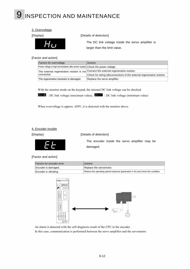
9 INSPECTION AND MAINTENANCE
9-12
MONITOR
3. Overvoltage
[Display] [Details of detection]
[Factor and action]
With the monitor mode on the keypad, the internal DC link voltage can be checked.
: DC link voltage (maximum value), : DC link voltage (minimum value)
When overvoltage is approx. 420V, it is detected with the monitor above.
4. Encoder trouble
[Display] [Details of detection]
[Factor and action]
An alarm is detected with the self-diagnosis result of the CPU in the encoder. In this case, communication is performed between the servo amplifier and the servomotor.
The DC link voltage inside the servo amplifier is
larger than the limit value.
The encoder inside the servo amplifier may be
damaged.
Factors for overvoltage Actions
The external regenerative resistor is notconnected.
Connect the external regenerative resistor. Check for wiring (disconnection) of the external regenerative resistor.
Power voltage is high (immediately after power supply). Check the power voltage.
The regenerative transistor is damaged. Replace the servo amplifier.
Factors for encoder error Actions
Encoder is vibrating.Encoder is damaged. Replace the servomotor.
Reduce the operating speed response (parameter # 41) and check the condition.
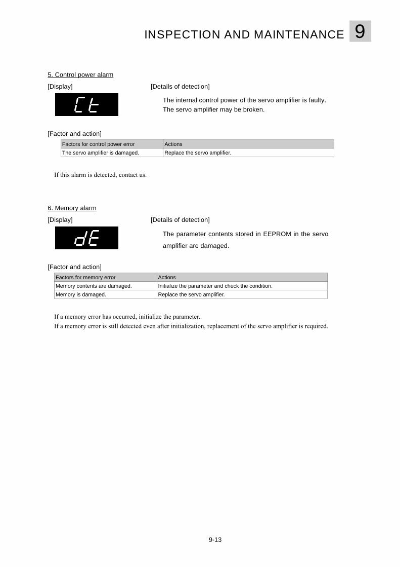
INSPECTION AND MAINTENANCE 9
9-13
5. Control power alarm
[Display] [Details of detection]
[Factor and action]
If this alarm is detected, contact us.
6. Memory alarm
[Display] [Details of detection]
[Factor and action]
If a memory error has occurred, initialize the parameter. If a memory error is still detected even after initialization, replacement of the servo amplifier is required.
The internal control power of the servo amplifier is faulty. The servo amplifier may be broken.
The parameter contents stored in EEPROM in the servo
amplifier are damaged.
Factors for control power error ActionsThe servo amplifier is damaged. Replace the servo amplifier.
Factors for memory error ActionsMemory contents are damaged. Initialize the parameter and check the condition.Memory is damaged. Replace the servo amplifier.
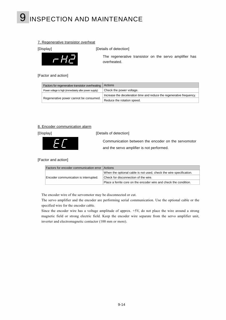
9 INSPECTION AND MAINTENANCE
9-14
7. Regenerative transistor overheat
[Display] [Details of detection]
[Factor and action]
8. Encoder communication alarm
[Display] [Details of detection]
[Factor and action]
The encoder wire of the servomotor may be disconnected or cut. The servo amplifier and the encoder are performing serial communication. Use the optional cable or the specified wire for the encoder cable. Since the encoder wire has a voltage amplitude of approx. +5V, do not place the wire around a strong magnetic field or strong electric field. Keep the encoder wire separate from the servo amplifier unit, inverter and electromagnetic contactor (100 mm or more).
The regenerative transistor on the servo amplifier hasoverheated.
Communication between the encoder on the servomotor
and the servo amplifier is not performed.
ActionsPower voltage is high (immediately after power supply) Check the power voltage.
Regenerative power cannot be consumed.Increase the deceleration time and reduce the regenerative frequency.
Factors for regenerative transistor overheating
Reduce the rotation speed.
Factors for encoder communication error Actions
Encoder communication is interrupted.When the optional cable is not used, check the wire specification.Check for disconnection of the wire.Place a ferrite core on the encoder wire and check the condition.
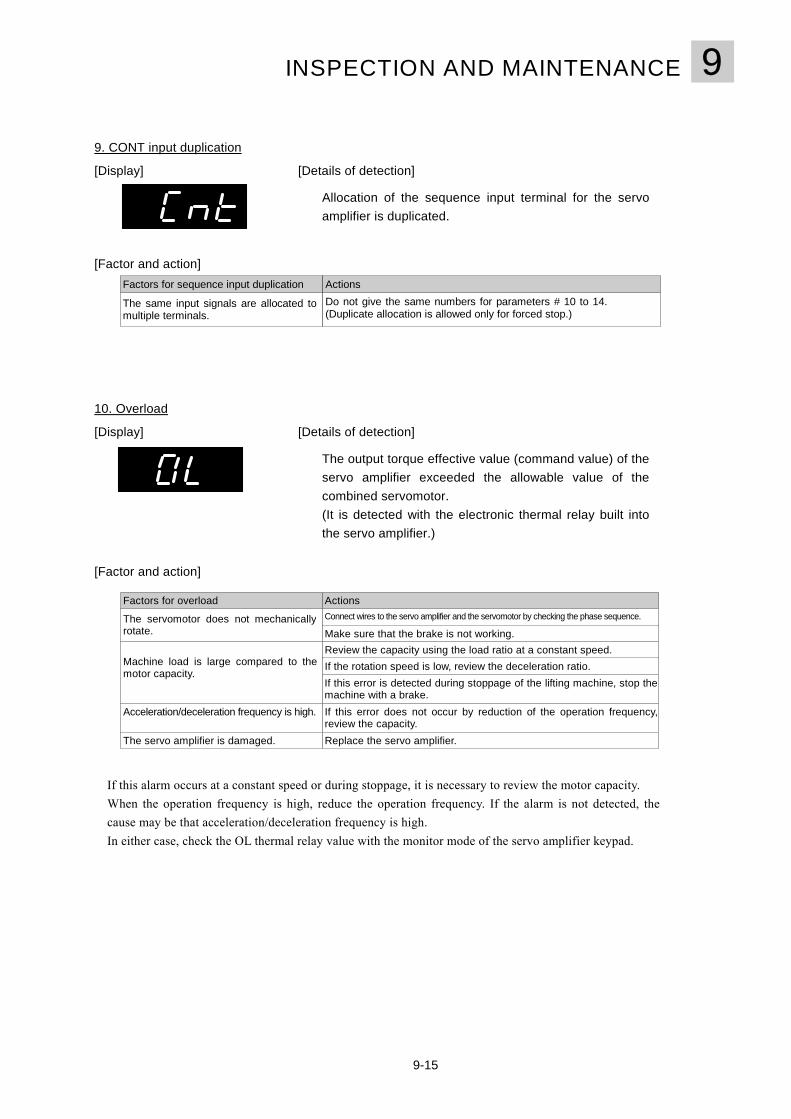
INSPECTION AND MAINTENANCE 9
9-15
9. CONT input duplication
[Display] [Details of detection]
[Factor and action]
10. Overload
[Display] [Details of detection]
[Factor and action]
If this alarm occurs at a constant speed or during stoppage, it is necessary to review the motor capacity. When the operation frequency is high, reduce the operation frequency. If the alarm is not detected, the cause may be that acceleration/deceleration frequency is high. In either case, check the OL thermal relay value with the monitor mode of the servo amplifier keypad.
Allocation of the sequence input terminal for the servo amplifier is duplicated.
The output torque effective value (command value) of theservo amplifier exceeded the allowable value of thecombined servomotor. (It is detected with the electronic thermal relay built intothe servo amplifier.)
Factors for sequence input duplication Actions
The same input signals are allocated tomultiple terminals.
Do not give the same numbers for parameters # 10 to 14.(Duplicate allocation is allowed only for forced stop.)
Factors for overload Actions
The servomotor does not mechanicallyrotate. Make sure that the brake is not working.
Machine load is large compared to themotor capacity.
Connect wires to the servo amplifier and the servomotor by checking the phase sequence.
Review the capacity using the load ratio at a constant speed.
Acceleration/deceleration frequency is high. If this error does not occur by reduction of the operation frequency,review the capacity.
If the rotation speed is low, review the deceleration ratio. If this error is detected during stoppage of the lifting machine, stop themachine with a brake.
The servo amplifier is damaged. Replace the servo amplifier.
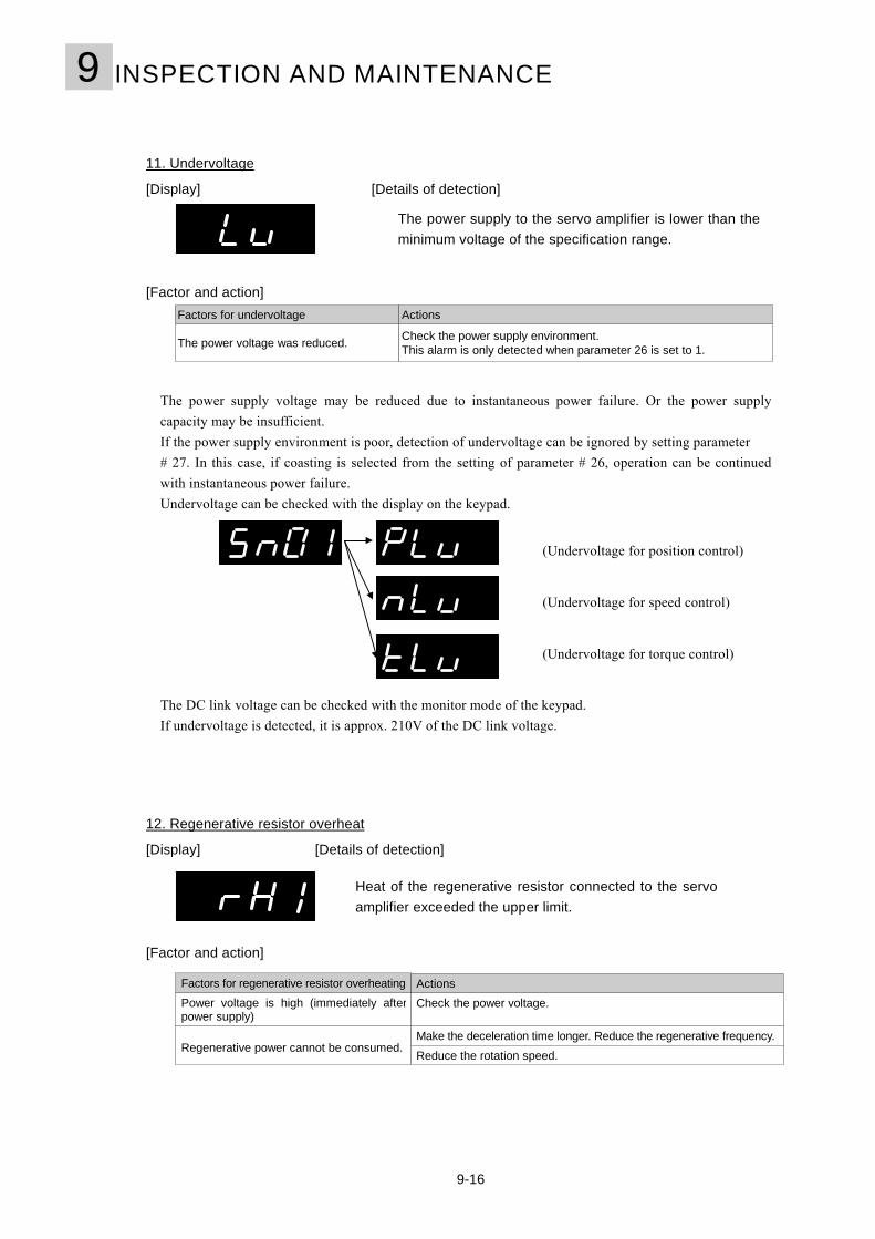
9 INSPECTION AND MAINTENANCE
9-16
11. Undervoltage
[Display] [Details of detection]
[Factor and action]
The power supply voltage may be reduced due to instantaneous power failure. Or the power supply capacity may be insufficient. If the power supply environment is poor, detection of undervoltage can be ignored by setting parameter # 27. In this case, if coasting is selected from the setting of parameter # 26, operation can be continued with instantaneous power failure. Undervoltage can be checked with the display on the keypad.
(Undervoltage for position control)
(Undervoltage for speed control)
(Undervoltage for torque control)
The DC link voltage can be checked with the monitor mode of the keypad. If undervoltage is detected, it is approx. 210V of the DC link voltage.
12. Regenerative resistor overheat
[Display] [Details of detection]
[Factor and action]
The power supply to the servo amplifier is lower than theminimum voltage of the specification range.
Heat of the regenerative resistor connected to the servoamplifier exceeded the upper limit.
Factors for undervoltage Actions
The power voltage was reduced. Check the power supply environment.This alarm is only detected when parameter 26 is set to 1.
ActionsFactors for regenerative resistor overheating
Regenerative power cannot be consumed.Make the deceleration time longer. Reduce the regenerative frequency.Reduce the rotation speed.
Power voltage is high (immediately afterpower supply)
Check the power voltage.

INSPECTION AND MAINTENANCE 9
9-17
13. Deviation limit
[Display] [Details of detection]
[Factor and action]
The initial value of standard parameter # 22 is 20000 (× 100) pulses. When the deviation exceeds 2000000 pulses, alarm for deviation limit is detected. With the normal operation method of the servo amplifier, the deviation becomes larger in proportion to the rotation speed. One rotation of the motor shaft is 131072 pulses. When deviation has become equivalent to approx. 15 rotations of the motor shaft, the deviation limit is detected. If the deviation limit is detected when the operation command [RUN] is ON, a different power wire of the servomotor may be used.
14. Amplifier overheat
[Display] [Details of detection]
[Factor and action]
Use the servo amplifier at the ambient temperature of +55°C or less. The life of the large capacity capacitor in the servo amplifier is greatly affected by the ambient temperature.
Deviation (difference between the current commandposition and the current feedback position) exceeded the deviation limit width of parameter # 22.
The cooling fin temperature of the servo amplifier exceeded
approx. 100°C.
Factors for deviation limit Actions
The pulse string frequency is quickly increased. Perform soft start.
The servomotor does not mechanically rotate. Make sure that the brake is not working.
Connect wires to the servo amplifier and the servomotor by checking the phase sequence.
Torque cannot be output. Increase parameter # 25.The deviation limit width is small. Increase parameter # 22.
Acceleration is slow. If “P motion” is set to be effective in the sequence input, cancel it. Adjust the gain according to chapter 6.
Actions
Ambient temperature exceeded 55°C. Use the system in an ambient temperature of 55°C or less.
Regenerative power cannot be consumed. Make the deceleration time longer.
Factors for amplifier overheat
To extend the life of the capacitor in the servo amplifier, it is recommended that the operation be 40°C or less.

9 INSPECTION AND MAINTENANCE
9-18
If an alarm appears, remedy it by referring to Chapter 9. If the alarm is ignored and reset without knowledge about the cause of the alarm to continue operation, damage will be caused to the servo amplifier and servomotor.
When contacting us, specify the following items.
Items to specify when faulty
(1) Data on rating plate
Type of servo amplifier and servomotor
→ Example. RYC201D3-VVT2
(2) Device configuration
Connected external resistor
→ Example. Connect the external regenerative resistor.
(3) Outline of mechanical equipment system driven by motor
→ Example. Ball-screw feed, vertical drive, reduction speed ratio 1/2
(4) Description of fault
Running duration (years). Was the motor operated normally even once?
Frequency of alarm occurrence, conditions
→ Example. When a certain device operates, the motor stops.
Alarm display contents
Is the alarm reproducible?
When does the alarm occur, during acceleration, during rotation at a constant speed, or during
deceleration?
Is there any difference between forward rotation and reverse rotation?
Does te alarm occur under particular conditions?
→ Example. When [RUN] signal has been turned on.
→ Example. When a table has advanced to a particular position.
If you have the machine or the servo amplifier with the same specifications, does the alarm occur
even after the amplifier or the machine is replaced?
INSPECTION AND MAINTENANCE 9
9-19
9.4 Expected service life and discharge (1) Expected service life
The servomotor and servo amplifier are susceptible to aging under regular operating conditions. Contact our service section for replacement of parts. Customers are not to disassemble or repair the unit themselves.
Servomotor
The bearing life of the servomotor varies depending on the operation conditions. If abnormal noise or vibration is found during inspection, it is necessary to replace the bearing.
Brake built in servomotor
The brake built into the servomotor is the non-exciting operation type brake for retention. It cannot be used for braking. Use the brake only for retention of the servomotor stopped status.
Large capacity capacitor built in servo amplifier
The servo amplifier incorporates large capacity capacitors. Contact us when replacement with new one is required.
(2) Discharge
Servomotor
It can be discharged as a general industrial waste.
Servo amplifier
It can be discharged as a general industrial waste.
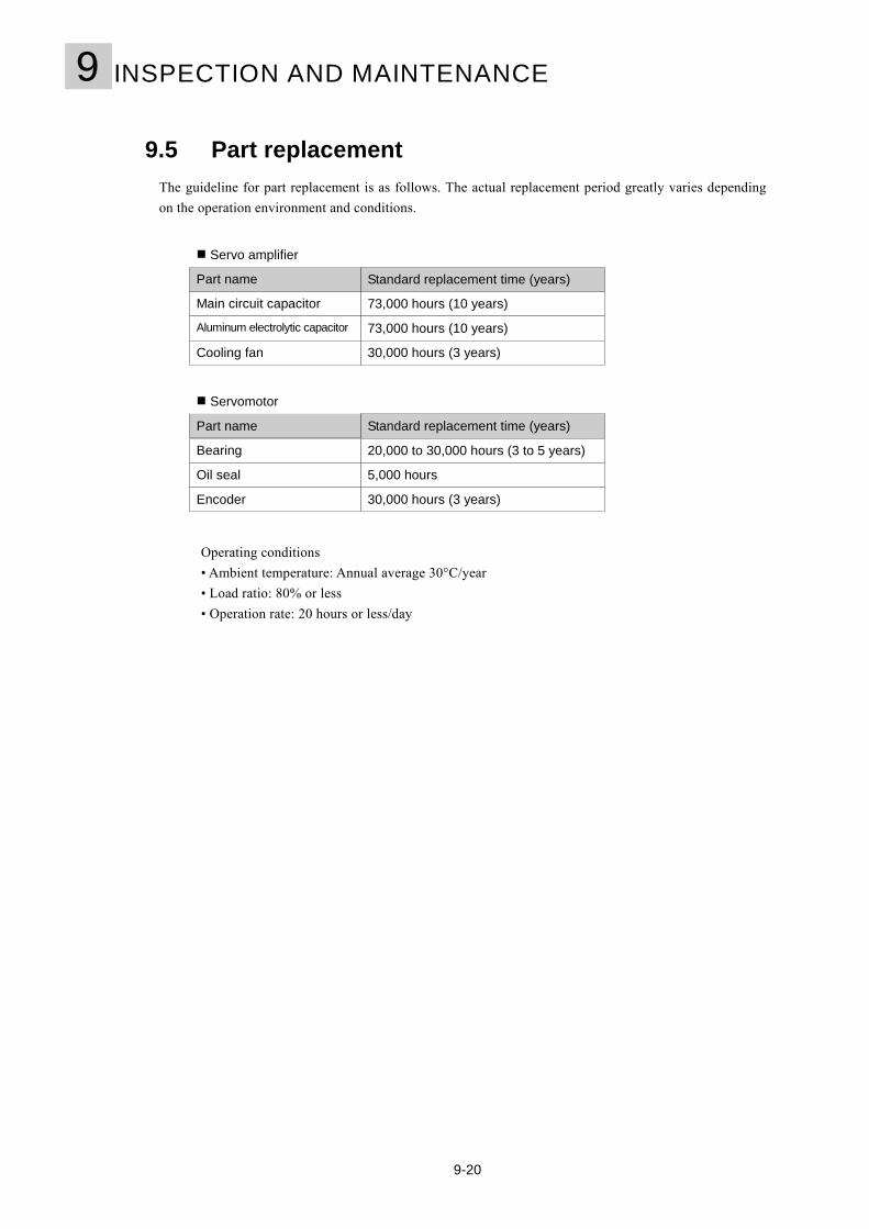
9 INSPECTION AND MAINTENANCE
9-20
9.5 Part replacement The guideline for part replacement is as follows. The actual replacement period greatly varies depending on the operation environment and conditions.
Operating conditions • Ambient temperature: Annual average 30°C/year • Load ratio: 80% or less • Operation rate: 20 hours or less/day
Standard replacement time (years)
Main circuit capacitor 73,000 hours (10 years)
Part name
Servo amplifier
Aluminum electrolytic capacitor
Cooling fan
73,000 hours (10 years)
30,000 hours (3 years)
Standard replacement time (years)
Bearing 20,000 to 30,000 hours (3 to 5 years)
Part name
Servomotor
Oil seal Encoder
5,000 hours
30,000 hours (3 years)

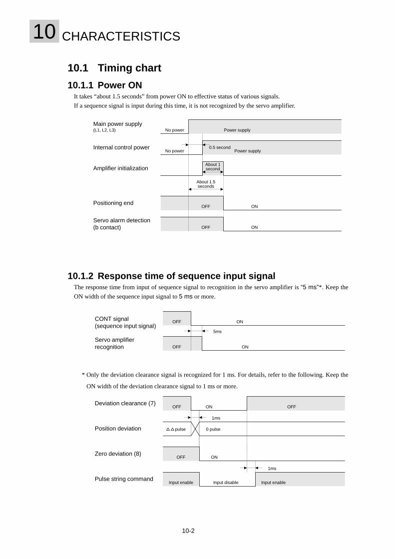
10 CHARACTERISTICS
10-2
10.1 Timing chart 10.1.1 Power ON
It takes “about 1.5 seconds” from power ON to effective status of various signals. If a sequence signal is input during this time, it is not recognized by the servo amplifier.
10.1.2 Response time of sequence input signal The response time from input of sequence signal to recognition in the servo amplifier is “5 ms”*. Keep the ON width of the sequence input signal to 5 ms or more.
* Only the deviation clearance signal is recognized for 1 ms. For details, refer to the following. Keep the
ON width of the deviation clearance signal to 1 ms or more.
Main power supply (L1, L2, L3)
Internal control power
Amplifier initialization
Positioning end
Servo alarm detection (b contact)
No power Power supply
No power Power supply0.5 second
About 1 second
About 1.5 seconds
OFF
OFF
ON
ON
CONT signal (sequence input signal)
OFF ON
Servo amplifier recognition OFF ON
5ms
Deviation clearance (7)OFF ON
Position deviation pulse
1ms
Zero deviation (8)OFF ON
0 pulse
OFF
Pulse string commandInput enable Input disable Input enable
1ms
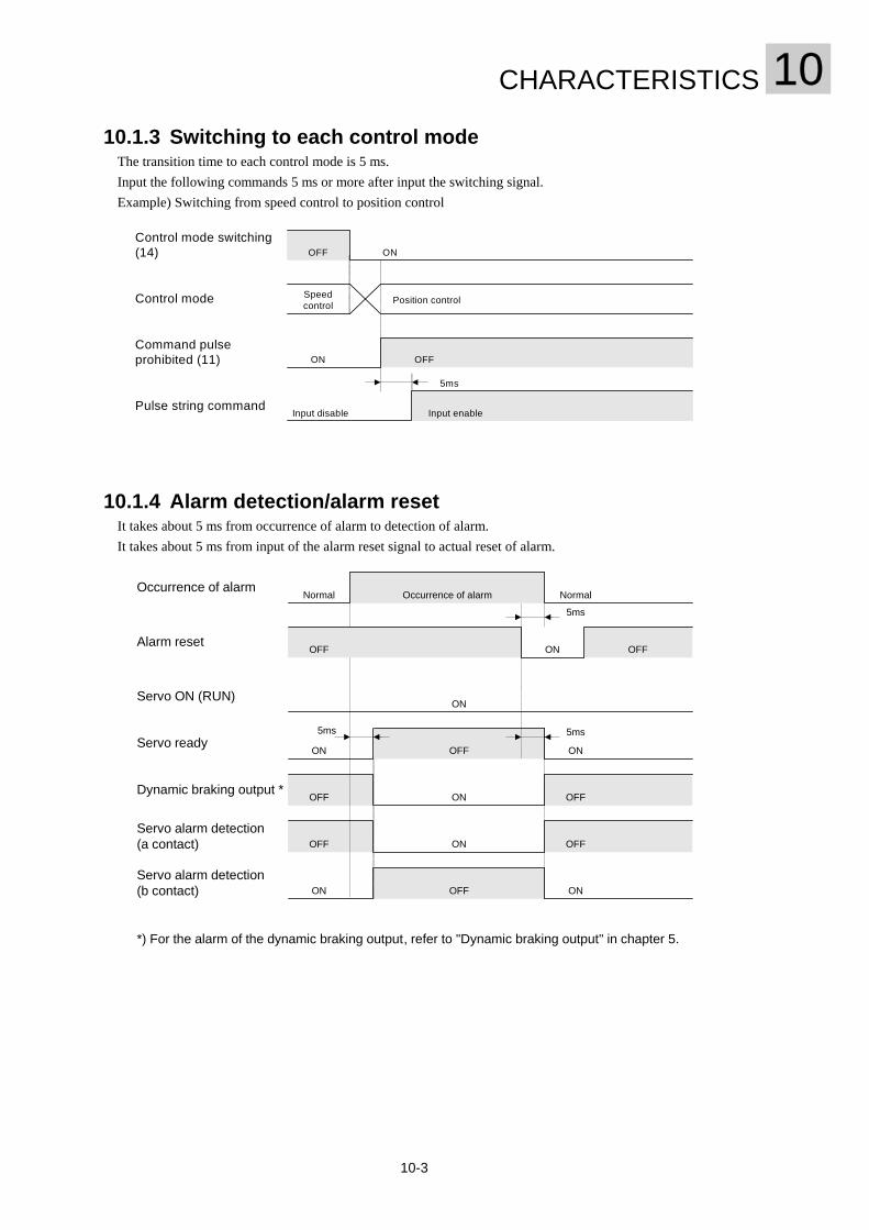
CHARACTERISTICS 10
10-3
10.1.3 Switching to each control mode The transition time to each control mode is 5 ms. Input the following commands 5 ms or more after input the switching signal. Example) Switching from speed control to position control
10.1.4 Alarm detection/alarm reset It takes about 5 ms from occurrence of alarm to detection of alarm. It takes about 5 ms from input of the alarm reset signal to actual reset of alarm.
Control mode switching (14) OFF ON
Control mode Speed control
Command pulseprohibited (11) ON OFF
Position control
5ms
Pulse string commandInput disable Input enable
Occurrence of alarm
Servo alarm detection (a contact)
Servo alarm detection (b contact)
Normal Occurrence of alarm
OFF ON
ON OFF
Servo readyON OFF
5ms
Dynamic braking output *OFF ON
Servo ON (RUN)ON
Alarm resetOFF ON OFF
ON
5ms
OFF
OFF
ON
Normal
5ms
*) For the alarm of the dynamic braking output, refer to "Dynamic braking output" in chapter 5.
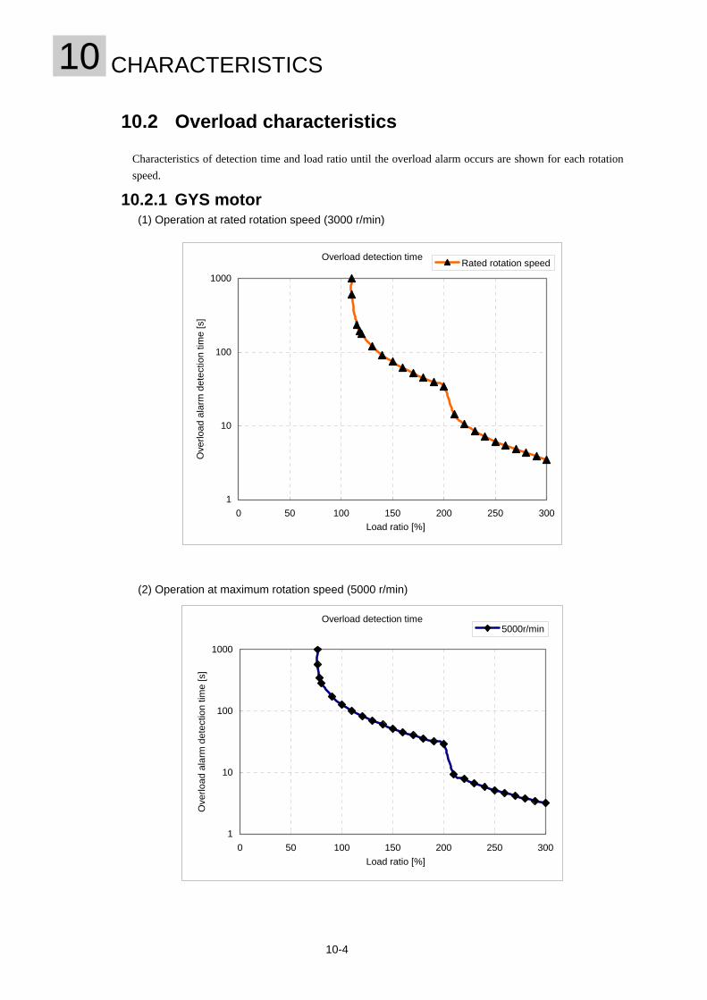
10 CHARACTERISTICS
10-4
10.2 Overload characteristics
Characteristics of detection time and load ratio until the overload alarm occurs are shown for each rotation speed.
10.2.1 GYS motor (1) Operation at rated rotation speed (3000 r/min)
Overload detection time
1
10
100
1000
0 50 100 150 200 250 300Load ratio [%]
Ove
rload
ala
rm d
etec
tion
time
[s]
Rated rotation speed
(2) Operation at maximum rotation speed (5000 r/min)
Overload detection time
1
10
100
1000
0 50 100 150 200 250 300Load ratio [%]
Ove
rload
ala
rm d
etec
tion
time
[s]
5000r/min

CHARACTERISTICS 10
10-5
10.2.2 GYG motor (1) Operation at rated rotation speed (2000 r/min & 1500 r/min)
Overload detection time
1
10
100
1000
0 50 100 150 200 250 300Load ratio [%]
Ove
rload
ala
rm d
etec
tion
time
[s]
Rated rotation speed
(2) Operation at maximum rotation speed (3000 r/min)
Overload detection time
1
10
100
1000
0 50 100 150 200 250 300Load ratio [%]
Ove
rload
ala
rm d
etec
tion
time
[s]
3000r/min

10 CHARACTERISTICS
10-6
10.3 Power supply capacity and generation loss
10.4 Inrush current
Inrush current value to the servo amplifier is shown.
Power capacity
[kVA]
Amplifier heat value (Qamp)
Power consumption (P)
Motor heat value (Qmot)
Servo amplifier type Servomotor type
RYC500D3-VVT2
RYC101D3-VVT2
RYC201D3-VVT2
RYC401D3-VVT2
RYC751D3-VVT2
RYC501C3-VVT2
RYC102C3-VVT2
RYC152C3-VVT2
RYC202C3-VVT2
RYC501B3-VVT2
GYS500DC2-T2A
GYS101DC2-T2A
GYS201DC2-T2A
GYS401DC2-T2A
GYS751DC2-T2A
GYG501CC1-T2B
GYG751CC1-T2B
GYG102CC1-T2B
GYG152CC1-T2B
GYG202CC1-T2B
GYG501BC1-T2B
RYC751C3-VVT2
Inrush current[A]
9.1
9.1
9.1
9.1
35.7
35.7
35.7
35.7
43.5
43.5
35.7
Rated rotation speed
3000[r/min]
RYC851B3-VVT2
RYC132B3-VVT2
GYG851BC1-T2B
GYG132BC1-T2B
35.7
43.5
Capacity[kW]
0.05
0.1
0.2
0.4
0.75
0.5
0.75
1.0
1.5
2.0
0.5
0.85
1.3
2000[r/min]
1500[r/min]
Servo amplifier type Servomotor typePower
consumption (P) [kW]
Amplifier heat value
(Qamp) [kW]
Motor heat value
(Qmot) [kW]
RYC500T3-VVT2
RYC101T3-VVT2
RYC201T3-VVT2
RYC401T3-VVT2
RYC751T3-VVT2
RYC501C3-VVT2
RYC102C3-VVT2
RYC152C3-VVT2
RYC202C3-VVT2
RYC501B3-VVT2
GYS500DC2-T2A
GYS101DC2-T2A
GYS201DC2-T2A
GYS401DC2-T2A
GYS751DC2-T2A
GYG501CC1-T2B
GYG751CC1-T2B
GYG102CC1-T2B
GYG152CC1-T2B
GYG202BC1-T2B
GYG501BC1-T2B
RYC751C3-VVT2
Power supply
capacity[kVA]
0.1
0.2
0.4
0.8
1.5
1.0
1.5
2.0
2.9
3.9
1.0
0.074
0.13
0.25
0.48
0.89
0.60
0.89
1.2
1.8
2.4
0.60
0.018
0.021
0.027
0.038
0.059
0.044
0.059
0.073
0.103
0.13
0.044
0.006
0.011
0.022
0.044
0.083
0.056
0.083
0.11
0.17
0.22
0.056
Rated rotation speed
3000[r/min]
RYC851B3-VVT2
RYC132B3-VVT2
GYG851BC1-T2B
GYG132BC1-T2B
1.7
2.6
1.0
1.5
0.065
0.091
0.94
0.14
Capacity[kW]
0.05
0.1
0.2
0.4
0.75
0.5
0.75
1.0
1.5
2.0
0.5
0.85
1.3
2000[r/min]
1500[r/min]

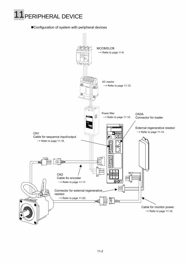
11PERIPHERAL DEVICE
11-2
Configuration of system with peripheral devices
CN3A Connector for loader
MCCB/ELCB → Refer to page 11-6.
AC reactor → Refer to page 11-12.
External regenerative resistor → Refer to page 11-14.
Power filter → Refer to page 11-10.
CN1 Cable for sequence input/output → Refer to page 11-16.
CN2 Cable for encoder → Refer to page 11-17.
Cable for monitor power.→ Refer to page 11-19.
Connector for external regenerative resistor. → Refer to page 11-25.
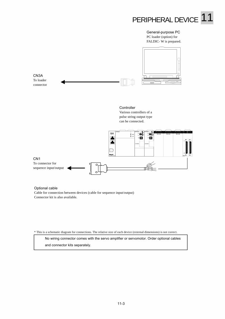
PERIPHERAL DEVICE 11
11-3
* This is a schematic diagram for connections. The relative size of each device (external dimensions) is not correct.
General-purpose PC PC loader (option) for FALDIC- W is prepared.
CN3A To loader connector
APS30
PWR
ALM
SXSCPU32
LOADER
RUNTERM
STOP
CPUNo.
ONLERR
RUNALMBAT
ONL 0 1 2 3 4 5 6 7
ERR 8 9 101112131415
ONL CH 1
ERR CH 2 EMG +OT -OT
20
1B/A
MP2
ONL 0 1 2 3 4 5 6 7
ERR 8 9 101112131415
ONL 0 1 2 3 4 5 6 7
ERR 8 9 101112131415
SCPU32
LOADER
RUNTERM
STOP
CPUNo.
ONLERR
RUNALMBAT
CN1 To connector for sequence input/output
Controller Various controllers of a pulse string output type can be connected.
Optional cable Cable for connection between devices (cable for sequence input/output) Connector kit is also available.
No wiring connector comes with the servo amplifier or servomotor. Order optional cables
and connector kits separately.
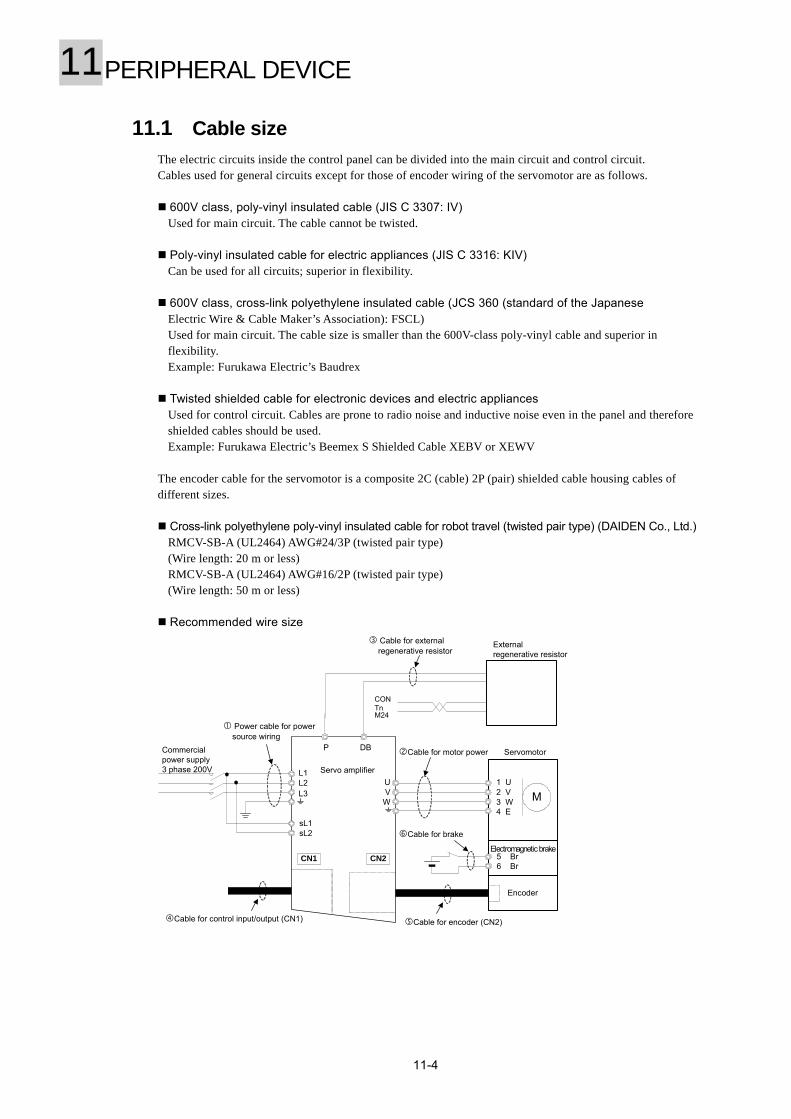
11PERIPHERAL DEVICE
11-4
11.1 Cable size The electric circuits inside the control panel can be divided into the main circuit and control circuit. Cables used for general circuits except for those of encoder wiring of the servomotor are as follows.
600V class, poly-vinyl insulated cable (JIS C 3307: IV) Used for main circuit. The cable cannot be twisted.
Poly-vinyl insulated cable for electric appliances (JIS C 3316: KIV) Can be used for all circuits; superior in flexibility.
600V class, cross-link polyethylene insulated cable (JCS 360 (standard of the Japanese Electric Wire & Cable Maker’s Association): FSCL) Used for main circuit. The cable size is smaller than the 600V-class poly-vinyl cable and superior in flexibility. Example: Furukawa Electric’s Baudrex
Twisted shielded cable for electronic devices and electric appliances Used for control circuit. Cables are prone to radio noise and inductive noise even in the panel and therefore shielded cables should be used. Example: Furukawa Electric’s Beemex S Shielded Cable XEBV or XEWV
The encoder cable for the servomotor is a composite 2C (cable) 2P (pair) shielded cable housing cables of different sizes.
Cross-link polyethylene poly-vinyl insulated cable for robot travel (twisted pair type) (DAIDEN Co., Ltd.) RMCV-SB-A (UL2464) AWG#24/3P (twisted pair type) (Wire length: 20 m or less) RMCV-SB-A (UL2464) AWG#16/2P (twisted pair type) (Wire length: 50 m or less)
Recommended wire size
U V
W
1 U 2 V3 W4 E
M
L1L2L3
CN2
P DB
Servo amplifier
ServomotorCommercial power supply 3 phase 200V
External regenerative resistor
M24
CONTn
CN1Electromagnetic brake
Encoder
5 Br 6 Br
Power cable for power source wiring
Cable for motor power
Cable for external regenerative resistor
Cable for brake
Cable for control input/output (CN1) Cable for encoder (CN2)
sL1sL2
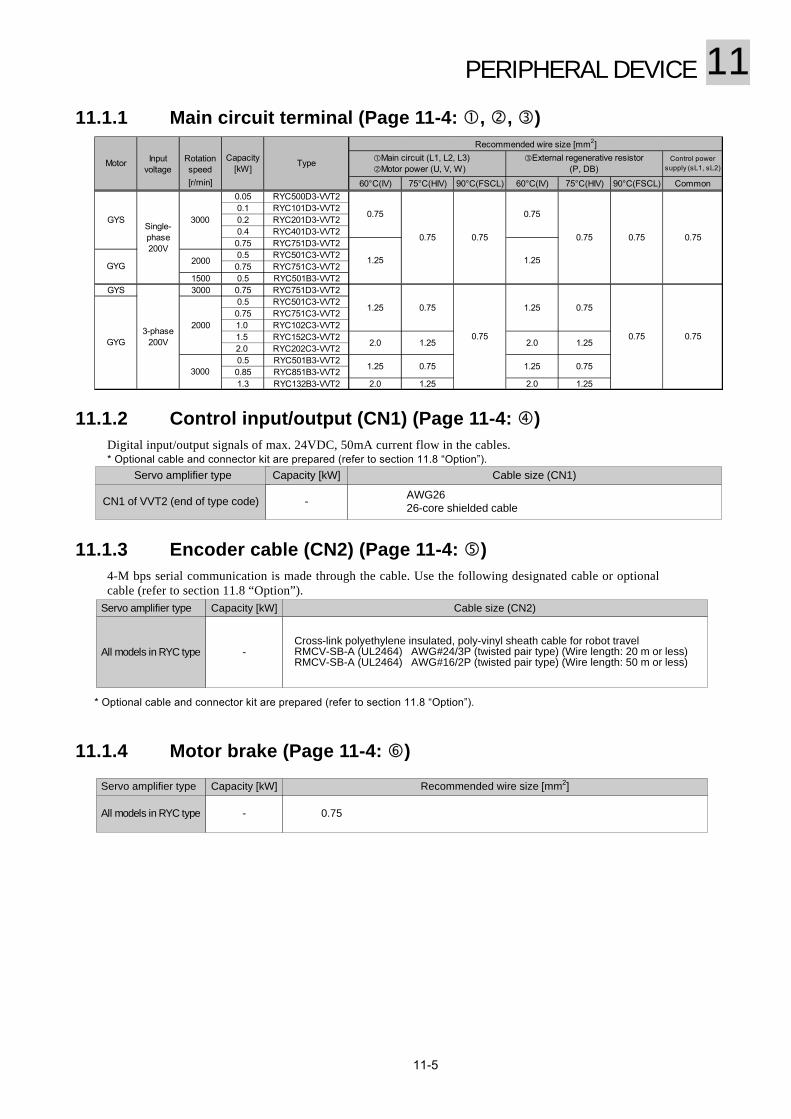
PERIPHERAL DEVICE 11
11-5
11.1.1 Main circuit terminal (Page 11-4: , , )
Inputvoltage
Rotationspeed
Control powersupply (sL1, sL2)
[r/min] 60°C(IV) 75°C(HIV) 90°C(FSCL) 60°C(IV) 75°C(HIV) 90°C(FSCL) Common0.05 RYC500D3-VVT20.1 RYC101D3-VVT20.2 RYC201D3-VVT20.4 RYC401D3-VVT20.75 RYC751D3-VVT20.5 RYC501C3-VVT20.75 RYC751C3-VVT2
1500 0.5 RYC501B3-VVT2GYS 3000 0.75 RYC751D3-VVT2
0.5 RYC501C3-VVT20.75 RYC751C3-VVT21.0 RYC102C3-VVT21.5 RYC152C3-VVT22.0 RYC202C3-VVT20.5 RYC501B3-VVT20.85 RYC851B3-VVT21.3 RYC132B3-VVT2 2.0 1.25 2.0 1.25
GYS
2000
3000
2000GYG
GYG
Single-phase200V
3000
3-phase200V
0.75
1.25
1.25
2.0
1.25 0.75
0.75
1.25
0.750.75
0.75
1.25
0.75
1.25
0.75
1.25 0.75
2.0 1.25
0.75
0.75 0.75
Main circuit (L1, L2, L3)Motor power (U, V, W)
0.75 0.75
Motor Capacity[kW] Type External regenerative resistor
(P, DB)
Recommended wire size [mm2]
11.1.2 Control input/output (CN1) (Page 11-4: )
Digital input/output signals of max. 24VDC, 50mA current flow in the cables. * Optional cable and connector kit are prepared (refer to section 11.8 “Option”).
Servo amplifier type Capacity [kW] Cable size (CN1)
CN1 of VVT2 (end of type code) -AWG2626-core shielded cable
11.1.3 Encoder cable (CN2) (Page 11-4: )
4-M bps serial communication is made through the cable. Use the following designated cable or optional cable (refer to section 11.8 “Option”).
Servo amplifier type
All models in RYC type
Capacity [kW]
-
Cable size (CN2)
Cross-link polyethylene insulated, poly-vinyl sheath cable for robot travel RMCV-SB-A (UL2464) AWG#24/3P (twisted pair type) (Wire length: 20 m or less) RMCV-SB-A (UL2464) AWG#16/2P (twisted pair type) (Wire length: 50 m or less)
* Optional cable and connector kit are prepared (refer to section 11.8 “Option”).
11.1.4 Motor brake (Page 11-4: )
Servo amplifier type
All models in RYC type
Capacity [kW]
-
Recommended wire size [mm2]
0.75
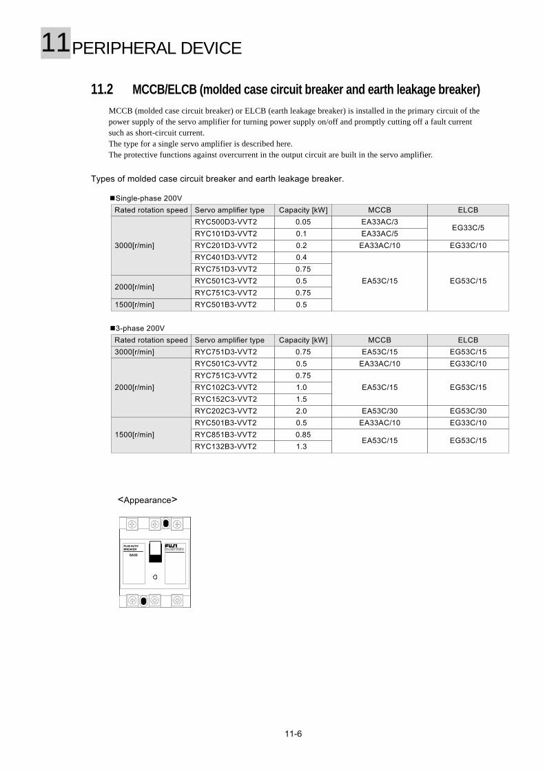
11PERIPHERAL DEVICE
11-6
11.2 MCCB/ELCB (molded case circuit breaker and earth leakage breaker) MCCB (molded case circuit breaker) or ELCB (earth leakage breaker) is installed in the primary circuit of the power supply of the servo amplifier for turning power supply on/off and promptly cutting off a fault current such as short-circuit current. The type for a single servo amplifier is described here. The protective functions against overcurrent in the output circuit are built in the servo amplifier.
Types of molded case circuit breaker and earth leakage breaker.
MCCBEA33AC/3EA33AC/5
EA53C/15
EA33AC/10
ELCB
EA53C/15
EA33AC/10
EA53C/30
EA53C/15
EA53C/15
EG33C/5
EG33C/10
EG53C/15
EG53C/15EG33C/10
EG53C/15
EG53C/30
EG53C/15
Capacity [kW]0.050.10.20.40.75
Servo amplifier typeRYC500D3-VVT2
Single-phase 200V
RYC101D3-VVT2RYC201D3-VVT2RYC401D3-VVT2RYC751D3-VVT2
RYC751D3-VVT2 0.75
Rated rotation speed
3000[r/min]
RYC501C3-VVT2RYC751C3-VVT2 0.75
0.5
RYC501C3-VVT2RYC751C3-VVT2RYC102C3-VVT2RYC152C3-VVT2RYC202C3-VVT2
0.750.5
1.51.0
0.5
2.0
2000[r/min]
RYC501B3-VVT2
RYC851B3-VVT2RYC501B3-VVT2
RYC132B3-VVT2
0.50.851.3
1500[r/min]
Capacity [kW]Servo amplifier typeRated rotation speed3-phase 200V
3000[r/min]
2000[r/min]
1500[r/min]
MCCB ELCB
EA33AC/10 EG33C/10
<Appearance>
FUJIi AUTOBREAKER
SA33
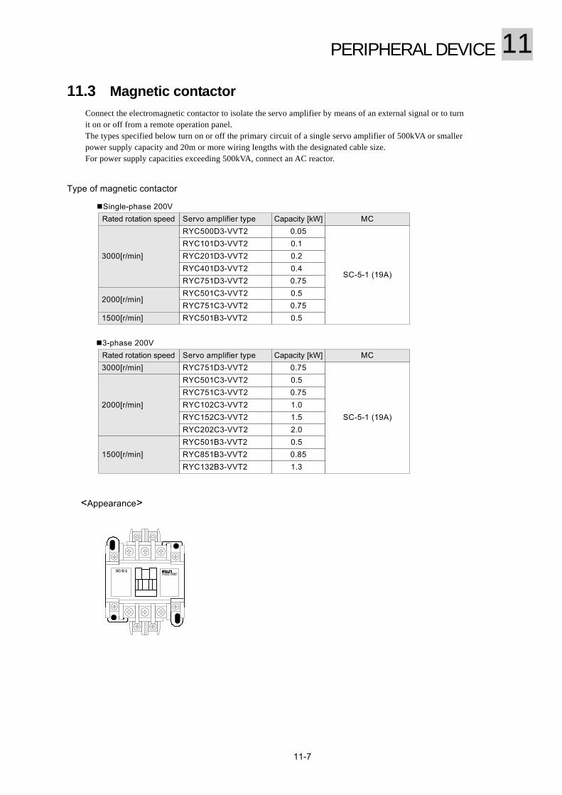
PERIPHERAL DEVICE 11
11-7
11.3 Magnetic contactor Connect the electromagnetic contactor to isolate the servo amplifier by means of an external signal or to turn it on or off from a remote operation panel. The types specified below turn on or off the primary circuit of a single servo amplifier of 500kVA or smaller power supply capacity and 20m or more wiring lengths with the designated cable size. For power supply capacities exceeding 500kVA, connect an AC reactor.
Type of magnetic contactor
Capacity [kW]0.050.10.20.40.75
Servo amplifier typeRYC500D3-VVT2
Single-phase 200V
RYC101D3-VVT2RYC201D3-VVT2RYC401D3-VVT2RYC751D3-VVT2
RYC751D3-VVT2 0.75
Rated rotation speed
3000[r/min]
RYC501C3-VVT2RYC751C3-VVT2 0.75
0.5
RYC501C3-VVT2RYC751C3-VVT2RYC102C3-VVT2RYC152C3-VVT2RYC202C3-VVT2
0.750.5
1.51.0
0.5
2.0
2000[r/min]
RYC501B3-VVT2
RYC851B3-VVT2RYC501B3-VVT2
RYC132B3-VVT2
0.50.851.3
1500[r/min]
Capacity [kW]Servo amplifier typeRated rotation speed3-phase 200V
3000[r/min]
2000[r/min]
1500[r/min]
MC
SC-5-1 (19A)
MC
SC-5-1 (19A)
<Appearance>
SC-5-1
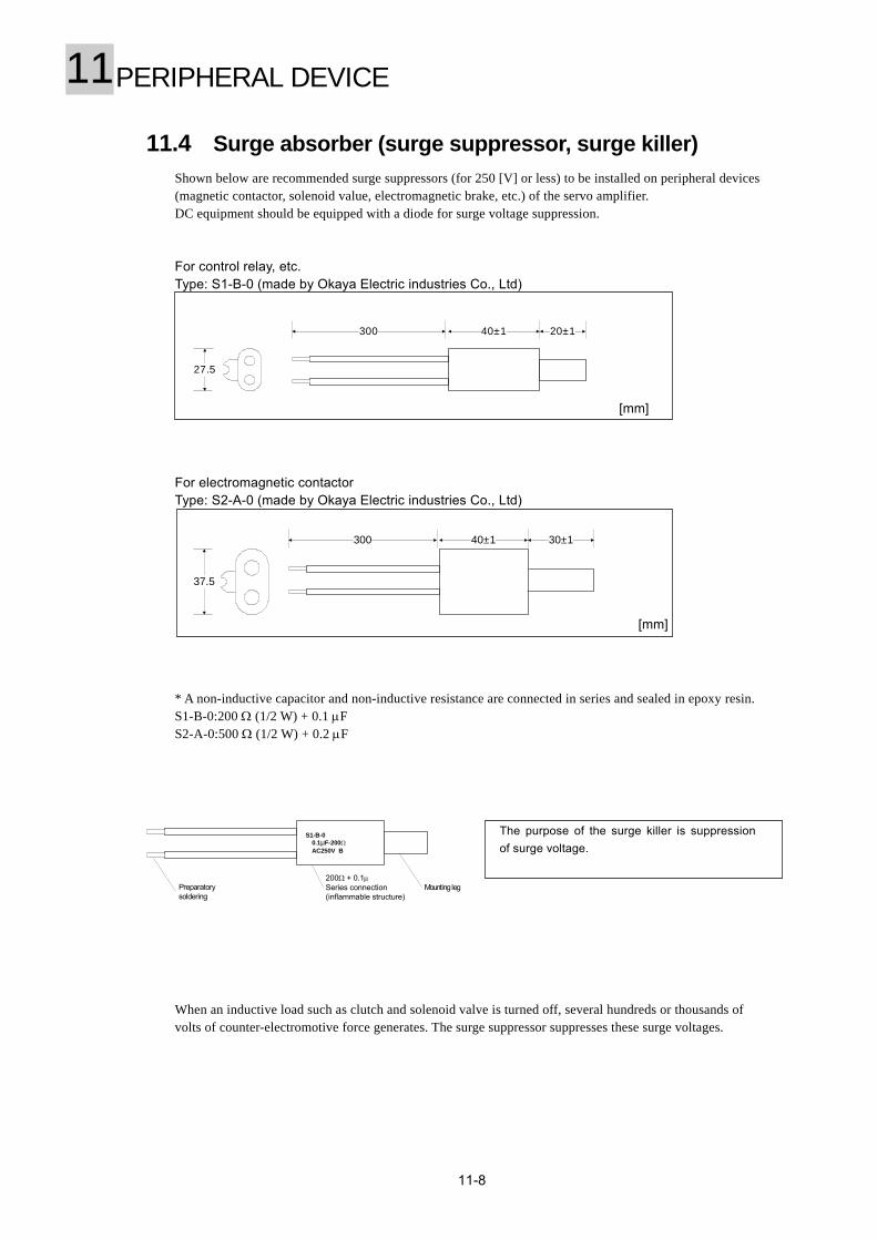
11PERIPHERAL DEVICE
11-8
11.4 Surge absorber (surge suppressor, surge killer) Shown below are recommended surge suppressors (for 250 [V] or less) to be installed on peripheral devices (magnetic contactor, solenoid value, electromagnetic brake, etc.) of the servo amplifier. DC equipment should be equipped with a diode for surge voltage suppression. For control relay, etc. Type: S1-B-0 (made by Okaya Electric industries Co., Ltd)
For electromagnetic contactor Type: S2-A-0 (made by Okaya Electric industries Co., Ltd)
* A non-inductive capacitor and non-inductive resistance are connected in series and sealed in epoxy resin. S1-B-0:200 Ω (1/2 W) + 0.1 µF S2-A-0:500 Ω (1/2 W) + 0.2 µF
When an inductive load such as clutch and solenoid valve is turned off, several hundreds or thousands of volts of counter-electromotive force generates. The surge suppressor suppresses these surge voltages.
300 40±1 20±1
27.5
300 40±1 30±1
37.5
The purpose of the surge killer is suppression of surge voltage.
[mm]
[mm]
S1-B-00.1µF-200ΩAC250V B
Mounting legPreparatorysoldering
200Ω + 0.1µSeries connection (inflammable structure)
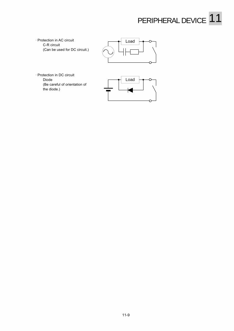
PERIPHERAL DEVICE 11
11-9
· Protection in AC circuit C-R circuit (Can be used for DC circuit.)
· Protection in DC circuit Diode (Be careful of orientation of the diode.)
Load
Load
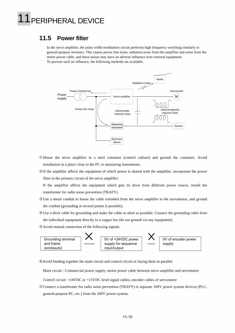
11PERIPHERAL DEVICE
11-10
11.5 Power filter In the servo amplifier, the pulse width modulation circuit performs high frequency switching similarly to general-purpose inverters. This causes power line noise, radiation noise from the amplifier and noise from the motor power cable, and these noises may have an adverse influence over external equipment. To prevent such an influence, the following methods are available.
House the servo amplifier in a steel container (control cabinet) and ground the container. Avoid
installation in a place close to the PC or measuring instruments.
If the amplifier affects the equipment of which power is shared with the amplifier, incorporate the power
filter in the primary circuit of the servo amplifier.
If the amplifier affects the equipment which gets its drive from different power source, install the
transformer for radio noise prevention (TRAFY).
Use a metal conduit to house the cable extended from the servo amplifier to the servomotor, and ground
the conduit (grounding at several points is possible).
Use a thick cable for grounding and make the cable as short as possible. Connect the grounding cable from
the individual equipment directly to a copper bar (do not ground via any equipment).
Avoid mutual connection of the following signals.
Avoid binding together the main circuit and control circuit or laying them in parallel.
Main circuit : Commercial power supply, motor power cable between servo amplifier and servomotor
Control circuit: +24VDC or +15VDC level signal cables, encoder cables of servomotor
Connect a transformer for radio noise prevention (TRAFY) to separate 100V power system devices (PLC,
general-purpose PC, etc.) from the 200V power system.
Power supply
Servo amplifier M
Servomotor
Measuring instrument
Electronicdevice
Sensor
Power line noise
Power transformer
Radio
Radiation noise
Electromagnetic induced noise
Electrostatic induced noise
Grounding terminal and frame (enclosure)
0V of +24VDC power supply for sequence input/output
0V of encoder power supply
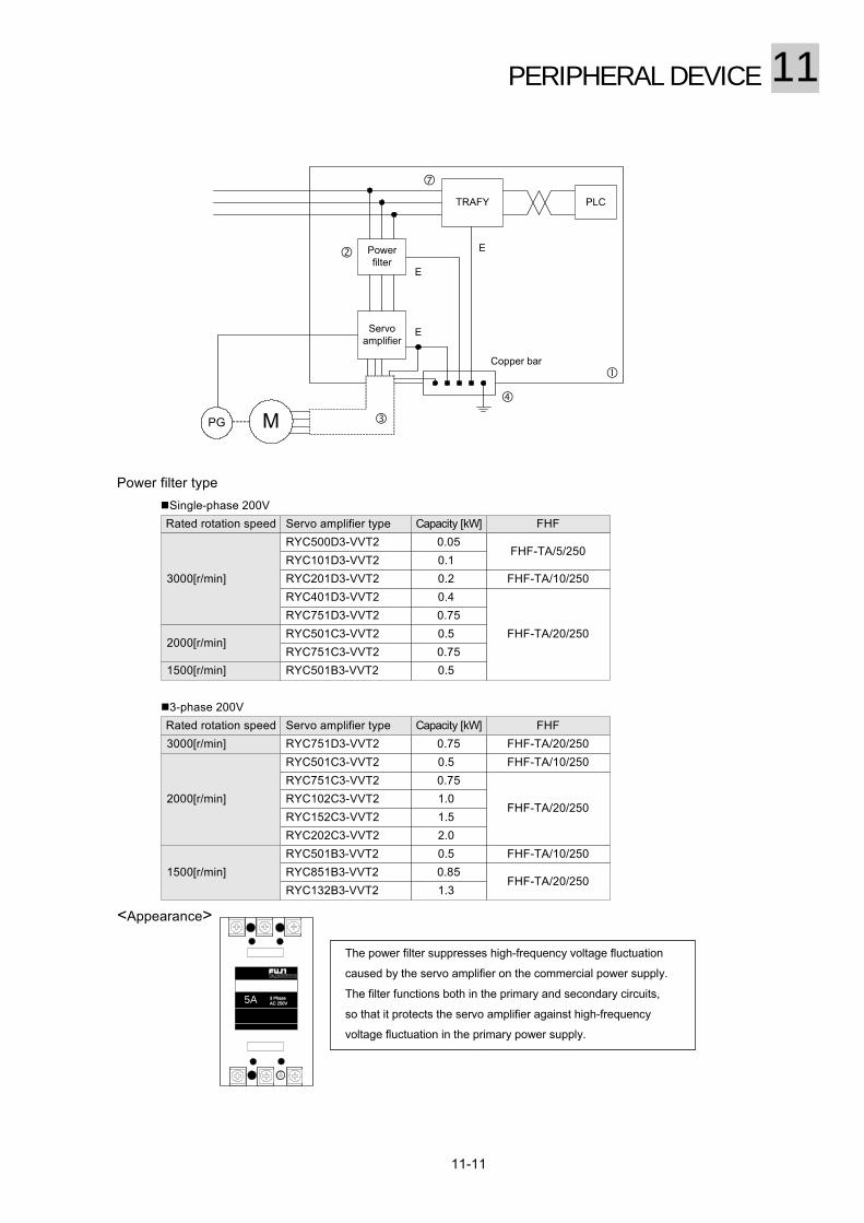
PERIPHERAL DEVICE 11
11-11
Power filter type
Capacity [kW]0.050.10.20.40.75
Servo amplifier typeRYC500D3-VVT2
Single-phase 200V
RYC101D3-VVT2RYC201D3-VVT2RYC401D3-VVT2RYC751D3-VVT2
RYC751D3-VVT2 0.75
Rated rotation speed
3000[r/min]
RYC501C3-VVT2RYC751C3-VVT2 0.75
0.5
RYC501C3-VVT2RYC751C3-VVT2RYC102C3-VVT2RYC152C3-VVT2RYC202C3-VVT2
0.750.5
1.51.0
0.5
2.0
2000[r/min]
RYC501B3-VVT2
RYC851B3-VVT2RYC501B3-VVT2
RYC132B3-VVT2
0.50.851.3
1500[r/min]
Capacity [kW]Servo amplifier typeRated rotation speed3-phase 200V
3000[r/min]
2000[r/min]
1500[r/min]
FHF
FHF-TA/5/250
FHF-TA/10/250
FHF-TA/20/250
FHF-TA/20/250FHF-TA/10/250
FHF-TA/20/250
FHF-TA/10/250
FHF-TA/20/250
FHF
<Appearance>
The power filter suppresses high-frequency voltage fluctuation
caused by the servo amplifier on the commercial power supply.
The filter functions both in the primary and secondary circuits,
so that it protects the servo amplifier against high-frequency
voltage fluctuation in the primary power supply.
5A 3 PhaseAC 250V
Servo amplifier
Power filter
TRAFY
MPG
PLC
E
E
Copper bar
E
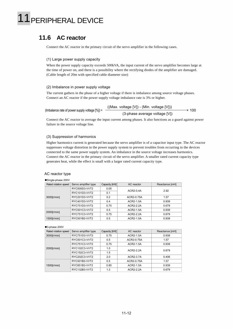
11PERIPHERAL DEVICE
11-12
11.6 AC reactor Connect the AC reactor in the primary circuit of the servo amplifier in the following cases.
(1) Large power supply capacity When the power supply capacity exceeds 500kVA, the input current of the servo amplifier becomes large at the time of power on, and there is a possibility where the rectifying diodes of the amplifier are damaged. (Cable length of 20m with specified cable diameter size)
(2) Imbalance in power supply voltage The current gathers in the phase of a higher voltage if there is imbalance among source voltage phases. Connect an AC reactor if the power supply voltage imbalance rate is 3% or higher.
Connect the AC reactor to average the input current among phases. It also functions as a guard against power failure in the source voltage line.
(3) Suppression of harmonics Higher harmonics current is generated because the servo amplifier is of a capacitor input type. The AC reactor suppresses voltage distortion in the power supply system to prevent troubles from occurring in the devices connected to the same power supply system. An imbalance in the source voltage increases harmonics. Connect the AC reactor in the primary circuit of the servo amplifier. A smaller rated current capacity type generates heat, while the effect is small with a larger rated current capacity type.
AC reactor type
Capacity [kW]0.050.10.20.40.75
Servo amplifier typeRYC500D3-VVT2
Single-phase 200V
RYC101D3-VVT2RYC201D3-VVT2RYC401D3-VVT2RYC751D3-VVT2
RYC751D3-VVT2 0.75
Rated rotation speed
3000[r/min]
RYC501C3-VVT2RYC751C3-VVT2 0.75
0.5
RYC501C3-VVT2RYC751C3-VVT2RYC102C3-VVT2RYC152C3-VVT2RYC202C3-VVT2
0.750.5
1.51.0
0.5
2.0
2000[r/min]
RYC501B3-VVT2
RYC851B3-VVT2RYC501B3-VVT2
RYC132B3-VVT2
0.50.851.3
1500[r/min]
Capacity [kW]Servo amplifier typeRated rotation speed3-phase 200V
3000[r/min]
2000[r/min]
1500[r/min]
Reactance [mH]AC reactor
2.92
1.570.9390.679
0.406
ACR2-0.4A
ACR2-0.75AACR2-1.5AACR2-2.2A
ACR2-1.5A
ACR2-3.7AACR2-0.75AACR2-1.5AACR2-2.2A
0.939
1.570.9390.679
0.9390.679
ACR2-1.5AACR2-2.2AACR2-1.5A 0.939
Reactance [mH]AC reactor
1.57ACR2-0.75AACR2-1.5A 0.939
0.679ACR2-2.2A
(Imbalance rate of power supply voltage [%]) =((Max. voltage [V]) - (Min. voltage [V]))
(3-phase average voltage [V]) × 100
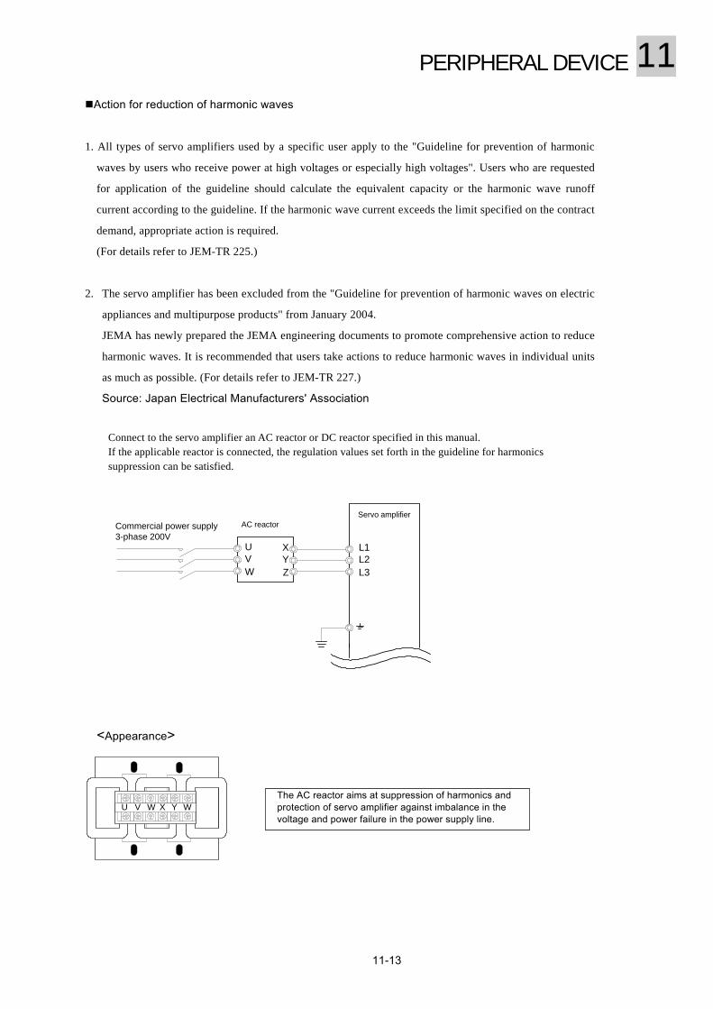
PERIPHERAL DEVICE 11
11-13
Action for reduction of harmonic waves
1. All types of servo amplifiers used by a specific user apply to the "Guideline for prevention of harmonic
waves by users who receive power at high voltages or especially high voltages". Users who are requested
for application of the guideline should calculate the equivalent capacity or the harmonic wave runoff
current according to the guideline. If the harmonic wave current exceeds the limit specified on the contract
demand, appropriate action is required.
(For details refer to JEM-TR 225.)
2. The servo amplifier has been excluded from the "Guideline for prevention of harmonic waves on electric
appliances and multipurpose products" from January 2004.
JEMA has newly prepared the JEMA engineering documents to promote comprehensive action to reduce
harmonic waves. It is recommended that users take actions to reduce harmonic waves in individual units
as much as possible. (For details refer to JEM-TR 227.)
Source: Japan Electrical Manufacturers' Association
Connect to the servo amplifier an AC reactor or DC reactor specified in this manual. If the applicable reactor is connected, the regulation values set forth in the guideline for harmonics suppression can be satisfied.
<Appearance>
U V W X Y W
The AC reactor aims at suppression of harmonics and protection of servo amplifier against imbalance in the voltage and power failure in the power supply line.
L1L2L3
Commercial power supply3-phase 200V
Servo amplifier
XYZ
UVW
AC reactor
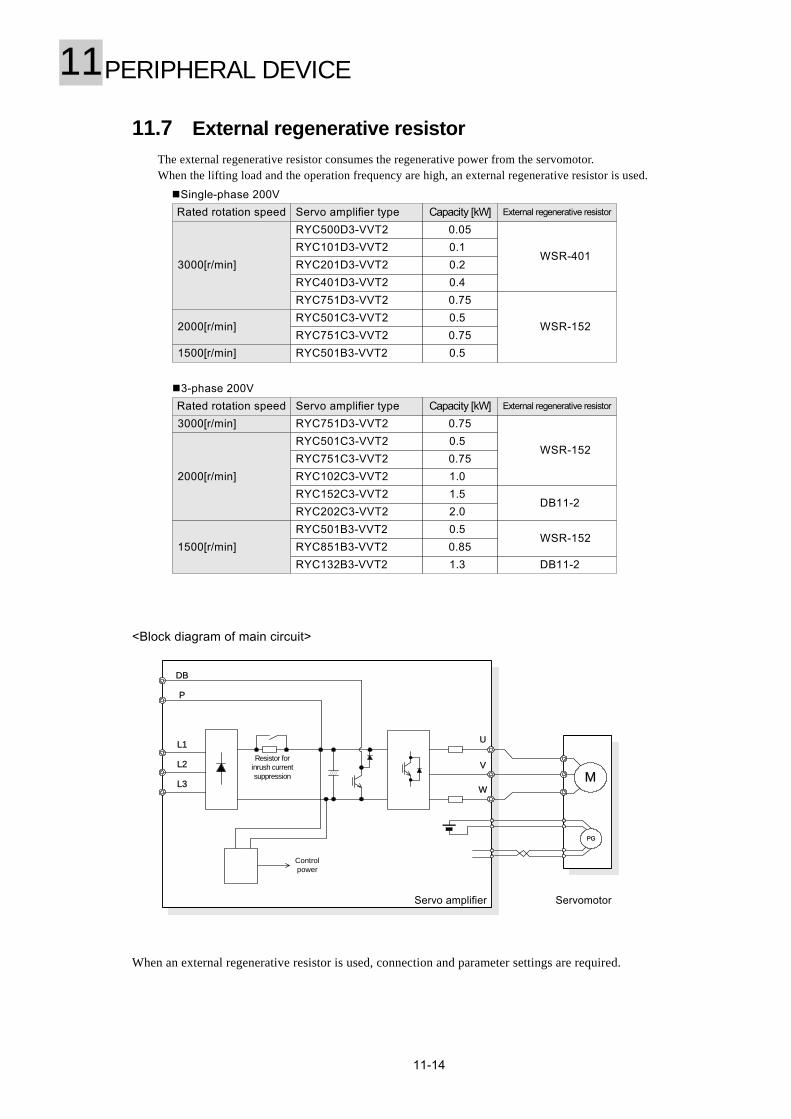
11PERIPHERAL DEVICE
11-14
11.7 External regenerative resistor The external regenerative resistor consumes the regenerative power from the servomotor. When the lifting load and the operation frequency are high, an external regenerative resistor is used.
External regenerative resistor
WSR-401
WSR-152
DB11-2
WSR-152
External regenerative resistor
WSR-152
DB11-2
Capacity [kW]0.050.10.20.40.75
Servo amplifier typeRYC500D3-VVT2
Single-phase 200V
RYC101D3-VVT2RYC201D3-VVT2RYC401D3-VVT2RYC751D3-VVT2
RYC751D3-VVT2 0.75
Rated rotation speed
3000[r/min]
RYC501C3-VVT2RYC751C3-VVT2 0.75
0.5
RYC501C3-VVT2RYC751C3-VVT2RYC102C3-VVT2RYC152C3-VVT2RYC202C3-VVT2
0.750.5
1.51.0
0.5
2.0
2000[r/min]
RYC501B3-VVT2
RYC851B3-VVT2RYC501B3-VVT2
RYC132B3-VVT2
0.50.851.3
1500[r/min]
Capacity [kW]Servo amplifier typeRated rotation speed 3-phase 200V
3000[r/min]
2000[r/min]
1500[r/min]
<Block diagram of main circuit>
Control power
M
PG
Resistor for inrush current suppression
L1
L2
L3
DB
P
U
V
W
When an external regenerative resistor is used, connection and parameter settings are required.
Servo amplifier Servomotor
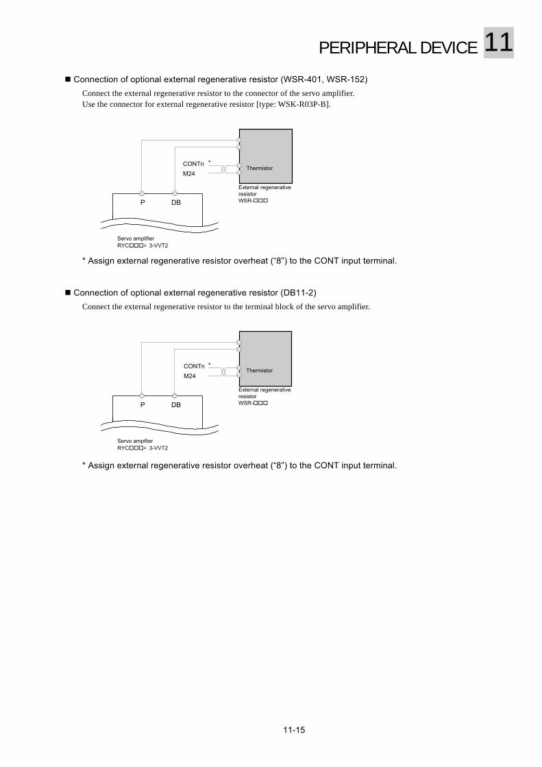
PERIPHERAL DEVICE 11
11-15
Connection of optional external regenerative resistor (WSR-401, WSR-152) Connect the external regenerative resistor to the connector of the servo amplifier. Use the connector for external regenerative resistor [type: WSK-R03P-B].
P DB
Servo amplifierRYC 3-VVT2
External regenerative resistorWSR-
M24CONTn
Thermistor*
Connection of optional external regenerative resistor (DB11-2) Connect the external regenerative resistor to the terminal block of the servo amplifier.
P DB
Servo ampifierRYC 3-VVT2
External regenerative resistorWSR-
M24CONTn
Thermistor*
* Assign external regenerative resistor overheat (“8”) to the CONT input terminal.
* Assign external regenerative resistor overheat (“8”) to the CONT input terminal.
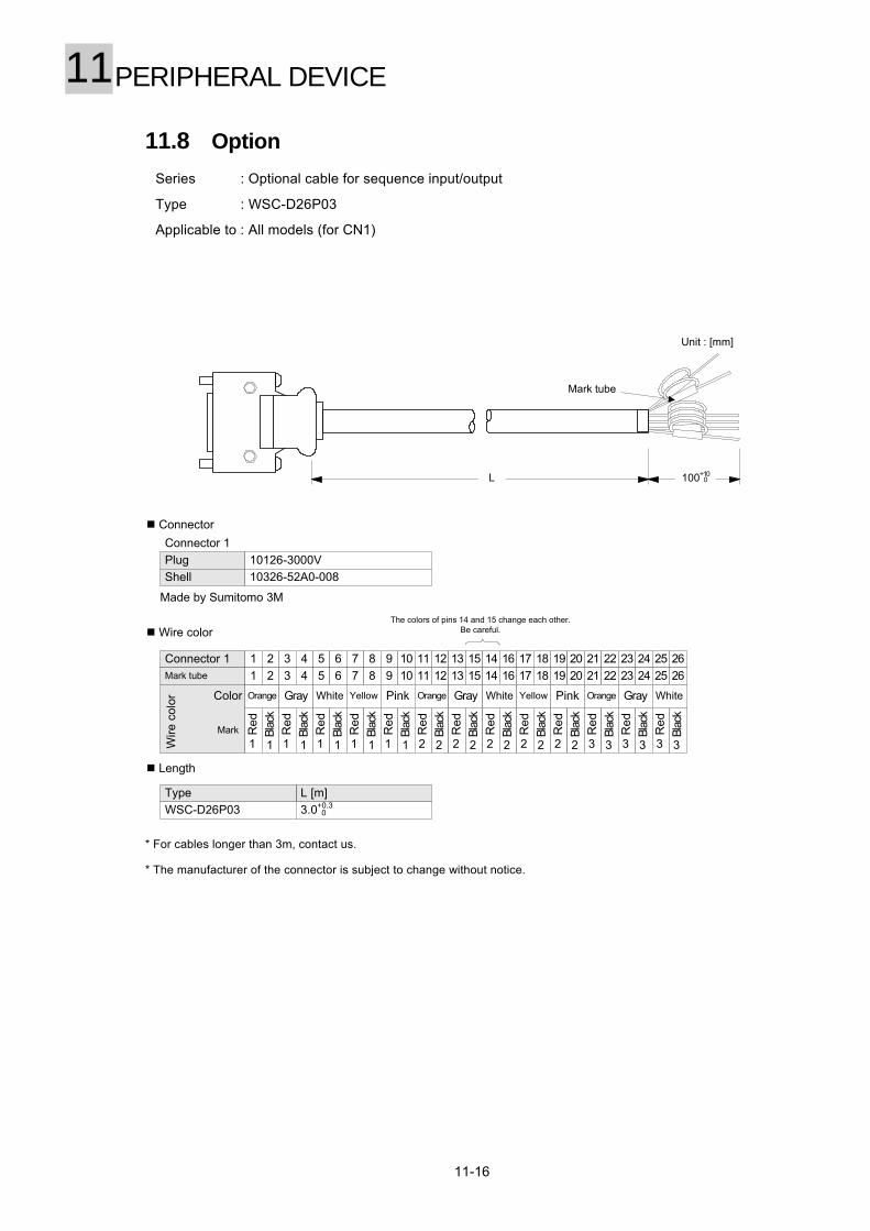
11PERIPHERAL DEVICE
11-16
11.8 Option Series : Optional cable for sequence input/output
Type : WSC-D26P03
Applicable to : All models (for CN1)
Connector 1Plug 10126-3000VShell 10326-52A0-008
Made by Sumitomo 3M
WSC-D26P03 L [m]Type3.0+0.3
0
Connector 1Mark tube
Wire
col
or
1 2 3 4 5 6
Orange
Red
1
7 8 9 10 11 12 13 15 14 16 17 18 19 20 21 22 23 24 25 261 2 3 4 5 6 7 8 9 10 11 12 13 15 14 16 17 18 19 20 21 22 23 24 25 26
Color
Mark Blac
k
1
Gray White Yellow Pink
Red
1
Blac
k
1
Red
1
Blac
k
1
Red
1
Blac
k
1
Red
1
Blac
k
1
Orange Gray White Yellow Pink
Red
2
Blac
k
2
Red
2
Blac
k
2
Red
2
Blac
k
2
Red
2
Blac
k
2
Red
2
Blac
k
2
Orange Gray White
Red
3
Blac
k
3
Red
3
Blac
k
3
Red
3
Blac
k
3
L 100+100
Unit : [mm]
Mark tube
Connector
Wire color
Length
The colors of pins 14 and 15 change each other. Be careful.
* For cables longer than 3m, contact us.
* The manufacturer of the connector is subject to change without notice.
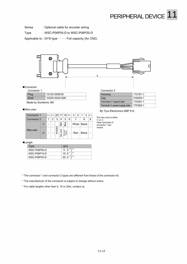
PERIPHERAL DEVICE 11
11-17
Series : Optional cable for encoder wiring
Type : WSC-P06P05-D to WSC-P06P20-D
Applicable to : GYS type · · · · · Full capacity (for CN2)
Connector 1Connector
Wire color
Length
L
WSC-P06P05-D L[m]Type 5. 0 + 0. 5
0
WSC-P06P10-D 10. 0 + 1. 00
WSC-P06P20-D 20. 0 + 2. 00
Plug 10120-3000VEShell 10320-52A0-008
Made by Sumitomo 3M
Connector 2Housing 172161-1Cap 316455-1
By Tyco Electronics AMP K.K.
Terminal signal sideTerminal power supply side
170361-1170362-1
Connector 1
Wire color
1 2 3 4 5 6 7 8 918
Shi
elde
d Red
Blue White
Connector 220 3 117N.C. N.C. N.C. N.C.
Black
Sky
blu
eSk
y bl
ue/W
hite Red Black
- - - -
----
The wire color is either or .
Other terminals of connector 1 are vacant.
4 2
* The connector 1 and connector 2 types are different from those of the connector kit.
* The manufacturer of the connector is subject to change without notice.
* For cable lengths other than 5, 10 or 20m, contact us.
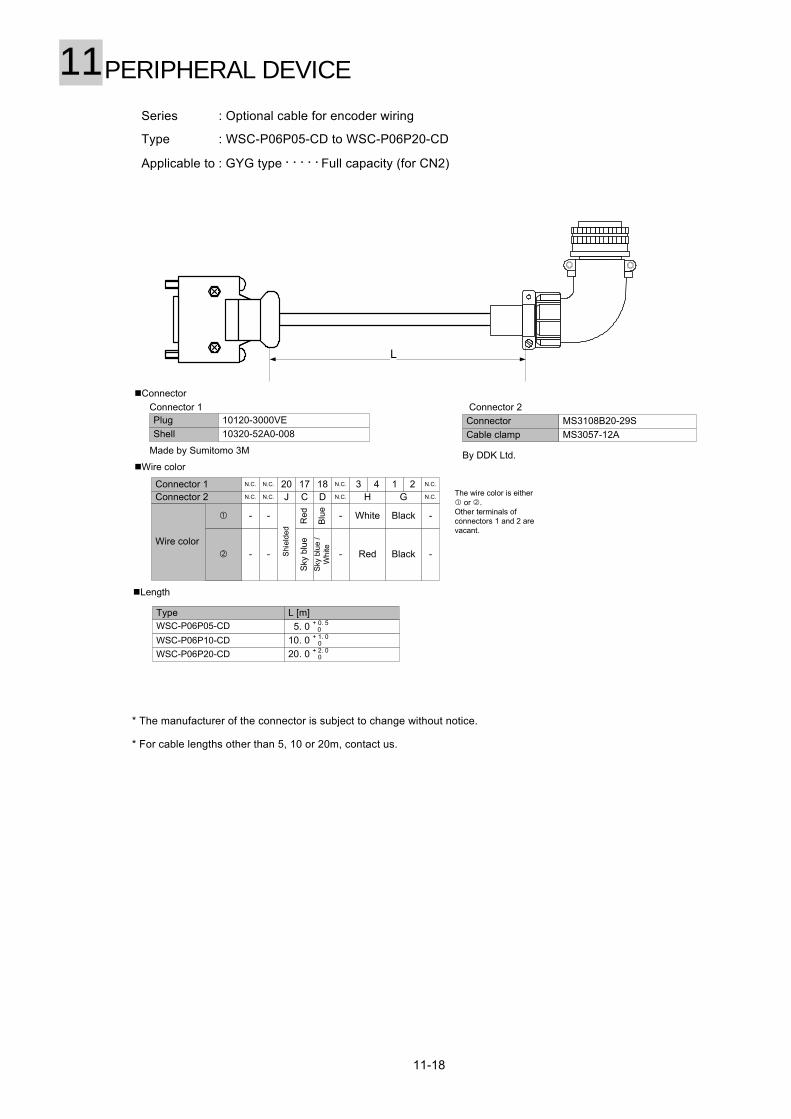
11PERIPHERAL DEVICE
11-18
Series : Optional cable for encoder wiring
Type : WSC-P06P05-CD to WSC-P06P20-CD
Applicable to : GYG type · · · · · Full capacity (for CN2)
Connector 1Connector
Wire color
Length
L
WSC-P06P05-CD L [m]Type 5. 0 + 0. 5
0
WSC-P06P10-CD 10. 0 + 1. 00
WSC-P06P20-CD 20. 0 + 2. 00
Plug 10120-3000VEShell 10320-52A0-008
Made by Sumitomo 3M
Connector 2Connector MS3108B20-29SCable clamp MS3057-12A
By DDK Ltd.
Connector 1
Wire color
J C D H G18
Shi
elde
d
Red
Blu
e
White
Connector 220 3 117N.C. N.C. N.C. N.C.
Black
Sky
blu
eS
ky b
lue
/ W
hite Red Black
- - - -
----
The wire color is either or .
Other terminals of connectors 1 and 2 are vacant.
N.C. N.C. N.C.N.C.
24
* The manufacturer of the connector is subject to change without notice.
* For cable lengths other than 5, 10 or 20m, contact us.
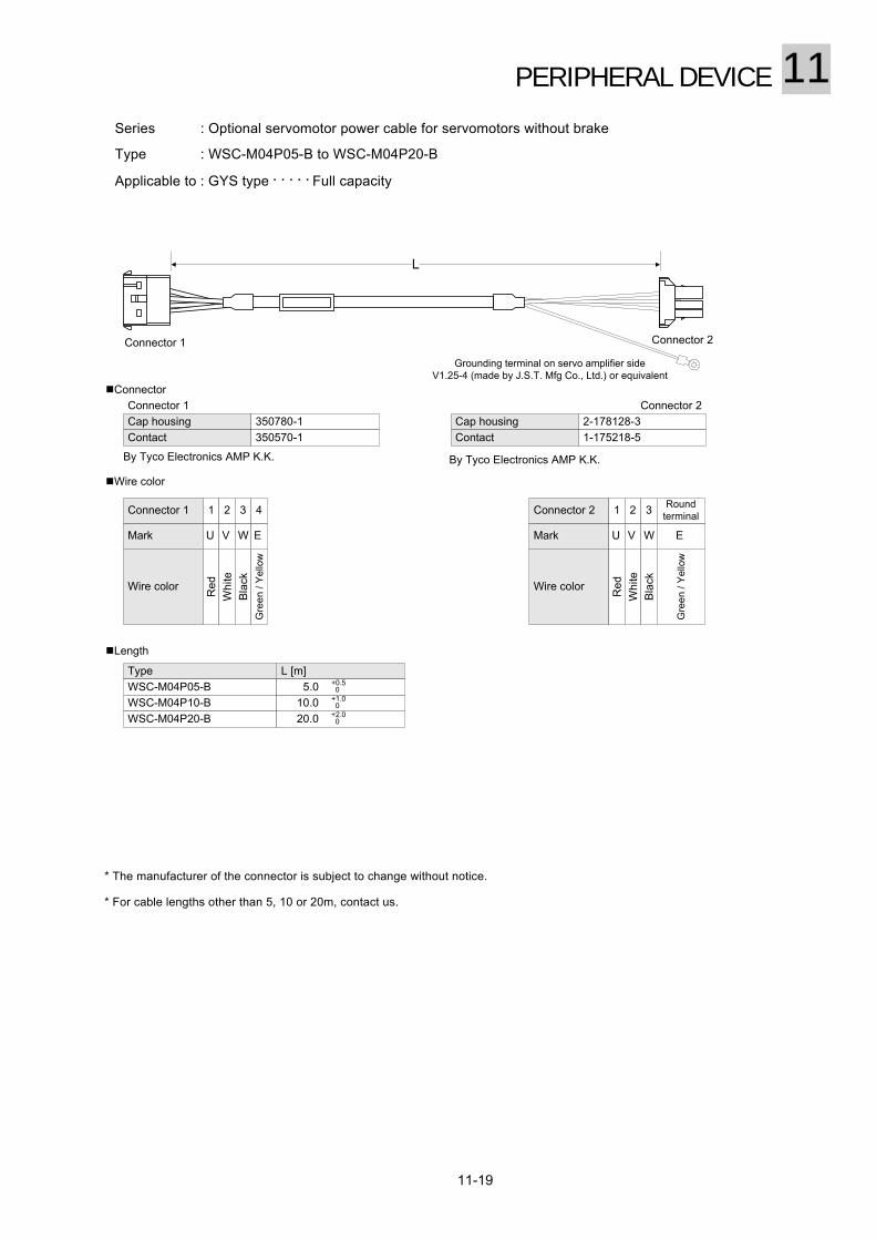
PERIPHERAL DEVICE 11
11-19
Series : Optional servomotor power cable for servomotors without brake
Type : WSC-M04P05-B to WSC-M04P20-B
Applicable to : GYS type · · · · · Full capacity
Connector
Wire color
Length
Mark
Wire color Red
Whi
teBl
ack
Gre
en /
Yel
low
Connector 1 1 2 3 4
U V W E
Connector 1Cap housing 350780-1Contact 350570-1
By Tyco Electronics AMP K.K.
L
Connector 1 Connector 2
Grounding terminal on servo amplifier sideV1.25-4 (made by J.S.T. Mfg Co., Ltd.) or equivalent
Connector 2Cap housing 2-178128-3Contact 1-175218-5
Mark
Wire color Red
Whi
teBl
ack
Gre
en /
Yel
low
Connector 2 1 2 3 Round terminal
U V W E
L [m]TypeWSC-M04P05-BWSC-M04P10-BWSC-M04P20-B 20.0 +2.0
0
10.0 +1.00
5.0 +0.50
By Tyco Electronics AMP K.K.
* The manufacturer of the connector is subject to change without notice.
* For cable lengths other than 5, 10 or 20m, contact us.
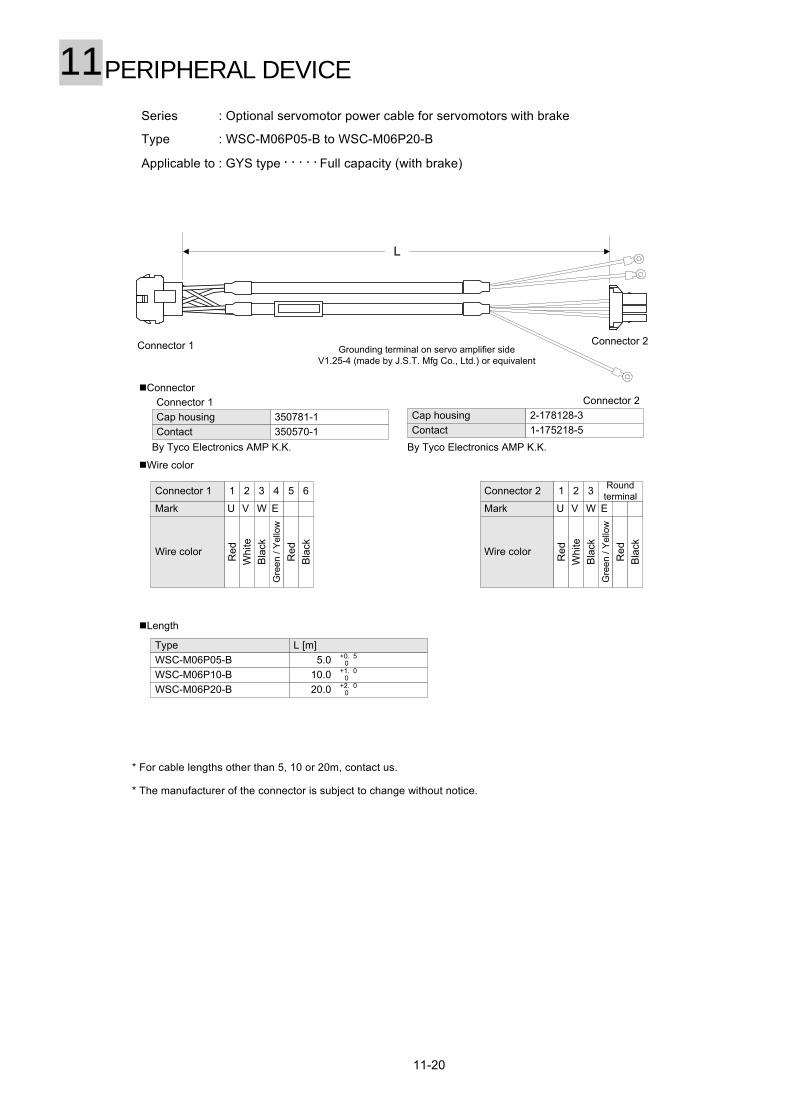
11PERIPHERAL DEVICE
11-20
Series : Optional servomotor power cable for servomotors with brake
Type : WSC-M06P05-B to WSC-M06P20-B
Applicable to : GYS type · · · · · Full capacity (with brake)
L [m]TypeWSC-M06P05-BWSC-M06P10-BWSC-M06P20-B 20.0 +2. 0
0
10.0 +1. 00
5.0 +0. 50
Connector 1Cap housing 350781-1Contact 350570-1
Mark
Wire color Red
Whi
teB
lack
Gre
en /
Yel
low
Connector 1 1 2 3 4
U V W E
Red
Bla
ck
5 6
Connector
Wire color
Length
Connector 2Cap housing 2-178128-3Contact 1-175218-5
Mark
Wire color Red
Whi
teB
lack
Gre
en /
Yel
low
Connector 2 1 2 3 Roundterminal
U V W E
Red
Bla
ck
Connector 1
L
Connector 2Grounding terminal on servo amplifier side
V1.25-4 (made by J.S.T. Mfg Co., Ltd.) or equivalent
By Tyco Electronics AMP K.K. By Tyco Electronics AMP K.K.
* For cable lengths other than 5, 10 or 20m, contact us.
* The manufacturer of the connector is subject to change without notice.
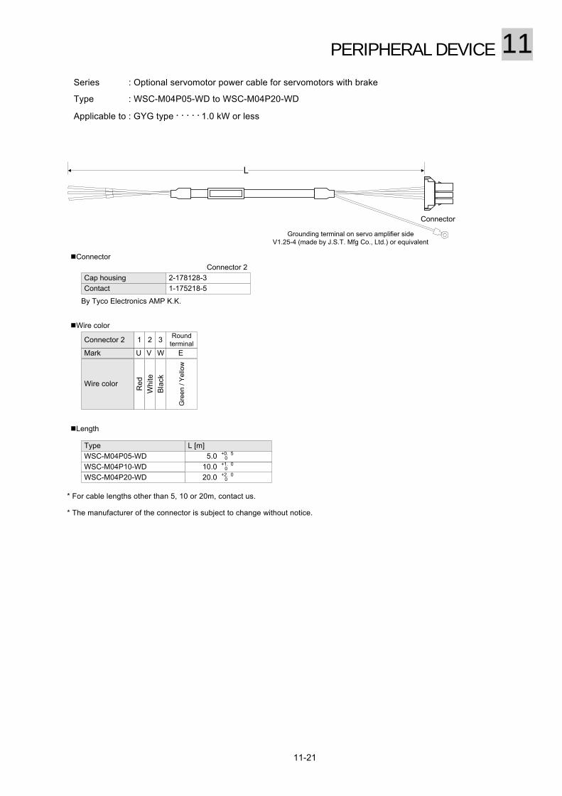
PERIPHERAL DEVICE 11
11-21
Series : Optional servomotor power cable for servomotors with brake
Type : WSC-M04P05-WD to WSC-M04P20-WD
Applicable to : GYG type · · · · · 1.0 kW or less
Connector
Wire color
Length
L
Connector
Grounding terminal on servo amplifier sideV1.25-4 (made by J.S.T. Mfg Co., Ltd.) or equivalent
By Tyco Electronics AMP K.K.
Connector 2Cap housing 2-178128-3Contact 1-175218-5
Mark
Wire color Red
Whi
teB
lack
Gre
en /
Yel
low
Connector 2 1 2 3 Roundterminal
U V W E
L [m]TypeWSC-M04P05-WDWSC-M04P10-WDWSC-M04P20-WD 20.0 +2. 0
0
10.0 +1. 00
5.0 +0. 50
* For cable lengths other than 5, 10 or 20m, contact us.
* The manufacturer of the connector is subject to change without notice.
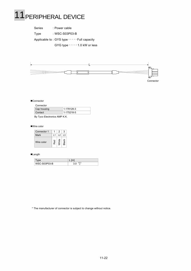
11PERIPHERAL DEVICE
11-22
Series : Power cable
Type : WSC-S03P03-B
Applicable to : GYS type · · · · · Full capacity
GYG type · · · · · 1.0 kW or less
* The manufacturer of connector is subject to change without notice.
Connector
Wire color
Length
ConnectorCap housing 1-178128-3Contact 1-175218-5
By Tyco Electronics AMP K.K.
L
Connector
Mark
Wire color Red
Whi
te
Bla
ck
Connector 1 1 2L1 L2
3L3
L [m]TypeWSC-S03P03-B 3.0 +0.3
0
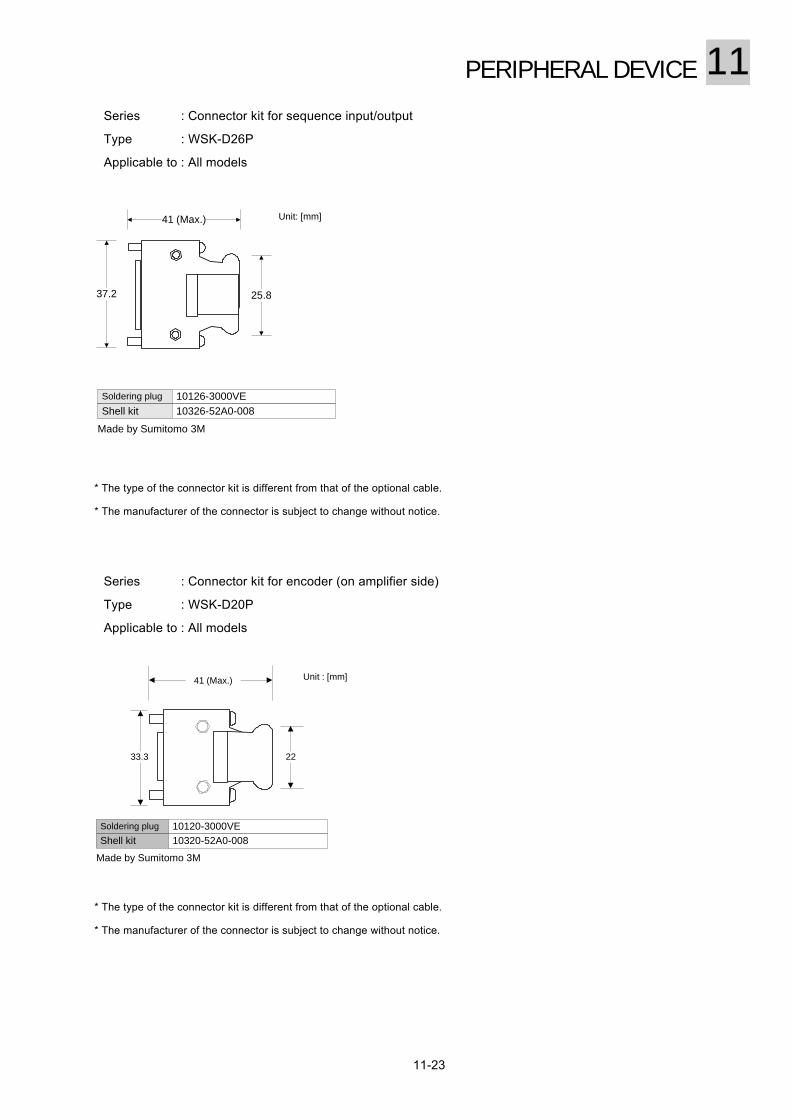
PERIPHERAL DEVICE 11
11-23
Series : Connector kit for sequence input/output
Type : WSK-D26P
Applicable to : All models
41 (Max.)
37.2 25.8
Soldering plug 10126-3000VE
Made by Sumitomo 3M
Shell kit 10326-52A0-008
Unit: [mm]
* The type of the connector kit is different from that of the optional cable.
* The manufacturer of the connector is subject to change without notice.
Series : Connector kit for encoder (on amplifier side)
Type : WSK-D20P
Applicable to : All models
Soldering plug 10120-3000VE
Made by Sumitomo 3M
Shell kit 10320-52A0-008
33.3
41 (Max.)
22
Unit : [mm]
* The type of the connector kit is different from that of the optional cable.
* The manufacturer of the connector is subject to change without notice.
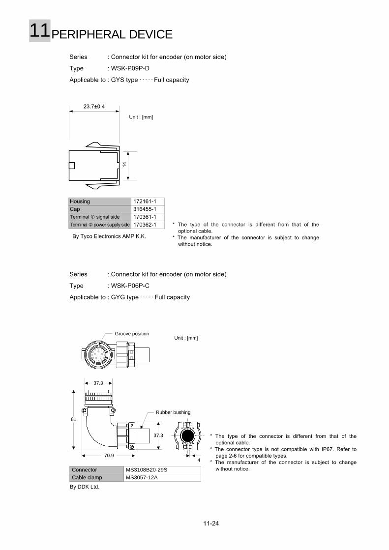
11PERIPHERAL DEVICE
11-24
Series : Connector kit for encoder (on motor side)
Type : WSK-P09P-D
Applicable to : GYS type · · · · · Full capacity
23.7±0.4
14Unit : [mm]
Housing 172161-1Cap 316455-1
By Tyco Electronics AMP K.K.
Terminal signal sideTerminal power supply side
170361-1170362-1
Series : Connector kit for encoder (on motor side)
Type : WSK-P06P-C
Applicable to : GYG type · · · · · Full capacity
Connector MS3108B20-29S
Cable clamp MS3057-12A
By DDK Ltd.
Groove position
Rubber bushing
4
37.3
70.9
81
37.3
Unit : [mm]
* The type of the connector is different from that of the optional cable.
* The manufacturer of the connector is subject to changewithout notice.
* The type of the connector is different from that of theoptional cable.
* The connector type is not compatible with IP67. Refer to page 2-6 for compatible types.
* The manufacturer of the connector is subject to changewithout notice.

PERIPHERAL DEVICE 11
11-25
Series : Connector kit for servomotor power cable (on amplifier side)
Type : WSK-M03P-B
Applicable to : GYS type · · · · · Full capacity
GYG type · · · · · 1.0 kW or less
Series : Connector kit for power cable (on amplifier side)
Type : WSK-S03P-B
Applicable to : GYS type · · · · · Full capacity
GYG type · · · · · 1.0 kW or less
Series : Connector kit for external regenerative resistor (on amplifier side)
Type : WSK-R03P-B
Applicable to : GYS type · · · · · Full capacity
GYG type · · · · · 1.0 kW or less
Unit : [mm]
29.7
16.3 22
.8
5.08
Housing 2-178128-3
Contact 1-175218-5
Housing 1-178128-3
Housing 1-178128-3
1-175218-5Contact
By Tyco Electronics AMP K.K.
Contact 1-175218-5
Connector kit for servomotor power cableWSK-M03P-B
Connector kit for power cableWSK-S03P-B
Keying plug 175855-1
Connector kit for external regenerative resistorWSK-R03P-B
6.55
7.15
Series : Connector kit for control power wiring (amplifier side)
Type : WSK-L02P-D
Applicable to : GYS type · · · · · Full capacity
GYG type · · · · · 1.0 kW or less
22.8
24.7
By Tyco Electronics AMP K.K.
Connector kit for control power wiringWSK-L02P-D
Housing 1-178128-2
Contact 1-175218-5
6.55
7.15
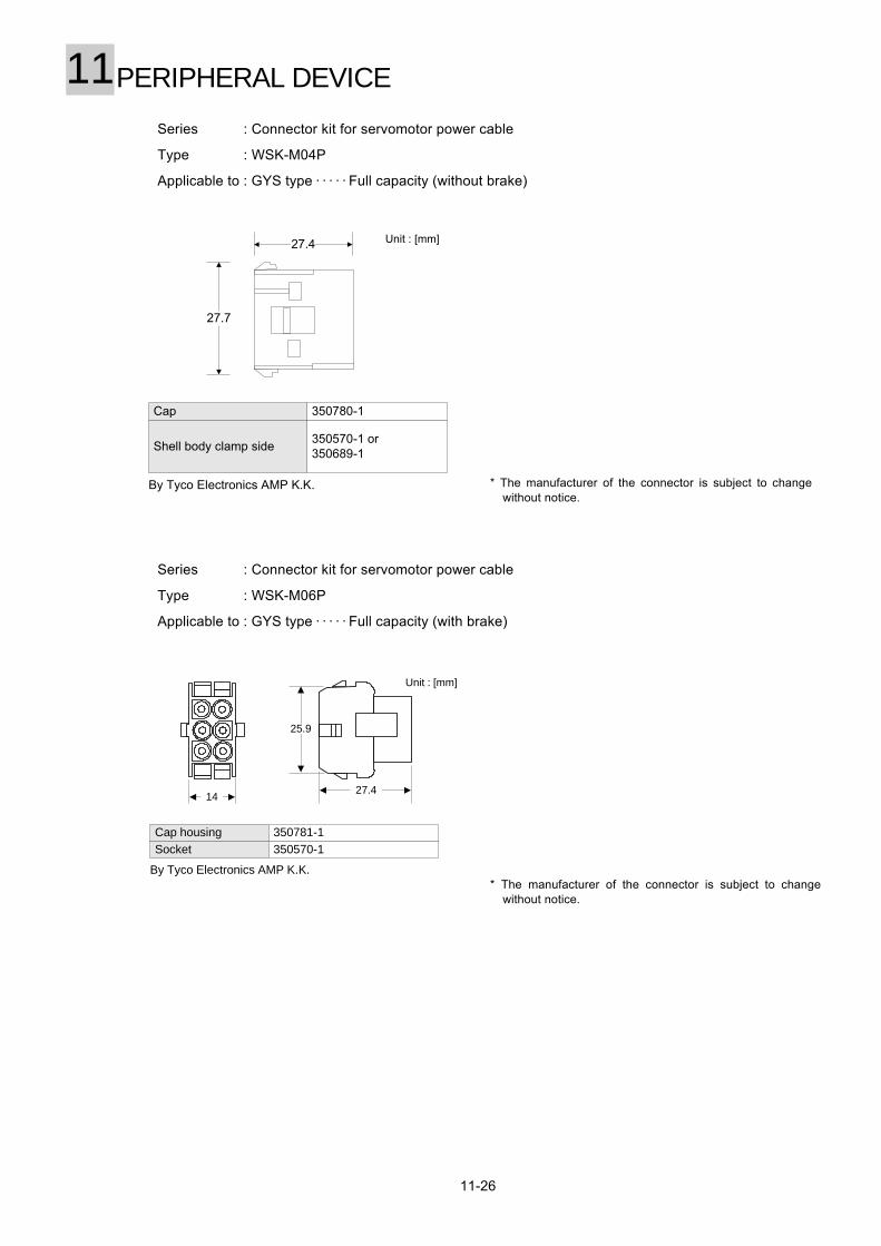
11PERIPHERAL DEVICE
11-26
Series : Connector kit for servomotor power cable
Type : WSK-M04P
Applicable to : GYS type · · · · · Full capacity (without brake)
27.4
27.7
Cap 350780-1
Shell body clamp side 350570-1 or 350689-1
By Tyco Electronics AMP K.K.
Unit : [mm]
Series : Connector kit for servomotor power cable
Type : WSK-M06P
Applicable to : GYS type · · · · · Full capacity (with brake)
14
25.9
27.4
Cap housing 350781-1
Socket 350570-1
By Tyco Electronics AMP K.K.
Unit : [mm]
* The manufacturer of the connector is subject to changewithout notice.
* The manufacturer of the connector is subject to changewithout notice.
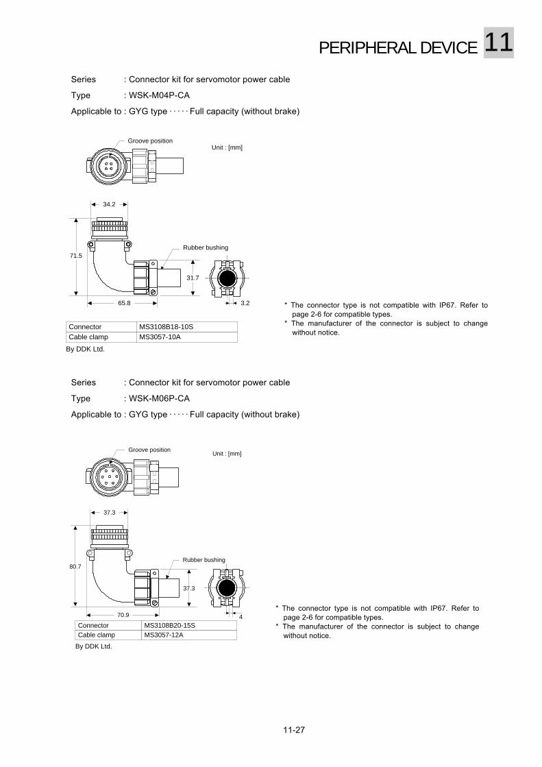
PERIPHERAL DEVICE 11
11-27
Series : Connector kit for servomotor power cable
Type : WSK-M04P-CA
Applicable to : GYG type · · · · · Full capacity (without brake)
Groove position
Rubber bushing
31.7
65.8
71.5
34.2
3.2
Connector MS3108B18-10S
Cable clamp MS3057-10A
By DDK Ltd.
Unit : [mm]
Series : Connector kit for servomotor power cable
Type : WSK-M06P-CA
Applicable to : GYG type · · · · · Full capacity (without brake)
Groove position
Rubber bushing
37.3
70.9
80.7
37.3
4
Connector MS3108B20-15S
Cable clamp MS3057-12A
By DDK Ltd.
Unit : [mm]
* The connector type is not compatible with IP67. Refer to page 2-6 for compatible types.
* The manufacturer of the connector is subject to changewithout notice.
* The connector type is not compatible with IP67. Refer to page 2-6 for compatible types.
* The manufacturer of the connector is subject to changewithout notice.
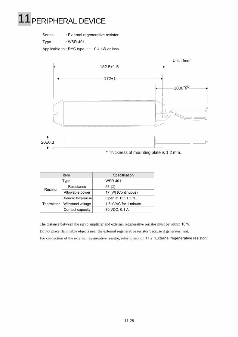
11PERIPHERAL DEVICE
11-28
Series : External regenerative resistor
Type : WSR-401
Applicable to : RYC type · · · · · 0.4 kW or less
182.5±1.5
172±1
1000+1000
20±0.3
* Thickness of mounting plate is 1.2 mm.
ItemType
Resistor
Thermistor
ResistanceAllowable power
Operating temperature
Withstand voltageContact capacity
SpecificationWSR-40168 [Ω]17 [W] (Continuous)Open at 135 ± 5 °C1.5 kVAC for 1 minute30 VDC, 0.1 A
The distance between the servo amplifier and external regenerative resistor must be within 10m.
Do not place flammable objects near the external regenerative resistor because it generates heat.
For connection of the external regenerative resistor, refer to section 11.7 “External regenerative resistor.”
Unit : [mm]
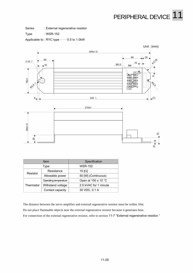
PERIPHERAL DEVICE 11
11-29
Series : External regenerative resistor
Type : WSR-152
Applicable to : RYC type · · · · · 0.5 to 1.0kW
76±1
R3.5+0
.3
-0
∅15 +0.3-0
6
10
50
345±1.5
60 25
10M4M3.5
8
4-C18
R3.5
(7)332 +0-1.0
94±1
.5
25
210±1
15t2
P D
B 1
2
ItemType
Resistor
Thermistor
ResistanceAllowable power
Operating temperature
Withstand voltageContact capacity
SpecificationWSR-15215 [Ω]50 [W] (Continuous)Open at 150 ± 10 °C2.5 kVAC for 1 minute30 VDC, 0.1 A
The distance between the servo amplifier and external regenerative resistor must be within 10m.
Do not place flammable objects near the external regenerative resistor because it generates heat.
For connection of the external regenerative resistor, refer to section 11-7 “External regenerative resistor.”
Unit : [mm]
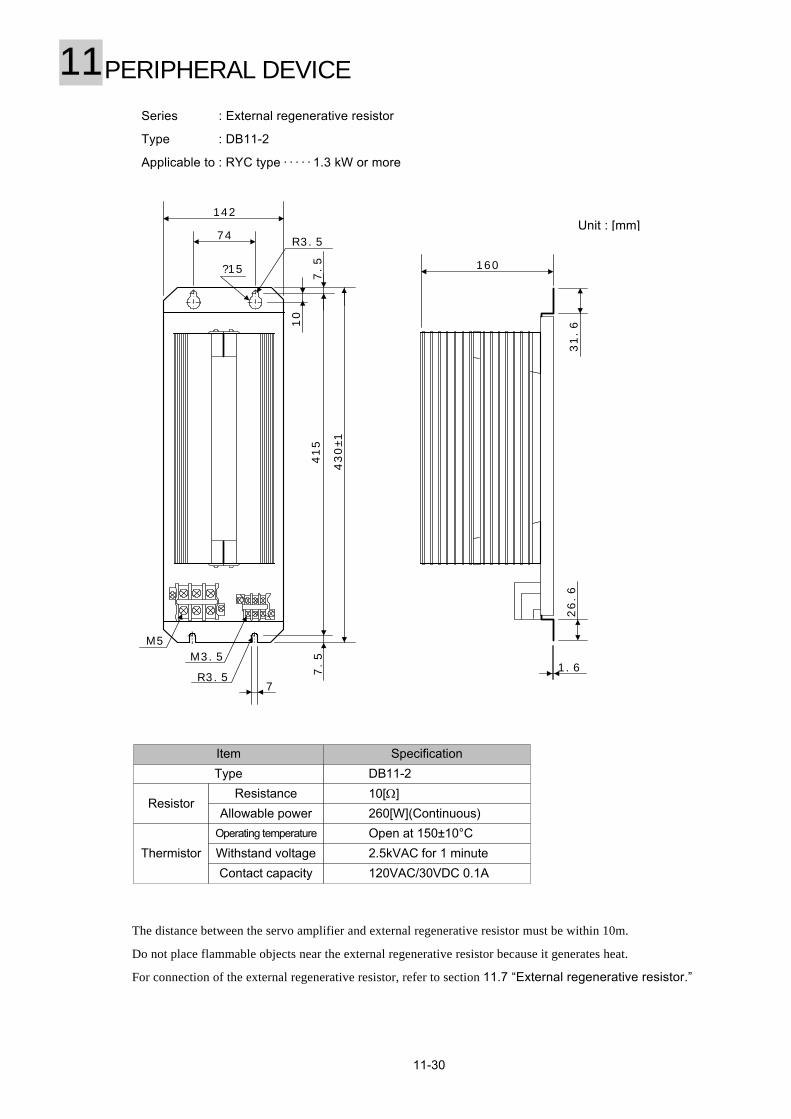
11PERIPHERAL DEVICE
11-30
Series : External regenerative resistor
Type : DB11-2
Applicable to : RYC type · · · · · 1.3 kW or more
M5M3. 5
R3 . 57
7.
54
15
43
0±
1
10
7.
5
R3 . 5
?15
74
142
160
31
.6
26
.6
1 . 6
ItemType
Resistor
Thermistor
ResistanceAllowable power
Operating temperature
Withstand voltageContact capacity
SpecificationDB11-210[Ω]260[W](Continuous)Open at 150±10°C2.5kVAC for 1 minute120VAC/30VDC 0.1A
The distance between the servo amplifier and external regenerative resistor must be within 10m.
Do not place flammable objects near the external regenerative resistor because it generates heat.
For connection of the external regenerative resistor, refer to section 11.7 “External regenerative resistor.”
Unit : [mm]
SPECIFICATIONS

12-2
SPECIFICATIONS12
12.1 List of servomotor specifications 12.1.1 Low inertia series (GYS motor) 3000r/min
7.3 8.5 6.1[W] Power consumption
40 20
3000 Rated speed
0.853 × 10⁻⁴
7.17
14.44.8
GYS751DC2-T2
2.390.75
0.246 × 10⁻⁴
3.82
8.12.7
GYS401DC2-T2
1.270.4
0.135 × 10⁻⁴
1.91
4.51.5
GYS201DC2-T2
0.6370.2
0.0371 × 10⁻⁴
0.955
2.550.85
GYS101DC2-T2
0.3180.1
17-bit serial encoder
0.0192 × 10⁻⁴
0.478
2.550.85
GYS500DC2-T2 Motor type
Rated output Rated torque *1
[kW]
Max. speed
Max. torque
Moment of inertia [kg·m2] Rated current [A]
[A] Max. current Insulation class Rating Protective ventilation Terminal (Motor) Terminal (Detector) Overheat protection Mounting method Shaft extension Paint color Detector Vibration Install location, altitude, Atmosphere Ambient temperatures and humidity Acceleration vibration, acceptable Mass
[m/s2] [kg]
[N·m]
[r/min][r/min]
Standard specifications
0.159
5000
Continuous rating
Cable 0.3 m (with connector)
None (Detection with servo amplifier)
Cylindrical shaft, with key
Indoors, altitude of 1000 m or less, place without corrosive gas, flammable gas, oil mist or dust
49
0.05
Class B
Totally enclosed, self-cooling (IP 67) (except for shaft sealing and connectors )
Cable 0.3 m (with connector)
Flange IMB5 (L51) , IMV1 (L52) , IMV3 (L53)
N1.5
V5 or below
-10 to +40 °C, humidity: 90 % RH max. (free from condensation)
0.45 0.55 1.2 1.8 3.4
1.203 × 10⁻⁴
2560
GYS751DC2-T2 -B
2.390.75
0.446 × 10⁻⁴
GYS401DC2-T2 -B
1.270.4
0.335 × 10⁻⁴ 1.27
GYS201DC2-T2 -B
0.6370.2
0.0402 × 10⁻⁴
GYS101DC2-T2 -B
0.3180.1
0.0223 × 10⁻⁴ 0.34
35 DC24
GYS500DC2-T2 -B Motor type
Rated output Rated torque *1
[kW]
Static friction torque Moment of inertia [kg·m2] Rated voltage [V]
[ms] Attraction time Release time
[N·m] 0.1590.05
10
Motor with brake (*2)
[N·m]
[N·m]
[ms]
4.22.31.70.7 Mass [kg] 0.6
2.45
*1) Rated torque is the value when operation is performed with the following aluminum heat sinks. GYS500DC2-T2 ,GYS101DC2-T2 ······· 200 × 200 × 6 [mm] GYS201DC2-T2 ,GYS401DC2-T2 ······· 250 × 250 × 6 [mm] GYS751DC2-T2 ········································ 300 × 300 × 6 [mm]
*2) When the servomotor is operating at a low speed, a rattling noise may be heard from the brake lining. It is acceptable as to performance.

12-3
SPECIFICATIONS 12
12.1.2 Middle inertia series (GYG motor) 2000r/min
14 (at 20°C)[W] Power consumption
2000 Rated speed
29.51 × 10⁻⁴
28.6
36.912.3
GYG202CC2-T2
9.552.0
22.33 × 10⁻⁴
21.5
30.010.0
GYG152CC2-T2
7.161.5
15.14 × 10⁻⁴
14.3
19.26.4
GYG102CC2-T2
4.771.0
11.55 × 10⁻⁴
10.7
15.65.2
GYG751CC2-T2
3.580.75
17-bit serial encoder
7.96 × 10⁻⁴
7.2
10.53.5
GYG501CC2-T2 Motor type
Rated output Rated torque *1
[kW]
Max. speed
Max. torque
Moment of inertia [kg·m2] Rated current [A]
[A] Max. current Insulation class Rating Protective ventilation Terminal (Motor) Terminal (Detector) Overheat protection Mounting method Shaft extension Paint color Detector Vibration Install location, altitude, Atmosphere Ambient temperatures and humidity Acceleration vibration, acceptable Mass
[m/s2] [kg]
[N·m]
[r/min][r/min]
Standard specifications
2.39
3000
Continuous rating
Cannon connector
None (Detection with servo amplifier)
With straight shaft key, with oil seal
Indoors, altitude of 1000 m or less, place without corrosive gas, flammable gas, oil mist or dust
24.5
0.5
Class F
Totally enclosed, self-cooling (IP 67) (except for shaft sealing)
Cannon connector
Flange IMB5 (L51) , IMV1 (L52) , IMV3 (L53)
N1.5
V5 or below
-10 to +40 °C, humidity: 90 % RH max. (free from condensation)
5.3 6.4 7.5 9.8 12.0
31.6 × 10⁻⁴
GYG202CC2-T2 -B
9.552.0
24.4 × 10⁻⁴
GYG152CC2-T2 -B
7.161.5
17.2 × 10⁻⁴
GYG102CC2-T2 -B
4.771.0
13.6 × 10⁻⁴
GYG751CC2-T2 -B
3.580.75
10 × 10-4 17
120 DC24 ± 10%
GYG501CC2-T2 -B Motor type
Rated output Rated torque *1
[kW]
Static friction torque Moment of inertia [kg·m2] Rated voltage [V]
[ms] Attraction time Release time
[N·m] 2.390.5
30
Motor with brake (*2)
[N·m]
[N·m]
[ms]
14.212.09.78.6 Mass [kg] 7.5
2.45
*1) Rated torque is the value when operation is performed with the following aluminum heat sinks.
GYG501CC2-T2 ,GYG751CC2-T2 ,GYG102CC2-T2 ······· 300 × 300 × 12 [mm] GYG152CC2-T2 ,GYG202CC2-T2 ········································· 400 × 400 × 12 [mm]
*2) When the servomotor is operating at a low speed, a rattling noise may be heard from the brake lining. It is acceptable as to performance.
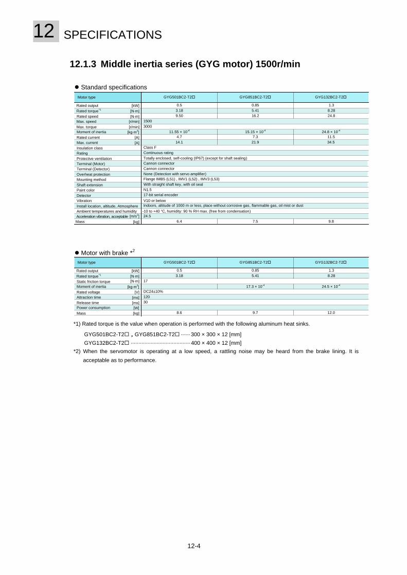
12-4
SPECIFICATIONS12
12.1.3 Middle inertia series (GYG motor) 1500r/min
16.25.410.85
24.88.281.3
24.8 × 10⁻⁴
34.511.5
GYG851BC2-T2 GYG132BC2-T2
15.15 × 10⁻⁴
21.97.3
1500 Max. speed
17-bit serial encoder
11.55 × 10⁻⁴
9.50
14.14.7
GYG501BC2-T2 Motor type
Rated output Rated torque*1
[kW]
Max. torque
Rated speed
Moment of inertia [kg·m2] Rated current [A]
[A] Max. current Insulation class Rating Protective ventilation Terminal (Motor) Terminal (Detector) Overheat protection Mounting method Shaft extension Paint color Detector Vibration Install location, altitude, Atmosphere Ambient temperatures and humidityAcceleration vibration, acceptable
Mass[m/s2]
[kg]
[N·m]
[r/min][r/min]
Standard specifications
3.18
3000
Continuous rating
Cannon connector
None (Detection with servo amplifier)
With straight shaft key, with oil seal
Indoors, altitude of 1000 m or less, place without corrosive gas, flammable gas, oil mist or dust
24.5
0.5
Class F
Totally enclosed, self-cooling (IP67) (except for shaft sealing)
Cannon connector
Flange IMB5 (L51) , IMV1 (L52) , IMV3 (L53)
N1.5
V10 or below
-10 to +40 °C, humidity: 90 % RH max. (free from condensation)
Motor with brake *2
[N·m]
9.87.56.4
5.410.85
8.281.3
24.5 × 10⁻⁴
GYG851BC2-T2 GYG132BC2-T2
17.3 × 10⁻⁴ 17
120 DC24±10%
GYG501BC2-T2 Motor type
Rated output Rated torque*1
[kW]
Static friction torque Moment of inertia [kg·m2] Rated voltage [V]
[ms] Attraction time
[N·m] 3.180.5
[N·m]
12.09.7
30
8.6
Release time Power consumption [W] Mass [kg]
[ms]
*1) Rated torque is the value when operation is performed with the following aluminum heat sinks.
GYG501BC2-T2 ,GYG851BC2-T2 ······ 300 × 300 × 12 [mm] GYG132BC2-T2 ······································· 400 × 400 × 12 [mm]
*2) When the servomotor is operating at a low speed, a rattling noise may be heard from the brake lining. It is acceptable as to performance.
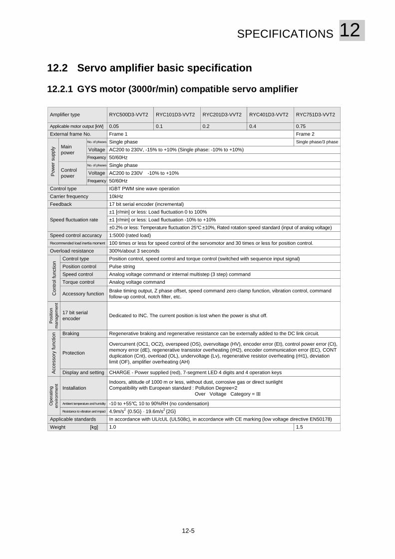
12-5
SPECIFICATIONS 12
12.2 Servo amplifier basic specification
12.2.1 GYS motor (3000r/min) compatible servo amplifier
Amplifier type
Applicable motor output [kW] 0.05 0.1 0.2 0.4 0.75
Pow
er s
uppl
y AC200 to 230V, -15% to +10% (Single phase: -10% to +10%) 50/60Hz
Control typeCarrier frequencyFeedback
Speed fluctuation rate±0.2% or less: Temperature fluctuation 25°C ±10%, Rated rotation speed standard (input of analog voltage)
Speed control accuracy 1:5000 (rated load)
Overload resistance
Regenerative braking and regenerative resistance can be externally added to the DC link circuit.
Overcurrent (OC1, OC2), overspeed (OS), overvoltage (HV), encoder error (Et), control power error (Ct), memory error (dE), regenerative transistor overheating (rH2), encoder communication error (EC), CONT duplication (Cnt), overload (OL), undervoltage (Lv), regenerative resistor overheating (rH1), deviation limit (OF), amplifier overheating (AH)
Display and setting CHARGE - Power supplied (red), 7-segment LED 4 digits and 4 operation keys
InstallationIndoors, altitude of 1000 m or less, without dust, corrosive gas or direct sunlightCompatibility with European standard : Pollution Degree=2
Over Voltage Category = III
RYC500D3-VVT2 RYC101D3-VVT2 RYC201D3-VVT2 RYC401D3-VVT2 RYC751D3-VVT2
No. of phases
VoltageFrequency
Single phase
IGBT PWM sine wave operation10kHz17 bit serial encoder (incremental)±1 [r/min] or less: Load fluctuation 0 to 100%
Acce
ssor
y fu
nctio
n Braking
Protection
Ope
ratin
g en
viro
nmen
t
Ambient temperature and humidity -10 to +55°C, 10 to 90%RH (no condensation)Resistance to vibration and impact 4.9m/s2 0.5G · 19.6m/s2 2G
Weight [kg] 1.0
300%/about 3 seconds
Main power
AC200 to 230V -10% to +10%50/60Hz
No. of phases
VoltageFrequency
Single phaseControl power
Applicable standards In accordance with UL/cUL (UL508c), in accordance with CE marking (low voltage directive EN50178)1.5
External frame No. Frame 1 Frame 2
Con
trol f
unct
ion
Control type Position control, speed control and torque control (switched with sequence input signal)
Speed control Analog voltage command or internal multistep (3 step) commandAnalog voltage command
Accessory function Brake timing output, Z phase offset, speed command zero clamp function, vibration control, command follow-up control, notch filter, etc.
Position control Pulse string
Torque control
Posi
tion
man
agem
ent
17 bit serial encoder Dedicated to INC. The current position is lost when the power is shut off.
Single phase/3 phase
Recommended load inertia moment 100 times or less for speed control of the servomotor and 30 times or less for position control.
±1 [r/min] or less: Load fluctuation -10% to +10%
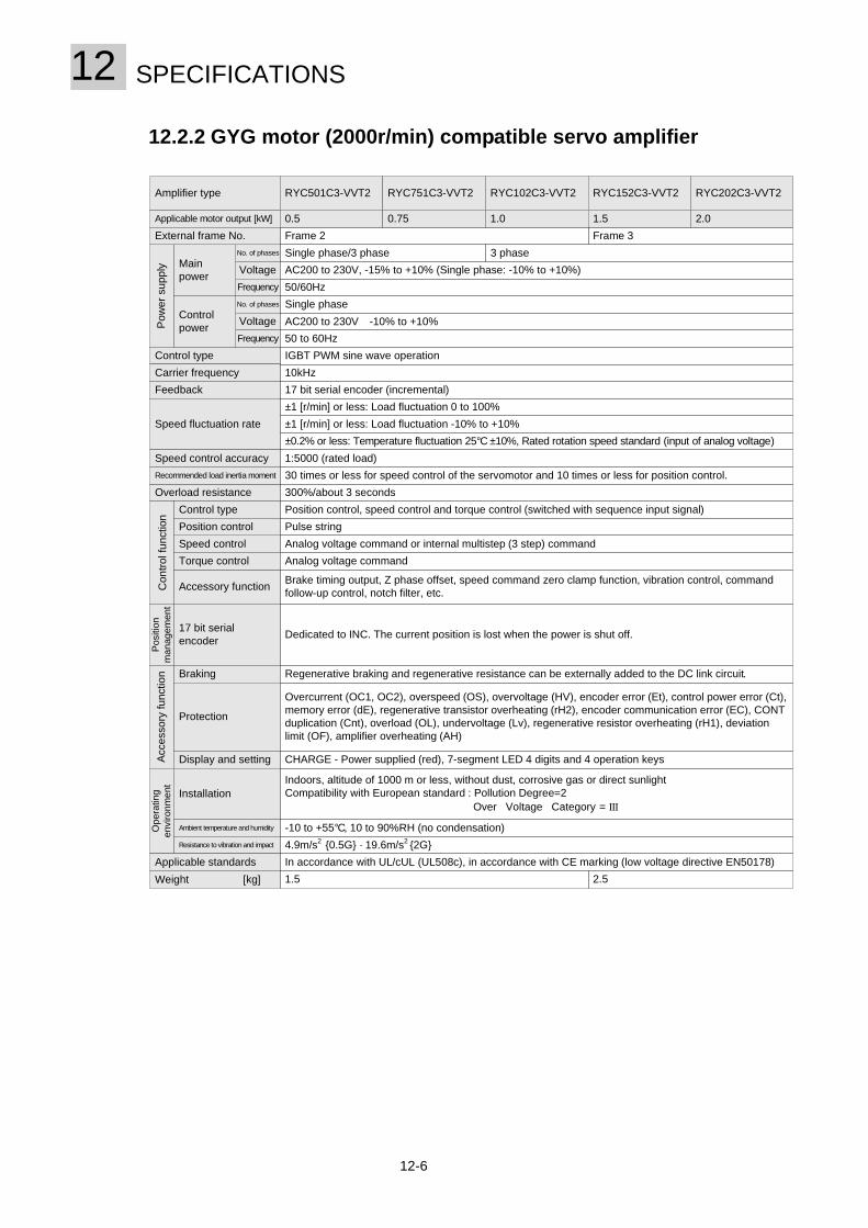
12-6
SPECIFICATIONS12
12.2.2 GYG motor (2000r/min) compatible servo amplifier
Amplifier type
Applicable motor output [kW] 0.5 0.75 1.0 1.5 2.0
Pow
er s
uppl
y AC200 to 230V, -15% to +10% (Single phase: -10% to +10%)50/60Hz
Control typeCarrier frequencyFeedback
Speed fluctuation rate ±1 [r/min] or less: Load fluctuation -10% to +10%±0.2% or less: Temperature fluctuation 25°C ±10%, Rated rotation speed standard (input of analog voltage)
Speed control accuracy 1:5000 (rated load)
Overload resistance
Regenerative braking and regenerative resistance can be externally added to the DC link circuit.
Overcurrent (OC1, OC2), overspeed (OS), overvoltage (HV), encoder error (Et), control power error (Ct), memory error (dE), regenerative transistor overheating (rH2), encoder communication error (EC), CONT duplication (Cnt), overload (OL), undervoltage (Lv), regenerative resistor overheating (rH1), deviation limit (OF), amplifier overheating (AH)
Display and setting CHARGE - Power supplied (red), 7-segment LED 4 digits and 4 operation keys
InstallationIndoors, altitude of 1000 m or less, without dust, corrosive gas or direct sunlightCompatibility with European standard : Pollution Degree=2
Over Voltage Category = III
RYC501C3-VVT2 RYC751C3-VVT2 RYC102C3-VVT2 RYC152C3-VVT2 RYC202C3-VVT2
No. of phases
VoltageFrequency
Single phase/3 phase
IGBT PWM sine wave operation10kHz17 bit serial encoder (incremental)±1 [r/min] or less: Load fluctuation 0 to 100%
Acce
ssor
y fu
nctio
n Braking
Protection
Ope
ratin
g en
viro
nmen
t
Ambient temperature and humidity -10 to +55°C, 10 to 90%RH (no condensation)Resistance to vibration and impact 4.9m/s2 0.5G · 19.6m/s2 2G
Weight [kg] 1.5
300%/about 3 seconds
Main power
AC200 to 230V -10% to +10%50 to 60Hz
No. of phases
VoltageFrequency
Single phaseControl power
Applicable standards In accordance with UL/cUL (UL508c), in accordance with CE marking (low voltage directive EN50178)
External frame No. Frame 2 Frame 33 phase
2.5
Con
trol f
unct
ion
Control type Position control, speed control and torque control (switched with sequence input signal)
Speed control Analog voltage command or internal multistep (3 step) commandAnalog voltage command
Accessory function Brake timing output, Z phase offset, speed command zero clamp function, vibration control, command follow-up control, notch filter, etc.
Position control Pulse string
Torque control
Posi
tion
man
agem
ent
17 bit serial encoder Dedicated to INC. The current position is lost when the power is shut off.
Recommended load inertia moment 30 times or less for speed control of the servomotor and 10 times or less for position control.
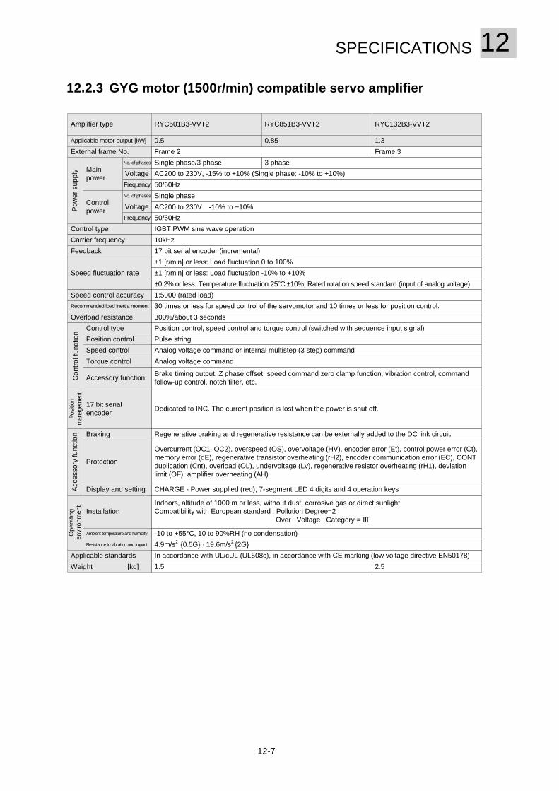
12-7
SPECIFICATIONS 12
12.2.3 GYG motor (1500r/min) compatible servo amplifier
Amplifier type
Applicable motor output [kW] 0.5
Pow
er s
uppl
y AC200 to 230V, -15% to +10% (Single phase: -10% to +10%) 50/60Hz
Control typeCarrier frequencyFeedback
Speed fluctuation rate ±1 [r/min] or less: Load fluctuation -10% to +10%±0.2% or less: Temperature fluctuation 25°C ±10%, Rated rotation speed standard (input of analog voltage)
Speed control accuracy 1:5000 (rated load)
Overload resistance
Regenerative braking and regenerative resistance can be externally added to the DC link circuit.
Overcurrent (OC1, OC2), overspeed (OS), overvoltage (HV), encoder error (Et), control power error (Ct), memory error (dE), regenerative transistor overheating (rH2), encoder communication error (EC), CONT duplication (Cnt), overload (OL), undervoltage (Lv), regenerative resistor overheating (rH1), deviation limit (OF), amplifier overheating (AH)
Display and setting CHARGE - Power supplied (red), 7-segment LED 4 digits and 4 operation keys
InstallationIndoors, altitude of 1000 m or less, without dust, corrosive gas or direct sunlightCompatibility with European standard : Pollution Degree=2
Over Voltage Category = III
RYC501B3-VVT2
No. of phases
VoltageFrequency
Single phase/3 phase
IGBT PWM sine wave operation10kHz17 bit serial encoder (incremental)±1 [r/min] or less: Load fluctuation 0 to 100%
Acc
esso
ry fu
nctio
n Braking
Protection
Ope
ratin
g en
viro
nmen
t
Ambient temperature and humidity -10 to +55°C, 10 to 90%RH (no condensation)Resistance to vibration and impact 4.9m/s2 0.5G · 19.6m/s2 2G
Weight [kg] 1.5
300%/about 3 seconds
Main power
AC200 to 230V -10% to +10%50/60Hz
No. of phases
VoltageFrequency
Single phaseControl power
Applicable standards In accordance with UL/cUL (UL508c), in accordance with CE marking (low voltage directive EN50178)
External frame No. Frame 2 Frame 33 phase
RYC851B3-VVT2 RYC132B3-VVT2
0.85 1.3
2.5
Con
trol f
unct
ion
Control type Position control, speed control and torque control (switched with sequence input signal)
Speed control Analog voltage command or internal multistep (3 step) commandAnalog voltage command
Accessory function Brake timing output, Z phase offset, speed command zero clamp function, vibration control, command follow-up control, notch filter, etc.
Position control Pulse string
Torque control
Posit
ion
man
agem
ent
17 bit serial encoder Dedicated to INC. The current position is lost when the power is shut off.
Recommended load inertia moment 30 times or less for speed control of the servomotor and 10 times or less for position control.

12-8
SPECIFICATIONS12
12.2.4 Servo amplifier interface specification
Terminal name
Pulse string input
Specification
· Maximum input frequency: 1 MHz (differential input), 200 kHz (open collector)· Pulse string type: Select the type from the following 3 types with a parameter.
(1) Command pulse/command symbol, (2) Forward rotation pulse/reverse rotation pulse, (3) 90 degree phase difference 2 signal
Maximum output frequency: 500 kHz (differential output)Output type: 90 degree phase difference 2 signalNo. of output pulses: 16 to 32768 [pulse/rev]
Analog input
Power input for sequence signal
Power (24VDC) for sequence signal is externally supplied.Power supply specification: +24VDC/300 mA (externally supplied)
Sequence input signal
+24VDC/10 mA (1 point) source inputExternal sequence input terminal
Sequence output signal
Division output
Analog command input for speed and torque controlInput voltage: ±10V (input impedance 20 kη )
Monitor output 1/2Output for analog meter (both side movement/one side movement)(1) Speed command, (2) Feedback speed, (3) Torque command, (4) Position deviation, (5) Expansion of position deviation, (6) Pulse string input
Terminal symbol
CA, *CACB, *CB
FFA, *FFAFFB, *FFB
Vref
MON1MON2
P24, M24
CONT1 to CONT5
+30VDC/50 mA (maximum) sink outputExternal sequence output terminalOUT1 to OUT5
Operation power supply input for input of open collector (+ 24VDC)PPI
Differential output, 1 [pulse/rev]FFZ, *FFZOpen collector output, 1 [pulse/rev]FZ, M5
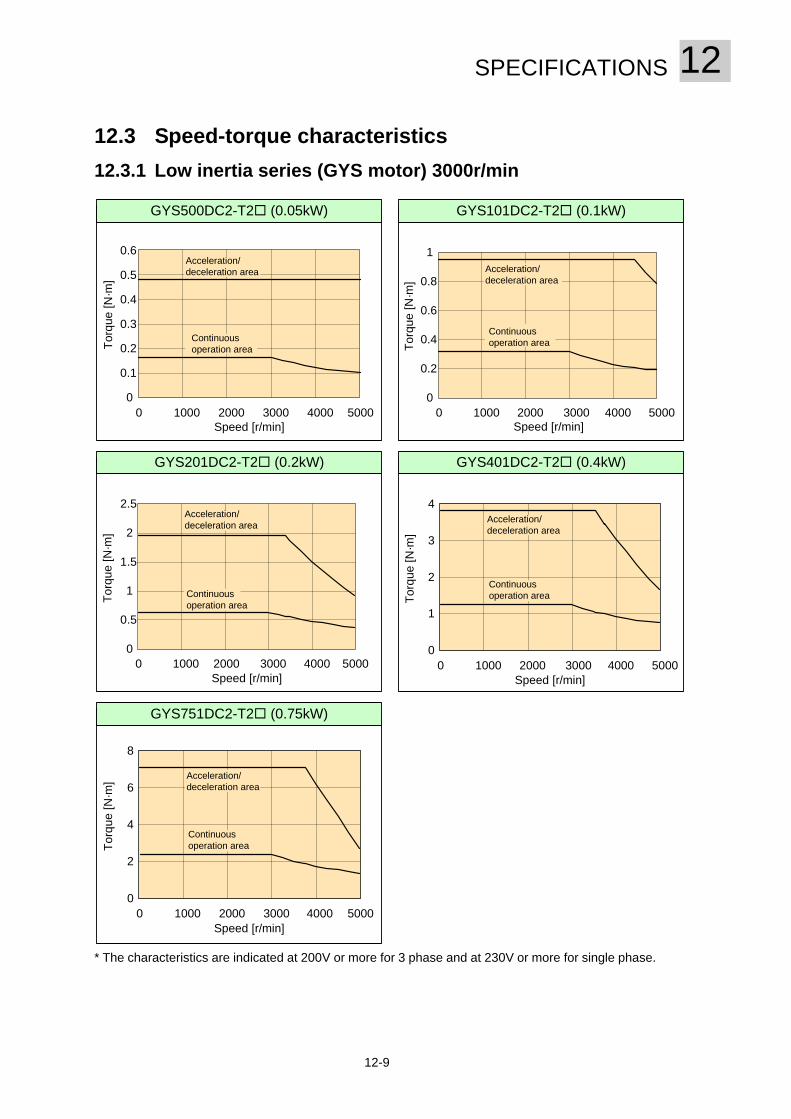
12-9
SPECIFICATIONS 12
12.3 Speed-torque characteristics 12.3.1 Low inertia series (GYS motor) 3000r/min
* The characteristics are indicated at 200V or more for 3 phase and at 230V or more for single phase.
GYS500DC2-T2 (0.05kW) GYS101DC2-T2 (0.1kW)
GYS201DC2-T2 (0.2kW) GYS401DC2-T2 (0.4kW)
GYS751DC2-T2 (0.75kW)
Acceleration/deceleration area
Continuous operation area
0.6
0.5
0.4
0.3
0.2
0.1
00 1000 2000 3000 4000 5000
Torq
ue [N
·m]
Speed [r/min]
Acceleration/deceleration area
Continuous operation area
1
0.8
0.6
0.4
0.2
00 1000 2000 4000 5000
Torq
ue [N
·m]
Speed [r/min]3000
Acceleration/deceleration area
Continuous operation area
2.5
2
1.5
1
0.5
00 1000 2000 3000 4000 5000
Torq
ue [N
·m]
Speed [r/min]
Acceleration/deceleration area
Continuous operation area
4
3
2
1
00 1000 2000 3000 4000 5000
Torq
ue [N
·m]
Speed [r/min]
Acceleration/deceleration area
Continuous operation area
8
6
4
2
00 1000 2000 3000 4000 5000
Torq
ue [N
·m]
Speed [r/min]
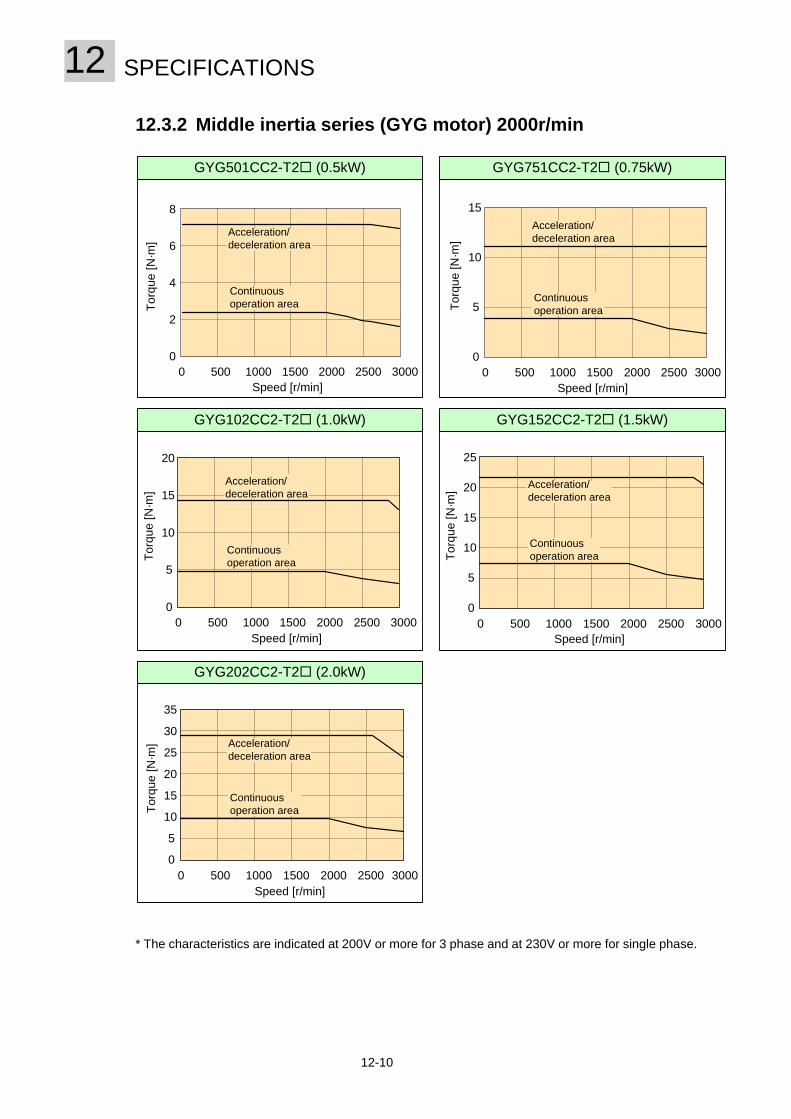
12-10
SPECIFICATIONS12
12.3.2 Middle inertia series (GYG motor) 2000r/min
GYG501CC2-T2 (0.5kW) GYG751CC2-T2 (0.75kW)
GYG102CC2-T2 (1.0kW) GYG152CC2-T2 (1.5kW)
GYG202CC2-T2 (2.0kW)
8
6
4
2
00 1000500 1500 2000 2500 3000
Acceleration/deceleration area
Continuousoperation areaTo
rque
[N·m
]
Speed [r/min]
Acceleration/deceleration area
Continuousoperation area
15
10
5
00 1000500 1500 2000 2500 3000
Torq
ue [N
·m]
Speed [r/min]
Continuousoperation area
20
15
10
5
00 1000500 1500 2000 2500 3000
Acceleration/deceleration area
Torq
ue [N
·m]
Speed [r/min]
25
20
15
10
5
00 1000500 1500 2000 2500 3000
Acceleration/deceleration area
Continuousoperation areaTo
rque
[N·m
]
Speed [r/min]
35
30
25
15
5
10
20
00 1000500 1500 2000 2500 3000
Acceleration/deceleration area
Continuousoperation areaTo
rque
[N·m
]
Speed [r/min]
* The characteristics are indicated at 200V or more for 3 phase and at 230V or more for single phase.

12-11
SPECIFICATIONS 12
12.3.3 Middle inertia series (GYG motor) 1500r/min
* The characteristics are indicated at 200V or more for 3 phase and at 230V or more for single phase.
GYG501BC2-T2 (0.5kW) GYG851BC2-T2 (0.85kW)
GYG132BC2-T2 (1.3kW)
Acceleration/deceleration area
Continuous operation area
10
8
6
4
2
00 500 1000 1500 25002000 3000
Torq
ue [N
·m]
Speed [r/min]
Acceleration/deceleration area
Continuous operation area
20
15
10
5
00 500 1000 1500 25002000 3000
Torq
ue [N
·m]
Speed [r/min]
Acceleration/deceleration area
Continuous operation area
30
25
20
15
10
5
00 500 1000 1500 25002000 3000
Torq
ue [N
·m]
Speed [r/min]
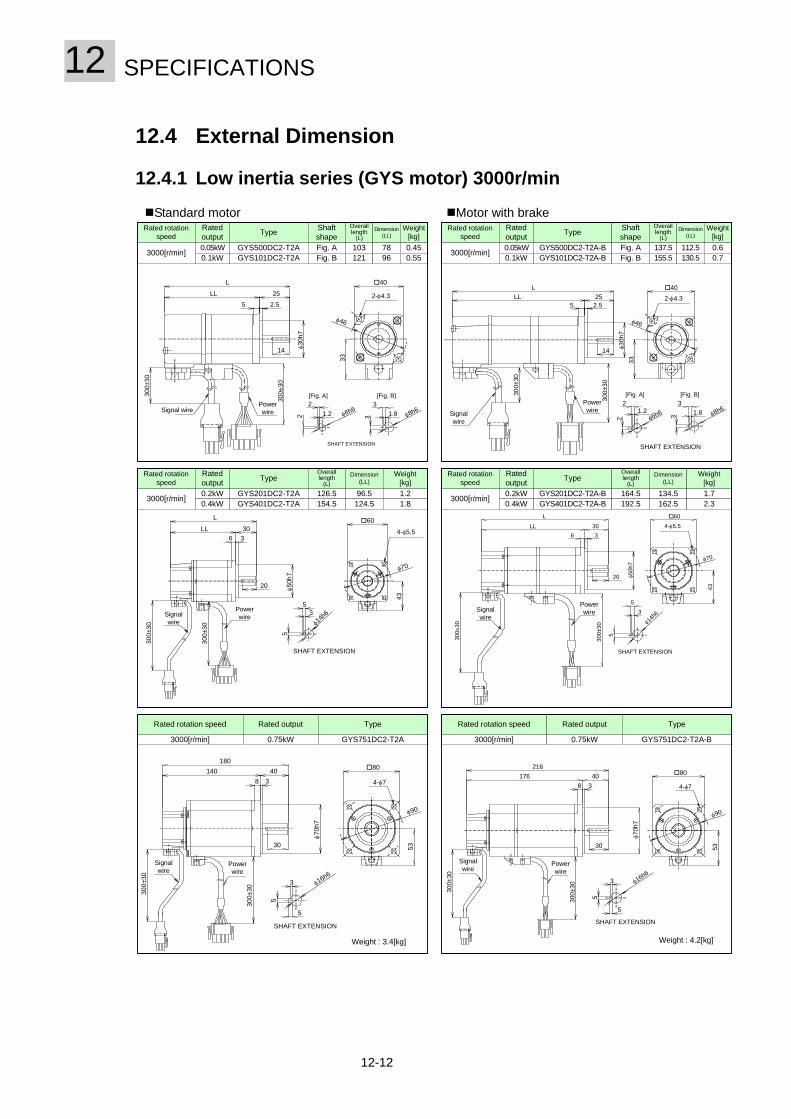
12-12
SPECIFICATIONS12
12.4 External Dimension
12.4.1 Low inertia series (GYS motor) 3000r/min
Standard motor Motor with brake
300±
30
2-φ4.32
21.2 φ6h6
Power wireSignal wire
300±
30L
14
LL 255 2.5
φ30h
7
φ46
33
40
3
31.8 φ8h6
SHAFT EXTENSION
[Fig. A] [Fig. B]
Rated rotation speed
Rated output Type Shaft
shapeOverall length
(L)
3000[r/min] 0.05kW GYS500DC2-T2AGYS101DC2-T2A
Fig. AFig. B
103121
Dimension(LL)
Weight[kg]
7896
0.450.550.1kW
300±
30
43
5
53
20
300±
30
Signal wire
Power wire
L
LL6 3
30
φ50h
7
φ70
60
4-φ5.5
φ14h
6
SHAFT EXTENSION
Rated rotation speed
Rated output Type
Overalllength
(L)
3000[r/min] 0.2kW GYS201DC2-T2AGYS401DC2-T2A
126.5154.50.4kW
Dimension(LL)
Weight[kg]
96.5124.5
1.21.8
Rated rotation speed Rated output Type
3000[r/min] 0.75kW GYS751DC2-T2A
300±
30
53
Power wire
300±
30
SHAFT EXTENSION
4-φ7
5
5
3 φ16h6
80140 40180
3
φ70h
7
30
8
φ90
Signal wire
LLL 2-φ4.3
Power wireSignal
wire
300±
30
40
14
255 2.5
φ30h
733
SHAFT EXTENSION
φ6h61.22
2
300±
30
φ46
[Fig. A] [Fig. B]
1.83
3φ8h6
Rated rotation speed
Rated output Type Shaft
shapeOverall length
(L)
3000[r/min] 0.05kW GYS500DC2-T2A-BGYS101DC2-T2A-B
Fig. AFig. B
137.5155.5
Dimension(LL)
Weight[kg]
112.5130.5
0.60.70.1kW
Rated rotation speed
Rated output Type
Overall length
(L)
3000[r/min] 0.2kW GYS201DC2-T2A-BGYS401DC2-T2A-B
164.5192.50.4kW
Dimension(LL)
Weight[kg]
134.5162.5
1.72.3
LL
L
SHAFT EXTENSION
φ14h
6
4-φ5.5
60
φ70
35
5
43
3036
Power wireSignal
wire
300±
30
300±
30
20 φ50h
7
Rated rotation speed Rated output Type
3000[r/min] 0.75kW GYS751DC2-T2A-B
216176
Signal wire
8
30
φ70h
7
340 80
φ16h63
5
5
4-φ7
SHAFT EXTENSION
300±
30
Power wire
53
300±
30
φ90
Weight : 3.4[kg] Weight : 4.2[kg]
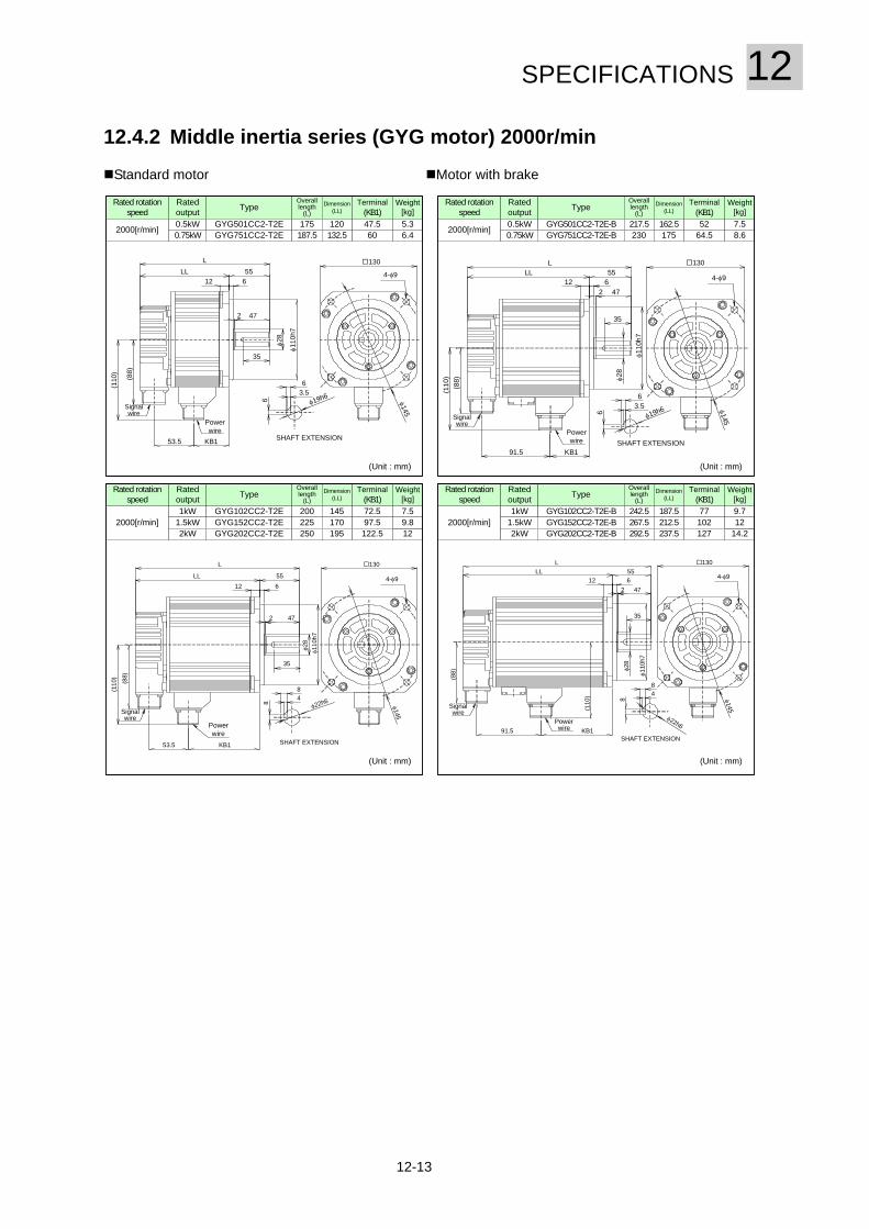
12-13
SPECIFICATIONS 12
12.4.2 Middle inertia series (GYG motor) 2000r/min
Standard motor Motor with brake
12
Rated rotation speed
Rated output Type Terminal
(KB1)Overall length
(L)
2000[r/min] 0.5kW GYG501CC2-T2EGYG751CC2-T2E
47.560
175187.5
Dimension(LL)
Weight[kg]
120132.5
5.36.40.75kW
6
63.5
φ28
12
Signal wire
Power wire
53.5 KB1
L
2 47
35
φ19h6
4-φ9
(88)
(110
)
130LL
φ110
h76
φ145
55
SHAFT EXTENSION
8
84
φ28
12
Signalwire
Powerwire
53.5 KB1
2 47
L
4-φ9
(88)
130
LL
φ110
h7
6
φ145
55
(110
)
φ22h6
SHAFT EXTENSION
35
Rated rotation speed
Rated output Type Terminal
(KB1)Overall length
(L)
2000[r/min]1kW GYG102CC2-T2E
GYG152CC2-T2E72.597.5
200225
Dimension(LL)
Weight[kg]
145170
7.59.81.5kW
GYG202CC2-T2E 122.5250 1952kW
35
6
63.5
φ19h6
SHAFT EXTENSION
φ28
12
Signalwire
Power wire
91.5 KB1
2 47
L
φ145
6
φ110
h7
LL130
(110
)(8
8)
4-φ955
Rated rotation speed
Rated output Type Terminal
(KB1)Overall length
(L)
2000[r/min] 0.5kW GYG501CC2-T2E-BGYG751CC2-T2E-B
5264.5
217.5230
Dimension(LL)
Weight[kg]
162.5175
7.58.60.75kW
14.2
Rated rotation speed
Rated output Type Terminal
(KB1)Overall length
(L)
2000[r/min]1kW GYG102CC2-T2E-B
GYG152CC2-T2E-B77102
242.5267.5
Dimension(LL)
Weight[kg]
187.5212.5
9.7121.5kW
GYG202CC2-T2E-B 127292.5 237.52kW
(110
) 8
84
φ28
12
Signalwire
Power wire91.5 KB1
φ22h6
2 47
L
φ145
6
φ110
h7
LL130
(88)
4-φ955
SHAFT EXTENSION
35
(Unit : mm) (Unit : mm)
(Unit : mm) (Unit : mm)

12-14
SPECIFICATIONS12
12.4.3 Middle inertia series (GYG motor) 1500r/min
Standard motor Motor with brake Shaft shape
9.8
Rated rotation speed
Rated output Type Terminal
(KB1)Overall length
(L)
1500[r/min]
0.5kW GYG501BC2-T2EGYG851BC2-T2E
6072.5
190.5203
Dimension(LL)
Weight[kg]
132.5145
6.47.50.85kW
GYG132BC2-T2E 97.5228 1701.3kW
(Unit : mm) (Unit : mm)
φ28
12
12 40
L
Signalwire
Powerwire
53.5 KB1
φ145
6
φ110
h7
LL
130
(88)
4-φ958
(110
)
SHAFT EXTENSION
6
63.5
φ19h6
84
8
φ22h6
[Fig. A] [Fig. B]
30
SHAFT EXTENSION
(110
)
φ28
12
12 40
L
Signalwire
Powerwire
91.5 KB1
φ145
6
φ110
h7
LL
130
(88)
4-φ958
6
63.5
φ19h6
[Fig. A] [Fig. B]84
8
φ22h6
30
Fig. AFig. AFig. B
Shaft shape
12
Rated rotation speed
Rated output Type Terminal
(KB1)Overall length
(L)
1500[r/min]
0.5kW GYG501BC2-T2E-BGYG851BC2-T2E-B
64.577
233245.5
Dimension(LL)
Weight[kg]
175187.5
8.69.70.85kW
GYG132BC2-T2E-B 102270.5 212.51.3kW
Fig. AFig. AFig. B

12-15
SPECIFICATIONS 12
12.4.4 Servo amplifier
Frame 1 Frame 2
Frame 3
Rated rotation speed Applicable motor output Type
(Unit : mm)
(Unit : mm)
Dimensions of installation
hole
2-M4
40
515
0±0.
516
0
(5)
45 70 165
3000[r/min]
0.05kW0.1kW0.2kW0.4kW
RYC500D3-VVT2RYC101D3-VVT2RYC201D3-VVT2RYC401D3-VVT2
Rated rotation speed Applicable motor output Type3000[r/min]
2000[r/min]
0.75kW0.5kW0.75kW
1kW
RYC751D3-VVT2RYC501C3-VVT2RYC751C3-VVT2RYC102C3-VVT2
1500[r/min]0.5kW0.85kW
RYC501B3-VVT2RYC851B3-VVT2
Dimensions of installation
hole
4-M4
515
0±0.
5(5
)16
0
85 70 165
36 44±0.5 (5)
sL1
sL2
L1
L2
L2
P
N
DB
U
V
W
CHARGE
N.P.
Dimensions of installation
hole
4-M4
519
0±0.
5(5
)20
0
95 70 185
36 50±0.5 (5)
Rated rotation speed Applicable motor output Type
(Unit : mm)
2000[r/min]1.5kW2kW
1.3kW
RYC152C3-VVT2RYC202C3-VVT2RYC132B3-VVT21500[r/min]
Weight : 1.0 [kg] Weight : 1.5 [kg]
Weight : 2.5 [kg]

12-16
SPECIFICATIONS12
-MEMO-

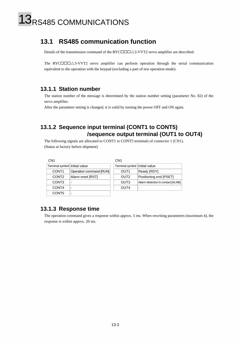
13-2
RS485 COMMUNICATIONS13
13.1 RS485 communication function Details of the transmission command of the RYC 3-VVT2 servo amplifier are described. The RYC 3-VVT2 servo amplifier can perform operation through the serial communication equivalent to the operation with the keypad (excluding a part of test operation mode).
13.1.1 Station number The station number of the message is determined by the station number setting (parameter No. 82) of the servo amplifier. After the parameter setting is changed, it is valid by turning the power OFF and ON again.
13.1.2 Sequence input terminal (CONT1 to CONT5) /sequence output terminal (OUT1 to OUT4)
The following signals are allocated to CONT1 to CONT5 terminals of connector 1 (CN1). (Status at factory before shipment)
Terminal symbol
CONT1
CONT2
Initial value
CONT3
CONT4
CONT5
CN1
Terminal symbol
OUT1
OUT2
Initial value
OUT3
OUT4
CN1
-
-
-
Alarm reset [RST]
Operation command [RUN]
-
Alarm detection b contact [ALMb]
Ready [RDY]
Positioning end [PSET]
13.1.3 Response time The operation command gives a response within approx. 5 ms. When rewriting parameters (maximum 4), the response is within approx. 20 ms.
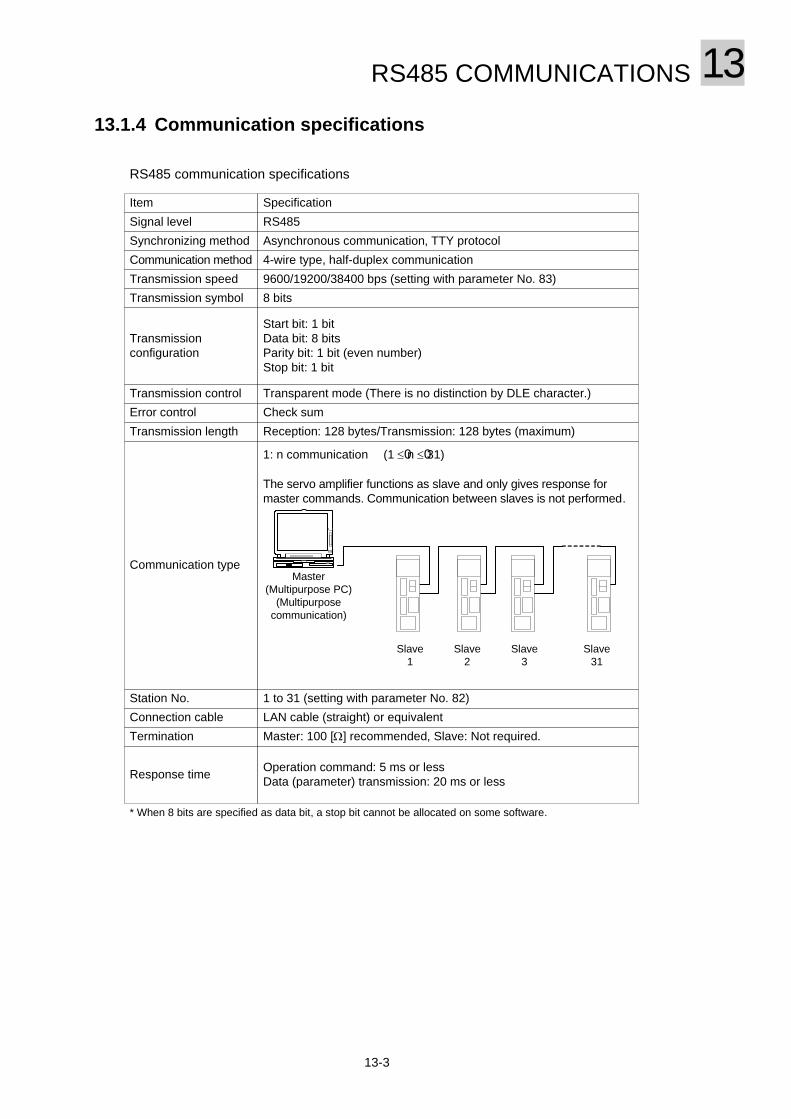
13-3
RS485 COMMUNICATIONS 1313.1.4 Communication specifications
RS485 communication specifications
Specification Item RS485Asynchronous communication, TTY protocol
Signal level Synchronizing methodCommunication method 4-wire type, half-duplex communication
Transmission symbol 8 bits
Error control Check sum Transmission length Reception: 128 bytes/Transmission: 128 bytes (maximum)
Transmission configuration
Start bit: 1 bitData bit: 8 bitsParity bit: 1 bit (even number) Stop bit: 1 bit
Transmission speed 9600/19200/38400 bps (setting with parameter No. 83)
Communication type
1: n communication (1 2≤ n 2≤ 31)
The servo amplifier functions as slave and only gives response for master commands. Communication between slaves is not performed.
Master(Multipurpose PC)
(Multipurpose communication)
Slave 1
Slave 2
Slave 3
Transmission control Transparent mode (There is no distinction by DLE character.)
Station No. 1 to 31 (setting with parameter No. 82)
Slave 31
* When 8 bits are specified as data bit, a stop bit cannot be allocated on some software.
Response time Operation command: 5 ms or lessData (parameter) transmission: 20 ms or less
Connection cable LAN cable (straight) or equivalentTermination Master: 100 [Ω] recommended, Slave: Not required.
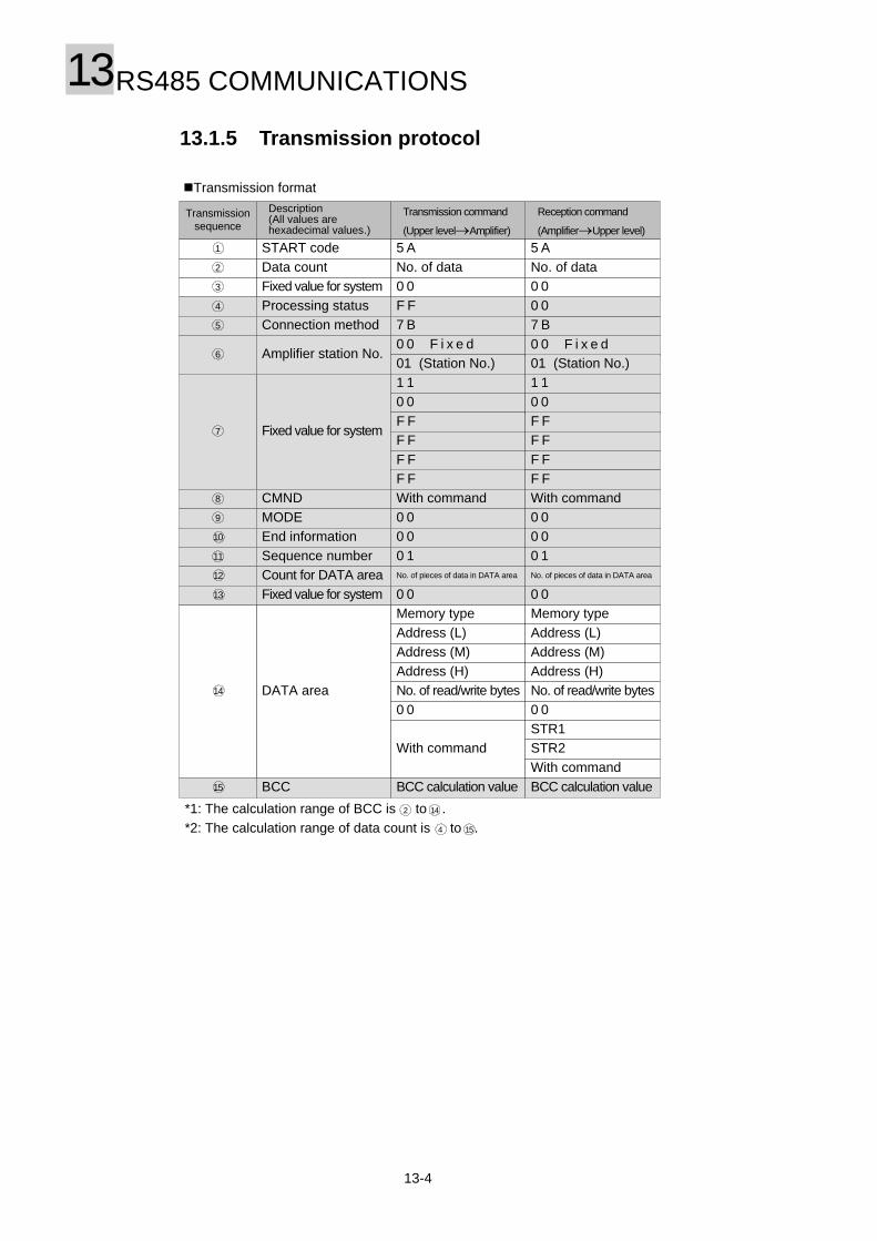
13-4
RS485 COMMUNICATIONS1313.1.5 Transmission protocol
Transmission sequence
Description(All values are hexadecimal values.)
Reception command
(Amplifier→Upper level) 1 START code2 Data count3 Fixed value for system 4 Processing status5 Connection method
6 Amplifier station No.
Fixed value for system 7
8
9
10
11
12
13
CMND
14
MODE
15
End information Sequence numberCount for DATA areaFixed value for system
DATA area
BCC
Transmission command
(Upper level→Amplifier) 5 ANo. of data0 0F F7 B0 0 F i x e d01 (Station No.)1 10 0F FF FF FF FWith command 0 00 00 1No. of pieces of data in DATA area
0 0
BCC calculation value
Memory type
5 ANo. of data0 0
7 B0 0 F i x e d01 (Station No.)1 10 0F FF FF FF FWith command 0 00 00 1No. of pieces of data in DATA area
0 0
BCC calculation value
0 0
*1: The calculation range of BCC is 2 to 14 . *2: The calculation range of data count is 4 to 15 .
Transmission format
Address (L) Address (M) Address (H) No. of read/write bytes0 0
STR1STR2
Memory typeAddress (L) Address (M) Address (H) No. of read/write bytes0 0
With commandWith command
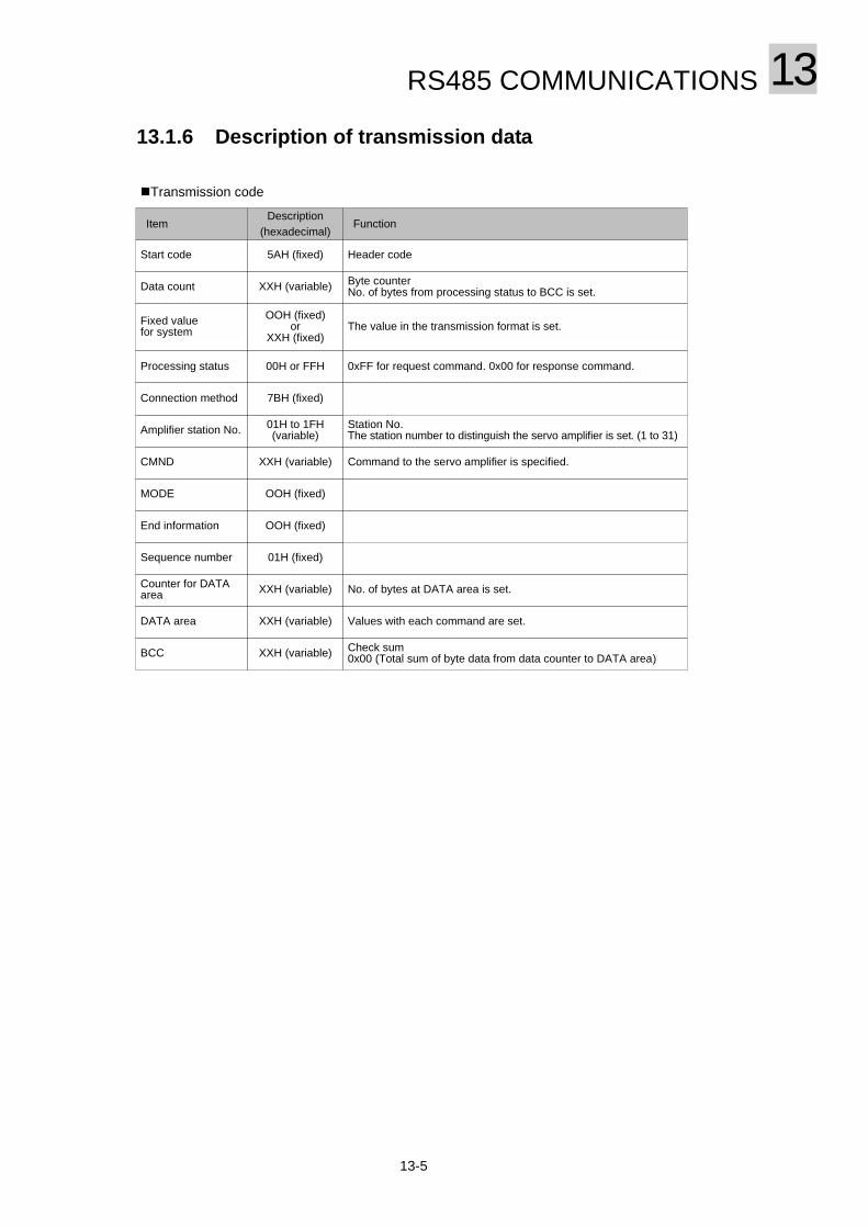
13-5
RS485 COMMUNICATIONS 1313.1.6 Description of transmission data
Item
Start code
Data count
Fixed value for system
Processing status
Connection method
Amplifier station No.
CMND
MODE
End information
Sequence number
Counter for DATAarea
DATA area
BCC
Transmission code
Description (hexadecimal)
5AH (fixed)
00H or FFH
7BH (fixed)
01H to 1FH (variable)
XXH (variable)
OOH (fixed)or
XXH (fixed)
XXH (variable)
OOH (fixed)
OOH (fixed)
01H (fixed)
XXH (variable)
XXH (variable)
XXH (variable)
Function
Header code
Byte counterNo. of bytes from processing status to BCC is set.
0xFF for request command. 0x00 for response command.
Station No. The station number to distinguish the servo amplifier is set. (1 to 31)
The value in the transmission format is set.
No. of bytes at DATA area is set.
Check sum 0x00 (Total sum of byte data from data counter to DATA area)
Values with each command are set.
Command to the servo amplifier is specified.
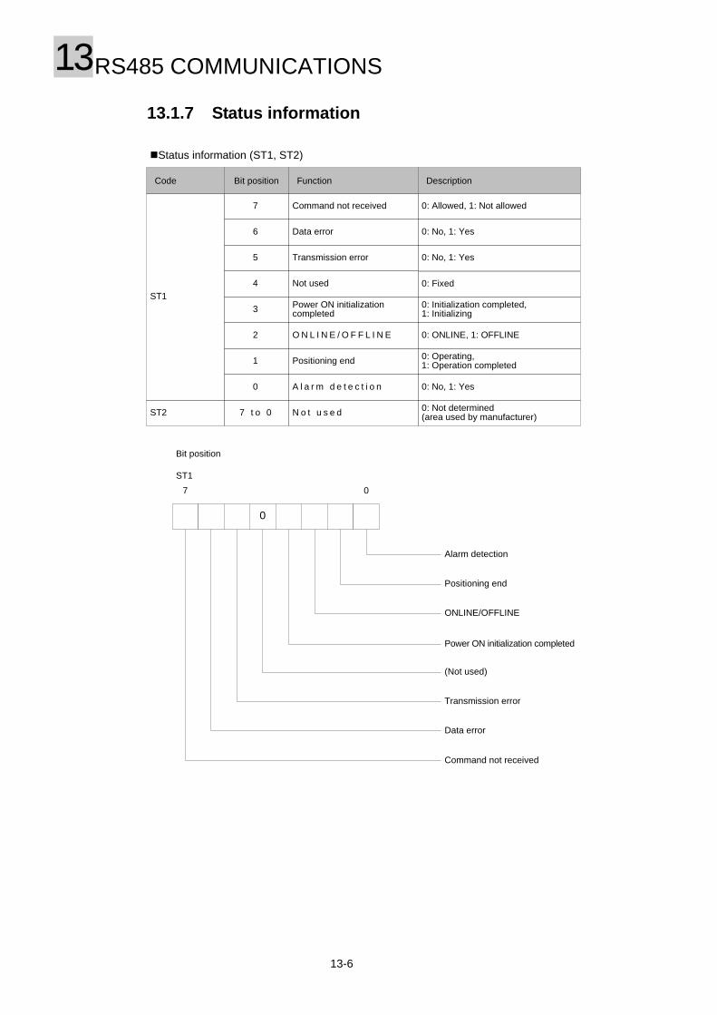
13-6
RS485 COMMUNICATIONS1313.1.7 Status information
Code
ST1
ST2
Status information (ST1, ST2)
Bit position
7
4
3
2
1
6
5
Function
A l a r m d e t e c t i o n
Positioning end
O N L I N E / O F F L I N E
Power ON initializationcompleted
0: Not determined (area used by manufacturer)
0
7 t o 0
Not used
Transmission error
Data error
Command not received
N o t u s e d
0: No, 1: Yes
0: Fixed
0: Allowed, 1: Not allowed
Description
0: No, 1: Yes
0: No, 1: Yes
0: Initialization completed, 1: Initializing
0: ONLINE, 1: OFFLINE
0: Operating, 1: Operation completed
Bit position
ST1
Alarm detection
Positioning end
ONLINE/OFFLINE
7 0
Power ON initialization completed
(Not used)
Transmission error
Data error
Command not received
0

13-7
RS485 COMMUNICATIONS 1313.1.8 List of commands
List of commands
CMND
5 0 H
Function
Data read with multiple monitors
5 0 H
5 1 H
No.
Monitor
01
Sequence monitor
02
03
04
05
Parameter edit
07
08
Operation command
06
09
10
Sequence mode read
Sequence input/output signal read
Alarm history read
System status read
Current alarm read
Parameter read
Parameter write
Alarm reset
Alarm history initialization
5 0 H
5 1 H
Address (L) Address (M) Address (H)Memory typeDATA area
0 1 H
0 2 H
0 3 H
0 8 H
Monitor designated bit 0 0 H
0 0 H 0 0 H
0 1 H
0 2 H
0 3 H
0 4 H
0 7 H
0 0 H
0 1 H
1 7 H
2 3 H
Quantity (1 to 4)
Number (1 to 99)
0 0 H 0 1 H
13-8
RS485 COMMUNICATIONS13
13.2 Command transmission specification The messages transmitted between the upper level system and the amplifier are classified into the following two messages: • Request command: Message transmitted from the upper level system to the amplifier • Response command: Message transmitted from the amplifier to the upper level system Communication between amplifiers is not performed.
13.2.1 Communication start procedure The amplifier does not give response for communication from the upper level system until internal initialization is completed after power supply. When the power is supplied, perform the following procedure before normal communication.
After the power is supplied, wait for approx. 1.5 [s]. Issue the "Status communication check" command from the upper level system and make sure that there
is a response from the amplifier. At this time, check if "Power ON initialization completion (3rd bit)" is 0 (= OFF) with the "Status information (STR1)" in the response data. When this bit is 1 (= ON), it is under initialization.
13.2.2 Normal communication procedure The upper level system transmits the request command to the amplifier. After reception of the request command, the amplifier performs the requested command processing and
transmits the response command. The upper level system should confirm the response command before transmitting the next request command. The request commands should not be continuously transmitted without confirmation of the response command.
Other than the processing in , the amplifier is always waiting for commands from the upper level system.
<Procedure for error to improve reliability (Example)> Transmission error of physical or character level (detection by amplifier)
If a physical or character level (e.g. parity error) transmission error occurs during reception of the request
command from the upper level system, the amplifier does not return the response command (no response).
If there is no response from the amplifier, the upper level system should send the same request command.
• The timer start timing for no response judgment time (timeout) is completion of the request command
transmission.
• Set the timeout time as follows according to the transmission speed:
38400 [bps] : 100 [ms] or more
19200 [bps] : 200 [ms] or more
9600 [bps] : 500 [ms] or more
• Several retry counts, depending on the application, are recommended.
13-9
RS485 COMMUNICATIONS 13 Transmission error of physical or character level (detection by upper level system)
If a physical or character level transmission error occurs during reception of the response command from the
amplifier, it recommended that the upper level system should send the same request command.
• Set the retransmission timing as follows after transmission error:
38400 [bps] : 100 [ms] or more
19200 [bps] : 200 [ms] or more
9600 [bps] : 500 [ms] or more
• Several retry counts, depending on the application, are recommended.
13.3 Protocol level error When the protocol is incorrect (data error), the amplifier does not perform the requested command processing. Error information is notified of with "Status information (STR1)" in the response command. For details of STR1, refer to 13-1 (7) Data format details. While the upper level application software is developed, it is recommended that error information is checked. Debug the protocol according to error information.
• Data error occurs when the request command data (header, BCC, setting range for parameter data, etc.) is incorrect. Modify the data details.
• Command not received occurs when the parameter is written with parameter write protect. Check the
setting for parameter No. 29 "parameter write protect." • Access to the memory in the amplifier is limited with LV (undervoltage). When a parameter is
read/written or when an alarm history is read, the command may not be received. Check the power supply status.
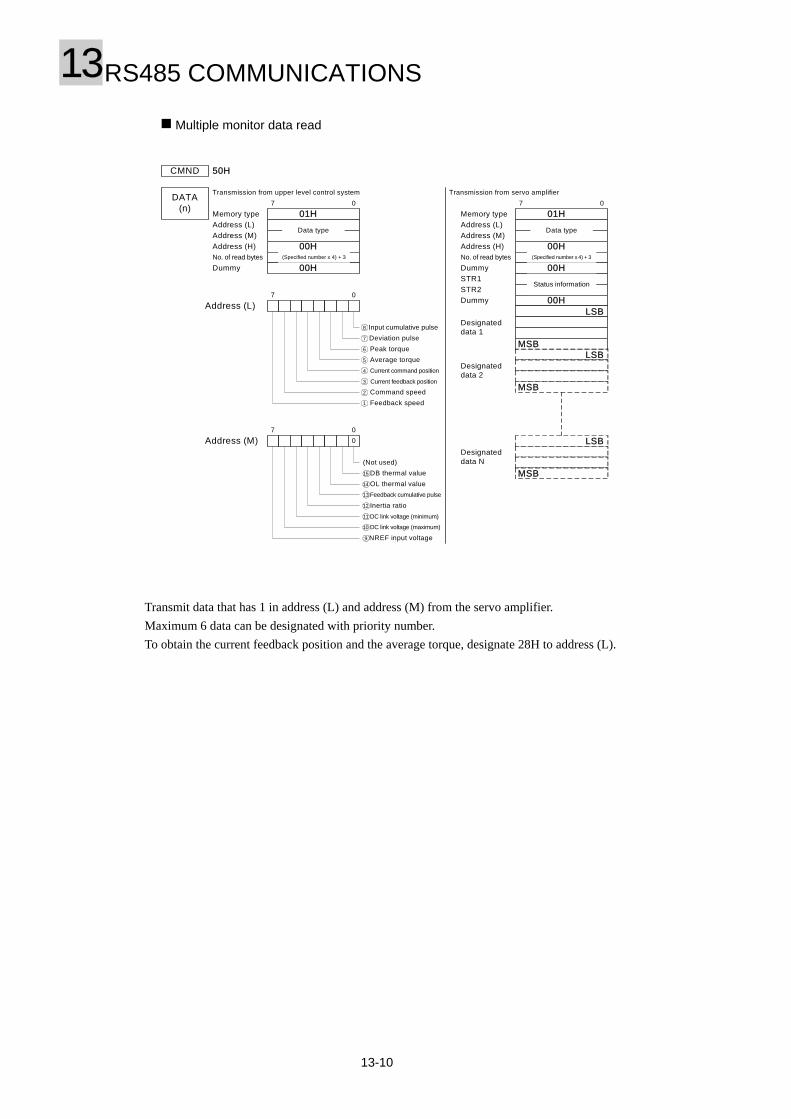
13-10
RS485 COMMUNICATIONS13 Multiple monitor data read
7 0
Address (L)
7 Deviation pulse
8 Input cumulative pulse
1 Feedback speed
2 Command speed
3 Current feedback position
4 Current command position
5 Average torque
6 Peak torque
Address (M)
15 DB thermal value
(Not used)
9 NREF input voltage
11 DC link voltage (minimum)
12 Inertia ratio
13 Feedback cumulative pulse
14 OL thermal value
7 0
10 DC link voltage (maximum)
0
7 0
Memory type
Address (L)
Address (M)
Address (H)
01H
Data type
00HNo. of read bytes
Dummy 00H(Specified number x 4) + 3
DATA(n)
50H
Transmission from upper level control system
CMND
Transmission from servo amplifier
7 0
Memory type
Address (L)
Address (M)
Address (H)
01H
Data type
00HNo. of read bytes
Dummy 00H(Specified number x 4) + 3
STR1
STR2Status information
Dummy 00H
Designated data 1
MSB
LSB
MSB
LSB
MSB
LSB
Designated data 2
Designated data N
Transmit data that has 1 in address (L) and address (M) from the servo amplifier. Maximum 6 data can be designated with priority number. To obtain the current feedback position and the average torque, designate 28H to address (L).
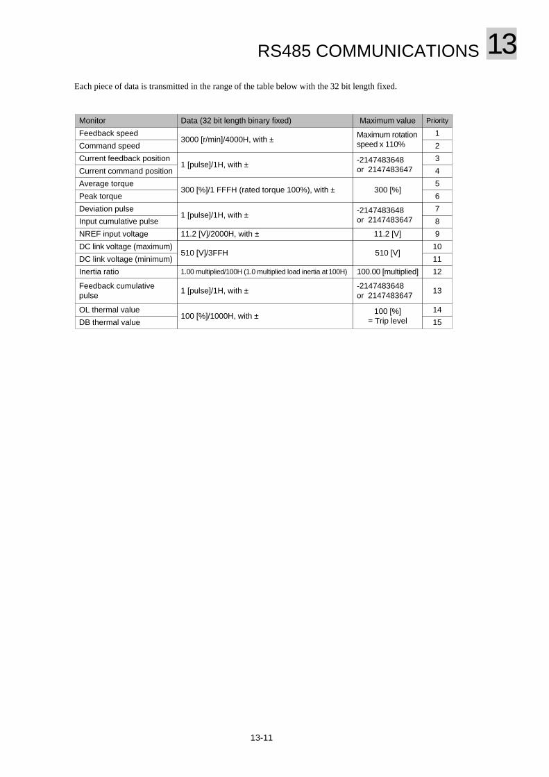
13-11
RS485 COMMUNICATIONS 13Each piece of data is transmitted in the range of the table below with the 32 bit length fixed.
Deviation pulse
Input cumulative pulse
Feedback speed
Command speed
Current feedback position
Current command position
Average torque
Peak torque
Inertia ratio
OL thermal value
Monitor Data (32 bit length binary fixed)
300 [%]/1 FFFH (rated torque 100%), with ±
3000 [r/min]/4000H, with ±
1.00 multiplied/100H (1.0 multiplied load inertia at 100H)
Priority
8
7
6
5
4
3
2
1
Maximum value
13
12
NREF input voltage 9
DC link voltage (maximum)
DC link voltage (minimum)
DB thermal value
10
11
14
1 [pulse]/1H, with ±
1 [pulse]/1H, with ±
100 [%]/1000H, with ±
Maximum rotation speed x 110%
300 [%]
100.00 [multiplied]
100 [%] = Trip level
Feedback cumulative pulse
1 [pulse]/1H, with ±
15
11.2 [V]/2000H, with ± 11.2 [V]
510 [V]/3FFH 510 [V]
-2147483648or 2147483647
-2147483648or 2147483647
-2147483648or 2147483647
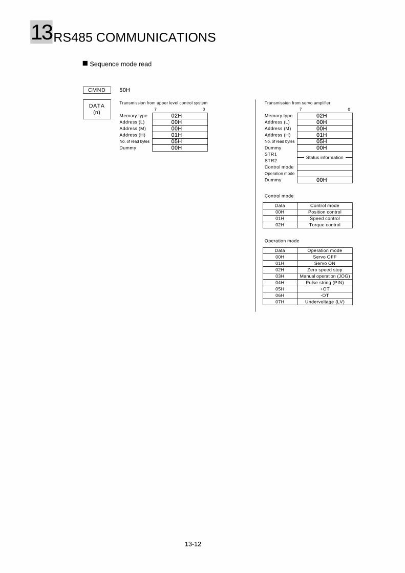
13-12
RS485 COMMUNICATIONS13 Sequence mode read
7 0
Memory type
Address (L)
Address (M)
Address (H)
02H
01HNo. of read bytes
Dummy 00H
DATA(n)
50H
Transmission from upper level control system
CMND
Transmission from servo amplifier
00H00H
05H
7 0
Memory type
Address (L)
Address (M)
Address (H)
02H
01HNo. of read bytes
Dummy 00H
00H00H
05H
STR1
STR2
Control modeOperation mode
Dummy 00H
Status information
Control mode
Position control
Speed control
Torque control
Data
00H
01H
02H
Control mode
Operation mode
Servo OFF
Servo ON
Zero speed stop
Data
00H
01H
02H
Operation mode
03H
04H
05H
06H
Manual operation (JOG)
Pulse string (PIN)
+OT
-OT
07H Undervoltage (LV)
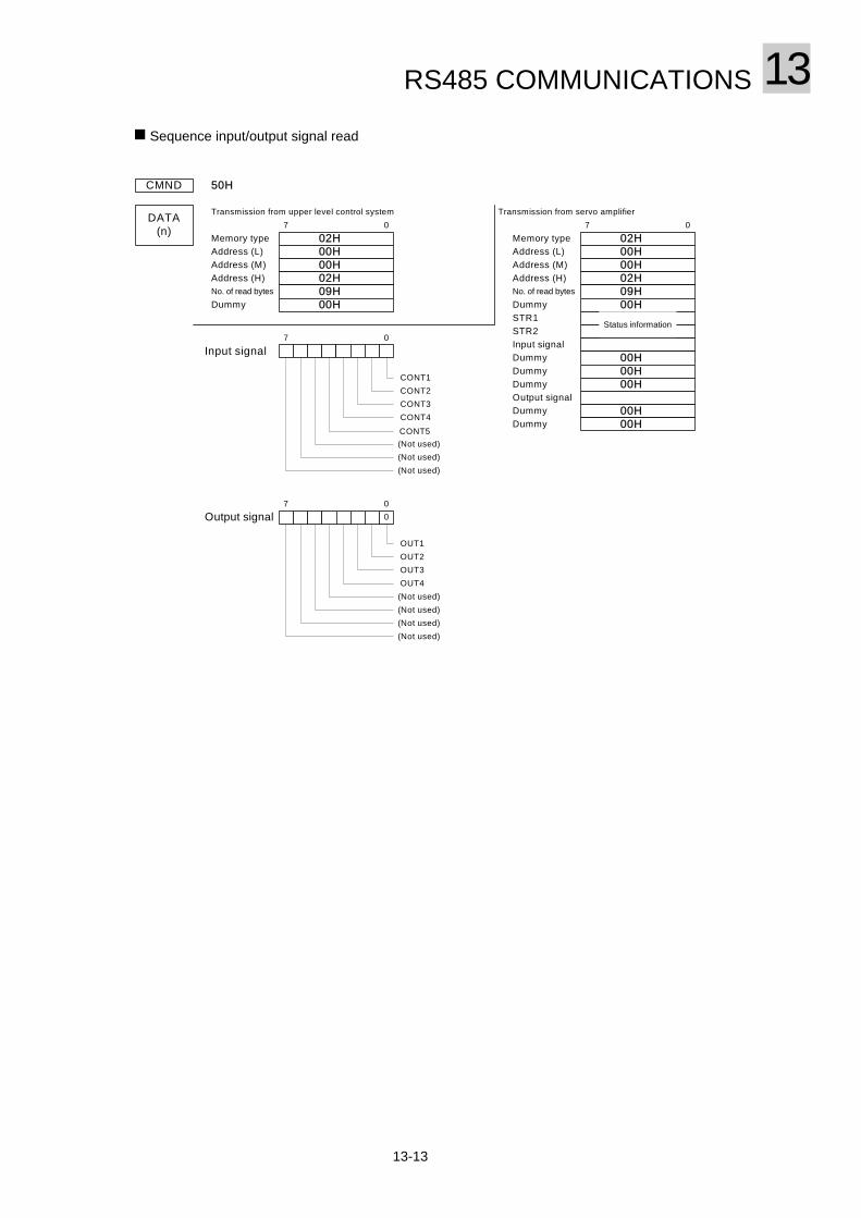
13-13
RS485 COMMUNICATIONS 13 Sequence input/output signal read
7 0
Input signal
CONT2
CONT1
(Not used)
(Not used)
(Not used)
CONT5
CONT4
CONT3
Output signal
OUT2
OUT1
(Not used)
(Not used)
(Not used)
OUT4
OUT3
7 0
(Not used)
0
7 0
Memory typeAddress (L)
Address (M)
Address (H)
02H
No. of read bytes
Dummy 00H
DATA(n)
50H
Transmission from upper level control system
CMND
00H00H
02H09H
Transmission from servo amplifier
7 0
Memory typeAddress (L)
Address (M)
Address (H)
02H
00H
No. of read bytes
Dummy 00HSTR1
STR2Status information
Input signal Dummy
Dummy
Dummy
Output signal
00H
02H09H
00H00H00H
Dummy
Dummy00H00H
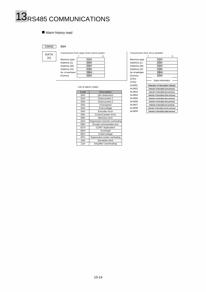
13-14
RS485 COMMUNICATIONS13 Alarm history read
7 0
Memory type
Address (L)
Address (M)
Address (H)
02H
No. of read bytes
Dummy 00H
DATA(n)
50H
Transmission from upper level control system
CMND
00H00H
03H0BH
Transmission from servo amplifier
7 0
Memory type
Address (L)
Address (M)
Address (H)
02H
00H
No. of read bytes
Dummy 00HSTR1
STR2Status information
ALM01
00H
03H0BH
Detection of description (latest)
ALM02
ALM03
ALM04
ALM05
ALM06
ALM07
ALM08
ALM09
Detection of description (one previous)
Detection of description (two previous)
Detection of description (four previous)
Detection of description (five previous)
Detection of description (six previous)
Detection of description (seven previous)
Detection of description (three previous)
Overcurrent 1
Overcurrent 2
Overspeed
Overvoltage
Encoder error
Control power error
Memory errorRegenerative transistor overheating
Encoder communication error
CONT duplication
Overload
UndervoltageRegenerative resistor overheating
Deviation limit
Amplifier overheating
01H
02H
03H
04H
05H
06H
08H
0AH
0BH
0CH
0DH
0EH
0FH
10H
11H
Description
(No detection)
Code
00H
List of alarm codes
Detection of description (eight previous)
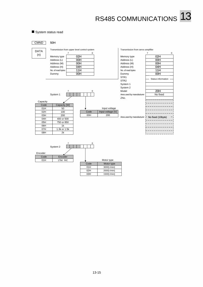
13-15
RS485 COMMUNICATIONS 13 System status read
7 0
Memory type
Address (L)
Address (M)
Address (H)
02H
No. of read bytes
Dummy 00H
DATA(n)
50H
Transmission from upper level control system
CMND
00H00H
04H11H
System 1
07
01H
02H
03H
04H
05H
06H
07H
08H
Code
? ? ?? ? ? 200
Code
00H
50
100
200
400 or 500
750 or 850
1k
2k
1.3k or 1.5k
Capacity [W]
Capacity
Input voltage
Input voltage [V]
Transmission from servo amplifier
7 0
Memory type
Address (L)
Address (M)
Address (H)
02H
00H
No. of read bytes
Dummy 00HSTR1
STR2Status information
System 1
00H
04H11H
System 2
ModelArea used by manufacturer
ZNo.
Area used by manufacturer
20HNo fixed
System 2
07
01H
Code
Encoder
17bit INC
Encoder
2000[ r/min]
01H
02H
Code
Motor type
Motor type
03H 1500[ r/min]
3000[ r/min]
No fixed (10byte)
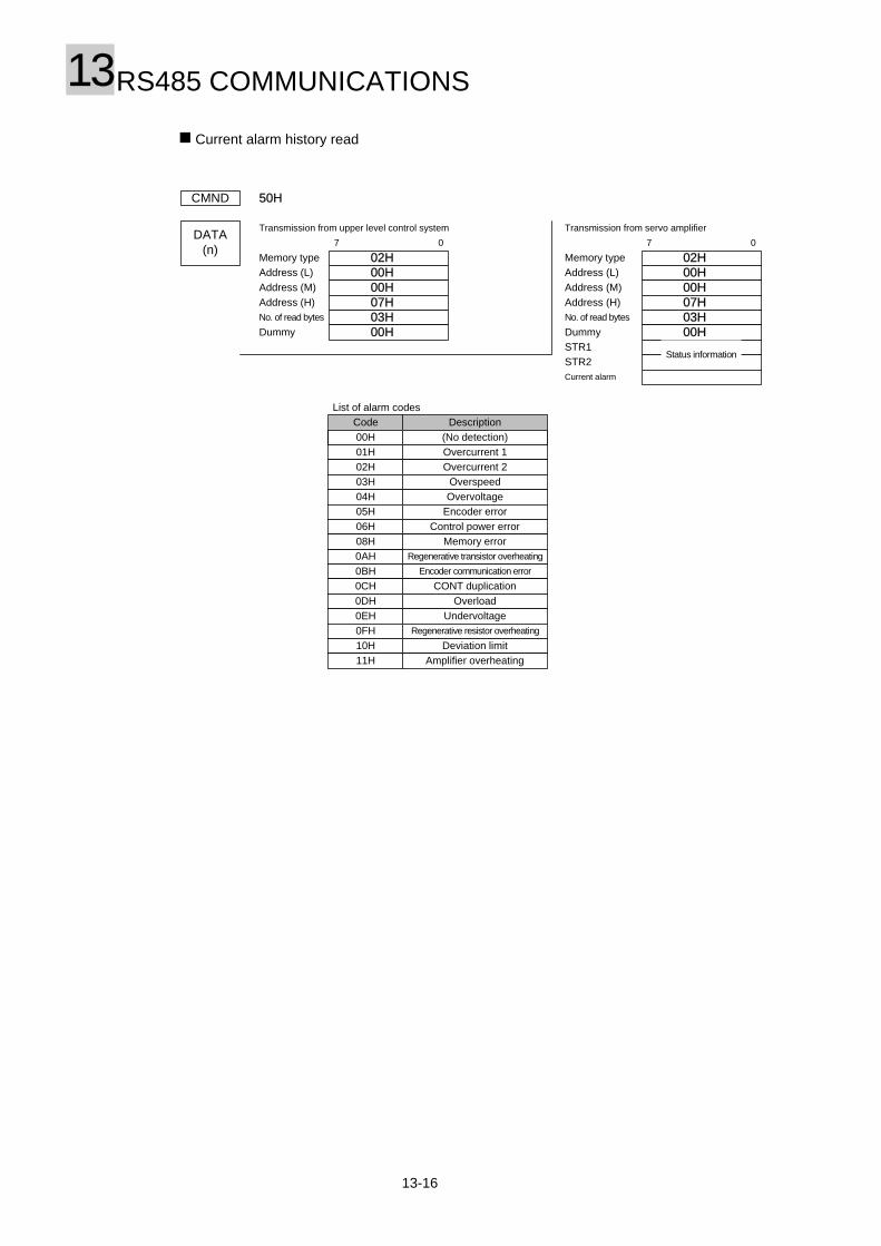
13-16
RS485 COMMUNICATIONS13 Current alarm history read
7 0
Memory type
Address (L)
Address (M)
Address (H)
02H
No. of read bytes
Dummy 00H
DATA(n)
50H
Transmission from upper level control system
CMND
00H00H
07H03H
? ?? ? ? ? ?? ? ?
Transmission from servo amplifier
7 0
Memory type
Address (L)
Address (M)
Address (H)
02H
00H
No. of read bytes
Dummy 00HSTR1
STR2Status information
Current alarm
00H
07H03H
Overcurrent 1
Overcurrent 2
Overspeed
Overvoltage
Encoder error
Control power error
Memory errorRegenerative transistor overheating
Encoder communication error
CONT duplication
Overload
UndervoltageRegenerative resistor overheating
Deviation limit
Amplifier overheating
01H
02H
03H
04H
05H
06H
0AH
0BH
0CH
0DH
0EH
0FH
10H
11H
Description
(No detection)
Code
00H
List of alarm codes
08H
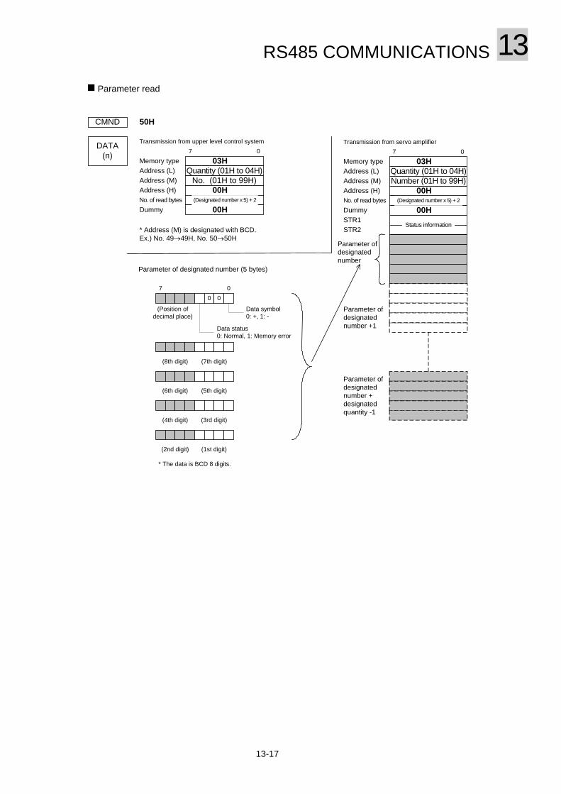
13-17
RS485 COMMUNICATIONS 13 Parameter read
7 0
Quantity (01H to 04H)Memory typeAddress (L)
No. (01H to 99H)Address (M)Address (H)
03H
00HNo. of read bytesDummy 00H
(Designated number x 5) + 2
DATA(n)
50H
Transmission from upper level control system
CMND
* Address (M) is designated with BCD. Ex.) No. 49→49H, No. 50→50H
Parameter of designated number (5 bytes)
(8th digit)
Data status0: Normal, 1: Memory error
Data symbol0: +, 1: -
7 0
(7th digit)
(6th digit) (5th digit)
(4th digit) (3rd digit)
(2nd digit) (1st digit)
(Position of decimal place)
00
* The data is BCD 8 digits.
7 0Transmission from servo amplifier
Memory typeAddress (L)Address (M)Address (H)
03H
00HNo. of read bytesDummy 00H
(Designated number x 5) + 2
STR1STR2
Status information
Parameter of designated number
Number (01H to 99H)Quantity (01H to 04H)
Parameter of designated number +1
Parameter of designated number + designated quantity -1
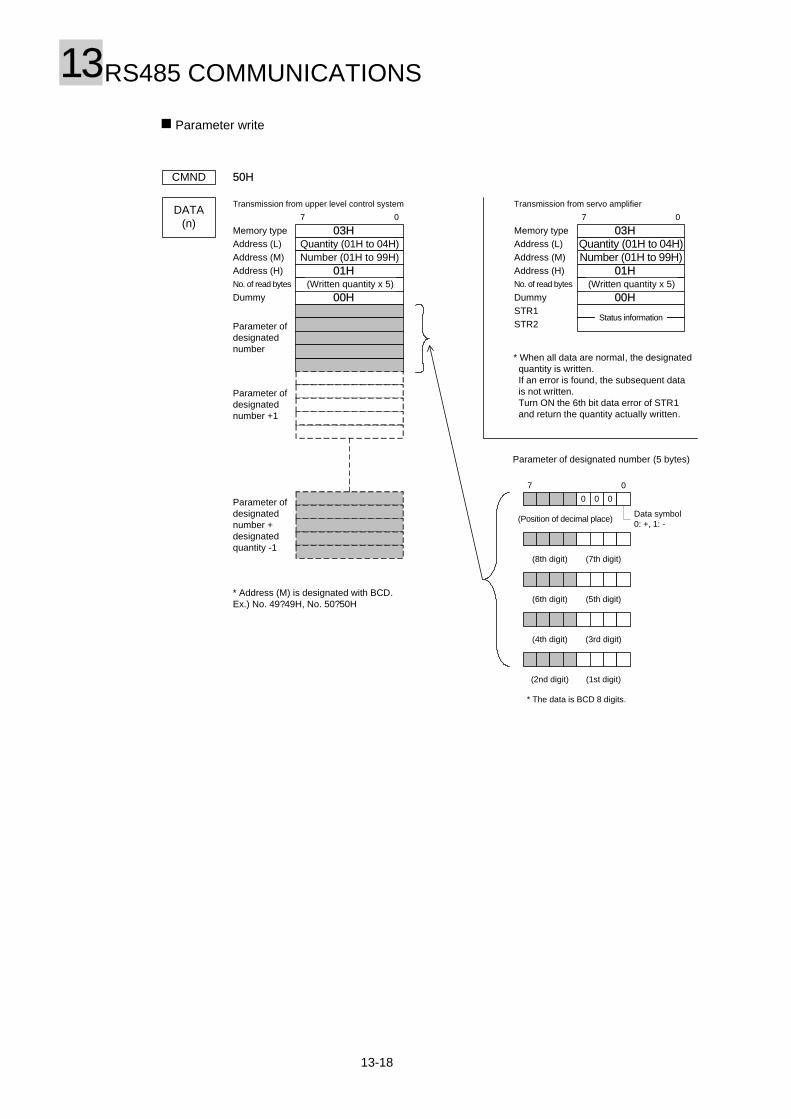
13-18
RS485 COMMUNICATIONS13 Parameter write
DATA(n)
50H
Transmission from upper level control system
CMND
Transmission from servo amplifier
7 0
Memory type
Address (L)
Address (M)
Address (H)
03H
01HNo. of read bytes
Dummy 00H(Written quantity x 5)
STR1
STR2Status information
Number (01H to 99H)Quantity (01H to 04H)
* When all data are normal, the designated quantity is written. If an error is found, the subsequent data is not written. Turn ON the 6th bit data error of STR1 and return the quantity actually written.
Parameter of designated number (5 bytes)
(8th digit)
Data symbol0: +, 1: -
7 0
(7th digit)
(6th digit) (5th digit)
(4th digit) (3rd digit)
(2nd digit) (1st digit)
(Position of decimal place)
00
* The data is BCD 8 digits.
0
7 0
Quantity (01H to 04H)Memory type
Address (L)
Number (01H to 99H)Address (M)
Address (H)
03H
01HNo. of read bytes
Dummy 00H(Written quantity x 5)
* Address (M) is designated with BCD. Ex.) No. 49?49H, No. 50?50H
Parameter of designated number
Parameter of designated number +1
Parameter of designated number + designated quantity -1

13-19
RS485 COMMUNICATIONS 13 Alarm reset
Transmission from servo amplifier
7 0
Memory type
Address (L)
Address (M)
Address (H)
08H00H
No. of read bytes
Dummy 00HSTR1
STR2Status information
17H01H
00H
7 0
Memory type
Address (L)
Address (M)
Address (H)
08H
17HNo. of read bytes
Dummy 00H
DATA(n)
51H
Transmission from upper level control system
CMND
00H01H
00H
Alarm history initialization
Transmission from servo amplifier
7 0
Memory type
Address (L)
Address (M)
Address (H)
08H00H
No. of read bytes
Dummy 00HSTR1
STR2Status information
23H01H
00H
7 0
Memory type
Address (L)
Address (M)
Address (H)
08H
23HNo. of read bytes
Dummy 00H
DATA(n)
51H
Transmission from upper level control system
CMND
00H01H
00H

13-20
RS485 COMMUNICATIONS13
- MEMO -

APPENDIXES
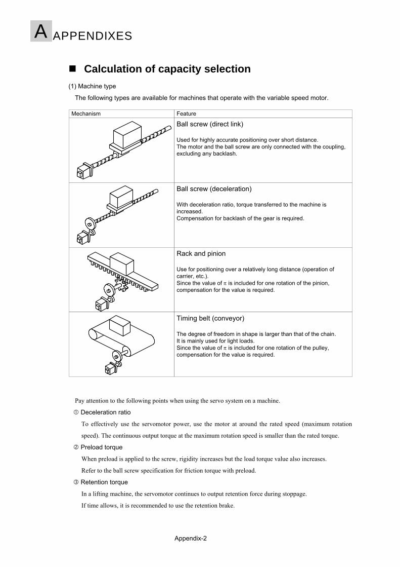
A APPENDIXES
Appendix-2
Calculation of capacity selection (1) Machine type
The following types are available for machines that operate with the variable speed motor.
Mechanism Feature
Ball screw (direct link)
Used for highly accurate positioning over short distance.The motor and the ball screw are only connected with the coupling, excluding any backlash.
Ball screw (deceleration)
With deceleration ratio, torque transferred to the machine is increased.Compensation for backlash of the gear is required.
Rack and pinion
Use for positioning over a relatively long distance (operation of carrier, etc.).Since the value of π is included for one rotation of the pinion, compensation for the value is required.
Timing belt (conveyor)
The degree of freedom in shape is larger than that of the chain.It is mainly used for light loads.Since the value of π is included for one rotation of the pulley, compensation for the value is required.
Pay attention to the following points when using the servo system on a machine.
Deceleration ratio
To effectively use the servomotor power, use the motor at around the rated speed (maximum rotation
speed). The continuous output torque at the maximum rotation speed is smaller than the rated torque.
Preload torque
When preload is applied to the screw, rigidity increases but the load torque value also increases.
Refer to the ball screw specification for friction torque with preload.
Retention torque
In a lifting machine, the servomotor continues to output retention force during stoppage.
If time allows, it is recommended to use the retention brake.
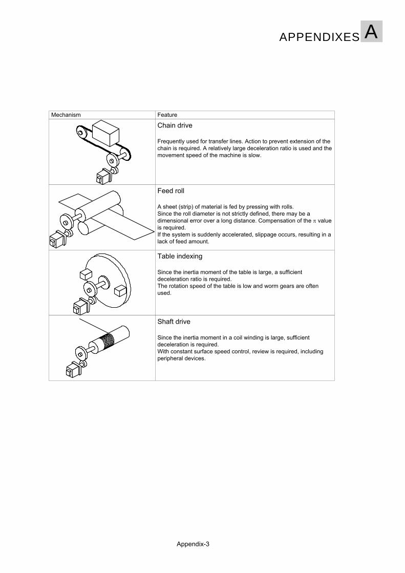
APPENDIXES A
Appendix-3
Mechanism Feature
Feed roll
A sheet (strip) of material is fed by pressing with rolls. Since the roll diameter is not strictly defined, there may be a dimensional error over a long distance. Compensation of the π value is required. If the system is suddenly accelerated, slippage occurs, resulting in a lack of feed amount.
Table indexing
Since the inertia moment of the table is large, a sufficient deceleration ratio is required. The rotation speed of the table is low and worm gears are often used.
Shaft drive
Since the inertia moment in a coil winding is large, sufficient deceleration is required. With constant surface speed control, review is required, including peripheral devices.
Chain drive
Frequently used for transfer lines. Action to prevent extension of the chain is required. A relatively large deceleration ratio is used and the movement speed of the machine is slow.

A APPENDIXES
Appendix-4
<Reference>
Module
* Metric gear
Chain size
Material density Guideline of friction coefficient µ
Guideline value for machine efficiency η
Rail and steel wheel (carrier, crane)
0.05
Mechanism Friction coefficient
Linear guide
Roller system
Roller table
Ball spline0.05 to 0.2
Copper 8.96 × 10³Material Density kg/m3
Brass 8.54 × 10³
Stainless steel IronAluminum Polyacetal
7.91 × 10³
7.85 × 10³
2.7 × 10³
1.43 × 10³
Trapezoidal thread 0.5 to 0.8
Mechanism Machine efficiency
Ball screw 0.9Rack & pinion
Gear deceleration
Worm gear deceleration (start)
Belt transfer
0.8
0.8 to 0.95
0.5 to 0.7
0.95
Worm gear deceleration (during operation) 0.6 to 0.8
0.9Chain transfer
(Module) =(Pitch circle diameter of gear)
(Number of teeth)
* Module 0.5 0.75 0.8 1 1.5 2 2.5 3 4 5 6 7
PitchNo.4.762156.3525
9.5253512.740
15.8755019.0560
PitchNo.25.480
31.7510038.1120
44.4514050.8160
57.15180
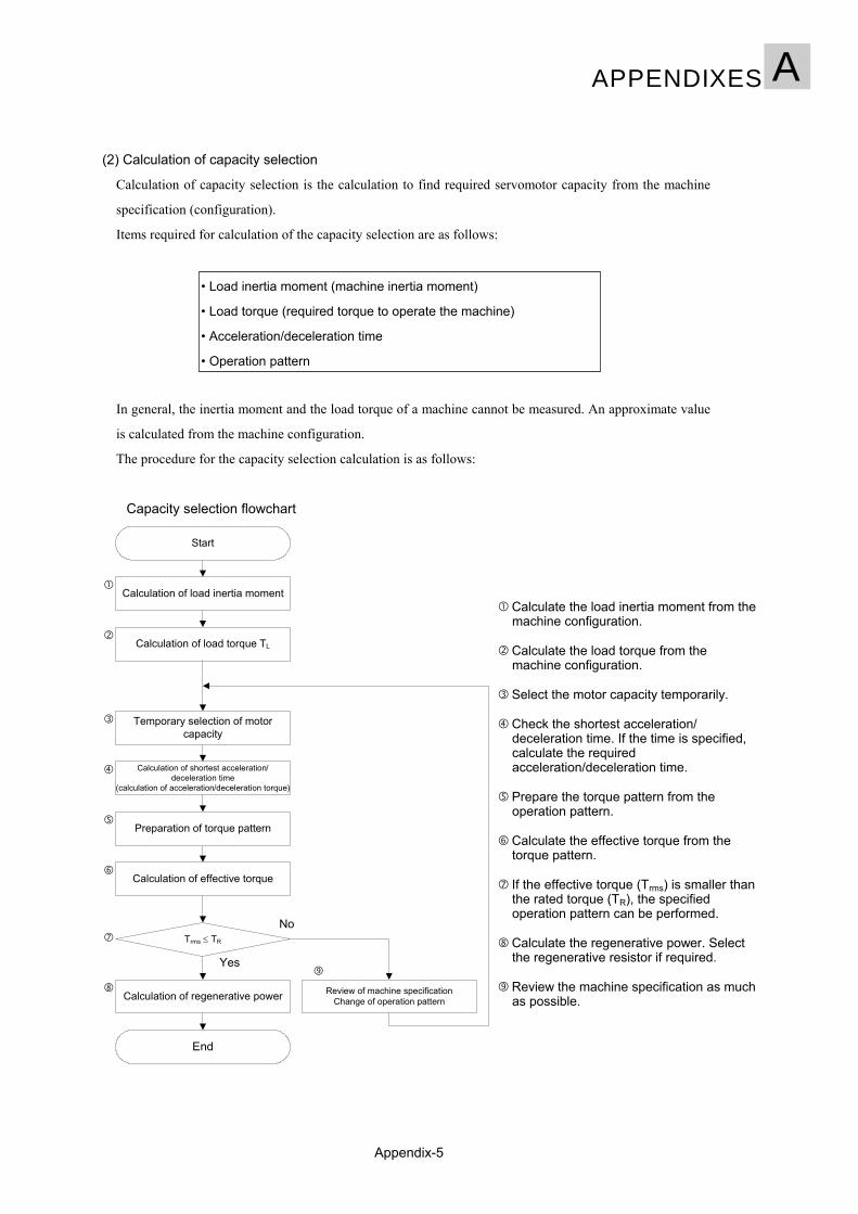
APPENDIXES A
Appendix-5
(2) Calculation of capacity selection
Calculation of capacity selection is the calculation to find required servomotor capacity from the machine
specification (configuration).
Items required for calculation of the capacity selection are as follows:
In general, the inertia moment and the load torque of a machine cannot be measured. An approximate value
is calculated from the machine configuration.
The procedure for the capacity selection calculation is as follows:
Capacity selection flowchart
Start
Calculation of load inertia moment
Calculation of load torque TL
Temporary selection of motor capacity
Calculation of shortest acceleration/deceleration time
(calculation of acceleration/deceleration torque)
Preparation of torque pattern
Calculation of effective torque
Trms ≤ TR
Calculation of regenerative power
End
Review of machine specification Change of operation pattern
Yes
No
• Load inertia moment (machine inertia moment)
• Load torque (required torque to operate the machine)
• Acceleration/deceleration time
• Operation pattern
Calculate the load inertia moment from the machine configuration. Calculate the load torque from the machine configuration. Select the motor capacity temporarily. Check the shortest acceleration/ deceleration time. If the time is specified, calculate the required acceleration/deceleration time. Prepare the torque pattern from the operation pattern. Calculate the effective torque from the torque pattern. If the effective torque (Trms) is smaller than the rated torque (TR), the specified operation pattern can be performed. Calculate the regenerative power. Select the regenerative resistor if required. Review the machine specification as much as possible.
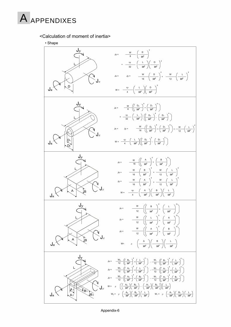
A APPENDIXES
Appendix-6
<Calculation of moment of inertia> • Shape
16
Jz =
103
D4
Jx =
W
8
W
103
D2
+W
12 103
L2
Jy =
=πρ
32 103
L
D
103
2
W =πρ
4 103
L D
103
2
W =πρ
4 103
L D2
103
2D1
103
2
-
Jz =W8
D2
103
2D1
103
2
+
=πρ
32 103
L D2
103
4D1
103
4
-
Jx =16
W D2
103
2D1
103
2
+ +W
12 103
L2
Jy =
Jz =W
16
A
103
2B
103
2
+
Jx =16
W
103
B2
+W
12 103
L2
Jy =16
W
103
A2
+W
12 103
L2
W =πρ
4 103
A
103
B
103
L
W=103
A
103
B
103
Lρ
12
W B
103
2
L
103
2
+Jx =
Jy =
Jz =
12
W L
103
2
A
103
2
+
12
W A
103
2
B
103
2
+
W =103A2
103B2
103L
ρ103A1
103B2 -
W2 = 103A2
103B2
103L
ρ W1 = 103A1
103B1
103L
ρ
12W2 B2
103
2L
103
2
+Jx = - 12W1 B1
103
2L
103
2
+
12W2 A2
103
2L
103
2
+Jy = -12W1 A1
103
2L
103
2
+
12W2 A2
103
2B2
103
2
+Jz = -12W1 A1
103
2B1
103
2
+
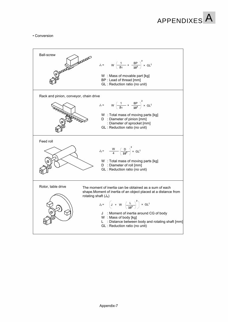
APPENDIXES A
Appendix-7
• Conversion
W : Mass of movable part [kg]BP : Lead of thread [mm]GL : Reduction ratio (no unit)
W : Total mass of moving parts [kg]D : Diameter of pinion [mm]
: Diameter of sprocket [mm]GL : Reduction ratio (no unit)
W : Total mass of moving parts [kg]D : Diameter of roll [mm]GL : Reduction ratio (no unit)
J : Moment of inertia around CG of bodyW : Mass of body [kg]L : Distance between body and rotating shaft [mm]GL : Reduction ratio (no unit)
Ball-screw
Rack and pinion, conveyor, chain drive
Feed roll
Rotor, table drive The moment of inertia can be obtained as a sum of each shape.Moment of inertia of an object placed at a distance from rotating shaft (J4)
4W D
103
2
J3 = × GL2
J + W L103
2
J4 = × GL2
2π 103W1 BP
2
J1 = × GL2×
2π 103W1 BP
2
J1 = × GL2×
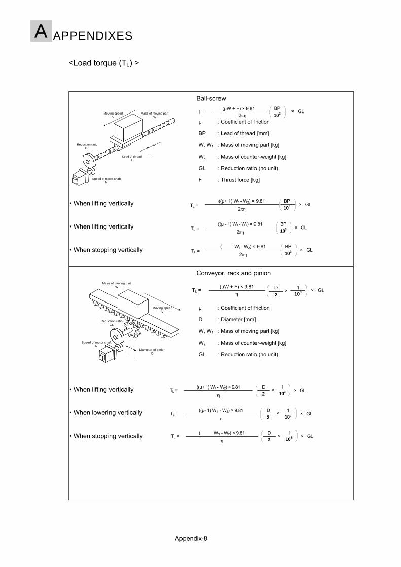
A APPENDIXES
Appendix-8
Ball-screw
µ : Coefficient of friction
BP : Lead of thread [mm]
W, W1 : Mass of moving part [kg]
W2 : Mass of counter-weight [kg]
GL : Reduction ratio (no unit)
F : Thrust force [kg]
• When lifting vertically
• When lifting vertically
• When stopping vertically
Conveyor, rack and pinion
µ : Coefficient of friction
D : Diameter [mm]
W, W1 : Mass of moving part [kg]
W2 : Mass of counter-weight [kg]
GL : Reduction ratio (no unit)
• When lifting vertically
• When lowering vertically
• When stopping vertically
<Load torque (TL) >
Speed of motor shaftN
Reduction ratioGL
Moving speedV
Mass of moving partW
Lead of threadL
Speed of motor shaftN
Reduction ratioGL
Moving speedV
Mass of moving partW
Diameter of pinionD
2πη(µW + F) × 9.81 BP
103TL = × GL
2πη((µ+ 1) W1 - W2) × 9.81 BP
103TL = × GL
2πη((µ - 1) W1 - W2) × 9.81 BP
103TL = × GL
2πη( W1 - W2) × 9.81 BP
103TL = × GL
D2η
(µW + F) × 9.81TL = × GL× 1
103
× GLD2
TL = × 1103
η
((µ+ 1) W1 - W2) × 9.81
× GLD2
TL = × 1103
η
((µ- 1) W1 - W2) × 9.81
× GLD2
TL = × 1103
η
( W1 - W2) × 9.81
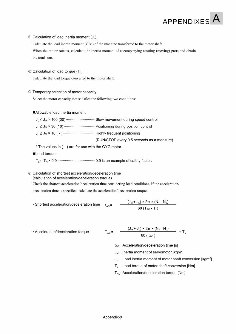
APPENDIXES A
Appendix-9
Calculation of load inertia moment (JL)
Calculate the load inertia moment (GD2) of the machine transferred to the motor shaft.
When the motor rotates, calculate the inertia moment of accompanying rotating (moving) parts and obtain
the total sum.
Calculation of load torque (TL)
Calculate the load torque converted to the motor shaft.
Temporary selection of motor capacity
Select the motor capacity that satisfies the following two conditions:
Allowable load inertia moment
JL ≤ JM × 100 (30) ····························Slow movement during speed control
JL ≤ JM × 30 (10) ······························Positioning during position control
JL ≤ JM × 10 ( - ) ·······························Highly frequent positioning
(RUN/STOP every 0.5 seconds as a measure)
* The values in ( ) are for use with the GYG motor.
Load torque
TL ≤ TR × 0.9 ····································0.9 is an example of safety factor.
Calculation of shortest acceleration/deceleration time (calculation of acceleration/deceleration torque) Check the shortest acceleration/deceleration time considering load conditions. If the acceleration/
deceleration time is specified, calculate the acceleration/deceleration torque.
• Shortest acceleration/deceleration time
• Acceleration/deceleration torque
tAC : Acceleration/deceleration time [s]
JM : Inertia moment of servomotor [kgm2]
JL : Load inertia moment of motor shaft conversion [kgm2]
TL : Load torque of motor shaft conversion [Nm]
TAC : Acceleration/deceleration torque [Nm]
(JM + JL) × 2π × (N1 - N0)
60 (TAC - TL) tAC =
(JM + JL) × 2π × (N1 - N0)
60 ( tAC ) + TL TAC =
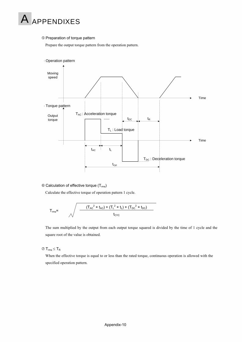
A APPENDIXES
Appendix-10
Preparation of torque pattern
Prepare the output torque pattern from the operation pattern.
Moving speed
Time
Output torque
Time
TAC : Acceleration torque
TDC : Deceleration torque
TL : Load torque
tAC tL
tDC tR
tcyc
· Operation pattern
· Torque pattern
Calculation of effective torque (Trms)
Calculate the effective torque of operation pattern 1 cycle.
The sum multiplied by the output from each output torque squared is divided by the time of 1 cycle and the
square root of the value is obtained.
Trms ≤ TR
When the effective torque is equal to or less than the rated torque, continuous operation is allowed with the
specified operation pattern.
(TAC2 × tAC) + (TL
2 × tL) + (TDC2 × tDC)
tCYC Trms=
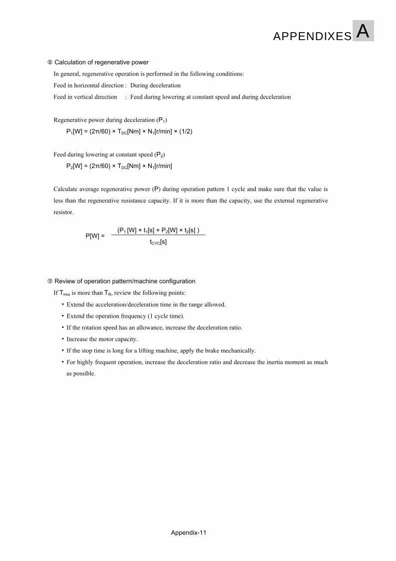
APPENDIXES A
Appendix-11
Calculation of regenerative power
In general, regenerative operation is performed in the following conditions:
Feed in horizontal direction : During deceleration
Feed in vertical direction : Feed during lowering at constant speed and during deceleration
Regenerative power during deceleration (P1)
P1[W] = (2π/60) × TDC[Nm] × N1[r/min] × (1/2)
Feed during lowering at constant speed (P2)
P2[W] = (2π/60) × TDC[Nm] × N1[r/min]
Calculate average regenerative power (P) during operation pattern 1 cycle and make sure that the value is
less than the regenerative resistance capacity. If it is more than the capacity, use the external regenerative
resistor.
Review of operation pattern/machine configuration
If Trms is more than TR, review the following points:
・ Extend the acceleration/deceleration time in the range allowed.
・ Extend the operation frequency (1 cycle time).
・ If the rotation speed has an allowance, increase the deceleration ratio.
・ Increase the motor capacity.
・ If the stop time is long for a lifting machine, apply the brake mechanically.
・ For highly frequent operation, increase the deceleration ratio and decrease the inertia moment as much
as possible.
P[W] = (P1 [W] × t1[s] + P2[W] × t2[s] )
tCYC[s]
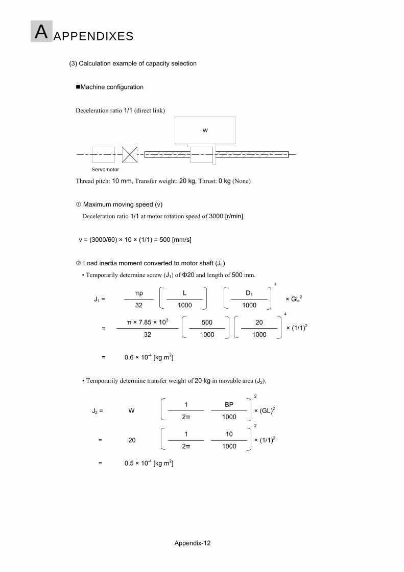
A APPENDIXES
Appendix-12
(3) Calculation example of capacity selection
Machine configuration
Deceleration ratio 1/1 (direct link)
Servomotor
W
Thread pitch: 10 mm, Transfer weight: 20 kg, Thrust: 0 kg (None)
Maximum moving speed (v)
Deceleration ratio 1/1 at motor rotation speed of 3000 [r/min]
v = (3000/60) × 10 × (1/1) = 500 [mm/s]
Load inertia moment converted to motor shaft (JL)
• Temporarily determine screw (J1) of Φ20 and length of 500 mm.
• Temporarily determine transfer weight of 20 kg in movable area (J2).
= 0.6 × 10⁻⁴ [kg m2]
πρ
32
D1
1000
4
× GL2 J1 = L
1000
= π × 7.85 × 10³
32
20
1000
4
× (1/1)2 500
1000
= 0.5 × 10⁻⁴ [kg m2]
× (GL)2 W J2 = 1
2π
2
BP
1000
× (1/1)2 20 = 1
2π
2
10
1000
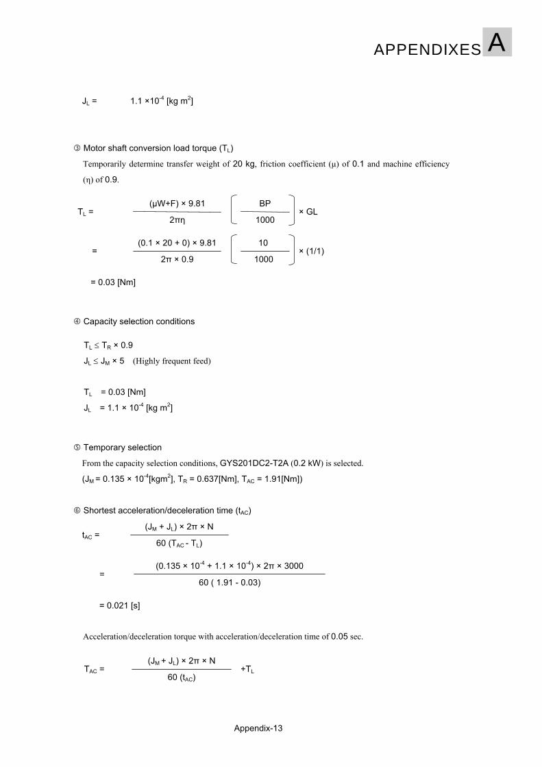
APPENDIXES A
Appendix-13
Motor shaft conversion load torque (TL)
Temporarily determine transfer weight of 20 kg, friction coefficient (µ) of 0.1 and machine efficiency
(η) of 0.9.
Capacity selection conditions
Temporary selection
From the capacity selection conditions, GYS201DC2-T2A (0.2 kW) is selected.
(JM = 0.135 × 10⁻⁴[kgm2], TR = 0.637[Nm], TAC = 1.91[Nm])
Shortest acceleration/deceleration time (tAC)
Acceleration/deceleration torque with acceleration/deceleration time of 0.05 sec.
= 0.021 [s]
(JM + JL) × 2π × N
60 (TAC - TL) tAC =
= (0.135 × 10⁻⁴ + 1.1 × 10-4) × 2π × 3000
60 ( 1.91 - 0.03)
= 0.03 [Nm]
TL ≤ TR × 0.9
JL ≤ JM × 5 (Highly frequent feed)
TL = 0.03 [Nm]
JL = 1.1 × 10⁻⁴ [kg m2]
(µW+F) × 9.81
2πη
BP
1000 × GL TL =
JL = 1.1 ×10⁻⁴ [kg m2]
(0.1 × 20 + 0) × 9.81
2π × 0.9
10
1000 × (1/1) =
(JM + JL) × 2π × N
60 (tAC) +TL TAC =
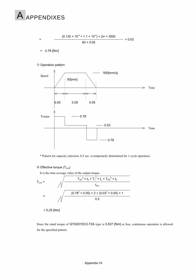
A APPENDIXES
Appendix-14
Operation pattern
* Pattern for capacity selection. 0.5 sec. is temporarily determined for 1 cycle operation.
Effective torque (Trms)
It is the time average value of the output torque.
Since the rated torque of GYS201DC2-T2A type is 0.637 [Nm] or less, continuous operation is allowed
for the specified pattern.
500[mm/s]
TAC2 × ta + TL
2 × tL + TDC2 × td
tcyc Trms =
(0.782 × 0.05) × 2 + (0.032 × 0.05) × 1
0.5 =
= 0.25 [Nm]
0.05 0.05 0.05
Speed
Time
= + 0.03 (0.135 × 10⁻⁴ + 1.1 × 10-4) × 2π × 3000
60 × 0.05
Torque
Time
0.78
= 0.78 [Nm]
0.78
0.03
50[mm]
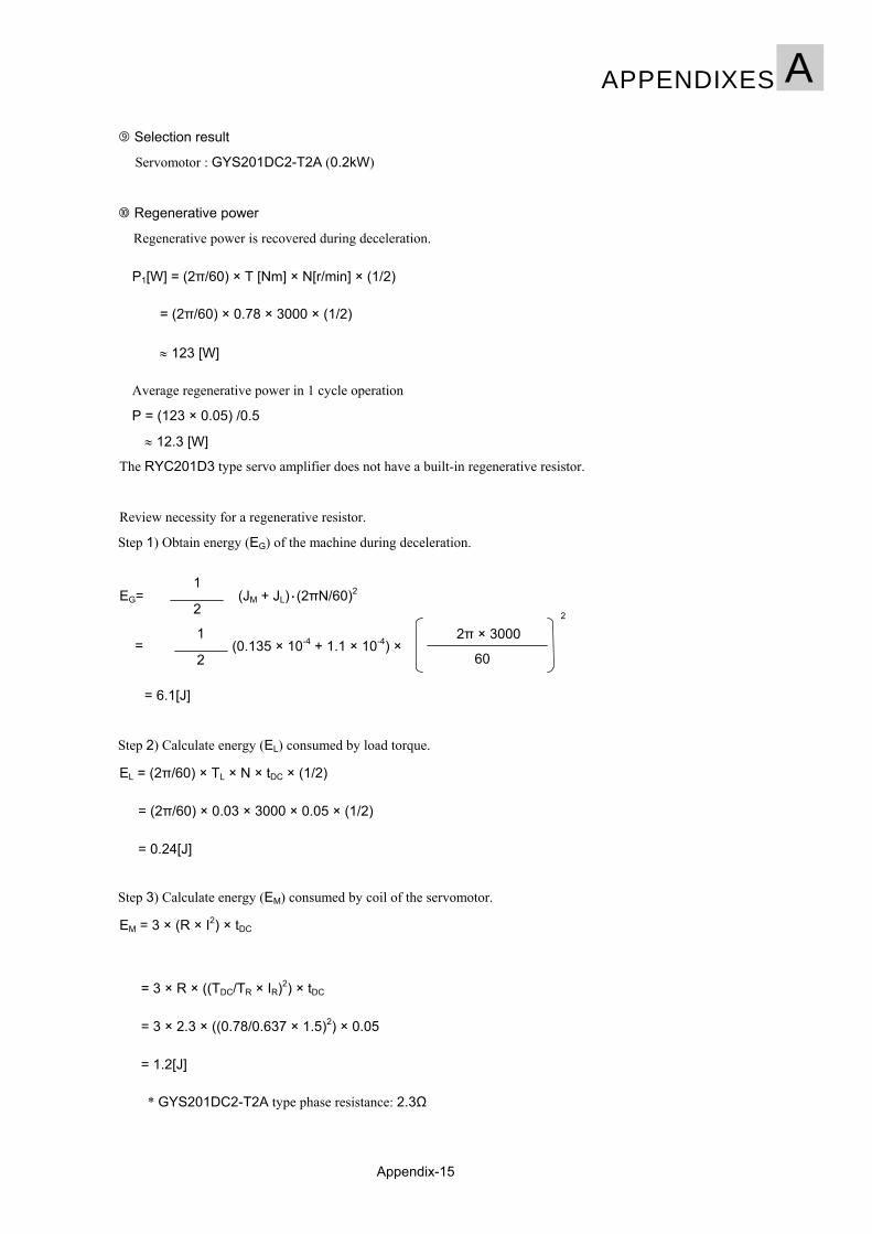
APPENDIXES A
Appendix-15
Selection result
Servomotor : GYS201DC2-T2A (0.2kW)
Regenerative power
Regenerative power is recovered during deceleration.
Average regenerative power in 1 cycle operation
P = (123 × 0.05) /0.5
≈ 12.3 [W]
The RYC201D3 type servo amplifier does not have a built-in regenerative resistor.
Review necessity for a regenerative resistor.
Step 1) Obtain energy (EG) of the machine during deceleration.
Step 2) Calculate energy (EL) consumed by load torque.
Step 3) Calculate energy (EM) consumed by coil of the servomotor.
P1[W] = (2π/60) × T [Nm] × N[r/min] × (1/2)
= (2π/60) × 0.78 × 3000 × (1/2)
≈ 123 [W]
1
2 (JM + JL)・(2πN/60)2 EG=
= 6.1[J]
= 2π × 3000
60
2
(0.135 × 10⁻⁴ + 1.1 × 10-4) ×1
2
EL = (2π/60) × TL × N × tDC × (1/2)
= (2π/60) × 0.03 × 3000 × 0.05 × (1/2)
= 0.24[J]
EM = 3 × (R × I2) × tDC
= 3 × R × ((TDC/TR × IR)2) × tDC
= 3 × 2.3 × ((0.78/0.637 × 1.5)2) × 0.05
* GYS201DC2-T2A type phase resistance: 2.3Ω
= 1.2[J]
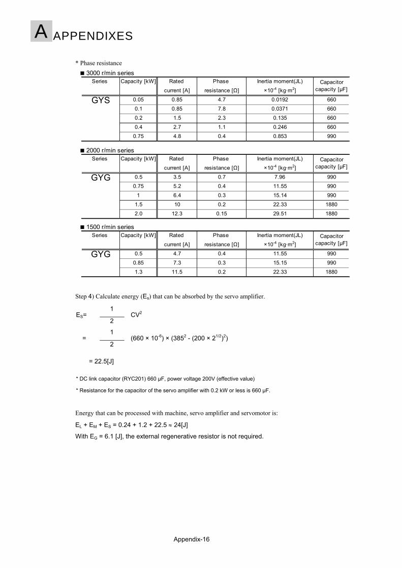
A APPENDIXES
Appendix-16
* Phase resistance
Step 4) Calculate energy (Es) that can be absorbed by the servo amplifier.
Energy that can be processed with machine, servo amplifier and servomotor is:
EL + EM + ES = 0.24 + 1.2 + 22.5 ≈ 24[J]
With EG = 6.1 [J], the external regenerative resistor is not required.
1
2 CV2 ES=
= 22.5[J]
1
2 (660 × 10-6) × (3852 - (200 × 21/2)2) =
* DC link capacitor (RYC201) 660 µF, power voltage 200V (effective value)
* Resistance for the capacitor of the servo amplifier with 0.2 kW or less is 660 µF.
3000 r/min seriesSeries Capacity [kW] Rated Phase Inertia moment(JL)
current [A] resistance [Ω] ×10-4 [kg·m2]
GYS 0.05 0.85 4.7 0.0192 660
0.1 0.85 7.8 0.0371 660
0.2 1.5 2.3 0.135 660
0.4 2.7 1.1 0.246 660
0.75 4.8 0.4 0.853 990
2000 r/min seriesSeries Capacity [kW] Rated Phase Inertia moment(JL)
current [A] resistance [Ω] ×10-4 [kg·m2]
GYG 0.5 3.5 0.7 7.96 990
0.75 5.2 0.4 11.55 990
1 6.4 0.3 15.14 990
1.5 10 0.2 22.33 1880
2.0 12.3 0.15 29.51 1880
1500 r/min seriesSeries Capacity [kW] Rated Phase Inertia moment(JL)
current [A] resistance [Ω] ×10-4 [kg·m2]
GYG 0.5 4.7 0.4 11.55 990
0.85 7.3 0.3 15.15 990
1.3 11.5 0.2 22.33 1880
Capacitorcapacity [µF]
Capacitorcapacity [µF]
Capacitorcapacity [µF]

APPENDIXES A
Appendix-17
PC loader PC loader software for FALDIC-W can be downloaded from our website below:
http:/www.fujielectric.co.jp/fcs/
The following settings are available on the PC loader:
(1) Real time tracing ········· Speed or torque waveform can be continuously obtained.
(2) Historical tracing ········· Detailed waveform which is shorter than real time tracing can
be obtained.
(3) Monitor 2················ I/O check, alarm history and system configuration can be monitored.
(4) Parameter editing ········ Parameters are edited, transferred, compared and initialized.
(5) Communication settings··· Communication conditions between the servo amplifier and the PC
are set.
(6) Easy tuning·············· Reciprocal operation of the servomotor is automatically performed with
simple settings. The auto tuning gain suitable for the machine is adjusted. (7) Servo analyzing ·········· Resonance point/anti-resonance point of the machine is checked.
Effects can also be checked with a notch filter.
OS environment················ Windows 98SE, Windows NT4.0/WS (service pack 4 or later),
Windows 2000, Windows ME, Windows XP
CPU ·································· Pentium 133 MHz or higher is recommended.
Memory environment········ 32 MB or better
Display······························ Display that has SVGA resolution of 800 × 600 or better,
compatible with Windows
Environment ···················· Hard disk drive space of 40MB bytes or larger (80MB bytes or
for installation larger is recommended.)
Operating environment

A APPENDIXES
Appendix-18
Parameter list FALDIC-W parameter list (1)
0 to 21 (in 1 increments)Power
Power
Power
Power
Power
19 Output pulse count 16 to 32768 [pulse] (in 1 increments) Power
20 Phase-Z offset 0 to 65535 [×2 pulse] (in 1 increments) Power
21 Zero deviation width 1 to 20000 [pulse] (in 1 increments) Always
22 Deviation limit width 10 to 65535 [×100 pulse] (in 1 increments) Always
23 Zero speed width 10 - Maximum rotation speed [r/min] (in 1 increments) Always
24 Positioning end judgment time 0.000 to 1.000 sec. (in 0.001 increments) Always
25 Max. current limit 0 to 300 % (in 1 increments) Always
1: Servo ON [RUN]3: +OT5: Emergency stop [EMG]7: Deviation clear9: Anti-resonance frequency selection 011: Command pulse inhibition 13: Command pulse α selection 115: Manual forward rotation [FWD]17: Multistep speed 1 [x1]19: Acceleration/deceleration time selection21: Coasting [BX]
0: Not specified2: Positioning end [PSET]4: Alarm detection: b contact6: OT detection8: Zero deviation 10: Current limit detection
1: Ready [RDY]3: Alarm detection: a contact5: Dynamic braking7: Forced stop detection 9: Zero speed 11: Brake timing
04Rotating direction switching/output pulse phase switching
0: Positive direction forward rotation (CCW)/B phase advance1: Positive direction reverse rotation (CW)/B phase advance2: Positive direction forward rotation (CCW)/A phase advance3: Positive direction reverse rotation (CW)/A phase advance
Power
05 Tuning mode0: Auto tuning,1: Semi-auto tuning,2: Manual tuning
Always
06 Load inertia ratio GYS type: 0.0 to 100.0 times (in 0.1 increments)GYG type: 0.0 to 30.0 times (in 0.1 increments) Always
07 Auto tuning gain 1 to 20 (in 1 increments) Always
09 Control mode switching 0: Position 1: Speed 2: Torque 3: Position Speed4: Position Torque 5: Speed Torque
Power
No. Name Setting range Setting Change01 Command pulse correction α 1 to 32767 (in 1 increments) Always
02 Command pulse correction ß 1 to 32767 (in 1 increments) Always
03 Pulse string input form0: Command pulse/command sign,1: Forward/reverse rotation pulse,2: Two signals with 90-degree phase difference
Power
08 Auto forward gain 1 to 20 (in 1 increments) Always
0: Not specified2: Reset [RST]4: -OT6: P motion 8: External regenerative resistor overheating10: Anti-resonance frequency selection 112: Command pulse α selection 014: Control mode switching 16: Manual reverse rotation [REV]18: Multistep speed 2 [x2]20: Current limiting regulator ON
10 CONT 1 signal allocation
11 CONT 2 signal allocation
12 CONT 3 signal allocation
13 CONT 4 signal allocation
14 CONT 5 signal allocation
0 to 10 (in 1 increments) 15 OUT 1 signal allocation
16 OUT 2 signal allocation
17 OUT 3 signal allocation
18 OUT 4 signal allocation
Power
Power
Power
Power
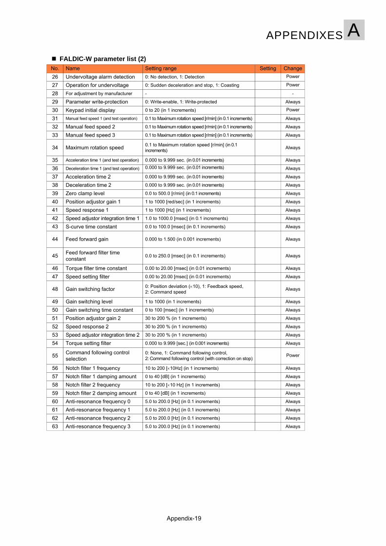
APPENDIXES A
Appendix-19
FALDIC-W parameter list (2) No. Name Setting range Setting Change
40 Position adjustor gain 1 1 to 1000 [red/sec] (in 1 increments) Always
41 Speed response 1 1 to 1000 [Hz] (in 1 increments) Always
42 Speed adjustor integration time 1 1.0 to 1000.0 [msec] (in 0.1 increments) Always
43 S-curve time constant 0.0 to 100.0 [msec] (in 0.1 increments) Always
44 Feed forward gain 0.000 to 1.500 (in 0.001 increments) Always
46 Torque filter time constant 0.00 to 20.00 [msec] (in 0.01 increments) Always
56 Notch filter 1 frequency 10 to 200 [×10Hz] (in 1 increments) Always
57 Notch filter 1 damping amount 0 to 40 [dB] (in 1 increments) Always
47 Speed setting filter 0.00 to 20.00 [msec] (in 0.01 increments) Always
48 Gain switching factor 0: Position deviation (×10), 1: Feedback speed,2: Command speed Always
49 Gain switching level 1 to 1000 (in 1 increments) Always
50 Gain switching time constant 0 to 100 [msec] (in 1 increments) Always
45 Feed forward filter time constant 0.0 to 250.0 [msec] (in 0.1 increments) Always
58 Notch filter 2 frequency 10 to 200 [×10 Hz] (in 1 increments) Always
59 Notch filter 2 damping amount 0 to 40 [dB] (in 1 increments) Always
51 Position adjustor gain 2 30 to 200 % (in 1 increments) Always
52 Speed response 2 30 to 200 % (in 1 increments) Always
53 Speed adjustor integration time 2 30 to 200 % (in 1 increments) Always
54 Torque setting filter Always
55 Command following control selection
0: None, 1: Command following control,2: Command following control (with correction on stop)
Power
60 Anti-resonance frequency 0 5.0 to 200.0 [Hz] (in 0.1 increments) Always
61 Anti-resonance frequency 1 5.0 to 200.0 [Hz] (in 0.1 increments) Always
62 Anti-resonance frequency 2 5.0 to 200.0 [Hz] (in 0.1 increments) Always
63 Anti-resonance frequency 3 5.0 to 200.0 [Hz] (in 0.1 increments) Always
0.000 to 9.999 [sec.] (in 0.001 increments)
35 Acceleration time 1 (and test operation) 0.000 to 9.999 sec. (in 0.01 increments) Always
36 Deceleration time 1 (and test operation) 0.000 to 9.999 sec. (in 0.01 increments) Always
37 Acceleration time 2 0.000 to 9.999 sec. (in 0.01 increments) Always
38 Deceleration time 2 0.000 to 9.999 sec. (in 0.01 increments) Always
39 Zero clamp level Always0.0 to 500.0 [r/min] (in 0.1 increments)
31 Manual feed speed 1 (and test operation) 0.1 to Maximum rotation speed [r/min] (in 0.1 increments) Always
32 Manual feed speed 2 Always
33 Manual feed speed 3 Always
34 Maximum rotation speed Always
0.1 to Maximum rotation speed [r/min] (in 0.1 increments)
0.1 to Maximum rotation speed [r/min] (in 0.1 increments)
0.1 to Maximum rotation speed [r/min] (in 0.1 increments)
26 Undervoltage alarm detection 0: No detection, 1: Detection Power
28 For adjustment by manufacturer - -
29 Parameter write-protection 0: Write-enable, 1: Write-protected Always
30 Keypad initial display 0 to 20 (in 1 increments) Power
27 Operation for undervoltage 0: Sudden deceleration and stop, 1: Coasting Power
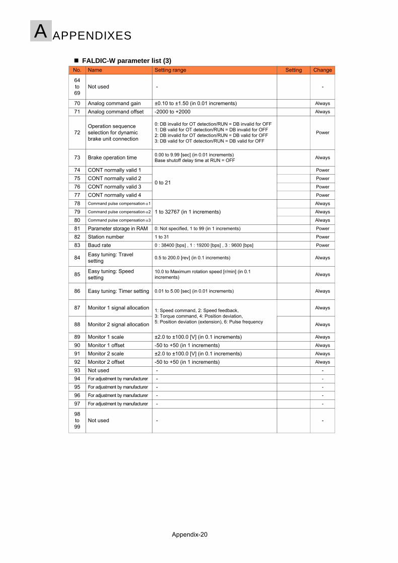
A APPENDIXES
Appendix-20
FALDIC-W parameter list (3) No. Name Setting range Setting Change
89 Monitor 1 scale Always
90 Monitor 1 offset Always
93 Not used - -
91 Always
92 Always
87 Monitor 1 signal allocation 1: Speed command, 2: Speed feedback, 3: Torque command, 4: Position deviation, 5: Position deviation (extension), 6: Pulse frequency
95 For adjustment by manufacturer - -
96 For adjustment by manufacturer - -
97 For adjustment by manufacturer - -
74 CONT normally valid 175 CONT normally valid 276 CONT normally valid 377 CONT normally valid 4
0 to 21
Power
Power
Power
Power
78 Command pulse compensation α1
7980
1 to 32767 (in 1 increments)
81 Parameter storage in RAM 0: Not specified, 1 to 99 (in 1 increments) Power
82 Station number 1 to 31 Power
83 Baud rate 0 : 38400 [bps] , 1 : 19200 [bps] , 3 : 9600 [bps] Power
84 0.5 to 200.0 [rev] (in 0.1 increments) Always
85 Easy tuning: Speed setting
10.0 to Maximum rotation speed [r/min] (in 0.1 increments) Always
Easy tuning: Timer setting86
Easy tuning: Travel setting
0.01 to 5.00 [sec] (in 0.01 increments) Always
88 Monitor 2 signal allocation
Monitor 2 scaleMonitor 2 offset
±2.0 to ±100.0 [V] (in 0.1 increments)-50 to +50 (in 1 increments)±2.0 to ±100.0 [V] (in 0.1 increments)-50 to +50 (in 1 increments)
64to69
Not used - -
70 Analog command gain ±0.10 to ±1.50 (in 0.01 increments) Always
71 Analog command offset -2000 to +2000
Always
72Operation sequence selection for dynamic brake unit connection
0: DB invalid for OT detection/RUN = DB invalid for OFF 1: DB valid for OT detection/RUN = DB invalid for OFF 2: DB invalid for OT detection/RUN = DB valid for OFF 3: DB valid for OT detection/RUN = DB valid for OFF
Power
73 Brake operation time Always0.00 to 9.99 [sec] (in 0.01 increments)Base shutoff delay time at RUN = OFF
98to99
Not used - -
Command pulse compensation α2
Command pulse compensation α3
Always
Always
Always
Always
Always
94 For adjustment by manufacturer - -