warning: heat pump outdoor units -...
TRANSCRIPT

VARIABLE SPEED R-410A HEAT PUMP OUTDOOR UNITS
INSTALLATION INSTRUCTIONS
92-105074-09-00 (3/16) Printed in USA
[ ] indicates metric conversions.
Do not destroy this manual. Please read carefully and keep in a safe place for future reference by a serviceman.
WARNINGTHESE INSTRUCTIONS ARE INTENDED AS AN AID TO QUALIFIED, LICENSED SERVICE PERSONNEL FOR PROPER INSTALLATION, ADJUSTMENT, AND OPERATION OF THIS UNIT. READ THESE INSTRUCTIONS THOROUGHLY BEFORE ATTEMPTING INSTALLATION OR OPERATION. FAILURE TO FOLLOW THESE INSTRUCTIONS MAY RESULT IN IMPROPER INSTALLATION, ADJUSTMENT, SERVICE, OR MAINTENANCE POSSIBLY RESULTING IN FIRE, ELECTRICAL SHOCK, PROPERTY DAMAGE, PERSONAL INJURY, OR DEATH.
(-)P20 (20 SEER) EQUIPPED WITH ECONET™ COMMUNICATIONS
WARNING: RECOGNIZE THIS SYMBOL AS AN INDICATION OF IMPORTANT SAFETY INFORMATION
Enabled

Cont
ents Important
Safety Information ............................................. 3 General Information ........................................4-7Checking Product Received ........................................4Application ...................................................................4Electrical and Physical Data ..................................... 5-6Specifications ........................................................... 6-7Proper Installation ........................................................7Installation ....................................................8-22Choosing a Location ......................................8-10Operational Issues........................................................8 Corrosive Environment .................................................8For Units WithSpace Limitations .........................................................9Customer Satisfaction Issues ......................................9Unit Mounting ...............................................................9Factory-Preferred Tie-Down Method.........................................................9Snow Depth Table ......................................................10Tools and Refrigerant .......................................11Tools Required for Installing and Servicing R-410A Models ..........................................11Specifications of R-410A ...........................................11Quick-Reference Guide for R-410A .......................................................11Replacement Units ...........................................12Indoor Coil ........................................................12Location ......................................................................12Interconnecting Tubing ................................ 12-26Refrigerant Level Adjustment .....................................12Maximum Length of Lines ..........................................12Interconnecting Tubing andFitting Losses .............................................................13Liquid Line Selection ..................................................13Long Line Set Applications ........................................14Oil Level Adjustments for Long Line ..........................14Suction Line Selection ...............................................15Refrigerant Migration During Off Cycle ......................15Tubing Installation ......................................................20Tubing Connections ...................................................21Leak Testing ...............................................................22Wiring .........................................................23-26EcoNet™ Control Communications ...........................23Control Wiring ............................................................23EcoNet™ Control BoardCommunication Wiring .............................................. 23 Conventional 24VAC Thermostat Control Wiring ...... 24Conventional 24VAC Mode of Operation ...................24Typical Noncommunicating ThermostatWiring Diagrams .........................................................25Power Wiring ..............................................................25Grounding ...................................................................26Start-Up ......................................................27-32Start-Up ......................................................................27Checking Airflow ........................................................27Evacuation Procedure ............................................... 28Final Leak Testing .......................................................28
Checking Refrigerant Charge ......................29-32Charging Units With R-410A Refrigerant ............................................29Confirm ID Airflow and Coils Are Clean .....................29Measurement Device Setup .......................................29Charging by Weight ....................................................29Setting Compressor Speed ........................................30Gross Charging by Pressures ....................................30Final Charge by Subcooling .......................................31Finishing Up Installation .............................................31Components and Controls ..........................33-54Compressor Stator Heat (CSH) .........................33Stator Heat Operation ................................................33High- and Low-PressureControls (HPC and SPT) ....................................33Accumulator .................................................... 34Outdoor Fan Motors......................................... 34Outdoor Fan Blades ......................................... 34Electronic Expansion ....................................... 34Alternate Suction LINE THERMISTOR .............35Coil Thermistor ................................................ 35Compressor Sump Thermistor 35 Suction Pressure Transducer (SPT) ................. 36Discharge Line Thermistor .............................. 36Power Inverter Compressor Controls .............. 36Choke/Inductor ................................................ 37Filter & Ferrite Rings ....................................... 37EcoNet™ Variable SpeedUnitary Control ................................................ 38Test and SW2 Buttons ...............................................38Memory Card .............................................................39Factory Programmed Superheat ................................39Superheat Offset Dip Switch Settings .......................39Compressor Operation ...............................................41Demand Defrost .........................................................42Active Compressor Protection Mode ........................ 44Default Operations Upon Component Failure ........... 51Test and Fault Recall Modes ..................................... 51Agency Test Mode Instructions ................................. 52Accessories .....................................................55Heat Pump Thermostat Warning Light Kit ................ 55Communicating 2 Wire Kit ........................................ 55Diagnostics ................................................ 56-77Replacement of EcoNet™ Variable SpeedUnitary Control Board ............................................... 56ICC Diagnostic Codes ..........................................57-60Electrical, Mechanical Checks Flowcharts ..........61-64General Troubleshooting Chart ................................. 65Service Analyzer Charts .......................................66-71Cooling and Heating Mode Troubleshooting Tips .... 72Wiring Diagram .......................................................... 73
2
CONTENTS

Safety
3
IMPORTANT SAFETY INFORMATIONWARNINGS:
• These instructions are intended as an aid to qualified, licensed service personnel for proper installation, adjustment, and operation of this unit. Read these instructions thoroughly before attempting installation or operation. Failure to follow these instructions may result in improper installation, adjustment, service, or maintenance possibly resulting in fire, electrical shock, property damage, personal injury, or death.
• The unit must be permanently grounded. Failure to do so can cause electrical shock resulting in severe personal injury or death.
• Turn off electric power at the fuse box or service panel before making any electrical connections.
• Complete the ground connection before making line voltage connections. Failure to do so can result in electrical shock, severe personal injury, or death.
• Disconnect all power to unit before starting maintenance. Failure to do so can cause electrical shock resulting in severe personal injury or death.
• Never assume the unit is properly wired and/or grounded. Always test the unit cabinet with a noncontact voltage detector available at most electrical supply houses or home centers before removing access panels or coming into contact with the unit cabinet.
• Do not use oxygen to purge lines or pressurize system for leak test. Oxygen reacts violently with oil, which can cause an explosion resulting in severe personal injury or death.
• The top of the scroll compressor shell is hot. Touching the compressor top may result in serious personal injury.
• The manufacturer’s warranty does not cover any damage or defect to the unit caused by the attachment or use of any components, accessories, or devices (other than those authorized by the manufacturer) into, onto, or in conjunction with the heat pump. You should be aware that the use of unauthorized components, accessories, or devices may adversely affect the operation of the heat pump and may also endanger life and property. The manufacturer disclaims any responsibility for such loss or injury resulting from the use of such unauthorized components, accessories, or devices.
CAUTIONS: • R-410A systems operate at approximately 60%
higher pressures (1.6 times) than R-22 systems. Do not use R-22 service equipment or components on R-410A equipment. Use appropriate care when using this refrigerant. Failure to exercise care may result in equipment damage or personal injury.
• Only match this outdoor unit with a matched indoor coil or air handler approved for use with this outdoor unit per the unit manufacturer’s specification sheet. The use of unmatched coils or air handler will likely result in a charge imbalance between the cooling and heating modes which can cause unsatisfactory operation including a high-pressure switch lockout condition.
• Only use indoor coils approved for use on R-410A systems. An R-22 coil will have a TXV or fixed restrictor device that is not designed to operate properly in an R-410A system and will result in serious operational issues. The R-22 coil could also contain mineral oil which is incompatible with the POE oil used in R-410A systems and could result in reliability issues with the compressor and TXVs.
• When coil is installed over a finished ceiling and/or living area, it is required that a secondary sheet metal condensate pan be constructed and installed under the entire unit. Failure to do so can result in property damage.
• The compressor has an internal overload protector. Under some conditions, it can take up to 2 hours for this overload to reset. Make sure overload has had time to reset before condemning the compressor.
• UNIT MAY START SUDDENLY AND WITHOUT WARNING. A flashing red light on the heat pump/defrost control indicates a call for unit operation is present at the heat pump/defrost control. The heat pump/defrost control will attempt to start unit after the anti-short cycle time expires, when a high or low pressure control automatically resets, or when the heat pump/defrost control exits the lockout mode as the temperature rises above 5°F.

4
GENERAL INFORMATIONWARNING:
Improper installation, or installation not made in accordance with these instructions, can result in unsatisfactory operation and/or dangerous conditions and can cause the related warranty not to apply.The RP series of heat pumps are designed to operate with standard 24 VAC thermostats and air handlers or gas furnaces. This installation instruction manual contains complete instructions for installation and setup using conventional 24 VAC controls. Please refer to the manufacturer’s specification sheets for complete performance data, thermostat, and accessory listings. The information contained in this manual has been prepared to assist in the proper installation, operation, and maintenance of the air conditioning system. Read this manual and any instructions packaged with separate equipment required to make up the system prior to installation. Homeowner should retain this manual for future reference.To achieve optimum efficiency and capacity, the matching indoor cooling coils listed in the manufacturer’s specification sheet must be used for this model heat pump.
Checking Product ReceivedUpon receiving unit, inspect it for any shipping damage. Claims for damage, either apparent or concealed, should be filed immediately with the shipping company. Check model number, electrical characteristics, and accessories to determine if they are correct. Check system components (indoor coil, outdoor unit, air handler/furnace, etc.) to make sure they are properly matched.
ApplicationBefore specifying any heat pump equipment, a survey of the structure and a heat loss and heat gain calculation must be made. A heat loss calculation involves identifying all surfaces and openings that lose heat to the surrounding air and quantifying that heat loss. A cooling heat gain calculation makes similar measurements and determines the amount of heat needed to be removed. A heat gain calculation also calculates the extra heat load caused by sunlight and by humidity removal. These factors must be considered before selecting a heat pump system to provide year-round comfort. The Air Conditioning Contractors of America (ACCA) J Manual method of load calculation is one recognized procedure for determining the heating and cooling load.After the proper equipment combination has been selected, satisfying both sensible and latent requirements, the system must be properly installed. Only then can the unit provide the comfort it was designed to provide.There are several factors that installers must consider.• Outdoor unit location • Indoor unit blower speed and airflow• Proper equipment evacuation • Supply and return air duct design and sizing• Refrigerant charge • System air balancing• Diffuser and return air grille location and sizing
Gene
ral I
nfor
matio
n

5
GENERAL INFORMATION
General Information
Electrical and Physical Data
Rev. 03/16 ELECTRICAL
Model Number (-)P20
Phase Frequency (Hz) Voltage (Volts)
Fan Motor Full Load
Amperes (FLA)
Minimum Circuit
Ampacity Amperes
Rated Load Amperes
(RLA)
Locked Rotor
Amperes (LRA)
Minimum Amperes
Maximum Amperes
24 1-60-208/230 20.7/20.7 35 1.4 28/28 35/35 45/45
48 1-60-208/230 21.6/21.6 50 5.3 46/46 60/60 70/70
Rev. 03/16 PHYSICAL
Model Number (-)P20
Outdoor Coil
Refrig. Per Circuit Oz. [g]
Weight
Face Area Sq. Ft. [m2] No. Rows CFM [L/s] Net Lbs. [kg] Shipping Lbs. [kg]
24 21.53 [2] 14375 [2065],2770 [1307],2078 [981]
135.2 [3832] 223 [101] 231 [104]
48 28.24 [2.6] 14994 [2357],2618 [1236],2057 [971]
215.2 [6100] 293 [133] 301 [137]
Compressor Fuse or HACR Circuit Breaker

6
“L”
“W”
“H”
AIR
DISCHARGE
ALLOW 60” [1524mm] OF CLEARANCE
AIR INLET LOUVERS ALLOW6” [152mm] Min. OF CLEARANCE ALL SIDES
12” [305mm] RECCOMMENDED
SERVICE PANELS/INLET CONNECTIONS / HIGH & LOW
VOLTAGE ACCESS ALLOW 24” [ 610 mm] OF CLEARANCE
ST-A1226-02-00
ALLOW 60" [1524mm] OF CLEARANCE
SERVICE PANELS/INLET CONNECTIONS /HIGH & LOW VOLTAGEACCESS ALLOW24" [610 mm] OFCLEARANCE
AIR INLET LOUVERS ALLOW6" [152 mm] OF CLEARANCE ALL SIDES12" [305 mm] RECOMMENDED
R P 20 36 A J V C A
MINOR SERIES
Z
TYPEV - INVERTER
VOLTAGEJ = 1 PH, 208-230/60
MAJOR SERIES
CAPACITY24 = 24000 BTU/HR [7.03 kW]36 = 36000 BTU/HR [10.55 kW]48 = 48000 BTU/HR [14.07 kW]60 = 60000 BTU/HR [17.58 kW]
20 SEER
HEAT PUMP
BRAND
CONTROLSC - COMMUNICATING
GENERAL INFORMATION
Gene
ral I
nfor
matio
n
7
GENERAL INFORMATION
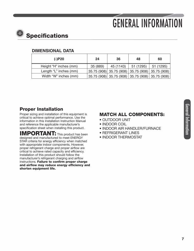
Proper InstallationProper sizing and installation of this equipment is critical to achieve optimal performance. Use the information in this Installation Instruction Manual and reference the applicable manufacturer’s specification sheet when installing this product.
IMPORTANT: This product has been designed and manufactured to meet ENERGY STAR criteria for energy efficiency when matched with appropriate indoor components. However, proper refrigerant charge and proper airflow are critical to achieve rated capacity and efficiency. Installation of this product should follow the manufacturer’s refrigerant charging and airflow instructions. Failure to confirm proper charge and airflow may reduce energy efficiency and shorten equipment life.
MATCH ALL COMPONENTS:• OUTDOOR UNIT• INDOOR COIL• INDOOR AIR HANDLER/FURNACE• REFRIGERANT LINES• INDOOR THERMOSTAT
Specifi cations
DIMENSIONAL DATA
(-)P20 24
35 (889) 45 (1143) 51 (1295)51 (1295)35.75 (908) 35.75 (908) 35.75 (908)35.75 (908)35.75 (908) 35.75 (908) 35.75 (908)35.75 (908)
Height “H” inches (mm)Length “L” inches (mm)Width “W” inches (mm)
36 6048
General Information

8
INSTALLATIONChoosing a Location
IMPORTANT: Consult local and national building codes and ordinances for special installation requirements. Following location information will provide longer life and simplified servicing of the outdoor heat pump.
NOTICE: These units must be installed outdoors. No ductwork can be attached, or other modifications made, to the discharge grille. Modifications will affect performance or operation.
Operational IssuesIMPORTANT: Locate the unit in a manner that will not prevent, impair, or compromise the performance of other equipment installed in proximity to the unit. Maintain all required minimum distances to gas and electric meters, dryer vents, and exhaust and inlet openings. In the absence of national codes or manufacturers’ recommendations, local code recommendations and requirements will take precedence.• Refrigerant piping and wiring should be properly
sized and kept as short as possible to avoid capacity losses and increased operating costs.
• Locate the unit where water runoff will not create a problem with the equipment. Position the unit away from the drip edge of the roof whenever possible. Units are weatherized, but can be affected by the following:• Water pouring into the unit from the junction
of rooflines, without protective guttering. Large volumes of water entering the heat pump while in operation can impact fan blade or motor life, and coil damage may occur to a heat pump if moisture cannot drain from the unit under freezing conditions.
• Freezing moisture or sleeting conditions can cause the cabinet to ice-over prematurely and prevent heat pump operation, requiring backup heat, which generally results in less economical operation.
• Closely follow the clearance recommendations on page 8.• 24" [61.0 cm] to the service panel access• 60" [152.4 cm] above heat pump fan
discharge (unit top) to prevent recirculation• 6" [15.2 cm] to heat pump coil grille air inlets
with 12" [30.5 cm] minimum recommended
Corrosive EnvironmentThe metal parts of this unit may be subject to rust or deterioration if exposed to a corrosive environment. This oxidation could shorten the equipment’s useful life.Corrosive elements include, but are not limited to, salt spray, fog or mist in seacoast areas, sulphur or chlorine from lawn watering systems, and various chemical contaminants from industries such as paper mills and petroleum refineries.If the unit is to be installed in an area where contaminants are likely to be a problem, special attention should be given to the equipment location and exposure.• Avoid having lawn sprinkler heads spray directly
on the unit cabinet.• In coastal areas, locate the unit on the side of
the building away from the waterfront.• Shielding provided by a fence or shrubs may
give some protection, but cannot violate minimum airflow and service access clearances.
• Elevating the unit off its slab or base enough to allow air circulation will help avoid holding water against the base pan.
WARNING: Disconnect all power to unit before starting maintenance. Failure to do so can cause electrical shock resulting in severe personal injury or death.Regular maintenance will reduce the buildup of contaminants and help to protect the unit’s finish.• Frequent washing of the cabinet, fan blade, and
coil with fresh water will remove most of the salt or other contaminants that build up on the unit.
• Regular cleaning and waxing of the cabinet with a good automobile polish will provide some protection.
• A good liquid cleaner may be used several times a year to remove matter that will not wash off with water.
Loca
tion

9
Location
INSTALLATIONChoosing a Location (cont.)
For Units With Space LimitationsIn the event that a space limitation exists, we will permit the following clearances:Single-Unit Applications: Clearances below 6" [15.2 cm] will reduce unit capacity and efficiency. Do not reduce the 60" [152.4 cm] discharge or the 24" [61.0 cm] service clearances.Multiple-Unit Applications: When multiple condenser grille sides are aligned, a 6" [15.2 cm] clearance is recommended for 1.5 and 2 ton models and 9" [22.9 cm] for 2.5 ton to 5 ton models. Two combined clearances below the minimum will reduce capacity and efficiency. Do not reduce the 60" [152.4 cm] discharge or 24" [61.0 cm] service clearances.
Customer Satisfaction Issues• The heat pump should be located away from the
living, sleeping, and recreational spaces of the owner and those spaces on adjoining property.
• To prevent noise transmission, the mounting pad for the outdoor unit should not be connected to the structure and should be located a sufficient distance above grade to prevent ground water from entering the unit.
Unit MountingWARNING: Secure an elevated unit
and its elevating stand in order to prevent tipping. Failure to do so may result in severe personal injury or death.
Elevation of UnitIf elevating the heat pump, either on a flat roof or on a slab, observe the following guidelines.
• If elevating a unit on a flat roof, use 4" x 4" [10.2 cm x 10.2 cm] or equivalent stringers positioned to distribute unit weight evenly and prevent noise and vibration.
• Where snowfall is anticipated, raise the unit above the base pad to prevent ice buildup and coil damage. Mount the unit high enough to be above the average accumulated area snowfall. See “Ground Snow Depth” chart on page 10 for representative snow depths.
NOTICE: Do not block drain openings on bottom of unit.• If unit must be elevated because of anticipated
snowfall, secure unit and elevating stand such that unit and/or stand will not tip over or fall off. Keep in mind that someone may try to climb on unit.
Factory-Preferred Tie-Down Method for High Wind or Seismic LoadsIMPORTANT: The manufacturer-approved/recommended method is a guide to securing equipment for wind and seismic loads. Other methods might provide the same result, but the manufacturer method is the only one endorsed by the manufacturer for securing equipment where wind or earthquake damage can occur. Additional information is available in the PTS (Product Technical Support) section of the manufacturer’s Web sites MyRheem.com, or MyRuud.com and can be found as a listing under each outdoor model. If you do not have access to this site, your distributor can offer assistance.
SERVICE PANELS/INLET CONNECTIONS
/ HIGH & LOW VOLTAGE ACCESS
ALLOW 24” [610 mm] OF CLEARANCE
ALLOW 60” [1524 mm] OF CLEARANCE
AIR INLET LOUVERS ALLOW6” [152 mm] Min. OF
CLEARANCE ALL SIDES12” [305 mm] RECOMMENDED
ST-A1226-04-00
6" MIN. (152 mm) FOR 1.5 & 2 TON9" MIN. (229 mm) FOR 2.5-5 TON24" MIN. (610 mm)
ST-A1226-03-00
ELEVATE ABOVE ANTICIPATE HIGH
SNOW FALL
DO NOT BLOCK OPENINGS
IN BASE PAN
BASE PAD(CONCRETE OR OTHER SUITABLE
MATERIAL)

10
Loca
tion
INSTALLATIONChoosing a Location (cont.)
GROUND SNOW DEPTH – INCHES
ALABAMA INDIANA MINNESOTA NEW MEXICO PENNSYLVANIA VIRGINIA
Huntsville 7 Evansville 12 Duluth 64 Albuquerque 4 Allentown 23 Dulles Airport 19
ARIZONA Fort Wayne 17 International Falls 43 Clayton 10 Erie 19 Lynchburg 16
Flagstaff 48 Indianapolis 21 Minneapolis/St. Paul 50 Roswell 8 Harrisburg 23 National Airport 18
Prescott 3 South Bend 44 Rochester 50 NEW YORK Philadelphia 16 Norfolk 9
Winslow 7 IOWA St. Cloud 53 Albany 25 Pittsburgh 22 Richmond 12
ARKANSAS Burlington 17 MISSISSIPPI Binghamton 35 Scranton 16 Roanoke 17
Ft. Smith 5 Des Moines 22 Jackson 3 Buffalo 42 Williamsport 20 WASHINGTON
Little Rock 6 Dubuque 38 MISSOURI NYC – Kennedy Airport 18 RHODE ISLAND Olympia 24
CALIFORNIA Sioux City 33 Columbia 21 NYC – LaGuardia Airport 18 Providence 21 Quillayute 24
Blue Canyon 25 Waterloo 36 Kansas City 18 Rochester 38 SOUTH CAROLINA Seattle-Tacoma 14
Mt. Shasta 69 KANSAS St. Louis 16 Syracuse 35 Columbia 12 Spokane 41
COLORADO Concordia 23 Springfi eld 14 NORTH CAROLINA Greenville 4 Stampede Pass 51
Alamosa 15 Dodge City 12 MONTANA Asheville 12 SOUTH DAKOTA Yakima 25
Colorado Springs 14 Goodland 14 Billings 17 Cape Hattaras 5 Aberdeen 42 WEST VIRGINIA
Denver 15 Topeka 19 Glasgow 17 Charlotte 10 Huron 43 Beckley 51
Grand Junction 16 Wichita 11 Great Falls 16 Greensboro 11 Rapid City 14 Charleston 20
Pueblo 7 KENTUCKY Havre 24 Raleigh-Durham 10 Sioux Falls 38 Elkins 21
CONNECTICUT Covington 12 Helena 18 Wilmington 9 TENNESSEE Huntington 15
Bridgeport 23 Lexington 12 Kalispell 53 Winston-Salem 17 Bristol 8 WISCONSIN
Hartford 29 Louisville 11 Missoula 23 NORTH DAKOTA Chattanooga 6 Green Bay 36
New Haven 15 MAINE NEBRASKA Bismarck 25 Knoxville 8 La Crosse 32
DELAWARE Caribou 100 Grand Island 30 Fargo 34 Memphis 5 Madison 32
Wilmington 13 Portland 62 Lincoln 20 Williston 25 Nashville 8 Milwaukee 32
GEORGIA MARYLAND Norfolk 29 OHIO TEXAS WYOMING
Athens 5 Baltimore 17 North Platte 15 Akron-Canton 15 Abilene 6 Casper 10
Macon 8 MASSACHUSETTS Omaha 20 Cleveland 16 Amarillo 10 Cheyenne 15
IDAHO Boston 30 Scottsbluff 11 Columbus 10 Dallas 3 Lander 20
Boise 6 Nantucket 18 Valentine 22 Dayton 11 El Paso 5 Sheridan 25
Lewiston 9 Worcester 35 NEVADA Mansfi eld 17 Fort Worth 6
0 Pocatello 7 MICHIGAN Elko 20 Toledo Express 8 Lubbock 10
ILLINOIS Alpena 53 Ely 9 Youngstown 12 Midland 2
Chicago O’Hare 18 Detroit City 9 Reno 11 OKLAHOMA San Antonio 3
Chicago 22 Detroit Airport 17 Winnemucca 6 Oklahoma City 5 Wichita Falls 5
Moline 17 Detroit – Willow Run 21 NEW HAMPSHIRE Tulsa 8 UTAH
Peoria 16 Flint 28 Concord 66 OREGON Milford 16
Rockford 25 Grand Rapids 37 NEW JERSEY Burns City 24 Salt Lake City 8
Springfi eld 23 Houghton Lake 56 Atlantic City 11 Eugene 17 Wendover 3
Lansing 42 Newark 15 Medford 8 VERMONT
Marquette 53 Pendleton 11 Burlington 37
Muskegon 43 Portland 10
Sault Ste. Marie 80 Salem 7
NOTICE: Local records and experience must be considered when establishing the unit installation height. There is a 2% probability that the ground snow depth shown in this table will be exceeded annually. Drifts have not been considered. This data represents 184 National Weather Service locations at which measurements are made and assumes a nationwide snow density of 12 lb./ft.3
11
INSTALLATION
Tools
Tools and Refrigerant
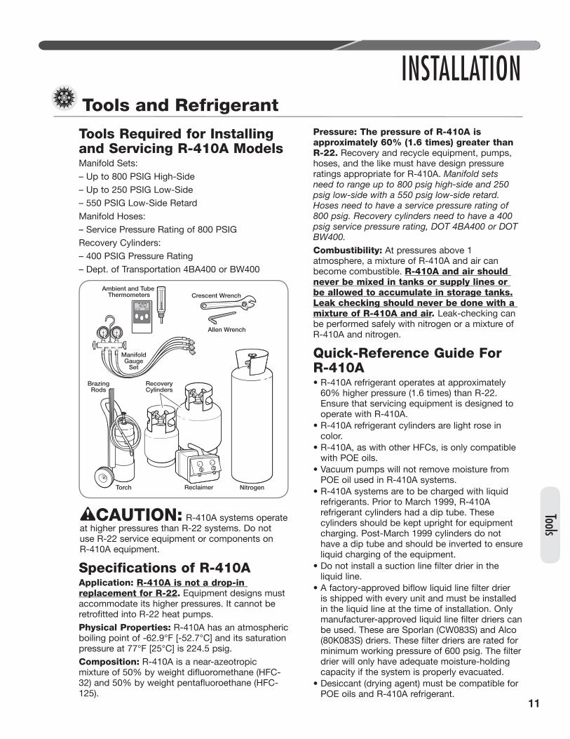
Tools Required for Installing and Servicing R-410A ModelsManifold Sets:– Up to 800 PSIG High-Side– Up to 250 PSIG Low-Side– 550 PSIG Low-Side RetardManifold Hoses:– Service Pressure Rating of 800 PSIGRecovery Cylinders:– 400 PSIG Pressure Rating– Dept. of Transportation 4BA400 or BW400
CAUTION: R-410A systems operate at higher pressures than R-22 systems. Do not use R-22 service equipment or components on R-410A equipment.
Specifications of R-410AApplication: R-410A is not a drop-in replacement for R-22. Equipment designs must accommodate its higher pressures. It cannot be retrofitted into R-22 heat pumps.Physical Properties: R-410A has an atmospheric boiling point of -62.9°F [-52.7°C] and its saturation pressure at 77°F [25°C] is 224.5 psig.Composition: R-410A is a near-azeotropic mixture of 50% by weight difluoromethane (HFC-32) and 50% by weight pentafluoroethane (HFC-125).
Pressure: The pressure of R-410A is approximately 60% (1.6 times) greater than R-22. Recovery and recycle equipment, pumps, hoses, and the like must have design pressure ratings appropriate for R-410A. Manifold sets need to range up to 800 psig high-side and 250 psig low-side with a 550 psig low-side retard. Hoses need to have a service pressure rating of 800 psig. Recovery cylinders need to have a 400 psig service pressure rating, DOT 4BA400 or DOT BW400.Combustibility: At pressures above 1 atmosphere, a mixture of R-410A and air can become combustible. R-410A and air should never be mixed in tanks or supply lines or be allowed to accumulate in storage tanks. Leak checking should never be done with a mixture of R-410A and air. Leak-checking can be performed safely with nitrogen or a mixture of R-410A and nitrogen.
Quick-Reference Guide For R-410A• R-410A refrigerant operates at approximately
60% higher pressure (1.6 times) than R-22. Ensure that servicing equipment is designed to operate with R-410A.
• R-410A refrigerant cylinders are light rose in color.
• R-410A, as with other HFCs, is only compatible with POE oils.
• Vacuum pumps will not remove moisture from POE oil used in R-410A systems.
• R-410A systems are to be charged with liquid refrigerants. Prior to March 1999, R-410A refrigerant cylinders had a dip tube. These cylinders should be kept upright for equipment charging. Post-March 1999 cylinders do not have a dip tube and should be inverted to ensure liquid charging of the equipment.
• Do not install a suction line filter drier in the liquid line.
• A factory-approved biflow liquid line filter drier is shipped with every unit and must be installed in the liquid line at the time of installation. Only manufacturer-approved liquid line filter driers can be used. These are Sporlan (CW083S) and Alco (80K083S) driers. These filter driers are rated for minimum working pressure of 600 psig. The filter drier will only have adequate moisture-holding capacity if the system is properly evacuated.
• Desiccant (drying agent) must be compatible for POE oils and R-410A refrigerant.
Ambient and Tube Thermometers
ManifoldGauge
Set
BrazingRods
Torch NitrogenReclaimer
RecoveryCylinders
Allen Wrench
Crescent Wrench

12
INSTALLATIONReplacement Units To prevent failure of a new unit, the existing line set must be correctly sized and cleaned or replaced. Care must be exercised that the expansion device is not plugged. For new and replacement units, a liquid line filter drier must be installed and refrigerant tubing must be properly sized. Test the oil for acid. If positive, a suction line filter drier is mandatory.
IMPORTANT: When replacing an R-22 unit with an R-410A unit, either replace the line set or ensure that residual mineral oil is drained from existing lines including oil trapped in low spots.
Indoor Coil
CAUTION: Only use evaporators approved for use on R-410A systems that are specifically matched with the outdoor unit per the manufacturer’s specification sheets. Use of existing R-22 evaporators can introduce mineral oil to the R-410A refrigerant, forming two different liquids and decreasing oil return to the compressor. This can result in compressor failure.REFER TO INDOOR COIL MANUFACTURER’S INSTALLATION INSTRUCTIONS.
IMPORTANT: The manufacturer is not responsible for the performance and operation of a mismatched system or for a match listed with another manufacturer’s coil.
NOTICE: All outdoor units must be installed with a matched TXV indoor coil. Refer to manufacturer’s outdoor unit specification sheet for approved indoor coils.
The thermostatic expansion valve in the matching coil is specifically designed to operate with R-410A. DO NOT use an R-22 TXV or evaporator. The existing evaporator must be replaced with the factory-specified EXV evaporator specifically designed for R-410A.
LocationDo not install the indoor coil in the return duct system of a gas or oil furnace. Provide a service inlet to the coil for inspection and cleaning. Keep the coil pitched toward the drain connection.
CAUTION: When coil is installed over a finished ceiling and/or living area, it is required that a secondary condensate pan be installed under entire unit. Failure to do so can result in property damage.
Interconnecting TubingThe purpose of this section is to specify the best construction/sizing practices for installing interconnection tubing between the indoor and outdoor unit.
Refrigerant Level AdjustmentAll units are factory-charged with R-410A refrigerant to cover 15 feet of standard size interconnecting liquid and vapor lines, not including the required liquid line filter drier. Refrigerant must be added for the filter/drier. Adjustment of charge may be necessary even if the application has exactly 15 feet of line set due to other installation variables such as pressure drop, vertical lift, and indoor coil size. For different lengths, adjust the charge as indicated below.
• 1/4" ± .3 oz./foot [6.4 mm ± 8.5 g/.30 m]• 5/16" ± .4 oz./foot [7.9 mm ± 11.3 g/.30 m]• 3/8" ± .6 oz./foot [9.5 mm ± 17.0 g/.30 m]• 1/2" ± 1.2 oz./foot [12.7 mm ± 34.0 g/.30 m]• 6 oz. required factory supplied field-installed• filter drier.
Charge Adjustment = (Line Set (oz./ft.) x TotalLength) – Factory Charge for Line Set
Example: A three ton heat pump unit with factory installed 3/8” liquid service valve requires 75 ft. of line set with a liquid line diameter of 1/2”.Factory Charge for Line Set = 15 ft. x .6 oz. = 9 oz.Charge Adjustment = (1.2 oz. x 75 ft.) – 9 oz. =+ 81 oz.
Tubin
g

13
Tubing
INSTALLATIONInterconnecting Tubing (cont.)
Interconnecting Tubing and Fitting LossesRefrigerant tubing is measured in terms of actual length and equivalent length. Actual length is used for refrigerant charge applications. Equivalent length takes into account pressure losses from
tubing length, fi ttings, vertical separation, acces-sories, and fi lter dryers. The table below references diff erent commonly used equivalent lengths.
Equivalent Length for Fi�ngs (�)
Line Size (in)
90° Short Radius Elbow
90° Long Radius Elbow
45° Elbow
Solenoid Valve
Check Valve
Site Glass
Filter Dryer
3/8 1.3 0.8 0.3 6 4 0.4 6 1/2 1.4 0.9 0.4 9 5 0.6 6 5/8 1.5 1 0.5 12 6 0.8 6 3/4 1.9 1.3 0.6 14 7 0.9 6 7/8 2.3 1.5 0.7 15 8 1 6
1-1/8 2.7 1.8 0.9 22 12 1.5 6
Liquid Line SelectionThe purpose of the liquid line is to transport warm sub-cooled liquid refrigerant from the outdoor unit to the indoor unit in cooling mode. In heating mode the liquid line returns sub-cooled liquid from the indoor unit to the outdoor unit. It is important not to allow the refrigerant to fl ash any superheated vapor prior to the expansion device of the indoor coil. The fl ashing of refrigerant can occur for the follow-ing reasons:• Low refrigerant charge • Improperly selected liquid line size • Absorption of heat prior to expansion device • Excessive vertical rise between the condenser
and evaporatorTable 2 lists the equivalent length per 25’ of liquid
line at various diameters up to 300’. The total pres-sure drop allowed for the liquid line is 50 PSI. The procedure for selecting the proper liquid line is as follows: • Measure the total amount of vertical rise • Measure the total amount of liquid line needed • Add all of the equivalent lengths associated with
any fi ttings or accessories using the table above. • Add the total length and fi tting pressure drop.
This will equal your total equivalent length. • Round-down the total equivalent length to the
closest value in Table 2. • Reference Table 2 to verify the rounded-down
value of the calculated equivalent length is com-patible with the required vertical rise and diam-eter of liquid line.
Table 1
Note: Eleva�on is defined as the highest point of the line set to the
lowest

14
INSTALLATIONInterconnecting Tubing (cont.)
Example: A 3-Ton heat pump unit is installed 50’ below the ID unit, requires a 75’ of 1/2” diameter liquid line, and 4 90° LR elbows. • Fitting Equivalent Length (ft.) = 4 x .9 = 3.6’ • Total Equivalent Length (ft.) = 75’ + 3.6’ = 78.6’ • Rounded-down value (ft.) = 75’
This application is acceptable because the 50’ vertical rise is less than the maximum rise of 75’ for this application. The application is also considered to have a long line set. Reference the long line set section of the I&O for detail.
R-410A System Capacity
Model
Liquid Line Size
Connection Size (Inch I.D.) [mm]
Liquid Line Size (Inch
O.D.) [mm]
Liquid Line Size Elevation (Above or Below) Indoor Coil
Total Equivalent Length - Feet [m] 25 [7.62] 50 [15.24] 75 [22.86] 100 [30.48] 125 [45.72] 150 [45.72] 175 [53.34] 200 [60.96] 225 [68.58] 250 [76.20] 275 [83.82] 300 [91.44]
Maximum Vertical Separation - Feet [m]
37 3/8" [9.53]
1/4 [6.35] 25 [7.62] N/R N/R N/R N/R N/R N/R N/R N/R N/R N/R N/R 5/16 [7.94] 25 [7.62] 50 [15.24] 60 [18.29] 45 [13.72] 35 [10.67] 20 [6.1] 5 [1.52] N/R N/R N/R N/R N/R 3/8 [9.53] 25 [7.62] 50 [15.24] 75 [22.86] 80 [24.38] 80 [24.38] 75 [22.86] 70 [21.34] 65 [19.81] 60 [18.29] 55 [16.76] 50 [15.24] 45 [13.72]
7/16 [11.12] 25 [7.62] 50 [15.24] 75 [22.86] 95 [28.96] 90 [27.43] 90 [27.43] 85 [25.91] 85 [25.91] 85 [25.91] 80 [24.38] 80 [24.38] 80 [24.38] 1/2 [12.71] 25 [7.62] 50 [15.24] 75 [22.86] 95 [28.96] 95 [28.96] 95 [28.96] 95 [28.96] 95 [28.96] 95 [28.96] 90 [27.43] 90 [27.43] 90 [27.43]
Long Line Set ApplicationsLong line set applications are defi ned as applica-tions that require accessories or alternate construc-tion methods. The following are special consider-ations that need to be addressed when installing a long line set application:
• Additional refrigerant charge • Fitting losses and maximum equivalent length
considerations • Refrigerant migration during the off cycle • Oil return to the compressor • Capacity losses • System oil level adjustment
Table 2 is used to determine if the application is considered to have a long line set. The region of the chart that is shaded grey is considered to be a long line set application.
Oil Level Adjustments for Long Line Set ApplicationsAdditional oil will need to be added for long line set applications. (Ref. Table 2). Below is the equation for the oil level adjustment and the compressor name plate oil charge for the diff erent od units.
Oil to be Added = [(Charge Adjustment + OD Unit Name Plate Charge (oz.)) x (0.022) – [(0.10) x (Compressor Name Plate Oil Charge (oz.))]
Example: An application requires 125ft of line set with a liquid line diameter of 3/8”, Charge Adjust-ment = 52.4 oz., Name Plate Charge = 107 oz., Name Plate Oil Charge = 25 oz., Oil to be Added = ((52.4 oz. +107 oz.) x .022) – (.10 x 25 oz.) = 1.0 oz.
OD Model Compressor Nameplate Oil Charge (oz)
(-)P2024 ZPV0212E-ZE9-130 40
(-)P2036
ZPV0342E-ZE9-130 40(-)P2048
(-)P2060 ZPV038CE-2E9-130 40
(Exerpt from Table 2, page 17)
Tubin
g

15
Tubing
Interconnecting Tubing (cont.)
Suction Line SelectionPurpose of the suction line is to return superheated vapor to the condensing unit from the evaporator in cooling mode. While in heating mode the suction line transports discharge vapor to the indoor unit from the outdoor unit. Proper suction line sizing is important because it plays an important role in returning oil to the compressor to prevent potential damage to the bearings, valves, and scroll sets. Also, an improperly sized suction line can dra-matically reduce capacity and performance of the system. The procedure for selecting the proper suction line is as follows: • The total amount of suction line needed • Add all of the equivalent lengths associated with
any fi ttings or accessories using the table on previous page.
• Add the total length and fi tting pressure drop. This will equal your total equivalent length.
• Reference Table 2 to verify that the calculated equivalent length falls within the compatibility region of the chart.
• Verify Table 3 to verify the capacity diff erence is compatible with the application.
Refrigerant Migration During Off CycleLong line set applications can require a consider-able amount of additional refrigerant. This addition-al refrigerant needs to be managed throughout the entire ambient operating envelope that the system will go through during its life cycle. Off -Cycle mi-gration is where excess refrigerant condenses and migrates to the lowest part of the system. Exces-sive build-up of refrigerant at the compressor will result in poor reliability and noisy operation during startup. This section demonstrates the required accessories and unit confi guration for diff erent ap-plications.
INSTALLATION
LIQUID LINE.
ST-A1219-01-01
IDEALLY, LINE SET SLOPES AWAYFROM OUTDOOR. VERIFYSUB-COOLING PRIOR TO
THROTTLEING DEVICE, INSULATED
REFERENCE TABLE 2 FOR MAXIMUM LENGTH LIMITATIONS
Outdoor Unit Level or Near Level to Indoor Section Line Set

16
INSTALLATIONInterconnecting Tubing (cont.)
For applications that are considered to have a long line set with the outdoor unit and indoor unit on the same level the following is required:
• EXV on the indoor unit (standard equipment) • Insulated liquid and suction line in unconditioned
space only.
• Vapor line should slope toward the indoor unit • Follow the proper line sizing, equivalent length,
charging requirements, and oil level adjustments spelled out in this document
• Verify at least 5°F sub-cooling at the ID unit prior to throttling device
For applications that are considered to have a long line set with the outdoor unit below the indoor unit the following is required: • EXV at the IDunit (standard equipment) • Inverted vapor-line trap (Reference Figure 3) • Insulated liquid and suction line in uncondi-
tioned space only.
• Follow the proper line sizing, equivalent length, charging requirements, and oil level adjustments spelled out in this document
• Measure pressure at the liquid line service valve and prior to expansion device. Verify that it is not greater than 50 PSI
• For elevations greater that 25’ can expect a lower sub-cooling
Figure 4
Tubin
g
INVERT TRAPEVEN WITH TOPOF THE COIL
INSULATE LIQUIDAND SUCTION
REFERENCE TABLE 2 FOR MAXIMUM LENGTH LIMITATIONS
ST-A1219-02-01
LINE
Outdoor Unit Below Indoor Section Line Set

17
Tubing
INSTALLATIONInterconnecting Tubing (cont.)
Figure 5
Insulated liquid and suc�on line
TXV or EEV at indoor evaporator
Reference Table 2 for eleva�on limita�ons
Verify sub-cooling prior to thro�ling device
For applications that are considered to have a long line set with the outdoor unit above the indoor unit the following is required: • EXV at the indoor unit (standard equipment) • Insulated liquid and suction line in unconditioned
space only.
• Follow the proper line sizing, equivalent length, charging requirements, and oil level adjustments spelled out in this document
• Verify at least 5°F sub-cooling at the ID unit prior to throttling device
Outdoor Unit Above Indoor Unit

18
25 [7.62]50 [15.24]
75 [22.86]100 [30.48]
125 [45.72]150 [45.72]
175 [53.34]200 [60.96]
225 [68.58]250 [76.20]
275 [83.82]300 [91.44
]
1/4 [6.35]25 [7.62]
50 [15.24]25 [7.62]
N/R
N/R
N/R
N/R
N/R
N/R
N/R
N/R
N/R
5/16 [7.94]25 [7.62]
50 [15.24]75 [22.86]
75 [22.86]70 [21.34]
65 [19.81]60 [18.29]
50 [15.24]45 [13.72]
40 [12.19]30 [9.14]
25 [7.62]
3/8 [9.53]25 [7.62]
50 [15.24]75 [22.86]
95 [28.96]90 [27.43]
90 [27.43]85 [25.91]
85 [25.91]85 [25.91]
80 [24.38]80 [24.38]
75 [22.86]
7/16 [11.12]25 [7.62]
50 [15.24]75 [22.86]
100 [30.48]100 [30.48]
95 [28.96]95 [28.96]
95 [28.96]95 [28.96]
95 [28.96]95 [28.96]
90 [27.43]1/2 [12.71]
25 [7.62]50 [15.24]
75 [22.86]100 [30.48]
100 [30.48]100 [30.48]
100 [30.48]100 [30.48]
100 [30.48]100 [30.48]
100 [30.48]
100 [30.48]
1/4 [6.35]10 [3.05]
N/R
N/R
N/R
N/R
N/R
N/R
N/R
N/R
N/R
N/R
N/R
5/16 [7.94]25 [7.62]
50 [15.24]30 [9.14]
10 [3.05]N
/RN
/RN
/RN
/RN
/RN
/RN
/RN
/R3/8 [9.53]
25 [7.62]50 [15.24]
70 [21.34]65 [19.81]
55 [16.76]50 [15.24]
45 [13.72]35 [10.67]
30 [9.14]25 [7.62]
15 [4.57]10 [3.05]
7/16 [11.12]25 [7.62]
50 [15.24]75 [22.86]
80 [24.38]75 [22.86]
75 [22.86]70 [21.34]
65 [19.81]65 [19.81]
60 [18.29]60 [18.29]
55 [16.76]
1/2 [12.71]25 [7.62]
50 [15.24]75 [22.86]
85 [25.91]85 [25.91]
80 [24.38]80 [24.38]
80 [24.38]80 [24.38]
75 [22.86]75 [22.86]
75 [22.86]N
OT
ES
:N
/R =
Application not recom
mended.
Grey = This application is acceptable, but the long line guidelines m
ust be followed. Reference Long Line Set section in the I&
O.
Total E
qu
ivalent Length - F
eet [m]
INSTALLATION Interconnecting T
ubing
R-410A
S
ystem
Capacity M
odel
Liquid Line C
onnection S
ize (Inch I.D.)
[mm
]
Liquid Line S
ize (Inch O
.D.) [m
m]
Maxim
um
Vertical S
eparation - Feet [m
]
Liq
uid
Lin
e Size
Elevatio
n A
bo
ve or B
elow
Ind
oo
r Co
il
RP
2048A3/8" [9.53]
3/8" [9.53]R
P2024A
Tubin
g

19
Tubing
25 [7.62]50 [15.24]
75 [22.86]100 [30.48]
125 [45.72]150 [45.72]
175 [53.34]200 [60.96]
225 [68.58]250 [76.20]
275 [83.82]300 [91.44
]
5/8 [15.88]0.99
0.990.97
0.960.95
0.940.93
0.920.91
0.910.89
0.893/4 [19.05]
1.001.00
0.990.99
0.990.98
0.970.97
0.960.96
0.960.95
7/8 [22.23]N
/RN
/RN
/RN
/RN
/RN
/RN
/RN
/RN
/RN
/RN
/RN
/R1 [25.4]
N/R
N/R
N/R
N/R
N/R
N/R
N/R
N/R
N/R
N/R
N/R
N/R
1-1/8 [28.58]N
/RN
/RN
/RN
/RN
/RN
/RN
/RN
/RN
/RN
/RN
/RN
/R5/8 [15.88]
0.990.97
0.970.96
0.950.93
0.930.92
0.910.9
0.890.88
3/4 [19.05]0.96
0.940.91
0.890.86
0.840.82
0.820.81
0.810.8
0.817/8 [22.23]
1.000.99
0.980.97
0.970.97
0.960.96
0.950.95
0.950.94
1 [25.4]N
/RN
/RN
/RN
/RN
/RN
/RN
/RN
/RN
/RN
/RN
/RN
/R1-1/8 [28.58]
N/R
N/R
N/R
N/R
N/R
N/R
N/R
N/R
N/R
N/R
N/R
N/R
NO
TE
S:
N/R
= A
pplication not recomm
ended.A
ll calculations accume a 3/8" liquid line
INSTALLATION Interconnecting T
ubing (cont.)
R-410A
S
ystem
Capacity M
odel
Vapor Line
Connection S
ize (Inch I.D
.) [mm
]
Vapor Line
Size (Inch
O.D
.) [mm
]
Vap
or L
ine S
election
Ch
artC
apacity M
ultip
lier Tab
le
Total E
qu
ivalent Length - F
eet [m]
RP
2048A7/8" [22.23]
RP
2024A3/4" [19.06]

20
Tubing InstallationObserve the following when installing correctly sized type “L” refrigerant tubing between the condensing unit and evaporator coil:• Check the tables on pages 18 and 19 for the
correct suction line size and liquid line size.• If a portion of the liquid line passes through a
very hot area where liquid refrigerant can be heated to form vapor, insulating the liquid line is required.
• Use clean, dehydrated, sealed refrigeration-grade tubing.
• Always keep tubing sealed until tubing is in place and connections are to be made.
• A high-quality biflow filter drier is included with all R-410A heat pump units and must be installed in the liquid line upon unit installation.
• When replacing an R-22 system with an R-410A system and the line set is not replaced, use a flush kit available through aftermarket stores such as Prostock.
• If tubing has been cut, make sure ends are deburred while holding in a position to prevent chips from falling into tubing. Burrs such as those caused by tubing cutters can affect performance dramatically, particularly on small liquid line sizes.
• For best operation, keep tubing run as short as possible with a minimum number of elbows or bends.
• Locations where the tubing will be exposed to mechanical damage should be avoided. If it is necessary to use such locations, the copper tubing should be housed to prevent damage.
INSTALLATIONInterconnecting Tubing (cont.)
Tubin
g

21
Tubing
• If tubing is to be run underground, it must be run in a sealed watertight chase.
• Use care in routing tubing and do not kink or twist. Use a good tubing bender on the vapor line to prevent kinking.
• Route the tubing using temporary hangers; then straighten the tubing and install permanent hangers. Line must be adequately supported.
• If the vapor line comes in contact with inside walls, ceiling, or flooring, the vibration of the vapor line in the heating mode will result in noise inside the structure.
• Blow out the liquid and vapor lines with dry nitrogen before connecting to the outdoor unit and indoor coil. Any debris in the line set will end up plugging the expansion device.
Tubing ConnectionsIndoor coils have only a holding charge of dry nitrogen. Keep all tube ends sealed until connections are to be made.• Use type “L” copper refrigeration tubing. Braze
the connections with the following alloys:– copper to copper, 5% silver minimum– copper to steel or brass, 15% silver minimum
• Be certain both refrigerant shutoff valves at the outdoor unit are closed.
• Remove the caps and Schrader cores from the pressure ports to protect seals from heat damage. Both the Schrader valves and the service valves have seals that may be damaged by excessive heat.
• Clean the inside of the fittings and outside of the tubing with a clean, dry cloth before soldering. Clean out debris, chips, dirt, etc., that enters tubing or service valve connections.
• Wrap valves with a wet rag or thermal barrier compound before applying heat.
INSTALLATIONInterconnecting Tubing (cont.)
TEMPORARYHANGER PERMANENT
HANGER
ST-A1226-05-00
22
Tubin
g
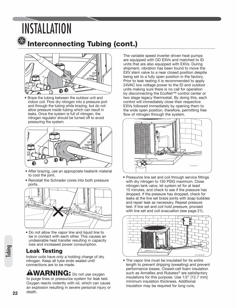
• Braze the tubing between the outdoor unit and indoor coil. Flow dry nitrogen into a pressure port and through the tubing while brazing, but do not allow pressure inside tubing which can result in leaks. Once the system is full of nitrogen, the nitrogen regulator should be turned off to avoid pressuring the system.
• After brazing, use an appropriate heatsink material to cool the joint.
• Reinstall the Schrader cores into both pressure ports.
• Do not allow the vapor line and liquid line to be in contact with each other. This causes an undesirable heat transfer resulting in capacity loss and increased power consumption.
Leak TestingIndoor coils have only a holding charge of dry nitrogen. Keep all tube ends sealed until connections are to be made.
WARNING: Do not use oxygen to purge lines or pressurize system for leak test. Oxygen reacts violently with oil, which can cause an explosion resulting in severe personal injury or death.
The variable speed inverter driven heat pumps are equipped with OD EXVs and matched to ID units that are also equipped with EXVs. During shipment, vibration has been found to move the EXV stem valve to a near closed position despite being set to a fully open position in the factory. Prior to leak testing it is recommended to apply 24VAC low voltage power to the ID and outdoor units making sure there is no call for operation by disconnecting the EcoNet™ control center or two stage legacy thermostat. By doing this, each control will immediately close their respective EXVs followed immediately by opening them to the wide open position, therefore, permitting free flow of nitrogen through the system.
• Pressurize line set and coil through service fittings with dry nitrogen to 150 PSIG maximum. Close nitrogen tank valve, let system sit for at least 15 minutes, and check to see if the pressure has dropped. If the pressure has dropped, check for leaks at the line set braze joints with soap bubbles and repair leak as necessary. Repeat pressure test. If line set and coil hold pressure, proceed with line set and coil evacuation (see page 21).
• The vapor line must be insulated for its entire length to prevent dripping (sweating) and prevent performance losses. Closed-cell foam insulation such as Armaflex and Rubatex® are satisfactory insulations for this purpose. Use 1/2" [12.7 mm] minimum insulation thickness. Additional insulation may be required for long runs.
INSTALLATIONInterconnecting Tubing (cont.)
ST-A1226-07-00
ST-A1226-06-00

23
WIRINGControl Wiring
WiringWARNING: Turn off electric power at the fuse box or service panel before making any electrical connections. Also, the ground connection must be completed before making line voltage connections. Failure to do so can result in electrical shock, severe personal injury, or death.
EcoNet™ Control CommunicationsThe EcoNet™ enabled (-)P20 series of heat pumps are designed to operate with conventional 24VAC Thermostat or an EcoNet™ communicating control center. If the (-)P20 outdoor unit is installed with a conventional 24VAC Thermostat some features and comfort settings will not be available.
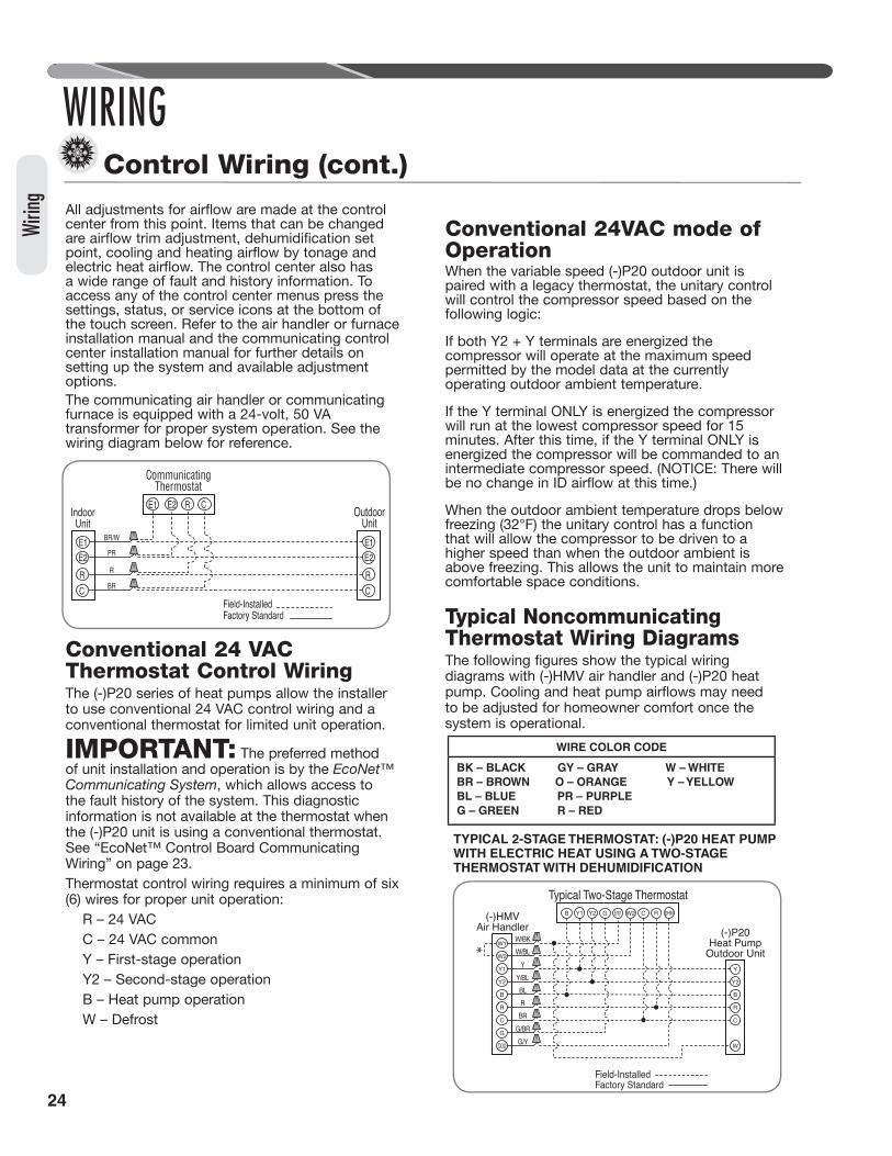
Control WiringRunning low-voltage wires in conduit with line voltage power wires is not recommended. Low-voltage wiring may be run through the insulated bushing provided in the 7/8" [19 mm] hole in the base panel, up to and attached to the pigtails from the bottom of the control box. Conduit can be run to the base panel if desired by removing the insulated bushing.A thermostat and a 24-volt, 40 VA minimum transformer are required for the control circuit of the system. The furnace or the air handler transformer may be used if sufficient. See the wiring diagram for reference. Use “Wire Size” table on page 23 to size the 24-volt control wiring.
EcoNet™ Control Board Communication WiringThe four 18 AWG low-voltage control wires must be installed from the control center to the indoor unit and from the indoor unit to the outdoor unit. The wire length between the control center and indoor unit should not be greater than 100 feet [30.5 m].
The wire length between the indoor unit and outdoor unit should not be greater than 125 feet [38.1 m].An EcoNet™ communicating HVAC system consists of these matched components:
• EcoNet™ communicating heat pump or EcoNet™ communicating condensing unit.
• EcoNet™ communicating air handler or EcoNet™ communicating furnace.
• EcoNet™ control center.
IMPORTANT: If the installed system does not meet these requirements, the system must be wired using traditional control wiring. See “Conventional 24 VAC Thermostat Control Wiring” on page 24.Do not use phone cord to connect indoor and outdoor units. This will damage the controls.
IMPORTANT: EcoNet™ require systems continuous 18 AWG thermostat wire. The EcoNet™ Control requires four (4) control wires for unit operation:• R 24 VAC• C 24 VAC common• Data wire E1 Communications• Data wire E2 Communications
Air Handler Air Conditioner or Furnace or Heat PumpControl Center Indoor OutdoorE1 – – – – – – – – – – – E1– – – – – – – – – E1E2 – – – – – – – – – – – E2 – – – – – – – – E2R – – – – – – – – – – – – R – – – – – – – – – RC – – – – – – – – – – – – C – – – – – – – – – C
These wires need to be connected to each device control center, indoor air handler or furnace, and outdoor unit (heat pump or AC).Once all devices are connected, apply the line and low voltage to the system.When all devices are powered, the control center should detect the indoor and outdoor units within 45 seconds.Once the system is powered, the airflow settings will be configured for all devices.
Thermo-stat Load (amps)
SOLID COPPER WIRE – AWG
3.02.52.0
16 14 12 10 10 10 16 14 12 10 10 10 16 14 12 10 10 10
50 100 150 200 250 300[15] [30] [46] [61] [76] [91]Length of Run – Feet [m] (1)
FIELD WIRE SIZE FOR 24-VOLT THERMOSTAT CIRCUITS
(1) Wire length equals twice the run distance.NOTICE: Do not use control wiring smaller than No. 18 AWG between thermostat and outdoor unit.
24
All adjustments for airflow are made at the control center from this point. Items that can be changed are airflow trim adjustment, dehumidification set point, cooling and heating airflow by tonage and electric heat airflow. The control center also has a wide range of fault and history information. To access any of the control center menus press the settings, status, or service icons at the bottom of the touch screen. Refer to the air handler or furnace installation manual and the communicating control center installation manual for further details on setting up the system and available adjustment options.The communicating air handler or communicating furnace is equipped with a 24-volt, 50 VA transformer for proper system operation. See the wiring diagram below for reference.
Conventional 24 VACThermostat Control WiringThe (-)P20 series of heat pumps allow the installer to use conventional 24 VAC control wiring and a conventional thermostat for limited unit operation.
IMPORTANT: The preferred method of unit installation and operation is by the EcoNet™ Communicating System, which allows access to the fault history of the system. This diagnostic information is not available at the thermostat when the (-)P20 unit is using a conventional thermostat. See “EcoNet™ Control Board Communicating Wiring” on page 23.Thermostat control wiring requires a minimum of six (6) wires for proper unit operation:
R – 24 VACC – 24 VAC commonY – First-stage operationY2 – Second-stage operationB – Heat pump operationW – Defrost
Conventional 24VAC mode ofOperationWhen the variable speed (-)P20 outdoor unit is paired with a legacy thermostat, the unitary control will control the compressor speed based on the following logic:
If both Y2 + Y terminals are energized the compressor will operate at the maximum speed permitted by the model data at the currently operating outdoor ambient temperature.
If the Y terminal ONLY is energized the compressor will run at the lowest compressor speed for 15 minutes. After this time, if the Y terminal ONLY is energized the compressor will be commanded to an intermediate compressor speed. (NOTICE: There will be no change in ID airflow at this time.)
When the outdoor ambient temperature drops below freezing (32°F) the unitary control has a function that will allow the compressor to be driven to a higher speed than when the outdoor ambient is above freezing. This allows the unit to maintain more comfortable space conditions.
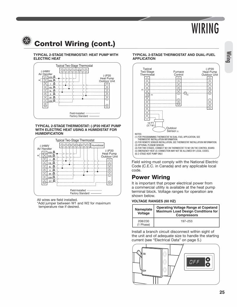
Typical Noncommunicating Thermostat Wiring DiagramsThe following figures show the typical wiring diagrams with (-)HMV air handler and (-)P20 heat pump. Cooling and heat pump airflows may need to be adjusted for homeowner comfort once the system is operational.
Wirin
g
WIRINGControl Wiring (cont.)
TYPICAL 2-STAGE THERMOSTAT: (-)P20 HEAT PUMP WITH ELECTRIC HEAT USING A TWO-STAGE THERMOSTAT WITH DEHUMIDIFICATION
Field-Installed Factory Standard
(-)HMVAir Handler (-)P20
Heat PumpOutdoor Unit
Typical Two-Stage Thermostat
W1
W2
Y1
Y2
B
R
C
G
ODD
B Y1 Y2 G E/W1 W2 C R DHM
Y
Y2
B
R
C
W
W/BK
W/BL
Y
Y/BL
BL
R
BR
G/BR
G/Y
IndoorUnit
BR/W
PR
R
BR
E1 E2 CR
CommunicatingThermostat
OutdoorUnit
E1
E2
C
R
E1
E2
C
R
Field-Installed Factory Standard
WIRE COLOR CODE
BK – BLACK GY – GRAY W – WHITEBR – BROWN O – ORANGE Y – YELLOWBL – BLUE PR – PURPLEG – GREEN R – RED
25
Field wiring must comply with the National Electric Code (C.E.C. in Canada) and any applicable local code.
Power WiringIt is important that proper electrical power from a commercial utility is available at the heat pump terminal block. Voltage ranges for operation are shown below.VOLTAGE RANGES (60 HZ)
Install a branch circuit disconnect within sight of the unit and of adequate size to handle the starting current (see “Electrical Data” on page 5.)
TYPICAL 2-STAGE THERMOSTAT: HEAT PUMP WITH ELECTRIC HEAT
Field-Installed Factory Standard
(-)HMVAir Handler (-)P20
Heat PumpOutdoor Unit
Typical Two-Stage Thermostat
W/BK
W/BL
Y
Y/BL
BL
R
BR
G/BK
W1
W2
Y1
Y2
B
R
C
G
ODD
B Y1 Y2 G E/W1 W2 C R
Y
Y2
B
R
C
W
TYPICAL 2-STAGE THERMOSTAT: (-)P20 HEAT PUMP WITH ELECTRIC HEAT USING A HUMIDISTAT FOR HUMIDIFICATION
Field-Installed Factory Standard
(-)HMVAir Handler
(-)P20Heat Pump
Outdoor Unit
Typical Two-Stage Thermostat
W1
W2
Y1
Y2
B
R
C
G
ODD
B Y1 Y2 G E/W1 W2 C R
Y
Y2
B
R
C
W
Humidistat
W/BK
W/BL
Y
Y/BL
BL
R
BR
G/BK
G/Y
All wires are field installed.*Add jumper between W1 and W2 for maximum temperature rise if desired.
WIRING
Wiring
Control Wiring (cont.)
Nameplate Voltage
Operating Voltage Range at Copeland Maximum Load Design Conditions for
Compressors
208/230 (1 Phase)
197–253
NOTES:(1) FOR PROGRAMMING THERMOSTAT IN DUAL-FUEL APPLICATION, SEE THERMOSTAT INSTALLATION INFORMATION.(2) FOR REMOTE SENSOR INSTALLATION, SEE THERMOSTAT INSTALLATION INFORMATION.(3) OPTIONAL PLENUM SENSOR.(4) FOR TWO STAGES, CONNECT W2 ON THERMOSTAT TO W2 ON THE CONTROL BOARD.(5) EMERGENCY HEAT (E) CONNECTION MAY NOT BE ALLOWED BY LOCAL CODES.(6) 2-STAGE HEAT PUMP ONLY.
R
C
W2
W/E
Y
(5)
(6) Y2
G
V
B
+
S
–
R
C
W
Y
Y2
1
2
B
W2
R
C
W
YL
YH
G
PS(3)
OutdoorSensor (2)
12 FT.(3.7 M )
(-)P20Heat Pump
Outdoor Unit
TypicalTwo-StageThermostat
FurnaceControl
TYPICAL 2-STAGE THERMOSTAT AND DUAL-FUEL APPLICATION

26
Power wiring must be run in a rain-tight conduit. Conduit must be run through the connector panel below the access cover (see page 6) and attached to the bottom of the control box.
Connect power wiring to line-voltage lugs located in the outdoor heat pump unit electrical box. (See wiring diagram attached to unit access panel.)
Check all electrical connections, including factory wiring within the unit and make sure all connections are tight.DO NOT connect aluminum field wire to the (-)P20 terminal block.
GroundingWARNING: The unit must be
permanently grounded. Failure to do so can cause electrical shock resulting in severe personal injury or death.
A grounding lug is provided near the line-voltage power entrance for a ground wire.
Wirin
g
WIRINGControl Wiring (cont.)
ST-A1241-02-X0
ST-A1241-01-X0

27
The air distribution system has the greatest effect on airflow. The duct system is totally controlled by the contractor. For this reason, the contractor should use only industry-recognized procedures.The correct air quantity is critical to air conditioning systems. Proper operation, efficiency, compressor life, and humidity control depend on the correct balance between indoor load and outdoor unit capacity. Excessive indoor airflow increases the possibility of high humidity problems. Low indoor airflow reduces total capacity and causes coil icing. Serious harm can be done to the compressor by low airflow, such as that caused by refrigerant flooding.Heat pump systems require a specified airflow. Each ton of cooling requires between 320 and 450 cubic feet of air per minute (CFM). See the manufacturer’s spec sheet for rated airflow for the system being installed.Duct design and construction should be carefully done. System performance can be lowered dramatically through bad planning or workmanship.The fully variable speed inverter driven systems have a dramatic variation between maximum and minimum airflow. For this reason only certain indoor air handlers and furnaces are approved as air moving matches to this product. When designing duct work this variation must be considered for optimal air delivery to all conditioned spaces. If the duct work is not adequately designed low stage airflow may not reach certain registers within the conditioned area.
Air supply diffusers must be selected and located carefully. They must be sized and positioned to deliver treated air along the perimeter of the space. If they are too small for their intended airflow, they become noisy. If they are not located properly, they cause drafts. Return air grilles must be properly sized to carry air back to the blower. If they are too small, they also cause noise.The installers should balance the air distribution system to ensure proper quiet airflow to all rooms in the home. This ensures a comfortable living space.These simple mathematical formulas can be used to determine the CFM in a residential or light commercial system.Electric resistance heaters can use: CFM = volts x amps x 3.413 SHC x temp riseGas furnaces can use: CFM = Output Capacity in BTUH* SHC x temp rise*Refer to furnace data plate for furnace output capacity.SHC = Sensible Heat Constant (see table below)An air velocity meter or airflow hood can give a more accurate reading of the system CFM.The measurement for temperature rise should be performed at the indoor coil inlet and near the outlet, but out of direct line of sight of the heater element or heat exchanger. For best results, measure air temperature at multiple points and average the measurements to obtain coil inlet and outlet temperatures.
START-UP
Start-Up
Start-Up
At initial start-up or after extended shutdown periods, make sure the stator heat is energized for at least 12 hours before the compressor is started. (Disconnect switch is on and wall thermostat is off.)
Connect the communicating system according to the wiring diagram on pages 24 or 25. Once all devices are connected, power up the line and low voltage to the system. When all devices are powered, the thermostat should detect the indoor and outdoor units within 45 seconds.Even though the unit is factory-charged with Refrigerant-410A, the charge must be checked to the charge table attached to the service panel and adjusted, if required. Allow a minimum of 15 minutes of run time before analyzing charge.
Checking Airfl ow
Airfl ow

28
Evacuation ProcedureEvacuation is the most important part of the entire service procedure. The life and efficiency of the equipment is dependent upon the thoroughness exercised by the serviceman when evacuating air and moisture from the system.Air or nitrogen in the system causes high condensing temperatures and pressure, resulting in increased power input and nonverifiable performance. Moisture chemically reacts with the refrigerant and oil to form corrosive hydrofluoric acid. This attacks motor windings and parts, causing breakdown.
• After the system has been leak-checked and proven sealed, connect the vacuum pump and evacuate system to 500 microns and hold 500 microns or less for at least 15 minutes. The vacuum pump must be connected to both the high and low sides of the system by connecting to the two pressure ports. Use the largest size connections available since restrictive service connections may lead to false readings because of pressure drop through the fittings.
• After adequate evacuation, open both service valves by removing both brass service valve caps with an adjustable wrench. Insert a 3/16" [5 mm] or 5/16" [8 mm] hex wrench into the stem and turn counterclockwise until the wrench stops.
• Gauges must be connected at this point to check and adjust charge. Do not replace caps yet.
IMPORTANT: Compressors (especially scroll type) should never be used to evacuate the air conditioning system because internal electrical arcing may result in a damaged or failed compressor. Never run a scroll compressor while the system is in a vacuum or compressor failure will occur.
Final Leak TestingAfter the unit has been properly evacuated and service valves opened, a halogen leak detector should be used to detect leaks in the system. All piping within the heat pump, evaporator, and interconnecting tubing should be checked for leaks. If a leak is detected, the refrigerant should be recovered before repairing the leak. The Clean Air Act prohibits releasing refrigerant into the atmosphere.
ALTITUDE (FEET)
SENSIBLE HEAT CONSTANT
(SHC)
ALTITUDE (FEET)
SENSIBLE HEAT CONSTANT
(SHC)
Sea Level 1.08 6000 0.87
500 1.07 7000 0.84
1000 1.05 8000 0.81
2000 1.01 9000 0.78
3000 0.97 10000 0.75
4000 0.94 15000 0.61
5000 0.90 20000 0.50
START-UP
Evac
uatio
n
Evacuation and Leak Testing

29
START-UPChecking Refrigerant Charge
Charge for all systems should be checked against the Charging Chart inside the access panel cover.
WARNING: The top of the scroll compressor shell is hot. Touching the compressor top may result in serious personal injury.
IMPORTANT: Use factory-approved charging method as outlined on the next page to ensure proper system charge.
NOTICE: The optimum refrigerant charge for any outdoor unit matched with an indoor coil/air handler is affected by the application. Therefore, charging data has been developed to assist the field technician in optimizing the charge for all mounting configurations (UF – Upflow, DF – Downflow, LH – Left-Hand Discharge, and RH – Right-Hand Discharge). Refer to the charging chart inside the access panel cover on the unit and choose the appropriate column for the specific application being installed or serviced. New installations utilizing either an RCF indoor coil installed on a gas furnace or an RH series air handler in the downflow or horizontal right-hand discharge may require removal of refrigerant since the factory charge could result in an overcharge condition.
Charging Units With R-410A Refrigerant
CAUTION: R-410A pressures are approximately 60% higher (1.6 times) than R-22 pressures. Use appropriate care when using this refrigerant. Failure to exercise care may result in equipment damage or personal injury.Charge for all systems should be checked against the Charging Chart inside the access panel cover.
IMPORTANT: Do not operate the compressor without charge in the system.Addition of R-410A will raise high-side pressures (liquid and discharge).
NOTICE: System maintenance is to be performed by a qualified and certified technician.The following method is used for charging systems in the cooling and heating mode. All steps listed should be performed to ensure proper charge has been set. For measuring pressures, the service valve port on the liquid valve (small valve) and the service port on the suction line between the reversing valve and compressor are to be used.
Confirm ID Airflow and Coils Are CleanConfirm adequate indoor supply airflow prior to starting the system. See the Technical Specification Sheet for rated airflow for each ID/OD unit match. Air filter(s) and coils (indoor and outdoor) are to be clean and free of frost prior to starting the system. Supply airflow must be between 320 and 450 cfm per rated cooling ton prior to adjusting system charge. If a humidification system is installed, disengage it from operation prior to charge adjustment. Verify that the outdoor unit is operating in high stage and the indoor air mover is delivering the high-stage airflow for this system size. Refer to the “Checking Airflow” section of this manual for further instruction.
NOTICE: Verify system components are matched according to the outdoor unit Specification Sheet.
Measurement Device Setup1. With an R-410A gauge set, attach the high-
pressure hose to the access fitting on the liquid line (small) service valve at the OD unit.
2. Attach the low-pressure hose to the common suction port connected to the common suction line between the reversing valve and compressor.
3. Attach a temperature probe within 6" [15.2 cm] outside of the unit on the copper liquid line (small line). For more accurate measurements, clean the copper line prior to measurement and use a calibrated clamp-on temperature probe or an insulated surface thermocouple.
Charging by WeightNOTICE: Adjust the system charge by weight for the straight length of the refrigerant line set.For a new installation, evacuation of inter-connecting tubing and indoor coil is adequate; otherwise, evacuate the entire system. Use the factory charge shown in “Electrical and Physical Data” on page 5 of these instructions or on the unit data plate. Note that the charge value includes charge required for 15 ft. [4.6 m] of standard-size interconnecting liquid line without a filter drier. Calculate actual charge required with installed liquid line size and length using:1/4" [6.4 mm] O.D. = .3 oz./ft. [8.5 g/.30 m]5/16" [7.9 mm] O.D. = .4 oz./ft. [11.3 g/.30 m]3/8" [9.5 mm] O.D. = .6 oz./ft. [17.0 g/.30 m]1/2" [12.7 mm] O.D. = 1.2 oz./ft. [34.0 g/.30 m]Add 6 oz. for field-installed filter drier.
Refrigerant

30
With an accurate scale (+/– 1 oz. [28.3 g]) or volumetric charging device, adjust charge difference between that shown on the unit data plate and that calculated for the new system installation. If the entire system has been evacuated, add the total calculated charge.
IMPORTANT: Charging by weight is not always accurate since the application can affect the optimum refrigerant charge. Charging by weight is considered a starting point ONLY. Always check the charge by using the Charging Chart and adjust as necessary. CHARGING BY LIQUID SUBCOOLING MUST BE USED FOR FINAL CHARGE ADJUSTMENT.
With thermostat in the “Off” position, turn on the power to the furnace or air handler and the heat pump. Start the heat pump and the furnace or air handler with the thermostat. Verify that the outdoor unit is operating in high stage and the indoor air mover is delivering the correct airflow for the system size.
IMPORTANT: R-410A is a blended refrigerant of R-32 and R-125 ( 50/50). These two refrigerants have different saturation curves and therefore change state at different pressures and temperatures. If charge is added to the system in the vapor state, it is possible to have a disproportionate amount of each part of the R-410A blend which will cause unstable and inefficient operation. Therefore, it is critical to add R-410A in the liquid form only!
Setting Compressor Speed for Charge AdjustmentWhen operating the Three Stage Variable speed system in legacy mode, it is necessary to set the compressor speed by using the push buttons located on the control board in the outdoor unit. In order to set proper charge level the compressor speed must be operating at high speed/high stage. Use the following process to set the compressor speed for charge mode:
IMPORTANT: It is necessary to make sure the ID unit is receiving a high stage operation call (Y + Y2) from the thermostat before entering this mode. Failure to do so can cause operating envelope, low pressure, or overcurrent faults causing the system to automatically shut down.1. Depress the TEST & SW2 buttons at the same
time for 5 – 8 seconds.2. After this time the dual seven segment LEDs
will show the first menu option (FC).3. Depress the TEST button one time and the
dual seven segment LEDs will show CS, which represents Compressor Speed.
4. Depress the SW2 button to enter the Compressor Speed menu.
5. After entering the Compressor Speed menu the dual seven segment will show a value of 3.
Note: If the dual seven segment LEDs show a value of 1, the VS ODU does not have a Y+Y2 signal. Check the wiring and thermostat requested stage of operation before proceding.
6. At this point the control will send the compressor to high stage based on the outdoor dry bulb temperature and model data programed for the specific model being installed.
NOTICE: After Charge analysis is complete the Test button must be pushed to exit the Compressor Speed menu and allow the thermostat to regain control of the outdoor unit. If this is not performed the unit will respond to operational calls from the thermostat, but will not reduce compressor speed for 24 hours. This will result in reduced efficiency for the three stage system and may induce nuisance operating envelope, low pressure, or overcurrent faults.
Gross Charging by Pressures1. Following airflow verification and charge weigh-
in, run the unit for a minimum of 15 minutes prior to noting pressures and temperature.
IMPORTANT: Indoor conditions as measured at the indoor coil must be within 2°F [1.1°C] of the following during gross charge (pressure) evaluation:
Cooling Mode: 80°F [26.7°C] Dry BulbHeating Mode: 70°F [21.1°C] Dry Bulb
NOTICE: If the Indoor temperature is above or below this range, run the system to bring the
START-UPChecking Refrigerant Charge (cont.)
Refri
gera
nt

31
Refrigerant
START-UPChecking Refrigerant Charge (cont.)
temperature down or run the electric heat/furnace to bring the temperature within this range. System pressure values provided in the Charging Chart for outdoor dry bulbs corresponding to conditions outside of these ranges are provided as reference ONLY. 2. Note the Outdoor Dry Bulb Temperature,
ODDB° = _____°F [_____°C]. Unit charging is recommended under the following outdoor conditions ONLY:Cooling Mode ONLY: 55°F [12.8°C] outdoor dry bulb and aboveHeating Mode ONLY: Between 40°F [4.4°C] and 60°F [15.6°C] outdoor dry bulb
3. Locate and note the design pressures. The correct liquid and vapor pressures are found at the intersection of the installed system and the outdoor ambient temperature on the Charging Chart located inside the access panel cover. Liquid Pressure: = ______psig; Vapor Pressure = ______psig
NOTICE: The refrigerant pressures provided are for gross charge check ONLY. These pressure values are typical, but may vary due to application. Evaporator load (indoor coil in cooling mode/outdoor coil in heating mode) will cause pressures to deviate. Note that all systems have unique pressure curves. The variation in the slope and value is determined by the component selection for that indoor/outdoor matched system. The variation from system to system seen in the table is normal. The values listed are for the applicable indoor coil match ONLY!4. If the measured liquid pressure is below the
listed requirement for the given outdoor and indoor conditions, add charge. If the measured liquid pressure is above the listed requirement for the given outdoor and indoor conditions, remove charge.
Final Charge by Subcooling1. After gross charging, note the designed
subcooling value. The correct subcooling value is found at the intersection of the installed system and the outdoor ambient temperature on the Charging Chart located inside the access panel cover. SC° from Charging Chart = _____°F [_____°C].
IMPORTANT: Indoor conditions as measured at the indoor coil are required to be between 70°F [21.1°C] and 80°F [26.7°C] dry
bulb for fine-tuned unit charge adjustment. Unit charging is recommended under the following outdoor conditions ONLY:
Cooling Mode ONLY: 55°F [12.8°C] outdoor dry bulb and aboveHeating Mode ONLY: Between 40°F [4.4°C] and 60°F [15.6°C] outdoor dry bulb
NOTICE: If the indoor temperature is above or below the recommended range, run the system to bring the temperature down or run the electric heat/furnace to bring the temperature up. System subcooling values provided in the Charging Chart for outdoor dry bulbs corresponding to conditions outside of the above range are provided as reference ONLY. 2. Note the measured Liquid Pressure, Pliq =
______psig, as measured from the liquid (small) service valve. Use the Temperature Pressure Chart below to note the corresponding saturation temperature for R-410A at the measured liquid pressure.Liquid Saturation Temperature, SAT°= _____°F [_____°C].
3. Note the liquid line temperature, Liq° = _____°F [_____°C], as measured from a temperature probe located within 6" [15.2 cm] outside of the unit on the copper liquid line (small line). It is recommended to use a calibrated clamp-on temperature probe or an insulated surface thermocouple.
4. Subtract the liquid line temperature from the saturation temperature to calculate subcooling. SAT°_____°F [_____°C] - Liq°_____°F [_____°C] = SC°_____°F [_____°C]
5. Adjust charge to obtain the specified subcooling value. If the measured subcool is below the listed requirement for the given outdoor and indoor conditions, add charge. If the measured subcool is above the listed requirement for the given outdoor and indoor conditions, remove charge.
Finishing Up Installation• Disconnect pressure gauges from pressure ports;
then replace the pressure port caps and tighten adequately to seal caps. Do not overtighten.
• Replace the service valve caps finger-tight and then tighten with an open-end wrench adequately to seal caps. Do not overtighten.

32
• Replace control box cover and service panel and install screws to secure service panel.
• Restore power to unit at disconnect if required.• Configure indoor thermostat per the thermostat
installation instructions and set thermostat to desired mode and temperature.
NOTICE: Systems should not be fine-tune charged below 40°F [4.4°C] outdoor dry bulb.
IMPORTANT: Excessive use of elbows in the refrigerant line set can produce excessive pressure drop. Follow industry best practices for installation. Installation and commissioning of this equipment is to be performed by trained and qualified HVAC professionals. For technical assistance, contact your Distributor Service Coordinator.
START-UPChecking Refrigerant Charge (cont.)
Refri
gera
nt
TEMPERATURE PRESSURE CHARTSATURATION
TEMP(Deg. F) [Deg.
C]
R-410APSIG
SATURATION TEMP
(Deg. F) [Deg. C]
R-410APSIG
SATURATION TEMP
(Deg. F) [Deg. C]
R-410APSIG
SATURATION TEMP
(Deg. F) [Deg. C]
R-410APSIG
-150 [-101] – -30 [-34] 17.9 35 [2] 107.5 100 [38] 317.4-140 [-96] – -25 [-32] 22.0 40 [4] 118.5 105 [41] 340.6-130 [-90] – -20 [-29] 26.4 45 [7] 130.2 110 [43] 365.1-120 [-84] – -15 [-26] 31.3 50 [10] 142.7 115 [46] 390.9-110 [-79] – -10 [-23] 36.5 55 [13] 156.0 120 [49] 418.0-100 [-73] – -5 [-21] 42.2 60 [16] 170.1 125 [52] 446.5-90 [-68] – 0 [-18] 48.4 65 [18] 185.1 130 [54] 476.5-80 [-62] – 5 [-15] 55.1 70 [21] 201.0 135 [57] 508.0-70 [-57] – 10 [-12] 62.4 75 [24] 217.8 140 [60] 541.2-60 [-51] 0.4 15 [-9] 70.2 80 [27] 235.6 145 [63] 576.0-50 [-46] 5.1 20 [-7] 78.5 85 [29] 254.5 150 [66] 612.8-40 [-40] 10.9 25 [-4] 87.5 90 [32] 274.3-35 [-37] 14.2 30 [-1] 97.2 95 [35] 295.3

33
CSH is standard on these models due to refrigerant migration during the off cycle that can result in a noisy start-up and compressor damage.
Stator Heat Operation: Supplemental stator heat is required to prevent refrigerant migration in systems with relatively high system refrigerant charges.Summary of operation:• Stator heat is off whenever the compressor is
running.
At initial start-up or after extended shutdown periods the control board will automatically keep the system from operating if a flooded compressor condition is sensed.Under specific conditions, the refrigerant in the system can condense to a liquid and collect in the sump of the compressor when the unit is not running. This will result in the compressor pumping liquid instead of gas on the next startup. Noisy startup and potential compressor damage can occur. To prevent this condition, an internal heat source is used to keep the compressor temperature elevated. The compressor temperature shall be checked in the OFF cycle for the proper temperature range.If heat is required the control will energize the internal heater. Once predetermined temperature has been reached the control will de-energize the heater.Note: Compressor stator heat may only operate when the outdoor ambient temperature is less than 45°F. Upon initial install at temperatures less thanthis, the stator heat will keep the compressor from operating until the compressor shell is greater than 50°F.
Compressor Stator Heat (CSH)
High- and Low-Pressure Controls (HPC and LPC)These controls keep the compressor from operating in pressure ranges which can cause damage to the compressor. Both controls are in the low-voltage control circuit.The high-pressure control (HPC) is an automatic-reset which opens near 610 PSIG and closes near 420 PSIG.The (-)P20 EcoNet™ enabled three stage variable speed heat pumps are equipped with a pressure transducer for low pressure control, diagnostic, and refrigerant charging purposes. Algorithms exist to detect low/high refrigerant levels, and detect/prevent unreliable compressor operation.The control will only indicate a low pressure condition when a call for heat or cool is made.A low pressure condition will be declared per the following table:
In heating mode, during the first 2 minutes of operation for each call for space heating the low pressure value will be ignored.
The control will respond when the pressure is beyond the NO OPERATION levels as follows:• Command the compressor to zero (0) RPM.• EXV to follow the shutdown control sequence
by completely closing for 5 minutes or until the call for compressor operation returns whichever comes first, before opening to a wide open position.
• The outdoor fan will remain operating for the compressor off delay (5min).
• Display the appropriate error code on the dual seven segment LED and send an error status to the control center when operating with the EcoNet™ control center.
• If a demand persists after the delay and the pressure has reached the operation level, then operation will be resumed. The seven segment display error code will be cleared and the unitary control will communicate the cleared error to the control center when operating in communicating mode.
Components
COMPONENTS AND CONTROLS
Cooling Low Pressure
(No Operation)
Cooling Low Pressure
(Operation)
Heating Low Pressure
(No Operation)
Heating Low
Pressure (Operation)
< 50psig ≥ 95psig < 15psig ≥ 40psig

34
High- and Low-Pressure Controls (HPC and LPC) (cont.)
COMPONENTS AND CONTROLS
• If a demand persists after the delay but the suction pressure has not recovered, the outdoor fan will be turned off. If the pressure recovers any time after the delay then compressor operation will resume.
• If a pressure drops below the NO-operation level 3 consecutive times during a single call for operation, the unitary control will keep the system from conditioning the space, and the appropriate error code will be displayed at the outdoor unit. The unitary control will also
communicate the lockout fault to the EcoNet™ control center when used in communicating mode.
• The suction pressure transducer (SPT) faults will be recorded in historical data.
• During defrost the LP fault will be ignored. After the system has returned to heating mode LP monitoring will commence.
NOTICE: HPC and LPC are monitored by the EcoNet™ System.
Comp
onen
ts
All (-)P20 EcoNet™ enabled variable speed heat pumps are equipped with accumulators for the purpose of managing possible refrigerant
flood back issues that may occur at abnormal environmental conditions.
All (-)P20 heat pumps are equipped with fully variable outdoor fans controlled with a pulse width modulated signal (PWM) provided by the variable
speed unitary control. The fan speed is selected to optimize the heat pump performance based on compressor speed.
All (-)P20 heat pumps are equipped with swept fan blade designs. These fan blades allow for a reduced amount of vortex shedding over that of a standard paddle blade. The design also provides optimal scfm/watt efficiency which permit the (-)P20 models to operate at a low sound level while delivering exceptional performance.
Electronic ExpansionThe (-)P20 EcoNet™ enabled variable speed heat pumps are equipped with an electronic refrigerant expansion device otherwise known as EXVs. One of the biggest advantages of an EXV is the control can intelligently change the EXV position based on system demands other than just suction line temperature. By the measurement of the suction pressure via the vapor line pressure transducer and the alternate suction line thermistor, the EcoNet™ enabled (-)P20 unitary control calculates the suction superheat at the outdoor coil. This calculation permits the unitary control to make decisions for when to open and close the electronic expansion valve for the purpose of maintaining a predetermined suction superheat. The electronic valve is equipped with a 4-pole
removable external stator for optimal serviceability. These valves also have an internal check valve to provide cooling mode compatibility. When operating in cooling mode, the unitary control will open the electronic valve completely to permit the check valve to operate and maximize reverse refrigerant flow.
Accumulator
Outdoor Fan Motors
Outdoor Fan Blades
Electronic Expansion

35
The EcoNet™ enabled (-)P20 variable speed heat pumps utilize a sump thermistor to monitor the condition of the lower bearing in the compressor sump. As environmental variables change it is possible to have liquid refrigerant flood back to the compressor. Although the (-)P20 designs have been specified to minimize this from happening, occasions will occur where this may happen. During these times the EcoNet™ unitary control has been programmed with algorithms to slow the compressor speed until the liquid refrigerant exits the compressor shell. The sump thermistor is also used to identify when compressor stator heat is needed during off cycles. See the compressor stator heat section for more details on this operation.
Components
Alternate Section Line Thermistor (OST)
COMPONENTS AND CONTROLS
Figure 1: Thermister Location
The EcoNet™ enabled (-)P20 variable speed heat pumps are equipped with an alternate suction line thermistor for the purposes of measuring suction gas temperature during heating mode. The measured temperature is paired with the saturated suction temperature and used by the unitary control to calculate superheat and adjust the outdoor EXV.
IMPORTANT: The clamp on the vapor line thermistor securely attaches to the alternate suction line at the 10 to 2 o’clock position with a corrosion resistant stainless steel clip. Insulation is factory installed over the alternate suction line thermistor and alternate suction line. This thermistor is provided with the coil thermistor as a single harness.
The EcoNet™ enabled (-)P20 variable speed heat pumps are equipped with a coil sensor that is used for the purposes of identifying defrost parameters and low ambient cooling operational conditions. This thermistor is provided with the alternate suction line thermistor as a single harness.
Coil Thermistor (EVAPIN)
Compressor Sump Thermistor (CPT)
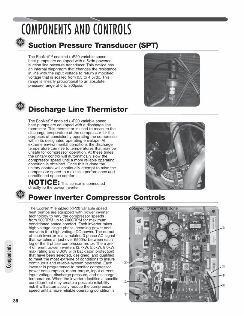
36
COMPONENTS AND CONTROLS
➂
➁
➀
➅
➄
➃
➆
Comp
onen
ts
Suction Pressure Transducer (SPT)
The EcoNet™ enabled (-)P20 variable speed heat pumps are equipped with a discharge line thermistor. This thermistor is used to measure the discharge temperature at the compressor for the purposes of consistently operating the compressor within its designated operating envelope. At extreme environmental conditions the discharge temperature can rise to temperatures that may be unsafe for compressor operation. At these times the unitary control will automatically slow the compressor speed until a more reliable operating condition is obtained. Once this is done the unitary control will continually attempt to raise the compressor speed to maximize performance and conditioned space comfort.
NOTICE: This sensor is connected directly to the power inverter.
The EcoNet™ enabled (-)P20 variable speed heat pumps are equipped with a 5vdc powered suction line pressure transducer. This device has an internal diaphragm that changes the resistance in line with the input voltage to return a modified voltage that is scalled from 0.5 to 4.5vdc. This range is linearly proportional to an absolute pressure range of 0 to 300psia.
Discharge Line Thermistor
The EcoNet™ enabled (-)P20 variable speed heat pumps are equipped with power inverter technology to vary the compressor speeds from 900RPM up to 7000RPM for maximum conditioned space comfort. Each inverter takes high voltage single phase incoming power and converts it to high voltage DC power. The output of each inverter is a simulated 3 phase AC signal that switches at just over 6500hz between each leg of the 3 phase compressor motor. There are 4 different power inverters (3.7kW, 5.5kW, 8.0kW max rating and 8.0kW with back spin protection) that have been selected, designed, and qualified to meet the most extreme of conditions to insure continuous and reliable system operation. Each inverter is programmed to monitor compressor power consumption, motor torque, input current, input voltage, discharge pressure, and discharge temperature. When the inverter identifies a specific condition that may create a possible reliability risk it will automatically reduce the compressor speed until a more reliable operating condition is
obtained. Once this is done
Power Inverter Compressor Controls
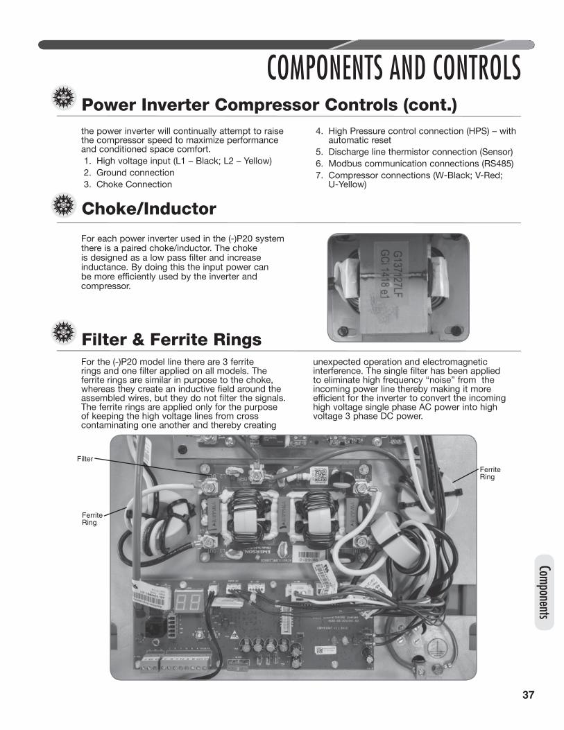
37
Components
COMPONENTS AND CONTROLS
For each power inverter used in the (-)P20 system there is a paired choke/inductor. The choke is designed as a low pass filter and increase inductance. By doing this the input power can be more efficiently used by the inverter and compressor.
Choke/Inductor
Filter
FerriteRing
FerriteRing
Filter & Ferrite RingsFor the (-)P20 model line there are 3 ferrite rings and one filter applied on all models. The ferrite rings are similar in purpose to the choke, whereas they create an inductive field around the assembled wires, but they do not filter the signals. The ferrite rings are applied only for the purpose of keeping the high voltage lines from cross contaminating one another and thereby creating
unexpected operation and electromagnetic interference. The single filter has been applied to eliminate high frequency “noise” from the incoming power line thereby making it more efficient for the inverter to convert the incoming high voltage single phase AC power into high voltage 3 phase DC power.
Power Inverter Compressor Controls (cont.)the power inverter will continually attempt to raise the compressor speed to maximize performance and conditioned space comfort. 1. High voltage input (L1 – Black; L2 – Yellow)2. Ground connection3. Choke Connection
4. High Pressure control connection (HPS) – with automatic reset
5. Discharge line thermistor connection (Sensor)6. Modbus communication connections (RS485)7. Compressor connections (W-Black; V-Red;
U-Yellow)

38
EcoNet™ Variable Speed Unitary Control
COMPONENTS AND CONTROLS
The EcoNet™ system is the next generation of the integrated compressor control (ICC) and is an integral part of the EcoNet™ communication network 1. Thermostat Terminals2. Communication wire terminals3. Modbus unitary inverter communication
connection4. Outdoor PSC Fan relay connections5. Outdoor ambient thermistor connection6. Coil Sensor (EVAPIN) and Alternate Suction
(OST) thermistor connections7. Liquid line (OLT – for future use) and
compressor sump (CPT) connections8. Outdoor ECM fan PWM output connection9. Suction pressure transducer (SPT) connection10. Liquid pressure transducer (LPT) connection11. Electronic expansion valve connection12. Reversing Valve Connections13. 3 Amp fuse14. Test and SW2 Button15. Communications LEDs (ET – EcoNet™
communication is transmitting; RT – EcoNet™communication is receiving)
16. Memory card connection
17. Dual seven segment LED – Displays status, diagnostic codes, fault recall, compressor speed, superheat, and defrost menus
18. Dip Switches (Defrost [DFST] and EXV [EXV] offset)
19. Dip Switches (EXV [1600/500] selection)20. EXV Operational Lights (Green – EXV is
opening; Amber - EXV is closing)
CAUTION: UNIT MAY START SUDDENLY AND WITHOUT WARNING.TEST and SW2 ButtonsTEST and SW2 buttons are used to enter the following menus and modes:• Test mode• Forced Defrost• Fault Code Recall Menu• Compressor Speed Menu• Superheat Menu• Forced 6 hour defrost menu
1918
17
16
15
14 13
12
11
10987654
3
2
1
Comp
onen
ts
20

39
COMPONENTS AND CONTROLS
Memory Card• The memory card stores all unit information.• The unit information is called model data.• The model data is all the information needed for
proper unit operation.
Factory Programmed SuperheatThe EcoNet™ unitary control is pre-programmed with the optimum superheat setting for each outdoor unit. The following settings will be assigned from the factory and active at time of install.
Superheat offset DIP Switch SettingsAlthough the factory programmed superheat set point is considered to be the most efficient set point for each unit, installation conditions can drastically effect the measurement of superheat by the unitary control. For this reason the following dip switch settings have been provided to enable flexibility for various installation conditions.
EcoNet™ Variable Speed Unitary Control (cont.)
Components

40
EcoNet™ Variable Speed Unitary Control
COMPONENTS AND CONTROLS
Installation Verification• 24 VAC power on R and C must be present at
the ICC for it to operate.• Line voltage must be present at the ICC for the
compressor and the outdoor fan to operate.• The ICC displays a “0” for standby mode.
Standby mode indicates line voltage and 24 VAC are present at the ICC and there is not a call for unit operation from the serial communicating thermostat.
Call for Compressor Operation• If a call for compressor operation is received by the ICC (high-stage/low-stage cooling or high-stage/low-stage heating).• The ICC has an on/off fan delay of one (1) second for each stage of heating or cooling.• The ICC ignores the low-pressure control for the first 90 seconds of compressor operation.• On heat pumps, the ICC ignores the LPC during the defrost cycle.• The dual 7-segment LEDs display five (5) operational status codes:
1) Low-Stage Cooling Operation – When the ICC receives a call for first-stage cooling operation, a lower-case “c” is displayed on the dual 7-segment LEDs.
2) High-Stage Cooling Operation – When the ICC receives a call for second-stage cooling operation, an upper-case “C” is displayed on the dual 7-segment LEDs.
3) Low-Stage Heating Operation – When the ICC receives a call for first-stage heating operation, “h” is displayed on the dual 7-segment LEDs.
4) High-Stage Heating Operation – When the ICC receives a call for second-stage heating operation, an upper-case “H” is displayed on the dual 7-segment LEDs.
5) Defrost Operation – When the ICC starts a defrost cycle, a lower-case “d” is displayed on the dual 7-segment LEDs.
4-Minute Anti-Short-Cycle Timer• The ICC has a built-in 4-minute time delay
between compressor operations to protect the compressor against short cycling. The dual 7-segment LEDs will flash “c,” “C,” “h,” or “H” while the short-cycle timer is active and a call for unit operation is received.
When a call for compressor operation is present, the 4-minute time delay can be bypassed by pressing the TEST button for 1 second and releasing. The compressor will begin operation and the dual 7-segment LEDs will stop flashing.30-Second Minimum Run Timer• The ICC has a built-in 30-second minimum unit
run time. If a call for compressor operation is received by the ICC and the call is removed, the compressor will continue to operate for 30 seconds. The dual 7-segment LEDs will flash “c,” “C,” “h,” or “H” while the minimum run timer is active.
Lower-case “c” indicates Low-stage cooling operation.
Lower-case “h” indicates Low-stage heating operation.
Upper-case “C” indicates high-stage cooling operation.
Zero (0) displayed. The unit is in standby.
Upper-case “H” indicates high-stage heating operation.
Lower-case “d” indicates defrost operation (in heating mode).
Flashing lower-case "c"A call for low-stage cooling has been received.Flashing high-case "C"A call for low-stage cooling has been received.Flashing lower-case "h"A call for low-stage heating has been received.Flashing upper-case "H"A call for high-stage heating has been received.
Comp
onen
ts
41
Components
EcoNet™ Variable Speed Unitary Control (cont.)
COMPONENTS AND CONTROLS
1-Second Compressor/Fan Delay• The ICC starts/stops the outdoor fan one (1)
second after the start/stop of the compressor upon a call for compressor operation to minimize current inrush and/or voltage drop.
Compressor OperationThe (-)P20 series of EcoNet™ compatible outdoor heat pumps are equipped with legacy and communicating modes of operation. To maximize the performance and efficiency of these systems it is highly recommended to operate the (-)P20 systems in communicating mode. It is possible where communication signals are corrupted resulting in an application that may only utilize 24VAC legacy thermostat control. In these situations a 2 stage legacy thermostat is required. Communicating Mode: Compressor OperationWhen the (-)P20 series of outdoor heat pumps are installed with the EcoNet™ communicating control center the ICC will respond to building capacity demand. This demand is converted by the ICC into compressor RPMs which can vary in 1 RPM increments from a minimum speed to a maximum speed as defined by the outdoor unit model data. The magnitude of instantaneous compressor speed change will depend on the change in building load measured by the control center. Through this process the (-)P20 heat pumps only provide to the building the required amount of conditioning for optimal comfort and efficiency.Legacy Mode: Low/Intermediate Speed Compressor OperationWhen the (-)P20 series of outdoor heat pumps are installed in legacy mode with a 2 stage thermostat the low and intermediate compressor speed operation defaults to a time based logic. In this situation when a Y ONLY 24VAC signal is present the ICC requests the inverter to run the minimum speed as defined by the model data for 15 minutes. After this time has passed and the Y ONLY 24VAC signal remains present the ICC will automatically increase the compressor speed to the intermediate speed as set by the model data. The ICC will keep the compressor at this speed until the call for compressor operation is removed or a Y + Y2 signal is received from the legacy 2 stage thermostat.
IMPORTANT: This logic only occurs for legacy installs. All compressor speeds will be requested discretely when the (-)P20 heat pump is operating in communicating mode with the Rheem Control Center.Indoor AirflowSimilar to the compressor operation outlined in the prior section, the Indoor airflow will be set by the control center based on the building load percentage. While operating in communicating mode after the ICC set the compressor speed it will transmit the necessary indoor airflow as identified by the outdoor unit model data to the control center where it will relay the information to the indoor air mover. When the (-)P20 heat pump is matched with a constant CFM indoor air handler or furnace, the ICC will request discrete airflow for each compressor speed. Prior to the control center sending the requested air flow to the indoor air mover it will apply any offset or corrections as identified in the control center installer menu.Outdoor Fan ControlThe ICC can accommodate electronically commutated (ECM) or permanent start capacitor (PSC) outdoor fan motors. If the outdoor unit is equipped with a PSC motor, the model data will set the ICC firmware to energize the PSC fan relay when the outdoor fan motor is required to operate. If the outdoor unit is enabled with an ECM outdoor fan motor, the model data will set the ICC firmware to utilize a pulse width modulated signal from the PWM terminal to control the outdoor fan motor. This output is a 80Hz pulse-width-modulated signal that can be varied from 0 to 100% duty cycle in 1% increments. Secondary parameters such as rpm blocking ranges, startup mandatory ranges, shutdown ranges, fault induced rpm reduction, and low ambient cooling ranges can also impact the final calculated RPM value.
Oil CirculationDuring operation it is possible that an excess of refrigerant could be returned to the compressor causing a flooded compressor sump condition. If this event occurs the compressor reliability and/or life could be drastically reduced. For this reason the (-)P20 heat pumps are equipped with a sump thermistor (CPT) to monitor the sump temperature of the compressor. The ICC will evaluate the differential between the compressor sump temperature and the saturated suction temperature (aka sump superheat). If the ICC concludes that
42
EcoNet™ Variable Speed Unitary Control (cont.)
COMPONENTS AND CONTROLS
the sump superheat is below the design limit, the ICC will request for the inverter to reduce the compressor RPM incrementally until the differential value has sufficiently increased. After the minimum sump superheat is obtained the ICC will request for the inverter to raise the compressor RPM a rate of no greater than 2000RPM per minute. During the ramp up period the ICC will continuously evaluate the sump superheat temperature and hold the compressor speed to a limit resulting in acceptable sump superheat.Discharge Temperature (DLT) Fold back ProtectionIf the discharge line temperature, as read from the Modbus communication between the ICC and the inverter, reaches 235°F the ICC will request the inverter to reduce the compressor RPM incrementally until the discharge line temperature (DLT) reduces to 200°F. After the DLT reaches this level, the compressor RPM will be set to rise at a rate of no greater than 500RPM per minute until the compressor equals the requested speed from the requested capacity. During the ramp period the discharge line temperature will continue to be monitored.Low Ambient CoolingIn some installations, a requirement exists for cooling a space when the outdoor ambient is below the normal range (<55°F), such as a computer room or other enclosed areas where a large heat load exists that must be kept cool. Low ambient cooling is a special cooling mode that allows the unit to provide cooling when the outdoor temperature is below 55°F. When necessary, the outdoor fan is cycled off to maintain condensing pressure and temperature in the system at an acceptable level.Menu StructureThe (-)P20 product line is equipped with a dual 7-segment LED display and two push buttons (SW2 and TEST). The display and push buttons work together to allow the technician access to fault recall, compressor speed locking, and current SH measurement (heating only). The following process can be used to access any of these menus:- Press the SW2 and TEST buttons for 5-8
seconds.- After this time the dual seven segment LEDs
will show the first menu option (FC).- To enter a menu, depress the SW2 button- To toggle to the next menu depress the test
button.
- No action for 5 seconds in the root menu structure will return the control to normal operation.
Menu Definition:FC (Fault Codes)CS (Compressor Speeds)• 3 (MAXIMUM Speed)• 2 (INTSPEED Speed)• 1 (MINIMUM Speed)SH (Superheat Measurement)• The display is to show the following options:• HI = Superheat is ≥+5°F away from SH_SP• hI = Superheat is between +5° and 1.5°F_away
from SH_SP• 00 = Superheat is between +1.5°F and -1.5°F
away from SH_SP• lo = Superheat is between -1.5°F and -5°F
away from SH_SP• LO = Superheat is ≤-5°F away from SH_SP.dF (Defrost Mode)• 6 – Forced 6 hour defrost. When this mode
is selected the ICC will begin a 9 hour timer. During this time defrosts will be limited to 6 hour intervals between occurances.
Key: FC = Fault Codes – by selecting this menu
the control will list the stored numerical fault codes in order of sequence by which they were stored. Depressing the SW2 button while a fault code is shown will increment to the next fault. Depressing the TEST button will force the control back to the main menu.
CS = Compressor Speed – For this selection menu to initiate the requested compressor speed, there must be an active call for compressor operation, the compressor must be operating, and the selection must be static for 5 seconds. The Compressor Start and Run, and Compressor Shut down algorithms will be used to obtain the requested compressor speed.
IMPORTANT: This mode should be manually exited. If this menu is not exited manually the ICC will wait 24 hours before returning to normal operation. During this time the ICC will only request the selected compressor speed.
Demand DefrostThe integrated compressor control (ICC) has a demand defrost algorithm so a separate defrost control is not needed. The ICC monitors the Outdoor Ambient Temperature (OAT) and Outdoor
Comp
onen
ts

43
Components
EcoNet™ Variable Speed Unitary Control (cont.)
COMPONENTS AND CONTROLS
Coil Temperature (EVAPIN) to determine when a defrost cycle is required.Defrost InitiationA defrost will be initiated when these three conditions are satisfied:
1) The outdoor coil temperature is below 35°F [1.7°C].
2) The compressor has operated for at least 34 minutes with the outdoor coil temperature below 35°F [1.7°C].
3) The defrost algorithm determines a defrost is required.
When all the defrost initiation conditions have been met, the following sequence will occur:• The ICC will request for the inverter to change
the compressor speed to the predetermined reversing valve switching speed.
• The compressor will hold the reversing valve switching speed for a noise abatement period (30 sec).
• When the noise abatement period is concluded the reversing valve will be de-energized.
• The outdoor EXV will be opened to the maximum step permissible based on the unit model data.
• The ICC will energize the auxiliary heat (W). • Send the status of defrost initiate to the UI
when in communicating mode. The system user interface will energize the auxiliary heat.
• The outdoor fan will be de-energized.• The ICC will request for the inverter to ramp
the compressor speed to the defrost speed and remain there for the duration of the Defrost cycle.
Defrost TerminationOnce a defrost is initiated, the defrost will continue until 14 minutes have elapsed or the coil temperature has reached the termination temperature. The termination temperature is factory-set at 60°F [15.6°C], although the temperature can be changed to 50°F [10°C], 60°F [15.6°C], 70°F [21.1°C], or 80°F [26.7°C] by relocating dip switches on the ICC.When all the defrost termination conditions have been met, the following sequence will occur:• The ICC will request for the inverter to change
the compressor speed to the predetermined reversing valve switching speed.
• The compressor will hold the reversing valve switching speed for a noise abatement period (30 sec.).
• When the noise abatement period is concluded the reversing valve will be energized.
• The ICC will re-energize the outdoor fan output.• The compressor will change speed to oil
circulation speed and run for a period of 6 minutes.
• The EXV algorithm will go into the control mode.
• In a communicating system, the ICC will advise the control center that the defrost cycle has concluded.
• After the reversing valve is changed, the ICC will de-energize the auxiliary heat (W) if in a non-communicating system. (The system user interface will de-energize the auxiliary heat in a communication system.)
• The ICC will return to heating operation per the control center or thermostat demand.
Defrost Termination Dip Switches
Temperature SensorsThe coil sensor is clipped to the top tube on the outdoor coil at the point fed by the distribution tubes from the expansion device (short 3/8" [8.3 mm] diameter tube).If the ambient sensor fails, the defrost control will initiate a defrost every 34 minutes in heat mode with the coil temperature below 35°F [1.7°C].Defrost Test ModeThe Defrost Test Mode is initiated by pressing pushbutton TEST for 1 second with the unit running in HP mode. Upon release of pushbutton test, the unit will go into defrost until termination temperature is achieved or 14 minutes have expired. Pressing TEST while in Defrost Test Mode will terminate the test mode.Troubleshooting Demand Defrost• Set the indoor thermostat select switch to heat
and initiate a call for heat.• Press TEST to put the unit into defrost. If the unit
goes into defrost and comes back out of defrost, the indication is that the control is working properly.
OffOnOffOn
OffOffOnOn
60504070
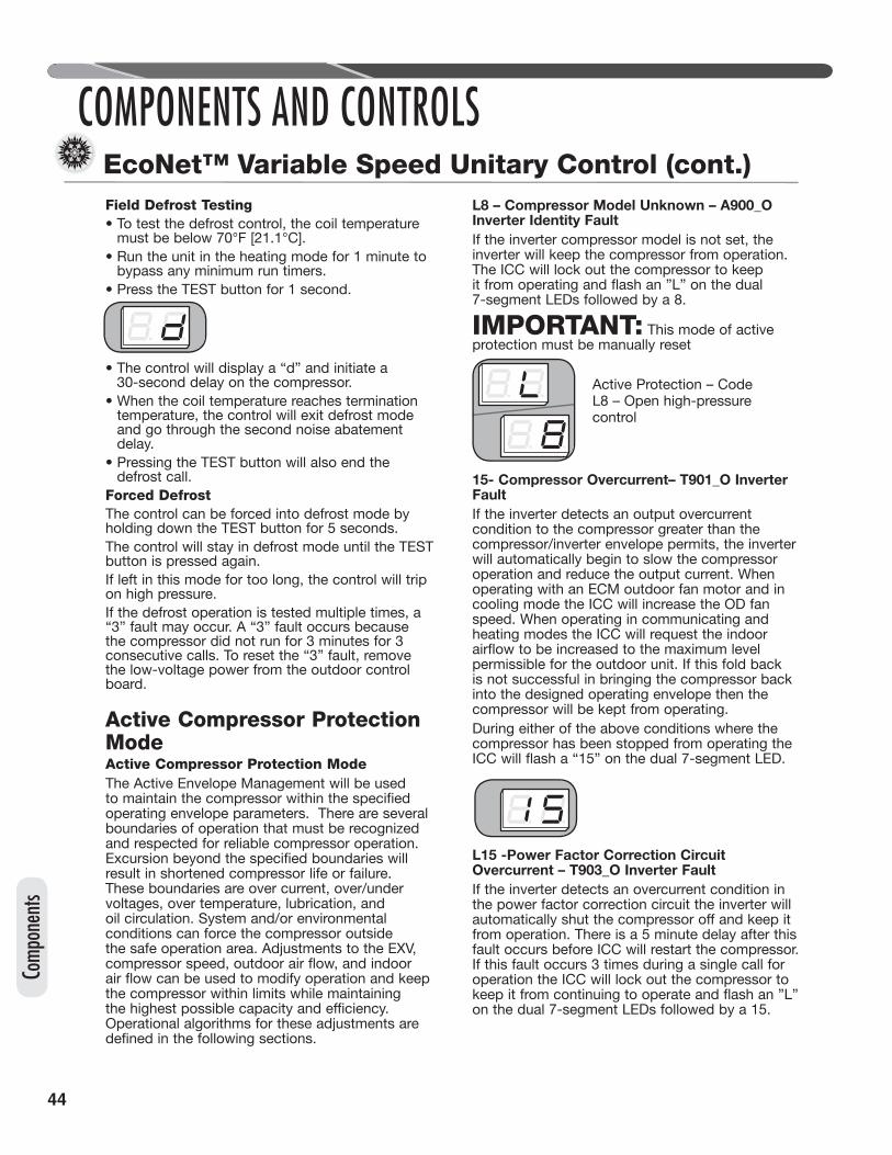
44
EcoNet™ Variable Speed Unitary Control (cont.)
COMPONENTS AND CONTROLS
Field Defrost Testing• To test the defrost control, the coil temperature
must be below 70°F [21.1°C].• Run the unit in the heating mode for 1 minute to
bypass any minimum run timers.• Press the TEST button for 1 second.
• The control will display a “d” and initiate a 30-second delay on the compressor.
• When the coil temperature reaches termination temperature, the control will exit defrost mode and go through the second noise abatement delay.
• Pressing the TEST button will also end the defrost call.
Forced DefrostThe control can be forced into defrost mode by holding down the TEST button for 5 seconds.The control will stay in defrost mode until the TEST button is pressed again. If left in this mode for too long, the control will trip on high pressure.If the defrost operation is tested multiple times, a “3” fault may occur. A “3” fault occurs because the compressor did not run for 3 minutes for 3 consecutive calls. To reset the “3” fault, remove the low-voltage power from the outdoor control board.
Active Compressor Protection ModeActive Compressor Protection ModeThe Active Envelope Management will be used to maintain the compressor within the specified operating envelope parameters. There are several boundaries of operation that must be recognized and respected for reliable compressor operation. Excursion beyond the specified boundaries will result in shortened compressor life or failure. These boundaries are over current, over/under voltages, over temperature, lubrication, and oil circulation. System and/or environmental conditions can force the compressor outside the safe operation area. Adjustments to the EXV, compressor speed, outdoor air flow, and indoor air flow can be used to modify operation and keep the compressor within limits while maintaining the highest possible capacity and efficiency. Operational algorithms for these adjustments are defined in the following sections.
L8 – Compressor Model Unknown – A900_O Inverter Identity FaultIf the inverter compressor model is not set, the inverter will keep the compressor from operation. The ICC will lock out the compressor to keep it from operating and flash an ”L” on the dual 7-segment LEDs followed by a 8.
IMPORTANT: This mode of active protection must be manually reset
15- Compressor Overcurrent– T901_O Inverter FaultIf the inverter detects an output overcurrent condition to the compressor greater than the compressor/inverter envelope permits, the inverter will automatically begin to slow the compressor operation and reduce the output current. When operating with an ECM outdoor fan motor and in cooling mode the ICC will increase the OD fan speed. When operating in communicating and heating modes the ICC will request the indoor airflow to be increased to the maximum level permissible for the outdoor unit. If this fold back is not successful in bringing the compressor back into the designed operating envelope then the compressor will be kept from operating.During either of the above conditions where the compressor has been stopped from operating the ICC will flash a “15” on the dual 7-segment LED.
L15 -Power Factor Correction Circuit Overcurrent – T903_O Inverter FaultIf the inverter detects an overcurrent condition in the power factor correction circuit the inverter will automatically shut the compressor off and keep it from operation. There is a 5 minute delay after this fault occurs before ICC will restart the compressor. If this fault occurs 3 times during a single call for operation the ICC will lock out the compressor to keep it from continuing to operate and flash an ”L” on the dual 7-segment LEDs followed by a 15.
Comp
onen
ts
Active Protection – Code L8 – Open high-pressure control

45
IMPORTANT: This mode of active protection must be manually reset
L15 - DC Bus Over Voltage – A904_O Inverter FaultIf the inverter detects an overvoltage condition in the DC bus circuit the inverter will automatically shut the compressor off and keep it from operation. The ICC will leave the compressor off until the DC bus voltage drops below 380Vdc. At this time the ICC will restart the compressor. If this fault occurs 3 times in one hour the ICC will lock out the compressor to keep it from continuing to operate for one hour and flash an ”L” on the dual 7-segment LEDs followed by a 15.
IMPORTANT: This mode of active protection must be manually reset.
L15 – DC Bus Under Voltage - A905_O Inverter FaultIf the inverter detects an under voltage condition in the DC bus circuit the inverter will automatically shut the compressor off and keep it from operation. The ICC will leave the compressor off until the DC bus voltage rises above 300Vdc. At this time the ICC will restart the compressor. If this fault occurs 3 times in one hour the ICC will lock out the compressor to keep it from continuing to operate for one hour and flash an ”L” on the dual 7-segment LEDs followed by a 15.
IMPORTANT: This mode of active protection must be manually reset.
L15 – PIM Over-temp – T908_O Inverter FaultIf the inverter detects an over temperature condition in the Power Module circuit the inverter will automatically shut the compressor off and keep it from operation. The ICC will leave the compressor off until the circuit temperature is reduced to acceptable levels. At this time the ICC will restart the compressor. If this fault occurs 3 times during one call for operation the ICC will lock out the compressor to keep it from continuing to operate for one hour and flash an ”L” on the dual 7-segment LEDs followed by a 15
IMPORTANT: This mode of active protection must be manually reset.
L15 – PFC Over-temp – T909_O Inverter FaultIf the inverter detects an over temperature condition in the Power Factor Correction circuit the inverter will automatically shut the compressor off and keep it from operation. The ICC will leave the compressor off until the circuit temperature is reduced to acceptable levels. At this time the ICC will restart the compressor. If this fault occurs 3 times during one call for operation the ICC will lock out the compressor to keep it from continuing to operate for one hour and flash an ”L” on the dual 7-segment LEDs followed by a 15.
IMPORTANT: This mode of active protection must be manually reset.
L15 – Lost Rotor Position- A910_O Inverter FaultIf the inverter loses the rotor position in the compressor the inverter will automatically shut the compressor off and keep it from operation. There is a 5 minute delay after this fault occurs before ICC will restart the compressor. If this fault occurs 3 times during a single call for operation the ICC will lock out the compressor to keep it from continuing to operate and flash an ”L” on the dual 7-segment LEDs followed by a 15.
Components
EcoNet™ Variable Speed Unitary Control (cont.)
COMPONENTS AND CONTROLS

46
EcoNet™ Variable Speed Unitary Control (cont.)
COMPONENTS AND CONTROLS
IMPORTANT:This mode of active protection must be manually reset.
L15- Current Imbalance – T911_O Inverter FaultIf the inverter identifies an imbalanced current draw between the compressor 3 phase windings, the inverter will automatically shut the compressor off and keep it from operation. There is a 5 minute delay after this fault occurs before ICC will restart the compressor. If this fault occurs 3 times during a single call for operation the ICC will lock out the compressor to keep it from continuing to operate and flash an ”L” on the dual 7-segment LEDs followed by a 15.
IMPORTANT:This mode of active protection must be manually reset.
L15 – DC Voltage Low – T914_O Inverter FaultIf the inverter detects an sustained low voltage condition in the DC bus circuit the inverter will automatically shut the compressor off and keep it from operation. The ICC will immediately restart the compressor. If this fault occurs 3 times during one call for operation the ICC will lock out the compressor to keep it from continuing to operate and flash an ”L” on the dual 7-segment LEDs followed by a 15.
IMPORTANT: This mode of active protection must be manually reset.
L15- PIM Temperature High – T917_O Inverter FaultIf the inverter identifies a high Power Module temperature thermistor reading the inverter will
automatically shut the compressor off and keep it from operation. If this fault occurs 3 times during one call for operation the ICC will lock out the compressor to keep it from continuing to operate and flash an ”L” on the dual 7-segment LEDs followed by a 15.
IMPORTANT: This mode of active protection must be manually reset.
L15 – PFC & IGBT Temperature High – T918_O Inverter FaultIf the inverter identifies a high insulated-gate bipolar transistor (IGBT) temperature or power factor correction (PFC)circuit temperature reading the inverter will automatically shut the compressor off and keep it from operation. If this fault occurs 3 times during one call for operation the ICC will lock out the compressor to keep it from continuing to operate and flash an ”L” on the dual 7-segment LEDs followed by a 15.
IMPORTANT: This mode of active protection must be manually reset.
L15- PIM Temperature Fold back – T922_O Inverter FaultIf the inverter detects a high Power Module temperature the inverter will automatically begin to slow the compressor operation. If this fold back is not successful in bringing the PIM temperature into the acceptable range then the compressor will be kept from operating. If this fault occurs 3 times during one call for operation ICC will lock out the compressor to keep it from continuing to operate and flash an “L” on the dual 7-segment LEDs followed by a 15.
IMPORTANT: This mode of active protection must be manually reset.
Comp
onen
ts
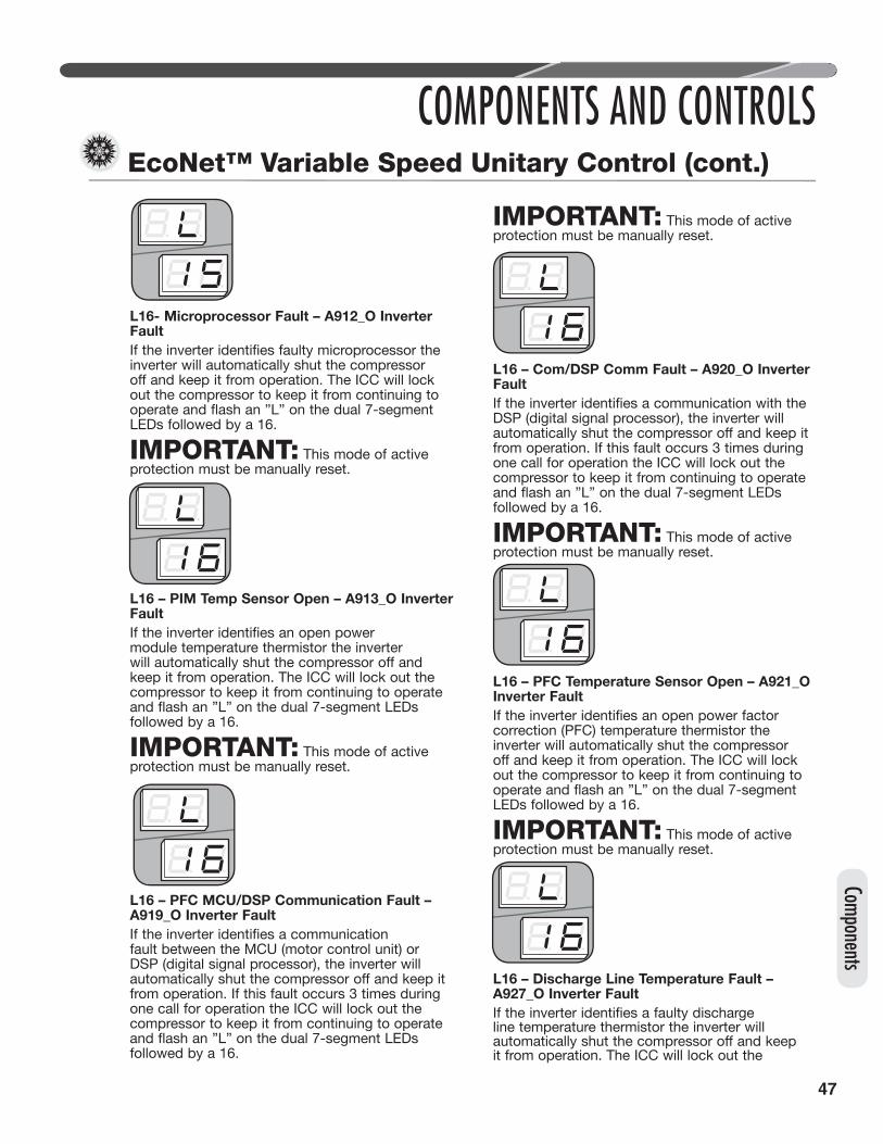
47
L16- Microprocessor Fault – A912_O Inverter FaultIf the inverter identifies faulty microprocessor the inverter will automatically shut the compressor off and keep it from operation. The ICC will lock out the compressor to keep it from continuing to operate and flash an ”L” on the dual 7-segment LEDs followed by a 16.
IMPORTANT: This mode of active protection must be manually reset.
L16 – PIM Temp Sensor Open – A913_O Inverter FaultIf the inverter identifies an open power module temperature thermistor the inverter will automatically shut the compressor off and keep it from operation. The ICC will lock out the compressor to keep it from continuing to operate and flash an ”L” on the dual 7-segment LEDs followed by a 16.
IMPORTANT: This mode of active protection must be manually reset.
L16 – PFC MCU/DSP Communication Fault – A919_O Inverter FaultIf the inverter identifies a communication fault between the MCU (motor control unit) or DSP (digital signal processor), the inverter will automatically shut the compressor off and keep it from operation. If this fault occurs 3 times during one call for operation the ICC will lock out the compressor to keep it from continuing to operate and flash an ”L” on the dual 7-segment LEDs followed by a 16.
IMPORTANT: This mode of active protection must be manually reset.
L16 – Com/DSP Comm Fault – A920_O Inverter FaultIf the inverter identifies a communication with the DSP (digital signal processor), the inverter will automatically shut the compressor off and keep it from operation. If this fault occurs 3 times during one call for operation the ICC will lock out the compressor to keep it from continuing to operate and flash an ”L” on the dual 7-segment LEDs followed by a 16.
IMPORTANT: This mode of active protection must be manually reset.
L16 – PFC Temperature Sensor Open – A921_O Inverter FaultIf the inverter identifies an open power factor correction (PFC) temperature thermistor the inverter will automatically shut the compressor off and keep it from operation. The ICC will lock out the compressor to keep it from continuing to operate and flash an ”L” on the dual 7-segment LEDs followed by a 16.
IMPORTANT: This mode of active protection must be manually reset.
L16 – Discharge Line Temperature Fault – A927_O Inverter FaultIf the inverter identifies a faulty discharge line temperature thermistor the inverter will automatically shut the compressor off and keep it from operation. The ICC will lock out the
EcoNet™ Variable Speed Unitary Control (cont.)
COMPONENTS AND CONTROLS
Components

48
compressor to keep it from continuing to operate and flash an ”L” on the dual 7-segment LEDs followed by a 16.
IMPORTANT: This mode of active protection must be automatic reset once the discharge line thermistor fault is corrected.
L16 – Discharge Temperature – T916_O Inverter FaultIf the ICC detects the compressor discharge temperature is greater 235°F the ICC will automatically begin to slow the compressor operation until the temperature is ≤200°F. If this fold back is not successful in bringing the compressor discharge temperature below 200°F prior to reaching the minimum compressor speed then the compressor will be kept from operating. After the compressor off delay is complete the ICC will return the compressor to operation. If this fault occurs 3 times during one call for operation the ICC will lock out the compressor to keep it from continuing to operate and flash an “L” on the dual 7-segment LEDs followed by a 16.
IMPORTANT: This mode of active protection must be manually reset.
L16 – Communication Failure – A929_O Inverter FaultIf the inverter identifies a communication error with the ICC, the inverter will automatically shut the compressor off and keep it from operation. When this fault occurs the ICC will lock out the compressor to keep it from operating and flash an ”L” on the dual 7-segment LEDs followed by a 16.
IMPORTANT: This mode of active protection must be manually reset.
16 – HP Sensor Not Configured – T926_OIf the inverter is not configured or does not hold the configuration for the high pressure switch in the Modbus register, the inverter will provide this fault.
L16 – Brown Out Fault – A959_O Brown Out FaultIf the inverter detects input AC voltage < 155VAC for 4 seconds the ICC will automatically shut the compressor off and keep it from operation. The ICC will leave the compressor off until the input AC voltage increases to >175VAC for 4 seconds. At this time the ICC will restart the compressor. While the compressor is off the ICC will display a 16 on the dual 7-segment LEDs.IMPORTANT: This mode of active protection is automatically reset.
L21 – Low Pressure Refrigerant – A/T 021_0 Low Refrigerant Pressure• The ICC will display a flashing “21” followed by a
flashing “L” when a low-pressure control lockout occurs.
IMPORTANT: This mode of active protection must be manually reset.
• The ICC addresses low-pressure control faults differently depending on the mode of unit operation (cooling or heating mode).
Cooling Mode• If the LPC opens three (3) times during the same
call for cooling operation, the ICC will lock out the compressor to keep it from continuing to operate and flash a “21” on the dual 7-segment LEDs followed by an “L.”
EcoNet™ Variable Speed Unitary Control (cont.)
COMPONENTS AND CONTROLS
Comp
onen
ts
Active Protection – Code 21L – Open low-pressure control

49
IMPORTANT: This mode of active protection must be manually reset.Heating Mode• There are two scenarios that will cause active
protection during an LPC trip when the unit is in the heating mode:
Active Protection With Hard Lockout:• If the LPC opens three (3) times within 120
minutes for the same call for heating operation, the ICC will lock out the compressor to keep it from continuing to operate and flash an “21” on the dual 7-segment LEDs followed by a “L.”
IMPORTANT: This mode of active protection must be manually reset.Active Protection With Soft Lockout:• If the LPC opens three (3) times for the same
call for heating and the outdoor ambient temperature is below -10°F [-23°C], the ICC will lock out the compressor to keep it from continuing to operate and flash a “21” on the dual 7-segment LEDs followed by an “L.” Once the outdoor ambient rises above -10°F [-23°C], the ICC will clear active protection automatically.
IMPORTANT: This mode of active protection will automatically deactivate once the outdoor temperature rises above -10°F [-23°C]. Wait until the outdoor ambient temperature rises above -10°F [-23°C] before performing further diagnostics.
27- AC Input Under Voltage – A907_O_Inverter FaultIf the inverter detects input AC under voltage the ICC will automatically shut the compressor off and keep it from operation. The ICC will leave the compressor off until the input AC voltage
increases to ≥187VAC. At this time the ICC will restart the compressor. While the compressor is off the ICC will display a 27 on the dual 7-segment LEDs.
IMPORTANT: This mode of active protection is automatically reset.
28 – AC Input Over Voltage – A906_O Inverter FaultIf the inverter detects input AC over voltage the ICC will automatically shut the compressor off and keep it from operation. The ICC will leave the compressor off until the input AC voltage reduces to ≤252VAC. At this time the ICC will restart the compressor. While the compressor is off the ICC will display a 28 on the dual 7-segment LEDs.
IMPORTANT: This mode of active protection is automatically reset.
L29 – High Refrigerant Pressure – A/T 923_O High Refrigerant Pressure• If the HPC opens three (3) times during the same
call for unit operation, the ICC will lock out the compressor to keep it from continuing to operate and flash a “29” on the dual 7-segment LEDs followed by an “L.”
IMPORTANT: This mode of active protection must be manually reset.
31 - Compressor Envelope Protection- T902_O Inverter Fault – Envelope ProtectionIf the inverter detects the calculated compressor torque is greater than the designed operating envelope permits the inverter will automatically begin to slow the compressor operation. If this fold back is not successful in bringing the compressor back into the designed operating envelope then the compressor will be kept from operating.
EcoNet™ Variable Speed Unitary Control (cont.)
COMPONENTS AND CONTROLS
Components
Active Protection – Code 21L – Open low-pressure control
Active Protection – Code 21L – Open low-pressure control
Active Protection – Code 29L – Open high-pressure control

50
IMPORTANT: For a single stage or two stage system it is very common during startup and shutdown for the compressor to venture outside the designed operating envelope. It is possible this fault can be seen on an installation when there is nothing globally wrong with the installation. For this reason the ICC will auto reset and return the system to operational condition after the compressor delay is complete.Prior to restarting the compressor the ICC 7-segment display will flash a “31”.
35- Suction Temperature Thermistor Failure – A102_OIf the ICC identifies an issue with Outdoor Suction Thermistor (OST) sensor the ICC will flash a 35 on the dual 7-segment LEDs.
IMPORTANT: This mode of active protection is automatically reset once the OAT sensor failure is corrected.
36 – Suction Pressure Sensor Failure – A956_OIf the ICC identifies an issue with the Suction Pressure Transducer (SPT) sensor the ICC will flash a 36 on the dual 7-segment LEDs.
IMPORTANT: This mode of active protection is automatically reset once the OAT sensor failure is corrected.
42- Compressor Temperature Thermistor Failure – T955_OIf the ICC identifies an issue with the Compressor Sump Thermistor (CPT) the ICC will flash a 42 on the dual 7-segment LEDs.
IMPORTANT: This mode of active protection is automatically reset once the CPT sensor failure is corrected.
83 – Evaporator Temperature Thermistor Failure – T953_OIf the ICC identifies an issue with the Evaporator Temperature Thermistor (EVAPIN) sensor the ICC will flash an 83 on the dual 7-segment LEDs.
IMPORTANT: This mode of active protection is automatically reset once the OAT sensor failure is corrected.
84 – Outside Ambient Thermistor Failure - T952 If the ICC identifies an issue with the Outdoor Ambient Thermistor (OAT) sensor the ICC will flash an 84 on the dual 7-segment LEDs.
IMPORTANT: This mode of active protection is automatically reset once the OAT sensor failure is corrected.
93 – Configuration Data Restore Failure – A950_OIf the ICC identifies issue(s) reading the model data from the memory card, the ICC will automatically shut the compressor off and keep it from operation. When this fault occurs the ICC will lock out the compressor to keep it from operating and flash an ”L” on the dual 7-segment LEDs followed by a 93.
IMPORTANT: This mode of active protection must be manually reset.
EcoNet™ Variable Speed Unitary Control (cont.)
COMPONENTS AND CONTROLS
Comp
onen
ts
51
D1 – Memory Card Configuration Data Write Failure – A951_OIf the ICC identifies issue(s) writing the model data from the memory card, the ICC will automatically shut the compressor off and keep it from operation. When this fault occurs the ICC will lock out the compressor to keep it from operating and flash an ”D1” on the dual 7-segment LEDs.
IMPORTANT: This mode of active protection must be manually reset.
Exiting Active Compressor Protection LockoutThere are three methods to reset the ICC after an active protection lockout:
1) Cycle the line voltage to the unit.2) Cycle 24 VAC to the ICC (remove the R or C
connection to the ICC).
Default Operations UponComponent FailureIf any of the following components on the (-)P20 heat pump fail, there are multiple fail safe logic routines to keep the system conditioning the space while service is being sought. The table below outlines the effect for each of these routines.
Test and Fault Recall ModesTest Mode (Test Button on the ICC) • Enter TEST mode by pressing the TEST button
with an insulated probe for one (1) second and release.
• The TEST mode causes the ICC to do the following:1) Resets the 4-minute anti-short-cycle timer.2) Energizes the unit without a call for unit
operation.• If the 4-minute anti-short-cycle timer or
30-second minimum run timer is active (a
EcoNet™ Variable Speed Unitary Control (cont.)
COMPONENTS AND CONTROLS
Components
AEM Lubrica�on Protec�on,Oil Circula�ng Ra�on
Protec�on, Compressor StatorHeat
The compressor opera�onoutlined in the applicable
sec�ons will be performed oncean hour. The compressor stator
heat will be kept from opera�ng.

52
EcoNet™ Variable Speed Unitary Control (cont.)
COMPONENTS AND CONTROLS
Comp
onen
ts
flashing “c,” “C,” “h,” or “H” is displayed on the dual 7-segment LEDs) and a call for unit operation is present, the TEST mode causes:1) A “t” to display momentarily on the dual
7-segment display.
2) The compressor will start and the outdoor fan will operate.
3) The display will change to a steady “c,” “C,” “h,” or “H” to show the current demand for unit operation.
NOTICE: If a call for unit operation is present at the end of the TEST mode, the unit will continue to operate.• If no call for unit operation is present, the TEST
mode causes: 1) A steady “C” to appear on the dual
7-segment LEDs.
2) The compressor will start.3) The compressor will turn off after 5 seconds.
NOTICE: Entering TEST mode without a call for unit operation will cause the compressor to run for 5 seconds.
Agency Test ModeInstructionsThe (-)P20 variable speed system by nature varies the compressor speed based on building load and thermostat call for operation. Therefore the following set of special instructions is necessary for agency testing ONLY. These modes should not be used for field installation use.Low Compressor Speed Test ModeTo enter low compressor speed test mode where the ICC will keep the compressor speed at the minimum possible speed for the given/tested outdoor ambient temperature use the following procedure:
1. Supply a Y ONLY signal to the ICC. (NOTE: for heating also supply a 24VAC signal to the “B” terminal)
2. Allow the 5min delay to expire and for the compressor to start.
3. Once the compressor has started depress the SW2 and TEST buttons together for 5-8 seconds.
4. After this time the dual seven segment LEDs will show the “FC” menu option.
5. Press the TEST button one time. The dual 7-segment display will show a “CS”, which refers to compressor speed.
6. To enter this menu, depress the SW2 button once.
7. The LED display should now show a value of “1”. This refers to 1st stage or low stage operation.
IMPORTANT: When testing in this mode with an RHMV air handler, it is required to short the WIT or P12 pins to keep the ID blower supplying the rated low stage airflow. If this is not completed, the indoor airflow will move to intermediate stage cfm.
IMPORTANT: When operating in this mode the ICC will stop compressor operation if the Y signal is removed for the purposes of completing the optional cycle tests. Upon the return of the Y signal the ICC will continue to operate in low compressor speed.To exit this mode and return to standard thermostat signal control mode, depress the TEST button once and wait 5-10 seconds or provide the ICC with a Y+Y2 24VAC signal. The dual 7-segment display will display the current thermostat requested stage of operation.
Intermediate Compressor Speed ModeTo enter intermediate compressor speed test mode where the ICC will keep the compressor speed at the intermediate compressor speed for the given/tested outdoor ambient temperature use the following procedure:1. Supply a Y ONLY signal to the ICC. (NOTE: for
heating also supply a 24VAC signal to the “B” terminal)
2. Allow the 5min delay to expire and for the compressor to start.
3. Once the compressor has started depress the SW2 and TEST buttons together for 5-8 seconds.
4. After this time, the dual seven segment LEDs will show the “FC” menu option.
5. Press the TEST button one time. The dual 7-segment display will show a “CS”, which refers to compressor speed.

53
6. To enter this menu, depress the SW2 button once.
7. The LED display should now show a value of “1”. This refers to 1st stage or low compressor speed operation.
8. To toggle to the next compressor speed by depressing the SW2 button once.
9. The LED display should now show a value of “2”. This refers to the intermediate compressor speed operating stage.
IMPORTANT: When testing in this mode with an RHMV air handler provide a Y2 thermostat signal only and the intermediate airflow will be provided immediately.
IMPORTANT: When operating in this mode the ICC will stop compressor operation if the Y signal is removed. Upon the return of the Y signal the ICC will continue to operate in intermediate compressor speed.To exit this mode and return to standard thermostat signal control mode, depress the TEST button once and wait 5-10 seconds. The dual 7-segment display will display the current thermostat requested stage of operation.
High/Maximum Compressor Speed ModeTo enter high/maximum compressor speed test mode where the ICC will keep the compressor speed at the intermediate compressor speed for the given/tested outdoor ambient temperature use the following procedure:1. Supply a Y+Y2 signal to the ICC. (NOTE: for
heating also supply a 24VAC signal to the “B” terminal)
2. Allow the 5min delay to expire and for the compressor to start.
3. Once the compressor has started depress the SW2 and TEST buttons together for 5-8 seconds.
4. After this time, the dual seven segment LEDs will show the “FC” menu option.
5. Press the TEST button one time. The dual 7-segment display will show a “CS”, which refers to compressor speed.
6. To enter this menu, depress the SW2 button once.
7. The LED display should now show a value of “3”. This refers to the high/maximum compressor speed operating stage.
IMPORTANT: When testing in this mode with an air handler or furnace provide a Y1+Y2 thermostat signal only and the high/maximum airflow will be provided immediately.
IMPORTANT: When operating in this mode the ICC will stop compressor operation if the Y+Y2 signal is removed. Upon the return of the Y+Y2 signal the ICC will continue to operate in low compressor speed.To exit this mode and return to standard thermostat signal control mode, depress the TEST button once and wait 5-10 seconds. The dual 7-segment display will display the current thermostat requested stage of operation.
Control Center Ratings Test ModeWhen testing a (-)P20 variable speed heat pump with a rated combination requiring a control center (according to the AHRI rating database) as an accessory to obtain the rated performance utilize the following instructions to properly operate the system during ratings tests.1. Install the rated system in alignment with this
I&O and ASHRAE 37.2. Leak check and charge the rated system per
the instructions found in this I&O.3. Wire the outdoor unit, indoor air mover/furnace,
indoor coil EXV control (when necessary), and control center according to the following wiring diagrams.
EcoNet™ Variable Speed Unitary Control (cont.)
COMPONENTS AND CONTROLS
Components
(-)HMVAir Handler
BR/W
PR
R
BR
E1 E2 CR
CommunicatingThermostat
(-)P20Heat Pump
E1
E2
C
R
E1
E2
C
R
Field-InstalledFactory Standard
AUXC
AUX1
(-)CFCoil w/EEV
E1 E2 CR
CommunicatingThermostat
(-)P20Heat Pump
E1
E2
C
RR
C
Y2
Y1Field-InstalledFactory Standard
E1
E2
C
R
Y1
Y2AUX C
AUX 1
EcoNetEnabledFurnace

54
4. Supply high and low voltage to the system.5. Once each control is powered turn off the
Dehumidification feature: a. Pressing the “Settings” button on the home
screen followed by pressing the “humidity” button.
b. Once in the “humidity” screen, select “Yes” next to the “Enable Dehumidification ?” label.
c. To turn dehumidification off press the orange up or blue down arrows once.
d. The “Yes” should turn to a value of “No.”6. Once the dehumidification feature is turned
off, the Aux 1 configuration needs to be set to normally closed (N.C.) as to permit a closed switch attached to the Aux 1 contacts to keep the system operating. Thereby an open switch would indicate to the system to shut down:
a. Press the back arrow in the bottom left of the dehumidification screen to return to the “settings” screen.
b. Press the “installer” button in the bottom right corner of the “settings” screen.
c. Press the “air handler” or “furnace” button. d. Once in the “air handler settings” or “furnace
settings” screen select “N.C.” next to the “Aux Input #1 Config” label.
e. Change the “Aux #1 Config” type to “N.C.” by pressing the orange up or blue down arrows at the bottom of the screen twice.
f. Select “Off” next to the “Aux Input #1 Config” label.
g. Change the “Aux #1 Config” value from “Off” to “Shutdown” by pressing the orange up button at the bottom of the screen two times. After each press of the orange up button the value next to the “Aux #1 Config” label should change.
7. Entering the Test Mode a. Press the back arrow in the bottom left of the
screen 3 times to return to the home screen showing the inside temperature.
b. Press the “Service” button on the home screen. c. Press the “installer” button in the bottom right
corner of the “service” screen to enter the “installer checkout” screen.
d. Select the desired mode of operation by pressing “Off” next to the “Var Speed ODU Test” label and then the orange up arrow or blue down arrow at the bottom of the “installer checkout” screen.
NOTE: Any faults must be resolved before the system will start. See the troubleshooting guide in this manual for assistance.
NOTE: If the unit does not start when the “start” button is pushed verify the switch attached to the Aux 1 input on the air handler or furnace control board is closed and no alarms are active.
NOTE: In order to change from heating mode to cooling mode or vice versa the system must first be turned off by pressing the blue down button until “stop test” appears at the bottom of the “installer checkout” screen. Then press the “Stop” button.
8. Cycle Testing a. The Aux #1 configuration performed above
permits a N.C. set of contacts to be connected to these terminals on the air handler or the furnace controls.
b. When performing the optional AHRI cycle tests, the Aux #1 terminals should be used to turn the unit on and off.
c. When the system is desired to be operating the air handler or furnace control should sense continuity between the Aux #1 and Aux C terminals. This continuity will tell the system to turn on and the Test Mode selection outlined in step 7 above identifies the mode and stage of operation.
d. When the unit is desired to be off/not operating the air handler or furnace control should sense an open state between the Aux #1 and the Aux C terminals.
9. Exiting the Test Mode NOTE: While the test mode is active the
thermostat will not permit return to the home screen.
a. To turn the unit off either press the blue down button until “stop test” appears at the bottom of the screen and then press “stop test” on the “installer checkout” screen or open the normally closed switch attached to the air handler or furnace Aux 1 inputs.
NOTE: Once the unit is requested to shut down there is a 4 min. delay during which the test mode cannot be changed.
IMPORTANT: The minimum run and minimum off timers built into the ICC will be active while operating in the test mode.
b. Opening the N.C. contact will not exit the test mode, but will permit the system to perform a soft shutdown.
c. In order for the system to return to normal operating mode press the “Stop” button on the “installer checkout” screen and then press the back arrow in the bottom left hand side of the screen two times. This will return the thermostat to the home screen.
EcoNet™ Variable Speed Unitary Control (cont.)
COMPONENTS AND CONTROLS
Comp
onen
ts
55
WARNING: Turn off electric power at the fuse box or service panel for at least 1 minute before making any electrical connections. Also, the ground connection must be completed before making line voltage connections. Failure to do so can result in electrical shock, severe personal injury, or death.
Heat Pump ThermostatWarning Light Kit RXPX-D01This component senses a compressor lock out and tells the thermostat service light to come on. This will let the homeowner know that service is needed on the system.NOTE: Warning light on thermostat will come on during a 5 minute compressor time delay and for 5 seconds during defrost while the compressor is off. Homeowner should only be concerned if light stays on for more than 5 minutes.
Communicating 2-Wire Kit(Part No. RXME-A02)This kit allows the outdoor unit to operate with only 2 control wires. A communicating air handler/furnace and communicating thermostat must be used in conjunction with this kit.
ACCESSORIES
Accessories

56
DIAGNOSTICS
IMPORTANT: The (-)P20 series units with the ICC (Integrated Compressor Control) provide status and diagnostic information that greatly enhances the ability to quickly diagnose system faults. Use the following troubleshooting guides as another tool in system diagnostics.
NOTICE: In diagnosing common faults in the cooling system, develop a logical thought pattern as used by experienced technicians. The charts which follow are not intended to be an answer to all problems but only to guide the technician’s troubleshooting. Through a series of yes and no answers, follow the logical path to a likely conclusion.A novice technician should use these charts like a road map. Remember that the chart should clarify a logical path to the solution.
Replacement of EcoNet™ Variable Speed Unitary Control BoardEach control board in the EcoNet™ Communication Network needs information specific to the unit the control is installed in. This information is called model data because it is model specific information required for the HVAC network to operate properly for the specific model installed. The data for a unit contains information that allows the unit to operate correctly.When a control board requires replacement, it is important that the replacement board gets the model data from the old control. The primary way the replacement control gets this information is by the memory card that should be installed on the old control. Remove the memory card from the old control, replace the control, and reinstall the memory card on the new control. The memory card from a different unit should never be used.NOTE: See links to training and service manuals at MyRheem.com or MyRuud.com, or contact the wholesale distributor selling this unit.
Diag
nosti
cs
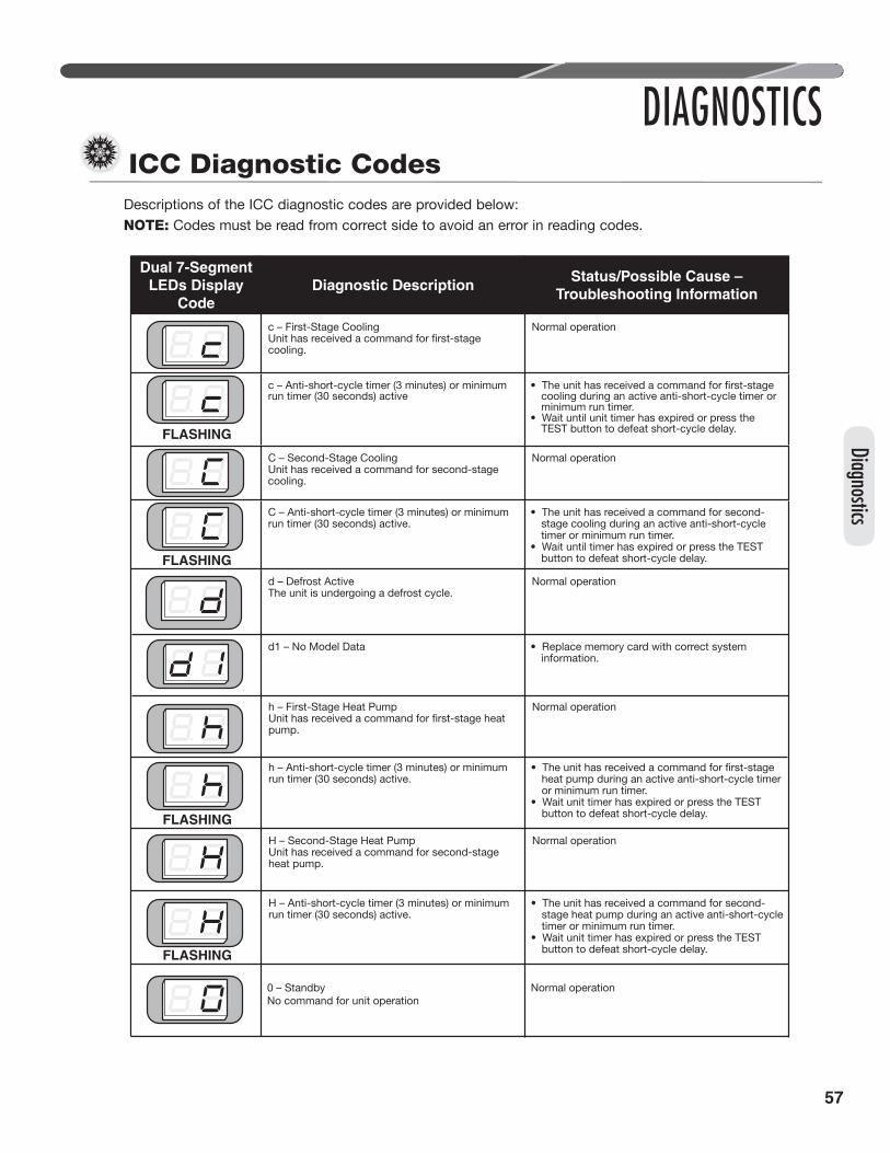
57
Diagnostics
ICC Diagnostic Codes
DIAGNOSTICS
Descriptions of the ICC diagnostic codes are provided below:NOTE: Codes must be read from correct side to avoid an error in reading codes.
Dual 7-SegmentLEDs Display
CodeDiagnostic Description
Status/Possible Cause –Troubleshooting Information
c – First-Stage Cooling
cooling.
Normal operation
FLASHING
c – Anti-short-cycle timer (3 minutes) or minimum run timer (30 seconds) active cooling during an active anti-short-cycle timer or
minimum run timer.• Wait until unit timer has expired or press the
TEST button to defeat short-cycle delay.
C – Second-Stage CoolingUnit has received a command for second-stage cooling.
Normal operation
FLASHING
C – Anti-short-cycle timer (3 minutes) or minimum run timer (30 seconds) active.
• The unit has received a command for second-stage cooling during an active anti-short-cycle timer or minimum run timer.
• Wait until timer has expired or press the TEST button to defeat short-cycle delay.
d – Defrost ActiveThe unit is undergoing a defrost cycle.
Normal operation
d1 – No Model Data • Replace memory card with correct system information.
h – First-Stage Heat Pump
pump.
Normal operation
FLASHING
h – Anti-short-cycle timer (3 minutes) or minimum run timer (30 seconds) active. heat pump during an active anti-short-cycle timer
or minimum run timer.• Wait unit timer has expired or press the TEST
button to defeat short-cycle delay.
H – Second-Stage Heat PumpUnit has received a command for second-stage heat pump.
Normal operation
FLASHING
H – Anti-short-cycle timer (3 minutes) or minimum run timer (30 seconds) active.
• The unit has received a command for second-stage heat pump during an active anti-short-cycle timer or minimum run timer.
• Wait unit timer has expired or press the TEST button to defeat short-cycle delay.
0 – StandbyNo command for unit operation
Normal operation

58
DIAGNOSTICSDual 7-Segment
LEDs DisplayCode
Diagnostic DescriptionStatus/Possible Cause –
Troubleshooting Information
L15 – T901, A903, A904, A905, A908, A909, A910,T911, T914, T917, T918 & T922Inverter Fault
• Verify high voltage connections at the terminal• block, filter and inverter are all tight.• Verify communication cable connection between• the inverter and ICC is complete.• Check the U/V/W output wires are correct.• Verify there is not a short in the filter or choke.• Verify input voltage is within 187VAC and 252VAC.• Check outdoor airflow and verify OD fan is• operating.• Check the power inverter heat sync for debris.• Replace model data card• If none of the above corrects the issue,• replace drive.
L16 – A912, A913, A919, A920, A921, & A929Inverter Fault
• Power cycle the system. Verify all lights on the• inverter are out prior to returning power to the• drive.• Check the U/V/W output wires are correct.• Check charge level. Reduce charge.• Check continuity of discharge line thermistor• and connection at the drive. If issue persists,• replace the thermistor.• If none of the above corrects the issue, replace• the drive.
L17 – Discharge line temperature – T916Inverter Fault
• Outdoor ambient is above 125°F. Allow unit to• cool and condensing pressure to reduce before• restarting.• Outdoor ambient is below 0°F. Allow unit to• heat up and evaporating pressure to increase• before restarting.• Check charge level. Reduce charge.• Check thermistor continuity. The discharge• thermistor is a 10k thermistor. See the 10k• thermistor chart for correct resistance value.
L18 – Communication failure – T915Inverter Fault
• Verify communication cable connection • between the inverter and ICC is complete.• Verify shielding on communication cable is• adequately connected to the connector.• Verify crimp terminals in the ICC to inverter• communication cable are fully inserted and• making good contact with the receptacle.
L8 – Compressor Model UnknownA900–O Inverter Identity Fault
• Check model data card is properly connected• Cycle power – remove power until all the lights• on the inverter have gone out. Then restore• power to inverter then ICC.• Replace model data card
09 – Low Secondary VoltsThe secondary voltage at R and C is below 18VAC.
• Control transformer overloaded.• Low line voltage
21 – Low Pressure Control OpenThe ICC detects the LPC is open.Notice: The low-pressure control is ignored for the
• Unit has low refrigerant charge.• Indoor coil is frozen (cooling mode).
• Indoor blower is not running (cooling mode).• Outdoor coil is frozen (heating mode).• Expansion valve is not operating correctly.
Diag
nosti
cs
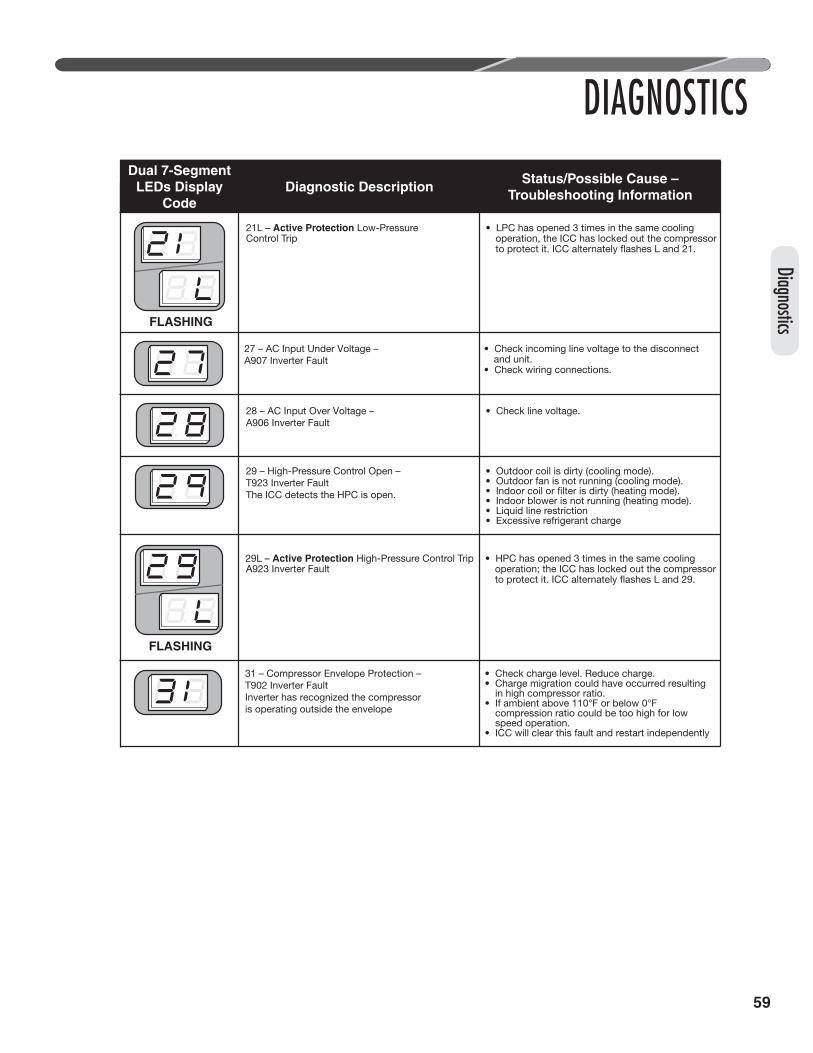
59
Diagnostics
DIAGNOSTICSDual 7-Segment
LEDs DisplayCode
Diagnostic DescriptionStatus/Possible Cause –
Troubleshooting Information
FLASHING
21L – Active Protection Low-PressureControl Trip
• LPC has opened 3 times in the same cooling operation, the ICC has locked out the compressor
28 – AC Input Over Voltage – A906 Inverter Fault
• Check line voltage.
29 – High-Pressure Control Open –T923 Inverter FaultThe ICC detects the HPC is open.
• Outdoor coil is dirty (cooling mode).• Outdoor fan is not running (cooling mode).
• Indoor blower is not running (heating mode).• Liquid line restriction• Excessive refrigerant charge
27 – AC Input Under Voltage – A907 Inverter Fault
• Check incoming line voltage to the disconnect and unit.
• Check wiring connections.
FLASHING
29L – Active Protection High-Pressure Control Trip • HPC has opened 3 times in the same cooling operation; the ICC has locked out the compressor A923 Inverter Fault
31 – Compressor Envelope Protection – T902 Inverter FaultInverter has recognized the compressoris operating outside the envelope
• Check charge level. Reduce charge.• Charge migration could have occurred resulting• in high compressor ratio.• If ambient above 110°F or below 0°F• compression ratio could be too high for low• speed operation.• ICC will clear this fault and restart independently

60
DIAGNOSTICSDual 7-Segment
LEDs DisplayCode
Diagnostic DescriptionStatus/Possible Cause –
Troubleshooting Information
83 – Condenser Coil Temperature FaultThe sensor detects an abnormally low or high coil temperature.
• Replace the sensor.• Check sensor is installed correctly on control.
84 – Outdoor Ambient Temperature FaultThe sensor detects an abnormally low or high outdoor ambient temperature.T952
• Check unit placement. If the outdoor unit is in a high-temperature area, wait until the ambient temperature drops and check sensor reading.
• Replace the sensor.• Check sensor is installed correctly on control.
93 – Configuration Data Restore FailureA950The control is not functioning properly.
• Check control for proper system operation.• Replace control.
L36 – Suction Pressure Sensor Failure –A956
• Check pressure transducer wiring harness for• continuity while attached to sensor.• Check 5Vdc is constant between black and red• at the sensor.• Check return voltage between Black and Green• terminals on back of control board.• Calculate the gauge pressure from the voltage• readings: PSIG = (375 * (Vout/Vin) - 22.8)-14.7• On a legacy controlled system verify that the• voltage readings convert to the servicer gauge• readings.• On a communicating system verify that the• voltage readings convert to the displayed• pressure listed on the control center.• If all voltage measurements convert to a• similar pressure as displayed by the control• center or manual gauges replace the control.• If not replace the harness and/or pressure• transducer.
L42 – Compressor Temperature ThermistorFailure – T955
• Check thermistor continuity. The compressor• thermistor is a 10k thermistor. See the 10k• thermistor chart for correct resistance value.
L32 – Compressor Temperature ThermisterFailure – A902 Inverter Fault
• Check thermister continuity. The compressor• thermister is a 10k thermister. See the 10k thermister chart for correct resistance value.
L32 – Compressor Temperature ThermisterFailure – A902 Inverter Fault
• Check thermister continuity. The compressor• thermister is a 10k thermister. See the 10k thermister chart for correct resistance value.
Diag
nosti
cs

61
Diagnostics
DIAGNOSTICSElectrical Checks Flowchart
YES
YES
YES
YES
NO
YES
NO
NO
NO
Outdoor UnitRunning
7-SegmentDisplay Lit?
Flashing ModeCharacter
Alternating ``C´´or ``H´´
and ``##´´ (Code)
Refer to the ICC Diagnostics Codes section from thismanual for fault code troubleshooting.
Check fault history for other faults.
See the “ICC DiagnosticCodes and the “ActiveCompressor Protection
Mode” section fromthis manual for fault code
troubleshooting.
Control in lockout mode.
Check fault history and refer to diagnostic chart andthe ICC Diagnostic Codes section of this manual.
Waiting for anti-short-cycle delay to clear.
Notice: For solid comm. LED, check comm. wiring, term/busswitches at ICC and AH controls.
Check control voltage (R and C) to control. Check transformer or Check 3A fuse on ICC Board
Bad control board or incorrect wiring – check wiring and replace control if bad.
NO
NO
THERMOSTAT CALL FOR COOLING, NO COOLING

62
DIAGNOSTICS
High Head Pressure orCompressor Envelope
Protection
YES
NO
PressureProblems?
Low LiquidPressure
Low SuctionPressure
Go to ElectricalChecks Flowchart
Dirty Filters
Dirty Indoor Coil
Inadequate IndoorAirflow
Inoperative IndoorBlower
Low onCharge
Low AmbientTemperature
BadCompressor
Outdoor CheckValve Closed
Restricted IndoorMetering Device
RestrictedFilter Drier
Dirty Outdoor Coil
Inoperative OutdoorFan
Overcharge
Recirculation ofOutdoor Air
Noncondensibles
Higher Than Ambient AirEntering Outdoor Coil
Wrong OutdoorFan Rotation
Inadequate Ducts
Outdoor CheckValve Closed
RestrictedFilter Drier
Outdoor UnitRunning?
Low on Charge
Restricted IndoorMetering Device
Restriction inSystem
Recirculation ofIndoor Air
Wrong IndoorBlower Rotation
Cooling Mechanical Checks Flowchart
Diag
nosti
cs

63
Diagnostics
YES
NO
PressureProblems?
Low LiquidPressure
Low SuctionPressure
High Liquid Pressure orCompressor Envelope
Protection
Go to ElectricalChecks Flowchart
Dirty Outdoor Coil
Inadequate OutdoorAirflow
Inoperative OutdoorFan Motor
Low onCharge
Low IndoorTemperature
BadCompressor
Indoor CheckValve Closed
Restricted OutdoorMetering Device
RestrictedFilter Drier
Dirty Indoor Coil
Inoperative IndoorFan
Overcharge
Noncondensibles
Dirty Filters
0
Wrong IndoorFan Rotation
Outdoor CheckValve Closed
RestrictedFilter Drier
Outdoor UnitRunning?
Low on Charge
Restricted OutdoorMetering Device
Restriction inSystem
Recirculation ofOutdoor Air
Wrong OutdoorBlower Rotation
Reversing ValveFailure
Heating Mechanical Checks Flowchart
DIAGNOSTICS
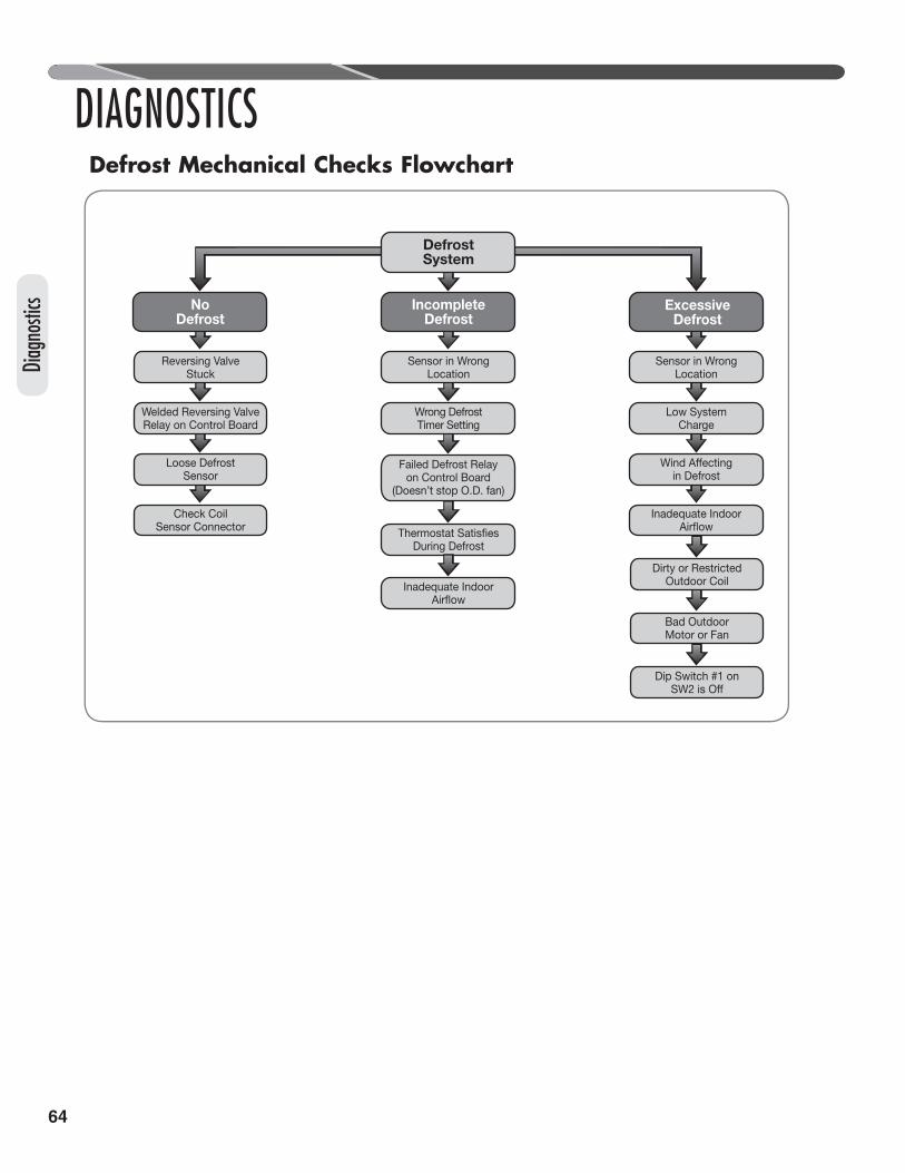
64
Thermostat SatisfiesDuring Defrost
Failed Defrost Relayon Control Board
(Doesn’t stop O.D. fan)
IncompleteDefrost
ExcessiveDefrost
NoDefrost
Sensor in WrongLocation
Low SystemCharge
Wind Affectingin Defrost
Sensor in WrongLocation
Wrong DefrostTimer Setting
Reversing ValveStuck
Welded Reversing ValveRelay on Control Board
Loose DefrostSensor
Check CoilSensor Connector
DefrostSystem
Inadequate IndoorAirflow
Inadequate IndoorAirflow
Dirty or RestrictedOutdoor Coil
Bad OutdoorMotor or Fan
Dip Switch #1 onSW2 is Off
Defrost Mechanical Checks Flowchart
DIAGNOSTICS
Diag
nosti
cs

65
Diagnostics
DIAGNOSTICSGeneral Troubleshooting Chart
WARNING: Disconnect all power to unit before servicing. Contactor may break only one
side. Failure to shut off power can cause electrical shock resulting in personal injury or death.
SYMPTOM POSSIBLE CAUSE REMEDYUnit will not run • Power off or loose electrical connection
• Thermostat out of calibration – set too high.• Unit in active compresor protection• lockout mode• Defective control board
• Blown fuses/tripped breaker• Transformer defective• High-pressure control open • Miswiring of communications (communication
light on continuously)
• Check for correct voltage at line voltage connections in condensing unit.
• Reset – Power cycle high and low voltage to outdoor• unit
• Check control board diagnostic codes.• Replace fuses/reset breaker.• Check wiring. Replace transformer.• Reset. Also see high head pressure remedy. The high-
pressure control opens at 610 PSIG.• Check communication wiring.
Outdoor fan runs, compressor doesn't
• Loose connection
• Communication cable disconnected or failed• Compressor stuck, grounded or open motor
winding, open internal overload.• Low-voltage condition
• Check for correct voltage at fi lter and inverter. Check and tighten all connections.
• Check control board diagnostic codes.• Replace
Insuffi cient cooling • Improperly sized unit• Improper indoor airfl ow• Incorrect refrigerant charge• Air, noncondensibles, or moisture in system
• Recalculate load.• Check airfl ow. Should be approximately 400 CFM per
ton.• Charge per procedure attached to unit service panel.• Recover refrigerant. Evacuate and recharge. Replace fi lter drier.
Compressor short cycles
• Incorrect voltage• Improperly sized unit• Refrigerant undercharge
• At inverter input terminals, voltage must be between 187-252VAC when unit is operating.
• Add refrigerant.
Registers sweat • Low indoor airfl ow • Increase speed of blower or reduce restriction.Replace air fi lter.
High head, low vapor pressures
• Restriction in liquid line, expansion device, or fi lter drier
• Stuck EXV
• Remove or replace defective component.
• Verify EXV operation.
High head, high or normal vapor pressure – Cooling mode
• Dirty outdoor coil• Refrigerant overcharge• Outdoor fan not running• Air or noncondensibles in system
• Clean coil.• Correct system charge.• Repair or replace.• Recover refrigerant. Evacuate and recharge.
Low head, high vapor pressures
• EXV in bypass mode
• Bad compressor
• Verify thermostat connections at EXV control• Verify thermister and pressure transducer connection
and operation• Replace compressor.
Low vapor, cool compressor, iced indoor coil
• Low indoor airfl ow
• Operating below 55°F outdoors• Moisture in system• Low ambient cooling not operating (coil or ambient thermister failure)
• Increase speed of blower or reduce restriction. Replace air fi lter.
• Recover refrigerant. Evacuate and recharge. Replace fi lter drier.
High vapor pressure • Excessive load• Defective compressor
• Recheck load calculation.• Replace compressor.
Fluctuating head and vapor pressures
• EXV hunting
• Air or noncondensibles in system
• Check thermistor to vapor line connection. Check air distribution on coil.
• Check suction thermistor and pressure transducer operation
• Recover refrigerant. Evacuate and recharge.• Remove & confi rm EXV movement. Clean EXV inside
with nitrogen to remove any debris then reinstall
Gurgle or pulsing noise at expansion device or liquid line
• Air or noncondensibles in system • Recover refrigerant. Evacuate and recharge.
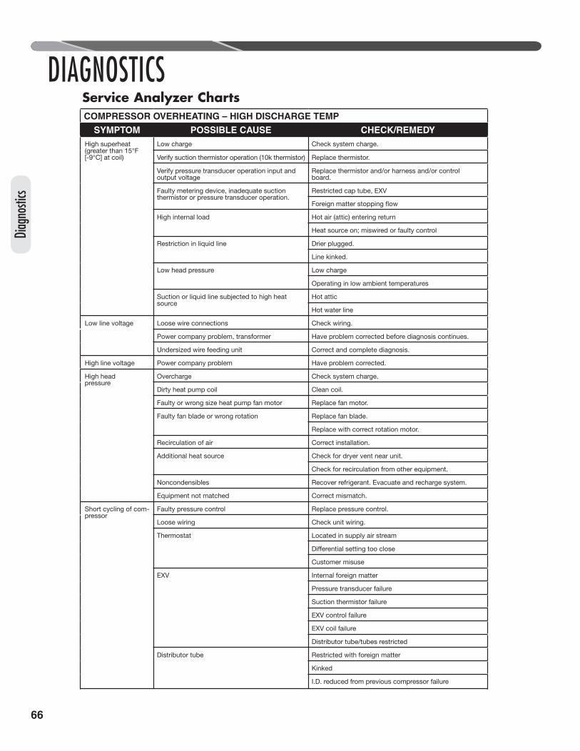
66
DIAGNOSTICSService Analyzer ChartsCOMPRESSOR OVERHEATING – HIGH DISCHARGE TEMP
SYMPTOM POSSIBLE CAUSE CHECK/REMEDYHigh superheat (greater than 15°F [-9°C] at coil)
Low charge Check system charge.
Verify suction thermistor operation (10k thermistor) Replace thermistor.
Verify pressure transducer operation input andoutput voltage
Replace thermistor and/or harness and/or controlboard.
Faulty metering device, inadequate suctionthermistor or pressure transducer operation.
Restricted cap tube, EXV
High internal load Hot air (attic) entering return
Heat source on; miswired or faulty control
Restriction in liquid line Drier plugged.
Line kinked.
Low head pressure Low charge
Operating in low ambient temperatures
Suction or liquid line subjected to high heat source
Hot attic
Hot water line
Low line voltage Loose wire connections Check wiring.
Power company problem, transformer Have problem corrected before diagnosis continues.
Undersized wire feeding unit Correct and complete diagnosis.
High line voltage Power company problem Have problem corrected.
High head pressure
Overcharge Check system charge.
Dirty heat pump coil Clean coil.
Faulty or wrong size heat pump fan motor Replace fan motor.
Faulty fan blade or wrong rotation Replace fan blade.
Replace with correct rotation motor.
Recirculation of air Correct installation.
Additional heat source Check for dryer vent near unit.
Check for recirculation from other equipment.
Noncondensibles Recover refrigerant. Evacuate and recharge system.
Equipment not matched Correct mismatch.
Short cycling of com-pressor
Faulty pressure control Replace pressure control.
Loose wiring Check unit wiring.
Thermostat Located in supply air stream
Customer misuse
EXV Internal foreign matter
Pressure transducer failure
Suction thermistor failure
EXV control failure
EXV coil failure
Distributor tube/tubes restricted
Distributor tube Restricted with foreign matter
Kinked
I.D. reduced from previous compressor failure
Diag
nosti
cs

67
Diagnostics
DIAGNOSTICSService Analyzer ChartsCOMPRESSOR OVERHEATING – HIGH DISCHARGE TEMP (cont.)
SYMPTOM POSSIBLE CAUSE CHECK OR REMEDIESShort cycling of compressor (cont.)
Low charge Check system charge.
Dirty coil
Duct too small or restricted
Faulty run capacitor Replace.
Faulty internal overload Replace compressor.
ELECTRICALSYMPTOM POSSIBLE CAUSE CHECK OR REMEDIES
Voltage present on load side of inverterand compressor won't run
Communication failure from ICC to inverter. Check communication harness connectors and wirecontinuity.
Compressor windings Check for correct ohms.
187 – 252VACpresent at input toinverter
Thermostat Check for control voltage to contactor coil.
Compressor control circuit High-pressure switch
Low-pressure cut-out
Ambient thermostat
Stater heat is active
No voltage at inputto inverter
Blown fuses or tripped circuit breaker Check for short in wiring or unit.
Improper wiring Recheck wiring diagram.
Improper voltage High voltage Wrong unit
Power supply problem
Low voltage Wrong unit
Power supply problem
Wiring undersized
Loose connections
FLOODED STARTSSYMPTOM POSSIBLE CAUSE CHECK OR REMEDIES
Liquid in the com-pressor shell
Faulty stator heat circuit (compressor thermistoror single leg output to compressor)
Replace compressor thermistorCheck inverter for single leg output power and correctwiring.
Too much liquid in system
Incorrect piping Check piping guidelines.
Overcharge Check and adjust charge.

68
DIAGNOSTICSService Analyzer Charts
SYMPTOM POSSIBLE CAUSE REMEDYMoisture Poor evacuation on installation or during service In each case, the cure is the same. Recover refrigerant.
High head pressure Noncondensibles air
Unusual head and suction readings
Wrong refrigerant or mixed refrigerants
Foreign matter – Copper tubing cuttings
Copper oxide Dirty copper piping or nitrogen not used when brazing
Welding scale Nitrogen not used during brazing
Excess soft solder Wrong solder material
LOSS OF LUBRICATIONSYMPTOM POSSIBLE CAUSE REMEDY
Compressor failures Line tubing too large Reduce pipe size to improve oil return.
Low suction pressure Low charge Check system charge.
Refrigerant leaks Repair and recharge.
Cold, noisy compressor – Slugging
Dilution of oil with refrigerant Observe piping guidelines.
Noisy compressor Migration Check stater heat and compressor thermistor.
Cold, sweating compressor
Flooding Check system charge.
Low load
Dirty coil
Wrong duct size
Restricted duct
Thermostat setting Advise customer.
Short cycling of compressor
Faulty high- or low-pressure control Replace control.
Loose wiring Check all control wires.
Thermostat In supply air stream, out of calibration
Customer misuse
SLUGGING
SYMPTOM POSSIBLE CAUSE REMEDYOn start-up Incorrect piping Review pipe size guidelines.
EXV hunting when running
Faulty EXV components Check EXV, suction pressure transducer, and suctionthermistor for operation.
CONTAMINATION
Diag
nosti
cs

69
Diagnostics
DIAGNOSTICSService Analyzer Charts
FLOODING
SYMPTOM POSSIBLE CAUSE REMEDY
Poor system control using an EXV
Bad pressure reading Check transducer wiring.
Suction thermistor in wrong location Relocate thermistor.
Bad suction thermistor Replace thermistor.
Improper superheat setting (less than 5°F [-15°C]) Adjust EXV SH setpoint dipswitches and validatevalve operation.
ELECTRONIC EXPANSION VALVESSYMPTOM POSSIBLE CAUSE REMEDY
High Superheat, Low Suction Pressure (superheat over
15°F [9°C])
Moisture freezing and blocking valve Recover charge, replace filter-drier, evacuate system,recharge.
Dirt or foreign material blocking valve Recover charge, replace filter-drier, evacuate system,recharge
Low refrigerant charge Correct the charge.
Vapor bubbles in liquid line Remove restriction in liquid line. Correct the refrigerant charge.
Remove noncondensible gases.
Size liquid line correctly.
Verify suction thermistor resistance is correct andproperly attached and insulated to the vapor line.
Incorrectly sensing vapor line temperature
Replace suction thermistor assembly.Suction thermistor incorrectly calibrated.
If harness has a short, replace harness
If gauge pressure measurement and the convertedvoltage readings at the control are the same, replacethe control.
EXV is stuck
If EXV will not open, validate EXV wiring harness androtor resistance between the black wire and theother 4 wires.
Replace with correct valve.Undersized EXV
After verifying lack of connectivity, replace the pressuretransducer or harness.
Vapor pressure measured incorrectly.
If gauge pressure measurement and the convertedvoltage readings at the control are different replacepressure transducer
Remove EXV from the system and purge with nitrogen,replace filter drier, and recharge.
If none of the above rectifies the issue, replace EXVand filter drier and recharge.
ICC dc circuit failed Verify 5Vdc to pressure transducer is present. If not,replace ICC.
High superheat adjustment Change the superheat offset dip switches to increasesuperheat.

70
DIAGNOSTICSService Analyzer Charts
ELECTRONIC EXPANSION VALVES (cont.)
SYMPTOM POSSIBLE CAUSE REMEDY
Moisture causing valve to stick open. Recover refrigerant, replace filter-drier, evacuatesystem, and recharge.
Dirt or foreign material causing valve to stickopen
Recover refrigerant, replace filter-drier, remove EXVand purge with nitrogen, evacuate system, and recharge.
Valve feeds too muchrefrigerant, with lowsuperheat, with low
superheat andhigher than normalsuction pressure.
If EXV is completely clogged use the ICC to open the EXV,and purge with nitrogen, replace filter drier, and recharge.
Oversized EXV Install correct EXV
Incorrect suction thermistor location Install suction thermistor with the provided stainlesssteel strap and an additional zip tie at the 10:00 or 2:00position on suction line, with insulation.
Change the superheat offset dip switches to increasesuperheat.
Verify suction thermistor resistance is correct andproperly attached and insulated to the vapor line.
Incorrectly sensing vapor line temperature
Replace suction thermistor assembly.Suction thermistor incorrectly calibrated.
If harness has a short, replace harness
If gauge pressure measurement and the convertedvoltage readings at the control are the same, replacethe control.
Inoperable stator heat Verify compressor thermistor (OST). Replace if needed.
After verifying lack of connectivity, replace the pressuretransducer or harness.
Vapor pressure measured incorrectly.
If gauge pressure measurement and the convertedvoltage readings at the control are different replacepressure transducer
Install trap riser to the top of the evaporator coil.
Any of the solutions listed under Solutions of ElectricalProblems on page 60.
Low superheat adjustment
Refrigerant drainage from flooded evaporatorCompressor flood
back uponstart-up
Any of the causes listed under Symptomsof Electrical Problems on page 60.
Diag
nosti
cs

71
Diagnostics
DIAGNOSTICSService Analyzer Charts
ELECTRONIC EXPANSION VALVES (cont.)
SYMPTOM POSSIBLE CAUSE REMEDYUnequal evaporator circuit loading Ensure airflow is equally distributed through
evaporator.
Check for blocked distributor tubes.
Low load or airflow entering evaporator coil Ensure blower is moving proper air CFM.
Remove/Correct any airflow restriction.
Superheat is lowto normal with lowsuction pressure
Expansion valve is oversized. Install correct EXV
Section thermister is affected by liquid refrigerantor refrigerant oil flowing through suction line
Relocate sensing bulb in another position around thecircumference of the suction line.
Ensure sensing bulb is located properly.
Check for blocked distributor tubes.
Recover refrigerant, change filter-drier, evacuatesystem, and recharge.
Moisture freezing and partially blocking EXV
Connect pressure transducer in proper location, orremove any blockage.
Pressure transducer not connected or plugged
Install suction line thermistor in correct horizontalclean section of copper pipe.
Unequal refrigerant flow through evaporatorcircuit
Suction line thermistor not connected, orinstalled on heat effected zone.
Superheat andsuction pressurefluctuate (valve
is hunting)
Valve does notregulate at all
Replace suction line thermistor.Suction line thermistor failed (continuity tocontrol, wire damaged, resistance valuesincorrect)

72
DIAGNOSTICSCOOLING MODE
TROUBLESHOOTING TIPS
SYSTEM PROBLEM
INDICATORS
DISCHARGE PRESSURE
SUCTION PRESSURE
SUPERHEATNormal: 5°–15°F
[-15° – -9°C]
SUBCOOLINGNormal: See
Charging Chart
COMPRESSOR AMPS
Overcharge High High Low High HighUndercharge Low Low High Low Low
Liquid Restriction (Drier) Low Low High High Low
Low Indoor Airfl ow Low Low Low Low LowDirty Outdoor Coil High High Low Low High
Low Outdoor Ambient Temperature Low Low High High Low
Ineffi cient Compressor Low High High High Low
Indoor SuctionPressure Transducer Faulty Measurement
Low Low High High Low
Poorly Insulated Indoor Vapor Line
ThermistorHigh High Low Low High
HEATING MODETROUBLESHOOTING TIPS
SYSTEM PROBLEM
INDICATORS
DISCHARGE PRESSURE
SUCTION PRESSURE
SUPERHEATNormal: 5°–15°F
[-15° – -9°C]
SUBCOOLINGNormal: See
Charging Chart
COMPRESSOR AMPS
Overcharge High High OK High HighUndercharge Low Low OK or High Low Low
Liquid Restriction (Drier) Low Low High High Low
Low Outdoor Airfl ow Low Low Low Low LowDirty Indoor Coil High High Low Low High
Low Indoor Ambient Temperature Low Low OK High Low
Ineffi cient Compressor Low High High High Low
Outdoor SuctionPressure TransducerFaulty Measurement
Low Low High High Low
Poorly Insulated Outdoor Suction Line
ThermistorHigh High Low Low High
Diag
nosti
cs

73
Wiring Diagram
WIRING DIAGRAM
COM
P
ODF
MOD
BUS
OAT
EVAP
IN O
STOL
T C
PT
Mem
ory
Card
PWM
SPT
LPT
EXV
RVS
RVSC
RT
E2
E1
C
R
Y
Y2
B
W U
TIL2
4 UT
IL
RC
GND
TEST
SW2
ETER
LED3
LED5
ACT
L1L2
GND
H2 H1
UVW
Chok
e
Filte
rIN
OUT
L1L2
Pow
er
In
Inve
rter
BKBKBK
G
G
YYR Y
GY
GY
BKY
G
HPC
SENS
OR
RS48
5
OFM
G/Y
BLY
BRBK
HPC
ETENOC
RV
ODF
SPT
LPT
RVS
RVSC
MOD
BUS
Mem
ory
Card
MPW
OAT
CD
GN
TEST
R
SW2
ETRE
LED3
LED5
ACT
OLT
CPT
OIPAN
VE
ST
UTIL 2UTIL
C R
YY2
BW
RT E
2 E
1
VXE
ETENOC
Comp.
Inverter
1L2L
Filte
rPo
wer
RV

74

75

76